H2020 GA No. 258301 D4.1 WiSHF L 1 Wireless Software and Hardware platforms for Flexible and Unified radio and network controL Project Deliverable D4.1 Design of software architecture for unified network control Contractual date of delivery: 30062015 Actual date of delivery: 30062015 Beneficiaries: TUB, IMINDS, CNIT Lead beneficiary: TUB Authors: Anatolij Zubow (TUB), Mikolaj Chwalisz (TUB), Piotr Gawłowicz (TUB), Adam Wolisz (TUB), Peter Ruckebusch (IMINDS), Ingrid Moerman (IMINDS), Pierluigi Gallo (CNIT), Nicolò Facchi (CNIT), Ilenia Tinnirello (CNIT) Reviewers: Carolina Fortuna (IMINDS), Daniele Croce (CNIT) Work package: WP4 – Network Control Estimated person months: 8 Nature: R Dissemination level: PU Version: 2.2 Abstract: This deliverable describes the first definition of the UPI_N interface for configuring and control of the higherlayers of the network protocol stack of the WiSHFUL programmable network nodes. The specification is based on the generalization of two architectures, namely Linuxbased devices and embedded devices based on Contiki. By exposing a highlevel programming interface, easy programming of upper MAC, network, routing and higher layers is enabled. For coordinated (i.e. time synchronized) execution of configuration and monitoring related functions an additional UPI is defined, the UPI_G, allowing networkwide operations on a group of nodes. Finally, this document also covers all management related functions provided by UPI_M required for managing protocol software modules at any layer of the network protocol stack. Keywords: Programmable network architecture, network control, softwaredefined networking WiSHF L

Welcome message from author
This document is posted to help you gain knowledge. Please leave a comment to let me know what you think about it! Share it to your friends and learn new things together.
Transcript
H2020 -‐ GA No. 258301 D4.1
WiSHF L
1
Wireless Software and Hardware platforms for Flexible and Unified radio and network controL
Project Deliverable D4.1 Design of software architecture for unified network control
Contractual date of delivery: 30-‐06-‐2015
Actual date of delivery: 30-‐06-‐2015
Beneficiaries: TUB, IMINDS, CNIT
Lead beneficiary: TUB
Authors: Anatolij Zubow (TUB), Mikolaj Chwalisz (TUB), Piotr Gawłowicz (TUB), Adam Wolisz (TUB), Peter Ruckebusch (IMINDS), Ingrid Moerman (IMINDS), Pierluigi Gallo (CNIT), Nicolò Facchi (CNIT), Ilenia Tinnirello (CNIT)
Reviewers: Carolina Fortuna (IMINDS), Daniele Croce (CNIT)
Work package: WP4 – Network Control
Estimated person months: 8
Nature: R
Dissemination level: PU
Version: 2.2
Abstract: This deliverable describes the first definition of the UPI_N interface for configuring and control of the higher-‐layers of the network protocol stack of the WiSHFUL programmable network nodes. The specification is based on the generalization of two architectures, namely Linux-‐based devices and embedded devices based on Contiki. By exposing a high-‐level programming interface, easy programming of upper MAC, network, routing and higher layers is enabled. For coordinated (i.e. time synchronized) execution of configuration and monitoring related functions an additional UPI is defined, the UPI_G, allowing network-‐wide operations on a group of nodes. Finally, this document also covers all management related functions provided by UPI_M required for managing protocol software modules at any layer of the network protocol stack.
Keywords: Programmable network architecture, network control, software-‐defined networking
WiSHF L
H2020 -‐ GA No. 258301 D4.1
WiSHF L
2
Executive Summary This public deliverable will report on the software architecture for network control and its unified programming interfaces. The document will serve as a guideline for the implementation of the basic network control software platform that will be offered for the first open calls at the end of year 1.
First, we present the different network architectures used in the testbeds of the project partners. Second, we generalize these architectures in a common network architecture, in which the concrete hardware is abstracted. By exposing a high-‐level programming interface, i.e. UPI_N, easy programming of upper MAC, network, routing and higher layers is enabled. For coordinated execution of configuration and monitoring related functions an additional UPI is defined, the UPI_G, allowing network-‐wide operations on a group of nodes. Finally, this document also covers all management related functions required for managing protocol software modules at any layer of the network protocol stack. A multitude of examples programmed by using the proposed interfaces, namely UPI_N, UPI_G and UPI_M are also presented.
H2020 -‐ GA No. 258301 D4.1
WiSHF L
3
List of Acronyms and Abbreviations 6LoWPAN IPv6 over Low power Wireless Personal Area Networks
AODV Ad-‐hoc On-‐demand Distance Vector
AP Access Point
BE Best Effort
BLIP Berkeley IP
COAP Constrained Application Protocol
CPE Customer Premises Equipment
CREW Cognitive Radio Experimentation World – EU project
CTP Collection Tree Protocol
CWMP CPE WAN Management Protocol
DHCP Dynamic Host Configuration Protocol
DVB Digital Video Broadcasting
GITAR Generic extensions for Internet-‐of-‐Things Architectures
GTS Guaranteed Time Slot
HGI Home Gateway Initiative
HTTP Hypertext Transfer Protocol
ICMP Internet Control Message Protocol
IDS Intrusion Detection System
IP Internet Protocol
MAC Medium Access Control
MTU Maximum Transmission Unit
OLSR Optimized Link State Routing Protocol
OS Operating System
QoS Quality of Service
RPL Routing Protocol for Low-‐Power and Lossy Networks
SDN Software-‐defined networking
SNMP Simple Network Management Protocol
SOAP Simple Object Access Protocol
SSID Service Set Identifier
STA Station
TinyRPL IPv6 Routing Protocol for Low-‐power and Lossy Networks (RPL)
ToS Type of Service
UPI Unified Programming Interface
UPI_G Unified Programming Interface global
H2020 -‐ GA No. 258301 D4.1
WiSHF L
4
UPI_M Unified Programming Interface management
UPI_N
UPI_R
Unified Programming Interface network
Unified Programming Interface radio
VoIP Voice over IP
VPN Virtual Private Network
WAN Wide Area Network
WiMAX Worldwide Interoperability for Microwave Access
WDS Wireless Distribution System
ZeroMQ Embeddable networking library and a concurrency framework
H2020 -‐ GA No. 258301 D4.1
WiSHF L
5
Table of contents
1 Introduction .......................................................................................................... 7
2 Programmable Network Architectures available in WiSHFUL ......................... 8 2.1 GNU-‐Linux .......................................................................................................................... 8 2.2 Contiki/TinyOS .................................................................................................................... 8
3 Mapping UPI_N Requirements into WiSHFUL Programmable Network Platforms .................................................................................................................... 8
3.1 Linux Networking Subsystem .............................................................................................. 9 3.2 Sensor Networks ............................................................................................................... 10
3.2.1 TinyOS ......................................................................................................................................... 12 3.2.2 Contiki ......................................................................................................................................... 12 3.2.3 GITAR ........................................................................................................................................... 12
4 Abstracting Network Architectures .................................................................. 12
5 Unified network control interface ..................................................................... 13 5.1 UPI_N Interface Definition ................................................................................................ 13
5.1.1 Network configuration and monitoring ...................................................................................... 14 5.1.2 Routing configuration and monitoring ........................................................................................ 15 5.1.3 Traffic control and monitoring .................................................................................................... 16 5.1.4 Packet filtering, manipulation and monitoring ........................................................................... 17 5.1.5 Scheduling flows over multiple outbound interfaces ................................................................. 18 5.1.6 Connection tracking .................................................................................................................... 19 5.1.7 Wireless mode control ................................................................................................................ 20 5.1.8 Generic configuration and monitoring ........................................................................................ 21
6 Global control interface ..................................................................................... 22
7 Unified management interface .......................................................................... 24
8 Examples of UPI_N utilization ........................................................................... 27 8.1 Traffic-‐aware 802.11 airtime management ....................................................................... 27
8.1.1 Example Description ................................................................................................................... 27 8.1.2 Requirements for UPI_R .............................................................................................................. 27 8.1.3 Requirements for UPI_N ............................................................................................................. 28 8.1.4 Requirements for UPI_G ............................................................................................................. 28
8.2 WIFI and Sensor Network Co-‐existence ............................................................................. 28
H2020 -‐ GA No. 258301 D4.1
WiSHF L
6
8.2.1 Example Description ................................................................................................................... 28 8.2.2 Requirements for UPI_R .............................................................................................................. 29 8.2.3 Requirements for UPI_N ............................................................................................................. 29 8.2.4 Requirements for UPI_G ............................................................................................................. 29
8.3 Intelligent Download with WIFI Tethering ......................................................................... 29 8.3.1 Example Description ................................................................................................................... 29 8.3.2 Requirements for UPI_N ............................................................................................................. 30 8.3.3 Requirements for UPI_G ............................................................................................................. 30
8.4 WIFI Offloading ................................................................................................................. 30 8.4.1 Example Description ................................................................................................................... 30 8.4.2 Requirements for UPI_N ............................................................................................................. 31
8.5 Dynamically adjusting the link estimation algorithm based on the density of the network 31 8.5.1 Example description .................................................................................................................... 31 8.5.2 Requirements for UPI_N ............................................................................................................. 32 8.5.3 Requirements for UPI_G ............................................................................................................. 32 8.5.4 Requirements for UPI_M ............................................................................................................ 32
8.6 Increasing reliability by changing the lifetimes of routes in the network ........................... 32 8.6.1 Example description .................................................................................................................... 32 8.6.2 Requirements for UPI_N ............................................................................................................. 32 8.6.3 Requirements for UPI_G ............................................................................................................. 33
8.7 Switching the routing strategy based on the type of active traffic flows ............................ 33 8.7.1 Example description .................................................................................................................... 33 8.7.2 Requirements for UPI_N ............................................................................................................. 33 8.7.3 Requirements for UPI_G ............................................................................................................. 33 8.7.4 Requirements for UPI_M ............................................................................................................ 33
9 Relation to other architectures ......................................................................... 34 9.1 CWMP ............................................................................................................................... 34 9.2 Software-‐defined Networking (Openflow) ........................................................................ 35 9.3 Openstack ......................................................................................................................... 35 9.4 OpenRoads ....................................................................................................................... 35 9.5 Active Networking ............................................................................................................ 36
10 Conclusion .......................................................................................................... 36
11 References .......................................................................................................... 37
H2020 -‐ GA No. 258301 D4.1
WiSHF L
7
1 Introduction WiSHFUL aims to expand the software defined networking concepts to the edge of the Internet, mainly targeting all wireless devices between, and including, the broadband access gateways and the end devices. This is very challenging because the targeted devices are very heterogeneous in terms of capabilities, networking scenarios and supported applications.
This deliverable describes the software architectures provided by the WiSHFUL consortium for supporting network control. The different network architectures used in the testbeds of the project partners (e.g. CREW at TUB and w.iLab.t at IMINDS) are integrated into WiSHFUL and offered to experimenters of novel services and protocols by means of a common programming model and unified interface for network control.
This deliverable focuses on the configuration, control and monitoring of the higher layers of the network protocol stack on a particular or a set of wireless node(s). By exposing a high-‐level programming interface, easy programming of upper MAC, network, routing and higher layers is enabled. For coordinated (i.e. time synchronized) execution of configuration and monitoring related functions an additional UPI is defined, the UPI_G, allowing network-‐wide operations on a group of nodes. Finally, this document also covers all management related functions required for managing protocol software modules at any layer of the network protocol stack.
This deliverable describes: i) the mapping of requirements for network control into the WiSHFUL programmable network architecture, ii) the design of a platform-‐independnet network control interface and the mapping of this interface to the different platforms; iii) global control interface allowing network-‐wide operations on a group of nodes, iv) unified management interface and v) some utilization examples.
For the first year activities of the project we will focus on unified control of wireless local area networks (IEEE 802.11) and wireless sensor networks (IEEE 802.15.4/6LowPan) which are based on the GNU-‐Linux and Contiki-‐OS network architectures. The developed solutions will provide a basic abstraction layer for controlling the higher layer network protocols. In year two, we aim to provide a more advanced abstraction of network control and we will extend to other wireless technologies (Bluetooth, LoRA, SDR) based on the input and demands from the open call experiments.
H2020 -‐ GA No. 258301 D4.1
WiSHF L
8
2 Programmable Network Architectures available in WiSHFUL In our vision, programmable network architectures is soft-‐ and hardware platforms that expose a high-‐level programming interface, which allows easy programming and control of the higher layers of the network protocol stack (i.e. data-‐plane functionality). In order to simplify programming of such platforms an appropriate abstraction is required.
The two different network architectures that are available in WiSHFUL and that will be offered to experimenters are in year1 are 1) architectures based on GNU-‐Linux and 2) embedded device based on Contiki/TinyOS.
2.1 GNU-‐Linux Most wireless network architectures today are based on open source GNU-‐Linux. Examples are IEEE-‐802.11 wireless devices, which use OpenWrt [1], a Linux distribution optimized for embedded devices like Access Points (AP) and Routers to route network traffic. Linux-‐based systems are very flexible with respect to configuration and run-‐time control of the networking stack. The generic low-‐level Netlink API allows the transfer of miscellaneous networking information between the kernel space and the user space processes. The majority of networking utilities, such as iproute2 and the utilities used for configuring a mac80211-‐based wireless driver, use Netlink to communicate with the Linux kernel from user space.
2.2 Contiki/TinyOS In contrast to Linux-‐based systems, operating systems for sensor networks like TinyOS [2] and Contiki [3] are optimized for very resource-‐limited, energy-‐efficient devices. Hence they rarely expose any API for providing networking information and allowing changing configuration parameters, monitoring protocol statistics or observing QoS. Moreover, most fine-‐tuning of protocol software needs to be done at compile and therefore cannot be changed at runtime. This is problematic because for each configuration value that needs to change, the firmware of the devices must be updated.
3 Mapping UPI_N Requirements into WiSHFUL Programmable Network Platforms
The advanced programming interface (API), exposed by the WiSHFUL programmable network platforms, allow to easily program the mechanisms on higher-‐layers (upper MAC, network, routing, transport layers) without knowing the internal details of the platform. Examples of such programmable platforms are Linux-‐based systems and embedded device based on Contiki/TinyOS. WiSHFUL aims to provide an unified API that allows the programming of all those platforms in a similar fashion.
The functional requirements for unified network control using UPI_N as identified in D2.1 can be classified into two groups:
• configuration-‐related functions, • monitoring-‐related functions.
The first group allows the configuration of networking, packet filtering and manipulation, routing, scheduling, traffic control and the wireless mode (so-‐called upper MAC). Examples are the setup of network configuration of interfaces/bridges and the configuration of firewall and Quality of Service (QoS). Moreover, these functions allow us to alter the behaviour of the different layers of the network protocol stack. The latter group is related to monitoring of parameters/variables of the upper layers of the network protocol stack. Examples are the tracking of IP connections as well as the monitoring of the network queue size and routing link metrics.
H2020 -‐ GA No. 258301 D4.1
WiSHF L
9
In case of GNU-‐Linux-‐based systems the low-‐level Netlink API allows us to implement the configuration related functions by providing a proper mapping to the corresponding functions in the UPI_N. This possibility is not given by embedded OSs used in sensor networks like TinyOS and Contiki and must therefore be implemented. Moreover, in general a specific protocol (e.g. routing protocol) is in such embedded OSs is selected and configured at compile time, not at runtime. In order to allow dynamic reconfiguration we have to provide modifications in embedded OS like Contiki/TinyOS.
In case of Linux-‐based systems most of the monitoring related functions can be implemented using again the Linux Netlink API which allows us to monitor INET sockets, routing tables, etc. Hence, we have to provide a proper mapping to the Linux Netlink API. Again the situation is more complicated with embedded devices where such a generic API is missing. Here we have to implement the required monitoring capabilities in the network stack.
Besides the functional requirements, there are also optional requirements regarding the consistency of node configuration. There are situations where the execution of a batch of configuration functions needs to be performed in a transactional context to prevent configuration inconsistencies at the node level (e.g. an 802.11 AP configured with parameters that do not work well together). That means any change on a parameter is not executed on a node immediately but waits until the end of the transaction scope.
Finally, there are also requirements regarding the performance in terms of delays between local controller calls (using UPI_N) and platform latencies on reconfiguration/information. In order to keep latencies low the UPI_N should be directly mapped on the underlying networking subsystem, i.e. in case of Linux a direct mapping on Netlink API is desirable instead of using tools like iptables for packet filtering.
3.1 Linux Networking Subsystem Wireless networks based on GNU-‐Linux already provide a generic low-‐level API (Netlink API [4] [5]) for configuration and monitoring protocol statistics. Netlink allows the transfer of miscellaneous networking information between the kernel space and user space processes. Most networking utilities such as iproute2 use Netlink to communicate with the Linux kernel from user space. Netlink provides a standard socket-‐based interface for user space processes and a kernel space API for internal use by kernel modules.
Unfortunately, Netlink is a low-‐level API and therefore hard to use. Therefore, we aim to provide high-‐level functions in UPI_N which are mapped on the related low-‐level Netlink functions. To enable WISHFUL UPI a local controller must be able to observe the behaviour of the full network protocol stack and to perform direct configurations of each protocol layer. To avoid inconsistency the execution of a batch of configuration functions is performed in a transactional context by a transaction manager. Most of the monitoring related functions can be directly mapped to the Linux Netlink API. However, some statistics (e.g. STAs associated to an AP in 802.11) are not directly available and hence must be implemented.
Not always a complete, full-‐fledged GNU-‐Linux is used. More often Linux distributions like OpenWrt optimized for embedded devices are widely used. The main components of OpenWRT are the Linux kernel, util-‐linux, uClibc and BusyBox. All components have been optimized for size, to be small enough for fitting into the limited storage and memory available in home routers. The downside is that not all the functionalities, provided by a full Linux distribution, are available on those devices.
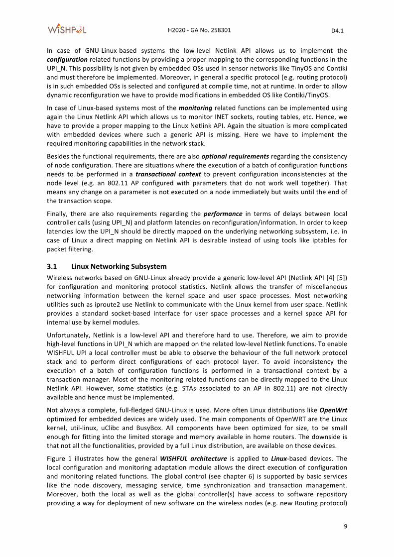
Figure 1 illustrates how the general WISHFUL architecture is applied to Linux-‐based devices. The local configuration and monitoring adaptation module allows the direct execution of configuration and monitoring related functions. The global control (see chapter 6) is supported by basic services like the node discovery, messaging service, time synchronization and transaction management. Moreover, both the local as well as the global controller(s) have access to software repository providing a way for deployment of new software on the wireless nodes (e.g. new Routing protocol)
H2020 -‐ GA No. 258301 D4.1
WiSHF L
10
and managing its life-‐cycle. These functions will be discussed in depth in Section 7 and are mentioned here for the sake of completeness. The messaging service based on a high-‐performance asynchronous messaging library like ZeroMQ [6] which allows a very efficient and fast exchange of control information between the global controller and the nodes under control.
Figure 1. WISHFUL architecture applied to Linux devices with example of IEEE 802.11 stack.
3.2 Sensor Networks Opposed to Linux systems, operating systems for sensor networks (TinyOS, Contiki) rarely expose an API for changing configuration parameters, monitoring protocol statistics, observing QoS or obtaining flow information. Moreover, most fine-‐tuning of protocol software needs to be done at compile time by changing the value of static defines. This is problematic because for each configuration value that needs to change, the firmware of the devices must be updated.
To enable WiSHFUL UPIs, the existing software on such devices needs to be extended with control plane functionality that allows a local control program to observe protocol behaviour and directly change the protocol configuration. The added control plane must also allow remote access by a global control program. This also implies that the control plane incorporates coordination functions, allowing a global control program to change configuration on multiple devices within certain time boundaries (e.g. change channel on all nodes). Beside the control plane extension, the existing protocol software also needs to be adapted so that it exposes configuration parameters as variables that can be set/get.
Since the available memory on such devices is very limited, each extension must be as small as possible. For instance, using string names to identify protocol parameters introduces too much overhead for practical use. Hence, parameters must be identified using unique IDs. Also the protocol overhead for allowing remote access by a global control program must be optimized for such devices. This is necessary for enabling operation on low bit-‐rate interfaces and, in case of battery powered devices, energy constrained devices.
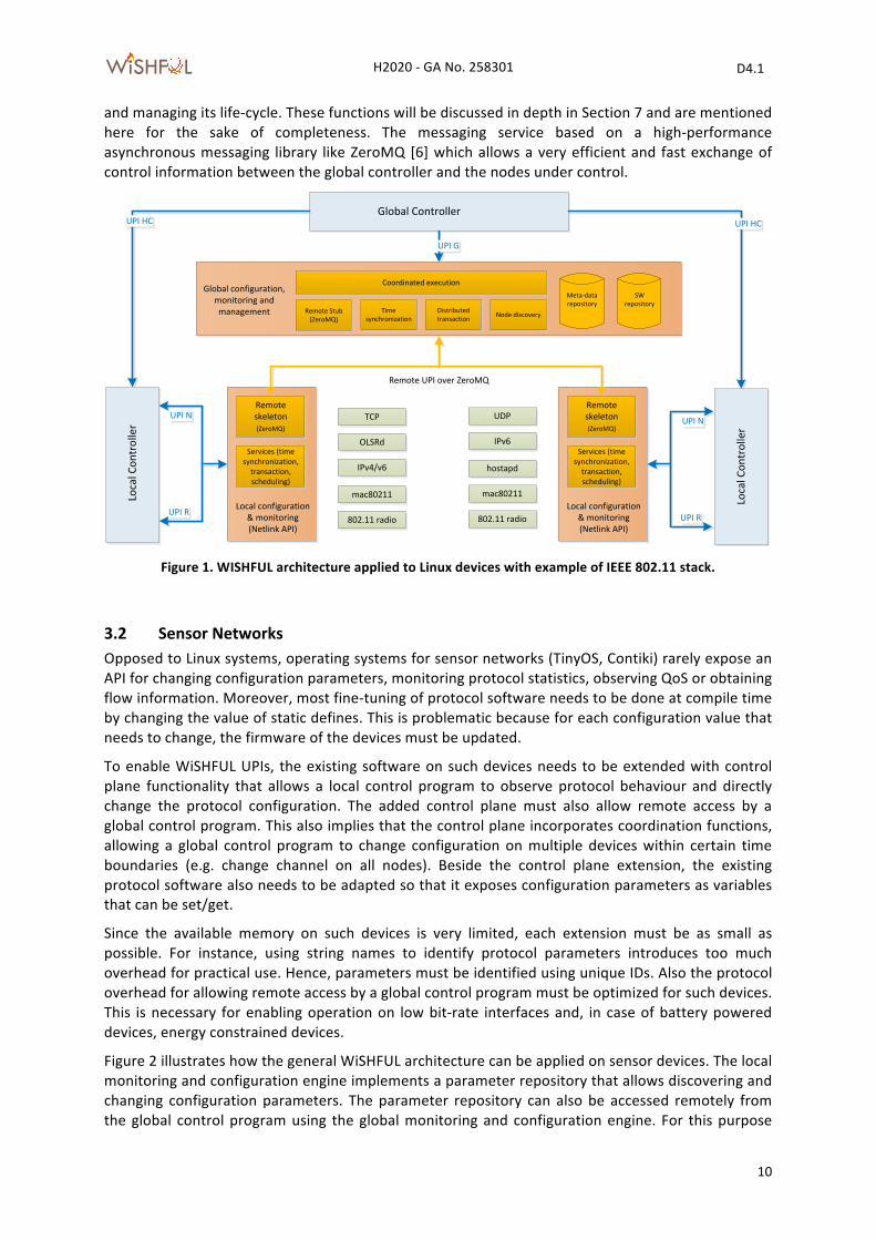
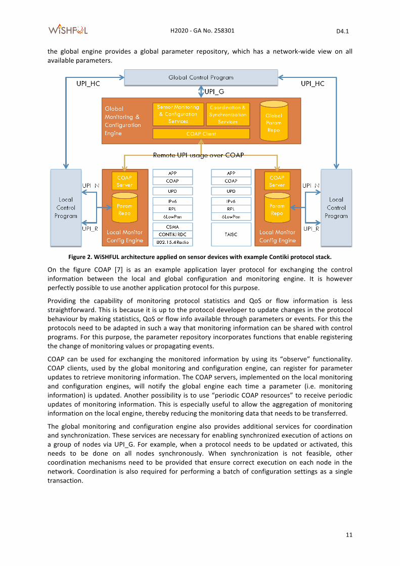
Figure 2 illustrates how the general WiSHFUL architecture can be applied on sensor devices. The local monitoring and configuration engine implements a parameter repository that allows discovering and changing configuration parameters. The parameter repository can also be accessed remotely from the global control program using the global monitoring and configuration engine. For this purpose
802.11 radio
UPI N
UPI R
Local Con
troller
Global Controller
Local configuration & monitoring(Netlink API)
Local configuration & monitoring(Netlink API)
Remote skeleton(ZeroMQ)
Services (time synchronization, transaction, scheduling)
UPI HC
UPI G
Global configuration, monitoring and management
Global configuration, monitoring and management
Remote UPI over ZeroMQRemote UPI over ZeroMQ
Time synchronization
Coordinated execution
Distributed transaction Node discoveryRemote Stub
(ZeroMQ)
Meta-‐data repositoryMeta-‐data repository
SW repository
SW repository
mac80211
OLSRd
IPv4/v6
TCP
802.11 radio
UPI N
UPI R
Local Con
troller
Local configuration & monitoring(Netlink API)
Local configuration & monitoring(Netlink API)
Remote skeleton(ZeroMQ)
Services (time synchronization, transaction, scheduling)
mac80211
hostapd
IPv6
UDP
UPI HC
H2020 -‐ GA No. 258301 D4.1
WiSHF L
11
the global engine provides a global parameter repository, which has a network-‐wide view on all available parameters.
Figure 2. WiSHFUL architecture applied on sensor devices with example Contiki protocol stack.
On the figure COAP [7] is as an example application layer protocol for exchanging the control information between the local and global configuration and monitoring engine. It is however perfectly possible to use another application protocol for this purpose.
Providing the capability of monitoring protocol statistics and QoS or flow information is less straightforward. This is because it is up to the protocol developer to update changes in the protocol behaviour by making statistics, QoS or flow info available through parameters or events. For this the protocols need to be adapted in such a way that monitoring information can be shared with control programs. For this purpose, the parameter repository incorporates functions that enable registering the change of monitoring values or propagating events.
COAP can be used for exchanging the monitored information by using its “observe” functionality. COAP clients, used by the global monitoring and configuration engine, can register for parameter updates to retrieve monitoring information. The COAP servers, implemented on the local monitoring and configuration engines, will notify the global engine each time a parameter (i.e. monitoring information) is updated. Another possibility is to use “periodic COAP resources” to receive periodic updates of monitoring information. This is especially useful to allow the aggregation of monitoring information on the local engine, thereby reducing the monitoring data that needs to be transferred.
The global monitoring and configuration engine also provides additional services for coordination and synchronization. These services are necessary for enabling synchronized execution of actions on a group of nodes via UPI_G. For example, when a protocol needs to be updated or activated, this needs to be done on all nodes synchronously. When synchronization is not feasible, other coordination mechanisms need to be provided that ensure correct execution on each node in the network. Coordination is also required for performing a batch of configuration settings as a single transaction.
H2020 -‐ GA No. 258301 D4.1
WiSHF L
12
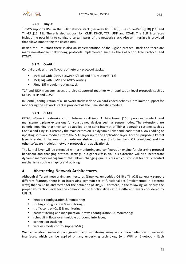
3.2.1 TinyOS TinyOS supports IPv6 in the BLIP network stack (Berkeley IP). BLIP[8] uses 6LowPan[9][10] [11] and TinyRPL[12][11]. There is also support for ICMP, DHCP, TCP, UDP and COAP. The BLIP interfaces include the possibility to configure certain parts of the network stack. Also an interface is provided that allows monitoring the IP statistics.
Beside the IPv6 stack there is also an implementation of the ZigBee protocol stack and there are many non-‐standard networking protocols implemented such as the Collection Tree Protocol and DYMO.
3.2.2 Contiki Contiki provides three flavours of network protocol stacks:
• IPv6[13] with ICMP, 6LowPan[9][10] and RPL routing[8][12] • IPv4[14] with ICMP and AODV routing • Rime[15] modular routing stack
TCP and UDP transport layers are also supported together with application level protocols such as DHCP, HTTP and COAP.
In Contiki, configuration of all network stacks is done via hard-‐coded defines. Only limited support for monitoring the network stack is provided via the Rime statistics module.
3.2.3 GITAR GITAR (Generic extensions for Internet-‐of-‐Things Architectures [16]) provides control and management plane extensions for constrained devices such as sensor nodes. The extensions are generic, meaning that they can be applied on existing Internet-‐of-‐Things operating systems such as Contiki and TinyOS. Currently the main extension is a dynamic linker and loader that allows adding or updating software modules from the MAC layer up to the application layer. For this purpose a kernel layer is added in between the hardware abstraction layer (including basic OS primitives) and the other software modules (network protocols and applications).
The kernel layer will be extended with a monitoring and configuration engine for observing protocol behaviour and changing protocol settings in a generic fashion. This extension will also incorporate dynamic memory management that allows changing queue sizes which is crucial for traffic control mechanisms such as shaping and policing.
4 Abstracting Network Architectures Although different networking architectures (Linux vs. embedded OS like TinyOS) generally support different features, there is an interesting common set of functionalities (implemented in different ways) that could be abstracted for the definition of UPI_N. Therefore, in the following we discuss the proper abstraction level for the common set of functionalities at the different layers considered by UPI_N:
• network configuration & monitoring; • routing configuration & monitoring; • traffic control (QoS) & monitoring; • packet filtering and manipulation (firewall configuration) & monitoring; • scheduling flows over multiple outbound interfaces; • connection tracking; • wireless mode control (upper MAC).
We can abstract network configuration and monitoring using a common definition of network interfaces, which can be applied on any underlying technology (e.g. WiFi or Bluetooth). Each
H2020 -‐ GA No. 258301 D4.1
WiSHF L
13
interface has a name (e.g. wlan0 or pan0), an address (IP, BT_ADDR), an MTU and can be configured as a gateway (WiFi AP and Bluetooth Master). Similarly, each interface allows monitoring the TX_queue length and the link statistics (number of RX/TX packets, packet errors, dropped packets, and collisions).
Routing configuration and monitoring can be abstracted using a common notion of routes where each route has a destination, a gateway (e.g. next hop), an outgoing interface and a route lifetime and priority. Routing tables can also be abstracted by offering generic functions for adding, deleting and listing routes. For monitoring purposes, we consider an abstract notion of routing metrics like hop count, latency, jitter, path bandwidth, path MTU and path reliability.
The abstraction of traffic control capabilities requires that we can configure queuing disciplines for bandwidth management (traffic shaping) and flow priorization (QoS). For this purpose, we need generic functions that allow adding queues and configuring the properties of schedulers (e.g. egress vs. ingress), shapers (e.g. rate and ceil) and filters (e.g. priority bands and matching rules). With respect to monitoring it is important that we define a proper abstraction for identifying QoS requirements (latency, jitter, throughput, reliability) of packet flows. The common notion of type of service (ToS) already available in IP offers a good starting point.
For the configuration of the firewall the following abstraction level seems to be appropriate. Here we have the concepts of zones, forwarding’s, redirects and rules. For each of them we can provide a proper function in the UPI_N. A firewall itself can be expressed by the common notion of a table which consists of chains. Each chain contains a number of filtering rules that are sequentially processed until one matches. Each rule defines a policy or action (accept, drop, queue or return) that is executed when the rule matches.
Connection tracking is extremely important in order to build networks that can adapt dynamically to changing traffic requirements. A connection can generally be expressed as a flow with a source and a destination address (e.g. IP) and port (e.g UDP/TCP). Each flow stores the timestamp when it is created, allowing to monitor the addition of flows. The requirements of a flow are expressed using ToS information.
In contrast for the configuration of the upper MAC which covers wireless management functions it is harder to find a proper abstraction which is due to the wide variety of the different wireless technologies. Here we can only provide generic functions that allow setting properties.
5 Unified network control interface In the following we define the UPI_N interface and adaptation modules towards each WiSHFUL programmable architecture (mapping the general function into platform-‐specific functions and compiling the general language into platform-‐specific programs).
Our objective is to provide a high-‐level object-‐oriented API to the higher parts of the network protocol stack configuration and monitoring.
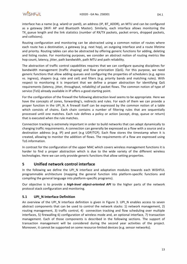
5.1 UPI_N Interface Definition An overview of the UPI_N interface definition is given in Figure 3. UPI_N enables access to seven abstract components that can be used to control the network stacks: 1) network management, 2) routing management, 3) traffic control, 4) connection tracking and flow scheduling over multiple interfaces, 5) firewalling 6) configuration of wireless mode and, an optional interface, 7) transaction management. Each of those components is described in the following sections. The support of transaction management will be considered during the second year activities of the project. Moreover, it cannot be supported on some resource-‐limited devices (e.g. sensor networks).
H2020 -‐ GA No. 258301 D4.1
WiSHF L
14
Beside the abstract components also components are added that enable control and monitoring in a generic fashion via parameter and event exchanges. These components can be used when no suitable abstraction can be identified or when it is not feasible to implement the high-‐level OO API.
Figure 3. Overview of the UPI_N interface definition.
5.1.1 Network configuration and monitoring The network configuration and monitoring functions aim to provide:
• on-‐the-‐fly configuration of interfaces, bridges and IPv4/v6 address assignment; • dynamic routing management; • monitoring of address assignment and changes as well as gateways.
The following example illustrates the run-‐time configuration of a bridge between two interfaces, wlan0 and eth0, and the address configuration:
net_mgr = UPI_N::getNetworkManager()
iface = net_mgr.createInterface(name=”my_bridge”)
iface.addPort(net_mgr.getInterfaces().get(“wlan0”))
iface.addPort(net_mgr.getInterfaces().get(“eth0”))
iface.addIP(“10.0.0.1/24”)
The list of configured gateways can be obtained by:
listOfGWs = net_mgr.getGateways()
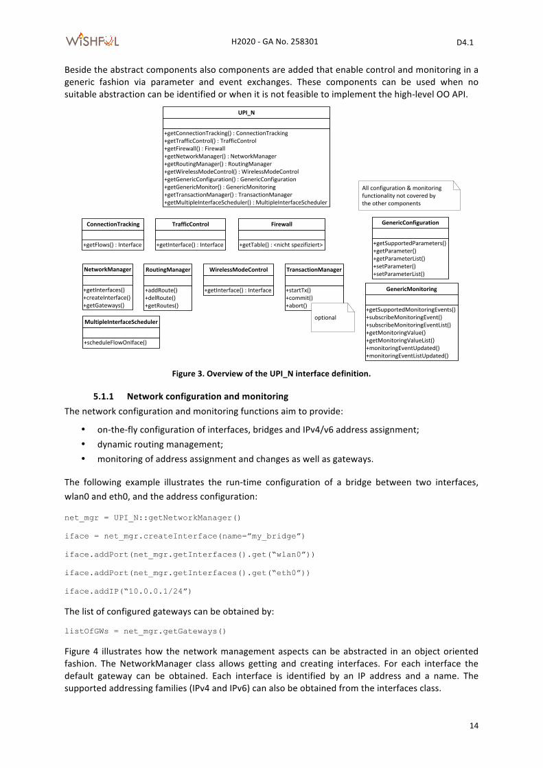
Figure 4 illustrates how the network management aspects can be abstracted in an object oriented fashion. The NetworkManager class allows getting and creating interfaces. For each interface the default gateway can be obtained. Each interface is identified by an IP address and a name. The supported addressing families (IPv4 and IPv6) can also be obtained from the interfaces class.
+getConnectionTracking() : ConnectionTracking+getTrafficControl() : TrafficControl+getFirewall() : Firewall+getNetworkManager() : NetworkManager+getRoutingManager() : RoutingManager+getWirelessModeControl() : WirelessModeControl+getGenericConfiguration() : GenericConfiguration+getGenericMonitor() : GenericMonitoring+getTransactionManager() : TransactionManager+getMultipleInterfaceScheduler() : MultipleInterfaceScheduler
UPI_N
+getFlows() : Interface
ConnectionTracking
+getInterface() : Interface
TrafficControl
+getInterface() : Interface
WirelessModeControl
+getTable() : <nicht spezifiziert>
Firewall
+getInterfaces()+createInterface()+getGateways()
NetworkManager
+getSupportedParameters()+getParameter()+getParameterList()+setParameter()+setParameterList()
GenericConfiguration
+getSupportedMonitoringEvents()+subscribeMonitoringEvent()+subscribeMonitoringEventList()+getMonitoringValue()+getMonitoringValueList()+monitoringEventUpdated()+monitoringEventListUpdated()
GenericMonitoring
All configuration & monitoring functionality not covered by the other components
+addRoute()+delRoute()+getRoutes()
RoutingManager
+startTx()+commit()+abort()
TransactionManager
optional
+scheduleFlowOnIface()
MultipleInterfaceScheduler
H2020 -‐ GA No. 258301 D4.1
WiSHF L
15
Figure 4. The network configuration related part in UPI_N.
5.1.2 Routing configuration and monitoring The main objective of this part of the UPI_N is the manipulating of entries in the routing table. Such functionality can be used by routing daemons, e.g. OLSRd is used to provide ad-‐hoc mesh networking in 802.11 networks. Note, you have to set the table attribute in Route in case you need more than one routing table.
The following example shows how to create a route entry in a specific routing table: route_mgr = UPI_N::getRoutingManager()
route_mgr.addRoute(Route(out_iface=”eth1”, gateway=”10.1.1.1”, table=”myRTable”))
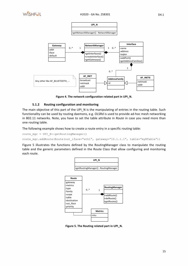
Figure 5 illustrates the functions defined by the RoutingManager class to manipulate the routing table and the generic parameters defined in the Route Class that allow configuring and monitoring each route.
Figure 5. The Routing related part in UPI_N.
+getNetworkManager() : NetworkManager
UPI_N
+getInterfaces()+createInterface()+getGateways()
NetworkManager
+addPort()+getAddressFamilies()
-‐name-‐address-‐txqlen
Interface0..*1
-‐id
AddressFamily
10..*
-‐broadcast-‐netmask-‐addr
AF_INET
-‐netmask-‐addr
AF_INET6
-‐addr-‐iface-‐default
Gateway10..*
Any other like AF_BLUETOOTH, ...
+getRoutingManager() : RoutingManager
UPI_N
+addRoute()+delRoute()+getRoutes()
RoutingManager
-‐gateway-‐metrics-‐type-‐family-‐scope-‐table-‐destination-‐out_iface-‐priority
Route
-‐mtu
Metrics
10..*
H2020 -‐ GA No. 258301 D4.1
WiSHF L
16
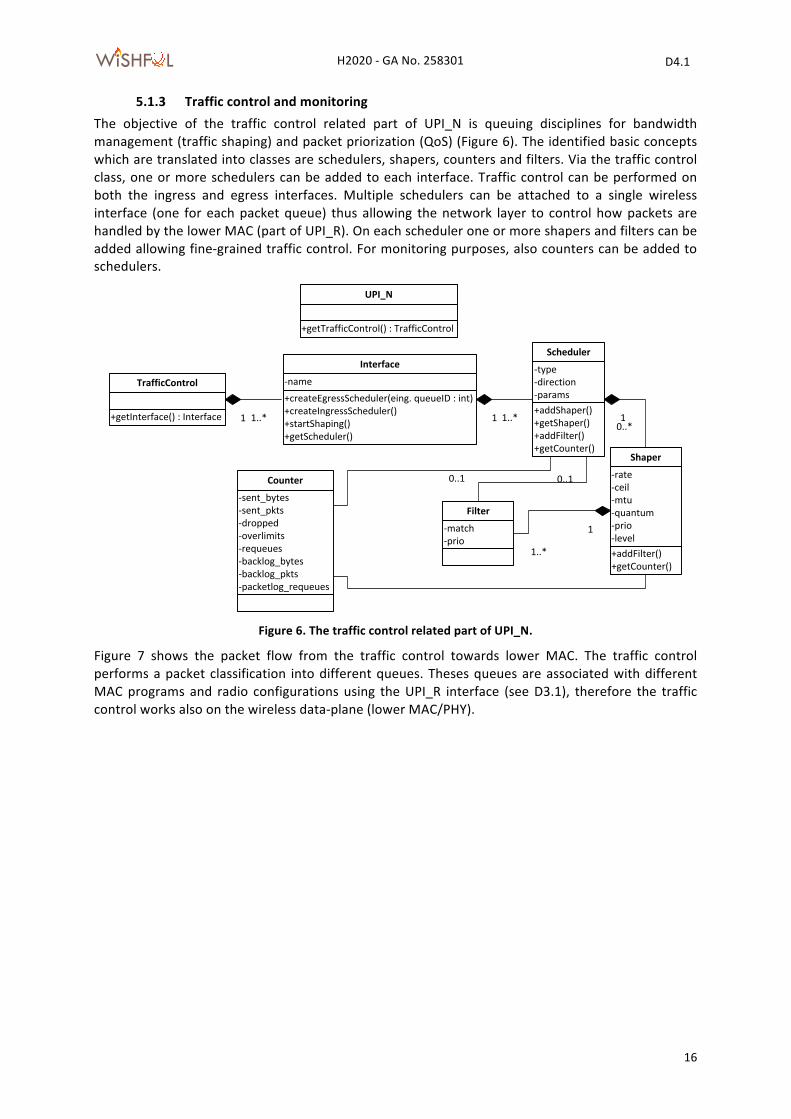
5.1.3 Traffic control and monitoring The objective of the traffic control related part of UPI_N is queuing disciplines for bandwidth management (traffic shaping) and packet priorization (QoS) (Figure 6). The identified basic concepts which are translated into classes are schedulers, shapers, counters and filters. Via the traffic control class, one or more schedulers can be added to each interface. Traffic control can be performed on both the ingress and egress interfaces. Multiple schedulers can be attached to a single wireless interface (one for each packet queue) thus allowing the network layer to control how packets are handled by the lower MAC (part of UPI_R). On each scheduler one or more shapers and filters can be added allowing fine-‐grained traffic control. For monitoring purposes, also counters can be added to schedulers.
Figure 6. The traffic control related part of UPI_N.
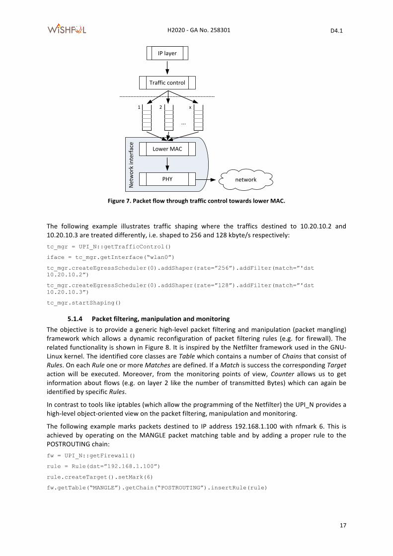
Figure 7 shows the packet flow from the traffic control towards lower MAC. The traffic control performs a packet classification into different queues. Theses queues are associated with different MAC programs and radio configurations using the UPI_R interface (see D3.1), therefore the traffic control works also on the wireless data-‐plane (lower MAC/PHY).
+getTrafficControl() : TrafficControl
UPI_N
+getInterface() : Interface
TrafficControl
+addShaper()+getShaper()+addFilter()+getCounter()
-‐type-‐direction-‐params
Scheduler
1 1..*
+createEgressScheduler(eing. queueID : int)+createIngressScheduler()+startShaping()+getScheduler()
-‐name
Interface
1 1..*
-‐match-‐prio
Filter
+addFilter()+getCounter()
-‐rate-‐ceil-‐mtu-‐quantum-‐prio-‐level
Shaper
10..*
1..*
1
-‐sent_bytes-‐sent_pkts-‐dropped-‐overlimits-‐requeues-‐backlog_bytes-‐backlog_pkts-‐packetlog_requeues
Counter 0..10..1
H2020 -‐ GA No. 258301 D4.1
WiSHF L
17
Figure 7. Packet flow through traffic control towards lower MAC.
The following example illustrates traffic shaping where the traffics destined to 10.20.10.2 and 10.20.10.3 are treated differently, i.e. shaped to 256 and 128 kbyte/s respectively: tc_mgr = UPI_N::getTrafficControl()
iface = tc_mgr.getInterface(“wlan0”)
tc_mgr.createEgressScheduler(0).addShaper(rate=”256”).addFilter(match=”'dst 10.20.10.2”)
tc_mgr.createEgressScheduler(0).addShaper(rate=”128”).addFilter(match=”'dst 10.20.10.3”)
tc_mgr.startShaping()
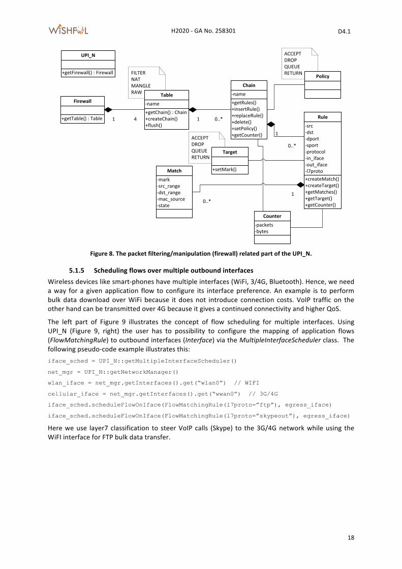
5.1.4 Packet filtering, manipulation and monitoring The objective is to provide a generic high-‐level packet filtering and manipulation (packet mangling) framework which allows a dynamic reconfiguration of packet filtering rules (e.g. for firewall). The related functionality is shown in Figure 8. It is inspired by the Netfilter framework used in the GNU-‐Linux kernel. The identified core classes are Table which contains a number of Chains that consist of Rules. On each Rule one or more Matches are defined. If a Match is success the corresponding Target action will be executed. Moreover, from the monitoring points of view, Counter allows us to get information about flows (e.g. on layer 2 like the number of transmitted Bytes) which can again be identified by specific Rules.
In contrast to tools like iptables (which allow the programming of the Netfilter) the UPI_N provides a high-‐level object-‐oriented view on the packet filtering, manipulation and monitoring.
The following example marks packets destined to IP address 192.168.1.100 with nfmark 6. This is achieved by operating on the MANGLE packet matching table and by adding a proper rule to the POSTROUTING chain: fw = UPI_N::getFirewall()
rule = Rule(dst=”192.168.1.100”)
rule.createTarget().setMark(6)
fw.getTable(“MANGLE”).getChain(“POSTROUTING”).insertRule(rule)
IP layer
Traffic control
Lower MAC
networkPHY
Network interface
1 2 x
...
H2020 -‐ GA No. 258301 D4.1
WiSHF L
18
Figure 8. The packet filtering/manipulation (firewall) related part of the UPI_N.
5.1.5 Scheduling flows over multiple outbound interfaces Wireless devices like smart-‐phones have multiple interfaces (WiFi, 3/4G, Bluetooth). Hence, we need a way for a given application flow to configure its interface preference. An example is to perform bulk data download over WiFi because it does not introduce connection costs. VoIP traffic on the other hand can be transmitted over 4G because it gives a continued connectivity and higher QoS.
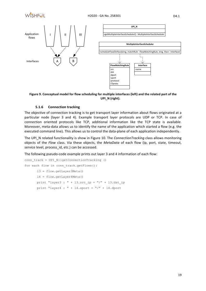
The left part of Figure 9 illustrates the concept of flow scheduling for multiple interfaces. Using UPI_N (Figure 9, right) the user has to possibility to configure the mapping of application flows (FlowMatchingRule) to outbound interfaces (Interface) via the MultipleInterfaceScheduler class. The following pseudo-‐code example illustrates this: iface_sched = UPI_N::getMultipleInterfaceScheduler()
net_mgr = UPI_N::getNetworkManager()
wlan_iface = net_mgr.getInterfaces().get(“wlan0”) // WIFI
cellular_iface = net_mgr.getInterfaces().get(“wwan0”) // 3G/4G
iface_sched.scheduleFlowOnIface(FlowMatchingRule(l7proto=”ftp”), egress_iface)
iface_sched.scheduleFlowOnIface(FlowMatchingRule(l7proto=”skypeout”), egress_iface)
Here we use layer7 classification to steer VoIP calls (Skype) to the 3G/4G network while using the WiFI interface for FTP bulk data transfer.
ACCEPTDROPQUEUERETURN
ACCEPTDROPQUEUERETURNFILTER
NATMANGLERAW
+getFirewall() : Firewall
UPI_N
+getTable() : Table
Firewall
+getChain() : Chain+createChain()+flush()
-‐name
Table+getRules()+insertRule()+replaceRule()+delete()+setPolicy()+getCounter()
-‐name
Chain
+createMatch()+createTarget()+getMatches()+getTarget()+getCounter()
-‐src-‐dst-‐dport-‐sport-‐protocol-‐in_iface-‐out_iface-‐l7proto
Rule
-‐mark-‐src_range-‐dst_range-‐mac_source-‐state
Match +setMark()
Target
Policy
1 4 1 0..*
1
0..*
0..*1
-‐packets-‐bytes
Counter
H2020 -‐ GA No. 258301 D4.1
WiSHF L
19
Figure 9. Conceptual model for flow scheduling for multiple interfaces (left) and the related part of the
UPI_N (right).
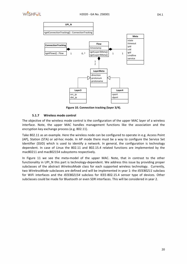
5.1.6 Connection tracking The objective of connection tracking is to get transport layer information about flows originated at a particular node (layer 3 and 4). Example transport layer protocols are UDP or TCP. In case of connection oriented protocols like TCP, additional information like the TCP state is available. Moreover, meta-‐data allows us to identify the name of the application which started a flow (e.g. the executed command line). This allows us to control the data-‐plane of each application independently.
The UPI_N related functionality is show in Figure 10. The ConnectionTracking class allows monitoring objects of the Flow class. Via these objects, the MetaData of each flow (ip, port, state, timeout, service level, process_id, etc.) can be accessed.
The following pseudo-‐code example prints out layer 3 and 4 information of each flow: conn_track = UPI_N::getConnectionTracking ()
for each flow in conn_track.getFlows():
l3 = flow.getLayer3Meta()
l4 = flow.getLayer4Meta()
print “layer3 : ” + l3.src_ip + “/” + l3.dst_ip
print “layer4 : ” + l4.sport + “/” + l4.dport
Applicationflows
I II III
Interfaces A B
+getMultipleInterfaceScheduler() : MultipleInterfaceScheduler
UPI_N
+scheduleFlowOnIface(eing. matchRule : FlowMatchingRule, eing. iface : Interface)
MultipleInterfaceScheduler
-‐src-‐dst-‐dport-‐sport-‐protocol-‐l7proto
FlowMatchingRule
-‐name
Interface
H2020 -‐ GA No. 258301 D4.1
WiSHF L
20
Figure 10. Connection tracking (layer 3/4).
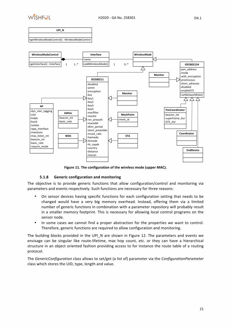
5.1.7 Wireless mode control The objective of the wireless mode control is the configuration of the upper MAC layer of a wireless interface. Note, the upper MAC handles management functions like the association and the encryption key exchange process (e.g. 802.11).
Take 802.11 as an example. Here the wireless node can be configured to operate in e.g. Access Point (AP), Station (STA) or ad-‐hoc mode. In AP mode there must be a way to configure the Service Set Identifier (SSID) which is used to identify a network. In general, the configuration is technology dependent. In case of Linux the 802.11 and 802.15.4 related functions are implemented by the mac80211 and mac802154 subsystems respectively.
In Figure 11 we see the meta-‐model of the upper MAC. Note, that in contrast to the other functionality in UPI_N this part is technology-‐dependent. We address this issue by providing proper subclasses of the abstract WirelessMode class for each supported wireless technology. Currently, two WirelessMode subclasses are defined and will be implemented in year 1: the IEEE80211 subclass for WiFi interfaces and the IEEE802154 subclass for IEEE-‐802.15.4 sensor type of devices. Other subclasses could be made for Bluetooth or even SDR interfaces. This will be considered in year 2.
+getConnectionTracking() : ConnectionTracking
UPI_N
+getFlows() : Flow
ConnectionTracking
1 0..*+getLayer3Meta()+getLayer4Meta()
-‐timestamp
Flow
-‐direction-‐protonum-‐protoname
LayerMeta
-‐src_ip-‐dst_ip
Layer3
-‐sport-‐dport
Layer4
12
-‐state-‐timeout-‐pid-‐uid-‐gid-‐cmdline-‐service
Meta
1 1
H2020 -‐ GA No. 258301 D4.1
WiSHF L
21
Figure 11. The configuration of the wireless mode (upper MAC).
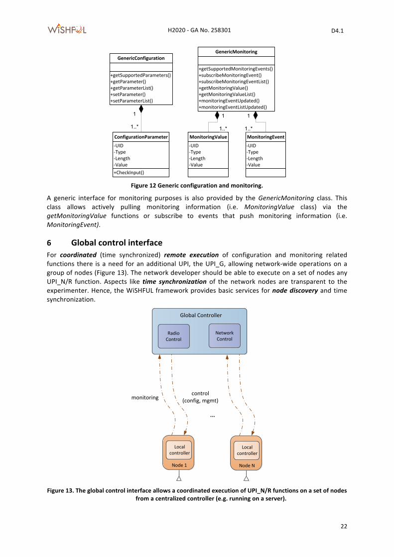
5.1.8 Generic configuration and monitoring The objective is to provide generic functions that allow configuration/control and monitoring via parameters and events respectively. Such functions are necessary for three reasons:
• On sensor devices having specific functions for each configuration setting that needs to be changed would have a very big memory overhead. Instead, offering them via a limited number of generic functions in combination with a parameter repository will probably result in a smaller memory footprint. This is necessary for allowing local control programs on the sensor node.
• In some cases we cannot find a proper abstraction for the properties we want to control. Therefore, generic functions are required to allow configuration and monitoring.
The building blocks provided in the UPI_N are shown in Figure 12. The parameters and events we envisage can be singular like route-‐lifetime, max hop count, etc. or they can have a hierarchical structure in an object oriented fashion providing access to for instance the route table of a routing protocol.
The GenericConfiguration class allows to set/get (a list of) parameter via the ConfigurationParameter class which stores the UID, type, length and value.
+getWirelessModeControl() : WirelessModeControl
UPI_N
+getInterface() : Interface
WirelessModeControl
1 1..* +addWirelessMode()-‐name
Interface WirelessMode
1 0..*
-‐disabled-‐wmm-‐encryption-‐key-‐key1-‐key2-‐key3-‐key4-‐macfilter-‐maclist-‐rsn_preauth-‐macaddr-‐dtim_period-‐short_preamble-‐mcast_rate-‐hwmode-‐htmode-‐ht_capab-‐country-‐distance-‐noscan
IEEE80211
-‐dyn_vlan_tagging-‐ssid-‐hidde-‐bssid-‐isolate-‐iapp_interface-‐maxassoc-‐max_listen_int-‐beacon_int-‐basic_rate-‐require_mode
AP
STA
-‐mesh_id
MeshPoint
Monitor
-‐beacon_int-‐basic_rate
AdHoc
WDS
+setNetworkRole()
-‐pan_address-‐mode-‐with_encryption-‐promiscous-‐short_adresses-‐disabled-‐enableGTS
IEEE802154
Monitor
Coordinator
-‐beacon_int-‐superframe_dur-‐GTS_dur
PanCoordinator
EndDevice
H2020 -‐ GA No. 258301 D4.1
WiSHF L
22
Figure 12 Generic configuration and monitoring.
A generic interface for monitoring purposes is also provided by the GenericMonitoring class. This class allows actively pulling monitoring information (i.e. MonitoringValue class) via the getMonitoringValue functions or subscribe to events that push monitoring information (i.e. MonitoringEvent).
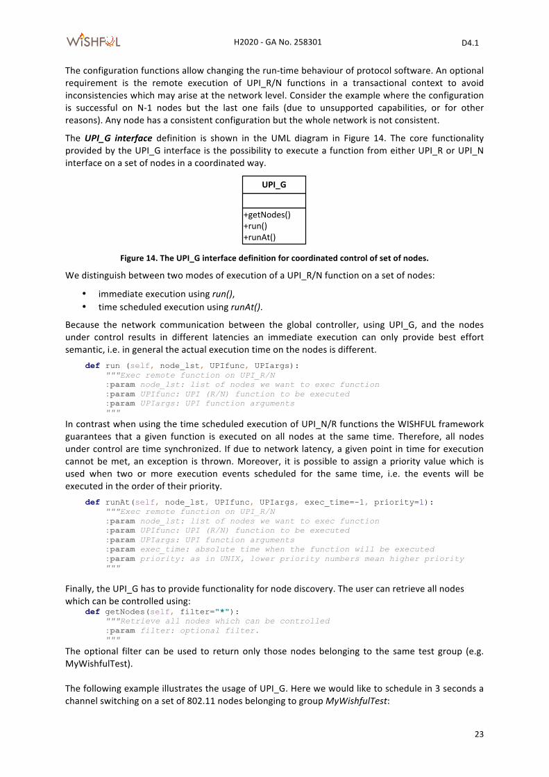
6 Global control interface For coordinated (time synchronized) remote execution of configuration and monitoring related functions there is a need for an additional UPI, the UPI_G, allowing network-‐wide operations on a group of nodes (Figure 13). The network developer should be able to execute on a set of nodes any UPI_N/R function. Aspects like time synchronization of the network nodes are transparent to the experimenter. Hence, the WiSHFUL framework provides basic services for node discovery and time synchronization.
Figure 13. The global control interface allows a coordinated execution of UPI_N/R functions on a set of nodes
from a centralized controller (e.g. running on a server).
+getSupportedParameters()+getParameter()+getParameterList()+setParameter()+setParameterList()
GenericConfiguration
+getSupportedMonitoringEvents()+subscribeMonitoringEvent()+subscribeMonitoringEventList()+getMonitoringValue()+getMonitoringValueList()+monitoringEventUpdated()+monitoringEventListUpdated()
GenericMonitoring
+CheckInput()
-‐UID-‐Type-‐Length-‐Value
ConfigurationParameter
-‐UID-‐Type-‐Length-‐Value
MonitoringValue
-‐UID-‐Type-‐Length-‐Value
MonitoringEvent
1
1..*
1
1..*
1
1..*
Global Controller
Node 1
Local controller
Radio Control
monitoring
Network Control
control(config, mgmt)
...
Node N
Local controller
H2020 -‐ GA No. 258301 D4.1
WiSHF L
23
The configuration functions allow changing the run-‐time behaviour of protocol software. An optional requirement is the remote execution of UPI_R/N functions in a transactional context to avoid inconsistencies which may arise at the network level. Consider the example where the configuration is successful on N-‐1 nodes but the last one fails (due to unsupported capabilities, or for other reasons). Any node has a consistent configuration but the whole network is not consistent.
The UPI_G interface definition is shown in the UML diagram in Figure 14. The core functionality provided by the UPI_G interface is the possibility to execute a function from either UPI_R or UPI_N interface on a set of nodes in a coordinated way.
Figure 14. The UPI_G interface definition for coordinated control of set of nodes.
We distinguish between two modes of execution of a UPI_R/N function on a set of nodes:
• immediate execution using run(), • time scheduled execution using runAt().
Because the network communication between the global controller, using UPI_G, and the nodes under control results in different latencies an immediate execution can only provide best effort semantic, i.e. in general the actual execution time on the nodes is different. def run (self, node_lst, UPIfunc, UPIargs): """Exec remote function on UPI_R/N :param node_lst: list of nodes we want to exec function :param UPIfunc: UPI (R/N) function to be executed :param UPIargs: UPI function arguments """ In contrast when using the time scheduled execution of UPI_N/R functions the WISHFUL framework guarantees that a given function is executed on all nodes at the same time. Therefore, all nodes under control are time synchronized. If due to network latency, a given point in time for execution cannot be met, an exception is thrown. Moreover, it is possible to assign a priority value which is used when two or more execution events scheduled for the same time, i.e. the events will be executed in the order of their priority. def runAt(self, node_lst, UPIfunc, UPIargs, exec_time=-1, priority=1): """Exec remote function on UPI_R/N :param node_lst: list of nodes we want to exec function :param UPIfunc: UPI (R/N) function to be executed :param UPIargs: UPI function arguments :param exec_time: absolute time when the function will be executed :param priority: as in UNIX, lower priority numbers mean higher priority """
Finally, the UPI_G has to provide functionality for node discovery. The user can retrieve all nodes which can be controlled using: def getNodes(self, filter="*"): """Retrieve all nodes which can be controlled :param filter: optional filter. """ The optional filter can be used to return only those nodes belonging to the same test group (e.g. MyWishfulTest). The following example illustrates the usage of UPI_G. Here we would like to schedule in 3 seconds a channel switching on a set of 802.11 nodes belonging to group MyWishfulTest:
+getNodes()+run()+runAt()
UPI_G
H2020 -‐ GA No. 258301 D4.1
WiSHF L
24
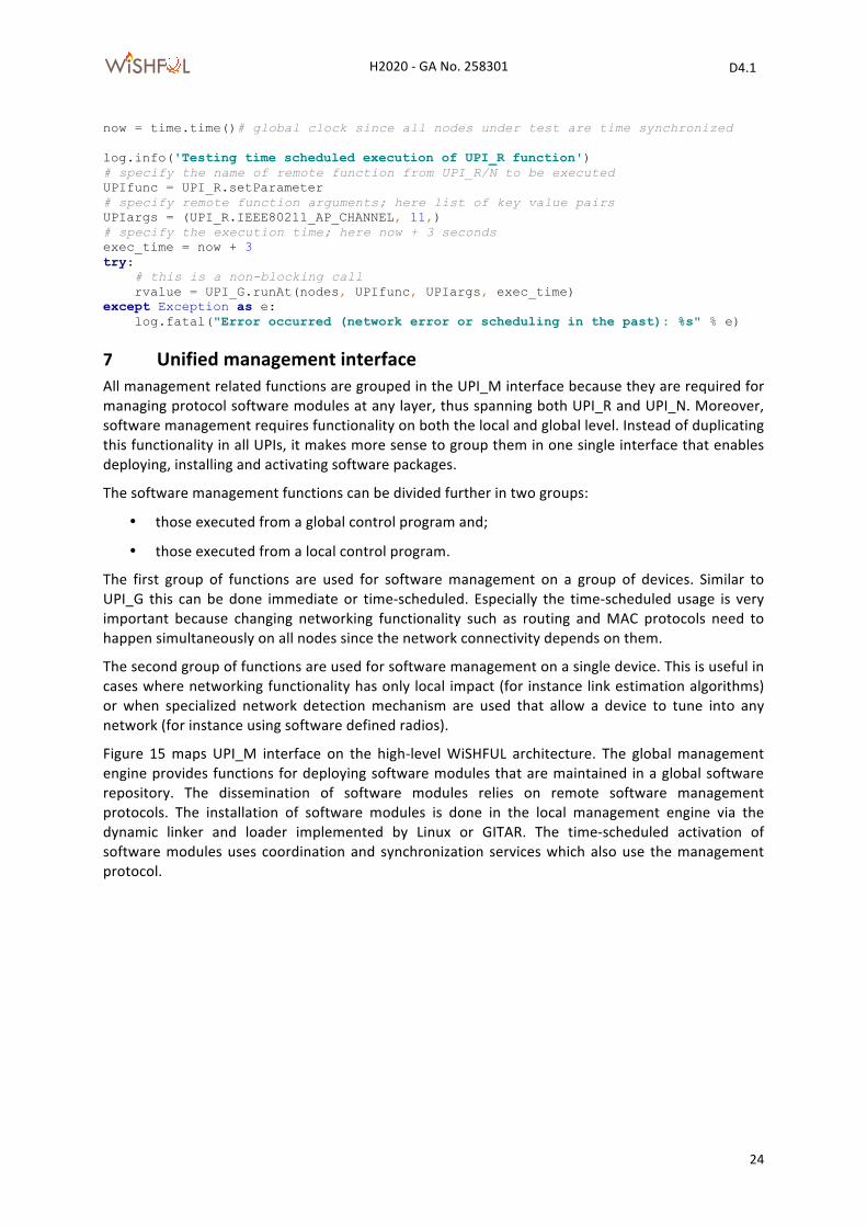
now = time.time()# global clock since all nodes under test are time synchronized log.info('Testing time scheduled execution of UPI_R function') # specify the name of remote function from UPI_R/N to be executed UPIfunc = UPI_R.setParameter # specify remote function arguments; here list of key value pairs UPIargs = (UPI_R.IEEE80211_AP_CHANNEL, 11,) # specify the execution time; here now + 3 seconds exec_time = now + 3 try: # this is a non-blocking call rvalue = UPI_G.runAt(nodes, UPIfunc, UPIargs, exec_time) except Exception as e: log.fatal("Error occurred (network error or scheduling in the past): %s" % e)
7 Unified management interface All management related functions are grouped in the UPI_M interface because they are required for managing protocol software modules at any layer, thus spanning both UPI_R and UPI_N. Moreover, software management requires functionality on both the local and global level. Instead of duplicating this functionality in all UPIs, it makes more sense to group them in one single interface that enables deploying, installing and activating software packages.
The software management functions can be divided further in two groups:
• those executed from a global control program and;
• those executed from a local control program.
The first group of functions are used for software management on a group of devices. Similar to UPI_G this can be done immediate or time-‐scheduled. Especially the time-‐scheduled usage is very important because changing networking functionality such as routing and MAC protocols need to happen simultaneously on all nodes since the network connectivity depends on them.
The second group of functions are used for software management on a single device. This is useful in cases where networking functionality has only local impact (for instance link estimation algorithms) or when specialized network detection mechanism are used that allow a device to tune into any network (for instance using software defined radios).
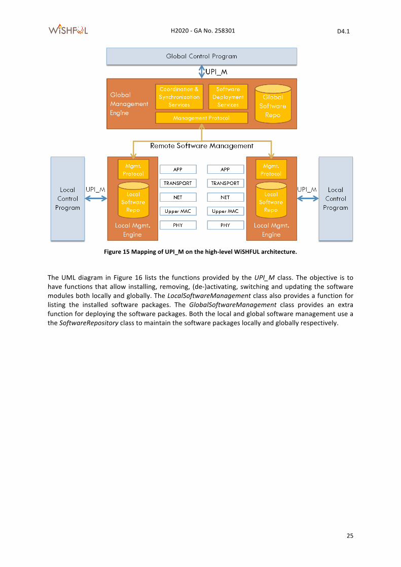
Figure 15 maps UPI_M interface on the high-‐level WiSHFUL architecture. The global management engine provides functions for deploying software modules that are maintained in a global software repository. The dissemination of software modules relies on remote software management protocols. The installation of software modules is done in the local management engine via the dynamic linker and loader implemented by Linux or GITAR. The time-‐scheduled activation of software modules uses coordination and synchronization services which also use the management protocol.
H2020 -‐ GA No. 258301 D4.1
WiSHF L
25
Figure 15 Mapping of UPI_M on the high-‐level WiSHFUL architecture.
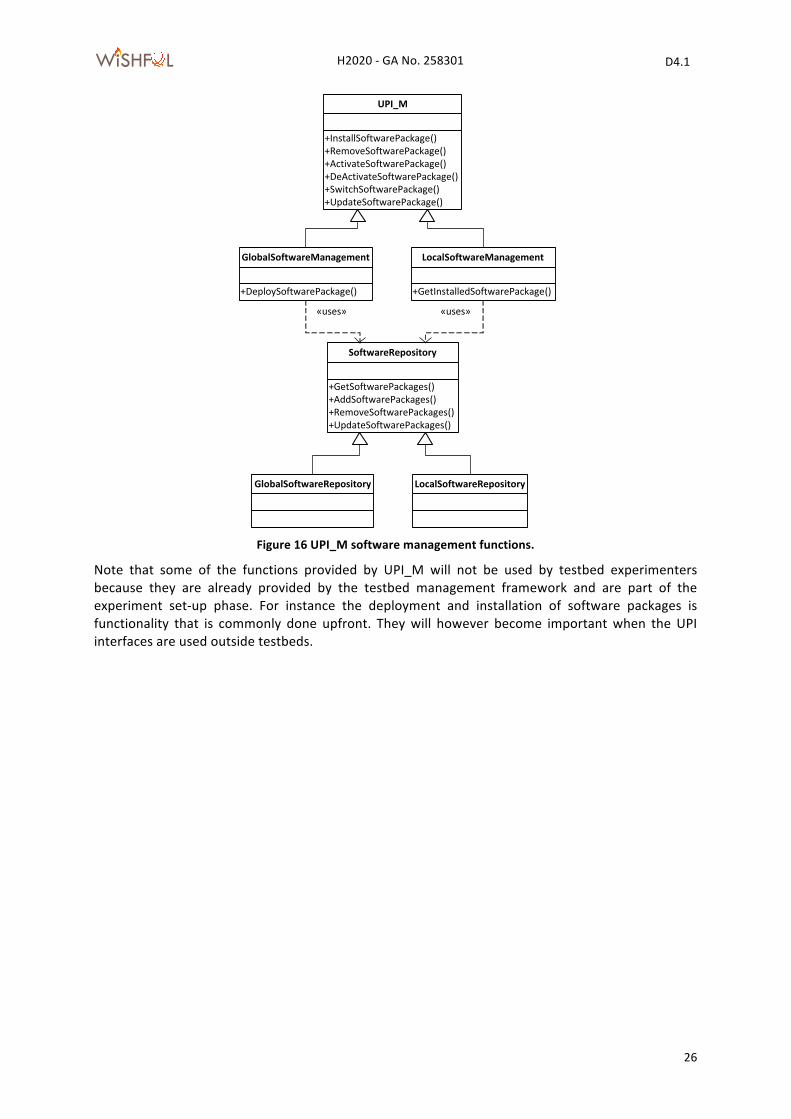
The UML diagram in Figure 16 lists the functions provided by the UPI_M class. The objective is to have functions that allow installing, removing, (de-‐)activating, switching and updating the software modules both locally and globally. The LocalSoftwareManagement class also provides a function for listing the installed software packages. The GlobalSoftwareManagement class provides an extra function for deploying the software packages. Both the local and global software management use a the SoftwareRepository class to maintain the software packages locally and globally respectively.
H2020 -‐ GA No. 258301 D4.1
WiSHF L
26
Figure 16 UPI_M software management functions.
Note that some of the functions provided by UPI_M will not be used by testbed experimenters because they are already provided by the testbed management framework and are part of the experiment set-‐up phase. For instance the deployment and installation of software packages is functionality that is commonly done upfront. They will however become important when the UPI interfaces are used outside testbeds.
+InstallSoftwarePackage()+RemoveSoftwarePackage()+ActivateSoftwarePackage()+DeActivateSoftwarePackage()+SwitchSoftwarePackage()+UpdateSoftwarePackage()
UPI_M
+GetInstalledSoftwarePackage()
LocalSoftwareManagement
+DeploySoftwarePackage()
GlobalSoftwareManagement
+GetSoftwarePackages()+AddSoftwarePackages()+RemoveSoftwarePackages()+UpdateSoftwarePackages()
SoftwareRepository
«uses» «uses»
GlobalSoftwareRepository LocalSoftwareRepository
H2020 -‐ GA No. 258301 D4.1
WiSHF L
27
8 Examples of UPI_N utilization The following example scenarios demonstrate the utilization of the UPI_N, UPI_G interfaces and UPI-‐M. Some examples also require functionality from the UPI_R interface, which is described in Deliverable 3.1.
8.1 Traffic-‐aware 802.11 airtime management
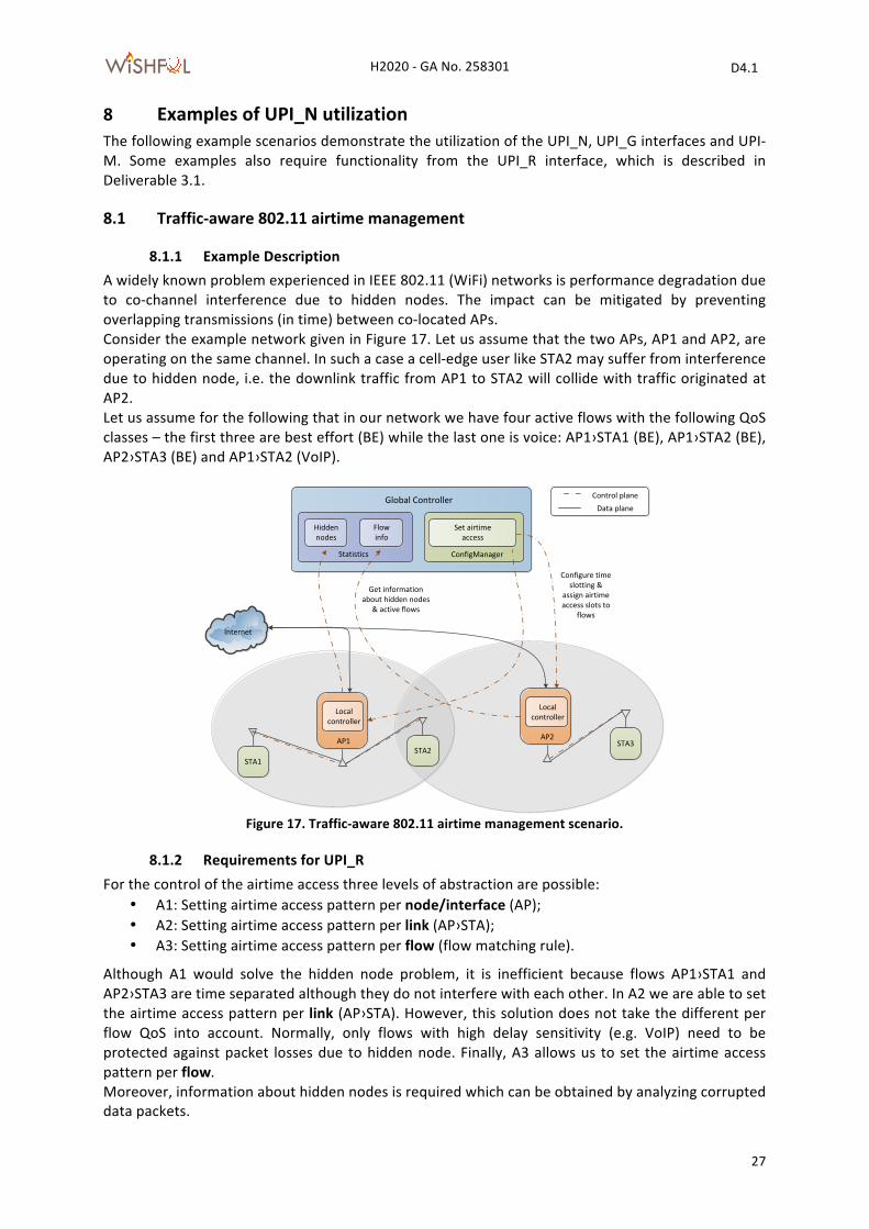
8.1.1 Example Description A widely known problem experienced in IEEE 802.11 (WiFi) networks is performance degradation due to co-‐channel interference due to hidden nodes. The impact can be mitigated by preventing overlapping transmissions (in time) between co-‐located APs. Consider the example network given in Figure 17. Let us assume that the two APs, AP1 and AP2, are operating on the same channel. In such a case a cell-‐edge user like STA2 may suffer from interference due to hidden node, i.e. the downlink traffic from AP1 to STA2 will collide with traffic originated at AP2. Let us assume for the following that in our network we have four active flows with the following QoS classes – the first three are best effort (BE) while the last one is voice: AP1›STA1 (BE), AP1›STA2 (BE), AP2›STA3 (BE) and AP1›STA2 (VoIP).
Figure 17. Traffic-‐aware 802.11 airtime management scenario.
8.1.2 Requirements for UPI_R For the control of the airtime access three levels of abstraction are possible:
• A1: Setting airtime access pattern per node/interface (AP); • A2: Setting airtime access pattern per link (AP›STA); • A3: Setting airtime access pattern per flow (flow matching rule).
Although A1 would solve the hidden node problem, it is inefficient because flows AP1›STA1 and AP2›STA3 are time separated although they do not interfere with each other. In A2 we are able to set the airtime access pattern per link (AP›STA). However, this solution does not take the different per flow QoS into account. Normally, only flows with high delay sensitivity (e.g. VoIP) need to be protected against packet losses due to hidden node. Finally, A3 allows us to set the airtime access pattern per flow. Moreover, information about hidden nodes is required which can be obtained by analyzing corrupted data packets.
Global Controller
AP1
Internet
Control planeData plane
Local controller
Hidden nodes
STA1
STA3STA2
Get information about hidden nodes
& active flows
Flow info
Statistics
Set airtime access
ConfigManager
AP2
Local controller
Configure time slotting &
assign airtime access slots to
flows
H2020 -‐ GA No. 258301 D4.1
WiSHF L
28
8.1.3 Requirements for UPI_N The UPI_N needs to provide QoS information about active flows on each wireless link (AP›STA), i.e. flow type (VoIP, bulk transfer).
8.1.4 Requirements for UPI_G The described example requires a global controller to coordinate the airtime access of APs. It requires the following information (statistics) from each AP under control: i) information about hidden nodes (UPI_R), ii) QoS information about active flows on each link (UPI_N). The output of the global controller is the assignment of time slots to nodes/STAs/flows (UPI_R).
8.2 WIFI and Sensor Network Co-‐existence
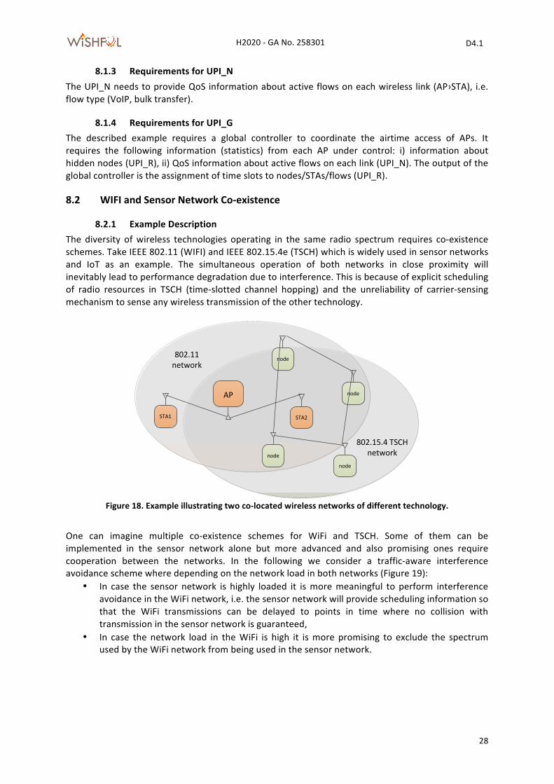
8.2.1 Example Description The diversity of wireless technologies operating in the same radio spectrum requires co-‐existence schemes. Take IEEE 802.11 (WIFI) and IEEE 802.15.4e (TSCH) which is widely used in sensor networks and IoT as an example. The simultaneous operation of both networks in close proximity will inevitably lead to performance degradation due to interference. This is because of explicit scheduling of radio resources in TSCH (time-‐slotted channel hopping) and the unreliability of carrier-‐sensing mechanism to sense any wireless transmission of the other technology.
Figure 18. Example illustrating two co-‐located wireless networks of different technology.
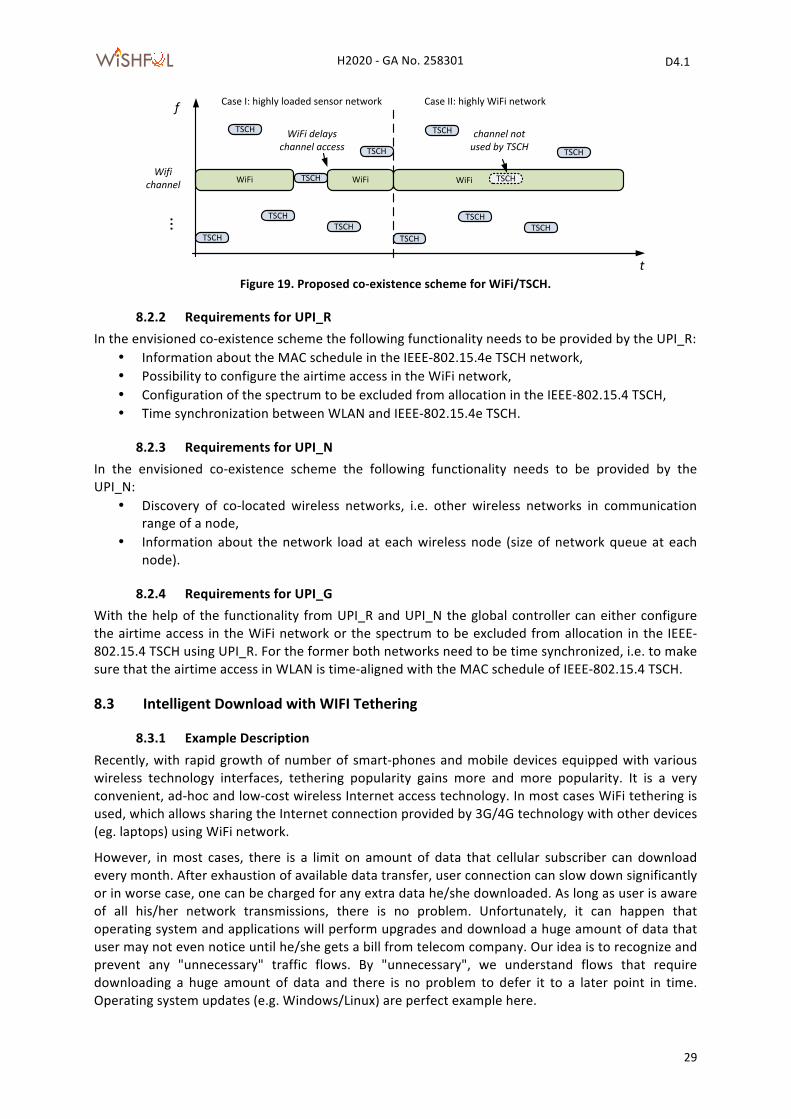
One can imagine multiple co-‐existence schemes for WiFi and TSCH. Some of them can be implemented in the sensor network alone but more advanced and also promising ones require cooperation between the networks. In the following we consider a traffic-‐aware interference avoidance scheme where depending on the network load in both networks (Figure 19):
• In case the sensor network is highly loaded it is more meaningful to perform interference avoidance in the WiFi network, i.e. the sensor network will provide scheduling information so that the WiFi transmissions can be delayed to points in time where no collision with transmission in the sensor network is guaranteed,
• In case the network load in the WiFi is high it is more promising to exclude the spectrum used by the WiFi network from being used in the sensor network.
AP
STA1 STA2
802.11 network
node
node
node
node
802.15.4 TSCH network
H2020 -‐ GA No. 258301 D4.1
WiSHF L
29
Figure 19. Proposed co-‐existence scheme for WiFi/TSCH.
8.2.2 Requirements for UPI_R In the envisioned co-‐existence scheme the following functionality needs to be provided by the UPI_R:
• Information about the MAC schedule in the IEEE-‐802.15.4e TSCH network, • Possibility to configure the airtime access in the WiFi network, • Configuration of the spectrum to be excluded from allocation in the IEEE-‐802.15.4 TSCH, • Time synchronization between WLAN and IEEE-‐802.15.4e TSCH.
8.2.3 Requirements for UPI_N In the envisioned co-‐existence scheme the following functionality needs to be provided by the UPI_N:
• Discovery of co-‐located wireless networks, i.e. other wireless networks in communication range of a node,
• Information about the network load at each wireless node (size of network queue at each node).
8.2.4 Requirements for UPI_G With the help of the functionality from UPI_R and UPI_N the global controller can either configure the airtime access in the WiFi network or the spectrum to be excluded from allocation in the IEEE-‐802.15.4 TSCH using UPI_R. For the former both networks need to be time synchronized, i.e. to make sure that the airtime access in WLAN is time-‐aligned with the MAC schedule of IEEE-‐802.15.4 TSCH.
8.3 Intelligent Download with WIFI Tethering
8.3.1 Example Description Recently, with rapid growth of number of smart-‐phones and mobile devices equipped with various wireless technology interfaces, tethering popularity gains more and more popularity. It is a very convenient, ad-‐hoc and low-‐cost wireless Internet access technology. In most cases WiFi tethering is used, which allows sharing the Internet connection provided by 3G/4G technology with other devices (eg. laptops) using WiFi network.
However, in most cases, there is a limit on amount of data that cellular subscriber can download every month. After exhaustion of available data transfer, user connection can slow down significantly or in worse case, one can be charged for any extra data he/she downloaded. As long as user is aware of all his/her network transmissions, there is no problem. Unfortunately, it can happen that operating system and applications will perform upgrades and download a huge amount of data that user may not even notice until he/she gets a bill from telecom company. Our idea is to recognize and prevent any "unnecessary" traffic flows. By "unnecessary", we understand flows that require downloading a huge amount of data and there is no problem to defer it to a later point in time. Operating system updates (e.g. Windows/Linux) are perfect example here.
TSCH
WiFi
f
t
Wifichannel
...
TSCH
TSCH
TSCH
TSCH
TSCH
WiFi
WiFi delayschannel access
Case I: highly loaded sensor network Case II: highly WiFi network
TSCH
TSCH
TSCHTSCH
TSCH
WiFiTSCH
channel not used by TSCH
WiFi
H2020 -‐ GA No. 258301 D4.1
WiSHF L
30
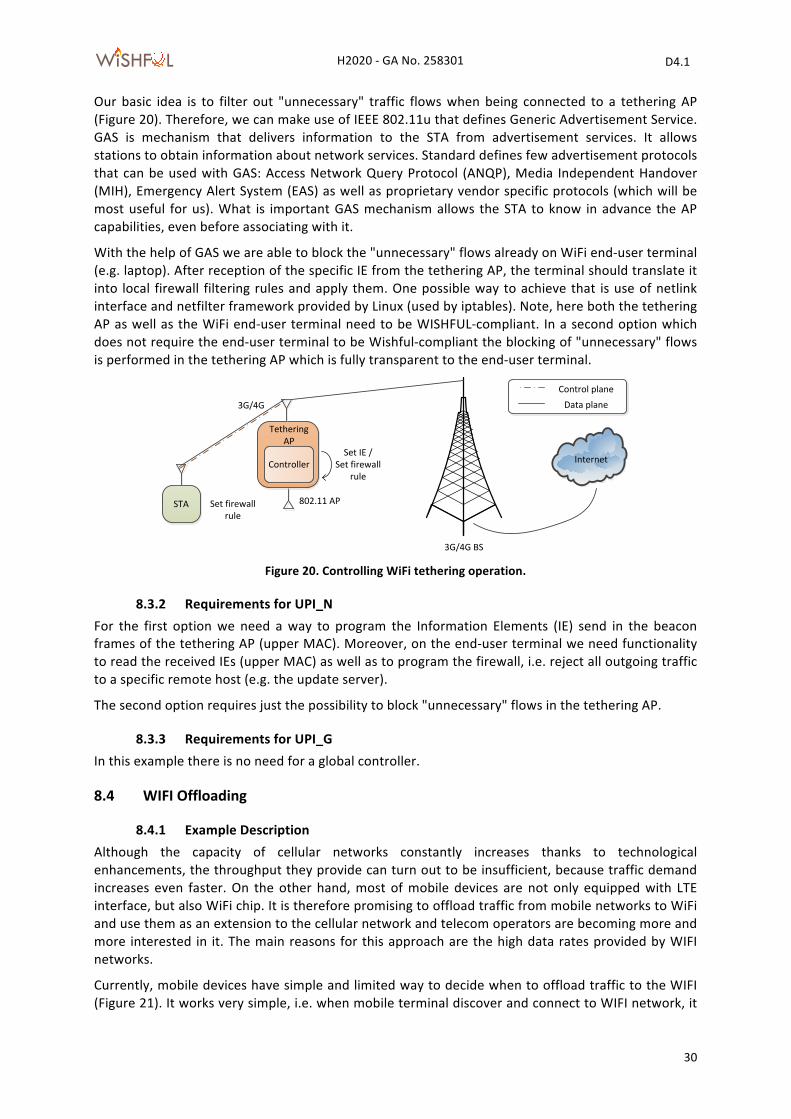
Our basic idea is to filter out "unnecessary" traffic flows when being connected to a tethering AP (Figure 20). Therefore, we can make use of IEEE 802.11u that defines Generic Advertisement Service. GAS is mechanism that delivers information to the STA from advertisement services. It allows stations to obtain information about network services. Standard defines few advertisement protocols that can be used with GAS: Access Network Query Protocol (ANQP), Media Independent Handover (MIH), Emergency Alert System (EAS) as well as proprietary vendor specific protocols (which will be most useful for us). What is important GAS mechanism allows the STA to know in advance the AP capabilities, even before associating with it.
With the help of GAS we are able to block the "unnecessary" flows already on WiFi end-‐user terminal (e.g. laptop). After reception of the specific IE from the tethering AP, the terminal should translate it into local firewall filtering rules and apply them. One possible way to achieve that is use of netlink interface and netfilter framework provided by Linux (used by iptables). Note, here both the tethering AP as well as the WiFi end-‐user terminal need to be WISHFUL-‐compliant. In a second option which does not require the end-‐user terminal to be Wishful-‐compliant the blocking of "unnecessary" flows is performed in the tethering AP which is fully transparent to the end-‐user terminal.
Figure 20. Controlling WiFi tethering operation.
8.3.2 Requirements for UPI_N For the first option we need a way to program the Information Elements (IE) send in the beacon frames of the tethering AP (upper MAC). Moreover, on the end-‐user terminal we need functionality to read the received IEs (upper MAC) as well as to program the firewall, i.e. reject all outgoing traffic to a specific remote host (e.g. the update server).
The second option requires just the possibility to block "unnecessary" flows in the tethering AP.
8.3.3 Requirements for UPI_G In this example there is no need for a global controller.
8.4 WIFI Offloading
8.4.1 Example Description Although the capacity of cellular networks constantly increases thanks to technological enhancements, the throughput they provide can turn out to be insufficient, because traffic demand increases even faster. On the other hand, most of mobile devices are not only equipped with LTE interface, but also WiFi chip. It is therefore promising to offload traffic from mobile networks to WiFi and use them as an extension to the cellular network and telecom operators are becoming more and more interested in it. The main reasons for this approach are the high data rates provided by WIFI networks.
Currently, mobile devices have simple and limited way to decide when to offload traffic to the WIFI (Figure 21). It works very simple, i.e. when mobile terminal discover and connect to WIFI network, it
802.11 AP
InternetController
STA
Set IE /Set firewall
rule
3G/4G
3G/4G BS
Tethering AP
Set firewallrule
Control planeData plane
H2020 -‐ GA No. 258301 D4.1
WiSHF L
31
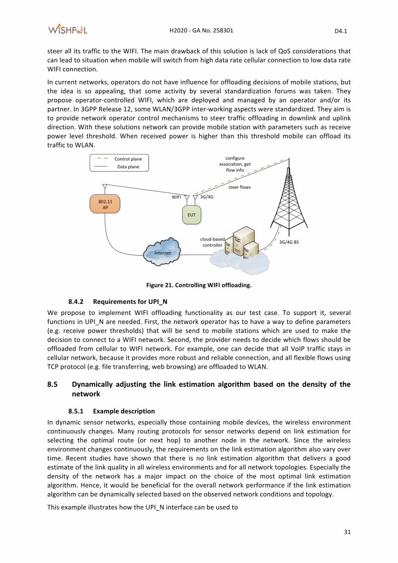
steer all its traffic to the WIFI. The main drawback of this solution is lack of QoS considerations that can lead to situation when mobile will switch from high data rate cellular connection to low data rate WIFI connection.
In current networks, operators do not have influence for offloading decisions of mobile stations, but the idea is so appealing, that some activity by several standardization forums was taken. They propose operator-‐controlled WIFI, which are deployed and managed by an operator and/or its partner. In 3GPP Release 12, some WLAN/3GPP inter-‐working aspects were standardized. They aim is to provide network operator control mechanisms to steer traffic offloading in downlink and uplink direction. With these solutions network can provide mobile station with parameters such as receive power level threshold. When received power is higher than this threshold mobile can offload its traffic to WLAN.
Figure 21. Controlling WIFI offloading.
8.4.2 Requirements for UPI_N We propose to implement WIFI offloading functionality as our test case. To support it, several functions in UPI_N are needed. First, the network operator has to have a way to define parameters (e.g. receive power thresholds) that will be send to mobile stations which are used to make the decision to connect to a WIFI network. Second, the provider needs to decide which flows should be offloaded from cellular to WIFI network. For example, one can decide that all VoIP traffic stays in cellular network, because it provides more robust and reliable connection, and all flexible flows using TCP protocol (e.g. file transferring, web browsing) are offloaded to WLAN.
8.5 Dynamically adjusting the link estimation algorithm based on the density of the network
8.5.1 Example description In dynamic sensor networks, especially those containing mobile devices, the wireless environment continuously changes. Many routing protocols for sensor networks depend on link estimation for selecting the optimal route (or next hop) to another node in the network. Since the wireless environment changes continuously, the requirements on the link estimation algorithm also vary over time. Recent studies have shown that there is no link estimation algorithm that delivers a good estimate of the link quality in all wireless environments and for all network topologies. Especially the density of the network has a major impact on the choice of the most optimal link estimation algorithm. Hence, it would be beneficial for the overall network performance if the link estimation algorithm can be dynamically selected based on the observed network conditions and topology.
This example illustrates how the UPI_N interface can be used to
Internet
EUT
steer flows
3G/4G
3G/4G BS
802.11 AP
configure association, get
flow info
WIFI
Control planeData plane
cloud-‐based controller
H2020 -‐ GA No. 258301 D4.1
WiSHF L
32
a) Gather node local information (e.g. density of the neighbourhood) required to decide when to switch the link estimation algorithm.
b) Switch the link estimation algorithm dynamically without requiring a device reboot or affecting the already active routing protocol.
8.5.2 Requirements for UPI_N The UPI_N interface must allow a local control program to monitor the density of the neighbourhood. The density can be retrieved from the number of nodes in the neighbour table.
8.5.3 Requirements for UPI_G The UPI_G must permit the global controller to periodically execute the UPI_N function for monitoring local density on a set of nodes. There is no need for a hard time synchronized execution. Based on the results it needs to perform a network-‐wide switch to another link estimation algorithm.
8.5.4 Requirements for UPI_M The UPI_M interface is used by either the local control program or the global control program to switch to another link estimation algorithm at run-‐time. The time scheduled execution function of UPI_M is required when global control program decides to switch the link estimation algorithm.
8.6 Increasing reliability by changing the lifetimes of routes in the network
8.6.1 Example description Routing protocols in dynamic sensor networks do not use static routing table entries for maintaining routes to the other nodes in the network. Instead, they use route discovery mechanisms to dynamically form a network topology and to change routes continuously. For this purpose, the entries in the routing table are only valid for a limited time, i.e. the route lifetime. If a route is not used during the route lifetime, the corresponding entry is removed from the routing table. The choice for the route lifetime is currently done at compile-‐time and is a trade-‐off between reliability (shorter route lifetimes better reflect the current optimal topology), latency (longer route lifetimes require less latency for route discovery) and energy usage (longer route lifetimes require less energy for route discovery).
In this example we want to demonstrate that by adjusting the route lifetime dynamically, the overall network performance (reliability, latency and energy usage) can be increased. Since decreasing reliability also has a negative effect on latency and energy usage, it is the primary objective for optimizing the network performance. If the reliability drops below a certain threshold, the route lifetime is decreased, conversely if the reliability stabilizes above a certain threshold, it is increased again.
This example illustrates how the UPI_N interface can be used to
a) gather node local information (e.g. packet loss) to monitor the reliability;
b) change node local parameters (e.g. route lifetime) to increase reliability or decrease latency and energy usage.
8.6.2 Requirements for UPI_N The UPI_N interface must allow a local control program to monitor the packet loss and to change the route lifetime.
H2020 -‐ GA No. 258301 D4.1
WiSHF L
33
8.6.3 Requirements for UPI_G Although this example is more suited for local control programs it should also be possible to use the UPI_G interface for the same purpose.
8.7 Switching the routing strategy based on the type of active traffic flows
8.7.1 Example description The low link budget and battery powered operation of sensor networks requires specialized routing strategies which are tightly coupled to the specific application requirements and network conditions. Therefore, many routing protocols have been proposed. For this reason, sensor networks are limited in the applications they can support. In dynamic sensor networks, more applications need to be supported and the networking conditions vary frequently.
This example shows how sensor networks can adapt to new applications and networking conditions by changing the routing strategy on the fly. For this the global control program should be able to detect the currently active traffic flows in the network and activate the most appropriate routing protocol at run-‐time without requiring a device reboot, or worse, a firmware upgrade. The global control thus needs to monitor the active traffic flows in the network and detect the type of traffic each flow introduces. Based on this information, the global control program can decide to switch to another routing protocol that is more suited to support the currently active flows in the network.
8.7.2 Requirements for UPI_N This example is mainly controlled from the global control program hence it needs no functions from UPI_N.
8.7.3 Requirements for UPI_G This example requires that the global configuration and monitoring engine is notified when new application flows are activated.
8.7.4 Requirements for UPI_M Switching to another routing protocol is a typical example of something that needs to be coordinated on a global level because all nodes in the network need to execute the same protocol. Therefore, it is very important that if the global control program decides to switch to another routing protocol, the switching can be done on all nodes at the same time. Another important requirement is that if for some reason, the switching fails or another problem is detected a roll-‐back to the previous stable configuration can be made.
H2020 -‐ GA No. 258301 D4.1
WiSHF L
34
9 Relation to other architectures Unification of APIs for controlling networking aspects has gained a lot of attention in many networking areas in the Internet such as core IP networks, access networks and cloud systems. The main motivation is always to simplify the control of networked resources thereby lessening the burden for network administrators from an operational viewpoint and for facilitating integration of innovative solutions proposed by the research community. This has resulted in the proposal of several frameworks applying software defined networking concepts where each targets a specific network area in the Internet. This section will give an overview of these frameworks and discuss the positioning of the WiSHFUL project with respect to the discussed frameworks.
WiSHFUL aims to expand the software defined networking concepts to the edge of the Internet, mainly targeting all wireless devices between, and including, the broadband access gateways and the end devices. This is very challenging because the targeted devices are very heterogeneous in terms of capabilities, networking scenarios and supported applications. The capabilities vary from resource constrained sensor devices to general purpose devices with much more processing power and memory.
The following frameworks will be discussed in the remainder of this section:
• CWMP or CPE WAN Management Protocol (TR-‐069)[17] designed for remote management of end-‐user devices (customer premises equipment or CPE) owned by broadband internet providers. CWMP targets internet access devices such as modems, routers and gateways as well as set-‐top boxes and VoIP phones;
• Software-‐defined Networking and Openflow [18]; • Openstack [19]; • OpenRoads [20]; • Active Networking [21].
9.1 CWMP TR-‐069 [17] describes the CPE WAN Management Protocol, intended for communication between a CPE and Auto-‐Configuration Server (ACS). The CPE WAN Management Protocol defines a mechanism that encompasses secure auto-‐configuration of a CPE, and also incorporates other CPE management functions into a common framework. CWMP is a bidirectional SOAP/HTTP-‐based protocol. It is adopted by other forums such as Home Gateway Initiative (HGI), Digital Video Broadcasting (DVB) and WiMAX forum as the protocol for remote management of the devices installed on the customer premises.
The CWMP protocol aims to provide the following functionalities:
• Auto-‐configuration and dynamic service provisioning • Software/firmware image management • Software module management • Status and performance monitoring • Diagnostics
Most of the configuration and diagnostics is performed through setting and retrieving the value of the device parameters. These are organized in a well defined hierarchical structure that is more or less common to all device models and manufacturers. Such an approach could also be interesting for WiSHFUL although we should be careful that it is possible to apply it on constrained sensor devices.
In contrast to WiSHFUL all control and management is done centrally. There is no possibility to add auto configuration capabilities to the end-‐devices; hence there is only global control. Moreover, it is not intended as a protocol for real-‐time control meaning that (re-‐) configuration is only done sporadically without hard timing requirements. Also the scope of the devices is different. In WiSHFUL
H2020 -‐ GA No. 258301 D4.1
WiSHF L
35
wireless devices are targeted, ranging from very constrained sensor devices to much more capable general purpose devices such as smart-‐phones. CWMP only targets general purpose devices and requires a broadband wired connection with the device that needs to be controlled.
9.2 Software-‐defined Networking (Openflow) WISHFUL is related to the concept of Software-‐defined networking (SDN) both in goals and in challenges [22]. SDN is an approach to computer networking that allows network administrators to manage network services through abstraction of lower-‐level functionality. This is done by decoupling the system that makes decisions about where traffic is sent (the control plane) from the underlying systems that forward traffic to the selected destination (the data plane).
SDN requires some method for the control plane to communicate with the data plane. One such mechanism is OpenFlow [18]. OpenFlow enables controllers to determine the path of network packets through the network of switches. The separation of the control from the forwarding allows for more sophisticated traffic management and routing protocols.
The key design consideration is to pick the right abstractions to balance flexibility against performance. While interoperation with existing devices on the Internet is a major consideration for layer-‐3 SDN interfaces in Wishful, inter-‐operation is much less of an issue as it operates also on lower layers (layer 1 and 2).
Openflow focuses only on a specific functionality, i.e. networking and routing. In contrast WISHFUL allows the configuration, control and monitoring of the whole network protocol stack including the configuration of the wireless mode (upper MAC) of a particular wireless node. In particular, WISHFUL’s data-‐plane enables the network protocol developer to program the network stack for specific traffic subsets. However, the developer does not need to specify how the packet processing behaviour is integrated into an operational network and realized in practice. This low-‐level complexity is abstracted out by the UPI_N interface.
9.3 Openstack OpenStack Networking [19] is a API-‐driven system for managing networks and IP addresses designed for data-‐center networks. Users can create their own networks, control traffic and connect servers and devices to one or more networks. Moreover, it builds on top of SDN technology like OpenFlow. The Openstack Networking core API contains functionality to configure networks, subnet resources and ports. The OpenStack Networking has an extension framework allowing additional network services, such as intrusion detection systems (IDS), load balancing, firewalls and virtual private networks (VPN) to be deployed and managed.
In contrast to WiSHFUL it is focused on the configuration and management of wired datacenter networks whereas WISHFUL focuses on configuration and management of wireless devices and its real-‐time control. In contrast the Openstack Networking API is not optimized for real-‐time control and does not meet the required scalability goals.
9.4 OpenRoads The goal of OpenRoads [20] is to create an open platform for researchers to experiment and explore different mobility solutions, network controllers and/or routing protocols. OpenRoads provides researchers control of the network through two means, namely, control of the data-‐path using OpenFlow and control of the device configuration using SNMP. The OpenRoads interface abstraction for network control provides an API for communication, flow management and (wireless) device control. It aims for an uniform interface for heterogeneous technologies and vendors, I while allowing technology specific control if so desired.
H2020 -‐ GA No. 258301 D4.1
WiSHF L
36
For device control OpenRoads uses SNMP, but provides just a very-‐low level API, i.e. simple get/set functions and provision of notifications of events. In contrast Wishful aims to provide a high-‐level API for programming the network stack.
9.5 Active Networking The Active Networking [21] initiative, proposed in the mid 1990s, tried to break with the traditional networking approach, where bits are passively transmitted from one system to another (i.e. the network is insensitive to the bits it carries). In active networking, the network can perform customized computations on the user data. For example, a user of an active network could send a customized compression program to a node within the network (e.g., a router) and request that the node execute that program when processing their packets. These networks are “active” in two ways:
• switches perform computations on the user data flowing through them; • individuals can inject programs into the network, thereby tailoring the node processing to be
user-‐and application-‐specific.
Active Networking was never widely adopted mainly due to practical security and performance concerns but tried to tackle some of the network management issues WiSHFUL also tries to solve. One of the main differences is however that opposed to Active Networking, WiSHFUL does not propose a clean-‐slate approach where all existing protocols need to be changed. WiSHFUL proposes a more pragmatic approach that enables more flexibility by providing unified interfaces on top of existing networking software.
10 Conclusion
In this deliverable, starting from the presentation of the different network architectures used in the testbeds of the project partners (namely Linux-‐based devices and embedded devices based on Contiki.), we have described the first UPI_N specification. The UPI_N interface offers a unified interface to experimenters willing to work on heterogeneous network platforms and enables the definition of platform-‐independent adaptation logics of the upper MAC, routing and higher layers. Although different networking architectures (Linux vs. embedded OS like Contiki) generally support different features, a common set of functionalities for network configuration and monitoring have been abstracted for the definition of the UPI_N, which can be applied to any underlying technology. For coordinated execution of configuration and monitoring related functions an additional UPI is defined, the UPI_G, allowing network-‐wide operations on a group of nodes. Finally, a third unified interface, UPI_M has been defined that covers all management related functions required for managing protocol software modules at any layer of the network protocol stack.
For illustrating the use of the different UPIs, several example scenarios have been worked out, such as traffic-‐aware 802.11 airtime management, WIFI and sensor network co-‐existence, intelligent download with WIFI tethering, WiFi offloading, dynamic adjusting of a link estimation algorithm, adapting lifetimes of routes, and switching routing strategy.
This deliverables serves as a guideline for the implementation of the configuration, monitoring and management adaptation modules and the UPIs that will be offered in the first open call at the end of the first year. We anticipate that some minor refinements could be necessary during the implementation phase (that will last for the next six months of the project).
H2020 -‐ GA No. 258301 D4.1
WiSHF L
37
11 References [1] „OpenWRT,“ [Online]. Available: https://openwrt.org/.
[2] „TinyOS,“ [Online]. Available: http://www.tinyos.net/.
[3] „Contiki,“ [Online]. Available: http://www.contiki-‐os.org/.
[4] „Netlink API,“ [Online]. Available: http://www.linuxfoundation.org/collaborate/workgroups/networking/netlink.
[5] „Linux Netlink as an IP Services Protocol,“ 2003. [Online]. Available: https://tools.ietf.org/html/rfc3549.
[6] „ZeroMQ,“ [Online]. Available: http://zeromq.org/.
[7] Z. Shelby, K. Hartke und C. Bormann, The constrained application protocol (CoAP), Internet Engineering Task Force (IETF), 2014.
[8] S. Duquennoy, F. Osterlind und A. Dunkels, „Lossy Links, Low Power, High Throughput,“ in s Proceedings of the 9th ACM Conference on Embedded Networked Sensor Systems, Seatlle, 2011.
[9] C. Bormann, 6LoWPAN-‐GHC: Generic Header Compression for IPv6 over Low-‐Power Wireless Personal Area Networks (6LoWPANs), IETF RFC 7400, 2014.
[10] G. Montenegro, N. Kushalnagar, J. Hui und D. Culler, Transmission of IPv6 Packets over IEEE 802.15.4 Networks, IETF RFC 4944.
[11] J. Ko, S. Dawson-‐Haggerty, O. Gnawali, D. Culler und A. Terzis, „Evaluating the Performance of RPL and 6LoWPAN in TinyOS,“ in s Workshop on Extending the Internet to Low Power and Lossy Networks (IP+ SN), 2011.
[12] T. E. Winter, P. E. Thubert, A. Brandt, J. Hui, R. Kelsey, P. Levis, K. Pister, R. Struik, J. Vasseur und A. R., RPL: IPv6 Routing Protocol for Low-‐Power and Lossy Networks, IETF RFC6550, 2012.
[13] J. Ko, J. Eriksson, N. Tsiftes, S. Dawson-‐Haggerty, J.-‐P. Vasseur, M. Durvy, A. Terzis, A. Dunkels und D. Culler, „Beyond Interoperability: Pushing the Performance of Sensor Network IP Stacks,“ in s Proceedings of the 9th ACM Conference on Embedded Networked Sensor Systems, Seattle, 2009.
[14] A. Dunkels, „Full TCP/IP for 8-‐bit Architectures,“ in s Proceedings of the 1st International Conference on Mobile Systems, Applications and Services, 2003.
[15] A. Dunkels, F. Osterlind und Z. He, „An Adaptive Communication Architecture for Wireless Sensor Networks,“ in s Proceedings of the 5th International Conference on Embedded Networked Sensor Systems, Sydney, 2007.
[16] P. Ruckebusch, E. De Poorter, C. Fortuna und I. Moerman, GITAR: Generic extension for Internet-‐of-‐Things ARchitectures enabling dynamic updates of network and application modules, Ad Hoc Networks, 2015.
[17] J. Bernstein und T. Spets, „CPE WAN Management Protocol,“ DSL Forum TR-‐069, https://www.broadband-‐forum.org/technical/download/TR-‐069.pdf, 2004.
[18] „OpenFlow,“ [Online]. Available: https://www.opennetworking.org/sdn-‐resources/openflow/.
[19] „OpenStack Networking,“ [Online]. Available: www.openstack.org.
H2020 -‐ GA No. 258301 D4.1
WiSHF L
38
[20] K.-‐K. Yap, OpenRoads: Empowering research in mobile networks, ACM SIGCOMM Computer Communication Review, 2010.
[21] S. F. Bush und A. Kulkarni, Active Networks and Active Network Management: A Proactive Management Framework, Springer, 2006.
[22] „Open Networking Foundation's definition of SDN,“ [Online]. Available: https://www.opennetworking.org/sdn-‐resources/sdn-‐definition.
Related Documents