applied sciences Review Wax Formation Mechanisms, Wax Chemical Inhibitors and Factors Affecting Chemical Inhibition Thevaruban Ragunathan 1 , Hazlina Husin 1, * and Colin D. Wood 2 1 Department of Petroleum Engineering, Universiti Teknologi Petronas, Seri Iskandar 32610, Malaysia; [email protected] 2 Energy, Commonwealth Science and Industrial Research Organization, Kensington, WA 6152, Australia; [email protected] * Correspondence: [email protected] Received: 30 September 2019; Accepted: 18 October 2019; Published: 9 January 2020 Abstract: When crude oil is extracted out of a subterranean reservoir at high temperature and pressure, it is usually transported via a pipeline, where the crude oil experiences radical changes in its physical and chemical properties, instigating numerous complications. Among the various flow assurance problems, wax deposition and build up are among the most commonly found. However, the accurate mechanism of wax deposition is still unclear and is widely debated among researchers. The mechanism under multiphase conditions is also an ambiguity. This review covers the six wax deposition mechanisms, the challenges in multiphase flow conditions, the latest types of chemical inhibitor, and a summary of factors governing chemical inhibitor performance. Keywords: crude oil; wax deposition; wax deposition mechanism; flow assurance; molecular diffusion; chemical inhibitors 1. Introduction Paraffin deposition is a major problem, especially during crude oil transportation via pipelines as well as during production in the tubing string, in which the deposition of the unwanted substance causes an increase in the pressure drop (requiring higher pressure to transport the crude oil) [1]. Paraffins are defined as a class of i-alkanes and n-alkanes that comprises a long hydrocarbon chain usually attached via single bonds. High molecular weight paraffins are commonly found in solid wax deposits, where the carbon numbers are in the range of 18 to 75 and where the melting point ranges from 40 ◦ C to 70 ◦ C[2,3]. The lowest-energy chain alkane has a conformational structure of carbon atoms with hydrogen atoms in planes passing perpendicularly through the carbon atoms to the chain axes, as shown in Figure 1. Commonly, the solid phase specific heat ranges between 1.80 and 2.30 kJ/kg·K. Figure 1. Structure of the lowest energy chain alkane. There are two kinds of wax: microcrystalline wax, which contributes to tank-bottom sludges, and macrocrystalline wax, which causes the flow assurance problems in production and transportation operations [4,5]. Before the deposition of paraffin wax occurs, paraffin wax will first crystallize or precipitate out from crude oil. The precipitation of paraffin wax occurs in two stages, which are known Appl. Sci. 2020, 10, 479; doi:10.3390/app10020479 www.mdpi.com/journal/applsci

Welcome message from author
This document is posted to help you gain knowledge. Please leave a comment to let me know what you think about it! Share it to your friends and learn new things together.
Transcript

applied sciences
Review
Wax Formation Mechanisms, Wax ChemicalInhibitors and Factors Affecting Chemical Inhibition
Thevaruban Ragunathan 1, Hazlina Husin 1,* and Colin D. Wood 2
1 Department of Petroleum Engineering, Universiti Teknologi Petronas, Seri Iskandar 32610, Malaysia;[email protected]
2 Energy, Commonwealth Science and Industrial Research Organization, Kensington, WA 6152, Australia;[email protected]
* Correspondence: [email protected]
Received: 30 September 2019; Accepted: 18 October 2019; Published: 9 January 2020�����������������
Abstract: When crude oil is extracted out of a subterranean reservoir at high temperature andpressure, it is usually transported via a pipeline, where the crude oil experiences radical changes inits physical and chemical properties, instigating numerous complications. Among the various flowassurance problems, wax deposition and build up are among the most commonly found. However,the accurate mechanism of wax deposition is still unclear and is widely debated among researchers.The mechanism under multiphase conditions is also an ambiguity. This review covers the six waxdeposition mechanisms, the challenges in multiphase flow conditions, the latest types of chemicalinhibitor, and a summary of factors governing chemical inhibitor performance.
Keywords: crude oil; wax deposition; wax deposition mechanism; flow assurance; moleculardiffusion; chemical inhibitors
1. Introduction
Paraffin deposition is a major problem, especially during crude oil transportation via pipelines aswell as during production in the tubing string, in which the deposition of the unwanted substancecauses an increase in the pressure drop (requiring higher pressure to transport the crude oil) [1].Paraffins are defined as a class of i-alkanes and n-alkanes that comprises a long hydrocarbon chainusually attached via single bonds. High molecular weight paraffins are commonly found in solidwax deposits, where the carbon numbers are in the range of 18 to 75 and where the melting pointranges from 40 ◦C to 70 ◦C [2,3]. The lowest-energy chain alkane has a conformational structure ofcarbon atoms with hydrogen atoms in planes passing perpendicularly through the carbon atoms to thechain axes, as shown in Figure 1. Commonly, the solid phase specific heat ranges between 1.80 and2.30 kJ/kg·K.
Figure 1. Structure of the lowest energy chain alkane.
There are two kinds of wax: microcrystalline wax, which contributes to tank-bottom sludges, andmacrocrystalline wax, which causes the flow assurance problems in production and transportationoperations [4,5]. Before the deposition of paraffin wax occurs, paraffin wax will first crystallize orprecipitate out from crude oil. The precipitation of paraffin wax occurs in two stages, which are known
Appl. Sci. 2020, 10, 479; doi:10.3390/app10020479 www.mdpi.com/journal/applsci
Appl. Sci. 2020, 10, 479 2 of 18
as nucleation and crystal growth [6–8]. Nucleation occurs when the temperature of the crude oildecreases to the wax appearance temperature (WAT). The wax molecules form clusters, causing acloudy appearance—prompting the term “cloud point”, which refers to WAT value. Progressively, theparaffin wax molecules attach and detach until they reach a critical size cluster in order to be stable.These clusters are better known as nuclei, and the formation of these nuclei is defined as nucleation.Homogeneous nucleation takes place in the absence of contaminant or nucleating materials [6].Meanwhile, heterogeneous nucleation occurs in the presence of nucleating material(s) throughout theliquid. The crystal growth process then begins after the nuclei has stabilized as further moleculesattach in a plate-like or lamellar structure. In general, the precipitation of wax can cause an incrementin crude oil viscosity, although the adhesion of wax to the pipe wall does not occur [9].
The correlation between the crude oil properties and rheology, including the deposition as well asthe precipitation of wax during flow, has been extensively studied by a group of researchers [10–13]. Thedeveloped correlation is applied to predict the onset precipitation and deposition of wax in the pipeline.The standard technique used to investigate wax precipitation is by using a cold finger system, flow loop,or viscometer apparatus [14–29]. Nonetheless, the precise modelling of deposition along the pipelinewalls is challenging. This is because the deposition of wax is a function of thermodynamic variables,hydrodynamic flow, heat and mass transfer, as well as solid–solid and surface–solid interactions.Modelling wax deposition in the presence of multiphase flow is even more complex to derive manually,as numerous variables need to be considered. In addition, a few wax deposition models have been putforward by researchers over the past few years in order to describe wax precipitation using computersimulation software such as OLGATM from Schlumberger, LedaFlow from Kongsberg and FloWaxfrom KBC [30]. A brief explanation of the model utilized by the software is illustrated in Table 1.
Table 1. Examples of models used in wax deposition studies.
Model Software Description References
Rygg, Rydahl and R∅nningsen OLGATMMultiphase flow wax deposition model which
predicts wax deposition in wells as well aspipelines.
[31]
Matzain OLGATMSemi empirical model which takes into accountshear stripping, molecular diffusion and shear
dispersion to predict wax deposition.[5]
Heat Analogy OLGATM Computes the mass transfer rate of wax utilizingthe heat transfer analogy. [30]
University of Michigan Model LedaFlow Models the wax crystallization and the waxdeposition on pipe wall. [30]
FloWax FloWax
A complete compositional wax deposition modelthat considers the thermodynamics wax
precipitation, wax diffusion based on heat andmass transfer analogy and the shearing effect.
[32]
Hence, this review paper aims to discuss the current understanding of the wax depositionmechanism in pipelines. The mechanisms for wax deposition include molecular diffusion, Soretdiffusion, Brownian diffusion, gravity settling, shear dispersion, and shear stripping, which will befurther discussed in this paper. In addition, the factors affecting wax deposition in multiphase flow,especially in the presence of gas–oil and oil–water flow, respectively, are also discussed. Further, thisreview covers the latest chemical inhibitors in the literature and the factors that affect the efficiency ofchemical inhibitors in developing a sustainable source of knowledge in flow assurance.
2. Wax Deposition Mechanism
Among the six wax deposition mechanisms that have been suggested by researchers, moleculardiffusion has been agreed by most researchers to be the dominant deposition mechanism [33]. This isbecause the pipe walls in deep water pipelines are influenced by cold subsea conditions. This causes

Appl. Sci. 2020, 10, 479 3 of 18
the crude oil flowing in the pipeline to experience a radial thermal gradient. This means that thetemperature of crude oil situated closer to the pipe wall is lower compared to the temperature of thecrude oil at the center of the pipeline [34]. When the temperature of the crude oil reaches the cloudpoint, the crystallization of wax takes place in the cold region closer to the pipe wall. The crystallizationof wax thereby changes the equilibrium of the liquid and solid phases. As the solubility of wax in thecrude oil decreases with respect to thermal energy, there will be a concentration gradient present. Coldregions situated closer to the pipe wall will have a lower wax concentration in the liquid phase. This isdue to the solid wax depositing out of the bulk liquid crude oil on to the colder pipeline wall. Hence,wax molecular diffusion occurs from the bulk fluid to the pipeline wall [35–37].
The wax molecular diffusion or the rate of deposited wax in mass can be predicted by utilizingFick’s law of diffusion:
dmm
dt= ρdDmA
dCdr
(1)
where mm is the deposited wax mass, ρd is the solid wax density, Dm is the liquid wax diffusioncoefficient, A is the deposition surface area, C is the wax concentration in solution, and r is the radialcoordinate. Equation (1) can also be written in terms of the wax solubility coefficient of the crude oil:
dmm
dt= ρdDmA
(dCdT
)(dTdr
)(2)
where dT/dr is the radial thermal gradient [38]. Expanding the molecular diffusion equation will givethe molecular diffusion coefficient [38,39] as follows:
Dm = 7.4 × 10⁻⁹[T(εM)1/2
]/µV0.6 (3)
where T is defined as the absolute temperature, ε is a parameter for association, M is the molecularweight of crude oil, µ is the dynamic viscosity of crude oil, and V is the molecular volume of wax.
Subsequently, the second deposition mechanism based on thermal gradient is Soret diffusion [40].Soret diffusion occurs when large molecules and small molecules are dispersed under thermal gradientregions. As yet, the employment of Soret diffusion in the wax deposition model is not fully understoodand is recommended as the subject of future studies.
In one case, Soret diffusion was negligible in the wax deposition model [41], while in anothercase, Soret diffusion was taken into account in the development of the wax deposition model [42].This notwithstanding, implementing both molecular diffusion and Soret diffusion will develop anaccurate wax deposition model. This is because the rate of the deposited wax will be based onthe concentration gradient and thermal gradient as well as variables associated with the diffusioncoefficient and thermo-diffusion coefficient [40].
The third deposition mechanism due to the movement of particles is Brownian diffusion, whichoccurs when the surrounding temperature is less than WAT [35,36]. The presence of a solid crystalconcentration gradient instigates a net transport of the crystal in the direction of lower concentration.The mass of deposited wax by Brownian motion can be predicted by
dmB
dt= ρdDBA
dC∗
dr(4)
where mB is the deposited wax by Brownian motion, DB is the Brownian motion wax diffusioncoefficient, and C* is defined as the wax concentration of solid wax. Wax deposition caused byBrownian diffusion is dimly understood because, according to its definition, Brownian diffusion fluxoccurs away from the wall, around the center region of a pipeline [43]. Thus, this dismisses theoccurrence of wax deposition onto the pipe wall. On the contrary, it was argued that wax crystals aretrapped in the immobile solid layer at the pipe wall—i.e., the concentration of the wax crystals near thewall is ~0—thus permitting Brownian diffusion towards the wall [44].

Appl. Sci. 2020, 10, 479 4 of 18
Not many papers have explained the last three deposition mechanisms, namely the sheardispersion, shear stripping, and gravity settling. Shear dispersion contributes to wax deposition bylateral particle motion immersed in flow-induced conditions, which is also known as shear flow. Theshear dispersion mechanism is dominant when the temperatures are lower than the cloud point [45].Meanwhile, shear stripping is more dominant in the presence of turbulent flow, where the effect ofshear forces will be significant compared to laminar flow. Shear forces cause the removal of waxdeposits and lead to deposition at regions of lower velocity in the production pipeline as well asreducing the wax deposition thickness [46,47]. Hence, these two former mechanisms are significantin the wax deposition model as well as in wax removal as they can enhance flow improver chemicalperformance. The later mechanism (gravity settling) is due to the formation of large wax particle sizes.Since the density of crystallized wax is higher than the density of crude oil, the probability for waxcrystals to deposit at the bottom of the pipe is high. Depending on the settling velocity coefficient,studies have reported that the mass of deposited wax is found to be identical under vertical andhorizontal flows [35,38].
3. Wax Deposition in Multiphase Flow
In comparison to single-phase, literature data on two-phase wax deposition studies (e.g., gas–oiland oil–water) are limited due to the complexity of the experiment. In fact, there is no published studyon three-phase gas–oil–water paraffin deposition due to various variables that need to be controlledand considered. Nevertheless, there is a need to extend the study of wax deposition under multiphaseflowing conditions since the actual crude oil transportation via subsea pipelines could encountermultiphase flow conditions which lead to different in flow patterns [48,49].
Figure 2i,ii [50] shows two categories of flow pattern which resulted from the inclination orelevation of the crude oil pipeline. For a horizontal pipeline, the flow patterns are bubbly flow,wavy flow, intermittent flow (plug and slug), and annular flow, as shown in Figure 2i. Meanwhile,flow patterns in a vertical pipeline are bubbly flow, intermittent flow (slug and churn), annular flow,and annular mist, as shown in Figure 2ii. In general, wax deposition distribution depends on theposition of the pipeline, the flow pattern, and the multiphase system (such as the gas–oil system or theoil–water system).
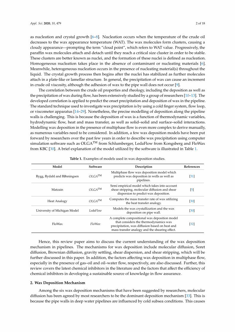
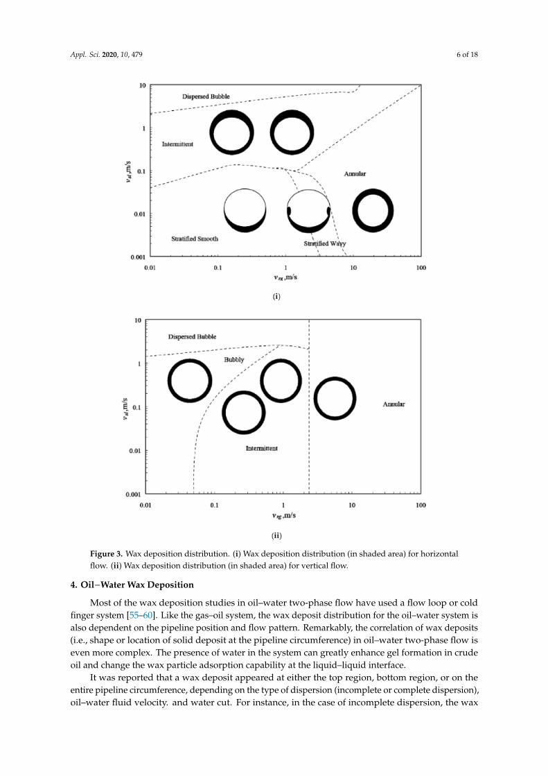
A limited database can be found for wax deposition studies in gas–oil two-phase flow conductedby researchers worldwide [48,49,51–53]. Figure 3i,ii shows the variation of wax deposit distributionfor a gas–oil system, based on the pipeline position and flow pattern. It is reported that wax depositedaround the circumference of the pipeline (i.e., the internal pipeline wall) with different thickness andhardness when the pipeline position is vertical. It is notable that the flow pattern has no major effect onthe shape of the deposited wax. A similar observation has been reported when the pipeline position ishorizontal. For horizontal stratified flow, the deposit was distributed in a crescent shape and was foundto be softer and thicker. Meanwhile, for horizontal intermittent flow, a harder deposit was producedthan that of stratified flow, while the wax hardness for annular and intermittent flow was similar.

Appl. Sci. 2020, 10, 479 5 of 18
Figure 2. Flow patterns in pipelines. (i) Flow patterns of near-horizontal pipeline [50]. (ii) Flowpatterns of near-vertical flow [50].
In terms of increasing gas velocity, the wax deposit thickness in gas–oil two-phase flow wasreported to be thicker [48]. In contrast, the wax deposit thickness in single-phase flow was reportedto be thinner at increasing flow velocity [16]. The equivalent wax deposition in gas–oil two-phaseflow depends on of two factors: the deposition-promoting and the deposition-inhibiting factors. Thedeposition-promoting factor is an increase in heat transfer or thermal gradient due to the increase in thecrude oil velocity simultaneously as the gas velocity increases. In contrast, the deposition-hinderingfactor is attributed to the surface area of the crude oil pipeline which is in-contact with the oilwhen the liquid holdup decreases as the gas velocity increases. Few studies have found that thedeposition-hindering factor is amplified for bubbly, wavy, and intermittent flow patterns [49,54].
Appl. Sci. 2020, 10, 479 6 of 18
Figure 3. Wax deposition distribution. (i) Wax deposition distribution (in shaded area) for horizontalflow. (ii) Wax deposition distribution (in shaded area) for vertical flow.
4. Oil−Water Wax Deposition
Most of the wax deposition studies in oil–water two-phase flow have used a flow loop or coldfinger system [55–60]. Like the gas–oil system, the wax deposit distribution for the oil–water system isalso dependent on the pipeline position and flow pattern. Remarkably, the correlation of wax deposits(i.e., shape or location of solid deposit at the pipeline circumference) in oil–water two-phase flow iseven more complex. The presence of water in the system can greatly enhance gel formation in crudeoil and change the wax particle adsorption capability at the liquid–liquid interface.
It was reported that a wax deposit appeared at either the top region, bottom region, or on theentire pipeline circumference, depending on the type of dispersion (incomplete or complete dispersion),oil–water fluid velocity. and water cut. For instance, in the case of incomplete dispersion, the wax

Appl. Sci. 2020, 10, 479 7 of 18
deposit would appear either at the top region or bottom region of the pipeline wall. Hypothetically, oilfloats in water; thus, the oil film will be at the top region, in the position of the wax deposit. This isvalid for both high and low oil-viscosity systems [55,58]. Unless the oil–water fluid velocity is highenough to suppress the oil film towards the bottom region, the wax deposition occurs at the bottomregion [58]. In case of complete dispersion, the wax deposit was found to be on the entire pipelinecircumference, in which its thickness decreased at an increasing oil–water fluid velocity [55].
Further, it was observed that an increment in water cut could lead to a decrease in wax depositthickness [56,57,61]. This is because a high water cut means a decrease in the oil volume present inthe pipeline. Hence, the amount of wax crystal required for deposition to occur in production feed isreduced. In addition, a high water cut could also lower the heat transfer rate, as water has a higherspecific heat value compared to oil. Some researchers have reported that the wax deposit thicknessincreases and then decreases at higher water cuts [26,62]. As yet, there are no correlation modelswhich are available to preview the impact of water cut on wax deposition distribution. It is importantto conduct further investigation in order to manage the risk of wax deposit formation in the crudeoil pipelines.
5. Wax Chemical Inhibitors
Between the mechanical method and chemical method, the latter is preferred by the industryin inhibiting the wax deposition issue [5,63,64]. Tables 2–4 show the progress of studies involvingthree types of chemical inhibitor, namely the wax dispersant, pour point depressant (PPD), and waxcrystal modifier.
Table 2. Examples of wax dispersant used in deposition studies.
Type of Crude Oil Sample Used as Wax Dispersant Year/References
Malaysia Poly (ethylene-co-vinyl acetate)/poly (maleicanhydride-alt-1-octadecene)/nano particle sodium cloisite 2019/[65]
Indian Sapindus mukorossi sp. 2017/[66]
Egyptian Poly (octadecyl acrylate) 2015/[67]
Laboratory sample Poly (octadecyl acrylate)/nanosilica hybrid particles 2015/[68]
Nada Poly (n-alkyl recinoleate-co-N-hexadecyl maleimide) 2012/[20]
Dragon RPI Non-ionic surfactant 2001/[69]
Table 3. Examples of pour point depressant used in was deposition study.
Type of Crude Oil Sample Used as Pour Point Depressant Year/References
Norwegian Polycarboxilate/poly acrylate/poly vinyl acetate 2019/[70]
Nigerian Poly acrylate ester copolymer 2019/[71]
Nigerian Jatropha seed oil 2018/[18]
Laboratory sample Ethylene vinyl acetate-co-diethanolamine 2017/[63]
Langhnaj Poly (hexyl oleate-co-hexadecyl maleamide-co-n-alkyl oleate) 2017/[28]
Egyptian Halomonas xianhensis sp. 2016/[72]
Changqing Poly (octadecylarylate)/Clay nano composite 2009/[73]
Umbaraka Monohexatriethanolamine 2007/[74]
Egyptian Polyster R 1000 (1,3-dicarboxymethoxy benzene withpolyethylene glycol with molecular weight of 1000). 2007/[75]
White Tiger CTP2 Poly (ethylene-co-vinyl acetate) 2001/[69]
Albacor Poly (ethylene-co-vinyl acetate) 2001/[76]
Badejo Poly (ethylene-co-vinyl acetate) 2001/[76]

Appl. Sci. 2020, 10, 479 8 of 18
Table 4. Examples of wax crystal modifier used in was deposition study.
Type of Crude Oil Sample Used as Wax Crystal Modifier Year/References
Malaysia Silane-based surfactants with SiO2 particles 2018/[77]
China (Xuzhou) Nano composite of montmorillonite 2016/[78]
Karama Poly (cinamoyloxy ethyl methacrylate-co-octadecyl arylate) 2008/[79]
Iranian Ethylene vinyl acetate copolymer 2008/[80]
5.1. Wax Dispersant
Wax dispersants are a group of surfactants that adsorb onto pipe wall surfaces and decrease thewax adhesion either by altering the wettability of the pipe wall or by forming a thin layer where waxcrystals shear off easily. A wax dispersant also adsorbs onto wax crystals and forms a wax crystal latticestructure in the crude oil. The wax crystal structure later reduces the growing crystals’ morphologyand delays the formation of a three-dimensional crystal. This altered spherical-like crystal from a largeplate-like crystal is expected to increase the ability of the crude oil to flow [81,82]. Note that the waxdispersant has limited effectiveness when not used with a polymeric flow improver. It is reported thata wax dispersant works extremely well with a polymeric flow improver due to its characteristic ofhindering wax from settling and depositing at the pipe wall surface.
In the presence of water, surfactants such as alkyl sulfonates and fatty amine ethoxylates canalso function as wax dispersants. Interaction between the wax particles and hydrophilic groups ofthe surfactant disperses the wax particles to smaller sizes. This can lead to the prevention of waxagglomeration and deposition [83,84]. Attributed to the molecular structural factor, these surfactantswere reported to perform the best with longer chain esters in reducing the pour point and surfacetension, altering the morphology as well as reducing co-crystallization [85–87].
5.2. Pour Point Depressant (PPD)
PPDs function by co-crystallizing into the paraffin structure via van der Waals forces. This allowsthe polar end tail (unattached) to form a steric interference with the alignment of other new waxmolecules. PPDs decrease the pour point temperatures of the crude oil and then weaken the waxdeposition solid structure, thus allowing for the easy removal of the deposition by shear force. Itshould be noted that the decrease in the crude oil’s PPD does not reflect the decrease in the WAT of thecrude oil, as PPDs do not inhibit the crystallization of the wax crystals but rather inhibit the growth ofthe wax crystals [33,88]. The difference between PPD and wax dispersant is that the wax dispersantadsorbs into the wax crystal and hinders the further sticking of the wax molecules. Examples of PPDare polyethylene vinyl acetate (EVA), methyl methacrylate (MMA), olefin-maleic anhydride copolymer(MAC), and diethanolamine (DEA) [63,89].
One of the most common PPDs used in the industry is polyethylene vinyl acetate (EVA). EVAis the product of the copolymerization of ethylene and vinyl acetate (VA). There are two processesinvolved in the wax deposition inhibition mechanism. Firstly, the polar compound, which is VA,comprises methyl and methylene groups that contains two active oxygen atoms—due to this, EVAexhibits strong van der Waals interaction with the long-chain paraffin waxes. As a result, the waxsolubility is increased, the gel strength of the wax is reduced, and ultimately there is a reduction in thewax deposition [75,90,91]. Secondly, the non-polar long alkyl moieties of EVA will interact with thelong-chain paraffin waxes. This interaction will then alter the wax crystallization process, which leadsto a reduction in the pour point value (or a lower WAT) [68]. The shape and growth of the wax crystalswill form in different axial directions when different EVA concentrations are utilized [91]. Meanwhile,the concentration of EVA does not directly influence the PPD performance. For example, EVA (with20 wt % VA content) at 50 ppm and 500 ppm concentrations both reduced the pour point by more than26 ◦C [76].

Appl. Sci. 2020, 10, 479 9 of 18
Another type of PPD that is commonly used in the industry is the comb polymer, which can becategorised into two different polymer groups: maleic anhydride copolymer (MAC) and poly-acrylate/
methacrylate (PA or PMA) ester polymers. The length of the pendant chain as well as the length ofthe chain wax molecule should be similar to obtain optimum deposition inhibition performance. Thepolyvinyl backbone of the polymer has little or no effect on the performance of the inhibitor; in contrast,amending the backbone regularity significantly affects the structure of the polymer which functions asa pour point as well as the degree of the crystallinity reducer [46,89]. MAC, PA and PMA performedbest with longer alkyl chains compared to short alkyl chains by reducing the wax crystal size. Thisis because the longer the alkyl chain, the higher the solubility of the copolymer in the paraffin waxstructure; thus, the pour point is reduced from 27 ◦C to −3 ◦C (at 10,000 ppm) [84,92].
Li et al. (2012) also reported that MAC is not only a good pour point reducer agent but also anexcellent reducer of the deposition rate of wax and the yield stress of the wax gel [93]. The disadvantageof utilizing comb polymers is that the series of comb polymers must be compatible with the paraffinchain length to prevent the wax crystals from interlocking. This means that the outcome of the waxinhibition effectiveness will depend on the crude oil composition and the paraffin chain length [75].High molecular weight copolymers are suggested if a crude oil contains a high range of normalparaffins and low carbon number. Meanwhile, for a crude oil that contains a narrow range of normalparaffins and high carbon number, low molecular weight copolymers are recommended [84,94,95].
Due to challenges in dealing with waxy crude oil, these polymeric PPDs showed limitedwax inhibition performance. Recent findings showed that nanotechnology had contributed in thedevelopment of wax deposition inhibitors. Examples of polymeric nano-hybrids which have showedpotential include polyoctadecyl acrylate, EVA co-polymers, and methacrylate [46,89]. The abilityof nanoparticles is that they can alter the nucleation site and hence form dispersed nucleation sites,alter the wax crystals growth (co-crystallization) and consequently depress the pour point better thanutilizing EVA alone [96,97]. It was reported that the pour point of crude oil was reduced by 25% whenEVA was added, while the pour point was further reduced by up to 50% when a nano-hybrid wasadded together with EVA [96].
Another effective PPD that has been widely used includes the addition of organic solventsprior to polymeric wax inhibitors, which reduces the viscosity of the crude oil and enhancesthe oil flowability [98]. Examples of effective organic solvents include benzene-, carbondisulphide-, chlorinated hydrocarbons-, xylene- and toluene-based chemicals. For example, whentrichloroethylene-xylene (TEX) was added to Nigerian crude oil in a ratio of 0.01 to 0.1 wt %, TEXwas able to depress WAT, reduce the total wax deposition from 0.050 g/g to 0.0015 g/g (at 0.1 wt %),and further increase the wax deposition inhibition performance by adding a corrosion inhibitor [99].However, there are safety concerns around the storage and handling of these organic solvents due tothe toxicity of the solvents and their low flash point [100,101].
Non-ionic surfactants have been reported to behave in a similar manner to polymeric PPDsby altering the wax crystals’ morphology, impeding the three-dimensional wax formation [102,103].Non-ionic surfactants are generally viscous sticky liquids, which have extra surface-active propertiesand can act as a durable emulsifier. Non-ionic surfactants do not ionize in aqueous solution due to thepresence of hydrophilic groups (alcohols, phenol, ester, and ether). In addition, non-ionic surfactantsare better than anionic surfactants, as they are more reactive at higher temperature, hence performingbetter at reservoir temperature. Also, the low viscous emulsions make the non-ionic surfactants easierto recover at the refinery.
Presently, natural surfactants are also being investigated under the category of PPDs and havebeen found to be much more promising than conventional surfactants. This is mainly due to theirlower toxicity, ability to biodegrade, wide structural variety, and the fact that they can be obtainedfrom cheap renewable materials as well as being stable under wide range of pH values [104,105]. Thenatural surfactants that show promising results include sapindus mukorossi sp. and halomonas xianhensissp. nov. bacteria. For example, halomonas xianhensis sp. nov. bacteria were able to reduce the pour

Appl. Sci. 2020, 10, 479 10 of 18
point of crude oil by up to 24 ◦C and reduce the crude oil viscosity by up to 70% [66,72]. Recently,polyamine amide from canola oil showed potential as an excellent pour point reducer with smallconcentration [106]. Akinyemi et al. (2018) also reported that Jatropha seeds and castor seed oil wereable to reduce the pour point (from 24 ◦C to 8 ◦C) and the viscosity of waxy crude oils when a lowdosage was used (0.1–0.3 vol %) [18].
5.3. Wax Crystal Modifier
Wax crystal modifier can incorporate into wax crystals during the nucleation process and changethe growth and surface characteristics of the crystals, causing them to reassemble into micelle-likeaggregates. This forms more subcritical nuclei and reduces the supersaturation properties of the crudeoil. Subsequently, smaller wax crystals form and remain stable in the oil phase [68,107,108]. Waxcrystal modifier will also aid in reducing the tendency of the wax crystals to form a three-dimensionalnetwork, hence reducing the pour point and the oil viscosity.
There are reports in which the term wax crystal modifier is interchangeable with pour pointdepressant. However, the exact mechanism of how the crystal modifier functions is still ambiguousand requires further investigation. Some researchers have instigated a theory that wax crystalmodifier reduces the pour point by forming hindering needle star-like crystals (spherulites) [109].Examples of wax crystal modifiers are polyalkyl methacrylate, polymeric fatty ester, methacrylic acidester, and crystalline-amorphous copolymers such as polyethylene–polyethylene propylene (PE-PEP)and polyethylene butene (PEB). It has been reported that PE-PEP and PEB could aid in regulatingthe rheological properties and the size of the wax crystals in the middle distillate crude oils andfuels [110,111].
6. Factors Affecting Wax Inhibition Performance
6.1. Flow Regimes
The variance in flow regimes affects the thermal gradients and plays a vital role in depositionbehavior as well as wax inhibition performance. The two main flow regimes that are involved in crudeoil fluid flow behavior are laminar and turbulent flow. Deposited wax under laminar flow conditionswould result in the deposition of a low paraffin content wax deposit solid. In a turbulent flow, thedeposit solid would comprise a high paraffin content wax deposit [112]. Further, the wax depositionmass under laminar flow conditions is higher compared to the wax deposited under turbulent flowconditions. This is expected as, in turbulent flow, the shear force acting on the deposited wax depositcauses softer low paraffin content wax deposit to be sheared off the pipe wall, leaving behind the harderhigh paraffin content wax deposit [14,15,112]. This hard-and-high content paraffin wax deposit makespigging operations difficult. In general, the flow regime in the crude oil pipeline must be consideredwhen selecting chemical inhibitors.
6.2. Temperature
The performance of a chemical inhibitor is temperature-dependent. When the temperatureincreases, the deposited wax mass reduces while the critical carbon number increases. The incrementin the critical carbon number is due to the longer paraffin inhibitor chain used, which hinders the lowern-paraffin components but leads to the increase in the deposition of higher n-paraffin components [113].The critical carbon number determines the hardness of the wax deposition [114]. The harder thewax deposited, the higher the concentration of chemical inhibitor required. Others have describedthat chemical inhibitors are efficient at lower bulk oil temperatures but highly inefficent at highertemperatures [5,15,38,115,116]. Hence, a suitable operating temperature condition during the injectionof chemical inhibitors must be considered to reduce the deposition of wax as well as the criticalcarbon number.
Appl. Sci. 2020, 10, 479 11 of 18
6.3. Wax Content
The wax content present in the crude oil determines the amount as well as the thickness of thewax that will be deposited. Various research has shown that approximately 2 wt % of paraffin waxis sufficient to induce the gelling of a virgin waxy crude oil [117]. The higher the wax content in thecrude oil, the higher the pour point of the crude oil. This does not indicate that a higher concentrationof chemical inhibitor is required to reduce the pour point; however, some authors have concludedfrom their research that the interaction of the molecular structure of the chemical inhibitor and thewax molecules is a more prominent factor which dictates the amount of chemical inhibitor required toinhibit wax deposition [26,38,118–121].
6.4. Chemical Inhibitor’s Molecular Structure
Most chemical inhibitors are polymers that have a backbone and a hydrocarbon pendant chainwhich interacts with the wax molecule in the crude oil and inhibits the agglomeration of large waxcrystal structures. This contributes to the list of factors that influence the performance of the chemicalinhibitors: the polymer backbone, the length of the hydrocarbon pendant chain, and the molecularweight. Despite earlier findings that the polymer backbone factor was not significant in affecting thepour point reduction [117], the polymer backbone of ethylene vinyl acetate co-polymer was reportedto affect the polymer’s inhibition performance. The length of the hydrocarbon pendant chain lengthis expected to match the length of wax molecules in the crude oil to obtain the inhibitor optimumperformance [118]. A short, low molecular weight polymer may not have the molecular volume tointerrupt the co-crystallization of the wax crystals, while a long, high molecular weight polymer maybe insoluble or could interact with itself and not with the wax molecule in the crude oil. Also, thesolubility of the polymer in the crude oil could be limited, thus inducing wax crystallization andincreasing the pour point of the crude oil [118].
6.5. Effect of Solvent and Dilution
Undiluted chemical inhibitors are often solid under room temperature. For the transportation anddistribution of the chemical inhibitors, the use of a solvent is therefore necessary for dilution. However,the solvent can influence the effective hydrodynamic specific volume of the chemical inhibitor, andthus the inhibition performance. The effective hydrodynamic specific volume is known as the degreeof the chemical inhibitor which reacts with the solvent as well as the measure of the degree of thecoiled and uncoiled chemical inhibitor in the solvent [15]. A chemical inhibitor or polymer whichhas a strong interaction with a good solvent as well as the polymer is uncoiled, and a high radius ofgyration is said to have a high effective hydrodynamic specific volume. This means that the chemicalinhibitor exhibits high performance. A good polymer solvent portrays a higher package viscosity andmore fully expanded compound than a poor polymer solvent. The expansion polymer structure leadsto a complex polymer/solvent formation which appears as an enormous molecule with an increasein viscosity [119]. On the contrary, a poor polymer solvent has a weak polymer–solvent interaction,causing the polymer to be coiled. The coiled polymer–solvent exhibits a low radius of gyration andis said to have a low effective hydrodynamic specific volume, which means the chemical inhibitorexhibits low performance.
The dilution or net concentration of a polymer in a solvent has a large influence on the polymer’sphysical properties. Theoretically, at a low dilution (high concentration), the polymer could interactwith other polymer molecules which causes coiling effects, hence limiting the accessibility of thepolymer to the wax molecules in the crude oil. This means that a concentrated chemical inhibitor couldhave low performance. At a high dilution (low concentration), the polymer is completely solvated andcompletely accessible to interact with the wax molecule in the crude oil [15,119,120]. The difference inthe chemical inhibitor performance can be altered by introducing a mixing procedure while adding thesolvent into the chemical inhibitor [118].

Appl. Sci. 2020, 10, 479 12 of 18
6.6. Polar Crude Fractions
Polar extracts from crude and distillate oils such as asphaltenes, aromatics, and resins havepotential as low-cost flow improvers [116,121]. It was reported that the presence of asphaltenes reducedthe gelation temperature of wax–crude oil solutions. Further addition of the asphaltenes resultedin a macroscopic phase separation of the wax–crude oil solutions caused by gravity settling. It isexpected that the flocculation of the asphaltene strongly affects the wax crystallization mechanism oncrude oils. Unfortunately, the mechanisms by which polar asphaltenes form a molecular interaction(intra- or inter-) with wax molecules and how asphaltenes affect the size of the wax crystals are notfully understood.
7. Conclusions
Wax deposition is among the most common flow assurance problem endured by petroleumindustries, especially during the production and transportation of crude oils. Continuous researchworks have led to a comprehensive understanding of how to mitigate the occurrence of pipelineblockages caused by wax deposition. This review describes the differences between six types ofwax deposition mechanism, issues related to deposition mechanism, challenges that are attributed tomultiphase flow condition, and the latest chemical inhibitors used by researchers, as well as a list offactors that affect the inhibitor performance.
Author Contributions: Conceptualization, T.R.; H.H. and C.D.W.; Resources, T.R.; H.H. and C.D.W.;Writing—Original Draft Preparation, T.R.; Writing—Review & Editing, H.H.; C.D.W. All authors have read andagreed to the published version of the manuscript.
Funding: This postgraduate work conducted by the first author was funded by YUTP-FRG grant (015LC0-064).
Conflicts of Interest: The authors declare no conflict of interest.
Nomenclature
DEA DiethanolamineEVA Ethylene vinyl acetateMAC Olefin-maleic anhydride copolymerMMA Methyl methacrylatePA Poly-acrylatePEB Polyethylene butenePE-PEP Polyethylene–polyethylene propylenePMA Poly-methacrylatePPDs Pour point depressantsTEX Trichloroethylene-xyleneVA Vinyl acetateWAT Wax appearance temperatureHTGC High temperature gas chromatographyνsg Superficial gas velocityνsl Superficial liquid velocity
References
1. Arnold, K.; Stewart, M. Surface Production Operations; Gulf Professional Publishing: Oxford, UK, 2008.2. Pedersen, K.S.; Fredenslund, A.; Thomassen, P. Properties of Oils and Natural Gases 5; Gulf Pub Co: Pittsburgh,
PA, USA, 1989.3. Srivastava, S.; Handoo, J.; Agrawal, K.; Joshi, G. Phase-transition studies in n-alkanes and petroleum-related
waxes—A review. J. Phys. Chem. Solids 1993, 54, 639–670. [CrossRef]
Appl. Sci. 2020, 10, 479 13 of 18
4. Ferworn, K.A.; Fluid, D.B.R.; Hammami, A.; Robinson, D.B.; Ellis, H. Control of Wax Deposition:An Experimental Investigation of Crystal Morphology and an Evaluation of Various Chemical Solvents.In Proceedings of the SPE International Symposium on Oilfield Chemistry, Houston, TX, USA, 18–21 February1997; pp. 1–20.
5. Aiyejina, A.; Chakrabarti, D.P.; Pilgrim, A.; Sastry, M. Wax formation in oil pipelines: A critical review. Int. J.Multiph. Flow 2011, 37, 671–694. [CrossRef]
6. Behbahani, T.J.; Beigi, A.A.M.; Taheri, Z.; Ghanbari, B. Investigation of wax precipitation in crude oil:Experimental and modeling. Petroleum 2015, 1, 223–230. [CrossRef]
7. Lira-Galeana, C.; Hammami, A. Chapter 21 Wax precipitation from petroleum fluids: A Review. Dev. Pet.Sci. 2000, 40, 557–608.
8. Weingarten, J.S.; Euchner, J.A. Methods for predicting wax precipitation and deposition. SPE Prod. Eng.1988, 3, 121–126. [CrossRef]
9. Struchkov, I.A.; Rogachev, M.K. Wax precipitation in multicomponent hydrocarbon system. J. Pet. Explor.Prod. Technol. 2017, 7, 543–553. [CrossRef]
10. Garcia, M.D.C.; Urbina, A. Effect of crude oil composition and blending on flowing properties. Pet. Sci.Technol. 2003, 21, 863–878. [CrossRef]
11. García, M.D.C.; Orea, M.; Carbognani, L.; Urbina, A. The effect of paraffinic fractions on crude oil waxcrystallization. Pet. Sci. Technol. 2001, 19, 189–196. [CrossRef]
12. Hammami, A.; Ratulowski, J.; Coutinho, J.A.P. Cloud points: Can we measure or model them? SPE Repr. Ser.2004, 21, 144–154. [CrossRef]
13. Daraboina, N.; Soedarmo, A.; Sarica, C. Microscopic Study of Wax Inhibition Mechanism. In Proceedings ofthe Offshore Technology Conference, Society of Petroleum Engineers, Houston, TX, USA, 2–5 May 2016;pp. 1–10.
14. Chi, Y.; Daraboina, N.; Sarica, C. Investigation of inhibitors efficacy in wax deposition mitigation using alaboratory scale flow loop. AIChE J. 2016, 62, 4131–4139. [CrossRef]
15. Perez, P.; Boden, E.; Chichak, K.; Gurnon, A.K.; Hu, L.; Lee, J.; McDermott, J.; Osaheni, J.; Peng, W.;Richards, W.; et al. Evaluation of Paraffin Wax Inhibitors: An Experimental Comparison of Bench-Top TestResults and Small-Scale Deposition Rigs for Model Waxy Oils. In Proceedings of the Offshore TechnologyConference, Houston, TX, USA, 4–7 May 2015; pp. 4–7.
16. Singh, P.; Venkatesan, R.; Fogler, H.S.; Nagarajan, N. Formation and aging of incipient thin film wax-oil gels.AIChE J. 2000, 46, 1059–1074. [CrossRef]
17. Soedarmo, A.A.; Daraboina, N.; Sarica, C. Validation of wax deposition models with recent laboratory scaleflow loop experimental data. J. Pet. Sci. Eng. 2017, 149, 351–366. [CrossRef]
18. Akinyemi, O.; Udonne, J.; Oyedeko, K. Study of effects of blend of plant seed oils on wax depositiontendencies of Nigerian waxy crude oil. J. Pet. Sci. Eng. 2018, 161, 551–558. [CrossRef]
19. Correra, S.; Fasano, A.; Fusi, L.; Primicerio, M. Modelling wax diffusion in crude oils: The cold finger device.Appl. Math. Model. 2007, 31, 2286–2298. [CrossRef]
20. Deshmukh, S.; Bharambe, D.P. Wax dispersant additives for improving the low temperature flow behaviorof waxy crude oil. Energy Sources Part A Recover. Util. Environ. Eff. 2012, 34, 1121–1129. [CrossRef]
21. Santos, A.D.; Fernandes, A.; Giulietti, M. Study of the paraffin deposit formation using the cold fingermetholodogy for Brazilian crude oils. J. Pet. Sci. Eng. 2004, 45, 47–60. [CrossRef]
22. Fan, K.; Huang, Q.; Li, S.; Zhao, D. Wax Deposition Study in a Cold-finger System with Model Oil. InProceedings of the SPE/IATMI Asia Pacific Oil & Gas Conference and Exhibition, Bali, Indonesia, 20–22October 2015; pp. 20–22.
23. Hunt, E.B., Jr. Laboratory study of paraffin deposition. J. Pet. Technol. 1962, 14, 1259–1269. [CrossRef]24. Ridzuan, N.; Adam, F.; Yaacob, Z. Effects of shear rate and inhibitors on wax deposition of Malaysian crude
oil. Orient. J. Chem. 2015, 31, 1999–2004. [CrossRef]25. Wei, F.; Acosta, E.; Gawas, K.; Krishnamurthy, P. Targeting High Molecular Weight Wax. In Proceedings
of the SPE International Symposium on Oilfield Chemistry, The Woodlands, TX, USA, 13–15 April 2015;pp. 13–15.
26. Zhang, Y.; Gong, J.; Wu, H. An experimental study on wax deposition of water in waxy crude oil emulsions.Pet. Sci. Technol. 2010, 28, 1653–1664. [CrossRef]

Appl. Sci. 2020, 10, 479 14 of 18
27. Akinyemi, O.P.; Udonne, J.D.; Efeovbokhan, V.E.; Ayoola, A.A. A study on the use of plant seed oils,triethanolamine and xylene as flow improvers of Nigerian waxy crude oil. J. Appl. Res. Technol. 2016, 14,195–205. [CrossRef]
28. Patel, M.R.; Chitte, P.S.; Bharambe, D. Oleic acid based polymeric flow improvers for Langhnaj (NorthGujarat, India) crude oil. Egypt. J. Pet. 2017, 26, 895–903. [CrossRef]
29. Hoffmann, R.; Amundsen, L. Single-phase wax deposition experiments. Energy Fuels 2010, 24, 1069–1080.[CrossRef]
30. Leporini, M.; Terenzi, A.; Marchetti, B.; Giacchetta, G.; Corvaro, F. Experiences in numerical simulation ofwax deposition in oil and multiphase pipelines: Theory versus reality. J. Pet. Sci. Eng. 2019, 174, 997–1008.[CrossRef]
31. Rosvold, K. Wax Deposition Models; Department of Petroleum Engineering, NTNU: Taipei, Taiwan, 2008.32. Coutinho, J.A.P.; Edmonds, B.; Moorwood, T.; Szczepanski, R.; Zhang, X. Reliable wax predictions for flow
assurance. Energy Fuels 2006, 20, 1081–1088. [CrossRef]33. Huang, Z.; Zheng, S.; Fogler, H.S. Wax Deposition: Experimental Characterizations, Theoretical Modeling, and
Field Practices, 1st ed.; CRC Press: Boca Raton, FL, USA, 2015.34. Chi, Y.; Yang, J.; Sarica, C.; Daraboina, N. A critical review of controlling paraffin deposition in production
lines using chemicals. Energy Fuels 2019, 33, 2797–2809. [CrossRef]35. Harun, A.; Ab Lah, N.K.I.N.; Husin, H.; Hassan, Z. An overview of wax crystallization, deposition mechanism
and effect of temperature & shear. In Proceedings of the ICIMSA 2016 3rd International Conference onIndustrial Engineering, Management Science and Applications, Jeju, Korea, 23–26 May 2016; pp. 1–5.
36. Leiroz, A.; Azevedo, L. Studies on the Mechanisms Of Wax Deposition In Pipelines. In Proceedings of theOffshore Technology Conference, Houston, TX, USA, 2–5 May 2005.
37. Li, M.; Su, J.; Wu, Z.; Yang, Y.; Ji, S. Study of the mechanisms of wax prevention in a pipeline with glass innerlayer. Colloids Surf. A Phys. Eng. Asp. 1997, 123, 635–649. [CrossRef]
38. Burger, E.; Perkins, T.; Striegler, J. Studies of Wax Deposition in the Trans Alaska Pipeline. J. Pet. Technol.1981, 33, 1075–1086. [CrossRef]
39. Wilke, C.R.; Chang, P. Correlation of diffusion coefficients in dilute solutions. AIChE J. 1955, 1, 264–270.[CrossRef]
40. Ekweribe, C.K.; Civan, F.; Lee, H.S.; Singh, P. Interim report on pressure effect on waxy-crude pipeline-restartconditions investigated by a model system. SPE Proj. Facil. Constr. 2009, 4, 61–74. [CrossRef]
41. Merino-Garcia, D.; Correra, S. Cold Flow: A review of a technology to avoid wax deposition. Pet. Sci. Technol.2008, 26, 446–459. [CrossRef]
42. Banki, R.; Hoteit, H.; Firoozabadi, A. Mathematical formulation and numerical modeling of wax depositionin pipelines from enthalpy–porosity approach and irreversible thermodynamics. Int. J. Heat Mass Transf.2008, 51, 3387–3398. [CrossRef]
43. Majeed, A.; Bringeal, B.; Overa, S. Model calculates wax deposition for North sea. J. Oil Gas 1990, 88, 63–69.44. Azevedo, L.F.A.; Teixeira, A.M. A critical review of the modeling of wax deposition mechanisms. Pet. Sci.
Technol. 2003, 21, 393–408. [CrossRef]45. Fasano, A.; Fusi, L.; Correra, S. Mathematical models for waxy crude oils. Meccanica 2004, 39, 441–482.
[CrossRef]46. Hao, L.Z.; Al-Salim, H.S.; Ridzuan, N. A review of the mechanism and role of wax inhibitors in the wax
deposition and precipitation. Pertanika J. Sci. Technol. 2019, 27, 499–526.47. Hernandez, O.; Hensley, H.; Sarica, C.; Brill, J.; Volk, M.; Dellecase, E. Improvements in Single-Phase Paraffin
Deposition Modeling. In Proceedings of the SPE Annual Technical Conference and Exhibition, Society ofPetroleum Engineers, Denver, CO, USA, 5–8 October 2003.
48. Gong, J.; Zhang, Y.; Liao, L.; Duan, J.; Wang, P.; Zhou, J. Wax deposition in the oil/gas two-phase flow for ahorizontal pipe. Energy Fuels 2011, 25, 1624–1632. [CrossRef]
49. Matzain, A.; Apte, M.S.; Zhang, H.-Q.; Volk, M.; Brill, J.P.; Creek, J.L. Investigation of Paraffin DepositionDuring Multiphase Flow in Pipelines and Wellbores—Part 1: Experiments. J. Energy Resour. Technol. 2002,124, 180–186. [CrossRef]
50. Sultan, R.; Leulmi, H. CFD Simulation Investigation of Natural Gas Components through a Drilling Pipe Faculty ofEngineering and Applied Sciences; University of Newfoundland: St. John’s, NL, Canada, 2016.
Appl. Sci. 2020, 10, 479 15 of 18
51. Matzain, A. Multiphase Flow Paraffin Deposition Modeling. 1999. Available online: https://www.osti.gov/
servlets/purl/834175 (accessed on 22 September 2019).52. Taitel, Y.; Dukler, A. A model for predicting flow regime transitions in horizontal and near horizontal
gas-liquid ow. AIChE J. 1976, 22, 47–55. [CrossRef]53. Kilincer, N. Multiphase Paraffin Deposition Behavior of a Garden Banks Condensate, M.E. Project. 2003.
Available online: https://www.osti.gov/servlets/purl/834175 (accessed on 21 September 2019).54. Rittirong, A.; Panacharoensawad, E.; Sarica, C. Experimental Study of Paraffin Deposition under Two-Phase
Gas/Oil Slug Flow in Horizontal Pipes. SPE Prod. Oper. 2016, 32, 99–117.55. Anosike, C.F. Effect of Flow Patterns on Oil−Water Flow Paraffin Deposition in Horizontal Pipes; University of
Tulsa: Tulsa, OK, USA, 2007.56. Bruno, A. Paraffin Deposition of Crude Oil and Water Dispersions under Flowing Conditions; Tulsa University:
Tulsa, OK, USA, 2006.57. Couto, G.H.; Chen, H.; Delle-Case, E.; Sarica, C.; Volk, M. An Investigation of Two-Phase Oil/Water Paraffin
Deposition. SPE Prod. Oper. 2008, 23, 49–55. [CrossRef]58. Vuong, D.H.; Zhang, H.-Q.; Sarica, C.; Li, M. Experimental Study on High Viscosity Oil/Water Flow in
Horizontal and Vertical Pipes. In Proceedings of the SPE Annual Technical Conference and Exhibition, NewOrleans, Louisiana, USA, 4–7 October 2009; pp. 1–10.
59. Huang, Z.; Lu, Y.; Hoffmann, R.; Amundsen, L.; Fogler, H.S. The effect of operating temperatures on waxdeposition. Energy Fuels 2011, 25, 5180–5188. [CrossRef]
60. Robustillo, M.D.; Coto, B.; Martos, C.; Espada, J.J. Assessment of different methods to determine the totalwax content of crude oils. Energy Fuels 2012, 26, 6352–6357. [CrossRef]
61. Phan, T.; Faust, M.; Balsamo, V.; Champion, N. A More Effective Solution to Treat Paraffinic Crude Oil Wells.In Proceedings of the SPE Production & Operations, Galveston, TX, USA, 8–9 April 2019; pp. 8–9.
62. Kasumu, A.S.; Mehrotra, A.K. Solids deposition from two-phase wax–solvent–water “Waxy” mixtures underturbulent flow. Energy Fuels 2013, 27, 1914–1925. [CrossRef]
63. Anisuzzaman, S.M.; Abang, S.; Bono, A.; Krishnaiah, D.; Karali, R.; Safuan, M.K. Wax inhibitor based onethylene vinyl acetate with methyl methacrylate and diethanolamine for crude oil pipeline. IOP Conf. Ser.Mater. Sci. Eng. 2017, 206, 12074. [CrossRef]
64. Patton, C.C. Paraffin deposition from refined wax-solvent systems. Soc. Petrol. Eng. 1970, 10, 17–24.[CrossRef]
65. Subramanie, P.A.; Padhi, A.; Ridzuan, N.; Adam, F. Experimental study on the effect of wax inhibitor andnanoparticles on rheology of Malaysian crude oil. J. King Saud Univ.-Eng. Sci. 2019, in press. [CrossRef]
66. Kumar, R.; Banerjee, S.; Mandal, A.; Naiya, T.K. Flow improvement of heavy crude oil through pipelinesusing surfactant extracted from soapnuts. J. Pet. Sci. Eng. 2017, 152, 353–360. [CrossRef]
67. Atta, A.M.; El-Ghazawy, R.A.; Morsy, F.A.; Hebishy, A.M.S.; Elmorsy, A. Adsorption of polymeric additivesbased on Vinyl Acetate copolymers as wax dispersant and its relevance to polymer crystallization mechanisms.J. Chem. 2015, 2015, 1–8. [CrossRef]
68. Yang, F.; Paso, K.; Norrman, J.; Li, C.; Oschmann, H.; Sjöblom, J. Hydrophilic nanoparticles facilitate waxinhibition. Energy Fuels 2015, 29, 1368–1374. [CrossRef]
69. Tung, N.P.; Phong, N.T.P.; Long, B.Q.K.; Thuc, P.D.; Son, T.C. Studying the Mechanisms of Crude Oil PourPoint and Viscosity Reductions When Developing Chemical Additives With the Use of Advanced AnalyticalTools. In Proceedings of the Society of Petroleum Engineers, Houston, TX, USA, 13–16 February 2001;pp. 1–12.
70. Ruwoldt, J.; Sørland, G.H.; Simon, S.; Oschmann, H.-J.; Sjöblom, J. Inhibitor-wax interactions and PPDeffect on wax crystallization: New approaches for GC/MS and NMR, and comparison with DSC, CPM, andrheometry. J. Pet. Sci. Eng. 2019, 177, 53–68. [CrossRef]
71. Adeyanju, O.A.; Oyekunle, L.O. Experimental study of water-in-oil emulsion flow on wax deposition insubsea pipelines. J. Pet. Sci. Eng. 2019, 182, 106294. [CrossRef]
72. El-Sheshtawy, H.S.; Khidr, T.T. Some biosurfactants used as pour point depressant for waxy egyptian crudeoil. Pet. Sci. Technol. 2016, 34, 1475–1482. [CrossRef]
73. Al-Sabagh, A.M.; El-Din, M.R.N.; Morsi, R.E.; Elsabee, M.Z.; El-Din, M.R.N. Styrene-Maleic Anhydridecopolymer esters as flow improvers of waxy crude oil. J. Dispers. Sci. Technol. 2009, 30, 420–426. [CrossRef]
Appl. Sci. 2020, 10, 479 16 of 18
74. Hafiz, A.; Khidr, T. Hexa-triethanolamine oleate esters as pour point depressant for waxy crude oils. J. Pet.Sci. Eng. 2007, 56, 296–302. [CrossRef]
75. Al-Sabagh, A.M.; El-Kafrawy, A.F.; Khidr, T.T.; El-Ghazawy, R.A.; Mishrif, M.R. Synthesis and evaluationof some novel polymeric surfactants ased on aromatic amines used as wax dispersant for waxy gas oil. J.Dispers. Sci. Technol. 2007, 28, 976–983. [CrossRef]
76. Machado, A.L.C.; Lucas, E.F.; González, G. Poly(ethylene-co-vinyl acetate) (EVA) as wax inhibitor of aBrazilian crude oil: Oil viscosity, pour point and phase behavior of organic solutions. J. Pet. Sci. Eng. 2001,32, 159–165. [CrossRef]
77. Lim, Z.H.; Al Salim, H.S.; Ridzuan, N.; Nguele, R.; Sasaki, K. Effect of surfactants and their blend with silicananoparticles on wax deposition in a Malaysian crude oil. Pet. Sci. 2018, 15, 577–590. [CrossRef]
78. He, C.; Ding, Y.; Chen, J.; Wang, F.; Gao, C.; Zhang, S.; Yang, M. Influence of the nano-hybrid pour pointdepressant on flow properties of waxy crude oil. Fuel 2016, 167, 40–48. [CrossRef]
79. Farag, R.K. Poly (Cinnamoyloxy Ethyl Methacrylate-Co-Octadecyl Acrylate) as flow improver for Egyptianwaxy crude oils. Int. J. Polym. Mater. 2008, 57, 189–202. [CrossRef]
80. Taraneh, J.B.; Rahmatollah, G.; Hassan, A.; Alireza, D. Effect of wax inhibitors on pour point and rheologicalproperties of Iranian waxy crude oil. Fuel Process. Technol. 2008, 89, 973–977. [CrossRef]
81. Ansaroudi, H.R.J.; Vafaie-Sefti, M.; Masoudi, S.; Behbahani, T.J.; Jafari, H. Study of the morphology ofwax crystals in the presence of Ethylene-co-vinyl Acetate copolymer. Pet. Sci. Technol. 2013, 31, 643–651.[CrossRef]
82. Soni, H.P.; Kiranbala, K.S.; Agrawal, A.; Bharambe, D.P. Designing maleic anhydride-α-olifin copolymericcombs as wax crystal growth nucleators. Fuel Process. Technol. 2010, 91, 997–1004. [CrossRef]
83. Al-Yaari, M. Paraffin Wax Deposition: Mitigation and Removal Techniques. In Proceedings of the SPE SaudiArabia, Dhahran, Saudi Arabia, 14–16 March 2011.
84. Zhang, C.; Gao, C.; Gao, F.; Wang, J.; Zhang, D.; Wang, Y.; Xu, D. Synthesis of comb bipolymers and theirpour point depressing properties. Pet. Sci. 2014, 11, 155–160. [CrossRef]
85. Ahmed, S.M.; Khidr, T.T.; Ismail, D.A. Effect of gemini surfactant additives on pour point depressant ofcrude oil. J. Dispers. Sci. Technol. 2018, 39, 1160–1164. [CrossRef]
86. Maithufi, M.N.; Joubert, D.J.; Klumperman, B. Application of Gemini Surfactants as diesel fuel waxdispersants. Energy Fuels 2011, 25, 162–171. [CrossRef]
87. Sahai, M.; Singh, R.K.; Kukrety, A.; Kumar, A.; Ray, S.S.; Chhibber, V.K.; Kumar, S. Application ofTriazine-Based Gemini surfactants as viscosity reducing agents of Tar Sand derived bituminous crude. EnergyFuels 2018, 32, 3031–3038. [CrossRef]
88. Coto, B.; Martos, C.; Espada, J.J.; Robustillo, M.D.; Peña, J.L. Experimental study of the effect of inhibitors inwax precipitation by different techniques. Energy Sci. Eng. 2014, 2, 196–203. [CrossRef]
89. Sivakumar, P.; Sircar, A.; Deka, B.; Anumegalai, A.S.; Moorthi, P.S.; Yasvanthrajan, N. Flow improvers forassured flow of crude oil in midstream pipeline—A review. J. Pet. Sci. Eng. 2018, 164, 24–30. [CrossRef]
90. Taiwo, E.; Otolorin, J.; Afolabi, T. Crude Oil Transportation: Nigerian Niger Delta Waxy Crude, CrudeOil Exploration in the World 2010. 2012. Available online: https://www.intechopen.com/books/crude-oil-exploration-in-the-world/crude-oil-transportation-nigerian-niger-delta-waxy-crude-oil (accessed on 15September 2019).
91. Ridzuan, N.; Adam, F.; Yaacob, Z.; Ump, P. Molecular Recognition of Wax Inhibitor through PourPoint Depressant. Spetember 2014, pp. 1–9. Available online: http://www.pertanika.upm.edu.my/
Pertanika%20PAPERS/JST%20Vol.%2027%20(1)%20Jan.%202019/29%20JST-1110-2018.pdf (accessed on 15September 2019).
92. Xu, J.; Zhang, X.; Sun, J.; Li, L.; Guo, X. How comb-type poly (maleic acid alkylamide-co-a-olefin) assemblein waxy oils and improve flowing ability. Asia-Pac. J. Chem. Eng. 2018, 58, 2254–2261. [CrossRef]
93. Li, L.; Xu, J.; Tinsley, J.; Adamson, D.; Pethica, B.; Huang, J.; Prud’homme, R.; Guo, X. Improvement of oilflowability by assembly of comb-type copolymers with paraffin and asphaltene. AIChE J. 2012, 58, 2254–2261.[CrossRef]
94. Borthakur, A.; Chanda, D.; Choudhury, S.R.D.; Rao, K.V.; Subrahmanyam, B. Alkyl Fumarate−Vinyl Acetatecopolymer as flow improver for high waxy Indian crude oils. Energy Fuels 1996, 10, 844–848. [CrossRef]
95. Yang, F.; Li, C.; Lin, M.; Li, Z.; Yu, T. Depressive effect of polyacrylate (PA) pour point depressant on waxycrude oils. J. Petrochem. Univ. 2009, 22, 20–25.

Appl. Sci. 2020, 10, 479 17 of 18
96. Wang, F.; Zhang, D.; Ding, Y.; Zhang, L.; Yang, M.; Jiang, B.; Huo, L. The effect of nanohybrid materials onthe pour-point and viscosity depressing of waxy crude oil. Chin. Sci. Bull. 2011, 56, 14–17. [CrossRef]
97. Yang, F.; Yao, B.; Li, C.; Shi, X.; Sun, G.; Ma, X. Performance improvement of the ethylene-vinyl acetatecopolymer (EVA) pour point depressant by small dosages of the polymethylsilsesquioxane (PMSQ)microsphere: An experimental study. Fuel 2017, 207, 204–213. [CrossRef]
98. Gateau, P.; Henaut, I.; Barre, L.; Argillier, J. Heavy oil dilution. Oil Gas Sci. Technol. 2004, 59, 503–509.[CrossRef]
99. Bello, O.; Fasesan, S.; Teodoriu, C.; Reinicke, K. An Evaluation of the performance of selected wax inhibitorson paraffin deposition of Nigerian crude oils. Pet. Sci. Technol. 2006, 24, 195–206. [CrossRef]
100. Straub, T.; Autry, S.; King, G. An Investigation into Practical Removal of Downhole Paraffin by ThermalMethods and Chemical Solvents. In Proceedings of the SPE Production & Operations, Olahoma City, OK,USA, 13–14 March 1989.
101. Woo, G.; Garbis, S.; Gray, T. Long-Term Control of Paraffin Deposition. In Proceedings of the SPE AnnualTechnical Conference and Exhibition, Houston, TX, USA, 16–19 September 1984.
102. Ahmed, N.S.; Nassar, A.M.; Zaki, N.N.; Gharieb, H.K. Stability and rheology of heavy crude oil-in-wateremulsion stabilized by an anionic- nonionic surfactant mixture. Pet. Sci. Technol. 1999, 17, 553–576. [CrossRef]
103. Khidr, T.T.; Doheim, M.M.; El-Shamy, O.A.A. Pour point depressant of fuel oil using non-ionic surfactants.Pet. Sci. Technol. 2015, 33, 1619–1626. [CrossRef]
104. Okoliegbe, L.; Agarry, O. Application of microbial surfactant (A review). Sch. J. Biotechnol. 2012, 1, 15–23.105. Oguntimein, G.; Erdmann, H.; Schmid, R. Lipase catalysed synthesis of sugar eser in organic solvents.
Biotechnol. Lett. 1993, 15, 175–180. [CrossRef]106. Chen, G.; Bai, Y.; Zhang, J.; Yuan, W.; Song, H.; Jeje, A. Synthesis of new flow improvers from canola oil and
application to waxy crude oil. Pet. Sci. Technol. 2016, 34, 1285–1290. [CrossRef]107. Marie, E.; Chevalier, Y.; Eydoux, F.; Germanaud, L.; Flores, P. Control of n-alkanes crystallization by
ethylene–vinyl acetate copolymers. J. Colloid Interface Sci. 2005, 290, 406–418. [CrossRef] [PubMed]108. Naiya, T.K.; Banerjee, S.; Kumar, R.; Mandal, A. Heavy Crude Oil Rheology Improvement Using Naturally
Extracted Surfactant. In Proceedings of the SPE Oil & Gas India Conference and Exhibition, Society ofPetroleum Engineers, Mumbai, India, 24–26 November 2015.
109. Wei, B. Recent advances on mitigating wax problem using polymeric wax crystal modifier. J. Pet. Explor.Prod. Technol. 2015, 5, 391–401. [CrossRef]
110. Ashbaugh, H.S.; Fetters, L.J.; Adamson, D.; Prud’homme, R.K. Flow improvement of waxy oils mediated byself-aggregating partially cystallizable diblock copolymers. J. Rheol. 2002, 46, 763–776. [CrossRef]
111. Leube, W.; Monkenbusch, M.; Schneiders, D.; Richter, D.; Adamson, D.; Fetters, L.; Dounis, P.; Lovegrove, R.Wax-Crystal modification for fuel oils by self-aggregating partially crystallizable hydrocarbon blockcopolymers. Energy Fuels 2000, 14, 419–430. [CrossRef]
112. Chi, Y.; Daraboina, N.; Sarica, C. Effect of the Flow Field on the Wax Deposition and Performance of WaxInhibitors: Cold Finger and Flow Loop Testing. Energy Fuels 2017, 31, 4915–4924. [CrossRef]
113. Dubey, A.; Chi, Y.; Daraboina, N. Investigating the Performance of Paraffin Inhibitors under DifferentOperating Conditions. In Proceedings of the SPE Annual Technical Conference and Exhibitionn, Society ofPetroleum Engineers, San Antonio, Texas, USA, 9–11 October 2017; pp. 1–20.
114. Quan, Q.; Gong, J.; Wang, W.; Gao, G. Study on the aging and critical carbon number of wax deposition withtemperature for crude oils. J. Pet. Sci. Eng. 2015, 130, 1–5. [CrossRef]
115. Jennings, D.W.; Breitigam, J. Paraffin inhibitor formulations for different application environments: Fromheated injection in the desert to extreme cold arctic temperatures. Energy Fuels 2010, 24, 2337–2349. [CrossRef]
116. Kelland, M. Production Chemicals for the Oil and Gas Industry. CRC Press. 2014. Availableonline: https://books.google.com.my/books/about/Production_Chemicals_for_the_Oil_and_Gas.html?id=
Aw6xjq2cBaQC&redir_esc=y (accessed on 1 October 2019).117. Beiny, D.H.M.; Mullins, J.W.; Lewtas, K. Crystallization of N-Dotriacontaine from hydrocarbon solution with
polymeric additives. J. Cryst. Growth 1990, 102, 801–806. [CrossRef]118. Manka, J.S.; Ziegler, K.L. Factors affecting the performance of crude oil wax-control additives. Soc. Pet. Eng.
SPE 2001, 67326, 1–7.119. Qian, J.W.; Qi, G.R.; Xu, Y.L.; Yang, S.L. Solvent effect on the action of ethylene-vinyl acetate copolymer pour
point depressant in waxy solutions. J. Appl. Polym. Sci. 1996, 60, 1575–1578. [CrossRef]
Appl. Sci. 2020, 10, 479 18 of 18
120. Xiong, C.X. The structure and activity of polyalphaolefins as pour point depressants. Lub. Eng. 1993, 49,196–200.
121. Venkatesan, R.; Östlund, J.-A.; Chawla, H.; Wattana, P.; Nydén, M.; Fogler, H.S. The effect of asphaltenes onthe gelation of waxy oils. Energy Fuels 2003, 17, 1630–1640. [CrossRef]
© 2020 by the authors. Licensee MDPI, Basel, Switzerland. This article is an open accessarticle distributed under the terms and conditions of the Creative Commons Attribution(CC BY) license (http://creativecommons.org/licenses/by/4.0/).
Related Documents