VTL-1 VENTILATION, HEATER & AIR CONDITIONER C D E F G H J K L M SECTION VTL A B VTL N O P CONTENTS VENTILATION SYSTEM PRECAUTION .............................................. 2 PRECAUTIONS .................................................. 2 Precaution for Supplemental Restraint System (SRS) "AIR BAG" and "SEAT BELT PRE-TEN- SIONER" .................................................................. 2 Precaution for Working with HFC-134a (R-134a)...... 2 Precaution for Procedure without Cowl Top Cover ...... 3 PREPARATION ........................................... 4 PREPARATION .................................................. 4 Commercial Service Tool ......................................... 4 FUNCTION DIAGNOSIS .............................. 5 IN-CABIN MICROFILTER .................................. 5 Description ............................................................... 5 ON-VEHICLE MAINTENANCE .................... 6 IN-CABIN MICROFILTER .................................. 6 Removal and Installation .......................................... 6 ON-VEHICLE REPAIR ................................. 7 CONTROL UNIT ................................................. 7 Removal and Installation .......................................... 7 INTAKE SENSOR .............................................. 8 Removal and Installation .......................................... 8 BLOWER MOTOR .............................................. 9 Component .............................................................. 9 Removal and Installation ......................................... 9 VARIABLE BLOWER CONTROL ..................... 10 Removal and Installation ........................................10 FRONT BLOWER MOTOR RESISTOR ............ 11 Removal and Installation ........................................11 HEATER & COOLING UNIT ASSEMBLY ........ 12 Component .............................................................12 Removal and Installation ........................................12 EVAPORATOR ................................................. 14 Removal and Installation ........................................14 HEATER CORE ................................................. 16 Component .............................................................16 Removal and Installation ........................................16 INTAKE DOOR MOTOR ................................... 17 Removal and Installation ........................................17 MODE DOOR MOTOR ...................................... 18 Removal and Installation ........................................18 AIR MIX DOOR MOTOR ................................... 19 Component .............................................................19 Removal and Installation ........................................19 DUCTS AND GRILLES ..................................... 20 Component .............................................................20 Removal and Installation ........................................21

Welcome message from author
This document is posted to help you gain knowledge. Please leave a comment to let me know what you think about it! Share it to your friends and learn new things together.
Transcript
VENTILATION, HEATER & AIR CONDITIONER
C
D
E
SECTION VTLA
B
VENTILATION SYSTEM
F
G
H
J
K
L
M
TL
N
O
P
CONTENTS
V
PRECAUTION ............................................... 2
PRECAUTIONS ................................................... 2Precaution for Supplemental Restraint System (SRS) "AIR BAG" and "SEAT BELT PRE-TEN-SIONER" ...................................................................2Precaution for Working with HFC-134a (R-134a) ......2Precaution for Procedure without Cowl Top Cover ......3
PREPARATION ............................................ 4
PREPARATION ................................................... 4Commercial Service Tool ..........................................4
FUNCTION DIAGNOSIS ............................... 5
IN-CABIN MICROFILTER ................................... 5Description ................................................................5
ON-VEHICLE MAINTENANCE ..................... 6
IN-CABIN MICROFILTER ................................... 6Removal and Installation ...........................................6
ON-VEHICLE REPAIR .................................. 7
CONTROL UNIT .................................................. 7Removal and Installation ...........................................7
INTAKE SENSOR ............................................... 8Removal and Installation ...........................................8
BLOWER MOTOR ............................................... 9
Component ............................................................... 9Removal and Installation .......................................... 9
VARIABLE BLOWER CONTROL .....................10Removal and Installation .........................................10
FRONT BLOWER MOTOR RESISTOR ............11Removal and Installation .........................................11
HEATER & COOLING UNIT ASSEMBLY ........12Component ..............................................................12Removal and Installation .........................................12
EVAPORATOR .................................................14Removal and Installation .........................................14
HEATER CORE .................................................16Component ..............................................................16Removal and Installation .........................................16
INTAKE DOOR MOTOR ...................................17Removal and Installation .........................................17
MODE DOOR MOTOR ......................................18Removal and Installation .........................................18
AIR MIX DOOR MOTOR ...................................19Component ..............................................................19Removal and Installation .........................................19
DUCTS AND GRILLES .....................................20Component ..............................................................20Removal and Installation .........................................21
VTL-1
PRECAUTIONS
< PRECAUTION >PRECAUTIONPRECAUTIONS
Precaution for Supplemental Restraint System (SRS) "AIR BAG" and "SEAT BELT PRE-TENSIONER" INFOID:0000000004055825
The Supplemental Restraint System such as “AIR BAG” and “SEAT BELT PRE-TENSIONER”, used alongwith a front seat belt, helps to reduce the risk or severity of injury to the driver and front passenger for certaintypes of collision. This system includes seat belt switch inputs and dual stage front air bag modules. The SRSsystem uses the seat belt switches to determine the front air bag deployment, and may only deploy one frontair bag, depending on the severity of a collision and whether the front occupants are belted or unbelted.Information necessary to service the system safely is included in the SR and SB section of this Service Man-ual.WARNING:• To avoid rendering the SRS inoperative, which could increase the risk of personal injury or death in
the event of a collision which would result in air bag inflation, all maintenance must be performed byan authorized NISSAN/INFINITI dealer.
• Improper maintenance, including incorrect removal and installation of the SRS, can lead to personalinjury caused by unintentional activation of the system. For removal of Spiral Cable and Air BagModule, see the SR section.
• Do not use electrical test equipment on any circuit related to the SRS unless instructed to in thisService Manual. SRS wiring harnesses can be identified by yellow and/or orange harnesses or har-ness connectors.
Precaution for Working with HFC-134a (R-134a) INFOID:0000000004055826
WARNING:• CFC-12 (R-12) refrigerant and HFC-134a (R-134a) refrigerant are not compatible. If the refrigerants
are mixed compressor failure is likely to occur. Refer to HA-3, "Contaminated Refrigerant". To deter-mine the purity of HFC-134a (R-134a) in the vehicle and recovery tank, use Refrigerant Recovery/Recycling Recharging equipment and Refrigerant Identifier.
• Use only specified oil for the HFC-134a (R-134a) A/C system and HFC-134a (R-134a) components. Ifoil other than that specified is used, compressor failure is likely to occur.
• The specified HFC-134a (R-134a) oil rapidly absorbs moisture from the atmosphere. The followinghandling precautions must be observed:
- When removing refrigerant components from a vehicle, immediately cap (seal) the component tominimize the entry of moisture from the atmosphere.
- When installing refrigerant components to a vehicle, do not remove the caps (unseal) until justbefore connecting the components. Connect all refrigerant loop components as quickly as possibleto minimize the entry of moisture into system.
- Only use the specified oil from a sealed container. Immediately reseal containers of oil. Withoutproper sealing, oil will become moisture saturated and should not be used.
- Avoid breathing A/C refrigerant and oil vapor or mist. Exposure may irritate eyes, nose and throat.Remove HFC-134a (R-134a) from the A/C system using certified service equipment meeting require-ments of SAE J2210 [HFC-134a (R-134a) recycling equipment], or SAE J2209 [HFC-134a (R-134a)recovery equipment]. If accidental system discharge occurs, ventilate work area before resumingservice. Additional health and safety information may be obtained from refrigerant and oil manufac-turers.
- Do not allow oil, Genuine NISSAN A/C System Oil Type R to come in contact with styrofoam parts.Damage may result.
VTL-2
PRECAUTIONS
C
D
E
F
G
H
J
K
L
M
A
B
TL
N
O
P
< PRECAUTION >
V
Precaution for Procedure without Cowl Top Cover INFOID:0000000004055827
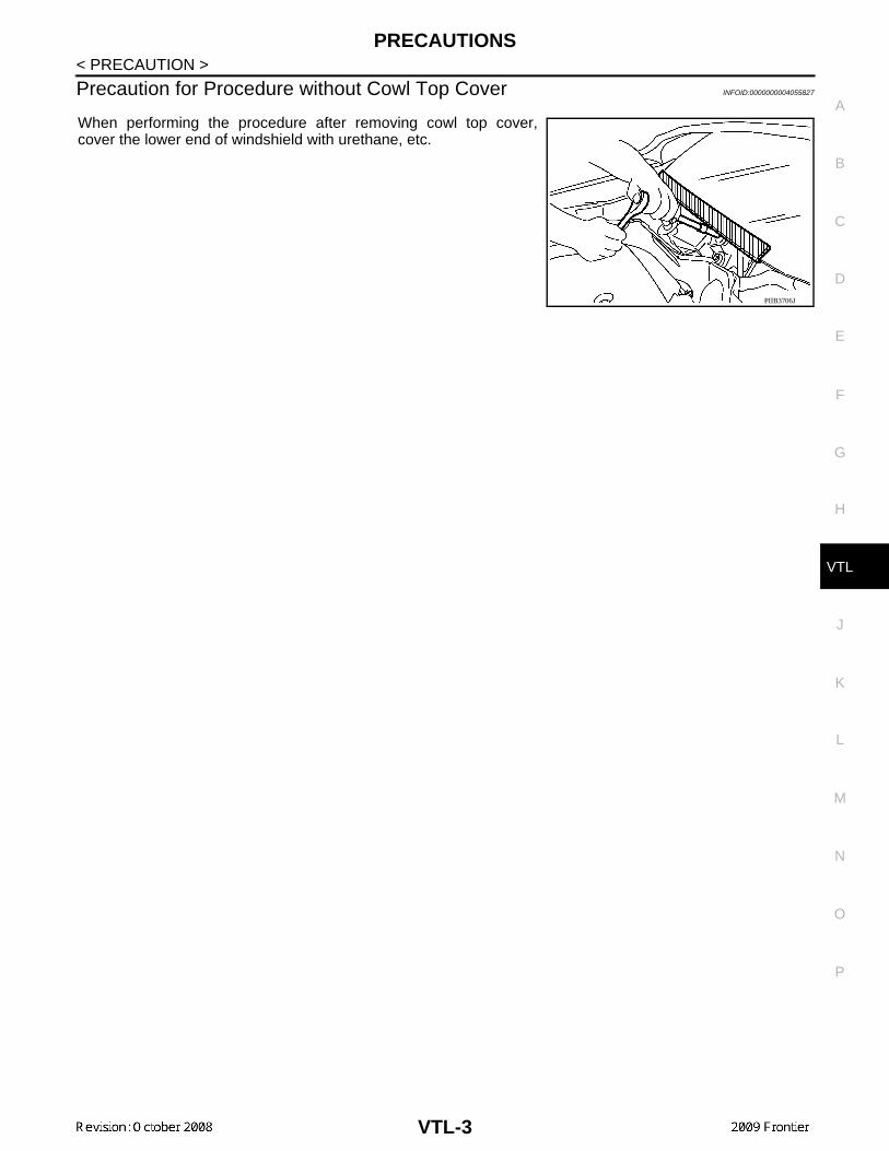
When performing the procedure after removing cowl top cover,cover the lower end of windshield with urethane, etc.
PIIB3706J
VTL-3
PREPARATION
< PREPARATION >PREPARATIONPREPARATION
Commercial Service Tool INFOID:0000000004055828
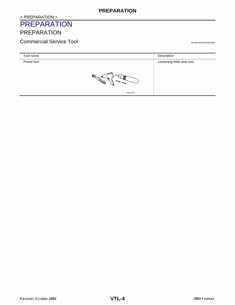
Tool name Description
Power tool Loosening bolts and nuts
PIIB1407E
VTL-4
IN-CABIN MICROFILTER
C
D
E
F
G
H
J
K
L
M
A
B
TL
N
O
P
< FUNCTION DIAGNOSIS >
V
FUNCTION DIAGNOSISIN-CABIN MICROFILTER
Description INFOID:0000000004055829
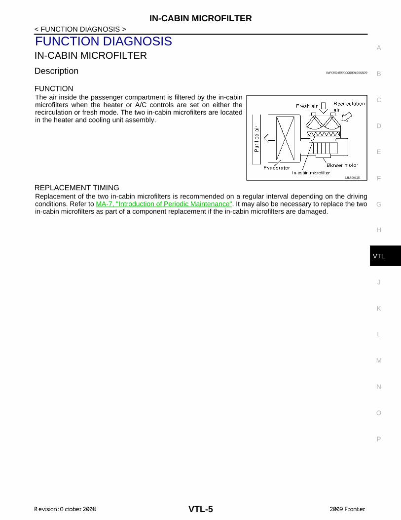
FUNCTIONThe air inside the passenger compartment is filtered by the in-cabinmicrofilters when the heater or A/C controls are set on either therecirculation or fresh mode. The two in-cabin microfilters are locatedin the heater and cooling unit assembly.
REPLACEMENT TIMINGReplacement of the two in-cabin microfilters is recommended on a regular interval depending on the drivingconditions. Refer to MA-7, "Introduction of Periodic Maintenance". It may also be necessary to replace the twoin-cabin microfilters as part of a component replacement if the in-cabin microfilters are damaged.
LJIA0012E
VTL-5
IN-CABIN MICROFILTER
< ON-VEHICLE MAINTENANCE >ON-VEHICLE MAINTENANCEIN-CABIN MICROFILTER
Removal and Installation INFOID:0000000004055830
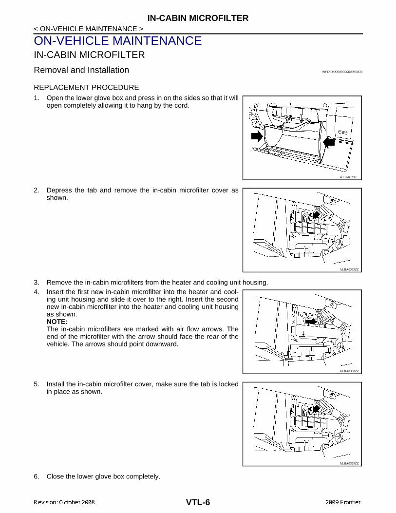
REPLACEMENT PROCEDURE1. Open the lower glove box and press in on the sides so that it will
open completely allowing it to hang by the cord.
2. Depress the tab and remove the in-cabin microfilter cover asshown.
3. Remove the in-cabin microfilters from the heater and cooling unit housing.4. Insert the first new in-cabin microfilter into the heater and cool-
ing unit housing and slide it over to the right. Insert the secondnew in-cabin microfilter into the heater and cooling unit housingas shown.NOTE:The in-cabin microfilters are marked with air flow arrows. Theend of the microfilter with the arrow should face the rear of thevehicle. The arrows should point downward.
5. Install the in-cabin microfilter cover, make sure the tab is lockedin place as shown.
6. Close the lower glove box completely.
WLIA0023E
ALIIA0359ZZ
ALIIA0360ZZ
ALIIA0359ZZ
VTL-6
CONTROL UNIT
C
D
E
F
G
H
J
K
L
M
A
B
TL
N
O
P
< ON-VEHICLE REPAIR >
V
ON-VEHICLE REPAIRCONTROL UNIT
Removal and Installation INFOID:0000000004055831
FRONT AIR CONTROL
Removal
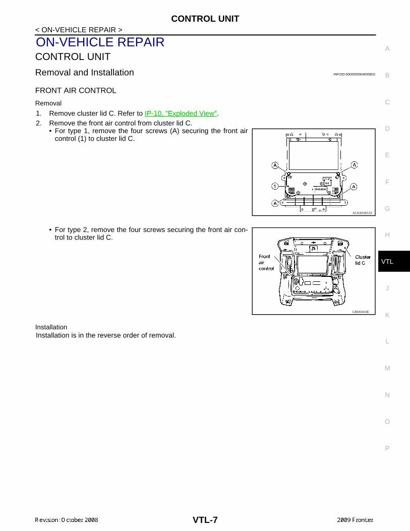
1. Remove cluster lid C. Refer to IP-10, "Exploded View".2. Remove the front air control from cluster lid C.
• For type 1, remove the four screws (A) securing the front aircontrol (1) to cluster lid C.
• For type 2, remove the four screws securing the front air con-trol to cluster lid C.
InstallationInstallation is in the reverse order of removal.
ALIIA0361ZZ
LBIA0416E
VTL-7
INTAKE SENSOR
< ON-VEHICLE REPAIR >INTAKE SENSOR
Removal and Installation INFOID:0000000004055832
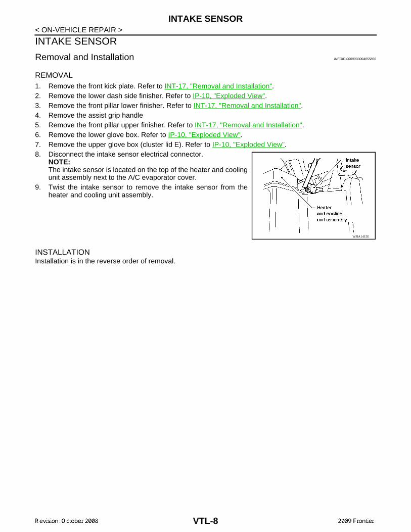
REMOVAL1. Remove the front kick plate. Refer to INT-17, "Removal and Installation".2. Remove the lower dash side finisher. Refer to IP-10, "Exploded View".3. Remove the front pillar lower finisher. Refer to INT-17, "Removal and Installation".4. Remove the assist grip handle5. Remove the front pillar upper finisher. Refer to INT-17, "Removal and Installation".6. Remove the lower glove box. Refer to IP-10, "Exploded View".7. Remove the upper glove box (cluster lid E). Refer to IP-10, "Exploded View".8. Disconnect the intake sensor electrical connector.
NOTE:The intake sensor is located on the top of the heater and coolingunit assembly next to the A/C evaporator cover.
9. Twist the intake sensor to remove the intake sensor from theheater and cooling unit assembly.
INSTALLATIONInstallation is in the reverse order of removal.
WJIA1415E
VTL-8
BLOWER MOTOR
C
D
E
F
G
H
J
K
L
M
A
B
TL
N
O
P
< ON-VEHICLE REPAIR >
V
BLOWER MOTOR
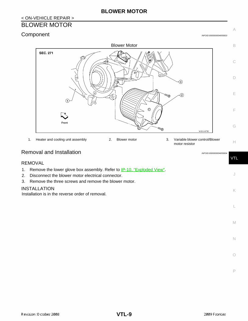
Component INFOID:0000000004055833
Blower Motor
Removal and Installation INFOID:0000000004055834
REMOVAL1. Remove the lower glove box assembly. Refer to IP-10, "Exploded View".2. Disconnect the blower motor electrical connector.3. Remove the three screws and remove the blower motor.
INSTALLATIONInstallation is in the reverse order of removal.
WJIA1479E
1. Heater and cooling unit assembly 2. Blower motor 3. Variable blower control/Blower motor resistor
VTL-9
VARIABLE BLOWER CONTROL
< ON-VEHICLE REPAIR >VARIABLE BLOWER CONTROL
Removal and Installation INFOID:0000000004455913
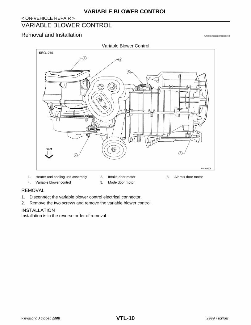
Variable Blower Control
REMOVAL1. Disconnect the variable blower control electrical connector.2. Remove the two screws and remove the variable blower control.
INSTALLATIONInstallation is in the reverse order of removal.
WJIA1480E
1. Heater and cooling unit assembly 2. Intake door motor 3. Air mix door motor
4. Variable blower control 5. Mode door motor
VTL-10
FRONT BLOWER MOTOR RESISTOR
C
D
E
F
G
H
J
K
L
M
A
B
TL
N
O
P
< ON-VEHICLE REPAIR >
V
FRONT BLOWER MOTOR RESISTOR
Removal and Installation INFOID:0000000004055835
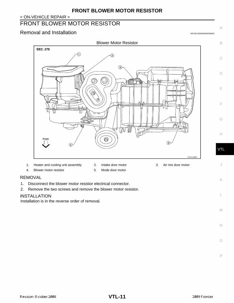
Blower Motor Resistor
REMOVAL1. Disconnect the blower motor resistor electrical connector.2. Remove the two screws and remove the blower motor resistor.
INSTALLATIONInstallation is in the reverse order of removal.
WJIA1480E
1. Heater and cooling unit assembly 2. Intake door motor 3. Air mix door motor
4. Blower motor resistor 5. Mode door motor
VTL-11
HEATER & COOLING UNIT ASSEMBLY
< ON-VEHICLE REPAIR >HEATER & COOLING UNIT ASSEMBLY
Component INFOID:0000000004055836
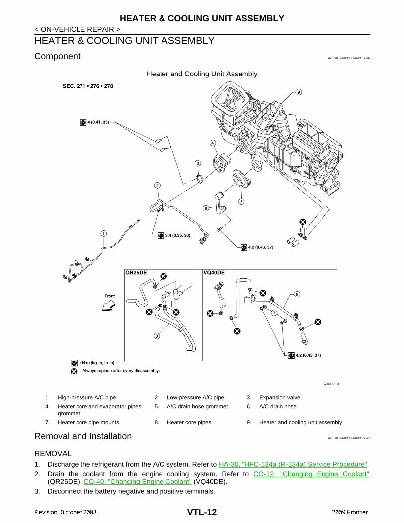
Heater and Cooling Unit Assembly
Removal and Installation INFOID:0000000004055837
REMOVAL1. Discharge the refrigerant from the A/C system. Refer to HA-30, "HFC-134a (R-134a) Service Procedure".2. Drain the coolant from the engine cooling system. Refer to CO-12, "Changing Engine Coolant"
(QR25DE), CO-40, "Changing Engine Coolant" (VQ40DE).3. Disconnect the battery negative and positive terminals.
WJIA1291E
1. High-pressure A/C pipe 2. Low-pressure A/C pipe 3. Expansion valve
4. Heater core and evaporator pipes grommet
5. A/C drain hose grommet 6. A/C drain hose
7. Heater core pipe mounts 8. Heater core pipes 9. Heater and cooling unit assembly
VTL-12
HEATER & COOLING UNIT ASSEMBLY
C
D
E
F
G
H
J
K
L
M
A
B
TL
N
O
P
< ON-VEHICLE REPAIR >
V
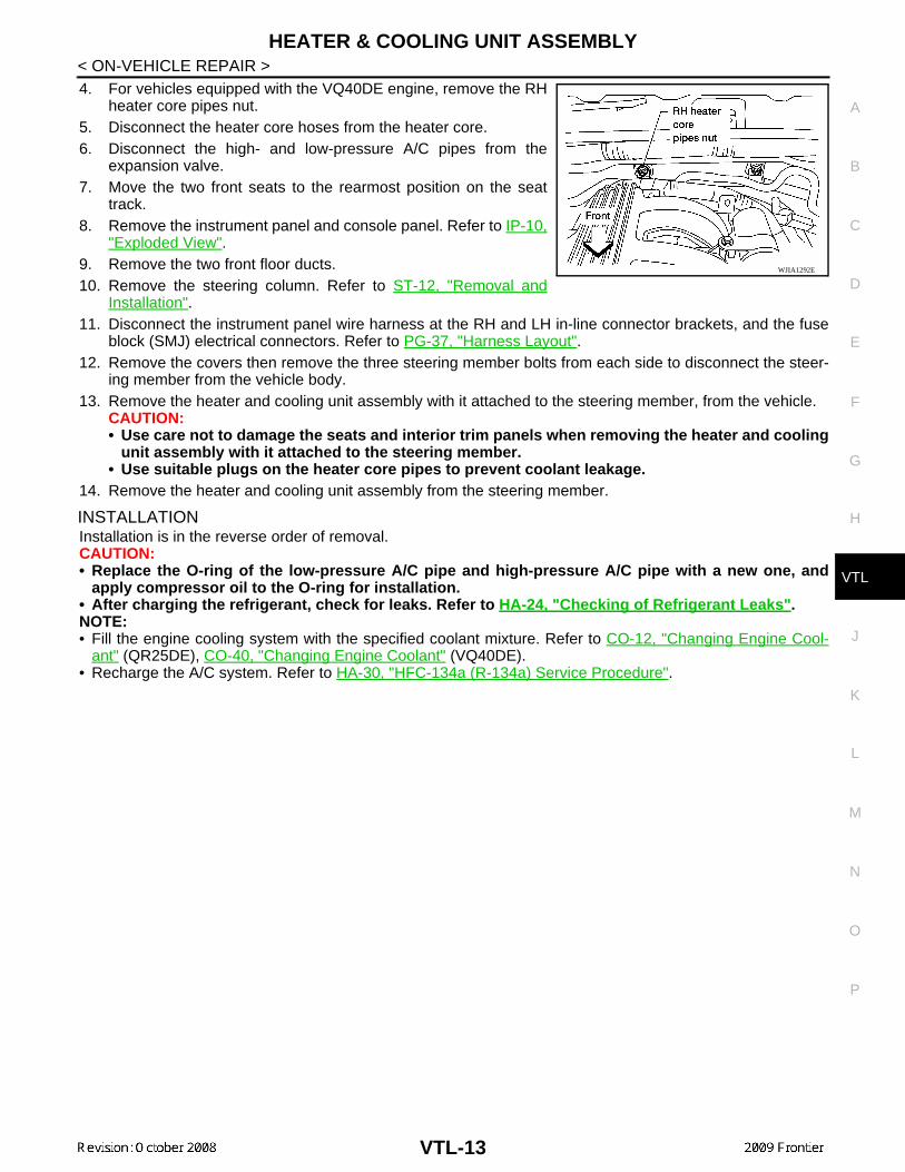
4. For vehicles equipped with the VQ40DE engine, remove the RHheater core pipes nut.
5. Disconnect the heater core hoses from the heater core.6. Disconnect the high- and low-pressure A/C pipes from the
expansion valve.7. Move the two front seats to the rearmost position on the seat
track.8. Remove the instrument panel and console panel. Refer to IP-10,
"Exploded View".9. Remove the two front floor ducts.10. Remove the steering column. Refer to ST-12, "Removal and
Installation".11. Disconnect the instrument panel wire harness at the RH and LH in-line connector brackets, and the fuse
block (SMJ) electrical connectors. Refer to PG-37, "Harness Layout".12. Remove the covers then remove the three steering member bolts from each side to disconnect the steer-
ing member from the vehicle body.13. Remove the heater and cooling unit assembly with it attached to the steering member, from the vehicle.
CAUTION:• Use care not to damage the seats and interior trim panels when removing the heater and cooling
unit assembly with it attached to the steering member.• Use suitable plugs on the heater core pipes to prevent coolant leakage.
14. Remove the heater and cooling unit assembly from the steering member.
INSTALLATIONInstallation is in the reverse order of removal.CAUTION:• Replace the O-ring of the low-pressure A/C pipe and high-pressure A/C pipe with a new one, and
apply compressor oil to the O-ring for installation.• After charging the refrigerant, check for leaks. Refer to HA-24, "Checking of Refrigerant Leaks".NOTE:• Fill the engine cooling system with the specified coolant mixture. Refer to CO-12, "Changing Engine Cool-
ant" (QR25DE), CO-40, "Changing Engine Coolant" (VQ40DE).• Recharge the A/C system. Refer to HA-30, "HFC-134a (R-134a) Service Procedure".
WJIA1292E
VTL-13
EVAPORATOR
< ON-VEHICLE REPAIR >EVAPORATOR
Removal and Installation INFOID:0000000004055838
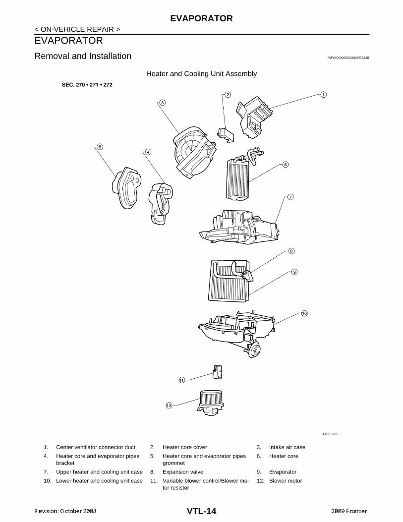
Heater and Cooling Unit Assembly
LJIA0178E
1. Center ventilator connector duct 2. Heater core cover 3. Intake air case
4. Heater core and evaporator pipes bracket
5. Heater core and evaporator pipes grommet
6. Heater core
7. Upper heater and cooling unit case 8. Expansion valve 9. Evaporator
10. Lower heater and cooling unit case 11. Variable blower control/Blower mo-tor resistor
12. Blower motor
VTL-14
EVAPORATOR
C
D
E
F
G
H
J
K
L
M
A
B
TL
N
O
P
< ON-VEHICLE REPAIR >
V
REMOVAL1. Remove the heater core. Refer to VTL-16, "Component".2. Separate the heater and cooling unit case.3. Remove the evaporator.
INSTALLATIONInstallation is in the reverse order of removal.CAUTION:Replace the O-rings on the A/C low-pressure flexible A/C hose and the high-pressure A/C pipe withnew ones. Apply compressor oil to the O-rings for installation.
VTL-15
HEATER CORE
< ON-VEHICLE REPAIR >HEATER CORE
Component INFOID:0000000004055839
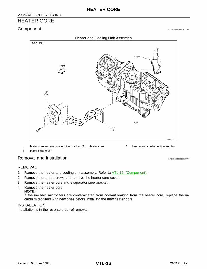
Heater and Cooling Unit Assembly
Removal and Installation INFOID:0000000004055840
REMOVAL1. Remove the heater and cooling unit assembly. Refer to VTL-12, "Component".2. Remove the three screws and remove the heater core cover.3. Remove the heater core and evaporator pipe bracket.4. Remove the heater core.
NOTE:If the in-cabin microfilters are contaminated from coolant leaking from the heater core, replace the in-cabin microfilters with new ones before installing the new heater core.
INSTALLATIONInstallation is in the reverse order of removal.
LJIA0167E
1. Heater core and evaporator pipe bracket 2. Heater core 3. Heater and cooling unit assembly
4. Heater core cover
VTL-16
INTAKE DOOR MOTOR
C
D
E
F
G
H
J
K
L
M
A
B
TL
N
O
P
< ON-VEHICLE REPAIR >
V
INTAKE DOOR MOTOR
Removal and Installation INFOID:0000000004055841
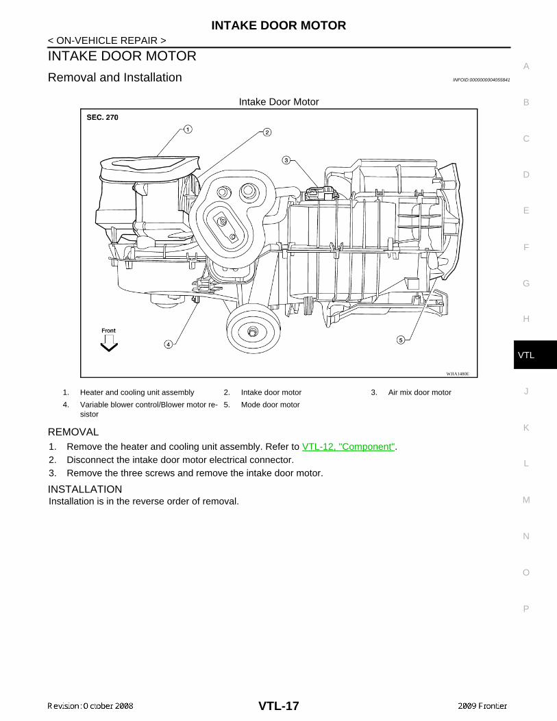
Intake Door Motor
REMOVAL1. Remove the heater and cooling unit assembly. Refer to VTL-12, "Component".2. Disconnect the intake door motor electrical connector.3. Remove the three screws and remove the intake door motor.
INSTALLATIONInstallation is in the reverse order of removal.
WJIA1480E
1. Heater and cooling unit assembly 2. Intake door motor 3. Air mix door motor
4. Variable blower control/Blower motor re-sistor
5. Mode door motor
VTL-17
MODE DOOR MOTOR
< ON-VEHICLE REPAIR >MODE DOOR MOTOR
Removal and Installation INFOID:0000000004055842
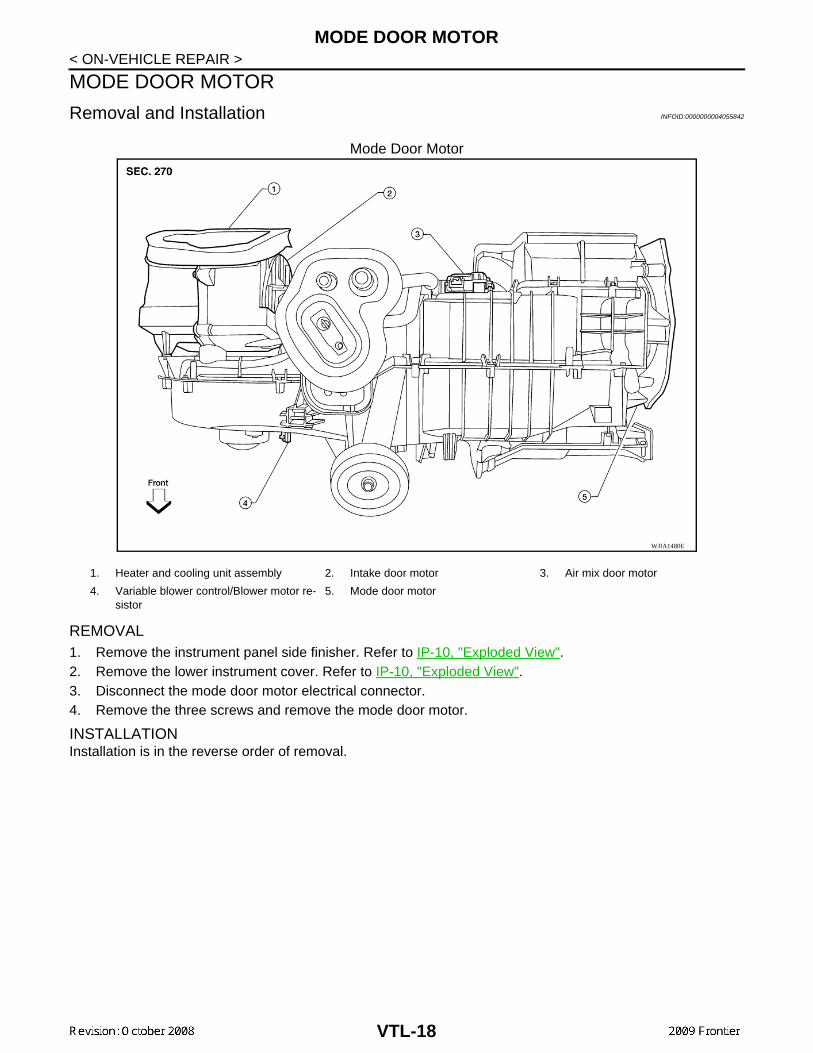
Mode Door Motor
REMOVAL1. Remove the instrument panel side finisher. Refer to IP-10, "Exploded View".2. Remove the lower instrument cover. Refer to IP-10, "Exploded View".3. Disconnect the mode door motor electrical connector.4. Remove the three screws and remove the mode door motor.
INSTALLATIONInstallation is in the reverse order of removal.
WJIA1480E
1. Heater and cooling unit assembly 2. Intake door motor 3. Air mix door motor
4. Variable blower control/Blower motor re-sistor
5. Mode door motor
VTL-18
AIR MIX DOOR MOTOR
C
D
E
F
G
H
J
K
L
M
A
B
TL
N
O
P
< ON-VEHICLE REPAIR >
V
AIR MIX DOOR MOTOR
Component INFOID:0000000004055843
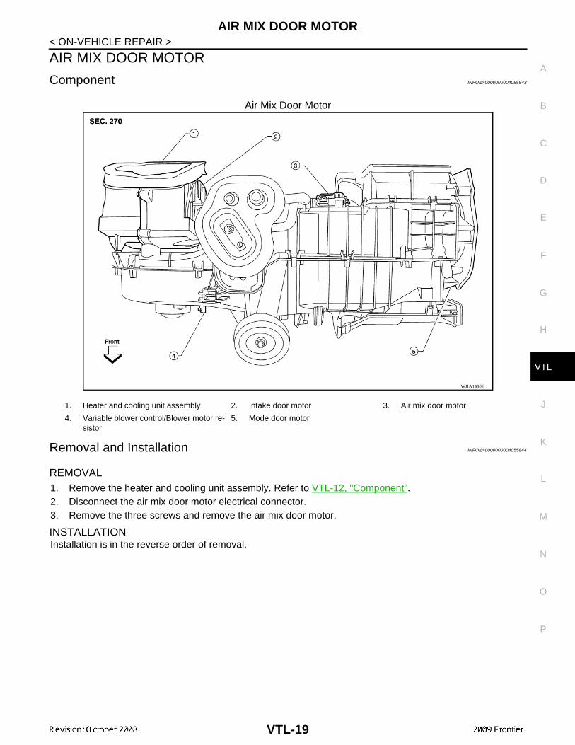
Air Mix Door Motor
Removal and Installation INFOID:0000000004055844
REMOVAL1. Remove the heater and cooling unit assembly. Refer to VTL-12, "Component".2. Disconnect the air mix door motor electrical connector.3. Remove the three screws and remove the air mix door motor.
INSTALLATIONInstallation is in the reverse order of removal.
WJIA1480E
1. Heater and cooling unit assembly 2. Intake door motor 3. Air mix door motor
4. Variable blower control/Blower motor re-sistor
5. Mode door motor
VTL-19
DUCTS AND GRILLES
< ON-VEHICLE REPAIR >DUCTS AND GRILLES
Component INFOID:0000000004055845
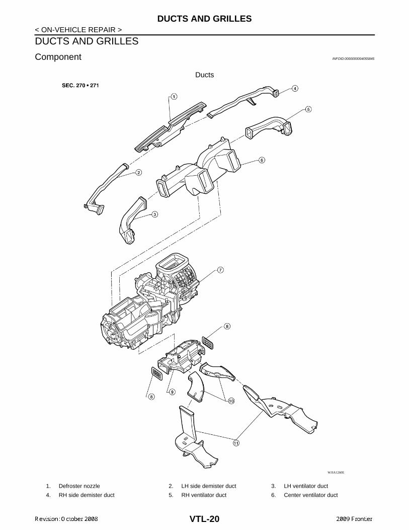
Ducts
WJIA1260E
1. Defroster nozzle 2. LH side demister duct 3. LH ventilator duct
4. RH side demister duct 5. RH ventilator duct 6. Center ventilator duct
VTL-20
DUCTS AND GRILLES
C
D
E
F
G
H
J
K
L
M
A
B
TL
N
O
P
< ON-VEHICLE REPAIR >
V
Grilles
Removal and Installation INFOID:0000000004055846
DEFROSTER NOZZLE
Removal
1. Remove the heater and cooling unit assembly. Refer to VTL-12, "Component".2. Remove the defroster nozzle.
InstallationInstallation is in the reverse order of removal.
RH AND LH SIDE DEMISTER DUCTS
Removal
1. Remove the heater and cooling unit assembly. Refer to VTL-12, "Component".2. Remove the RH or LH side demister duct.
Installation
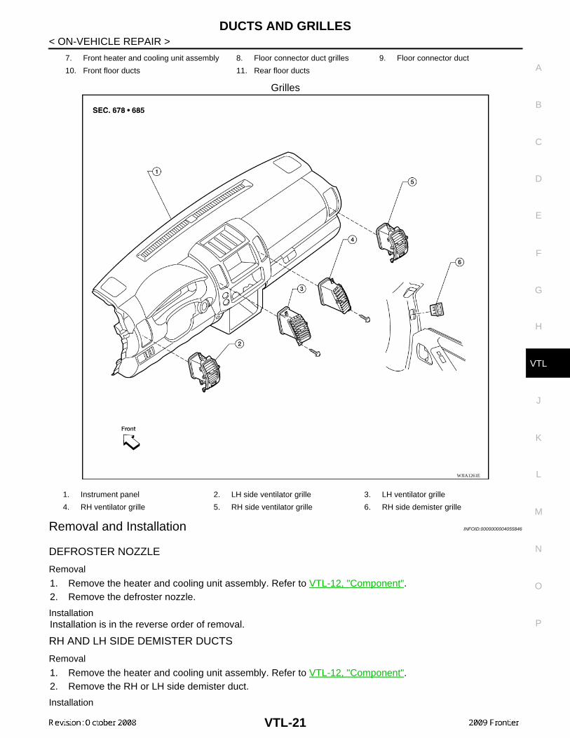
7. Front heater and cooling unit assembly 8. Floor connector duct grilles 9. Floor connector duct
10. Front floor ducts 11. Rear floor ducts
WJIA1261E
1. Instrument panel 2. LH side ventilator grille 3. LH ventilator grille
4. RH ventilator grille 5. RH side ventilator grille 6. RH side demister grille
VTL-21
DUCTS AND GRILLES
< ON-VEHICLE REPAIR >Installation is in the reverse order of removal.RH AND LH VENTILATOR DUCTS
Removal
1. Remove the heater and cooling unit assembly. Refer to VTL-12, "Component".2. Remove the RH or LH ventilator duct.
InstallationInstallation is in the reverse order of removal.
CENTER VENTILATOR DUCT
Removal
1. Remove the heater and cooling unit assembly. Refer to VTL-12, "Component".2. Remove the defroster nozzle.3. Remove the RH and LH ventilator ducts.4. Remove the RH and LH side demister ducts.5. Remove the center ventilator duct.
InstallationInstallation is in the reverse order of removal.
FLOOR CONNECTOR DUCT
Removal
1. Remove the heater and cooling unit assembly. Refer to VTL-12, "Component".2. Remove the floor connector duct.
InstallationInstallation is in the reverse order of removal.
FRONT AND REAR FLOOR DUCTS
Removal
1. Remove the floor carpet. Refer to INT-21, "Removal and Installation".2. Remove the clips and front and rear floor ducts.
InstallationInstallation is in the reverse order of removal.
GRILLES
Removal
1. Remove the interior trim panel as necessary that contains the grille to be removed. Refer to INT-16,"Component" and IP-10, "Exploded View".
2. Remove the grille from the interior trim panel.
InstallationInstallation is in the reverse order of removal.
VTL-22
Related Documents