Purdue University Purdue e-Pubs International Refrigeration and Air Conditioning Conference School of Mechanical Engineering 2016 ermoelectric Multi-Utility Water Heater cum Air-Conditioner Milind Vishwanath Rane IIT Bombay, India, [email protected] Dinesh B Uphade IIT Bombay, India, [email protected] Adiya M Rane Vishwakarma Institute of Technology, Pune, INDIA, [email protected] Follow this and additional works at: hp://docs.lib.purdue.edu/iracc is document has been made available through Purdue e-Pubs, a service of the Purdue University Libraries. Please contact [email protected] for additional information. Complete proceedings may be acquired in print and on CD-ROM directly from the Ray W. Herrick Laboratories at hps://engineering.purdue.edu/ Herrick/Events/orderlit.html Rane, Milind Vishwanath; Uphade, Dinesh B; and Rane, Adiya M, "ermoelectric Multi-Utility Water Heater cum Air- Conditioner" (2016). International Reigeration and Air Conditioning Conference. Paper 1816. hp://docs.lib.purdue.edu/iracc/1816

Welcome message from author
This document is posted to help you gain knowledge. Please leave a comment to let me know what you think about it! Share it to your friends and learn new things together.
Transcript

Purdue UniversityPurdue e-PubsInternational Refrigeration and Air ConditioningConference School of Mechanical Engineering
2016
Thermoelectric Multi-Utility Water Heater cumAir-ConditionerMilind Vishwanath RaneIIT Bombay, India, [email protected]
Dinesh B UphadeIIT Bombay, India, [email protected]
Adittya M RaneVishwakarma Institute of Technology, Pune, INDIA, [email protected]
Follow this and additional works at: http://docs.lib.purdue.edu/iracc
This document has been made available through Purdue e-Pubs, a service of the Purdue University Libraries. Please contact [email protected] foradditional information.Complete proceedings may be acquired in print and on CD-ROM directly from the Ray W. Herrick Laboratories at https://engineering.purdue.edu/Herrick/Events/orderlit.html
Rane, Milind Vishwanath; Uphade, Dinesh B; and Rane, Adittya M, "Thermoelectric Multi-Utility Water Heater cum Air-Conditioner" (2016). International Refrigeration and Air Conditioning Conference. Paper 1816.http://docs.lib.purdue.edu/iracc/1816

2623, Page 1
16th International Refrigeration and Air Conditioning Conference at Purdue, July 11-14, 2016
Thermoelectric Multi-Utility Water Heater cum Air-Conditioner
Milind V RANE1*, Dinesh B UPHADE1, Adittya M RANE2
1Heat Pump Laboratory, Mechanical Engineering Department,
IIT Bombay, Powai, Mumbai INDIA 400 076
Phone +91 22 2576 7514, Fax +91 22 2572 6875, [email protected]
2Mechanical Engineering Department, Vishwakarma Institute of Technology,
Pune, INDIA 411 037
* Corresponding Author
ABSTRACT
A novel Thermoelectric Multi-Utility Water Heater cum Air-Conditioner, TE_MUWH, with water heating as
primary utility and air-conditioning as bonus utility is presented. It is intended to serve the residential market. In
India, 2 to 3 kW electric instant water heaters are typically deployed in residences. They typically consume ~3
kWh/day of electrical power. Their use contributes significantly to the peaking demand from residential buildings.
Patented TE_MUWH is being developed as a modular scalable unit. It is expected to reduce energy consumption
for residential water heating applications by over 50% and reduce demand by over 95% when coupled with suitable
storage. As it has no moving parts and is expected to operate reliably for 20+ years.
An enhanced surface aluminum extrusion serves as a radiant-cum-convective heat collection surface.
Thermoelectric, TE, heating chips are in thermal contact with the extrusion on one side and a rectangular tube on the
other. Tap water flows through the tube and heats up from 25oC to 50oC. The radiant-cum-convectively cooled
surface of the TE_MUWH dispenses the cooling effect in the conditioned space of the house. It can cool the room
air from 27oC to ~21oC. Judicious deployment of the chips ensures that the lift across the TE heat pump ranges from
10 to 41oC while heating water up to 50oC.
Simulation of air/water flow over/in the TE_MUWH module are presented. Simulation results are compared with
preliminary experimental data. This simple, modular, maintenance free TE_MUWH is expected to pave the way for
future wide spread adoption of this type of energy efficient green technologies in residences.
1. INTRODUCTION
Thermoelectric coolers can be used to transfer heat from cold side to hot side without using moving parts and
refrigerant. Flow of free electrons enables pumping heat from low temperature to high temperature. Novel
Thermoelectric Multi-Utility Water Heater heats tap water from 25oC to 50oC while simultaneously cooling
conditioned space air from 27oC to 21oC. Residential water heaters are commonly used for meeting the hot water
needs for bathing, dish washing, cloth washing, etc. Storage type electric water heaters are having 2 kWe capacity.
While instantaneous or tank less water heaters are typically 3 kWe capacity. They are operated one hour in a day for
3 to 4 person family. Bathing water temperature ranges between 38 to 40oC. Bathing hot water requirement per
person is 20 to 25 liter (Shaban and Sharma, 2007). Total water requirement is about 100 liter per day. Air-
conditioning of room is a co-produced utility. It is utilized for conditioning of living room/bed room. Residential
water heaters are operated using electric resistance heaters, LPG, solar or electricity based heat pumps.
2623, Page 2
16th International Refrigeration and Air Conditioning Conference at Purdue, July 11-14, 2016
1.1 Electric resistance water heaters Electric resistance heating are commonly used for water heating from several decades. Storage type water heaters
were used in earlier days. Current market is growing up for instantaneous water heaters (Paul, 2014). One unit of
electricity heats 35 L water from 25oC to 50oC. Operating cost is high as compare to any other system.
1.2 LPG water heaters Instantaneous gas geysers are also popular. There are issues like space for gas storage, higher cost of non-
subsidized gas. It saves about 3 to 5% compared to electric resistance water heating.
1.3 Solar water heaters These are storage type solar energy operated water heaters. Solar water heaters heats up the water using evacuated
glass tubes and stores it in insulated storage tanks. Storage tank is situated above solar thermal collectors. Water is
naturally circulated due to density difference. Hot water temperature depend on incident solar radiation. It varies
from day and month of the year. Initial cost of solar assisted water heater is about INR 15,000/- for 100 L
(www.mnre.gov.in). Due care is required to handle solar collector with evacuated glass tubes. Space requirement is
high. It is major constraint in urban areas. Payback is typically 3 to 4 years, if electrical resistance water heating is
replaced.
1.4 Heat pump assisted water heaters Small capacity heat pump assisted water heaters can provide water along with air-conditioning as bonus utility. Hot
water requirement is about one hour in a day. Hence, refrigerant based heat pumps are not currently serving water
heating for residential purpose. Thermoelectric coolers are small capacity heat pumps. Their cooling coefficient of
performance is about 7 for low lift of 5 K (Winkler et al., 2006). Judicious design of heat exchangers for cold and
hot side gives low temperature lift. This paper investigates the use of thermoelectric coolers for water heating as
primary use and air-conditioning as bonus utility. Simulation of heat pump model is performed in SolidWorks to
predict the temperature lift.
2. THERMOELECTRIC HEATERS
Thermoelectric cooling chips are typically used for meeting cooling needs of small appliances. These cooling chips
can also be used for heating. Performance of TE heaters is mainly affected by temperature across hot and cold side.
It reduces as the temperature rise increases.
Typical heat flux on cold and hot side ranges from 20 to 25 kW/m2. It is very high. It increases temperature
difference across the heat source and heat sink, the contact resistances on the hot and cold sides and reduces the
performance of chip. Hence, heat source and heat sinks need to be developed with increase heat transfer area, and
which offer good heat transfer coefficients.
2.1 Construction Simple thermoelectric refrigerator is represented with a single element. It consists of p and n type semiconductors.
They are commonly made up Bismuth Telluride or Bismuth Selenide (Goldsmid, 1964). Both are electrically
connected in series with thin copper plates. These plates are attached to the electrically insulated and thermally
conductive ceramic substrates. Lead wires are connected to copper plate to provide direct current supply. Elements
are thermally connected in parallel and electrically in series. This is the optimum configuration based on voltage
and current demand of all elements.
2623, Page 3
16th International Refrigeration and Air Conditioning Conference at Purdue, July 11-14, 2016
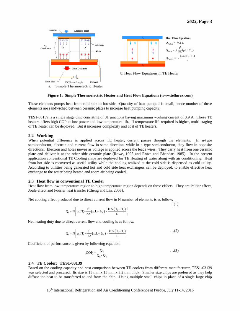
a. Simple Thermoelectric Heater
b. Heat Flow Equations in TE Heater
Figure 1: Simple Thermoelectric Heater and Heat Flow Equations (www.tellurex.com)
These elements pumps heat from cold side to hot side. Quantity of heat pumped is small, hence number of these
elements are sandwiched between ceramic plates to increase heat pumping capacity.
TES1-03139 is a single stage chip consisting of 31 junctions having maximum working current of 3.9 A. These TE
heaters offers high COP at low power and low temperature lift. If temperature lift required is higher, multi-staging
of TE heater can be deployed. But it increases complexity and cost of TE heaters.
2.2 Working When potential difference is applied across TE heater, current passes through the elements. In n-type
semiconductor, electron and current flow in same direction, while in p-type semiconductor, they flow in opposite
directions. Electron and holes moves as voltage is applied across the leads wires. They carry heat from one ceramic
plate and deliver it at the other side ceramic plate (Rowe, 1995 and Rowe and Bhandari 1985). In the present
application conventional TE Cooling chips are deployed for TE Heating of water along with air conditioning. Heat
from hot side is recovered as useful utility while the cooling realized at the cold side is dispensed as cold utility.
According to utilities being generated hot and cold side heat exchangers can be deployed, to enable effective heat
exchange to the water being heated and room air being cooled.
2.3 Heat flow in conventional TE Cooler Heat flow from low temperature region to high temperature region depends on three effects. They are Peltier effect,
Joule effect and Fourier heat transfer (Cheng and Lin, 2005).
Net cooling effect produced due to direct current flow in N number of elements is as follow,
2
h c
c c c
k.A. T - TIQ = N µ.I.T - ρ.L+ 2r -
2A L
…(1)
Net heating duty due to direct current flow and cooling is as follow,
2
h c
h h c
k.A. T - TIQ = N µ.I.T + ρ.L+ 2r -
2A L
…(2)
Coefficient of performance is given by following equation,
c c
h c
QCOP =
Q - Q
…(3)
2.4 TE Cooler: TES1-03139 Based on the cooling capacity and cost comparison between TE coolers from different manufacturer, TES1-03139
was selected and procured. Its size is 15 mm x 15 mm x 3.2 mm thick. Smaller size chips are preferred as they help
diffuse the heat to be transferred to and from the chip. Using multiple small chips in place of a single large chip
2623, Page 4
16th International Refrigeration and Air Conditioning Conference at Purdue, July 11-14, 2016
helps distribute the heat load on the cold and hot heat exchange elements which are deployed to exchange heat with
the cold and hot utility streams.
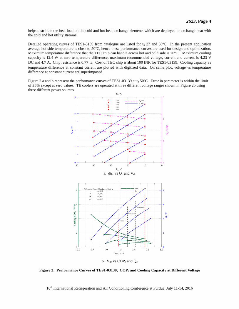
Detailed operating curves of TES1-3139 from catalogue are listed for th 27 and 50oC. In the present application
average hot side temperature is close to 50oC, hence these performance curves are used for design and optimization.
Maximum temperature difference that the TEC chip can handle across hot and cold side is 76oC. Maximum cooling
capacity is 12.4 W at zero temperature difference, maximum recommended voltage, current and current is 4.23 V
DC and 4.7 A. Chip resistance is 0.77 W. Cost of TEC chip is about 100 INR for TES1-03139. Cooling capacity vs
temperature difference at constant current are plotted with digitized data. On same plot, voltage vs temperature
difference at constant current are superimposed.
Figure 2 a and b represent the performance curves of TES1-03139 at th 50oC. Error in parameter is within the limit
of ±5% except at zero values. TE coolers are operated at three different voltage ranges shown in Figure 2b using
three different power sources.
a. dthc vs Qc and Vdc
b. Vdc vs COPc and Qc
Figure 2: Performance Curves of TES1-03139, COPc and Cooling Capacity at Different Voltage
Section I
Section II
Section III
2623, Page 5
16th International Refrigeration and Air Conditioning Conference at Purdue, July 11-14, 2016
Above plot indicates that at low voltage and low temperature difference across hot and cold side leads to high
coefficient of performance. Low temperature difference across hot and cold side can be ensured by reducing the
thermal resistances along the heat flow path. Overall thermal resistance can be reduced by minimizing individual
resistances. Thermal resistances at the source and sink heat exchangers can be reduced by using heat exchange
elements with high thermal conductivity and liberally sizing the heat exchange surfaces. Contact resistances at the
interfaces can be reduced by minimizing bonding/interface material thickness and using high thermal conductivity
bonding material. Optimally sizing the fin structure to minimize weight while ensuring high fin efficiency for
conduction of heat form the heat source/sink to the base of the TE chips is important to ensure cost effectiveness.
Optimal placement for TE chips on the heat exchange surfaces also places an important role in overall optimization.
3. WATER HEATING USING TE HEAT PUMP
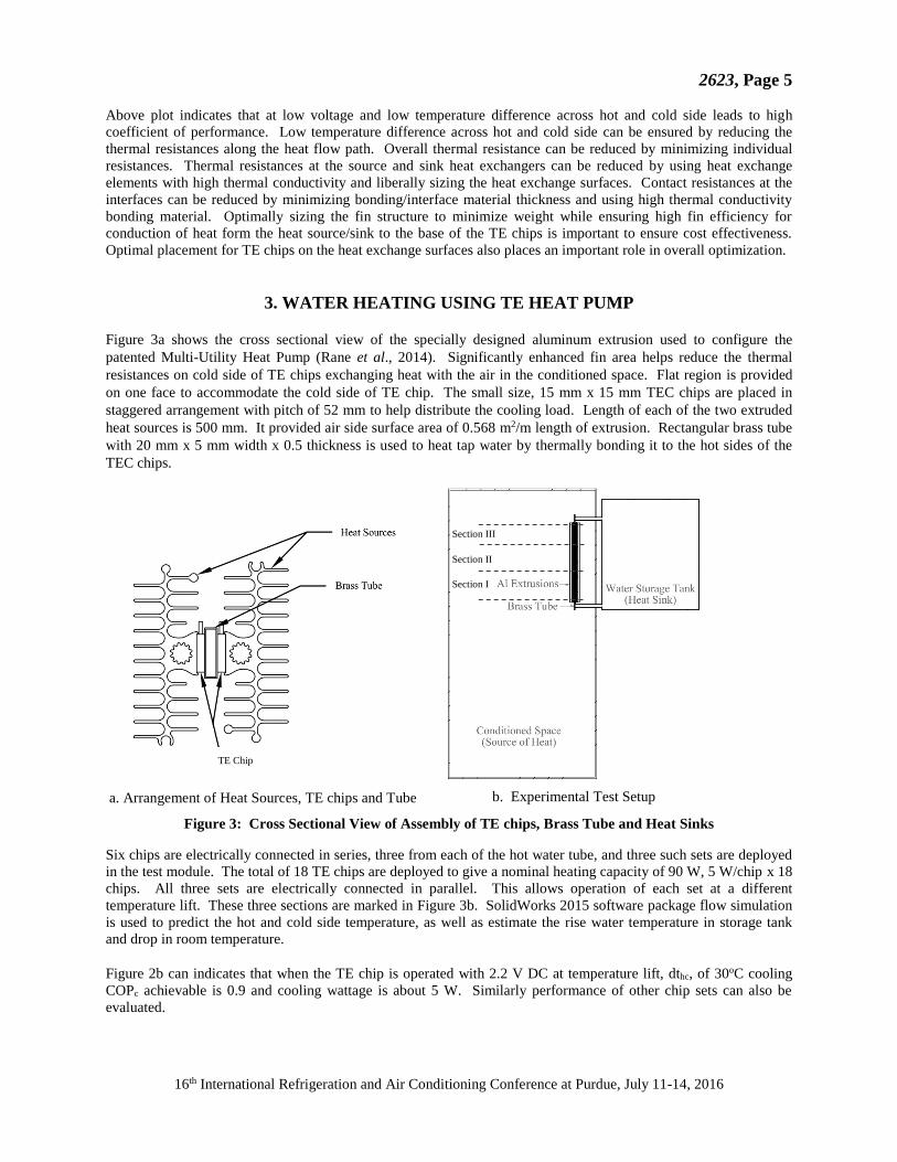
Figure 3a shows the cross sectional view of the specially designed aluminum extrusion used to configure the
patented Multi-Utility Heat Pump (Rane et al., 2014). Significantly enhanced fin area helps reduce the thermal
resistances on cold side of TE chips exchanging heat with the air in the conditioned space. Flat region is provided
on one face to accommodate the cold side of TE chip. The small size, 15 mm x 15 mm TEC chips are placed in
staggered arrangement with pitch of 52 mm to help distribute the cooling load. Length of each of the two extruded
heat sources is 500 mm. It provided air side surface area of 0.568 m2/m length of extrusion. Rectangular brass tube
with 20 mm x 5 mm width x 0.5 thickness is used to heat tap water by thermally bonding it to the hot sides of the
TEC chips.
a. Arrangement of Heat Sources, TE chips and Tube b. Experimental Test Setup
Figure 3: Cross Sectional View of Assembly of TE chips, Brass Tube and Heat Sinks
Six chips are electrically connected in series, three from each of the hot water tube, and three such sets are deployed
in the test module. The total of 18 TE chips are deployed to give a nominal heating capacity of 90 W, 5 W/chip x 18
chips. All three sets are electrically connected in parallel. This allows operation of each set at a different
temperature lift. These three sections are marked in Figure 3b. SolidWorks 2015 software package flow simulation
is used to predict the hot and cold side temperature, as well as estimate the rise water temperature in storage tank
and drop in room temperature.
Figure 2b can indicates that when the TE chip is operated with 2.2 V DC at temperature lift, dthc, of 30oC cooling
COPc achievable is 0.9 and cooling wattage is about 5 W. Similarly performance of other chip sets can also be
evaluated.
Section III
Section II
Section I
TE Chip
2623, Page 6
16th International Refrigeration and Air Conditioning Conference at Purdue, July 11-14, 2016
3.1 Working Principle Aluminum heat source is used to receive heat from the room, which is to be conditioned. Heat from the room is
utilized to heat the water. Thermoelectric chips are place on the flat surface of brass tube in staggered order. Then,
aluminum heat sources are placed on chips using thermal bonding material. Flow of water is maintained using
natural circulation in vertical brass tube. Cold air drops down as it gets cooled. It operates both flows of fluids in
counter flow manner. Heat from room is added together with electrical energy and pumped into water.
Figure 4: Heat Flow in TE Heat Pump
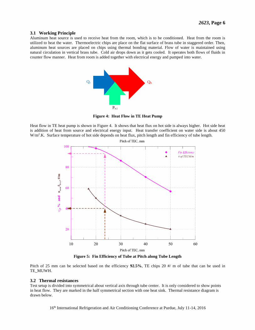
Heat flow in TE heat pump is shown in Figure 4. It shows that heat flux on hot side is always higher. Hot side heat
is addition of heat from source and electrical energy input. Heat transfer coefficient on water side is about 450
W/m2.K. Surface temperature of hot side depends on heat flux, pitch length and fin efficiency of tube length.
Figure 5: Fin Efficiency of Tube at Pitch along Tube Length
Pitch of 25 mm can be selected based on the efficiency 92.5%, TE chips 20 #/ m of tube that can be used in
TE_MUWH.
3.2 Thermal resistances Test setup is divided into symmetrical about vertical axis through tube center. It is only considered to show points
in heat flow. They are marked in the half symmetrical section with one heat sink. Thermal resistance diagram is
drawn below.
Qc
Pe.i
Qh
TEC

2623, Page 7
16th International Refrigeration and Air Conditioning Conference at Purdue, July 11-14, 2016
Thermal resistances in heat flow from cold water to the heat sinks are as follows.
1. Bulk temperature of water
2. Inside surface temperature of tube
3. Outside surface temperature of tube
4. Temperature at tube and TBM contact
5. Temperature at TBM and TE chip contact
6. Temperature at TBM and heat sink contact
7. Outside temperature at heat sink base surface
8. Room air
Figure 6: Thermal Resistances in Heat Flow
Figure 7: Thermal Resistances in Heat Flow from Room Air to Water
Thermal resistances are calculated as below.
Convection resistance due to water flow
It can be found out for known temperature of water and calculated as follows.
Rconv.hw = 1 /(hhw . Ahe.brs.t.i) = (t1 - t2)/Qh …(4)
Here, hhw for laminar flow is 5.35 for uniform heat flux (ASHRAE HBF 2013). Hence, temperature at the surface of
brass tube over which water is flowing can be calculated.
Rconv.hw = 1 /(Øs.brs.t . hhw . Ahe.brs.t.i) = (t1 - t2)/Qc
hhw = Nu . khw / dh.brs.t …(5)
Here, hhw for laminar flow is 5.35 for uniform heat flux (Bejan and Kraus, 2003).
Conduction resistance due to brass tube
It can be found out for known temperature of water and calculated as follows.
Rcond.brs.t = thkbrs.t /(kbrs . Ahe.brs.t.i) = (t2 - t3)/Qc …(6)
Here, kbrs , thermal conductivity of brass material is known. It is 120 W/m.K (ASHRAE HBF 2013). Hence,
temperature at the contact between brass tube and thermal bonding material is calculated.
Conduction resistance due to thermal bonding material
It can be found out for known temperature of water and calculated as follows.
Rcond.tbm = thktbm /(ktbm . Ahe.tec) = (t3 - t4)/Qc …(7)
Here, ktbm , thermal conductivity of bonding material and t4 are unknowns and required to calculate.
Convection resistance due to air
Ambient air temperature is measured. Convention resistance can be found out for known temperature of air,
Rconv.a = 1 /(ha . Ahe.al.hs) = (t7 - t8)/Qh …(8)
ha for air flow over heat sink is known for still/moving air. Temperature t7 is unknown and required to calculate.
Room Air

2623, Page 8
16th International Refrigeration and Air Conditioning Conference at Purdue, July 11-14, 2016
Conduction resistance due to aluminium heat sources,
It can be found out for known temperature of water and calculated as follows.
Rcond.brs.t = thkal.hs.b /(kal.hs . Ahe.al.hs) = (t6 - t7)/Qh …(9)
Here, kal , thermal conductivity of aluminium material is known. It is 210 W/m.K. Hence, temperature at the contact
between heat sink and thermal bonding material is calculated.
Conduction resistance due to thermal bonding material
It can be found out for known temperature of water and calculated as follows.
Rcond.tbm = thktbm /(ktbm . Ahe.tec) = (t5 - t6)/Qh …(10)
Here, ktbm , thermal conductivity of bonding material is measured using Tube-Tube Heat Exchanger in previous
year’s experiments and t5 is unknown and required to calculate.
Overall Heat Transfer Coefficient
Cold side heat transfer is calculated as follows,
Uc.ra = Qc.ra / (Ahe.al.hs.o . LMTDcs) …(11)
4. RESULTS AND DISCUSSIONS
Cold and hot side surface temperature of TE heat pump is obtained using the simulation in SolidWorks 2014, as
shown in Figure . It indicates that cold side temperature is almost 19.8oC. Hot side temperature rises from 42.2 to
60.7oC. Overall dthc increases from 22.6oC to 41.1oC. Chips in section I, II and III operates at average 26.8oC, 32.8
oC and 39.1 oC dthc respectively. Weighted average cooling capacity is 4.7 W and COPc is 1.0. It causes the natural
circulation of air. Water get heated from 27oC to 46oC in single pass with natural convection.
Figure 8: Variation in Cold and Hot Side Temperature of TE Heat Pump
Transient analysis of conditioned space is shown in Figure 8, from time 10 s, 100 s, 500 s, 1000 s and 1110 s. Flow
trajectories with fluid temperature vectors shows that at 10 s time, natural circulation of air is just started. About
50% of room space is under the flow of air at 0.09 m/s. Room temperature dropped from 27oC to 19.4oC in 1110 s.
Room temperature causes the changes in density of air and cold air displaces the hot air. Overall heat transfer
coefficient on air side is 9.7 W/m2.K. Velocity vectors indicates that air gets circulated throughout the room within
initial 10 s duration. Experimental cooling COP obtained was 0.92 with 12 V DC supply and 5.4 A current input.

2623, Page 9
16th International Refrigeration and Air Conditioning Conference at Purdue, July 11-14, 2016
a. Physical Time 10 s
b. Physical Time 100 s
c. Physical Time 500 s
d. Physical Time 1000 s
e. Physical Time 1110 s
f. Physical Time 1110 s
Figure 9: Temperature Distribution in Conditioned Space at Different Time

2623, Page 10
16th International Refrigeration and Air Conditioning Conference at Purdue, July 11-14, 2016
5. CONCLUSIONS
A novel Thermoelectric Multi-Utility Water Heater cum Air-Conditioner, TE_MUWH, provides hot water as
primary utility with air-conditioning as bonus utility. It replaces the storage type 2 kW electric water heater, which
is commonly used in residential buildings. Judicious design of heat source and heat sink as heat exchangers
maintains the hot and cold side temperature difference in the range of 11 to 42oC. It is validated by the simulation
results using SolidWorks flow simulation. The radiant-cum-convective cool surface of the TE_MUWH distributed
the cooling in the house and recover hot water. Thermoelectric Multi-Utility Water Heater cum Air-Conditioner
seems to be a viable option delivering heating COP of 2 while simultaneously offering cooling COP of 1.0. This
reduces energy consumption for residential water heating applications by over 50% and reduce demand by over 95%
when coupled with suitable storage. As it has no moving parts and is expected to operate reliably for 20+ years.
NOMENCLATURE
cp specific heat at constant pressure (kJ/kg.K)
d diameter (m)
dt temperature difference (K)
I current (A)
k thermal conductivity (W/m.K)
N number of thermocouples (#)
P power (kW)
Q heat duty (kW)
T / t temperature (K / oC)
thk thickness (m)
v velocity (m/s)
W power (kW)
Subscripts
a air
av average
c cold/cooling
e electrical
f fin
hw hot water
r room
th thermal
TE Thermoelectric
TBM Thermal Bonding Material
REFERENCES
American Society of Heating Refrigerating and Air conditioning Engineers Handbook – Fundamentals 2013, p 33.3.
Bejan, A and Kraus, D P, 2003, Heat transfer handbook, published by John Wiley & Sons, Inc., Hoboken, New Jersey, pp 994-
1091.
Cheng, Y H, Lin, W K, (2005), Geometric Optimization of Thermoelectric Coolers
in a Confined Volume using Genetic Algorithms, Journal of Applied Thermal Engineering, vol 25, pp 2983-2997.
Goldsmid, H J (1964), “Thermoelectric Refrigeration”, Springer Science and Business Media, New York, p 1-5.
Paul, R (2014), “Scoping Study for Residential Water Heaters Mapping and Benchmarking Project”, Technical Report by Weide
Strategic Efficiency, pp 39-42.
Rane M V, Dhumane, R S, Pinto, D I (2014) Panel Heat and Mass Exchanger, Indian Patent 1828/MUM/2014.
Rowe, D M and Bhandari, C M, 1983 Book on Modern Thermoelectrics, Published by Reston Publishing Company, Virginia.
Rowe, D M, (1995) Handbook of Thermoelectrics, Published by CRC Press LLC.
Shaban and Sharma (2014), Water Proverty in India, UGC Summer Programme.
Winkler, J, Aute, V, Yang, B, Radermacher, R (2006), Potential Benefits of Thermoelectric Elements used with Air-Cooled Heat
Exchangers, Refrigeration and Air Conditioning Conference at Purdue, pp 1 - 8.
www.mnre.gov.in last accessed on 25/04/2016 17:30, Solar Water Heaters.
www.tellurex.com in last accessed on 9/07/2015 11:23, Thermoelectric Coolers.
www.thermonamic.com last accessed on 01/05/2016 16:03, Thermoelectric Coolers.
Related Documents