HEATER & AIR CONDITIONER SECTION HA When you read wiring diagrams: I Read GI section, “HOW TO READ WIRING DIAGRAMS”. I See EL section, “POWER SUPPLY ROUTING” for power distribution circuit. When you perform trouble diagnoses, read GI section, “HOW TO FOLLOW FLOW CHART IN TROUBLE DIAGNOSES” and “HOW TO PERFORM EFFICIENT DIAGNOSIS FOR AN ELECTRICAL INCIDENT”. Go to Table of Contents Go to Quick Reference Index

Welcome message from author
This document is posted to help you gain knowledge. Please leave a comment to let me know what you think about it! Share it to your friends and learn new things together.
Transcript
HEATER &AIR CONDITIONER
SECTIONHA
When you read wiring diagrams:I Read GI section, “HOW TO READ WIRING DIAGRAMS”.I See EL section, “POWER SUPPLY ROUTING” for power distribution circuit.When you perform trouble diagnoses, read GI section, “HOW TO FOLLOW FLOWCHART IN TROUBLE DIAGNOSES” and “HOW TO PERFORM EFFICIENT DIAGNOSISFOR AN ELECTRICAL INCIDENT”.
Go to Table of Contents
Go to Quick Reference Index

Supplemental Restraint System (SRS) “AIRBAG”
The Supplemental Restraint System “AIR BAG”, used along with a seat belt, helps to reduce the risk or severityof injury to the driver and front passenger in a frontal collision. The Supplemental Restraint System consistsof air bag modules (located in the center of the steering wheel and on the instrument panel on the passen-ger side), a diagnosis sensor unit, warning lamp, wiring harness and spiral cable. If the vehicle is equippedwith side air bag as the Supplemental Restraint System, the supplemental side air bag used along with theseat belt helps to reduce the risk or severity of injury to the driver and front passenger in a side collision. Thesupplemental side air bag consists of air bag modules (located in the outer side of front seats), satellite sensor,diagnosis sensor unit (which is one of components of supplemental air bags for a frontal collision), wiringharness, warning lamp (which is one of components of supplemental air bags for a frontal collision). Informa-tion necessary to service the system safely is included in the RS section in this Service Manual.WARNING:I To avoid rendering the SRS inoperative, which could increase the risk of personal injury or death
in the event of a collision which would result in air bag inflation, all maintenance must be performedby an authorized NISSAN dealer.
I Improper maintenance, including incorrect removal and installation of the SRS, can lead to per-sonal injury caused by unintentional activation of the system.
I Do not use electrical test equipment on any circuit related to the SRS unless instructed to in thisService Manual. SRS wiring harnesses can be identified with yellow harness protector or yellowinsulation tape before the harness connectors.
PRECAUTIONS AND PREPARATION MANUAL AND AUTO
HA-2
Precautions for Working with HFC-134a(R-134a)
WARNING:
I CFC-12 (R-12) refrigerant and HFC-134a (R-134a) refrigerant are not compatible. These refrigerantsmust never be mixed, even in the smallest amounts. If the refrigerants are mixed, compressorfailure is likely to occur.
I Use only specified lubricant for the HFC-134a (R-134a) A/C system and HFC-134a (R-134a) com-ponents. If lubricant other than that specified is used, compressor failure is likely to occur.
I The specified HFC-134a (R-134a) lubricant rapidly absorbs moisture from the atmosphere. Thefollowing handling precautions must be observed:a: When removing refrigerant components from a vehicle, immediately cap (seal) the component
to minimize the entry of moisture from the atmosphere.b: When installing refrigerant components to a vehicle, do not remove the caps (unseal) until just
before connecting the components. Connect all refrigerant loop components as quickly aspossible to minimize the entry of moisture into system.
c: Only use the specified lubricant from a sealed container. Immediately reseal containers oflubricant. Without proper sealing, lubricant will become moisture saturated and should not beused.
d: Avoid breathing A/C refrigerant and lubricant vapor or mist. Exposure may irritate eyes, noseand throat. Remove R-134a from the A/C system, using certified service equipment meetingrequirements of SAE J2210 (R-134a recycling equipment), or J2209 (R-134a recovery equip-ment). If accidental system discharge occurs, ventilate work area before resuming service.Additional health and safety information may be obtained from refrigerant and lubricant manu-facturers.
e: Do not allow lubricant (Nissan A/C System Oil Type S) to come in contact with styrofoam parts.Damage may result.
General Refrigerant PrecautionsWARNING:I Do not release refrigerant into the air. Use approved recovery/recycling equipment to capture the
refrigerant every time an air conditioning system is discharged.I Always wear eye and hand protection (goggles and gloves) when working with any refrigerant or
air conditioning system.I Do not store or heat refrigerant containers above 52°C (125°F).I Do not heat a refrigerant container with an open flame; if container warming is required, place the
bottom of the container in a warm pail of water.I Do not intentionally drop, puncture, or incinerate refrigerant containers.I Keep refrigerant away from open flames: poisonous gas will be produced if refrigerant burns.I Refrigerant will displace oxygen, therefore be certain to work in well ventilated areas to prevent
suffocation.I Do not introduce compressed air to any refrigerant container or refrigerant component.
PRECAUTIONS AND PREPARATION MANUAL AND AUTO
HA-3
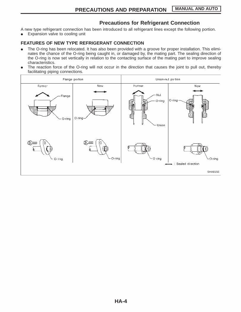
Precautions for Refrigerant ConnectionA new type refrigerant connection has been introduced to all refrigerant lines except the following portion.I Expansion valve to cooling unit
FEATURES OF NEW TYPE REFRIGERANT CONNECTIONI The O-ring has been relocated. It has also been provided with a groove for proper installation. This elimi-
nates the chance of the O-ring being caught in, or damaged by, the mating part. The sealing direction ofthe O-ring is now set vertically in relation to the contacting surface of the mating part to improve sealingcharacteristics.
I The reaction force of the O-ring will not occur in the direction that causes the joint to pull out, therebyfacilitating piping connections.
SHA815E
PRECAUTIONS AND PREPARATION MANUAL AND AUTO
HA-4
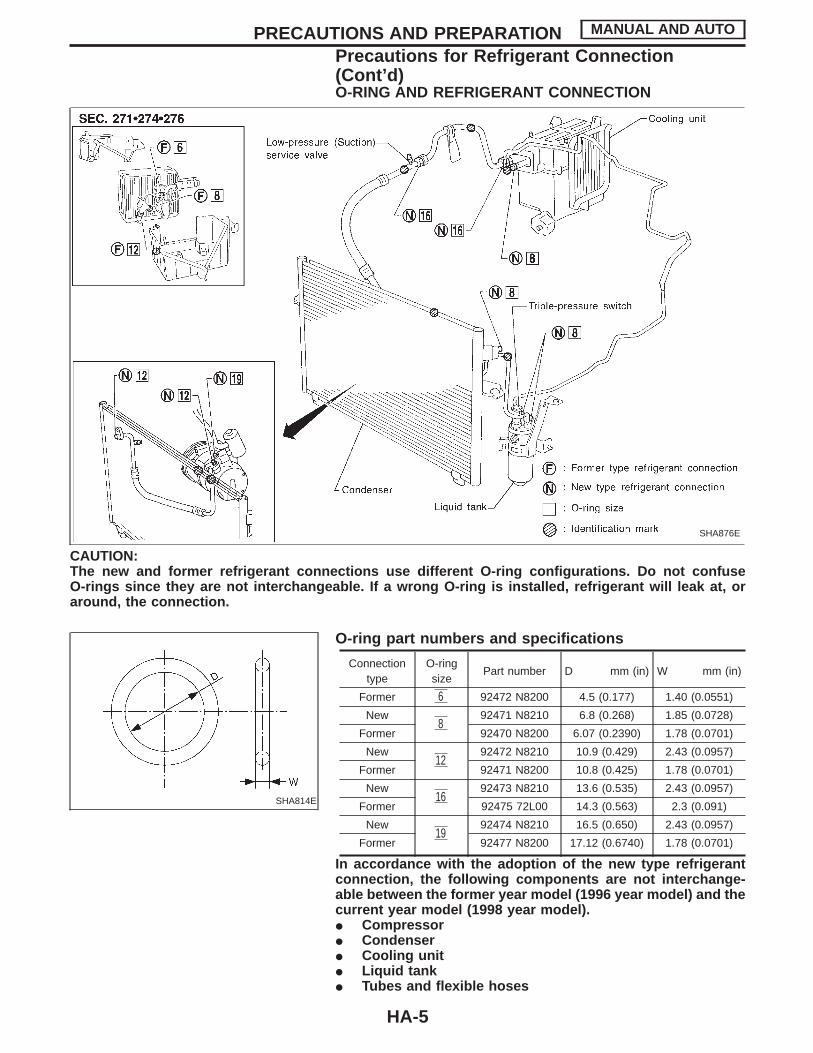
O-RING AND REFRIGERANT CONNECTION
SHA876E
CAUTION:The new and former refrigerant connections use different O-ring configurations. Do not confuseO-rings since they are not interchangeable. If a wrong O-ring is installed, refrigerant will leak at, oraround, the connection.
SHA814E
O-ring part numbers and specifications
Connectiontype
O-ringsize
Part number D mm (in) W mm (in)
Former 6 92472 N8200 4.5 (0.177) 1.40 (0.0551)
New8
92471 N8210 6.8 (0.268) 1.85 (0.0728)
Former 92470 N8200 6.07 (0.2390) 1.78 (0.0701)
New12
92472 N8210 10.9 (0.429) 2.43 (0.0957)
Former 92471 N8200 10.8 (0.425) 1.78 (0.0701)
New16
92473 N8210 13.6 (0.535) 2.43 (0.0957)
Former 92475 72L00 14.3 (0.563) 2.3 (0.091)
New19
92474 N8210 16.5 (0.650) 2.43 (0.0957)
Former 92477 N8200 17.12 (0.6740) 1.78 (0.0701)
In accordance with the adoption of the new type refrigerantconnection, the following components are not interchange-able between the former year model (1996 year model) and thecurrent year model (1998 year model).I CompressorI CondenserI Cooling unitI Liquid tankI Tubes and flexible hoses
PRECAUTIONS AND PREPARATION MANUAL AND AUTO
Precautions for Refrigerant Connection(Cont’d)
HA-5
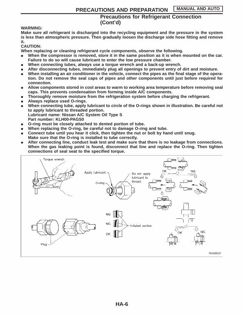
WARNING:Make sure all refrigerant is discharged into the recycling equipment and the pressure in the systemis less than atmospheric pressure. Then gradually loosen the discharge side hose fitting and removeit.CAUTION:When replacing or cleaning refrigerant cycle components, observe the following.I When the compressor is removed, store it in the same position as it is when mounted on the car.
Failure to do so will cause lubricant to enter the low pressure chamber.I When connecting tubes, always use a torque wrench and a back-up wrench.I After disconnecting tubes, immediately plug all openings to prevent entry of dirt and moisture.I When installing an air conditioner in the vehicle, connect the pipes as the final stage of the opera-
tion. Do not remove the seal caps of pipes and other components until just before required forconnection.
I Allow components stored in cool areas to warm to working area temperature before removing sealcaps. This prevents condensation from forming inside A/C components.
I Thoroughly remove moisture from the refrigeration system before charging the refrigerant.I Always replace used O-rings.I When connecting tube, apply lubricant to circle of the O-rings shown in illustration. Be careful not
to apply lubricant to threaded portion.Lubricant name: Nissan A/C System Oil Type SPart number: KLH00-PAGS0
I O-ring must be closely attached to dented portion of tube.I When replacing the O-ring, be careful not to damage O-ring and tube.I Connect tube until you hear it click, then tighten the nut or bolt by hand until snug.
Make sure that the O-ring is installed to tube correctly.I After connecting line, conduct leak test and make sure that there is no leakage from connections.
When the gas leaking point is found, disconnect that line and replace the O-ring. Then tightenconnections of seal seat to the specified torque.
RHA861F
PRECAUTIONS AND PREPARATION MANUAL AND AUTO
Precautions for Refrigerant Connection(Cont’d)
HA-6
Precautions for Servicing CompressorI Plug all openings to prevent moisture and foreign matter from entering.I When the compressor is removed, store it in the same position as it is when mounted on the car.I When replacing or repairing compressor, follow “Maintenance of Lubricant Quantity in Compres-
sor” exactly. Refer to HA-123.I Keep friction surfaces between clutch and pulley clean. If the surface is contaminated, with
lubricant, wipe it off by using a clean waste cloth moistened with thinner.I After compressor service operation, turn the compressor shaft by hand more than five turns in
both directions. This will equally distribute lubricant inside the compressor. After the compressoris installed, let the engine idle and operate the compressor for one hour.
I After replacing the compressor magnet clutch, apply voltage to the new one and check for normaloperation.
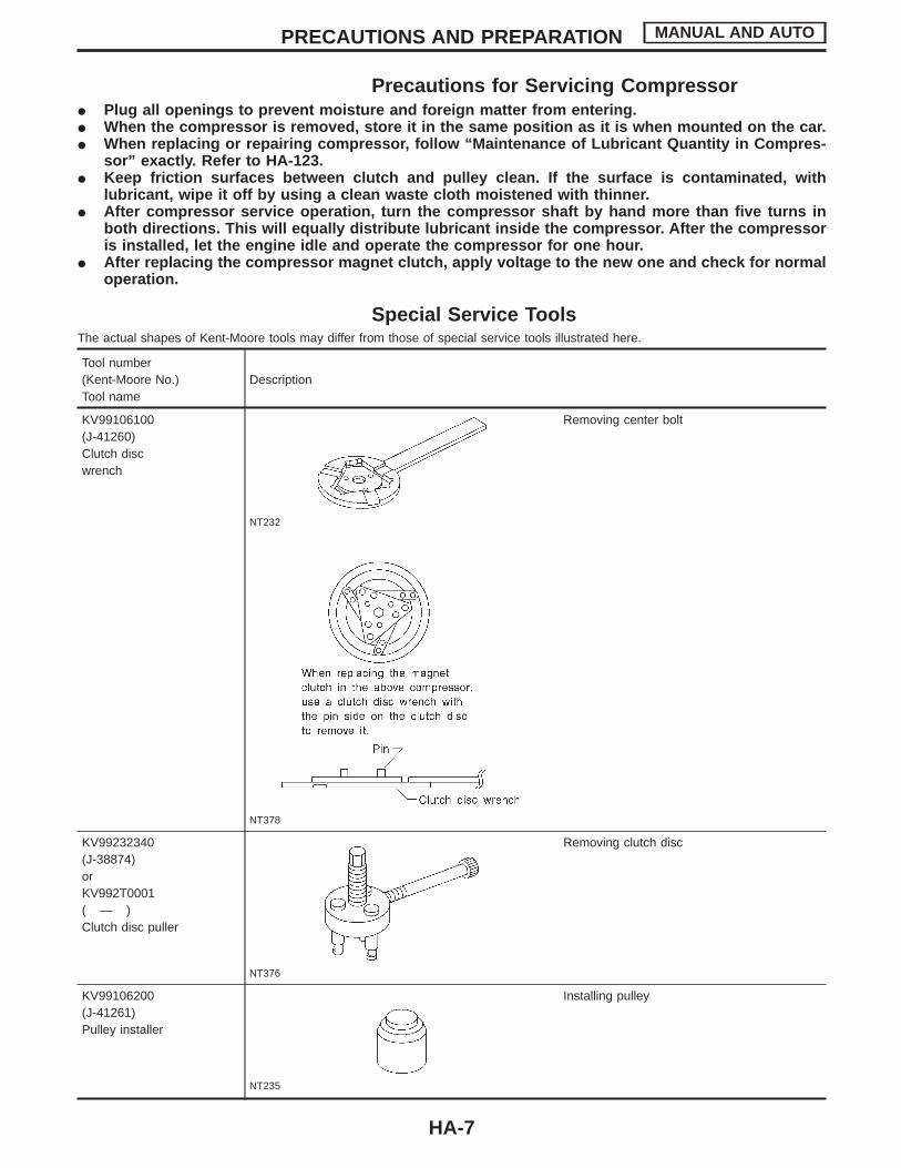
Special Service ToolsThe actual shapes of Kent-Moore tools may differ from those of special service tools illustrated here.
Tool number(Kent-Moore No.)Tool name
Description
KV99106100(J-41260)Clutch discwrench
NT232
NT378
Removing center bolt
KV99232340(J-38874)orKV992T0001( — )Clutch disc puller
NT376
Removing clutch disc
KV99106200(J-41261)Pulley installer
NT235
Installing pulley
PRECAUTIONS AND PREPARATION MANUAL AND AUTO
HA-7

HFC-134a (R-134a) Service Tools andEquipment
Never mix HFC-134a refrigerant and/or its specified lubricant with CFC-12 (R-12) refrigerant and/or its lubri-cant.Separate and non-interchangeable service equipment must be used for handling each type of refrigerant/lubricant.Refrigerant container fittings, service hose fittings and service equipment fittings (equipment which handlesrefrigerant and/or lubricant) are different between CFC-12 (R-12) and HFC-134a (R-134a). This is to avoidmixed use of the refrigerants/lubricant.Adapters that convert one size fitting to another must never be used: refrigerant/lubricant contamination willoccur and compressor failure will result.
Tool number(Kent-Moore No.)Tool name
Description Note
HFC-134a (R-134a) refrig-erant
NT196
Container color: Light blueContainer marking: HFC-134a (R-134a)Fitting size: Thread sizeI large container 1/2″-16 ACME
KLH00-PAGS0( — )Nissan A/C System OilType S
NT197
Type: Poly alkylene glycol oil (PAG), type SApplication: HFC-134a (R-134a) swash plate(piston) compressors (Nissan only)Lubricity: 40 m (1.4 US fl oz, 1.4 Imp fl oz)
(J-39500-NI)Recovery/RecyclingRecharging equipment(ACR4)
NT195
Function: Refrigerant Recovery and Recyclingand Recharging
(J-39400)Electrical leak detector
NT198
Power supply:I DC 12V (Cigarette lighter)
(J-39183)Manifold gauge set (withhoses and couplers)
NT199
Identification:I The gauge face indicates R-134a.Fitting size: Thread sizeI 1/2″-16 ACME
PRECAUTIONS AND PREPARATION MANUAL AND AUTO
HA-8
Tool number(Kent-Moore No.)Tool name
Description Note
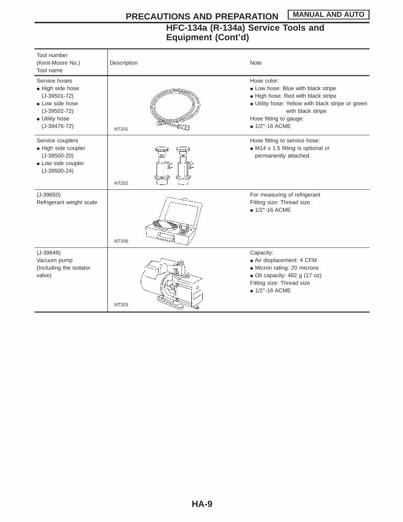
Service hosesI High side hose
(J-39501-72)I Low side hose
(J-39502-72)I Utility hose
(J-39476-72) NT201
Hose color:I Low hose: Blue with black stripeI High hose: Red with black stripeI Utility hose: Yellow with black stripe or green
with black stripeHose fitting to gauge:I 1/2″-16 ACME
Service couplersI High side coupler
(J-39500-20)I Low side coupler
(J-39500-24)
NT202
Hose fitting to service hose:I M14 x 1.5 fitting is optional or
permanently attached.
(J-39650)Refrigerant weight scale
NT200
For measuring of refrigerantFitting size: Thread sizeI 1/2″-16 ACME
(J-39649)Vacuum pump(Including the isolatorvalve)
NT203
Capacity:I Air displacement: 4 CFMI Micron rating: 20 micronsI Oil capacity: 482 g (17 oz)Fitting size: Thread sizeI 1/2″-16 ACME
PRECAUTIONS AND PREPARATION MANUAL AND AUTO
HFC-134a (R-134a) Service Tools andEquipment (Cont’d)
HA-9
Precautions for Service EquipmentRECOVERY/RECYCLING EQUIPMENTFollow the manufacturer’s instructions for machine operation andmachine maintenance. Never introduce any refrigerant other thanthat specified into the machine.
ELECTRONIC LEAK DETECTORFollow the manufacture’s instructions for tester operation andtester maintenance.
RHA270D
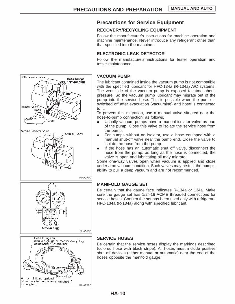
VACUUM PUMPThe lubricant contained inside the vacuum pump is not compatiblewith the specified lubricant for HFC-134a (R-134a) A/C systems.The vent side of the vacuum pump is exposed to atmosphericpressure. So the vacuum pump lubricant may migrate out of thepump into the service hose. This is possible when the pump isswitched off after evacuation (vacuuming) and hose is connectedto it.To prevent this migration, use a manual valve situated near thehose-to-pump connection, as follows.I Usually vacuum pumps have a manual isolator valve as part
of the pump. Close this valve to isolate the service hose fromthe pump.
I For pumps without an isolator, use a hose equipped with amanual shut-off valve near the pump end. Close the valve toisolate the hose from the pump.
I If the hose has an automatic shut off valve, disconnect thehose from the pump: as long as the hose is connected, thevalve is open and lubricating oil may migrate.
Some one-way valves open when vacuum is applied and closeunder a no vacuum condition. Such valves may restrict the pump’sability to pull a deep vacuum and are not recommended.
SHA533D
MANIFOLD GAUGE SETBe certain that the gauge face indicates R-134a or 134a. Makesure the gauge set has 1/2″-16 ACME threaded connections forservice hoses. Confirm the set has been used only with refrigerantHFC-134a (R-134a) along with specified lubricant.
RHA272D
SERVICE HOSESBe certain that the service hoses display the markings described(colored hose with black stripe). All hoses must include positiveshut off devices (either manual or automatic) near the end of thehoses opposite the manifold gauge.
PRECAUTIONS AND PREPARATION MANUAL AND AUTO
HA-10
RHA273D
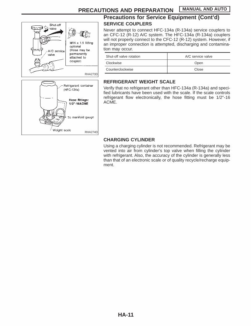
SERVICE COUPLERSNever attempt to connect HFC-134a (R-134a) service couplers toan CFC-12 (R-12) A/C system. The HFC-134a (R-134a) couplerswill not properly connect to the CFC-12 (R-12) system. However, ifan improper connection is attempted, discharging and contamina-tion may occur.
Shut-off valve rotation A/C service valve
Clockwise Open
Counterclockwise Close
RHA274D
REFRIGERANT WEIGHT SCALEVerify that no refrigerant other than HFC-134a (R-134a) and speci-fied lubricants have been used with the scale. If the scale controlsrefrigerant flow electronically, the hose fitting must be 1/2″-16ACME.
CHARGING CYLINDERUsing a charging cylinder is not recommended. Refrigerant may bevented into air from cylinder’s top valve when filling the cylinderwith refrigerant. Also, the accuracy of the cylinder is generally lessthan that of an electronic scale or of quality recycle/recharge equip-ment.
PRECAUTIONS AND PREPARATION MANUAL AND AUTO
Precautions for Service Equipment (Cont’d)
HA-11
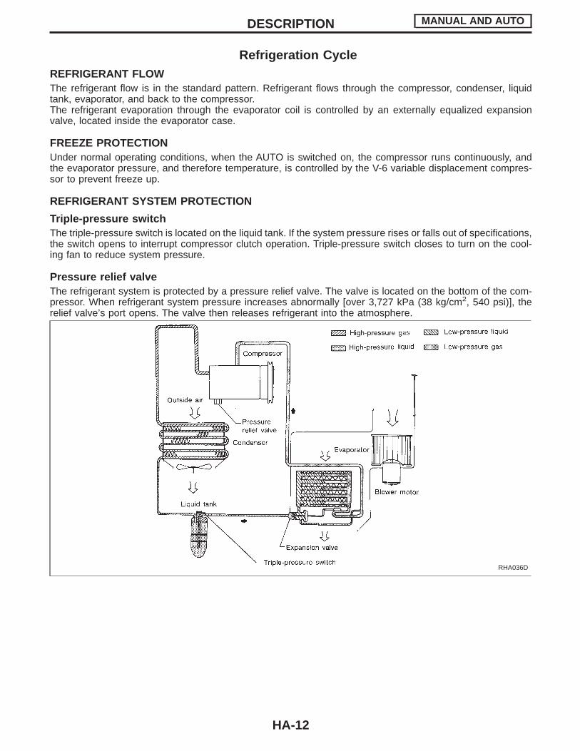
Refrigeration CycleREFRIGERANT FLOWThe refrigerant flow is in the standard pattern. Refrigerant flows through the compressor, condenser, liquidtank, evaporator, and back to the compressor.The refrigerant evaporation through the evaporator coil is controlled by an externally equalized expansionvalve, located inside the evaporator case.
FREEZE PROTECTIONUnder normal operating conditions, when the AUTO is switched on, the compressor runs continuously, andthe evaporator pressure, and therefore temperature, is controlled by the V-6 variable displacement compres-sor to prevent freeze up.
REFRIGERANT SYSTEM PROTECTION
Triple-pressure switchThe triple-pressure switch is located on the liquid tank. If the system pressure rises or falls out of specifications,the switch opens to interrupt compressor clutch operation. Triple-pressure switch closes to turn on the cool-ing fan to reduce system pressure.
Pressure relief valveThe refrigerant system is protected by a pressure relief valve. The valve is located on the bottom of the com-pressor. When refrigerant system pressure increases abnormally [over 3,727 kPa (38 kg/cm2, 540 psi)], therelief valve’s port opens. The valve then releases refrigerant into the atmosphere.
RHA036D
DESCRIPTION MANUAL AND AUTO
HA-12
V-6 Variable Displacement CompressorGENERAL INFORMATION1. The V-6 variable compressor differs from previous units. The vent temperatures of the V-6 variable com-
press do not drop too far below 5°C (41°F) when:I evaporator intake air temperature is less than 20°C (68°F)I engine is running at speeds less than 1,500 rpm.This is because the V-6 compressor provides a means of “capacity” control.
2. The V-6 variable compressor provides refrigerant control under varying conditions. During cold winters, itmay not produce high refrigerant pressure discharge (compared to previous units) when used with airconditioning systems.
3. A “clanking” sound may occasionally be heard during refrigerant charge. The sound indicates that the tiltangle of the swash plate has changed and is not a problem.
4. For air conditioning systems with the V-6 compressor, the clutch remains engaged unless: the system mainswitch, fan switch or ignition switch is turned OFF. When ambient (outside) temperatures are low or whenthe amount of refrigerant is insufficient, the clutch is disengaged to protect the compressor.
5. A constant range of suction pressure is maintained when engine speed is greater than a certain value. Itnormally ranges from 147 to 177 kPa (1.5 to 1.8 kg/cm2, 21 to 26 psi) under varying conditions.In previous compressors, however, suction pressure was reduced with increases in engine speed.
DESCRIPTION MANUAL AND AUTO
HA-13

DESCRIPTION
GeneralThe variable compressor is basically a swash plate type that changes piston stroke in response to the requiredcooling capacity.The tilt of the swash plate allows the piston’s stroke to change so that refrigerant discharge can be continu-ously changed from 10.5 to 184 cm3 (0.641 to 11.228 cu in).
RHA037DA
DESCRIPTION MANUAL AND AUTO
V-6 Variable Displacement Compressor (Cont’d)
HA-14

Operation1. Operation control valve
Operation control valve is located in the suction port (low-pressure) side, and opens or closes in responseto changes in refrigerant suction pressure.Operation of the valve controls the internal pressure of the crankcase.The angle of the swash plate is controlled between the crankcase’s internal pressure and the piston cyl-inder pressure.
2. Maximum coolingRefrigerant pressure on the low-pressure side increases with an increase in heat loads.When this occurs, the control valve’s bellows compress to open the low-pressure side valve and close thehigh-pressure side valve.This causes the following pressure changes:I the crankcase’s internal pressure to equal the pressure on the low-pressure side;I the cylinder’s internal pressure to be greater than the crankcase’s internal pressure.Under this condition, the swash plate is set to the maximum stroke position.
RHA473C
DESCRIPTION MANUAL AND AUTO
V-6 Variable Displacement Compressor (Cont’d)
HA-15
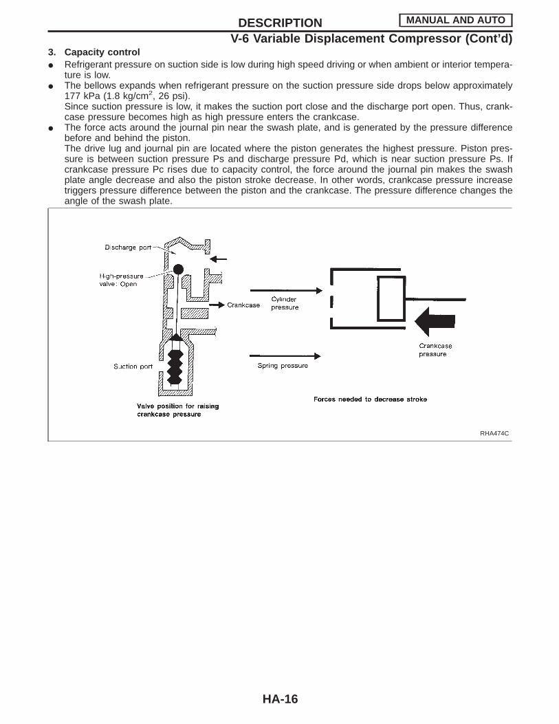
3. Capacity controlI Refrigerant pressure on suction side is low during high speed driving or when ambient or interior tempera-
ture is low.I The bellows expands when refrigerant pressure on the suction pressure side drops below approximately
177 kPa (1.8 kg/cm2, 26 psi).Since suction pressure is low, it makes the suction port close and the discharge port open. Thus, crank-case pressure becomes high as high pressure enters the crankcase.
I The force acts around the journal pin near the swash plate, and is generated by the pressure differencebefore and behind the piston.The drive lug and journal pin are located where the piston generates the highest pressure. Piston pres-sure is between suction pressure Ps and discharge pressure Pd, which is near suction pressure Ps. Ifcrankcase pressure Pc rises due to capacity control, the force around the journal pin makes the swashplate angle decrease and also the piston stroke decrease. In other words, crankcase pressure increasetriggers pressure difference between the piston and the crankcase. The pressure difference changes theangle of the swash plate.
RHA474C
DESCRIPTION MANUAL AND AUTO
V-6 Variable Displacement Compressor (Cont’d)
HA-16
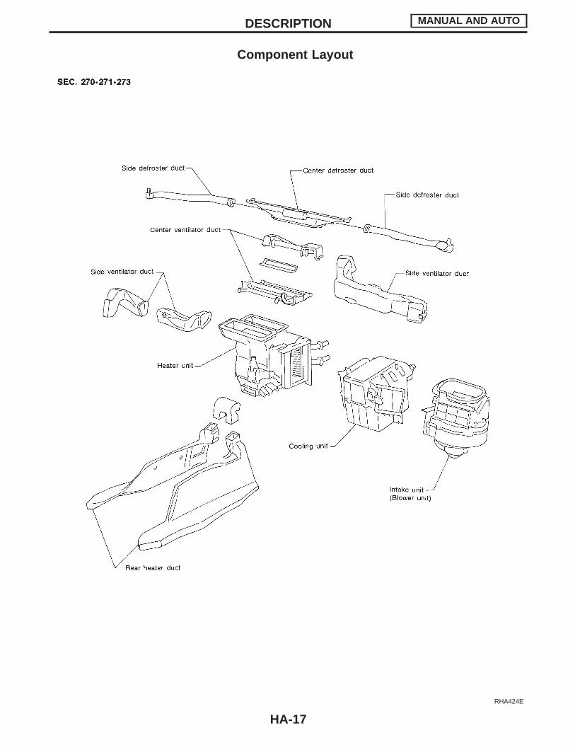
Component Layout
RHA424E
DESCRIPTION MANUAL AND AUTO
HA-17
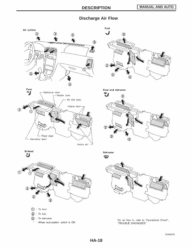
Discharge Air Flow
SHA847E
DESCRIPTION MANUAL AND AUTO
HA-18
Control Operation
RHA426EA
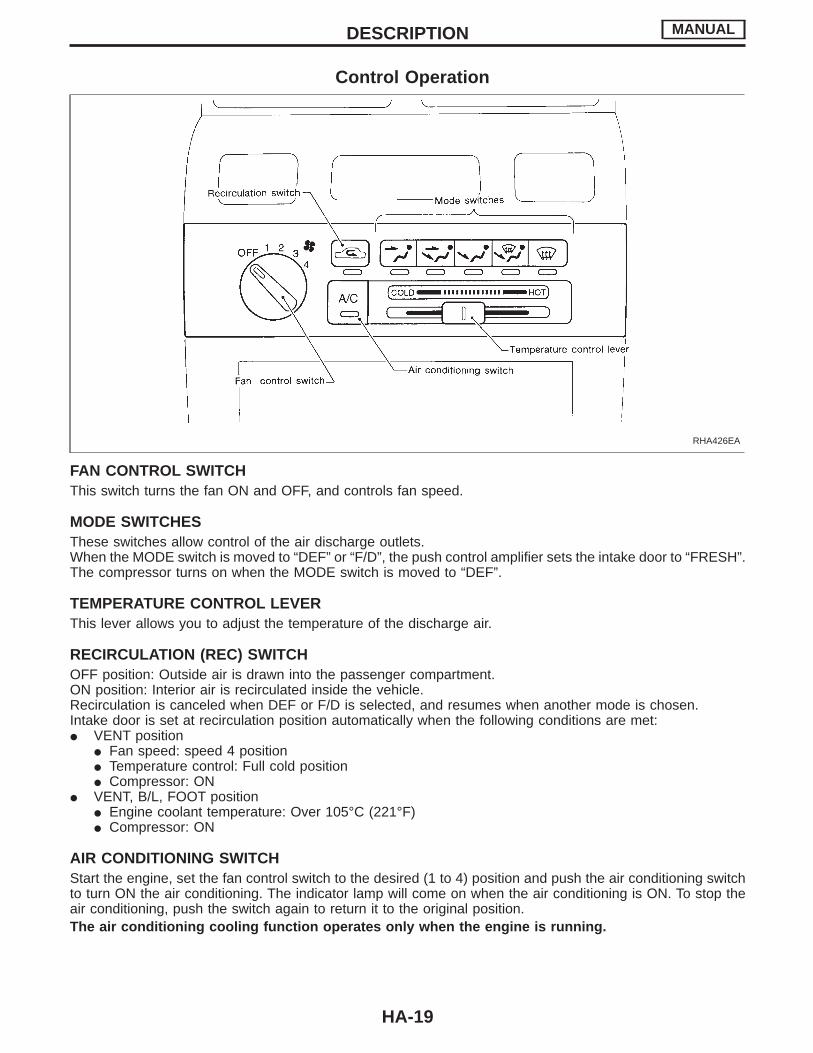
FAN CONTROL SWITCHThis switch turns the fan ON and OFF, and controls fan speed.
MODE SWITCHESThese switches allow control of the air discharge outlets.When the MODE switch is moved to “DEF” or “F/D”, the push control amplifier sets the intake door to “FRESH”.The compressor turns on when the MODE switch is moved to “DEF”.
TEMPERATURE CONTROL LEVERThis lever allows you to adjust the temperature of the discharge air.
RECIRCULATION (REC) SWITCHOFF position: Outside air is drawn into the passenger compartment.ON position: Interior air is recirculated inside the vehicle.Recirculation is canceled when DEF or F/D is selected, and resumes when another mode is chosen.Intake door is set at recirculation position automatically when the following conditions are met:I VENT position
I Fan speed: speed 4 positionI Temperature control: Full cold positionI Compressor: ON
I VENT, B/L, FOOT positionI Engine coolant temperature: Over 105°C (221°F)I Compressor: ON
AIR CONDITIONING SWITCHStart the engine, set the fan control switch to the desired (1 to 4) position and push the air conditioning switchto turn ON the air conditioning. The indicator lamp will come on when the air conditioning is ON. To stop theair conditioning, push the switch again to return it to the original position.The air conditioning cooling function operates only when the engine is running.
DESCRIPTION MANUAL
HA-19

NOTE
DESCRIPTION MANUAL
HA-20
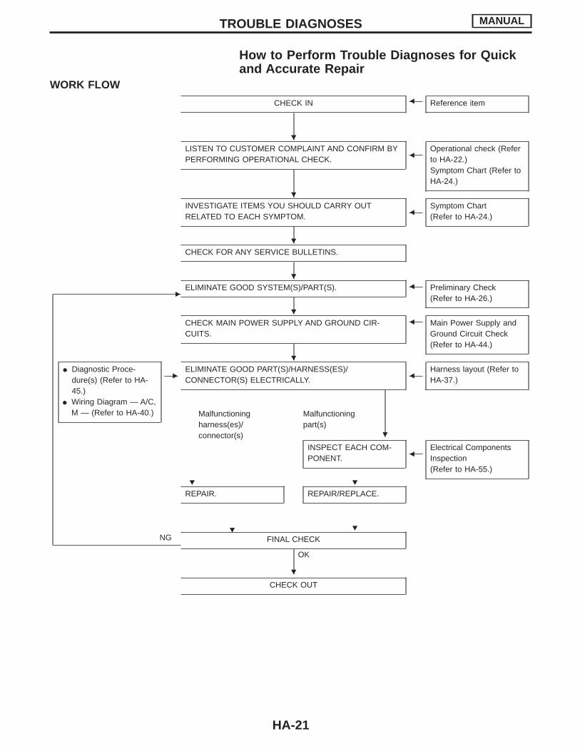
How to Perform Trouble Diagnoses for Quickand Accurate Repair
WORK FLOW
CHECK IN F Reference item
LISTEN TO CUSTOMER COMPLAINT AND CONFIRM BYPERFORMING OPERATIONAL CHECK. F
Operational check (Referto HA-22.)Symptom Chart (Refer toHA-24.)
INVESTIGATE ITEMS YOU SHOULD CARRY OUTRELATED TO EACH SYMPTOM. F
Symptom Chart(Refer to HA-24.)
CHECK FOR ANY SERVICE BULLETINS.
EELIMINATE GOOD SYSTEM(S)/PART(S). F Preliminary Check
(Refer to HA-26.)
CHECK MAIN POWER SUPPLY AND GROUND CIR-CUITS.
F Main Power Supply andGround Circuit Check(Refer to HA-44.)
I Diagnostic Proce-dure(s) (Refer to HA-45.)
I Wiring Diagram — A/C,M — (Refer to HA-40.)
EELIMINATE GOOD PART(S)/HARNESS(ES)/CONNECTOR(S) ELECTRICALLY. F
Harness layout (Refer toHA-37.)
Malfunctioningharness(es)/connector(s)
Malfunctioningpart(s)
INSPECT EACH COM-PONENT. F
Electrical ComponentsInspection(Refer to HA-55.)
REPAIR.
H
REPAIR/REPLACE.
NG FINAL CHECK
OK
CHECK OUT
TROUBLE DIAGNOSES MANUAL
H
H
H
H
H
H
H
H H
H
H
HA-21
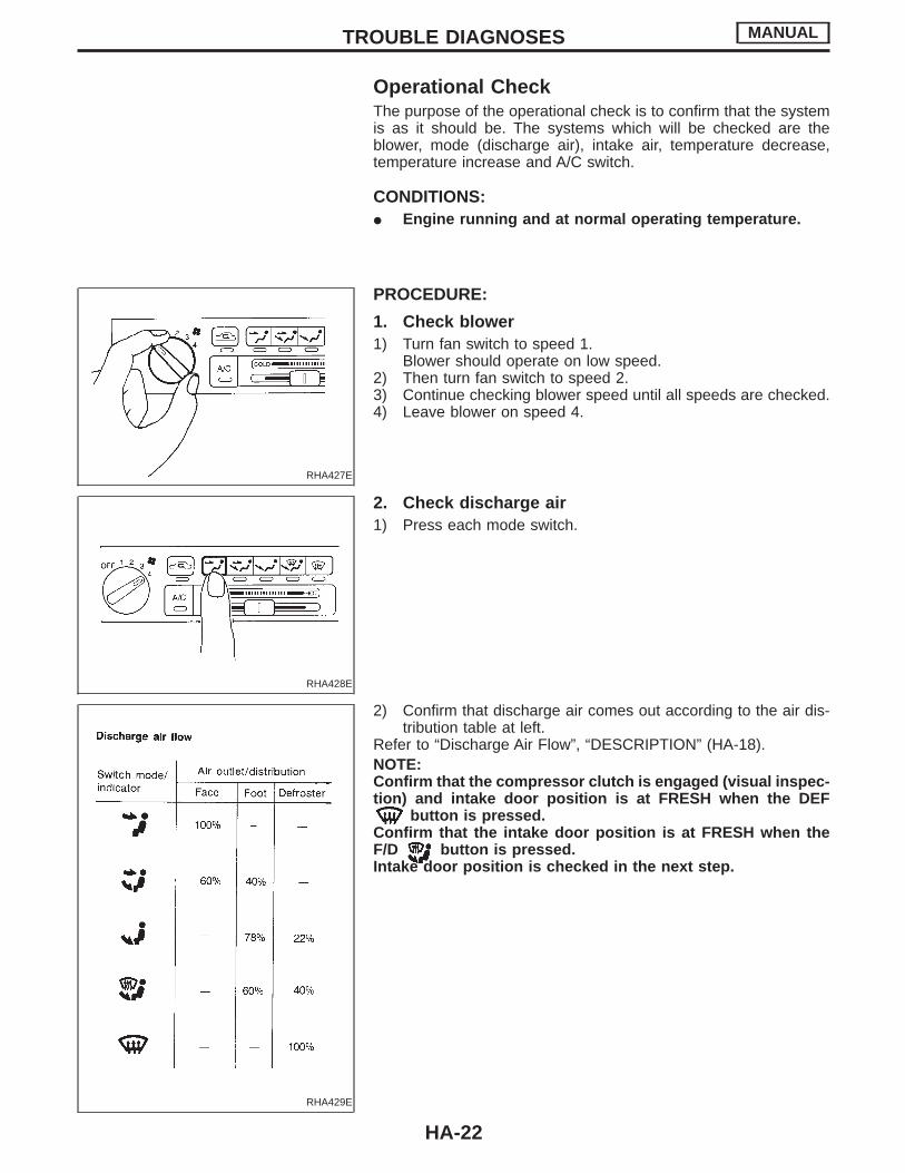
Operational CheckThe purpose of the operational check is to confirm that the systemis as it should be. The systems which will be checked are theblower, mode (discharge air), intake air, temperature decrease,temperature increase and A/C switch.
CONDITIONS:I Engine running and at normal operating temperature.
RHA427E
PROCEDURE:
1. Check blower1) Turn fan switch to speed 1.
Blower should operate on low speed.2) Then turn fan switch to speed 2.3) Continue checking blower speed until all speeds are checked.4) Leave blower on speed 4.
RHA428E
2. Check discharge air1) Press each mode switch.
RHA429E
2) Confirm that discharge air comes out according to the air dis-tribution table at left.
Refer to “Discharge Air Flow”, “DESCRIPTION” (HA-18).NOTE:Confirm that the compressor clutch is engaged (visual inspec-tion) and intake door position is at FRESH when the DEF
button is pressed.Confirm that the intake door position is at FRESH when theF/D button is pressed.Intake door position is checked in the next step.
TROUBLE DIAGNOSES MANUAL
HA-22
RHA430E
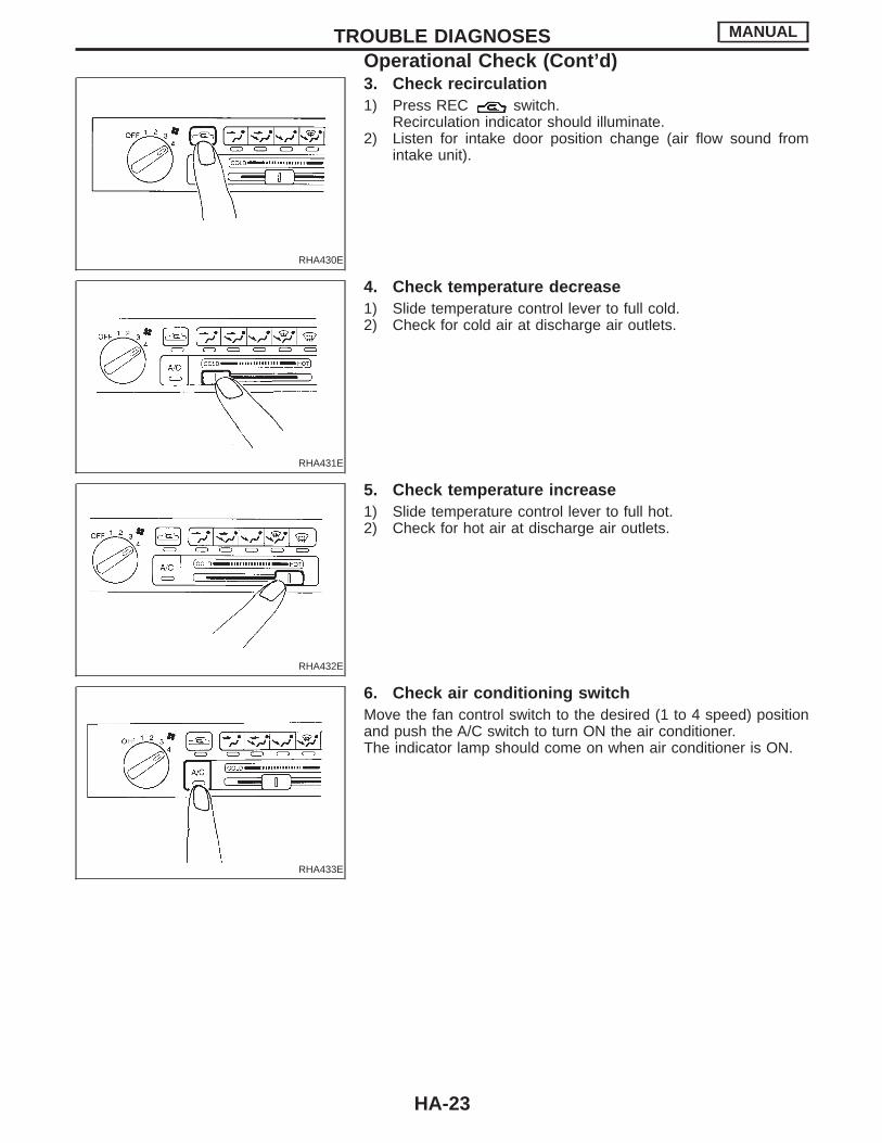
3. Check recirculation1) Press REC switch.
Recirculation indicator should illuminate.2) Listen for intake door position change (air flow sound from
intake unit).
RHA431E
4. Check temperature decrease1) Slide temperature control lever to full cold.2) Check for cold air at discharge air outlets.
RHA432E
5. Check temperature increase1) Slide temperature control lever to full hot.2) Check for hot air at discharge air outlets.
RHA433E
6. Check air conditioning switchMove the fan control switch to the desired (1 to 4 speed) positionand push the A/C switch to turn ON the air conditioner.The indicator lamp should come on when air conditioner is ON.
TROUBLE DIAGNOSES MANUAL
Operational Check (Cont’d)
HA-23
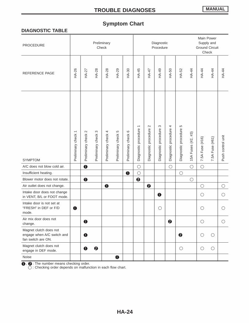
Symptom ChartDIAGNOSTIC TABLE
PROCEDUREPreliminary
CheckDiagnosticProcedure
Main PowerSupply and
Ground CircuitCheck
REFERENCE PAGEH
A-2
6
HA
-27
HA
-28
HA
-28
HA
-29
HA
-30
HA
-45
HA
-47
HA
-49
HA
-50
HA
-52
HA
-44
HA
-44
HA
-44
HA
-44
SYMPTOM Pre
limin
ary
chec
k1
Pre
limin
ary
chec
k2
Pre
limin
ary
chec
k3
Pre
limin
ary
chec
k4
Pre
limin
ary
chec
k5
Pre
limin
ary
chec
k6
Dia
gnos
ticpr
oced
ure
1
Dia
gnos
ticpr
oced
ure
2
Dia
gnos
ticpr
oced
ure
3
Dia
gnos
ticpr
oced
ure
4
Dia
gnos
ticpr
oced
ure
5
15A
Fus
es(#
2,#3
)
7.5A
Fus
e(#
16)
7.5A
Fus
e(#
61)
Pus
hco
ntro
luni
t
A/C does not blow cold air. q q q q
Insufficient heating. q q
Blower motor does not rotate. q
Air outlet does not change. q q
Intake door does not changein VENT, B/L or FOOT mode.
q q
Intake door is not set at“FRESH” in DEF or F/Dmode.
q q q
Air mix door does notchange.
q q
Magnet clutch does notengage when A/C switch andfan switch are ON.
q q
Magnet clutch does notengage in DEF mode.
q q q
Noise
, : The number means checking order.q : Checking order depends on malfunction in each flow chart.
TROUBLE DIAGNOSES MANUAL
HA-24
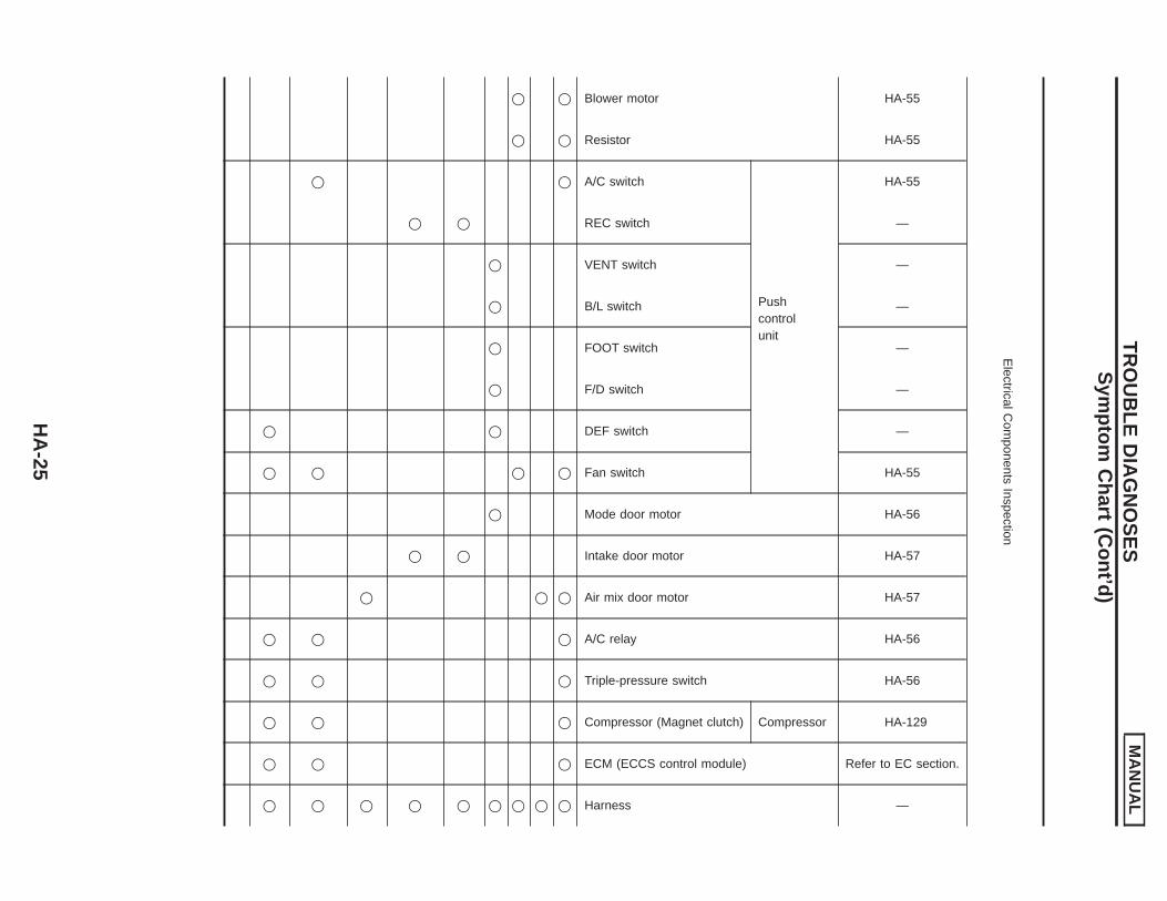
ElectricalC
omponents
Inspection
HA-55
HA-55
HA-55
—
—
—
—
—
—
HA-55
HA-56
HA-57
HA-57
HA-56
HA-56
HA-129
Refer to EC section.
—
Blower motor
Resistor
Pushcontrolunit
Mode door motor
Intake door motor
Air mix door motor
A/C relay
Triple-pressure switch
Compressor
ECM (ECCS control module)
Harness
A/C switch
REC switch
VENT switch
B/L switch
FOOT switch
F/D switch
DEF switch
Fan switch
Compressor (Magnet clutch)
q
q
q
q
q
TR
OU
BLE
DIA
GN
OS
ES
MA
NU
AL
Sym
ptomC
hart(C
ont’d)
HA
-25
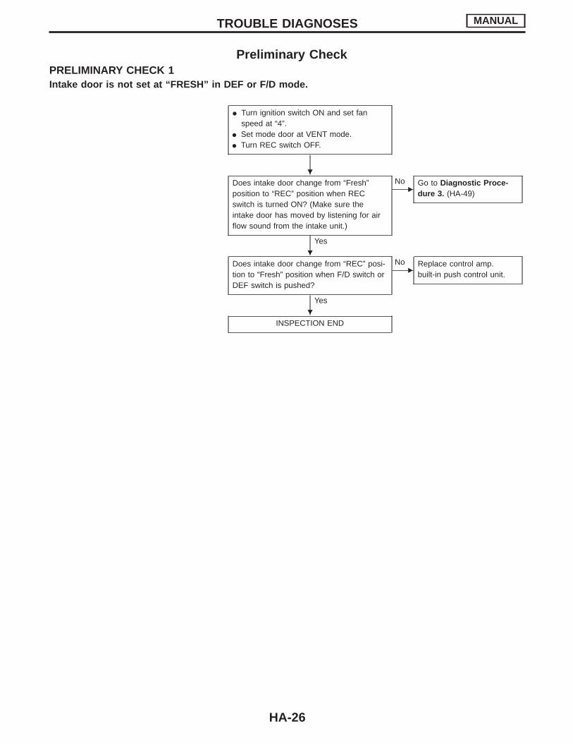
Preliminary CheckPRELIMINARY CHECK 1Intake door is not set at “FRESH” in DEF or F/D mode.
I Turn ignition switch ON and set fanspeed at “4”.
I Set mode door at VENT mode.I Turn REC switch OFF.
Does intake door change from “Fresh”position to “REC” position when RECswitch is turned ON? (Make sure theintake door has moved by listening for airflow sound from the intake unit.)
Yes
ENo Go to Diagnostic Proce-
dure 3. (HA-49)
Does intake door change from “REC” posi-tion to “Fresh” position when F/D switch orDEF switch is pushed?
Yes
ENo Replace control amp.
built-in push control unit.
INSPECTION END
TROUBLE DIAGNOSES MANUAL
H
H
H
HA-26
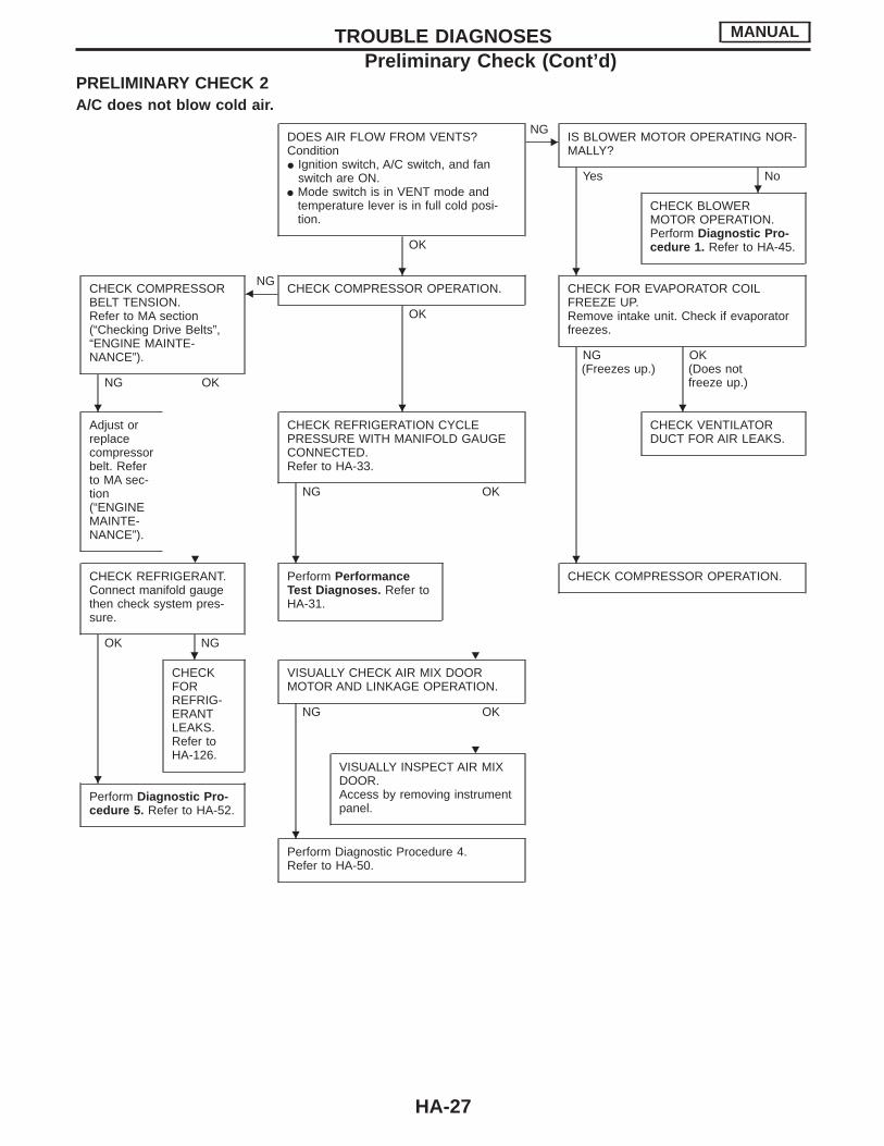
PRELIMINARY CHECK 2A/C does not blow cold air.
DOES AIR FLOW FROM VENTS?ConditionI Ignition switch, A/C switch, and fan
switch are ON.I Mode switch is in VENT mode and
temperature lever is in full cold posi-tion.
OK
ENG
IS BLOWER MOTOR OPERATING NOR-MALLY?
Yes No
CHECK BLOWERMOTOR OPERATION.Perform Diagnostic Pro-cedure 1. Refer to HA-45.
CHECK COMPRESSORBELT TENSION.Refer to MA section(“Checking Drive Belts”,“ENGINE MAINTE-NANCE”).
NG OK
FNG
CHECK COMPRESSOR OPERATION.
OK
CHECK FOR EVAPORATOR COILFREEZE UP.Remove intake unit. Check if evaporatorfreezes.
NG OK(Freezes up.) (Does not
freeze up.)
Adjust orreplacecompressorbelt. Referto MA sec-tion(“ENGINEMAINTE-NANCE”).
CHECK REFRIGERATION CYCLEPRESSURE WITH MANIFOLD GAUGECONNECTED.Refer to HA-33.
NG OK
CHECK VENTILATORDUCT FOR AIR LEAKS.
CHECK REFRIGERANT.Connect manifold gaugethen check system pres-sure.
OK NG
Perform PerformanceTest Diagnoses. Refer toHA-31.
CHECK COMPRESSOR OPERATION.
CHECKFORREFRIG-ERANTLEAKS.Refer toHA-126.
VISUALLY CHECK AIR MIX DOORMOTOR AND LINKAGE OPERATION.
NG OK
Perform Diagnostic Pro-cedure 5. Refer to HA-52.
VISUALLY INSPECT AIR MIXDOOR.Access by removing instrumentpanel.
Perform Diagnostic Procedure 4.Refer to HA-50.
TROUBLE DIAGNOSES MANUAL
Preliminary Check (Cont’d)
H
H H
H H H
H H H
H H
H
H
H
HA-27
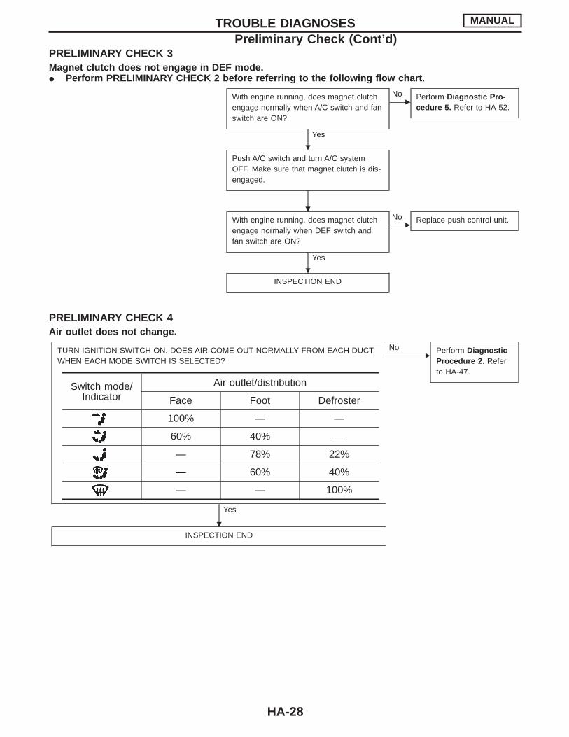
PRELIMINARY CHECK 3Magnet clutch does not engage in DEF mode.I Perform PRELIMINARY CHECK 2 before referring to the following flow chart.
With engine running, does magnet clutchengage normally when A/C switch and fanswitch are ON?
Yes
ENo Perform Diagnostic Pro-
cedure 5. Refer to HA-52.
Push A/C switch and turn A/C systemOFF. Make sure that magnet clutch is dis-engaged.
With engine running, does magnet clutchengage normally when DEF switch andfan switch are ON?
Yes
ENo Replace push control unit.
INSPECTION END
PRELIMINARY CHECK 4Air outlet does not change.
TURN IGNITION SWITCH ON. DOES AIR COME OUT NORMALLY FROM EACH DUCTWHEN EACH MODE SWITCH IS SELECTED?
Yes
ENo Perform Diagnostic
Procedure 2. Referto HA-47.
INSPECTION END
Switch mode/Indicator
Air outlet/distribution
Face Foot Defroster
100% — —
60% 40% —
— 78% 22%
— 60% 40%
— — 100%
TROUBLE DIAGNOSES MANUAL
Preliminary Check (Cont’d)
H
H
H
H
HA-28
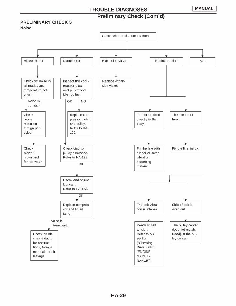
PRELIMINARY CHECK 5Noise
Check where noise comes from.
Blower motor Compressor Expansion valve Refrigerant line Belt
Check for noise inall modes andtemperature set-tings.
Noise isconstant.
Inspect the com-pressor clutchand pulley andidler pulley.
OK NG
Replace expan-sion valve.
Checkblowermotor forforeign par-ticles.
Replace com-pressor clutchand pulley.Refer to HA-129.
The line is fixeddirectly to thebody.
The line is notfixed.
Checkblowermotor andfan for wear.
Check disc-to-pulley clearance.Refer to HA-132.
OK
Fix the line withrubber or somevibrationabsorbingmaterial.
Fix the line tightly.
HCheck and adjustlubricant.Refer to HA-123.
OK
Noise isintermittent.
Replace compres-sor and liquidtank.
The belt vibra-tion is intense.
Side of belt isworn out.
Check air dis-charge ductsfor obstruc-tions, foreignmaterials or airleakage.
Readjust belttension.Refer to MAsection(“CheckingDrive Belts”,“ENGINEMAINTE-NANCE”).
The pulley centerdoes not match.Readjust the pul-ley center.
TROUBLE DIAGNOSES MANUAL
Preliminary Check (Cont’d)
H H H H H
H H H
H H H H
H H H H
H
H H H
H
H H
HA-29
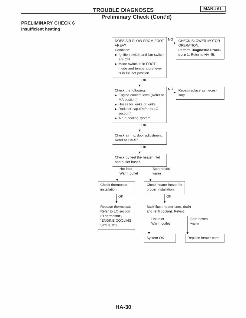
PRELIMINARY CHECK 6Insufficient heating
DOES AIR FLOW FROM FOOTAREA?Condition:I Ignition switch and fan switch
are ON.I Mode switch is in FOOT
mode and temperature leveris in full hot position.
OK
ENG CHECK BLOWER MOTOR
OPERATION.Perform Diagnostic Proce-dure 1. Refer to HA-45.
Check the following:I Engine coolant level (Refer to
MA section.)I Hoses for leaks or kinksI Radiator cap (Refer to LC
section.)I Air in cooling system.
OK
ENG Repair/replace as neces-
sary.
Check air mix door adjustment.Refer to HA-57.
OK
Check by feel the heater inletand outlet hoses.
Hot inletWarm outlet
Both hoseswarm
Check thermostatinstallation.
OK
Check heater hoses forproper installation.
OK
Replace thermostat.Refer to LC section(“Thermostat”,“ENGINE COOLINGSYSTEM”).
Back flush heater core, drainand refill coolant. Retest.
Hot inletWarm outlet
Both hoseswarm
System OK Replace heater core.
TROUBLE DIAGNOSES MANUAL
Preliminary Check (Cont’d)
H
H
H
H H
H H
H H
HA-30
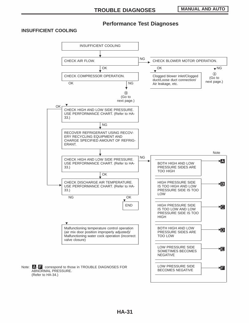
Performance Test DiagnosesINSUFFICIENT COOLING
INSUFFICIENT COOLING
CHECK AIR FLOW.
OK
ENG
CHECK BLOWER MOTOR OPERATION.
OK NG
CHECK COMPRESSOR OPERATION.
OK NG
Clogged blower inlet/Cloggedduct/Loose duct connection/Air leakage, etc.
qA
(Go tonext page.)
qB
(Go tonext page.)
OKCHECK HIGH AND LOW SIDE PRESSURE.USE PERFORMANCE CHART. (Refer to HA-33.)
NG
RECOVER REFRIGERANT USING RECOV-ERY RECYCLING EQUIPMENT ANDCHARGE SPECIFIED AMOUNT OF REFRIG-ERANT.
CHECK HIGH AND LOW SIDE PRESSURE.USE PERFORMANCE CHART. (Refer to HA-33.)
OK
ENG
BOTH HIGH AND LOWPRESSURE SIDES ARETOO HIGH
E
Note
ECHECK DISCHARGE AIR TEMPERATURE.USE PERFORMANCE CHART. (Refer to HA-33.)
NG OK
HIGH PRESSURE SIDEIS TOO HIGH AND LOWPRESSURE SIDE IS TOOLOW
E
END HIGH PRESSURE SIDEIS TOO LOW AND LOWPRESSURE SIDE IS TOOHIGH
E
Malfunctioning temperature control operation(air mix door position improperly adjusted)/Malfunctioning water cock operation (incorrectvalve closure)
BOTH HIGH AND LOWPRESSURE SIDES ARETOO LOW
E
LOW PRESSURE SIDESOMETIMES BECOMESNEGATIVE
E
LOW PRESSURE SIDEBECOMES NEGATIVE
ENote: - correspond to those in TROUBLE DIAGNOSES FORABNORMAL PRESSURE.(Refer to HA-34.)
TROUBLE DIAGNOSES MANUAL AND AUTO
H
H HH
H
H
H
H
H
H
H
HA-31
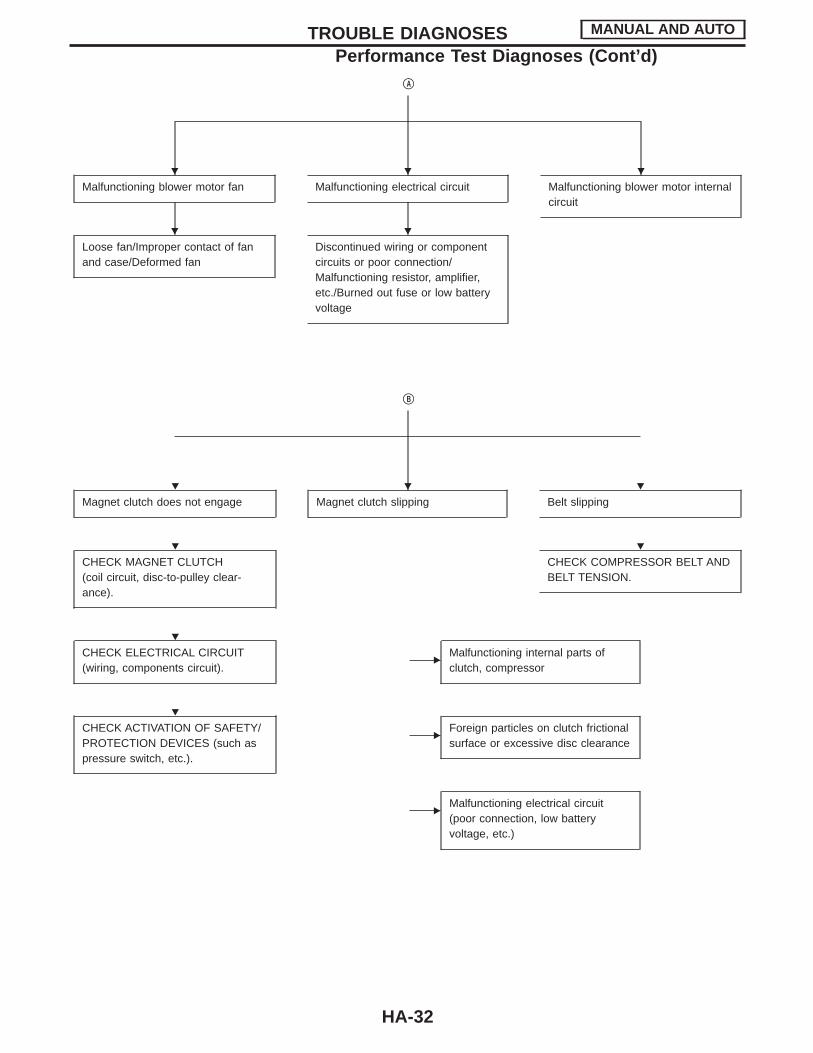
qA
Malfunctioning blower motor fan Malfunctioning electrical circuit Malfunctioning blower motor internalcircuit
Loose fan/Improper contact of fanand case/Deformed fan
Discontinued wiring or componentcircuits or poor connection/Malfunctioning resistor, amplifier,etc./Burned out fuse or low batteryvoltage
qB
Magnet clutch does not engage Magnet clutch slipping Belt slipping
CHECK MAGNET CLUTCH(coil circuit, disc-to-pulley clear-ance).
CHECK COMPRESSOR BELT ANDBELT TENSION.
CHECK ELECTRICAL CIRCUIT(wiring, components circuit).
EMalfunctioning internal parts ofclutch, compressor
CHECK ACTIVATION OF SAFETY/PROTECTION DEVICES (such aspressure switch, etc.).
EForeign particles on clutch frictionalsurface or excessive disc clearance
EMalfunctioning electrical circuit(poor connection, low batteryvoltage, etc.)
TROUBLE DIAGNOSES MANUAL AND AUTO
Performance Test Diagnoses (Cont’d)
H H H
H H
H H H
H H
H
H
HA-32

Performance ChartTEST CONDITIONTesting must be performed as follows:
Vehicle location: Indoors or in the shade (in a well ventilatedplace)
Doors: ClosedDoor window: OpenHood: OpenTEMP. setting: Max. COLDDischarge Air: Face VentRECIRC switch: (Recirculation) ONFAN speed: 4-speedA/C switch: ONEngine speed: 1,500 rpmOperate the air conditioning system for 10 minutes before tak-ing measurements.
TEST READINGRecirculating-to-discharge air temperature table
Inside air (Recirculating air) at blower assembly inlet Discharge air temperature at center venti-lator
°C (°F)Relative humidity
%Air temperature
°C (°F)
50 - 60
20 (68) 1.5 - 2.6 (35 - 37)
25 (77) 3.7 - 5.7 (39 - 42)
30 (86) 7.6 - 10.0 (46 - 50)
35 (95) 12.4 - 15.2 (54 - 59)
60 - 70
20 (68) 2.6 - 3.6 (37 - 38)
25 (77) 5.7 - 7.6 (42 - 46)
30 (86) 10.0 - 12.4 (50 - 54)
35 (95) 15.2 - 18.0 (59 - 64)
Ambient air temperature-to-operating pressure table
Ambient airHigh-pressure (Discharge side)
kPa (kg/cm2, psi)Low-pressure (Suction side)
kPa (kg/cm2, psi)Relative humidity
%Air temperature
°C (°F)
50 - 70
20 (68)785 - 1,040
(8.0 - 10.6, 114 - 151)137 - 167
(1.4 - 1.7, 20 - 24)
25 (77)981 - 1,304
(10.0 - 13.3, 142 - 189)137 - 167
(1.4 - 1.7, 20 - 24)
30 (86)1,167 - 1,550
(11.9 - 15.8, 169 - 225)147 - 177
(1.5 - 1.8, 21 - 26)
35 (95)1,373 - 1,804
(14.0 - 18.4, 199 - 262)157 - 186
(1.6 - 1.9, 23 - 27)
40 (104)1,550 - 2,059
(15.8 - 21.0, 225 - 299)167 - 206
(1.7 - 2.1, 24 - 30)
If pressure is not within range, refer to HA-34, “Trouble Diagnoses for Abnormal Pressure”.
TROUBLE DIAGNOSES MANUAL AND AUTO
HA-33

Trouble Diagnoses for Abnormal PressureWhenever system’s high or low side pressure is abnormal, diagnose using a manifold gauge. The markerabove the gauge scale in the following tables indicates the standard (normal) pressure range. Since the stan-dard (normal) pressure, however, differs from vehicle to vehicle, refer to HA-33 (“Ambient air temperature-to-operating pressure table”).
Gauge indication Refrigerant cycle Probable cause Corrective action
Both high and low-pressuresides are too high.
AC359A
I Pressure is reduced soonafter water is splashed oncondenser.
Excessive refrigerant charge inrefrigeration cycle
Reduce refrigerant until speci-fied pressure is obtained.
Air suction by cooling fan isinsufficient.
Insufficient condenser coolingperformance
"
q1 Condenser fins are clogged.q2 Improper fan rotation of
cooling fan
I Clean condenser.I Check and repair cooling fan
as necessary.
I Low-pressure pipe is notcold.
I When compressor is stoppedhigh-pressure value quicklydrops by approximately 196kPa (2 kg/cm2, 28 psi). Itthen decreases graduallythereafter.
Poor heat exchange in con-denser(After compressor operationstops, high pressure decreasestoo slowly.)
"
Air in refrigeration cycle
Evacuate repeatedly andrecharge system.
Engine tends to overheat. Engine cooling systems mal-function.
Check and repair each enginecooling system.
I An area of the low-pressurepipe is colder than areasnear the evaporator outlet.
I Plates are sometimes cov-ered with frost.
I Excessive liquid refrigeranton low-pressure side
I Excessive refrigerant dis-charge flow
I Expansion valve is open alittle compared with thespecification.
"
q1 Improper thermal valveinstallation
q2 Improper expansion valveadjustment
Replace expansion valve.
High-pressure side is too highand low-pressure side is toolow.
AC360A
Upper side of condenser andhigh-pressure side are hot,however, liquid tank is not sohot.
High-pressure tube or partslocated between compressorand condenser are clogged orcrushed.
I Check and repair or replacemalfunctioning parts.
I Check lubricant for contami-nation.
TROUBLE DIAGNOSES MANUAL AND AUTO
HA-34

Gauge indication Refrigerant cycle Probable cause Corrective action
High-pressure side is too lowand low-pressure side is toohigh.
AC356A
High and low-pressure sidesbecome equal soon after com-pressor operation stops.
Compressor pressure operationis improper.
"
Damaged inside compressorpackings
Replace compressor.
No temperature differencebetween high and low-pressuresides
Compressor discharge capacitydoes not change. (Compressorstroke is set at maximum.)
Replace compressor.
Both high- and low-pressuresides are too low.
AC353A
I There is a big temperaturedifference between liquid tankoutlet and inlet. Outlet tem-perature is extremely low.
I Liquid tank inlet and expan-sion valve are frosted.
Liquid tank inside is clogged alittle.
I Replace liquid tank.I Check lubricant for contami-
nation.
I Temperature of expansionvalve inlet is extremely lowas compared with areas nearliquid tank.
I Expansion valve inlet may befrosted.
I Temperature differenceoccurs somewhere in high-pressure side
High-pressure pipe locatedbetween liquid tank and expan-sion valve is clogged.
I Check and repair malfunc-tioning parts.
I Check lubricant for contami-nation.
I Expansion valve and liquidtank are warm or only cool tothe touch.
Low refrigerant charge."
Leaking fittings or components.
I Check for refrigerant leaks.Refer to “Checking Refriger-ant Leaks”, HA-126.
There is a big temperature dif-ference between expansionvalve inlet and outlet while thevalve itself is frosted.
Expansion valve closes a littlecompared with the specifica-tion.
"
q1 Improper expansion valveadjustment
q2 Malfunctioning thermal valveq3 Outlet and inlet may be
clogged.
I Remove foreign particles byusing compressed air.
I Check lubricant for contami-nation.
An area of the low-pressurepipe is colder than areas nearthe evaporator outlet.
Low-pressure pipe is cloggedor crushed.
I Check and repair malfunc-tioning parts.
I Check lubricant for contami-nation.
Air flow volume is not enoughor is too low.
Evaporator is frozen."
Compressor discharge capacitydoes not change. (Compressorstroke is set at maximumlength.)
Replace compressor.
TROUBLE DIAGNOSES MANUAL AND AUTO
Trouble Diagnoses for Abnormal Pressure(Cont’d)
HA-35
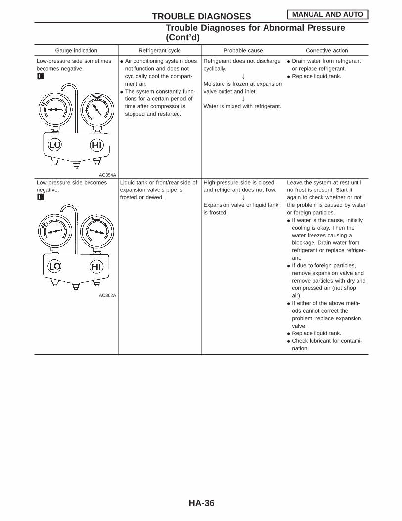
Gauge indication Refrigerant cycle Probable cause Corrective action
Low-pressure side sometimesbecomes negative.
AC354A
I Air conditioning system doesnot function and does notcyclically cool the compart-ment air.
I The system constantly func-tions for a certain period oftime after compressor isstopped and restarted.
Refrigerant does not dischargecyclically.
"
Moisture is frozen at expansionvalve outlet and inlet.
"
Water is mixed with refrigerant.
I Drain water from refrigerantor replace refrigerant.
I Replace liquid tank.
Low-pressure side becomesnegative.
AC362A
Liquid tank or front/rear side ofexpansion valve’s pipe isfrosted or dewed.
High-pressure side is closedand refrigerant does not flow.
"
Expansion valve or liquid tankis frosted.
Leave the system at rest untilno frost is present. Start itagain to check whether or notthe problem is caused by wateror foreign particles.I If water is the cause, initially
cooling is okay. Then thewater freezes causing ablockage. Drain water fromrefrigerant or replace refriger-ant.
I If due to foreign particles,remove expansion valve andremove particles with dry andcompressed air (not shopair).
I If either of the above meth-ods cannot correct theproblem, replace expansionvalve.
I Replace liquid tank.I Check lubricant for contami-
nation.
TROUBLE DIAGNOSES MANUAL AND AUTO
Trouble Diagnoses for Abnormal Pressure(Cont’d)
HA-36

Harness LayoutEngine compartment
RHA111F
TROUBLE DIAGNOSES MANUAL
HA-37
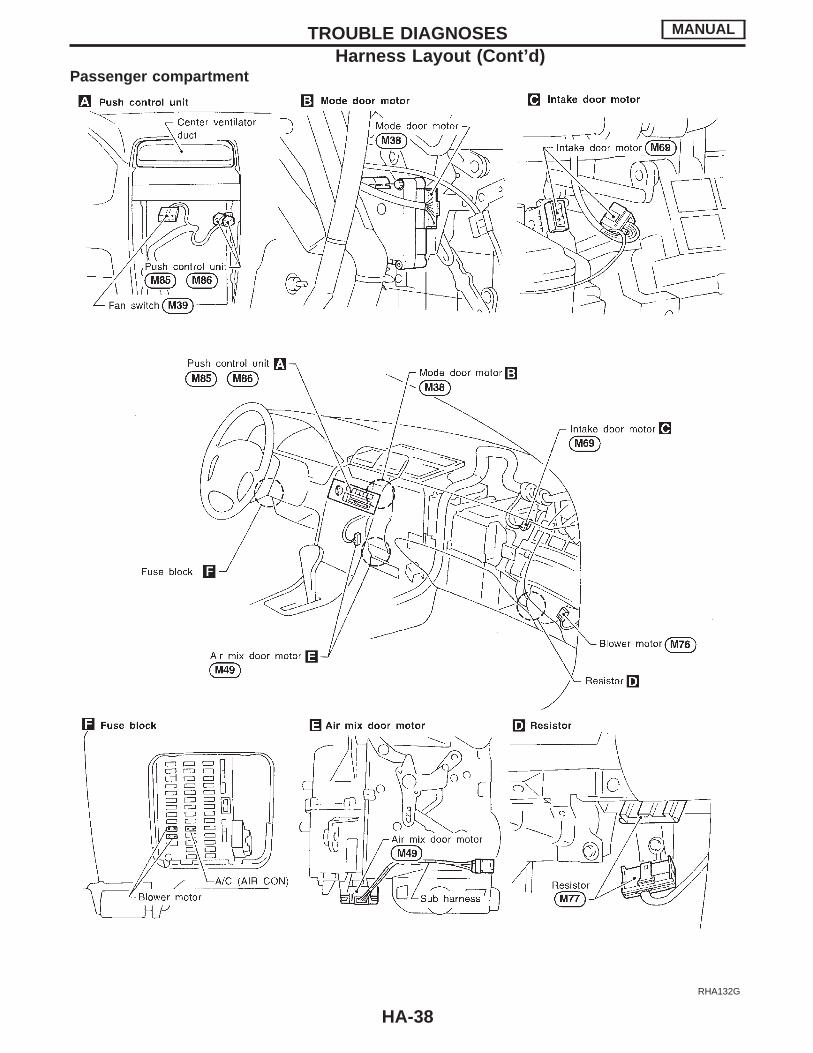
Passenger compartment
RHA132G
TROUBLE DIAGNOSES MANUAL
Harness Layout (Cont’d)
HA-38
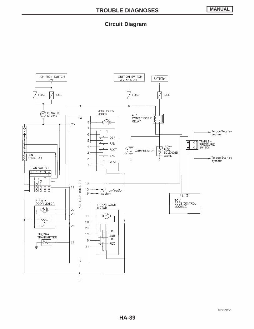
Circuit Diagram
MHA704A
TROUBLE DIAGNOSES MANUAL
HA-39
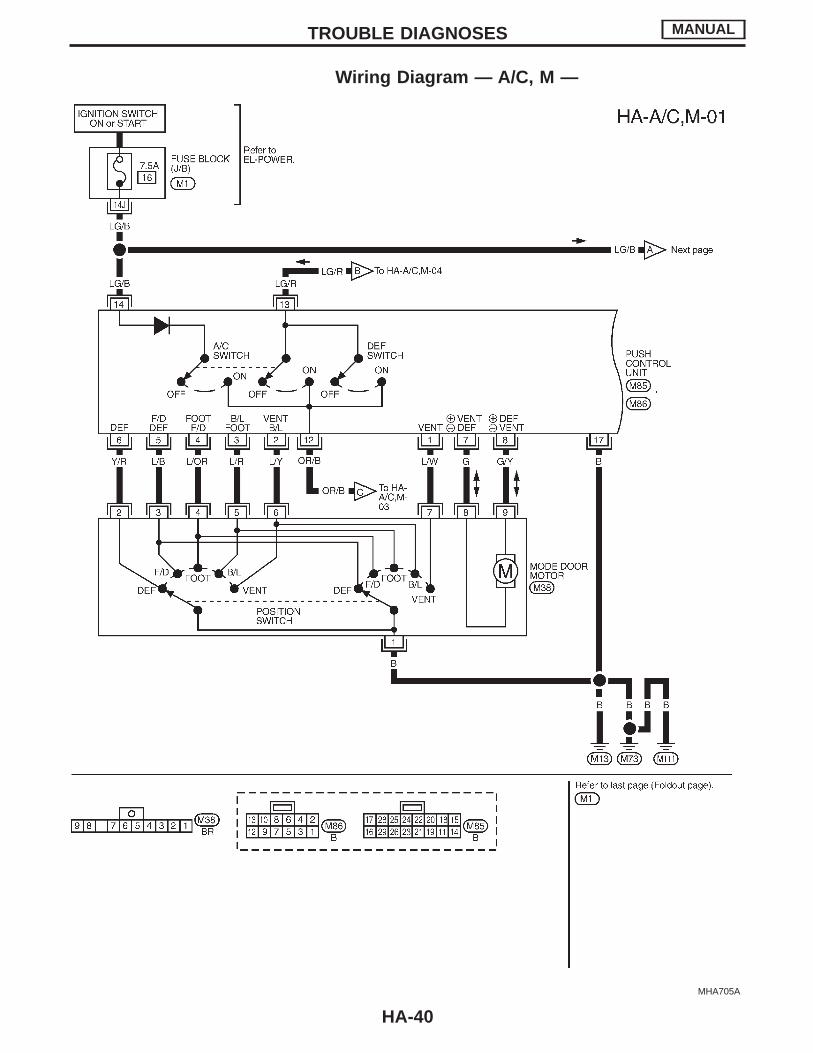
Wiring Diagram — A/C, M —
MHA705A
TROUBLE DIAGNOSES MANUAL
HA-40
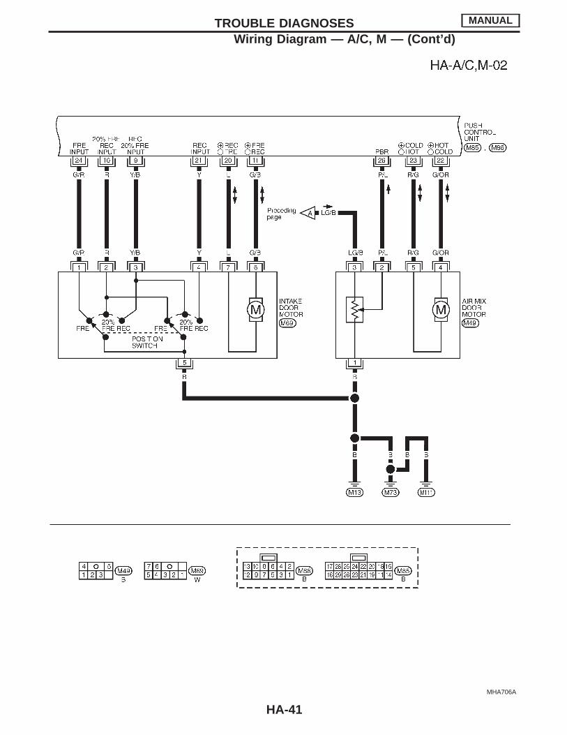
MHA706A
TROUBLE DIAGNOSES MANUAL
Wiring Diagram — A/C , M — (Cont’d)
HA-41
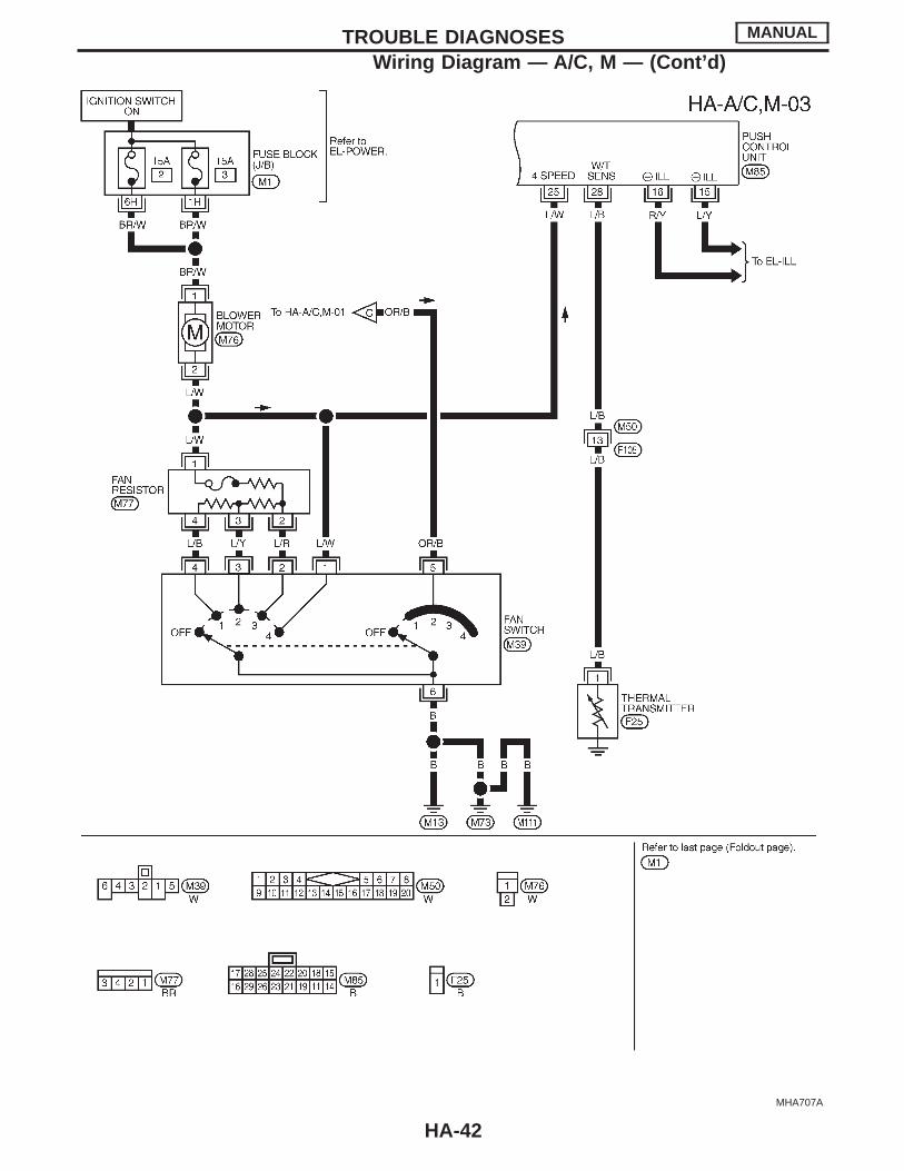
MHA707A
TROUBLE DIAGNOSES MANUAL
Wiring Diagram — A/C , M — (Cont’d)
HA-42
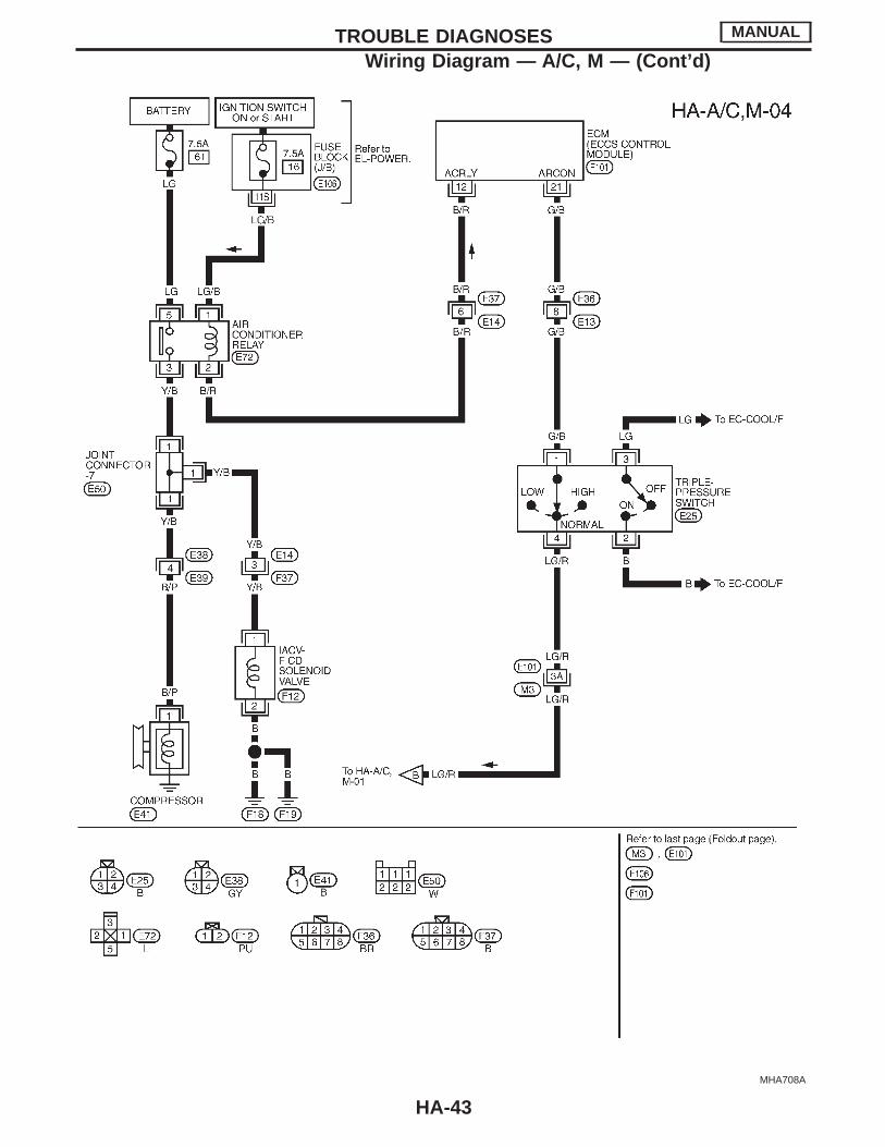
MHA708A
TROUBLE DIAGNOSES MANUAL
Wiring Diagram — A/C , M — (Cont’d)
HA-43
Main Power Supply and Ground Circuit CheckPOWER SUPPLY CIRCUIT CHECKCheck power supply circuit for air conditioning system.Refer to EL section (“Wiring Diagram”, “POWER SUPPLYROUTING”).
RHA464EB
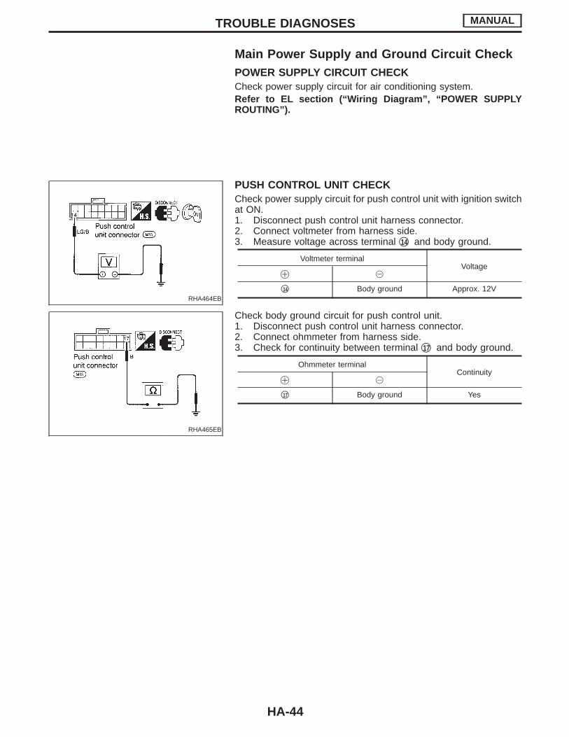
PUSH CONTROL UNIT CHECKCheck power supply circuit for push control unit with ignition switchat ON.1. Disconnect push control unit harness connector.2. Connect voltmeter from harness side.3. Measure voltage across terminal q14 and body ground.
Voltmeter terminalVoltage
! @
q14 Body ground Approx. 12V
RHA465EB
Check body ground circuit for push control unit.1. Disconnect push control unit harness connector.2. Connect ohmmeter from harness side.3. Check for continuity between terminal q17 and body ground.
Ohmmeter terminalContinuity
! @
q17 Body ground Yes
TROUBLE DIAGNOSES MANUAL
HA-44
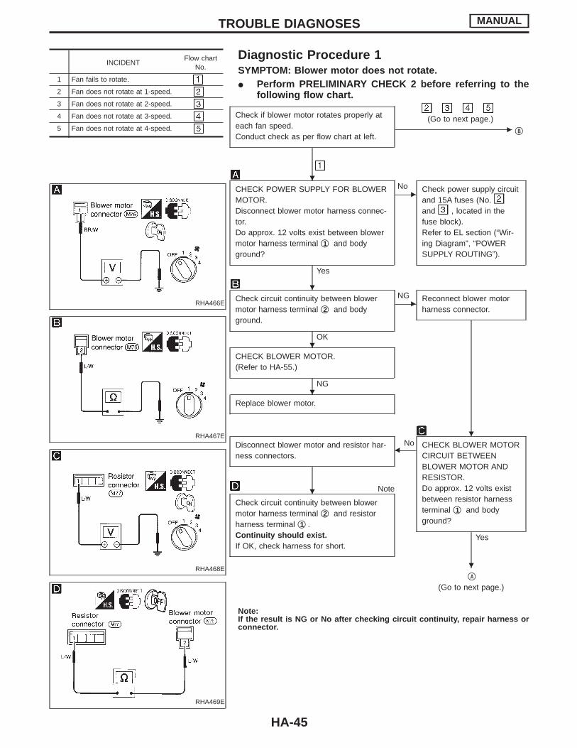
Diagnostic Procedure 1SYMPTOM: Blower motor does not rotate.I Perform PRELIMINARY CHECK 2 before referring to the
following flow chart.
INCIDENTFlow chart
No.
1 Fan fails to rotate.
2 Fan does not rotate at 1-speed.
3 Fan does not rotate at 2-speed.
4 Fan does not rotate at 3-speed.
5 Fan does not rotate at 4-speed.
RHA466E
RHA467E
RHA468E
RHA469E
Check if blower motor rotates properly ateach fan speed.Conduct check as per flow chart at left.
E(Go to next page.)
qB
CHECK POWER SUPPLY FOR BLOWERMOTOR.Disconnect blower motor harness connec-tor.Do approx. 12 volts exist between blowermotor harness terminal q1 and bodyground?
Yes
ENo Check power supply circuit
and 15A fuses (No.and , located in thefuse block).Refer to EL section (“Wir-ing Diagram”, “POWERSUPPLY ROUTING”).
Check circuit continuity between blowermotor harness terminal q2 and bodyground.
OK
ENG Reconnect blower motor
harness connector.
CHECK BLOWER MOTOR.(Refer to HA-55.)
NG
Replace blower motor.
NoDisconnect blower motor and resistor har-ness connectors.
FCHECK BLOWER MOTORCIRCUIT BETWEENBLOWER MOTOR ANDRESISTOR.Do approx. 12 volts existbetween resistor harnessterminal q1 and bodyground?
Yes
Note
Check circuit continuity between blowermotor harness terminal q2 and resistorharness terminal q1 .Continuity should exist.If OK, check harness for short.
qA
(Go to next page.)
Note:If the result is NG or No after checking circuit continuity, repair harness orconnector.
TROUBLE DIAGNOSES MANUAL
H
H
H
H
H
H
H
HA-45
RHA470E
RHA471E
RHA477E
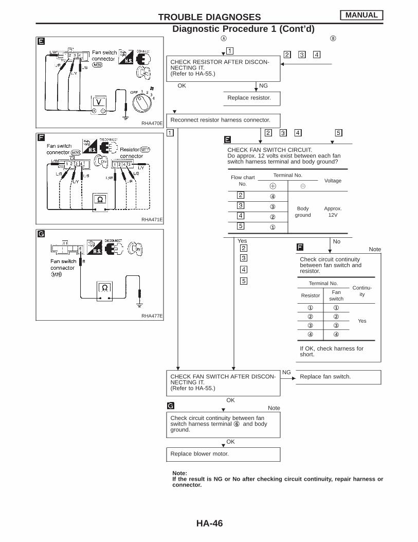
qA qB
H
CHECK RESISTOR AFTER DISCON-NECTING IT.(Refer to HA-55.)
OK NG
F
Replace resistor.
Reconnect resistor harness connector.
H
CHECK FAN SWITCH CIRCUIT.Do approx. 12 volts exist between each fanswitch harness terminal and body ground?
NoYes
H
Note
Check circuit continuitybetween fan switch andresistor.
If OK, check harness forshort.
CHECK FAN SWITCH AFTER DISCON-NECTING IT.(Refer to HA-55.)
OK
ENG
Replace fan switch.
Note
Check circuit continuity between fanswitch harness terminal q6 and bodyground.
OK
Replace blower motor.
Note:If the result is NG or No after checking circuit continuity, repair harness orconnector.
Flow chartNo.
Terminal No.Voltage
! @
q4
Bodyground
Approx.12V
q3
q2
q1
Terminal No.Continu-
ityResistorFan
switch
q1 q1
Yesq2 q2
q3 q3
q4 q4
TROUBLE DIAGNOSES MANUAL
Diagnostic Procedure 1 (Cont’d)
H
H
H
H
H
H
H
HA-46
SHA454EB
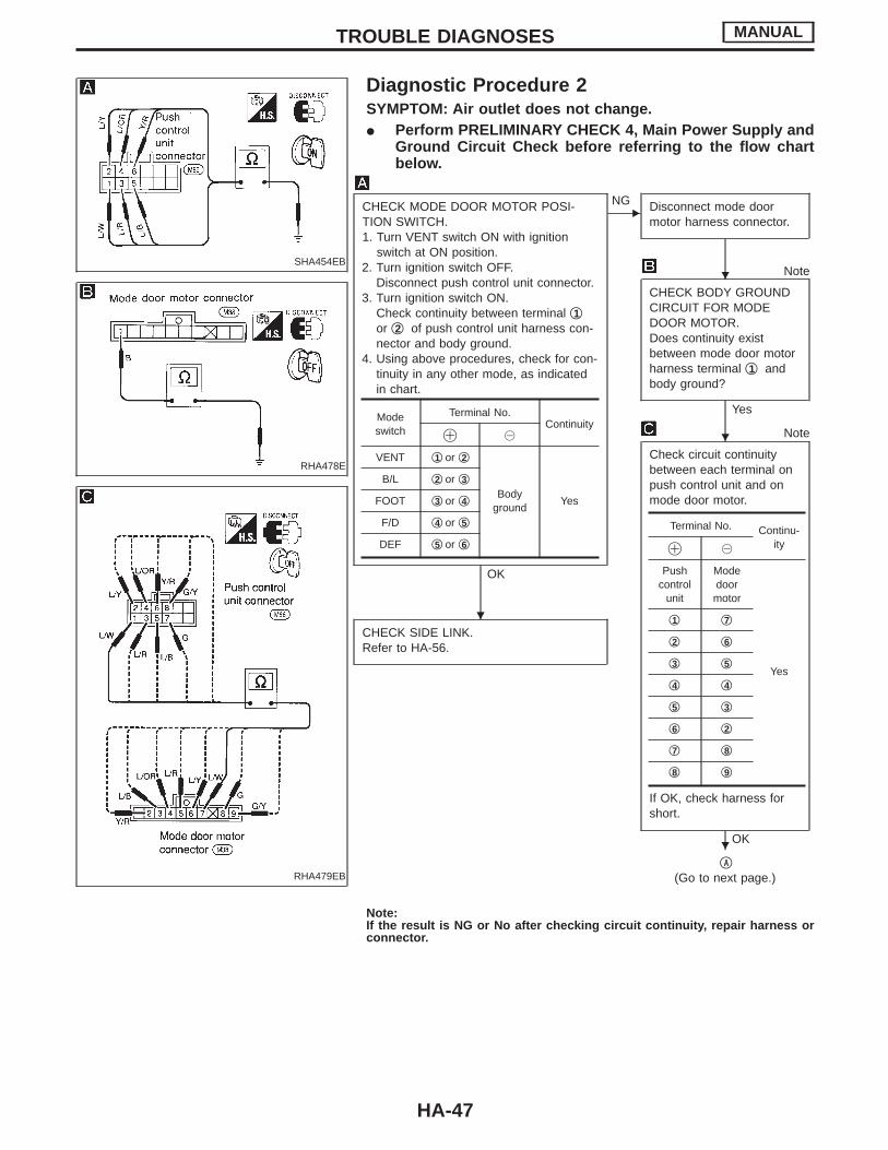
Diagnostic Procedure 2SYMPTOM: Air outlet does not change.I Perform PRELIMINARY CHECK 4, Main Power Supply and
Ground Circuit Check before referring to the flow chartbelow.
RHA478E
RHA479EB
CHECK MODE DOOR MOTOR POSI-TION SWITCH.1. Turn VENT switch ON with ignition
switch at ON position.2. Turn ignition switch OFF.
Disconnect push control unit connector.3. Turn ignition switch ON.
Check continuity between terminal q1or q2 of push control unit harness con-nector and body ground.
4. Using above procedures, check for con-tinuity in any other mode, as indicatedin chart.
OK
ENG Disconnect mode door
motor harness connector.
Note
CHECK BODY GROUNDCIRCUIT FOR MODEDOOR MOTOR.Does continuity existbetween mode door motorharness terminal q1 andbody ground?
Yes
Note
Check circuit continuitybetween each terminal onpush control unit and onmode door motor.
If OK, check harness forshort.
OK
CHECK SIDE LINK.Refer to HA-56.
qA
(Go to next page.)
Note:If the result is NG or No after checking circuit continuity, repair harness orconnector.
Modeswitch
Terminal No.Continuity
! @
VENT q1 or q2
Bodyground
Yes
B/L q2 or q3
FOOT q3 or q4
F/D q4 or q5
DEF q5 or q6
Terminal No. Continu-ity! @
Pushcontrol
unit
Modedoormotor
Yes
q1 q7
q2 q6
q3 q5
q4 q4
q5 q3
q6 q2
q7 q8
q8 q9
TROUBLE DIAGNOSES MANUAL
H
H
H
H
HA-47
SHA455EB
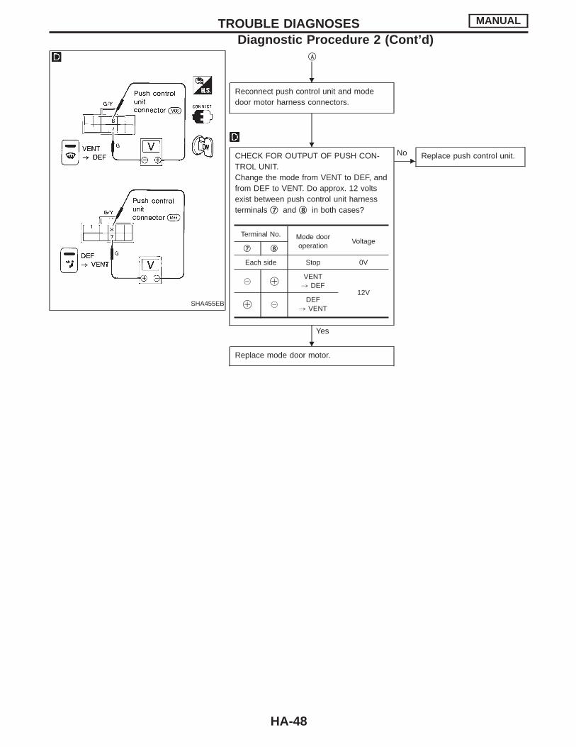
qA
Reconnect push control unit and modedoor motor harness connectors.
CHECK FOR OUTPUT OF PUSH CON-TROL UNIT.Change the mode from VENT to DEF, andfrom DEF to VENT. Do approx. 12 voltsexist between push control unit harnessterminals q7 and q8 in both cases?
Yes
ENo Replace push control unit.
Replace mode door motor.
Terminal No. Mode dooroperation
Voltageq7 q8
Each side Stop 0V
@ !VENT, DEF
12V
! @DEF
, VENT
TROUBLE DIAGNOSES MANUAL
Diagnostic Procedure 2 (Cont’d)
H
H
H
HA-48
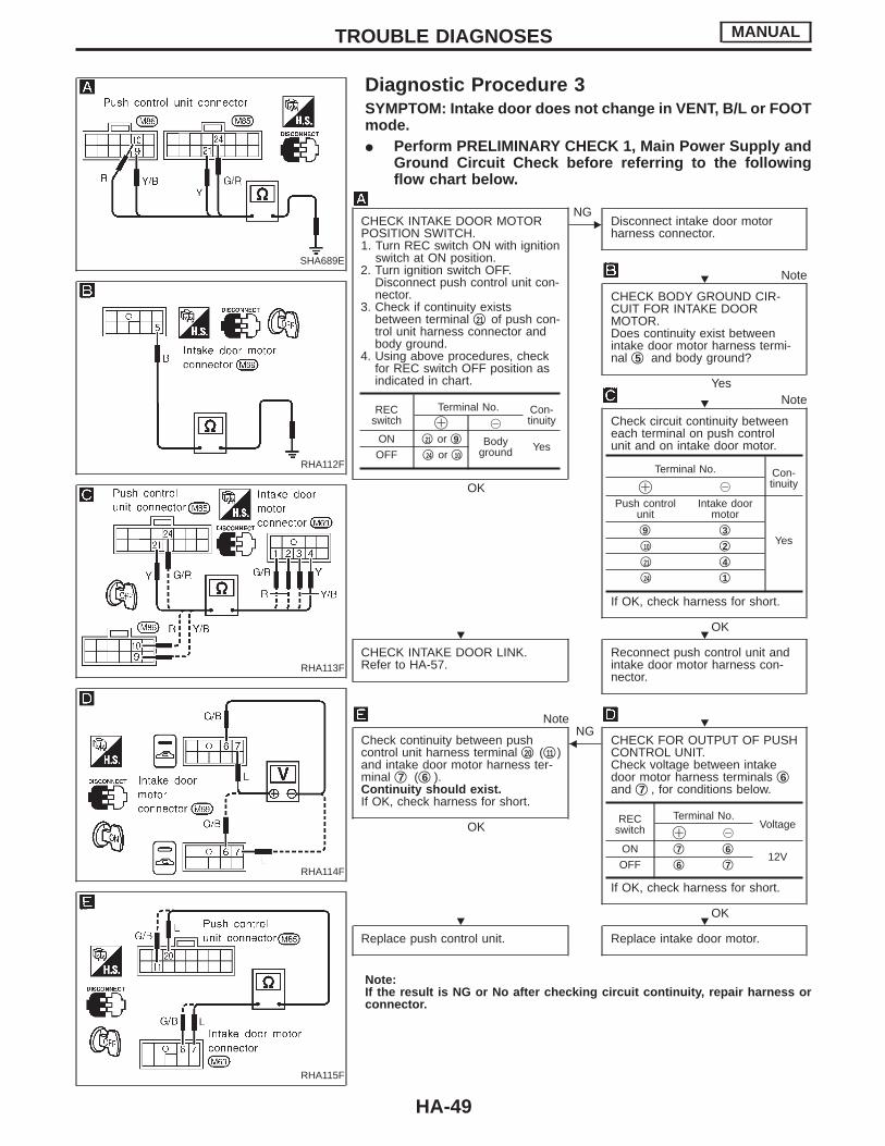
SHA689E
Diagnostic Procedure 3SYMPTOM: Intake door does not change in VENT, B/L or FOOTmode.I Perform PRELIMINARY CHECK 1, Main Power Supply and
Ground Circuit Check before referring to the followingflow chart below.
RHA112F
RHA113F
RHA114F
RHA115F
CHECK INTAKE DOOR MOTORPOSITION SWITCH.1. Turn REC switch ON with ignition
switch at ON position.2. Turn ignition switch OFF.
Disconnect push control unit con-nector.
3. Check if continuity existsbetween terminal q21 of push con-trol unit harness connector andbody ground.
4. Using above procedures, checkfor REC switch OFF position asindicated in chart.
OK
ENG
Disconnect intake door motorharness connector.
Note
CHECK BODY GROUND CIR-CUIT FOR INTAKE DOORMOTOR.Does continuity exist betweenintake door motor harness termi-nal q5 and body ground?
YesNote
Check circuit continuity betweeneach terminal on push controlunit and on intake door motor.
If OK, check harness for short.
OK
CHECK INTAKE DOOR LINK.Refer to HA-57.
Reconnect push control unit andintake door motor harness con-nector.
Note
Check continuity between pushcontrol unit harness terminal q20 (q11 )and intake door motor harness ter-minal q7 (q6 ).Continuity should exist.If OK, check harness for short.
OK
NGF CHECK FOR OUTPUT OF PUSH
CONTROL UNIT.Check voltage between intakedoor motor harness terminals q6and q7 , for conditions below.
If OK, check harness for short.
OK
Replace push control unit. Replace intake door motor.
Note:If the result is NG or No after checking circuit continuity, repair harness orconnector.
RECswitch
Terminal No. Con-tinuity! @
ON q21 or q9 Bodyground Yes
OFF q24 or q10
Terminal No. Con-tinuity! @
Push controlunit
Intake doormotor
Yesq9 q3q10 q2q21 q4q24 q1
RECswitch
Terminal No.Voltage
! @
ON q7 q612V
OFF q6 q7
TROUBLE DIAGNOSES MANUAL
H
H
H H
H
H H
HA-49

RHA116F
Diagnostic Procedure 4SYMPTOM: Air mix door does not change.I Perform PRELIMINARY CHECK 2, Main Power Supply and
Ground Circuit Check before referring to the followingchart.
RHA117F
RHA118F
CHECK POWER SUPPLY FOR AIR MIXDOOR MOTOR.Disconnect air mix door motor harnessconnector.Do approx. 12V exist between air mixdoor motor harness terminal q3 and bodyground?
Yes
ENo Check power supply circuit
and 7.5A fuse (No. 16 ,located in the fuse block).Refer to EL section (“Wir-ing Diagram”, “POWERSUPPLY ROUTING”).
Note
Check circuit continuity between air mixdoor motor harness terminal No. q1 andbody ground.
OK
Disconnect push control unit harness con-nector.
Note
Check circuit continuity between each ter-minal on push control unit and air mixdoor motor.
If OK, check harness for short.
OK
Reconnect push control unit and air mixdoor motor harness connector.
qA
(Go to next page.)
Note:If the result is NG or No after checking circuit continuity, repair harness orconnector.
Terminal No. Continuity
Push controlunit
Air mix doormotor
Yesq22 q4
q23 q5
q26 q2
TROUBLE DIAGNOSES MANUAL
H
H
H
H
H
HA-50
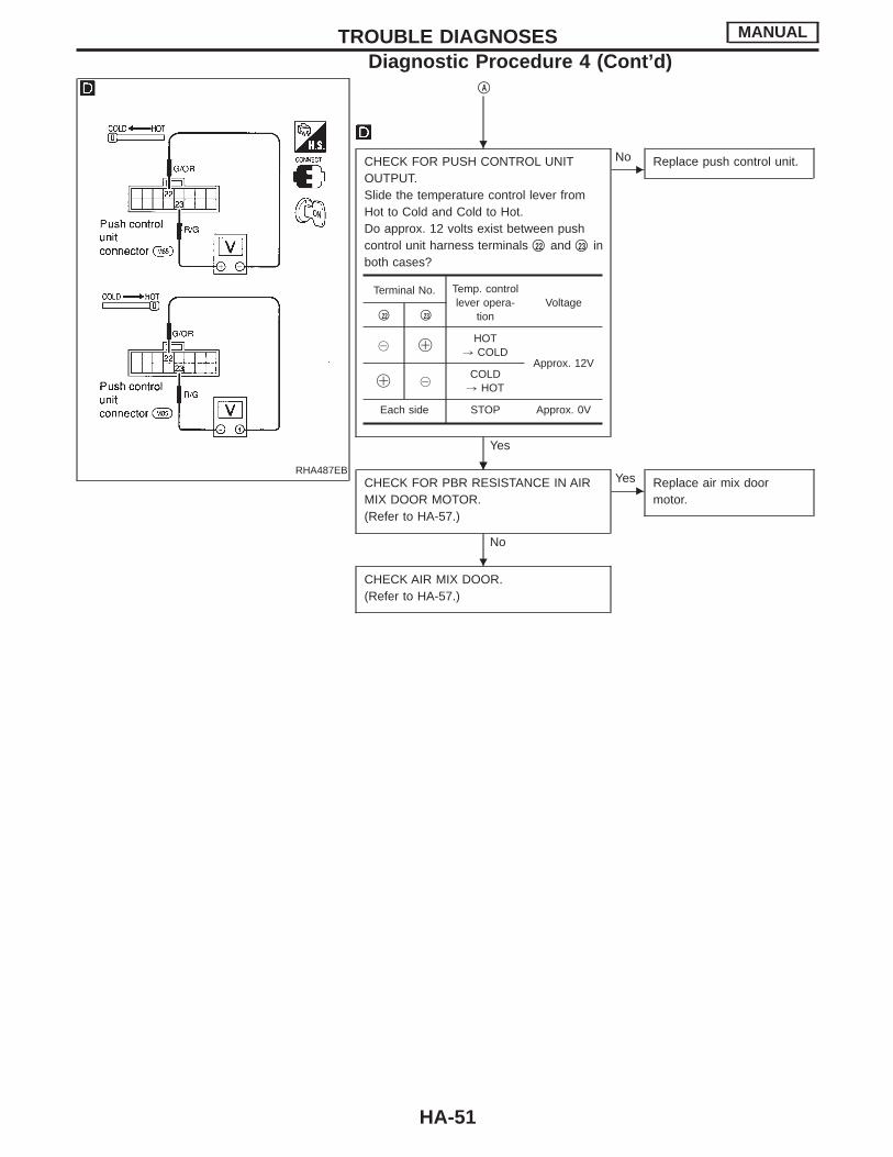
RHA487EB
qA
CHECK FOR PUSH CONTROL UNITOUTPUT.Slide the temperature control lever fromHot to Cold and Cold to Hot.Do approx. 12 volts exist between pushcontrol unit harness terminals q22 and q23 inboth cases?
Yes
ENo Replace push control unit.
CHECK FOR PBR RESISTANCE IN AIRMIX DOOR MOTOR.(Refer to HA-57.)
No
EYes Replace air mix door
motor.
CHECK AIR MIX DOOR.(Refer to HA-57.)
Terminal No. Temp. controllever opera-
tionVoltage
q22 q23
@ !HOT
, COLDApprox. 12V
! @COLD, HOT
Each side STOP Approx. 0V
TROUBLE DIAGNOSES MANUAL
Diagnostic Procedure 4 (Cont’d)
H
HH
H
HA-51
RHA129GA
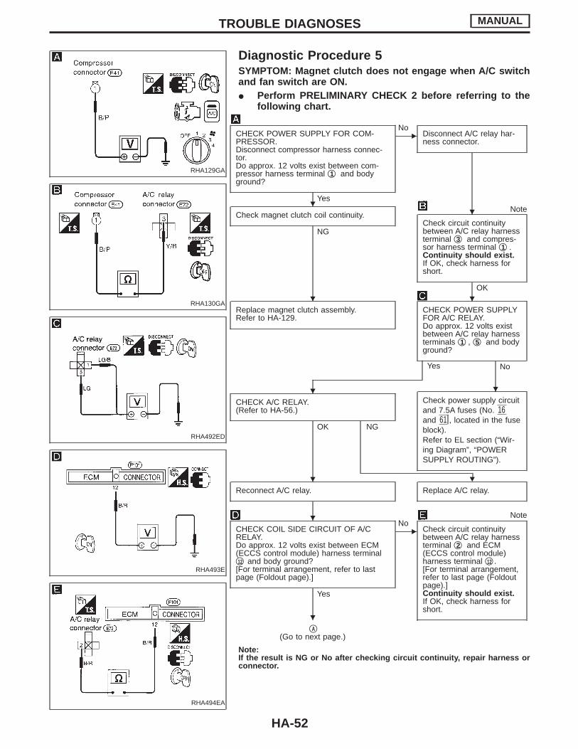
Diagnostic Procedure 5SYMPTOM: Magnet clutch does not engage when A/C switchand fan switch are ON.I Perform PRELIMINARY CHECK 2 before referring to the
following chart.
RHA130GA
RHA492ED
RHA493E
RHA494EA
CHECK POWER SUPPLY FOR COM-PRESSOR.Disconnect compressor harness connec-tor.Do approx. 12 volts exist between com-pressor harness terminal q1 and bodyground?
Yes
ENo
Disconnect A/C relay har-ness connector.
Check magnet clutch coil continuity.
NG
Note
Check circuit continuitybetween A/C relay harnessterminal q3 and compres-sor harness terminal q1 .Continuity should exist.If OK, check harness forshort.
OK
Replace magnet clutch assembly.Refer to HA-129.
CHECK POWER SUPPLYFOR A/C RELAY.Do approx. 12 volts existbetween A/C relay harnessterminals q1 , q5 and bodyground?
Yes No
CHECK A/C RELAY.(Refer to HA-56.)
OK NG
Check power supply circuitand 7.5A fuses (No. 16and 61 , located in the fuseblock).Refer to EL section (“Wir-ing Diagram”, “POWERSUPPLY ROUTING”).
H
Reconnect A/C relay. Replace A/C relay.
Note
CHECK COIL SIDE CIRCUIT OF A/CRELAY.Do approx. 12 volts exist between ECM(ECCS control module) harness terminalq12 and body ground?[For terminal arrangement, refer to lastpage (Foldout page).]
Yes
ENo
Check circuit continuitybetween A/C relay harnessterminal q2 and ECM(ECCS control module)harness terminal q12 .[For terminal arrangement,refer to last page (Foldoutpage).]Continuity should exist.If OK, check harness forshort.
qA(Go to next page.)
Note:If the result is NG or No after checking circuit continuity, repair harness orconnector.
TROUBLE DIAGNOSES MANUAL
HH
H H
H H
H
H
H
HA-52

RHA129FA
RHA014G
RHA131G
RHA015G
qA
CHECK COIL SIDE CIRCUIT OF A/CRELAY CONTROLLED BY ECM (ECCScontrol module).Do approx. 8 to 9 volts exist betweenECM (ECCS control module) harness ter-minal No. q21 and body ground?[For terminal arrangement, refer to lastpage (Foldout page).]
No
EYes
CHECK TRIPLE-PRES-SURE SWITCH CIRCUITBETWEEN TRIPLE-PRESSURE SWITCH ANDECM (ECCS control mod-ule).Disconnect triple-pressureswitch harness connector.Do approx. 8 to 9 voltsexist between triple-pres-sure switch harness termi-nal q1 and body ground?
Yes No
CHECK ECM (ECCS control module).Refer to EC section (“ECM Terminals andReference Value”, “TROUBLE DIAG-NOSES — General Description”).
Disconnect ECM (ECCScontrol module) harnessconnector.
CHECK TRIPLE-PRESSURE SWITCH.(Refer to HA-56.)
OK
NG
E
Note
Check circuit continuitybetween ECM (ECCS con-trol module) harness termi-nal q21 and triple-pressureswitch harness terminal q1 .[For terminal arrangement,refer to last page (Foldoutpage).]Continuity should exist.If OK, check harness forshort.
Note
Check circuit continuity between triple-pressure switch harness terminal q4 andpush control unit harness terminal q13 .Continuity should exist.If OK, check harness for short.
OK
Replace triple-pressureswitch.
qB
(Go to next page.)
TROUBLE DIAGNOSES MANUAL
Diagnostic Procedure 5 (Cont’d)
H
H
H
HH
H
H
HA-53
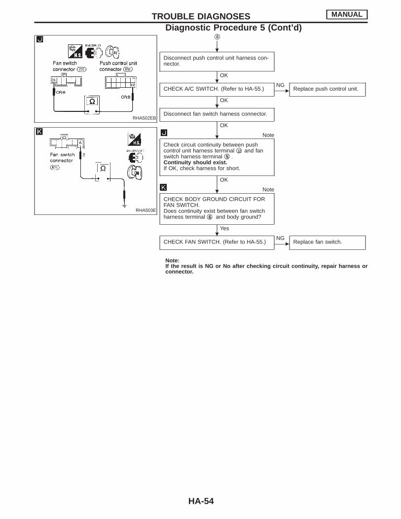
RHA502EB
RHA503E
qB
Disconnect push control unit harness con-nector.
OK
CHECK A/C SWITCH. (Refer to HA-55.)
OK
ENG
Replace push control unit.
Disconnect fan switch harness connector.
OK
Note
Check circuit continuity between pushcontrol unit harness terminal q12 and fanswitch harness terminal q5 .Continuity should exist.If OK, check harness for short.
OK
Note
CHECK BODY GROUND CIRCUIT FORFAN SWITCH.Does continuity exist between fan switchharness terminal q6 and body ground?
Yes
CHECK FAN SWITCH. (Refer to HA-55.) ENG
Replace fan switch.
Note:If the result is NG or No after checking circuit continuity, repair harness orconnector.
TROUBLE DIAGNOSES MANUAL
Diagnostic Procedure 5 (Cont’d)
H
H
H
H
H
H
HA-54

RHA436E
Electrical Components InspectionFAN SWITCHCheck continuity between terminals at each position.
POSITIONTERMINAL
1 2 3 4 5 6
OFF
1 q q q
2 q q q
3 q q q
4 q q q
RHA244D
BLOWER MOTORCheck blower motor for smooth rotation.I Ensure that there are no foreign particles inside the intake unit.
AHA230
BLOWER RESISTORCheck continuity between terminals.
RHA504EB
A/C SWITCH (Push control unit)Check continuity between terminals.
A/C switch Terminals Continuity
ONq12 - q13
Exists.
OFF Does not exist.
TROUBLE DIAGNOSES MANUAL
HA-55
SHA691E
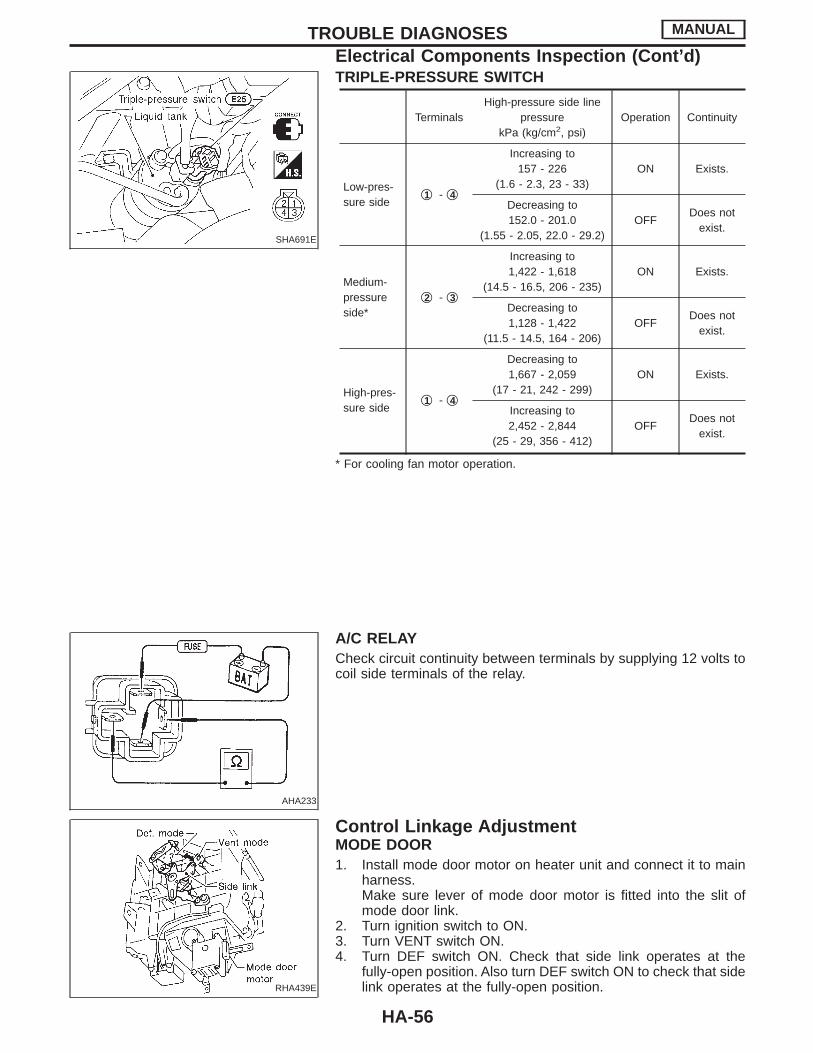
TRIPLE-PRESSURE SWITCH
TerminalsHigh-pressure side line
pressurekPa (kg/cm2, psi)
Operation Continuity
Low-pres-sure side
q1 - q4
Increasing to157 - 226
(1.6 - 2.3, 23 - 33)ON Exists.
Decreasing to152.0 - 201.0
(1.55 - 2.05, 22.0 - 29.2)OFF
Does notexist.
Medium-pressureside*
q2 - q3
Increasing to1,422 - 1,618
(14.5 - 16.5, 206 - 235)ON Exists.
Decreasing to1,128 - 1,422
(11.5 - 14.5, 164 - 206)OFF
Does notexist.
High-pres-sure side
q1 - q4
Decreasing to1,667 - 2,059
(17 - 21, 242 - 299)ON Exists.
Increasing to2,452 - 2,844
(25 - 29, 356 - 412)OFF
Does notexist.
* For cooling fan motor operation.
AHA233
A/C RELAYCheck circuit continuity between terminals by supplying 12 volts tocoil side terminals of the relay.
RHA439E
Control Linkage AdjustmentMODE DOOR1. Install mode door motor on heater unit and connect it to main
harness.Make sure lever of mode door motor is fitted into the slit ofmode door link.
2. Turn ignition switch to ON.3. Turn VENT switch ON.4. Turn DEF switch ON. Check that side link operates at the
fully-open position. Also turn DEF switch ON to check that sidelink operates at the fully-open position.
TROUBLE DIAGNOSES MANUAL
Electrical Components Inspection (Cont’d)
HA-56
SHA848E
RHA564EA
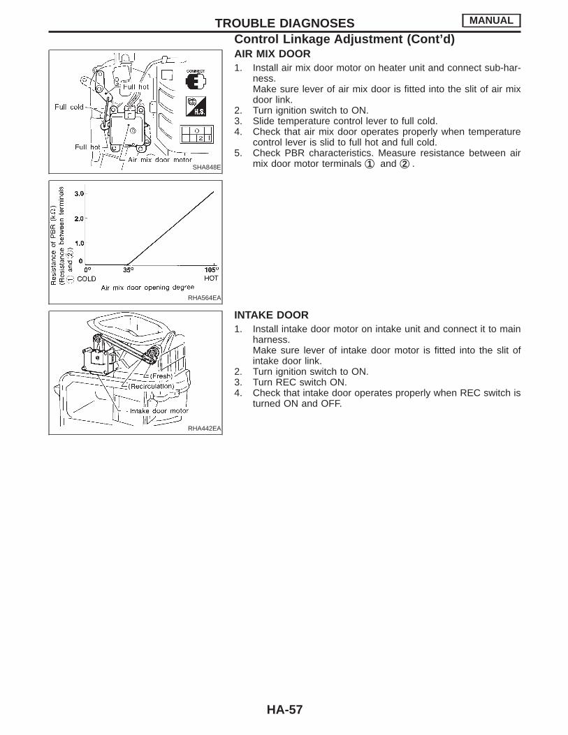
AIR MIX DOOR1. Install air mix door motor on heater unit and connect sub-har-
ness.Make sure lever of air mix door is fitted into the slit of air mixdoor link.
2. Turn ignition switch to ON.3. Slide temperature control lever to full cold.4. Check that air mix door operates properly when temperature
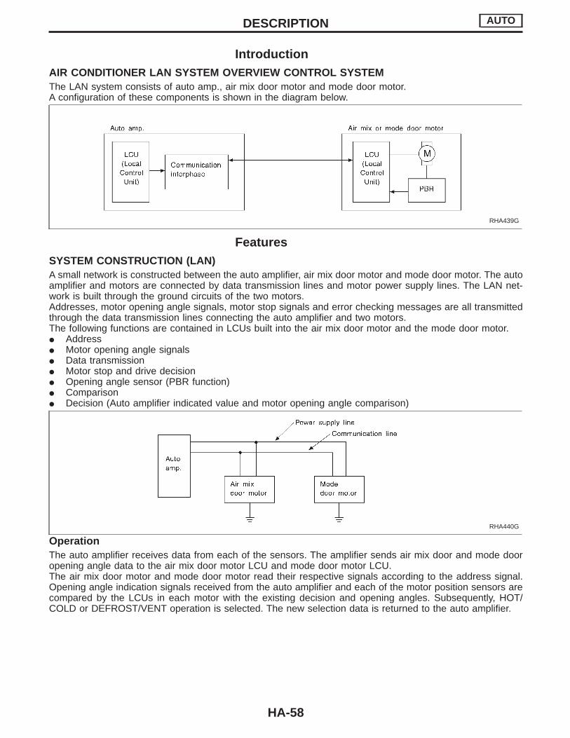
control lever is slid to full hot and full cold.5. Check PBR characteristics. Measure resistance between air
mix door motor terminals q1 and q2 .
RHA442EA
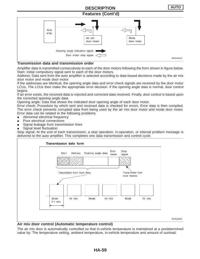
INTAKE DOOR1. Install intake door motor on intake unit and connect it to main
harness.Make sure lever of intake door motor is fitted into the slit ofintake door link.
2. Turn ignition switch to ON.3. Turn REC switch ON.4. Check that intake door operates properly when REC switch is
turned ON and OFF.
TROUBLE DIAGNOSES MANUAL
Control Linkage Adjustment (Cont’d)
HA-57
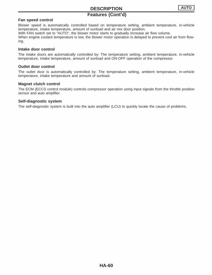
IntroductionAIR CONDITIONER LAN SYSTEM OVERVIEW CONTROL SYSTEMThe LAN system consists of auto amp., air mix door motor and mode door motor.A configuration of these components is shown in the diagram below.
RHA439G
FeaturesSYSTEM CONSTRUCTION (LAN)A small network is constructed between the auto amplifier, air mix door motor and mode door motor. The autoamplifier and motors are connected by data transmission lines and motor power supply lines. The LAN net-work is built through the ground circuits of the two motors.Addresses, motor opening angle signals, motor stop signals and error checking messages are all transmittedthrough the data transmission lines connecting the auto amplifier and two motors.The following functions are contained in LCUs built into the air mix door motor and the mode door motor.I AddressI Motor opening angle signalsI Data transmissionI Motor stop and drive decisionI Opening angle sensor (PBR function)I ComparisonI Decision (Auto amplifier indicated value and motor opening angle comparison)
RHA440G
OperationThe auto amplifier receives data from each of the sensors. The amplifier sends air mix door and mode dooropening angle data to the air mix door motor LCU and mode door motor LCU.The air mix door motor and mode door motor read their respective signals according to the address signal.Opening angle indication signals received from the auto amplifier and each of the motor position sensors arecompared by the LCUs in each motor with the existing decision and opening angles. Subsequently, HOT/COLD or DEFROST/VENT operation is selected. The new selection data is returned to the auto amplifier.
DESCRIPTION AUTO
HA-58
RHA441G
Transmission data and transmission orderAmplifier data is transmitted consecutively to each of the door motors following the form shown in figure below.Start: Initial compulsory signal sent to each of the door motors.Address: Data sent from the auto amplifier is selected according to data-based decisions made by the air mixdoor motor and mode door motor.If the addresses are identical, the opening angle data and error check signals are received by the door motorLCUs. The LCUs then make the appropriate error decision. If the opening angle data is normal, door controlbegins.If an error exists, the received data is rejected and corrected data received. Finally, door control is based uponthe corrected opening angle data.Opening angle: Data that shows the indicated door opening angle of each door motor.Error check: Procedure by which sent and received data is checked for errors. Error data is then compiled.The error check prevents corrupted data from being used by the air mix door motor and mode door motor.Error data can be related to the following problems.I Abnormal electrical frequencyI Poor electrical connectionsI Signal leakage from transmission linesI Signal level fluctuationStop signal: At the end of each transmission, a stop operation, in-operation, or internal problem message isdelivered to the auto amplifier. This completes one data transmission and control cycle.
RHA442G
Air mix door control (Automatic temperature control)The air mix door is automatically controlled so that in-vehicle temperature is maintained at a predeterminedvalue by: The temperature setting, ambient temperature, in-vehicle temperature and amount of sunload.
DESCRIPTION AUTO
Features (Cont’d)
HA-59
Fan speed controlBlower speed is automatically controlled based on temperature setting, ambient temperature, in-vehicletemperature, intake temperature, amount of sunload and air mix door position.With FAN switch set to “AUTO”, the blower motor starts to gradually increase air flow volume.When engine coolant temperature is low, the blower motor operation is delayed to prevent cool air from flow-ing.
Intake door controlThe intake doors are automatically controlled by: The temperature setting, ambient temperature, in-vehicletemperature, intake temperature, amount of sunload and ON-OFF operation of the compressor.
Outlet door controlThe outlet door is automatically controlled by: The temperature setting, ambient temperature, in-vehicletemperature, intake temperature and amount of sunload.
Magnet clutch controlThe ECM (ECCS control module) controls compressor operation using input signals from the throttle positionsensor and auto amplifier.
Self-diagnostic systemThe self-diagnostic system is built into the auto amplifier (LCU) to quickly locate the cause of problems.
DESCRIPTION AUTO
Features (Cont’d)
HA-60
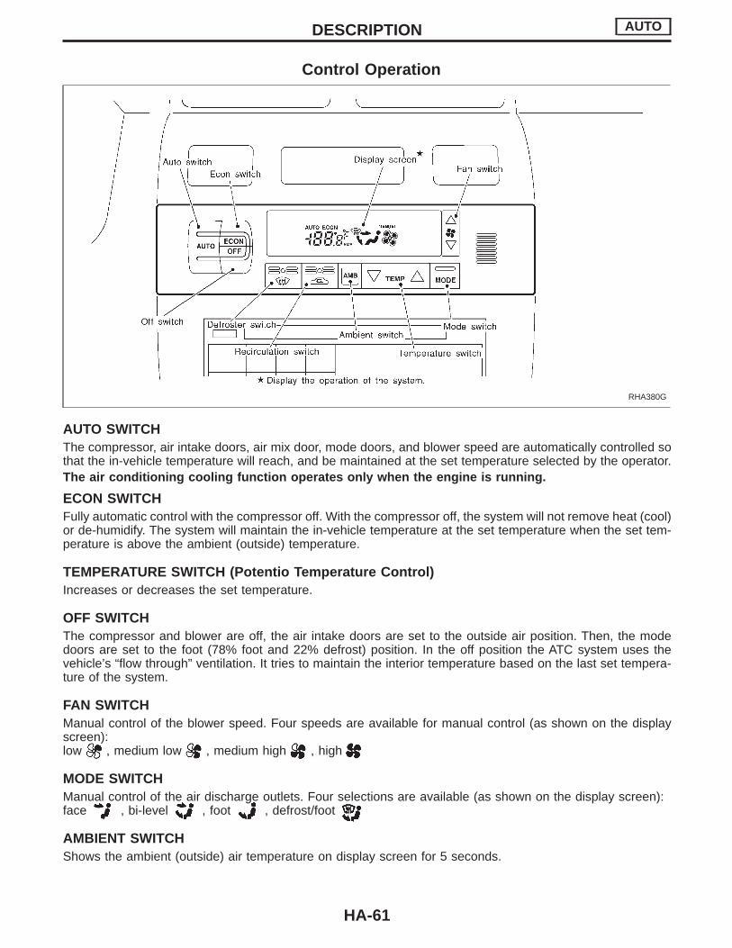
Control Operation
RHA380G
AUTO SWITCHThe compressor, air intake doors, air mix door, mode doors, and blower speed are automatically controlled sothat the in-vehicle temperature will reach, and be maintained at the set temperature selected by the operator.The air conditioning cooling function operates only when the engine is running.
ECON SWITCHFully automatic control with the compressor off. With the compressor off, the system will not remove heat (cool)or de-humidify. The system will maintain the in-vehicle temperature at the set temperature when the set tem-perature is above the ambient (outside) temperature.
TEMPERATURE SWITCH (Potentio Temperature Control)Increases or decreases the set temperature.
OFF SWITCHThe compressor and blower are off, the air intake doors are set to the outside air position. Then, the modedoors are set to the foot (78% foot and 22% defrost) position. In the off position the ATC system uses thevehicle’s “flow through” ventilation. It tries to maintain the interior temperature based on the last set tempera-ture of the system.
FAN SWITCHManual control of the blower speed. Four speeds are available for manual control (as shown on the displayscreen):low , medium low , medium high , high
MODE SWITCHManual control of the air discharge outlets. Four selections are available (as shown on the display screen):face , bi-level , foot , defrost/foot
AMBIENT SWITCHShows the ambient (outside) air temperature on display screen for 5 seconds.
DESCRIPTION AUTO
HA-61
RECIRCULATION (REC) SWITCHON position: Interior air is recirculated inside the vehicle.OFF position: Automatic control resumes.Recirculation is canceled when AUTO, DEF or ECON is selected. Recirculation resumes when another modeis chosen.
DEFROSTER (DEF) SWITCHPositions the mode doors to the defrost position. Also positions the air intake doors to the outside air position.The compressor operates at ambient temperature approx. 2°C (35°F) or above.
DESCRIPTION AUTO
Control Operation (Cont’d)
HA-62
NOTE
DESCRIPTION AUTO
HA-63
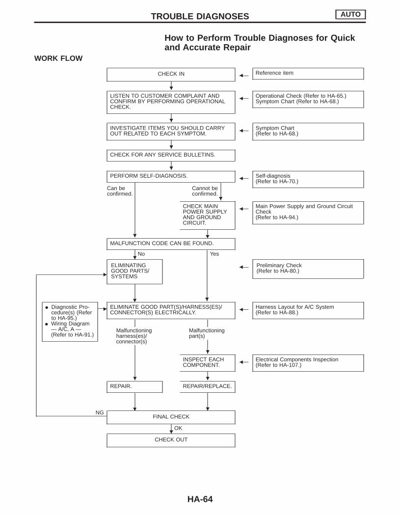
How to Perform Trouble Diagnoses for Quickand Accurate Repair
WORK FLOW
CHECK IN F Reference item
LISTEN TO CUSTOMER COMPLAINT ANDCONFIRM BY PERFORMING OPERATIONALCHECK.
F Operational Check (Refer to HA-65.)Symptom Chart (Refer to HA-68.)
INVESTIGATE ITEMS YOU SHOULD CARRYOUT RELATED TO EACH SYMPTOM. F Symptom Chart
(Refer to HA-68.)
CHECK FOR ANY SERVICE BULLETINS.
PERFORM SELF-DIAGNOSIS. F Self-diagnosis(Refer to HA-70.)
Can beconfirmed.
Cannot beconfirmed.
CHECK MAINPOWER SUPPLYAND GROUNDCIRCUIT.
H
F Main Power Supply and Ground CircuitCheck(Refer to HA-94.)
E
MALFUNCTION CODE CAN BE FOUND.
No Yes
I Diagnostic Pro-cedure(s) (Referto HA-95.)
I Wiring Diagram— A/C, A —(Refer to HA-91.)
E
ELIMINATINGGOOD PARTS/SYSTEMS
H
F Preliminary Check(Refer to HA-80.)
ELIMINATE GOOD PART(S)/HARNESS(ES)/CONNECTOR(S) ELECTRICALLY. F Harness Layout for A/C System
(Refer to HA-88.)
Malfunctioningharness(es)/connector(s)
Malfunctioningpart(s)
INSPECT EACHCOMPONENT. F Electrical Components Inspection
(Refer to HA-107.)
REPAIR.
H
REPAIR/REPLACE.
NGFINAL CHECK
OK
CHECK OUT
TROUBLE DIAGNOSES AUTO
H
H
H
H
H
H
H
H
H
H H
H
H
HA-64
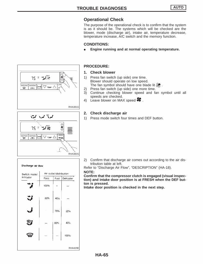
Operational CheckThe purpose of the operational check is to confirm that the systemis as it should be. The systems which will be checked are theblower, mode (discharge air), intake air, temperature decrease,temperature increase, A/C switch and the memory function.
CONDITIONS:I Engine running and at normal operating temperature.
RHA381G
PROCEDURE:
1. Check blower1) Press fan switch (up side) one time.
Blower should operate on low speed.The fan symbol should have one blade lit .
2) Press fan switch (up side) one more time.3) Continue checking blower speed and fan symbol until all
speeds are checked.4) Leave blower on MAX speed .
RHA382G
2. Check discharge air1) Press mode switch four times and DEF button.
RHA429E
2) Confirm that discharge air comes out according to the air dis-tribution table at left.
Refer to “Discharge Air Flow”, “DESCRIPTION” (HA-18).NOTE:Confirm that the compressor clutch is engaged (visual inspec-tion) and intake door position is at FRESH when the DEF but-ton is pressed.Intake door position is checked in the next step.
TROUBLE DIAGNOSES AUTO
HA-65

RHA383G
3. Check recirculation1) Press REC switch.
Recirculation indicator should illuminate.2) Listen for intake door position change (you should hear blower
sound change slightly).
RHA384G
4. Check temperature decrease1) Press the temperature decrease button until 18°C (65°F) is
displayed.2) Check for cold air at discharge air outlets.
RHA385G
5. Check temperature increase1) Press the temperature increase button until 32°C (85°F) is
displayed.2) Check for hot air at discharge air outlets.
RHA386G
6. Check ECON mode1) Press ECON switch.2) Display should indicate ECON (no AUTO, no MANUAL).
Confirm that the compressor clutch is not engaged (visualinspection).(Discharge air will depend on ambient, in-vehicle, and set tem-peratures.)
3) Check for intake air at Fresh position.
RHA387G
7. Check AUTO mode1) Press AUTO switch.2) Display should indicate AUTO (no ECON, no MANUAL).
Confirm that the compressor clutch engages (audio or visualinspection).(Discharge air and suction air will depend on ambient, in-vehicle, and set temperatures.)
TROUBLE DIAGNOSES AUTO
Operational Check (Cont’d)
HA-66
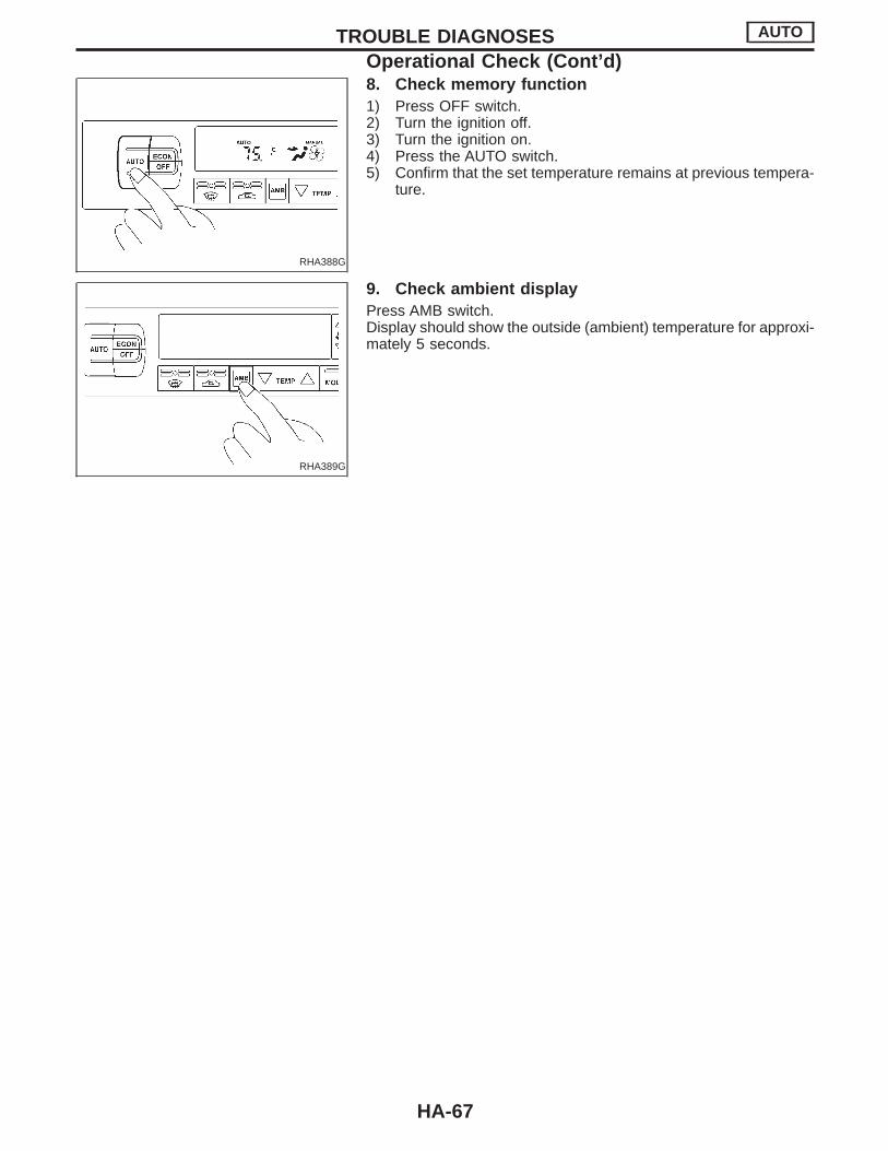
RHA388G
8. Check memory function1) Press OFF switch.2) Turn the ignition off.3) Turn the ignition on.4) Press the AUTO switch.5) Confirm that the set temperature remains at previous tempera-
ture.
RHA389G
9. Check ambient displayPress AMB switch.Display should show the outside (ambient) temperature for approxi-mately 5 seconds.
TROUBLE DIAGNOSES AUTO
Operational Check (Cont’d)
HA-67

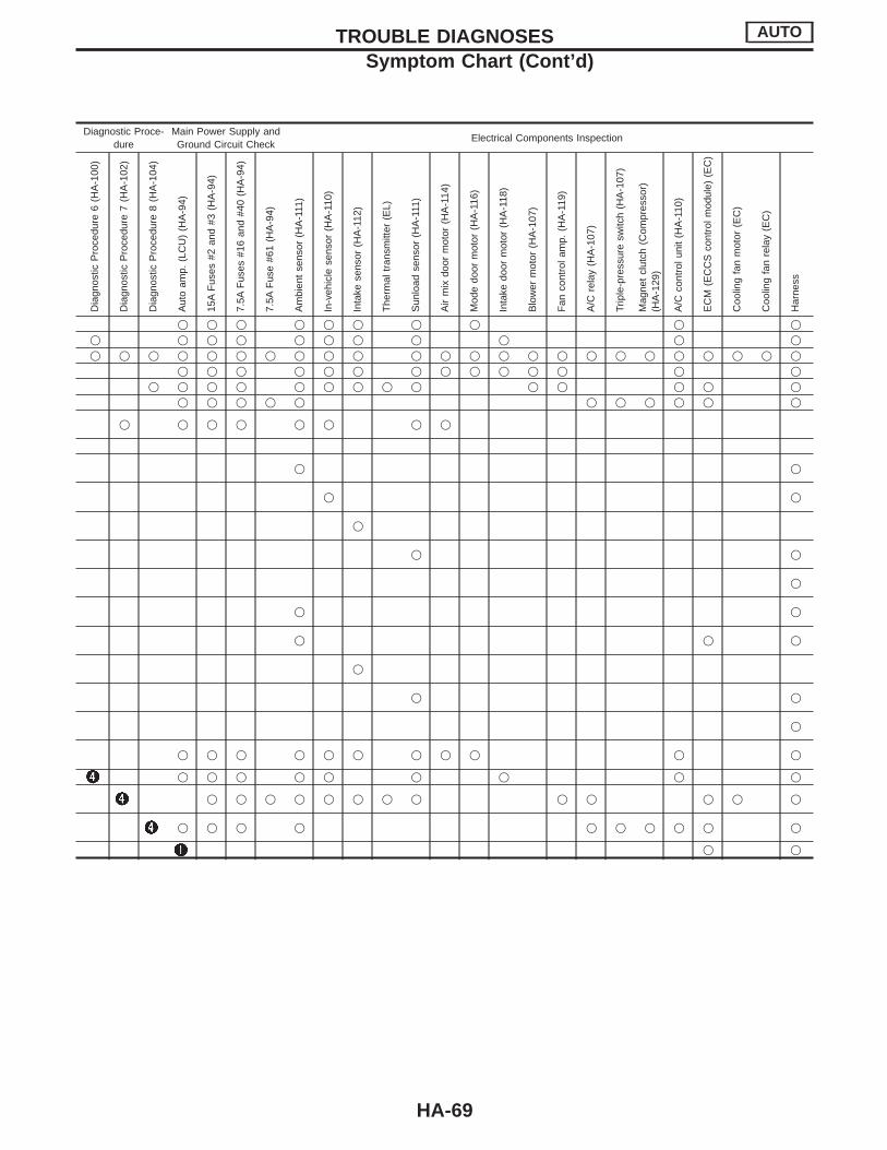
Symptom ChartDIAGNOSTIC TABLE
PROCEDURE Self-diagnosis Preliminary Check Diagnostic Procedure
SYMPTOM
DIA
GN
OS
TIC
ITE
MA
ND
RE
FE
RE
NC
EP
AG
E
ST
EP
1(H
A-7
4,71
)
ST
EP
2(H
A-7
4,71
)
ST
EP
3(H
A-7
5,72
)
ST
EP
4(H
A-7
2,76
)
ST
EP
5(H
A-7
3,77
)
AU
XIL
IAR
YM
EC
HA
NIS
M(H
A-7
9)
Pre
limin
ary
Che
ck1
(HA
-80)
Pre
limin
ary
Che
ck2
(HA
-81)
Pre
limin
ary
Che
ck3
(HA
-82)
Pre
limin
ary
Che
ck4
(HA
-83)
Pre
limin
ary
Che
ck5
(HA
-84)
Pre
limin
ary
Che
ck6
(HA
-85)
Pre
limin
ary
Che
ck7
(HA
-86)
Pre
limin
ary
Che
ck8
(HA
-87)
Dia
gnos
ticP
roce
dure
1(H
A-9
5)
Dia
gnos
ticP
roce
dure
2(H
A-9
6)
Dia
gnos
ticP
roce
dure
3(H
A-9
7)
Dia
gnos
ticP
roce
dure
4(H
A-9
8)
Dia
gnos
ticP
roce
dure
5(H
A-9
9)
Air outlet does not change. q q q q q q qIntake door does not change. q q q q q qInsufficient cooling q q q q q q q q q q q q q q qInsufficient heating q q q q q q q q q q q q q qBlower motor operation is malfunctioning. q q q q q q qMagnet clutch does not engage. q q q q q qDischarged air temperature doesnot change.
q q q q q q
Noise
Res
ult
ofse
lf-di
agno
sis
ST
EP
2
Ambient sensor circuit isopen.
In-vehicle sensor circuit isopen.
Intake sensor circuit isopen.
Sunload sensor circuit isopen.
PBR signal is open.
—Ambient sensor circuit isshorted.
—In-vehicle sensor circuit isshorted.
—Intake sensor circuit isshorted.
—Sunload sensor circuit isshorted.
—PBR signal is shorted.
Mode door motor and/or air mix door motordo not operate normally.
q q q q
Intake door motor does not operate normally. q q q q qBlower motor operation is malfunctioningunder out of Starting Fan Speed Control.
q q q q q q q
Magnet clutch does not operate after perform-ing Preliminary Check 6.
q q q
Self-diagnosis cannot be performed.
- : The numbers refer to the probability of the cause, being the most likely.q: As for checking order, refer to each flow chart. (It depends on malfunctioning portion.)
TROUBLE DIAGNOSES AUTO
HA-68
Diagnostic Proce-dure
Main Power Supply andGround Circuit Check
Electrical Components Inspection
Dia
gnos
ticP
roce
dure
6(H
A-1
00)
Dia
gnos
ticP
roce
dure
7(H
A-1
02)
Dia
gnos
ticP
roce
dure
8(H
A-1
04)
Aut
oam
p.(L
CU
)(H
A-9
4)
15A
Fus
es#2
and
#3(H
A-9
4)
7.5A
Fus
es#1
6an
d#4
0(H
A-9
4)
7.5A
Fus
e#6
1(H
A-9
4)
Am
bien
tse
nsor
(HA
-111
)
In-v
ehic
lese
nsor
(HA
-110
)
Inta
kese
nsor
(HA
-112
)
The
rmal
tran
smitt
er(E
L)
Sun
load
sens
or(H
A-1
11)
Air
mix
door
mot
or(H
A-1
14)
Mod
edo
orm
otor
(HA
-116
)
Inta
kedo
orm
otor
(HA
-118
)
Blo
wer
mot
or(H
A-1
07)
Fan
cont
rola
mp.
(HA
-119
)
A/C
rela
y(H
A-1
07)
Trip
le-p
ress
ure
switc
h(H
A-1
07)
Mag
net
clut
ch(C
ompr
esso
r)(H
A-1
29)
A/C
cont
rolu
nit
(HA
-110
)
EC
M(E
CC
Sco
ntro
lmod
ule)
(EC
)
Coo
ling
fan
mot
or(E
C)
Coo
ling
fan
rela
y(E
C)
Har
ness
q q q q q q q q q qq q q q q q q q q q qq q q q q q q q q q q q q q q q q q q q q q q q
q q q q q q q q q q q q q qq q q q q q q q q q q q q q
q q q q q q q q q q q
q q q q q q q q
q q
q q
q
q q
q
q q
q q q
q
q q
q
q q q q q q q q q q q
q q q q q q q q q
q q q q q q q q q q q q q
q q q q q q q q q q
q q
TROUBLE DIAGNOSES AUTO
Symptom Chart (Cont’d)
HA-69

Self-diagnosisThe self-diagnostic system diagnoses sensors, door motors,blower motor, etc. by system line. Refer to applicable sections(items) for details. Shifting from normal control to the self-diagnos-tic system is done as follows. Start the engine (turn the ignitionswitch from “OFF” to “ON”). And press “ ” switch for at least 5seconds. The “ ” switch must be pressed within 5 seconds afterstarting the engine (ignition switch is turned “ON”). This system willbe canceled by either pressing switch or turning the ignitionswitch “OFF”. Shifting from one step to another is accomplished bymeans of pushing (HOT) or (COLD) switch, asrequired.Additionally shifting from STEP 5 to AUXILIARY MECHANISM isaccomplished by means of pushing (fan up) switch.
(Ignition switch OFF , ON)
Within 5 seconds after starting engine (ignition
switch is turned “ON”), press switch for
at least 5 seconds.
STEP 1 — LEDs and segments are checked.Ignition switch: OFF
switch: ONG
STEP 2 — Input signals from each sensor arechecked.
Ignition switch: OFF
switch: ONG
STEP 3 — Mode and intake door motor posi-tion switch is checked.
Ignition switch: OFFE
switch: ON
Self-diagnostic function is canceled.
G
Note
STEP 4 — Actuators are checked.Ignition switch: OFF
switch: ONG
STEP 5 — Temperature detected by eachsensor is checked. Multiplex communicationerrors are detected.
Ignition switch: OFF
switch: ON
G
AUXILIARY MECHANISM — Temperature set-ting trimmer
Ignition switch: OFF
switch: ON
Note:For STEP 4 and 5, engine must be running for compres-sor to operate.
TROUBLE DIAGNOSES AUTO
H
H
H
H
H
H
H
HA-70

CHECKING PROCEDURE
(Ignition switch OFF , ON)
Set in self-diagnostic mode.[Within 5 seconds after starting engine (ignition switch is turned“ON”), press switch ON for 5 seconds.]
STEP 1All LEDs and segments illuminate.
Yes
ENo
Malfunctioning switch, LED or fluorescentdisplay tube
Press (HOT) switch.
Advance to self-diagnosis STEP 2?
Yes
ENo
Malfunctioning (HOT) switch
Press (COLD) switch.
Return to self-diagnosis STEP 1?
Yes
ENo
Malfunctioning (COLD) switch
Press (HOT) switch.
Display
STEP 2
All sensors are ingood order.
Display
Sensor(s) is(are)malfunctioning.
*1: Conduct self-diagnosis STEP 2 under sun-shine.When conducting indoors, direct light (more than60W) at sunload sensor or Code No. willindicate despite the fact that sunload sensor isfunctioning properly.
HCode No. of malfunctioning sen-sor is indicated on display.
E
Press (HOT) switch.
qA
Note:At any time, you can return to a previous step in the self-diagno-sis by pressing the (COLD) switch.
CodeNo.
Malfunctioning sensor(including circuits)
Ambient sensor
In-vehicle sensor
Intake sensor
Sunload sensor*1
PBR
TROUBLE DIAGNOSES AUTO
Self-diagnosis (Cont’d)
H
H
H
H
H
H
H
H
H
H
H
HA-71
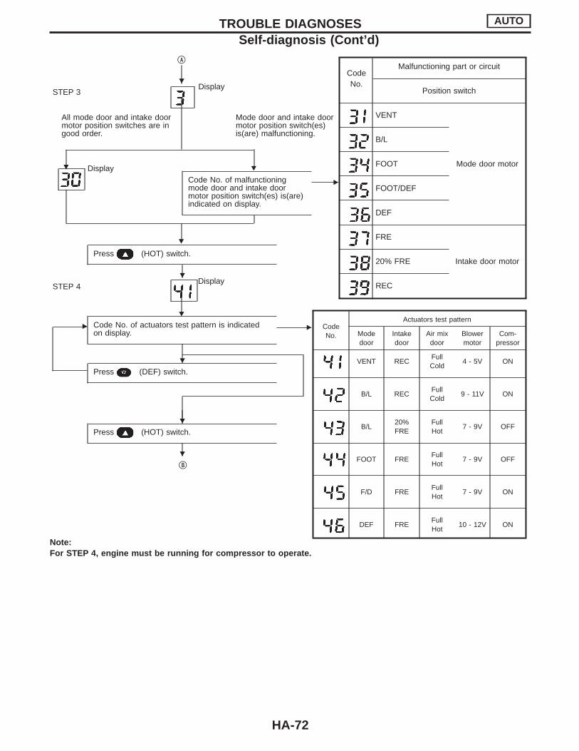
qA
DisplaySTEP 3
All mode door and intake doormotor position switches are ingood order.
Mode door and intake doormotor position switch(es)is(are) malfunctioning.
HH DisplayCode No. of malfunctioningmode door and intake doormotor position switch(es) is(are)indicated on display.
E
H
Press (HOT) switch.
DisplaySTEP 4
H
E Code No. of actuators test pattern is indicatedon display.
E
Press (DEF) switch.
Press (HOT) switch.
qB
CodeNo.
Malfunctioning part or circuit
Position switch
VENT
Mode door motor
B/L
FOOT
FOOT/DEF
DEF
FRE
Intake door motor20% FRE
REC
CodeNo.
Actuators test pattern
Modedoor
Intakedoor
Air mixdoor
Blowermotor
Com-pressor
VENT RECFullCold
4 - 5V ON
B/L RECFullCold
9 - 11V ON
B/L20%FRE
FullHot
7 - 9V OFF
FOOT FREFullHot
7 - 9V OFF
F/D FREFullHot
7 - 9V ON
DEF FREFullHot
10 - 12V ON
Note:For STEP 4, engine must be running for compressor to operate.
TROUBLE DIAGNOSES AUTO
Self-diagnosis (Cont’d)
H
H
H
H
H
HA-72

qB
DisplaySTEP 5
E Press (DEF) switch.
Temperature detected by each sensor is indi-cated on display.
EAmbient sensorIn-vehicle sensorIntake sensor
Press REC switch.
Display
[Multiplex communication error betweencontrol unit and auto amplifier is detected]
E
Turn ignition switch OFF or (AUTO)switch ON.
END
Display Signal direction
In good order
Push control unit , Auto amp.
blinks twotimes"
Auto amp. , Push control unit
TROUBLE DIAGNOSES AUTO
Self-diagnosis (Cont’d)
H
H
H
H
H
H
H
H
HA-73

HOW TO INTERPRET THE RESULTS
STEP 1: Checks LEDs and segmentsWhen switch’s LED and segments are in functioning properly inSTEP 1, LED and display will come on.
RHA390G
RHA391G
If LEDs or segments malfunction, LED will not come on or displaywill show incomplete segment.
RHA499AB
STEP 2: Checks each sensor circuit for open or shortcircuitDisplay shows “ ” in STEP 2 mode.When all sensors are in good order, display shows “ ”.It takes approximately 25 seconds to check all sensors.
RHA392G
If a sensor is malfunctioning, the corresponding code No. blinks ondisplay. A short circuit is identified by a blinking “− ” mark preced-ing mode number.
TROUBLE DIAGNOSES AUTO
Self-diagnosis (Cont’d)
HA-74
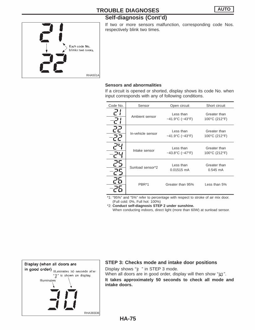
RHA501A
If two or more sensors malfunction, corresponding code Nos.respectively blink two times.
Sensors and abnormalitiesIf a circuit is opened or shorted, display shows its code No. wheninput corresponds with any of following conditions.
Code No. Sensor Open circuit Short circuit
Ambient sensorLess than
−41.9°C (−43°F)Greater than
100°C (212°F)—
In-vehicle sensorLess than
−41.9°C (−43°F)Greater than
100°C (212°F)—
Intake sensorLess than
−43.8°C (−47°F)Greater than
100°C (212°F)—
Sunload sensor*2Less than
0.01515 mAGreater than
0.545 mA—
PBR*1 Greater than 95% Less than 5%—
*1: “95%” and “5%” refer to percentage with respect to stroke of air mix door.(Full cold: 0%, Full hot: 100%)
*2: Conduct self-diagnosis STEP 2 under sunshine.When conducting indoors, direct light (more than 60W) at sunload sensor.
RHA383DB
STEP 3: Checks mode and intake door positionsDisplay shows “ ” in STEP 3 mode.When all doors are in good order, display will then show “ ”.It takes approximately 50 seconds to check all mode andintake doors.
TROUBLE DIAGNOSES AUTO
Self-diagnosis (Cont’d)
HA-75
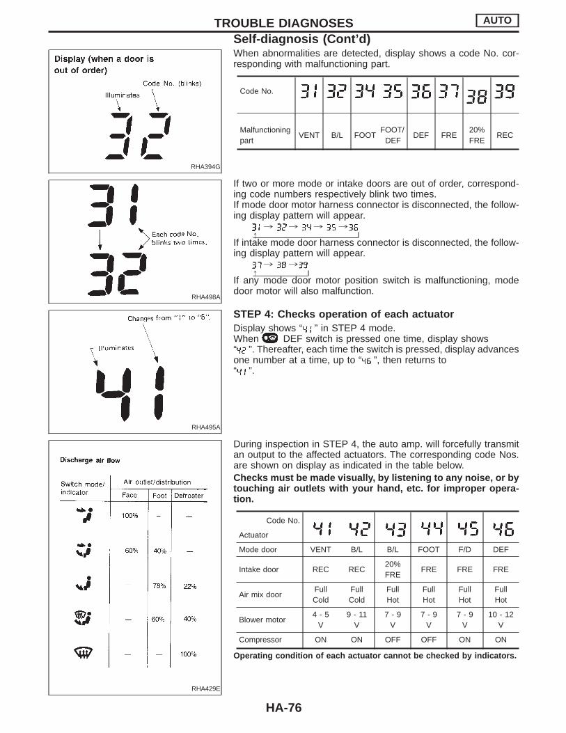
RHA394G
When abnormalities are detected, display shows a code No. cor-responding with malfunctioning part.
Code No.
Malfunctioningpart
VENT B/L FOOTFOOT/
DEFDEF FRE
20%FRE
REC
RHA498A
If two or more mode or intake doors are out of order, correspond-ing code numbers respectively blink two times.If mode door motor harness connector is disconnected, the follow-ing display pattern will appear.
, , , ,!
If intake mode door harness connector is disconnected, the follow-ing display pattern will appear.
, ,!
If any mode door motor position switch is malfunctioning, modedoor motor will also malfunction.
RHA495A
STEP 4: Checks operation of each actuatorDisplay shows “ ” in STEP 4 mode.When DEF switch is pressed one time, display shows“ ”. Thereafter, each time the switch is pressed, display advancesone number at a time, up to “ ”, then returns to“ ”.
RHA429E
During inspection in STEP 4, the auto amp. will forcefully transmitan output to the affected actuators. The corresponding code Nos.are shown on display as indicated in the table below.Checks must be made visually, by listening to any noise, or bytouching air outlets with your hand, etc. for improper opera-tion.
Code No.
Actuator
Mode door VENT B/L B/L FOOT F/D DEF
Intake door REC REC20%FRE
FRE FRE FRE
Air mix doorFullCold
FullCold
FullHot
FullHot
FullHot
FullHot
Blower motor4 - 5
V9 - 11
V7 - 9
V7 - 9
V7 - 9
V10 - 12
V
Compressor ON ON OFF OFF ON ON
Operating condition of each actuator cannot be checked by indicators.
TROUBLE DIAGNOSES AUTO
Self-diagnosis (Cont’d)
HA-76

RHA054D
RHA426G
STEP 5: Checks temperature detected by sensors, anddetects multiplex communication errorChecks temperature detected by sensorsDisplay shows “ ” in STEP 5 mode.I When FRONT DEF switch is pressed one time, display
shows temperature detected by ambient sensor.I When FRONT DEF switch is pressed second time, dis-
play shows temperature detected by in-vehicle sensor.I When FRONT DEF switch is pressed third time, display
shows temperature detected by intake sensor.I When FRONT DEF switch is pressed fourth time, display
returns to original presentation “ ”.
RHA395G
If temperature shown on display greatly differs from actualtemperature, check sensor circuit at first. Then inspect sensor itselfaccording to the procedures described in Control System InputComponent . Refer to HA-110.
TROUBLE DIAGNOSES AUTO
Self-diagnosis (Cont’d)
HA-77
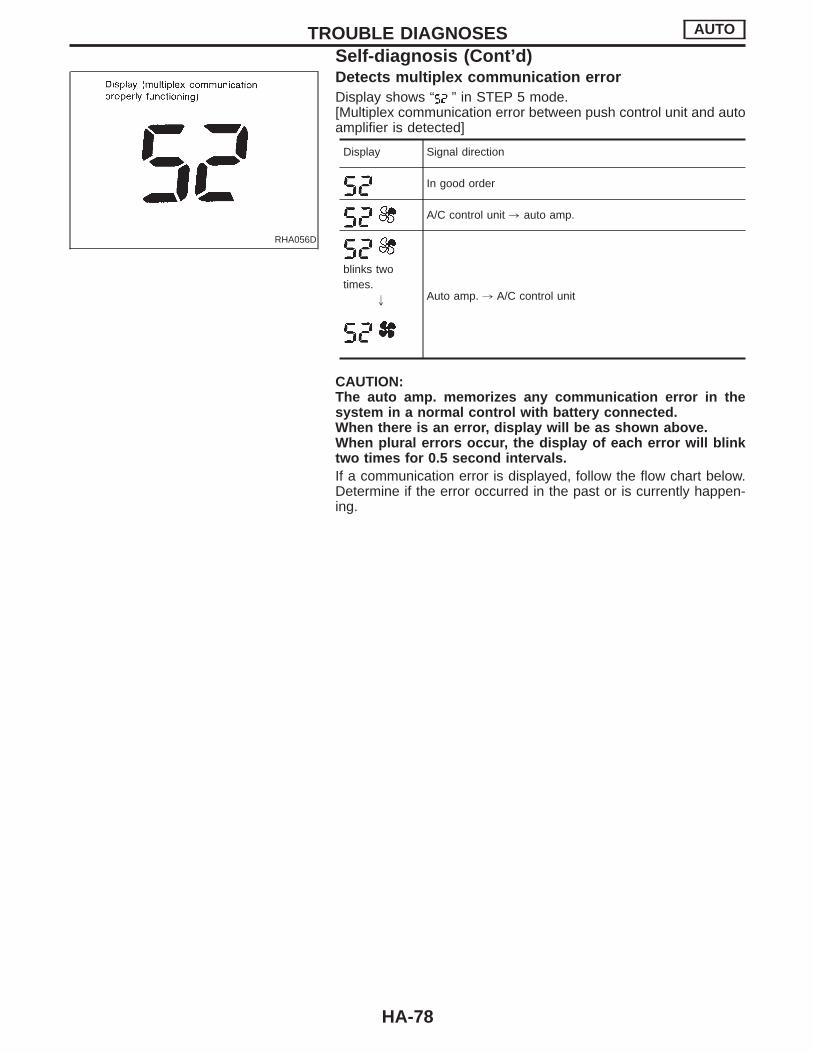
RHA056D
Detects multiplex communication errorDisplay shows “ ” in STEP 5 mode.[Multiplex communication error between push control unit and autoamplifier is detected]
Display Signal direction
In good order
A/C control unit , auto amp.
blinks twotimes.
" Auto amp. , A/C control unit
CAUTION:The auto amp. memorizes any communication error in thesystem in a normal control with battery connected.When there is an error, display will be as shown above.When plural errors occur, the display of each error will blinktwo times for 0.5 second intervals.If a communication error is displayed, follow the flow chart below.Determine if the error occurred in the past or is currently happen-ing.
TROUBLE DIAGNOSES AUTO
Self-diagnosis (Cont’d)
HA-78

AUXILIARY MECHANISM: Temperature setting trimmerThis trimmer compensates for differences between temperaturesetting (displayed digitally) and temperature felt by driver in a rangeof ±3°C (±6°F).Operating procedures for this trimmer are as follows:Starting with STEP 5 under “Self-diagnostic mode”, press
(fan up) switch to set air conditioning system in auxiliary mode.Display shows “ ” in auxiliary mechanism. It takes approximately3 seconds. Then, press either (HOT) or (COLD) switchas desired. Temperature will change at a rate of 0.5°C (1°F) eachtime a switch is pressed.
SHA197E
When battery cable is disconnected, trimmer operation is can-celed and temperature set becomes that of initial condition,i.e. 0°C (0°F).
TROUBLE DIAGNOSES AUTO
Self-diagnosis (Cont’d)
HA-79

Preliminary CheckPRELIMINARY CHECK 1Air outlet does not change.I Perform Self-diagnosis STEP 1 before referring to the flow chart.
CHECK SENSOR CIRCUIT.Set up Self-diagnosis STEP 2.Is each sensor circuit normal?Code No. 20 should be indicated on the dis-play after approx. 3 seconds.
Yes
ENo CHECK SENSOR CIRCUIT IN DETAIL ACCORDING TO THE DIAG-
NOSTIC PROCEDURE BELOW CORRESPONDING TO EACH CODENO.
Are sensor circuits for ambient sensor, in-vehicle sensor and intakesensor operating normally? If malfunction is suspected, check tem-perature detected by each sensor using Self-diagnosis STEP 5. Con-firm the temperature is within normal range before performing Diag-nostic Procedures.
CHECK MODE DOOR MOTOR.Set up Self-diagnosis STEP 3.Is mode door motor operating normally?Code No. 30 should be indicated on the dis-play after approx. 3 seconds.
Yes
ENo Go to Diagnostic Procedure 5. (HA-99)
CHECK MODE DOOR OPERATION.Set up Self-diagnosis STEP 4.Does air outlet change according to each codeNo.?
Refer to Air Flow. (HA-18)
Yes
ENo CHECK SIDE LINK MECHANISM.
Refer to CONTROL LINKAGE ADJUST-MENT. (HA-108)
OK
ENG Repair or adjust.
Go to Diagnostic Procedure 5. (HA-99)
Air outlet control system is normal. Refer toMode door control specification. (HA-116)
Code No. How to repairReference
page
Go to Diagnostic Procedure 1. HA-95
Go to Diagnostic Procedure 2. HA-96
Go to Diagnostic Procedure 3. HA-97
Go to Diagnostic Procedure 4. HA-98
Go to Diagnostic Procedure 5. HA-99
− Go to Diagnostic Procedure 1. HA-95
− Go to Diagnostic Procedure 2. HA-96
− Go to Diagnostic Procedure 3. HA-97
− Go to Diagnostic Procedure 4. HA-98
− Go to Diagnostic Procedure 5. HA-99
VENT B/L B/L FOOT F/D2 DEF
TROUBLE DIAGNOSES AUTO
H
H
H
H
HA-80
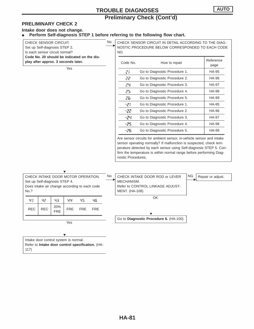
PRELIMINARY CHECK 2Intake door does not change.I Perform Self-diagnosis STEP 1 before referring to the following flow chart.
CHECK SENSOR CIRCUIT.Set up Self-diagnosis STEP 2.Is each sensor circuit normal?Code No. 20 should be indicated on the dis-play after approx. 3 seconds later.
Yes
ENo CHECK SENSOR CIRCUIT IN DETAIL ACCORDING TO THE DIAG-
NOSTIC PROCEDURE BELOW CORRESPONDED TO EACH CODENO.
Are sensor circuits for ambient sensor, in-vehicle sensor and intakesensor operating normally? If malfunction is suspected, check tem-perature detected by each sensor using Self-diagnosis STEP 5. Con-firm the temperature is within normal range before performing Diag-nostic Procedures.
CHECK INTAKE DOOR MOTOR OPERATION.Set up Self-diagnosis STEP 4.Does intake air change according to each codeNo.?
Yes
ENo CHECK INTAKE DOOR ROD or LEVER
MECHANISM.Refer to CONTROL LINKAGE ADJUST-MENT. (HA-108)
OK
ENG Repair or adjust.
Go to Diagnostic Procedure 6. (HA-100)
Intake door control system is normal.Refer to Intake door control specification. (HA-117)
Code No. How to repairReference
page
Go to Diagnostic Procedure 1. HA-95
Go to Diagnostic Procedure 2. HA-96
Go to Diagnostic Procedure 3. HA-97
Go to Diagnostic Procedure 4. HA-98
Go to Diagnostic Procedure 5. HA-99
− Go to Diagnostic Procedure 1. HA-95
− Go to Diagnostic Procedure 2. HA-96
− Go to Diagnostic Procedure 3. HA-97
− Go to Diagnostic Procedure 4. HA-98
− Go to Diagnostic Procedure 5. HA-99
REC REC20%FRE
FRE FRE FRE
TROUBLE DIAGNOSES AUTO
Preliminary Check (Cont’d)
H
H
H
HA-81

PRELIMINARY CHECK 3Insufficient cooling
CHECK MODE DOOR OPERA-TION.
OK
ENG Go to Preliminary Check 1. (HA-
80)
CHECK INTAKE DOOR OPERA-TION.
OK
ENG Go to Preliminary Check 2. (HA-
81)
CHECK BLOWER MOTOROPERATION.
OK
ENG Go to Preliminary Check 5. (HA-
84)
CHECK MAGNET CLUTCHOPERATION.
OK
ENG Go to Preliminary Check 6. (HA-
85)
CHECK COMPRESSOR BELTTENSION.Refer to MA section.
OK
ENG Adjust or replace compressor belt.
CHECK AIR MIX DOOR OPERA-TION.
OK
ENG Go to Preliminary Check 7. (HA-
86)
CHECK COOLING FAN MOTOROPERATION.
OK
ENG Go to EC section.
CHECK REFRIGERATION CYCLEPRESSURE WITH MANIFOLDGAUGE CONNECTED.Refer to Performance Chart. (HA-33)
OK
ENG Go to Performance Test Diag-
noses. (HA-31)
CHECK FOR EVAPORATOR COILFREEZE UP.1. Confirm center vent air is dis-
charged sufficiently.
OK(Does not freezeup.)
ENG
(Freezes up.)
Go to Preliminary Check 6. (HA-85)
OK
Replace compressor.
CHECK DUCTS FOR AIR LEAKS.
OKE
NG Repair air leaks.
PERFORM TEMPERATURE SET-TING TRIMMING.1. Set up AUXILIARY MECHANISM
mode in self-diagnosis.2. Press (COLD) switch at
desirable times.
TROUBLE DIAGNOSES AUTO
Preliminary Check (Cont’d)
H
H
H
H
H
H
H
H
H
H
H
HA-82

PRELIMINARY CHECK 4Insufficient heating
CHECK MODE DOOR OPERA-TION.
OK
ENG Perform Preliminary Check
1. Refer to HA-80.
CHECK BLOWER MOTOROPERATION.
OK
ENG Perform Preliminary Check
5. Refer to HA-84.
CHECK THE FOLLOWING:I Engine coolant level (Refer to
MA section.)I Hoses for leaks or kinksI Radiator cap (Refer to LC
section.)I Air in cooling system.
OK
ENG Repair/replace as neces-
sary.
CHECK AIR MIX DOOROPERATION.Refer to HA-108.
OK
ENG Perform Preliminary Check
7. Refer to HA-86.
CHECK DUCTS FOR AIRLEAKS.
OK
ENG Repair leaks.
CHECK BY FEEL THEHEATER INLET AND OUTLETHOSES.
Hot inletWarm outlet
Both hoseswarm
Check thermostatinstallation.
OK
Check heater hoses forproper installation.
OK
Note Note
Replace thermostat.Refer to LC section(“Thermostat”,“ENGINE COOLINGSYSTEM”).
Back flush heater core, drainand refill coolant. Retest.
Hot inletWarm outlet
Both hoseswarm
SYSTEM OK Replace heater core.
Note: To avoid unnecessary service of heating system,first perform TEMPERATURE SETTING TRIMMING.Refer to “AUXILIARY MECHANISM”, “Self-diagnosis”.(HA-79)
TROUBLE DIAGNOSES AUTO
Preliminary Check (Cont’d)
H
H
H
H
H
H H
H H
H H
HA-83
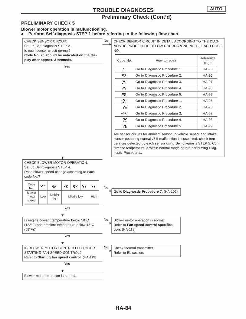
PRELIMINARY CHECK 5Blower motor operation is malfunctioning.I Perform Self-diagnosis STEP 1 before referring to the following flow chart.
CHECK SENSOR CIRCUIT.Set up Self-diagnosis STEP 2.Is each sensor circuit normal?Code No. 20 should be indicated on the dis-play after approx. 3 seconds.
Yes
ENo CHECK SENSOR CIRCUIT IN DETAIL ACCORDING TO THE DIAG-
NOSTIC PROCEDURE BELOW CORRESPONDING TO EACH CODENO.
Are sensor circuits for ambient sensor, in-vehicle sensor and intakesensor operating normally? If malfunction is suspected, check tem-perature detected by each sensor using Self-diagnosis STEP 5. Con-firm the temperature is within normal range before performing Diag-nostic Procedures.
CHECK BLOWER MOTOR OPERATION.Set up Self-diagnosis STEP 4.Does blower speed change according to eachcode No.?
Yes
ENo
Go to Diagnostic Procedure 7. (HA-102)
Is engine coolant temperature below 50°C(122°F) and ambient temperature below 15°C(59°F)?
Yes
ENo Blower motor operation is normal.
Refer to Fan speed control specifica-tion. (HA-119)
IS BLOWER MOTOR CONTROLLED UNDERSTARTING FAN SPEED CONTROL?Refer to Starting fan speed control. (HA-119)
Yes
ENo Check thermal transmitter.
Refer to EL section.
Blower motor operation is normal.
Code No. How to repairReference
page
Go to Diagnostic Procedure 1. HA-95
Go to Diagnostic Procedure 2. HA-96
Go to Diagnostic Procedure 3. HA-97
Go to Diagnostic Procedure 4. HA-98
Go to Diagnostic Procedure 5. HA-99
− Go to Diagnostic Procedure 1. HA-95
− Go to Diagnostic Procedure 2. HA-96
− Go to Diagnostic Procedure 3. HA-97
− Go to Diagnostic Procedure 4. HA-98
− Go to Diagnostic Procedure 5. HA-99
CodeNo.
Blowermotorspeed
LowMiddlehigh
Middle low High
TROUBLE DIAGNOSES AUTO
Preliminary Check (Cont’d)
H
H
H
H
HA-84
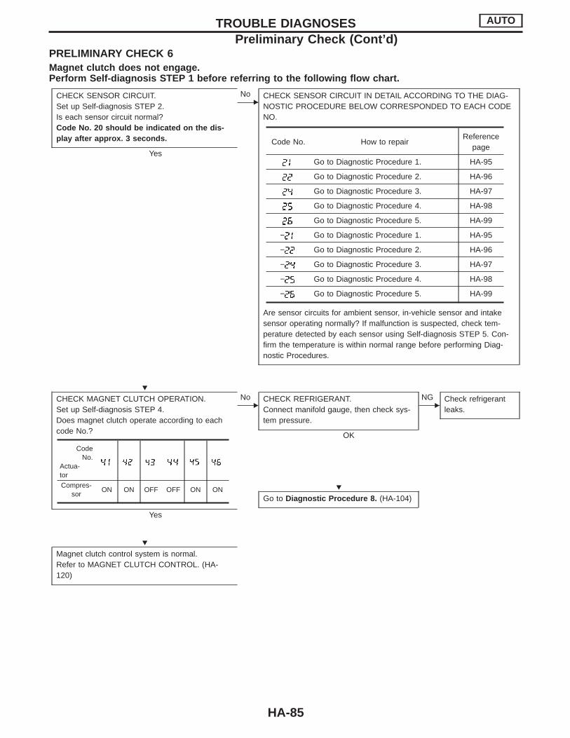
PRELIMINARY CHECK 6Magnet clutch does not engage.Perform Self-diagnosis STEP 1 before referring to the following flow chart.
CHECK SENSOR CIRCUIT.Set up Self-diagnosis STEP 2.Is each sensor circuit normal?Code No. 20 should be indicated on the dis-play after approx. 3 seconds.
Yes
ENo CHECK SENSOR CIRCUIT IN DETAIL ACCORDING TO THE DIAG-
NOSTIC PROCEDURE BELOW CORRESPONDED TO EACH CODENO.
Are sensor circuits for ambient sensor, in-vehicle sensor and intakesensor operating normally? If malfunction is suspected, check tem-perature detected by each sensor using Self-diagnosis STEP 5. Con-firm the temperature is within normal range before performing Diag-nostic Procedures.
CHECK MAGNET CLUTCH OPERATION.Set up Self-diagnosis STEP 4.Does magnet clutch operate according to eachcode No.?
Yes
ENo CHECK REFRIGERANT.
Connect manifold gauge, then check sys-tem pressure.
OK
ENG Check refrigerant
leaks.
Go to Diagnostic Procedure 8. (HA-104)
Magnet clutch control system is normal.Refer to MAGNET CLUTCH CONTROL. (HA-120)
Code No. How to repairReference
page
Go to Diagnostic Procedure 1. HA-95
Go to Diagnostic Procedure 2. HA-96
Go to Diagnostic Procedure 3. HA-97
Go to Diagnostic Procedure 4. HA-98
Go to Diagnostic Procedure 5. HA-99
− Go to Diagnostic Procedure 1. HA-95
− Go to Diagnostic Procedure 2. HA-96
− Go to Diagnostic Procedure 3. HA-97
− Go to Diagnostic Procedure 4. HA-98
− Go to Diagnostic Procedure 5. HA-99
CodeNo.
Actua-tor
Compres-sor
ON ON OFF OFF ON ON
TROUBLE DIAGNOSES AUTO
Preliminary Check (Cont’d)
H
H
H
HA-85

PRELIMINARY CHECK 7Discharged air temperature does not change.Perform Self-diagnosis STEP 1 before referring to the following flow chart.
CHECK SENSOR CIRCUIT.Set up Self-diagnosis STEP 2.Is each sensor circuit normal?Code No. 20 should be indicated on the dis-play after approx. 3 seconds later.
Yes
ENo CHECK SENSOR CIRCUIT IN DETAIL ACCORDING TO THE DIAG-
NOSTIC PROCEDURE BELOW CORRESPONDING TO EACH CODENO.
Are sensor circuits for ambient sensor, in-vehicle sensor and intakesensor operating normally? If malfunction is suspected, check tem-perature detected by each sensor using Self-diagnosis STEP 5. Con-firm the temperature is within normal range before performing Diag-nostic Procedures.
CHECK AIR MIX DOOR OPERATION.Set up Self-diagnosis STEP 4.Does discharged air temperature change accord-ing to each code No.?
Yes No
Air mix door control sys-tem is normal.Refer to Air mix doorcontrol specification.(HA-132)
CHECK AIR MIX DOOR MECHANISM.Refer to CONTROL LINKAGE ADJUSTMENT.(HA-108)
OK
ENG Repair or adjust.
Go to Diagnostic Procedure 5. (HA-99)
Code No. How to repairReference
page
Go to Diagnostic Procedure 1. HA-95
Go to Diagnostic Procedure 2. HA-96
Go to Diagnostic Procedure 3. HA-97
Go to Diagnostic Procedure 4. HA-98
Go to Diagnostic Procedure 5. HA-99
− Go to Diagnostic Procedure 1. HA-95
− Go to Diagnostic Procedure 2. HA-96
− Go to Diagnostic Procedure 3. HA-97
− Go to Diagnostic Procedure 4. HA-98
− Go to Diagnostic Procedure 5. HA-99
Full cold Full hot
TROUBLE DIAGNOSES AUTO
Preliminary Check (Cont’d)
H
H
H
H
HA-86
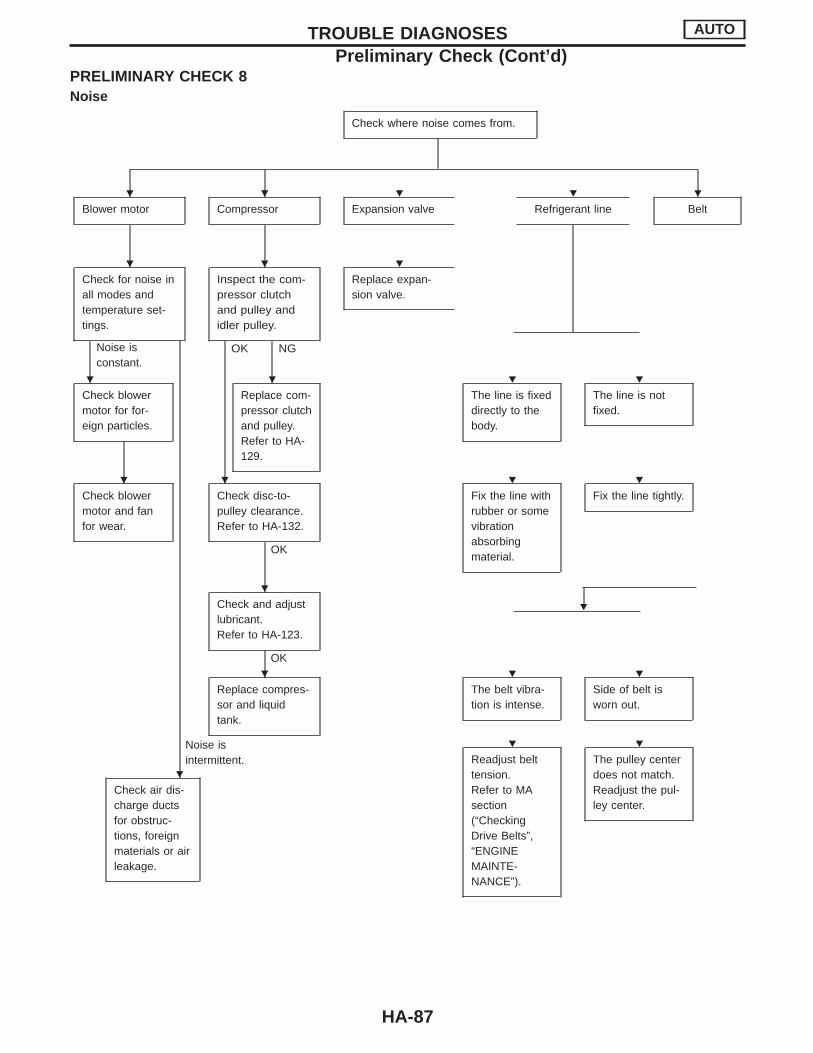
PRELIMINARY CHECK 8Noise
Check where noise comes from.
Blower motor Compressor Expansion valve Refrigerant line Belt
Check for noise inall modes andtemperature set-tings.
Noise isconstant.
Inspect the com-pressor clutchand pulley andidler pulley.
OK NG
Replace expan-sion valve.
Check blowermotor for for-eign particles.
Replace com-pressor clutchand pulley.Refer to HA-129.
The line is fixeddirectly to thebody.
The line is notfixed.
Check blowermotor and fanfor wear.
Check disc-to-pulley clearance.Refer to HA-132.
OK
Fix the line withrubber or somevibrationabsorbingmaterial.
Fix the line tightly.
HCheck and adjustlubricant.Refer to HA-123.
OK
Noise isintermittent.
Replace compres-sor and liquidtank.
The belt vibra-tion is intense.
Side of belt isworn out.
Check air dis-charge ductsfor obstruc-tions, foreignmaterials or airleakage.
Readjust belttension.Refer to MAsection(“CheckingDrive Belts”,“ENGINEMAINTE-NANCE”).
The pulley centerdoes not match.Readjust the pul-ley center.
TROUBLE DIAGNOSES AUTO
Preliminary Check (Cont’d)
H H H H H
H H H
H H H H
H H H H
H
H H H
H
H H
HA-87
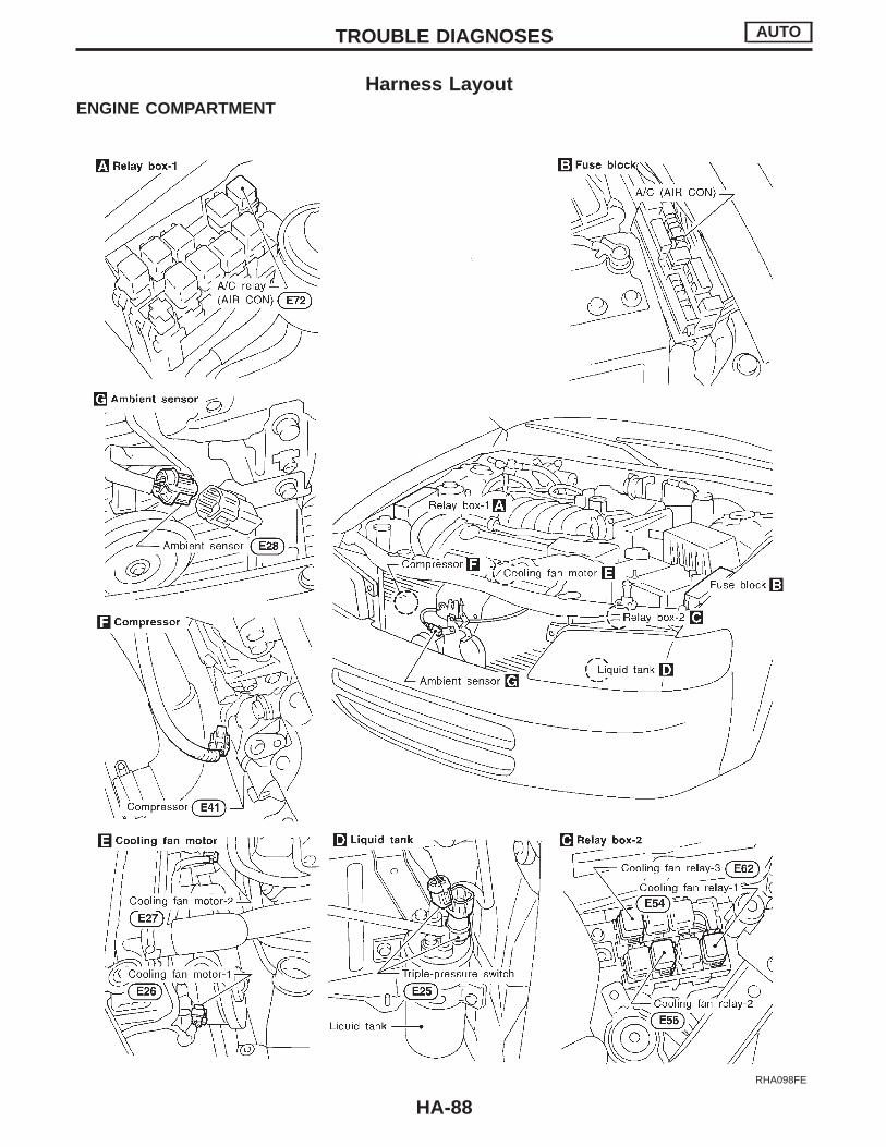
Harness LayoutENGINE COMPARTMENT
RHA098FE
TROUBLE DIAGNOSES AUTO
HA-88

PASSENGER COMPARTMENT
SHA969E
TROUBLE DIAGNOSES AUTO
Harness Layout (Cont’d)
HA-89

Circuit Diagram
MHA709A
TROUBLE DIAGNOSES AUTO
HA-90

Wiring Diagram — A/C, A —
MHA710A
TROUBLE DIAGNOSES AUTO
HA-91
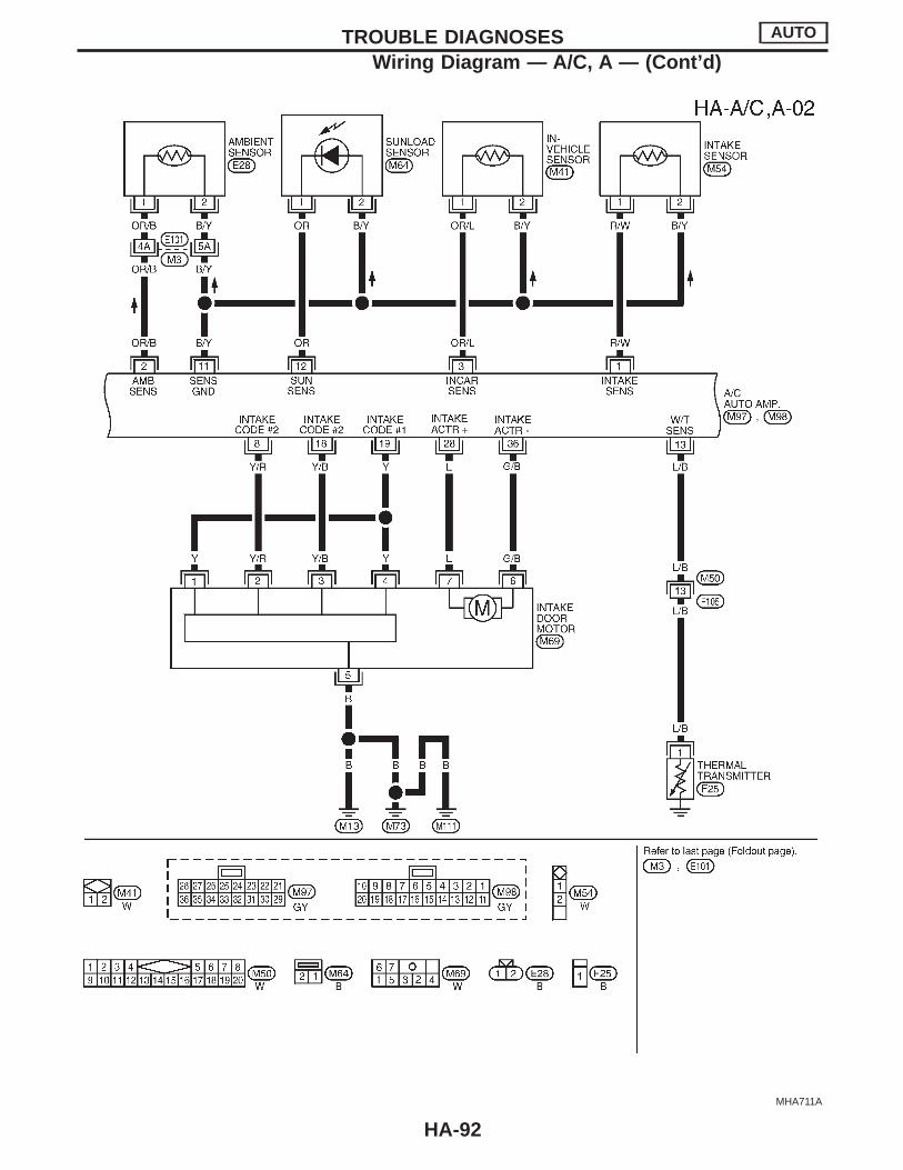
MHA711A
TROUBLE DIAGNOSES AUTO
Wiring Diagram — A/C, A — (Cont’d)
HA-92
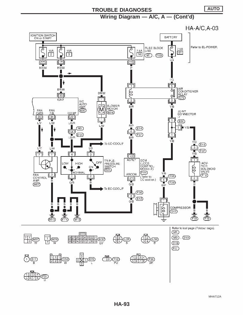
MHA712A
TROUBLE DIAGNOSES AUTO
Wiring Diagram — A/C, A — (Cont’d)
HA-93
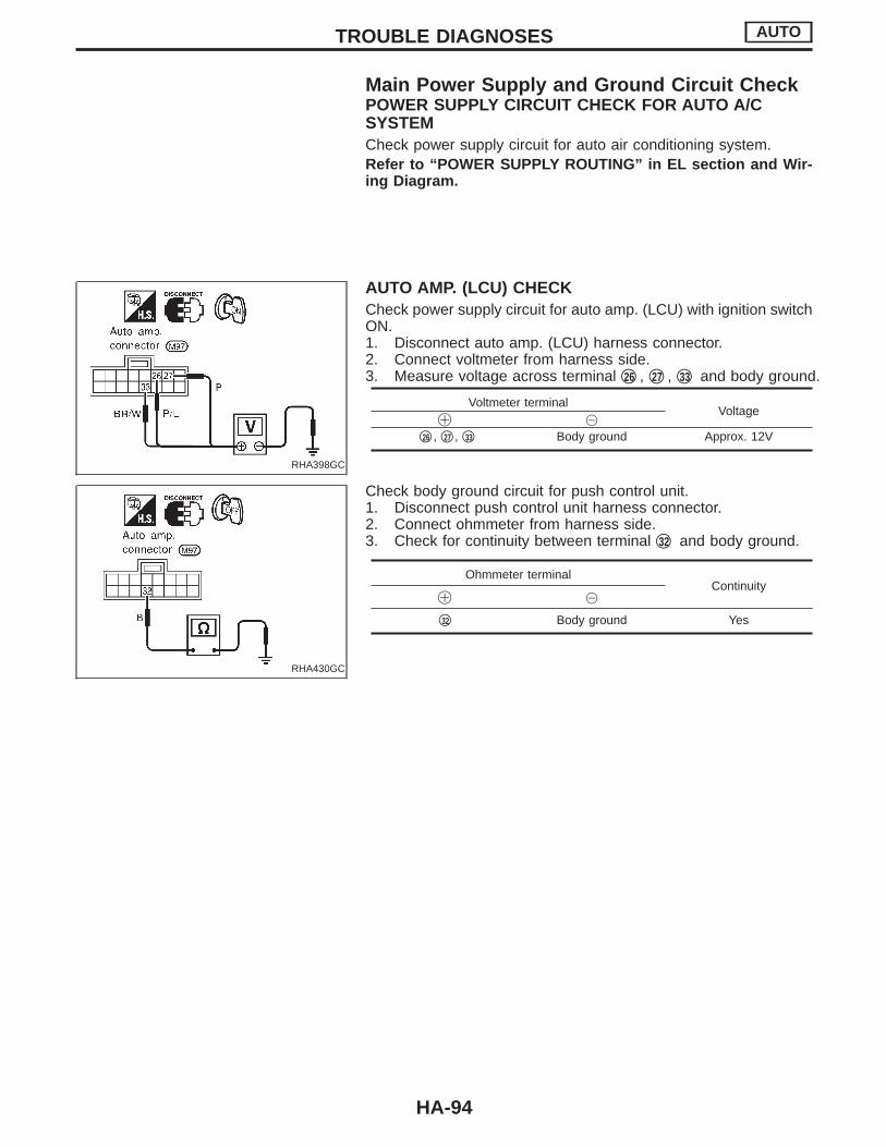
Main Power Supply and Ground Circuit CheckPOWER SUPPLY CIRCUIT CHECK FOR AUTO A/CSYSTEMCheck power supply circuit for auto air conditioning system.Refer to “POWER SUPPLY ROUTING” in EL section and Wir-ing Diagram.
RHA398GC
AUTO AMP. (LCU) CHECKCheck power supply circuit for auto amp. (LCU) with ignition switchON.1. Disconnect auto amp. (LCU) harness connector.2. Connect voltmeter from harness side.3. Measure voltage across terminal q26 , q27 , q33 and body ground.
Voltmeter terminalVoltage
! @
q26 , q27 , q33 Body ground Approx. 12V
RHA430GC
Check body ground circuit for push control unit.1. Disconnect push control unit harness connector.2. Connect ohmmeter from harness side.3. Check for continuity between terminal q32 and body ground.
Ohmmeter terminalContinuity
! @
q32 Body ground Yes
TROUBLE DIAGNOSES AUTO
HA-94
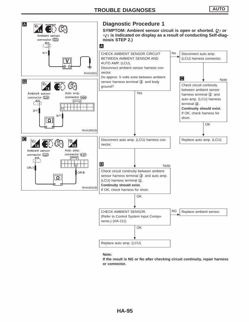
RHA030G
Diagnostic Procedure 1SYMPTOM: Ambient sensor circuit is open or shorted. ( or− is indicated on display as a result of conducting Self-diag-nosis STEP 2.)
RHA399GB
RHA400GB
CHECK AMBIENT SENSOR CIRCUITBETWEEN AMBIENT SENSOR ANDAUTO AMP. (LCU).Disconnect ambient sensor harness con-nector.Do approx. 5 volts exist between ambientsensor harness terminal q2 and bodyground?
Yes
ENo Disconnect auto amp.
(LCU) harness connector.
Note
Check circuit continuitybetween ambient sensorharness terminal q1 andauto amp. (LCU) harnessterminal q33 .Continuity should exist.If OK, check harness forshort.
OK
Disconnect auto amp. (LCU) harness con-nector.
Replace auto amp. (LCU).
Note
Check circuit continuity between ambientsensor harness terminal q2 and auto amp.(LCU) harness terminal q11 .Continuity should exist.If OK, check harness for short.
OK
CHECK AMBIENT SENSOR.(Refer to Control System Input Compo-nents.) (HA-111)
OK
ENG Replace ambient sensor.
Replace auto amp. (LCU).
Note:If the result is NG or No after checking circuit continuity, repair harnessor connector.
TROUBLE DIAGNOSES AUTO
H
H H
H
H
H
HA-95

RHA033G
Diagnostic Procedure 2SYMPTOM: In-vehicle sensor circuit is open or shorted. ( or− is indicated on display as a result of conducting Self-diag-nosis STEP 2.)
RHA401GB
RHA402GB
CHECK IN-VEHICLE SENSOR CIRCUITBETWEEN IN-VEHICLE SENSOR ANDAUTO AMP. (LCU).Disconnect in-vehicle sensor harness con-nector.Do approx. 5 volts exist between in-vehiclesensor harness terminal q2 and bodyground?
Yes
ENo Disconnect auto amp.
(LCU) harness connector.
Note
Check circuit continuitybetween in-vehicle sensorharness terminal q1 andauto amp. (LCU) harnessterminal q3 .Continuity should exist.If OK, check harness forshort.
OK
Disconnect auto amp. (LCU) harness con-nector.
Replace auto amp. (LCU).
Note
Check circuit continuity between in-vehiclesensor harness terminal q2 and auto amp.(LCU) harness terminal q11 .Continuity should exist.If OK, check harness for short.
OK
CHECK IN-VEHICLE SENSOR.(Refer to Control System Input Compo-nents.) (HA-110)
OK
ENG Replace in-vehicle sensor.
Replace auto amp. (LCU).
Note:If the result is NG or No after checking circuit continuity, repair harnessor connector.
TROUBLE DIAGNOSES AUTO
H
H H
H
H
H
HA-96

RHA431G
Diagnostic Procedure 3SYMPTOM: Intake sensor circuit is open or shorted. ( or− is indicated on auto amp. as a result of conducting Self-diagnosis STEP 2.)
RHA432GB
RHA433GB
CHECK INTAKE SENSOR CIRCUITBETWEEN INTAKE SENSOR AND AUTOAMP. (LCU).Disconnect intake sensor harness connec-tor.Do approx. 5 volts exist between intakesensor harness terminal No.q1 and bodyground?
Yes
ENo Disconnect auto amp.
(LCU) harness connector.
Note
Check circuit continuitybetween intake sensor har-ness terminal No.q1 andauto amp. (LCU) harnessterminal No.q1 .Continuity should exist.If OK, check harness forshort.
OK
Disconnect auto amp. (LCU) harness con-nector.
Replace auto amp. (LCU).
Note
Check circuit continuity between intakesensor harness terminal No.q2 and autoamp. (LCU) harness terminal No.q11 .Continuity should exist.If OK, check harness for short.
OK
CHECK INTAKE SENSOR.(Refer to HA-112.)
OK
ENG Replace intake sensor.
Replace auto amp. (LCU).
Note:If the result is NG or No after checking circuit continuity, repair harnessor connector.
TROUBLE DIAGNOSES AUTO
H
H H
H
H
H
HA-97
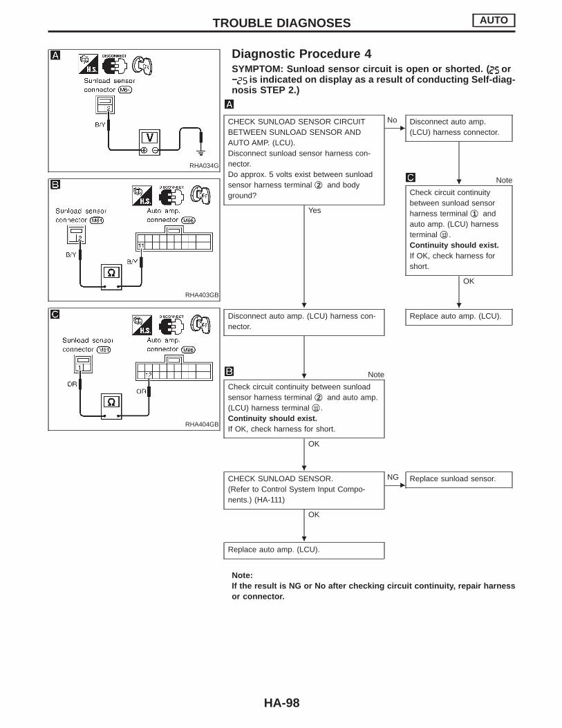
RHA034G
Diagnostic Procedure 4SYMPTOM: Sunload sensor circuit is open or shorted. ( or− is indicated on display as a result of conducting Self-diag-nosis STEP 2.)
RHA403GB
RHA404GB
CHECK SUNLOAD SENSOR CIRCUITBETWEEN SUNLOAD SENSOR ANDAUTO AMP. (LCU).Disconnect sunload sensor harness con-nector.Do approx. 5 volts exist between sunloadsensor harness terminal q2 and bodyground?
Yes
ENo Disconnect auto amp.
(LCU) harness connector.
Note
Check circuit continuitybetween sunload sensorharness terminal q1 andauto amp. (LCU) harnessterminal q12 .Continuity should exist.If OK, check harness forshort.
OK
Disconnect auto amp. (LCU) harness con-nector.
Replace auto amp. (LCU).
Note
Check circuit continuity between sunloadsensor harness terminal q2 and auto amp.(LCU) harness terminal q11 .Continuity should exist.If OK, check harness for short.
OK
CHECK SUNLOAD SENSOR.(Refer to Control System Input Compo-nents.) (HA-111)
OK
ENG Replace sunload sensor.
Replace auto amp. (LCU).
Note:If the result is NG or No after checking circuit continuity, repair harnessor connector.
TROUBLE DIAGNOSES AUTO
H
H H
H
H
H
HA-98
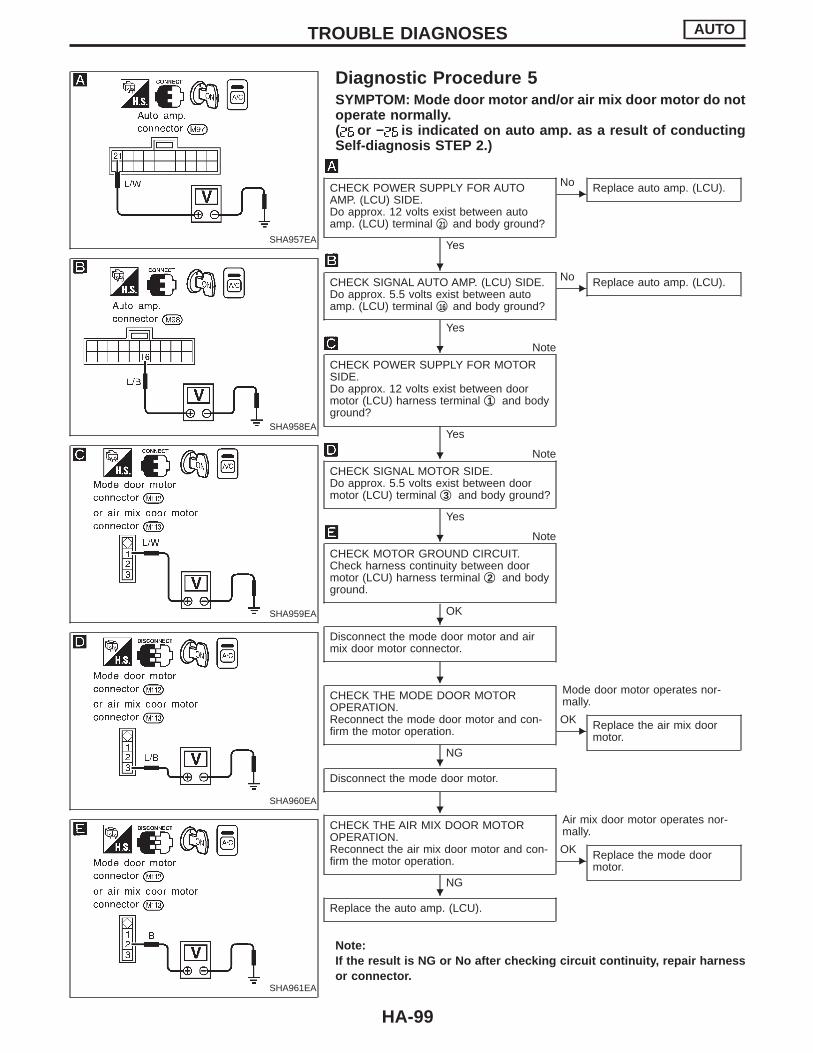
SHA957EA
Diagnostic Procedure 5SYMPTOM: Mode door motor and/or air mix door motor do notoperate normally.( or − is indicated on auto amp. as a result of conductingSelf-diagnosis STEP 2.)
SHA958EA
SHA959EA
SHA960EA
SHA961EA
CHECK POWER SUPPLY FOR AUTOAMP. (LCU) SIDE.Do approx. 12 volts exist between autoamp. (LCU) terminal q21 and body ground?
Yes
ENo Replace auto amp. (LCU).
CHECK SIGNAL AUTO AMP. (LCU) SIDE.Do approx. 5.5 volts exist between autoamp. (LCU) terminal q16 and body ground?
Yes
ENo Replace auto amp. (LCU).
Note
CHECK POWER SUPPLY FOR MOTORSIDE.Do approx. 12 volts exist between doormotor (LCU) harness terminal q1 and bodyground?
Yes
Note
CHECK SIGNAL MOTOR SIDE.Do approx. 5.5 volts exist between doormotor (LCU) terminal q3 and body ground?
Yes
Note
CHECK MOTOR GROUND CIRCUIT.Check harness continuity between doormotor (LCU) harness terminal q2 and bodyground.
OK
Disconnect the mode door motor and airmix door motor connector.
CHECK THE MODE DOOR MOTOROPERATION.Reconnect the mode door motor and con-firm the motor operation.
NG
Mode door motor operates nor-mally.
EOK Replace the air mix door
motor.
Disconnect the mode door motor.
CHECK THE AIR MIX DOOR MOTOROPERATION.Reconnect the air mix door motor and con-firm the motor operation.
NG
Air mix door motor operates nor-mally.
EOK Replace the mode door
motor.
Replace the auto amp. (LCU).
Note:If the result is NG or No after checking circuit continuity, repair harnessor connector.
TROUBLE DIAGNOSES AUTO
H
H
H
H
H
H
H
H
H
HA-99

SHA971E
Diagnostic Procedure 6SYMPTOM: Intake door motor does not operate normally.I Perform Self-diagnosis STEPS 1, 2 and 4 before referring
to the flow chart.
RHA413GB
SHA972E
Note
CHECK BODY GROUND CIRCUIT FORINTAKE DOOR MOTOR.Disconnect intake door motor harnessconnector.Does continuity exist between intake doormotor harness terminal q5 and bodyground?
Yes
Reconnect intake door motor harnessconnector.
Note
CHECK FOR AUTO AMP. (LCU) OUT-PUT.Set up Self-diagnosis STEP 4.Measure voltage across auto amp. (LCU)harness terminals and body ground.
If OK, check harness for short.
OK
ENG Check circuit continuity
between each terminal onauto amp. (LCU) and onintake door motor.
If OK, check harness forshort.
OK
INSPECTION END qA
(Go to next page.)
Note:If the result is NG or No after checking circuit continuity, repair harnessor connector.
CodeNo.
Terminal No. Condi-tion
VoltageV! @
q19
Bodyground
REC5
q8 , q18 0
q8 20%REC
5
q19 , q18 0
q18
FRE5
q19 , q8 0
5V: Approx. 5V
Terminal No.
Continu-ity
Autoamp.(LCU)
Intakedoormotor
q8 q2
Yes
q19 q1
q18 q3
q19 q4
q28 q7
q36 q6
TROUBLE DIAGNOSES AUTO
H
H
H H
HA-100
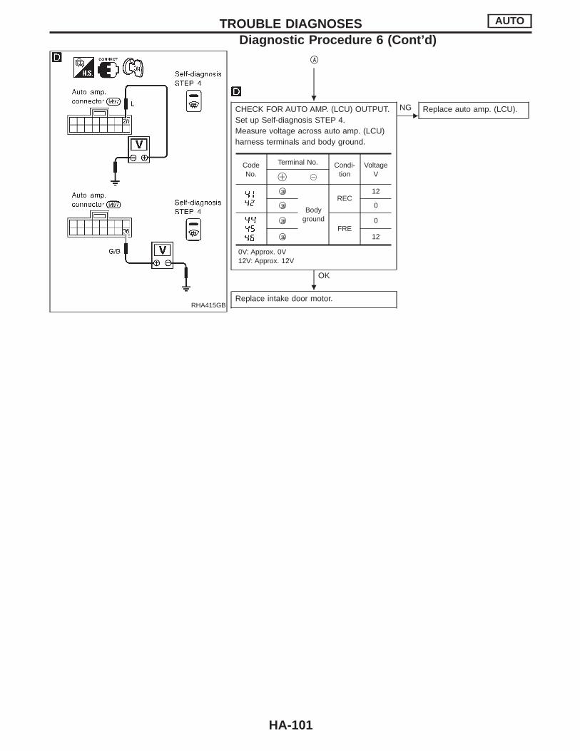
RHA415GB
qA
CHECK FOR AUTO AMP. (LCU) OUTPUT.Set up Self-diagnosis STEP 4.Measure voltage across auto amp. (LCU)harness terminals and body ground.
OK
ENG Replace auto amp. (LCU).
Replace intake door motor.
CodeNo.
Terminal No. Condi-tion
VoltageV! @
q28
Bodyground
REC12
q36 0
q28
FRE0
q36 12
0V: Approx. 0V12V: Approx. 12V
TROUBLE DIAGNOSES AUTO
Diagnostic Procedure 6 (Cont’d)
H
H
HA-101
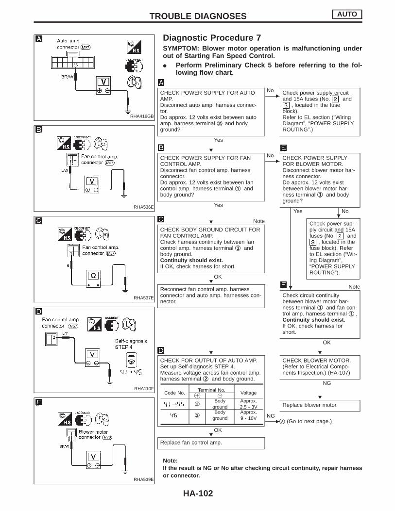
RHA416GB
Diagnostic Procedure 7SYMPTOM: Blower motor operation is malfunctioning underout of Starting Fan Speed Control.I Perform Preliminary Check 5 before referring to the fol-
lowing flow chart.
RHA536E
RHA537E
RHA110F
RHA539E
CHECK POWER SUPPLY FOR AUTOAMP.Disconnect auto amp. harness connec-tor.Do approx. 12 volts exist between autoamp. harness terminal q33 and bodyground?
Yes
ENo Check power supply circuit
and 15A fuses (No. and, located in the fuse
block).Refer to EL section (“WiringDiagram”, “POWER SUPPLYROUTING”.)
CHECK POWER SUPPLY FOR FANCONTROL AMP.Disconnect fan control amp. harnessconnector.Do approx. 12 volts exist between fancontrol amp. harness terminal q1 andbody ground?
Yes
ENo CHECK POWER SUPPLY
FOR BLOWER MOTOR.Disconnect blower motor har-ness connector.Do approx. 12 volts existbetween blower motor har-ness terminal q1 and bodyground?
Yes No
Note
CHECK BODY GROUND CIRCUIT FORFAN CONTROL AMP.Check harness continuity between fancontrol amp. harness terminal q3 andbody ground.Continuity should exist.If OK, check harness for short.
OK
Check power sup-ply circuit and 15Afuses (No. and
, located in thefuse block). Referto EL section (“Wir-ing Diagram”,“POWER SUPPLYROUTING”).
Reconnect fan control amp. harnessconnector and auto amp. harnesses con-nector.
Note
Check circuit continuitybetween blower motor har-ness terminal q1 and fan con-trol amp. harness terminal q1 .Continuity should exist.If OK, check harness forshort.
OK
CHECK FOR OUTPUT OF AUTO AMP.Set up Self-diagnosis STEP 4.Measure voltage across fan control amp.harness terminal q2 and body ground.
OK
CHECK BLOWER MOTOR.(Refer to Electrical Compo-nents Inspection.) (HA-107)
NG
Replace blower motor.
ENG
qA (Go to next page.)
Replace fan control amp.
Note:If the result is NG or No after checking circuit continuity, repair harnessor connector.
Code No.Terminal No.
Voltage! @
, q2 Bodyground
Approx.2.5 - 3V
q2 Bodyground
Approx.9 - 10V
TROUBLE DIAGNOSES AUTO
H
HH
HH
H H
H
H
HA-102
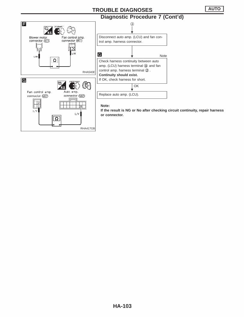
RHA540E
RHA417GB
qA
Disconnect auto amp. (LCU) and fan con-trol amp. harness connector.
Note
Check harness continuity between autoamp. (LCU) harness terminal q35 and fancontrol amp. harness terminal q2 .Continuity should exist.If OK, check harness for short.
OK
Replace auto amp. (LCU).
Note:If the result is NG or No after checking circuit continuity, repair harnessor connector.
TROUBLE DIAGNOSES AUTO
Diagnostic Procedure 7 (Cont’d)
H
H
H
HA-103
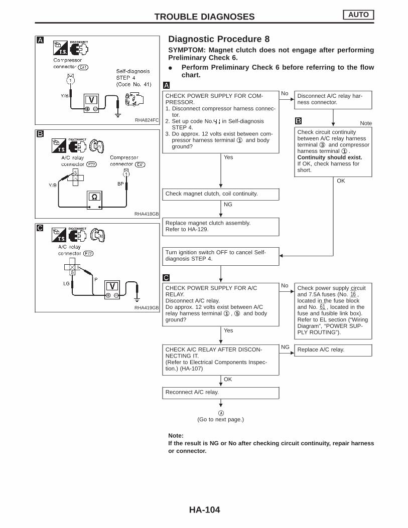
RHA824FC
Diagnostic Procedure 8SYMPTOM: Magnet clutch does not engage after performingPreliminary Check 6.I Perform Preliminary Check 6 before referring to the flow
chart.
RHA418GB
RHA419GB
CHECK POWER SUPPLY FOR COM-PRESSOR.1. Disconnect compressor harness connec-
tor.2. Set up code No. in Self-diagnosis
STEP 4.3. Do approx. 12 volts exist between com-
pressor harness terminal q1 and bodyground?
Yes
ENo Disconnect A/C relay har-
ness connector.
Note
Check circuit continuitybetween A/C relay harnessterminal q3 and compressorharness terminal q1 .Continuity should exist.If OK, check harness forshort.
OK
Check magnet clutch, coil continuity.
NG
Replace magnet clutch assembly.Refer to HA-129.
Turn ignition switch OFF to cancel Self-diagnosis STEP 4. F
CHECK POWER SUPPLY FOR A/CRELAY.Disconnect A/C relay.Do approx. 12 volts exist between A/Crelay harness terminal q1 , q5 and bodyground?
Yes
ENo Check power supply circuit
and 7.5A fuses (No. 16 ,located in the fuse blockand No. 61 , located in thefuse and fusible link box).Refer to EL section (“WiringDiagram”, “POWER SUP-PLY ROUTING”).
CHECK A/C RELAY AFTER DISCON-NECTING IT.(Refer to Electrical Components Inspec-tion.) (HA-107)
OK
ENG Replace A/C relay.
Reconnect A/C relay.
qA
(Go to next page.)
Note:If the result is NG or No after checking circuit continuity, repair harnessor connector.
TROUBLE DIAGNOSES AUTO
H
H
H
H
H
H
H
HA-104
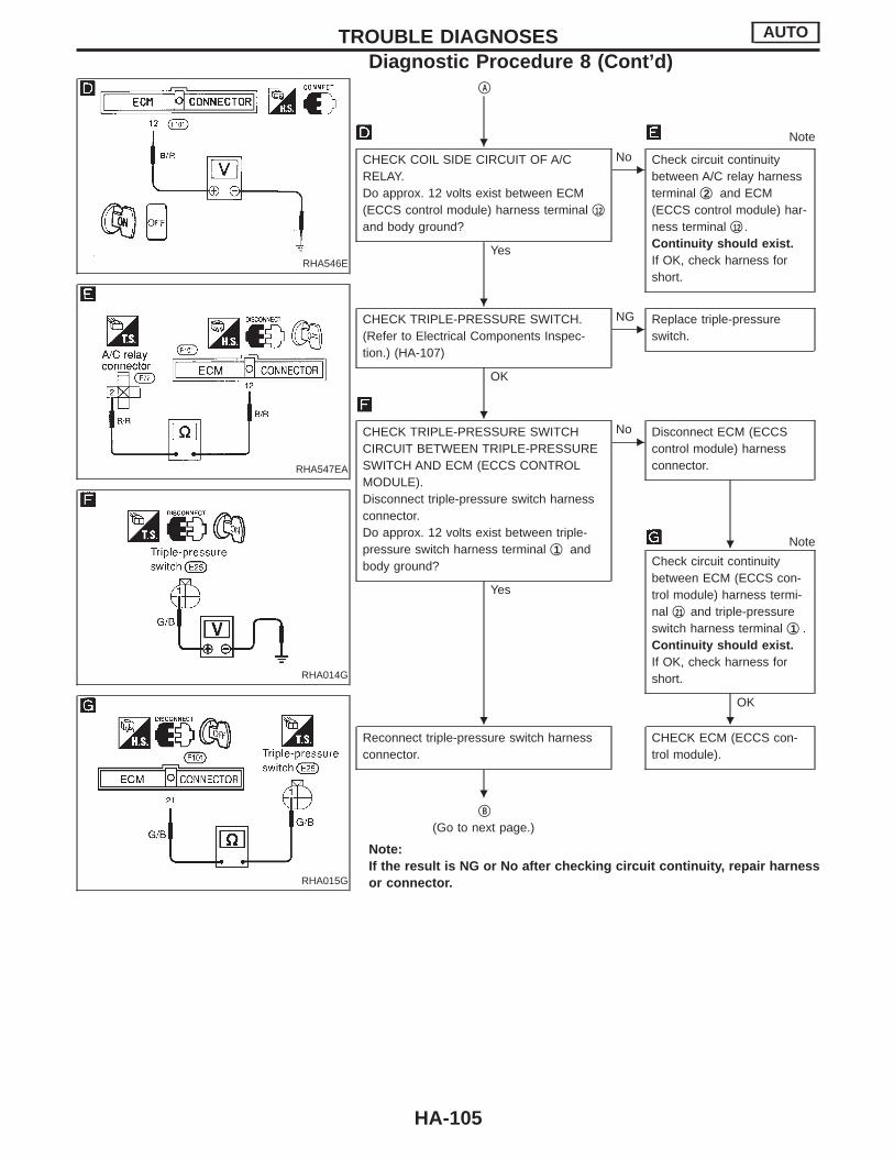
RHA546E
RHA547EA
RHA014G
RHA015G
qA
Note
CHECK COIL SIDE CIRCUIT OF A/CRELAY.Do approx. 12 volts exist between ECM(ECCS control module) harness terminal q12
and body ground?
Yes
ENo Check circuit continuity
between A/C relay harnessterminal q2 and ECM(ECCS control module) har-ness terminal q12 .Continuity should exist.If OK, check harness forshort.
CHECK TRIPLE-PRESSURE SWITCH.(Refer to Electrical Components Inspec-tion.) (HA-107)
OK
ENG Replace triple-pressure
switch.
CHECK TRIPLE-PRESSURE SWITCHCIRCUIT BETWEEN TRIPLE-PRESSURESWITCH AND ECM (ECCS CONTROLMODULE).Disconnect triple-pressure switch harnessconnector.Do approx. 12 volts exist between triple-pressure switch harness terminal q1 andbody ground?
Yes
ENo Disconnect ECM (ECCS
control module) harnessconnector.
Note
Check circuit continuitybetween ECM (ECCS con-trol module) harness termi-nal q21 and triple-pressureswitch harness terminal q1 .Continuity should exist.If OK, check harness forshort.
OK
Reconnect triple-pressure switch harnessconnector.
CHECK ECM (ECCS con-trol module).
qB
(Go to next page.)
Note:If the result is NG or No after checking circuit continuity, repair harnessor connector.
TROUBLE DIAGNOSES AUTO
Diagnostic Procedure 8 (Cont’d)
H
H
H
H
H H
H
HA-105
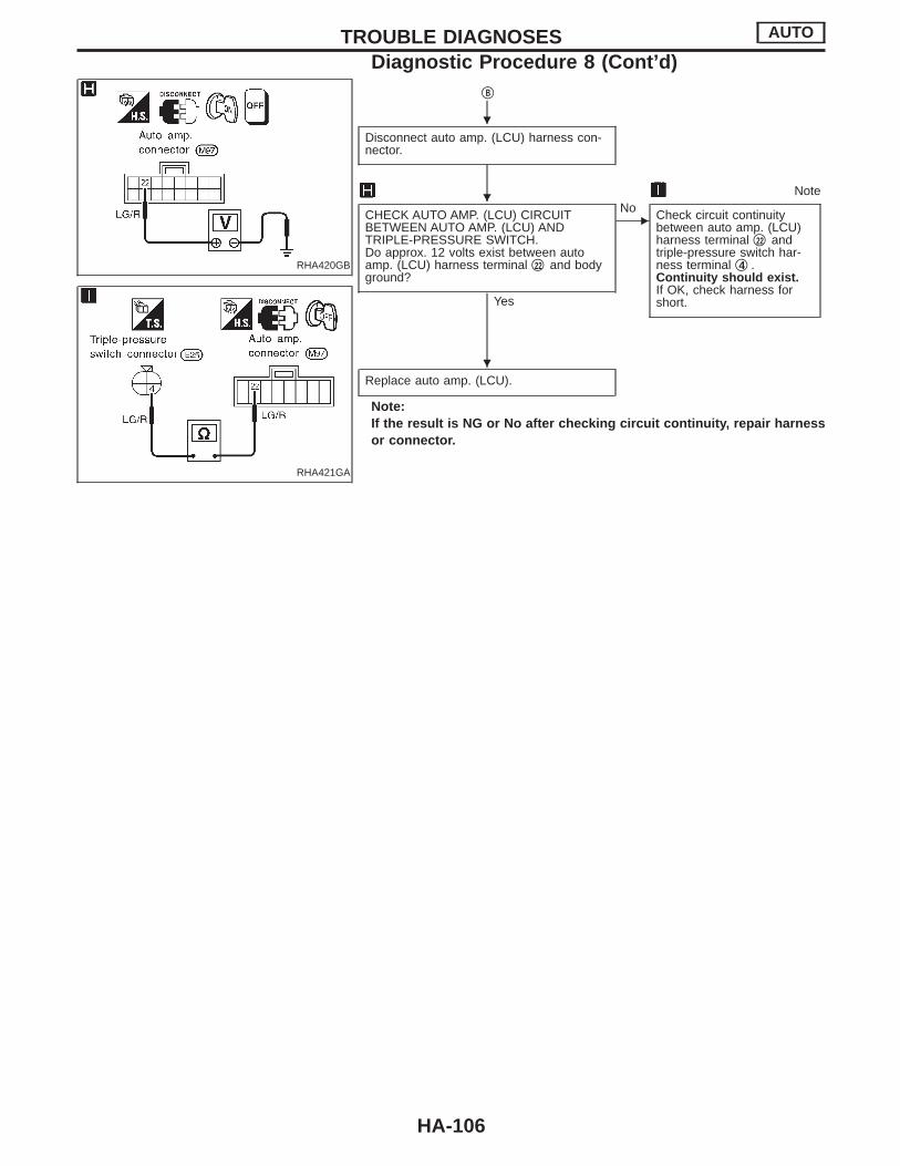
RHA420GB
RHA421GA
qB
Disconnect auto amp. (LCU) harness con-nector.
Note
CHECK AUTO AMP. (LCU) CIRCUITBETWEEN AUTO AMP. (LCU) ANDTRIPLE-PRESSURE SWITCH.Do approx. 12 volts exist between autoamp. (LCU) harness terminal q22 and bodyground?
Yes
ENo Check circuit continuity
between auto amp. (LCU)harness terminal q22 andtriple-pressure switch har-ness terminal q4 .Continuity should exist.If OK, check harness forshort.
Replace auto amp. (LCU).
Note:If the result is NG or No after checking circuit continuity, repair harnessor connector.
TROUBLE DIAGNOSES AUTO
Diagnostic Procedure 8 (Cont’d)
H
H
H
HA-106

RHA244D
Electrical Components InspectionBLOWER MOTORCheck blower motor for smooth rotation.I Ensure that there are no foreign particles inside the intake unit.
SHA691E
TRIPLE-PRESSURE SWITCH
TerminalsHigh-pressure side line
pressurekPa (kg/cm2, psi)
Operation Continuity
Low-pres-sure side
q1 - q4
Increasing to157 - 226
(1.6 - 2.3, 23 - 33)ON Exists.
Decreasing to152.0 - 201.0
(1.55 - 2.05, 22.0 -29.2)
OFF Does notexist.
Medium-pressureside*
q2 - q3
Increasing to1,422 - 1,618
(14.5 - 16.5, 206 - 235)ON Exists.
Decreasing to1,128 - 1,422
(11.5 - 14.5, 164 - 206)OFF Does not
exist.
High-pres-sure side
q1 - q4
Decreasing to1,667 - 2,059
(17 - 21, 242 - 299)ON Exists.
Increasing to2,452 - 2,844
(25 - 29, 356 - 412)OFF Does not
exist.
* For cooling fan motor operation.
AHA233
A/C RELAYCheck circuit continuity between terminals by supplying 12 volts tocoil side terminals of the relay.
TROUBLE DIAGNOSES AUTO
HA-107
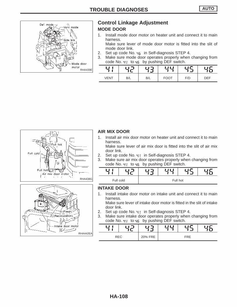
RHA439E
Control Linkage AdjustmentMODE DOOR1. Install mode door motor on heater unit and connect it to main
harness.Make sure lever of mode door motor is fitted into the slit ofmode door link.
2. Set up code No. in Self-diagnosis STEP 4.3. Make sure mode door operates properly when changing from
code No. to by pushing DEF switch.
VENT B/L B/L FOOT F/D DEF
RHA438G
RHA442EA
AIR MIX DOOR1. Install air mix door motor on heater unit and connect it to main
harness.Make sure lever of air mix door is fitted into the slit of air mixdoor link.
2. Set up code No. in Self-diagnosis STEP 4.3. Make sure air mix door operates properly when changing from
code No. to by pushing DEF switch.
Full cold Full hot
INTAKE DOOR1. Install intake door motor on intake unit and connect it to main
harness.Make sure lever of intake door motor is fitted in the slit of intakedoor link.
2. Set up code No. in Self-diagnosis STEP 4.3. Make sure intake door operates properly when changing from
code No. to by pushing DEF switch.
REC 20% FRE FRE
TROUBLE DIAGNOSES AUTO
HA-108

Overview of Control SystemThe control system consists of a) input sensors and switches, b)the auto amp. (microcomputer), and c) outputs. The relationship ofthese components is shown in the diagram below:
SHA973E
SYSTEM DESCRIPTION AUTO
HA-109
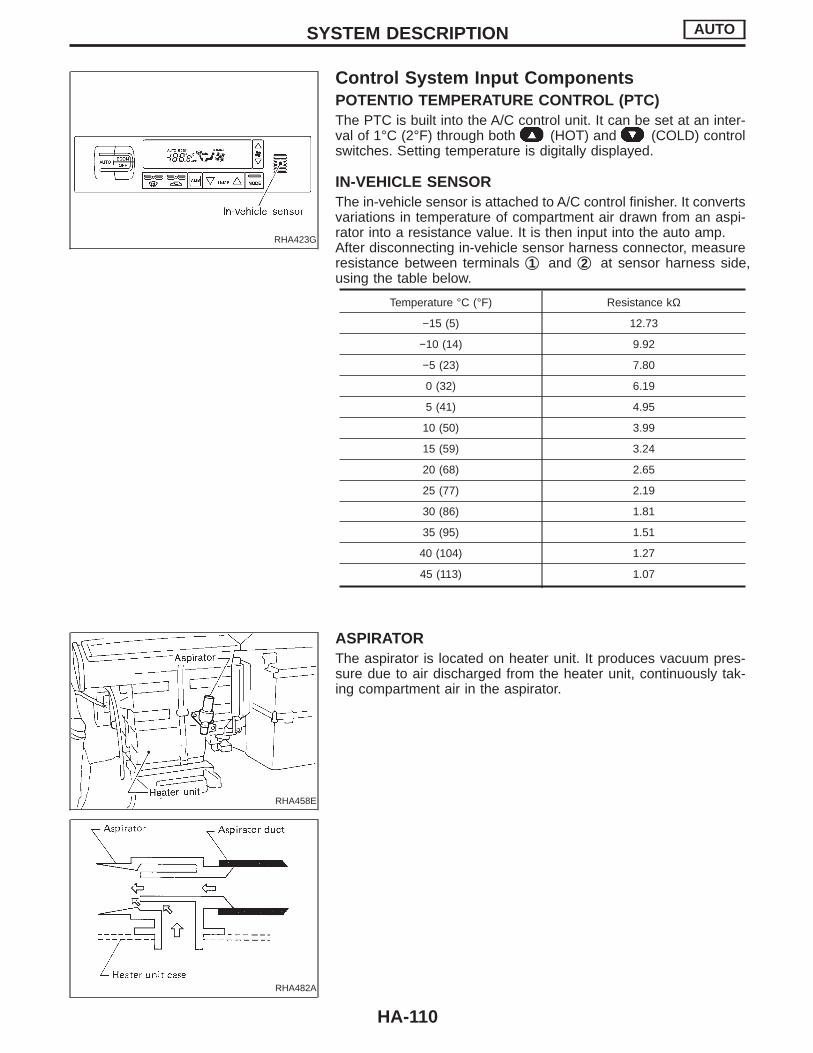
RHA423G
Control System Input ComponentsPOTENTIO TEMPERATURE CONTROL (PTC)The PTC is built into the A/C control unit. It can be set at an inter-val of 1°C (2°F) through both (HOT) and (COLD) controlswitches. Setting temperature is digitally displayed.
IN-VEHICLE SENSORThe in-vehicle sensor is attached to A/C control finisher. It convertsvariations in temperature of compartment air drawn from an aspi-rator into a resistance value. It is then input into the auto amp.After disconnecting in-vehicle sensor harness connector, measureresistance between terminals q1 and q2 at sensor harness side,using the table below.
Temperature °C (°F) Resistance kΩ
−15 (5) 12.73
−10 (14) 9.92
−5 (23) 7.80
0 (32) 6.19
5 (41) 4.95
10 (50) 3.99
15 (59) 3.24
20 (68) 2.65
25 (77) 2.19
30 (86) 1.81
35 (95) 1.51
40 (104) 1.27
45 (113) 1.07
RHA458E
ASPIRATORThe aspirator is located on heater unit. It produces vacuum pres-sure due to air discharged from the heater unit, continuously tak-ing compartment air in the aspirator.
RHA482A
SYSTEM DESCRIPTION AUTO
HA-110
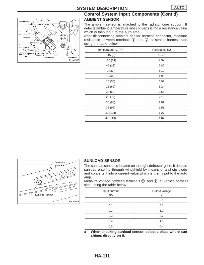
RHA459E
AMBIENT SENSORThe ambient sensor is attached to the radiator core support. Itdetects ambient temperature and converts it into a resistance valuewhich is then input to the auto amp.After disconnecting ambient sensor harness connector, measureresistance between terminals q1 and q2 at sensor harness side,using the table below.
Temperature °C (°F) Resistance kΩ
−15 (5) 12.73
−10 (14) 9.92
−5 (23) 7.80
0 (32) 6.19
5 (41) 4.95
10 (50) 3.99
15 (59) 3.24
20 (68) 2.65
25 (77) 2.19
30 (86) 1.81
35 (95) 1.51
40 (104) 1.27
45 (113) 1.07
RHA460E
SUNLOAD SENSORThe sunload sensor is located on the right defroster grille. It detectssunload entering through windshield by means of a photo diodeand converts it into a current value which is then input to the autoamp.Measure voltage between terminals q1 and q2 at vehicle harnessside, using the table below.
Input currentmA
Output voltageV
0 5.0
0.1 4.1
0.2 3.1
0.3 2.2
0.4 1.3
0.5 0.4
I When checking sunload sensor, select a place where sunshines directly on it.
SYSTEM DESCRIPTION AUTO
Control System Input Components (Cont’d)
HA-111

RHA434G
INTAKE SENSORAfter disconnecting intake sensor harness connector, measureresistance between terminals q1 and q2 at sensor harness side,using the table below.
Temperature °C (°F) Resistance kΩ
−20 (−4) 16.2
−10 (14) 9.8
0 (32) 6.0
10 (50) 3.94
20 (68) 2.64
25 (77) 2.12
30 (86) 1.82
40 (104) 1.27
SYSTEM DESCRIPTION AUTO
Control System Input Components (Cont’d)
HA-112
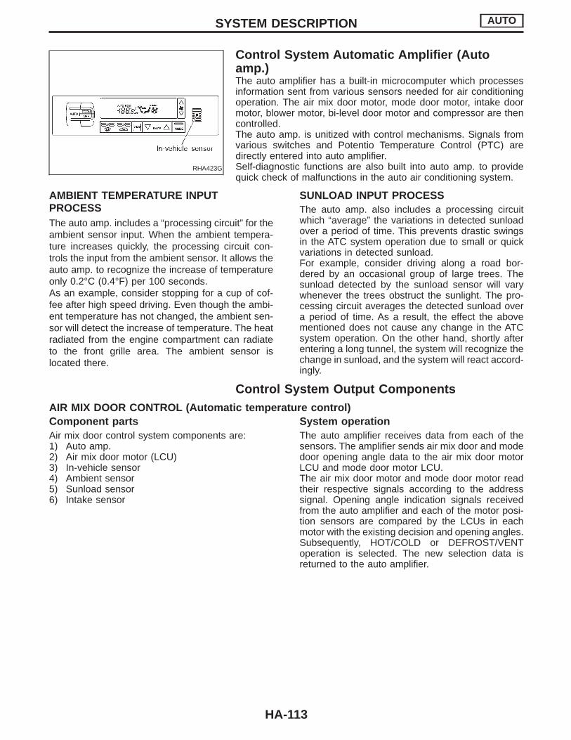
RHA423G
Control System Automatic Amplifier (Autoamp.)The auto amplifier has a built-in microcomputer which processesinformation sent from various sensors needed for air conditioningoperation. The air mix door motor, mode door motor, intake doormotor, blower motor, bi-level door motor and compressor are thencontrolled.The auto amp. is unitized with control mechanisms. Signals fromvarious switches and Potentio Temperature Control (PTC) aredirectly entered into auto amplifier.Self-diagnostic functions are also built into auto amp. to providequick check of malfunctions in the auto air conditioning system.
AMBIENT TEMPERATURE INPUTPROCESSThe auto amp. includes a “processing circuit” for theambient sensor input. When the ambient tempera-ture increases quickly, the processing circuit con-trols the input from the ambient sensor. It allows theauto amp. to recognize the increase of temperatureonly 0.2°C (0.4°F) per 100 seconds.As an example, consider stopping for a cup of cof-fee after high speed driving. Even though the ambi-ent temperature has not changed, the ambient sen-sor will detect the increase of temperature. The heatradiated from the engine compartment can radiateto the front grille area. The ambient sensor islocated there.
SUNLOAD INPUT PROCESSThe auto amp. also includes a processing circuitwhich “average” the variations in detected sunloadover a period of time. This prevents drastic swingsin the ATC system operation due to small or quickvariations in detected sunload.For example, consider driving along a road bor-dered by an occasional group of large trees. Thesunload detected by the sunload sensor will varywhenever the trees obstruct the sunlight. The pro-cessing circuit averages the detected sunload overa period of time. As a result, the effect the abovementioned does not cause any change in the ATCsystem operation. On the other hand, shortly afterentering a long tunnel, the system will recognize thechange in sunload, and the system will react accord-ingly.
Control System Output ComponentsAIR MIX DOOR CONTROL (Automatic temperature control)Component partsAir mix door control system components are:1) Auto amp.2) Air mix door motor (LCU)3) In-vehicle sensor4) Ambient sensor5) Sunload sensor6) Intake sensor
System operationThe auto amplifier receives data from each of thesensors. The amplifier sends air mix door and modedoor opening angle data to the air mix door motorLCU and mode door motor LCU.The air mix door motor and mode door motor readtheir respective signals according to the addresssignal. Opening angle indication signals receivedfrom the auto amplifier and each of the motor posi-tion sensors are compared by the LCUs in eachmotor with the existing decision and opening angles.Subsequently, HOT/COLD or DEFROST/VENToperation is selected. The new selection data isreturned to the auto amplifier.
SYSTEM DESCRIPTION AUTO
HA-113

SHA974E
Air mix door control specification
RHA568E
RHA437G
AIR MIX DOOR MOTOR
The air mix door motor is attached to the bottom of the heater unit.It rotates so that the air mix door is opened to a position set by theauto amp. Motor rotation is then conveyed through a shaft and airmix door position is then fed back to the auto amp. by PBR built-inair mix door motor (LCU).
SYSTEM DESCRIPTION AUTO
Control System Output Components (Cont’d)
HA-114

MODE DOOR CONTROL
Component partsMode door control system components are:1) Auto amp.2) Mode door motor (LCU)3) In-vehicle sensor4) Ambient sensor5) Sunload sensor6) Intake sensor
System operationThe auto amplifier receives data from each of thesensors. The amplifier sends air mix door and modedoor opening angle data to the air mix door motorLCU and mode door motor LCU.The air mix door motor and mode door motor readtheir respective signals according to the addresssignal. Opening angle indication signals receivedfrom the auto amplifier and each of the motor posi-tion sensors are compared by the LCUs in eachmotor with the existing decision and opening angles.Subsequently, HOT/COLD or DEFROST/VENToperation is selected. The new selection data isreturned to the auto amplifier.
SHA975E
SYSTEM DESCRIPTION AUTO
Control System Output Components (Cont’d)
HA-115
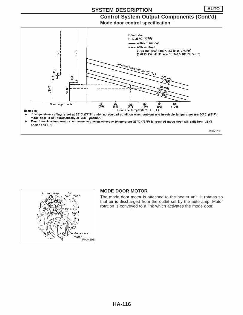
Mode door control specification
RHA573E
RHA439E
MODE DOOR MOTORThe mode door motor is attached to the heater unit. It rotates sothat air is discharged from the outlet set by the auto amp. Motorrotation is conveyed to a link which activates the mode door.
SYSTEM DESCRIPTION AUTO
Control System Output Components (Cont’d)
HA-116

INTAKE DOOR CONTROL
Components partsIntake door control system components are:1) Auto amp.2) Intake door motor3) A/C LAN system (PBR built-in mode door motor
and air mix door motor)4) In-vehicle sensor5) Ambient sensor6) Sunload sensor7) Intake sensor
System operationThe intake door control determines intake door posi-tion based on the ambient temperature and the in-vehicle temperature. When the ECON, DEF, or OFFbuttons are pushed, the auto amp. sets the intakedoor at the “Fresh” position.
SHA976E
Intake door control specification
RHA576EB
SYSTEM DESCRIPTION AUTO
Control System Output Components (Cont’d)
HA-117
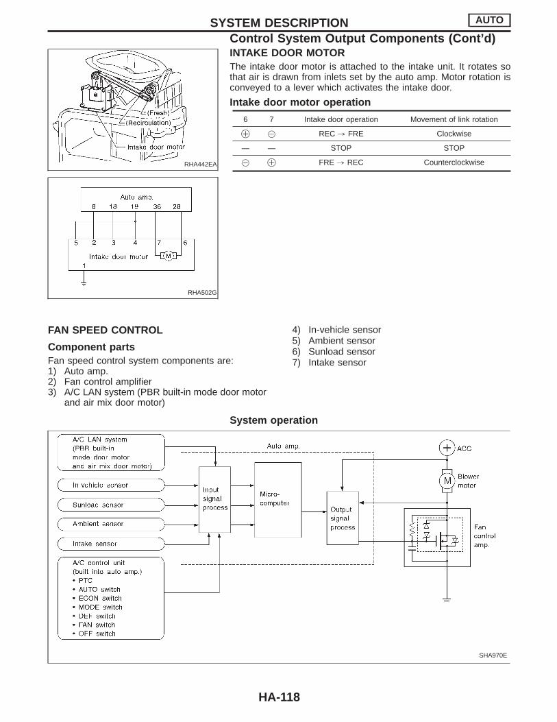
RHA442EA
RHA502G
INTAKE DOOR MOTORThe intake door motor is attached to the intake unit. It rotates sothat air is drawn from inlets set by the auto amp. Motor rotation isconveyed to a lever which activates the intake door.
Intake door motor operation
6 7 Intake door operation Movement of link rotation
! @ REC , FRE Clockwise
— — STOP STOP
@ ! FRE , REC Counterclockwise
FAN SPEED CONTROL
Component partsFan speed control system components are:1) Auto amp.2) Fan control amplifier3) A/C LAN system (PBR built-in mode door motor
and air mix door motor)
4) In-vehicle sensor5) Ambient sensor6) Sunload sensor7) Intake sensor
System operation
SHA970E
SYSTEM DESCRIPTION AUTO
Control System Output Components (Cont’d)
HA-118
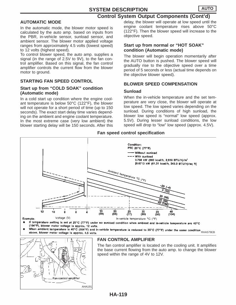
AUTOMATIC MODEIn the automatic mode, the blower motor speed iscalculated by the auto amp. based on inputs fromthe PBR, in-vehicle sensor, sunload sensor, andambient sensor. The blower motor applied voltageranges from approximately 4.5 volts (lowest speed)to 12 volts (highest speed).To control blower speed, the auto amp. supplies asignal (in the range of 2.5V to 9V), to the fan con-trol amplifier. Based on this signal, the fan controlamplifier controls the current flow from the blowermotor to ground.
STARTING FAN SPEED CONTROL
Start up from “COLD SOAK” condition(Automatic mode)In a cold start up condition where the engine cool-ant temperature is below 50°C (122°F), the blowerwill not operate for a short period of time (up to 150seconds). The exact start delay time varies depend-ing on the ambient and engine coolant temperature.In the most extreme case (very low ambient) theblower starting delay will be 150 seconds. After this
delay, the blower will operate at low speed until theengine coolant temperature rises above 50°C(122°F). Then the blower speed will increase to theobjective speed.
Start up from normal or “HOT SOAK”condition (Automatic mode)The blower will begin operation momentarily afterthe AUTO button is pushed. The blower speed willgradually rise to the objective speed over a timeperiod of 5 seconds or less (actual time depends onthe objective blower speed).
BLOWER SPEED COMPENSATION
SunloadWhen the in-vehicle temperature and the set tem-perature are very close, the blower will operate atlow speed. The low speed varies depending on thesunload. During conditions of high sunload, theblower low speed is “normal” low speed (approx.5.5V). During lesser sunload conditions, the lowspeed will drop to “low” low speed (approx. 4.5V).
Fan speed control specification
RHA579EB
AHA191
FAN CONTROL AMPLIFIERThe fan control amplifier is located on the cooling unit. It amplifiesthe base current flowing from the auto amp. to change the blowerspeed within the range of 4V to 12V.
SYSTEM DESCRIPTION AUTO
Control System Output Components (Cont’d)
HA-119
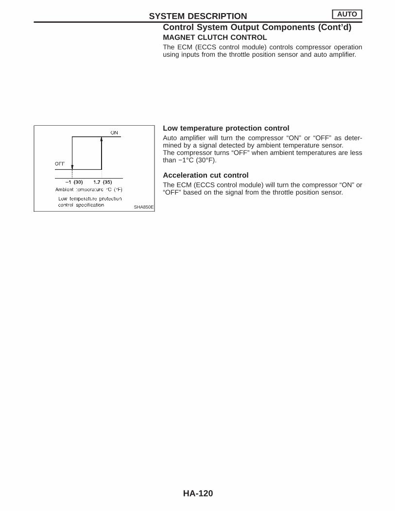
MAGNET CLUTCH CONTROLThe ECM (ECCS control module) controls compressor operationusing inputs from the throttle position sensor and auto amplifier.
SHA850E
Low temperature protection controlAuto amplifier will turn the compressor “ON” or “OFF” as deter-mined by a signal detected by ambient temperature sensor.The compressor turns “OFF” when ambient temperatures are lessthan −1°C (30°F).
Acceleration cut controlThe ECM (ECCS control module) will turn the compressor “ON” or“OFF” based on the signal from the throttle position sensor.
SYSTEM DESCRIPTION AUTO
Control System Output Components (Cont’d)
HA-120

HFC-134a (R-134a) Service ProcedureSETTING OF SERVICE TOOLS AND EQUIPMENT
DISCHARGING REFRIGERANTWARNING:Avoid breathing A/C refrigerant and lubricant vapor or mist. Exposure may irritate eyes, nose andthroat. Remove R-134a from A/C system, using certified service equipment meeting requirements ofSAE J2210 (R-134a recycling equipment), or J2209 (R-134a recovery equipment). If accidental systemdischarge occurs, ventilate work area before resuming service. Additional health and safety informa-tion may be obtained from refrigerant and lubricant manufacturers.
RHA275DF
EVACUATING SYSTEM AND CHARGING REFRIGERANT
RHA276DG
SERVICE PROCEDURES MANUAL AND AUTO
HA-121
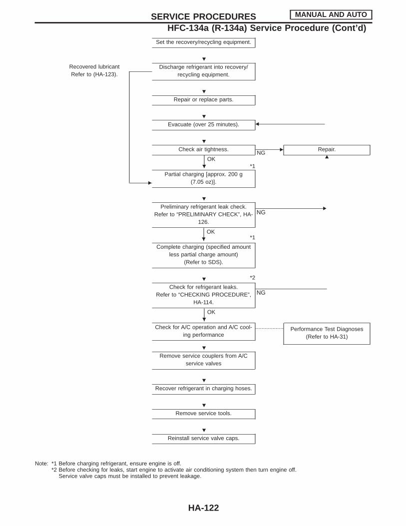
Set the recovery/recycling equipment.
Recovered lubricantRefer to (HA-123).
E
Discharge refrigerant into recovery/recycling equipment.
Repair or replace parts.
Evacuate (over 25 minutes). F
Check air tightness.
OK*1
ENG
Repair.G
Partial charging [approx. 200 g(7.05 oz)].
Preliminary refrigerant leak check.Refer to “PRELIMINARY CHECK”, HA-
126.
OK*1
ENG
Complete charging (specified amountless partial charge amount)
(Refer to SDS).
*2
Check for refrigerant leaks.Refer to “CHECKING PROCEDURE”,
HA-114.
OK
NG
Check for A/C operation and A/C cool-ing performance
.................. Performance Test Diagnoses(Refer to HA-31)
Remove service couplers from A/Cservice valves
Recover refrigerant in charging hoses.
Remove service tools.
Reinstall service valve caps.
Note: *1 Before charging refrigerant, ensure engine is off.*2 Before checking for leaks, start engine to activate air conditioning system then turn engine off.
Service valve caps must be installed to prevent leakage.
SERVICE PROCEDURES MANUAL AND AUTO
HFC-134a (R-134a) Service Procedure (Cont’d)
H
H
H
H
H
H
H
H
H
H
H
H
H
HA-122
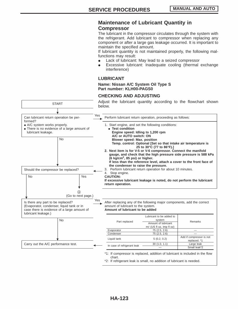
Maintenance of Lubricant Quantity inCompressorThe lubricant in the compressor circulates through the system withthe refrigerant. Add lubricant to compressor when replacing anycomponent or after a large gas leakage occurred. It is important tomaintain the specified amount.If lubricant quantity is not maintained properly, the following mal-functions may result:I Lack of lubricant: May lead to a seized compressorI Excessive lubricant: Inadequate cooling (thermal exchange
interference)
LUBRICANTName: Nissan A/C System Oil Type SPart number: KLH00-PAGS0
CHECKING AND ADJUSTINGAdjust the lubricant quantity according to the flowchart shownbelow.
START
Can lubricant return operation be per-formed?I A/C system works properly.I There is no evidence of a large amount of
lubricant leakage.
No
EYes
Perform lubricant return operation, proceeding as follows:------------------------------------------------------------------------------------------------------------------------------------------------------------------------------------------------------------------------------------------------------------------------------------------------------------------------------------------------------------------------------------------------------------------------------------------------------------------------------------------------------------------------------------
1. Start engine, and set the following conditions:I Test condition
Engine speed: Idling to 1,200 rpmA/C or AUTO switch: ONBlower speed: Max. positionTemp. control: Optional [Set so that intake air temperature is
25 to 30°C (77 to 86°F).]2. Next item is for V-5 or V-6 compressor. Connect the manifold
gauge, and check that the high pressure side pressure is 588 kPa(6 kg/cm 2, 85 psi) or higher.If less than the reference level, attach a cover to the front face ofthe condenser to raise the pressure.
3. Perform lubricant return operation for about 10 minutes.4. Stop engine.CAUTION:If excessive lubricant leakage is noted, do not perform the lubricantreturn operation.
Should the compressor be replaced?
No Yes
F
qA
(Go to next page.)
Is there any part to be replaced?(Evaporator, condenser, liquid tank or incase there is evidence of a large amount oflubricant leakage.)
No
EYes
After replacing any of the following major components, add the correctamount of lubricant to the system.Amount of lubricant to be added
*1: If compressor is replaced, addition of lubricant is included in the flowchart.
*2: If refrigerant leak is small, no addition of lubricant is needed.
Carry out the A/C performance test. F
Part replaced
Lubricant to be added tosystem
RemarksAmount of lubricant
m (US fl oz, Imp fl oz)Evaporator 75 (2.5, 2.6) —Condenser 75 (2.5, 2.6) —
Liquid tank 5 (0.2, 0.2)Add if compressor is not
replaced. *1
In case of refrigerant leak30 (1.0, 1.1) Large leak
— Small leak*2
SERVICE PROCEDURES MANUAL AND AUTO
H
H
H
H
H
HA-123

qA
1. Discharge refrigerant into the refrigerant recovery/recycling equipment. Measure lubricant discharged into the recovery/recycling equipment.
2. Remove the drain plug of the “old” (removed) compressor (applicable only to V-5, V-6 or DKS-16H compressor). Drain thelubricant into a graduated container and record the amount of drained lubricant.
3. Remove the drain plug and drain the lubricant from the “new” compressor into a separate, clean container.4. Measure an amount of new lubricant installed equal to amount drained from “old” compressor. Add this lubricant to “new”
compressor through the suction port opening.5. Measure an amount of new lubricant equal to the amount recovered during discharging. Add this lubricant to “new” compres-
sor through the suction port opening.6. Torque the drain plug.
V-5 or V-6 compressor: 18 - 19 N ⋅m (1.8 - 1.9 kg-m, 13 - 14 ft-lb)DKS-16H compressor: 14 - 16 N ⋅m (1.4 - 1.6 kg-m, 10 - 12 ft-lb)
7. If the liquid tank also needs to be replaced, add an additional 5 m (0.2 US fl oz, 0.2 Imp fl oz) of lubricant at this time.Do not add this 5 m (0.2 US fl oz, 0.2 Imp fl oz) of lubricant if only replacing the compressor.
RHA065DD
SERVICE PROCEDURES MANUAL AND AUTO
Maintenance of Lubricant Quantity inCompressor (Cont’d)
H
HA-124
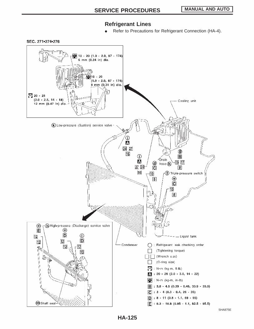
Refrigerant LinesI Refer to Precautions for Refrigerant Connection (HA-4).
SHA875E
SERVICE PROCEDURES MANUAL AND AUTO
HA-125

Checking Refrigerant LeaksPRELIMINARY CHECKPerform a visual inspection of all refrigeration parts, fittings, hoses,and components for signs of A/C lubricant leakage, damage andcorrosion.
SHA705E
PRECAUTIONS FOR HANDLING LEAK DETECTORWhen performing a refrigerant leak check, use a J39400 A/C leakdetector or equivalent. Ensure that the instrument is calibrated andset properly per the operating instructions.The leak detector is a delicate device. In order to use the leakdetector properly, read the operating instructions and perform anyspecified maintenance.Other gases in the work area or substances on the A/Ccomponents, for example, anti-freeze, windshield washerfluid, solvents and cleaners, may falsely trigger the leak detec-tor. Make sure the surfaces to be checked are clean. Do notallow the sensor tip of the detector to come into contact withany substance. This can also cause false readings and maydamage the detector.
SHA707EA
1. Position probe approximately 5 mm (3/16 in) away from pointto be checked.
SHA706E
2. When testing, circle each fitting completely with probe.
SERVICE PROCEDURES MANUAL AND AUTO
HA-126
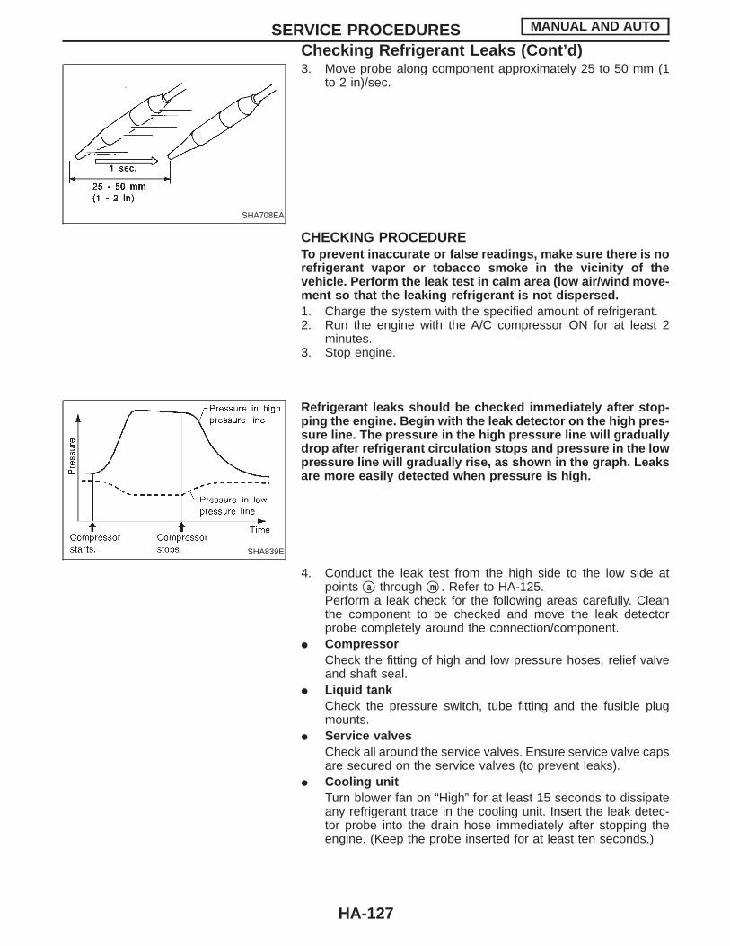
SHA708EA
3. Move probe along component approximately 25 to 50 mm (1to 2 in)/sec.
CHECKING PROCEDURETo prevent inaccurate or false readings, make sure there is norefrigerant vapor or tobacco smoke in the vicinity of thevehicle. Perform the leak test in calm area (low air/wind move-ment so that the leaking refrigerant is not dispersed.1. Charge the system with the specified amount of refrigerant.2. Run the engine with the A/C compressor ON for at least 2
minutes.3. Stop engine.
SHA839E
Refrigerant leaks should be checked immediately after stop-ping the engine. Begin with the leak detector on the high pres-sure line. The pressure in the high pressure line will graduallydrop after refrigerant circulation stops and pressure in the lowpressure line will gradually rise, as shown in the graph. Leaksare more easily detected when pressure is high.
4. Conduct the leak test from the high side to the low side atpoints qa through qm . Refer to HA-125.Perform a leak check for the following areas carefully. Cleanthe component to be checked and move the leak detectorprobe completely around the connection/component.
I CompressorCheck the fitting of high and low pressure hoses, relief valveand shaft seal.
I Liquid tankCheck the pressure switch, tube fitting and the fusible plugmounts.
I Service valvesCheck all around the service valves. Ensure service valve capsare secured on the service valves (to prevent leaks).
I Cooling unitTurn blower fan on “High” for at least 15 seconds to dissipateany refrigerant trace in the cooling unit. Insert the leak detec-tor probe into the drain hose immediately after stopping theengine. (Keep the probe inserted for at least ten seconds.)
SERVICE PROCEDURES MANUAL AND AUTO
Checking Refrigerant Leaks (Cont’d)
HA-127
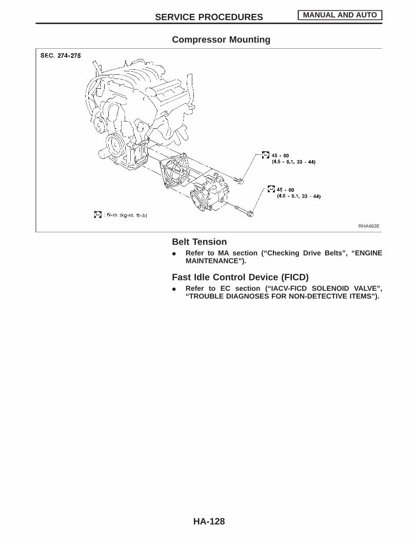
Compressor Mounting
RHA463E
Belt TensionI Refer to MA section (“Checking Drive Belts”, “ENGINE
MAINTENANCE”).
Fast Idle Control Device (FICD)I Refer to EC section (“IACV-FICD SOLENOID VALVE”,
“TROUBLE DIAGNOSES FOR NON-DETECTIVE ITEMS”).
SERVICE PROCEDURES MANUAL AND AUTO
HA-128
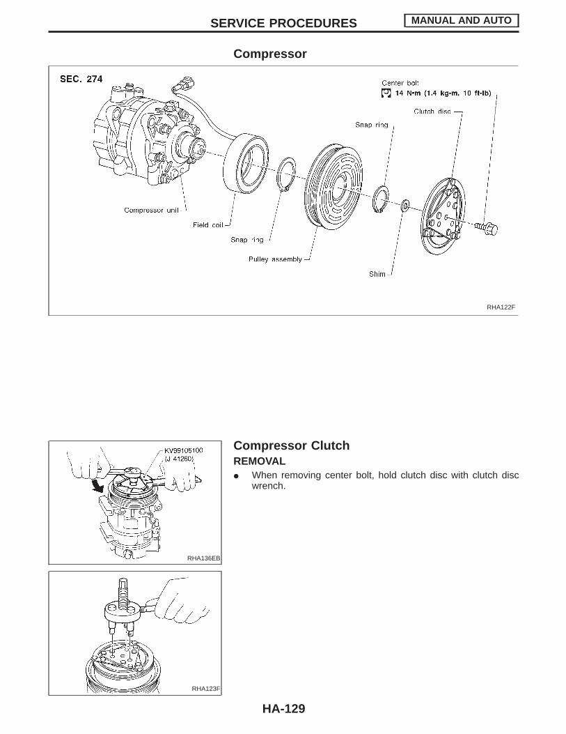
Compressor
RHA122F
RHA136EB
RHA123F
Compressor ClutchREMOVALI When removing center bolt, hold clutch disc with clutch disc
wrench.
SERVICE PROCEDURES MANUAL AND AUTO
HA-129
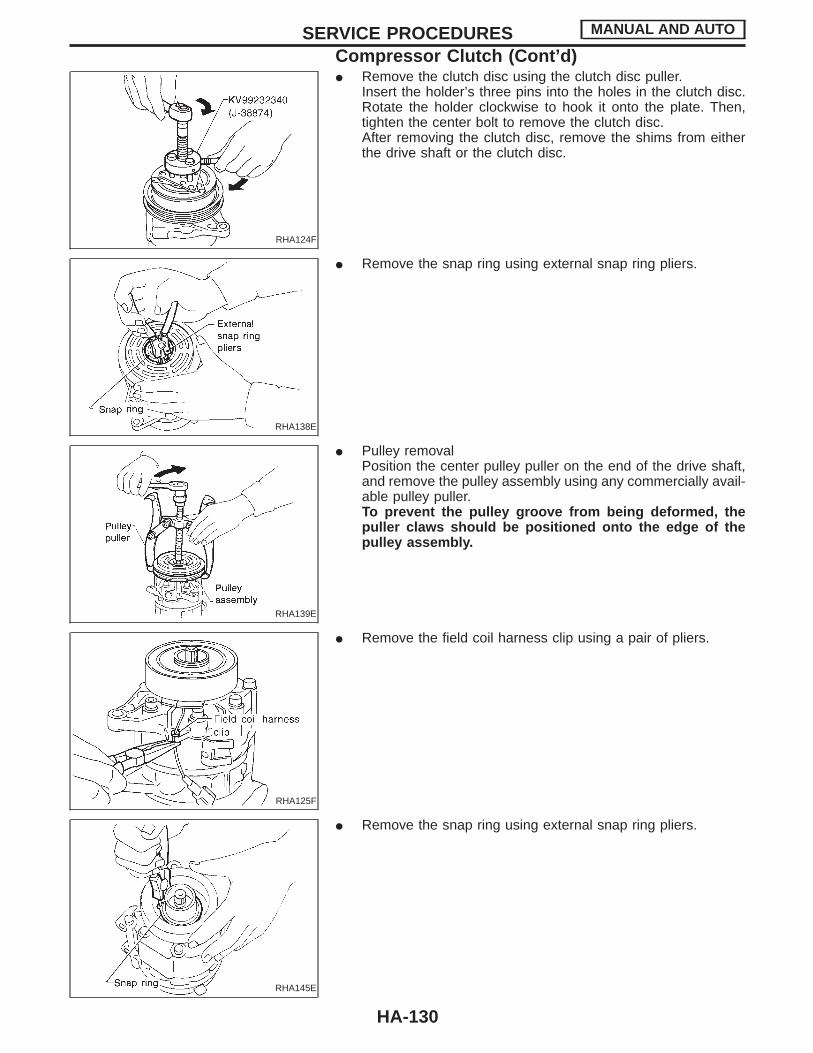
RHA124F
I Remove the clutch disc using the clutch disc puller.Insert the holder’s three pins into the holes in the clutch disc.Rotate the holder clockwise to hook it onto the plate. Then,tighten the center bolt to remove the clutch disc.After removing the clutch disc, remove the shims from eitherthe drive shaft or the clutch disc.
RHA138E
I Remove the snap ring using external snap ring pliers.
RHA139E
I Pulley removalPosition the center pulley puller on the end of the drive shaft,and remove the pulley assembly using any commercially avail-able pulley puller.To prevent the pulley groove from being deformed, thepuller claws should be positioned onto the edge of thepulley assembly.
RHA125F
I Remove the field coil harness clip using a pair of pliers.
RHA145E
I Remove the snap ring using external snap ring pliers.
SERVICE PROCEDURES MANUAL AND AUTO
Compressor Clutch (Cont’d)
HA-130
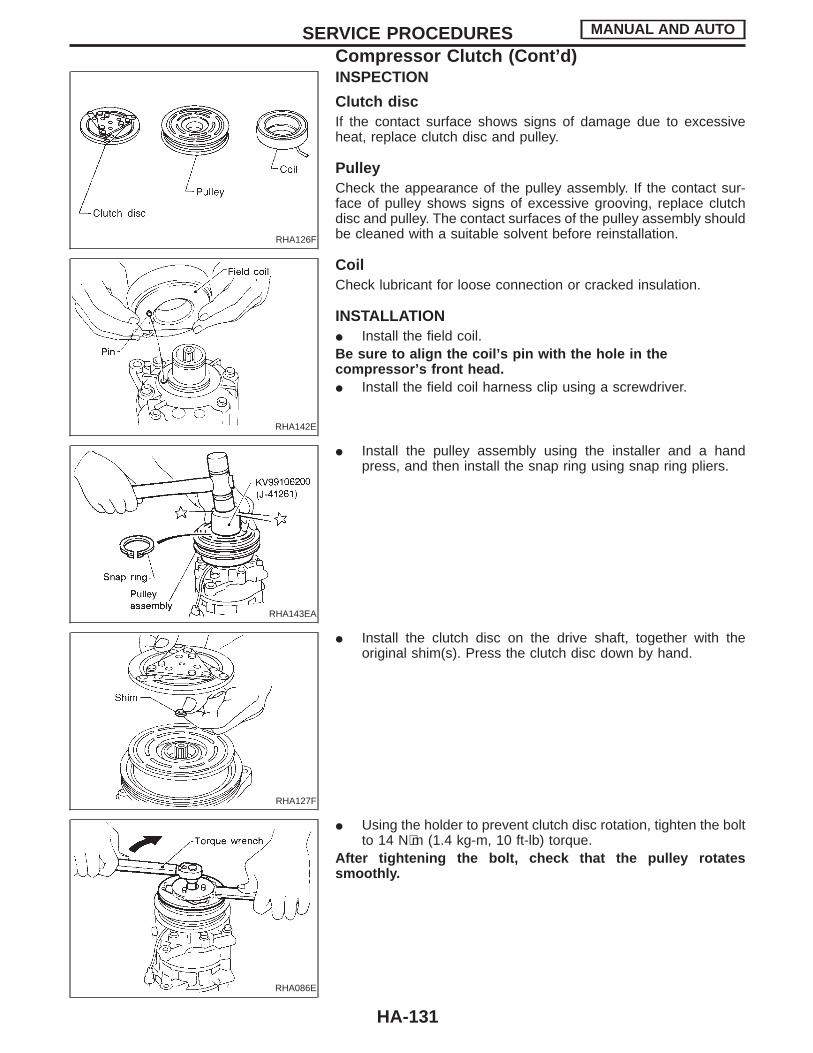
RHA126F
RHA142E
INSPECTION
Clutch discIf the contact surface shows signs of damage due to excessiveheat, replace clutch disc and pulley.
PulleyCheck the appearance of the pulley assembly. If the contact sur-face of pulley shows signs of excessive grooving, replace clutchdisc and pulley. The contact surfaces of the pulley assembly shouldbe cleaned with a suitable solvent before reinstallation.
CoilCheck lubricant for loose connection or cracked insulation.
INSTALLATIONI Install the field coil.Be sure to align the coil’s pin with the hole in thecompressor’s front head.I Install the field coil harness clip using a screwdriver.
RHA143EA
I Install the pulley assembly using the installer and a handpress, and then install the snap ring using snap ring pliers.
RHA127F
I Install the clutch disc on the drive shaft, together with theoriginal shim(s). Press the clutch disc down by hand.
RHA086E
I Using the holder to prevent clutch disc rotation, tighten the boltto 14 N⋅m (1.4 kg-m, 10 ft-lb) torque.
After tightening the bolt, check that the pulley rotatessmoothly.
SERVICE PROCEDURES MANUAL AND AUTO
Compressor Clutch (Cont’d)
HA-131

RHA087E
I Check clearance around the entire periphery of clutch disc.Disc-to-pulley clearance:
0.3 - 0.6 mm (0.012 - 0.024 in)If the specified clearance is not obtained, replace adjustingspacer and readjust.
BREAK-IN OPERATIONWhen replacing compressor clutch assembly, always carry out thebreak-in operation. This is done by engaging and disengaging theclutch about thirty times. Break-in operation raises the level oftransmitted torque.
SERVICE PROCEDURES MANUAL AND AUTO
Compressor Clutch (Cont’d)
HA-132
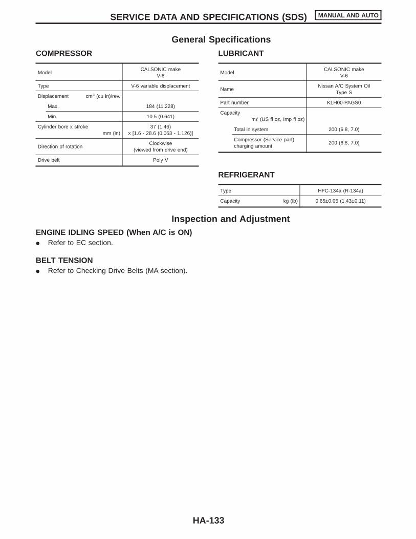
General SpecificationsCOMPRESSOR
ModelCALSONIC make
V-6
Type V-6 variable displacement
Displacement cm3 (cu in)/rev.
Max. 184 (11.228)
Min. 10.5 (0.641)
Cylinder bore x strokemm (in)
37 (1.46)x [1.6 - 28.6 (0.063 - 1.126)]
Direction of rotationClockwise
(viewed from drive end)
Drive belt Poly V
LUBRICANT
ModelCALSONIC make
V-6
NameNissan A/C System Oil
Type S
Part number KLH00-PAGS0
Capacitym (US fl oz, Imp fl oz)
Total in system 200 (6.8, 7.0)
Compressor (Service part)charging amount
200 (6.8, 7.0)
REFRIGERANT
Type HFC-134a (R-134a)
Capacity kg (lb) 0.65±0.05 (1.43±0.11)
Inspection and AdjustmentENGINE IDLING SPEED (When A/C is ON)I Refer to EC section.
BELT TENSIONI Refer to Checking Drive Belts (MA section).
SERVICE DATA AND SPECIFICATIONS (SDS) MANUAL AND AUTO
HA-133

HEATER & AIR CONDITIONER
SECTIONHACONTENTS
PRECAUTIONS AND PREPARATION ............................2Supplemental Restraint System (SRS) “AIRBAG” ............................................................................2Precautions for Working with HFC-134a (R-134a) .....3General Refrigerant Precautions .................................3Precautions for Refrigerant Connection ......................4Precautions for Servicing Compressor........................7Special Service Tools ..................................................7HFC-134a (R-134a) Service Tools andEquipment....................................................................8Precautions for Service Equipment ...........................10
DESCRIPTION ...............................................................12Refrigeration Cycle ....................................................12V-6 Variable Displacement Compressor....................13Component Layout ....................................................17Discharge Air Flow.....................................................18
DESCRIPTION ...............................................................19Control Operation ......................................................19
TROUBLE DIAGNOSES ...............................................21How to Perform Trouble Diagnoses for Quickand Accurate Repair ..................................................21Operational Check .....................................................22Symptom Chart..........................................................24Preliminary Check......................................................26
TROUBLE DIAGNOSES ...............................................31Performance Test Diagnoses ....................................31Performance Chart ....................................................33Trouble Diagnoses for Abnormal Pressure ...............34
TROUBLE DIAGNOSES ...............................................37Harness Layout..........................................................37Circuit Diagram..........................................................39Wiring Diagram — A/C, M — ....................................40Main Power Supply and Ground Circuit Check ........44Diagnostic Procedure 1 .............................................45Diagnostic Procedure 2 .............................................47Diagnostic Procedure 3 .............................................49Diagnostic Procedure 4 .............................................50Diagnostic Procedure 5 .............................................52Electrical Components Inspection .............................55
Control Linkage Adjustment.......................................56DESCRIPTION ...............................................................58
Introduction ................................................................58Features.....................................................................58Control Operation ......................................................61
TROUBLE DIAGNOSES ...............................................64How to Perform Trouble Diagnoses for Quickand Accurate Repair ..................................................64Operational Check .....................................................65Symptom Chart..........................................................68Self-diagnosis ............................................................70Preliminary Check......................................................80Harness Layout..........................................................88Circuit Diagram..........................................................90Wiring Diagram — A/C, A — .....................................91Main Power Supply and Ground Circuit Check ........94Diagnostic Procedure 1 .............................................95Diagnostic Procedure 2 .............................................96Diagnostic Procedure 3 .............................................97Diagnostic Procedure 4 .............................................98Diagnostic Procedure 5 .............................................99Diagnostic Procedure 6 ...........................................100Diagnostic Procedure 7 ...........................................102Diagnostic Procedure 8 ...........................................104Electrical Components Inspection ...........................107Control Linkage Adjustment.....................................108
SYSTEM DESCRIPTION .............................................109Overview of Control System....................................109Control System Input Components .........................110Control System Automatic Amplifier (Auto amp.) ....113Control System Output Components.......................113
SERVICE PROCEDURES ...........................................121HFC-134a (R-134a) Service Procedure ..................121Maintenance of Lubricant Quantity inCompressor .............................................................123Refrigerant Lines .....................................................125Checking Refrigerant Leaks ....................................126Compressor Mounting .............................................128Belt Tension .............................................................128

Fast Idle Control Device (FICD) ..............................128Compressor .............................................................129Compressor Clutch ..................................................129
SERVICE DATA AND SPECIFICATIONS (SDS) ........133General Specifications.............................................133Inspection and Adjustment ......................................133
CONTENTS (Cont’d)
Z 98.10.1/A32d’98 X
Related Documents