GROUP 55 HEATER, AIR CONDITIONER AND VENTILATION CONTENTS GENERAL INFORMATION . . . . . . . . 55-2 HEATER UNIT . . . . . . . . . . . . . . . . . . 55-5 HEATER CONTROL . . . . . . . . . . . . . 55-7 A/C-ECU . . . . . . . . . . . . . . . . . . . . . . . 55-8 DUCTS . . . . . . . . . . . . . . . . . . . . . . . . 55-11 VENTILATION SYSTEM . . . . . . . . . . . 55-12

Welcome message from author
This document is posted to help you gain knowledge. Please leave a comment to let me know what you think about it! Share it to your friends and learn new things together.
Transcript
GROUP 55
HEATER, AIR CONDITIONER AND
VENTILATIONCONTENTS
GENERAL INFORMATION . . . . . . . . 55-2
HEATER UNIT . . . . . . . . . . . . . . . . . . 55-5
HEATER CONTROL . . . . . . . . . . . . . 55-7
A/C-ECU . . . . . . . . . . . . . . . . . . . . . . . 55-8
DUCTS . . . . . . . . . . . . . . . . . . . . . . . . 55-11
VENTILATION SYSTEM. . . . . . . . . . . 55-12
GENERAL INFORMATIONHEATER, AIR CONDITIONER AND VENTILATION55-2
GENERAL INFORMATIONM2551000100759
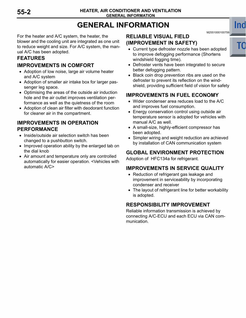
For the heater and A/C system, the heater, the blower and the cooling unit are integrated as one unit to reduce weight and size. For A/C system, the man-ual A/C has been adopted.FEATURESIMPROVEMENTS IN COMFORT• Adoption of low noise, large air volume heater
and A/C system• Adoption of smaller air intake box for larger pas-
senger leg space.• Optimising the areas of the outside air induction
hole and the air outlet improves ventilation per-formance as well as the quietness of the room
• Adoption of clean air filter with deodorant function for cleaner air in the compartment.
IMPROVEMENTS IN OPERATION PERFORMANCE• Inside/outside air selection switch has been
changed to a pushbutton switch.• Improved operation ability by the enlarged tab on
the dial knob• Air amount and temperature only are controlled
automatically for easier operation. <Vehicles with automatic A/C>
RELIABLE VISUAL FIELD (IMPROVEMENT IN SAFETY)• Current type defroster nozzle has been adopted
to improve defogging performance (Shortens windshield fogging time).
• Defroster vents have been integrated to secure better defogging pattern.
• Black coin drop prevention ribs are used on the defroster to prevent its reflection on the wind-shield, providing sufficient field of vision for safety
IMPROVEMENTS IN FUEL ECONOMY• Wider condenser area reduces load to the A/C
and improves fuel consumption.• Energy conservation control using outside air
temperature sensor is adopted for vehicles with manual A/C as well.
• A small-size, highly-efficient compressor has been adopted.
• Simpler wiring and weight reduction are achieved by installation of CAN communication system
GLOBAL ENVIRONMENT PROTECTIONAdoption of HFC134a for refrigerant.
IMPROVEMENTS IN SERVICE QUALITY• Reduction of refrigerant gas leakage and
improvement in serviceability by incorporating condenser and receiver
• The layout of refrigerant line for better workability is adopted.
RESPONSIBILITY IMPROVEMENTReliable information transmission is achieved by connecting A/C-ECU and each ECU via CAN com-munication.
GENERAL INFORMATIONHEATER, AIR CONDITIONER AND VENTILATION 55-3
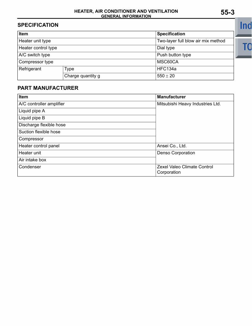
SPECIFICATIONItem SpecificationHeater unit type Two-layer full blow air mix methodHeater control type Dial typeA/C switch type Push button typeCompressor type MSC60CARefrigerant Type HFC134a
Charge quantity g 550 ± 20
PART MANUFACTURERItem ManufacturerA/C controller amplifier Mitsubishi Heavy Industries Ltd.Liquid pipe ALiquid pipe BDischarge flexible hoseSuction flexible hoseCompressorHeater control panel Ansei Co., Ltd.Heater unit Denso CorporationAir intake boxCondenser Zexel Valeo Climate Control
Corporation
GENERAL INFORMATIONHEATER, AIR CONDITIONER AND VENTILATION55-4
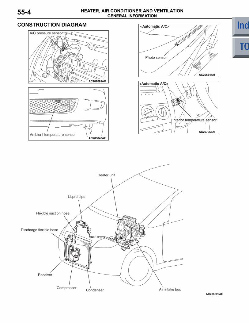
CONSTRUCTION DIAGRAM
AC207081AG
A/C pressure sensor
AC206840Ambient temperature sensor
AF
AC206841
<Automatic A/C>
AI
Photo sensor
AC207058
Interior temperature sensor
AI
<Automatic A/C>
AC206029AE
Heater unit
Liquid pipe
Flexible suction hose
Discharge flexible hose
Receiver
CompressorCondenser Air intake box
HEATER UNITHEATER, AIR CONDITIONER AND VENTILATION 55-5
HEATER UNITM2551000800219
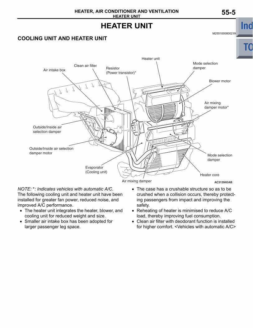
COOLING UNIT AND HEATER UNIT
AC313940AB
Air intake box Resistor (Power transistor)*
Heater unitMode selection damper
Blower motor
Air mixing damper motor*
Mode selection damper
Heater core
Air mixing damper
Evaporator (Cooling unit)
Outside/Inside air selection damper
Outside/Inside air selection damper motor
Clean air filter
NOTE: *: Indicates vehicles with automatic A/C.The following cooling unit and heater unit have been installed for greater fan power, reduced noise, and improved A/C performance.• The heater unit integrates the heater, blower, and
cooling unit for reduced weight and size.• Smaller air intake box has been adopted for
larger passenger leg space.
• The case has a crushable structure so as to be crushed when a collision occurs, thereby protect-ing passengers from impact and improving the safety.
• Reheating of heater is minimised to reduce A/C load, thereby improving fuel consumption.
• Clean air filter with deodorant function is installed for higher comfort. <Vehicles with automatic A/C>
HEATER UNITHEATER, AIR CONDITIONER AND VENTILATION55-6
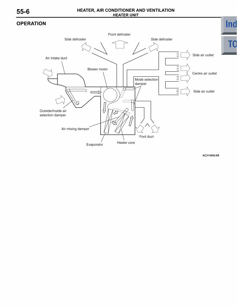
OPERATION
AC314092AB
Front defrosterSide defrosterSide defroster
Side air outlet
Centre air outlet
Side air outlet
Air intake duct
Blower motor
Outside/Inside air selection damper
Air mixing damper
Evaporator Heater core
Foot duct
Mode selection damper
HEATER CONTROLHEATER, AIR CONDITIONER AND VENTILATION 55-7
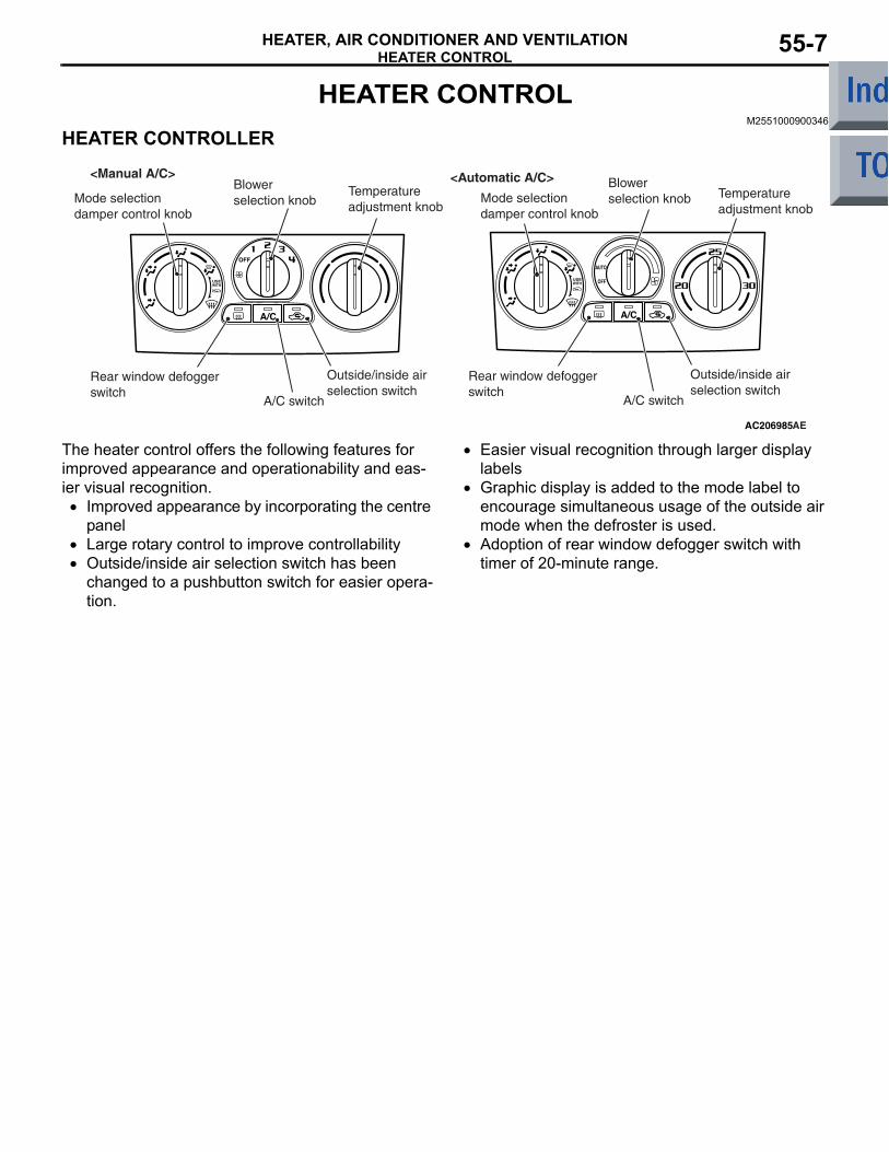
HEATER CONTROLM2551000900346
HEATER CONTROLLER
AC206985AE
<Manual A/C> <Automatic A/C>
Mode selection damper control knob
Blower selection knob
Temperature adjustment knob
Mode selection damper control knob
Blower selection knob Temperature
adjustment knob
Outside/inside air selection switch
A/C switch
Rear window defogger switch
Outside/inside air selection switch
A/C switch
Rear window defogger switch
The heater control offers the following features for improved appearance and operationability and eas-ier visual recognition.• Improved appearance by incorporating the centre
panel• Large rotary control to improve controllability• Outside/inside air selection switch has been
changed to a pushbutton switch for easier opera-tion.
• Easier visual recognition through larger display labels
• Graphic display is added to the mode label to encourage simultaneous usage of the outside air mode when the defroster is used.
• Adoption of rear window defogger switch with timer of 20-minute range.
A/C-ECUHEATER, AIR CONDITIONER AND VENTILATION55-8
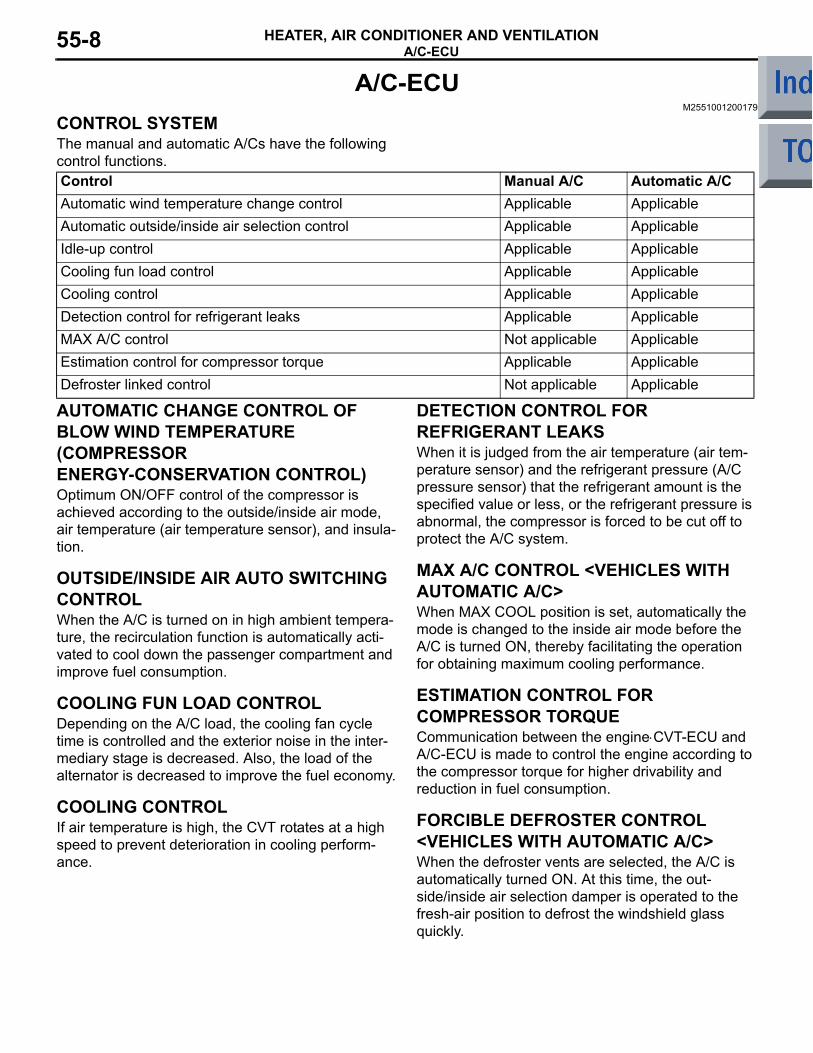
A/C-ECUM2551001200179
CONTROL SYSTEMThe manual and automatic A/Cs have the following control functions.Control Manual A/C Automatic A/CAutomatic wind temperature change control Applicable ApplicableAutomatic outside/inside air selection control Applicable ApplicableIdle-up control Applicable ApplicableCooling fun load control Applicable ApplicableCooling control Applicable ApplicableDetection control for refrigerant leaks Applicable ApplicableMAX A/C control Not applicable ApplicableEstimation control for compressor torque Applicable ApplicableDefroster linked control Not applicable Applicable
AUTOMATIC CHANGE CONTROL OF BLOW WIND TEMPERATURE (COMPRESSOR ENERGY-CONSERVATION CONTROL) Optimum ON/OFF control of the compressor is achieved according to the outside/inside air mode, air temperature (air temperature sensor), and insula-tion.
OUTSIDE/INSIDE AIR AUTO SWITCHING CONTROLWhen the A/C is turned on in high ambient tempera-ture, the recirculation function is automatically acti-vated to cool down the passenger compartment and improve fuel consumption.
COOLING FUN LOAD CONTROLDepending on the A/C load, the cooling fan cycle time is controlled and the exterior noise in the inter-mediary stage is decreased. Also, the load of the alternator is decreased to improve the fuel economy.
COOLING CONTROLIf air temperature is high, the CVT rotates at a high speed to prevent deterioration in cooling perform-ance.
DETECTION CONTROL FOR REFRIGERANT LEAKSWhen it is judged from the air temperature (air tem-perature sensor) and the refrigerant pressure (A/C pressure sensor) that the refrigerant amount is the specified value or less, or the refrigerant pressure is abnormal, the compressor is forced to be cut off to protect the A/C system.
MAX A/C CONTROL <VEHICLES WITH AUTOMATIC A/C>When MAX COOL position is set, automatically the mode is changed to the inside air mode before the A/C is turned ON, thereby facilitating the operation for obtaining maximum cooling performance.
ESTIMATION CONTROL FOR COMPRESSOR TORQUECommunication between the engine⋅CVT-ECU and A/C-ECU is made to control the engine according to the compressor torque for higher drivability and reduction in fuel consumption.
FORCIBLE DEFROSTER CONTROL <VEHICLES WITH AUTOMATIC A/C>When the defroster vents are selected, the A/C is automatically turned ON. At this time, the out-side/inside air selection damper is operated to the fresh-air position to defrost the windshield glass quickly.
A/C-ECUHEATER, AIR CONDITIONER AND VENTILATION 55-9
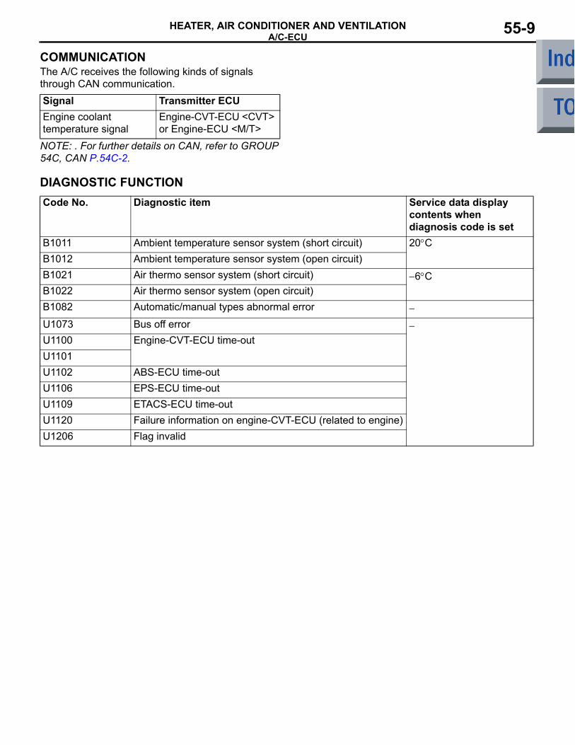
COMMUNICATIONThe A/C receives the following kinds of signals through CAN communication.Signal Transmitter ECUEngine coolant temperature signal
Engine-CVT-ECU <CVT> or Engine-ECU <M/T>
NOTE: . For further details on CAN, refer to GROUP 54C, CAN P.54C-2.
DIAGNOSTIC FUNCTIONCode No. Diagnostic item Service data display
contents when diagnosis code is set
B1011 Ambient temperature sensor system (short circuit) 20°CB1012 Ambient temperature sensor system (open circuit)B1021 Air thermo sensor system (short circuit) −6°CB1022 Air thermo sensor system (open circuit)B1082 Automatic/manual types abnormal error −
U1073 Bus off error −U1100 Engine-CVT-ECU time-outU1101U1102 ABS-ECU time-outU1106 EPS-ECU time-outU1109 ETACS-ECU time-outU1120 Failure information on engine-CVT-ECU (related to engine)U1206 Flag invalid
A/C-ECUHEATER, AIR CONDITIONER AND VENTILATION55-10
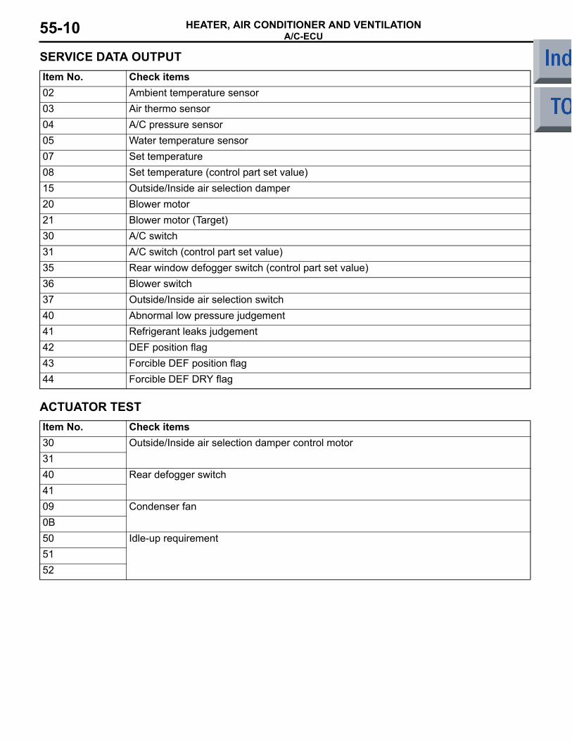
SERVICE DATA OUTPUTItem No. Check items02 Ambient temperature sensor03 Air thermo sensor04 A/C pressure sensor05 Water temperature sensor07 Set temperature08 Set temperature (control part set value)15 Outside/Inside air selection damper20 Blower motor21 Blower motor (Target)30 A/C switch31 A/C switch (control part set value)35 Rear window defogger switch (control part set value)36 Blower switch37 Outside/Inside air selection switch40 Abnormal low pressure judgement41 Refrigerant leaks judgement42 DEF position flag43 Forcible DEF position flag44 Forcible DEF DRY flag
ACTUATOR TESTItem No. Check items30 Outside/Inside air selection damper control motor3140 Rear defogger switch4109 Condenser fan0B50 Idle-up requirement5152
DUCTSHEATER, AIR CONDITIONER AND VENTILATION 55-11
DUCTSM2551001300110
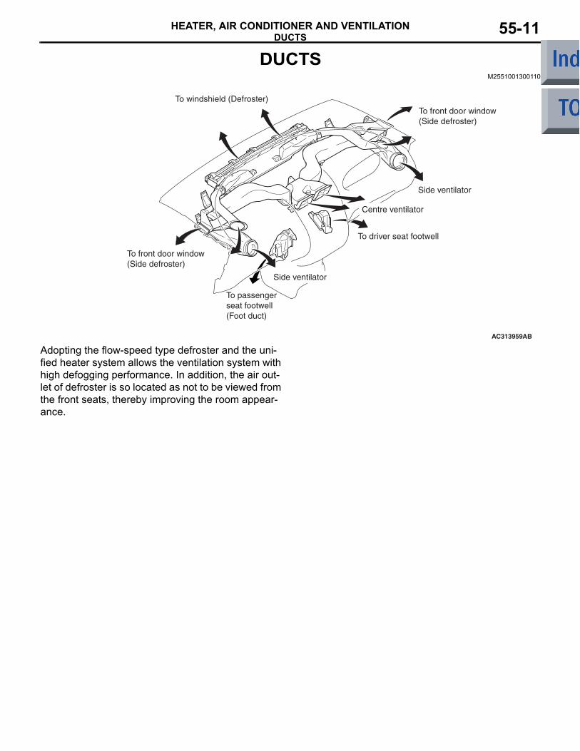
AC313959AB
To windshield (Defroster)To front door window (Side defroster)
Side ventilator
Side ventilator
Centre ventilator
To passenger seat footwell (Foot duct)
To front door window (Side defroster)
To driver seat footwell
Adopting the flow-speed type defroster and the uni-fied heater system allows the ventilation system with high defogging performance. In addition, the air out-let of defroster is so located as not to be viewed from the front seats, thereby improving the room appear-ance.
VENTILATION SYSTEMHEATER, AIR CONDITIONER AND VENTILATION55-12
VENTILATION SYSTEMM2551002000305
AC206030AB
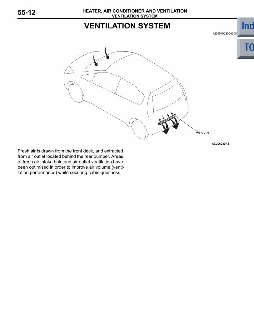
Air outlet
Fresh air is drawn from the front deck, and extracted from air outlet located behind the rear bumper. Areas of fresh air intake hole and air outlet ventilation have been optimised in order to improve air volume (venti-lation performance) while securing cabin quietness.
Related Documents