The company Impact Design Europe is glad to inform you about the development of Visual Crash Studio. The following newsletter is purposed to present the newest features and improvements of VCS tools, which are available in the latest VCS 2.4 version. In this version of our software you will find the new Cross Section Optimizer, new 3D view Orientation tool, Solution Layers, new Cross Section calculate features (Lateral Crushing and Denting) and other improvements. If you do not wish to receive further newsletters please let us know on above email address. We would very much appreciate all of your comments and suggestions, which can be sent to our e-mail address: [email protected]. We will try to meet your expectations in the future versions of VCS software. Best Regards, Agata Abramowicz Sokoll, Impact Design Europe, www.impactdesign.pl, contact: [email protected], VCS 2.4 What’s new: Cross Section Optimizer Solution Layers Orientation tool Welcome Screen Merge Proximate Nodes Copy Cross Section from other Beam Cross Section – Lateral Crushing and Denting Compare Selected Cross Sections Import and Units Conversion Utility Mass of Selected Objects Chart wizard – time marker Cross Sections Editor – dimensions Clean Model Select all Beams with a chosen Cross Section New “Calculate” icon

Welcome message from author
This document is posted to help you gain knowledge. Please leave a comment to let me know what you think about it! Share it to your friends and learn new things together.
Transcript
The company Impact Design Europe is glad to inform you about the
development of Visual Crash Studio.
The following newsletter is purposed to present the newest features and
improvements of VCS tools, which are available in the latest VCS 2.4
version. In this version of our software you will find the new Cross Section
Optimizer, new 3D view Orientation tool, Solution Layers, new Cross
Section calculate features (Lateral Crushing and Denting) and other
improvements. If you do not wish to receive further newsletters please let
us know on above email address.
We would very much appreciate all of your comments and suggestions,
which can be sent to our e-mail address: [email protected]. We
will try to meet your expectations in the future versions of VCS software.
Best Regards,
Agata Abramowicz Sokoll,
Impact Design Europe, www.impactdesign.pl,
contact: [email protected],
VCS 2.4
What’s new:
Cross Section
Optimizer
Solution Layers
Orientation tool
Welcome Screen
Merge Proximate
Nodes
Copy Cross Section
from other Beam
Cross Section –
Lateral Crushing
and Denting
Compare Selected
Cross Sections
Import and Units
Conversion Utility
Mass of Selected
Objects
Chart wizard – time
marker
Cross Sections
Editor – dimensions
Clean Model
Select all Beams
with a chosen Cross
Section
New “Calculate” icon
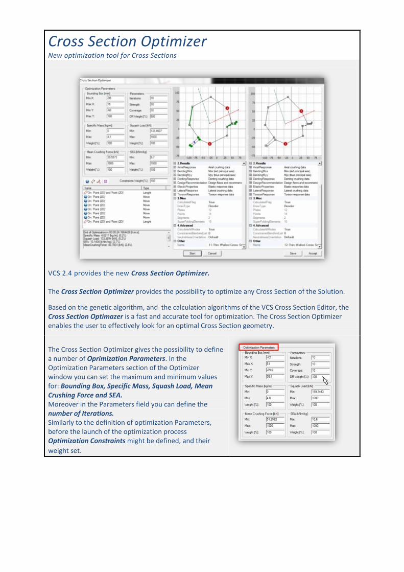
Cross Section Optimizer New optimization tool for Cross Sections
VCS 2.4 provides the new Cross Section Optimizer. The Cross Section Optimizer provides the possibility to optimize any Cross Section of the Solution.
Based on the genetic algorithm, and the calculation algorithms of the VCS Cross Section Editor, the Cross Section Optimazer is a fast and accurate tool for optimization. The Cross Section Optimizer enables the user to effectively look for an optimal Cross Section geometry.
The Cross Section Optimizer gives the possibility to define a number of Oprimization Parameters. In the Optimization Parameters section of the Optimizer window you can set the maximum and minimum values for: Bounding Box, Specific Mass, Squash Load, Mean Crushing Force and SEA. Moreover in the Parameters field you can define the number of Iterations. Similarly to the definition of optimization Parameters, before the launch of the optimization process Optimization Constraints might be defined, and their
weight set.
Solution Layers Objects of the Solution can be assigned to separate layers
back
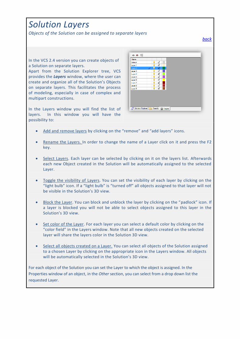
In the VCS 2.4 version you can create objects of a Solution on separate layers. Apart from the Solution Explorer tree, VCS provides the Layers window, where the user can create and organize all of the Solution’s Objects on separate layers. This facilitates the process of modeling, especially in case of complex and multipart constructions. In the Layers window you will find the list of layers. In this window you will have the possibility to:
Add and remove layers by clicking on the “remove” and “add layers” icons.
Rename the Layers. In order to change the name of a Layer click on it and press the F2 key.
Select Layers. Each layer can be selected by clicking on it on the layers list. Afterwards each new Object created in the Solution will be automatically assigned to the selected Layer.
Toggle the visibility of Layers. You can set the visibility of each layer by clicking on the “light bulb” icon. If a “light bulb” is “turned off” all objects assigned to that layer will not be visible in the Solution’s 3D view.
Block the Layer. You can block and unblock the layer by clicking on the “padlock” icon. If a layer is blocked you will not be able to select objects assigned to this layer in the Solution’s 3D view.
Set color of the Layer. For each layer you can select a default color by clicking on the “color field” in the Layers window. Note that all new objects created on the selected layer will share the layers color in the Solution 3D view.
Select all objects created on a Layer. You can select all objects of the Solution assigned to a chosen Layer by clicking on the appropriate icon in the Layers window. All objects will be automatically selected in the Solution’s 3D view.
For each object of the Solution you can set the Layer to which the object is assigned. In the
Properties window of an object, in the Other section, you can select from a drop down list the
requested Layer.
Orientation tool The new 3D view Orientation tool back
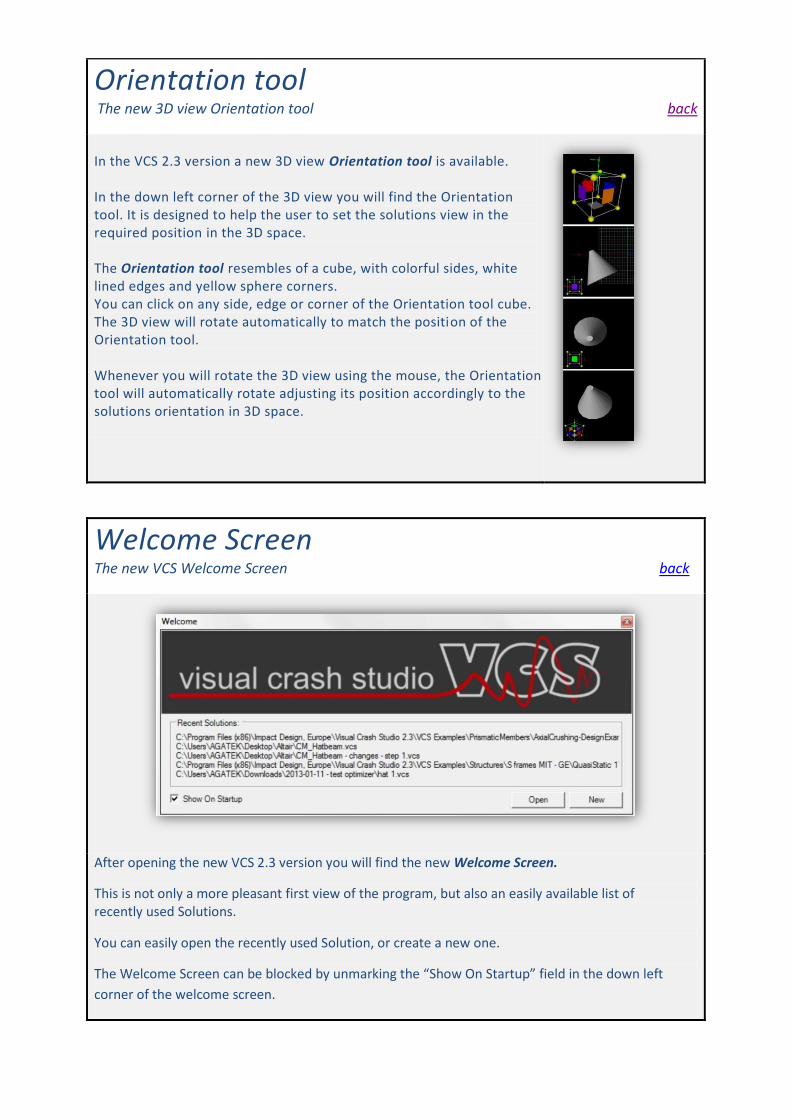
In the VCS 2.3 version a new 3D view Orientation tool is available. In the down left corner of the 3D view you will find the Orientation tool. It is designed to help the user to set the solutions view in the required position in the 3D space. The Orientation tool resembles of a cube, with colorful sides, white lined edges and yellow sphere corners. You can click on any side, edge or corner of the Orientation tool cube. The 3D view will rotate automatically to match the position of the Orientation tool. Whenever you will rotate the 3D view using the mouse, the Orientation tool will automatically rotate adjusting its position accordingly to the solutions orientation in 3D space.
Welcome Screen The new VCS Welcome Screen back
After opening the new VCS 2.3 version you will find the new Welcome Screen.
This is not only a more pleasant first view of the program, but also an easily available list of recently used Solutions.
You can easily open the recently used Solution, or create a new one.
The Welcome Screen can be blocked by unmarking the “Show On Startup” field in the down left
corner of the welcome screen.
Merge Proximate Nodes A new Merge Proximate Nodes tool back
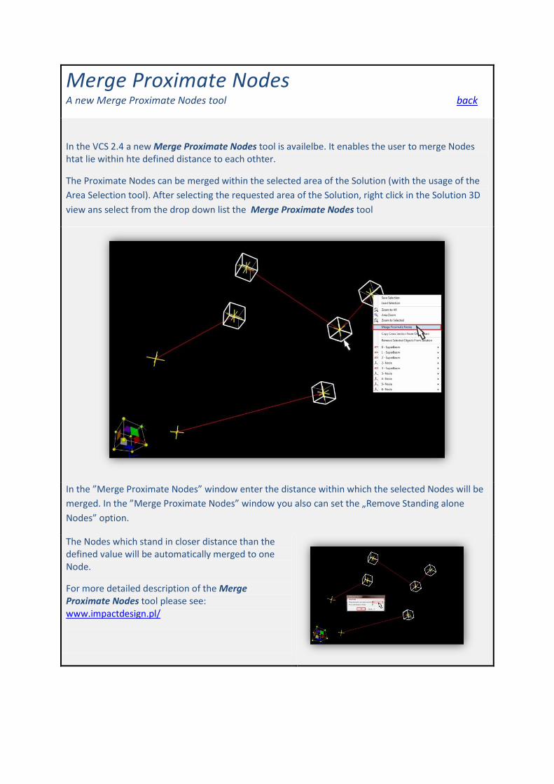
In the VCS 2.4 a new Merge Proximate Nodes tool is availelbe. It enables the user to merge Nodes htat lie within hte defined distance to each othter.
The Proximate Nodes can be merged within the selected area of the Solution (with the usage of the
Area Selection tool). After selecting the requested area of the Solution, right click in the Solution 3D
view ans select from the drop down list the Merge Proximate Nodes tool
In the ”Merge Proximate Nodes” window enter the distance within which the selected Nodes will be
merged. In the ”Merge Proximate Nodes” window you also can set the „Remove Standing alone
Nodes” option.
The Nodes which stand in closer distance than the defined value will be automatically merged to one Node.
For more detailed description of the Merge Proximate Nodes tool please see: www.impactdesign.pl/
Copy Cross Section from other Beam A new beam edition tool back
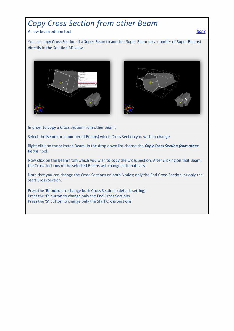
You can copy Cross Section of a Super Beam to another Super Beam (or a number of Super Beams)
directly in the Solution 3D view.
In order to copy a Cross Section from other Beam:
Select the Beam (or a number of Beams) which Cross Section you wish to change.
Right click on the selected Beam. In the drop down list choose the Copy Cross Section from other Beam tool.
Now click on the Beam from which you wish to copy the Cross Section. After clicking on that Beam, the Cross Sections of the selected Beams will change automatically.
Note that you can change the Cross Sections on both Nodes; only the End Cross Section, or only the Start Cross Section. Press the ‘B’ button to change both Cross Sections (default setting) Press the ‘E’ button to change only the End Cross Sections Press the ‘S’ button to change only the Start Cross Sections
Cross Section – Lateral Crushing and Denting New calculation options available in the Cross Section Editor
back
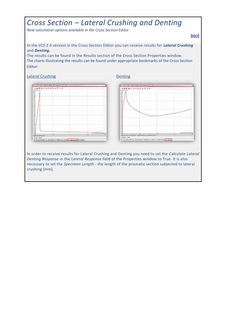
In the VCS 2.4 version in the Cross Section Editor you can receive results for Lateral Crushing and Denting. The results can be found in the Results section of the Cross Section Properties window. The charts illustrating the results can be found under appropriate bookmarks of the Cross Section
Editor:
Lateral Crushing
Denting
In order to receive results for Lateral Crushing and Denting you need to set the Calculate Lateral Denting Response in the Lateral Response field of the Properties window to True. It is also necessary to set the Specimen Length - the length of the prismatic section subjected to lateral crushing [mm].
Compare Selected Cross Sections New tool for compering results of various Cross Sections
back
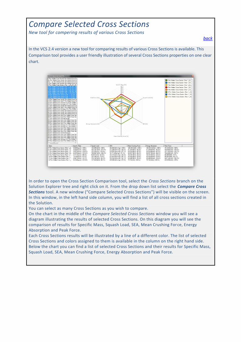
In the VCS 2.4 version a new tool for comparing results of various Cross Sections is available. This
Comparison tool provides a user friendly illustration of several Cross Sections properties on one clear
chart.
In order to open the Cross Section Comparison tool, select the Cross Sections branch on the Solution Explorer tree and right click on it. From the drop down list select the Compare Cross Sections tool. A new window (“Compare Selected Cross Sections”) will be visible on the screen. In this window, in the left hand side column, you will find a list of all cross sections created in the Solution. You can select as many Cross Sections as you wish to compare. On the chart in the middle of the Compare Selected Cross Sections window you will see a diagram illustrating the results of selected Cross Sections. On this diagram you will see the comparison of results for Specific Mass, Squash Load, SEA, Mean Crushing Force, Energy Absorption and Peak Force. Each Cross Sections results will be illustrated by a line of a different color. The list of selected Cross Sections and colors assigned to them is available in the column on the right hand side. Below the chart you can find a list of selected Cross Sections and their results for Specific Mass, Squash Load, SEA, Mean Crushing Force, Energy Absorption and Peak Force.

Import and Units Conversion Utility back
In the VCS 2.4 version the possibility to set the required units when importing a FE model is available.
After selecting the Import option a new window “Import and Units Conversion Utility” will appear on the screen. In this window you can set the required units of the imported model (length, mass, mass density, pressure / stress, strain). You can also save your setting as default settings by pressing the “set as default” button in the Import and Units Conversion Utility window.
Mass of Selected Objects back
VCS 2.4 provides the possibility to easily check the mass of the selected area and / or selected objects
of the Solution.
After selecting objects of a Solution, by area selection or by multi selection, you will be able to see the summarized mass of those objects in the down right corner of the screen.

Chart wizard – time marker A new time marker animation
back
In the new 2.4 version of Visual Crash Studio a new feture – time marker – has been added to the
Chart Wizard.
When viewing the result charts for solution’s calculations you will now find a green time marker. This line illustrates the movement of the load case simmulation. This feature anables the user to easily observe how speciffic results reffer to the simmulation visible in the solution’s 3D view.
Cross Section Editor - dimensions New tool available in the Cross Section Editor back
A new tool showing the dimensions of Plates of a Cross Section has been added to the Cross Section
Editor.
Afret clicking on the „Dimensions” icon in the Cross Section Editor window, the dimensions for each Plate of the Cross Section will be visible on the screen. If the geometry of a Cross Section will be changed, by moving Points, Plates or Segments, the dimensions will change automatically acordingly to the modifications.
Clean Model Possibility to remove unused Objects from the Solution
back
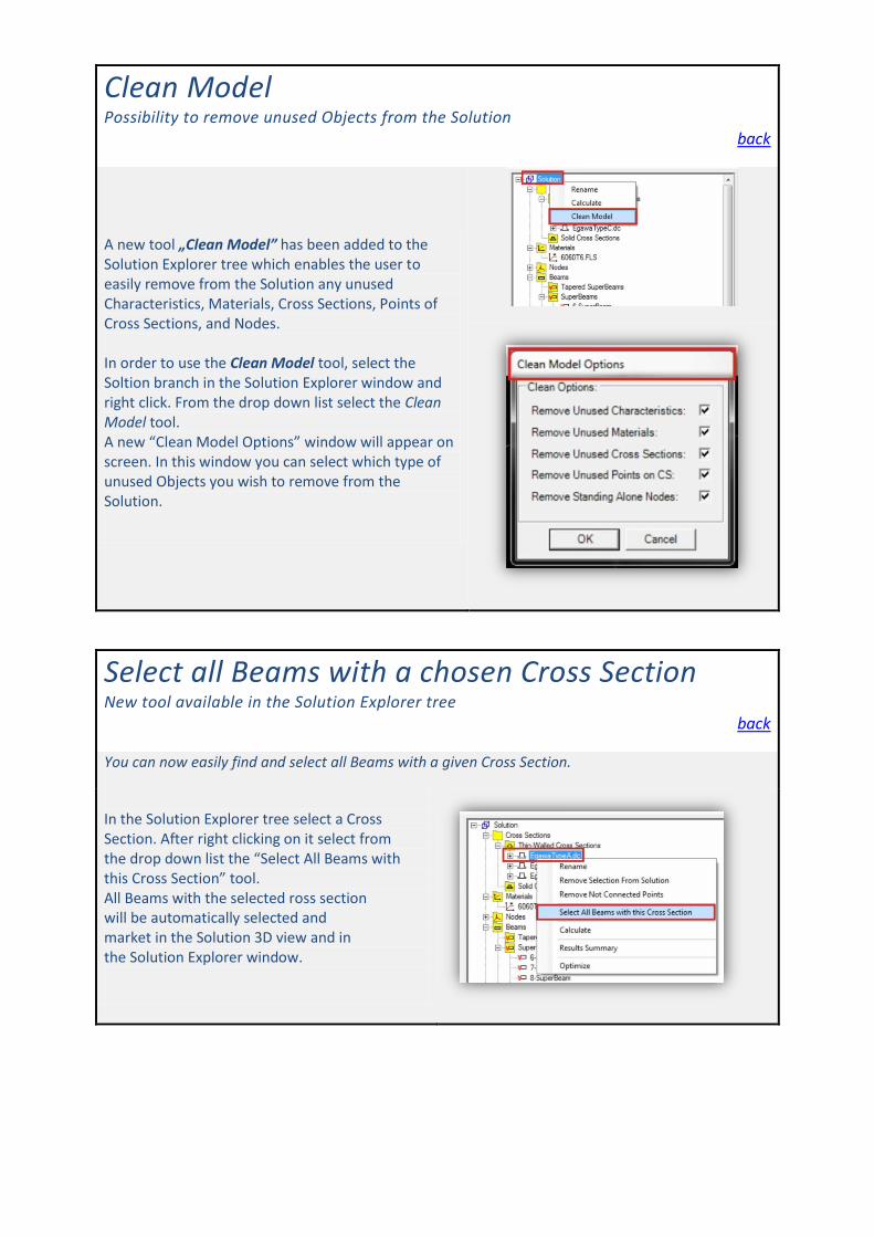
A new tool „Clean Model” has been added to the Solution Explorer tree which enables the user to easily remove from the Solution any unused Characteristics, Materials, Cross Sections, Points of Cross Sections, and Nodes. In order to use the Clean Model tool, select the Soltion branch in the Solution Explorer window and right click. From the drop down list select the Clean Model tool. A new “Clean Model Options” window will appear on screen. In this window you can select which type of unused Objects you wish to remove from the Solution.
Select all Beams with a chosen Cross Section New tool available in the Solution Explorer tree
back
You can now easily find and select all Beams with a given Cross Section.
In the Solution Explorer tree select a Cross Section. After right clicking on it select from the drop down list the “Select All Beams with this Cross Section” tool. All Beams with the selected ross section will be automatically selected and market in the Solution 3D view and in the Solution Explorer window.

New “Calculate” icon back
New icon has been added to the main toolbar.
In order to start the calculation process of the Solution, simply click on the „calculate” icon
on the mai toolbar.
In previous versions of VCS the calculate option was available only through the Solution Explorer
window.

Related Documents