User’s Manual for OMT, Remote OMT and Remote OMT over IP 1/19817-CXC 112 516/1 Uen AY Ericsson AB 2007 1 (211) 2007-11-05 All rights reserved User’s Manual for OMT, Remote OMT and Remote OMT over IP Ericsson AB 1995-2007 í All rights reserved í

Welcome message from author
This document is posted to help you gain knowledge. Please leave a comment to let me know what you think about it! Share it to your friends and learn new things together.
Transcript
User’s Manual for OMT, Remote OMT and Remote OMT over IP
1/19817-CXC 112 516/1 Uen AY Ericsson AB 2007 1 (211)2007-11-05 All rights reserved
User’s Manual for OMT, Remote OMT and Remote OMT over IP
Ericsson AB 1995-2007
All rights reserved
User’s Manual for OMT, Remote OMT and Remote OMT over IP
1/19817-CXC 112 516/1 Uen AY Ericsson AB 2007 2 (211)2007-11-05 All rights reserved
Due to continued progress in methodology, design and manufacturing the contents of thisdocument are subject to revision without notice. Ericsson assumes no legal responsibility for anyerror or damage resulting from the use of this document.
User’s Manual for OMT, Remote OMT and Remote OMT over IP
1/19817-CXC 112 516/1 Uen AY Ericsson AB 2007 3 (211)2007-11-05 All rights reserved
1 Preface ........................................................................................................................................................... 62 Getting Started................................................................................................................................................ 8
2.1 Prior knowledge ....................................................................................................................................... 82.2 Install the OMT software .......................................................................................................................... 82.3 Install the Remote OMT software and hardware ........................................................................................ 8
2.3.1 PCM communication boards............................................................................................................ 92.3.2 Installing a Thor-2-PCI board .......................................................................................................... 92.3.3 Installing Thor-2-PCI board driver ................................................................................................... 92.3.4 Special handling for the Thor-2-PCI-Plus board ............................................................................... 92.3.5 Configuration of the Thor-2-ISA board .......................................................................................... 102.3.6 Installing the Thor-2-ISA board driver ........................................................................................... 112.3.7 Remote OMT with Thor-2-ISA board under Windows 2000........................................................... 11
2.4 Uninstall the OMT software.................................................................................................................... 113 Learning OMT.............................................................................................................................................. 13
3.1 OMT main window................................................................................................................................. 133.1.1 Object ........................................................................................................................................... 153.1.2 Operation ...................................................................................................................................... 163.1.3 The different main menus .............................................................................................................. 17
3.2 OMT states............................................................................................................................................. 183.2.1 State relations................................................................................................................................ 19
3.3 View ...................................................................................................................................................... 203.3.1 System view .................................................................................................................................. 213.3.2 Cabinet view ................................................................................................................................. 223.3.3 Radio view .................................................................................................................................... 233.3.4 Object view ................................................................................................................................... 24
4 Using OMT .................................................................................................................................................. 254.1 Start the OMT......................................................................................................................................... 25
4.1.1 The Exit command......................................................................................................................... 264.2 Operations on objects.............................................................................................................................. 27
4.2.1 Make the Changes Permanent ........................................................................................................ 274.2.2 Connect OMT................................................................................................................................ 284.2.3 Connect Remote OMT................................................................................................................... 294.2.4 Connect Remote OMT over IP....................................................................................................... 304.2.5 Disconnect..................................................................................................................................... 324.2.6 Read IDB ...................................................................................................................................... 334.2.7 Open IDB...................................................................................................................................... 344.2.8 Install IDB..................................................................................................................................... 354.2.9 Save IDB....................................................................................................................................... 364.2.10 Create IDB .................................................................................................................................... 374.2.11 Define Present RUs ....................................................................................................................... 474.2.12 Export Site Specific Data............................................................................................................... 484.2.13 Import Site Specific Data............................................................................................................... 494.2.14 Display Site Specific Data ............................................................................................................. 514.2.15 Display Information....................................................................................................................... 524.2.16 Display Status................................................................................................................................ 544.2.17 Display Paging Queue Status ......................................................................................................... 554.2.18 Display TEI Values ....................................................................................................................... 564.2.19 Display Software Information ........................................................................................................ 574.2.20 Display Cable List ......................................................................................................................... 584.2.21 Display Inventory List ................................................................................................................... 594.2.22 Display RBS Software Download .................................................................................................. 604.2.23 Display Battery Log....................................................................................................................... 624.2.24 Monitor Information ...................................................................................................................... 644.2.25 Define Alarm Inlets ....................................................................................................................... 684.2.26 Define Antenna Supervision .......................................................................................................... 704.2.27 Define TEI .................................................................................................................................... 714.2.28 Define Transmission...................................................................................................................... 724.2.29 Define Hardware Information ........................................................................................................ 73
User’s Manual for OMT, Remote OMT and Remote OMT over IP
1/19817-CXC 112 516/1 Uen AY Ericsson AB 2007 4 (211)2007-11-05 All rights reserved
4.2.30 Define Loss ................................................................................................................................... 754.2.31 Define Delay ................................................................................................................................. 764.2.32 Define GPS Parameters.................................................................................................................. 774.2.33 Define ESB Delay List................................................................................................................... 784.2.34 Define TF Compensation ............................................................................................................... 804.2.35 Define TF Holdover Mode............................................................................................................. 824.2.36 Define RBS Identity ...................................................................................................................... 834.2.37 Define Climate .............................................................................................................................. 844.2.38 Define VSWR Limits..................................................................................................................... 854.2.39 Set CDU Power Supervision .......................................................................................................... 864.2.40 Change Local/Remote State........................................................................................................... 874.2.41 Reset ............................................................................................................................................. 884.2.42 Display Log................................................................................................................................... 894.2.43 Set Measurement Reports On/Off................................................................................................... 904.2.44 Set SSQIU On/Off......................................................................................................................... 914.2.45 Display Faulty RUs ....................................................................................................................... 924.2.46 Save Field Configuration ............................................................................................................... 934.2.47 Open Field Configuration .............................................................................................................. 944.2.48 Display Field Configuration Information........................................................................................ 954.2.49 Attach Field Configuration Information ......................................................................................... 964.2.50 Define TNOM ............................................................................................................................... 974.2.51 Display TNOM Values .................................................................................................................. 984.2.52 Calibrate Oscillator........................................................................................................................ 994.2.53 Define ALNA/TMA .................................................................................................................... 1004.2.54 Define Battery Parameters ........................................................................................................... 1024.2.55 Define System Voltage ................................................................................................................ 1044.2.56 Load Flash Card .......................................................................................................................... 1054.2.57 Display Detected HW Information ............................................................................................... 1074.2.58 Check IDB .................................................................................................................................. 1084.2.59 Display Battery Backup Time Test Parameters ............................................................................. 1094.2.60 Define Battery Backup Time Test Parameters .............................................................................. 1104.2.61 Display Battery Backup Time Test Result .................................................................................... 1114.2.62 Change Battery............................................................................................................................ 1124.2.63 Display RX/TX Antenna Mapping............................................................................................... 113
4.3 Tools .................................................................................................................................................... 1144.3.1 Wizards....................................................................................................................................... 1144.3.2 Options – Local OMT.................................................................................................................. 1154.3.3 Options – Remote OMT and Remote OMT over IP ...................................................................... 116
4.4 Help ..................................................................................................................................................... 1174.4.1 Help menu contents ..................................................................................................................... 1174.4.2 Contents ...................................................................................................................................... 1174.4.3 Context help ................................................................................................................................ 1174.4.4 About OMT................................................................................................................................. 117
5 Appendix.................................................................................................................................................... 1185.1 System software and hardware requirements ......................................................................................... 1185.2 Cable specifications .............................................................................................................................. 119
5.2.1 OMT cable .................................................................................................................................. 1195.2.2 Remote OMT cables .................................................................................................................... 1195.2.3 Remote OMT over IP cables ........................................................................................................ 119
5.3 Contents of the Display Information Window........................................................................................ 1205.4 Contents of the Display Status Window................................................................................................. 1235.5 Monitor Description.............................................................................................................................. 1285.6 RBS 2000 Configuration Parameters ..................................................................................................... 146
5.6.1 Define ALNA/TMA Parameters................................................................................................... 1465.6.2 Define Alarm Inlets ..................................................................................................................... 1505.6.3 Define RX-Imbalance Supervision Parameters ............................................................................. 1565.6.4 Define Battery Backup Time Test Parameters .............................................................................. 1595.6.5 Define Battery Parameters ........................................................................................................... 1625.6.6 Define Climate ............................................................................................................................ 1665.6.7 Define Delay ............................................................................................................................... 167
User’s Manual for OMT, Remote OMT and Remote OMT over IP
1/19817-CXC 112 516/1 Uen AY Ericsson AB 2007 5 (211)2007-11-05 All rights reserved
5.6.8 Define GPS Parameters................................................................................................................ 1695.6.9 Define Hardware Info .................................................................................................................. 1715.6.10 Define Loss ................................................................................................................................. 1755.6.11 Define Present RUs ..................................................................................................................... 1765.6.12 Define RBS Identity .................................................................................................................... 1785.6.13 Define System Voltage ................................................................................................................ 1795.6.14 Define TEI .................................................................................................................................. 1805.6.15 Define TF Compensation ............................................................................................................. 1815.6.16 Define TF Holdover Mode........................................................................................................... 1865.6.17 Define TNOM ............................................................................................................................. 1875.6.18 Define Transmission.................................................................................................................... 1905.6.19 Define VSWR Limits................................................................................................................... 196
5.7 Terminology......................................................................................................................................... 2006 Glossary ..................................................................................................................................................... 2027 Index .......................................................................................................................................................... 207
Preface
1/19817-CXC 112 516/1 Uen AY Ericsson AB 2007 6 (211)2007-11-05 All rights reserved
1 Preface
The OMT, Operation and Maintenance Terminal, is a powerful PC application providingefficient aid for the operation and maintenance of RBS 2000 base stations. The OMT supports allRBSs in the RBS 2000 family and is used locally at the RBS site. It connects via a serial cablefrom the OMT PC to a port on the RBS.
The main areas of OMT usage are RBS 2000 configuration and fault localization.
Other important features are:
n An easy-to-use graphical user interface.
n On-line help.
The Remote OMT and the Remote OMT over IP have the same functionality as the OMT butcan be used remotely. The Remote OMT utilizes the regular site transmission via the BSC forcommunication with the RBS. The Remote OMT over IP can connect to any RBS 2000 in thenetwork from any remote location with IP access to the serving BSC.
The ability to perform OMT operations remotely yields a number of benefits:
n Limited presence at site is needed.
n Faster site configuration.
n Easier site surveillance.
The OMT, the Remote OMT, and the Remote OMT over IP are different products. The RemoteOMT and the Remote OMT over IP does not replace the OMT, they are complements.
This manual describes the contents and functions of the OMT, the Remote OMT and the RemoteOMT over IP. It contains instructions on how to perform all functions.For information and instructions about RBSs, refer to the RBS manuals.
Unless otherwise stated, all information about the OMT in this manual is also valid for theRemote OMT and the Remote OMT over IP.
The manual is organized in five different parts.
Preface General information.
Getting Started General information and installation notes.
Learning OMT A general overview of OMT usage.
Using OMT Description of the different OMT functions.
Preface
1/19817-CXC 112 516/1 Uen AY Ericsson AB 2007 7 (211)2007-11-05 All rights reserved
Appendix Requirements, Specifications, Abbreviations, and Terminology.
We hope that you will be satisfied with the OMT, the Remote OMT, and the Remote OMT overIP.
Getting Started
1/19817-CXC 112 516/1 Uen AY Ericsson AB 2007 8 (211)2007-11-05 All rights reserved
2 Getting StartedThis chapter describes the required prior knowledge for OMT users, and how to install anduninstall the software.
2.1 Prior knowledge
n Basic Microsoft Windows™ knowledge.
n Good knowledge and understanding of the RBS technology.
n Basic knowledge of the BSC technology when the Remote OMT is used.
2.2 Install the OMT softwareBefore installation, make sure the system software and hardware requirements are fulfilled. Formore information about these requirements, see the readme file.
The OMT is installed by executing the installation file: \OMT\ Setup.exefound on the OMT installation CD-ROM. All OMT software on the CD-ROM is then installed toa specified or default (C:\Program Files\Ericsson AB\<Type> OMT <XXX>) directory on thehard disk.
Do as follows:
Insert the OMT installation CD-ROM into the CD-ROM drive.Run the OMT installation program by browsing to and double clicking the \OMT\ Setup.exe
file or by executing it from the Run... alternative in the Start menu.Follow the setup instructions on screen.
The installation creates a new Program Menu entry for the OMT, from which the OMT can bestarted. When upgrading from an earlier version of the OMT, the new version is installed inanother folder and a new Program Menu entry is created.
2.3 Install the Remote OMT software and hardwareBefore installation, make sure the system software and hardware requirements are fulfilled. Formore information about requirements, see the readme file. Follow the usual precautionsregarding the handling of electronic components.
Be aware of the risk of damaging the sensitive electronics on the board with static electricitydischarges. Use anti-static protection devices while handling the board.
For further instructions about the connection of a Remote OMT to the BSC, refer to theOperational Instruction Remote Operation and Maintenance Terminal, Connect documentnumber: 3/154 31-APT 210 09 Uen.
Getting Started
1/19817-CXC 112 516/1 Uen AY Ericsson AB 2007 9 (211)2007-11-05 All rights reserved
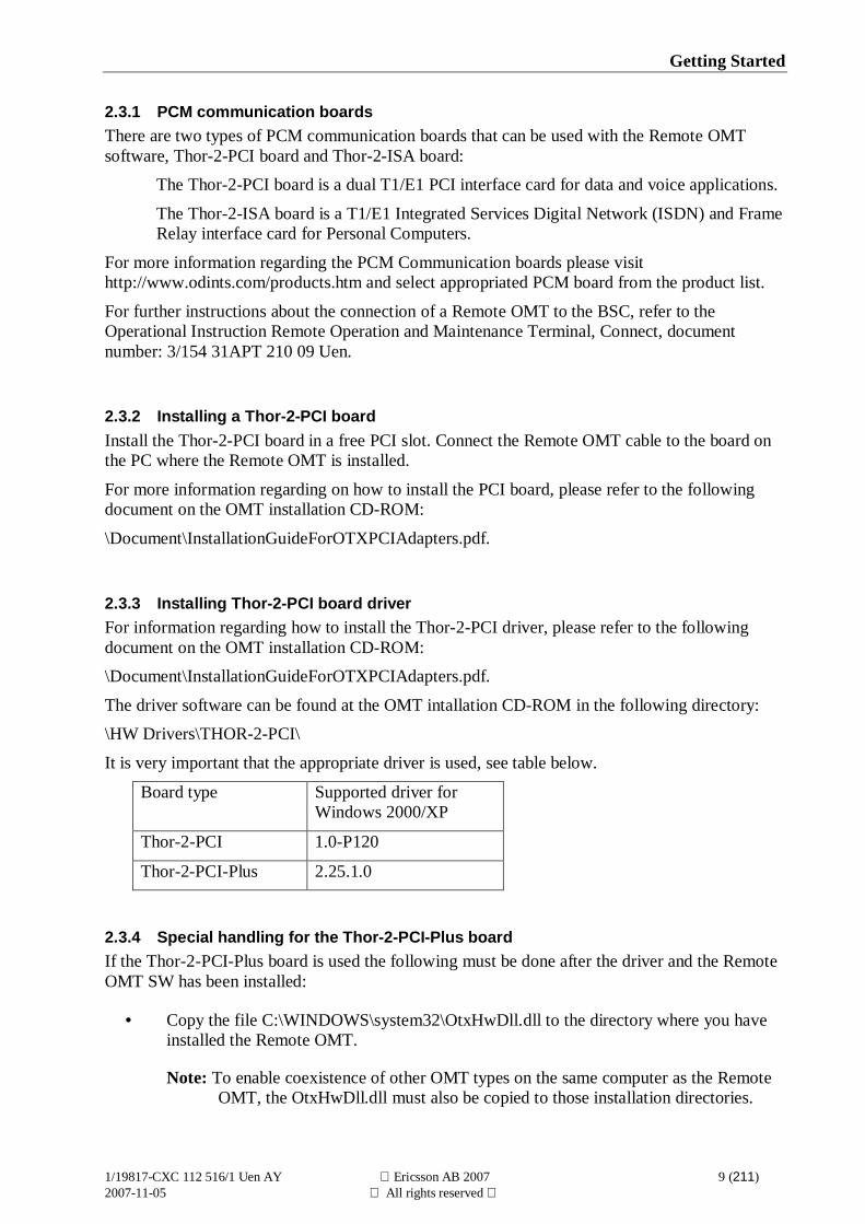
2.3.1 PCM communication boardsThere are two types of PCM communication boards that can be used with the Remote OMTsoftware, Thor-2-PCI board and Thor-2-ISA board:
The Thor-2-PCI board is a dual T1/E1 PCI interface card for data and voice applications.
The Thor-2-ISA board is a T1/E1 Integrated Services Digital Network (ISDN) and FrameRelay interface card for Personal Computers.
For more information regarding the PCM Communication boards please visithttp://www.odints.com/products.htm and select appropriated PCM board from the product list.
For further instructions about the connection of a Remote OMT to the BSC, refer to theOperational Instruction Remote Operation and Maintenance Terminal, Connect, documentnumber: 3/154 31APT 210 09 Uen.
2.3.2 Installing a Thor-2-PCI boardInstall the Thor-2-PCI board in a free PCI slot. Connect the Remote OMT cable to the board onthe PC where the Remote OMT is installed.
For more information regarding on how to install the PCI board, please refer to the followingdocument on the OMT installation CD-ROM:
\Document\InstallationGuideForOTXPCIAdapters.pdf.
2.3.3 Installing Thor-2-PCI board driverFor information regarding how to install the Thor-2-PCI driver, please refer to the followingdocument on the OMT installation CD-ROM:\Document\InstallationGuideForOTXPCIAdapters.pdf.
The driver software can be found at the OMT intallation CD-ROM in the following directory:\HW Drivers\THOR-2-PCI\
It is very important that the appropriate driver is used, see table below.
Board type Supported driver forWindows 2000/XP
Thor-2-PCI 1.0-P120
Thor-2-PCI-Plus 2.25.1.0
2.3.4 Special handling for the Thor-2-PCI-Plus boardIf the Thor-2-PCI-Plus board is used the following must be done after the driver and the RemoteOMT SW has been installed:
• Copy the file C:\WINDOWS\system32\OtxHwDll.dll to the directory where you haveinstalled the Remote OMT.
Note: To enable coexistence of other OMT types on the same computer as the RemoteOMT, the OtxHwDll.dll must also be copied to those installation directories.
Getting Started
1/19817-CXC 112 516/1 Uen AY Ericsson AB 2007 10 (211)2007-11-05 All rights reserved
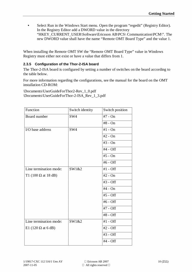
• Select Run in the Windows Start menu. Open the program “regedit” (Registry Editor).In the Registry Editor add a DWORD value in the directory“HKEY_CURRENT_USER\Software\Ericsson AB\PCS\ Communication\PCM\”. Thenew DWORD value shall have the name “Remote OMT Board Type” and the value 1.
When installing the Remote OMT SW the “Remote OMT Board Type” value in WindowsRegistry must either not exist or have a value that differs from 1.
2.3.5 Configuration of the Thor-2-ISA boardThe Thor-2-ISA board is configured by setting a number of switches on the board according tothe table below.For more information regarding the configurations, see the manual for the board on the OMTinstallation CD-ROM:\Documents\UserGuideForThor2-Rev_1_0.pdf\Documents\UserGuideForThor-2-ISA_Rev_1_3.pdf
Function Switch identity Switch position
#7 - OnBoard number SW4
#8 - On
#1 - On
#2 - On
#3 - On
#4 - Off
#5 - On
I/O base address SW4
#6 - Off
#1 - Off
#2 - On
#3 - Off
#4 - On
#5 - Off
#6 - Off
#7 - Off
Line termination mode:T1 (100 at 18 dB)
SW1&2
#8 - Off
#1 - Off
#2 - Off
#3 - Off
Line termination mode:
E1 (120 at 6 dB)
SW1&2
#4 - Off
Getting Started
1/19817-CXC 112 516/1 Uen AY Ericsson AB 2007 11 (211)2007-11-05 All rights reserved
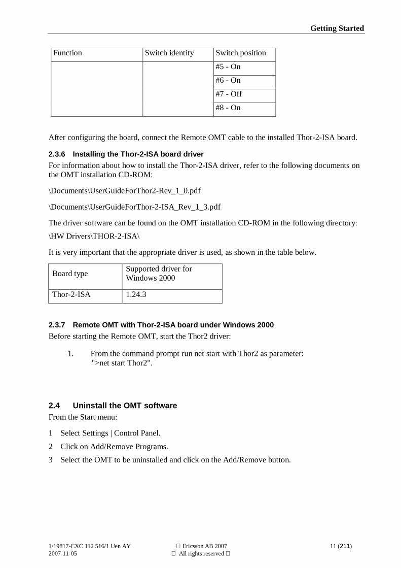
Function Switch identity Switch position
#5 - On
#6 - On
#7 - Off
#8 - On
After configuring the board, connect the Remote OMT cable to the installed Thor-2-ISA board.
2.3.6 Installing the Thor-2-ISA board driverFor information about how to install the Thor-2-ISA driver, refer to the following documents onthe OMT installation CD-ROM:
\Documents\UserGuideForThor2-Rev_1_0.pdf
\Documents\UserGuideForThor-2-ISA_Rev_1_3.pdf
The driver software can be found on the OMT installation CD-ROM in the following directory:\HW Drivers\THOR-2-ISA\
It is very important that the appropriate driver is used, as shown in the table below.
Board type Supported driver forWindows 2000
Thor-2-ISA 1.24.3
2.3.7 Remote OMT with Thor-2-ISA board under Windows 2000Before starting the Remote OMT, start the Thor2 driver:
1. From the command prompt run net start with Thor2 as parameter:">net start Thor2".
2.4 Uninstall the OMT softwareFrom the Start menu:
1 Select Settings | Control Panel.
2 Click on Add/Remove Programs.3 Select the OMT to be uninstalled and click on the Add/Remove button.

Learning OMT
1/19817-CXC 112 516/1 Uen AY Ericsson AB 2007 13 (211)2007-11-05 All rights reserved
3 Learning OMTThis chapter gives a general overview of the OMT application. It shows the relationshipbetween objects, operations, and states.
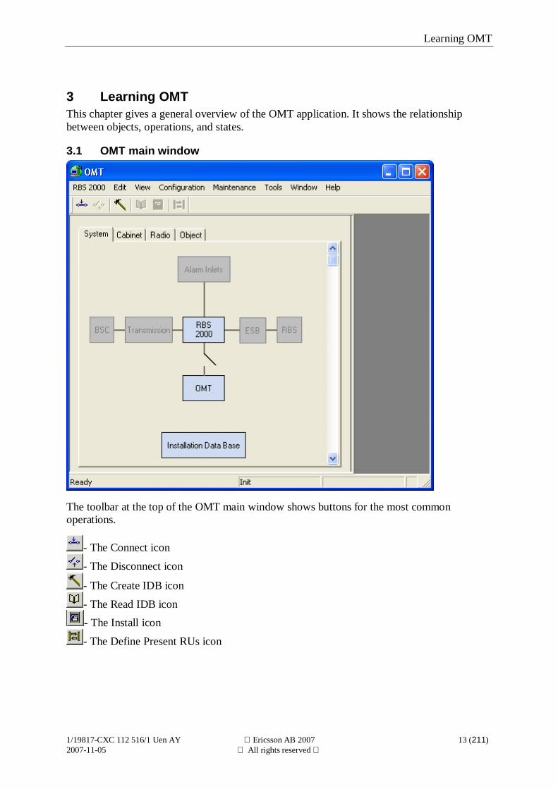
3.1 OMT main window
The toolbar at the top of the OMT main window shows buttons for the most commonoperations.
- The Connect icon
- The Disconnect icon
- The Create IDB icon
- The Read IDB icon- The Install icon
- The Define Present RUs icon

Learning OMT
1/19817-CXC 112 516/1 Uen AY Ericsson AB 2007 14 (211)2007-11-05 All rights reserved
A tab panel in the OMT main window displays a graphical view. The tab panel consists oftabs called System, Cabinet, Radio, and Object.Information windows are shown in the right pane, and several windows can be open at thesame time.The status bar at the bottom of the OMT main window shows the current OMT state, thename of the selected object, and a help text for the highlighted menu option.
Learning OMT
1/19817-CXC 112 516/1 Uen AY Ericsson AB 2007 15 (211)2007-11-05 All rights reserved
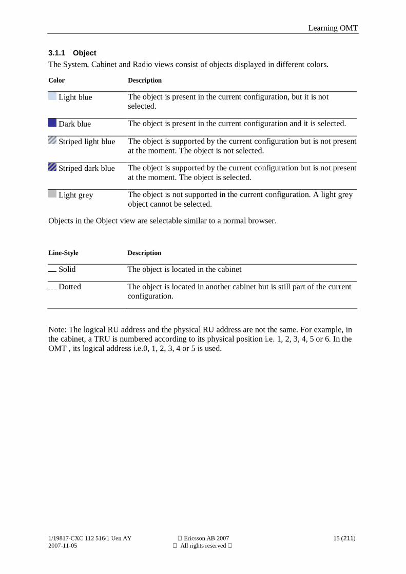
3.1.1 ObjectThe System, Cabinet and Radio views consist of objects displayed in different colors.
Color Description
Light blue The object is present in the current configuration, but it is notselected.
Dark blue The object is present in the current configuration and it is selected.
Striped light blue The object is supported by the current configuration but is not presentat the moment. The object is not selected.
Striped dark blue The object is supported by the current configuration but is not presentat the moment. The object is selected.
Light grey The object is not supported in the current configuration. A light greyobject cannot be selected.
Objects in the Object view are selectable similar to a normal browser.
Line-Style Description
Solid The object is located in the cabinet
Dotted The object is located in another cabinet but is still part of the currentconfiguration.
Note: The logical RU address and the physical RU address are not the same. For example, inthe cabinet, a TRU is numbered according to its physical position i.e. 1, 2, 3, 4, 5 or 6. In theOMT , its logical address i.e.0, 1, 2, 3, 4 or 5 is used.
Learning OMT
1/19817-CXC 112 516/1 Uen AY Ericsson AB 2007 16 (211)2007-11-05 All rights reserved
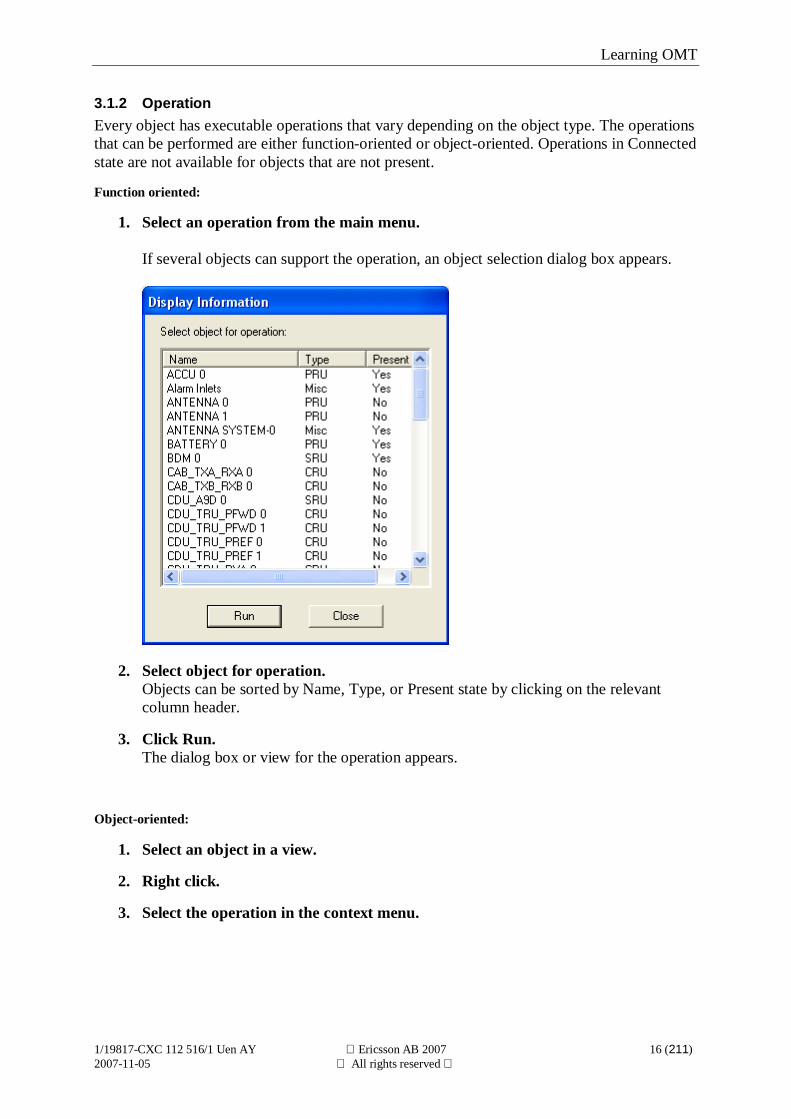
3.1.2 OperationEvery object has executable operations that vary depending on the object type. The operationsthat can be performed are either function-oriented or object-oriented. Operations in Connectedstate are not available for objects that are not present.
Function oriented:
1. Select an operation from the main menu.
If several objects can support the operation, an object selection dialog box appears.
2. Select object for operation.Objects can be sorted by Name, Type, or Present state by clicking on the relevantcolumn header.
3. Click Run.The dialog box or view for the operation appears.
Object-oriented:
1. Select an object in a view.
2. Right click.
3. Select the operation in the context menu.
Learning OMT
1/19817-CXC 112 516/1 Uen AY Ericsson AB 2007 17 (211)2007-11-05 All rights reserved
3.1.3 The different main menusMenu item Functions/Content
RBS 2000 To connect/disconnect the OMT to/from the RBS:ConnectDisconnectExit
Edit CopySelect All
View The view menu enables the user to select different views:
System viewCabinet viewRadio viewObject view
Configuration The Configuration menu contains IDB-related operations:Create IDB…Install IDBOpen IDB…Read IDBSave IDB…Save IDB as…DefineDisplayField ConfigurationLoad Flash Card…Site Specific Data
Maintenance Calibrate Oscillator…Change Local/Remote State…Check IDBChange Battery…DisplayMonitor…Reset…Set CDU Power Supervision…Set Measurements Reports On/Off…Set SSQIU On/Off…
Tools Wizards…Options…
Window Commands that are used to arrange windows and icons.
Help The Help menu offers commands that display help pages for both theOMT application and the help tool.
Learning OMT
1/19817-CXC 112 516/1 Uen AY Ericsson AB 2007 18 (211)2007-11-05 All rights reserved
3.2 OMT statesThe OMT executes in one of five different states and the current state is displayed on thestatus bar.
The five different states are:
Init By default, the OMT enters the Init state at startup.The OMT is not connected to the RBS and does not operate on any IDB.
Local IDB The OMT is not connected to the RBS, but is operating on a local copy ofthe IDB.Note: To implement changes made in the IDB, the IDB must be installedin the RBS.
Connected(No IDB)
The OMT is connected to the RBS but has no access to any IDB.The Connected (No IDB) state should be seen as a transitional state.
Connected(Local IDB)
The OMT is connected to the RBS but operates on a local IDB copy. TheConnected (Local IDB) state should be seen as a transitional state.Note: To implement changes made in the IDB, the IDB must be installedin the RBS.
Connected The OMT is connected to the RBS and operates on its currently activeIDB. The IDB has been read from the RBS to the OMT, or the local IDBcopy has been installed in the RBS.Note: The IDB in the OMT is not automatically updated when the IDB inthe RBS is changed.
All operations are not available in every state. Menu items are displayed in light grey textwhen they represent operations that are not available in the current state or for the selectedconfiguration.
Learning OMT
1/19817-CXC 112 516/1 Uen AY Ericsson AB 2007 19 (211)2007-11-05 All rights reserved
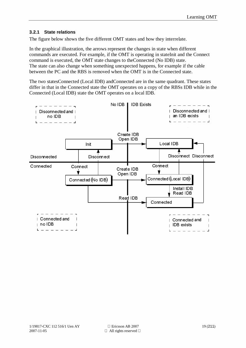
3.2.1 State relationsThe figure below shows the five different OMT states and how they interrelate.
In the graphical illustration, the arrows represent the changes in state when differentcommands are executed. For example, if the OMT is operating in stateInit and the Connectcommand is executed, the OMT state changes to theConnected (No IDB) state.The state can also change when something unexpected happens, for example if the cablebetween the PC and the RBS is removed when the OMT is in the Connected state.
The two statesConnected (Local IDB) andConnected are in the same quadrant. These statesdiffer in that in the Connected state the OMT operates on a copy of the RBSs IDB while in theConnected (Local IDB) state the OMT operates on a local IDB.
Learning OMT
1/19817-CXC 112 516/1 Uen AY Ericsson AB 2007 20 (211)2007-11-05 All rights reserved
3.3 ViewA view displays the RBS 2000 system graphically.
There are four types of views:
System view
Cabinet view
Radio view
Object view
A view contains several objects where each object represents a hardware unit or a logical unit,such as the Transmission, Alarm Inlets or objects in the Object view.
The number of objects in System view is fixed. The number of objects in the other views canchange depending on the current IDB configuration.
To select a view from the menu:
1. View | a view.
This command can also be executed by selecting the different views from the tabs in the OMTmain window.
Learning OMT
1/19817-CXC 112 516/1 Uen AY Ericsson AB 2007 21 (211)2007-11-05 All rights reserved
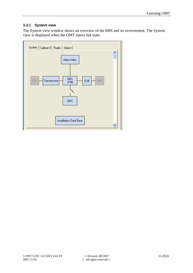
3.3.1 System viewThe System view window shows an overview of the RBS and its environment. The Systemview is displayed when the OMT enters Init state.
Learning OMT
1/19817-CXC 112 516/1 Uen AY Ericsson AB 2007 22 (211)2007-11-05 All rights reserved
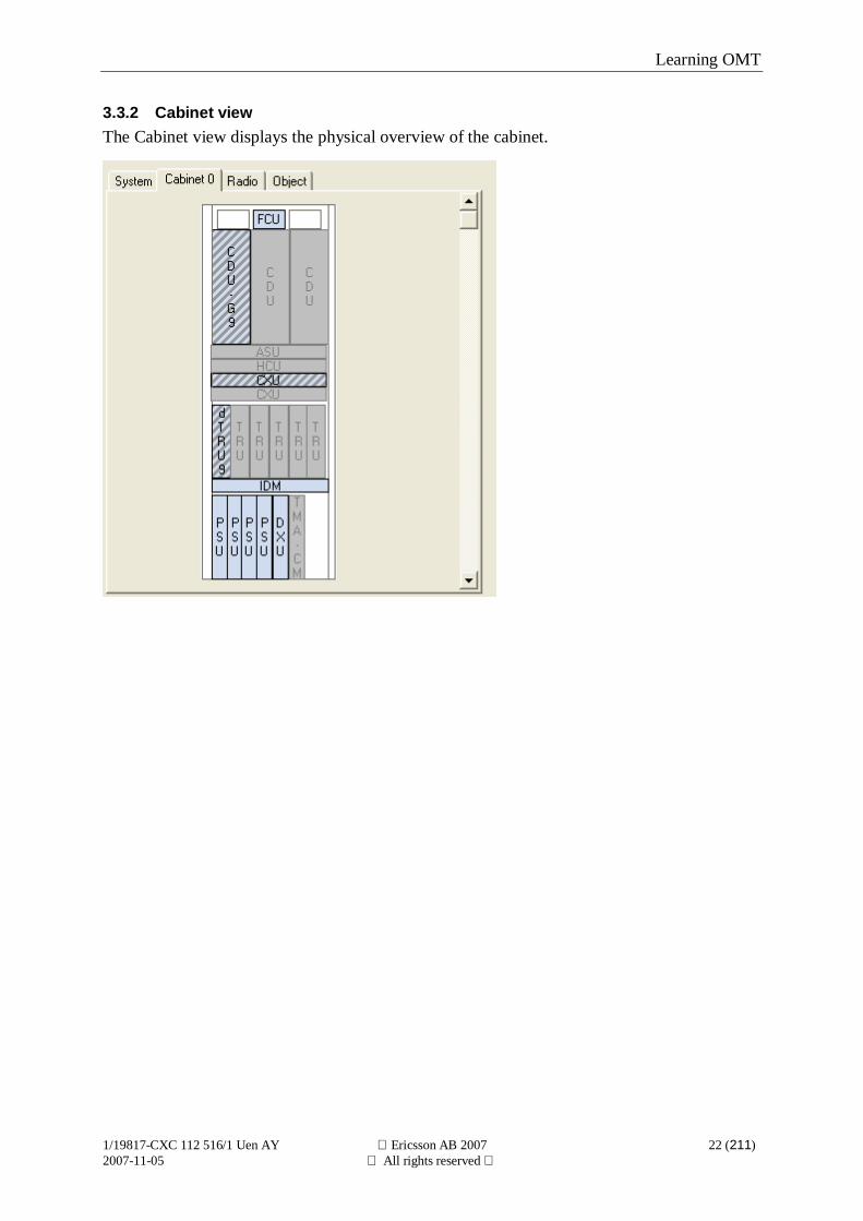
3.3.2 Cabinet viewThe Cabinet view displays the physical overview of the cabinet.
Learning OMT
1/19817-CXC 112 516/1 Uen AY Ericsson AB 2007 23 (211)2007-11-05 All rights reserved
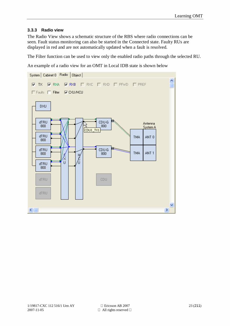
3.3.3 Radio viewThe Radio View shows a schematic structure of the RBS where radio connections can beseen. Fault status monitoring can also be started in the Connected state. Faulty RUs aredisplayed in red and are not automatically updated when a fault is resolved.
The Filter function can be used to view only the enabled radio paths through the selected RU.
An example of a radio view for an OMT in Local IDB state is shown below
Learning OMT
1/19817-CXC 112 516/1 Uen AY Ericsson AB 2007 24 (211)2007-11-05 All rights reserved
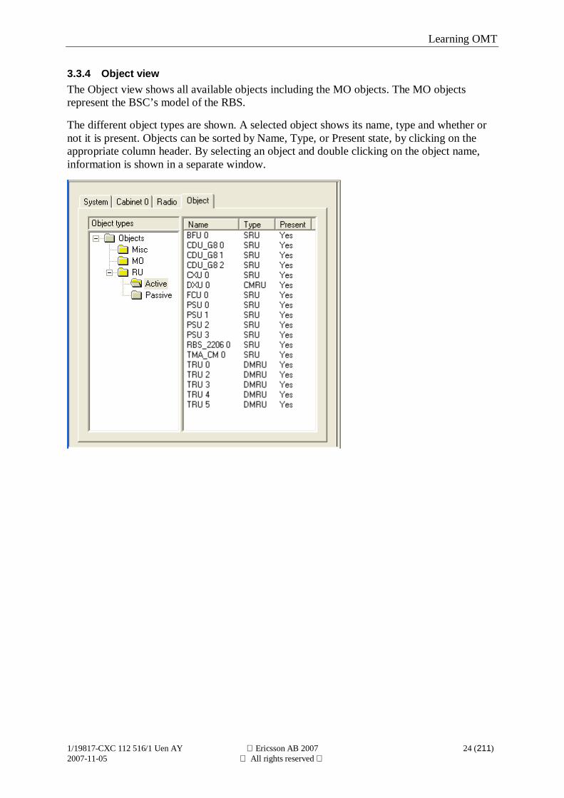
3.3.4 Object viewThe Object view shows all available objects including the MO objects. The MO objectsrepresent the BSC’s model of the RBS.
The different object types are shown. A selected object shows its name, type and whether ornot it is present. Objects can be sorted by Name, Type, or Present state, by clicking on theappropriate column header. By selecting an object and double clicking on the object name,information is shown in a separate window.
Using OMT
1/19817-CXC 112 516/1 Uen AY Ericsson AB 2007 25 (211)2007-11-05 All rights reserved
4 Using OMT
4.1 Start the OMTStart the OMT as follows:
1. Select the OMT program group from the Start | Program menu.
2. Select the OMT version to be started.
Using OMT
1/19817-CXC 112 516/1 Uen AY Ericsson AB 2007 26 (211)2007-11-05 All rights reserved
4.1.1 The Exit commandThe Exit command closes the OMT application.Before closing the program, it is recommended to close all open windows and disconnect theOMT from the RBS.Exit as follows:
1. Select RBS 2000 | Exit.
Using OMT
1/19817-CXC 112 516/1 Uen AY Ericsson AB 2007 27 (211)2007-11-05 All rights reserved
4.2 Operations on objects
4.2.1 Make the Changes PermanentChanges made to the Local IDB are not synchronized with the IDB in the RBS until the IDBhas been installed into the RBS. For more information regarding installation of an IDB, seesection "Install IDB".
Save IDB to disk can be selected to save the new values before closing the OMT application.This must be done for parameters changed in Local IDB state.
Using OMT
1/19817-CXC 112 516/1 Uen AY Ericsson AB 2007 28 (211)2007-11-05 All rights reserved
4.2.2 Connect OMTA physical cable must be connected between the OMT and the RBS (the DXU on Macrocabinets) before the OMT can monitor information or use the IDB in the RBS. See alsoAppendix, section "Cable specifications".
Valid OMT states: Change to state:
Init Connected (No IDB)
Local IDB Connected (Local IDB)
Execute this command as follows:
1. Select RBS 2000 | Connect.
Note: If the OMT is older than the RBS SW, an information message is shown. The OMT isbackward compatible and all functionality provided by older RBS SW is supported.
Using OMT
1/19817-CXC 112 516/1 Uen AY Ericsson AB 2007 29 (211)2007-11-05 All rights reserved
4.2.3 Connect Remote OMTA physical cable must be connected between the BSC and the Remote OMT before theRemote OMT can monitor information or use the IDB in the RBS. See also Appendix, section"Cable specifications".
The RBS’s address can be given when selecting one of several RBSs that are connected in acascade chain. The address for the RBS is the CF TEI configured for the RBS.
Note: It is not necessary to enter CF TEI Value if the RBS is running standalone.
Valid OMT states: Change to state:
Init Connected (No IDB)
Local IDB Connected (Local IDB)
Execute this command as follows:
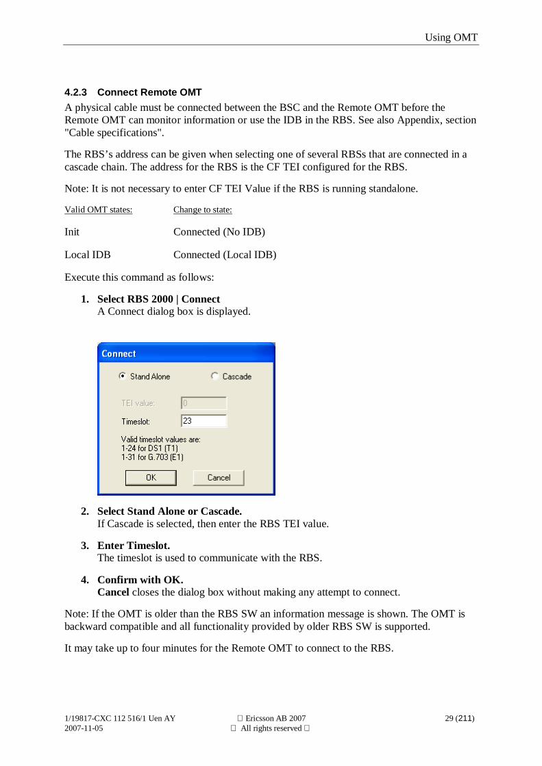
1. Select RBS 2000 | ConnectA Connect dialog box is displayed.
2. Select Stand Alone or Cascade.If Cascade is selected, then enter the RBS TEI value.
3. Enter Timeslot.The timeslot is used to communicate with the RBS.
4. Confirm with OK.Cancel closes the dialog box without making any attempt to connect.
Note: If the OMT is older than the RBS SW an information message is shown. The OMT isbackward compatible and all functionality provided by older RBS SW is supported.
It may take up to four minutes for the Remote OMT to connect to the RBS.
Using OMT
1/19817-CXC 112 516/1 Uen AY Ericsson AB 2007 30 (211)2007-11-05 All rights reserved
4.2.4 Connect Remote OMT over IPThe Remote OMT over IP must have IP access to the serving BSC.
Valid OMT states: Change to state:
Init Connected (No IDB)
Local IDB Connected (Local IDB)
Execute this command as follows:
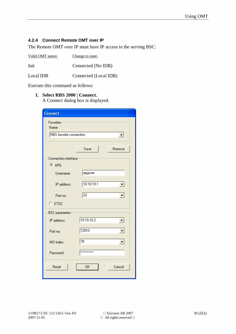
1. Select RBS 2000 | Connect.A Connect dialog box is displayed.
Using OMT
1/19817-CXC 112 516/1 Uen AY Ericsson AB 2007 31 (211)2007-11-05 All rights reserved
2. Choose APG or STOC connection interface.If connection interface is APG please enter:- Username for APG- IP address for APG.- Port number for APG (normally 22).
3. Enter IP address for the BSC.
4. Enter Port number for the BSC.Valid range is 12000 to 12110.
5. Enter MO Index.Valid range is 0 to 511.
6. Enter Password.Valid characters are: A-Z, a-z, and 0-9.
7. Confirm with OK.Selecting Reset reverts all changes to their original values.Cancel closes the dialog without making any attempt to connect.
Note: Connection parameters can be saved in a list of Favorites.
Note: If the OMT is older than the RBS SW an information message is shown. The OMT isbackward compatible and all functionality provided by older RBS SW is supported.
Note: If the connection to the BSC is established with APG a password dialog may appearafter confirming with OK. The password for the APG user must be entered in this dialog forthe connection to be successful.
It may take up to 30 seconds for the Remote OMT over IP to connect to the RBS.
Using OMT
1/19817-CXC 112 516/1 Uen AY Ericsson AB 2007 32 (211)2007-11-05 All rights reserved
4.2.5 DisconnectThe OMT can be disconnected from the RBS by executing the Disconnect command.
Valid OMT states: Change to state:
Connected (No IDB) Init
Connected (Local IDB) Local IDB
Connected Local IDB
Execute this command as follows:
1. Select RBS 2000 | Disconnect.
If any monitors are running when the Disconnect command is executed, a warning message isdisplayed, indicating that all monitoring will be stopped.
Using OMT
1/19817-CXC 112 516/1 Uen AY Ericsson AB 2007 33 (211)2007-11-05 All rights reserved
4.2.6 Read IDBThis command transfers an IDB copy from the RBS to the OMT .
Valid OMT states: Change to state:
Connected (No IDB) Connected
Connected (Local IDB) Connected
Execute this command as follows:
1. Select Configuration | Read IDB.If the OMT is in Connected (Local IDB) state, then a confirmation dialog box isdisplayed. Confirm with Yes.
A progress bar is shown during execution.While the progress bar is shown, the operation can be cancelled by selecting Cancel.This command changes the state to Connected (No IDB) or Connected (Local IDB) state.
Using OMT
1/19817-CXC 112 516/1 Uen AY Ericsson AB 2007 34 (211)2007-11-05 All rights reserved
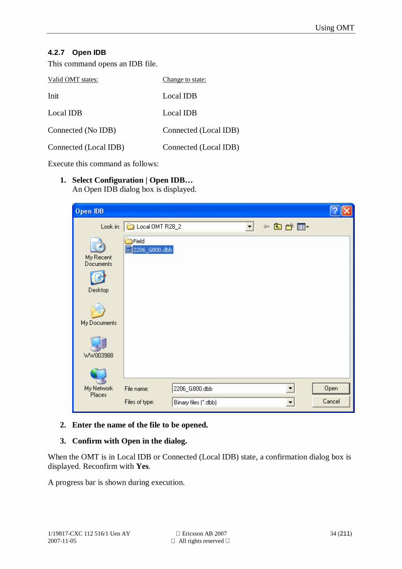
4.2.7 Open IDBThis command opens an IDB file.
Valid OMT states: Change to state:
Init Local IDB
Local IDB Local IDB
Connected (No IDB) Connected (Local IDB)
Connected (Local IDB) Connected (Local IDB)
Execute this command as follows:
1. Select Configuration | Open IDB…An Open IDB dialog box is displayed.
2. Enter the name of the file to be opened.
3. Confirm with Open in the dialog.
When the OMT is in Local IDB or Connected (Local IDB) state, a confirmation dialog box isdisplayed. Reconfirm with Yes.
A progress bar is shown during execution.
Using OMT
1/19817-CXC 112 516/1 Uen AY Ericsson AB 2007 35 (211)2007-11-05 All rights reserved
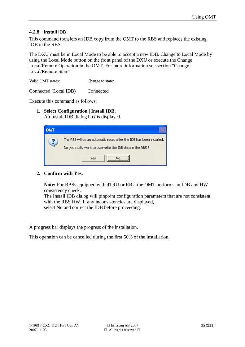
4.2.8 Install IDBThis command transfers an IDB copy from the OMT to the RBS and replaces the existingIDB in the RBS.
The DXU must be in Local Mode to be able to accept a new IDB. Change to Local Mode byusing the Local Mode button on the front panel of the DXU or execute the ChangeLocal/Remote Operation in the OMT. For more information see section "ChangeLocal/Remote State"
Valid OMT states: Change to state:
Connected (Local IDB) Connected
Execute this command as follows:
1. Select Configuration | Install IDB.An Install IDB dialog box is displayed.
2. Confirm with Yes.
Note: For RBSs equipped with dTRU or RRU the OMT performs an IDB and HWconsistency check.The Install IDB dialog will pinpoint configuration parameters that are not consistentwith the RBS HW. If any inconsistencies are displayed,select No and correct the IDB before proceeding.
A progress bar displays the progress of the installation.
This operation can be cancelled during the first 50% of the installation.
Using OMT
1/19817-CXC 112 516/1 Uen AY Ericsson AB 2007 36 (211)2007-11-05 All rights reserved
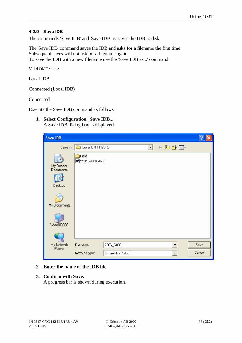
4.2.9 Save IDBThe commands 'Save IDB' and 'Save IDB as' saves the IDB to disk.
The 'Save IDB' command saves the IDB and asks for a filename the first time.Subsequent saves will not ask for a filename again.To save the IDB with a new filename use the 'Save IDB as...' command
Valid OMT states:
Local IDB
Connected (Local IDB)
Connected
Execute the Save IDB command as follows:
1. Select Configuration | Save IDB...A Save IDB dialog box is displayed.
2. Enter the name of the IDB file.
3. Confirm with Save.A progress bar is shown during execution.
Using OMT
1/19817-CXC 112 516/1 Uen AY Ericsson AB 2007 37 (211)2007-11-05 All rights reserved
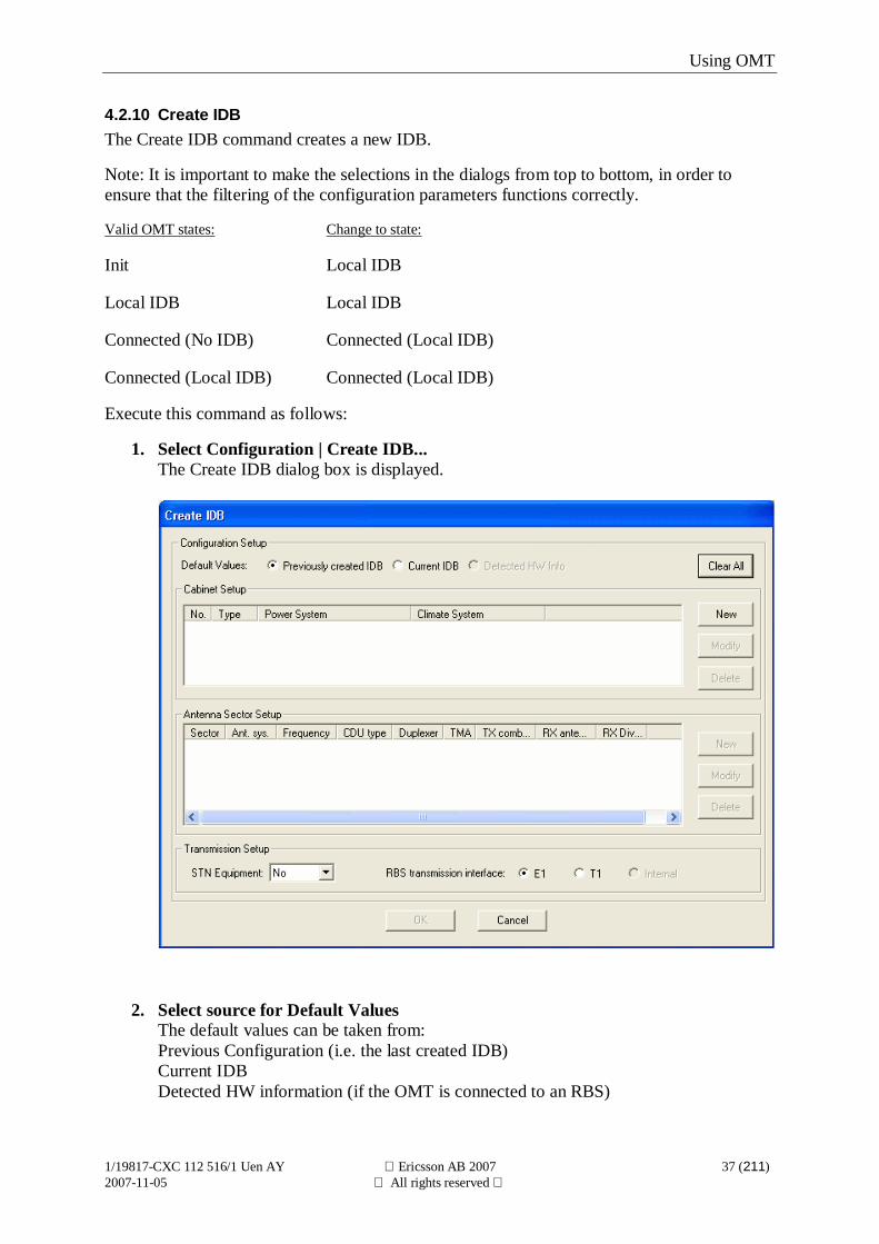
4.2.10 Create IDBThe Create IDB command creates a new IDB.
Note: It is important to make the selections in the dialogs from top to bottom, in order toensure that the filtering of the configuration parameters functions correctly.
Valid OMT states: Change to state:
Init Local IDB
Local IDB Local IDB
Connected (No IDB) Connected (Local IDB)
Connected (Local IDB) Connected (Local IDB)
Execute this command as follows:
1. Select Configuration | Create IDB...The Create IDB dialog box is displayed.
2. Select source for Default ValuesThe default values can be taken from:Previous Configuration (i.e. the last created IDB)Current IDBDetected HW information (if the OMT is connected to an RBS)
Using OMT
1/19817-CXC 112 516/1 Uen AY Ericsson AB 2007 38 (211)2007-11-05 All rights reserved
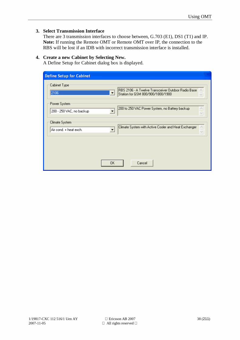
3. Select Transmission InterfaceThere are 3 transmission interfaces to choose between, G.703 (E1), DS1 (T1) and IP.Note: If running the Remote OMT or Remote OMT over IP, the connection to theRBS will be lost if an IDB with incorrect transmission interface is installed.
4. Create a new Cabinet by Selecting New.A Define Setup for Cabinet dialog box is displayed.
Using OMT
1/19817-CXC 112 516/1 Uen AY Ericsson AB 2007 39 (211)2007-11-05 All rights reserved
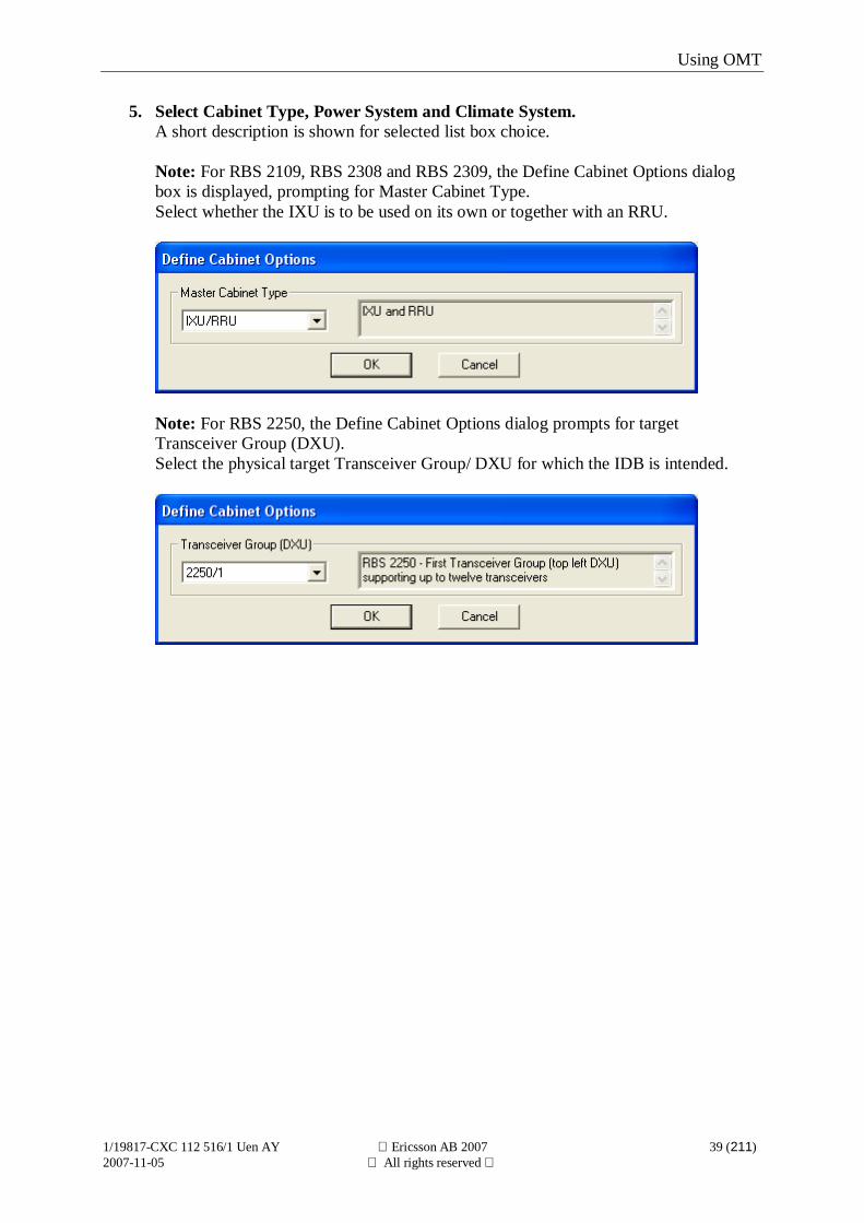
5. Select Cabinet Type, Power System and Climate System.A short description is shown for selected list box choice.
Note: For RBS 2109, RBS 2308 and RBS 2309, the Define Cabinet Options dialogbox is displayed, prompting for Master Cabinet Type.Select whether the IXU is to be used on its own or together with an RRU.
Note: For RBS 2250, the Define Cabinet Options dialog prompts for targetTransceiver Group (DXU).Select the physical target Transceiver Group/ DXU for which the IDB is intended.
Using OMT
1/19817-CXC 112 516/1 Uen AY Ericsson AB 2007 40 (211)2007-11-05 All rights reserved
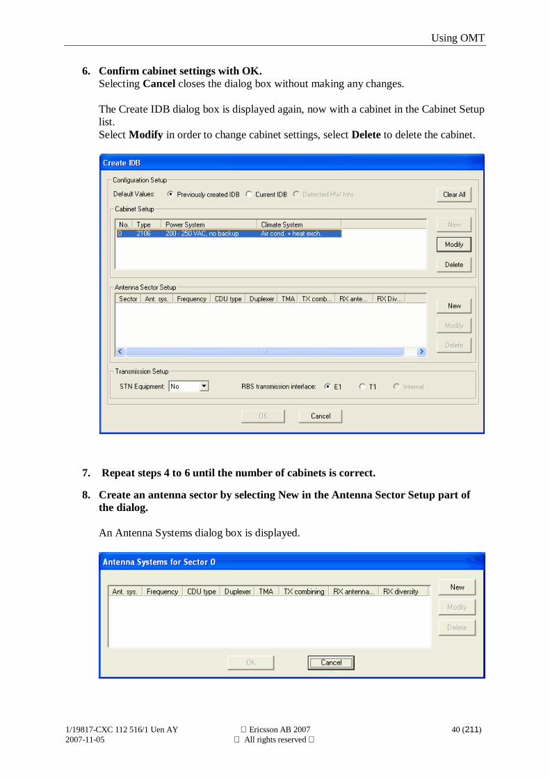
6. Confirm cabinet settings with OK.Selecting Cancel closes the dialog box without making any changes.
The Create IDB dialog box is displayed again, now with a cabinet in the Cabinet Setuplist.Select Modify in order to change cabinet settings, select Delete to delete the cabinet.
7. Repeat steps 4 to 6 until the number of cabinets is correct.
8. Create an antenna sector by selecting New in the Antenna Sector Setup part ofthe dialog.
An Antenna Systems dialog box is displayed.
Using OMT
1/19817-CXC 112 516/1 Uen AY Ericsson AB 2007 41 (211)2007-11-05 All rights reserved
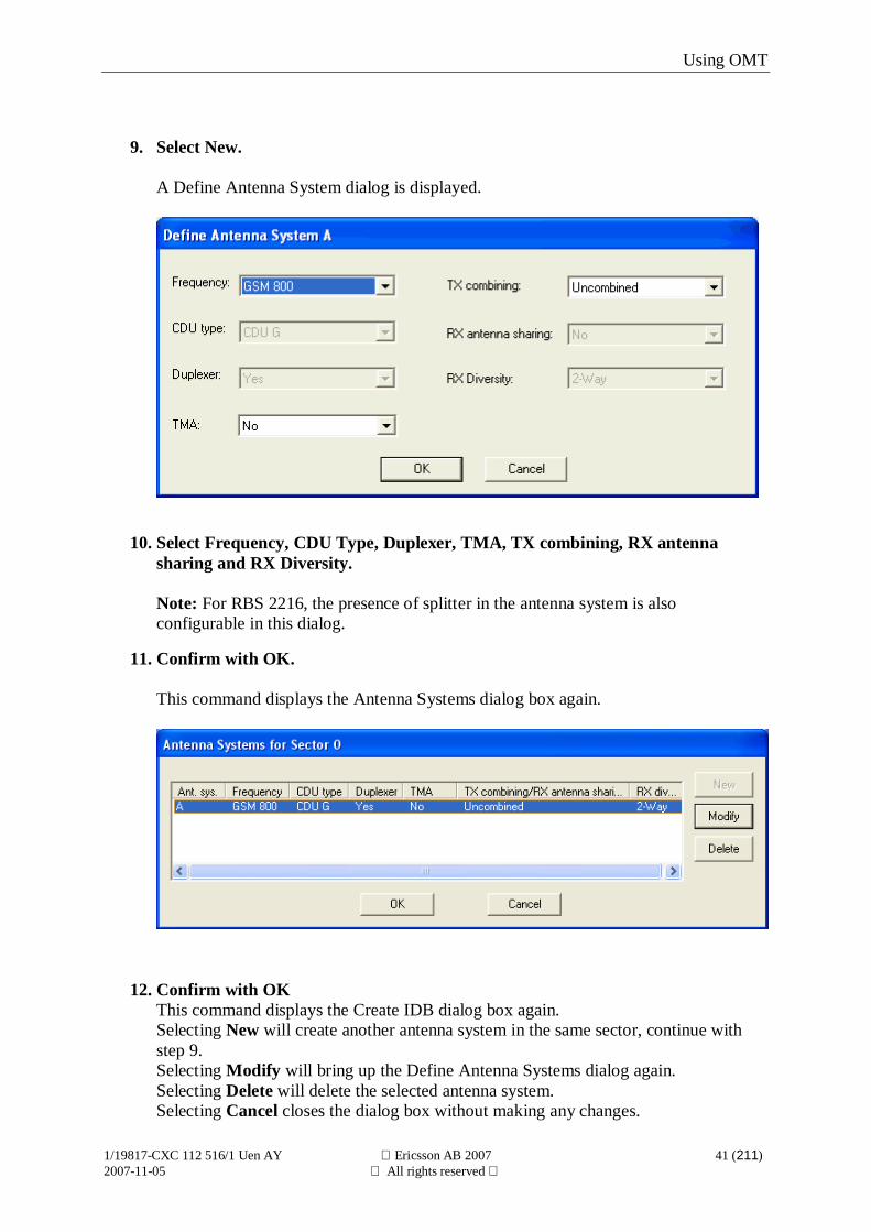
9. Select New.
A Define Antenna System dialog is displayed.
10. Select Frequency, CDU Type, Duplexer, TMA, TX combining, RX antennasharing and RX Diversity.
Note: For RBS 2216, the presence of splitter in the antenna system is alsoconfigurable in this dialog.
11. Confirm with OK.
This command displays the Antenna Systems dialog box again.
12. Confirm with OKThis command displays the Create IDB dialog box again.Selecting New will create another antenna system in the same sector, continue withstep 9.Selecting Modify will bring up the Define Antenna Systems dialog again.Selecting Delete will delete the selected antenna system.Selecting Cancel closes the dialog box without making any changes.
Using OMT
1/19817-CXC 112 516/1 Uen AY Ericsson AB 2007 42 (211)2007-11-05 All rights reserved
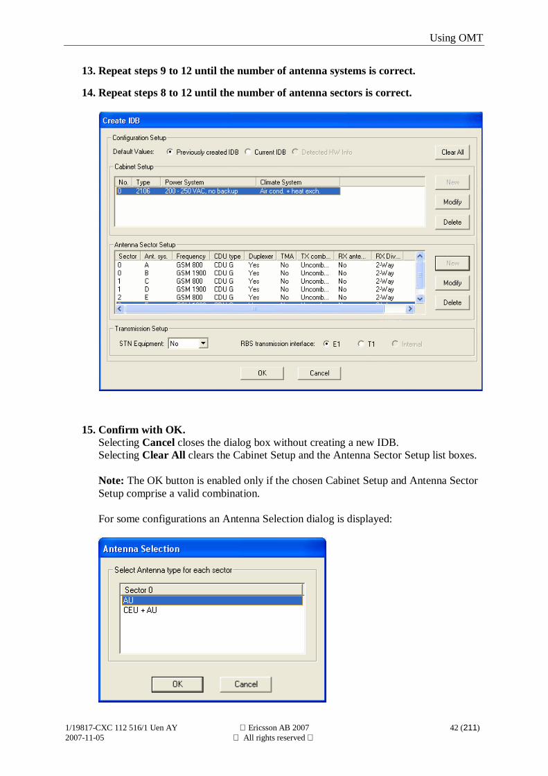
13. Repeat steps 9 to 12 until the number of antenna systems is correct.
14. Repeat steps 8 to 12 until the number of antenna sectors is correct.
15. Confirm with OK.Selecting Cancel closes the dialog box without creating a new IDB.Selecting Clear All clears the Cabinet Setup and the Antenna Sector Setup list boxes.
Note: The OK button is enabled only if the chosen Cabinet Setup and Antenna SectorSetup comprise a valid combination.
For some configurations an Antenna Selection dialog is displayed:
Using OMT
1/19817-CXC 112 516/1 Uen AY Ericsson AB 2007 43 (211)2007-11-05 All rights reserved
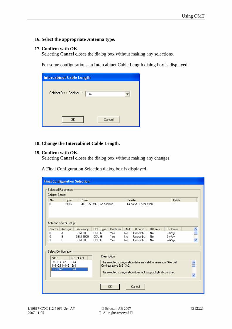
16. Select the appropriate Antenna type.
17. Confirm with OK.Selecting Cancel closes the dialog box without making any selections.
For some configurations an Intercabinet Cable Length dialog box is displayed:
18. Change the Intercabinet Cable Length.
19. Confirm with OK.Selecting Cancel closes the dialog box without making any changes.
A Final Configuration Selection dialog box is displayed.
Using OMT
1/19817-CXC 112 516/1 Uen AY Ericsson AB 2007 44 (211)2007-11-05 All rights reserved
20. Select Configuration.
In the configuration list, the combinations of SCC and number of antennas aredisplayed.To separate frequencies in dual band configurations, the character ‘|’ is used. E.g.3x2|3x2 means:3 antenna sectors with 2 TRXs in each antenna sectors first frequency3 antenna sectors with 2 TRXs in each antenna sectors second frequency.
SCC uses one of the following formats:< no. of antenna sectors > x < no. of TRXs in each antenna sector >or< no. of TRXs in antenna sector 0 > + < no. of TRXs in antenna sector 1 > + …or< 1 > x < no. of TRXs in antenna sector 0 > +< 1 > x < no. of TRXs in antenna sector 1 >
No. of Ant. uses one of the following formats:< no. of antenna sectors > x < no. of antennas in each antenna sector>or< no. of ant. in antenna sector 0 > + < no. of ant. in antenna sector 1 > + …
Note: Plan for future capacity expansion when selecting SCC.
Using OMT
1/19817-CXC 112 516/1 Uen AY Ericsson AB 2007 45 (211)2007-11-05 All rights reserved
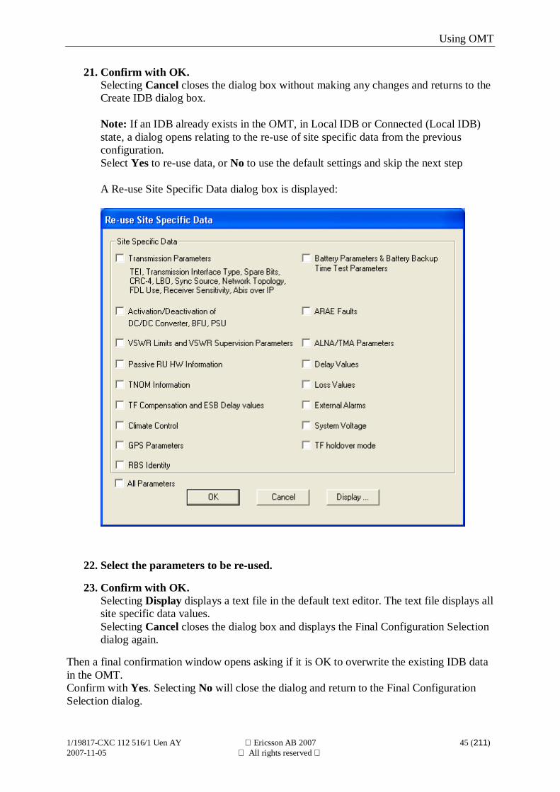
21. Confirm with OK.Selecting Cancel closes the dialog box without making any changes and returns to theCreate IDB dialog box.
Note: If an IDB already exists in the OMT, in Local IDB or Connected (Local IDB)state, a dialog opens relating to the re-use of site specific data from the previousconfiguration.Select Yes to re-use data, or No to use the default settings and skip the next step
A Re-use Site Specific Data dialog box is displayed:
22. Select the parameters to be re-used.
23. Confirm with OK.Selecting Display displays a text file in the default text editor. The text file displays allsite specific data values.Selecting Cancel closes the dialog box and displays the Final Configuration Selectiondialog again.
Then a final confirmation window opens asking if it is OK to overwrite the existing IDB datain the OMT.Confirm with Yes. Selecting No will close the dialog and return to the Final ConfigurationSelection dialog.

Using OMT
1/19817-CXC 112 516/1 Uen AY Ericsson AB 2007 46 (211)2007-11-05 All rights reserved
Using OMT
1/19817-CXC 112 516/1 Uen AY Ericsson AB 2007 47 (211)2007-11-05 All rights reserved
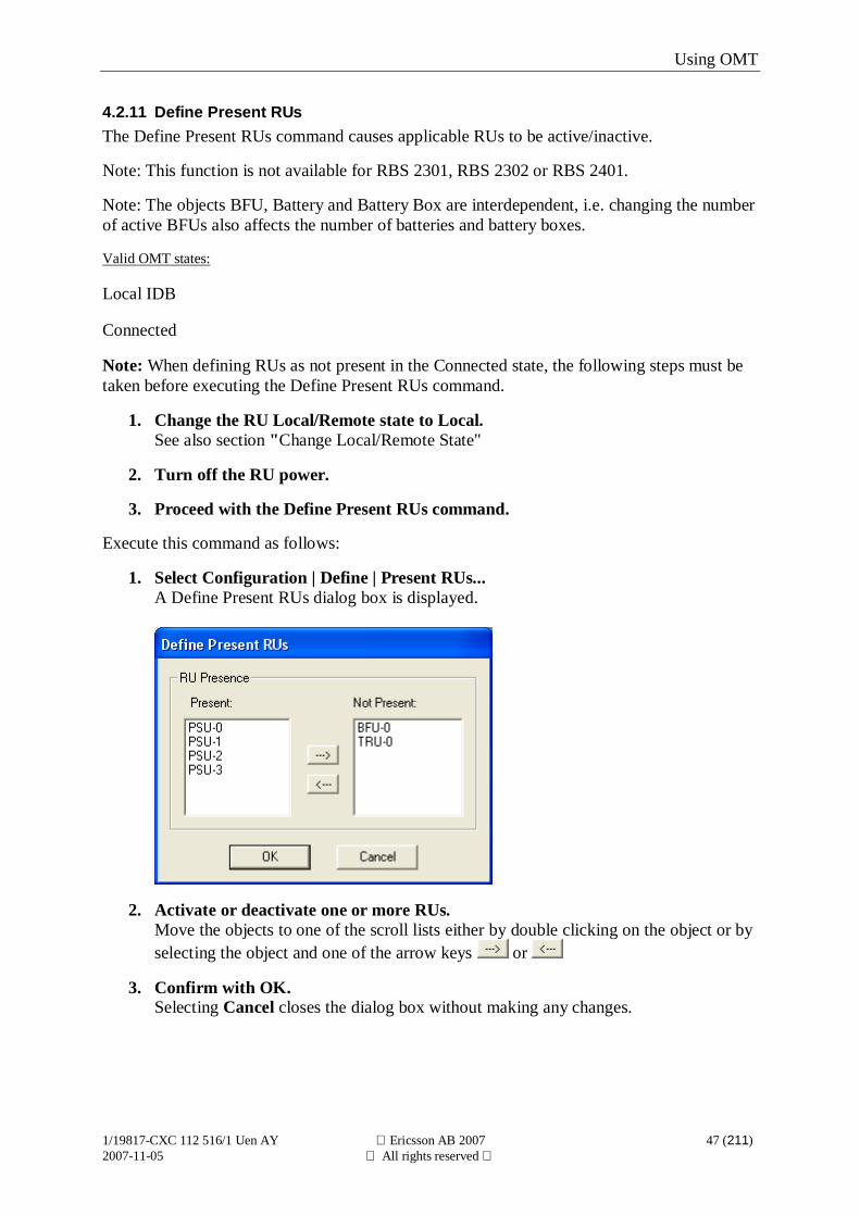
4.2.11 Define Present RUsThe Define Present RUs command causes applicable RUs to be active/inactive.
Note: This function is not available for RBS 2301, RBS 2302 or RBS 2401.
Note: The objects BFU, Battery and Battery Box are interdependent, i.e. changing the numberof active BFUs also affects the number of batteries and battery boxes.
Valid OMT states:
Local IDB
Connected
Note: When defining RUs as not present in the Connected state, the following steps must betaken before executing the Define Present RUs command.
1. Change the RU Local/Remote state to Local.See also section "Change Local/Remote State"
2. Turn off the RU power.
3. Proceed with the Define Present RUs command.
Execute this command as follows:
1. Select Configuration | Define | Present RUs...A Define Present RUs dialog box is displayed.
2. Activate or deactivate one or more RUs.Move the objects to one of the scroll lists either by double clicking on the object or byselecting the object and one of the arrow keys or
3. Confirm with OK.Selecting Cancel closes the dialog box without making any changes.
Using OMT
1/19817-CXC 112 516/1 Uen AY Ericsson AB 2007 48 (211)2007-11-05 All rights reserved
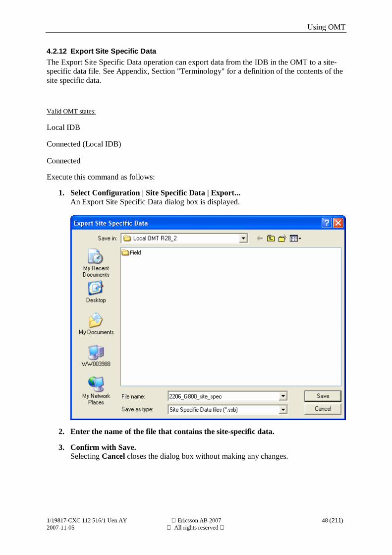
4.2.12 Export Site Specific DataThe Export Site Specific Data operation can export data from the IDB in the OMT to a site-specific data file. See Appendix, Section "Terminology" for a definition of the contents of thesite specific data.
Valid OMT states:
Local IDB
Connected (Local IDB)
Connected
Execute this command as follows:
1. Select Configuration | Site Specific Data | Export...An Export Site Specific Data dialog box is displayed.
2. Enter the name of the file that contains the site-specific data.
3. Confirm with Save.Selecting Cancel closes the dialog box without making any changes.
Using OMT
1/19817-CXC 112 516/1 Uen AY Ericsson AB 2007 49 (211)2007-11-05 All rights reserved
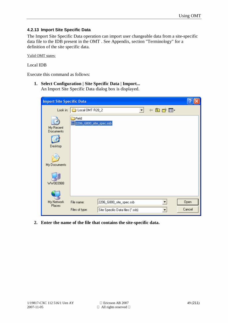
4.2.13 Import Site Specific DataThe Import Site Specific Data operation can import user changeable data from a site-specificdata file to the IDB present in the OMT . See Appendix, section "Terminology" for adefinition of the site specific data.
Valid OMT states:
Local IDB
Execute this command as follows:
1. Select Configuration | Site Specific Data | Import...An Import Site Specific Data dialog box is displayed.
2. Enter the name of the file that contains the site-specific data.
Using OMT
1/19817-CXC 112 516/1 Uen AY Ericsson AB 2007 50 (211)2007-11-05 All rights reserved
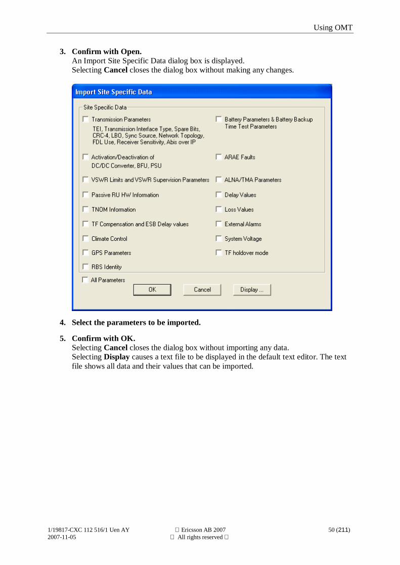
3. Confirm with Open.An Import Site Specific Data dialog box is displayed.Selecting Cancel closes the dialog box without making any changes.
4. Select the parameters to be imported.
5. Confirm with OK.Selecting Cancel closes the dialog box without importing any data.Selecting Display causes a text file to be displayed in the default text editor. The textfile shows all data and their values that can be imported.
Using OMT
1/19817-CXC 112 516/1 Uen AY Ericsson AB 2007 51 (211)2007-11-05 All rights reserved
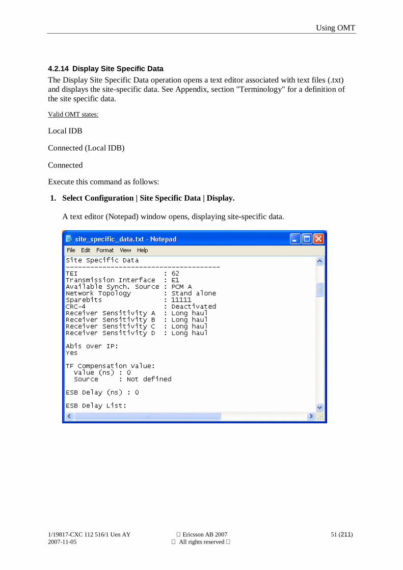
4.2.14 Display Site Specific DataThe Display Site Specific Data operation opens a text editor associated with text files (.txt)and displays the site-specific data. See Appendix, section "Terminology" for a definition ofthe site specific data.
Valid OMT states:
Local IDB
Connected (Local IDB)
Connected
Execute this command as follows:
1. Select Configuration | Site Specific Data | Display.
A text editor (Notepad) window opens, displaying site-specific data.
Using OMT
1/19817-CXC 112 516/1 Uen AY Ericsson AB 2007 52 (211)2007-11-05 All rights reserved
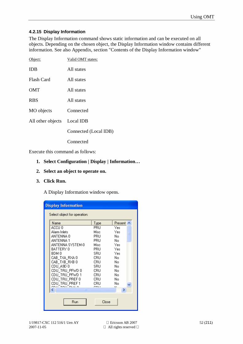
4.2.15 Display InformationThe Display Information command shows static information and can be executed on allobjects. Depending on the chosen object, the Display Information window contains differentinformation. See also Appendix, section "Contents of the Display Information window"
Object: Valid OMT states:
IDB All states
Flash Card All states
OMT All states
RBS All states
MO objects Connected
All other objects Local IDB
Connected (Local IDB)
Connected
Execute this command as follows:
1. Select Configuration | Display | Information…
2. Select an object to operate on.
3. Click Run.
A Display Information window opens.

Using OMT
1/19817-CXC 112 516/1 Uen AY Ericsson AB 2007 53 (211)2007-11-05 All rights reserved
This command can also be executed by double clicking on an object.
Using OMT
1/19817-CXC 112 516/1 Uen AY Ericsson AB 2007 54 (211)2007-11-05 All rights reserved
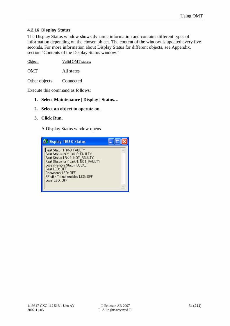
4.2.16 Display StatusThe Display Status window shows dynamic information and contains different types ofinformation depending on the chosen object. The content of the window is updated every fiveseconds. For more information about Display Status for different objects, see Appendix,section "Contents of the Display Status window."
Object: Valid OMT states:
OMT All states
Other objects Connected
Execute this command as follows:
1. Select Maintenance | Display | Status…
2. Select an object to operate on.
3. Click Run.
A Display Status window opens.
Using OMT
1/19817-CXC 112 516/1 Uen AY Ericsson AB 2007 55 (211)2007-11-05 All rights reserved
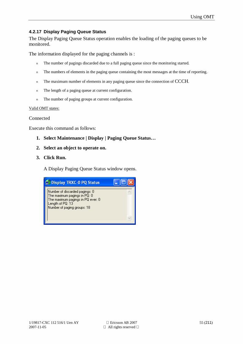
4.2.17 Display Paging Queue StatusThe Display Paging Queue Status operation enables the loading of the paging queues to bemonitored.
The information displayed for the paging channels is :
n The number of pagings discarded due to a full paging queue since the monitoring started.
n The numbers of elements in the paging queue containing the most messages at the time of reporting.
n The maximum number of elements in any paging queue since the connection of CCCH.
n The length of a paging queue at current configuration.
n The number of paging groups at current configuration.
Valid OMT states:
Connected
Execute this command as follows:
1. Select Maintenance | Display | Paging Queue Status…
2. Select an object to operate on.
3. Click Run.
A Display Paging Queue Status window opens.
Using OMT
1/19817-CXC 112 516/1 Uen AY Ericsson AB 2007 56 (211)2007-11-05 All rights reserved
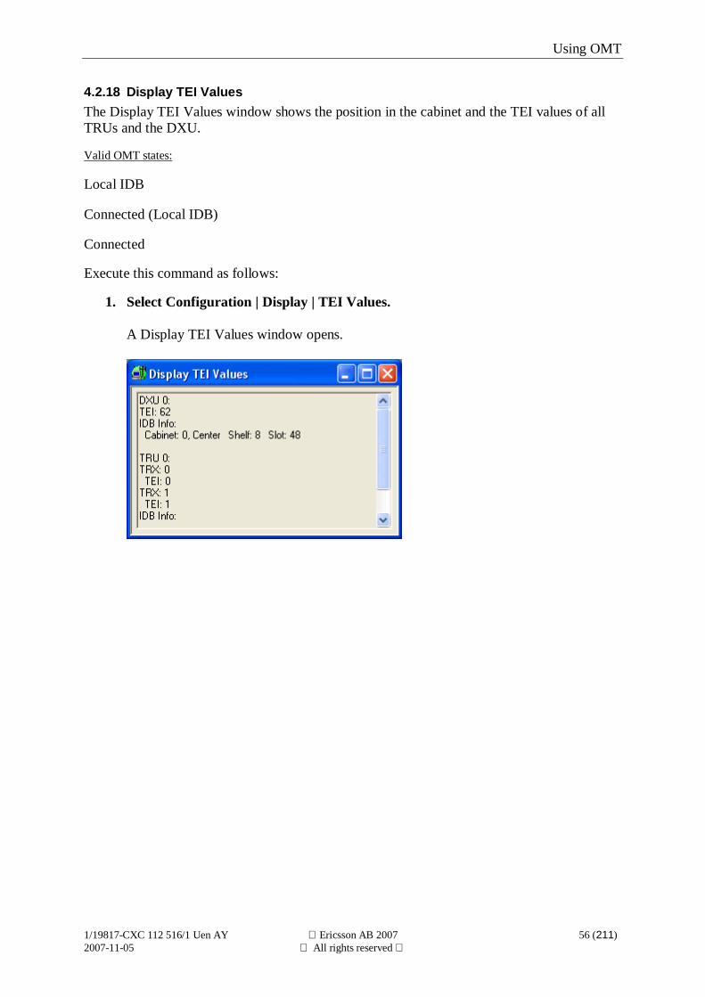
4.2.18 Display TEI ValuesThe Display TEI Values window shows the position in the cabinet and the TEI values of allTRUs and the DXU.
Valid OMT states:
Local IDB
Connected (Local IDB)
Connected
Execute this command as follows:
1. Select Configuration | Display | TEI Values.
A Display TEI Values window opens.
Using OMT
1/19817-CXC 112 516/1 Uen AY Ericsson AB 2007 57 (211)2007-11-05 All rights reserved
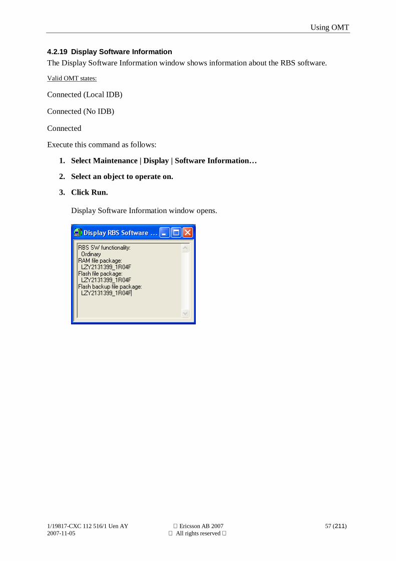
4.2.19 Display Software InformationThe Display Software Information window shows information about the RBS software.
Valid OMT states:
Connected (Local IDB)
Connected (No IDB)
Connected
Execute this command as follows:
1. Select Maintenance | Display | Software Information…
2. Select an object to operate on.
3. Click Run.
Display Software Information window opens.
Using OMT
1/19817-CXC 112 516/1 Uen AY Ericsson AB 2007 58 (211)2007-11-05 All rights reserved
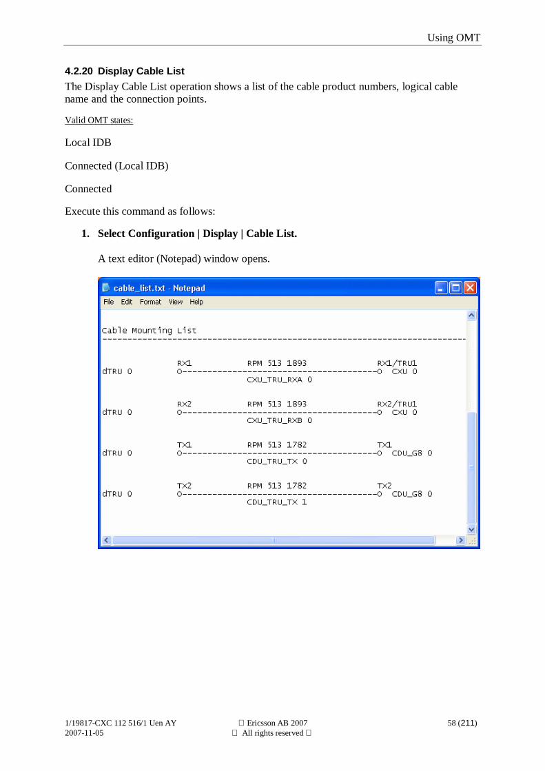
4.2.20 Display Cable ListThe Display Cable List operation shows a list of the cable product numbers, logical cablename and the connection points.
Valid OMT states:
Local IDB
Connected (Local IDB)
Connected
Execute this command as follows:
1. Select Configuration | Display | Cable List.
A text editor (Notepad) window opens.
Using OMT
1/19817-CXC 112 516/1 Uen AY Ericsson AB 2007 59 (211)2007-11-05 All rights reserved
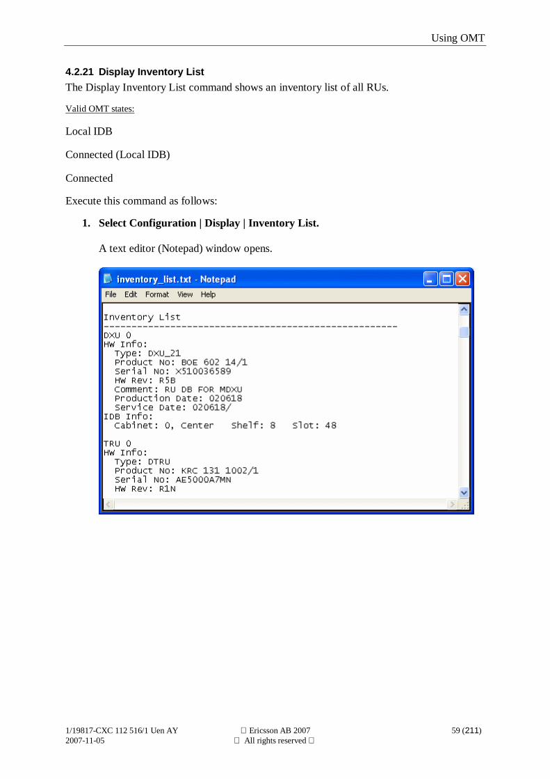
4.2.21 Display Inventory ListThe Display Inventory List command shows an inventory list of all RUs.
Valid OMT states:
Local IDB
Connected (Local IDB)
Connected
Execute this command as follows:
1. Select Configuration | Display | Inventory List.
A text editor (Notepad) window opens.
Using OMT
1/19817-CXC 112 516/1 Uen AY Ericsson AB 2007 60 (211)2007-11-05 All rights reserved
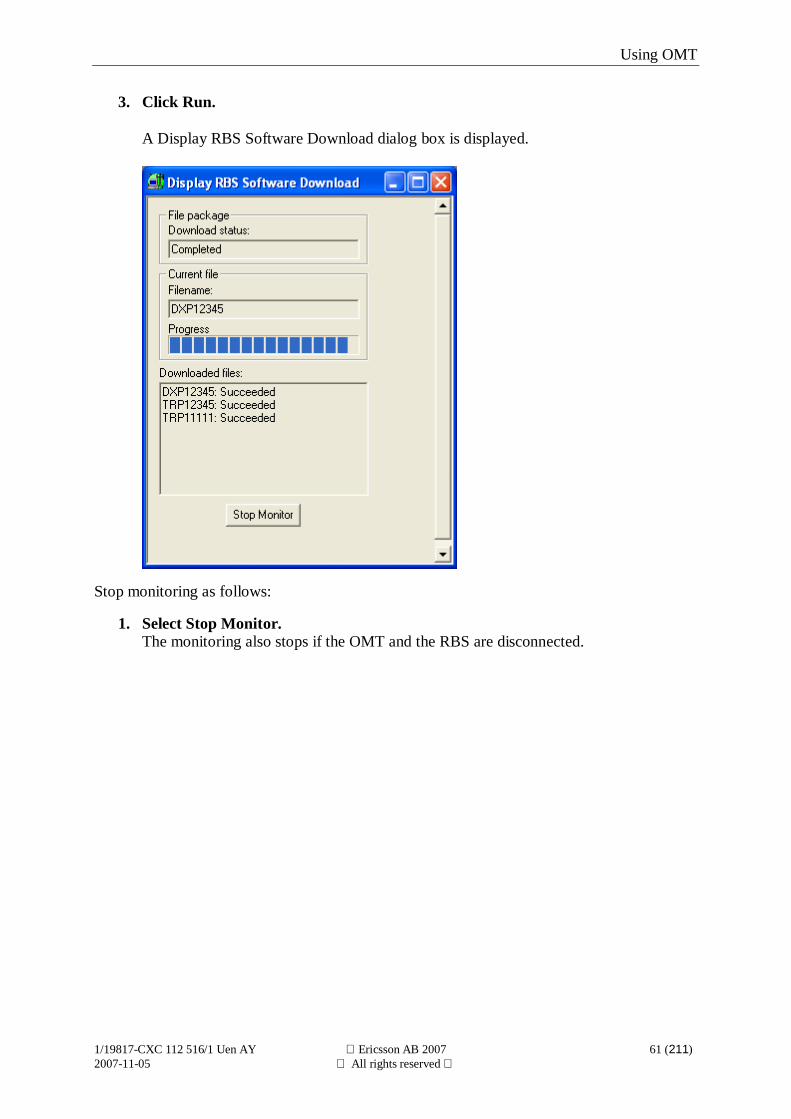
4.2.22 Display RBS Software DownloadThe Display RBS Software Download operation shows the following parameters during asoftware download from the BSC:
n Download status
n Filename
n Progress
n Downloaded files
Valid OMT states:
Connected (No IDB)
Connected (Local IDB)
Connected
Note: Only RBSs equipped with DXU-21, DXU-22, DXU-23, DXU-31 or IXU-21 can bemonitored. The RBS also needs to be running on SW release 11A/10E or later.
Files to be downloaded: Type:
ZFJxxxxZ RBS SW file info file
DXPxxxxZ (1) DXU/IXU load file
TRPxxxxZ (1) dTRU/sTRU/RRU/DRU loadfile
ECAxxxxZ (2) ECU load file
TRAxxxxZ (2) cTRU load file
ECXxxxxZ (2) ECU base file
TRXxxxxZ (2) cTRU base file
¹ If an unconditional function change is initiated, the file is always downloaded. If aconditional function change is initiated, the file is downloaded if it differs from the filepresent in the RBS.
² This file is not always downloaded, depending on software version and RBS type.
Execute this command as follows:
1. Select Maintenance | Display | RBS Software Download…
2. Select an object to operate on.
Using OMT
1/19817-CXC 112 516/1 Uen AY Ericsson AB 2007 61 (211)2007-11-05 All rights reserved
3. Click Run.
A Display RBS Software Download dialog box is displayed.
Stop monitoring as follows:
1. Select Stop Monitor.The monitoring also stops if the OMT and the RBS are disconnected.
Using OMT
1/19817-CXC 112 516/1 Uen AY Ericsson AB 2007 62 (211)2007-11-05 All rights reserved
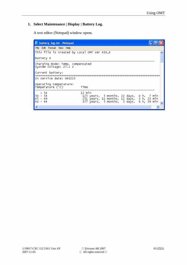
4.2.23 Display Battery LogThe Display Battery Log shows information about Charging Mode and System Voltage.
The log contains the following information about the current battery:
n In service date.
n Time duration in different temperature intervals.
n Time duration in different voltage intervals in combination with an evaluation of the charging.
n No. of discharges and time duration in different voltage intervals.
n Maximum disconnect time.
The log contains the following information about the previous battery:
n In service date.
n Out of service date.
n Time duration in different temperature intervals.
n Time duration in different voltage intervals in combination with an evaluation of the charging.
n No. of discharges and time duration in different voltage intervals.
n Maximum disconnect time.
This operation is available only for RBS 2106, RBS 2106i, RBS 2107, RBS 2206 and RBS2207 with AC Power Supply and Battery Backup.
Valid OMT states:
Connected
Execute this command as follows:
Using OMT
1/19817-CXC 112 516/1 Uen AY Ericsson AB 2007 63 (211)2007-11-05 All rights reserved
1. Select Maintenance | Display | Battery Log.
A text editor (Notepad) window opens.
Using OMT
1/19817-CXC 112 516/1 Uen AY Ericsson AB 2007 64 (211)2007-11-05 All rights reserved
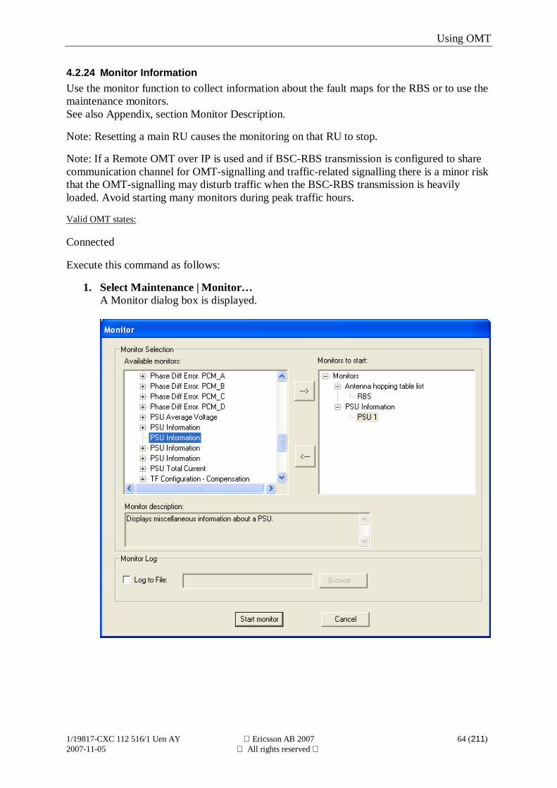
4.2.24 Monitor InformationUse the monitor function to collect information about the fault maps for the RBS or to use themaintenance monitors.See also Appendix, section Monitor Description.
Note: Resetting a main RU causes the monitoring on that RU to stop.
Note: If a Remote OMT over IP is used and if BSC-RBS transmission is configured to sharecommunication channel for OMT-signalling and traffic-related signalling there is a minor riskthat the OMT-signalling may disturb traffic when the BSC-RBS transmission is heavilyloaded. Avoid starting many monitors during peak traffic hours.
Valid OMT states:
Connected
Execute this command as follows:
1. Select Maintenance | Monitor…A Monitor dialog box is displayed.
Using OMT
1/19817-CXC 112 516/1 Uen AY Ericsson AB 2007 65 (211)2007-11-05 All rights reserved
2. Select monitors and objects from Available monitors list.The Available monitors list shows all monitors that can be monitored. If a monitor isexpanded, all objects supporting the monitor are shown. To add a monitor, select theobject to be monitored and click the right arrow button. The selected object is movedto the Monitors to start list. To remove an added monitor, select that monitor and clickthe left arrow button.A short description of the selected monitor is given in the Monitor description field.In addition to reading the monitored data, it can also be saved in a text file (.log) bymarking the Log to File check box and entering a file name. Selecting Browse causesa Log to File dialog box to be displayed.
3. Select Start Monitor in the Monitor dialog box.All monitors in the Monitors to start list are started and displayed in the same window.
An alternative way to start monitoring is as follows:
1. Select an object in a view.
2. Right click.
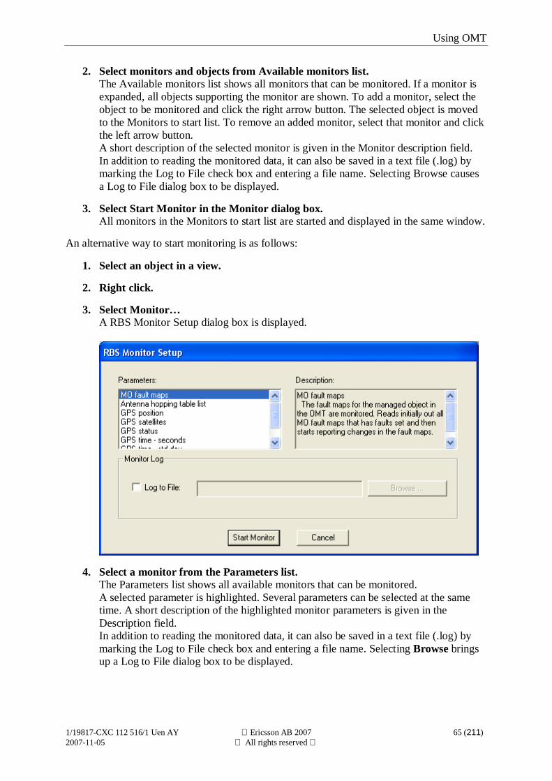
3. Select Monitor…A RBS Monitor Setup dialog box is displayed.
4. Select a monitor from the Parameters list.The Parameters list shows all available monitors that can be monitored.A selected parameter is highlighted. Several parameters can be selected at the sametime. A short description of the highlighted monitor parameters is given in theDescription field.In addition to reading the monitored data, it can also be saved in a text file (.log) bymarking the Log to File check box and entering a file name. Selecting Browse bringsup a Log to File dialog box to be displayed.
Using OMT
1/19817-CXC 112 516/1 Uen AY Ericsson AB 2007 66 (211)2007-11-05 All rights reserved
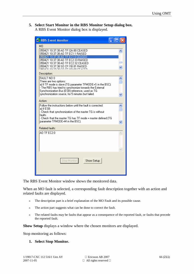
5. Select Start Monitor in the RBS Monitor Setup dialog box.A RBS Event Monitor dialog box is displayed.
The RBS Event Monitor window shows the monitored data.
When an MO fault is selected, a corresponding fault description together with an action andrelated faults are displayed.
n The description part is a brief explanation of the MO Fault and its possible cause.
n The action part suggests what can be done to correct the fault.
n The related faults may be faults that appear as a consequence of the reported fault, or faults that precedethe reported fault.
Show Setup displays a window where the chosen monitors are displayed.
Stop monitoring as follows:
1. Select Stop Monitor.
Using OMT
1/19817-CXC 112 516/1 Uen AY Ericsson AB 2007 67 (211)2007-11-05 All rights reserved
Monitoring also stops if the OMT and RBS are disconnected.
Using OMT
1/19817-CXC 112 516/1 Uen AY Ericsson AB 2007 68 (211)2007-11-05 All rights reserved
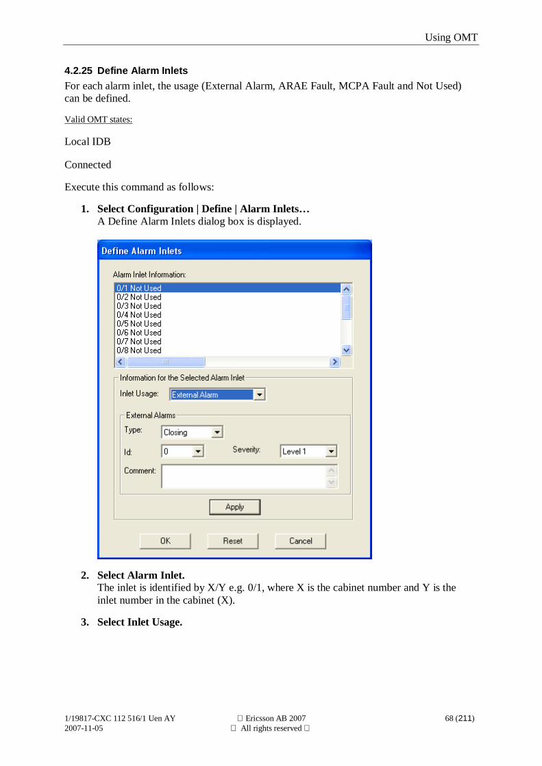
4.2.25 Define Alarm InletsFor each alarm inlet, the usage (External Alarm, ARAE Fault, MCPA Fault and Not Used)can be defined.
Valid OMT states:
Local IDB
Connected
Execute this command as follows:
1. Select Configuration | Define | Alarm Inlets…A Define Alarm Inlets dialog box is displayed.
2. Select Alarm Inlet.The inlet is identified by X/Y e.g. 0/1, where X is the cabinet number and Y is theinlet number in the cabinet (X).
3. Select Inlet Usage.
Using OMT
1/19817-CXC 112 516/1 Uen AY Ericsson AB 2007 69 (211)2007-11-05 All rights reserved
4. Insert new value or values.For each alarm inlet used for external alarms a unique ID, severity and contact closurefor alarm (closing/breaking) must be defined. An optional text comment can also bedefined.Valid characters are:A-Z 0-9 space ! # $ % & ' ( ) * + , - . / : ; < = > ? _.For each alarm inlet used for an ARAE fault, a fault class, functionality, contactclosure for alarm (closing/breaking) and antenna instance must be defined.For each alarm inlet used for MCPA fault, the MCPA TX Redundancy Switch(enabled/disabled) and the MCPA instance must be defined.
5. Confirm with Apply.
6. Repeat steps 3 to 5 until all desired Alarm Inlets are defined.
7. Confirm with OK.Selecting Reset reverts all changes to their original values.Cancel closes the dialog box without making any changes.
Using OMT
1/19817-CXC 112 516/1 Uen AY Ericsson AB 2007 70 (211)2007-11-05 All rights reserved
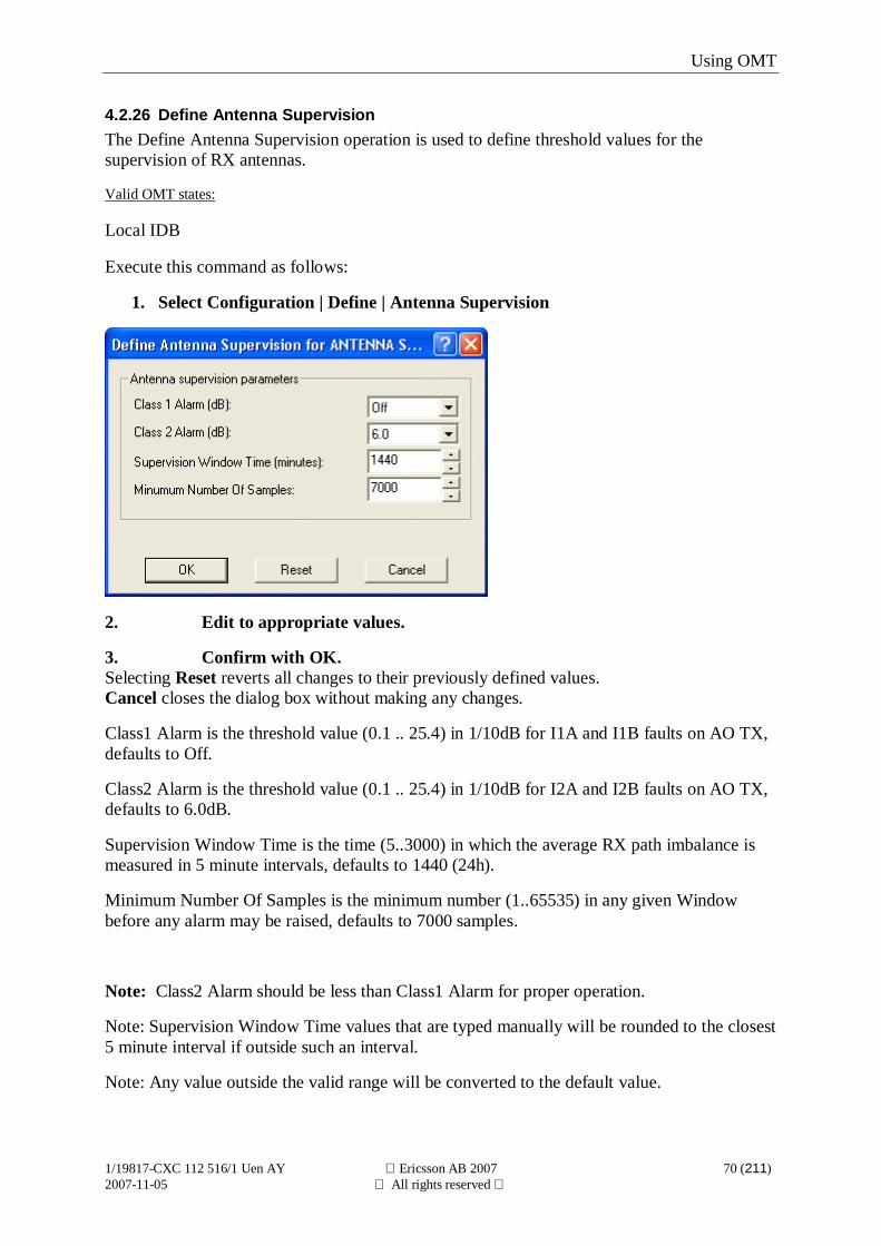
4.2.26 Define Antenna SupervisionThe Define Antenna Supervision operation is used to define threshold values for thesupervision of RX antennas.
Valid OMT states:
Local IDB
Execute this command as follows:
1. Select Configuration | Define | Antenna Supervision
2. Edit to appropriate values.
3. Confirm with OK.Selecting Reset reverts all changes to their previously defined values.Cancel closes the dialog box without making any changes.
Class1 Alarm is the threshold value (0.1 .. 25.4) in 1/10dB for I1A and I1B faults on AO TX,defaults to Off.
Class2 Alarm is the threshold value (0.1 .. 25.4) in 1/10dB for I2A and I2B faults on AO TX,defaults to 6.0dB.
Supervision Window Time is the time (5..3000) in which the average RX path imbalance ismeasured in 5 minute intervals, defaults to 1440 (24h).
Minimum Number Of Samples is the minimum number (1..65535) in any given Windowbefore any alarm may be raised, defaults to 7000 samples.
Note: Class2 Alarm should be less than Class1 Alarm for proper operation.
Note: Supervision Window Time values that are typed manually will be rounded to the closest5 minute interval if outside such an interval.
Note: Any value outside the valid range will be converted to the default value.
Using OMT
1/19817-CXC 112 516/1 Uen AY Ericsson AB 2007 71 (211)2007-11-05 All rights reserved
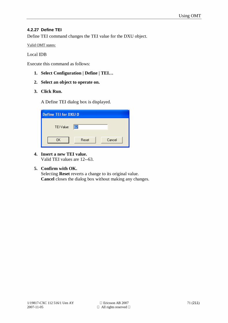
4.2.27 Define TEIDefine TEI command changes the TEI value for the DXU object.
Valid OMT states:
Local IDB
Execute this command as follows:
1. Select Configuration | Define | TEI…
2. Select an object to operate on.
3. Click Run.
A Define TEI dialog box is displayed.
4. Insert a new TEI value.Valid TEI values are 12--63.
5. Confirm with OK.Selecting Reset reverts a change to its original value.Cancel closes the dialog box without making any changes.
Using OMT
1/19817-CXC 112 516/1 Uen AY Ericsson AB 2007 72 (211)2007-11-05 All rights reserved
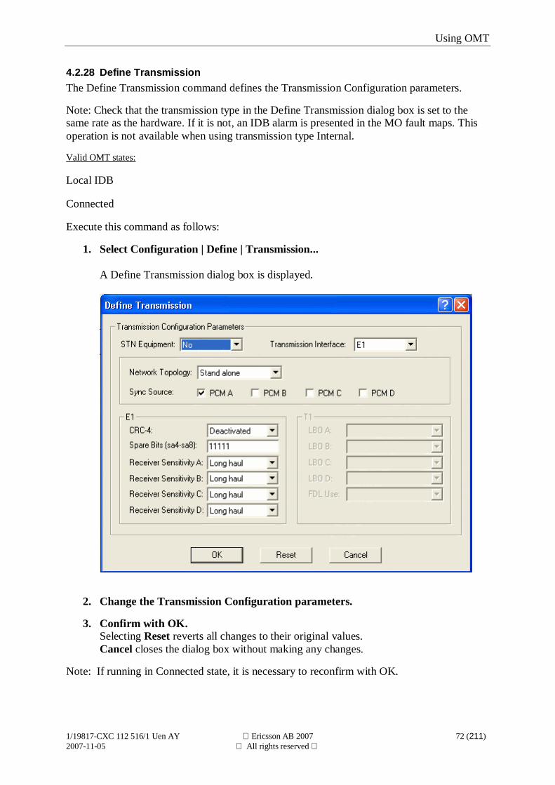
4.2.28 Define TransmissionThe Define Transmission command defines the Transmission Configuration parameters.
Note: Check that the transmission type in the Define Transmission dialog box is set to thesame rate as the hardware. If it is not, an IDB alarm is presented in the MO fault maps. Thisoperation is not available when using transmission type Internal.
Valid OMT states:
Local IDB
Connected
Execute this command as follows:
1. Select Configuration | Define | Transmission...
A Define Transmission dialog box is displayed.
2. Change the Transmission Configuration parameters.
3. Confirm with OK.Selecting Reset reverts all changes to their original values.Cancel closes the dialog box without making any changes.
Note: If running in Connected state, it is necessary to reconfirm with OK.
Using OMT
1/19817-CXC 112 516/1 Uen AY Ericsson AB 2007 73 (211)2007-11-05 All rights reserved
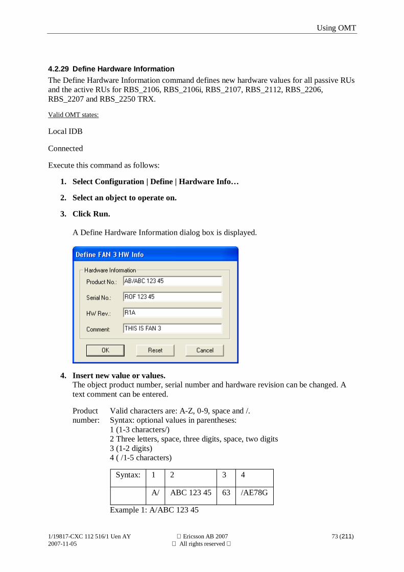
4.2.29 Define Hardware InformationThe Define Hardware Information command defines new hardware values for all passive RUsand the active RUs for RBS_2106, RBS_2106i, RBS_2107, RBS_2112, RBS_2206,RBS_2207 and RBS_2250 TRX.
Valid OMT states:
Local IDB
Connected
Execute this command as follows:
1. Select Configuration | Define | Hardware Info…
2. Select an object to operate on.
3. Click Run.
A Define Hardware Information dialog box is displayed.
4. Insert new value or values.The object product number, serial number and hardware revision can be changed. Atext comment can be entered.
Productnumber:
Valid characters are: A-Z, 0-9, space and /.Syntax: optional values in parentheses:1 (1-3 characters/)2 Three letters, space, three digits, space, two digits3 (1-2 digits)4 ( /1-5 characters)
Syntax: 1 2 3 4
A/ ABC 123 45 63 /AE78G
Example 1: A/ABC 123 45
Using OMT
1/19817-CXC 112 516/1 Uen AY Ericsson AB 2007 74 (211)2007-11-05 All rights reserved
Example 2: A/ABC 123 45/AE89G
Serialnumber:
Valid characters are: space ! # $ % & ' ( ) * + , - . / 0-9: ; < = > ? A-Z _
Hardwarerevsion:
Valid characters are: A-Z, 0-9, space and /.Syntax: optional values in parentheses:1 Letter, 1-3 characters2 (/character | /two digits)
Syntax: 1 2
C2E6 9
Example: C2E6
Textcomment:
Valid characters are:space ! # $ % & ' ( ) * + , - . / 0-9: ; < = > ? A-Z _
5. Confirm with OK.Selecting Reset reverts all changes to their original values.Cancel closes the dialog box without making any changes.
Using OMT
1/19817-CXC 112 516/1 Uen AY Ericsson AB 2007 75 (211)2007-11-05 All rights reserved
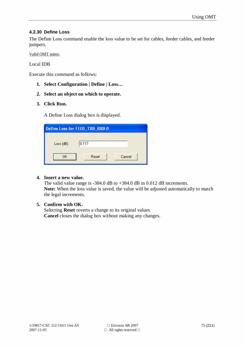
4.2.30 Define LossThe Define Loss command enable the loss value to be set for cables, feeder cables, and feederjumpers.
Valid OMT states:
Local IDB
Execute this command as follows:
1. Select Configuration | Define | Loss…
2. Select an object on which to operate.
3. Click Run.
A Define Loss dialog box is displayed.
4. Insert a new value.The valid value range is -384.0 dB to +384.0 dB in 0.012 dB increments.Note: When the loss value is saved, the value will be adjusted automatically to matchthe legal increments.
5. Confirm with OK.Selecting Reset reverts a change to its original values.Cancel closes the dialog box without making any changes.
Using OMT
1/19817-CXC 112 516/1 Uen AY Ericsson AB 2007 76 (211)2007-11-05 All rights reserved
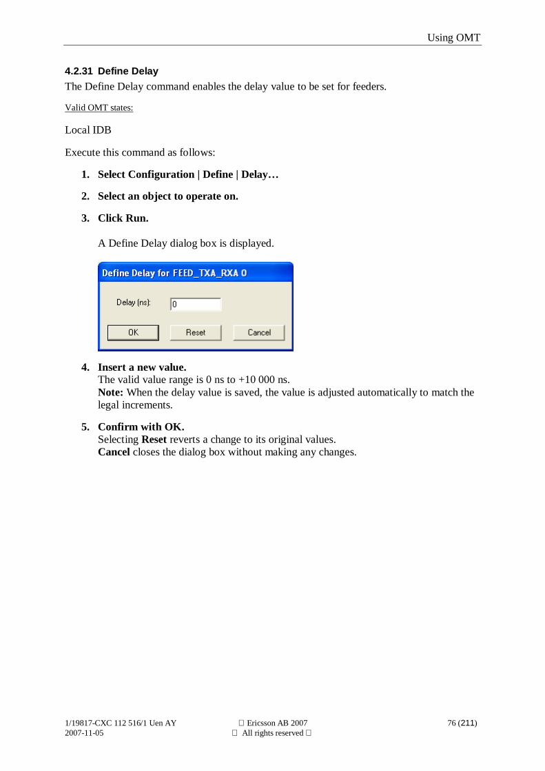
4.2.31 Define DelayThe Define Delay command enables the delay value to be set for feeders.
Valid OMT states:
Local IDB
Execute this command as follows:
1. Select Configuration | Define | Delay…
2. Select an object to operate on.
3. Click Run.
A Define Delay dialog box is displayed.
4. Insert a new value.The valid value range is 0 ns to +10 000 ns.Note: When the delay value is saved, the value is adjusted automatically to match thelegal increments.
5. Confirm with OK.Selecting Reset reverts a change to its original values.Cancel closes the dialog box without making any changes.
Using OMT
1/19817-CXC 112 516/1 Uen AY Ericsson AB 2007 77 (211)2007-11-05 All rights reserved
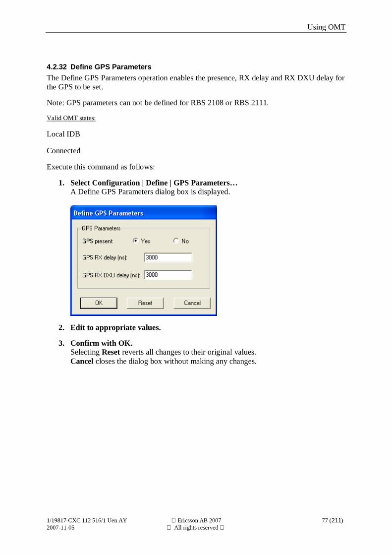
4.2.32 Define GPS ParametersThe Define GPS Parameters operation enables the presence, RX delay and RX DXU delay forthe GPS to be set.
Note: GPS parameters can not be defined for RBS 2108 or RBS 2111.
Valid OMT states:
Local IDB
Connected
Execute this command as follows:
1. Select Configuration | Define | GPS Parameters…A Define GPS Parameters dialog box is displayed.
2. Edit to appropriate values.
3. Confirm with OK.Selecting Reset reverts all changes to their original values.Cancel closes the dialog box without making any changes.
Using OMT
1/19817-CXC 112 516/1 Uen AY Ericsson AB 2007 78 (211)2007-11-05 All rights reserved
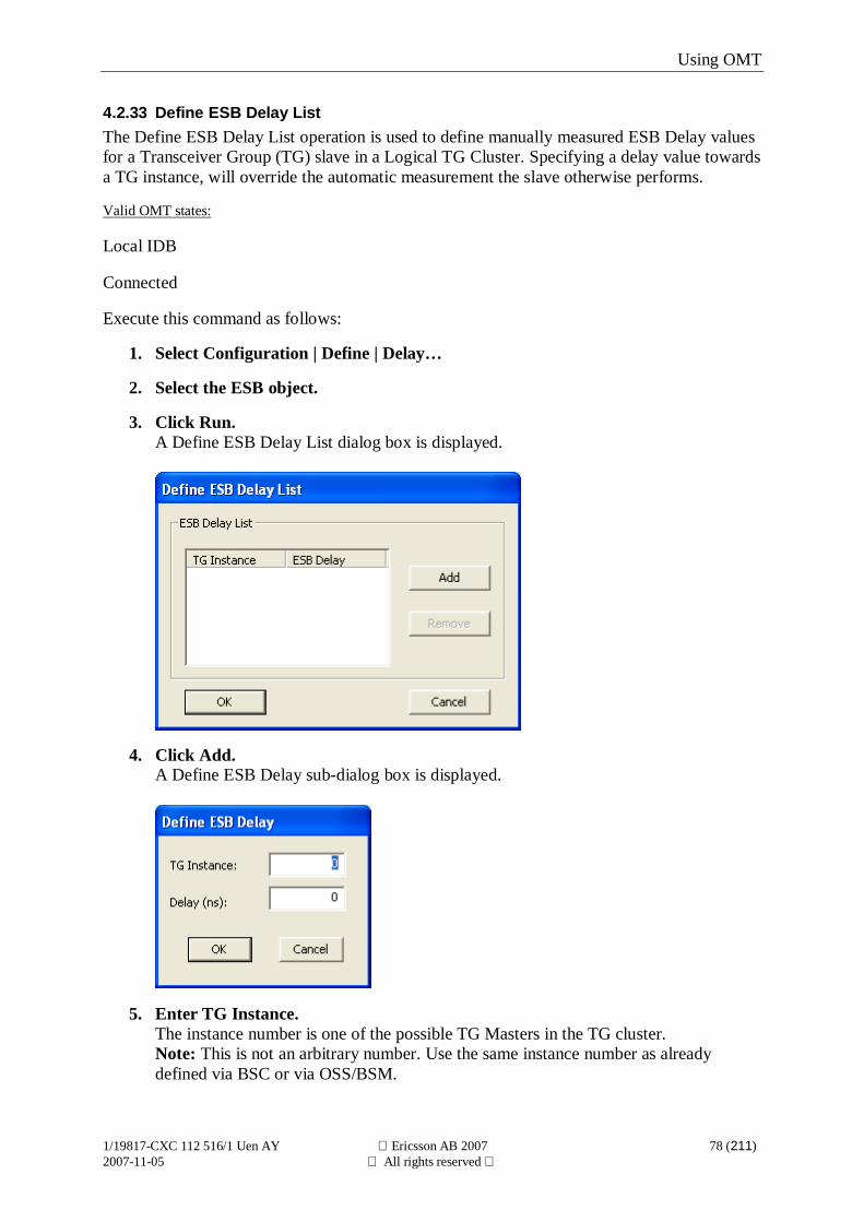
4.2.33 Define ESB Delay ListThe Define ESB Delay List operation is used to define manually measured ESB Delay valuesfor a Transceiver Group (TG) slave in a Logical TG Cluster. Specifying a delay value towardsa TG instance, will override the automatic measurement the slave otherwise performs.
Valid OMT states:
Local IDB
Connected
Execute this command as follows:
1. Select Configuration | Define | Delay…
2. Select the ESB object.
3. Click Run.A Define ESB Delay List dialog box is displayed.
4. Click Add.A Define ESB Delay sub-dialog box is displayed.
5. Enter TG Instance.The instance number is one of the possible TG Masters in the TG cluster.Note: This is not an arbitrary number. Use the same instance number as alreadydefined via BSC or via OSS/BSM.
Using OMT
1/19817-CXC 112 516/1 Uen AY Ericsson AB 2007 79 (211)2007-11-05 All rights reserved
6. Enter ESB Delay.Enter the ESB delay value towards the TG defined in previous step.
7. Confirm with OK.Selecting OK closes the Define ESB Delay sub-dialog box and returns focus to theESB Delay List dialog.Selecting Cancel will close the sub-dialog box without adding a ESB Delay value.
Confirm with OK in the Define ESB Delay List dialog.Selecting OK will set the configured values.Selecting Cancel will close the dialog box without making any changes.
To add more ESB Delay values for other possible TG Masters, click Add and repeat steps 5to 7.To remove a previously defined ESB Delay value, select the ESB Delay value in the list andclick Remove.
Using OMT
1/19817-CXC 112 516/1 Uen AY Ericsson AB 2007 80 (211)2007-11-05 All rights reserved
4.2.34 Define TF CompensationThis function is used to calculate and set a value for TF Compensation. It is only applicablefor a TG configured as a slave in a Notional TG Cluster.
Note: Setting TF Compensation value is not applicable for DXU-01, DXU-03, RBS 2108,RBS 2111 or any Micro Cabinet since they do not support TG Synchronisation.
Before setting TF Compensation, information is required from the master TG.
If the master TG is an RBS 2000, the required information is the Transmitter Chain Delay.Use the OMT at the master TG to retrieve this information. The Transmitter Chain Delayinformation can be found by executing the Display Information operation on the RBS object.See section Display Information.
If the master TG is an RBS 200/RBS 205, the required information is Combiner type, usageof TMA and Feeder Delay.
In addition, delays for all feeder objects must be defined in order to get a correctrecommended TF Compensation value. This is applicable for all types of master TG’s. Todefine delay use the Define Delay operation. See section Define Delay.
Valid OMT states:
Local IDB
Execute this command as follows:
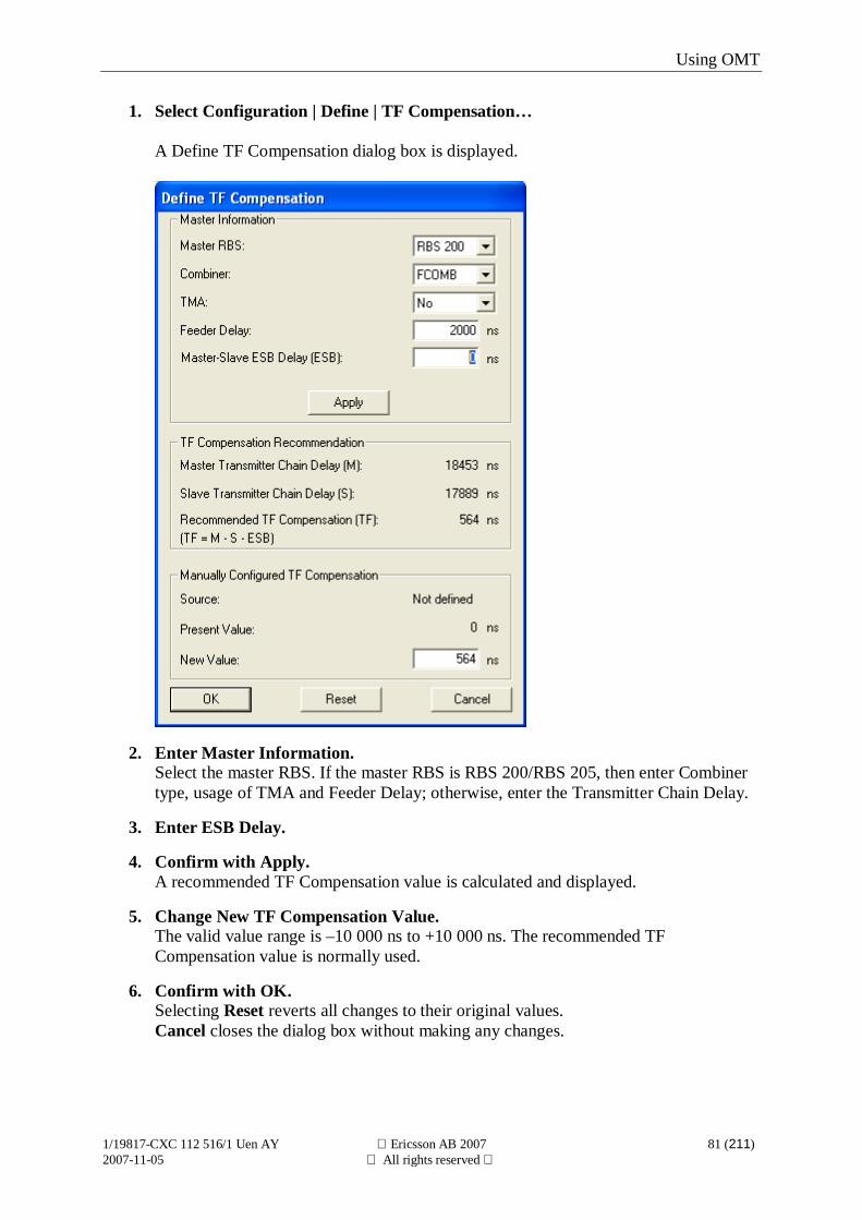
Using OMT
1/19817-CXC 112 516/1 Uen AY Ericsson AB 2007 81 (211)2007-11-05 All rights reserved
1. Select Configuration | Define | TF Compensation…
A Define TF Compensation dialog box is displayed.
2. Enter Master Information.Select the master RBS. If the master RBS is RBS 200/RBS 205, then enter Combinertype, usage of TMA and Feeder Delay; otherwise, enter the Transmitter Chain Delay.
3. Enter ESB Delay.
4. Confirm with Apply.A recommended TF Compensation value is calculated and displayed.
5. Change New TF Compensation Value.The valid value range is –10 000 ns to +10 000 ns. The recommended TFCompensation value is normally used.
6. Confirm with OK.Selecting Reset reverts all changes to their original values.Cancel closes the dialog box without making any changes.
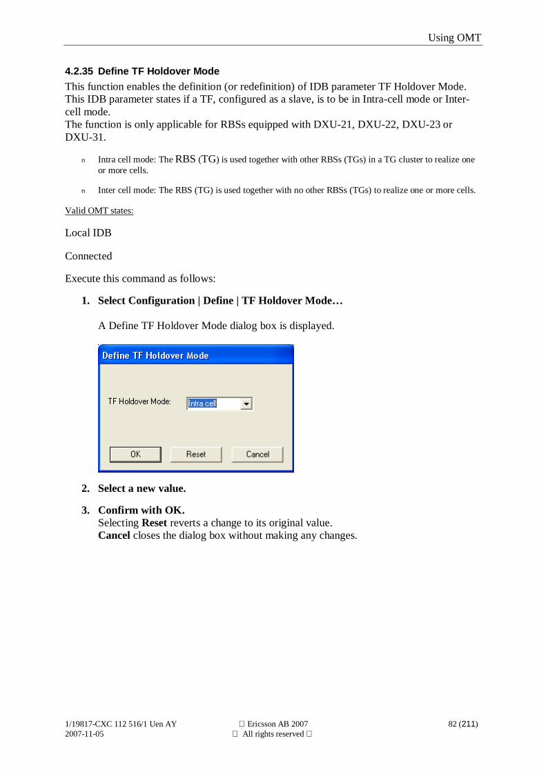
Using OMT
1/19817-CXC 112 516/1 Uen AY Ericsson AB 2007 82 (211)2007-11-05 All rights reserved
4.2.35 Define TF Holdover ModeThis function enables the definition (or redefinition) of IDB parameter TF Holdover Mode.This IDB parameter states if a TF, configured as a slave, is to be in Intra-cell mode or Inter-cell mode.The function is only applicable for RBSs equipped with DXU-21, DXU-22, DXU-23 orDXU-31.
n Intra cell mode: The RBS (TG) is used together with other RBSs (TGs) in a TG cluster to realize oneor more cells.
n Inter cell mode: The RBS (TG) is used together with no other RBSs (TGs) to realize one or more cells.
Valid OMT states:
Local IDB
Connected
Execute this command as follows:
1. Select Configuration | Define | TF Holdover Mode…
A Define TF Holdover Mode dialog box is displayed.
2. Select a new value.
3. Confirm with OK.Selecting Reset reverts a change to its original value.Cancel closes the dialog box without making any changes.
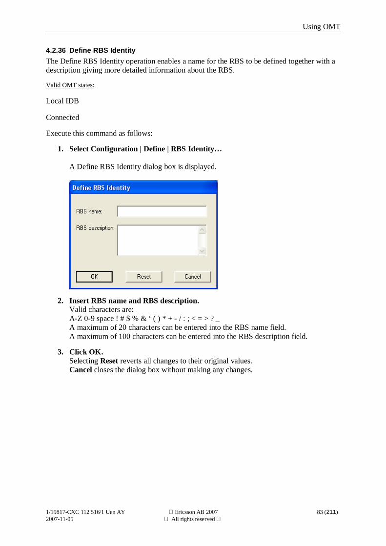
Using OMT
1/19817-CXC 112 516/1 Uen AY Ericsson AB 2007 83 (211)2007-11-05 All rights reserved
4.2.36 Define RBS IdentityThe Define RBS Identity operation enables a name for the RBS to be defined together with adescription giving more detailed information about the RBS.
Valid OMT states:
Local IDB
Connected
Execute this command as follows:
1. Select Configuration | Define | RBS Identity…
A Define RBS Identity dialog box is displayed.
2. Insert RBS name and RBS description.Valid characters are:A-Z 0-9 space ! # $ % & ‘ ( ) * + - / : ; < = > ? _A maximum of 20 characters can be entered into the RBS name field.A maximum of 100 characters can be entered into the RBS description field.
3. Click OK.Selecting Reset reverts all changes to their original values.Cancel closes the dialog box without making any changes.
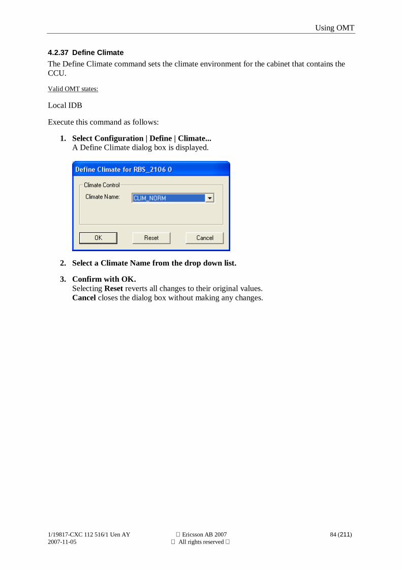
Using OMT
1/19817-CXC 112 516/1 Uen AY Ericsson AB 2007 84 (211)2007-11-05 All rights reserved
4.2.37 Define ClimateThe Define Climate command sets the climate environment for the cabinet that contains theCCU.
Valid OMT states:
Local IDB
Execute this command as follows:
1. Select Configuration | Define | Climate...A Define Climate dialog box is displayed.
2. Select a Climate Name from the drop down list.
3. Confirm with OK.Selecting Reset reverts all changes to their original values.Cancel closes the dialog box without making any changes.
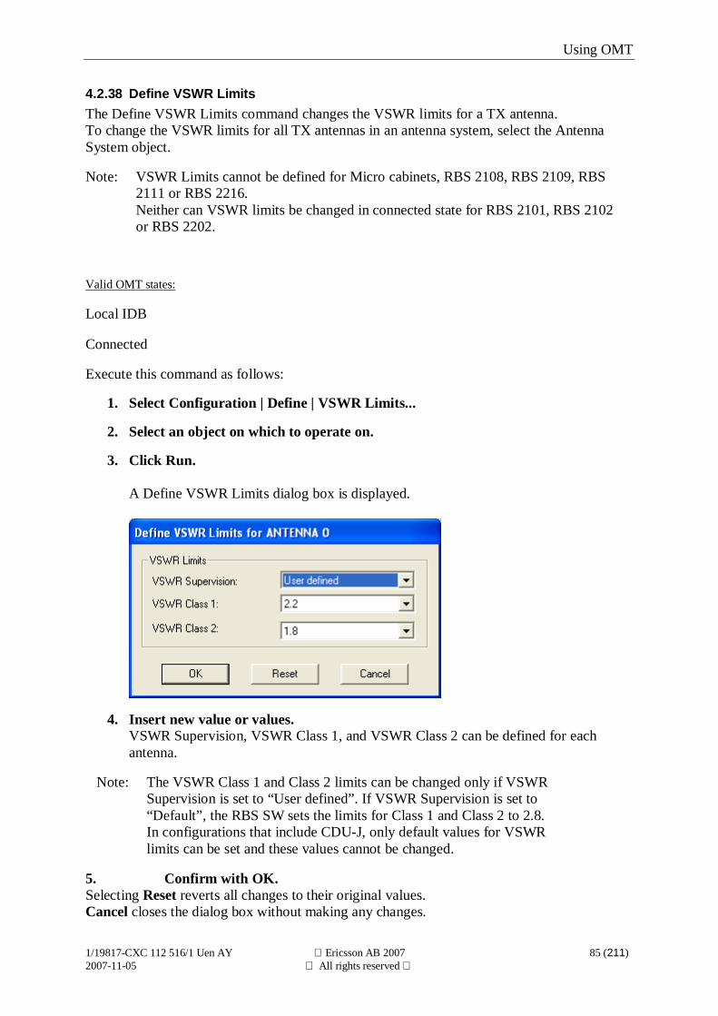
Using OMT
1/19817-CXC 112 516/1 Uen AY Ericsson AB 2007 85 (211)2007-11-05 All rights reserved
4.2.38 Define VSWR LimitsThe Define VSWR Limits command changes the VSWR limits for a TX antenna.To change the VSWR limits for all TX antennas in an antenna system, select the AntennaSystem object.
Note: VSWR Limits cannot be defined for Micro cabinets, RBS 2108, RBS 2109, RBS2111 or RBS 2216.Neither can VSWR limits be changed in connected state for RBS 2101, RBS 2102or RBS 2202.
Valid OMT states:
Local IDB
Connected
Execute this command as follows:
1. Select Configuration | Define | VSWR Limits...
2. Select an object on which to operate on.
3. Click Run.
A Define VSWR Limits dialog box is displayed.
4. Insert new value or values.VSWR Supervision, VSWR Class 1, and VSWR Class 2 can be defined for eachantenna.
Note: The VSWR Class 1 and Class 2 limits can be changed only if VSWRSupervision is set to “User defined”. If VSWR Supervision is set to“Default”, the RBS SW sets the limits for Class 1 and Class 2 to 2.8.In configurations that include CDU-J, only default values for VSWRlimits can be set and these values cannot be changed.
5. Confirm with OK.Selecting Reset reverts all changes to their original values.Cancel closes the dialog box without making any changes.
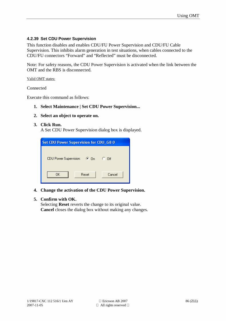
Using OMT
1/19817-CXC 112 516/1 Uen AY Ericsson AB 2007 86 (211)2007-11-05 All rights reserved
4.2.39 Set CDU Power SupervisionThis function disables and enables CDU/FU Power Supervision and CDU/FU CableSupervision. This inhibits alarm generation in test situations, when cables connected to theCDU/FU connectors “Forward” and “Reflected” must be disconnected.
Note: For safety reasons, the CDU Power Supervision is activated when the link between theOMT and the RBS is disconnected.
Valid OMT states:
Connected
Execute this command as follows:
1. Select Maintenance | Set CDU Power Supervision...
2. Select an object to operate on.
3. Click Run.A Set CDU Power Supervision dialog box is displayed.
4. Change the activation of the CDU Power Supervision.
5. Confirm with OK.Selecting Reset reverts the change to its original value.Cancel closes the dialog box without making any changes.
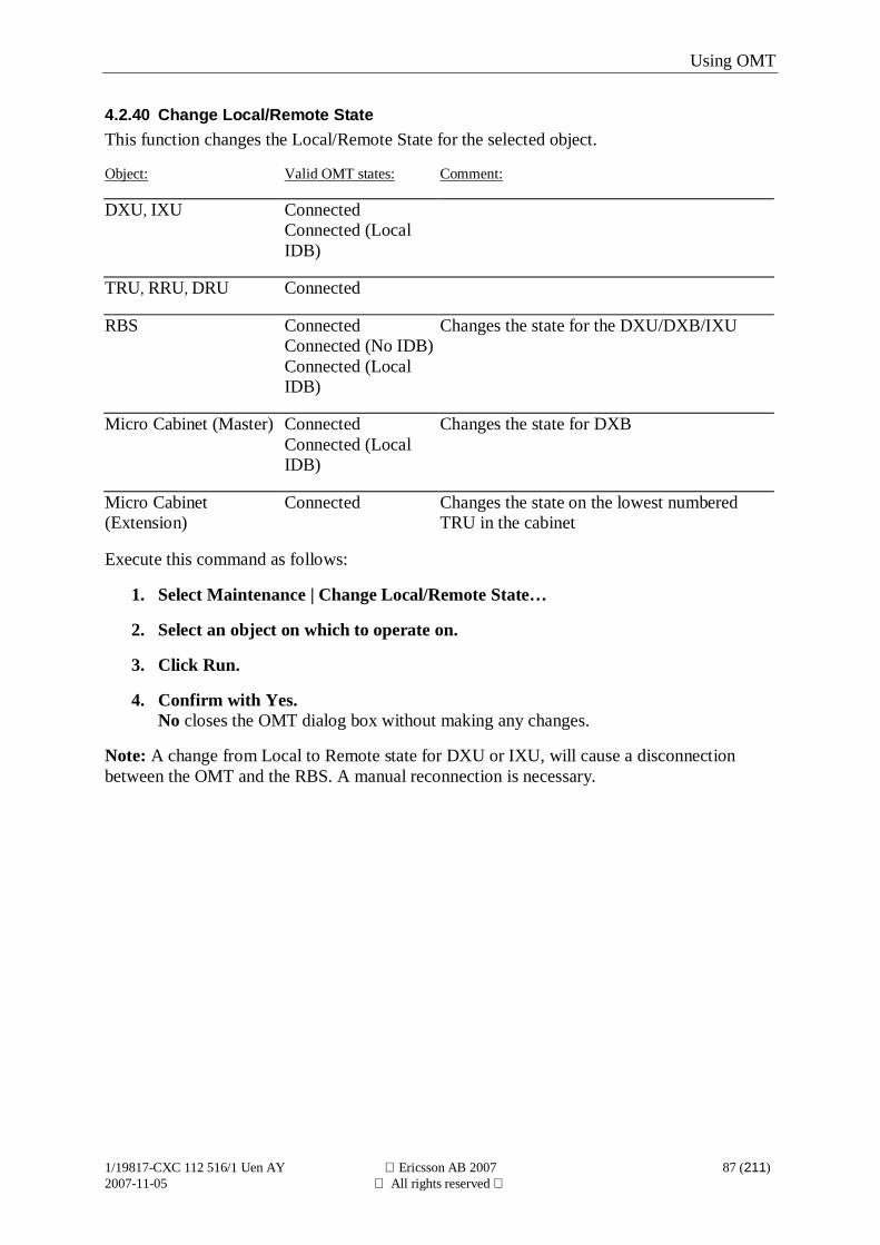
Using OMT
1/19817-CXC 112 516/1 Uen AY Ericsson AB 2007 87 (211)2007-11-05 All rights reserved
4.2.40 Change Local/Remote StateThis function changes the Local/Remote State for the selected object.
Object: Valid OMT states: Comment:
DXU, IXU ConnectedConnected (LocalIDB)
TRU, RRU, DRU Connected
RBS ConnectedConnected (No IDB)Connected (LocalIDB)
Changes the state for the DXU/DXB/IXU
Micro Cabinet (Master) ConnectedConnected (LocalIDB)
Changes the state for DXB
Micro Cabinet(Extension)
Connected Changes the state on the lowest numberedTRU in the cabinet
Execute this command as follows:
1. Select Maintenance | Change Local/Remote State…
2. Select an object on which to operate on.
3. Click Run.
4. Confirm with Yes.No closes the OMT dialog box without making any changes.
Note: A change from Local to Remote state for DXU or IXU, will cause a disconnectionbetween the OMT and the RBS. A manual reconnection is necessary.
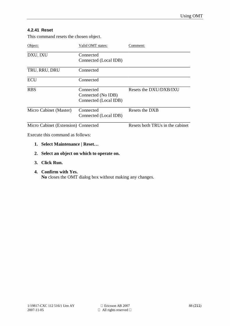
Using OMT
1/19817-CXC 112 516/1 Uen AY Ericsson AB 2007 88 (211)2007-11-05 All rights reserved
4.2.41 ResetThis command resets the chosen object.
Object: Valid OMT states: Comment:
DXU, IXU ConnectedConnected (Local IDB)
TRU, RRU, DRU Connected
ECU Connected
RBS ConnectedConnected (No IDB)Connected (Local IDB)
Resets the DXU/DXB/IXU
Micro Cabinet (Master) ConnectedConnected (Local IDB)
Resets the DXB
Micro Cabinet (Extension) Connected Resets both TRUs in the cabinet
Execute this command as follows:
1. Select Maintenance | Reset…
2. Select an object on which to operate on.
3. Click Run.
4. Confirm with Yes.No closes the OMT dialog box without making any changes.
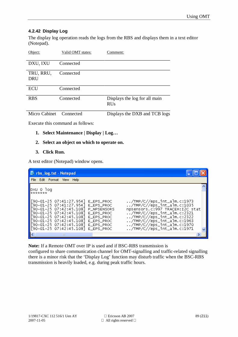
Using OMT
1/19817-CXC 112 516/1 Uen AY Ericsson AB 2007 89 (211)2007-11-05 All rights reserved
4.2.42 Display LogThe display log operation reads the logs from the RBS and displays them in a text editor(Notepad).
Object: Valid OMT states: Comment:
DXU, IXU Connected
TRU, RRU,DRU
Connected
ECU Connected
RBS Connected Displays the log for all mainRUs
Micro Cabinet Connected Displays the DXB and TCB logs
Execute this command as follows:
1. Select Maintenance | Display | Log…
2. Select an object on which to operate on.
3. Click Run.
A text editor (Notepad) window opens.
Note: If a Remote OMT over IP is used and if BSC-RBS transmission isconfigured to share communication channel for OMT-signalling and traffic-related signallingthere is a minor risk that the ‘Display Log’ function may disturb traffic when the BSC-RBStransmission is heavily loaded, e.g. during peak traffic hours.
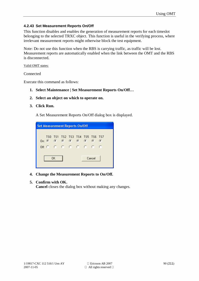
Using OMT
1/19817-CXC 112 516/1 Uen AY Ericsson AB 2007 90 (211)2007-11-05 All rights reserved
4.2.43 Set Measurement Reports On/OffThis function disables and enables the generation of measurement reports for each timeslotbelonging to the selected TRXC object. This function is useful in the verifying process, whereirrelevant measurement reports might otherwise block the test equipment.
Note: Do not use this function when the RBS is carrying traffic, as traffic will be lost.Measurement reports are automatically enabled when the link between the OMT and the RBSis disconnected.
Valid OMT states:
Connected
Execute this command as follows:
1. Select Maintenance | Set Measurement Reports On/Off…
2. Select an object on which to operate on.
3. Click Run.
A Set Measurement Reports On/Off dialog box is displayed.
4. Change the Measurement Reports to On/Off.
5. Confirm with OK.Cancel closes the dialog box without making any changes.
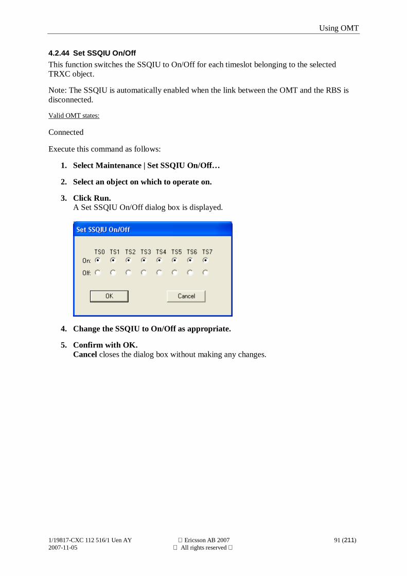
Using OMT
1/19817-CXC 112 516/1 Uen AY Ericsson AB 2007 91 (211)2007-11-05 All rights reserved
4.2.44 Set SSQIU On/OffThis function switches the SSQIU to On/Off for each timeslot belonging to the selectedTRXC object.
Note: The SSQIU is automatically enabled when the link between the OMT and the RBS isdisconnected.
Valid OMT states:
Connected
Execute this command as follows:
1. Select Maintenance | Set SSQIU On/Off…
2. Select an object on which to operate on.
3. Click Run.A Set SSQIU On/Off dialog box is displayed.
4. Change the SSQIU to On/Off as appropriate.
5. Confirm with OK.Cancel closes the dialog box without making any changes.
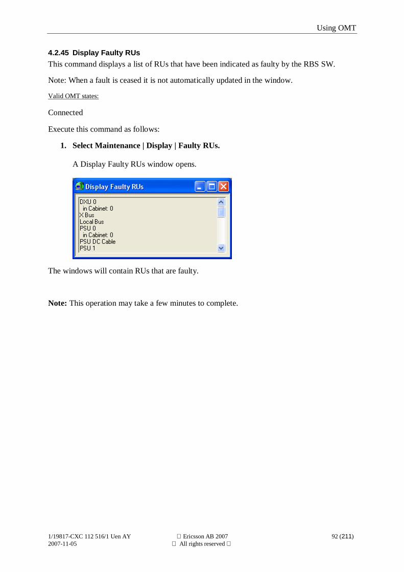
Using OMT
1/19817-CXC 112 516/1 Uen AY Ericsson AB 2007 92 (211)2007-11-05 All rights reserved
4.2.45 Display Faulty RUsThis command displays a list of RUs that have been indicated as faulty by the RBS SW.
Note: When a fault is ceased it is not automatically updated in the window.
Valid OMT states:
Connected
Execute this command as follows:
1. Select Maintenance | Display | Faulty RUs.
A Display Faulty RUs window opens.
The windows will contain RUs that are faulty.
Note: This operation may take a few minutes to complete.
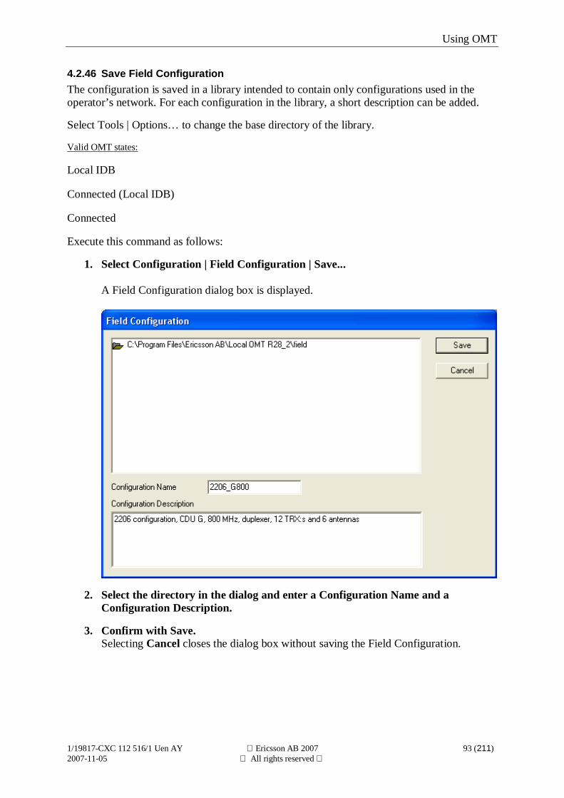
Using OMT
1/19817-CXC 112 516/1 Uen AY Ericsson AB 2007 93 (211)2007-11-05 All rights reserved
4.2.46 Save Field ConfigurationThe configuration is saved in a library intended to contain only configurations used in theoperator’s network. For each configuration in the library, a short description can be added.
Select Tools | Options… to change the base directory of the library.
Valid OMT states:
Local IDB
Connected (Local IDB)
Connected
Execute this command as follows:
1. Select Configuration | Field Configuration | Save...
A Field Configuration dialog box is displayed.
2. Select the directory in the dialog and enter a Configuration Name and aConfiguration Description.
3. Confirm with Save.Selecting Cancel closes the dialog box without saving the Field Configuration.
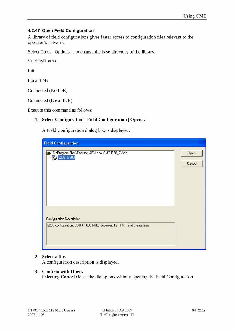
Using OMT
1/19817-CXC 112 516/1 Uen AY Ericsson AB 2007 94 (211)2007-11-05 All rights reserved
4.2.47 Open Field ConfigurationA library of field configurations gives faster access to configuration files relevant to theoperator’s network.
Select Tools | Options… to change the base directory of the library.
Valid OMT states:
Init
Local IDB
Connected (No IDB)
Connected (Local IDB)
Execute this command as follows:
1. Select Configuration | Field Configuration | Open...
A Field Configuration dialog box is displayed.
2. Select a file.A configuration description is displayed.
3. Confirm with Open.Selecting Cancel closes the dialog box without opening the Field Configuration.
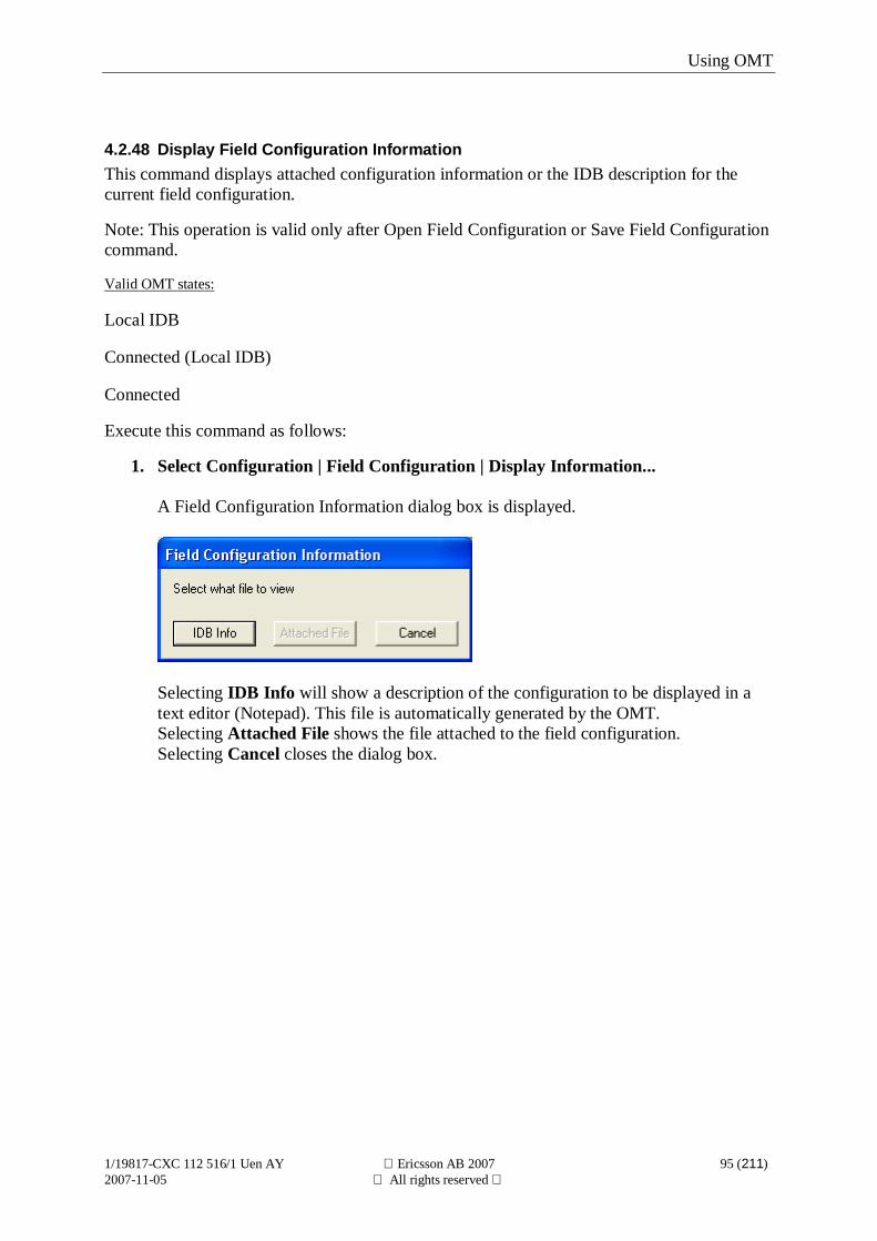
Using OMT
1/19817-CXC 112 516/1 Uen AY Ericsson AB 2007 95 (211)2007-11-05 All rights reserved
4.2.48 Display Field Configuration InformationThis command displays attached configuration information or the IDB description for thecurrent field configuration.
Note: This operation is valid only after Open Field Configuration or Save Field Configurationcommand.
Valid OMT states:
Local IDB
Connected (Local IDB)
Connected
Execute this command as follows:
1. Select Configuration | Field Configuration | Display Information...
A Field Configuration Information dialog box is displayed.
Selecting IDB Info will show a description of the configuration to be displayed in atext editor (Notepad). This file is automatically generated by the OMT.Selecting Attached File shows the file attached to the field configuration.Selecting Cancel closes the dialog box.
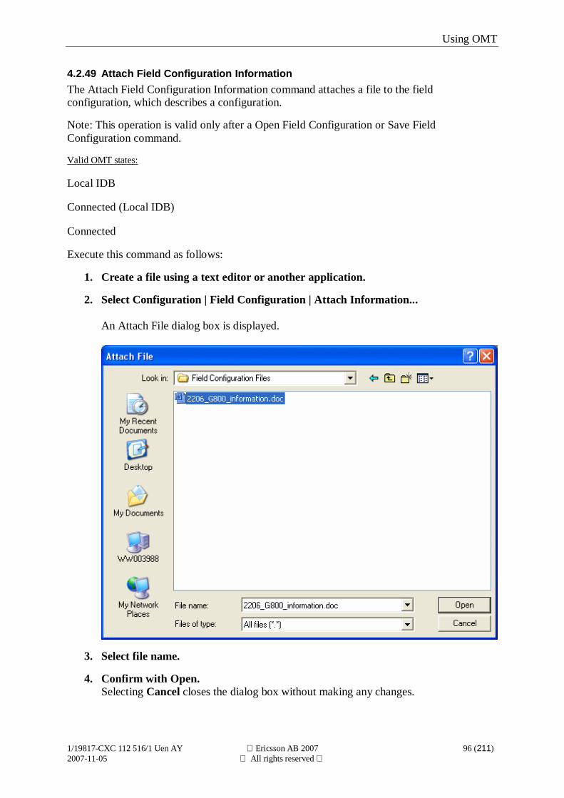
Using OMT
1/19817-CXC 112 516/1 Uen AY Ericsson AB 2007 96 (211)2007-11-05 All rights reserved
4.2.49 Attach Field Configuration InformationThe Attach Field Configuration Information command attaches a file to the fieldconfiguration, which describes a configuration.
Note: This operation is valid only after a Open Field Configuration or Save FieldConfiguration command.
Valid OMT states:
Local IDB
Connected (Local IDB)
Connected
Execute this command as follows:
1. Create a file using a text editor or another application.
2. Select Configuration | Field Configuration | Attach Information...
An Attach File dialog box is displayed.
3. Select file name.
4. Confirm with Open.Selecting Cancel closes the dialog box without making any changes.
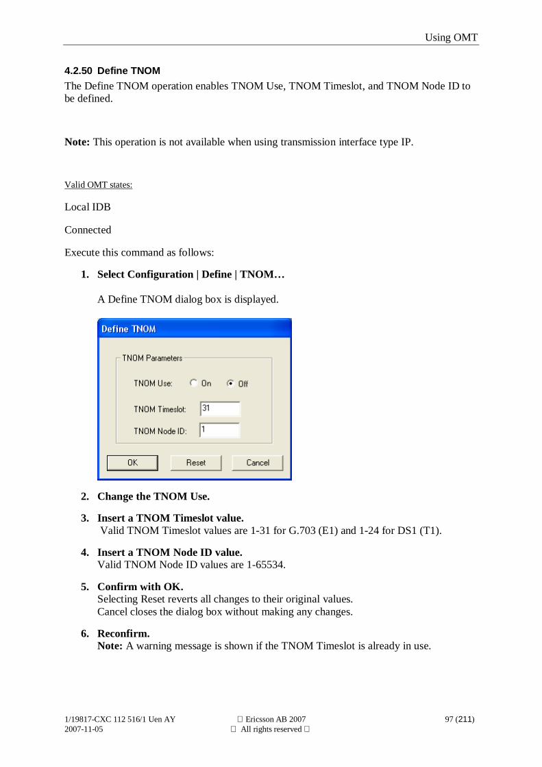
Using OMT
1/19817-CXC 112 516/1 Uen AY Ericsson AB 2007 97 (211)2007-11-05 All rights reserved
4.2.50 Define TNOMThe Define TNOM operation enables TNOM Use, TNOM Timeslot, and TNOM Node ID tobe defined.
Note: This operation is not available when using transmission interface type IP.
Valid OMT states:
Local IDB
Connected
Execute this command as follows:
1. Select Configuration | Define | TNOM…
A Define TNOM dialog box is displayed.
2. Change the TNOM Use.
3. Insert a TNOM Timeslot value. Valid TNOM Timeslot values are 1-31 for G.703 (E1) and 1-24 for DS1 (T1).
4. Insert a TNOM Node ID value.Valid TNOM Node ID values are 1-65534.
5. Confirm with OK.Selecting Reset reverts all changes to their original values.Cancel closes the dialog box without making any changes.
6. Reconfirm.Note: A warning message is shown if the TNOM Timeslot is already in use.
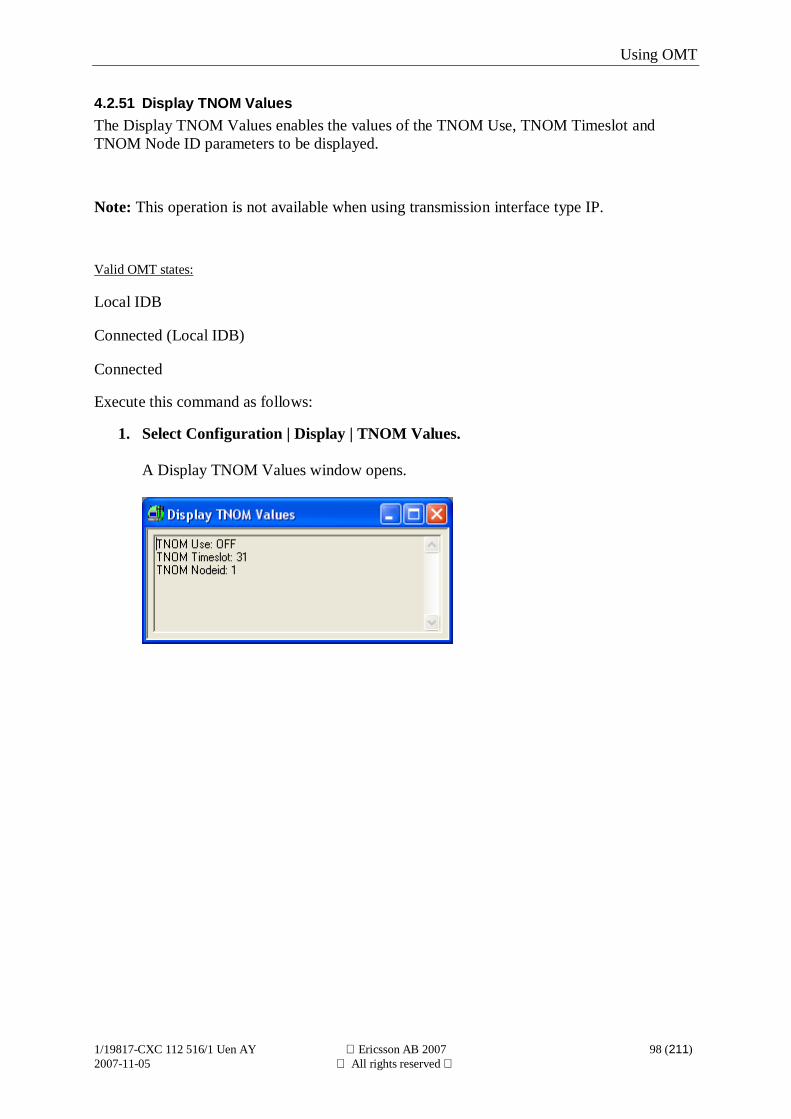
Using OMT
1/19817-CXC 112 516/1 Uen AY Ericsson AB 2007 98 (211)2007-11-05 All rights reserved
4.2.51 Display TNOM ValuesThe Display TNOM Values enables the values of the TNOM Use, TNOM Timeslot andTNOM Node ID parameters to be displayed.
Note: This operation is not available when using transmission interface type IP.
Valid OMT states:
Local IDB
Connected (Local IDB)
Connected
Execute this command as follows:
1. Select Configuration | Display | TNOM Values.
A Display TNOM Values window opens.
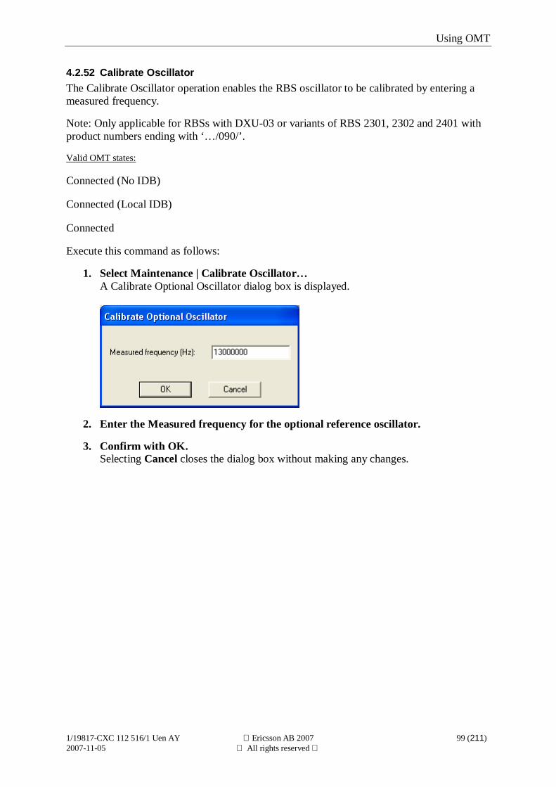
Using OMT
1/19817-CXC 112 516/1 Uen AY Ericsson AB 2007 99 (211)2007-11-05 All rights reserved
4.2.52 Calibrate OscillatorThe Calibrate Oscillator operation enables the RBS oscillator to be calibrated by entering ameasured frequency.
Note: Only applicable for RBSs with DXU-03 or variants of RBS 2301, 2302 and 2401 withproduct numbers ending with ‘…/090/’.
Valid OMT states:
Connected (No IDB)
Connected (Local IDB)
Connected
Execute this command as follows:
1. Select Maintenance | Calibrate Oscillator…A Calibrate Optional Oscillator dialog box is displayed.
2. Enter the Measured frequency for the optional reference oscillator.
3. Confirm with OK.Selecting Cancel closes the dialog box without making any changes.
Using OMT
1/19817-CXC 112 516/1 Uen AY Ericsson AB 2007 100 (211)2007-11-05 All rights reserved
4.2.53 Define ALNA/TMAThe Define ALNA/TMA operation enables ALNA/TMA parameters to be defined.
Note: ALNA/TMA can not be defined for RBS 2108 or RBS 2111.
Note: TMA type is not valid for RBS 2109 or RBS 2250.
The loss parameter specifies the loss of the TMA. Since a TMA actually has a gain instead ofa loss, the TMA gain is specified as a negative loss.
Valid OMT states: ALNA/TMA parameters:
Local IDB TMA TypeCurrent Supervision LimitsTX Group DelayRX Group DelayLossRX Frequency Range
Connected TMA TypeCurrent Supervision Limits
Execute this command as follows:
1. Select Configuration | Define | ALNA/TMA…
2. Select an object on which to operate.
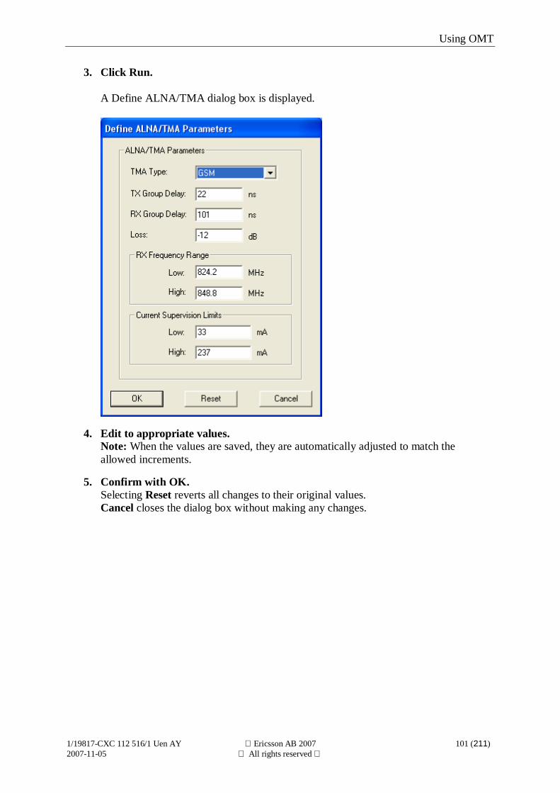
Using OMT
1/19817-CXC 112 516/1 Uen AY Ericsson AB 2007 101 (211)2007-11-05 All rights reserved
3. Click Run.
A Define ALNA/TMA dialog box is displayed.
4. Edit to appropriate values.Note: When the values are saved, they are automatically adjusted to match theallowed increments.
5. Confirm with OK.Selecting Reset reverts all changes to their original values.Cancel closes the dialog box without making any changes.
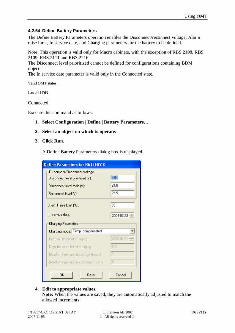
Using OMT
1/19817-CXC 112 516/1 Uen AY Ericsson AB 2007 102 (211)2007-11-05 All rights reserved
4.2.54 Define Battery ParametersThe Define Battery Parameters operation enables the Disconnect/reconnect voltage, Alarmraise limit, In service date, and Charging parameters for the battery to be defined.
Note: This operation is valid only for Macro cabinets, with the exception of RBS 2108, RBS2109, RBS 2111 and RBS 2216.The Disconnect level prioritized cannot be defined for configurations containing BDMobjects.The In service date parameter is valid only in the Connected state.
Valid OMT states:
Local IDB
Connected
Execute this command as follows:
1. Select Configuration | Define | Battery Parameters…
2. Select an object on which to operate.
3. Click Run.
A Define Battery Parameters dialog box is displayed.
4. Edit to appropriate values.Note: When the values are saved, they are automatically adjusted to match theallowed increments.

Using OMT
1/19817-CXC 112 516/1 Uen AY Ericsson AB 2007 103 (211)2007-11-05 All rights reserved
5. Confirm with OK.Selecting Reset reverts all changes to their original values.Cancel closes the dialog box without making any changes.
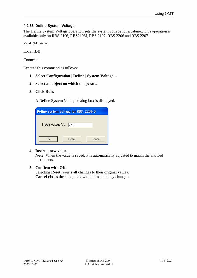
Using OMT
1/19817-CXC 112 516/1 Uen AY Ericsson AB 2007 104 (211)2007-11-05 All rights reserved
4.2.55 Define System VoltageThe Define System Voltage operation sets the system voltage for a cabinet. This operation isavailable only on RBS 2106, RBS2106I, RBS 2107, RBS 2206 and RBS 2207.
Valid OMT states:
Local IDB
Connected
Execute this command as follows:
1. Select Configuration | Define | System Voltage…
2. Select an object on which to operate.
3. Click Run.
A Define System Voltage dialog box is displayed.
4. Insert a new value.Note: When the value is saved, it is automatically adjusted to match the allowedincrements.
5. Confirm with OK.Selecting Reset reverts all changes to their original values.Cancel closes the dialog box without making any changes.
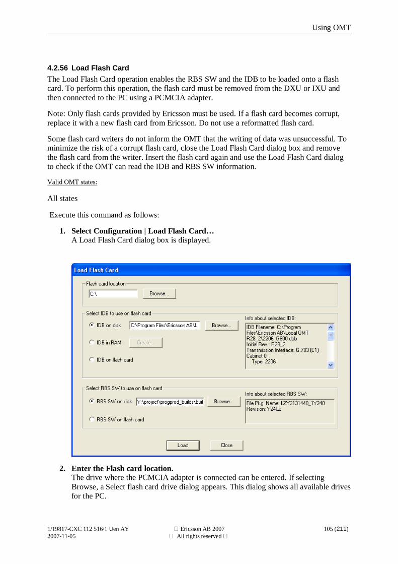
Using OMT
1/19817-CXC 112 516/1 Uen AY Ericsson AB 2007 105 (211)2007-11-05 All rights reserved
4.2.56 Load Flash CardThe Load Flash Card operation enables the RBS SW and the IDB to be loaded onto a flashcard. To perform this operation, the flash card must be removed from the DXU or IXU andthen connected to the PC using a PCMCIA adapter.
Note: Only flash cards provided by Ericsson must be used. If a flash card becomes corrupt,replace it with a new flash card from Ericsson. Do not use a reformatted flash card.
Some flash card writers do not inform the OMT that the writing of data was unsuccessful. Tominimize the risk of a corrupt flash card, close the Load Flash Card dialog box and removethe flash card from the writer. Insert the flash card again and use the Load Flash Card dialogto check if the OMT can read the IDB and RBS SW information.
Valid OMT states:
All states
Execute this command as follows:
1. Select Configuration | Load Flash Card…A Load Flash Card dialog box is displayed.
2. Enter the Flash card location.The drive where the PCMCIA adapter is connected can be entered. If selectingBrowse, a Select flash card drive dialog appears. This dialog shows all available drivesfor the PC.
Using OMT
1/19817-CXC 112 516/1 Uen AY Ericsson AB 2007 106 (211)2007-11-05 All rights reserved
3. Select IDB to use on flash cardThere are three options:
Select IDB on disk: Enter the path to the IDB in the textbox orselect Browse
Select IDB in RAM: The existing IDB in the OMT is loaded ontothe flash card.Selecting Create causes a Create IDB dialogbox to be displayed, which enables a newIDB to be created in RAM.Note: When creating a new IDB, the existingIDB in the OMT is overwritten
Select IDB on flash card: The existing IDB on the flash card is retained.
Information about the selected IDB is shown.
4. Select RBS SW to use on flash card.The RBS SW to be used can be located on disk or on a flash card.Select RBS SW on disk: Enter the path to the directory that includes the RBS SW file packageor select BrowseSelect RBS SW on flash card: The existing RBS SW on the flash card is retained.Information about the selected RBS SW file package is shown.
5. Select LoadThe selected RBS SW and IDB is to be loaded to the flash card. A progress bar is shownwhen the RBS SW is copied to the flash card. Selecting Close closes the dialog box withoutloading the flash card.
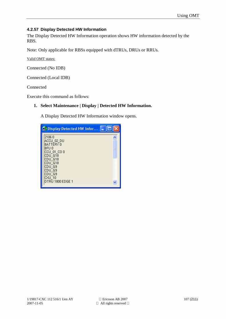
Using OMT
1/19817-CXC 112 516/1 Uen AY Ericsson AB 2007 107 (211)2007-11-05 All rights reserved
4.2.57 Display Detected HW InformationThe Display Detected HW Information operation shows HW information detected by theRBS.
Note: Only applicable for RBSs equipped with dTRUs, DRUs or RRUs.
Valid OMT states:
Connected (No IDB)
Connected (Local IDB)
Connected
Execute this command as follows:
1. Select Maintenance | Display | Detected HW Information.
A Display Detected HW Information window opens.
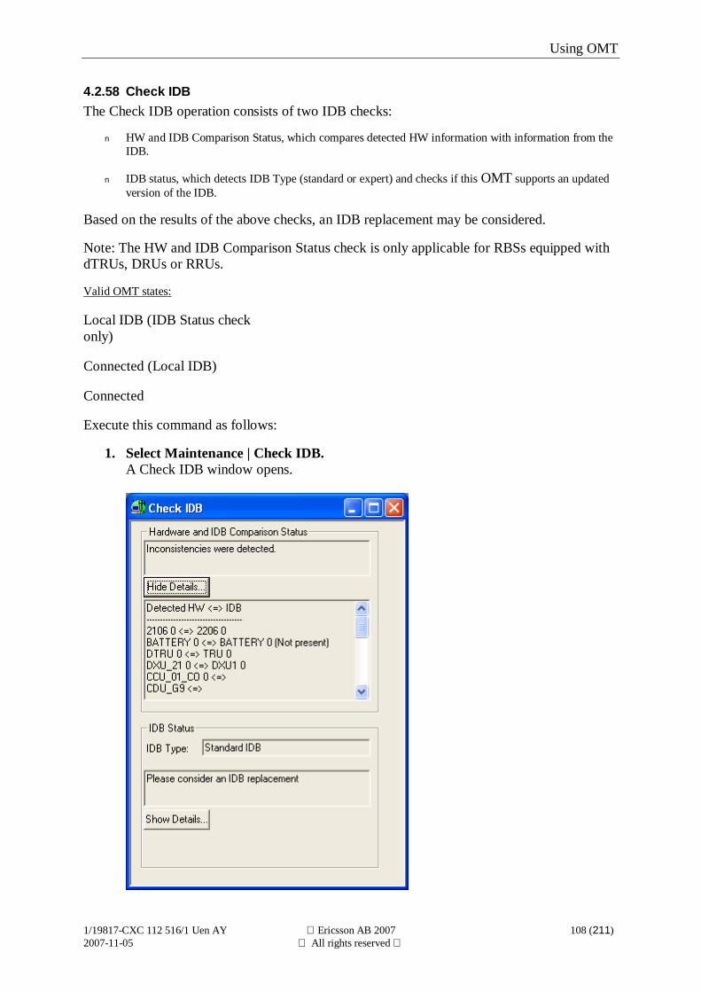
Using OMT
1/19817-CXC 112 516/1 Uen AY Ericsson AB 2007 108 (211)2007-11-05 All rights reserved
4.2.58 Check IDBThe Check IDB operation consists of two IDB checks:
n HW and IDB Comparison Status, which compares detected HW information with information from theIDB.
n IDB status, which detects IDB Type (standard or expert) and checks if this OMT supports an updatedversion of the IDB.
Based on the results of the above checks, an IDB replacement may be considered.
Note: The HW and IDB Comparison Status check is only applicable for RBSs equipped withdTRUs, DRUs or RRUs.
Valid OMT states:
Local IDB (IDB Status checkonly)
Connected (Local IDB)
Connected
Execute this command as follows:
1. Select Maintenance | Check IDB.A Check IDB window opens.
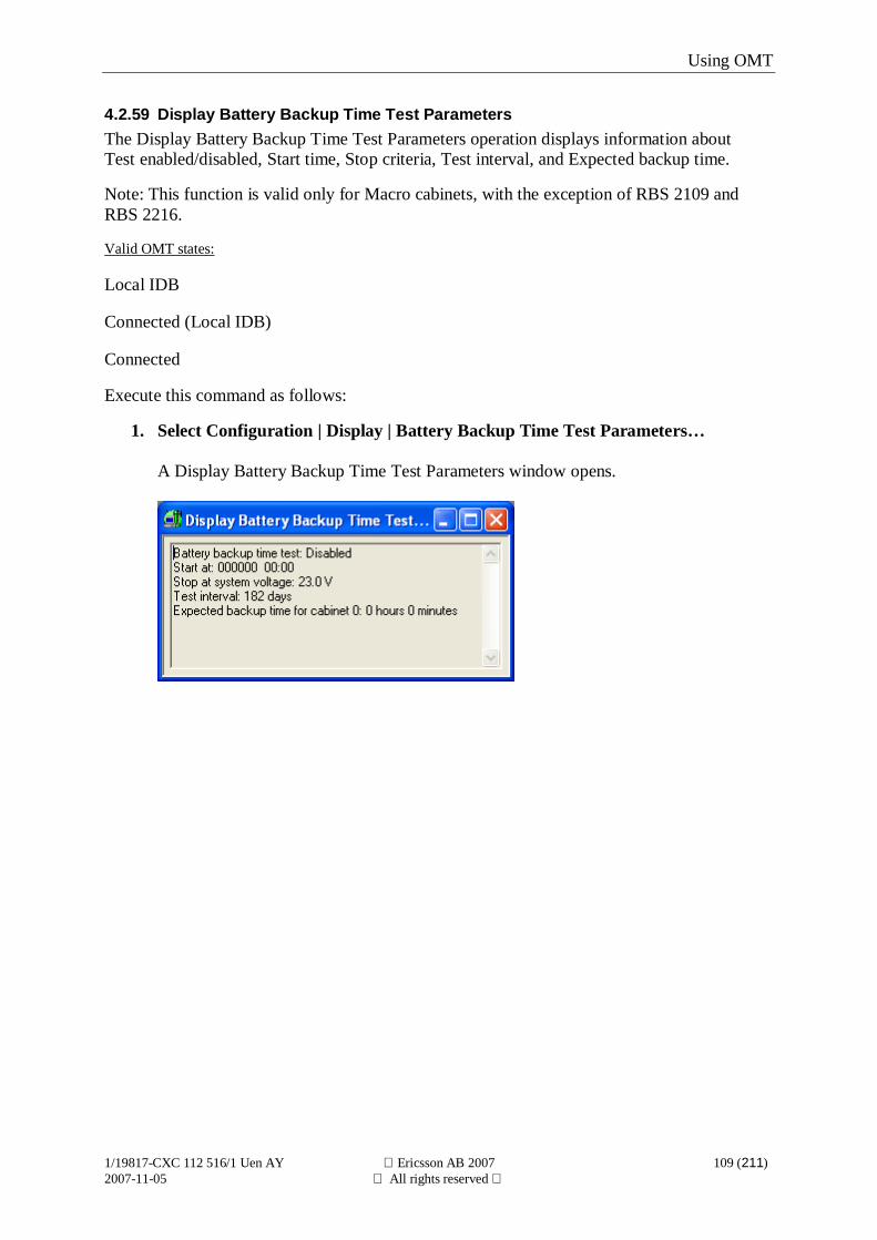
Using OMT
1/19817-CXC 112 516/1 Uen AY Ericsson AB 2007 109 (211)2007-11-05 All rights reserved
4.2.59 Display Battery Backup Time Test ParametersThe Display Battery Backup Time Test Parameters operation displays information aboutTest enabled/disabled, Start time, Stop criteria, Test interval, and Expected backup time.
Note: This function is valid only for Macro cabinets, with the exception of RBS 2109 andRBS 2216.
Valid OMT states:
Local IDB
Connected (Local IDB)
Connected
Execute this command as follows:
1. Select Configuration | Display | Battery Backup Time Test Parameters…
A Display Battery Backup Time Test Parameters window opens.
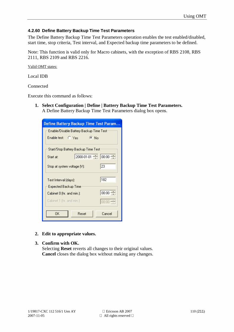
Using OMT
1/19817-CXC 112 516/1 Uen AY Ericsson AB 2007 110 (211)2007-11-05 All rights reserved
4.2.60 Define Battery Backup Time Test ParametersThe Define Battery Backup Time Test Parameters operation enables the test enabled/disabled,start time, stop criteria, Test interval, and Expected backup time parameters to be defined.
Note: This function is valid only for Macro cabinets, with the exception of RBS 2108, RBS2111, RBS 2109 and RBS 2216.
Valid OMT states:
Local IDB
Connected
Execute this command as follows:
1. Select Configuration | Define | Battery Backup Time Test Parameters.A Define Battery Backup Time Test Parameters dialog box opens.
2. Edit to appropriate values.
3. Confirm with OK.Selecting Reset reverts all changes to their original values.Cancel closes the dialog box without making any changes.
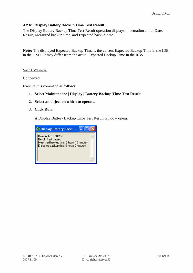
Using OMT
1/19817-CXC 112 516/1 Uen AY Ericsson AB 2007 111 (211)2007-11-05 All rights reserved
4.2.61 Display Battery Backup Time Test ResultThe Display Battery Backup Time Test Result operation displays information about Date,Result, Measured backup time, and Expected backup time.
Note: The displayed Expected Backup Time is the current Expected Backup Time in the IDBin the OMT. It may differ from the actual Expected Backup Time in the RBS.
Valid OMT states:
Connected
Execute this command as follows:
1. Select Maintenance | Display | Battery Backup Time Test Result.
2. Select an object on which to operate.
3. Click Run.
A Display Battery Backup Time Test Result window opens.
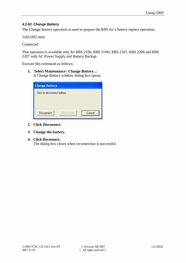
Using OMT
1/19817-CXC 112 516/1 Uen AY Ericsson AB 2007 112 (211)2007-11-05 All rights reserved
4.2.62 Change BatteryThe Change Battery operation is used to prepare the RBS for a battery replace operation.
Valid OMT states:
Connected
This operation is available only for RBS 2106, RBS 2106i, RBS 2107, RBS 2206 and RBS2207 with AC Power Supply and Battery Backup.
Execute this command as follows:
1. Select Maintenance | Change Battery…A Change Battery window dialog box opens:
2. Click Disconnect.
3. Change the battery.
4. Click Reconnect.The dialog box closes when reconnection is successful.
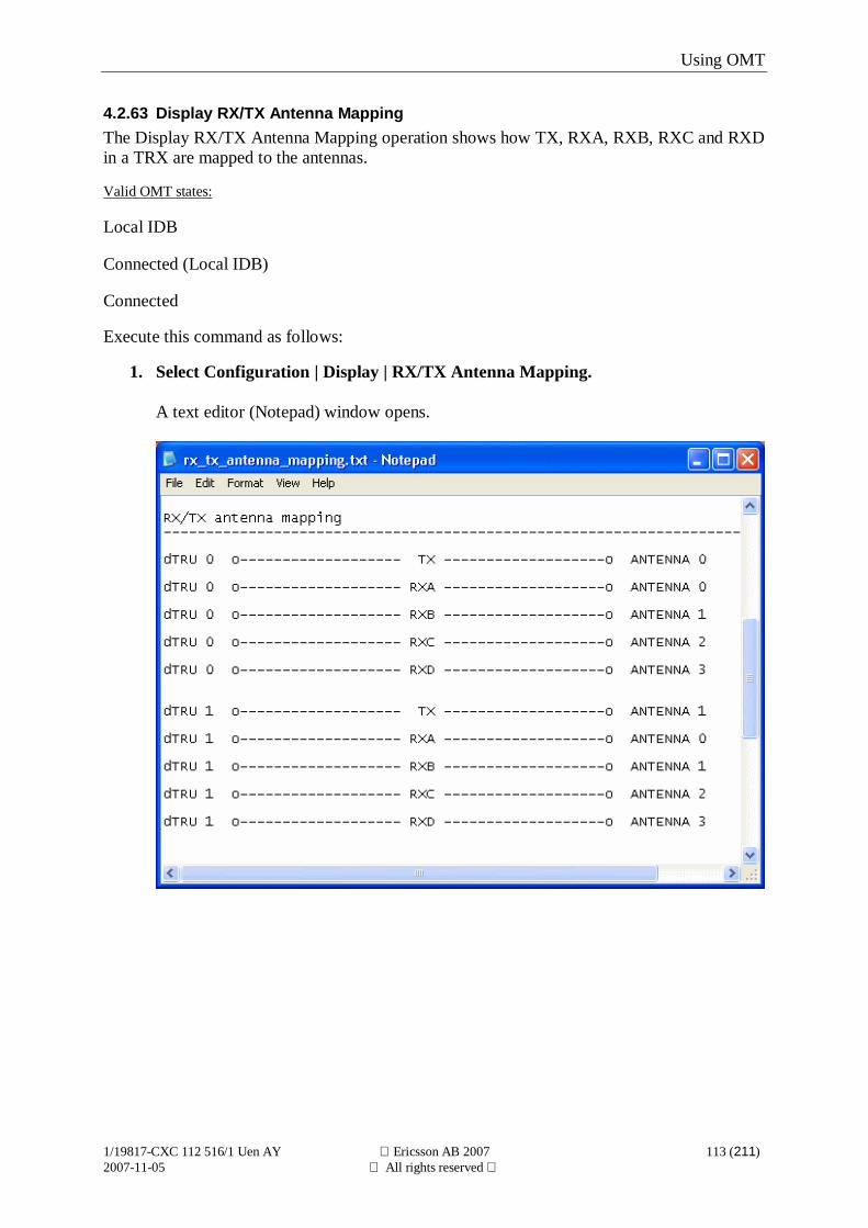
Using OMT
1/19817-CXC 112 516/1 Uen AY Ericsson AB 2007 113 (211)2007-11-05 All rights reserved
4.2.63 Display RX/TX Antenna MappingThe Display RX/TX Antenna Mapping operation shows how TX, RXA, RXB, RXC and RXDin a TRX are mapped to the antennas.
Valid OMT states:
Local IDB
Connected (Local IDB)
Connected
Execute this command as follows:
1. Select Configuration | Display | RX/TX Antenna Mapping.
A text editor (Notepad) window opens.
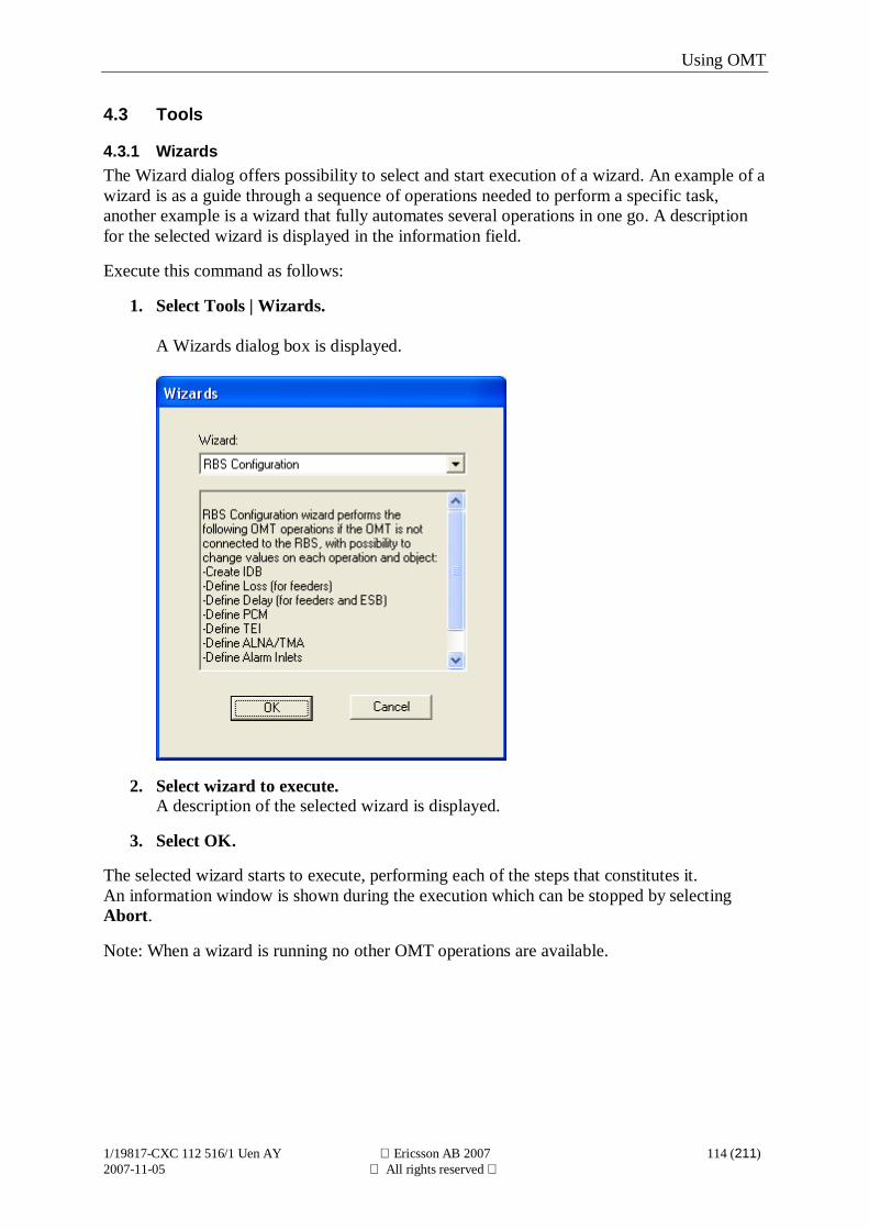
Using OMT
1/19817-CXC 112 516/1 Uen AY Ericsson AB 2007 114 (211)2007-11-05 All rights reserved
4.3 Tools
4.3.1 WizardsThe Wizard dialog offers possibility to select and start execution of a wizard. An example of awizard is as a guide through a sequence of operations needed to perform a specific task,another example is a wizard that fully automates several operations in one go. A descriptionfor the selected wizard is displayed in the information field.
Execute this command as follows:
1. Select Tools | Wizards.
A Wizards dialog box is displayed.
2. Select wizard to execute.A description of the selected wizard is displayed.
3. Select OK.
The selected wizard starts to execute, performing each of the steps that constitutes it.An information window is shown during the execution which can be stopped by selectingAbort.
Note: When a wizard is running no other OMT operations are available.
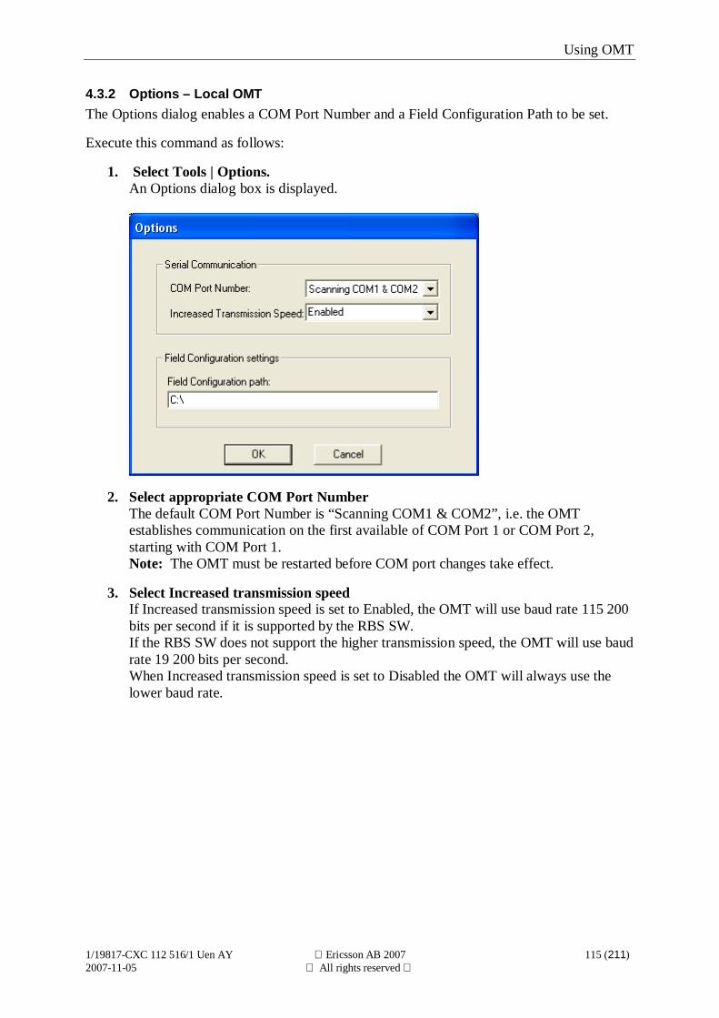
Using OMT
1/19817-CXC 112 516/1 Uen AY Ericsson AB 2007 115 (211)2007-11-05 All rights reserved
4.3.2 Options – Local OMTThe Options dialog enables a COM Port Number and a Field Configuration Path to be set.
Execute this command as follows:
1. Select Tools | Options.An Options dialog box is displayed.
2. Select appropriate COM Port NumberThe default COM Port Number is “Scanning COM1 & COM2”, i.e. the OMTestablishes communication on the first available of COM Port 1 or COM Port 2,starting with COM Port 1.Note: The OMT must be restarted before COM port changes take effect.
3. Select Increased transmission speedIf Increased transmission speed is set to Enabled, the OMT will use baud rate 115 200bits per second if it is supported by the RBS SW.If the RBS SW does not support the higher transmission speed, the OMT will use baudrate 19 200 bits per second.When Increased transmission speed is set to Disabled the OMT will always use thelower baud rate.
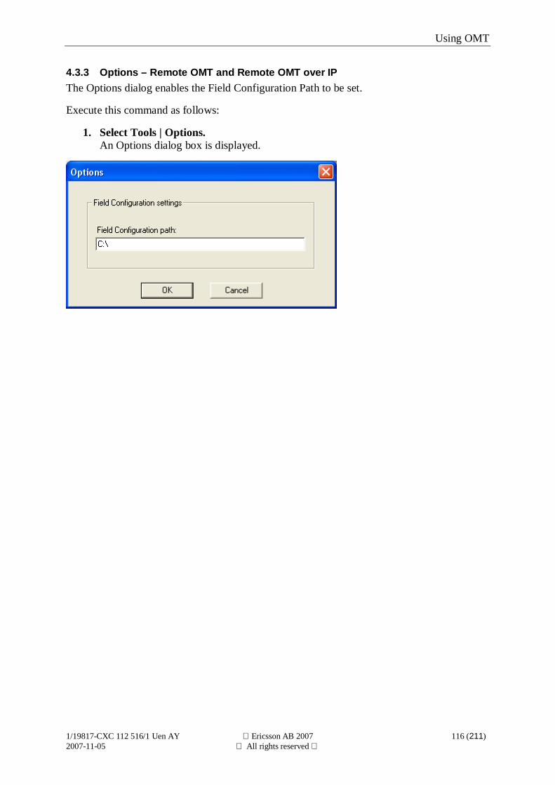
Using OMT
1/19817-CXC 112 516/1 Uen AY Ericsson AB 2007 116 (211)2007-11-05 All rights reserved
4.3.3 Options – Remote OMT and Remote OMT over IPThe Options dialog enables the Field Configuration Path to be set.
Execute this command as follows:
1. Select Tools | Options.An Options dialog box is displayed.
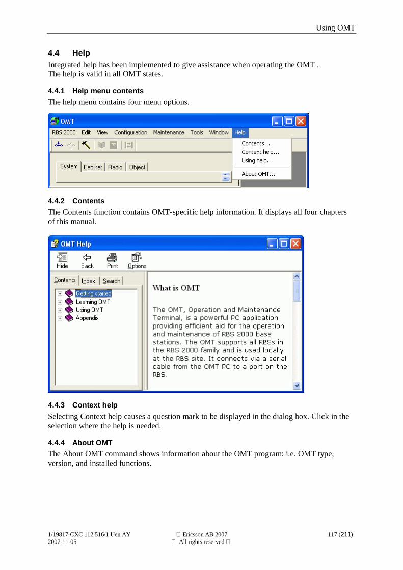
Using OMT
1/19817-CXC 112 516/1 Uen AY Ericsson AB 2007 117 (211)2007-11-05 All rights reserved
4.4 HelpIntegrated help has been implemented to give assistance when operating the OMT .The help is valid in all OMT states.
4.4.1 Help menu contentsThe help menu contains four menu options.
4.4.2 ContentsThe Contents function contains OMT-specific help information. It displays all four chaptersof this manual.
4.4.3 Context helpSelecting Context help causes a question mark to be displayed in the dialog box. Click in theselection where the help is needed.
4.4.4 About OMTThe About OMT command shows information about the OMT program: i.e. OMT type,version, and installed functions.

Appendix
1/19817-CXC 112 516/1 Uen AY Ericsson AB 2007 118 (211)2007-11-05 All rights reserved
5 Appendix
5.1 System software and hardware requirementsPlease see the readme file for information regarding system software and hardwarerequirements.
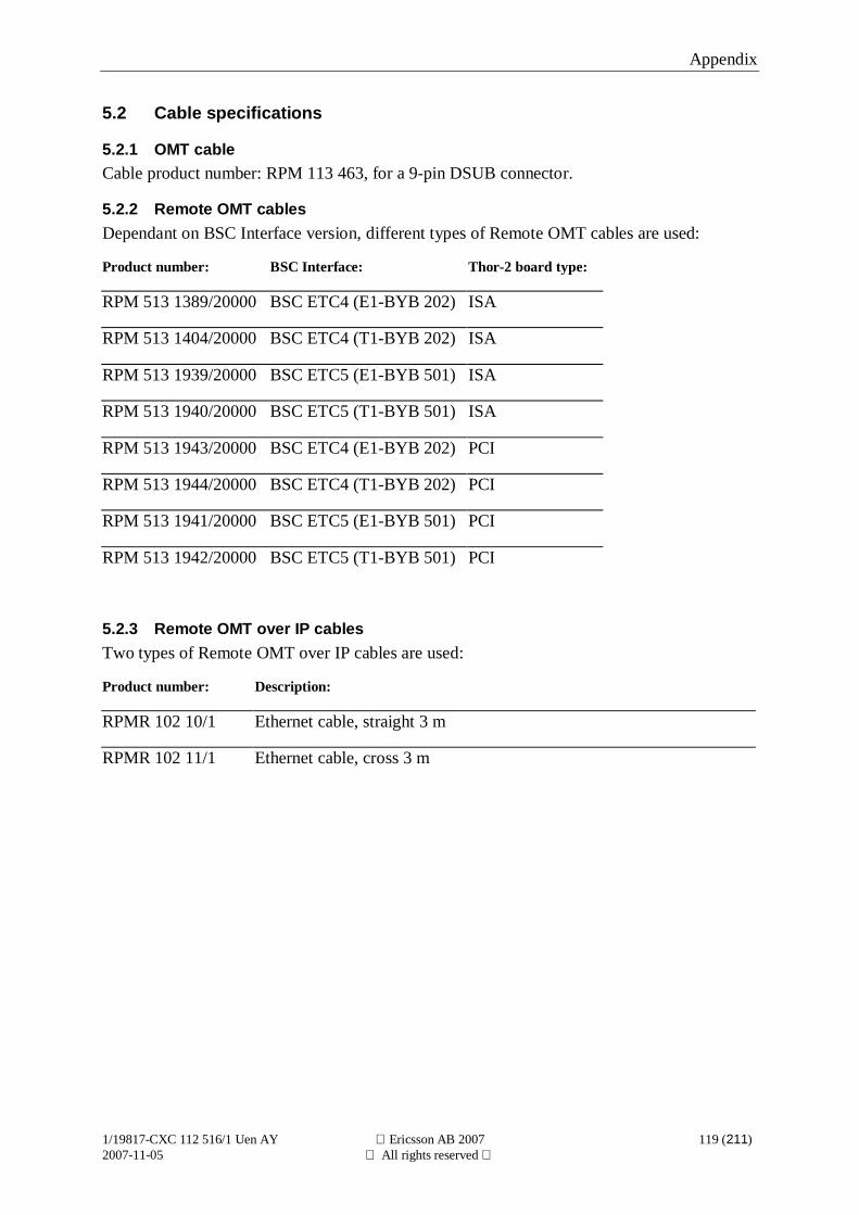
Appendix
1/19817-CXC 112 516/1 Uen AY Ericsson AB 2007 119 (211)2007-11-05 All rights reserved
5.2 Cable specifications
5.2.1 OMT cableCable product number: RPM 113 463, for a 9-pin DSUB connector.
5.2.2 Remote OMT cablesDependant on BSC Interface version, different types of Remote OMT cables are used:
Product number: BSC Interface: Thor-2 board type:
RPM 513 1389/20000 BSC ETC4 (E1-BYB 202) ISA
RPM 513 1404/20000 BSC ETC4 (T1-BYB 202) ISA
RPM 513 1939/20000 BSC ETC5 (E1-BYB 501) ISA
RPM 513 1940/20000 BSC ETC5 (T1-BYB 501) ISA
RPM 513 1943/20000 BSC ETC4 (E1-BYB 202) PCI
RPM 513 1944/20000 BSC ETC4 (T1-BYB 202) PCI
RPM 513 1941/20000 BSC ETC5 (E1-BYB 501) PCI
RPM 513 1942/20000 BSC ETC5 (T1-BYB 501) PCI
5.2.3 Remote OMT over IP cablesTwo types of Remote OMT over IP cables are used:
Product number: Description:
RPMR 102 10/1 Ethernet cable, straight 3 m
RPMR 102 11/1 Ethernet cable, cross 3 m
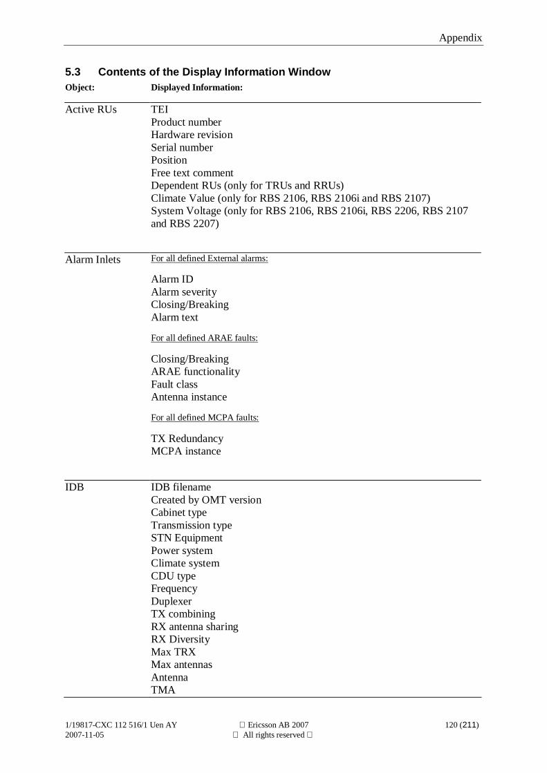
Appendix
1/19817-CXC 112 516/1 Uen AY Ericsson AB 2007 120 (211)2007-11-05 All rights reserved
5.3 Contents of the Display Information WindowObject: Displayed Information:
Active RUs TEIProduct numberHardware revisionSerial numberPositionFree text commentDependent RUs (only for TRUs and RRUs)Climate Value (only for RBS 2106, RBS 2106i and RBS 2107)System Voltage (only for RBS 2106, RBS 2106i, RBS 2206, RBS 2107and RBS 2207)
Alarm Inlets For all defined External alarms:
Alarm IDAlarm severityClosing/BreakingAlarm text
For all defined ARAE faults:
Closing/BreakingARAE functionalityFault classAntenna instance
For all defined MCPA faults:
TX RedundancyMCPA instance
IDB IDB filenameCreated by OMT versionCabinet typeTransmission typeSTN EquipmentPower systemClimate systemCDU typeFrequencyDuplexerTX combiningRX antenna sharingRX DiversityMax TRXMax antennasAntennaTMA
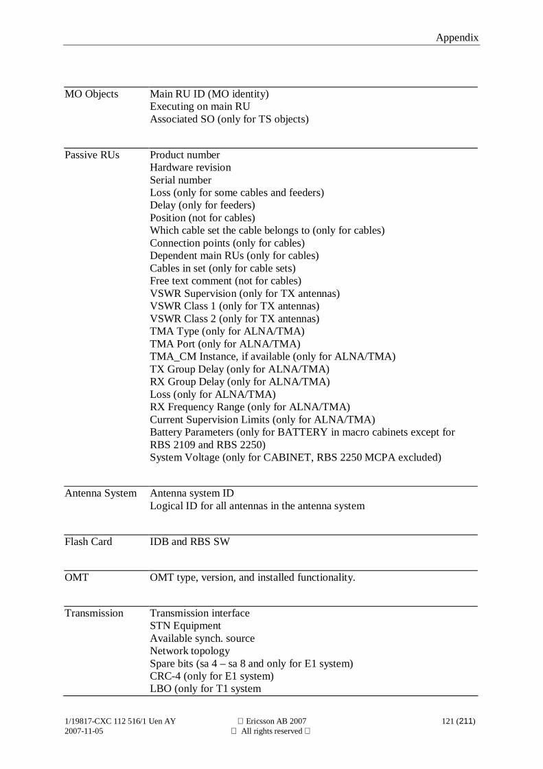
Appendix
1/19817-CXC 112 516/1 Uen AY Ericsson AB 2007 121 (211)2007-11-05 All rights reserved
MO Objects Main RU ID (MO identity)Executing on main RUAssociated SO (only for TS objects)
Passive RUs Product numberHardware revisionSerial numberLoss (only for some cables and feeders)Delay (only for feeders)Position (not for cables)Which cable set the cable belongs to (only for cables)Connection points (only for cables)Dependent main RUs (only for cables)Cables in set (only for cable sets)Free text comment (not for cables)VSWR Supervision (only for TX antennas)VSWR Class 1 (only for TX antennas)VSWR Class 2 (only for TX antennas)TMA Type (only for ALNA/TMA)TMA Port (only for ALNA/TMA)TMA_CM Instance, if available (only for ALNA/TMA)TX Group Delay (only for ALNA/TMA)RX Group Delay (only for ALNA/TMA)Loss (only for ALNA/TMA)RX Frequency Range (only for ALNA/TMA)Current Supervision Limits (only for ALNA/TMA)Battery Parameters (only for BATTERY in macro cabinets except forRBS 2109 and RBS 2250)System Voltage (only for CABINET, RBS 2250 MCPA excluded)
Antenna System Antenna system IDLogical ID for all antennas in the antenna system
Flash Card IDB and RBS SW
OMT OMT type, version, and installed functionality.
Transmission Transmission interfaceSTN EquipmentAvailable synch. sourceNetwork topologySpare bits (sa 4 – sa 8 and only for E1 system)CRC-4 (only for E1 system)LBO (only for T1 system

Appendix
1/19817-CXC 112 516/1 Uen AY Ericsson AB 2007 122 (211)2007-11-05 All rights reserved
FDL-use (only for T1 systemReceiver Sensitivity (only for E1 system)
RBS GPS parametersTF compensationTransmitter chain delayTF holdover modeRBS Identity
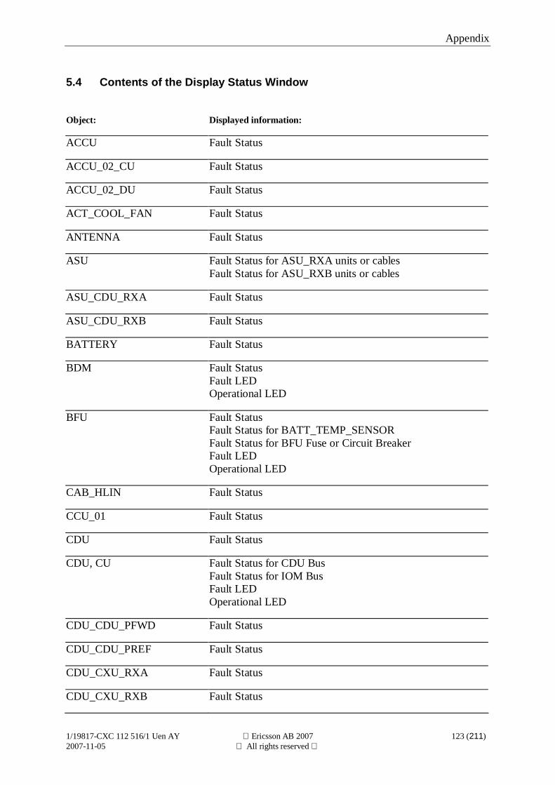
Appendix
1/19817-CXC 112 516/1 Uen AY Ericsson AB 2007 123 (211)2007-11-05 All rights reserved
5.4 Contents of the Display Status Window
Object: Displayed information:
ACCU Fault Status
ACCU_02_CU Fault Status
ACCU_02_DU Fault Status
ACT_COOL_FAN Fault Status
ANTENNA Fault Status
ASU Fault Status for ASU_RXA units or cablesFault Status for ASU_RXB units or cables
ASU_CDU_RXA Fault Status
ASU_CDU_RXB Fault Status
BATTERY Fault Status
BDM Fault StatusFault LEDOperational LED
BFU Fault StatusFault Status for BATT_TEMP_SENSORFault Status for BFU Fuse or Circuit BreakerFault LEDOperational LED
CAB_HLIN Fault Status
CCU_01 Fault Status
CDU Fault Status
CDU, CU Fault Status for CDU BusFault Status for IOM BusFault LEDOperational LED
CDU_CDU_PFWD Fault Status
CDU_CDU_PREF Fault Status
CDU_CXU_RXA Fault Status
CDU_CXU_RXB Fault Status
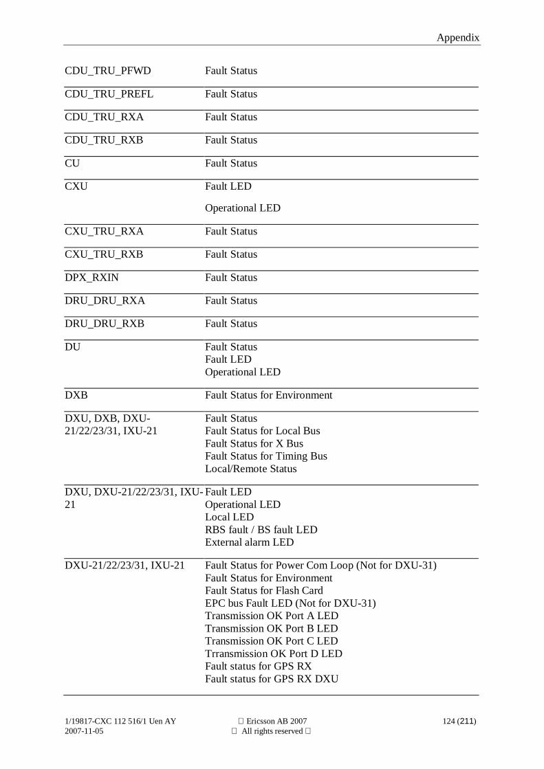
Appendix
1/19817-CXC 112 516/1 Uen AY Ericsson AB 2007 124 (211)2007-11-05 All rights reserved
CDU_TRU_PFWD Fault Status
CDU_TRU_PREFL Fault Status
CDU_TRU_RXA Fault Status
CDU_TRU_RXB Fault Status
CU Fault Status
CXU Fault LED
Operational LED
CXU_TRU_RXA Fault Status
CXU_TRU_RXB Fault Status
DPX_RXIN Fault Status
DRU_DRU_RXA Fault Status
DRU_DRU_RXB Fault Status
DU Fault StatusFault LEDOperational LED
DXB Fault Status for Environment
DXU, DXB, DXU-21/22/23/31, IXU-21
Fault StatusFault Status for Local BusFault Status for X BusFault Status for Timing BusLocal/Remote Status
DXU, DXU-21/22/23/31, IXU-21
Fault LEDOperational LEDLocal LEDRBS fault / BS fault LEDExternal alarm LED
DXU-21/22/23/31, IXU-21 Fault Status for Power Com Loop (Not for DXU-31)Fault Status for EnvironmentFault Status for Flash CardEPC bus Fault LED (Not for DXU-31)Transmission OK Port A LEDTransmission OK Port B LEDTransmission OK Port C LEDTrransmission OK Port D LEDFault status for GPS RXFault status for GPS RX DXU
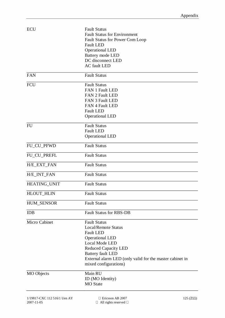
Appendix
1/19817-CXC 112 516/1 Uen AY Ericsson AB 2007 125 (211)2007-11-05 All rights reserved
ECU Fault StatusFault Status for EnvironmentFault Status for Power Com LoopFault LEDOperational LEDBattery mode LEDDC disconnect LEDAC fault LED
FAN Fault Status
FCU Fault StatusFAN 1 Fault LEDFAN 2 Fault LEDFAN 3 Fault LEDFAN 4 Fault LEDFault LEDOperational LED
FU Fault StatusFault LEDOperational LED
FU_CU_PFWD Fault Status
FU_CU_PREFL Fault Status
H/E_EXT_FAN Fault Status
H/E_INT_FAN Fault Status
HEATING_UNIT Fault Status
HLOUT_HLIN Fault Status
HUM_SENSOR Fault Status
IDB Fault Status for RBS-DB
Micro Cabinet Fault StatusLocal/Remote StatusFault LEDOperational LEDLocal Mode LEDReduced Capacity LEDBattery fault LEDExternal alarm LED (only valid for the master cabinet inmixed configurations)
MO Objects Main RUID (MO Identity)MO State
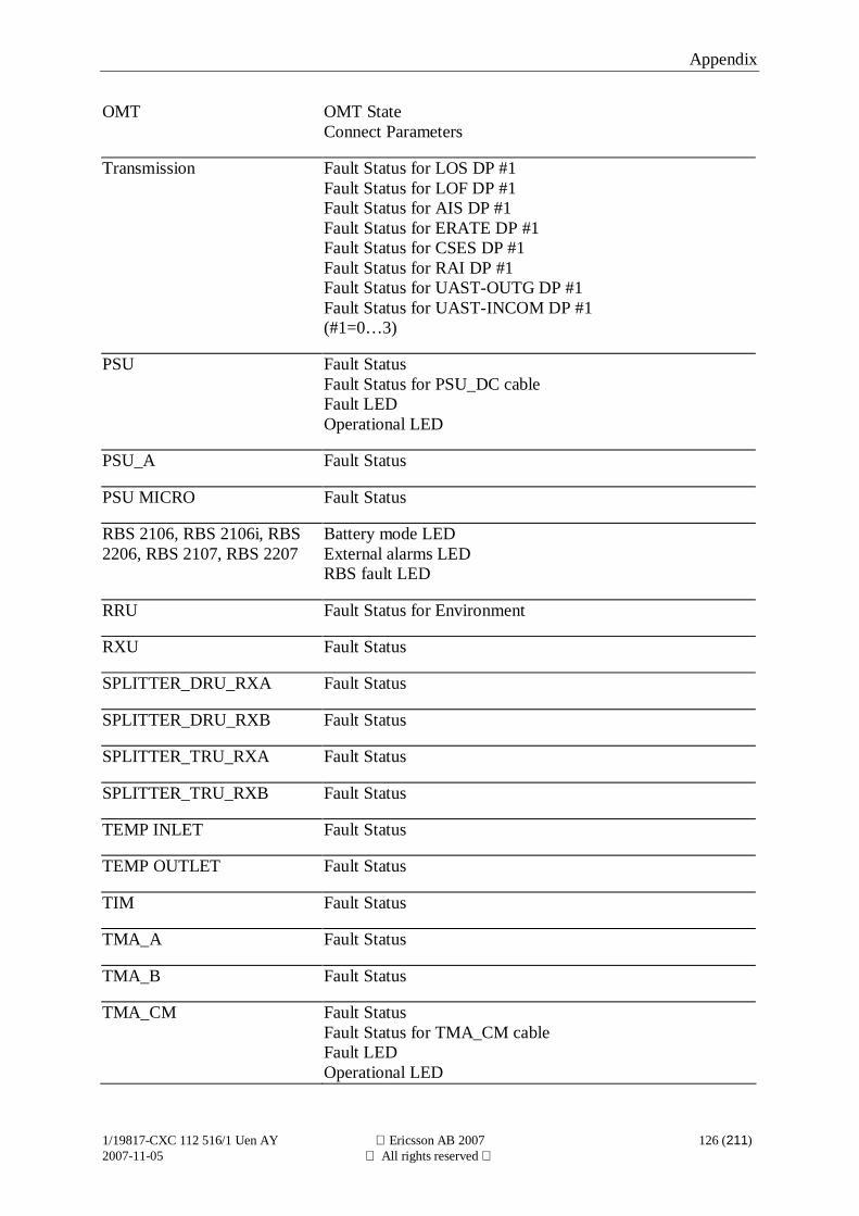
Appendix
1/19817-CXC 112 516/1 Uen AY Ericsson AB 2007 126 (211)2007-11-05 All rights reserved
OMT OMT StateConnect Parameters
Transmission Fault Status for LOS DP #1Fault Status for LOF DP #1Fault Status for AIS DP #1Fault Status for ERATE DP #1Fault Status for CSES DP #1Fault Status for RAI DP #1Fault Status for UAST-OUTG DP #1Fault Status for UAST-INCOM DP #1(#1=0…3)
PSU Fault StatusFault Status for PSU_DC cableFault LEDOperational LED
PSU_A Fault Status
PSU MICRO Fault Status
RBS 2106, RBS 2106i, RBS2206, RBS 2107, RBS 2207
Battery mode LEDExternal alarms LEDRBS fault LED
RRU Fault Status for Environment
RXU Fault Status
SPLITTER_DRU_RXA Fault Status
SPLITTER_DRU_RXB Fault Status
SPLITTER_TRU_RXA Fault Status
SPLITTER_TRU_RXB Fault Status
TEMP INLET Fault Status
TEMP OUTLET Fault Status
TIM Fault Status
TMA_A Fault Status
TMA_B Fault Status
TMA_CM Fault StatusFault Status for TMA_CM cableFault LEDOperational LED
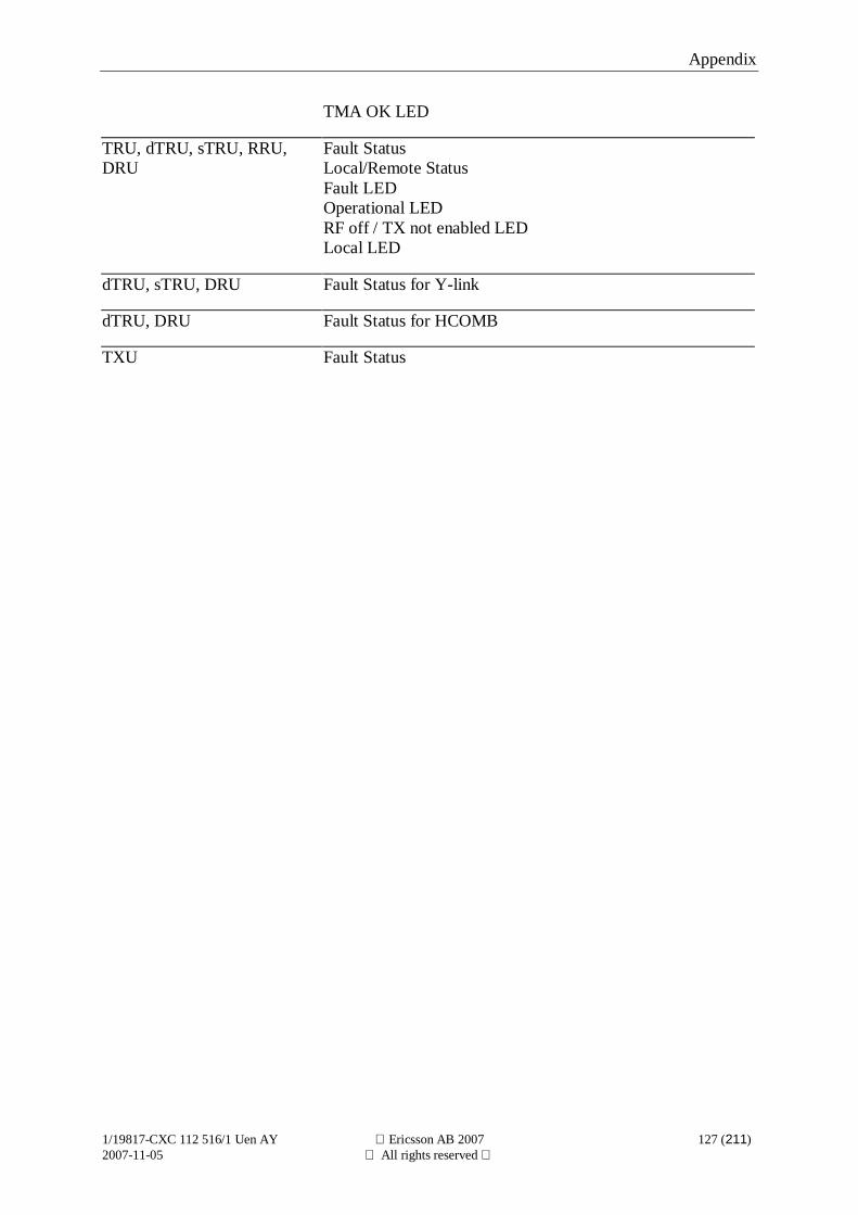
Appendix
1/19817-CXC 112 516/1 Uen AY Ericsson AB 2007 127 (211)2007-11-05 All rights reserved
TMA OK LED
TRU, dTRU, sTRU, RRU,DRU
Fault StatusLocal/Remote StatusFault LEDOperational LEDRF off / TX not enabled LEDLocal LED
dTRU, sTRU, DRU Fault Status for Y-link
dTRU, DRU Fault Status for HCOMB
TXU Fault Status
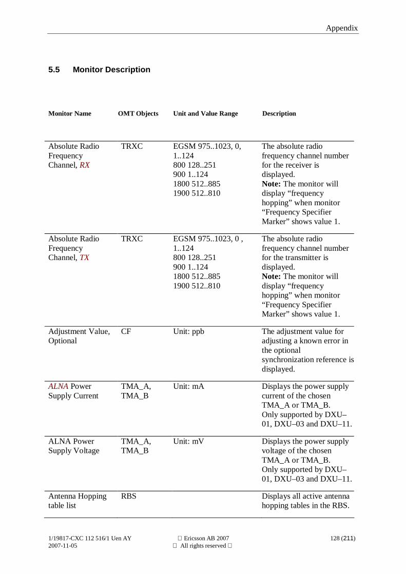
Appendix
1/19817-CXC 112 516/1 Uen AY Ericsson AB 2007 128 (211)2007-11-05 All rights reserved
5.5 Monitor Description
Monitor Name OMT Objects Unit and Value Range Description
Absolute RadioFrequencyChannel, RX
TRXC EGSM 975..1023, 0,1..124800 128..251900 1..1241800 512..8851900 512..810
The absolute radiofrequency channel numberfor the receiver isdisplayed.Note: The monitor willdisplay “frequencyhopping” when monitor“Frequency SpecifierMarker” shows value 1.
Absolute RadioFrequencyChannel, TX
TRXC EGSM 975..1023, 0 ,1..124800 128..251900 1..1241800 512..8851900 512..810
The absolute radiofrequency channel numberfor the transmitter isdisplayed.Note: The monitor willdisplay “frequencyhopping” when monitor“Frequency SpecifierMarker” shows value 1.
Adjustment Value,Optional
CF Unit: ppb The adjustment value foradjusting a known error inthe optionalsynchronization reference isdisplayed.
ALNA PowerSupply Current
TMA_A,TMA_B
Unit: mA Displays the power supplycurrent of the chosenTMA_A or TMA_B.Only supported by DXU–01, DXU–03 and DXU–11.
ALNA PowerSupply Voltage
TMA_A,TMA_B
Unit: mV Displays the power supplyvoltage of the chosenTMA_A or TMA_B.Only supported by DXU–01, DXU–03 and DXU–11.
Antenna Hoppingtable list
RBS Displays all active antennahopping tables in the RBS.
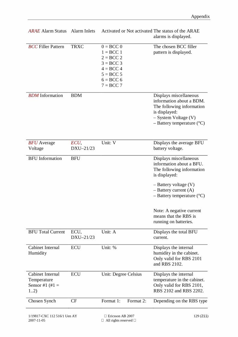
Appendix
1/19817-CXC 112 516/1 Uen AY Ericsson AB 2007 129 (211)2007-11-05 All rights reserved
ARAE Alarm Status Alarm Inlets Activated or Not activated The status of the ARAEalarms is displayed.
BCC Filler Pattern TRXC 0 = BCC 01 = BCC 12 = BCC 23 = BCC 34 = BCC 45 = BCC 56 = BCC 67 = BCC 7
The chosen BCC fillerpattern is displayed.
BDM Information BDM Displays miscellaneousinformation about a BDM.The following informationis displayed:– System Voltage (V)– Battery temperature (°C)
BFU AverageVoltage
ECU,DXU–21/23
Unit: V Displays the average BFUbattery voltage.
BFU Information BFU Displays miscellaneousinformation about a BFU.The following informationis displayed:
– Battery voltage (V)– Battery current (A)– Battery temperature (°C)
Note: A negative currentmeans that the RBS isrunning on batteries.
BFU Total Current ECU,DXU–21/23
Unit: A Displays the total BFUcurrent.
Cabinet InternalHumidity
ECU Unit: % Displays the internalhumidity in the cabinet.Only valid for RBS 2101and RBS 2102.
Cabinet InternalTemperatureSensor #1 (#1 =1..2)
ECU Unit: Degree Celsius Displays the internaltemperature in the cabinet.Only valid for RBS 2101,RBS 2102 and RBS 2202.
Chosen Synch CF Format 1: Format 2: Depending on the RBS type
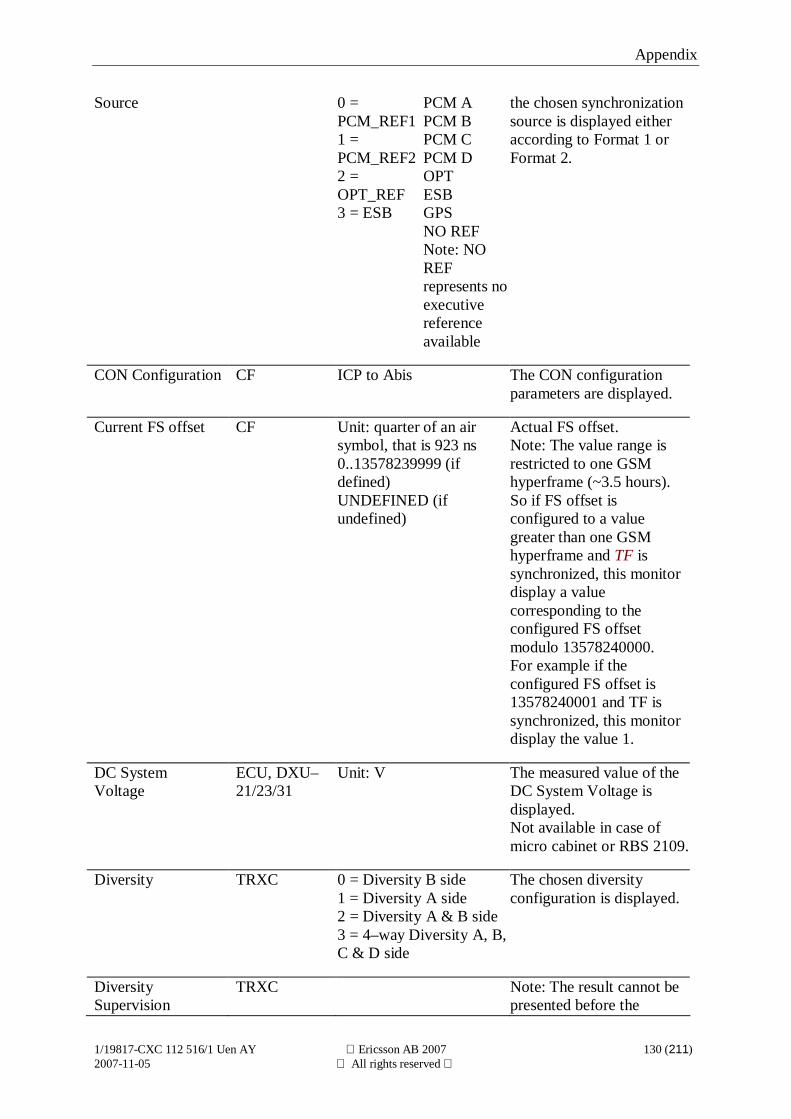
Appendix
1/19817-CXC 112 516/1 Uen AY Ericsson AB 2007 130 (211)2007-11-05 All rights reserved
Source 0 =PCM_REF11 =PCM_REF22 =OPT_REF3 = ESB
PCM APCM BPCM CPCM DOPTESBGPSNO REFNote: NOREFrepresents noexecutivereferenceavailable
the chosen synchronizationsource is displayed eitheraccording to Format 1 orFormat 2.
CON Configuration CF ICP to Abis The CON configurationparameters are displayed.
Current FS offset CF Unit: quarter of an airsymbol, that is 923 ns0..13578239999 (ifdefined)UNDEFINED (ifundefined)
Actual FS offset.Note: The value range isrestricted to one GSMhyperframe (~3.5 hours).So if FS offset isconfigured to a valuegreater than one GSMhyperframe and TF issynchronized, this monitordisplay a valuecorresponding to theconfigured FS offsetmodulo 13578240000.For example if theconfigured FS offset is13578240001 and TF issynchronized, this monitordisplay the value 1.
DC SystemVoltage
ECU, DXU–21/23/31
Unit: V The measured value of theDC System Voltage isdisplayed.Not available in case ofmicro cabinet or RBS 2109.
Diversity TRXC 0 = Diversity B side1 = Diversity A side2 = Diversity A & B side3 = 4–way Diversity A, B,C & D side
The chosen diversityconfiguration is displayed.
DiversitySupervision
TRXC Note: The result cannot bepresented before the
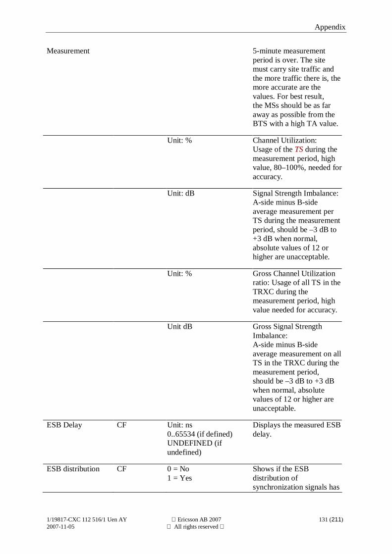
Appendix
1/19817-CXC 112 516/1 Uen AY Ericsson AB 2007 131 (211)2007-11-05 All rights reserved
Measurement 5-minute measurementperiod is over. The sitemust carry site traffic andthe more traffic there is, themore accurate are thevalues. For best result,the MSs should be as faraway as possible from theBTS with a high TA value.
Unit: % Channel Utilization:Usage of the TS during themeasurement period, highvalue, 80–100%, needed foraccuracy.
Unit: dB Signal Strength Imbalance:A-side minus B-sideaverage measurement perTS during the measurementperiod, should be –3 dB to+3 dB when normal,absolute values of 12 orhigher are unacceptable.
Unit: % Gross Channel Utilizationratio: Usage of all TS in theTRXC during themeasurement period, highvalue needed for accuracy.
Unit dB Gross Signal StrengthImbalance:A-side minus B-sideaverage measurement on allTS in the TRXC during themeasurement period,should be –3 dB to +3 dBwhen normal, absolutevalues of 12 or higher areunacceptable.
ESB Delay CF Unit: ns0..65534 (if defined)UNDEFINED (ifundefined)
Displays the measured ESBdelay.
ESB distribution CF 0 = No1 = Yes
Shows if the ESBdistribution ofsynchronization signals has
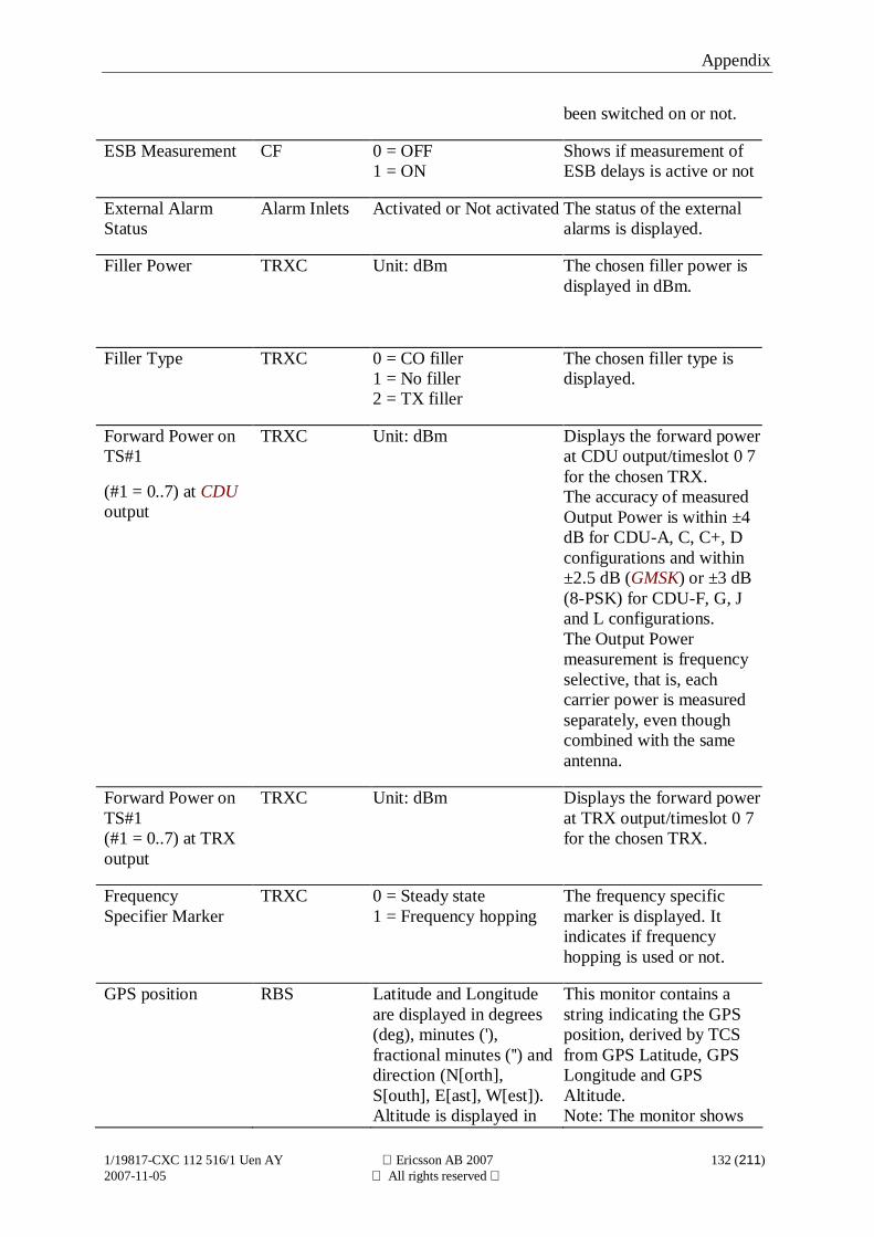
Appendix
1/19817-CXC 112 516/1 Uen AY Ericsson AB 2007 132 (211)2007-11-05 All rights reserved
been switched on or not.
ESB Measurement CF 0 = OFF1 = ON
Shows if measurement ofESB delays is active or not
External AlarmStatus
Alarm Inlets Activated or Not activated The status of the externalalarms is displayed.
Filler Power TRXC Unit: dBm The chosen filler power isdisplayed in dBm.
Filler Type TRXC 0 = CO filler1 = No filler2 = TX filler
The chosen filler type isdisplayed.
Forward Power onTS#1
(#1 = 0..7) at CDUoutput
TRXC Unit: dBm Displays the forward powerat CDU output/timeslot 0 7for the chosen TRX.The accuracy of measuredOutput Power is within ±4dB for CDU-A, C, C+, Dconfigurations and within±2.5 dB (GMSK) or ±3 dB(8-PSK) for CDU-F, G, Jand L configurations.The Output Powermeasurement is frequencyselective, that is, eachcarrier power is measuredseparately, even thoughcombined with the sameantenna.
Forward Power onTS#1(#1 = 0..7) at TRXoutput
TRXC Unit: dBm Displays the forward powerat TRX output/timeslot 0 7for the chosen TRX.
FrequencySpecifier Marker
TRXC 0 = Steady state1 = Frequency hopping
The frequency specificmarker is displayed. Itindicates if frequencyhopping is used or not.
GPS position RBS Latitude and Longitudeare displayed in degrees(deg), minutes ('),fractional minutes ('') anddirection (N[orth],S[outh], E[ast], W[est]).Altitude is displayed in
This monitor contains astring indicating the GPSposition, derived by TCSfrom GPS Latitude, GPSLongitude and GPSAltitude.Note: The monitor shows
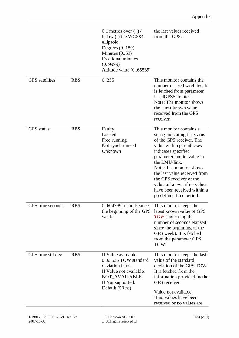
Appendix
1/19817-CXC 112 516/1 Uen AY Ericsson AB 2007 133 (211)2007-11-05 All rights reserved
0.1 metres over (+) /below (-) the WGS84ellipsoid.Degrees (0..180)Minutes (0..59)Fractional minutes(0..9999)Altitude value (0..65535)
the last values receivedfrom the GPS.
GPS satellites RBS 0..255 This monitor contains thenumber of used satellites. Itis fetched from parameterUsedGPSSatellites.Note: The monitor showsthe latest known valuereceived from the GPSreceiver.
GPS status RBS FaultyLockedFree runningNot synchronizedUnknown
This monitor contains astring indicating the statusof the GPS receiver. Thevalue within parenthesesindicates specifiedparameter and its value inthe LMU-link.Note: The monitor showsthe last value received fromthe GPS receiver or thevalue unknown if no valueshave been received within apredefined time period.
GPS time seconds RBS 0..604799 seconds sincethe beginning of the GPSweek.
This monitor keeps thelatest known value of GPSTOW (indicating thenumber of seconds elapsedsince the beginning of theGPS week). It is fetchedfrom the parameter GPSTOW.
GPS time std dev RBS If Value available:0..65535 TOW standarddeviation in ns.If Value not available:NOT_AVAILABLEIf Not supported:Default (50 ns)
This monitor keeps the lastvalue of the standarddeviation of the GPS TOW.It is fetched from theinformation provided by theGPS receiver.
Value not available:If no values have beenreceived or no values are
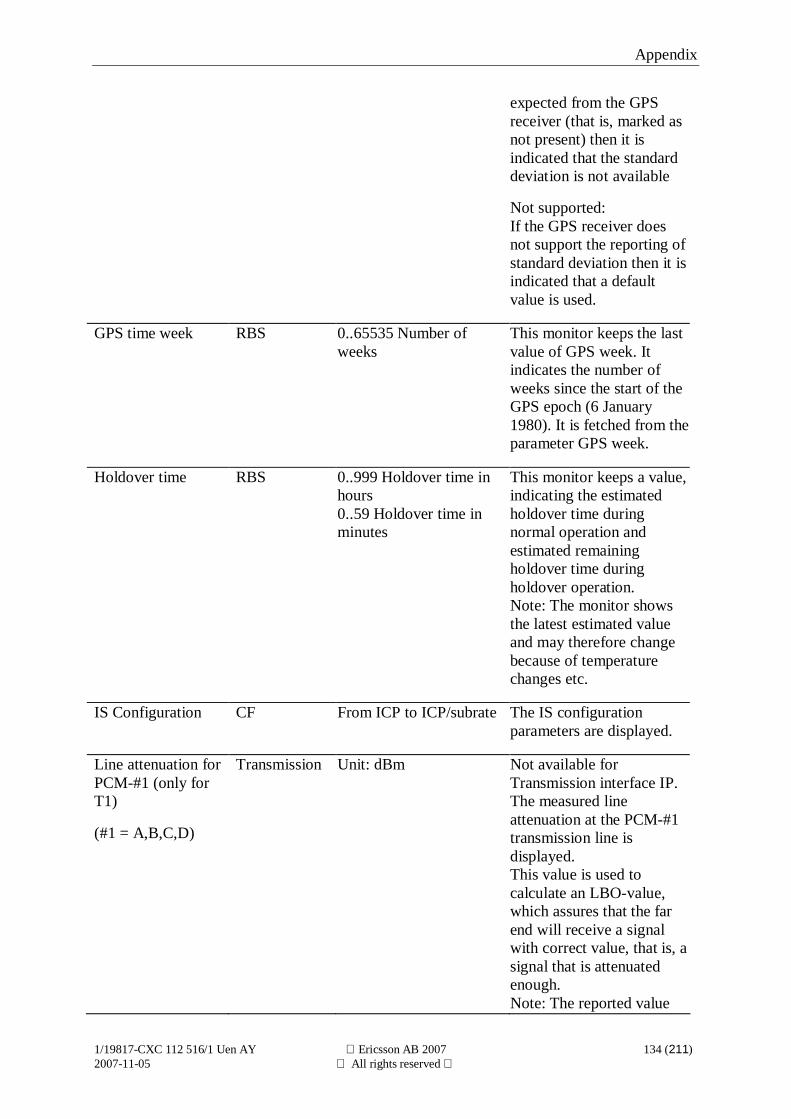
Appendix
1/19817-CXC 112 516/1 Uen AY Ericsson AB 2007 134 (211)2007-11-05 All rights reserved
expected from the GPSreceiver (that is, marked asnot present) then it isindicated that the standarddeviation is not available
Not supported:If the GPS receiver doesnot support the reporting ofstandard deviation then it isindicated that a defaultvalue is used.
GPS time week RBS 0..65535 Number ofweeks
This monitor keeps the lastvalue of GPS week. Itindicates the number ofweeks since the start of theGPS epoch (6 January1980). It is fetched from theparameter GPS week.
Holdover time RBS 0..999 Holdover time inhours0..59 Holdover time inminutes
This monitor keeps a value,indicating the estimatedholdover time duringnormal operation andestimated remainingholdover time duringholdover operation.Note: The monitor showsthe latest estimated valueand may therefore changebecause of temperaturechanges etc.
IS Configuration CF From ICP to ICP/subrate The IS configurationparameters are displayed.
Line attenuation forPCM-#1 (only forT1)
(#1 = A,B,C,D)
Transmission Unit: dBm Not available forTransmission interface IP.The measured lineattenuation at the PCM-#1transmission line isdisplayed.This value is used tocalculate an LBO-value,which assures that the farend will receive a signalwith correct value, that is, asignal that is attenuatedenough.Note: The reported value
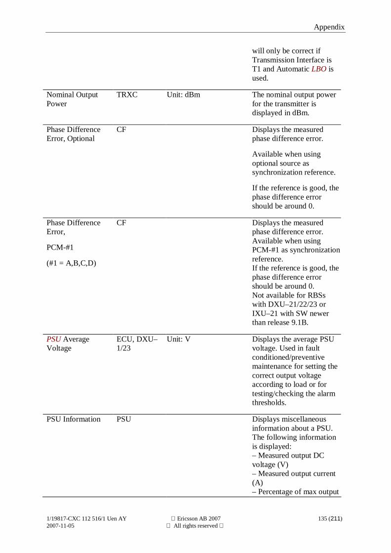
Appendix
1/19817-CXC 112 516/1 Uen AY Ericsson AB 2007 135 (211)2007-11-05 All rights reserved
will only be correct ifTransmission Interface isT1 and Automatic LBO isused.
Nominal OutputPower
TRXC Unit: dBm The nominal output powerfor the transmitter isdisplayed in dBm.
Phase DifferenceError, Optional
CF Displays the measuredphase difference error.
Available when usingoptional source assynchronization reference.
If the reference is good, thephase difference errorshould be around 0.
Phase DifferenceError,
PCM-#1
(#1 = A,B,C,D)
CF Displays the measuredphase difference error.Available when usingPCM-#1 as synchronizationreference.If the reference is good, thephase difference errorshould be around 0.Not available for RBSswith DXU–21/22/23 orIXU–21 with SW newerthan release 9.1B.
PSU AverageVoltage
ECU, DXU–1/23
Unit: V Displays the average PSUvoltage. Used in faultconditioned/preventivemaintenance for setting thecorrect output voltageaccording to load or fortesting/checking the alarmthresholds.
PSU Information PSU Displays miscellaneousinformation about a PSU.The following informationis displayed:– Measured output DCvoltage (V)– Measured output current(A)– Percentage of max output
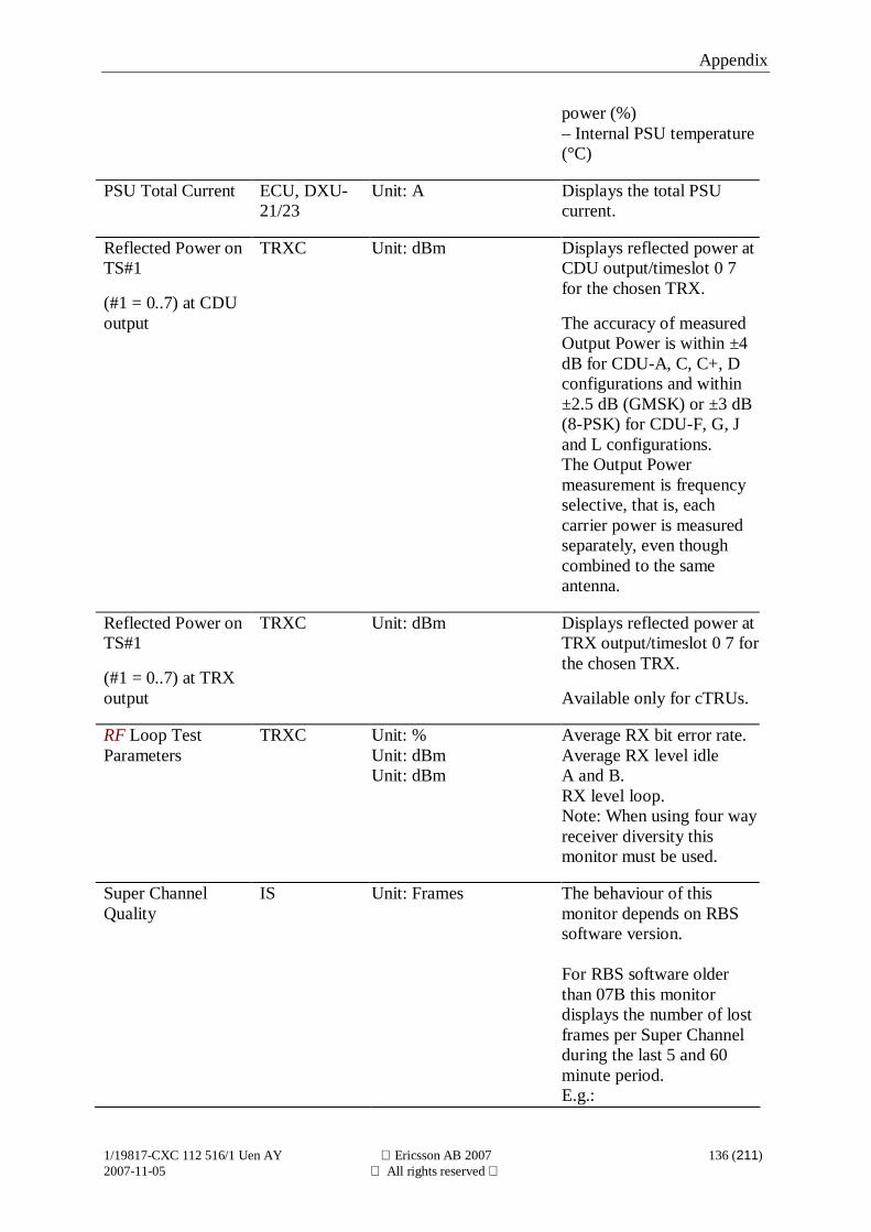
Appendix
1/19817-CXC 112 516/1 Uen AY Ericsson AB 2007 136 (211)2007-11-05 All rights reserved
power (%)– Internal PSU temperature(°C)
PSU Total Current ECU, DXU-21/23
Unit: A Displays the total PSUcurrent.
Reflected Power onTS#1
(#1 = 0..7) at CDUoutput
TRXC Unit: dBm Displays reflected power atCDU output/timeslot 0 7for the chosen TRX.
The accuracy of measuredOutput Power is within ±4dB for CDU-A, C, C+, Dconfigurations and within±2.5 dB (GMSK) or ±3 dB(8-PSK) for CDU-F, G, Jand L configurations.The Output Powermeasurement is frequencyselective, that is, eachcarrier power is measuredseparately, even thoughcombined to the sameantenna.
Reflected Power onTS#1
(#1 = 0..7) at TRXoutput
TRXC Unit: dBm Displays reflected power atTRX output/timeslot 0 7 forthe chosen TRX.
Available only for cTRUs.
RF Loop TestParameters
TRXC Unit: %Unit: dBmUnit: dBm
Average RX bit error rate.Average RX level idleA and B.RX level loop.Note: When using four wayreceiver diversity thismonitor must be used.
Super ChannelQuality
IS Unit: Frames The behaviour of thismonitor depends on RBSsoftware version.
For RBS software olderthan 07B this monitordisplays the number of lostframes per Super Channelduring the last 5 and 60minute period.E.g.:
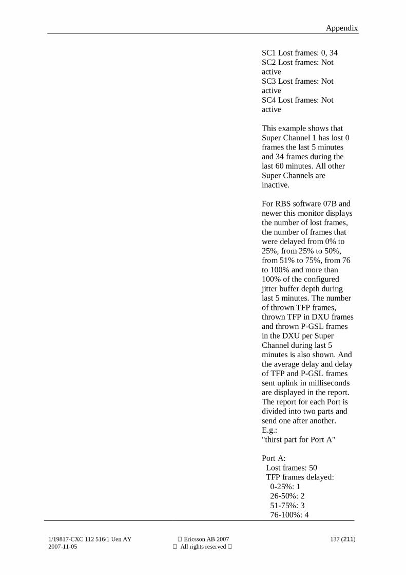
Appendix
1/19817-CXC 112 516/1 Uen AY Ericsson AB 2007 137 (211)2007-11-05 All rights reserved
SC1 Lost frames: 0, 34SC2 Lost frames: NotactiveSC3 Lost frames: NotactiveSC4 Lost frames: Notactive
This example shows thatSuper Channel 1 has lost 0frames the last 5 minutesand 34 frames during thelast 60 minutes. All otherSuper Channels areinactive.
For RBS software 07B andnewer this monitor displaysthe number of lost frames,the number of frames thatwere delayed from 0% to25%, from 25% to 50%,from 51% to 75%, from 76to 100% and more than100% of the configuredjitter buffer depth duringlast 5 minutes. The numberof thrown TFP frames,thrown TFP in DXU framesand thrown P-GSL framesin the DXU per SuperChannel during last 5minutes is also shown. Andthe average delay and delayof TFP and P-GSL framessent uplink in millisecondsare displayed in the report.The report for each Port isdivided into two parts andsend one after another.E.g.:"thirst part for Port A"
Port A: Lost frames: 50 TFP frames delayed: 0-25%: 1 26-50%: 2 51-75%: 3 76-100%: 4
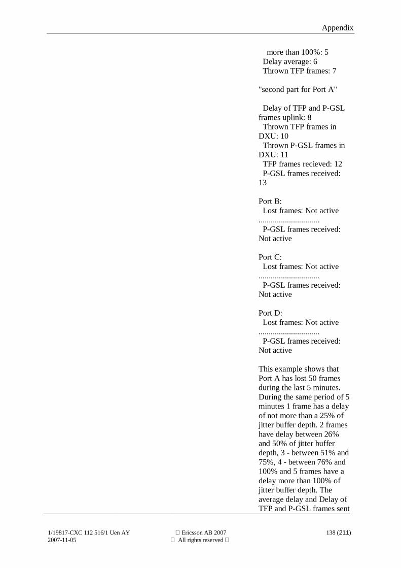
Appendix
1/19817-CXC 112 516/1 Uen AY Ericsson AB 2007 138 (211)2007-11-05 All rights reserved
more than 100%: 5 Delay average: 6 Thrown TFP frames: 7
"second part for Port A"
Delay of TFP and P-GSLframes uplink: 8 Thrown TFP frames inDXU: 10 Thrown P-GSL frames inDXU: 11 TFP frames recieved: 12 P-GSL frames received:13
Port B: Lost frames: Not active.............................. P-GSL frames received:Not active
Port C: Lost frames: Not active.............................. P-GSL frames received:Not active
Port D: Lost frames: Not active.............................. P-GSL frames received:Not active
This example shows thatPort A has lost 50 framesduring the last 5 minutes.During the same period of 5minutes 1 frame has a delayof not more than a 25% ofjitter buffer depth. 2 frameshave delay between 26%and 50% of jitter bufferdepth, 3 - between 51% and75%, 4 - between 76% and100% and 5 frames have adelay more than 100% ofjitter buffer depth. Theaverage delay and Delay ofTFP and P-GSL frames sent
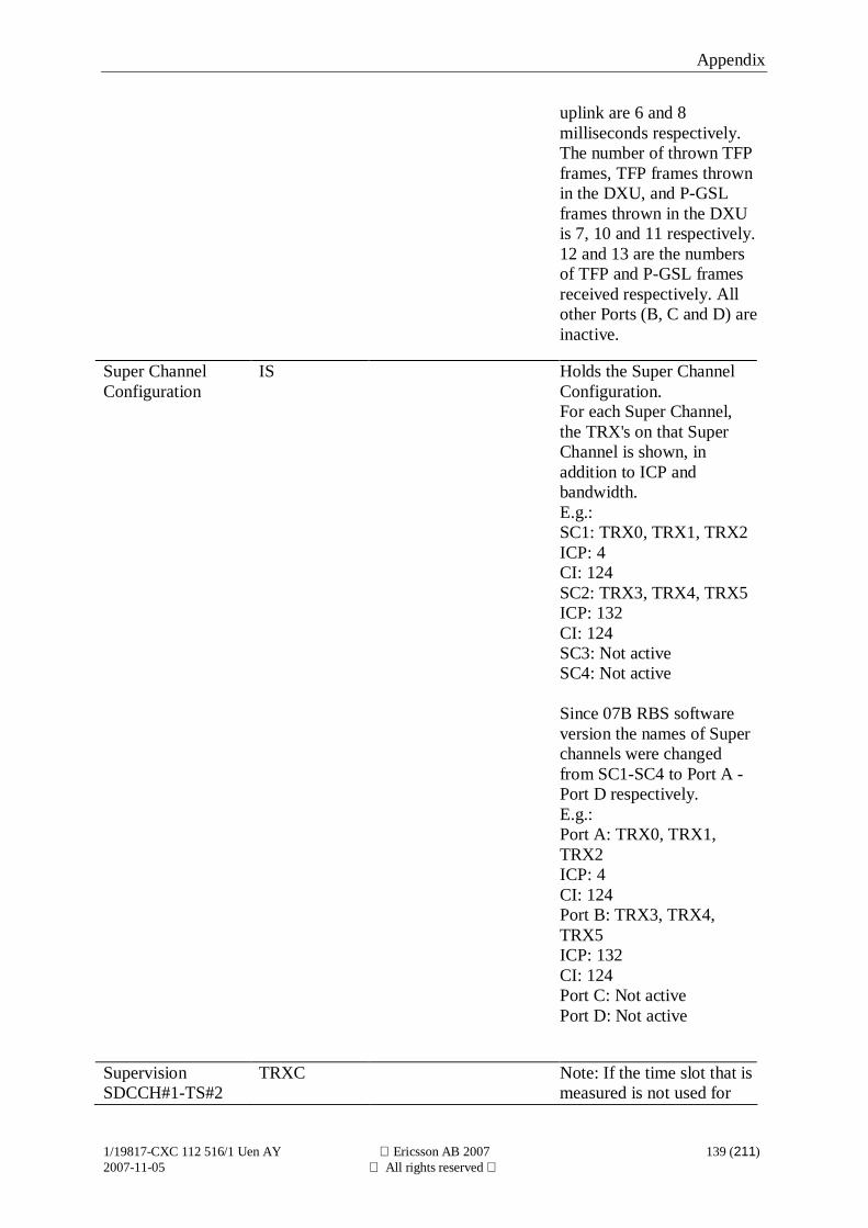
Appendix
1/19817-CXC 112 516/1 Uen AY Ericsson AB 2007 139 (211)2007-11-05 All rights reserved
uplink are 6 and 8milliseconds respectively.The number of thrown TFPframes, TFP frames thrownin the DXU, and P-GSLframes thrown in the DXUis 7, 10 and 11 respectively.12 and 13 are the numbersof TFP and P-GSL framesreceived respectively. Allother Ports (B, C and D) areinactive.
Super ChannelConfiguration
IS Holds the Super ChannelConfiguration.For each Super Channel,the TRX's on that SuperChannel is shown, inaddition to ICP andbandwidth.E.g.:SC1: TRX0, TRX1, TRX2ICP: 4CI: 124SC2: TRX3, TRX4, TRX5ICP: 132CI: 124SC3: Not activeSC4: Not active
Since 07B RBS softwareversion the names of Superchannels were changedfrom SC1-SC4 to Port A -Port D respectively.E.g.:Port A: TRX0, TRX1,TRX2ICP: 4CI: 124Port B: TRX3, TRX4,TRX5ICP: 132CI: 124Port C: Not activePort D: Not active
SupervisionSDCCH#1-TS#2
TRXC Note: If the time slot that ismeasured is not used for
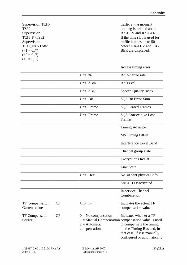
Appendix
1/19817-CXC 112 516/1 Uen AY Ericsson AB 2007 140 (211)2007-11-05 All rights reserved
Supervision TCH-TS#2SupervisionTCH_F -TS#2SupervisionTCH_H#3-TS#2(#1 = 0..7)(#2 = 0..7)(#3 = 0, 1)
traffic at the momentnothing is printed aboutRX-LEV and RX-BER.If the time slot is used fortraffic it takes up to 50 sbefore RX-LEV and RX-BER are displayed.
Access timing error
Unit: % RX bit error rate
Unit: dBm RX Level
Unit: dBQ Speech Quality Index
Unit: Bit SQS Bit Error Sum
Unit: Frame SQS Erased Frames
Unit: Frame SQS Consecutive LostFrames
Timing Advance
MS Timing Offset
Interference Level Band
Channel group state
Encryption On/Off
Link State
Unit: Hex No. of sent physical info.
SACCH Deactivated
In-service ChannelCombination
TF CompensationCurrent value
CF Unit: ns Indicates the actual TFcompensation value
TF Compensation –Source
CF 0 = No compensation1 = Manual Compensation2 = Automaticcompensation
Indicates whether a TFcompensation value is usedto compensate the timingon the Timing Bus and, inthat case, if it is manuallyconfigured or automatically
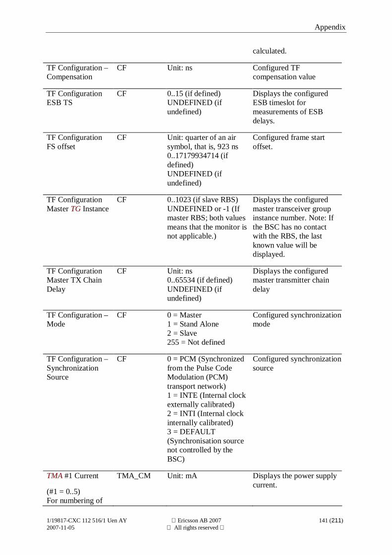
Appendix
1/19817-CXC 112 516/1 Uen AY Ericsson AB 2007 141 (211)2007-11-05 All rights reserved
calculated.
TF Configuration –Compensation
CF Unit: ns Configured TFcompensation value
TF ConfigurationESB TS
CF 0..15 (if defined)UNDEFINED (ifundefined)
Displays the configuredESB timeslot formeasurements of ESBdelays.
TF ConfigurationFS offset
CF Unit: quarter of an airsymbol, that is, 923 ns0..17179934714 (ifdefined)UNDEFINED (ifundefined)
Configured frame startoffset.
TF ConfigurationMaster TG Instance
CF 0..1023 (if slave RBS)UNDEFINED or -1 (Ifmaster RBS; both valuesmeans that the monitor isnot applicable.)
Displays the configuredmaster transceiver groupinstance number. Note: Ifthe BSC has no contactwith the RBS, the lastknown value will bedisplayed.
TF ConfigurationMaster TX ChainDelay
CF Unit: ns0..65534 (if defined)UNDEFINED (ifundefined)
Displays the configuredmaster transmitter chaindelay
TF Configuration –Mode
CF 0 = Master1 = Stand Alone2 = Slave255 = Not defined
Configured synchronizationmode
TF Configuration –SynchronizationSource
CF 0 = PCM (Synchronizedfrom the Pulse CodeModulation (PCM)transport network)1 = INTE (Internal clockexternally calibrated)2 = INTI (Internal clockinternally calibrated)3 = DEFAULT(Synchronisation sourcenot controlled by theBSC)
Configured synchronizationsource
TMA #1 Current
(#1 = 0..5)For numbering of
TMA_CM Unit: mA Displays the power supplycurrent.
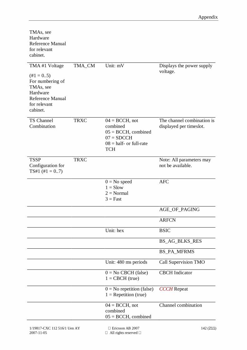
Appendix
1/19817-CXC 112 516/1 Uen AY Ericsson AB 2007 142 (211)2007-11-05 All rights reserved
TMAs, seeHardwareReference Manualfor relevantcabinet.
TMA #1 Voltage
(#1 = 0..5)For numbering ofTMAs, seeHardwareReference Manualfor relevantcabinet.
TMA_CM Unit: mV Displays the power supplyvoltage.
TS ChannelCombination
TRXC 04 = BCCH, notcombined05 = BCCH, combined07 = SDCCH08 = half- or full-rateTCH
The channel combination isdisplayed per timeslot.
TSSPConfiguration forTS#1 (#1 = 0..7)
TRXC Note: All parameters maynot be available.
0 = No speed1 = Slow2 = Normal3 = Fast
AFC
AGE_OF_PAGING
ARFCN
Unit: hex BSIC
BS_AG_BLKS_RES
BS_PA_MFRMS
Unit: 480 ms periods Call Supervision TMO
0 = No CBCH (false)1 = CBCH (true)
CBCH Indicator
0 = No repetition (false)1 = Repetition (true)
CCCH Repeat
04 = BCCH, notcombined05 = BCCH, combined
Channel combination
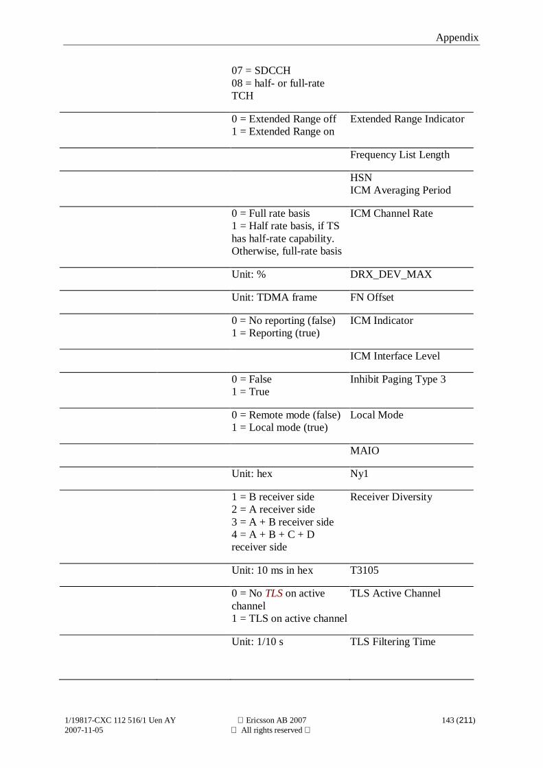
Appendix
1/19817-CXC 112 516/1 Uen AY Ericsson AB 2007 143 (211)2007-11-05 All rights reserved
07 = SDCCH08 = half- or full-rateTCH
0 = Extended Range off1 = Extended Range on
Extended Range Indicator
Frequency List Length
HSNICM Averaging Period
0 = Full rate basis1 = Half rate basis, if TShas half-rate capability.Otherwise, full-rate basis
ICM Channel Rate
Unit: % DRX_DEV_MAX
Unit: TDMA frame FN Offset
0 = No reporting (false)1 = Reporting (true)
ICM Indicator
ICM Interface Level
0 = False1 = True
Inhibit Paging Type 3
0 = Remote mode (false)1 = Local mode (true)
Local Mode
MAIO
Unit: hex Ny1
1 = B receiver side2 = A receiver side3 = A + B receiver side4 = A + B + C + Dreceiver side
Receiver Diversity
Unit: 10 ms in hex T3105
0 = No TLS on activechannel1 = TLS on active channel
TLS Active Channel
Unit: 1/10 s TLS Filtering Time
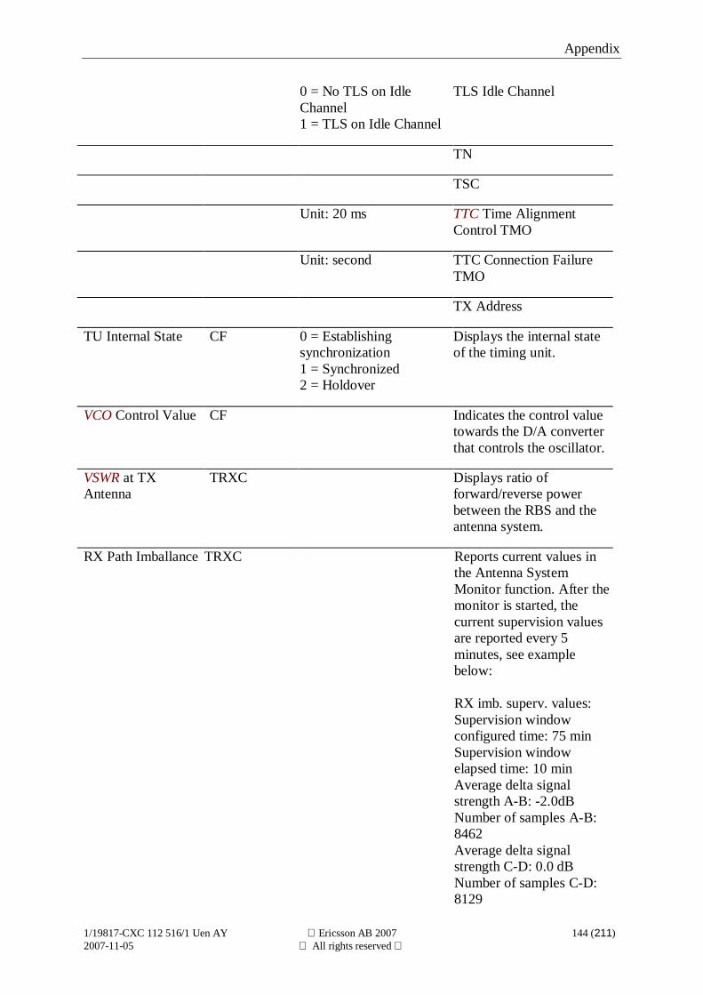
Appendix
1/19817-CXC 112 516/1 Uen AY Ericsson AB 2007 144 (211)2007-11-05 All rights reserved
0 = No TLS on IdleChannel1 = TLS on Idle Channel
TLS Idle Channel
TN
TSC
Unit: 20 ms TTC Time AlignmentControl TMO
Unit: second TTC Connection FailureTMO
TX Address
TU Internal State CF 0 = Establishingsynchronization1 = Synchronized2 = Holdover
Displays the internal stateof the timing unit.
VCO Control Value CF Indicates the control valuetowards the D/A converterthat controls the oscillator.
VSWR at TXAntenna
TRXC Displays ratio offorward/reverse powerbetween the RBS and theantenna system.
RX Path Imballance TRXC Reports current values inthe Antenna SystemMonitor function. After themonitor is started, thecurrent supervision valuesare reported every 5minutes, see examplebelow:
RX imb. superv. values:Supervision windowconfigured time: 75 minSupervision windowelapsed time: 10 minAverage delta signalstrength A-B: -2.0dBNumber of samples A-B:8462Average delta signalstrength C-D: 0.0 dBNumber of samples C-D:8129
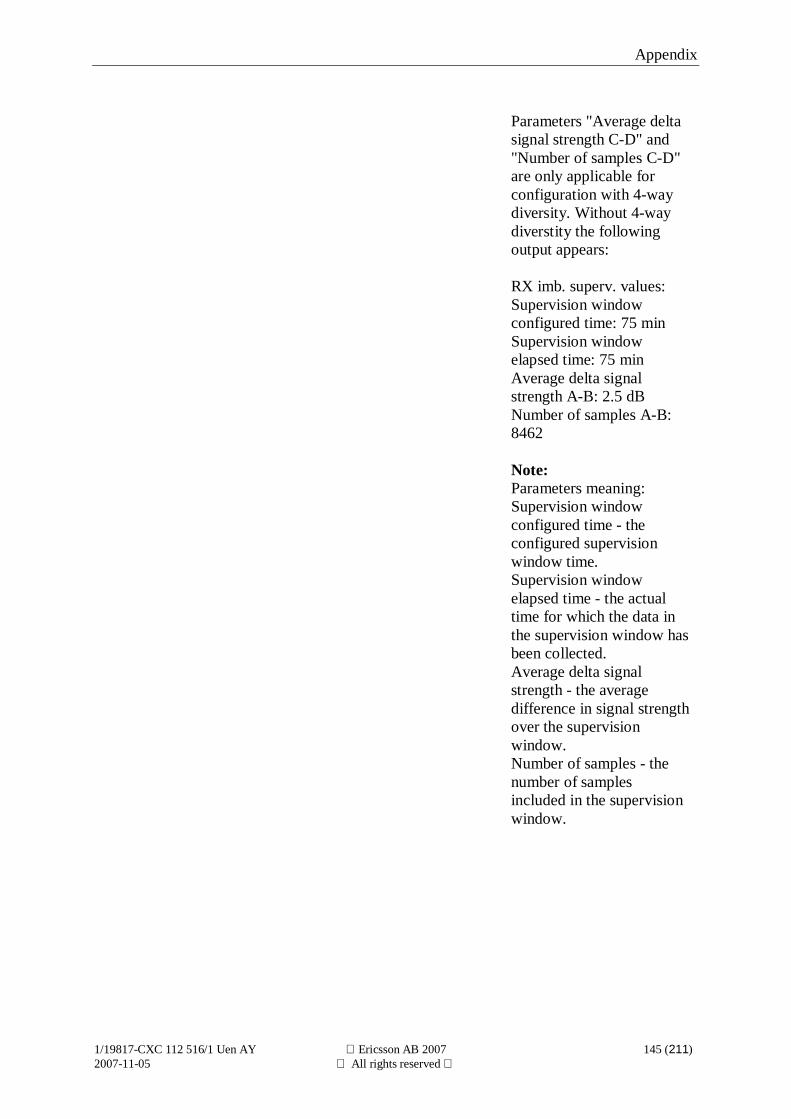
Appendix
1/19817-CXC 112 516/1 Uen AY Ericsson AB 2007 145 (211)2007-11-05 All rights reserved
Parameters "Average deltasignal strength C-D" and"Number of samples C-D"are only applicable forconfiguration with 4-waydiversity. Without 4-waydiverstity the followingoutput appears:
RX imb. superv. values:Supervision windowconfigured time: 75 minSupervision windowelapsed time: 75 minAverage delta signalstrength A-B: 2.5 dBNumber of samples A-B:8462
Note:Parameters meaning:Supervision windowconfigured time - theconfigured supervisionwindow time.Supervision windowelapsed time - the actualtime for which the data inthe supervision window hasbeen collected.Average delta signalstrength - the averagedifference in signal strengthover the supervisionwindow.Number of samples - thenumber of samplesincluded in the supervisionwindow.
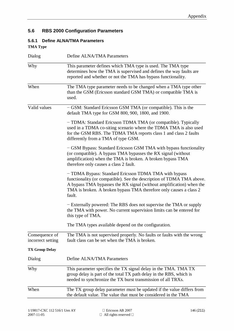
Appendix
1/19817-CXC 112 516/1 Uen AY Ericsson AB 2007 146 (211)2007-11-05 All rights reserved
5.6 RBS 2000 Configuration Parameters
5.6.1 Define ALNA/TMA ParametersTMA Type
Dialog Define ALNA/TMA Parameters
Why This parameter defines which TMA type is used. The TMA typedetermines how the TMA is supervised and defines the way faults arereported and whether or not the TMA has bypass functionality.
When The TMA type parameter needs to be changed when a TMA type otherthan the GSM (Ericsson standard GSM TMA) or compatible TMA isused.
Valid values GSM: Standard Ericsson GSM TMA (or compatible). This is thedefault TMA type for GSM 800, 900, 1800, and 1900.
TDMA: Standard Ericsson TDMA TMA (or compatible). Typicallyused in a TDMA co-siting scenario where the TDMA TMA is also usedfor the GSM RBS. The TDMA TMA reports class 1 and class 2 faultsdifferently from a TMA of type GSM.
GSM Bypass: Standard Ericsson GSM TMA with bypass functionality(or compatible). A bypass TMA bypasses the RX signal (withoutamplification) when the TMA is broken. A broken bypass TMAtherefore only causes a class 2 fault.
TDMA Bypass: Standard Ericsson TDMA TMA with bypassfunctionality (or compatible). See the description of TDMA TMA above.A bypass TMA bypasses the RX signal (without amplification) when theTMA is broken. A broken bypass TMA therefore only causes a class 2fault.
Externally powered: The RBS does not supervise the TMA or supplythe TMA with power. No current supervision limits can be entered forthis type of TMA.
The TMA types available depend on the configuration.
Consequence ofincorrect setting
The TMA is not supervised properly. No faults or faults with the wrongfault class can be set when the TMA is broken.
TX Group Delay
Dialog Define ALNA/TMA Parameters
Why This parameter specifies the TX signal delay in the TMA. TMA TXgroup delay is part of the total TX path delay in the RBS, which isneeded to synchronize the TX burst transmission of all TRXs.
When The TX group delay parameter must be updated if the value differs fromthe default value. The value that must be considered in the TMA
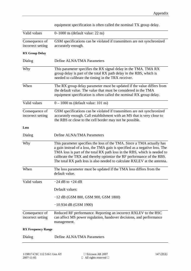
Appendix
1/19817-CXC 112 516/1 Uen AY Ericsson AB 2007 147 (211)2007-11-05 All rights reserved
equipment specification is often called the nominal TX group delay.
Valid values 0–1000 ns (default value: 22 ns)
Consequence ofincorrect setting
GSM specifications can be violated if transmitters are not synchronizedaccurately enough.
RX Group Delay
Dialog Define ALNA/TMA Parameters
Why This parameter specifies the RX signal delay in the TMA. TMA RXgroup delay is part of the total RX path delay in the RBS, which isneeded to calibrate the timing in the TRX receiver.
When The RX group delay parameter must be updated if the value differs fromthe default value. The value that must be considered in the TMAequipment specification is often called the nominal RX group delay.
Valid values 0 – 1000 ns (default value: 101 ns)
Consequence ofincorrect setting
GSM specifications can be violated if transmitters are not synchronizedaccurately enough. Call establishment with an MS that is very close tothe RBS or close to the cell border may not be possible.
Loss
Dialog Define ALNA/TMA Parameters
Why This parameter specifies the loss of the TMA. Since a TMA actually hasa gain instead of a loss, the TMA gain is specified as a negative loss. TheTMA loss is part of the total RX path loss in the RBS, which is needed tocalibrate the TRX and thereby optimize the RF performance of the RBS.The total RX path loss is also needed to calculate RXLEV at the antenna.
When The loss parameter must be updated if the TMA loss differs from thedefault value.
Valid values 24 dB to +24 dB
Default values:
12 dB (GSM 800, GSM 900, GSM 1800)
10.934 dB (GSM 1900)
Consequence ofincorrect setting
Reduced RF performance. Reporting an incorrect RXLEV to the BSCcan affect MS power regulation, handover decisions, and performancemanagement.
RX Frequency Range
Dialog Define ALNA/TMA Parameters
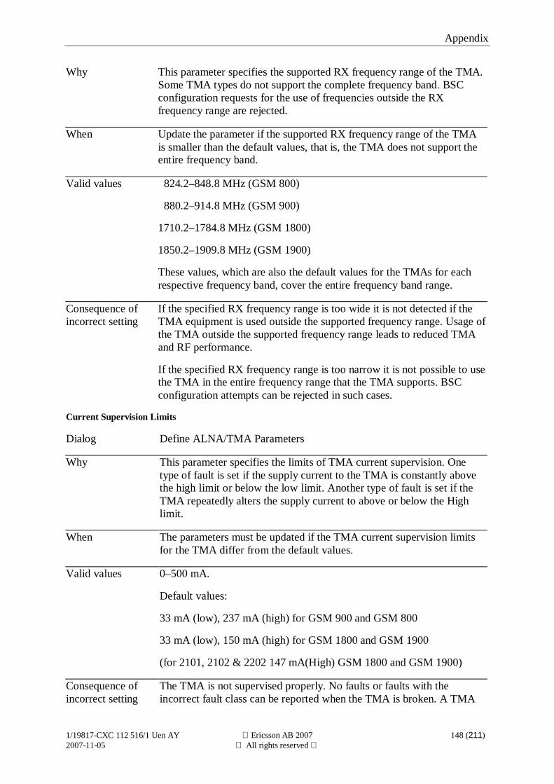
Appendix
1/19817-CXC 112 516/1 Uen AY Ericsson AB 2007 148 (211)2007-11-05 All rights reserved
Why This parameter specifies the supported RX frequency range of the TMA.Some TMA types do not support the complete frequency band. BSCconfiguration requests for the use of frequencies outside the RXfrequency range are rejected.
When Update the parameter if the supported RX frequency range of the TMAis smaller than the default values, that is, the TMA does not support theentire frequency band.
Valid values 824.2–848.8 MHz (GSM 800)
880.2–914.8 MHz (GSM 900)
1710.2–1784.8 MHz (GSM 1800)
1850.2–1909.8 MHz (GSM 1900)
These values, which are also the default values for the TMAs for eachrespective frequency band, cover the entire frequency band range.
Consequence ofincorrect setting
If the specified RX frequency range is too wide it is not detected if theTMA equipment is used outside the supported frequency range. Usage ofthe TMA outside the supported frequency range leads to reduced TMAand RF performance.
If the specified RX frequency range is too narrow it is not possible to usethe TMA in the entire frequency range that the TMA supports. BSCconfiguration attempts can be rejected in such cases.
Current Supervision Limits
Dialog Define ALNA/TMA Parameters
Why This parameter specifies the limits of TMA current supervision. Onetype of fault is set if the supply current to the TMA is constantly abovethe high limit or below the low limit. Another type of fault is set if theTMA repeatedly alters the supply current to above or below the Highlimit.
When The parameters must be updated if the TMA current supervision limitsfor the TMA differ from the default values.
Valid values 0–500 mA.
Default values:
33 mA (low), 237 mA (high) for GSM 900 and GSM 800
33 mA (low), 150 mA (high) for GSM 1800 and GSM 1900
(for 2101, 2102 & 2202 147 mA(High) GSM 1800 and GSM 1900)
Consequence ofincorrect setting
The TMA is not supervised properly. No faults or faults with theincorrect fault class can be reported when the TMA is broken. A TMA

Appendix
1/19817-CXC 112 516/1 Uen AY Ericsson AB 2007 149 (211)2007-11-05 All rights reserved
fault can be reported when no fault is present.
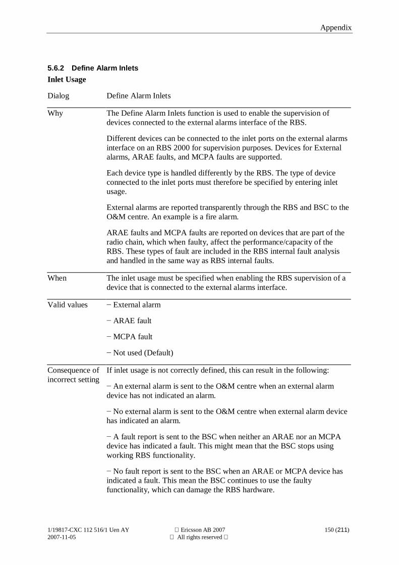
Appendix
1/19817-CXC 112 516/1 Uen AY Ericsson AB 2007 150 (211)2007-11-05 All rights reserved
5.6.2 Define Alarm InletsInlet Usage
Dialog Define Alarm Inlets
Why The Define Alarm Inlets function is used to enable the supervision ofdevices connected to the external alarms interface of the RBS.
Different devices can be connected to the inlet ports on the external alarmsinterface on an RBS 2000 for supervision purposes. Devices for Externalalarms, ARAE faults, and MCPA faults are supported.
Each device type is handled differently by the RBS. The type of deviceconnected to the inlet ports must therefore be specified by entering inletusage.
External alarms are reported transparently through the RBS and BSC to theO&M centre. An example is a fire alarm.
ARAE faults and MCPA faults are reported on devices that are part of theradio chain, which when faulty, affect the performance/capacity of theRBS. These types of fault are included in the RBS internal fault analysisand handled in the same way as RBS internal faults.
When The inlet usage must be specified when enabling the RBS supervision of adevice that is connected to the external alarms interface.
Valid values External alarm
ARAE fault
MCPA fault
Not used (Default)
Consequence ofincorrect setting
If inlet usage is not correctly defined, this can result in the following:
An external alarm is sent to the O&M centre when an external alarmdevice has not indicated an alarm.
No external alarm is sent to the O&M centre when external alarm devicehas indicated an alarm.
A fault report is sent to the BSC when neither an ARAE nor an MCPAdevice has indicated a fault. This might mean that the BSC stops usingworking RBS functionality.
No fault report is sent to the BSC when an ARAE or MCPA device hasindicated a fault. This mean the BSC continues to use the faultyfunctionality, which can damage the RBS hardware.
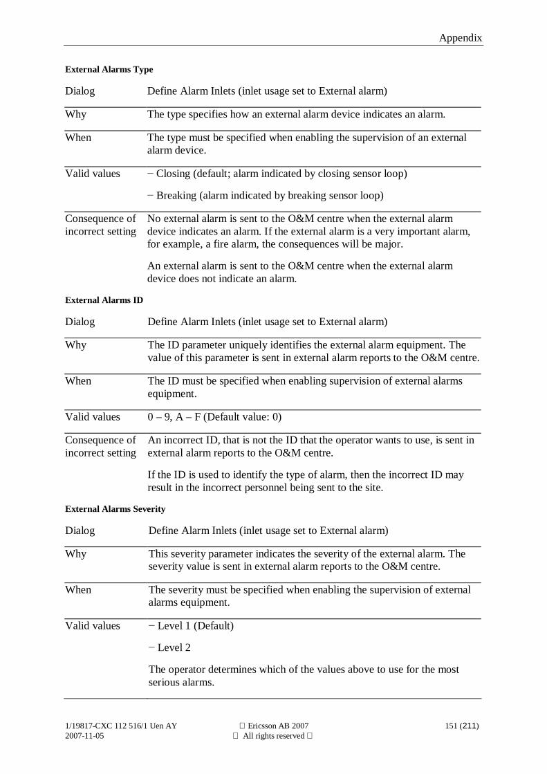
Appendix
1/19817-CXC 112 516/1 Uen AY Ericsson AB 2007 151 (211)2007-11-05 All rights reserved
External Alarms Type
Dialog Define Alarm Inlets (inlet usage set to External alarm)
Why The type specifies how an external alarm device indicates an alarm.
When The type must be specified when enabling the supervision of an externalalarm device.
Valid values Closing (default; alarm indicated by closing sensor loop)
Breaking (alarm indicated by breaking sensor loop)
Consequence ofincorrect setting
No external alarm is sent to the O&M centre when the external alarmdevice indicates an alarm. If the external alarm is a very important alarm,for example, a fire alarm, the consequences will be major.
An external alarm is sent to the O&M centre when the external alarmdevice does not indicate an alarm.
External Alarms ID
Dialog Define Alarm Inlets (inlet usage set to External alarm)
Why The ID parameter uniquely identifies the external alarm equipment. Thevalue of this parameter is sent in external alarm reports to the O&M centre.
When The ID must be specified when enabling supervision of external alarmsequipment.
Valid values 0 – 9, A – F (Default value: 0)
Consequence ofincorrect setting
An incorrect ID, that is not the ID that the operator wants to use, is sent inexternal alarm reports to the O&M centre.
If the ID is used to identify the type of alarm, then the incorrect ID mayresult in the incorrect personnel being sent to the site.
External Alarms Severity
Dialog Define Alarm Inlets (inlet usage set to External alarm)
Why This severity parameter indicates the severity of the external alarm. Theseverity value is sent in external alarm reports to the O&M centre.
When The severity must be specified when enabling the supervision of externalalarms equipment.
Valid values Level 1 (Default)
Level 2
The operator determines which of the values above to use for the mostserious alarms.
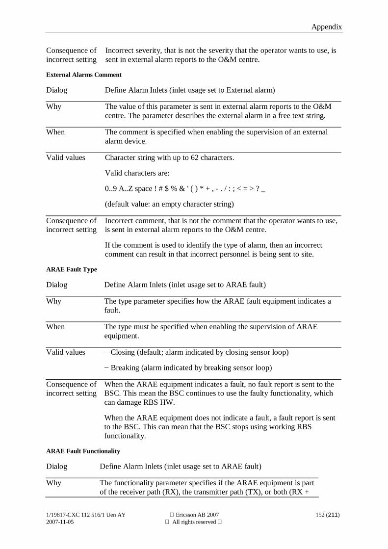
Appendix
1/19817-CXC 112 516/1 Uen AY Ericsson AB 2007 152 (211)2007-11-05 All rights reserved
Consequence ofincorrect setting
Incorrect severity, that is not the severity that the operator wants to use, issent in external alarm reports to the O&M centre.
External Alarms Comment
Dialog Define Alarm Inlets (inlet usage set to External alarm)
Why The value of this parameter is sent in external alarm reports to the O&Mcentre. The parameter describes the external alarm in a free text string.
When The comment is specified when enabling the supervision of an externalalarm device.
Valid values Character string with up to 62 characters.
Valid characters are:
0..9 A..Z space ! # $ % & ' ( ) * + , - . / : ; < = > ? _
(default value: an empty character string)
Consequence ofincorrect setting
Incorrect comment, that is not the comment that the operator wants to use,is sent in external alarm reports to the O&M centre.
If the comment is used to identify the type of alarm, then an incorrectcomment can result in that incorrect personnel is being sent to site.
ARAE Fault Type
Dialog Define Alarm Inlets (inlet usage set to ARAE fault)
Why The type parameter specifies how the ARAE fault equipment indicates afault.
When The type must be specified when enabling the supervision of ARAEequipment.
Valid values Closing (default; alarm indicated by closing sensor loop)
Breaking (alarm indicated by breaking sensor loop)
Consequence ofincorrect setting
When the ARAE equipment indicates a fault, no fault report is sent to theBSC. This mean the BSC continues to use the faulty functionality, whichcan damage RBS HW.
When the ARAE equipment does not indicate a fault, a fault report is sentto the BSC. This can mean that the BSC stops using working RBSfunctionality.
ARAE Fault Functionality
Dialog Define Alarm Inlets (inlet usage set to ARAE fault)
Why The functionality parameter specifies if the ARAE equipment is partof the receiver path (RX), the transmitter path (TX), or both (RX +
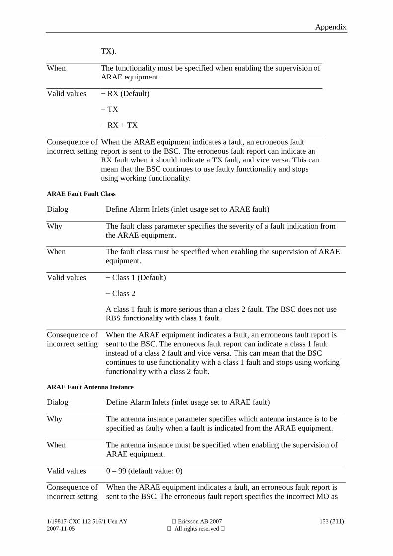
Appendix
1/19817-CXC 112 516/1 Uen AY Ericsson AB 2007 153 (211)2007-11-05 All rights reserved
TX).
When The functionality must be specified when enabling the supervision ofARAE equipment.
Valid values RX (Default)
TX
RX + TX
Consequence ofincorrect setting
When the ARAE equipment indicates a fault, an erroneous faultreport is sent to the BSC. The erroneous fault report can indicate anRX fault when it should indicate a TX fault, and vice versa. This canmean that the BSC continues to use faulty functionality and stopsusing working functionality.
ARAE Fault Fault Class
Dialog Define Alarm Inlets (inlet usage set to ARAE fault)
Why The fault class parameter specifies the severity of a fault indication fromthe ARAE equipment.
When The fault class must be specified when enabling the supervision of ARAEequipment.
Valid values Class 1 (Default)
Class 2
A class 1 fault is more serious than a class 2 fault. The BSC does not useRBS functionality with class 1 fault.
Consequence ofincorrect setting
When the ARAE equipment indicates a fault, an erroneous fault report issent to the BSC. The erroneous fault report can indicate a class 1 faultinstead of a class 2 fault and vice versa. This can mean that the BSCcontinues to use functionality with a class 1 fault and stops using workingfunctionality with a class 2 fault.
ARAE Fault Antenna Instance
Dialog Define Alarm Inlets (inlet usage set to ARAE fault)
Why The antenna instance parameter specifies which antenna instance is to bespecified as faulty when a fault is indicated from the ARAE equipment.
When The antenna instance must be specified when enabling the supervision ofARAE equipment.
Valid values 0 – 99 (default value: 0)
Consequence ofincorrect setting
When the ARAE equipment indicates a fault, an erroneous fault report issent to the BSC. The erroneous fault report specifies the incorrect MO as
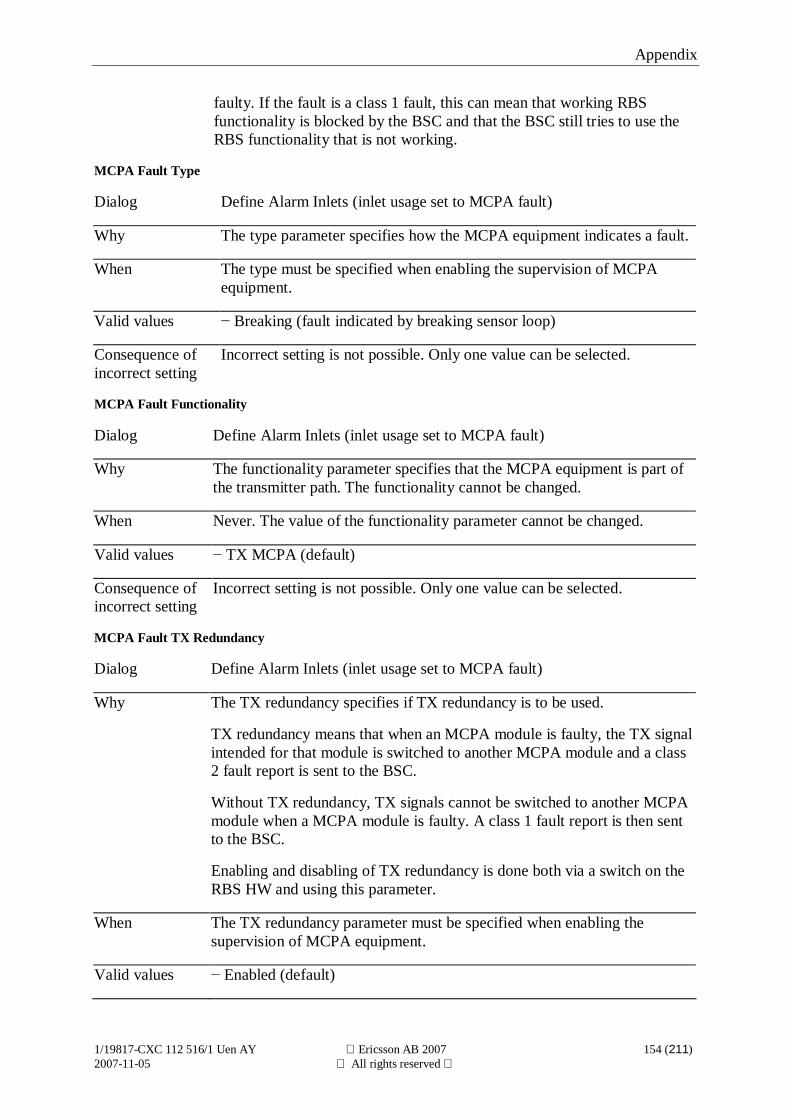
Appendix
1/19817-CXC 112 516/1 Uen AY Ericsson AB 2007 154 (211)2007-11-05 All rights reserved
faulty. If the fault is a class 1 fault, this can mean that working RBSfunctionality is blocked by the BSC and that the BSC still tries to use theRBS functionality that is not working.
MCPA Fault Type
Dialog Define Alarm Inlets (inlet usage set to MCPA fault)
Why The type parameter specifies how the MCPA equipment indicates a fault.
When The type must be specified when enabling the supervision of MCPAequipment.
Valid values Breaking (fault indicated by breaking sensor loop)
Consequence ofincorrect setting
Incorrect setting is not possible. Only one value can be selected.
MCPA Fault Functionality
Dialog Define Alarm Inlets (inlet usage set to MCPA fault)
Why The functionality parameter specifies that the MCPA equipment is part ofthe transmitter path. The functionality cannot be changed.
When Never. The value of the functionality parameter cannot be changed.
Valid values TX MCPA (default)
Consequence ofincorrect setting
Incorrect setting is not possible. Only one value can be selected.
MCPA Fault TX Redundancy
Dialog Define Alarm Inlets (inlet usage set to MCPA fault)
Why The TX redundancy specifies if TX redundancy is to be used.
TX redundancy means that when an MCPA module is faulty, the TX signalintended for that module is switched to another MCPA module and a class2 fault report is sent to the BSC.
Without TX redundancy, TX signals cannot be switched to another MCPAmodule when a MCPA module is faulty. A class 1 fault report is then sentto the BSC.
Enabling and disabling of TX redundancy is done both via a switch on theRBS HW and using this parameter.
When The TX redundancy parameter must be specified when enabling thesupervision of MCPA equipment.
Valid values Enabled (default)
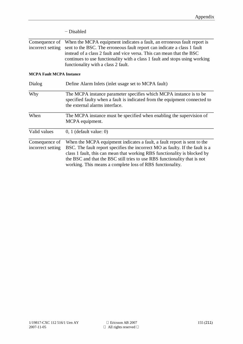
Appendix
1/19817-CXC 112 516/1 Uen AY Ericsson AB 2007 155 (211)2007-11-05 All rights reserved
Disabled
Consequence ofincorrect setting
When the MCPA equipment indicates a fault, an erroneous fault report issent to the BSC. The erroneous fault report can indicate a class 1 faultinstead of a class 2 fault and vice versa. This can mean that the BSCcontinues to use functionality with a class 1 fault and stops using workingfunctionality with a class 2 fault.
MCPA Fault MCPA Instance
Dialog Define Alarm Inlets (inlet usage set to MCPA fault)
Why The MCPA instance parameter specifies which MCPA instance is to bespecified faulty when a fault is indicated from the equipment connected tothe external alarms interface.
When The MCPA instance must be specified when enabling the supervision ofMCPA equipment.
Valid values 0, 1 (default value: 0)
Consequence ofincorrect setting
When the MCPA equipment indicates a fault, a fault report is sent to theBSC. The fault report specifies the incorrect MO as faulty. If the fault is aclass 1 fault, this can mean that working RBS functionality is blocked bythe BSC and that the BSC still tries to use RBS functionality that is notworking. This means a complete loss of RBS functionality.
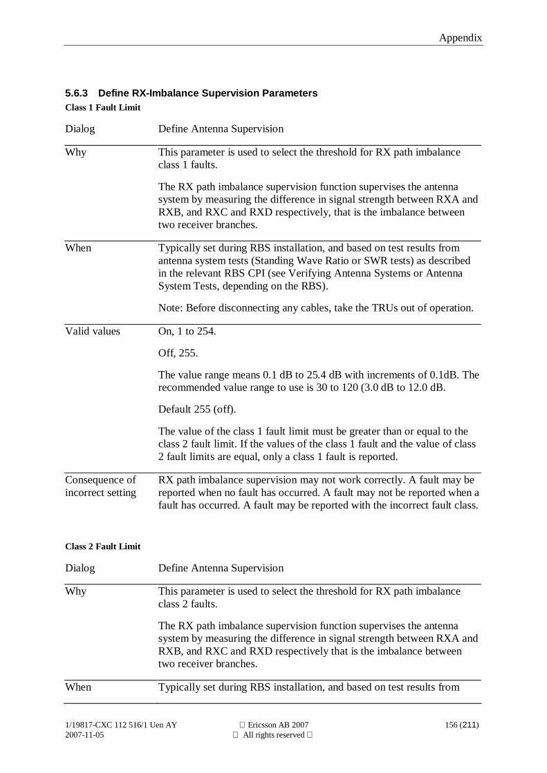
Appendix
1/19817-CXC 112 516/1 Uen AY Ericsson AB 2007 156 (211)2007-11-05 All rights reserved
5.6.3 Define RX-Imbalance Supervision ParametersClass 1 Fault Limit
Dialog Define Antenna Supervision
Why This parameter is used to select the threshold for RX path imbalanceclass 1 faults.
The RX path imbalance supervision function supervises the antennasystem by measuring the difference in signal strength between RXA andRXB, and RXC and RXD respectively, that is the imbalance betweentwo receiver branches.
When Typically set during RBS installation, and based on test results fromantenna system tests (Standing Wave Ratio or SWR tests) as describedin the relevant RBS CPI (see Verifying Antenna Systems or AntennaSystem Tests, depending on the RBS).
Note: Before disconnecting any cables, take the TRUs out of operation.
Valid values On, 1 to 254.
Off, 255.
The value range means 0.1 dB to 25.4 dB with increments of 0.1dB. Therecommended value range to use is 30 to 120 (3.0 dB to 12.0 dB.
Default 255 (off).
The value of the class 1 fault limit must be greater than or equal to theclass 2 fault limit. If the values of the class 1 fault and the value of class2 fault limits are equal, only a class 1 fault is reported.
Consequence ofincorrect setting
RX path imbalance supervision may not work correctly. A fault may bereported when no fault has occurred. A fault may not be reported when afault has occurred. A fault may be reported with the incorrect fault class.
Class 2 Fault Limit
Dialog Define Antenna Supervision
Why This parameter is used to select the threshold for RX path imbalanceclass 2 faults.
The RX path imbalance supervision function supervises the antennasystem by measuring the difference in signal strength between RXA andRXB, and RXC and RXD respectively that is the imbalance betweentwo receiver branches.
When Typically set during RBS installation, and based on test results from
Appendix
1/19817-CXC 112 516/1 Uen AY Ericsson AB 2007 157 (211)2007-11-05 All rights reserved
antenna system tests (Standing Wave Ratio or SWR tests) as describedin the relevant RBS CPI (see Verifying Antenna Systems or AntennaSystem Tests, depending on the RBS).
Note: Before disconnecting any cables, take the TRUs out of operation.
Valid values On, 1 to 254.
Off, 255.
The value range means 0.1 dB to 25.4 dB with increments of 0.1dB. Therecommended value range to use is 30 to 120 (3.0 dB to 12.0 dB.
Default 60 (6dB).
The value of the class 1 fault limit must be greater than or equal to thevalue of the class 2 fault limit. If the values of the class 1 fault and class2 fault limits are equal, only a class 1 fault is exported.
Consequence ofincorrect setting
RX path imbalance supervision may not work correctly. A fault may bereported when no fault has occurred. A fault may not be reported when afault has occurred. A fault may be reported with the incorrect fault class.
Supervision Window Time
Dialog Define Antenna Supervision
Why This parameter is used to specify how long measurement samples are tobe part of the RX path imbalance calculation. RX path imbalance iscalculated as the mean imbalance for two receiver branches during thespecified time.
A shorter supervision window time, gives a more rapid fault indicationbut is also more sensitive to short RX path imbalance disturbances.
When Typically at RBS installation, or when more rapid and less stable values,or slower and more stable values of the RX path imbalance are needed.
Valid values 5 3000 minutes or, 5 minutes to 50 hours (default: 1440 minutes, or24 hours).
Consequence ofincorrect setting
RX path imbalance supervision may not work correctly. A fault may bereported when no fault has occurred. A fault may not be reported when afault has occurred. A fault may be reported with the incorrect fault class.
Minimum Number Of Samples
Dialog Define Antenna Supervision
Appendix
1/19817-CXC 112 516/1 Uen AY Ericsson AB 2007 158 (211)2007-11-05 All rights reserved
Why This parameter is used to select the minimum number of measurementsamples that must be present in the supervision window for any RX pathimbalance faults to be reported. This is to prevent false alarms in cellswhere there are low traffic volumes, as one single phone call could beresponsible for most of the samples if there are low number of samples.
When Typically does not need to be changed.
Valid values 1 65535 (default: 7000).
Consequence ofincorrect setting
RX path imbalance supervision may not work correctly. A fault may bereported when no fault has occurred. A fault may not be reported when afault has occurred. A fault may be reported with the incorrect fault class.
Appendix
1/19817-CXC 112 516/1 Uen AY Ericsson AB 2007 159 (211)2007-11-05 All rights reserved
5.6.4 Define Battery Backup Time Test ParametersEnable test
Dialog Define Battery Backup Time Test Parameters
Why This parameter is used to enable the battery backup time test. Default thetest is disabled.
The test forces the RBS to run on battery. The time the RBS will run onbattery backup is measured and compared to the expected backup time.If the measured backup time is exceeding the defined expected backuptime then the test is considered successful.
When When the battery backup time test function is to be enabled or disabled.
Valid values Yes (enable)
No (disable)
Consequence ofincorrect setting
The battery backup time test is not run when intended or run when notintended.
Note! It is not enough to just enable the test. The other parameters mustbe checked since the default values cannot be used in all cases.
Start date
Dialog Define Battery Backup Time Test Parameters
Why The battery backup time test is a cyclic function and it is thereforenecessary to state a start date for the test.
The test forces the RBS to run on battery. The time the RBS will run onbattery backup is measured and compared to the expected backup time.If the measured backup time is exceeding the expected backup time thenthe test is considered successful.
When When the battery backup time test function is to be enabled.
Valid values YYMMDD
Consequence ofincorrect setting
The battery backup time test is not initiated when intended.
Start time
Dialog Define Battery Backup Time Test Parameters
Why This parameter defines the time of day when the battery backup time testis performed.
The battery backup time depends on the traffic load and this must beconsidered when choosing a start time for the test. If the backup time is
Appendix
1/19817-CXC 112 516/1 Uen AY Ericsson AB 2007 160 (211)2007-11-05 All rights reserved
expected to support high traffic load the start time must be during peakhours, otherwise the start time should be during low traffic.
The test forces the RBS to run on battery. The time the RBS will run onbattery backup is measured and compared to the expected backup time.If the measured backup time is exceeding the expected backup time thenthe test is considered successful.
When When the battery backup time test function is to be enabled.
Valid values 00:00–23:59 (hh:mm)
Consequence ofincorrect setting
The battery backup time test is not initiated when intended.
Voltage level to stop the test
Dialog Define Battery Backup Time Test Parameters
Why This parameter defines the voltage level that stops the test. The test mustbe stopped before the batteries are fully discharged.
The test forces the RBS to run on battery. The length of time that theRBS runs on battery backup is measured and compared with theexpected backup time. If the measured backup time exceeds the expectedbackup time, then the test is considered successful.
When When the battery backup time test function is to be enabled.
Valid values 22.5–23.5 V (default value: 23.0)
Consequence ofincorrect setting
If the value is wrong, the test reports an incorrect outcome. A low levelmeans a longer test period, which gives a more reliable test result, butthe batteries will be more discharged so more time must elapse before amains failure can be handled. A high level results in a greater differencebetween the measured backup time and the true backup time. Thedisconnect level main parameter defines the true backup time, and thevoltage level that stops the test must be at least 0.3 V higher than thedisconnect level.
Test interval
Dialog Define Battery Backup Time Test Parameters
Why This parameter defines the number of days between the battery backuptime tests. The battery backup time test is performed cyclically.
The test forces the RBS to run on battery. The time the RBS will run onbattery backup is measured and compared to the expected backup time.If the measured backup time is exceeding the expected backup time thenthe test is considered successful.
When When the battery backup time test function is to be enabled.
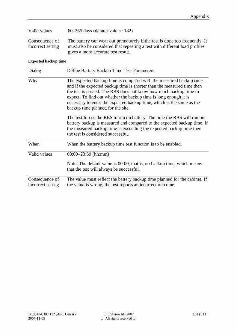
Appendix
1/19817-CXC 112 516/1 Uen AY Ericsson AB 2007 161 (211)2007-11-05 All rights reserved
Valid values 60–365 days (default values: 182)
Consequence ofincorrect setting
The battery can wear out prematurely if the test is done too frequently. Itmust also be considered that repeating a test with different load profilesgives a more accurate test result.
Expected backup time
Dialog Define Battery Backup Time Test Parameters
Why The expected backup time is compared with the measured backup timeand if the expected backup time is shorter than the measured time thenthe test is passed. The RBS does not know how much backup time toexpect. To find out whether the backup time is long enough it isnecessary to enter the expected backup time, which is the same as thebackup time planned for the site.
The test forces the RBS to run on battery. The time the RBS will run onbattery backup is measured and compared to the expected backup time. Ifthe measured backup time is exceeding the expected backup time thenthe test is considered successful.
When When the battery backup time test function is to be enabled.
Valid values 00:00–23:59 (hh:mm)
Note: The default value is 00:00, that is, no backup time, which meansthat the test will always be successful.
Consequence ofincorrect setting
The value must reflect the battery backup time planned for the cabinet. Ifthe value is wrong, the test reports an incorrect outcome.
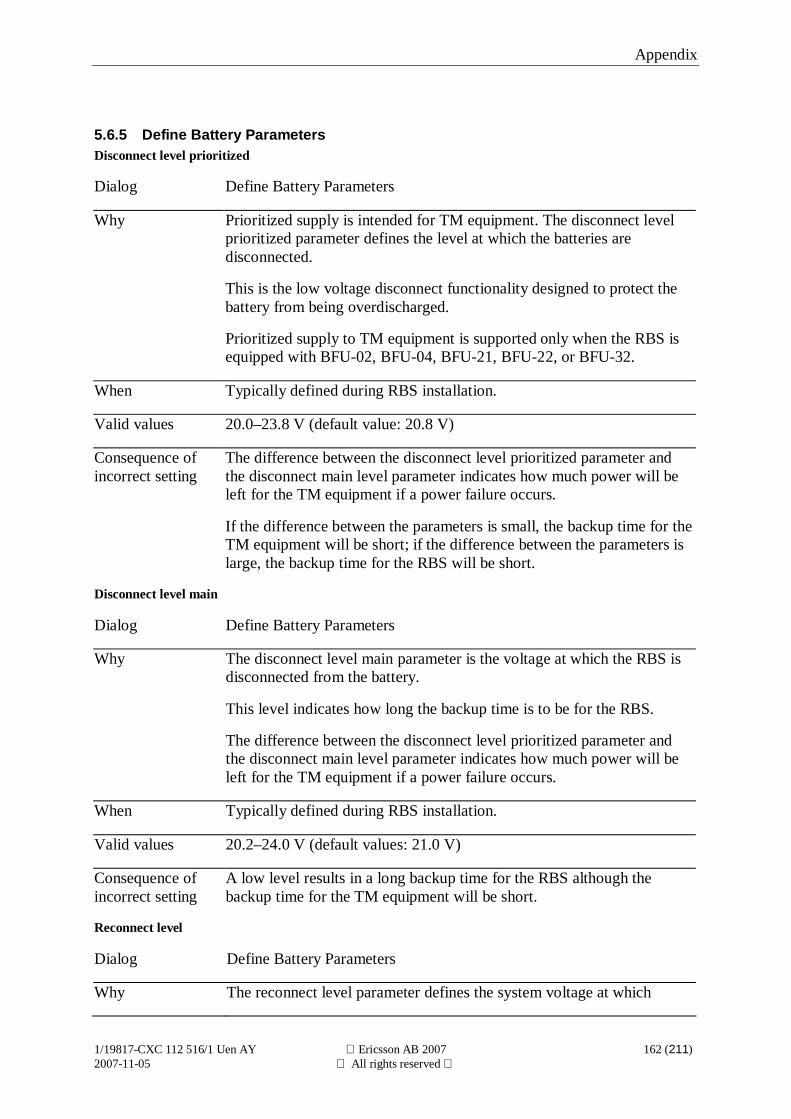
Appendix
1/19817-CXC 112 516/1 Uen AY Ericsson AB 2007 162 (211)2007-11-05 All rights reserved
5.6.5 Define Battery ParametersDisconnect level prioritized
Dialog Define Battery Parameters
Why Prioritized supply is intended for TM equipment. The disconnect levelprioritized parameter defines the level at which the batteries aredisconnected.
This is the low voltage disconnect functionality designed to protect thebattery from being overdischarged.
Prioritized supply to TM equipment is supported only when the RBS isequipped with BFU-02, BFU-04, BFU-21, BFU-22, or BFU-32.
When Typically defined during RBS installation.
Valid values 20.0–23.8 V (default value: 20.8 V)
Consequence ofincorrect setting
The difference between the disconnect level prioritized parameter andthe disconnect main level parameter indicates how much power will beleft for the TM equipment if a power failure occurs.
If the difference between the parameters is small, the backup time for theTM equipment will be short; if the difference between the parameters islarge, the backup time for the RBS will be short.
Disconnect level main
Dialog Define Battery Parameters
Why The disconnect level main parameter is the voltage at which the RBS isdisconnected from the battery.
This level indicates how long the backup time is to be for the RBS.
The difference between the disconnect level prioritized parameter andthe disconnect main level parameter indicates how much power will beleft for the TM equipment if a power failure occurs.
When Typically defined during RBS installation.
Valid values 20.2–24.0 V (default values: 21.0 V)
Consequence ofincorrect setting
A low level results in a long backup time for the RBS although thebackup time for the TM equipment will be short.
Reconnect level
Dialog Define Battery Parameters
Why The reconnect level parameter defines the system voltage at which
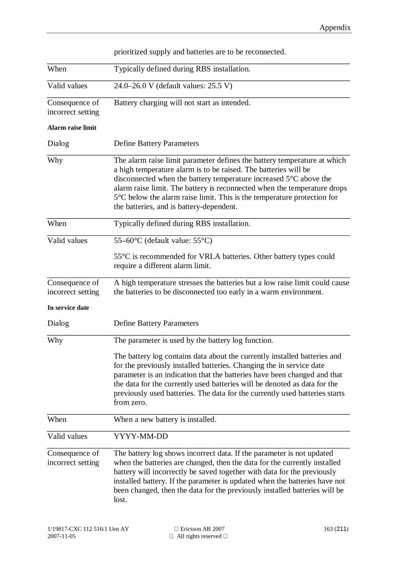
Appendix
1/19817-CXC 112 516/1 Uen AY Ericsson AB 2007 163 (211)2007-11-05 All rights reserved
prioritized supply and batteries are to be reconnected.
When Typically defined during RBS installation.
Valid values 24.0–26.0 V (default values: 25.5 V)
Consequence ofincorrect setting
Battery charging will not start as intended.
Alarm raise limit
Dialog Define Battery Parameters
Why The alarm raise limit parameter defines the battery temperature at whicha high temperature alarm is to be raised. The batteries will bedisconnected when the battery temperature increased 5°C above thealarm raise limit. The battery is reconnected when the temperature drops5°C below the alarm raise limit. This is the temperature protection forthe batteries, and is battery-dependent.
When Typically defined during RBS installation.
Valid values 55–60°C (default value: 55°C)
55°C is recommended for VRLA batteries. Other battery types couldrequire a different alarm limit.
Consequence ofincorrect setting
A high temperature stresses the batteries but a low raise limit could causethe batteries to be disconnected too early in a warm environment.
In service date
Dialog Define Battery Parameters
Why The parameter is used by the battery log function.
The battery log contains data about the currently installed batteries andfor the previously installed batteries. Changing the in service dateparameter is an indication that the batteries have been changed and thatthe data for the currently used batteries will be denoted as data for thepreviously used batteries. The data for the currently used batteries startsfrom zero.
When When a new battery is installed.
Valid values YYYY-MM-DD
Consequence ofincorrect setting
The battery log shows incorrect data. If the parameter is not updatedwhen the batteries are changed, then the data for the currently installedbattery will incorrectly be saved together with data for the previouslyinstalled battery. If the parameter is updated when the batteries have notbeen changed, then the data for the previously installed batteries will belost.
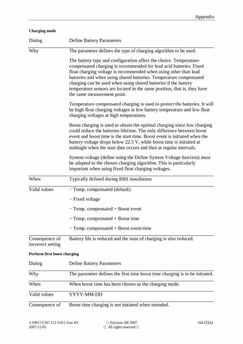
Appendix
1/19817-CXC 112 516/1 Uen AY Ericsson AB 2007 164 (211)2007-11-05 All rights reserved
Charging mode
Dialog Define Battery Parameters
Why The parameter defines the type of charging algorithm to be used.
The battery type and configuration affect the choice. Temperature-compensated charging is recommended for lead acid batteries. Fixedfloat charging voltage is recommended when using other than leadbatteries and when using shared batteries. Temperature compensatedcharging can be used when using shared batteries if the batterytemperature sensors are located in the same position, that is, they havethe same measurement point.
Temperature compensated charging is used to protect the batteries. It willbe high float charging voltages at low battery temperature and low floatcharging voltages at high temperatures.
Boost charging is used to obtain the optimal charging since low chargingcould reduce the batteries lifetime. The only difference between boostevent and boost time is the start time. Boost event is initiated when thebattery voltage drops below 22.5 V, while boost time is initiated atmidnight when the start date occurs and then at regular intervals.
System voltage (define using the Define System Voltage function) mustbe adapted to the chosen charging algorithm. This is particularlyimportant when using fixed float charging voltages.
When Typically defined during RBS installation.
Valid values Temp. compensated (default)
Fixed voltage
Temp. compensated + Boost event
Temp. compensated + Boost time
Temp. compensated + Boost event/time
Consequence ofincorrect setting
Battery life is reduced and the state of charging is also reduced.
Perform first boost charging
Dialog Define Battery Parameters
Why The parameter defines the first time boost time charging is to be initiated.
When When boost time has been chosen as the charging mode.
Valid values YYYY-MM-DD
Consequence of Boost time charging is not initiated when intended.
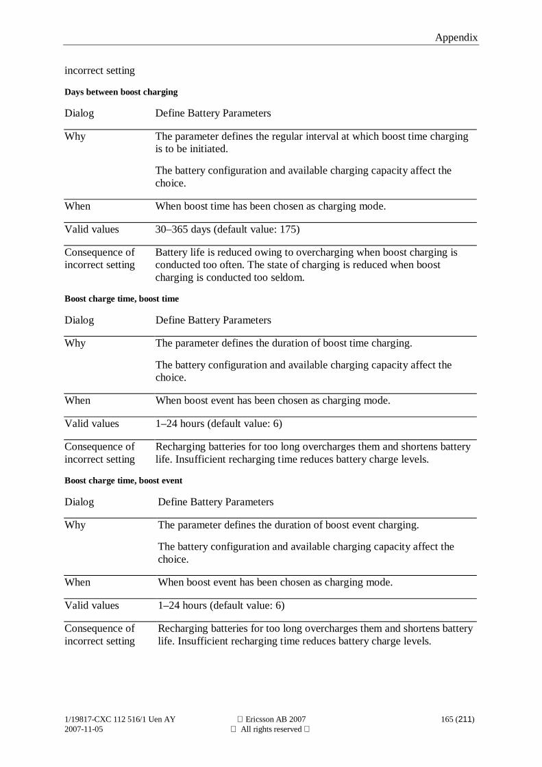
Appendix
1/19817-CXC 112 516/1 Uen AY Ericsson AB 2007 165 (211)2007-11-05 All rights reserved
incorrect setting
Days between boost charging
Dialog Define Battery Parameters
Why The parameter defines the regular interval at which boost time chargingis to be initiated.
The battery configuration and available charging capacity affect thechoice.
When When boost time has been chosen as charging mode.
Valid values 30–365 days (default value: 175)
Consequence ofincorrect setting
Battery life is reduced owing to overcharging when boost charging isconducted too often. The state of charging is reduced when boostcharging is conducted too seldom.
Boost charge time, boost time
Dialog Define Battery Parameters
Why The parameter defines the duration of boost time charging.
The battery configuration and available charging capacity affect thechoice.
When When boost event has been chosen as charging mode.
Valid values 1–24 hours (default value: 6)
Consequence ofincorrect setting
Recharging batteries for too long overcharges them and shortens batterylife. Insufficient recharging time reduces battery charge levels.
Boost charge time, boost event
Dialog Define Battery Parameters
Why The parameter defines the duration of boost event charging.
The battery configuration and available charging capacity affect thechoice.
When When boost event has been chosen as charging mode.
Valid values 1–24 hours (default value: 6)
Consequence ofincorrect setting
Recharging batteries for too long overcharges them and shortens batterylife. Insufficient recharging time reduces battery charge levels.
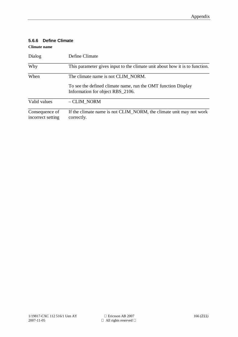
Appendix
1/19817-CXC 112 516/1 Uen AY Ericsson AB 2007 166 (211)2007-11-05 All rights reserved
5.6.6 Define ClimateClimate name
Dialog Define Climate
Why This parameter gives input to the climate unit about how it is to function.
When The climate name is not CLIM_NORM.
To see the defined climate name, run the OMT function DisplayInformation for object RBS_2106.
Valid values – CLIM_NORM
Consequence ofincorrect setting
If the climate name is not CLIM_NORM, the climate unit may not workcorrectly.
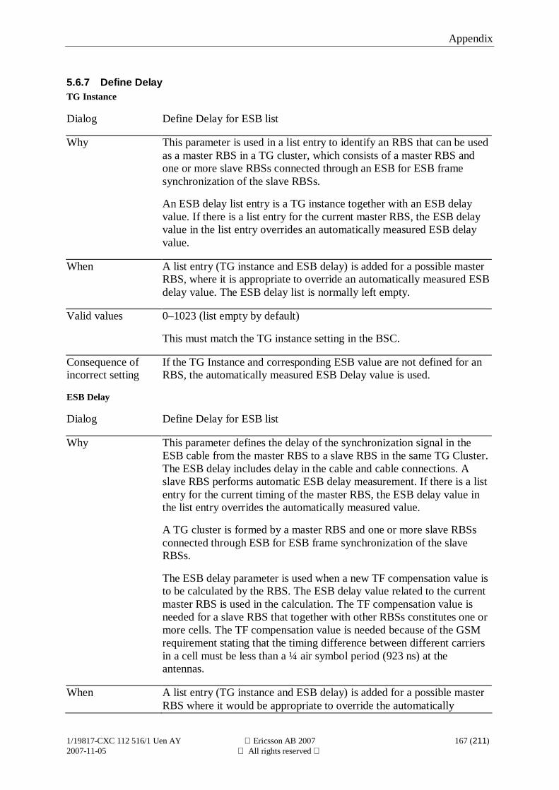
Appendix
1/19817-CXC 112 516/1 Uen AY Ericsson AB 2007 167 (211)2007-11-05 All rights reserved
5.6.7 Define DelayTG Instance
Dialog Define Delay for ESB list
Why This parameter is used in a list entry to identify an RBS that can be usedas a master RBS in a TG cluster, which consists of a master RBS andone or more slave RBSs connected through an ESB for ESB framesynchronization of the slave RBSs.
An ESB delay list entry is a TG instance together with an ESB delayvalue. If there is a list entry for the current master RBS, the ESB delayvalue in the list entry overrides an automatically measured ESB delayvalue.
When A list entry (TG instance and ESB delay) is added for a possible masterRBS, where it is appropriate to override an automatically measured ESBdelay value. The ESB delay list is normally left empty.
Valid values 0–1023 (list empty by default)
This must match the TG instance setting in the BSC.
Consequence ofincorrect setting
If the TG Instance and corresponding ESB value are not defined for anRBS, the automatically measured ESB Delay value is used.
ESB Delay
Dialog Define Delay for ESB list
Why This parameter defines the delay of the synchronization signal in theESB cable from the master RBS to a slave RBS in the same TG Cluster.The ESB delay includes delay in the cable and cable connections. Aslave RBS performs automatic ESB delay measurement. If there is a listentry for the current timing of the master RBS, the ESB delay value inthe list entry overrides the automatically measured value.
A TG cluster is formed by a master RBS and one or more slave RBSsconnected through ESB for ESB frame synchronization of the slaveRBSs.
The ESB delay parameter is used when a new TF compensation value isto be calculated by the RBS. The ESB delay value related to the currentmaster RBS is used in the calculation. The TF compensation value isneeded for a slave RBS that together with other RBSs constitutes one ormore cells. The TF compensation value is needed because of the GSMrequirement stating that the timing difference between different carriersin a cell must be less than a ¼ air symbol period (923 ns) at theantennas.
When A list entry (TG instance and ESB delay) is added for a possible masterRBS where it would be appropriate to override the automatically
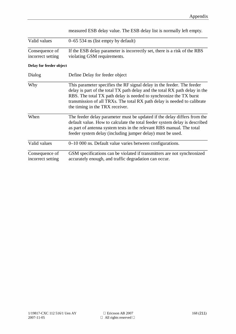
Appendix
1/19817-CXC 112 516/1 Uen AY Ericsson AB 2007 168 (211)2007-11-05 All rights reserved
measured ESB delay value. The ESB delay list is normally left empty.
Valid values 0–65 534 ns (list empty by default)
Consequence ofincorrect setting
If the ESB delay parameter is incorrectly set, there is a risk of the RBSviolating GSM requirements.
Delay for feeder object
Dialog Define Delay for feeder object
Why This parameter specifies the RF signal delay in the feeder. The feederdelay is part of the total TX path delay and the total RX path delay in theRBS. The total TX path delay is needed to synchronize the TX bursttransmission of all TRXs. The total RX path delay is needed to calibratethe timing in the TRX receiver.
When The feeder delay parameter must be updated if the delay differs from thedefault value. How to calculate the total feeder system delay is describedas part of antenna system tests in the relevant RBS manual. The totalfeeder system delay (including jumper delay) must be used.
Valid values 0–10 000 ns. Default value varies between configurations.
Consequence ofincorrect setting
GSM specifications can be violated if transmitters are not synchronizedaccurately enough, and traffic degradation can occur.
Appendix
1/19817-CXC 112 516/1 Uen AY Ericsson AB 2007 169 (211)2007-11-05 All rights reserved
5.6.8 Define GPS ParametersGPS present
Dialog Define GPS Parameters
Why This parameter defines whether or not a GPS receiver should be present.
A GPS receiver is used as a reference for RF frequency generation andas a reference for the GSM time-base counters. The GPS receiver can beused to achieve a synchronized radio network, which enables lowerinterference and higher capacity in a GSM radio network whencombined with radio network planning adapted for a synchronized radionetwork.
When When a GPS receiver is added to the site the GPS receiver HW isautomatically detected by the RBS, and the GPS present parameter isautomatically changed to yes.
The parameter is manually set to no when the GPS receiver is to beremoved from the RBS.
Comment: When the parameter is manually set to no the automaticdetection of GPS HW is stopped until the RBS is restarted.
Valid values Yes
No (default)
Consequence ofincorrect setting
If GPS present is incorrectly set to yes, the RBS reports that the GPSreceiver is missing. It can also cause RBS synchronization to fail, andcause the RBS to be taken out of traffic.
If GPS present is incorrectly set to no, there is a risk of the RBSviolating GSM requirements, entering holdover mode, and eventuallybeing taken out of traffic.
GPS RX delay
Dialog Define GPS Parameters
Why This parameter specifies the delays in the GPS receiver antenna, GPSreceiver antenna cables, and the GPS receiver.
The delay is relevant when the GPS receiver is used for GPS framesynchronization. GPS frame synchronization is used to achieve asynchronized radio network, which enables lower interference andhigher capacity in a GSM radio network when combined with radionetwork planning adapted for a synchronized radio network.
When The parameter is changed when a GPS receiver is to be added to theRBS. If the GPS receiver compensates for the RX delay the GPS RXdelay parameter is set to 0.
Appendix
1/19817-CXC 112 516/1 Uen AY Ericsson AB 2007 170 (211)2007-11-05 All rights reserved
Valid values 0–65 535 ns (default value: 0)
Consequence ofincorrect setting
If the RBS is part of a synchronized radio network, an incorrect settingof the delay degrades radio network performance.
GPS RX DXU delay
Dialog Define GPS Parameters
Why This parameter specifies the delays in the path from the GPS receiver tothe DXU, including delays in the OVP unit.
The delay is relevant when the GPS receiver is used for GPS framesynchronization. GPS frame synchronization is used to achieve asynchronized radio network, which enables lower interference andhigher capacity in a GSM radio network when combined with radionetwork planning adapted for a synchronized radio network.
When The parameter is changed when a GPS receiver is to be added to theRBS.
Valid values 0–65 535 ns (default value: 0)
Consequence ofincorrect setting
If the RBS is part of a synchronized radio network, an incorrect settingof the delay degrades radio network performance.
Appendix
1/19817-CXC 112 516/1 Uen AY Ericsson AB 2007 171 (211)2007-11-05 All rights reserved
5.6.9 Define Hardware InfoProduct No.
Dialog Define Hardware Info
Why Product numbers are defined to enable the RBS inventory information,available in the OMT and at the O&M centre, to be more complete.
Product number can be defined for the following RUs:
– Passive RUs
– Cabinets with memory, such as RBS 2106 and RBS 2206.
Product numbers for RUs can be displayed using the OMT functionsDisplay Inventory List and Display Information.
Product numbers for the cabinet RUs above can also be displayed at theO&M centre.
When Product numbers for passive RUs are defined if the operator wants tosee them in the inventory list in OMT.
Product numbers for cabinets with memory are defined when replacingcabinet backplane.
Valid values The product number is a character string. Valid characters are 0..9, A..Z,space /. The product number, which is normally found on a labelattached to the RU, must be written in accordance with the Ericssonproduct number format.
Default values:
– Empty character string for passive RUs
– Set at production for cabinet RUs
Consequence ofincorrect setting
For passive RUs and cabinets with memory:
The wrong product number is displayed by the OMT functions DisplayInventory List and Display Information.
For cabinets with memory:
The wrong product number is displayed at the O&M centre.
Serial No.
Dialog Define Hardware Info
Why Serial numbers are defined to enable the RBS inventory information,available in the OMT and at the O&M centre, to be more complete.
Appendix
1/19817-CXC 112 516/1 Uen AY Ericsson AB 2007 172 (211)2007-11-05 All rights reserved
Serial number can be defined for the following RUs:
– Passive RUs
– Cabinets with memory, such as RBS 2106 and RBS 2206.
Serial numbers for RUs can be displayed using the OMT functionsDisplay Inventory List and Display Information.
Serial numbers for the cabinet RUs above can also be displayed at theO&M centre.
When Serial numbers for passive RUs are defined if the operator wants to seethem in the inventory list in OMT.
Serial numbers for cabinets with memory are defined when replacingcabinet backplane.
Valid values The serial number is a character string with a maximum length of 13characters. Valid characters are:
0..9 A..Z space ! # $ % & ‘ ( ) * + , . /: ; < = > ? _.
The serial number, which is normally found on a label attached to theRU, must be written in accordance with the Ericsson serial numberformat.
Default values:
– Empty character string for passive RUs
– Set at production for cabinet RUs
Consequence ofincorrect setting
For passive RUs and cabinets with memory:
The wrong serial number is displayed by the OMT functions DisplayInventory List and Display Information.
For cabinet with memory:
The wrong serial number is displayed at the O&M centre.
HW Rev.
Dialog Define Hardware Info
Why Hardware revisions are defined to enable the RBS inventoryinformation, available in the OMT and at the O&M centre, to be morecomplete.
Hardware revision can be defined for the following RUs:
– Passive RUs
– Cabinets with memory, such as RBS 2106 and RBS 2206.
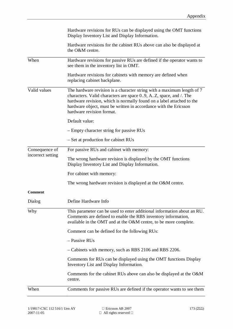
Appendix
1/19817-CXC 112 516/1 Uen AY Ericsson AB 2007 173 (211)2007-11-05 All rights reserved
Hardware revisions for RUs can be displayed using the OMT functionsDisplay Inventory List and Display Information.
Hardware revisions for the cabinet RUs above can also be displayed atthe O&M centre.
When Hardware revisions for passive RUs are defined if the operator wants tosee them in the inventory list in OMT.
Hardware revisions for cabinets with memory are defined whenreplacing cabinet backplane.
Valid values The hardware revision is a character string with a maximum length of 7characters. Valid characters are space 0..9, A..Z, space, and /. Thehardware revision, which is normally found on a label attached to thehardware object, must be written in accordance with the Ericssonhardware revision format.
Default value:
– Empty character string for passive RUs
– Set at production for cabinet RUs
Consequence ofincorrect setting
For passive RUs and cabinet with memory:
The wrong hardware revision is displayed by the OMT functionsDisplay Inventory List and Display Information.
For cabinet with memory:
The wrong hardware revision is displayed at the O&M centre.
Comment
Dialog Define Hardware Info
Why This parameter can be used to enter additional information about an RU.Comments are defined to enable the RBS inventory information,available in the OMT and at the O&M centre, to be more complete.
Comment can be defined for the following RUs:
– Passive RUs
– Cabinets with memory, such as RBS 2106 and RBS 2206.
Comments for RUs can be displayed using the OMT functions DisplayInventory List and Display Information.
Comments for the cabinet RUs above can also be displayed at the O&Mcentre.
When Comments for passive RUs are defined if the operator wants to see them
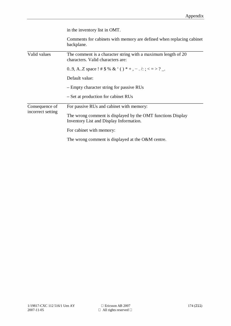
Appendix
1/19817-CXC 112 516/1 Uen AY Ericsson AB 2007 174 (211)2007-11-05 All rights reserved
in the inventory list in OMT.
Comments for cabinets with memory are defined when replacing cabinetbackplane.
Valid values The comment is a character string with a maximum length of 20characters. Valid characters are:
0..9, A..Z space ! # $ % & ‘ ( ) * + , . /: ; < = > ? _.
Default value:
– Empty character string for passive RUs
– Set at production for cabinet RUs
Consequence ofincorrect setting
For passive RUs and cabinet with memory:
The wrong comment is displayed by the OMT functions DisplayInventory List and Display Information.
For cabinet with memory:
The wrong comment is displayed at the O&M centre.
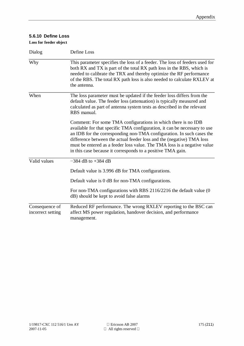
Appendix
1/19817-CXC 112 516/1 Uen AY Ericsson AB 2007 175 (211)2007-11-05 All rights reserved
5.6.10 Define LossLoss for feeder object
Dialog Define Loss
Why This parameter specifies the loss of a feeder. The loss of feeders used forboth RX and TX is part of the total RX path loss in the RBS, which isneeded to calibrate the TRX and thereby optimize the RF performanceof the RBS. The total RX path loss is also needed to calculate RXLEV atthe antenna.
When The loss parameter must be updated if the feeder loss differs from thedefault value. The feeder loss (attenuation) is typically measured andcalculated as part of antenna system tests as described in the relevantRBS manual.
Comment: For some TMA configurations in which there is no IDBavailable for that specific TMA configuration, it can be necessary to usean IDB for the corresponding non-TMA configuration. In such cases thedifference between the actual feeder loss and the (negative) TMA lossmust be entered as a feeder loss value. The TMA loss is a negative valuein this case because it corresponds to a positive TMA gain.
Valid values 384 dB to +384 dB
Default value is 3.996 dB for TMA configurations.
Default value is 0 dB for non-TMA configurations.
For non-TMA configurations with RBS 2116/2216 the default value (0dB) should be kept to avoid false alarms
Consequence ofincorrect setting
Reduced RF performance. The wrong RXLEV reporting to the BSC canaffect MS power regulation, handover decision, and performancemanagement.
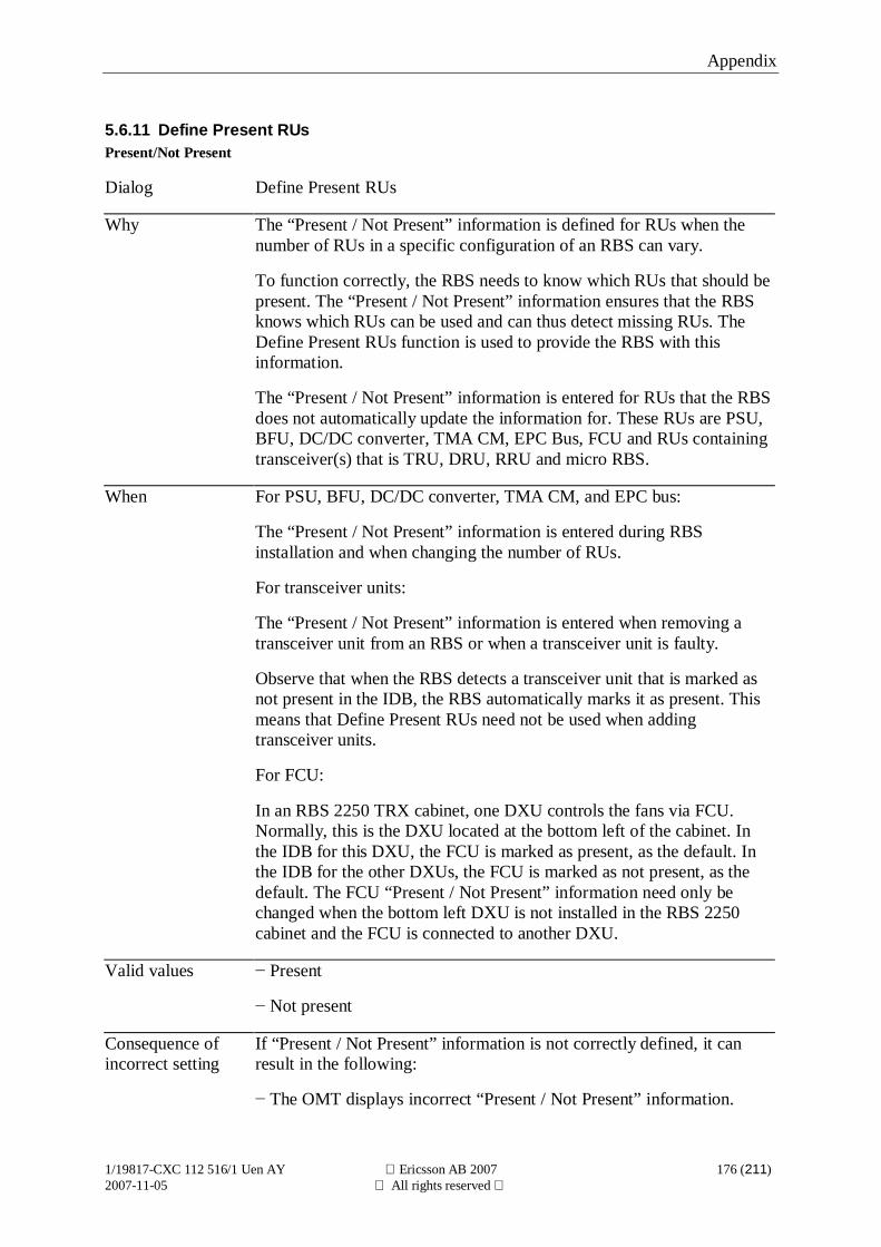
Appendix
1/19817-CXC 112 516/1 Uen AY Ericsson AB 2007 176 (211)2007-11-05 All rights reserved
5.6.11 Define Present RUsPresent/Not Present
Dialog Define Present RUs
Why The “Present / Not Present” information is defined for RUs when thenumber of RUs in a specific configuration of an RBS can vary.
To function correctly, the RBS needs to know which RUs that should bepresent. The “Present / Not Present” information ensures that the RBSknows which RUs can be used and can thus detect missing RUs. TheDefine Present RUs function is used to provide the RBS with thisinformation.
The “Present / Not Present” information is entered for RUs that the RBSdoes not automatically update the information for. These RUs are PSU,BFU, DC/DC converter, TMA CM, EPC Bus, FCU and RUs containingtransceiver(s) that is TRU, DRU, RRU and micro RBS.
When For PSU, BFU, DC/DC converter, TMA CM, and EPC bus:
The “Present / Not Present” information is entered during RBSinstallation and when changing the number of RUs.
For transceiver units:
The “Present / Not Present” information is entered when removing atransceiver unit from an RBS or when a transceiver unit is faulty.
Observe that when the RBS detects a transceiver unit that is marked asnot present in the IDB, the RBS automatically marks it as present. Thismeans that Define Present RUs need not be used when addingtransceiver units.
For FCU:
In an RBS 2250 TRX cabinet, one DXU controls the fans via FCU.Normally, this is the DXU located at the bottom left of the cabinet. Inthe IDB for this DXU, the FCU is marked as present, as the default. Inthe IDB for the other DXUs, the FCU is marked as not present, as thedefault. The FCU “Present / Not Present” information need only bechanged when the bottom left DXU is not installed in the RBS 2250cabinet and the FCU is connected to another DXU.
Valid values Present
Not present
Consequence ofincorrect setting
If “Present / Not Present” information is not correctly defined, it canresult in the following:
The OMT displays incorrect “Present / Not Present” information.
Appendix
1/19817-CXC 112 516/1 Uen AY Ericsson AB 2007 177 (211)2007-11-05 All rights reserved
If an RU is defined as present when it is not present, then a fault reportis sent to the BSC.
If an RU is defined as not present when it is present, then a HW andIDB inconsistency fault report is sent to the BSC. The HW and IDBinconsistency are also displayed in the OMT. The RU will not besupervised.
If the BFU is defined as not present when it is present then the featuresbattery test and battery log cannot be used. Similarly, battery parametersused to provide optimal usage of batteries cannot be set.
If FCU is not present in any of the IDBs in an RBS 2250 TRX cabinet,then no DXU controls the fans in the cabinet. The fans operate at fullspeed all the time.
Appendix
1/19817-CXC 112 516/1 Uen AY Ericsson AB 2007 178 (211)2007-11-05 All rights reserved
5.6.12 Define RBS IdentityRBS name
Dialog Define RBS Identity
Why This parameter is used to specify an operator-defined name for the RBS.
This could be used as an extra safeguard when using the Remote OMTor Remote OMT over IP to ensure that the correct RBS is connected.
When Typically defined during RBS installation.
Valid values A free text string with a maximum length of 20 characters. Validcharacters are:
0..9 A..Z space ! # $ % & ‘ ( ) * + , . / ; < = > ? _
Consequence ofincorrect setting
The RBS is incorrectly identified.
RBS description
Dialog Define RBS Identity
Why This parameter enables more information to be entered about the RBSthan the RBS name. The extra information could include, for example,the location of the RBS or special information about the RBS that couldbe of interest.
When Typically defined during RBS installation.
Valid values A free text string with a maximum length of 20 characters. Validcharacters are:
0..9 A..Z space ! # $ % & ‘ ( ) * + , . / ; < = > ? _
Consequence ofincorrect setting
The RBS is incorrectly described.
Appendix
1/19817-CXC 112 516/1 Uen AY Ericsson AB 2007 179 (211)2007-11-05 All rights reserved
5.6.13 Define System VoltageSystem_Voltage
Dialog Define System Voltage
Why This parameter defines the voltage supplied to the RUs in the RBS. Thesystem voltage is the output voltage from the PSUs.
In configurations that include batteries:
The system voltage is the voltage with which the batteries are charged.
In configurations that do not include batteries:
In case there are several RBSes with different power systems connectedthen all power systems must have the same system voltages in order towork optimally.
When Typically at RBS installation and the RBS is equipped with PSU-AC orPSU 230 (power source configuration is VAC) when batteries are includedor when several RBSes with different power systems are connected to beable to share power resources.
Valid values 24.0–28.5 V (default value: 27.2 V) if the configuration does not includebatteries.
25.5–28.5 V (default value: 27.2 V) if the configuration includes batteriesand the charging mode (algorithm) is fixed voltage charging.
26.7–27.7 V System voltage at 25°C (default value: 27.2 V) if theconfiguration includes batteries and the charging mode (algorithm) istemperature-compensated charging.
Consequence ofincorrect setting
In a configuration that include batteries:
A high system voltage charges the batteries faster but this places morestress on the batteries. A low system voltage results in slower charging. Itis not certain if a low system voltage is better for the batteries than a highsystem voltage. This depends on the type of battery.
In a configuration that do not include batteries:
If the power systems use different system voltages then the power systemwith the highest system voltage will be more stressed since that powersystem will also support the other power systems.
Appendix
1/19817-CXC 112 516/1 Uen AY Ericsson AB 2007 180 (211)2007-11-05 All rights reserved
5.6.14 Define TEITEI value
Dialog Define TEI
Why This parameter is used as a unique identifier for the CMRU of a specificRBS.
Communication that takes place over the A-bis interface (between theBSC and RBS) is based on the LAPD protocol standard. In LAPD, aTerminal Endpoint Identifier (TEI) and a Service Access Point Identifier(SAPI) identify a specific link. To be able uniquely to identify theCMRU of a specific RBS connected in a cascade chain, each RBS in thecascade chain must have a different TEI value assigned to its CMRU.
When The TEI value must be updated when an RBS is connected in a cascadechain with at least one other RBS. For RBSs not connected in a cascadechain, the default TEI value can be used.
Valid values 12–63 (default value: 62)
The value must match the value that the BSC uses to identify the CMRUof the RBS.
Consequence ofincorrect setting
If the TEI value does not match the TEI value set in the BSC, then theBSC is unable to communicate with that RBS. Remote maintenanceusing Remote OMT over IP is not possible.
If the TEI value is equal to the TEI value set for another RBS in thesame cascade chain, then the second RBS (with that TEI value) cannotbe reached by the BSC. The first of the conflicting RBSs can be reachedby the BSC, but possibly by taking the identity of the second RBS.
Appendix
1/19817-CXC 112 516/1 Uen AY Ericsson AB 2007 181 (211)2007-11-05 All rights reserved
5.6.15 Define TF CompensationMaster RBS
Dialog Define TF Compensation
Why This parameter is used to define the type of RBS that is the master RBSin the TG Cluster. A TG cluster is made up of a master RBS and one ormore slave RBSs, connected via ESB for ESB Frame Synchronization ofthe slave RBSs.
This parameter is used when a new TF compensation value is to becalculated. The TF compensation value is needed for a slave RBS that,together with other RBSs, constitutes one or more cells. The TFcompensation value is needed because the GSM requirement that statesthat the timing difference between different carriers within a cell mustbe less than ¼ air symbol period (923 ns) at the antennas.
When This parameter is used when a new TF compensation value is to bemanually calculated, for example, when a new master RBS is to beselected.
Valid values RBS 200
RBS 205
RBS 2000
The value defined must indicate the type of RBS used as master RBS.
Consequence ofincorrect setting
The calculation of the recommended TF compensation value will beincorrect.
Combiner
Dialog Define TF Compensation (Master RBS set to RBS 200 or RBS 205)
Why This parameter is used to specify the type of combiner that is used by themaster RBS in the TG cluster. A TG cluster is made up of a master RBSand one or more slave RBSs, connected via ESB for ESB framesynchronization of the slave RBSs.
This parameter is used when a new TF compensation value is to becalculated. The TF compensation value is needed for a slave RBS that,together with other RBSs, constitutes one or more cells. The TFcompensation value is needed because the GSM requirement that statesthat the timing difference between different carriers within a cell mustbe less than ¼ air symbol period (923 ns) at the antennas.
When This parameter is used when a new TF compensation value is to bemanually calculated, for example, when a new master RBS is to beselected. The parameter is used only when the master RBS parameter isset to RBS 200 or RBS 205.
Appendix
1/19817-CXC 112 516/1 Uen AY Ericsson AB 2007 182 (211)2007-11-05 All rights reserved
Valid values HCOMB
FCOMB
The value defined must indicate the type of combiner used in the masterRBS.
Consequence ofincorrect setting
The calculation of the recommended TF compensation value will beincorrect.
TMA
Dialog Define TF Compensation (Master RBS set to RBS 200 or RBS 205)
Why This parameter is used to specify if a TMA is used by the master RBS inthe TG cluster. A TG cluster is made up of a master RBS and one ormore slave RBSs, connected via ESB for ESB Frame Synchronization ofthe slave RBSs.
This parameter is used when a new TF Compensation value is to becalculated. The TF compensation value is needed for a slave RBS that,together with other RBSs, constitutes one or more cells. The TFcompensation value is needed because the GSM requirement that statesthat the timing difference between different carriers within a cell mustbe less than ¼ air symbol period (923 ns) at the antennas.
When This parameter is used when a new TF compensation value is to bemanually calculated, for example, when a new master RBS is to beselected. The parameter is used only when the master RBS parameter isset to RBS 200 or RBS 205.
Valid values Yes
No
The value defined must reflect the use of TMA in the master RBS.
Consequence ofincorrect setting
The calculation of the recommended TF compensation value will beincorrect.
Feeder Delay
Dialog Define TF Compensation (Master RBS set to RBS 200 or RBS 205)
Why This parameter is used to specify the feeder delay of the master RBS inthe TG cluster. A TG cluster is made up of a master RBS and one ormore slave RBSs, connected via ESB for ESB frame synchronization ofthe slave RBSs.
This parameter is used when a new TF compensation value is to becalculated. The TF compensation value is needed for a slave RBS that,together with other RBSs, constitutes one or more cells. The TF
Appendix
1/19817-CXC 112 516/1 Uen AY Ericsson AB 2007 183 (211)2007-11-05 All rights reserved
compensation value is needed because the GSM requirement that statesthat the timing difference between different carriers within a cell mustbe less than ¼ air symbol period (923 ns) at the antennas.
When This parameter is used when a new TF compensation value is to bemanually calculated, for example, when a new master RBS is to beselected. The parameter is used only if the master RBS parameter is setto RBS 200 or RBS 205.
Valid values 0–10 000 ns
The value defined must be the feeder delay of the master RBS.
Consequence ofincorrect setting
The calculation of recommended TF compensation value will beincorrect.
Master-Slave ESB Delay
Dialog Define TF Compensation
Why This parameter is used to specify the ESB delay between the masterRBS and a slave RBS in a TG cluster. A TG cluster is made up of amaster RBS and one or more slave RBSs, connected via ESB for ESBframe synchronization of the slave RBSs.
This parameter is used when a new TF compensation value is to becalculated. The TF compensation constitutes one or more cells. The TFcompensation value is needed because the GSM requirement that statesthat the timing difference between different carriers within a cell mustbe less than ¼ air symbol period (923 ns) at the antennas.
When This parameter is used when a new TF compensation value is to bemanually calculated, for example, when a new master RBS is to beselected.
Valid values 0–10 000 ns
The value defined must be the ESB delay between the RBS and themaster RBS.
Consequence ofincorrect setting
The calculation of recommended TF compensation value will beincorrect.
Master Transmitter Chain Delay
Dialog Define TF Compensation (Master RBS set to RBS 2000)
Why This parameter is used to specify the master transmitter chain delay ofthe master RBS in the TG cluster. A TG cluster is made up of a masterRBS and one or more slave RBSs, connected via ESB for ESB framesynchronization of the slave RBSs.
This parameter is used when a new TF compensation value is to becalculated. The TF compensation value is needed for a slave RBS that,
Appendix
1/19817-CXC 112 516/1 Uen AY Ericsson AB 2007 184 (211)2007-11-05 All rights reserved
together with other RBSs, constitutes one or more cells. The TFcompensation value is needed because the GSM requirement that statesthat the timing difference between different carriers within a cell mustbe less than ¼ air symbol period (923 ns) at the antennas.
When This parameter is used when a new TF compensation value is to bemanually calculated, for example, when a new master RBS is to beselected. The parameter is used only if the master RBS parameter is setto RBS 2000.
Valid values 0–65 535 ns
The master transmitter chain delay can be retrieved from the masterRBS. The transmitter chain delay information can be found by executingthe display information operation on the RBS object at the master RBS.
Consequence ofincorrect setting
The calculation of recommended TF compensation value will beincorrect.
TF Compensation Value
Dialog Define TF Compensation
Why This parameter is used to specify the TF compensation value of a slaveRBS in a TG cluster. A TG cluster is made up of a master RBS and oneor more slave RBSs, connected via ESB for ESB frame synchronizationof the slave RBSs.The TF compensation value is the time adjustment (innanoseconds) the Slave RBS must make relative to the ESB referenceused.
TF compensation value is needed for slave RBSs that, together withother RBSs, constitute one or more cells. The TF compensation value isneeded because the GSM requirement that states that the timingdifference between different carriers within a cell must be less than ¼air symbol period (923 ns) at the antennas.
When A new TF compensation value is typically needed when a new masterRBS is to be selected.
The BSC can override the manually set TF compensation value.
If BSC is stated in field “Source:” in dialog ‘Define TF Compensation’there is no need to maintain TF Compensation Value.
Valid values 10 000 ns to +10 000 ns (default value: 0)
The recommended TF compensation value calculated by the OMT isnormally used. A positive TF compensation value indicates that theinternal timing is delayed relative to the ESB frame synchronization onESB. A negative TF compensation value indicates that the internaltiming is advanced relative to the ESB frame synchronization on ESB.

Appendix
1/19817-CXC 112 516/1 Uen AY Ericsson AB 2007 185 (211)2007-11-05 All rights reserved
Consequence ofincorrect setting
There is a risk that the RBS will violate GSM requirements.
Appendix
1/19817-CXC 112 516/1 Uen AY Ericsson AB 2007 186 (211)2007-11-05 All rights reserved
5.6.16 Define TF Holdover ModeTF holdover mode
Dialog Define TF Holdover Mode
Why This parameter makes it possible to specify if an RBS configured asslave, should be in intracell or intercell holdover mode.
An RBS internal oscillator provides short-term timing stability. Thelong-term frequency and timing accuracy of the RBS relies on asynchronization source. For a slave RBS, the frame synchronizationreceived from the ESB serves as the synchronization source. When theRBS loses its synchronization source, it can rely on the internaloscillator for a limited time period, called “holdover”. The length of theholdover time depends on the setting of the TF holdover mode. Whenthe holdover time expires, the RBS is taken out of traffic.
In intracell holdover mode, the RBS is used together with other RBSs toconstitute one or more cells, which requires that the RBSs are in framesynchronization with each other. In intercell holdover mode, the RBS isnot realizing cells together with other RBSs. The GSM requirementstates that the timing difference between different carriers within a cellmust be less than ¼ air symbol period (923 ns) at the antennas.
When It may be necessary to change the parameter when the cell structure ofthe TG cluster is changed, and the change includes cells realized by theRBS.
Valid values Intra cell (default value)
Inter cell
Consequence ofincorrect setting
If TF holdover mode is incorrectly set to intra cell, then the holdovertime will be shorter than necessary and the RBS will be taken out oftraffic too soon.
If TF holdover mode is incorrectly set to inter cell, then the holdovertime will be longer than necessary and with the risk that the RBS willviolate GSM requirements.
Appendix
1/19817-CXC 112 516/1 Uen AY Ericsson AB 2007 187 (211)2007-11-05 All rights reserved
5.6.17 Define TNOMTNOM Use
Dialog Define TNOM
Why This parameter is used to activate or deactivate DXX support in an RBS.
DXX support in RBS 2000 is intended to enable the O&M centre in aDXX network to monitor the transmission performance of the RBS. Ifthe RBS is connected to a DXX transport module, transmissionperformance can be monitored using the transport module withoutactivating DXX support. DXX is a transmission system that includesO&M and switching functionality, and is used for cellular applications.
When It may be necessary to update this parameter when DXX support is to beactivated or deactivated in an RBS.
Valid values On
Off (default value)
Consequence ofincorrect setting
If TNOM use is incorrectly set to off, then the O&M centre of the DXXnetwork will be unable to reach the RBS.
If TNOM use is incorrectly set to on, then the BSC will be unable to usethe timeslot defined by TNOM Timeslot. If the RBS has networktopology set to cascade, then signalling to a downstream RBS is affectedin the same way. If the RBS is a Macro RBS using DXU 01, DXU 03, orDXU 11, or a Micro RBS of type RBS 2301, RBS 2302, or RBS 2401,then a configuration request from the BSC is rejected if it includes thetimeslot defined by TNOM timeslot. For other RBSs, the configurationrequest is accepted but the timeslot specified by TNOM timeslot is notconfigured for use by the BSC. If overlap between TNOM configuredtimeslots and an IS configuration containing super channels is detected atIS_CONFIGURATION_REQUEST, the configuration is discarded andan IS_CONFIGURATION_REJECT is sent.
TNOM Timeslot
Dialog Define TNOM
Why This parameter is used to define the 64 kbit/s timeslot on the E1/T1 linkthat is to be used for DXX support of an RBS.
DXX support in RBS 2000 enables the O&M centre in a DXX networkto monitor the transmission performance of the RBS. DXX is atransmission system that includes O&M and switching functionality, andis used for cellular applications.
Note: The same timeslot is allocated on PCM A and PCM B. If atimeslot is allocated for DXX support, then that timeslot cannot be
Appendix
1/19817-CXC 112 516/1 Uen AY Ericsson AB 2007 188 (211)2007-11-05 All rights reserved
allocated for signalling or for traffic to/from the RBS
When It can be needed to update this parameter when DXX support is to beactivated, or when the timeslot for DXX support is to be changed. TheTNOM Timeslot parameter is only of interest if the TNOM Useparameter is set to ON.
Valid values For transmission type E1: 1–31 (default value: 31)
For transmission type T1: 1–24 (default value: 24)
The timeslot defined must be the same timeslot defined in the O&Mcentre of a DXX network.
Consequence ofincorrect setting
If TNOM use is incorrectly set to off, then the O&M centre of the DXXnetwork will be unable to reach the RBS. If TNOM use is incorrectly setto on, then the BSC will be unable to use the timeslot defined by TNOMTimeslot. If the RBS has network topology set to cascade, then signallingto a downstream RBS is affected in the same way. If the RBS is a MacroRBS using DXU 01, DXU 03, or DXU 11, or a Micro RBS of type RBS2301, RBS 2302, or RBS 2401, then a configuration request from theBSC is rejected if it includes the timeslot defined by TNOM timeslot.For other RBSs, the configuration request is accepted but the timeslotspecified by TNOM timeslot is not configured for use by the BSC. Ifoverlap between TNOM configured timeslots and an IS configurationcontaining super channels is detected atIS_CONFIGURATION_REQUEST, the configuration is discarded andan IS_CONFIGURATION_REJECT is sent.
TNOM Node Id
Dialog Define TNOM
Why This parameter is used to provide a unique identifier for a node, such asan RBS in a DXX network.
DXX is a transmission system for cellular applications that includesO&M and switching functionality. DXX support in RBS 2000 enablesthe O&M centre in a DXX network to monitor the transmissionperformance of the RBS.
When It necessary to update this parameter when DXX support is to beactivated or when the TNOM node Id is changed. The TNOM node Idparameter is of interest only if the TNOM use parameter is set to on.
Valid values 1–65 534 (default value: 1)
The TNOM node Id defined must be equal to the value set in the O&Mcentre.
Consequence ofincorrect setting
If TNOM node Id is incorrectly set, then the O&M centre of the DXXnetwork will be unable to reach the RBS. If set to the same value as theTNOM node Id for another RBS, then the RBS can be reached by the
Appendix
1/19817-CXC 112 516/1 Uen AY Ericsson AB 2007 189 (211)2007-11-05 All rights reserved
O&M Centre but the O&M centre believes that it is communicating withanother RBS.

Appendix
1/19817-CXC 112 516/1 Uen AY Ericsson AB 2007 190 (211)2007-11-05 All rights reserved
5.6.18 Define TransmissionSTN Equipment
Dialog Define Transmission
Why This parameter specifies if STN equipment is used between the RBS andthe BSC.
When The STN equipment selection must be done when a new RBS isinstalled. Note that the STN equipment selection gets its first value whenthe IDB is created.
Valid values - No- PSTU- Integrated- OtherThe selection done must match the transport network used from the BSCto the RBS.
Consequence ofincorrect setting
If there is a mismatch in parameter setting and HW configuration forSTN equipment, the RBS is likely to misinterpret the status of theincoming sync. This misinterpretation may in the end cause the RBShaving problem to carry traffic.Incorrect setting to "PSTU" when it should have been "No" has anadditional side affect. RBS configured with STN equipment will onlysupport Abis IWDs 06A and on, not older. The RBS also will reportSTN equipment as supported functionality to the BSC.
Transmission Interface
Dialog Define Transmission
Why This parameter specifies the transmission type to be used between theRBS and the BSC.
Most operators use the same transmission type for their entire network.
When The type of transmission interface must be specified when a new RBS isinstalled. The transmission interface is normally not changed during thelife of an RBS. Note that the transmission interface type gets its firstvalue when the IDB is created.
Valid values E1
T1
Internal
The value defined must match the transport network used.
Consequence of If the value does not match the transport network used, the BSC cannotcommunicate with that RBS. Remote maintenance using OMT (Remote
Appendix
1/19817-CXC 112 516/1 Uen AY Ericsson AB 2007 191 (211)2007-11-05 All rights reserved
incorrect setting OMT or Remote OMT over IP) is not possible.
If the RBS has network topology set to cascade, communication to alldownstream RBSs is lost.
Network Topology
Dialog Define Transmission
Why This parameter is used to specify whether an RBS is connected with allits transmission ports towards the BSC or whether it is to be part of acascade chain.
The RBSs in a cascade chain are connected so that each RBS uses portA towards the BSC and port B towards the next downstream RBS. PortsC and D are connected in the same way.
When The network topology has to be defined for every new RBS. Thenetwork topology setting of an RBS can require updating when thenetwork is changed.
Valid values Stand alone
Cascade
Consequence ofincorrect setting
If network topology is incorrectly set to stand alone the communicationbetween the BSC and the downstream RBSs is lost.
If network topology is incorrectly set to cascade the RBS cannot useports B and D.
Sync Source
Dialog Define Transmission
Why This parameter defines which E1/T1 transmission interfaces areavailable as a synchronization source.
The synchronization source is used as a basis for RF frequencygeneration, clocking the GSM time base counters, and internalsynchronization of the RBS. An RBS internal oscillator provides short-term timing stability. Long-term frequency and timing accuracy of theRBS relies on the selected synchronization source.
An RBS using the GPS as a synchronization source for RF generationand time base counters uses the incoming transmission interface as asynchronization source for the internal switch function and for theoutgoing transmission interface. It can also use an incomingtransmission interface as a backup synchronization source if this allowedby the TF configuration.
When The sync source parameter is set when a new RBS is installed. It can bemanually changed to not available if a transmission interface is unusableas a synchronization source. If the transport network is modified it can
Appendix
1/19817-CXC 112 516/1 Uen AY Ericsson AB 2007 192 (211)2007-11-05 All rights reserved
be appropriate to change the setting of the sync source parameter.
Valid values PCM A – ticked if available (default value: available)
PCM B – ticked if available (default value: not available)
PCM C – ticked if available (default value: not available)
PCM D – ticked if available (default value: not available)
For an RBS in network topology cascade, only PCM A and PCM C canbe selected as available for synchronization. It is recommended tospecify as available only transmission interfaces that are stable enoughfor use as a synchronization source, but at least one must be specified asavailable.
Consequence ofincorrect setting
If sync source is set incorrectly there is a risk of the RBS violating GSMrequirements, entering holdover mode, and eventually being taken out oftraffic.
CRC-4
Dialog Define Transmission
Why This parameter is used to activate or deactivate CRC 4 handling.
The Cyclic Redundancy Check 4 (CRC 4) procedure provides enhancederror-monitoring capability. Most operators use the same CRC 4 settingfor their entire network. CRC 4 is only applicable for type E1transmission interfaces.
When The correct CRC 4 setting must be set for every new RBS with E1transmission. The CRC 4 setting is not normally changed.
Valid values Activated
Deactivated (default)
The value defined must match the CRC 4 setting in the transportnetwork.
Consequence ofincorrect setting
If CRC 4 is incorrectly activated, the RBS fails to achieve CRCmultiframe alignment, which causes all E1 transmission interfaces to betaken out of service because of Loss of Frame Alignment (LOF).
If CRC 4 is incorrectly deactivated, the equipment at the remote end ofthe E1 transmission interfaces fails to achieve CRC multiframealignment, which can cause the E1 transmission interface to be taken outof service.
Spare Bits (sa4-sa8)
Dialog Define Transmission
Appendix
1/19817-CXC 112 516/1 Uen AY Ericsson AB 2007 193 (211)2007-11-05 All rights reserved
Why This parameter is used to specify the setting to be used for E1 spare bits.
Spare bits are given fixed values and can be set to comply with nationalrequirements. Most operators use the same spare bit setting for theirentire network.
When The correct spare bit setting must be set for every new RBS with E1transmission. Spare bit setting is normally not changed.
When configured for STN equipment, the Sa4 is used for aSynchronization Status Message (SSM) and can override any settingdone through this parameter.
Valid values Sa4 0 or 1 (Default value: 1)Sa5 0 or 1 (Default value: 1)Sa6 0 or 1 (Default value: 1)Sa7 0 or 1 (Default value: 1)Sa8 0 or 1 (Default value: 1)
Consequence ofincorrect setting
One consequence is that the RBS does not comply with nationalrequirements; further consequences depend on national rules.
Receiver Sensitivity A/B/C/D
Dialog Define Transmission
Why This parameter is used to set the sensitivity of the receiver for an E1transmission interface.
The receiver sensitivity can be used for optimizing RBS performance forvarious cable lengths of the E1 transmission interface. Short-haul modehas limited receiver sensitivity but can have better noise immunity thanlong-haul mode. Long-haul mode supports both short and long cablelengths owing to adaptive high receiver sensitivity.
When Receiver sensitivity is set when a new RBS with E1 transmission isinstalled. If the transport network is modified it can be necessary tochange the receiver sensitivity setting.
Valid values Long haul (default)
Short haul
The formal loss of signal requirement in ITU-T G.775 is only fulfilled inshort-haul mode.
The value is set individually for each transmission interface.
Consequence ofincorrect setting
If set to short-haul mode when a long cable is used there is a risk of thesignal being treated as a lost signal because the RBS cannot detect it.
If set to long-haul mode when short-haul mode is applicable theinterface has less noise immunity than when the receiver sensitivity is
Appendix
1/19817-CXC 112 516/1 Uen AY Ericsson AB 2007 194 (211)2007-11-05 All rights reserved
set to short-haul mode.
LBO A, LBO B, LBO C, and LBO D
Dialog Define Transmission
Why An LBO parameter is used to set the transmitter signal level and receiversensitivity of a T1 transmission interface.
The LBO parameters are used to fulfil the T1 transmission interfacerequirements of the specific interface.
When An LBO parameter is set when a new RBS with T1 transmission isinstalled. If the transport network is modified, for example, expanded,then it may be necessary to change the LBO values.
Valid values Long h, 0 dB (default)
Long h, 7.5 dB
Long h, 15 dB
Long h, 22.5 dB
Long h, ALBO, 0 dB
Long h, ALBO, 7.5 dB
Long h, ALBO, 15 dB
Long h, ALBO, 22.5 dB
Short h, 0–133 feet
Short h, 133–266 feet
Short h, 266–399 feet
Short h, 399–533 feet
Short h, 533–655 feet
If the interface shall comply with the standard defined by ANSI T1.403,then long haul must be used. The long haul output level can be attenuatedto four levels to fulfil maximum signal levels at the far end. When usinglong haul ALBO, the RBS automatically selects a transmitter attenuationthat gives a defined maximum level of the signal strength of the receiverat the far end.
If the interface shall comply with the standard defined by ANSI T1.102,then short haul must be used. The output level can be amplified in fivesteps to fulfil the 0 dB signal level at a DSX 1 cross-connection interface.
If no standard is defined for the interface, then using long haul 0 dB isappropriate in most cases. Long haul is more adaptable and providesmuch higher receiver sensitivity than short haul. Short haul can provide
Appendix
1/19817-CXC 112 516/1 Uen AY Ericsson AB 2007 195 (211)2007-11-05 All rights reserved
better noise immunity.
The value is set individually for each transmission interface.
Consequence ofincorrect setting
If set to short haul in a situation where a long cable is used, there is a riskthat the signal is considered as lost because the level of the signallingstrength is too low.
In other situations, setting an LBO parameter incorrectly means that theoutgoing signal strength will not be optimal. This can cause the receiveron the far end to view the signal as disturbed, severely disturbed or, inthe worst case, as lost.
FDL Use
Dialog Define Transmission
Why This parameter is used to specify if loopbacks can be activated on a T1transmission in accordance with CSU ANSI.
A CSU loopback can be initiated by the use of ANSI bit-patternedmessages and loopback commands on the ESF Data Link. The loopbacksare used to verify the operation of the transmission network. This is doneby reconnecting the transmission network to test equipment, ordering theloopback, and performing the test.
When The FDL Use parameter is set to CSU-ANSI when there is a need to setthe transmission interfaces in loopback mode. This is set only for RBSswith T1 transmission.
Valid values Used only for RAI (default)
CSU-ANSI
The recommendation is to use the default value.
Consequence ofincorrect setting
If FDL Use is incorrectly set to ‘Used only for RAI’ then it will not bepossible to activate CSU ANSI loopback on that RBS.
If FDL Use is incorrectly set to CSU-ANSI then the RBS may be set toloopback mode by mistake. For example: If there is an external CSU unita received loopback command may set both the external CSU and theRBS to loopback mode. This may cause problems for the RBS to recoverwhen a loopback deactivate command is sent.
Appendix
1/19817-CXC 112 516/1 Uen AY Ericsson AB 2007 196 (211)2007-11-05 All rights reserved
5.6.19 Define VSWR LimitsVSWR Supervision
Dialog Define VSWR Limits
Why This parameter specifies if the limits for VSWR Class 1 and VSWRClass 2 faults are to be set to default values or if the user can definethem.
The VSWR supervision function supervises the antenna system bymeasuring the forward and reflected power at the CDU output. Thefunction calculates the VSWR at CDU output by using the powerforward and power reflected measurements, and compares the VSWRwith the limits defined by the VSWR class 1 and VSWR class 2parameters.
When User defined is the preferred setting. VSWR limits that are accuratelydefined and adjusted to the specific site enable the earlier detection ofantenna system-related problems. Examples of problems that can bedetected are water in the antennas or feeders, and bad antenna/feederconnections. In configurations with CDU-J, user defined VSWR limitsare not supported, only default settings are supported, which means thatthe VSWR limits values cannot be changed.
This parameter is typically set at RBS installation, based on test resultsfrom antenna system tests (SWR test) as described in the relevant RBSmanual.
Valid values Default
User defined
• Default: High default values (2.8) are to be used for both the VSWRclass 1 and VSWR class 2 parameters. The VSWR class 1 and VSWRclass 2 parameter values cannot be changed. This is the predefinedsetting for TMA configurations. The supervision detects only majorfaults.
• User defined: Values for the VSWR class 1 and VSWR class 2parameters can be entered manually. This is the predefined setting fornon-TMA configurations. In this case, predefined values for the VSWRclass 1 and VSWR class 2 parameters are provided.
Consequence ofincorrect setting
VSWR supervision may not work correctly. A fault may be reportedwhen no fault has occurred. A fault may not be reported when a fault hasoccurred. A fault may be reported with the incorrect fault class.
VSWR Class 1
Dialog Define VSWR Limits
Appendix
1/19817-CXC 112 516/1 Uen AY Ericsson AB 2007 197 (211)2007-11-05 All rights reserved
Why This parameter is used to select the threshold for VSWR class 1 faults.
The VSWR supervision function supervises the antenna system bymeasuring the forward and reflected power at the CDU output. Thefunction calculates the VSWR at CDU output by using the powerforward and power reflected measurements and compares the VSWRwith the limits defined by the VSWR class 1 and VSWR class 2parameters.
When The parameter can be set if the VSWR Supervision parameter is set touser defined.
This parameter is typically set at RBS installation, based on test resultsfrom antenna system tests (SWR test) as described in the relevant RBSmanual. Recommended values can also be found in this manual. Theparameter can also be changed when the VSWR supervision parametersneed to be updated because of false alarms or other situations in whichVSWR supervision is not working correctly.
Example of factors that affect the selection of suitable limits defined bythe VSWR class 1 and VSWR class 2 parameters:
• Short feeder (only a few metres) typically requires higher VSWRlimits.
• Diplexer (filter) and TMA usage typically requires higher VSWRlimits.
Valid values 1.5
1.6
1.7
1.8
2.0
2.2
2.5
2.8
The value of the VSWR class 1 parameter must be greater than or equalto the value of the VSWR class 2 parameter. If the values of the VSWRclass 1 and 2 parameters are equal, no class 2 fault will be reported, onlya class 1 fault.
The predefined value is configuration-dependent.
Consequence ofincorrect setting
VSWR supervision may not work correctly. A fault may be reportedwhen no fault has occurred. A fault may not be reported when a fault hasoccurred. A fault may be reported with the incorrect fault class.
Appendix
1/19817-CXC 112 516/1 Uen AY Ericsson AB 2007 198 (211)2007-11-05 All rights reserved
VSWR Class 2
Dialog Define VSWR Limits
Why This parameter is used to select the threshold for VSWR class 2 faults.
The VSWR supervision function supervises the antenna system bymeasuring the forward and reflected power at the CDU output. Thefunction calculates the VSWR at CDU output by using the powerforward and power reflected measurements and compares the VSWRwith the limits defined by the VSWR class 1 and VSWR class 2parameters.
When The parameter can be set if the VSWR Supervision parameter is set touser defined.
This parameter is typically set at RBS installation, based on test resultsfrom antenna system tests (SWR test) as described in the relevant RBSmanual. Recommended values can also be found in this manual. Theparameter can also be changed when the VSWR supervision parametersneed to be updated because of false alarms or other situations in whichthe VSWR supervision is not working correctly.
Example of factors that affect the selection of suitable limits defined bythe VSWR class 1 and VSWR class 2 parameters:
• Short feeder (only a few metres) typically requires higher VSWRlimits.
• Diplexer (filter) and TMA usage typically requires higher VSWRlimits.
Valid values 1.5
1.6
1.7
1.8
2.0
2.2
2.5
2.8
The value of the VSWR class 2 parameter must be less than or equal tothe value of the VSWR class 1 parameter. If the values of the VSWRclass 1 and 2 parameters are equal, no class 2 fault will be reported, onlya class 1 fault.
The predefined value is configuration-dependent.

Appendix
1/19817-CXC 112 516/1 Uen AY Ericsson AB 2007 199 (211)2007-11-05 All rights reserved
Consequence ofincorrect setting
VSWR supervision may not work correctly. A fault may be reportedwhen no fault has occurred. A fault may not be reported when a fault hasoccurred. A fault may be reported with the incorrect fault class.
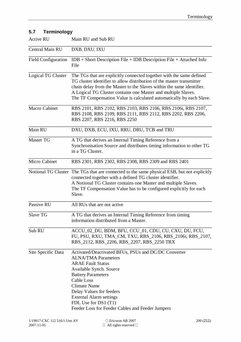
Terminology
1/19817-CXC 112 516/1 Uen AY Ericsson AB 2007 200 (211)2007-11-05 All rights reserved
5.7 TerminologyActive RU Main RU and Sub RU
Central Main RU DXB, DXU, IXU
Field Configuration IDB + Short Description File + IDB Description File + Attached InfoFile
Logical TG Cluster The TGs that are explicitly connected together with the same definedTG cluster identifier to allow distribution of the master transmitterchain delay from the Master to the Slaves within the same identifier.A Logical TG Cluster contains one Master and multiple Slaves.The TF Compensation Value is calculated automatically by each Slave.
Macro Cabinet RBS 2101, RBS 2102, RBS 2103, RBS 2106, RBS 2106i, RBS 2107,RBS 2108, RBS 2109, RBS 2111, RBS 2112, RBS 2202, RBS 2206,RBS 2207, RBS 2216, RBS 2250
Main RU DXU, DXB, ECU, IXU, RRU, DRU, TCB and TRU
Master TG A TG that derives an Internal Timing Reference from aSynchronisation Source and distributes timing information to other TGin a TG Cluster.
Micro Cabinet RBS 2301, RBS 2302, RBS 2308, RBS 2309 and RBS 2401
Notional TG Cluster The TGs that are connected to the same physical ESB, but not explicitlyconnected together with a defined TG cluster identifier.A Notional TG Cluster contains one Master and multiple Slaves.The TF Compensation Value has to be configured explicitly for eachSlave.
Passive RU All RUs that are not active
Slave TG A TG that derives an Internal Timing Reference from timinginformation distributed from a Master.
Sub RU ACCU_02_DU, BDM, BFU, CCU_01, CDU, CU, CXU, DU, FCU,FU, PSU, RXU, TMA_CM, TXU, RBS_2106, RBS_2106i, RBS_2107,RBS_2112, RBS_2206, RBS_2207, RBS_2250 TRX
Site Specific Data Activated/Deactivated BFUs, PSUs and DC/DC ConverterALNA/TMA ParametersARAE Fault StatusAvailable Synch. SourceBattery ParametersCable LossClimate NameDelay Values for feedersExternal Alarm settingsFDL Use for DS1 (T1)Feeder Loss for Feeder Cables and Feeder Jumpers
Terminology
1/19817-CXC 112 516/1 Uen AY Ericsson AB 2007 201 (211)2007-11-05 All rights reserved
GPS ParametersLBO for DS1 (T1)Network TopologyPassive RU HW informationRBS IdentityReceiver SensitivitySpare bits and CRC-4 for G.703 (E1)System VoltageTEI for CMRU DXUTF Compensation Values and ESB Delay ValuesTF holdover modeTNOM ParametersTransmission Interface typeSTN EquipmentVSWR Limits for Antenna Systems and Supervision
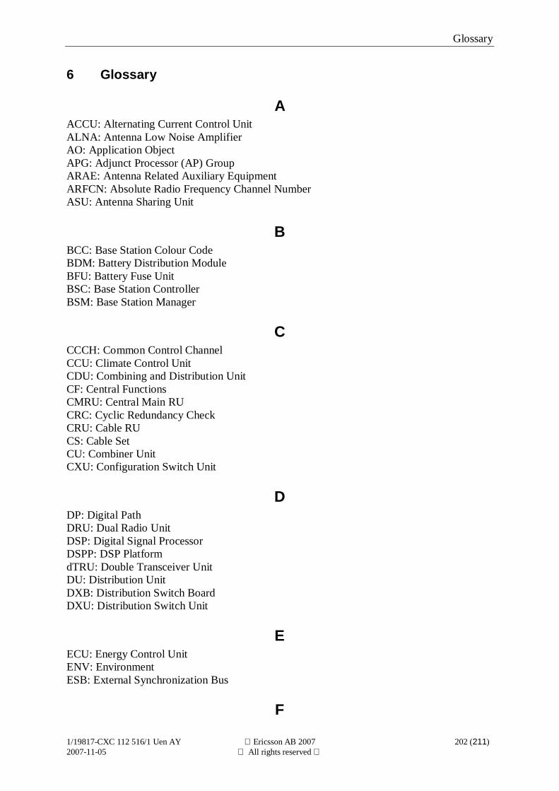
Glossary
1/19817-CXC 112 516/1 Uen AY Ericsson AB 2007 202 (211)2007-11-05 All rights reserved
6 Glossary
AACCU: Alternating Current Control UnitALNA: Antenna Low Noise AmplifierAO: Application ObjectAPG: Adjunct Processor (AP) GroupARAE: Antenna Related Auxiliary EquipmentARFCN: Absolute Radio Frequency Channel NumberASU: Antenna Sharing Unit
BBCC: Base Station Colour CodeBDM: Battery Distribution ModuleBFU: Battery Fuse UnitBSC: Base Station ControllerBSM: Base Station Manager
CCCCH: Common Control ChannelCCU: Climate Control UnitCDU: Combining and Distribution UnitCF: Central FunctionsCMRU: Central Main RUCRC: Cyclic Redundancy CheckCRU: Cable RUCS: Cable SetCU: Combiner UnitCXU: Configuration Switch Unit
DDP: Digital PathDRU: Dual Radio UnitDSP: Digital Signal ProcessorDSPP: DSP PlatformdTRU: Double Transceiver UnitDU: Distribution UnitDXB: Distribution Switch BoardDXU: Distribution Switch Unit
EECU: Energy Control UnitENV: EnvironmentESB: External Synchronization Bus
F
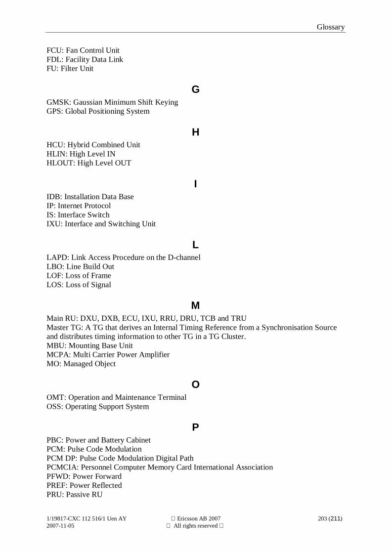
Glossary
1/19817-CXC 112 516/1 Uen AY Ericsson AB 2007 203 (211)2007-11-05 All rights reserved
FCU: Fan Control UnitFDL: Facility Data LinkFU: Filter Unit
GGMSK: Gaussian Minimum Shift KeyingGPS: Global Positioning System
HHCU: Hybrid Combined UnitHLIN: High Level INHLOUT: High Level OUT
IIDB: Installation Data BaseIP: Internet ProtocolIS: Interface SwitchIXU: Interface and Switching Unit
LLAPD: Link Access Procedure on the D-channelLBO: Line Build OutLOF: Loss of FrameLOS: Loss of Signal
MMain RU: DXU, DXB, ECU, IXU, RRU, DRU, TCB and TRUMaster TG: A TG that derives an Internal Timing Reference from a Synchronisation Sourceand distributes timing information to other TG in a TG Cluster.MBU: Mounting Base UnitMCPA: Multi Carrier Power AmplifierMO: Managed Object
OOMT: Operation and Maintenance TerminalOSS: Operating Support System
PPBC: Power and Battery CabinetPCM: Pulse Code ModulationPCM DP: Pulse Code Modulation Digital PathPCMCIA: Personnel Computer Memory Card International AssociationPFWD: Power ForwardPREF: Power ReflectedPRU: Passive RU
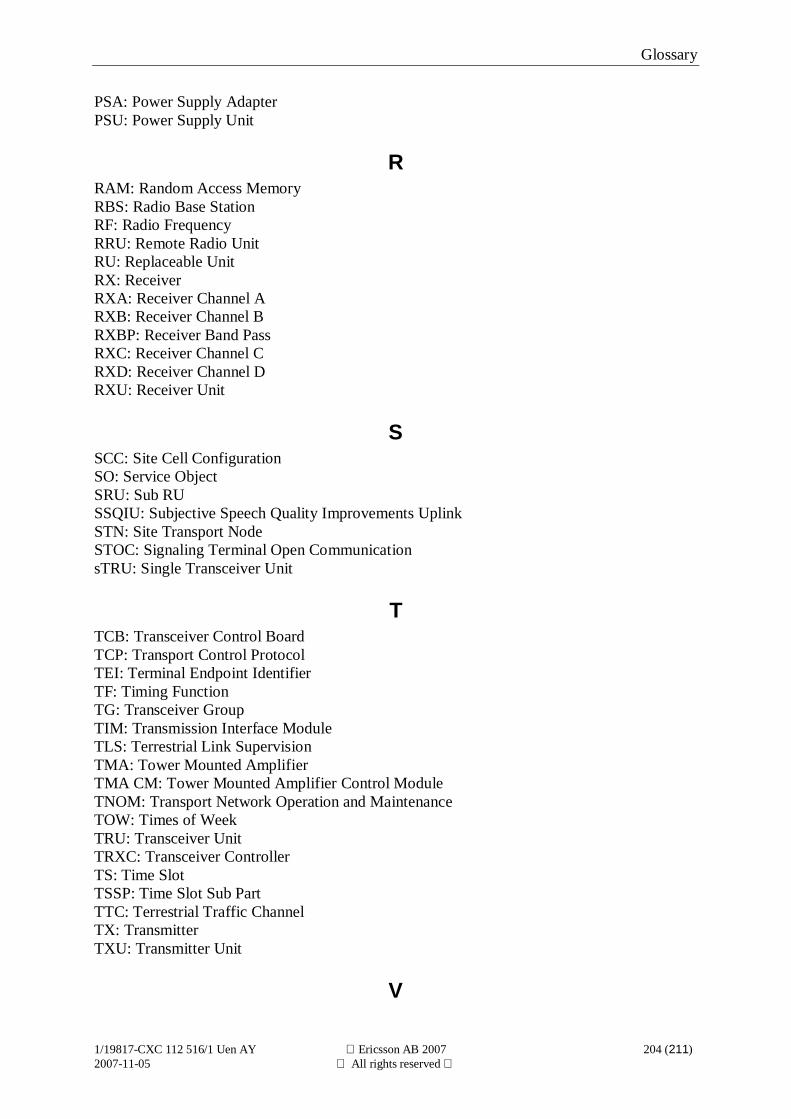
Glossary
1/19817-CXC 112 516/1 Uen AY Ericsson AB 2007 204 (211)2007-11-05 All rights reserved
PSA: Power Supply AdapterPSU: Power Supply Unit
RRAM: Random Access MemoryRBS: Radio Base StationRF: Radio FrequencyRRU: Remote Radio UnitRU: Replaceable UnitRX: ReceiverRXA: Receiver Channel ARXB: Receiver Channel BRXBP: Receiver Band PassRXC: Receiver Channel CRXD: Receiver Channel DRXU: Receiver Unit
SSCC: Site Cell ConfigurationSO: Service ObjectSRU: Sub RUSSQIU: Subjective Speech Quality Improvements UplinkSTN: Site Transport NodeSTOC: Signaling Terminal Open CommunicationsTRU: Single Transceiver Unit
TTCB: Transceiver Control BoardTCP: Transport Control ProtocolTEI: Terminal Endpoint IdentifierTF: Timing FunctionTG: Transceiver GroupTIM: Transmission Interface ModuleTLS: Terrestrial Link SupervisionTMA: Tower Mounted AmplifierTMA CM: Tower Mounted Amplifier Control ModuleTNOM: Transport Network Operation and MaintenanceTOW: Times of WeekTRU: Transceiver UnitTRXC: Transceiver ControllerTS: Time SlotTSSP: Time Slot Sub PartTTC: Terrestrial Traffic ChannelTX: TransmitterTXU: Transmitter Unit
V

Glossary
1/19817-CXC 112 516/1 Uen AY Ericsson AB 2007 205 (211)2007-11-05 All rights reserved
VCO: Voltage Controlled OscillatorVSWR: Voltage Standing Wave Ratio


Glossary
1/19817-CXC 112 516/1 Uen AY Ericsson AB 2007 207 (211)2007-11-05 All rights reserved
7 Index
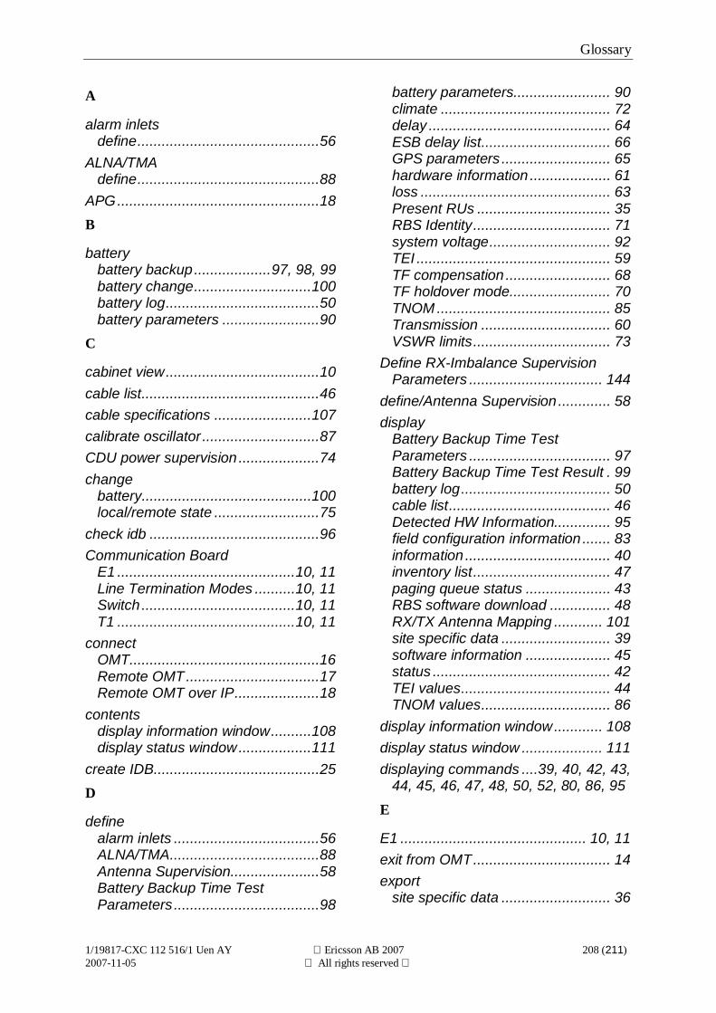
Glossary
1/19817-CXC 112 516/1 Uen AY Ericsson AB 2007 208 (211)2007-11-05 All rights reserved
A
alarm inletsdefine.............................................56
ALNA/TMAdefine.............................................88
APG..................................................18B
batterybattery backup...................97, 98, 99battery change.............................100battery log......................................50battery parameters ........................90
C
cabinet view......................................10cable list............................................46cable specifications ........................107calibrate oscillator .............................87CDU power supervision ....................74change
battery..........................................100local/remote state ..........................75
check idb ..........................................96Communication Board
E1 ............................................10, 11Line Termination Modes ..........10, 11Switch ......................................10, 11T1 ............................................10, 11
connectOMT...............................................16Remote OMT.................................17Remote OMT over IP.....................18
contentsdisplay information window..........108display status window..................111
create IDB.........................................25D
definealarm inlets ....................................56ALNA/TMA.....................................88Antenna Supervision......................58Battery Backup Time TestParameters ....................................98
battery parameters........................ 90climate .......................................... 72delay ............................................. 64ESB delay list................................ 66GPS parameters ........................... 65hardware information .................... 61loss ............................................... 63Present RUs ................................. 35RBS Identity.................................. 71system voltage.............................. 92TEI ................................................ 59TF compensation .......................... 68TF holdover mode......................... 70TNOM ........................................... 85Transmission ................................ 60VSWR limits.................................. 73
Define RX-Imbalance SupervisionParameters ................................. 144
define/Antenna Supervision ............. 58display
Battery Backup Time TestParameters ................................... 97Battery Backup Time Test Result . 99battery log..................................... 50cable list........................................ 46Detected HW Information.............. 95field configuration information ....... 83information .................................... 40inventory list.................................. 47paging queue status ..................... 43RBS software download ............... 48RX/TX Antenna Mapping ............ 101site specific data ........................... 39software information ..................... 45status ............................................ 42TEI values..................................... 44TNOM values................................ 86
display information window............ 108display status window .................... 111displaying commands ....39, 40, 42, 43,
44, 45, 46, 47, 48, 50, 52, 80, 86, 95
E
E1 .............................................. 10, 11exit from OMT.................................. 14export
site specific data ........................... 36
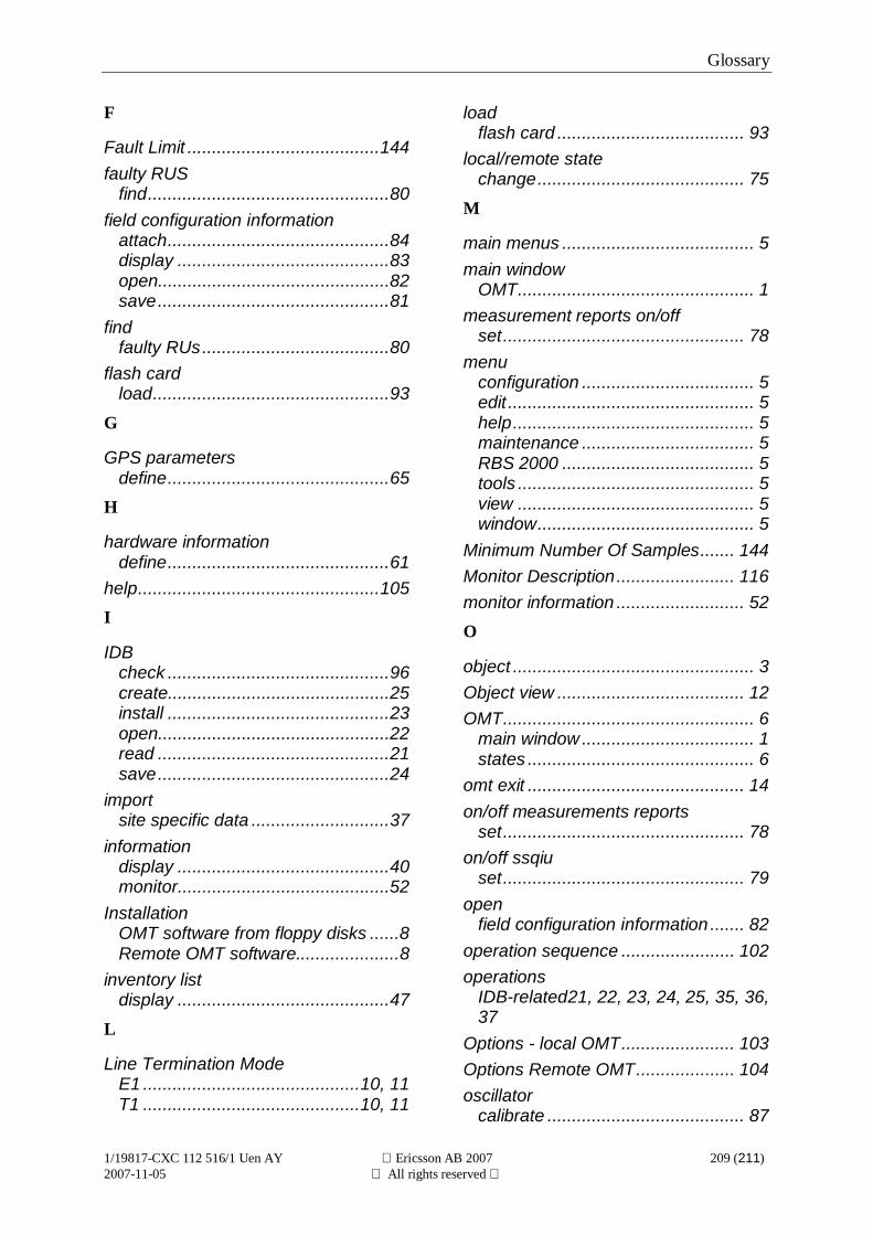
Glossary
1/19817-CXC 112 516/1 Uen AY Ericsson AB 2007 209 (211)2007-11-05 All rights reserved
F
Fault Limit .......................................144faulty RUS
find.................................................80field configuration information
attach.............................................84display ...........................................83open...............................................82save...............................................81
findfaulty RUs......................................80
flash cardload................................................93
G
GPS parametersdefine.............................................65
H
hardware informationdefine.............................................61
help.................................................105I
IDBcheck .............................................96create.............................................25install .............................................23open...............................................22read ...............................................21save...............................................24
importsite specific data ............................37
informationdisplay ...........................................40monitor...........................................52
InstallationOMT software from floppy disks ......8Remote OMT software.....................8
inventory listdisplay ...........................................47
L
Line Termination ModeE1 ............................................10, 11T1 ............................................10, 11
loadflash card ...................................... 93
local/remote statechange.......................................... 75
M
main menus ....................................... 5main window
OMT................................................ 1measurement reports on/off
set................................................. 78menu
configuration ................................... 5edit .................................................. 5help................................................. 5maintenance ................................... 5RBS 2000 ....................................... 5tools ................................................ 5view ................................................ 5window............................................ 5
Minimum Number Of Samples....... 144Monitor Description........................ 116monitor information .......................... 52O
object ................................................. 3Object view ...................................... 12OMT................................................... 6
main window ................................... 1states .............................................. 6
omt exit ............................................ 14on/off measurements reports
set................................................. 78on/off ssqiu
set................................................. 79open
field configuration information ....... 82operation sequence ....................... 102operations
IDB-related21, 22, 23, 24, 25, 35, 36,37
Options - local OMT....................... 103Options Remote OMT.................... 104oscillator
calibrate ........................................ 87
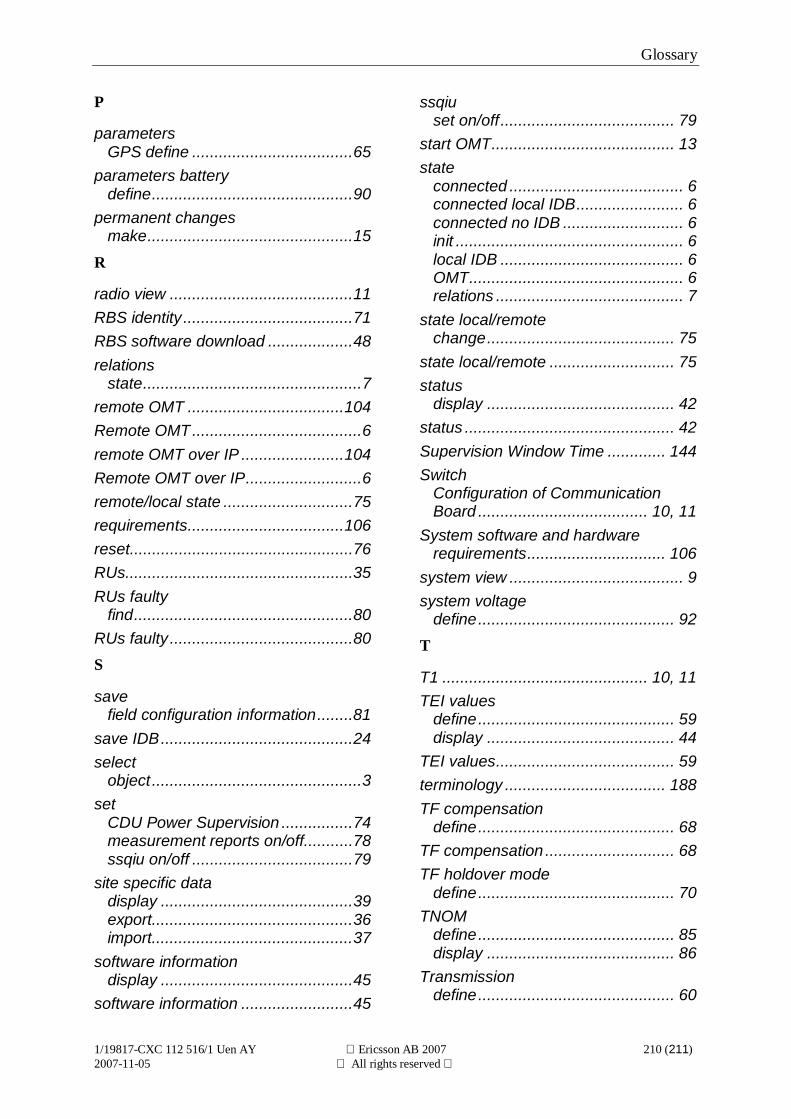
Glossary
1/19817-CXC 112 516/1 Uen AY Ericsson AB 2007 210 (211)2007-11-05 All rights reserved
P
parametersGPS define ....................................65
parameters batterydefine.............................................90
permanent changesmake..............................................15
R
radio view .........................................11RBS identity......................................71RBS software download ...................48relations
state.................................................7remote OMT ...................................104Remote OMT......................................6remote OMT over IP .......................104Remote OMT over IP..........................6remote/local state .............................75requirements...................................106reset..................................................76RUs...................................................35RUs faulty
find.................................................80RUs faulty .........................................80S
savefield configuration information........81
save IDB...........................................24select
object ...............................................3set
CDU Power Supervision ................74measurement reports on/off...........78ssqiu on/off ....................................79
site specific datadisplay ...........................................39export.............................................36import.............................................37
software informationdisplay ...........................................45
software information .........................45
ssqiuset on/off....................................... 79
start OMT......................................... 13state
connected ....................................... 6connected local IDB........................ 6connected no IDB ........................... 6init ................................................... 6local IDB ......................................... 6OMT................................................ 6relations .......................................... 7
state local/remotechange.......................................... 75
state local/remote ............................ 75status
display .......................................... 42status ............................................... 42Supervision Window Time ............. 144Switch
Configuration of CommunicationBoard ...................................... 10, 11
System software and hardwarerequirements............................... 106
system view ....................................... 9system voltage
define............................................ 92T
T1 .............................................. 10, 11TEI values
define............................................ 59display .......................................... 44
TEI values........................................ 59terminology .................................... 188TF compensation
define............................................ 68TF compensation ............................. 68TF holdover mode
define............................................ 70TNOM
define............................................ 85display .......................................... 86
Transmissiondefine............................................ 60
Glossary
1/19817-CXC 112 516/1 Uen AY Ericsson AB 2007 211 (211)2007-11-05 All rights reserved
U
Uninstall OMT...................................11
V
viewcabinet ...........................................10Object view ....................................12
radio view...................................... 11system view .................................... 9
VSWR limitsdefine............................................ 73
W
wizards........................................... 102
Related Documents