
Welcome message from author
This document is posted to help you gain knowledge. Please leave a comment to let me know what you think about it! Share it to your friends and learn new things together.
Transcript
Introduction
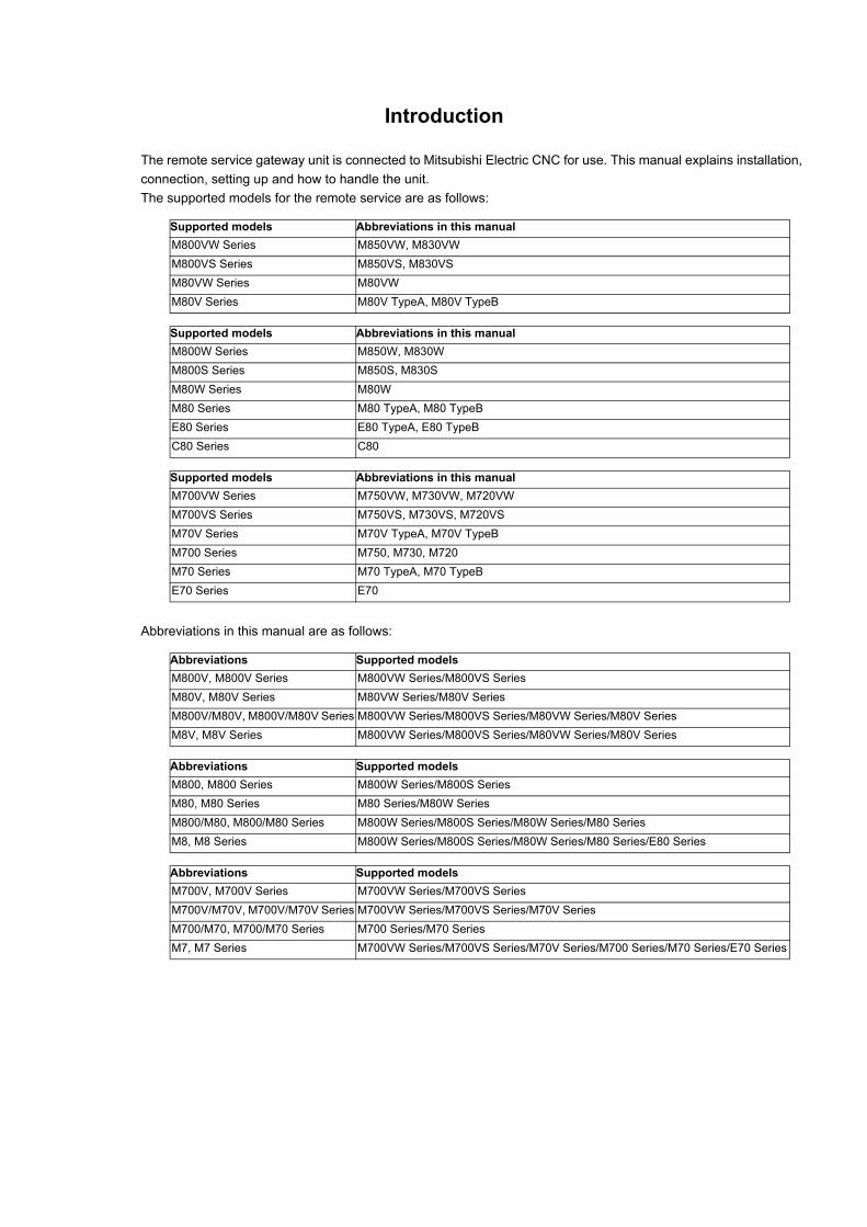
The remote service gateway unit is connected to Mitsubishi Electric CNC for use. This manual explains installation,
connection, setting up and how to handle the unit.
The supported models for the remote service are as follows:
Abbreviations in this manual are as follows:
Supported models Abbreviations in this manual
M800VW Series M850VW, M830VW
M800VS Series M850VS, M830VS
M80VW Series M80VW
M80V Series M80V TypeA, M80V TypeB
Supported models Abbreviations in this manual
M800W Series M850W, M830W
M800S Series M850S, M830S
M80W Series M80W
M80 Series M80 TypeA, M80 TypeB
E80 Series E80 TypeA, E80 TypeB
C80 Series C80
Supported models Abbreviations in this manual
M700VW Series M750VW, M730VW, M720VW
M700VS Series M750VS, M730VS, M720VS
M70V Series M70V TypeA, M70V TypeB
M700 Series M750, M730, M720
M70 Series M70 TypeA, M70 TypeB
E70 Series E70
Abbreviations Supported models
M800V, M800V Series M800VW Series/M800VS Series
M80V, M80V Series M80VW Series/M80V Series
M800V/M80V, M800V/M80V Series M800VW Series/M800VS Series/M80VW Series/M80V Series
M8V, M8V Series M800VW Series/M800VS Series/M80VW Series/M80V Series
Abbreviations Supported models
M800, M800 Series M800W Series/M800S Series
M80, M80 Series M80 Series/M80W Series
M800/M80, M800/M80 Series M800W Series/M800S Series/M80W Series/M80 Series
M8, M8 Series M800W Series/M800S Series/M80W Series/M80 Series/E80 Series
Abbreviations Supported models
M700V, M700V Series M700VW Series/M700VS Series
M700V/M70V, M700V/M70V Series M700VW Series/M700VS Series/M70V Series
M700/M70, M700/M70 Series M700 Series/M70 Series
M7, M7 Series M700VW Series/M700VS Series/M70V Series/M700 Series/M70 Series/E70 Series
Read this manual thoroughly and understand the product's functions and performance before starting to use.
This manual is written on the assumption that all optional functions are added, but the actually delivered device may
not have all functions.
The unit names, cable names and various specifications are subject to change without notice. Please confirm these
before placing an order.
Be sure to keep this manual always at hand.
This product is commercially available encryption device and commercially available encryption program.
Notes on Reading This Manual
(1) This manual is intended to contain as much descriptions as possible even about special operations.
The operations to which no reference is made in this manual should be considered "impossible".
(2) This manual is for the machine tool builders who set up the NC system.
(3) Do not connect to the pin described as "NC" on the pin assignment table of the connector.
(4) The characteristic values and numerical values without tolerances mentioned in this manual are representative
values.
If the descriptions relating to the "restrictions" and "allowable conditions" conflict between this manual
and the machine tool builder's instruction manual‚ the latter has priority over the former.
Items that are not described in this manual must be interpreted as "not possible".
This manual is written on the assumption that all the applicable functions are included. Some of them,
however, may not be available for your NC system. Refer to the specifications issued by the machine tool
builder before use.
For information about each machine tool, refer to manuals issued from the machine tool builder.
Some screens and functions may differ depending on each NC system (or version), and some functions
may not be possible. Please confirm the specifications before starting to use.
To protect the availability, integrity and confidentiality of the NC system against cyber-attacks including
unauthorized access, denial-of-service (Dos) (*1) attack, and computer virus from external sources via a
network, take security measures such as firewall, VPN, and anti-virus software.
(*1) Denial-of-service (Dos): refers to a type of cyber-attack that disrupts services by overloading the
system or by exploiting a vulnerability of the system.
Mitsubishi Electric assumes no responsibility for any problems caused to the NC system by any type of
cyber-attacks including DoS attack, unauthorized access and computer virus.
The numerical control unit is configured of the control unit, display unit, personal computer unit, operation board
(operation panel I/O unit), servo drive unit, spindle drive unit, power supply unit + driver, servomotor, spindle motor,
etc.
In this manual, the following items are generically called "controller".
- Control unit
- Display unit
- Personal computer unit
- Operation board (operation panel I/O unit)
- Numerical control unit peripheral devices (input/output unit, safety unit)
In this manual, the following items are generically called "drive unit".
- Servo drive unit
- Spindle drive unit
- Power supply unit + driver
In this manual, the following items are generically called "motor".
- Servo motor
- Spindle motor
Also refer to the manuals on "Manual List" as necessary.
CAUTION
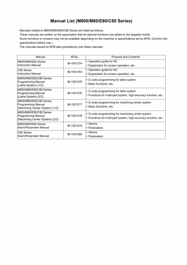
Manual List (M800/M80/E80/C80 Series)
Manuals related to M800/M80/E80/C80 Series are listed as follows.
These manuals are written on the assumption that all optional functions are added to the targeted model.
Some functions or screens may not be available depending on the machine or specifications set by MTB. (Confirm the
specifications before use.)
The manuals issued by MTB take precedence over these manuals.
Manual IB No. Purpose and Contents
M800/M80/E80 SeriesInstruction Manual
IB-1501274 Operation guide for NC
Explanation for screen operation, etc.
C80 SeriesInstruction Manual
IB-1501453 Operation guide for NC
Explanation for screen operation, etc.
M800/M80/E80/C80 SeriesProgramming Manual(Lathe System) (1/2)
IB-1501275 G code programming for lathe system
Basic functions, etc.
M800/M80/E80/C80 SeriesProgramming Manual(Lathe System) (2/2)
IB-1501276 G code programming for lathe system
Functions for multi-part system, high-accuracy function, etc.
M800/M80/E80/C80 SeriesProgramming Manual(Machining Center System) (1/2)
IB-1501277 G code programming for machining center system
Basic functions, etc.
M800/M80/E80/C80 SeriesProgramming Manual(Machining Center System) (2/2)
IB-1501278 G code programming for machining center system
Functions for multi-part system, high-accuracy function, etc.
M800/M80/E80 SeriesAlarm/Parameter Manual
IB-1501279 Alarms
Parameters
C80 SeriesAlarm/Parameter Manual
IB-1501560 Alarms
Parameters
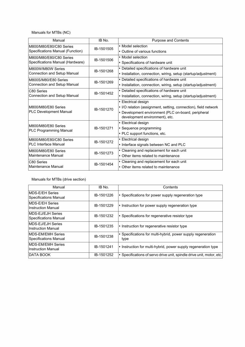
Manuals for MTBs (NC)
Manuals for MTBs (drive section)
Manual IB No. Purpose and Contents
M800/M80/E80/C80 SeriesSpecifications Manual (Function)
IB-1501505 Model selection
Outline of various functions
M800/M80/E80/C80 SeriesSpecifications Manual (Hardware)
IB-1501506 Model selection
Specifications of hardware unit
M800W/M80W SeriesConnection and Setup Manual
IB-1501268 Detailed specifications of hardware unit
Installation, connection, wiring, setup (startup/adjustment)
M800S/M80/E80 SeriesConnection and Setup Manual
IB-1501269 Detailed specifications of hardware unit
Installation, connection, wiring, setup (startup/adjustment)
C80 SeriesConnection and Setup Manual
IB-1501452 Detailed specifications of hardware unit
Installation, connection, wiring, setup (startup/adjustment)
M800/M80/E80 SeriesPLC Development Manual
IB-1501270
Electrical design
I/O relation (assignment, setting, connection), field network
Development environment (PLC on-board, peripheral development environment), etc.
M800/M80/E80 SeriesPLC Programming Manual
IB-1501271
Electrical design
Sequence programming
PLC support functions, etc.
M800/M80/E80/C80 SeriesPLC Interface Manual
IB-1501272 Electrical design
Interface signals between NC and PLC
M800/M80/E80 SeriesMaintenance Manual
IB-1501273 Cleaning and replacement for each unit
Other items related to maintenance
C80 SeriesMaintenance Manual
IB-1501454 Cleaning and replacement for each unit
Other items related to maintenance
Manual IB No. Contents
MDS-E/EH SeriesSpecifications Manual
IB-1501226 Specifications for power supply regeneration type
MDS-E/EH SeriesInstruction Manual
IB-1501229 Instruction for power supply regeneration type
MDS-EJ/EJH SeriesSpecifications Manual
IB-1501232 Specifications for regenerative resistor type
MDS-EJ/EJH SeriesInstruction Manual
IB-1501235 Instruction for regenerative resistor type
MDS-EM/EMH SeriesSpecifications Manual
IB-1501238 Specifications for multi-hybrid, power supply regeneration
type
MDS-EM/EMH SeriesInstruction Manual
IB-1501241 Instruction for multi-hybrid, power supply regeneration type
DATA BOOK IB-1501252 Specifications of servo drive unit, spindle drive unit, motor, etc.
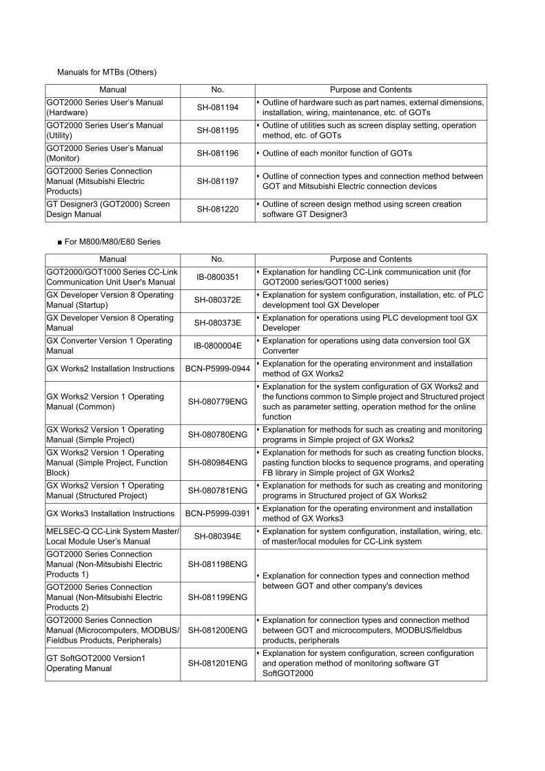
Manuals for MTBs (Others)
■ For M800/M80/E80 Series
Manual No. Purpose and Contents
GOT2000 Series User’s Manual (Hardware)
SH-081194 Outline of hardware such as part names, external dimensions,
installation, wiring, maintenance, etc. of GOTs
GOT2000 Series User’s Manual (Utility)
SH-081195 Outline of utilities such as screen display setting, operation
method, etc. of GOTs
GOT2000 Series User’s Manual (Monitor)
SH-081196 Outline of each monitor function of GOTs
GOT2000 Series Connection Manual (Mitsubishi Electric Products)
SH-081197 Outline of connection types and connection method between
GOT and Mitsubishi Electric connection devices
GT Designer3 (GOT2000) Screen Design Manual
SH-081220 Outline of screen design method using screen creation
software GT Designer3
Manual No. Purpose and Contents
GOT2000/GOT1000 Series CC-Link Communication Unit User's Manual
IB-0800351 Explanation for handling CC-Link communication unit (for
GOT2000 series/GOT1000 series)
GX Developer Version 8 Operating Manual (Startup)
SH-080372E Explanation for system configuration, installation, etc. of PLC
development tool GX Developer
GX Developer Version 8 Operating Manual
SH-080373E Explanation for operations using PLC development tool GX
Developer
GX Converter Version 1 Operating Manual
IB-0800004E Explanation for operations using data conversion tool GX
Converter
GX Works2 Installation Instructions BCN-P5999-0944 Explanation for the operating environment and installation
method of GX Works2
GX Works2 Version 1 Operating Manual (Common)
SH-080779ENG
Explanation for the system configuration of GX Works2 and the functions common to Simple project and Structured project such as parameter setting, operation method for the online function
GX Works2 Version 1 Operating Manual (Simple Project)
SH-080780ENG Explanation for methods for such as creating and monitoring
programs in Simple project of GX Works2
GX Works2 Version 1 Operating Manual (Simple Project, Function Block)
SH-080984ENG Explanation for methods for such as creating function blocks,
pasting function blocks to sequence programs, and operating FB library in Simple project of GX Works2
GX Works2 Version 1 Operating Manual (Structured Project)
SH-080781ENG Explanation for methods for such as creating and monitoring
programs in Structured project of GX Works2
GX Works3 Installation Instructions BCN-P5999-0391 Explanation for the operating environment and installation
method of GX Works3
MELSEC-Q CC-Link System Master/Local Module User’s Manual
SH-080394E Explanation for system configuration, installation, wiring, etc.
of master/local modules for CC-Link system
GOT2000 Series Connection Manual (Non-Mitsubishi Electric Products 1)
SH-081198ENG Explanation for connection types and connection method
between GOT and other company's devicesGOT2000 Series Connection Manual (Non-Mitsubishi Electric Products 2)
SH-081199ENG
GOT2000 Series Connection Manual (Microcomputers, MODBUS/Fieldbus Products, Peripherals)
SH-081200ENG Explanation for connection types and connection method
between GOT and microcomputers, MODBUS/fieldbus products, peripherals
GT SoftGOT2000 Version1 Operating Manual
SH-081201ENG Explanation for system configuration, screen configuration
and operation method of monitoring software GT SoftGOT2000
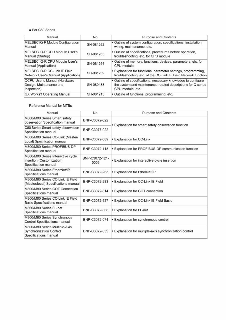
■ For C80 Series
Reference Manual for MTBs
Manual No. Purpose and Contents
MELSEC iQ-R Module Configuration Manual
SH-081262 Outline of system configuration, specifications, installation,
wiring, maintenance, etc.
MELSEC iQ-R CPU Module User’s Manual (Startup)
SH-081263 Outline of specifications, procedures before operation,
troubleshooting, etc. for CPU module
MELSEC iQ-R CPU Module User’s Manual (Application)
SH-081264 Outline of memory, functions, devices, parameters, etc. for
CPU module
MELSEC iQ-R CC-Link IE Field Network User's Manual (Application)
SH-081259 Explanation for functions, parameter settings, programming,
troubleshooting, etc. of the CC-Link IE Field Network function
QCPU User’s Manual (Hardware Design, Maintenance and Inspection)
SH-080483 Outline of specifications, necessary knowledge to configure
the system and maintenance-related descriptions for Q series CPU module, etc.
GX Works3 Operating Manual SH-081215 Outline of functions, programming, etc.
Manual No. Purpose and Contents
M800/M80 Series Smart safety observation Specification manual
BNP-C3072-022 Explanation for smart safety observation function
C80 Series Smart safety observation Specification manual
BNP-C3077-022
M800/M80 Series CC-Link (Master/Local) Specification manual
BNP-C3072-089 Explanation for CC-Link
M800/M80 Series PROFIBUS-DP Specification manual
BNP-C3072-118 Explanation for PROFIBUS-DP communication function
M800/M80 Series Interactive cycle insertion (Customization) Specification manual
BNP-C3072-121-0003
Explanation for interactive cycle insertion
M800/M80 Series EtherNet/IP Specifications manual
BNP-C3072-263 Explanation for EtherNet/IP
M800/M80 Series CC-Link IE Field (Master/local) Specifications manual
BNP-C3072-283 Explanation for CC-Link IE Field
M800/M80 Series GOT Connection Specifications manual
BNP-C3072-314 Explanation for GOT connection
M800/M80 Series CC-Link IE Field Basic Specifications manual
BNP-C3072-337 Explanation for CC-Link IE Field Basic
M800/M80 Series FL-net Specifications manual
BNP-C3072-368 Explanation for FL-net
M800/M80 Series Synchronous Control Specifications manual
BNP-C3072-074 Explanation for synchronous control
M800/M80 Series Multiple-Axis Synchronization Control Specifications manual
BNP-C3072-339 Explanation for multiple-axis synchronization control
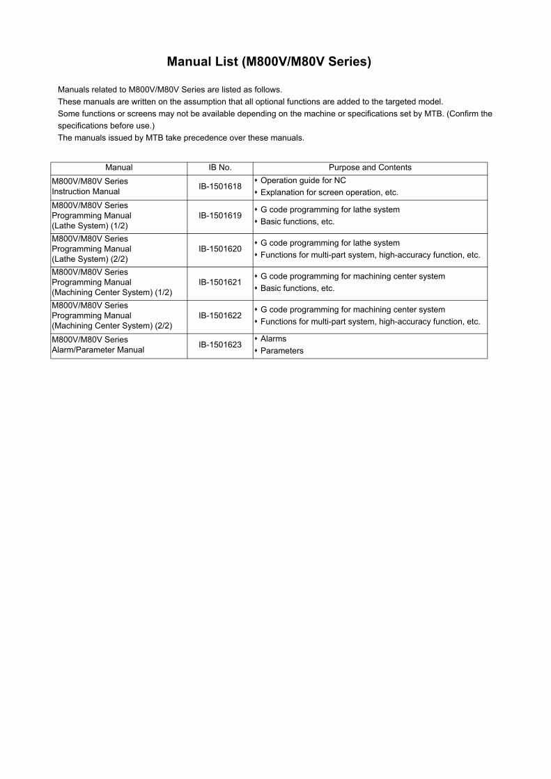
Manual List (M800V/M80V Series)
Manuals related to M800V/M80V Series are listed as follows.
These manuals are written on the assumption that all optional functions are added to the targeted model.
Some functions or screens may not be available depending on the machine or specifications set by MTB. (Confirm the
specifications before use.)
The manuals issued by MTB take precedence over these manuals.
Manual IB No. Purpose and Contents
M800V/M80V SeriesInstruction Manual
IB-1501618 Operation guide for NC
Explanation for screen operation, etc.
M800V/M80V SeriesProgramming Manual(Lathe System) (1/2)
IB-1501619 G code programming for lathe system
Basic functions, etc.
M800V/M80V SeriesProgramming Manual(Lathe System) (2/2)
IB-1501620 G code programming for lathe system
Functions for multi-part system, high-accuracy function, etc.
M800V/M80V SeriesProgramming Manual(Machining Center System) (1/2)
IB-1501621 G code programming for machining center system
Basic functions, etc.
M800V/M80V SeriesProgramming Manual(Machining Center System) (2/2)
IB-1501622 G code programming for machining center system
Functions for multi-part system, high-accuracy function, etc.
M800V/M80V SeriesAlarm/Parameter Manual
IB-1501623 Alarms
Parameters
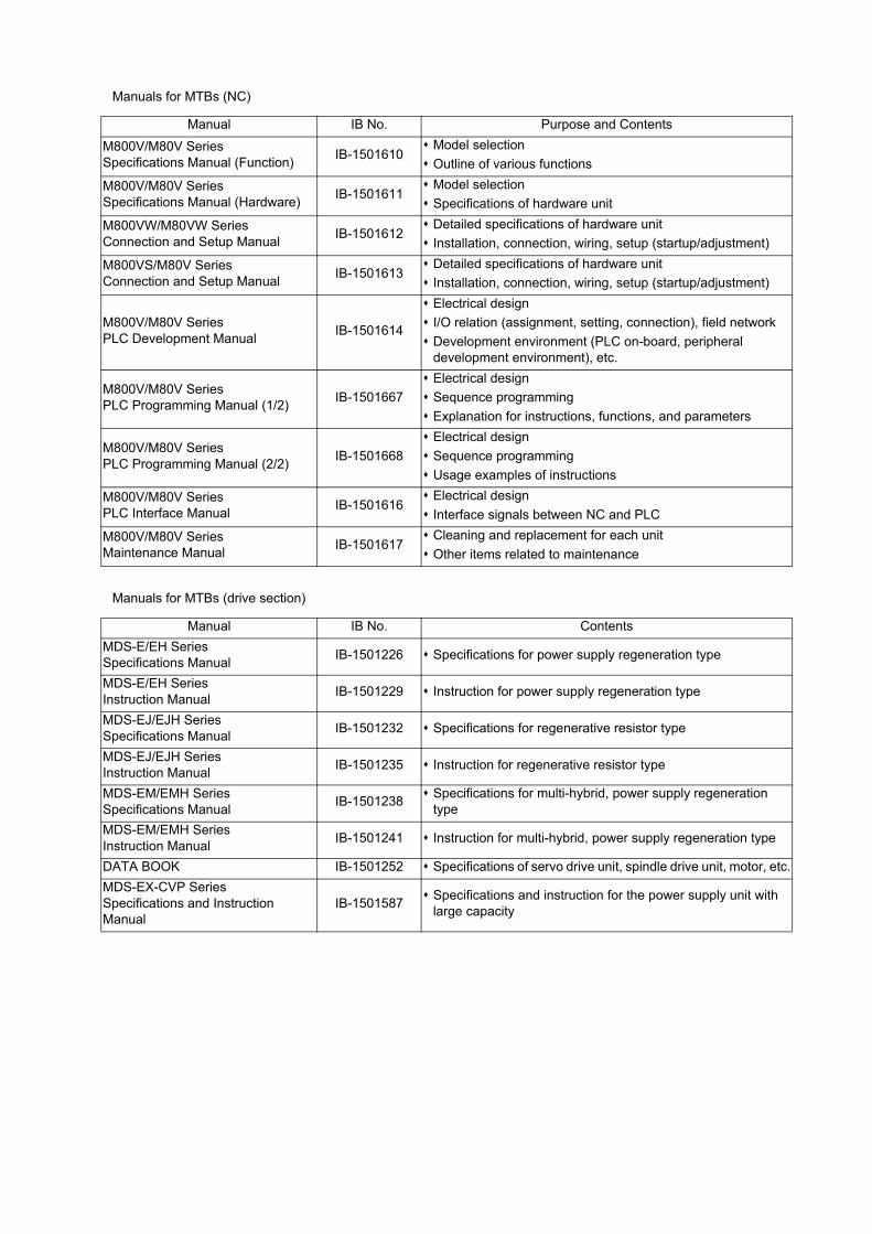
Manuals for MTBs (NC)
Manuals for MTBs (drive section)
Manual IB No. Purpose and Contents
M800V/M80V SeriesSpecifications Manual (Function)
IB-1501610 Model selection
Outline of various functions
M800V/M80V SeriesSpecifications Manual (Hardware)
IB-1501611 Model selection
Specifications of hardware unit
M800VW/M80VW SeriesConnection and Setup Manual
IB-1501612 Detailed specifications of hardware unit
Installation, connection, wiring, setup (startup/adjustment)
M800VS/M80V SeriesConnection and Setup Manual
IB-1501613 Detailed specifications of hardware unit
Installation, connection, wiring, setup (startup/adjustment)
M800V/M80V SeriesPLC Development Manual
IB-1501614
Electrical design
I/O relation (assignment, setting, connection), field network
Development environment (PLC on-board, peripheral development environment), etc.
M800V/M80V SeriesPLC Programming Manual (1/2)
IB-1501667
Electrical design
Sequence programming
Explanation for instructions, functions, and parameters
M800V/M80V SeriesPLC Programming Manual (2/2)
IB-1501668
Electrical design
Sequence programming
Usage examples of instructions
M800V/M80V SeriesPLC Interface Manual
IB-1501616 Electrical design
Interface signals between NC and PLC
M800V/M80V SeriesMaintenance Manual
IB-1501617 Cleaning and replacement for each unit
Other items related to maintenance
Manual IB No. Contents
MDS-E/EH SeriesSpecifications Manual
IB-1501226 Specifications for power supply regeneration type
MDS-E/EH SeriesInstruction Manual
IB-1501229 Instruction for power supply regeneration type
MDS-EJ/EJH SeriesSpecifications Manual
IB-1501232 Specifications for regenerative resistor type
MDS-EJ/EJH SeriesInstruction Manual
IB-1501235 Instruction for regenerative resistor type
MDS-EM/EMH SeriesSpecifications Manual
IB-1501238 Specifications for multi-hybrid, power supply regeneration
type
MDS-EM/EMH SeriesInstruction Manual
IB-1501241 Instruction for multi-hybrid, power supply regeneration type
DATA BOOK IB-1501252 Specifications of servo drive unit, spindle drive unit, motor, etc.
MDS-EX-CVP SeriesSpecifications and Instruction Manual
IB-1501587 Specifications and instruction for the power supply unit with
large capacity
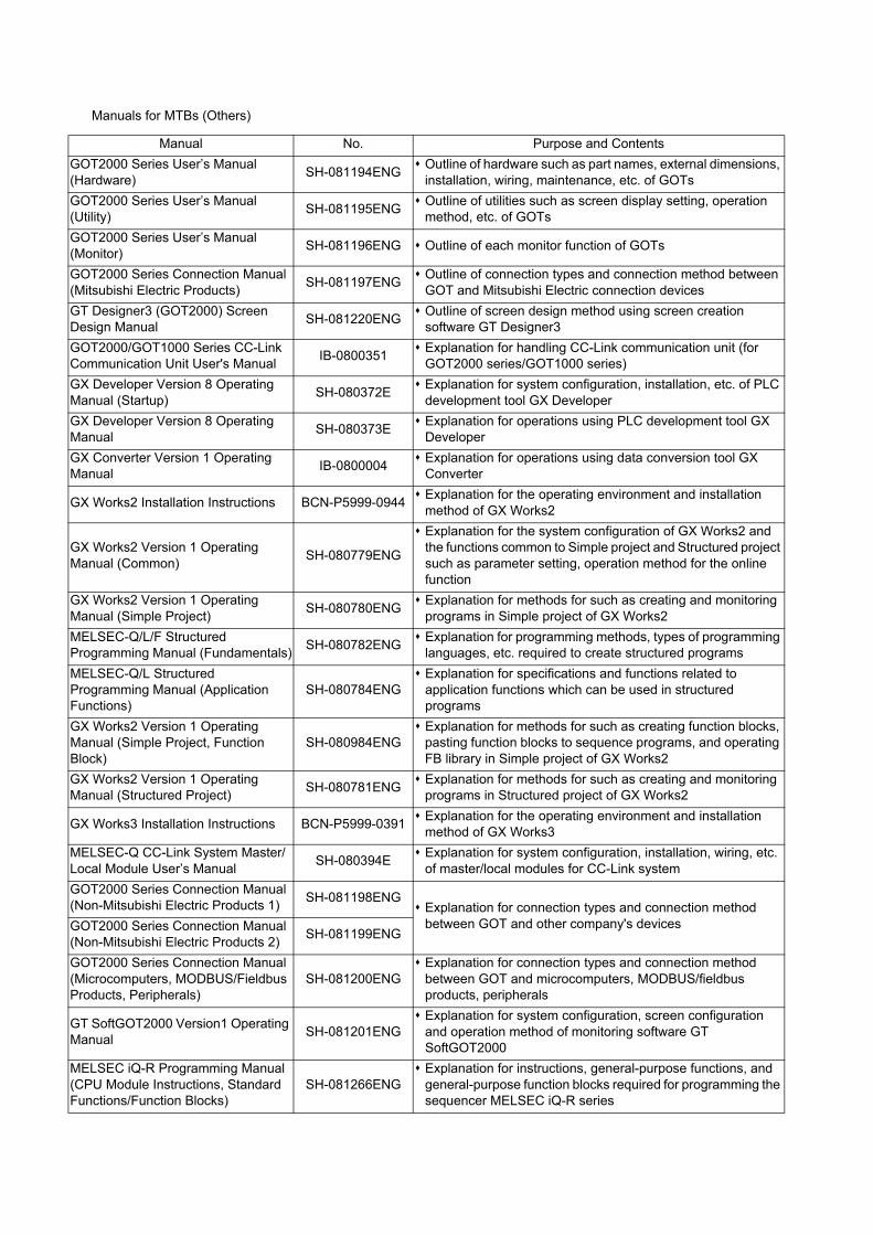
Manuals for MTBs (Others)
Manual No. Purpose and Contents
GOT2000 Series User’s Manual (Hardware)
SH-081194ENG Outline of hardware such as part names, external dimensions,
installation, wiring, maintenance, etc. of GOTs
GOT2000 Series User’s Manual (Utility)
SH-081195ENG Outline of utilities such as screen display setting, operation
method, etc. of GOTs
GOT2000 Series User’s Manual (Monitor)
SH-081196ENG Outline of each monitor function of GOTs
GOT2000 Series Connection Manual (Mitsubishi Electric Products)
SH-081197ENG Outline of connection types and connection method between
GOT and Mitsubishi Electric connection devices
GT Designer3 (GOT2000) Screen Design Manual
SH-081220ENG Outline of screen design method using screen creation
software GT Designer3
GOT2000/GOT1000 Series CC-Link Communication Unit User's Manual
IB-0800351 Explanation for handling CC-Link communication unit (for
GOT2000 series/GOT1000 series)
GX Developer Version 8 Operating Manual (Startup)
SH-080372E Explanation for system configuration, installation, etc. of PLC
development tool GX Developer
GX Developer Version 8 Operating Manual
SH-080373E Explanation for operations using PLC development tool GX
Developer
GX Converter Version 1 Operating Manual
IB-0800004 Explanation for operations using data conversion tool GX
Converter
GX Works2 Installation Instructions BCN-P5999-0944 Explanation for the operating environment and installation
method of GX Works2
GX Works2 Version 1 Operating Manual (Common)
SH-080779ENG
Explanation for the system configuration of GX Works2 and the functions common to Simple project and Structured project such as parameter setting, operation method for the online function
GX Works2 Version 1 Operating Manual (Simple Project)
SH-080780ENG Explanation for methods for such as creating and monitoring
programs in Simple project of GX Works2
MELSEC-Q/L/F Structured Programming Manual (Fundamentals)
SH-080782ENG Explanation for programming methods, types of programming
languages, etc. required to create structured programs
MELSEC-Q/L Structured Programming Manual (Application Functions)
SH-080784ENG Explanation for specifications and functions related to
application functions which can be used in structured programs
GX Works2 Version 1 Operating Manual (Simple Project, Function Block)
SH-080984ENG Explanation for methods for such as creating function blocks,
pasting function blocks to sequence programs, and operating FB library in Simple project of GX Works2
GX Works2 Version 1 Operating Manual (Structured Project)
SH-080781ENG Explanation for methods for such as creating and monitoring
programs in Structured project of GX Works2
GX Works3 Installation Instructions BCN-P5999-0391 Explanation for the operating environment and installation
method of GX Works3
MELSEC-Q CC-Link System Master/Local Module User’s Manual
SH-080394E Explanation for system configuration, installation, wiring, etc.
of master/local modules for CC-Link system
GOT2000 Series Connection Manual (Non-Mitsubishi Electric Products 1)
SH-081198ENG Explanation for connection types and connection method
between GOT and other company's devicesGOT2000 Series Connection Manual (Non-Mitsubishi Electric Products 2)
SH-081199ENG
GOT2000 Series Connection Manual (Microcomputers, MODBUS/Fieldbus Products, Peripherals)
SH-081200ENG Explanation for connection types and connection method
between GOT and microcomputers, MODBUS/fieldbus products, peripherals
GT SoftGOT2000 Version1 Operating Manual
SH-081201ENG Explanation for system configuration, screen configuration
and operation method of monitoring software GT SoftGOT2000
MELSEC iQ-R Programming Manual (CPU Module Instructions, Standard Functions/Function Blocks)
SH-081266ENG Explanation for instructions, general-purpose functions, and
general-purpose function blocks required for programming the sequencer MELSEC iQ-R series

Reference Manual for MTBs
Manual No. Purpose and Contents
M800/M80 Series Smart safety observation Specification manual
BNP-C3072-022 Explanation for smart safety observation function
M800/M80 Series CC-Link (Master/Local) Specification manual
BNP-C3072-089 Explanation for CC-Link
M800/M80 Series PROFIBUS-DP Specification manual
BNP-C3072-118 Explanation for PROFIBUS-DP communication function
M800/M80 Series Interactive cycle insertion (Customization) Specification manual
BNP-C3072-121-0003
Explanation for interactive cycle insertion
M800/M80 Series EtherNet/IP Specifications manual
BNP-C3072-263 Explanation for EtherNet/IP
M800/M80 Series CC-Link IE Field (Master/local) Specifications manual
BNP-C3072-283 Explanation for CC-Link IE Field
M800/M80 Series GOT Connection Specifications manual
BNP-C3072-314 Explanation for GOT connection
M800/M80 Series CC-Link IE Field Basic Specifications manual
BNP-C3072-337 Explanation for CC-Link IE Field Basic
M800/M80 Series FL-net Specifications manual
BNP-C3072-368 Explanation for FL-net
M800/M80 Series Synchronous Control Specifications manual
BNP-C3072-074 Explanation for synchronous control
M800/M80 Series Multiple-Axis Synchronization Control Specifications manual
BNP-C3072-339 Explanation for multiple-axis synchronization control
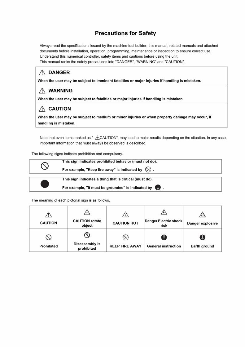
Precautions for Safety
Always read the specifications issued by the machine tool builder, this manual, related manuals and attached
documents before installation, operation, programming, maintenance or inspection to ensure correct use.
Understand this numerical controller, safety items and cautions before using the unit.
This manual ranks the safety precautions into "DANGER", "WARNING" and "CAUTION".
Note that even items ranked as " CAUTION", may lead to major results depending on the situation. In any case,
important information that must always be observed is described.
The following signs indicate prohibition and compulsory.
The meaning of each pictorial sign is as follows.
DANGER
When the user may be subject to imminent fatalities or major injuries if handling is mistaken.
WARNING
When the user may be subject to fatalities or major injuries if handling is mistaken.
CAUTION
When the user may be subject to medium or minor injuries or when property damage may occur, if
handling is mistaken.
This sign indicates prohibited behavior (must not do).
For example, "Keep fire away" is indicated by .
This sign indicates a thing that is critical (must do).
For example, "it must be grounded" is indicated by .
CAUTION
CAUTION rotate
object
CAUTION HOT
Danger Electric shock
risk
Danger explosive
Prohibited
Disassembly is
prohibited
KEEP FIRE AWAY
General instruction
Earth ground
MITSUBISHI CNC is designed and manufactured solely for applications to machine tools to be used for industrial
purposes.
Do not use this product in any applications other than those specified above, especially those which are
substantially influential on the public interest or which are expected to have significant influence on human lives or
properties.
1. Items related to prevention of electric shocks
2. Items related to prevention of fire
For Safe Use
WARNING
Do not open or remove the front cover while the power is ON or during operation. The high voltage terminals and charged sections will be exposed, and this could result in electric shocks.
Do not remove the front cover even when the power is OFF, except for the wiring works or periodic inspections. The inside of the controller and drive unit are charged, and this could result in electric shocks.
Always wait at least 15 minutes after turning the power OFF. Then, check the voltage with a tester, etc., before wiring works, inspections or connecting with peripheral devices. Failure to observe this could result in electric shocks.
Earth ground the controller, drive unit and motor according to the local laws. (In Japan, ground the 200V Series input products with Class C or higher protective grounding and the 400V Series input with Class D or higher protective grounding.)
All wiring works, maintenance and inspections must be carried out by a qualified technician. Failure to observe this could result in electric shocks. Contact your nearby Service Center for replacing parts and servicing.
Wire the controller, drive unit and motor after installation. Failure to observe this could result in electric shocks.
Do not operate the switches with wet hands. Failure to observe this could result in electric shocks.
Do not damage, apply excessive stress, place heavy things on or sandwich the cables. Failure to observe this could result in electric shocks.
Insulate the power lead using a fixed terminal block. Failure to observe this could result in electric shocks.
Completely turn off the all lines of the power supply externally before wiring. Not completely turning off all power could result in electric shock or damage to the product.
When turning on the power supply or operating the module after wiring, be sure that the module's terminal covers are correctly attached. Not attaching the terminal cover could result in electric shock.
CAUTION
Install the controller, drive unit, motor and regenerative resistor on non-combustible material Installation directly on or near combustible materials could result in fires.
If any malfunction in the unit is observed, shut off the power at the unit’s power supply side. Continuous flow of large current could result in fires.
Install an appropriate no fuse breaker (NFB) and contactor (MC) on the power input section of the drive unit and configure the sequence that shuts the power off upon drive unit’s emergency stop or alarm.
When a breaker is shared for multiple power supply units, the breaker may not function upon short-circuit failure in a small capacity unit. Do not share a breaker for multiple units as this is dangerous
Incorrect wiring and connections could cause the devices to damage or burn.
3. Items related to prevention of bodily injury or property damage
DANGER
When transporting or installing a built-in IPM spindle or linear servomotor, be careful so that your hand or property will not be trapped in the motors or other metal objects. Also keep the devices with low magnetic tolerance away from the product.
CAUTION
Do not apply voltages to the connectors or terminals other than voltages indicated in the connection and setup manual for the controller or specifications manual for the drive unit. Failure to observe this could cause bursting, damage, etc.
Incorrect connections could cause the devices to rupture or damage, etc Always connect the cables to the indicated connectors or terminals.
Incorrect polarity (+ -) could cause the devices to rupture or damage, etc.
Persons wearing medical devices, such as pacemakers, must stay away from this unit.
The electromagnetic waves could adversely affect the medical devices. Fins on the rear of the unit, regenerative resistor and motor, etc., will be hot during operation and for a while after the power has been turned OFF. Failure to observe this could result in burns.
Do not enter the machine’s movable range during automatic operation. Keep your hands, feet or face away from the spindle during rotation.

4. General precautions
Always follow the precautions below. Incorrect handling could result in faults, injuries or electric shocks, etc.
(1) Items related to product and manual
CAUTION
If the descriptions relating to the "restrictions" and "allowable conditions" conflict between this manual and the machine tool builder's instruction manual‚ the latter has priority over the former.
Items that are not described in this manual must be interpreted as "not possible".
This manual is written on the assumption that all the applicable functions are included. Some of them, however, may not be available for your NC system. Refer to the specifications issued by the machine tool builder before use.
For information about each machine tool, refer to manuals issued from the machine tool builder.
Some screens and functions may differ depending on each NC system (or version), and some functions may not be possible. Please confirm the specifications before starting to use.
Refer to "Smart safety observation" (BNP-C3072-022) for details about the connection with safety observing I/O device.
To protect the availability, integrity and confidentiality of the NC system against cyber-attacks including unauthorized access, denial-of-service (Dos) (*1) attack, and computer virus from external sources via a network, take security measures such as firewall, VPN, and anti-virus software.(*1) Denial-of-service (Dos): refers to a type of cyber-attack that disrupts services by overloading the system or by exploiting a vulnerability of the system.
Mitsubishi Electric assumes no responsibility for any problems caused to the NC system by any type of cyber-attacks including DoS attack, unauthorized access and computer virus.
(2) Transportation and installation
CAUTION
Correctly transport the products according to the mass.
Use motor’s suspension bolts to transport the motor itself. Do not use it to transport the motor after installation onto the machine.
Do not stack the products exceeding the indicated limit.
Do not hold the cables, shaft or encoder when transporting the motor.
Do not transport the controller or drive unit by suspending or holding the connected wires or cables.
Do not hold the front cover when transporting the unit, or the front cover could come off, causing the unit to drop.
Install on a non-combustible place where the unit’s or motor’s mass can be withstood according to the instruction manual.
The motor does not have a complete water-proof (oil-proof) structure. Do not allow oil or water to contact or enter the motor. Prevent the cutting chips from being accumulated on the motor as they easily soak up oil.
When installing the motor facing upwards, take measures on the machine side so that gear oil, etc., will not enter the motor shaft.
Do not remove the encoder from the motor. (The encoder installation screw is treated with sealing.)
Do not allow foreign matters, especially, conductive foreign matters such as screws or metal chips, or combustible foreign matters such as oil, to enter the controller, drive unit or motor. Failure to observe this could result in rupture or damage.
Do not get on the product or place heavy objects on it.
Provide prescribed distance between the controller/drive unit and inner surface of the control panel/other devices.
Do not install or operate the controller, drive unit or motor that is damaged or has missing parts.
Take care not to cut hands, etc. with the heat radiating fins or metal edges.

CAUTION
Do not block the intake/outtake ports of the motor with the cooling fan.
Install the controller’s display section and operation board section on the spot where cutting oil will not reach.
The controller, drive unit and motor are precision devices, so do not drop or apply thumping vibration and strong impacts on them.
The controller and drive unit are precision devices, so do not drop or apply strong impacts on them.
Store and use the units according to the environment conditions indicated in each specifications manual.
When disinfectants or insecticides must be used to treat wood packaging materials, always use methods other than fumigation (for example, apply heat treatment at the minimum wood core temperature of 56 °C for a minimum duration of 30 minutes (ISPM No. 15 (2009))).
If products such as units are directly fumigated or packed with fumigated wooden materials, halogen substances (including fluorine, chlorine, bromine and iodine) contained in fumes may contribute to the erosion of the capacitors. When exporting the products, make sure to comply with the laws and regulations of each country.
Do not use the products in conjunction with any components that contain halogenated flame retardants (bromine, etc). Failure to observe this may cause the erosion of the capacitors.
Securely fix the motor to the machine. The motor could come off during operation if insecurely fixed.
Always install the motor with reduction gear in the designated direction. Failure to observe this could result in oil leaks.
Always install a cover, etc., over the shaft so that the rotary section of the motor cannot be touched during motor rotation.
When installing a coupling to the servomotor shaft end, do not apply impacts by hammering, etc. The encoder could be damaged.
Use a flexible coupling when connecting with a ball screw, etc., and keep the shaft core deviation smaller than the tolerable radial load of the shaft.
Do not use a rigid coupling as an excessive bending load will be applied on the shaft and could cause the shaft to break.
Do not apply a load exceeding the tolerable level onto the motor shaft. The shaft or bearing could be damaged.
Before using this product after a long period of storage, please contact the Service Center.
Following the UN recommendations, battery units and batteries should be transported based on the international regulations such as those determined by International Civil Aviation Organization (ICAO), International Air Transport Association (IATA), International Maritime Organization (IMO) and U.S. Department of Transportation (DOT).
(3) Items related to wiring
CAUTION
Correctly wire this product. Failure to observe this could result in motor runaway, etc.
Incorrect terminal connections could cause the devices to rupture or damage, etc. Always connect the cables to the indicated connectors or terminals.
Do not install a phase advancing capacitor, surge absorber or radio noise filter on the output side of the drive unit.
Correctly connect the output side (terminal U, V, W). The motor will not run properly if incorrectly connected.
Always install an AC reactor per each power supply unit.
Always install an appropriate breaker per each power supply unit. A breaker cannot be shared for multiple power supply units.
Do not directly connect a commercial power supply to the motor. Failure to observe this could result in faults.
When using an inductive load such as relays, always connect a diode in parallel to the load as a noise countermeasure.
hen using a capacitive load such as a lamp, always connect a protective resistor serially to the load to suppress rush currents.
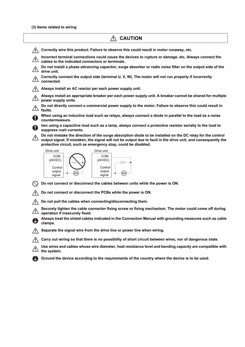
Do not mistake the direction of the surge absorption diode to be installed on the DC relay for the control output signal. If mistaken, the signal will not be output due to fault in the drive unit, and consequently the protective circuit, such as emergency stop, could be disabled.
Do not connect or disconnect the cables between units while the power is ON.
Do not connect or disconnect the PCBs while the power is ON.
Do not pull the cables when connecting/disconnecting them.
Securely tighten the cable connector fixing screw or fixing mechanism. The motor could come off during operation if insecurely fixed.
Always treat the shield cables indicated in the Connection Manual with grounding measures such as cable clamps.
Separate the signal wire from the drive line or power line when wiring.
Carry out wiring so that there is no possibility of short circuit between wires, nor of dangerous state.
Use wires and cables whose wire diameter, heat resistance level and bending capacity are compatible with the system.
Ground the device according to the requirements of the country where the device is to be used.
RA RA
COM COM
Controloutputsignal
Drive unit
Controloutputsignal
Drive unit
(24VDC) (24VDC)
CAUTION
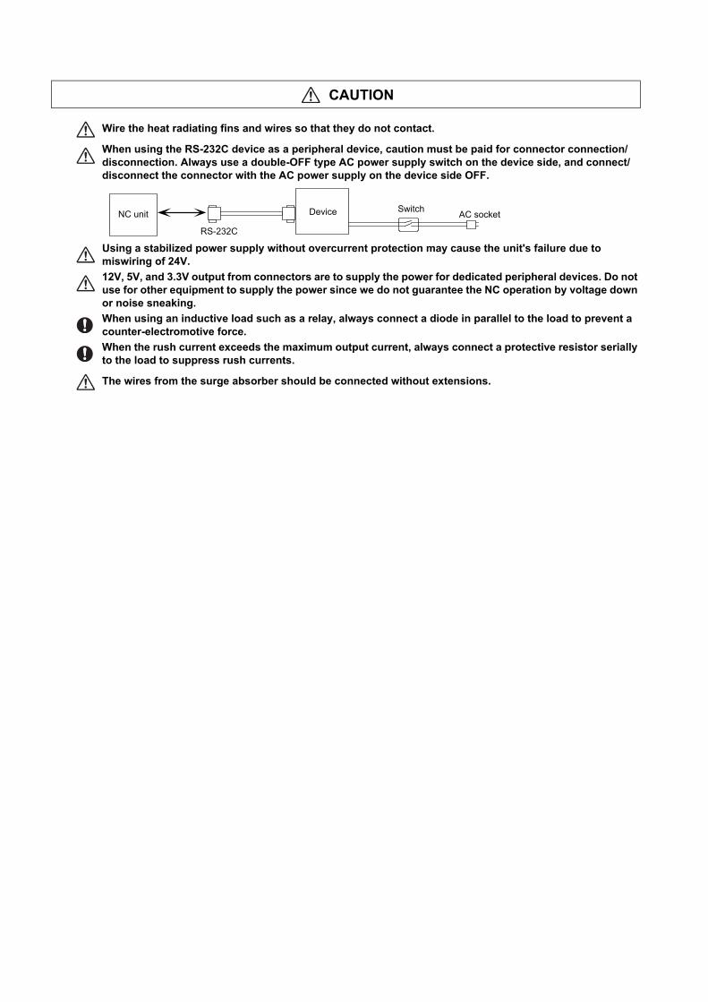
Wire the heat radiating fins and wires so that they do not contact.
When using the RS-232C device as a peripheral device, caution must be paid for connector connection/disconnection. Always use a double-OFF type AC power supply switch on the device side, and connect/disconnect the connector with the AC power supply on the device side OFF.
Using a stabilized power supply without overcurrent protection may cause the unit's failure due to miswiring of 24V.
12V, 5V, and 3.3V output from connectors are to supply the power for dedicated peripheral devices. Do not use for other equipment to supply the power since we do not guarantee the NC operation by voltage down or noise sneaking.
When using an inductive load such as a relay, always connect a diode in parallel to the load to prevent a counter-electromotive force.
When the rush current exceeds the maximum output current, always connect a protective resistor serially to the load to suppress rush currents.
The wires from the surge absorber should be connected without extensions.
RS-232C
NC unit Device Switch AC socket
(4) Set up
(5) Operation and Adjustments
WARNING
Do not cancel the emergency stop before confirming the basic operation.
Always set the stroke end and stroke limit. Failure to set this could result in collision with the machine end.
CAUTION
If the descriptions relating to the "restrictions" and "allowable conditions" conflict between this manual and the machine tool builder's instruction manual‚ the latter has priority over the former.
The operations to which no reference is made in this manual should be considered impossible.
This manual is written on the assumption that all the applicable functions are included. Some of them, however, may not be available for your NC system. Refer to the specifications issued by the machine tool builder before use.
Some screens and functions may differ depending on each NC system (or version), and some functions may not be possible. Please confirm the specifications before starting to use.
If the battery low warning is issued, save the machining programs, tool data and parameters in an input/output device, and then replace the battery. When the battery alarm is issued, the machining programs, tool data and parameters may have been destroyed. Replace the battery and then reload the data.
Do not adjust the spindle when possible risks associated with adjustment procedures are not thoroughly taken into consideration
Be careful when touching spindle's rotating section, or your hand may be caught in or cut.
CAUTION
If the operation start position is set in a block which is in the middle of the program and the program is started, the program before the set block is not executed. Please confirm that G and F modal and coordinate values are appropriate. If there are coordinate system shift commands or M, S, T and B commands before the block set as the start position, carry out the required commands using the MDI, etc. If the program is run from the set block without carrying out these operations, there is a danger of interference with the machine or of machine operation at an unexpected speed, which may result in breakage of tools or machine tool or may cause damage to the operators.
Under the constant surface speed control (during G96 modal), if the axis targeted for the constant surface speed control moves toward the spindle center, the spindle rotation speed will increase and may exceed the allowable speed of the workpiece or chuck, etc. In this case, the workpiece, etc. may jump out during machining, which may result in breakage of tools or machine tool or may cause damage to the operators.
Check and adjust programs and each parameter before starting operation. Failure to observe this could result in unpredictable operations depending on the machine.
Do not make drastic adjustments or changes in the parameters as the operation could become unstable.
In the explanation on bits, set all bits not used, including blank bits, to "0".
(6) Usage
CAUTION
Use this product within the range of environmental condition described in this manual. Using this product in an environment outside the range could result in electric shock, fire, operation failure, or damage to or deterioration of the product.
Install an external emergency stop circuit so that the operation can be stopped and the power turns OFF immediately when unforeseen situation occurs. A contactor, etc., is required in addition to the shutoff function mounted in the controller.
Turn OFF the power immediately if any smoke, abnormal noise or odor is generated from the controller, drive unit or motor.
Only a qualified technician may disassemble or repair this product.
Do not alter.
Use a noise filter, etc. to reduce the effect of electromagnetic disturbances in the case where electromagnetic disturbances could adversely affect the electronic devices used near the drive unit.
Use the drive unit, motor and each regenerative resistor with the designated combination. Failure to observe this could result in fires or faults.
The combination of the motor and drive unit that can be used is determined. Be sure to check the models of motor and drive unit before test operation.
The brakes (electromagnetic brakes) mounted in the servomotor are used for the purpose of holding, and must not be used for normal braking. Also, do not run the motor with the motor brake applied. Motor brake is used for the purpose of holding.
For the system running via a timing belt, install a brake on the machine side so that safety can be ensured.
Be sure to confirm SERVO OFF (or READY OFF) when applying the electromagnetic brake. Also, be sure to confirm SERVO ON prior to releasing the brake.
When using the DC OFF type electromagnetic brake, be sure to install a surge absorber on the brake terminal.
Do not connect or disconnect the cannon plug while the electromagnetic brake’s power is ON. The cannon plug pins could be damaged by sparks.
After changing programs/parameters, or after maintenance/inspection, always carry out a test operation before starting actual operation.
Use the power that are complied with the power specification conditions (input voltage, input frequency, tolerable instantaneous power failure time) indicated in each specifications manual.
When making encoder cables, do not mistake connection. Failure to observe this could result in malfunction, runaway or fire.
Surge absorber to be selected varies depending on input power voltage.
(7) Troubleshooting
(8) Maintenance, inspection and part replacement
CAUTION
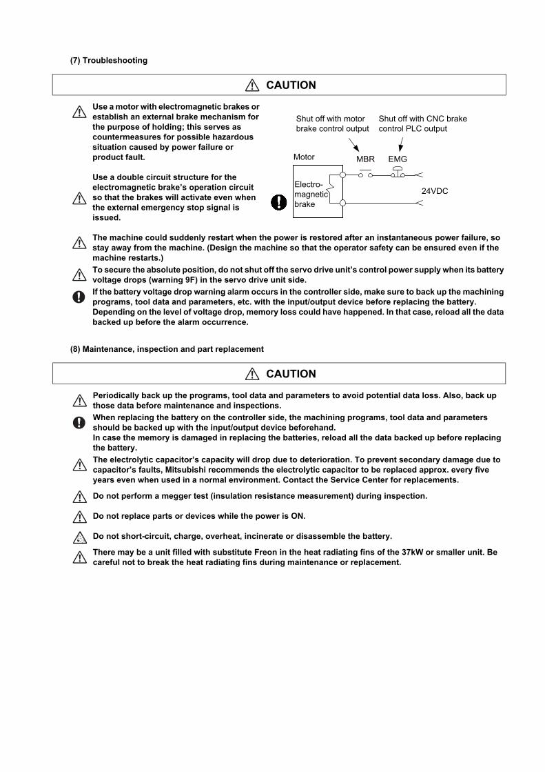
Use a motor with electromagnetic brakes or establish an external brake mechanism for the purpose of holding; this serves as countermeasures for possible hazardous situation caused by power failure or product fault.
Use a double circuit structure for the electromagnetic brake’s operation circuit so that the brakes will activate even when the external emergency stop signal is issued.
The machine could suddenly restart when the power is restored after an instantaneous power failure, so stay away from the machine. (Design the machine so that the operator safety can be ensured even if the machine restarts.)
To secure the absolute position, do not shut off the servo drive unit’s control power supply when its battery voltage drops (warning 9F) in the servo drive unit side.
If the battery voltage drop warning alarm occurs in the controller side, make sure to back up the machining programs, tool data and parameters, etc. with the input/output device before replacing the battery. Depending on the level of voltage drop, memory loss could have happened. In that case, reload all the data backed up before the alarm occurrence.
CAUTION
Periodically back up the programs, tool data and parameters to avoid potential data loss. Also, back up those data before maintenance and inspections.
When replacing the battery on the controller side, the machining programs, tool data and parameters should be backed up with the input/output device beforehand. In case the memory is damaged in replacing the batteries, reload all the data backed up before replacing the battery.
The electrolytic capacitor’s capacity will drop due to deterioration. To prevent secondary damage due to capacitor’s faults, Mitsubishi recommends the electrolytic capacitor to be replaced approx. every five years even when used in a normal environment. Contact the Service Center for replacements.
Do not perform a megger test (insulation resistance measurement) during inspection.
Do not replace parts or devices while the power is ON.
Do not short-circuit, charge, overheat, incinerate or disassemble the battery.
There may be a unit filled with substitute Freon in the heat radiating fins of the 37kW or smaller unit. Be careful not to break the heat radiating fins during maintenance or replacement.
MBR EMGMotor
Electro-magnetic brake
Shut off with motorbrake control output
Shut off with CNC brakecontrol PLC output
24VDC
(9) Disposal
(10) General precautions
CAUTION
Take the batteries and backlights for LCD, etc., off from the controller, drive unit and motor, and dispose of them as general industrial wastes.
Do not alter or disassemble controller, drive unit, or motor.
Collect and dispose of the spent batteries and the backlights for LCD according to the local laws.
To explain the details, drawings given in the instruction manual, etc., may show the unit with the cover or safety partition removed. When operating the product, always place the cover or partitions back to their original position, and operate as indicated in the instruction manual, etc.

Treatment of waste
The following two laws will apply when disposing of this product. Considerations must be made to each law. The
following laws are in effect in Japan. Thus, when using this product overseas, the local laws will have a priority. If
necessary, indicate or notify these laws to the final user of the product.
(1) Requirements for "Law for Promotion of Effective Utilization of Resources"
(a) Recycle as much of this product as possible when finished with use.
(b) When recycling, often parts are sorted into steel scraps and electric parts, etc., and sold to scrap contractors.
Mitsubishi Electric recommends sorting the product and selling the members to appropriate contractors.
(2) Requirements for "Law for Treatment of Waste and Cleaning"
(a) Mitsubishi Electric recommends recycling and selling the product when no longer needed according to item (1)
above. The user should make an effort to reduce waste in this manner.
(b) When disposing a product that cannot be resold, it shall be treated as a waste product.
(c) The treatment of industrial waste must be commissioned to a licensed industrial waste treatment contractor,
and appropriate measures, including a manifest control, must be taken.
(d) Batteries correspond to "primary batteries", and must be disposed of according to local disposal laws.
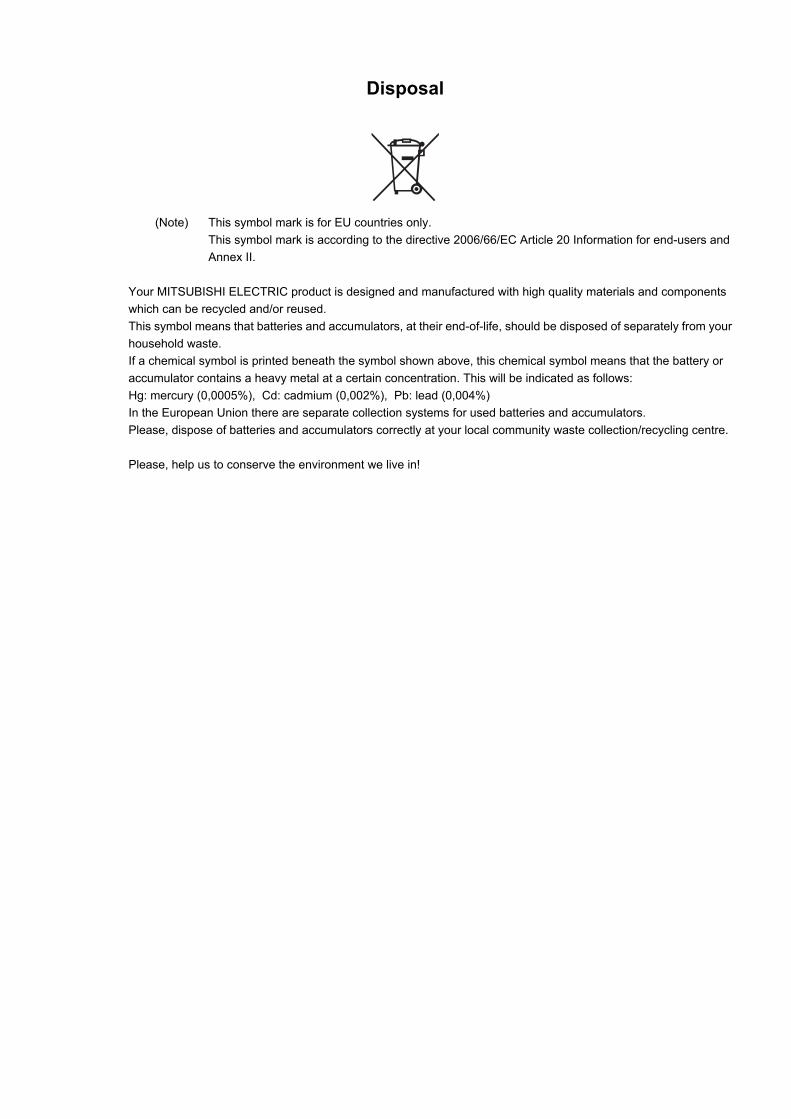
Disposal
(Note) This symbol mark is for EU countries only.
This symbol mark is according to the directive 2006/66/EC Article 20 Information for end-users and
Annex II.
Your MITSUBISHI ELECTRIC product is designed and manufactured with high quality materials and components
which can be recycled and/or reused.
This symbol means that batteries and accumulators, at their end-of-life, should be disposed of separately from your
household waste.
If a chemical symbol is printed beneath the symbol shown above, this chemical symbol means that the battery or
accumulator contains a heavy metal at a certain concentration. This will be indicated as follows:
Hg: mercury (0,0005%), Cd: cadmium (0,002%), Pb: lead (0,004%)
In the European Union there are separate collection systems for used batteries and accumulators.
Please, dispose of batteries and accumulators correctly at your local community waste collection/recycling centre.
Please, help us to conserve the environment we live in!
Trademarks
MELDAS, MELSEC, EZSocket, EZMotion, iQ Platform, MELSEC iQ-R, MELSOFT, GOT, CC-Link, CC-Link/LT,
CC-Link IE, CC-Link IE/field, EcoMonitorLight and SLMP are either trademarks or registered trademarks of
Mitsubishi Electric Corporation in Japan and/or other countries.
Ethernet is a registered trademark of Xerox Corporation in the United States and/or other countries.
Microsoft®, Windows®, SQL Server®, Access®, Microsoft® Internet Explorer® and Microsoft® Edge are either
trademarks or registered trademarks of Microsoft Corporation in the United States and/or other countries.
SD logo and SDHC logo are either registered trademarks or trademarks of LLC.
UNIX is a registered trademark of The Open Group in the United States and/or other countries.
Intel® and Pentium® are either trademarks or registered trademarks of Intel Corporation in the United States and/or
other countries.
MODBUS® is either a trademark or a registered trademark of Schneider Electric USA, Inc. or the affiliated
companies in Japan and/or other countries.
EtherNet/IP is a trademark of Open DeviceNet Vendor Association,Inc.
PROFIBUS-DP and PROFINET are either trademarks of Profibus International.
Oracle® is a registered trademark of Oracle Corporation, the subsidiaries, or the affiliated companies in the United
States and /or other countries.
VNC is a registered trademark of RealVNC Ltd. in the United States and other countries.
Android, Google Chrome are either trademarks or registered trademarks of Google Inc.
The iOS trademark is used under license from Cisco in the United States.
Safari is a trademark of Apple Inc., registered in the U.S. and other countries.
Other company and product names that appear in this manual are trademarks or registered trademarks of the
respective companies.

本製品の取扱いについて
( 日本語 /Japanese)
本製品は工業用 ( クラス A) 電磁環境適合機器です。販売者あるいは使用者はこの点に注意し、住商業環境以外での使
用をお願いいたします。
Handling of our product
(English)
This is a class A product. In a domestic environment this product may cause radio interference in which case the user
may be required to take adequate measures.
본 제품의 취급에 대해서
( 한국어 /Korean)
이 기기는 업무용 (A 급 ) 전자파적합기기로서 판매자 또는 사용자는 이 점을 주의하시기 바라며 가정외의 지역에 서 사
용하는 것을 목적으로 합니다 .
Contents
1 Outline........................................................................................................................................................... 11.1 System Image ........................................................................................................................................................... 3
1.1.1 RGU Connection .............................................................................................................................................. 31.1.2 NC Direct Connection....................................................................................................................................... 3
1.2 Characteristics .......................................................................................................................................................... 41.3 Operation Environment ............................................................................................................................................. 4
2 Connection (RGU Connection) ................................................................................................................... 52.1 System Basic Configuration Drawing........................................................................................................................ 62.2 General Connection Diagram.................................................................................................................................... 7
2.2.1 Connection Example: Remote Service Gateway Unit and 800W/M80W Series .............................................. 72.2.2 Connection Example: Remote Service Gateway Unit and M800S/M80/E80 Series ........................................ 8
2.3 List of Configuration .................................................................................................................................................. 92.3.1 Module Configuration List................................................................................................................................. 92.3.2 Replacements .................................................................................................................................................. 92.3.3 Cables .............................................................................................................................................................. 9
2.4 General Specifications ............................................................................................................................................ 102.4.1 Environment Conditions (Installation Environment Conditions)...................................................................... 102.4.2 24VDC Stabilized Power Supply Selecting Conditions .................................................................................. 112.4.3 Outline Dimension .......................................................................................................................................... 122.4.4 Installation Dimension .................................................................................................................................... 122.4.5 Connectors ..................................................................................................................................................... 132.4.6 Exclusive SD Cards for MITSUBISHI ELECTRIC CNC ................................................................................. 20
2.4.6.1 SD Interface........................................................................................................................................... 202.5 Installation ............................................................................................................................................................... 21
2.5.1 Heat Radiation Countermeasures .................................................................................................................. 212.5.2 Noise Countermeasures................................................................................................................................. 24
2.5.2.1 Connection of Frame Ground (FG)........................................................................................................ 242.5.2.2 Shield Clamping of Cables .................................................................................................................... 252.5.2.3 Connecting Spark Killers ....................................................................................................................... 262.5.2.4 Lightning Surge Protection Countermeasure......................................................................................... 27
2.5.3 Unit Installation............................................................................................................................................... 282.6 Precautions for Connecting..................................................................................................................................... 30
2.6.1 Precautions for Wiring .................................................................................................................................... 302.6.1.1 Precautions when Connecting/Disconnecting Cables ........................................................................... 302.6.1.2 Precautions for Connecting 24V Power Supply..................................................................................... 32
2.6.2 Turning the Power ON/OFF ........................................................................................................................... 322.6.3 Turning the Power ON/OFF of Remote Service Gateway Unit ...................................................................... 32
2.7 Connecting Remote Service Gateway Unit............................................................................................................. 332.7.1 General Connection System Drawing ............................................................................................................ 332.7.2 Connecting with Power Supply....................................................................................................................... 342.7.3 Connecting with Control Unit .......................................................................................................................... 352.7.4 Connecting with Host Device (Cloud Server) ................................................................................................. 40
2.8 Cables ..................................................................................................................................................................... 41
3 Initial Setup................................................................................................................................................. 433.1 Setup Procedures ................................................................................................................................................... 44
3.1.1 When Using RGU Connection........................................................................................................................ 453.1.2 When Using NC Direct Connection ................................................................................................................ 46
3.2 When Using RGU Connection ................................................................................................................................ 473.2.1 Connecting with Remote Service Gateway Unit (RGU) ................................................................................. 47
3.2.1.1 Network Connecting Method ................................................................................................................. 473.2.1.2 DIP Switch ............................................................................................................................................. 483.2.1.3 Rotary Switch......................................................................................................................................... 48
3.2.2 Setting Parameters......................................................................................................................................... 493.2.2.1 Setting the IP Address for the NC Control Unit...................................................................................... 493.2.2.2 Connecting with a PC for Setting........................................................................................................... 493.2.2.3 Setting the IP Address for the RGU....................................................................................................... 503.2.2.4 Parameters for Remote Service Connection of the RGU ...................................................................... 533.2.2.5 Setting Example..................................................................................................................................... 55
3.2.3 Checking Cloud Connection Status................................................................................................................ 593.2.3.1 Checking the Status by LEDs ................................................................................................................ 593.2.3.2 Checking on the Setting Screen ............................................................................................................ 60

3.2.3.3 Checking on the Remote Service Screen ............................................................................................. 603.3 When Using NC Direct Connection ........................................................................................................................ 62
3.3.1 NC Connection............................................................................................................................................... 623.3.1.1 Network Connecting Method ................................................................................................................. 623.3.1.2 General Connection System Drawing ................................................................................................... 633.3.1.3 Connecting with Host Device (Cloud Server) ........................................................................................ 63
3.3.2 Setting Parameters ........................................................................................................................................ 643.3.2.1 Setting the IP Address for the NC Control Unit ..................................................................................... 643.3.2.2 Parameters for Remote Service Connection......................................................................................... 643.3.2.3 Setting Example .................................................................................................................................... 67
3.3.3 Setting Parameters ........................................................................................................................................ 683.3.3.1 Checking on the Self Diagnosis Screen of the NC Control Unit ............................................................ 683.3.3.2 Checking on the Remote Service Screen ............................................................................................. 683.3.3.3 Precautions ........................................................................................................................................... 68
3.4 Applicable Models................................................................................................................................................... 69
4 NC Remote Service .................................................................................................................................... 714.1 Remote Service Screen.......................................................................................................................................... 724.2 Basic Operations .................................................................................................................................................... 73
4.2.1 Starting Up a Browser .................................................................................................................................... 734.2.2 Display Language Setting .............................................................................................................................. 744.2.3 Logging in to Remote Service ........................................................................................................................ 744.2.4 Device Selection ............................................................................................................................................ 754.2.5 Changing Password ....................................................................................................................................... 764.2.6 Changing Screens.......................................................................................................................................... 774.2.7 Scheduled Operation Time Setting ................................................................................................................ 784.2.8 Logging Out of Remote Service ..................................................................................................................... 78
4.3 Details of Each Function......................................................................................................................................... 794.3.1 Login Screen .................................................................................................................................................. 794.3.2 Device Screen................................................................................................................................................ 804.3.3 Operation Screen ........................................................................................................................................... 834.3.4 Use Screen .................................................................................................................................................... 884.3.5 Alarm Screen ................................................................................................................................................. 904.3.6 Diagnosis Screen ........................................................................................................................................... 91
4.3.6.1 S/W Configuration ................................................................................................................................. 924.3.6.2 H/W Configuration ................................................................................................................................. 934.3.6.3 I/F Diagnosis ......................................................................................................................................... 944.3.6.4 Parameter Reference ............................................................................................................................ 954.3.6.5 Drive Monitor ......................................................................................................................................... 964.3.6.6 Self Diagnosis ....................................................................................................................................... 974.3.6.7 Key Operation History ........................................................................................................................... 984.3.6.8 Sampling Chart.................................................................................................................................... 100
4.3.7 Utilities Screen ............................................................................................................................................. 1024.3.7.1 Operation Status Acquisition ............................................................................................................... 104
4.3.7.1.1 Daily Operation Detail................................................................................................................. 1054.3.7.1.2 Monthly Operation Total ............................................................................................................. 1094.3.7.1.3 Machining Result List.................................................................................................................. 111
4.3.7.2 History Data Acquisition ...................................................................................................................... 1134.3.7.2.1 Alarm History List........................................................................................................................ 1144.3.7.2.2 Key History List........................................................................................................................... 115
4.3.7.3 NC File Data........................................................................................................................................ 1164.3.7.4 Alarm Diagnosis .................................................................................................................................. 123
4.3.7.4.1 Diagnosis Data Settings ............................................................................................................. 1254.3.7.4.2 Diagnosis Data Setting Screen................................................................................................... 128
4.3.7.5 Email Notification Settings................................................................................................................... 1304.3.7.5.1 Edit Email Notification Condition Screen .................................................................................... 1324.3.7.5.2 Notification Condition Setting Method......................................................................................... 137
4.3.8 Password Change Screen ........................................................................................................................... 1384.3.9 Machine Information Edit Screen ................................................................................................................. 139
4.3.9.1 How to Edit the Machine Information .................................................................................................. 1404.3.10 Information Display .................................................................................................................................... 141
4.4 Restrictions ........................................................................................................................................................... 1424.5 Message Outputs.................................................................................................................................................. 143
4.5.1 Output of Messages at the Top of the Browser............................................................................................ 1434.5.2 Message Outputs on the "Utilities" Screen .................................................................................................. 1434.5.3 Message Outputs on the Machine Information Edit Screen......................................................................... 145
4.5.4 Message Outputs on the Scheduled Operation Time Setting Dialog ........................................................... 1454.6 Troubleshooting and FAQ..................................................................................................................................... 146
5 Appendix 1: EMC Installation Guidelines .............................................................................................. 1475.1 Introduction ........................................................................................................................................................... 1485.2 EMC Directives ..................................................................................................................................................... 1485.3 EMC Measures ..................................................................................................................................................... 1495.4 Panel Structure ..................................................................................................................................................... 149
5.4.1 Measures for Control Panel Body ................................................................................................................ 1495.4.2 Measures for Door........................................................................................................................................ 1505.4.3 Measures for Power Supply ......................................................................................................................... 150
5.5 Measures for Wiring in Panel ................................................................................................................................ 1515.5.1 Precautions for Wiring in Panel .................................................................................................................... 1515.5.2 Shield Treatment of Cables.......................................................................................................................... 152
5.6 EMC Countermeasure Parts ................................................................................................................................. 1535.6.1 Shield Clamp Fitting ..................................................................................................................................... 1535.6.2 Ferrite Core .................................................................................................................................................. 1545.6.3 Surge Absorber ............................................................................................................................................ 1555.6.4 Selection of Stabilized Power Supply ........................................................................................................... 157
6 Appendix 2: Precautions for Compliance to UL/c-UL Standards ........................................................ 159
7 Appendix 3: Parameter List..................................................................................................................... 161
8 Appendix 4: Error List ............................................................................................................................. 165

1 IB-1501552-H
1
Outline

Remote Service iQ Care Remote4U User’s Manual
1 Outline
2IB-1501552-H
Remote service is a network service which enables users to check a state of machine tools from a web browser by
viewing information of machine tools equipped with Mitsubishi Electric CNC via the Internet. There are two methods to
connect remote service, RGU connection and NC direct connection.
RGU connection connects to remote service via a remote service gateway (hereinafter RGU). The compatible NC control
units (hereinafter NC) are M7/M8/C80 Series. M8V Series cannot use the RGU to connect remote service.
NC direct connection uses only an NC to connect remote service without using the RGU. The compatible NC is M8V
Series.
NC acquires and transfers information to the cloud server by the connection above. By doing so, users can view various
information through a web browser under an Internet-accessible environment.

Remote Service iQ Care Remote4U User’s Manual
1 Outline
3 IB-1501552-H
1.1 System Image1.1.1 RGU Connection
1.1.2 NC Direct Connection
User
Remote servicecloud server
MTBservice center
Mitsubishi Electricservice center
Internet connection
Ethernet
Mitsubishi Electric CNC(M8/M7 Series)
Remote servicegateway unit
User
Remote servicecloud server
MTBservice center
Mitsubishi Electricservice center
Internet connection
Mitsubishi Electric CNC(M8V Series)

Remote Service iQ Care Remote4U User’s Manual
1 Outline
4IB-1501552-H
1.2 CharacteristicsMain functions available from the remote service are as follows.
Users can view a state of machines from a remote place through a web screen.
The machine tool builder (MTB) can access screens related to machine maintenance and carry out maintenance.
1.3 Operation EnvironmentOperation environment of Mitsubishi Electric CNC remote service screen (hereinafter referred to as "remote service
screen") are described below.
Operation environment of personal computer
Operation environment of smart phones and tablet devices
Function Main functionsUser classification
UsersMachine tool builder (MTB)
Devices Listing device information, specifying detailed display object ○ ○
OperationGraph display of operation rate, machining program name, ONB No. ○ -
UseServo axis load graph, spindle load graph, power consumption amount ○ -
Alarm Current alarm, alarm history, total display ○ ○
DiagnosisS/W configuration, H/W configuration, I/F diagnosis, parameter reference, self diagnosis, key operation history, sampling chart ○ ○
Utility
Operation status acquisition, alarm diagnosis, email notification settings ○ -
History data acquisition ○ ○
NC file data ○ ○
Items Details
OS Windows 8.1/Windows 10 64bit
BrowserMicrosoft Edge (Ver38)Google Chrome (Ver65)
Memory 3 GB or more
Items Details
OS iOS
Browser Safari
Memory 3 GB or more

5 IB-1501552-H
2
Connection (RGU Connection)
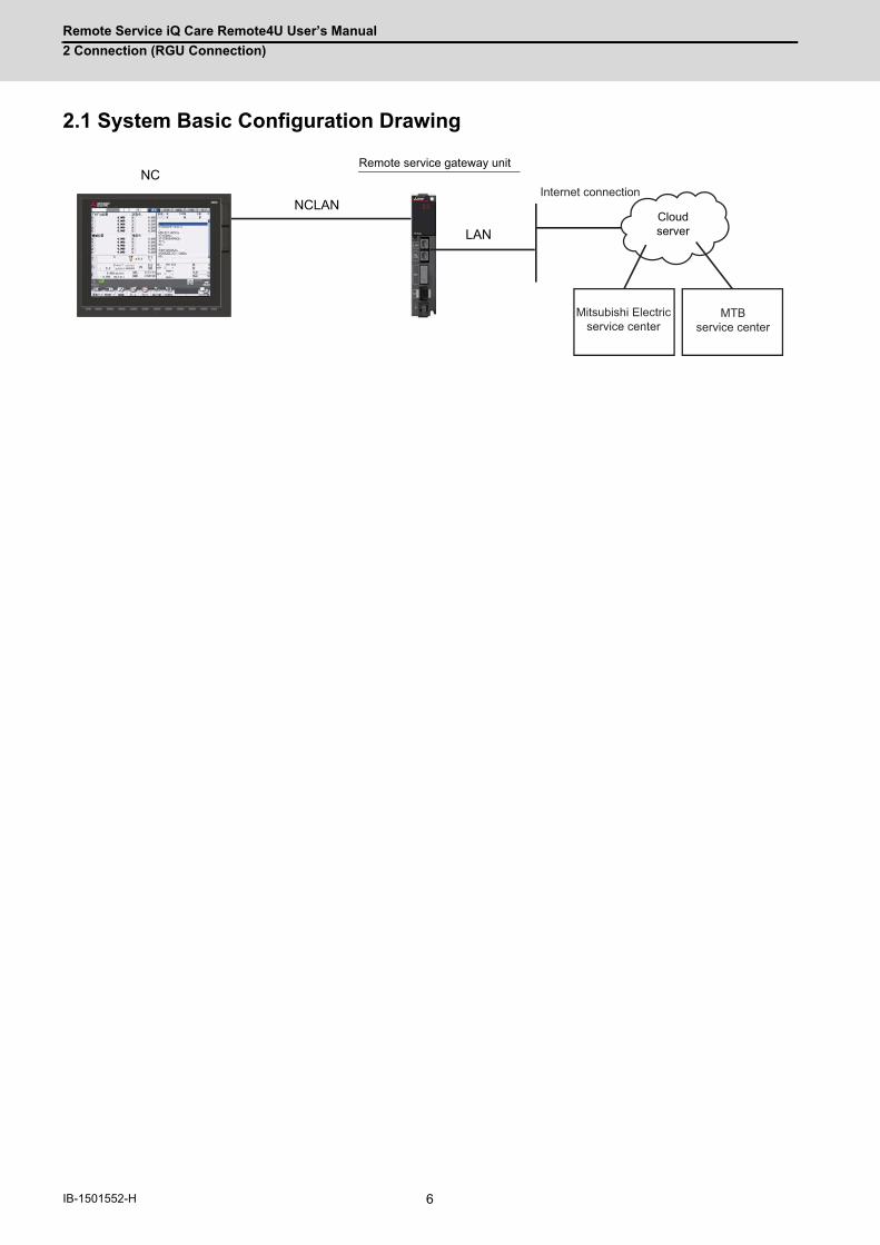
Remote Service iQ Care Remote4U User’s Manual
2 Connection (RGU Connection)
6IB-1501552-H
2.1 System Basic Configuration Drawing
NC
LAN
NCLAN
Remote service gateway unit
Cloud server
Mitsubishi Electricservice center
MTBservice center
Internet connection

Remote Service iQ Care Remote4U User’s Manual
2 Connection (RGU Connection)
7 IB-1501552-H
2.2 General Connection Diagram2.2.1 Connection Example: Remote Service Gateway Unit and 800W/M80W Series
This is an example of M800W Series, Windows-based display (19-type).
(Note) The above drawing shows an example of connection. For details of the connection methods, refer to "2.7 Connecting
Remote Service Gateway Unit".
SIO
1ch:J030 2ch:J0312ch
RS232C
SKIP
RIO2
SD
RIO3
GDI
LAN J303 Network
FCU8-EX56x/EX744
J100
SD
FCU8-DX2xx/DX6xx/DX4xx
RIO1
DCINJ070/071
(EcoMonitor)
OPTH1
OPTH2
J395/J396
J395/J396
EMGJ120
Max. 8 points
J070/071 J070/071
J210
DI:CJ31/33DO:CJ32/34
RIO1
DCIN
RIO2
DI:CJ31/33DO:CJ32/34
RIO1
DCIN
RIO2
J350/351J350/351
J070/071 J070/071
J210
DI:CJ31/33DO:CJ32/34
RIO1
DCIN
RIO2
DI:CJ31/33DO:CJ32/34
RIO1
DCIN
RIO2
J350/351J350/351
(R2-TM)
(R2-TM)
FG5V:J023/J024/J02512V:J020/J021/J022
L1 L2 L3
(NFB)
DCOUT
FGACIN
CP
MC
ON OFF
MC
MC
J350/351
J350/351
J350/351
J350/351
FCU8-EX54xEXT1
EXT3
G430
device
Skip signal input
Control unit
Max. 32 units for each port
Remote I/O unit
Remote I/O unit
Remote I/O unit
Remote I/O unit
24VDC
Energy measuring units
Drive units
Stored in control unit
To the next remote I/O or terminator connector
To the next remote I/O or terminator connector
Emergency stop switch
SD memory card
24VDC24VDC
24VDC24VDC
Machine control relay/contact
Machine control relay/contact
24VDC
Manual pulse generator (5V/12V)
Machine operation panel made by the machine tool builder
Dotted lines indicate the sections prepared by the machine tool builder.<> Angle brackets indicates attached cable of unit.
No-fuse breaker
24VDC stabilized power supply
(Note 1)
Handy terminal
Function expansion unit
Function expansion unit
FCU8-EX56x/EX744
FCU8-EX54x
FCU8-MA041/MU042
MA041:M850WMU042:M830W
RIO8AIO
J026/J027
J220
EXT2
EXT4
RIO4
RIO6
RIO7
RIO5
Function expansion unit
Function expansion unit
Analog input : 4 pointsAnalog output : 2 points
Manual pulse generator (5V)
J120
ON/OFF
CFASTCFast
LVDS1
USB2-1
USB2-2
FCU8-PC231
LANJ303
MENUKEY
RIO3EXT
ON
OFF
G170
MPG
INV
RS232CUSB-RS232C
GDI
KEYUSB
RIO3
J303
NCKBKEYUSB
J210
J291
J210
LVDS2 SD
DCINJ070/071
EMG
USB
USB3-2USB3-1
USB2-4USB2-3
USB2-6USB2-5
FCU8-DX2xx/DX6xx/DX4xx
CJ71
FCU8-CF001-001
DCINJ070/071
Network
CG31CG32
FCU8-DX830/834/837
CG33CG34
SDIMax. 8 points
DI:CJ31/33DO:CJ32/34
RIO1
DCIN
RIO2
J350/351J350/351
(R2-TM)
J210
FCU8-KB92x FCU8-KB941/KB931
<G460>
DX834:
DX837:
OPKBJ460/461
24VDC
Machine operation panel manufactured by Mitsubishi Electric
Emergency stop switch
Personal computer unit
deviceconversion
24VDC
USB memory
24VDC
Remote I/O unit
24VDC
Operation panel I/O unit
Safety signal input
Stored in personal computer unit
CFast unit
(Safety signal input is DX837 only.)
To the next remote I/O or terminator connector
Added onto back of display unit
SD memory card
24VDC Machine control relay/contact
Backlight I/F PCB
With scan input/output
With safety signal input
Scan input /Scan output
(Scan input/output is DX834 only.)
<J09x>
<J292>
<J190>
<J290>
<G195>
<J420>
FCU8-EP201-2
USB
SD
PCUSB
19-type LCD
Side memory I/F unit
wth touch panel
Display unitFCU8-DU191-75FCU8-DU192-75
LAN
DCIN SIODI
J070/071
FCU8-RT601
J303
Cloud ServerNCLAN
Remote service gateway unit
Broadband router
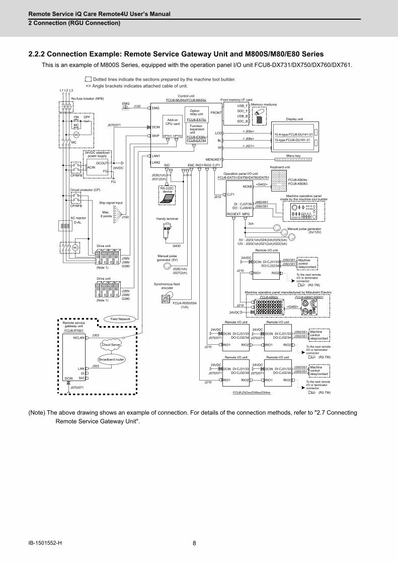
Remote Service iQ Care Remote4U User’s Manual
2 Connection (RGU Connection)
8IB-1501552-H
2.2.2 Connection Example: Remote Service Gateway Unit and M800S/M80/E80 Series
This is an example of M800S Series, equipped with the operation panel I/O unit FCU8-DX731/DX750/DX760/DX761.
(Note) The above drawing shows an example of connection. For details of the connection methods, refer to "2.7 Connecting
Remote Service Gateway Unit".
J395/J396/G380
FCUA-R050/054
(1ch)
Field Network
L1 L2 L3
D-AL
MC
DCOUT
FGACIN
CP/NFB
MC
ON OFF
MC
MC
CP/NFB
FG
Max. 8 points
EMGJ120
J303
J070/071
J303
J100
J030(1ch)J031(2ch)
EMG
LAN1
SKIP
DCIN
SIOLAN2
FCU8-EX56x
FCU8-EX70x
FRONT
RIO2ENC CJ71
BL
< J09x>
RIO1
USB_FSDC_FUSB_BSDC_B
< J08x>
NCKB
3ch
<G402>
J210
RIO3EXT MPG
5V : J023(1ch)/024(2ch)/025(3ch)12V : J020(1ch)/021(2ch)/022(3ch)
J350/351
LCD
MENUKEY
DI:CJ31/33DO:CJ32/34
RIO1
DCIN
RIO2
J350/351J350/351
(R2-TM)
G430
J210
FCU8-KB92x FCU8-KB941/KB931
<G460>
J026(1ch)J027(2ch)
Machine operation panel manufactured by Mitsubishi Electric
(Note 1)
Drive unit
Control unit
Synchronous feed encoder
No-fuse breaker (NFB)
AC reactor
Circuit protector (CP)
Ethernet device
Ethernet device
24VDC
RS-232C device
Function expansion unit
Menu key
Display unit
Memory mediumsFront memory I/F card
Operation panel I/O unit
Machine control relay/contact
Remote I/O unit
24VDC
Keyboard unit
Machine operation panel made by the machine tool builder
Skip signal input
24VDC stabilized power supply
To the next remote I/O or terminator connector
Manual pulse generator (5V/12V)
Dotted lines indicate the sections prepared by the machine tool builder.<> Angle brackets indicates attached cable of unit.
Option relay unit
Handy terminal
24VDC
Manual pulse generator (5V)
J070/071
J070/071
J210
J210
J070/071DI:CJ31/33
DO:CJ32/34
RIO1
DCIN
RIO2
DI:CJ31/33DO:CJ32/34
RIO1
DCIN
RIO2
J350/351J350/351
J070/071DI:CJ31/33
DO:CJ32/34
RIO1
DCIN
RIO2
DI:CJ31/33DO:CJ32/34
RIO1
DCIN
RIO2
J350/351J350/351
(R2-TM)
(R2-TM)
Remote I/O unit
24VDC
Remote I/O unit
24VDC
Remote I/O unit
24VDC
Remote I/O unit
24VDC
To the next remote I/O or terminator connector
To the next remote I/O or terminator connector
Machine control relay/contact
Machine control relay/contact
J010CJ71
FCU8-DX731/DX750/DX760/DX761
DI : CJ37/39DO : CJ38/40
J460/461
/FCU8-EX744
TP < J421>
FCU8-KB04xFCU8-KB083
FCU8-DX2xx/DX6xx/DX4xx
OPTH1 OPTH2
J395/J396/G380
FCU8-MU54x/FCU8-MA54x
10.4-type:FCU8-DU141-31
15-type:FCU8-DU181-31
Add-on CPU card
Drive unit
(Note 1)
DCIN
J070/071
FCU8-RT601
NCLANJ303
LAN
SIODI
J303
Cloud Server
Remote service gateway unit
Broadband router
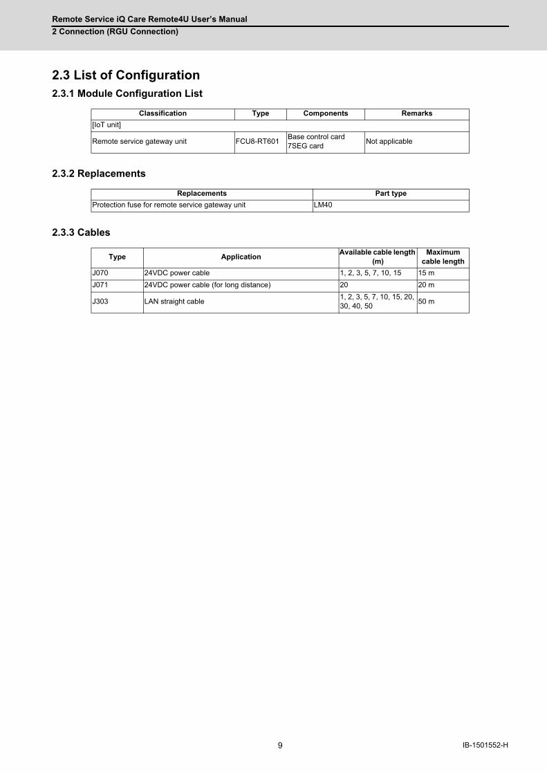
Remote Service iQ Care Remote4U User’s Manual
2 Connection (RGU Connection)
9 IB-1501552-H
2.3 List of Configuration2.3.1 Module Configuration List
2.3.2 Replacements
2.3.3 Cables
Classification Type Components Remarks
[IoT unit]
Remote service gateway unit FCU8-RT601Base control card 7SEG card
Not applicable
Replacements Part type
Protection fuse for remote service gateway unit LM40
Type ApplicationAvailable cable length
(m)Maximum
cable length
J070 24VDC power cable 1, 2, 3, 5, 7, 10, 15 15 m
J071 24VDC power cable (for long distance) 20 20 m
J303 LAN straight cable1, 2, 3, 5, 7, 10, 15, 20, 30, 40, 50
50 m
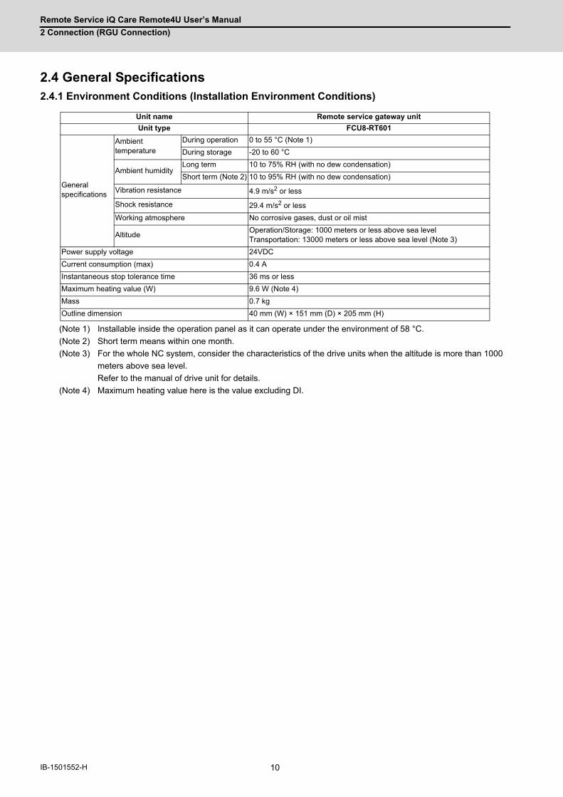
Remote Service iQ Care Remote4U User’s Manual
2 Connection (RGU Connection)
10IB-1501552-H
2.4 General Specifications2.4.1 Environment Conditions (Installation Environment Conditions)
(Note 1) Installable inside the operation panel as it can operate under the environment of 58 °C.
(Note 2) Short term means within one month.
(Note 3) For the whole NC system, consider the characteristics of the drive units when the altitude is more than 1000
meters above sea level.
Refer to the manual of drive unit for details.
(Note 4) Maximum heating value here is the value excluding DI.
Unit name Remote service gateway unit
Unit type FCU8-RT601
General specifications
Ambient temperature
During operation 0 to 55 °C (Note 1)
During storage -20 to 60 °C
Ambient humidityLong term 10 to 75% RH (with no dew condensation)
Short term (Note 2) 10 to 95% RH (with no dew condensation)
Vibration resistance 4.9 m/s2 or less
Shock resistance 29.4 m/s2 or less
Working atmosphere No corrosive gases, dust or oil mist
AltitudeOperation/Storage: 1000 meters or less above sea levelTransportation: 13000 meters or less above sea level (Note 3)
Power supply voltage 24VDC
Current consumption (max) 0.4 A
Instantaneous stop tolerance time 36 ms or less
Maximum heating value (W) 9.6 W (Note 4)
Mass 0.7 kg
Outline dimension 40 mm (W) × 151 mm (D) × 205 mm (H)
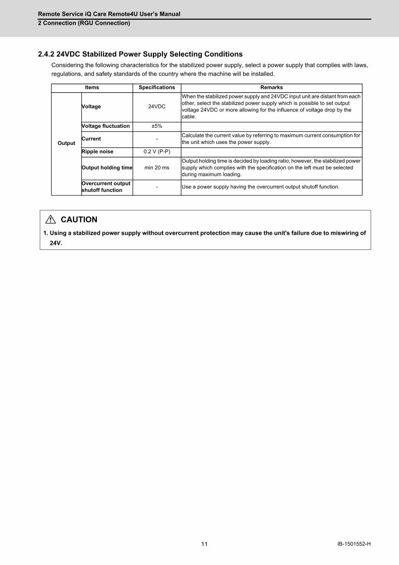
Remote Service iQ Care Remote4U User’s Manual
2 Connection (RGU Connection)
11 IB-1501552-H
2.4.2 24VDC Stabilized Power Supply Selecting Conditions
Considering the following characteristics for the stabilized power supply, select a power supply that complies with laws,
regulations, and safety standards of the country where the machine will be installed.
Items Specifications Remarks
Output
Voltage 24VDC
When the stabilized power supply and 24VDC input unit are distant from each other, select the stabilized power supply which is possible to set output voltage 24VDC or more allowing for the influence of voltage drop by the cable.
Voltage fluctuation ±5%
Current -Calculate the current value by referring to maximum current consumption for the unit which uses the power supply.
Ripple noise 0.2 V (P-P)
Output holding time min 20 msOutput holding time is decided by loading ratio; however, the stabilized power supply which complies with the specification on the left must be selected during maximum loading.
Overcurrent output shutoff function
- Use a power supply having the overcurrent output shutoff function.
CAUTION
1. Using a stabilized power supply without overcurrent protection may cause the unit's failure due to miswiring of
24V.
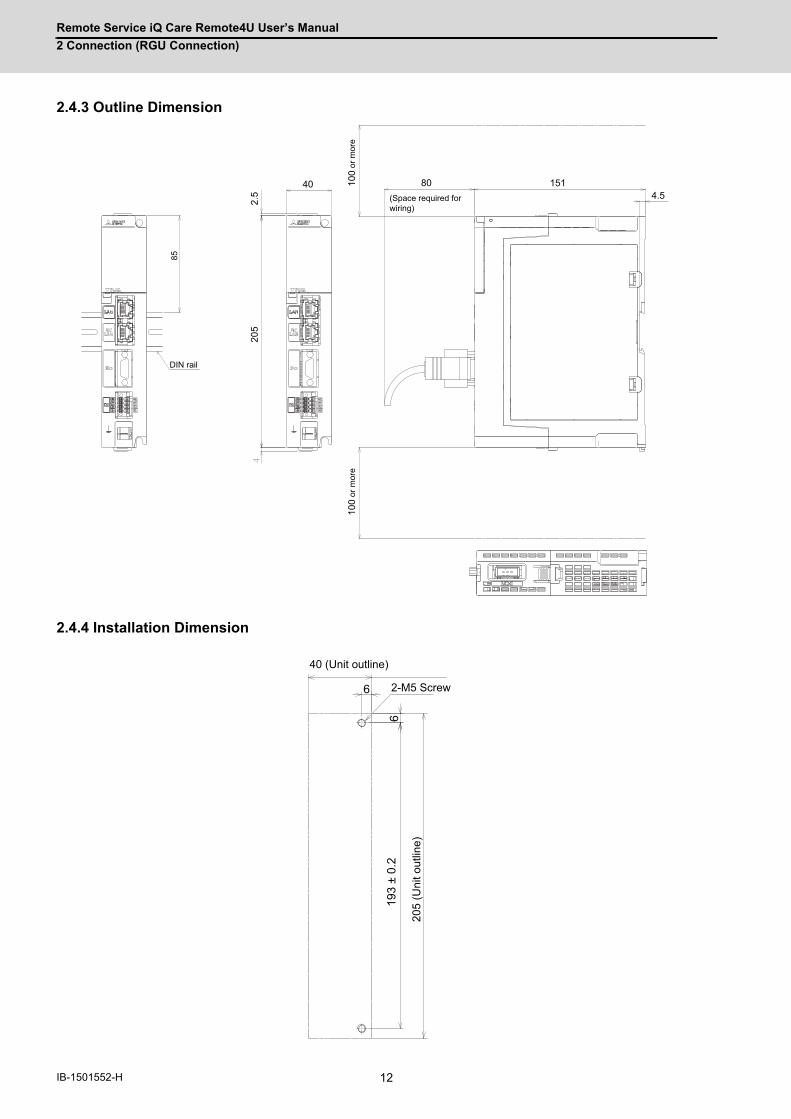
Remote Service iQ Care Remote4U User’s Manual
2 Connection (RGU Connection)
12IB-1501552-H
2.4.3 Outline Dimension
2.4.4 Installation Dimension
85
2.5
205
40 1514.5
100
or m
ore
100
or m
ore
80
DIN rail
(Space required for wiring)
6
619
3 ±
0.2
40 (Unit outline)
2-M5 Screw
205
(Uni
t out
line)
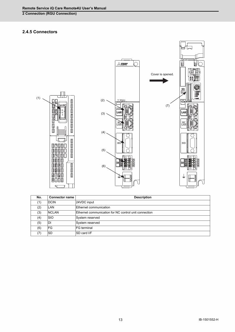
Remote Service iQ Care Remote4U User’s Manual
2 Connection (RGU Connection)
13 IB-1501552-H
2.4.5 Connectors
No. Connector name Description
(1) DCIN 24VDC input
(2) LAN Ethernet communication
(3) NCLAN Ethernet communication for NC control unit connection
(4) SIO System reserved
(5) DI System reserved
(6) FG FG terminal
(7) SD SD card I/F
(1)(2)
(3)
(4)
(5)
(6)
(7)
Cover is opened.

Remote Service iQ Care Remote4U User’s Manual
2 Connection (RGU Connection)
14IB-1501552-H
(1) DCIN (24VDC input)
<Cable side connector type>
Connector: 2-178288-3
Contact: 1-175218-5
Recommended manufacturer: Tyco Electronics
(a) Specifications of power supply
Consider the following characteristics when selecting the stabilized power supply (prepared by machine
tool builder). Use a power supply that complies with CE Marking or that follows the safety standards given
below.
[Stabilized power supply selection items]
[Standards]
Safety Standards: UL1950, CSA C22.2 No. 234 approved, IEC950 compliant
Noise Terminal Voltage: FCC Class A, VCCI-Class A
High Harmonics Current Restrictions: IEC61000-3-2
(Note) 24VDC voltage may drop temporarily due to rush current at the beginning of 24V power supply
to the control unit.
The level of voltage drop depends on the capacity of the power supply. Do not share the power
supply with the devices that generate alarms to warn the voltage drop.
1 I +24V
2 0 V
3 FG
Items Standard setting
OutputVoltage fluctuation±5% or less of 24VDC
Ripple noise 200 mV (P-P)
Power capacityCalculate the current value as a reference of maximum current consumption for the unit which uses the power supply.
Output holding time 20 ms
Overcurrent protection Required
CAUTION
1. Using a stabilized power supply without overcurrent protection may cause the unit's failure due to miswiring of
24V.
1 3
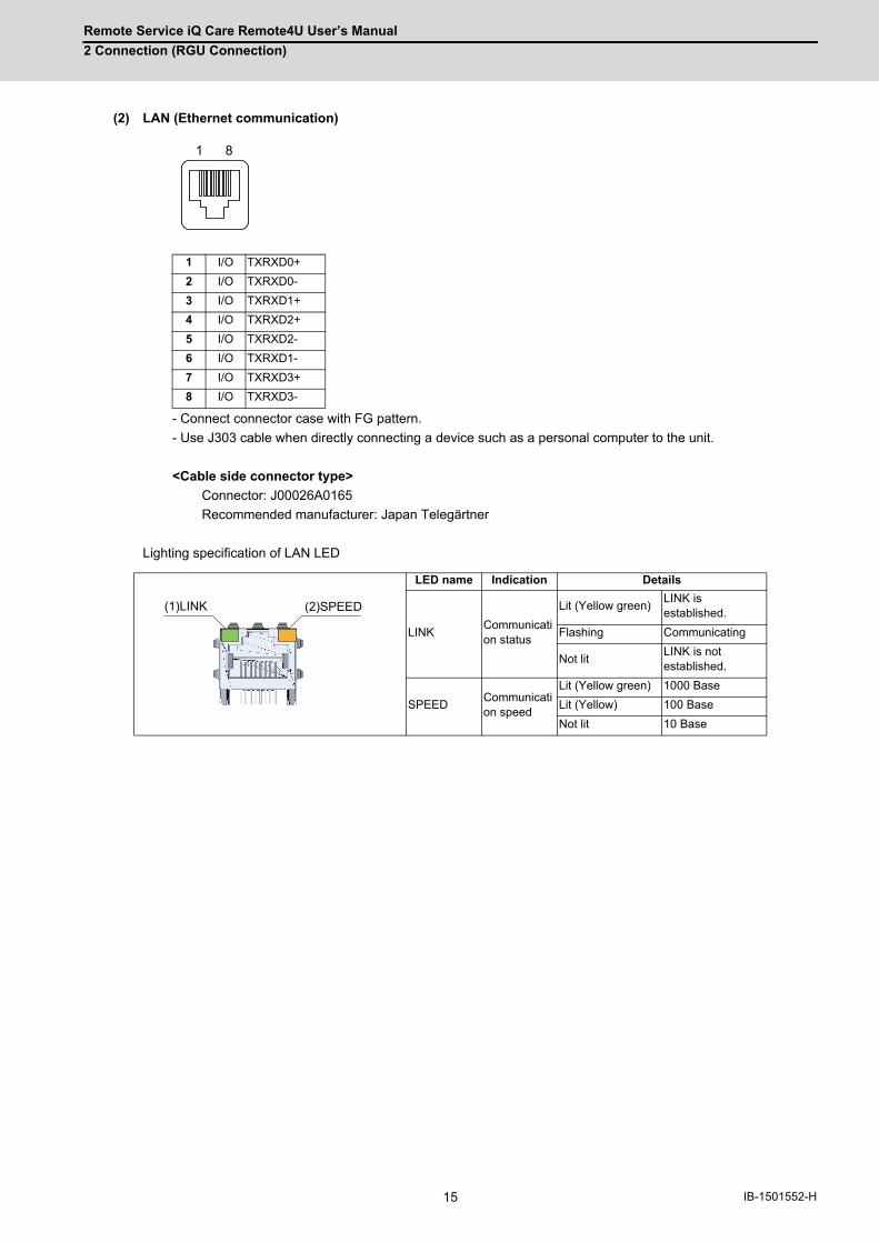
Remote Service iQ Care Remote4U User’s Manual
2 Connection (RGU Connection)
15 IB-1501552-H
(2) LAN (Ethernet communication)
- Connect connector case with FG pattern.
- Use J303 cable when directly connecting a device such as a personal computer to the unit.
<Cable side connector type>
Connector: J00026A0165
Recommended manufacturer: Japan Telegärtner
Lighting specification of LAN LED
1 I/O TXRXD0+
2 I/O TXRXD0-
3 I/O TXRXD1+
4 I/O TXRXD2+
5 I/O TXRXD2-
6 I/O TXRXD1-
7 I/O TXRXD3+
8 I/O TXRXD3-
LED name Indication Details
LINKCommunication status
Lit (Yellow green)LINK is established.
Flashing Communicating
Not litLINK is not established.
SPEEDCommunication speed
Lit (Yellow green) 1000 Base
Lit (Yellow) 100 Base
Not lit 10 Base
81
(1)LINK (2)SPEED
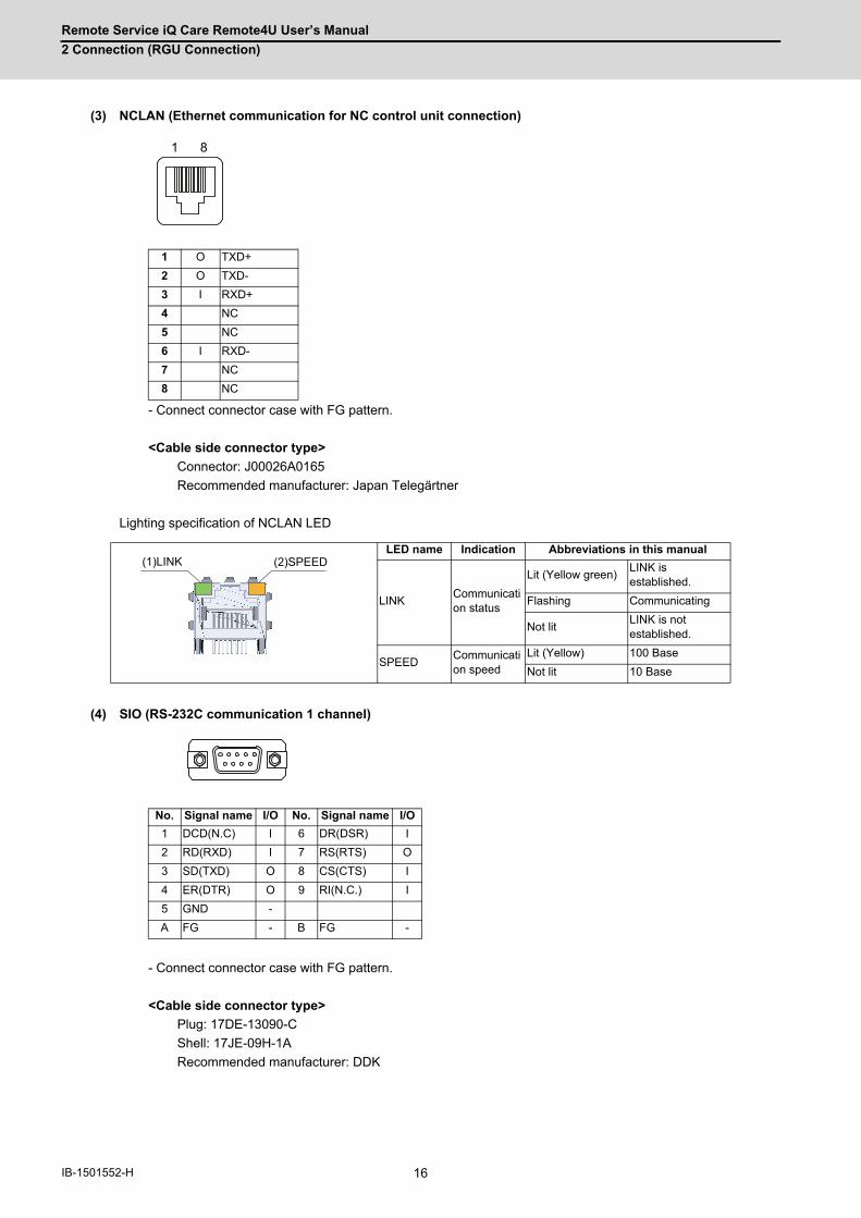
Remote Service iQ Care Remote4U User’s Manual
2 Connection (RGU Connection)
16IB-1501552-H
(3) NCLAN (Ethernet communication for NC control unit connection)
- Connect connector case with FG pattern.
<Cable side connector type>
Connector: J00026A0165
Recommended manufacturer: Japan Telegärtner
Lighting specification of NCLAN LED
(4) SIO (RS-232C communication 1 channel)
- Connect connector case with FG pattern.
<Cable side connector type>
Plug: 17DE-13090-C
Shell: 17JE-09H-1A
Recommended manufacturer: DDK
1 O TXD+
2 O TXD-
3 I RXD+
4 NC
5 NC
6 I RXD-
7 NC
8 NC
LED name Indication Abbreviations in this manual
LINKCommunication status
Lit (Yellow green)LINK is established.
Flashing Communicating
Not litLINK is not established.
SPEEDCommunication speed
Lit (Yellow) 100 Base
Not lit 10 Base
No. Signal name I/O No. Signal name I/O
1 DCD(N.C) I 6 DR(DSR) I
2 RD(RXD) I 7 RS(RTS) O
3 SD(TXD) O 8 CS(CTS) I
4 ER(DTR) O 9 RI(N.C.) I
5 GND -
A FG - B FG -
81
(1)LINK (2)SPEED
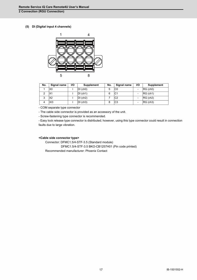
Remote Service iQ Care Remote4U User’s Manual
2 Connection (RGU Connection)
17 IB-1501552-H
(5) DI (Digital input 4 channels)
- COM separate type connector
- The cable side connector is provided as an accessory of the unit.
- Screw-fastening type connector is recommended.
- Easy lock release type connector is distributed; however, using this type connector could result in connection
faults due to large vibration.
<Cable side connector type>
Connector: DFMC1.5/4-STF-3.5 (Standard module)
DFMC1.5/4-STF-3.5 BKO-CB1257H01 (Pin code printed)
Recommended manufacturer: Phoenix Contact
No. Signal name I/O Supplement No. Signal name I/O Supplement
1 X0 I DI (ch0) 5 C0 - RG (ch0)
2 X1 I DI (ch1) 6 C1 - RG (ch1)
3 X2 I DI (ch2) 7 C2 - RG (ch2)
4 XI3 I DI (ch3) 8 C3 - RG (ch3)
1 4
5 8
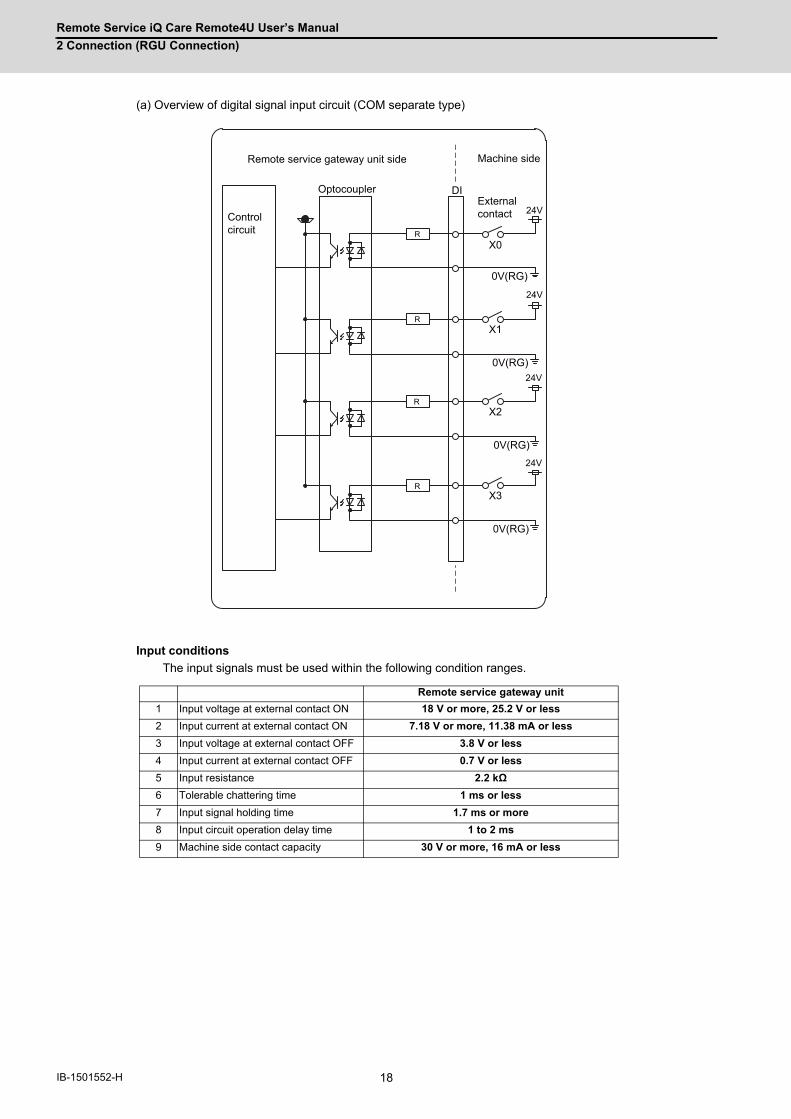
Remote Service iQ Care Remote4U User’s Manual
2 Connection (RGU Connection)
18IB-1501552-H
(a) Overview of digital signal input circuit (COM separate type)
Input conditions
The input signals must be used within the following condition ranges.
Remote service gateway unit
1 Input voltage at external contact ON 18 V or more, 25.2 V or less
2 Input current at external contact ON 7.18 V or more, 11.38 mA or less
3 Input voltage at external contact OFF 3.8 V or less
4 Input current at external contact OFF 0.7 V or less
5 Input resistance 2.2 kΩ
6 Tolerable chattering time 1 ms or less
7 Input signal holding time 1.7 ms or more
8 Input circuit operation delay time 1 to 2 ms
9 Machine side contact capacity 30 V or more, 16 mA or less
DI
24V
24V
24V
24V
R
R
R
R
X0
X1
X2
X3
0V(RG)
0V(RG)
0V(RG)
0V(RG)
Remote service gateway unit side Machine side
Control circuit
OptocouplerExternal contact

Remote Service iQ Care Remote4U User’s Manual
2 Connection (RGU Connection)
19 IB-1501552-H
DI Input timing
(E): External signal, (I): Internal signal
(6) FG (FG terminal)
(7) SD (SD card I/F)
Connection to 24V common input Connection to 0V common input
T1T1
T2
GND
+24V
T4T3
(E)
(I)
T1T1
T2
T4T3
GND
+24V
(E)
(I)

Remote Service iQ Care Remote4U User’s Manual
2 Connection (RGU Connection)
20IB-1501552-H
2.4.6 Exclusive SD Cards for MITSUBISHI ELECTRIC CNC
(Note 1) SLC stands for Single Level Cell, and it stores one bit data in each memory cell.
This provides longer life span and high product reliability in comparison with such as MLC (Multi Level Cell)
and TLC (Triple Level Cell), which are commonly applied to SD cards.
(Note 2) Do not touch the terminal part with fingers, etc. when handling the SD cards.
A stain on the terminal part of SD card causes a poor contact or a failure.
2.4.6.1 SD Interface
(Note 1) SDXC is not supported.
(1) Precautions for use of commercially available SD card
MITUBISHI will not provide performance guarantee and maintenance for commercially available SD card, mini SD
card or micro SD card (converting adapter required). Using any of them requires the machine tool builder a careful
performance check.
Commercially available devices may not be compatible with MITSUBISHI units or suitable FA environment for
temperature- or noise-wise.
(2) Precautions for insertion/removal of SD card
When inserting/removing an SD card, turn the MITUBISHI device's power OFF. Do not remove the card or turn OFF
the power during access to the SD card. Failure to observe this could cause the memory contents to be erased.
As a precaution, always backup important data by duplicating it, for example, as MITUBISHI will not guarantee the
broken or lost data.
Items FCU8-SD001G FCU8-SD004G
Capacity 1 GB 4 GB
NAND Flash SLC (Note 1)
Ambient temperatureDuring operation -25 °C to +85 °C
During storage -40 °C to +85 °C
Ambient humidityDuring operation 5% to 95%RH (with no dew condensation)
During storage 5% to 95%RH (with no dew condensation)
Standards SD/SDHC (Note 1)
Transfer speed Depends on the connecting SD card
Maximum capacity 32 GB
Number of free ports 1
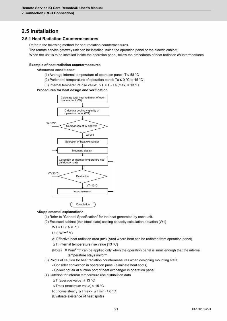
Remote Service iQ Care Remote4U User’s Manual
2 Connection (RGU Connection)
21 IB-1501552-H
2.5 Installation2.5.1 Heat Radiation Countermeasures
Refer to the following method for heat radiation countermeasures.
The remote service gateway unit can be installed inside the operation panel or the electric cabinet.
When the unit is to be installed inside the operation panel, follow the procedures of heat radiation countermeasures.
Example of heat radiation countermeasures
<Assumed conditions>
(1) Average internal temperature of operation panel: T ≤ 58 °C
(2) Peripheral temperature of operation panel: Ta ≤ 0 °C to 45 °C
(3) Internal temperature rise value: ΔT = T - Ta (max) = 13 °C
Procedures for heat design and verification
<Supplemental explanation>
(1) Refer to "General Specification" for the heat generated by each unit.
(2) Enclosed cabinet (thin steel plate) cooling capacity calculation equation (W1)
W1 = U × A × ΔT
U: 6 W/m2 °C
A: Effective heat radiation area (m2) (Area where heat can be radiated from operation panel)
ΔT: Internal temperature rise value (13 °C)
(Note) 8 W/m2 °C can be applied only when the operation panel is small enough that the internal
temperature stays uniform.
(3) Points of caution for heat radiation countermeasures when designing mounting state
- Consider convection in operation panel (eliminate heat spots).
- Collect hot air at suction port of heat exchanger in operation panel.
(4) Criterion for internal temperature rise distribution data
ΔT (average value) ≤ 13 °C
ΔTmax (maximum value) ≤ 15 °C
R (inconsistency ΔTmax - ΔTmin) ≤ 6 °C
(Evaluate existence of heat spots)
W ≤ W1
W>W1
ΔT≤13°C
ΔT>13°C
Calculate total heat radiation of eachmounted unit (W)
Comparison of W and W1
Collection of internal temperature risedistribution data
Mounting design
Improvements
Completion
Selection of heat exchanger
Evaluation
Calculate cooling capacity ofoperation panel (W1)

Remote Service iQ Care Remote4U User’s Manual
2 Connection (RGU Connection)
22IB-1501552-H
The following shows an example of calculation applied to heat radiation countermeasures for the operation panel when
19-type display unit is used. Because heat accumulates in the upper portions of the unit, install an agitating fan as
required.
120
440
365
600
500
Display unit
(Agitating fan)

Remote Service iQ Care Remote4U User’s Manual
2 Connection (RGU Connection)
23 IB-1501552-H
Calculation example of panel internal heating value (When the remote service gateway unit in installed inside
the operation panel)
* Maximum heating value described "2.4.1 Environment Conditions (Installation Environment Conditions)" is
the value excluding DI.
(1) Calculation of unit heating value (When FCU8-DU191-75 + FCU8-DX837 is assumed to be used)
Heating value (W)
Total heating value of units (W):
38.6 W (= display unit + operation panel I/O unit + remote service gateway unit)
Total heating value (W) by machine input (D1) of operation panel I/O unit
8.3 W = ((24 V)2/5 kΩ) × 72 points)
Total heating value when the following DIs are simultaneously turned ON
- 64 points of the operation panel I/O unit DI
- 8 points of safety DI
1.05 W = ((24 V)2/2.2 kΩ) × 4 points)
Total heating value when the DIs of 4 points for the remote gateway unit are simultaneously turned
ON
Total heating value W = 47.95 W (38.6 + 8.3 + 1.05)
(2) Calculation of operation panel cooling capacity
Tolerance value for temperature rise (Δt)
- Panel internal temperature (according to each unit's specification) T ≤ 58 °C
- Panel peripheral temperature (according to machine's specification) Ta ≤ 45 °C
Tolerance value for internal temperature rise ΔT = 13 °C (T - Ta)
Heat radiation area (A)
The surface of the molded unit, which has lower radiation capacity than the metal plate surface, should be
excluded from the heat radiation area in principle.
The bottom of the operation panel, which has difficulty in radiating due to the temperature distribution,
should also be excluded from the heat radiation area in principle.
Operation panel cooling capacity (W1)
Calculate the cooling capacity to keep the temperature rise in the operation panel 13 °C or less.
Cooling capacity W1 = 50.2 W (6 × A × ΔT)
(3) Comparison of heating value and operation panel cooling capacity
The operation panel cooling capacity is over the heating value, thus installing the heat exchanger is presumed
to be unnecessary.
(4) Confirmation with the actual machine
The result of the calculation above is only a rough indication. The actual temperature rise may differ according
to the structure of the operation panel.
Be sure to confirm the temperature rise value in the operation panel when the machine is running.
Heat radiation area A
= 0.643 mm2 (≈ 0.5 × 0.12 + 0.6 × 0.5 × 2 + 0.6 × 0.12 × 2 - 0.44 × 0.365)
(Top surface) (Front, rear surface) (Both sides surface) (Unit surface)

Remote Service iQ Care Remote4U User’s Manual
2 Connection (RGU Connection)
24IB-1501552-H
2.5.2 Noise Countermeasures
2.5.2.1 Connection of Frame Ground (FG)
The frame should basically be grounded at one ground point.
Because the personal computer unit and the operation panel I/O unit are located in a place away from the electric
cabinet, connect the ground terminal of the personal computer to the grounding plate of the operation section and
connect the grounding plate of the operation panel to the grounding plate of the electric cabinet. (Be sure to ground the
ground terminal of the personal computer. Otherwise, it affects controllability of the touchscreen.)
Connect 0V (common) and FG on the 24VDC power supply.
0V
DCIN
0VFG
0V
ACIN
FG FG0V
FG
ACIN
DCIN
0VFG
0VRIO3KEYUSB
RIO3EXTMPG
0V GDILAN
DCIN
0VFG
0V
24VDCEMG
0VFG
GDILAN
SIORIO*SKIPAIO
RIO1RIO2
DCIN
0VFG
: Indicates that the metal case of connector is connected to FG according to the pattern on PCB.
Control panel grounding plate
24VDCStabilized power supply
24VDC
Screw hole
Display unit
24VDC
Screw hole
Remote I/O unit
24VDC
24VDC
Operation panel I/O unit Screw hole
Screw hole
Personal computer unit24VDC
Control unitEmergencystop button
24VDCStabilized power supply
Control panel
Operation panel
Operation panel grounding plate
(Grounded through the metal plate on the back side of the display unit)
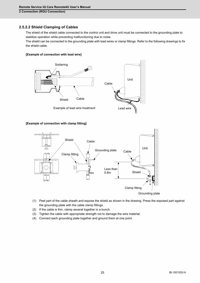
Remote Service iQ Care Remote4U User’s Manual
2 Connection (RGU Connection)
25 IB-1501552-H
2.5.2.2 Shield Clamping of Cables
The shield of the shield cable connected to the control unit and drive unit must be connected to the grounding plate to
stabilize operation while preventing malfunctioning due to noise.
The shield can be connected to the grounding plate with lead wires or clamp fittings. Refer to the following drawings to fix
the shield cable.
[Example of connection with lead wire]
[Example of connection with clamp fitting]
(1) Peel part of the cable sheath and expose the shield as shown in the drawing. Press the exposed part against
the grounding plate with the cable clamp fittings.
(2) If the cable is thin, clamp several together in a bunch.
(3) Tighten the cable with appropriate strength not to damage the wire material.
(4) Connect each grounding plate together and ground them at one point.
CableUnit
Lead wireExample of lead wire treatment
CableShield
Soldering
Cable
Grounding plate
Shield
Grounding plate
Cable
Clamp fitting
Shield
Unit
Clamp fitting
Less than 0.8m

Remote Service iQ Care Remote4U User’s Manual
2 Connection (RGU Connection)
26IB-1501552-H
2.5.2.3 Connecting Spark Killers
The noise which is generated during the operation of the coil or contact needs to be eliminated.
Connect the spark killers (CR composite element) in parallel with the coil and the contact for the countermeasure.
The spark killer is effective in eliminating the noise generated by electromagnetic induction.
E
C : 0.033 to 0.1μF R : 10 to 120Ω
Contact
Sparkkiller
Coil
Spark
killer
Spark killer
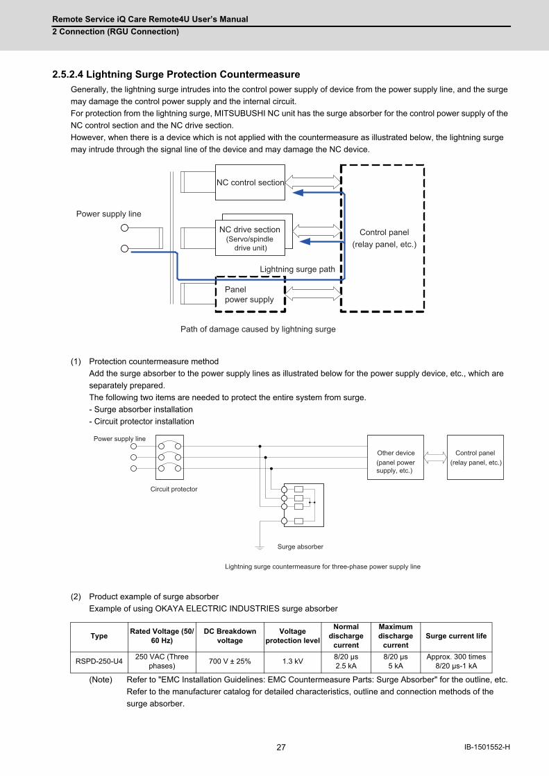
Remote Service iQ Care Remote4U User’s Manual
2 Connection (RGU Connection)
27 IB-1501552-H
2.5.2.4 Lightning Surge Protection Countermeasure
Generally, the lightning surge intrudes into the control power supply of device from the power supply line, and the surge
may damage the control power supply and the internal circuit.
For protection from the lightning surge, MITSUBUSHI NC unit has the surge absorber for the control power supply of the
NC control section and the NC drive section.
However, when there is a device which is not applied with the countermeasure as illustrated below, the lightning surge
may intrude through the signal line of the device and may damage the NC device.
(1) Protection countermeasure method
Add the surge absorber to the power supply lines as illustrated below for the power supply device, etc., which are
separately prepared.
The following two items are needed to protect the entire system from surge.
- Surge absorber installation
- Circuit protector installation
(2) Product example of surge absorber
Example of using OKAYA ELECTRIC INDUSTRIES surge absorber
(Note) Refer to "EMC Installation Guidelines: EMC Countermeasure Parts: Surge Absorber" for the outline, etc.
Refer to the manufacturer catalog for detailed characteristics, outline and connection methods of the
surge absorber.
TypeRated Voltage (50/
60 Hz)DC Breakdown
voltageVoltage
protection level
Normal discharge
current
Maximum discharge
currentSurge current life
RSPD-250-U4250 VAC (Three
phases)700 V ± 25% 1.3 kV
8/20 μs 2.5 kA
8/20 μs 5 kA
Approx. 300 times 8/20 μs-1 kA
NC control section
NC drive section(Servo/spindle
drive unit)
Panel power supply
Control panel(relay panel, etc.)
Power supply line
Path of damage caused by lightning surge
Lightning surge path
Other device(panel power supply, etc.)
Control panel(relay panel, etc.)
Power supply line
Circuit protector
Surge absorber
Lightning surge countermeasure for three-phase power supply line
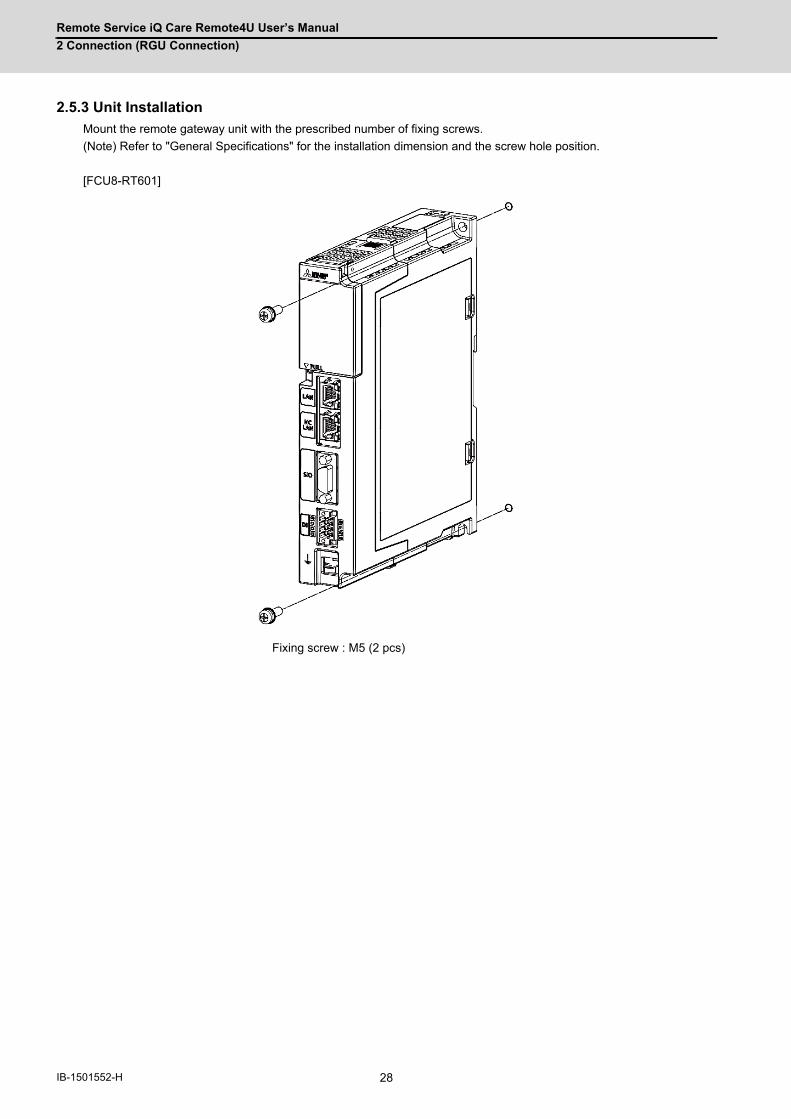
Remote Service iQ Care Remote4U User’s Manual
2 Connection (RGU Connection)
28IB-1501552-H
2.5.3 Unit Installation
Mount the remote gateway unit with the prescribed number of fixing screws.
(Note) Refer to "General Specifications" for the installation dimension and the screw hole position.
[FCU8-RT601]
Fixing screw : M5 (2 pcs)
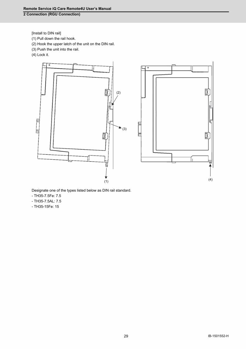
Remote Service iQ Care Remote4U User’s Manual
2 Connection (RGU Connection)
29 IB-1501552-H
[Install to DIN rail]
(1) Pull down the rail hook.
(2) Hook the upper latch of the unit on the DIN rail.
(3) Push the unit into the rail.
(4) Lock it.
Designate one of the types listed below as DIN rail standard.
- TH35-7.5Fe: 7.5
- TH35-7.5AL: 7.5
- TH35-15Fe: 15
(2)
(3)
(1) (4)

Remote Service iQ Care Remote4U User’s Manual
2 Connection (RGU Connection)
30IB-1501552-H
2.6 Precautions for Connecting2.6.1 Precautions for Wiring
2.6.1.1 Precautions when Connecting/Disconnecting Cables
If the cable is connected/disconnected without turning the power OFF, the normal unit or peripheral devices could be
damaged, and risks could be imposed.
Disconnect each cable with the following procedures.
(a) For the following type of connector, press the tabs with a thumb and a forefinger in the direction of the arrow, and pull
the connector off.
CAUTION
1. Do not connect or disconnect the cables between units while the power is ON.
2. Do not pull the cables when connecting/disconnecting it.
Y
(1)
(2)
Press
Pull (2)
(1)
Pull
Press
(2)
(1)
View from above
Pull
Press
(1)
(2)
Press
Pull

Remote Service iQ Care Remote4U User’s Manual
2 Connection (RGU Connection)
31 IB-1501552-H
(b) For a flat cable type connector with latches, open the latches in the directions of the arrows, and pull the connector
off.
(c) For a flat cable type connector without latches, hold the connector with a thumb and a forefinger, and pull the
connector off.
(d) For the screw fixed type connector, loosen the two fixing screws, and pull the connector off.
CAUTION
1. Do not connect or disconnect the cables between units while the power is ON.
2. Do not pull the cables when connecting/disconnecting it.
(1)
(2)
Open
Pull
(1)
(2)
Hold with thumb and forefinger.
Pull
(1)
(2)
Loosen
Pull
(1)
(2)
Loosen
Pull

Remote Service iQ Care Remote4U User’s Manual
2 Connection (RGU Connection)
32IB-1501552-H
(e) For the Ethernet connector, pull it off while holding down the locked latch.
(f) For the USB connector, pull it off while holding down the locked latch.
2.6.1.2 Precautions for Connecting 24V Power Supply
(1) Note that when 24V power is supplied to the unit, welding may occur on the contacts due to rush current when both
of the following conditions are met.
- When 24 VDC's ON/OFF are directly controlled by a magnetic switch such as relay
- When heat capacity of the contacts for relay, etc. used to control 24 VDC's ON/OFF is small
2.6.2 Turning the Power ON/OFF
For details on the process of turning the power ON/OFF, refer to "Connection and Setup Manual" of the NC you are
using.
2.6.3 Turning the Power ON/OFF of Remote Service Gateway Unit
Turn ON the power of the remote service gateway unit at the same time or earlier when the NC control unit is turned ON.
CAUTION
1. Do not connect or disconnect the cables between units while the power is ON.
2. Do not pull the cables when connecting/disconnecting it.
(1)
(2)
Press
Pull
(1)
(2)
Press
Pull
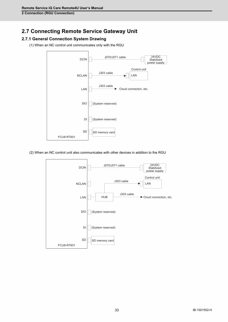
Remote Service iQ Care Remote4U User’s Manual
2 Connection (RGU Connection)
33 IB-1501552-H
2.7 Connecting Remote Service Gateway Unit2.7.1 General Connection System Drawing
(1) When an NC control unit communicates only with the RGU
(2) When an NC control unit also communicates with other devices in addition to the RGU
SD
DI
SIO
LAN
NCLAN
DCIN
LAN
FCU8-RT601
(System reserved)
(System reserved)
Control unit
24VDC Stabilized
power supply
J070/J071 cable
J303 cable
J303 cable
SD memory card
Cloud connection, etc.
SD
DI
SIO
LAN
NCLAN
DCIN
LAN
FCU8-RT601
HUB
(System reserved)
(System reserved)
Control unit
24VDC Stabilized
power supply
J070/J071 cable
J303 cable
J303 cable
SD memory card
Cloud connection, etc.
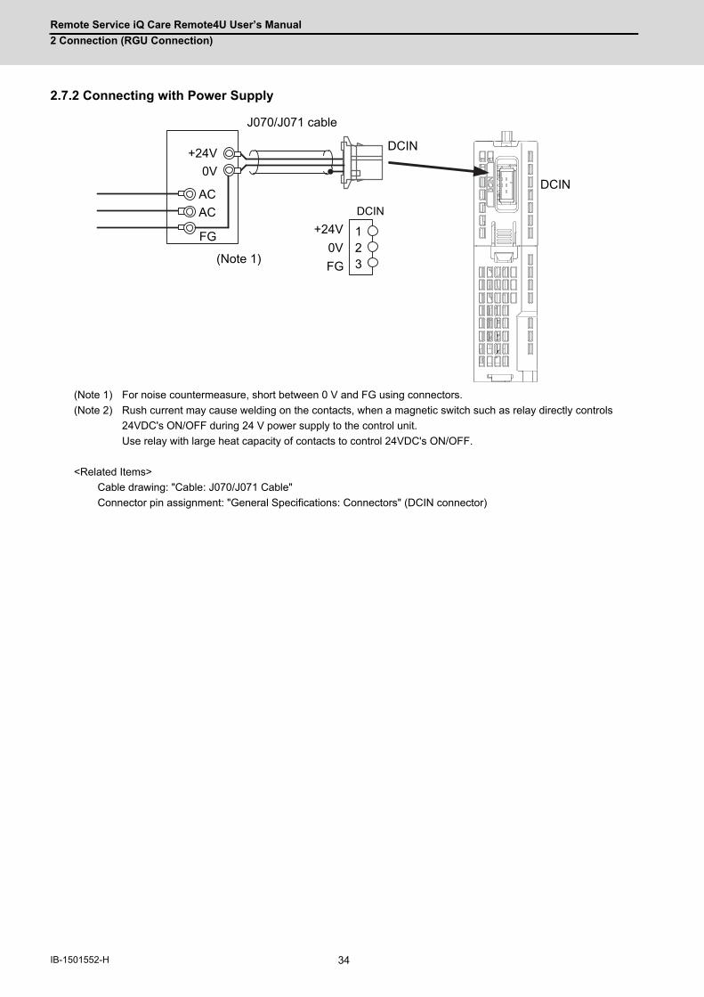
Remote Service iQ Care Remote4U User’s Manual
2 Connection (RGU Connection)
34IB-1501552-H
2.7.2 Connecting with Power Supply
(Note 1) For noise countermeasure, short between 0 V and FG using connectors.
(Note 2) Rush current may cause welding on the contacts, when a magnetic switch such as relay directly controls
24VDC's ON/OFF during 24 V power supply to the control unit.
Use relay with large heat capacity of contacts to control 24VDC's ON/OFF.
<Related Items>
Cable drawing: "Cable: J070/J071 Cable"
Connector pin assignment: "General Specifications: Connectors" (DCIN connector)
DCIN
DCIN
DCIN
123
+24V0V
ACAC
FG +24V0VFG
J070/J071 cable
(Note 1)
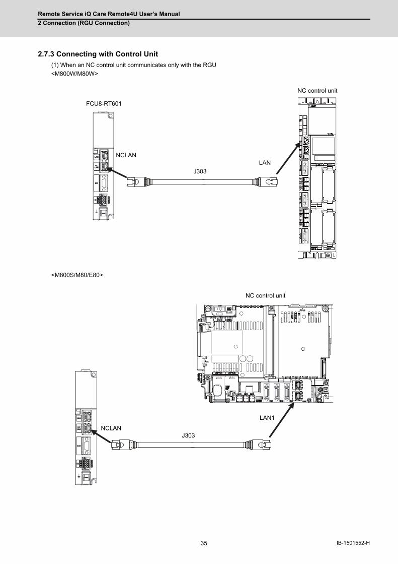
Remote Service iQ Care Remote4U User’s Manual
2 Connection (RGU Connection)
35 IB-1501552-H
2.7.3 Connecting with Control Unit
(1) When an NC control unit communicates only with the RGU
<M800W/M80W>
<M800S/M80/E80>
FCU8-RT601
J303
NCLANLAN
NC control unit
LAN1
J303NCLAN
NC control unit
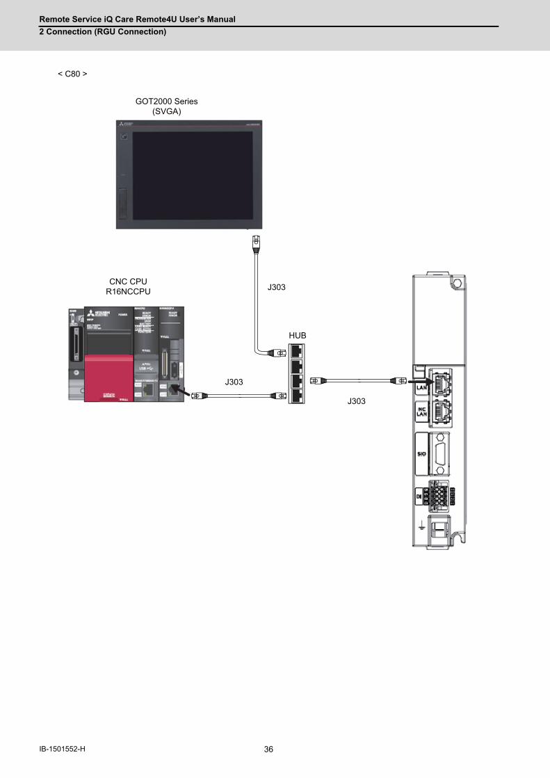
Remote Service iQ Care Remote4U User’s Manual
2 Connection (RGU Connection)
36IB-1501552-H
< C80 >
GOT2000 Series(SVGA)
CNC CPUR16NCCPU
J303
J303
J303
HUB
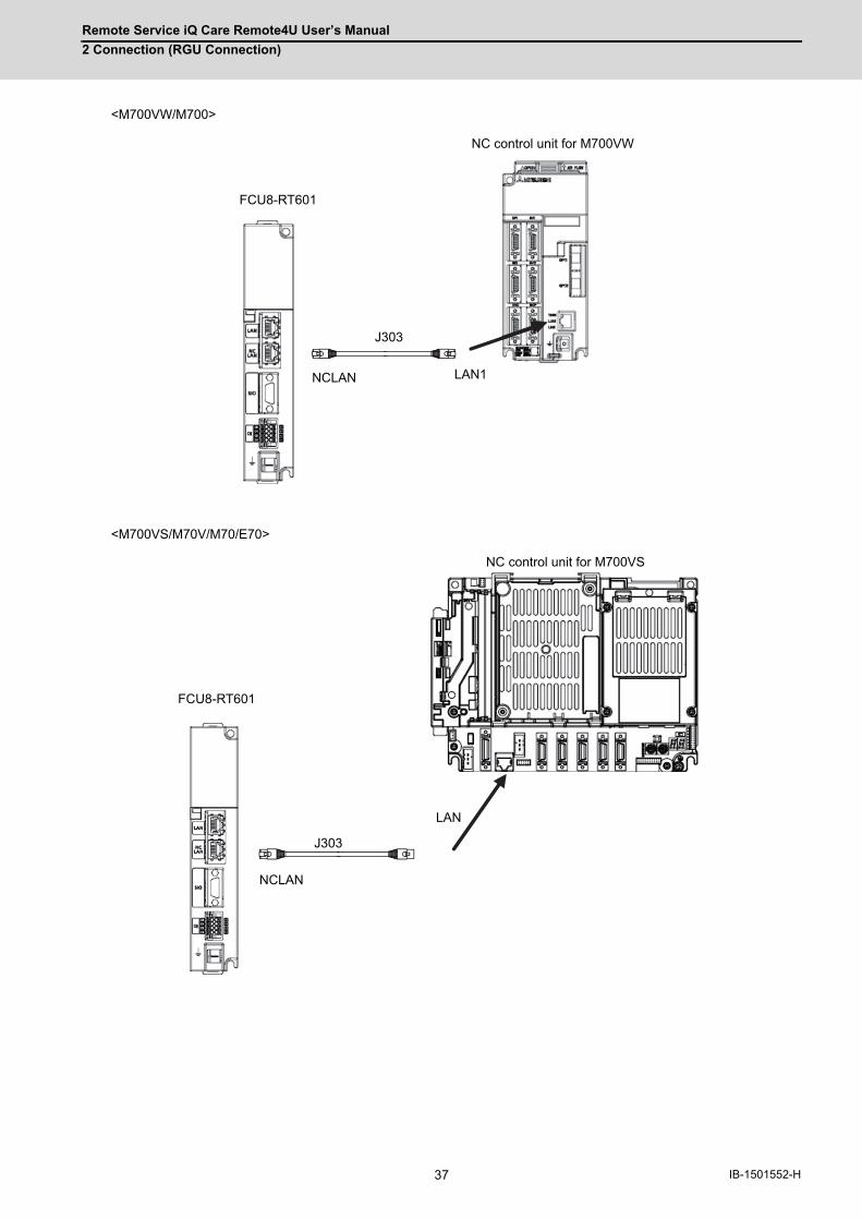
Remote Service iQ Care Remote4U User’s Manual
2 Connection (RGU Connection)
37 IB-1501552-H
<M700VW/M700>
<M700VS/M70V/M70/E70>
FCU8-RT601
J303
NCLAN LAN1
NC control unit for M700VW
LAN
FCU8-RT601
NCLAN
J303
NC control unit for M700VS
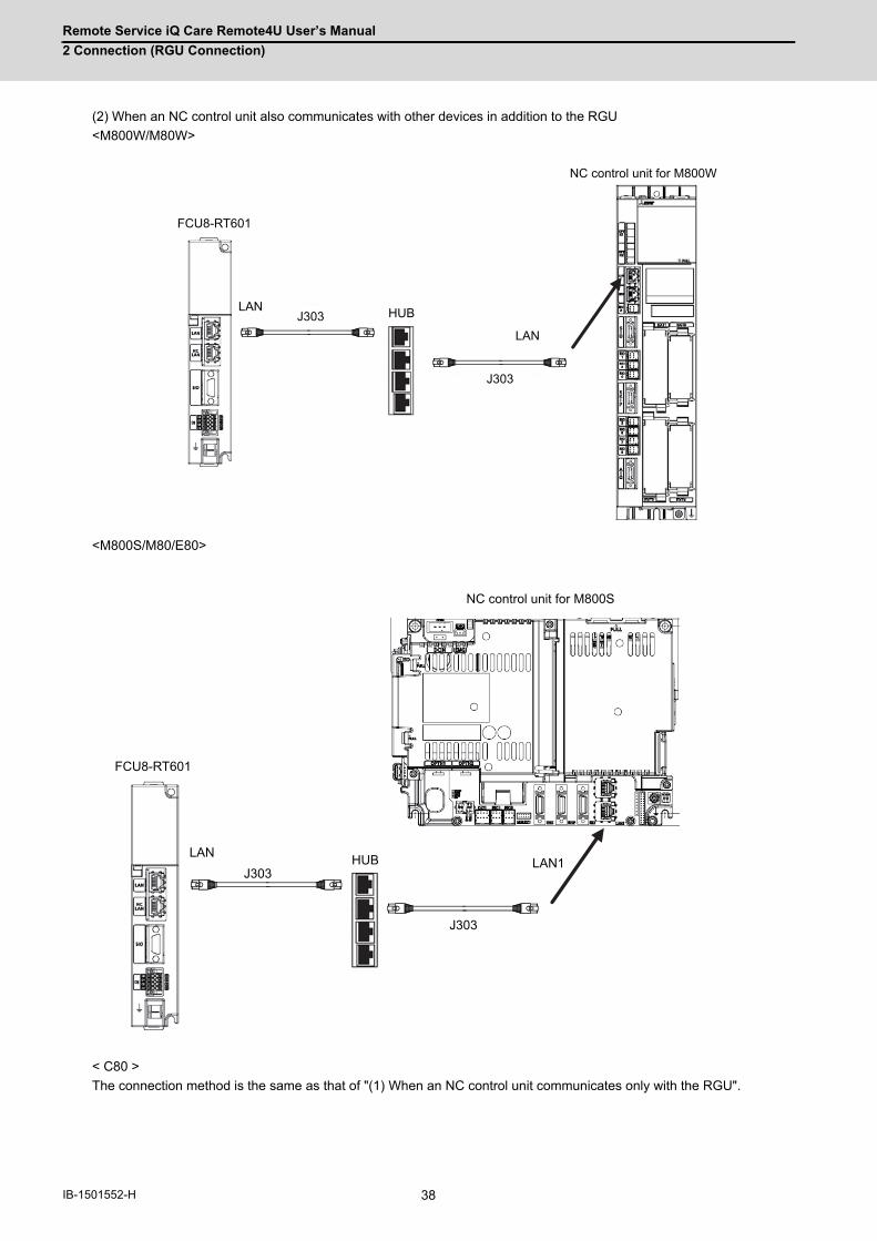
Remote Service iQ Care Remote4U User’s Manual
2 Connection (RGU Connection)
38IB-1501552-H
(2) When an NC control unit also communicates with other devices in addition to the RGU
<M800W/M80W>
<M800S/M80/E80>
< C80 >
The connection method is the same as that of "(1) When an NC control unit communicates only with the RGU".
FCU8-RT601
J303LAN HUB
J303
LAN
NC control unit for M800W
FCU8-RT601
LAN1HUBJ303
J303
LAN
NC control unit for M800S

Remote Service iQ Care Remote4U User’s Manual
2 Connection (RGU Connection)
39 IB-1501552-H
<M700VW/M700>
<M700VS/M70V/M70/E70>
<Related Items>
Cable drawing: "Cable: J303 Cable"
Connector pin assignment: "General Specifications: Connectors" (NCLAN connector)
FCU8-RT601
J303 HUB
J303
LAN
LAN1
NC control unit for M700VW
FCU8-RT601
LANLANHUB
J303
J303
NC control unit for M700VS
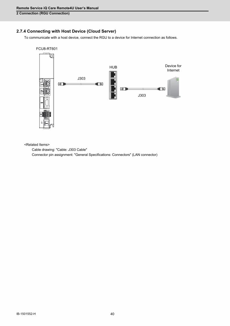
Remote Service iQ Care Remote4U User’s Manual
2 Connection (RGU Connection)
40IB-1501552-H
2.7.4 Connecting with Host Device (Cloud Server)
To communicate with a host device, connect the RGU to a device for Internet connection as follows.
<Related Items>
Cable drawing: "Cable: J303 Cable"
Connector pin assignment: "General Specifications: Connectors" (LAN connector)
J303
FCU8-RT601
J303
HUB Device for Internet
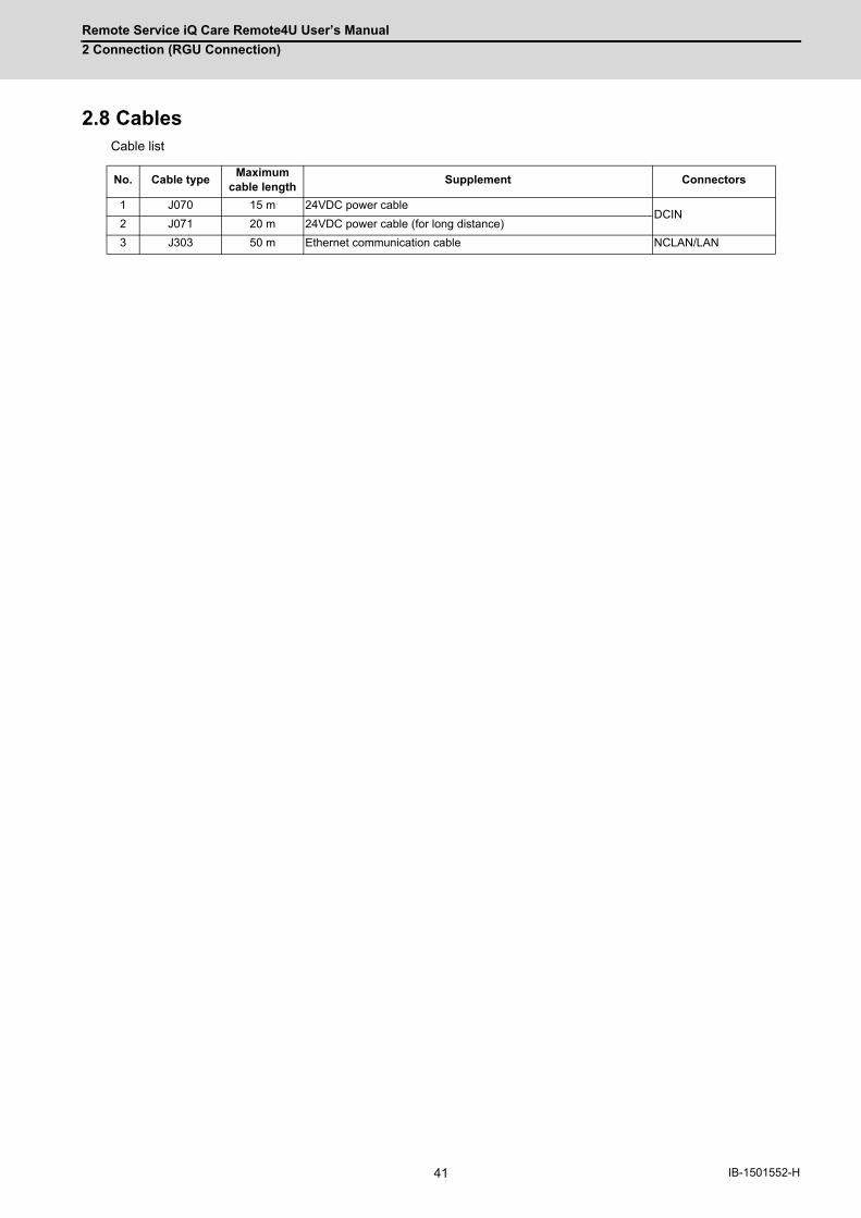
Remote Service iQ Care Remote4U User’s Manual
2 Connection (RGU Connection)
41 IB-1501552-H
2.8 CablesCable list
No. Cable typeMaximum
cable lengthSupplement Connectors
1 J070 15 m 24VDC power cableDCIN
2 J071 20 m 24VDC power cable (for long distance)
3 J303 50 m Ethernet communication cable NCLAN/LAN
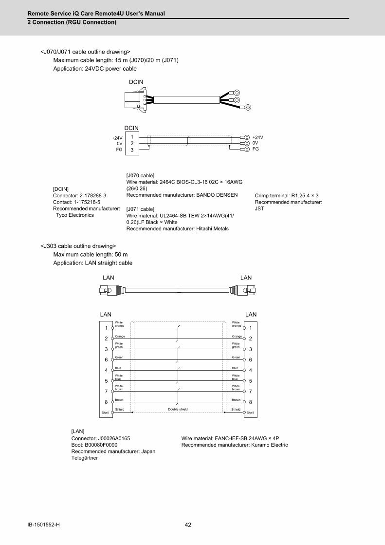
Remote Service iQ Care Remote4U User’s Manual
2 Connection (RGU Connection)
42IB-1501552-H
<J070/J071 cable outline drawing>
Maximum cable length: 15 m (J070)/20 m (J071)
Application: 24VDC power cable
<J303 cable outline drawing>
Maximum cable length: 50 m
Application: LAN straight cable
[DCIN] Connector: 2-178288-3 Contact: 1-175218-5 Recommended manufacturer: Tyco Electronics
[J070 cable] Wire material: 2464C BIOS-CL3-16 02C × 16AWG (26/0.26) Recommended manufacturer: BANDO DENSEN Crimp terminal: R1.25-4 × 3
Recommended manufacturer: JST[J071 cable]
Wire material: UL2464-SB TEW 2×14AWG(41/0.26)LF Black × White Recommended manufacturer: Hitachi Metals
[LAN]Connector: J00026A0165 Boot: B00080F0090 Recommended manufacturer: Japan Telegärtner
Wire material: FANC-IEF-SB 24AWG × 4P Recommended manufacturer: Kuramo Electric
1
2
3
Y
DCIN
DCIN123
+24V0VFG
+24V0VFG
LAN LAN
LAN LAN
1
2
3
6
4
5
7
8
1
2
3
6
4
5
7
8Double shield ShieldShield
Shell Shell
White orange
Orange
White green
Green
Blue
White blue
White brown
Brown
White orange
Orange
White green
Green
Blue
White blue
White brown
Brown

43 IB-1501552-H
3
Initial Setup

Remote Service iQ Care Remote4U User’s Manual
3 Initial Setup
44IB-1501552-H
This chapter explains the standard procedures when this unit is newly connected to MITSUBISHI CNC remote service.
Turn ON each device by following setup procedures.
For details for remote service connection method, refer to "3.2 When Using RGU Connection" and "3.3 When Using NC
Direct Connection".
For details for the models and versions to use this function, refer to "3.4 Applicable Models".
< Compatible NC for each connection >
3.1 Setup ProceduresThe following flow chart shows the setup procedures.
Connection methodAvailable models
M7 Series M8 Series C80 Series M8V Series
RGU connection ○ ○ ○ ×
NC direct connection × × × ○
YES
Use the RGU connection.Refer to Chapter 3.2.
Use the NC direct connection.Refer to Chapter 3.3.
NC to collect data is M7/M8/C80 Series
Remote service is not available.
M8V Series
NO
YES NO
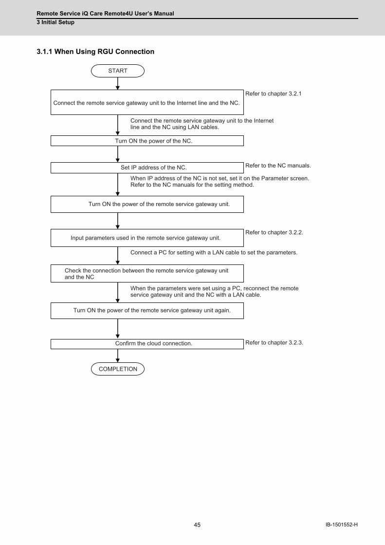
Remote Service iQ Care Remote4U User’s Manual
3 Initial Setup
45 IB-1501552-H
3.1.1 When Using RGU Connection
COMPLETION
START
Connect the remote service gateway unit to the Internet line and the NC.Refer to chapter 3.2.1
Connect the remote service gateway unit to the Internet line and the NC using LAN cables.
Turn ON the power of the NC.
Turn ON the power of the remote service gateway unit.
Set IP address of the NC.
Input parameters used in the remote service gateway unit.
Check the connection between the remote service gateway unit and the NC
Turn ON the power of the remote service gateway unit again.
Confirm the cloud connection.
When IP address of the NC is not set, set it on the Parameter screen.Refer to the NC manuals for the setting method.
Connect a PC for setting with a LAN cable to set the parameters.
When the parameters were set using a PC, reconnect the remote service gateway unit and the NC with a LAN cable.
Refer to the NC manuals.
Refer to chapter 3.2.2.
Refer to chapter 3.2.3.
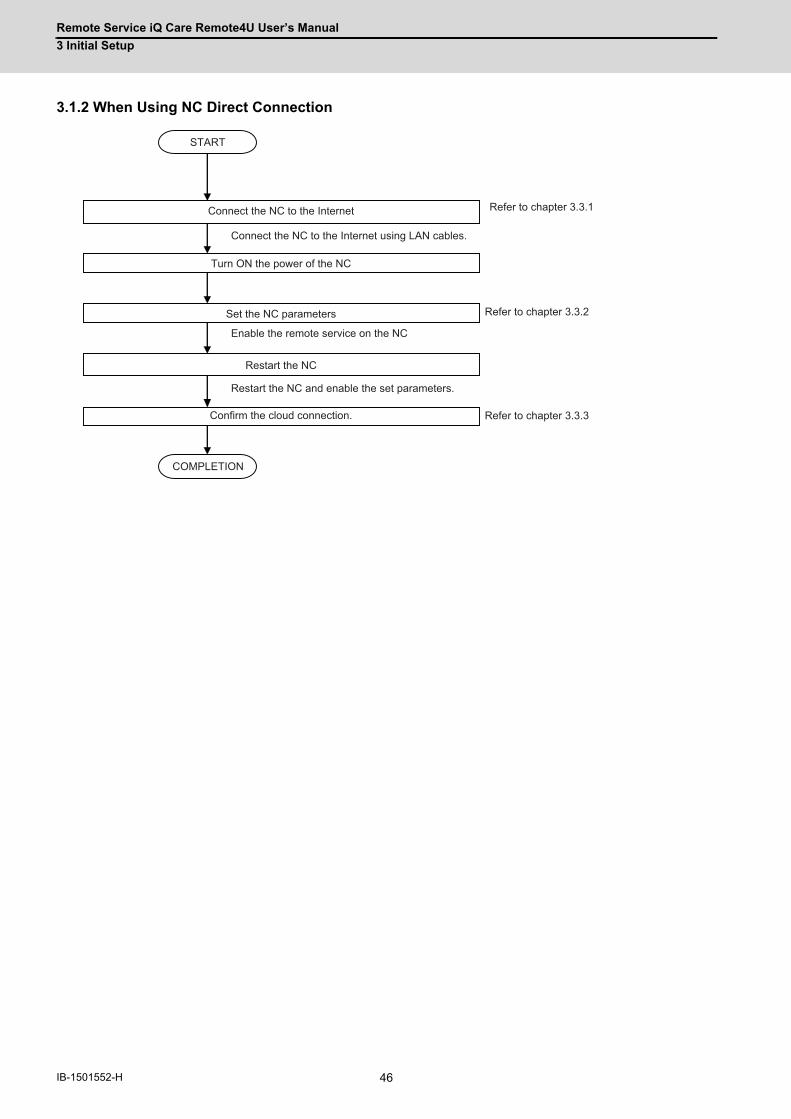
Remote Service iQ Care Remote4U User’s Manual
3 Initial Setup
46IB-1501552-H
3.1.2 When Using NC Direct Connection
COMPLETION
START
Connect the NC to the Internet Refer to chapter 3.3.1
Connect the NC to the Internet using LAN cables.
Turn ON the power of the NC
Set the NC parameters
Confirm the cloud connection.
Enable the remote service on the NC
Refer to chapter 3.3.2
Restart the NC
Restart the NC and enable the set parameters.
Refer to chapter 3.3.3
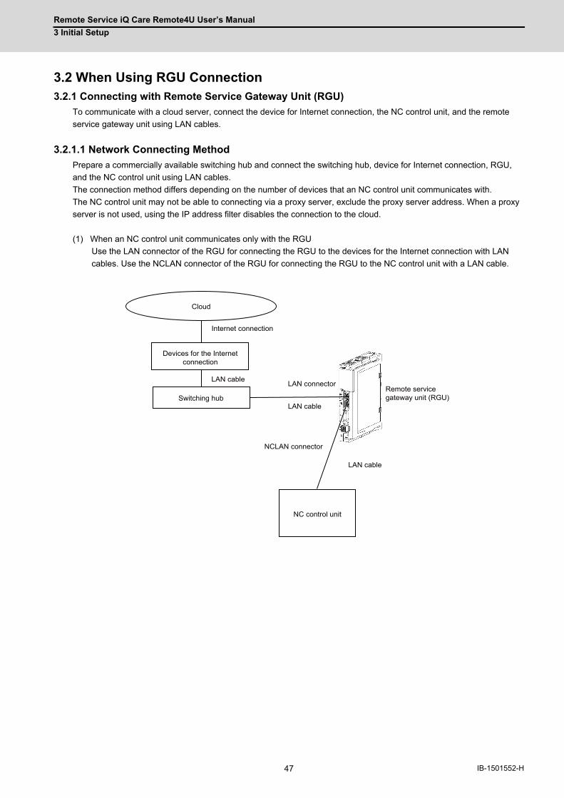
Remote Service iQ Care Remote4U User’s Manual
3 Initial Setup
47 IB-1501552-H
3.2 When Using RGU Connection3.2.1 Connecting with Remote Service Gateway Unit (RGU)
To communicate with a cloud server, connect the device for Internet connection, the NC control unit, and the remote
service gateway unit using LAN cables.
3.2.1.1 Network Connecting Method
Prepare a commercially available switching hub and connect the switching hub, device for Internet connection, RGU,
and the NC control unit using LAN cables.
The connection method differs depending on the number of devices that an NC control unit communicates with.
The NC control unit may not be able to connecting via a proxy server, exclude the proxy server address. When a proxy
server is not used, using the IP address filter disables the connection to the cloud.
(1) When an NC control unit communicates only with the RGU
Use the LAN connector of the RGU for connecting the RGU to the devices for the Internet connection with LAN
cables. Use the NCLAN connector of the RGU for connecting the RGU to the NC control unit with a LAN cable.
Cloud
Devices for the Internet connection
NC control unit
Internet connection
LAN cableRemote service gateway unit (RGU)
LAN cable
LAN connector
Switching hubLAN cable
NCLAN connector
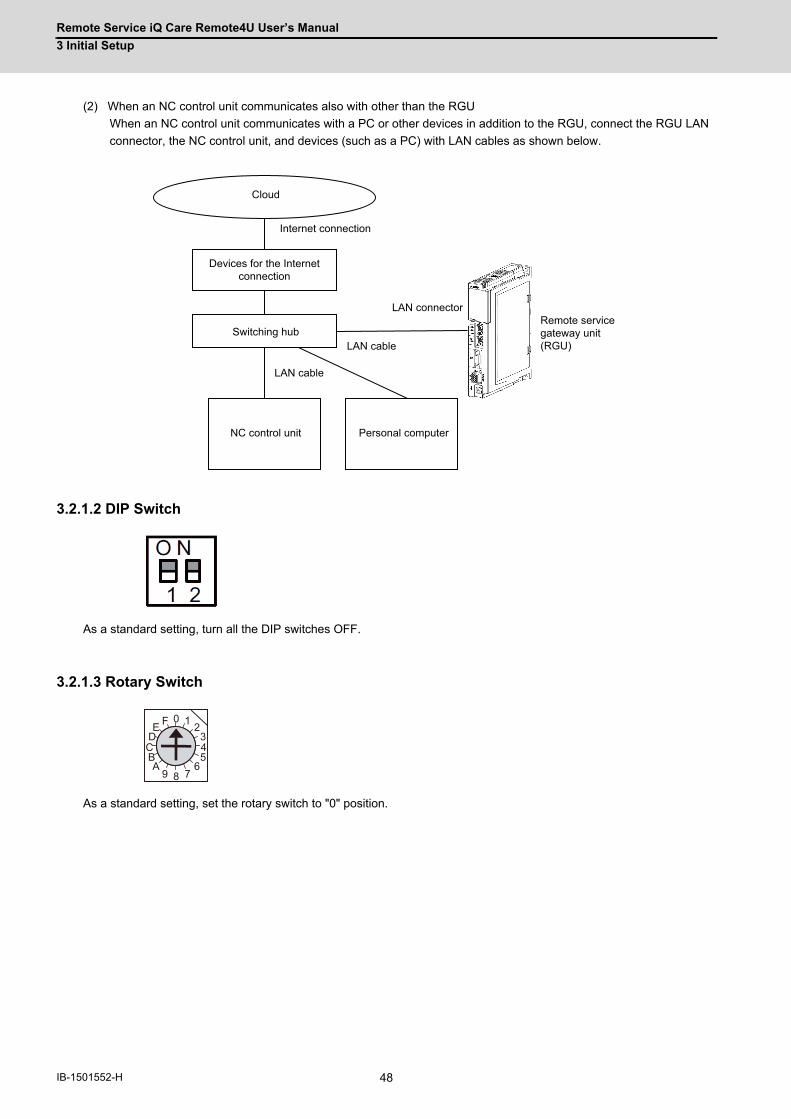
Remote Service iQ Care Remote4U User’s Manual
3 Initial Setup
48IB-1501552-H
(2) When an NC control unit communicates also with other than the RGU
When an NC control unit communicates with a PC or other devices in addition to the RGU, connect the RGU LAN
connector, the NC control unit, and devices (such as a PC) with LAN cables as shown below.
3.2.1.2 DIP Switch
As a standard setting, turn all the DIP switches OFF.
3.2.1.3 Rotary Switch
As a standard setting, set the rotary switch to "0" position.
Cloud
Devices for the Internet connection
NC control unit
Internet connection
LAN cable
Remote service gateway unit (RGU)
Personal computer
Switching hub
LAN cable
LAN connector
2 E
5
3 4 C
7 9 8 6 A
1 F
B
D
0
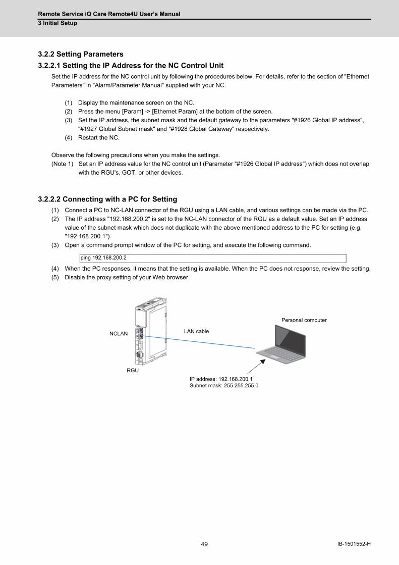
Remote Service iQ Care Remote4U User’s Manual
3 Initial Setup
49 IB-1501552-H
3.2.2 Setting Parameters
3.2.2.1 Setting the IP Address for the NC Control Unit
Set the IP address for the NC control unit by following the procedures below. For details, refer to the section of "Ethernet
Parameters" in "Alarm/Parameter Manual" supplied with your NC.
(1) Display the maintenance screen on the NC.
(2) Press the menu [Param] -> [Ethernet Param] at the bottom of the screen.
(3) Set the IP address, the subnet mask and the default gateway to the parameters "#1926 Global IP address",
"#1927 Global Subnet mask" and "#1928 Global Gateway" respectively.
(4) Restart the NC.
Observe the following precautions when you make the settings.
(Note 1) Set an IP address value for the NC control unit (Parameter "#1926 Global IP address") which does not overlap
with the RGU's, GOT, or other devices.
3.2.2.2 Connecting with a PC for Setting
(1) Connect a PC to NC-LAN connector of the RGU using a LAN cable, and various settings can be made via the PC.
(2) The IP address "192.168.200.2" is set to the NC-LAN connector of the RGU as a default value. Set an IP address
value of the subnet mask which does not duplicate with the above mentioned address to the PC for setting (e.g.
"192.168.200.1").
(3) Open a command prompt window of the PC for setting, and execute the following command.
(4) When the PC responses, it means that the setting is available. When the PC does not response, review the setting.
(5) Disable the proxy setting of your Web browser.
ping 192.168.200.2
RGU
NCLAN
IP address: 192.168.200.1Subnet mask: 255.255.255.0
LAN cable
Personal computer

Remote Service iQ Care Remote4U User’s Manual
3 Initial Setup
50IB-1501552-H
3.2.2.3 Setting the IP Address for the RGU
(1) Start up the Web browser on the PC for setting, input the following URL in the address bar of the browser.
(2) When the following screen appears, press the [Login] button.
(3) When the following pop-up screen appears, input "user" in the upper field, "password" in the lower field with half-
width characters, and then press the [Sign in] button.
(4) Click the [Param] tab.
http://192.168.200.2/
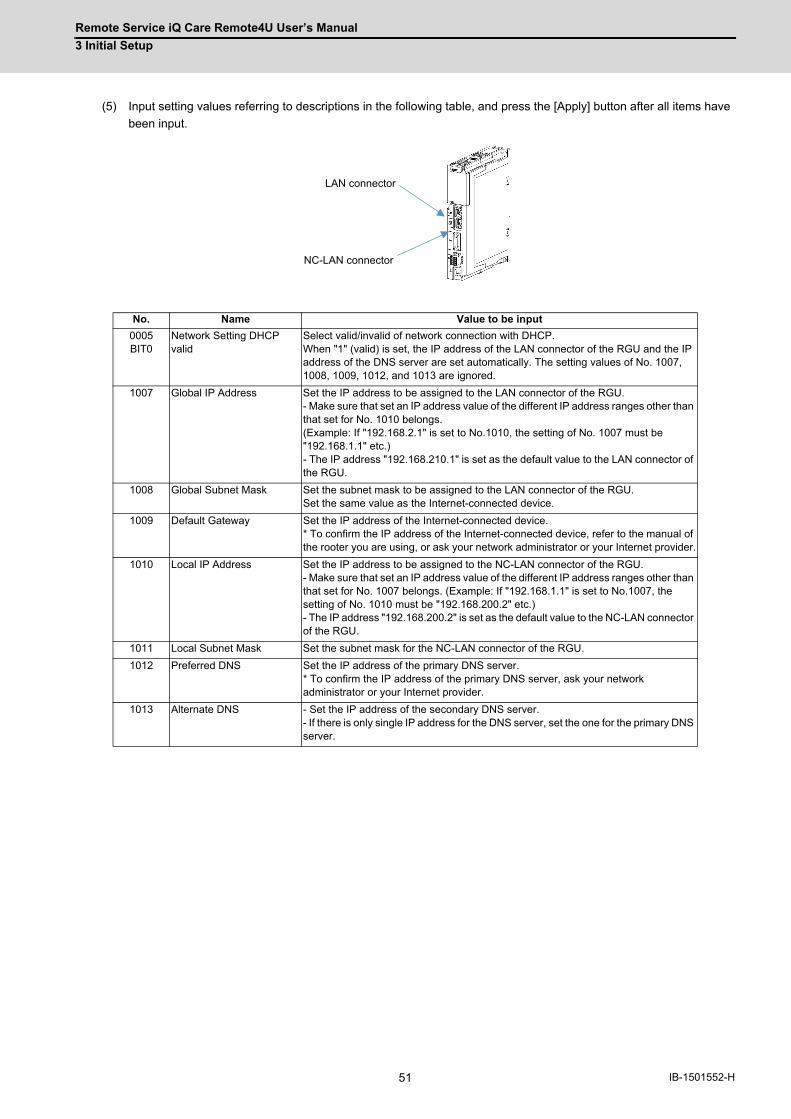
Remote Service iQ Care Remote4U User’s Manual
3 Initial Setup
51 IB-1501552-H
(5) Input setting values referring to descriptions in the following table, and press the [Apply] button after all items have
been input.
No. Name Value to be input
0005BIT0
Network Setting DHCP valid
Select valid/invalid of network connection with DHCP. When "1" (valid) is set, the IP address of the LAN connector of the RGU and the IP address of the DNS server are set automatically. The setting values of No. 1007, 1008, 1009, 1012, and 1013 are ignored.
1007 Global IP Address Set the IP address to be assigned to the LAN connector of the RGU. - Make sure that set an IP address value of the different IP address ranges other than that set for No. 1010 belongs. (Example: If "192.168.2.1" is set to No.1010, the setting of No. 1007 must be "192.168.1.1" etc.) - The IP address "192.168.210.1" is set as the default value to the LAN connector of the RGU.
1008 Global Subnet Mask Set the subnet mask to be assigned to the LAN connector of the RGU. Set the same value as the Internet-connected device.
1009 Default Gateway Set the IP address of the Internet-connected device. * To confirm the IP address of the Internet-connected device, refer to the manual of the rooter you are using, or ask your network administrator or your Internet provider.
1010 Local IP Address Set the IP address to be assigned to the NC-LAN connector of the RGU. - Make sure that set an IP address value of the different IP address ranges other than that set for No. 1007 belongs. (Example: If "192.168.1.1" is set to No.1007, the setting of No. 1010 must be "192.168.200.2" etc.) - The IP address "192.168.200.2" is set as the default value to the NC-LAN connector of the RGU.
1011 Local Subnet Mask Set the subnet mask for the NC-LAN connector of the RGU.
1012 Preferred DNS Set the IP address of the primary DNS server. * To confirm the IP address of the primary DNS server, ask your network administrator or your Internet provider.
1013 Alternate DNS - Set the IP address of the secondary DNS server. - If there is only single IP address for the DNS server, set the one for the primary DNS server.
LAN connector
NC-LAN connector
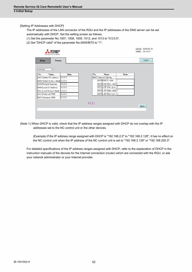
Remote Service iQ Care Remote4U User’s Manual
3 Initial Setup
52IB-1501552-H
[Setting IP Addresses with DHCP]
The IP addresses of the LAN connector of the RGU and the IP addresses of the DNS server can be set
automatically with DHCP. Set the setting screen as follows.
(1) Set the parameter No.1007, 1008, 1009, 1012, and 1013 to "0.0.0.0".
(2) Set "DHCP valid" of the parameter No.0005/BIT0 to "1".
(Note 1) When DHCP is valid, check that the IP address ranges assigned with DHCP do not overlap with the IP
addresses set to the NC control unit or the other devices.
(Example) If the IP address range assigned with DHCP is "192.168.2.0" to "192.168.2.128", it has no effect on
the NC control unit when the IP address of the NC control unit is set to "192.168.2.129" or "192.168.200.3".
For detailed specifications of the IP address ranges assigned with DHCP, refer to the explanation of DHCP in the
instruction manuals of the devices for the Internet connection (router) which are connected with the RGU, or ask
your network administrator or your Internet provider.

Remote Service iQ Care Remote4U User’s Manual
3 Initial Setup
53 IB-1501552-H
3.2.2.4 Parameters for Remote Service Connection of the RGU
(1) Select [Remote Service] from the pull-down menu on the upper left.
(2) Input setting values referring to descriptions in the following table, and press the [Apply] button after all items have
been input.
No. Name Value to be input
1606 Proxy Address If a proxy server is used in your network environment, set its address. To confirm the use of the proxy server, ask your network administrator.
0404 Proxy Port Set the port No. of the proxy server.
1605 Cloud URL Since it has been input as a factory default setting, you need not change it.
1047 NC1 IP Address Set the IP address of the NC to be connected.
1011 NC1 Serial No. Set the serial number of the NC to be connected.
0210 Server Type Setting is not necessary.

Remote Service iQ Care Remote4U User’s Manual
3 Initial Setup
54IB-1501552-H
(3) Select [Common] from the pull-down menu on the upper left to go to page 3.
(4) Input setting values referring to descriptions in the following table, and press the [Apply] button after all items have
been input.
No. Name Value to be input
1607 SNTP Server If an SNTP server is used in your network environment, set its address. If an SNTP server is not used, leave it blank. To confirm the use of the SNTP server, ask your network administrator.
0402 SNTP time lag (h) Set the time difference from UTC to current location (hour)
0403 SNTP time lag (m) Set the time difference from UTC to current location (minute)
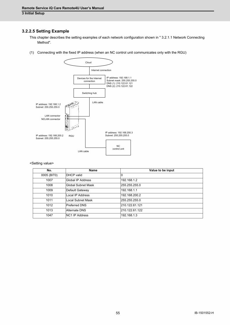
Remote Service iQ Care Remote4U User’s Manual
3 Initial Setup
55 IB-1501552-H
3.2.2.5 Setting Example
This chapter describes the setting examples of each network configuration shown in " 3.2.1.1 Network Connecting
Method".
(1) Connecting with the fixed IP address (when an NC control unit communicates only with the RGU)
<Setting value>
No. Name Value to be input
0005 (BIT0) DHCP valid 0
1007 Global IP Address 192.168.1.2
1008 Global Subnet Mask 255.255.255.0
1009 Default Gateway 192.168.1.1
1010 Local IP Address 192.168.200.2
1011 Local Subnet Mask 255.255.255.0
1012 Preferred DNS 210.122.61.121
1013 Alternate DNS 210.122.61.122
1047 NC1 IP Address 192.168.1.3
Cloud
Devices for the Internet connection
NCcontrol unit
Internet connection
LAN cable
RGU
NCLAN connector
IP address: 192.168.1.1Subnet mask: 255.255.255.0DNS (1): 210.122.61.121DNS (2): 210.122.61.122
IP address: 192.168.200.3Subnet: 255.255.255.0IP address: 192.168.200.2
Subnet: 255.255.255.0
IP address: 192.168.1.2Subnet: 255.255.255.0
LAN connector
Switching hub
LAN cable

Remote Service iQ Care Remote4U User’s Manual
3 Initial Setup
56IB-1501552-H
(2) Connecting with the fixed IP address (when an NC control unit also communicates with other devices in addition to
the RGU)
<Setting value>
(Note 1) NCLAN port is not used. Set the IP address of No.1010 to "0.0.0.0” or "192.168.200.2". Set the IP address of
No.1007 outside the range of "192.168.200.1" to "192.168.200.255".
No. Name Value to be input
0005 (BIT0) DHCP valid 0
1007 Global IP Address 192.168.1.2
1008 Global Subnet Mask 255.255.255.0
1009 Default Gateway 192.168.1.1
1010 Local IP Address 192.168.200.2
1011 Local Subnet Mask 255.255.255.0
1012 Preferred DNS 210.122.61.121
1013 Alternate DNS 210.122.61.122
1047 NC1 IP Address 192.168.200.3
Cloud
Devices for the Internet connection
NCcontrol unit
Internet connection
LAN cable
RGU
NCLAN connector
IP address: 192.168.1.1Subnet: 255.255.255.0DNS (1): 210.122.61.121DNS (2): 210.122.61.122
IP address: 192.168.1.101Subnet: 255.255.255.0
IP address: 192.168.200.2Subnet: 255.255.255.0
IP address: 192.168.1.2Subnet: 255.255.255.0
LAN connector
Switching hub
LAN cable
Personal computer
IP address: 192.168.1.102Subnet: 255.255.255.0
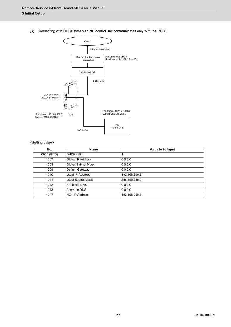
Remote Service iQ Care Remote4U User’s Manual
3 Initial Setup
57 IB-1501552-H
(3) Connecting with DHCP (when an NC control unit communicates only with the RGU)
<Setting value>
No. Name Value to be input
0005 (BIT0) DHCP valid 1
1007 Global IP Address 0.0.0.0
1008 Global Subnet Mask 0.0.0.0
1009 Default Gateway 0.0.0.0
1010 Local IP Address 192.168.200.2
1011 Local Subnet Mask 255.255.255.0
1012 Preferred DNS 0.0.0.0
1013 Alternate DNS 0.0.0.0
1047 NC1 IP Address 192.168.200.3
Cloud
Devices for the Internet connection
NCcontrol unit
Internet connection
LAN cable
RGU
NCLAN connector
Assigned with DHCPIP address: 192.168.1.2 to 254
IP address: 192.168.200.3Subnet: 255.255.255.0IP address: 192.168.200.2
Subnet: 255.255.255.0
LAN connector
Switching hub
LAN cable

Remote Service iQ Care Remote4U User’s Manual
3 Initial Setup
58IB-1501552-H
(4) Connecting with DHCP (when an NC control unit also communicates with other devices in addition to the RGU)
<Setting value>
(Note 1) NCLAN port is not used. Set the IP address of No.1010 to "0.0.0.0” or "192.168.200.2". Also, adjust the DHCP
setting of the devices for the Internet connection so that IP addresses outside the range of "192.168.200.1" to
"192.168.200.255" are assigned.
No. Name Value to be input
0005 (BIT0) DHCP valid 1
1007 Global IP Address 0.0.0.0
1008 Global Subnet Mask 0.0.0.0
1009 Default Gateway 0.0.0.0
1010 Local IP Address 192.168.200.2
1011 Local Subnet Mask 255.255.255.0
1012 Preferred DNS 0.0.0.0
1013 Alternate DNS 0.0.0.0
1047 NC1 IP Address 192.168.200.3
Cloud
Devices for the Internet connection
NCcontrol unit
Internet connection
LAN cable
RGU
NCLAN connector
Assigned with DHCPIP address: 192.168.1.2 to 128
IP address: 192.168.1.129Subnet: 255.255.255.0
IP address: 192.168.200.2Subnet: 255.255.255.0
LAN connector
Switching hub
LAN cable
Personal computer
Assigned with DHCP
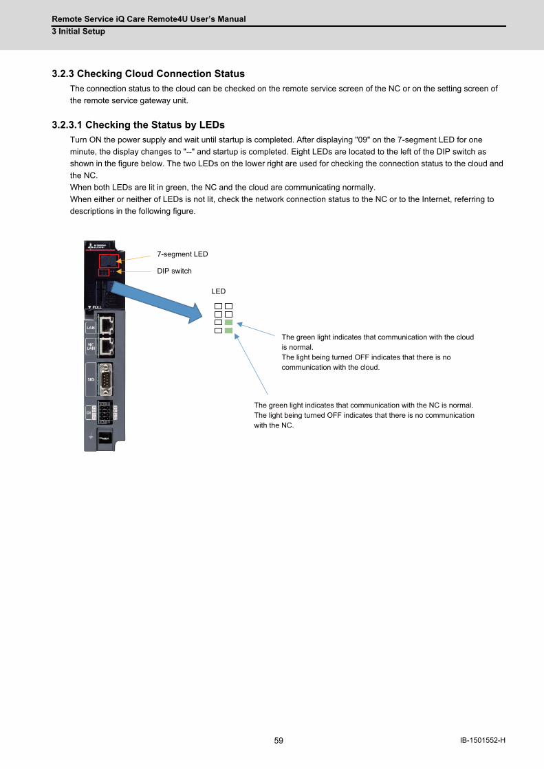
Remote Service iQ Care Remote4U User’s Manual
3 Initial Setup
59 IB-1501552-H
3.2.3 Checking Cloud Connection Status
The connection status to the cloud can be checked on the remote service screen of the NC or on the setting screen of
the remote service gateway unit.
3.2.3.1 Checking the Status by LEDs
Turn ON the power supply and wait until startup is completed. After displaying "09" on the 7-segment LED for one
minute, the display changes to "--" and startup is completed. Eight LEDs are located to the left of the DIP switch as
shown in the figure below. The two LEDs on the lower right are used for checking the connection status to the cloud and
the NC.
When both LEDs are lit in green, the NC and the cloud are communicating normally.
When either or neither of LEDs is not lit, check the network connection status to the NC or to the Internet, referring to
descriptions in the following figure.
DIP switch
LED
The green light indicates that communication with the cloud is normal.The light being turned OFF indicates that there is no communication with the cloud.
The green light indicates that communication with the NC is normal.The light being turned OFF indicates that there is no communication with the NC.
7-segment LED
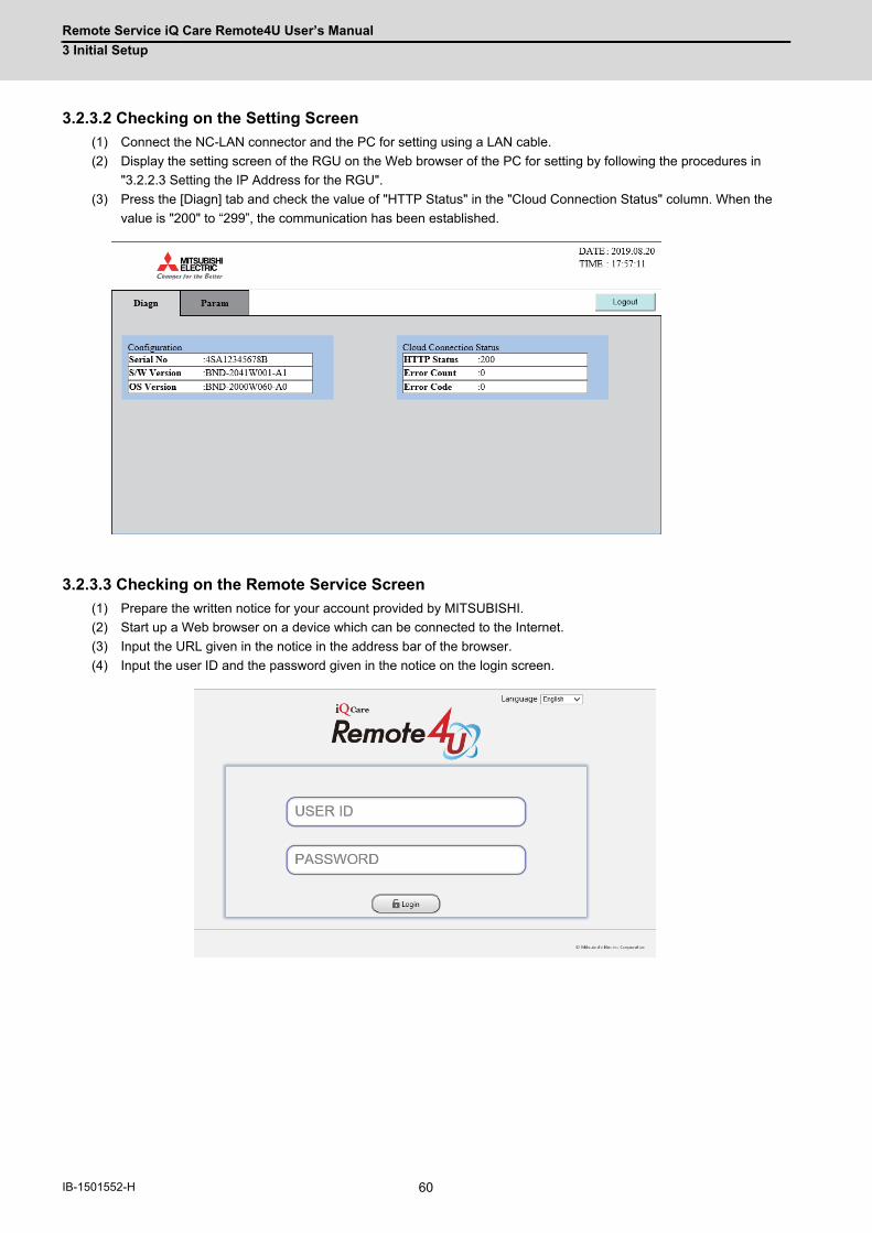
Remote Service iQ Care Remote4U User’s Manual
3 Initial Setup
60IB-1501552-H
3.2.3.2 Checking on the Setting Screen
(1) Connect the NC-LAN connector and the PC for setting using a LAN cable.
(2) Display the setting screen of the RGU on the Web browser of the PC for setting by following the procedures in
"3.2.2.3 Setting the IP Address for the RGU".
(3) Press the [Diagn] tab and check the value of "HTTP Status" in the "Cloud Connection Status" column. When the
value is "200" to “299”, the communication has been established.
3.2.3.3 Checking on the Remote Service Screen
(1) Prepare the written notice for your account provided by MITSUBISHI.
(2) Start up a Web browser on a device which can be connected to the Internet.
(3) Input the URL given in the notice in the address bar of the browser.
(4) Input the user ID and the password given in the notice on the login screen.
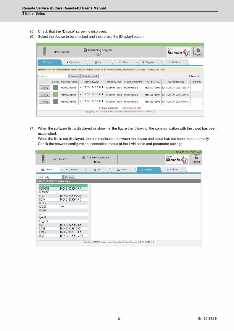
Remote Service iQ Care Remote4U User’s Manual
3 Initial Setup
61 IB-1501552-H
(5) Check that the "Device" screen is displayed.
(6) Select the device to be checked and then press the [Display] button.
(7) When the software list is displayed as shown in the figure the following, the communication with the cloud has been
established.
When the list is not displayed, the communication between the device and cloud has not been made normally.
Check the network configuration, connection status of the LAN cable and parameter settings.

Remote Service iQ Care Remote4U User’s Manual
3 Initial Setup
62IB-1501552-H
3.3 When Using NC Direct Connection3.3.1 NC Connection
To communicate with a cloud server, connect the device for Internet connection and the NC control unit using LAN
cables. Refer to "M800VW/M80VW Series Connection and Setup Manual (IB-1501612)" and "M800VS/M80V Series
Connection and Setup Manual (IB-1501613)" for details of the connection method.
When connecting the NC to the Internet, take security into consideration when configuring devices for Internet
connection. Refer to the manuals of each device for details.
The NC control unit may not be able to connect to the cloud due to the settings of the IP address filter of the NC control
unit. When connecting via a proxy server, exclude the proxy server address. When a proxy server is not used, using the
IP address filter disables the connection to the cloud.
The following are the connection examples for M800VS.
3.3.1.1 Network Connecting Method
Prepare a commercially available switching hub and connect the switching hub, device for Internet connection, and the
NC control unit using LAN cables.
(1) When an NC control unit communicates only with the RGU
Use the LAN connector of the RGU for connecting the RGU to the devices for the Internet connection with LAN
cables. Use the NCLAN connector of the RGU for connecting the RGU to the NC control unit with a LAN cable.
Cloud
Devices for the Internet connection
NC control unit
Internet connection
LAN cable
Switching hub
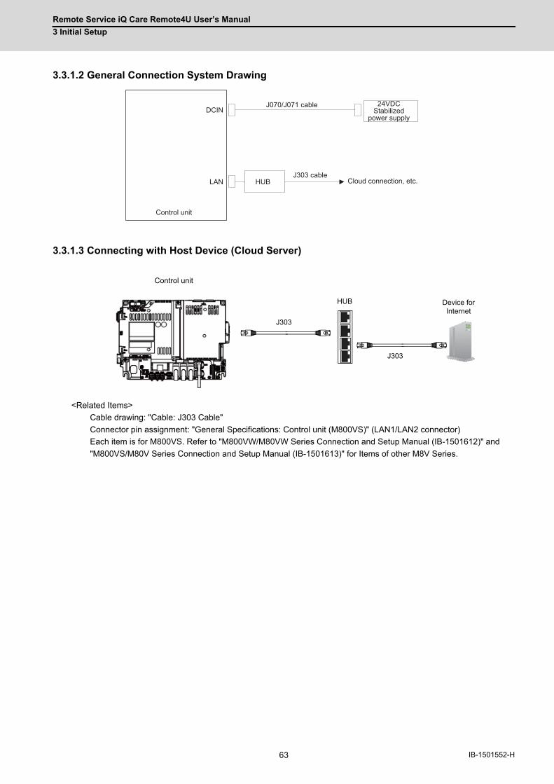
Remote Service iQ Care Remote4U User’s Manual
3 Initial Setup
63 IB-1501552-H
3.3.1.2 General Connection System Drawing
3.3.1.3 Connecting with Host Device (Cloud Server)
<Related Items>
Cable drawing: "Cable: J303 Cable"
Connector pin assignment: "General Specifications: Control unit (M800VS)" (LAN1/LAN2 connector)
Each item is for M800VS. Refer to "M800VW/M80VW Series Connection and Setup Manual (IB-1501612)" and
"M800VS/M80V Series Connection and Setup Manual (IB-1501613)" for Items of other M8V Series.
LAN
DCIN
HUB
Control unit
24VDCStabilized
power supply
J070/J071 cable
J303 cableCloud connection, etc.
J303
J303
HUB
Control unit
Device for Internet
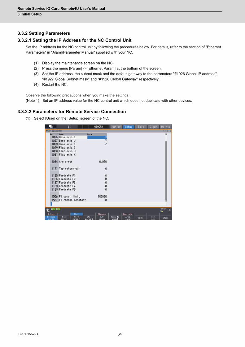
Remote Service iQ Care Remote4U User’s Manual
3 Initial Setup
64IB-1501552-H
3.3.2 Setting Parameters
3.3.2.1 Setting the IP Address for the NC Control Unit
Set the IP address for the NC control unit by following the procedures below. For details, refer to the section of "Ethernet
Parameters" in "Alarm/Parameter Manual" supplied with your NC.
(1) Display the maintenance screen on the NC.
(2) Press the menu [Param] -> [Ethernet Param] at the bottom of the screen.
(3) Set the IP address, the subnet mask and the default gateway to the parameters "#1926 Global IP address",
"#1927 Global Subnet mask" and "#1928 Global Gateway" respectively.
(4) Restart the NC.
Observe the following precautions when you make the settings.
(Note 1) Set an IP address value for the NC control unit which does not duplicate with other devices.
3.3.2.2 Parameters for Remote Service Connection
(1) Select [User] on the [Setup] screen of the NC.
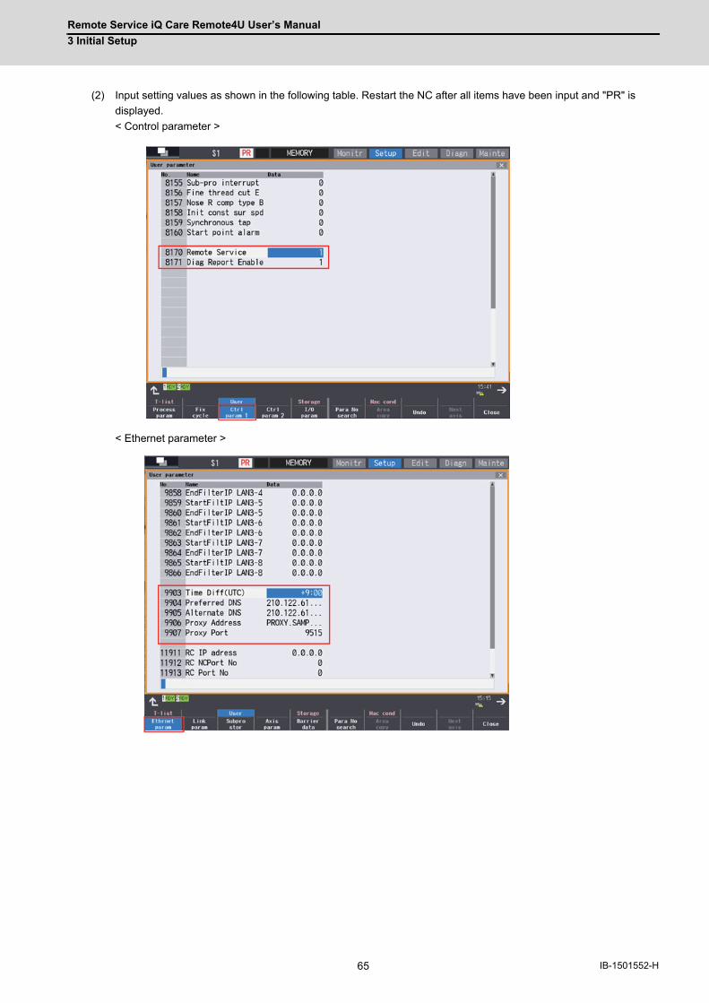
Remote Service iQ Care Remote4U User’s Manual
3 Initial Setup
65 IB-1501552-H
(2) Input setting values as shown in the following table. Restart the NC after all items have been input and "PR" is
displayed.
< Control parameter >
< Ethernet parameter >

Remote Service iQ Care Remote4U User’s Manual
3 Initial Setup
66IB-1501552-H
#8170 and #8171 can also be set by opening the "Mainte" screen and selecting "Parameter" - > "Ctrl param 1" at
the bottom of the screen.
No. Data types Name Value to be input
8170 Control parameter 1 Remote Service Set the remote service function to valid or invalid. 0: invalid, 1: valid
8171 Control parameter 1 Diag Report Enable Set the diagnosis report of the remote service function to valid or invalid. 0: invalid, 1: valid
9903 Ethernet parameter Time Diff (UTC) Set the time difference from UTC to the location of the NC.
9904 Ethernet parameter Preferred DNS Set the IP address of the primary DNS server.* To confirm the IP address of the primary DNS server, ask your network administrator or your Internet provider.
9905 Ethernet parameter Alternate DNS - Set the IP address of the secondary DNS server.- If there is only single IP address for the DNS server, set the one for the primary DNS server.
9906 Ethernet parameter Proxy Address If a proxy server is used in your network environment, set its address. To confirm the use of the proxy server, ask your network administrator.
9907 Ethernet parameter Proxy Port Set the port No. of the proxy server.
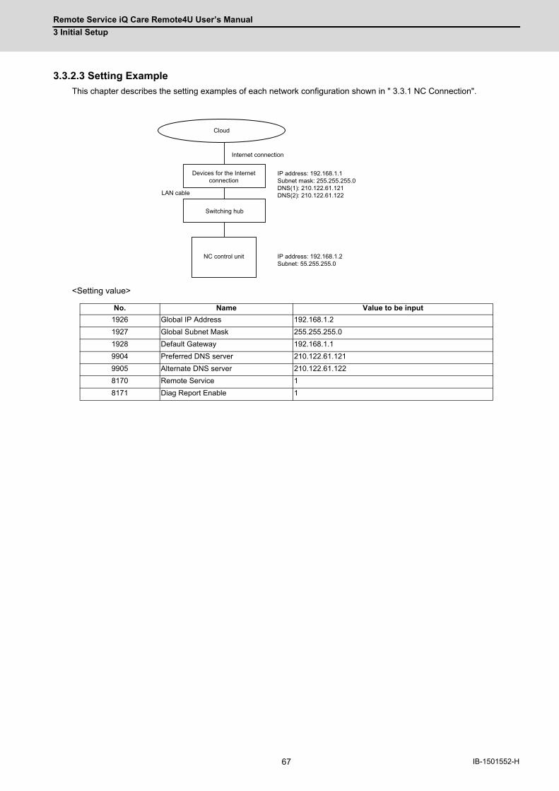
Remote Service iQ Care Remote4U User’s Manual
3 Initial Setup
67 IB-1501552-H
3.3.2.3 Setting Example
This chapter describes the setting examples of each network configuration shown in " 3.3.1 NC Connection".
<Setting value>
No. Name Value to be input
1926 Global IP Address 192.168.1.2
1927 Global Subnet Mask 255.255.255.0
1928 Default Gateway 192.168.1.1
9904 Preferred DNS server 210.122.61.121
9905 Alternate DNS server 210.122.61.122
8170 Remote Service 1
8171 Diag Report Enable 1
Cloud
Devices for the Internet connection
NC control unit
Internet connection
LAN cable
IP address: 192.168.1.1Subnet mask: 255.255.255.0DNS(1): 210.122.61.121DNS(2): 210.122.61.122
Switching hub
IP address: 192.168.1.2Subnet: 55.255.255.0
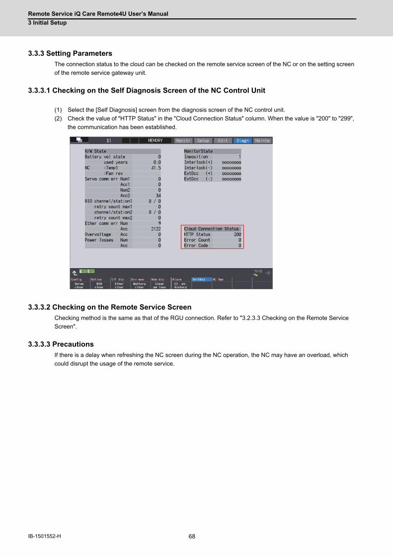
Remote Service iQ Care Remote4U User’s Manual
3 Initial Setup
68IB-1501552-H
3.3.3 Setting Parameters
The connection status to the cloud can be checked on the remote service screen of the NC or on the setting screen
of the remote service gateway unit.
3.3.3.1 Checking on the Self Diagnosis Screen of the NC Control Unit
(1) Select the [Self Diagnosis] screen from the diagnosis screen of the NC control unit.
(2) Check the value of "HTTP Status" in the "Cloud Connection Status" column. When the value is "200" to "299",
the communication has been established.
3.3.3.2 Checking on the Remote Service Screen
Checking method is the same as that of the RGU connection. Refer to "3.2.3.3 Checking on the Remote Service
Screen".
3.3.3.3 Precautions
If there is a delay when refreshing the NC screen during the NC operation, the NC may have an overload, which
could disrupt the usage of the remote service.

Remote Service iQ Care Remote4U User’s Manual
3 Initial Setup
69 IB-1501552-H
3.4 Applicable ModelsThe following shows the connection method for each NC. ○ shows "Available” and × shows "Unavailable". The
alphanumeric characters indicate that the version or later are compatible. Remote service is not available in earlier
versions.
M8V Series
M800VW M80VW M800VS M80V
M850VW M830VW - M850VS M830VS Type A Type B
RGU connection × × × × × × ×
NC direct connection A2 A2 A2 A2 A2 A2 A2
M8 Series
M800W M80W M800S M80 E80
M850W M830W - M850S M830S Type A Type B Type LA Type A Type B
RGU connection 〇 〇 〇 〇 〇 〇 〇 〇 〇 〇
NC direct connection × × × × × × × × × ×
C80 Series
C80
-
RGU connection 〇
NC direct connection ×
M7V Series
M700VW M700VS M70V
M750VW M730VW M720VW M750VS M730VS M720VS Type A Type B
RGU connection 〇 〇 〇 〇 〇 〇 〇 〇
NC direct connection × × × × × × × ×
M7 Series
M700 M700 E70
M750 M730 M720 Type A Type B -
RGU connection 〇 〇 〇 〇 〇 〇
NC direct connection × × × × × ×

Remote Service iQ Care Remote4U User’s Manual
3 Initial Setup
70IB-1501552-H

71 IB-1501552-H
4
NC Remote Service
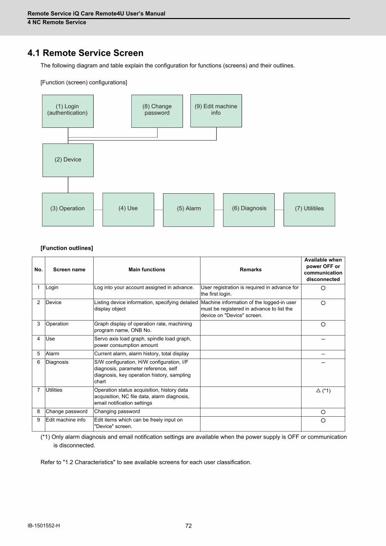
Remote Service iQ Care Remote4U User’s Manual
4 NC Remote Service
72IB-1501552-H
4.1 Remote Service ScreenThe following diagram and table explain the configuration for functions (screens) and their outlines.
[Function (screen) configurations]
[Function outlines]
(*1) Only alarm diagnosis and email notification settings are available when the power supply is OFF or communication
is disconnected.
Refer to "1.2 Characteristics" to see available screens for each user classification.
No. Screen name Main functions Remarks
Available when power OFF or
communication disconnected
1 Login Log into your account assigned in advance. User registration is required in advance for the first login.
○
2 Device Listing device information, specifying detailed display object
Machine information of the logged-in user must be registered in advance to list the device on "Device" screen.
○
3 Operation Graph display of operation rate, machining program name, ONB No.
○
4 Use Servo axis load graph, spindle load graph, power consumption amount
-
5 Alarm Current alarm, alarm history, total display -
6 Diagnosis S/W configuration, H/W configuration, I/F diagnosis, parameter reference, self diagnosis, key operation history, sampling chart
-
7 Utilities Operation status acquisition, history data acquisition, NC file data, alarm diagnosis, email notification settings
△ (*1)
8 Change password Changing password ○
9 Edit machine info Edit items which can be freely input on "Device" screen.
○
(1) Login (authentication)
(8) Change password
(9) Edit machine info
(2) Device
(3) Operation (4) Use (5) Alarm (6) Diagnosis (7) Utilitiles
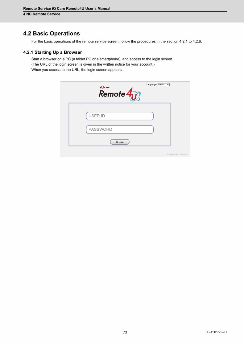
Remote Service iQ Care Remote4U User’s Manual
4 NC Remote Service
73 IB-1501552-H
4.2 Basic OperationsFor the basic operations of the remote service screen, follow the procedures in the section 4.2.1 to 4.2.6.
4.2.1 Starting Up a Browser
Start a browser on a PC (a tablet PC or a smartphone), and access to the login screen.
(The URL of the login screen is given in the written notice for your account.)
When you access to the URL, the login screen appears.
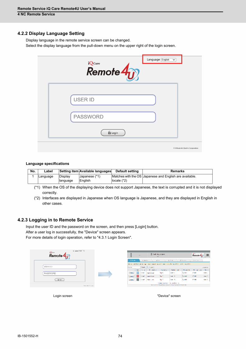
Remote Service iQ Care Remote4U User’s Manual
4 NC Remote Service
74IB-1501552-H
4.2.2 Display Language Setting
Display language in the remote service screen can be changed.
Select the display language from the pull-down menu on the upper right of the login screen.
Language specifications
(*1) When the OS of the displaying device does not support Japanese, the text is corrupted and it is not displayed
correctly.
(*2) Interfaces are displayed in Japanese when OS language is Japanese, and they are displayed in English in
other cases.
4.2.3 Logging in to Remote Service
Input the user ID and the password on the screen, and then press [Login] button.
After a user log in successfully, the "Device" screen appears.
For more details of login operation, refer to "4.3.1 Login Screen".
No. Label Setting item Available languages Default setting Remarks
1 Language Display language
Japanese (*1) English
Matches with the OS locale (*2)
Japanese and English are available.
Login screen "Device" screen

Remote Service iQ Care Remote4U User’s Manual
4 NC Remote Service
75 IB-1501552-H
4.2.4 Device Selection
Press the [Display] button for a device to be checked the operation status while the "Device" screen is displayed. This
changes the screen to the "Operation" screen.
"Operation" screen
"Device" screen
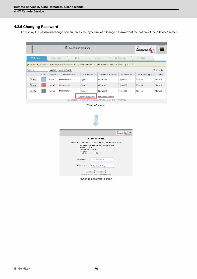
Remote Service iQ Care Remote4U User’s Manual
4 NC Remote Service
76IB-1501552-H
4.2.5 Changing Password
To display the password change screen, press the hyperlink of "Change password" at the bottom of the "Device" screen.
"Change password" screen
"Device" screen

Remote Service iQ Care Remote4U User’s Manual
4 NC Remote Service
77 IB-1501552-H
4.2.6 Changing Screens
Change the screen by pressing each tab menu.
When the browser is started (initial status), the "Device" screen is displayed, and the tabs other than [Device] are
disabled (unselectable).
After the screen changes to "Operation" screen by performing the procedures in "4.2.4 Device Selection", all tabs are
enabled (selectable).
Refer to "1.2 Characteristics" to see available tab menus for each user classification.
When you have logged in to the remote service using a smartphone or a tablet PC, tap the [Menu] button at the bottom
right to change the screen. After you log in (initial status), the "Device" screen appears.
After the screen changes to "Operation" screen by performing the procedures in "4.2.4 Device Selection", the [Menu]
button appears at the bottom right of the screen and all tabs are enabled (selectable).
(*) After any of the devices is selected in "Device" screen, the [Menu] button appears at the bottom right of the screen
and you can perform menu operations.
Tab menus
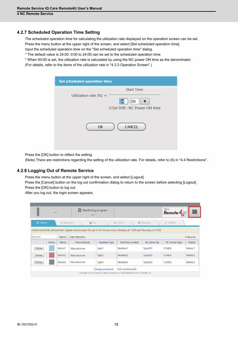
Remote Service iQ Care Remote4U User’s Manual
4 NC Remote Service
78IB-1501552-H
4.2.7 Scheduled Operation Time Setting
The scheduled operation time for calculating the utilization rate displayed on the operation screen can be set.
Press the menu button at the upper right of the screen, and select [Set scheduled operation time].
Input the scheduled operation time on the "Set scheduled operation time" dialog.
* The default value is 24:00. 0:00 to 24:00 can be set to the scheduled operation time.
* When 00:00 is set, the utilization rate is calculated by using the NC power ON time as the denominator.
(For details, refer to the items of the utilization rate in "4.3.3 Operation Screen".)
Press the [OK] button to reflect the setting.
(Note) There are restrictions regarding the setting of the utilization rate. For details, refer to (6) in "4.4 Restrictions".
4.2.8 Logging Out of Remote Service
Press the menu button at the upper right of the screen, and select [Logout].
Press the [Cancel] button on the log out confirmation dialog to return to the screen before selecting [Logout].
Press the [OK] button to log out.
After you log out, the login screen appears.
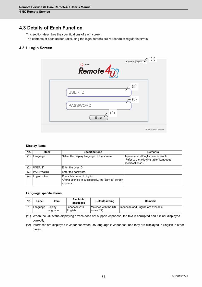
Remote Service iQ Care Remote4U User’s Manual
4 NC Remote Service
79 IB-1501552-H
4.3 Details of Each FunctionThis section describes the specifications of each screen.
The contents of each screen (excluding the login screen) are refreshed at regular intervals.
4.3.1 Login Screen
Display items
Language specifications
(*1) When the OS of the displaying device does not support Japanese, the text is corrupted and it is not displayed
correctly.
(*2) Interfaces are displayed in Japanese when OS language is Japanese, and they are displayed in English in other
cases.
No. Item Specifications Remarks
(1) Language Select the display language of the screen. Japanese and English are available. (Refer to the following table "Language specifications".)
(2) USER ID Enter the user ID.
(3) PASSWORD Enter the password.
(4) Login button Press this button to log in. After a user log in successfully, the "Device" screen appears.
No. Label ItemAvailable
languagesDefault setting Remarks
1 Language Display language
Japanese (*1) English
Matches with the OS locale (*2)
Japanese and English are available.
(1)
(2)
(3)
(4)
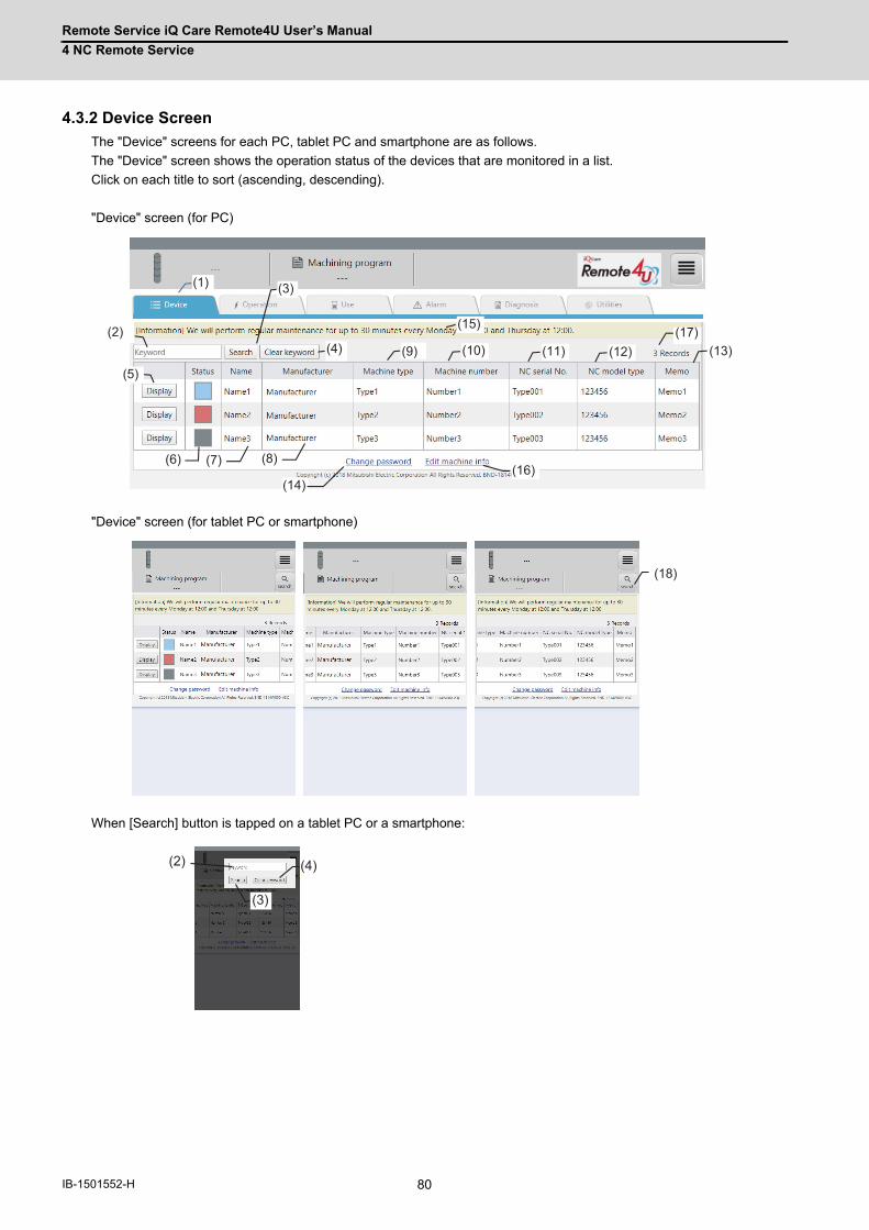
Remote Service iQ Care Remote4U User’s Manual
4 NC Remote Service
80IB-1501552-H
4.3.2 Device Screen
The "Device" screens for each PC, tablet PC and smartphone are as follows.
The "Device" screen shows the operation status of the devices that are monitored in a list.
Click on each title to sort (ascending, descending).
"Device" screen (for PC)
"Device" screen (for tablet PC or smartphone)
When [Search] button is tapped on a tablet PC or a smartphone:
(1)
(2)
(3)
(4)
(5)
(6)
(12)
(14)
(15)
(16)
(11) (13)(10)(9)
(8)(7)
(17)
(18)
(2)
(3)
(4)
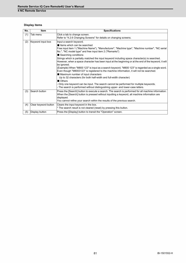
Remote Service iQ Care Remote4U User’s Manual
4 NC Remote Service
81 IB-1501552-H
Display items
No. Item Specifications
(1) Tab menu Click a tab to change screen. Refer to "4.2.6 Changing Screens" for details on changing screens.
(2) Keyword input box Input a search keyword. ■ Items which can be searched Free input item 1 ("Machine Name"), "Manufacturer", "Machine type", "Machine number", "NC serial No.", "NC model type" and free input item 2 ("Remarks") ■ Searching conditions Strings which is partially matched the input keyword including space character(s) is searched. However, when a space character has been input at the beginning or at the end of the keyword, it will be ignored. (Example) When "M800 123" is input as a search keyword, "M800 123" is regarded as a single word. Even though "M8003123" is registered to the machine information, it will not be searched. ■ Maximum number of input characters Up to 32 characters (for both half-width and full-width character) ■ Others - Only one keyword can be input. The search cannot be performed for multiple keywords. - The search is performed without distinguishing upper- and lower-case letters.
(3) Search button Press the [Search] button to execute a search. The search is performed for all machine information. When the [Search] button is pressed without inputting a keyword, all machine information are displayed. You cannot refine your search within the results of the previous search.
(4) Clear keyword button Clears the input keyword in the box. * The search result is not cleared (reset) by pressing this button.
(5) Display button Press the [Display] button to transit the "Operation" screen.
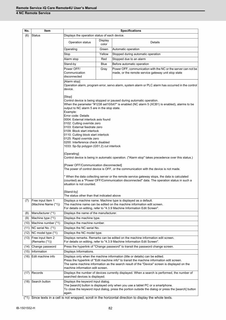
Remote Service iQ Care Remote4U User’s Manual
4 NC Remote Service
82IB-1501552-H
(*1) Since texts in a cell is not wrapped, scroll in the horizontal direction to display the whole texts.
(6) Status Displays the operation status of each device.
Operation statusDisplay color
Details
Operating Green Automatic operation
Stop Yellow Stopped during automatic operation
Alarm stop Red Stopped due to an alarm
Stand-by Blue Before automatic operation
Power OFF/Communication disconnected
Gray Power OFF, communication with the NC or the server can not be made, or the remote service gateway unit stop state
[Alarm stop] Operation alarm, program error, servo alarm, system alarm or PLC alarm has occurred in the control device. [Stop] Control device is being stopped or paused during automatic operation. When the parameter "#1238 set10/bit7" is enabled (NC alarm 5 (XCB1) is enabled), alarms to be output to NC alarm 5 are in the stop state. Example: Error code: Details 0004: External interlock axis found 0102: Cutting override zero 0103: External feedrate zero 0109: Block start interlock 0110: Cutting block start interlock 0125: Rapid override zero 0200: Interference check disabled 1033: Sp-Sp polygon (G51.2) cut interlock [Operating] Control device is being in automatic operation. ("Alarm stop" takes precedence over this status.) [Power OFF/Communication disconnected] The power of control device is OFF, or the communication with the device is not made. * When the data collecting server or the remote service gateway stops, the data is calculated (counted) as a "Power OFF/Communication disconnected" data. The operation status in such a situation is not counted. [Stand-by] The status other than that indicated above
(7) Free input Item 1 (Machine Name (*1))
Displays a machine name. Machine type is displayed as a default. The machine name can be edited on the machine information edit screen. For details on editing, refer to "4.3.9 Machine Information Edit Screen".
(8) Manufacturer (*1) Displays the name of the manufacturer.
(9) Machine type (*1) Displays the machine type.
(10) Machine number (*1) Displays the machine number.
(11) NC serial No. (*1) Displays the NC serial No.
(12) NC model type (*1) Displays the NC model type.
(13) Free input Item 2 (Remarks (*1))
Displays remarks. Remarks can be edited on the machine information edit screen. For details on editing, refer to "4.3.9 Machine Information Edit Screen".
(14) Change password Press the hyperlink of "Change password" to transit the password change screen.
(15) Information Displays Informations.
(16) Edit machine info Displays only when the machine information (title or details) can be edited. Press the hyperlink of "Edit machine info" to transit the machine information edit screen. The same machine information as the search result of the "Device" screen is displayed on the machine information edit screen.
(17) Records Displays the number of devices currently displayed. When a search is performed, the number of searched devices is displayed.
(18) Search button Displays the keyword input dialog. The [search] button is displayed only when you use a tablet PC or a smartphone. To close the keyword input dialog, press the portion outside the dialog or press the [search] button again.
No. Item Specifications
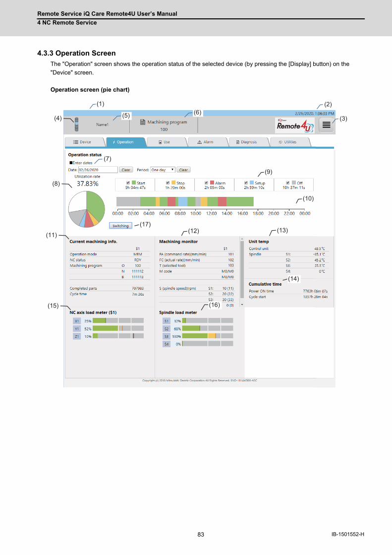
Remote Service iQ Care Remote4U User’s Manual
4 NC Remote Service
83 IB-1501552-H
4.3.3 Operation Screen
The "Operation" screen shows the operation status of the selected device (by pressing the [Display] button) on the
"Device" screen.
Operation screen (pie chart)
(1) (2)
(12)
(14)
(10)
(13)
(9)
(16)
(3)(4) (5) (6)
(7)
(8)
(11)
(15)
(17)
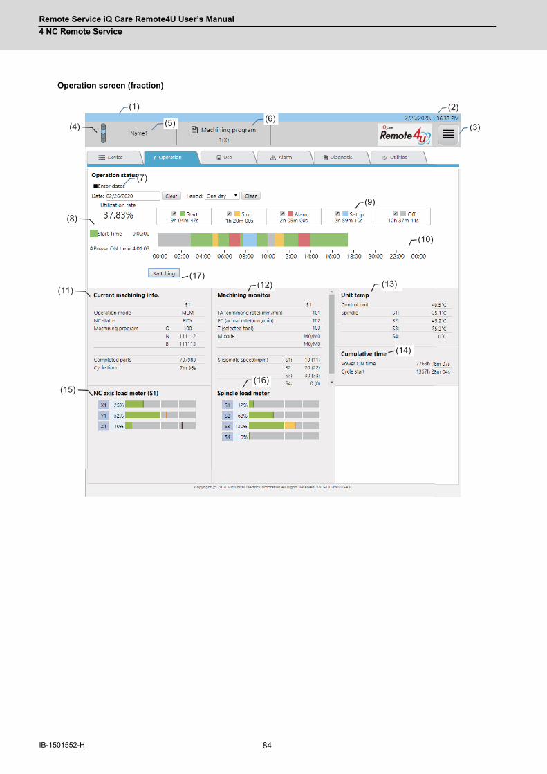
Remote Service iQ Care Remote4U User’s Manual
4 NC Remote Service
84IB-1501552-H
Operation screen (fraction)
(1) (2)
(12)
(14)
(10)
(13)
(9)
(16)
(3)(4) (5) (6)
(7)
(8)
(11)
(15)
(17)
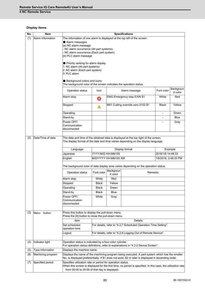
Remote Service iQ Care Remote4U User’s Manual
4 NC Remote Service
85 IB-1501552-H
Display items
No. Item Specifications
(1) Alarm information The information of one alarm is displayed at the top left of the screen. ■ Alarm messages (a) NC alarm message - NC alarm occurrence (All part systems) - NC alarm occurrence (Each part system) (b) PLC alarm message ■ Priority ranking for alarm display 1: NC alarm (All part systems) 2: NC alarm (Each part system) 3: PLC alarm ■ Background colors and icons The background color of the screen indicates the operation status.
Operation status Icon Alarm message Font colorBackgroun
d color
Alarm stop EMG Emergency stop EXIN $1 White Red
Stopped M01 Cutting override zero 0102 $1 Black Yellow
Operating - Green
Stand-by - Blue
Power OFF/Communication disconnected
- Gray
(2) Date/Time of data The date and time of the obtained data is displayed at the top right of the screen. The display format of the date and time varies depending on the display language.
Language Display format Example
Japanese YYYY/M/D HH:MM:SS 2018/1/6 14:48:33
English M/D/YYYY HH:MM:SS XM 1/6/2018, 2:48:33 PM
The background color of data display area varies depending on the operation status.
Operation status Font colorBackgroun
d colorRemarks
Alarm stop White Red
Stopped Black Yellow
Operating Black Green
Stand-by Black Blue
Power OFF/Communication disconnected
White Gray
(3) Menu button Press this button to display the pull-down menu. Press the [X] button to close the pull-down menu.
Item Details
Set scheduled operation time
For details, refer to "4.2.7 Scheduled Operation Time Setting".
Logout For details, refer to "4.2.8 Logging Out of Remote Service".
(4) Indicator light Operation status is indicated by a four-color cylinder. For operation status definitions, refer to explanations in "4.3.2 Device Screen".
(5) Type information Displays the machine name.
(6) Machining program Displays the name of the machining program being executed. A part system which has the smaller No. is displayed preferentially. If $1 does not exist, $2 or later is displayed in ascending order.
(7) Specified period Specifies utilization rate or period for operation status. When this screen is displayed for the first time, no period is specified. In this case, the utilization rate from 00:00 to 24:00 of that day is displayed.
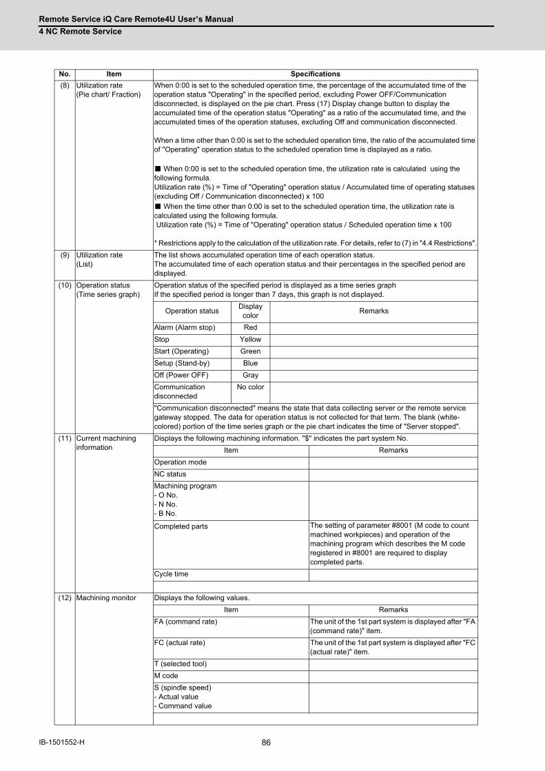
Remote Service iQ Care Remote4U User’s Manual
4 NC Remote Service
86IB-1501552-H
(8) Utilization rate (Pie chart/ Fraction)
When 0:00 is set to the scheduled operation time, the percentage of the accumulated time of the operation status "Operating" in the specified period, excluding Power OFF/Communication disconnected, is displayed on the pie chart. Press (17) Display change button to display the accumulated time of the operation status "Operating" as a ratio of the accumulated time, and the accumulated times of the operation statuses, excluding Off and communication disconnected. When a time other than 0:00 is set to the scheduled operation time, the ratio of the accumulated time of "Operating" operation status to the scheduled operation time is displayed as a ratio. ■ When 0:00 is set to the scheduled operation time, the utilization rate is calculated using the following formula. Utilization rate (%) = Time of "Operating" operation status / Accumulated time of operating statuses (excluding Off / Communication disconnected) x 100 ■ When the time other than 0:00 is set to the scheduled operation time, the utilization rate is calculated using the following formula. Utilization rate (%) = Time of "Operating" operation status / Scheduled operation time x 100 * Restrictions apply to the calculation of the utilization rate. For details, refer to (7) in "4.4 Restrictions".
(9) Utilization rate (List)
The list shows accumulated operation time of each operation status. The accumulated time of each operation status and their percentages in the specified period are displayed.
(10) Operation status (Time series graph)
Operation status of the specified period is displayed as a time series graph If the specified period is longer than 7 days, this graph is not displayed.
Operation statusDisplay color
Remarks
Alarm (Alarm stop) Red
Stop Yellow
Start (Operating) Green
Setup (Stand-by) Blue
Off (Power OFF) Gray
Communication disconnected
No color
"Communication disconnected" means the state that data collecting server or the remote service gateway stopped. The data for operation status is not collected for that term. The blank (white-colored) portion of the time series graph or the pie chart indicates the time of "Server stopped".
(11) Current machining information
Displays the following machining information. "$" indicates the part system No.
Item Remarks
Operation mode
NC status
Machining program - O No. - N No. - B No.
Completed parts The setting of parameter #8001 (M code to count machined workpieces) and operation of the machining program which describes the M code registered in #8001 are required to display completed parts.
Cycle time
(12) Machining monitor Displays the following values.
Item Remarks
FA (command rate) The unit of the 1st part system is displayed after "FA (command rate)" item.
FC (actual rate) The unit of the 1st part system is displayed after "FC (actual rate)" item.
T (selected tool)
M code
S (spindle speed) - Actual value - Command value
No. Item Specifications
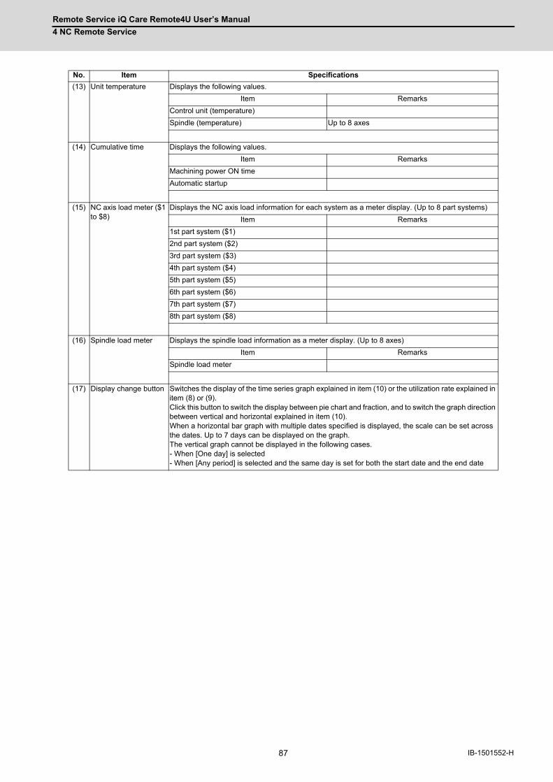
Remote Service iQ Care Remote4U User’s Manual
4 NC Remote Service
87 IB-1501552-H
(13) Unit temperature Displays the following values.
Item Remarks
Control unit (temperature)
Spindle (temperature) Up to 8 axes
(14) Cumulative time Displays the following values.
Item Remarks
Machining power ON time
Automatic startup
(15) NC axis load meter ($1 to $8)
Displays the NC axis load information for each system as a meter display. (Up to 8 part systems)
Item Remarks
1st part system ($1)
2nd part system ($2)
3rd part system ($3)
4th part system ($4)
5th part system ($5)
6th part system ($6)
7th part system ($7)
8th part system ($8)
(16) Spindle load meter Displays the spindle load information as a meter display. (Up to 8 axes)
Item Remarks
Spindle load meter
(17) Display change button Switches the display of the time series graph explained in item (10) or the utilization rate explained in item (8) or (9). Click this button to switch the display between pie chart and fraction, and to switch the graph direction between vertical and horizontal explained in item (10). When a horizontal bar graph with multiple dates specified is displayed, the scale can be set across the dates. Up to 7 days can be displayed on the graph. The vertical graph cannot be displayed in the following cases. - When [One day] is selected - When [Any period] is selected and the same day is set for both the start date and the end date
No. Item Specifications

Remote Service iQ Care Remote4U User’s Manual
4 NC Remote Service
88IB-1501552-H
4.3.4 Use Screen
The "Use" screen shows the consumption information of the selected device (by pressing the [Display] button) on the
"Device" screen.
Display items
No. Item Specifications
(1) NC axis load graph ($1) to ($8) (*1)
Displays the NC axis load information as a graph. ■ Graph display details (a) Horizontal axis: Time (time series) (b) Vertical axis: NC axis load value (%) (c) Display items: The latest 1000 items (plotted) ■ Display items
Item Remarks
1st part system ($1) to 8th part system ($8)
(2) Spindle load graph (*1)
Displays the spindle load information as a graph. ■ Graph display details (a) Horizontal axis: Time (time series) (b) Vertical axis: Spindle load value (%) (c) Display items: The latest 1000 items (plotted) ■ Display items
Item Remarks
Spindle: 1 to 8
(1) (2)
(4)
(3)
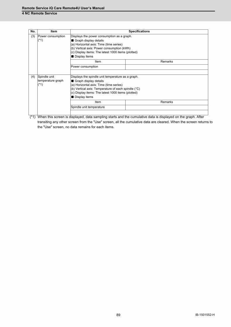
Remote Service iQ Care Remote4U User’s Manual
4 NC Remote Service
89 IB-1501552-H
(*1) When this screen is displayed, data sampling starts and the cumulative data is displayed on the graph. After
transiting any other screen from the "Use" screen, all the cumulative data are cleared. When the screen returns to
the "Use" screen, no data remains for each items.
(3) Power consumption (*1)
Displays the power consumption as a graph. ■ Graph display details (a) Horizontal axis: Time (time series) (b) Vertical axis: Power consumption (kWh) (c) Display items: The latest 1000 items (plotted) ■ Display items
Item Remarks
Power consumption
(4) Spindle unit temperature graph (*1)
Displays the spindle unit temperature as a graph. ■ Graph display details (a) Horizontal axis: Time (time series) (b) Vertical axis: Temperature of each spindle (°C) (c) Display items: The latest 1000 items (plotted) ■ Display items
Item Remarks
Spindle unit temperature
No. Item Specifications
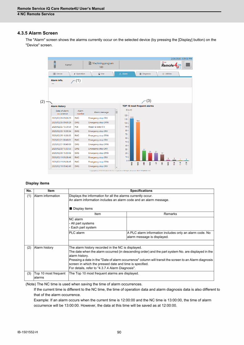
Remote Service iQ Care Remote4U User’s Manual
4 NC Remote Service
90IB-1501552-H
4.3.5 Alarm Screen
The "Alarm" screen shows the alarms currently occur on the selected device (by pressing the [Display] button) on the
"Device" screen.
Display items
(Note) The NC time is used when saving the time of alarm occurrences.
If the current time is different to the NC time, the time of operation data and alarm diagnosis data is also different to
that of the alarm occurrence.
Example: If an alarm occurs when the current time is 12:00:00 and the NC time is 13:00:00, the time of alarm
occurrence will be 13:00:00. However, the data at this time will be saved as at 12:00:00.
No. Item Specifications
(1) Alarm information Displays the information for all the alarms currently occur. An alarm information includes an alarm code and an alarm message. ■ Display items
Item Remarks
NC alarm - All part systems - Each part system
PLC alarm A PLC alarm information includes only an alarm code. No alarm message is displayed.
(2) Alarm history The alarm history recorded in the NC is displayed. The date when the alarm occurred (in descending order) and the part system No. are displayed in the alarm history.Pressing a date in the "Date of alarm occurrence" column will transit the screen to an Alarm diagnosis screen in which the pressed date and time is specified.For details, refer to "4.3.7.4 Alarm Diagnosis".
(3) Top 10 most frequent alarms
The Top 10 most frequent alarms are displayed.
(1)
(3)(2)
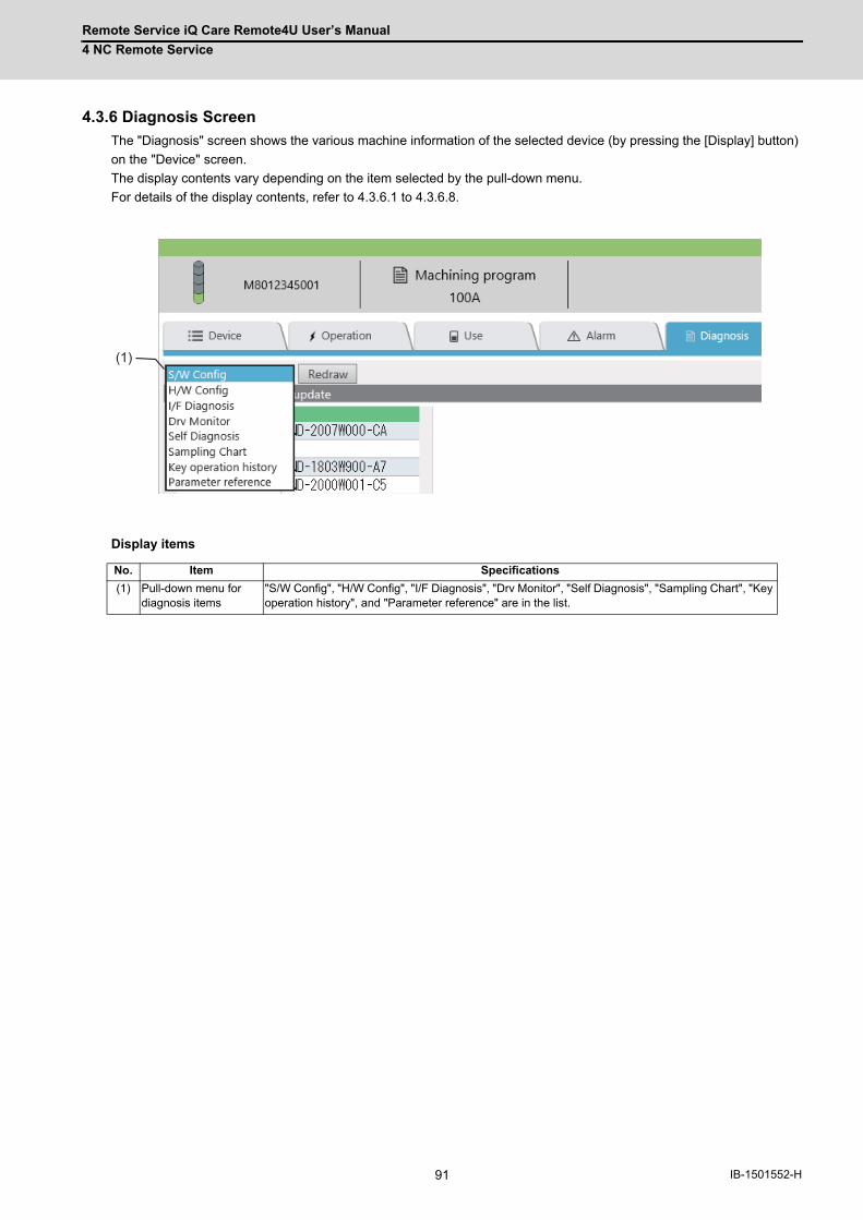
Remote Service iQ Care Remote4U User’s Manual
4 NC Remote Service
91 IB-1501552-H
4.3.6 Diagnosis Screen
The "Diagnosis" screen shows the various machine information of the selected device (by pressing the [Display] button)
on the "Device" screen.
The display contents vary depending on the item selected by the pull-down menu.
For details of the display contents, refer to 4.3.6.1 to 4.3.6.8.
Display items
No. Item Specifications
(1) Pull-down menu for diagnosis items
"S/W Config", "H/W Config", "I/F Diagnosis", "Drv Monitor", "Self Diagnosis", "Sampling Chart", "Key operation history", and "Parameter reference" are in the list.
(1)
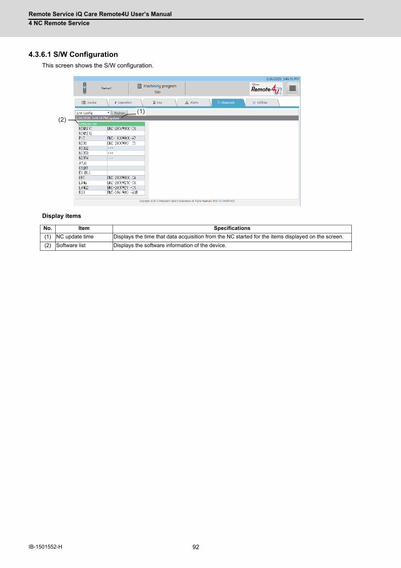
Remote Service iQ Care Remote4U User’s Manual
4 NC Remote Service
92IB-1501552-H
4.3.6.1 S/W Configuration
This screen shows the S/W configuration.
Display items
No. Item Specifications
(1) NC update time Displays the time that data acquisition from the NC started for the items displayed on the screen.
(2) Software list Displays the software information of the device.
(2)(1)
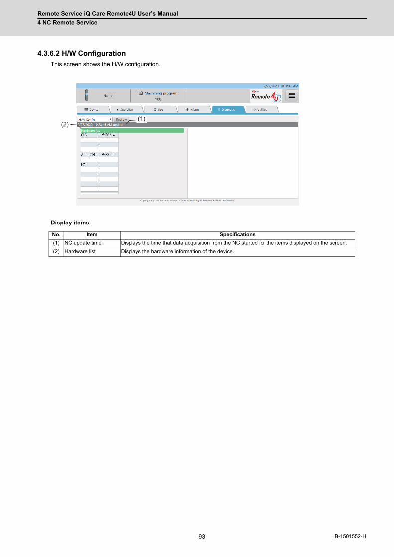
Remote Service iQ Care Remote4U User’s Manual
4 NC Remote Service
93 IB-1501552-H
4.3.6.2 H/W Configuration
This screen shows the H/W configuration.
Display items
No. Item Specifications
(1) NC update time Displays the time that data acquisition from the NC started for the items displayed on the screen.
(2) Hardware list Displays the hardware information of the device.
(2)(1)

Remote Service iQ Care Remote4U User’s Manual
4 NC Remote Service
94IB-1501552-H
4.3.6.3 I/F Diagnosis
This screen shows the device information.
Display items
No. Item Specifications
(1) NC update time Displays the time that data acquisition from the NC started for the items displayed on the screen.
(2) Device information list The information of the selected device are displayed in the list. Pressing the [DEV] button changes the background color of the cell to green, and the devices of that column becomes active (editable).
(3) UP/DOWN buttons For the active device in the list, press the [UP] button to display the previous page, and press [DOWN] button to display the next page.
(4) Keyword input area for a device search
For the active device, a search can be performed by inputting the device number as a keyword. The types of devices which can be displayed are as follows.
Device type Range which can be displayed
X 0 to 8191
Y 0 to 8191
D [M7] x = 0 to 2047 / [M8] x = 0 to 8191
R [M7] x = 0 to 13311 / [M8] x = 0 to 32767
(2)
(3) (4)
(1)
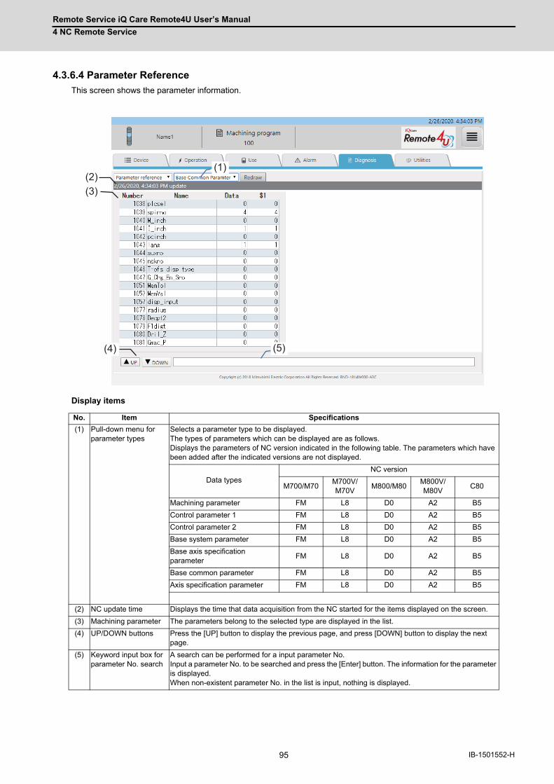
Remote Service iQ Care Remote4U User’s Manual
4 NC Remote Service
95 IB-1501552-H
4.3.6.4 Parameter Reference
This screen shows the parameter information.
Display items
No. Item Specifications
(1) Pull-down menu for parameter types
Selects a parameter type to be displayed. The types of parameters which can be displayed are as follows. Displays the parameters of NC version indicated in the following table. The parameters which have been added after the indicated versions are not displayed.
Data types
NC version
M700/M70M700V/M70V
M800/M80M800V/M80V
C80
Machining parameter FM L8 D0 A2 B5
Control parameter 1 FM L8 D0 A2 B5
Control parameter 2 FM L8 D0 A2 B5
Base system parameter FM L8 D0 A2 B5
Base axis specification parameter
FM L8 D0 A2 B5
Base common parameter FM L8 D0 A2 B5
Axis specification parameter FM L8 D0 A2 B5
(2) NC update time Displays the time that data acquisition from the NC started for the items displayed on the screen.
(3) Machining parameter The parameters belong to the selected type are displayed in the list.
(4) UP/DOWN buttons Press the [UP] button to display the previous page, and press [DOWN] button to display the next page.
(5) Keyword input box for parameter No. search
A search can be performed for a input parameter No. Input a parameter No. to be searched and press the [Enter] button. The information for the parameter is displayed. When non-existent parameter No. in the list is input, nothing is displayed.
(3)
(4) (5)
(1) (2)

Remote Service iQ Care Remote4U User’s Manual
4 NC Remote Service
96IB-1501552-H
4.3.6.5 Drive Monitor
This screen shows the drive monitor information.
Display items
No. Item Specifications
(1) Pull-down menu for drive monitor types
Selects a unit type to be displayed.
(2) NC update time Displays the time that data acquisition from the NC started for the items displayed on the screen.
(3) Drive monitor information
The drive monitor information of the selected unit are displayed in the list.
(4) UP/DOWN buttons Press the [UP] button to display the previous page, and press [DOWN] button to display the next page.
(3) (2)
(4)
(1)
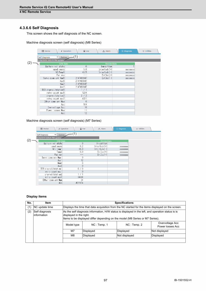
Remote Service iQ Care Remote4U User’s Manual
4 NC Remote Service
97 IB-1501552-H
4.3.6.6 Self Diagnosis
This screen shows the self diagnosis of the NC screen.
Machine diagnosis screen (self diagnosis) (M8 Series)
Machine diagnosis screen (self diagnosis) (M7 Series)
Display items
No. Item Specifications
(1) NC update time Displays the time that data acquisition from the NC started for the items displayed on the screen.
(2) Self diagnosis information
As the self diagnosis information, H/W status is displayed in the left, and operation status is is displayed in the right. Items to be displayed differ depending on the model (M8 Series or M7 Series).
Model type NC : Temp. 1 NC : Temp. 2Overvoltage Acc
Power losses Acc
M7 Displayed Displayed Not displayed
M8 Displayed Not displayed Displayed
(2) (1)
(2) (1)
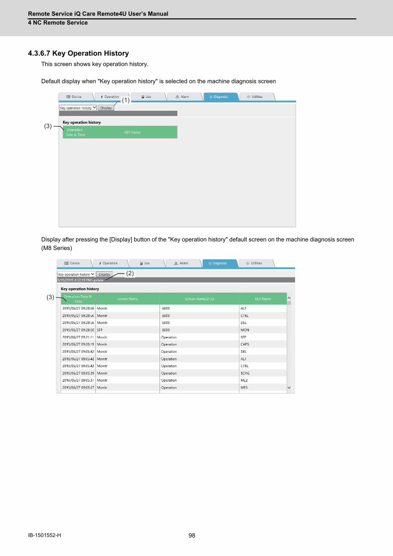
Remote Service iQ Care Remote4U User’s Manual
4 NC Remote Service
98IB-1501552-H
4.3.6.7 Key Operation History
This screen shows key operation history.
Default display when "Key operation history" is selected on the machine diagnosis screen
Display after pressing the [Display] button of the "Key operation history" default screen on the machine diagnosis screen
(M8 Series)
(3)
(1)
(3)
(2)
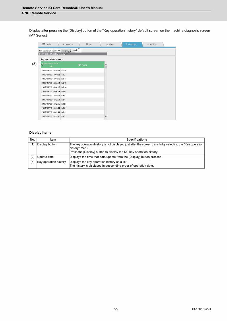
Remote Service iQ Care Remote4U User’s Manual
4 NC Remote Service
99 IB-1501552-H
Display after pressing the [Display] button of the "Key operation history" default screen on the machine diagnosis screen
(M7 Series)
Display items
No. Item Specifications
(1) Display button The key operation history is not displayed just after the screen transits by selecting the "Key operation history" menu. Press the [Display] button to display the NC key operation history.
(2) Update time Displays the time that data update from the [Display] button pressed.
(3) Key operation history Displays the key operation history as a list. The history is displayed in descending order of operation date.
(2) (3)
(2) (2)
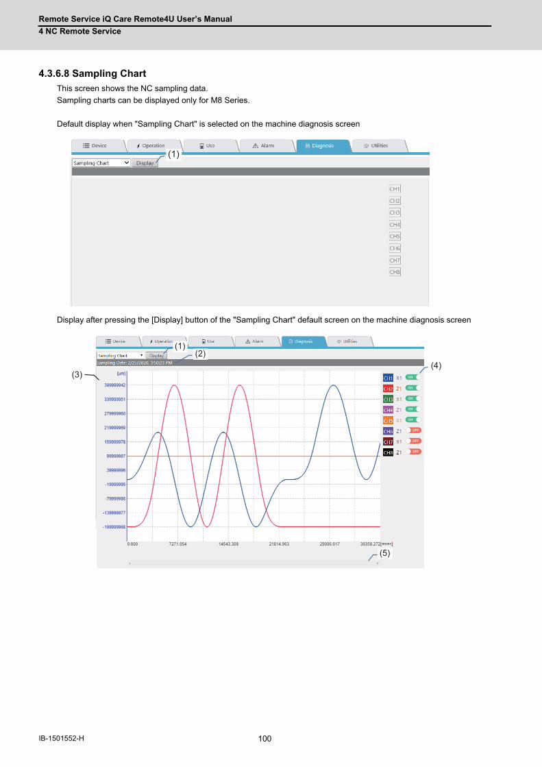
Remote Service iQ Care Remote4U User’s Manual
4 NC Remote Service
100IB-1501552-H
4.3.6.8 Sampling Chart
This screen shows the NC sampling data.
Sampling charts can be displayed only for M8 Series.
Default display when "Sampling Chart" is selected on the machine diagnosis screen
Display after pressing the [Display] button of the "Sampling Chart" default screen on the machine diagnosis screen
(1)
(3)
(5)
(1)(2)
(4)
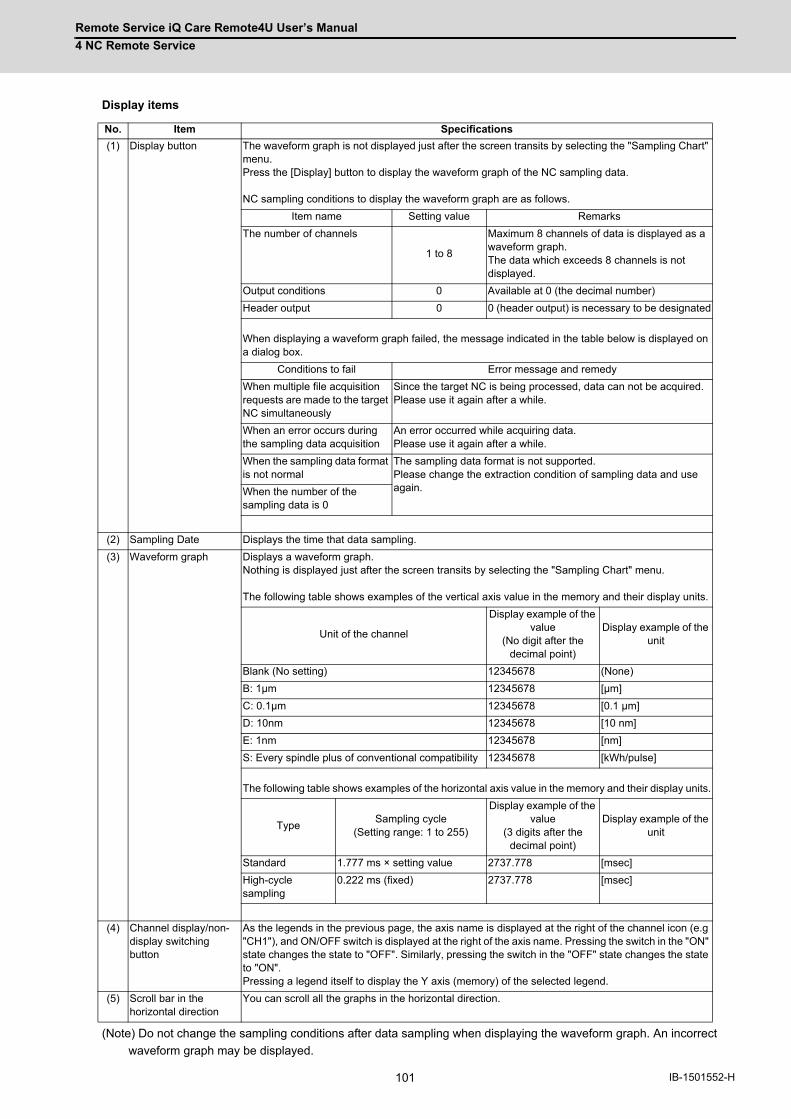
Remote Service iQ Care Remote4U User’s Manual
4 NC Remote Service
101 IB-1501552-H
Display items
(Note) Do not change the sampling conditions after data sampling when displaying the waveform graph. An incorrect
waveform graph may be displayed.
No. Item Specifications
(1) Display button The waveform graph is not displayed just after the screen transits by selecting the "Sampling Chart" menu. Press the [Display] button to display the waveform graph of the NC sampling data. NC sampling conditions to display the waveform graph are as follows.
Item name Setting value Remarks
The number of channels
1 to 8
Maximum 8 channels of data is displayed as a waveform graph. The data which exceeds 8 channels is not displayed.
Output conditions 0 Available at 0 (the decimal number)
Header output 0 0 (header output) is necessary to be designated
When displaying a waveform graph failed, the message indicated in the table below is displayed on a dialog box.
Conditions to fail Error message and remedy
When multiple file acquisition requests are made to the target NC simultaneously
Since the target NC is being processed, data can not be acquired. Please use it again after a while.
When an error occurs during the sampling data acquisition
An error occurred while acquiring data. Please use it again after a while.
When the sampling data format is not normal
The sampling data format is not supported. Please change the extraction condition of sampling data and use again.When the number of the
sampling data is 0
(2) Sampling Date Displays the time that data sampling.
(3) Waveform graph Displays a waveform graph. Nothing is displayed just after the screen transits by selecting the "Sampling Chart" menu. The following table shows examples of the vertical axis value in the memory and their display units.
Unit of the channel
Display example of the value
(No digit after the decimal point)
Display example of the unit
Blank (No setting) 12345678 (None)
B: 1μm 12345678 [μm]
C: 0.1μm 12345678 [0.1 μm]
D: 10nm 12345678 [10 nm]
E: 1nm 12345678 [nm]
S: Every spindle plus of conventional compatibility 12345678 [kWh/pulse]
The following table shows examples of the horizontal axis value in the memory and their display units.
TypeSampling cycle
(Setting range: 1 to 255)
Display example of the value
(3 digits after the decimal point)
Display example of the unit
Standard 1.777 ms × setting value 2737.778 [msec]
High-cycle sampling
0.222 ms (fixed) 2737.778 [msec]
(4) Channel display/non-display switching button
As the legends in the previous page, the axis name is displayed at the right of the channel icon (e.g "CH1"), and ON/OFF switch is displayed at the right of the axis name. Pressing the switch in the "ON" state changes the state to "OFF". Similarly, pressing the switch in the "OFF" state changes the state to "ON". Pressing a legend itself to display the Y axis (memory) of the selected legend.
(5) Scroll bar in the horizontal direction
You can scroll all the graphs in the horizontal direction.
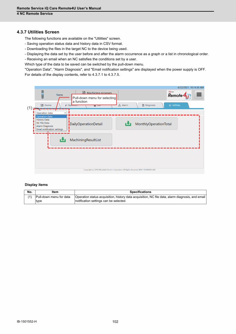
Remote Service iQ Care Remote4U User’s Manual
4 NC Remote Service
102IB-1501552-H
4.3.7 Utilities Screen
The following functions are available on the "Utilities" screen.
- Saving operation status data and history data in CSV format.
- Downloading the files in the target NC to the device being used.
- Displaying the data set by the user before and after the alarm occurrence as a graph or a list in chronological order.
- Receiving an email when an NC satisfies the conditions set by a user.
Which type of the data to be saved can be switched by the pull-down menu.
"Operation Data", "Alarm Diagnosis", and "Email notification settings" are displayed when the power supply is OFF.
For details of the display contents, refer to 4.3.7.1 to 4.3.7.5.
Display items
No. Item Specifications
(1) Pull-down menu for data type
Operation status acquisition, history data acquisition, NC file data, alarm diagnosis, and email notification settings can be selected.
(1)
Pull-down menu for selecting a function
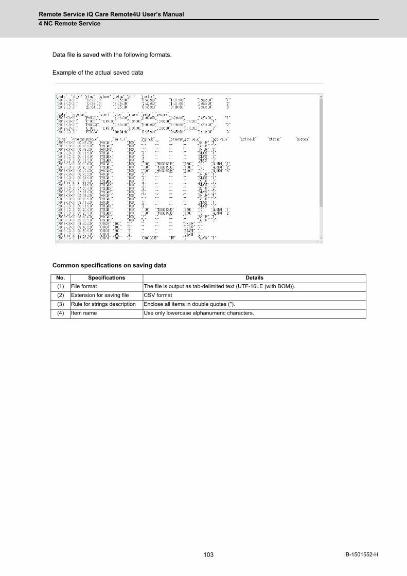
Remote Service iQ Care Remote4U User’s Manual
4 NC Remote Service
103 IB-1501552-H
Data file is saved with the following formats.
Example of the actual saved data
Common specifications on saving data
No. Specifications Details
(1) File format The file is output as tab-delimited text (UTF-16LE (with BOM)).
(2) Extension for saving file CSV format
(3) Rule for strings description Enclose all items in double quotes (").
(4) Item name Use only lowercase alphanumeric characters.

Remote Service iQ Care Remote4U User’s Manual
4 NC Remote Service
104IB-1501552-H
4.3.7.1 Operation Status Acquisition
The operation status acquisition screen is displayed by selecting "Operation Data" from the pull-down menu.
On this screen, you can save the data of "DailyOperationDetail", "MonthlyOperationTotal" or "MachiningResultList" as a
file to your device.
Display items
No. Item Specifications
(1) [DailyOperationDetail] button
Saves the detailed information of daily operation in a file. When this button is pressed, a dialog box to specify the period appears. Input the period. For details of the data to be saved in the file, refer to "4.3.7.1.1 Daily Operation Detail".
(2) [MonthlyOperationTotal] button
Saves the aggregated data of monthly operation in a file. When this button is pressed, a dialog box to specify the period appears. Input the period. For details of the data to be saved in the file, refer to "4.3.7.1.2 Monthly Operation Total".
(3) [MachiningResultList] button
Saves the machining result list in a file. When this button is pressed, a dialog box to specify the date appears. Input the date. For details of the data to be saved in the file, refer to "4.3.7.1.3 Machining Result List".
(1)
(3)
(2)
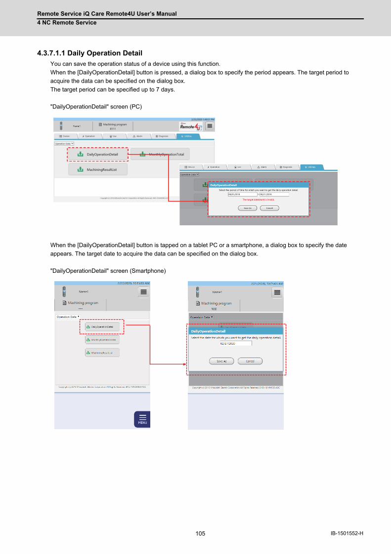
Remote Service iQ Care Remote4U User’s Manual
4 NC Remote Service
105 IB-1501552-H
4.3.7.1.1 Daily Operation Detail
You can save the operation status of a device using this function.
When the [DailyOperationDetail] button is pressed, a dialog box to specify the period appears. The target period to
acquire the data can be specified on the dialog box.
The target period can be specified up to 7 days.
"DailyOperationDetail" screen (PC)
When the [DailyOperationDetail] button is tapped on a tablet PC or a smartphone, a dialog box to specify the date
appears. The target date to acquire the data can be specified on the dialog box.
"DailyOperationDetail" screen (Smartphone)
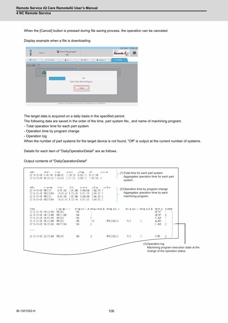
Remote Service iQ Care Remote4U User’s Manual
4 NC Remote Service
106IB-1501552-H
When the [Cancel] button is pressed during file saving process, the operation can be canceled.
Display example when a file is downloading
The target data is acquired on a daily basis in the specified period.
The following data are saved in the order of the time, part system No., and name of machining program.
- Total operation time for each part system
- Operation time by program change
- Operation log
When the number of part systems for the target device is not found, "Off" is output at the current number of systems.
Details for each item of "DailyOperationDetail" are as follows.
Output contents of "DailyOperationDetail"
Total time for each part systemAggregates operation time for each part system.
(1)
Operation time by program changeAggregates operation time by each machining program.
(2)
Operation logMachining program execution state at the change of the operation status
(3)

Remote Service iQ Care Remote4U User’s Manual
4 NC Remote Service
107 IB-1501552-H
(1) Total operation time for each part system
The accumulated time of the operation status is output for each part system.
Output example of "DailyOperationDetail" (Total operation time for each part system)
Specifications for the saved file of "DailyOperationDetail" (Total operation time for each part system)
(2) Operation time by program change
The accumulated time of the operation status by each program change is output for each part system.
Output example of "DailyOperationDetail" (Total operation time by program change)
Specifications for the saved file of "DailyOperationDetail" (Total operation time by program change)
(*1) When one program is executed multiple times in a part system on the same day; however another program is
executed in between the said programs, the data will be aggregated separately.
Item name Details Format
date The date in the specified target period yyyy-mm-dd
start Aggregate result of the time for each part system when its operation status is "Start" hh:mm:ss
stop Aggregate result of the time for each part system when its operation status is "Stop" hh:mm:ss
alarm Aggregate result of the time for each part system when its operation status is "Alarm" hh:mm:ss
setup Aggregate result of the time for each part system when its operation status is "Setup" hh:mm:ss
off Aggregate result of the time for each part system when its operation status is "Off" or when the communication is disconnected.
hh:mm:ss
system Part system No. Numeric value
Item name Details Format
date The date in the specified target period yyyy-mm-dd
program The name of main program currently being executed is output for each part system in the order of execution.
String
start Aggregate result of the time when the operation status is "Start" classified by main program name (*1)
hh:mm:ss
stop Aggregate result of the time when the operation status is "Stop" classified by main program name (*1)
hh:mm:ss
alarm Aggregate result of the time when the operation status is "Alarm" classified by main program name (*1)
hh:mm:ss
setup Aggregate result of the time when the operation status is "Setup" classified by main program name (*1)
hh:mm:ss
system Part system No. in which the main program is being executed (*1) Numeric value
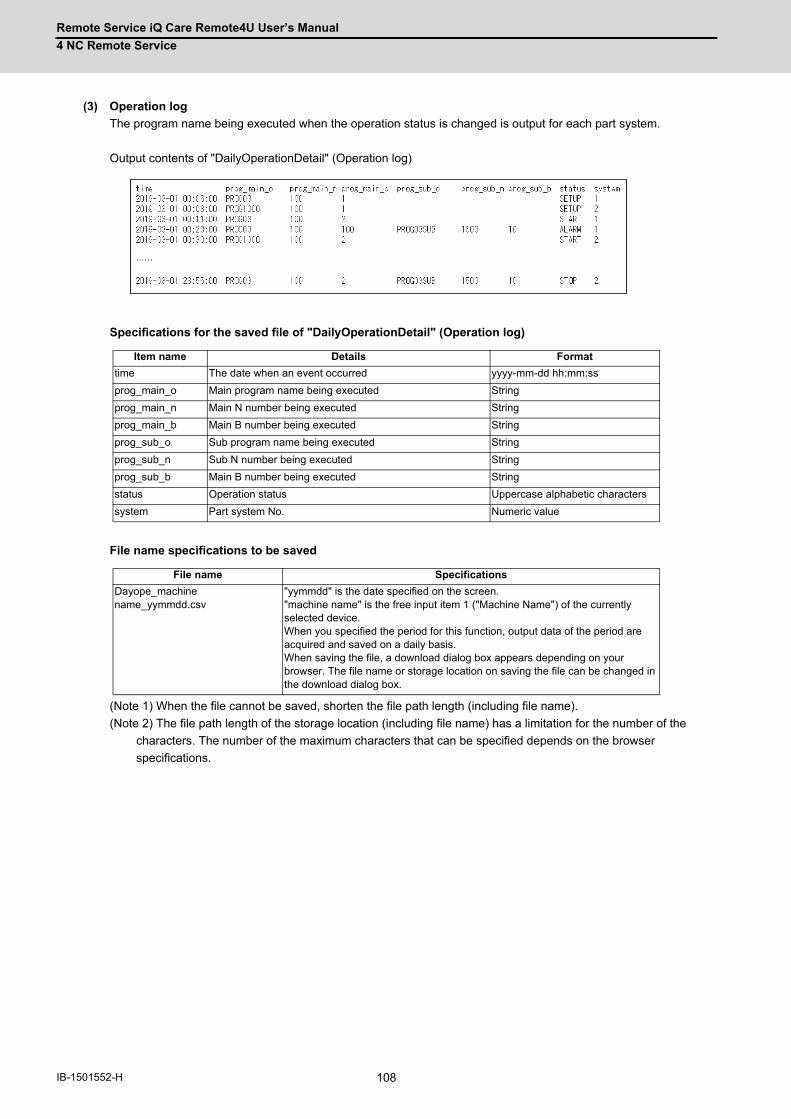
Remote Service iQ Care Remote4U User’s Manual
4 NC Remote Service
108IB-1501552-H
(3) Operation log
The program name being executed when the operation status is changed is output for each part system.
Output contents of "DailyOperationDetail" (Operation log)
Specifications for the saved file of "DailyOperationDetail" (Operation log)
File name specifications to be saved
(Note 1) When the file cannot be saved, shorten the file path length (including file name).
(Note 2) The file path length of the storage location (including file name) has a limitation for the number of the
characters. The number of the maximum characters that can be specified depends on the browser
specifications.
Item name Details Format
time The date when an event occurred yyyy-mm-dd hh:mm:ss
prog_main_o Main program name being executed String
prog_main_n Main N number being executed String
prog_main_b Main B number being executed String
prog_sub_o Sub program name being executed String
prog_sub_n Sub N number being executed String
prog_sub_b Main B number being executed String
status Operation status Uppercase alphabetic characters
system Part system No. Numeric value
File name Specifications
Dayope_machine name_yymmdd.csv
"yymmdd" is the date specified on the screen. "machine name" is the free input item 1 ("Machine Name") of the currently selected device. When you specified the period for this function, output data of the period are acquired and saved on a daily basis. When saving the file, a download dialog box appears depending on your browser. The file name or storage location on saving the file can be changed in the download dialog box.
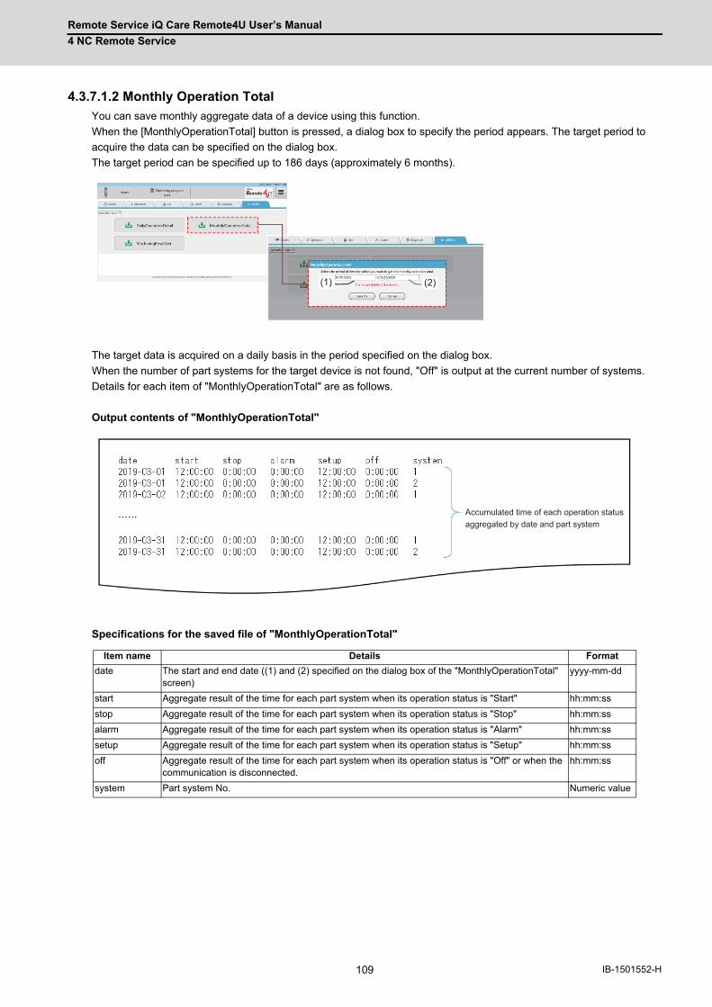
Remote Service iQ Care Remote4U User’s Manual
4 NC Remote Service
109 IB-1501552-H
4.3.7.1.2 Monthly Operation Total
You can save monthly aggregate data of a device using this function.
When the [MonthlyOperationTotal] button is pressed, a dialog box to specify the period appears. The target period to
acquire the data can be specified on the dialog box.
The target period can be specified up to 186 days (approximately 6 months).
The target data is acquired on a daily basis in the period specified on the dialog box.
When the number of part systems for the target device is not found, "Off" is output at the current number of systems.
Details for each item of "MonthlyOperationTotal" are as follows.
Output contents of "MonthlyOperationTotal"
Specifications for the saved file of "MonthlyOperationTotal"
Item name Details Format
date The start and end date ((1) and (2) specified on the dialog box of the "MonthlyOperationTotal" screen)
yyyy-mm-dd
start Aggregate result of the time for each part system when its operation status is "Start" hh:mm:ss
stop Aggregate result of the time for each part system when its operation status is "Stop" hh:mm:ss
alarm Aggregate result of the time for each part system when its operation status is "Alarm" hh:mm:ss
setup Aggregate result of the time for each part system when its operation status is "Setup" hh:mm:ss
off Aggregate result of the time for each part system when its operation status is "Off" or when the communication is disconnected.
hh:mm:ss
system Part system No. Numeric value
(1) (2)
Accumulated time of each operation status aggregated by date and part system

Remote Service iQ Care Remote4U User’s Manual
4 NC Remote Service
110IB-1501552-H
File name specifications to be saved
(Note 1) When the file cannot be saved, shorten the file path length (including file name).
(Note 2) The file path length of the storage location (including file name) has a limitation for the number of the characters.
The number of the maximum characters that can be specified depends on the browser specifications.
File name Specifications
monope_machine name_yymmdd1_yymmdd2.csv "yymmdd1" is the date (1) specified on the dialog box of the "MonthlyOperationTotal" screen. "yymmdd2" is the date (2) specified on the dialog box of the "MonthlyOperationTotal" screen. "machine name" is the free input item 1 ("Machine Name") of the currently selected device. When you specified the period for this function, output data of the period are acquired and it is saved as one file. When saving the file, a download dialog box appears depending on your browser. The file name or storage location on saving the file can be changed in the download dialog box.

Remote Service iQ Care Remote4U User’s Manual
4 NC Remote Service
111 IB-1501552-H
4.3.7.1.3 Machining Result List
You can save the accumulated data for machined workpieces for each part system of a device using this function.
When the [MachiningResultList] button is pressed, a dialog box to specify the date appears. The target date acquire the
data can be specified on the dialog box.
The setting of parameter #8001 (M code to count machined workpieces) and operation of the machining program which
describes the M code registered in #8001 are required to acquire CSV files of machining result list.
The data of the date specified on the dialog box is acquired.
The time spent for one machining, such as cycle time, cutting time, operation stop or alarm stop, can be saved for each
program in the order of the time the machining was completed and part system No.
Details for each item of "MachiningResultList" are as follows.
Output contents of "MachiningResultList"

Remote Service iQ Care Remote4U User’s Manual
4 NC Remote Service
112IB-1501552-H
Specifications for the saved file of "MachiningResultList"
(*1) When using the following NCs, the contents of "cutting time" is the cutting time calculated on the RGU side as the
NCs do not have a cutting time.
- M7 Series
- C80 Series
- M8 Series version C0 or before
In this case, the cutting time may differ from the actual cutting time due to the following reasons.
- The cycle for acquiring the calculation values is longer than the cycle in the NC and short cutting times during the
cycle for acquiring the calculation values cannot be calculated.
- During cycles determined to be "cutting", the times that are not cutting are still calculated as "cutting".
- The acquisition cycle is delayed.
As the calculation values are accumulated, the difference between the calculation value and the actual cutting time
may grow larger.
File name specifications to be saved
(Note 1) When the file cannot be saved, shorten the file path length (including file name).
(Note 2) The file path length of the storage location (including file name) has a limitation for the number of the characters.
The number of the maximum characters that can be specified depends on the browser specifications.
Item name Details Format
time The date when a machining is started yyyy-mm-dd hh:mm:ss
program Main program name String
count Number of the machined workpieces Numeric value
cycle_time Cycle time for one machining hhhh:mm:ss
cutting_time Cutting time for one machining (*1) hhhh:mm:ss
stop The time when the operation status is "Stop" for one machining hhhh:mm:ss
alarm The time when the operation status is "Alarm" for one machining hhhh:mm:ss
system Part system No. Numeric value
File name Specifications
mcnlog_machine name_yymmdd_x.csv "yymmdd" is the date specified on the screen. "machine name" is the free input item 1 ("Machine Name") of the currently selected device. When the layout of the machining result file on the same day was changed, output file is saved as a different file, adding "_1" (underscore + number) to the end of the original file name. When saving the file, a download dialog box appears depending on your browser. The file name or storage location on saving the file can be changed in the download dialog box.
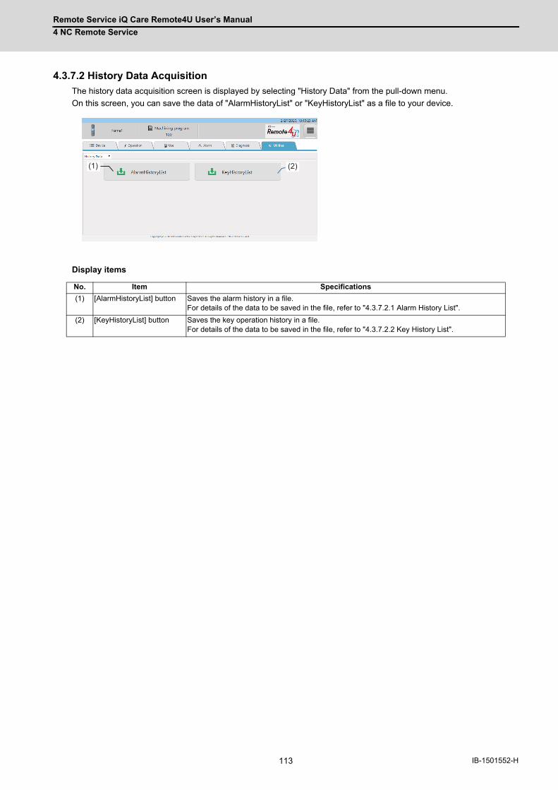
Remote Service iQ Care Remote4U User’s Manual
4 NC Remote Service
113 IB-1501552-H
4.3.7.2 History Data Acquisition
The history data acquisition screen is displayed by selecting "History Data" from the pull-down menu.
On this screen, you can save the data of "AlarmHistoryList" or "KeyHistoryList" as a file to your device.
Display items
No. Item Specifications
(1) [AlarmHistoryList] button Saves the alarm history in a file. For details of the data to be saved in the file, refer to "4.3.7.2.1 Alarm History List".
(2) [KeyHistoryList] button Saves the key operation history in a file. For details of the data to be saved in the file, refer to "4.3.7.2.2 Key History List".
(1) (2)
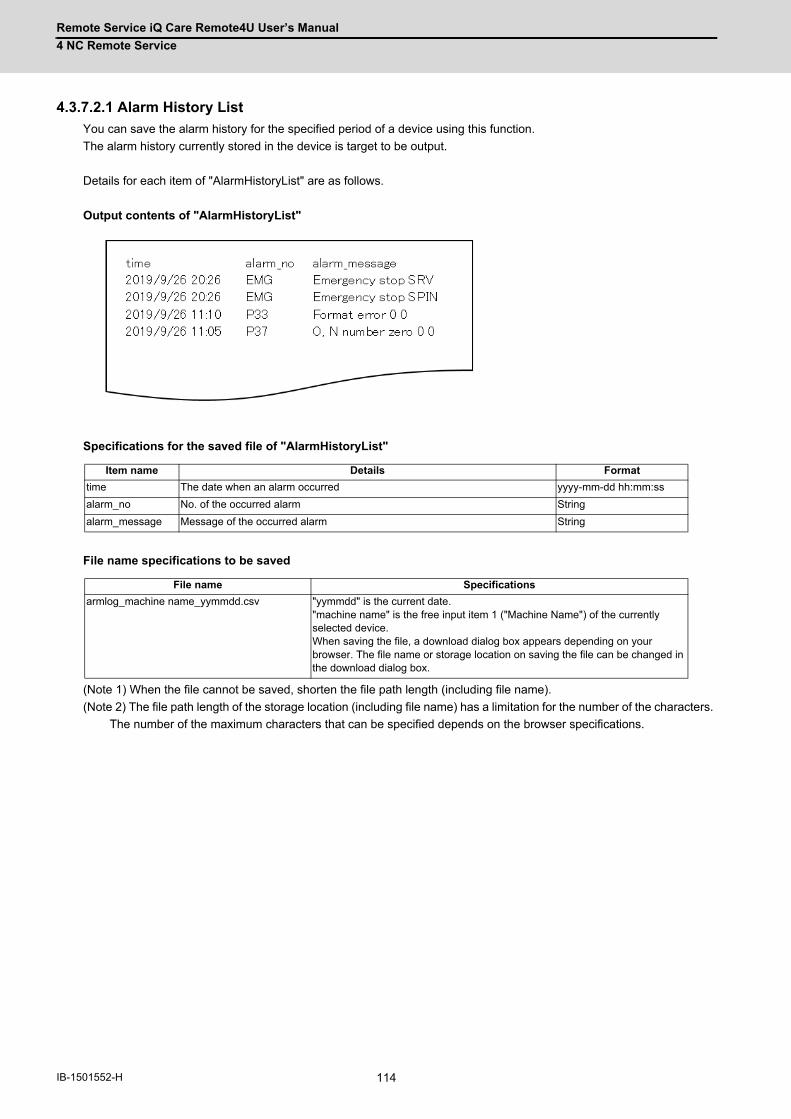
Remote Service iQ Care Remote4U User’s Manual
4 NC Remote Service
114IB-1501552-H
4.3.7.2.1 Alarm History List
You can save the alarm history for the specified period of a device using this function.
The alarm history currently stored in the device is target to be output.
Details for each item of "AlarmHistoryList" are as follows.
Output contents of "AlarmHistoryList"
Specifications for the saved file of "AlarmHistoryList"
File name specifications to be saved
(Note 1) When the file cannot be saved, shorten the file path length (including file name).
(Note 2) The file path length of the storage location (including file name) has a limitation for the number of the characters.
The number of the maximum characters that can be specified depends on the browser specifications.
Item name Details Format
time The date when an alarm occurred yyyy-mm-dd hh:mm:ss
alarm_no No. of the occurred alarm String
alarm_message Message of the occurred alarm String
File name Specifications
armlog_machine name_yymmdd.csv "yymmdd" is the current date. "machine name" is the free input item 1 ("Machine Name") of the currently selected device. When saving the file, a download dialog box appears depending on your browser. The file name or storage location on saving the file can be changed in the download dialog box.
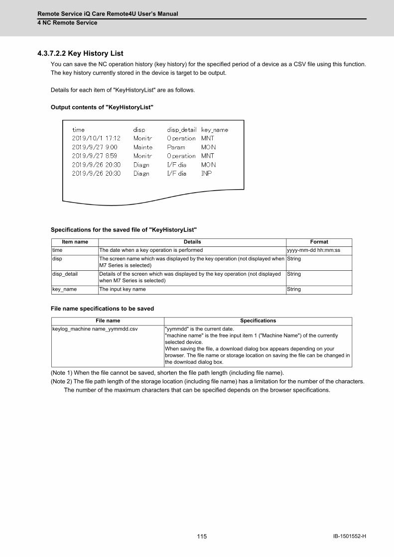
Remote Service iQ Care Remote4U User’s Manual
4 NC Remote Service
115 IB-1501552-H
4.3.7.2.2 Key History List
You can save the NC operation history (key history) for the specified period of a device as a CSV file using this function.
The key history currently stored in the device is target to be output.
Details for each item of "KeyHistoryList" are as follows.
Output contents of "KeyHistoryList"
Specifications for the saved file of "KeyHistoryList"
File name specifications to be saved
(Note 1) When the file cannot be saved, shorten the file path length (including file name).
(Note 2) The file path length of the storage location (including file name) has a limitation for the number of the characters.
The number of the maximum characters that can be specified depends on the browser specifications.
Item name Details Format
time The date when a key operation is performed yyyy-mm-dd hh:mm:ss
disp The screen name which was displayed by the key operation (not displayed when M7 Series is selected)
String
disp_detail Details of the screen which was displayed by the key operation (not displayed when M7 Series is selected)
String
key_name The input key name String
File name Specifications
keylog_machine name_yymmdd.csv "yymmdd" is the current date. "machine name" is the free input item 1 ("Machine Name") of the currently selected device. When saving the file, a download dialog box appears depending on your browser. The file name or storage location on saving the file can be changed in the download dialog box.
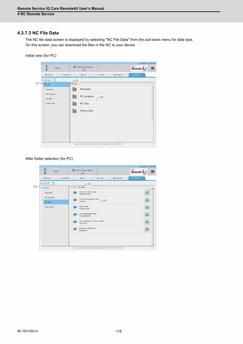
Remote Service iQ Care Remote4U User’s Manual
4 NC Remote Service
116IB-1501552-H
4.3.7.3 NC File Data
The NC file data screen is displayed by selecting "NC File Data" from the pull-down menu for data type.
On this screen, you can download the files in the NC to your device.
Initial view (for PC)
After folder selection (for PC)
(2)
(3)
(1)
(2)
(3)
(1)(4)

Remote Service iQ Care Remote4U User’s Manual
4 NC Remote Service
117 IB-1501552-H
After pressing the download button (for PC)
(2)
(3)
(1)(4)

Remote Service iQ Care Remote4U User’s Manual
4 NC Remote Service
118IB-1501552-H
Tablet PC or smartphone screen
Tablet PC or smartphone screen file contents viewing window
(2)
(3)
(1)
(7)
(5) (5)
(6) (7)

Remote Service iQ Care Remote4U User’s Manual
4 NC Remote Service
119 IB-1501552-H
Display items
No. Item Specifications
(1) NC folder menu Displays the NC folders as a tree structure. The files in a folder that can be acquired are displayed in (3) File list by selecting an NC folder. * For tablet PCs and smartphones, tap the "+" sign on (2) File list upper menu.
(2) File list upper menu Displays the tiers to the folder currently displayed in a list format. The files in a folder that can be acquired are displayed in (3) File list by selecting a folder name.
(3) File list Displays the files that can be acquired in the folders selected in (1) and (2). (Note) For tablet PCs and smartphones, tapping the displayed file name opens (5) File contents viewing window, which displays the contents of a file. * When a binary file is selected, (5) File contents viewing window does not open and the file contents are not displayed. ■ Displayed icons
Icon Details
Folder
Text file
Binary file
(4) Download button/cancel button
Files can be downloaded by pressing the download button. While downloading, a progress bar is displayed under the file name, and the download button changes to a cancel button. The download can be cancelled by pressing the cancel button. ■ Displayed buttons
Button Details
Download button
Cancel button
(5) File contents viewing window
Displays the contents of the file tapped in (3). A loading dialog is displayed while loading the file contents for display.
(6) Download button (File contents viewing window)
After displaying the file contents, the file can be downloaded by tapping the download button.
(7) Cancel button (File contents viewing window)
Tapping the cancel button closes the (5) File contents viewing window. Tapping the cancel button while loading the file contents cancels the display and closes the window.
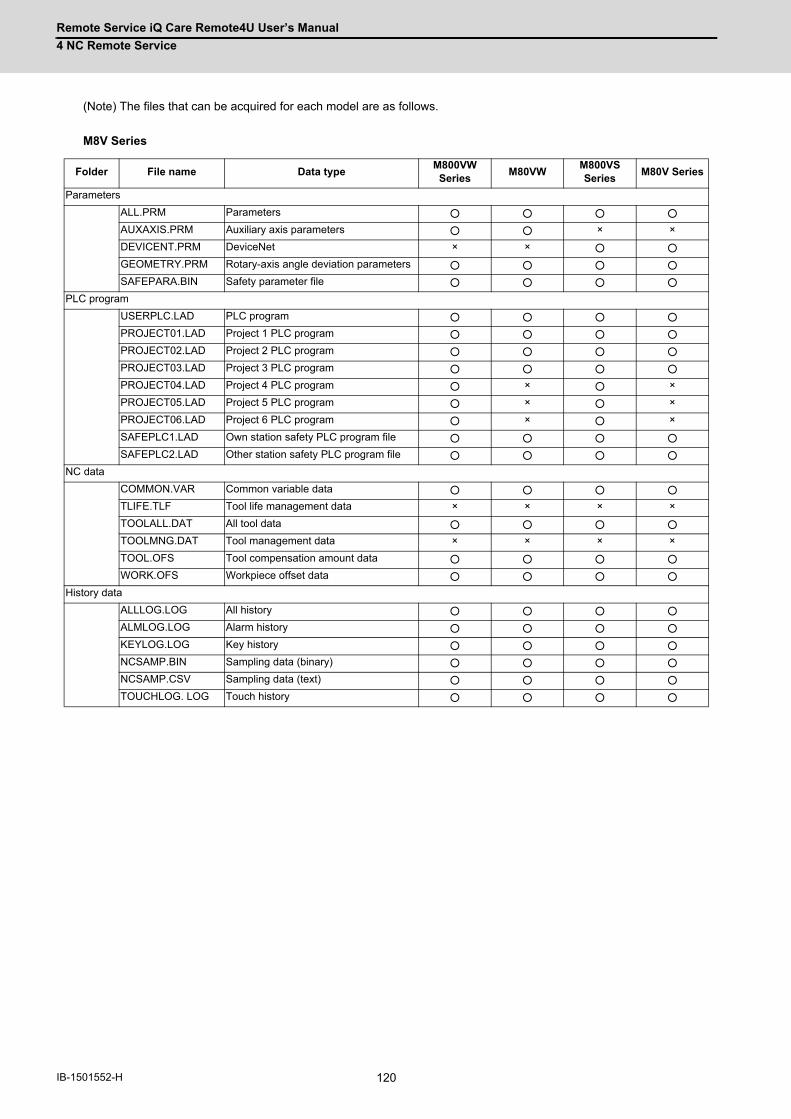
Remote Service iQ Care Remote4U User’s Manual
4 NC Remote Service
120IB-1501552-H
(Note) The files that can be acquired for each model are as follows.
M8V Series
Folder File name Data typeM800VW Series
M80VWM800VS Series
M80V Series
Parameters
ALL.PRM Parameters ○ ○ ○ ○
AUXAXIS.PRM Auxiliary axis parameters ○ ○ × ×
DEVICENT.PRM DeviceNet × × ○ ○
GEOMETRY.PRM Rotary-axis angle deviation parameters ○ ○ ○ ○
SAFEPARA.BIN Safety parameter file ○ ○ ○ ○
PLC program
USERPLC.LAD PLC program ○ ○ ○ ○
PROJECT01.LAD Project 1 PLC program ○ ○ ○ ○
PROJECT02.LAD Project 2 PLC program ○ ○ ○ ○
PROJECT03.LAD Project 3 PLC program ○ ○ ○ ○
PROJECT04.LAD Project 4 PLC program ○ × ○ ×
PROJECT05.LAD Project 5 PLC program ○ × ○ ×
PROJECT06.LAD Project 6 PLC program ○ × ○ ×
SAFEPLC1.LAD Own station safety PLC program file ○ ○ ○ ○
SAFEPLC2.LAD Other station safety PLC program file ○ ○ ○ ○
NC data
COMMON.VAR Common variable data ○ ○ ○ ○
TLIFE.TLF Tool life management data × × × ×
TOOLALL.DAT All tool data ○ ○ ○ ○
TOOLMNG.DAT Tool management data × × × ×
TOOL.OFS Tool compensation amount data ○ ○ ○ ○
WORK.OFS Workpiece offset data ○ ○ ○ ○
History data
ALLLOG.LOG All history ○ ○ ○ ○
ALMLOG.LOG Alarm history ○ ○ ○ ○
KEYLOG.LOG Key history ○ ○ ○ ○
NCSAMP.BIN Sampling data (binary) ○ ○ ○ ○
NCSAMP.CSV Sampling data (text) ○ ○ ○ ○
TOUCHLOG. LOG Touch history ○ ○ ○ ○

Remote Service iQ Care Remote4U User’s Manual
4 NC Remote Service
121 IB-1501552-H
M8 Series/C80 Series
Folder File name Data typeM800W Series
M80WM800S Series
M80 Series
E80 Series
C80
Parameters
ALL.PRM Parameters ○ ○ ○ ○ ○ ○
AUXAXIS.PRM Auxiliary axis parameters ○ ○ × × × ×
DEVICENT.PRM DeviceNet × × ○ ○ × ×
GEOMETRY.PRM Rotary-axis angle deviation parameters ○ ○ ○ ○ ○ ×
SAFEPARA.BIN Safety parameter file ○ ○ ○ ○ ○ ○
PLC program
USERPLC.LAD PLC program ○ ○ ○ ○ ○ ×
PROJECT01.LAD Project 1 PLC program ○ ○ ○ ○ ○ ×
PROJECT02.LAD Project 2 PLC program ○ ○ ○ ○ ○ ×
PROJECT03.LAD Project 3 PLC program ○ ○ ○ ○ ○ ×
PROJECT04.LAD Project 4 PLC program ○ × ○ × × ×
PROJECT05.LAD Project 5 PLC program ○ × ○ × × ×
PROJECT06.LAD Project 6 PLC program ○ × ○ × × ×
SAFEPLC1.LAD Own station safety PLC program file ○ ○ ○ ○ ○ ○
SAFEPLC2.LAD Other station safety PLC program file ○ ○ ○ ○ ○ ○
NC data
COMMON.VAR Common variable data ○ ○ ○ ○ ○ ○
TLIFE.TLF Tool life management data × × × × × ×
TOOLALL.DAT All tool data ○ ○ ○ ○ ○ ○
TOOLMNG.DAT Tool management data × × × × × ×
TOOL.OFS Tool compensation amount data ○ ○ ○ ○ ○ ○
WORK.OFS Workpiece offset data ○ ○ ○ ○ ○ ○
History data
ALLLOG.LOG All history ○ ○ ○ ○ ○ ○
ALMLOG.LOG Alarm history ○ ○ ○ ○ ○ ○
KEYLOG.LOG Key history ○ ○ ○ ○ ○ ○
NCSAMP.BIN Sampling data (binary) ○ ○ ○ ○ ○ ○
NCSAMP.CSV Sampling data (text) ○ ○ ○ ○ ○ ○
TOUCHLOG. LOG Touch history ○ ○ ○ ○ ○ ○
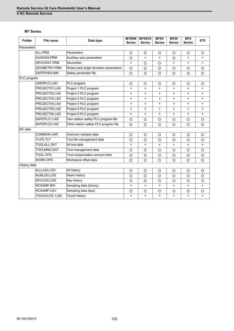
Remote Service iQ Care Remote4U User’s Manual
4 NC Remote Service
122IB-1501552-H
M7 Series
Folder File name Data typeM700W Series
M700VS Series
M70V Series
M700 Series
M70 Series
E70
Parameters
ALL.PRM Parameters ○ ○ ○ ○ ○ ○
AUXAXIS.PRM Auxiliary axis parameters ○ × × ○ × ×
DEVICENT.PRM DeviceNet × ○ ○ × × ×
GEOMETRY.PRM Rotary-axis angle deviation parameters ○ ○ ○ ○ ○ ○
SAFEPARA.BIN Safety parameter file ○ ○ ○ ○ ○ ○
PLC program
USERPLC.LAD PLC program ○ ○ ○ ○ ○ ○
PROJECT01.LAD Project 1 PLC program × × × × × ×
PROJECT02.LAD Project 2 PLC program × × × × × ×
PROJECT03.LAD Project 3 PLC program × × × × × ×
PROJECT04.LAD Project 4 PLC program × × × × × ×
PROJECT05.LAD Project 5 PLC program × × × × × ×
PROJECT06.LAD Project 6 PLC program × × × × × ×
SAFEPLC1.LAD Own station safety PLC program file ○ ○ ○ ○ ○ ○
SAFEPLC2.LAD Other station safety PLC program file ○ ○ ○ ○ ○ ○
NC data
COMMON.VAR Common variable data ○ ○ ○ ○ ○ ○
TLIFE.TLF Tool life management data ○ ○ ○ ○ ○ ○
TOOLALL.DAT All tool data × × × × × ×
TOOLMNG.DAT Tool management data ○ ○ ○ ○ ○ ○
TOOL.OFS Tool compensation amount data ○ ○ ○ ○ ○ ○
WORK.OFS Workpiece offset data ○ ○ ○ ○ ○ ○
History data
ALLLOG.LOG All history ○ ○ ○ ○ ○ ○
ALMLOG.LOG Alarm history ○ ○ ○ ○ ○ ○
KEYLOG.LOG Key history ○ ○ ○ ○ ○ ○
NCSAMP.BIN Sampling data (binary) × × × × × ×
NCSAMP.CSV Sampling data (text) ○ ○ ○ ○ ○ ○
TOUCHLOG. LOG Touch history × × × × × ×
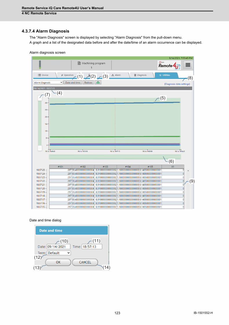
Remote Service iQ Care Remote4U User’s Manual
4 NC Remote Service
123 IB-1501552-H
4.3.7.4 Alarm Diagnosis
The "Alarm Diagnosis" screen is displayed by selecting "Alarm Diagnosis" from the pull-down menu.
A graph and a list of the designated data before and after the date/time of an alarm occurrence can be displayed.
Alarm diagnosis screen
Date and time dialog
(1) (2) (3)
(4)(5)
(6)
(7)
(8)
(9)
(10) (11)
(13)
(12)
(14)

Remote Service iQ Care Remote4U User’s Manual
4 NC Remote Service
124IB-1501552-H
Display items
No. Item Specifications
(1) Date and time button Displays the date and time dialog.
(2) Redraw button Acquires the data of the date/time set on the date and time dialog.
(3) Download button Downloads the data of (9) Data list as a CSV file.
(4) Date and time Displays the date/time set on the date and time dialog.
(5) Data graph Displays the graph of data set on the setting screen. Moving a mouse cursor over points or tapping points on a graph displays data of each point by a tooltip.
(6) Sub chart Drag the sub chart to set the range of time to display on a graph. Clicking or tapping outside the set range on the sub chart resets the setting range.
(7) Range slider Move the handles on both ends to set the range of values to display in the graph.
(8) Diagnosis data settings link Opens the screen to set the data for using diagnosis. Refer to "4.3.7.4.1 Diagnosis Data Settings" for details.
(9) Data list Displays the data for the designated date/time selected in (4) in chronological order. When the display format in the diagnosis data setting is bit, "0" is displayed for the designated position bit that is OFF, and "1" is displayed for the designated position bit that is ON.When bit position is "all", all bit statuses are displayed as "0010110111010001". When no data can be displayed, this field is blank.
(10) Date Selects the designated date.
(11) Time Selects the designated time.
(12) Term Set the time interval to display in (5) Data graph/(9) Data list.Default: Displays the changing points of the data for 15 minutes before and after the designated date and time.1h: Displays the changing points of the data for an hour before and after the designated date and time.24h: Displays the changing points of the data for 24 hours before and after the designated date and time.
(13) OK button Clicking this sets the designated date/time and closes the dialog. Then starts acquiring the data of the designated date/time.
(14) CANCEL button Clicking this closes the dialog without reflecting the settings.
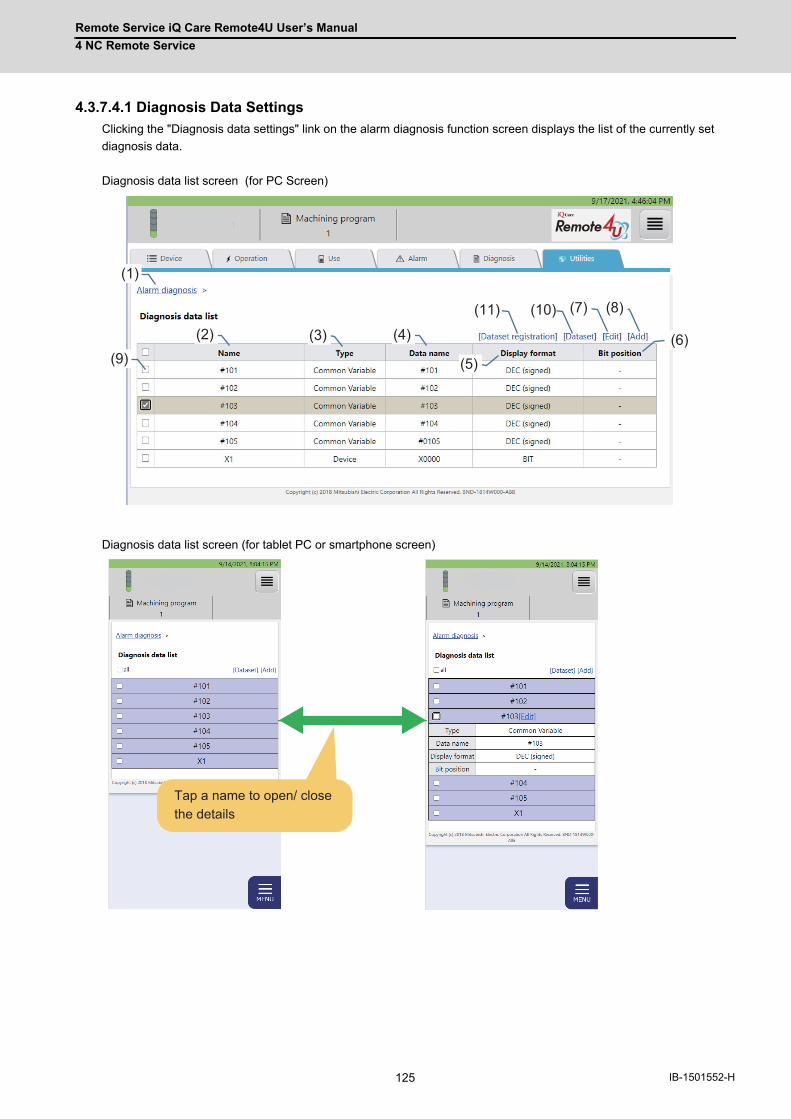
Remote Service iQ Care Remote4U User’s Manual
4 NC Remote Service
125 IB-1501552-H
4.3.7.4.1 Diagnosis Data Settings
Clicking the "Diagnosis data settings" link on the alarm diagnosis function screen displays the list of the currently set
diagnosis data.
Diagnosis data list screen (for PC Screen)
Diagnosis data list screen (for tablet PC or smartphone screen)
1(1)
1(2) 1(3) 1(4)
1(5)1(6)
(7) 1(8)
(9)
1(11) 1(10)
Tap a name to open/ close the details
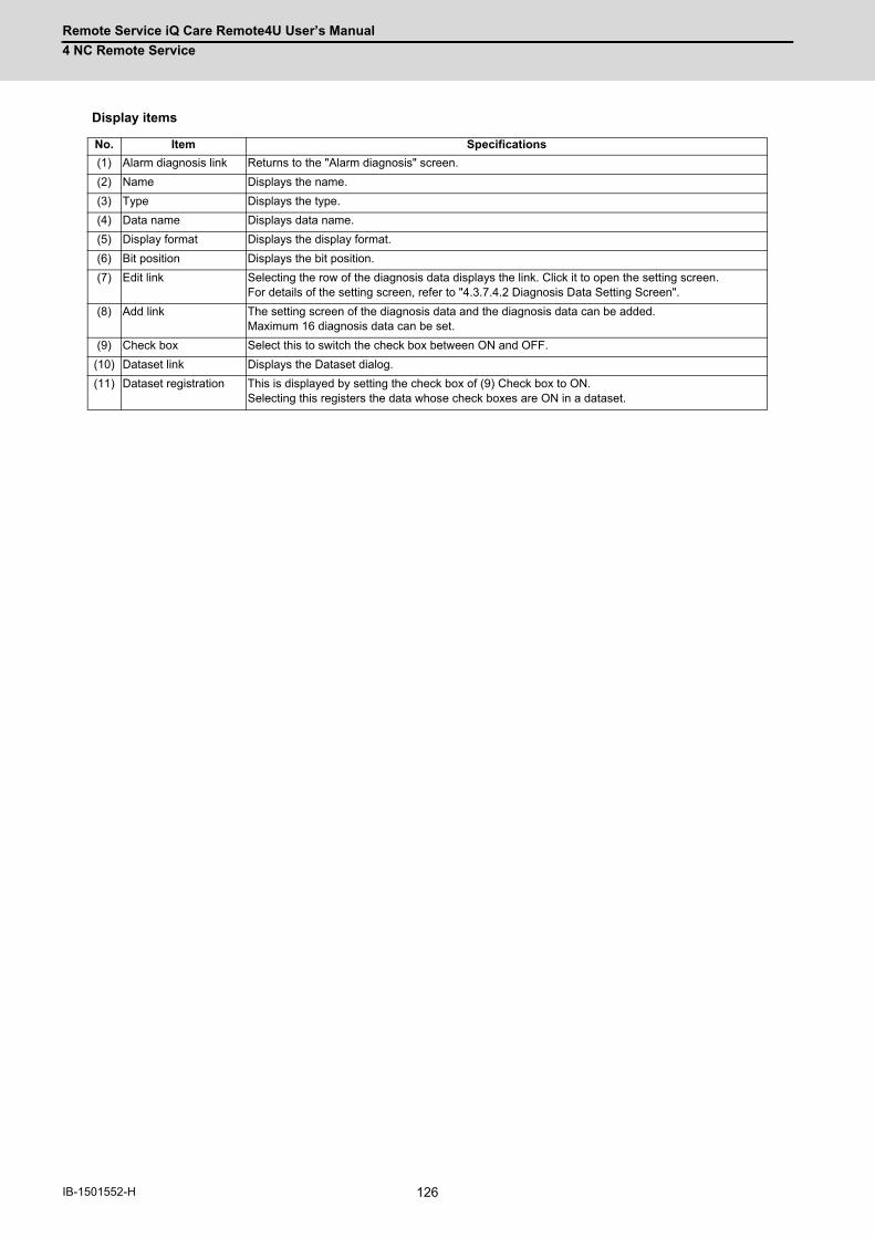
Remote Service iQ Care Remote4U User’s Manual
4 NC Remote Service
126IB-1501552-H
Display items
No. Item Specifications
(1) Alarm diagnosis link Returns to the "Alarm diagnosis" screen.
(2) Name Displays the name.
(3) Type Displays the type.
(4) Data name Displays data name.
(5) Display format Displays the display format.
(6) Bit position Displays the bit position.
(7) Edit link Selecting the row of the diagnosis data displays the link. Click it to open the setting screen.For details of the setting screen, refer to "4.3.7.4.2 Diagnosis Data Setting Screen".
(8) Add link The setting screen of the diagnosis data and the diagnosis data can be added. Maximum 16 diagnosis data can be set.
(9) Check box Select this to switch the check box between ON and OFF.
(10) Dataset link Displays the Dataset dialog.
(11) Dataset registration This is displayed by setting the check box of (9) Check box to ON.Selecting this registers the data whose check boxes are ON in a dataset.

Remote Service iQ Care Remote4U User’s Manual
4 NC Remote Service
127 IB-1501552-H
Dataset dialog
The registered contents on the diagnosis data list can be shared in the organization by using dataset function.
Register to the dataset by clicking the [Dataset registration] link on the diagnosis data list.
Read and delete from the dataset on the dataset dialog.
Display items
No. Item Specifications
(1) Name Displays the name.
(2) Type Displays the type.
(3) Data name Displays data name.
(4) Display format Displays the display format.
(5) Bit position Displays the bit position.
(6) Check box Select this to switch the check box between ON and OFF.
(7) "Delete from dataset" button
This button can be selected by setting the check box of (6) Check box to ON.Select this button to display a confirmation dialog and press the OK button to delete the data whose check boxes are ON from the dataset.
(8) Add button This button can be selected by setting the check box of (6) Check box to ON.Selecting this button adds the data whose check boxes are ON to the diagnosis data list.
(9) × button Closes the Dataset dialog.
(6)
(1) (2) (3) (4) (5)(9)
(8)(7)
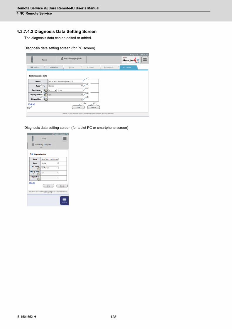
Remote Service iQ Care Remote4U User’s Manual
4 NC Remote Service
128IB-1501552-H
4.3.7.4.2 Diagnosis Data Setting Screen
The diagnosis data can be edited or added.
Diagnosis data setting screen (for PC screen)
Diagnosis data setting screen (for tablet PC or smartphone screen)
(1)
(2)
(4)
(6)
(8)
(10) (11)
(3)
(5)
(7)
(9)
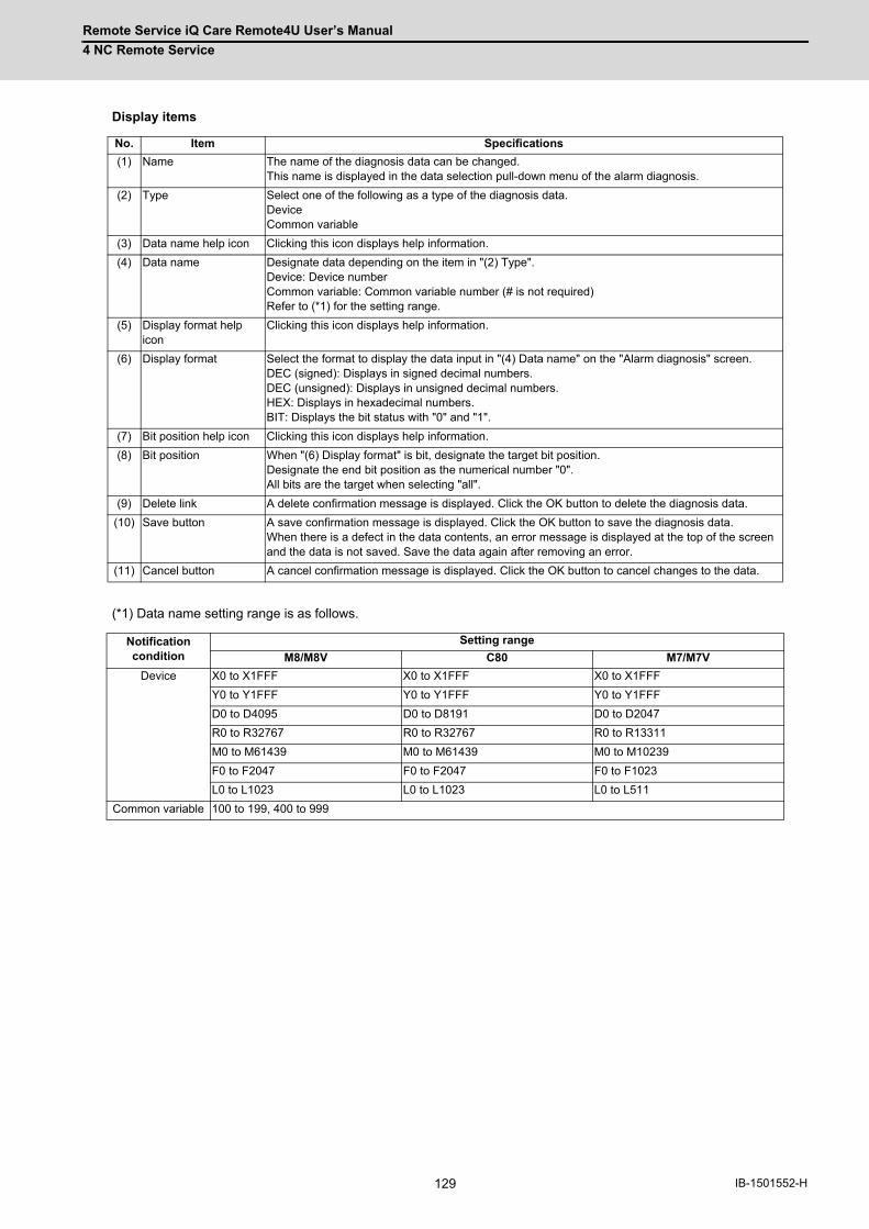
Remote Service iQ Care Remote4U User’s Manual
4 NC Remote Service
129 IB-1501552-H
Display items
(*1) Data name setting range is as follows.
No. Item Specifications
(1) Name The name of the diagnosis data can be changed. This name is displayed in the data selection pull-down menu of the alarm diagnosis.
(2) Type Select one of the following as a type of the diagnosis data. Device Common variable
(3) Data name help icon Clicking this icon displays help information.
(4) Data name Designate data depending on the item in "(2) Type". Device: Device number Common variable: Common variable number (# is not required) Refer to (*1) for the setting range.
(5) Display format help icon
Clicking this icon displays help information.
(6) Display format Select the format to display the data input in "(4) Data name" on the "Alarm diagnosis" screen. DEC (signed): Displays in signed decimal numbers. DEC (unsigned): Displays in unsigned decimal numbers. HEX: Displays in hexadecimal numbers. BIT: Displays the bit status with "0" and "1".
(7) Bit position help icon Clicking this icon displays help information.
(8) Bit position When "(6) Display format" is bit, designate the target bit position.Designate the end bit position as the numerical number "0".All bits are the target when selecting "all".
(9) Delete link A delete confirmation message is displayed. Click the OK button to delete the diagnosis data.
(10) Save button A save confirmation message is displayed. Click the OK button to save the diagnosis data.When there is a defect in the data contents, an error message is displayed at the top of the screen and the data is not saved. Save the data again after removing an error.
(11) Cancel button A cancel confirmation message is displayed. Click the OK button to cancel changes to the data.
Notification condition
Setting range
M8/M8V C80 M7/M7V
Device X0 to X1FFF X0 to X1FFF X0 to X1FFF
Y0 to Y1FFF Y0 to Y1FFF Y0 to Y1FFF
D0 to D4095 D0 to D8191 D0 to D2047
R0 to R32767 R0 to R32767 R0 to R13311
M0 to M61439 M0 to M61439 M0 to M10239
F0 to F2047 F0 to F2047 F0 to F1023
L0 to L1023 L0 to L1023 L0 to L511
Common variable 100 to 199, 400 to 999

Remote Service iQ Care Remote4U User’s Manual
4 NC Remote Service
130IB-1501552-H
4.3.7.5 Email Notification Settings
The email notification conditions currently set are displayed by selecting "Email notification settings" from the pull-down
menu.
By setting the email notification conditions, an email can be received depending on the NC status. The email is sent
when the set conditions are satisfied. A maximum of 8 email notification conditions can be set.
Email notification conditions screen (for PC screen)
Email notification conditions screen (for tablet PC or smartphone screen)
(9)(1) (3) (4) (5) (6) (7) (8) (9)(11) (12)
(10)(2)
Tap a notification condition name to open
Notification condition list
Edit link is displayed
Tap the open notification condition name to closeOnly the tapped notification condition name opens.
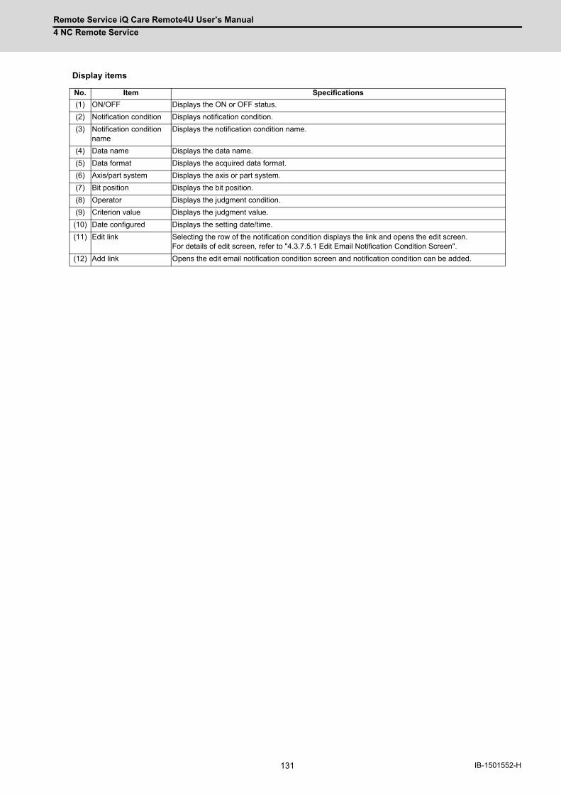
Remote Service iQ Care Remote4U User’s Manual
4 NC Remote Service
131 IB-1501552-H
Display items
No. Item Specifications
(1) ON/OFF Displays the ON or OFF status.
(2) Notification condition Displays notification condition.
(3) Notification condition name
Displays the notification condition name.
(4) Data name Displays the data name.
(5) Data format Displays the acquired data format.
(6) Axis/part system Displays the axis or part system.
(7) Bit position Displays the bit position.
(8) Operator Displays the judgment condition.
(9) Criterion value Displays the judgment value.
(10) Date configured Displays the setting date/time.
(11) Edit link Selecting the row of the notification condition displays the link and opens the edit screen. For details of edit screen, refer to "4.3.7.5.1 Edit Email Notification Condition Screen".
(12) Add link Opens the edit email notification condition screen and notification condition can be added.
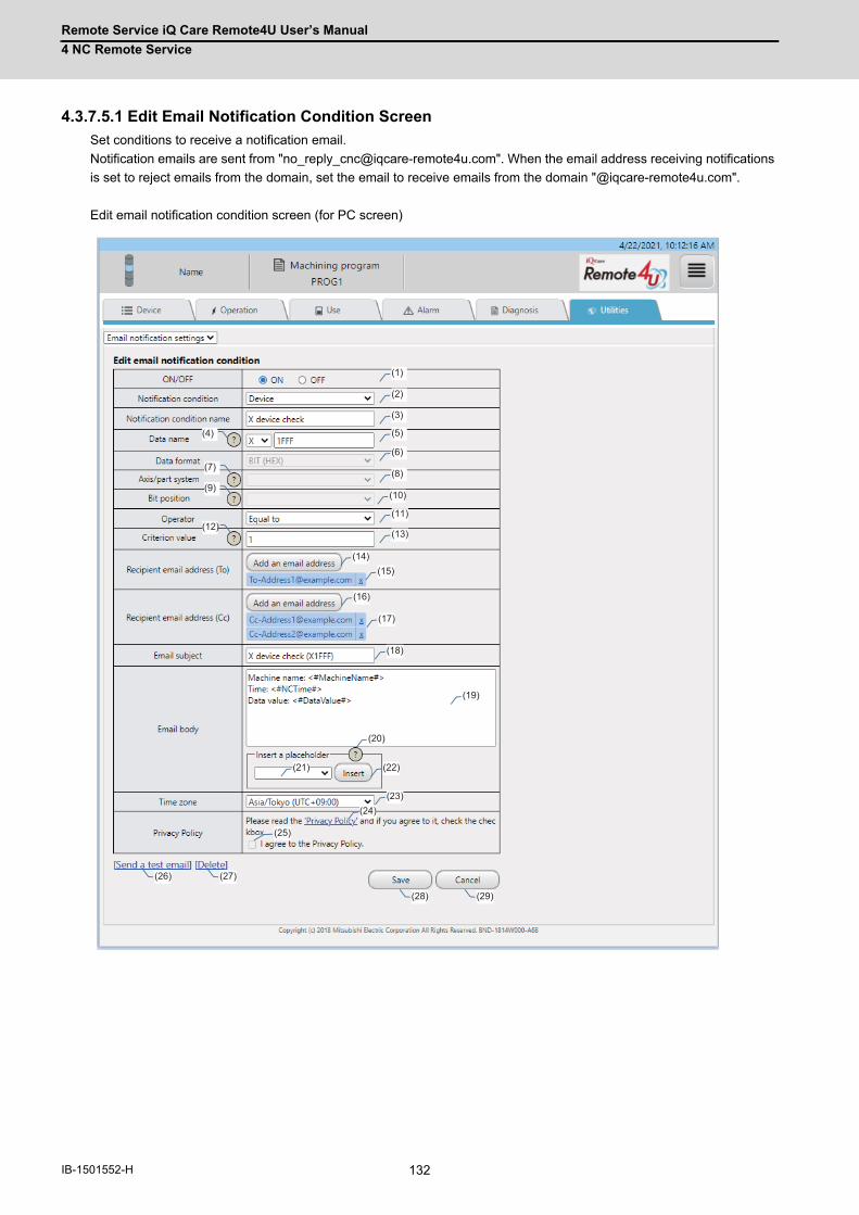
Remote Service iQ Care Remote4U User’s Manual
4 NC Remote Service
132IB-1501552-H
4.3.7.5.1 Edit Email Notification Condition Screen
Set conditions to receive a notification email.
Notification emails are sent from "[email protected]". When the email address receiving notifications
is set to reject emails from the domain, set the email to receive emails from the domain "@iqcare-remote4u.com".
Edit email notification condition screen (for PC screen)
(1)
(2)
(3)
(5)
(6)
(8)
(10)
(11)
(13)
(4)
(7)
(9)
(12)
(14)(15)
(16)
(17)
(18)
(19)
(20)
(21) (22)
(23)(24)
(25)
(26) (27)
(28) (29)

Remote Service iQ Care Remote4U User’s Manual
4 NC Remote Service
133 IB-1501552-H
Edit email notification condition screen (for tablet PC or smartphone screen)
Continue
Continued
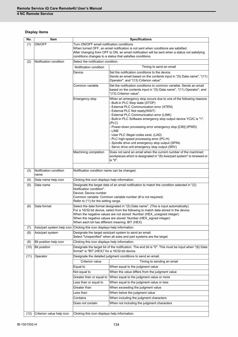
Remote Service iQ Care Remote4U User’s Manual
4 NC Remote Service
134IB-1501552-H
Display items
No. Item Specifications
(1) ON/OFF Turn ON/OFF email notification conditions.When turned OFF, an email notification is not sent when conditions are satisfied.After changing from OFF to ON, an email notification will be sent when a status not satisfying conditions changes to a status that satisfies conditions.
(2) Notification condition Select the notification condition.
Notification condition Timing to send an email
Device Set the notification conditions to the device.Sends an email based on the contents input in "(5) Data name", "(11) Operator", and "(13) Criterion value".
Common variable Set the notification conditions to common variable. Sends an email based on the contents input in "(5) Data name", "(11) Operator", and "(13) Criterion value".
Emergency stop When an emergency stop occurs due to one of the following reasons - Built-in PLC Stop state (STOP) - External PLC Communication error (XTEN) - External PLC Not ready(WAIT) - External PLC Communication error (LINK) - Built-in PLC Software emergency stop output device YC2C is "1". (PLC) - Power-down processing error emergency stop [C80] (IPWD) - LINE - User PLC Illegal codes exist. (LAD) - PLC high-speed processing error (PC-H) - Spindle drive unit emergency stop output (SPIN) - Servo drive unit emergency stop output (SRV)
Machining completion Does not send an email when the current number of the machined workpieces which is designated in "(8) Axis/part system" is renewed or is "0".
(3) Notification condition name
Notification condition name can be changed.
(4) Data name help icon Clicking this icon displays help information.
(5) Data name Designate the target data of an email notification to match the condition selected in "(2) Notification condition". Device: Device number Common variable: Common variable number (# is not required) Refer to (*1) for the setting range.
(6) Data format Select the data format designated in "(5) Data name". (This is input automatically) For a 16/32-bit device, select from the following to match data stored in the device. When the negative values are not stored: Number (HEX_unsigned integer)When the negative values are stored: Number (HEX_signed integer)When each bit has different meaning: BIT (HEX)
(7) Axis/part system help icon Clicking this icon displays help information.
(8) Axis/part system Designate the target axis/part system to send an email. Select "Unspecified" when all axes and part systems are the target.
(9) Bit position help icon Clicking this icon displays help information.
(10) Bit position Designate the target bit of the notification. The end bit is "0". This must be input when "(6) Data format" is "BIT (HEX)" for a 16/32-bit device.
(11) Operator Designate the detailed judgment conditions to send an email.
Criterion value Timing to sending an email
Equal to When equal to the judgment value
Not equal to When the value differs from the judgment value
Greater than or equal to When equal to the judgment value or more
Less than or equal to When equal to the judgment value or less
Greater than When exceeding the judgment value
Less than When below the judgment value
Contains When including the judgment characters
Does not contain When not including the judgment characters
(12) Criterion value help icon Clicking this icon displays help information.
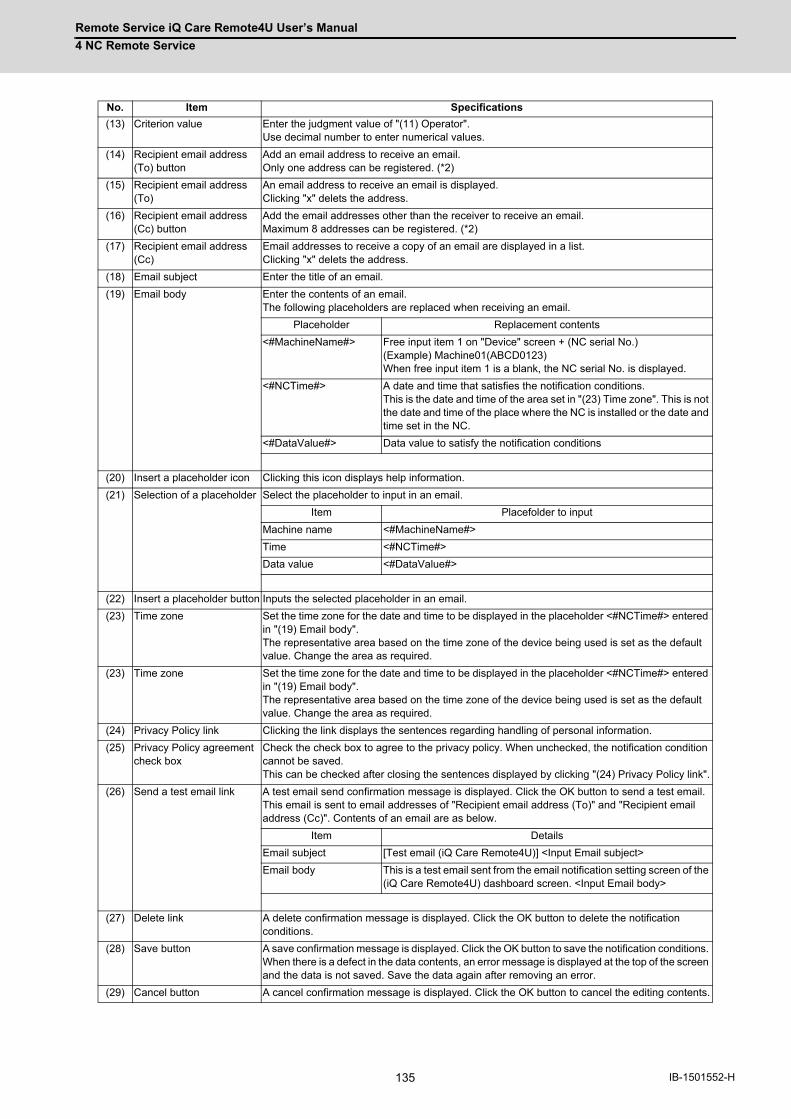
Remote Service iQ Care Remote4U User’s Manual
4 NC Remote Service
135 IB-1501552-H
(13) Criterion value Enter the judgment value of "(11) Operator". Use decimal number to enter numerical values.
(14) Recipient email address (To) button
Add an email address to receive an email. Only one address can be registered. (*2)
(15) Recipient email address (To)
An email address to receive an email is displayed. Clicking "x" delets the address.
(16) Recipient email address (Cc) button
Add the email addresses other than the receiver to receive an email. Maximum 8 addresses can be registered. (*2)
(17) Recipient email address (Cc)
Email addresses to receive a copy of an email are displayed in a list. Clicking "x" delets the address.
(18) Email subject Enter the title of an email.
(19) Email body Enter the contents of an email. The following placeholders are replaced when receiving an email.
Placeholder Replacement contents
<#MachineName#> Free input item 1 on "Device" screen + (NC serial No.) (Example) Machine01(ABCD0123) When free input item 1 is a blank, the NC serial No. is displayed.
<#NCTime#> A date and time that satisfies the notification conditions.This is the date and time of the area set in "(23) Time zone". This is not the date and time of the place where the NC is installed or the date and time set in the NC.
<#DataValue#> Data value to satisfy the notification conditions
(20) Insert a placeholder icon Clicking this icon displays help information.
(21) Selection of a placeholder Select the placeholder to input in an email.
Item Placefolder to input
Machine name <#MachineName#>
Time <#NCTime#>
Data value <#DataValue#>
(22) Insert a placeholder button Inputs the selected placeholder in an email.
(23) Time zone Set the time zone for the date and time to be displayed in the placeholder <#NCTime#> entered in "(19) Email body".The representative area based on the time zone of the device being used is set as the default value. Change the area as required.
(23) Time zone Set the time zone for the date and time to be displayed in the placeholder <#NCTime#> entered in "(19) Email body".The representative area based on the time zone of the device being used is set as the default value. Change the area as required.
(24) Privacy Policy link Clicking the link displays the sentences regarding handling of personal information.
(25) Privacy Policy agreement check box
Check the check box to agree to the privacy policy. When unchecked, the notification condition cannot be saved.This can be checked after closing the sentences displayed by clicking "(24) Privacy Policy link".
(26) Send a test email link A test email send confirmation message is displayed. Click the OK button to send a test email. This email is sent to email addresses of "Recipient email address (To)" and "Recipient email address (Cc)". Contents of an email are as below.
Item Details
Email subject [Test email (iQ Care Remote4U)] <Input Email subject>
Email body This is a test email sent from the email notification setting screen of the (iQ Care Remote4U) dashboard screen. <Input Email body>
(27) Delete link A delete confirmation message is displayed. Click the OK button to delete the notification conditions.
(28) Save button A save confirmation message is displayed. Click the OK button to save the notification conditions. When there is a defect in the data contents, an error message is displayed at the top of the screen and the data is not saved. Save the data again after removing an error.
(29) Cancel button A cancel confirmation message is displayed. Click the OK button to cancel the editing contents.
No. Item Specifications

Remote Service iQ Care Remote4U User’s Manual
4 NC Remote Service
136IB-1501552-H
(*1) The setting range of data name is as below.
(*2) An error does not occur when an email address which does not exist is set. Conduct an email reception test by
clicking "(26) Send a test email".
As an error does not occur when an email address is disabled after setting the notification, check if the set email
address can still be used when you stop receiving emails.
Notification condition
Setting range
M8/M8V C80 M7/M7V
Device X0 to X1FFF X0 to X1FFF X0 to X1FFF
Y0 to Y1FFF Y0 to Y1FFF Y0 to Y1FFF
D0 to D4095 D0 to D8191 D0 to D2047
R0 to R32767 R0 to R32767 R0 to R13311
M0 to M61439 M0 to M61439 M0 to M10239
F0 to F2047 F0 to F2047 F0 to F1023
L0 to L1023 L0 to L1023 L0 to L511
Common variable 100 to 199, 400 to 999
Remote Service iQ Care Remote4U User’s Manual
4 NC Remote Service
137 IB-1501552-H
4.3.7.5.2 Notification Condition Setting Method
The following shows the setting methods of the notification condition. The following are the setting procedures to receive
an email.
(1) When X4 device is ON
(2) When D200 device is "100" or below
(3) When bit3 of D300 device is OFF
(4) When common variable #123 of the 3rd part system is "45.6" or more.
Item Details
Notification condition Select "Device".
Data name Enter "X4"
Data format This is selected automatically.
Axis/part system This is not necessary.
Bit position This is not necessary.
Operator Select "Equal to" to receive an email when X4 device is ON (when bit is "1").
Criterion value Select "1" to receive an email when X4 device is ON (when bit is "1").
Item Details
Notification condition Select "Device".
Data name Enter "D200".
Data format Select "Number (HEX_unsigned integer)" when only positive values are entered in the D200 device with the NC.Select "Number (HEX_signed integer)" when negative values are entered.
Axis/part system This is not necessary.
Bit position This is not necessary.
Operator Select "Less than or equal to" to receive an email when the D200 device is "100" or below.
Criterion value Select "100" to receive an email when the D200 device is "100" or below.
Item Details
Notification condition Select "Device".
Data name Enter "D300".
Data format Select "BIT (HEX)".
Axis/part system This is not necessary.
Bit position Enter "3" because bit3 is the target.
Operator Select "Equal to" to receive an email when bit3 is OFF (when bit is "0").
Criterion value Enter "0" to receive an email when bit3 is OFF (when bit is "0").
Item Details
Notification condition Select "Common variable".
Data name Enter "123".
Data format This is selected automatically.
Axis/part system Enter "3" because the 3rd part system is the target.
Bit position This is not necessary.
Operator Select "Greater than" to receive an email when common varible is "45.6" or bigger.
Criterion value Enter "45.6" to receive an email when common varible is "45.6" or bigger.
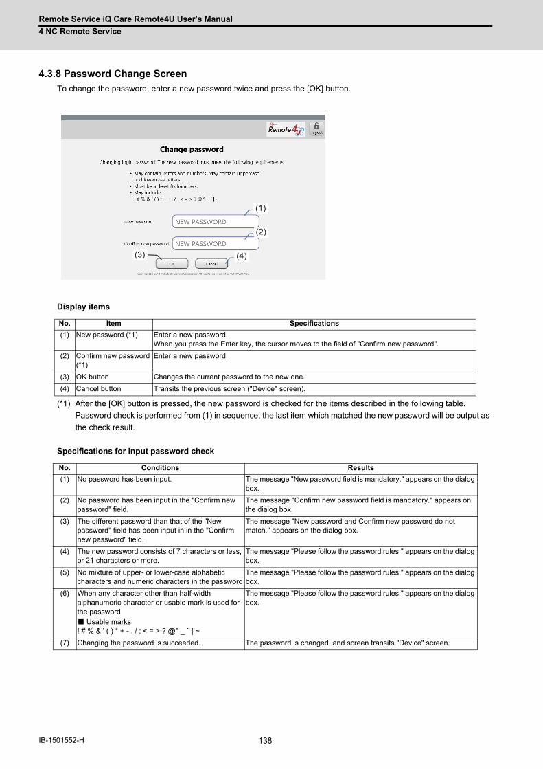
Remote Service iQ Care Remote4U User’s Manual
4 NC Remote Service
138IB-1501552-H
4.3.8 Password Change Screen
To change the password, enter a new password twice and press the [OK] button.
Display items
(*1) After the [OK] button is pressed, the new password is checked for the items described in the following table.
Password check is performed from (1) in sequence, the last item which matched the new password will be output as
the check result.
Specifications for input password check
No. Item Specifications
(1) New password (*1) Enter a new password. When you press the Enter key, the cursor moves to the field of "Confirm new password".
(2) Confirm new password (*1)
Enter a new password.
(3) OK button Changes the current password to the new one.
(4) Cancel button Transits the previous screen ("Device" screen).
No. Conditions Results
(1) No password has been input. The message "New password field is mandatory." appears on the dialog box.
(2) No password has been input in the "Confirm new password" field.
The message "Confirm new password field is mandatory." appears on the dialog box.
(3) The different password than that of the "New password" field has been input in in the "Confirm new password" field.
The message "New password and Confirm new password do not match." appears on the dialog box.
(4) The new password consists of 7 characters or less, or 21 characters or more.
The message "Please follow the password rules." appears on the dialog box.
(5) No mixture of upper- or lower-case alphabetic characters and numeric characters in the password
The message "Please follow the password rules." appears on the dialog box.
(6) When any character other than half-width alphanumeric character or usable mark is used for the password ■ Usable marks ! # % & ' ( ) * + - . / ; < = > ? @^ _ ` | ~
The message "Please follow the password rules." appears on the dialog box.
(7) Changing the password is succeeded. The password is changed, and screen transits "Device" screen.
(3) (4)
(1)
(2)

Remote Service iQ Care Remote4U User’s Manual
4 NC Remote Service
139 IB-1501552-H
4.3.9 Machine Information Edit Screen
On this screen, you can edit some of the information of "4.3.2 Device Screen".
Display items of this screen are the same as "4.3.2 Device Screen".
You can edit some of items in the following table. Items (2) and (8) as titles, and corresponding items (9) and (10) as
contents of them are editable.
Only the user who is authorized to edit the machine information by his/her account setting can display this screen.
Display items
(*1) Since texts in a cell is not wrapped, scroll in the horizontal direction to display the whole texts.
No. Item Specifications
(1) Search keyword Displays the search keyword for executed search on "Device" screen.
(2) Free input Item 1 (Title) Register a title for free input item 1 Default setting: Machine Name Up to 32 characters
(3) Manufacturer (*1) Displays the name of the manufacturer.
(4) Machine type (*1) Displays the machine type.
(5) Machine number (*1) Displays the machine number.
(6) NC serial No. (*1) Displays the NC serial No.
(7) NC model type (*1) Displays the NC model type.
(8) Free input Item 2 (Title) Register a title for free input item 2 Default setting: Remarks Up to 32 characters
(9) Free input Item 1 (Contents)
Register contents for free input item 1 Default setting: Machine type name Up to 32 characters
(10) Free input Item 2 (Contents)
Register contents for free input item 2 Default setting: Blank Up to 64 characters
(11) Update button The update confirmation dialog is displayed by pressing the [Update] button. Press the [Cancel] button to return to the screen before the [Update] button was pressed. Press the [OK] button to update the input values for the fields of "Machine Name" and "Remarks". After the update is completed, the original screen which calls machine information edit screen appears.
(12) Cancel button When the contents on the screen are updated, a cancel confirmation dialog appears. Press [OK] button to return to the original screen which calls machine information edit screen.
(13) Records Displays the number of devices currently displayed. When a search was performed on "Device" screen, the number of searched devices is displayed.
(2) (3) (4) (5) (6) (7) (8) (1)
(9)(12)(11)
(10)
(13)
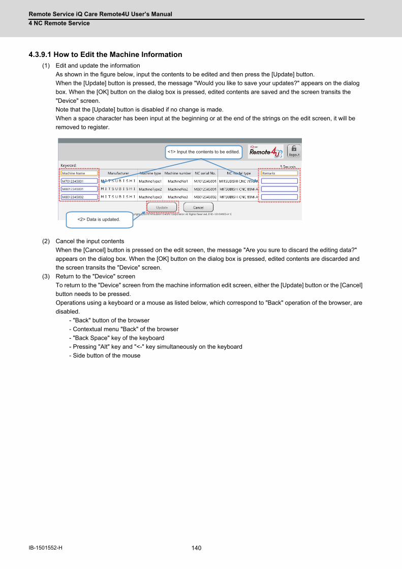
Remote Service iQ Care Remote4U User’s Manual
4 NC Remote Service
140IB-1501552-H
4.3.9.1 How to Edit the Machine Information
(1) Edit and update the information
As shown in the figure below, input the contents to be edited and then press the [Update] button.
When the [Update] button is pressed, the message "Would you like to save your updates?" appears on the dialog
box. When the [OK] button on the dialog box is pressed, edited contents are saved and the screen transits the
"Device" screen.
Note that the [Update] button is disabled if no change is made.
When a space character has been input at the beginning or at the end of the strings on the edit screen, it will be
removed to register.
(2) Cancel the input contents
When the [Cancel] button is pressed on the edit screen, the message "Are you sure to discard the editing data?"
appears on the dialog box. When the [OK] button on the dialog box is pressed, edited contents are discarded and
the screen transits the "Device" screen.
(3) Return to the "Device" screen
To return to the "Device" screen from the machine information edit screen, either the [Update] button or the [Cancel]
button needs to be pressed.
Operations using a keyboard or a mouse as listed below, which correspond to "Back" operation of the browser, are
disabled.
- "Back" button of the browser
- Contextual menu "Back" of the browser
- "Back Space" key of the keyboard
- Pressing "Alt" key and "<-" key simultaneously on the keyboard
- Side button of the mouse
<1> Input the contents to be edited.
<2> Data is updated.
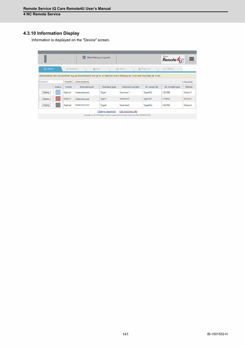
Remote Service iQ Care Remote4U User’s Manual
4 NC Remote Service
141 IB-1501552-H
4.3.10 Information Display
Information is displayed on the "Device" screen.
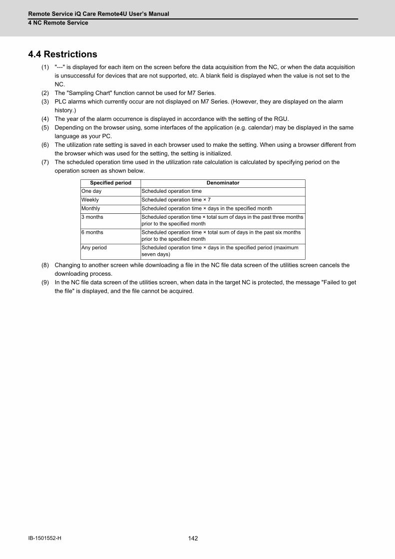
Remote Service iQ Care Remote4U User’s Manual
4 NC Remote Service
142IB-1501552-H
4.4 Restrictions(1) "---" is displayed for each item on the screen before the data acquisition from the NC, or when the data acquisition
is unsuccessful for devices that are not supported, etc. A blank field is displayed when the value is not set to the
NC.
(2) The "Sampling Chart" function cannot be used for M7 Series.
(3) PLC alarms which currently occur are not displayed on M7 Series. (However, they are displayed on the alarm
history.)
(4) The year of the alarm occurrence is displayed in accordance with the setting of the RGU.
(5) Depending on the browser using, some interfaces of the application (e.g. calendar) may be displayed in the same
language as your PC.
(6) The utilization rate setting is saved in each browser used to make the setting. When using a browser different from
the browser which was used for the setting, the setting is initialized.
(7) The scheduled operation time used in the utilization rate calculation is calculated by specifying period on the
operation screen as shown below.
(8) Changing to another screen while downloading a file in the NC file data screen of the utilities screen cancels the
downloading process.
(9) In the NC file data screen of the utilities screen, when data in the target NC is protected, the message "Failed to get
the file" is displayed, and the file cannot be acquired.
Specified period Denominator
One day Scheduled operation time
Weekly Scheduled operation time × 7
Monthly Scheduled operation time × days in the specified month
3 months Scheduled operation time × total sum of days in the past three months prior to the specified month
6 months Scheduled operation time × total sum of days in the past six months prior to the specified month
Any period Scheduled operation time × days in the specified period (maximum seven days)
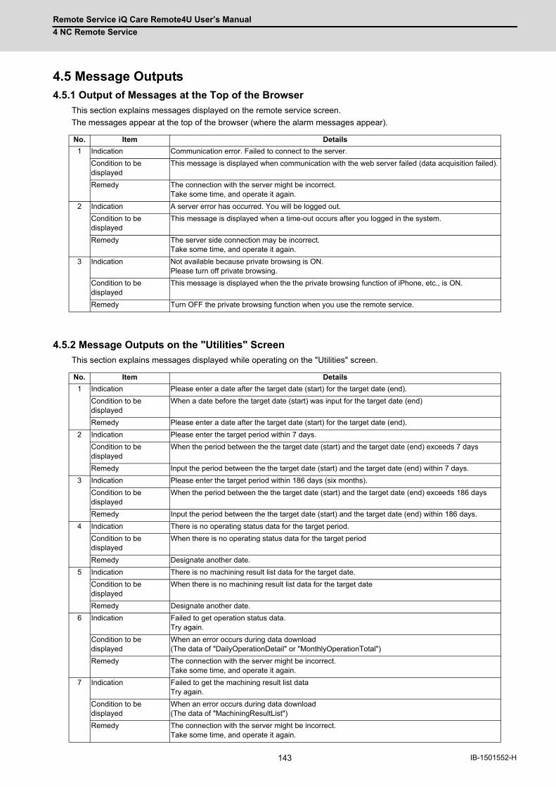
Remote Service iQ Care Remote4U User’s Manual
4 NC Remote Service
143 IB-1501552-H
4.5 Message Outputs4.5.1 Output of Messages at the Top of the Browser
This section explains messages displayed on the remote service screen.
The messages appear at the top of the browser (where the alarm messages appear).
4.5.2 Message Outputs on the "Utilities" Screen
This section explains messages displayed while operating on the "Utilities" screen.
No. Item Details
1 Indication Communication error. Failed to connect to the server.
Condition to be displayed
This message is displayed when communication with the web server failed (data acquisition failed).
Remedy The connection with the server might be incorrect. Take some time, and operate it again.
2 Indication A server error has occurred. You will be logged out.
Condition to be displayed
This message is displayed when a time-out occurs after you logged in the system.
Remedy The server side connection may be incorrect. Take some time, and operate it again.
3 Indication Not available because private browsing is ON. Please turn off private browsing.
Condition to be displayed
This message is displayed when the the private browsing function of iPhone, etc., is ON.
Remedy Turn OFF the private browsing function when you use the remote service.
No. Item Details
1 Indication Please enter a date after the target date (start) for the target date (end).
Condition to be displayed
When a date before the target date (start) was input for the target date (end)
Remedy Please enter a date after the target date (start) for the target date (end).
2 Indication Please enter the target period within 7 days.
Condition to be displayed
When the period between the the target date (start) and the target date (end) exceeds 7 days
Remedy Input the period between the the target date (start) and the target date (end) within 7 days.
3 Indication Please enter the target period within 186 days (six months).
Condition to be displayed
When the period between the the target date (start) and the target date (end) exceeds 186 days
Remedy Input the period between the the target date (start) and the target date (end) within 186 days.
4 Indication There is no operating status data for the target period.
Condition to be displayed
When there is no operating status data for the target period
Remedy Designate another date.
5 Indication There is no machining result list data for the target date.
Condition to be displayed
When there is no machining result list data for the target date
Remedy Designate another date.
6 Indication Failed to get operation status data. Try again.
Condition to be displayed
When an error occurs during data download (The data of "DailyOperationDetail" or "MonthlyOperationTotal")
Remedy The connection with the server might be incorrect. Take some time, and operate it again.
7 Indication Failed to get the machining result list data Try again.
Condition to be displayed
When an error occurs during data download (The data of "MachiningResultList")
Remedy The connection with the server might be incorrect. Take some time, and operate it again.
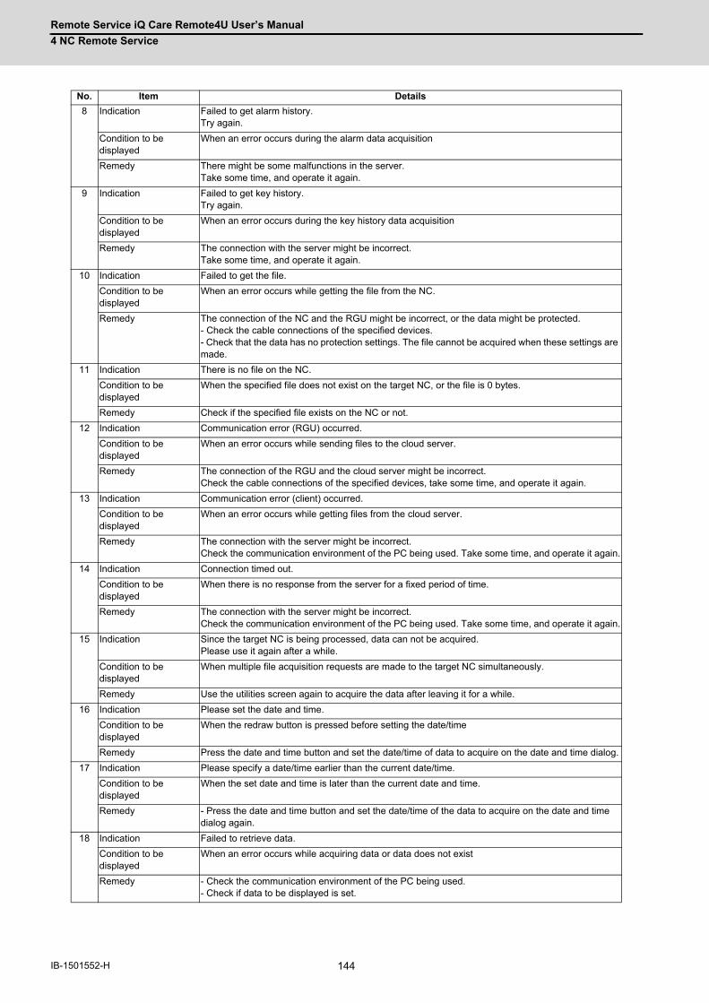
Remote Service iQ Care Remote4U User’s Manual
4 NC Remote Service
144IB-1501552-H
8 Indication Failed to get alarm history. Try again.
Condition to be displayed
When an error occurs during the alarm data acquisition
Remedy There might be some malfunctions in the server. Take some time, and operate it again.
9 Indication Failed to get key history. Try again.
Condition to be displayed
When an error occurs during the key history data acquisition
Remedy The connection with the server might be incorrect. Take some time, and operate it again.
10 Indication Failed to get the file.
Condition to be displayed
When an error occurs while getting the file from the NC.
Remedy The connection of the NC and the RGU might be incorrect, or the data might be protected.- Check the cable connections of the specified devices.- Check that the data has no protection settings. The file cannot be acquired when these settings are made.
11 Indication There is no file on the NC.
Condition to be displayed
When the specified file does not exist on the target NC, or the file is 0 bytes.
Remedy Check if the specified file exists on the NC or not.
12 Indication Communication error (RGU) occurred.
Condition to be displayed
When an error occurs while sending files to the cloud server.
Remedy The connection of the RGU and the cloud server might be incorrect.Check the cable connections of the specified devices, take some time, and operate it again.
13 Indication Communication error (client) occurred.
Condition to be displayed
When an error occurs while getting files from the cloud server.
Remedy The connection with the server might be incorrect.Check the communication environment of the PC being used. Take some time, and operate it again.
14 Indication Connection timed out.
Condition to be displayed
When there is no response from the server for a fixed period of time.
Remedy The connection with the server might be incorrect.Check the communication environment of the PC being used. Take some time, and operate it again.
15 Indication Since the target NC is being processed, data can not be acquired.Please use it again after a while.
Condition to be displayed
When multiple file acquisition requests are made to the target NC simultaneously.
Remedy Use the utilities screen again to acquire the data after leaving it for a while.
16 Indication Please set the date and time.
Condition to be displayed
When the redraw button is pressed before setting the date/time
Remedy Press the date and time button and set the date/time of data to acquire on the date and time dialog.
17 Indication Please specify a date/time earlier than the current date/time.
Condition to be displayed
When the set date and time is later than the current date and time.
Remedy - Press the date and time button and set the date/time of the data to acquire on the date and time dialog again.
18 Indication Failed to retrieve data.
Condition to be displayed
When an error occurs while acquiring data or data does not exist
Remedy - Check the communication environment of the PC being used. - Check if data to be displayed is set.
No. Item Details
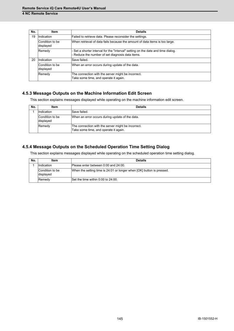
Remote Service iQ Care Remote4U User’s Manual
4 NC Remote Service
145 IB-1501552-H
4.5.3 Message Outputs on the Machine Information Edit Screen
This section explains messages displayed while operating on the machine information edit screen.
4.5.4 Message Outputs on the Scheduled Operation Time Setting Dialog
This section explains messages displayed while operating on the scheduled operation time setting dialog.
19 Indication Failed to retrieve data. Please reconsider the settings.
Condition to be displayed
When retrieval of data fails because the amount of data items is too large.
Remedy - Set a shorter interval for the "interval" setting on the date and time dialog.- Reduce the number of set diagnosis data items.
20 Indication Save failed.
Condition to be displayed
When an error occurs during update of the data.
Remedy The connection with the server might be incorrect. Take some time, and operate it again.
No. Item Details
1 Indication Save failed.
Condition to be displayed
When an error occurs during update of the data.
Remedy The connection with the server might be incorrect. Take some time, and operate it again.
No. Item Details
1 Indication Please enter between 0:00 and 24:00.
Condition to be displayed
When the setting time is 24:01 or longer when [OK] button is pressed.
Remedy Set the time within 0:00 to 24:00.
No. Item Details
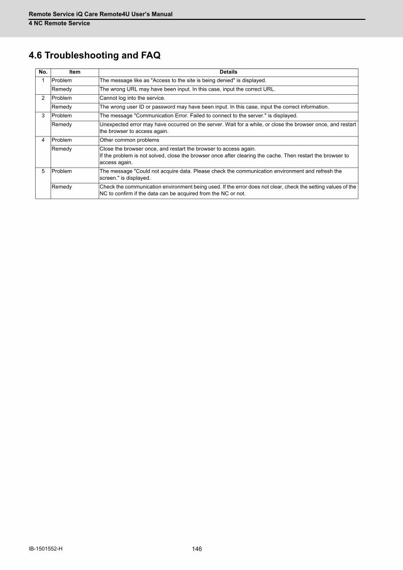
Remote Service iQ Care Remote4U User’s Manual
4 NC Remote Service
146IB-1501552-H
4.6 Troubleshooting and FAQ
No. Item Details
1 Problem The message like as "Access to the site is being denied" is displayed.
Remedy The wrong URL may have been input. In this case, input the correct URL.
2 Problem Cannot log into the service.
Remedy The wrong user ID or password may have been input. In this case, input the correct information.
3 Problem The message "Communication Error. Failed to connect to the server." is displayed.
Remedy Unexpected error may have occurred on the server. Wait for a while, or close the browser once, and restart the browser to access again.
4 Problem Other common problems
Remedy Close the browser once, and restart the browser to access again. If the problem is not solved, close the browser once after clearing the cache. Then restart the browser to access again.
5 Problem The message "Could not acquire data. Please check the communication environment and refresh the screen." is displayed.
Remedy Check the communication environment being used. If the error does not clear, check the setting values of the NC to confirm if the data can be acquired from the NC or not.

147 IB-1501552-H
5
Appendix 1: EMC Installation Guidelines

Remote Service iQ Care Remote4U User’s Manual
5 Appendix 1: EMC Installation Guidelines
148IB-1501552-H
For details of the drive section (servo/spindle drive unit), refer to "EMC Installation Guidelines" of instruction manuals for
each drive unit.
5.1 IntroductionEMC Directives became mandatory as of January 1, 1996. The subject products must have a CE mark attached
indicating that the product complies with the Directives.
As the NC unit is a component designed to control machine tools, we believe that it is not a direct EMC Directives
subject. However, we would like to introduce the following measure plans to back up EMC Directives compliance of the
machine tool as the NC unit is a major component of the machine tools.
(1) Methods of installation in control/operation panel
(2) Methods of wiring cables to outside of panel
(3) Introduction of members for measures
Mitsubishi is carrying out tests to confirm the compliance to the EMC Directives under the environment described in this
manual. However, the level of the noise varies depending on the equipment type and layout, control panel structure and
wiring lead-in, etc.
Thus, we ask that the machine tool builder for confirming the final noise level.
5.2 EMC DirectivesThe items that the EMC Directives regulate can be roughly divided into the following two types.
- Emission: Capacity to prevent output of obstructive noise that adversely affects external devices
- Immunity: Capacity to not malfunction due to obstructive noise from external source
Contents of the regulation are summarized in the table below.
We assume that the standards and test contents required for a machine tool are almost the same as the following.
Class Name Details EN Standards
Emission
Radiated noiseRestriction of electromagnetic noise radiated through the air
EN61000-6-4 (General industrial machine) EN61800-3 (Motor control unit)
EN55011 (CLASS: A)
Conductive noiseRestriction of electromagnetic noise discharged from power supply line
Immunity
Static electricity electrical discharge
(Example) Regulation of withstand level of static electricity electrical discharge accumulated in human body
EN61000-6-2 (General industrial machine) EN61800-3 (Motor control unit)
EN61000-4-2
Radiation immunity(Example) Simulation of immunity from digital wireless telephones
EN61000-4-3
Burst immunity(Example) Regulation of withstand level of noise from relay or plug and play
EN61000-4-4
Conductive immunity(Example) Regulation of withstand level of noise flowed from power supply wires, etc.
EN61000-4-6
Power supply frequency magnetic field
(Example) Regulation of electromagnetic noise of 50/60Hz power supply frequency
EN61000-4-8
Power supply dip (fluctuation)
(Example) Regulation of power voltage drop withstand level
EN61000-4-11
Surge(Example) Regulation of withstand level of noise caused by lightning
EN61000-4-5

Remote Service iQ Care Remote4U User’s Manual
5 Appendix 1: EMC Installation Guidelines
149 IB-1501552-H
5.3 EMC MeasuresThe following items mainly need to be taken into account as a countermeasure for EMC.
(1) Store the device in a sealed metal panel.
(2) Ground all conductors that are floating electrically. Decrease the impedance.
(3) Increase the distance between the drive line and signal wire.
(4) Shield the cables wired outside of the panel.
(5) Install a noise filter.
Pay attention to the following items to suppress the noise radiated outside of the panel.
(1) Accurately ground the devices.
(2) Use shielded cables.
(3) Increase the electrical seal of the panel. Reduce the gaps and holes.
5.4 Panel StructureThe design of the panel is a very important factor for the EMC measures. Take the following measures sufficiently into
consideration when creating a panel.
5.4.1 Measures for Control Panel Body
(1) Use metal for all members configuring the panel.
(2) When joining the metal plate, treat the welded or contacting sections so that the impedance is reduced, and then fix
with screws.
(3) Be careful not to bend the plate by such as screwing work. If there is a gap, noise leaks out from that part.
(4) Plate (nickel tin) the metal plate surface at the grounding plate, and connect the connection parts with the low
impedance.
(5) If there is a large opening, such as ventilation holes, make sure to close the hole.
(Note 1) Using screws to fix the plates that have been painted is the same as an insulated state. Remove the paint and
fix the screws.
Painting mask
Joining interval: approximately 20 cm
Mesh cover(conductive sponge)
Opening
Control panel

Remote Service iQ Care Remote4U User’s Manual
5 Appendix 1: EMC Installation Guidelines
150IB-1501552-H
5.4.2 Measures for Door
(1) Use metal for all members configuring the panel.
(2) When joining the door, use a gasket to lower the impedance of the contacting sections, or use a structure with a
large contact area as shown below.
(3) The EMI gasket or conductive packing must contact the metal surface uniformly and at the correct position.
(Note 1) When not using a gasket, ground the control panel grounding with a grounding wire to lower the door's
impedance.
(Note 2) Using screws to fix the plates that have been painted (attachment of packing) is the same as an insulated
state. Remove the paint and fix the screws.
5.4.3 Measures for Power Supply
(1) Shield the power supply section and insert a filter to prevent the noise from flowing in or out. Selection of the noise
filter capacity varies depending on the drive unit and devices to be used.
(Note 1) The conductive noise can be suppressed by inserting a noise filter, but the radiated noise will flow out.
(Note 2) The conductive and radiated noise can both be suppressed by adding a partition plate to the noise filter.
(a) (b)
EMI gasket
Use of gasket Large contact area
Control panel
Door
Cross-section drawing
Contact area
Controlpanel
Door
NFNF
Device
Radiatednoise
AC input
Noisefilter
Partitionplate
Device
Radiated noise
AC input
Flow out
Conductivenoise Conductive
noiseNoisefilter
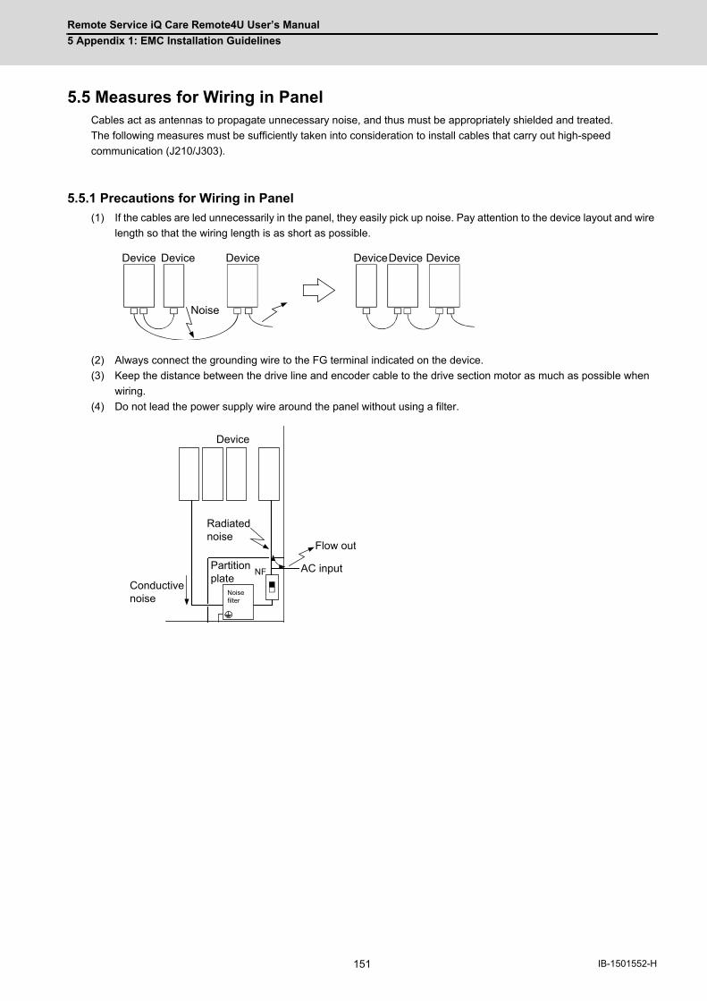
Remote Service iQ Care Remote4U User’s Manual
5 Appendix 1: EMC Installation Guidelines
151 IB-1501552-H
5.5 Measures for Wiring in PanelCables act as antennas to propagate unnecessary noise, and thus must be appropriately shielded and treated.
The following measures must be sufficiently taken into consideration to install cables that carry out high-speed
communication (J210/J303).
5.5.1 Precautions for Wiring in Panel
(1) If the cables are led unnecessarily in the panel, they easily pick up noise. Pay attention to the device layout and wire
length so that the wiring length is as short as possible.
(2) Always connect the grounding wire to the FG terminal indicated on the device.
(3) Keep the distance between the drive line and encoder cable to the drive section motor as much as possible when
wiring.
(4) Do not lead the power supply wire around the panel without using a filter.
Noise
Device Device Device DeviceDevice Device
NFPartition plate
Device
Radiated noise
AC inputConductive noise
Flow out
Noise filter
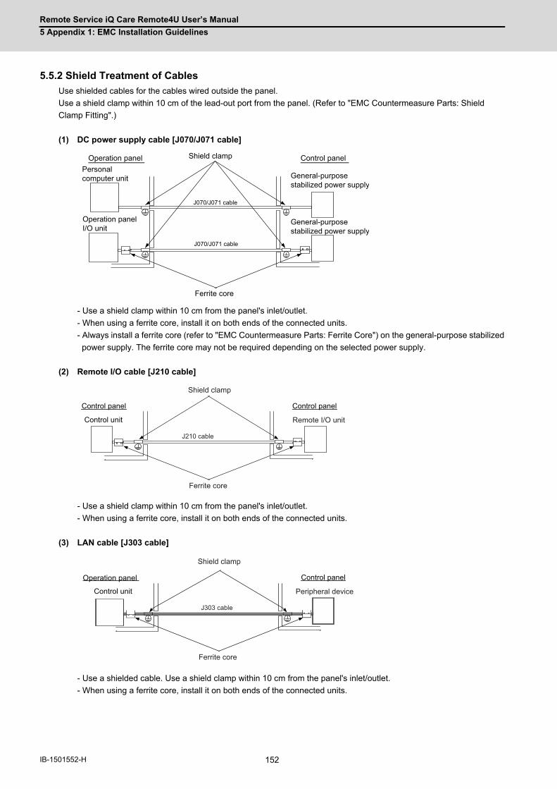
Remote Service iQ Care Remote4U User’s Manual
5 Appendix 1: EMC Installation Guidelines
152IB-1501552-H
5.5.2 Shield Treatment of Cables
Use shielded cables for the cables wired outside the panel.
Use a shield clamp within 10 cm of the lead-out port from the panel. (Refer to "EMC Countermeasure Parts: Shield
Clamp Fitting".)
(1) DC power supply cable [J070/J071 cable]
- Use a shield clamp within 10 cm from the panel's inlet/outlet.
- When using a ferrite core, install it on both ends of the connected units.
- Always install a ferrite core (refer to "EMC Countermeasure Parts: Ferrite Core") on the general-purpose stabilized
power supply. The ferrite core may not be required depending on the selected power supply.
(2) Remote I/O cable [J210 cable]
- Use a shield clamp within 10 cm from the panel's inlet/outlet.
- When using a ferrite core, install it on both ends of the connected units.
(3) LAN cable [J303 cable]
- Use a shielded cable. Use a shield clamp within 10 cm from the panel's inlet/outlet.
- When using a ferrite core, install it on both ends of the connected units.
Operation panel Control panelPersonal computer unit
J070/J071 cable
Shield clamp
General-purpose stabilized power supply
J070/J071 cable
Ferrite core
Operation panel I/O unit
General-purpose stabilized power supply
Control panelControl panel
Control unit
Shield clamp
Ferrite core
Remote I/O unit
J210 cable
Control panel
Control unit
Shield clamp
Ferrite core
Peripheral device
J303 cable
Operation panel
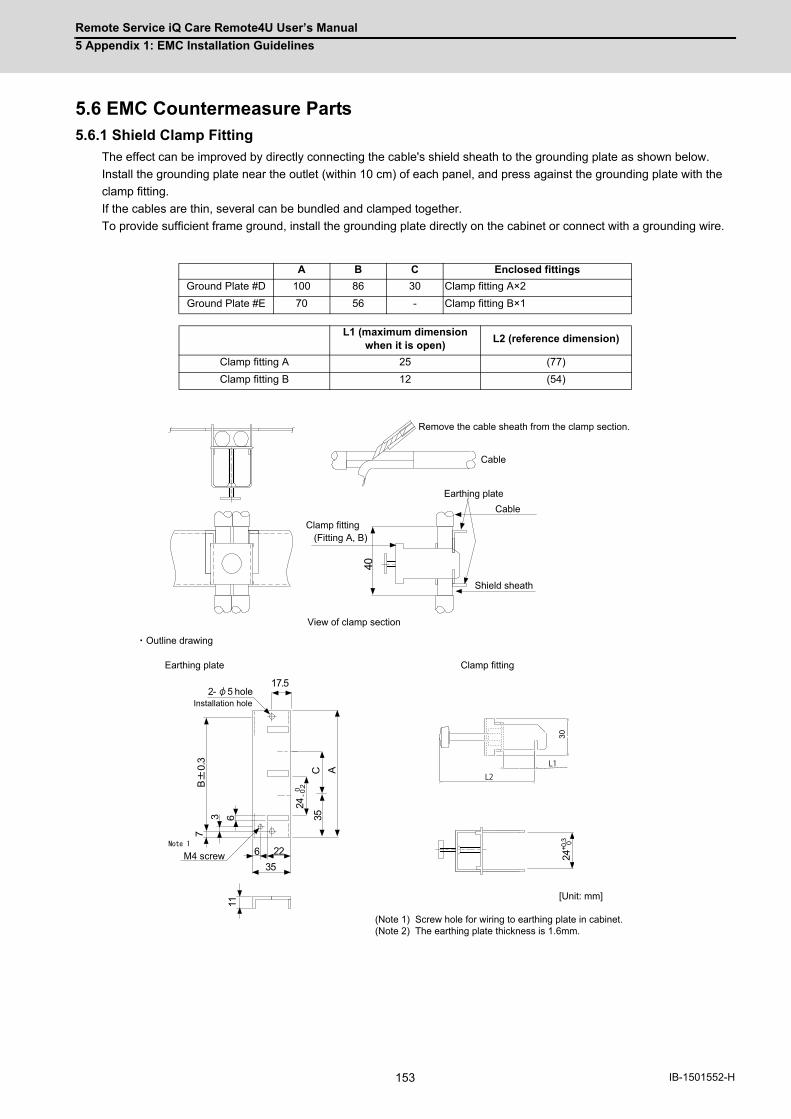
Remote Service iQ Care Remote4U User’s Manual
5 Appendix 1: EMC Installation Guidelines
153 IB-1501552-H
5.6 EMC Countermeasure Parts5.6.1 Shield Clamp Fitting
The effect can be improved by directly connecting the cable's shield sheath to the grounding plate as shown below.
Install the grounding plate near the outlet (within 10 cm) of each panel, and press against the grounding plate with the
clamp fitting.
If the cables are thin, several can be bundled and clamped together.
To provide sufficient frame ground, install the grounding plate directly on the cabinet or connect with a grounding wire.
A B C Enclosed fittings
Ground Plate #D 100 86 30 Clamp fitting A×2
Ground Plate #E 70 56 - Clamp fitting B×1
L1 (maximum dimension when it is open)
L2 (reference dimension)
Clamp fitting A 25 (77)
Clamp fitting B 12 (54)
+0.3 0
24
40
356 22
17.5
AC35
24-0
.20
11
73 6
B0.
3
30
L1
L2
2-
[Unit: mm]
(Note 1) Screw hole for wiring to earthing plate in cabinet.(Note 2) The earthing plate thickness is 1.6mm.
hole
(Fitting A, B)
Installation hole
Clamp fittingEarthing plate
Outline drawing
5
M4 screw
Shield sheath
Cable
Cable
Earthing plate
Remove the cable sheath from the clamp section.
View of clamp section
Clamp fitting
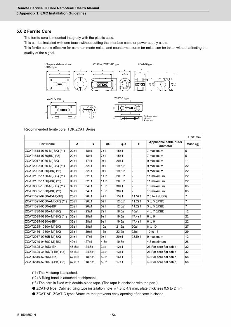
Remote Service iQ Care Remote4U User’s Manual
5 Appendix 1: EMC Installation Guidelines
154IB-1501552-H
5.6.2 Ferrite Core
The ferrite core is mounted integrally with the plastic case.
This can be installed with one touch without cutting the interface cable or power supply cable.
This ferrite core is effective for common mode noise, and countermeasures for noise can be taken without affecting the
quality of the signal.
Recommended ferrite core: TDK ZCAT Series
(*1) The M stamp is attached.
(*2) A fixing band is attached at shipment.
(*3) The core is fixed with double-sided tape. (The tape is enclosed with the part.)
● ZCAT-B type: Cabinet fixing type installation hole φ4.8 to 4.9 mm, plate thickness 0.5 to 2 mm
● ZCAT-AP, ZCAT-C type: Structure that prevents easy opening after case is closed.
Unit: mm
Part Name A B φC φD EApplicable cable outer
diameterMass (g)
ZCAT1518-0730-M(-BK) (*1) 22±1 18±1 7±1 15±1 - 7 maximum 6
ZCAT1518-0730(BK) (*2) 22±1 18±1 7±1 15±1 - 7 maximum 6
ZCAT2017-0930-M(-BK) 21±1 17±1 9±1 20±1 - 9 maximum 11
ZCAT2032-0930-M(-BK) (*1) 36±1 32±1 9±1 19.5±1 - 9 maximum 22
ZCAT2032-0930(-BK) (*2) 36±1 32±1 9±1 19.5±1 - 9 maximum 22
ZCAT2132-1130-M(-BK) (*1) 36±1 32±1 11±1 20.5±1 - 11 maximum 22
ZCAT2132-1130(-BK) (*2) 36±1 32±1 11±1 20.5±1 - 11 maximum 22
ZCAT3035-1330-M(-BK) (*1) 39±1 34±1 13±1 30±1 - 13 maximum 63
ZCAT3035-1330(-BK) (*2) 39±1 34±1 13±1 30±1 - 13 maximum 63
ZCAT1525-0430AP-M(-BK) 25±1 20±1 4±1 15±1 11.5±1 2.5 to 4 (USB) 7
ZCAT1325-0530A-M(-BK) (*1) 25±1 20±1 5±1 12.8±1 11.2±1 3 to 5 (USB) 7
ZCAT1325-0530A(-BK) 25±1 20±1 5±1 12.8±1 11.2±1 3 to 5 (USB) 7
ZCAT1730-0730A-M(-BK) 30±1 23±1 7±1 16.5±1 15±1 4 to 7 (USB) 12
ZCAT2035-0930A-M(-BK) (*1) 35±1 28±1 9±1 19.5±1 17.4±1 6 to 9 22
ZCAT2035-0930A(-BK) 35±1 28±1 9±1 19.5±1 17.4±1 6 to 9 22
ZCAT2235-1030A-M(-BK) 35±1 28±1 10±1 21.5±1 20±1 8 to 10 27
ZCAT2436-1330A-M(-BK) 36±1 29±1 13±1 23.5±1 22±1 10 to 13 29
ZCAT2017-0930B-M(-BK) 21±1 17±1 9±1 20±1 28.5±1 9 maximum 12
ZCAT2749-0430C-M(-BK) 49±1 27±1 4.5±1 19.5±1 - 4.5 maximum 26
ZCAT4625-3430D(-BK) 45.5±1 24.5±1 34±1 12±1 - 26 For core flat cable 32
ZCAT4625-3430DT(-BK) (*3) 45.5±1 24.5±1 34±1 13±1 - 26 For core flat cable 32
ZCAT6819-5230D(-BK) 67.5±1 18.5±1 52±1 16±1 - 40 For core flat cable 58
ZCAT6819-5230DT(-BK) (*3) 67.5±1 18.5±1 52±1 17±1 - 40 For core flat cable 58
ZCAT-A, ZCAT-AP typeShape and dimensionsZCAT type
ZCAT-C type
ZCAT-B type
ZCAT-D type

Remote Service iQ Care Remote4U User’s Manual
5 Appendix 1: EMC Installation Guidelines
155 IB-1501552-H
5.6.3 Surge Absorber
Make sure that the surge does not directly enter the AC line of the general-purpose stabilized power supply (user-
prepared) supplying power to the control unit and DIO. Select a product equivalent to or higher than the following
products for the surge absorber. Refer to the manufacturer catalog for detailed characteristics, outline and connection
methods of the surge absorber.
(1) Part name: RSPD-250-U4
Manufacturer: OKAYA ELECTRIC INDUSTRIES
Outline drawing
Circuit drawing
Rated Voltage(50/60Hz)
DC Breakdown voltage
Voltage protection level
Normal discharge current
Maximum discharge current
Surge current life
250VAC (Three phase)
700V±25% 1.3kV8/20μs2.5kA
8/20μs5kA
Approximately 300 times8/20μs-1kA
Resin
Extraction wire
Case
321
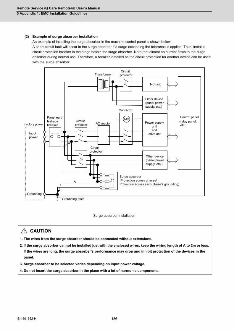
Remote Service iQ Care Remote4U User’s Manual
5 Appendix 1: EMC Installation Guidelines
156IB-1501552-H
(2) Example of surge absorber installation
An example of installing the surge absorber in the machine control panel is shown below.
A short-circuit fault will occur in the surge absorber if a surge exceeding the tolerance is applied. Thus, install a
circuit protection breaker in the stage before the surge absorber. Note that almost no current flows to the surge
absorber during normal use. Therefore, a breaker installed as the circuit protection for another device can be used
with the surge absorber.
Surge absorber installation
CAUTION
1. The wires from the surge absorber should be connected without extensions.
2. If the surge absorber cannot be installed just with the enclosed wires, keep the wiring length of A to 2m or less.
If the wires are long, the surge absorber's performance may drop and inhibit protection of the devices in the
panel.
3. Surge absorber to be selected varies depending on input power voltage.
4. Do not insert the surge absorber in the place with a lot of harmonic components.
A
MC Circuitprotector
NC unit
Control panel
(relay panel, etc.)
Other device (panel power supply, etc.)
Other device (panel power supply, etc.)
Panel earthleakage breaker
Input power
Circuitprotector
AC reactor
Transformer
GroundingGrounding plate
Factory power
Contactor
Circuitprotector
Power supply unit and
drive unit
Surge absorber(Protection across phases/Protection across each phase’s grounding)
Remote Service iQ Care Remote4U User’s Manual
5 Appendix 1: EMC Installation Guidelines
157 IB-1501552-H
5.6.4 Selection of Stabilized Power Supply
Consider the following characteristics when selecting the stabilized power supply (prepared by machine manufacturer).
Use a power supply that complies with CE Marking or that follows the safety standards given below.
Stabilized power supply selection items
Standards
Safety Standards: UL1950, CSA C22.2 No. 234 approved, IEC950 compliant
Noise Terminal Voltage: FCC Class A, VCCI-Class A
High Harmonics Current Restrictions: IEC61000-3-2
Item Standard setting Remarks
Output
Voltage fluctuation ±5% ±5% or less of 24VDC output
Ripple noise120 mV (maximum)
Spike noise500 mV (maximum)
Output current ――Refer to the maximum current consumption of the unit in use and calculate.
Output holding time 20 ms (min) Instantaneous power failure time (AC side)

Remote Service iQ Care Remote4U User’s Manual
5 Appendix 1: EMC Installation Guidelines
158IB-1501552-H

159 IB-1501552-H
6
Appendix 2: Precautions for Compliance to UL/c-ULStandards

Remote Service iQ Care Remote4U User’s Manual
6 Appendix 2: Precautions for Compliance to UL/c-UL Standards
160IB-1501552-H
(1) Selection of external 24VDC power supply unit (The unit shall be prepared by the machine tool builder.)
This NC system complies with the UL Standards on the condition that the stabilized power supply unit supplying
24VDC to each unit is a UL-approved part of SELV/limited power LPS or Class 2.
Use a UL-approved part for the stabilized power supply unit supplying 24VDC to each unit.
(2) Unit ambient temperature
This NC system complies with the UL Standards on the condition that the unit is used at a temperature less than the
maximum ambient temperature given in "Environment Conditions" section. Make sure that the maximum ambient
temperature of each unit does not exceed the temperature given in "Environment Conditions" section.

161 IB-1501552-H
7
Appendix 3: Parameter List
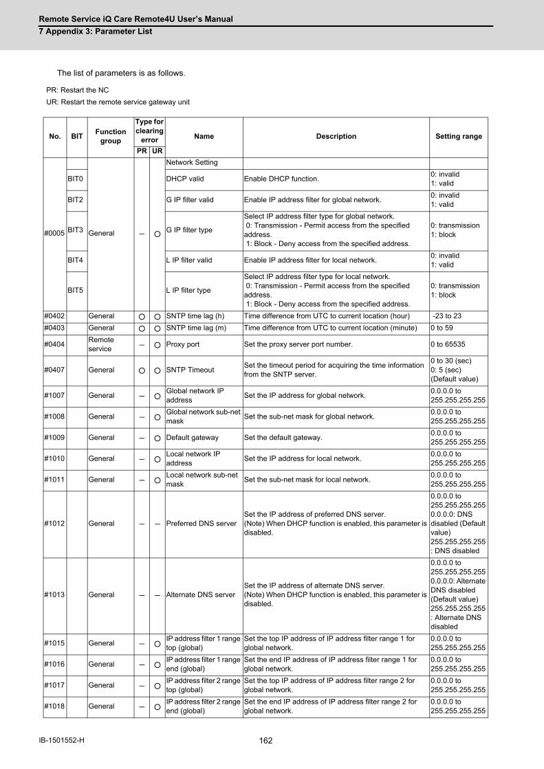
Remote Service iQ Care Remote4U User’s Manual
7 Appendix 3: Parameter List
162IB-1501552-H
The list of parameters is as follows.
PR: Restart the NC
UR: Restart the remote service gateway unit
No. BITFunction
group
Type for clearing
error Name Description Setting range
PR UR
#0005 General - ○
Network Setting
BIT0 DHCP valid Enable DHCP function.0: invalid 1: valid
BIT2 G IP filter valid Enable IP address filter for global network.0: invalid 1: valid
BIT3 G IP filter type
Select IP address filter type for global network. 0: Transmission - Permit access from the specified address. 1: Block - Deny access from the specified address.
0: transmission 1: block
BIT4 L IP filter valid Enable IP address filter for local network.0: invalid 1: valid
BIT5 L IP filter type
Select IP address filter type for local network. 0: Transmission - Permit access from the specified address. 1: Block - Deny access from the specified address.
0: transmission 1: block
#0402 General ○ ○ SNTP time lag (h) Time difference from UTC to current location (hour) -23 to 23
#0403 General ○ ○ SNTP time lag (m) Time difference from UTC to current location (minute) 0 to 59
#0404Remote service - ○ Proxy port Set the proxy server port number. 0 to 65535
#0407 General ○ ○ SNTP TimeoutSet the timeout period for acquiring the time information from the SNTP server.
0 to 30 (sec) 0: 5 (sec) (Default value)
#1007 General - ○Global network IP address
Set the IP address for global network.0.0.0.0 to 255.255.255.255
#1008 General - ○Global network sub-net mask
Set the sub-net mask for global network.0.0.0.0 to 255.255.255.255
#1009 General - ○ Default gateway Set the default gateway.0.0.0.0 to 255.255.255.255
#1010 General - ○Local network IP address
Set the IP address for local network.0.0.0.0 to 255.255.255.255
#1011 General - ○Local network sub-net mask
Set the sub-net mask for local network.0.0.0.0 to 255.255.255.255
#1012 General - - Preferred DNS serverSet the IP address of preferred DNS server.(Note) When DHCP function is enabled, this parameter is disabled.
0.0.0.0 to 255.255.255.2550.0.0.0: DNS disabled (Default value)255.255.255.255: DNS disabled
#1013 General - - Alternate DNS serverSet the IP address of alternate DNS server.(Note) When DHCP function is enabled, this parameter is disabled.
0.0.0.0 to 255.255.255.2550.0.0.0: Alternate DNS disabled (Default value)255.255.255.255: Alternate DNS disabled
#1015 General - ○IP address filter 1 range top (global)
Set the top IP address of IP address filter range 1 for global network.
0.0.0.0 to 255.255.255.255
#1016 General - ○IP address filter 1 range end (global)
Set the end IP address of IP address filter range 1 for global network.
0.0.0.0 to 255.255.255.255
#1017 General - ○IP address filter 2 range top (global)
Set the top IP address of IP address filter range 2 for global network.
0.0.0.0 to 255.255.255.255
#1018 General - ○IP address filter 2 range end (global)
Set the end IP address of IP address filter range 2 for global network.
0.0.0.0 to 255.255.255.255

Remote Service iQ Care Remote4U User’s Manual
7 Appendix 3: Parameter List
163 IB-1501552-H
#1019 General - ○IP address filter 3 range top (global)
Set the top IP address of IP address filter range 3 for global network.
0.0.0.0 to 255.255.255.255
#1020 General - ○IP address filter 3 range end (global)
Set the end IP address of IP address filter range 3 for global network.
0.0.0.0 to 255.255.255.255
#1021 General - ○IP address filter 4 range top (global)
Set the top IP address of IP address filter range 4 for global network.
0.0.0.0 to 255.255.255.255
#1022 General - ○IP address filter 4 range end (global)
Set the end IP address of IP address filter range 4 for global network.
0.0.0.0 to 255.255.255.255
#1023 General - ○IP address filter 5 range top (global)
Set the top IP address of IP address filter range 5 for global network.
0.0.0.0 to 255.255.255.255
#1024 General - ○IP address filter 5 range end (global)
Set the end IP address of IP address filter range 5 for global network.
0.0.0.0 to 255.255.255.255
#1025 General - ○IP address filter 6 range top (global)
Set the top IP address of IP address filter range 6 for global network.
0.0.0.0 to 255.255.255.255
#1026 General - ○IP address filter 6 range end (global)
Set the end IP address of IP address filter range 6 for global network.
0.0.0.0 to 255.255.255.255
#1027 General - ○IP address filter 7 range top (global)
Set the top IP address of IP address filter range 7 for global network.
0.0.0.0 to 255.255.255.255
#1028 General - ○IP address filter 7 range end (global)
Set the end IP address of IP address filter range 7 for global network.
0.0.0.0 to 255.255.255.255
#1029 General - ○IP address filter 8 range top (global)
Set the top IP address of IP address filter range 8 for global network.
0.0.0.0 to 255.255.255.255
#1030 General - ○IP address filter 8 range end (global)
Set the end IP address of IP address filter range 8 for global network.
0.0.0.0 to 255.255.255.255
#1031 General - ○IP address filter 1 range top (local)
Set the top IP address of IP address filter range 1 for local network.
0.0.0.0 to 255.255.255.255
#1032 General - ○IP address filter 1 range end (local)
Set the end IP address of IP address filter range 1 for local network.
0.0.0.0 to 255.255.255.255
#1033 General - ○IP address filter 2 range top (local)
Set the top IP address of IP address filter range 2 for local network.
0.0.0.0 to 255.255.255.255
#1034 General - ○IP address filter 2 range end (local)
Set the end IP address of IP address filter range 2 for local network.
0.0.0.0 to 255.255.255.255
#1035 General - ○IP address filter 3 range top (local)
Set the top IP address of IP address filter range 3 for local network.
0.0.0.0 to 255.255.255.255
#1036 General - ○IP address filter 3 range end (local)
Set the end IP address of IP address filter range 3 for local network.
0.0.0.0 to 255.255.255.255
#1037 General - ○IP address filter 4 range top (local)
Set the top IP address of IP address filter range 4 for local network.
0.0.0.0 to 255.255.255.255
#1038 General - ○IP address filter 4 range end (local)
Set the end IP address of IP address filter range 4 for local network.
0.0.0.0 to 255.255.255.255
#1039 General - ○IP address filter 5 range top (local)
Set the top IP address of IP address filter range 5 for local network.
0.0.0.0 to 255.255.255.255
#1040 General - ○IP address filter 5 range end (local)
Set the end IP address of IP address filter range 5 for local network.
0.0.0.0 to 255.255.255.255
#1041 General - ○IP address filter 6 range top (local)
Set the top IP address of IP address filter range 6 for local network.
0.0.0.0 to 255.255.255.255
#1042 General - ○IP address filter 6 range end (local)
Set the end IP address of IP address filter range 6 for local network.
0.0.0.0 to 255.255.255.255
#1043 General - ○IP address filter 7 range top (local)
Set the top IP address of IP address filter range 7 for local network.
0.0.0.0 to 255.255.255.255
#1044 General - ○IP address filter 7 range end (local)
Set the end IP address of IP address filter range 7 for local network.
0.0.0.0 to 255.255.255.255
#1045 General - ○IP address filter 8 range top (local)
Set the top IP address of IP address filter range 8 for local network.
0.0.0.0 to 255.255.255.255
#1046 General - ○IP address filter 8 range end (local)
Set the end IP address of IP address filter range 8 for local network.
0.0.0.0 to 255.255.255.255
#1047Remote service - ○ NC1 IP Address Set the IP address of NC to be connected.
0.0.0.0 to 255.255.255.255
No. BITFunction
group
Type for clearing
error Name Description Setting range
PR UR

Remote Service iQ Care Remote4U User’s Manual
7 Appendix 3: Parameter List
164IB-1501552-H
#1601Remote service - ○ NC1 Serial No. Set the serial number of NC to be connected. String
#1605Remote service - ○ Cloud URL Set the URL of the cloud. String
#1606Remote service - - Proxy Address Set the proxy server address. String
#1607 General - ○ SNTP Server Set the name of SNTP (Time synchronization) server. String
No. BITFunction
group
Type for clearing
error Name Description Setting range
PR UR

165 IB-1501552-H
8
Appendix 4: Error List
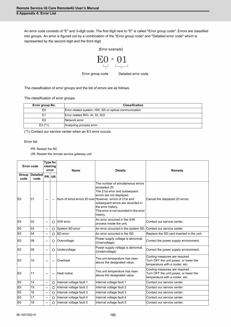
Remote Service iQ Care Remote4U User’s Manual
8 Appendix 4: Error List
166IB-1501552-H
An error code consists of "E" and 3-digit code. The first digit next to "E" is called "Error group code". Errors are classified
into groups. An error is figured out by a combination of the "Error group code" and "Detailed error code" which is
represented by the second digit and the third digit.
The classification of error groups and the list of errors are as follows.
The classification of error groups
(*1) Contact our service center when an E3 error occurs.
Error list
Error group No. Classification
E0 Error related system, HW, SD or optical communication
E1 Error related RIO, AI, DI, SIO
E2 Network error
E3 (*1) Analyzing process error
PR: Restart the NC
UR: Restart the remote service gateway unit
Error codeType for clearing
error Name Details RemedyGroup code
Detailed code
PR UR
E0 01 - - Num of simul errors 20 over
The number of simultaneous errors exceeded 20. The 21st error and subsequent errors are not displayed. However, errors of 21st and subsequent errors are recorded in the error history. This error is not recorded in the error history.
Cancel the displayed 20 errors.
E0 02 - ○ S/W errorAn error occurred in the S/W process inside the unit.
Contact our service center.
E0 03 - ○ System SD error An error occurred in the system SD. Contact our service center.
E0 04 - ○ SD error An error occurred in the SD. Replace the SD card inserted in the unit.
E0 08 - ○ OvervoltagePower supply voltage is abnormal. (Overvoltage)
Correct the power supply environment.
E0 09 - ○ UndervoltagePower supply voltage is abnormal. (Undervoltage)
Correct the power supply environment.
E0 10 - - OverheatThe unit temperature has risen above the designated value.
Cooling measures are required. Turn OFF the unit power, or lower the temperature with a cooler, etc.
E0 11 - - Heat noticeThe unit temperature has risen above the designated value.
Cooling measures are required. Turn OFF the unit power, or lower the temperature with a cooler, etc.
E0 14 - ○ Internal voltage fault 1 Internal voltage fault 1 Contact our service center.
E0 15 - ○ Internal voltage fault 2 Internal voltage fault 2 Contact our service center.
E0 16 - ○ Internal voltage fault 3 Internal voltage fault 3 Contact our service center.
E0 17 - ○ Internal voltage fault 4 Internal voltage fault 4 Contact our service center.
E0 18 - ○ Internal voltage fault 5 Internal voltage fault 5 Contact our service center.
E0 - 01[Error example]
Error group code Detailed error code
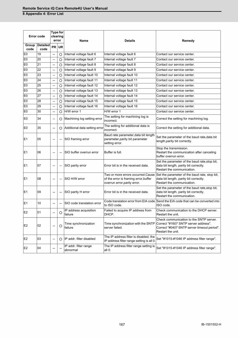
Remote Service iQ Care Remote4U User’s Manual
8 Appendix 4: Error List
167 IB-1501552-H
E0 19 - ○ Internal voltage fault 6 Internal voltage fault 6 Contact our service center.
E0 20 - ○ Internal voltage fault 7 Internal voltage fault 7 Contact our service center.
E0 21 - ○ Internal voltage fault 8 Internal voltage fault 8 Contact our service center.
E0 22 - ○ Internal voltage fault 9 Internal voltage fault 9 Contact our service center.
E0 23 - ○ Internal voltage fault 10 Internal voltage fault 10 Contact our service center.
E0 24 - ○ Internal voltage fault 11 Internal voltage fault 11 Contact our service center.
E0 25 - ○ Internal voltage fault 12 Internal voltage fault 12 Contact our service center.
E0 26 - ○ Internal voltage fault 13 Internal voltage fault 13 Contact our service center.
E0 27 - ○ Internal voltage fault 14 Internal voltage fault 14 Contact our service center.
E0 28 - ○ Internal voltage fault 15 Internal voltage fault 15 Contact our service center.
E0 29 - ○ Internal voltage fault 16 Internal voltage fault 16 Contact our service center.
E0 30 - ○ H/W error 1 H/W error 1 Contact our service center.
E0 34 - ○ Machining log setting errorThe setting for machining log is incorrect.
Correct the setting for machining log.
E0 35 - ○ Additional data setting errorThe setting for additional data is incorrect.
Correct the setting for additional data.
E1 05 - - SIO framing errorBaud rate parameter,data bit length parameter,parity bit parameter setting error.
Set the parameter of the baud rate,data bit length,parity bit correctly.
E1 06 - - SIO buffer overrun error Buffer is full.Stop the transmission.Restart the communication after canceling buffer overrun error.
E1 07 - - SIO parity error Error bit is in the received data.Set the parameter of the baud rate,stop bit, data bit length, parity bit correctly.Restart the communication.
E1 08 - - SIO H/W errorTwo or more errors occurred.Cause of the error is framing error,buffer overrun error,parity error.
Set the parameter of the baud rate, stop bit, data bit length, parity bit correctly.Restart the communication.
E1 09 - - SIO parity H error Error bit is in the received data.Set the parameter of the baud rate,stop bit, data bit length, parity bit correctly.Restart the communication.
E1 10 - - SIO code translation errorCode translation error from EIA code to ISO code.
Send the EIA code that can be converted into ISO code.
E2 01 - ○IP address acquisition failure
Failed to acquire IP address from DHCP.
Check communication to the DHCP server. Restart the unit.
E2 02 - ○Time synchronization failure
Time synchronization with the SNTP server failed.
Check communication to the SNTP server. Correct "#1607 SNTP server address". Correct "#0407 SNTP server timeout period". Restart the unit.
E2 03 - ○ IP addr. filter disabledThe IP address filter is disabled, the IP address filter range setting is all 0.
Set "#1015-#1046 IP address filter range".
E2 04 - -IP addr. filter range abnormal
The IP address filter range setting is all 0.
Set "#1015-#1046 IP address filter range".
Error codeType for clearing
error Name Details RemedyGroup code
Detailed code
PR UR

Remote Service iQ Care Remote4U User’s Manual
8 Appendix 4: Error List
168IB-1501552-H

Function Compatibility
Details Version
First version A0
Diagnosis report function A2
Utilization rate calculation customization functionA3
C80 supported
NC file data function A4
Email notification functionA7
Alarm diagnosis function

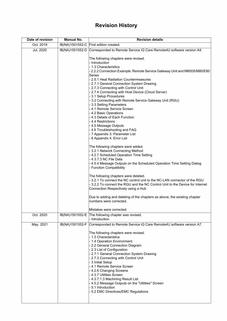
Revision History
Date of revision Manual No. Revision details
Oct. 2019 IB(NA)1501552-C First edition created.
Jul. 2020 IB(NA)1501552-D Corresponded to Remote Service iQ Care Remote4U software version A4. The following chapters were revised.- Introduction- 1.3 Characteristics- 2.2.2 Connection Example: Remote Service Gateway Unit and M800S/M80/E80 Series- 2.5.1 Heat Radiation Countermeasures- 2.7.1 General Connection System Drawing- 2.7.3 Connecting with Control Unit- 2.7.4 Connecting with Host Device (Cloud Server)- 3.1 Setup Procedures- 3.2 Connecting with Remote Service Gateway Unit (RGU)- 3.3 Setting Parameters- 4.1 Remote Service Screen- 4.2 Basic Operations- 4.3 Details of Each Function- 4.4 Restrictions- 4.5 Message Outputs- 4.6 Troubleshooting and FAQ- 7 Appendix 3: Parameter List- 8 Appendix 4: Error List The following chapters were added.- 3.2.1 Network Connecting Method- 4.2.7 Scheduled Operation Time Setting- 4.3.7.3 NC File Data- 4.5.4 Message Outputs on the Scheduled Operation Time Setting Dialog- Function Compatibility The following chapters were deleted.- 3.2.1 To connect the NC control unit to the NC-LAN connector of the RGU- 3.2.2 To connect the RGU and the NC Control Unit to the Device for Internet Connection Respectively using a Hub Due to adding and deleting of the chapters as above, the existing chapter numbers were corrected. Mistakes were corrected.
Oct. 2020 IB(NA)1501552-E The following chapter was revised.- Introduction
May. 2021 IB(NA)1501552-F Corresponded to Remote Service iQ Care Remote4U software version A7.
The following chapters were revised.- 1.3 Characteristics- 1.4 Operation Environment- 2.2 General Connection Diagram- 2.3 List of Configuration- 2.7.1 General Connection System Drawing- 2.7.3 Connecting with Control Unit- 3 Initial Setup- 4.1 Remote Service Screen- 4.2.6 Changing Screens- 4.3.7 Utilities Screen- 4.3.7.1.3 Machining Result List- 4.5.2 Message Outputs on the "Utilities" Screen- 5.1 Introduction- 5.2 EMC Directives/EMC Regulations

Date of revision Manual No. Revision details
May. 2021 IB(NA)1501552-F The following chapters were added.- 4.3.7.4 Alarm Diagnosis- 4.3.7.5 Email Notification Settings Mistakes were corrected.
Sep. 2021 IB(NA)1501552-G Corresponded to Remote Service iQ Care Remote4U software version A9. The following chapters were revised.- 4.3.5 Alarm Screen- 4.3.7.1.3 Machining Result List- 4.3.7.4 Alarm Diagnosis- 4.3.7.5.1 Edit Email Notification Condition Screen- 4.5.2 Message Outputs on the "Utilities" Screen- 5.1 Introduction- 5.2 EMC Directives
Jan. 2022 IB(NA)1501552-H Corresponded to Remote Service iQ Care Remote4U software version AA.
The following chapters were revised.- Introduction- 1 Outline- 3 Initial Setup- 3.1 Setup Procedures- 3.2 Connecting with Remote Service Gateway Unit (RGU)- 4.3.3 Operation Screen- 4.3.7 Utilities Screen- 4.5 Message Outputs The following chapters were added.- Manual List (M800V/M80V Series)- 3.3 When Using NC Direct Connection- 3.4 Applicable Models Due to adding and deleting of the chapters as above, the existing chapternumbers were corrected. Mistakes were corrected.


Global Service Network
AMERICA EUROPE
.V.B EPORUE CIRTCELE IHSIBUSTIM)RETNEC AF ACIREMA( .CNI NOITAMOTUA CIRTCELE IHSIBUSTIMCentral Region Service Center (Chicago) European Service Headquarters (Dusseldorf, GERMANY)
YNAMREG ,NEGNITAR 28804 1 ztalP-cirtcelE-ihsibustiM .A.S.U ,16006 SIONILLI ,SLLIH NONREV ,YAWKRAP SDOOW ETAROPROC 005 0195-684-2012-94+ :XAF / 0005-684-2012-94+ :LET 0562-874-748-1+ :XAF / 0052-874-748-1+ :LET
Minneapolis, MN Service Satellite Detroit, MI Service Satellite South Germany Service Center (Stuttgart) Grand Rapids, MI Service Satellite SCHELMENWASENSTRASSE 16-20, 70567 STUTTGART, GERMANY Milwaukee, WI Service Satellite TEL: + 49-711-770598-123 / FAX: +49-711-770598-141 Cleveland, OH Service Satellite Indianapolis, IN Service Satellite France Service Center (Paris) St. Louis, MO Service Satellite 2 RUE DE L’UNION, 92565 RUEIL-MALMAISON CEDEX, FRANCE
TEL: +33-1-41-02-83-13 / FAX: +33-1-49-01-07-25South/East Region Service Center (Georgia) 1845 SATTELITE BOULEVARD STE. 450, DULUTH, GEORGIA 30097, U.S.A. France Service Satellite (Lyon)
ECNARF TSEIRP TNIAS 00896 DONOM SEUQCAJ EELLA ,021 9154-852-876-1+ XAF / 9254-852-876-1+ LET Charleston, SC Service Satellite TEL: +33-1-41-02-83-13 / FAX: +33-1-49-01-07-25 Charlotte, NC Service Satellite Raleigh, NC Service Satellite Italy Service Center (Milan) Dallas, TX Service Satellite CENTRO DIR. COLLEONI, PALAZZO SIRIO, VIALE COLLEONI 7, 20864 AGRATE BRIANZA (MB) ITALY Houston, TX Service Satellite TEL: +39-039-6053-342 / FAX: +39-039-6053-206 Hartford, CT Service Satellite Knoxville, TN Service Satellite Italy Service Satellite (Padova) Nashville, TN Service Satellite VIA G. SAVELLI, 24 - 35129 PADOVA, ITALY Baltimore, MD Service Satellite TEL: +39-039-6053-342 / FAX: +39-039-6053-206 Pittsburg, PA Service Satellite Tampa, FL Service Satellite U.K. Service Center Syracuse, NY Service Satellite TRAVELLERS LANE, HATFIELD, HERTFORDSHIRE, AL10 8XB, U.K. Orlando, FL Service Satellite TEL: +44-1707-288-780 / FAX: +44-1707-278 695 Lafayette, LA Service Satellite Philadelphia, PA Service Satellite Spain Service Center
CTRA. RUBI, 76-80 8174 SAINT CUGAT DEL VALLES, BARCELONA SPAINWestern Region Service Center (California) TEL: +34-935-65-2236 / FAX: +34-935-89-1579 5900-B KATELLA AVE. - 5900-A KATELLA AVE. CYPRESS, CALIFORNIA 90630, U.S.A. TEL: +1-714-699-2625 / FAX: +1-847-478-2650 Poland Service Center San Jose, CA Service Satellite UL.KRAKOWSKA 50, 32-083 BALICE, POLAND Seattle, WA Service Satellite TEL: +48-12-347-6500 / FAX: +48-12-630-4701 Denver, CO Service Satellite
Hungary Service CenterCanada Region Service Center (Tronto) BUDAÖRS OFFICE PARK, SZABADSÁG ÚT 117., 2040 BUDAÖRS, HUNGARY
1074-036-21-84+ :XAF / 0056-743-21-84+ :LET ADANAC ,2JO R3L OIRATNO ,MAHKRAM EUNEVA HT41 9924 TEL: +1-905-475-7728 / FAX: +1-905-475-7935 Edmonton, AB Service Satellite Turkey Service Center Montreal, QC Service Satellite MITSUBISHI ELECTRIC TURKEY ELEKTRİK ÜRÜNLERİ A.Ş
SERIFALI MAHALLESI KALE SOKAK. NO.41 34775Mexico Region Service Center (Queretaro) UMRANIYE, ISTANBUL, TURKEY Parque Tecnológico Innovación Querétaro, Lateral Carretera Estatal 431, Km 2+200, Lote 91 Modulos 1 y 2 TEL: +90-216-969-2500 / FAX: +90-216-661-44-47 Hacienda la Machorra, CP 76246, El Marqués, Querétaro, México TEL: +52-442-153 6050 Czech Republic Service Center Monterrey, NL Service Satellite AutoCont Control Systems s.r.o (Service Partner) Mexico City, DF Service Satellite KAFKOVA 1853/3, 702 00 OSTRAVA 2, CZECH REPUBLIC
TEL: +420-59-5691-185 / FAX: +420-59-5691-199
BRAZIL Russia Service CenterMITSUBISHI ELECTRIC RUSSIA LLC
MITSUBISHI ELECTRIC DO BRASIL COMÉRCIO E SERVIÇOS LTDA. LETNIKOVSKAYA STREET 2, BLD.1, 5TH 115114 MOSCOW, RUSSIAVotorantim Office TEL: +7-495-721-2070 / FAX: +7-495-721-2071 AV. GISELE CONSTANTINO,1578, PARQUE BELA VISTA, VOTORANTIM-SP, BRAZIL CEP:18.110-650 TEL: +55-15-3023-9000 Sweden Service Center Blumenau, Santa Catarina office HAMMARBACKEN 14, P.O.BOX 750 SE-19127, SOLLENTUNA, SWEDEN
TEL: +46-8-6251200 / FAX: +46-8-6251014
Bulgaria Service Center AKHNATON Ltd. (Service Partner) 4 ANDREJ LJAPCHEV BLVD. POB 21, BG-1756 SOFIA, BULGARIA TEL: +359-2-8176009 / FAX: +359-2-9744061
Ukraine Service Center (Kiev) CSC Automation Ltd. (Service Partner) 4 B, YEVHENA SVERSTYUKA STR., 02002 KIEV, UKRAINE TEL: +380-44-494-3344 / FAX: +380-44-494-3366
Belarus Service Center TECHNIKON Ltd. (Service Partner) NEZAVISIMOSTI PR.177, 220125 MINSK, BELARUS TEL: +375-17-393-1177 / FAX: +375-17-393-0081
South Africa Service Center Adroit Technologies (Service Partner) 20 WATERFORD OFFICE PARK, WATERFORD DRIVE, CNR OF WITKOPPEN ROAD, FOURWAYS JOHANNESBURG SOUTH AFRICA TEL: +27-11-658-8100 / FAX: +27-11- 658-8101
ASEAN CHINA
)RETNEC AF ANIHC( .DTL )ANIHC( NOITAMOTUA CIRTCELE IHSIBUSTIM)RETNEC AF NAESA( .DTL .ETP AISA CIRTCELE IHSIBUSTIMSingapore Service Center CNC Call Center 307 ALEXANDRA ROAD #05-01/02 MITSUBISHI ELECTRIC BUILDING SINGAPORE 159943 TEL: +86-400-921-5130 TEL: +65-6473-2308 / FAX: +65-6476-7439
Shanghai Service Center 1-3,5-10,18-23/F, NO.1386 HONG QIAO ROAD, CHANG NING QU,
PHILIPPINE SHANGHAI 200336, CHINA TEL: +86-21-2322-3030 / FAX: +86-21-2322-3000*8422
MELCO FACTORY AUTOMATION PHILIPPINES INC. Qingdao Service CenterHead Office Suzhou Service Center 128 LOPEZ RIZAL STREET, BRGY., HIGHWAY HILLS, MANDALUYONG CITY , MM PHILIPPINES 1550 Wuhan Service Center TEL: +63-2-8256-8042 / FAX: +632-8637-2294 Ningbo Service Center
Hefei Service CenterPhilippines Service Center Beijing Service Center KM.23 WEST SERVICE ROAD SSH, CUPANG ,MUNTINLUPA CITY PHILIPPINES Tianjin Service Center TEL: +63-2-8807-0420 / FAX: +63-2-8842-5202 Xian Service Center
Dalian Service Center Chengdu Service Center
VIETNAMShenzhen Service Center
MITSUBISHI ELECTRIC VIETNAM CO.,LTD. LEVEL8, GALAXY WORLD TOWER B, 1 YABAO ROAD, LONGGANG DISTRICT,Vietnam Ho Chi Minh Service Center SHENZHEN 518129, CHINA 11TH & 12TH FLOOR, VIETTEL TOWER B, 285 CACH MANG THANG 8 STREET, WARD 12, DISTRICT 10, TEL: +86-755-2399-8272 / FAX: +86-755-8229-3686 HO CHI MINH CITY, VIETNAM Dongguan Service Center TEL: +84-28-3910 5945 / FAX: +84-28-3910 5947 Xiamen Service Center
Vietnam Hanoi Service Center 24TH FLOOR, HANDICO TOWER, PHAM HUNG ROAD, ME TRI HA, ME TRI WARD, KOREA NAM TU LIEM DISTRICT, HA NOI CITY, VIETNAM TEL: +84-24-3937-8075 / FAX: +84-24-3937-8076 MITSUBISHI ELECTRIC AUTOMATION KOREA CO., LTD. (KOREA FA CENTER)
Korea Service Center 8F GANGSEO HANGANG XI-TOWER A, 401 YANGCHEON-RO, GANGSEO-GU,
INDONESIA SEOUL 07528 KOREA TEL: +82-2-3660-9631 / FAX: +82-2-3664-8668
PT. MITSUBISHI ELECTRIC INDONESIA Korea Daegu Service SatelliteIndonesia Service Center (Cikarang) JL. KENARI RAYA BLOK G2-07A, DELTA SILICON 5, LIPPO CIKARANG - BEKASI 17550, INDONESIA TEL: +62-21-2961-7797 / FAX: +62-21-2961-7794 TAIWAN
MITSUBISHI ELECTRIC TAIWAN CO., LTD. (TAIWAN FA CENTER) MALAYSIA Taiwan Taichung Service Center
NO. 8-1, GONGYEQU 16th RD., XITUN DIST., TAICHUNG CITY 40768 , TAIWANMITSUBISHI ELECTRIC SALES MALAYSIA SDN. BHD. TEL: +886-4-2359-0688 / FAX: +886-4-2359-0689Malaysia Service Center (Kuala Lumpur Service Center) LOT 11, JALAN 219, P.O BOX 1036, 46860 PETALING JAYA, SELANGOR DARUL EHSAN. MALAYSIA Taiwan Taipei Service Center
NAWIAT ,55111 YTIC IEPIAT ,.TSID NILIHS ,.DR .N NAHSGNOHZ ,6.CES ,88.ON ,F11 9262-0697-3-06+ :XAF / 2305-6267-3-06+ :LET Johor Bahru Service Satellite TEL: +886-2-2833-5430 / FAX: +886-2-2833-5433 Pulau Pinang Service Satellite
Taiwan Tainan Service Center 11F.-1, NO.30, ZHONGZHENG S. RD., YONGKANG DIST., TAINAN CITY 71067, TAIWAN
THAILAND TEL: +886-6-252-5030 / FAX: +886-6-252-5031
MITSUBISHI ELECTRIC FACTORY AUTOMATION (THAILAND) CO.,LTD.Thailand Service Center (Bangkok) OCEANIA 101, TRUE DIGITAL PARK OFFICE, 5TH FLOOR, SUKHUMVIT ROAD, BANGCHAK, PHRAKHANONG, BANGKOK, 10260 THAILAND MITSUBISHI ELECTRIC AUSTRALIA PTY. LTD. TEL: +66-2-092-8600 / FAX: +66-2-043-1231-33 Oceania Service Center
348 VICTORIA ROAD, RYDALMERE, N.S.W. 2116 AUSTRALIA TEL: +61-2-9684-7269/ FAX: +61-2-9684-7245
INDIA
MITSUBISHI ELECTRIC INDIA PVT., LTD.CNC Technical Center (Bangalore) PLOT NO. 56, 4TH MAIN ROAD, PEENYA PHASE 3, PEENYA INDUSTRIAL AREA, BANGALORE 560058, KARNATAKA, INDIA TEL : +91-80-4655-2121 / FAX : +91-80-4655-2147 Chennai Service Satellite Coimbatore Service Satellite Hyderabad Service Satellite
North India Service Center (Gurgaon) PLOT 517, GROUND FLOOR, UDYOG VIHAR PHASE-III, GURUGRAM 122008, HARYANA, INDIA TEL : +91-124-463-0300 / FAX : +91-124-463-0399 Ludhiana Service Satellite Panthnagar Service Satellite Delhi Service Satellite Jamshedpur Service Satellite Manesar Service Satellite
West India Service Center (Pune) ICC-Devi GAURAV TECHNOLOGY PARK, UNIT NO.402, FOURTH FLOOR, NORTH WING, SURVEY NUMBER 191-192 (P), NEXT to INDIAN CARD CLOTHING COMPANY Ltd, OPP. VALLABH NAGAR, PIMPRI, PUNE- 411 018, MAHARASHTRA, INDIA TEL : +91-20-6819 2274 / FAX : +91-20-4624 2100 Kolhapur Service Satellite Aurangabad Service Satellite Mumbai Service Satellite
West India Service Center (Ahmedabad) 204-209, 2ND FLOOR, 31FIVE, CORPORATE ROAD PRAHLADNAGAR, AHMEDABAD -380015, GUJARAT, INDIA TEL : + 91-79-6777 7888 Rajkot Service Satellite
Notice
Every effort has been made to keep up with software and hardware revisions in the contents described in this manual. However, please understand that in some unavoidable cases simultaneous revision is not possible.Please contact your Mitsubishi Electric dealer with any questions or comments regarding the use of this product.
Duplication Prohibited
This manual may not be reproduced in any form, in part or in whole, without written permission from Mitsubishi Electric Corporation.
COPYRIGHT 2019-2022 MITSUBISHI ELECTRIC CORPORATION ALL RIGHTS RESERVED

Related Documents


