Infrared Remote Controller Workshop User’s Guide Revision: V1.00 Date: June 03, 2021

Welcome message from author
This document is posted to help you gain knowledge. Please leave a comment to let me know what you think about it! Share it to your friends and learn new things together.
Transcript
Infrared Remote Controller WorkshopUser’s Guide
Revision: V1.00 Date: June 03, 2021
Rev. 1.00 2 June 03, 2021 Rev. 1.00 3 June 03, 2021
Infrared Remote Controller Workshop User’s Guide Infrared Remote Controller Workshop User’s Guide
Table of Contents1. Introduction ...................................................................................................... 32. Workshop Software ......................................................................................... 4
2.1 General Remote Controller Development ..............................................................................62.2 LCD Remote Controller Development ..................................................................................14
3. Workshop Hardware ...................................................................................... 293.1 ESK-IRRC-T00 .....................................................................................................................293.2 ESK-IRRC-T01 .....................................................................................................................293.3 ESK-IRRC-R00 ....................................................................................................................30
4. Decoding and Learning Code Development ............................................... 314.1 Code Verification ..................................................................................................................314.2 Code Development ..............................................................................................................33
5. Description of Other Functions .................................................................... 365.1 F/W Power Control ...............................................................................................................365.2 Decode Recognition .............................................................................................................36
6. Appendix & FAQ ............................................................................................. 376.1 LCD Remote Controller Code Control and Data Table ........................................................376.2 Special Modulation Code Description and Applications .......................................................376.3 MARK and SPACE Design Error Description .......................................................................38
Rev. 1.00 2 June 03, 2021 Rev. 1.00 3 June 03, 2021
Infrared Remote Controller Workshop User’s Guide Infrared Remote Controller Workshop User’s Guide
1. IntroductionThe HOLTEK Infrared Remote Controller Workshop is a design platform for the fast design of infrared remote controllers. The software not only supports remote controller software development based on general standard protocols, such as NEC, NEC-16, Philips RC-5, Philips RC-6, Sharp and other common remote controller protocols, but also provides a design method for users to define their own infrared remote code parameters which are different from other standard protocols. In addition, together with the HOLTEK IR decoder board, the workshop can analyse IR waveforms for existing remote controllers. This can then be used for new remote controller development based on the same protocol or used to verify the sending code for remote controllers under development.
The main application functions for common infrared remote controllers are divided into the following categories:
1. General remote controllers
Keys: identify user actions.
Code modulation: use different code protocols to modulate signals to avoid interference between different receiver devices.
Indicators: code indication.
Static power control: extend battery life.
2. LCD remote controllers
Keys: identify user actions.
Code modulation: use different code protocols to modulate signals to avoid interference between different receiver devices.
LCD display: display various operation status information that the remote controller sends to the receiver device.
Backlight: LCD backlight driver.
Static power control: extend battery life.
Rev. 1.00 4 June 03, 2021 Rev. 1.00 5 June 03, 2021
Infrared Remote Controller Workshop User’s Guide Infrared Remote Controller Workshop User’s Guide
2. Workshop Software
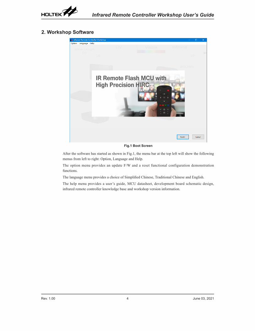
Fig.1 Boot Screen
After the software has started as shown in Fig.1, the menu bar at the top left will show the following menus from left to right: Option, Language and Help.
The option menu provides an update F/W and a reset functional configuration demonstration functions.
The language menu provides a choice of Simplified Chinese, Traditional Chinese and English.
The help menu provides a user’s guide, MCU datasheet, development board schematic design, infrared remote controller knowledge base and workshop version information.
Rev. 1.00 4 June 03, 2021 Rev. 1.00 5 June 03, 2021
Infrared Remote Controller Workshop User’s Guide Infrared Remote Controller Workshop User’s Guide
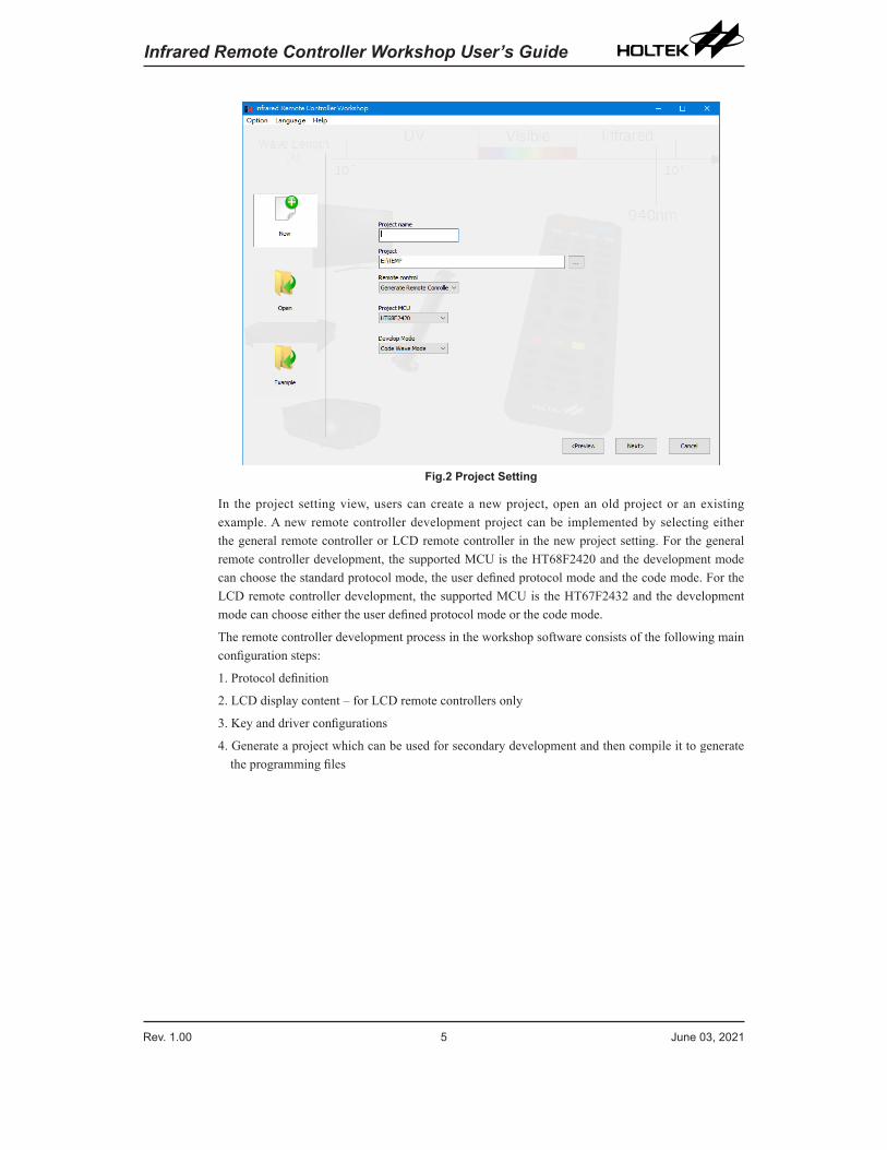
Fig.2 Project Setting
In the project setting view, users can create a new project, open an old project or an existing example. A new remote controller development project can be implemented by selecting either the general remote controller or LCD remote controller in the new project setting. For the general remote controller development, the supported MCU is the HT68F2420 and the development mode can choose the standard protocol mode, the user defined protocol mode and the code mode. For the LCD remote controller development, the supported MCU is the HT67F2432 and the development mode can choose either the user defined protocol mode or the code mode.
The remote controller development process in the workshop software consists of the following main configuration steps:
1. Protocol definition
2. LCD display content – for LCD remote controllers only
3. Key and driver configurations
4. Generate a project which can be used for secondary development and then compile it to generate the programming files
Rev. 1.00 6 June 03, 2021 Rev. 1.00 7 June 03, 2021
Infrared Remote Controller Workshop User’s Guide Infrared Remote Controller Workshop User’s Guide
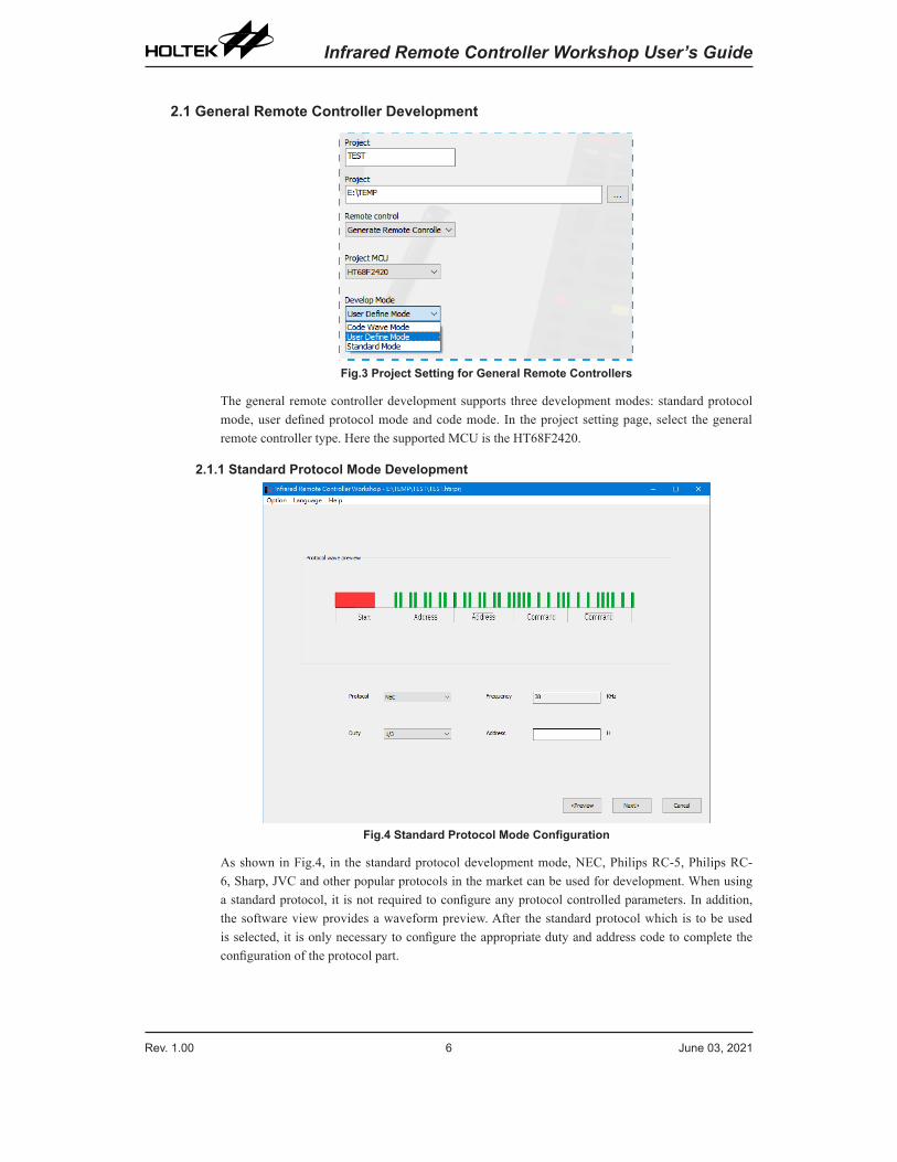
2.1 General Remote Controller Development
Fig.3 Project Setting for General Remote Controllers
The general remote controller development supports three development modes: standard protocol mode, user defined protocol mode and code mode. In the project setting page, select the general remote controller type. Here the supported MCU is the HT68F2420.
2.1.1 Standard Protocol Mode Development
Fig.4 Standard Protocol Mode Configuration
As shown in Fig.4, in the standard protocol development mode, NEC, Philips RC-5, Philips RC-6, Sharp, JVC and other popular protocols in the market can be used for development. When using a standard protocol, it is not required to configure any protocol controlled parameters. In addition, the software view provides a waveform preview. After the standard protocol which is to be used is selected, it is only necessary to configure the appropriate duty and address code to complete the configuration of the protocol part.
Rev. 1.00 6 June 03, 2021 Rev. 1.00 7 June 03, 2021
Infrared Remote Controller Workshop User’s Guide Infrared Remote Controller Workshop User’s Guide
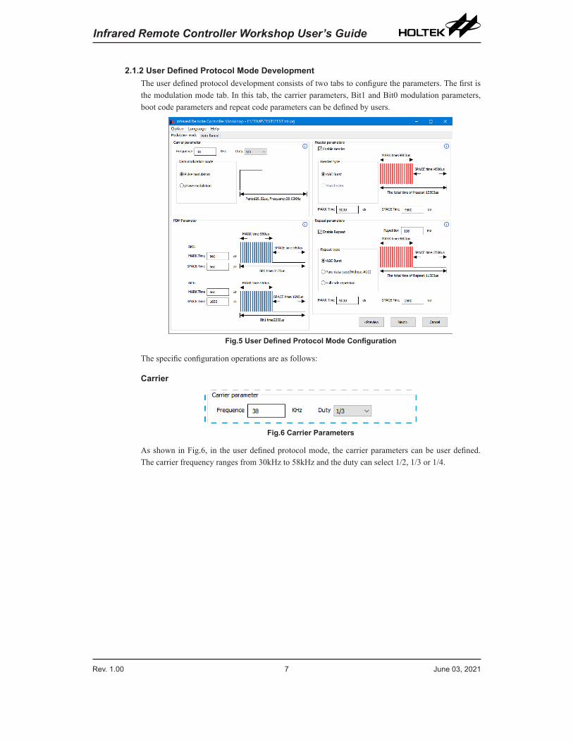
2.1.2 User Defined Protocol Mode DevelopmentThe user defined protocol development consists of two tabs to configure the parameters. The first is the modulation mode tab. In this tab, the carrier parameters, Bit1 and Bit0 modulation parameters, boot code parameters and repeat code parameters can be defined by users.
Fig.5 User Defined Protocol Mode Configuration
The specific configuration operations are as follows:
Carrier
Fig.6 Carrier Parameters
As shown in Fig.6, in the user defined protocol mode, the carrier parameters can be user defined. The carrier frequency ranges from 30kHz to 58kHz and the duty can select 1/2, 1/3 or 1/4.
Rev. 1.00 8 June 03, 2021 Rev. 1.00 9 June 03, 2021
Infrared Remote Controller Workshop User’s Guide Infrared Remote Controller Workshop User’s Guide
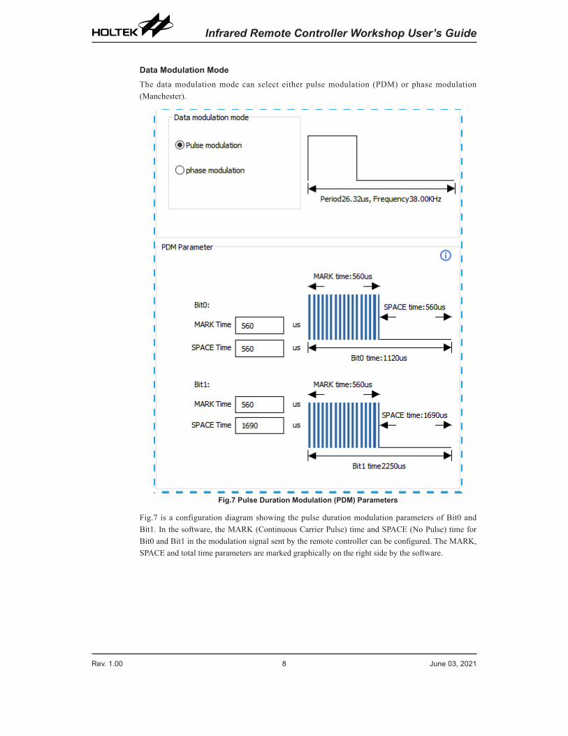
Data Modulation ModeThe data modulation mode can select either pulse modulation (PDM) or phase modulation (Manchester).
Fig.7 Pulse Duration Modulation (PDM) Parameters
Fig.7 is a configuration diagram showing the pulse duration modulation parameters of Bit0 and Bit1. In the software, the MARK (Continuous Carrier Pulse) time and SPACE (No Pulse) time for Bit0 and Bit1 in the modulation signal sent by the remote controller can be configured. The MARK, SPACE and total time parameters are marked graphically on the right side by the software.
Rev. 1.00 8 June 03, 2021 Rev. 1.00 9 June 03, 2021
Infrared Remote Controller Workshop User’s Guide Infrared Remote Controller Workshop User’s Guide
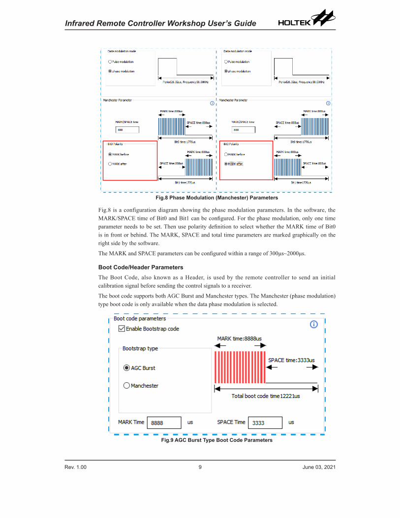
Fig.8 Phase Modulation (Manchester) Parameters
Fig.8 is a configuration diagram showing the phase modulation parameters. In the software, the MARK/SPACE time of Bit0 and Bit1 can be configured. For the phase modulation, only one time parameter needs to be set. Then use polarity definition to select whether the MARK time of Bit0 is in front or behind. The MARK, SPACE and total time parameters are marked graphically on the right side by the software.
The MARK and SPACE parameters can be configured within a range of 300μs~2000μs.
Boot Code/Header ParametersThe Boot Code, also known as a Header, is used by the remote controller to send an initial calibration signal before sending the control signals to a receiver.
The boot code supports both AGC Burst and Manchester types. The Manchester (phase modulation) type boot code is only available when the data phase modulation is selected.
Fig.9 AGC Burst Type Boot Code Parameters
Rev. 1.00 10 June 03, 2021 Rev. 1.00 11 June 03, 2021
Infrared Remote Controller Workshop User’s Guide Infrared Remote Controller Workshop User’s Guide
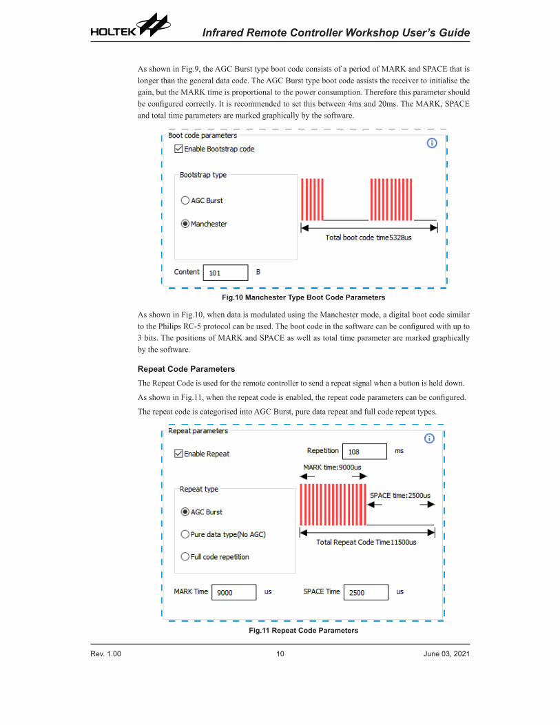
As shown in Fig.9, the AGC Burst type boot code consists of a period of MARK and SPACE that is longer than the general data code. The AGC Burst type boot code assists the receiver to initialise the gain, but the MARK time is proportional to the power consumption. Therefore this parameter should be configured correctly. It is recommended to set this between 4ms and 20ms. The MARK, SPACE and total time parameters are marked graphically by the software.
Fig.10 Manchester Type Boot Code Parameters
As shown in Fig.10, when data is modulated using the Manchester mode, a digital boot code similar to the Philips RC-5 protocol can be used. The boot code in the software can be configured with up to 3 bits. The positions of MARK and SPACE as well as total time parameter are marked graphically by the software.
Repeat Code ParametersThe Repeat Code is used for the remote controller to send a repeat signal when a button is held down.
As shown in Fig.11, when the repeat code is enabled, the repeat code parameters can be configured.
The repeat code is categorised into AGC Burst, pure data repeat and full code repeat types.
Fig.11 Repeat Code Parameters
Rev. 1.00 10 June 03, 2021 Rev. 1.00 11 June 03, 2021
Infrared Remote Controller Workshop User’s Guide Infrared Remote Controller Workshop User’s Guide
Only the AGC Burst type repeat code needs to be configured, which can be inconsistent with the header. It is recommended to set this between 4ms and 20ms.
To ensure that the repeated second frame signal is sent 10ms later after the end of the first frame signal, the repetition period can be set between 40ms and 200ms.
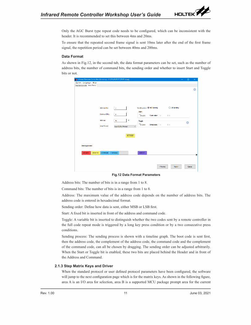
Data FormatAs shown in Fig.12, in the second tab, the data format parameters can be set, such as the number of address bits, the number of command bits, the sending order and whether to insert Start and Toggle bits or not.
Fig.12 Data Format Parameters
Address bits: The number of bits is in a range from 1 to 8.
Command bits: The number of bits is in a range from 1 to 8.
Address: The maximum value of the address code depends on the number of address bits. The address code is entered in hexadecimal format.
Sending order: Define how data is sent, either MSB or LSB first.
Start: A fixed bit is inserted in front of the address and command code.
Toggle: A variable bit is inserted to distinguish whether the two codes sent by a remote controller in the full code repeat mode is triggered by a long key press condition or by a two consecutive press conditions.
Sending process: The sending process is shown with a timeline graph. The boot code is sent first, then the address code, the complement of the address code, the command code and the complement of the command code, can all be chosen by dragging. The sending order can be adjusted arbitrarily. When the Start or Toggle bit is enabled, these two bits are placed behind the Header and in front of the Address and Command.
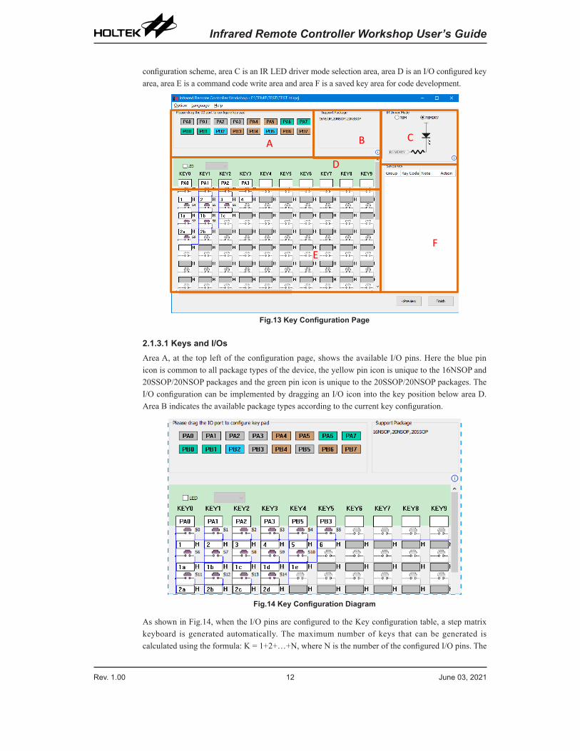
2.1.3 Step Matrix Keys and DriverWhen the standard protocol or user defined protocol parameters have been configured, the software will jump to the next configuration page which is for the matrix keys. As shown in the following figure, area A is an I/O area for selection, area B is a supported MCU package prompt area for the current
Rev. 1.00 12 June 03, 2021 Rev. 1.00 13 June 03, 2021
Infrared Remote Controller Workshop User’s Guide Infrared Remote Controller Workshop User’s Guide
configuration scheme, area C is an IR LED driver mode selection area, area D is an I/O configured key area, area E is a command code write area and area F is a saved key area for code development.
A B C
FE
D
Fig.13 Key Configuration Page
2.1.3.1 Keys and I/OsArea A, at the top left of the configuration page, shows the available I/O pins. Here the blue pin icon is common to all package types of the device, the yellow pin icon is unique to the 16NSOP and 20SSOP/20NSOP packages and the green pin icon is unique to the 20SSOP/20NSOP packages. The I/O configuration can be implemented by dragging an I/O icon into the key position below area D. Area B indicates the available package types according to the current key configuration.
Fig.14 Key Configuration Diagram
As shown in Fig.14, when the I/O pins are configured to the Key configuration table, a step matrix keyboard is generated automatically. The maximum number of keys that can be generated is calculated using the formula: K = 1+2+…+N, where N is the number of the configured I/O pins. The
Rev. 1.00 12 June 03, 2021 Rev. 1.00 13 June 03, 2021
Infrared Remote Controller Workshop User’s Guide Infrared Remote Controller Workshop User’s Guide
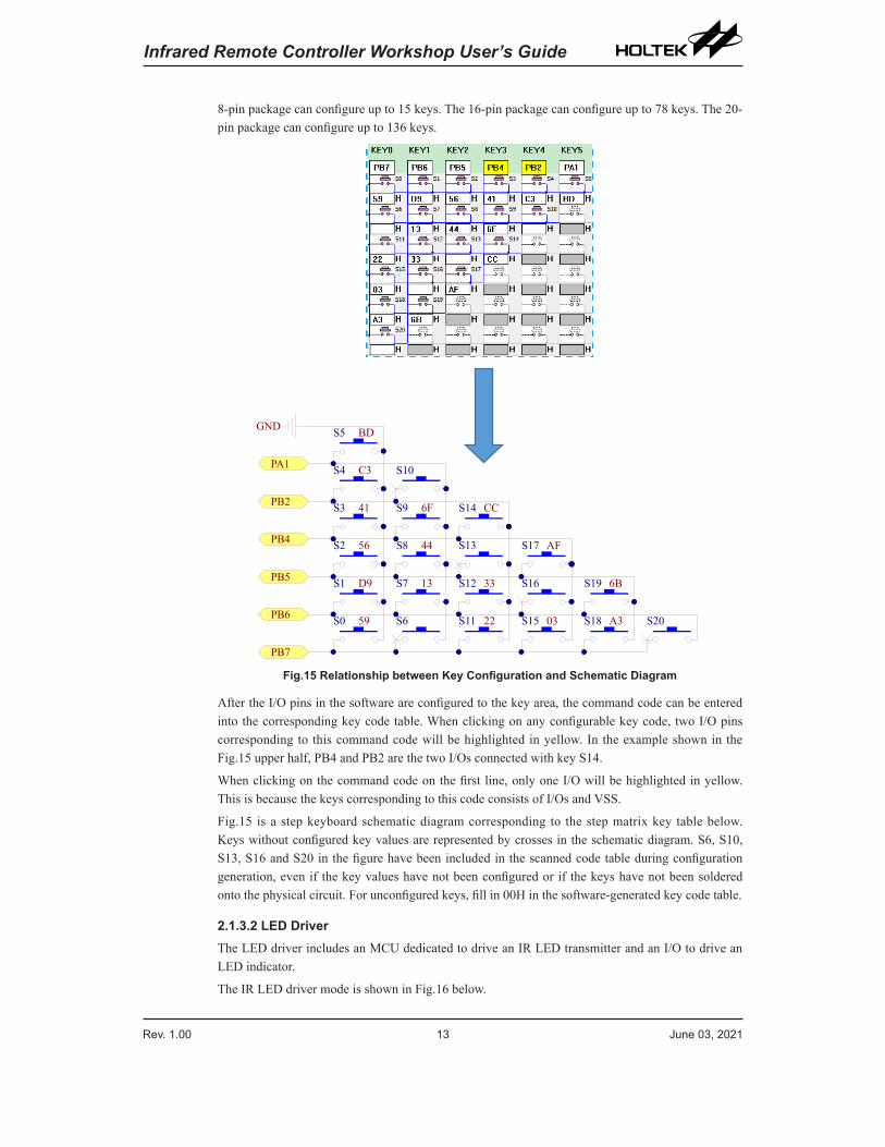
8-pin package can configure up to 15 keys. The 16-pin package can configure up to 78 keys. The 20-pin package can configure up to 136 keys.
PB7
PB6
PB5
PB4
PA1
GND
S10
S14
S17
S19
S20
S9
S13
S16
S18
S8
S12
S15
S7
S11S6
PB2
S5
S4
S3
S2
S1
S0 59
D9
56
41
C3
BD
13
44
6F
A3
6B
03
AF
22
33
CC
Fig.15 Relationship between Key Configuration and Schematic Diagram
After the I/O pins in the software are configured to the key area, the command code can be entered into the corresponding key code table. When clicking on any configurable key code, two I/O pins corresponding to this command code will be highlighted in yellow. In the example shown in the Fig.15 upper half, PB4 and PB2 are the two I/Os connected with key S14.
When clicking on the command code on the first line, only one I/O will be highlighted in yellow. This is because the keys corresponding to this code consists of I/Os and VSS.
Fig.15 is a step keyboard schematic diagram corresponding to the step matrix key table below. Keys without configured key values are represented by crosses in the schematic diagram. S6, S10, S13, S16 and S20 in the figure have been included in the scanned code table during configuration generation, even if the key values have not been configured or if the keys have not been soldered onto the physical circuit. For unconfigured keys, fill in 00H in the software-generated key code table.
2.1.3.2 LED DriverThe LED driver includes an MCU dedicated to drive an IR LED transmitter and an I/O to drive an LED indicator.
The IR LED driver mode is shown in Fig.16 below.
Rev. 1.00 14 June 03, 2021 Rev. 1.00 15 June 03, 2021
Infrared Remote Controller Workshop User’s Guide Infrared Remote Controller Workshop User’s Guide
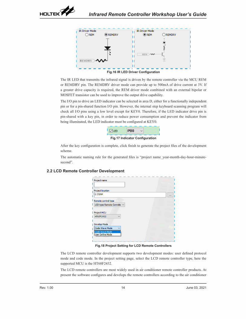
Fig.16 IR LED Driver Configuration
The IR LED that transmits the infrared signal is driven by the remote controller via the MCU REM or REMDRV pin. The REMDRV driver mode can provide up to 500mA of drive current at 3V. If a greater drive capacity is required, the REM driver mode combined with an external bipolar or MOSFET transistor can be used to improve the output drive capability.
The I/O pin to drive an LED indicator can be selected in area D, either for a functionally independent pin or for a pin-shared function I/O pin. However, the internal step keyboard scanning program will check all I/O pins using a low level except for KEY0. Therefore, if the LED indicator drive pin is pin-shared with a key pin, in order to reduce power consumption and prevent the indicator from being illuminated, the LED indicator must be configured at KEY0.
Fig.17 Indicator Configuration
After the key configuration is complete, click finish to generate the project files of the development scheme.
The automatic naming rule for the generated files is “project name_year-month-day-hour-minute-second”.
2.2 LCD Remote Controller Development
Fig.18 Project Setting for LCD Remote Controllers
The LCD remote controller development supports two development modes: user defined protocol mode and code mode. In the project setting page, select the LCD remote controller type, here the supported MCU is the HT68F2432.
The LCD remote controllers are most widely used in air conditioner remote controller products. At present the software configures and develops the remote controllers according to the air conditioner
Rev. 1.00 14 June 03, 2021 Rev. 1.00 15 June 03, 2021
Infrared Remote Controller Workshop User’s Guide Infrared Remote Controller Workshop User’s Guide
functions. In the future, updated versions of the software will increase the range of remote controller product development types.
2.2.1 Protocol DefinitionThe workshop software provides a user defined protocol mode for LCD remote controller development. Users can define their own parameter and code rules according to their product requirements.
Fig.19 Modulation Mode Configuration Page
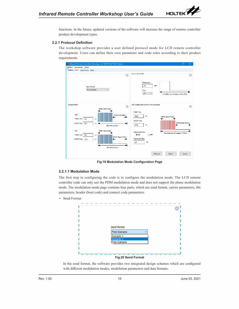
2.2.1.1 Modulation ModeThe first step in configuring the code is to configure the modulation mode. The LCD remote controller code can only use the PDM modulation mode and does not support the phase modulation mode. The modulation mode page contains four parts, which are send format, carrier parameters, Bit parameters, header (boot code) and connect code parameters.
• Send Format
Fig.20 Send Format
In the send format, the software provides two integrated design schemes which are configured with different modulation modes, modulation parameters and data formats.
Rev. 1.00 16 June 03, 2021 Rev. 1.00 17 June 03, 2021
Infrared Remote Controller Workshop User’s Guide Infrared Remote Controller Workshop User’s Guide
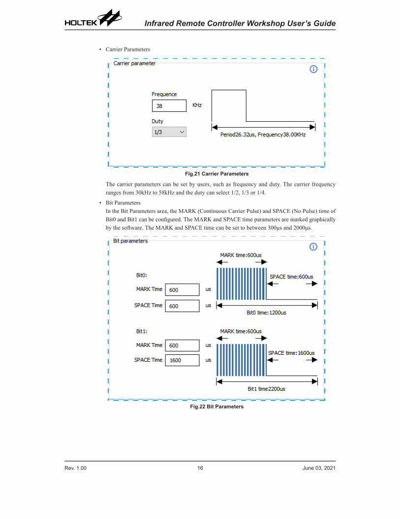
• Carrier Parameters
Fig.21 Carrier Parameters
The carrier parameters can be set by users, such as frequency and duty. The carrier frequency ranges from 30kHz to 58kHz and the duty can select 1/2, 1/3 or 1/4.
• Bit ParametersIn the Bit Parameters area, the MARK (Continuous Carrier Pulse) and SPACE (No Pulse) time of Bit0 and Bit1 can be configured. The MARK and SPACE time parameters are marked graphically by the software. The MARK and SPACE time can be set to between 300μs and 2000μs.
Fig.22 Bit Parameters
Rev. 1.00 16 June 03, 2021 Rev. 1.00 17 June 03, 2021
Infrared Remote Controller Workshop User’s Guide Infrared Remote Controller Workshop User’s Guide
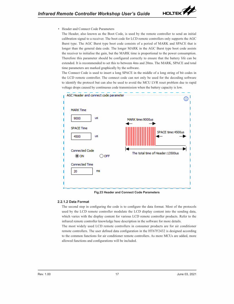
• Header and Connect Code ParametersThe Header, also known as the Boot Code, is used by the remote controller to send an initial calibration signal to a receiver. The boot code for LCD remote controllers only supports the AGC Burst type. The AGC Burst type boot code consists of a period of MARK and SPACE that is longer than the general data code. The longer MARK in the AGC Burst type boot code assists the receiver to initialise the gain, but the MARK time is proportional to the power consumption. Therefore this parameter should be configured correctly to ensure that the battery life can be extended. It is recommended to set this to between 4ms and 20ms. The MARK, SPACE and total time parameters are marked graphically by the software. The Connect Code is used to insert a long SPACE in the middle of a long string of bit codes in the LCD remote controller. The connect code can not only be used for the decoding software to identify the protocol but can also be used to avoid the MCU LVR reset problem due to rapid voltage drops caused by continuous code transmission when the battery capacity is low.
Fig.23 Header and Connect Code Parameters
2.2.1.2 Data FormatThe second step in configuring the code is to configure the data format. Most of the protocols used by the LCD remote controller modulate the LCD display content into the sending data, which varies with the display content for various LCD remote controller products. Refer to the infrared remote controller knowledge base description in the software for more details.The most widely used LCD remote controllers in consumer products are for air conditioner remote controllers. The user defined data configuration in the HT67F2432 is designed according to the common functions for air conditioner remote controllers. As more MCUs are added, more allowed functions and configurations will be included.
Rev. 1.00 18 June 03, 2021 Rev. 1.00 19 June 03, 2021
Infrared Remote Controller Workshop User’s Guide Infrared Remote Controller Workshop User’s Guide
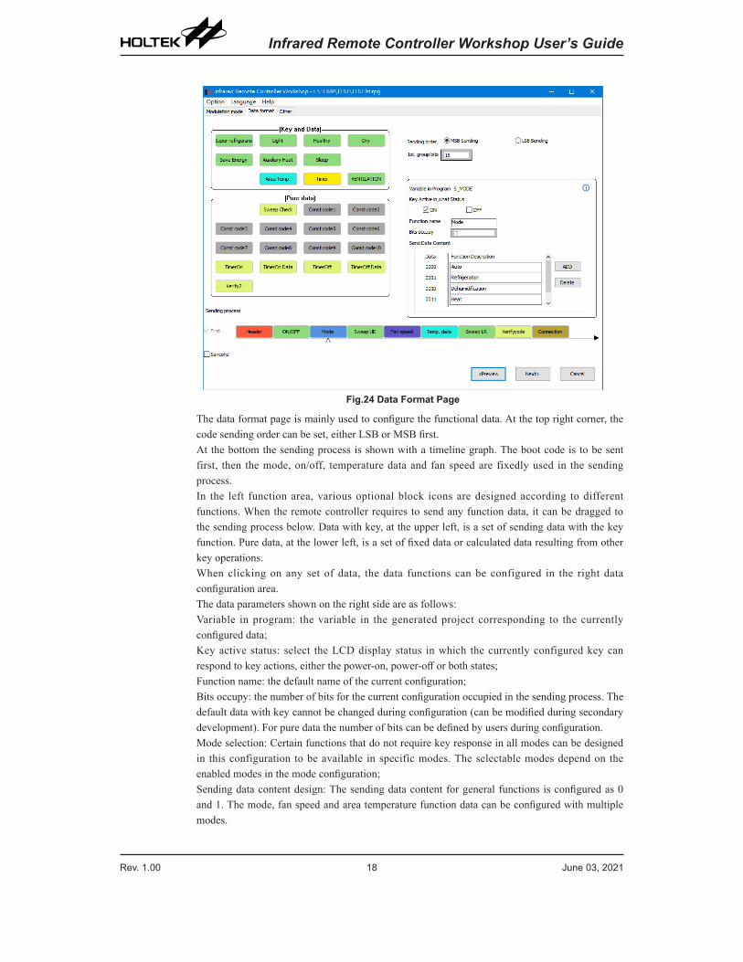
Fig.24 Data Format Page
The data format page is mainly used to configure the functional data. At the top right corner, the code sending order can be set, either LSB or MSB first.At the bottom the sending process is shown with a timeline graph. The boot code is to be sent first, then the mode, on/off, temperature data and fan speed are fixedly used in the sending process.In the left function area, various optional block icons are designed according to different functions. When the remote controller requires to send any function data, it can be dragged to the sending process below. Data with key, at the upper left, is a set of sending data with the key function. Pure data, at the lower left, is a set of fixed data or calculated data resulting from other key operations.When clicking on any set of data, the data functions can be configured in the right data configuration area.The data parameters shown on the right side are as follows:Variable in program: the variable in the generated project corresponding to the currently configured data;Key active status: select the LCD display status in which the currently configured key can respond to key actions, either the power-on, power-off or both states;Function name: the default name of the current configuration;Bits occupy: the number of bits for the current configuration occupied in the sending process. The default data with key cannot be changed during configuration (can be modified during secondary development). For pure data the number of bits can be defined by users during configuration.Mode selection: Certain functions that do not require key response in all modes can be designed in this configuration to be available in specific modes. The selectable modes depend on the enabled modes in the mode configuration;Sending data content design: The sending data content for general functions is configured as 0 and 1. The mode, fan speed and area temperature function data can be configured with multiple modes.
Rev. 1.00 18 June 03, 2021 Rev. 1.00 19 June 03, 2021
Infrared Remote Controller Workshop User’s Guide Infrared Remote Controller Workshop User’s Guide
• On/Off
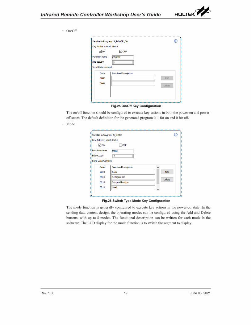
Fig.25 On/Off Key Configuration
The on/off function should be configured to execute key actions in both the power-on and power-off states. The default definition for the generated program is 1 for on and 0 for off.
• Mode
Fig.26 Switch Type Mode Key Configuration
The mode function is generally configured to execute key actions in the power-on state. In the sending data content design, the operating modes can be configured using the Add and Delete buttons, with up to 8 modes. The functional description can be written for each mode in the software. The LCD display for the mode function is to switch the segment to display.
Rev. 1.00 20 June 03, 2021 Rev. 1.00 21 June 03, 2021
Infrared Remote Controller Workshop User’s Guide Infrared Remote Controller Workshop User’s Guide
• Sweep Up and Down, Sweep Left and Right, Healthy, Ventilation, Light
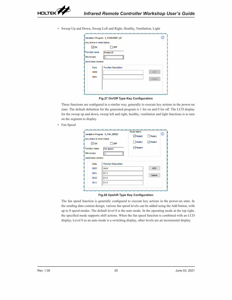
Fig.27 On/Off Type Key Configuration
These functions are configured in a similar way, generally to execute key actions in the power-on state. The default definition for the generated program is 1 for on and 0 for off. The LCD display for the sweep up and down, sweep left and right, healthy, ventilation and light functions is to turn on the segment to display.
• Fan Speed
Fig.28 Upshift Type Key Configuration
The fan speed function is generally configured to execute key actions in the power-on state. In the sending data content design, various fan speed levels can be added using the Add button, with up to 8 speed modes. The default level 0 is the auto mode. In the operating mode at the top right, the specified mode supports shift actions. When the fan speed function is combined with an LCD display, Level 0 as an auto mode is a switching display, other levels are an incremental display.
Rev. 1.00 20 June 03, 2021 Rev. 1.00 21 June 03, 2021
Infrared Remote Controller Workshop User’s Guide Infrared Remote Controller Workshop User’s Guide
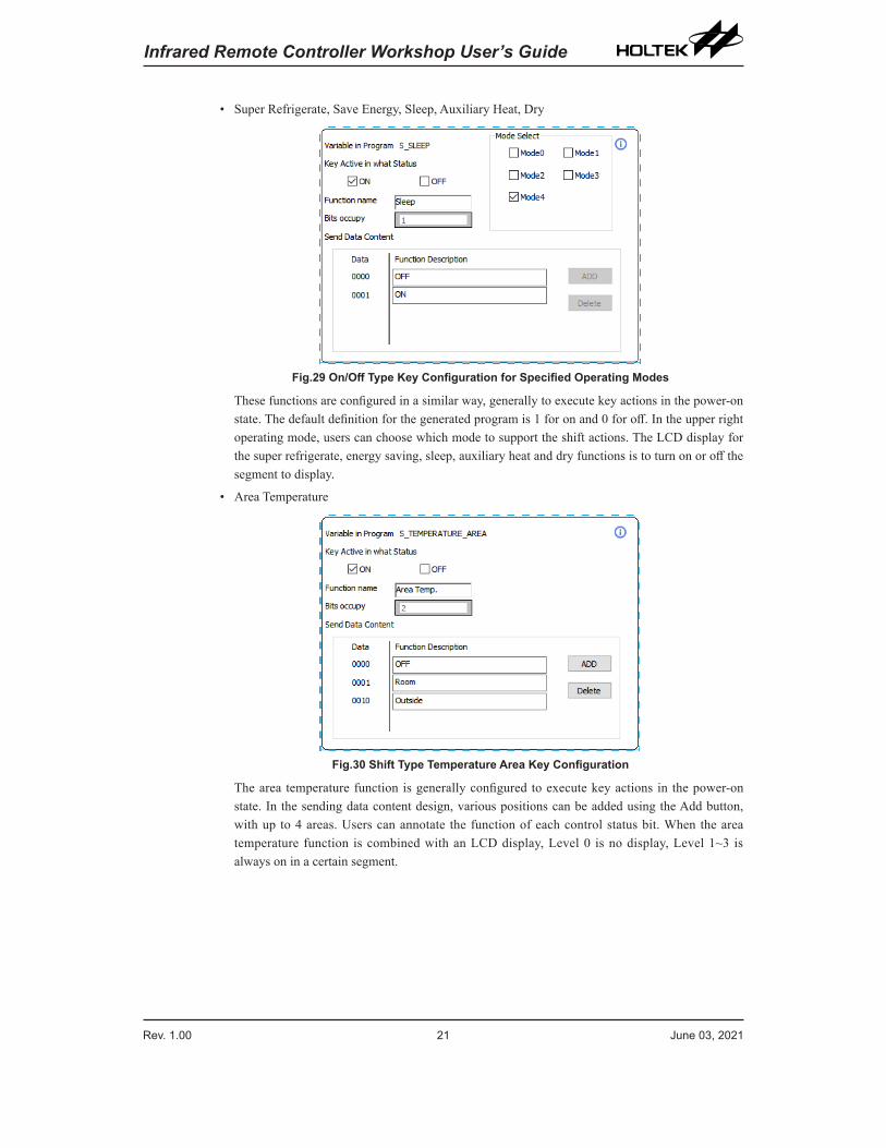
• Super Refrigerate, Save Energy, Sleep, Auxiliary Heat, Dry
Fig.29 On/Off Type Key Configuration for Specified Operating Modes
These functions are configured in a similar way, generally to execute key actions in the power-on state. The default definition for the generated program is 1 for on and 0 for off. In the upper right operating mode, users can choose which mode to support the shift actions. The LCD display for the super refrigerate, energy saving, sleep, auxiliary heat and dry functions is to turn on or off the segment to display.
• Area Temperature
Fig.30 Shift Type Temperature Area Key Configuration
The area temperature function is generally configured to execute key actions in the power-on state. In the sending data content design, various positions can be added using the Add button, with up to 4 areas. Users can annotate the function of each control status bit. When the area temperature function is combined with an LCD display, Level 0 is no display, Level 1~3 is always on in a certain segment.
Rev. 1.00 22 June 03, 2021 Rev. 1.00 23 June 03, 2021
Infrared Remote Controller Workshop User’s Guide Infrared Remote Controller Workshop User’s Guide
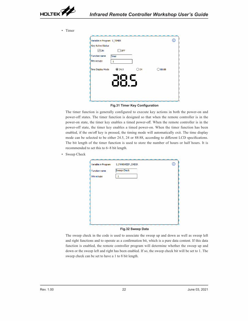
• Timer
Fig.31 Timer Key Configuration
The timer function is generally configured to execute key actions in both the power-on and power-off states. The timer function is designed so that when the remote controller is in the power-on state, the timer key enables a timed power-off. When the remote controller is in the power-off state, the timer key enables a timed power-on. When the timer function has been enabled, if the on/off key is pressed, the timing mode will automatically exit. The time display mode can be selected to be either 24.5, 24 or 88:88, according to different LCD specifications. The bit length of the timer function is used to store the number of hours or half hours. It is recommended to set this to 6~8 bit length.
• Sweep Check
Fig.32 Sweep Data
The sweep check in the code is used to associate the sweep up and down as well as sweep left and right functions and to operate as a confirmation bit, which is a pure data content. If this data function is enabled, the remote controller program will determine whether the sweep up and down or the sweep left and right has been enabled. If so, the sweep check bit will be set to 1. The sweep check can be set to have a 1 to 8 bit length.
Rev. 1.00 22 June 03, 2021 Rev. 1.00 23 June 03, 2021
Infrared Remote Controller Workshop User’s Guide Infrared Remote Controller Workshop User’s Guide
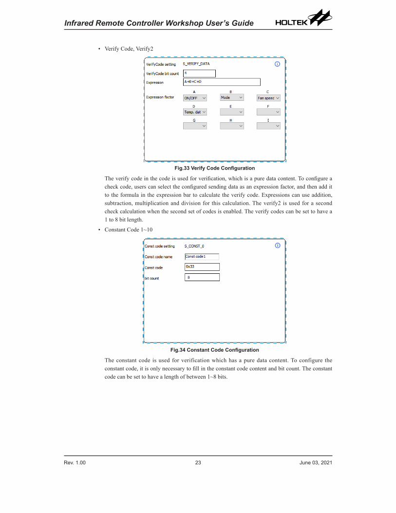
• Verify Code, Verify2
Fig.33 Verify Code Configuration
The verify code in the code is used for verification, which is a pure data content. To configure a check code, users can select the configured sending data as an expression factor, and then add it to the formula in the expression bar to calculate the verify code. Expressions can use addition, subtraction, multiplication and division for this calculation. The verify2 is used for a second check calculation when the second set of codes is enabled. The verify codes can be set to have a 1 to 8 bit length.
• Constant Code 1~10
Fig.34 Constant Code Configuration
The constant code is used for verification which has a pure data content. To configure the constant code, it is only necessary to fill in the constant code content and bit count. The constant code can be set to have a length of between 1~8 bits.
Rev. 1.00 24 June 03, 2021 Rev. 1.00 25 June 03, 2021
Infrared Remote Controller Workshop User’s Guide Infrared Remote Controller Workshop User’s Guide
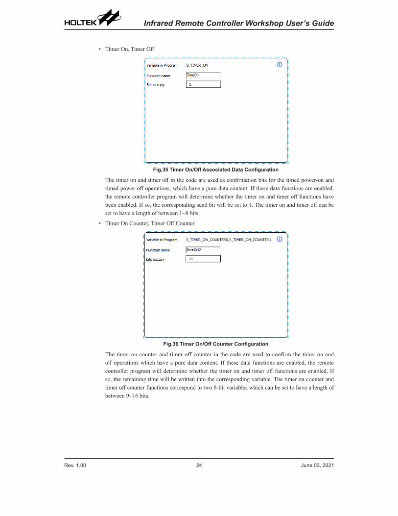
• Timer On, Timer Off
Fig.35 Timer On/Off Associated Data Configuration
The timer on and timer off in the code are used as confirmation bits for the timed power-on and timed power-off operations, which have a pure data content. If these data functions are enabled, the remote controller program will determine whether the timer on and timer off functions have been enabled. If so, the corresponding send bit will be set to 1. The timer on and timer off can be set to have a length of between 1~8 bits.
• Timer On Counter, Timer Off Counter
Fig.36 Timer On/Off Counter Configuration
The timer on counter and timer off counter in the code are used to confirm the timer on and off operations which have a pure data content. If these data functions are enabled, the remote controller program will determine whether the timer on and timer off functions are enabled. If so, the remaining time will be written into the corresponding variable. The timer on counter and timer off counter functions correspond to two 8-bit variables which can be set to have a length of between 9~16 bits.
Rev. 1.00 24 June 03, 2021 Rev. 1.00 25 June 03, 2021
Infrared Remote Controller Workshop User’s Guide Infrared Remote Controller Workshop User’s Guide
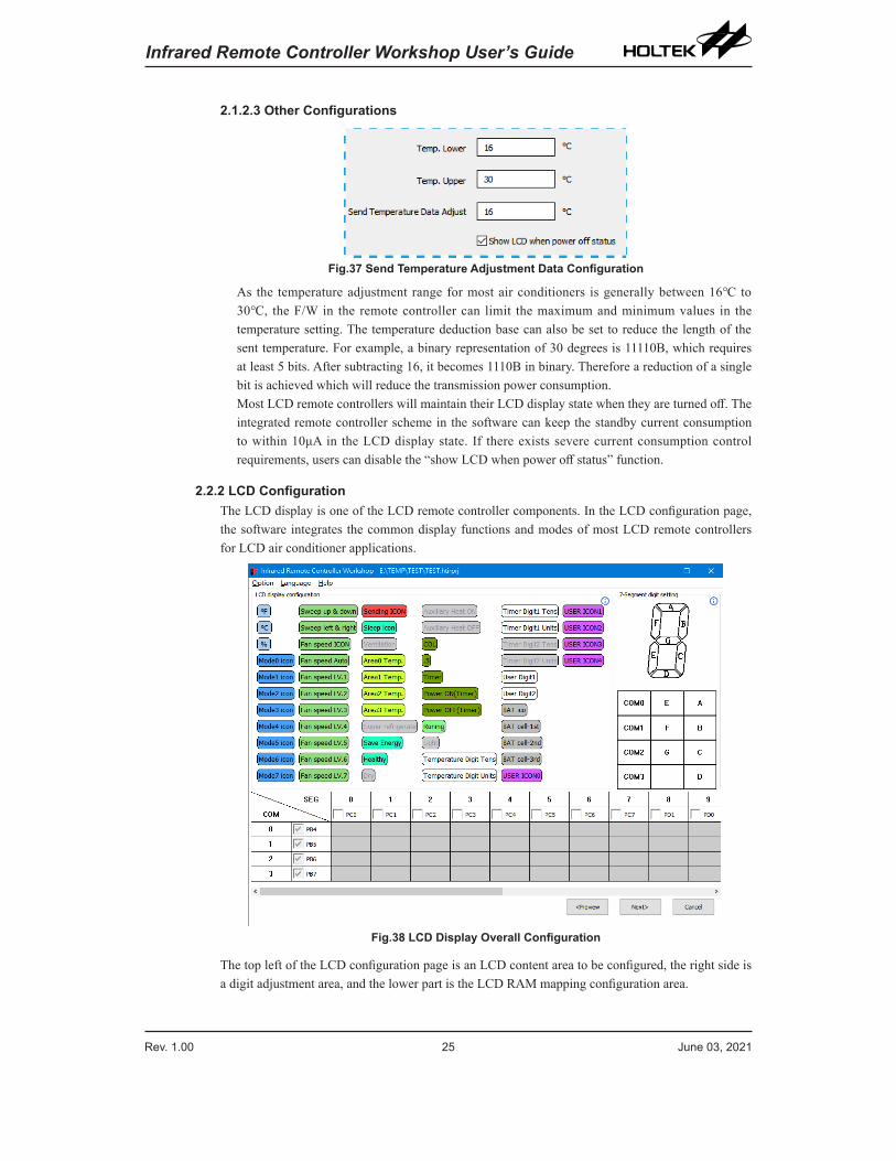
2.1.2.3 Other Configurations
Fig.37 Send Temperature Adjustment Data Configuration
As the temperature adjustment range for most air conditioners is generally between 16℃ to 30℃, the F/W in the remote controller can limit the maximum and minimum values in the temperature setting. The temperature deduction base can also be set to reduce the length of the sent temperature. For example, a binary representation of 30 degrees is 11110B, which requires at least 5 bits. After subtracting 16, it becomes 1110B in binary. Therefore a reduction of a single bit is achieved which will reduce the transmission power consumption.Most LCD remote controllers will maintain their LCD display state when they are turned off. The integrated remote controller scheme in the software can keep the standby current consumption to within 10μA in the LCD display state. If there exists severe current consumption control requirements, users can disable the “show LCD when power off status” function.
2.2.2 LCD ConfigurationThe LCD display is one of the LCD remote controller components. In the LCD configuration page, the software integrates the common display functions and modes of most LCD remote controllers for LCD air conditioner applications.
Fig.38 LCD Display Overall Configuration
The top left of the LCD configuration page is an LCD content area to be configured, the right side is a digit adjustment area, and the lower part is the LCD RAM mapping configuration area.
Rev. 1.00 26 June 03, 2021 Rev. 1.00 27 June 03, 2021
Infrared Remote Controller Workshop User’s Guide Infrared Remote Controller Workshop User’s Guide
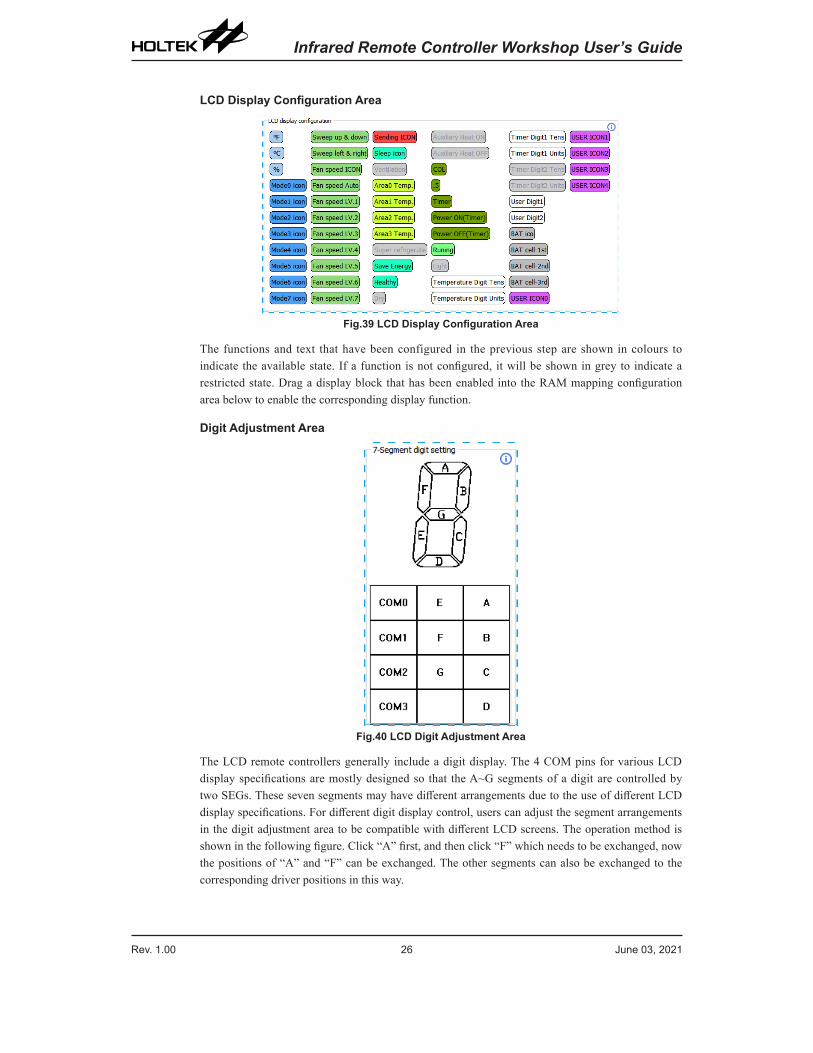
LCD Display Configuration Area
Fig.39 LCD Display Configuration Area
The functions and text that have been configured in the previous step are shown in colours to indicate the available state. If a function is not configured, it will be shown in grey to indicate a restricted state. Drag a display block that has been enabled into the RAM mapping configuration area below to enable the corresponding display function.
Digit Adjustment Area
Fig.40 LCD Digit Adjustment Area
The LCD remote controllers generally include a digit display. The 4 COM pins for various LCD display specifications are mostly designed so that the A~G segments of a digit are controlled by two SEGs. These seven segments may have different arrangements due to the use of different LCD display specifications. For different digit display control, users can adjust the segment arrangements in the digit adjustment area to be compatible with different LCD screens. The operation method is shown in the following figure. Click “A” first, and then click “F” which needs to be exchanged, now the positions of “A” and “F” can be exchanged. The other segments can also be exchanged to the corresponding driver positions in this way.
Rev. 1.00 26 June 03, 2021 Rev. 1.00 27 June 03, 2021
Infrared Remote Controller Workshop User’s Guide Infrared Remote Controller Workshop User’s Guide
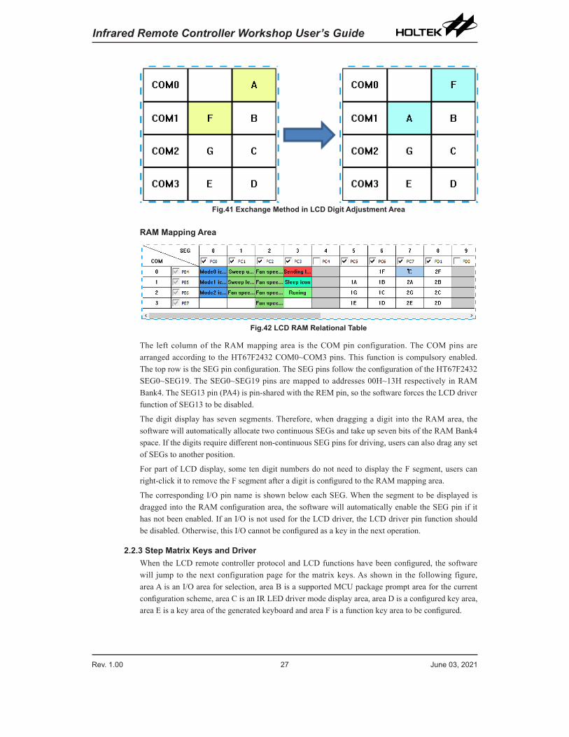
Fig.41 Exchange Method in LCD Digit Adjustment Area
RAM Mapping Area
Fig.42 LCD RAM Relational Table
The left column of the RAM mapping area is the COM pin configuration. The COM pins are arranged according to the HT67F2432 COM0~COM3 pins. This function is compulsory enabled. The top row is the SEG pin configuration. The SEG pins follow the configuration of the HT67F2432 SEG0~SEG19. The SEG0~SEG19 pins are mapped to addresses 00H~13H respectively in RAM Bank4. The SEG13 pin (PA4) is pin-shared with the REM pin, so the software forces the LCD driver function of SEG13 to be disabled.
The digit display has seven segments. Therefore, when dragging a digit into the RAM area, the software will automatically allocate two continuous SEGs and take up seven bits of the RAM Bank4 space. If the digits require different non-continuous SEG pins for driving, users can also drag any set of SEGs to another position.
For part of LCD display, some ten digit numbers do not need to display the F segment, users can right-click it to remove the F segment after a digit is configured to the RAM mapping area.
The corresponding I/O pin name is shown below each SEG. When the segment to be displayed is dragged into the RAM configuration area, the software will automatically enable the SEG pin if it has not been enabled. If an I/O is not used for the LCD driver, the LCD driver pin function should be disabled. Otherwise, this I/O cannot be configured as a key in the next operation.
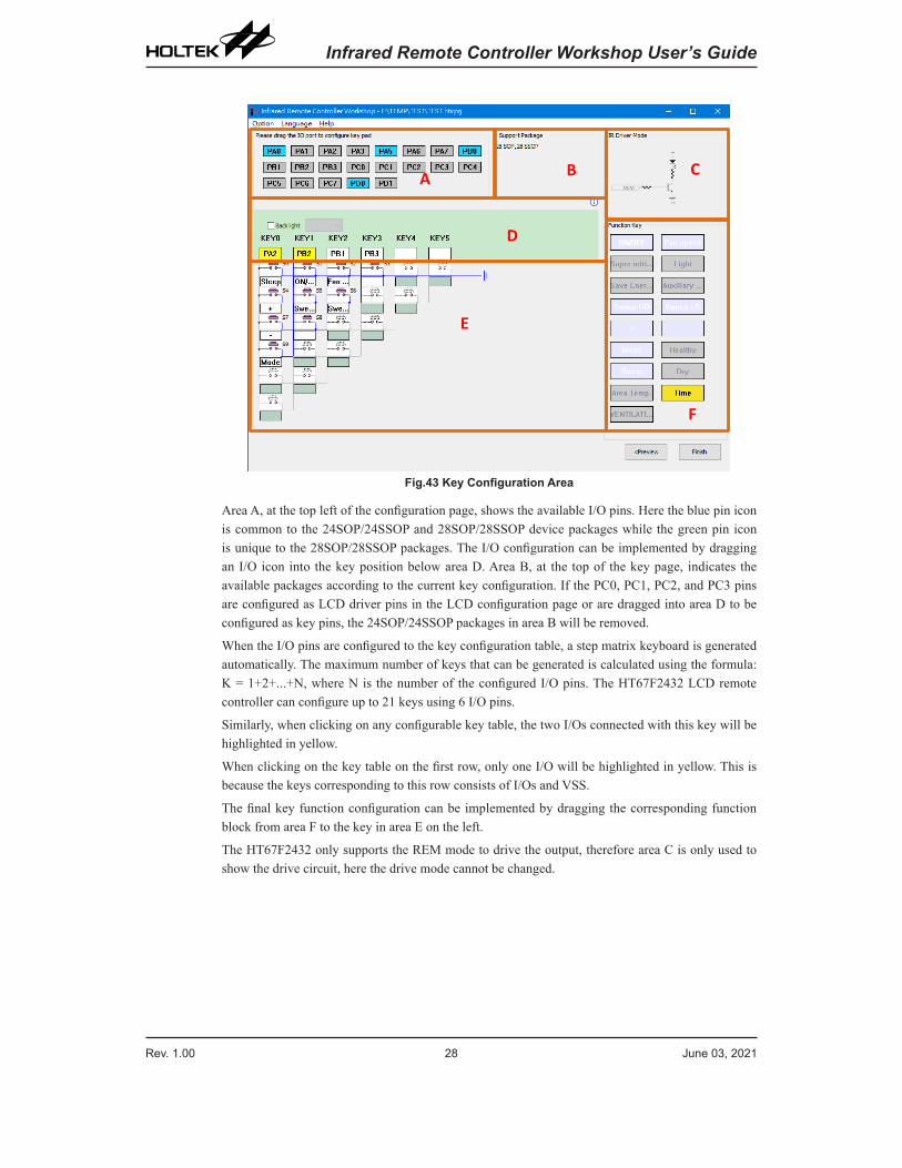
2.2.3 Step Matrix Keys and DriverWhen the LCD remote controller protocol and LCD functions have been configured, the software will jump to the next configuration page for the matrix keys. As shown in the following figure, area A is an I/O area for selection, area B is a supported MCU package prompt area for the current configuration scheme, area C is an IR LED driver mode display area, area D is a configured key area, area E is a key area of the generated keyboard and area F is a function key area to be configured.
Rev. 1.00 28 June 03, 2021 Rev. 1.00 29 June 03, 2021
Infrared Remote Controller Workshop User’s Guide Infrared Remote Controller Workshop User’s Guide
BA C
E
D
F
Fig.43 Key Configuration Area
Area A, at the top left of the configuration page, shows the available I/O pins. Here the blue pin icon is common to the 24SOP/24SSOP and 28SOP/28SSOP device packages while the green pin icon is unique to the 28SOP/28SSOP packages. The I/O configuration can be implemented by dragging an I/O icon into the key position below area D. Area B, at the top of the key page, indicates the available packages according to the current key configuration. If the PC0, PC1, PC2, and PC3 pins are configured as LCD driver pins in the LCD configuration page or are dragged into area D to be configured as key pins, the 24SOP/24SSOP packages in area B will be removed.
When the I/O pins are configured to the key configuration table, a step matrix keyboard is generated automatically. The maximum number of keys that can be generated is calculated using the formula: K = 1+2+...+N, where N is the number of the configured I/O pins. The HT67F2432 LCD remote controller can configure up to 21 keys using 6 I/O pins.
Similarly, when clicking on any configurable key table, the two I/Os connected with this key will be highlighted in yellow.
When clicking on the key table on the first row, only one I/O will be highlighted in yellow. This is because the keys corresponding to this row consists of I/Os and VSS.
The final key function configuration can be implemented by dragging the corresponding function block from area F to the key in area E on the left.
The HT67F2432 only supports the REM mode to drive the output, therefore area C is only used to show the drive circuit, here the drive mode cannot be changed.
Rev. 1.00 28 June 03, 2021 Rev. 1.00 29 June 03, 2021
Infrared Remote Controller Workshop User’s Guide Infrared Remote Controller Workshop User’s Guide
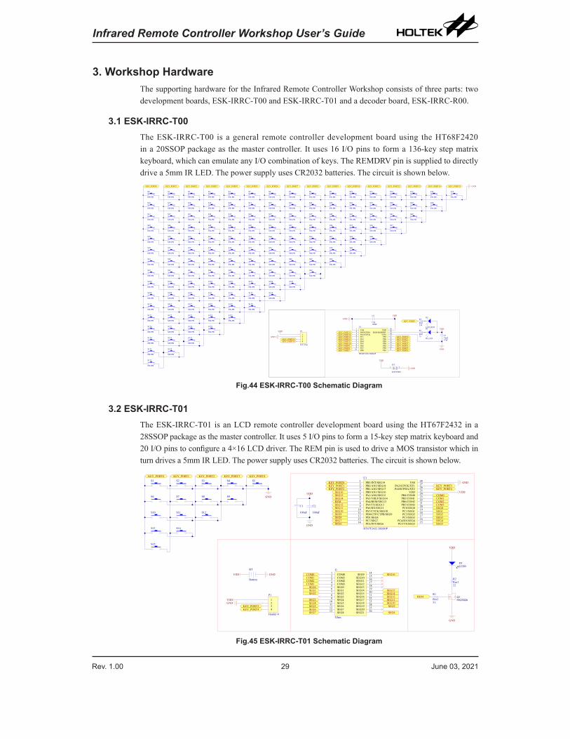
3. Workshop HardwareThe supporting hardware for the Infrared Remote Controller Workshop consists of three parts: two development boards, ESK-IRRC-T00 and ESK-IRRC-T01 and a decoder board, ESK-IRRC-R00.
3.1 ESK-IRRC-T00The ESK-IRRC-T00 is a general remote controller development board using the HT68F2420 in a 20SSOP package as the master controller. It uses 16 I/O pins to form a 136-key step matrix keyboard, which can emulate any I/O combination of keys. The REMDRV pin is supplied to directly drive a 5mm IR LED. The power supply uses CR2032 batteries. The circuit is shown below.
D2
LED_REDD1
IR_LED
VDD
47uF
C1Cap2
100nF
C2
CapGND
15
R1
Res1
GND
VDD
GND
VDD
1234
P1
ICP_Port
330
R2
Res1
VSS1
PA79
PB010 PB1 11
VDD 20
PA0/ICPDA2
PA2/ICPCK3
PA14
PA35
PA46
PA57
PB2 12PB3 13PB4 14PB5 15PB6 16PB7 17VSS1 18REM/REMDRV 19
PA68
U1
HT68F2420 20SSOP
+1 - 2BT
BATTERY
VDD
GND
S0
SW-PB
S1
SW-PB
S2
SW-PB
S3
SW-PB
S4
SW-PB
S5
SW-PB
S6
SW-PB
S7
SW-PB
S8
SW-PB
S9
SW-PB
S10
SW-PB
S11
SW-PB
S12
SW-PB
S13
SW-PB
S14
SW-PB
S16
SW-PB
S17
SW-PB
S18
SW-PB
S19
SW-PB
S20
SW-PB
S21
SW-PB
S22
SW-PB
S23
SW-PB
S24
SW-PB
S25
SW-PB
S26
SW-PB
S27
SW-PB
S28
SW-PB
S29
SW-PB
S30
SW-PB
S31
SW-PB
S32
SW-PB
S33
SW-PB
S34
SW-PB
S35
SW-PB
S36
SW-PB
S37
SW-PB
S38
SW-PB
S39
SW-PB
S40
SW-PB
S41
SW-PB
S42
SW-PB
S43
SW-PB
S44
SW-PB
S45
SW-PB
S46
SW-PB
S47
SW-PB
S48
SW-PB
S49
SW-PB
S50
SW-PB
S51
SW-PB
S52
SW-PB
S53
SW-PB
S54
SW-PB
S55
SW-PB
S56
SW-PB
S57
SW-PB
S58
SW-PB
S59
SW-PB
S60
SW-PB
S61
SW-PB
S62
SW-PB
S63
SW-PB
S64
SW-PB
S65
SW-PB
S66
SW-PB
S67
SW-PB
S68
SW-PB
S69
SW-PB
S70
SW-PB
S71
SW-PB
S72
SW-PB
S73
SW-PB
S74
SW-PB
S75
SW-PB
S76
SW-PB
S77
SW-PB
S78
SW-PB
S79
SW-PB
S80
SW-PB
S15
SW-PB
S81
SW-PB
S82
SW-PB
S83
SW-PB
S84
SW-PB
S85
SW-PB
S86
SW-PB
S87
SW-PB
S88
SW-PB
S89
SW-PB
S90
SW-PB
S91
SW-PB
S92
SW-PB
S93
SW-PB
S94
SW-PB
S95
SW-PB
S96
SW-PB
S97
SW-PB
S98
SW-PB
S99
SW-PB
S100
SW-PB
S101
SW-PB
S102
SW-PB
S103
SW-PB
S104
SW-PB
S105
SW-PB
S106
SW-PB
S107
SW-PB
S108
SW-PB
S109
SW-PB
S110
SW-PB
S111
SW-PB
S112
SW-PB
S113
SW-PB
S115
SW-PB
S116
SW-PB
S117
SW-PB
S118
SW-PB
S119
SW-PB
S120
SW-PB
S121
SW-PB
S122
SW-PB
S123
SW-PB
S124
SW-PB
S125
SW-PB
S126
SW-PB
S127
SW-PB
S128
SW-PB
S129
SW-PB
S130
SW-PB
S131
SW-PB
S132
SW-PB
S133
SW-PB
S134
SW-PB
S135
SW-PB
GND
KEY_PORT0
KEY_PORT2KEY_PORT3KEY_PORT4KEY_PORT5KEY_PORT6KEY_PORT7
KEY_PORT12KEY_PORT13KEY_PORT14KEY_PORT15
KEY_PORT11KEY_PORT10KEY_PORT9KEY_PORT8
KEY_PORT1 KEY_PORT2 KEY_PORT3 KEY_PORT4 KEY_PORT5 KEY_PORT6 KEY_PORT7 KEY_PORT8 KEY_PORT9 KEY_PORT10 KEY_PORT11 KEY_PORT12 KEY_PORT13 KEY_PORT14 KEY_PORT15
KEY_PORT1
S114
SW-PB
KEY_PORT15KEY_PORT14
KEY_PORT0
KEY_PORT0
Fig.44 ESK-IRRC-T00 Schematic Diagram
3.2 ESK-IRRC-T01The ESK-IRRC-T01 is an LCD remote controller development board using the HT67F2432 in a 28SSOP package as the master controller. It uses 5 I/O pins to form a 15-key step matrix keyboard and 20 I/O pins to configure a 4×16 LCD driver. The REM pin is used to drive a MOS transistor which in turn drives a 5mm IR LED. The power supply uses CR2032 batteries. The circuit is shown below.
S1 S2 S3 S4 S5
S6 S8 S9
S10 S11 S12
S13 S14
S15
GND
VDD
KEY_PORT0 KEY_PORT1 KEY_PORT2 KEY_PORT3 KEY_PORT4
KEY_PORT0KEY_PORT1KEY_PORT2
KEY_PORT3KEY_PORT4
D1LED0
22
R2Res1
GND
VDD
51
R1
Res1REM
REM
COM0COM1COM2COM3SEG0SEG1SEG2SEG3SEG4SEG5SEG6
SEG7SEG8SEG9SEG10SEG11SEG12
SEG14
1234
P1
Header 4
VDDGND
COM0COM1COM2COM3
SEG0SEG1SEG2
SEG3SEG4SEG5SEG6SEG7
SEG16
SEG15SEG14SEG12SEG11SEG10
SEG15SEG16
COM01
COM12
COM23
COM34
SEG05
SEG16
SEG27
SEG38
SEG49
SEG510
SEG611
SEG712
SEG813
SEG9 14
SEG10 15
SEG11 16
SEG12 17
SEG13 18
SEG14 19
SEG15 20
SEG16 21
SEG17 22
SEG18 23
SEG19 24
SEG20 25
SEG21 26
G
Glass
SEG9
SEG8
KEY_PORT3KEY_PORT4
PB3/INT/SEG191
PB2/AN3/SEG182
PB1/AN2/SEG173
PB0/AN1/SEG164
PA1/AN0/SEG155
PA3/VREF/SEG146
PA4/REM/SEG137
PA5/TX/SEG128
PA6/RX/SEG119
PA7/CTCK/SEG1010
PD0/CTP/CTPB/SEG911
PD1/SEG812
PC7/SEG713
PC6/INT/SEG614 PC5/TX/SEG5 15PC4/RX/SEG4 16PC3/SEG3 17PC2/SEG2 18PC1/SEG1 19PC0/SEG0 20PB7/COM3 21PB6/COM2 22PB5/COM1 23PB4/COM0 24VDD 25PA0/ICPDA/XT2 26PA2/ICPCK/XT1 27VSS 28U1
HT67F2432 28SSOP
GND
VDD
GNDS7
BT
Battery
100nF
C2
100uF
C1
Q1HX2302A
GNDVDD
Fig.45 ESK-IRRC-T01 Schematic Diagram
Rev. 1.00 30 June 03, 2021 Rev. 1.00 31 June 03, 2021
Infrared Remote Controller Workshop User’s Guide Infrared Remote Controller Workshop User’s Guide
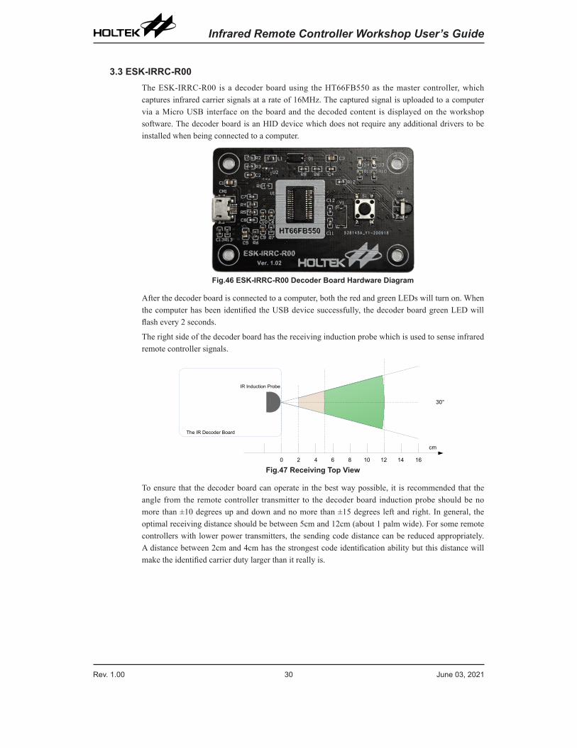
3.3 ESK-IRRC-R00The ESK-IRRC-R00 is a decoder board using the HT66FB550 as the master controller, which captures infrared carrier signals at a rate of 16MHz. The captured signal is uploaded to a computer via a Micro USB interface on the board and the decoded content is displayed on the workshop software. The decoder board is an HID device which does not require any additional drivers to be installed when being connected to a computer.
Fig.46 ESK-IRRC-R00 Decoder Board Hardware Diagram
After the decoder board is connected to a computer, both the red and green LEDs will turn on. When the computer has been identified the USB device successfully, the decoder board green LED will flash every 2 seconds.
The right side of the decoder board has the receiving induction probe which is used to sense infrared remote controller signals.
0 2 4 6 8 10 12 14 16
30°
cm
IR Induction Probe
The IR Decoder Board
Fig.47 Receiving Top View
To ensure that the decoder board can operate in the best way possible, it is recommended that the angle from the remote controller transmitter to the decoder board induction probe should be no more than ±10 degrees up and down and no more than ±15 degrees left and right. In general, the optimal receiving distance should be between 5cm and 12cm (about 1 palm wide). For some remote controllers with lower power transmitters, the sending code distance can be reduced appropriately. A distance between 2cm and 4cm has the strongest code identification ability but this distance will make the identified carrier duty larger than it really is.
Rev. 1.00 30 June 03, 2021 Rev. 1.00 31 June 03, 2021
Infrared Remote Controller Workshop User’s Guide Infrared Remote Controller Workshop User’s Guide
4. Decoding and Learning Code Development
4.1 Code VerificationAfter a remote controller with standard protocol or a user defined protocol development has completed, the generated project can be compiled and programmed to the remote controller development board. The remote controller development board program can then be verified by sending the code to the decoder board using the development board.
The operations are as follows:
1. Connect the decoder board to a computer.
2. Select new project and “code/waveform mode” then jump to the software view as shown in Fig.48.
3. Press the “start decode” button in the software. Now the decoder board will enter a receiving state and the red LED will turn on. The remote controller to be tested should now be aimed at the decoder board induction probe within 6 seconds and press a remote controller button to emit an infrared waveform.
4. When the decoder board green LED turns on, this indicates that the reception has completed and that the sending data will be uploaded to the computer. When the upload is successful, the decoder board green LED will flash 4 times and the sending parameters will be displayed after the decoding has completed.
5. If the sending code is not received or the data is abnormal, the decoder board red LED will flash 4 times to indicate that the upload has failed.
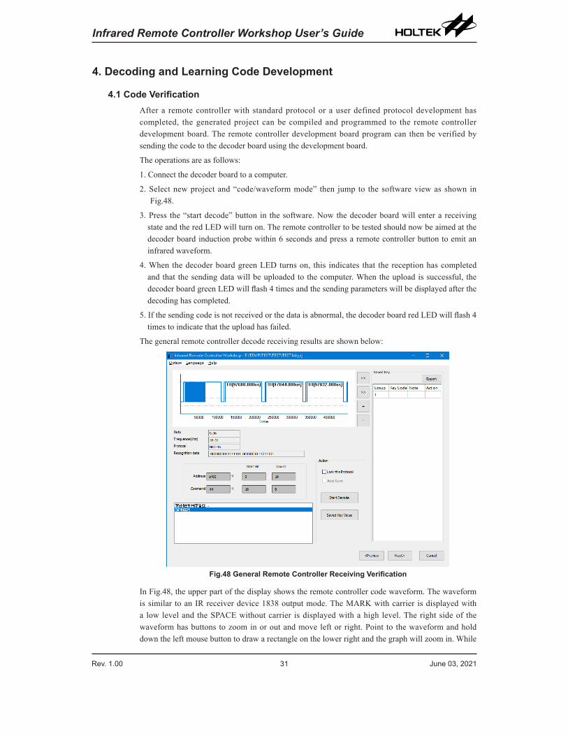
The general remote controller decode receiving results are shown below:
Fig.48 General Remote Controller Receiving Verification
In Fig.48, the upper part of the display shows the remote controller code waveform. The waveform is similar to an IR receiver device 1838 output mode. The MARK with carrier is displayed with a low level and the SPACE without carrier is displayed with a high level. The right side of the waveform has buttons to zoom in or out and move left or right. Point to the waveform and hold down the left mouse button to draw a rectangle on the lower right and the graph will zoom in. While
Rev. 1.00 32 June 03, 2021 Rev. 1.00 33 June 03, 2021
Infrared Remote Controller Workshop User’s Guide Infrared Remote Controller Workshop User’s Guide
holding down the left mouse button to draw a rectangle on the upper right, the graph can be zoomed out. The graph can be dragged left or right for viewing by holding down the right mouse button.
The contents below the waveform diagram show the specific parameters of the sending code, such as the carrier duty, frequency, the identified protocol type and each bit recorded by the waveform. Below this string of bits are the identified address and command as well as their start bit and total bit count. Only when a standard protocol has been identified will the software automatically identify the start bit and the total bit count of the address and command according to the protocol type. If the sending code does not conform to a standard protocol, the software will determine that it is a user defined protocol, which requires users to manually enter the start bit and total bit count of the address and command.
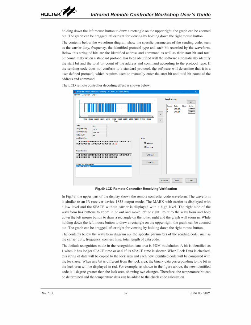
The LCD remote controller decoding effect is shown below:
Fig.49 LCD Remote Controller Receiving Verification
In Fig.49, the upper part of the display shows the remote controller code waveform. The waveform is similar to an IR receiver device 1838 output mode. The MARK with carrier is displayed with a low level and the SPACE without carrier is displayed with a high level. The right side of the waveform has buttons to zoom in or out and move left or right. Point to the waveform and hold down the left mouse button to draw a rectangle on the lower right and the graph will zoom in. While holding down the left mouse button to draw a rectangle on the upper right, the graph can be zoomed out. The graph can be dragged left or right for viewing by holding down the right mouse button.
The contents below the waveform diagram are the specific parameters of the sending code, such as the carrier duty, frequency, connect time, total length of data code.
The default recognition mode in the recognition data area is PDM modulation. A bit is identified as 1 when it has longer SPACE time or as 0 if its SPACE time is shorter. When Lock Data is checked, this string of data will be copied to the lock area and each new identified code will be compared with the lock area. When any bit is different from the lock area, the binary data corresponding to the bit in the lock area will be displayed in red. For example, as shown in the figure above, the new identified code is 1 degree greater than the lock area, showing two changes. Therefore, the temperature bit can be determined and the temperature data can be added to the check code calculation.
Rev. 1.00 32 June 03, 2021 Rev. 1.00 33 June 03, 2021
Infrared Remote Controller Workshop User’s Guide Infrared Remote Controller Workshop User’s Guide
In the content of the identification data area, C means a connect code is inserted here, L means an inserted interval between two codes and E means the end of the sending code.
4.2 Code DevelopmentIf there is an existing remote controller and the original project or source code cannot be found, but a scheme with the same protocol as this remote controller needs to be developed, in this case the code development mode can be used. Use a decoder board to read the remote controller protocol, carrier, address, command and other parameters to develop remote controller products with consistent protocol and functions.
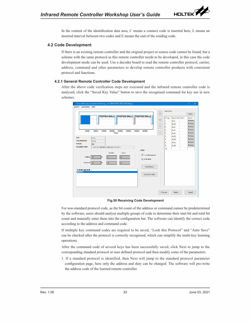
4.2.1 General Remote Controller Code DevelopmentAfter the above code verification steps are executed and the infrared remote controller code is analysed, click the “Saved Key Value” button to save the recognised command for key use in new schemes.
Fig.50 Receiving Code Development
For non-standard protocol code, as the bit count of the address or command cannot be predetermined by the software, users should analyse multiple groups of code to determine their start bit and total bit count and manually enter them into the configuration bar. The software can identify the correct code according to the address and command code.
If multiple key command codes are required to be saved, “Lock this Protocol” and “Auto Save” can be checked after the protocol is correctly recognised, which can simplify the multi-key learning operations.
After the command code of several keys has been successfully saved, click Next to jump to the corresponding standard protocol or user defined protocol and then modify some of the parameters.
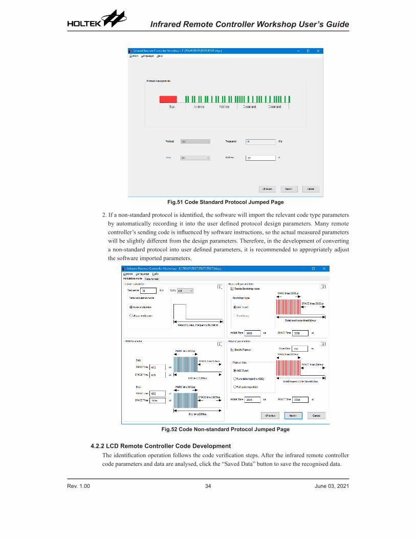
1. If a standard protocol is identified, then Next will jump to the standard protocol parameter configuration page, here only the address and duty can be changed. The software will pre-write the address code of the learned remote controller.
Rev. 1.00 34 June 03, 2021 Rev. 1.00 35 June 03, 2021
Infrared Remote Controller Workshop User’s Guide Infrared Remote Controller Workshop User’s Guide
Fig.51 Code Standard Protocol Jumped Page
2. If a non-standard protocol is identified, the software will import the relevant code type parameters by automatically recording it into the user defined protocol design parameters. Many remote controller’s sending code is influenced by software instructions, so the actual measured parameters will be slightly different from the design parameters. Therefore, in the development of converting a non-standard protocol into user defined parameters, it is recommended to appropriately adjust the software imported parameters.
Fig.52 Code Non-standard Protocol Jumped Page
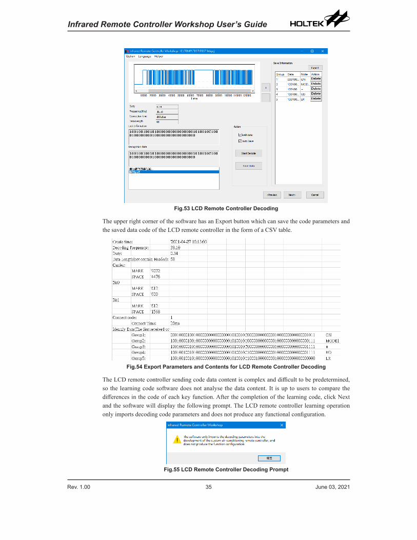
4.2.2 LCD Remote Controller Code DevelopmentThe identification operation follows the code verification steps. After the infrared remote controller code parameters and data are analysed, click the “Saved Data” button to save the recognised data.
Rev. 1.00 34 June 03, 2021 Rev. 1.00 35 June 03, 2021
Infrared Remote Controller Workshop User’s Guide Infrared Remote Controller Workshop User’s Guide
Fig.53 LCD Remote Controller Decoding
The upper right corner of the software has an Export button which can save the code parameters and the saved data code of the LCD remote controller in the form of a CSV table.
Fig.54 Export Parameters and Contents for LCD Remote Controller Decoding
The LCD remote controller sending code data content is complex and difficult to be predetermined, so the learning code software does not analyse the data content. It is up to users to compare the differences in the code of each key function. After the completion of the learning code, click Next and the software will display the following prompt. The LCD remote controller learning operation only imports decoding code parameters and does not produce any functional configuration.
Fig.55 LCD Remote Controller Decoding Prompt
Rev. 1.00 36 June 03, 2021 Rev. 1.00 37 June 03, 2021
Infrared Remote Controller Workshop User’s Guide Infrared Remote Controller Workshop User’s Guide
5. Description of Other Functions
5.1 F/W Power ControlThe Infrared Remote Controller Workshop has been especially designed for remote controllers. The power consumption for the remote controllers has been optimised as much as possible.
5.1.1 Dynamic Power ControlIn the market, some remote controllers have the IR LED completely on during the SPACE time, which is not good for battery life. The workshop generated remote controller program can implement a situation where the IR LED is only driven by the MARK duty time and is completely off during the SPACE control time, greatly extending the battery life.
General remote controllers normally need to send repeat codes due to their protocol. They will continue to send codes after their buttons are pressed. Most remote controllers do not set a time threshold. If any remote controller buttons are accidentally pressed by nearby objects, this will cause the remote controller to send repeat codes until the battery energy is exhausted. However, this workshop’s firmware can determine the number of repeat code sending times. When the remote control enters a press button state, the repeat codes will only be repeatedly sent 255 times. When this preset threshold is reached, the program will turn off the IR LED emission until the button is released to reduce power consumption.
5.1.2 Static Power ControlUsing the F/W generated remote controller program, the general remote controller is woken up from the HALT mode by a WDT overflow every 0.128s to scan the keys. While the LCD remote controller is woken up by an interrupt every 64ms to check the timer, it can scan the keys every 0.128 seconds and execute an LCD flash function, backlight timing or battery voltage detection (open in secondary development only) every 0.512 seconds. General remote controllers can scan up to 136 keys, and the standby power consumption can be controlled to within 7μA. For LCD remote controllers, the power consumption can be controlled to within 10μA when the LCD is always on and to within 5μA when the LCD is off.
5.2 Decode RecognitionThe decoder board can identify code lengths of up to 148 combinations of MARK and SPACE which basically covers the codes of all general remote controllers and most LCD remote controllers.
As there are many remote controller protocols and code sending protocols in the market, some special protocols that do not conform to general coding rules may be difficult to identify in the workshop, therefore it is not guaranteed that every protocol can be recognised and restored. In the future, updated versions of the software will continue to enhance these learning functions and attempt to increase the range of available protocols.
Rev. 1.00 36 June 03, 2021 Rev. 1.00 37 June 03, 2021
Infrared Remote Controller Workshop User’s Guide Infrared Remote Controller Workshop User’s Guide
6. Appendix & FAQ
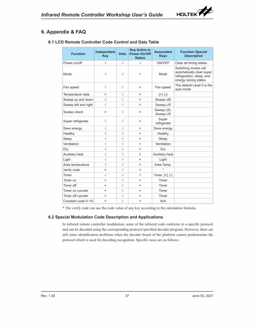
6.1 LCD Remote Controller Code Control and Data Table
Function Independent Key Data
Key Active in Power-On/Off
Status
Associated Keys
Function Special Description
Power on/off √ √ √ ON/OFF Clear all timing states
Mode √ √ × Mode
Switching modes will automatically clear super refrigeration, sleep, and energy saving states
Fan speed √ √ × Fan speed The default Level 0 is the auto mode
Temperature data × √ × [+], [-]Sweep up and down √ √ × Sweep UDSweep left and right √ √ × Sweep LR
Sweep check × √ × Sweep UD, Sweep LR
Super refrigerate √ √ × Super refrigerate
Save energy √ √ × Save energyHealthy √ √ × HealthySleep √ √ × SleepVentilation √ √ × VentilationDry √ √ × DryAuxiliary heat √ √ × Auxiliary heatLight √ √ × LightArea temperature √ √ × Area Temp.Verify code × √ × *Timer √ √ √ Timer, [+], [-]Timer on × √ × TimerTimer off × √ × TimerTimer on counter × √ × TimerTimer off counter × √ × TimerConstant code 0~10 × √ × N/A
* The verify code can use the code value of any key according to the calculation formula.
6.2 Special Modulation Code Description and ApplicationsIn infrared remote controller modulation, some of the infrared code conforms to a specific protocol and can be decoded using the corresponding protocol specified decoder program. However, there are still some identification problems when the decoder board of the platform cannot predetermine the protocol which is used for decoding recognition. Specific cases are as follows.
Rev. 1.00 38 June 03, 2021 Rev. 1.00 39 June 03, 2021
Infrared Remote Controller Workshop User’s Guide Infrared Remote Controller Workshop User’s Guide
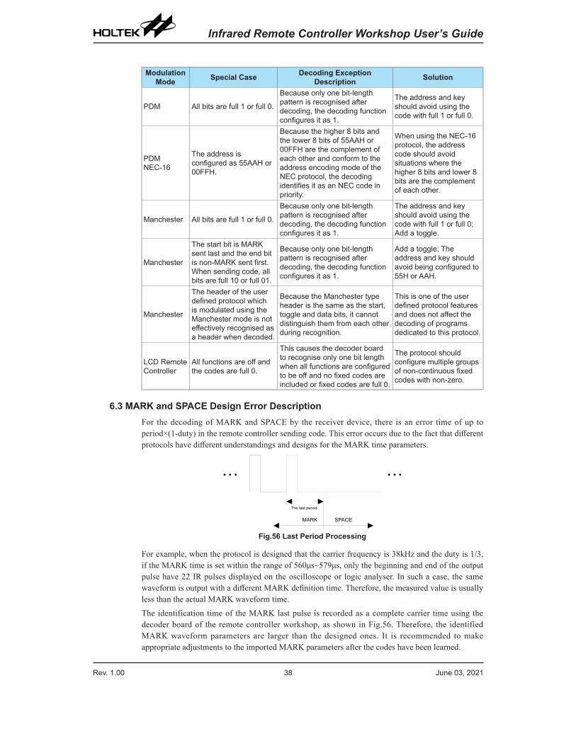
Modulation Mode Special Case Decoding Exception
Description Solution
PDM All bits are full 1 or full 0.
Because only one bit-length pattern is recognised after decoding, the decoding function configures it as 1.
The address and key should avoid using the code with full 1 or full 0.
PDM NEC-16
The address is configured as 55AAH or 00FFH.
Because the higher 8 bits and the lower 8 bits of 55AAH or 00FFH are the complement of each other and conform to the address encoding mode of the NEC protocol, the decoding identifies it as an NEC code in priority.
When using the NEC-16 protocol, the address code should avoid situations where the higher 8 bits and lower 8 bits are the complement of each other.
Manchester All bits are full 1 or full 0.
Because only one bit-length pattern is recognised after decoding, the decoding function configures it as 1.
The address and key should avoid using the code with full 1 or full 0; Add a toggle.
Manchester
The start bit is MARK sent last and the end bit is non-MARK sent first. When sending code, all bits are full 10 or full 01.
Because only one bit-length pattern is recognised after decoding, the decoding function configures it as 1.
Add a toggle; The address and key should avoid being configured to 55H or AAH.
Manchester
The header of the user defined protocol which is modulated using the Manchester mode is not effectively recognised as a header when decoded.
Because the Manchester type header is the same as the start, toggle and data bits, it cannot distinguish them from each other during recognition.
This is one of the user defined protocol features and does not affect the decoding of programs dedicated to this protocol.
LCD Remote Controller
All functions are off and the codes are full 0.
This causes the decoder board to recognise only one bit length when all functions are configured to be off and no fixed codes are included or fixed codes are full 0.
The protocol should configure multiple groups of non-continuous fixed codes with non-zero.
6.3 MARK and SPACE Design Error DescriptionFor the decoding of MARK and SPACE by the receiver device, there is an error time of up to period×(1-duty) in the remote controller sending code. This error occurs due to the fact that different protocols have different understandings and designs for the MARK time parameters.
The last period
SPACEMARK
Fig.56 Last Period Processing
For example, when the protocol is designed that the carrier frequency is 38kHz and the duty is 1/3, if the MARK time is set within the range of 560μs~579μs, only the beginning and end of the output pulse have 22 IR pulses displayed on the oscilloscope or logic analyser. In such a case, the same waveform is output with a different MARK definition time. Therefore, the measured value is usually less than the actual MARK waveform time.The identification time of the MARK last pulse is recorded as a complete carrier time using the decoder board of the remote controller workshop, as shown in Fig.56. Therefore, the identified MARK waveform parameters are larger than the designed ones. It is recommended to make appropriate adjustments to the imported MARK parameters after the codes have been learned.
Rev. 1.00 38 June 03, 2021 Rev. 1.00 39 June 03, 2021
Infrared Remote Controller Workshop User’s Guide Infrared Remote Controller Workshop User’s Guide
Copyright© 2021 by HOLTEK SEMICONDUCTOR INC.
The information appearing in this Data Sheet is believed to be accurate at the time of publication. However, Holtek assumes no responsibility arising from the use of the specifications described. The applications mentioned herein are used solely for the purpose of illustration and Holtek makes no warranty or representation that such applications will be suitable without further modification, nor recommends the use of its products for application that may present a risk to human life due to malfunction or otherwise. Holtek's products are not authorized for use as critical components in life support devices or systems. Holtek reserves the right to alter its products without prior notification. For the most up-to-date information, please visit our web site at http://www.holtek.com.
Related Documents


