UAD Plug-Ins Manual Software Version 8.6 www.uaudio.com Manual Version 160425

Welcome message from author
This document is posted to help you gain knowledge. Please leave a comment to let me know what you think about it! Share it to your friends and learn new things together.
Transcript
UAD Powered Plug-Ins Manual Table Of Contents 2
Tip: Click any section or page number to jump directly to that page.
Table Of Contents
UAD Plug-Ins Overview ............................................................................................ 5
AKG BX 20 Spring Reverb ....................................................................................... 8
Ampex ATR-102 Mastering Tape Recorder ............................................................... 17
API 500 Series EQ Collection ................................................................................ 43
API Vision Channel Strip ....................................................................................... 50
Bermuda Triangle ................................................................................................. 66
Boss CE-1 Chorus Ensemble .................................................................................. 70
Cambridge EQ ...................................................................................................... 74
Cooper Time Cube ................................................................................................. 83
CS-1 Channel Strip ............................................................................................... 89
dbx 160 Compressor/Limiter ................................................................................ 102
DreamVerb ......................................................................................................... 105
Empirical Labs EL7 FATSO .................................................................................. 123
EMT 140 Plate Reverb ........................................................................................ 137
EMT 250 Electronic Reverberator ......................................................................... 143
EP-34 Classic Tape Echo ..................................................................................... 155
Fairchild Tube Limiter Collection .......................................................................... 161
Fender ‘55 Tweed Deluxe .................................................................................... 177
Harrison 32C EQ ................................................................................................ 201
Helios Type 69 Equalizer ..................................................................................... 206
Ibanez Tube Screamer TS808 .............................................................................. 211
LA-3A Compressor .............................................................................................. 216
Lexicon 224 ....................................................................................................... 218
UAD Powered Plug-Ins Manual Table Of Contents 3
Little Labs IBP ................................................................................................... 236
Little Labs VOG .................................................................................................. 239
Manley Massive Passive EQ ................................................................................. 243
Manley Stereo Variable Mu Limiter Compressor ...................................................... 254
Moog Multimode Filter ........................................................................................ 266
MXR Flanger/Doubler .......................................................................................... 275
Neve 88RS Channel Strip Collection .................................................................... 282
Neve 1073 Preamp & EQ Collection ..................................................................... 308
Neve 1081 Equalizer .......................................................................................... 321
Neve 31102 Console EQ ..................................................................................... 329
Neve 33609 Compressor ..................................................................................... 334
Ocean Way Studios ............................................................................................. 343
Oxide Tape Recorder ........................................................................................... 372
Precision Buss Compressor .................................................................................. 379
Precision Channel Strip ....................................................................................... 384
Precision De-Esser .............................................................................................. 393
Precision Delay Modulation .................................................................................. 397
Precision Enhancer Hz ........................................................................................ 406
Precision Enhancer kHz ...................................................................................... 410
Precision Equalizer ............................................................................................. 413
Precision K-Stereo Ambience Recovery ................................................................. 418
Precision Limiter ................................................................................................ 430
Precision Maximizer ............................................................................................ 436
Precision Multiband ............................................................................................ 441
Precision Reflection Engine ................................................................................. 453
Pultec Passive EQ Collection ............................................................................... 458
UAD Powered Plug-Ins Manual Table Of Contents 4
Raw Distortion .................................................................................................... 470
RealVerb Pro ...................................................................................................... 474
Roland Dimension D ........................................................................................... 487
Roland RE-201 Space Echo ................................................................................ 489
SPL Transient Designer ....................................................................................... 496
SSL E Channel Strip ........................................................................................... 505
SSL G Bus Compressor ....................................................................................... 518
Studer A800 Multichannel Tape Recorder ............................................................. 522
Teletronix® LA-2A Leveler Collection ..................................................................... 534
Thermionic Culture Vulture .................................................................................. 542
Trident A-Range EQ ............................................................................................ 549
UA 1176 Classic Limiter Collection ...................................................................... 554
UA 610 Tube Preamp & EQ Collection .................................................................. 565
Additional Latency .............................................................................................. 575
Notices .............................................................................................................. 578
Technical Support ............................................................................................... 579
UAD Powered Plug-Ins Manual UAD Plug-Ins Overview 5
UAD Plug-Ins Overview
The Authentic Sound of AnalogThe UAD Powered Plug-Ins platform offers the world’s most authentic analog hardware emulations and award-winning audio plug-ins for Mac and PC. Powered by our popular DSP Accelerator hardware and Apollo Interfaces, UAD plug-ins deliver rich, analog sound quality that would be difficult or impossible to achieve with native recording systems.
The industry’s most respected collection of audio plug-insFrom serious home recordists to multi-platinum mix engineers, UAD Powered Plug-Ins have been winning over audio professionals for more than 10 years. The UAD library now features over 90 plug-ins, co-developed with the biggest brands in audio — including Studer, Ampex, Lexicon, Neve, Manley, Marshall, SSL, and more.
These exclusive plug-ins can be purchased alongside UAD-2 DSP Accelerator hardware as part of the “Custom” and “Ultimate” packages, or you can buy UAD plug-ins à la carte from UA’s Online Store.
UAD plug-in craftsmanship: The science behind the scenesMost people don’t immediately think of audio software when they hear the word “craftsmanship.” But that’s what separates UAD plug-ins from the rest. One of the most common responses from UAD users is, “Wow, I didn’t know plug-ins could sound this good.” That’s because in developing UAD plug-ins, UA’s engineering group undertakes a thorough physical modeling of classic audio hardware. This process means that we essentially “rebuild” vintage analog gear in the digital world, component by component.
Using UAD plug-ins, your mixes will benefit from the exact, sometimes quirky, sound of analog hardware — giving you rich, three-dimensional tone and harmonics “in the box.”
*All trademarks are recognized as property of their respective owners. Individual UAD Powered Plug-Ins sold separately.
UAD Powered Plug-Ins Manual UAD Plug-Ins Overview 6
Documentation OverviewThis section describes the various instructional and technical resources that are available for installing, using, and troubleshooting UAD Powered Plug-Ins, UAD-2 devices, and Apollo audio interfaces. Documentation for all products are available in written, video, and online formats.
Note: All manuals are in PDF format. PDF files require a free PDF reader application such as Adobe Acrobat Reader (Windows) or Preview (Mac).
Operation ManualsDocumentation for UAD-2 and Apollo system components is extensive, so instructions are separated by areas of functionality. Each functional area has a separate manual file. An overview of each file, and how they are accessed, is provided in this section.
UAD Plug-Ins ManualThe features and functionality of all individual UAD plug-ins is detailed in the UAD Plug-Ins Manual. Refer to this document to learn about the operation, controls, and user interface of each UAD plug-in that is developed by Universal Audio.
Direct Developer Plug-InsUAD Powered Plug-Ins includes plug-ins created by our Direct Developer partners. Documentation for these 3rd-party plug-ins are separate files written and provided by the plug-in developers. The file names for these plug-in manuals are the same as the plug-in titles.
UAD System ManualThe UAD System Manual is the complete operation manual for the entire UAD-2 product family. It contains detailed information about installing and configuring UAD devices, the UAD Meter & Control Panel application, buying optional plug-ins at the UA online store, using multiple UAD devices, and more. It includes everything about UAD except Apollo-specific information and individual UAD plug-in descriptions.
Apollo ManualsApollo models have separate software and hardware manuals that document all the features and functionality of Universal Audio’s Apollo audio interface products. These manuals are installed with the Apollo software.
Host DAW DocumentationEach host DAW software application has its own particular methods for configuring and using plug-ins. Refer to the host DAW’s documentation for specific instructions about using plug-in features within the DAW.
HyperlinksLinks to other manual sections and web pages are highlighted in blue text. Click a hyperlink to jump directly to the linked item.
Tip: Use the “back” button in the PDF reader application to return to the previous page after clicking a hyperlink.
UAD Powered Plug-Ins Manual UAD Plug-Ins Overview 7
Accessing Installed DocumentationAll operation manuals are copied to the system drive during software installation. Any of the following methods can be used to access installed documentation:
• Click the “View Documentation” button in the Help panel within the UAD Meter & Control Panel application
• On Mac systems, navigate to: /Applications/Universal Audio/Documentation
• On Windows systems navigate to: Start Menu>All Programs>UAD Powered Plug-Ins>Documentation
• The UAD Plug-Ins Manual can be accessed from the UAD Toolbar (at the bottom of each plug-in interface) by choosing “Manual” from the drop menu after clicking the “?” button in the UAD Toolbar
• If Apollo software is installed, choose “Documentation” from the Help menu within the Console application
• All manuals can also be downloaded from help.uaudio.com
Additional ResourcesFor additional resources, or if you need to contact Universal Audio for assistance, see the Technical Support page.
UAD Powered Plug-Ins Manual AKG BX 20 Spring Reverb 8
AKG BX 20 Spring Reverb
The only AKG®-licensed emulation of this one-of-a-kind spring reverbIntroduced in the late 1960s, the AKG BX 20 reverb was a high-water mark for AKG’s esteemed engineers. An ingenious assembly of mechanical and electronic componentry, the BX 20 offered the glorious depth and color of spring reverb without any of the limitations.
The AKG BX 20 Spring Reverb plug-in for UAD-2 hardware and Apollo interfaces is exclusively endorsed by AKG Acoustics, Austria and envelops your sources in gorgeously dark, dense ambience that only spring reverb can provide.
Now You Can:• Mix with the only licensed and endorsed AKG Acoustics BX 20 reverb plug-in
• Envelop instruments in dark, dense, clear ambience with original dual spring tank configuration
• Harness new “plug-in only” features like stereoized A/B Tank Select, Direct signal defeat, and BX 10 Tone controls
• Mix with artist presets from Patrick Carney (The Black Keys), Vance Powell (Jack White), and Jacquire King (Kings of Leon)
Unparalleled DensityThe AKG BX 20’s utterly unique character makes it a versatile tool for ambience as well as tone shaping. Its sonic personality features the quick onset of a classic plate reverb, and also the natural-sounding density and diffusion of a chamber — with little of the flutter or “boing” artifacts common with other spring reverbs.
Unlike other spring reverb emulations, Universal Audio’s hybrid delay network/convolution design provides the only plug-in representation of this mechanically controllable, acoustic ambience system. To that end, UA obsessively emulated a “golden unit” BX 20 from legendary producer, Jon Brion.
Spring TimeThe BX 20 plug-in expertly captures the hardware’s unique two-stage decay. This yields warm, organic sounds whether it’s applied on percussion, vocals, or guitars, adding a unique timbre that can make individual tracks stand out — or melt away — in your mix. Short textures are chock full of colorful depth and dimension, while longer decays are rife with lush three-dimensionality, while never washing out.
UAD Powered Plug-Ins Manual AKG BX 20 Spring Reverb 9
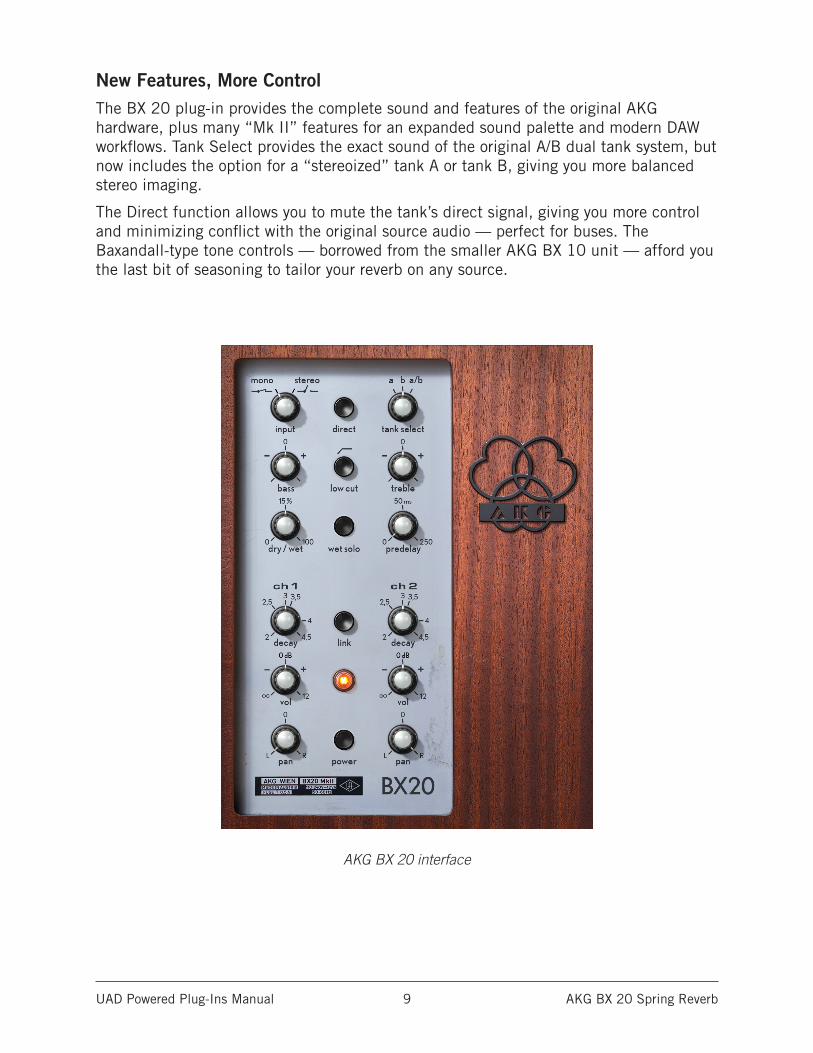
New Features, More ControlThe BX 20 plug-in provides the complete sound and features of the original AKG hardware, plus many “Mk II” features for an expanded sound palette and modern DAW workflows. Tank Select provides the exact sound of the original A/B dual tank system, but now includes the option for a “stereoized” tank A or tank B, giving you more balanced stereo imaging.
The Direct function allows you to mute the tank’s direct signal, giving you more control and minimizing conflict with the original source audio — perfect for buses. The Baxandall-type tone controls — borrowed from the smaller AKG BX 10 unit — afford you the last bit of seasoning to tailor your reverb on any source.
AKG BX 20 interface
UAD Powered Plug-Ins Manual AKG BX 20 Spring Reverb 10
Operational OverviewThe AKG BX 20 plug-in for UAD-2 is a faithful recreation of AKG’s coveted spring reverb that captures the subtle nuances of the original BX 20’s dual tank Torsion Transmission Line (TTL) reverb unit along with the R20 Decay Remote Control. Unique among its competitors, the AKG BX 20 creates dark, dense spring reverb ambience for buses or individual sources without the flutter or overly metallic sound of other spring reverb emulations.
Re-imagined for today’s DAW workflows, the AKG BX 20 also includes features like stereoized A and B tanks for balanced stereo imaging, pre-delay, low-cut filter, dry/wet blend control, and independent left/right pan and volume controls.
The AKG BX 20’s all-important TTL (Torsional Transmission Line) reverb system is fully represented, including all of the mechanical behaviors and idiosyncrasies that are part of the AKG BX 20’s unique variable decay time. Within the interactive electromagnetic and mechanical nature of the design, the hardware exhibits a unique two-stage decay which is faithfully captured by the plug-in.
Hybrid TechnologyThe AKG BX 20 Spring Reverb is not a general impulse response (“IR”) convolution reverb nor a typical algorithmic reverb. Instead, AKG BX 20 utilizes breakthrough hybrid technologies, combining advanced delay network and convolution technologies, layering impulse responses into a hybrid algorithmic plug-in design. Impulse responses are combined and synthesized in real time to match the onset of the reverb, regardless of the continuously adjustable decay time. The delay network component provides an uncanny model of the AKG BX 20’s two stage decay, with DSP mechanisms keeping the two systems in sync.
Artist PresetsThe AKG BX 20 includes artist presets from prominent UAD users. The artist presets are in the internal factory bank and are accessed via the DAW application’s preset menu. The artist presets are also copied to disk by the UAD installer so they can be used within Apollo’s Console application. The presets can be loaded using the Settings menu in the UAD Toolbar.
Note: Switching through presets is not instantaneous and sonic artifacts can occur while the presets are loading. See Load Time below for related information.
UAD Powered Plug-Ins Manual AKG BX 20 Spring Reverb 11
Load TimeWhen the Tank Select and Decay controls are modified, the impulse response engine is updated by the plug-in. These IR updates and recalculations are not instantaneous; there is a time lag before the new control values are heard. Additionally, sonic artifacts and/or host CPU increases can occur while these recalculations are performed if audio is currently being processed by the plug-in.
Tip: The Power Lamp is a status indicator that flashes while the impulse response engine is updated.
Automation LimitationsThe impulse response engine load time can be an impediment if the Tank Select, and to a lesser degree, Decay controls are modified with automation during a mix. We recommend against automating these specific controls to avoid sonic artifacts and/or host CPU increases. If automation must be used on these controls, only snapshot automation should be used (instead of continuous automation), and optimally only when the signal being processed is not audible (for example, between musical phrases).
AKG BX 20 LatencyThe AKG BX 20 plug-in uses upsampling and other proprietary techniques to achieve sonic design goals. These techniques result in a larger latency than most other UAD plug-ins (between 974 and 4120 samples, depending on the sample rate). Precautions should be observed to prevent the extra latency from becoming an issue during live performance (such as when recording) or monitoring with Apollo’s Console.
Note: See Additional Latency for related information.
Apollo ConsoleAKG BX 20 latency can exceed the maximum value of Apollo Console’s Input Delay Compensation engine. When the plug-in is used on input inserts (but not auxiliary buses) within Apollo’s Console application, the “Input Delay Compensation Exceeded” dialog may appear. In this case, Console’s Input Delay Compensation feature can be disabled (in the Console Settings window), or simply ignore the dialog.
Live PerformanceExtra latency can be problematic during live performance if the plug-in is inserted into the signal chain of the source signal and the performer is monitoring the source signal chain. For this reason, the AKG BX 20 is recommended for use in auxiliary send/return configurations (as is typical with time-based effects) during live performance.
UAD Powered Plug-Ins Manual AKG BX 20 Spring Reverb 12
AKG BX 20 Controls
Input SelectInput Select can be changed when the plug-in is used in a stereo channel configuration. When used in a mono channel configuration, this control is locked in the mono position.
Note: When the plug-in is used in a mono-in/stereo-out configuration, there is no sonic difference when Input Select is switched between mono and stereo.
MonoWhen set to Mono, a stereo input signal is summed to mono before reverb processing. If the plug-in is inserted on a stereo signal, the reverb output is stereoized even if the stereo inputs are summed to mono.
StereoWhen set to Stereo, the stereo input signal is passed into the reverb processor.
Tip: Clicking the mono or stereo label text selects that configuration.
Tank SelectThe AKG BX 20 has two mono reverb tanks (the spring containers) and each has a unique sonic signature. This control determines which reverb tank is used for reverb processing.
The original hardware design incorporates the two spring tanks “a” and “b” which are associated with channels 1 and 2, respectively. As with the hardware, the plug-in allows for stereo input use with either a summed mono or discrete stereo input (single channel/mono use is also common). The AKG BX 20 plug-in faithfully captures this original stereo use case when “a/b” is selected with this control.
Tip: Clicking any tank label text selects that tank.
With the AKG BX 20, the two reverb tanks can behave and sound noticeably different from each other when used together as a stereo effect, which may not be suitable for all use cases. Therefore the AKG BX 20 plug-in goes beyond the hardware with useful stereoized versions of the original mono tanks when either the “a” or “b” tank is selected. These options provide two perfectly balanced stereo reverbs, each with unique sonic responses and decay behaviors.
Note: When Tank Select is adjusted, a time lag occurs before the new tank configuration is heard. The Power Lamp flashes while the impulse response engine is updated.
Tank AThe stereoized Tank A features a dark and rich sound derived from a more intense reverberation of low frequencies. This darker reverb subdues reverberations of higher frequencies,allowing for a dissipation effect that warms the source it is applied to.
UAD Powered Plug-Ins Manual AKG BX 20 Spring Reverb 13
Tank BThe stereoized Tank B provides a bright and present response that sits forward in the mix allowing both the content and the reverberation to be more prominently heard. It alleviates the low to mid frequency reverberation build up associated with muddiness.
Tank A/BWhen set to “a/b” the left signal is sent to Tank A and the right signal is sent to Tank B. Note that the A and B tanks are notstereoized in this mode. Instead, the original mono tank outputs are sent to the left and right channels respectively, resulting in a stereo reverb output.
Note: When used on mono signals, tank configurations A and B work in mono just like the hardware, while A/B sums both tanks.
DirectWhen Direct is engaged (when switch is depressed), the direct signal component within the reverberated signal is audible. When disengaged, the direct signal component is removed from the reverberated signal.
The naturally dominant direct signal component in spring-based systems can sometimes overwhelm the reverb’s late field response with certain sources. The Direct control allows an alteration of the original reverberant sound by muting the spring tank’s direct signal component, minimizing possible conflict with the original source audio.
Removing the direct signal component from the reverb is different than simply not mixing in the dry signal (as could be achieved with the Dry/Wet mix control). This is a UAD-only feature that is made possible by advanced modeling techniques.
Disabling the direct path signal enables greater BX 20 flexibility in ambience-shaping possibilities, especially with transient-rich sources such as drums and percussion.
Tone ControlsThe tone controls affect both reverb tanks (a, b) and both channels (1, 2).
BassBass controls the amount of low frequency reverberation processing. This continuous knob controls a Baxendall type filter centered at 150 Hz and spans a range of ±8 dB with a default setting of 0.
Tip: Clicking the “0” or “bass” label text returns the control to the default value of 0.
Low CutThe Low Cut button engages a high pass filter that reduces processing of frequencies below 80 Hz. This filter is useful for removing the buildup of low frequency reverberations that cause bass-heavy signals to sound muddy. The slope of the Low Cut filter is 12 dB per octave.
UAD Powered Plug-Ins Manual AKG BX 20 Spring Reverb 14
TrebleTreble controls the amount of high frequency reverberation processing. This continuous knob controls a Baxendall type filter centered at 5 kHz and spans a range of ±4 dB with a default setting of 0.
Tip: Clicking the “0” or “treble” label text returns the control to the default value of 0.
Dry/WetThe Dry/Wet controls determines the balance between the original and the processed signal. The range is from 0% (dry, unprocessed) to 100% (wet, processed signal only). The default value is 15%.
Note: If Wet Solo is active, adjusting Dry/Wet will have no effect.
Dry/Wet control behavior is based on a logarithmic scale to provide increased resolution when selecting lower values. When the knob is set to the 12 o’clock position, the blend value is 15%.
Important: When the Direct switch is engaged, Dry/Wet should be set to 100% (or engage Wet Solo) because the direct signal component is already mixed with the reverb signal. Otherwise, doubled and/or out-of-phase signals may be heard.
Wet SoloThe Wet Solo button puts the AKG BX 20 into 100% Wet mode. When Wet Solo is on, it is the equivalent of setting the Dry/Wet control to 100% wet (and the Mix value is ignored).
Wet Solo defaults to On, which is optimal when using the BX 20 in the “classic” reverb configuration (placed on an effect group/bus that is configured for use with channel sends). When the AKG BX 20 is used directly within a signal chain (such as in a channel insert), this control should be deactivated.
Note: Wet Solo is a global (per BX 20 plug-in instance) control.
PredelayThe time between the dry signal and the onset of reverb is controlled with this knob. The range is 0.0 to 250 milliseconds with a default setting of 0.
This control uses a logarithmic scale to provide increased resolution when selecting lower values. When the knob is in the 12 o’clock position, the value is 50 milliseconds.
Higher Predelay values can be useful for tracks where the clarity of the source should stand out before the reverb starts.
UAD Powered Plug-Ins Manual AKG BX 20 Spring Reverb 15
DecayChannel 1 and 2 Decay controls the duration of the unique two-stage decay/frequency control which is faithfully captured by the plug-in. The available range is from 2 seconds to 4.5 seconds. The default value is 3 seconds. Rotate the control clockwise to increase the Decay time.
Note: When Decay is adjusted, the impulse response engine is updated by the plug-in and there is a time lag before the new Decay value is heard. The Power Lamp flashes while the impulse response engine is updated.
LinkWhen activated, Link enables the three controls that are identical for the Channels 1 and 2 (Decay, Volume, and Pan) to be ganged for ease of operation when both channels require the same values, or unlinked when independent left/right control is desired. When linked, modifying any left or right channel control causes its adjacent stereo counterpart control to snap to the same position.
Important: When Link is inactive then Link is enabled, the left channel control values are copied to the right channel. Control offsets between channels are lost in this case.
VolumeChannel 1 and 2 Volume controls the relative volume of the AKG BX 20’s spring reverb effect. It does not affect the dry signal.
Rotate the control clockwise for more reverb. Reducing the control to its minimum value will disable the reverb.
Tip: Clicking the “0” or “vol” label text returns the value to 0 dB.
PanChannel 1 and 2 Pan controls determine the placement of the reverb signals in the stereo panorama when the plug-in is used in mono-in/stereo-out and stereo-in/stereo-out configurations. When the AKG BX 20 is used in a mono-in/mono-out configuration, the Pan controls are disabled.
Tip: Clicking the “0” or “pan” label text sets the value to center.
PowerThe power button determines whether the plug-in is active. When engaged, the Power Lamp is illuminated. When set to off, the Power Lamp is de-illuminated indicating that all plug-in processing is disabled and UAD DSP usage is reduced (load is not reduced if UAD-2 DSP LoadLock is enabled).
Tip: The Power Lamp also functions as a Power button.
UAD Powered Plug-Ins Manual AKG BX 20 Spring Reverb 16
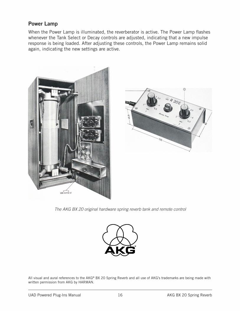
Power LampWhen the Power Lamp is illuminated, the reverberator is active. The Power Lamp flashes whenever the Tank Select or Decay controls are adjusted, indicating that a new impulse response is being loaded. After adjusting these controls, the Power Lamp remains solid again, indicating the new settings are active.
The AKG BX 20 original hardware spring reverb tank and remote control
All visual and aural references to the AKG® BX 20 Spring Reverb and all use of AKG’s trademarks are being made with written permission from AKG by HARMAN.
UAD Powered Plug-Ins Manual Ampex ATR-102 Mastering Tape Recorder 17
Ampex ATR-102 Mastering Tape Recorder
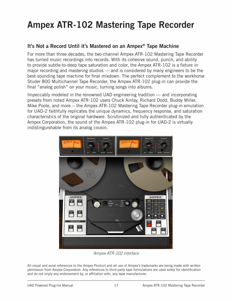
It’s Not a Record Until it’s Mastered on an Ampex® Tape MachineFor more than three decades, the two-channel Ampex ATR-102 Mastering Tape Recorder has turned music recordings into records. With its cohesive sound, punch, and ability to provide subtle-to-deep tape saturation and color, the Ampex ATR-102 is a fixture in major recording and mastering studios — and is considered by many engineers to be the best-sounding tape machine for final mixdown. The perfect complement to the workhorse Studer 800 Multichannel Tape Recorder, the Ampex ATR-102 plug-in can provide the final “analog polish” on your music, turning songs into albums.
Impeccably modeled in the renowned UAD engineering tradition — and incorporating presets from noted Ampex ATR-102 users Chuck Ainlay, Richard Dodd, Buddy Miller, Mike Poole, and more -- the Ampex ATR-102 Mastering Tape Recorder plug-in emulation for UAD-2 faithfully replicates the unique dynamics, frequency response, and saturation characteristics of the original hardware. Scrutinized and fully authenticated by the Ampex Corporation, the sound of the Ampex ATR-102 plug-in for UAD-2 is virtually indistinguishable from its analog cousin.
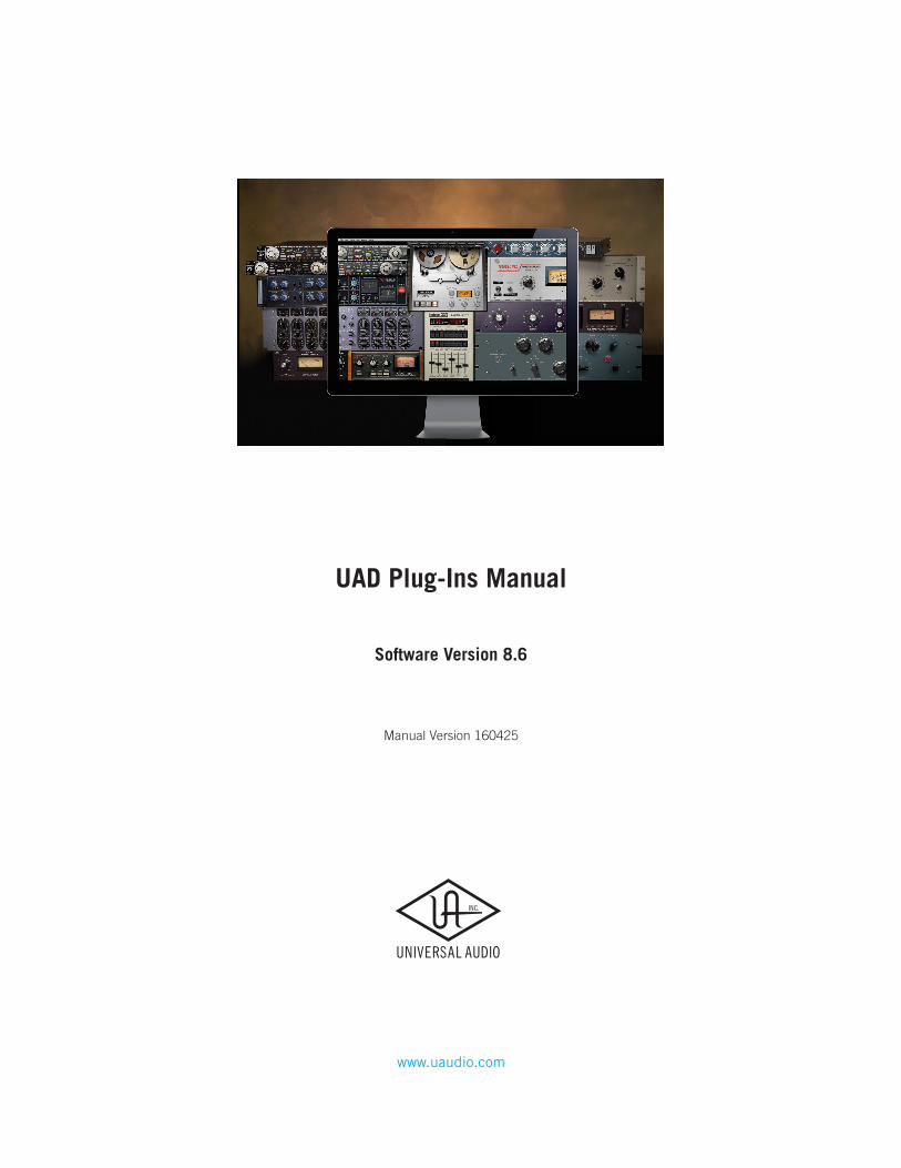
Ampex ATR-102 interface
All visual and aural references to the Ampex Product and all use of Ampex’s trademarks are being made with written permission from Ampex Corporation. Any references to third party tape formulations are used solely for identification and do not imply any endorsement by, or affiliation with, any tape manufacturer.
UAD Powered Plug-Ins Manual Ampex ATR-102 Mastering Tape Recorder 18
HistoryIntroduced in 1976, the Ampex ATR-102 2-Track Tape Recorder was a near-instant hit, thanks to its revolutionary servo-controlled reel motors and capstan, which provided smooth, continuous tape tension and handling. The large capstan, and absence of pinch rollers, provided nearly non-existent speed drift and ultra-low flutter. The clever ATR-102 design allowed users to change out heads and guides in mere minutes, with a 1” head being a very popular “hot-rod” modification in more recent years — especially when running at 15 IPS (inches per second). The ATR’s role in modern recording history is so prevalent, that it would be easier to list classic albums that weren’t mixed down on this machine, rather than to try to list all those that were.
Plug-In ParametersLike the ATR-102 hardware, the plug-in allows you to choose between various Signal Paths (Input, Sync, Repro), different Tape Speeds / Emphasis EQs (NAB, CCIR, AES) and Tape Formula combinations, even including home/consumer tape. The Input (Record) Gain knob and the Cal button are the primary controls for regulating levels, and even saturating the tape, and can be used to deliver a heavily colored sound if desired. Other ATR-102 features include: 1/4,” 1/2,” or 1” Head Select, Biasing/Calibration controls (auto and manual), crosstalk, adjustable wow and flutter, and adjustable tape delay, which can be used for Automatic Double Tracking effects on vocals, guitars, and more.
In UseThe primary use for Ampex ATR-102, and the recommended method for evaluating this plug-in, is as the last stereo insert on your master fader (or possibly the second-to-last insert before a brick-wall processor such as the UAD Precision Limiter). Set up the plug-in by first adjusting Tape Speed, Tape Formula, Cal Level, and Emphasis EQ, or simply select a preset. Note that as you lower the tape speed (i.e. 15 IPS, 7.5 IPS), the tape “sound” becomes more audible. Once this basic setup is made, adjust the L/R Record (input gain) levels for more or less tape/circuit coloration and saturation.
Other common uses for the Ampex ATR-102 are as individual mono or stereo insert effects, or as an auxiliary group effect where the user wishes to apply it only to specified sources or groups (e.g., drums, guitars, etc). Check out the ATR-102 Tips and Tricks blog article below to learn more.
• www.uaudio.com/blog/ampex-atr-102-tips-tricks
UAD Powered Plug-Ins Manual Ampex ATR-102 Mastering Tape Recorder 19
Operational Overview
Famous Tape SoundThe UAD Ampex ATR-102 provides all of the original unit’s desirable analog sweetness. Like magnetic tape, users can dial in a clean sound, or just the right amount of harmonic saturation.
Mixdown Tape DeckThe primary purpose of the UAD Ampex ATR-102 is to obtain tape mixdown sonics within the DAW environment. To obtain the classic tape mixdown sound, instantiate the plug-in as the last insert on the output bus, after other processing is applied (or possibly as the second-to-last insert, before a brick-wall processor such as the (UAD Precision Limiter). Of course, creative “non-standard” results can be obtained by placing the Ampex ATR-102 in any channel insert or on busses in a send/return configuration.
Multiple Tape TypesThe UAD Ampex ATR-102 models seven popular magnetic tape formulas. Each type has its own subtle sonic variation, distortion onset, and tape compression characteristics. The tape types that can be selected depend on the active tape speed and head type; all tape types are not available for all tape speeds and head types. Lower fidelity types are included to facilitate more signal coloration options.
Multiple Tape HeadsThe original hardware machine was manufactured with an interchangeable head block system which enabled the system to be quickly converted to use either 1/4” or 1/2” tape stock by simply swapping out the heads and recalibrating the electronics. As track width increases, subtle improvements to stability, fidelity, and noise become apparent. A popular custom aftermarket tape head is available which enables the use of 1” tape stock, enabling even higher fidelity with its greater track widths. All three tape head widths are accurately modeled and selectable in the UAD Ampex ATR-102.
Multiple Tape SpeedsAll four tape speeds in the original hardware are modeled in the UAD Ampex ATR-102. Speeds of 3.75, 7.5, 15, and 30 inches per second (IPS) are available. Each speed provides distinct frequency shift, head bump, and distortion characteristics. Higher speeds have higher fidelity; 3.75 IPS has a distinctively “lo fi” character.
UAD Powered Plug-Ins Manual Ampex ATR-102 Mastering Tape Recorder 20
Multiple Calibration LevelsTape machines can be setup with different calibration levels, which entails setting unity gain from input through output based on the magnetic flux (amount of magnetic field) of a given tape formulation. Different calibration levels provide different tape response characteristics for a given level into the recorder. Four selectable calibration levels are available in the UAD Ampex ATR-102.
Ancillary NoisesTape recorders have inherent signal noises that are a by-product of the electro-mechanical nature of the machine. While “undesirable” tape system noise is historically considered a negative and was an attribute that pushed the technical envelope for better machine design and tape formulas (and ultimately, “noiseless” digital recorders), noise is still an ever-present characteristic of the sound of using tape and tape machines.
The UAD Ampex ATR-102 models the hum, hiss, wow, flutter, and crosstalk characteristics of the original hardware. These noise components can be individually disabled, adjusted, and/or exaggerated for creative purposes (even though the servo-controlled, direct-drive capstan tape transport of the original hardware provides excellent wow and flutter specifications).
Modeled TransformerThe original hardware was manufactured with isolation transformers, which can color the signal. A common modification to the hardware tape machine eliminates the transformers from the signal path to produce a (subjectively) “cleaner” sound. UAD Ampex ATR-102 simulates the behavior of the transformers in the hardware circuit, and can be optionally disabled in the plug-in, providing both sonic options.
Tape DelayA popular application of multi-head tape recorders is to employ them for slapback tape echo effects. If the machine is running in record mode but the recorded signal is monitored from the repro head (as opposed to the sync head), the physical space between these two heads results in a short delay between the signal sent to the recorder and the monitored signal. When these signals are combined with mixer routings, the classic slapback echo is manifest. The UAD Ampex ATR-102 implements the ability to reproduce this classic effect with a simple set of controls, and expands the capabilities by extending the available delay times beyond what is possible in the physical realm.
UAD Powered Plug-Ins Manual Ampex ATR-102 Mastering Tape Recorder 21
Automatic CalibrationThe ability of a magnetic tape recorder, which has inherently non-linear response characteristics, to accurately reproduce an audio signal with a minimum of noise and distortion requires precise adjustments to the system electronics. The calibration settings are based on the current tape speed, formulation, emphasis EQ, and tape width. The hardware must be meticulously re-adjusted each time a different tape, speed, emphasis EQ, or head width is used (and for system wear and drift, even if these variables are not changed). UAD Ampex ATR-102 has an automatic calibration feature that tunes all calibration electronics with a single button.
Low Level TuningEven though automatic calibration is available, the individual controls that adjust calibration are exposed for sonic manipulation. Playback EQ, record (tape) EQ, and record bias can easily be altered for manual calibration and/or creative purposes.
Manual Calibration ToolsUAD Ampex ATR-102 includes the full suite of tools required to manually calibrate the recorder. Manual calibration tools are provided so expert users can calibrate the system to their preferred methods for obtaining desired results. The manual calibration tools consist of a tone generator (with multiple test tones and levels), a distortion meter with digital readouts, and a full suite of Magnetic Reference Laboratory (MRL) alignment tapes, which are used to calibrate playback electronics.
Mono/Stereo OperationWhile the UAD Ampex ATR-102 is a true stereo processor designed primarily for use in stereo-in/stereo-out configurations, it will also operate in mono-in/stereo-out and mono-in/mono-out modes.
When used in a mono-in/stereo-out configuration, the mono input signal is sent to both channels of the processor, which can then be adjusted independently. When used in a mono-in/mono-out configuration, adjusting any left or right control will change both the left and right controls (the left/right controls are always linked in mono mode).
Quick SetupSet up the plug-in by first adjusting Tape Speed, Tape Type (tape formulation), and Tape Speed, or simply select a factory preset. Note that as you lower the tape speed, the tape “sound” becomes more audible. Once this basic setup is made, adjust the L/R Record (gain) levels, for more or less tape/circuit coloration/saturation.
UAD Powered Plug-Ins Manual Ampex ATR-102 Mastering Tape Recorder 22
Artist PresetsUAD Ampex ATR-102 includes artist presets from prominent ATR-102 users. Some of the artist presets are in the internal factory bank and are accessed via the host application’s preset menu. Additional artist presets are copied to disk by the UAD installer. The additional presets can be loaded using the Settings menu in the UAD Toolbar.
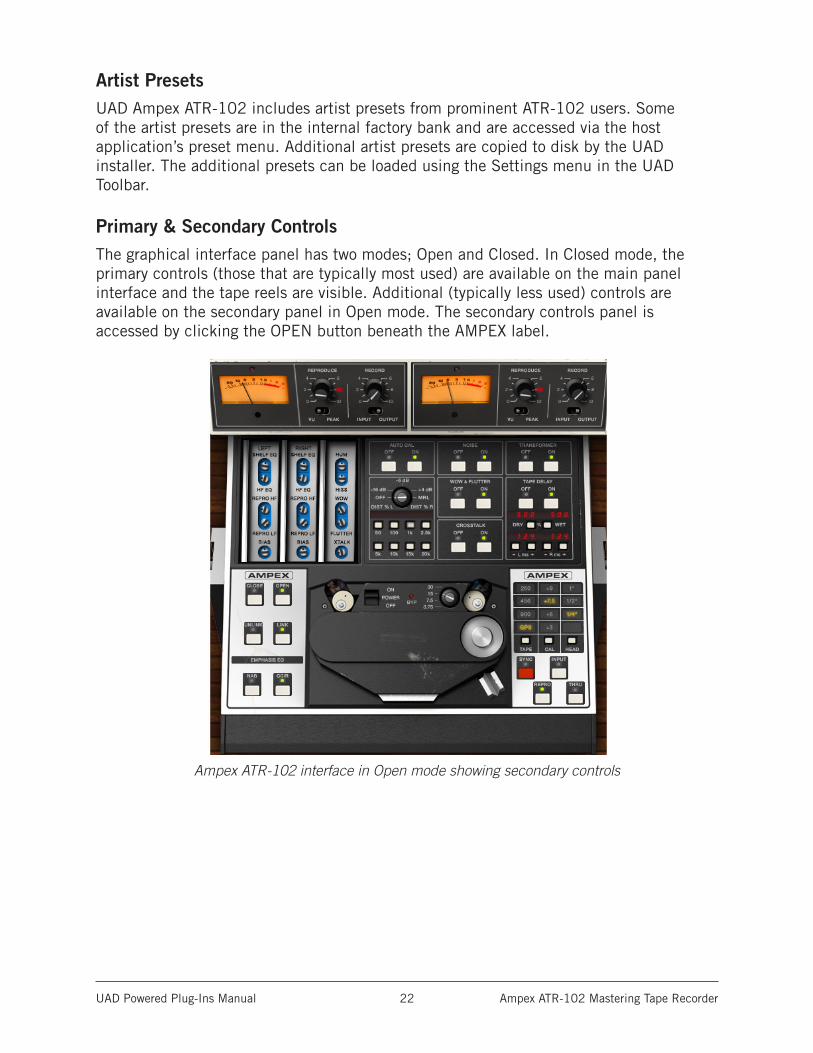
Primary & Secondary ControlsThe graphical interface panel has two modes; Open and Closed. In Closed mode, the primary controls (those that are typically most used) are available on the main panel interface and the tape reels are visible. Additional (typically less used) controls are available on the secondary panel in Open mode. The secondary controls panel is accessed by clicking the OPEN button beneath the AMPEX label.
Ampex ATR-102 interface in Open mode showing secondary controls
UAD Powered Plug-Ins Manual Ampex ATR-102 Mastering Tape Recorder 23
Primary Controls
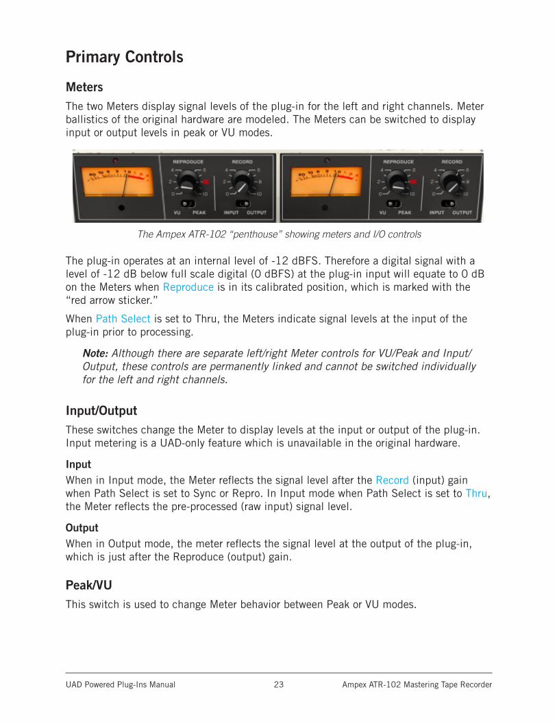
MetersThe two Meters display signal levels of the plug-in for the left and right channels. Meter ballistics of the original hardware are modeled. The Meters can be switched to display input or output levels in peak or VU modes.
The Ampex ATR-102 “penthouse” showing meters and I/O controls
The plug-in operates at an internal level of -12 dBFS. Therefore a digital signal with a level of -12 dB below full scale digital (0 dBFS) at the plug-in input will equate to 0 dB on the Meters when Reproduce is in its calibrated position, which is marked with the “red arrow sticker.”
When Path Select is set to Thru, the Meters indicate signal levels at the input of the plug-in prior to processing.
Note: Although there are separate left/right Meter controls for VU/Peak and Input/Output, these controls are permanently linked and cannot be switched individually for the left and right channels.
Input/OutputThese switches change the Meter to display levels at the input or output of the plug-in. Input metering is a UAD-only feature which is unavailable in the original hardware.
InputWhen in Input mode, the Meter reflects the signal level after the Record (input) gain when Path Select is set to Sync or Repro. In Input mode when Path Select is set to Thru, the Meter reflects the pre-processed (raw input) signal level.
OutputWhen in Output mode, the meter reflects the signal level at the output of the plug-in, which is just after the Reproduce (output) gain.
Peak/VUThis switch is used to change Meter behavior between Peak or VU modes.
UAD Powered Plug-Ins Manual Ampex ATR-102 Mastering Tape Recorder 24
Clip LEDThe left and right channels each have a Clip LED, just above the Meter. The Clip LED is not in the original hardware; it is a UAD-only feature.
The Clip LED illuminates only when the machine’s audio electronics clip. The Clip LED is not affected by the recorded tape signal, even if the tape is overloaded and distorting.
ReproduceReproduce adjusts the signal level coming off the virtual tape before the signal is sent to the Meters. There are two Reproduce controls, one each for the left and right channels. The left/right Reproduce controls can be adjusted individually, or simultaneously adjusted when Link mode is active.
The available range is -∞ dB (off) to +9.48 dB. The default value of 0 dB is the “calibrated position” which is marked with a “red arrow sticker.” Reproduce is not affected by Auto Cal.
Tip: Click the “REPRODUCE” label text to return Reproduce to 0 dB.
The Meters accurately reflect the output level (when set to Output mode) even if Reproduce is not in its calibrated position. However, if Reproduce is moved from the “cal” position, the Meters will no longer correspond to a particular level being recorded onto the virtual tape. In this case, the Meters will not reflect the actual “operating level” of the tape because Reproduce changes the signal level coming off the tape before it is sent to the Meters.
Note: The graphical interface panel values for Reproduce, which range from 0 - 10, are arbitrary and do not reflect a particular dB value.
RecordRecord adjusts the signal level into the plug-in and the tape circuitry. There are two Record controls, one for the left channel and one for the right. These left/right Record controls can be adjusted individually, or simultaneously when Link mode is active.
The available range is -∞ dB (off) to +9.3 dB. The default value is 0 dB. The graphical interface panel values, which range from 0 - 10, are arbitrary and do not reflect a particular dB value.
Tip: Click the “RECORD” label text to return the Record value to 0 dB.
Record is a primary “color” control for the plug-in. Just like genuine magnetic tape, lower Record levels will have a cleaner sound, while higher levels result in more harmonic saturation and coloration. Higher Record levels will also increase the output level from the plug-in. The Reproduce control can be lowered to compensate if unity gain operation is desired.
UAD Powered Plug-Ins Manual Ampex ATR-102 Mastering Tape Recorder 25
Reproduce/Record Controls ArrangementNote that the Reproduce control is to the left of the Record control, which is atypical of most signal flow designs, where inputs usually precede outputs (flowing from left to right). This quirky arrangement of the Ampex ATR-102 I/O controls, where the input control “follows” the output control, is true to the original hardware design. In Controls View, the Record (input) control precedes the Reproduce (output) control.
Open/CloseThe Secondary Controls are accessed by clicking the OPEN button beneath the AMPEX label. Conversely, the panel is closed by clicking the CLOSE button.
Link/UnlinkLink mode is a software-only addition that enables controls that are identical for the left and right channels to be linked for ease of operation when both channels require the same values, or unlinked when indepen dent left/right control is desired. In other words, left/right channel controls are ganged together in link mode.
The Link parameter is stored within presets and can be accessed via automation.
Note: Although there are separate left/right Meter controls for VU/Peak and Input/Output, these controls are permanently linked and cannot be switched individually for the left and right channels, even if Unlink mode is active.
LinkIn Link mode, modifying any left or right channel control causes its adjacent stereo counterpart control to snap to the same position.
Important: When Unlink mode is active and Link is enabled, the left channel control values are copied to the right channel. Control offsets between channels are lost in this case.
When Link is active, automation data is written and read for the left channel only. In this case, the automation data for the left will control both channels. Additionally, changing the right channel parameters from a control surface or when in “controls only” (non-GUI) mode will have no effect.
UnlinkWhen Unlink is active, the controls for the left and right channels are independent. When unlinked, automation data is written and read by each channel separately.
UAD Powered Plug-Ins Manual Ampex ATR-102 Mastering Tape Recorder 26
Emphasis EQ The Emphasis EQ buttons determine the active Emphasis EQ values and the frequency of the Hum noise. NAB or CCIR curves can be selected when the Tape Speed is 7.5 or 15 IPS. When the Tape Speed is 30 IPS, neither value is available (the LEDs are dimmed) because the EQ is fixed with the AES emphasis curve, per the original hardware. At 3.75 IPS, only NAB is available (as it is with the hardware).
NABWhen the value is set to NAB (traditionally the United States standard), the Hum Noise frequency is 60 Hz. When set to CCIR (traditionally the standard in Europe and other regions), the Hum Noise frequency is 50 Hz.
Tape Speed and Emphasis EQ were originally practical controls for recording duration versus noise and local standards. Historically, the origin of the tape machine (US or European) dictated the built-in EQ emphasis, but later machines like the Ampex ATR-102 had both circuits available.
CCIRCCIR (also known as IEC1) is the EQ pre-emphasis made famous on British records and is considered the technically superior EQ; many say this EQ was part of the “British sound” during tape’s heyday. NAB (also known as IEC2) was the American standard with its own sound. AES is truly standardized at 30 IPS and is the sole EQ found on the Ampex ATR-102 at 30 IPS.
PowerPower is the plug-in bypass control. When set to OFF, emulation processing is disabled, the Meters and control LEDs are dimmed, the Bypass LED illuminates, and DSP usage is reduced. Power is useful for comparing the processed settings to the original signal.
OFF is similar to the Thru position in the Path Select control except that the Meters are still active when the Thru control is used. However, in this state, the Meters indicate signal levels at the input of the plug-in prior to processing.
Note: DSP usage is reduced only when DSP LoadLock is disabled. If DSP Load-Lock is enabled (the default setting), activating OFF will not reduce DSP usage.
UAD Powered Plug-Ins Manual Ampex ATR-102 Mastering Tape Recorder 27
Tape SpeedThe Tape Speed control determines the speed of the tape transport, in inches per second (IPS). Tape Speed affects the recorder’s fidelity and associated “head bump” sonics. Head bump is bass frequency build-up that occurs with magnetic tape; the dominant frequencies shift according to transport speed.
To change the Tape Speed value, click the IPS text values, or drag the knob, or click the knob then use the mouse scroll wheel.
15 IPS is considered the favorite for rock and acoustic music due to its low frequency “head bump” (low frequency rise) and warmer sound, while 30 IPS is the norm for classical and jazz due to its lower noise floor, greater fidelity and flatter response. 7.5 and 3.75 IPS are also available for an even more colored experience, with even greater frequency shift and other artifacts.
Note: The available parameter ranges of Tape Type, Head Width, and Emphasis EQ are affected by Tape Speed.
Tape TypeTape Type selects the active tape stock formulation. Seven Tape Types are modeled in the UAD Ampex ATR-102. To select the Tape Type, click the TAPE button to cycle through the available types, or click directly on the Tape Type value label. The active Tape Type is highlighted in yellow.
Note: The available Tape Types and defaults are dependent on the current Tape Speed and Head values.
Each type has its own subtle sonic variation, distortion onset, and tape compression characteristics. Generally speaking, the lower the Cal Level for each formula, the higher the signal level required to reach saturation and distortion.
Cal LevelCal Level automatically sets tape calibration/fluxivity. The Cal Level setting takes care of the setup one would need to make under equivalent hardware operation, and sets the reference tape/flux level without disturbing the (unity) gain of the plug-in.
To select the Cal Level, click the CAL button to cycle through the available levels, or click directly on the calibration value label. The active Cal Level is highlighted in yellow. The default value is +6 dB.
Because Cal Level affects the operating levels in the plug-in, it can be used to compensate for overly high (or low) levels at the input of the plug-in. For example, if the input is too hot, lowering the Cal Level will reduce the signal level without changing Record, which can affect the tape saturation characteristics.
Note: The noise floor is affected by the Cal Level when Noise Enable is active.
UAD Powered Plug-Ins Manual Ampex ATR-102 Mastering Tape Recorder 28
As tape formulas advanced, their output level increased, thus lowering relative noise floor. Under normal use, the machine would be calibrated to the tape’s output level. However, sometimes the machine is under-calibrated to leave more headroom for a broader sweet spot or to prevent electronics from clipping. Therefore, one can “go traditional” and calibrate to the recommended levels, or select a non-corresponding calibration setting.
As an example, if 456 is the selected Tape Type and when Cal is set at +6 (6 dB higher than the NAB tape standard), the reference flux level is 355 nWb/m (nanoweber per meter) and is 10 dB below the point where THD reaches 3% (referred to as the maximum operating level). Therefore, with a 1 kHz test tone at -12 dBFS sent to the plug-in, with Tape Type set to 456, Cal set to +6, and Auto Cal enabled, output levels of the plug-in will match the input level and fluxivity on the tape will be 355 nWb/m.
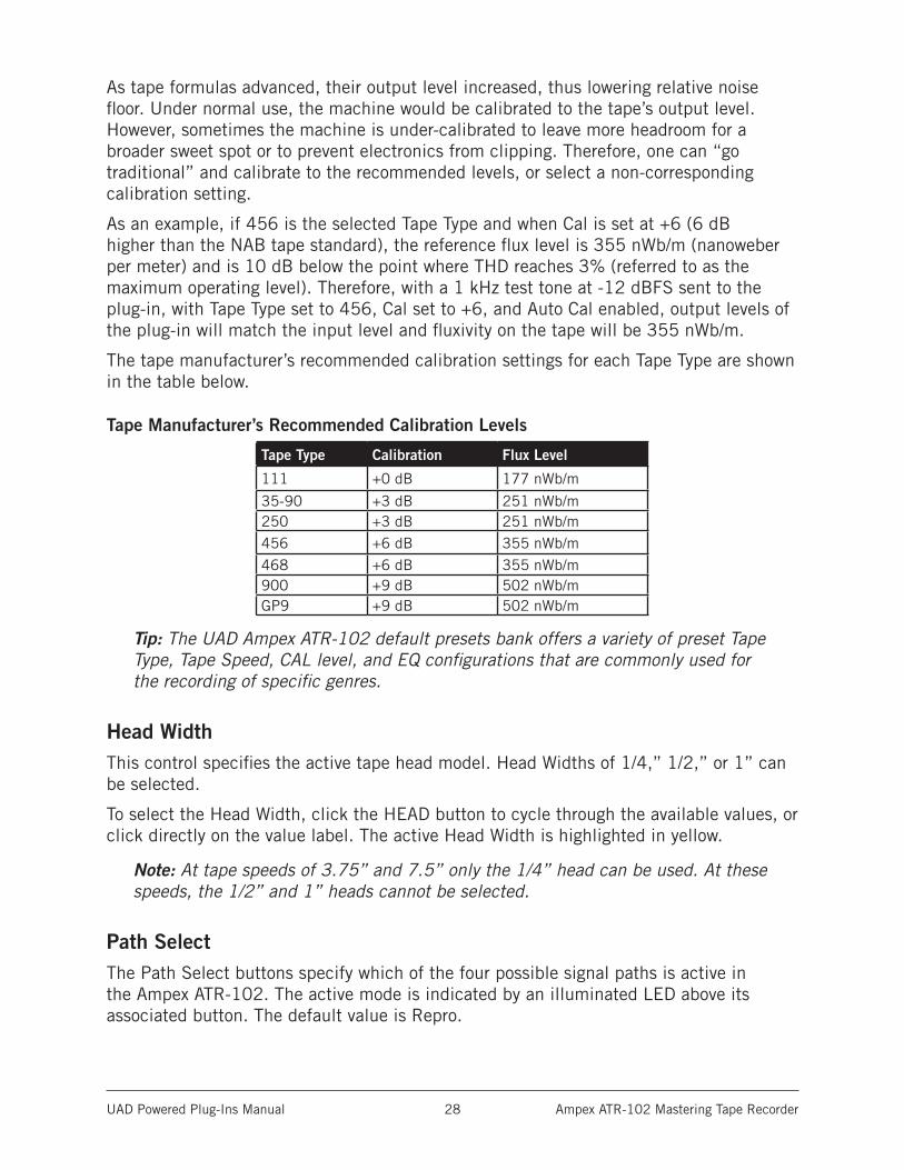
The tape manufacturer’s recommended calibration settings for each Tape Type are shown in the table below.
Tape Manufacturer’s Recommended Calibration Levels
Tape Type Calibration Flux Level
111 +0 dB 177 nWb/m
35-90 +3 dB 251 nWb/m250 +3 dB 251 nWb/m456 +6 dB 355 nWb/m468 +6 dB 355 nWb/m900 +9 dB 502 nWb/mGP9 +9 dB 502 nWb/m
Tip: The UAD Ampex ATR-102 default presets bank offers a variety of preset Tape Type, Tape Speed, CAL level, and EQ configurations that are commonly used for the recording of specific genres.
Head WidthThis control specifies the active tape head model. Head Widths of 1/4,” 1/2,” or 1” can be selected.
To select the Head Width, click the HEAD button to cycle through the available values, or click directly on the value label. The active Head Width is highlighted in yellow.
Note: At tape speeds of 3.75” and 7.5” only the 1/4” head can be used. At these speeds, the 1/2” and 1” heads cannot be selected.
Path SelectThe Path Select buttons specify which of the four possible signal paths is active in the Ampex ATR-102. The active mode is indicated by an illuminated LED above its associated button. The default value is Repro.
UAD Powered Plug-Ins Manual Ampex ATR-102 Mastering Tape Recorder 29
SyncSync mode models the sound of direct tape recording and playback via the sync/record head, plus all corresponding machine electronics.
Sync mode is generally not used for playback due to its poorer frequency response, but it is included for authenticity and creative purposes.
ReproRepro mode models the sound of tape recording through the record head and playback through the reproduction head, plus all corresponding machine electronics.
InputInput mode emulates the sound of the Ampex ATR-102 through the machine electronics only, without tape sonics. This is the scenario when the machine is in live monitoring mode but the tape transport is not running.
ThruThru is a processor bypass control. When Thru is enabled, all controls are inactive, emulation processing is disabled, and DSP usage is reduced.
Thru behavior is similar to that of the OFF position in the POWER control, except that the Meters are still active in Thru mode. In this state, the Meters indicate signal levels at the input of the plug-in prior to processing.
Note: DSP usage is reduced only when DSP LoadLock is disabled. If DSP Load-Lock is enabled (the default setting), activating Thru will not reduce DSP usage.
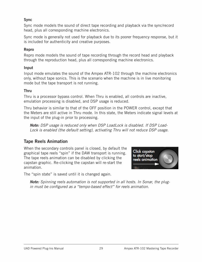
Tape Reels AnimationWhen the secondary controls panel is closed, by default the graphical tape reels “spin” if the DAW transport is running. The tape reels animation can be disabled by clicking the capstan graphic. Re-clicking the capstan will re-start the animation.
The “spin state” is saved until it is changed again.
Note: Spinning reels automation is not supported in all hosts. In Sonar, the plug-in must be configured as a “tempo-based effect” for reels animation.
UAD Powered Plug-Ins Manual Ampex ATR-102 Mastering Tape Recorder 30
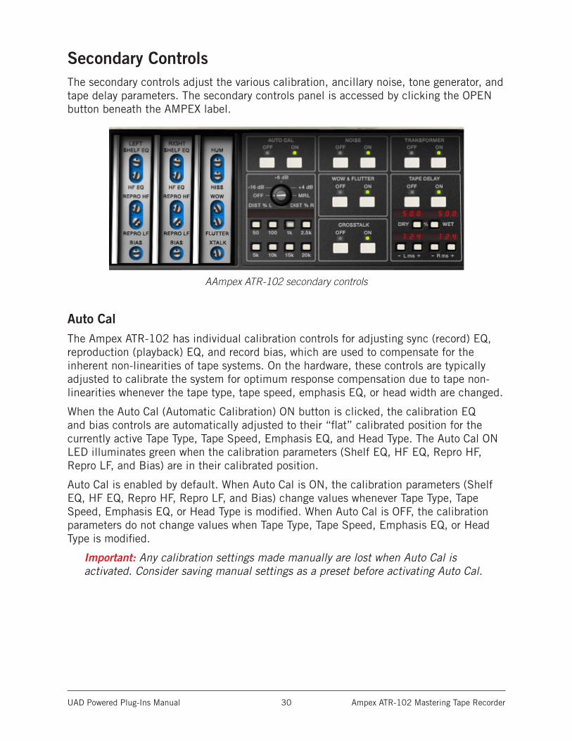
Secondary ControlsThe secondary controls adjust the various calibration, ancillary noise, tone generator, and tape delay parameters. The secondary controls panel is accessed by clicking the OPEN button beneath the AMPEX label.
AAmpex ATR-102 secondary controls
Auto CalThe Ampex ATR-102 has individual calibration controls for adjusting sync (record) EQ, reproduction (playback) EQ, and record bias, which are used to compensate for the inherent non-linearities of tape systems. On the hardware, these controls are typically adjusted to calibrate the system for optimum response compensation due to tape non-linearities whenever the tape type, tape speed, emphasis EQ, or head width are changed.
When the Auto Cal (Automatic Calibration) ON button is clicked, the calibration EQ and bias controls are automatically adjusted to their “flat” calibrated position for the currently active Tape Type, Tape Speed, Emphasis EQ, and Head Type. The Auto Cal ON LED illuminates green when the calibration parameters (Shelf EQ, HF EQ, Repro HF, Repro LF, and Bias) are in their calibrated position.
Auto Cal is enabled by default. When Auto Cal is ON, the calibration parameters (Shelf EQ, HF EQ, Repro HF, Repro LF, and Bias) change values whenever Tape Type, Tape Speed, Emphasis EQ, or Head Type is modified. When Auto Cal is OFF, the calibration parameters do not change values when Tape Type, Tape Speed, Emphasis EQ, or Head Type is modified.
Important: Any calibration settings made manually are lost when Auto Cal is activated. Consider saving manual settings as a preset before activating Auto Cal.
UAD Powered Plug-Ins Manual Ampex ATR-102 Mastering Tape Recorder 31
After Auto Calibration occurs, the automatically adjusted parameters can be modified to any other value if desired. If a calibration parameter is adjusted while Auto Cal is ON, the ON LED illuminates in red instead of green, indicating that the system is no longer in the calibrated state. If the moved controls are subsequently returned to their original position, the LED will return to its green state, indicating the unit is back in calibration.
Tip: To return any of the individual calibration controls to their “flat” (calibrated) position, click the label text adjacent to the control (or, simply re-click Auto Cal to return all calibration controls to their “flat” position).
The Manual Calibration Procedure has instructions for performing system calibration manually.
Record EQThe Record EQ controls (HF EQ and Shelf EQ) are applied in the tape recording circuit and affect tape saturation characteristics. They compensate for common residual HF loss due to bias optimization and system filtering, and affect HF content in the signal prior to the tape non-linearity.
HF EQHF EQ provides high frequency emphasis in the signal recorded to tape.
Shelf EQShelf EQ is another control (in addition to HF EQ) provided to compensate for tape non-linearity. Although adjustment of this control is not part of the Ampex factory calibration procedure, it can be used for customized manual calibrations or creative purposes.
Repro EQThe Repro EQ controls (Repro HF and Repro LF) are post-head controls for tape playback calibration. They affect the signal coming out of the tape circuitry in both Repro and Sync modes.
The Repro EQs are used as filters to shape the frequency response of the system in maintaining a flat response and enable compensation for any tape frequency loss or head wear.
Repro HFAdjusts the tape playback high frequency content when Path Select is set to Sync or Repro.
Repro LFAdjusts the tape playback low frequency content when Path Select is set to Sync or Repro.
UAD Powered Plug-Ins Manual Ampex ATR-102 Mastering Tape Recorder 32
BiasThis control adjusts the amount of bias in the record signal. Bias is defined as an oscillator beyond the audible range applied to the audio at the record head, allowing for adjustment of the record behavior. Ideal bias voltage settings provide maximum record sensitivity and low distortion. Intentionally overbiasing is a common technique especially for “tape compression” which produces a warmer, gently saturated sound. Underbiasing can also be used to add distortion and other nonlinear responses, similar to gate chatter or cold solder joints; extremely low voltages may even cause audio to drop out entirely.
Bias voltage, HF/Shelf EQ, and Emphasis EQ (CCIR, NAB, AES) all work together to provide a linear response to the recorded signal. The “flat” (calibrated position) is determined by tape speed, tape type, emphasis EQ, and head width.
Noise EnableThis is a global enable control for the Hum and Hiss effect. When Noise is ON, the level of Hum and Hiss can be independently adjusted using the Hum and Hiss Level controls.
The default values of 0 dB for Hum and Hiss are the actual modeled level in the original hardware. Noise is not affected by automatic calibration.
HumDetermines the amount of Hum in the signal. Hum is added after the tape circuitry. This control affects both the left and right channels. Noise Enable must be ON for the Hum control to function.
The default value of 0 dB for Hum is the actual modeled level in the original hardware. This default value can be offset by ±25 dB.
The Hum frequency is dependent on the Emphasis EQ control. The frequency is 60 Hz when set to NAB (US) and 50 Hz when set to CCIR (European).
When Tape Speed is set to 30 IPS, the green Emphasis EQ LEDs are not illuminated (and cannot be switched), indicating that the Emphasis EQ is set to AES. However, the Hum frequency can still be set for 30 IPS mode by setting Emphasis EQ to NAB (for 60 Hz) or CCIR (for 50 Hz) prior to setting Tape Speed to 30 IPS.
Note: When Tape Speed is 3.75 IPS, only 60 Hz is available.
UAD Powered Plug-Ins Manual Ampex ATR-102 Mastering Tape Recorder 33
HissHiss determines the amount of tape hiss in the tape playback signal. The default value is 0 dB and can be offset by -25 dB to +50 dB for creative purposes. Noise Enable must be ON for this control to function.
Like the hardware, the amount of hiss is dependent on settings of the various controls and may subtly change based on the values of Path Select, Tape Type, Emphasis EQ, Cal Level, Bias, Playback EQs, and Output Level.
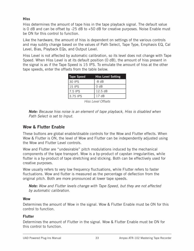
Hiss Level is not affected by automatic calibration, so its level does not change with Tape Speed. When Hiss Level is at its default position (0 dB), the amount of hiss present in the signal is as if the Tape Speed is 15 IPS. To emulate the amount of hiss at the other tape speeds, enter the offsets from the table below.
Tape Speed Hiss Level Setting
30 IPS -8 dB
15 IPS 0 dB
7.5 IPS 12.5 dB
3.75 IPS 17 dB
Hiss Level Offsets
Note: Because hiss noise is an element of tape playback, Hiss is disabled when Path Select is set to Input.
Wow & Flutter EnableThese buttons are global enable/disable controls for the Wow and Flutter effects. When Wow & Flutter is ON, the level of Wow and Flutter can be independently adjusted using the Wow and Flutter Level controls.
Wow and Flutter are “undesirable” pitch modulations induced by the mechanical components of the tape transport. Wow is a by-product of capstan irregularities, while flutter is a by-product of tape stretching and sticking. Both can be effectively used for creative purposes.
Wow usually refers to very low frequency fluctuations, while Flutter refers to faster fluctuations. Wow and flutter is measured as the percentage of deflection from the original pitch. Both are more pronounced at lower tape speeds.
Note: Wow and Flutter levels change with Tape Speed, but they are not affected by automatic calibration.
WowDetermines the amount of Wow in the signal. Wow & Flutter Enable must be ON for this control to function.
FlutterDetermines the amount of Flutter in the signal. Wow & Flutter Enable must be ON for this control to function.
UAD Powered Plug-Ins Manual Ampex ATR-102 Mastering Tape Recorder 34
Crosstalk EnableThese buttons are global enable/disable controls for the Crosstalk Level (XTALK) parameter. When Crosstalk is ON, the amount of Crosstalk can be adjusted using the Crosstalk Level control.
Crosstalk is the amount of signal bleed between the left and right channels. Crosstalk sonics can vary based upon the Tape Speed and Head Width parameters, however the amount of crosstalk does not vary with these settings.
Crosstalk LevelThis control determines the amount of signal crosstalk. Crosstalk Enable must be ON for the Crosstalk Level control to function. The default value of -45 dB is the actual modeled level in the original hardware. The available range is -50 dB to -10 dB. Crosstalk Level is not affected by automatic calibration.
Transformer EnableThese ON/OFF buttons enable and disable the transformer circuit of the Ampex ATR-102. For an overview of this feature, see Modeled Transformer.
Tape DelayThese parameters control the built-in Tape Delay, which creates tape echo effects. For an overview of this feature, see Tape Delay. The Tape Delay controls are not available in the original hardware.
Note: Tape Delay is not available when Path Select is set to Input or Thru, nor when the Manual Calibration Tools are active.
Tape Delay EnableThese buttons are global enable/disable controls for the Tape Delay effect. When Tape Delay is ON, its red numerical display is active, and other Tape Delay parameters can be adjusted.
Dry/Wet Mix
The Dry/Wet push buttons control the mix of the Tape Delay effect. The amount of dry and wet signals are displayed as percentages.
Click the Dry button to increase the dry signal level by 1%, or the Wet button to increase the delayed signal level by 1%.
Tip: Hold the Dry/Wet buttons down to rapidly change the mix values. For fine con-trol in increments/decrements of 0.1%, hold down Shift while changing values.
UAD Powered Plug-Ins Manual Ampex ATR-102 Mastering Tape Recorder 35
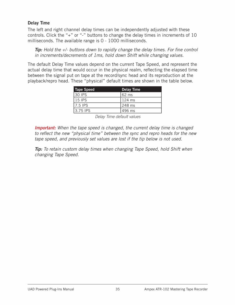
Delay TimeThe left and right channel delay times can be independently adjusted with these controls. Click the “+” or “-” buttons to change the delay times in increments of 10 milliseconds. The available range is 0 - 1000 milliseconds.
Tip: Hold the +/- buttons down to rapidly change the delay times. For fine control in increments/decrements of 1ms, hold down Shift while changing values.
The default Delay Time values depend on the current Tape Speed, and represent the actual delay time that would occur in the physical realm, reflecting the elapsed time between the signal put on tape at the record/sync head and its reproduction at the playback/repro head. These “physical” default times are shown in the table below.
Tape Speed Delay Time30 IPS 62 ms15 IPS 124 ms7.5 IPS 248 ms3.75 IPS 496 ms
Delay Time default values
Important: When the tape speed is changed, the current delay time is changed to reflect the new “physical time” between the sync and repro heads for the new tape speed, and previously set values are lost if the tip below is not used.
Tip: To retain custom delay times when changing Tape Speed, hold Shift when changing Tape Speed.
UAD Powered Plug-Ins Manual Ampex ATR-102 Mastering Tape Recorder 36
Manual Calibration ToolsThese controls are the suite of tools included to perform manual calibration of the recorder. These UAD-only tools are not in the original hardware. Manual calibration is entirely optional, as the Auto Cal feature can quickly and automatically calibrate the system.
The manual calibration tools consist of an “external” tone generator with multiple test tones and levels, a distortion meter with digital readouts, and a full suite of modeled Magnetic Reference Laboratory (MRL) alignment tapes.
Note: The Manual Calibration Tools are operational only when Path Select is set to Sync or Repro. Additionally, the tools may not operate in some hosts unless audio is present on the track containing the plug-in and the transport is running. Placing the plug-in on an aux, bus, or master output may eliminate this host limitation.
This section describes the functions of the manual calibration tools. For instructions on how to use the tools to perform a manual system calibration, see the Manual Calibration Procedure.
About MRL Alignment TapesAlignment tapes are carefully recorded with accurate and consistent flux levels and test tone frequencies. They are constant companions to all well-maintained professional tape machines. Different alignment tapes are required for each tape speed, head width, equalization standard (CCIR/IEC or NAB), and fluxivity level.
Alignment tapes are required for system calibration and adjustment so that playback of previously-recorded session tapes will have correct and consistent equalization and levels, regardless of when, or where, the session tape was originally recorded.
After tape playback system EQ and levels are calibrated to match the known-to-be-correct values of the alignment tape(s), the record-side alignment is performed. The entire record/playback system will then have proper EQ and gain structuring.
Magnetic Reference Laboratory (“MRL”) is a company that produces alignment tapes. The MRL tapes used in the UAD Ampex ATR-102 are fringing compensated. In-depth discussions about fringing compensation and system alignment are beyond the scope of this manual; thorough resources are available from the MRL website:
• www.mrltapes.com
UAD Powered Plug-Ins Manual Ampex ATR-102 Mastering Tape Recorder 37
Manual Cal KnobThe Manual Cal knob performs two functions: it sets the signal level of the “external” test tone generator for record calibration, and specifies when alignment tapes are to be used for playback calibration.
When set to -16 dB, -6 dB, or +4 dB, a generated sine wave test tone at the frequency specified by the Tones buttons is sent to the input of the record circuitry. This mode emulates sending external test tones into the system. The level of the test tone is set by the knob position and remains static regardless of other parameter values.
When set to MRL, a test tone from the “alignment tape” is sent into the playback circuitry. The MRL frequency is also specified by the Tones buttons, but the levels used are from the calibrated alignment tape. Therefore the MRL tone levels are dependent on other tape parameter values.
TonesThe Tones buttons set the frequency of the “external” test tone generator and the MRL tape test tones. Tone frequencies of 50 Hz, 100 Hz, 1 kHz, 2.5 kHz, 5 kHz, 10 kHz, 15 kHz, and 20 kHz are available.
Click a button to specify that frequency; the active frequency’s button is shadowed gray as if in the “down” position.
Distortion MeterThe red numerical display, between the Manual Cal knob and the Tones buttons, represents the amount (displayed as a percentage) of third harmonic distortion present in each of the left and right channels. This feature can be useful for custom calibration techniques.
When the Manual Cal knob is set to -16 dB, -6 dB, or +4 dB, the value represents third harmonic distortion in the tape playback circuit. Generally speaking, increasing Record (input) will increase distortion while in this mode, as tape saturation increases. If Bias is set very low, distortion may increase at lower Cal Levels.
Note: When the Manual Cal knob is set to MRL, the Distortion Meter is inactive (there is no distortion display in this mode).
UAD Powered Plug-Ins Manual Ampex ATR-102 Mastering Tape Recorder 38
Manual Calibration ProcedureManual calibration tools are provided so expert users can calibrate the system to their preferred methods for obtaining desired results. For example, some technicians may prefer adjustments for lowest distortion at a certain frequency; setting bias for maximum sensitivity (instead of overbiasing); or other non-standard techniques.
The calibration procedure described here is the most commonly used technique, and is the (albeit simplified) method recommended by the Ampex Operation and Service Manual.
Important: Manual calibration is not required to use UAD Ampex ATR-102. Following this procedure will result in the same (or nearly the same) values obtained by simply using the Auto Cal feature.
Tip: When making manual calibration settings, consider disabling Auto Cal so the manually calibrated values are not accidentally lost if any of the controls that force automatic calibration (Tape Type, Tape Speed, Emphasis EQ, and Head Width) are inadvertently modified.
Preparation• Reduce monitoring system volume to avoid loud sine wave Tones.
• Insert UAD Ampex ATR-102 on the DAW output bus (see note below).
• Set Path Select to Repro mode (Sync mode is not supported for manual cal).
• Set left and right Meter Input/Output switches to the “OUTPUT” position.
• Set left and right Meter Peak/VU switches to the “VU” position.
• Set Tape Speed, Tape Type, Cal Level, and Head Width to desired values.
• If Tape Speed is set to 3.75 IPS, set Cal Level to +3 dB.
• Disable Noise Enable (excessive Hiss may contribute to incorrect results).
• Do not change the above settings throughout the procedure.
• For related information, see the Manual Calibration Notes at the end of this chapter.
Note: The Manual Calibration Tools are operational only when Path Select is set to Sync or Repro. Additionally, the tools may not operate in some hosts unless audio is present on the track containing the plug-in and the transport is running. Placing the plug-in on an aux, bus, or master output may eliminate this host limitation.
UAD Powered Plug-Ins Manual Ampex ATR-102 Mastering Tape Recorder 39
Repro Level Calibration1. Set the Manual Cal Knob to the MRL position. The built-in alignment tape tone will sound and its level can be viewed on the Meters.
2. Set the Tones frequency to 1 kHz.
3. Adjust Reproduce (output) so the Meters display 0 dB.
Repro EQ Calibration4. Set the Tones frequency to 10 kHz.
5. Adjust Repro HF (not to be confused with HF EQ) so the Meters display 0 dB.
6. Set the Tones frequency to 100 Hz.
7. Adjust Repro LF so the Meters display 0 dB (or as close as possible).*
*Because the MRL alignment tapes we used have fringing compensation, it may not be possible to increase Repro LF enough to make the meter reach 0 dB at low frequencies. If a flat response is desired, you can switch the Manual Cal knob from MRL mode to the “external” tones then readjust Repro LF for flat response (0 dB) using the external tones instead of the MRL tones.
Note: If Repro HF and/or Repro LF EQs are adjusted by a large amount, it may be necessary to recalibrate the output level (steps 1-3).
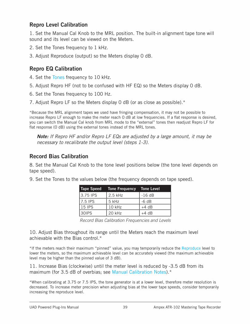
Record Bias Calibration8. Set the Manual Cal Knob to the tone level positions below (the tone level depends on tape speed).
9. Set the Tones to the values below (the frequency depends on tape speed).
Tape Speed Tone Frequency Tone Level
3.75 IPS 2.5 kHz -16 dB
7.5 IPS 5 kHz -6 dB15 IPS 10 kHz +4 dB30IPS 20 kHz +4 dB
Record Bias Calibration Frequencies and Levels
10. Adjust Bias throughout its range until the Meters reach the maximum level achievable with the Bias control.*
*If the meters reach their maximum “pinned” value, you may temporarily reduce the Reproduce level to lower the meters, so the maximum achievable level can be accurately viewed (the maximum achievable level may be higher than the pinned value of 3 dB).
11. Increase Bias (clockwise) until the meter level is reduced by -3.5 dB from its maximum (for 3.5 dB of overbias; see Manual Calibration Notes).*
*When calibrating at 3.75 or 7.5 IPS, the tone generator is at a lower level, therefore meter resolution is decreased. To increase meter precision when adjusting bias at the lower tape speeds, consider temporarily increasing the reproduce level.
UAD Powered Plug-Ins Manual Ampex ATR-102 Mastering Tape Recorder 40
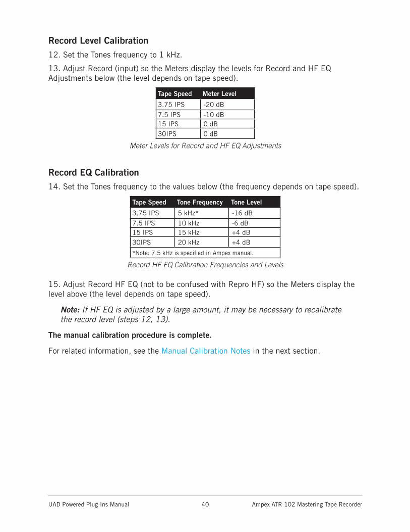
Record Level Calibration12. Set the Tones frequency to 1 kHz.
13. Adjust Record (input) so the Meters display the levels for Record and HF EQ Adjustments below (the level depends on tape speed).
Tape Speed Meter Level
3.75 IPS -20 dB
7.5 IPS -10 dB15 IPS 0 dB30IPS 0 dB
Meter Levels for Record and HF EQ Adjustments
Record EQ Calibration14. Set the Tones frequency to the values below (the frequency depends on tape speed).
Tape Speed Tone Frequency Tone Level
3.75 IPS 5 kHz* -16 dB
7.5 IPS 10 kHz -6 dB15 IPS 15 kHz +4 dB30IPS 20 kHz +4 dB
*Note: 7.5 kHz is specified in Ampex manual.
Record HF EQ Calibration Frequencies and Levels
15. Adjust Record HF EQ (not to be confused with Repro HF) so the Meters display the level above (the level depends on tape speed).
Note: If HF EQ is adjusted by a large amount, it may be necessary to recalibrate the record level (steps 12, 13).
The manual calibration procedure is complete.
For related information, see the Manual Calibration Notes in the next section.
UAD Powered Plug-Ins Manual Ampex ATR-102 Mastering Tape Recorder 41
Manual Calibration Notes• 0 dB on the output meter represents +4 dBm (and -12 dBFS digital) when
Reproduce is in its calibrated position, which is marked with the “red arrow sticker.”
• For proper calibration, follow the entire calibration procedure in order.
• This example uses 3.5 dB overbias. The amount of gain reduction in step 12 determines the amount of overbias. In some cases we used more than 3.5 dB of overbias to achieve a flatter response.
• Generally speaking, higher Cal Level values will have higher Distortion Meter values for a given reading on the Meters. If Bias is set very low, distortion may increase at lower Cal Levels.
• We recommend leaving the record SHELF EQ control in its default position.
• The Ampex ATR-102 hardware has an additional gain control via a setscrew (like Repro HF/LF, Bias, etc) which is usually used for manual gain calibrations. This control is not available in the plug-in because it would be redundant - the Reproduce control performs the same function.
• We chose to calibrate our reference machine using MRL fringing-compensated calibration tapes, without later adjusting the Repro LF EQ for unity gain using external test tones. Therefore the calibrated values in the plug-in reflect this alignment method. In-depth discussions about fringing compensation and system alignment are beyond the scope of this manual; thorough resources are available from the MRL website: www.mrltapes.com
• Tape Type 111 uses a calibration level of 0 dB. This value is not available in the plug-in, but it can be emulated by setting the CAL level to +3 dB, then reducing the input level (Record knob) by -3 dB and increasing the output level (Reproduce knob) by +3 dB.
• The plug-in operates at an internal level of -12 dBFS. Therefore a digital signal with a level of -12 dB below full scale digital (0 dBFS) at the plug-in input will represent 0 dB on the plug-in meters (if the plug-in is calibrated).
• The included Artist Presets demonstrate how manual calibration can be used to obtain sonic variations.
Tip: For easy recall in future sessions, save unique calibrations as a preset.
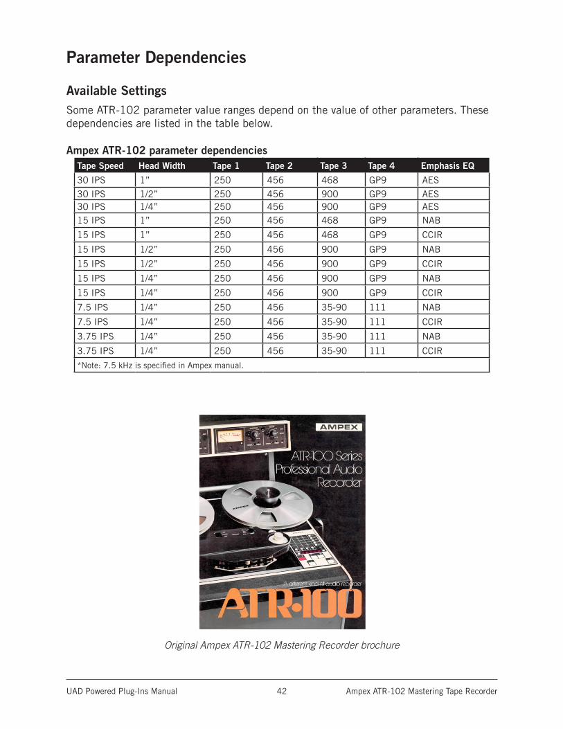
UAD Powered Plug-Ins Manual Ampex ATR-102 Mastering Tape Recorder 42
Parameter Dependencies
Available SettingsSome ATR-102 parameter value ranges depend on the value of other parameters. These dependencies are listed in the table below.
Ampex ATR-102 parameter dependenciesTape Speed Head Width Tape 1 Tape 2 Tape 3 Tape 4 Emphasis EQ
30 IPS 1” 250 456 468 GP9 AES
30 IPS 1/2” 250 456 900 GP9 AES30 IPS 1/4” 250 456 900 GP9 AES15 IPS 1” 250 456 468 GP9 NAB
15 IPS 1” 250 456 468 GP9 CCIR
15 IPS 1/2” 250 456 900 GP9 NAB
15 IPS 1/2” 250 456 900 GP9 CCIR
15 IPS 1/4” 250 456 900 GP9 NAB
15 IPS 1/4” 250 456 900 GP9 CCIR
7.5 IPS 1/4” 250 456 35-90 111 NAB
7.5 IPS 1/4” 250 456 35-90 111 CCIR
3.75 IPS 1/4” 250 456 35-90 111 NAB
3.75 IPS 1/4” 250 456 35-90 111 CCIR
*Note: 7.5 kHz is specified in Ampex manual.
Original Ampex ATR-102 Mastering Recorder brochure
UAD Powered Plug-Ins Manual API 500 Series EQ Collection 43
API 500 Series EQ Collection
The world’s most accurate emulations of API’s legendary EQsThe API 500 Series EQ Plug-In Collection for UAD-2 hardware and Apollo interfaces faithfully captures the punch, low-frequency transparency, and ultra-tight imaging of API’s iconic 550A and 560 Series EQs. With unique filter shapes, complex band interactions, and musical filter amp distortions, the 550A and 560
Series EQs left an indelible stamp on legendary recordings of the ’60s and ’70s. Painstakingly modeled on pristine early-’70s units provided by Ross Hogarth and Capitol Studios, the API 500 Series EQ Collection gives you stunningly accurate, end-to-end modeling of these revered EQs.
Now You Can:• Track and mix with full-circuit emulations of API’s iconic 550A and 560 EQs
• Harness API’s musical filter amp distortions and musical clipping behaviors
• Use API’s proprietary “Proportional Q” for more precise control over your sources
• Mix with artist presets from Ross Hogarth (Van Halen, Mötley Crüe), Darrell Thorp (Beck, Radiohead), and Vance Powell (Jack White, Kings of Leon)
550A Parametric EQIntroduced in 1971, the 550A was the standard channel EQ module on API’s first consoles. Its three overlapping bands of parametric EQ, independent 50 Hz to 15 kHz band-pass filter, and individually selectable peaking or shelving modes make it the perfect tool for getting drums and guitars to stand out in the mix.
560 Graphic EQWith ten bands of graphic EQ, the 560 EQ is ideal for shaping your mix with surgical precision. API’s proprietary “Proportional Q” intuitively widens bandwidth at lower boost/cut levels and narrows it at higher levels, giving you more musical control over precise bands of your mix.
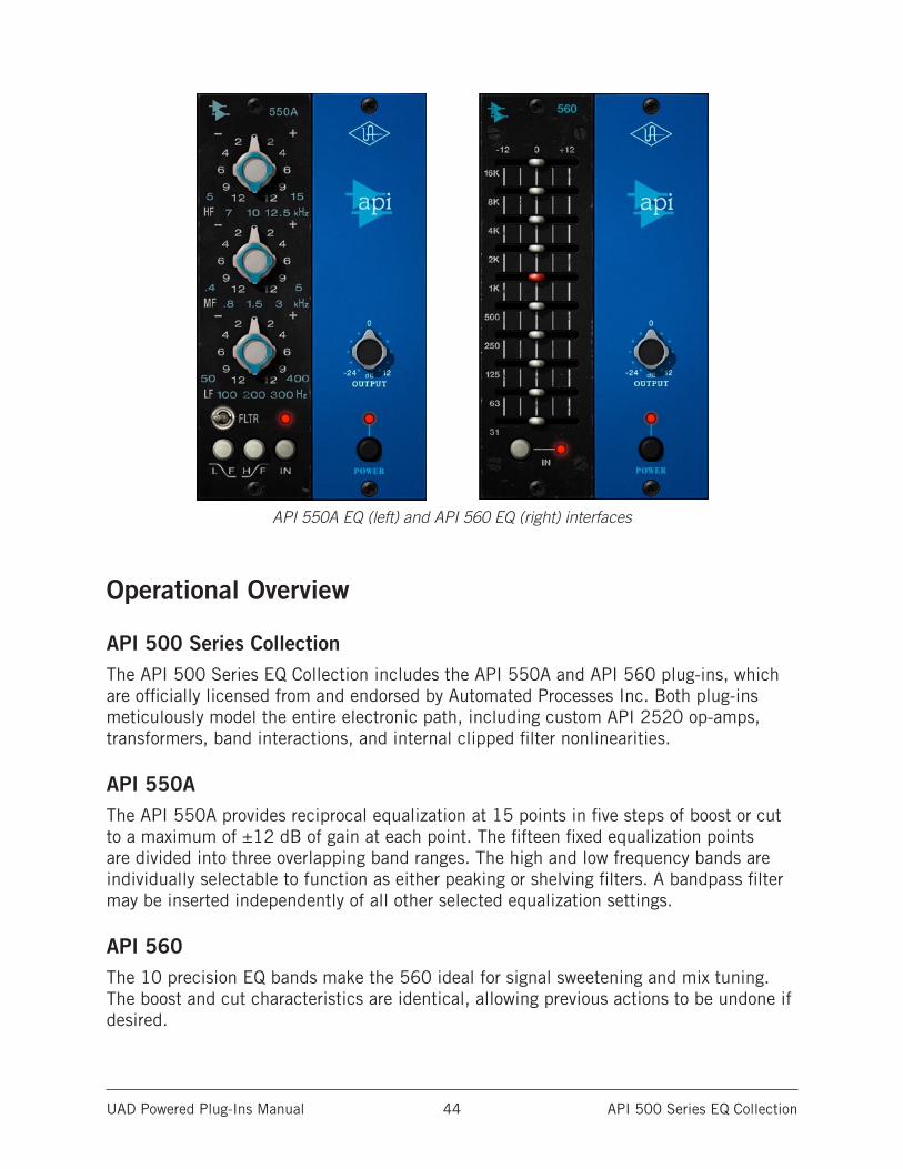
UAD Powered Plug-Ins Manual API 500 Series EQ Collection 44
API 550A EQ (left) and API 560 EQ (right) interfaces
Operational Overview
API 500 Series CollectionThe API 500 Series EQ Collection includes the API 550A and API 560 plug-ins, which are officially licensed from and endorsed by Automated Processes Inc. Both plug-ins meticulously model the entire electronic path, including custom API 2520 op-amps, transformers, band interactions, and internal clipped filter nonlinearities.
API 550AThe API 550A provides reciprocal equalization at 15 points in five steps of boost or cut to a maximum of ±12 dB of gain at each point. The fifteen fixed equalization points are divided into three overlapping band ranges. The high and low frequency bands are individually selectable to function as either peaking or shelving filters. A bandpass filter may be inserted independently of all other selected equalization settings.
API 560The 10 precision EQ bands make the 560 ideal for signal sweetening and mix tuning. The boost and cut characteristics are identical, allowing previous actions to be undone if desired.
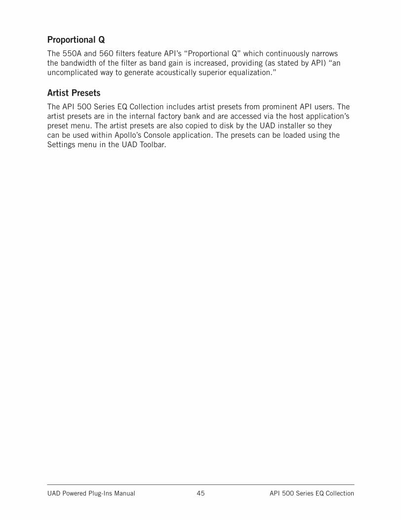
UAD Powered Plug-Ins Manual API 500 Series EQ Collection 45
Proportional QThe 550A and 560 filters feature API’s “Proportional Q” which continuously narrows the bandwidth of the filter as band gain is increased, providing (as stated by API) “an uncomplicated way to generate acoustically superior equalization.”
Artist PresetsThe API 500 Series EQ Collection includes artist presets from prominent API users. The artist presets are in the internal factory bank and are accessed via the host application’s preset menu. The artist presets are also copied to disk by the UAD installer so they can be used within Apollo’s Console application. The presets can be loaded using the Settings menu in the UAD Toolbar.
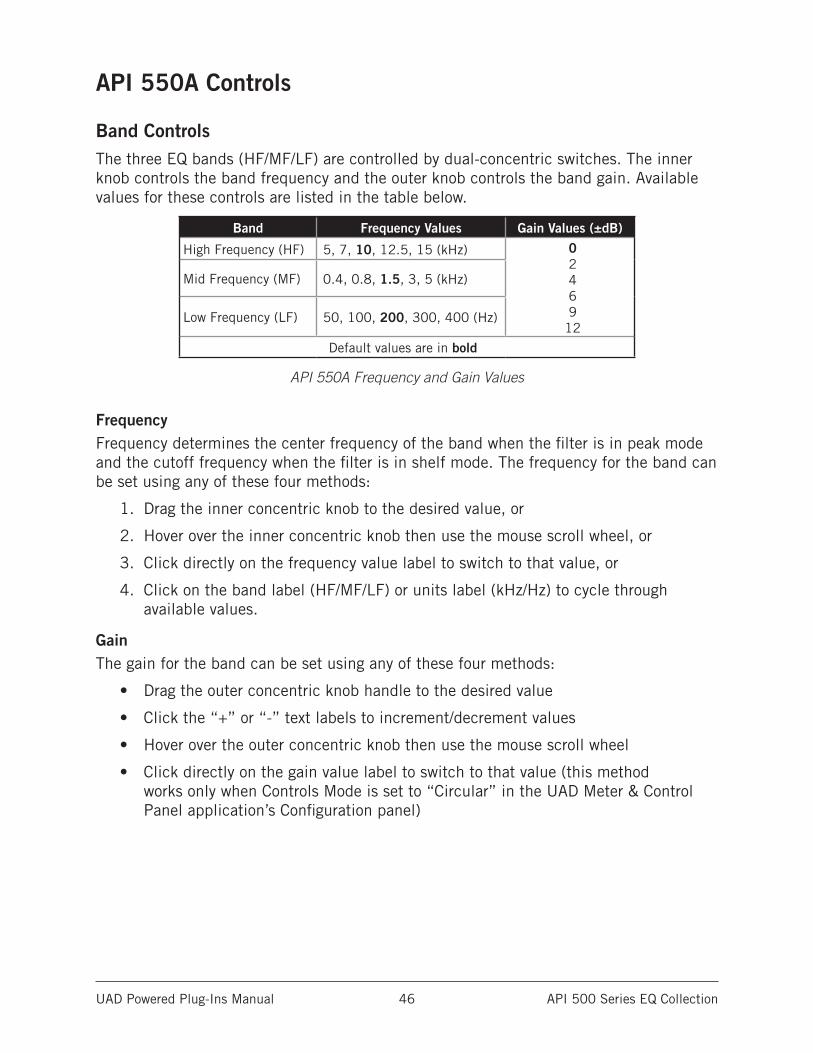
UAD Powered Plug-Ins Manual API 500 Series EQ Collection 46
API 550A Controls
Band ControlsThe three EQ bands (HF/MF/LF) are controlled by dual-concentric switches. The inner knob controls the band frequency and the outer knob controls the band gain. Available values for these controls are listed in the table below.
Band Frequency Values Gain Values (±dB)
High Frequency (HF) 5, 7, 10, 12.5, 15 (kHz) 0 2 4 6 9
12
Mid Frequency (MF) 0.4, 0.8, 1.5, 3, 5 (kHz)
Low Frequency (LF) 50, 100, 200, 300, 400 (Hz)
Default values are in bold
API 550A Frequency and Gain Values
FrequencyFrequency determines the center frequency of the band when the filter is in peak mode and the cutoff frequency when the filter is in shelf mode. The frequency for the band can be set using any of these four methods:
1. Drag the inner concentric knob to the desired value, or
2. Hover over the inner concentric knob then use the mouse scroll wheel, or
3. Click directly on the frequency value label to switch to that value, or
4. Click on the band label (HF/MF/LF) or units label (kHz/Hz) to cycle through available values.
GainThe gain for the band can be set using any of these four methods:
• Drag the outer concentric knob handle to the desired value
• Click the “+” or “-” text labels to increment/decrement values
• Hover over the outer concentric knob then use the mouse scroll wheel
• Click directly on the gain value label to switch to that value (this method works only when Controls Mode is set to “Circular” in the UAD Meter & Control Panel application’s Configuration panel)
UAD Powered Plug-Ins Manual API 500 Series EQ Collection 47
Bandpass Filter (FLTR)The FLTR switch applies a 50 Hz - 15 kHz bandpass filter to the entire signal. The bandpass filter is completely independent from the from the three main band filters.
Bell/Shelf SwitchesThe HF and LF bands are normally in bell mode. When the Bell/Shelf button is engaged for the band (in the darker “down” position), the band is switched to shelving mode.
LF ShelfWhen the LF Shelf button is engaged, the low frequency band is switched to shelving mode.
HF ShelfWhen the HF Shelf button is engaged, the high frequency band is switched to shelving mode.
OutputThis control provides -24 dB to +12 dB of clean uncolored gain at the output of the plug-in.
Tip: Click the “0” text label to return Output to the 0 dB position.
EQ InThe EQ In switch enables the three band filters and the bandpass filter. All filters are active when the switch is engaged and the “IN” LED is illuminated.
When disengaged, the filters are bypassed but other hardware circuitry is still modeled.
PowerThe plug-in is active when the POWER switch is engaged and its associated LED is illuminated. When this switch is off, all plug-in processing is disabled and UAD DSP usage is reduced (unless UAD-2 LoadLock is enabled).
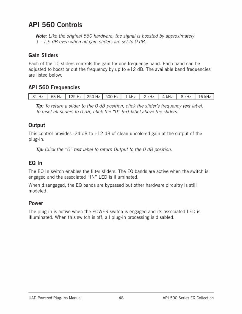
UAD Powered Plug-Ins Manual API 500 Series EQ Collection 48
API 560 ControlsNote: Like the original 560 hardware, the signal is boosted by approximately 1 - 1.5 dB even when all gain sliders are set to 0 dB.
Gain SlidersEach of the 10 sliders controls the gain for one frequency band. Each band can be adjusted to boost or cut the frequency by up to ±12 dB. The available band frequencies are listed below.
API 560 Frequencies
31 Hz 63 Hz 125 Hz 250 Hz 500 Hz 1 kHz 2 kHz 4 kHz 8 kHz 16 kHz
Tip: To return a slider to the 0 dB position, click the slider’s frequency text label. To reset all sliders to 0 dB, click the “0” text label above the sliders.
OutputThis control provides -24 dB to +12 dB of clean uncolored gain at the output of the plug-in.
Tip: Click the “0” text label to return Output to the 0 dB position.
EQ InThe EQ In switch enables the filter sliders. The EQ bands are active when the switch is engaged and the associated “IN” LED is illuminated.
When disengaged, the EQ bands are bypassed but other hardware circuitry is still modeled.
PowerThe plug-in is active when the POWER switch is engaged and its associated LED is illuminated. When this switch is off, all plug-in processing is disabled.
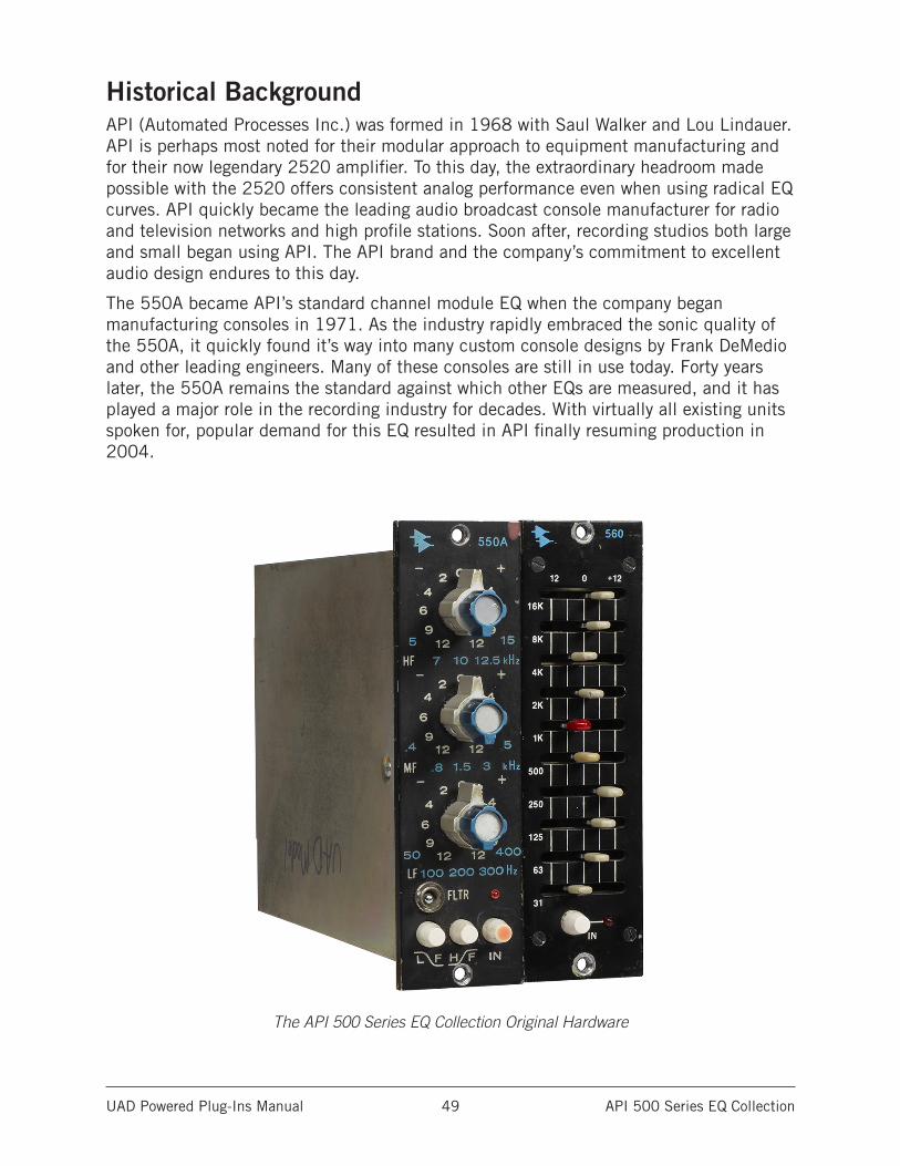
UAD Powered Plug-Ins Manual API 500 Series EQ Collection 49
Historical BackgroundAPI (Automated Processes Inc.) was formed in 1968 with Saul Walker and Lou Lindauer. API is perhaps most noted for their modular approach to equipment manufacturing and for their now legendary 2520 amplifier. To this day, the extraordinary headroom made possible with the 2520 offers consistent analog performance even when using radical EQ curves. API quickly became the leading audio broadcast console manufacturer for radio and television networks and high profile stations. Soon after, recording studios both large and small began using API. The API brand and the company’s commitment to excellent audio design endures to this day.
The 550A became API’s standard channel module EQ when the company began manufacturing consoles in 1971. As the industry rapidly embraced the sonic quality of the 550A, it quickly found it’s way into many custom console designs by Frank DeMedio and other leading engineers. Many of these consoles are still in use today. Forty years later, the 550A remains the standard against which other EQs are measured, and it has played a major role in the recording industry for decades. With virtually all existing units spoken for, popular demand for this EQ resulted in API finally resuming production in 2004.
The API 500 Series EQ Collection Original Hardware
UAD Powered Plug-Ins Manual API Vision Channel Strip 50
API Vision Channel Strip
The Classic Color of API’s Flagship Analog ConsoleA longtime leader in analog console design, API desks have shaped hits from the Foo Fighters to Fleetwood Mac’s classic, Rumours. Introduced in 2003, API’s flagship Vision Console was crafted to uphold the company’s soulful sonic tradition while providing flexibility and features for modern workflows. For the first time, you can have a complete channel strip of classic API punch, presence, and color with the API Vision Channel Strip plug-in — exclusively for UAD-2 DSP hardware and Apollo interfaces.
Now You Can:• Track and mix through a stunning emulation of API’s flagship analog console
• Warm up signals through the API 212L preamp with famed 2520 API op-amp
• Reshape envelopes and create dramatic dynamic effects with the 235L Gate/Expander
• Tame transients and craft wild new textures with API’s legendary 225L compres-sion circuit
• Control Apollo interface mic preamp gain staging and impedance directly from the Vision plug-in with Unison™ technology
UA’s Most Colorful Channel Strip Plug-InComprised of five classic API modules, the API Vision Channel Strip plug-in transforms your DAW into a high-end analog mixing desk, injecting your tracks with the sonic color and personality that has made API legendary. Take a quick tour of the five modules below.
Unison Technology for Apollo InterfacesHarnessing UA’s groundbreaking Unison technology, the API Vision Channel Strip plug-in gives you all of the API Vision’s important impedance, gain stage “sweet spots,” and circuit behaviors that have made the Vision Channel Strip’s 212L preamp one of the most detailed and punchy preamps ever devised. The secret is Unison’s bi-directional control and communication from the API Vision Channel Strip plug-in to the physical mic preamps in Apollo.
Run Signals through the 212L PreampWidely praised for its detail and warmth, the 212L Preamp finds its roots in the legendary API 2488 console — best known for the famed “LA sound” of the ’70s and ’80s. UA’s API Vision plug-in expertly models this preamp, right down to its custom 2520 API op-amp and transformers, giving you the unmistakable tone of its esteemed hardware counterpart.
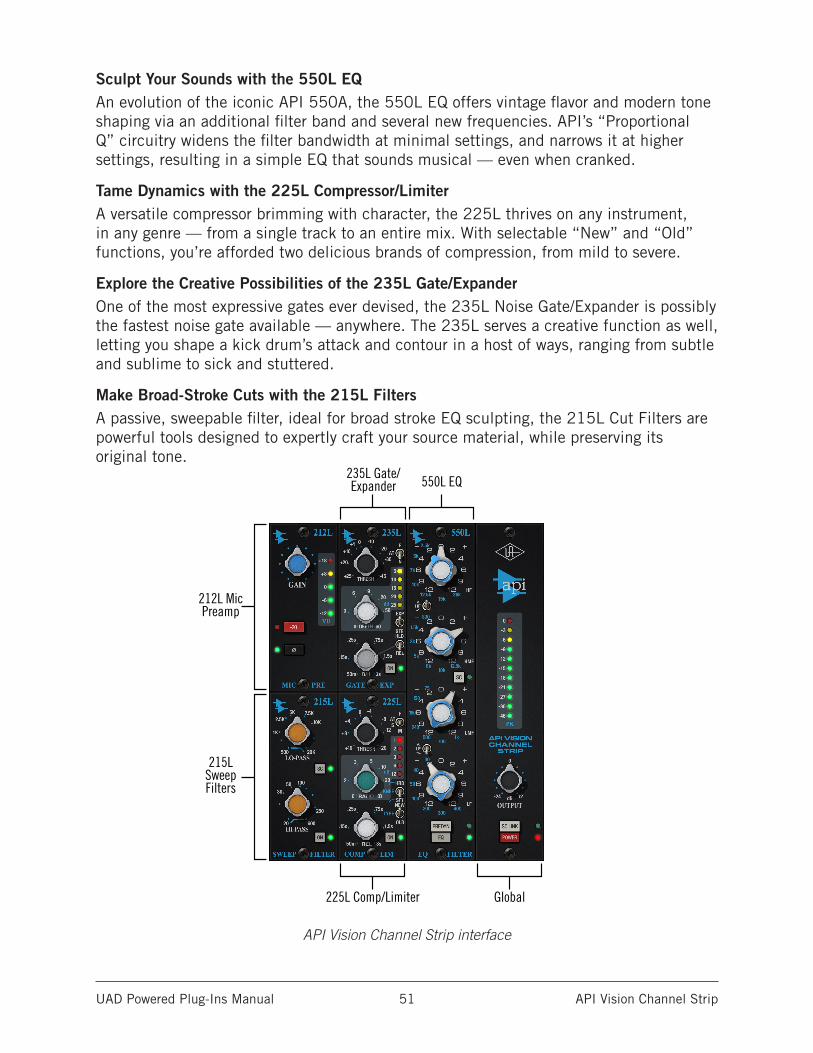
UAD Powered Plug-Ins Manual API Vision Channel Strip 51
Sculpt Your Sounds with the 550L EQAn evolution of the iconic API 550A, the 550L EQ offers vintage flavor and modern tone shaping via an additional filter band and several new frequencies. API’s “Proportional Q” circuitry widens the filter bandwidth at minimal settings, and narrows it at higher settings, resulting in a simple EQ that sounds musical — even when cranked.
Tame Dynamics with the 225L Compressor/LimiterA versatile compressor brimming with character, the 225L thrives on any instrument, in any genre — from a single track to an entire mix. With selectable “New” and “Old” functions, you’re afforded two delicious brands of compression, from mild to severe.
Explore the Creative Possibilities of the 235L Gate/ExpanderOne of the most expressive gates ever devised, the 235L Noise Gate/Expander is possibly the fastest noise gate available — anywhere. The 235L serves a creative function as well, letting you shape a kick drum’s attack and contour in a host of ways, ranging from subtle and sublime to sick and stuttered.
Make Broad-Stroke Cuts with the 215L FiltersA passive, sweepable filter, ideal for broad stroke EQ sculpting, the 215L Cut Filters are powerful tools designed to expertly craft your source material, while preserving its original tone.
API Vision Channel Strip interface
235L Gate/Expander
225L Comp/Limiter Global
212L Mic Preamp
215L Sweep Filters
550L EQ
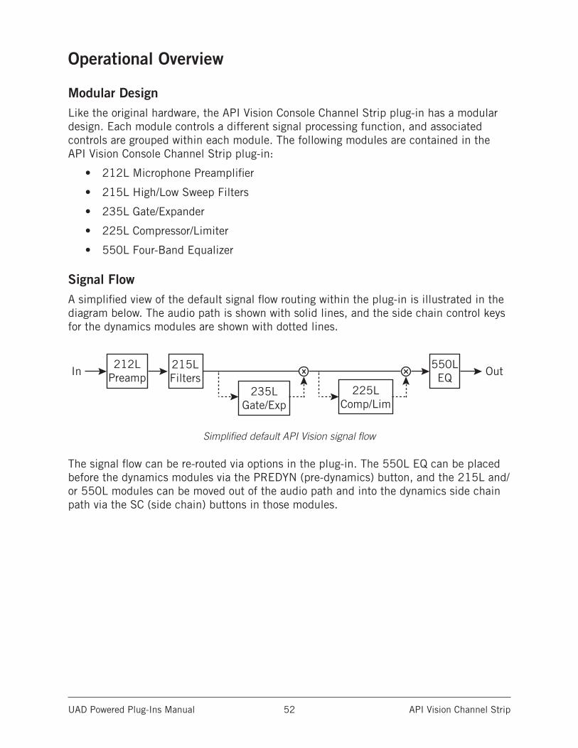
UAD Powered Plug-Ins Manual API Vision Channel Strip 52
Operational Overview
Modular DesignLike the original hardware, the API Vision Console Channel Strip plug-in has a modular design. Each module controls a different signal processing function, and associated controls are grouped within each module. The following modules are contained in the API Vision Console Channel Strip plug-in:
• 212L Microphone Preamplifier
• 215L High/Low Sweep Filters
• 235L Gate/Expander
• 225L Compressor/Limiter
• 550L Four-Band Equalizer
Signal FlowA simplified view of the default signal flow routing within the plug-in is illustrated in the diagram below. The audio path is shown with solid lines, and the side chain control keys for the dynamics modules are shown with dotted lines.
Simplified default API Vision signal flow
The signal flow can be re-routed via options in the plug-in. The 550L EQ can be placed before the dynamics modules via the PREDYN (pre-dynamics) button, and the 215L and/or 550L modules can be moved out of the audio path and into the dynamics side chain path via the SC (side chain) buttons in those modules.
215LFilters
212LPreamp
550LEQ
235LGate/Exp
235LGate/Exp
235LGate/Exp
225LComp/Lim
225LComp/Lim
225LComp/Lim
235LGate/Exp
225LComp/Lim
235LGate/Exp
225LComp/Lim
215LFilters
212LPreamp
550LEQ
215LFilters
212LPreamp
550LEQ
215LFilters
212LPreamp
550LEQ
215LFilters
212LPreamp
550LEQIn
In
In
Out
Out
Out
In Out
In Out
235LGate/Exp
225LComp/Lim
215LFilters
212LPreamp
550LEQ
In Out
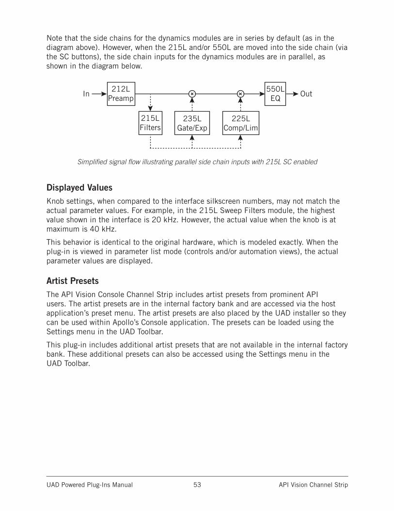
UAD Powered Plug-Ins Manual API Vision Channel Strip 53
Note that the side chains for the dynamics modules are in series by default (as in the diagram above). However, when the 215L and/or 550L are moved into the side chain (via the SC buttons), the side chain inputs for the dynamics modules are in parallel, as shown in the diagram below.
Simplified signal flow illustrating parallel side chain inputs with 215L SC enabled
Displayed ValuesKnob settings, when compared to the interface silkscreen numbers, may not match the actual parameter values. For example, in the 215L Sweep Filters module, the highest value shown in the interface is 20 kHz. However, the actual value when the knob is at maximum is 40 kHz.
This behavior is identical to the original hardware, which is modeled exactly. When the plug-in is viewed in parameter list mode (controls and/or automation views), the actual parameter values are displayed.
Artist PresetsThe API Vision Console Channel Strip includes artist presets from prominent API users. The artist presets are in the internal factory bank and are accessed via the host application’s preset menu. The artist presets are also placed by the UAD installer so they can be used within Apollo’s Console application. The presets can be loaded using the Settings menu in the UAD Toolbar.
This plug-in includes additional artist presets that are not available in the internal factory bank. These additional presets can also be accessed using the Settings menu in the UAD Toolbar.
215LFilters
212LPreamp
550LEQ
235LGate/Exp
235LGate/Exp
235LGate/Exp
225LComp/Lim
225LComp/Lim
225LComp/Lim
235LGate/Exp
225LComp/Lim
235LGate/Exp
225LComp/Lim
215LFilters
212LPreamp
550LEQ
215LFilters
212LPreamp
550LEQ
215LFilters
212LPreamp
550LEQ
215LFilters
212LPreamp
550LEQIn
In
In
Out
Out
Out
In Out
In Out
235LGate/Exp
225LComp/Lim
215LFilters
212LPreamp
550LEQ
In Out
UAD Powered Plug-Ins Manual API Vision Channel Strip 54
Unison™ IntegrationThe API Vision Channel Strip features Unison mic preamp technology integration with the mic preamp hardware in Universal Audio’s Apollo audio interfaces. With Unison, Apollo’s ultra-transparent mic preamps inherit all of the unique sonics, input characteristics, and features of the API Vision 212L hardware preamp module.
Note: Unison is active only when the plug-ins are inserted in the unique IN- PUT insert within Apollo’s Console application. For complete Unison details, see the Apollo Software Manual.
Realistic Tandem ControlUnison facilitates seamless interactive control of API Vision Channel Strip plug-in settings using Apollo’s digitally-controlled panel hardware and/or the plug-in interface. All equivalent preamp controls (gain, pad, polarity) are mirrored and bi-directional. The preamp controls respond to adjustments with precisely the same interplay behavior as the API Vision Channel Strip hard- ware, including gain levels and clipping points.
Hardware Input ImpedanceAll Apollo mic preamps feature input impedance switching in analog hard- ware that can be physically switched by Unison plug-ins for physical, micro- phone-to-preamp resistive interaction. This impedance switching enables Apollo’s preamps to physically match the emulated unit’s input impedance, which can significantly impact the sound of a microphone. Because the elec- trical loading occurs on input, prior to A/D conversion, the realism is faithful to the original target hardware preamp.
Tactile Gain StagingApollo’s front panel preamp knob can independently adjust the gain and level parameters available within the Unison plug-in via Gain Stage Mode. The gain stage being adjusted can be remotely switched via Apollo, so the gain levels and their associated colorations can be tuned from the hardware knob for precise physical tactile control, all without using the Unison plug-in’s software interface.
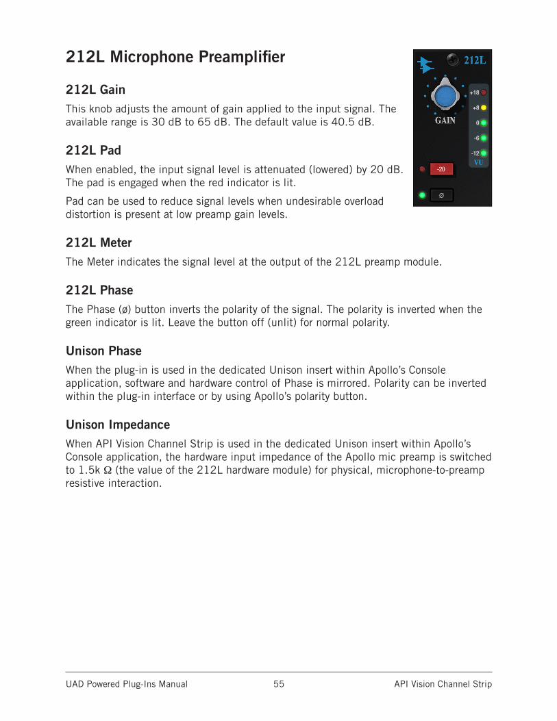
UAD Powered Plug-Ins Manual API Vision Channel Strip 55
212L Microphone Preamplifier
212L GainThis knob adjusts the amount of gain applied to the input signal. The available range is 30 dB to 65 dB. The default value is 40.5 dB.
212L PadWhen enabled, the input signal level is attenuated (lowered) by 20 dB. The pad is engaged when the red indicator is lit.
Pad can be used to reduce signal levels when undesirable overload distortion is present at low preamp gain levels.
212L MeterThe Meter indicates the signal level at the output of the 212L preamp module.
212L PhaseThe Phase (ø) button inverts the polarity of the signal. The polarity is inverted when the green indicator is lit. Leave the button off (unlit) for normal polarity.
Unison PhaseWhen the plug-in is used in the dedicated Unison insert within Apollo’s Console application, software and hardware control of Phase is mirrored. Polarity can be inverted within the plug-in interface or by using Apollo’s polarity button.
Unison ImpedanceWhen API Vision Channel Strip is used in the dedicated Unison insert within Apollo’s Console application, the hardware input impedance of the Apollo mic preamp is switched to 1.5k Ω (the value of the 212L hardware module) for physical, microphone-to-preamp resistive interaction.
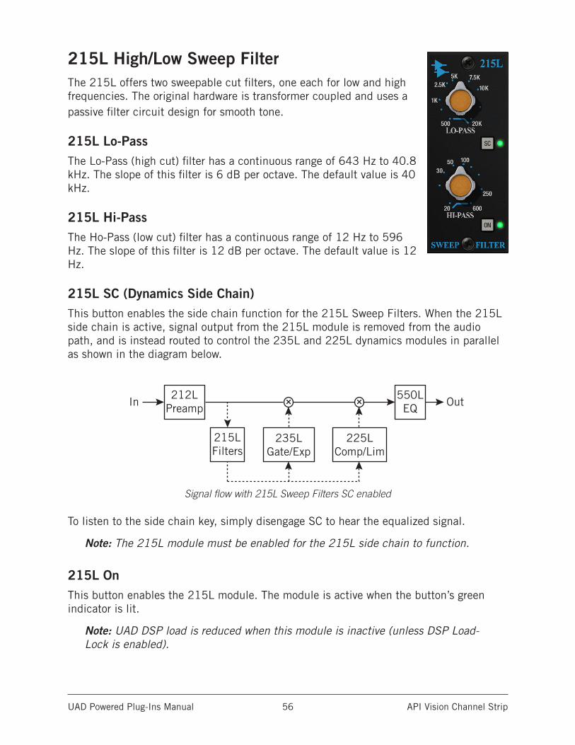
UAD Powered Plug-Ins Manual API Vision Channel Strip 56
215L High/Low Sweep FilterThe 215L offers two sweepable cut filters, one each for low and high frequencies. The original hardware is transformer coupled and uses a passive filter circuit design for smooth tone.
215L Lo-PassThe Lo-Pass (high cut) filter has a continuous range of 643 Hz to 40.8 kHz. The slope of this filter is 6 dB per octave. The default value is 40 kHz.
215L Hi-PassThe Ho-Pass (low cut) filter has a continuous range of 12 Hz to 596 Hz. The slope of this filter is 12 dB per octave. The default value is 12 Hz.
215L SC (Dynamics Side Chain)This button enables the side chain function for the 215L Sweep Filters. When the 215L side chain is active, signal output from the 215L module is removed from the audio path, and is instead routed to control the 235L and 225L dynamics modules in parallel as shown in the diagram below.
Signal flow with 215L Sweep Filters SC enabled
To listen to the side chain key, simply disengage SC to hear the equalized signal.
Note: The 215L module must be enabled for the 215L side chain to function.
215L OnThis button enables the 215L module. The module is active when the button’s green indicator is lit.
Note: UAD DSP load is reduced when this module is inactive (unless DSP Load-Lock is enabled).
215LFilters
212LPreamp
550LEQ
235LGate/Exp
235LGate/Exp
235LGate/Exp
225LComp/Lim
225LComp/Lim
225LComp/Lim
235LGate/Exp
225LComp/Lim
235LGate/Exp
225LComp/Lim
215LFilters
212LPreamp
550LEQ
215LFilters
212LPreamp
550LEQ
215LFilters
212LPreamp
550LEQ
215LFilters
212LPreamp
550LEQIn
In
In
Out
Out
Out
In Out
In Out
235LGate/Exp
225LComp/Lim
215LFilters
212LPreamp
550LEQ
In Out
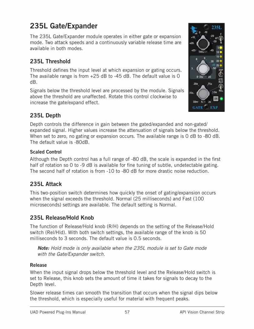
UAD Powered Plug-Ins Manual API Vision Channel Strip 57
235L Gate/ExpanderThe 235L Gate/Expander module operates in either gate or expansion mode. Two attack speeds and a continuously variable release time are available in both modes.
235L ThresholdThreshold defines the input level at which expansion or gating occurs. The available range is from +25 dB to -45 dB. The default value is 0 dB.
Signals below the threshold level are processed by the module. Signals above the threshold are unaffected. Rotate this control clockwise to increase the gate/expand effect.
235L DepthDepth controls the difference in gain between the gated/expanded and non-gated/expanded signal. Higher values increase the attenuation of signals below the threshold. When set to zero, no gating or expansion occurs. The available range is 0 dB to -80 dB. The default value is -80dB.
Scaled ControlAlthough the Depth control has a full range of -80 dB, the scale is expanded in the first half of rotation so 0 to -9 dB is available for fine tuning of subtle, undetectable gating. The second half of rotation is from -10 to -80 dB for more drastic noise reduction.
235L AttackThis two-position switch determines how quickly the onset of gating/expansion occurs when the signal exceeds the threshold. Normal (25 milliseconds) and Fast (100 microseconds) settings are available. The default setting is Normal.
235L Release/Hold KnobThe function of Release/Hold knob (R/H) depends on the setting of the Release/Hold switch (Rel/Hld). With both switch settings, the available range of the knob is 50 milliseconds to 3 seconds. The default value is 0.5 seconds.
Note: Hold mode is only available when the 235L module is set to Gate mode with the Gate/Expander switch.
ReleaseWhen the input signal drops below the threshold level and the Release/Hold switch is set to Release, this knob sets the amount of time it takes for signals to decay to the Depth level.
Slower release times can smooth the transition that occurs when the signal dips below the threshold, which is especially useful for material with frequent peaks.
UAD Powered Plug-Ins Manual API Vision Channel Strip 58
Fast release times are typically only suitable for certain types of percussion and other instruments with very fast decays. Using fast settings on other sources may produce undesirable results.
HoldWhen the input signal drops below the threshold level and the Release/Hold switch is set to Hold, this knob sets the amount of time that signals are held at normal levels before signals return to the Depth level.
Note: When set to Hold, the release time is fixed at 100 milliseconds.
235L Release/Hold SwitchThis two-position switch (REL/HLD) determines the behavior of the Release/Hold knob when the 235L module is set to Gate mode with the Gate/Expander switch. The default value is Release.
Note: This switch is locked in the Release position when the module is in Gate mode (Hold mode is unavailable in Expander mode).
235L Gate/Expander SwitchThis switch (GTE/EXP) toggles the module between Gate and Expander modes. The default value is Expander.
GTEWhen set to Gate mode, signals below the threshold are attenuated by the Depth amount.
EXPWhen set to Expander mode, the gate applies downwards expansion at a fixed 1:2 ratio, with the amount of gain reduction determined by the Depth control.
Expansion allows the signal to “sneak up” to the full signal level without any loss of “under threshold” nuances.
235L MeterThis meter displays, in dB, the amount of gain attenuation (downward expansion) occurring in the 235L module.
235L OnThis button enables the 235L module. The module is active when the button’s green indicator is lit.
Note: UAD DSP load is reduced when this module is inactive (unless DSP Load-Lock is enabled).
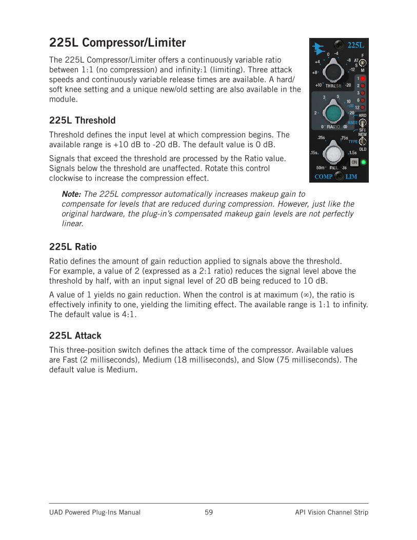
UAD Powered Plug-Ins Manual API Vision Channel Strip 59
225L Compressor/LimiterThe 225L Compressor/Limiter offers a continuously variable ratio between 1:1 (no compression) and infinity:1 (limiting). Three attack speeds and continuously variable release times are available. A hard/soft knee setting and a unique new/old setting are also available in the module.
225L ThresholdThreshold defines the input level at which compression begins. The available range is +10 dB to -20 dB. The default value is 0 dB.
Signals that exceed the threshold are processed by the Ratio value. Signals below the threshold are unaffected. Rotate this control clockwise to increase the compression effect.
Note: The 225L compressor automatically increases makeup gain to compensate for levels that are reduced during compression. However, just like the original hardware, the plug-in’s compensated makeup gain levels are not perfectly linear.
225L RatioRatio defines the amount of gain reduction applied to signals above the threshold. For example, a value of 2 (expressed as a 2:1 ratio) reduces the signal level above the threshold by half, with an input signal level of 20 dB being reduced to 10 dB.
A value of 1 yields no gain reduction. When the control is at maximum (∞), the ratio is effectively infinity to one, yielding the limiting effect. The available range is 1:1 to infinity. The default value is 4:1.
225L AttackThis three-position switch defines the attack time of the compressor. Available values are Fast (2 milliseconds), Medium (18 milliseconds), and Slow (75 milliseconds). The default value is Medium.
UAD Powered Plug-Ins Manual API Vision Channel Strip 60
225L ReleaseRelease sets the amount of time it takes for processing to cease once the input signal drops below the threshold level. The available control range is 50 milliseconds to 3 seconds.
Note: Actual release times are program dependent.
Slower release times can smooth the transition that occurs when the signal dips below the threshold, which is especially useful for material with frequent peaks. However, if the release is too long, compression for sections of audio with loud signals may extend to sections of audio with lower signals.
Fast release times are typically only suitable for certain types of percussion and other instruments with very fast decays. Using fast settings on other sources may produce undesirable results.
225L KneeThe knee (onset) characteristic of the compressor/limiter can be set to Soft (SFT) or Hard (HRD) with this two-position switch. The default value is Hard.
Soft provides a more subtle compression resulting in a very natural, less compressed sound. Hard results in a more typical, sharp knee type compression that has a more severe limiting effect.
225L TypeThe Type control switches the 225L compressor’s control side chain signal to use either a feed-back (OLD) or feed-forward (NEW) design, providing two types of gain reduction. The default value is Old.
Compressors typically have a side chain control signal based on either feed-back or feed-forward designs. NEW feed-forward gain reduction is typical of newer VCA type compressors that rely on RMS detectors for the side chain circuit. The OLD feed-back method is what most classic compressors use for the side chain circuit.
Note: Unlike the original hardware, side chain processing via the 215L and 550L modules can be performed with this switch in the OLD position (the hardware cannot use side chain filtering with feedback compression).
225L MeterThis meter displays, in dB, the amount of gain attenuation occurring in the 225L module.
225L OnThis button enables the 225L module. The module is active when the button’s green indicator is lit.
Note: UAD DSP load is reduced when this module is inactive (unless DSP Load-Lock is enabled).
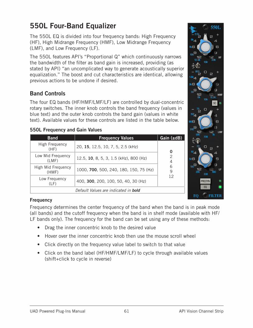
UAD Powered Plug-Ins Manual API Vision Channel Strip 61
550L Four-Band EqualizerThe 550L EQ is divided into four frequency bands: High Frequency (HF), High Midrange Frequency (HMF), Low Midrange Frequency (LMF), and Low Frequency (LF).
The 550L features API’s “Proportional Q” which continuously narrows the bandwidth of the filter as band gain is increased, providing (as stated by API) “an uncomplicated way to generate acoustically superior equalization.” The boost and cut characteristics are identical, allowing previous actions to be undone if desired.
Band ControlsThe four EQ bands (HF/HMF/LMF/LF) are controlled by dual-concentric rotary switches. The inner knob controls the band frequency (values in blue text) and the outer knob controls the band gain (values in white text). Available values for these controls are listed in the table below.
550L Frequency and Gain Values
Band Frequency Values Gain (±dB)High Frequency
(HF) 20, 15, 12.5, 10, 7, 5, 2.5 (kHz)0 2 4 6 9
12
Low Mid Frequency (LMF) 12.5, 10, 8, 5, 3, 1.5 (kHz), 800 (Hz)
High Mid Frequency (HMF) 1000, 700, 500, 240, 180, 150, 75 (Hz)
Low Frequency (LF) 400, 300, 200, 100, 50, 40, 30 (Hz)
Default Values are indicated in bold
FrequencyFrequency determines the center frequency of the band when the band is in peak mode (all bands) and the cutoff frequency when the band is in shelf mode (available with HF/LF bands only). The frequency for the band can be set using any of these methods:
• Drag the inner concentric knob to the desired value
• Hover over the inner concentric knob then use the mouse scroll wheel
• Click directly on the frequency value label to switch to that value
• Click on the band label (HF/HMF/LMF/LF) to cycle through available values (shift+click to cycle in reverse)
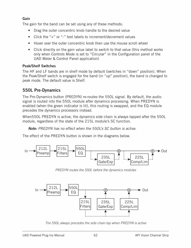
UAD Powered Plug-Ins Manual API Vision Channel Strip 62
GainThe gain for the band can be set using any of these methods:
• Drag the outer concentric knob handle to the desired value
• Click the “+” or “-” text labels to increment/decrement values
• Hover over the outer concentric knob then use the mouse scroll wheel
• Click directly on the gain value label to switch to that value (this method works only when Controls Mode is set to “Circular” in the Configuration panel of the UAD Meter & Control Panel application)
Peak/Shelf SwitchesThe HF and LF bands are in shelf mode by default (switches in “down” position). When the Peak/Shelf switch is engaged for the band (in “up” position), the band is changed to peak mode. The default value is Shelf.
550L Pre-DynamicsThe Pre-Dynamics button (PREDYN) re-routes the 550L signal. By default, the audio signal is routed into the 550L module after dynamics processing. When PREDYN is enabled (when the green indicator is lit), this routing is swapped, and the EQ module precedes the dynamics processors instead.
When550L PREDYN is active, the dynamics side chain is always tapped after the 550L module, regardless of the state of the 215L module’s SC function.
Note: PREDYN has no effect when the 550L’s SC button is active.
The effect of the PREDYN button is shown in the diagrams below.
PREDYN routes the 550L before the dynamics modules
The 550L always precedes the side chain tap when PREDYN is active
215LFilters
212LPreamp
550LEQ
235LGate/Exp
235LGate/Exp
235LGate/Exp
225LComp/Lim
225LComp/Lim
225LComp/Lim
235LGate/Exp
225LComp/Lim
235LGate/Exp
225LComp/Lim
215LFilters
212LPreamp
550LEQ
215LFilters
212LPreamp
550LEQ
215LFilters
212LPreamp
550LEQ
215LFilters
212LPreamp
550LEQIn
In
In
Out
Out
Out
In Out
In Out
235LGate/Exp
225LComp/Lim
215LFilters
212LPreamp
550LEQ
In Out
215LFilters
212LPreamp
550LEQ
235LGate/Exp
235LGate/Exp
235LGate/Exp
225LComp/Lim
225LComp/Lim
225LComp/Lim
235LGate/Exp
225LComp/Lim
235LGate/Exp
225LComp/Lim
215LFilters
212LPreamp
550LEQ
215LFilters
212LPreamp
550LEQ
215LFilters
212LPreamp
550LEQ
215LFilters
212LPreamp
550LEQIn
In
In
Out
Out
Out
In Out
In Out
235LGate/Exp
225LComp/Lim
215LFilters
212LPreamp
550LEQ
In Out

UAD Powered Plug-Ins Manual API Vision Channel Strip 63
550L SC (Dynamics Side Chain)This control enables the side chain function for the 550L EQ. When the 550L side chain is active, signal output from the 550L module is removed from the audio path, and is instead routed to control the 235L and 225L dynamics modules. The default value is Off.
Signal flow with 550L SC enabled
Note that both the 550L and 215L modules can both be routed simultaneously to the dynamics side chain. In this case, the 215L precedes the 550L in the side chain path, as shown below.
Signal flow with SC enabled in both 215L and 550L modules
550L EQThis button enables the 550L module. The module is active when the button’s green indicator is lit.
Note: UAD DSP load is reduced when this module is inactive (unless DSP Load-Lock is enabled).
215LFilters
212LPreamp
550LEQ
235LGate/Exp
235LGate/Exp
235LGate/Exp
225LComp/Lim
225LComp/Lim
225LComp/Lim
235LGate/Exp
225LComp/Lim
235LGate/Exp
225LComp/Lim
215LFilters
212LPreamp
550LEQ
215LFilters
212LPreamp
550LEQ
215LFilters
212LPreamp
550LEQ
215LFilters
212LPreamp
550LEQIn
In
In
Out
Out
Out
In Out
In Out
235LGate/Exp
225LComp/Lim
215LFilters
212LPreamp
550LEQ
In Out
215LFilters
212LPreamp
550LEQ
235LGate/Exp
235LGate/Exp
235LGate/Exp
225LComp/Lim
225LComp/Lim
225LComp/Lim
235LGate/Exp
225LComp/Lim
235LGate/Exp
225LComp/Lim
215LFilters
212LPreamp
550LEQ
215LFilters
212LPreamp
550LEQ
215LFilters
212LPreamp
550LEQ
215LFilters
212LPreamp
550LEQIn
In
In
Out
Out
Out
In Out
In Out
235LGate/Exp
225LComp/Lim
215LFilters
212LPreamp
550LEQ
In Out
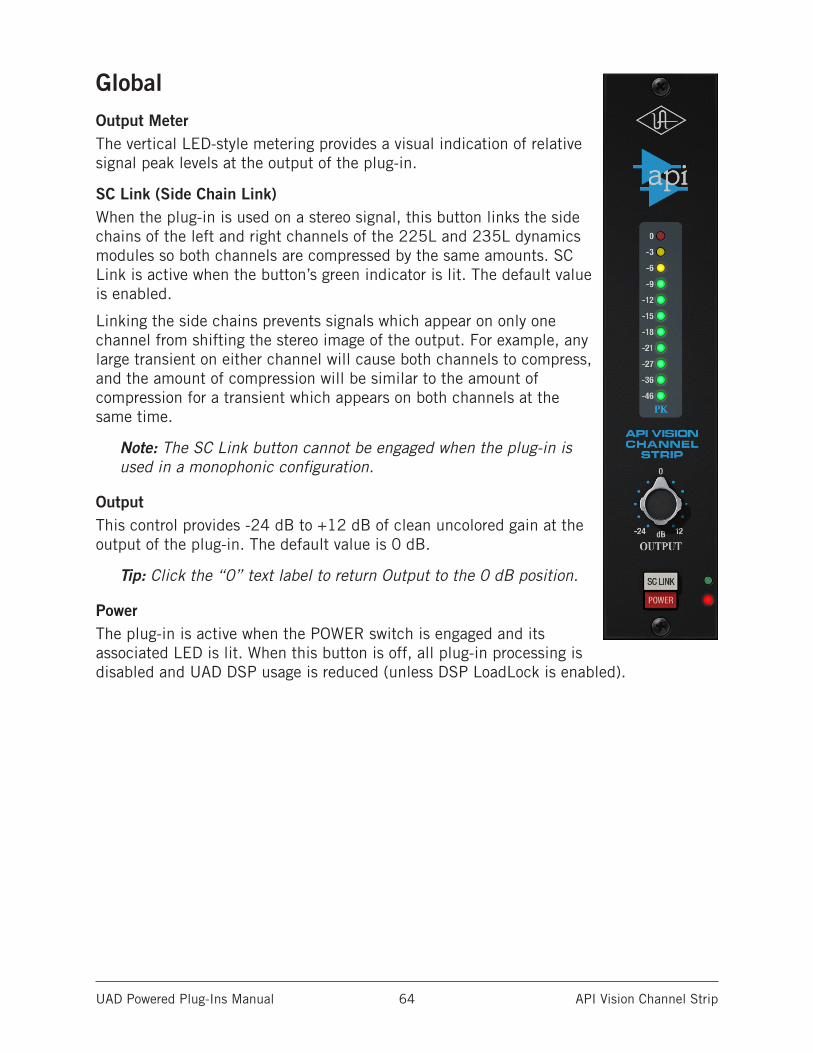
UAD Powered Plug-Ins Manual API Vision Channel Strip 64
GlobalOutput MeterThe vertical LED-style metering provides a visual indication of relative signal peak levels at the output of the plug-in.
SC Link (Side Chain Link)When the plug-in is used on a stereo signal, this button links the side chains of the left and right channels of the 225L and 235L dynamics modules so both channels are compressed by the same amounts. SC Link is active when the button’s green indicator is lit. The default value is enabled.
Linking the side chains prevents signals which appear on only one channel from shifting the stereo image of the output. For example, any large transient on either channel will cause both channels to compress, and the amount of compression will be similar to the amount of compression for a transient which appears on both channels at the same time.
Note: The SC Link button cannot be engaged when the plug-in is used in a monophonic configuration.
OutputThis control provides -24 dB to +12 dB of clean uncolored gain at the output of the plug-in. The default value is 0 dB.
Tip: Click the “0” text label to return Output to the 0 dB position.
PowerThe plug-in is active when the POWER switch is engaged and its associated LED is lit. When this button is off, all plug-in processing is disabled and UAD DSP usage is reduced (unless DSP LoadLock is enabled).
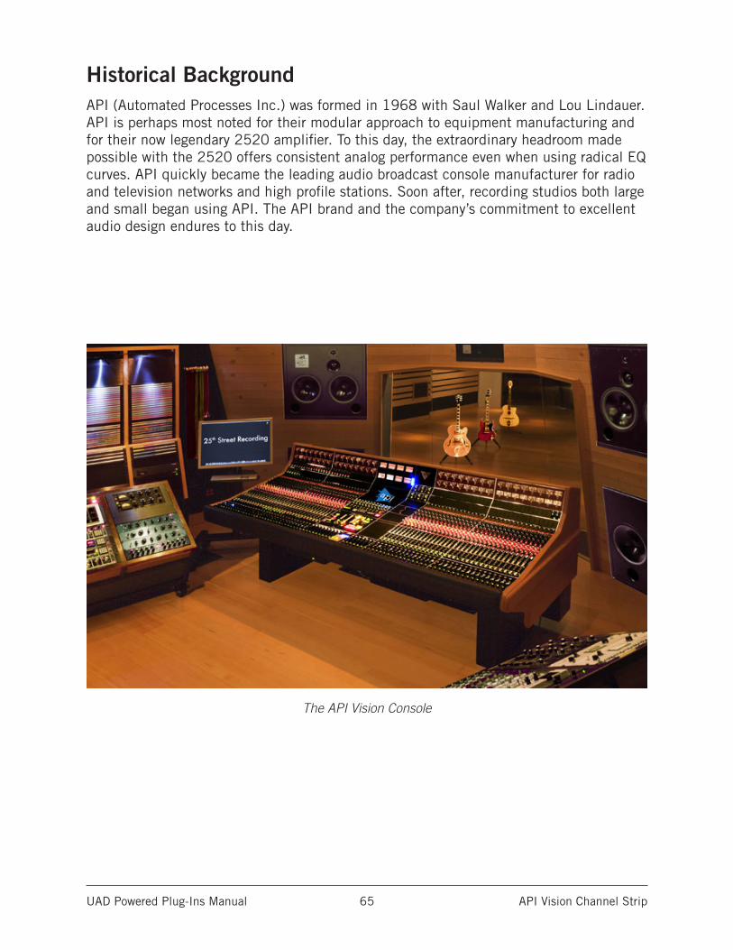
UAD Powered Plug-Ins Manual API Vision Channel Strip 65
Historical BackgroundAPI (Automated Processes Inc.) was formed in 1968 with Saul Walker and Lou Lindauer. API is perhaps most noted for their modular approach to equipment manufacturing and for their now legendary 2520 amplifier. To this day, the extraordinary headroom made possible with the 2520 offers consistent analog performance even when using radical EQ curves. API quickly became the leading audio broadcast console manufacturer for radio and television networks and high profile stations. Soon after, recording studios both large and small began using API. The API brand and the company’s commitment to excellent audio design endures to this day.
The API Vision Console
UAD Powered Plug-Ins Manual Bermuda Triangle 66
Bermuda Triangle
The King of Fuzz DistortionWhen it comes to unmistakable, classic fuzz/distortion, the Electro-Harmonix Big Muff reins supreme. A stompbox that defies classification and has never gone out of fashion, vintage Big Muffs are prized for powerfully fat sustain, aggressive attack, and an over-the-top sonic personality.
Inspired by the hallowed early ‘70s “triangle” version of the Big Muff, the Bermuda Triangle plug-in delivers the same bad-ass attitude and fiendish fuzz that has graced classic records and many-a-legend’s pedalboard for over four decades.
Now You Can:• Track through a faithful emulation of the legendary Electro-Harmonix Big Muff
with Apollo Twin, DUO, or QUAD
• Conjure violin-like sustain and powerful slabs of fuzz with the same pedal used by David Gilmour, Jack White, and Dan Auerbach
• Add colorful distortion/fuzz textures to guitars, synths, drums, and vocals at mix-down with any UAD-2 hardware
• Get the same circuit interaction, gain range, and clip points of a vintage Big Muff thanks to Unison technology for Apollo Twin, DUO, and QUAD
The Rise of the MuffThroughout the ‘70s, the Big Muff found its way onto classic tracks such as the Isley Brothers’ “Who’s That Lady (Part 1),” and the Carpenters’ “Goodbye to Love” — featur-ing a raging Big Muff plugged directly into the board!
Pink Floyd’s David Gilmour began using a Big Muff with 1976’s Animals, eventually using the pedal to conjure the beautifully lyrical sustain on The Wall’s “Comfortably Numb.” Sonic mavericks like Adrian Belew relied on the Muff to elicit beastly howls from a Stratocaster, and in the ‘90s, Smashing Pumpkins’ Billy Corgan and Dinosaur Jr.’s J. Mascis used the Big Muff to deliver bludgeoning, influential riffs. In more recent years, Jack White and the Black Keys’ Dan Auerbach have also used the Big Muff as their go-to distortion.
A Faithful Fuzz EmulationThe Bermuda Triangle plug-in expertly captures the original Big Muff’s huge sounding bass response and rich-yet-raspy character. Its simple Volume, Tone, Sustain control set allows you to easily and intuitively dial-in single-coil or humbucker-equipped guitars.
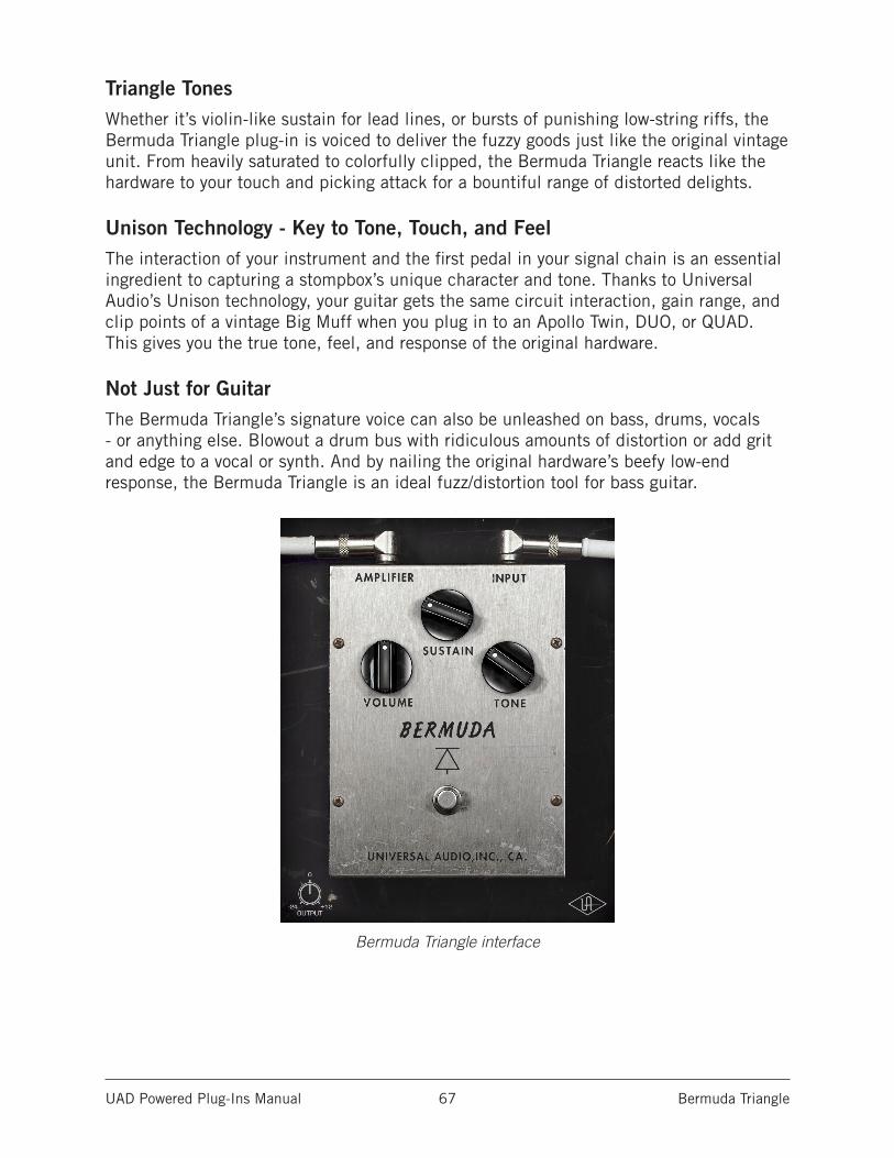
UAD Powered Plug-Ins Manual Bermuda Triangle 67
Triangle TonesWhether it’s violin-like sustain for lead lines, or bursts of punishing low-string riffs, the Bermuda Triangle plug-in is voiced to deliver the fuzzy goods just like the original vintage unit. From heavily saturated to colorfully clipped, the Bermuda Triangle reacts like the hardware to your touch and picking attack for a bountiful range of distorted delights.
Unison Technology - Key to Tone, Touch, and FeelThe interaction of your instrument and the first pedal in your signal chain is an essential ingredient to capturing a stompbox’s unique character and tone. Thanks to Universal Audio’s Unison technology, your guitar gets the same circuit interaction, gain range, and clip points of a vintage Big Muff when you plug in to an Apollo Twin, DUO, or QUAD. This gives you the true tone, feel, and response of the original hardware.
Not Just for GuitarThe Bermuda Triangle’s signature voice can also be unleashed on bass, drums, vocals - or anything else. Blowout a drum bus with ridiculous amounts of distortion or add grit and edge to a vocal or synth. And by nailing the original hardware’s beefy low-end response, the Bermuda Triangle is an ideal fuzz/distortion tool for bass guitar.
Bermuda Triangle interface
UAD Powered Plug-Ins Manual Bermuda Triangle 68
Using Bermuda Triangle
Standard DAW InsertsIn much the same way as some premier recording and mix engineers use stomp boxes in a mix, Bermuda Triangle can be used for creative purposes on any source signal by plac-ing it in any plug-in insert within a DAW. For typical guitar tones, follow the pedal with a guitar amp emulation (as one would with a hardware guitar pedal and amp).
Because the plug-in accurately models the original hardware’s high-impedance operating levels, precautions may need to be taken to avoid undesirable input clipping.
Note: Since Hi-Z devices typically operate at much lower signal levels than line-level devices, signal levels being routed into the pedal may need to be reduced to avoid undesirable input distortion.
Unison™ Technology with ApolloBermuda Triangle features Unison technology for integration with the high- impedance input hardware in Universal Audio’s Apollo audio interfaces. With Unison, Apollo’s Hi-Z inputs inherit all of the unique circuit interaction, gain
range, and clip points of the original guitar pedal.
Hi-Z Signal RoutingFor the most authentic stompbox tones, plug any high-impedance instrument (guitar, bass, etc.) into Apollo’s Hi-Z instrument input and place the pedal plug-in into the unique Unison INPUT insert on the same channel within Apollo’s Console application. If desired, follow the Unison pedal plug-in with another pedal or guitar amp emulation in Console’s standard insert slots.
This Hi-Z workflow enables near-zero latency monitoring or recording with the same input characteristics and dynamic response as the original pedal.
Note: This plug-in can be Unison-enabled with Apollo’s Mic or Line inputs. How-ever, because the original hardware has a high-impedance instrument input only, Apollo’s Hi-Z input and Unison insert will provide the most accurate sound and experience of the hardware pedal that is modeled.
Important: Unison is active only when the pedal plug-in is placed in the unique INPUT insert available on Hi-Z inputs within Apollo’s Console application. For complete Unison details, see the Apollo Software Manual.
Tactile ControlApollo’s front panel preamp knob can independently adjust the Volume, Sustain, and Output controls available within the Unison pedal plug-in via Gain Stage Mode. The con-trol being adjusted can be remotely switched via Apollo, so the control levels and their associated colorations can be tuned from the hardware knob for precise physical tactile control, all without using the Unison plug-in’s software interface.
UAD Powered Plug-Ins Manual Bermuda Triangle 69
Bermuda Triangle Controls
SustainSustain varies the amount of signal overdrive. Rotate the control clockwise to increase distortion and sustain.
VolumeVolume adjusts the pedal’s modeled output level. Rotate the control clockwise to increase the volume.
ToneTone adjusts the high-frequency content of the signal. Rotate the control clockwise to increase the filter amount, which reduces treble content.
PowerThe stomp switch toggles between plug-in enable and disable. Click the switch to toggle the Power state.
Like the original hardware, this is a true-bypass control. When disabled, the signal is not colored by the circuitry.
Tip: Power can also be toggled by clicking the UA diamond logo.
OutputOutput controls the clean (unmodeled) gain at the output of the plug-in. The available range is -24 dB to +12 dB.
Tip: Click the “0” label to return the control to zero dB.
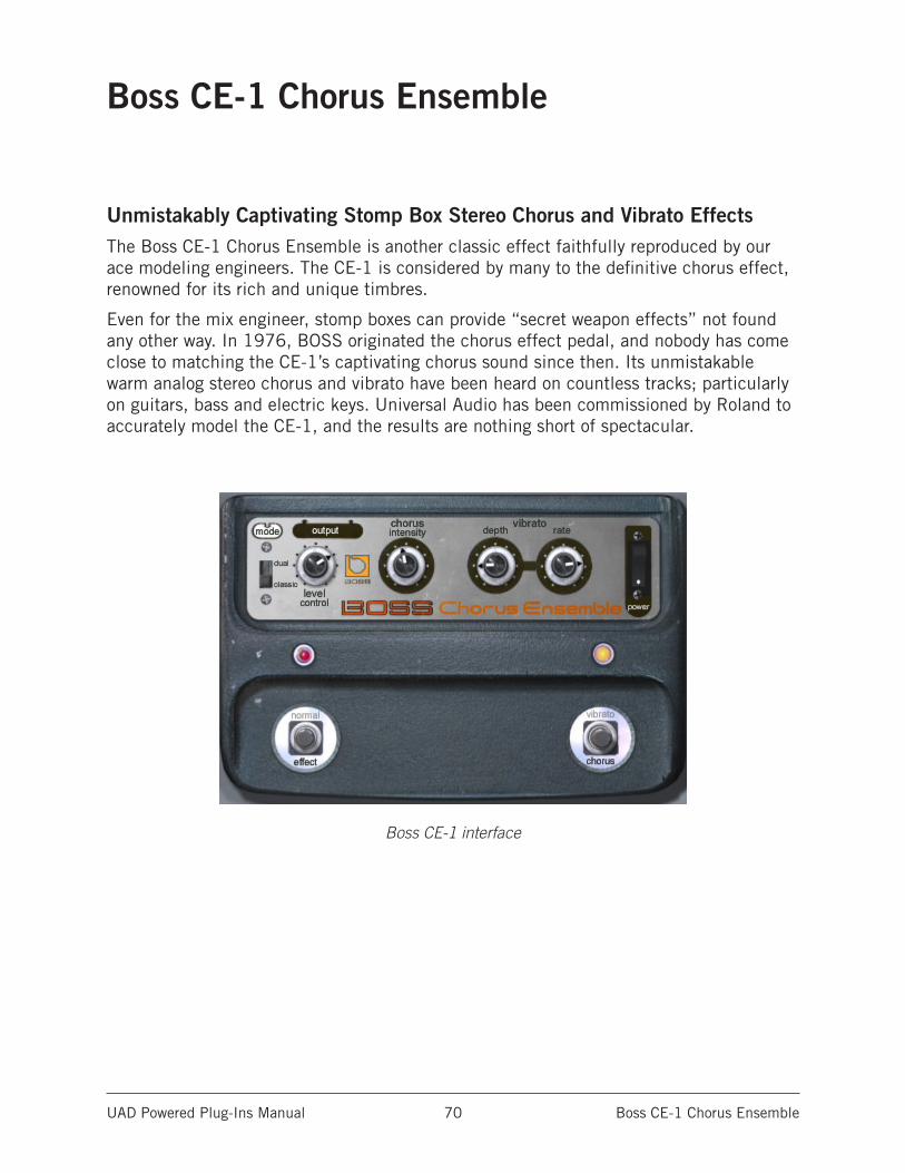
UAD Powered Plug-Ins Manual Boss CE-1 Chorus Ensemble 70
Boss CE-1 Chorus Ensemble
Unmistakably Captivating Stomp Box Stereo Chorus and Vibrato EffectsThe Boss CE-1 Chorus Ensemble is another classic effect faithfully reproduced by our ace modeling engineers. The CE-1 is considered by many to the definitive chorus effect, renowned for its rich and unique timbres.
Even for the mix engineer, stomp boxes can provide “secret weapon effects” not found any other way. In 1976, BOSS originated the chorus effect pedal, and nobody has come close to matching the CE-1’s captivating chorus sound since then. Its unmistakable warm analog stereo chorus and vibrato have been heard on countless tracks; particularly on guitars, bass and electric keys. Universal Audio has been commissioned by Roland to accurately model the CE-1, and the results are nothing short of spectacular.
Boss CE-1 interface
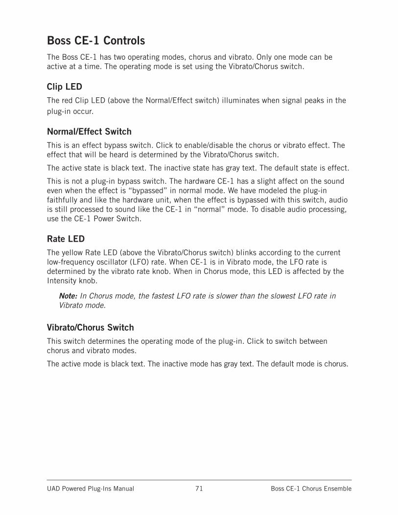
UAD Powered Plug-Ins Manual Boss CE-1 Chorus Ensemble 71
Boss CE-1 ControlsThe Boss CE-1 has two operating modes, chorus and vibrato. Only one mode can be active at a time. The operating mode is set using the Vibrato/Chorus switch.
Clip LEDThe red Clip LED (above the Normal/Effect switch) illuminates when signal peaks in the plug-in occur.
Normal/Effect SwitchThis is an effect bypass switch. Click to enable/disable the chorus or vibrato effect. The effect that will be heard is determined by the Vibrato/Chorus switch.
The active state is black text. The inactive state has gray text. The default state is effect.
This is not a plug-in bypass switch. The hardware CE-1 has a slight affect on the sound even when the effect is “bypassed” in normal mode. We have modeled the plug-in faithfully and like the hardware unit, when the effect is bypassed with this switch, audio is still processed to sound like the CE-1 in “normal” mode. To disable audio processing, use the CE-1 Power Switch.
Rate LEDThe yellow Rate LED (above the Vibrato/Chorus switch) blinks according to the current low-frequency oscillator (LFO) rate. When CE-1 is in Vibrato mode, the LFO rate is determined by the vibrato rate knob. When in Chorus mode, this LED is affected by the Intensity knob.
Note: In Chorus mode, the fastest LFO rate is slower than the slowest LFO rate in Vibrato mode.
Vibrato/Chorus SwitchThis switch determines the operating mode of the plug-in. Click to switch between chorus and vibrato modes.
The active mode is black text. The inactive mode has gray text. The default mode is chorus.
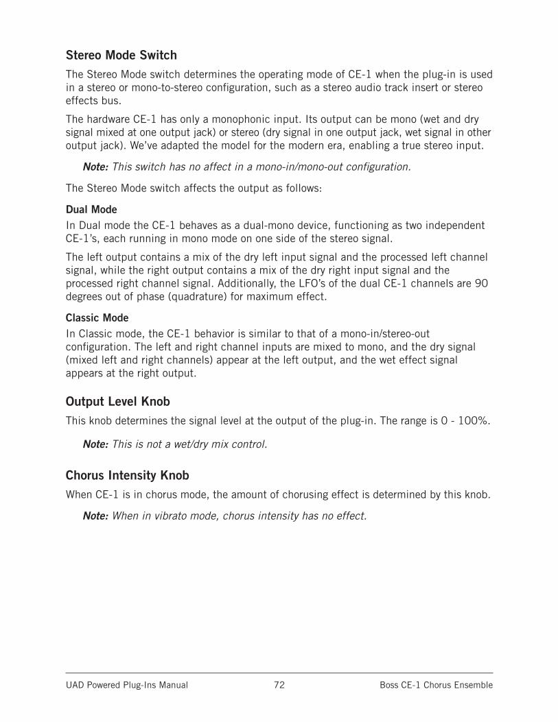
UAD Powered Plug-Ins Manual Boss CE-1 Chorus Ensemble 72
Stereo Mode SwitchThe Stereo Mode switch determines the operating mode of CE-1 when the plug-in is used in a stereo or mono-to-stereo configuration, such as a stereo audio track insert or stereo effects bus.
The hardware CE-1 has only a monophonic input. Its output can be mono (wet and dry signal mixed at one output jack) or stereo (dry signal in one output jack, wet signal in other output jack). We’ve adapted the model for the modern era, enabling a true stereo input.
Note: This switch has no affect in a mono-in/mono-out configuration.
The Stereo Mode switch affects the output as follows:
Dual ModeIn Dual mode the CE-1 behaves as a dual-mono device, functioning as two independent CE-1’s, each running in mono mode on one side of the stereo signal.
The left output contains a mix of the dry left input signal and the processed left channel signal, while the right output contains a mix of the dry right input signal and the processed right channel signal. Additionally, the LFO’s of the dual CE-1 channels are 90 degrees out of phase (quadrature) for maximum effect.
Classic ModeIn Classic mode, the CE-1 behavior is similar to that of a mono-in/stereo-out configuration. The left and right channel inputs are mixed to mono, and the dry signal (mixed left and right channels) appear at the left output, and the wet effect signal appears at the right output.
Output Level KnobThis knob determines the signal level at the output of the plug-in. The range is 0 - 100%.
Note: This is not a wet/dry mix control.
Chorus Intensity KnobWhen CE-1 is in chorus mode, the amount of chorusing effect is determined by this knob.
Note: When in vibrato mode, chorus intensity has no effect.
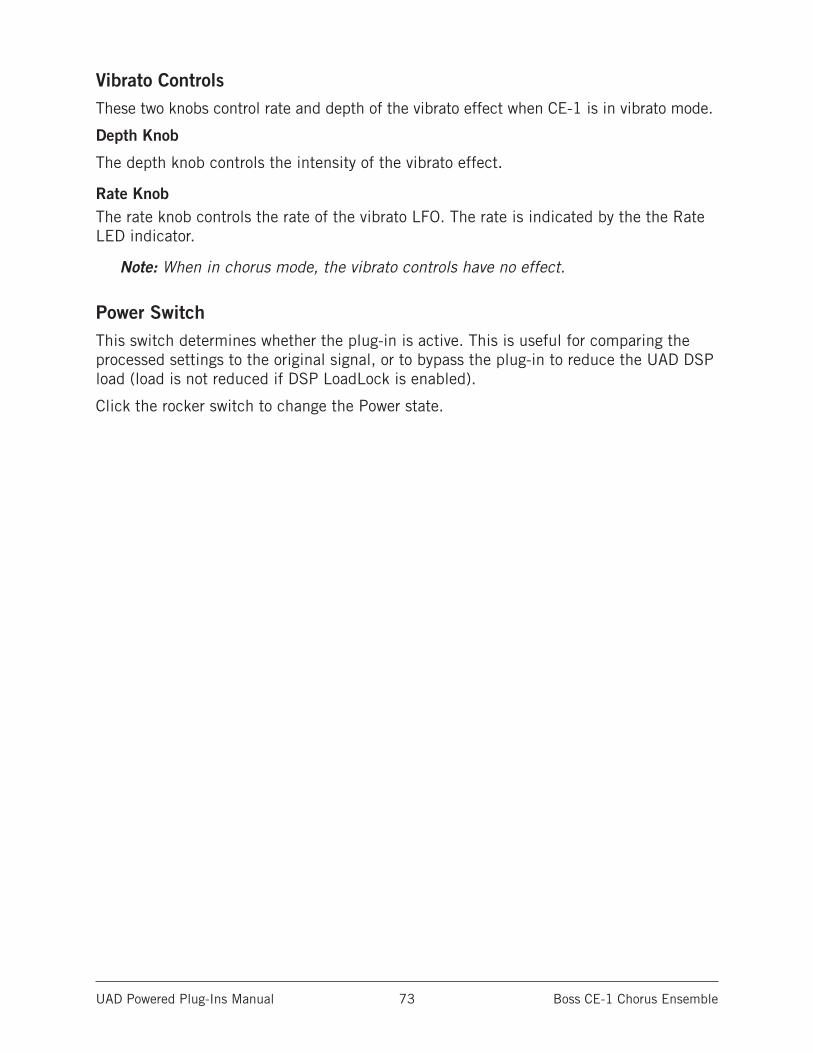
UAD Powered Plug-Ins Manual Boss CE-1 Chorus Ensemble 73
Vibrato ControlsThese two knobs control rate and depth of the vibrato effect when CE-1 is in vibrato mode.
Depth Knob
The depth knob controls the intensity of the vibrato effect.
Rate KnobThe rate knob controls the rate of the vibrato LFO. The rate is indicated by the the Rate LED indicator.
Note: When in chorus mode, the vibrato controls have no effect.
Power SwitchThis switch determines whether the plug-in is active. This is useful for comparing the processed settings to the original signal, or to bypass the plug-in to reduce the UAD DSP load (load is not reduced if DSP LoadLock is enabled).
Click the rocker switch to change the Power state.
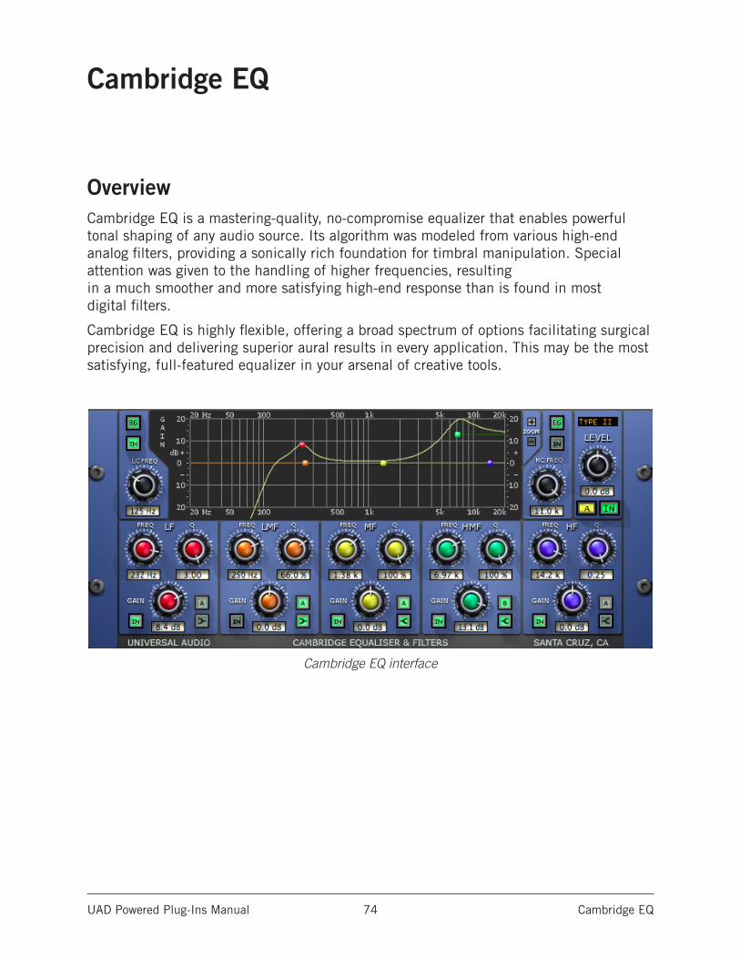
UAD Powered Plug-Ins Manual Cambridge EQ 74
Cambridge EQ
OverviewCambridge EQ is a mastering-quality, no-compromise equalizer that enables powerful tonal shaping of any audio source. Its algorithm was modeled from various high-end analog filters, providing a sonically rich foundation for timbral manipulation. Special attention was given to the handling of higher frequencies, resulting in a much smoother and more satisfying high-end response than is found in most digital filters.
Cambridge EQ is highly flexible, offering a broad spectrum of options facilitating surgical precision and delivering superior aural results in every application. This may be the most satisfying, full-featured equalizer in your arsenal of creative tools.
Cambridge EQ interface
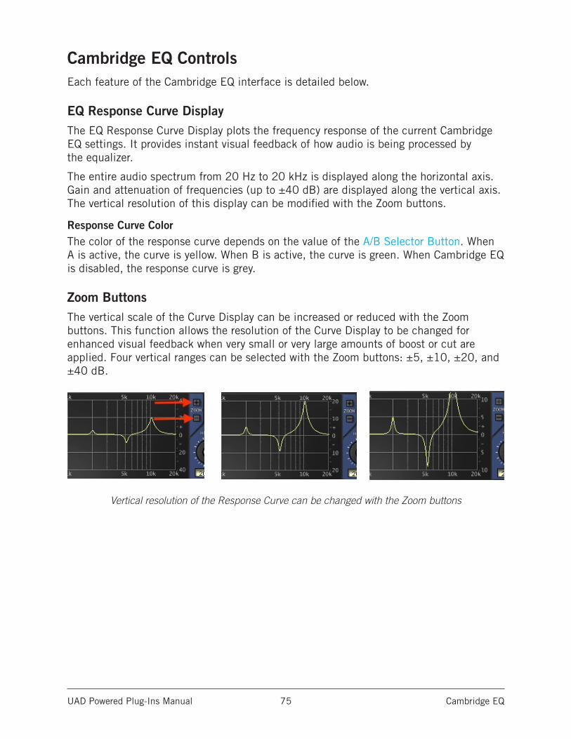
UAD Powered Plug-Ins Manual Cambridge EQ 75
Cambridge EQ ControlsEach feature of the Cambridge EQ interface is detailed below.
EQ Response Curve DisplayThe EQ Response Curve Display plots the frequency response of the current Cambridge EQ settings. It provides instant visual feedback of how audio is being processed by the equalizer.
The entire audio spectrum from 20 Hz to 20 kHz is displayed along the horizontal axis. Gain and attenuation of frequencies (up to ±40 dB) are displayed along the vertical axis. The vertical resolution of this display can be modified with the Zoom buttons.
Response Curve ColorThe color of the response curve depends on the value of the A/B Selector Button. When A is active, the curve is yellow. When B is active, the curve is green. When Cambridge EQ is disabled, the response curve is grey.
Zoom ButtonsThe vertical scale of the Curve Display can be increased or reduced with the Zoom buttons. This function allows the resolution of the Curve Display to be changed for enhanced visual feedback when very small or very large amounts of boost or cut are applied. Four vertical ranges can be selected with the Zoom buttons: ±5, ±10, ±20, and ±40 dB.
Vertical resolution of the Response Curve can be changed with the Zoom buttons
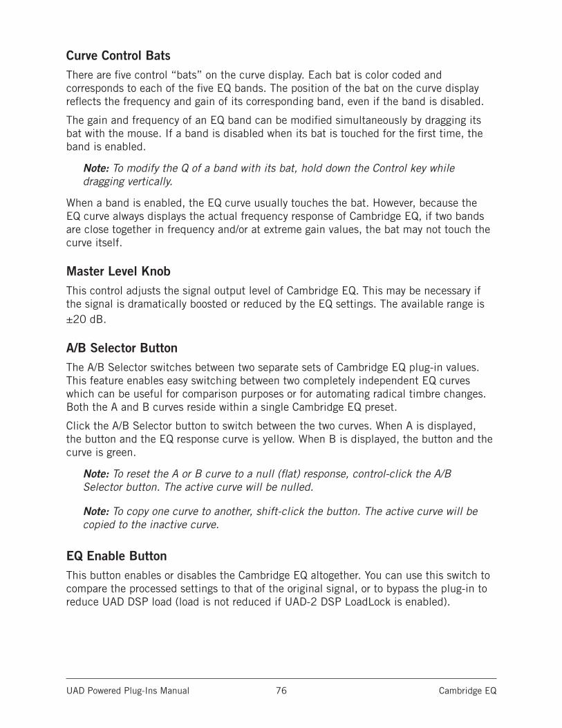
UAD Powered Plug-Ins Manual Cambridge EQ 76
Curve Control BatsThere are five control “bats” on the curve display. Each bat is color coded and corresponds to each of the five EQ bands. The position of the bat on the curve display reflects the frequency and gain of its corresponding band, even if the band is disabled.
The gain and frequency of an EQ band can be modified simultaneously by dragging its bat with the mouse. If a band is disabled when its bat is touched for the first time, the band is enabled.
Note: To modify the Q of a band with its bat, hold down the Control key while dragging vertically.
When a band is enabled, the EQ curve usually touches the bat. However, because the EQ curve always displays the actual frequency response of Cambridge EQ, if two bands are close together in frequency and/or at extreme gain values, the bat may not touch the curve itself.
Master Level KnobThis control adjusts the signal output level of Cambridge EQ. This may be necessary if the signal is dramatically boosted or reduced by the EQ settings. The available range is ±20 dB.
A/B Selector ButtonThe A/B Selector switches between two separate sets of Cambridge EQ plug-in values. This feature enables easy switching between two completely independent EQ curves which can be useful for comparison purposes or for automating radical timbre changes. Both the A and B curves reside within a single Cambridge EQ preset.
Click the A/B Selector button to switch between the two curves. When A is displayed, the button and the EQ response curve is yellow. When B is displayed, the button and the curve is green.
Note: To reset the A or B curve to a null (flat) response, control-click the A/B Selector button. The active curve will be nulled.
Note: To copy one curve to another, shift-click the button. The active curve will be copied to the inactive curve.
EQ Enable ButtonThis button enables or disables the Cambridge EQ altogether. You can use this switch to compare the processed settings to that of the original signal, or to bypass the plug-in to reduce UAD DSP load (load is not reduced if UAD-2 DSP LoadLock is enabled).
UAD Powered Plug-Ins Manual Cambridge EQ 77
Low Cut / High Cut FiltersThe Low Cut and High Cut filters are offered in addition to the five parametric/shelf bands. A wide range of filter types is provided to facilitate tonal creativity. Many filters that are available are represented.
Three controls are offered: Cut Type, Enable, and Frequency. Each control is detailed below.
Cut Type MenuThe Cut Type menu determines the sound of the low and high cut filters. To view the Cut Type menu, click and hold the green cut type button.
Four types of responses are provided: Coincident Pole, Bessel, Butterworth, and Elliptic. The numbers represent the filter order, i.e. Bessel 4 is a fourth-order filter. Each offers a different sound. To select a new cut response, drag to the desired response and release.
The responses are more gentle on filters with lower numbers, and get steeper and more aggressive as the numbers increase. The coincident-pole filters are first-order filters cascaded in series and offer gentle slopes. Bessel filters are popular because of their smooth phase characteristic with decent rejection. Butterworth filters offer even stronger rejection. The Elliptic setting is about as “brick wall” as you can get. Generally speaking, more phase shifting occurs as the response gets steeper.
Note: UAD DSP usage does increase some as the filters get stronger (unless UAD-2 DSP LoadLock is enabled).
Cut Enable ButtonThis button activates the cut filters. The filters are enabled when the “In” button is green. UAD DSP usage is slightly reduced when the cut filters are disabled (unless UAD-2 DSP LoadLock is enabled).
Cut Frequency KnobThis knob determines the cutoff frequency for the Cut filters. The available range is from 20 Hz - 5 kHz for the low cut filter, and 20 Hz - 20 kHz for the high cut filter.
UAD Powered Plug-Ins Manual Cambridge EQ 78
EQ BandsAll five of the EQ bands can be used in parametric or shelf mode. Each band has identical controls, the only difference is the frequency range values.
The function of the controls is similar in both parametric and shelf modes. The two modes are described separately (see Parametric EQ and Shelf EQ).
The EQ band controls
Enable ButtonEach band can be individually engaged with the Enable (IN) button. The button is green when the band is enabled. All bands default to disabled. To enable any band, click the Enable button.
You can use these buttons to compare the band settings to that of the original signal, or to bypass the individual band. UAD DSP usage is slightly decreased when a band is disabled (unless UAD-2 DSP LoadLock is enabled).
Frequency KnobThis parameter determines the center frequency to be boosted or attenuated by the Gain setting. The available range for each of the five bands is the same for both parametric and shelf modes. The ranges are shown in the table below.
Available Band Frequency Ranges
Low Frequencies (LF) 20 – 400 Hz
Low-Mid Frequencies (LMF) 30 – 600 Hz
Mid Frequencies (MF) 100 Hz – 6 kHz
High-Mid Frequencies (HMF) 900 Hz – 18 kHz
High Frequencies (HF) 2 kHz – 20 kHz
Gain KnobThis parameter determines the amount by which the frequency setting for the band is boosted or attenuated. The available range is ±20 dB.
Q (Bandwidth) KnobThe behavior of the Q parameter varies depending on the band mode and the gain. For this reason Q is detailed separately in the Parametric Q and Shelf Q sections.
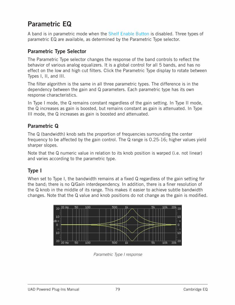
UAD Powered Plug-Ins Manual Cambridge EQ 79
Parametric EQA band is in parametric mode when the Shelf Enable Button is disabled. Three types of parametric EQ are available, as determined by the Parametric Type selector.
Parametric Type SelectorThe Parametric Type selector changes the response of the band controls to reflect the behavior of various analog equalizers. It is a global control for all 5 bands, and has no effect on the low and high cut filters. Click the Parametric Type display to rotate between Types I, II, and III.
The filter algorithm is the same in all three parametric types. The difference is in the dependency between the gain and Q parameters. Each parametric type has its own response characteristics.
In Type I mode, the Q remains constant regardless of the gain setting. In Type II mode, the Q increases as gain is boosted, but remains constant as gain is attenuated. In Type III mode, the Q increases as gain is boosted and attenuated.
Parametric QThe Q (bandwidth) knob sets the proportion of frequencies surrounding the center frequency to be affected by the gain control. The Q range is 0.25-16; higher values yield sharper slopes.
Note that the Q numeric value in relation to its knob position is warped (i.e. not linear) and varies according to the parametric type.
Type IWhen set to Type I, the bandwidth remains at a fixed Q regardless of the gain setting for the band; there is no Q/Gain interdependency. In addition, there is a finer resolution of the Q knob in the middle of its range. This makes it easier to achieve subtle bandwidth changes. Note that the Q value and knob positions do not change as the gain is modified.
Parametric Type I response
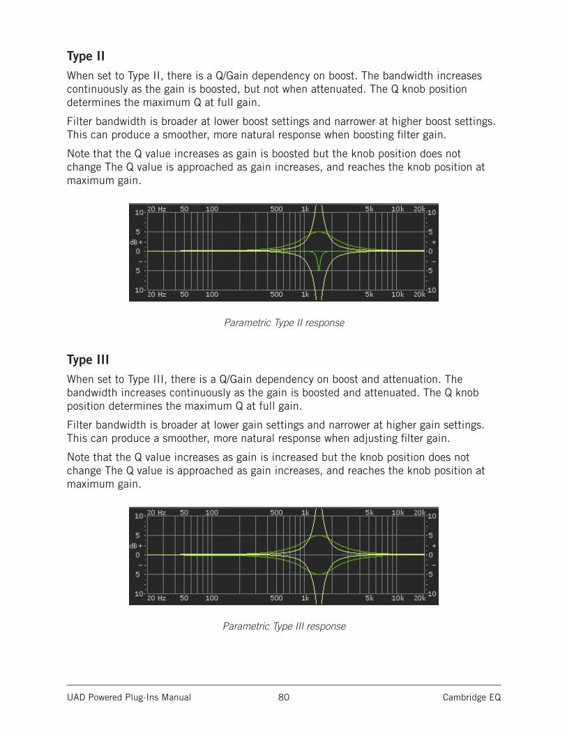
UAD Powered Plug-Ins Manual Cambridge EQ 80
Type IIWhen set to Type II, there is a Q/Gain dependency on boost. The bandwidth increases continuously as the gain is boosted, but not when attenuated. The Q knob position determines the maximum Q at full gain.
Filter bandwidth is broader at lower boost settings and narrower at higher boost settings. This can produce a smoother, more natural response when boosting filter gain.
Note that the Q value increases as gain is boosted but the knob position does not change The Q value is approached as gain increases, and reaches the knob position at maximum gain.
Parametric Type II response
Type IIIWhen set to Type III, there is a Q/Gain dependency on boost and attenuation. The bandwidth increases continuously as the gain is boosted and attenuated. The Q knob position determines the maximum Q at full gain.
Filter bandwidth is broader at lower gain settings and narrower at higher gain settings. This can produce a smoother, more natural response when adjusting filter gain.
Note that the Q value increases as gain is increased but the knob position does not change The Q value is approached as gain increases, and reaches the knob position at maximum gain.
Parametric Type III response
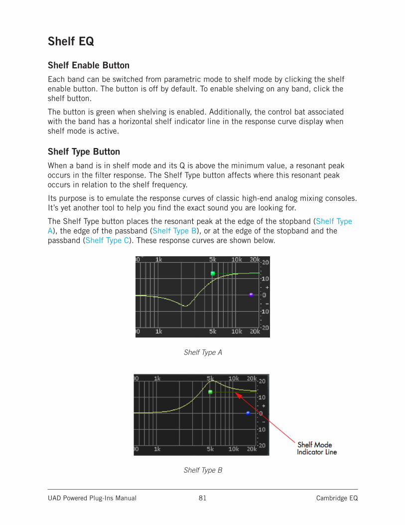
UAD Powered Plug-Ins Manual Cambridge EQ 81
Shelf EQ
Shelf Enable ButtonEach band can be switched from parametric mode to shelf mode by clicking the shelf enable button. The button is off by default. To enable shelving on any band, click the shelf button.
The button is green when shelving is enabled. Additionally, the control bat associated with the band has a horizontal shelf indicator line in the response curve display when shelf mode is active.
Shelf Type ButtonWhen a band is in shelf mode and its Q is above the minimum value, a resonant peak occurs in the filter response. The Shelf Type button affects where this resonant peak occurs in relation to the shelf frequency.
Its purpose is to emulate the response curves of classic high-end analog mixing consoles. It’s yet another tool to help you find the exact sound you are looking for.
The Shelf Type button places the resonant peak at the edge of the stopband (Shelf Type A), the edge of the passband (Shelf Type B), or at the edge of the stopband and the passband (Shelf Type C). These response curves are shown below.
Shelf Type A
Shelf Type B
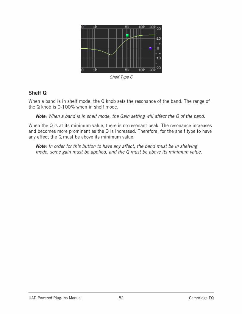
UAD Powered Plug-Ins Manual Cambridge EQ 82
Shelf Type C
Shelf QWhen a band is in shelf mode, the Q knob sets the resonance of the band. The range of the Q knob is 0-100% when in shelf mode.
Note: When a band is in shelf mode, the Gain setting will affect the Q of the band.
When the Q is at its minimum value, there is no resonant peak. The resonance increases and becomes more prominent as the Q is increased. Therefore, for the shelf type to have any effect the Q must be above its minimum value.
Note: In order for this button to have any affect, the band must be in shelving mode, some gain must be applied, and the Q must be above its minimum value.
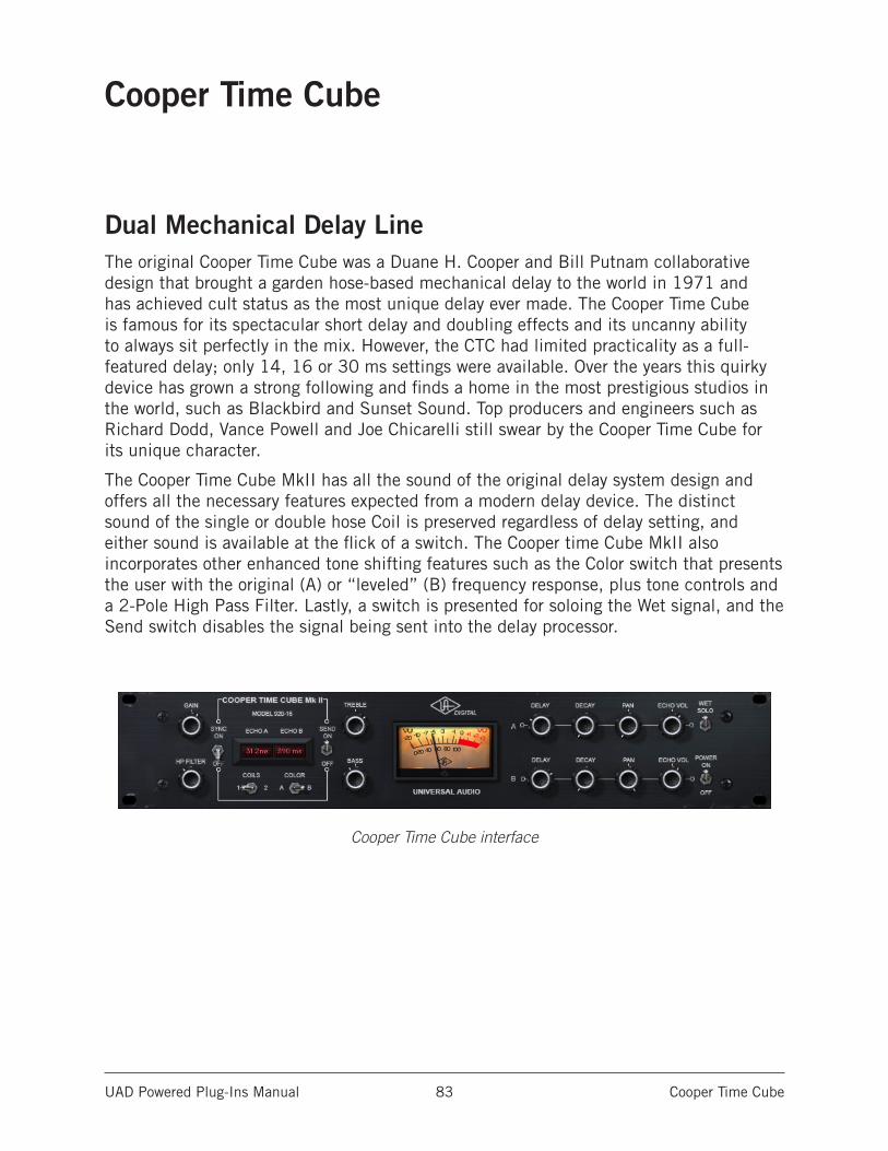
UAD Powered Plug-Ins Manual Cooper Time Cube 83
Cooper Time Cube
Dual Mechanical Delay LineThe original Cooper Time Cube was a Duane H. Cooper and Bill Putnam collaborative design that brought a garden hose-based mechanical delay to the world in 1971 and has achieved cult status as the most unique delay ever made. The Cooper Time Cube is famous for its spectacular short delay and doubling effects and its uncanny ability to always sit perfectly in the mix. However, the CTC had limited practicality as a full-featured delay; only 14, 16 or 30 ms settings were available. Over the years this quirky device has grown a strong following and finds a home in the most prestigious studios in the world, such as Blackbird and Sunset Sound. Top producers and engineers such as Richard Dodd, Vance Powell and Joe Chicarelli still swear by the Cooper Time Cube for its unique character.
The Cooper Time Cube MkII has all the sound of the original delay system design and offers all the necessary features expected from a modern delay device. The distinct sound of the single or double hose Coil is preserved regardless of delay setting, and either sound is available at the flick of a switch. The Cooper time Cube MkII also incorporates other enhanced tone shifting features such as the Color switch that presents the user with the original (A) or “leveled” (B) frequency response, plus tone controls and a 2-Pole High Pass Filter. Lastly, a switch is presented for soloing the Wet signal, and the Send switch disables the signal being sent into the delay processor.
Cooper Time Cube interface
UAD Powered Plug-Ins Manual Cooper Time Cube 84
Design OverviewThe original UREI/Universal Audio Model 920-16 Cooper Time Cube hardware has two audio channels, A and B. Each channel is transduced to/from a coiled length of plastic tubing which provides the acoustic “sound columns” that define its distinctive sonic character.
The coils for each channel are at fixed but different lengths, which define the available single delay times of 16 ms for channel A and 14 ms for channel B. The two channels can be cascaded in series via external routing, for a total available delay time of 30 ms at reasonable fidelity for its era, which (according to the original product brochure) “brings complete respectability to the heretofore marginally feasible acoustical delay line.”
The UAD Cooper Time Cube plug-in has all the vibe of the original, with modern feature enhancements. It is a true stereo plug-in with two independent delay processors. Each channel has its own set of controls, and there are global controls that affect the plug-in overall.
Cooper Time Cube Controls
Global ControlsThe global controls affect both channels of the processor simultaneously.
GainGain controls the signal input level to the plug-in for both A (left) and B (right) channels. Gain affects the combined wet and dry signals.
The available range is ±15 dB and the 12 o’clock position is unity gain.
HP FilterThe 12 dB per octave high pass filter is used to reduce low frequencies at the input to the delays when desired. The high pass filter affects the delayed (wet) signals only. The available frequency range is from 20 Hz to 12 kHz.
Turn the knob clockwise to reduce low frequencies into the delay processors. Full processor bandwidth is obtained with the knob in the fully counter-clockwise position.
UAD Powered Plug-Ins Manual Cooper Time Cube 85
Echo A/BThese two readouts display the current delay times of channels A and B. Displayed values are defined by the Delay A/B parameter. Delay values can be entered here directly using the text entry method.
When Sync mode is off, delay times are expressed in milliseconds. When Sync is on, delay times are expressed as a fractional bar value.
When the beat value is out of range, the value is displayed in parentheses. This occurs in Sync mode when the time of the note value exceeds 2500 ms (as defined by the current tempo of the host application).
SyncThis switch engages Sync mode for both channels of the plug-in. In Sync mode, delay times are synchronized to (and therefore dependent upon) the master tempo of the host application. When Sync is toggled, parameter units are converted between milliseconds and beats to the closest matching value.
See the “Tempo Sync” chapter in the UAD System Manual for detailed information about tempo synchronization.
SendSend determines whether or not signals are sent into the delay processors. When Send is ON, the input signals are delayed. When OFF, the delay inputs are muted.
CoilsWhen both coiled tubes of the original hardware are cascaded to increase the available delay time (when both channels are serially connected), the sonics are slightly different than when only one coil is used. The Coils switch toggles between these two sounds available on the hardware, regardless of the Delay value.
Tip: Longer decays are available when Coils value is set to 1.
ColorThe Color switch toggles between the original filter emphasis of the hardware in position A and the “leveled” filter in position B which allows for greater Decay ranges.
Unlike the other parameters, the A and B labels for Color are for reference only. They do not represent the left and right channels.
Note: Color can be subtle, and its affect can vary depending on the value of Coils and/or Decay.
UAD Powered Plug-Ins Manual Cooper Time Cube 86
TrebleTreble controls the high frequency response in the delayed portion of the signals. It does not affect the dry signal. Treble is a cut/boost control; it has no effect when in the 12 o’clock position.
BassBass controls the low frequency response in the delayed portion of the signals. It does not affect the dry signal. Bass is a cut/boost control; it has no effect when in the 12 o’clock position.
Wet SoloThe Wet Solo switch puts the Cooper Time Cube into 100% Wet mode. When Wet Solo is on (in the “up” position), it mutes the dry unprocessed signal.
Wet Solo is optimal when the plug-in is used on an effect group/bus that is configured for use with channel sends. When the plug-in is used on a channel insert, this control should be deactivated.
Note: Wet Solo is a global (per plug-in instance) control. Its value is saved within the host project/session file, but not within individual preset files.
PowerThe Power switch determines whether the plug-in is active. It’s useful for comparing the processed sound to the original signal.
MeterThe VU Meter provides a visual indication of the output level of the plug-in (the meter is not calibrated). The meter needle drops to minimum when the plug-in is disabled with the Power switch.
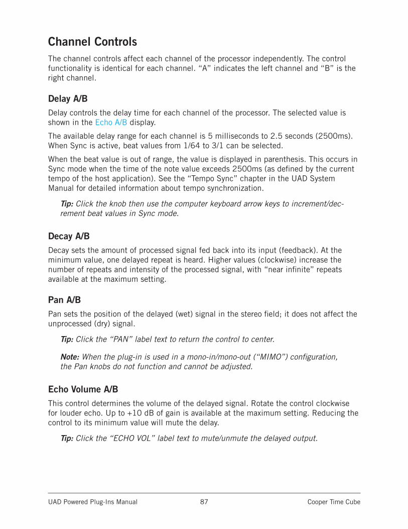
UAD Powered Plug-Ins Manual Cooper Time Cube 87
Channel ControlsThe channel controls affect each channel of the processor independently. The control functionality is identical for each channel. “A” indicates the left channel and “B” is the right channel.
Delay A/BDelay controls the delay time for each channel of the processor. The selected value is shown in the Echo A/B display.
The available delay range for each channel is 5 milliseconds to 2.5 seconds (2500ms). When Sync is active, beat values from 1/64 to 3/1 can be selected.
When the beat value is out of range, the value is displayed in parenthesis. This occurs in Sync mode when the time of the note value exceeds 2500ms (as defined by the current tempo of the host application). See the “Tempo Sync” chapter in the UAD System Manual for detailed information about tempo synchronization.
Tip: Click the knob then use the computer keyboard arrow keys to increment/dec-rement beat values in Sync mode.
Decay A/BDecay sets the amount of processed signal fed back into its input (feedback). At the minimum value, one delayed repeat is heard. Higher values (clockwise) increase the number of repeats and intensity of the processed signal, with “near infinite” repeats available at the maximum setting.
Pan A/BPan sets the position of the delayed (wet) signal in the stereo field; it does not affect the unprocessed (dry) signal.
Tip: Click the “PAN” label text to return the control to center.
Note: When the plug-in is used in a mono-in/mono-out (“MIMO”) configuration, the Pan knobs do not function and cannot be adjusted.
Echo Volume A/BThis control determines the volume of the delayed signal. Rotate the control clockwise for louder echo. Up to +10 dB of gain is available at the maximum setting. Reducing the control to its minimum value will mute the delay.
Tip: Click the “ECHO VOL” label text to mute/unmute the delayed output.
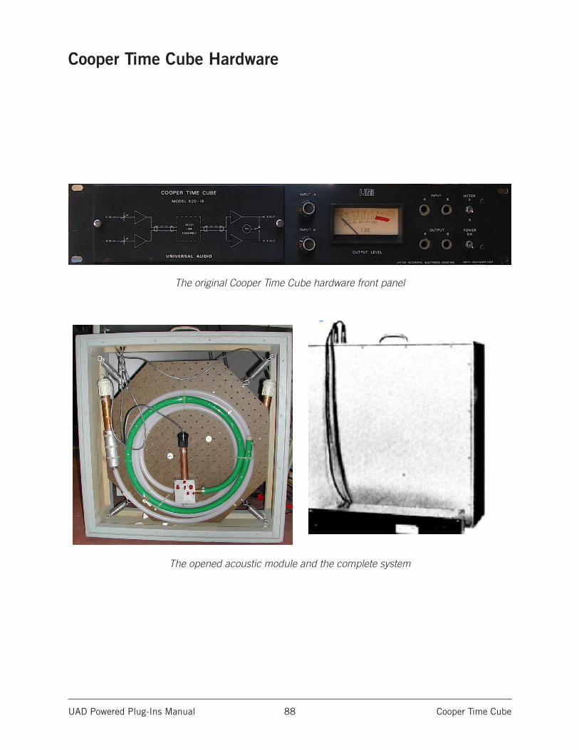
UAD Powered Plug-Ins Manual Cooper Time Cube 88
Cooper Time Cube Hardware
The original Cooper Time Cube hardware front panel
The opened acoustic module and the complete system
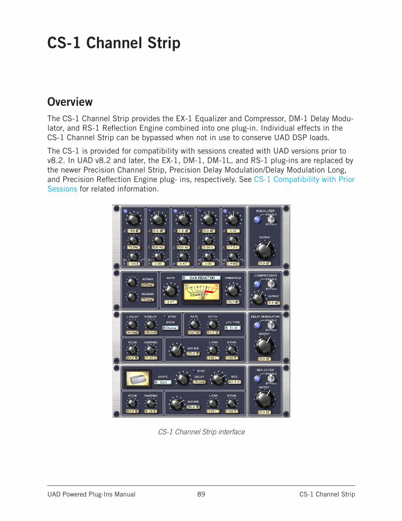
UAD Powered Plug-Ins Manual CS-1 Channel Strip 89
CS-1 Channel Strip
OverviewThe CS-1 Channel Strip provides the EX-1 Equalizer and Compressor, DM-1 Delay Modu-lator, and RS-1 Reflection Engine combined into one plug-in. Individual effects in the CS-1 Channel Strip can be bypassed when not in use to conserve UAD DSP loads.
The CS-1 is provided for compatibility with sessions created with UAD versions prior to v8.2. In UAD v8.2 and later, the EX-1, DM-1, DM-1L, and RS-1 plug-ins are replaced by the newer Precision Channel Strip, Precision Delay Modulation/Delay Modulation Long, and Precision Reflection Engine plug- ins, respectively. See CS-1 Compatibility with Prior Sessions for related information.
CS-1 Channel Strip interface
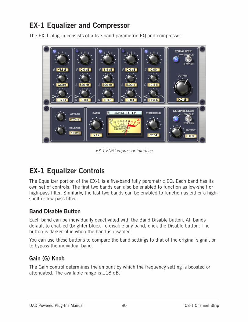
UAD Powered Plug-Ins Manual CS-1 Channel Strip 90
EX-1 Equalizer and CompressorThe EX-1 plug-in consists of a five-band parametric EQ and compressor.
EX-1 EQ/Compressor interface
EX-1 Equalizer ControlsThe Equalizer portion of the EX-1 is a five-band fully parametric EQ. Each band has its own set of controls. The first two bands can also be enabled to function as low-shelf or high-pass filter. Similarly, the last two bands can be enabled to function as either a high-shelf or low-pass filter.
Band Disable ButtonEach band can be individually deactivated with the Band Disable button. All bands default to enabled (brighter blue). To disable any band, click the Disable button. The button is darker blue when the band is disabled.
You can use these buttons to compare the band settings to that of the original signal, or to bypass the individual band.
Gain (G) KnobThe Gain control determines the amount by which the frequency setting is boosted or attenuated. The available range is ±18 dB.
UAD Powered Plug-Ins Manual CS-1 Channel Strip 91
Frequency (fc) KnobDetermines the center frequency to be boosted or attenuated by the Gain setting. The available range is 20 Hertz to 20 kiloHertz. When operating at sample rates less than 44.1kHz, the maximum frequency will be limited.
Bandwidth (Q) KnobSets the proportion of frequencies surrounding the center frequency to be affected. The Bandwidth range is 0.03-32; higher values yield sharper bands.
In either of the first two bands, when the Bandwidth value is at minimum the band becomes a low-shelf filter, and at maximum the band becomes a high-pass filter.
Similarly, in either of the last two bands, when the Bandwidth value is at minimum the band becomes a high-shelf filter, and at maximum the band becomes a low-pass filter.
Enable/Bypass SwitchGlobally enables or disables all bands of the Equalizer. You can use this switch to com-pare the EQ settings to the original signal or bypass the entire EQ section to reduce UAD DSP load (unless UAD-2 DSP LoadLock is enabled).
Output KnobAdjusts the signal output level of the plug-in. This may be necessary if the signal is dramatically boosted or reduced by the EQ and/or compressor settings.
UAD Powered Plug-Ins Manual CS-1 Channel Strip 92
EX-1 Compressor Controls
Attack KnobSets the amount of time that must elapse, once the input signal reaches the Threshold level, before compression will occur. The faster the Attack, the more rapidly compression is applied to signals above the Threshold. The range is 0.05 milliseconds to 100 ms.
Release KnobSets the amount of time it takes for compression to cease once the input signal drops below the Threshold level. Slower release times can smooth the transition that occurs when the signal dips below the threshold, especially useful for material with frequent peaks. However, if you set too large of a Release time, compression for sections of audio with loud signals may extend to lengthy sections of audio with lower signals. The range is 25 milliseconds to 2500 milliseconds (2.5 seconds).
Ratio KnobDetermines the amount of gain reduction used by the compression. For example, a value of 2 (expressed as a 2:1 ratio) reduces the signal by half, with an input signal of 20 dB being reduced to 10 dB. A value of 1 yields no compression. Values beyond 10 yield a limiting effect. The range is 1 to Infinity.
Threshold KnobSets the threshold level for the compression. Any signals that exceed this level are compressed. Signals below the level are unaffected. A Threshold of 0 dB yields no com-pression. The range is 0 dB to -60 dB.
As the Threshold control is increased and more compression occurs, output level is typi-cally reduced. However, the EX-1 provides an auto-makeup gain function to automatically compensate for reduced levels. Adjust the Output level control if more gain is desired.
Meter Pop-up MenuDetermines whether the VU Meter monitors the Input Level, Output Level, Gain Reduc-tion, or Meter Off. Click the menu above the meter display to select a different metering function.
Enable/Bypass SwitchEnables or disables the Compressor.You can use this switch to compare the compressor settings to that of the original signal or bypass the entire compressor section to reduce UAD DSP load (unless UAD-2 DSP LoadLock is enabled).
Compressor Output KnobAdjusts the signal output level of the plug-in.
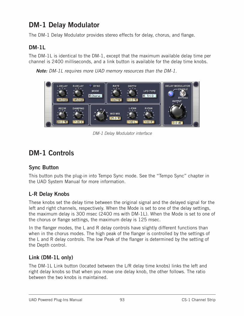
UAD Powered Plug-Ins Manual CS-1 Channel Strip 93
DM-1 Delay ModulatorThe DM-1 Delay Modulator provides stereo effects for delay, chorus, and flange.
DM-1LThe DM-1L is identical to the DM-1, except that the maximum available delay time per channel is 2400 milliseconds, and a link button is available for the delay time knobs.
Note: DM-1L requires more UAD memory resources than the DM-1.
DM-1 Delay Modulator interface
DM-1 Controls
Sync ButtonThis button puts the plug-in into Tempo Sync mode. See the “Tempo Sync” chapter in the UAD System Manual for more information.
L-R Delay KnobsThese knobs set the delay time between the original signal and the delayed signal for the left and right channels, respectively. When the Mode is set to one of the delay settings, the maximum delay is 300 msec (2400 ms with DM-1L). When the Mode is set to one of the chorus or flange settings, the maximum delay is 125 msec.
In the flanger modes, the L and R delay controls have slightly different functions than when in the chorus modes. The high peak of the flanger is controlled by the settings of the L and R delay controls. The low Peak of the flanger is determined by the setting of the Depth control.
Link (DM-1L only)The DM-1L Link button (located between the L/R delay time knobs) links the left and right delay knobs so that when you move one delay knob, the other follows. The ratio between the two knobs is maintained.
UAD Powered Plug-Ins Manual CS-1 Channel Strip 94
Mode Drop MenuDetermines the DM-1 effect mode. The available modes are: Chorus, Chorus180, QuadChorus, Flanger1, Flanger2, Dual Delay, and Ping Pong Delay. In addition to recon-figuring the DM-1’s settings, the Mode also determines the available parameter ranges for L/R Delay and Depth.
In Chorus mode, both oscillators (or modulating signals) are in phase.
In Chorus 180 mode, both oscillators (the modulating signals) are 180 degrees out of phase (inverted).
In QuadChorus mode, both oscillators (the modulating signals) are 90 degrees out of phase.
In Ping Pong delay mode, you will only get a ping-pong effect if you have a mono source feeding the DM-1 on a stereo group track or send effect. On a mono disk track, it works exactly like Dual Delay.
Rate KnobSets the modulation rate for the delayed signal, expressed in Hertz.
Depth KnobSets the modulation depth for the delayed signal, expressed as a percentage.
In Dual Delay and Ping Pong Delay modes, adjusting the Depth and Rate controls can offer some very otherworldly sounds.
LFO Type Drop MenuDetermines the LFO (low frequency oscillator) waveshape and phase used to modulate the delayed signal. The waveshape can be set to triangle or sine, each with a phase value of 0, 90, or 180 degrees.
Recirculation (RECIR) KnobSets the amount of processed signal fed back into its input. Higher values increase the number of delays and intensity of the processed signal.
Recirculation allows both positive and negative values. The polarity refers to the phase of the delays as compared to the original signal. If Recirculation displays a positive value, all the delays will be in phase with the source. If it displays a negative value, then the phase of the delays flips back and forth between in phase and out of phase.
In the flanger mode, Recir has the potential to make some very interesting sounds. Try turning RECIR fully clockwise or counter-clockwise, and set the delay to very short but different values.
The RECIR units are expressed as a percentage in all Modes except Dual Delay and Ping Pong. In these modes, RECIR values are expressed as T60 time, or the time before the signal drops 60 decibels.
UAD Powered Plug-Ins Manual CS-1 Channel Strip 95
Damping KnobThis low pass filter reduces the amount of high frequencies in the signal. Turn down this control to reduce the brightness. Higher values yield a brighter signal. Damping also mimics air absorption, or high frequency roll-off inherent in tape-based delay systems.
Wet/Dry Mix KnobThis control determines the balance between the delayed and original signal. Values greater than 50% emphasize the wet signal, and values less than 50% emphasize the dry signal. A value of 50% delivers equal signals. A value of 0% is just the dry signal.
Wet/Dry Mix allows both positive and negative values. The polarity refers to the phase of the delays as compared to the original signal. If a positive value is displayed, then all the delays will be in phase with the source. With a negative value, the delayed signal is flipped 180 degrees out of phase with the source.
L-Pan KnobSets the stereo position for the left channel, allowing you to adjust the width or balance of the stereo signal. For a mono signal, L-Pan behaves as the level control for the left delay tap.
R-Pan KnobSets the stereo position for the right channel, allowing you to adjust the width or balance of the stereo signal. For a mono signal, R-Pan behaves as the level control for the right delay tap.
Enable/Bypass SwitchEnables or disables the Delay Modulator. You can use this switch to compare the DM-1 settings to the original signal or bypass the entire DM-1 section to reduce UAD DSP load (load is not reduced if UAD-2 DSP LoadLock is enabled).
Output KnobAdjusts the signal output level of the plug-in.
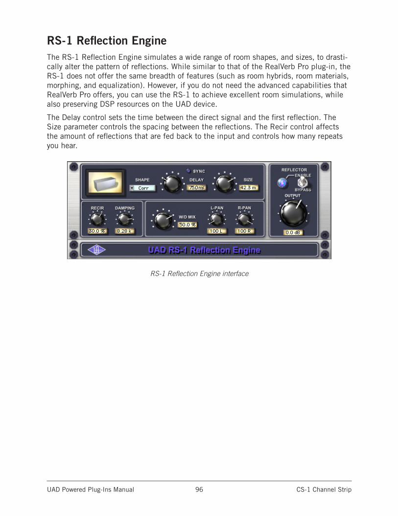
UAD Powered Plug-Ins Manual CS-1 Channel Strip 96
RS-1 Reflection EngineThe RS-1 Reflection Engine simulates a wide range of room shapes, and sizes, to drasti-cally alter the pattern of reflections. While similar to that of the RealVerb Pro plug-in, the RS-1 does not offer the same breadth of features (such as room hybrids, room materials, morphing, and equalization). However, if you do not need the advanced capabilities that RealVerb Pro offers, you can use the RS-1 to achieve excellent room simulations, while also preserving DSP resources on the UAD device.
The Delay control sets the time between the direct signal and the first reflection. The Size parameter controls the spacing between the reflections. The Recir control affects the amount of reflections that are fed back to the input and controls how many repeats you hear.
RS-1 Reflection Engine interface
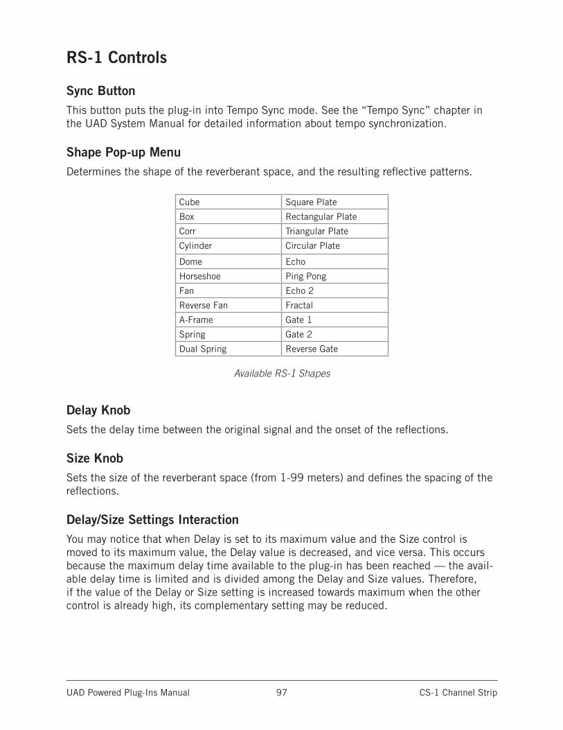
UAD Powered Plug-Ins Manual CS-1 Channel Strip 97
RS-1 Controls
Sync ButtonThis button puts the plug-in into Tempo Sync mode. See the “Tempo Sync” chapter in the UAD System Manual for detailed information about tempo synchronization.
Shape Pop-up MenuDetermines the shape of the reverberant space, and the resulting reflective patterns.
Cube Square Plate
Box Rectangular Plate
Corr Triangular Plate
Cylinder Circular Plate
Dome Echo
Horseshoe Ping Pong
Fan Echo 2
Reverse Fan Fractal
A-Frame Gate 1
Spring Gate 2
Dual Spring Reverse Gate
Available RS-1 Shapes
Delay KnobSets the delay time between the original signal and the onset of the reflections.
Size KnobSets the size of the reverberant space (from 1-99 meters) and defines the spacing of the reflections.
Delay/Size Settings InteractionYou may notice that when Delay is set to its maximum value and the Size control is moved to its maximum value, the Delay value is decreased, and vice versa. This occurs because the maximum delay time available to the plug-in has been reached — the avail-able delay time is limited and is divided among the Delay and Size values. Therefore, if the value of the Delay or Size setting is increased towards maximum when the other control is already high, its complementary setting may be reduced.
UAD Powered Plug-Ins Manual CS-1 Channel Strip 98
Recirculation (RECIR) KnobSets the amount of processed signal fed back into its input. Higher values increase the number of reverberations/delays and intensity of the processed signal.
Recirculation allows both positive and negative values. The polarity refers to the phase of the delays as compared to the original signal. If Recirculation displays a positive value, all the delays will be in phase with the source. If it displays a negative value, then the phase of the delays flips back and forth between in phase and out of phase.
Damping KnobThis low pass filter reduces the amount of high frequencies in the signal. Turn down this control to reduce the brightness. Higher values yield a brighter signal. Damping also mimics air absorption, or high frequency rolloff inherent in tape-based delay systems.
Wet/Dry Mix KnobThis control determines the balance between the delayed and original signal. Values greater than 50% emphasize the wet signal, and values less than 50% emphasize the dry signal.
Wet/Dry Mix allows both positive and negative values. The polarity refers to the phase of the delays as compared to the original signal. If a positive value is displayed, then all the delays will be in phase with the source. With a negative value, the delayed signal is flipped 180 degrees out of phase with the source.
L-Pan KnobSets the stereo position for the left channel, allowing you to adjust the width or balance of the stereo signal. For a mono signal, set both the L-Pan and R-Pan to the left.
R-Pan KnobSets the stereo position for the right channel, allowing you to adjust the width or balance of the stereo signal. For a mono signal, set both the L-Pan and R-Pan to the left.
Enable/Bypass SwitchEnables or disables the Reflection Engine. You can use this switch to compare the RS-1 settings to the original signal or bypass the entire RS-1 section to reduce UAD DSP load (load is not reduced if UAD-2 DSP LoadLock is enabled).
Output KnobAdjusts the relative output of the plug-in.
UAD Powered Plug-Ins Manual CS-1 Channel Strip 99
CS-1 Compatibility with Prior SessionsAs of UAD version 8.2, the Precision Mix Rack Collection plug-ins (Precision Channel Strip, Precision Delay Mod, Precision Delay Mod L, Precision Reflection Engine) replace the discontinued EX-1, DM-1, DM-1L, and RS-1 plug-ins, respectively.
When sessions containing the discontinued EX-1, DM-1, DM-1L, and RS-1 plug-ins are loaded in UAD v8.2 (and higher), the discontinued plug-ins in the session, along with their settings, are automatically migrated to their newer Precision Mix Rack Collection replacements.
The Precision Mix Rack Collection provides a modern interface, better controls, added features, and improved sonics versus the prior CS-1 sub-module plug-ins that they replace.
Note: Each individual plug-in title in the Precision Mix Rack Collection is doc- umented separately.
Migrating Prior SessionsIf a session created with UAD v8.1 or lower contains the CS-1 plug-in, and that session is subsequently loaded with UAD v8.2 or higher, the original/identical CS-1 is loaded and the original settings and sonics are maintained.
If a session created with UAD v8.1 or lower contains the EX-1, DM-1, DM-1L, or RS-1 plug-ins, and that session is then loaded under UAD v8.2 or higher, those prior plug-in instances are automatically replaced by their newer counterparts, and the original set-tings in the session are maintained.
UAD plug-in replacements when loading old sessions into UAD v8.2 and higher• EX-1 instances are replaced with Precision Channel Strip
• DM-1 instances are replaced with Precision Delay Mod
• DM-1L instances are replaced with Precision Delay Mod L
• RS-1 instances are replaced with Precision Reflection Engine
• CS-1 instances are not replaced (original CS-1 is loaded)
Note: Precision Mix Rack Collection plug-in settings cannot be loaded into CS-1, EX-1, DM-1, DM-1L, or RS-1.
UAD Powered Plug-Ins Manual CS-1 Channel Strip 100
Sonic DifferencesIn most cases (as detailed below), a migrated session with replaced EX-1/DM-1/DM-1L/RS-1 plug-ins will sound the same as, or subtly better than, the original session.
In some cases, the migrated session may be audibly different. The specific sonic differ-ences when migrating from EX-1/DM-1/DM-1L/RS-1 plug-ins to their replacements are detailed below.
Note: In all migration cases, it is possible to revert to the exact same prior son-ics (if desired) under UAD v8.2 and higher using the “Converting To Prior Sonics” procedure detailed later in this document.
EX-1 to Precision Channel StripImproved EQ filter design – This change subtly improves the lowest and highest EQ frequencies in the EX-1/CS-1 and improves the Q (bandwidth) symmetry at the highest frequencies.
Dynamics behavioral corrections at low ratio values – A knee calculation error at small ratios in the original EX-1/CS-1 compressor is resolved with Precision Channel Strip, resulting in higher plug-in output levels if the Dynamics module was engaged when migrated.
The approximate level increases in Precision Channel Strip compared to EX-1 at given ratios are: 2 dB at 1.5:1, 1.3 dB at 2:1, 0.5 dB at 3:1, 0.25 dB at 4:1, and 0.1 dB at 6:1.
RS-1 to Precision Reflection EngineEcho-based shapes are removed – The three echo-based shapes are un- available within Precision Reflection Engine due to underlying technical constraints. When migrating from RS-1, Echo, Echo 2, and Ping Pong shapes are replaced with the Cube shape in the Precision Reflection Engine, with an au- dibly different sonic result.
DM-1/DM-1L to Precision Delay Mod/Delay Mod LThere are no sonic differences between the discontinued DM-1/DM-1L and Precision Delay Mod/Delay Mod L plug-ins. The Precision Delay Mod/Delay Mod L has new features only.
UAD Powered Plug-Ins Manual CS-1 Channel Strip 101
Converting To Exact Prior SonicsIf a session containing the EX-1 or RS-1 plug-ins is migrated to UAD v8.2 (and higher), and the migrated session sounds different due to the sonic differences detailed above (and those differences are undesirable), the session can be converted to the exact same prior sonics, even when using UAD v8.2 (and higher).
UAD v8.2 and higher includes the original CS-1 plug-in, and CS-1 can load preset files from EX-1/RS-1, resulting in identical sonics.
Therefore, converting to exact prior sonics is accomplished by loading EX-1/RS-1 preset file settings created in UAD v8.1 (or lower) into CS-1 in UAD v8.2 (and higher).
Detailed steps for this process are provided on the following page.
Important: Migration sessions from UAD v8.1 and lower to UAD v8.2 and higher is automatic. In most cases, migrated sessions will simply sound the same or subtly better. The process on the next page is only necessary if: a) the migrated session contains EX-1/RS-1, AND b) the automatically-migrated session is sonically unsatisfactory or must sound identical to the pre-migrated session.
To convert a migrated session to exact prior sonics:1. Install UAD v8.1 (or lower) software.
2. Load the session(s) containing the EX-1, DM-1, DM-1L, or RS-1 plug-in(s).
3. Open the EX-1/DM-1/DM-1L/RS-1 plug-in that contains the settings you want to migrate.
4. Save the plug-in’s settings to disk as a preset file via the UAD Toolbar (click the folder icon at the lower left of the interface). Save the preset(s) to a convenient disk location; you’ll load these files in step 9.
5. Repeat steps 2 – 4 for each plug-in instance whose settings you want to migrate.
6. Install UAD v8.2 (or higher). Restart the computer after installation.
7. Load the session containing the EX-1/DM-1/DM-1L/RS-1 plug-ins you are migrating. The EX-1/DM-1/DM-1L/RS-1 plug-ins are automatically migrated to their Precision Mix Rack equivalents.
8. Replace the EX-1/DM-1/DM-1L/RS-1 plug-in(s) with the CS-1 plug-in.
9. Load the previously-saved EX-1/DM-1/DM-1L/RS-1 preset file into CS-1 via the UAD Toolbar. The original settings for the sub-module are imported into CS-1.
10. Disable the unused sub-modules on CS-1 to ensure they are not processing audio. For example, if loading an EX-1 preset into CS-1, disable the DM-1 and RS-1 mod-ules in CS-1.
11. Repeat steps 7 – 10 for each plug-in whose settings you want to migrate.
12. Save the session. Sonically identical migration is complete.
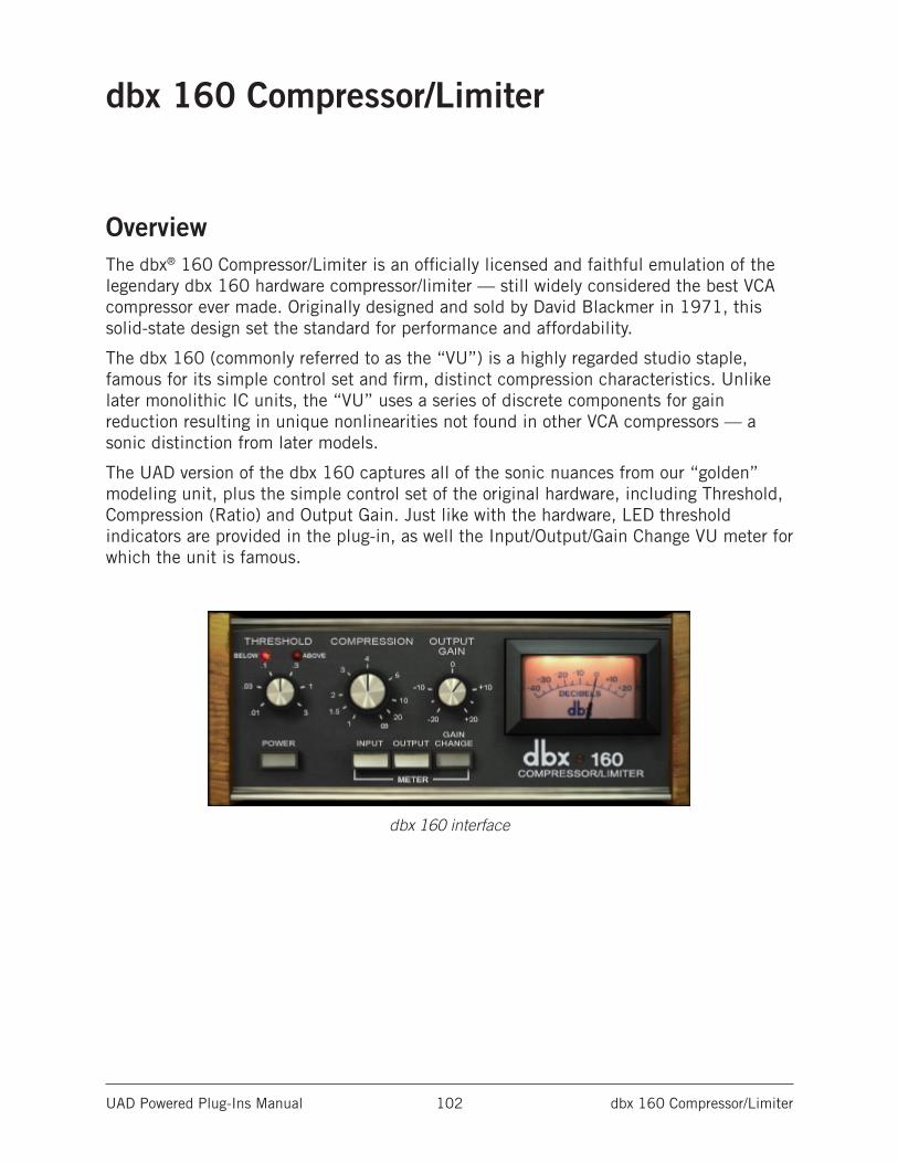
UAD Powered Plug-Ins Manual dbx 160 Compressor/Limiter 102
dbx 160 Compressor/Limiter
OverviewThe dbx® 160 Compressor/Limiter is an officially licensed and faithful emulation of the legendary dbx 160 hardware compressor/limiter — still widely considered the best VCA compressor ever made. Originally designed and sold by David Blackmer in 1971, this solid-state design set the standard for performance and affordability.
The dbx 160 (commonly referred to as the “VU”) is a highly regarded studio staple, famous for its simple control set and firm, distinct compression characteristics. Unlike later monolithic IC units, the “VU” uses a series of discrete components for gain reduction resulting in unique nonlinearities not found in other VCA compressors — a sonic distinction from later models.
The UAD version of the dbx 160 captures all of the sonic nuances from our “golden” modeling unit, plus the simple control set of the original hardware, including Threshold, Compression (Ratio) and Output Gain. Just like with the hardware, LED threshold indicators are provided in the plug-in, as well the Input/Output/Gain Change VU meter for which the unit is famous.
dbx 160 interface
UAD Powered Plug-Ins Manual dbx 160 Compressor/Limiter 103
dbx 160 ControlsThe minimal controls on the dbx 160 make it very simple to operate.
Threshold
KnobThe Threshold knob defines the level at which the onset of compression occurs. Incoming signals that exceed the Threshold level are compressed. Signals below the Threshold are unaffected.
The available range is from -55 dB to 0 dB. The numbers on the graphical interface indicate volts, as on the original hardware.
As the Threshold control is decreased and more compression occurs, output level is typically reduced. Adjust the Output Gain control to increase the output to compensate if desired.
BelowWhen the input signal is below the compression threshold value, the Below LED illuminates. No compression is occurring when Below is lit.
AboveThe Above LED illuminates when the input signal has exceeded the Threshold value, indicating that compression is occurring. The higher the signal is above the Threshold, the brighter the LED glows.
CompressionThe Compression parameter determines the ratio for the compressor. Less compression occurs at lower values. The available range is continuous, from 1.00:1 to Infinity:1. At values above approximately 10:1, the compressor behaves more like a peak-limiter.
Note: For compression to occur, signals must exceed the Threshold value.
Output GainOutput Gain controls the signal level that is output from the plug-in. The available range is ±20 dB.
Generally speaking, adjust the Output control after the desired amount of compression is achieved with the Threshold and Compression controls. Output does not affect the amount of compression.
Meter ButtonsThe Meter buttons define the mode of the VU Meter. The buttons do not change the sound of the signal processor. The active button has a darker appearance when compared to the inactive buttons.
UAD Powered Plug-Ins Manual dbx 160 Compressor/Limiter 104
VU MeterWhen set to Input, the VU Meter indicates the plug-in input level in dB. When set to Output, the VU Meter indicates the plug-in output level in dB. When set to Gain Change, the VU Meter indicates the amount of Gain Reduction in dB.
PowerThe Power switch determines whether the plug-in is active. Click the button to toggle the state. When the Power switch is in the Off (lighter) position, plug-in processing is disabled and UAD DSP usage is reduced (load is not reduced if UAD-2 DSP LoadLock is enabled).
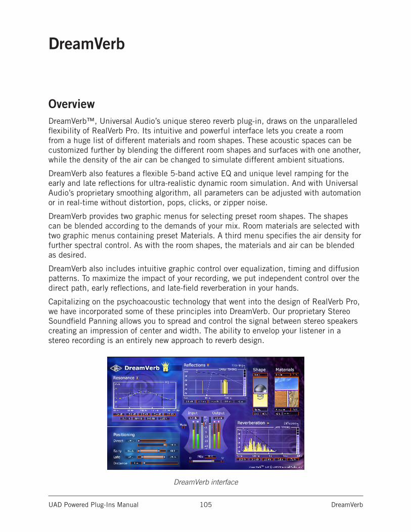
UAD Powered Plug-Ins Manual DreamVerb 105
DreamVerb
OverviewDreamVerb™, Universal Audio’s unique stereo reverb plug-in, draws on the unparalleled flexibility of RealVerb Pro. Its intuitive and powerful interface lets you create a room from a huge list of different materials and room shapes. These acoustic spaces can be customized further by blending the different room shapes and surfaces with one another, while the density of the air can be changed to simulate different ambient situations.
DreamVerb also features a flexible 5-band active EQ and unique level ramping for the early and late reflections for ultra-realistic dynamic room simulation. And with Universal Audio’s proprietary smoothing algorithm, all parameters can be adjusted with automation or in real-time without distortion, pops, clicks, or zipper noise.
DreamVerb provides two graphic menus for selecting preset room shapes. The shapes can be blended according to the demands of your mix. Room materials are selected with two graphic menus containing preset Materials. A third menu specifies the air density for further spectral control. As with the room shapes, the materials and air can be blended as desired.
DreamVerb also includes intuitive graphic control over equalization, timing and diffusion patterns. To maximize the impact of your recording, we put independent control over the direct path, early reflections, and late-field reverberation in your hands.
Capitalizing on the psychoacoustic technology that went into the design of RealVerb Pro, we have incorporated some of these principles into DreamVerb. Our proprietary Stereo Soundfield Panning allows you to spread and control the signal between stereo speakers creating an impression of center and width. The ability to envelop your listener in a stereo recording is an entirely new approach to reverb design.
DreamVerb interface
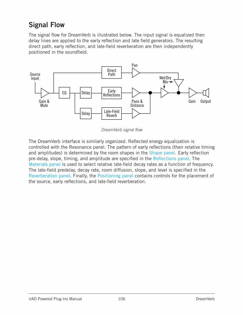
UAD Powered Plug-Ins Manual DreamVerb 106
Signal FlowThe signal flow for DreamVerb is illustrated below. The input signal is equalized then delay lines are applied to the early reflection and late field generators. The resulting direct path, early reflection, and late-field reverberation are then independently positioned in the soundfield.
DreamVerb signal flow
The DreamVerb interface is similarly organized. Reflected energy equalization is controlled with the Resonance panel. The pattern of early reflections (their relative timing and amplitudes) is determined by the room shapes in the Shape panel. Early reflection pre-delay, slope, timing, and amplitude are specified in the Reflections panel. The Materials panel is used to select relative late-field decay rates as a function of frequency. The late-field predelay, decay rate, room diffusion, slope, and level is specified in the Reverberation panel. Finally, the Positioning panel contains controls for the placement of the source, early reflections, and late-field reverberation.
SourceInput
Gain & Mute
Pan
Pans & Distance
Wet/DryMix
Gain Output
EQ Delay
Delay
Direct Path
Early Reflections
Late-FieldReverb
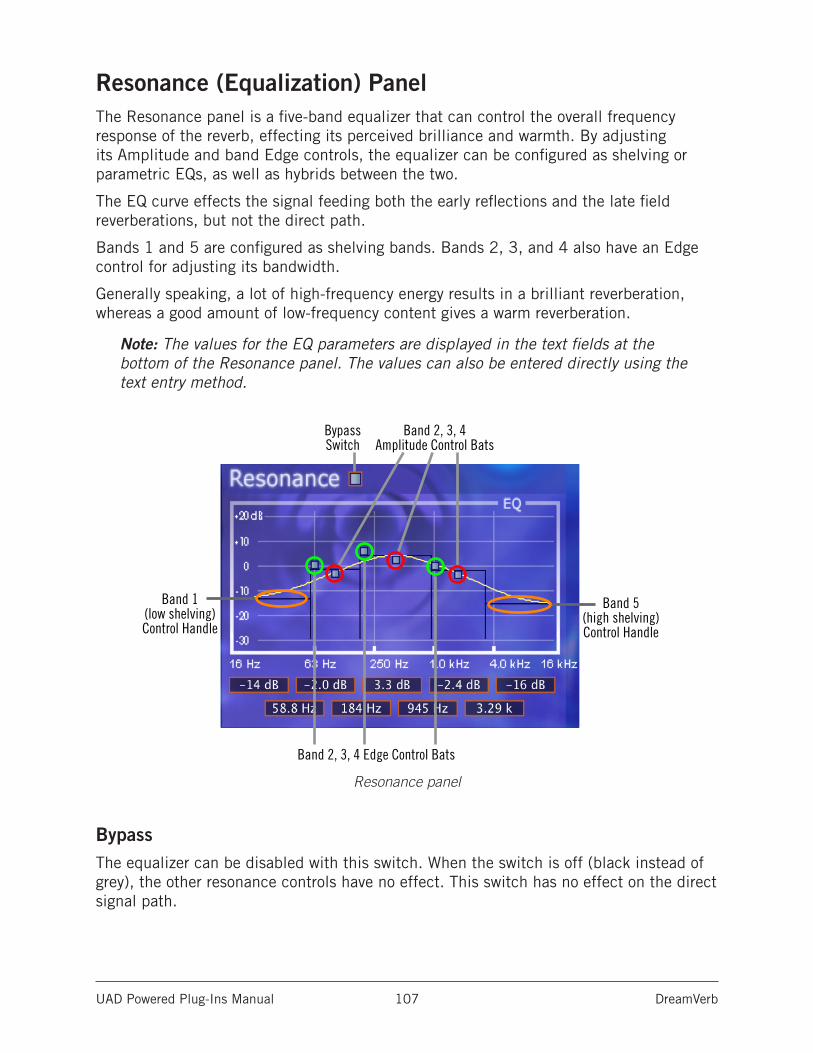
UAD Powered Plug-Ins Manual DreamVerb 107
Resonance (Equalization) PanelThe Resonance panel is a five-band equalizer that can control the overall frequency response of the reverb, effecting its perceived brilliance and warmth. By adjusting its Amplitude and band Edge controls, the equalizer can be configured as shelving or parametric EQs, as well as hybrids between the two.
The EQ curve effects the signal feeding both the early reflections and the late field reverberations, but not the direct path.
Bands 1 and 5 are configured as shelving bands. Bands 2, 3, and 4 also have an Edge control for adjusting its bandwidth.
Generally speaking, a lot of high-frequency energy results in a brilliant reverberation, whereas a good amount of low-frequency content gives a warm reverberation.
Note: The values for the EQ parameters are displayed in the text fields at the bottom of the Resonance panel. The values can also be entered directly using the text entry method.
Resonance panel
BypassThe equalizer can be disabled with this switch. When the switch is off (black instead of grey), the other resonance controls have no effect. This switch has no effect on the direct signal path.
BypassSwitch
Band 1 (low shelving) Control Handle
Band 2, 3, 4 Edge Control Bats
Band 5 (high shelving) Control Handle
Band 2, 3, 4Amplitude Control Bats
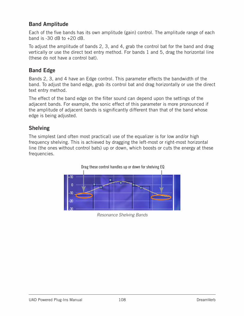
UAD Powered Plug-Ins Manual DreamVerb 108
Band AmplitudeEach of the five bands has its own amplitude (gain) control. The amplitude range of each band is -30 dB to +20 dB.
To adjust the amplitude of bands 2, 3, and 4, grab the control bat for the band and drag vertically or use the direct text entry method. For bands 1 and 5, drag the horizontal line (these do not have a control bat).
Band EdgeBands 2, 3, and 4 have an Edge control. This parameter effects the bandwidth of the band. To adjust the band edge, grab its control bat and drag horizontally or use the direct text entry method.
The effect of the band edge on the filter sound can depend upon the settings of the adjacent bands. For example, the sonic effect of this parameter is more pronounced if the amplitude of adjacent bands is significantly different than that of the band whose edge is being adjusted.
ShelvingThe simplest (and often most practical) use of the equalizer is for low and/or high frequency shelving. This is achieved by dragging the left-most or right-most horizontal line (the ones without control bats) up or down, which boosts or cuts the energy at these frequencies.
Resonance Shelving Bands
Drag these control handles up or down for shelving EQ
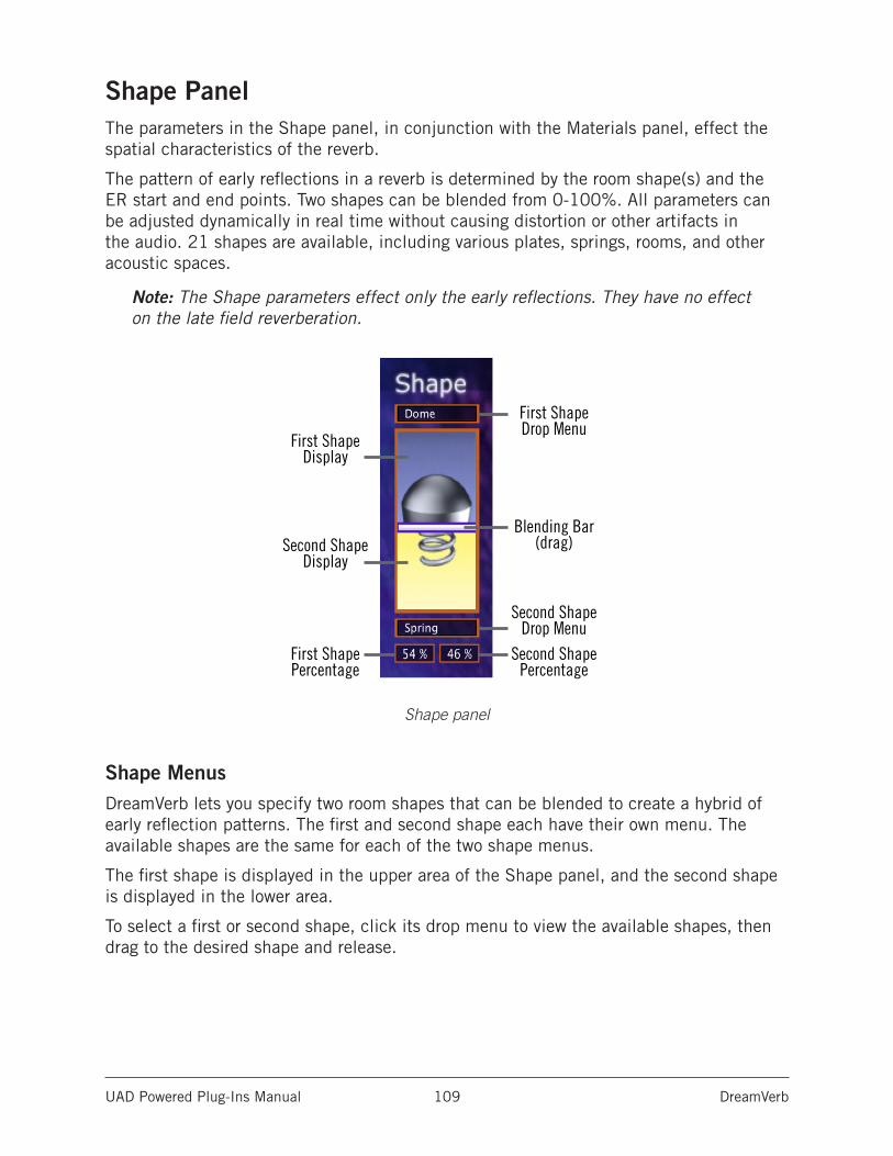
UAD Powered Plug-Ins Manual DreamVerb 109
Shape PanelThe parameters in the Shape panel, in conjunction with the Materials panel, effect the spatial characteristics of the reverb.
The pattern of early reflections in a reverb is determined by the room shape(s) and the ER start and end points. Two shapes can be blended from 0-100%. All parameters can be adjusted dynamically in real time without causing distortion or other artifacts in the audio. 21 shapes are available, including various plates, springs, rooms, and other acoustic spaces.
Note: The Shape parameters effect only the early reflections. They have no effect on the late field reverberation.
Shape panel
Shape MenusDreamVerb lets you specify two room shapes that can be blended to create a hybrid of early reflection patterns. The first and second shape each have their own menu. The available shapes are the same for each of the two shape menus.
The first shape is displayed in the upper area of the Shape panel, and the second shape is displayed in the lower area.
To select a first or second shape, click its drop menu to view the available shapes, then drag to the desired shape and release.
First ShapeDisplay
Second ShapeDisplay
First ShapePercentage
Second ShapePercentage
First Shape Drop Menu
Blending Bar(drag)
Second Shape Drop Menu
UAD Powered Plug-Ins Manual DreamVerb 110
Shape Blending BarThe Shape Blending Bar is used to blend the two shapes together at any ratio. The two shapes are not just mixed together with this parameter; the early reflections algorithm itself is modified by blending.
Blend the early reflection patterns of the two rooms by dragging the Blending Bar. Drag the bar to the bottom to emphasize the first shape; drag to the top to emphasize the second shape.
The relative percentages of the two rooms appear at the bottom of the Shape panel. To use only one room shape, drag the Blending Bar so a shape is set to 100%.
The resulting early reflection pattern is displayed at the top of the Reflections panel, where each reflection is represented by a yellow vertical line with a height indicating its arrival energy, and a location indicating its arrival time.
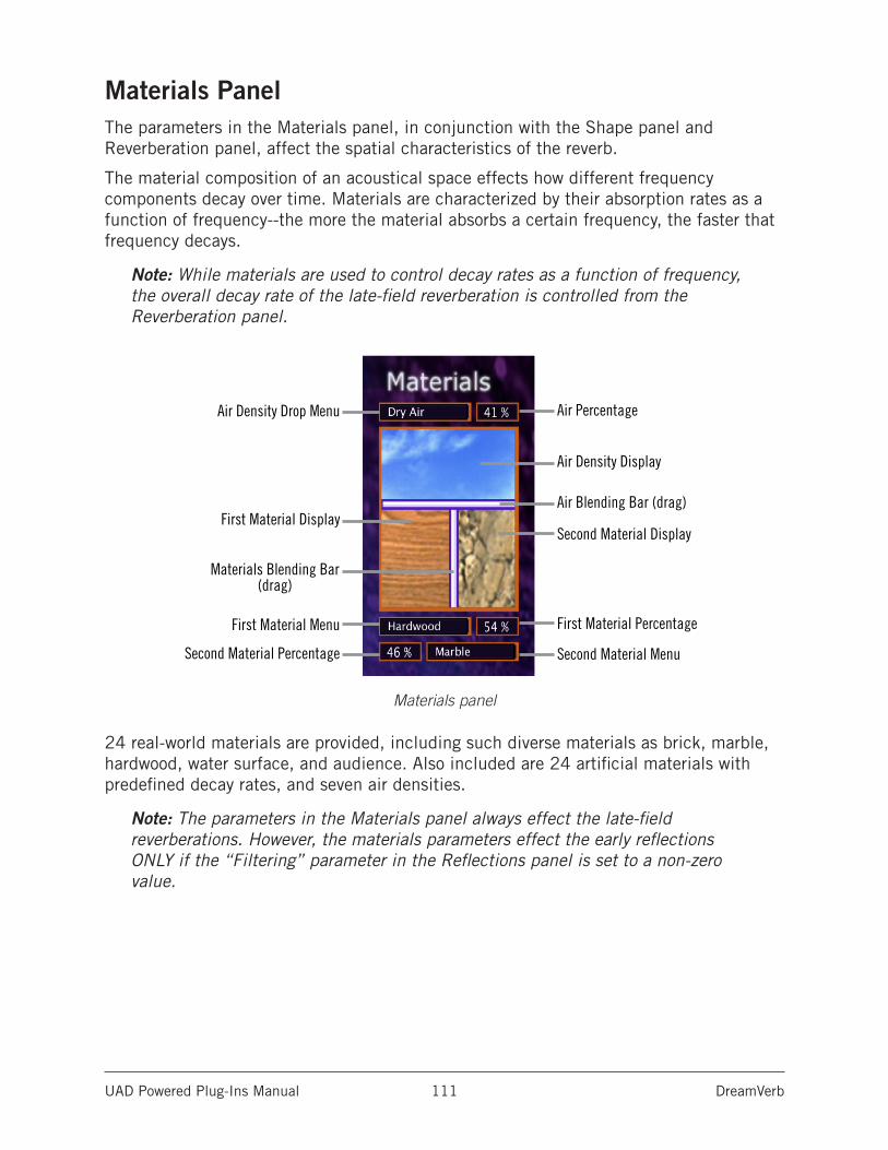
UAD Powered Plug-Ins Manual DreamVerb 111
Materials PanelThe parameters in the Materials panel, in conjunction with the Shape panel and Reverberation panel, affect the spatial characteristics of the reverb.
The material composition of an acoustical space effects how different frequency components decay over time. Materials are characterized by their absorption rates as a function of frequency--the more the material absorbs a certain frequency, the faster that frequency decays.
Note: While materials are used to control decay rates as a function of frequency, the overall decay rate of the late-field reverberation is controlled from the Reverberation panel.
Materials panel
24 real-world materials are provided, including such diverse materials as brick, marble, hardwood, water surface, and audience. Also included are 24 artificial materials with predefined decay rates, and seven air densities.
Note: The parameters in the Materials panel always effect the late-field reverberations. However, the materials parameters effect the early reflections ONLY if the “Filtering” parameter in the Reflections panel is set to a non-zero value.
Air Density Drop Menu
First Material Display
First Material Menu
Materials Blending Bar(drag)
Second Material Percentage Second Material Menu
First Material Percentage
Air Percentage
Air Density Display
Air Blending Bar (drag)
Second Material Display
UAD Powered Plug-Ins Manual DreamVerb 112
Materials MenusDreamVerb lets you specify two room materials, which can be blended to create a hybrid of absorption and reflection properties. The first and second room material each has its own menu. The available materials are the same for each of the two materials menus.
The first material is displayed in the lower left area of the Materials panel, and the second material is displayed in the lower right area.
To select the first or second material, click its drop menu to view the available materials, then drag to the desired material and release.
In addition to the “perfect” materials marked with a K, DreamVerb provides “J” materials that are not found in RealVerb Pro. These perform the inverse of the “K” materials. The materials marked with a J preferentially absorb low frequencies; they give the selected decay time at high frequencies, and a much shorter decay time at low frequencies.
Air Density MenuDreamVerb allows you to specify the density of the air in the reverberant space with this menu, enabling another dimension of sonic control.
The more dense the air is, the more it absorbs high frequencies. At the top of the Air Density menu is Ideal Gas, where no frequencies are absorbed. The air quality increases in density with each selection as you go down the menu.
Inverse Air and Inverse Thick Fog absorb more low frequencies instead of high frequencies.
Materials Blending BarsThe Materials Blending Bars are used to blend the three materials together at any ratio. The materials are not just mixed together with the bars; the reverberation algorithm itself is modified by blending.
Materials BlendingBlend the two materials by dragging the vertical Blending Bar horizontally. Drag the bar to the right to emphasize the first material; drag to the left to emphasize the second material.
The relative percentages of the two materials appear next to each menu in the Materials panel. To use only one material, drag the Blending Bar so a material is set to 100%.
Air BlendingBlend the air density with the materials by dragging the horizontal Blending Bar vertically. Drag the bar to the top to emphasize the solid materials; drag to the bottom to emphasize the air.
The percentage of air used appears next to the Air Density menu. To use only solid materials, drag the horizontal Blending Bar to the top so air is set to 0%. To use only air, drag the horizontal Blending Bar to the bottom so air is set to 100%.
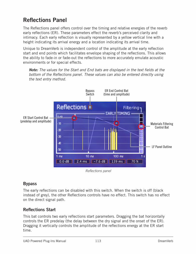
UAD Powered Plug-Ins Manual DreamVerb 113
Reflections PanelThe Reflections panel offers control over the timing and relative energies of the reverb early reflections (ER). These parameters effect the reverb’s perceived clarity and intimacy. Each early reflection is visually represented by a yellow vertical line with a height indicating its arrival energy and a location indicating its arrival time.
Unique to DreamVerb is independent control of the amplitude at the early reflection start and end points which facilitates envelope shaping of the reflections. This allows the ability to fade-in or fade-out the reflections to more accurately emulate acoustic environments or for special effects.
Note: The values for the Start and End bats are displayed in the text fields at the bottom of the Reflections panel. These values can also be entered directly using the text entry method.
Reflections panel
BypassThe early reflections can be disabled with this switch. When the switch is off (black instead of grey), the other Reflections controls have no effect. This switch has no effect on the direct signal path.
Reflections StartThis bat controls two early reflections start parameters. Dragging the bat horizontally controls the ER predelay (the delay between the dry signal and the onset of the ER). Dragging it vertically controls the amplitude of the reflections energy at the ER start time.
BypassSwitch
ER Start Control Bat (predelay and amplitude)
LF Panel Outline
ER End Control Bat (time and amplitude)
Materials Filtering Control Bat
UAD Powered Plug-Ins Manual DreamVerb 114
Reflections EndThis bat controls two ER end point parameters. Dragging the bat horizontally controls the ER end time (the time at which the ER is no longer heard). Dragging it vertically controls the amplitude of the reflections energy at the end point.
FilteringThis parameter determines the amount of filtering from the Materials panel to be applied to the early reflections. The Materials effect upon the ER is most pronounced when Filtering is set to 100%.
Note: The parameters in the Materials panel have no effect on the early reflections unless this parameter value is above 0%.
Late-Field Relative TimingTo highlight the relative timing relationship between the early reflections and late-field reverberation components, the shape and timing of the late-field is represented as an outline in the Reflections panel.
Tip: The shape of the LF outline is modified by parameters in the Reverberations panel, not the Reflections panel.
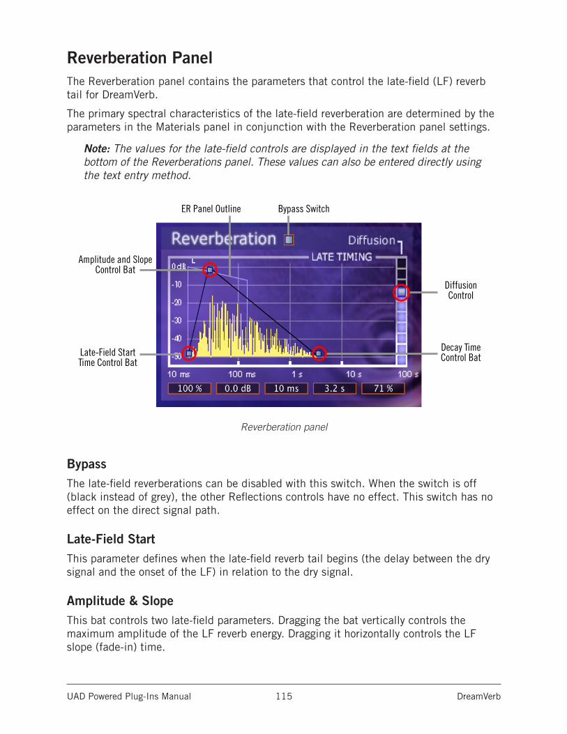
UAD Powered Plug-Ins Manual DreamVerb 115
Reverberation PanelThe Reverberation panel contains the parameters that control the late-field (LF) reverb tail for DreamVerb.
The primary spectral characteristics of the late-field reverberation are determined by the parameters in the Materials panel in conjunction with the Reverberation panel settings.
Note: The values for the late-field controls are displayed in the text fields at the bottom of the Reverberations panel. These values can also be entered directly using the text entry method.
Reverberation panel
BypassThe late-field reverberations can be disabled with this switch. When the switch is off (black instead of grey), the other Reflections controls have no effect. This switch has no effect on the direct signal path.
Late-Field StartThis parameter defines when the late-field reverb tail begins (the delay between the dry signal and the onset of the LF) in relation to the dry signal.
Amplitude & SlopeThis bat controls two late-field parameters. Dragging the bat vertically controls the maximum amplitude of the LF reverb energy. Dragging it horizontally controls the LF slope (fade-in) time.
Bypass SwitchER Panel Outline
Decay Time Control Bat
Amplitude and Slope Control Bat
DiffusionControl
Late-Field Start Time Control Bat
UAD Powered Plug-Ins Manual DreamVerb 116
Decay TimeThis control effects the length of the reverb tail. Drag the bat to the left for a short decay, or to the right for a long decay.
DiffusionThis slider effects how quickly the late-field reverberations become more dense. The higher the Diffusion value, the more rapidly a dense reverb tail evolves.
ER Relative TimingTo highlight the relative timing relationship between the early reflections and late-field reverberation components, the shape and timing of the early reflections is represented as an outline in the Reverberation panel.
Tip: The shape of the ER outline is modified by parameters in the Reflections panel, not the Reverberation panel.
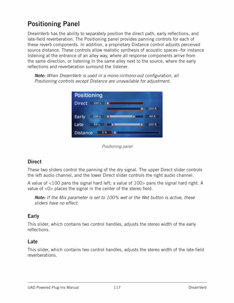
UAD Powered Plug-Ins Manual DreamVerb 117
Positioning PanelDreamVerb has the ability to separately position the direct path, early reflections, and late-field reverberation. The Positioning panel provides panning controls for each of these reverb components. In addition, a proprietary Distance control adjusts perceived source distance. These controls allow realistic synthesis of acoustic spaces--for instance listening at the entrance of an alley way, where all response components arrive from the same direction, or listening in the same alley next to the source, where the early reflections and reverberation surround the listener.
Note: When DreamVerb is used in a mono-in/mono-out configuration, all Positioning controls except Distance are unavailable for adjustment.
Positioning panel
DirectThese two sliders control the panning of the dry signal. The upper Direct slider controls the left audio channel, and the lower Direct slider controls the right audio channel.
A value of <100 pans the signal hard left; a value of 100> pans the signal hard right. A value of <0> places the signal in the center of the stereo field.
Note: If the Mix parameter is set to 100% wet or the Wet button is active, these sliders have no effect.
EarlyThis slider, which contains two control handles, adjusts the stereo width of the early reflections.
LateThis slider, which contains two control handles, adjusts the stereo width of the late-field reverberations.
UAD Powered Plug-Ins Manual DreamVerb 118
Early & Late AdjustmentThe left and right slider handles are dragged to adjust the stereo width. For a full stereo spread, drag the left handle all the way to left and right handle all the way to the right. When the slider handles are not set to maximum width, the center of the slider can be dragged left or right to set the positioning of the signal.
To pan a mono signal hard left or right, drag the slider all the way to the left or right.
DistanceDreamVerb allows you to control the distance of the perceived source with this slider. In reverberant environments, sounds originating close to the listener have a different mix of direct and reflected energy than those originating further from the listener.
Larger percentages yield a source that is farther away from the listener. A value of 0% places the source as close as possible to the listener.
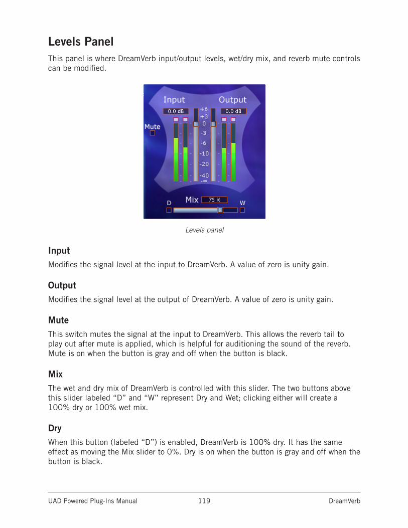
UAD Powered Plug-Ins Manual DreamVerb 119
Levels PanelThis panel is where DreamVerb input/output levels, wet/dry mix, and reverb mute controls can be modified.
Levels panel
InputModifies the signal level at the input to DreamVerb. A value of zero is unity gain.
OutputModifies the signal level at the output of DreamVerb. A value of zero is unity gain.
MuteThis switch mutes the signal at the input to DreamVerb. This allows the reverb tail to play out after mute is applied, which is helpful for auditioning the sound of the reverb. Mute is on when the button is gray and off when the button is black.
MixThe wet and dry mix of DreamVerb is controlled with this slider. The two buttons above this slider labeled “D” and “W” represent Dry and Wet; clicking either will create a 100% dry or 100% wet mix.
DryWhen this button (labeled “D”) is enabled, DreamVerb is 100% dry. It has the same effect as moving the Mix slider to 0%. Dry is on when the button is gray and off when the button is black.
UAD Powered Plug-Ins Manual DreamVerb 120
WetWhen this button (labeled “W”) is enabled, DreamVerb is 100% wet. It has the same effect as moving the Mix slider to 100%. Wet is on when the button is gray and off when the button is black.
Spatial Characteristics
SizeThe apparent size of a reverberant space is dependent on many factors. Most reverbs on the market have a “size” parameter, which usually modifies several facets of the reverb algorithm at once. You may notice DreamVerb does not have a “size” parameter. Instead, the elements that control the reverberant space are available to the user.
In DreamVerb, room size is determined by the interaction between all the parameters in the Reflections and Reverberation panels. To get a larger-sounding space, increase the T60 (reverberation time), use proportionally more air, increase the pre-delays, and slightly shift the Resonance transition frequencies to lower values.
Pre-DelayIntimacy and remoteness are largely controlled by the pre-delays. Generally speaking, use shorter pre-delays for more intimate spaces. Clear spaces have most of their energy in the first eighty milliseconds or so; muddy spaces have a lot of late arriving energy.
SpaceIn some sense, Shape determines the spatial characteristics of the reverberator, whereas Materials effects the spectral characteristics.
UAD Powered Plug-Ins Manual DreamVerb 121
DreamVerb PresetsDreamVerb includes 100+ presets in addition to the internal factory bank. Presets in the internal factory bank are accessed via the host application’s preset menu. The additional presets are copied to disk by the UAD installer and can be loaded using the Settings menu in the UAD Toolbar.
Preset Design TipsHere are some practical tips for creating useful reverbs with DreamVerb. These are not rules of course, but techniques that can be helpful in designing the perfect sonic environment.
ER = Early Reflections Hf = High Frequency
LF = Late-field Reverberation Lf = Low frequency
Preset Design Tips abbreviations
General Tips (a tour):• Start by setting a general timing on the ER and LF graphs to give a rough reverb
size. This timing ordinarily needs to be tweaked several times along the way.
• The materials and air density define the frequency decay of the LF, and also the coloration of the ER if ER filtering is used (the slider on the right of the Reflec-tions panel).
• Typically, materials should be blended. Try blending contrasting high frequency roll-off materials with high-frequency reflecting materials or inverse materials. This tends to add nice dimension to the LF tail. Start with one useful material and experiment with blending.
• Materials can have an extreme filtering effect if no air density is used. Most pre-sets sound better with an air blending. If you don’t want the additional coloration of air, blend with “Ideal Gas” which performs no filtering.
• The room shapes define the ER pattern; they do not effect the LF. Solo the ER and choose a shape that works well for your source or environment.
• Blending shapes does not always yield desirable results. Use shape blending with discretion, or to define a more complex room.
• Start with the EQ flat, set the approximate sound with the materials, then EQ the input to cut or boost specific frequencies.
• The EQ is often most useful for a simple Lf or Hf roll-off/boost, or to notch out bothersome frequencies for particular sources. For full mix ambience/mastering presets, use the EQ to cut most of all LF input, which yields added ambience without mucking up the mix. This is a powerful EQ, so experiment!
UAD Powered Plug-Ins Manual DreamVerb 122
• Try different diffusion settings for your preset (the slider on the right of the Reverberation panel). Diffusion radically alters the reverberation sound and is source dependent. Higher diffusion values yield a fuller sound, good for percus-sive sounds; lower diffusion values yield a less dense sound, good for vocals, synths, etcetera.
• When monitoring your preset, try switching from Dry solo, Wet solo, and a useful mix. Solo the reflections and reverberation, and disable/enable EQ. Try different sources and mixes. Reach for the headphones every now and then. In general just keep things moving, as ear fatigue can be particularly deceiving with reverb sounds.
• The Positioning panel is generally only needed for automation. Ignore these settings for preset design unless going for a panning effect or monitoring real-world use.
• Often when you’ve got a really great preset designed, all it takes are a few subtle changes to make a number of other great presets.
Tips for designing a natural environment sound:• Make timing proportional. As the size of the simulated environment increases, the
length of the pre-delay for the EF, LF, and LF tail should increase proportionally. Typically, ER and LF pre-delay should be not too far apart, with LF starting shortly after ER.
• Place the ER timing preceding/leading into the LF
• ER amplitude naturally decays. Slope the amplitude down from left to right.
• Use ER filtering, as this improves the reverb sound in almost all situations.
• Try a gradual Lf or Hf roll-off (or boost) with the EQ section. The left and right-most EQ bands are shelf filters, which are perfect for this job. The adjacent bands can be used to shape the roll-off.
• Try natural materials and air densities before the unnatural custom or inverse materials and air densities.
• Try adding onset (slope) to the LF, as many environments naturally have an LF onset.
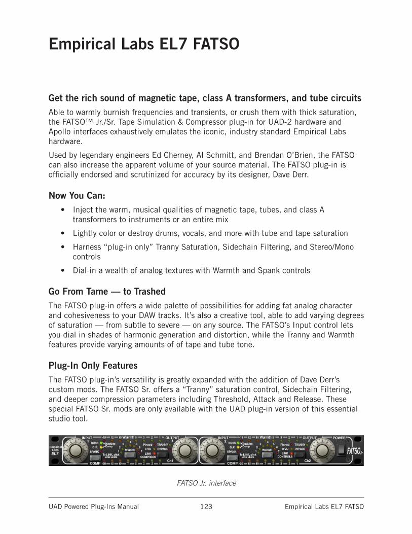
UAD Powered Plug-Ins Manual Empirical Labs EL7 FATSO 123
Empirical Labs EL7 FATSO
Get the rich sound of magnetic tape, class A transformers, and tube circuitsAble to warmly burnish frequencies and transients, or crush them with thick saturation, the FATSO™ Jr./Sr. Tape Simulation & Compressor plug-in for UAD-2 hardware and Apollo interfaces exhaustively emulates the iconic, industry standard Empirical Labs hardware.
Used by legendary engineers Ed Cherney, Al Schmitt, and Brendan O’Brien, the FATSO can also increase the apparent volume of your source material. The FATSO plug-in is officially endorsed and scrutinized for accuracy by its designer, Dave Derr.
Now You Can:• Inject the warm, musical qualities of magnetic tape, tubes, and class A
transformers to instruments or an entire mix
• Lightly color or destroy drums, vocals, and more with tube and tape saturation
• Harness “plug-in only” Tranny Saturation, Sidechain Filtering, and Stereo/Mono controls
• Dial-in a wealth of analog textures with Warmth and Spank controls
Go From Tame — to TrashedThe FATSO plug-in offers a wide palette of possibilities for adding fat analog character and cohesiveness to your DAW tracks. It’s also a creative tool, able to add varying degrees of saturation — from subtle to severe — on any source. The FATSO’s Input control lets you dial in shades of harmonic generation and distortion, while the Tranny and Warmth features provide varying amounts of of tape and tube tone.
Plug-In Only FeaturesThe FATSO plug-in’s versatility is greatly expanded with the addition of Dave Derr’s custom mods. The FATSO Sr. offers a “Tranny” saturation control, Sidechain Filtering, and deeper compression parameters including Threshold, Attack and Release. These special FATSO Sr. mods are only available with the UAD plug-in version of this essential studio tool.
FATSO Jr. interface
UAD Powered Plug-Ins Manual Empirical Labs EL7 FATSO 124
FATSO Functional Overview
Four Processing TypesThe FATSO was essentially designed to integrate frequencies in a musical manner and provide some foolproof vintage sounding compression. Generally, it is difficult to make the unit sound unnatural due to its vintage topology. FATSO provides four types of processing: Saturation and Distortion, Warmth, Tranny, and Compression.
Saturation and Distortion Processor
Harmonic Generation & Soft ClipperBasically, this is a distortion generator associated with the Input knobs. Anytime you pass a signal through the FATSO, it passes through this part except in bypass. This processing is useful to softly but instantly clip peaks and transients, allowing a higher average level. Aggressive distortion can also be achieved through the same controls.
It is well known that the triode distortion in tube circuits produces lots of 2nd order and 3rd order harmonics, in somewhat varying ratios. Analog tape also saturates in this manner. The 3rd order harmonic is induced in the FATSO by increasing the level through two discrete distortion circuits and is usually the result of flattening the tops and bottoms of waveforms. Second order harmonics are also added especially while compressing in the FATSO.
The FATSO’s input clipping will give you the same result. These lower order harmonics form “the octave” and “the octave and a fifth” to the fundamental musical tones. They are actually “musical” distortion. Harmonics above the 2nd and 3rd get increasingly harsh and unmusical, and therefore should be lower in amplitude (<-60 dB) to keep within our line of thinking. Second harmonic is considered to be the warmest and most “consonant” harmonic distortion.
Warmth Processor
High Frequency SaturationThis circuit is meant to simulate the softening of the high frequencies that occurs with analog tape. Basically, as the Warmth is increased, overly bright signals and transients will be quickly attenuated. The time constants are very nearly instant, so the high frequencies return very quickly after a loud burst.
The Warmth circuit is by far the most complex part of the FATSO. Basically, it is a very strange high frequency (HF) gain control circuit or HF limiter. It is very unobtrusive in operation since it gets in and out of the way very quickly. The desired result is akin to the HF saturation that analog tape exhibits when the HF amplitude interacts with the tape recorder bias to produce “self erasure” of certain frequencies. The nature of the filter allows the corner frequency to move as attenuation occurs.
UAD Powered Plug-Ins Manual Empirical Labs EL7 FATSO 125
There is only one control for Warmth but there are other ways to control the overall action of this circuit. If you do decide to use the compressor, set it up first because it affects the operation of Warmth. There is heavy interaction between the compressor and Warmth settings. Perhaps the best way to think of the settings is as compressor threshold, with 7 having the lowest threshold and the most Warmth, responding quickly and often to high frequency content. Just remember that instead of controlling the overall level, the Warmth “compressor” threshold only affects the high frequencies.
The Tranny Processor
Transformer & Tape Head EmulationThe Tranny circuit (“Tranny” is short for transformer) is a simulation of the effect of input and output transformers of older devices and adds the low frequency harmonics that characterize analog tape. This is extremely useful on pure low frequency type tones that don’t cut through small speakers. It adds upper “warm” harmonics to frequencies below 150 Hz, especially those even lower such as 40 Hz, the low string on a bass guitar, helping it to cut through on smaller speakers.
Transformer design and use is an art, and there are always trade-offs. However, it has been widely known that a good audio transformer circuit can do wonderful things to an audio signal. This was the goal of the Tranny circuit. The hardware designers tried to emulate the desirable characteristics of the good old input/output transformers in a consistent musical way, and in a selectable fashion. The addition of harmonics and peak saturation along with frequency and phase changes on the low frequencies occurs. They found that they could capture the low frequency effects of large and now expensive older output transformers in a weird, internally buffered switchable design.
To sum up the musical results of the Tranny circuit, there will be a little more edge in the midrange, and the super low frequencies will have been harmonically altered in a way that allows them to sound louder, even though the peaks are less than the original. Playback on small speakers will show an improved audibility of low end from the result of the psycho-acoustically-pleasing distortion the Tranny adds.
UAD Powered Plug-Ins Manual Empirical Labs EL7 FATSO 126
Compression Processor
Classic Knee Compression, Empirical Labs StyleThese are your typical automatic leveling devices that you find used on just about every instrument and vocal track, as well as on the overall buss. Only it’s Empirical Labs compression - smooth and sweet, but in your face!
There are essentially four discrete compressors in the FATSO: Buss, General Purpose (G.P.), Tracking, and Spank. Switching modes simultaneously sets the compressor threshold, ratio, attack, and decay. This was done to provide an easy-to-set, yet versatile group of curves. The release curve of all types is logarithmic, meaning it lets off quickly at first and then slows. This release curve is a big part of the FATSO’s compressor sound.
Note: Threshold, attack, and decay values can be modified in the FATSO Sr.
BussBuss mode (green LED) is a very gentle 2:1 type ratio with slow attack, fast release, and very soft knee. One to four dB of gain reduction is typical for this compressor type. Five or more dB of Buss compression is hitting it hard!
G.P.General Purpose mode (yellow LED) is medium attack slow release type that sounds pretty invisible while able to maintain a consistent RMS level. The slow release will not pull things into your face unnaturally.
TrackingTracking mode (green and yellow LED) is an 1176 type compressor that is great for tracking instruments and vocals during the recording process or during mixdown.
SpankSpank mode (red LED) is a radical limiter type compressor that was specifically designed to emulate the nice squeeze of the older SSL talkback compressors from the 70’s & 80’s, but with quite a bit of higher fidelity. Note that Spank’s aggressive nature will tend to dominate when combined with any of the other modes.
UAD Powered Plug-Ins Manual Empirical Labs EL7 FATSO 127
FATSO ControlsGeneral notes about FATSO controls are below, followed by a detailed description of each channel-specific control, the global controls, and the FATSO SR. controls.
Mono/Stereo OperationThe FATSO is a two-channel device capable of running in stereo or dual-mono modes. Controls for both channels can be linked for ease of stereo operation when both channels require the same values (see Link Controls), or unlinked when dual-mono operation is desired.
Each of the channel functions has its own separate group of controls (one set each for channels 1 and 2). Since the controls for each of the two channels are identical, they are detailed only once.
Note: When the FATSO is used in a mono-in/mono-out configuration, the channel 2 controls have no effect and the LINK parameters (page 131) are disabled.
PushbuttonsAll FATSO pushbuttons are momentary. The value of the parameter increments by one step each time the button is clicked (holding the button down does not continue to increment the value). The value cycles to the beginning when the end of the range is reached. Clicking on the control LED indicators has no effect, with the exception of the LINK parameters (page 131).
Tip: Shift+click any pushbutton to decrement its value by one.
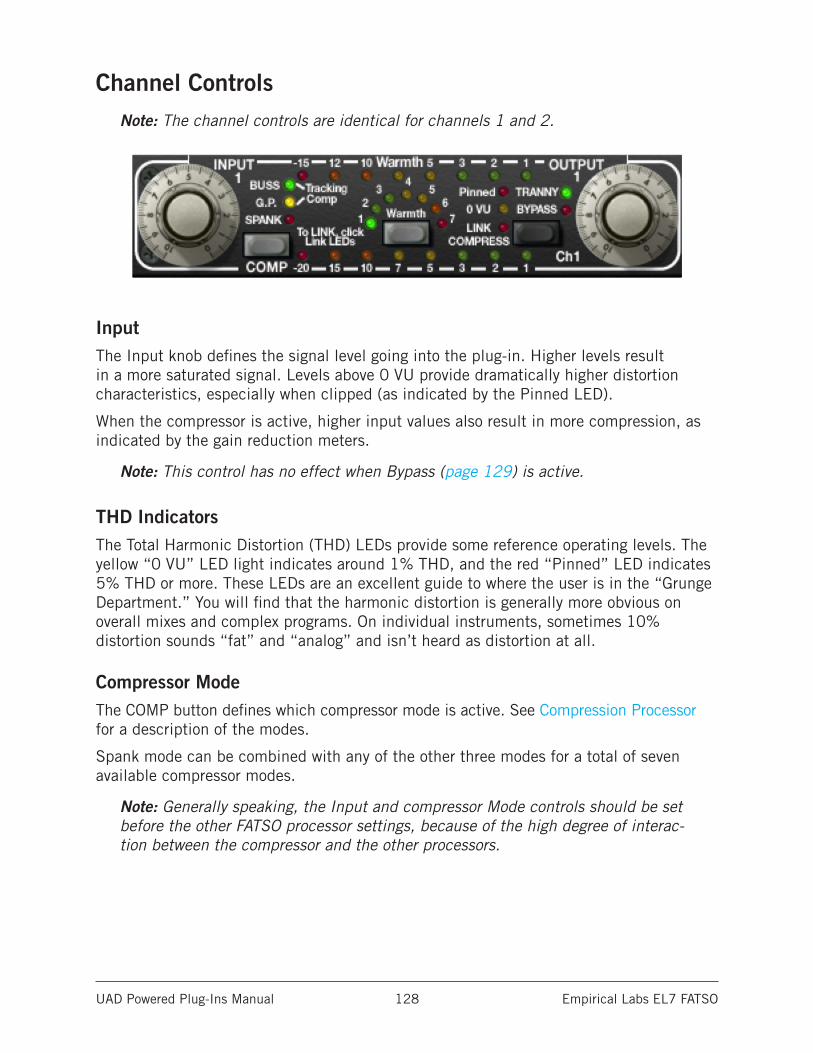
UAD Powered Plug-Ins Manual Empirical Labs EL7 FATSO 128
Channel ControlsNote: The channel controls are identical for channels 1 and 2.
InputThe Input knob defines the signal level going into the plug-in. Higher levels result in a more saturated signal. Levels above 0 VU provide dramatically higher distortion characteristics, especially when clipped (as indicated by the Pinned LED).
When the compressor is active, higher input values also result in more compression, as indicated by the gain reduction meters.
Note: This control has no effect when Bypass (page 129) is active.
THD IndicatorsThe Total Harmonic Distortion (THD) LEDs provide some reference operating levels. The yellow “0 VU” LED light indicates around 1% THD, and the red “Pinned” LED indicates 5% THD or more. These LEDs are an excellent guide to where the user is in the “Grunge Department.” You will find that the harmonic distortion is generally more obvious on overall mixes and complex programs. On individual instruments, sometimes 10% distortion sounds “fat” and “analog” and isn’t heard as distortion at all.
Compressor ModeThe COMP button defines which compressor mode is active. See Compression Processor for a description of the modes.
Spank mode can be combined with any of the other three modes for a total of seven available compressor modes.
Note: Generally speaking, the Input and compressor Mode controls should be set before the other FATSO processor settings, because of the high degree of interac-tion between the compressor and the other processors.
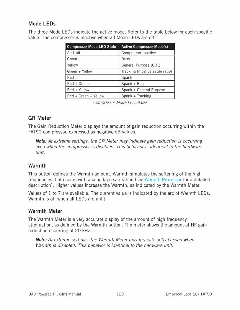
UAD Powered Plug-Ins Manual Empirical Labs EL7 FATSO 129
Mode LEDsThe three Mode LEDs indicate the active mode. Refer to the table below for each specific value. The compressor is inactive when all Mode LEDs are off.
Compressor Mode LED State Active Compressor Mode(s)
All Unit Compressor inactive
Green Buss
Yellow General Purpose (G.P.)
Green + Yellow Tracking (most versatile ratio)
Red Spank
Red + Green Spank + Buss
Red + Yellow Spank + General Purpose
Red + Green + Yellow Spank + Tracking
Compressor Mode LED States
GR MeterThe Gain Reduction Meter displays the amount of gain reduction occurring within the FATSO compressor, expressed as negative dB values.
Note: At extreme settings, the GR Meter may indicate gain reduction is occurring even when the compressor is disabled. This behavior is identical to the hardware unit.
WarmthThis button defines the Warmth amount. Warmth simulates the softening of the high frequencies that occurs with analog tape saturation (see Warmth Processor for a detailed description). Higher values increase the Warmth, as indicated by the Warmth Meter.
Values of 1 to 7 are available. The current value is indicated by the arc of Warmth LEDs. Warmth is off when all LEDs are unlit.
Warmth MeterThe Warmth Meter is a very accurate display of the amount of high frequency attenuation, as defined by the Warmth button. The meter shows the amount of HF gain reduction occurring at 20 kHz.
Note: At extreme settings, the Warmth Meter may indicate activity even when Warmth is disabled. This behavior is identical to the hardware unit.
UAD Powered Plug-Ins Manual Empirical Labs EL7 FATSO 130
Bypass/TrannyThis black button is a multifunction control. Clicking the button repeatedly cycles through Tranny, Bypass, and Tranny Off modes. The currently active mode is indicated by the adjacent LEDs.
Tranny (green LED)The Tranny Processor is active in this mode. The Tranny circuit adds frequency “rounding,” low order clipping, intermodular distortion and transient clipping. On FATSO Sr., the Tranny amount can be set with the Tranny Level control
Note: Disabling Tranny will yield a significant reduction in UAD DSP usage when DSP LoadLock is disabled. If DSP LoadLock is enabled (the default setting), dis-abling Tranny will not reduce DSP usage.
Tranny Off (red and green LEDs off)In this mode, the Tranny processor is inactive but the other processors are active. This mode requires less UAD DSP than when Tranny is active.
Bypass (red LED)All FATSO controls and processing for the channel are inactive in this mode.
Note: UAD DSP load is not reduced in Bypass mode. If you want to reduce UAD DSP usage when bypassing both channels of the FATSO, use the Power switch instead.
OutputThe Output knob controls the signal level that is output from the plug-in.
Note: This control has no effect when Bypass/Tranny is active.
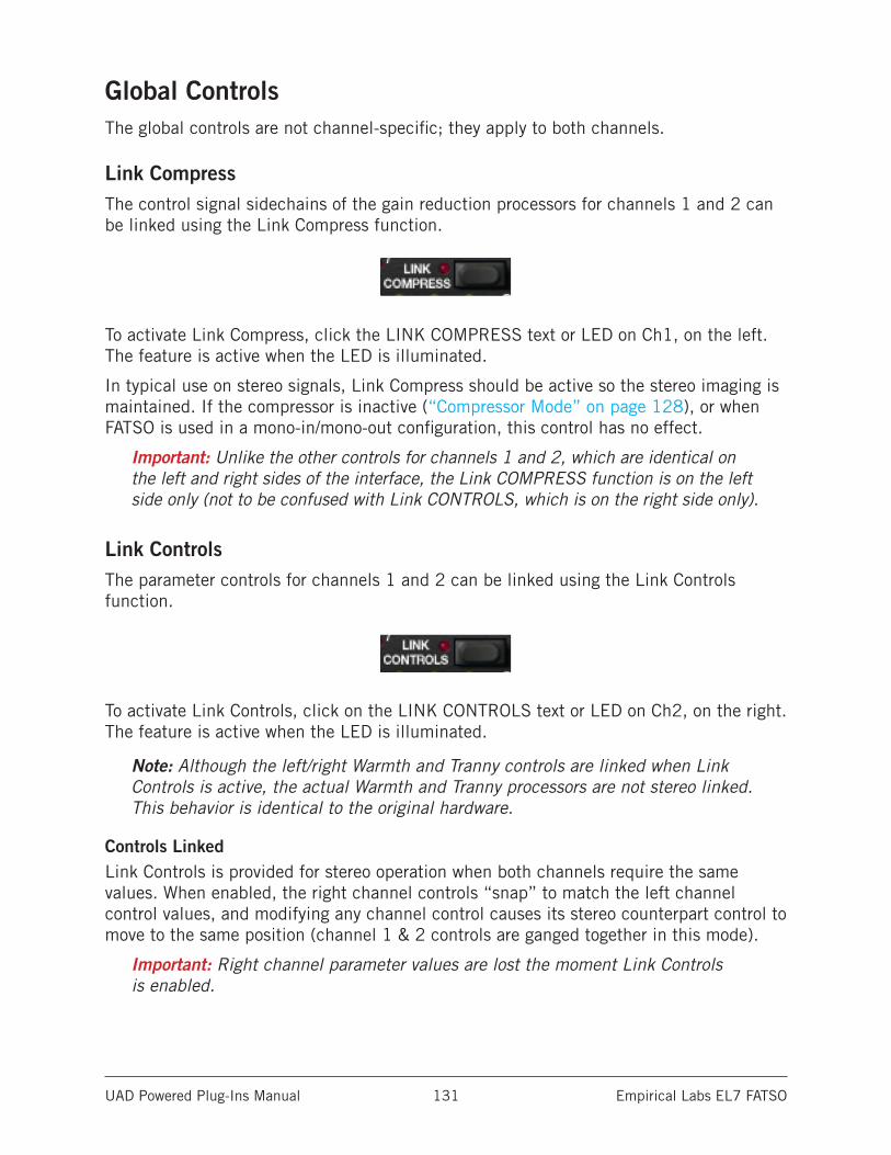
UAD Powered Plug-Ins Manual Empirical Labs EL7 FATSO 131
Global ControlsThe global controls are not channel-specific; they apply to both channels.
Link CompressThe control signal sidechains of the gain reduction processors for channels 1 and 2 can be linked using the Link Compress function.
To activate Link Compress, click the LINK COMPRESS text or LED on Ch1, on the left. The feature is active when the LED is illuminated.
In typical use on stereo signals, Link Compress should be active so the stereo imaging is maintained. If the compressor is inactive (“Compressor Mode” on page 128), or when FATSO is used in a mono-in/mono-out configuration, this control has no effect.
Important: Unlike the other controls for channels 1 and 2, which are identical on the left and right sides of the interface, the Link COMPRESS function is on the left side only (not to be confused with Link CONTROLS, which is on the right side only).
Link ControlsThe parameter controls for channels 1 and 2 can be linked using the Link Controls function.
To activate Link Controls, click on the LINK CONTROLS text or LED on Ch2, on the right. The feature is active when the LED is illuminated.
Note: Although the left/right Warmth and Tranny controls are linked when Link Controls is active, the actual Warmth and Tranny processors are not stereo linked. This behavior is identical to the original hardware.
Controls LinkedLink Controls is provided for stereo operation when both channels require the same values. When enabled, the right channel controls “snap” to match the left channel control values, and modifying any channel control causes its stereo counterpart control to move to the same position (channel 1 & 2 controls are ganged together in this mode).
Important: Right channel parameter values are lost the moment Link Controls is enabled.
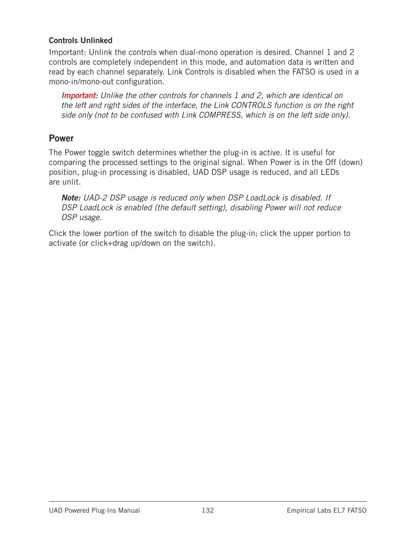
UAD Powered Plug-Ins Manual Empirical Labs EL7 FATSO 132
Controls UnlinkedImportant: Unlink the controls when dual-mono operation is desired. Channel 1 and 2 controls are completely independent in this mode, and automation data is written and read by each channel separately. Link Controls is disabled when the FATSO is used in a mono-in/mono-out configuration.
Important: Unlike the other controls for channels 1 and 2, which are identical on the left and right sides of the interface, the Link CONTROLS function is on the right side only (not to be confused with Link COMPRESS, which is on the left side only).
PowerThe Power toggle switch determines whether the plug-in is active. It is useful for comparing the processed settings to the original signal. When Power is in the Off (down) position, plug-in processing is disabled, UAD DSP usage is reduced, and all LEDs are unlit.
Note: UAD-2 DSP usage is reduced only when DSP LoadLock is disabled. If DSP LoadLock is enabled (the default setting), disabling Power will not reduce DSP usage.
Click the lower portion of the switch to disable the plug-in; click the upper portion to activate (or click+drag up/down on the switch).
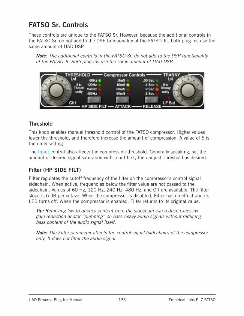
UAD Powered Plug-Ins Manual Empirical Labs EL7 FATSO 133
FATSO Sr. ControlsThese controls are unique to the FATSO Sr. However, because the additional controls in the FATSO Sr. do not add to the DSP functionality of the FATSO Jr., both plug-ins use the same amount of UAD DSP.
Note: The additional controls in the FATSO Sr. do not add to the DSP functionality of the FATSO Jr. Both plug-ins use the same amount of UAD DSP.
ThresholdThis knob enables manual threshold control of the FATSO compressor. Higher values lower the threshold, and therefore increase the amount of compression. A value of 5 is the unity setting.
The Input control also affects the compression threshold. Generally speaking, set the amount of desired signal saturation with Input first, then adjust Threshold as desired.
Filter (HP SIDE FILT)Filter regulates the cutoff frequency of the filter on the compressor’s control signal sidechain. When active, frequencies below the filter value are not passed to the sidechain. Values of 60 Hz, 120 Hz, 240 Hz, 480 Hz, and Off are available. The filter slope is 6 dB per octave. When the compressor is disabled, Filter has no effect and its LED turns off. When the compressor is enabled, Filter returns to its original value.
Tip: Removing low frequency content from the sidechain can reduce excessive gain reduction and/or “pumping” on bass-heavy audio signals without reducing bass content of the audio signal itself.
Note: The Filter parameter affects the control signal (sidechain) of the compressor only. It does not filter the audio signal.
UAD Powered Plug-Ins Manual Empirical Labs EL7 FATSO 134
AttackAttack sets the amount of time that must elapse once the input signal reaches the threshold level before compression is applied. The faster the attack, the more rapidly compression is applied to signals above the threshold.
The available attack time values are 0.9ms, 10ms, 30ms, 60ms, and Default (unlit). The unlit behavior is depends upon whether or not the compressor is active. These behaviors are described below.
Note: Attack values are approximations. Actual attack and release times may vary depending on the compressor mode selected.
Attack LEDs Unlit - Compressor ActiveWhen the compressor is enabled and all Attack LEDs are unlit, the attack characteristic of the active compressor mode in FATSO Jr. is used. This “default” FATSO Jr. behavior can then be manually overridden with the Attack button. However, when “pure” Spank mode is active, Attack cannot be modified. When Spank mode is combined with another compressor mode, Attack can be changed, but the results are typically very subtle.
Tip: After experimenting with other time constants, one can return to the default attack setting of the FATSO Jr. if desired by cycling the attack control until NO LEDs are lit (which indicates the default FATSO Jr. time constant).
Attack LEDs Unlit - Compressor InactiveWhen the compressor is disabled and all Attack LEDs are unlit, the button is disabled.
Note: This control has no effect when the compressor is inactive, or when it is in “pure” Spank mode (see Compressor Mode).
ReleaseRelease sets the amount of time it takes for compression to cease once the input signal drops below the threshold level. Slower release times can smooth the transition that occurs when the signal dips below the threshold, especially useful for material with frequent peaks. However, if you set too large of a Release time, compression for sections of audio with loud signals may extend to lengthy sections of audio with lower signals.
The available release time values are 0.05s, 0.1s, 0.s, 0.5s, and Default (unlit). The unlit behavior is depends upon whether or not the compressor is active. These behaviors are described below.
Note: Release values are approximations. Actual attack and release times may vary depending on the compressor mode selected.
UAD Powered Plug-Ins Manual Empirical Labs EL7 FATSO 135
Release LEDs Unlit - Compressor ActiveWhen the compressor is enabled and all Release LEDs are unlit, the release characteristic of the active compressor mode in FATSO Jr. is used. This “default” FATSO Jr. behavior can then be manually overridden with the Release button. However, when “pure” Spank mode is active, Release cannot be modified. When Spank mode is combined with another compressor mode, Release can be changed, but the results are typically very subtle.
Tip: After experimenting with other time constants, one can return to the default release setting of the FATSO Jr. if desired by cycling the release control until NO LEDs are lit (which indicates the default FATSO Jr. time constant).
Release LEDs Unlit - Compressor InactiveWhen the compressor is disabled and all Release LEDs are unlit, the button is disabled.
Note: This control has no effect when the compressor is inactive, or when it is in “pure” Spank mode (see Compressor Mode).
Tranny LevelThis control determines the amount of Tranny processing (see The Tranny Processor for a detailed description). Higher values make the Tranny effect more prominent. Increasing the Tranny level also increases the signal THD (see THD Indicators), and the sensitivity of the Warmth processor. A value of 5 is the unity setting.
Note: This control has no effect when the Tranny processor is inactive.
LF Sat LEDThe LF Sat (Low Frequency Saturation) LED indicates the amount of LF saturation in the Tranny processor. Higher Tranny Level values increase the LF saturation.
FATSO Jr. PresetsWhen loading presets created on the FATSO Jr. into the FATSO Sr., the parameters that are unique to FATSO Sr. are set to their default control values. The default values of the unique FATSO Sr. parameters are: Threshold/Tranny knobs at 5, and Filter/Attack/Release buttons off.
UAD Powered Plug-Ins Manual Empirical Labs EL7 FATSO 136
The Empirical Labs EL7 FATSO Jr. hardware unit
All visual and aural references to the FATSO and all use of EMPIRICAL LABS’s trademarks are being made with written permission from EMPIRICAL LABS. Special thanks to Dave Derr for assistance with this project.
UAD Powered Plug-Ins Manual EMT 140 Plate Reverb 137
EMT 140 Plate Reverb
Three Legendary Plate Reverbs Captured in Single, Powerful Plug-InIn 1957, German company EMT made a breakthrough in audio technology with the release of the EMT 140 plate reverb, which utilized a resonating metal plate to create ambience. Nothing is quite like the wonderfully lush and distinctive tone of plate reverb, which still endures as part of the fabric of modern music.
Endorsed by EMT Studiotechnik GmbH, and painstakingly modeled by Universal Audio, the EMT® 140 Classic Plate Reverberator plug-in for UAD-2 hardware and Apollo interfaces expertly replicates the sonic signature of three uniquely different EMT 140s installed at The Plant Studios in Sausalito, CA.
Now You Can:• Choose from three uniquely different EMT plate reverbs
• Add natural depth and shimmer to vocals and instruments
• Sculpt your sound with original controls such as mechanical damping and system input filters
• Enhance plate ambience further with plug-in only Balance, Width and Modulation controls
Expertly Emulated FeaturesThe EMT 140 plug-in offers three distinct plates for varying reverb textures. Plates A and B use the original EMT electronics system, for which the plates themselves had inten-tionally not been tuned in some time. Plate C — the most full frequency plate — uses the more modern Martech electronics which had just been fully serviced.
Emulations of both the original EMT 80 Hz shelf filter electronics and the popular after-market Martech electronics with their 12 dB cut filters are represented first in the signal path. The user is then presented with three switchable plate controllers (A, B and C) that recreate the mechanical dampers that decrease plate decay time, each with its own mea-sured characteristic sound.
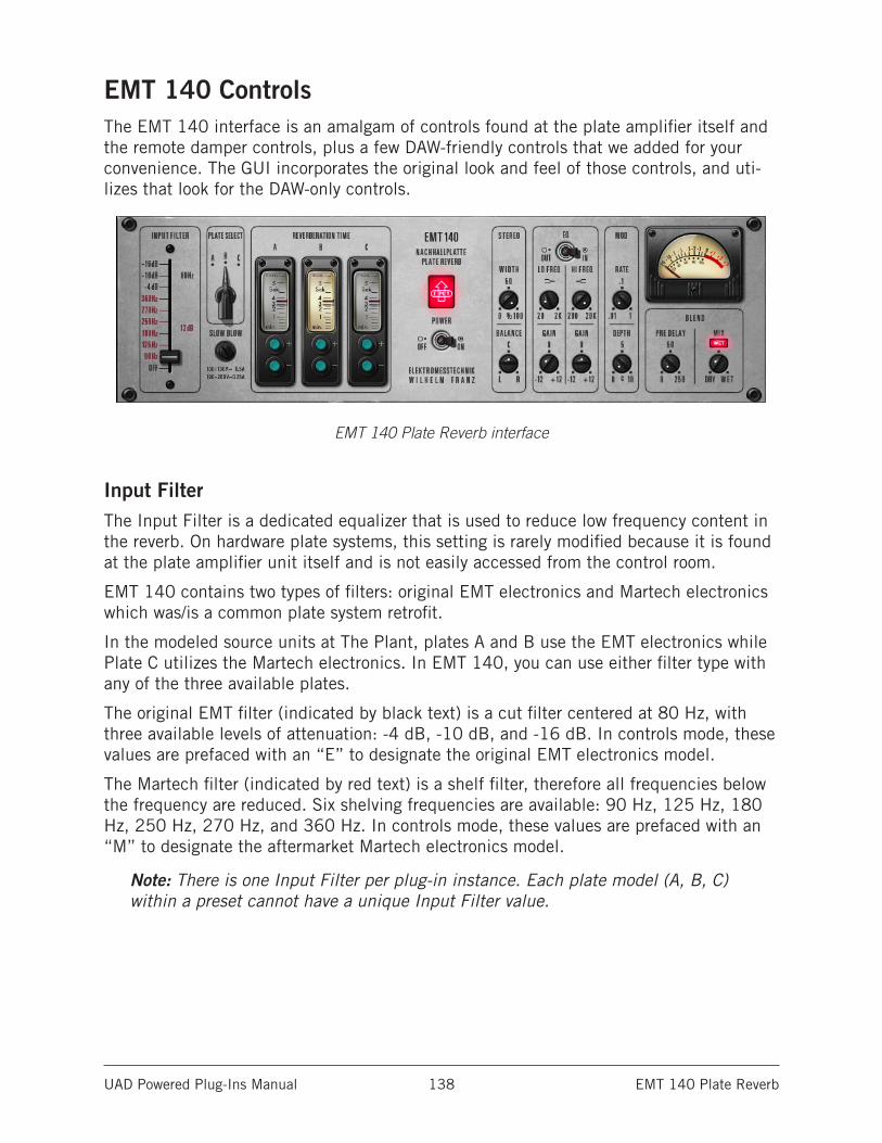
UAD Powered Plug-Ins Manual EMT 140 Plate Reverb 138
EMT 140 ControlsThe EMT 140 interface is an amalgam of controls found at the plate amplifier itself and the remote damper controls, plus a few DAW-friendly controls that we added for your convenience. The GUI incorporates the original look and feel of those controls, and uti-lizes that look for the DAW-only controls.
EMT 140 Plate Reverb interface
Input FilterThe Input Filter is a dedicated equalizer that is used to reduce low frequency content in the reverb. On hardware plate systems, this setting is rarely modified because it is found at the plate amplifier unit itself and is not easily accessed from the control room.
EMT 140 contains two types of filters: original EMT electronics and Martech electronics which was/is a common plate system retrofit.
In the modeled source units at The Plant, plates A and B use the EMT electronics while Plate C utilizes the Martech electronics. In EMT 140, you can use either filter type with any of the three available plates.
The original EMT filter (indicated by black text) is a cut filter centered at 80 Hz, with three available levels of attenuation: -4 dB, -10 dB, and -16 dB. In controls mode, these values are prefaced with an “E” to designate the original EMT electronics model.
The Martech filter (indicated by red text) is a shelf filter, therefore all frequencies below the frequency are reduced. Six shelving frequencies are available: 90 Hz, 125 Hz, 180 Hz, 250 Hz, 270 Hz, and 360 Hz. In controls mode, these values are prefaced with an “M” to designate the aftermarket Martech electronics model.
Note: There is one Input Filter per plug-in instance. Each plate model (A, B, C) within a preset cannot have a unique Input Filter value.
UAD Powered Plug-Ins Manual EMT 140 Plate Reverb 139
Reverb ControlsPlate reverb systems are extremely simple: A remote damper setting, and a high pass or shelf filter found at the plate itself. Additional manipulation is often used, including reverb return equalization, which is typically achieved at the console. Predelay is/was often achieved when necessary with tape delay, sending the return to a tape deck. Different tape speeds allowed different pre-delay amount.
The original damper controls are remote control devices, usually found somewhere near the control room for quick access. Our hybrid panel combines three remotes into the panel, with a switch to select each of the three available systems.
Note: The reverb controls (Plate Select and Reverb Time) are completely indepen-dent from all other plug-in controls.
Plate SelectThree plate models (algorithms) are available for reverb processing. The Plate Select switch specifies which plate will be active.
Each setting is a model of a completely separate and unique plate system. Three 140’s for the price of one!
Tip: You can also switch the active plate by clicking the A, B, or C letters above the Plate Select switch and the Reverb Time meters.
Reverb Time MetersThe Reverb Time Meters display the reverb time of plates A, B, and C in seconds. The meter for the active plate model (as specified by the Plate Select switch) is illuminated.
Damper Controls (Reverb Time)The Damper Controls (the green buttons beneath the Reverb Time Meters) change the reverb time for each plate. The range is from 0.5 to 5.5 seconds, in intervals of 0.1 sec. Click the buttons to increment or decrement the reverb time.
Note: The reverb time can be changed by dragging a Reverb Time Meter “needle” in addition to its corresponding Damper controls.
UAD Powered Plug-Ins Manual EMT 140 Plate Reverb 140
Stereo Controls
WidthWidth allows you to narrow the stereo image of EMT 140. The range is from 0 - 100%. At a value of zero, EMT 140 returns a monophonic reverb. At 100%, the stereo reverb field is as wide as possible.
BalanceThis control balances the level between the left and right channels of the reverb return. Rotating the knob to the left attenuates the right channel, and vice versa (it is not a mono pan control).
EQ ControlsThis group of parameters contains the controls for EMT 140’s onboard utility equalizer. It is a two band (low and high) shelving EQ that uses analog-sounding algorithms for great tonal shaping options.
The EQ section is independent from the reverb algorithms and the Input Filter on the modeled plate systems.
The frequency parameters specify the center of the transition band, which is defined as the frequency at which the level in dB is the midpoint between DC and the band edge level.
Note: There is one EQ per plug-in instance. Each plate model (A, B, C) within a preset cannot have unique EQ values.
EQ EnableThe EMT 140 equalizer can be disabled with the EQ Enable switch. UAD DSP usage is not increased when EQ is enabled.
Low Frequency
This parameter specifies the low shelving band transition frequency to be boosted or attenuated by the low band Gain setting. The range is 20 Hz to 2 kHz.
Because this is a shelving EQ, all frequencies below this setting will be affected by the low band Gain value.
Low Gain
This parameter determines the amount by which the transition frequency setting for the low band is boosted or attenuated. The available range is ±12 dB, in increments of 0.5 dB (fine control) or 1.0 dB (coarse control).
High Frequency
This parameter determines the high shelving band transition frequency to be boosted or attenuated by the high band Gain setting. The range is 200 Hz to 20 kHz.
Because this is a shelving EQ, all frequencies above this setting will be affected by the high band Gain value.
UAD Powered Plug-Ins Manual EMT 140 Plate Reverb 141
High Gain
This parameter determines the amount by which the frequency setting for the high band is boosted or attenuated. The available range is ±12 dB, in increments of 0.5 dB (fine control) or 1.0 dB (coarse control).
Modulation ControlsThe EMT 140 reverb time can be modulated by a low frequency oscillator using rate and depth controls. The effect is subtle but it can increase dispersion and reduce ringing on some source material, such as loud signals with sudden endings and percussive content.
Mod RateMod Rate controls the rate of reverb time modulation. The available range is from 0.01 Hz to 1.0 Hz.
Mod DepthThis parameter controls the amount of reverb time modulation. The available range is from 0 - 10 cents.
Output MeterThe vintage-style VU Meter represents the plug-in output level. It is active when the Power switch is on, and slowly returns to zero when Power is switched off.
Blend Controls
PredelayThe amount of time between the dry signal and the onset of the reverb is controlled with this knob. The range is 0.0 to 250 milliseconds.
This control uses a logarithmic scale to provide increased resolution when selecting lower values. When the knob is in the 12 o’clock position, the value is 50 milliseconds.
MixThe Mix control determines the balance between the original and the processed signal. The range is from Dry (0%, unprocessed) to Wet (100%, processed signal only).
This control uses a logarithmic scale to provide increased resolution when selecting lower values. When the knob is in the 12 o’clock position, the value is 15%.
Note: If Wet Solo is active, adjusting this knob will have no affect.
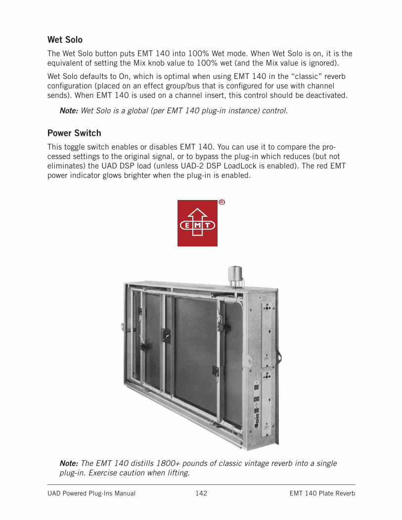
UAD Powered Plug-Ins Manual EMT 140 Plate Reverb 142
Wet SoloThe Wet Solo button puts EMT 140 into 100% Wet mode. When Wet Solo is on, it is the equivalent of setting the Mix knob value to 100% wet (and the Mix value is ignored).
Wet Solo defaults to On, which is optimal when using EMT 140 in the “classic” reverb configuration (placed on an effect group/bus that is configured for use with channel sends). When EMT 140 is used on a channel insert, this control should be deactivated.
Note: Wet Solo is a global (per EMT 140 plug-in instance) control.
Power SwitchThis toggle switch enables or disables EMT 140. You can use it to compare the pro-cessed settings to the original signal, or to bypass the plug-in which reduces (but not eliminates) the UAD DSP load (unless UAD-2 DSP LoadLock is enabled). The red EMT power indicator glows brighter when the plug-in is enabled.
Note: The EMT 140 distills 1800+ pounds of classic vintage reverb into a single plug-in. Exercise caution when lifting.
UAD Powered Plug-Ins Manual EMT 250 Electronic Reverberator 143
EMT 250 Electronic Reverberator
Iconic lever-driven digital reverb & modulation effects unitStill regarded as one of the best-sounding reverb units ever made, the EMT® 250 Classic Electronic Reverb plug-in for UAD-2 and Apollo interfaces is a faithful emulation of the first digital reverb/modulation effects unit introduced in 1976.
The EMT 250 continues to leave an immeasurable mark on record-making history in the hands of studio legends like George Massenburg, Bruce Swedien, Daniel Lanois, Brian Eno, and Allen Sides.
Now You Can:• Track and mix with the only emulation of the EMT 250 reverb unit, fully endorsed
by EMT Studiotechnik GmbH
• Dial in lush delay, phasing, chorus, and echo effects
• Add distinctive space and depth to drums, guitars, and vocals with the same algorithm found in the original hardware
• Harness plug-in-only features including Dry/Wet Mix, Wet Solo, and Hard bypass
Used on Countless ClassicsThe EMT 250’s distinctive clear and open reverb sound has appeared on countless records, including Prince & The Revolution’s Purple Rain, Elvis Costello’s Spike, and modern classics like The Red Hot Chili Pepper’s Stadium Arcadium.
Exclusively endorsed by EMT StudiotechnikDesigned in conjunction with EMT 250 designer Dr. Barry Blesser, the UAD plug-in version uses the same algorithms found in the original, extremely rare hardware. The EMT 250 plug-in was modeled from Allen Sides’ “golden unit” EMT 250 that resides at the legendary United/Ocean Way Recording.
Added Versatility with New Features The EMT 250 plug-in goes beyond the original hardware, adding modern, workflow enhancing features like Dry/Wet Mix, Wet Solo, and Hard bypass. With these useful additions, the EMT 250 plug-in is even more powerful than the iconic hardware.
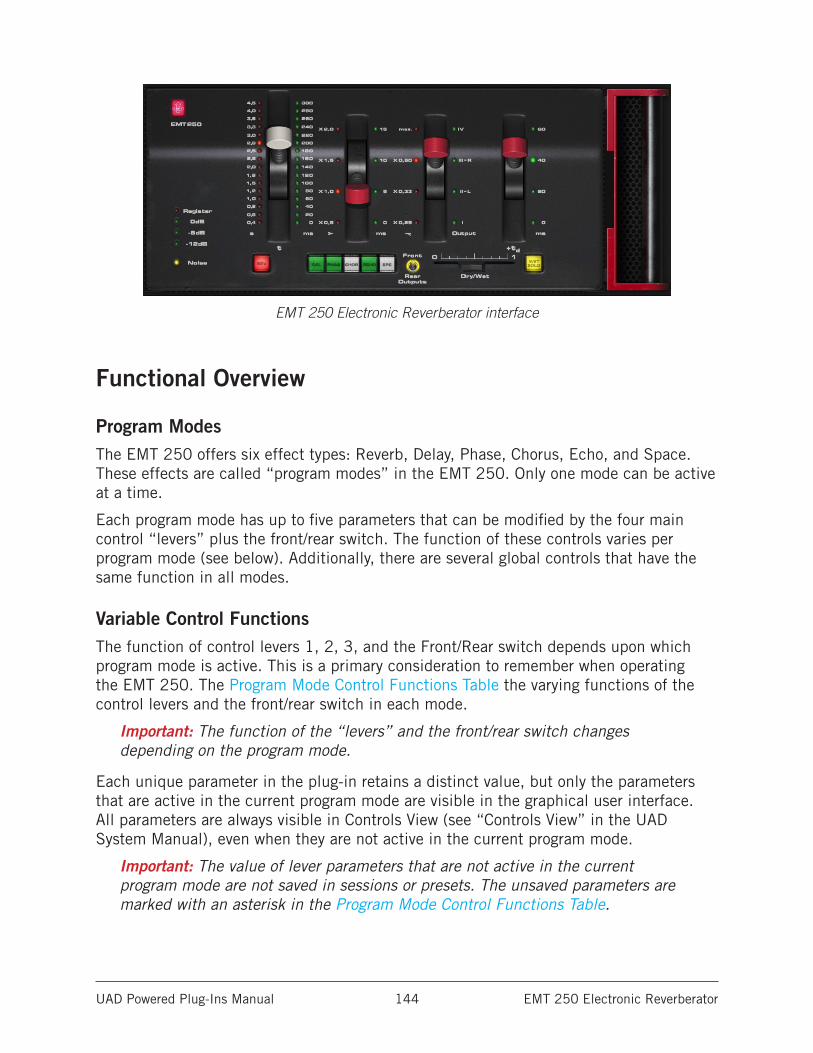
UAD Powered Plug-Ins Manual EMT 250 Electronic Reverberator 144
EMT 250 Electronic Reverberator interface
Functional Overview
Program ModesThe EMT 250 offers six effect types: Reverb, Delay, Phase, Chorus, Echo, and Space. These effects are called “program modes” in the EMT 250. Only one mode can be active at a time.
Each program mode has up to five parameters that can be modified by the four main control “levers” plus the front/rear switch. The function of these controls varies per program mode (see below). Additionally, there are several global controls that have the same function in all modes.
Variable Control FunctionsThe function of control levers 1, 2, 3, and the Front/Rear switch depends upon which program mode is active. This is a primary consideration to remember when operating the EMT 250. The Program Mode Control Functions Table the varying functions of the control levers and the front/rear switch in each mode.
Important: The function of the “levers” and the front/rear switch changes depending on the program mode.
Each unique parameter in the plug-in retains a distinct value, but only the parameters that are active in the current program mode are visible in the graphical user interface. All parameters are always visible in Controls View (see “Controls View” in the UAD System Manual), even when they are not active in the current program mode.
Important: The value of lever parameters that are not active in the current program mode are not saved in sessions or presets. The unsaved parameters are marked with an asterisk in the Program Mode Control Functions Table.
UAD Powered Plug-Ins Manual EMT 250 Electronic Reverberator 145
When switching between program modes that have different parameters mapped to the same control, parameter values are retained within each mode (controls jump back to the prior value that was set in each respective mode).
Lever 4 PredelayIn all program modes, lever 4 controls the predelay (the initial delay before other processing occurs) of both channels (left and right). Predelay times of 0ms, 20ms, 40ms, and 60ms are available in 4 steps. The green LEDs on the right side of lever 4 display the current predelay value.
Mono/Stereo OperationThe EMT 250 hardware unit has one (mono) input. For accurate emulation when the plug-in is used in a stereo-in/stereo-out configuration, stereo signals at the plug-in input are summed to mono before processing; the dry signal is passed in stereo.
Four channels of processed audio, selectable with the Front/Rear Outputs switch, are generated from this mono input in all modes (with the exception of Echo, which has mono output only).
Front/Rear OutputsThe EMT 250 hardware unit has four discrete outputs. Two outputs were designed to be used as the main stereo left/right outputs, or the “front” left/right outs in quadraphonic applications. The other two outputs were used for the “rear” left/right signals in quad (or other creative applications). The UAD EMT 250 fully models the individual sonics of all four outputs.
The name of the “Front/Rear Outputs” switch is derived from the original hardware design. This control (which is unique to the plug-in) enables access to the processed quadraphonic signal in pairs, at either the front L/R or rear L/R outputs. When a different sound is available at the front and rear outputs, the yellow “LED ring” around the control is illuminated. For program modes that do not offer quadraphonic processing (e.g., Delay), the switch is re-purposed to sum the processed outputs to mono. In Echo mode, it functions as an input mute.
In some program modes, the yellow “LED ring” around the control is illuminated to indicate that changing the switch position will change the sound. For program modes that do not offer quadraphonic processing (e.g., Delay), the switch is re-purposed to sum the processed outputs to mono. In Echo mode, it functions as an input mute.
UAD Powered Plug-Ins Manual EMT 250 Electronic Reverberator 146
AutomationSome EMT 250 control functions change depending on the active mode (see Variable Control Functions). To accommodate this design, all EMT 250 parameters are exposed for automation and external control surfaces even if the parameter is not active in the current program mode.
Important: Parameters that are automated and/or externally controlled will have no effect if those parameters are not active in the current program mode.
Modeled I/OAll input and output characteristics of the EMT 250 are fully emulated in the plug-in. This includes all of its idiosyncrasies, such as the A/D and D/A anti-aliasing filters (which are not linear-phase), system latency, input clipping, and limited frequency response. All these quirks embellish the unique sonic signature.
EMT 250 LatencyThe EMT 250’s anti-aliasing filters for its A/D and D/A conversion are not linear-phase filters; therefore the emulation does not have a latency that is the same at all frequencies. Thus, we cannot report to the delay compensation engines a delay that is correct for all frequencies. The value we report is good at low frequencies, but becomes off at high frequencies. For additional information, see Additional Latency.
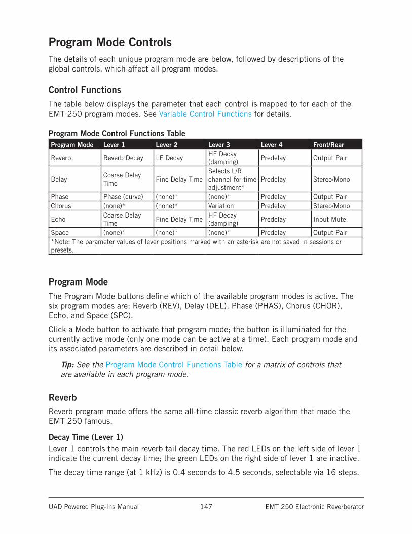
UAD Powered Plug-Ins Manual EMT 250 Electronic Reverberator 147
Program Mode ControlsThe details of each unique program mode are below, followed by descriptions of the global controls, which affect all program modes.
Control FunctionsThe table below displays the parameter that each control is mapped to for each of the EMT 250 program modes. See Variable Control Functions for details.
Program Mode Control Functions Table Program Mode Lever 1 Lever 2 Lever 3 Lever 4 Front/Rear
Reverb Reverb Decay LF DecayHF Decay (damping)
Predelay Output Pair
DelayCoarse Delay Time
Fine Delay TimeSelects L/R channel for time adjustment*
Predelay Stereo/Mono
Phase Phase (curve) (none)* (none)* Predelay Output PairChorus (none)* (none)* Variation Predelay Stereo/Mono
EchoCoarse Delay Time
Fine Delay TimeHF Decay (damping)
Predelay Input Mute
Space (none)* (none)* (none)* Predelay Output Pair*Note: The parameter values of lever positions marked with an asterisk are not saved in sessions or presets.
Program ModeThe Program Mode buttons define which of the available program modes is active. The six program modes are: Reverb (REV), Delay (DEL), Phase (PHAS), Chorus (CHOR), Echo, and Space (SPC).
Click a Mode button to activate that program mode; the button is illuminated for the currently active mode (only one mode can be active at a time). Each program mode and its associated parameters are described in detail below.
Tip: See the Program Mode Control Functions Table for a matrix of controls that are available in each program mode.
ReverbReverb program mode offers the same all-time classic reverb algorithm that made the EMT 250 famous.
Decay Time (Lever 1)Lever 1 controls the main reverb tail decay time. The red LEDs on the left side of lever 1 indicate the current decay time; the green LEDs on the right side of lever 1 are inactive.
The decay time range (at 1 kHz) is 0.4 seconds to 4.5 seconds, selectable via 16 steps.
UAD Powered Plug-Ins Manual EMT 250 Electronic Reverberator 148
LF Decay (Lever 2)Lever 2 controls the low frequency decay time (at 300 Hz). The red LEDs on the left side of lever 2 display the current value; the green LEDs on the right side of lever 2 are inactive.
Four multipliers are available: x 0.5, x 1.0, x 1.5, and x 2.0. The multiplier refers to a factor of the main decay time (lever 1). Higher values (upper lever positions) generally result in more low frequency content in the reverb tail.
HF Decay (Lever 3)Lever 3 controls the high frequency decay time. The red LEDs on the left side of lever 3 display the current value; the green LEDs on the right side of lever 3 are inactive.
Four multipliers (at 6 kHz) are available: x 0.25, x 0.33, x 0.5, and max. At the max position, the HF decay factor is x 1.0 at approximately three seconds. The multiplier refers to a factor of the main decay time (lever 1). Higher values (upper lever positions) generally result in more high frequency content in the reverb tail.
Predelay (Lever 4)Lever 4 is used as a typical reverb predelay parameter. See Lever 4 Predelay for more information.
Front/RearIn Reverb mode, the Front/Rear Outputs switch is illuminated. Changing the switch setting will yield a slightly different effect. See Front/Rear Outputs.
DelayDelay program mode offers two independent delay processors, one each for the left and right output channels. Up to 375 ms delay time is available for each channel. Delay repeats (feedback) are not available in Delay mode; use Echo mode if delay feedback is desired.
Note: The maximum per-channel delay time of 375 ms in Delay mode is obtained by setting the coarse, fine, and predelay times to their respective maximum values.
Coarse Delay Time (Lever 1)Lever 1 controls the coarse delay time for the currently selected channel (left or right). The currently selected channel is defined by lever 3.
The coarse delay time range is 0 to 300 ms, selectable via 16 steps. The green LEDs on the right side of lever 1 display the current value; the red LEDs on the left side of lever 1 are inactive.
Fine Delay Time (Lever 2)Lever 2 controls the fine delay time for the currently selected channel (left or right). The currently selected channel is defined by lever 3.
UAD Powered Plug-Ins Manual EMT 250 Electronic Reverberator 149
Fine delay times of 0ms, 5ms, 10ms, and 15ms are available. The green LEDs on the right side of lever 2 display the current value; the red LEDs on the left side of lever 2 are inactive.
Note: Levers 1 and 2 both control the delay time, but these parameters are not individually exposed for external control surfaces and automation. Instead, a single delay time parameter is exposed for each channel, and levers 1 and 2 in the plug-in interface are both updated to match the value.
Channel Select (Lever 3)Important: In Delay mode, lever 3 selects which channel (left or right) the delay time parameters (levers 1 and 2) will affect. When lever 3 is in position “L” the left channel delay time can be adjusted; when in position “R” the right channel delay time can be adjusted.
The green LEDs on the right side of lever 3 display the channel selected for delay time adjustment; the red LEDs on the left side of lever 3 are inactive.
Note: Lever 3 position “I” is a duplicate of position “II - L” in Delay mode. Like-wise, position “IV” is a duplicate of position “III - R.” All positions can be used to select a channel for delay time adjustment.
Important: In Delay mode, lever 3 does not control a “real” parameter; it is only used to select the active channel for other parameters in the graphical user interface. For this reason, the parameter is not exposed for external control surfaces or automation, nor is it saved in sessions or presets.
Predelay (Lever 4)Lever 4 can be used as a common predelay to both channels (the predelay time is added to the delay times of both channels). See Front/Rear Outputs for more information.
Front/RearIn Delay mode, the Front/Rear Outputs switch is not illuminated (the sound is identical in both pairs of outputs). When moved to the Rear position, the plug-in output is summed to mono. See Front/Rear Outputs for more information.
UAD Powered Plug-Ins Manual EMT 250 Electronic Reverberator 150
PhasePhase program mode creates a comb filter curve that results from the addition and subtraction of two signals with a small time shift between them. The comb filter changes the amplitude of the source signal’s harmonic overtones, resulting in interesting tonal variations.
Tip: Phasing is most apparent when the plug-in is set to 100% wet (or when Wet Solo is active).
In the EMT 250, the input is fed to two delay processors; one with a fixed delay time of 15 ms, and the other which is variable from 0-15 ms, controlled by lever 1. By changing this variable “time shift” the phase (shape) of the comb filter, and therefore the timbre of the output signal, is changed.
Note: Unlike many “phasors,” the EMT 250 does not modulate the variable “time shift” with a low frequency oscillator (LFO), which results in the continuously varying “swooshing” effect that is often associated with the process name. This conventional phasor effect can be reproduced (with outstanding results) by mov-ing lever 1 back and forth, either manually or with automation.
Phase (Lever 1)In Phase program mode, lever 1 controls the delay time (the phase time shift) between the two signals that create the comb filter. Phase values of 0 ms to 15 ms are available, selectable via 16 steps.
In Phase mode the green LEDs to the of right lever 1 are active, but the panel markings (0 - 300 ms) do not represent the actual phase delay time values. Instead, the LEDs indicate the relative value between 0-15 ms.
Predelay (Lever 4)Lever 4 can be used as a common predelay to both phase delays. See Lever 4 Predelay for more information.
Note: Levers 2 and 3 have no effect in Phase program mode.
Front/RearThe Front/Rear Outputs switch is illuminated in Phase program mode. Changing the switch setting will yield a different comb filter phase. Due to the nature of the effect in Phase mode, when the switch is in the Rear position and the Phase time (lever 1) is at minimum and maximum values, the signal is only output on one side (right-only at minimum, left-only at maximum). This behavior is identical to the original hardware. See Front/Rear Outputs for more information.
For more information about phasing, see the “Flangers and Phasors” article in the December 2008 Webzine:
• www.uaudio.com/webzine/2008/december/doctors.html
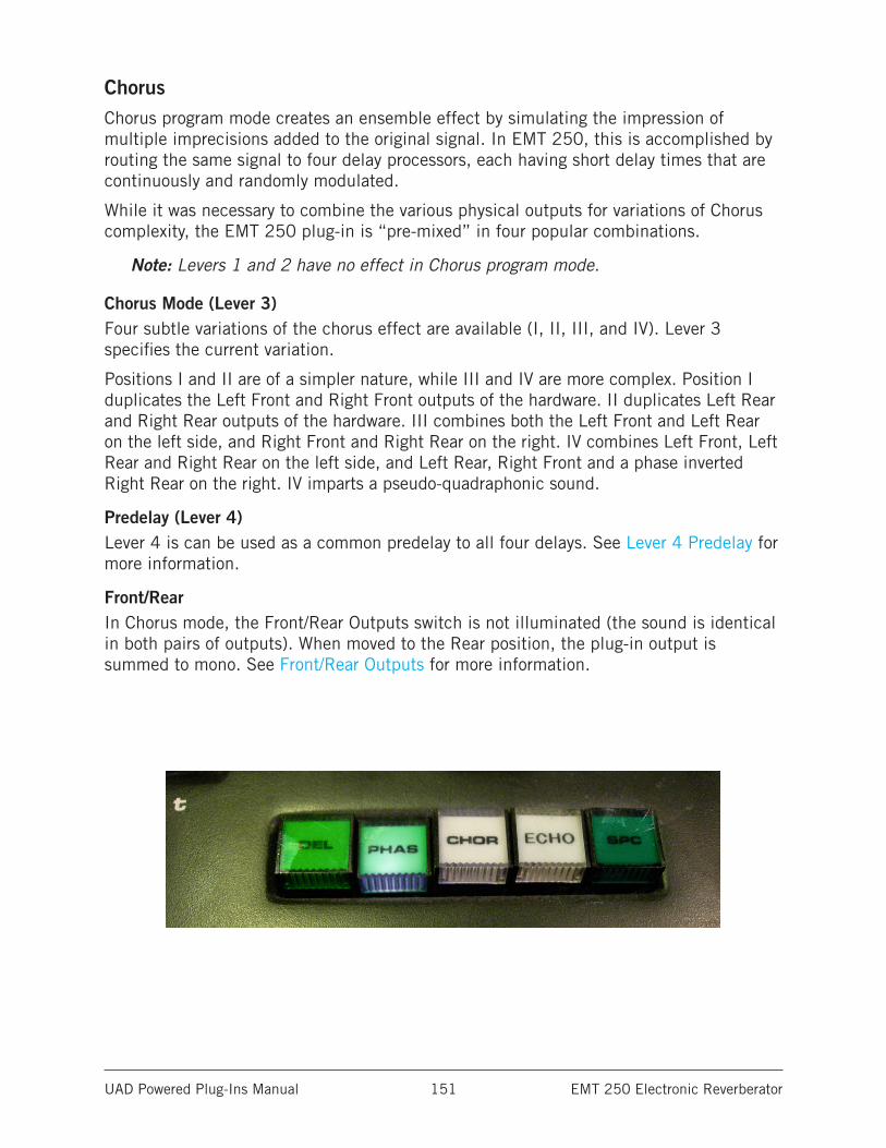
UAD Powered Plug-Ins Manual EMT 250 Electronic Reverberator 151
ChorusChorus program mode creates an ensemble effect by simulating the impression of multiple imprecisions added to the original signal. In EMT 250, this is accomplished by routing the same signal to four delay processors, each having short delay times that are continuously and randomly modulated.
While it was necessary to combine the various physical outputs for variations of Chorus complexity, the EMT 250 plug-in is “pre-mixed” in four popular combinations.
Note: Levers 1 and 2 have no effect in Chorus program mode.
Chorus Mode (Lever 3)Four subtle variations of the chorus effect are available (I, II, III, and IV). Lever 3 specifies the current variation.
Positions I and II are of a simpler nature, while III and IV are more complex. Position I duplicates the Left Front and Right Front outputs of the hardware. II duplicates Left Rear and Right Rear outputs of the hardware. III combines both the Left Front and Left Rear on the left side, and Right Front and Right Rear on the right. IV combines Left Front, Left Rear and Right Rear on the left side, and Left Rear, Right Front and a phase inverted Right Rear on the right. IV imparts a pseudo-quadraphonic sound.
Predelay (Lever 4)Lever 4 is can be used as a common predelay to all four delays. See Lever 4 Predelay for more information.
Front/RearIn Chorus mode, the Front/Rear Outputs switch is not illuminated (the sound is identical in both pairs of outputs). When moved to the Rear position, the plug-in output is summed to mono. See Front/Rear Outputs for more information.
UAD Powered Plug-Ins Manual EMT 250 Electronic Reverberator 152
EchoEcho program mode produces a single monophonic delay effect, with feedback and adjustable delay time. Up to 375 ms of delay is available.
The feedback (recirculation) circuit is always active in Echo mode. The feedback signal path is attenuated by approximately 10% per loop circulation, and includes an adjustable high frequency attenuator for damping.
Note: The maximum delay time of 375 ms in Echo mode is obtained by setting the coarse, fine, and predelay times to their respective maximum values.
Coarse Echo Time (Lever 1)Lever 1 controls the coarse delay time. The coarse delay time range is 0 to 300 ms, selectable via 16 steps.
The green LEDs on right side of lever 1 display the current value; the red LEDs on the left side of lever 1 are inactive.
Fine Echo Time (Lever 2)Lever 2 controls the fine delay time. Fine delay times of 0 ms, 5 ms, 10 ms, and 15 ms are available. The green LEDs on right side of lever 2 display the current value; the red LEDs on the left side of lever 2 are inactive.
Note: Levers 1 and 2 both control the echo time, but these parameters are not in-dividually exposed for external control surfaces and automation. Instead, a single echo time parameter is exposed, and levers 1 and 2 in the plug-in interface are both updated to match the value.
HF Decay (Lever 3)Lever 3 controls the high frequency damping in Echo mode. The red LEDs on left side of lever 3 display the current value; the green LEDs on the right side of lever 3 are inactive.
Four multipliers are available: x 0.25, x 0.33, x 0.5, and max. Higher values (upper lever positions) result in more feedback.
Predelay (Lever 4)Lever 4 is used as a predelay to the echo processor in this mode. The predelay time is added to the echo times, but not to the HF decay feedback loop. See Lever 4 Predelay for more information.
Front/RearThe Front/Rear Outputs switch is not illuminated in Echo mode (the same monophonic signal is generated at the front and rear outputs). However, the Front/Rear Outputs switch has a special function in Echo mode.
In the Front position, the program behaves normally. In the Rear position, the input to the echo processor is muted, while still allowing the echo output to be passed. This feature is useful for adding echo to specific passages only, by flipping the switch to Front when echo is desired. The behavior is identical to the popular “dub” switch on the Roland RE-201. See Front/Rear Outputs for more information.
UAD Powered Plug-Ins Manual EMT 250 Electronic Reverberator 153
SpaceSpace mode is a special reverb program with an extremely long decay time and linear distribution of the reverberation time with frequency (all frequencies decay at the same rate). Because this condition doesn’t exist in nature, and the program was originally intended for science fiction productions, the “reverberation in outer space” moniker was derived.
The reverb decay time is approximately 10 seconds in Space mode. Predelay and Front/Rear are the only adjustable parameters in this program mode.
Note: Levers 1, 2, and 3 have no effect in Space mode.
Predelay (Lever 4)Lever 4 is used as a typical reverb predelay parameter. See Lever 4 Predelay for more information.
Front/RearIn Space mode, the Front/Rear Outputs switch is illuminated. Changing the switch setting will yield a slightly different effect. See Front/Rear Outputs for more information.
Global ControlsThe global controls are not program-specific; they apply to all program modes.
PowerThe Power button (the red EMT logo) determines whether the plug-in is active. It is useful for comparing the processed signal to the original signal. Click the button to disable the plug-in; click it again to enable it.
When Power is in the Off (unlit) position, plug-in processing is disabled, and UAD DSP usage is reduced.
Note: UAD-2 DSP usage is reduced only when DSP LoadLock is disabled. If DSP LoadLock is enabled (the default setting), disabling Power will not reduce DSP usage.
Input MeterThe Input Meter indicates the level going into the plug-in. On the original hardware, the red “Register” LED illuminates when digital full code is reached, at 6 dB above 0 dB (i.e., there is 6 dB of headroom on the hardware, as the meaning of “0 dB digital” wasn’t yet standardized in those days).
The distortion characteristics of the A/D converters are modeled, therefore “EMT 250-style” clipping can be heard when the EMT 250 input is overdriven.
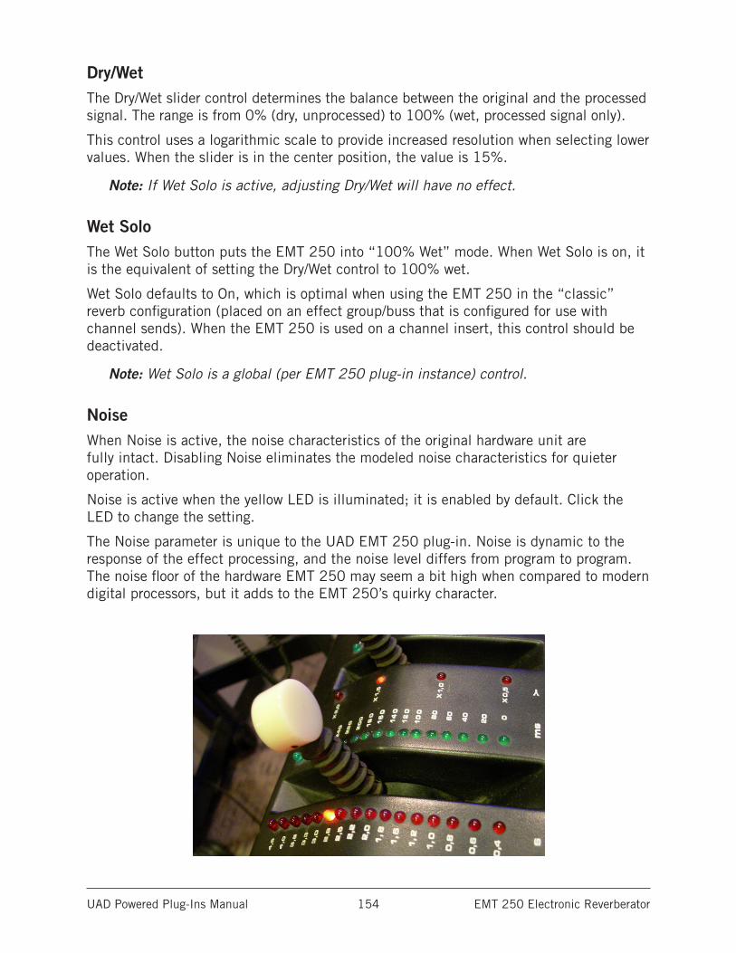
UAD Powered Plug-Ins Manual EMT 250 Electronic Reverberator 154
Dry/WetThe Dry/Wet slider control determines the balance between the original and the processed signal. The range is from 0% (dry, unprocessed) to 100% (wet, processed signal only).
This control uses a logarithmic scale to provide increased resolution when selecting lower values. When the slider is in the center position, the value is 15%.
Note: If Wet Solo is active, adjusting Dry/Wet will have no effect.
Wet SoloThe Wet Solo button puts the EMT 250 into “100% Wet” mode. When Wet Solo is on, it is the equivalent of setting the Dry/Wet control to 100% wet.
Wet Solo defaults to On, which is optimal when using the EMT 250 in the “classic” reverb configuration (placed on an effect group/buss that is configured for use with channel sends). When the EMT 250 is used on a channel insert, this control should be deactivated.
Note: Wet Solo is a global (per EMT 250 plug-in instance) control.
NoiseWhen Noise is active, the noise characteristics of the original hardware unit are fully intact. Disabling Noise eliminates the modeled noise characteristics for quieter operation.
Noise is active when the yellow LED is illuminated; it is enabled by default. Click the LED to change the setting.
The Noise parameter is unique to the UAD EMT 250 plug-in. Noise is dynamic to the response of the effect processing, and the noise level differs from program to program. The noise floor of the hardware EMT 250 may seem a bit high when compared to modern digital processors, but it adds to the EMT 250’s quirky character.
UAD Powered Plug-Ins Manual EP-34 Classic Tape Echo 155
EP-34 Classic Tape Echo
Warm, Highly Adjustable, Tape Echo Emulation Inspired By Two Classic Echoplex* Units.Universal Audio’s EP-34 Tape Echo plug-in gives guitar players and mix engineers the rich, warm tape delay effects of vintage Echoplex units on the UAD Powered Plug-Ins platform for Mac and PC. One need only listen to classic recordings from Jimmy Page, Brian May, Chick Corea, Eddie Van Halen, Eric Johnson and Andy Summers to hear the Echoplex sound in action. Unlike other Echoplex emulations, the EP-34 is the first plug-in that targets specific behaviors of both the EP-3 and EP-4 Echoplexes.
The original Echoplex hardware boxes employed an infinite tape loop combined with a sliding record head, allowing the user to set the desired delay length. Of course, as an analog tape-based unit, there were many idiosyncrasies along the way — including distortion, wow and flutter, self-oscillation, squelch effects, and other vintage magic. The EP-34 plug-in emulates all of these attributes, with a record head slider that can be moved in real time and used in conjunction with an Echo Repeats control to create echo and pitch chaos. The distinct, musical input clipping of the original hardware is also captured via a Record Volume control, giving the EP-34 some subtle to not-so-subtle tonal coloring and distortion as desired. Recreating the infinite delay times afforded by a sliding record head — as well as capturing the desirable distortion of the hardware’s preamp circuit — were difficult and DSP-intensive tasks, but the experts at UA sweated every last detail, ensuring that the EP-34 plug-in is verifiably the most accurate model for those who want the distinct, chaotic Echoplex sound, “warts and all.”
Just like the original hardware, faster-than-tape-path speeds can be achieved with the EP-34 plug-in, leading to “sonic-boom/tape squeal” effects, self-chorusing due to speed variations, plus pinch roller wow and flutter. The Echo Volume control allows the blending of processed and unprocessed signal; however as with the original, even the dry signal is tonally affected by the plug-in. Finally, the original Echoplex’s self-oscillation capabilities are present as well, including the “squelch” effect (an interruption in self-oscillation) achieved at extreme settings when processing low-frequency material.
The EP-34 includes the same metering and highly musical tone controls found on the EP-4, but removes its undesirable in-line noise reduction circuit that guitarists often disabled (original manufacturer Maestro removed this circuit soon after the product’s release). A few EP-34 “extras” not found on the original hardware include modern conveniences like Tempo Sync, Input Select (allows for a cleaner sound [LO] or a dirtier sound [HI] ), Tension (for a snappy or sludgy response time), Echo Send, Wet Solo, Pan (wet signal only) and Power (plug-in bypass).
Taken together, these features make the EP-34 more than just a tape delay plug-in, but a warm and inspiring instrument that can be played by manipulating the controls as you go.
*EP-34 Tape Echo is not affiliated with, sponsored nor endorsed by any companies currently using the Echoplex name. The EP-34 Tape Echo name, as well as the EP-3 and EP-4 model names, are used solely to identify the classic effects emulated by Universal Audio’s product.
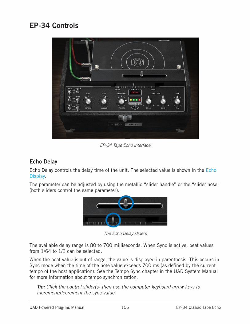
UAD Powered Plug-Ins Manual EP-34 Classic Tape Echo 156
EP-34 Controls
EP-34 Tape Echo interface
Echo DelayEcho Delay controls the delay time of the unit. The selected value is shown in the Echo Display.
The parameter can be adjusted by using the metallic “slider handle” or the “slider nose” (both sliders control the same parameter).
The Echo Delay sliders
The available delay range is 80 to 700 milliseconds. When Sync is active, beat values from 1/64 to 1/2 can be selected.
When the beat value is out of range, the value is displayed in parenthesis. This occurs in Sync mode when the time of the note value exceeds 700 ms (as defined by the current tempo of the host application). See the Tempo Sync chapter in the UAD System Manual for more information about tempo synchronization.
Tip: Click the control slider(s) then use the computer keyboard arrow keys to increment/decrement the sync value.
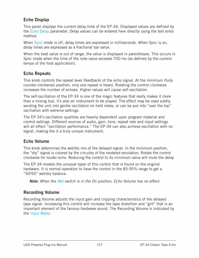
UAD Powered Plug-Ins Manual EP-34 Classic Tape Echo 157
Echo DisplayThis panel displays the current delay time of the EP-34. Displayed values are defined by the Echo Delay parameter. Delay values can be entered here directly using the text entry method.
When Sync mode is off, delay times are expressed in milliseconds. When Sync is on, delay times are expressed as a fractional bar value.
When the beat value is out of range, the value is displayed in parentheses. This occurs in Sync mode when the time of the note value exceeds 700 ms (as defined by the current tempo of the host application).
Echo RepeatsThis knob controls the repeat level (feedback) of the echo signal. At the minimum (fully counter-clockwise) position, only one repeat is heard. Rotating the control clockwise increases the number of echoes. Higher values will cause self-oscillation.
The self-oscillation of the EP-34 is one of the magic features that really makes it more than a mixing tool, it’s also an instrument to be played. The effect may be used subtly, sending the unit into gentle oscillation on held notes, or can be put into “over the top” oscillation with extreme settings.
The EP-34’s oscillation qualities are heavily dependent upon program material and control settings. Different sources of audio, gain, tone, repeat rate and input settings will all effect “oscillation performance.” The EP-34 can also achieve oscillation with no signal, making the it a truly unique instrument.
Echo VolumeThis knob determines the wet/dry mix of the delayed signal. In the minimum position, the “dry” signal is colored by the circuitry of the modeled emulation. Rotate the control clockwise for louder echo. Reducing the control to its minimum value will mute the delay.
The EP-34 models the unusual taper of this control that is found on the original hardware. It is normal operation to have the control in the 85-95% range to get a “50/50” wet/dry balance.
Note: When the Wet switch is in the On position, Echo Volume has no effect.
Recording VolumeRecording Volume adjusts the input gain and clipping characteristics of the delayed tape signal. Increasing this control will increase the tape distortion and “grit” that is an important element of the famous hardware sound. The Recording Volume is indicated by the Input Meter.
UAD Powered Plug-Ins Manual EP-34 Classic Tape Echo 158
Input MeterThe Input Meter in the EP-34 is a three-segment horizontal LED array (two green, one red) that indicates the recording level at the input of the tape recorder.
The yellow LED indicates that the plug-in is active. When the Power switch is enabled, the yellow LED is illuminated.
Echo ToneThe frequency response of the delayed (wet) signal can be modified with the Echo Tone controls. These knobs are cut/boost controls; they have no effect when in the 12 o’clock position. The available range is ±10 dB of gain.
Note: The Echo Tone controls do not effect the dry signal.
TrebleControls the high frequency response in the delayed signals.
BassControls the low frequency response in the delayed signals.
Echo PanPan sets the position of the delayed (wet) signal in the stereo field; it does not affect the unprocessed (dry) signal.
Tip: Click the “Echo” control text to return the knob to center.
Note: When the plug-in is used in a mono-in/mono-out configuration, the Pan knob does not function and cannot be adjusted.
InputThe original hardware unit had two inputs: Instrument and Microphone. The Input switch on the EP-34 toggles between the gain levels of these two inputs.
The “LO” position captures the gain structure of the Instrument input, while the “HI” position captures the gain structure of the Microphone input. This allows for a cleaner (LO) or dirtier (HI) sound depending on the switch position.
Important: Depending on the source material and gain structuring, switching between LO and HI may cause a significant jump in output levels.
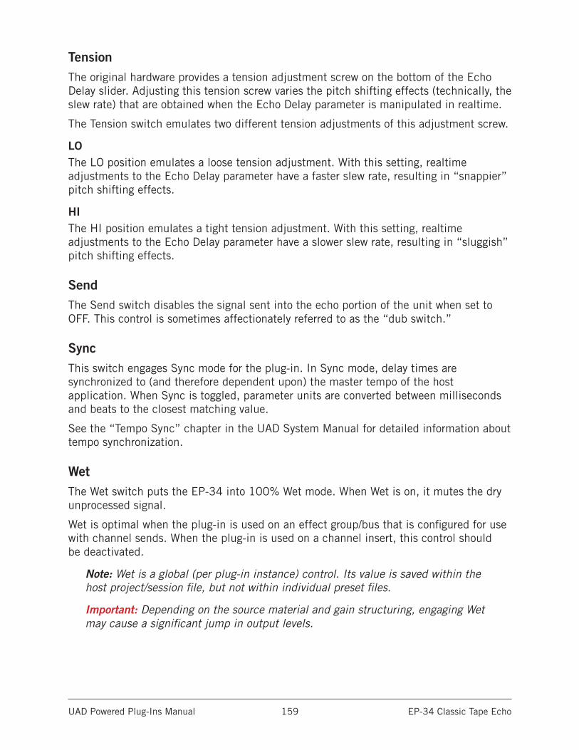
UAD Powered Plug-Ins Manual EP-34 Classic Tape Echo 159
TensionThe original hardware provides a tension adjustment screw on the bottom of the Echo Delay slider. Adjusting this tension screw varies the pitch shifting effects (technically, the slew rate) that are obtained when the Echo Delay parameter is manipulated in realtime.
The Tension switch emulates two different tension adjustments of this adjustment screw.
LOThe LO position emulates a loose tension adjustment. With this setting, realtime adjustments to the Echo Delay parameter have a faster slew rate, resulting in “snappier” pitch shifting effects.
HIThe HI position emulates a tight tension adjustment. With this setting, realtime adjustments to the Echo Delay parameter have a slower slew rate, resulting in “sluggish” pitch shifting effects.
SendThe Send switch disables the signal sent into the echo portion of the unit when set to OFF. This control is sometimes affectionately referred to as the “dub switch.”
SyncThis switch engages Sync mode for the plug-in. In Sync mode, delay times are synchronized to (and therefore dependent upon) the master tempo of the host application. When Sync is toggled, parameter units are converted between milliseconds and beats to the closest matching value.
See the “Tempo Sync” chapter in the UAD System Manual for detailed information about tempo synchronization.
WetThe Wet switch puts the EP-34 into 100% Wet mode. When Wet is on, it mutes the dry unprocessed signal.
Wet is optimal when the plug-in is used on an effect group/bus that is configured for use with channel sends. When the plug-in is used on a channel insert, this control should be deactivated.
Note: Wet is a global (per plug-in instance) control. Its value is saved within the host project/session file, but not within individual preset files.
Important: Depending on the source material and gain structuring, engaging Wet may cause a significant jump in output levels.
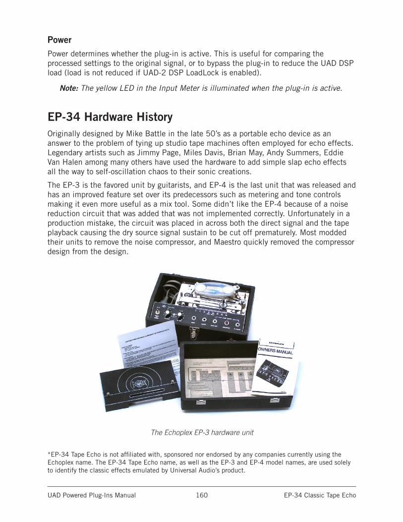
UAD Powered Plug-Ins Manual EP-34 Classic Tape Echo 160
PowerPower determines whether the plug-in is active. This is useful for comparing the processed settings to the original signal, or to bypass the plug-in to reduce the UAD DSP load (load is not reduced if UAD-2 DSP LoadLock is enabled).
Note: The yellow LED in the Input Meter is illuminated when the plug-in is active.
EP-34 Hardware HistoryOriginally designed by Mike Battle in the late 50’s as a portable echo device as an answer to the problem of tying up studio tape machines often employed for echo effects. Legendary artists such as Jimmy Page, Miles Davis, Brian May, Andy Summers, Eddie Van Halen among many others have used the hardware to add simple slap echo effects all the way to self-oscillation chaos to their sonic creations.
The EP-3 is the favored unit by guitarists, and EP-4 is the last unit that was released and has an improved feature set over its predecessors such as metering and tone controls making it even more useful as a mix tool. Some didn’t like the EP-4 because of a noise reduction circuit that was added that was not implemented correctly. Unfortunately in a production mistake, the circuit was placed in across both the direct signal and the tape playback causing the dry source signal sustain to be cut off prematurely. Most modded their units to remove the noise compressor, and Maestro quickly removed the compressor design from the design.
The Echoplex EP-3 hardware unit
*EP-34 Tape Echo is not affiliated with, sponsored nor endorsed by any companies currently using the Echoplex name. The EP-34 Tape Echo name, as well as the EP-3 and EP-4 model names, are used solely to identify the classic effects emulated by Universal Audio’s product.

UAD Powered Plug-Ins Manual Fairchild Tube Limiter Collection 161
Fairchild Tube Limiter Collection
The Gold Standard in Vintage Tube LimitersThe Fairchild 670 and 660 are the most coveted vintage compressor/limiters in the world, with good reason. These 20-tube tone titans — which now fetch upwards of $50,000 — impart an unmistakable silky warmth heard on hundreds of hit records from the Beatles and Pink Floyd, to Miles Davis and countless Motown classics. Now your vocal tracks, drum bus, and entire mix can benefit from the world’s most accurate plug-in recreations of these one-of-a-kind compressors.
Now You Can:• Give your tracks and mixes classic Fairchild tube warmth and character
• Harness the Fairchild’s tube-driven gain control, compression curves, and tube amp and transformer sections
• Duplicate the famed Ocean Way Studios’ compression sound with circuit-modeled recreations of their golden reference units
• Complete your “Big Three” compressor arsenal, alongside the LA-2A and 1176 plug-ins
The World’s Most Coveted CompressorThe very first Fairchild limiter that audio genius Rein Narma created on Les Paul’s kitchen table transformed the sound of recording forever. Soon, these 20-tube, 14-transformer, 67-pound behemoths were embraced by world-class studios, many of which still employ their vintage Fairchilds despite the increasing difficulty in maintaining these tube-driven tone machines.
For a half-century, the Fairchild 670 — and its aggressive little brother, the Fairchild 660 — have defined popular music’s most revered vocal and drum sounds. In fact, the world’s elite mixers often employ a 670 simply for the “glow” it brings to their final mixes, even without compression happening.
The Closest You Can Get to Vintage Fairchilds in a Plug-InIn 2004, Universal Audio released the Fairchild 670 Legacy plug-in, which was quickly heralded as the best 670 emulation available. Today, UA’s team of DSP experts have improved the original Time Constants and gain reduction curves, while modeling — for the first time ever — the complete tube-powered amplifier and transformer sections of their hardware counterparts. Far beyond other Fairchild emulations, only the new UAD Fairchild Collection is based on an accurate circuit models of Ocean Way Studios’ “golden-reference” units.
UAD Powered Plug-Ins Manual Fairchild Tube Limiter Collection 162
New Features — Classic TonesAlthough the Fairchild Tube Limiter Plug-In Collection nails the classic sonics of yesteryear, it also sports useful new features for modern workflows.
Blend Sounds with the Wet/Dry Mix ControlA Parallel Mix control lets you blend your unprocessed signal with the compressed signal, opening worlds of textural possibilities on everything from a drum bus to a mix bus.
Enhance Drums with Sidechain FiltersBy using the Fairchild’s Sidechain Filtering, you gain another level of control over your tracks. In this example, it’s used to punch up the drum bus to enhance its impact without triggering the threshold of the compressor with the kick drum.
Add Grit with the Headroom ControlThe Headroom (HR) control can be increased to make mastering applications a breeze, raising the gain reduction threshold and lowering distortion. Conversely, you can decrease headroom, lowering the gain reduction threshold and raising distortion for grittier textures that work on everything from vocals and drums to guitar and bass.
The Ultimate Companion to the LA-2A and 1176 Plug-In CollectionsCombined with the Electro-Optical (LA-2A) and FET-based (1176) compressor plug-ins, the Fairchild’s unique tube-driven sound completes the compression “Triple Crown.” Renowned for its aggressive power on piano, bass, and guitar, the 660 is a stereo/mono version of the original mono compressor, while the flagship 670 is a full stereo compressor that can inject vibe and color into tracks or add the final touch to mixes.
Historical BackgroundThe origins of the Fairchild 660/670 design come from Estonian-born immigrant Rein Narma. Les Paul hired Narma to modify his first 8-track Ampex machine. Later, Narma built consoles for Olmsted Recording, Rudy Van Gelder, and Les Paul, who then asked him to build an all-new, sonically reliable audio limiter. In the post-war years, this refugee from Soviet Russia worked for the U.S. Army as a broadcast/recording tech during the Nuremberg trials, then later immigrated to the New York and took a job at Gotham Recording. Narma and others founded Gotham Audio Developments to build recording gear.
The compressor’s Fairchild connection begins with Sherman Fairchild, the son of Congressman George Winthrop Fairchild, one of the founders of IBM. Sherman Fairchild built and designed the first aerial photography equipment during World War I. After that war ended, he started the Fairchild Aerial Camera Corporation in 1920. Sherman Fairchild eventually went on to design a multitude of products, from aircraft to semiconductors, and opened several more companies, including Fairchild Recording Equipment Corporation. After Narma began the limiter project for Les Paul, Sherman Fairchild heard about it, licensed the design, and hired Narma as the company’s chief engineer. Afterhis time at Fairchild, Narma moved to Northern California and was a vice-president at Ampex. The Fairchild was advertised as “The World Accepted Standard for Level Control” back in the 1950s when it was originally sold. It is still revered for its extremely smooth, artifact-free sound.
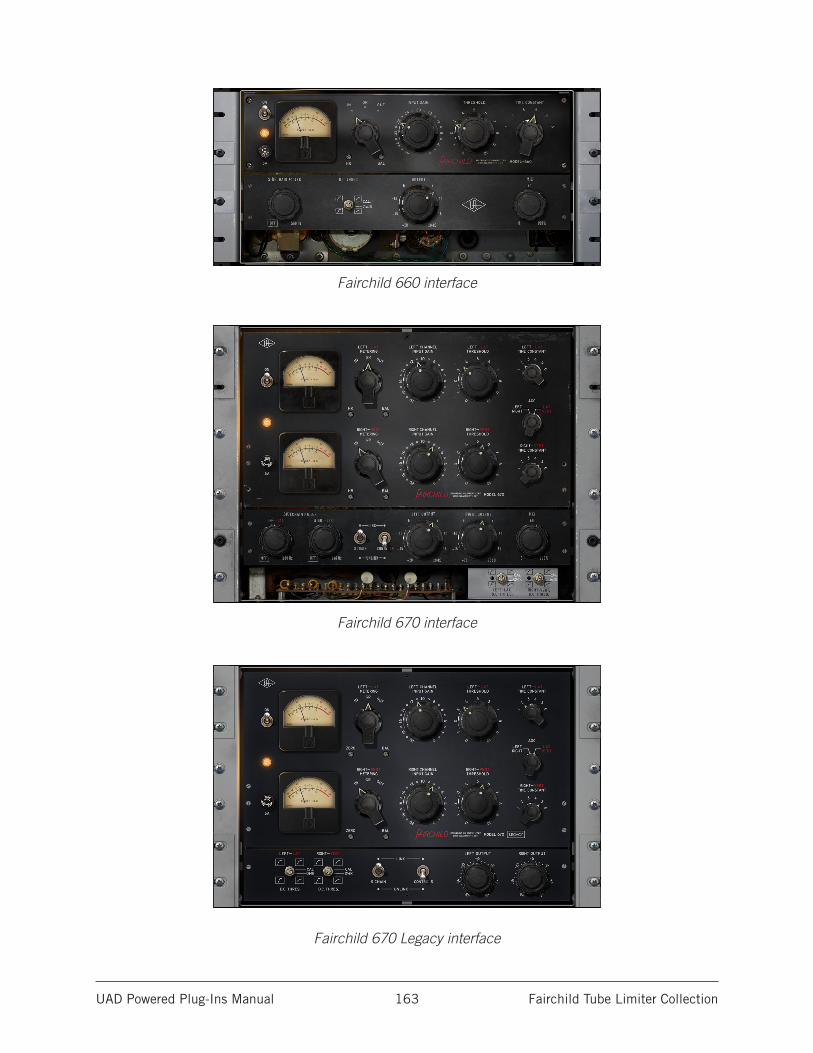
UAD Powered Plug-Ins Manual Fairchild Tube Limiter Collection 163
Fairchild 660 interface
Fairchild 670 interface
Fairchild 670 Legacy interface
UAD Powered Plug-Ins Manual Fairchild Tube Limiter Collection 164
Fairchild Plug-In FamilyThe complete Fairchild family is comprised of three individual plug-ins, as seen in the screenshots above and described below. Each variation has its own unique sonic characteristics.
Fairchild Tube Limiter CollectionThe Fairchild Tube Limiter Collection includes three UAD plug-ins: Fairchild 660, Fairchild 670, and Fairchild 670 Legacy.
Fairchild 660The original Fairchild 660 hardware is a single-channel (monophonic) processor. The UAD Fairchild 660 plug-in was faithfully modeled from the original 660 hardware, independently from the Fairchild 670 plug-in modeling.
The Fairchild 660 may be handy with mono sources, or when less control is required via its simpler interface. The Fairchild 660 controls are identical to one channel of the Fairchild 670.
Fairchild 670The Fairchild 670 is the two-channel (stereo) workhorse revered by engineers and producers worldwide.
Second-Generation AlgorithmsThe newer state-of-the-art algorithms in the Fairchild Tube Limiter Collection take full advantage of the extra processing power available on UAD-2 devices, along with the design sophistication and expertise gained since the original Fairchild Legacy plug-in was developed.
Sonic DifferencesLike the differences between the original Fairchild 660 and 670 hardware units, the UAD models in the Fairchild Tube Limiter Collection offer variations in threshold behaviors, total gain, input attenuation range, distortion amount, distortion structure, program dependence, time constant subtleties and more. These differences provides an expanded palette within the Fairchild sound.
UAD Powered Plug-Ins Manual Fairchild Tube Limiter Collection 165
Fairchild 670 LegacyThe original version of the Fairchild 670 was released in January of 2004 for the UAD-1 platform. To accommodate the limited DSP resources of the first-generation UAD-1 hardware, the transformer and I/O distortion characteristics were not modeled in this version of the plug-in.
The Fairchild 670 Legacy has a great sound and is very usable, especially in situations where less distortion is desirable, or when there are not enough DSP resources to use the second-generation models in the newer Fairchild Tube Limiter Collection. It also has slightly less overall latency since it is not an upsampled plug-in.
Note: See the Additional Latency chapter for related information.
The Fairchild 670 Legacy can be distinguished from the two newer Fairchild plug-ins by the word LEGACY in the plug-in title and within the interface.
Note: The Fairchild 670 Legacy is included with the purchase of the Fairchild Tube Limiter Collection if it is not already owned.
Mono/Stereo OperationAlthough the Fairchild 660 original hardware is a single-channel processor and the Fairchild 670 original hardware is a dual-channel processor, all UAD Fairchild plug-ins can each be used on either mono or stereo sources.
Artist PresetsThe Fairchild Tube Limiter Collection includes artist presets from prominent Fairchild users. The artist presets are in the internal factory bank and are accessed via the host application’s preset menu.
The artist presets are also copied to disk by the UAD installer so they can be used within Apollo’s Console application. These presets can be loaded using the Settings menu in the UAD Toolbar (see the “Using UAD Powered Plug-Ins” chapter in the UAD System Manual).
The Fairchild Tube Limiter Collection includes additional artist presets that are not available in the internal factory bank. These additional presets can also be accessed using the Settings menu in the UAD Toolbar.
Note: Presets created with the original Fairchild Legacy plug-in are incompatible with the newer Fairchild Tube Limiter Collection plug-ins.
UAD Powered Plug-Ins Manual Fairchild Tube Limiter Collection 166
Fairchild 670 Operational Overview
Unique ControlsControls in the UAD Fairchild plug-ins are original Fairchild hardware controls with the following exceptions:
• The VU meter and the Meter Switch are re-purposed, enabling the ability to moni-tor input and output levels (the original hardware does not have this ability). In the hardware, the function of the meter switch is to enable calibrating the bias currents; this function is achieved automatically in the plug-in when the Balance control is in the default position.
• The Headroom (HR) control replaces the VU meter’s Zero control, which originally corrected for component wear offsets in the VU meter pin.
• The Sidechain Link control is a common modification which had been performed on the unit we modeled.
• Output Level, Controls Link, Sidechain Filter, Mix, and Headroom controls are digital-only additions for the UAD plug-ins.
• The D.C. Threshold controls are original controls, however on the Fairchild 660 they were located on the rear panel.
Note: Not all controls are available in the Fairchild 670 Legacy plug-in.
Lateral/VerticalOne of the design goals of the Fairchild 670 hardware was to facilitate its use as a limiter when producing vinyl phonograph masters. The terms lateral (side-to-side) and vertical (up-and-down) refer to the mechanical modulations in a vinyl record groove that are transduced into electrical audio signals by the phonograph stylus and cartridge.
The Fairchild 670 can perform dynamics processing on the lateral (LAT) and vertical (VERT) components of stereo signals independently. In other words, the monophonic (middle) and/or stereo (side) components of a stereo source signal can be compressed or limited separately from the other component.
Lat/Vert processing facilitates maximum usable levels and efficient use of available groove space in phonograph mastering, resulting in higher volume recordings with longer playing times. Of course, the feature can also be used for creative effects outside of the phonograph environment.
Note: Lat/Vert processing is an operating mode of Fairchild 670. For additional details on the modes and how to access them, see Fairchild 670 Modes.
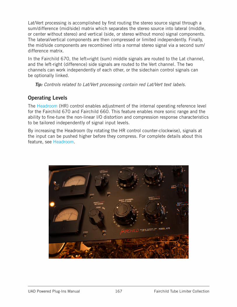
UAD Powered Plug-Ins Manual Fairchild Tube Limiter Collection 167
Lat/Vert processing is accomplished by first routing the stereo source signal through a sum/difference (mid/side) matrix which separates the stereo source into lateral (middle, or center without stereo) and vertical (side, or stereo without mono) signal components. The lateral/vertical components are then compressed or limited independently. Finally, the mid/side components are recombined into a normal stereo signal via a second sum/difference matrix.
In the Fairchild 670, the left+right (sum) middle signals are routed to the Lat channel, and the left-right (difference) side signals are routed to the Vert channel. The two channels can work independently of each other, or the sidechain control signals can be optionally linked.
Tip: Controls related to Lat/Vert processing contain red Lat/Vert text labels.
Operating LevelsThe Headroom (HR) control enables adjustment of the internal operating reference level for the Fairchild 670 and Fairchild 660. This feature enables more sonic range and the ability to fine-tune the non-linear I/O distortion and compression response characteristics to be tailored independently of signal input levels.
By increasing the Headroom (by rotating the HR control counter-clockwise), signals at the input can be pushed higher before they compress. For complete details about this feature, see Headroom.
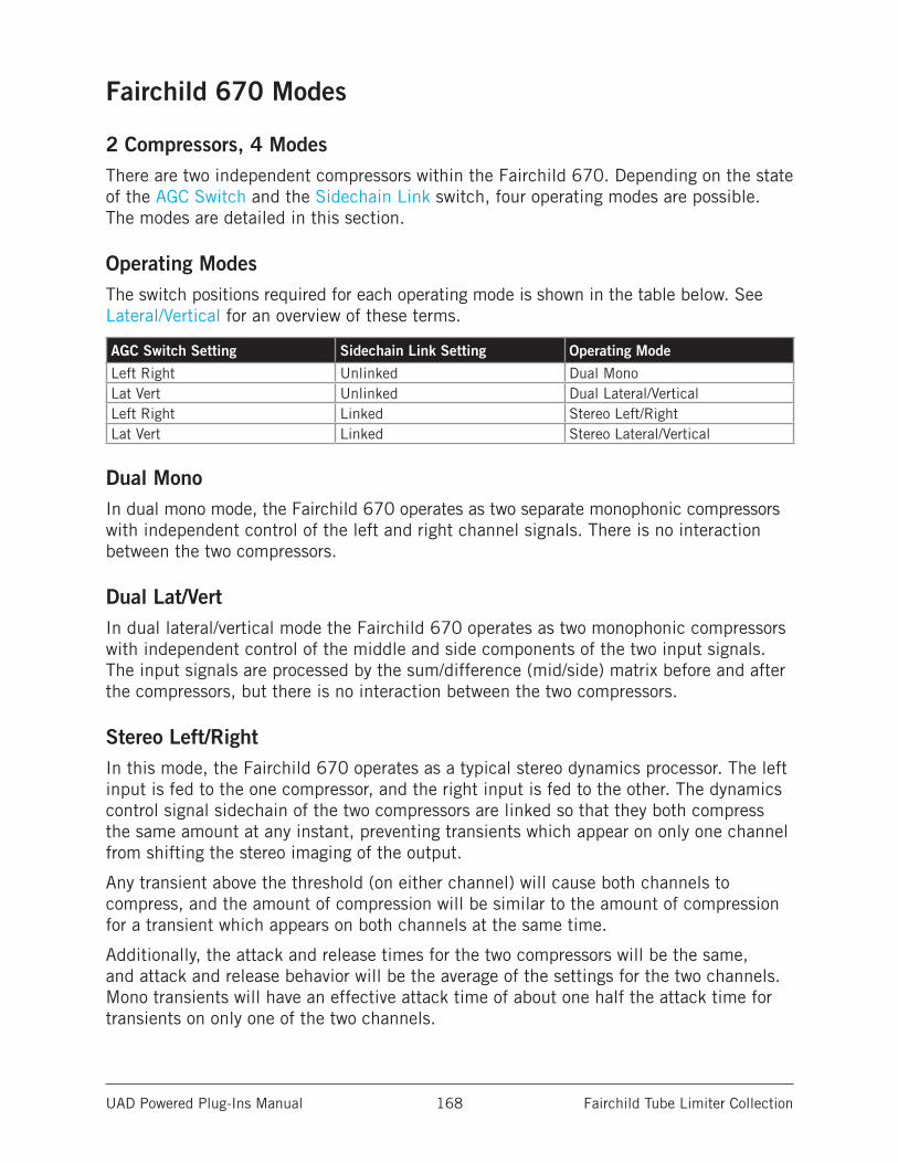
UAD Powered Plug-Ins Manual Fairchild Tube Limiter Collection 168
Fairchild 670 Modes
2 Compressors, 4 ModesThere are two independent compressors within the Fairchild 670. Depending on the state of the AGC Switch and the Sidechain Link switch, four operating modes are possible. The modes are detailed in this section.
Operating ModesThe switch positions required for each operating mode is shown in the table below. See Lateral/Vertical for an overview of these terms.
AGC Switch Setting Sidechain Link Setting Operating Mode
Left Right Unlinked Dual MonoLat Vert Unlinked Dual Lateral/VerticalLeft Right Linked Stereo Left/RightLat Vert Linked Stereo Lateral/Vertical
Dual MonoIn dual mono mode, the Fairchild 670 operates as two separate monophonic compressors with independent control of the left and right channel signals. There is no interaction between the two compressors.
Dual Lat/VertIn dual lateral/vertical mode the Fairchild 670 operates as two monophonic compressors with independent control of the middle and side components of the two input signals. The input signals are processed by the sum/difference (mid/side) matrix before and after the compressors, but there is no interaction between the two compressors.
Stereo Left/RightIn this mode, the Fairchild 670 operates as a typical stereo dynamics processor. The left input is fed to the one compressor, and the right input is fed to the other. The dynamics control signal sidechain of the two compressors are linked so that they both compress the same amount at any instant, preventing transients which appear on only one channel from shifting the stereo imaging of the output.
Any transient above the threshold (on either channel) will cause both channels to compress, and the amount of compression will be similar to the amount of compression for a transient which appears on both channels at the same time.
Additionally, the attack and release times for the two compressors will be the same, and attack and release behavior will be the average of the settings for the two channels. Mono transients will have an effective attack time of about one half the attack time for transients on only one of the two channels.
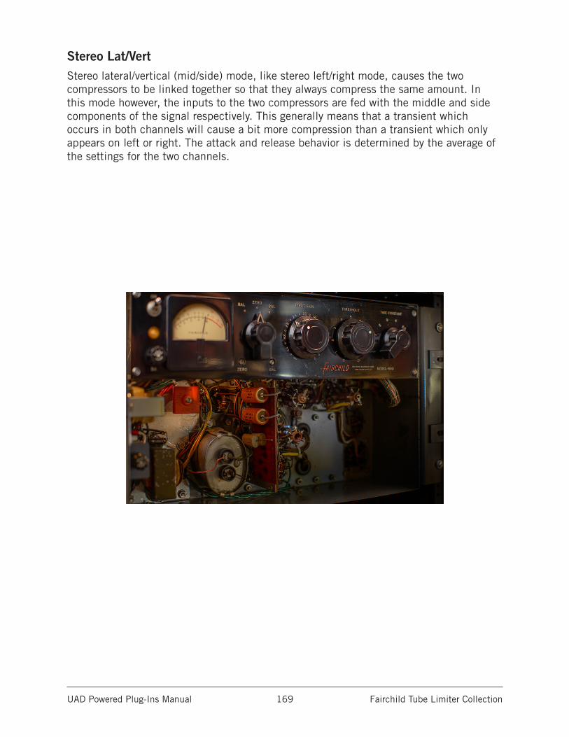
UAD Powered Plug-Ins Manual Fairchild Tube Limiter Collection 169
Stereo Lat/VertStereo lateral/vertical (mid/side) mode, like stereo left/right mode, causes the two compressors to be linked together so that they always compress the same amount. In this mode however, the inputs to the two compressors are fed with the middle and side components of the signal respectively. This generally means that a transient which occurs in both channels will cause a bit more compression than a transient which only appears on left or right. The attack and release behavior is determined by the average of the settings for the two channels.
UAD Powered Plug-Ins Manual Fairchild Tube Limiter Collection 170
Fairchild ControlsThe control functions are essentially identical across all three UAD plug-ins in the Fairchild family, so they are described only once. Any control differences between the three plug-ins are noted in the control descriptions.
Stereo ControlsControls that are identical for the left and right channels (Fairchild 670 and Fairchild 670 Legacy only) are only described once.
Power SwitchThis switch determines whether the plug-in is active. When the Power switch is in the Off position, plug-in processing is disabled and UAD DSP usage is reduced (unless UAD-2 DSP LoadLock is enabled).
Power LampThe lamp beneath the Power switch is illuminated when the plug-in is active.
Tip: Click the Power Lamp to toggle the enable/disable state of the plug-in.
VU MetersThere are two VU meters, one for each channel. The VU meters can display input levels, output levels, or gain reduction levels, as determined by the Meter Switch.
Meter SwitchThis switch determines what is displayed on the VU meters. Input, output, or gain reduction (“GR”) levels can be selected.
The default position is GR. If GR is selected, the meter will show gain reduction in dB for the corresponding compressor channel.
If the AGC Switch is set to left/right, the GR shown will be for the left or right channel. If the AGC switch is set to Lat/Vert, the GR shown will be for the middle (upper meter) or side (lower meter) channel. In GR mode, the upper labels show gain reduction in dB.
If the meter select switch is set to IN or OUT, then that meter will reflect the relative level of the right or left input or output signal (the I/O meters are not calibrated).
UAD Powered Plug-Ins Manual Fairchild Tube Limiter Collection 171
Channel Input GainThis is a stepped attenuation control which always applies to the left or right input, regardless of the AGC control setting. The steps are approximately 1 dB apart.
Fairchild 670The available range is -20 to 0 dB with a default value of -4 dB (unity gain).
Fairchild 660The available range is -Infinity (off) to 0 dB with a default value of -14 dB (unity gain).
Note: Like the 660 hardware, there is some signal leakage even when Input Gain is set to -Inf.
Fairchild 670 LegacyThe available range is -20 to 0 dB with a default value of -18 dB (unity gain).
ThresholdThis continuously variable control determines the amount of compression to be applied to the channel. Rotate clockwise for more compression (increasing the control lowers the threshold).
In the Fairchild 670, the default value is 1.5. In the Fairchild 660, the default value is 5. In the Fairchild 670 Legacy, the default value is 3.
Input Gain versus ThresholdThe amount of signal compression is determined by both the Input Gain and Threshold controls. If one is increased and the other decreased, the compression characteristics won’t change much, but the distortion characteristics will.
The input control is located ahead of the tubes, directly “behind” the input transformer. Therefore as the input control is increased, the input tube (the gain-varying stage) is hit with more signal which can increase distortion (which may or may not be desirable).
Tip: For less distortion with the same amount of compression, lower the input gain and increase the threshold control.
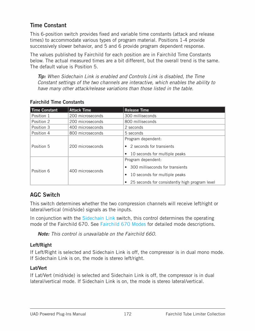
UAD Powered Plug-Ins Manual Fairchild Tube Limiter Collection 172
Time ConstantThis 6-position switch provides fixed and variable time constants (attack and release times) to accommodate various types of program material. Positions 1-4 provide successively slower behavior, and 5 and 6 provide program dependent response.
The values published by Fairchild for each position are in Fairchild Time Constants below. The actual measured times are a bit different, but the overall trend is the same. The default value is Position 5.
Tip: When Sidechain Link is enabled and Controls Link is disabled, the Time Constant settings of the two channels are interactive, which enables the ability to have many other attack/release variations than those listed in the table.
Fairchild Time Constants
Time Constant Attack Time Release TimePosition 1 200 microseconds 300 millisecondsPosition 2 200 microseconds 800 millisecondsPosition 3 400 microseconds 2 secondsPosition 4 800 microseconds 5 seconds
Position 5 200 microseconds
Program dependent:
• 2 seconds for transients
• 10 seconds for multiple peaks
Position 6 400 microseconds
Program dependent:
• 300 milliseconds for transients
• 10 seconds for multiple peaks
• 25 seconds for consistently high program level
AGC SwitchThis switch determines whether the two compression channels will receive left/right or lateral/vertical (mid/side) signals as the inputs.
In conjunction with the Sidechain Link switch, this control determines the operating mode of the Fairchild 670. See Fairchild 670 Modes for detailed mode descriptions.
Note: This control is unavailable on the Fairchild 660.
Left/RightIf Left/Right is selected and Sidechain Link is off, the compressor is in dual mono mode. If Sidechain Link is on, the mode is stereo left/right.
Lat/VertIf Lat/Vert (mid/side) is selected and Sidechain Link is off, the compressor is in dual lateral/vertical mode. If Sidechain Link is on, the mode is stereo lateral/vertical.
UAD Powered Plug-Ins Manual Fairchild Tube Limiter Collection 173
Sidechain LinkWhen this control is set to Link, it causes the two channels of the compressor to compress in equal amounts. This does not mean that the compressor will be equally sensitive to either channel however; that depends on the settings of the other controls.
Note: This control is unavailable on the Fairchild 660.
Linking the sidechains simply means that the instantaneous amount of compression for the two channels will always be the same, thereby preventing left-right image shifting at the output. Threshold and input gains can be set independently to cause the compressor to be more sensitive to instruments which are panned to one side or the other. Output controls can be set separately in order to correct an overall image shift at the output.
Tip: In conjunction with the AGC Switch, the Sidechain Link switch determines the operating mode of the Fairchild 670 and Fairchild 670 Legacy.
Controls LinkThis switch allows the two sets of controls for the interface to be stereo linked. The control is unavailable on the Fairchild 660.
Important: When unlink is switched to link, the left channel values are copied to the right channel, and any control offsets between channels are lost.
HeadroomThe Fairchild hardware units can accept an analog signal level of approximately +27 dBm before undesirable signal clipping occurs. As the signal increases up to this point however, desirable audio-path nonlinearities and “good” harmonic distortion characteristics occur. This musically pleasing “warmth” at higher levels is what gives the unit much of its revered sonic character. Because analog mixing consoles can typically output high signal levels, audio engineers often take advantage of the ability to “push” the hardware unit into the colorful arena.
This complete pallet of sonic nuance, including the dynamic input response, is captured in the Fairchild Tube Limiter Collection models (but not the Fairchild 670 Legacy). The 660 and 670 plug-ins are calibrated internally so that when the Headroom control is at its nominal value of 16 dB, 0 dBFS at their input is equivalent to an input level of approximately +20 dBu on the hardware, where the coloring is more prominent. The result is that a typical signal within a DAW will drive the UAD Fairchild 660/670 into these “virtual” higher levels, resulting in fairly high amounts gain reduction.
UAD Powered Plug-Ins Manual Fairchild Tube Limiter Collection 174
Headroom ControlThe Headroom (HR) control is provided to accommodate applications where high amounts of gain reduction are not desired. Headroom simply changes the internal operating level so that the plug-in is not “pushed” into gain reduction as much.
Note: There is only one headroom parameter. Although the HR control appears twice in the Fairchild 670 window, they are permanently linked.
Headroom can be set (in dB) to 4, 8, 12, 16, 20, 24, or 28. The default value is 16 dB (when the set screw dot is in the straight up 12 o’clock position). Note that Headroom is increased as the dB value decreases.
Tip: Click the HR text label to return the control to the default value.
At higher dB values (clockwise rotation), signals will push the plug-in into gain reduction (and more non-linearity and “good” harmonic distortion color) more easily. Set the control to a lower value (counter-clockwise rotation) when less gain reduction and less color is desired.
Note: To avoid the temporary gain increases that can result when adjusting Headroom, automating this control is not recommended.
Keep in mind there are no hard and fast headroom rules. Feel free to experiment with the various positions of the HR control regardless of the audio source. If it sounds good, use it!
Note: The HR control is not available with Fairchild 670 Legacy. On the hardware unit, the Zero screw (as displayed in the Fairchild 670 Legacy) adjusted the meter pointer to compensate voltage fluctuation and component wear.
BalanceBalance (BAL) controls the bias current balance. It always controls one channel of the compressor, regardless of what the nearby Meter Switch is set to. The point of perfectly calibrated bias currents is achieved when the screw slot is at the 12 o’clock position (the default value).
Tip: Click the BAL text label to return the control to the default position.
At the default setting, the amount of additive signal deflection (“thud”) which happens due to an attack is minimized. Setting this control counter-clockwise from this position results in a thud of one polarity on transients, and going clockwise produces a thud of opposite polarity.
Note: To avoid the DC settling artifacts that can result when adjusting Balance, automating this control is not recommended.
UAD Powered Plug-Ins Manual Fairchild Tube Limiter Collection 175
Sidechain FilterThe Sidechain Filters (one each for the Left/Lat and Right/Vert channels) control the cutoff frequency of a low-cut filter on the compressor’s control signal sidechain. They have a slope of 12 dB per octave. The available range is 20 Hz to 500 Hz, and Off. The default value is Off.
Tip: Click the OFF label to disable the sidechain filter.
Removing low-frequency content from the sidechain can reduce excessive gain reduction and/or “pumping” on bass-heavy audio signals without reducing bass content of the audio signal itself.
Note: Sidechain Filters are not available with Fairchild 670 Legacy.
Auditioning the Sidechain FilterTo quickly switch back and forth between OFF and the last set value, click the OFF label. This feature is handy for comparing the filtered and unfiltered sidechains.
Note: The Sidechain Filter affects the control signal of the compressor only. It does not filter the audio signal.
DC ThresholdDC Threshold controls the ratio of compression as well as the knee width. As the knob is turned clockwise, the ratio gets lower and the knee gets broader. The threshold also gets lower as the knob is turned clockwise.
It’s more technically accurate to say that this control simply changes the knee width, since no matter where it’s set, the ratio always approaches true limiting eventually. However, the knee becomes so broad that it becomes more practical to speak of the ratio changing, because for reasonable amounts of compression (less than 25 dB), this is the case.
CALTo calibrate the plug-in to factory specifications (the default value), align the white CAL mark with the black dot on the adjustment screw.
Tip: Click the CAL text label to return the control to the factory calibrated position.
OWRTo calibrate the plug-in to the setting used by Ocean Way Recording (the source unit for the plug-in modeling), align the white OWR mark with the black dot on the adjustment screw.
Tip: Click the OWR text label to return the control to the Ocean Way Recording position.
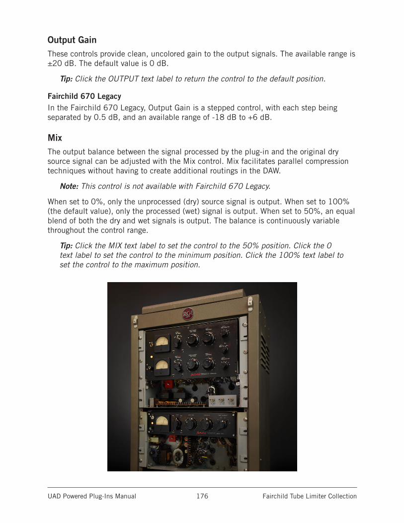
UAD Powered Plug-Ins Manual Fairchild Tube Limiter Collection 176
Output GainThese controls provide clean, uncolored gain to the output signals. The available range is ±20 dB. The default value is 0 dB.
Tip: Click the OUTPUT text label to return the control to the default position.
Fairchild 670 LegacyIn the Fairchild 670 Legacy, Output Gain is a stepped control, with each step being separated by 0.5 dB, and an available range of -18 dB to +6 dB.
MixThe output balance between the signal processed by the plug-in and the original dry source signal can be adjusted with the Mix control. Mix facilitates parallel compression techniques without having to create additional routings in the DAW.
Note: This control is not available with Fairchild 670 Legacy.
When set to 0%, only the unprocessed (dry) source signal is output. When set to 100% (the default value), only the processed (wet) signal is output. When set to 50%, an equal blend of both the dry and wet signals is output. The balance is continuously variable throughout the control range.
Tip: Click the MIX text label to set the control to the 50% position. Click the 0 text label to set the control to the minimum position. Click the 100% text label to set the control to the maximum position.
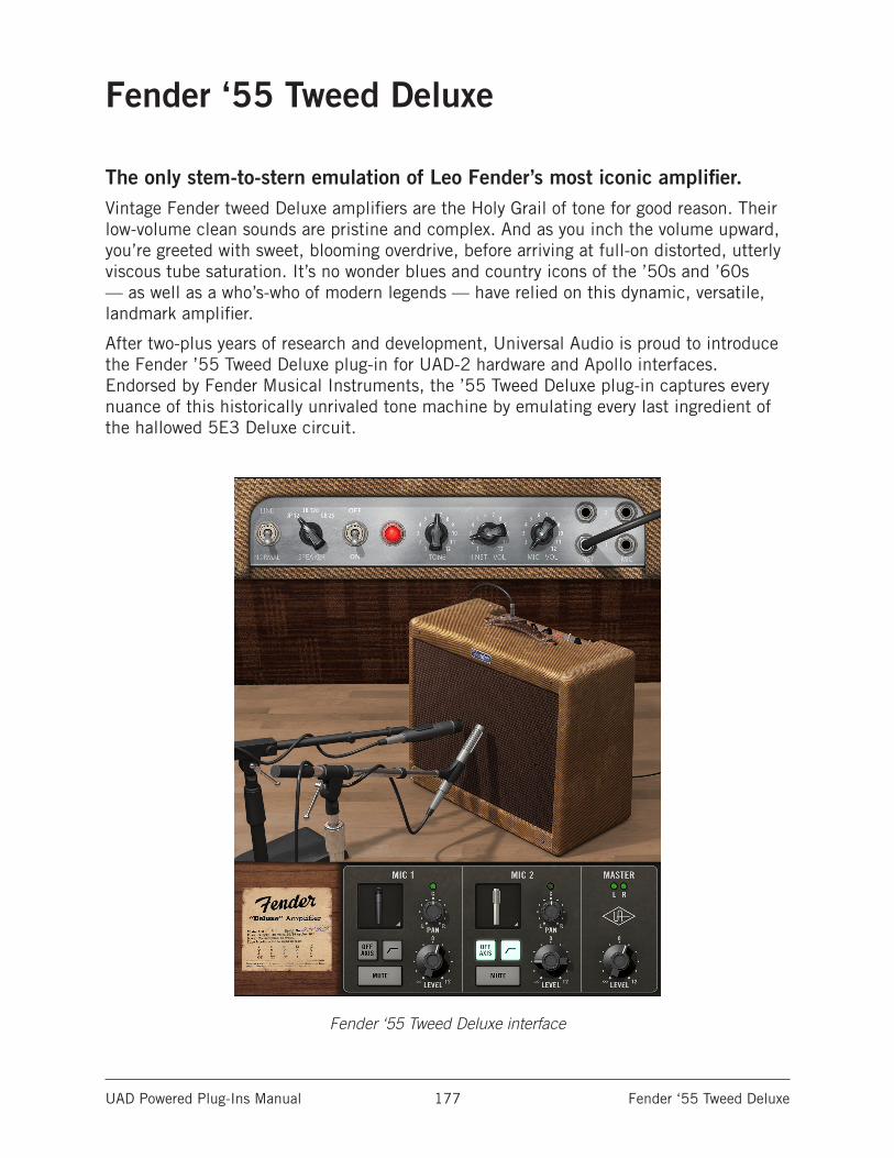
UAD Powered Plug-Ins Manual Fender ‘55 Tweed Deluxe 177
Fender ‘55 Tweed Deluxe
The only stem-to-stern emulation of Leo Fender’s most iconic amplifier.Vintage Fender tweed Deluxe amplifiers are the Holy Grail of tone for good reason. Their low-volume clean sounds are pristine and complex. And as you inch the volume upward, you’re greeted with sweet, blooming overdrive, before arriving at full-on distorted, utterly viscous tube saturation. It’s no wonder blues and country icons of the ’50s and ’60s — as well as a who’s-who of modern legends — have relied on this dynamic, versatile, landmark amplifier.
After two-plus years of research and development, Universal Audio is proud to introduce the Fender ’55 Tweed Deluxe plug-in for UAD-2 hardware and Apollo interfaces. Endorsed by Fender Musical Instruments, the ’55 Tweed Deluxe plug-in captures every nuance of this historically unrivaled tone machine by emulating every last ingredient of the hallowed 5E3 Deluxe circuit.
Fender ‘55 Tweed Deluxe interface
UAD Powered Plug-Ins Manual Fender ‘55 Tweed Deluxe 178
Now You Can:• Use your Apollo with Unison™ technology to track through an authentic
emulation of a 1955 Fender tweed Deluxe amplifier— with indiscernible latency
• Re-amp previously recorded tracks with any UAD-2 hardware
• Easily track perfect studio amp tones with different microphone combinations and placements — without phase issues
• Choose from three different speaker types for a huge range of tones and textures
Through Science We Found… MagicUniversal Audio chose two bone-stock 1955 tweed Deluxe amps as “golden units” to be emulated. This began a two-year R&D project to capture every single component — from speaker paper and heat dissipation, to filter caps and transformers — the essential ingredients that allow the tweed Deluxe to deliver expressive, dynamic, easy-to-record sounds, with only Volume and Tone controls.
Three Genre-Defining Speaker Choices The speaker is one of the most important elements to the character of the tweed Deluxe. The ’55 Tweed Deluxe plug-in gives you three common “hot rod” mods that pro players have been using for over 40 years.
Expertly Placed Dual Mic Setup The ’55 Tweed Deluxe plug-in offers expertly placed multi-mic tones with a collection of legendary mics — and zero phase issues. You can use the intuitive Mic Mixer to season your tones with separate Level, Pan, and high-pass filter. Additionally, you can set each mic to a secondary off-axis position for further tone tweaking.
Dialed-In PresetsA broad selection of carefully crafted plug-in presets are provided. The presets are designed by guitar tone experts to provide optimum combinations of amp, speaker, and microphone settings.
Auditioning the presets is a great way to learn how professional guitar players and engineers dial in their sound. Of course, experimentation is encouraged — it’s practically impossible to get a bad sound out of this plug-in.
Unison™ Technology for Apollo InterfacesHarnessing UA’s groundbreaking Unison technology, the Fender ‘55 Tweed Deluxe plug-in gives you the impedance, gain staging, and circuit behaviors that have contributed to making the tweed Deluxe one of the most recorded guitar amps in history. And like the original amp, you can plug into any of the amp’s four inputs and achieve different gain levels or impedance changes, or plug in using a vintage “Y” cable to jump the inputs and blend the channels.
UAD Powered Plug-Ins Manual Fender ‘55 Tweed Deluxe 179
Technical OverviewNote: This section provides a conceptual overview of the plug-in. For detailed control descriptions, see the Fender ‘55 Tweed Deluxe Controls section in this chapter.
The UAD Fender ‘55 Tweed Deluxe plug-in contains three distinct areas of technology that comprise the overall plug-in: The amplifier circuitry, the speakers, and the microphones. These items have all been separately and meticulously emulated using the latest state-of-the-art proprietary modeling techniques.
The 1955 Fender DeluxeThis particular Fender Deluxe amp, one of a long line of Deluxe models, was originally produced in 1955. Its simple feature set is comprised of two channels with a volume control for each channel and a single tone control shared by the two channels. The amp outputs approximately 15 watts into a single 12” speaker enclosed in an open-back cabinet covered with distinctive tweed fabric.
The 5E3 CircuitThe amp’s electronics are designated by Fender as the “5E3” circuit. The circuit is simple compared to most amps, and contains five tubes: 12AX7 and 12AY7 preamp tubes, two 6V6GT power tubes, and a single 5Y3GT rectifier tube. There are no transistors in this circuit.
The 5E3 is well known for its warmth, touch sensitivity, and a fuzzy distortion characteristic that cleans up nicely as the guitar’s volume is reduced. The preamp and power sections both run hot – breaking up easily in a musically pleasing way – creating layers of gain and distortion that are key to its dynamic response. The tube rectifier also contributes to its spongy, compressed quality.
Despite its simplicity, the amp is popular and surprisingly versatile with players – not just guitarists – in a multitude of genres. The complex interactions between the simple controls, preamp tubes, power amp tubes, and speaker provide an exceptionally wide range of excellent tones.
The interactive dynamic tonal response of the amp is legendary. The amp has been notoriously difficult to model because of the extreme interactions between components. However, the authentic sound and live feel of the amp is available with stunning accuracy in the Fender ‘55 Tweed Deluxe plug-in, which provides all the tools you need to easily produce great recorded guitar tones.
UAD Powered Plug-Ins Manual Fender ‘55 Tweed Deluxe 180
SpeakersThree classic speaker selections are available in the plug-in. In addition to the original stock speaker, two alternate speakers were carefully chosen that complement the 5E3 circuit and suit a variety of musical genres.
Each speaker has a unique frequency response and dynamic range, providing a wide sonic palette from classic American clean, British rock, and everything in between.
MicrophonesFive high quality mics, from the vintage and modern eras, are available in the plug-in for capturing the sound of the amp. Two mics can be used simultaneously, each with its own level, high pass filter, and pan settings.
Because two mics can be mixed together, the available mics were selected to complement each other as well as the speaker itself. For example, you can choose a mic with punchy midrange to cut through the mix and blend in a second mic that has more low end to add body and depth.
Mic PlacementsIt can take experienced engineers years to find the perfect combinations of mic and position for every type of speaker. Even extremely nuanced adjustments to a mic’s position in relation to the speaker cone can have a significant impact to the recorded sound of the amp.
With the Fender ‘55 Tweed Deluxe plug-in, this work is done for you. Each mic placement is carefully positioned for the optimum “sweet spot” and each placement is unique to the specific speaker that is selected.
An option to place the mic in a off-axis position is available, offering an alternate tonal option. As with the normal positions, the off-axis placements are positioned for optimum sound, and the placements are unique for every speaker selection.
Mic MixingIn the physical realm, using two microphones on a single source can cause out-of-phase signals, resulting in undesirable sonic artifacts such as comb filtering. With the Fender ‘55 Tweed Deluxe, all phase alignment is done by our experts, allowing you to concentrate on the music. By using both microphones together, big and lush guitar tones are easily achieved.
Guitar WorkflowsThe Fender ‘55 Tweed Deluxe can be used with Apollo’s Realtime UAD Processing and/or DAW setups with UAD-2 devices. For optimum results when playing live through UAD guitar amp plug-ins, and when processing previously recorded tracks, see the example setups in the Guitar Amp Plug-In Workflows section in this chapter.
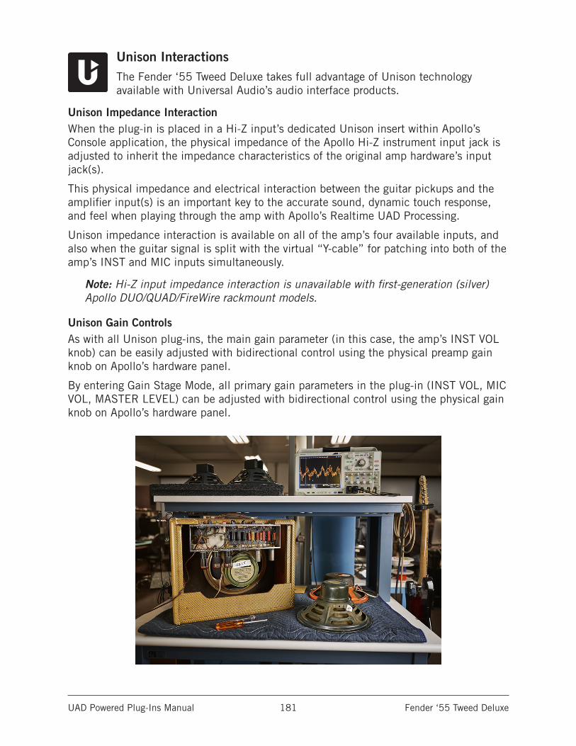
UAD Powered Plug-Ins Manual Fender ‘55 Tweed Deluxe 181
Unison InteractionsThe Fender ‘55 Tweed Deluxe takes full advantage of Unison technology available with Universal Audio’s audio interface products.
Unison Impedance InteractionWhen the plug-in is placed in a Hi-Z input’s dedicated Unison insert within Apollo’s Console application, the physical impedance of the Apollo Hi-Z instrument input jack is adjusted to inherit the impedance characteristics of the original amp hardware’s input jack(s).
This physical impedance and electrical interaction between the guitar pickups and the amplifier input(s) is an important key to the accurate sound, dynamic touch response, and feel when playing through the amp with Apollo’s Realtime UAD Processing.
Unison impedance interaction is available on all of the amp’s four available inputs, and also when the guitar signal is split with the virtual “Y-cable” for patching into both of the amp’s INST and MIC inputs simultaneously.
Note: Hi-Z input impedance interaction is unavailable with first-generation (silver) Apollo DUO/QUAD/FireWire rackmount models.
Unison Gain ControlsAs with all Unison plug-ins, the main gain parameter (in this case, the amp’s INST VOL knob) can be easily adjusted with bidirectional control using the physical preamp gain knob on Apollo’s hardware panel.
By entering Gain Stage Mode, all primary gain parameters in the plug-in (INST VOL, MIC VOL, MASTER LEVEL) can be adjusted with bidirectional control using the physical gain knob on Apollo’s hardware panel.
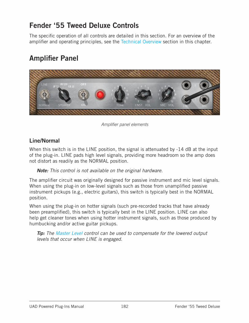
UAD Powered Plug-Ins Manual Fender ‘55 Tweed Deluxe 182
Fender ‘55 Tweed Deluxe ControlsThe specific operation of all controls are detailed in this section. For an overview of the amplifier and operating principles, see the Technical Overview section in this chapter.
Amplifier Panel
Amplifier panel elements
Line/NormalWhen this switch is in the LINE position, the signal is attenuated by -14 dB at the input of the plug-in. LINE pads high level signals, providing more headroom so the amp does not distort as readily as the NORMAL position.
Note: This control is not available on the original hardware.
The amplifier circuit was originally designed for passive instrument and mic level signals. When using the plug-in on low-level signals such as those from unamplified passive instrument pickups (e.g., electric guitars), this switch is typically best in the NORMAL position.
When using the plug-in on hotter signals (such pre-recorded tracks that have already been preamplified), this switch is typically best in the LINE position. LINE can also help get cleaner tones when using hotter instrument signals, such as those produced by humbucking and/or active guitar pickups.
Tip: The Master Level control can be used to compensate for the lowered output levels that occur when LINE is engaged.
UAD Powered Plug-Ins Manual Fender ‘55 Tweed Deluxe 183
Speaker SelectThis rotary switch determines the active speaker model. Three speaker selections are available; each has distinct and highly usable sonic characteristics.
Speaker Descriptions
JP 12Modeled on the original factory-installed 25-watt Jensen P12R speaker. It has a sparkly top and thick bottom, but not as much midrange as the other speakers. The quintessential sound of early country & western, blues, and rock ‘n’ roll.
JB 120Modeled on the 120-watt JBL D-120F that was designed for Fender as an aftermarket speaker in the ‘70s. It delivers a glassy, snappy sound, a more airy presence, and a slight peak in the upper midrange.
GB 25Modeled on the classic Celestion 25-watt “greenback” speaker that’s popular with rock players. It has a warm, thick bottom end, buttery midrange, and a darker, more velvety treble response that’s perfect when pushing the amp into distortion.
On/Off (Enable)The OFF/ON toggle switch is the plug-in’s bypass control for comparing the processed sound to the original signal.
Tip: Click the power lamp to toggle the OFF/ON state.
When this toggle switch is in the ON position (down), plug-in processing is active and the red power lamp is lit. In the OFF position (up), plug-in processing is bypassed and the power lamp and mic buttons are unlit.
When set to OFF, the plug-in remains loaded on UAD DSP for a glitch-free soft bypass. To unload the plug-in and conserve UAD DSP, use the Power (UA logo) switch instead.
Unison InteractionWhen the plug-in is placed in a Hi-Z input’s dedicated Unison insert within Apollo’s Console application, Unison’s physical impedance interactions between Apollo’s Hi-Z input and the amp’s input jack selection remains active and can be switched, even when Enable is set to OFF.
This feature allows the amp’s input jack selections to control Apollo’s Unison impedance interactions without otherwise processing the signal with the amp. You could, for example, record the signal dry but with Unison impedance interactions so the amp’s sound can be subsequently added and adjusted to taste during mixdown, thus maintaining complete Unison modeling accuracy all the way through the tracking and mixing process.
Note: For specific examples, see the Guitar Amp Plug-In Workflows in this chapter.
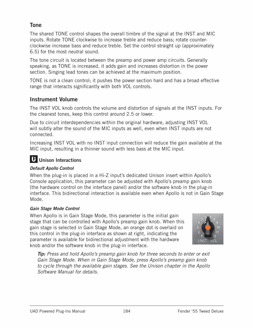
UAD Powered Plug-Ins Manual Fender ‘55 Tweed Deluxe 184
ToneThe shared TONE control shapes the overall timbre of the signal at the INST and MIC inputs. Rotate TONE clockwise to increase treble and reduce bass; rotate counter-clockwise increase bass and reduce treble. Set the control straight up (approximately 6.5) for the most neutral sound.
The tone circuit is located between the preamp and power amp circuits. Generally speaking, as TONE is increased, it adds gain and increases distortion in the power section. Singing lead tones can be achieved at the maximum position.
TONE is not a clean control; it pushes the power section hard and has a broad effective range that interacts significantly with both VOL controls.
Instrument VolumeThe INST VOL knob controls the volume and distortion of signals at the INST inputs. For the cleanest tones, keep this control around 2.5 or lower.
Due to circuit interdependencies within the original hardware, adjusting INST VOL will subtly alter the sound of the MIC inputs as well, even when INST inputs are not connected.
Increasing INST VOL with no INST input connection will reduce the gain available at the MIC input, resulting in a thinner sound with less bass at the MIC input.
Unison Interactions
Default Apollo Control
When the plug-in is placed in a Hi-Z input’s dedicated Unison insert within Apollo’s Console application, this parameter can be adjusted with Apollo’s preamp gain knob (the hardware control on the interface panel) and/or the software knob in the plug-in interface. This bidirectional interaction is available even when Apollo is not in Gain Stage Mode.
Gain Stage Mode Control
When Apollo is in Gain Stage Mode, this parameter is the initial gain stage that can be controlled with Apollo’s preamp gain knob. When this gain stage is selected in Gain Stage Mode, an orange dot is overlaid on this control in the plug-in interface as shown at right, indicating the parameter is available for bidirectional adjustment with the hardware knob and/or the software knob in the plug-in interface.
Tip: Press and hold Apollo’s preamp gain knob for three seconds to enter or exit Gain Stage Mode. When in Gain Stage Mode, press Apollo’s preamp gain knob to cycle through the available gain stages. See the Unison chapter in the Apollo Software Manual for details.
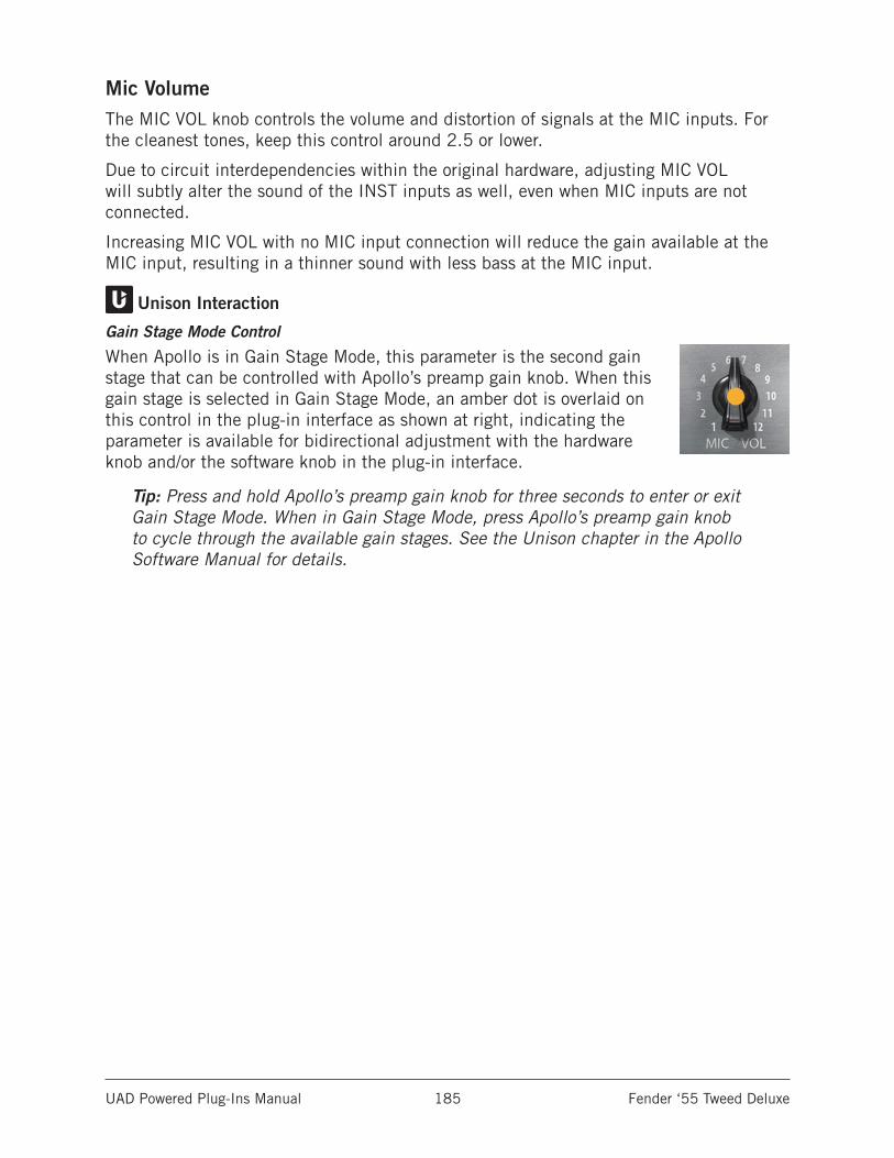
UAD Powered Plug-Ins Manual Fender ‘55 Tweed Deluxe 185
Mic VolumeThe MIC VOL knob controls the volume and distortion of signals at the MIC inputs. For the cleanest tones, keep this control around 2.5 or lower.
Due to circuit interdependencies within the original hardware, adjusting MIC VOL will subtly alter the sound of the INST inputs as well, even when MIC inputs are not connected.
Increasing MIC VOL with no MIC input connection will reduce the gain available at the MIC input, resulting in a thinner sound with less bass at the MIC input.
Unison Interaction
Gain Stage Mode Control
When Apollo is in Gain Stage Mode, this parameter is the second gain stage that can be controlled with Apollo’s preamp gain knob. When this gain stage is selected in Gain Stage Mode, an amber dot is overlaid on this control in the plug-in interface as shown at right, indicating the parameter is available for bidirectional adjustment with the hardware knob and/or the software knob in the plug-in interface.
Tip: Press and hold Apollo’s preamp gain knob for three seconds to enter or exit Gain Stage Mode. When in Gain Stage Mode, press Apollo’s preamp gain knob to cycle through the available gain stages. See the Unison chapter in the Apollo Software Manual for details.
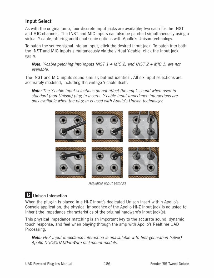
UAD Powered Plug-Ins Manual Fender ‘55 Tweed Deluxe 186
Input SelectAs with the original amp, four discrete input jacks are available; two each for the INST and MIC channels. The INST and MIC inputs can also be patched simultaneously using a virtual Y-cable, offering additional sonic options with Apollo’s Unison technology.
To patch the source signal into an input, click the desired input jack. To patch into both the INST and MIC inputs simultaneously via the virtual Y-cable, click the input jack again.
Note: Y-cable patching into inputs INST 1 + MIC 2, and INST 2 + MIC 1, are not available.
The INST and MIC inputs sound similar, but not identical. All six input selections are accurately modeled, including the vintage Y-cable itself.
Note: The Y-cable input selections do not affect the amp’s sound when used in standard (non-Unison) plug-in inserts. Y-cable input impedance interactions are only available when the plug-in is used with Apollo’s Unison technology.
Available Input settings
Unison InteractionWhen the plug-in is placed in a Hi-Z input’s dedicated Unison insert within Apollo’s Console application, the physical impedance of the Apollo Hi-Z input jack is adjusted to inherit the impedance characteristics of the original hardware’s input jack(s).
This physical impedance matching is an important key to the accurate sound, dynamic touch response, and feel when playing through the amp with Apollo’s Realtime UAD Processing.
Note: Hi-Z input impedance interaction is unavailable with first-generation (silver) Apollo DUO/QUAD/FireWire rackmount models.
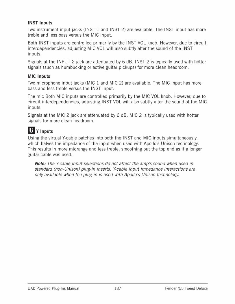
UAD Powered Plug-Ins Manual Fender ‘55 Tweed Deluxe 187
INST InputsTwo instrument input jacks (INST 1 and INST 2) are available. The INST input has more treble and less bass versus the MIC input.
Both INST inputs are controlled primarily by the INST VOL knob. However, due to circuit interdependencies, adjusting MIC VOL will also subtly alter the sound of the INST inputs.
Signals at the INPUT 2 jack are attenuated by 6 dB. INST 2 is typically used with hotter signals (such as humbucking or active guitar pickups) for more clean headroom.
MIC InputsTwo microphone input jacks (MIC 1 and MIC 2) are available. The MIC input has more bass and less treble versus the INST input.
The mic Both MIC inputs are controlled primarily by the MIC VOL knob. However, due to circuit interdependencies, adjusting INST VOL will also subtly alter the sound of the MIC inputs.
Signals at the MIC 2 jack are attenuated by 6 dB. MIC 2 is typically used with hotter signals for more clean headroom.
Y InputsUsing the virtual Y-cable patches into both the INST and MIC inputs simultaneously, which halves the impedance of the input when used with Apollo’s Unison technology. This results in more midrange and less treble, smoothing out the top end as if a longer guitar cable was used.
Note: The Y-cable input selections do not affect the amp’s sound when used in standard (non-Unison) plug-in inserts. Y-cable input impedance interactions are only available when the plug-in is used with Apollo’s Unison technology.
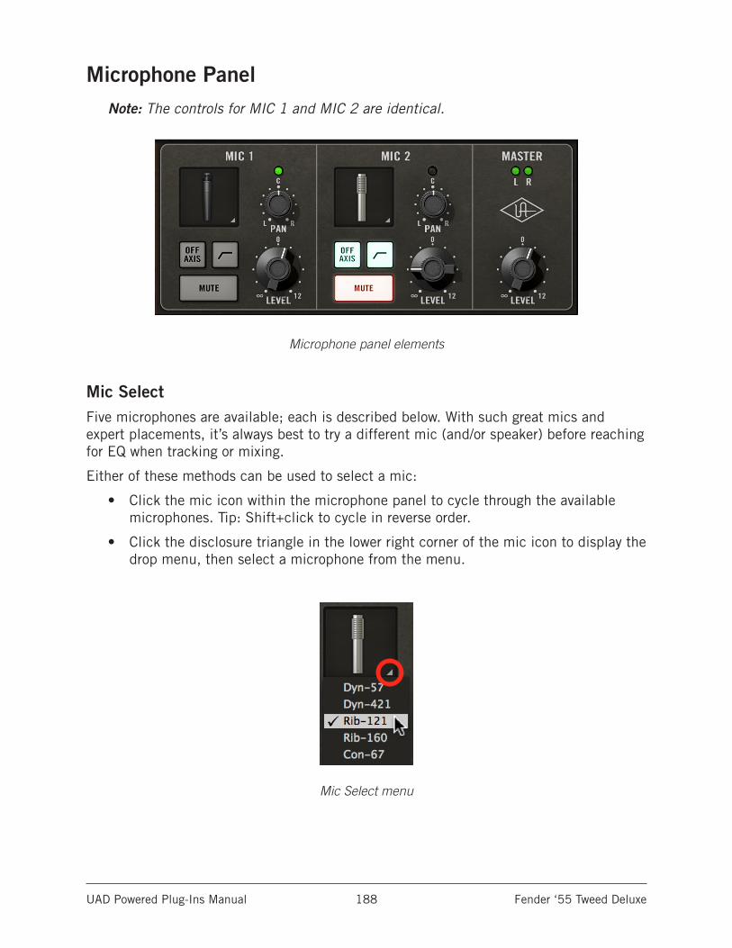
UAD Powered Plug-Ins Manual Fender ‘55 Tweed Deluxe 188
Microphone PanelNote: The controls for MIC 1 and MIC 2 are identical.
Microphone panel elements
Mic SelectFive microphones are available; each is described below. With such great mics and expert placements, it’s always best to try a different mic (and/or speaker) before reaching for EQ when tracking or mixing.
Either of these methods can be used to select a mic:
• Click the mic icon within the microphone panel to cycle through the available microphones. Tip: Shift+click to cycle in reverse order.
• Click the disclosure triangle in the lower right corner of the mic icon to display the drop menu, then select a microphone from the menu.
Mic Select menu
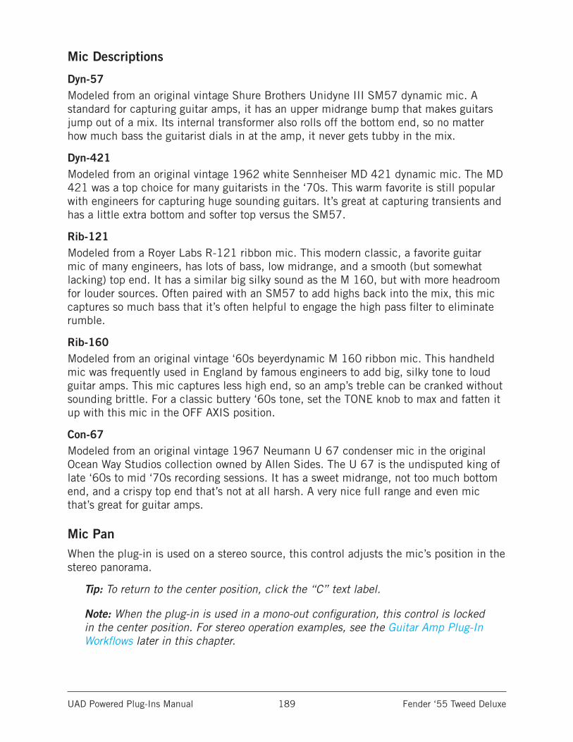
UAD Powered Plug-Ins Manual Fender ‘55 Tweed Deluxe 189
Mic Descriptions
Dyn-57Modeled from an original vintage Shure Brothers Unidyne III SM57 dynamic mic. A standard for capturing guitar amps, it has an upper midrange bump that makes guitars jump out of a mix. Its internal transformer also rolls off the bottom end, so no matter how much bass the guitarist dials in at the amp, it never gets tubby in the mix.
Dyn-421Modeled from an original vintage 1962 white Sennheiser MD 421 dynamic mic. The MD 421 was a top choice for many guitarists in the ‘70s. This warm favorite is still popular with engineers for capturing huge sounding guitars. It’s great at capturing transients and has a little extra bottom and softer top versus the SM57.
Rib-121Modeled from a Royer Labs R-121 ribbon mic. This modern classic, a favorite guitar mic of many engineers, has lots of bass, low midrange, and a smooth (but somewhat lacking) top end. It has a similar big silky sound as the M 160, but with more headroom for louder sources. Often paired with an SM57 to add highs back into the mix, this mic captures so much bass that it’s often helpful to engage the high pass filter to eliminate rumble.
Rib-160Modeled from an original vintage ‘60s beyerdynamic M 160 ribbon mic. This handheld mic was frequently used in England by famous engineers to add big, silky tone to loud guitar amps. This mic captures less high end, so an amp’s treble can be cranked without sounding brittle. For a classic buttery ‘60s tone, set the TONE knob to max and fatten it up with this mic in the OFF AXIS position.
Con-67Modeled from an original vintage 1967 Neumann U 67 condenser mic in the original Ocean Way Studios collection owned by Allen Sides. The U 67 is the undisputed king of late ‘60s to mid ‘70s recording sessions. It has a sweet midrange, not too much bottom end, and a crispy top end that’s not at all harsh. A very nice full range and even mic that’s great for guitar amps.
Mic PanWhen the plug-in is used on a stereo source, this control adjusts the mic’s position in the stereo panorama.
Tip: To return to the center position, click the “C” text label.
Note: When the plug-in is used in a mono-out configuration, this control is locked in the center position. For stereo operation examples, see the Guitar Amp Plug-In Workflows later in this chapter.
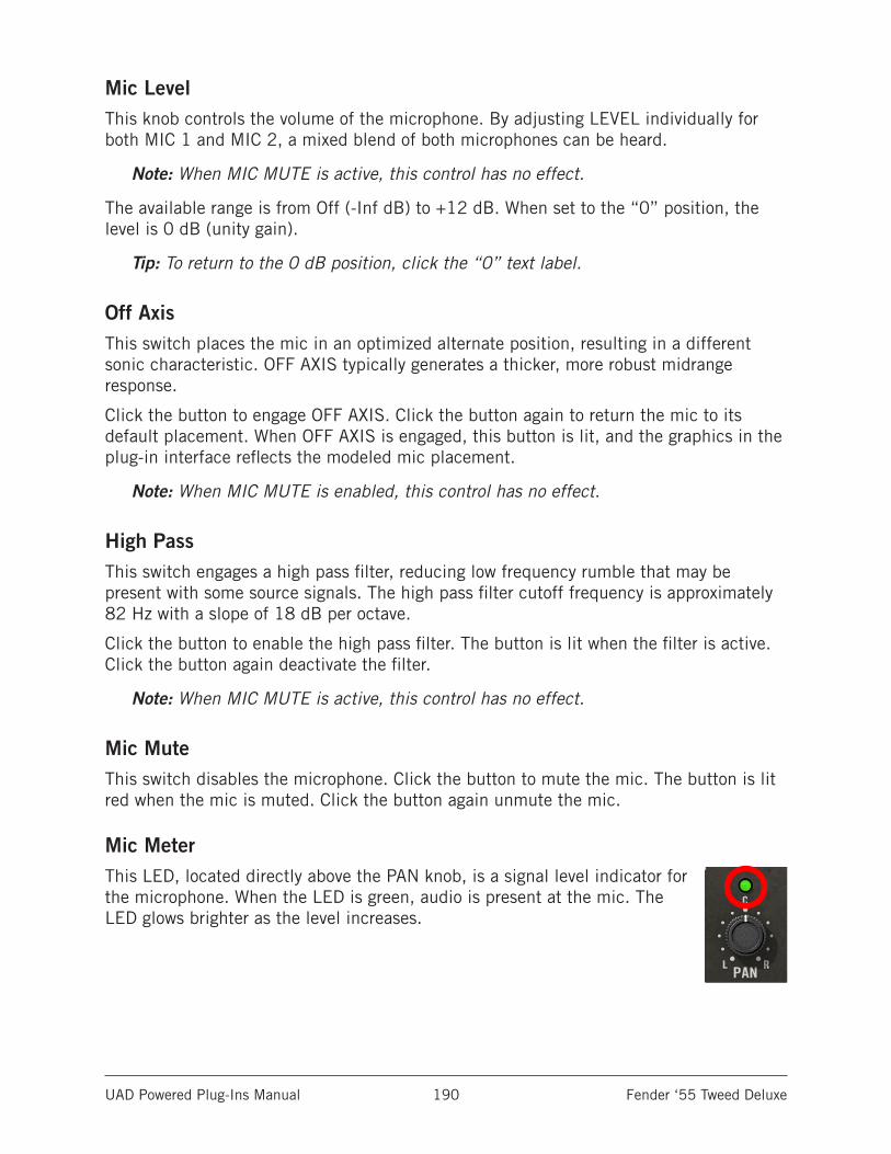
UAD Powered Plug-Ins Manual Fender ‘55 Tweed Deluxe 190
Mic LevelThis knob controls the volume of the microphone. By adjusting LEVEL individually for both MIC 1 and MIC 2, a mixed blend of both microphones can be heard.
Note: When MIC MUTE is active, this control has no effect.
The available range is from Off (-Inf dB) to +12 dB. When set to the “0” position, the level is 0 dB (unity gain).
Tip: To return to the 0 dB position, click the “0” text label.
Off AxisThis switch places the mic in an optimized alternate position, resulting in a different sonic characteristic. OFF AXIS typically generates a thicker, more robust midrange response.
Click the button to engage OFF AXIS. Click the button again to return the mic to its default placement. When OFF AXIS is engaged, this button is lit, and the graphics in the plug-in interface reflects the modeled mic placement.
Note: When MIC MUTE is enabled, this control has no effect.
High PassThis switch engages a high pass filter, reducing low frequency rumble that may be present with some source signals. The high pass filter cutoff frequency is approximately 82 Hz with a slope of 18 dB per octave.
Click the button to enable the high pass filter. The button is lit when the filter is active. Click the button again deactivate the filter.
Note: When MIC MUTE is active, this control has no effect.
Mic MuteThis switch disables the microphone. Click the button to mute the mic. The button is lit red when the mic is muted. Click the button again unmute the mic.
Mic MeterThis LED, located directly above the PAN knob, is a signal level indicator for the microphone. When the LED is green, audio is present at the mic. The LED glows brighter as the level increases.
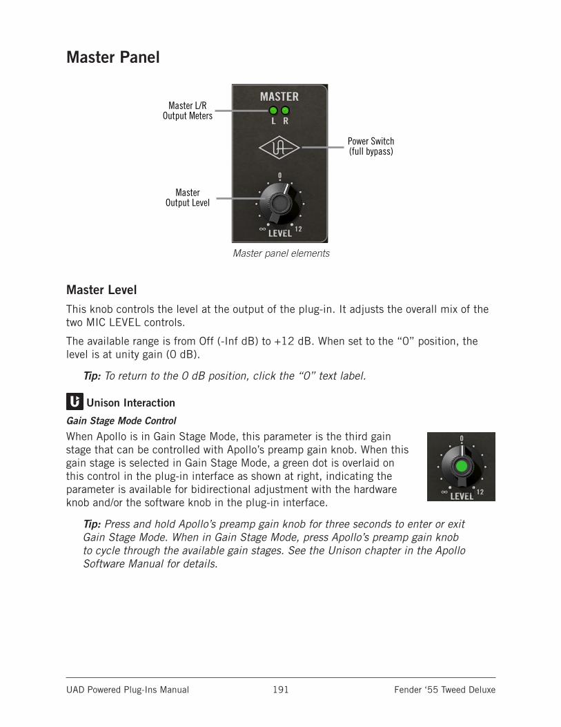
UAD Powered Plug-Ins Manual Fender ‘55 Tweed Deluxe 191
Master Panel
Master panel elements
Master Level This knob controls the level at the output of the plug-in. It adjusts the overall mix of the two MIC LEVEL controls.
The available range is from Off (-Inf dB) to +12 dB. When set to the “0” position, the level is at unity gain (0 dB).
Tip: To return to the 0 dB position, click the “0” text label.
Unison Interaction
Gain Stage Mode Control
When Apollo is in Gain Stage Mode, this parameter is the third gain stage that can be controlled with Apollo’s preamp gain knob. When this gain stage is selected in Gain Stage Mode, a green dot is overlaid on this control in the plug-in interface as shown at right, indicating the parameter is available for bidirectional adjustment with the hardware knob and/or the software knob in the plug-in interface.
Tip: Press and hold Apollo’s preamp gain knob for three seconds to enter or exit Gain Stage Mode. When in Gain Stage Mode, press Apollo’s preamp gain knob to cycle through the available gain stages. See the Unison chapter in the Apollo Software Manual for details.
Master L/ROutput Meters
MasterOutput Level
Power Switch(full bypass)
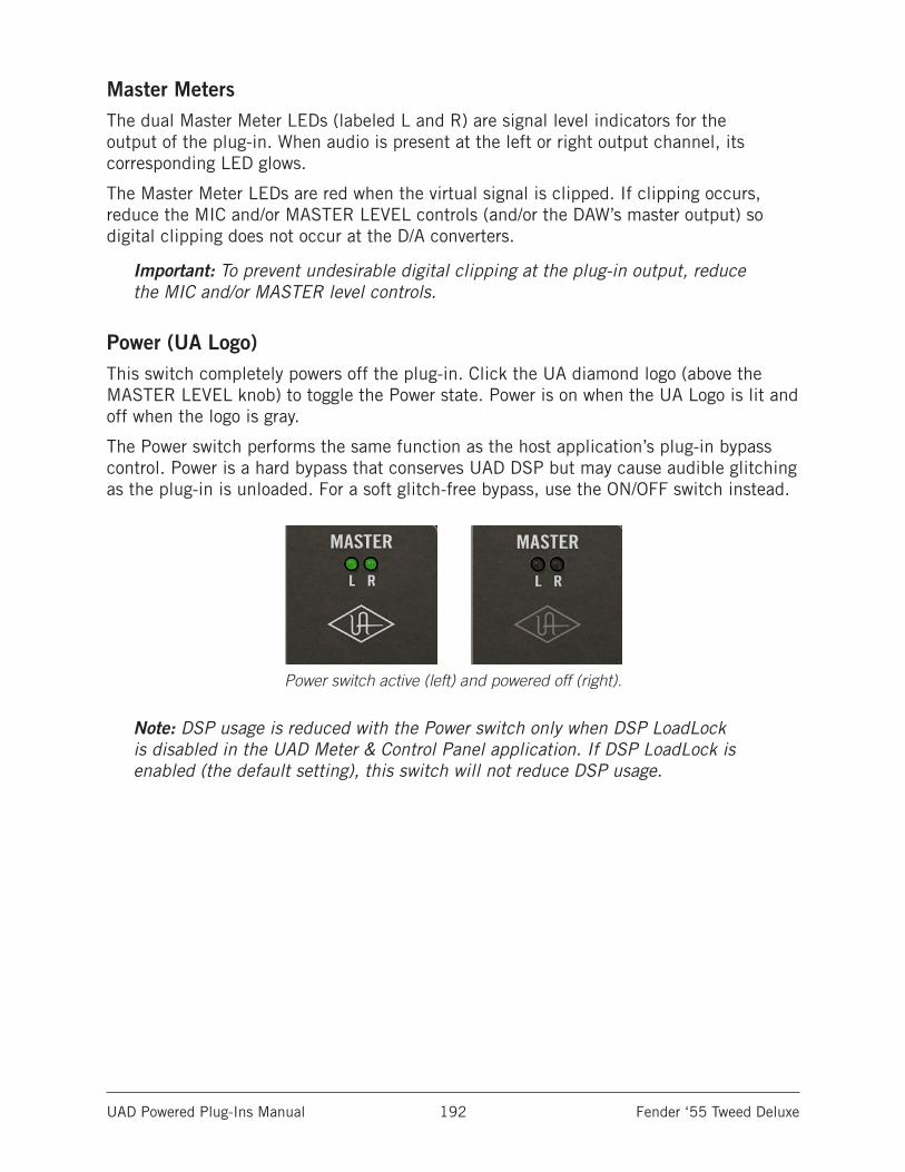
UAD Powered Plug-Ins Manual Fender ‘55 Tweed Deluxe 192
Master MetersThe dual Master Meter LEDs (labeled L and R) are signal level indicators for the output of the plug-in. When audio is present at the left or right output channel, its corresponding LED glows.
The Master Meter LEDs are red when the virtual signal is clipped. If clipping occurs, reduce the MIC and/or MASTER LEVEL controls (and/or the DAW’s master output) so digital clipping does not occur at the D/A converters.
Important: To prevent undesirable digital clipping at the plug-in output, reduce the MIC and/or MASTER level controls.
Power (UA Logo)This switch completely powers off the plug-in. Click the UA diamond logo (above the MASTER LEVEL knob) to toggle the Power state. Power is on when the UA Logo is lit and off when the logo is gray.
The Power switch performs the same function as the host application’s plug-in bypass control. Power is a hard bypass that conserves UAD DSP but may cause audible glitching as the plug-in is unloaded. For a soft glitch-free bypass, use the ON/OFF switch instead.
Power switch active (left) and powered off (right).
Note: DSP usage is reduced with the Power switch only when DSP LoadLock is disabled in the UAD Meter & Control Panel application. If DSP LoadLock is enabled (the default setting), this switch will not reduce DSP usage.
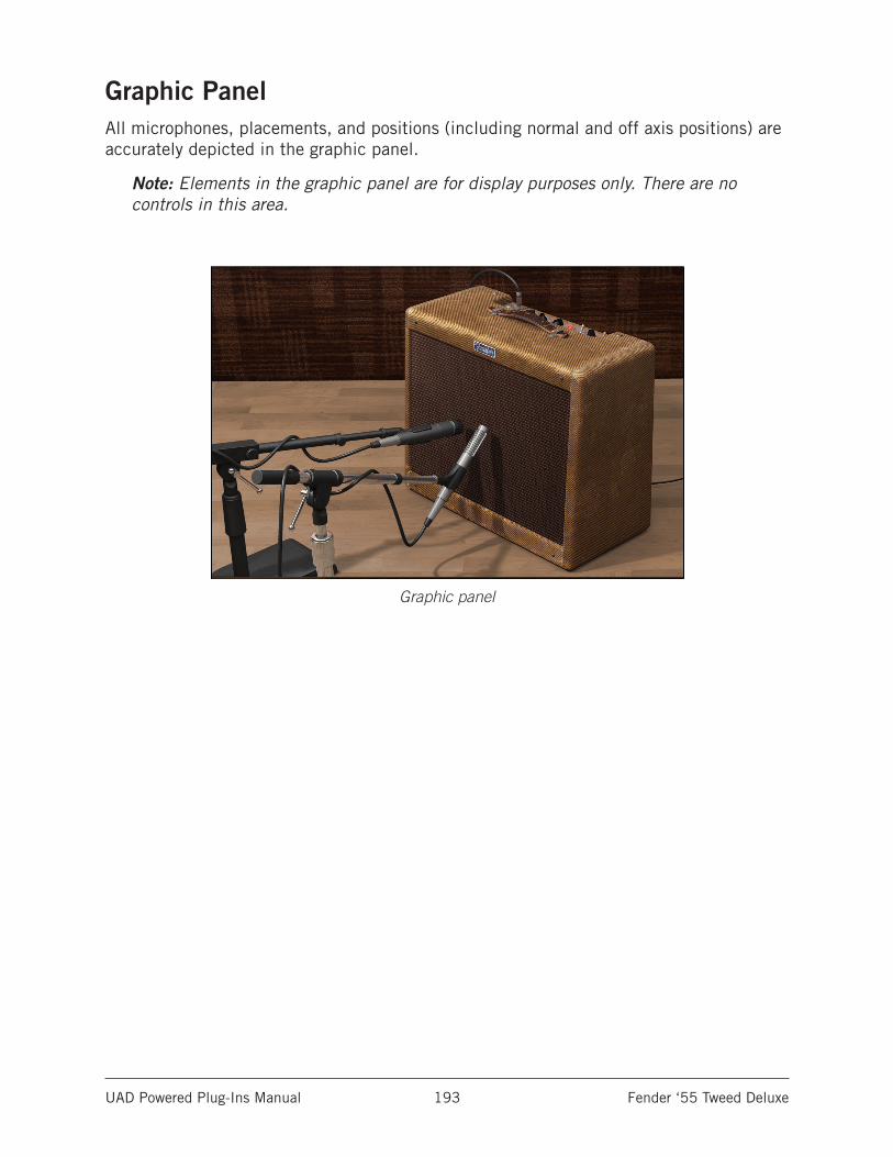
UAD Powered Plug-Ins Manual Fender ‘55 Tweed Deluxe 193
Graphic PanelAll microphones, placements, and positions (including normal and off axis positions) are accurately depicted in the graphic panel.
Note: Elements in the graphic panel are for display purposes only. There are no controls in this area.
Graphic panel
UAD Powered Plug-Ins Manual Fender ‘55 Tweed Deluxe 194
Guitar Amp Plug-In WorkflowsUAD plug-ins can be used with any Apollo audio interface or UAD-2 DSP accelerator. Typical input (monitoring/recording) and output (playback/mixing) workflows for the two product types when using Fender 55’ Tweed Deluxe are described below.
Apollo WorkflowsApollo’s Realtime UAD Processing feature enables monitoring and/or recording through UAD plug-ins with no discernible latency. While using this feature, the plug-in can be recorded with or without amp processing, while still monitoring the processed signal.
Important: Whenever Apollo is used for input monitoring, software monitoring must be disabled in the DAW to prevent doubled signals. Consult the DAW’s documentation for instructions.
Note: For related details, see the Apollo Software Manual.
Apollo: Live input processingFor the most authentic sound, dynamic touch response, and feel of the original amp:
1. Plug the guitar (or other passive instrument) into the Hi-Z instrument input on Apollo’s front panel. The input is automatically switched to use the Hi-Z jack.
2. Within Apollo’s included Console application, place the amp plug-in into the Hi-Z input’s dedicated Unison insert slot. The Hi-Z input is routed into the amp with Unison impedance and bidirectional control interactions.
3. DAW tracks that use this Hi-Z input as its source will have the complete sound of the amp (Unison insert processing is always recorded).
Tip: Adjust the amp’s INST VOL control with Apollo’s preamp gain knob and/or enter Gain Stage Mode to adjust additional plug-in gain stages with the hardware knob.
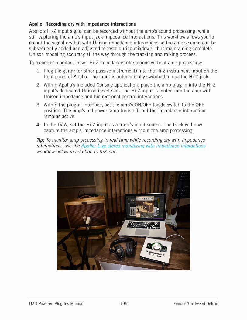
UAD Powered Plug-Ins Manual Fender ‘55 Tweed Deluxe 195
Apollo: Recording dry with impedance interactionsApollo’s Hi-Z input signal can be recorded without the amp’s sound processing, while still capturing the amp’s input jack impedance interactions. This workflow allows you to record the signal dry but with Unison impedance interactions so the amp’s sound can be subsequently added and adjusted to taste during mixdown, thus maintaining complete Unison modeling accuracy all the way through the tracking and mixing process.
To record or monitor Unison Hi-Z impedance interactions without amp processing:
1. Plug the guitar (or other passive instrument) into the Hi-Z instrument input on the front panel of Apollo. The input is automatically switched to use the Hi-Z jack.
2. Within Apollo’s included Console application, place the amp plug-in into the Hi-Z input’s dedicated Unison insert slot. The Hi-Z input is routed into the amp with Unison impedance and bidirectional control interactions.
3. Within the plug-in interface, set the amp’s ON/OFF toggle switch to the OFF position. The amp’s red power lamp turns off, but the impedance interaction remains active.
4. In the DAW, set the Hi-Z input as a track’s input source. The track will now capture the amp’s impedance interactions without the amp processing.
Tip: To monitor amp processing in real time while recording dry with impedance interactions, use the Apollo: Live stereo monitoring with impedance interactions workflow below in addition to this one.
UAD Powered Plug-Ins Manual Fender ‘55 Tweed Deluxe 196
Apollo: Live stereo monitoring with impedance interactionsTo hear the amp’s dual microphones in stereo, the plug-in must be used on a stereo source. However, Apollo’s Hi-Z inputs are monophonic. With this workflow, two amp plug-in instances are used in Console: One in the Unison insert to capture impedance interactions, and one on a stereo auxiliary bus for amp processing so the mic pan controls can be adjusted.
To capture Unison Hi-Z impedance interactions while monitoring amp processing in stereo:
1. In Console, prepare an AUX for the workflow by muting (or lowering to zero) the SEND to AUX controls for all inputs except the Hi-Z input.
2. Follow steps 1, 2, and 3 in the Apollo: Recording dry with impedance interactions workflow above.
3. In Console, switch the Hi-Z input to MUTE. The input is no longer routed to the monitor outputs, preventing doubled signals.
4. In Console, route the Hi-Z input to the AUX by setting the SEND control in the Hi-Z channel to maximum. The dry signal with impedance interactions is routed to the AUX for further processing.
5. In Console, place the amp plug-in into an insert in the AUX. (The signal is not yet heard, because the Hi-Z input is muted.)
6. Switch the AUX from POST to PRE so the muted Hi-Z input is heard in the AUX. The Hi-Z input can now be monitored in stereo with complete Unison amp processing.
Tips: To record complete Unison amp processing in the DAW with this configuration, set a stereo track to use the AUX as its source. To record the signal dry but with Unison impedance interactions, set a mono track in the DAW to use the Hi-Z input as its source.
UAD Powered Plug-Ins Manual Fender ‘55 Tweed Deluxe 197
UAD-2 WorkflowsThe Fender ‘55 Tweed Deluxe amp plug-in can be used as a standard UAD plug-in inside any compatible DAW. Following the guidelines below, the plug-in adds great guitar amp color and tone on any signal source with any UAD-2 hardware.
UAD-2: Live input processingWhen playing live through UAD plug-ins when loaded in a DAW using a traditional (non-Apollo) audio interface, the DAW’s software monitoring feature is used, and throughput latency is determined by the hardware I/O buffer setting. In this scenario, you’ll want to lower the I/O buffer to the lowest setting your system will allow.
Note: This technique is controlled by features within the DAW and/or audio interface. Consult the manufacturer’s documentation for detailed procedures.
To minimize live input latency and get the best sound when playing through the amp plug-in when it’s loaded in a DAW:
1. Set the hardware I/O buffer size to the lowest value the system will allow without audio artifacts. The lower the buffer size, the lower the latency.
2. To prevent doubled signals, disable the audio interface’s hardware input monitoring feature (if available). Consult the audio interface documentation for instructions.
3. Insert the amp plug-in on the live input’s channel in the DAW. For optimum results, use a Hi-Z instrument input (if available).
4. Enable software input monitoring in the DAW (and the low-latency monitoring feature, if available). You should now be able to hear the input through the amp plug-in.
5. Don’t preamplify the guitar signal in the analog domain (audio interface preamps or other external mic preamps) or digital domain (gain controls within the DAW). The amp plug-in input is expecting low-level instrument signals, such as those from passive guitar pickups. If the amp sounds overloaded (but not like a guitar amp), try engaging the LINE switch in the amp plug-in’s interface.
6. After monitoring and/or recording the live input, the I/O buffer size can be increased during playback to reduce the computer’s CPU load. Throughput latency is irrelevant during playback.
Tip: To reduce latency when using a UAD-2 PCIe card or UAD-2 Satellite (Thunderbolt or USB models only), enable UAD-2 LiveTrack mode by clicking the mic icon in the UAD Toolbar at the bottom of the plug-in interface.
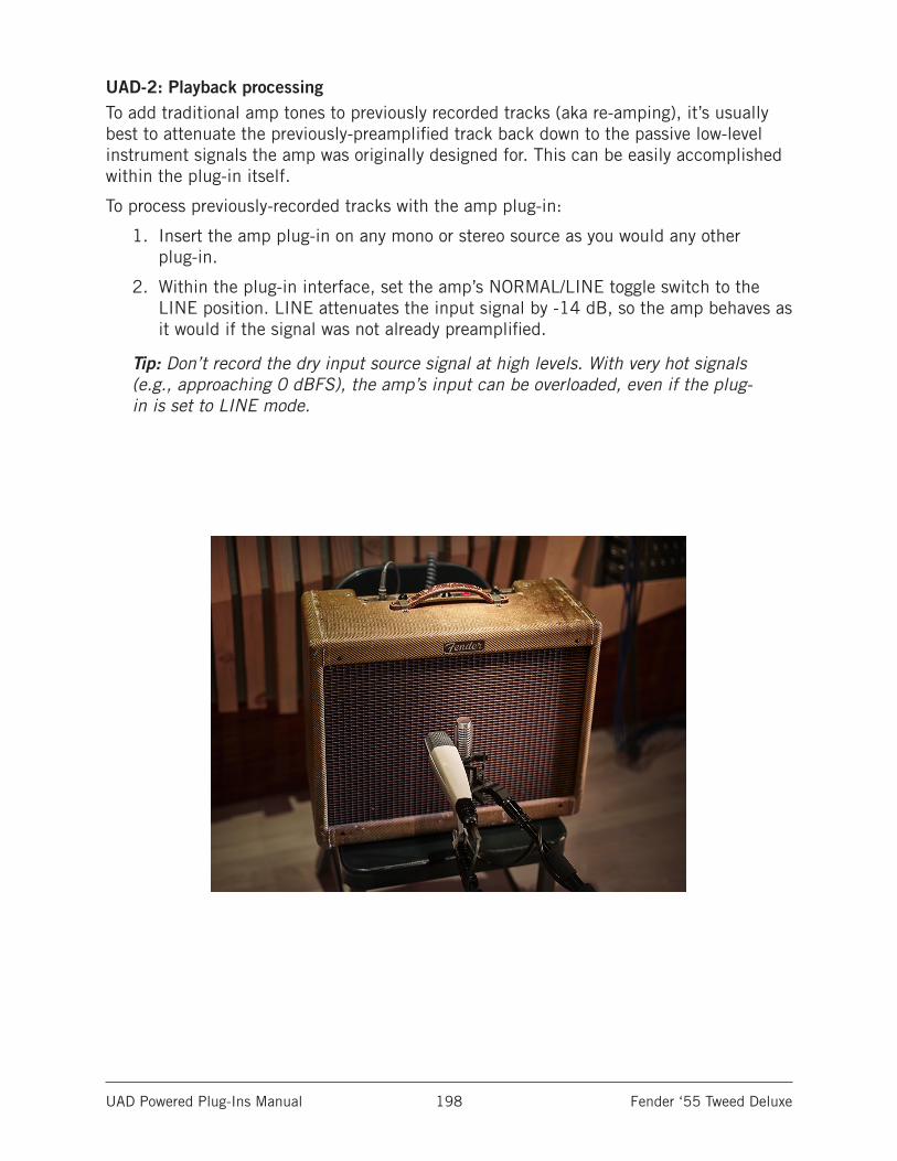
UAD Powered Plug-Ins Manual Fender ‘55 Tweed Deluxe 198
UAD-2: Playback processingTo add traditional amp tones to previously recorded tracks (aka re-amping), it’s usually best to attenuate the previously-preamplified track back down to the passive low-level instrument signals the amp was originally designed for. This can be easily accomplished within the plug-in itself.
To process previously-recorded tracks with the amp plug-in:
1. Insert the amp plug-in on any mono or stereo source as you would any other plug-in.
2. Within the plug-in interface, set the amp’s NORMAL/LINE toggle switch to the LINE position. LINE attenuates the input signal by -14 dB, so the amp behaves as it would if the signal was not already preamplified.
Tip: Don’t record the dry input source signal at high levels. With very hot signals (e.g., approaching 0 dBFS), the amp’s input can be overloaded, even if the plug-in is set to LINE mode.
UAD Powered Plug-Ins Manual Fender ‘55 Tweed Deluxe 199
History of the 1955 Fender DeluxeThe Deluxe began as one of Leo Fender’s first ever amps to go along with his main business of selling lap-steel instruments. Early versions of the Deluxe (known as TV-front and later narrow-panel) came out in 1946, years before the release of his first solid-body electric guitars like the Esquire/Broadcaster/Telecaster (1950) and Stratocaster (1954).
With some tweaks and tube changes to the circuit, Leo eventually landed on the now historic, “wide-panel” 5E3 Deluxe in 1955. This version of the amp became legendary as the ultimate bar gig, mid-sized club, and studio amp. With a single 12-inch speaker and around 15 watts, it was just loud enough to compete with most country and jazz drummers of the ‘50s.
As rock ‘n’ roll began to take shape, and drummers and bass players starting digging in and getting louder, the Deluxe couldn’t keep up. And it was that limitation of the 5E3 circuit being pushed into tube saturation that gave birth to the gritty, overdriven sound of rock guitar.
Even as Leo Fender made bigger, and cleaner sounding tweed amps like the 2x12 80-watt Twin, many players never gave up their Deluxe. This was nearly a decade before distortion and fuzz pedals even existed. If you wanted that overdriven rock sound, you needed to turn your amp all the way up.
Even as the ‘60s, ‘70s, and ‘80s saw many new ways to get distortion and that classic “tweed on 12” sound live at any volume, many guitar icons always took their Deluxe into the studio to capture the real deal. For them, nothing could replace the powerful and dynamic tones of their favorite guitar, and a cable plugged directly into that iconic, tattered, and road worn tweed-covered Deluxe amp. Regardless of the decade and musical genre, the Fender ‘55 Tweed Deluxe is what electric guitar is supposed to sound like: ICONIC.
UAD Powered Plug-Ins Manual Fender ‘55 Tweed Deluxe 200
The original Fender Deluxe amplifier
All visual and aural references to the Fender Deluxe, and all use of Fender’s trademarks, are being made with written permission from Fender Musical Instruments Corporation.
SOLID BLACK
PMS 485 RED
TM
TM
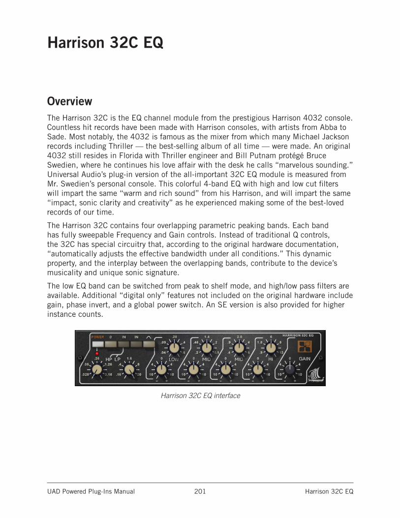
UAD Powered Plug-Ins Manual Harrison 32C EQ 201
Harrison 32C EQ
OverviewThe Harrison 32C is the EQ channel module from the prestigious Harrison 4032 console. Countless hit records have been made with Harrison consoles, with artists from Abba to Sade. Most notably, the 4032 is famous as the mixer from which many Michael Jackson records including Thriller — the best-selling album of all time — were made. An original 4032 still resides in Florida with Thriller engineer and Bill Putnam protégé Bruce Swedien, where he continues his love affair with the desk he calls “marvelous sounding.” Universal Audio’s plug-in version of the all-important 32C EQ module is measured from Mr. Swedien’s personal console. This colorful 4-band EQ with high and low cut filters will impart the same “warm and rich sound” from his Harrison, and will impart the same “impact, sonic clarity and creativity” as he experienced making some of the best-loved records of our time.
The Harrison 32C contains four overlapping parametric peaking bands. Each band has fully sweepable Frequency and Gain controls. Instead of traditional Q controls, the 32C has special circuitry that, according to the original hardware documentation, “automatically adjusts the effective bandwidth under all conditions.” This dynamic property, and the interplay between the overlapping bands, contribute to the device’s musicality and unique sonic signature.
The low EQ band can be switched from peak to shelf mode, and high/low pass filters are available. Additional “digital only” features not included on the original hardware include gain, phase invert, and a global power switch. An SE version is also provided for higher instance counts.
Harrison 32C EQ interface
UAD Powered Plug-Ins Manual Harrison 32C EQ 202
Harrison 32C ControlsNote: Knob settings, when compared to the graphical user interface silkscreen numbers, may not match the actual parameter values (e.g., if a knob is pointing to 8 kHz, the actual frequency may not be 8 kHz). This behavior is identical to the original hardware, which we modeled exactly. When the plug-in is viewed in pa-rameter list mode (Controls View), the actual parameter values are displayed.
PowerThe Power switch determines whether the plug-in is active. Click the button to toggle the state. When the Power switch is in the Off (lighter) position, plug-in processing is disabled and UAD DSP usage is reduced (unless UAD-2 DSP LoadLock is enabled).
Power LEDThe Power LED is illuminated when the plug-in is active.
PolarityThe Polarity (Ø) button inverts the phase of the signal. The polarity is inverted when the button is engaged (darker). Leave the button inactive (lighter) for normal polarity.
Cut FiltersIn addition to the four-band EQ, the Harrison 32C offers two cut filters, one each for low and high frequencies. The slope of the cut filters is 12 dB per octave.
Cut EnableThe high and low pass filters are engaged with the Cut Enable switch. The Cut Filters are active when the “In” switch is engaged (darker). When the Cut Filters are engaged, circuit coloration is modeled even when set to “zero cut” frequency values (25 Hz and 20 kHz respectively).
The Cut Enable “In” switch is to the left of the EQ “In” switch on the graphical interface.
High Pass (HP)This control determines the cutoff frequency for the high pass filter. The available range is 25 Hz to 3.15 kHz.
Low Pass (LP)This control determines the cutoff frequency for the low pass filter. The available range is 1.6 kHz to 20 kHz.
UAD Powered Plug-Ins Manual Harrison 32C EQ 203
Four EQ BandsEach of the four EQ bands have similar controls. The band center frequency is controlled the top row of knobs, and the band gain is controlled by the bottom row.
Low PeakThe low EQ band can be operated in either peak or shelf mode. When the Low Peak switch is in the “out” position, the low EQ band operates in shelf mode. When the Low Peak switch is engaged (darker), the low EQ band operates in peak mode (the other bands always operate in peak mode).
Low FrequencyThis control determines the low band center frequency (or the edge frequency when in shelf mode) to be boosted or attenuated by the band Gain setting. The available range is 40 Hz to 600 Hz.
Low GainThis control determines the amount by which the frequency setting for the low band is boosted or attenuated. The available range is ±10 dB.
Low Mid FrequencyThis control determines the low midrange band center frequency to be boosted or attenuated by the band Gain setting. The available range is 200 Hz to 3.1kHz.
Low Mid GainThis control determines the amount by which the frequency setting for the low midrange band is boosted or attenuated. The available range is ±10 dB.
High Mid FrequencyThis control determines the low midrange band center frequency to be boosted or attenuated by the band Gain setting. The available range is 400 Hz to 6 kHz.
High Mid GainThis control determines the amount by which the frequency setting for the high midrange band is boosted or attenuated. The available range is ±10 dB.
Hi FrequencyThis control determines the high band center frequency to be boosted or attenuated by the band Gain setting. The available range is 900 Hz to 13 kHz.
Hi GainThis control determines the amount by which the frequency setting for the high band is boosted or attenuated. The available range is ±10 dB.
GainThe Gain knob controls the signal level that is output from the plug-in. The default value is 0 dB. The available range is ±10 dB.
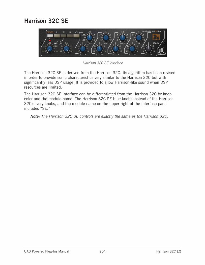
UAD Powered Plug-Ins Manual Harrison 32C EQ 204
Harrison 32C SE
Harrison 32C SE interface
The Harrison 32C SE is derived from the Harrison 32C. Its algorithm has been revised in order to provide sonic characteristics very similar to the Harrison 32C but with significantly less DSP usage. It is provided to allow Harrison-like sound when DSP resources are limited.
The Harrison 32C SE interface can be differentiated from the Harrison 32C by knob color and the module name. The Harrison 32C SE blue knobs instead of the Harrison 32C’s ivory knobs, and the module name on the upper right of the interface panel includes “SE.”
Note: The Harrison 32C SE controls are exactly the same as the Harrison 32C.
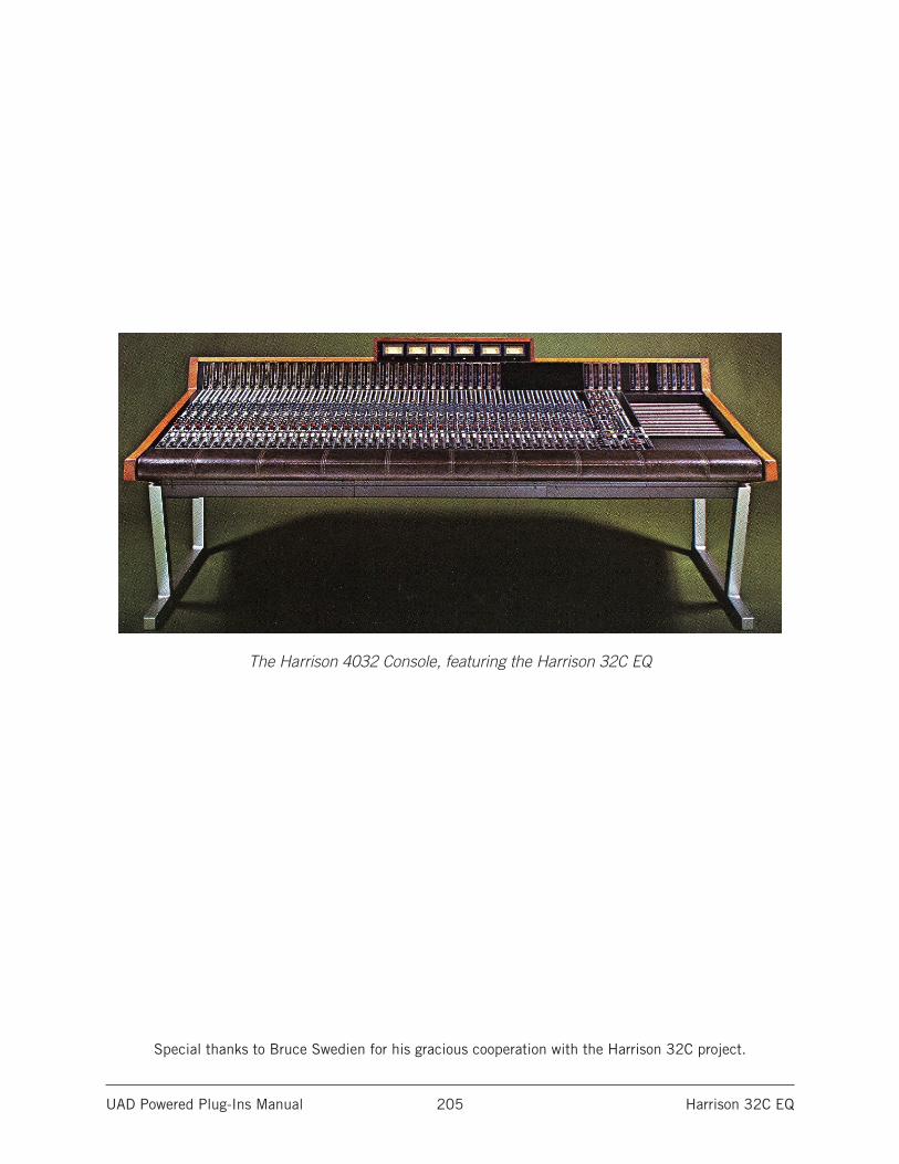
UAD Powered Plug-Ins Manual Harrison 32C EQ 205
The Harrison 4032 Console, featuring the Harrison 32C EQ
Special thanks to Bruce Swedien for his gracious cooperation with the Harrison 32C project.
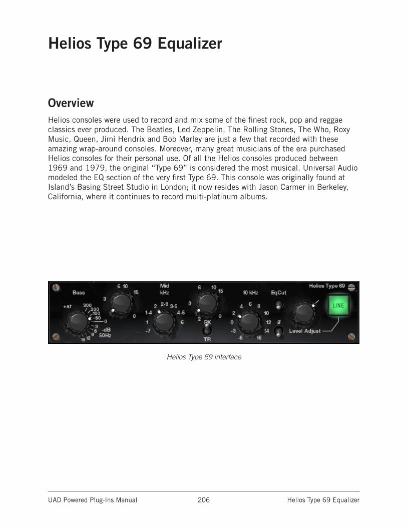
UAD Powered Plug-Ins Manual Helios Type 69 Equalizer 206
Helios Type 69 Equalizer
OverviewHelios consoles were used to record and mix some of the finest rock, pop and reggae classics ever produced. The Beatles, Led Zeppelin, The Rolling Stones, The Who, Roxy Music, Queen, Jimi Hendrix and Bob Marley are just a few that recorded with these amazing wrap-around consoles. Moreover, many great musicians of the era purchased Helios consoles for their personal use. Of all the Helios consoles produced between 1969 and 1979, the original “Type 69” is considered the most musical. Universal Audio modeled the EQ section of the very first Type 69. This console was originally found at Island’s Basing Street Studio in London; it now resides with Jason Carmer in Berkeley, California, where it continues to record multi-platinum albums.
Helios Type 69 interface
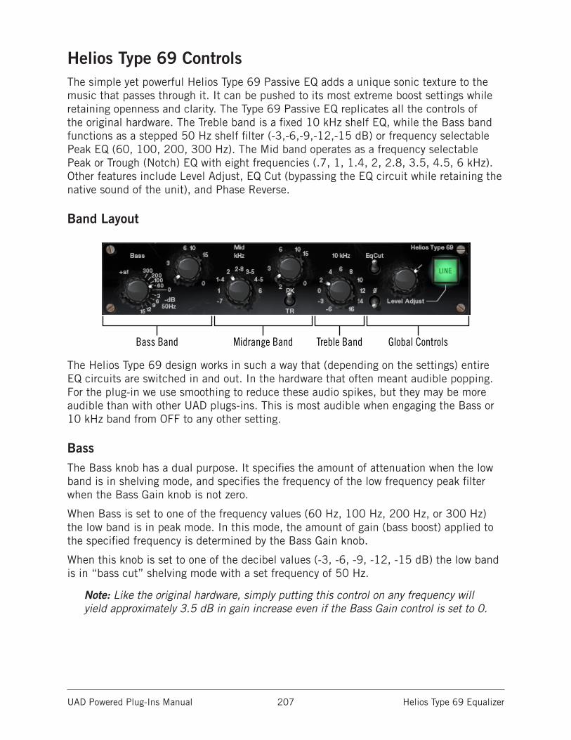
UAD Powered Plug-Ins Manual Helios Type 69 Equalizer 207
Helios Type 69 ControlsThe simple yet powerful Helios Type 69 Passive EQ adds a unique sonic texture to the music that passes through it. It can be pushed to its most extreme boost settings while retaining openness and clarity. The Type 69 Passive EQ replicates all the controls of the original hardware. The Treble band is a fixed 10 kHz shelf EQ, while the Bass band functions as a stepped 50 Hz shelf filter (-3,-6,-9,-12,-15 dB) or frequency selectable Peak EQ (60, 100, 200, 300 Hz). The Mid band operates as a frequency selectable Peak or Trough (Notch) EQ with eight frequencies (.7, 1, 1.4, 2, 2.8, 3.5, 4.5, 6 kHz). Other features include Level Adjust, EQ Cut (bypassing the EQ circuit while retaining the native sound of the unit), and Phase Reverse.
Band Layout
The Helios Type 69 design works in such a way that (depending on the settings) entire EQ circuits are switched in and out. In the hardware that often meant audible popping. For the plug-in we use smoothing to reduce these audio spikes, but they may be more audible than with other UAD plugs-ins. This is most audible when engaging the Bass or 10 kHz band from OFF to any other setting.
BassThe Bass knob has a dual purpose. It specifies the amount of attenuation when the low band is in shelving mode, and specifies the frequency of the low frequency peak filter when the Bass Gain knob is not zero.
When Bass is set to one of the frequency values (60 Hz, 100 Hz, 200 Hz, or 300 Hz) the low band is in peak mode. In this mode, the amount of gain (bass boost) applied to the specified frequency is determined by the Bass Gain knob.
When this knob is set to one of the decibel values (-3, -6, -9, -12, -15 dB) the low band is in “bass cut” shelving mode with a set frequency of 50 Hz.
Note: Like the original hardware, simply putting this control on any frequency will yield approximately 3.5 dB in gain increase even if the Bass Gain control is set to 0.
Bass Band Midrange Band Global Controls Treble Band
UAD Powered Plug-Ins Manual Helios Type 69 Equalizer 208
Bass GainThe Bass Gain knob determines the amount of low band gain to be applied when the Bass knob is in one of the frequency positions. Up to +15 dB of boost is available.
Note: Bass Gain has no effect when the Bass knob is in shelving mode (when Bass set to one of the dB positions).
Mid FreqThis control determines the frequency of the midrange band. The following frequencies can be specified: 700 Hz, 1 kHz, 1.4 kHz, 2 kHz, 2.8 kHz, 3.5 kHz, 4.5 kHz, and 6 kHz.
Note: The gain for the mid band is determined by the Mid Gain control. MidFreq has no effect if the Mid Gain control is set to zero.
In the graphic interface of this control, what may appear to be a dash (“-”) actually represents a decimal point. This anomaly mimics the original hardware.
Mid GainThis control determines the amount of gain or attenuation to be applied to the mid band. Up to 15 dB of boost or cut is available.
The Q (bandwidth) on the midrange band is fairly wide and gentle at low settings, but gets progressively narrower as the gain value is increased.
Note: Whether gain or attenuation is applied is determined by the Mid Type control.
Mid TypeMid Type specifies whether the midrange band is in Peak or Trough mode. When switched to Peak, the Mid Gain control will boost the midrange. When switched to Trough, Mid Gain will cut the midrange.
Note: When using Trough, a 1 dB loss occurs on the overall output of the plug-in. This is normal; the behavior is the same in the original hardware.
High Shelf GainThe High Shelf Gain knob offers fixed frequency shelving equalization at 10 kHz. This stepped control can cut the treble by -3 dB or -6 dB, or boost treble in 2 dB increments up to +16 dB.
UAD Powered Plug-Ins Manual Helios Type 69 Equalizer 209
EqCutThis switch is an EQ bypass control. It allows you to compare the processed and unprocessed signal. The EQ is active when in the up position.
The EQ is bypassed when in the down position. EqCut does not reduce UAD DSP load.
In the original Helios hardware, the audio is still slightly colored even when the EQ switch is in the Cut position. This is due to the fact that the signal is still passing through its circuitry. Because the plug-in emulates the hardware in every regard, the signal will be slightly processed when this switch is in the Cut position. If a true bypass is desired, use the Line switch instead.
PhaseThe Phase (Ø) switch inverts the polarity of the signal. When the switch is in the up position, the polarity is reversed. Leave the switch in the down position for normal polarity.
Level AdjustThis control adjusts the signal output level of Helios Type 69. This may be necessary if the signal is dramatically boosted or reduced by the EQ settings. The available range is -20 dB to +10 dB.
LineThe Line switch determines whether the plug-in is active. This is useful for comparing the processed settings to the original signal, or to bypass the plug-in to reduce the UAD DSP load (load is not reduced if UAD-2 DSP LoadLock is enabled).
Click the switch to toggle the state; the switch is illuminated in green when the plug-in is active.
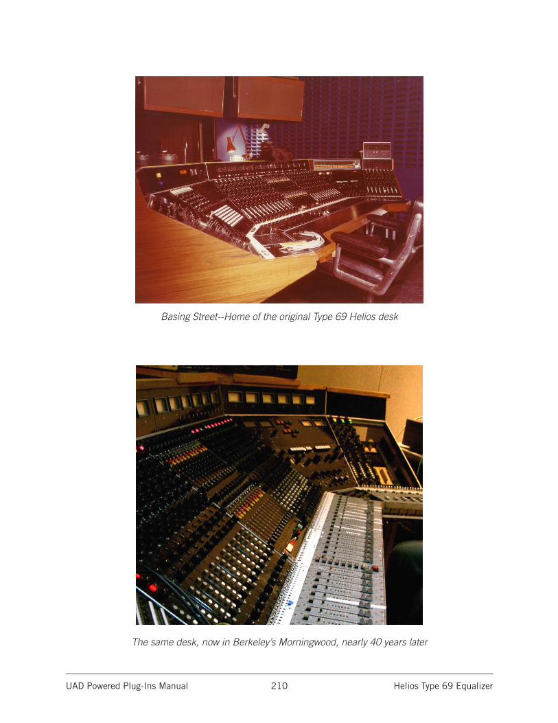
UAD Powered Plug-Ins Manual Helios Type 69 Equalizer 210
Basing Street--Home of the original Type 69 Helios desk
The same desk, now in Berkeley’s Morningwood, nearly 40 years later
UAD Powered Plug-Ins Manual Ibanez Tube Screamer TS808 211
Ibanez Tube Screamer TS808
The Most Iconic Overdrive Pedal Ever CreatedReleased in 1979, the Ibanez Tube Screamer TS808 overdrive pedal quickly became legend for its dynamic, touch-sensitive distortion and throaty midrange. A mainstay on the pedalboards of Stevie Ray Vaughan, Eric Johnson, Brad Paisley, Trey Anastasio, and Joe Bonamassa, the TS808 holds a hallowed place in guitar lore.
The Ibanez Tube Screamer has inspired hundreds of knock-offs and vintage units com-mand insane prices. Now, for the first time, you can track through the only Ibanez-licensed TS808 emulation with the Ibanez Tube Screamer TS808 for UAD-2 and Apollo interfaces.
Now You Can:• Track through a stunning emulation of the legendary Ibanez Tube Screamer
TS808 with Apollo Twin, DUO, or QUAD
• Add colorful distortion textures to guitars, synths, drums, and vocals at mixdown with any UAD-2 hardware
• Get the same circuit interaction, gain range, and clip points of a vintage TS808 Tube Screamer thanks to Unison technology for Apollo Twin, DUO, and QUAD
• Use the TS808 plug-in in front of an already-overdriven amp model, adding body and sustain to your sound
Dynamic DistortionsThe Ibanez Tube Screamer TS808 for UAD-2 and Apollo nails every detail of this vin-tage grind machine, allowing guitarists of all styles a vast array of sounds at tracking or mixdown. Key to this is capturing the original’s unique circuit, which actually mixes the clean input signal with the output signal of the TS808’s clipping circuit — preserving your playing dynamics and actually improving clarity and responsiveness.
From Subtle Rhythms to Searing SolosNo matter what type of guitar you’re using, the TS808 plug-in can transform your tones with its signature character. Use it to add a touch of dirt to ringing chords, enhancing your guitar’s string-to-string separation, or crank the Level and Drive controls to unleash the TS808’s legendary creamy, singing midrange. You can also call on the TS808 plug-in to deliver chunky rhythm tones à la Keith Richards.
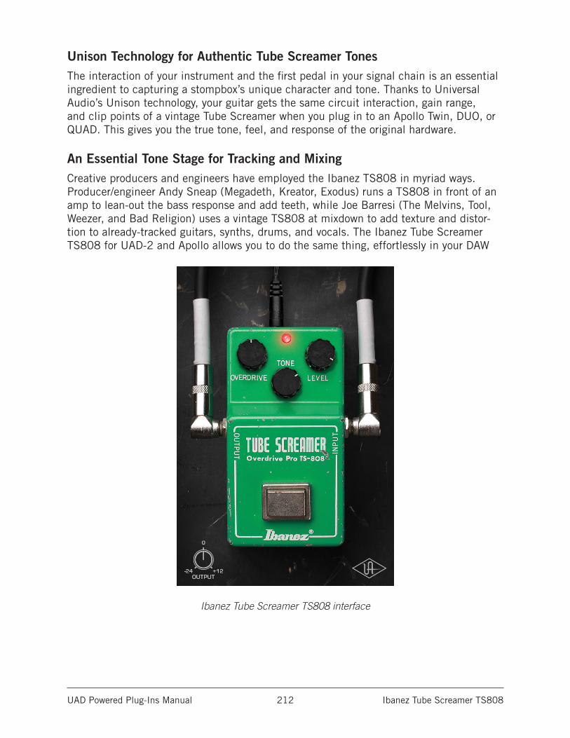
UAD Powered Plug-Ins Manual Ibanez Tube Screamer TS808 212
Unison Technology for Authentic Tube Screamer TonesThe interaction of your instrument and the first pedal in your signal chain is an essential ingredient to capturing a stompbox’s unique character and tone. Thanks to Universal Audio’s Unison technology, your guitar gets the same circuit interaction, gain range, and clip points of a vintage Tube Screamer when you plug in to an Apollo Twin, DUO, or QUAD. This gives you the true tone, feel, and response of the original hardware.
An Essential Tone Stage for Tracking and MixingCreative producers and engineers have employed the Ibanez TS808 in myriad ways. Producer/engineer Andy Sneap (Megadeth, Kreator, Exodus) runs a TS808 in front of an amp to lean-out the bass response and add teeth, while Joe Barresi (The Melvins, Tool, Weezer, and Bad Religion) uses a vintage TS808 at mixdown to add texture and distor-tion to already-tracked guitars, synths, drums, and vocals. The Ibanez Tube Screamer TS808 for UAD-2 and Apollo allows you to do the same thing, effortlessly in your DAW
Ibanez Tube Screamer TS808 interface
UAD Powered Plug-Ins Manual Ibanez Tube Screamer TS808 213
Using Ibanez Tube Screamer
Standard DAW InsertsIn much the same way as some premier recording and mix engineers use stomp boxes in a mix, Ibanez Tube Screamer can be used for creative purposes on any source signal by placing it in any plug-in insert within a DAW. For typical guitar tones, follow the pedal with a guitar amp emulation (as one would with a hardware guitar pedal and amp).
Because the plug-in accurately models the original hardware’s high-impedance operating levels, precautions may need to be taken to avoid undesirable input clipping.
Note: Since Hi-Z devices typically operate at much lower signal levels than line-level devices, signal levels being routed into the pedal may need to be reduced to avoid undesirable input distortion.
Unison™ Technology with ApolloThe Ibanez Tube Screamer features Unison technology for integration with the high-impedance input hardware in Universal Audio’s Apollo audio interfaces. With Unison, Apollo’s Hi-Z inputs inherit all of the unique circuit interaction, gain range, and clip points of the original guitar pedal.
Hi-Z Signal RoutingFor the most authentic stompbox tones, plug any high-impedance instrument (guitar, bass, etc.) into Apollo’s Hi-Z instrument input and place the pedal plug-in into the unique Unison INPUT insert on the same channel within Apollo’s Console application. If desired, follow the Unison pedal plug-in with another pedal or guitar amp emulation in Console’s standard insert slots.
This Hi-Z workflow enables near-zero latency monitoring or recording with the same input characteristics and dynamic response as the original pedal.
Note: This plug-in can be Unison-enabled with Apollo’s Mic or Line inputs. How-ever, because the original hardware has a high-impedance instrument input only, Apollo’s Hi-Z input and Unison insert will provide the most accurate sound and experience of the hardware pedal that is modeled.
Important: Unison is active only when the pedal plug-in is placed in the unique INPUT insert available on Hi-Z inputs within Apollo’s Console application. For complete Unison details, see the Apollo Software Manual.
Tactile ControlApollo’s front panel preamp knob can independently adjust the Overdrive, Level, and Output controls available within the Unison pedal plug-in via Gain Stage Mode. The con-trol being adjusted can be remotely switched via Apollo, so the control levels and their associated colorations can be tuned from the hardware knob for precise physical tactile control, all without using the Unison plug-in’s software interface.
UAD Powered Plug-Ins Manual Ibanez Tube Screamer TS808 214
Ibanez Tube Screamer Controls
OverdriveOverdrive varies the amount of signal distortion. Rotate the control clockwise to increase overdrive and sustain.
ToneTone adjusts the high-frequency content of the signal. Rotate the control clockwise to decrease the filter amount, which increases treble content.
LevelLevel adjusts the pedal’s modeled output level. Rotate the control clockwise to increase the volume.
BypassThe stomp switch toggles the overdrive effect. When the effect is active, the red LED (above the Tone knob) glows.
Like the original hardware, this is a not a “true bypass” switch. When the effect is inactive, the signal is still colored by the circuitry.
Tip: For true bypass, click the UA diamond logo.
OutputOutput controls the clean (unmodeled) gain at the output of the plug-in. The available range is -24 dB to +12 dB.
Tip: Click the “0” label to return the control to zero dB.
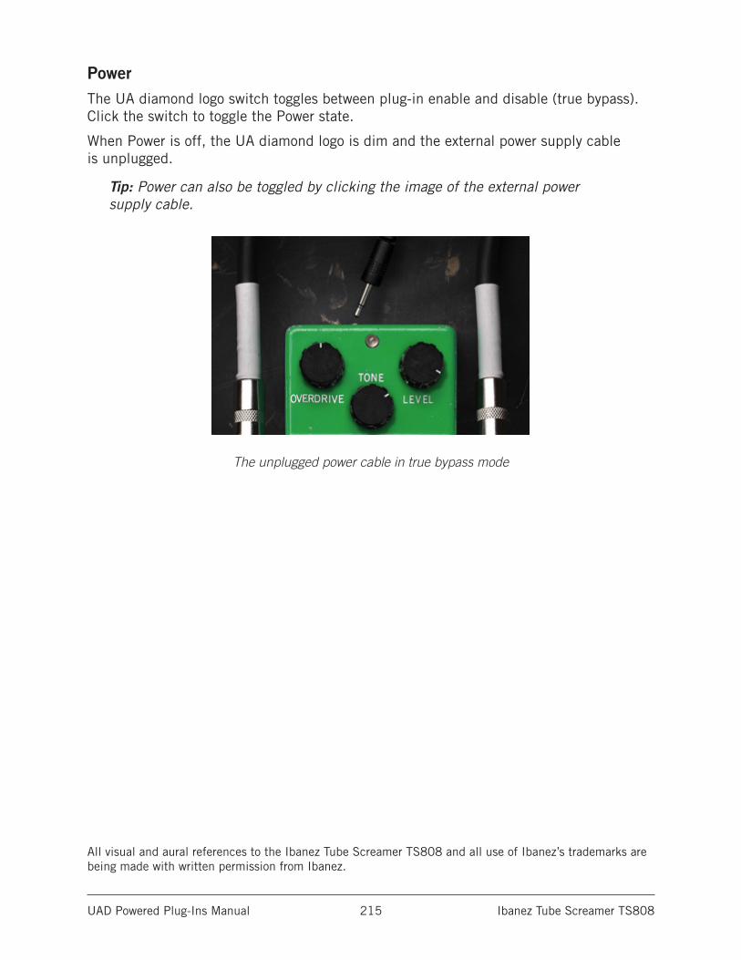
UAD Powered Plug-Ins Manual Ibanez Tube Screamer TS808 215
PowerThe UA diamond logo switch toggles between plug-in enable and disable (true bypass). Click the switch to toggle the Power state.
When Power is off, the UA diamond logo is dim and the external power supply cable is unplugged.
Tip: Power can also be toggled by clicking the image of the external power supply cable.
The unplugged power cable in true bypass mode
All visual and aural references to the Ibanez Tube Screamer TS808 and all use of Ibanez’s trademarks are being made with written permission from Ibanez.
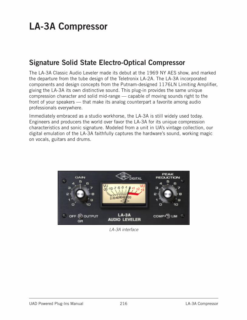
UAD Powered Plug-Ins Manual LA-3A Compressor 216
LA-3A Compressor
Signature Solid State Electro-Optical CompressorThe LA-3A Classic Audio Leveler made its debut at the 1969 NY AES show, and marked the departure from the tube design of the Teletronix LA-2A. The LA-3A incorporated components and design concepts from the Putnam-designed 1176LN Limiting Amplifier, giving the LA-3A its own distinctive sound. This plug-in provides the same unique compression character and solid mid-range — capable of moving sounds right to the front of your speakers — that make its analog counterpart a favorite among audio professionals everywhere.
Immediately embraced as a studio workhorse, the LA-3A is still widely used today. Engineers and producers the world over favor the LA-3A for its unique compression characteristics and sonic signature. Modeled from a unit in UA’s vintage collection, our digital emulation of the LA-3A faithfully captures the hardware’s sound, working magic on vocals, guitars and drums.
LA-3A interface
UAD Powered Plug-Ins Manual LA-3A Compressor 217
LA-3A Controls
Comp/LimThis switch changes the characteristics of the compressor I/O curve. When set to Compress, the curve is more gentle, and presents a low compression ratio. When set to Limit, a higher compression ratio is used.
GainThe Gain knob adjusts the output level (by up to 50 dB). Make sure to adjust the Gain control after the desired amount of compression is achieved with the Peak Reduction control. The Gain control does not affect the amount of compression.
Peak ReductionThis control adjusts the amount of gain reduction, as well as the relative threshold. A Peak Reduction value of 0 yields no compression. Rotate this control clockwise until the desired amount of compression is achieved (to monitor the Peak Reduction, set the VU Meter to Gain Reduction). The Peak Reduction should be adjusted independently of the Gain control.
MeterThis switch sets the mode of the VU Meter and also disables the plug-in. When set to Gain Reduction, the VU Meter indicates the Gain Reduction level in dB. When set to output, the VU Meter represents the output level (the output meter is not calibrated).
When in the Off position, the plug-in is disabled and UAD DSP usage is reduced.
Note: (UAD-2 only) UAD-2 DSP usage is reduced only when DSP LoadLock is disabled. If DSP LoadLock is enabled (the default setting), setting the switch to Off will not reduce DSP usage.
Stereo OperationAs with all UAD plug-ins, phase-coherent stereo imaging is maintained when the LA-3A plug-in is used on a stereo signal.
UAD Powered Plug-Ins Manual Lexicon 224 218
Lexicon 224
An Era-Defining Digital ReverbFrom the moment it was unleashed in 1978, the Lexicon 224 Digital Reverb — with its tactile, slider-based controller and famously lush reverb tail — single-handedly defined the sound of an entire era. From Talking Heads’ Remain In Light and Grandmaster Flash & The Furious Five’s The Message, to Vangelis’ incredible
Blade Runner soundtrack and U2’s The Unforgettable Fire, the Lexicon 224 remains one of the most popular digital reverb units of all time. Now you can track and mix with this singular piece of audio history with the Lexicon 224 Reverb plug-in for UAD-2 hardware and Apollo interfaces.
Now You Can:• Track and mix with the legendary Lexicon 224 Digital Reverb, using the same
algorithms as the original hardware
• Employ eight classic reverb programs and one chorus program on drums, vocals, guitars, and more
• Use the Plate and Concert programs for vintage ‘80s sounds
• Mix with presets from famous Lexicon 224 users Chuck Zwicky (Prince), Kevin Killen (Peter Gabriel), and others
A Breakthrough in EmulationUsing the exact algorithms and control processor code from the original hardware, the Lexicon 224 plug-in precisely captures all eight legendary reverb programs and the chorus program — based on the Lexicon 224’s final and hard-to-find firmware version 4.4. The Lexicon 224 plug-in also incorporates the original hardware’s input transformers and early AD/DA 12-bit gain stepping converters.
Easy NavigationEvery parameter from the original hardware is present in the Lexicon 224 plug-in, and exposed as dedicated sliders and buttons. Lexicon’s distinctive Bass/Mid “split decay” adjustments and Crossover control set the highly tunable reverb image, while the Treble Decay rolls off high frequencies. Use the Depth control to adjust the distance between source and reverb, while Predelay produces a short delay between the sound source and the onset of reverberation. Diffusion affects how quickly the echo density in the reverb builds up over time.
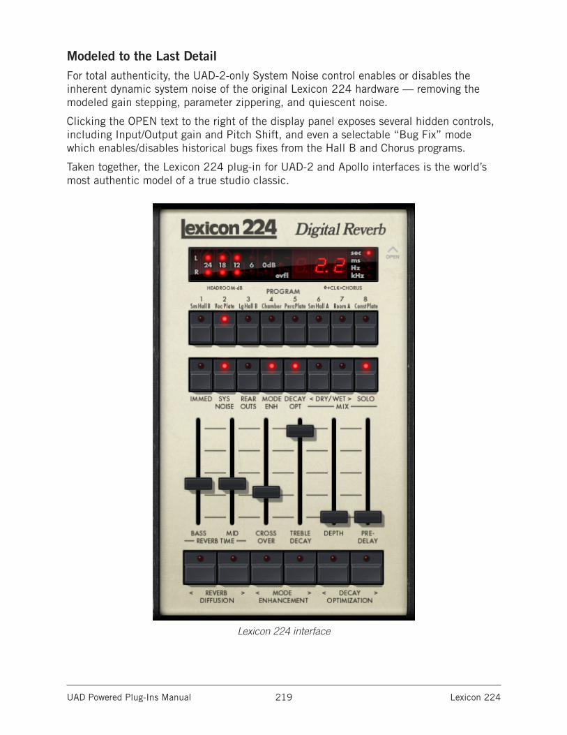
UAD Powered Plug-Ins Manual Lexicon 224 219
Modeled to the Last DetailFor total authenticity, the UAD-2-only System Noise control enables or disables the inherent dynamic system noise of the original Lexicon 224 hardware — removing the modeled gain stepping, parameter zippering, and quiescent noise.
Clicking the OPEN text to the right of the display panel exposes several hidden controls, including Input/Output gain and Pitch Shift, and even a selectable “Bug Fix” mode which enables/disables historical bugs fixes from the Hall B and Chorus programs.
Taken together, the Lexicon 224 plug-in for UAD-2 and Apollo interfaces is the world’s most authentic model of a true studio classic.
Lexicon 224 interface
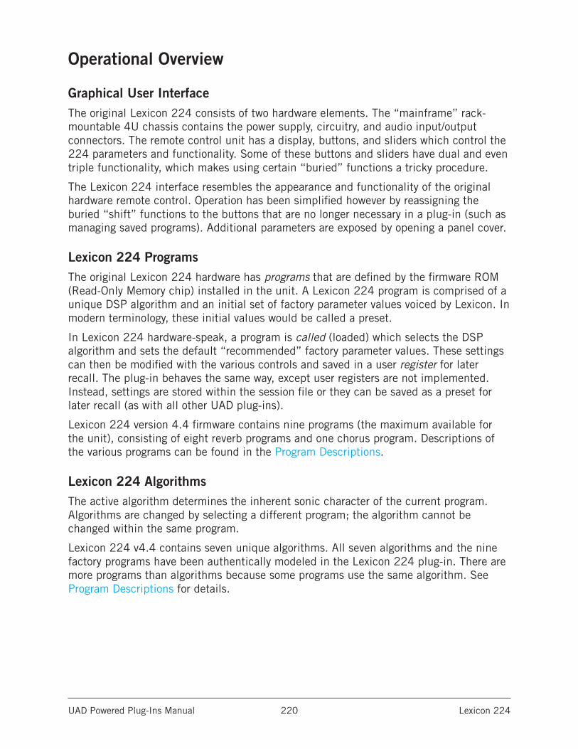
UAD Powered Plug-Ins Manual Lexicon 224 220
Operational Overview
Graphical User InterfaceThe original Lexicon 224 consists of two hardware elements. The “mainframe” rack-mountable 4U chassis contains the power supply, circuitry, and audio input/output connectors. The remote control unit has a display, buttons, and sliders which control the 224 parameters and functionality. Some of these buttons and sliders have dual and even triple functionality, which makes using certain “buried” functions a tricky procedure.
The Lexicon 224 interface resembles the appearance and functionality of the original hardware remote control. Operation has been simplified however by reassigning the buried “shift” functions to the buttons that are no longer necessary in a plug-in (such as managing saved programs). Additional parameters are exposed by opening a panel cover.
Lexicon 224 ProgramsThe original Lexicon 224 hardware has programs that are defined by the firmware ROM (Read-Only Memory chip) installed in the unit. A Lexicon 224 program is comprised of a unique DSP algorithm and an initial set of factory parameter values voiced by Lexicon. In modern terminology, these initial values would be called a preset.
In Lexicon 224 hardware-speak, a program is called (loaded) which selects the DSP algorithm and sets the default “recommended” factory parameter values. These settings can then be modified with the various controls and saved in a user register for later recall. The plug-in behaves the same way, except user registers are not implemented. Instead, settings are stored within the session file or they can be saved as a preset for later recall (as with all other UAD plug-ins).
Lexicon 224 version 4.4 firmware contains nine programs (the maximum available for the unit), consisting of eight reverb programs and one chorus program. Descriptions of the various programs can be found in the Program Descriptions.
Lexicon 224 AlgorithmsThe active algorithm determines the inherent sonic character of the current program. Algorithms are changed by selecting a different program; the algorithm cannot be changed within the same program.
Lexicon 224 v4.4 contains seven unique algorithms. All seven algorithms and the nine factory programs have been authentically modeled in the Lexicon 224 plug-in. There are more programs than algorithms because some programs use the same algorithm. See Program Descriptions for details.
UAD Powered Plug-Ins Manual Lexicon 224 221
Lexicon 224 ButtonsLike the original hardware, Lexicon 224 buttons are momentary-style and don’t latch in a down position. When a function is unavailable within a particular program, the button’s LED will not illuminate when clicked (the LEDs also don’t illuminate for the increment/decrement buttons).
The first click of an increment/decrement button displays the current value of the parameter; the value is actually changed only with subsequent clicks. This feature enables viewing the current setting without changing it.
Tip: For the inc/dec buttons (e.g., Reverb Diffusion), the value can be continuously changed by holding the button down.
Lexicon 224 SlidersThe six sliders control the main reverb parameters within a program. These are the most obvious controls to reach for when fine-tuning a reverb program to best suit the material at hand.
In P9 Chorus A, the first four sliders don’t control the labeled parameters. See P9 Chorus A for descriptions of the sliders in this program.
Tip: Clicking a slider “cap” will show its value in the Numerical Display. Clicking the text label of any slider will return that slider to the default value for the active program.
Inputs & OutputsThe Lexicon 224 hardware has two inputs (see Mono/Stereo below), and four discrete outputs, labeled as A, B, C, and D. Outputs A and C were designed to be used as the main stereo left/right outputs. The other two outputs, B and D, are implemented in some programs for use as quadraphonic reverb.
The UAD Lexicon 224 fully models the individual sonics of all four outputs when available in the program algorithm. The alternate B and D outputs are available via the Rear Outs control.
Note: The dry signal at the Lexicon 224 output is completely unprocessed.
UAD Powered Plug-Ins Manual Lexicon 224 222
Mono/Stereo OperationThe Lexicon 224 hardware has dual channel inputs (left and right) and is a true stereo processor. Like the hardware, when the Lexicon 224 plug-in is used in a stereo-in/stereo out configuration, the left and right channel signals are both processed.
When used in a mono-in/stereo out configuration, the mono input is sent to both channels of the stereo processor.
When configured as mono-in/mono-out (MIMO), output A is used exclusively except in programs 2, 4, and 9, where outputs A and C are summed into one monophonic signal. This implementation is recommended in the original hardware manual. If Rear Outs is enabled in MIMO mode, outputs B and D are used instead of A and C. See MIMO Program Outputs for a list of outputs used with each program in this configuration.
Primary & Hidden ControlsThe primary controls (those that are most typically used) are on the main “remote control” panel interface. Additional (less typically used) controls are available in a hidden control panel. The hidden control panel (see The Lexicon 224 Hidden Controls) is accessed by clicking the OPEN text label to the right of the Display Panel.
Parameter Ranges & Default ValuesThe parameter value ranges, default values, and availability of particular parameters within a given program may vary depending on which program is active. Parameter ranges are listed in the individual control descriptions. Default parameter values for each program are listed in the Program Descriptions.
Note: Extreme parameter settings can cause Lexicon 224 to self-oscillate or cause other unexpected sounds. This behavior is identical to the original hardware.
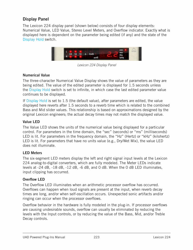
UAD Powered Plug-Ins Manual Lexicon 224 223
Display PanelThe Lexicon 224 display panel (shown below) consists of four display elements: Numerical Value, LED Value, Stereo Level Meters, and Overflow indicator. Exactly what is displayed here is dependent on the parameter being edited (if any) and the state of the Display Hold switch.
Lexicon 224 Display Panel
Numerical ValueThe three-character Numerical Value Display shows the value of parameters as they are being edited. The value of the edited parameter is displayed for 1.5 seconds unless the Display Hold switch is set to infinite, in which case the last edited parameter value continues to be displayed.
If Display Hold is set to 1.5 (the default value), after parameters are edited, the value displayed here reverts after 1.5 seconds to a reverb time which is related to the combined Bass and Mid slider values. This relationship is based on approximations designed by the original Lexicon engineers; the actual decay times may not match the displayed value.
Value LEDThe Value LED shows the units of the numerical value being displayed for a particular control. For parameters in the time domain, the “sec” (seconds) or “ms” (milliseconds) LED is lit. For parameters in the frequency domain, the “Hz” (Hertz) or “kHz” (kilohertz) LED is lit. For parameters that have no units value (e.g., Dry/Wet Mix), the value LED does not illuminate.
LED MetersThe six-segment LED meters display the left and right signal input levels at the Lexicon 224 analog-to-digital converters, which are fully modeled. The Meter LEDs indicate levels at -24 dB, -18 dB, -12 dB, -6 dB, and 0 dB. When the 0 dB LED illuminates, input clipping has occurred.
Overflow LEDThe Overflow LED illuminates when an arithmetic processor overflow has occurred. Overflows can happen when loud signals are present at the input, when reverb decay times are long, and/or when self-oscillation occurs. Unexpected sonic artifacts and/or ringing can occur when the processor overflows.
Overflow behavior in the hardware is fully modeled in the plug-in. If processor overflows are causing undesirable sounds, overflow can usually be eliminated by reducing the levels with the Input controls, or by reducing the value of the Bass, Mid, and/or Treble Decay controls.
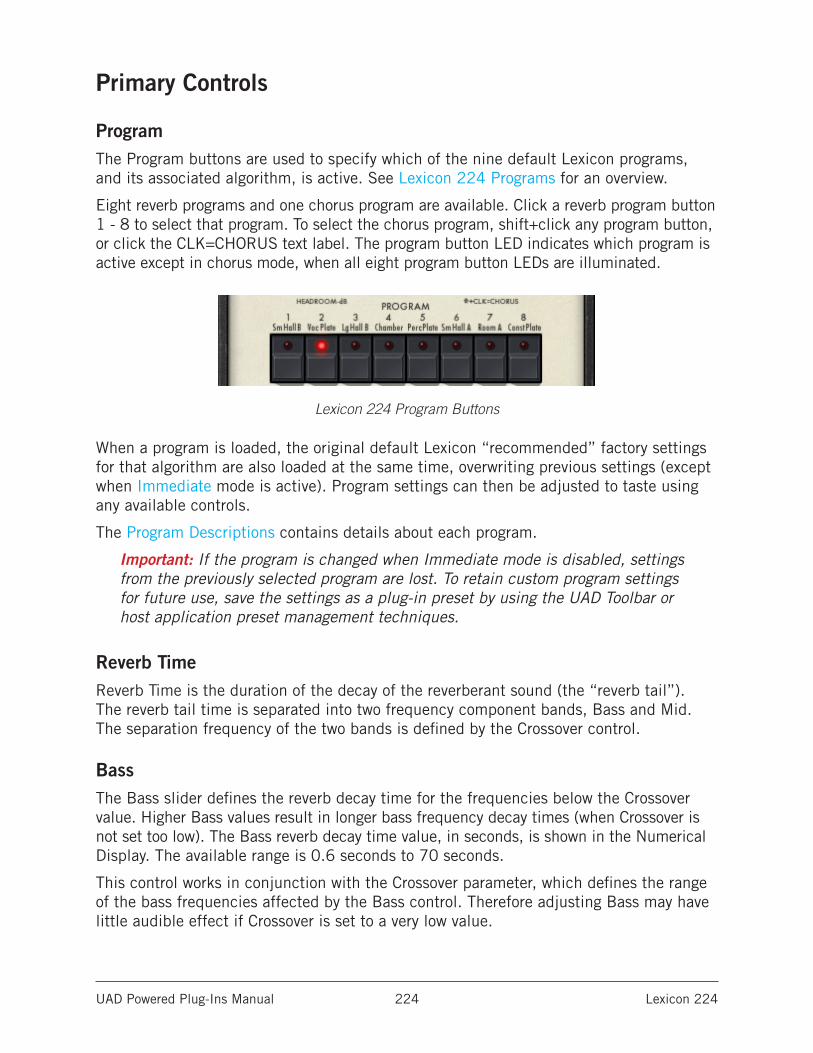
UAD Powered Plug-Ins Manual Lexicon 224 224
Primary Controls
ProgramThe Program buttons are used to specify which of the nine default Lexicon programs, and its associated algorithm, is active. See Lexicon 224 Programs for an overview.
Eight reverb programs and one chorus program are available. Click a reverb program button 1 - 8 to select that program. To select the chorus program, shift+click any program button, or click the CLK=CHORUS text label. The program button LED indicates which program is active except in chorus mode, when all eight program button LEDs are illuminated.
Lexicon 224 Program Buttons
When a program is loaded, the original default Lexicon “recommended” factory settings for that algorithm are also loaded at the same time, overwriting previous settings (except when Immediate mode is active). Program settings can then be adjusted to taste using any available controls.
The Program Descriptions contains details about each program.
Important: If the program is changed when Immediate mode is disabled, settings from the previously selected program are lost. To retain custom program settings for future use, save the settings as a plug-in preset by using the UAD Toolbar or host application preset management techniques.
Reverb TimeReverb Time is the duration of the decay of the reverberant sound (the “reverb tail”). The reverb tail time is separated into two frequency component bands, Bass and Mid. The separation frequency of the two bands is defined by the Crossover control.
BassThe Bass slider defines the reverb decay time for the frequencies below the Crossover value. Higher Bass values result in longer bass frequency decay times (when Crossover is not set too low). The Bass reverb decay time value, in seconds, is shown in the Numerical Display. The available range is 0.6 seconds to 70 seconds.
This control works in conjunction with the Crossover parameter, which defines the range of the bass frequencies affected by the Bass control. Therefore adjusting Bass may have little audible effect if Crossover is set to a very low value.
UAD Powered Plug-Ins Manual Lexicon 224 225
MidThe Mid slider defines the reverb decay time for the frequencies above the Crossover value. Higher Mid values result in longer high frequency decay times (when Crossover is not set too high). The Mid reverb decay value, in seconds, is shown in the Numerical Display. The available range is 0.6 seconds to 70 seconds.
Mid works in conjunction with the Crossover parameter, which defines the range of high frequencies affected by the Mid control. Therefore adjusting Mid may have little audible effect if Crossover is set to a very high value.
Mid is a slightly misleading label, because this control actually affects the reverb decay for all frequencies above the Crossover value (not just the midrange). However, because the “highs” in the reverb can be rolled off with the Treble Decay control (and usually are), the midrange frequencies are often more prominent than a full-range tail.
CrossoverThis control defines the crossover frequency (the split point) between the bass and upper frequency bands in the reverb tail. Higher Crossover values make the Bass parameter control a wider range of frequencies. Conversely, lower values make the Mid parameter control a wider range of frequencies. The available range is 100 Hz to 10.9 kHz.
Crossover affects the reverb decay because it works in conjunction with the Bass and Mid reverb time parameters, which both define the length of the reverb tail (one control for each frequency band). If those parameters are set to very short times, the result of adjusting Crossover may be very subtle.
Note: Crossover will have no apparent effect if Bass and Mid are set to the same value.
Treble DecayTreble Decay sets a frequency above which decay is very rapid. Lower values will produce a “darker” reverb with less high frequency content. If Treble Decay is set very low, then adjusting Bass, Mid, and Crossover may have little to no audible effect. The available range is 100 Hz to 10.9 kHz.
Tip: Treble Decay adjusts the AMOUNT of reverb tail highs, while Mid adjusts the TIME.
DepthDepth sets the apparent distance between a source and its reverb, much like the positioning of microphones in an echo chamber. As the value is increased, the apparent distance from the source increases. The available range is 0 - 71, with zero being “close” and 71 being “far” (the numbers are arbitrary). The default value is program dependent.
Note: Depth is not available in P9 Chorus A. In this program, the display is not updated when the Depth slider is moved.
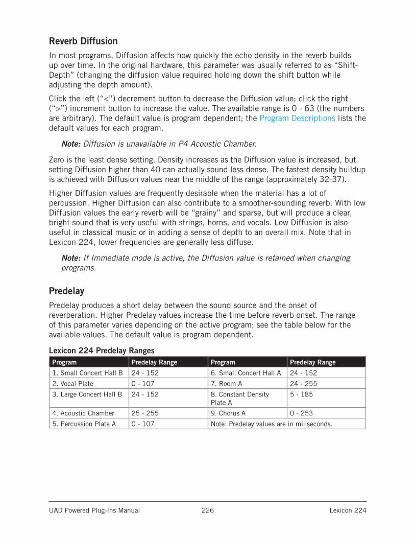
UAD Powered Plug-Ins Manual Lexicon 224 226
Reverb DiffusionIn most programs, Diffusion affects how quickly the echo density in the reverb builds up over time. In the original hardware, this parameter was usually referred to as “Shift-Depth” (changing the diffusion value required holding down the shift button while adjusting the depth amount).
Click the left (“<”) decrement button to decrease the Diffusion value; click the right (“>”) increment button to increase the value. The available range is 0 - 63 (the numbers are arbitrary). The default value is program dependent; the Program Descriptions lists the default values for each program.
Note: Diffusion is unavailable in P4 Acoustic Chamber.
Zero is the least dense setting. Density increases as the Diffusion value is increased, but setting Diffusion higher than 40 can actually sound less dense. The fastest density buildup is achieved with Diffusion values near the middle of the range (approximately 32-37).
Higher Diffusion values are frequently desirable when the material has a lot of percussion. Higher Diffusion can also contribute to a smoother-sounding reverb. With low Diffusion values the early reverb will be “grainy” and sparse, but will produce a clear, bright sound that is very useful with strings, horns, and vocals. Low Diffusion is also useful in classical music or in adding a sense of depth to an overall mix. Note that in Lexicon 224, lower frequencies are generally less diffuse.
Note: If Immediate mode is active, the Diffusion value is retained when changing programs.
PredelayPredelay produces a short delay between the sound source and the onset of reverberation. Higher Predelay values increase the time before reverb onset. The range of this parameter varies depending on the active program; see the table below for the available values. The default value is program dependent.
Lexicon 224 Predelay RangesProgram Predelay Range Program Predelay Range
1. Small Concert Hall B 24 - 152 6. Small Concert Hall A 24 - 152
2. Vocal Plate 0 - 107 7. Room A 24 - 255
3. Large Concert Hall B 24 - 152 8. Constant Density Plate A
5 - 185
4. Acoustic Chamber 25 - 255 9. Chorus A 0 - 253
5. Percussion Plate A 0 - 107 Note: Predelay values are in miliseconds.
UAD Powered Plug-Ins Manual Lexicon 224 227
ImmediateWhen Immediate (“IMMED”) is enabled, current parameter values are retained when a new program is selected. When Immediate is inactive and a program is selected, the Lexicon default factory preset parameter values for the program are loaded and the control sliders move to the preset values.
Enabling Immediate mode is convenient for quickly auditioning the various program algorithms using the same “persistent” parameter values. Disabling Immediate mode is convenient for quickly auditioning the various programs with the Lexicon factory default settings.
The default Immediate value is OFF. Immediate affects the following parameters: Bass, Mid, Crossover, Treble Decay, Depth, Predelay, Diffusion, Mode Enhancement, Pitch Shift, Decay Optimization, and Rear Outs.
Important: When Immediate is off and a program is changed, previously modified parameter values are lost, unless the settings were saved as a preset or if the session file was previously saved so it can be recalled.
System NoiseThis UAD-only control (“SYS NOISE”) enables or disables the modeled inherent dynamic system noise of the original Lexicon 224 hardware. Disabling System Noise enables a more modern-sounding (i.e., cleaner) 224. Click the button to toggle the state; System Noise is active when the button LED is lit. The default state is ON.
The elements of the modeled System Noise include quantization effects (at input A/D, output D/A, and within the algorithm), zipper/stepping noise when adjusting parameters, transformer distortion, and the quiescent noise floor.
Zipper/stepping noise when adjusting parameters can be defeated by disabling System Noise. However, zipper/stepping noise in delay modulation (i.e., Mode Enhancement) can only be reduced, but not completely defeated, by disabling System Noise.
Note: System Noise is a global (per instance) parameter; its state does not change when different programs are selected.
UAD Powered Plug-Ins Manual Lexicon 224 228
Rear OutsThe Rear Outs control is available to select the alternate pair when the algorithm has alternate sonics at outputs B and D. See Inputs & Outputs for an overview of the hardware implementation.
Rear Outs Notes• The left/right outputs of the plug-in always reflect hardware outputs A and C
respectively when Rear Outs is inactive, and outputs B and D respectively when Rear Outs is active.
• Outputs A and C are “recommended” for stereo use (the rear outs are generally not used in typical applications).
• Outputs A and C are identical to D and B respectively in the following programs: P2 Vocal Plate A, P5 Percussion Plate A, P8 Constant Density Plate A, and P9 Chorus A. Consequently, the Rear Outs control effectively swaps the left/right out-puts in these programs.
Mode EnhancementMode Enhancement makes the sound of the Lexicon 224 programs more natural by preventing room modes from ringing in the reverb tail. Mode Enhancement works by continuously modulating certain delay lines (taps) within the program algorithms, which increases the effective density without thickening the reverb itself.
Mode Enhancement is factory-optimized for each program and should not require adjustment in typical use. For this reason, it was deliberately made difficult to access in the original hardware. However, creative use of the parameter is encouraged by making it easier to access in the plug-in.
Mode Enhancement has three control elements: Enable, Amount, and Pitch Shift. As in the original hardware, lower values of Mode Enhance Amount and higher values of Pitch Shift increase “movement” and make the result more prominent.
Note: The Mode Enhance Amount and Pitch Shift controls have no effect unless the Mode Enhance Enable control is active.
Mode Enhance EnableThis button (“MODE ENH”) enables or disables Mode Enhancement for the active program. Mode Enhancement is active when the button LED is lit. The default state is ON for all programs.
Tip: This control, just as with the original hardware, resets the algorithm. Therefore Mode Enhance Enable can be used to quickly “kill” the reverb tail while staying in the same program.
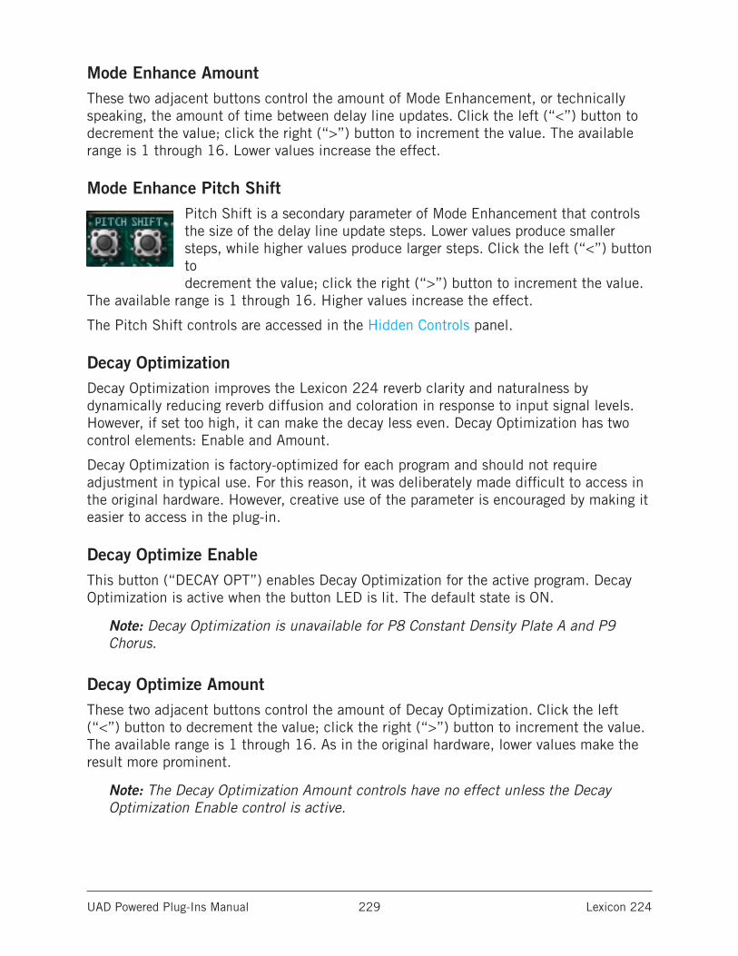
UAD Powered Plug-Ins Manual Lexicon 224 229
Mode Enhance AmountThese two adjacent buttons control the amount of Mode Enhancement, or technically speaking, the amount of time between delay line updates. Click the left (“<”) button to decrement the value; click the right (“>”) button to increment the value. The available range is 1 through 16. Lower values increase the effect.
Mode Enhance Pitch ShiftPitch Shift is a secondary parameter of Mode Enhancement that controls the size of the delay line update steps. Lower values produce smaller steps, while higher values produce larger steps. Click the left (“<”) button to decrement the value; click the right (“>”) button to increment the value.
The available range is 1 through 16. Higher values increase the effect.
The Pitch Shift controls are accessed in the Hidden Controls panel.
Decay OptimizationDecay Optimization improves the Lexicon 224 reverb clarity and naturalness by dynamically reducing reverb diffusion and coloration in response to input signal levels. However, if set too high, it can make the decay less even. Decay Optimization has two control elements: Enable and Amount.
Decay Optimization is factory-optimized for each program and should not require adjustment in typical use. For this reason, it was deliberately made difficult to access in the original hardware. However, creative use of the parameter is encouraged by making it easier to access in the plug-in.
Decay Optimize EnableThis button (“DECAY OPT”) enables Decay Optimization for the active program. Decay Optimization is active when the button LED is lit. The default state is ON.
Note: Decay Optimization is unavailable for P8 Constant Density Plate A and P9 Chorus.
Decay Optimize AmountThese two adjacent buttons control the amount of Decay Optimization. Click the left (“<”) button to decrement the value; click the right (“>”) button to increment the value. The available range is 1 through 16. As in the original hardware, lower values make the result more prominent.
Note: The Decay Optimization Amount controls have no effect unless the Decay Optimization Enable control is active.
UAD Powered Plug-Ins Manual Lexicon 224 230
Mix ControlsThe Dry, Wet, and Solo parameters control the effect mix in the plug-in. These controls are not available in the original hardware.
Note: The Mix controls are global parameters; their state does not change when different programs are selected.
SoloWhen Solo is activated, the Dry/Wet mix is set to 100% wet and the Dry/Wet controls are deactivated. Solo mode is optimal when using Lexicon 224 in the “classic” reverb configuration (placed on an effect group/bus that is configured for use with channel sends). When Lexicon 224 is used on a channel insert, Solo should be deactivated. The default state is ON.
Note: Solo is a global (per Lexicon 224 plug-in instance) control.
Dry/WetThese two buttons control the balance between the reverb processor and the source signal when Solo mode is inactive. Click the DRY button to reduce the reverb amount; click the WET button to increase the reverb amount.
The Dry/Wet mix is indicated in the Numerical Display as a percentage. A value of 50 produces an equal blend of the wet and dry signals. Values greater than 50 emphasize the wet signal, and values less than 50 emphasize the dry signal.
Clicking the DRY button once will decrement the value by one percent; clicking WET once will increment the value by one percent. To increase the fine resolution when adjusting these controls, hold SHIFT (on the computer keyboard) when clicking the controls. Shift+click will decrement (DRY) and increment (WET) by a value of 0.1 percent instead of one percent.
The Dry/Wet controls are typically used when Lexicon 224 is inserted on individual channels. When Lexicon 224 is used on a group/bus in a typical reverb send/return configuration, set to 100% WET or activate SOLO mode.
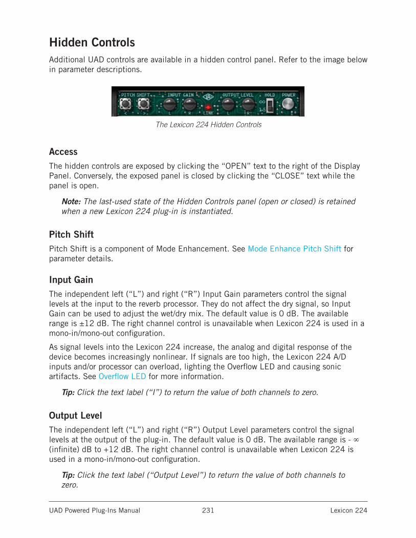
UAD Powered Plug-Ins Manual Lexicon 224 231
Hidden ControlsAdditional UAD controls are available in a hidden control panel. Refer to the image below in parameter descriptions.
The Lexicon 224 Hidden Controls
AccessThe hidden controls are exposed by clicking the “OPEN” text to the right of the Display Panel. Conversely, the exposed panel is closed by clicking the “CLOSE” text while the panel is open.
Note: The last-used state of the Hidden Controls panel (open or closed) is retained when a new Lexicon 224 plug-in is instantiated.
Pitch ShiftPitch Shift is a component of Mode Enhancement. See Mode Enhance Pitch Shift for parameter details.
Input GainThe independent left (“L”) and right (“R”) Input Gain parameters control the signal levels at the input to the reverb processor. They do not affect the dry signal, so Input Gain can be used to adjust the wet/dry mix. The default value is 0 dB. The available range is ±12 dB. The right channel control is unavailable when Lexicon 224 is used in a mono-in/mono-out configuration.
As signal levels into the Lexicon 224 increase, the analog and digital response of the device becomes increasingly nonlinear. If signals are too high, the Lexicon 224 A/D inputs and/or processor can overload, lighting the Overflow LED and causing sonic artifacts. See Overflow LED for more information.
Tip: Click the text label (“I”) to return the value of both channels to zero.
Output LevelThe independent left (“L”) and right (“R”) Output Level parameters control the signal levels at the output of the plug-in. The default value is 0 dB. The available range is - ∞ (infinite) dB to +12 dB. The right channel control is unavailable when Lexicon 224 is used in a mono-in/mono-out configuration.
Tip: Click the text label (“Output Level”) to return the value of both channels to zero.
UAD Powered Plug-Ins Manual Lexicon 224 232
LinkLink/unlink allows the left and right controls for Input Gain and Output Level to be unlinked (non-ganged) in order to apply a different value for each channel. Link is inactive when the LED is unlit. Click the Link LED to toggle the state. The default state is ON.
If the left and right controls have different values when link is inactive and Link is engaged, the left channel value is copied to the right channel (thereby overwriting the right channel value).
When Link is active, automation data is written and read for the left channel only. The automation for the left channel controls both channels in Link mode.
Note: When link is active, modifying the right channel parameters will have no effect when changed from a control surface or when in “controls only” (non-GUI) mode.
Bug FixesThe original Lexicon 224 code contains programming errors in the Hall B and Chorus algorithms. These computer code bugs can cause incorrect Bass decay times (Hall B programs) and undesirable “pops” and/or “thumps” in the right channel (Chorus program) with certain source signals and parameter configurations.
The bugs have been corrected in the UAD implementation of the plug-in, but we have provided the option of using the original code for the sake of pure authenticity.
The UA logo is actually a switch. When the UA logo is illuminated, the source code bugs are fixed. The default state is ON. Click the UA logo to disable the UA bug fixes and revert to the original hardware behavior.
Display HoldThe Display Hold switch alters the behavior of the Numerical Display (See Numerical Value). In the original hardware, the values of parameters that are being modified are displayed for 3 seconds before reverting back to displaying the average decay time.
The Hold switch changes this behavior. When set to infinite (“∞”), the Numerical Display will continue to show the last modified parameter value. When set to infinite and a program is changed, the average decay time is displayed until a parameter is modified.
Note: The last-used state of the Display Hold parameter is retained when a new Lexicon 224 plug-in is instantiated.
PowerThe Power switch is a bypass control. Click the switch to change the Power state. When bypassed, plug-in processing is disabled, and the Display Panel and all button LEDs are dimmed.
UAD Powered Plug-Ins Manual Lexicon 224 233
Program Descriptions
P1 Small Concert Hall BThis program emulates the sound of a small concert hall, with moderate initial density and moderately non-uniform decay. It is optimized for reverb times of 1.5 to 5 seconds (for longer decay times, P3 Large Concert Hall B is recommended instead). The most natural sound is obtained when Bass and Mid are relatively close to the same setting. This program uses the exact same algorithm as P3 Large Concert Hall B.
P2 Vocal PlateThis is a plate reverb emulation optimized for voice. It has low initial density and coloration, resulting in a clear, bright sound. This program uses the exact same algorithm as P5 Percussion Plate A, but with slightly different inherent diffusion.
P3 Large Concert Hall BThis program emulates the sound of a large concert hall, with low density and minimal coloration. It is optimized for long reverb times. With percussive sounds, increasing the diffusion value is recommended. This program uses the exact same algorithm as P1 Small Concert Hall B.
P4 Acoustic ChamberThis program sounds like a chamber, but with less initial density. It tends to sound best with shorter reverb times (2 to 5 seconds). The most chamber-like sound is obtained with Depth at a value of zero. Diffusion is preset in this program and cannot be modified. Unlike all other Lexicon 224 programs, this algorithm has monophonic input.
P5 Percussion Plate AThis is a plate reverb emulation optimized for percussive sounds. It has high initial density and coloration, and sounds best with shorter reverb times. This program uses the exact same algorithm as P2 Vocal Plate, but with slightly different inherent diffusion.
P6 Small Concert Hall AThis program is similar to P1 Small Concert Hall B, except it is brighter overall and the Treble Decay control is more gentle. The original hardware manual recommends equalizing this reverb return about +3 dB below 200 Hz to “add to the richness and naturalness of the reverb.”
P7 Room AProgram 7 is a room simulator with moderate to high initial density and low to moderate coloration. It sounds great on speech and many types of music. This program presents an especially wide output when used with a stereo input source.
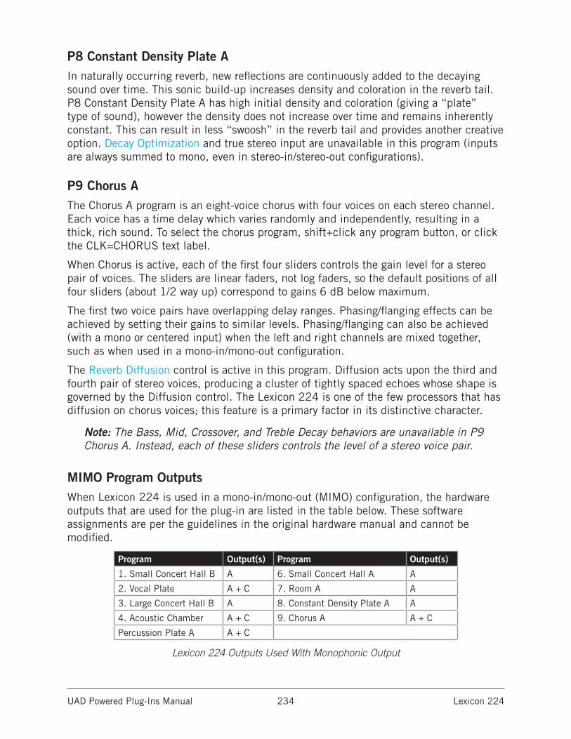
UAD Powered Plug-Ins Manual Lexicon 224 234
P8 Constant Density Plate AIn naturally occurring reverb, new reflections are continuously added to the decaying sound over time. This sonic build-up increases density and coloration in the reverb tail. P8 Constant Density Plate A has high initial density and coloration (giving a “plate” type of sound), however the density does not increase over time and remains inherently constant. This can result in less “swoosh” in the reverb tail and provides another creative option. Decay Optimization and true stereo input are unavailable in this program (inputs are always summed to mono, even in stereo-in/stereo-out configurations).
P9 Chorus AThe Chorus A program is an eight-voice chorus with four voices on each stereo channel. Each voice has a time delay which varies randomly and independently, resulting in a thick, rich sound. To select the chorus program, shift+click any program button, or click the CLK=CHORUS text label.
When Chorus is active, each of the first four sliders controls the gain level for a stereo pair of voices. The sliders are linear faders, not log faders, so the default positions of all four sliders (about 1/2 way up) correspond to gains 6 dB below maximum.
The first two voice pairs have overlapping delay ranges. Phasing/flanging effects can be achieved by setting their gains to similar levels. Phasing/flanging can also be achieved (with a mono or centered input) when the left and right channels are mixed together, such as when used in a mono-in/mono-out configuration.
The Reverb Diffusion control is active in this program. Diffusion acts upon the third and fourth pair of stereo voices, producing a cluster of tightly spaced echoes whose shape is governed by the Diffusion control. The Lexicon 224 is one of the few processors that has diffusion on chorus voices; this feature is a primary factor in its distinctive character.
Note: The Bass, Mid, Crossover, and Treble Decay behaviors are unavailable in P9 Chorus A. Instead, each of these sliders controls the level of a stereo voice pair.
MIMO Program OutputsWhen Lexicon 224 is used in a mono-in/mono-out (MIMO) configuration, the hardware outputs that are used for the plug-in are listed in the table below. These software assignments are per the guidelines in the original hardware manual and cannot be modified.
Program Output(s) Program Output(s)
1. Small Concert Hall B A 6. Small Concert Hall A A
2. Vocal Plate A + C 7. Room A A
3. Large Concert Hall B A 8. Constant Density Plate A A
4. Acoustic Chamber A + C 9. Chorus A A + C
Percussion Plate A A + C
Lexicon 224 Outputs Used With Monophonic Output
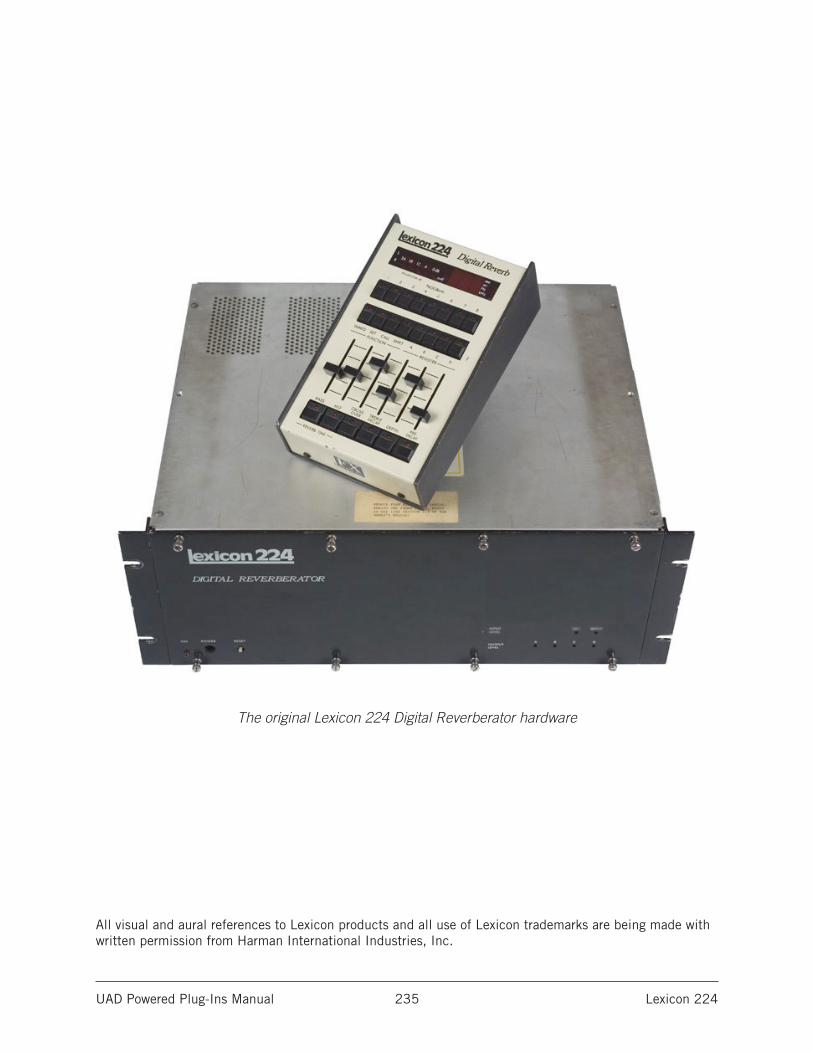
UAD Powered Plug-Ins Manual Lexicon 224 235
The original Lexicon 224 Digital Reverberator hardware
All visual and aural references to Lexicon products and all use of Lexicon trademarks are being made with written permission from Harman International Industries, Inc.
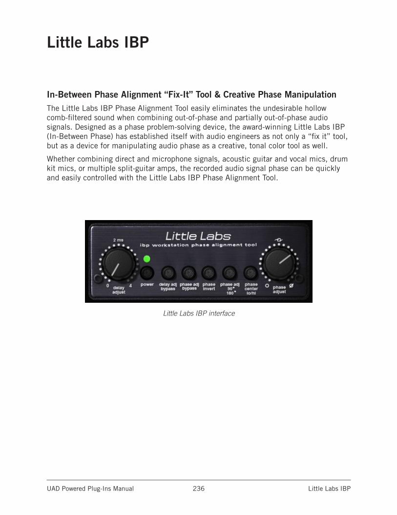
UAD Powered Plug-Ins Manual Little Labs IBP 236
Little Labs IBP
In-Between Phase Alignment “Fix-It” Tool & Creative Phase ManipulationThe Little Labs IBP Phase Alignment Tool easily eliminates the undesirable hollow comb-filtered sound when combining out-of-phase and partially out-of-phase audio signals. Designed as a phase problem-solving device, the award-winning Little Labs IBP (In-Between Phase) has established itself with audio engineers as not only a “fix it” tool, but as a device for manipulating audio phase as a creative, tonal color tool as well.
Whether combining direct and microphone signals, acoustic guitar and vocal mics, drum kit mics, or multiple split-guitar amps, the recorded audio signal phase can be quickly and easily controlled with the Little Labs IBP Phase Alignment Tool.
Little Labs IBP interface
UAD Powered Plug-Ins Manual Little Labs IBP 237
Little Labs IBP ControlsAll parameters are clearly labeled with control names.
Delay AdjustThe Delay Adjust parameter is unique to Universal Audio’s “workstation” version of the Little Labs IBP. Delay Adjust is a continuously variable control that simply delays the input signal from 0.0 to 4.0 milliseconds.
Unlike the “analog” Phase Adjust parameter, which is frequency dependent, Delay Adjust is purely “digital” and shifts all frequencies equally. Delay Adjust accomplishes the same function as manually moving an audio region forwards in the timeline so it plays back a little later in relation to other regions.
Delay Adjust BypassThis switch bypasses the Delay Adjust parameter. Delay Adjust is bypassed when the switch is engaged (darker).
Phase AdjustPhase Adjust is the main parameter in the Little Labs IBP. It is a continuously variable control that shifts the phase of the input signal. The range of Phase Adjust is either 90° or 180°, dependent on the Phase Adjust 90°/180° switch.
The Little Labs IBP hardware is an all-analog device that uses analog allpass filters to produce phase shifting. Allpass filters displace signals in time as a function of frequency (they are frequency dependent). The modeled UAD version accurately models the hardware along with all its idiosyncrasies.
Therefore phase shifting using the Phase Adjust knob is not “perfect” like mathematically-manipulated signals in the digital domain. When Phase Adjust is set to 180° on one of two identical tracks side-by-side, the signals will not cancel as you may expect.
Note: If a “standard” 180° phase shift is desired, use the Phase Invert switch. If “digitally pure” frequency-independent phase shift is desired, use the Delay Adjust parameter.
Phase Adjust BypassThis switch bypasses the Phase Adjust parameter. The signal phase is normal when the switch is engaged (darker).
Phase InvertThis switch inverts the polarity of the input signal, like the phase button on a mixing console. Phase is inverted when the switch is engaged (darker).
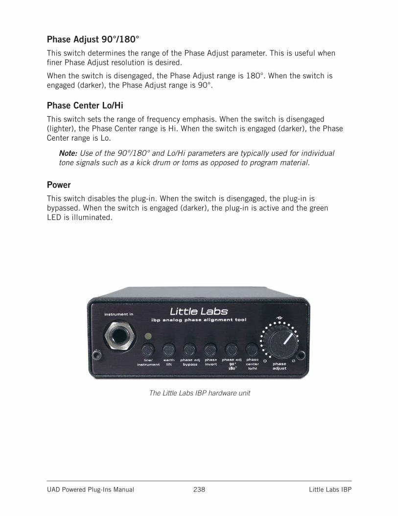
UAD Powered Plug-Ins Manual Little Labs IBP 238
Phase Adjust 90°/180°This switch determines the range of the Phase Adjust parameter. This is useful when finer Phase Adjust resolution is desired.
When the switch is disengaged, the Phase Adjust range is 180°. When the switch is engaged (darker), the Phase Adjust range is 90°.
Phase Center Lo/HiThis switch sets the range of frequency emphasis. When the switch is disengaged (lighter), the Phase Center range is Hi. When the switch is engaged (darker), the Phase Center range is Lo.
Note: Use of the 90°/180° and Lo/Hi parameters are typically used for individual tone signals such as a kick drum or toms as opposed to program material.
PowerThis switch disables the plug-in. When the switch is disengaged, the plug-in is bypassed. When the switch is engaged (darker), the plug-in is active and the green LED is illuminated.
The Little Labs IBP hardware unit
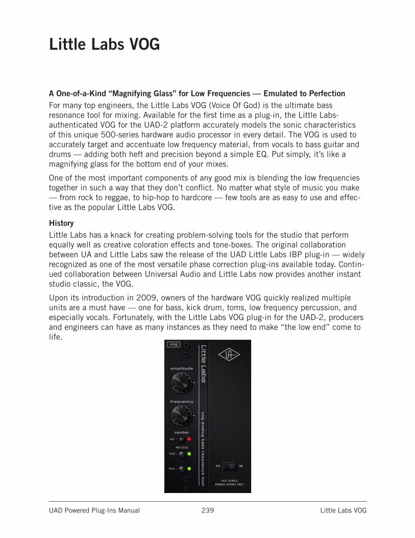
UAD Powered Plug-Ins Manual Little Labs VOG 239
Little Labs VOG
A One-of-a-Kind “Magnifying Glass” for Low Frequencies — Emulated to PerfectionFor many top engineers, the Little Labs VOG (Voice Of God) is the ultimate bass resonance tool for mixing. Available for the first time as a plug-in, the Little Labs-authenticated VOG for the UAD-2 platform accurately models the sonic characteristics of this unique 500-series hardware audio processor in every detail. The VOG is used to accurately target and accentuate low frequency material, from vocals to bass guitar and drums — adding both heft and precision beyond a simple EQ. Put simply, it’s like a magnifying glass for the bottom end of your mixes.
One of the most important components of any good mix is blending the low frequencies together in such a way that they don’t conflict. No matter what style of music you make — from rock to reggae, to hip-hop to hardcore — few tools are as easy to use and effec-tive as the popular Little Labs VOG.
HistoryLittle Labs has a knack for creating problem-solving tools for the studio that perform equally well as creative coloration effects and tone-boxes. The original collaboration between UA and Little Labs saw the release of the UAD Little Labs IBP plug-in — widely recognized as one of the most versatile phase correction plug-ins available today. Contin-ued collaboration between Universal Audio and Little Labs now provides another instant studio classic, the VOG.
Upon its introduction in 2009, owners of the hardware VOG quickly realized multiple units are a must have — one for bass, kick drum, toms, low frequency percussion, and especially vocals. Fortunately, with the Little Labs VOG plug-in for the UAD-2, producers and engineers can have as many instances as they need to make “the low end” come to life.
UAD Powered Plug-Ins Manual Little Labs VOG 240
Operational OverviewTwo simple knobs allow you to dial in the VOG’s desired frequency and effect amplitude. The center of the sweepable frequency range is selected via two push-buttons of 40 Hz and 100 Hz, or you can set the center to 200 Hz by pressing both buttons simultaneously. Everything below the targeted frequency peak is rolled off in a smooth curve — up to -24 dB per octave — ensuring that the low end is always tight and out of the mud, while the frequencies above remain intact. The higher the amplitude of the peak resonance frequency, the more you cut off the mud below, effectively performing two functions at once. A dedicated “flat” button allows you to quickly audition A/B comparisons.
In UseThe VOG is intended for mixing, mastering, post-production sweetening, sound design, and audio restoration. Use it to easily simulate proximity effect for adding chest reso-nance and “heft” to vocals. Simple adjustments will also yield enormous sounding drums just like tweaking the tension of a drumhead. Or, completely transform the tonal characteristics of electric bass tracks — for example, go from a solid body sound to a chambered body sound in seconds. The VOG’s flexibility makes it the right choice on a wide range of musical sources; it’s the perfect way to tune the low end of any mix for incredible detail and punch.
Stereo FunctionalityUnlike the original hardware (which is monophonic), the plug-in enables stereo use with one control set, providing perfectly matched stereo response. When the plug-in is used in mono-in/stereo-out and stereo-in/stereo-out configurations, the controls affect both the left and right signals.
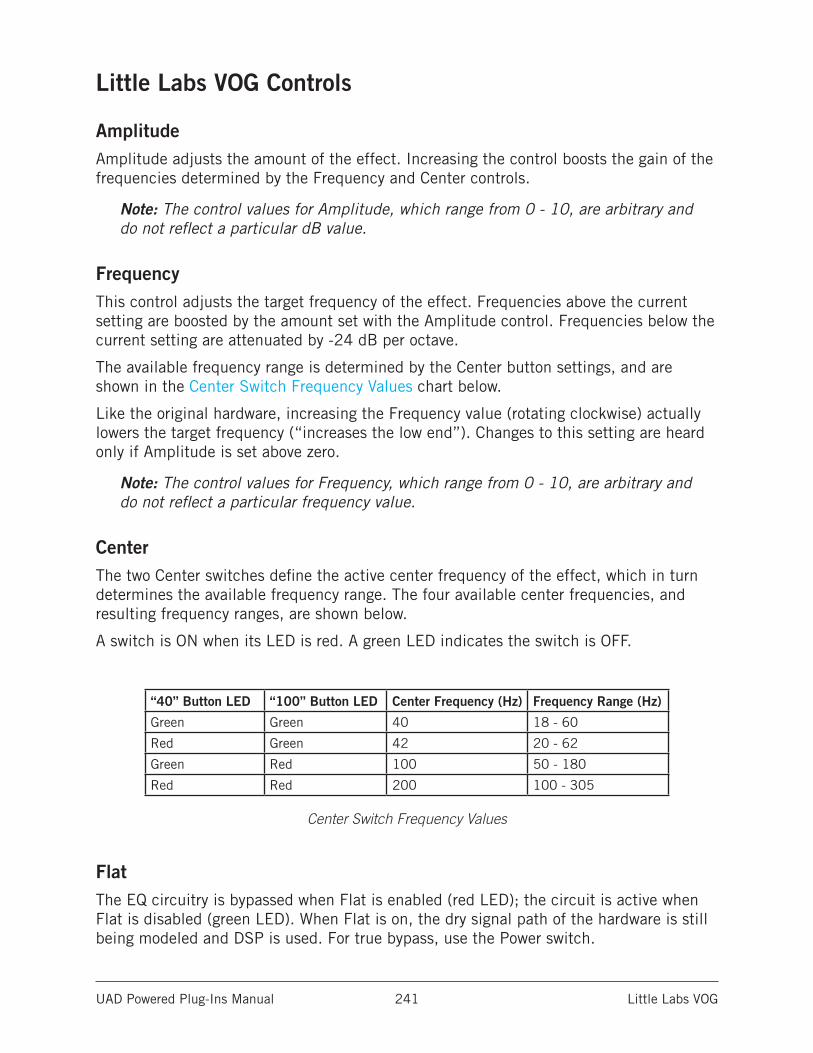
UAD Powered Plug-Ins Manual Little Labs VOG 241
Little Labs VOG Controls
AmplitudeAmplitude adjusts the amount of the effect. Increasing the control boosts the gain of the frequencies determined by the Frequency and Center controls.
Note: The control values for Amplitude, which range from 0 - 10, are arbitrary and do not reflect a particular dB value.
FrequencyThis control adjusts the target frequency of the effect. Frequencies above the current setting are boosted by the amount set with the Amplitude control. Frequencies below the current setting are attenuated by -24 dB per octave.
The available frequency range is determined by the Center button settings, and are shown in the Center Switch Frequency Values chart below.
Like the original hardware, increasing the Frequency value (rotating clockwise) actually lowers the target frequency (“increases the low end”). Changes to this setting are heard only if Amplitude is set above zero.
Note: The control values for Frequency, which range from 0 - 10, are arbitrary and do not reflect a particular frequency value.
CenterThe two Center switches define the active center frequency of the effect, which in turn determines the available frequency range. The four available center frequencies, and resulting frequency ranges, are shown below.
A switch is ON when its LED is red. A green LED indicates the switch is OFF.
“40” Button LED “100” Button LED Center Frequency (Hz) Frequency Range (Hz)
Green Green 40 18 - 60
Red Green 42 20 - 62
Green Red 100 50 - 180
Red Red 200 100 - 305
Center Switch Frequency Values
FlatThe EQ circuitry is bypassed when Flat is enabled (red LED); the circuit is active when Flat is disabled (green LED). When Flat is on, the dry signal path of the hardware is still being modeled and DSP is used. For true bypass, use the Power switch.
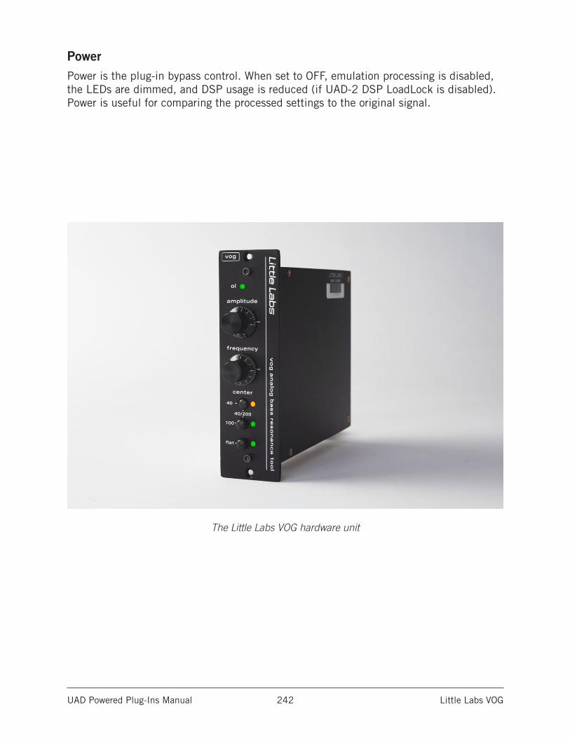
UAD Powered Plug-Ins Manual Little Labs VOG 242
PowerPower is the plug-in bypass control. When set to OFF, emulation processing is disabled, the LEDs are dimmed, and DSP usage is reduced (if UAD-2 DSP LoadLock is disabled). Power is useful for comparing the processed settings to the original signal.
The Little Labs VOG hardware unit
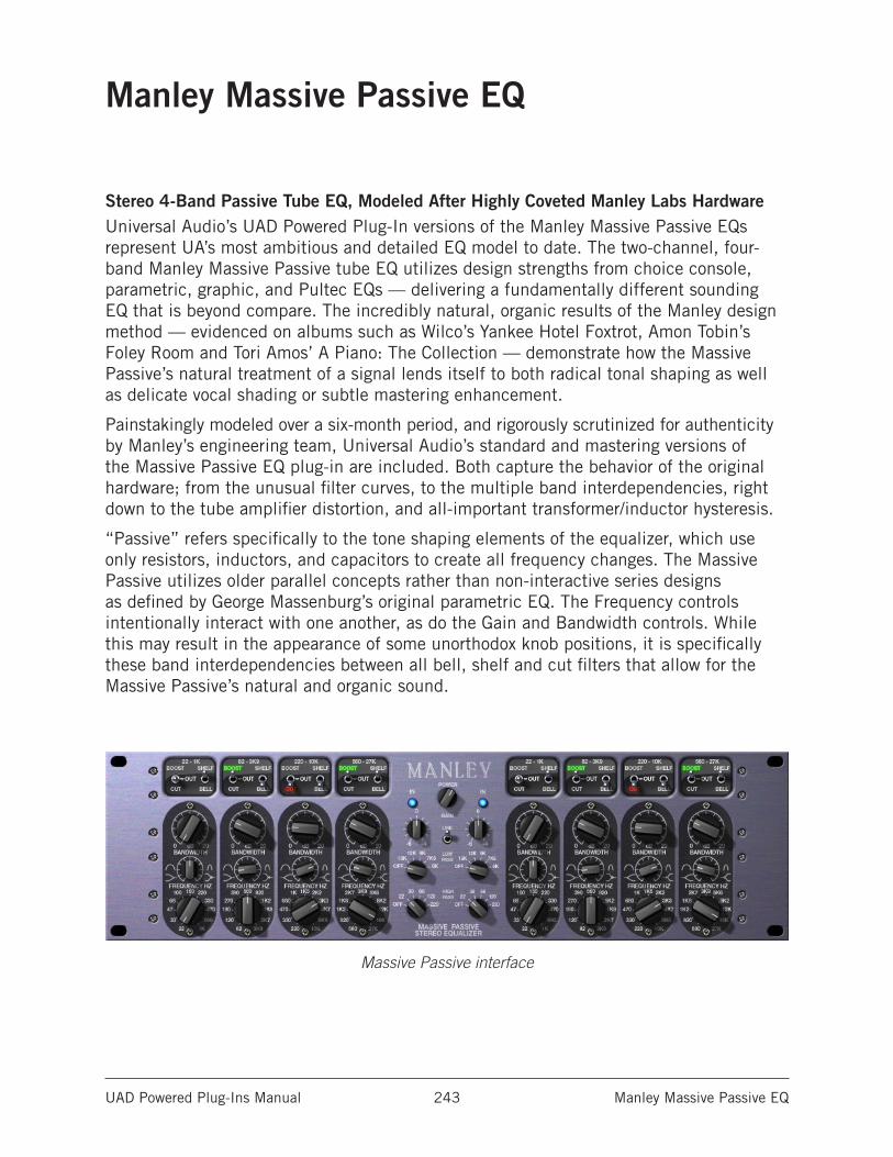
UAD Powered Plug-Ins Manual Manley Massive Passive EQ 243
Manley Massive Passive EQ
Stereo 4-Band Passive Tube EQ, Modeled After Highly Coveted Manley Labs HardwareUniversal Audio’s UAD Powered Plug-In versions of the Manley Massive Passive EQs represent UA’s most ambitious and detailed EQ model to date. The two-channel, four-band Manley Massive Passive tube EQ utilizes design strengths from choice console, parametric, graphic, and Pultec EQs — delivering a fundamentally different sounding EQ that is beyond compare. The incredibly natural, organic results of the Manley design method — evidenced on albums such as Wilco’s Yankee Hotel Foxtrot, Amon Tobin’s Foley Room and Tori Amos’ A Piano: The Collection — demonstrate how the Massive Passive’s natural treatment of a signal lends itself to both radical tonal shaping as well as delicate vocal shading or subtle mastering enhancement.
Painstakingly modeled over a six-month period, and rigorously scrutinized for authenticity by Manley’s engineering team, Universal Audio’s standard and mastering versions of the Massive Passive EQ plug-in are included. Both capture the behavior of the original hardware; from the unusual filter curves, to the multiple band interdependencies, right down to the tube amplifier distortion, and all-important transformer/inductor hysteresis.
“Passive” refers specifically to the tone shaping elements of the equalizer, which use only resistors, inductors, and capacitors to create all frequency changes. The Massive Passive utilizes older parallel concepts rather than non-interactive series designs as defined by George Massenburg’s original parametric EQ. The Frequency controls intentionally interact with one another, as do the Gain and Bandwidth controls. While this may result in the appearance of some unorthodox knob positions, it is specifically these band interdependencies between all bell, shelf and cut filters that allow for the Massive Passive’s natural and organic sound.
Massive Passive interface
UAD Powered Plug-Ins Manual Manley Massive Passive EQ 244
Unusual EQ ConventionsThe Massive Passive has design and operation characteristics that make it unique in the EQ world. Some of these factors mean the “Massivo” may not respond in a manner that you would expect from typical EQs. Keeping these points in mind may help you obtain more satisfactory results. See Notes from Manley Laboratories for more tips.
Passive EQNo active components are used in the EQ circuits, just like revered vintage EQs. This can make some adjustments respond in more subtle ways.
Parallel TopologyThe EQ bands are routed in parallel instead of serially, so gain values for the bands don’t “add up” like most EQs. For example, if two bands in the same channel are boosted 20 dB at 2.7 kHz, you’ll get much less than 40 dB of boost at 2.7 kHz.
Unique ShelvesMost EQs offer a shelving mode for the edge bands only. Massive Passive offers the shelving option on all bands for expanded sonic possibilities, such as “staircase” EQ curves.
No negative feedback loopsOne result of not using negative feedback loops in the design is that the gain control for a band cannot have a “bipolar” boost and cut control. Only band gain is available; how that band gain is applied, either as a boost or as a cut, is specified with a separate toggle switch.
Control InteractionDue in large part to the above points, the Massive Passive controls are much more interactive with, and interdependent upon, each other. We encourage experimentation with an open mind, without expectations of what a visual interpretation of what control settings “should” do.
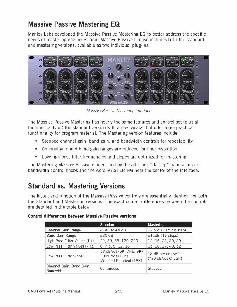
UAD Powered Plug-Ins Manual Manley Massive Passive EQ 245
Massive Passive Mastering EQManley Labs developed the Massive Passive Mastering EQ to better address the specific needs of mastering engineers. Your Massive Passive license includes both the standard and mastering versions, available as two individual plug-ins.
Massive Passive Mastering interface
The Massive Passive Mastering has nearly the same features and control set (plus all the musicality of) the standard version with a few tweaks that offer more practical functionality for program material. The Mastering version features include:
• Stepped channel gain, band gain, and bandwidth controls for repeatability.
• Channel gain and band gain ranges are reduced for finer resolution.
• Low/high pass filter frequencies and slopes are optimized for mastering.
The Mastering Massive Passive is identified by the all-black “flat top” band gain and bandwidth control knobs and the word MASTERING near the center of the interface.
Standard vs. Mastering VersionsThe layout and function of the Massive Passive controls are essentially identical for both the Standard and Mastering versions. The exact control differences between the controls are detailed in the table below.
Control differences between Massive Passive versions
Standard MasteringChannel Gain Range -6 dB to +4 dB ±2.5 dB (0.5 dB steps)Band Gain Range ±20 dB ±11dB (16 steps)High Pass Filter Values (Hz) 22, 39, 68, 120, 220 12, 16, 23, 30, 39Low Pass Filter Values (kHz) 6, 7.5, 9, 12, 18 15, 20, 27, 40, 52*
Low Pass Filter Slope18 dB/oct (6K, 7K5, 9K) 30 dB/oct (12K) Modified Elliptical (18K)
18 dB per octave* (*30 dB/oct @ 52K)
Channel Gain, Band Gain, Bandwidth
Continuous Stepped
UAD Powered Plug-Ins Manual Manley Massive Passive EQ 246
Massive Passive Band ControlsMassive Passive has two identical channels (left and right). Each channel has four EQ bands, with five controls in each band.
Because both Massive Passive plug-ins operate the same way (and the bands of each channel are identical), the control descriptions for each band are only detailed once.
Important: See Standard vs. Mastering Versions for the exact differences between the Massive Passive parameters.
Boost/Cut/OutThis three-position toggle switch determines whether the frequency band will be boosted, cut, or disabled altogether. The amount of boost or cut to be applied to the band is determined by the See Band Gain control.
When Boost or Cut is selected, its label illuminates (green for Boost, red for Cut). When the switch is in the OUT position, the band is disabled.
Note: When set to OUT, the other band controls have no effect.
Shelf/BellThe Shelf/Bell toggle switch defines the shape of the filter band. A unique aspect of this control is that unlike other EQs where only the edge frequencies offer a shelving mode, with Massive Passive all bands can be used in either mode for expanded sonic possibilities.
Note: The Bandwidth control affects the slope of the band filters in both Shelf and Bell modes.
ShelfThe two lowest (leftmost) bands can each be in Low Shelf mode; the two highest (rightmost) bands can each be in High Shelf mode. Shelf slopes generally boost or cut towards the highs or lows (thus the high shelves and low shelves). The two middle shelves are almost the same as the outer ones but just have other (interleaved) frequency choices.
BellBell curves focus their boost and cut at a given frequency, and the further away the signal is from that frequency, the less boost or cut is applied.
UAD Powered Plug-Ins Manual Manley Massive Passive EQ 247
Band GainThis control determines the amount of EQ gain to be applied to the band. The range is from zero gain (flat) at the fully counter-clockwise position, to the maximum value at the fully clockwise position. Whether the gain is applied as a boost or cut is defined by the Boost/Cut/Out switch.
The range for the standard version is continuously variable at up to ±20 dB; the range for the Mastering version is up to ±11 dB in 16 steps (in both versions the maximum value depends on the Bandwidth control).
Important: When Gain for the band is set to zero, the other band controls have no effect.
Unlike most EQs, this control is not flat at the center position with the gain cut or boosted by moving the control to left or right of center. This design allows the band gain to operate at twice the knob resolution as that of a “conventional” dual-purposed control, as well as facilitating a quicker and more accurate return to zero.
Gain has a fair amount of interaction with the Bandwidth control. The maximum band gain is available in Shelf mode when Bandwidth is fully counter-clockwise; less band gain is available in Shelf mode as the Bandwidth is decreased (rotated clockwise). Conversely, the maximum gain is available in Bell mode when Bandwidth is fully clockwise; in Bell mode less band gain is available as Bandwidth is decreased (rotated counter-clockwise).
Due to the parallel EQ topology, the four band Gain controls also interact with each other unlike typical EQs. For example, if two bands in the same channel are boosted 20 dB at 2.7 kHz, you’ll get much less than 40 dB of boost at 2.7 kHz. This also implies that if you first boost one band, that the next three will not seem to do anything if they are at similar frequencies and bandwidths.
BandwidthBandwidth adjusts the slope or “Q” of the band filter in both Bell and Shelf modes. Bandwidth does not have a lot of range and it also affects the maximum boost and cut (like a Pultec).
The widest Q (which is obtained at maximum boost or cut) is approximately 1 for the 22-1K (leftmost) band, and 1.5 for the other three bands. The narrowest Q is approximately 2.5 to 3 for all of the bands.
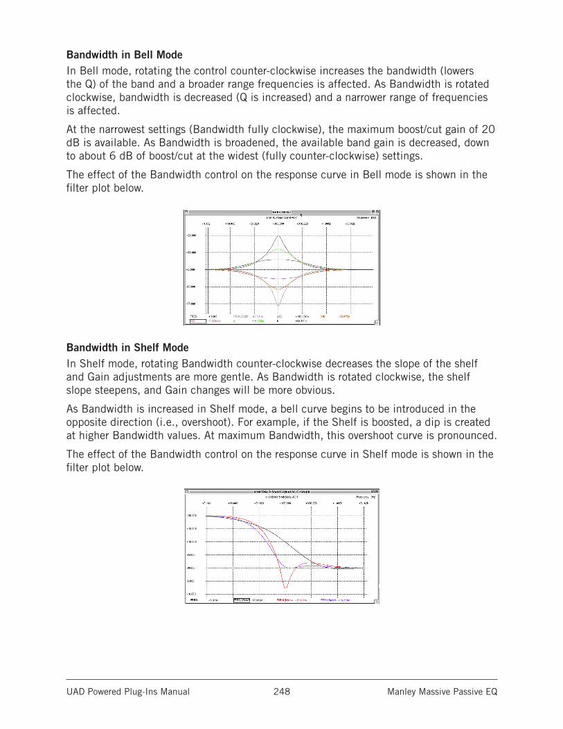
UAD Powered Plug-Ins Manual Manley Massive Passive EQ 248
Bandwidth in Bell ModeIn Bell mode, rotating the control counter-clockwise increases the bandwidth (lowers the Q) of the band and a broader range frequencies is affected. As Bandwidth is rotated clockwise, bandwidth is decreased (Q is increased) and a narrower range of frequencies is affected.
At the narrowest settings (Bandwidth fully clockwise), the maximum boost/cut gain of 20 dB is available. As Bandwidth is broadened, the available band gain is decreased, down to about 6 dB of boost/cut at the widest (fully counter-clockwise) settings.
The effect of the Bandwidth control on the response curve in Bell mode is shown in the filter plot below.
Bandwidth in Shelf ModeIn Shelf mode, rotating Bandwidth counter-clockwise decreases the slope of the shelf and Gain adjustments are more gentle. As Bandwidth is rotated clockwise, the shelf slope steepens, and Gain changes will be more obvious.
As Bandwidth is increased in Shelf mode, a bell curve begins to be introduced in the opposite direction (i.e., overshoot). For example, if the Shelf is boosted, a dip is created at higher Bandwidth values. At maximum Bandwidth, this overshoot curve is pronounced.
The effect of the Bandwidth control on the response curve in Shelf mode is shown in the filter plot below.
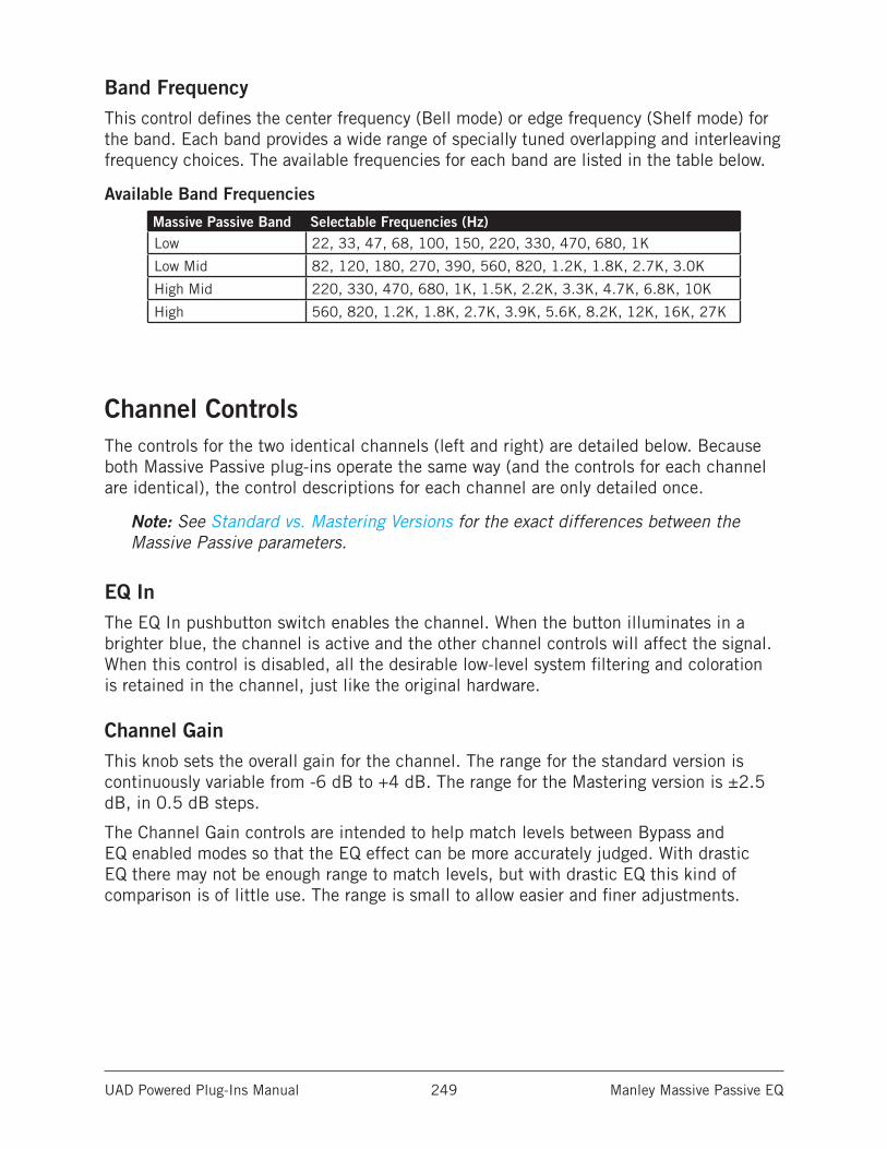
UAD Powered Plug-Ins Manual Manley Massive Passive EQ 249
Band FrequencyThis control defines the center frequency (Bell mode) or edge frequency (Shelf mode) for the band. Each band provides a wide range of specially tuned overlapping and interleaving frequency choices. The available frequencies for each band are listed in the table below.
Available Band Frequencies
Massive Passive Band Selectable Frequencies (Hz)Low 22, 33, 47, 68, 100, 150, 220, 330, 470, 680, 1K
Low Mid 82, 120, 180, 270, 390, 560, 820, 1.2K, 1.8K, 2.7K, 3.0K
High Mid 220, 330, 470, 680, 1K, 1.5K, 2.2K, 3.3K, 4.7K, 6.8K, 10K
High 560, 820, 1.2K, 1.8K, 2.7K, 3.9K, 5.6K, 8.2K, 12K, 16K, 27K
Channel ControlsThe controls for the two identical channels (left and right) are detailed below. Because both Massive Passive plug-ins operate the same way (and the controls for each channel are identical), the control descriptions for each channel are only detailed once.
Note: See Standard vs. Mastering Versions for the exact differences between the Massive Passive parameters.
EQ InThe EQ In pushbutton switch enables the channel. When the button illuminates in a brighter blue, the channel is active and the other channel controls will affect the signal. When this control is disabled, all the desirable low-level system filtering and coloration is retained in the channel, just like the original hardware.
Channel GainThis knob sets the overall gain for the channel. The range for the standard version is continuously variable from -6 dB to +4 dB. The range for the Mastering version is ±2.5 dB, in 0.5 dB steps.
The Channel Gain controls are intended to help match levels between Bypass and EQ enabled modes so that the EQ effect can be more accurately judged. With drastic EQ there may not be enough range to match levels, but with drastic EQ this kind of comparison is of little use. The range is small to allow easier and finer adjustments.
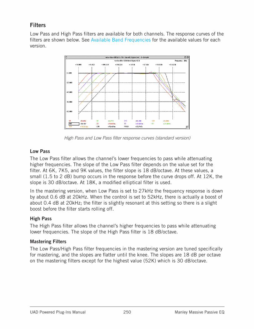
UAD Powered Plug-Ins Manual Manley Massive Passive EQ 250
FiltersLow Pass and High Pass filters are available for both channels. The response curves of the filters are shown below. See Available Band Frequencies for the available values for each version.
High Pass and Low Pass filter response curves (standard version)
Low PassThe Low Pass filter allows the channel’s lower frequencies to pass while attenuating higher frequencies. The slope of the Low Pass filter depends on the value set for the filter. At 6K, 7K5, and 9K values, the filter slope is 18 dB/octave. At these values, a small (1.5 to 2 dB) bump occurs in the response before the curve drops off. At 12K, the slope is 30 dB/octave. At 18K, a modified elliptical filter is used.
In the mastering version, when Low Pass is set to 27kHz the frequency response is down by about 0.6 dB at 20kHz. When the control is set to 52kHz, there is actually a boost of about 0.4 dB at 20kHz; the filter is slightly resonant at this setting so there is a slight boost before the filter starts rolling off.
High PassThe High Pass filter allows the channel’s higher frequencies to pass while attenuating lower frequencies. The slope of the High Pass filter is 18 dB/octave.
Mastering FiltersThe Low Pass/High Pass filter frequencies in the mastering version are tuned specifically for mastering, and the slopes are flatter until the knee. The slopes are 18 dB per octave on the mastering filters except for the highest value (52K) which is 30 dB/octave.
UAD Powered Plug-Ins Manual Manley Massive Passive EQ 251
Other ControlsThe Power and Link controls are global to both channels.
PowerPower is a two-state knob that determines whether the plug-in is active. When the knob is in the Off (counter-clockwise) position, all LED elements are unlit, plug-in processing is disabled, and UAD DSP usage is reduced (unless UAD-2 DSP LoadLock is enabled).
LinkThe Link switch is a software-only addition that allows the two sets of controls for each channel to be linked for ease of operation when both channels require the same values, or unlinked when dual-mono operation is desired. The Link parameter is stored within presets and can be accessed via automation.
Important: When unlink is switched to link, channel 1 controls are copied to channel 2. Control offsets between channels are lost in this case.
When set to Link (up position), modifying any channel one or channel two control causes its adjacent stereo counterpart control to snap to the same position (channel 1 & 2 controls are ganged together in Link mode).
When Link is active, automation data is written and read for channel one only. In this case, the automation data for channel one will control both channels.
Note: When Link is active, changing channel two parameters from a control surface or when in “controls only” (non-GUI) mode will have no effect.
When set to unlink (down position), the controls for channels one and two are completely independent. Unlink is generally used in mono mode. When unlinked, automation data is written and read by each channel separately.
Note: If disparate values are set under the unlinked state, the left channel will override the right channel when Link is activated.
UAD Powered Plug-Ins Manual Manley Massive Passive EQ 252
Notes from Manley Laboratories• Do not assume the knob settings “mean” what you expect they should mean. Part
of this is due to the interaction of the controls. Part is due to the new shelf slopes and part due to a lack of standards regarding shelf specification.
• You may find yourself leaning towards shelf frequencies closer to the mids than you are used to and the “action” seems closer to the edges of the spectrum than your other EQs. Same reasons as above.
• You may also find yourself getting away with what seems like massive amounts of boost. Where the knobs end up, may seem scary particularly for mastering. Keep in mind that, even at maximum boost, a wide bell might only max out at 6 dB of boost (less for the lowest band) and only reaches 20 dB at the narrowest bandwidth. On the other hand, because of how transparent this EQ is, you might actually be EQing more than you could with a different unit. Taste rules, test benches don’t make hit records, believe your ears.
• Sometimes the shelves will sound pretty weird, especially (only) at the narrow bandwidth settings. They might seem to be having a complex effect and not only at the “dialed in” frequency. This is certainly possible. Try wider bandwidths at first.
• If you seem to be boosting all 4 bands at widely separated frequencies and not hearing much “EQ” as you might expect (except for level) this is a side-effect of a passive EQ and probably a good thing. To get drastic sounding EQ you should try boosting a few bands and cutting a few bands. In fact, it is usually best to start with cutting rather than boosting.
• A reasonable starting point for the Bandwidth for shelves is straight up or between 11:00 and 1:00. It was designed this way and is roughly where the maximum flat-ness around the “knee” is, combined with a well defined steep slope.
• The Massive Passive may sound remarkably different from other high end EQs and completely different from the console EQs. Yes, this is quite deliberate. Hopefully it sounds better, sweeter, more musical and it complements your console EQs. We saw little need for yet another variation of the standard parametric with only sub-tle sonic differences. We suggest using the Massive Passive before tape, for the bulk of the EQ tasks and then using the console EQs for some fine tweaking and where narrow Q touch-ups like notches are needed. The Massive Passive is equally at home doing big, powerful EQ tasks such as is sometimes required for track-ing drums, bass and guitars, or for doing those demanding jobs where subtlety is required like vocals and mastering.
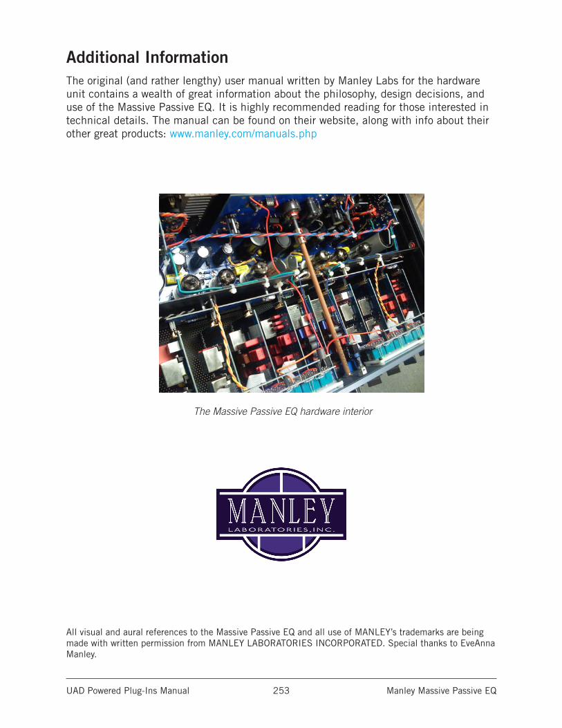
UAD Powered Plug-Ins Manual Manley Massive Passive EQ 253
Additional InformationThe original (and rather lengthy) user manual written by Manley Labs for the hardware unit contains a wealth of great information about the philosophy, design decisions, and use of the Massive Passive EQ. It is highly recommended reading for those interested in technical details. The manual can be found on their website, along with info about their other great products: www.manley.com/manuals.php
The Massive Passive EQ hardware interior
All visual and aural references to the Massive Passive EQ and all use of MANLEY’s trademarks are being made with written permission from MANLEY LABORATORIES INCORPORATED. Special thanks to EveAnna Manley.
UAD Powered Plug-Ins Manual Manley Stereo Variable Mu Limiter Compressor 254
Manley Stereo Variable Mu Limiter Compressor
Tube compression royalty for your mixesAs Manley Labs’ flagship compressor since 1994, the Variable Mu is a tube and transformer-driven classic that exudes hand-made craftsmanship. A gold standard among mixing and mastering engineers, the Variable Mu adds clarity and cohesion to stereo buses or your entire mix.
Developed under Manley Labs’ rigorous scrutiny, the Manley Variable Mu Limiter Compressor plug-in is a thorough emulation of this legendary tube limiter, and is based on the coveted “6BA6 T-BAR Tube Mod” unit. Now, its famed sound is available exclusively for UAD-2 hardware and Apollo interfaces.
Now You Can:• Add definition and fidelity to individual tracks, stereo buses, or an entire mix
• Glue together difficult mixes with signature Manley tube compression
• Link channels for a precise, perfectly matched stereo image
• Select from Left/Right or Mid/Side operation for precise control of stereo imaging
• Use the plug-in-only Dry/Wet Mix control to easily dial-in parallel compression
Manley Variable Mu® Under the HoodWhile the Manley Variable Mu uses the remote cut-off style gain reduction found in the Fairchild and other classic limiters, it has a sound and character all its own. Its classic dual-triode gain reduction design is constantly re-biased by the sidechain control voltages, creating a unique variable gain compressor with stunning transparency. This lets you treat source material with velvety-smooth gain reduction, while infusing warm harmonic content, free of audible compression artifacts.
King of the 2-BusThe Manley Variable Mu Limiter Compressor plug-in can be used on single instruments such as bass or a lead vocal, or on subgroups like strings or horns. But its raison d’être is on the mix bus, where its expert features can unify your mixes with a rich, hi-fi fit and finish.
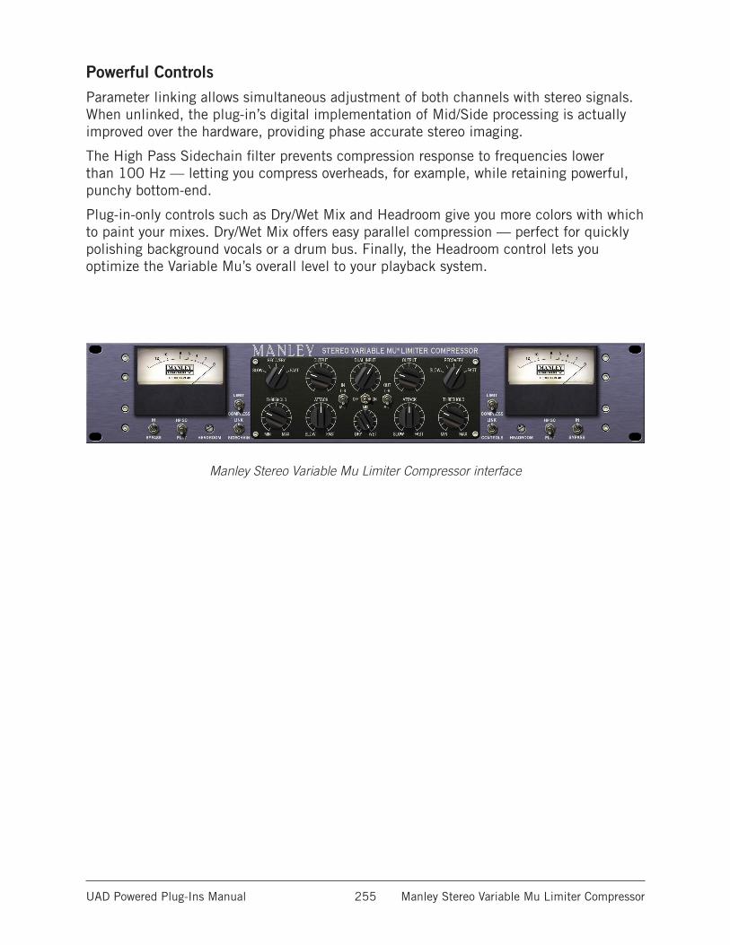
UAD Powered Plug-Ins Manual Manley Stereo Variable Mu Limiter Compressor 255
Powerful ControlsParameter linking allows simultaneous adjustment of both channels with stereo signals. When unlinked, the plug-in’s digital implementation of Mid/Side processing is actually improved over the hardware, providing phase accurate stereo imaging.
The High Pass Sidechain filter prevents compression response to frequencies lower than 100 Hz — letting you compress overheads, for example, while retaining powerful, punchy bottom-end.
Plug-in-only controls such as Dry/Wet Mix and Headroom give you more colors with which to paint your mixes. Dry/Wet Mix offers easy parallel compression — perfect for quickly polishing background vocals or a drum bus. Finally, the Headroom control lets you optimize the Variable Mu’s overall level to your playback system.
Manley Stereo Variable Mu Limiter Compressor interface
UAD Powered Plug-Ins Manual Manley Stereo Variable Mu Limiter Compressor 256
Variable Mu OverviewThe Manley Stereo Variable Mu Limiter Compressor is a highly flexible two-channel processor for adding transparent dynamics control and tube warmth to mix and master buses or individual tracks.
While the Manley Variable Mu uses the remote cut-off style gain reduction found in the Fairchild and other classic limiters, it has a sound and character all its own. Incorporating a traditional dual-triode gain reduction design which is constantly re-biased by the sidechain control voltages, the Variable Mu combines Manley’s hand-selected tubes and in-house transformer manufacturing to create a unique variable gain compressor design with stunning transparency. This lets you treat source material with velvety-smooth gain reduction, while infusing warm harmonic content, free of audible compression artifacts.
Dual Mono/Stereo ProcessingThe Manley Variable Mu can operate in stereo or as a dual-mono device.
Dual MonoWhen set to Left-Right (versus Mid-Side) and the sidechain is unlinked, the processor operates as a dual mono device. Except for the ganged Dual Input control, the left and right channels are completely independent, and each channel can have unique settings.
StereoWhen set to Left-Right and the sidechain is linked, the plug-in is operating as a stereo device. The left signal is fed to the left channel compressor, and the right signal is fed to the right channel compressor. The two compressors are constrained so that they both compress the same amount at any instant, preventing transients that appear only on one channel from shifting the stereo image of the output (any big transient on either channel will cause both channels to compress). The amount of compression will be similar to the amount of compression for a transient which appears on both channels at the same time.
In stereo operation, the controls for the left and right channels can be unlinked so they are independent and can be adjusted separately. Threshold, attack, and recovery can be set independently to cause the compressor to be more sensitive to instruments which are panned to one side or the other. Output controls can be set separately in order to correct an overall image shift at the output.
UAD Powered Plug-Ins Manual Manley Stereo Variable Mu Limiter Compressor 257
Mid-Side ProcessingThe Manley Variable Mu can perform dynamics processing on the middle and side components of stereo signals independently. In other words, the monophonic (middle, or sum) and/or stereo (side, or difference) components of a stereo source signal can be processed separately from the other component.
Mid-Side processing is accomplished by first routing the stereo source signal through a sum/difference matrix on input which separates a stereo source signal into its mono and stereo signal components. The mid-side components are then compressed or limited independently. Finally, the mid-side components are recombined into a normal stereo signal via another sum/difference matrix on output.
In the Variable Mu, the left+right (sum) middle signals are routed to the left channel, and the left-right (difference) side signals are routed to the right channel. The two channels can work independently of each other, or the dynamics sidechain control signal can be optionally linked for creative uses.
The Variable Mu has separate Mid-Side switches for input and output. The M-S IN switch activates the sum/difference matrix on input (encode) and the M-S OUT switch activates the sum/difference matrix on output (decode). The separate matrices allow for using only “half” of a full encode/decode circuit on input or output (but not both) when a full encode/decode process is not desired. For example, this feature can be used to decode stereo tracks recorded with the mid-side microphone technique back into a standard left/right stereo signal.
Note: Each sum/difference matrix simply inverts the stereo signal type from left-right to mid-side, or from mid-side to left-right. They don’t distinguish between the original signal type, so they can be used to convert either type to the other type.
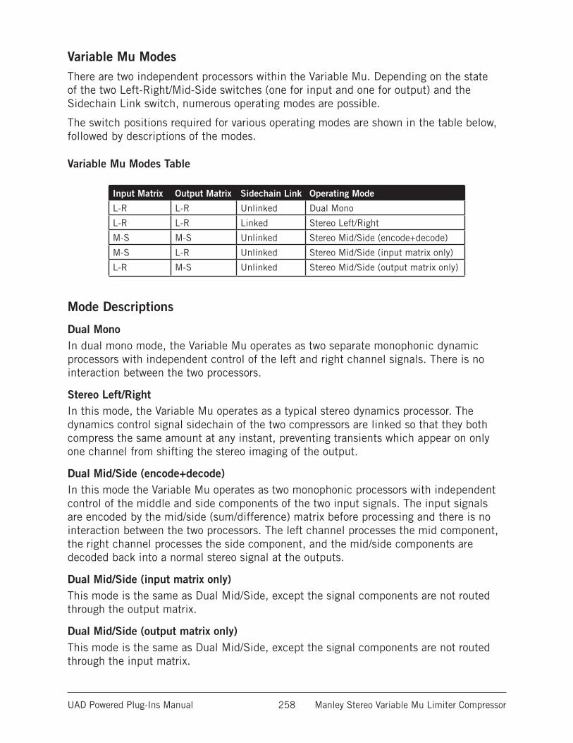
UAD Powered Plug-Ins Manual Manley Stereo Variable Mu Limiter Compressor 258
Variable Mu ModesThere are two independent processors within the Variable Mu. Depending on the state of the two Left-Right/Mid-Side switches (one for input and one for output) and the Sidechain Link switch, numerous operating modes are possible.
The switch positions required for various operating modes are shown in the table below, followed by descriptions of the modes.
Variable Mu Modes Table
Input Matrix Output Matrix Sidechain Link Operating Mode
L-R L-R Unlinked Dual Mono
L-R L-R Linked Stereo Left/Right
M-S M-S Unlinked Stereo Mid/Side (encode+decode)
M-S L-R Unlinked Stereo Mid/Side (input matrix only)
L-R M-S Unlinked Stereo Mid/Side (output matrix only)
Mode Descriptions
Dual MonoIn dual mono mode, the Variable Mu operates as two separate monophonic dynamic processors with independent control of the left and right channel signals. There is no interaction between the two processors.
Stereo Left/RightIn this mode, the Variable Mu operates as a typical stereo dynamics processor. The dynamics control signal sidechain of the two compressors are linked so that they both compress the same amount at any instant, preventing transients which appear on only one channel from shifting the stereo imaging of the output.
Dual Mid/Side (encode+decode)In this mode the Variable Mu operates as two monophonic processors with independent control of the middle and side components of the two input signals. The input signals are encoded by the mid/side (sum/difference) matrix before processing and there is no interaction between the two processors. The left channel processes the mid component, the right channel processes the side component, and the mid/side components are decoded back into a normal stereo signal at the outputs.
Dual Mid/Side (input matrix only)This mode is the same as Dual Mid/Side, except the signal components are not routed through the output matrix.
Dual Mid/Side (output matrix only)This mode is the same as Dual Mid/Side, except the signal components are not routed through the input matrix.
UAD Powered Plug-Ins Manual Manley Stereo Variable Mu Limiter Compressor 259
Operating HeadroomThe Headroom control, which is a UAD-only feature not found in the original hardware, enables adjustment of the internal operating reference level for the Manley Variable Mu. Headroom enables best practice operating level matching, or it can be used creatively to expand the sonic range of the processor. By fine-tuning Headroom, the non-linear I/O distortion and compression response characteristics can be tailored independently of signal input levels.
By increasing the Headroom (by rotating the control counter-clockwise), signals at the input can be pushed higher before they compress. For complete details about this feature, see Headroom.
Unmarked ControlsSome continuous controls (Dual Input, Threshold, Attack, Output) have a range of zero to ten when viewed in controls mode (if supported by the DAW). As with the original hardware, these controls are not marked with absolute values and are designed to be set “by ear” instead of by selecting pre-defined values.
Artist PresetsThe Manley Variable Mu includes artist presets from prominent Variable Mu users. The artist presets are in the internal factory bank and are accessed via the DAW application’s preset menu. The artist presets are also copied to disk by the UAD installer so they can be used within Apollo’s Console application. The presets can be loaded using the Settings menu in the UAD Toolbar.
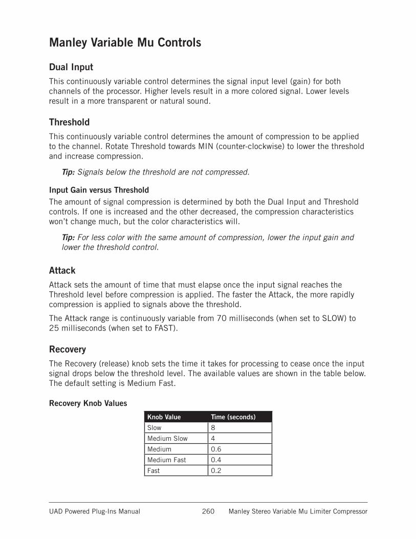
UAD Powered Plug-Ins Manual Manley Stereo Variable Mu Limiter Compressor 260
Manley Variable Mu Controls
Dual InputThis continuously variable control determines the signal input level (gain) for both channels of the processor. Higher levels result in a more colored signal. Lower levels result in a more transparent or natural sound.
ThresholdThis continuously variable control determines the amount of compression to be applied to the channel. Rotate Threshold towards MIN (counter-clockwise) to lower the threshold and increase compression.
Tip: Signals below the threshold are not compressed.
Input Gain versus ThresholdThe amount of signal compression is determined by both the Dual Input and Threshold controls. If one is increased and the other decreased, the compression characteristics won’t change much, but the color characteristics will.
Tip: For less color with the same amount of compression, lower the input gain and lower the threshold control.
AttackAttack sets the amount of time that must elapse once the input signal reaches the Threshold level before compression is applied. The faster the Attack, the more rapidly compression is applied to signals above the threshold.
The Attack range is continuously variable from 70 milliseconds (when set to SLOW) to 25 milliseconds (when set to FAST).
RecoveryThe Recovery (release) knob sets the time it takes for processing to cease once the input signal drops below the threshold level. The available values are shown in the table below. The default setting is Medium Fast.
Recovery Knob Values
Knob Value Time (seconds)
Slow 8
Medium Slow 4
Medium 0.6
Medium Fast 0.4
Fast 0.2
UAD Powered Plug-Ins Manual Manley Stereo Variable Mu Limiter Compressor 261
OutputOutput provides continuous attenuation of the Variable Mu’s signal level at the output of the plug-in. Note that output adjustment is only possible when the In/Bypass switch is set to In.
Note: This control has no effect on the dry signal component.
Compress/LimitThe Compress/Limit switch sets the channel to function as a limiter or a compressor.
Tip: For limiting or compression to occur, signal levels must exceed the Threshold value.
LimitWhen set to Limit, the ratio starts at 4:1 and moves up to 20:1 when limiting exceeds 12 dB. The limiter provides a sharper knee to catch peaks, but actually softens as more limiting is used.
CompressWhen set to Compress, the ratio is set to 1.5:1 with a soft-knee characteristic. Soft-knee provides a more subtle compression resulting in a natural, less compressed sound.
Note: As with the original hardware, the Variable Mu plug-in can never achieve greater than -10 dB of gain reduction.
Sidechain FilterWhen set to HP SC, this switch rolls off low frequencies in the dynamics control sidechain. The signal is attenuated by -3 dB at 100 Hz with a slope of 6 dB per octave. When set to FLAT, the sidechain is unfiltered. The default setting is FLAT.
Removing low-frequency content from the sidechain by engaging the filter can reduce excessive gain reduction and/or “pumping” on bass-heavy audio signals without reducing bass content of the audio signal itself.
BypassThe Bypass switch determines whether or not the incoming signal is processed by the plug-in. When set to Bypass, the source signal is unaffected.
UAD Powered Plug-Ins Manual Manley Stereo Variable Mu Limiter Compressor 262
Mid-Side/Left-Right
Note: For an overview of this feature, see Mid-Side Processing.
These two switches enable the sum/difference matrix for the input and/or the output. The switch on the left (labeled IN) enables the processor input matrix, and the switch on the right (labeled OUT) enables the processor output matrix.
• For mid/side compression on a standard stereo left-right signal, set both IN and OUT switches to M-S.
• For single-ended processing (for example, to process a stereo track recorded with a mid/side microphone technique), set only one switch to M-S.
• Sidechain Link should generally be disabled for traditional mid-side processing. Of course, the sidechains can be linked for creative purposes.
INWhen the M-S switch labeled IN is set to L-R, incoming stereo signals are passed directly into the compressor inputs, bypassing the input sum/difference matrix.
When set to M-S, incoming stereo signals are passed through the sum/difference matrix, converting one signal type (left/right or mid/side) to the other type before compression.
OUTWhen the M-S switch labeled OUT is set to L-R, outgoing (post-compression) stereo signals are passed directly to the outputs, bypassing the output sum/difference matrix.
When set to M-S, outgoing stereo signals are passed through the sum/difference matrix after compression, converting one signal type (left/right or mid/side) to the other type before being output.
Sidechain LinkWhen this control is set to Link, it causes the two channels of the compressor to compress in equal amounts. This does not mean that the compressor will be equally sensitive to either channel however; that depends on the settings of the other controls.
When Sidechain is set to LINK but Controls Link is off, the Threshold controls can be set independently to cause the compressor to be more sensitive to instruments which are panned to one side or the other. Output controls can be set separately in order to correct an overall image shift at the output.
UAD Powered Plug-Ins Manual Manley Stereo Variable Mu Limiter Compressor 263
Controls LinkThis switch links the controls for the left and right channels of the processor. When set to LINK, adjusting the left channel controls will force the equivalent right channel controls to move to the same position.
To read and write automation data for both channels independently when in dual-mono mode, Controls Link must be disabled.
Important: When unlink is switched to link, the left channel values are copied to the right channel, and any control offsets between channels are lost.
MixThe output balance between the signal processed by the plug-in and the original dry source signal can be adjusted with the Mix control. Mix facilitates parallel compression techniques without having to create additional routings in the DAW.
When set to DRY, only the unprocessed source signal is output. When set to WET (the default value), only the processed signal is output. When set to the center position (50%), an equal blend of both the dry and wet signals is output. The balance is continuously variable throughout the control range.
Note that the dry signal is unaffected by the Variable Mu’s Output control.
Tip: Click the “MIX” text label to set the control to the 50% position. Click the “DRY” text label to set the control to the minimum position. Click the “WET” text label to set the control to the maximum position.
UAD Powered Plug-Ins Manual Manley Stereo Variable Mu Limiter Compressor 264
HeadroomThe Headroom control is provided to allow best practice operating levels and accommodate applications where high amounts of gain reduction are not desired. Headroom simply changes the internal operating level so that the plug-in is not “pushed” into gain reduction as much.
Note: There is only one headroom parameter. Although the Headroom control appears twice in the Variable Mu window, they are permanently linked.
Headroom can be set (in dB) to 4, 8, 12, 14, 16, 18, 20, 24, or 28. The default value is 16 dB (when the set screw “dot” is in the straight up 12 o’clock position). Note that Headroom is increased as the dB value decreases.
Tip: Click the “HEADROOM” text label to return the control to the default value.
At higher dB values (clockwise rotation), signals will push the plug-in into gain reduction (and more non-linearity and “good” harmonic distortion color) more easily. Set the control to a lower value (counter-clockwise rotation) when less gain reduction and less color is desired.
Note: To avoid the temporary gain increases that can result when adjusting Head-room, automating this control is not recommended.
Keep in mind there are no hard and fast headroom rules. Feel free to experiment with the various positions of the Headroom control regardless of the audio source. If it sounds good, use it!
On/OffThis switch determines whether the plug-in is active. When set to the Off position, the VU meters go dark to indicate signal processing has ceased. In this state, plug-in processing is disabled and UAD DSP usage is reduced (unless UAD-2 DSP LoadLock is enabled).
Gain Reduction MetersDual VU meters display the amount of gain reduction in decibels. In typical use, adjusting Threshold towards MIN (counter-clockwise) results in the VU meters displaying higher amounts of reduction.

UAD Powered Plug-Ins Manual Manley Stereo Variable Mu Limiter Compressor 265
Additional InformationThe original user manual written by Manley Labs for the hardware unit contains a wealth of great information about the philosophy, design decisions, and use of the Massive Variable Mu. It is highly recommended reading for those interested in technical details. The manual can be found on their website, along with info about their other great products: http://www.manley.com/manuals.php
The Manley Stereo Variable Mu Limiter Compressor original hardware
All visual and aural references to the Variable Mu and all use of MANLEY’s trademarks are being made with written permission from MANLEY LABORATORIES INCORPORATED. Special thanks to EveAnna Manley and Dave Collins.
UAD Powered Plug-Ins Manual Moog Multimode Filter 266
Moog Multimode Filter
True Analog-Sounding VCF Emulation in a Table Top Filter Set Plug-InThe Moog Multimode Filter represents the first truly analog-sounding VCF (voltage controlled filter) emulation made for mixing, performing, creating, or destroying. The Multimode Filter combines the best of Bob Moog’s classic designs with select features from his final Voyager instrument. UA meticulously modeled the analog behavior of the historical 4-pole ladder filter including all of the non-linearities of the original. UA takes this analog marvel to the next level by combining a Lowpass, Bandpass, and Highpass filter in one unit, and allowing Moog’s signature self oscillation and extreme resonance in any of the filter modes.
The Moog Multimode Filter incorporates other features such as a +20 dB gain switch giving an option for the extreme distortion capabilities found at the Minimoog’s external input. There is also an Envelope control with both positive and negative values, plus a simple Smooth/Fast switch to change Envelope response time. Next, the Voyager’s Spacing control is included that detunes two separate hard-panned filters. Also included is a tempo-syncable LFO section that incorporates six wave selections and an LFO phase Offset control (±180º). Mix blends wet and dry signal, while Output controls the final volume of the instrument. In addition, a Mono/Stereo switch enables the mono summing of any stereo effect, plus Effect/Bypass turns off all effects but leaves the Drive and Output controls enabled. Finally, Step/Track disables/enables filter smoothing, in cases where extreme DAW automation may be required.
Warning: Like most resonant filters, Moog Multimode Filter has the potential to create unpredictable sonic results that can result in unexpected jumps in output amplitude. Depending on the source material, input levels, and parameter values, the filter output can suddenly get extremely loud, with the potential to damage speakers and/or hearing. This condition is particularly susceptible when the simultaneous conditions of high gain, low filter cutoff, and high resonance values are applied, and/or when the LFO sweeps into these conditions. Use caution and/or low monitoring levels when dialing in extreme parameter values to avoid speaker and/or hearing damage!
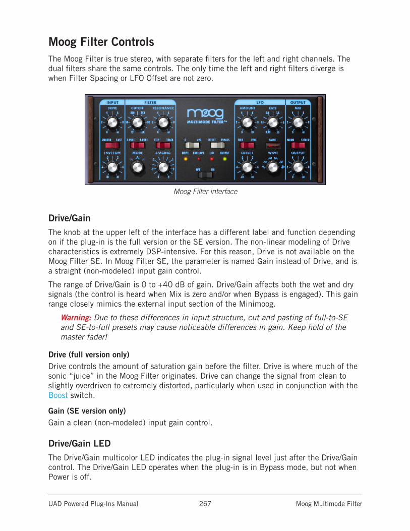
UAD Powered Plug-Ins Manual Moog Multimode Filter 267
Moog Filter ControlsThe Moog Filter is true stereo, with separate filters for the left and right channels. The dual filters share the same controls. The only time the left and right filters diverge is when Filter Spacing or LFO Offset are not zero.
Moog Filter interface
Drive/GainThe knob at the upper left of the interface has a different label and function depending on if the plug-in is the full version or the SE version. The non-linear modeling of Drive characteristics is extremely DSP-intensive. For this reason, Drive is not available on the Moog Filter SE. In Moog Filter SE, the parameter is named Gain instead of Drive, and is a straight (non-modeled) input gain control.
The range of Drive/Gain is 0 to +40 dB of gain. Drive/Gain affects both the wet and dry signals (the control is heard when Mix is zero and/or when Bypass is engaged). This gain range closely mimics the external input section of the Minimoog.
Warning: Due to these differences in input structure, cut and pasting of full-to-SE and SE-to-full presets may cause noticeable differences in gain. Keep hold of the master fader!
Drive (full version only)Drive controls the amount of saturation gain before the filter. Drive is where much of the sonic “juice” in the Moog Filter originates. Drive can change the signal from clean to slightly overdriven to extremely distorted, particularly when used in conjunction with the Boost switch.
Gain (SE version only)Gain a clean (non-modeled) input gain control.
Drive/Gain LEDThe Drive/Gain multicolor LED indicates the plug-in signal level just after the Drive/Gain control. The Drive/Gain LED operates when the plug-in is in Bypass mode, but not when Power is off.
UAD Powered Plug-Ins Manual Moog Multimode Filter 268
EnvelopeThe Envelope controls (Envelope knob, Smooth/Fast switch) closely mimic the controls of the MF-101 Moogerfooger. However, UA has broadened the sonic palette with a negative range allowing unique negative envelope effects.
The cutoff frequency of Moog Filter can be modulated by the amplitude of the signal coming into the plug-in. This function is typically called an “envelope follower” or “auto wah” because the cutoff frequency “follows” the signal input level. The amount and speed of the envelope response can be adjusted.
The envelope knob determines how much the filter cutoff frequency is affected by the signal input level. Positive and negative values are possible. Positive values increase the filter cutoff as the input amplitude increases (the filter opens as the signal gets louder). Negative values decrease the filter cutoff as input amplitude increases (the filter closes as the signal gets louder).
The greater the value (either positive or negative), the greater the amount of filter modulation (the cutoff frequency range is increased with greater values).
Tip: Click the knob label (“ENVELOPE”) to return the value to zero.
Envelope LEDThis LED indicates the relative peaks of the control envelope. The envelope LED does not illuminate when the plug-in is in Bypass mode or when Power is off.
Smooth/FastThis toggle switch determines the release time of the control envelope. In Smooth mode, the release time is 200 milliseconds. In Fast mode, the release time is 40 milliseconds. In both modes, the attack time is 25 milliseconds.
In typical applications, Fast mode is useful on percussive sounds, while Smooth mode is better suited to sounds with longer and/or uneven decays.
CutoffThis parameter defines the cutoff frequency of both filter channels in all modes (lowpass, bandpass, highpass). UA has expanded the available frequency range of 20 Hz to 12 kHz on the MF-101 Moogerfooger to the broader available range of 12 Hz to 12 kHz on the Moog Mulitmode Filter.
In lowpass mode, frequencies above the cutoff are attenuated. In highpass mode, frequencies below the cutoff are attenuated. In bandpass mode, the cutoff value is the center frequency; attenuation occurs above and below the cutoff value in this mode.
Tip: The cutoff value can be adjusted in musical semitone (1/2 step) increments/decrements using coarse control shortcuts, and 1/4 semitone increment/decrement using fine control shortcuts. See “Shortcuts” in the UAD System Manual for details.
UAD Powered Plug-Ins Manual Moog Multimode Filter 269
ResonanceResonance determines the amount of filter feedback, which accentuates the harmonic content at the cutoff frequency. Higher values can produce a “whistling” quality to the filter, and at very high values the filter may self-oscillate.
Resonance works the same way in all three filter modes.
Pole (Slope)The filter slope is determined by this switch. The slope defines how “steep” the frequencies above the cutoff in lowpass mode (or below the cutoff in highpass mode) are rolled off.
2-PoleIn 2-pole mode, the filter has a slope of 12 dB per octave. For example, in lowpass mode frequencies that are double the cutoff frequency (an octave) are attenuated by 12 dB. 2-pole filtering is less aggressive than 4-pole mode, but has its own unique sound that you may find is better suited for certain types of signals.
4-Pole4-Pole mode has a steeper slope (24 dB per octave), so the filtering is more obvious. This is the “classic” (and luscious) Moog filter, in all its glory, that has been employed on just about every Moog product, from the Modular to the Minimoog to the Voyager.
Step/TrackThis switch is a smoothing control for the filter cutoff frequency parameter. Smoothing is most obvious on continuous filter sweeps when varying the cutoff rapidly with the knob or automation. Step mode can be desirable when sudden cutoff changes are automated and other creative purposes.
Smoothing is on in the Track position, and off in the Step position.
Note: When set to Track, the plug-in does not “track” the input signal frequency like a synthesizer filter.
UAD Powered Plug-Ins Manual Moog Multimode Filter 270
ModeThis control is the heart of the Moog Multimode filter, combining Moog’s classic lowpass filter with highpass and bandpass in one control. Unlike Moog highpass and bandpass filters of the past, UA’s design presents Moog’s signature self-oscillation in all three modes, bringing a new level of sophistication to Moog filter designs of the past. The knob switches between the available filter types.
LowpassFrequencies above the cutoff value are filtered.
BandpassFrequencies above and below the cutoff value are filtered.
Highpass
Frequencies below the cutoff value are filtered.
SpacingSpacing inversely offsets the filter cutoff values for the left and right channels. In other words, positive Spacing values increase the right channel cutoff while lowering the left channel cutoff, and vice versa.
Spacing is borrowed from Bob Moog’s Voyager instrument, and separates the hard-panned filters by up to three octaves. Unlike the original however, both filters are moving away from each other in pitch, rather than one fixed filter plus one adjustable filter pitch. Positive or negative values enable positioning the de-tuned filters from left to right, low to high, or high to low.
Spacing can create great stereo spacial effects. When the filter is in Mono mode, both filters are still heard.
Tip: Click the knob label (“SPACING”) to return the value to zero.
LFOThe LFO (low frequency oscillator) modulates the filter cutoff frequency. Several waveform shapes are available. The LFO can be synchronized to the tempo of the host (see Free/Sync below).
AmountAmount controls the depth of the LFO filter cutoff modulation. A higher value will have a broader filter sweep.
RateRate controls the speed of the LFO. The available range is from 0.03 Hz to 25 Hz in Free mode, or 16/1 to 1/64 to in Sync mode.
UAD Powered Plug-Ins Manual Moog Multimode Filter 271
Rate LEDThe LFO Rate LED illuminates in conjunction with the LFO rate, once per LFO cycle. Clicking this LED resets the LFO cycle.
LFO ResetThe LFO is reset to its zero crossing by clicking the LFO Rate LED. This parameter can be automated for mixing or bouncing.
Normally the LFO is “free running” but this behavior is not always desirable. For example, if you are using LFO filter modulation, you may want playback to always sound exactly the same when bouncing or mixing. To accomplish this, the LFO must be started at the same place (zero crossing) of the LFO waveform. Reset enables this sonic consistency when using the LFO.
Free/SyncThis switch defines whether the LFO is synchronized to the tempo of the host application (if this feature is supported by the host).
Note: See the “Tempo Sync” chapter in the UAD System Manual for detailed information about tempo synchronization.
To ensure the LFO phase is consistent when in Sync mode, automate the LFO Reset parameter.
ValueThe Value display depends upon the setting of the Free/Sync switch. Value displays the LFO frequency in Free mode, and the tempo sync note value in Sync mode.
WaveThis control determines the waveform shape used by the LFO. Six waveshapes are available: Sine, Triangle, Sawtooth-Up, Sawtooth-Down, Square, and Random.
OffsetOffset adjusts the polarity between LFO signals for the left and right channels. The available range is ±180 degrees.
Offset can create great stereo spacial effects. When the filter is in Mono mode, both filters are still heard.
Tip: Click the knob label (“OFFSET”) to return the value to zero.
UAD Powered Plug-Ins Manual Moog Multimode Filter 272
MixMix varies the amount of filtering that is occurring. It is not a true dry/wet control; it mimics the mix function on the MF-101 Moogerfooger. When Mix is at zero, the Drive/Gain control (and Boost on non-SE version) are still active and audible.
Setting Mix at zero is the same as setting the Effect/Bypass switch to Bypass.
Stereo/MonoThe left and right channel filters are always independent in the UAD Moog Filter. However, when this switch is set to Mono, the left and right output channels are summed. In Stereo mode, the left/right separation is retained.
OutputThe Output control changes the gain at the output of the plug-in. The available range is ±20 dB.
Output LEDThis LED gives a visual indication of the plug-in output level. The Output LED is active when Bypass is enabled, but not when Power is off. When the LED is red, the output is 0 dBfs.
Effect/BypassWhen Bypass is enabled, filter processing is inactive. Drive/Gain and Output still operate in Bypass mode. Enabling Bypass has the same effect as setting Mix to zero.
If the Free/Sync switch is set to Free, the LFO phase is reset to zero when Bypass is switched to Effect.
BoostBoost shifts the “Drive” gain range up a full 20 dB, while simultaneously shifting the Output range down -20 dB. This mimics the behavior of the external input on the Minimoog.
Note: This control is not available on the SE version.
PowerPower disables the plug-in altogether and disables DSP processing. When off, the background will “dim” much in the same way the Voyager’s panel does when powered off.

UAD Powered Plug-Ins Manual Moog Multimode Filter 273
Moog Filter SEMoog Filter SE is derived from the UAD Moog Filter. Its algorithm has been revised (primarily the elimination of the Drive circuit) in order to provide sonic characteristics very similar to the Moog Filter but with significantly less DSP usage. It is provided to allow Moog Filter benefits when DSP resources are limited. The Moog Filter SE sounds great even without Drive, and is very usable in many situations.
The Moog Filter SE interface can be differentiated from the full Moog Filter by color and the module name. The Moog Filter SE is uses the “Luna” background and maple sides borrowed from the Voyager “Select Series.” The full version uses the Voyager’s “electric blue” backlighting and mahogany sides.”
Moog Filter SE interface
Moog Filter SE ControlsThe Moog Filter SE controls are nearly the same as Moog Filter. The exceptions are the Drive related controls (Drive and Boost) are unavailable on the SE model, and the Drive control is replaced with a straight (non-modeled) Gain control.
Note: When preset settings are copied from the full Moog Filter version to the SE version, the Boost (+20) switch value is retained, even though the parameter is not available for SE. If you subsequently copy from SE back to the full version, the original Boost value is pasted.
UAD Powered Plug-Ins Manual Moog Multimode Filter 274
The venerable Dr. Robert Arthur Moog
Moog® is a registered trademark of Moog Music, and is used under license with kind permission.
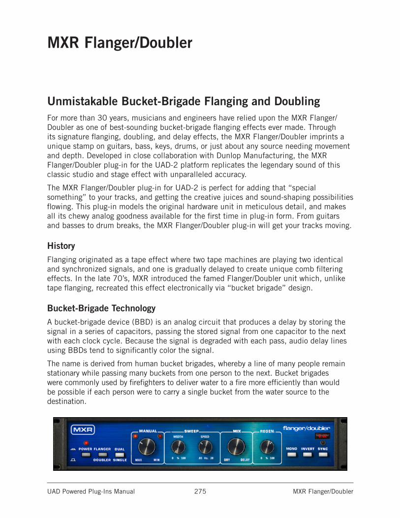
UAD Powered Plug-Ins Manual MXR Flanger/Doubler 275
MXR Flanger/Doubler
Unmistakable Bucket-Brigade Flanging and DoublingFor more than 30 years, musicians and engineers have relied upon the MXR Flanger/Doubler as one of best-sounding bucket-brigade flanging effects ever made. Through its signature flanging, doubling, and delay effects, the MXR Flanger/Doubler imprints a unique stamp on guitars, bass, keys, drums, or just about any source needing movement and depth. Developed in close collaboration with Dunlop Manufacturing, the MXR Flanger/Doubler plug-in for the UAD-2 platform replicates the legendary sound of this classic studio and stage effect with unparalleled accuracy.
The MXR Flanger/Doubler plug-in for UAD-2 is perfect for adding that “special something” to your tracks, and getting the creative juices and sound-shaping possibilities flowing. This plug-in models the original hardware unit in meticulous detail, and makes all its chewy analog goodness available for the first time in plug-in form. From guitars and basses to drum breaks, the MXR Flanger/Doubler plug-in will get your tracks moving.
HistoryFlanging originated as a tape effect where two tape machines are playing two identical and synchronized signals, and one is gradually delayed to create unique comb filtering effects. In the late 70’s, MXR introduced the famed Flanger/Doubler unit which, unlike tape flanging, recreated this effect electronically via “bucket brigade” design.
Bucket-Brigade TechnologyA bucket-brigade device (BBD) is an analog circuit that produces a delay by storing the signal in a series of capacitors, passing the stored signal from one capacitor to the next with each clock cycle. Because the signal is degraded with each pass, audio delay lines using BBDs tend to significantly color the signal.
The name is derived from human bucket brigades, whereby a line of many people remain stationary while passing many buckets from one person to the next. Bucket brigades were commonly used by firefighters to deliver water to a fire more efficiently than would be possible if each person were to carry a single bucket from the water source to the destination.
UAD Powered Plug-Ins Manual MXR Flanger/Doubler 276
Operational Overview
Model 126The MXR Model 126 Flanger/Doubler is an analog delay processor that uses “bucket-brigade” technology to create short signal delays. The delay time can be modulated manually, or automatically with a low frequency oscillator (LFO). The delayed signal can be mixed with itself in a feedback loop (“regenerated”), and its polarity can be inverted. The amount of processed signal relative to the original signal is adjustable.
All sonics and control behaviors are authentically modeled, including the inherent aliasing characteristics and dry signal path coloration.
Modes
FlangerThe flanging effect in MXR Flanger/Doubler is generated by using very short delay times whereby the delayed (wet) signal is not heard as separate from the original (dry) signal. When this delayed signal is combined with the dry signal, the comb filtering that is the essence of the flanging effect is generated. By modulating (“sweeping”) the delay time, the response of the comb filtering is modified, and the characteristic “swoosh” is produced. Additional sonic options are possible by increasing the delayed signal feedback (“regeneration”) to produce a deeper and more resonant effect, and/or reversing the polarity (“invert”) to give the sound a more “hollow” character.
DoublerWhen in Doubler mode, all controls have the exact same functionality as Flanger mode; the only difference is that the available delay times are longer in this mode. The delayed signal produces a very short echo, hence a “double” of the original signal is heard.
Software-Only FeaturesThe MXR Flanger/Doubler plug-in has some features not included in the original hardware. The LFO rate can be synchronized to the tempo of the DAW session; the LFO can be reset; Stereo mode can apply processing to both sides of a stereo signal; and stereo output can be summed to mono.
Stereo FunctionalityThe original hardware is monophonic. To accommodate modern applications, the plug-in can be used in mono-in/stereo-out and stereo-in/stereo-out configurations. Two different stereo modes are available, and the stereo output can be summed to mono if desired. See for details.
UAD Powered Plug-Ins Manual MXR Flanger/Doubler 277
In UseThe MXR Flanger/Doubler is well suited for sound-shaping, recording, and mixing, and even for adding some post-production flavor. Flanging is particularly popular as an individual effect on a wide range of musical sources — including guitar, bass, drums, keyboards, full source material, and more. Another common use for the MXR Flanger/Doubler is as a group effect, where effecting more than one signal is desired. Try applying the MXR Flanger/Doubler to drum busses or even the entire mix, most often for a brief period in the song, such as a break or bridge. In addition to Flanging, the Flanger/Doubler excels as a short-range delay/doubler.
MXR Flanger/Doubler Controls
ButtonsThe buttons on MXR Flanger/Doubler are two-state switches. The buttons are ON when they are in the “DOWN” position. When ON/DOWN, they are gray with a darker “shadow.” When OFF/UP, they are white.
PowerPower is the plug-in bypass control. Power is ON when the LED is red. When set to OFF, emulation processing is disabled, the LEDs are dimmed, and DSP usage is reduced (if DSP LoadLock is inactive).
Power is useful for comparing the processed settings to the original signal.
EffectThis button switches between Flanger and Doubler modes. It defines the range of signal delay available for the mode. The function of all the other controls is the same in both modes.
See Modes for additional details about the two effects.
FlangerWhen in the “down” (gray) position, Flanger mode is active. This is the default setting.
DoublerDoubler mode is active when the button is in the “up” (white) position.
UAD Powered Plug-Ins Manual MXR Flanger/Doubler 278
Stereo ModeThis software-only switch modifies the processed signals at the outputs when used in a stereo-output configuration.
The control does not switch the processor between mono and stereo modes; both modes are true stereo (when configured for stereo output).
In both stereo modes (Single and Dual), stereo separation of the dry signals is maintained, and the stereo signal is not mixed to mono before processing is applied.
Note: This function is only available when the plug-in is used in a mono-in/ stereo-out or stereo-in/stereo-out configuration. When used in a mono-in/mono-out configuration, the switch has no effect.
SingleWhen in the “up” (white) position, Single mode is active. This is the default setting.
In Single mode, the left and right signals are processed identically and the Sweep LFO for both channels are in phase.
DualWhen in the “down” (gray) position, Dual mode is active.
When Dual mode is enabled in a stereo-out configuration, the processing is applied to both the left and right channels. In this mode, the settings are the same for both processors, but a phase difference of 180° (antiphase) is applied between the Sweep LFO of the two channels. When Sweep Width is above 0% in Dual mode, this phase offset produces a swirling effect that pans back-and-forth.
ManualThis continuous control determines the delay time of the processor. The delay time is modulated by the Sweep LFO when the Width value is higher than 0%.
The available range of the control depends on the setting of the Effect button. In Flanger mode, the available delay time range is 4.9 milliseconds to 0.33 milliseconds. In Doubler mode, the available delay time range is 66 milliseconds to 18.5 milliseconds.
SweepThe Sweep parameters (Width and Speed) control the LFO (Low Frequency Oscillator) that modulates the delay time of the processor.
UAD Powered Plug-Ins Manual MXR Flanger/Doubler 279
WidthSweep Width controls the amount of modulation applied to the delay time LFO. The available range is 0 - 100%.
At 0%, no modulation occurs and delay time is determined by the Manual setting. As Width is increased, the amount of modulation becomes “wider” (a broader sweep). At 100%, the delay time sweeps throughout its entire range, automatically creating the same sound as moving the Manual control repeatedly back and forth from minimum to maximum.
SpeedSweep Speed controls the rate of modulation applied to the delay time LFO. The available range is 0.02 Hz to 15.96 Hz (this is the actual range of the original hardware; the knob text on the hardware panel doesn’t match exactly). The current speed is indicated by the Sweep LEDs and also shown in the Rate Display.
The Sweep Speed can be synchronized to the tempo of the host application by engaging the Sync function.
MixThis continuous control adjusts the blend between the original dry signal and the processed wet signal(s). The available range is 0 - 100%.
When set to minimum, only the dry signal is heard. When set to maximum, the signal is almost entirely wet, however a small amount of dry signal is present (like the original hardware).
When Mix is set to the minimum/dry position, the input signal is colored by the electronics of the unit (like the original hardware).
RegenerationThis is a feedback control for the delay processor. The available range is 0 - 100%.
When set above its minimum value, the output of the effect is routed back to its input. As the value increases, a more resonant signal is produced. Regeneration has a governor that prevents feedback “runaway” (overload) even when set to the maximum value of 100%.
MonoThis switch sums the stereo output of the dry and wet signals to mono when the plug-in used in a stereo-output configuration. This function is useful for creative purposes or checking phase relationships. The output is stereo when the switch is in the “up” (white) position, and mono when the switch in the “down” (gray) position.
Mono is only available when the plug-in is used in a mono-in/stereo-out or stereo-in/stereo-out configuration. When used in a mono-in/mono-out configuration, the switch is locked in the Mono position.
Note: See Stereo Mode for additional details about stereo output.
UAD Powered Plug-Ins Manual MXR Flanger/Doubler 280
InvertThis switch inverts the polarity (“phase”) of the processed signal. The wet signal polarity is normal when in the “up” (white) position, and inverted when in the “down” (gray) position.
When the processed signal is inverted and combined with the dry signal, the resultant comb filtering has a different timbre than when polarity is normal. This is particularly evident in Flanger mode, which often sounds more “hollow” when polarity is inverted.
SyncThe speed of the Sweep LFO can be synchronized to the tempo of the host application by engaging the Sync button. Tempo Sync is engaged when the button is in the “down” (gray) position and the LED above the button is illuminated.
See the “Tempo Sync” chapter in the UAD System Manual for detailed information about tempo synchronization.
Rate DisplayThe rate of the Sweep LFO is displayed here. When Sync is inactive, the LFO speed is displayed in Hertz. When Sync is active, the LFO speed is shown as a beat division (or multiplier). The Rate Display is unique to the plug-in; the original hardware does not have this feature.
Sweep LEDsThe Sweep LEDs, located above the Manual knob, perform two functions: LFO rate indication and LFO reset.
RateThe Sweep LEDs illuminate in tandem with the current Sweep Speed, providing a visual indication of the LFO rate. The Width amount must be higher than 0% for the LEDs to blink. As Width increases, the blinking is more obvious.
The manner in which the LED response manifests depends on the state of the Manual, Width, and Speed controls; their quirky behavior is the same as the original hardware.
ResetThe LEDs provide a mechanism to reset the Sweep LFO so the sweep cycle can be consistently controlled. The LFO cycle is reset to begin sweeping “downwards” in pitch (negative sweep) by clicking either LED. This function, which is not available on the hardware unit, can be automated for mixing or bouncing.
Normally the Sweep LFO is “free running” but this behavior is not always desirable. For example, you may want playback to always sound exactly the same when bouncing or mixing. To accomplish this sonic consistency, the Sweep LFO must be started at a specific place in the LFO cycle by using the Reset function.
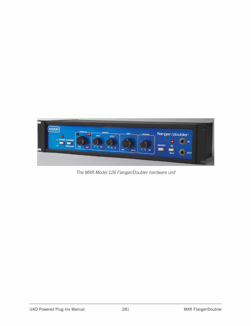
UAD Powered Plug-Ins Manual MXR Flanger/Doubler 281
The MXR Model 126 Flanger/Doubler hardware unit
UAD Powered Plug-Ins Manual Neve 88RS Channel Strip Collection 282
Neve 88RS Channel Strip Collection
Neve’s premier analog console emulation - featuring Unison™ mic preamp modelingThe Neve 88 Series is a paragon of large-format analog console design. Introduced in 2001, the 88 Series is renowned for its startling depth, airiness, and clarity — deftly encompassing the best of all Neve designs that came before it. Not surprisingly, Neve 88 Series consoles are found in some of the world’s finest recording studios and scoring stages, including Skywalker Ranch, Capitol, Abbey Road, and United/Ocean Way recording.
Now for the first time, you can track through an authentic emulation of this modern masterpiece — complete with its famous mic/line preamp, cut filters, dynamics, four-band EQ, plus post-fader output amplifier — exclusively for UAD-2 hardware and Apollo interfaces.
Now you can:• Sculpt your mix with Neve’s premium large-format analog console sound
• Get the clarity and openness of Neve’s famous 88RS transformer-based mic preamp
• Shape your signals with legendary Neve 88RS Formant Spectrum EQ and Dynamics sections
• Control Apollo interface mic preamp gain staging and impedance directly from the plug-in via Unison™ technology
• Mix with artist presets from Jimmy Douglass, Andrew Dawson, Joey Waronker, and Ryan West
• Create a modern Neve analog console in your DAW
The only end-to-end Neve 88RS Channel Strip Circuit EmulationUniversal Audio’s all-new Neve 88RS Channel Strip for Apollo and UAD-2 precisely emulates the unique circuit behaviors of Neve’s flagship large-format mixer. Modeling the mic/line preamp, cut filters, dynamics, four-band EQ, plus post-fader output amplifier with fanatical detail, the Neve 88RS Channel Strip plug-in replicates the luxurious sonics and high-fidelity sound of Neve’s ultimate mixing console.
UAD Powered Plug-Ins Manual Neve 88RS Channel Strip Collection 283
Unison Technology for Apollo InterfacesHarnessing UA’s groundbreaking Unison technology, the Neve 88RS Channel Strip Collection gives you all of the 88RS mic/line preamp’s impedance, gain stage “sweet spots,” and circuit behaviors that have made it the modern benchmark in analog preamp design. The secret is Unison’s bi-directional control and communication from the Neve 88RS plug-in to the physical mic preamps in Apollo. And the results are nothing short of spectacular.
Sculpt with Neve’s Formant Spectrum EQThe 88RS is outfitted with broad range, minimum-phase 12 dB high and low cut filters to shape any signal during tracking or mixdown. In addition, Neve’s famed Formant Spectrum four-band EQ, perfect for ambitious tonal strokes or precise surgery, offers classic Neve color on any source.
Crush or Expand with Neve 88RS DynamicsWith versatile and musical VCA-type limit/compress and gate/expand modules, the 88RS’ dynamics sections can precisely tailor any source; transparently smoothing a lead vocal, bringing excitement and immediacy to a percussion bus, or even providing frequency-dependent gain reduction for de-essing.
Add Depth and Openness with any UAD-2 hardwareOf course, the Neve 88RS Channel Strip Collection isn’t just for Apollo owners. UAD-2 owners can use the Neve 88RS Channel Strip for amplification, EQ tone shaping, dynamics control, or adding the Neve sheen to any source, without going outside the box.
With the Neve 88RS Channel Strip’s complete console channel emulation, plus the included DSP-lite Neve 88RS Channel Strip Legacy, you can craft your projects with the stunning analog clarity the 88RS is famous for.
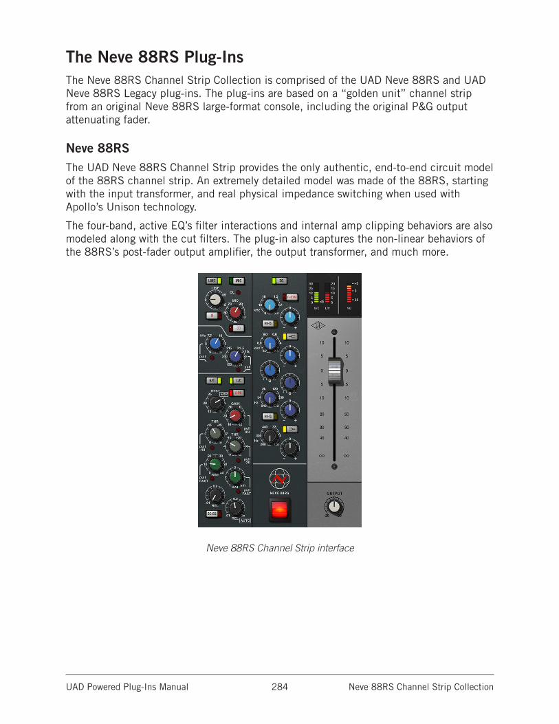
UAD Powered Plug-Ins Manual Neve 88RS Channel Strip Collection 284
The Neve 88RS Plug-InsThe Neve 88RS Channel Strip Collection is comprised of the UAD Neve 88RS and UAD Neve 88RS Legacy plug-ins. The plug-ins are based on a “golden unit” channel strip from an original Neve 88RS large-format console, including the original P&G output attenuating fader.
Neve 88RSThe UAD Neve 88RS Channel Strip provides the only authentic, end-to-end circuit model of the 88RS channel strip. An extremely detailed model was made of the 88RS, starting with the input transformer, and real physical impedance switching when used with Apollo’s Unison technology.
The four-band, active EQ’s filter interactions and internal amp clipping behaviors are also modeled along with the cut filters. The plug-in also captures the non-linear behaviors of the 88RS’s post-fader output amplifier, the output transformer, and much more.
Neve 88RS Channel Strip interface
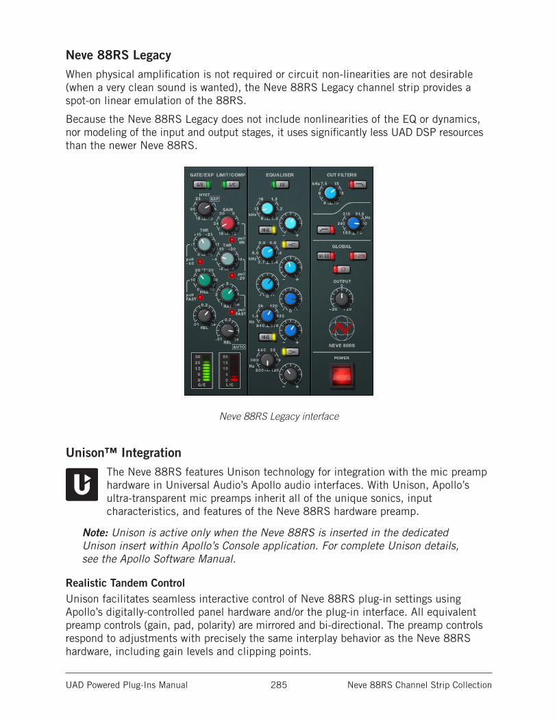
UAD Powered Plug-Ins Manual Neve 88RS Channel Strip Collection 285
Neve 88RS LegacyWhen physical amplification is not required or circuit non-linearities are not desirable (when a very clean sound is wanted), the Neve 88RS Legacy channel strip provides a spot-on linear emulation of the 88RS.
Because the Neve 88RS Legacy does not include nonlinearities of the EQ or dynamics, nor modeling of the input and output stages, it uses significantly less UAD DSP resources than the newer Neve 88RS.
Neve 88RS Legacy interface
Unison™ IntegrationThe Neve 88RS features Unison technology for integration with the mic preamp hardware in Universal Audio’s Apollo audio interfaces. With Unison, Apollo’s ultra-transparent mic preamps inherit all of the unique sonics, input characteristics, and features of the Neve 88RS hardware preamp.
Note: Unison is active only when the Neve 88RS is inserted in the dedicated Unison insert within Apollo’s Console application. For complete Unison details, see the Apollo Software Manual.
Realistic Tandem ControlUnison facilitates seamless interactive control of Neve 88RS plug-in settings using Apollo’s digitally-controlled panel hardware and/or the plug-in interface. All equivalent preamp controls (gain, pad, polarity) are mirrored and bi-directional. The preamp controls respond to adjustments with precisely the same interplay behavior as the Neve 88RS hardware, including gain levels and clipping points.
UAD Powered Plug-Ins Manual Neve 88RS Channel Strip Collection 286
Hardware Input ImpedanceAll Apollo mic preamps feature variable input impedance in analog hardware that can be physically changed by Unison plug-ins for physical, microphone-to-preamp resistive interaction. This impedance switching enables Apollo’s preamps to physically match the emulated unit’s input impedance, which can significantly impact the sound of a microphone. Because the electrical loading occurs on input, prior to A/D conversion, the realism is faithful to the original target hardware preamp.
Tactile Gain StagingApollo’s front panel preamp knob can independently adjust the gain and level parameters available within the Unison plug-in via Gain Stage Mode. The gain stage being adjusted can be remotely switched via Apollo, so the gain levels and their associated colorations can be tuned from the hardware knob for precise physical tactile control, all without using the Unison plug-in’s software interface.
Note: Unison technology is not available with Neve 88RS Legacy.
Artist PresetsThe Neve 88RS includes artist presets from prominent Neve 88RS users. The artist presets are in the internal factory bank and are accessed via the host application’s preset menu. The artist presets are also placed by the UAD installer so they can be used within Apollo’s Console application. The presets can be loaded using the Settings menu in the UAD Toolbar (see “Using UAD Powered Plug-Ins” in the UAD System Manual).
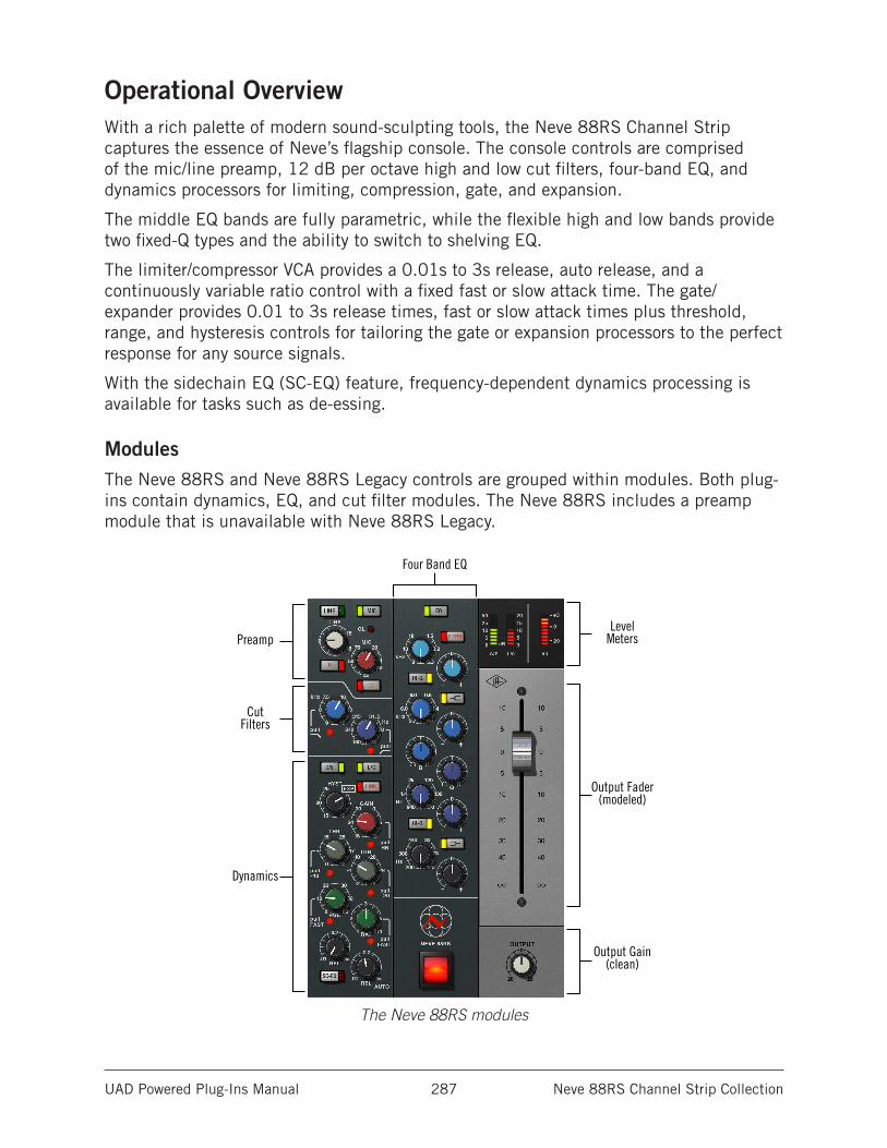
UAD Powered Plug-Ins Manual Neve 88RS Channel Strip Collection 287
Operational OverviewWith a rich palette of modern sound-sculpting tools, the Neve 88RS Channel Strip captures the essence of Neve’s flagship console. The console controls are comprised of the mic/line preamp, 12 dB per octave high and low cut filters, four-band EQ, and dynamics processors for limiting, compression, gate, and expansion.
The middle EQ bands are fully parametric, while the flexible high and low bands provide two fixed-Q types and the ability to switch to shelving EQ.
The limiter/compressor VCA provides a 0.01s to 3s release, auto release, and a continuously variable ratio control with a fixed fast or slow attack time. The gate/expander provides 0.01 to 3s release times, fast or slow attack times plus threshold, range, and hysteresis controls for tailoring the gate or expansion processors to the perfect response for any source signals.
With the sidechain EQ (SC-EQ) feature, frequency-dependent dynamics processing is available for tasks such as de-essing.
ModulesThe Neve 88RS and Neve 88RS Legacy controls are grouped within modules. Both plug-ins contain dynamics, EQ, and cut filter modules. The Neve 88RS includes a preamp module that is unavailable with Neve 88RS Legacy.
The Neve 88RS modules
Four Band EQ
Preamp
CutFilters
Dynamics
LevelMeters
Output Fader(modeled)
Output Gain(clean)
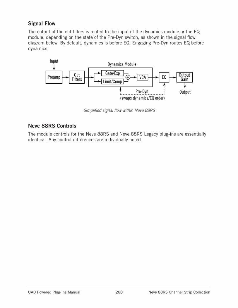
UAD Powered Plug-Ins Manual Neve 88RS Channel Strip Collection 288
Signal FlowThe output of the cut filters is routed to the input of the dynamics module or the EQ module, depending on the state of the Pre-Dyn switch, as shown in the signal flow diagram below. By default, dynamics is before EQ. Engaging Pre-Dyn routes EQ before dynamics.
Preamp
Input
Output
Dynamics Module
(swaps dynamics/EQ order)
Gate/Exp
Limit/CompOutputGainEQVCACut
Filters
Pre-Dyn
Simplified signal flow within Neve 88RS
Neve 88RS ControlsThe module controls for the Neve 88RS and Neve 88RS Legacy plug-ins are essentially identical. Any control differences are individually noted.
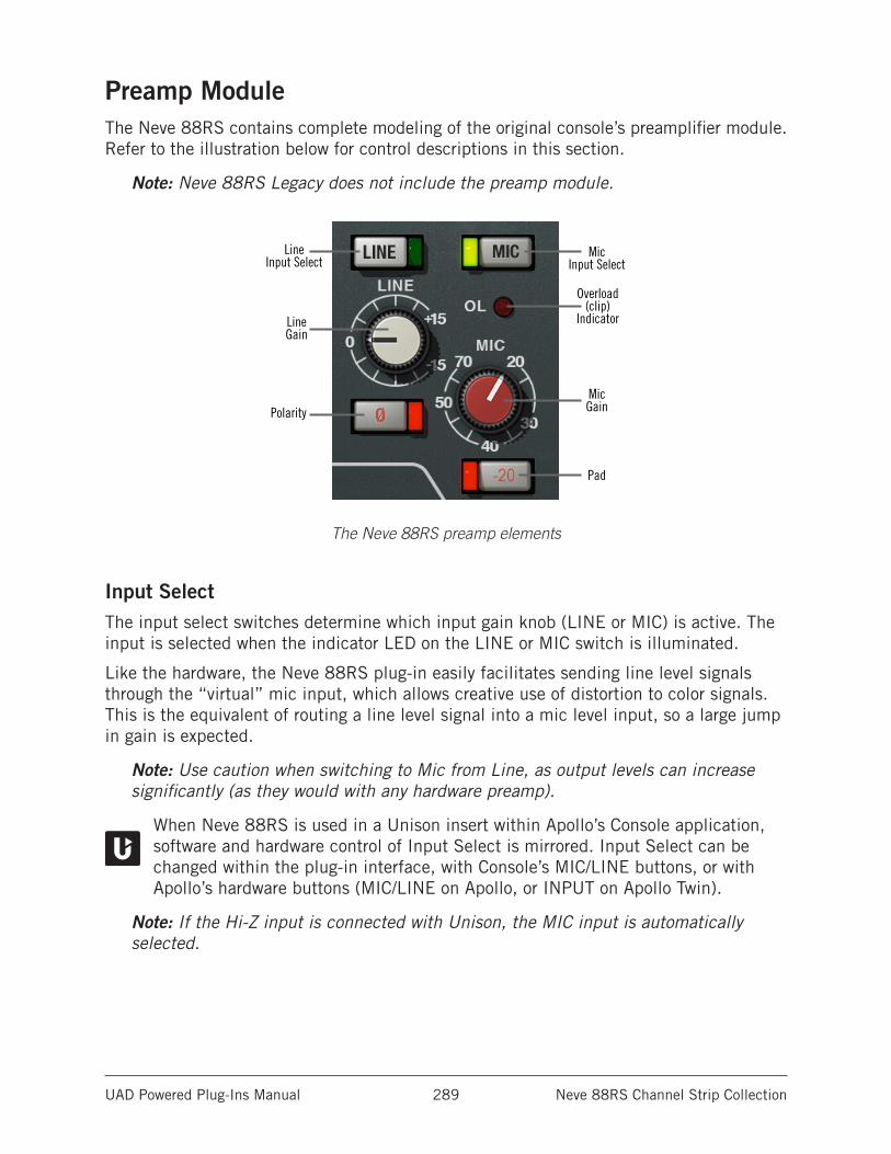
UAD Powered Plug-Ins Manual Neve 88RS Channel Strip Collection 289
Preamp ModuleThe Neve 88RS contains complete modeling of the original console’s preamplifier module. Refer to the illustration below for control descriptions in this section.
Note: Neve 88RS Legacy does not include the preamp module.
Line Input Select
Line Gain
MicGain
Overload(clip)
Indicator
Pad
Polarity
MicInput Select
The Neve 88RS preamp elements
Input SelectThe input select switches determine which input gain knob (LINE or MIC) is active. The input is selected when the indicator LED on the LINE or MIC switch is illuminated.
Like the hardware, the Neve 88RS plug-in easily facilitates sending line level signals through the “virtual” mic input, which allows creative use of distortion to color signals. This is the equivalent of routing a line level signal into a mic level input, so a large jump in gain is expected.
Note: Use caution when switching to Mic from Line, as output levels can increase significantly (as they would with any hardware preamp).
When Neve 88RS is used in a Unison insert within Apollo’s Console application, software and hardware control of Input Select is mirrored. Input Select can be changed within the plug-in interface, with Console’s MIC/LINE buttons, or with Apollo’s hardware buttons (MIC/LINE on Apollo, or INPUT on Apollo Twin).
Note: If the Hi-Z input is connected with Unison, the MIC input is automatically selected.
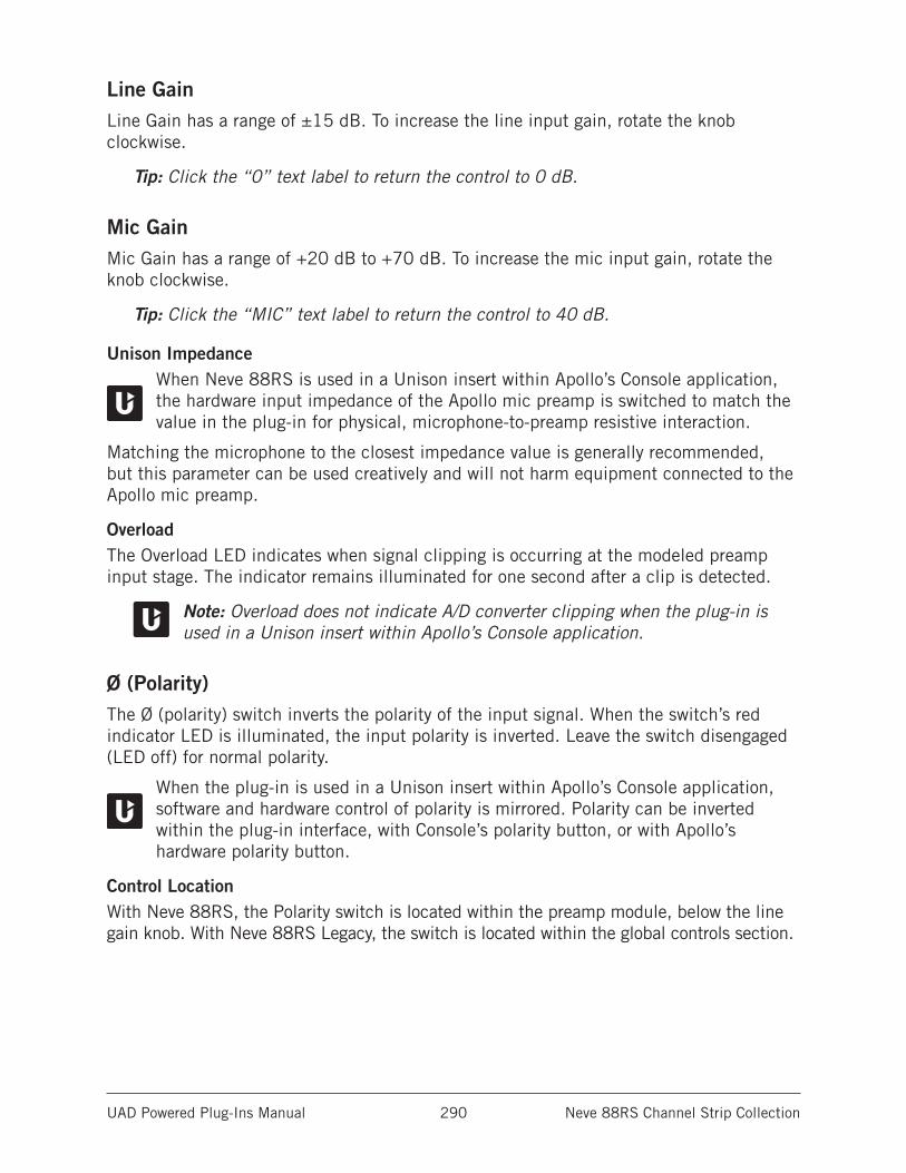
UAD Powered Plug-Ins Manual Neve 88RS Channel Strip Collection 290
Line GainLine Gain has a range of ±15 dB. To increase the line input gain, rotate the knob clockwise.
Tip: Click the “0” text label to return the control to 0 dB.
Mic GainMic Gain has a range of +20 dB to +70 dB. To increase the mic input gain, rotate the knob clockwise.
Tip: Click the “MIC” text label to return the control to 40 dB.
Unison ImpedanceWhen Neve 88RS is used in a Unison insert within Apollo’s Console application, the hardware input impedance of the Apollo mic preamp is switched to match the value in the plug-in for physical, microphone-to-preamp resistive interaction.
Matching the microphone to the closest impedance value is generally recommended, but this parameter can be used creatively and will not harm equipment connected to the Apollo mic preamp.
OverloadThe Overload LED indicates when signal clipping is occurring at the modeled preamp input stage. The indicator remains illuminated for one second after a clip is detected.
Note: Overload does not indicate A/D converter clipping when the plug-in is used in a Unison insert within Apollo’s Console application.
Ø (Polarity)The Ø (polarity) switch inverts the polarity of the input signal. When the switch’s red indicator LED is illuminated, the input polarity is inverted. Leave the switch disengaged (LED off) for normal polarity.
When the plug-in is used in a Unison insert within Apollo’s Console application, software and hardware control of polarity is mirrored. Polarity can be inverted within the plug-in interface, with Console’s polarity button, or with Apollo’s hardware polarity button.
Control LocationWith Neve 88RS, the Polarity switch is located within the preamp module, below the line gain knob. With Neve 88RS Legacy, the switch is located within the global controls section.
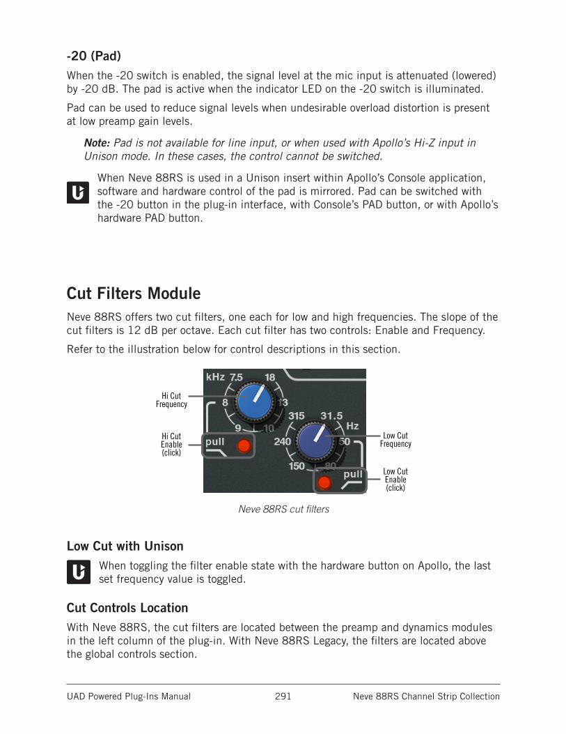
UAD Powered Plug-Ins Manual Neve 88RS Channel Strip Collection 291
-20 (Pad)When the -20 switch is enabled, the signal level at the mic input is attenuated (lowered) by -20 dB. The pad is active when the indicator LED on the -20 switch is illuminated.
Pad can be used to reduce signal levels when undesirable overload distortion is present at low preamp gain levels.
Note: Pad is not available for line input, or when used with Apollo’s Hi-Z input in Unison mode. In these cases, the control cannot be switched.
When Neve 88RS is used in a Unison insert within Apollo’s Console application, software and hardware control of the pad is mirrored. Pad can be switched with the -20 button in the plug-in interface, with Console’s PAD button, or with Apollo’s hardware PAD button.
Cut Filters ModuleNeve 88RS offers two cut filters, one each for low and high frequencies. The slope of the cut filters is 12 dB per octave. Each cut filter has two controls: Enable and Frequency.
Refer to the illustration below for control descriptions in this section.
Hi CutFrequency
Hi CutEnable(click)
Low CutEnable(click)
Low CutFrequency
Neve 88RS cut filters
Low Cut with UnisonWhen toggling the filter enable state with the hardware button on Apollo, the last set frequency value is toggled.
Cut Controls LocationWith Neve 88RS, the cut filters are located between the preamp and dynamics modules in the left column of the plug-in. With Neve 88RS Legacy, the filters are located above the global controls section.
UAD Powered Plug-Ins Manual Neve 88RS Channel Strip Collection 292
Cut EnableEach cut filter is active when its dedicated enable switch is engaged. The appearance of these switches vary according to the plug-in, as detailed below.
Note: UAD DSP load is not reduced when the cut filters are disabled.
Neve 88RSTo activate a cut filter, click the “pull” label text or the red indicator LED just below the Cut Frequency control. The cut filter is active when its red indicator is illuminated.
Neve 88RS LegacyTo activate a cut filter, click the enable switch just below the Cut Frequency control. The cut filter is active when its red indicator is illuminated.
Cut FrequencyThe frequency knobs determine the cutoff frequency for the cut filter.
High CutThe available range is 7.5 kHz to 18 kHz for the high cut filter (lighter blue control).
Low CutThe available range is 31.5 Hz to 315 Hz for the low cut filter (darker blue control).
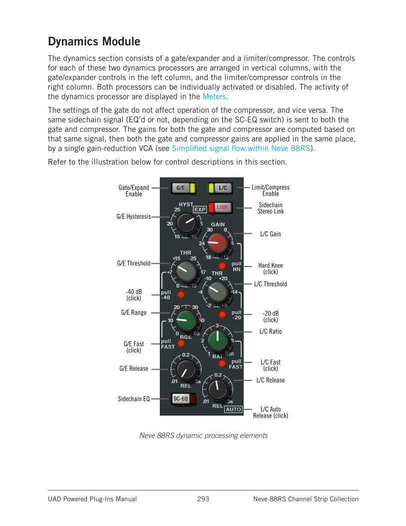
UAD Powered Plug-Ins Manual Neve 88RS Channel Strip Collection 293
Dynamics ModuleThe dynamics section consists of a gate/expander and a limiter/compressor. The controls for each of these two dynamics processors are arranged in vertical columns, with the gate/expander controls in the left column, and the limiter/compressor controls in the right column. Both processors can be individually activated or disabled. The activity of the dynamics processor are displayed in the Meters.
The settings of the gate do not affect operation of the compressor, and vice versa. The same sidechain signal (EQ’d or not, depending on the SC-EQ switch) is sent to both the gate and compressor. The gains for both the gate and compressor are computed based on that same signal, then both the gate and compressor gains are applied in the same place, by a single gain-reduction VCA (see Simplified signal flow within Neve 88RS).
Refer to the illustration below for control descriptions in this section.
Gate/ExpandEnable
G/E Hysteresis
G/E Threshold
-40 dB(click)
G/E Fast(click)
G/E Range
G/E Release
Sidechain EQ
Limit/CompressEnable
SidechainStereo Link
L/C Gain
Hard Knee(click)
-20 dB(click)
L/C AutoRelease (click)
L/C Threshold
L/C Ratio
L/C Fast(click)
L/C Release
Neve 88RS dynamic processing elements
UAD Powered Plug-Ins Manual Neve 88RS Channel Strip Collection 294
Sidechain LinkWhen Neve 88RS is used in a stereo-in/stereo-out configuration and LINK is enabled (when the LINK switch LED is illuminated), it causes the two channels of the compressor to compress in equal amounts.
Linking the sidechains simply means that the instantaneous amount of compression for the two channels will always be the same, thereby preventing left-right image shifting at the output.
Note: This control is unavailable on the Neve 88RS Legacy. The Neve 88RS Legacy sidechain is always linked when used in a stereo or mono-in/stereo-out configuration.
Sidechain EQ (SC-EQ)This control enables the Neve 88RS sidechain function. When sidechain is active, signal output from the EQ module is removed from the audio path and is instead routed to control the dynamics module. Sidechain EQ is active when the button’s red indicator LED is illuminated.
Note: The EQ module and at least one dynamics module must be active in con-junction with SC-EQ for the sidechain to function (see EQ Enable (EQ)). SC-EQ overrides P-DYN if both functions are enabled.
Sidechaining is typically used for de-essing and similar frequency-conscious techniques. To listen to the sidechain key, simply disengage SC-EQ to hear the EQ’d signal.
Note: The sidechain dynamics/EQ implementations are true stereo when used in a stereo-in/stereo-out configuration.
Control LocationWith Neve 88RS, the Sidechain EQ switch is located within the dynamics module, at the lower left of the interface. With Neve 88RS Legacy, the switch is located within the global controls section.
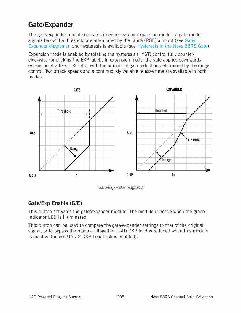
UAD Powered Plug-Ins Manual Neve 88RS Channel Strip Collection 295
Gate/ExpanderThe gate/expander module operates in either gate or expansion mode. In gate mode, signals below the threshold are attenuated by the range (RGE) amount (see Gate/Expander diagrams), and hysteresis is available (see Hysteresis in the Neve 88RS Gate).
Expansion mode is enabled by rotating the hysteresis (HYST) control fully counter-clockwise (or clicking the EXP label). In expansion mode, the gate applies downwards expansion at a fixed 1:2 ratio, with the amount of gain reduction determined by the range control. Two attack speeds and a continuously variable release time are available in both modes.
0 dB
Out
Threshold
Range
In
GATE
0 dB
Out
1:2 ratio
Threshold
Range
In
EXPANDER
Gate/Expander diagrams
Gate/Exp Enable (G/E)This button activates the gate/expander module. The module is active when the green indicator LED is illuminated.
This button can be used to compare the gate/expander settings to that of the original signal, or to bypass the module altogether. UAD DSP load is reduced when this module is inactive (unless UAD-2 DSP LoadLock is enabled).
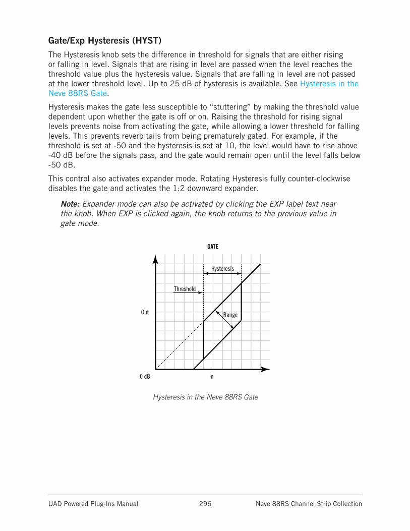
UAD Powered Plug-Ins Manual Neve 88RS Channel Strip Collection 296
Gate/Exp Hysteresis (HYST)The Hysteresis knob sets the difference in threshold for signals that are either rising or falling in level. Signals that are rising in level are passed when the level reaches the threshold value plus the hysteresis value. Signals that are falling in level are not passed at the lower threshold level. Up to 25 dB of hysteresis is available. See Hysteresis in the Neve 88RS Gate.
Hysteresis makes the gate less susceptible to “stuttering” by making the threshold value dependent upon whether the gate is off or on. Raising the threshold for rising signal levels prevents noise from activating the gate, while allowing a lower threshold for falling levels. This prevents reverb tails from being prematurely gated. For example, if the threshold is set at -50 and the hysteresis is set at 10, the level would have to rise above -40 dB before the signals pass, and the gate would remain open until the level falls below -50 dB.
This control also activates expander mode. Rotating Hysteresis fully counter-clockwise disables the gate and activates the 1:2 downward expander.
Note: Expander mode can also be activated by clicking the EXP label text near the knob. When EXP is clicked again, the knob returns to the previous value in gate mode.
0 dB
Out
Threshold
Hysteresis
Range
In
GATE
Hysteresis in the Neve 88RS Gate
UAD Powered Plug-Ins Manual Neve 88RS Channel Strip Collection 297
Gate/Exp Threshold (THR)Threshold defines the input level at which expansion or gating occurs. Any signals below this level are processed. Signals above the threshold are unaffected.
The available range is -25 dB to +15 dB. A range of -25 dB to -65 dB is available when the Gate/Exp Threshold -40 dB switch is engaged.
In typical use it’s best to set the threshold value to just above the noise floor of the desired signal (so the noise doesn’t pass when the desired signal is not present), but below the desired signal level (so the signal passes when present).
Gate/Exp Threshold -40 dBThe -40 dB switch increases the sensitivity of the gate and expander by lowering the range of the available threshold values. When -40 dB mode is active, the threshold range is -25 dB to -65 dB. When -40 is inactive, the threshold range is -25 dB to +15 dB.
To activate -40 dB mode, click the “pull -40” label text or the red indicator LED just below the Threshold control. -40 dB mode is active when the red indicator is illuminated.
Gate/Exp Range (RGE)Range (RGE) controls the difference in gain between the gated/expanded and non-gated/expanded signal. Higher values increase the attenuation of signals below the threshold. When set to zero, no gating or expansion occurs. The available range is 0 dB to -60 dB.
Gate/Exp FastThe Fast mode switch defines the gate/expander attack time, which is the duration between the input signal reaching the threshold and processing being applied. Two times are available: 500 microseconds (when Fast is off) and 50 microseconds (when Fast is active).
To activate Fast mode, click the “pull FAST” label text or the red indicator LED just below the Range (RGE) control. Fast mode is active when the red indicator is illuminated.
Gate/Exp Release (REL)Release sets the amount of time it takes for processing to disengage once the input signal drops below the threshold level. The available range is 10 milliseconds to 3 seconds.
Slower release times can smooth the transition that occurs when the signal dips below the threshold, which is especially useful for material with frequent peaks.
Note: Fast release times are typically only suitable for certain types of percussion and other instruments with very fast decays. Using fast settings on other sources may produce undesirable results.
Gate/Exp MeterThe G/E meter (see Meters) displays the amount of gain attenuation (downward expansion) occurring in the gate/expander module.
UAD Powered Plug-Ins Manual Neve 88RS Channel Strip Collection 298
Limiter/CompressorThe limiter/compressor module (see Neve 88RS dynamic processing elements) offers a continuously variable ratio between 1:1 (no compression) and infinity:1 (limiting). Signals above the threshold are attenuated according to the ratio (RAT) value. Two attack speeds and continuously variable release times are available, along with a pleasing automatic triple time-constant program-dependent release mode (auto mode has a three-stage release). A makeup gain control and a hard/soft knee setting are also available in the module.
From the AMS-Neve 88RS User Manual:
“Anti pumping and breathing circuitry allows the unit to operate on the source musically whilst retaining absolute control over the dynamic range.”
The 88RS compressor has another nifty property: Two thresholds. When the signal falls below the threshold, the compressor is releasing. But, if the signal falls below a second (non-adjustable) threshold, which is roughly 40 dB below the adjustable threshold value, then the release slows down drastically. This acts as a “silence detector.” The concept is that if there is a quiet signal, then the compressor should release to reduce the dynamic range. But if there is a sudden onset of silence, it is likely that, when the signal returns, it will be at about the same level as the region before the silence. So in that case, the compressor doesn’t release quickly.
An example: When compressing a snare track with a standard compressor, if the snare hits are sparse, the compressor will release between each hit, so that each hit has a squashed sound. With the 88R compressor, distortion will be reduced, because the compressor will not come out of compression as much between the snare hits. The compressor will still release somewhat during the snare hits, however.
L/C Enable (L/C)This button activates the limiter/compressor module. The module is active when the green indicator LED is illuminated.
This button can be used to compare the limiter/compressor settings to that of the original signal, or to bypass the module altogether. UAD DSP load is reduced when this module is inactive (unless UAD-2 DSP LoadLock is enabled).
L/C GainThe Gain control adjusts the output level of the limiter/compressor module. The available range is 0 dB to 30 dB.
Generally speaking, adjust this makeup gain control after the desired amount of processing is achieved with the Threshold control. The Gain control does not affect the amount of processing.
UAD Powered Plug-Ins Manual Neve 88RS Channel Strip Collection 299
L/C Hard Knee (HN)Normally, the limiter and compressor operate with soft knee characteristics. This switch gives the limiter and compressor a hard knee instead.
To activate Hard Knee mode, click the “pull HN” label text or the red indicator LED just below the Gain control. Hard Knee mode is active when the red indicator is illuminated.
L/C ThresholdThreshold defines the input level at which limiting or compression begins. Signals that exceed this level are processed. Signals below the threshold are unaffected.
The available range is +20 dB to -10 dB. A range of 0 dB to -30 dB is available when the L/C Threshold -20 dB switch is engaged.
Tip: As threshold is increased and more processing occurs, the output level is typi-cally reduced. Adjust the L/C Gain control to increase the output of the module to compensate if desired.
L/C Threshold -20 dBThe -20 dB switch increases the sensitivity of the limiter/compressor by lowering the range of the available threshold values. When -20 dB mode is active, the threshold range is 0 dB to -30 dB. When -20 is inactive, the threshold range is +20 dB to -10 dB.
To activate -20 dB mode, click the “pull -20” label text or the red indicator LED just below the Threshold control. -20 dB mode is active when the red indicator is illuminated.
L/C Ratio (RAT)Ratio defines the amount of gain reduction to be processed by the module. For example, a value of 2 (expressed as a 2:1 ratio) reduces the signal by half, with an input signal of 20 dB being reduced to 10 dB.
A value of 1 yields no gain reduction. When the control is at maximum (“lim”), the ratio is effectively infinity to one, yielding the limiting effect. The available range is 1 to infinity.
L/C FastThe Fast mode switch defines the attack time (the duration between the input signal reaching the threshold and processing being applied) of the limiter and compressor.
Attack time is program dependent. Two ranges are available: 3 milliseconds to 7 milliseconds (Fast off) and 1 millisecond to 7 milliseconds (Fast active).
To activate Fast mode, click the “pull FAST” label text or the red indicator LED just below the Ratio (RAT) control. Fast mode is active when the red indicator is illuminated.
UAD Powered Plug-Ins Manual Neve 88RS Channel Strip Collection 300
L/C ReleaseRelease sets the amount of time it takes for processing to cease once the input signal drops below the threshold level. The available range is 10 milliseconds to 3 seconds, and automatic.
Automatic triple time-constant program dependent release time is activated by turning the release control fully clockwise (to 3s) or by clicking the “AUTO” label text.
Slower release times can smooth the transition that occurs when the signal dips below the threshold, which is especially useful for material with frequent peaks. However, if the release is too long, compression for sections of audio with loud signals may extend to sections of audio with lower signals.
Note: Fast release times are typically only suitable for certain types of percussion and other instruments with very fast decays. Using fast settings on other sources may produce undesirable results.
L/C MeterThe L/C meter (see Meters) displays the amount of gain attenuation occurring in the limiter/compressor module.
UAD Powered Plug-Ins Manual Neve 88RS Channel Strip Collection 301
EQ ModuleFrom the AMS-Neve 88RS manual:
“The unique sound of AMS-Neve EQ is the result of years of research and extensive studio experience.”
The Neve 88RS “Formant Spectrum EQ” (AMS-Neve’s descriptor) is divided into four frequency bands: High Frequency (HF), High Midrange Frequency (HMF), Low Midrange Frequency (LMF), and Low Frequency (LF). The high and low bands can be switched into shelving and/or High-Q modes. The two midrange bands are fully parametric. The EQ module can be disabled altogether.
When the high frequency (HF) and/or low frequency (LF) band is in shelf mode, the band gain affects the band frequency. As gain is increased, the shelf frequency more closely matches the knob value. As gain is reduced however, the low shelving frequency moves higher, and the high shelving frequency moves lower.
With the Neve 88RS EQ, the Q value and range is dependent on the gain setting of the band. With any non-zero gain setting, the Q will be calculated in real-time for that band. But if the band gain is zero, Q will always display zero.
Pre-Dynamics (P-DYN)By default, the audio signal is routed from the dynamics module into the EQ module (the EQ is post-dynamics). The signal can be routed so the EQ is pre-dynamics using the P-DYN switch. When the switch is enabled (when the button’s red indicator LED is illuminated), the EQ module precedes the dynamics module (see Simplified signal flow within Neve 88RS).
Note: Pre-dynamics can only be engaged if the EQ module and at least one dynamics module is active.
Control LocationWith Neve 88RS, the Pre-Dynamics switch is located within the EQ module, near the high frequency controls. With Neve 88RS Legacy, the switch is located within the global controls section.
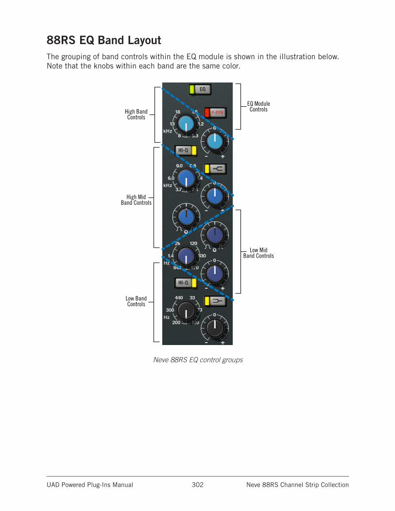
UAD Powered Plug-Ins Manual Neve 88RS Channel Strip Collection 302
88RS EQ Band LayoutThe grouping of band controls within the EQ module is shown in the illustration below. Note that the knobs within each band are the same color.
High BandControls
High MidBand Controls
Low MidBand Controls
EQ ModuleControls
Low BandControls
Neve 88RS EQ control groups
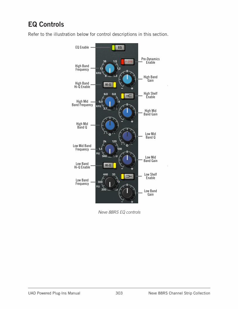
UAD Powered Plug-Ins Manual Neve 88RS Channel Strip Collection 303
EQ ControlsRefer to the illustration below for control descriptions in this section.
EQ Enable
High MidBand Frequency
Low Mid BandFrequency
High MidBand Q
Low MidBand Q
High MidBand Gain
Low MidBand Gain
High BandGain
Low BandGain
High BandFrequency
Low BandFrequency
High BandHi-Q Enable
Low BandHi-Q Enable
Pre-DynamicsEnable
High ShelfEnable
Low ShelfEnable
Neve 88RS EQ controls
UAD Powered Plug-Ins Manual Neve 88RS Channel Strip Collection 304
EQ Enable (EQ)This button activates the equalizer module. The module is active when the green indicator is illuminated.
This button can be used to compare the equalized signal to the original signal or bypass the EQ altogether. UAD DSP load is reduced when this module is inactive (unless UAD-2 DSP LoadLock is enabled).
High Band
HF FreqThis parameter determines the HF band center frequency to be boosted or attenuated by the band Gain setting. The available range is 1.5 kHz to 18 kHz.
HF GainThis control determines the amount by which the frequency setting for the HF band is boosted or attenuated. The available range is ±20 dB.
Tip: Click the “0” text label to return the control to 0 dB.
HF Hi-Q EnableThe filter slope of the HF band can be changed with this control. When Hi-Q is off, the Q is 0.7. When Hi-Q is active, the Q is 2. Higher Q values mean the peak (or trough) has steeper slopes.
Hi-Q is active when the yellow indicator LED is illuminated. Hi-Q is off by default.
Note: Hi-Q has no effect when the band is in shelf mode.
HF Shelf EnableThe HF band can be switched from bell mode to shelving mode by clicking the shelf enable button. Shelf mode is active when the yellow indicator LED is illuminated. Shelf is off by default.
High Mid Band
HMF FreqThis control determines the HMF band center frequency to be boosted or attenuated by the HMF Gain setting. The available range is 800 Hz to 9 kHz.
HMF GainThis control determines the amount by which the frequency setting for the HMF band is boosted or attenuated. The available range is ±20 dB.
Tip: Click the “0” text label to return the control to 0 dB.
UAD Powered Plug-Ins Manual Neve 88RS Channel Strip Collection 305
HMF QThe Q (bandwidth) control defines the proportion of frequencies surrounding the HMF band center frequency to be affected by the band gain control. The filter slopes get steeper (narrower) as the control is rotated clockwise. The available range is 0.4 to 10.
Low Mid Band
LMF FreqThis control determines the LMF band center frequency to be boosted or attenuated by the LMF Gain setting. The available range is 120 Hz to 2 kHz.
LMF GainThis control determines the amount by which the frequency setting for the LMF band is boosted or attenuated. The available range is ±20 dB.
Tip: Click the “0” text label to return the control to 0 dB.
LMF QThe Q (bandwidth) control defines the proportion of frequencies surrounding the LMF band center frequency to be affected by the band gain control. The filter slopes get steeper (narrower) as the control is rotated clockwise. The available range is 0.4 to 10.
Low Band
LF FreqThis parameter determines the LF band center frequency to be boosted or attenuated by the band Gain setting. The available range is 33 Hz to 440 kHz.
LF GainThis control determines the amount by which the frequency setting for the LF band is boosted or attenuated. The available range is ±20 dB.
Tip: Click the “0” text label to return the control to 0 dB.
LF Shelf EnableThe LF band can be switched from bell mode to shelving mode by clicking the shelf enable button. Shelf mode is active when the button is gray and the yellow indicator illuminates. Shelf is off by default.
LF Hi-Q Enable
The filter slope of the LF band can be switched with this control. When Hi-Q is off, the Q is 0.7. When Hi-Q is active, the Q is 2. Higher Q values mean the peak/trough has steeper slopes.
Hi-Q is active when the button is gray and the yellow indicator illuminates. Hi-Q is off by default.
Note: Hi-Q has no effect when the band is in shelf mode.
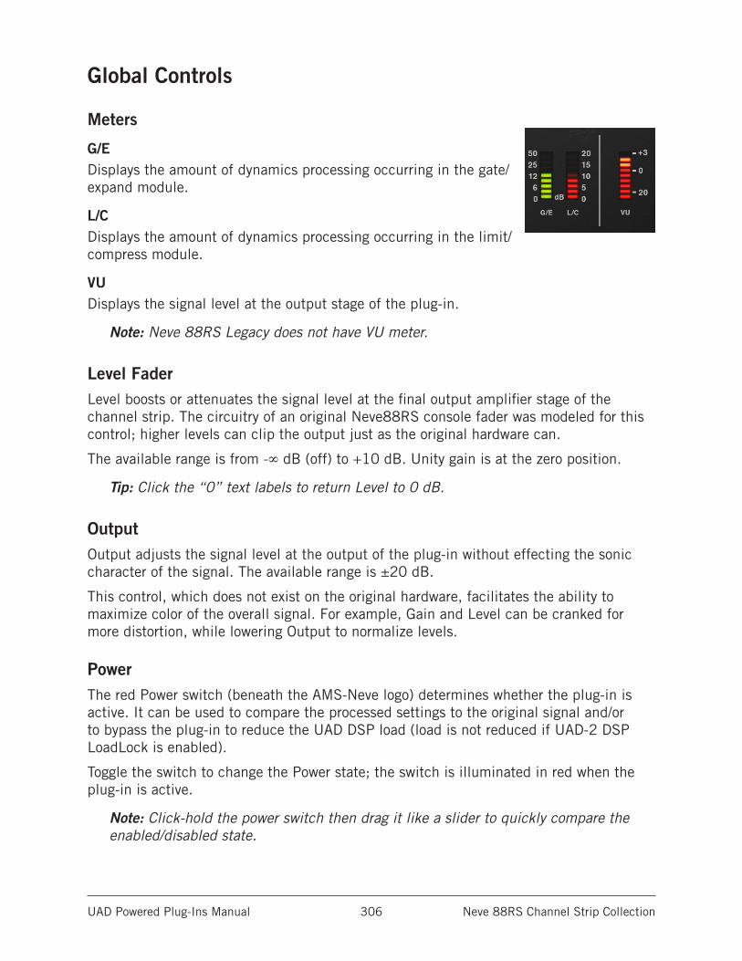
UAD Powered Plug-Ins Manual Neve 88RS Channel Strip Collection 306
Global Controls
Meters
G/EDisplays the amount of dynamics processing occurring in the gate/expand module.
L/CDisplays the amount of dynamics processing occurring in the limit/compress module.
VUDisplays the signal level at the output stage of the plug-in.
Note: Neve 88RS Legacy does not have VU meter.
Level FaderLevel boosts or attenuates the signal level at the final output amplifier stage of the channel strip. The circuitry of an original Neve88RS console fader was modeled for this control; higher levels can clip the output just as the original hardware can.
The available range is from -∞ dB (off) to +10 dB. Unity gain is at the zero position.
Tip: Click the “0” text labels to return Level to 0 dB.
OutputOutput adjusts the signal level at the output of the plug-in without effecting the sonic character of the signal. The available range is ±20 dB.
This control, which does not exist on the original hardware, facilitates the ability to maximize color of the overall signal. For example, Gain and Level can be cranked for more distortion, while lowering Output to normalize levels.
PowerThe red Power switch (beneath the AMS-Neve logo) determines whether the plug-in is active. It can be used to compare the processed settings to the original signal and/or to bypass the plug-in to reduce the UAD DSP load (load is not reduced if UAD-2 DSP LoadLock is enabled).
Toggle the switch to change the Power state; the switch is illuminated in red when the plug-in is active.
Note: Click-hold the power switch then drag it like a slider to quickly compare the enabled/disabled state.
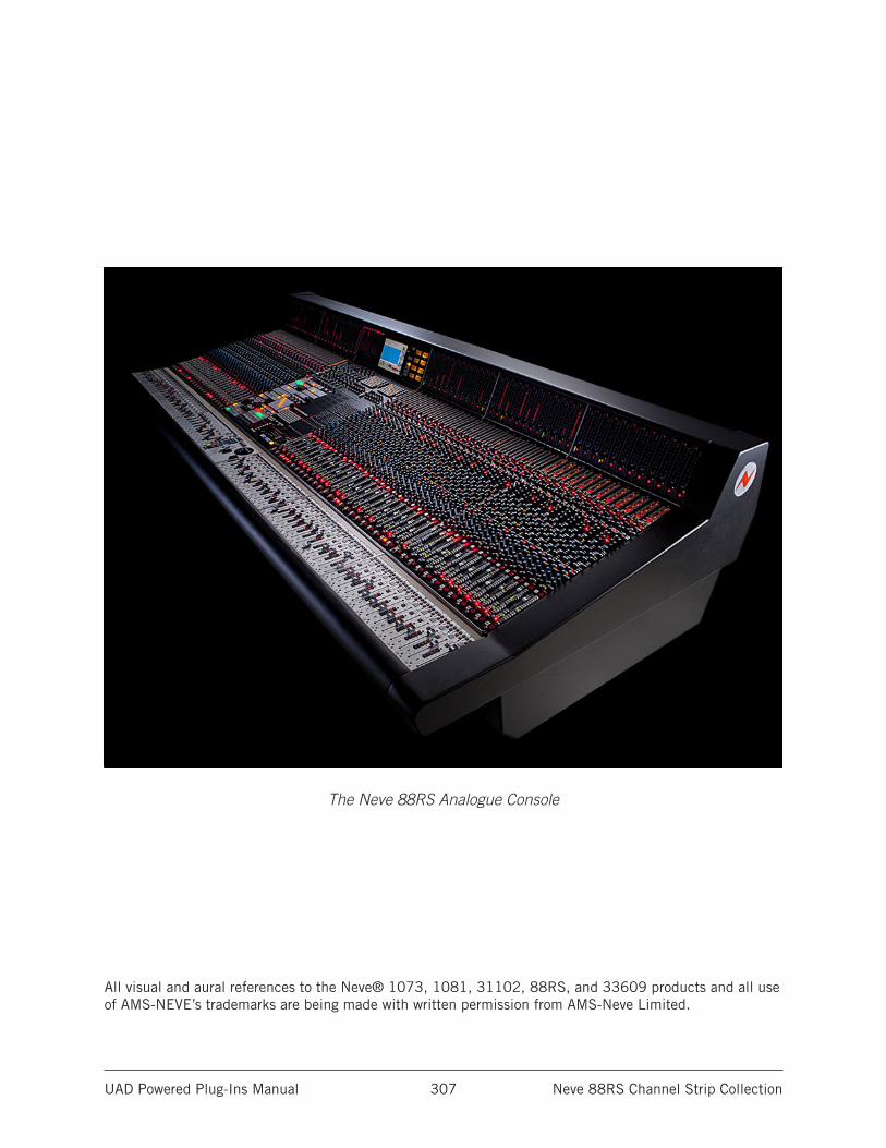
UAD Powered Plug-Ins Manual Neve 88RS Channel Strip Collection 307
The Neve 88RS Analogue Console
All visual and aural references to the Neve® 1073, 1081, 31102, 88RS, and 33609 products and all use of AMS-NEVE’s trademarks are being made with written permission from AMS-Neve Limited.
UAD Powered Plug-Ins Manual Neve 1073 Preamp & EQ Collection 308
Neve 1073 Preamp & EQ Collection
The authentic Neve preamp sound – captured as a plug-in featuring Unison™ technologyThe Neve 1073 Channel Amplifier is easily the most revered preamp and EQ circuit ever designed. Introduced in 1970, this hallowed class-A, transistor mic/line amp with EQ epitomizes the beautiful “Neve sound,” with unparalleled clarity, sheen, and bite.
Now for the first time, you can track through the only authentic end-to-end circuit emulation of this legendary piece of audio history, with the Neve 1073 Preamp & EQ Plug-In Collection for UAD-2 hardware and Apollo interfaces.
Now You Can:• Get the world’s only authentic and licensed plug-in emulation of the classic Neve
1073 Channel Amplifier
• Color and EQ your mix with Neve tone, including all 10 distinct clipping points from the vintage 1970’s era hardware
• Record “through” the 1073 preamp in real time using Apollo Twin, DUO, or QUAD interfaces
• Control Apollo interface mic preamp gain staging and impedance directly from the 1073 plug-in with Unison™ technology
• Mix with artist presets from Ed Cherney, Joe Chiccarelli, Jaquire King, Ryan Hewitt, David Isaac, Ryan West, and more
• Get the flagship Neve 1073 Preamp & EQ plug-in, plus the Legacy 1073 EQ and 1073SE (“DSP-Lite”) EQ plug-ins
The Only End-to-End Neve 1073 Circuit EmulationUniversal Audio’s all-new Neve 1073 plug-in for Apollo and UAD-2 provides all the features, unique circuit behaviors, and coveted sound of Neve’s original hardware design. By modeling the dual-stage “Red Knob” preamp, revered three-band EQ, and post-fader output amplifier with obsessive detail, the Neve 1073 Preamp & EQ replicates the experience of the original 1970s hardware with stunning accuracy. Like the hardware, the new Neve 1073 plug-in incorporates all 10 clipping points from the preamp and EQ circuitry, delivering trademark clarity, grit, and harmonically rich class-A saturation.
UAD Powered Plug-Ins Manual Neve 1073 Preamp & EQ Collection 309
Unison Technology for Apollo InterfacesHarnessing UA’s groundbreaking Unison technology, the Neve 1073 plug-in blurs the lines between analog and digital, giving you all of the 1073 preamp’s impedance, gain staging “sweet spots,” and circuit behaviors that have made it legendary among the audio faithful.
The secret is Unison’s bi-directional control and communication from the 1073 plug-in to the digitally controlled mic preamps in Apollo interfaces. With Unison, the Apollo preamp changes to the Neve 1073’s physical input impedance, allowing both Lo (300 Ω) and Hi (1200 Ω) impedance setting options. This provides the 1073’s full gain and tonal range to your favorite studio mics.
Add Clarity and Color to any SourceOf course, the Neve Preamp & EQ Plug-In Collection isn’t just for Apollo owners. UAD-2 hardware owners can employ the Neve 1073 Preamp & EQ Collection for mixing, tone shaping, or simply adding sheen and bite to vocals, guitars, drums and more — without ever leaving the box. To get you started, there are artist presets from renowned 1073 users such as Ed Cherney, Joe Chiccarelli, Jaquire King, Ryan Hewitt, David Isaac, Ryan West, and more.
UAD-2 power users can place Neve 1073 instances across multiple channels, turning their favorite DAW into a classic Neve console.
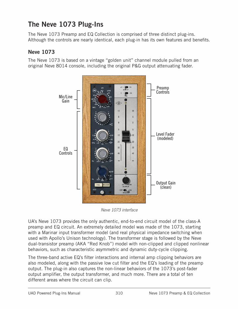
UAD Powered Plug-Ins Manual Neve 1073 Preamp & EQ Collection 310
The Neve 1073 Plug-InsThe Neve 1073 Preamp and EQ Collection is comprised of three distinct plug-ins. Although the controls are nearly identical, each plug-in has its own features and benefits.
Neve 1073The Neve 1073 is based on a vintage “golden unit” channel module pulled from an original Neve 8014 console, including the original P&G output attenuating fader.
Neve 1073 interface
UA’s Neve 1073 provides the only authentic, end-to-end circuit model of the class-A preamp and EQ circuit. An extremely detailed model was made of the 1073, starting with a Marinar input transformer model (and real physical impedance switching when used with Apollo’s Unison technology). The transformer stage is followed by the Neve dual-transistor preamp (AKA “Red Knob”) model with non-clipped and clipped nonlinear behaviors, such as characteristic asymmetric and dynamic duty-cycle clipping.
The three-band active EQ’s filter interactions and internal amp clipping behaviors are also modeled, along with the passive low cut filter and the EQ’s loading of the preamp output. The plug-in also captures the non-linear behaviors of the 1073’s post-fader output amplifier, the output transformer, and much more. There are a total of ten different areas where the circuit can clip.
EQControls
Mic/LineGain
Level Fader (modeled)
Output Gain (clean)
Preamp Controls
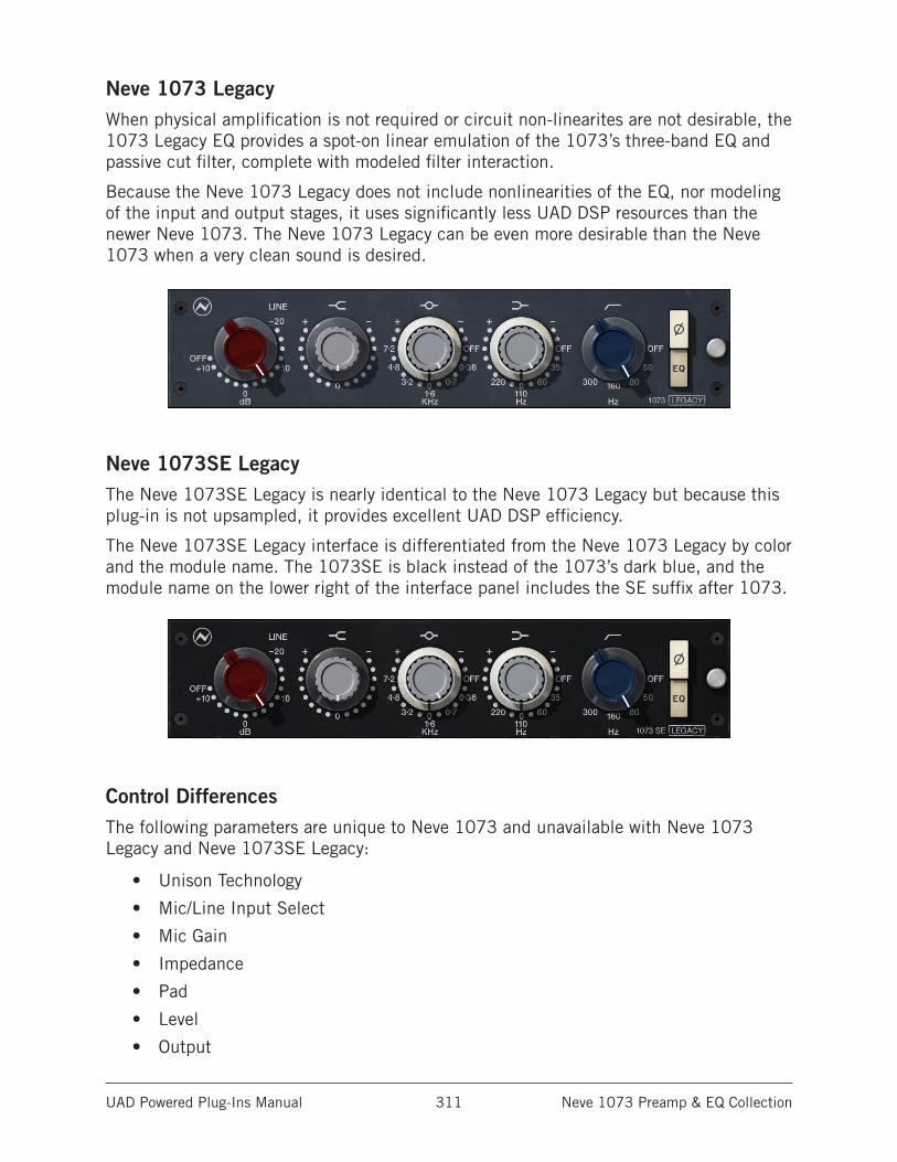
UAD Powered Plug-Ins Manual Neve 1073 Preamp & EQ Collection 311
Neve 1073 LegacyWhen physical amplification is not required or circuit non-linearites are not desirable, the 1073 Legacy EQ provides a spot-on linear emulation of the 1073’s three-band EQ and passive cut filter, complete with modeled filter interaction.
Because the Neve 1073 Legacy does not include nonlinearities of the EQ, nor modeling of the input and output stages, it uses significantly less UAD DSP resources than the newer Neve 1073. The Neve 1073 Legacy can be even more desirable than the Neve 1073 when a very clean sound is desired.
Neve 1073SE LegacyThe Neve 1073SE Legacy is nearly identical to the Neve 1073 Legacy but because this plug-in is not upsampled, it provides excellent UAD DSP efficiency.
The Neve 1073SE Legacy interface is differentiated from the Neve 1073 Legacy by color and the module name. The 1073SE is black instead of the 1073’s dark blue, and the module name on the lower right of the interface panel includes the SE suffix after 1073.
Control DifferencesThe following parameters are unique to Neve 1073 and unavailable with Neve 1073 Legacy and Neve 1073SE Legacy:
• Unison Technology
• Mic/Line Input Select
• Mic Gain
• Impedance
• Pad
• Level
• Output
UAD Powered Plug-Ins Manual Neve 1073 Preamp & EQ Collection 312
Unison™ IntegrationThe Neve 1073 features Unison technology for integration with the mic preamp hardware in Universal Audio’s Apollo audio interfaces. With Unison, Apollo’s ultra-transparent mic preamps inherit all of the unique sonics, input characteristics, and features of the Neve 1073 hardware preamp.
Note: Unison is active only when the Neve 1073 is inserted in the unique INPUT insert within Apollo’s Console application. For complete Unison details, see the Apollo Software Manual.
Realistic Tandem ControlUnison facilitates seamless interactive control of Neve 1073 plug-in settings using Apollo’s digitally-controlled panel hardware and/or the plug-in interface. All equivalent preamp controls (gain, pad, polarity) are mirrored and bi-directional. The preamp controls respond to adjustments with precisely the same interplay behavior as the Neve 1073 hardware, including gain levels and clipping points.
Hardware Input ImpedanceAll Apollo mic preamps feature variable input impedance in analog hardware that can be physically changed by Unison plug-ins for physical, microphone-to-preamp resistive interaction. This impedance switching enables Apollo’s preamps to physically match the emulated unit’s input impedance, which can significantly impact the sound of a microphone. Because the electrical loading occurs on input, prior to A/D conversion, the realism is faithful to the original target hardware preamp.
Tactile Gain StagingApollo’s front panel preamp knob can independently adjust the gain and level parameters available within the Unison plug-in via Gain Stage Mode. The gain stage being adjusted can be remotely switched via Apollo, so the gain levels and their associated colorations can be tuned from the hardware knob for precise physical tactile control, all without using the Unison plug-in’s software interface.
Note: Unison technology is not available with Neve 1073 Legacy or Neve 1073SE Legacy.
Artist PresetsThe Neve 1073 includes artist presets from prominent Neve 1073 users. The artist presets are in the internal factory bank and are accessed via the host application’s preset menu. The artist presets are also placed by the UAD installer so they can be used within Apollo’s Console application. The presets can be loaded within a DAW using the Settings menu in the UAD Toolbar.
This plug-in includes additional artist presets that are not available in the internal factory bank. These additional presets can also be accessed using the Settings menu in the UAD Toolbar.
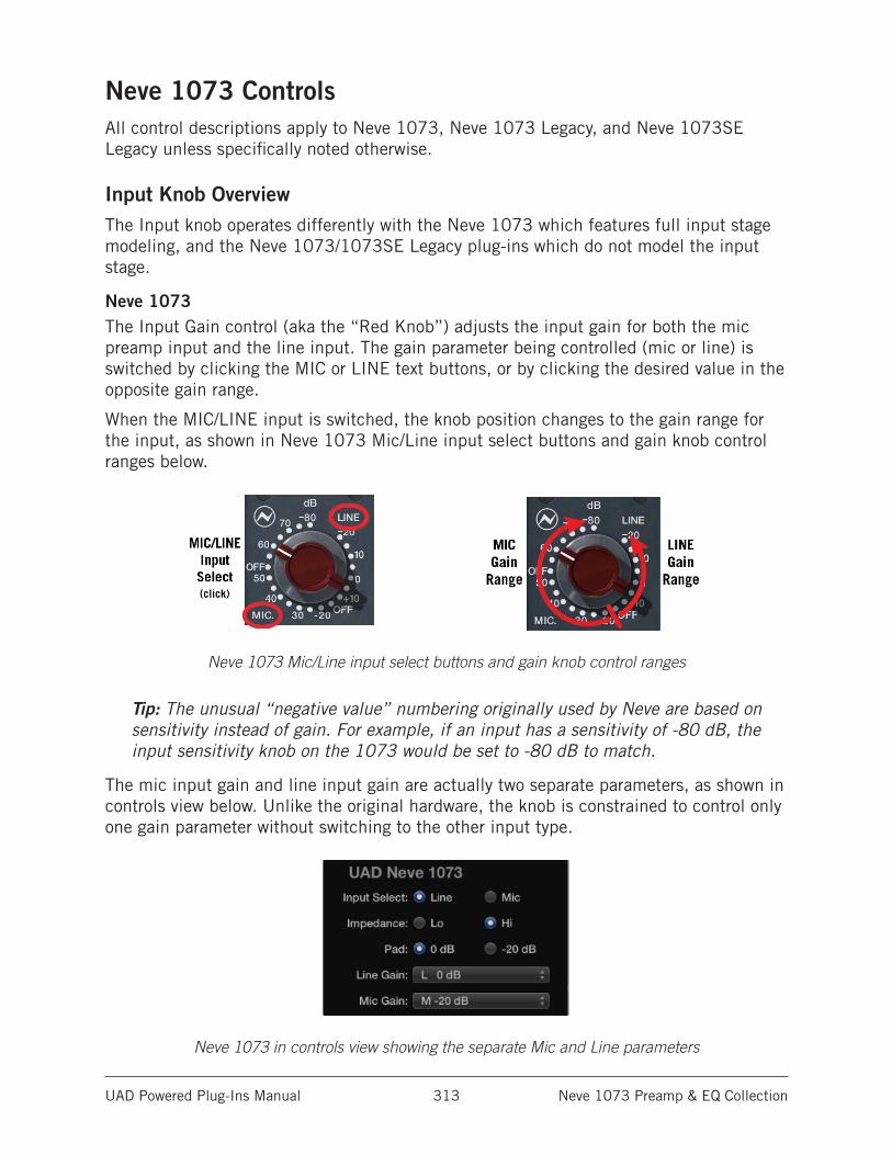
UAD Powered Plug-Ins Manual Neve 1073 Preamp & EQ Collection 313
Neve 1073 ControlsAll control descriptions apply to Neve 1073, Neve 1073 Legacy, and Neve 1073SE Legacy unless specifically noted otherwise.
Input Knob OverviewThe Input knob operates differently with the Neve 1073 which features full input stage modeling, and the Neve 1073/1073SE Legacy plug-ins which do not model the input stage.
Neve 1073The Input Gain control (aka the “Red Knob”) adjusts the input gain for both the mic preamp input and the line input. The gain parameter being controlled (mic or line) is switched by clicking the MIC or LINE text buttons, or by clicking the desired value in the opposite gain range.
When the MIC/LINE input is switched, the knob position changes to the gain range for the input, as shown in Neve 1073 Mic/Line input select buttons and gain knob control ranges below.
Neve 1073 Mic/Line input select buttons and gain knob control ranges
Tip: The unusual “negative value” numbering originally used by Neve are based on sensitivity instead of gain. For example, if an input has a sensitivity of -80 dB, the input sensitivity knob on the 1073 would be set to -80 dB to match.
The mic input gain and line input gain are actually two separate parameters, as shown in controls view below. Unlike the original hardware, the knob is constrained to control only one gain parameter without switching to the other input type.
Neve 1073 in controls view showing the separate Mic and Line parameters
UAD Powered Plug-Ins Manual Neve 1073 Preamp & EQ Collection 314
Neve 1073 Legacy and Neve 1073SE LegacyThe Input Gain control sets the level at the input of these plug-ins. Separate Mic/Line gain controls are unavailable because these plug-ins do not feature input stage modeling.
Input SelectInput Select determines which input (mic or line) is being controlled with the Gain knob. To change the input gain being controlled, click the MIC or LINE text to switch to that input.
Tip: Input Select can also be switched by clicking any of the “dots” or gain value labels in the range for the input type.
When Input Select is changed, the Gain knob changes to use only the range for that input type (as shown in Neve 1073 Mic/Line input select buttons and gain knob control ranges).
Like the hardware, the Neve 1073 plug-in easily facilitates sending Line level signal through the “virtual” Mic input, which allows creative use of distortion to color signals. This is the equivalent of routing a line level signal into a mic level input, so a large jump in gain is expected.
Important: Use caution when switching to Mic from Line, as output levels can increase significantly (as they would with any hardware preamp).
When Neve 1073 is used in a Unison insert within Apollo’s Console application, software and hardware control of Input Select is mirrored. Input Select can be changed within the plug-in interface, with Console’s MIC/LINE buttons, or with Apollo’s hardware buttons (MIC/LINE on Apollo, or INPUT on Apollo Twin).
Note: Input Select is unavailable with the Legacy 1073/1073SE.
Line Gain
Neve 1073Line Gain has a range of 30 dB, available in 5 dB increments. Line Gain can only be adjusted when Input Select is set to LINE mode.
Like the original hardware, gain is increased as the knob is rotated counter-clockwise in the plug-in interface. However:
• In Unison mode, Line Gain is increased by turning Apollo’s preamp level knob clockwise.
• In Controls View mode, Line Gain is increased by moving the control slider from left to right.
Note: When Line Gain is set to the OFF position, UAD DSP usage is reduced (unless UAD-2 LoadLock is enabled).
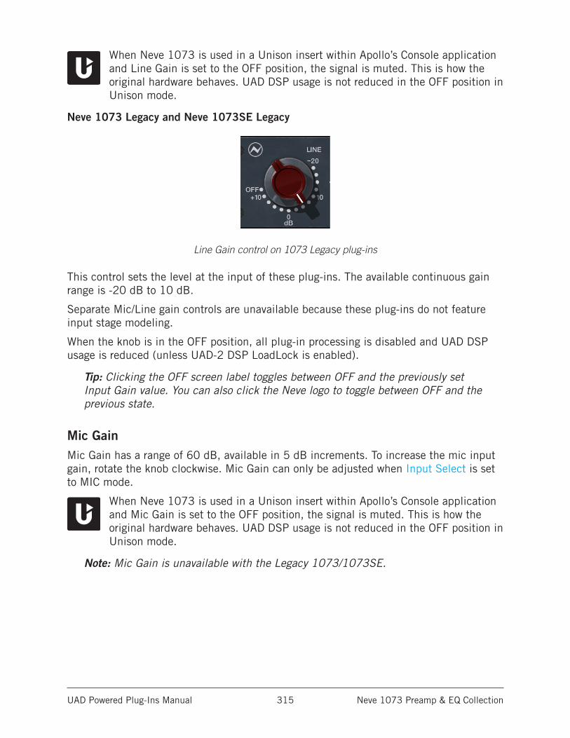
UAD Powered Plug-Ins Manual Neve 1073 Preamp & EQ Collection 315
When Neve 1073 is used in a Unison insert within Apollo’s Console application and Line Gain is set to the OFF position, the signal is muted. This is how the original hardware behaves. UAD DSP usage is not reduced in the OFF position in Unison mode.
Neve 1073 Legacy and Neve 1073SE Legacy
Line Gain control on 1073 Legacy plug-ins
This control sets the level at the input of these plug-ins. The available continuous gain range is -20 dB to 10 dB.
Separate Mic/Line gain controls are unavailable because these plug-ins do not feature input stage modeling.
When the knob is in the OFF position, all plug-in processing is disabled and UAD DSP usage is reduced (unless UAD-2 DSP LoadLock is enabled).
Tip: Clicking the OFF screen label toggles between OFF and the previously set Input Gain value. You can also click the Neve logo to toggle between OFF and the previous state.
Mic GainMic Gain has a range of 60 dB, available in 5 dB increments. To increase the mic input gain, rotate the knob clockwise. Mic Gain can only be adjusted when Input Select is set to MIC mode.
When Neve 1073 is used in a Unison insert within Apollo’s Console application and Mic Gain is set to the OFF position, the signal is muted. This is how the original hardware behaves. UAD DSP usage is not reduced in the OFF position in Unison mode.
Note: Mic Gain is unavailable with the Legacy 1073/1073SE.
UAD Powered Plug-Ins Manual Neve 1073 Preamp & EQ Collection 316
Mic Z (Impedance)The impedance of the mic input is set with the Mic Z switch. The modeled input impedances have subtle effects on the signal color and response (even when not used in Unison mode).
Note: Mic Z is unavailable with the Legacy 1073/1073SE.
LOWhen set to LO, the mic input impedance is 300 Ohms.
HIWhen set to HI, the mic input impedance is 1.2K Ohms.
Note: Mic Z is not available for line input, or when used with Apollo’s Hi-Z input in Unison mode. In these cases, the control cannot be switched.
With the original hardware, most studios leave this control in the HI position (the default value in the plug-in). If an engineer chooses to access the LO setting on the hardware for a low output microphone (such as a ribbon mic), they need to crawl under the console to access the control on the back of the module.
Unison ImpedanceWhen Neve 1073 is used in a Unison insert within Apollo’s Console application, the hardware input impedance of the Apollo mic preamp is switched to match the value in the plug-in for physical, microphone-to-preamp resistive interaction.
Matching the microphone to the closest impedance value is generally recommended, but this parameter can be used creatively and will not harm equipment connected to the Apollo mic preamp.
PadWhen enabled, the mic input signal level is attenuated (lowered) by -20 dB. Pad can be used to reduce signal levels when undesirable overload distortion is present at low preamp gain levels.
Note: Pad is not available for line input, or when used with Apollo’s Hi-Z input in Unison mode. In these cases, the control cannot be switched.
When Neve 1073 is used in a Unison insert within Apollo’s Console application, software and hardware control of PAD is mirrored. Pad can be switched within the plug-in interface, with Console’s PAD button, or with Apollo’s hardware PAD button.
UAD Powered Plug-Ins Manual Neve 1073 Preamp & EQ Collection 317
High ShelfThe High Shelf knob offers approximately ±18 dB of smooth fixed frequency shelving equalization at 12 kHz.
Rotate the control clockwise to add the famous high-end Neve sheen, or counter-clockwise to reduce the treble response.
Tip: Click the “0” text label to return the control to the zero position.
Midrange BandThe midrange band is controlled by dual-concentric knobs, delivering smooth semi- parametric midrange equalization.
The response for this band has a dependence on the bandwidth as the gain is adjusted. At higher center frequencies, the Q goes up, for a more focused peak.
The inner knob controls the band gain, and the outer ring selects the frequency or band disable. These two controls are detailed below.
Midrange GainThe equalization gain for the midrange band is selected with the inner knob of the dual-concentric control. The available range is approximately ±18 dB.
Tip: Click the “0” text label to return the control to the zero position.
Midrange FrequencyThe Mid frequency is selected with the outer ring of the dual-concentric knob controls. The ring control can be dragged with the mouse, or click directly on the text labels to specify a frequency or disable the Mid band.
Tip: Click the midrange symbol (at lower right of knob) or “KHz” label (at lower left of knob) to cycle through the available values. Shift + click to step back one frequency.
The available midrange center frequencies are 360 Hz, 700 Hz, 1.6 kHz, 3.2 kHz, 4.8 kHz, 7.2 kHz, and OFF. When set to OFF, the band is disabled.
UAD Powered Plug-Ins Manual Neve 1073 Preamp & EQ Collection 318
Low BandThe low frequency band is controlled by dual-concentric knobs, delivering smooth shelving equalization.
The inner knob controls the band gain, and the outer ring selects the frequency or band disable. These two controls are detailed below.
Low GainThe equalization gain for the low band is selected with the inner knob of the dual- concentric control. The available range is approximately ±15 dB.
Rotate the control clockwise to boost the selected low band frequency, or counter-clockwise to reduce the bass response.
Tip: Click the “0” text label to return the control to the zero position.
Low FrequencyThe Low frequency is selected with the outer ring of the dual-concentric knob controls. The ring control can be dragged with the mouse, or click directly on the “silkscreen” text to specify a frequency or disable the Low band.
Tip: Click the low shelf symbol (at lower right of knob) or “Hz” label (at lower left of knob) to cycle through the available values. Shift + click to step back one frequency.
The available low band center frequencies are 35 Hz, 60 Hz, 110 Hz, 220 Hz, and OFF. When set to OFF, the band is disabled.
High PassThis knob specifies the fixed frequency of the high pass (low cut) filter. This filter has an 18 dB per octave slope.
The available frequencies are 50 Hz, 80 Hz, 160 Hz, 300 Hz, and OFF. When OFF is specified, the high pass filter is disabled.
Note: Click the high pass symbol (at lower right of knob) or “Hz” label (at lower left of knob) to cycle through the available values. Shift + click to step back one frequency.
When Neve 1073 is used in a Unison insert within Apollo’s Console application, the following high pass filter behaviors apply:
• The filter is always in circuit, even when the EQL switch is disabled.
• When toggling the filter enable state with the hardware button on Apollo, the last set value is toggled.
UAD Powered Plug-Ins Manual Neve 1073 Preamp & EQ Collection 319
PhaseThe PHASE button inverts the polarity of the signal. When the switch is engaged (the darker “in” position), the phase is inverted. Leave the switch in the disengaged (the lighter “out” position) for normal phase.
When the plug-in is used in a Unison insert within Apollo’s Console application, software and hardware control of PHASE is mirrored. Polarity can be inverted within the plug-in interface, with Console’s polarity button, or with Apollo’s hardware polarity button.
EQLThe equalizer is engaged when the EQL switch is engaged (the darker “in” position). To disable the EQ, disengage the switch (the lighter “out” position).
The default position is disabled. Click the button to toggle the state.
UAD DSP usage is reduced when the EQ is bypassed with this control (unless UAD-2 DSP LoadLock is enabled).
In the hardware 1073, the audio is still slightly colored even when the EQL switch is disengaged and the EQ settings are in their “flat” positions. This is due to the fact that the signal is still passing through its circuitry.
More notably, all of the filter bands (except High Pass) can have an effect on the clipping behaviors of the Neve 1073 (except Legacy versions), even when EQL is disengaged. Therefore, the EQ values can have a significant effect on the signal when the EQ is “disabled” via the EQL switch.
If a true bypass is desired, use the OFF position of the Power switch (Neve 1073) or the OFF position of the Line Gain control (Neve 1073/1073SE Legacy).
LevelLevel controls the signal level at the output stage of the module. The circuitry of an original Neve console fader was modeled for this control.
The available range is from -∞ dB (off) to +10 dB. Unity gain is at the zero position. Raising Level above 0 dB can cause output amplifier clipping.
Tip: Click the “0” text labels to return Level to 0 dB.
OutputOutput adjusts the signal level at the output of the plug-in without effecting the sonic character of the signal. The available range is ±24 dB.
This control, which does not exist on the original hardware, facilitates the ability to maximize color of the overall signal. For example, Gain and Level can be cranked for more distortion, while lowering Output to normalize levels.
Note: If comparing the Neve 1073 plug-in (when it is not in Unison mode) with the original hardware, set Output to +10.8 dB so software and hardware levels will match.
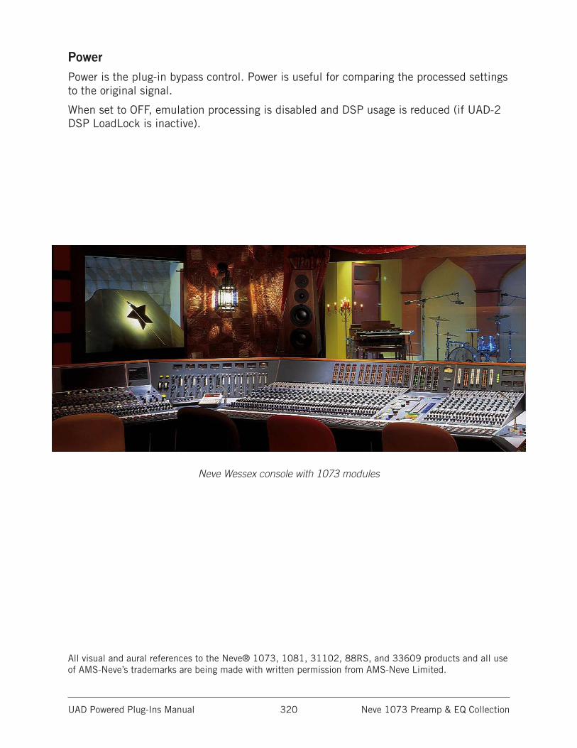
UAD Powered Plug-Ins Manual Neve 1073 Preamp & EQ Collection 320
PowerPower is the plug-in bypass control. Power is useful for comparing the processed settings to the original signal.
When set to OFF, emulation processing is disabled and DSP usage is reduced (if UAD-2 DSP LoadLock is inactive).
Neve Wessex console with 1073 modules
All visual and aural references to the Neve® 1073, 1081, 31102, 88RS, and 33609 products and all use of AMS-Neve’s trademarks are being made with written permission from AMS-Neve Limited.
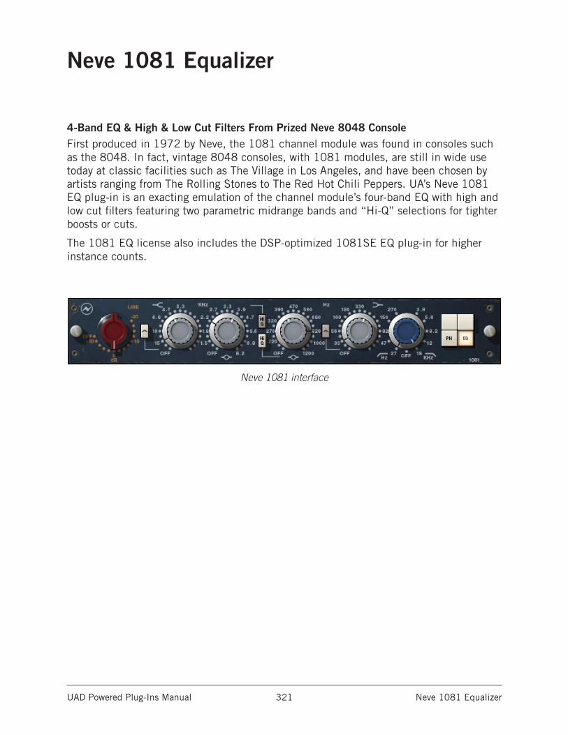
UAD Powered Plug-Ins Manual Neve 1081 Equalizer 321
Neve 1081 Equalizer
4-Band EQ & High & Low Cut Filters From Prized Neve 8048 ConsoleFirst produced in 1972 by Neve, the 1081 channel module was found in consoles such as the 8048. In fact, vintage 8048 consoles, with 1081 modules, are still in wide use today at classic facilities such as The Village in Los Angeles, and have been chosen by artists ranging from The Rolling Stones to The Red Hot Chili Peppers. UA’s Neve 1081 EQ plug-in is an exacting emulation of the channel module’s four-band EQ with high and low cut filters featuring two parametric midrange bands and “Hi-Q” selections for tighter boosts or cuts.
The 1081 EQ license also includes the DSP-optimized 1081SE EQ plug-in for higher instance counts.
Neve 1081 interface
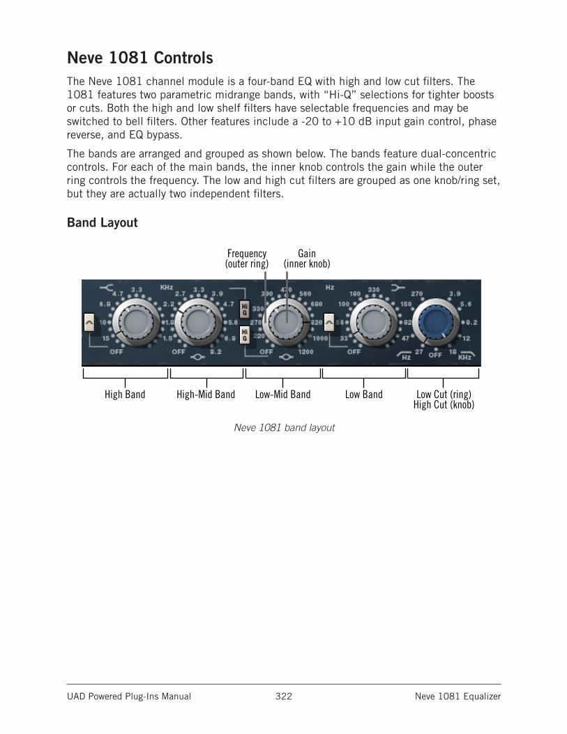
UAD Powered Plug-Ins Manual Neve 1081 Equalizer 322
Neve 1081 ControlsThe Neve 1081 channel module is a four-band EQ with high and low cut filters. The 1081 features two parametric midrange bands, with “Hi-Q” selections for tighter boosts or cuts. Both the high and low shelf filters have selectable frequencies and may be switched to bell filters. Other features include a -20 to +10 dB input gain control, phase reverse, and EQ bypass.
The bands are arranged and grouped as shown below. The bands feature dual-concentric controls. For each of the main bands, the inner knob controls the gain while the outer ring controls the frequency. The low and high cut filters are grouped as one knob/ring set, but they are actually two independent filters.
Band Layout
Neve 1081 band layout
High Band High-Mid Band Low-Mid Band Low Band Low Cut (ring)High Cut (knob)
Gain (inner knob)
Frequency (outer ring)
UAD Powered Plug-Ins Manual Neve 1081 Equalizer 323
Input GainThe Input Gain control sets the level at the input of the plug-in. The range is from -20 dB to +10 dB.
When the Input Gain knob “snaps” to the OFF position, plug-in processing is disabled and UAD DSP usage is reduced (unless UAD-2 DSP LoadLock is enabled).
Tip: Click the OFF screen label or the Neve logo to toggle between OFF and the previously set Input Gain value.
High BandThe high band delivers smooth high frequency shelving or peak equalization. The inner knob controls the band gain, and the outer ring selects the frequency or band disable.
High GainThe equalization gain for the high band is selected with the inner knob of the dual-concentric control. Rotate the control clockwise to add the famous high-end Neve sheen, or counter-clockwise to reduce the treble response. The available range is approximately ±18 dB.
High FrequencyThe high band frequency is selected with the outer ring of the dual-concentric knob controls. The ring control can be dragged with the mouse, or click directly on the “silkscreen” text to specify a frequency or disable the band.
Tip: Click the shelving symbol above the knob to cycle through the available values. Shift-click to step back one frequency.
The available high band center frequencies are 3.3 kHz, 4.7 kHz, 6.8 kHz, 10 kHz, 15 kHz, and OFF. When OFF is specified, the band is disabled. UAD DSP usage is not reduced when the band is OFF.
High Peak SelectThe High Peak button switches the high band from a shelving EQ to a peaking EQ. The band is in shelf mode by default; it is in peak mode when the button is “down” (darker).
UAD Powered Plug-Ins Manual Neve 1081 Equalizer 324
High-Mid BandThe high-midrange band delivers smooth high-mid frequency peak equalization with a choice of two bandwidths. The inner knob controls the band gain, and the outer ring selects the frequency or band disable.
High-Mid GainThe equalization gain for the high-midrange band is selected with the inner knob of the dual-concentric control. The available range is approximately ±18 dB.
High-Mid FrequencyThe high-midrange band frequency is selected with the outer ring of the dual-concentric knob controls. The ring control can be dragged with the mouse, or click directly on the “silkscreen” text to specify a frequency or disable the band.
Tip: Click the midrange symbol below the knob to cycle through the available values. Shift-click to step back one frequency.
The available high-mid band center frequencies are 1.5 kHz, 1.8 kHz, 2.2 kHz, 2.7 kHz, 3.3 kHz, 3.9 kHz, 4.7 kHz, 5.6 kHz, 6.8 kHz, 8.2 kHz, and OFF. When OFF is specified, the band is disabled. UAD DSP usage is not reduced when the band is OFF.
High-Mid Q SelectThe High Q button switches the response of the high-mid band from normal to a narrower bandwidth for a sharper EQ curve. The band is in normal mode by default; it’s in high Q mode when the button is “down” (darker).
UAD Powered Plug-Ins Manual Neve 1081 Equalizer 325
Low-Mid BandThe low-midrange band delivers smooth low-mid frequency peak equalization with a choice of two bandwidths. The inner knob controls the band gain, and the outer ring selects the frequency or band disable.
Low-Mid GainThe equalization gain for the low-midrange band is selected with the inner knob of the dual-concentric control. The available range is approximately ±18 dB.
Low-Mid FrequencyThe low-midrange band frequency is selected with the outer ring of the dual-concentric knob controls. The ring control can be dragged with the mouse, or click directly on the silkscreen text to specify a frequency or disable the band.
Tip: Click the midrange symbol below the knob to cycle through the available values. Shift-click to step back one frequency.
The available low-mid band center frequencies are 220 Hz, 270 Hz, 330 Hz, 390 Hz, 470 Hz, 560 Hz, 680 Hz, 820 Hz, 1000 Hz,1200 Hz, and OFF. When OFF is specified, the band is disabled. UAD CPU usage is not reduced when the band is OFF.
Low-Mid Q SelectThe High Q button switches the response of the low-mid band from “normal” to a narrower bandwidth for a sharper EQ curve. The band is in normal mode by default; it’s in high Q mode when the button is “down” (darker).
UAD Powered Plug-Ins Manual Neve 1081 Equalizer 326
Low BandThe low band delivers smooth low frequency shelving or peak equalization. The inner knob controls the band gain, and the outer ring selects the frequency or band disable.
Low GainThe equalization gain for the low band is selected with the inner knob of the dual-concentric control. The available range is approximately ±18 dB.
Low FrequencyThe low band frequency is selected with the outer ring of the dual-concentric knob controls. The ring control can be dragged with the mouse, or click directly on the silkscreen text to specify a frequency or disable the band.
The available low band center frequencies are 33Hz, 56 Hz, 100 Hz, 180 Hz, 330 Hz, and OFF. When OFF is specified, the band is disabled. UAD CPU usage is not reduced when the band is OFF.
Tip: Click the shelving symbol above the knob to cycle through the available values. Shift + click to step back one frequency.
Low Peak SelectThe Low Peak button switches the low band from a shelving EQ to a peaking EQ. The band is in shelf mode by default; it is in peak mode when the button is “down” (darker).
UAD Powered Plug-Ins Manual Neve 1081 Equalizer 327
Cut FiltersThe independent low and high cut filters are controlled by the dual-concentric knobs to the right of the low band (see Band Layout). The controls specify the fixed frequency of the cut filter. The cut filters have an 18 dB per octave slope.
Click+drag the control to change the value, or click the silkscreen frequency values.
Tip: Click the high cut/low cut symbols below the knob to cycle through the available values. Shift-click to step back one frequency.
High CutThe inner (blue) dual-concentric knob controls the high cut filter. The available frequencies for the high cut filter are 18 kHz, 12 kHz, 8.2 kHz, 5.6 kHz, 3.9 kHz, and OFF. When OFF is specified, the high cut filter is disabled. UAD CPU usage is not reduced when OFF.
Low CutThe outer (silver) dual-concentric ring controls the low cut filter. The available frequencies for the low cut filter are 27 Hz, 47 Hz, 82 Hz, 150 Hz, 270 Hz, and OFF. When OFF is specified, the low cut filter is disabled. UAD CPU usage is not reduced when OFF.
PhaseThe Phase (PH) button inverts the polarity of the signal. When the switch is in the “In” (lit) position, the phase is reversed. Leave the switch in the “Out” (unlit) position for normal phase.
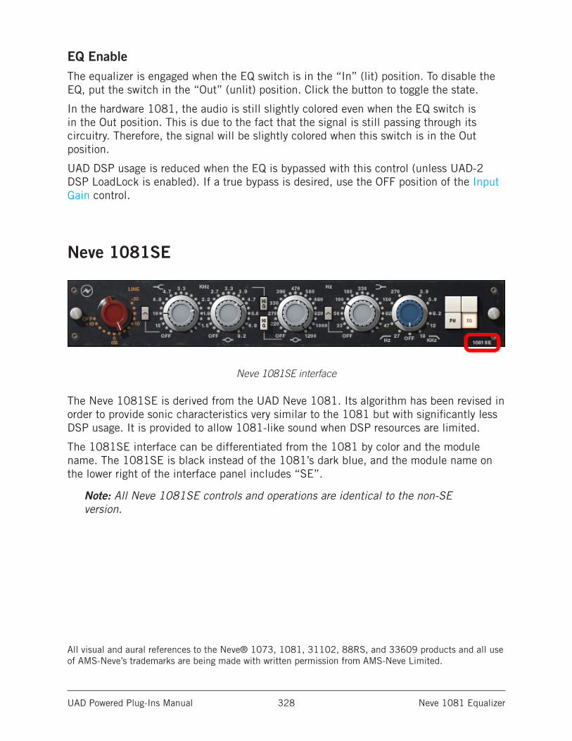
UAD Powered Plug-Ins Manual Neve 1081 Equalizer 328
EQ EnableThe equalizer is engaged when the EQ switch is in the “In” (lit) position. To disable the EQ, put the switch in the “Out” (unlit) position. Click the button to toggle the state.
In the hardware 1081, the audio is still slightly colored even when the EQ switch is in the Out position. This is due to the fact that the signal is still passing through its circuitry. Therefore, the signal will be slightly colored when this switch is in the Out position.
UAD DSP usage is reduced when the EQ is bypassed with this control (unless UAD-2 DSP LoadLock is enabled). If a true bypass is desired, use the OFF position of the Input Gain control.
Neve 1081SE
Neve 1081SE interface
The Neve 1081SE is derived from the UAD Neve 1081. Its algorithm has been revised in order to provide sonic characteristics very similar to the 1081 but with significantly less DSP usage. It is provided to allow 1081-like sound when DSP resources are limited.
The 1081SE interface can be differentiated from the 1081 by color and the module name. The 1081SE is black instead of the 1081’s dark blue, and the module name on the lower right of the interface panel includes “SE”.
Note: All Neve 1081SE controls and operations are identical to the non-SE version.
All visual and aural references to the Neve® 1073, 1081, 31102, 88RS, and 33609 products and all use of AMS-Neve’s trademarks are being made with written permission from AMS-Neve Limited.
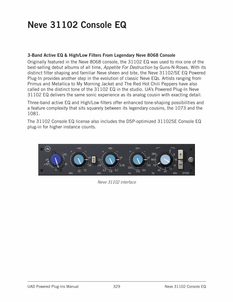
UAD Powered Plug-Ins Manual Neve 31102 Console EQ 329
Neve 31102 Console EQ
3-Band Active EQ & High/Low Filters From Legendary Neve 8068 ConsoleOriginally featured in the Neve 8068 console, the 31102 EQ was used to mix one of the best-selling debut albums of all time, Appetite For Destruction by Guns-N-Roses. With its distinct filter shaping and familiar Neve sheen and bite, the Neve 31102/SE EQ Powered Plug-In provides another step in the evolution of classic Neve EQs. Artists ranging from Primus and Metallica to My Morning Jacket and The Red Hot Chili Peppers have also called on the distinct tone of the 31102 EQ in the studio. UA’s Powered Plug-In Neve 31102 EQ delivers the same sonic experience as its analog cousin with exacting detail.
Three-band active EQ and High/Low filters offer enhanced tone-shaping possibilities and a feature complexity that sits squarely between its legendary cousins, the 1073 and the 1081.
The 31102 Console EQ license also includes the DSP-optimized 31102SE Console EQ plug-in for higher instance counts.
Neve 31102 interface
UAD Powered Plug-Ins Manual Neve 31102 Console EQ 330
Neve 31102 Controls
Input GainThe Input Gain control sets the level at the input of the plug-in, and doubles as a plug-in bypass control. The range is from -20 dB to +10 dB, and off.
When the Input Gain knob “snaps” to the off position, plug-in processing is disabled and UAD DSP usage is reduced (unless UAD-2 DSP LoadLock is enabled).
Tip: Click the “off” screen label or the Neve logo to toggle between off and the previously set Input Gain value.
High ShelfThe high shelf delivers smooth high frequency shelving equalization, controlled by dual-concentric knobs. The inner knob controls the band gain, and the outer ring selects the frequency or band disable.
High Shelving GainThe gain for the high band is selected with the inner knob of the dual-concentric control. Rotate the control clockwise to add the famous high-end Neve sheen, or counter-clockwise to reduce the treble response.
The available range is approximately ±15 dB. The gain value is zero when the knob position indicator is pointing straight down.
High Shelving FrequencyThe high shelving frequency is specified with the outer ring of the dual-concentric knob. The ring knob pointer can be dragged with the mouse, or click the shelving symbol above the knob to cycle through the available frequencies (shift+click to step back one frequency).
The available high shelving frequencies are 16 kHz, 12 kHz, 10 kHz, and off. When off is specified, the high shelf band is disabled. UAD DSP usage is not reduced when the band is off.
UAD Powered Plug-Ins Manual Neve 31102 Console EQ 331
Midrange BandThe midrange band is controlled by dual-concentric knobs, delivering smooth semi-parametric midrange equalization with a choice of two bandwidths. The inner knob controls the band gain, and the outer ring selects the frequency or band disable.
Midrange GainThe equalization gain for the midrange band is selected with the inner knob of the dual-concentric control. The available range is approximately ±15 dB. The gain value is zero when the knob position indicator is pointing straight down.
Midrange FrequencyThe midrange frequency is specified with the outer ring of the dual-concentric knob controls. The ring knob pointer can be dragged with the mouse, or click the peak/dip symbol above the knob to cycle through the available frequencies (shift+click to step back one frequency).
The available midrange center frequencies are 7.2 kHz, 4.8 kHz, 3.2 kHz, 1.6 kHz, 0.7 kHz, 0.35 kHz, and off. When off is specified, the band is disabled. UAD DSP usage is not reduced when the band is off.
High Q SelectThe High Q button switches the response of the midrange band from “normal” to a narrower bandwidth for a sharper EQ curve. The band is in normal mode by default; it’s in high Q mode when the button is “down” (darker).
Low ShelfThe low band is controlled by dual-concentric knobs, delivering smooth shelving equalization. The inner knob controls the band gain, and the outer ring selects the frequency or band disable.
Low GainThe equalization gain for the low band is selected with the inner knob of the dual-concentric control. The available range is approximately ±15 dB. The gain value is zero when the knob position indicator is pointing straight down.
Rotate the control clockwise to boost the selected low band frequency, or counter-clockwise to reduce the bass response.
Low FrequencyThe low frequency is selected with the outer ring of the dual-concentric knob controls. The ring knob pointer can be dragged with the mouse, or click the shelving symbol above the knob to cycle through the available frequencies (shift+click to step back one frequency).
The available low band center frequencies are 35 Hz, 60 Hz, 110 Hz, 220 Hz, and off. When off is specified, the band is disabled. UAD DSP usage is not reduced when off.
UAD Powered Plug-Ins Manual Neve 31102 Console EQ 332
Cut FiltersThe independent low and high cut filters are controlled by the dual-concentric knobs to the right of the low band. The controls specify the fixed frequency of each cut filter.
The knob pointers can be dragged with the mouse, or click the respective cut symbols above the knob (left symbol for low cut, right symbol for high cut) to cycle through the available frequencies (shift+click to step back one frequency).
High CutThe inner (blue) dual-concentric knob controls the high cut filter. The available frequencies for the high cut filter are 18 kHz, 14 kHz, 10 kHz, 8 kHz, 6 kHz, and off. When off is specified, the high cut filter is disabled.
Low CutThe outer dual-concentric ring controls the low cut filter. The available frequencies for the low cut filter are 45 Hz, 70 Hz, 160 Hz, 360 Hz,and off. When OFF is specified, the low cut filter is disabled.
Note: Each cut filter is disabled when its respective knob position indicator is pointing straight down. UAD DSP usage is not reduced when the cut filters are off.
PhaseThe Phase (Ø) button inverts the polarity of the signal. The signal is inverted when the button is engaged (darker). Leave the button inactive (lighter) for normal phase.
EQLThe equalizer is engaged when the EQL switch is in the “In” (darker) position. To disable the EQ, put the switch in the “Out” (lighter) position. Click the button to toggle the state.
In the hardware 31102, the audio is still slightly colored even when the EQL switch is in the Out position. This is due to the fact that the signal is still passing through its circuitry. Therefore, the signal will be slightly colored when this switch is in the Out position. UAD DSP usage is reduced when the EQ is bypassed with this control (unless UAD-2 DSP LoadLock is enabled).
Tip: If a true bypass is desired, use the OFF position of the Input Gain control.
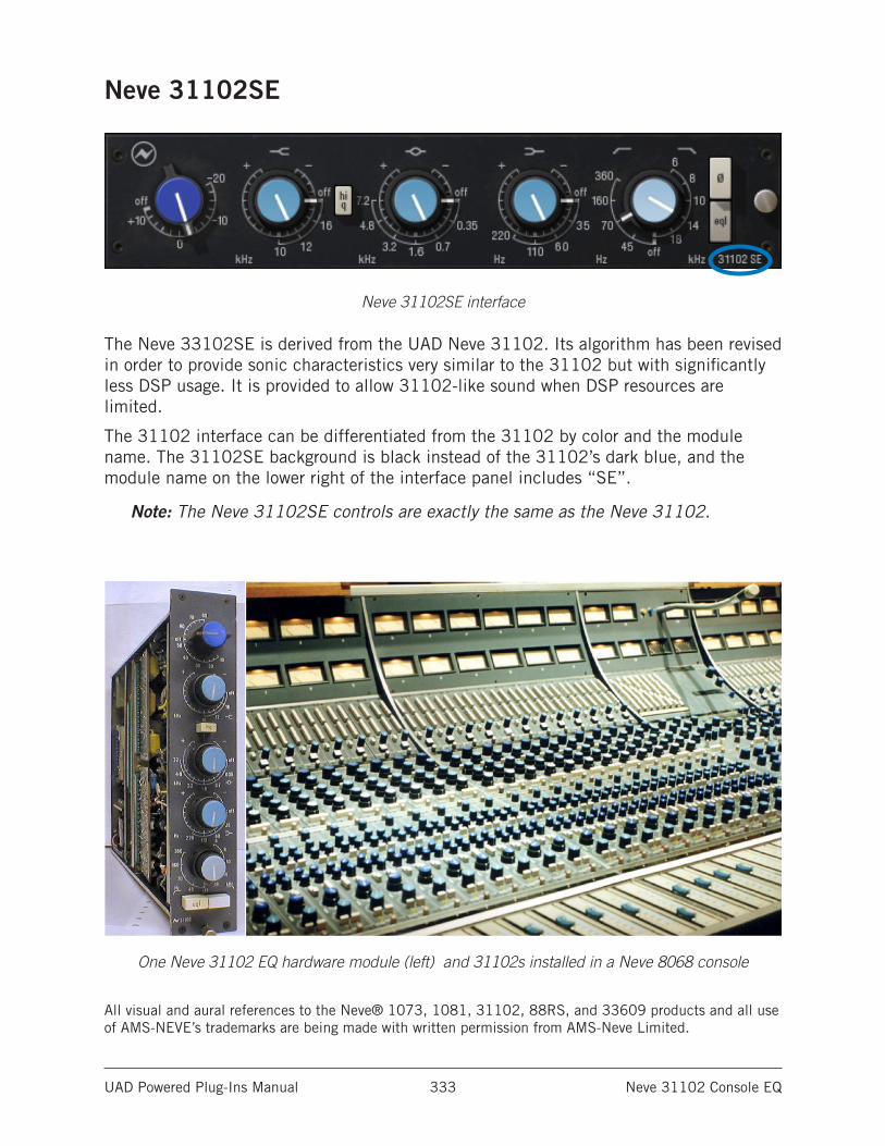
UAD Powered Plug-Ins Manual Neve 31102 Console EQ 333
Neve 31102SE
Neve 31102SE interface
The Neve 33102SE is derived from the UAD Neve 31102. Its algorithm has been revised in order to provide sonic characteristics very similar to the 31102 but with significantly less DSP usage. It is provided to allow 31102-like sound when DSP resources are limited.
The 31102 interface can be differentiated from the 31102 by color and the module name. The 31102SE background is black instead of the 31102’s dark blue, and the module name on the lower right of the interface panel includes “SE”.
Note: The Neve 31102SE controls are exactly the same as the Neve 31102.
One Neve 31102 EQ hardware module (left) and 31102s installed in a Neve 8068 console
All visual and aural references to the Neve® 1073, 1081, 31102, 88RS, and 33609 products and all use of AMS-NEVE’s trademarks are being made with written permission from AMS-Neve Limited.
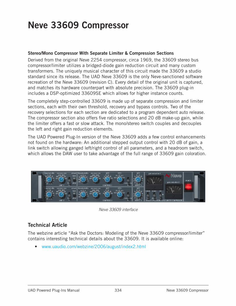
UAD Powered Plug-Ins Manual Neve 33609 Compressor 334
Neve 33609 Compressor
Stereo/Mono Compressor With Separate Limiter & Compression SectionsDerived from the original Neve 2254 compressor, circa 1969, the 33609 stereo bus compressor/limiter utilizes a bridged-diode gain reduction circuit and many custom transformers. The uniquely musical character of this circuit made the 33609 a studio standard since its release. The UAD Neve 33609 is the only Neve-sanctioned software recreation of the Neve 33609 (revision C). Every detail of the original unit is captured, and matches its hardware counterpart with absolute precision. The 33609 plug-in includes a DSP-optimized 33609SE which allows for higher instance counts.
The completely step-controlled 33609 is made up of separate compression and limiter sections, each with their own threshold, recovery and bypass controls. Two of the recovery selections for each section are dedicated to a program dependent auto release. The compressor section also offers five ratio selections and 20 dB make-up gain, while the limiter offers a fast or slow attack. The mono/stereo switch couples and decouples the left and right gain reduction elements.
The UAD Powered Plug-In version of the Neve 33609 adds a few control enhancements not found on the hardware: An additional stepped output control with 20 dB of gain, a link switch allowing ganged left/right control of all parameters, and a headroom switch, which allows the DAW user to take advantage of the full range of 33609 gain coloration.
Neve 33609 interface
Technical ArticleThe webzine article “Ask the Doctors: Modeling of the Neve 33609 compressor/limiter” contains interesting technical details about the 33609. It is available online:
• www.uaudio.com/webzine/2006/august/index2.html
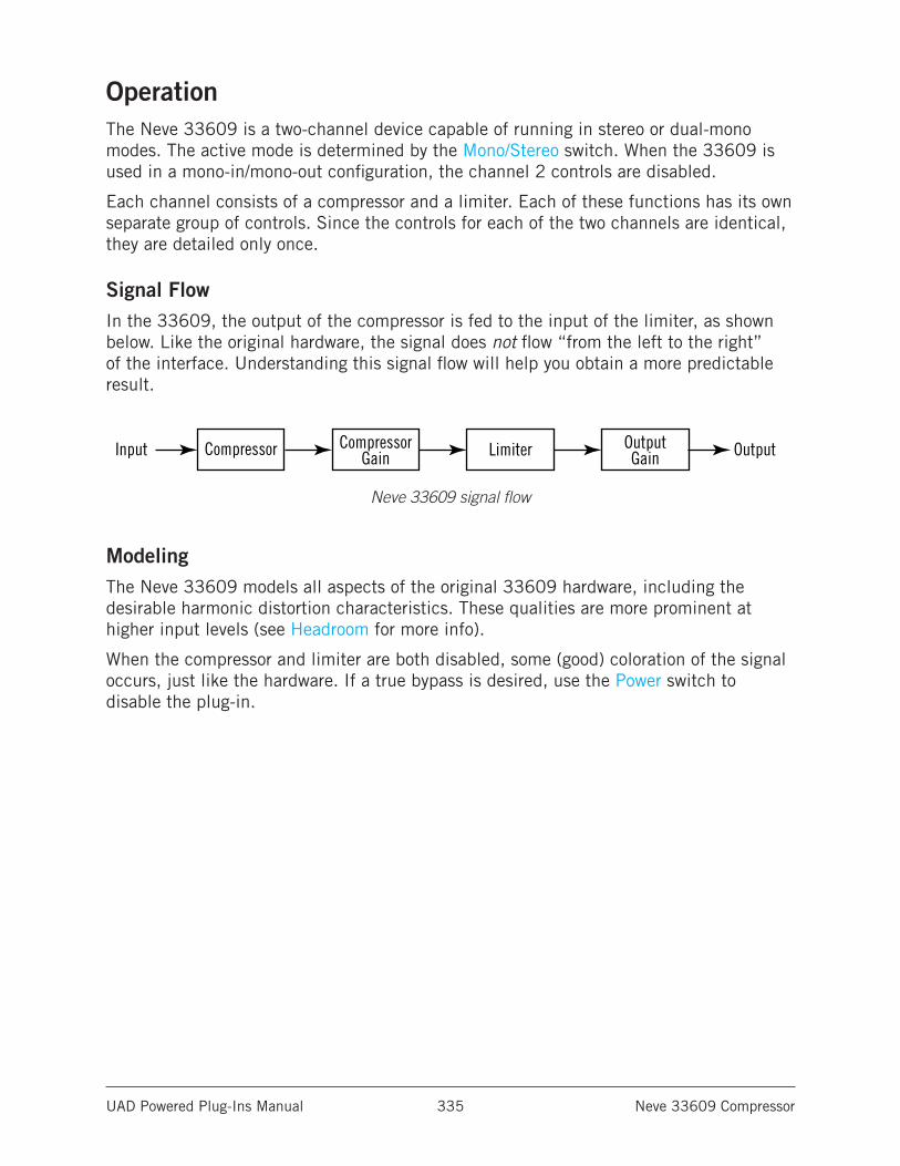
UAD Powered Plug-Ins Manual Neve 33609 Compressor 335
OperationThe Neve 33609 is a two-channel device capable of running in stereo or dual-mono modes. The active mode is determined by the Mono/Stereo switch. When the 33609 is used in a mono-in/mono-out configuration, the channel 2 controls are disabled.
Each channel consists of a compressor and a limiter. Each of these functions has its own separate group of controls. Since the controls for each of the two channels are identical, they are detailed only once.
Signal FlowIn the 33609, the output of the compressor is fed to the input of the limiter, as shown below. Like the original hardware, the signal does not flow “from the left to the right” of the interface. Understanding this signal flow will help you obtain a more predictable result.
Neve 33609 signal flow
ModelingThe Neve 33609 models all aspects of the original 33609 hardware, including the desirable harmonic distortion characteristics. These qualities are more prominent at higher input levels (see Headroom for more info).
When the compressor and limiter are both disabled, some (good) coloration of the signal occurs, just like the hardware. If a true bypass is desired, use the Power switch to disable the plug-in.
Input Compressor CompressorGain
OutputGain OutputLimiter
UAD Powered Plug-Ins Manual Neve 33609 Compressor 336
Neve 33609 Controls
LimiterControls in this section only function when the limiter is enabled with the “limit In” switch (the Power switch must also be on).
Note: The compressor is before the limiter (see Signal Flow).
Limiter ThresholdThreshold determines how much limiting will occur. When the input signal exceeds the threshold level, the signal above the threshold is limited. A smaller value results in more limiting. The available range is from +4 dB to +15 dB, in 0.5 dB increments.
If the compressor is enabled, the Compressor Gain in the compressor section will effect the input level into the limiter. In this case, the compressor gain can affect the limiter threshold response.
Limiter RecoveryRecovery (release) is the time it takes for the limiter to stop processing after the signal drops below the threshold value. The available values (in milliseconds) are 50, 100, 200, 800, a1, and a2.
The automatic settings (a1 and a2) are program dependant. The value for a1 can be as fast as 40 ms, but after a sustained period of high signal level, the period is 1500 ms. The value for a2 can be as fast as 150 ms, but after a sustained period of high signal level, the period is 3000 ms.
Limiter InThis toggle switch enables the limiter portion of the plug-in. The limiter has no effect unless this switch is in the “In” (down) position.
AttackAttack determines how fast limiting will engage when the signal exceeds the limiter threshold. The Fast setting is 2 milliseconds, and the Slow setting is 4 milliseconds.
UAD Powered Plug-Ins Manual Neve 33609 Compressor 337
CompressorControls in this section only function when the compressor is enabled with the “compress In” switch (the Power switch must also be on).
Note: The compressor is before the limiter (see Signal Flow).
Compressor ThresholdThreshold determines how much compression will occur. When the input signal exceeds the threshold level, the compressor engages. A smaller value results in more compression. The available range is from -20 dB to +10 dB, in 2 dB increments.
Compressor RecoveryRecovery (release) is the time it takes for the compressor to stop processing after the signal drops below the threshold value. The available values (in milliseconds) are 100, 400, 800, 1500, a1, and a2.
The automatic settings (a1 and a2) are program dependant. The value for a1 can be as fast as 40ms, but after a sustained period of high signal level, the period is 800 ms. The value for a2 can be as fast as 150 ms, but after a sustained period of high signal level, the period is 1500 ms.
Compressor GainThis makeup gain control increases the signal level out of the compressor to compensate for reduced levels as a result of compression. The available range is 0 to +20 dB, in 2 dB increments.
Make sure to adjust the Gain control after the desired amount of compression is achieved with the Threshold control. The Gain control does not affect the amount of compression.
Note: If the limiter is also enabled, this gain is applied before the limiter stage.
RatioThis control determines the compressor ratio. The available values are 1.5:1, 2:1, 3:1, 4:1, and 6:1, selectable in discrete increments.
Compressor InThis toggle switch enables the compressor portion of the plug-in. The compressor has no effect unless this switch is in the “In” (down) position.
UAD Powered Plug-Ins Manual Neve 33609 Compressor 338
Other ControlsThe interface elements that are not directly contained within the compressor or limiter are detailed below.
Output GainThis control is a software-only addition not found on the original hardware. It is an overall makeup gain stage at the output of the plug-in to compensate for reduced levels as a result of compression and/or limiting. The available range is -2 to +20 in 1 dB increments.
Gain Reduction MetersThe Gain Reduction Meters indicate the amount of gain reduction that is occurring in dB. There is one meter for each channel. The gain reduction displayed is the total reduction of the limiter plus the compressor.
Note: The meter indicator moves farther to the right as more gain reduction is occurring. This meter behavior is opposite that of many compressors.
LinkThis switch is a software-only addition that allows the two sets of controls for each channel to be linked for ease of operation when both channels require the same values, or unlinked when dual-mono operation is desired. The Link parameter is stored within presets and can be accessed via automation.
UnlinkWhen set to unlink (up position), the controls for channels one and two are completely independent. Unlink is generally used in mono mode. When unlinked, automation data is written and read by each channel separately.
Note: When unlink is switched to link, channel 1 controls are copied to channel 2. Control offsets between channels are lost in this case.
LinkWhen set to link (down position), modifying any channel one or channel two control causes its adjacent stereo counterpart control to snap to the same position (channel 1 & 2 controls are ganged together in link mode).
Note: When link is active, automation data is written and read for channel one only. In this case, the automation data for channel one will control both channels.
When link is active, changing channel two parameters from a control surface or when in “controls only” (non-GUI) mode will have no effect.
UAD Powered Plug-Ins Manual Neve 33609 Compressor 339
Mono/StereoThe Neve 33609 can operate in true stereo or dual-mono mode. This switch determines the active mode.
MonoIn mono mode, channels 1 and 2 are completely independent and the 33609 functions as a dual-mono device, each channel with its own compressor and limiter.
Note: To read and write automation data for both channels independently when in mono mode, link mode must be disabled.
StereoIn stereo mode, the left channel is fed to the channel one compressor, and the right channel is fed to the channel two compressor. The two compressors are constrained so that they both compress the same amount at any instant. This prevents transients which appear only on one channel from shifting the image of the output. Any big transient on either channel will cause both channels to compress. The amount of compression will be similar to the amount of compression for a transient which appears on both channels at the same time.
In stereo operation the controls for channels 1 and 2 are independent and can be set separately. Generally, the channel with the “most processing occurring” controls the processing for the other channel. For example, if the same signal is fed to both channels in stereo mode and channel 1 has a lower threshold setting than channel 2, the channel 1 threshold value is used for both channels. Similarly, if channel 1 were disabled (using “In” switches), channel 2 settings would be used because “more processing” occurs with the channel 2 settings. It’s not always so simple though, as in the following cases:
• If you feed the same signal into both channels, you can have a lower threshold with a lower ratio on one channel, and a higher threshold with a higher ratio on the other channel. In this case, you will get a double knee, with the lower ratio being used between the knees, and the higher ratio above both knees.
• If you feed the same signal into both channels, you can have a lower threshold with a faster release on one channel, and a higher threshold with a slower release in the other channel. In this case, you will get a two-stage release after a tran-sient, with the first channel releasing at the fast rate until you get down to where the other one is; then the release will continue at the slower rate.
Expert Question
Is there any reason I would want to use stereo mode and still have the settings for the two channels different?
Yes. Linking the sidechains simply prevents left-right image shifting. Threshold, attack, and recovery can be set independently to cause the compressor to be more sensitive to instruments which are panned to one side or the other. Output controls can be set separately in order to correct an overall image shift at the output.
UAD Powered Plug-Ins Manual Neve 33609 Compressor 340
HeadroomThe hardware Neve 33609 can accept an analog signal level of approximately +26 dBu before undesirable signal clipping occurs. As the signal increases up to this point however, desirable audio-path nonlinearities and “good” harmonic distortion characteristics occur. This musically pleasing “warmth” at higher levels is what gives the unit much of its revered sonic character. Because analog mixing consoles can typically output high signal levels, audio engineers often take advantage of the ability to “push” the hardware 33609 into the colorful arena.
This complete pallet of sonic nuance, including the dynamic input response, is captured in the Neve 33609 model. The plug-in is calibrated internally so that 0 dBFS at its input is equivalent to an input level of approximately +26 dBu on the 33609 hardware, where the coloring is more prominent. The result is that a typical signal within a DAW will drive the UAD Neve 33609 into these “virtual” higher levels, resulting in fairly high amounts gain reduction.
Headroom SwitchThe Headroom switch is provided to accommodate applications where high amounts of gain reduction are not desired. Headroom simply lowers the internal operating level so that the plug-in is not “pushed” into gain reduction as much.
Headroom can be set to 22 dB, 18 dB, or 14 dB. At 22 dB, signals will push the plug-in into gain reduction (and more non-linearity and “good” harmonic distortion) more easily. Set the switch to a lower value when less gain reduction and color is desired.
The numbers on the switch indicate where 0 dBFS falls relative to nominal +4 dBu. For example, with 22 dB of headroom, 0 dBFS corresponds to +4 dBu + 22 dB = 26 dBu. With 18 dB of headroom, 0 dBFS corresponds to +4 dBu + 18 dB = 22 dBu. The headroom selected will cause the plug-in to behave as though it were a hardware 33609 connected to a nominal +4 dBu interface with the selected amount of headroom. Industry standards for most DAW interfaces are +14 dB and +18 dB headroom. The +22 dB setting approximates some analog mixing environments, and allows the entire useful dynamic range of the 33609 to be exercised.
The following settings are application guidelines for the Headroom switch:
22 dBTypical starting point for individual track inserts where maximum gain reduction is desired.This setting is equivalent to having a real hardware 33609 connected to a +4 interface with +22 dB headroom.
18 dBTypical starting point when used on a buss or group where nominal gain reduction is desired.This setting is equivalent to having a real hardware 33609 connected to a +4 interface with +18 dB headroom.
UAD Powered Plug-Ins Manual Neve 33609 Compressor 341
14 dBTypical starting point for mastering where minimal gain reduction is desired. This setting is equivalent to having a real hardware 33609 connected to a +4 interface with +14 dB headroom.
Note: Keep in mind there are no hard and fast rules. Use the above recommenda-tions as guidelines and feel free to experiment with the various positions of the headroom switch regardless of the audio source. If it sounds good, use it!
Factory PresetsThe Neve 33609/33609SE includes a bank of factory presets. These presets can be useful starting points for your particular source audio.
The factory preset names begin with MSTR, BUSS, or TRAK. These names indicate the setting of the headroom parameter. (14 dB, 18 dB, and 22 dB respectively).
• Mastering (MSTR) presets are optimized for mixed program material that is already at a relatively high level.
• Buss/group (BUSS) presets are optimized for subgroups of audio, such as a drum group or vocal group. This type of application often has lower levels than full mixes, but higher levels than a track insert.
• Track (TRAK) presets are optimized for track inserts where signal levels typically aren’t as hot as groups or outputs.
The preset names are guidelines and not rules. In many cases, you can use any preset on any source with good results. You will probably need to adjust the threshold and/or gain controls to obtain the optimum results with your particular source audio.
PowerThe Power switch determines whether the plug-in is active. This is useful for comparing the processed settings to the original signal, or to bypass the plug-in to reduce the UAD DSP load (load is not reduced if UAD-2 DSP LoadLock is enabled). Toggle the switch to change the Power state; the switch is illuminated in red when the plug-in is active.
Note: You can click-hold the power switch then drag it like a slider to quickly compare the enabled/disabled state.
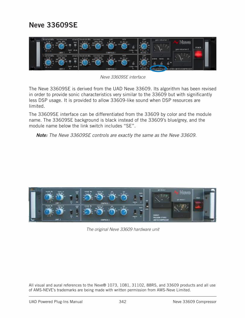
UAD Powered Plug-Ins Manual Neve 33609 Compressor 342
Neve 33609SE
Neve 33609SE interface
The Neve 33609SE is derived from the UAD Neve 33609. Its algorithm has been revised in order to provide sonic characteristics very similar to the 33609 but with significantly less DSP usage. It is provided to allow 33609-like sound when DSP resources are limited.
The 33609SE interface can be differentiated from the 33609 by color and the module name. The 33609SE background is black instead of the 33609’s blue/grey, and the module name below the link switch includes “SE”.
Note: The Neve 33609SE controls are exactly the same as the Neve 33609.
The original Neve 33609 hardware unit
All visual and aural references to the Neve® 1073, 1081, 31102, 88RS, and 33609 products and all use of AMS-NEVE’s trademarks are being made with written permission from AMS-Neve Limited.
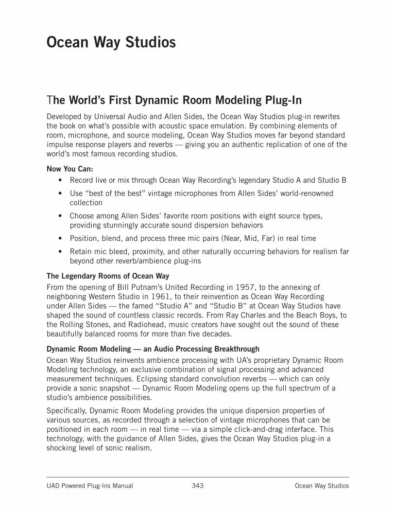
UAD Powered Plug-Ins Manual Ocean Way Studios 343
Ocean Way Studios
The World’s First Dynamic Room Modeling Plug-InDeveloped by Universal Audio and Allen Sides, the Ocean Way Studios plug-in rewrites the book on what’s possible with acoustic space emulation. By combining elements of room, microphone, and source modeling, Ocean Way Studios moves far beyond standard impulse response players and reverbs — giving you an authentic replication of one of the world’s most famous recording studios.
Now You Can:• Record live or mix through Ocean Way Recording’s legendary Studio A and Studio B
• Use “best of the best” vintage microphones from Allen Sides’ world-renowned collection
• Choose among Allen Sides’ favorite room positions with eight source types, providing stunningly accurate sound dispersion behaviors
• Position, blend, and process three mic pairs (Near, Mid, Far) in real time
• Retain mic bleed, proximity, and other naturally occurring behaviors for realism far beyond other reverb/ambience plug-ins
The Legendary Rooms of Ocean WayFrom the opening of Bill Putnam’s United Recording in 1957, to the annexing of neighboring Western Studio in 1961, to their reinvention as Ocean Way Recording under Allen Sides — the famed “Studio A” and “Studio B” at Ocean Way Studios have shaped the sound of countless classic records. From Ray Charles and the Beach Boys, to the Rolling Stones, and Radiohead, music creators have sought out the sound of these beautifully balanced rooms for more than five decades.
Dynamic Room Modeling — an Audio Processing BreakthroughOcean Way Studios reinvents ambience processing with UA’s proprietary Dynamic Room Modeling technology, an exclusive combination of signal processing and advanced measurement techniques. Eclipsing standard convolution reverbs — which can only provide a sonic snapshot — Dynamic Room Modeling opens up the full spectrum of a studio’s ambience possibilities.
Specifically, Dynamic Room Modeling provides the unique dispersion properties of various sources, as recorded through a selection of vintage microphones that can be positioned in each room — in real time — via a simple click-and-drag interface. This technology, with the guidance of Allen Sides, gives the Ocean Way Studios plug-in a shocking level of sonic realism.
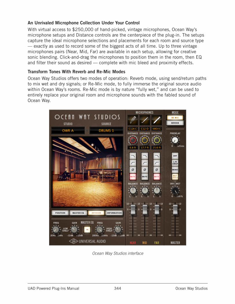
UAD Powered Plug-Ins Manual Ocean Way Studios 344
An Unrivaled Microphone Collection Under Your ControlWith virtual access to $250,000 of hand-picked, vintage microphones, Ocean Way’s microphone setups and Distance controls are the centerpiece of the plug-in. The setups capture the ideal microphone selections and placements for each room and source type — exactly as used to record some of the biggest acts of all time. Up to three vintage microphones pairs (Near, Mid, Far) are available in each setup, allowing for creative sonic blending. Click-and-drag the microphones to position them in the room, then EQ and filter their sound as desired — complete with mic bleed and proximity effects.
Transform Tones With Reverb and Re-Mic ModesOcean Way Studios offers two modes of operation: Reverb mode, using send/return paths to mix wet and dry signals; or Re-Mic mode, to fully immerse the original source audio within Ocean Way’s rooms. Re-Mic mode is by nature “fully wet,” and can be used to entirely replace your original room and microphone sounds with the fabled sound of Ocean Way.
Ocean Way Studios interface
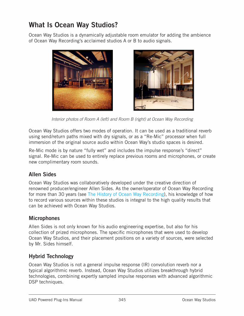
UAD Powered Plug-Ins Manual Ocean Way Studios 345
What Is Ocean Way Studios?Ocean Way Studios is a dynamically adjustable room emulator for adding the ambience of Ocean Way Recording’s acclaimed studios A or B to audio signals.
Interior photos of Room A (left) and Room B (right) at Ocean Way Recording
Ocean Way Studios offers two modes of operation. It can be used as a traditional reverb using send/return paths mixed with dry signals, or as a “Re-Mic” processor when full immersion of the original source audio within Ocean Way’s studio spaces is desired.
Re-Mic mode is by nature “fully wet” and includes the impulse response’s “direct” signal. Re-Mic can be used to entirely replace previous rooms and microphones, or create new complimentary room sounds.
Allen SidesOcean Way Studios was collaboratively developed under the creative direction of renowned producer/engineer Allen Sides. As the owner/operator of Ocean Way Recording for more than 30 years (see The History of Ocean Way Recording), his knowledge of how to record various sources within these studios is integral to the high quality results that can be achieved with Ocean Way Studios.
MicrophonesAllen Sides is not only known for his audio engineering expertise, but also for his collection of prized microphones. The specific microphones that were used to develop Ocean Way Studios, and their placement positions on a variety of sources, were selected by Mr. Sides himself.
Hybrid TechnologyOcean Way Studios is not a general impulse response (IR) convolution reverb nor a typical algorithmic reverb. Instead, Ocean Way Studios utilizes breakthrough hybrid technologies, combining expertly sampled impulse responses with advanced algorithmic DSP techniques.
UAD Powered Plug-Ins Manual Ocean Way Studios 346
Concise ModelingOcean Way Studios focuses on a limited set of studio spaces and exhaustively models numerous room positions, microphones, and sound source dispersion patterns — which all combine to provide the ultimate in acoustic realism. Ocean Way Studios is sonically superior in terms of overall model accuracy and dynamic customization.
PresetsThe factory presets are of particular importance with the Ocean Way Studios plug-in, because they are designed by Allen Sides and they capture his ideal microphone selections and placement positions for each studio and source. 32 presets are available in the internal factory bank, providing optimum control settings in both Re-Mic and Reverb modes. 10 additional presets that use the guitar cabinets as source can be accessed via the UAD Toolbar.
Choosing presets differs from simply choosing different Studio, Source, and Microphone selections. Because with Ocean Way Studios it’s possible to select a variety of microphones and place the microphones in positions that don’t sound optimum (just like in the physical realm), the presets provide excellent starting points for customizations and an easy way to quickly return to a great sound.
The factory presets have only one microphone pair enabled to ensure there are no undesirable phase interactions. Of course, more than one microphone pair can be used for sonic variety and/or to enable creative applications. See Phase Considerations for related information.
Note: Switching through presets is not instantaneous and sonic artifacts can occur while the presets are loading. See Load Time for related information.
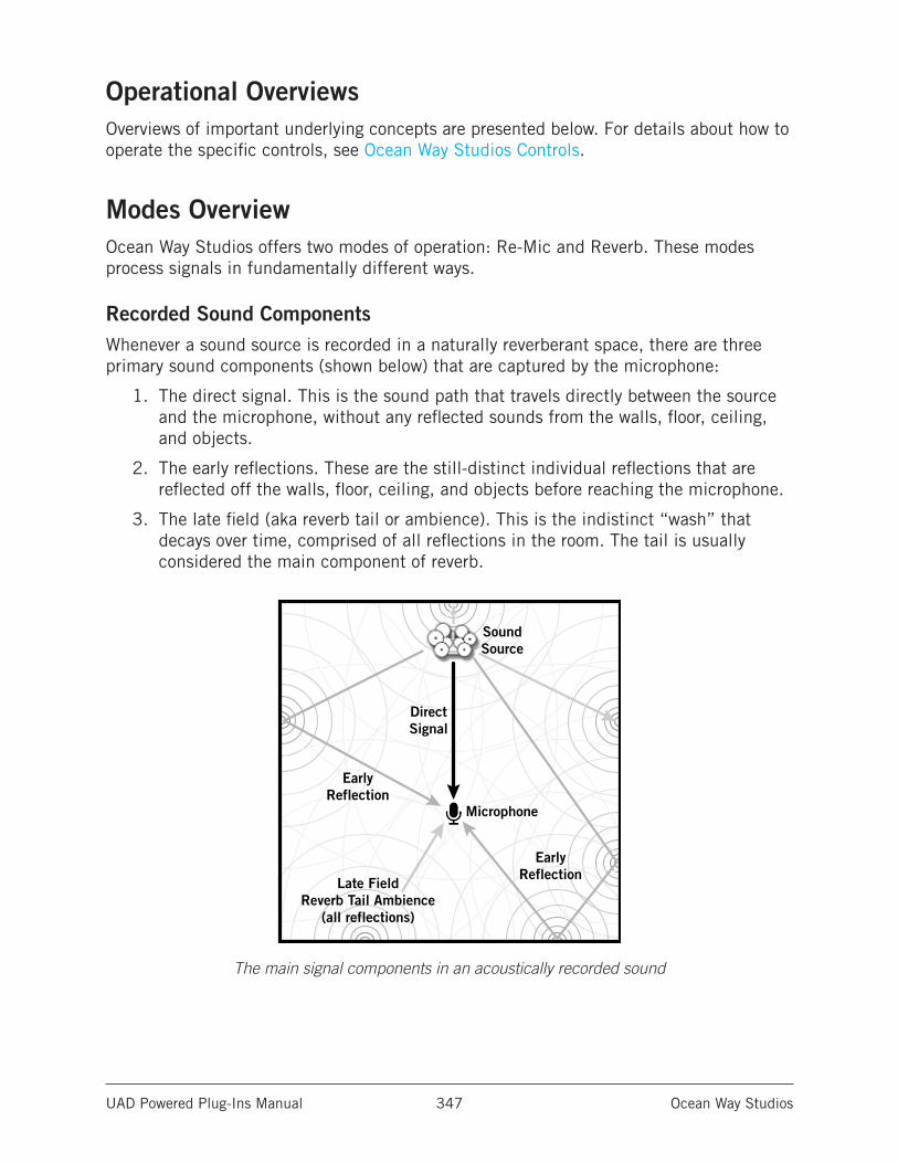
UAD Powered Plug-Ins Manual Ocean Way Studios 347
Operational OverviewsOverviews of important underlying concepts are presented below. For details about how to operate the specific controls, see Ocean Way Studios Controls.
Modes OverviewOcean Way Studios offers two modes of operation: Re-Mic and Reverb. These modes process signals in fundamentally different ways.
Recorded Sound ComponentsWhenever a sound source is recorded in a naturally reverberant space, there are three primary sound components (shown below) that are captured by the microphone:
1. The direct signal. This is the sound path that travels directly between the source and the microphone, without any reflected sounds from the walls, floor, ceiling, and objects.
2. The early reflections. These are the still-distinct individual reflections that are reflected off the walls, floor, ceiling, and objects before reaching the microphone.
3. The late field (aka reverb tail or ambience). This is the indistinct “wash” that decays over time, comprised of all reflections in the room. The tail is usually considered the main component of reverb.
The main signal components in an acoustically recorded sound
SoundSource
Microphone
DirectSignal
EarlyReflection
Late FieldReverb Tail Ambience
(all reflections)
EarlyReflection
UAD Powered Plug-Ins Manual Ocean Way Studios 348
It’s important to note that the recorded direct signal component (#1 on previous page) is different than pre-existing dry (unprocessed) acoustic recordings in a DAW. This is because within a DAW, the dry audio was already recorded - so it already contains the direct signal component (along with all the other components) that was captured by the microphone originally used. This distinction is fundamental to the Re-Mic process.
Re-Mic ProcessingRe-Mic mode is a tool for “replacing” the original dry audio signal.
When Ocean Way Studios is in Re-Mic mode, the original dry signal is not mixed back in with the wet processed signal. Instead, the dry signal is processed to sound as if it were recorded inside the studio space itself, by emulating the direct signal component. This processed source signal thus inherits the sonic characteristics of the studio acoustics, source dispersion patterns, and microphones with more accuracy and realism than is possible with reverb processing.
The concept is similar to that of guitar “re-amping” whereby previously recorded guitar tracks are routed out of the DAW, into a guitar amplifier, then re-recorded using a microphone to replace the original guitar track with a new track that inherits the sonic characteristics of the amp. This technique is also used in studios to great effect by “re-micing” any pre-existing audio to inherit the sonic characteristics of the recording room.
In the same way, with Ocean Way Studios, any track or bus can be routed into the plug-in to “re-record” the original source so it inherits the sonic characteristics of the Ocean Way studio acoustics, source dispersion patterns, and microphones.
Reverb ProcessingIn artificial reverb processors, the direct signal component is not actually part of the processed signal. Instead, the original dry signal is simply mixed back in with the reverb ambience (the wet signal). Although great results can be obtained with this method, it is only an approximation of what really happens in the physical realm.
When Ocean Way Studios is in Reverb mode, the plug-in behaves like most artificial reverb processors. The direct signal component is not in the processed signal. Instead, the original dry signal is mixed back in with the wet reverb ambience.
For additional details about Reverb and Re-Mic modes, see Using Ocean Way Studios.
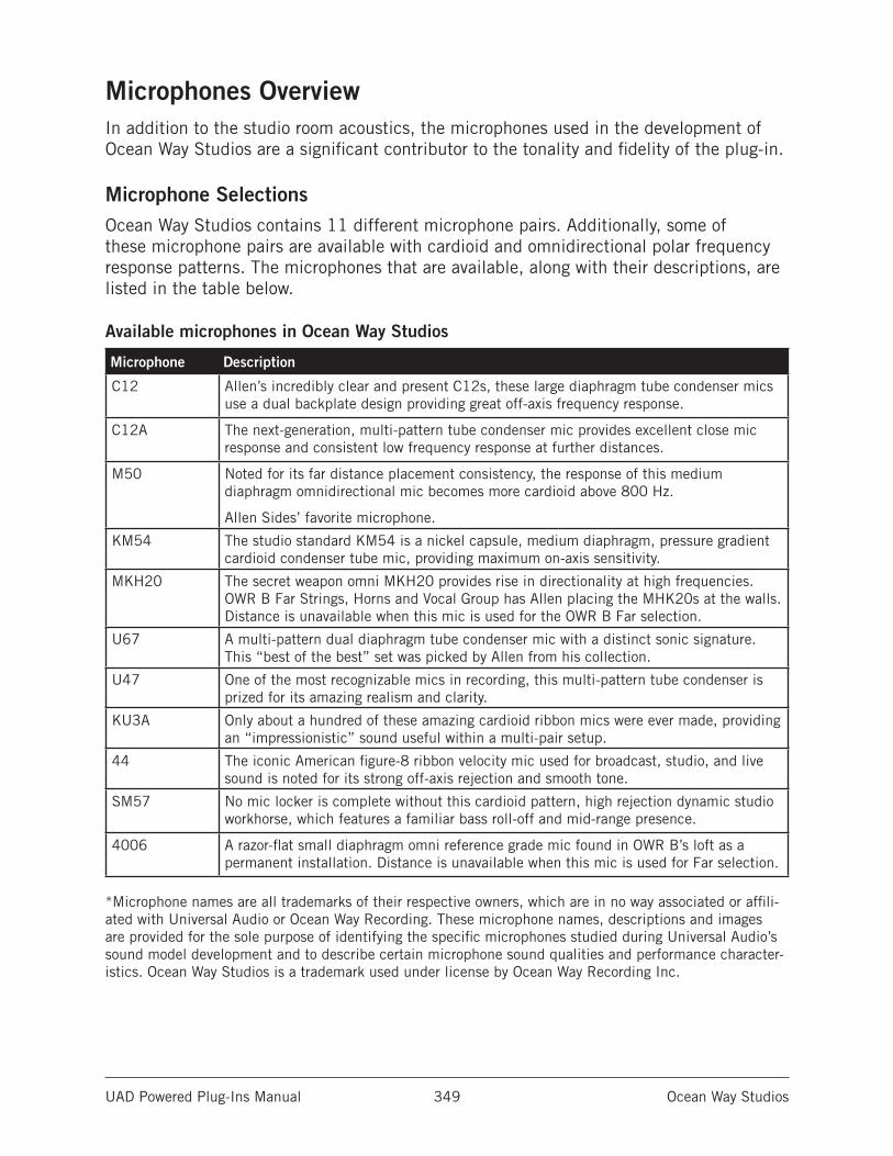
UAD Powered Plug-Ins Manual Ocean Way Studios 349
Microphones OverviewIn addition to the studio room acoustics, the microphones used in the development of Ocean Way Studios are a significant contributor to the tonality and fidelity of the plug-in.
Microphone SelectionsOcean Way Studios contains 11 different microphone pairs. Additionally, some of these microphone pairs are available with cardioid and omnidirectional polar frequency response patterns. The microphones that are available, along with their descriptions, are listed in the table below.
Available microphones in Ocean Way Studios
Microphone* Description
C12 Allen’s incredibly clear and present C12s, these large diaphragm tube condenser mics use a dual backplate design providing great off-axis frequency response.
C12A The next-generation, multi-pattern tube condenser mic provides excellent close mic response and consistent low frequency response at further distances.
M50 Noted for its far distance placement consistency, the response of this medium diaphragm omnidirectional mic becomes more cardioid above 800 Hz.
Allen Sides’ favorite microphone.
KM54 The studio standard KM54 is a nickel capsule, medium diaphragm, pressure gradient cardioid condenser tube mic, providing maximum on-axis sensitivity.
MKH20 The secret weapon omni MKH20 provides rise in directionality at high frequencies. OWR B Far Strings, Horns and Vocal Group has Allen placing the MHK20s at the walls. Distance is unavailable when this mic is used for the OWR B Far selection.
U67 A multi-pattern dual diaphragm tube condenser mic with a distinct sonic signature. This “best of the best” set was picked by Allen from his collection.
U47 One of the most recognizable mics in recording, this multi-pattern tube condenser is prized for its amazing realism and clarity.
KU3A Only about a hundred of these amazing cardioid ribbon mics were ever made, providing an “impressionistic” sound useful within a multi-pair setup.
44 The iconic American figure-8 ribbon velocity mic used for broadcast, studio, and live sound is noted for its strong off-axis rejection and smooth tone.
SM57 No mic locker is complete without this cardioid pattern, high rejection dynamic studio workhorse, which features a familiar bass roll-off and mid-range presence.
4006 A razor-flat small diaphragm omni reference grade mic found in OWR B’s loft as a permanent installation. Distance is unavailable when this mic is used for Far selection.
*Microphone names are all trademarks of their respective owners, which are in no way associated or affili-ated with Universal Audio or Ocean Way Recording. These microphone names, descriptions and images are provided for the sole purpose of identifying the specific microphones studied during Universal Audio’s sound model development and to describe certain microphone sound qualities and performance character-istics. Ocean Way Studios is a trademark used under license by Ocean Way Recording Inc.
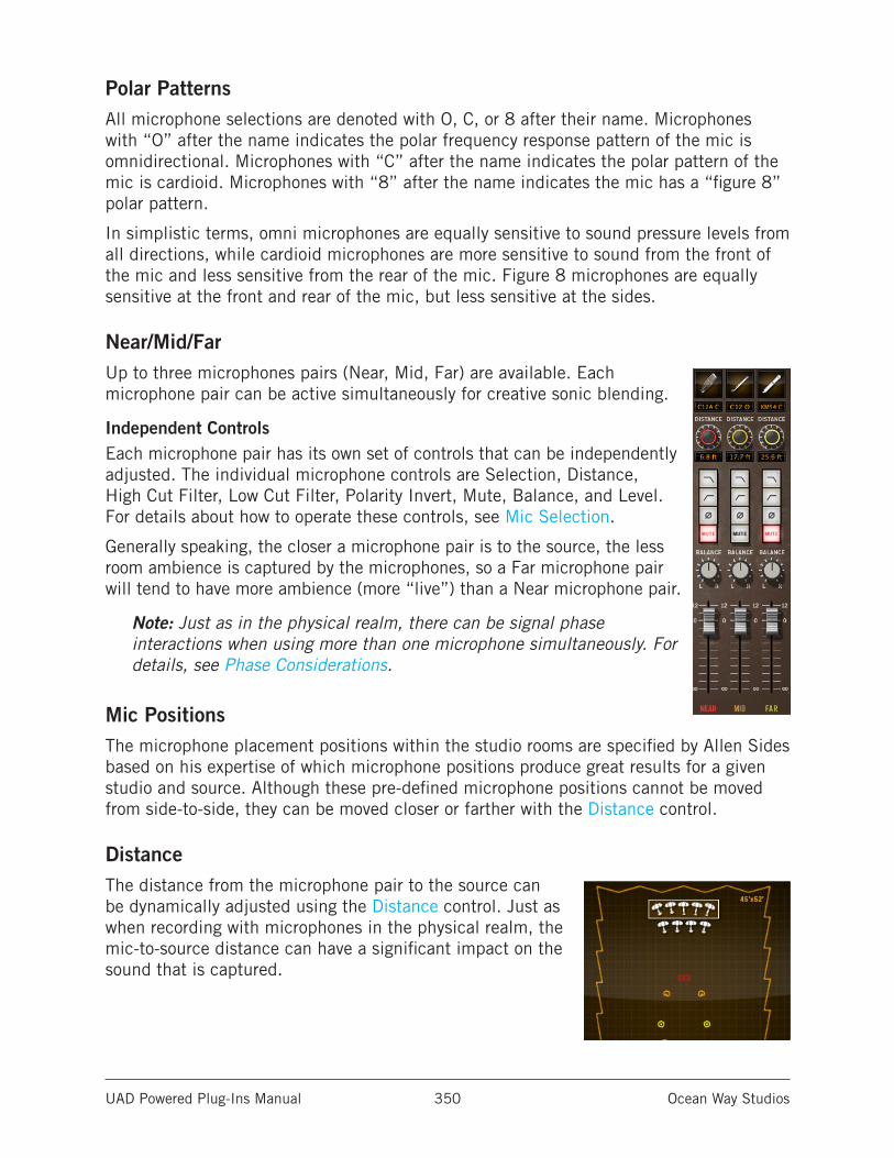
UAD Powered Plug-Ins Manual Ocean Way Studios 350
Polar PatternsAll microphone selections are denoted with O, C, or 8 after their name. Microphones with “O” after the name indicates the polar frequency response pattern of the mic is omnidirectional. Microphones with “C” after the name indicates the polar pattern of the mic is cardioid. Microphones with “8” after the name indicates the mic has a “figure 8” polar pattern.
In simplistic terms, omni microphones are equally sensitive to sound pressure levels from all directions, while cardioid microphones are more sensitive to sound from the front of the mic and less sensitive from the rear of the mic. Figure 8 microphones are equally sensitive at the front and rear of the mic, but less sensitive at the sides.
Near/Mid/FarUp to three microphones pairs (Near, Mid, Far) are available. Each microphone pair can be active simultaneously for creative sonic blending.
Independent ControlsEach microphone pair has its own set of controls that can be independently adjusted. The individual microphone controls are Selection, Distance, High Cut Filter, Low Cut Filter, Polarity Invert, Mute, Balance, and Level. For details about how to operate these controls, see Mic Selection.
Generally speaking, the closer a microphone pair is to the source, the less room ambience is captured by the microphones, so a Far microphone pair will tend to have more ambience (more “live”) than a Near microphone pair.
Note: Just as in the physical realm, there can be signal phase interactions when using more than one microphone simultaneously. For details, see Phase Considerations.
Mic PositionsThe microphone placement positions within the studio rooms are specified by Allen Sides based on his expertise of which microphone positions produce great results for a given studio and source. Although these pre-defined microphone positions cannot be moved from side-to-side, they can be moved closer or farther with the Distance control.
DistanceThe distance from the microphone pair to the source can be dynamically adjusted using the Distance control. Just as when recording with microphones in the physical realm, the mic-to-source distance can have a significant impact on the sound that is captured.
UAD Powered Plug-Ins Manual Ocean Way Studios 351
The room will sound tighter and more present the closer the mics are to the source; conversely, the room gets “bigger” when the mics are farther away from the source. The Ocean Way Studios modeling includes the proximity gain that occurs in the physical realm; the signal can be notably louder as microphones are positioned closer to the source.
Stereo SeparationThe separation between a stereo microphone pair varies depending on the microphone pair selected and its Distance setting. With most settings, the separation increases incrementally as the distance from the source increases.
Fixed Distance MicrophonesWhen Studio is set to OWR B and Source is set to Strings, Horns, or Vocal Group, the 4006 and MKH20 selections for the Far microphone cannot be repositioned with the Distance control.
With the Far MKH20, this is a specialized setup whereby Mr. Sides chose to set the microphones near the walls for the best sound. With the Far 4006, this is because these mics are fixed installations in the studio loft (they cannot be adjusted in the real studio either).
Distance Delay (Aligned) OverviewWhen recording a sound source with a microphone, there is an inherent delay between the source and the microphone. This delay is the time it takes for the sound waves to physically travel from the source to the mic (see Recorded Sound Components). The farther the distance is from the source to the mic, the longer the delay time.
When a microphone pair in Ocean Way Studios is set to “aligned” by clicking its Distance knob, this inherent mic delay is artificially removed so the sound source “reaches” the mic instantaneously. The setting is useful when the source audio signals need to remain time-aligned, or simply for its own physically-impossible sonic effect.
Removing this inherent delay can be especially useful in these scenarios:
• If a source is recorded with a distant room mic, it will play back later in relation to sources that are close-miced. Typically, this delay can be compensated in the DAW by manually shifting the track forward in time so it aligns with the other instruments. With Ocean Way Studios, removing the microphone delay will align the distant mics automatically.
• When the microphone pair is distant from the source, the additional microphone delay can be problematic for performers tracking in realtime while monitoring through the plug-in. Setting the microphone pairs to aligned reduces realtime latency.
Tip: The most realistic acoustic emulations are recreated when the distance delay is retained (aligned off). This is because the inherent source-to-mic delays provide subtle yet important auditory cues that our brains use to interpret the acoustic space.
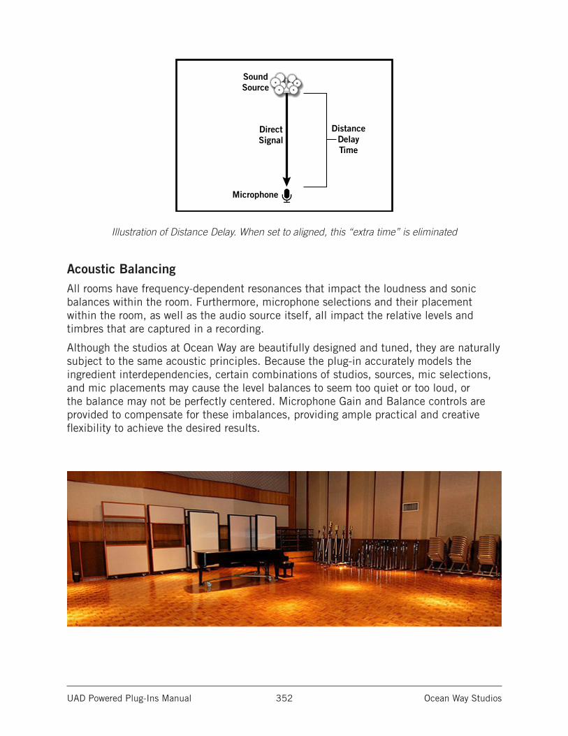
UAD Powered Plug-Ins Manual Ocean Way Studios 352
Illustration of Distance Delay. When set to aligned, this “extra time” is eliminated
Acoustic BalancingAll rooms have frequency-dependent resonances that impact the loudness and sonic balances within the room. Furthermore, microphone selections and their placement within the room, as well as the audio source itself, all impact the relative levels and timbres that are captured in a recording.
Although the studios at Ocean Way are beautifully designed and tuned, they are naturally subject to the same acoustic principles. Because the plug-in accurately models the ingredient interdependencies, certain combinations of studios, sources, mic selections, and mic placements may cause the level balances to seem too quiet or too loud, or the balance may not be perfectly centered. Microphone Gain and Balance controls are provided to compensate for these imbalances, providing ample practical and creative flexibility to achieve the desired results.
SoundSource
Microphone
DirectSignal
DistanceDelayTime
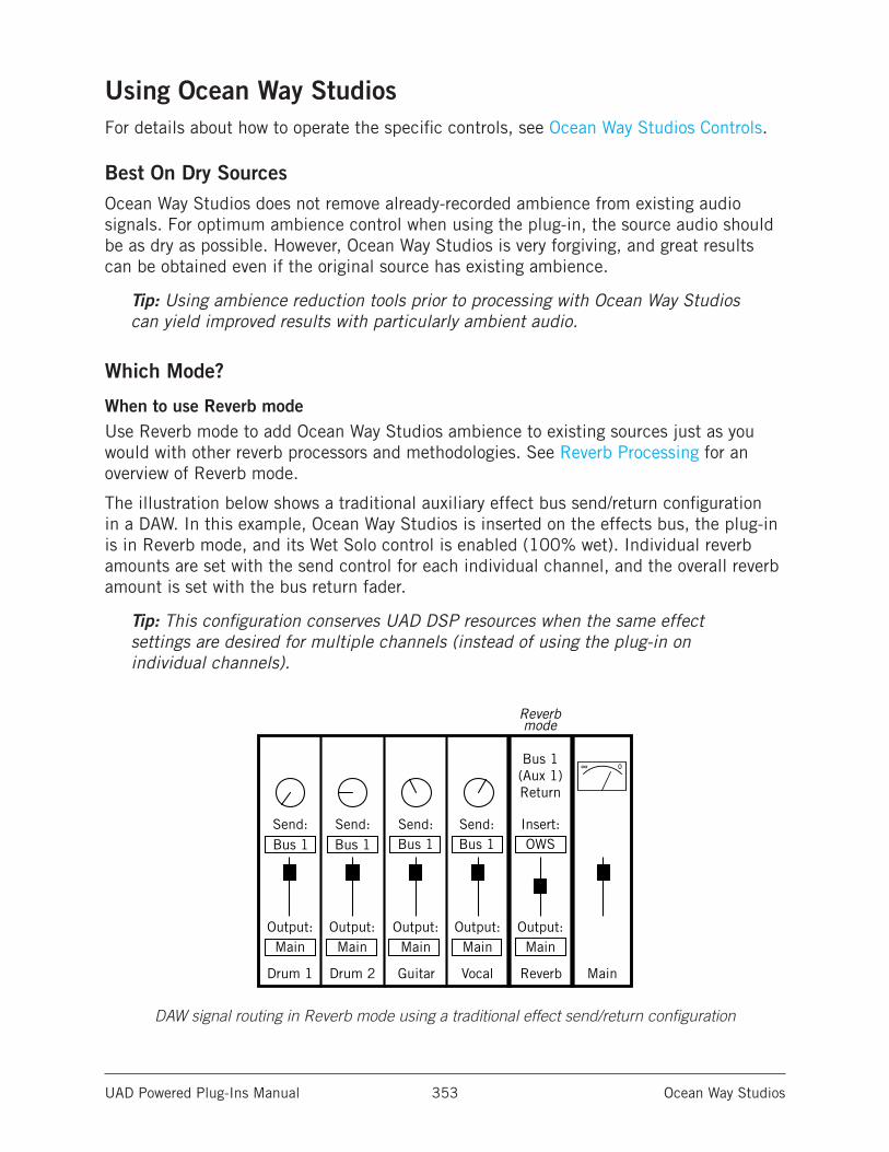
UAD Powered Plug-Ins Manual Ocean Way Studios 353
Using Ocean Way StudiosFor details about how to operate the specific controls, see Ocean Way Studios Controls.
Best On Dry SourcesOcean Way Studios does not remove already-recorded ambience from existing audio signals. For optimum ambience control when using the plug-in, the source audio should be as dry as possible. However, Ocean Way Studios is very forgiving, and great results can be obtained even if the original source has existing ambience.
Tip: Using ambience reduction tools prior to processing with Ocean Way Studios can yield improved results with particularly ambient audio.
Which Mode?
When to use Reverb modeUse Reverb mode to add Ocean Way Studios ambience to existing sources just as you would with other reverb processors and methodologies. See Reverb Processing for an overview of Reverb mode.
The illustration below shows a traditional auxiliary effect bus send/return configuration in a DAW. In this example, Ocean Way Studios is inserted on the effects bus, the plug-in is in Reverb mode, and its Wet Solo control is enabled (100% wet). Individual reverb amounts are set with the send control for each individual channel, and the overall reverb amount is set with the bus return fader.
Tip: This configuration conserves UAD DSP resources when the same effect settings are desired for multiple channels (instead of using the plug-in on individual channels).
DAW signal routing in Reverb mode using a traditional effect send/return configuration
Drum 1 Drum 2 Guitar Vocal Main
Output:Main
Output:Main
Output:Main
Output:Main
Output:Main
Send: Send: Send:Bus 1Bus 1 Bus 1
Send:Bus 1
Bus 1(Aux 1)Return
Reverb
Reverb mode
Insert:OWS
∞ 0
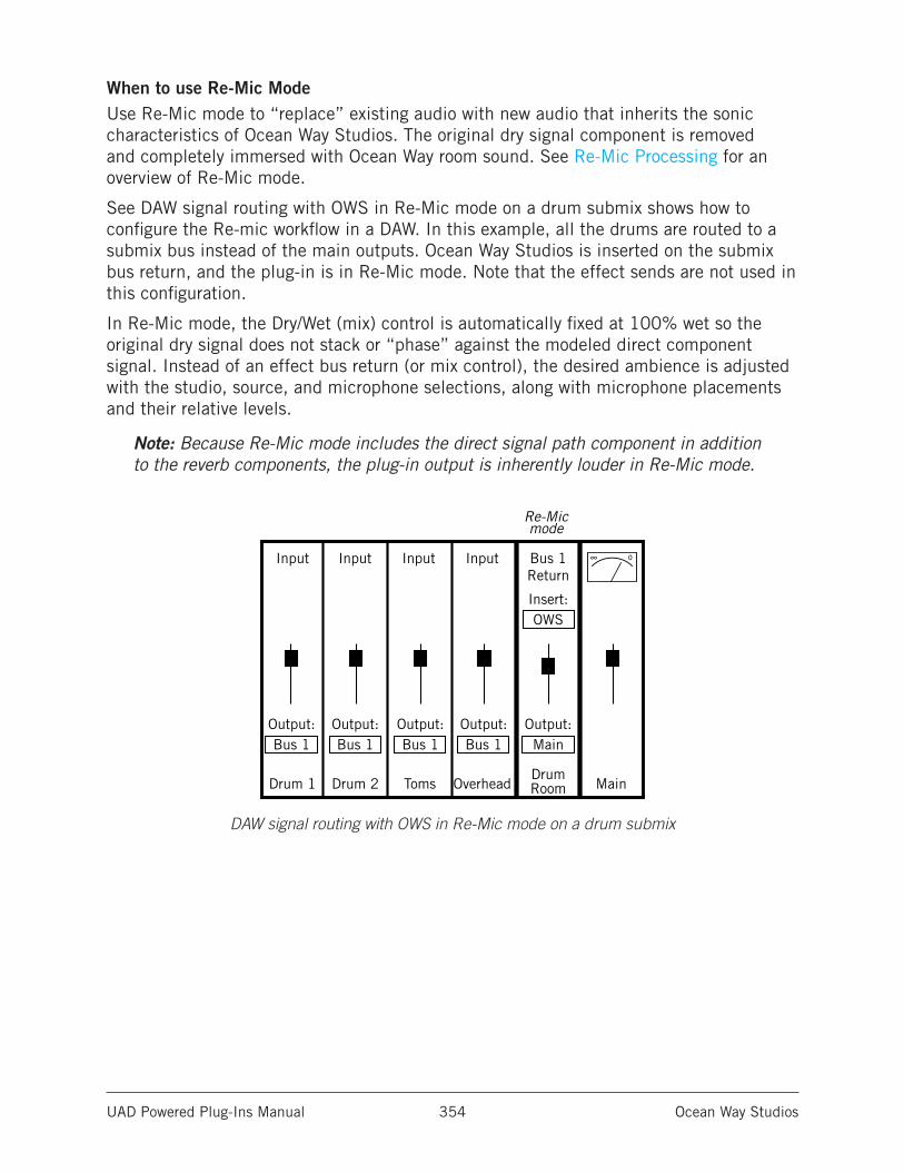
UAD Powered Plug-Ins Manual Ocean Way Studios 354
When to use Re-Mic ModeUse Re-Mic mode to “replace” existing audio with new audio that inherits the sonic characteristics of Ocean Way Studios. The original dry signal component is removed and completely immersed with Ocean Way room sound. See Re-Mic Processing for an overview of Re-Mic mode.
See DAW signal routing with OWS in Re-Mic mode on a drum submix shows how to configure the Re-mic workflow in a DAW. In this example, all the drums are routed to a submix bus instead of the main outputs. Ocean Way Studios is inserted on the submix bus return, and the plug-in is in Re-Mic mode. Note that the effect sends are not used in this configuration.
In Re-Mic mode, the Dry/Wet (mix) control is automatically fixed at 100% wet so the original dry signal does not stack or “phase” against the modeled direct component signal. Instead of an effect bus return (or mix control), the desired ambience is adjusted with the studio, source, and microphone selections, along with microphone placements and their relative levels.
Note: Because Re-Mic mode includes the direct signal path component in addition to the reverb components, the plug-in output is inherently louder in Re-Mic mode.
DAW signal routing with OWS in Re-Mic mode on a drum submix
Drum 1 Drum 2 TomsDrumRoomOverhead Main
Bus 1 Bus 1 Bus 1Output: Output: Output: Output:
Bus 1Output:Main
Insert:OWS
Re-Mic mode
Bus 1Return
Input Input Input Input ∞ 0
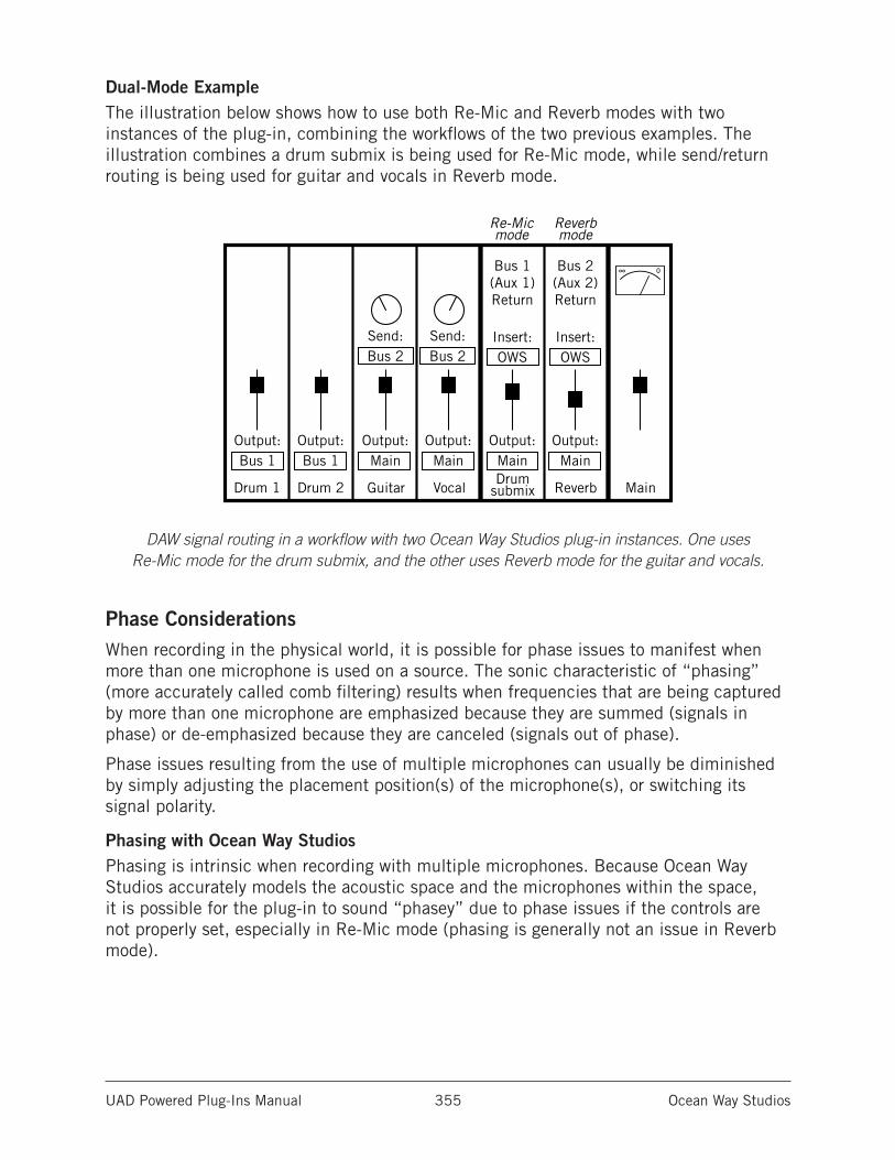
UAD Powered Plug-Ins Manual Ocean Way Studios 355
Dual-Mode ExampleThe illustration below shows how to use both Re-Mic and Reverb modes with two instances of the plug-in, combining the workflows of the two previous examples. The illustration combines a drum submix is being used for Re-Mic mode, while send/return routing is being used for guitar and vocals in Reverb mode.
DAW signal routing in a workflow with two Ocean Way Studios plug-in instances. One uses Re-Mic mode for the drum submix, and the other uses Reverb mode for the guitar and vocals.
Phase ConsiderationsWhen recording in the physical world, it is possible for phase issues to manifest when more than one microphone is used on a source. The sonic characteristic of “phasing” (more accurately called comb filtering) results when frequencies that are being captured by more than one microphone are emphasized because they are summed (signals in phase) or de-emphasized because they are canceled (signals out of phase).
Phase issues resulting from the use of multiple microphones can usually be diminished by simply adjusting the placement position(s) of the microphone(s), or switching its signal polarity.
Phasing with Ocean Way StudiosPhasing is intrinsic when recording with multiple microphones. Because Ocean Way Studios accurately models the acoustic space and the microphones within the space, it is possible for the plug-in to sound “phasey” due to phase issues if the controls are not properly set, especially in Re-Mic mode (phasing is generally not an issue in Reverb mode).
Drum 1 Drum 2 GuitarDrum
submix
Re-Mic mode
Reverb mode
Vocal Main
∞ 0
Output:Bus 1
Output:Bus 1
Output:Main
Output:Main
Output:Main
Send:Bus 2
Send:Bus 2
Reverb
Output:Main
Bus 1(Aux 1)Return
Bus 2(Aux 2)Return
Insert:OWS
Insert:OWS
UAD Powered Plug-Ins Manual Ocean Way Studios 356
Whenever more than one microphone pair is simultaneously enabled, careful attention should be paid to the Distance (position) and Polarity Invert parameters to avoid potential phase issues. Just as with moving microphones around and changing signal polarity when recording acoustically, changes to Distance and Polarity Invert can have a dramatic effect on the sound. Note that sometimes phasing can sound just fine, and can be useful for creative purposes.
Ocean Way Studios sounds amazing when set properly. If using more than one microphone and the plug-in doesn’t seem to sound right, adjust the Distance and/or Polarity parameters on one (or more) of the microphones to taste until phasing is minimized.
Don’t Include Original Dry Signal in Re-Mic ModeBecause Re-Mic mode includes the direct signal component, if the original dry signal is mixed with the processed signal when Ocean Way Studios is in Re-Mic mode, phasing is likely to occur in this configuration (for example, if the plug-in is in Re-Mic mode when used in a traditional effects bus send/return configuration). For illustrations of proper DAW routing in Re-Mic mode, see When to use Re-Mic Mode and Dual-Mode Example.
Important: For the intended design results and to minimize phasing when Ocean Way Studios is in Re-Mic mode, exercise caution to ensure the original dry signal is not mixed with Ocean Way Studio’s processed output.
LatencyDue to its unique design requirements, Ocean Way Studios is subject to increased latency versus other UAD plug-ins.
The increased latency may be objectionable when tracking through Ocean Way Studios if the plug-in is in Re-Mic mode and/or on individual inserts in Reverb mode. This impediment also applies with Apollo when using the Console application for Realtime UAD Processing. The latency is typically not an issue when used in a typical effect send/return configuration in Reverb mode, nor during mixdown when latency is not a concern.
Therefore, when tracking live performances and the performer is monitoring through Ocean Way Studios, we generally recommend using it in Reverb mode using a typical effect send/return configuration where latency with time-based effects does not affect the monitored performance.
Note: Latency can be reduced further with Distance Delay.
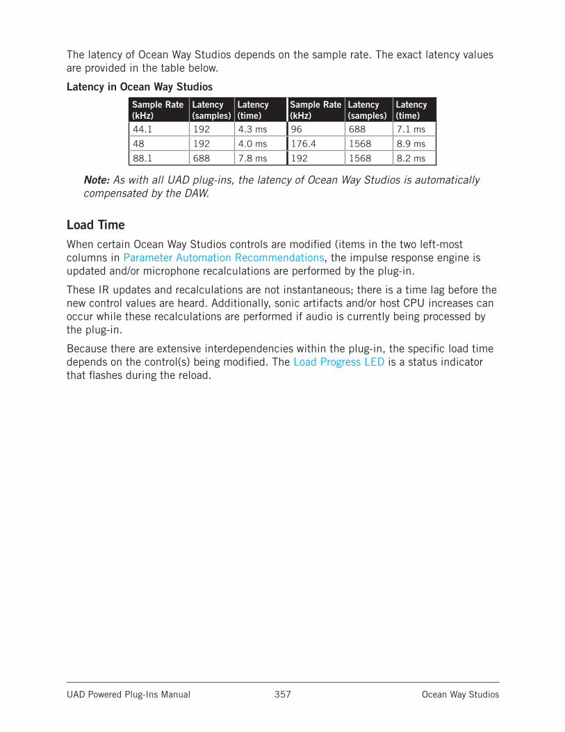
UAD Powered Plug-Ins Manual Ocean Way Studios 357
The latency of Ocean Way Studios depends on the sample rate. The exact latency values are provided in the table below.
Latency in Ocean Way Studios
Sample Rate (kHz)
Latency (samples)
Latency (time)
Sample Rate (kHz)
Latency (samples)
Latency (time)
44.1 192 4.3 ms 96 688 7.1 ms
48 192 4.0 ms 176.4 1568 8.9 ms
88.1 688 7.8 ms 192 1568 8.2 ms
Note: As with all UAD plug-ins, the latency of Ocean Way Studios is automatically compensated by the DAW.
Load TimeWhen certain Ocean Way Studios controls are modified (items in the two left-most columns in Parameter Automation Recommendations, the impulse response engine is updated and/or microphone recalculations are performed by the plug-in.
These IR updates and recalculations are not instantaneous; there is a time lag before the new control values are heard. Additionally, sonic artifacts and/or host CPU increases can occur while these recalculations are performed if audio is currently being processed by the plug-in.
Because there are extensive interdependencies within the plug-in, the specific load time depends on the control(s) being modified. The Load Progress LED is a status indicator that flashes during the reload.
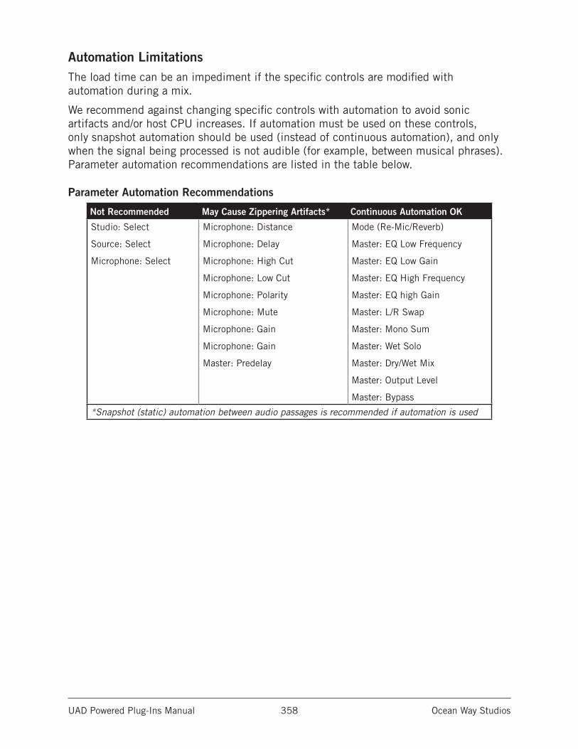
UAD Powered Plug-Ins Manual Ocean Way Studios 358
Automation LimitationsThe load time can be an impediment if the specific controls are modified with automation during a mix.
We recommend against changing specific controls with automation to avoid sonic artifacts and/or host CPU increases. If automation must be used on these controls, only snapshot automation should be used (instead of continuous automation), and only when the signal being processed is not audible (for example, between musical phrases). Parameter automation recommendations are listed in the table below.
Parameter Automation Recommendations
Not Recommended May Cause Zippering Artifacts* Continuous Automation OK
Studio: Select
Source: Select
Microphone: Select
Microphone: Distance
Microphone: Delay
Microphone: High Cut
Microphone: Low Cut
Microphone: Polarity
Microphone: Mute
Microphone: Gain
Microphone: Gain
Master: Predelay
Mode (Re-Mic/Reverb)
Master: EQ Low Frequency
Master: EQ Low Gain
Master: EQ High Frequency
Master: EQ high Gain
Master: L/R Swap
Master: Mono Sum
Master: Wet Solo
Master: Dry/Wet Mix
Master: Output Level
Master: Bypass
*Snapshot (static) automation between audio passages is recommended if automation is used
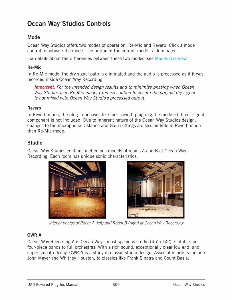
UAD Powered Plug-Ins Manual Ocean Way Studios 359
Ocean Way Studios Controls
ModeOcean Way Studios offers two modes of operation: Re-Mic and Reverb. Click a mode control to activate the mode. The button of the current mode is illuminated.
For details about the differences between these two modes, see Modes Overview.
Re-MicIn Re-Mic mode, the dry signal path is eliminated and the audio is processed as if it was recorded inside Ocean Way Recording.
Important: For the intended design results and to minimize phasing when Ocean Way Studios is in Re-Mic mode, exercise caution to ensure the original dry signal is not mixed with Ocean Way Studio’s processed output.
ReverbIn Reverb mode, the plug-in behaves like most reverb plug-ins; the modeled direct signal component is not included. Due to inherent nature of the Ocean Way Studios design, changes to the microphone Distance and Gain settings are less audible in Reverb mode than Re-Mic mode.
StudioOcean Way Studios contains meticulous models of rooms A and B at Ocean Way Recording. Each room has unique sonic characteristics.
Interior photos of Room A (left) and Room B (right) at Ocean Way Recording
OWR AOcean Way Recording A is Ocean Way’s most spacious studio (45’ x 52’), suitable for four-piece bands to full orchestras. With a rich sound, exceptionally clear low end, and super smooth decay, OWR A is a study in classic studio design. Associated artists include John Mayer and Whitney Houston, to classics like Frank Sinatra and Count Basie.
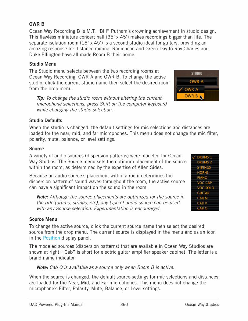
UAD Powered Plug-Ins Manual Ocean Way Studios 360
OWR BOcean Way Recording B is M.T. “Bill” Putnam’s crowning achievement in studio design. This flawless miniature concert hall (35’ x 45’) makes recordings bigger than life. The separate isolation room (18’ x 45’) is a second studio ideal for guitars, providing an amazing response for distance micing. Radiohead and Green Day to Ray Charles and Duke Ellington have all made Room B their home.
Studio MenuThe Studio menu selects between the two recording rooms at Ocean Way Recording: OWR A and OWR B. To change the active studio, click the current studio name then select the desired room from the drop menu.
Tip: To change the studio room without altering the current microphone selections, press Shift on the computer keyboard while changing the studio selection.
Studio DefaultsWhen the studio is changed, the default settings for mic selections and distances are loaded for the near, mid, and far microphones. This menu does not change the mic filter, polarity, mute, balance, or level settings.
SourceA variety of audio sources (dispersion patterns) were modeled for Ocean Way Studios. The Source menu sets the optimum placement of the source within the room, as determined by the expertise of Allen Sides.
Because an audio source’s placement within a room determines the dispersion pattern of sound waves throughout the room, the active source can have a significant impact on the sound in the room.
Note: Although the source placements are optimized for the source in the title (drums, strings, etc), any type of audio source can be used with any Source selection. Experimentation is encouraged.
Source MenuTo change the active source, click the current source name then select the desired source from the drop menu. The current source is displayed in the menu and as an icon in the Position display panel.
The modeled sources (dispersion patterns) that are available in Ocean Way Studios are shown at right. “Cab” is short for electric guitar amplifier speaker cabinet. The letter is a brand name indicator.
Note: Cab O is available as a source only when Room B is active.
When the source is changed, the default source settings for mic selections and distances are loaded for the Near, Mid, and Far microphones. This menu does not change the microphone’s Filter, Polarity, Mute, Balance, or Level settings.
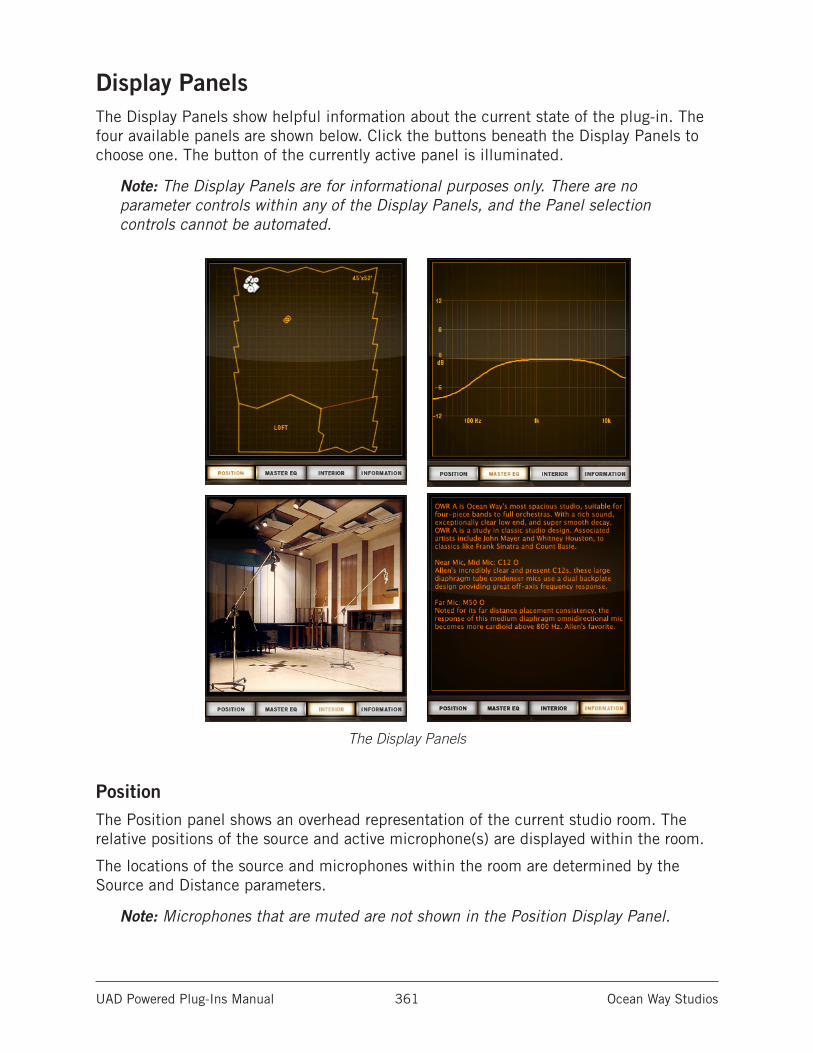
UAD Powered Plug-Ins Manual Ocean Way Studios 361
Display PanelsThe Display Panels show helpful information about the current state of the plug-in. The four available panels are shown below. Click the buttons beneath the Display Panels to choose one. The button of the currently active panel is illuminated.
Note: The Display Panels are for informational purposes only. There are no parameter controls within any of the Display Panels, and the Panel selection controls cannot be automated.
The Display Panels
PositionThe Position panel shows an overhead representation of the current studio room. The relative positions of the source and active microphone(s) are displayed within the room.
The locations of the source and microphones within the room are determined by the Source and Distance parameters.
Note: Microphones that are muted are not shown in the Position Display Panel.
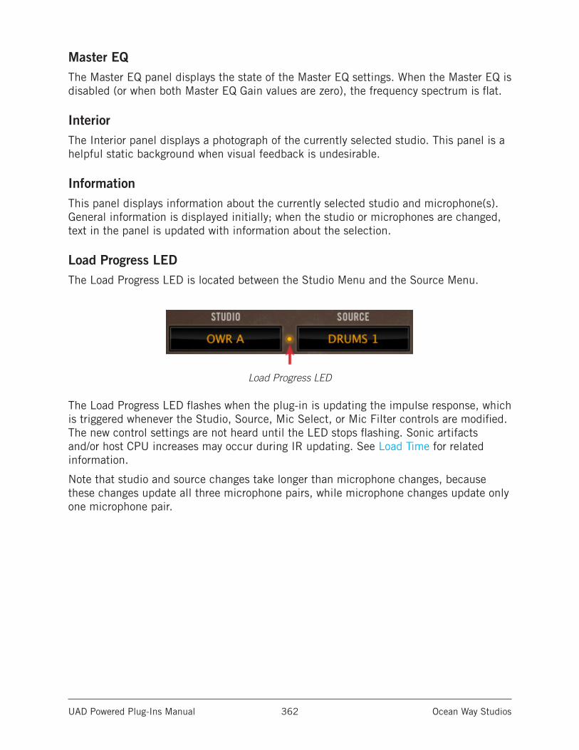
UAD Powered Plug-Ins Manual Ocean Way Studios 362
Master EQThe Master EQ panel displays the state of the Master EQ settings. When the Master EQ is disabled (or when both Master EQ Gain values are zero), the frequency spectrum is flat.
InteriorThe Interior panel displays a photograph of the currently selected studio. This panel is a helpful static background when visual feedback is undesirable.
InformationThis panel displays information about the currently selected studio and microphone(s). General information is displayed initially; when the studio or microphones are changed, text in the panel is updated with information about the selection.
Load Progress LEDThe Load Progress LED is located between the Studio Menu and the Source Menu.
Load Progress LED
The Load Progress LED flashes when the plug-in is updating the impulse response, which is triggered whenever the Studio, Source, Mic Select, or Mic Filter controls are modified. The new control settings are not heard until the LED stops flashing. Sonic artifacts and/or host CPU increases may occur during IR updating. See Load Time for related information.
Note that studio and source changes take longer than microphone changes, because these changes update all three microphone pairs, while microphone changes update only one microphone pair.
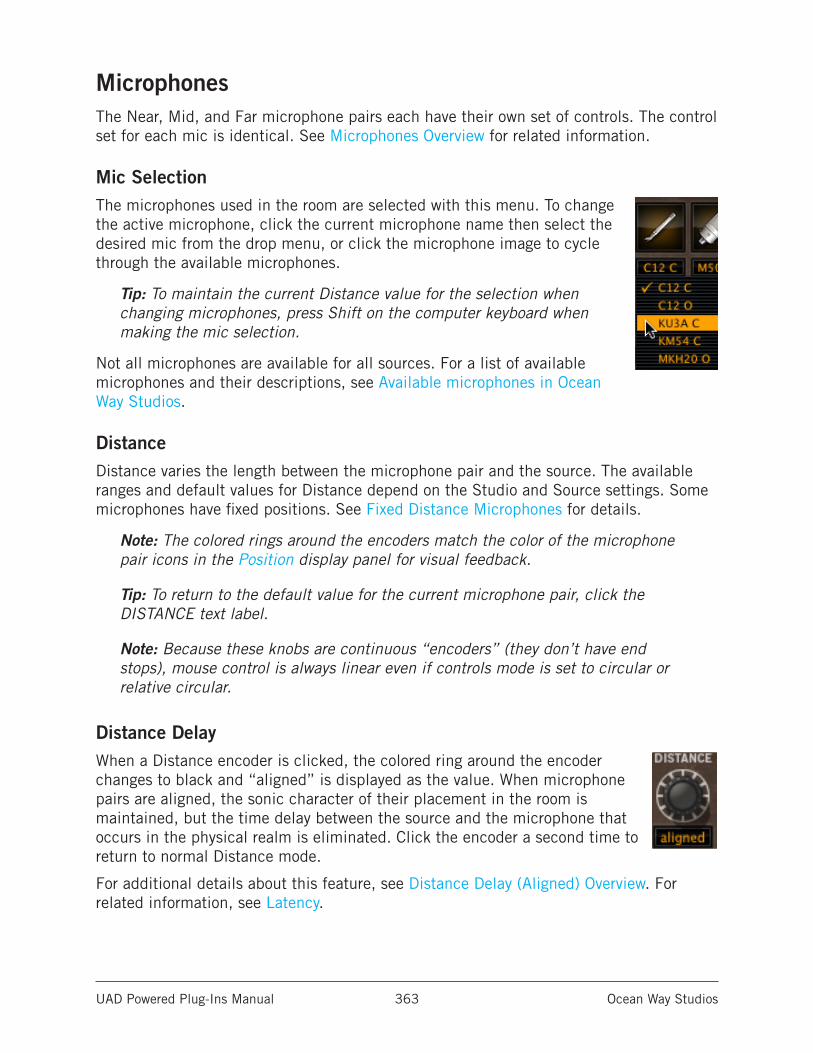
UAD Powered Plug-Ins Manual Ocean Way Studios 363
MicrophonesThe Near, Mid, and Far microphone pairs each have their own set of controls. The control set for each mic is identical. See Microphones Overview for related information.
Mic SelectionThe microphones used in the room are selected with this menu. To change the active microphone, click the current microphone name then select the desired mic from the drop menu, or click the microphone image to cycle through the available microphones.
Tip: To maintain the current Distance value for the selection when changing microphones, press Shift on the computer keyboard when making the mic selection.
Not all microphones are available for all sources. For a list of available microphones and their descriptions, see Available microphones in Ocean Way Studios.
DistanceDistance varies the length between the microphone pair and the source. The available ranges and default values for Distance depend on the Studio and Source settings. Some microphones have fixed positions. See Fixed Distance Microphones for details.
Note: The colored rings around the encoders match the color of the microphone pair icons in the Position display panel for visual feedback.
Tip: To return to the default value for the current microphone pair, click the DISTANCE text label.
Note: Because these knobs are continuous “encoders” (they don’t have end stops), mouse control is always linear even if controls mode is set to circular or relative circular.
Distance DelayWhen a Distance encoder is clicked, the colored ring around the encoder changes to black and “aligned” is displayed as the value. When microphone pairs are aligned, the sonic character of their placement in the room is maintained, but the time delay between the source and the microphone that occurs in the physical realm is eliminated. Click the encoder a second time to return to normal Distance mode.
For additional details about this feature, see Distance Delay (Aligned) Overview. For related information, see Latency.
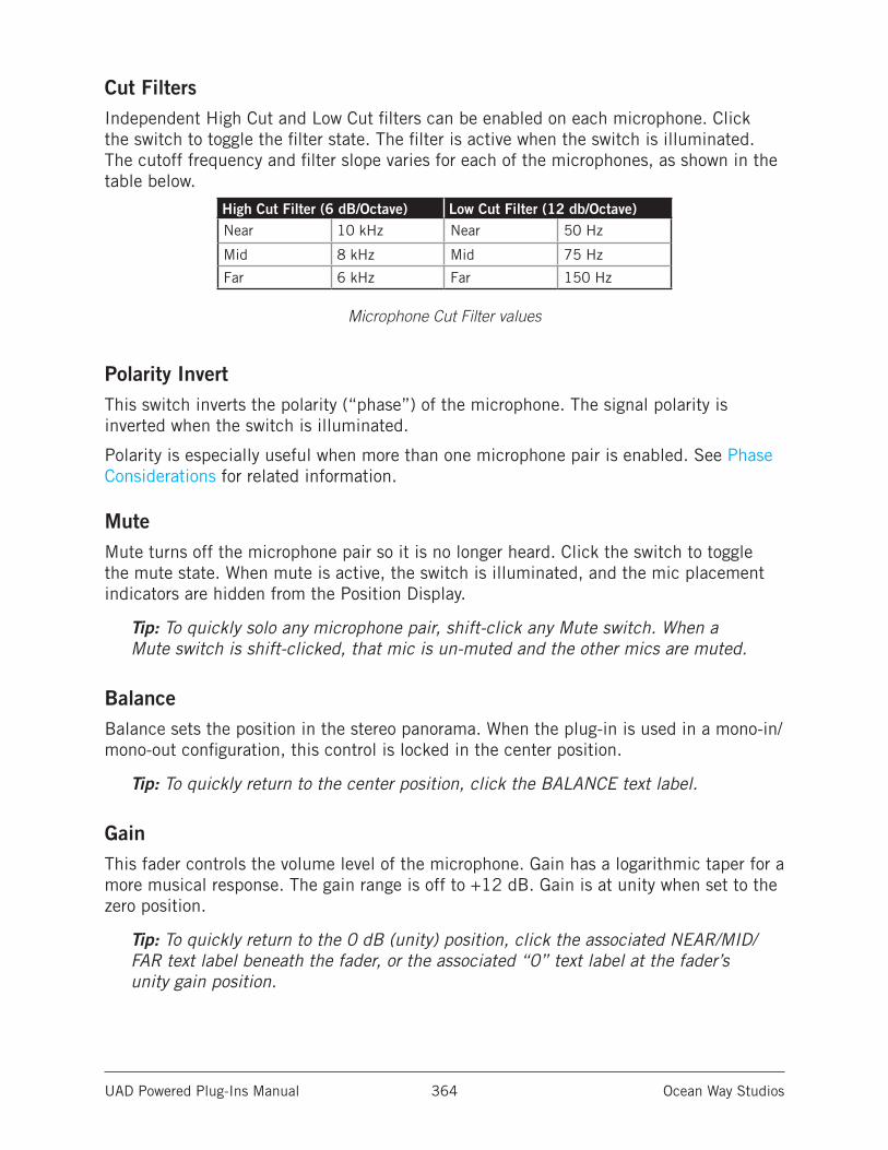
UAD Powered Plug-Ins Manual Ocean Way Studios 364
Cut FiltersIndependent High Cut and Low Cut filters can be enabled on each microphone. Click the switch to toggle the filter state. The filter is active when the switch is illuminated. The cutoff frequency and filter slope varies for each of the microphones, as shown in the table below.
High Cut Filter (6 dB/Octave) Low Cut Filter (12 db/Octave)Near 10 kHz Near 50 Hz
Mid 8 kHz Mid 75 Hz
Far 6 kHz Far 150 Hz
Microphone Cut Filter values
Polarity InvertThis switch inverts the polarity (“phase”) of the microphone. The signal polarity is inverted when the switch is illuminated.
Polarity is especially useful when more than one microphone pair is enabled. See Phase Considerations for related information.
MuteMute turns off the microphone pair so it is no longer heard. Click the switch to toggle the mute state. When mute is active, the switch is illuminated, and the mic placement indicators are hidden from the Position Display.
Tip: To quickly solo any microphone pair, shift-click any Mute switch. When a Mute switch is shift-clicked, that mic is un-muted and the other mics are muted.
BalanceBalance sets the position in the stereo panorama. When the plug-in is used in a mono-in/mono-out configuration, this control is locked in the center position.
Tip: To quickly return to the center position, click the BALANCE text label.
GainThis fader controls the volume level of the microphone. Gain has a logarithmic taper for a more musical response. The gain range is off to +12 dB. Gain is at unity when set to the zero position.
Tip: To quickly return to the 0 dB (unity) position, click the associated NEAR/MID/FAR text label beneath the fader, or the associated “0” text label at the fader’s unity gain position.
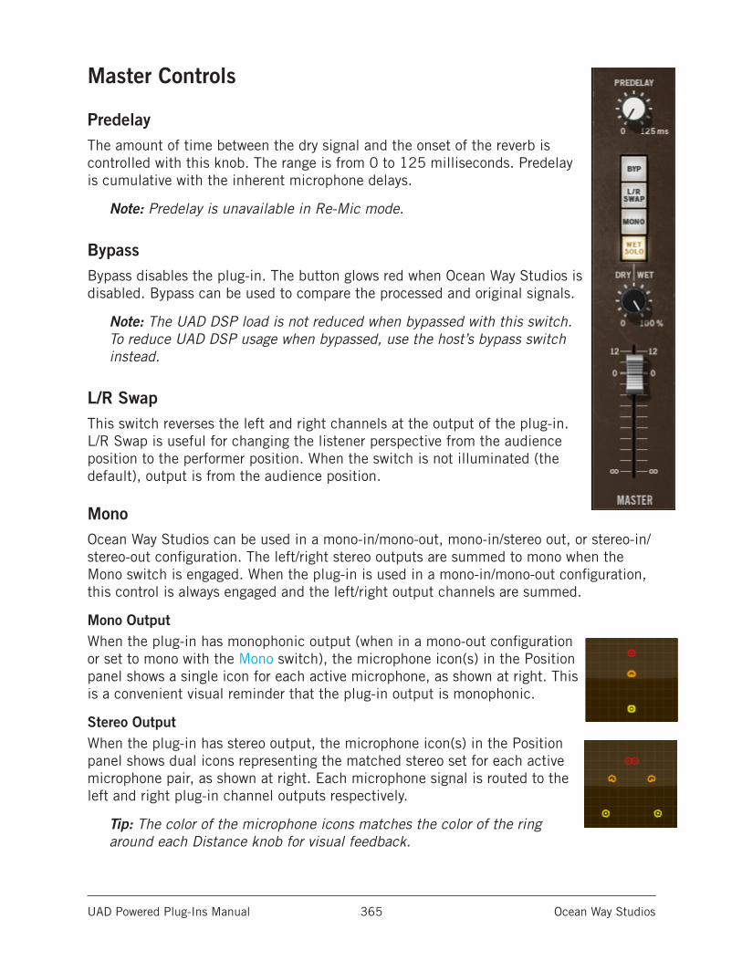
UAD Powered Plug-Ins Manual Ocean Way Studios 365
Master Controls
PredelayThe amount of time between the dry signal and the onset of the reverb is controlled with this knob. The range is from 0 to 125 milliseconds. Predelay is cumulative with the inherent microphone delays.
Note: Predelay is unavailable in Re-Mic mode.
BypassBypass disables the plug-in. The button glows red when Ocean Way Studios is disabled. Bypass can be used to compare the processed and original signals.
Note: The UAD DSP load is not reduced when bypassed with this switch. To reduce UAD DSP usage when bypassed, use the host’s bypass switch instead.
L/R SwapThis switch reverses the left and right channels at the output of the plug-in. L/R Swap is useful for changing the listener perspective from the audience position to the performer position. When the switch is not illuminated (the default), output is from the audience position.
MonoOcean Way Studios can be used in a mono-in/mono-out, mono-in/stereo out, or stereo-in/stereo-out configuration. The left/right stereo outputs are summed to mono when the Mono switch is engaged. When the plug-in is used in a mono-in/mono-out configuration, this control is always engaged and the left/right output channels are summed.
Mono OutputWhen the plug-in has monophonic output (when in a mono-out configuration or set to mono with the Mono switch), the microphone icon(s) in the Position panel shows a single icon for each active microphone, as shown at right. This is a convenient visual reminder that the plug-in output is monophonic.
Stereo OutputWhen the plug-in has stereo output, the microphone icon(s) in the Position panel shows dual icons representing the matched stereo set for each active microphone pair, as shown at right. Each microphone signal is routed to the left and right plug-in channel outputs respectively.
Tip: The color of the microphone icons matches the color of the ring around each Distance knob for visual feedback.
UAD Powered Plug-Ins Manual Ocean Way Studios 366
Dry/WetWhen the plug-in is used in Reverb mode in a track insert (versus effect send/return) configuration, Dry/Wet determines the balance between the original dry signal and the processed signal. The range is from 0% (dry, unprocessed) to 100% (wet, processed signal only).
Dry/Wet is used to set the amount of ambience when the plug-in is used in a track insert (versus aux send/return) configuration.
Note: If Wet Solo is enabled, this control is unavailable.
Wet SoloWet Solo puts Ocean Way Studios into 100% wet mode. When Wet Solo is on, it is the equivalent of setting the Dry/Wet knob value to 100%.
Wet Solo defaults to On, which is optimal when using Ocean Way Studios in Reverb mode in the “traditional” reverb configuration (placed on an effect group/bus that is configured for use with channel sends). When Ocean Way Studios is used on a channel insert in Reverb mode, this control should be deactivated so the Dry/Wet mix can be adjusted.
Wet Solo is fixed in the enabled position in Re-Mic mode so the original dry signal cannot be mixed with the modeled direct signal component within the plug-in.
This control uses a logarithmic taper to provide increased resolution when selecting lower values. When the knob is in the 12 o’clock position, the value is approximately 15%.
Note: Wet Solo is a global (per plug-in instance) control.
Master LevelThis fader controls the volume level at the output of the plug-in. It has a logarithmic taper for a more musical response. The gain range is from off to +12 dB. Gain is at unity when set to the zero position.
Tip: To quickly return to the 0 dB (unity) position, click the MASTER text label beneath the fader, or the “0” text label at the fader’s unity gain position.
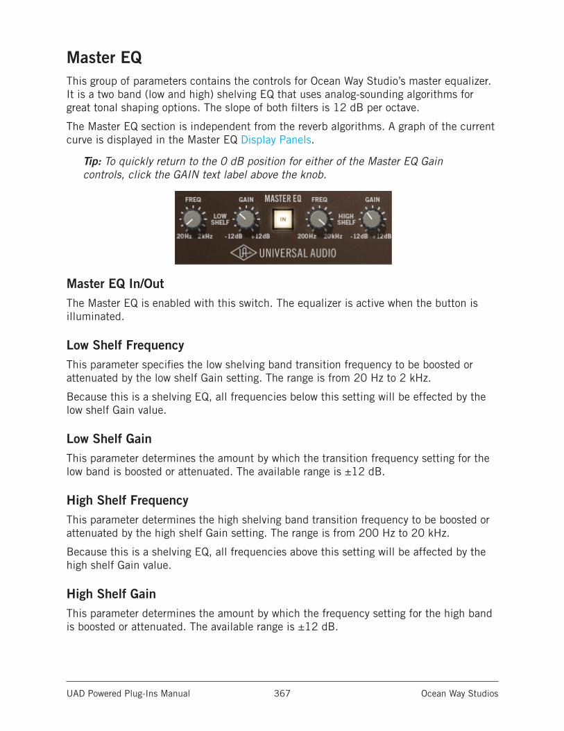
UAD Powered Plug-Ins Manual Ocean Way Studios 367
Master EQThis group of parameters contains the controls for Ocean Way Studio’s master equalizer. It is a two band (low and high) shelving EQ that uses analog-sounding algorithms for great tonal shaping options. The slope of both filters is 12 dB per octave.
The Master EQ section is independent from the reverb algorithms. A graph of the current curve is displayed in the Master EQ Display Panels.
Tip: To quickly return to the 0 dB position for either of the Master EQ Gain controls, click the GAIN text label above the knob.
Master EQ In/OutThe Master EQ is enabled with this switch. The equalizer is active when the button is illuminated.
Low Shelf FrequencyThis parameter specifies the low shelving band transition frequency to be boosted or attenuated by the low shelf Gain setting. The range is from 20 Hz to 2 kHz.
Because this is a shelving EQ, all frequencies below this setting will be effected by the low shelf Gain value.
Low Shelf GainThis parameter determines the amount by which the transition frequency setting for the low band is boosted or attenuated. The available range is ±12 dB.
High Shelf FrequencyThis parameter determines the high shelving band transition frequency to be boosted or attenuated by the high shelf Gain setting. The range is from 200 Hz to 20 kHz.
Because this is a shelving EQ, all frequencies above this setting will be affected by the high shelf Gain value.
High Shelf GainThis parameter determines the amount by which the frequency setting for the high band is boosted or attenuated. The available range is ±12 dB.

UAD Powered Plug-Ins Manual Ocean Way Studios 368
The History of Ocean Way Recording
Ocean Way Recording in Hollywood California is the world’s most awarded studio complex. Albums recorded at the studio have sold over 1 billion units. Generations of music icons, from Frank Sinatra, Nat King Cole, Ray Charles to The Rolling Stones, Eric Clapton, and Michael Jackson, all the way to contemporary artists like Green Day, Dr. Dre, Radiohead, Kanye West, and The Red Hot Chili Peppers, all choose Ocean Way for its phenomenal sounding rooms, customized equipment, impeccable electronic maintenance, and access to the music industry’s most famous collection of vintage tube microphones.
In 1972, Allen Sides began building custom loudspeakers and leased a garage in Santa Monica, California as a hi-fi demo room. This garage was within steps of the Pacific Ocean and was situated on a street appropriately named - Ocean Way. Since he knew exactly what kinds of sounds were most impressive on his speakers, Sides did limited live to two-track recordings as demo material. During these demos, listeners became as interested in the recordings as the speakers and before long, they were asking Allen to make their recordings. In order to service those clients, Ocean Way Recording was born. Five Grammys and a thousand albums later Allen is still rolling.
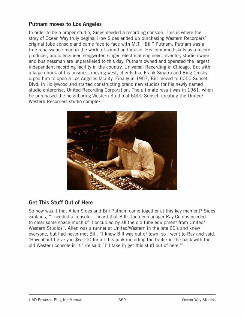
UAD Powered Plug-Ins Manual Ocean Way Studios 369
Putnam moves to Los AngelesIn order to be a proper studio, Sides needed a recording console. This is where the story of Ocean Way truly begins; How Sides ended up purchasing Western Recorders’ original tube console and came face to face with M.T. “Bill” Putnam. Putnam was a true renaissance man in the world of sound and music. His combined skills as a record producer, audio engineer, songwriter, singer, electrical engineer, inventor, studio owner and businessman are unparalleled to this day. Putnam owned and operated the largest independent recording facility in the country, Universal Recording in Chicago. But with a large chunk of his business moving west, clients like Frank Sinatra and Bing Crosby urged him to open a Los Angeles facility. Finally in 1957, Bill moved to 6050 Sunset Blvd. in Hollywood and started constructing brand new studios for his newly named studio enterprise, United Recording Corporation. The ultimate result was in 1961, when he purchased the neighboring Western Studio at 6000 Sunset, creating the United/Western Recorders studio complex.
Get This Stuff Out of HereSo how was it that Allen Sides and Bill Putnam come together at this key moment? Sides explains, “I needed a console. I heard that Bill’s factory manager Ray Combs needed to clear some space-much of it occupied by all the old tube equipment from United/Western Studios”. Allen was a runner at United/Western in the late 60’s and knew everyone, but had never met Bill. “I knew Bill was out of town, so I went to Ray and said, `How about I give you $6,000 for all this junk including the trailer in the back with the old Western console in it.’ He said, `I’ll take it; get this stuff out of here.’”
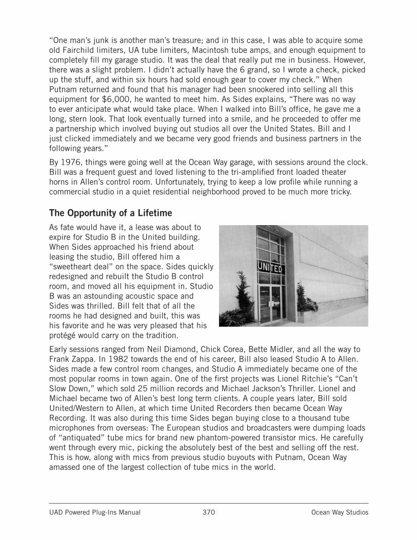
UAD Powered Plug-Ins Manual Ocean Way Studios 370
“One man’s junk is another man’s treasure; and in this case, I was able to acquire some old Fairchild limiters, UA tube limiters, Macintosh tube amps, and enough equipment to completely fill my garage studio. It was the deal that really put me in business. However, there was a slight problem. I didn’t actually have the 6 grand, so I wrote a check, picked up the stuff, and within six hours had sold enough gear to cover my check.” When Putnam returned and found that his manager had been snookered into selling all this equipment for $6,000, he wanted to meet him. As Sides explains, “There was no way to ever anticipate what would take place. When I walked into Bill’s office, he gave me a long, stern look. That look eventually turned into a smile, and he proceeded to offer me a partnership which involved buying out studios all over the United States. Bill and I just clicked immediately and we became very good friends and business partners in the following years.”
By 1976, things were going well at the Ocean Way garage, with sessions around the clock. Bill was a frequent guest and loved listening to the tri-amplified front loaded theater horns in Allen’s control room. Unfortunately, trying to keep a low profile while running a commercial studio in a quiet residential neighborhood proved to be much more tricky.
The Opportunity of a LifetimeAs fate would have it, a lease was about to expire for Studio B in the United building. When Sides approached his friend about leasing the studio, Bill offered him a “sweetheart deal” on the space. Sides quickly redesigned and rebuilt the Studio B control room, and moved all his equipment in. Studio B was an astounding acoustic space and Sides was thrilled. Bill felt that of all the rooms he had designed and built, this was his favorite and he was very pleased that his protégé would carry on the tradition.
Early sessions ranged from Neil Diamond, Chick Corea, Bette Midler, and all the way to Frank Zappa. In 1982 towards the end of his career, Bill also leased Studio A to Allen. Sides made a few control room changes, and Studio A immediately became one of the most popular rooms in town again. One of the first projects was Lionel Ritchie’s “Can’t Slow Down,” which sold 25 million records and Michael Jackson’s Thriller. Lionel and Michael became two of Allen’s best long term clients. A couple years later, Bill sold United/Western to Allen, at which time United Recorders then became Ocean Way Recording. It was also during this time Sides began buying close to a thousand tube microphones from overseas: The European studios and broadcasters were dumping loads of “antiquated” tube mics for brand new phantom-powered transistor mics. He carefully went through every mic, picking the absolutely best of the best and selling off the rest. This is how, along with mics from previous studio buyouts with Putnam, Ocean Way amassed one of the largest collection of tube mics in the world.
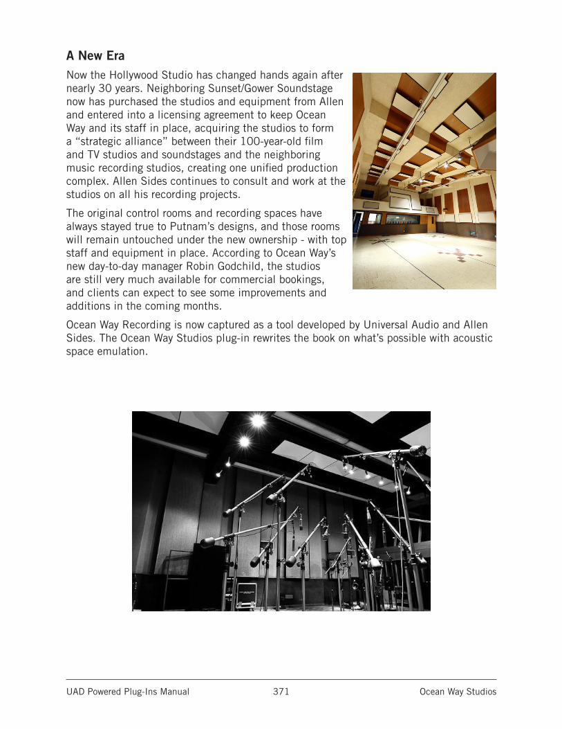
UAD Powered Plug-Ins Manual Ocean Way Studios 371
A New EraNow the Hollywood Studio has changed hands again after nearly 30 years. Neighboring Sunset/Gower Soundstage now has purchased the studios and equipment from Allen and entered into a licensing agreement to keep Ocean Way and its staff in place, acquiring the studios to form a “strategic alliance” between their 100-year-old film and TV studios and soundstages and the neighboring music recording studios, creating one unified production complex. Allen Sides continues to consult and work at the studios on all his recording projects.
The original control rooms and recording spaces have always stayed true to Putnam’s designs, and those rooms will remain untouched under the new ownership - with top staff and equipment in place. According to Ocean Way’s new day-to-day manager Robin Godchild, the studios are still very much available for commercial bookings, and clients can expect to see some improvements and additions in the coming months.
Ocean Way Recording is now captured as a tool developed by Universal Audio and Allen Sides. The Ocean Way Studios plug-in rewrites the book on what’s possible with acoustic space emulation.
UAD Powered Plug-Ins Manual Oxide Tape Recorder 372
Oxide Tape Recorder
The Oxide Tape Recorder plug-in provides UA’s revolutionary tape emulation technology in a simple, affordable package — with all of the essential features.
By harnessing the musical, mixable sound of tape, Oxide Tape Recorder plug-in imparts essential “sounds like a record” clarity, punch, and warmth to every track.
Now You Can:• Easily inject the warm color and punchy low-end response of large format analog
tape to your tracks
• Apply tape saturation and circuit overdrive via simple Input/Output controls
• Use presets designed by Engineer/Producer John Paterno guiding you to great sound
• Experience in-the-box recording “through” tape in real time using Apollo interfaces
• Load Oxide on 24 tracks with single UAD-2 QUAD DSP Accelerator
• Choose among 7.5 and 15 IPS Tape Speeds and various emphasis curves for colorful tape textures
Groundbreaking Tape Emulation TechnologyThe Oxide Tape Recorder plug-in was designed by the same team behind the industry-leading UAD Ampex ATR-102 Mastering Tape Machine and Studer A800 Multichannel Tape Machine plug-ins. Designed in conjunction with AES magnetic recording expert Jay McKnight, Oxide gives your tracks and mixes the warmth, presence, and vibe of professional analog tape.
Easy to Use Whether you’re tracking in real time using an Apollo interface, or mixing in your DAW, Oxide’s intuitive controls deliver musical results for beginners and pros alike. And when you purchase Oxide, you’re eligible for a discount toward UA’s deeper-featured Studer and Ampex Magnetic Tape Bundle that may be used at any time. By emulating fat tape compression and colorful circuit behaviors, Oxide gives your tracks and mixes a cohesive glue that only analog tape can.
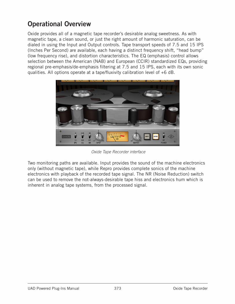
UAD Powered Plug-Ins Manual Oxide Tape Recorder 373
Operational OverviewOxide provides all of a magnetic tape recorder’s desirable analog sweetness. As with magnetic tape, a clean sound, or just the right amount of harmonic saturation, can be dialed in using the Input and Output controls. Tape transport speeds of 7.5 and 15 IPS (Inches Per Second) are available, each having a distinct frequency shift, “head bump” (low frequency rise), and distortion characteristics. The EQ (emphasis) control allows selection between the American (NAB) and European (CCIR) standardized EQs, providing regional pre-emphasis/de-emphasis filtering at 7.5 and 15 IPS, each with its own sonic qualities. All options operate at a tape/fluxivity calibration level of +6 dB.
Oxide Tape Recorder interface
Two monitoring paths are available. Input provides the sound of the machine electronics only (without magnetic tape), while Repro provides complete sonics of the machine electronics with playback of the recorded tape signal. The NR (Noise Reduction) switch can be used to remove the not-always-desirable tape hiss and electronics hum which is inherent in analog tape systems, from the processed signal.
UAD Powered Plug-Ins Manual Oxide Tape Recorder 374
General OperationThe main point to understand about Oxide operation is that the Input control adjusts the signal level recorded to tape, and is therefore the primary color parameter. As with hardware tape recorders, lower VU levels result in a cleaner, warmer sound with more headroom, while increasing VU levels results in more tape saturation, compression, `and bite.
After adjusting the Input control to taste, the Output control can be adjusted to compensate for resulting level changes. For example, if Input is reduced for low VU levels, the Output control can be increased for unity gain with the original input signal.
All controls are interactive and it’s normal for zeroed and/or reciprocal I/O gains to not always achieve perfect unity gain.
Using Oxide During MixdownThe primary purpose of Oxide is to obtain multichannel tape sonics within the DAW environment. To obtain the classic cumulative “cohesive” multitrack tape sound on mixdown, the plug-in should be placed as the first insert on individual tracks, before other processing is applied.
Creative “non-standard” results can be obtained by placing Oxide in subsequent inserts after other processors, on sub-mix buses, or aux buses in a send/return configuration. Mixdown to a two-track tape recorder can be emulated by placing the plug-in on the stereo output bus.
If the mix is already begun, be sure to bypass all other plug-ins initially. You may find, for example, that far less compression and EQ is needed and the mix “glues together” more easily. Of course, Oxide can sound incredible on the mix bus as well.
Realtime UAD Processing with Apollo InputsTo enable near-zero latency while recording or monitoring with Apollo through Oxide, simply assign the plug-in to the desired insert slot within Apollo’s Console application. To replicate a traditional analog signal chain while recording on Apollo, first assign one of Apollo’s Unison plug-ins (preamp or channel strip emulations such as UA 610-B) in the mic preamp channel’s dedicated Unison insert, then place Oxide in the first standard insert slot in the channel. If the session was already recorded through Apollo with Oxide, the mix session may benefit from a “second pass” through Oxide as well.
UAD Powered Plug-Ins Manual Oxide Tape Recorder 375
Artist PresetsOxide includes a bank of custom presets designed by engineer/producer John Paterno. These factory presets are provided as guides to help you achieve a great tape sound.
About Oxide Artist Preset NamesEach Oxide preset name includes two descriptors: Either Warm or Drive, plus a target VU value (+3VU, 0VU, etc). The preset names provide important guidance for achieving the desired sound.
The Warm presets are designed for a more pure analog tape sweetening, while the Drive presets are designed for a more saturated/compressed/colored tape sound.
The target VU value is the signal level to send into the recorder via the Input control, so the tape calibration levels are the same as the preset designer’s levels.
How To Use Oxide Artist Presets
1. Select a sonic quality
Based on the sonic result you want to achieve, choose either a Warm preset or a Drive preset from the Oxide preset bank.
2. Adjust Input to target the preset’s VU value
While the source signal is active in the plug-in (during input or playback), adjust Oxide’s Input control so the signal peaks in the VU Meter reach the preset’s target VU value in the preset name.
This step calibrates your input signals to the same reference levels as the preset designer, so the sonic results will be as intended. Without this adjustment, there would be no way to match how “hot” the recording levels are.
3. Adjust Output to taste
After adjusting Input, the processed signal may be quieter or louder than the original source signal. If desired, adjust the Output control to return to unity gain.
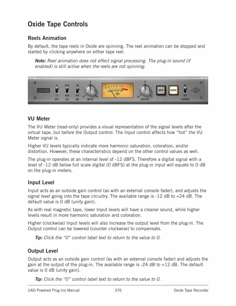
UAD Powered Plug-Ins Manual Oxide Tape Recorder 376
Oxide Tape Controls
Reels AnimationBy default, the tape reels in Oxide are spinning. The reel animation can be stopped and started by clicking anywhere on either tape reel.
Note: Reel animation does not effect signal processing. The plug-in sound (if enabled) is still active when the reels are not spinning.
VU MeterThe VU Meter (read-only) provides a visual representation of the signal levels after the virtual tape, but before the Output control. The Input control affects how “hot” the VU Meter signal is.
Higher VU levels typically indicate more harmonic saturation, coloration, and/or distortion. However, these characteristics depend on the other control values as well.
The plug-in operates at an internal level of -12 dBFS. Therefore a digital signal with a level of -12 dB below full scale digital (0 dBFS) at the plug-in input will equate to 0 dB on the plug-in meters.
Input LevelInput acts as an outside gain control (as with an external console fader), and adjusts the signal level going into the tape circuitry. The available range is -12 dB to +24 dB. The default value is 0 dB (unity gain).
As with real magnetic tape, lower Input levels will have a cleaner sound, while higher levels result in more harmonic saturation and coloration.
Higher (clockwise) Input levels will also increase the output level from the plug-in. The Output control can be lowered (counter clockwise) to compensate.
Tip: Click the “0” control label text to return to the value to 0.
Output LevelOutput acts as an outside gain control (as with an external console fader) and adjusts the gain at the output of the plug-in. The available range is -24 dB to +12 dB. The default value is 0 dB (unity gain).
Tip: Click the “0” control label text to return to the value to 0.
UAD Powered Plug-Ins Manual Oxide Tape Recorder 377
Path SelectThe Path Select buttons specify which of the two possible signal paths is active in Oxide. The mode is active when its button is lit.
InputInput mode emulates the sound of the circuit through the machine electronics only, without tape sonics. This is the scenario when the machine is in live monitoring mode but the tape transport is not running.
ReproRepro mode models the complete sound of the signal being recorded to tape through the record head and being played back through the reproduction head, plus all corresponding machine electronics.
IPS (Tape Speed)The IPS (Inches Per Second) control determines the speed of the tape transport and the associated “head bump.” Head bump is the bass frequency build-up that occurs with magnetic tape; the dominant frequencies shift according to transport speed. A faster tape speed results in a lower noise floor, greater fidelity, and flatter frequency response.
15 IPS15 IPS is considered the favorite for rock and acoustic music due to its low frequency “head bump” and warmer sound.
7.5 IPS7.5 IPS has a more colored experience, with even greater frequency shift versus the 15 IPS setting.
EQ (emphasis)This switch determines the active emphasis EQ values and the frequency of the hum noise.
Tape Speed and emphasis EQ were originally practical controls for record duration versus noise and local standards. Historically, the origin of the tape machine (US or European) dictated the built-in EQ emphasis, but later machines had both circuits available.
NABWhen EQ is set to NAB, the hum noise frequency is 60 Hz (the United States standard). NAB (also referred to as IEC2) was the American standard with its own unique sound.
CCIRWhen EQ set to CCIR (also known as IEC), the hum noise frequency is 50 Hz (the standard in Europe and other regions).
CCIR (also known as IEC) is the EQ pre-emphasis made famous on British records and is considered the technically superior EQ; many say this EQ was part of the “British Sound” during tape’s heyday.
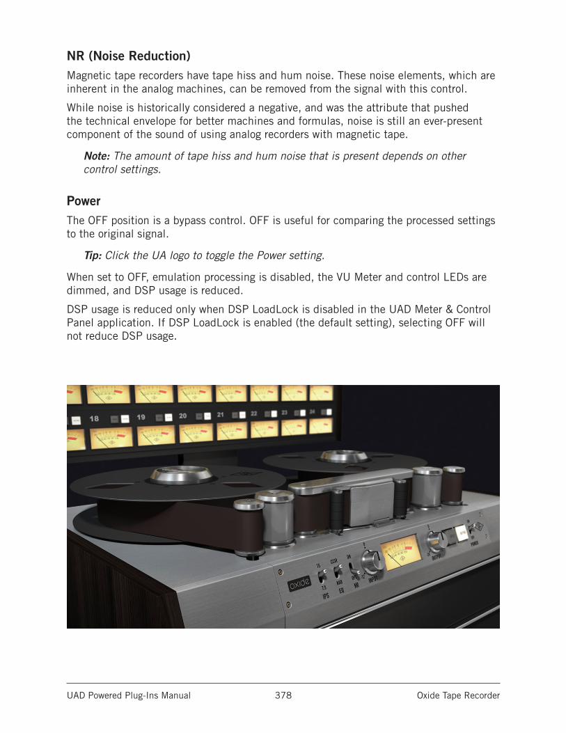
UAD Powered Plug-Ins Manual Oxide Tape Recorder 378
NR (Noise Reduction)Magnetic tape recorders have tape hiss and hum noise. These noise elements, which are inherent in the analog machines, can be removed from the signal with this control.
While noise is historically considered a negative, and was the attribute that pushed the technical envelope for better machines and formulas, noise is still an ever-present component of the sound of using analog recorders with magnetic tape.
Note: The amount of tape hiss and hum noise that is present depends on other control settings.
PowerThe OFF position is a bypass control. OFF is useful for comparing the processed settings to the original signal.
Tip: Click the UA logo to toggle the Power setting.
When set to OFF, emulation processing is disabled, the VU Meter and control LEDs are dimmed, and DSP usage is reduced.
DSP usage is reduced only when DSP LoadLock is disabled in the UAD Meter & Control Panel application. If DSP LoadLock is enabled (the default setting), selecting OFF will not reduce DSP usage.
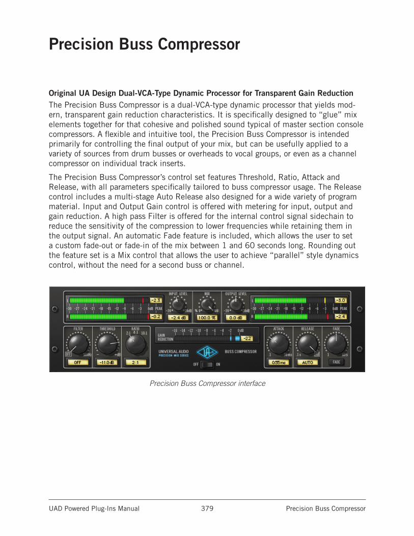
UAD Powered Plug-Ins Manual Precision Buss Compressor 379
Precision Buss Compressor
Original UA Design Dual-VCA-Type Dynamic Processor for Transparent Gain ReductionThe Precision Buss Compressor is a dual-VCA-type dynamic processor that yields mod-ern, transparent gain reduction characteristics. It is specifically designed to “glue” mix elements together for that cohesive and polished sound typical of master section console compressors. A flexible and intuitive tool, the Precision Buss Compressor is intended primarily for controlling the final output of your mix, but can be usefully applied to a variety of sources from drum busses or overheads to vocal groups, or even as a channel compressor on individual track inserts.
The Precision Buss Compressor’s control set features Threshold, Ratio, Attack and Release, with all parameters specifically tailored to buss compressor usage. The Release control includes a multi-stage Auto Release also designed for a wide variety of program material. Input and Output Gain control is offered with metering for input, output and gain reduction. A high pass Filter is offered for the internal control signal sidechain to reduce the sensitivity of the compression to lower frequencies while retaining them in the output signal. An automatic Fade feature is included, which allows the user to set a custom fade-out or fade-in of the mix between 1 and 60 seconds long. Rounding out the feature set is a Mix control that allows the user to achieve “parallel” style dynamics control, without the need for a second buss or channel.
Precision Buss Compressor interface

UAD Powered Plug-Ins Manual Precision Buss Compressor 380
Precision Buss Compressor ControlsControl knobs for the Precision Buss Compressor behave the same way as with all UAD plug-ins. Parameters with text values can be modified with text entry.
FilterFilter regulates the cutoff frequency of the filter on the compressor’s control signal side-chain. Removing low-frequency content from the sidechain can reduce excessive gain reduction and/or “pumping” on bass-heavy audio signals without reducing bass content of the audio signal itself.
The filter is an 18 dB per octave, coincident-pole high-pass filter. The available range is 20 Hz-500 Hz and Off.
Note: The Filter parameter affects the control signal (sidechain) of the compressor only. It does not filter the audio signal.
ThresholdThis parameter determines the threshold level for the onset of compression. Incoming signals that exceed this level are compressed. Signals below the level are unaffected.
The available threshold range depends on ratio setting. At higher Ratio values, more headroom is available. Since the plug-in is designed primarily as a buss compressor, where signal levels typically run hotter than individual tracks, this feature increases the control resolution for fine-tuning these higher levels.
When Ratio is changed, the Threshold value is updated accordingly:
• When Ratio is set to 2:1, the Threshold range is -55 dB to 0 dB.
• When Ratio is set to 4:1, the Threshold range is -45 dB to +10 dB.
• When Ratio is set to 10:1, the Threshold range is -40 dB to +15 dB.
Note: When Ratio is changed, Threshold numerical values are updated but the Threshold knob position does not move.
As the Threshold control is decreased and more compression occurs, output level is typi-cally reduced. Adjust the Gain control to modify the output to compensate if desired.
RatioRatio determines the amount of gain reduction for the compressor. For example, a 2:1 ratio reduces the signal above the threshold by half, with an input signal of 20 dB being reduced to 10 dB.
The available Ratio values are 2:1 (default), 4:1, and 10:1.
UAD Powered Plug-Ins Manual Precision Buss Compressor 381
AttackAttack sets the amount of time that must elapse once the input signal reaches the Threshold level before compression is applied. The faster the Attack, the more rapidly compression is applied to signals above the threshold.
The Attack range is from 0.10 milliseconds to 32 milliseconds. The availability of relatively slow attack times (as compared to other compressors) is one factor that can provide the in-your-face-pumping quality that is so popular with large console VCA-style compressors.
ReleaseRelease sets the amount of time it takes for compression to cease once the input signal drops below the threshold level.
The available range is from 0.10 seconds to 1.20 seconds, with Automatic release avail-able at the full-clockwise position.
The Auto release characteristic for Precision Buss Compressor has a unique quality that is optimized for program material.
Slower release times can smooth the transition that occurs when the signal dips below the threshold, especially useful for material with frequent peaks. However, if you set too large of a Release time, compression for sections of audio with loud signals may extend to lengthy sections of audio with lower signals.
FadeThe Precision Buss Compressor provides a Fade function that, upon activation, automatically reduces the plug-in output to minimum within a specified time period. This function enables extremely smooth-sounding fade outs (and fade ins), plus it can be automated as well. The Fade function processes the signal at the output of the compressor.
Fade SetFade Set determines the amount of time that will pass between the Fade button being activated and the plug-in output level being reduced to minimum (or being raised to 0 dB in the case of a fade in). The available range is from 1.0 second to 60 seconds.
Fade times immediately reflect the current Fade Set value. Therefore a fade out that has already been initiated can be accelerated by changing Fade Set during the fade out. Conversely, a fade in can be accelerated by changing Fade Set during the fade in.
Note that although the Fade Set control itself has linear taper, the fade signal level that is output has an exponential curve.
UAD Powered Plug-Ins Manual Precision Buss Compressor 382
Fade SwitchActivating the Fade switch initiates a fade out. The fade out time is determined by the Fade Set parameter.
The Fade switch flashes red when a fade out is in progress, and glows solid red when the fade out is complete (when the Fade Set time has elapsed).
Deactivating Fade initiates a fade in. During a fade in, the signal level is increased from the current level of attenuation to 0 dB of attenuation. The Fade switch flashes blue when a fade in is in progress, and is no longer
illuminated when the fade in is complete (when the Fade Set time has elapsed).
Toggling the Fade switch causes an already active fade to reverse direction, without a jump in output level. The Fade Set rate is constant even if an active fade is interrupted. For example: If the Fade Set value is 30 seconds and a fade out is initiated, then Fade is clicked again after 20 seconds, it will take 20 seconds to fade back in.
Note: Shift+click the Fade button to instantly return the level back to 0 dB (this feature cannot be automated).
Input LevelInput controls the signal level that is input to the plug-in. Increasing the input may result in more compression, depending on the values of the Threshold and Ratio parameters.
The default value is 0 dB. The available range is ±20 dB.
MixThe Mix control determines the balance between the original and the processed signal. The range is from 0% (dry unprocessed signal only) to 100% (wet processed signal only). The default value is 100%.
Output LevelOutput controls the signal level that is output from the plug-in. The default value is 0 dB. The available range is ±20 dB.
Output controls both the dry unprocessed and wet processed signals (as determined by the Mix control).
Generally speaking, adjust the Output control after the desired amount of compression is achieved with the Threshold and Ratio controls. Output does not affect the amount of compression.
Level MetersThe stereo peak/hold Input and Output Meters display the signal level at the input and output of the plug-in.
The range is from -30 dB to 0 dB. Signal peaks are held for 3 seconds before resetting.
UAD Powered Plug-Ins Manual Precision Buss Compressor 383
Gain Reduction MeterThe Gain Reduction meter displays the amount of gain reduction occurring within the compressor. More blue bars moving to the left indicate more gain reduction is occurring.
The meter range is from -16 dB to 0 dB. Signal peaks are held for 3 seconds before resetting.
PowerThe Power switch determines whether the plug-in is active. Click the toggle button or the UA logo to change the state.
When the Power switch is in the Off position, plug-in processing is disabled and UAD DSP usage is reduced (unless UAD-2 DSP LoadLock is enabled). When the plug-in is bypassed with this switch (but not by the host bypass), the I/O meters and the Input Level knob remain active.
UAD Powered Plug-Ins Manual Precision Channel Strip 384
Precision Channel Strip
Five-Band Equalizer and DynamicsPrecision Channel Strip is a modern, five-band EQ module combined with a clean compressor/limiter module for flexible dynamics processing.
The Precision Channel Strip’s EQ section offers up to five bands of powerful tone shaping, with filter switching among cut, shelf, and fully parametric EQ. Each band is capable of frequency overlap with a full 20 Hz to 20 kHz range, and the EQ can be easily routed before or after the dynamics section, giving you more sonic flexibility.
A versatile and easy to use design, Precision Channel Strip’s dynamics section offers a continuously adjustable ratio with a broad range of attack and release options from slow and transparent, to snappy, over-the-top smack and aggression. Use the Auto Gain feature for quick, on-the-fly adjustments, or bypass it for fine-tuned manual control of your sources.
Features• Musical and flexible EQ with lattice filter design
• Five overlapping bands with cut, peak, or shelf filtering
• Natural-to-aggressive dynamics control — from soft compression to hard limiting
• Optional dynamics auto-makeup gain and dynamics/EQ routing swap
Precision Mix Rack CollectionPrecision Channel Strip is part of the Precision Mix Rack Collection, which provides modern, high-quality production tools for tracking and mixing. The Precision Mix Rack Collection includes the following UAD plug-ins:
• Precision Channel Strip Five-band EQ plus dynamics processing
• Precision Delay Mod High fidelity stereo delay processor with modulation
• Precision Delay Mod Long Same as Precision Delay Mod with longer delay times
• Precision Reflection Engine Small room ambience simulator
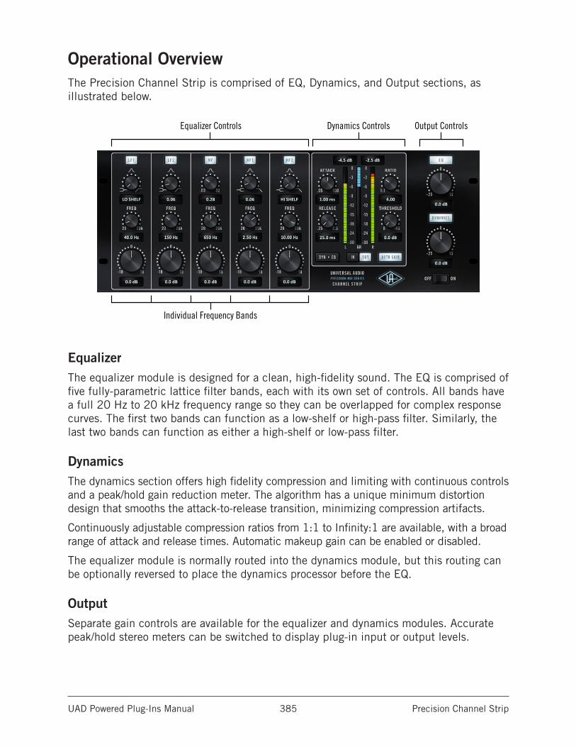
UAD Powered Plug-Ins Manual Precision Channel Strip 385
Operational OverviewThe Precision Channel Strip is comprised of EQ, Dynamics, and Output sections, as illustrated below.
Equalizer Controls
Individual Frequency Bands
Dynamics Controls Output Controls
EqualizerThe equalizer module is designed for a clean, high-fidelity sound. The EQ is comprised of five fully-parametric lattice filter bands, each with its own set of controls. All bands have a full 20 Hz to 20 kHz frequency range so they can be overlapped for complex response curves. The first two bands can function as a low-shelf or high-pass filter. Similarly, the last two bands can function as either a high-shelf or low-pass filter.
DynamicsThe dynamics section offers high fidelity compression and limiting with continuous controls and a peak/hold gain reduction meter. The algorithm has a unique minimum distortion design that smooths the attack-to-release transition, minimizing compression artifacts.
Continuously adjustable compression ratios from 1:1 to Infinity:1 are available, with a broad range of attack and release times. Automatic makeup gain can be enabled or disabled.
The equalizer module is normally routed into the dynamics module, but this routing can be optionally reversed to place the dynamics processor before the EQ.
OutputSeparate gain controls are available for the equalizer and dynamics modules. Accurate peak/hold stereo meters can be switched to display plug-in input or output levels.
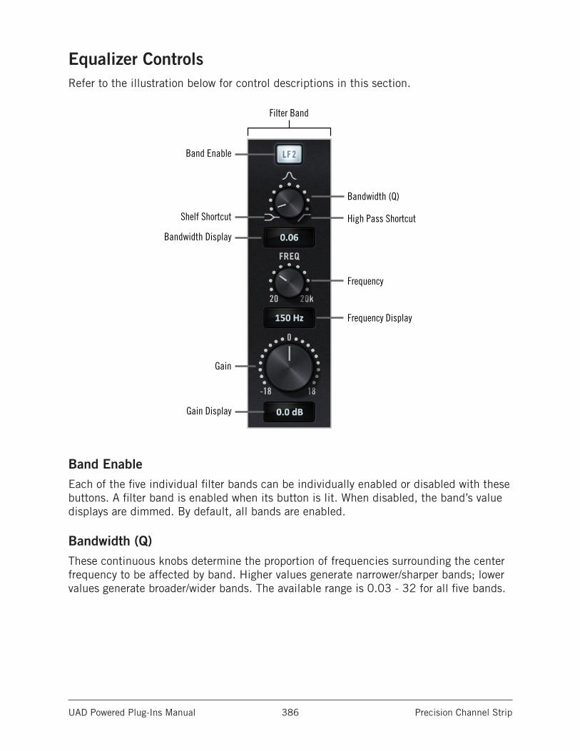
UAD Powered Plug-Ins Manual Precision Channel Strip 386
Equalizer ControlsRefer to the illustration below for control descriptions in this section.
Filter Band
Band Enable
Bandwidth (Q)
Shelf Shortcut High Pass Shortcut
Bandwidth Display
Frequency Display
Frequency
Gain
Gain Display
Band EnableEach of the five individual filter bands can be individually enabled or disabled with these buttons. A filter band is enabled when its button is lit. When disabled, the band’s value displays are dimmed. By default, all bands are enabled.
Bandwidth (Q)These continuous knobs determine the proportion of frequencies surrounding the center frequency to be affected by band. Higher values generate narrower/sharper bands; lower values generate broader/wider bands. The available range is 0.03 - 32 for all five bands.
UAD Powered Plug-Ins Manual Precision Channel Strip 387
LF1, LF2In both low frequency bands (LF1 and LF2), when Bandwidth is set to its minimum value, the band becomes a low-shelf filter. When set to its maximum value, the band becomes a high-pass filter.
Tip: Click the filter or shelf symbols to quickly select the function.
Note: When set to HI PASS, the band’s Gain control is disabled.
HF1, HF2In both high frequency bands (HF1 and HF2), when Bandwidth is set to its minimum value, the band becomes a high-shelf filter. When set to its maximum value, the band becomes a low-pass filter.
Note: When set to LO PASS, the band’s Gain control is disabled.
FrequencyThese continuous knobs define each band’s center frequency to be boosted or attenuated by the band’s Gain setting. The available range is 20 Hz to 20 kHz for all bands.
GainThe Gain control determines the amount by which the frequency setting is boosted or attenuated for the band. The available range is ±18 dB.
Tip: Click the “0” label to quickly set the value to 0 dB.
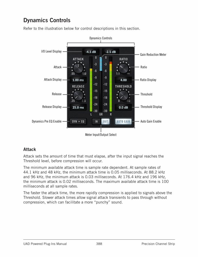
UAD Powered Plug-Ins Manual Precision Channel Strip 388
Dynamics ControlsRefer to the illustration below for control descriptions in this section.
Dynamics Controls
I/O Level Display
Ratio
Gain Reduction Meter
Attack
Ratio DisplayAttack Display
Release
Release Display Threshold Display
Auto Gain Enable
Threshold
Dynamics Pre EQ Enable
Meter Input/Output Select
AttackAttack sets the amount of time that must elapse, after the input signal reaches the Threshold level, before compression will occur.
The minimum available attack time is sample rate dependent. At sample rates of 44.1 kHz and 48 kHz, the minimum attack time is 0.05 milliseconds. At 88.2 kHz and 96 kHz, the minimum attack is 0.03 milliseconds. At 176.4 kHz and 196 kHz, the minimum attack is 0.02 milliseconds. The maximum available attack time is 100 milliseconds at all sample rates.
The faster the attack time, the more rapidly compression is applied to signals above the Threshold. Slower attack times allow signal attack transients to pass through without compression, which can facilitate a more “punchy” sound.
UAD Powered Plug-Ins Manual Precision Channel Strip 389
ReleaseRelease sets the amount of time it takes for compression to cease once the input signal drops below the Threshold level. The available range is 25 milliseconds to 2500 milliseconds (2.5 seconds).
Slower release times can smooth the transition that occurs when the signal dips below the threshold, which is especially useful for material with frequent peaks. However, if the release setting is too long, compression for audio sections with loud signals may extend to audio sections with lower signals.
RatioRatio determines the amount of gain reduction applied by the dynamics processor. For example, a value of 2 (expressed as a 2:1 ratio) reduces the signal above the threshold by half, with an input signal of 20 dB being reduced to 10 dB.
A value of 1 yields no compression. Values beyond 10 yield a limiting effect. The range is 1 to infinity (INF).
ThresholdSets the threshold level for dynamics processing. Any signals that exceed this level are compressed. Signals below the level are unaffected. A Threshold of 0 dB yields no compression. The range is 0 dB to -60 dB.
Note: As with many analog compressors, gain reduction can be triggered even if Threshold is set to 0 dB.
Auto GainAuto Gain is enabled when the button is lit. The default state is enabled.
As Threshold is increased and more compression occurs, the output level is inherently reduced by the gain reduction process. Auto Gain automatically compensates for this level reduction by reciprocally increasing the output gain as the compressor’s output level is reduced.
Dynamics Pre EQBy default, the input signal is routed into the EQ module, and the output of the EQ is routed into the dynamics module.
By enabling Dynamics Pre EQ, this signal routing is swapped. When the “DYN > EQ” button is lit, the input signal is routed into the dynamics module, and the output of the compressor is routed into the EQ module.
UAD Powered Plug-Ins Manual Precision Channel Strip 390
Gain Reduction MeterThe single Gain Reduction Meter (labeled “GR”) is located between the main left/right stereo I/O meters. This peak/hold meter displays (in blue) the amount of gain reduction occurring in the dynamics module. Maximum GR peaks are held for 3 seconds before resetting.
I/O MetersThe stereo peak/hold meters (labeled L and R, respectively) display the signal level at the input or output of the plug-in, depending on the Meter Input/Output buttons.
The meter range is from -30 dB to 0 dBFS. Signal peaks are held for 3 seconds before resetting.
Note: The I/O meters remain active even if either or both the EQ and dynamics modules are disabled (all meters are inactive when the plug-in is disabled).
Meter Input/OutputThese buttons determine whether the stereo I/O Meters display plug-in input levels or output levels. The IN or OUT button is lit when the meters are displaying input or output levels respectively.
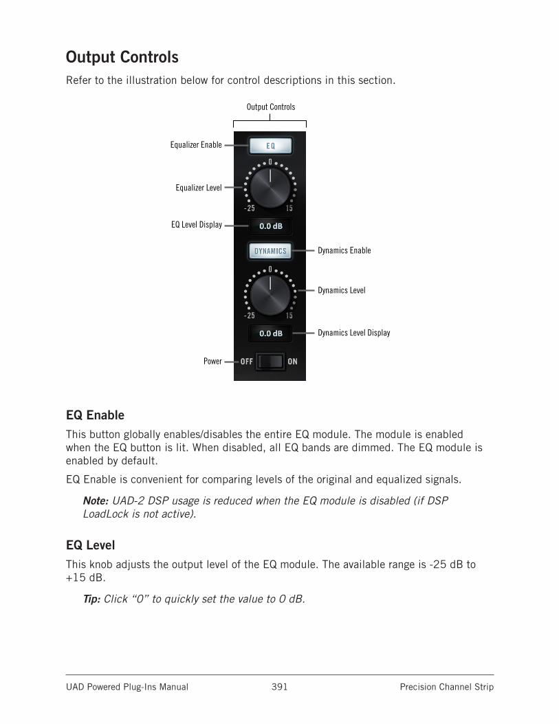
UAD Powered Plug-Ins Manual Precision Channel Strip 391
Output ControlsRefer to the illustration below for control descriptions in this section.
Output Controls
Equalizer Enable
Dynamics Enable
Equalizer Level
EQ Level Display
Dynamics Level Display
Dynamics Level
Power
EQ EnableThis button globally enables/disables the entire EQ module. The module is enabled when the EQ button is lit. When disabled, all EQ bands are dimmed. The EQ module is enabled by default.
EQ Enable is convenient for comparing levels of the original and equalized signals.
Note: UAD-2 DSP usage is reduced when the EQ module is disabled (if DSP LoadLock is not active).
EQ LevelThis knob adjusts the output level of the EQ module. The available range is -25 dB to +15 dB.
Tip: Click “0” to quickly set the value to 0 dB.
UAD Powered Plug-Ins Manual Precision Channel Strip 392
Dynamics EnableThis button globally enables/disables the entire dynamics module. The module is enabled when the DYNAMICS button is lit. When disabled, all dynamics parameters and display fields are dimmed. The dynamics module is enabled by default.
Dynamics Enable is convenient for comparing levels of the original and compressed signals.
Note: UAD-2 DSP usage is reduced when the dynamics module is disabled (if DSP LoadLock is not active).
Dynamics LevelThis knob adjusts the output level of the dynamics module. The available range is -25 dB to +15 dB.
Note: Click “0” to quickly set the value to 0 dB.
PowerPower is the plug-in bypass control. When set to OFF, all parameter and meter values are no longer visible, and the UA logo is dimmed.
Tip: Power can also be toggled by clicking the UA diamond logo.
If DSP LoadLock is disabled, UAD-2 DSP usage is reduced when the plug-in is bypassed. The DSP LoadLock setting is in the UAD Meter & Control Panel application.
Power is useful for comparing the processed settings to the original signal. Unlike the host application’s plug-in disable switch, which can cause audio artifacts, the Power switch offers glitch-free bypass.
EX-1 MigrationAs of UAD v8.2, Precision Channel Strip replaces the original EX-1 plug-in. When a session containing EX-1 is opened in UAD v8.2 and later, EX-1 plug-in instances, settings, and presets are automatically migrated to the newer Precision Channel Strip.
For additional information about how EX-1 migration is handled, see Migrating Prior Sessions in the CS-1 chapter.
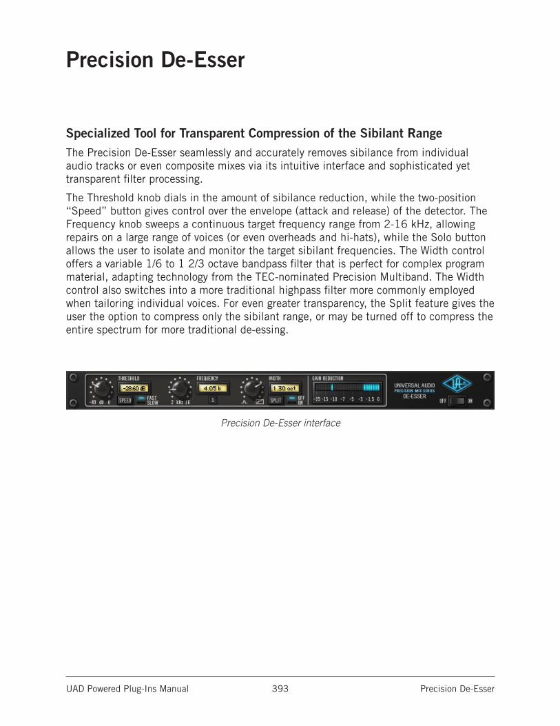
UAD Powered Plug-Ins Manual Precision De-Esser 393
Precision De-Esser
Specialized Tool for Transparent Compression of the Sibilant RangeThe Precision De-Esser seamlessly and accurately removes sibilance from individual audio tracks or even composite mixes via its intuitive interface and sophisticated yet transparent filter processing.
The Threshold knob dials in the amount of sibilance reduction, while the two-position “Speed” button gives control over the envelope (attack and release) of the detector. The Frequency knob sweeps a continuous target frequency range from 2-16 kHz, allowing repairs on a large range of voices (or even overheads and hi-hats), while the Solo button allows the user to isolate and monitor the target sibilant frequencies. The Width control offers a variable 1/6 to 1 2/3 octave bandpass filter that is perfect for complex program material, adapting technology from the TEC-nominated Precision Multiband. The Width control also switches into a more traditional highpass filter more commonly employed when tailoring individual voices. For even greater transparency, the Split feature gives the user the option to compress only the sibilant range, or may be turned off to compress the entire spectrum for more traditional de-essing.
Precision De-Esser interface
UAD Powered Plug-Ins Manual Precision De-Esser 394
Precision De-Esser ControlsControl knobs for the Precision De-Esser behave the same way as all UAD plug-ins. Threshold, Frequency, and Width values can be modified with text entry.
ThresholdThreshold controls the amount of de-essing by defining the signal level at which the processor is activated. Rotate Threshold counter-clockwise for more de-essing.
Signals peaks as determined by Frequency and Width that exceed the Threshold level are compressed by a ratio of 7:1.
The available range is -40 dB to 0 dB.
SpeedSpeed determines the response of the sibilance detector. Fast mode will usually make sibilance reduction more obvious. In Slow mode the effect is usually more subtle but can produce a more natural-sounding result. The actual times of the two modes are as follows:
• Fast: Attack = 0.5ms, Release = 30ms.
• Slow: Attack = 2.0ms, Release = 120ms.
Click the Speed button to change the mode. Alternately, you can click+hold the LED area and drag like a slider to change the value.
FrequencyThis control defines the center frequency of the de-esser when in bandpass mode, or the cutoff frequency of the de-esser when in highpass mode. For bandpass use, the value is set to the center of the undesirable frequency range that is to be reduced. For highpass use, the value is set below the frequency range that is to be reduced. Used in conjunction with the Width control, a broad range of de-essing is possible.
The available range is 2 kHz - 16 kHz.
SoloThe Solo button isolates the de-essing sidechain (the signal defined by the Frequency and Width controls). Solo makes it easier to hear the problem frequencies to be attenuated.
Click the button to active Solo mode. The button is red when Solo is active.
Note: When Solo is active, changes to the Threshold and Split controls cannot be heard.
UAD Powered Plug-Ins Manual Precision De-Esser 395
WidthWidth controls the bandwidth of the de-essing sidechain when in bandpass mode. Bandpass mode is active when the control is in any position except fully clockwise.
Smaller values have a narrower bandwidth, causing a tighter, more focused de-essing effect. Higher values have wider bandwidth, for de-essing when undesirable frequency ranges are broader.
When Width is rotated fully clockwise, High Pass mode is activated. In High Pass mode, Frequency defines the cutoff frequency of the high pass filter (instead of the center frequency of the bandpass filter). High Pass mode is useful when you want to attenuate all frequencies above the cutoff frequency.
The available range is 0.15 (about 1/6 octave) to 1.61 (about 1 2/3 octaves), plus High Pass mode.
Note: UAD DSP usage is slightly decreased when Precision De-Esser is in High Pass mode versus bandpass mode (unless UAD-2 DSP LoadLock is enabled).
SplitSplit determines if attenuation (compression) is applied to the sidechain signal only, or to the entire audio signal.
In normal use Split should be enabled, causing only the “ess” spectrum as defined by Frequency and Width (i.e., the sidechain), to be attenuated. This provides the most precise de-essing control.
Split can be disabled, which causes the entire input signal to be attenuated (instead of just the “ess” sidechain) which results in more traditional compression. However, the sidechain still controls attenuation when Split is off.
Click the Split button to change the mode. Alternately, you can click+hold the LED area and drag like a slider to change the value.
Note: UAD DSP usage is slightly decreased when Split is disabled (unless UAD-2 DSP LoadLock is enabled).
Gain ReductionThe Gain Reduction meter provides a visual indication of how much attenuation (compression) is occurring. Signal peaks are held for 3 seconds before resetting.
When Split is on, the amount of sidechain attenuation is displayed. When Split is off, it displays the attenuation of the entire signal.
UAD Powered Plug-Ins Manual Precision De-Esser 396
PowerThe Power switch determines whether the plug-in is active. This is useful for comparing the processed settings to the original signal or bypassing the plug-in to reduce the UAD DSP load (load is not reduced if UAD-2 DSP LoadLock is enabled).
Toggle the switch to change the Power state; the UA logo is illuminated in blue when the plug-in is active.
Note: You can click-hold the power switch then drag it like a slider to quickly compare the enabled/disabled state.
Operating Tips• For taming sibilance for a full mix/mastering, best results will usually be obtained
by enabling Highpass and Split modes.
• Generally, female “ess” and “shh” sounds vary more in frequency than those of males. Due to this situation, you may find that using the sidechain filter in High-pass mode (or Bandpass mode with a large width) may be more responsive.
• Over de-essing can degrade the natural sound of a vocal.
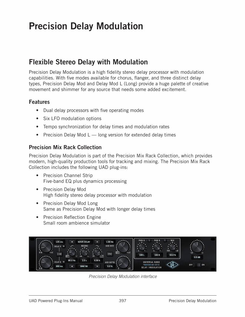
UAD Powered Plug-Ins Manual Precision Delay Modulation 397
Precision Delay Modulation
Flexible Stereo Delay with ModulationPrecision Delay Modulation is a high fidelity stereo delay processor with modulation capabilities. With five modes available for chorus, flanger, and three distinct delay types, Precision Delay Mod and Delay Mod L (Long) provide a huge palette of creative movement and shimmer for any source that needs some added excitement.
Features• Dual delay processors with five operating modes
• Six LFO modulation options
• Tempo synchronization for delay times and modulation rates
• Precision Delay Mod L — long version for extended delay times
Precision Mix Rack CollectionPrecision Delay Modulation is part of the Precision Mix Rack Collection, which provides modern, high-quality production tools for tracking and mixing. The Precision Mix Rack Collection includes the following UAD plug-ins:
• Precision Channel Strip Five-band EQ plus dynamics processing
• Precision Delay Mod High fidelity stereo delay processor with modulation
• Precision Delay Mod Long Same as Precision Delay Mod with longer delay times
• Precision Reflection Engine Small room ambience simulator
Precision Delay Modulation interface
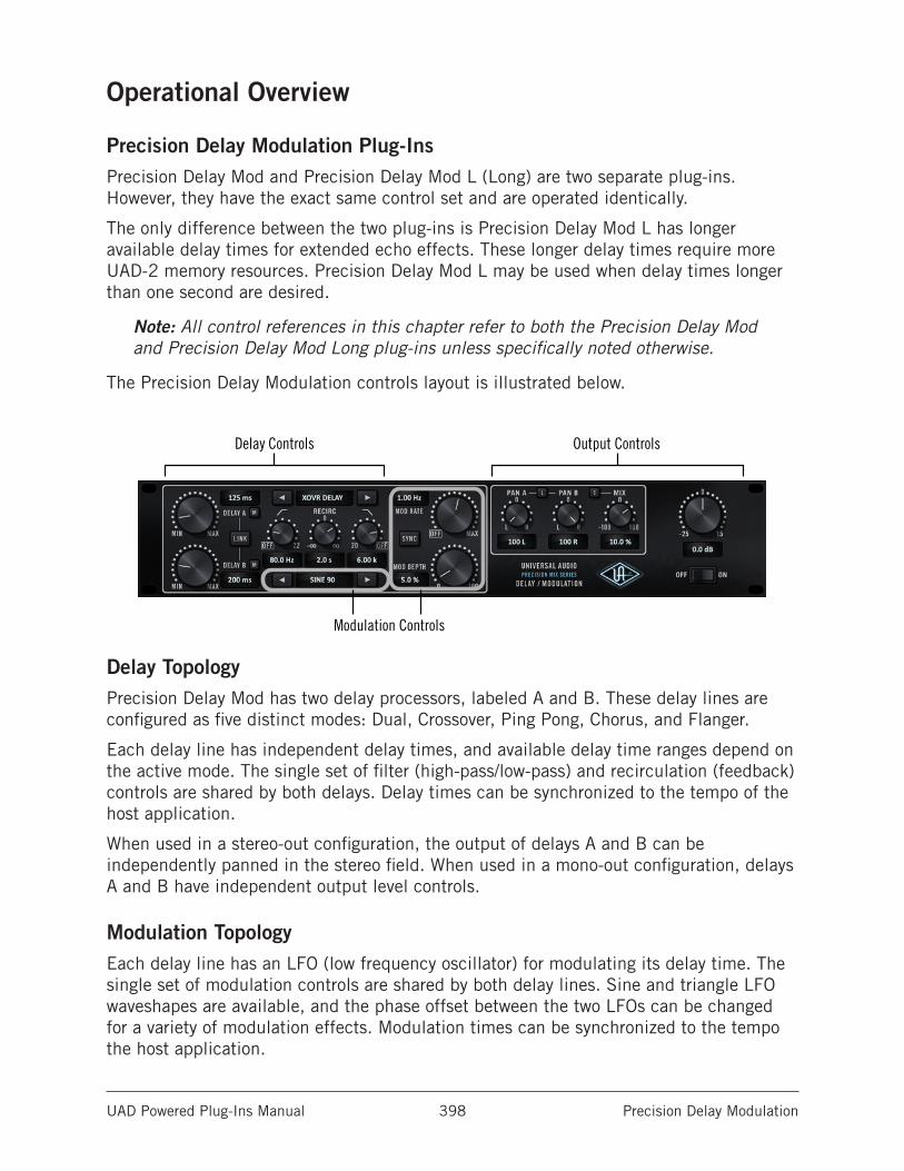
UAD Powered Plug-Ins Manual Precision Delay Modulation 398
Operational Overview
Precision Delay Modulation Plug-InsPrecision Delay Mod and Precision Delay Mod L (Long) are two separate plug-ins. However, they have the exact same control set and are operated identically.
The only difference between the two plug-ins is Precision Delay Mod L has longer available delay times for extended echo effects. These longer delay times require more UAD-2 memory resources. Precision Delay Mod L may be used when delay times longer than one second are desired.
Note: All control references in this chapter refer to both the Precision Delay Mod and Precision Delay Mod Long plug-ins unless specifically noted otherwise.
The Precision Delay Modulation controls layout is illustrated below.
Delay Controls
Modulation Controls
Output Controls
Delay TopologyPrecision Delay Mod has two delay processors, labeled A and B. These delay lines are configured as five distinct modes: Dual, Crossover, Ping Pong, Chorus, and Flanger.
Each delay line has independent delay times, and available delay time ranges depend on the active mode. The single set of filter (high-pass/low-pass) and recirculation (feedback) controls are shared by both delays. Delay times can be synchronized to the tempo of the host application.
When used in a stereo-out configuration, the output of delays A and B can be independently panned in the stereo field. When used in a mono-out configuration, delays A and B have independent output level controls.
Modulation TopologyEach delay line has an LFO (low frequency oscillator) for modulating its delay time. The single set of modulation controls are shared by both delay lines. Sine and triangle LFO waveshapes are available, and the phase offset between the two LFOs can be changed for a variety of modulation effects. Modulation times can be synchronized to the tempo the host application.
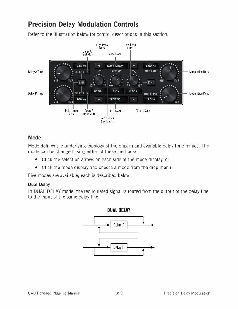
UAD Powered Plug-Ins Manual Precision Delay Modulation 399
Precision Delay Modulation ControlsRefer to the illustration below for control descriptions in this section.
ModeMode defines the underlying topology of the plug-in and available delay time ranges. The mode can be changed using either of these methods:
• Click the selection arrows on each side of the mode display, or
• Click the mode display and choose a mode from the drop menu.
Five modes are available; each is described below.
Dual DelayIn DUAL DELAY mode, the recirculated signal is routed from the output of the delay line to the input of the same delay line.
Delay A
Delay B
DUAL DELAY XOVR DELAY
Delay A
Delay B
PING PONG
Delay A
Delay B100%
L+R(summed)
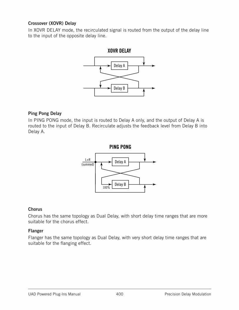
UAD Powered Plug-Ins Manual Precision Delay Modulation 400
Crossover (XOVR) DelayIn XOVR DELAY mode, the recirculated signal is routed from the output of the delay line to the input of the opposite delay line.
Delay A
Delay B
DUAL DELAY XOVR DELAY
Delay A
Delay B
PING PONG
Delay A
Delay B100%
L+R(summed)
Ping Pong DelayIn PING PONG mode, the input is routed to Delay A only, and the output of Delay A is routed to the input of Delay B. Recirculate adjusts the feedback level from Delay B into Delay A.
Delay A
Delay B
DUAL DELAY XOVR DELAY
Delay A
Delay B
PING PONG
Delay A
Delay B100%
L+R(summed)
ChorusChorus has the same topology as Dual Delay, with short delay time ranges that are more suitable for the chorus effect.
FlangerFlanger has the same topology as Dual Delay, with very short delay time ranges that are suitable for the flanging effect.
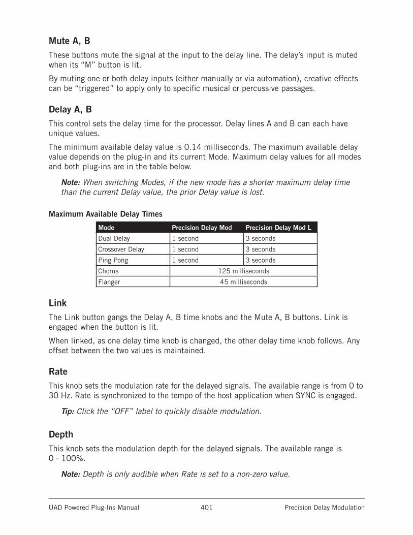
UAD Powered Plug-Ins Manual Precision Delay Modulation 401
Mute A, BThese buttons mute the signal at the input to the delay line. The delay’s input is muted when its “M” button is lit.
By muting one or both delay inputs (either manually or via automation), creative effects can be “triggered” to apply only to specific musical or percussive passages.
Delay A, BThis control sets the delay time for the processor. Delay lines A and B can each have unique values.
The minimum available delay value is 0.14 milliseconds. The maximum available delay value depends on the plug-in and its current Mode. Maximum delay values for all modes and both plug-ins are in the table below.
Note: When switching Modes, if the new mode has a shorter maximum delay time than the current Delay value, the prior Delay value is lost.
Maximum Available Delay Times
Mode Precision Delay Mod Precision Delay Mod L
Dual Delay 1 second 3 seconds
Crossover Delay 1 second 3 seconds
Ping Pong 1 second 3 seconds
Chorus 125 milliseconds
Flanger 45 milliseconds
LinkThe Link button gangs the Delay A, B time knobs and the Mute A, B buttons. Link is engaged when the button is lit.
When linked, as one delay time knob is changed, the other delay time knob follows. Any offset between the two values is maintained.
RateThis knob sets the modulation rate for the delayed signals. The available range is from 0 to 30 Hz. Rate is synchronized to the tempo of the host application when SYNC is engaged.
Tip: Click the “OFF” label to quickly disable modulation.
DepthThis knob sets the modulation depth for the delayed signals. The available range is 0 - 100%.
Note: Depth is only audible when Rate is set to a non-zero value.
UAD Powered Plug-Ins Manual Precision Delay Modulation 402
LFOThis menu defines the LFO (low frequency oscillator) waveshape and phase used to modulate the delayed signals. The LFO can be changed using either of these methods:
• Click the selection arrows on each side of the LFO display, or
• Click the LFO display and choose a mode from the drop menu.
The waveshape can be set to triangle or sine, each with a phase value of 0, 90, or 180 degrees.
SyncWhen Sync is enabled, delay times and modulation rates are synchronized to the host’s tempo. Sync is active when the button is lit. Sync is disabled by default.
When Sync is off, delay times are in milliseconds, and modulation rates are in Hertz. When Sync is on, delay times and modulation rates are displayed as fractional beat/bar values.
Note: For complete details about this feature, see the “Tempo Synchronization” chapter in the UAD System Manual.
RecirculationRecirculation (feedback) controls the amount of delayed signal routed back to its input. Higher values increase the number of delays and intensity of the processed signal.
Recirculation allows both positive and negative values. With positive values, the polarity of the feedback signal is in phase with the original source signal. With negative values, the polarity of the feedback signal is inverted.
Tip: Click the “0” label to quickly disable recirculation.
In Dual Delay, Crossover Delay, and Ping Pong modes, recirculation values are displayed as T60 time (the time before the signal drops 60 dB). In Chorus and Flanger modes, values are displayed as a percentage.
UAD Powered Plug-Ins Manual Precision Delay Modulation 403
High PassThe 12 dB per octave high pass (low cut) filter reduces low frequencies at the input to the delays. The filter affects the delayed (wet) signals only. The available frequency range is from 20 Hz to 22 kHz.
Rotate the knob clockwise to reduce low frequencies in the delay lines. The filter is disabled when rotated to the fully counter-clockwise position.
Tip: Click the “OFF” label to quickly disable the filter. Click again to return to the previous value.
Low PassThe 6 dB per octave low pass (high cut) damping filter reduces high frequencies at the input to the delays. The filter affects the delayed (wet) signals only. The available frequency range is from 20 Hz to 22 kHz.
Rotate the knob counter-clockwise to reduce high frequencies in the delay lines. The filter is disabled when rotated to the fully clockwise position.
Tip: Click the “OFF” label to quickly disable the filter. Click again to return to the previous value.
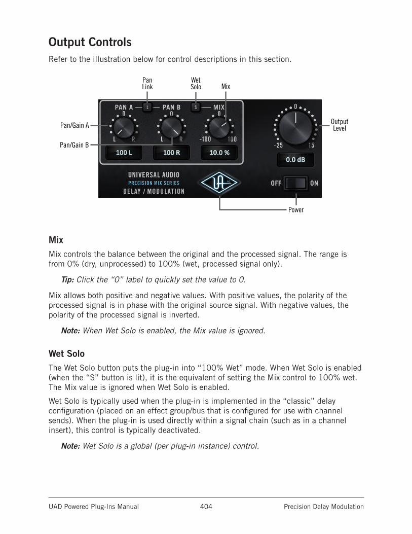
UAD Powered Plug-Ins Manual Precision Delay Modulation 404
Output ControlsRefer to the illustration below for control descriptions in this section.
Pan/Gain A
Pan/Gain B
PanLink
WetSolo Mix
OutputLevel
Power
MixMix controls the balance between the original and the processed signal. The range is from 0% (dry, unprocessed) to 100% (wet, processed signal only).
Tip: Click the “0” label to quickly set the value to 0.
Mix allows both positive and negative values. With positive values, the polarity of the processed signal is in phase with the original source signal. With negative values, the polarity of the processed signal is inverted.
Note: When Wet Solo is enabled, the Mix value is ignored.
Wet SoloThe Wet Solo button puts the plug-in into “100% Wet” mode. When Wet Solo is enabled (when the “S” button is lit), it is the equivalent of setting the Mix control to 100% wet. The Mix value is ignored when Wet Solo is enabled.
Wet Solo is typically used when the plug-in is implemented in the “classic” delay configuration (placed on an effect group/bus that is configured for use with channel sends). When the plug-in is used directly within a signal chain (such as in a channel insert), this control is typically deactivated.
Note: Wet Solo is a global (per plug-in instance) control.
UAD Powered Plug-Ins Manual Precision Delay Modulation 405
Pan A, BWhen the plug-in is used in a stereo-out configuration, these knobs are labeled “PAN” and determine the placement of the individual delay line’s output in the stereo panoramic field.
Tip: Click the “0” label to quickly center the signal in the stereo field.
Pan LinkWhen Pan Link is engaged (when the “L” button is lit), the Pan A and Pan B knobs are ganged, facilitating the ability to quickly narrow or spread the placement of the delay line outputs in the stereo panoramic field.
Note: When the plug-in is used in a mono-out configuration, this button is disabled.
Gain A, BWhen the plug-in is used in a mono-out configuration, these knobs are labeled “GAIN” and determine the output level of the individual delay line.
Note: The Gain A, B controls cannot be linked.
The automation labels are “Pan” for these controls, even when used in a mono-out configuration.
LevelThis knob adjusts the output level of the plug-in. The available range is -25 dB to +15 dB.
Tip: Click “0” to quickly set the value to 0 dB.
PowerPower is the plug-in bypass control. When set to OFF, all parameter and meter values are no longer visible, and the UA logo is dimmed.
Tip: Power can also be toggled by clicking the UA diamond logo.
Power is useful for comparing the processed settings to the original signal. Unlike the host application’s plug-in disable switch, which can cause audio artifacts, the Power switch offers glitch-free bypass.
DM-1/DM-1L MigrationAs of UAD v8.2, Precision Delay Modulation replaces the original DM-1 and DM-1L plug-ins. When a session containing DM-1/DM-1L is opened in UAD v8.2 and later, DM-1/DM-1L plug-in instances and settings are automatically migrated to the newer Precision Delay Modulation.
For additional information about how DM-1/DM-1L migration is handled, see Migrating Prior Sessions in the CS-1 chapter.
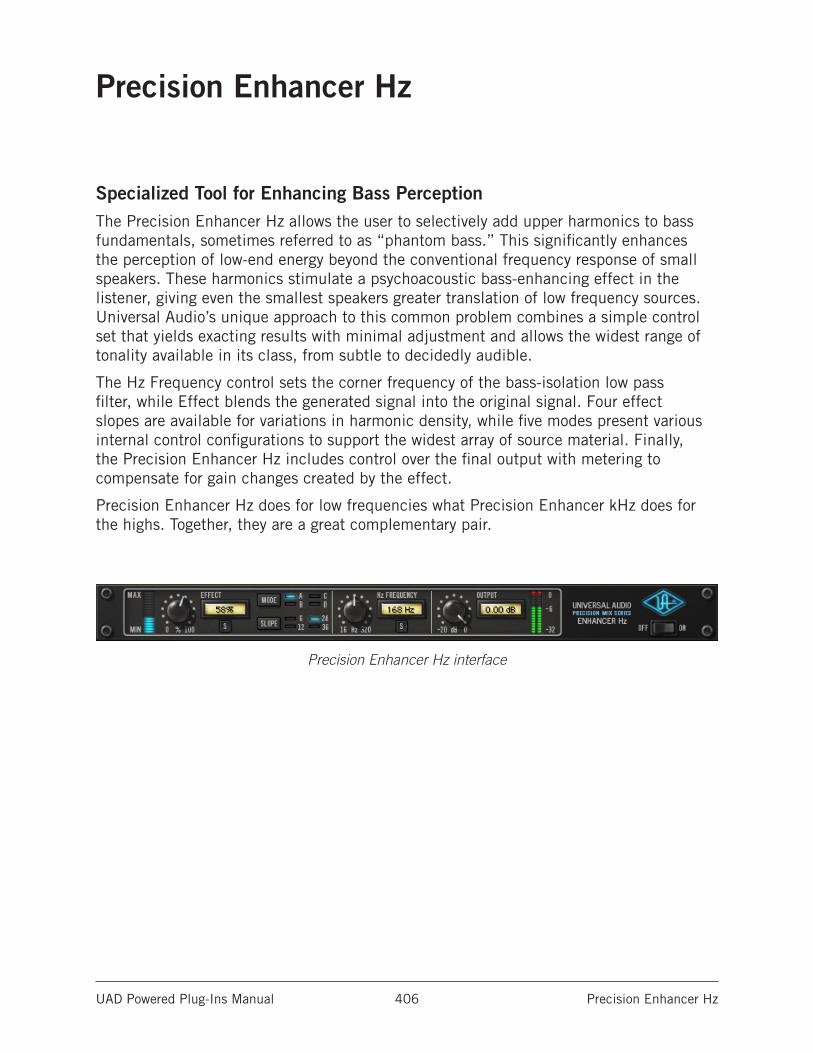
UAD Powered Plug-Ins Manual Precision Enhancer Hz 406
Precision Enhancer Hz
Specialized Tool for Enhancing Bass PerceptionThe Precision Enhancer Hz allows the user to selectively add upper harmonics to bass fundamentals, sometimes referred to as “phantom bass.” This significantly enhances the perception of low-end energy beyond the conventional frequency response of small speakers. These harmonics stimulate a psychoacoustic bass-enhancing effect in the listener, giving even the smallest speakers greater translation of low frequency sources. Universal Audio’s unique approach to this common problem combines a simple control set that yields exacting results with minimal adjustment and allows the widest range of tonality available in its class, from subtle to decidedly audible.
The Hz Frequency control sets the corner frequency of the bass-isolation low pass filter, while Effect blends the generated signal into the original signal. Four effect slopes are available for variations in harmonic density, while five modes present various internal control configurations to support the widest array of source material. Finally, the Precision Enhancer Hz includes control over the final output with metering to compensate for gain changes created by the effect.
Precision Enhancer Hz does for low frequencies what Precision Enhancer kHz does for the highs. Together, they are a great complementary pair.
Precision Enhancer Hz interface
UAD Powered Plug-Ins Manual Precision Enhancer Hz 407
Precision Enhancer Hz ControlsControl knobs for the Precision Enhancer Hz behave the same way as with all UAD plug-ins. Effect, Hz Frequency, and Output values can be modified with text entry.
Effect KnobThe Effect Knob controls the amount of processing that occurs in the plug-in. The available range is from 0.00 to 100.0%.
Technically speaking, Effect scales the input to the enhancer. Increasing this parameter makes the enhancer have a higher amplitude output for a given input level. Increasing Effect increases the overall enhancement effect.
Note: The signal level at the plug-in input will interact with the Effect control.
Effect MeterThe Effect Meter indicates the amount of signal processing that is occurring. More illuminated blue segments indicate more signal enhancement.
Effect SoloEffect Solo isolates the generated signal and is affected by Effect level. Effect Solo is active when the button is red.
The Effect Solo signal is “pure” and contains no added original or filtered bass signal. Therefore the soloed signal may not sound “pleasant” when heard by itself. When Effect Solo is used in conjunction with Hz Solo, the complete “mixed” effect is heard.
ModeThe five Modes (A, B, C, D, and “All”) optimize the plug-in internally to support the widest array of source material. The Mode control determines the type of enhancement that will be applied to the signal.
Tip: The active Mode can be selected by clicking the Mode button repeatedly to rotate through the Modes, or by clicking each Mode letter or LED.
Mode A (Bass 1)Mode A is tuned for both acoustic and electric bass instruments. Adds low frequency emphasis when set to low frequency value, mid to high frequencies aid in phantom bass generation for smaller sound systems.
Mode B (Bass 2)Mode B is primarily for electric and DI bass with balanced mid range harmonics to help the bass stick out of the mix.
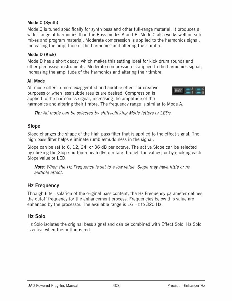
UAD Powered Plug-Ins Manual Precision Enhancer Hz 408
Mode C (Synth)Mode C is tuned specifically for synth bass and other full-range material. It produces a wider range of harmonics than the Bass modes A and B. Mode C also works well on sub-mixes and program material. Moderate compression is applied to the harmonics signal, increasing the amplitude of the harmonics and altering their timbre.
Mode D (Kick)Mode D has a short decay, which makes this setting ideal for kick drum sounds and other percussive instruments. Moderate compression is applied to the harmonics signal, increasing the amplitude of the harmonics and altering their timbre.
All ModeAll mode offers a more exaggerated and audible effect for creative purposes or when less subtle results are desired. Compression is applied to the harmonics signal, increasing the amplitude of the harmonics and altering their timbre. The frequency range is similar to Mode A.
Tip: All mode can be selected by shift+clicking Mode letters or LEDs.
SlopeSlope changes the shape of the high pass filter that is applied to the effect signal. The high pass filter helps eliminate rumble/muddiness in the signal.
Slope can be set to 6, 12, 24, or 36 dB per octave. The active Slope can be selected by clicking the Slope button repeatedly to rotate through the values, or by clicking each Slope value or LED.
Note: When the Hz Frequency is set to a low value, Slope may have little or no audible effect.
Hz FrequencyThrough filter isolation of the original bass content, the Hz Frequency parameter defines the cutoff frequency for the enhancement process. Frequencies below this value are enhanced by the processor. The available range is 16 Hz to 320 Hz.
Hz SoloHz Solo isolates the original bass signal and can be combined with Effect Solo. Hz Solo is active when the button is red.
UAD Powered Plug-Ins Manual Precision Enhancer Hz 409
OutputOutput controls the signal level that is output from the plug-in. The available range is -20 dB to 0 dB.
Generally speaking, adjust the Output control after the desired amount of processing is achieved with the Effect and Hz Frequency controls. Output does not affect the amount of enhancement processing, nor does it have any effect when the plug-in is disabled.
Output MeterThe stereo Output Meter displays the signal level at the output of the plug-in.
When the plug-in is disabled with the plug-in Power switch (but not the host plug-in enable switch), the output meters still function.
PowerThe Power switch determines whether the plug-in is active. This is useful for comparing the processed settings to the original signal or bypassing the plug-in to reduce the UAD DSP load (load is not reduced if UAD-2 DSP LoadLock is enabled).
Toggle the switch or click the UA logo to change the Power state. The UA logo is illuminated in blue when the plug-in is active.
Operating Tips• The Precision Enhancer Hz effect can serve multiple purposes. When the
frequency control is set low, the effect extends into the audible low end. Lower frequencies work well for adding a low end thump or beefing up percussive bass/kicks, but be careful not to overdo it. With the frequency control set to mid to higher frequencies, the effect is designed to add bass tone that would ordinarily disappear on smaller speakers.
• For the most predictable results, it is recommended to audition the mix on both full range systems with a subwoofer, as well as small consumer systems such as a boombox or computer speakers.
• A different effect response will be achieved when the plug-in is used pre-compression. It is recommended to experiment with processing order as results can vary substantially.
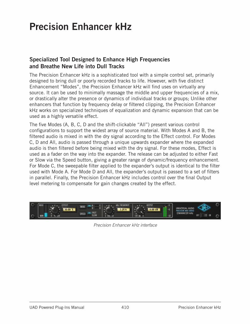
UAD Powered Plug-Ins Manual Precision Enhancer kHz 410
Precision Enhancer kHz
Specialized Tool Designed to Enhance High Frequencies and Breathe New Life into Dull TracksThe Precision Enhancer kHz is a sophisticated tool with a simple control set, primarily designed to bring dull or poorly recorded tracks to life. However, with five distinct Enhancement “Modes”, the Precision Enhancer kHz will find uses on virtually any source. It can be used to minimally massage the middle and upper frequencies of a mix, or drastically alter the presence or dynamics of individual tracks or groups; Unlike other enhancers that function by frequency delay or filtered clipping, the Precision Enhancer kHz works on specialized techniques of equalization and dynamic expansion that can be used as a highly versatile effect.
The five Modes (A, B, C, D and the shift-clickable “All”) present various control configurations to support the widest array of source material. With Modes A and B, the filtered audio is mixed in with the dry signal according to the Effect control. For Modes C, D and All, audio is passed through a unique upwards expander where the expanded audio is then filtered before being mixed with the dry signal. For these modes, Effect is used as a fader on the way into the expander. The release can be adjusted to either Fast or Slow via the Speed button, giving a greater range of dynamic/frequency enhancement. For Mode C, the sweepable filter applied to the expander’s output is identical to the filter used with Mode A. For Mode D and All, the expander’s output is passed to a set of filters in parallel. Finally, the Precision Enhancer kHz includes control over the final Output level metering to compensate for gain changes created by the effect.
Precision Enhancer kHz interface
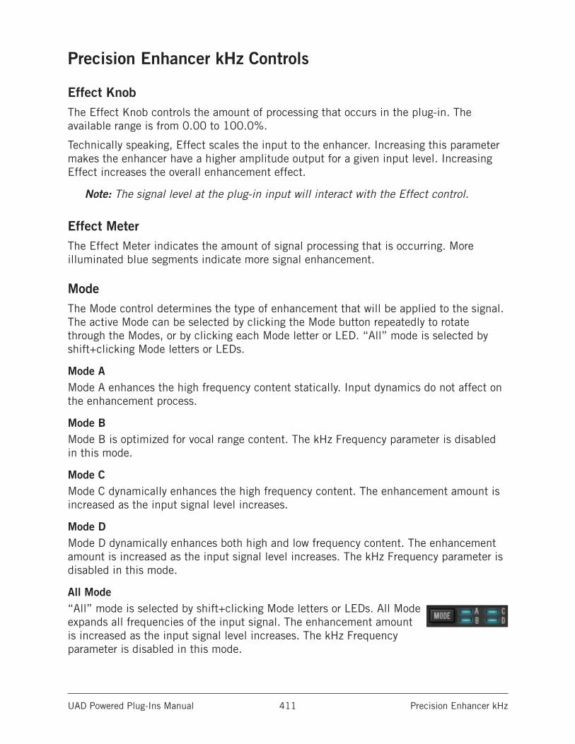
UAD Powered Plug-Ins Manual Precision Enhancer kHz 411
Precision Enhancer kHz Controls
Effect KnobThe Effect Knob controls the amount of processing that occurs in the plug-in. The available range is from 0.00 to 100.0%.
Technically speaking, Effect scales the input to the enhancer. Increasing this parameter makes the enhancer have a higher amplitude output for a given input level. Increasing Effect increases the overall enhancement effect.
Note: The signal level at the plug-in input will interact with the Effect control.
Effect MeterThe Effect Meter indicates the amount of signal processing that is occurring. More illuminated blue segments indicate more signal enhancement.
ModeThe Mode control determines the type of enhancement that will be applied to the signal. The active Mode can be selected by clicking the Mode button repeatedly to rotate through the Modes, or by clicking each Mode letter or LED. “All” mode is selected by shift+clicking Mode letters or LEDs.
Mode AMode A enhances the high frequency content statically. Input dynamics do not affect on the enhancement process.
Mode BMode B is optimized for vocal range content. The kHz Frequency parameter is disabled in this mode.
Mode CMode C dynamically enhances the high frequency content. The enhancement amount is increased as the input signal level increases.
Mode DMode D dynamically enhances both high and low frequency content. The enhancement amount is increased as the input signal level increases. The kHz Frequency parameter is disabled in this mode.
All Mode“All” mode is selected by shift+clicking Mode letters or LEDs. All Mode expands all frequencies of the input signal. The enhancement amount is increased as the input signal level increases. The kHz Frequency parameter is disabled in this mode.
UAD Powered Plug-Ins Manual Precision Enhancer kHz 412
SpeedThe Speed parameter defines the attack and release characteristic of the enhancement process.
FastIn Fast mode, the enhancement processor has a quick response time of 30 ms, which yields a more percussive “bite” and/or a more aggressive sound.
SlowSlow mode has a slower response time of 180 ms which can deliver a smoother sound overall.
kHz FrequencyThe kHz Frequency parameter defines the cutoff frequency for the enhancement process in Mode A and Mode C. Frequencies above this value are enhanced by the processor. The available range is 1.00 kHz to 10.0 kHz.
Note: kHz Frequency is disabled in Modes B, D, and All.
OutputOutput controls the signal level that is output from the plug-in. The available range is -20 dB to 0 dB.
Generally speaking, adjust the Output control after the desired amount of processing is achieved with the Effect and kHz Frequency controls. Output does not affect the amount of enhancement processing, nor does it have any effect when the plug-in is disabled.
Output MeterThe Output Meter displays the signal level at the output of the plug-in.
When the plug-in is disabled with the plug-in Power switch (but not the host plug-in enable switch), the output meters still function.
PowerThe Power switch determines whether the plug-in is active. This is useful for comparing the processed settings to the original signal or bypassing the plug-in to reduce the UAD DSP load (load is not reduced if UAD-2 DSP LoadLock is enabled).
Toggle the switch or click the UA logo to change the Power state. The UA logo is illuminated in blue when the plug-in is active.
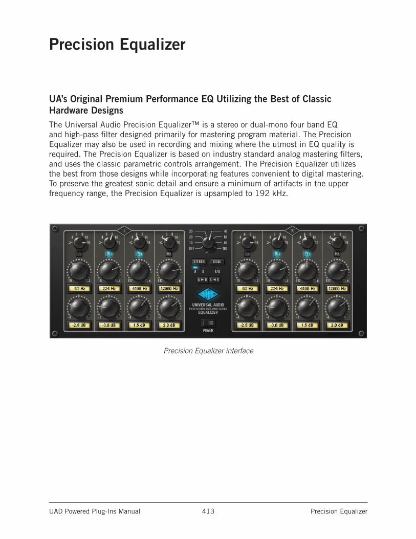
UAD Powered Plug-Ins Manual Precision Equalizer 413
Precision Equalizer
UA’s Original Premium Performance EQ Utilizing the Best of Classic Hardware DesignsThe Universal Audio Precision Equalizer™ is a stereo or dual-mono four band EQ and high-pass filter designed primarily for mastering program material. The Precision Equalizer may also be used in recording and mixing where the utmost in EQ quality is required. The Precision Equalizer is based on industry standard analog mastering filters, and uses the classic parametric controls arrangement. The Precision Equalizer utilizes the best from those designs while incorporating features convenient to digital mastering. To preserve the greatest sonic detail and ensure a minimum of artifacts in the upper frequency range, the Precision Equalizer is upsampled to 192 kHz.
Precision Equalizer interface
UAD Powered Plug-Ins Manual Precision Equalizer 414
Precision Equalizer ControlsThe easy to use Precision Equalizer features stepped controls throughout for easy recall. Both the left and right channels feature four bands of EQ, grouped in two overlapping pairs. There are two bands for low frequencies (L1 and L2), and two for highs (H1 and H2). There is also a shelving or peak/notch filter available for each band, along with five peak/notch (Q) responses per band. The high-pass filter is a far-reaching 18 dB per octave, which enables precise filtering of power-robbing sub-harmonic content, or other creative uses.
The Precision Equalizer also features flexibility in auditioning. There are three separate EQ configurations, allowing selection of two complete sets of stereo parameters or the Dual mode when disparate channel adjustments are necessary. In addition, parameter values can be easily transferred between parameter groups using the Copy buttons.
Control GroupingThe L and R equalizer sections are independent groups of parameters, each controlling one side (left or right) of the stereo source signal.
The L and R controls are linked except when in Dual mode. In Dual mode, control groups L and R can be independently adjusted.
ModesThe Mode switches define the operating mode of Precision Equalizer. The currently active mode is indicated by a blue light. Each mode is detailed below.
Stereo ModeIn Stereo mode, the L and R equalizer sections both control one side of the stereo source signal. The L and R controls are linked in stereo mode.
In stereo mode there are two sets of EQ settings (referred to as A and B), with each set containing the full set of L and R parameter values (the high-pass filter value is global per preset). This feature enables easy switching between two EQ settings for comparison purposes. Both the A and B parameter sets are contained within a single Precision Equalizer preset.
UAD Powered Plug-Ins Manual Precision Equalizer 415
Dual ModeIn Dual mode (dual-mono mode), the left and right parameters can be independently adjusted so that each side of the stereo signal can have different EQ settings. Note that this mode is infrequently used during mastering because phase, imaging, and level inconsistencies may be induced in the resulting stereo signal.
Mode SelectionAny of these methods can be used to modify the Mode value:
• Click the Stereo button to cycle through modes A and B
• Click the Dual button to activate dual-mono mode
• Click the indicator light above each mode
• Click+hold+drag the indicator light above each mode
Parameter Copy ButtonsThe Parameter Copy buttons provide an easy method for copying parameter values. The behavior of the buttons is determined by the current operating mode of Precision Equalizer.
Important: The values that existed at the destination before copying are overwritten.
Stereo ModeWhen in Stereo mode, clicking A > B copies the left AND right parameter values from parameter set A to parameter set B, and clicking the A < B button copies all the values from parameter set B to parameter set A.
This feature is useful when you want to make an EQ change to a stereo signal while maintaining the original values so the two settings can be easily compared.
Note: The high-pass filter parameter is global per preset and is not effected by this control.
Parameter Copy in Dual ModeWhen in Dual mode, the A and B buttons behave as left and right channel copy buttons. Clicking A > B copies all the values from the left channel parameters to the right channel parameters, and clicking A < B copies all the values from the right channel parameters to the left channel parameters.
PowerThe Power Switch determines whether the plug-in is active. This is useful for comparing the processed settings to the original signal, or to bypass the plug-in to reduce the UAD DSP load (load is not reduced if UAD-2 DSP LoadLock is enabled).
Click the rocker switch or the blue UA logo to change the Power state.
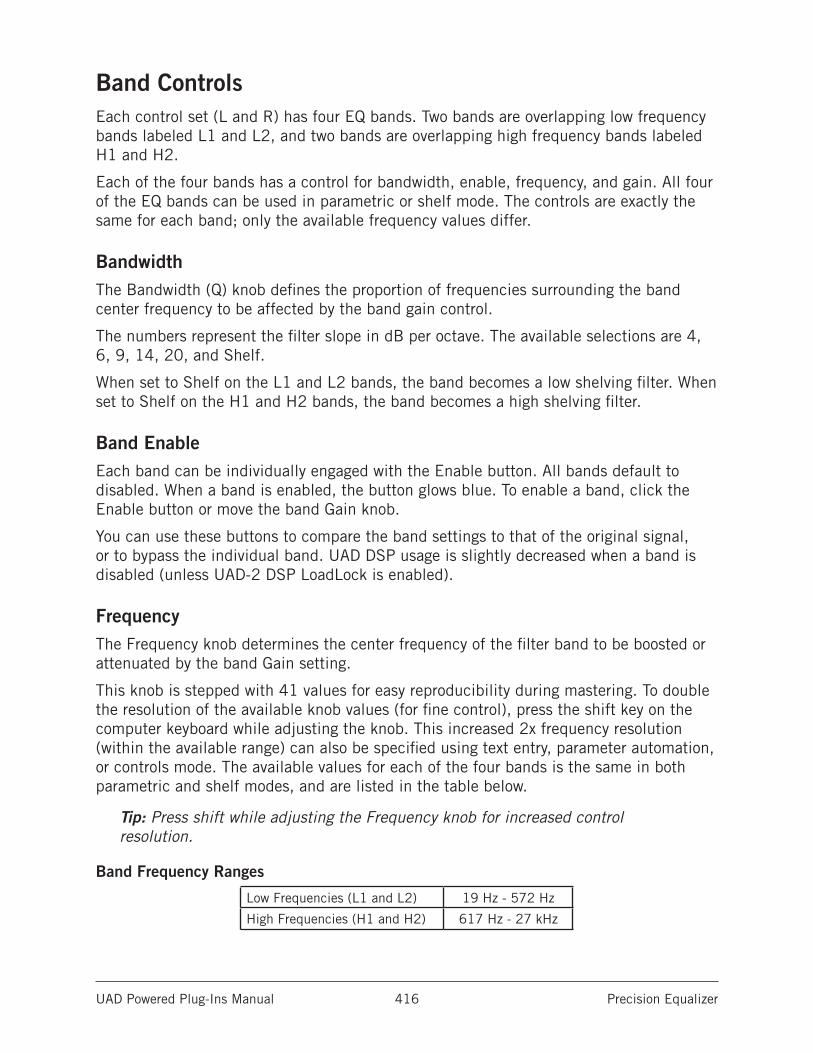
UAD Powered Plug-Ins Manual Precision Equalizer 416
Band ControlsEach control set (L and R) has four EQ bands. Two bands are overlapping low frequency bands labeled L1 and L2, and two bands are overlapping high frequency bands labeled H1 and H2.
Each of the four bands has a control for bandwidth, enable, frequency, and gain. All four of the EQ bands can be used in parametric or shelf mode. The controls are exactly the same for each band; only the available frequency values differ.
BandwidthThe Bandwidth (Q) knob defines the proportion of frequencies surrounding the band center frequency to be affected by the band gain control.
The numbers represent the filter slope in dB per octave. The available selections are 4, 6, 9, 14, 20, and Shelf.
When set to Shelf on the L1 and L2 bands, the band becomes a low shelving filter. When set to Shelf on the H1 and H2 bands, the band becomes a high shelving filter.
Band EnableEach band can be individually engaged with the Enable button. All bands default to disabled. When a band is enabled, the button glows blue. To enable a band, click the Enable button or move the band Gain knob.
You can use these buttons to compare the band settings to that of the original signal, or to bypass the individual band. UAD DSP usage is slightly decreased when a band is disabled (unless UAD-2 DSP LoadLock is enabled).
FrequencyThe Frequency knob determines the center frequency of the filter band to be boosted or attenuated by the band Gain setting.
This knob is stepped with 41 values for easy reproducibility during mastering. To double the resolution of the available knob values (for fine control), press the shift key on the computer keyboard while adjusting the knob. This increased 2x frequency resolution (within the available range) can also be specified using text entry, parameter automation, or controls mode. The available values for each of the four bands is the same in both parametric and shelf modes, and are listed in the table below.
Tip: Press shift while adjusting the Frequency knob for increased control resolution.
Band Frequency Ranges
Low Frequencies (L1 and L2) 19 Hz - 572 Hz
High Frequencies (H1 and H2) 617 Hz - 27 kHz
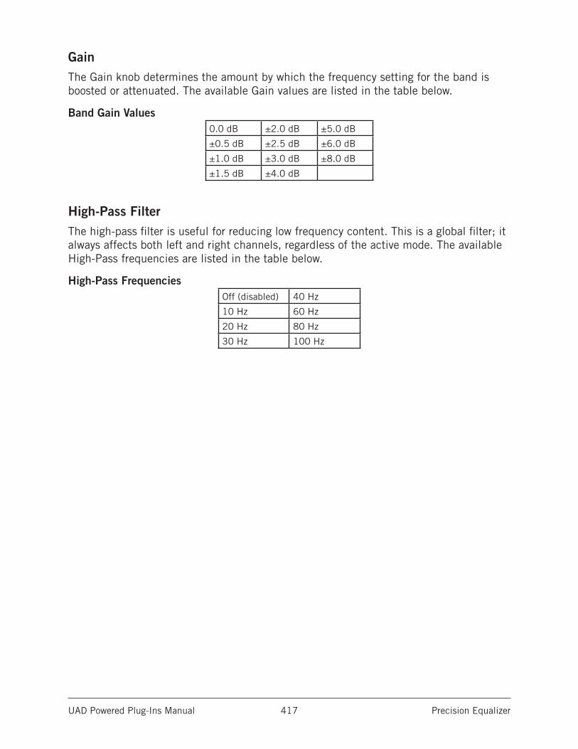
UAD Powered Plug-Ins Manual Precision Equalizer 417
GainThe Gain knob determines the amount by which the frequency setting for the band is boosted or attenuated. The available Gain values are listed in the table below.
Band Gain Values0.0 dB ±2.0 dB ±5.0 dB
±0.5 dB ±2.5 dB ±6.0 dB
±1.0 dB ±3.0 dB ±8.0 dB
±1.5 dB ±4.0 dB
High-Pass FilterThe high-pass filter is useful for reducing low frequency content. This is a global filter; it always affects both left and right channels, regardless of the active mode. The available High-Pass frequencies are listed in the table below.
High-Pass FrequenciesOff (disabled) 40 Hz
10 Hz 60 Hz
20 Hz 80 Hz
30 Hz 100 Hz
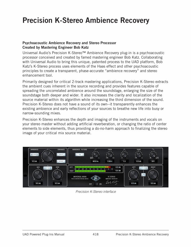
UAD Powered Plug-Ins Manual Precision K-Stereo Ambience Recovery 418
Precision K-Stereo Ambience Recovery
Psychoacoustic Ambience Recovery and Stereo Processor Created by Mastering Engineer Bob KatzUniversal Audio’s Precision K-Stereo™ Ambience Recovery plug-in is a psychoacoustic processor conceived and created by famed mastering engineer Bob Katz. Collaborating with Universal Audio to bring this unique, patented process to the UAD platform, Bob Katz’s K-Stereo process uses elements of the Haas effect and other psychoacoustic principles to create a transparent, phase-accurate “ambience recovery” and stereo enhancement tool.
Primarily designed for critical 2-track mastering applications, Precision K-Stereo extracts the ambient cues inherent in the source recording and provides features capable of spreading the uncorrelated ambience around the soundstage, enlarging the size of the soundstage both deeper and wider. It also increases the clarity and localization of the source material within its algorithm while increasing the third dimension of the sound. Precision K-Stereo does not have a sound of its own--it transparently enhances the existing ambience and early reflections of your sources to breathe new life into busy or narrow-sounding mixes.
Precision K-Stereo enhances the depth and imaging of the instruments and vocals on your stereo master without adding artificial reverberation, or changing the ratio of center elements to side elements, thus providing a do-no-harm approach to finalizing the stereo image of your critical mix source material.
Precision K-Stereo interface
UAD Powered Plug-Ins Manual Precision K-Stereo Ambience Recovery 419
Operational Overview
Ambience RecoveryThe primary function of Precision K-Stereo is for ambience recovery and enhancement. The plug-in doesn’t add new ambience or change the balance of the mix. Instead, it extracts, recovers, polishes, and embellishes the ambience that already exists in a source recording.
Precision K-Stereo does not use any comb filters, matrixing, phase processing, or related techniques which are used in typical image processors. Instead, the ambience recovery process is accomplished using established psychoacoustic principles. The result is a smooth, natural, phase-coherent, and mono-compatible sound that meets professional mastering standards.
In addition to ambience level and enhancement adjustments, the ambient portion of the source material can be further equalized using low/high cut filters and a fully parametric bell filter. These ambience filters affect the “wet” signal only and are completely independent from the “dry” portion of the recording.
Primary ApplicationPrecision K-Stereo is designed for use during the mastering process to fine-tune the ambience that exists in previously-mixed stereo program material. Generally speaking, adjusting ambience during multitrack mixdown is best managed within the mix itself because of the higher level of control and detail available at that stage.
Of course, Precision K-Stereo can be used across the stereo bus during mixing and/or in other creative applications as well. However, since the process is optimized for broad spectrum mixes with at least some ambient content, the effect may be extremely subtle on individual tracks, depending on the ambient content in the recording.
Mid/Side LevelingThe Precision K-Stereo processor does not use or require mid/side encoding or decoding techniques to achieve ambience recovery nor enhancement. However, the plug-in has an independent mid/side ratio leveling feature that can be useful during mastering to compensate for overall center-to-side level imbalances within the stereo field.
The ambience recovery feature can then be used to recover ambience and space that is lost when the mid-channel level is increased (such as when raising a center-located vocal or instrument).
UAD Powered Plug-Ins Manual Precision K-Stereo Ambience Recovery 420
ConfigurationsPrecision K-Stereo is optimized for use in stereo-in/stereo-out configurations. However, ambience recovery is possible on monophonic source recordings when the plug-in is used in a mono-in/stereo-out (MISO) configuration. Mono signals are “stereo-ized” in the MISO context.
Note: Due to the inherent stereo nature of the ambience recovery process, Precision K-Stereo is not intended for use in mono-in/mono-out configurations.
PresetsPrecision K-Stereo includes factory presets designed by Bob Katz. A list of these presets and their application notes are at the end of this chapter.
Blog Article by Bob KatzBob Katz has contributed a blog article that contains lots of interesting details and application tips for Precision K-Stereo. The article is published on our website:
• www.uaudio.com/blog/k-stereo-tips-and-tricks.html
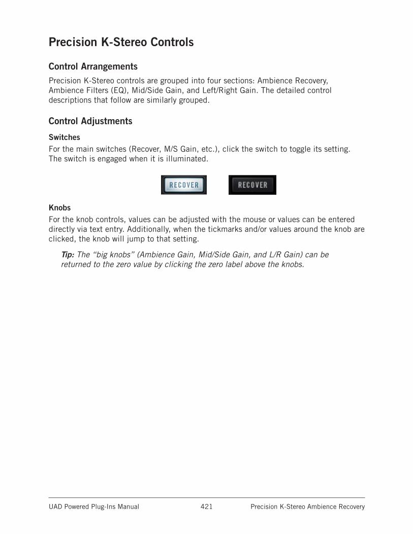
UAD Powered Plug-Ins Manual Precision K-Stereo Ambience Recovery 421
Precision K-Stereo Controls
Control ArrangementsPrecision K-Stereo controls are grouped into four sections: Ambience Recovery, Ambience Filters (EQ), Mid/Side Gain, and Left/Right Gain. The detailed control descriptions that follow are similarly grouped.
Control Adjustments
SwitchesFor the main switches (Recover, M/S Gain, etc.), click the switch to toggle its setting. The switch is engaged when it is illuminated.
KnobsFor the knob controls, values can be adjusted with the mouse or values can be entered directly via text entry. Additionally, when the tickmarks and/or values around the knob are clicked, the knob will jump to that setting.
Tip: The “big knobs” (Ambience Gain, Mid/Side Gain, and L/R Gain) can be returned to the zero value by clicking the zero label above the knobs.
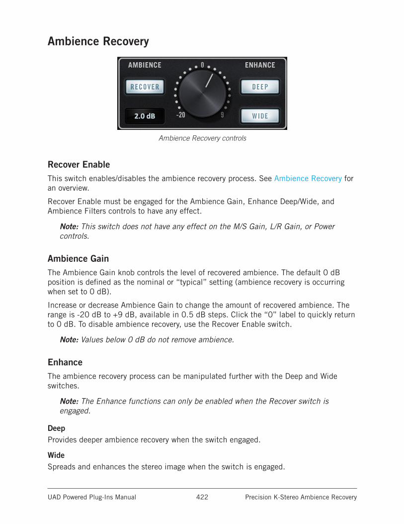
UAD Powered Plug-Ins Manual Precision K-Stereo Ambience Recovery 422
Ambience Recovery
Ambience Recovery controls
Recover EnableThis switch enables/disables the ambience recovery process. See Ambience Recovery for an overview.
Recover Enable must be engaged for the Ambience Gain, Enhance Deep/Wide, and Ambience Filters controls to have any effect.
Note: This switch does not have any effect on the M/S Gain, L/R Gain, or Power controls.
Ambience GainThe Ambience Gain knob controls the level of recovered ambience. The default 0 dB position is defined as the nominal or “typical” setting (ambience recovery is occurring when set to 0 dB).
Increase or decrease Ambience Gain to change the amount of recovered ambience. The range is -20 dB to +9 dB, available in 0.5 dB steps. Click the “0” label to quickly return to 0 dB. To disable ambience recovery, use the Recover Enable switch.
Note: Values below 0 dB do not remove ambience.
EnhanceThe ambience recovery process can be manipulated further with the Deep and Wide switches.
Note: The Enhance functions can only be enabled when the Recover switch is engaged.
DeepProvides deeper ambience recovery when the switch engaged.
WideSpreads and enhances the stereo image when the switch is engaged.
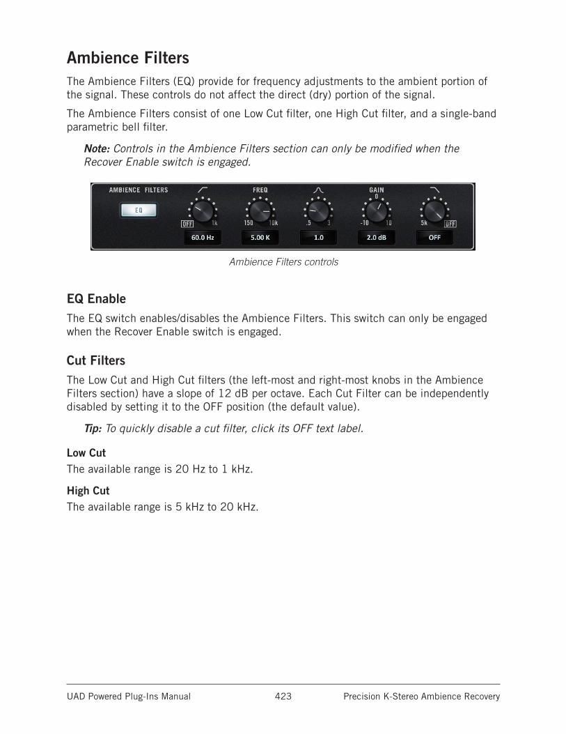
UAD Powered Plug-Ins Manual Precision K-Stereo Ambience Recovery 423
Ambience FiltersThe Ambience Filters (EQ) provide for frequency adjustments to the ambient portion of the signal. These controls do not affect the direct (dry) portion of the signal.
The Ambience Filters consist of one Low Cut filter, one High Cut filter, and a single-band parametric bell filter.
Note: Controls in the Ambience Filters section can only be modified when the Recover Enable switch is engaged.
Ambience Filters controls
EQ EnableThe EQ switch enables/disables the Ambience Filters. This switch can only be engaged when the Recover Enable switch is engaged.
Cut FiltersThe Low Cut and High Cut filters (the left-most and right-most knobs in the Ambience Filters section) have a slope of 12 dB per octave. Each Cut Filter can be independently disabled by setting it to the OFF position (the default value).
Tip: To quickly disable a cut filter, click its OFF text label.
Low CutThe available range is 20 Hz to 1 kHz.
High CutThe available range is 5 kHz to 20 kHz.
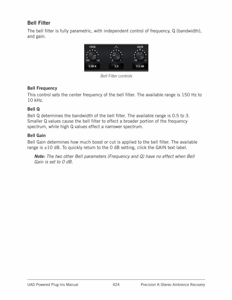
UAD Powered Plug-Ins Manual Precision K-Stereo Ambience Recovery 424
Bell FilterThe bell filter is fully parametric, with independent control of frequency, Q (bandwidth), and gain.
Bell Filter controls
Bell FrequencyThis control sets the center frequency of the bell filter. The available range is 150 Hz to 10 kHz.
Bell QBell Q determines the bandwidth of the bell filter. The available range is 0.5 to 3. Smaller Q values cause the bell filter to effect a broader portion of the frequency spectrum, while high Q values effect a narrower spectrum.
Bell GainBell Gain determines how much boost or cut is applied to the bell filter. The available range is ±10 dB. To quickly return to the 0 dB setting, click the GAIN text label.
Note: The two other Bell parameters (Frequency and Q) have no effect when Bell Gain is set to 0 dB.
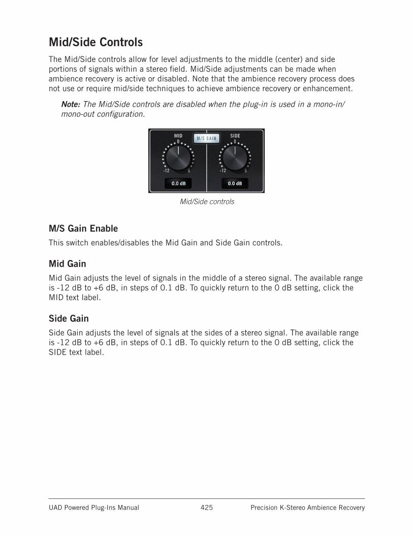
UAD Powered Plug-Ins Manual Precision K-Stereo Ambience Recovery 425
Mid/Side ControlsThe Mid/Side controls allow for level adjustments to the middle (center) and side portions of signals within a stereo field. Mid/Side adjustments can be made when ambience recovery is active or disabled. Note that the ambience recovery process does not use or require mid/side techniques to achieve ambience recovery or enhancement.
Note: The Mid/Side controls are disabled when the plug-in is used in a mono-in/mono-out configuration.
Mid/Side controls
M/S Gain EnableThis switch enables/disables the Mid Gain and Side Gain controls.
Mid GainMid Gain adjusts the level of signals in the middle of a stereo signal. The available range is -12 dB to +6 dB, in steps of 0.1 dB. To quickly return to the 0 dB setting, click the MID text label.
Side GainSide Gain adjusts the level of signals at the sides of a stereo signal. The available range is -12 dB to +6 dB, in steps of 0.1 dB. To quickly return to the 0 dB setting, click the SIDE text label.
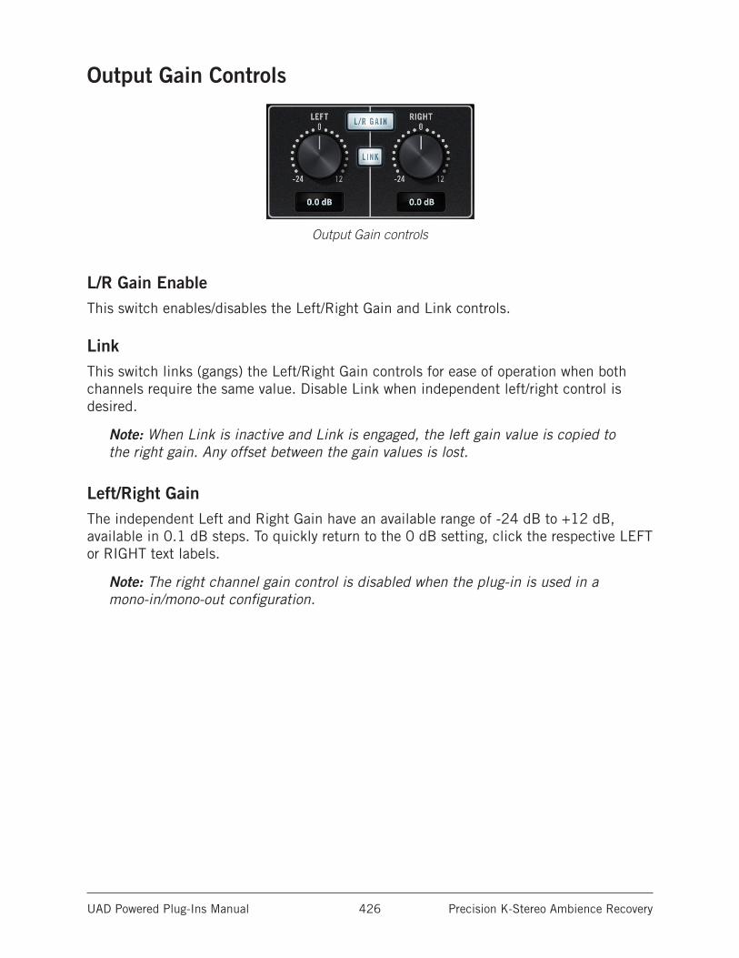
UAD Powered Plug-Ins Manual Precision K-Stereo Ambience Recovery 426
Output Gain Controls
Output Gain controls
L/R Gain EnableThis switch enables/disables the Left/Right Gain and Link controls.
LinkThis switch links (gangs) the Left/Right Gain controls for ease of operation when both channels require the same value. Disable Link when independent left/right control is desired.
Note: When Link is inactive and Link is engaged, the left gain value is copied to the right gain. Any offset between the gain values is lost.
Left/Right GainThe independent Left and Right Gain have an available range of -24 dB to +12 dB, available in 0.1 dB steps. To quickly return to the 0 dB setting, click the respective LEFT or RIGHT text labels.
Note: The right channel gain control is disabled when the plug-in is used in a mono-in/mono-out configuration.
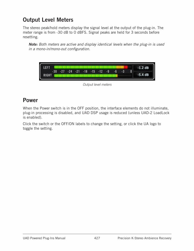
UAD Powered Plug-Ins Manual Precision K-Stereo Ambience Recovery 427
Output Level MetersThe stereo peak/hold meters display the signal level at the output of the plug-in. The meter range is from -30 dB to 0 dBFS. Signal peaks are held for 3 seconds before resetting.
Note: Both meters are active and display identical levels when the plug-in is used in a mono-in/mono-out configuration.
Output level meters
PowerWhen the Power switch is in the OFF position, the interface elements do not illuminate, plug-in processing is disabled, and UAD DSP usage is reduced (unless UAD-2 LoadLock is enabled).
Click the switch or the OFF/ON labels to change the setting, or click the UA logo to toggle the setting.
UAD Powered Plug-Ins Manual Precision K-Stereo Ambience Recovery 428
Factory Preset Notes by Bob KatzPrecision K-Stereo includes factory presets designed by Bob Katz for use with his signature plug-in. Descriptions about these presets are listed below.
The Default preset and presets with the “BK” prefix are the settings created by Mr. Katz. Two categories are included: “MIX” presets for use during mixing, and “MSTR” for use during mastering.
DefaultWhen Precision K-Stereo is instantiated, it automatically starts with the Default preset, which sets the Ambience Level to 0 dB (a nominal starting point which works well with a lot of music), engages Wide and Deep, and sets everything else to neutral. Feel free to turn the Ambience Level up or down to taste or to explore the possibilities. The rest of the factory presets are provided to demonstrate possibilities, but since there are very few controls, it’s easy to get the Precision K-Stereo working for any situation.
BK-MSTR-Rock Tight BassThis preset has Ambience Level at 0 dB, Wide and Deep engaged, and the Ambience Low Cut filter set to 125 Hz to maintain a tight bass instrument while increasing the size and depth of the rest of the instruments.
BK-MSTR-Rock Tight DrumsThis preset has Ambience Level at 0 dB, Wide and Deep engaged, Ambience Low Cut filter set to 125 Hz, Ambience High Cut Filter set to 10 kHz. This maintains the bass instrument tight (not as affected by the Ambience Level) as well as softens the ambience of the high frequencies to tighten the percussion, but it retains ambience in the midrange to enhance vocals and midrange instruments.
BK-MSTR-String EnsembleThis preset has Ambience Level at +1 dB, Wide is disengaged, Deep is engaged. This is very useful, as the name implies, for enhancing the ambience of a small ensemble or solo instrument without stretching it to the extreme sides, maintaining the ensemble’s small size but still help its richness and depth. Try this preset during mixing on a stereo-miked solo guitar (instead of a reverb chamber).
BK-MSTR-Full Orchestra AThis is the same as the default preset. Turn the Ambience Level up or down to taste. Perhaps add some Ambience EQ to warm up the sound, or add some presence to the ambience, depending on the nature of the reverberation in the original recording.
BK-MSTR-Full Orchestra BSame as Full Orchestra A, but the high cut filter is set to 10 kHz which softens the high frequency ambience to tighten the percussion.
UAD Powered Plug-Ins Manual Precision K-Stereo Ambience Recovery 429
BK-MSTR-Clear PresenceIf the hall or chamber in the original recording is missing some presence, here’s a suggestion on what to do.
BK-MSTR-Raise Mid InstrumentsThis preset subtly raises the Mid level 1 dB above the side level and recovers a bit of the spacious ambience which is commonly lost when the mid/side ratio is raised.
BK-MSTR-Warm AmbienceThis preset adds overall warmth to the recovery settings.
BK-MIX-Big SteinwayTry this preset on a stereo recording of a piano to enhance the size and body of the instrument without losing its definition. This preset will illustrate how ambience EQ is very different from direct EQ. Here we turn up the bottom end and lower midrange of the ambience channel. It might turn a six-foot Yamaha into a nine-foot Steinway, so be careful, or maybe that’s exactly what you want to do!
BK-MIX-BigThis preset turns up the ambience level a bit to quickly show you the possibilities.
BK-MIX-Too BigThis preset turns up the ambience level very far to quickly show you extreme possibilities.
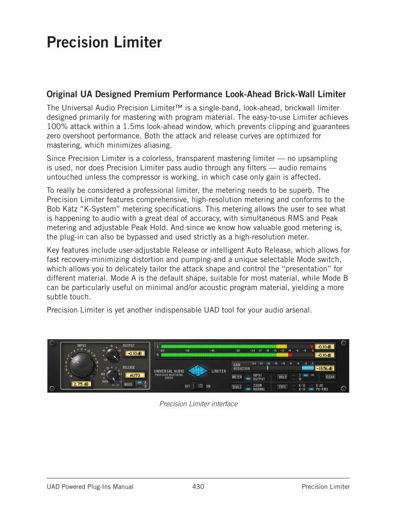
UAD Powered Plug-Ins Manual Precision Limiter 430
Precision Limiter
Original UA Designed Premium Performance Look-Ahead Brick-Wall LimiterThe Universal Audio Precision Limiter™ is a single-band, look-ahead, brickwall limiter designed primarily for mastering with program material. The easy-to-use Limiter achieves 100% attack within a 1.5ms look-ahead window, which prevents clipping and guarantees zero overshoot performance. Both the attack and release curves are optimized for mastering, which minimizes aliasing.
Since Precision Limiter is a colorless, transparent mastering limiter — no upsampling is used, nor does Precision Limiter pass audio through any filters — audio remains untouched unless the compressor is working, in which case only gain is affected.
To really be considered a professional limiter, the metering needs to be superb. The Precision Limiter features comprehensive, high-resolution metering and conforms to the Bob Katz “K-System” metering specifications. This metering allows the user to see what is happening to audio with a great deal of accuracy, with simultaneous RMS and Peak metering and adjustable Peak Hold. And since we know how valuable good metering is, the plug-in can also be bypassed and used strictly as a high-resolution meter.
Key features include user-adjustable Release or intelligent Auto Release, which allows for fast recovery-minimizing distortion and pumping-and a unique selectable Mode switch, which allows you to delicately tailor the attack shape and control the “presentation” for different material. Mode A is the default shape, suitable for most material, while Mode B can be particularly useful on minimal and/or acoustic program material, yielding a more subtle touch.
Precision Limiter is yet another indispensable UAD tool for your audio arsenal.
Precision Limiter interface
UAD Powered Plug-Ins Manual Precision Limiter 431
Precision Limiter ControlsPrecision Limiter introduced a new control style for UAD plug-ins. For the Mode, Meter, Scale, and Clear parameters, click the parameter label, the value text, or the LED to toggle between available values.
InputThe Input knob controls the signal level that is input into the limiter. Increasing the input will result in more limiting as the input signal exceeds 0 dB.
The default value is 0 dB. The available range is -6 dB to 24 dB.
OutputThe Output knob determines the maximum level at the output of the plug-in. This control does not affect the actual limiting.
Precision Limiter always limits the signal to 0 dB internally, and the actual output is set by attenuating this internal level. Likewise, the input control can drive the signal over 0 dB to get more limiting.
If Precision Limiter is the last processor in the signal path when mixing down to disk (bouncing), the Output value will be the level of the highest peak in the resultant audio file.
The default value is -0.10 dB. The available range is from -12 dB to 0 dB. Non-zero values are always negative, therefore during text entry operations positive or negative values may be entered and the result will be negative.
ReleaseThe Release knob sets the value of the limiter release time. The default value is Auto. The available range is from 1 second to 0.01 milliseconds.
Auto ModeWhen the Release knob is fully clockwise, Automatic mode is active. In Auto mode, release time is program-dependent. Isolated peaks will have a fast release time, while program material will have a slower release.
Tip: Type “A” or “a” to enter Auto mode during text entry.
UAD Powered Plug-Ins Manual Precision Limiter 432
ModeThe Mode switch affects the attack shape of the limiter. Subtle tonal variations are possible by switching the Mode between A and B.
Mode A is the default shape, suitable for most material, while Mode B can be particularly useful on minimal and/or acoustic program material, yielding a more subtle touch.
PowerThe Power switch determines whether the plug-in is active. When the Power switch is in the Off position, plug-in processing is disabled and UAD DSP usage is reduced (unless UAD-2 DSP LoadLock is enabled).
When the plug-in is bypassed with this switch (but not by the host bypass), the VU meter displays the unprocessed input signal level.
Precision Limiter Meters Overview
K-SystemPrecision Limiter has precise, calibrated stereo metering. It offers the option to use K-System metering, which is a method devised by renown audio engineer Bob Katz. The K-System is essentially a method of integrating metering and monitoring levels to standardize the apparent loudness of audio material while providing useful visual feedback of average and peak levels.
Integrated Meter/Monitor SystemThe K-System is not just a metering system; it is designed to be integrated with calibrated monitoring system levels. In a full K-System implementation, 0 dB on the level meter yields 83 dB sound pressure level (SPL) per channel in the monitor output level (86 dB running two channels in stereo), when measured with 20-20 kHz pink noise on an SPL meter set to C-weighted slow (i.e. average) response. It is this calibrated meter/monitor relationship that establishes a consistent average “perceived loudness” with reference to 0 dB on the meter.
Sliding Meter ScaleWith the K-System, programs with different amounts of dynamic range and headroom can be produced by using a loudness meter with a sliding scale, because the moveable 0 dB point is always tied to the same calibrated monitor SPL. Precision Limiter provides several meter ranges for various types of program material (see Type).
Long Live Dynamic Range!The K-System can help combat the bane of the “loudness wars” which is all-too common in today’s music, whereby material is made to appear louder when compared to other material at the same playback volume, at the expense of dynamic range and fidelity.
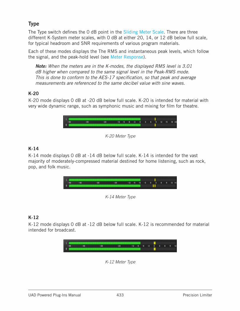
UAD Powered Plug-Ins Manual Precision Limiter 433
TypeThe Type switch defines the 0 dB point in the Sliding Meter Scale. There are three different K-System meter scales, with 0 dB at either 20, 14, or 12 dB below full scale, for typical headroom and SNR requirements of various program materials.
Each of these modes displays the The RMS and instantaneous peak levels, which follow the signal, and the peak-hold level (see Meter Response).
Note: When the meters are in the K-modes, the displayed RMS level is 3.01 dB higher when compared to the same signal level in the Peak-RMS mode. This is done to conform to the AES-17 specification, so that peak and average measurements are referenced to the same decibel value with sine waves.
K-20K-20 mode displays 0 dB at -20 dB below full scale. K-20 is intended for material with very wide dynamic range, such as symphonic music and mixing for film for theatre.
K-20 Meter Type
K-14K-14 mode displays 0 dB at -14 dB below full scale. K-14 is intended for the vast majority of moderately-compressed material destined for home listening, such as rock, pop, and folk music.
K-14 Meter Type
K-12K-12 mode displays 0 dB at -12 dB below full scale. K-12 is recommended for material intended for broadcast.
K-12 Meter Type
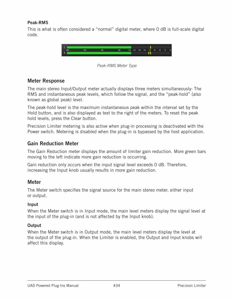
UAD Powered Plug-Ins Manual Precision Limiter 434
Peak-RMSThis is what is often considered a “normal” digital meter, where 0 dB is full-scale digital code.
Peak-RMS Meter Type
Meter ResponseThe main stereo Input/Output meter actually displays three meters simultaneously: The RMS and instantaneous peak levels, which follow the signal, and the “peak-hold” (also known as global peak) level.
The peak-hold level is the maximum instantaneous peak within the interval set by the Hold button, and is also displayed as text to the right of the meters. To reset the peak hold levels, press the Clear button.
Precision Limiter metering is also active when plug-in processing is deactivated with the Power switch. Metering is disabled when the plug-in is bypassed by the host application.
Gain Reduction MeterThe Gain Reduction meter displays the amount of limiter gain reduction. More green bars moving to the left indicate more gain reduction is occurring.
Gain reduction only occurs when the input signal level exceeds 0 dB. Therefore, increasing the Input knob usually results in more gain reduction.
MeterThe Meter switch specifies the signal source for the main stereo meter, either input or output.
InputWhen the Meter switch is in Input mode, the main level meters display the signal level at the input of the plug-in (and is not affected by the Input knob).
OutputWhen the Meter switch is in Output mode, the main level meters display the level at the output of the plug-in. When the Limiter is enabled, the Output and Input knobs will affect this display.
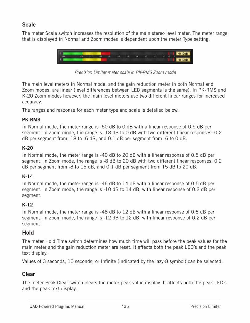
UAD Powered Plug-Ins Manual Precision Limiter 435
ScaleThe meter Scale switch increases the resolution of the main stereo level meter. The meter range that is displayed in Normal and Zoom modes is dependent upon the meter Type setting.
Precision Limiter meter scale in PK-RMS Zoom mode
The main level meters in Normal mode, and the gain reduction meter in both Normal and Zoom modes, are linear (level differences between LED segments is the same). In PK-RMS and K-20 Zoom modes however, the main level meters use two different linear ranges for increased accuracy.
The ranges and response for each meter type and scale is detailed below.
PK-RMSIn Normal mode, the meter range is -60 dB to 0 dB with a linear response of 0.5 dB per segment. In Zoom mode, the range is -18 dB to 0 dB with two different linear responses: 0.2 dB per segment from -18 to -6 dB, and 0.1 dB per segment from -6 to 0 dB.
K-20In Normal mode, the meter range is -40 dB to 20 dB with a linear response of 0.5 dB per segment. In Zoom mode, the range is -8 dB to 20 dB with two different linear responses: 0.2 dB per segment from -8 to 15 dB, and 0.1 dB per segment from 15 dB to 20 dB.
K-14In Normal mode, the meter range is -46 dB to 14 dB with a linear response of 0.5 dB per segment. In Zoom mode, the range is -10 dB to 14 dB, with linear response of 0.2 dB per segment.
K-12In Normal mode, the meter range is -48 dB to 12 dB with a linear response of 0.5 dB per segment. In Zoom mode, the range is -12 dB to 12 dB, with linear response of 0.2 dB per segment.
HoldThe meter Hold Time switch determines how much time will pass before the peak values for the main meter and the gain reduction meter are reset. It affects both the peak LED’s and the peak text display.
Values of 3 seconds, 10 seconds, or Infinite (indicated by the lazy-8 symbol) can be selected.
ClearThe meter Peak Clear switch clears the meter peak value display. It affects both the peak LED’s and the peak text display.
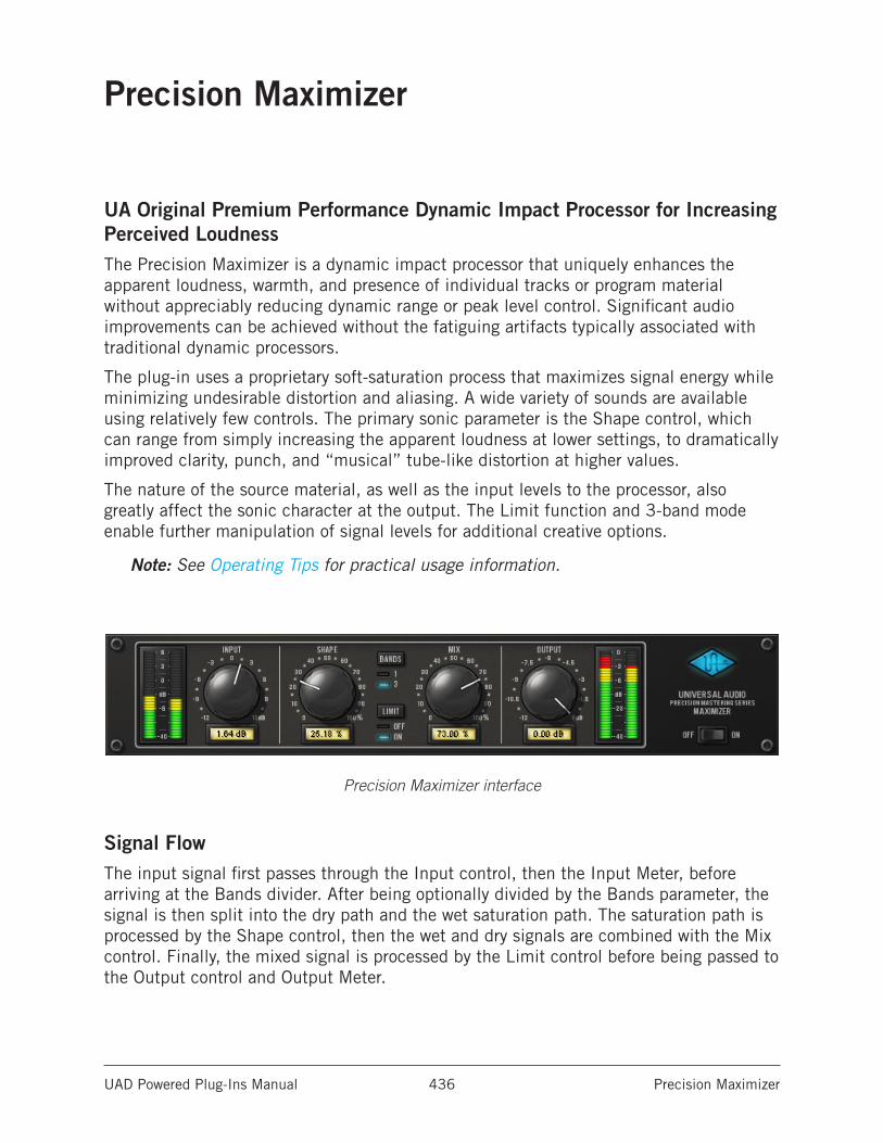
UAD Powered Plug-Ins Manual Precision Maximizer 436
Precision Maximizer
UA Original Premium Performance Dynamic Impact Processor for Increasing Perceived LoudnessThe Precision Maximizer is a dynamic impact processor that uniquely enhances the apparent loudness, warmth, and presence of individual tracks or program material without appreciably reducing dynamic range or peak level control. Significant audio improvements can be achieved without the fatiguing artifacts typically associated with traditional dynamic processors.
The plug-in uses a proprietary soft-saturation process that maximizes signal energy while minimizing undesirable distortion and aliasing. A wide variety of sounds are available using relatively few controls. The primary sonic parameter is the Shape control, which can range from simply increasing the apparent loudness at lower settings, to dramatically improved clarity, punch, and “musical” tube-like distortion at higher values.
The nature of the source material, as well as the input levels to the processor, also greatly affect the sonic character at the output. The Limit function and 3-band mode enable further manipulation of signal levels for additional creative options.
Note: See Operating Tips for practical usage information.
Precision Maximizer interface
Signal FlowThe input signal first passes through the Input control, then the Input Meter, before arriving at the Bands divider. After being optionally divided by the Bands parameter, the signal is then split into the dry path and the wet saturation path. The saturation path is processed by the Shape control, then the wet and dry signals are combined with the Mix control. Finally, the mixed signal is processed by the Limit control before being passed to the Output control and Output Meter.
UAD Powered Plug-Ins Manual Precision Maximizer 437
Precision Maximizer ControlsControl knobs for the Precision Maximizer behave the same way as all UAD plug-ins. Input, Shape, Mix, and Output values can be modified with text entry.
Input MeterThe stereo peak Input Meter displays the signal level at the input of the processor, after the Input control.
0 dB represents digital full scale (0 dBFS). Precision Maximizer can utilize input signals up to +6 dB at the input before input clipping occurs.
The displayed range is from -40 dB to +6 dB.
InputThe Input Level knob controls the signal level that is input to the plug-in. Increasing the input will generally result in more processing (depending on the settings of the other parameters).
By increasing the Input knob, input levels higher than 0 dBFS (up to +6 dBFS) within the plug-in can be processed. This can increase the distortion characteristic at the output, particularly when the Limit function is engaged.
The available range is ±12 dB. A good starting point for sonic experimentation is to set the input level so the input peaks occur around 0 dB, then adjust the other controls to taste.
ShapeThe Shape knob is the primary saturation control for the Maximizer effect. It contours the harmonic content and apparent dynamic range of the processor by changing the small-signal gain of the saturator. The available range is 0-100%.
At lower settings, apparent loudness is not as dramatic but harmonic processing still occurs, producing a richer sound with minimal reduction of dynamic range. As Shape is increased, the sound becomes more saturated with “sonically pleasing” distortion and perceived loudness, punch, and clarity.
Shape values between 0-50% will make the effect more subtle, but a richer sound is still obtained. Lower Shape values accentuate louder peaks, which can sound great on percussive instruments. Solo instruments can also benefit from lower Shape values by taming the peaks while maintaining dynamic range.
As Shape is increased beyond 50%, presence, excitement, and harmonic coloration can be dramatic, yet still highly musical and without the dynamic squashing of typical limiters.
The most natural warmth and tube-like distortion is obtained with Shape at 50%. This setting generates the lowest amount of higher order harmonics and most closely emulates characteristic tube qualities.
UAD Powered Plug-Ins Manual Precision Maximizer 438
BandsPrecision Maximizer can operate in one-band or three-band mode. In one-band mode, all frequencies are processed equally. In three-band mode, the frequency spectrum is split into three separate bands before maximizing is applied.
One-band mode is the normal setting for general usage. In this mode, more dramatic results can often be obtained because more saturation effect is possible before the output is clipped. At higher levels of distortion, the phase of the harmonics are also better retained in this mode, which usually produces a more desirable sound quality.
Higher levels of perceived loudness may be obtained in three-band mode, especially if the frequency spectrum of the source material is not balanced. In this mode, certain settings can produce higher output levels than input levels (and potential clipping), so it may be necessary to compensate by reducing the input/output levels, and/or engaging the Limit control.
The crossover frequencies in three-band mode are 200 Hz and 2.45 kHz.
Click the Bands button to change the mode. Alternately, you can click+hold the LED area and drag like a slider to change the value.
Note: UAD DSP usage is increased when three-band mode is active (unless UAD-2 DSP LoadLock is enabled).
LimitThe Limit function provides a second stage of soft-saturation just before the output control for the plug-in. It prevents digital “overs” by protecting the plug-in output from exceeding 0 dBFS. Limit enters into clipping range gradually instead of hard-clipping at 0 dB.
The Limit function has the same saturation form as the Shape parameter, but the effect is milder. Limit is especially useful for three-band mode, where output peaks over 0 dB (and clipping) can occur. However, great results can also be obtained in one-band mode when Limit is engaged.
If Limit is used to reduce levels by a significant amount, it is usually best to have Mix set to 100% in order to minimize audio artifacts (aliasing).
Click the Limit button to engage Limit. Alternately, you can click+hold the LED area and drag like a slider to change the value.
Note: UAD DSP usage is slightly decreased when Limit mode is inactive (unless UAD-2 DSP LoadLock is enabled).
UAD Powered Plug-Ins Manual Precision Maximizer 439
MixThis is a mix control for the plug-in. Mix determines the balance between the original and the processed signal. The range is from 0% (no processing) to 100% (wet, processed signal only).
Note that when Mix is at 0%, the signal is still processed by the Limit control if it is enabled, and by the band splitter when in three-band mode. For a true bypass, the Power switch should be used.
OutputThe Output knob controls the signal level that is output from the plug-in. The available range is -12 dB to 0 dB.
Note that when Limit is not engaged, it is possible for the output level to exceed 0 dB. In this case, Output can be lowered to eliminate any associated clipping.
Tip: When Precision Maximizer is used for CD mastering and it is the last processor in the signal chain, the recommended Output value is -0.10 dB
Output MeterThe stereo peak Output Meter displays the signal level at the output of the plug-in. The displayed range is from -40 dB to 0 dB.
The very top segment of the Output Meter is a clip LED (one each for the left and right channels) which illuminates when the signal exceeds 0 dB. The clip segments are held for three seconds before resetting.
Note: The Limit function prevents the output signal from exceeding 0 dB. Therefore, the clip LED’s will only illuminate if Limit is off.
PowerThe Power switch determines whether the plug-in is active. This is useful for comparing the processed settings to the original signal or bypassing the plug-in to reduce the UAD DSP load (load is not reduced if UAD-2 DSP LoadLock is enabled).
Toggle the switch to change the Power state; the UA logo is illuminated in blue when the plug-in is active.
Note: You can click-hold the power switch then drag it like a slider to quickly compare the enabled/disabled state.
UAD Powered Plug-Ins Manual Precision Maximizer 440
Operating Tips• As a starting point for general loudness enhancement, set Precision Maximizer to
one-band mode with Limit engaged, with Mix at 100% and Shape at 50%. Then set Input so signals peak at around 0 dB on the Input Meters. These settings offer good results under most conditions, producing more presence with a warmer sound and enhanced detail (especially with lower frequencies), while retaining the apparent dynamic range of the original signal.
• The most natural warmth and tube-style distortion can be obtained with Shape at 50% in one-band mode, with Limit off, and signal peaks just touching 0 dB at the input. Shape at 50% delivers the lowest amount of higher order harmonics and most closely emulates a tube characteristic.
• More overdrive may be obtained by disengaging the Limit function. Up to +6 dB of additional headroom is available before clipping occurs when Limit is off. This can cause clipping at the output, so reduce the Input and/or Output control to compensate if necessary.
• Input clipping can dramatically change the distortion characteristic, and may yield significantly different results in one-band versus three-band mode.
• Generally speaking, the input should be set as high as possible before undesirable sound quality is obtained.
• For optimum results (especially when Limit is off) ensure the source signal is not clipped before it arrives at the Precision Maximizer input.
• Output clipping can be completely avoided by enabling Limit.
• One-band mode is generally recommended for program material.
• Set Mix at 100% in order to hear the full affect of the Maximizer process. Reduce Mix when blending in the original signal is desired.
• Changing the order of plug-ins in the signal path can have a dramatic affect on Precision Maximizer results.
• Sonic experimentation is highly encouraged!
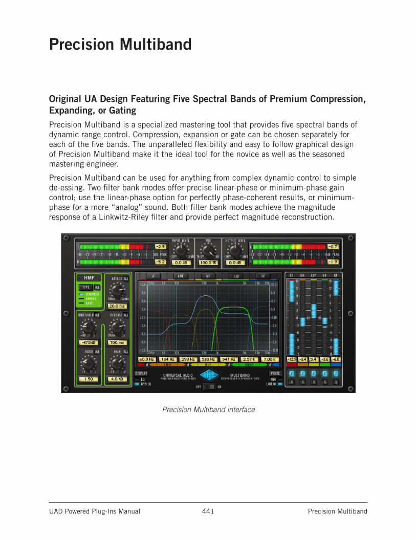
UAD Powered Plug-Ins Manual Precision Multiband 441
Precision Multiband
Original UA Design Featuring Five Spectral Bands of Premium Compression, Expanding, or GatingPrecision Multiband is a specialized mastering tool that provides five spectral bands of dynamic range control. Compression, expansion or gate can be chosen separately for each of the five bands. The unparalleled flexibility and easy to follow graphical design of Precision Multiband make it the ideal tool for the novice as well as the seasoned mastering engineer.
Precision Multiband can be used for anything from complex dynamic control to simple de-essing. Two filter bank modes offer precise linear-phase or minimum-phase gain control; use the linear-phase option for perfectly phase-coherent results, or minimum-phase for a more “analog” sound. Both filter bank modes achieve the magnitude response of a Linkwitz-Riley filter and provide perfect magnitude reconstruction.
Precision Multiband interface
UAD Powered Plug-Ins Manual Precision Multiband 442
Precision Multiband InterfaceThe Precision Multiband interface is designed to make this complex processor easier to use.
Five separate frequency bands are available for processing. Each band is identified by a unique color, and all controls specific to the band have the same color. This helps to visually associate parameters to the band that they affect. The band names and their colors are:
• Low Frequency (LF): Red
• Low-Mid Frequency (LMF): Orange
• Mid Frequency (MF): Yellow
• High-Mid Frequency (HMF): Green
• High Frequency (HF): Blue
The interface is divided into four primary areas of control:
• The Band Controls section contains the dynamic response parameters for each of the five bands. One set of band controls is displayed at a time. See.
• The EQ Display contains the band frequency parameters and shows a graphic representation of the band frequency response. The overall equalization response is also displayed (if enabled).
• The Dynamics Meters display the amount of gain reduction or expansion occurring on each band. The band enable and solo controls are here also.
• The Global Controls affect aspects of the plug-in not associated with individual bands. These include input/output controls and meters, power, and other controls.
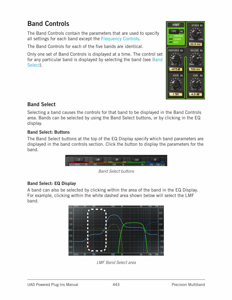
UAD Powered Plug-Ins Manual Precision Multiband 443
Band ControlsThe Band Controls contain the parameters that are used to specify all settings for each band except the Frequency Controls.
The Band Controls for each of the five bands are identical.
Only one set of Band Controls is displayed at a time. The control set for any particular band is displayed by selecting the band (see Band Select).
Band SelectSelecting a band causes the controls for that band to be displayed in the Band Controls area. Bands can be selected by using the Band Select buttons, or by clicking in the EQ display.
Band Select: ButtonsThe Band Select buttons at the top of the EQ Display specify which band parameters are displayed in the band controls section. Click the button to display the parameters for the band.
Band Select buttons
Band Select: EQ DisplayA band can also be selected by clicking within the area of the band in the EQ Display. For example, clicking within the white dashed area shown below will select the LMF band.
LMF Band Select area
UAD Powered Plug-Ins Manual Precision Multiband 444
Band ParametersBecause the Band Controls for each of the five bands are identical, they are only described once.
All ButtonThe ALL button provides a facility to link controls and copy parameter values to all bands when adjusting the current band. Each of the Band Controls has an ALL button. The behavior of the ALL button is the same for all the Band Controls in all the bands (with the exception of the Type Switch).
The ALL button can perform three functions: Relative Link, Absolute Link, and Copy Value. Note that the ALL button cannot be automated.
Relative LinkIn Relative mode, changes to a band control will change the same control in the other bands by a relative amount (i.e. the same amount), until any single band reaches its minimum or maximum value.
Single-click the ALL button to enter Relative mode; the button background changes to blue.
When adjusting a control in Relative mode, it may appear that the full range of the active control is unavailable; this occurs when a different band (not the active band) has reached the end of its range.
In Relative mode the Gain value can also be adjusted by dragging the Gain “handle” in the EQ Display.
Note: In Relative Link mode, the parameter values in other bands don’t change unless a control is actually adjusted (values are not forced to other bands when enabling the mode).
Note: Relative mode is not available for the Type parameter because the available Type values are discrete. Click and shift-click both activate Absolute mode for Type.
Absolute LinkIn Absolute mode, changes to a band control will force the same control in the other bands to snap to the same value as the current band.
Shift+click the ALL button to enter Absolute mode; the button background changes to red. In Absolute mode, the Gain value can also be adjusted by dragging the Gain “handle” in the EQ Display.
Note: In Absolute Link mode, the parameter values in other bands don’t change unless a control is actually adjusted (values are not forced to other bands when enabling the mode).
UAD Powered Plug-Ins Manual Precision Multiband 445
CopyCtrl+click the ALL button when it is NOT in Relative or Absolute modes (not blue or red) to copy the current value of the active band control to the same control value in the other bands.
Caution: The ctrl+click Copy function overwrites existing values in all other bands. Undo is not available.
Type SwitchThe Type button defines the dynamic nature of the band, allowing each band to function as a compressor, expander, or noise gate, independent of the Type value in the other bands.
Click the Type switch to scroll through the three available values.
The Type text (compress, expand, gate) behaves as a vertical “slider” and can be used for changing the Type as well. Alternately, the Type can be changed using the Dynamics Meters label text.
Note: When changing the band Type, the Ratio value for the band changes to 1:1. This prevents dramatic jumps in the output level that could result from extreme values of other band parameters.
CompressWhen a band is set to Compress, the dynamic range of the band will be reduced (dependent upon the band threshold and input level). This is the typical value in multiband compression.
ExpandWhen a band is set to Expand, the dynamic range of the band will be increased (dependent upon the band threshold and input level).
GateWhen a band is set to Gate, the band behaves as a gate. A gate stops the signal from passing when the signal level drops below the specified threshold value.
Gates are generally used to reduce noise levels by eliminating the noise floor when the main signal is not present, but they are also useful for special effects.
ThresholdThis parameter determines the threshold level for compression/expansion/gating. Any signals that exceed this level are processed. Signals below the level are unaffected. A Threshold of 0 dB yields no processing. The available range is -60 dB to 0 dB.
As the Threshold control is decreased and more processing occurs, output level is typically reduced (compression) or increased (expansion). Adjust the Gain control to modify the output of the band to compensate if desired.
UAD Powered Plug-Ins Manual Precision Multiband 446
RatioRatio determines the amount of gain reduction (or expansion) for the band. For example: When a band is set to Compress, a value of 2 (expressed as a 2:1 ratio) reduces the signal by half, with an input signal of 20 dB being reduced to 10 dB.
The available range depends on the value of the Type parameter, as follows:
• Ratio range in Compress mode is 1:1 to 60:1
• Ratio range in Expand mode is 1:1 to 1:4
• Ratio range in Gate mode is 1:1 to 8:1
AttackAttack sets the amount of time that must elapse once the input signal reaches the Threshold level before processing is applied. The faster the Attack, the more rapidly processing is applied to signals above the threshold.
The available range is 50 microseconds to 100 milliseconds.
ReleaseRelease sets the amount of time it takes for processing to cease once the input signal drops below the threshold level. Slower release times can smooth the transition that occurs when the signal dips below the threshold, especially useful for material with frequent peaks. However, if you set too large of a Release time, processing for sections of audio with loud signals may extend to lengthy sections of audio with lower signals. The available range is 20 milliseconds to 2 seconds.
GainThe Gain control adjusts the output level of the band. Generally speaking, adjust the Gain control after the desired amount of processing is achieved with the Threshold control. The Gain control does not affect the amount of processing. The available range is ±12 dB.
Tip: The Gain for each band can also be modified with the Curve Control Points in the EQ Display.
Band FrequenciesFor details about the band frequencies, see Frequency Controls.
Band Enable & SoloFor details about the band enable and solo controls, see Dynamics Meters.
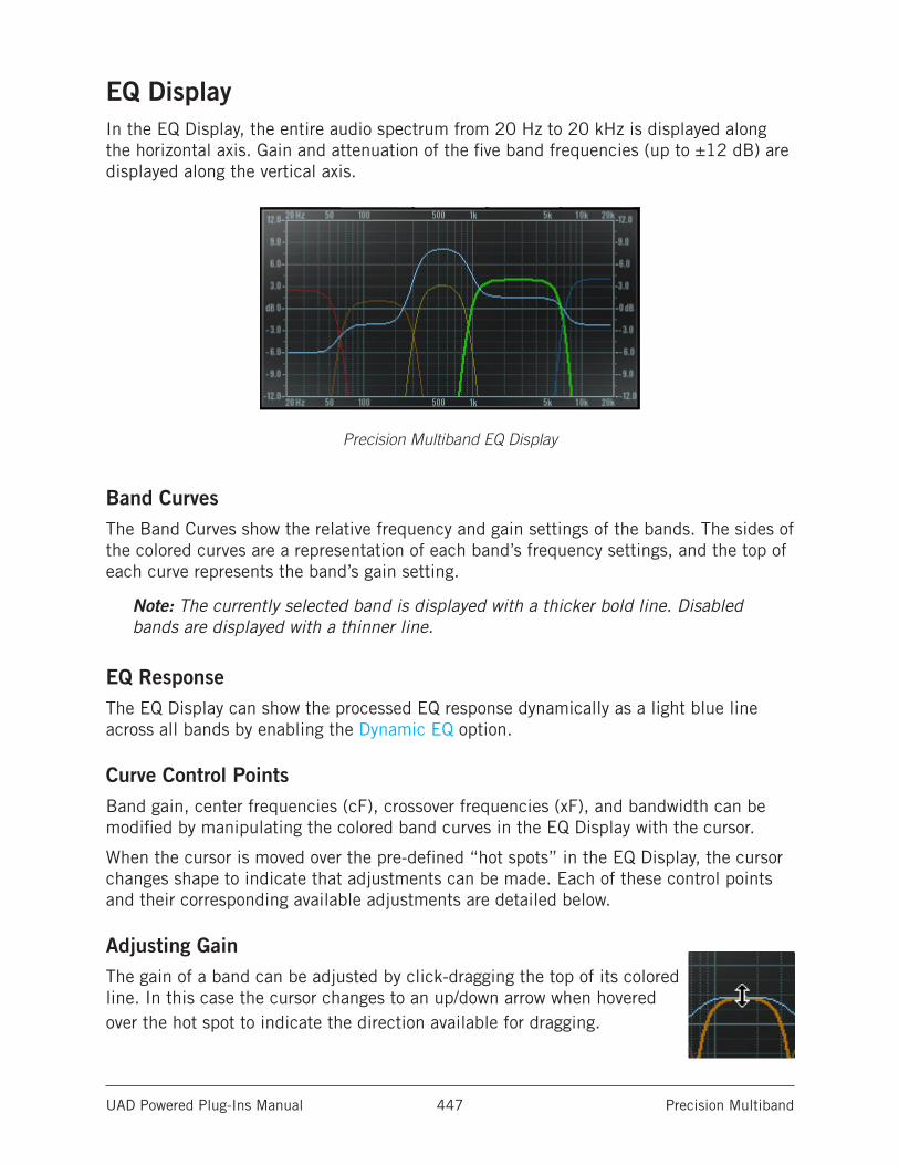
UAD Powered Plug-Ins Manual Precision Multiband 447
EQ DisplayIn the EQ Display, the entire audio spectrum from 20 Hz to 20 kHz is displayed along the horizontal axis. Gain and attenuation of the five band frequencies (up to ±12 dB) are displayed along the vertical axis.
Precision Multiband EQ Display
Band CurvesThe Band Curves show the relative frequency and gain settings of the bands. The sides of the colored curves are a representation of each band’s frequency settings, and the top of each curve represents the band’s gain setting.
Note: The currently selected band is displayed with a thicker bold line. Disabled bands are displayed with a thinner line.
EQ ResponseThe EQ Display can show the processed EQ response dynamically as a light blue line across all bands by enabling the Dynamic EQ option.
Curve Control PointsBand gain, center frequencies (cF), crossover frequencies (xF), and bandwidth can be modified by manipulating the colored band curves in the EQ Display with the cursor.
When the cursor is moved over the pre-defined “hot spots” in the EQ Display, the cursor changes shape to indicate that adjustments can be made. Each of these control points and their corresponding available adjustments are detailed below.
Adjusting GainThe gain of a band can be adjusted by click-dragging the top of its colored line. In this case the cursor changes to an up/down arrow when hovered over the hot spot to indicate the direction available for dragging.
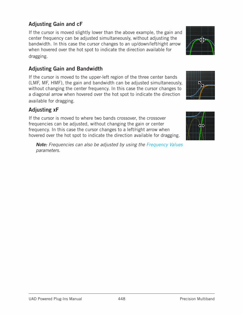
UAD Powered Plug-Ins Manual Precision Multiband 448
Adjusting Gain and cFIf the cursor is moved slightly lower than the above example, the gain and center frequency can be adjusted simultaneously, without adjusting the bandwidth. In this case the cursor changes to an up/down/left/right arrow when hovered over the hot spot to indicate the direction available for dragging.
Adjusting Gain and BandwidthIf the cursor is moved to the upper-left region of the three center bands (LMF, MF, HMF), the gain and bandwidth can be adjusted simultaneously, without changing the center frequency. In this case the cursor changes to a diagonal arrow when hovered over the hot spot to indicate the direction available for dragging.
Adjusting xFIf the cursor is moved to where two bands crossover, the crossover frequencies can be adjusted, without changing the gain or center frequency. In this case the cursor changes to a left/right arrow when hovered over the hot spot to indicate the direction available for dragging.
Note: Frequencies can also be adjusted by using the Frequency Values parameters.
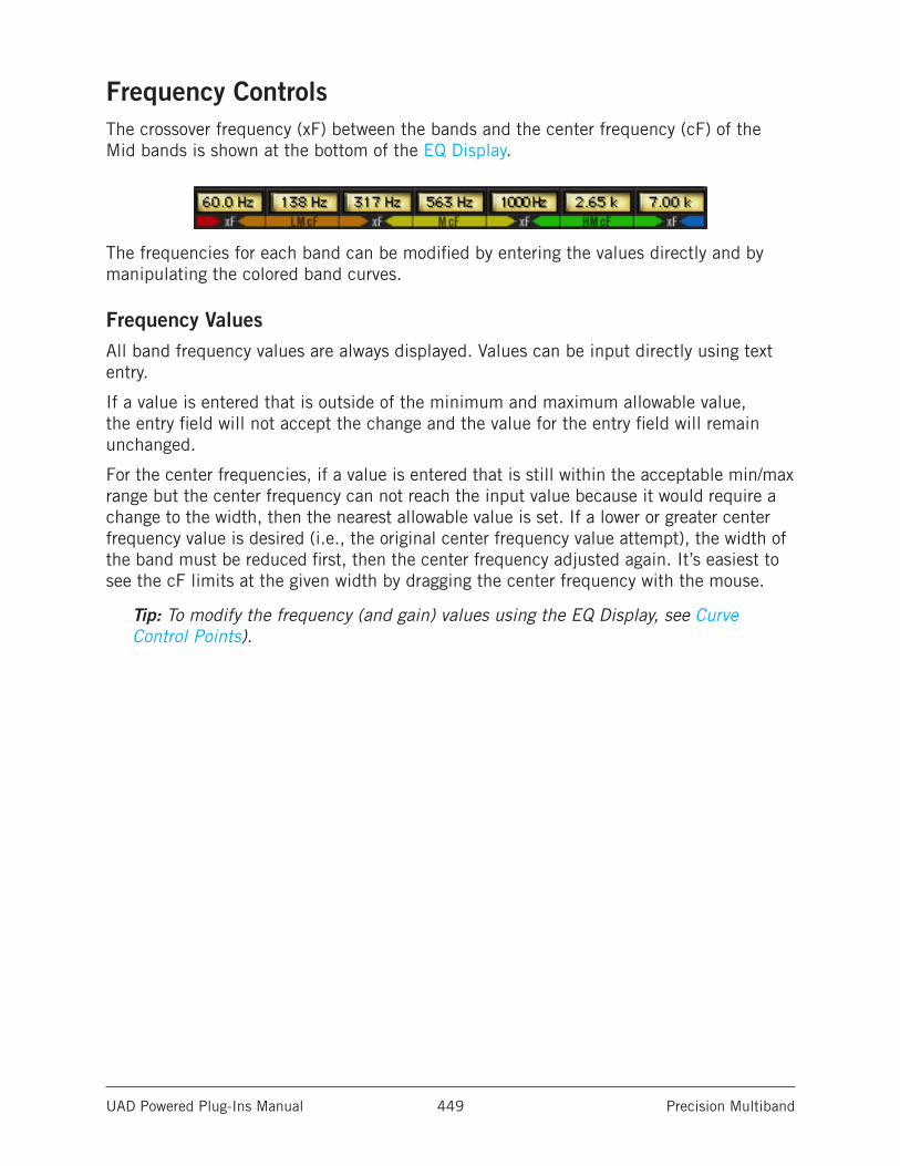
UAD Powered Plug-Ins Manual Precision Multiband 449
Frequency ControlsThe crossover frequency (xF) between the bands and the center frequency (cF) of the Mid bands is shown at the bottom of the EQ Display.
The frequencies for each band can be modified by entering the values directly and by manipulating the colored band curves.
Frequency ValuesAll band frequency values are always displayed. Values can be input directly using text entry.
If a value is entered that is outside of the minimum and maximum allowable value, the entry field will not accept the change and the value for the entry field will remain unchanged.
For the center frequencies, if a value is entered that is still within the acceptable min/max range but the center frequency can not reach the input value because it would require a change to the width, then the nearest allowable value is set. If a lower or greater center frequency value is desired (i.e., the original center frequency value attempt), the width of the band must be reduced first, then the center frequency adjusted again. It’s easiest to see the cF limits at the given width by dragging the center frequency with the mouse.
Tip: To modify the frequency (and gain) values using the EQ Display, see Curve Control Points).
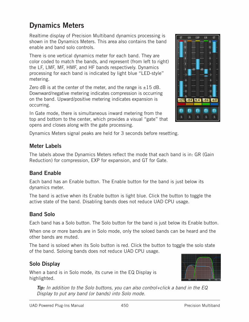
UAD Powered Plug-Ins Manual Precision Multiband 450
Dynamics MetersRealtime display of Precision Multiband dynamics processing is shown in the Dynamics Meters. This area also contains the band enable and band solo controls.
There is one vertical dynamics meter for each band. They are color coded to match the bands, and represent (from left to right) the LF, LMF, MF, HMF, and HF bands respectively. Dynamics processing for each band is indicated by light blue “LED-style” metering.
Zero dB is at the center of the meter, and the range is ±15 dB. Downward/negative metering indicates compression is occurring on the band. Upward/positive metering indicates expansion is occurring.
In Gate mode, there is simultaneous inward metering from the top and bottom to the center, which provides a visual “gate” that opens and closes along with the gate processing.
Dynamics Meters signal peaks are held for 3 seconds before resetting.
Meter LabelsThe labels above the Dynamics Meters reflect the mode that each band is in: GR (Gain Reduction) for compression, EXP for expansion, and GT for Gate.
Band EnableEach band has an Enable button. The Enable button for the band is just below its dynamics meter.
The band is active when its Enable button is light blue. Click the button to toggle the active state of the band. Disabling bands does not reduce UAD CPU usage.
Band SoloEach band has a Solo button. The Solo button for the band is just below its Enable button.
When one or more bands are in Solo mode, only the soloed bands can be heard and the other bands are muted.
The band is soloed when its Solo button is red. Click the button to toggle the solo state of the band. Soloing bands does not reduce UAD CPU usage.
Solo DisplayWhen a band is in Solo mode, its curve in the EQ Display is highlighted.
Tip: In addition to the Solo buttons, you can also control+click a band in the EQ Display to put any band (or bands) into Solo mode.
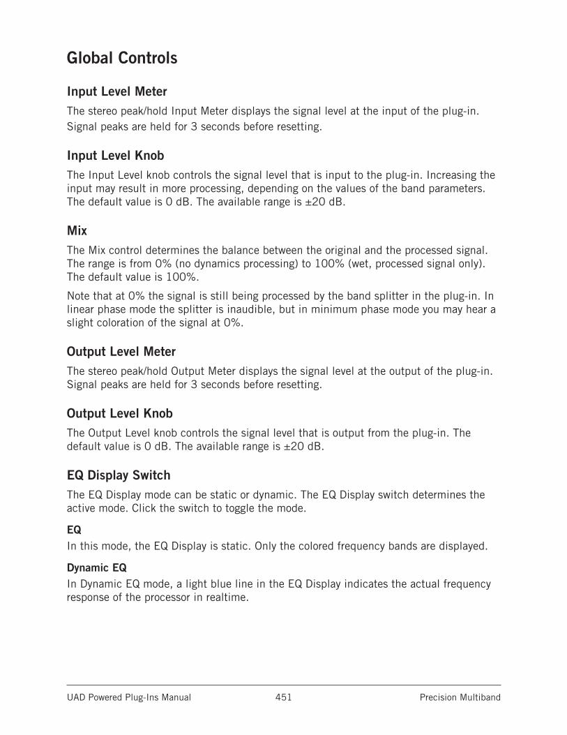
UAD Powered Plug-Ins Manual Precision Multiband 451
Global Controls
Input Level MeterThe stereo peak/hold Input Meter displays the signal level at the input of the plug-in. Signal peaks are held for 3 seconds before resetting.
Input Level KnobThe Input Level knob controls the signal level that is input to the plug-in. Increasing the input may result in more processing, depending on the values of the band parameters. The default value is 0 dB. The available range is ±20 dB.
MixThe Mix control determines the balance between the original and the processed signal. The range is from 0% (no dynamics processing) to 100% (wet, processed signal only). The default value is 100%.
Note that at 0% the signal is still being processed by the band splitter in the plug-in. In linear phase mode the splitter is inaudible, but in minimum phase mode you may hear a slight coloration of the signal at 0%.
Output Level MeterThe stereo peak/hold Output Meter displays the signal level at the output of the plug-in. Signal peaks are held for 3 seconds before resetting.
Output Level KnobThe Output Level knob controls the signal level that is output from the plug-in. The default value is 0 dB. The available range is ±20 dB.
EQ Display SwitchThe EQ Display mode can be static or dynamic. The EQ Display switch determines the active mode. Click the switch to toggle the mode.
EQIn this mode, the EQ Display is static. Only the colored frequency bands are displayed.
Dynamic EQIn Dynamic EQ mode, a light blue line in the EQ Display indicates the actual frequency response of the processor in realtime.
UAD Powered Plug-Ins Manual Precision Multiband 452
Phase Mode SwitchThe filter bank mode of Precision Multiband can be specified with the Phase Mode switch. Click the switch to toggle the mode. The default mode is Linear.
Both filter bank modes achieve the magnitude response of a Linkwitz-Riley filter and provide perfect magnitude reconstruction.
LinearUse linear phase mode when perfectly phase-coherent results are desired.
MinimumMinimum phase mode provides a more “analog” (i.e., colored) sound and uses slightly less UAD DSP.
While the DSP savings are rather negligible, there is a functional advantage to Min phase mode. When Precision Multiband is used as a track compressor, Min phase mode provides the advantage of rapid response time of the filters for smooth automation and filter sweeps.
Power SwitchThe Power Switch determines whether the plug-in is active. Click the toggle button or the UA logo to change the state.
When the Power switch is in the Off position, plug-in processing is disabled and UAD DSP usage is reduced (unless UAD-2 DSP LoadLock is enabled).
When the plug-in is bypassed with this switch (but not by the host bypass), the I/O meters and the Input Level knob remain active.
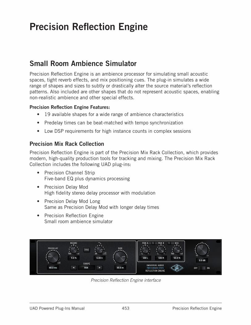
UAD Powered Plug-Ins Manual Precision Reflection Engine 453
Precision Reflection Engine
Small Room Ambience SimulatorPrecision Reflection Engine is an ambience processor for simulating small acoustic spaces, tight reverb effects, and mix positioning cues. The plug-in simulates a wide range of shapes and sizes to subtly or drastically alter the source material’s reflection patterns. Also included are other shapes that do not represent acoustic spaces, enabling non-realistic ambience and other special effects.
Precision Reflection Engine Features:• 19 available shapes for a wide range of ambience characteristics
• Predelay times can be beat-matched with tempo synchronization
• Low DSP requirements for high instance counts in complex sessions
Precision Mix Rack CollectionPrecision Reflection Engine is part of the Precision Mix Rack Collection, which provides modern, high-quality production tools for tracking and mixing. The Precision Mix Rack Collection includes the following UAD plug-ins:
• Precision Channel Strip Five-band EQ plus dynamics processing
• Precision Delay Mod High fidelity stereo delay processor with modulation
• Precision Delay Mod Long Same as Precision Delay Mod with longer delay times
• Precision Reflection Engine Small room ambience simulator
Precision Reflection Engine interface
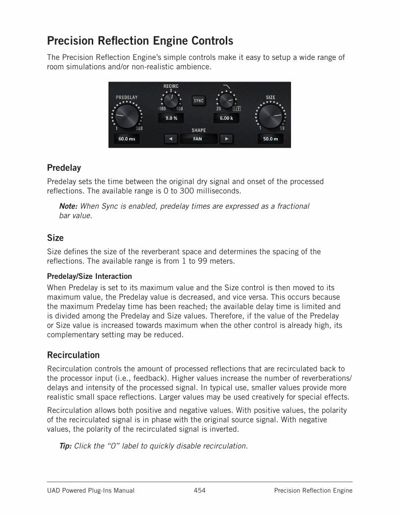
UAD Powered Plug-Ins Manual Precision Reflection Engine 454
Precision Reflection Engine ControlsThe Precision Reflection Engine’s simple controls make it easy to setup a wide range of room simulations and/or non-realistic ambience.
PredelayPredelay sets the time between the original dry signal and onset of the processed reflections. The available range is 0 to 300 milliseconds.
Note: When Sync is enabled, predelay times are expressed as a fractional bar value.
SizeSize defines the size of the reverberant space and determines the spacing of the reflections. The available range is from 1 to 99 meters.
Predelay/Size InteractionWhen Predelay is set to its maximum value and the Size control is then moved to its maximum value, the Predelay value is decreased, and vice versa. This occurs because the maximum Predelay time has been reached; the available delay time is limited and is divided among the Predelay and Size values. Therefore, if the value of the Predelay or Size value is increased towards maximum when the other control is already high, its complementary setting may be reduced.
RecirculationRecirculation controls the amount of processed reflections that are recirculated back to the processor input (i.e., feedback). Higher values increase the number of reverberations/delays and intensity of the processed signal. In typical use, smaller values provide more realistic small space reflections. Larger values may be used creatively for special effects.
Recirculation allows both positive and negative values. With positive values, the polarity of the recirculated signal is in phase with the original source signal. With negative values, the polarity of the recirculated signal is inverted.
Tip: Click the “0” label to quickly disable recirculation.
UAD Powered Plug-Ins Manual Precision Reflection Engine 455
ShapeShape defines the shape of the reverberant space, and the resulting reflective patterns. To change the Shape, either click the selection arrows on each side of the Shape display, or click the Shape display and choose one of the 19 available shapes from the drop menu.
Available Shapes
Cube Reverse Fan Circular Plate
Box A-Frame Fractal
Corridor Spring Gate 1
Cylinder Dual Spring Gate 2
Dome Square Plate Reverse Gate
Horseshoe Rectangular Plate
Fan Triangular Plate
SyncWhen Sync is enabled, Predelay times are synchronized to the host’s tempo. Sync is active when the button is lit. Sync is disabled by default.
When Sync is off, Predelay times are expressed in milliseconds. When Sync is on, Predelay times are expressed as a fractional beat/bar value.
For complete details about this feature, see the “Tempo Synchronization” chapter in the UAD System Manual.
Low PassThis control is a 6 dB per octave low pass (high cut) damping filter for reducing the amount of high frequency content in the processed signal. Rotate the control counter-clockwise for a darker ambience. Higher values yield a brighter ambience.
Tip: Click the “OFF” label to quickly disable the filter. Click again to return to the previous value.
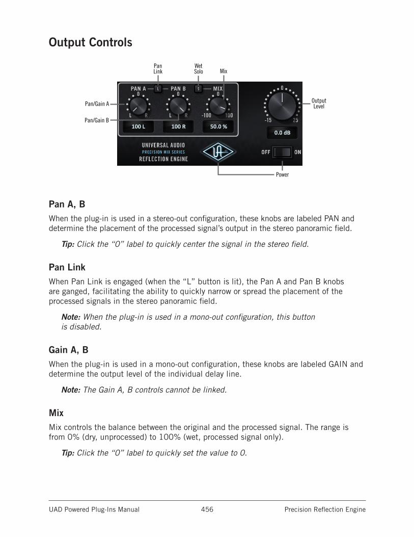
UAD Powered Plug-Ins Manual Precision Reflection Engine 456
Output Controls
Pan/Gain A
Pan/Gain B
PanLink
WetSolo Mix
OutputLevel
Power
Pan A, BWhen the plug-in is used in a stereo-out configuration, these knobs are labeled PAN and determine the placement of the processed signal’s output in the stereo panoramic field.
Tip: Click the “0” label to quickly center the signal in the stereo field.
Pan LinkWhen Pan Link is engaged (when the “L” button is lit), the Pan A and Pan B knobs are ganged, facilitating the ability to quickly narrow or spread the placement of the processed signals in the stereo panoramic field.
Note: When the plug-in is used in a mono-out configuration, this button is disabled.
Gain A, BWhen the plug-in is used in a mono-out configuration, these knobs are labeled GAIN and determine the output level of the individual delay line.
Note: The Gain A, B controls cannot be linked.
MixMix controls the balance between the original and the processed signal. The range is from 0% (dry, unprocessed) to 100% (wet, processed signal only).
Tip: Click the “0” label to quickly set the value to 0.
UAD Powered Plug-Ins Manual Precision Reflection Engine 457
Mix allows both positive and negative values. With positive values, the polarity of the processed signal is in phase with the original source signal. With negative values, the polarity of the processed signal is inverted.
Mix control behavior is based on a logarithmic scale to provide increased resolution when dialing in lower values.
Note: When Wet Solo is enabled, the Mix value is ignored.
Wet SoloThe Wet Solo button puts the plug-in into “100% Wet” mode. When Wet Solo is enabled (when the “S” button is lit), it is the equivalent of setting the Mix control to 100% wet. The Mix value is ignored when Wet Solo is enabled.
Wet Solo is typically used when the plug-in is implemented in the “classic” reverb configuration (placed on an effect group/bus that is configured for use with channel sends). When the plug-in is used directly within a signal chain (such as in a channel insert), this control is typically deactivated.
Note: Wet Solo is a global (per plug-in instance) control.
LevelThis knob adjusts the output level of the plug-in. The available range is -25 dB to +15 dB.
Tip: Click “0” to quickly set the value to 0 dB.
PowerPower is the plug-in bypass control. When set to OFF, all parameter and meter values are no longer visible, and the UA logo is dimmed.
Tip: Power can also be toggled by clicking the UA diamond logo.
Power is useful for comparing the processed settings to the original signal. Unlike the host application’s plug-in disable switch, which can cause audio artifacts, the Power switch offers glitch-free bypass.
RS-1 MigrationAs of UAD v8.2, Precision Reflection Engine replaces the original RS-1 plug-in. When a session containing RS-1 is opened in UAD v8.2 and later, RS-1 plug-in instances and settings are automatically migrated to the newer Precision Reflection Engine.
For additional information about how RS-1 migration is handled, see Migrating Prior Sessions in the CS-1 chapter.
UAD Powered Plug-Ins Manual Pultec Passive EQ Collection 458
Pultec Passive EQ Collection
Astonishingly accurate recreations of the “must-have” classic EQsBuilding on a decade of the world’s most intensive modeling research, UA has recreated the famed Pultec EQ experience as plug-ins — ones that are nearly indistinguishable from the original analog hardware.
Now You Can:• Use Pultec’s three most popular studio EQs on individual tracks or busses
• Provide the same Pultec analog “magic” for your tracks, making them sound better just by passing through
• Push the Pultec’s fully modeled transformer and tube-based amplifier sections
• Make difficult-to-isolate instruments and vocals breathtakingly clear without affecting neighboring frequencies
• Dial up extreme levels of EQ boost while staying natural and musical
• Give that signature airy, smooth-as-silk vintage tone to your master channel
The Pultec StoryWhen Ollie Summerland and Gene Shenk hand-crafted the first Pulse Techniques passive program equalizer in 1951, they had no idea they were transforming an industry. But like a Stradivarius, their little garage-built, made-to-order designs have been copied by nearly every EQ-maker for decades, and their early EQP-1A’s still bring thousands on the used market — if you’re lucky enough to find one.
The Pultec Passive EQ Plug-In Collection for UAD-2 and Apollo hardware includes the ultimate plug-in emulations of Pulse Techniques’ original passive EQs. With painstakingly modeled amplifier sections now onboard, the Pultec EQ Collection “breathes” like the original hardware.
Legendary Pultec Depth and ClarityGoing far beyond UA’s original standard-defining Pultec plug-ins, the EQP-1A faithfully models the overbuilt transformers and complex tube amplifiers of the original hardware. Simply running a full mix or single instrument through it imbues the track with the legendary Pultec analog magic. And, with these new plug-ins, you can actually hear the Pultec’s amplifier overload effects — just as you would with the hardware — unleashing a bounty of sublime results.
UAD Powered Plug-Ins Manual Pultec Passive EQ Collection 459
The Signature Effect on Low EndThe Pultec EQP-1A’s signature effect, unintended by its designers, is its ability to seemingly boost and cut the same frequency simultaneously. In reality, the filters actually alter adjacent frequencies, but the naturally interactive resonant dip has an amazing boosting and tightening effect — especially on bass guitar and kick drums.
Shaping Your Mids: The MEQ-5The MEQ-5 Mid-Range Equalizer is the richly colorful tube-amplified companion to the EQP-1A. With two bands of midrange boost and one band of midrange dip, the MEQ-5 gets the very best out of the ”power region” where guitars and vocals can make or break a mix. The unique band overlap and filter interaction unleash the vibrancy of these instruments in the track — without fighting your overall mix.
Tame The Sides: The HLF-3CThe never-before-available HLF-3C completes the Pultec Passive EQ Collection. This new plug-in adds 12 dB per octave low and high cut filters, for broad retro-tonal sculpting or bygone-era special effects. You can easily subtract the unnecessary frequencies in any instrument and sub-group so they stay wonderfully musical in the mix.
Artist PresetsIn developing the Pultec EQ Collection, UA commissioned some of the biggest names in the business to develop custom presets. Check out John Paterno’s (Steve Gadd, The Black Crowes, Bonnie Raitt) ”Clear, Big-Body Acoustic” and his ”U-47” and ”U-67” settings. Also demo Jacknife Lee’s (The Cars, U2, Taylor Swift) ”Drum Buss Earth and Air” and ”Acoustic Guitar Tamer.”
Note: Presets created with the original Legacy plug-ins are incompatible with the equivalent newer model plug-ins.
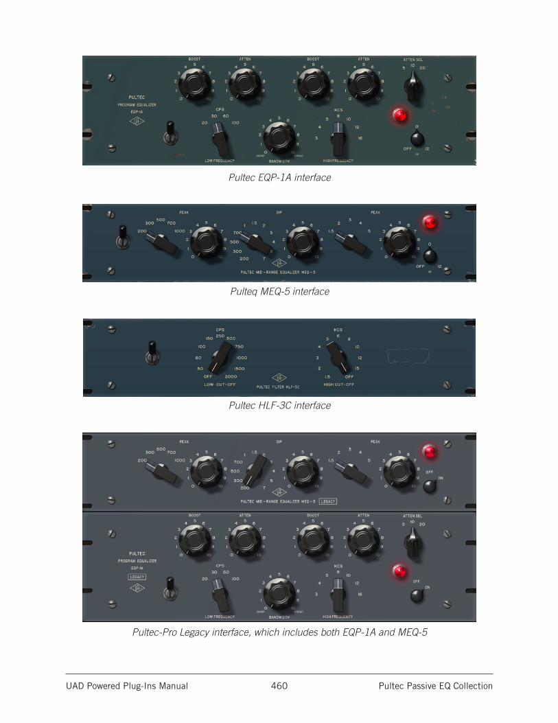
UAD Powered Plug-Ins Manual Pultec Passive EQ Collection 460
Pultec EQP-1A interface
Pulteq MEQ-5 interface
Pultec HLF-3C interface
Pultec-Pro Legacy interface, which includes both EQP-1A and MEQ-5
UAD Powered Plug-Ins Manual Pultec Passive EQ Collection 461
Pultec Plug-In FamilyThe complete Pultec family is comprised of five individual plug-ins, as seen on the previous page. Each variation has its own unique sonic characteristics.
Pultec Passive EQ CollectionThe Pultec Passive EQ Collection provides access to three historical and highly coveted revisions in the Pultec product line.
The plug-ins in the Pultec Passive EQ Collection benefit from the additional processing power afforded by the UAD-2, plus more than 10 years of UA’s evolving sophistication designing plug-ins. While the original EQP-1A Legacy and Pultec-Pro Legacy plug-ins remain an excellent rendition of the hardware, the plug-ins in the newer Pultec Passive EQ Collection add the transformer and complex tube amplifier nonlinearities for even more authenticity. The sophisticated modeling technology used in the newer plug-in collection captures all of these tone-enhancing characteristics.
Pultec EQP-1AUsed on a myriad of recordings from the 1950’s to today, the three-band, tube-amplified EQP-1A Program Equalizer has long been a studio staple of recording and mix engineers for its ability to bring out individual frequency ranges without significantly altering neighboring frequencies. This unit is equally famous for its ability to dial in seemingly dangerous amounts of boost and famously smooth-as-silk vintage tone. The EQP-1A is also known as the quintessential “magic” studio piece that makes audio simply sound better just by passing through it.
Pultec MEQ-5The Pultec MEQ-5 Mid-Range Equalizer is the richly colorful tube-amplified companion piece to the EQP-1A. With two bands of midrange boost and one band of midrange dip, the MEQ-5 is designed to enhance and control the “power region” where sound energy is often concentrated, covering the finer tone requirements in the Pultec Collection with an abundance of band overlap and filter interaction.
Pultec HLF-3CThe HLF-3C completes the Pultec Passive EQ Collection. This plug-in has 12 dB per octave low and high cut filters, providing broad retro-tonal sculpting or bygone-era special effects, without the inconvenience of insertion loss found with the unamplified passive hardware.
UAD Powered Plug-Ins Manual Pultec Passive EQ Collection 462
Pultec LegacyThe Pultec EQP-1A Legacy and Pultec-Pro Legacy plug-ins are the original versions of our Pultec emulations that run on both UAD-1 and UAD-2 devices. They still have a great sound and are very usable, especially when there are not enough DSP resources to use the second-generation versions in the newer Pultec Passive EQ Collection.
To accommodate the limited DSP resources of the original UAD-1, the transformer and I/O distortion characteristics were not modeled in these plug-ins. This makes these legacy versions especially useful in situations where less distortion, and less DSP usage, is desirable.
Operational OverviewThe Pultec EQP-1A/MEQ-5 combination is still standard fare in recording studios and was once widely used in mastering sessions. Whether used independently or together, mono or stereo, the Pultec Collection provides a complete vintage EQ palette for individual sources such as bass or kick drums, subgroups such rhythm, horn or string sections, or on the master bus. The EQP-1A’s 16 KCS high frequency setting is famous for adding “air” to master sources.
Although unintended by its designers, the Pultec EQP-1A is coveted for its unique ability to boost and cut the same low frequency simultaneously, creating a tightening effect as a naturally interactive resonant dip near the selected frequency. This has the sonic effect of simultaneously tightening and boosting bass frequencies. Select the bass frequency then adjust the balance of Boost and Cut to tune the effect.
EQP-1A Insertion BoostThe original EQP-1A hardware unit has an inherent level boost of approximately 1.13 dB when it is in the signal path. This inherent boost is present in the EQP-1A plug-in models as well.
Frequency ConventionsThe original Pultec hardware used frequency unit names that were conventional before the frequency unit of “Hertz” was widely adopted. The UAD Pultec plug-ins adopt the original frequency unit name conventions.
CPS is an acronym for Cycles Per Second, which is now more commonly referred to as Hertz and abbreviated as Hz. KCS is an acronym for KiloCycles per Second, which is now more commonly referred to as KiloHertz and abbreviated as kHz.
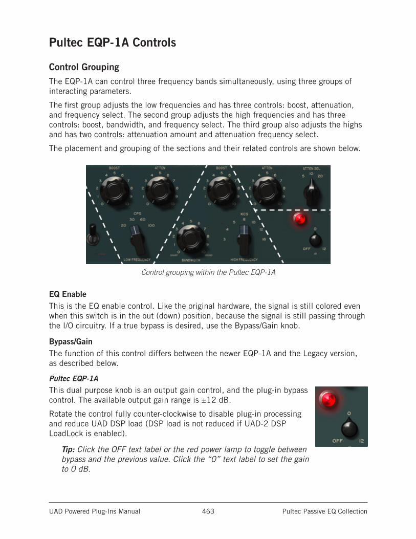
UAD Powered Plug-Ins Manual Pultec Passive EQ Collection 463
Pultec EQP-1A Controls
Control GroupingThe EQP-1A can control three frequency bands simultaneously, using three groups of interacting parameters.
The first group adjusts the low frequencies and has three controls: boost, attenuation, and frequency select. The second group adjusts the high frequencies and has three controls: boost, bandwidth, and frequency select. The third group also adjusts the highs and has two controls: attenuation amount and attenuation frequency select.
The placement and grouping of the sections and their related controls are shown below.
Control grouping within the Pultec EQP-1A
EQ EnableThis is the EQ enable control. Like the original hardware, the signal is still colored even when this switch is in the out (down) position, because the signal is still passing through the I/O circuitry. If a true bypass is desired, use the Bypass/Gain knob.
Bypass/GainThe function of this control differs between the newer EQP-1A and the Legacy version, as described below.
Pultec EQP-1A
This dual purpose knob is an output gain control, and the plug-in bypass control. The available output gain range is ±12 dB.
Rotate the control fully counter-clockwise to disable plug-in processing and reduce UAD DSP load (DSP load is not reduced if UAD-2 DSP LoadLock is enabled).
Tip: Click the OFF text label or the red power lamp to toggle between bypass and the previous value. Click the “0” text label to set the gain to 0 dB.
UAD Powered Plug-Ins Manual Pultec Passive EQ Collection 464
Pultec EQP-1A Legacy
This is the plug-in bypass control. The knob can be used to compare the processed settings to that of the original signal, or to disable the plug-in to reduce UAD DSP load (DSP load is not reduced if UAD-2 DSP LoadLock is enabled).
Note: Output gain is unavailable on the Pultec EQP-1A Legacy plug-in.
Low Frequency Controls
Low FrequencyThis switch determines the frequency of the low shelf portion of the equalizer. Four frequencies are available: 20, 30, 60, and 100 CPS.
Tip: To cycle through the available values, click the CPS text label, or shift+click the text label to cycle through available values in reverse. This function is unavailable with the Legacy version of the plug-in.
LF BoostThis knob determines the amount of low shelf gain to be applied to the frequency set by the CPS switch.
LF AttenuationThis knob (ATTEN) determines the amount of low shelf cut to be applied to the frequency set by the CPS switch.
Background
In the documentation supplied with hardware version of the EQP-1A, it is recommended that both Boost and Attenuation not be applied simultaneously because in theory, they would cancel each other out. In actual use however, the Boost control has slightly higher gain than the Attenuation has cut, and the frequencies they affect are slightly different too. The EQ curve that results when boost and attenuation are simultaneously applied to the low shelf is an additional feature.
UAD Powered Plug-Ins Manual Pultec Passive EQ Collection 465
High Boost Controls
High FrequencyThis switch determines the frequency of the high boost portion of the equalizer. Seven frequencies are available: 3, 4, 5, 8, 10, 12, and 16 KCS.
Tip: To cycle through the available values, click the KCS text label, or shift+click the text label to cycle through available values in reverse. These shortcuts are unavailable with the Legacy version of the plug-in.
HF Bandwidth (Q)This knob sets the proportion of frequencies surrounding the center frequency (determined by the KCS switch) to be affected by the high boost (this is a bandwidth control). Lower values yield a narrower band and effect fewer frequencies.
HF BoostThis knob controls sets the amount of gain for the high frequency portion of the equalizer.
High Attenuation Controls
HF Attenuation FrequencyThis switch (ATTEN SEL) determines the frequency of the high frequency attenuator. Three frequencies are available: 5, 10, and 20 KCS.
Tip: To cycle through the available values, click the ATTEN SEL text label, or shift+click the text label to cycle through available values in reverse. These shortcuts are unavailable with the Legacy version of the plug-in.
HF AttenuationThis knob (ATTEN) determines the amount of high shelf cut to be applied to the frequency set by the Attenuation Selector switch.
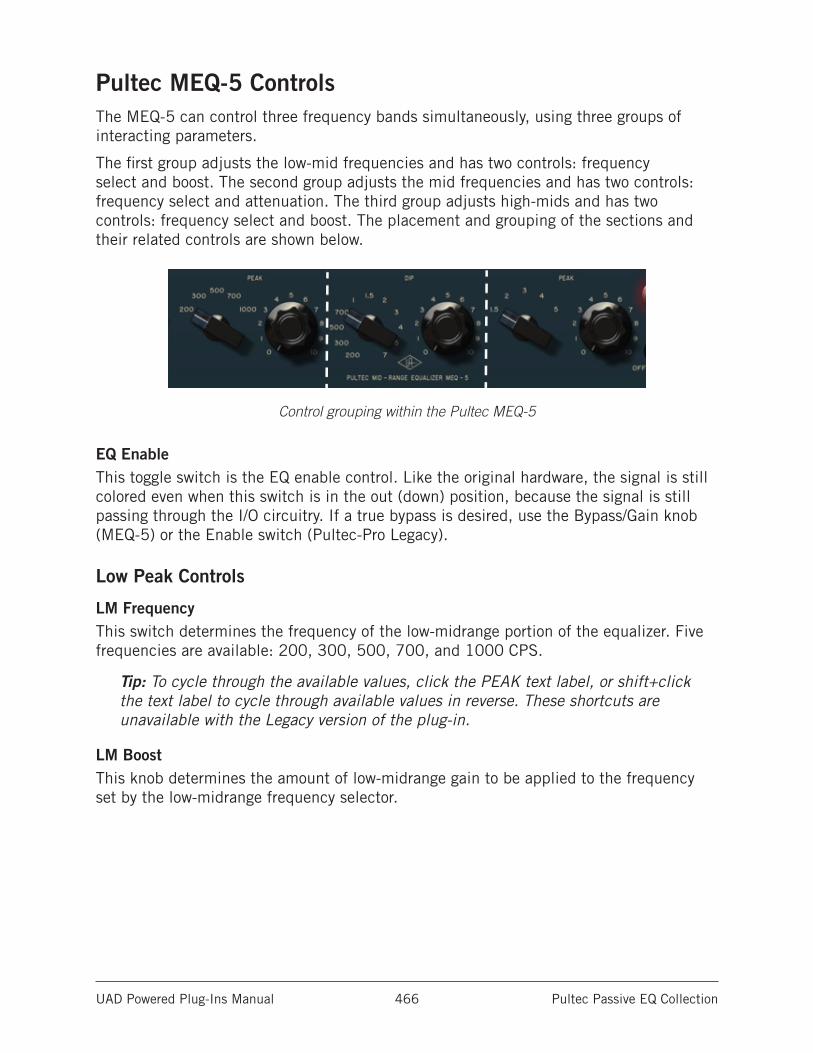
UAD Powered Plug-Ins Manual Pultec Passive EQ Collection 466
Pultec MEQ-5 ControlsThe MEQ-5 can control three frequency bands simultaneously, using three groups of interacting parameters.
The first group adjusts the low-mid frequencies and has two controls: frequency select and boost. The second group adjusts the mid frequencies and has two controls: frequency select and attenuation. The third group adjusts high-mids and has two controls: frequency select and boost. The placement and grouping of the sections and their related controls are shown below.
Control grouping within the Pultec MEQ-5
EQ EnableThis toggle switch is the EQ enable control. Like the original hardware, the signal is still colored even when this switch is in the out (down) position, because the signal is still passing through the I/O circuitry. If a true bypass is desired, use the Bypass/Gain knob (MEQ-5) or the Enable switch (Pultec-Pro Legacy).
Low Peak Controls
LM FrequencyThis switch determines the frequency of the low-midrange portion of the equalizer. Five frequencies are available: 200, 300, 500, 700, and 1000 CPS.
Tip: To cycle through the available values, click the PEAK text label, or shift+click the text label to cycle through available values in reverse. These shortcuts are unavailable with the Legacy version of the plug-in.
LM BoostThis knob determines the amount of low-midrange gain to be applied to the frequency set by the low-midrange frequency selector.
UAD Powered Plug-Ins Manual Pultec Passive EQ Collection 467
Dip Controls
Mid FrequencyThis switch determines the frequency of the midrange portion of the equalizer. Eleven frequencies are available: 200 CPS, 300 CPS, 500 CPS, 700 CPS, 1 KCS, 1.5 KCS, 2 KCS, 3 KCS, 4 KCS, 5 KCS, and 7 KCS.
Tip: To cycle through the available values, click the DIP text label, or shift+click the text label to cycle through available values in reverse. These shortcuts are unavailable with the Legacy version of the plug-in.
Mid Dip
This knob determines the amount of midrange cut (attenuation) to be applied to the frequency set by the midrange frequency selector.
High Peak Controls
HM FrequencyThis switch determines the frequency of the high-midrange portion of the equalizer. Five frequencies are available: 1.5, 2, 3, 4, and 5 KCS.
Tip: To cycle through the available values, click the PEAK text label, or shift+click the text label to cycle through available values in reverse. These shortcuts are unavailable with the Legacy version of the plug-in.
HM BoostThis knob determines the amount of high-midrange gain to be applied to the frequency set by the high-mid frequency selector.
Bypass/GainThis is dual purpose knob is an output gain control, and a plug-in bypass control. The available output gain range is ±12 dB.
Rotate the control fully counter-clockwise to bypass plug-in processing and reduce UAD DSP load (DSP load is not reduced if UAD-2 DSP LoadLock is enabled).
Tip: Click the OFF text label or the red power lamp to toggle between bypass and the previous value. Click the “0” text label to set the gain to 0 dB.
UAD Powered Plug-Ins Manual Pultec Passive EQ Collection 468
Pultec HLF-3C Controls
Unity GainThe Pultec HLF-3C hardware unit is a true passive design; there are no input/output amplifiers and it does not require any external power. As a result, there is an inherent loss of signal level when using the HLF-3C hardware.
The Pultec HLF-3C plug-in compensates for this inherent signal loss for simplified use in the modern era; it has unity gain upon insertion (there is no insertion loss until one or both of the cut filters is engaged).
The HLF-3C interface is very simple and includes only three controls.
EnableThis toggle switch is the plug-in bypass control. When in the down position (bypassed), plug-in processing is disabled altogether. The plug-in is engaged with the switch is in the up position.
This switch can be used to compare the processed settings to that of the original signal, or to bypass plug-in processing to reduce UAD DSP load (DSP load is not reduced if UAD-2 DSP LoadLock is enabled).
Note: The behavior of this toggle switch differs from the other UAD Pultec plug-ins. Because the HLF-3C hardware is not internally amplified, there is no I/O circuitry modeling to maintain when the EQ portion of the circuit is bypassed (the entire hardware unit is the EQ portion).
Low CutThis rotary switch specifies the cutoff frequency of the low cut filter. Eleven frequencies are available: 50, 80, 100, 150, 250, 500, 750, 1000, 1500, and 2000 CPS.
Tip: To cycle through the available values, click the CPS text label, or shift+click the text label to cycle through available values in reverse.
High CutThis rotary switch specifies the cutoff frequency of the high cut filter. Eleven frequencies are available: 1.5, 2, 3, 4, 5, 6, 8, 10, 12, and 15 KCS.
Tip: To cycle through the available values, click the KCS text label, or shift+click the text label to cycle through available values in reverse.
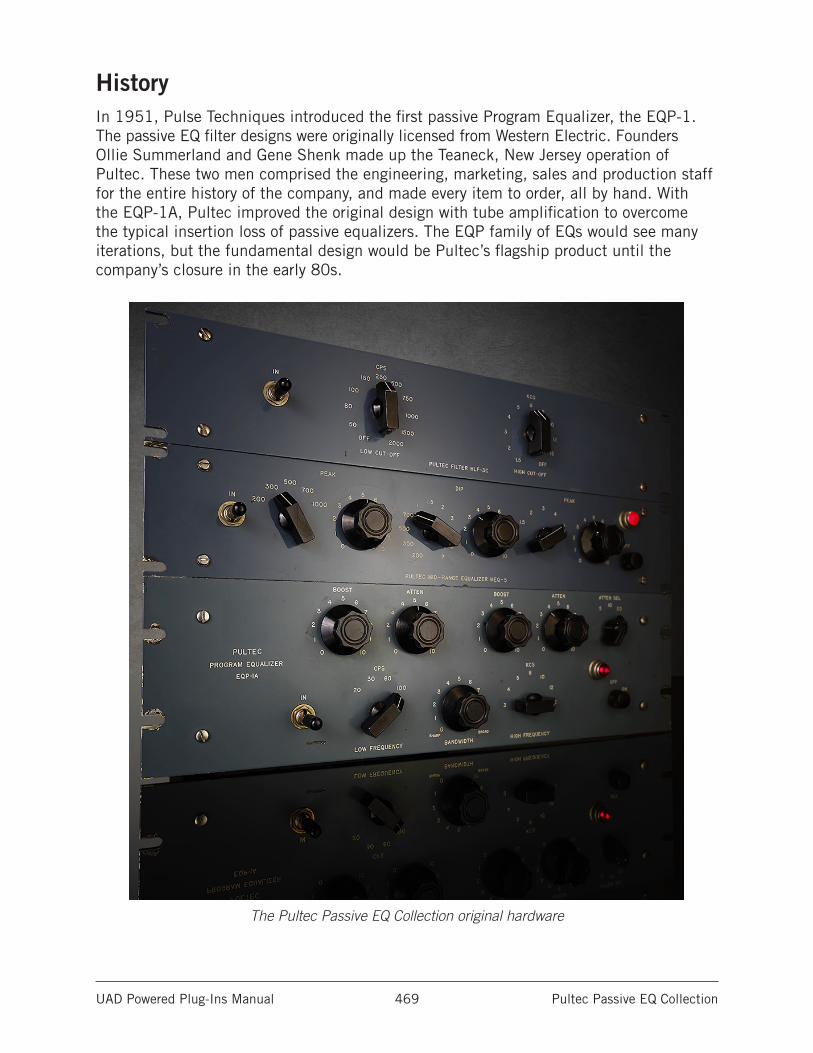
UAD Powered Plug-Ins Manual Pultec Passive EQ Collection 469
HistoryIn 1951, Pulse Techniques introduced the first passive Program Equalizer, the EQP-1. The passive EQ filter designs were originally licensed from Western Electric. Founders Ollie Summerland and Gene Shenk made up the Teaneck, New Jersey operation of Pultec. These two men comprised the engineering, marketing, sales and production staff for the entire history of the company, and made every item to order, all by hand. With the EQP-1A, Pultec improved the original design with tube amplification to overcome the typical insertion loss of passive equalizers. The EQP family of EQs would see many iterations, but the fundamental design would be Pultec’s flagship product until the company’s closure in the early 80s.
The Pultec Passive EQ Collection original hardware
UAD Powered Plug-Ins Manual Raw Distortion 470
Raw Distortion
A Classic Grinding DistortionEqual parts warm overdrive and raunchy grind, the Pro Co Rat distortion pedal has been a vital cog in countless guitar rigs since the late `70s. From Jeff Beck to John Scofield, Thom Yorke to Graham Coxon, players of all stripes revere the Rat’s tonal range, smooth-ness, and heaping amounts of gain.
Modeled from a vintage early `80s Pro Co Rat, the Raw Distortion plug-in for UAD-2 and Apollo interfaces is a faithful emulation of this legendary distortion box, delivering all of the grit, dynamics, and raunch of the original hardware.
Now You Can:• Track through a faithful emulation of the incomparable Pro Co Rat with Apollo
Twin, DUO, or QUAD
• Dial-in subtle grind or thick, saturated tones with the same pedal used by Jeff Beck, Johnny Greenwood, and Joe Walsh
• Add interesting overdriven textures to guitars, synths, drums, and vocals at mix-down with any UAD-2 hardware
• Get the same circuit interaction, gain range, and clip points for touch-sensitive tones, thanks to Unison™ technology for Apollo interfaces
Trapping Raw for a Faithful EmulationThe Raw Distortion plug-in for UAD-2 and Apollo interfaces captures the original hard-ware’s unique, single op-amp circuit as well as its famous “backwards” passive tone filter. This powerful tone control is at the heart of the Rat’s versatility, as it adds tube-like warmth to single-coils while also giving humbucker-equipped guitars an ultra-musical “slice” to stand out in a mix.
Subtle Bite or Grinding GainJust like the original Rat, the Raw Distortion for UAD-2 and Apollo excels at giving your tones a touch of “hair” — perfect for texture on chords — or all-out saturation and distortion. This versatility affords you bountiful sonic options with any guitar you plug in.
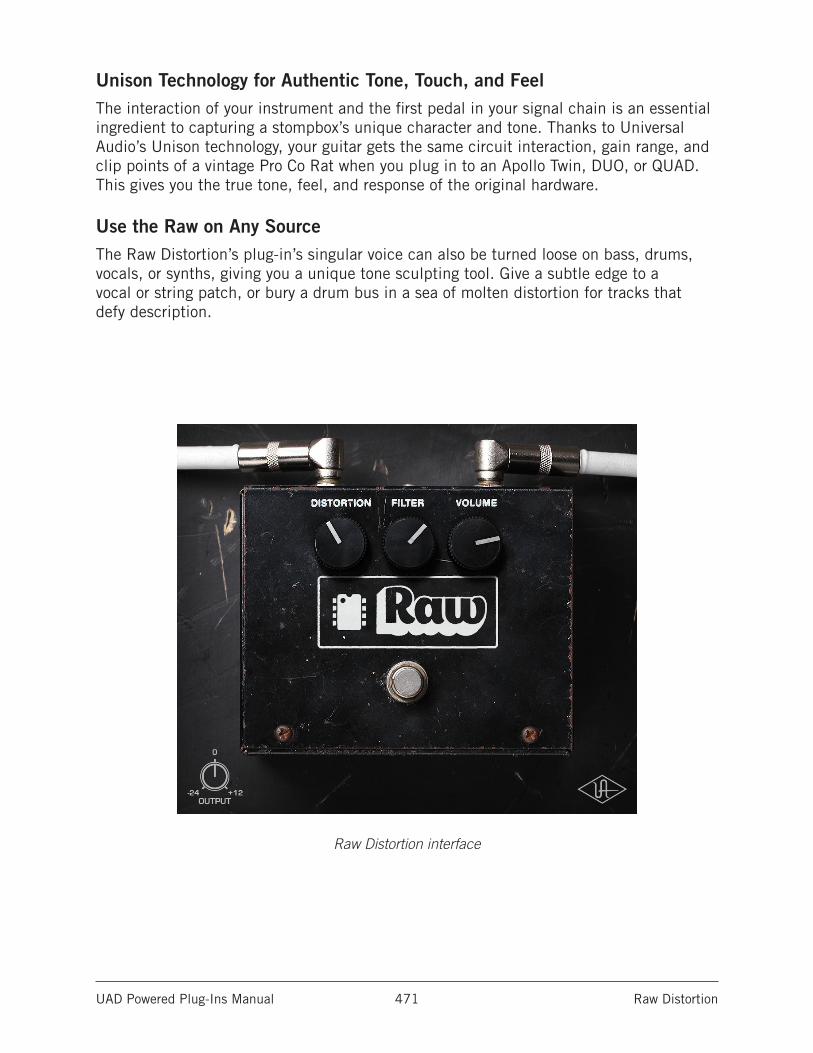
UAD Powered Plug-Ins Manual Raw Distortion 471
Unison Technology for Authentic Tone, Touch, and FeelThe interaction of your instrument and the first pedal in your signal chain is an essential ingredient to capturing a stompbox’s unique character and tone. Thanks to Universal Audio’s Unison technology, your guitar gets the same circuit interaction, gain range, and clip points of a vintage Pro Co Rat when you plug in to an Apollo Twin, DUO, or QUAD. This gives you the true tone, feel, and response of the original hardware.
Use the Raw on Any SourceThe Raw Distortion’s plug-in’s singular voice can also be turned loose on bass, drums, vocals, or synths, giving you a unique tone sculpting tool. Give a subtle edge to a vocal or string patch, or bury a drum bus in a sea of molten distortion for tracks that defy description.
Raw Distortion interface
UAD Powered Plug-Ins Manual Raw Distortion 472
Using Raw
Standard DAW InsertsIn much the same way as some premier recording and mix engineers use stomp boxes in a mix, Raw Distortion can be used for creative purposes on any source signal by plac-ing it in any plug-in insert within a DAW. For typical guitar tones, follow the pedal with a guitar amp emulation (as one would with a hardware guitar pedal and amp).
Because the plug-in accurately models the original hardware’s high-impedance operating levels, precautions may need to be taken to avoid undesirable input clipping.
Note: Since Hi-Z devices typically operate at much lower signal levels than line-level devices, signal levels being routed into the pedal may need to be reduced to avoid undesirable input distortion.
Unison™ Technology with ApolloRaw features Unison technology for integration with the high-impedance input hardware in Universal Audio’s Apollo audio interfaces. With Unison, Apollo’s Hi-Z inputs inherit all of the unique circuit interaction, gain range, and clip points of the original guitar pedal.
Hi-Z Signal RoutingFor the most authentic stompbox tones, plug any high-impedance instrument (guitar, bass, etc.) into Apollo’s Hi-Z instrument input and place the pedal plug-in into the unique Unison INPUT insert on the same channel within Apollo’s Console application. If desired, follow the Unison pedal plug-in with another pedal or guitar amp emulation Console’s standard insert slots.
This Hi-Z workflow enables near-zero latency monitoring or recording with the same input characteristics and dynamic response as the original pedal.
Note: This plug-in can be Unison-enabled with Apollo’s Mic or Line inputs. How-ever, because the original hardware has a high-impedance instrument input only, Apollo’s Hi-Z input and Unison insert will provide the most accurate sound and experience of the hardware pedal that is modeled.
Important: Unison is active only when the pedal plug-in is placed in the unique INPUT insert available on Hi-Z inputs within Apollo’s Console application. For complete Unison details, see the Apollo Software Manual.
Tactile ControlApollo’s front panel preamp knob can independently adjust the Distortion, Volume, and Output controls available within the Unison pedal plug-in via Gain Stage Mode. The control being adjusted can be remotely switched via Apollo, so the control levels and their associated colorations can be tuned from the hardware knob for precise physical tactile control, all without using the Unison plug-in’s software interface.
UAD Powered Plug-Ins Manual Raw Distortion 473
Raw Controls
DistortionDistortion varies the amount of signal overdrive. Rotate the control clockwise to increase distortion and sustain.
FilterFilter adjusts the high-frequency content of the signal. Rotate the control clockwise to increase the filter amount, which reduces treble content.
VolumeVolume adjusts the pedal’s modeled output level. Rotate the control clockwise to increase the volume.
PowerThe stomp switch toggles between plug-in enable and disable. Click the switch to toggle the Power state. Like the original hardware, this is a true-bypass control. When disabled, the signal is not colored by the circuitry.
Tip: Power can also be toggled by clicking the UA diamond logo.
OutputOutput controls the clean (unmodeled) gain at the output of the plug-in. The available range is -24 dB to +12 dB.
Tip: Click the “0” label to return the control to zero dB.
Raw Distortion is not affiliated with, sponsored nor endorsed by any companies currently using the Pro Co Rat name. The Raw Distortion name is used solely to identify the classic effect emulated by Universal Audio’s product.
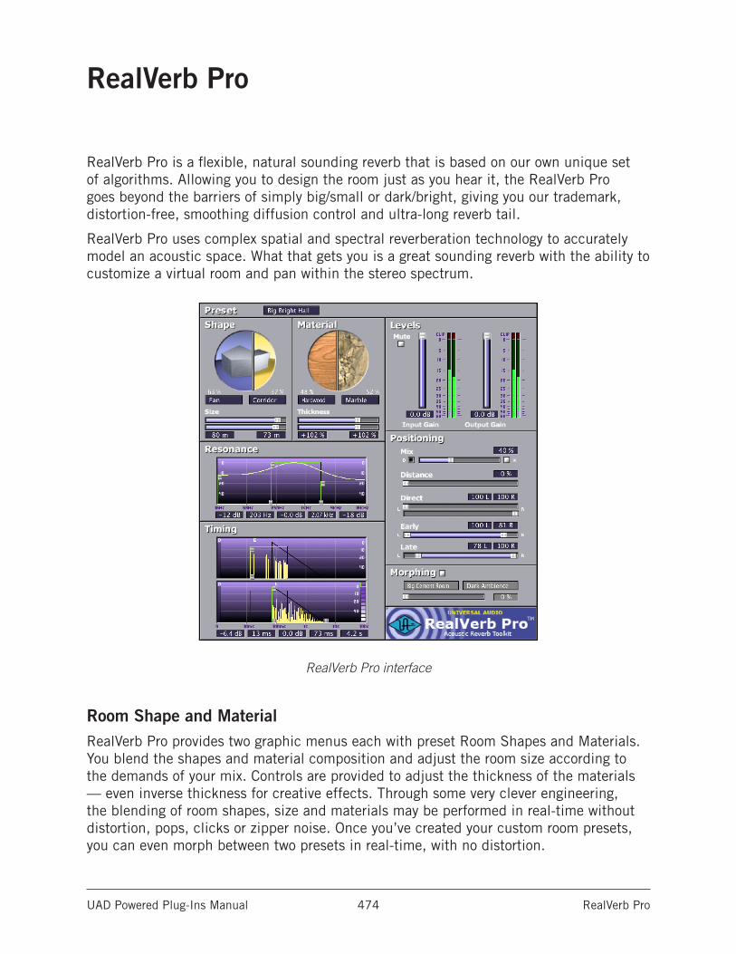
UAD Powered Plug-Ins Manual RealVerb Pro 474
RealVerb Pro
RealVerb Pro is a flexible, natural sounding reverb that is based on our own unique set of algorithms. Allowing you to design the room just as you hear it, the RealVerb Pro goes beyond the barriers of simply big/small or dark/bright, giving you our trademark, distortion-free, smoothing diffusion control and ultra-long reverb tail.
RealVerb Pro uses complex spatial and spectral reverberation technology to accurately model an acoustic space. What that gets you is a great sounding reverb with the ability to customize a virtual room and pan within the stereo spectrum.
RealVerb Pro interface
Room Shape and MaterialRealVerb Pro provides two graphic menus each with preset Room Shapes and Materials. You blend the shapes and material composition and adjust the room size according to the demands of your mix. Controls are provided to adjust the thickness of the materials — even inverse thickness for creative effects. Through some very clever engineering, the blending of room shapes, size and materials may be performed in real-time without distortion, pops, clicks or zipper noise. Once you’ve created your custom room presets, you can even morph between two presets in real-time, with no distortion.
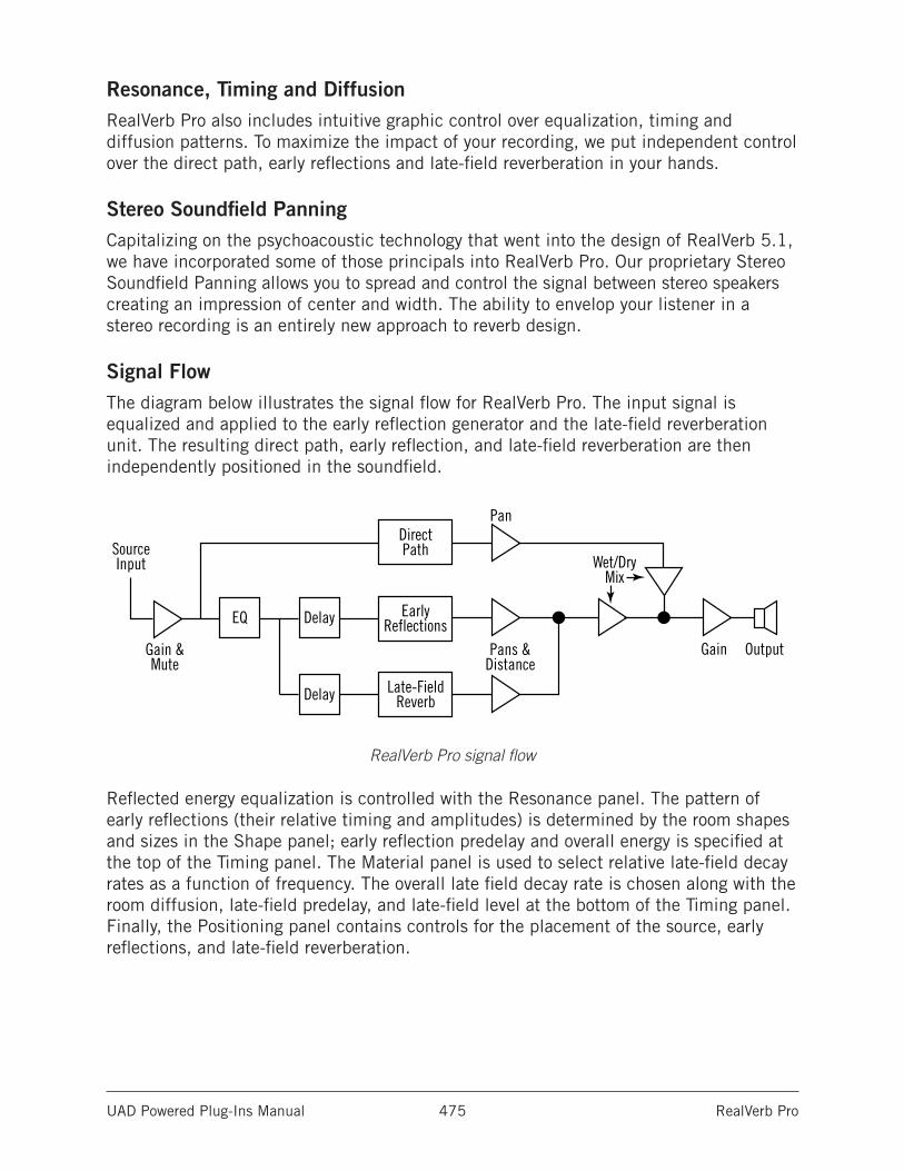
UAD Powered Plug-Ins Manual RealVerb Pro 475
Resonance, Timing and DiffusionRealVerb Pro also includes intuitive graphic control over equalization, timing and diffusion patterns. To maximize the impact of your recording, we put independent control over the direct path, early reflections and late-field reverberation in your hands.
Stereo Soundfield PanningCapitalizing on the psychoacoustic technology that went into the design of RealVerb 5.1, we have incorporated some of those principals into RealVerb Pro. Our proprietary Stereo Soundfield Panning allows you to spread and control the signal between stereo speakers creating an impression of center and width. The ability to envelop your listener in a stereo recording is an entirely new approach to reverb design.
Signal FlowThe diagram below illustrates the signal flow for RealVerb Pro. The input signal is equalized and applied to the early reflection generator and the late-field reverberation unit. The resulting direct path, early reflection, and late-field reverberation are then independently positioned in the soundfield.
RealVerb Pro signal flow
Reflected energy equalization is controlled with the Resonance panel. The pattern of early reflections (their relative timing and amplitudes) is determined by the room shapes and sizes in the Shape panel; early reflection predelay and overall energy is specified at the top of the Timing panel. The Material panel is used to select relative late-field decay rates as a function of frequency. The overall late field decay rate is chosen along with the room diffusion, late-field predelay, and late-field level at the bottom of the Timing panel. Finally, the Positioning panel contains controls for the placement of the source, early reflections, and late-field reverberation.
SourceInput
Gain & Mute
Pan
Pans & Distance
Wet/DryMix
Gain Output
EQ Delay
Delay
Direct Path
Early Reflections
Late-FieldReverb
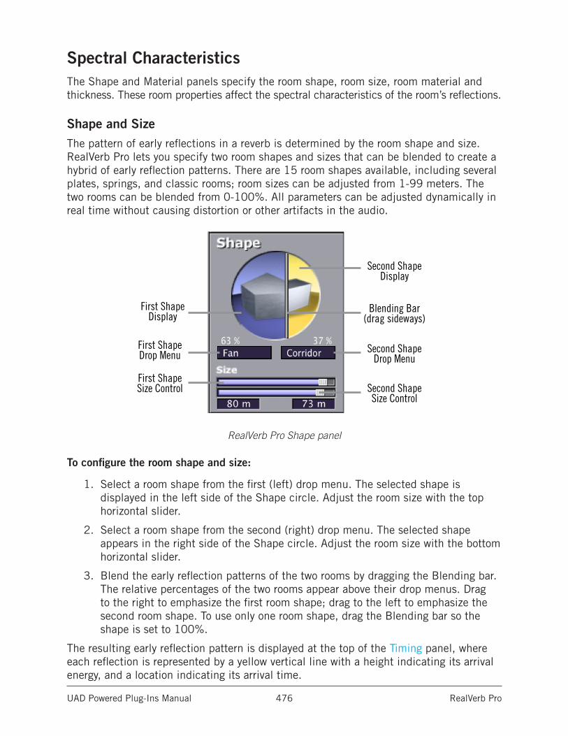
UAD Powered Plug-Ins Manual RealVerb Pro 476
Spectral CharacteristicsThe Shape and Material panels specify the room shape, room size, room material and thickness. These room properties affect the spectral characteristics of the room’s reflections.
Shape and SizeThe pattern of early reflections in a reverb is determined by the room shape and size. RealVerb Pro lets you specify two room shapes and sizes that can be blended to create a hybrid of early reflection patterns. There are 15 room shapes available, including several plates, springs, and classic rooms; room sizes can be adjusted from 1-99 meters. The two rooms can be blended from 0-100%. All parameters can be adjusted dynamically in real time without causing distortion or other artifacts in the audio.
First ShapeDisplay
First ShapeDrop Menu
First ShapeSize Control Second Shape
Size Control
Second ShapeDisplay
Second ShapeDrop Menu
Blending Bar(drag sideways)
RealVerb Pro Shape panel
To configure the room shape and size:
1. Select a room shape from the first (left) drop menu. The selected shape is displayed in the left side of the Shape circle. Adjust the room size with the top horizontal slider.
2. Select a room shape from the second (right) drop menu. The selected shape appears in the right side of the Shape circle. Adjust the room size with the bottom horizontal slider.
3. Blend the early reflection patterns of the two rooms by dragging the Blending bar. The relative percentages of the two rooms appear above their drop menus. Drag to the right to emphasize the first room shape; drag to the left to emphasize the second room shape. To use only one room shape, drag the Blending bar so the shape is set to 100%.
The resulting early reflection pattern is displayed at the top of the Timing panel, where each reflection is represented by a yellow vertical line with a height indicating its arrival energy, and a location indicating its arrival time.
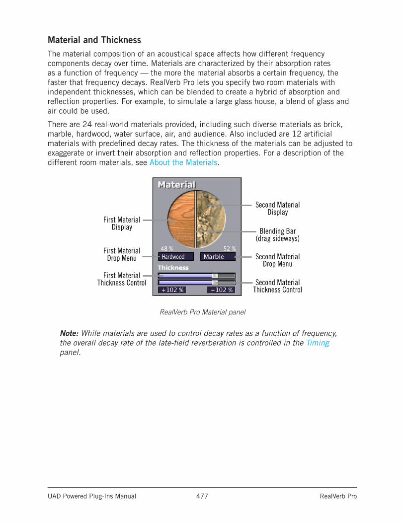
UAD Powered Plug-Ins Manual RealVerb Pro 477
Material and ThicknessThe material composition of an acoustical space affects how different frequency components decay over time. Materials are characterized by their absorption rates as a function of frequency — the more the material absorbs a certain frequency, the faster that frequency decays. RealVerb Pro lets you specify two room materials with independent thicknesses, which can be blended to create a hybrid of absorption and reflection properties. For example, to simulate a large glass house, a blend of glass and air could be used.
There are 24 real-world materials provided, including such diverse materials as brick, marble, hardwood, water surface, air, and audience. Also included are 12 artificial materials with predefined decay rates. The thickness of the materials can be adjusted to exaggerate or invert their absorption and reflection properties. For a description of the different room materials, see About the Materials.
First MaterialDisplay
First MaterialDrop Menu
First Material Thickness Control Second Material
Thickness Control
Second MaterialDisplay
Blending Bar(drag sideways)
Second MaterialDrop Menu
RealVerb Pro Material panel
Note: While materials are used to control decay rates as a function of frequency, the overall decay rate of the late-field reverberation is controlled in the Timing panel.
UAD Powered Plug-Ins Manual RealVerb Pro 478
To configure the room material and thickness:
1. Select a room material from the first (left) drop menu. The selected material is displayed in the left side of the Material circle.
2. Adjust the thickness for the first material with the top horizontal slider:
• A default thickness of +100% yields normal, real-world decays for the material.
• Thicknesses beyond the default (up to +200%) exaggerate how the frequencies are absorbed and reflected.
• Negative thicknesses invert the response of the material. If the material normally absorbs high frequencies (causing them to decay quickly) and reflects low frequencies (causing them to decay slowly), a negative thickness will instead absorb low frequencies (causing them to decay quickly) and reflect high frequencies (causing them to decay slowly).
• A thickness of 0% yields decay rates that are not affected by the material.
3. Select a material from the second (right) drop menu. The selected material is displayed in the right side of the Material circle. Adjust the material thickness with the bottom horizontal slider.
4. Blend the absorption properties of the two materials by dragging the Blending bar. The relative amount of each material, expressed as a percentage, appears above their respective drop menu. Drag the Blending bar to the right to emphasize the first material, and drag it to the left to emphasize the second material. To use only one room material, drag the Blending bar so the material is set to 100%.
About the MaterialsSome materials absorb high frequencies and reflect low frequencies, while other materials absorb low frequencies and reflect high frequencies. This characteristic is determined by the material surface and density.
Fiberglass, for example, absorbs high frequencies. When high frequencies strike fiberglass they bounce around inside the fibers and lose much of their energy.
At a thickness of 100%, fiberglass rolls off the high frequencies, a little bit each millisecond. After a while the high frequencies dissipate and the low frequencies linger. If we were to take fiberglass and increase its thickness to +200%, the high frequencies would roll off even faster. At +200%, this high frequency decay happens at twice its normal rate, producing a very heavy reverberant tail. At -200%, a very “sizzly” late field is created.
Some materials, such as plywood, naturally absorb low frequencies while reflecting high frequencies. Since plywood is usually very flat with little surface texture to capture high frequencies, high frequencies tend to be reflected. At +100%, the reverberation produced is very sizzly and increasingly bright. At -100%, it is very heavy.
UAD Powered Plug-Ins Manual RealVerb Pro 479
Keeping this in mind, if you look at the graphics in the material control panel, you can get a sense of how chosen materials, material blend, and thickness will affect the decay rate as a function of frequency. Hard materials that have lots of small cavities (Brick, Gravel, Plaster on Brick) and soft materials (Carpet, Grass, Soil) tend to absorb high frequencies. Flat, somewhat flexible materials (Heavy Plate Glass, Hardwood, Seats) tend to reflect high frequencies. Marble is the one material that tends to uniformly reflect all frequencies.
You may have noticed the artificial materials the top of the Materials menu. These are materials designed to have predictable behavior and can be very handy for achieving a desired reverberation preset when you know what decay rates you desire. All these materials preferentially absorb high frequencies; they give the selected decay time at low frequencies, and a much shorter decay time at high frequencies. The frequency in each graphic is the transition frequency, the frequency at which the decay rate is halfway between the low-frequency and high-frequency values. At 100% thickness, the ratio of low-frequency to high-frequency decay times is 10:1. This means that the high frequencies will decay 10 times faster than the low frequencies. At 200% thickness, this is multiplied by two (high frequencies decay at 20x the rate of the low frequencies). At negative 100%, the sense of low frequency and high frequency is swapped --low frequencies decay 10 times faster than the high frequencies.
Many hardware and software reverbs tend to compensate for the high frequency absorption that air provides. RealVerb Pro instead provides “Air” as a material. If you do not choose to use Air as one of the materials, you can effectively compensate for the high frequency absorption properties of air with the Resonance filters. Set the right-hand Transition Frequency slider to 4.794 kHz, and bring the level down about -10 dB to -15 dB for large to huge rooms, and down about -4 dB to -9 dB for small to medium rooms.
The following table classifies the materials under two headings: those that tend to reflect high frequencies, and those that tend to absorb them. They are listed in order of their transition frequencies, from lowest to highest.
Materials with high-frequency absorption Materials with high-frequency reflectionAudience Heavy Plate GlassCellulose PlywoodDrapery HardwoodPlaster on Concrete Block Glass WindowSoil CorkGravel SeatsPaint on Concrete Block MarbleCarpet Concrete BlockFiberglass LinoleumGrass
Plaster on Brick
Water Surface
Sand
Brick
Air
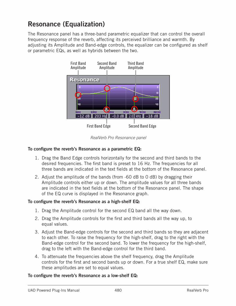
UAD Powered Plug-Ins Manual RealVerb Pro 480
Resonance (Equalization)The Resonance panel has a three-band parametric equalizer that can control the overall frequency response of the reverb, affecting its perceived brilliance and warmth. By adjusting its Amplitude and Band-edge controls, the equalizer can be configured as shelf or parametric EQs, as well as hybrids between the two.
RealVerb Pro Resonance panel
To configure the reverb’s Resonance as a parametric EQ:
1. Drag the Band Edge controls horizontally for the second and third bands to the desired frequencies. The first band is preset to 16 Hz. The frequencies for all three bands are indicated in the text fields at the bottom of the Resonance panel.
2. Adjust the amplitude of the bands (from -60 dB to 0 dB) by dragging their Amplitude controls either up or down. The amplitude values for all three bands are indicated in the text fields at the bottom of the Resonance panel. The shape of the EQ curve is displayed in the Resonance graph.
To configure the reverb’s Resonance as a high-shelf EQ:
1. Drag the Amplitude control for the second EQ band all the way down.
2. Drag the Amplitude controls for the first and third bands all the way up, to equal values.
3. Adjust the Band-edge controls for the second and third bands so they are adjacent to each other. To raise the frequency for the high-shelf, drag to the right with the Band-edge control for the second band. To lower the frequency for the high-shelf, drag to the left with the Band-edge control for the third band.
4. To attenuate the frequencies above the shelf frequency, drag the Amplitude controls for the first and second bands up or down. For a true shelf EQ, make sure these amplitudes are set to equal values.
To configure the reverb’s Resonance as a low-shelf EQ:
First BandAmplitude
Second BandAmplitude
Third BandAmplitude
First Band Edge Second Band Edge
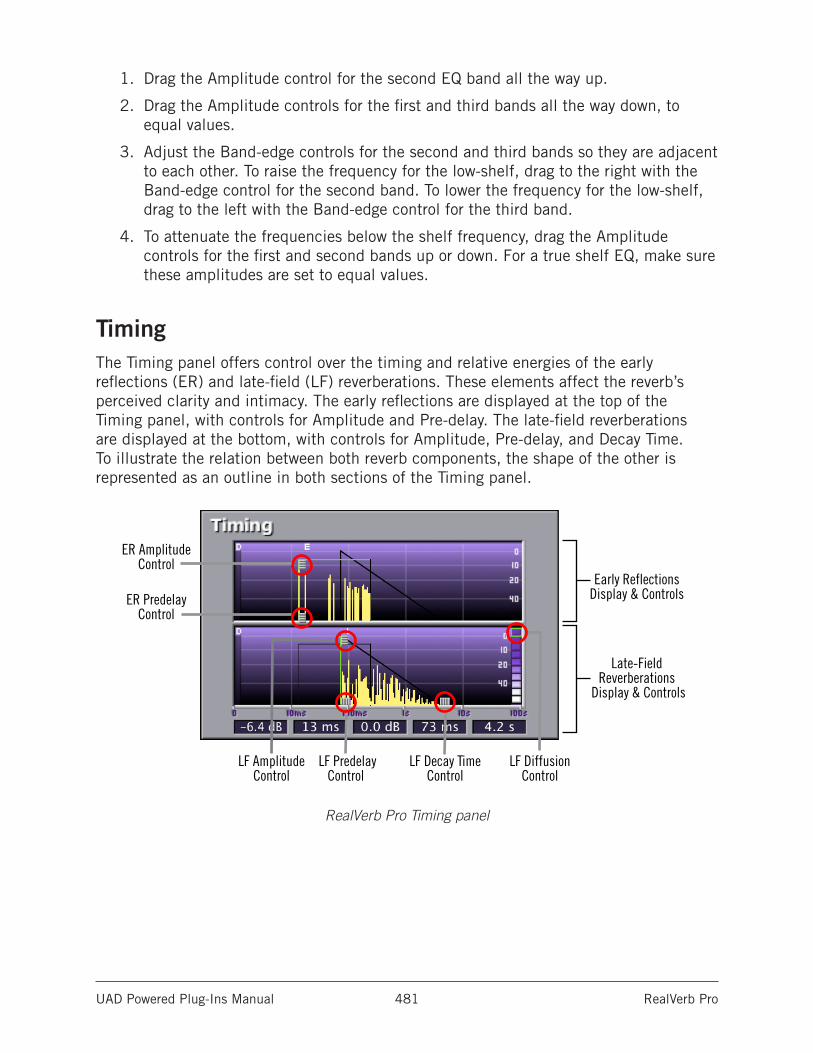
UAD Powered Plug-Ins Manual RealVerb Pro 481
1. Drag the Amplitude control for the second EQ band all the way up.
2. Drag the Amplitude controls for the first and third bands all the way down, to equal values.
3. Adjust the Band-edge controls for the second and third bands so they are adjacent to each other. To raise the frequency for the low-shelf, drag to the right with the Band-edge control for the second band. To lower the frequency for the low-shelf, drag to the left with the Band-edge control for the third band.
4. To attenuate the frequencies below the shelf frequency, drag the Amplitude controls for the first and second bands up or down. For a true shelf EQ, make sure these amplitudes are set to equal values.
TimingThe Timing panel offers control over the timing and relative energies of the early reflections (ER) and late-field (LF) reverberations. These elements affect the reverb’s perceived clarity and intimacy. The early reflections are displayed at the top of the Timing panel, with controls for Amplitude and Pre-delay. The late-field reverberations are displayed at the bottom, with controls for Amplitude, Pre-delay, and Decay Time. To illustrate the relation between both reverb components, the shape of the other is represented as an outline in both sections of the Timing panel.
RealVerb Pro Timing panel
Early ReflectionsDisplay & Controls
Late-FieldReverberations
Display & Controls
ER Amplitude Control
LF Amplitude Control
ER Predelay Control
LF Predelay Control
LF Decay Time Control
LF Diffusion Control
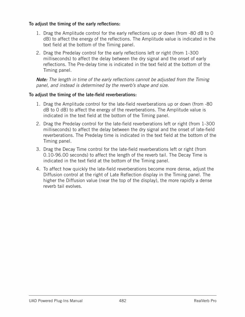
UAD Powered Plug-Ins Manual RealVerb Pro 482
To adjust the timing of the early reflections:
1. Drag the Amplitude control for the early reflections up or down (from -80 dB to 0 dB) to affect the energy of the reflections. The Amplitude value is indicated in the text field at the bottom of the Timing panel.
2. Drag the Predelay control for the early reflections left or right (from 1-300 milliseconds) to affect the delay between the dry signal and the onset of early reflections. The Pre-delay time is indicated in the text field at the bottom of the Timing panel.
Note: The length in time of the early reflections cannot be adjusted from the Timing panel, and instead is determined by the reverb’s shape and size.
To adjust the timing of the late-field reverberations:
1. Drag the Amplitude control for the late-field reverberations up or down (from -80 dB to 0 dB) to affect the energy of the reverberations. The Amplitude value is indicated in the text field at the bottom of the Timing panel.
2. Drag the Predelay control for the late-field reverberations left or right (from 1-300 milliseconds) to affect the delay between the dry signal and the onset of late-field reverberations. The Predelay time is indicated in the text field at the bottom of the Timing panel.
3. Drag the Decay Time control for the late-field reverberations left or right (from 0.10-96.00 seconds) to affect the length of the reverb tail. The Decay Time is indicated in the text field at the bottom of the Timing panel.
4. To affect how quickly the late-field reverberations become more dense, adjust the Diffusion control at the right of Late Reflection display in the Timing panel. The higher the Diffusion value (near the top of the display), the more rapidly a dense reverb tail evolves.
UAD Powered Plug-Ins Manual RealVerb Pro 483
PositioningOne of the unique features of RealVerb Pro is the ability to separately position the direct path, early reflections, and late-field reverberation. The Position panel provides panning controls for each of these reverb components. In addition, a proprietary Distance control adjusts perceived source distance. These controls allow realistic synthesis of acoustic spaces--for instance listening at the entrance of an alley way, where all response components arrive from the same direction, or listening in the same alley next to the source, where the early reflections and reverberation surround the listener.
Note: The Direct, Early, and Late controls are unavailable in mono-in/mono-out configurations.
RealVerb Pro Positioning panel
To pan the direct (dry) signal:
• Drag the Direct slider left or right. A value of <100 pans the signal hard left; a value of 100> pans the signal hard right. A value of <0> places the signal in the center of the stereo field.
Set the positioning for the early reflection or late-field reverberation with either of the following methods:
• Drag the left and right slider handles to adjust the stereo width. The length of the blue slider is adjusted. For a full stereo signal, drag the left handle all the way to left, and right handle all the way to the right.
• Drag the blue center of the slider left or right to set the positioning of the signal. If you drag all the way to the left or right, the stereo width is adjusted. For a mono signal panned hard left or right, drag the slider all the way to the left or right.
UAD Powered Plug-Ins Manual RealVerb Pro 484
DistanceRealVerb Pro allows you to control the distance of the perceived source with the Distance control in the Positioning panel (see See RealVerb Pro Positioning panel). In reverberant environments, sounds originating close to the listener have a different mix of direct and reflected energy than those originating further from the listener.
To adjust the distance of the source:
• Drag the Distance slider to the desired percentage value. Larger percentages yield a source that is further away from the listener. A value of 0% places the source as close as possible to the listener.
Wet/Dry MixThe wet and dry mix of the reverb is controlled from the Mix slider in the Positioning panel. The two buttons above this slider labeled “D” and “W” represent Dry and Wet; clicking either will create a 100% dry or 100% wet mix.
LevelsThe Levels panel adjusts the Input Gain and Output Gain for RealVerb Pro. These levels are adjusted by dragging the sliders to the desired values. You can mute the input signal by clicking the Mute button.
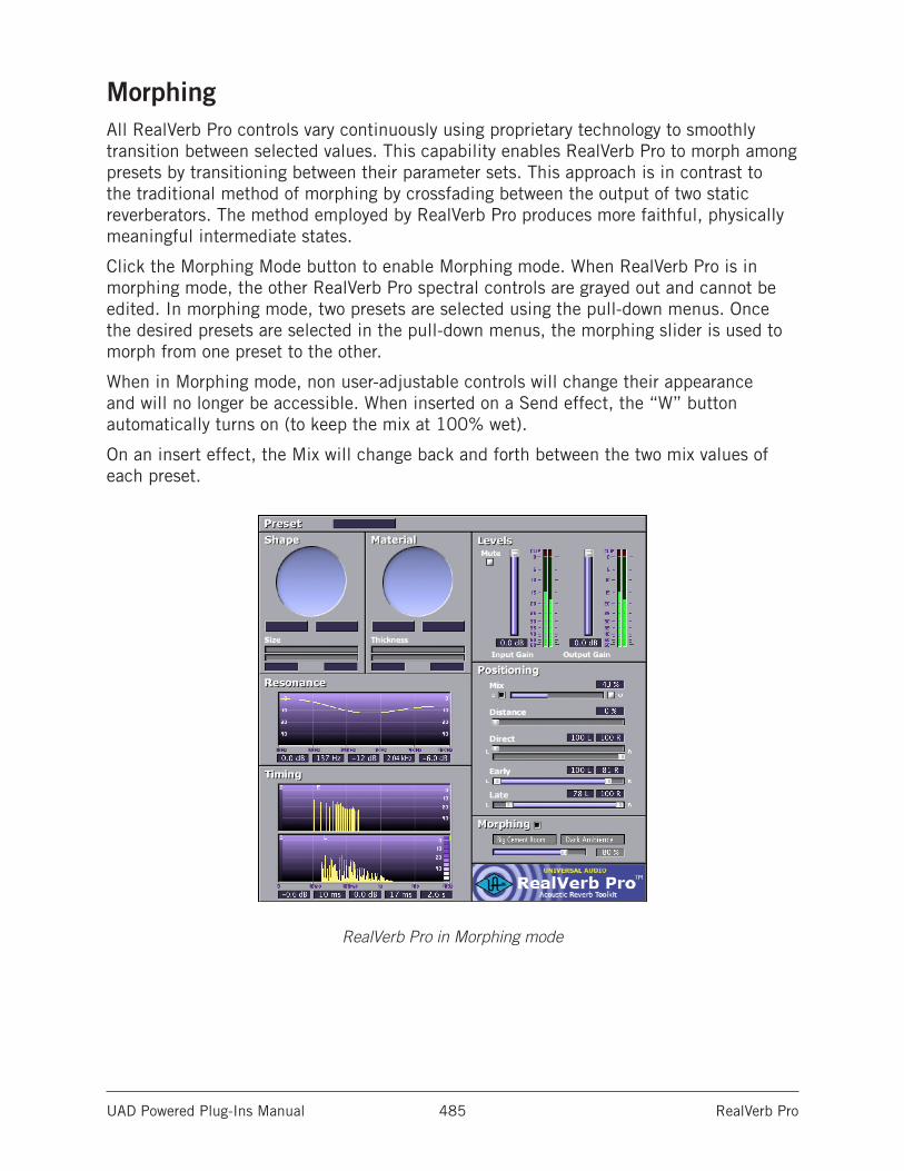
UAD Powered Plug-Ins Manual RealVerb Pro 485
MorphingAll RealVerb Pro controls vary continuously using proprietary technology to smoothly transition between selected values. This capability enables RealVerb Pro to morph among presets by transitioning between their parameter sets. This approach is in contrast to the traditional method of morphing by crossfading between the output of two static reverberators. The method employed by RealVerb Pro produces more faithful, physically meaningful intermediate states.
Click the Morphing Mode button to enable Morphing mode. When RealVerb Pro is in morphing mode, the other RealVerb Pro spectral controls are grayed out and cannot be edited. In morphing mode, two presets are selected using the pull-down menus. Once the desired presets are selected in the pull-down menus, the morphing slider is used to morph from one preset to the other.
When in Morphing mode, non user-adjustable controls will change their appearance and will no longer be accessible. When inserted on a Send effect, the “W” button automatically turns on (to keep the mix at 100% wet).
On an insert effect, the Mix will change back and forth between the two mix values of each preset.
RealVerb Pro in Morphing mode
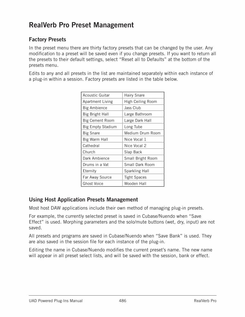
UAD Powered Plug-Ins Manual RealVerb Pro 486
RealVerb Pro Preset Management
Factory PresetsIn the preset menu there are thirty factory presets that can be changed by the user. Any modification to a preset will be saved even if you change presets. If you want to return all the presets to their default settings, select “Reset all to Defaults” at the bottom of the presets menu.
Edits to any and all presets in the list are maintained separately within each instance of a plug-in within a session. Factory presets are listed in the table below.
Acoustic Guitar Hairy Snare
Apartment Living High Ceiling Room
Big Ambience Jass Club
Big Bright Hall Large Bathroom
Big Cement Room Large Dark Hall
Big Empty Stadium Long Tube
Big Snare Medium Drum Room
Big Warm Hall Nice Vocal 1
Cathedral Nice Vocal 2
Church Slap Back
Dark Ambience Small Bright Room
Drums in a Vat Small Dark Room
Eternity Sparkling Hall
Far Away Source Tight Spaces
Ghost Voice Wooden Hall
Using Host Application Presets ManagementMost host DAW applications include their own method of managing plug-in presets.
For example, the currently selected preset is saved in Cubase/Nuendo when “Save Effect” is used. Morphing parameters and the solo/mute buttons (wet, dry, input) are not saved.
All presets and programs are saved in Cubase/Nuendo when “Save Bank” is used. They are also saved in the session file for each instance of the plug-in.
Editing the name in Cubase/Nuendo modifies the current preset’s name. The new name will appear in all preset select lists, and will be saved with the session, bank or effect.
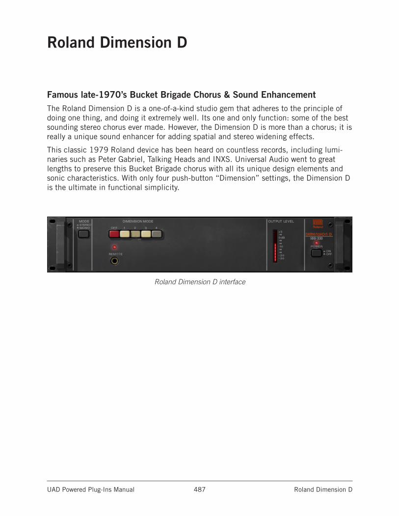
UAD Powered Plug-Ins Manual Roland Dimension D 487
Roland Dimension D
Famous late-1970’s Bucket Brigade Chorus & Sound EnhancementThe Roland Dimension D is a one-of-a-kind studio gem that adheres to the principle of doing one thing, and doing it extremely well. Its one and only function: some of the best sounding stereo chorus ever made. However, the Dimension D is more than a chorus; it is really a unique sound enhancer for adding spatial and stereo widening effects.
This classic 1979 Roland device has been heard on countless records, including lumi-naries such as Peter Gabriel, Talking Heads and INXS. Universal Audio went to great lengths to preserve this Bucket Brigade chorus with all its unique design elements and sonic characteristics. With only four push-button “Dimension” settings, the Dimension D is the ultimate in functional simplicity.
Roland Dimension D interface
UAD Powered Plug-Ins Manual Roland Dimension D 488
Roland Dimension D ControlsThe Roland Dimension D is very simple device to operate; it has only three controls: Power, Mono, and Mode. Each control is detailed below.
Dimension ModeThe Dimension Mode determines the effect intensity. Four different modes are available. Mode 1 is the most subtle effect, and Mode 4 is maximum intensity.
Multiple ButtonsTrue to the original hardware, multiple Dimension Mode buttons can be engaged simultaneously for subtle sonic variations of the four main modes. To engage multiple Dimension Mode buttons, press the Shift key on the computer keyboard while clicking the Mode buttons.
Input Mode SwitchThe original Roland Dimension D has an input switch on the back that puts the unit into mono-in/stereo-out mode. We have included this function and moved the switch “to the front” for your processing convenience.
When in Mono mode, the input to Dimension D is monophonic even when used in a ste-reo-input configuration (stereo inputs are summed to mono). This can be useful for sonic variation, such as when the plug-in is used in an auxiliary/effect send configuration.
The default position (in) is stereo mode. Click the pushbutton switch (out) to enable Mono mode.
Power SwitchThis switch determines whether the plug-in is active. This is useful for comparing the processed settings to the original signal, or to bypass the plug-in to reduce the UAD DSP load (load is not reduced if UAD-2 DSP LoadLock is enabled). Click the pushbutton switch to change the Power state.
Power LEDThe Power LED is illuminated when the plug-in is active.
Output LevelThis LED-style meter indicates the level of the signal at the output of the plug-in.
When the Dimension Mode is OFF but the Power switch is ON, audio is not processed but the Output Level meter is still active.
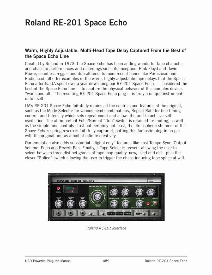
UAD Powered Plug-Ins Manual Roland RE-201 Space Echo 489
Roland RE-201 Space Echo
Warm, Highly Adjustable, Multi-Head Tape Delay Captured From the Best of the Space Echo LineCreated by Roland in 1973, the Space Echo has been adding wonderful tape character and chaos to performances and recordings since its inception. Pink Floyd and David Bowie, countless reggae and dub albums, to more recent bands like Portishead and Radiohead, all offer examples of the warm, highly adjustable tape delays that the Space Echo affords. UA spent over a year developing our RE-201 Space Echo — considered the best of the Space Echo line — to capture the physical behavior of this complex device, “warts and all.” The resulting RE-201 Space Echo plug-in is truly a unique instrument unto itself.
UA’s RE-201 Space Echo faithfully retains all the controls and features of the original, such as the Mode Selector for various head combinations, Repeat Rate for fine timing control, and Intensity which sets repeat count and allows the unit to achieve self-oscillation. The all-important Echo/Normal “Dub” switch is retained for muting, as well as the simple tone controls. Last but certainly not least, the atmospheric shimmer of the Space Echo’s spring reverb is faithfully captured, putting this fantastic plug-in on par with the original unit as a tool of infinite creativity.
Our emulation also adds substantial “digital only” features like host Tempo Sync, Output Volume, Echo and Reverb Pan. Finally, a Tape Select is present allowing the user to select between three distinct grades of tape loop quality, new, used and old—plus the clever “Splice” switch allowing the user to trigger the chaos-inducing tape splice at will.
Roland RE-201 interface
UAD Powered Plug-Ins Manual Roland RE-201 Space Echo 490
Roland RE-201 ControlsThe RE-201 interface is true to the original hardware, with a few customizations to bring it into the digital era.
The original mic and instrument volume controls have been replaced with echo/reverb pan controls and an input control. We’ve also added a “Tape Age” switch to emulate new and older tape, a Wet Solo control for use as a bus/send effect, and an output volume control for utility. The clever “Splice” switch allows the user to trigger the tape splice at will. Tempo synchronization controls round out the modernization of this classic analog processor. The fabulous sound of the original is untouched!
Peak LevelThe Peak lamp indicates when transient signal peaks and clipping are detected just after the input volume control. It begins illuminating at approximately -2 dB to -1.5 dB, then gets brighter as the level increases.
VU MeterThe VU meter indicates the average signal that is about to be written to the “tape.” Used in conjunction with the Peak lamp, an indication of signal level can be deduced.
The VU is essentially an input meter, therefore it doesn’t react when the Echo/Normal switch is switched from Echo to Normal.
Note: The Peak lamp and VU meter measure signal just after the input volume control. However, like the original hardware, echo intensity (feedback) is applied just before the level detection circuit. For this reason, the Intensity control will affect the level readings.
Echo PanEcho Pan determines the placement of the echo signal in the stereo panorama when the plug-in is used in mono-in/stereo-out and stereo-in/stereo-out configurations. When the RE-201 is used in a mono-in/mono-out configuration, this control is disabled.
Reverb PanReverb Pan determines the placement of the reverb signal in the stereo panorama when the plug-in is used in mono-in/stereo-out and stereo-in/stereo-out configurations. When the RE-201 is used in a mono-in/mono-out configuration, this control is disabled.
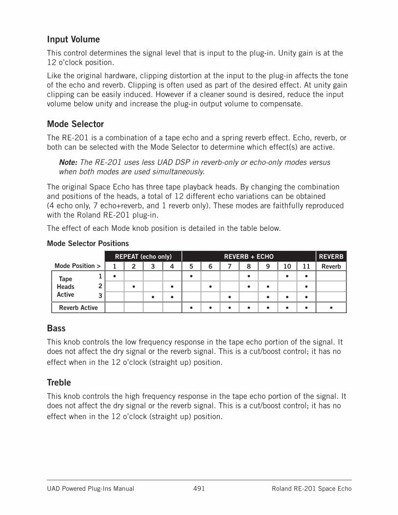
UAD Powered Plug-Ins Manual Roland RE-201 Space Echo 491
Input VolumeThis control determines the signal level that is input to the plug-in. Unity gain is at the 12 o’clock position.
Like the original hardware, clipping distortion at the input to the plug-in affects the tone of the echo and reverb. Clipping is often used as part of the desired effect. At unity gain clipping can be easily induced. However if a cleaner sound is desired, reduce the input volume below unity and increase the plug-in output volume to compensate.
Mode SelectorThe RE-201 is a combination of a tape echo and a spring reverb effect. Echo, reverb, or both can be selected with the Mode Selector to determine which effect(s) are active.
Note: The RE-201 uses less UAD DSP in reverb-only or echo-only modes versus when both modes are used simultaneously.
The original Space Echo has three tape playback heads. By changing the combination and positions of the heads, a total of 12 different echo variations can be obtained (4 echo only, 7 echo+reverb, and 1 reverb only). These modes are faithfully reproduced with the Roland RE-201 plug-in.
The effect of each Mode knob position is detailed in the table below.
Mode Selector Positions
Mode Position >REPEAT (echo only) REVERB + ECHO REVERB
1 2 3 4 5 6 7 8 9 10 11 Reverb
Tape Heads Active
123
• • • • •
• • • • • •
• • • • • •
Reverb Active • • • • • • • •
BassThis knob controls the low frequency response in the tape echo portion of the signal. It does not affect the dry signal or the reverb signal. This is a cut/boost control; it has no effect when in the 12 o’clock (straight up) position.
TrebleThis knob controls the high frequency response in the tape echo portion of the signal. It does not affect the dry signal or the reverb signal. This is a cut/boost control; it has no effect when in the 12 o’clock (straight up) position.
UAD Powered Plug-Ins Manual Roland RE-201 Space Echo 492
Reverb VolumeThis control determines the volume of the spring reverb effect. Rotate the control clockwise for more reverb. Reducing the control to its minimum value will disable the reverb.
On the original hardware the reverb output is quite low, and with some sources, unusable due to a high noise floor. Our model of the spring reverb has no noise, and has an increased available output level to improve usability.
Note: Reverb Volume has no affect when the Mode Selector is in positions 1 through 4.
Output VolumeThis control determines the output volume of the plug-in. It modifies the dry and effect signals.
The range of this control is ±20 dB from unity gain. Therefore, some signal may still be heard when this control is set to its minimum value.
Repeat RateThis knob controls the time interval of the echo effect. Rotating the control clockwise will decrease the delay time, and counter-clockwise rotation will increase the delay time.
The available delay times are as follows:
• Head 1: 69 ms - 177 ms
• Head 2: 131 ms - 337 ms
• Head 3: 189 ms - 489 ms
The head times available with this control are dependent upon the Mode Selector knob. As with the original hardware, this control varies the tape playback speed in realtime by manipulating the tape capstan motor and therefore has a musically useful “ramp-up” and “ramp-down” effect.
When Tempo Sync is enabled, this control is quantized to allow only rhythmic notes available at the leading head.
UAD Powered Plug-Ins Manual Roland RE-201 Space Echo 493
IntensityThis knob controls the repeat level (feedback) of the echo signal. Rotating the control clockwise increases the number of echoes. Higher values will cause self-oscillation; the exact position is program and Mode dependent.
The self-oscillation of the RE-201 is one of the magic features that really makes it more than a mixing tool; it’s also an instrument to be played. The effect may be used subtly, sending the unit into gentle oscillation on held notes, or can be put into “over the top” oscillation with extreme intensity settings. Different Modes will reveal different qualities of oscillation. Single head Modes tend to have simpler oscillation qualities, while multiple head modes will have a more complex sound when oscillating.
The RE-201’s oscillation qualities are heavily program and control dependent. Different sources of audio, gain, tone, repeat rate, and tape settings will all effect “oscillation performance.” The RE-201 can also achieve oscillation with no signal, making the RE-201 a truly unique instrument.
Echo VolumeThis control determines the volume of the echo effect. Rotate the control clockwise for louder echo. Reducing the control to its minimum value will disable the echo.
Note: Echo Volume has no affect when the Mode Selector is in the REVERB ONLY position.
Power SwitchThis switch determines whether the plug-in is active. This is useful for comparing the processed settings to the original signal, or to bypass the plug-in to reduce the UAD DSP load. Toggle the switch to change the Power state.
Toggling the power switch will also clear the tape echo. This can be useful if the RE-201 is self-oscillating and restarting the feedback loop is desired.
Echo/NormalThis switch disables the signal sent into the echo portion of the processor when set to NORMAL. The switch will have no effect if Mode Selector is set to REVERB ONLY. This control is sometimes affectionately referred to as the “dub” switch.
SyncThis switch puts the plug-in into tempo sync mode, for synchronizing the echos to the tempo of the host DAW application. See the “Tempo Sync” chapter in the UAD System Manual for related information.
UAD Powered Plug-Ins Manual Roland RE-201 Space Echo 494
Delay Time DisplayThese LCD-style readouts display the current delay time(s) of the RE-201. The three displays correspond to the three virtual “heads” in the plug-in, and always maintain their proportional relationship to each other.
The delay time values are displayed in milliseconds unless tempo sync is active, in which case beat values are displayed. When a particular head is inactive (see Mode Selector Positions), dashes are displayed.
When in tempo sync mode, note values that are out of range will flash. Imprecise note values due to head relationships are displayed with superscript + or - symbol before the note.
Tape AgeIn the original hardware, the tape loop is contained in a user-replaceable cartridge. As the tape wears out, it is subject to fidelity loss plus increased wow and flutter. The Tape Age switch allows the plug-in to mimic the behavior of new, used, and old tape cartridges.
Newer tape may be ideal for a pristine vocal track, while older tape could be described as having more “character” and might be more appropriate for sources where greater chaos may be musical.
SpliceNormally, the splice on the tape loop comes around at regular intervals. Thisinterval varies, and is determined by the selected Repeat Rate. Depending on what Tape Quality is selected, the splice can be subtle or obvious, and can work as a catalyst forchaos especially when the RE-201 is in a state of self-oscillation.
This switch resets the location of the tape “splice” when the switch is actuated. It is a momentary switch that pops back into the off position immediately after it is activated, allowing the user to trigger the splice point at will.
Note that the splice effect isn’t immediate. It drops the splice at the write head, and it needs time to go over the read heads (at which point there will be a dropout), and then the tape capstan (where it will create some wow and flutter).
Wet SoloWhen this switch is OFF, the dry/unprocessed signal is mixed with the wet/processed signal. When set to ON, only the processed signal is heard.
Wet Solo is useful when the plug-in is placed on an effect group/bus that is configured for use with channel sends. When the plug-in is used on a channel insert, this control should generally be OFF.
Note: Wet Solo is a global (per RE-201 plug-in instance) control.
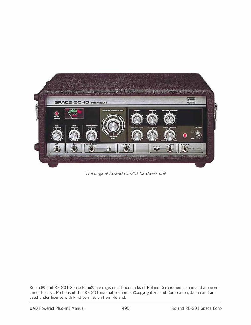
UAD Powered Plug-Ins Manual Roland RE-201 Space Echo 495
The original Roland RE-201 hardware unit
Roland® and RE-201 Space Echo® are registered trademarks of Roland Corporation, Japan and are used under license. Portions of this RE-201 manual section is ©copyright Roland Corporation, Japan and are used under license with kind permission from Roland.
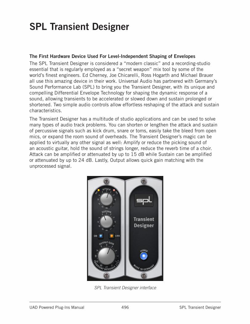
UAD Powered Plug-Ins Manual SPL Transient Designer 496
SPL Transient Designer
The First Hardware Device Used For Level-Independent Shaping of EnvelopesThe SPL Transient Designer is considered a “modern classic” and a recording-studio essential that is regularly employed as a “secret weapon” mix tool by some of the world’s finest engineers. Ed Cherney, Joe Chicarelli, Ross Hogarth and Michael Brauer all use this amazing device in their work. Universal Audio has partnered with Germany’s Sound Performance Lab (SPL) to bring you the Transient Designer, with its unique and compelling Differential Envelope Technology for shaping the dynamic response of a sound, allowing transients to be accelerated or slowed down and sustain prolonged or shortened. Two simple audio controls allow effortless reshaping of the attack and sustain characteristics.
The Transient Designer has a multitude of studio applications and can be used to solve many types of audio track problems. You can shorten or lengthen the attack and sustain of percussive signals such as kick drum, snare or toms, easily take the bleed from open mics, or expand the room sound of overheads. The Transient Designer’s magic can be applied to virtually any other signal as well: Amplify or reduce the picking sound of an acoustic guitar, hold the sound of strings longer, reduce the reverb time of a choir. Attack can be amplified or attenuated by up to 15 dB while Sustain can be amplified or attenuated by up to 24 dB. Lastly, Output allows quick gain matching with the unprocessed signal.
SPL Transient Designer interface
UAD Powered Plug-Ins Manual SPL Transient Designer 497
SPL Transient Designer ControlsContaining only two primary controls, the UAD SPL Transient Designer is extremely simple to operate. The technology behind the processor isn’t as important as how it sounds. However, for those who desire a deeper understanding of the process, a deeper explanation of the underlying Technology is presented at the end of this chapter.
AttackAttack enables amplification or attenuation of the attack of a signal by up to ±15 dB.
The Attack control circuitry uses two envelope generators. One follows the shape of the original curve and adapts perfectly to the dynamic gradient. The second envelope generator produces an envelope with a slower attack. From the difference of both envelopes the VCA control voltage is derived. Positive Attack values emphasize attack events; negative values smooth out the attack envelopes of sound events.
For more information, see .
SustainSustain enables amplification or attenuation of the sustain of a signal by up to ±24 dB.
The Sustain control circuitry also uses two envelope generators. One follows the shape of the original curve and adapts perfectly to the dynamic gradient. The second envelope generator produces an envelope with a longer sustain. From the difference of both envelopes the VCA control voltage is derived. The gradient of the control voltage matches the time flow of the original signal. Positive Sustain values lengthen the sustain; negative values shorten the sustain.
For more information, see The SUSTAIN Control Circuitry.
GainGain controls the signal level that is output from the plug-in. The available range is from -20 dB to +6 dB. The default value is 0 dB.
SignalThis 4-stage LED indicates the presence of audio signals at the input of the plug-in. When the input signal is below -25 dB, the indicator is off. At -25 dB to -19 dB, the indicator glows slightly. At -18 dB to -10 dB, it lights with medium intensity. At -9 dB to 0 dB, it shines brightly.
OverloadThe Overload LED illuminates when the signal level at the output of the plug-in reaches 0 dBFS. The indicator matches the behavior of the original hardware unit. However, in the software plug-in version, the output can be “overloaded” without causing distortion.
UAD Powered Plug-Ins Manual SPL Transient Designer 498
LinkLink indicates when stereo operation is active. It illuminates when used in a stereo-in/stereo-out or mono-in/stereo out configuration. It does not illuminate when used in a mono-in/mono-out configuration.
Note: Link is an indicator only; it does not control any plug-in parameter.
On/PowerThe On and Power switches determine whether the plug-in is active. Click the On or Power switches to change the state. On and Power illuminate when the plug-in is active.
When the plug-in is inactive, processing is disabled and UAD DSP usage is reduced (unless UAD-2 DSP LoadLock is enabled).
Note: The On and Power switches perform the exact same function.
AcknowledgementIn addition to creating an amazing piece of hardware, Sound Performance Lab also wrote an extensive user manual for the Transient Designer. Because Universal Audio has full license to make use of the Transient Designer technology, SPL has graciously authorized us to use their documentation as well.
The remainder of this chapter is excerpted from the SPL Transient Designer (RackPack) User Manual, and is used with kind permission from SPL. All copyrights are retained by SPL.
UAD Powered Plug-Ins Manual SPL Transient Designer 499
ApplicationsThe SPL Transient Designer is ideally suited for use in professional recording, in project or home studios and sound reinforcement applications.
For the first time you can manipulate and control the attack and sustain characteristics of a signal regardless of level in the most intuitive and simple way. Usually equalizers are used to separate instruments in a mix - the tonal aspect of the signal is considered, but not the temporal aspect.
The Transient Designer opens this further dimension in signal processing. By manipulating the attack and sustain curves of a sound event, the mix can be made to sound more transparent. Instruments can be mixed at lower levels while still maintaining their positions in the mix — but occupying less space.
During a remix or in general after micing you can arrange new positions of instruments. Reduce ATTACK and increase SUSTAIN to move signals back into the mix that are too present. Additionally the FX parts of too dry signals are strengthened.
Applied to single instruments or loops the Transient Designer allows you to create entirely new sounds and/or effects.
The following examples are given as suggestions and examples. The described procedures with specific instruments can of course be transferred to others that are not mentioned here.
Drums & PercussionsProcessing drum and percussion sounds is probably the Transient Designer’s most typical range of application; both from samples to live drum sets
• Emphasize the attack of a kick drum or a loop to increase the power and presence in the mix.
• Shorten the sustain period of a snare or a reverb tail in a very musical way to obtain more transparency in the mix.
• When recording a live drum set, shorten the toms or overheads without physically damping them. Usual efforts to damp and mike are reduced remarkably. Since muffling of any drum also changes the dynamic response, the Transient Designer opens up a whole new soundscape.
• Micing live drums is considerably faster and easier because you can correct the apparent “distance” of the microphone by simply varying the ATTACK and SUSTAIN values.
• The Transient Designer is a perfect alternative to noise gates in live drum micing. Adaptively reacting to the duration of the original signal, the sustain is shortened more musically than with fixed release times and a drumset is freed from any crosstalk quickly and effectively.
UAD Powered Plug-Ins Manual SPL Transient Designer 500
• Create unusual dynamic effects including new and interesting pan effects. For example, patch a mono loop through two channels of the Transient Designer and pan fully left and right in the mix. Process the left channel with increased ATTACK and reduced SUSTAIN while you adjust the right channel the opposite way and you get very special stereo loop sounds. You have to try this to appreciate what it sounds like, but expect to hear a lot of unusual stereo movement.
• Enjoy an amazingly simple integration of drum sounds into a mix. If the acoustic level of a snare is expanded to approximately +4 dB by increasing the attack value, the effective increase of peak levels in the overall mix is merely about 0.5 dB to 1 dB.
Drums: AmbienceIf your drums happen to sound as if the room mics have been placed in a shoe closet, the Transient Designer can immediately turn that sound into the ambience of an empty warehouse. Just send the stereo room mics through the Transient Designer and crank the ATTACK control to emphasize the first wave.
Now slowly increase SUSTAIN values to bring up an “all-buttons-in-1176-sound” room tone — but without pumping cymbals. For a solid and driving rhythm track just fine-tune the SUSTAIN control to make sure that the room mic envelope ends more or less exactly on the desired upbeat or downbeat.
GuitarsUse the Transient Designer on guitars to soften the sound by lowering the ATTACK. Increase ATTACK for in-the-face sounds, which is very useful and works particularly well for picking guitars. Or blow life and juice into quietly played guitar parts.
Distorted guitars usually are very compressed, thus not very dynamic. Simply increase the ATTACK to get a clearer sound with more precision and better intonation despite any distortion.
Heavy distortion also leads to very long sustain. The sound tends to become mushy; simply reduce SUSTAIN to change that. If you, how- ever, want to create soaring guitar solos that would make even David Gilmour blush, just crank up the SUSTAIN control to the max and there you go.
With miced acoustic guitars you can emphasize the room sound by turning up SUSTAIN. If you want the guitars to sound more intimate and with less ambience, simply reduce SUSTAIN.
Bass: Staccato vs. LegatoSpeaking of bass: Imagine a too sluggishly played bass track… you may not have to re-record it: Reduce the SUSTAIN until you can hear clear gaps between the downbeats — the legato will turn into a nice staccato, driving the rhythm-section forward.
UAD Powered Plug-Ins Manual SPL Transient Designer 501
The Re-Invention Of ReverbAlways and everywhere the same reverb presets - boring, aren`t they? Try sending the output of your reverb through the Transient Designer. Now crank the ATTACK control to the max and reduce SUSTAIN to a bare minimum. The intensity of the reverb is now much higher in the beginning while the reverb time is reduced.
The opposite can be just as intriguing: manipulate a reverb pattern so that it takes on a pyramidal slope. Turn the ATTACK all the way to the left and SUSTAIN all the way to the right. Now the beginning of the reverb is strongly reduced whereas the sustain blossoms and seems almost endless (obviously that will only happen if the decay of the reverb in the actual reverb device has been set to a sufficient value — a signal must always be present as long as the sustain time lasts.
You can also create a reverb effect that moves from one channel to the other. Reverb presets with a long decay or a long pre-delay and especially those that have flamboyant reflections set to appear after the beginning of the diffuse reverberation tail are predestined for that. Insert the left and the right channels of the reverb return through two separate Transient Designer instances. Turn the ATTACK fully right on one instance and reduce SUSTAIN slightly (about -1.5 dB). On the other instance turn the ATTACK fully left and the SUSTAIN to the 3-o`clock position (about +12 dB).
These settings preserve the original complexity of the reflections in the reverb but the maximum intensity of the effect will move from the left to the right in the mix while the reverb will maintain it`s presence in both channels. You can make this effect even more dramatic by setting all controls to their most extreme positions, but you run the danger of ending up with a lopsided effect that appears out of balance.
UAD Powered Plug-Ins Manual SPL Transient Designer 502
BackingsA common problem especially with tracks that are recorded and mixed in different studios: Backings lack of ambience, and finding a reverb that “matches” takes time… so simply emphasize the original ambience by turning up the Transient Designer’s SUSTAIN control.
And the opposite problem, too much ambience, is similarly simply solved with the opposite processing — just reduce SUSTAIN.
Keyboards & SamplerSounds in keyboards and samples are usually highly compressed and maintain only little of natural dynamics. Increase the ATTACK values to re-gain a more natural response characteristic. The sounds occupy less space in the mix and appear more identifiable even at lower volumes.
Post ProductionWhen dealing with overdubs in movies you can easily add more punch and definition to effect sounds from any sample library.
The same applies to outdoor recordings that suffer from poor microphone positioning — simply optimize them afterwards.
MasteringLike with any good thing, you also have to know where not to use it. For example, using a Transient Designer in mastering is not recommended, as it is rarely a good idea to treat a whole mix at once. Instead, treat individual elements within the mix.
TechnologyOf course you don`t have to know how the Transient Designer works in order to use it. However, since it offers a completely novel signal processing, nothing shall be concealed from the more curious users.
Differential Envelope Technology (DET)SPL’s DET is capable of level-independent envelope processing and thus makes any threshold settings unnecessary. Two envelopes are generated and then compared. From the difference of both envelopes the VCA control voltage is derived. The DET ensures that both low and loud signals (pianissimo to fortissimo) are treated the same way.
Both ATTACK and SUSTAIN control circuitries operate simultaneously and don`t affect each other.
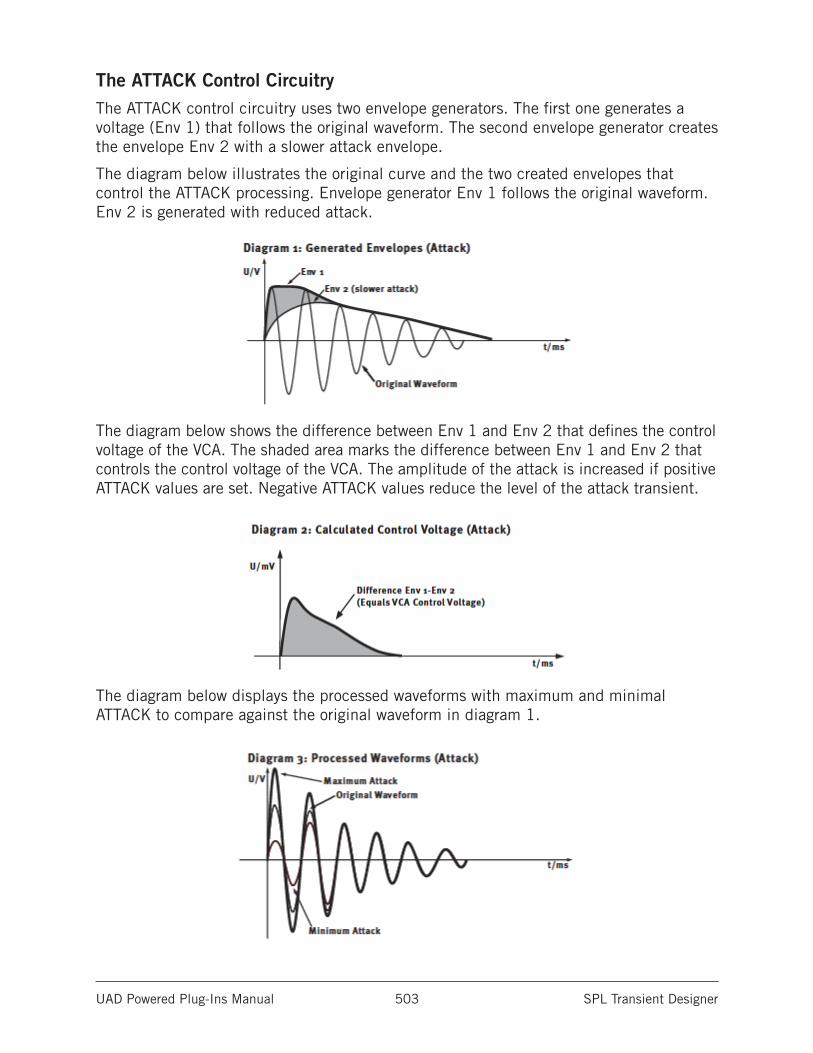
UAD Powered Plug-Ins Manual SPL Transient Designer 503
The ATTACK Control CircuitryThe ATTACK control circuitry uses two envelope generators. The first one generates a voltage (Env 1) that follows the original waveform. The second envelope generator creates the envelope Env 2 with a slower attack envelope.
The diagram below illustrates the original curve and the two created envelopes that control the ATTACK processing. Envelope generator Env 1 follows the original waveform. Env 2 is generated with reduced attack.
The diagram below shows the difference between Env 1 and Env 2 that defines the control voltage of the VCA. The shaded area marks the difference between Env 1 and Env 2 that controls the control voltage of the VCA. The amplitude of the attack is increased if positive ATTACK values are set. Negative ATTACK values reduce the level of the attack transient.
The diagram below displays the processed waveforms with maximum and minimal ATTACK to compare against the original waveform in diagram 1.
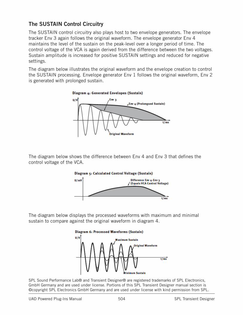
UAD Powered Plug-Ins Manual SPL Transient Designer 504
The SUSTAIN Control CircuitryThe SUSTAIN control circuitry also plays host to two envelope generators. The envelope tracker Env 3 again follows the original waveform. The envelope generator Env 4 maintains the level of the sustain on the peak-level over a longer period of time. The control voltage of the VCA is again derived from the difference between the two voltages. Sustain amplitude is increased for positive SUSTAIN settings and reduced for negative settings.
The diagram below illustrates the original waveform and the envelope creation to control the SUSTAIN processing. Envelope generator Env 1 follows the original waveform, Env 2 is generated with prolonged sustain.
The diagram below shows the difference between Env 4 and Env 3 that defines the control voltage of the VCA.
The diagram below displays the processed waveforms with maximum and minimal sustain to compare against the original waveform in diagram 4.
SPL Sound Performance Lab® and Transient Designer® are registered trademarks of SPL Electronics, GmbH Germany and are used under license. Portions of this SPL Transient Designer manual section is ©copyright SPL Electronics GmbH Germany and are used under license with kind permission from SPL.
UAD Powered Plug-Ins Manual SSL E Channel Strip 505
SSL E Channel Strip
Exacting Circuit Emulation of Hit-Making SSL 4000 E Series Console ChannelThe SSL 4000 is famous as the console employed on more Platinum-selling records than any other. With its wide range of VCA compression characteristics and intuitive EQ — rich with colorful band interdependencies — it’s easy to hear why. Today, working in close partnership with Solid State Logic®, UA proudly unveils the SSL E Series Channel Strip plug-in for UAD-2 and Apollo — an exacting circuit emulation of this certified hit-making machine.
The SSL E Series Channel Strip plug-in allows you to apply classic SSL 4000 EQ curves and dynamics control to your music. This unique plug-in is distinguished by its remarkably authentic sound, and its inclusion of both the Type E “black knob” and “brown knob” four-band EQ and filters, long considered favorites in SSL lineage. Other features include high and low cut filters, independent Expander/Gate, and bespoke Compressor/Limiter.
The E Series’ middle EQ bands are fully parametric, while the high and low bands provide the user with switchable bell or shelving filters. The Comp/Limiter provides Threshold, fast or slow Attack time, a 0.1 to 4 second Release, and a continuously variable Ratio control. The Exp/Gate offers Threshold, fast or slow Attack time, a 0.1 to 4 second Release time, and a Range control to tailor the Gate or Expansion effect. In addition, the SSL E Series Channel Strip plug-in adds a second Gate setting, featuring a “no-chatter” circuit borrowed from later SSL designs.
For increased flexibility, a PRE-DYN button allows users to reorder the signal chain, placing the EQ before the dynamics section. With the DYN-SC button, users may engage a sidechain feature, providing frequency-dependent compression using the EQ filters, cut filters, or both. Lastly, a Link button adds the ability to link or unlink the sidechain when using the stereo version of the plug-in.
Taken together, these features make the SSL E Series plug-in for UAD-2 and Apollo among the most flexible and best-sounding channel strip emulations available today, bar none.
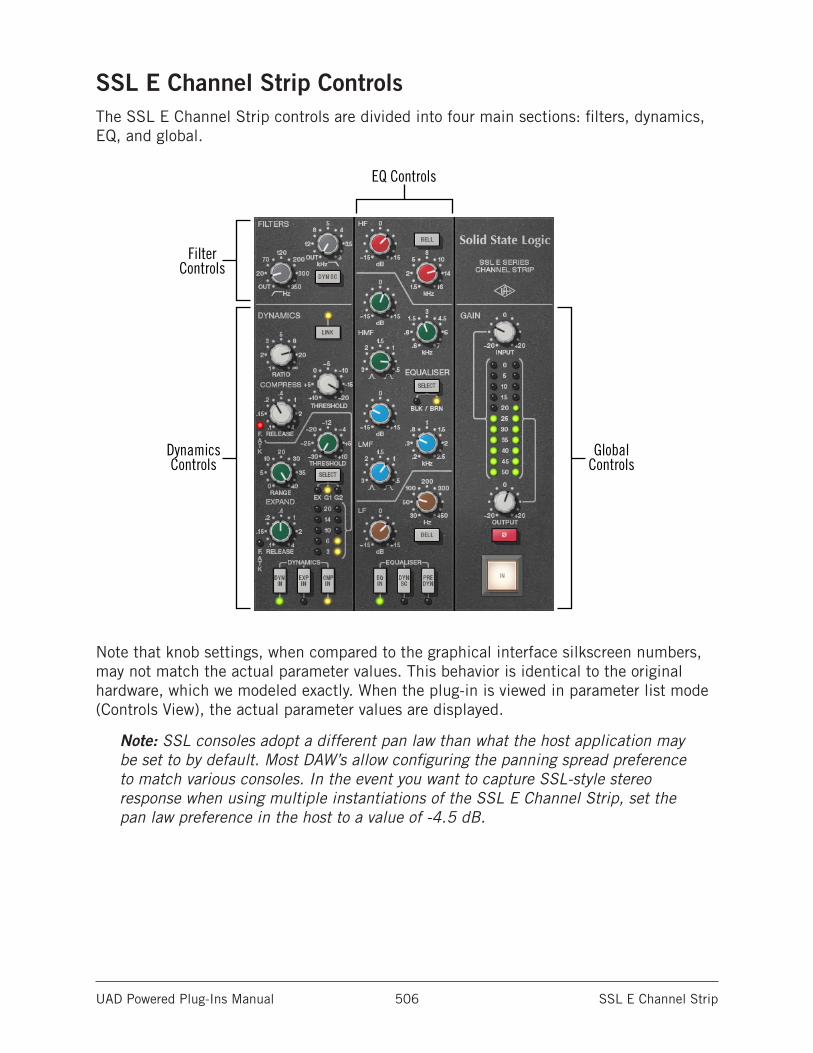
UAD Powered Plug-Ins Manual SSL E Channel Strip 506
SSL E Channel Strip ControlsThe SSL E Channel Strip controls are divided into four main sections: filters, dynamics, EQ, and global.
EQ Controls
FilterControls
DynamicsControls
Global Controls
Note that knob settings, when compared to the graphical interface silkscreen numbers, may not match the actual parameter values. This behavior is identical to the original hardware, which we modeled exactly. When the plug-in is viewed in parameter list mode (Controls View), the actual parameter values are displayed.
Note: SSL consoles adopt a different pan law than what the host application may be set to by default. Most DAW’s allow configuring the panning spread preference to match various consoles. In the event you want to capture SSL-style stereo response when using multiple instantiations of the SSL E Channel Strip, set the pan law preference in the host to a value of -4.5 dB.
UAD Powered Plug-Ins Manual SSL E Channel Strip 507
FiltersIn addition to the four-band EQ, the SSL E Channel Strip offers individual high and low pass filters.
When the Filter control is at minimum value (fully counter-clockwise), the filter is disabled.
The control ranges and sonics of these filters can be changed between “Black” and “Brown” modes with the EQ Type switch.
High PassThe left knob determines the cutoff frequency for the high pass filter. Rotate clockwise to reduce low frequencies.
In Black mode, the slope of the high pass filter is 18 dB per octave and the available range is 16 Hz to 350 Hz. In Brown mode, the slope of the high pass filter is 12 dB per octave and the available range is 20Hz to 350 Hz.
Low PassThe right knob determines the cutoff frequency for the low pass filter. Rotate clockwise to reduce high frequencies.
In Black mode the slope of the low pass filter is 12 dB per octave and the available range is 22 kHz to 3 kHz. In Brown mode the slope of the low pass filter is 12 dB per octave and the available range is 16 kHz to 3 kHz.
Filters to Sidechain (DYN SC)This button enables the Filters sidechain function. When the Filters sidechain is active, signal output from the Filters module is removed from the audio path and is instead routed to control (“key”) the dynamics module.
Sidechaining is typically used for de-essing and similar frequency-conscious techniques. To listen to the sidechain key, simply disengage DYN SC to hear the filtered signal. The sidechain dynamics/EQ implementations are true stereo when used in a stereo-in/stereo-out (“SISO”) configuration.
Note: The Filters module must be active (not at minimum value) in conjunction with the Filters DYN SC button for the Filters sidechain to function. An additional EQ to Sidechain (DYN SC) is available in the EQ section.
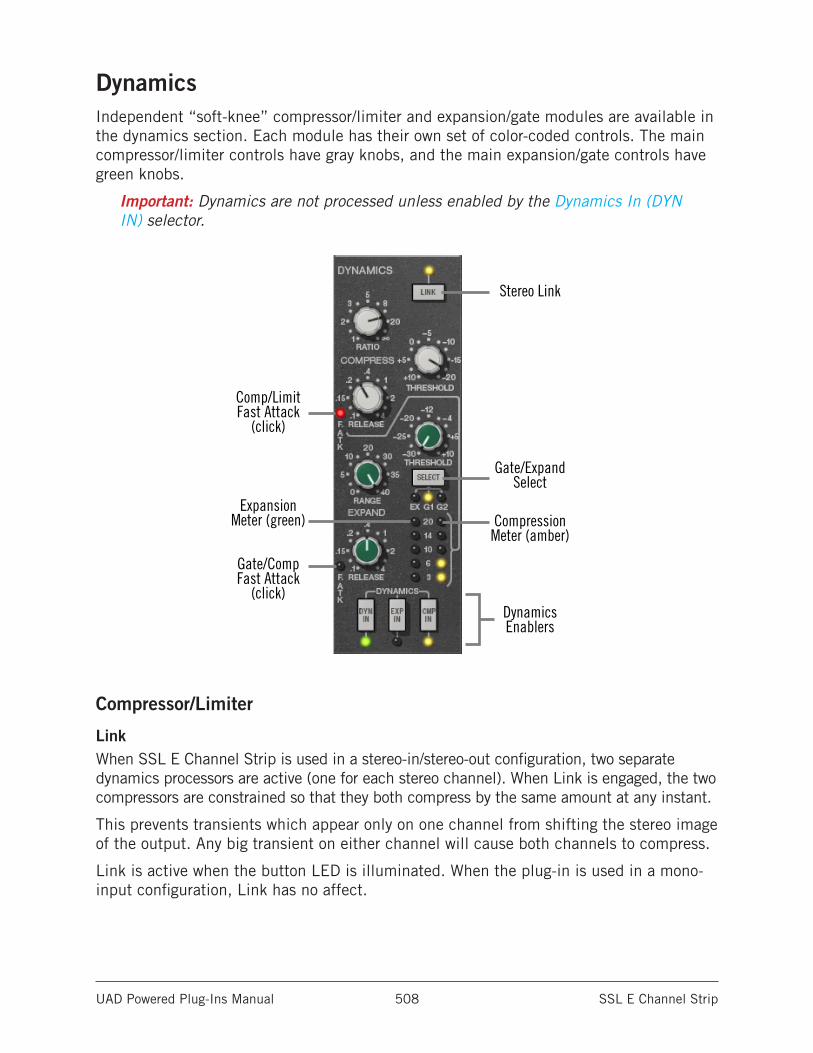
UAD Powered Plug-Ins Manual SSL E Channel Strip 508
DynamicsIndependent “soft-knee” compressor/limiter and expansion/gate modules are available in the dynamics section. Each module has their own set of color-coded controls. The main compressor/limiter controls have gray knobs, and the main expansion/gate controls have green knobs.
Important: Dynamics are not processed unless enabled by the Dynamics In (DYN IN) selector.
Stereo Link
Comp/Limit Fast Attack
(click)
Gate/Comp Fast Attack
(click)
Expansion Meter (green)
Dynamics Enablers
Gate/Expand Select
Compression Meter (amber)
Compressor/Limiter
LinkWhen SSL E Channel Strip is used in a stereo-in/stereo-out configuration, two separate dynamics processors are active (one for each stereo channel). When Link is engaged, the two compressors are constrained so that they both compress by the same amount at any instant.
This prevents transients which appear only on one channel from shifting the stereo image of the output. Any big transient on either channel will cause both channels to compress.
Link is active when the button LED is illuminated. When the plug-in is used in a mono-input configuration, Link has no affect.
UAD Powered Plug-Ins Manual SSL E Channel Strip 509
Compress RatioRatio defines the amount of gain reduction to be processed by the compressor. For example, a value of 2 (expressed as a 2:1 ratio) reduces the signal above the threshold by half, with an input signal of 20 dB being attenuated to 10 dB.
The SSL E Channel Strip compressor offers a continuously variable ratio between 1:1 (no compression) and infinity:1 (limiting).
Note: Signals must exceed the Threshold value before they are attenuated by the Ratio amount.
Compress ThresholdThreshold defines the signal level at which the onset of compression occurs. Incoming signals that exceed this level are compressed. Signals below the level are unaffected.
The available range is +10 dB to -20 dB. Rotate the control clockwise for more compression.
This compressor has an automatic make-up gain function. As Threshold is lowered and compression increases (as knob is rotated clockwise), output gain from the module is increased automatically to compensate.
Compress ReleaseRelease sets the amount of time it takes for gain reduction to cease once the input signal drops below the threshold level. Longer release times can smooth the transition that occurs when the signal dips below the threshold, which is especially useful for material with frequent peaks. However, if you set the Release time too long, the gain reduction imposed by loud sections of audio may initially reduce the level of subsequent sections of audio with lower signals.
Available Release times are continuously variable between 0.1 seconds and 4 seconds.
Compress AttackAttack defines the duration between the input signal reaching the threshold and processing being applied by the compressor. Attack time is normally 30 milliseconds (“slow” mode in Controls View). When Fast Attack is enabled, attack time is 3 milliseconds.
Fast Attack is active when the F.ATK LED is illuminated. To toggle Fast Attack, click the LED or its label text.
Note: On 4K Channel Strip, this LED is labeled F.ATT.
UAD Powered Plug-Ins Manual SSL E Channel Strip 510
Gate/ExpanderThe gate/expander module operates in either gate or expansion mode, as determined by the Dynamics Select button. Two attack speeds and a continuously variable release time are available in both modes.
Dynamics SelectThe Select button cycles through the three modes available in the gate/expander module: Expand, Gate 1, and Gate 2.
Expand (EX)
In Expand mode, the module applies downwards expansion at a fixed 1:2 ratio, with the amount of gain reduction determined by the Expand Range control.
Gate 1 (G1)
In Gate 1 mode, signals below the Expand Threshold are attenuated by the Expand Range amount. Gate 1 is authentic to the gate mode on earlier hardware consoles.
Gate 2 (G2)
Gate 2 mode operates the same way as Gate 1, but has a different “no-chatter” response characteristic that is derived from later versions of the hardware.
Expand ThresholdThreshold defines the input level at which expansion or gating occurs. Any signals below this level are processed. Signals above the threshold are unaffected. Threshold is continuously variable from -30 dB to +10 dB.
In typical use it’s best to set the threshold value to just above the noise floor of the desired signal (so the noise doesn’t pass when the desired signal is not present), but below the desired signal level (so the signal passes when present).
Expand RangeRange (depth) controls the difference in gain between the gated/expanded and non-gated/expanded signal. Higher values increase the attenuation of signals below the threshold. When set to zero, no gating or expansion occurs. Range is continuously variable from 0 dB to -40 dB.
Expand ReleaseRelease sets the amount of time it takes for gate/expander processing to engage once the input signal drops below the Threshold value. The available range is 0.1ms to 4 seconds.
Slower release times can smooth the transition that occurs when the signal dips below the threshold, which is especially useful for material with frequent peaks.
Note: Fast release times are typically only suitable for certain types of percussion and other instruments with very fast decays. Using fast settings on other sources may produce undesirable results.
UAD Powered Plug-Ins Manual SSL E Channel Strip 511
Expand AttackAttack defines the duration between the input signal reaching the threshold and processing being applied by the expander/gate. Attack time is normally auto-sensing and program dependent. When Fast Attack is enabled, attack time is 1ms.
Fast Attack is active when the F.ATK LED is illuminated. To toggle Fast Attack, click the LED or its label text.
Note: On 4K Channel Strip, this LED is labeled F.ATT.
Dynamics EnableThese three buttons determine the status of the dynamics processors.
Dynamics In (DYN IN)
The DYN IN button enables both the compressor/limiter and the expander/gate modules; neither module will function when DYN IN is disabled. Each dynamics module is enabled when the LED below the buttons are illuminated.
DYN IN is useful for quickly comparing the original signal dynamics to the dynamically processed signal.
Important: DYN IN must be engaged to enable compressor/limiter and/or expander/gate processing.
Expander In (EXP IN)
The EXP IN button enables the expander/gate module. The module is enabled when the EXP IN LED is illuminated. This button has no effect when DYN IN is disabled.
Compressor In (CMP IN)
The CMP IN button enables the compressor/limiter module. The module is enabled when the CMP IN LED is illuminated. This button has no effect when DYN IN is disabled.
Dynamics MetersThe Expansion Meter uses green LED’s (left column) to display the amount of downward expansion occurring in the expander/gate module. Higher values indicate more gain reduction.
The Compression Meter uses amber LED’s (right column) to display the amount of gain attenuation occurring in the compressor/limiter module. Higher values indicate more dynamics compression.
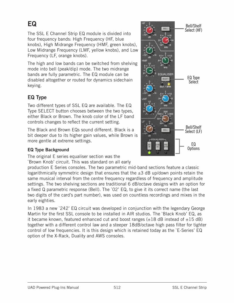
UAD Powered Plug-Ins Manual SSL E Channel Strip 512
EQThe SSL E Channel Strip EQ module is divided into four frequency bands: High Frequency (HF, blue knobs), High Midrange Frequency (HMF, green knobs), Low Midrange Frequency (LMF, yellow knobs), and Low Frequency (LF, orange knobs).
The high and low bands can be switched from shelving mode into bell (peak/dip) mode. The two midrange bands are fully parametric. The EQ module can be disabled altogether or routed for dynamics sidechain keying.
EQ TypeTwo different types of SSL EQ are available. The EQ Type SELECT button chooses between the two types, either Black or Brown. The knob color of the LF band controls changes to reflect the current setting.
The Black and Brown EQs sound different. Black is a bit deeper due to its higher gain values, while Brown is more gentle at extreme settings.
EQ Type BackgroundThe original E series equaliser section was the `Brown Knob’ circuit. This was standard on all early production E Series consoles. The two parametric mid-band sections feature a classic logarithmically symmetric design that ensures that the ±3 dB up/down points retain the same musical interval from the centre frequency regardless of frequency and amplitude settings. The two shelving sections are traditional 6 dB/octave designs with an option for a fixed Q parametric response (Bell). The `02’ EQ, to give it its correct name (the last two digits of the card’s part number), was used on countless recordings and mixes in the early eighties.
In 1983 a new `242’ EQ circuit was developed in conjunction with the legendary George Martin for the first SSL console to be installed in AIR studios. The `Black Knob’ EQ, as it became known, featured enhanced cut and boost ranges (±18 dB instead of ±15 dB) together with a different control law and a steeper 18dB/octave high pass filter for tighter control of low frequencies. It is this design which is retained today as the `E-Series’ EQ option of the X-Rack, Duality and AWS consoles.
Bell/Shelf Select (HF)
EQ TypeSelect
Bell/Shelf Select (LF)
EQOptions
UAD Powered Plug-Ins Manual SSL E Channel Strip 513
High Frequency (HF) Band
HF GainThis control determines the amount by which the frequency value for the band is boosted or attenuated. The available range is ±15 dB in both Black and Brown modes.
Tip: Click the “0” to return the Gain knob to its center position.
HF FrequencyThis control determines the band frequency to be boosted or attenuated by the band Gain setting. The available range is 1.5 kHz to 16 kHz in both Black and Brown modes.
HF BellThe Bell button switches the HF band from shelf mode to peak/dip mode. In normal (shelf) mode, only frequencies above the frequency value are boosted or attenuated. In Bell (peak/dip) mode, frequencies above and below the frequency value are boosted or attenuated.
In Black mode, the HF Bell Q is 1.3 and in Brown mode the HF Bell Q is 0.8.
High-Mid Frequency (HMF) Band
HMF GainThis control determines the amount by which the frequency value for the band is boosted or attenuated. The available range is ±15 dB in both Black and Brown modes.
Tip: Click the “0” to return the control knob to its center position.
HMF FrequencyThis control determines the HMF band center frequency to be boosted or attenuated by the band Gain setting. The available range is 0.6 kHz to 7 kHz in both Black and Brown modes.
HMF QThe Q (bandwidth) control defines the proportion of frequencies surrounding the band center frequency to be affected by the band gain control. The filter slopes get steeper (narrower bandwidth) as the control is rotated counter-clockwise. The available range is 0.5 to 2.5 in both Black and Brown modes.
UAD Powered Plug-Ins Manual SSL E Channel Strip 514
Low-Mid Frequency (LMF) Band
LMF GainThis control determines the amount by which the frequency value for the band is boosted or attenuated. The available range is ±15 dB in both Black and Brown modes.
Tip: Click the “0” to return the control knob to its center position.
LMF FrequencyThis control determines the LMF band center frequency to be boosted or attenuated by the band Gain setting. The available range is 0.2 kHz to 2.5 kHz in both Black and Brown modes.
LMF QThe Q (bandwidth) control defines the proportion of frequencies surrounding the band center frequency to be affected by the band gain control. The filter slopes get steeper (narrower bandwidth) as the control is rotated counter-clockwise. The available range is 0.5 to 2.5 in both Black and Brown modes.
Low Frequency (LF) Band
LF GainThis control determines the amount by which the frequency value for the LF band is boosted or attenuated. The available range is ±15 dB in both Black and Brown modes.
Tip: Click the “0” to return the control knob to its center position.
LF FrequencyThis control determines the band center frequency to be boosted or attenuated by the band Gain setting. The available range is 30 Hz to 450 Hz in both Black and Brown modes.
LF BellThe Bell button switches the LF band from shelf mode to peak/dip mode. In normal (shelf) mode, only frequencies below the frequency value are boosted or attenuated. In Bell (peak/dip) mode, frequencies below and above the frequency value are boosted or attenuated.
In Black mode, the LF Bell Q is 1.3 and the Brown mode the Bell Q is 0.8.
UAD Powered Plug-Ins Manual SSL E Channel Strip 515
EQ OptionsThese three buttons determine the status of the EQ module.
EQ InThe EQ IN button enables the EQ module. The module is enabled when the LED below the button is illuminated.
EQ to Sidechain (DYN SC)This control enables the EQ sidechain function. When the EQ sidechain is active, signal output from the EQ module is removed from the audio path and is instead routed to control (“key”) the dynamics module. The EQ sidechain is enabled when the LED below the button is illuminated.
Sidechaining is typically used for de-essing and similar frequency-conscious techniques. To listen to the sidechain key, simply disengage DYN SC to hear the equalised signal. The sidechain dynamics/EQ implementations are true stereo when used in a stereo in/stereo out (“SISO”) configuration.
Note: The EQ module must be active in conjunction with the EQ DYN SC button for the EQ sidechain to function. Note there is another dynamics sidechain available in the Filters section called Filters to Sidechain (DYN SC).
Pre-Dynamics (PRE DYN)During “normal” operation (PRE DYN disengaged) the audio signal is output from the dynamics module into the EQ module. Activating PRE DYN reverses this routing, so the EQ is ahead of the dynamics module instead. Pre-dynamics is active when the LED below the button is illuminated.
UAD Powered Plug-Ins Manual SSL E Channel Strip 516
Global
I/O MetersThe vertical LED-style metering provides a visual indication of the signal levels at the input and output of the plug-in (the meters are not calibrated).
The input meter is the left LED column and the output meter is the right LED column.
Note: Each meter column represents the sum of the left and right channels (it is not a stereo meter).
InputInput controls the signal level at the input to the plug-in. The default value is 0 dB. The available range is ±20 dB. Increasing the input may result in more compression, depending on the values of the Threshold and Ratio parameters.
Tip: Click the “0” to return the control knob to its center position.
OutputOutput controls the signal level that is output from the plug-in. The default value is 0 dB. The available range is ±20 dB.
Tip: Click the “0” to return the control knob to its center position.
(Ø)The Phase (Ø) button inverts the polarity of the signal. The signal is inverted when the button is depressed. Leave the button out for normal polarity.
PowerThe Power button determines whether the plug-in is active and is useful for comparing the processed sound to that of the original signal. Click the button to disable the processor.
UAD Powered Plug-Ins Manual SSL E Channel Strip 517
Operation NotesThe SSL E Series channel has been used to mix more hit records than any other in history. Its no-nonsense feature and control set make it easy to get the sound you’re looking for.
A useful approach to getting to know the SSL E is to start with a fresh mix, where little to no EQ or dynamic mixing has been done yet. Even better, start you mix with the SSL G Bus Comp on the master fader as well, which will give you the complete SSL sound. For an even more authentic SSL experience, adjust your DAW’s default pan rule (usually +3) to SSL’s custom +4.5 rule.
There are two four-band (LF, LMF, HMF HF) EQ options on the SSL E, known as “brown” and “black”. It is important to note that while only the LF bass knobs change color when switching EQ’s, ALL bands are affected.
Brown is the original SSL design, with gentler Q, and smaller gain and frequency ranges. It is the easier of the two to easily get a good, musical sound. LC and HC filtering is a gentle 12 dB. Brown is the recommended starting place for those unfamiliar with SSL. The black EQ is a later design, with the option for narrower Q and broader gain and frequency ranges, making it more useful for fixative EQ as sweetening. The black EQ design changes were recommended by famed Beatles producer George Martin. Each band is different from the brown design, plus the The LC is a steeper 18 dB per octave. The normal arrangement is dynamics first, but the EQ can be put as the first process with the PRE DYN (Pre Dynamics) button.
It is interesting to note that the console labels did not change on the consoles moving from the ±15 dB gain range to the ±18 dB of the black EQ, nor did the frequency or Q labels.
The gain section has remained largely the same on SSL consoles from the beginning until now, with dedicated VCA compressor and expand/gate circuits.
The compressor’s simple control set allows for a wide variety dynamics control, from transparent to aggressive. A fully continuous ratio allows for the full range of knee from very gentle to fully limited. A fixed two position attack and the continuously adjustable release are perfect control sets for general console dynamics control. it is interesting to note that at heavy compression with quick release times, the SSL design has a similar room-expanding quality as the 1176 on things like drums and room mics.
While gates are not as relevant in the DAW as they once were for analog mixing, the SSL has one of the most transparent and musical console gates available, which can be used for fixative or creative purposes. There are two gate modes, G1 is the original E series gate response, with G2 has a minimal chatter response borrowed from the later G series gate. The DYN SC (Dynamic Sidechain) button allows the user to create frequency dependent gain reduction arrangements with either the Compressor or Gate/expander.
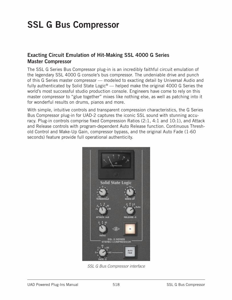
UAD Powered Plug-Ins Manual SSL G Bus Compressor 518
SSL G Bus Compressor
Exacting Circuit Emulation of Hit-Making SSL 4000 G Series Master CompressorThe SSL G Series Bus Compressor plug-in is an incredibly faithful circuit emulation of the legendary SSL 4000 G console’s bus compressor. The undeniable drive and punch of this G Series master compressor — modeled to exacting detail by Universal Audio and fully authenticated by Solid State Logic® — helped make the original 4000 G Series the world’s most successful studio production console. Engineers have come to rely on this master compressor to “glue together” mixes like nothing else, as well as patching into it for wonderful results on drums, pianos and more.
With simple, intuitive controls and transparent compression characteristics, the G Series Bus Compressor plug-in for UAD-2 captures the iconic SSL sound with stunning accu-racy. Plug-in controls comprise fixed Compression Ratios (2:1, 4:1 and 10:1), and Attack and Release controls with program-dependent Auto Release function. Continuous Thresh-old Control and Make-Up Gain, compressor bypass, and the original Auto Fade (1-60 seconds) feature provide full operational authenticity.
SSL G Bus Compressor interface
UAD Powered Plug-Ins Manual SSL G Bus Compressor 519
SSL G Bus Compressor Controls
ThresholdThreshold defines the signal level at which the onset of compression occurs. Incoming signals that exceed this level are compressed. Signals below the level are unaffected. The control range is ±15 dB.
As the Threshold control is decreased and more compression occurs, output level is typi-cally reduced. Adjust the Make Up control to modify the output to compensate if desired.
Make UpMake Up (post-compression make up gain) controls the signal level that is output from the plug-in. The range is 0 dB to +15 dB.
Generally speaking, adjust the Make Up control after the desired amount of compression is achieved with the Threshold and Ratio controls. Make Up does not affect the amount of compression.
AttackAttack sets the amount of time that must elapse once the input signal reaches the Threshold level before compression is applied. The faster the Attack, the more rapidly compression is applied to signals above the threshold. Available Attack times are discrete values of 0.1 ms, 0.3 ms, 1 ms, 3 ms, 10 ms, and 30 ms.
The availability of relatively slow attack times (as compared to other compressors) is one factor that can provide the in-your-face-pumping quality that is so popular with large console VCA-style compressors.
ReleaseRelease sets the amount of time it takes for compression to cease once the input sig-nal drops below the threshold level. Slower release times can smooth the transition that occurs when the signal dips below the threshold, especially useful for material with fre-quent peaks. However, if you set the Release time too long, compression for sections of audio with loud signals may extend to lengthy sections of audio with lower signals.
Available Release times are discrete values of 100 ms, 300 ms, 600 ms, 1.2 s, and Auto. The Auto release characteristic for SSL G Bus Compressor has a unique quality that is optimized for program material.
RatioRatio defines the amount of gain reduction to be processed by the compressor. For exam-ple, a value of 2 (expressed as a 2:1 ratio) reduces the signal above the threshold by half, with an input signal of 20 dB being reduced to 10 dB. The available Ratio values are 2:1, 4:1, and 10:1.
UAD Powered Plug-Ins Manual SSL G Bus Compressor 520
Power (IN)The Power button determines whether the plug-in is active. Click the Power button to toggle the processor state. Power is useful for comparing the processed sound to that of the original signal.
Gain Reduction MeterThe Gain Reduction VU-style meter displays the amount of gain reduction occurring in the compressor. Higher values indicate more gain reduction.
Increase the signal level into the plug-in and/or lower the Threshold control to increase gain reduction.
FadeThe SSL G Bus Compressor provides a Fade function that, upon activation, automatically reduces the plug-in output to minimum within a specified time period. This function enables extremely smooth-sounding fade outs (and fade ins), plus it can be automated as well.
The Fade function processes the signal at the output of the compressor. The fade signal level that is output has an exponential curve.
Fade RateFade Rate determines the amount of time that will pass between the Fade button being activated and the plug-in output level being reduced to minimum (or being raised to 0 dB in the case of a fade in). The available range is from 1.0 second to 60 seconds.
Fade times immediately reflect the current Fade Rate value. Therefore a fade out that has already been initiated can be accelerated by changing Fade Rate during the fade out. Conversely, a fade in can be accelerated by changing Fade Rate during the fade in.
Auto Fade ButtonActivating the Auto Fade button initiates a fade out. The fade out time is determined by the Fade Rate parameter. The Fade button blinks when a fade out is in progress, and is continuously lit when the fade out is complete (when the Fade Rate time has elapsed).
Deactivating Fade (clicking the solid-lit button) initiates a fade in. During a fade in, the signal level is increased from the current level of attenuation to 0 dB of attenuation. The Fade button flashes when a fade in is in progress, and is no longer illuminated when the fade in is complete (when the Fade Rate time has elapsed).
Toggling the Fade button causes an already active fade to reverse direction, without a jump in output level. The Fade Rate is constant even if an active fade is interrupted. For example: If the Fade Rate value is 30 seconds and a fade out is initiated, then Fade is clicked again after 20 seconds, it will take 20 seconds to fade back in.
Tip: Shift+click the Fade button to instantly return the level back to 0 dB (this feature cannot be automated).
UAD Powered Plug-Ins Manual SSL G Bus Compressor 521
Operation NotesThe SSL G Bus compressor has been used to put the final touch of cohesiveness or “glue” to more mixes than any other compressor in history! Its true usefulness and beauty is usually in its subtle ability to make your mix “pop” just a little more, with a subtle increase in energy and excitement.
The SSL G is designed with the 2-bus in mind, and the control set adjusts the L/R simul-taneously. The ratios, attack and release settings are also specially tailored for bus use, and give just the right variety of options to make it useful for a wide variety of source material. Attack and release times allow the compression behavior to be `tuned’ to the tempo and feel of the song to some degree, and the “Auto” setting provides a program-dependent, multi-stage release for the greatest degree of transparency. Use the 2:1 for the most transparent sound and 10:1 for tougher, more audible sound, or 4:1 for in between. Usually, this processor is meant to be used with minimal gain reduction. In most cases, setting the threshold for 1-2 dB average gain reduction is most common, with occasional transients that go beyond the average. In quieter passages little or no meter movement will occur. Use make up gain to get a good gain match between active and bypassed.
Traditionally, the SSL G is most commonly used from the beginning of the mix process, and the engineer is “mixing to” the sound and behavior of the compressor. The ideal way to audition this plugin is on a new mix, dropped into an insert on your stereo master fader. In this case, you will be spending a lot of time keeping an eye on gain reduction metering and you may make tweaks to the setup as the mix progresses. Of course it can also be dropped in existing mixes at any time, but keep in mind it may take a bit more effort to dial in, especially if your ear is already used to the sound without its compres-sion properties.
The SSL G is also useful of groups, such as drum busses. in this case, a more aggres-sive approach may be appropriate, with a greater range of gain reduction. 10:1 will give a harder sound often desired for drum groups. Fast attacks releases will give the most audible sound of the compressor working.
Finally, Auto Fade is useful when the end of a song needs a gradual decrease in volume. The speed of the fade can be tuned from 1 to 60 seconds, and incorporates SSL’s unique fade curves. Fade in is also available.
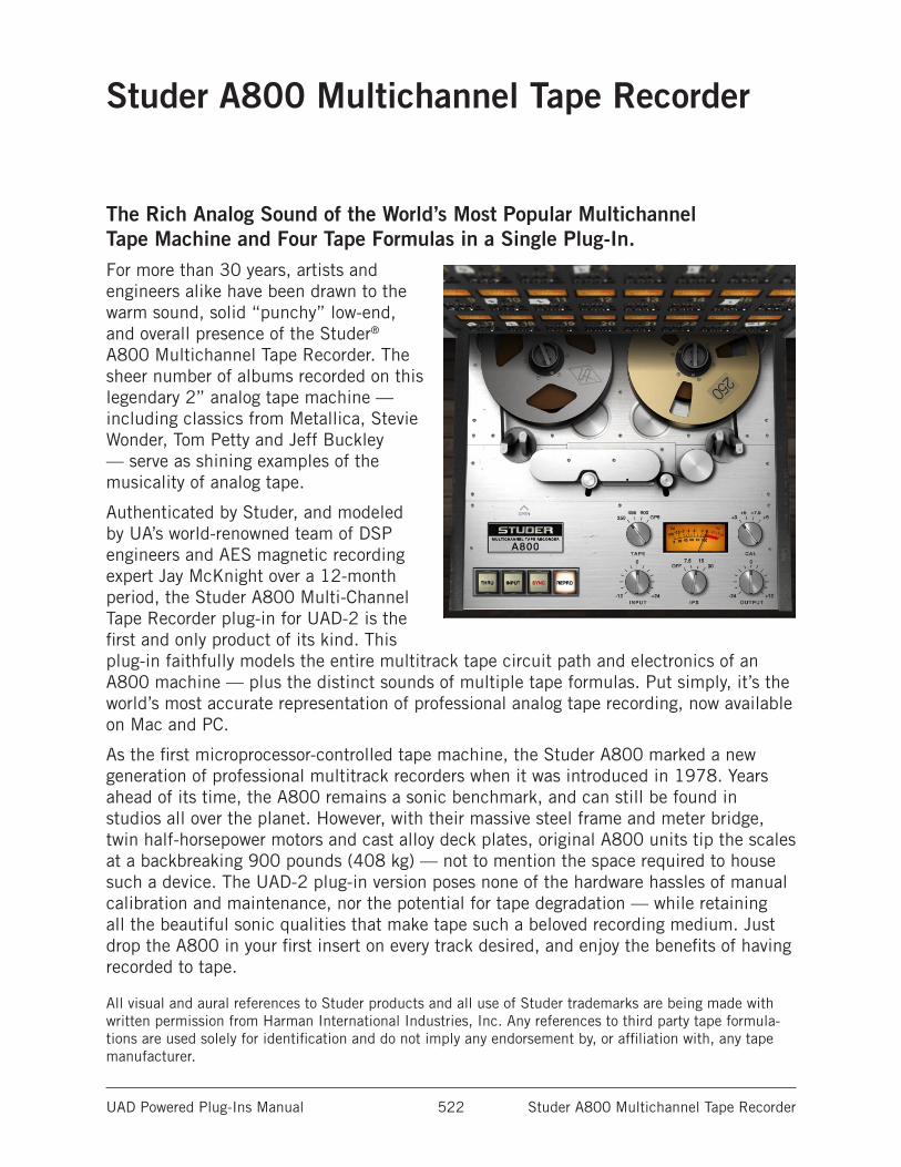
UAD Powered Plug-Ins Manual Studer A800 Multichannel Tape Recorder 522
Studer A800 Multichannel Tape Recorder
The Rich Analog Sound of the World’s Most Popular Multichannel Tape Machine and Four Tape Formulas in a Single Plug-In.For more than 30 years, artists and engineers alike have been drawn to the warm sound, solid “punchy” low-end, and overall presence of the Studer® A800 Multichannel Tape Recorder. The sheer number of albums recorded on this legendary 2” analog tape machine — including classics from Metallica, Stevie Wonder, Tom Petty and Jeff Buckley — serve as shining examples of the musicality of analog tape.
Authenticated by Studer, and modeled by UA’s world-renowned team of DSP engineers and AES magnetic recording expert Jay McKnight over a 12-month period, the Studer A800 Multi-Channel Tape Recorder plug-in for UAD-2 is the first and only product of its kind. This plug-in faithfully models the entire multitrack tape circuit path and electronics of an A800 machine — plus the distinct sounds of multiple tape formulas. Put simply, it’s the world’s most accurate representation of professional analog tape recording, now available on Mac and PC.
As the first microprocessor-controlled tape machine, the Studer A800 marked a new generation of professional multitrack recorders when it was introduced in 1978. Years ahead of its time, the A800 remains a sonic benchmark, and can still be found in studios all over the planet. However, with their massive steel frame and meter bridge, twin half-horsepower motors and cast alloy deck plates, original A800 units tip the scales at a backbreaking 900 pounds (408 kg) — not to mention the space required to house such a device. The UAD-2 plug-in version poses none of the hardware hassles of manual calibration and maintenance, nor the potential for tape degradation — while retaining all the beautiful sonic qualities that make tape such a beloved recording medium. Just drop the A800 in your first insert on every track desired, and enjoy the benefits of having recorded to tape.
All visual and aural references to Studer products and all use of Studer trademarks are being made with written permission from Harman International Industries, Inc. Any references to third party tape formula-tions are used solely for identification and do not imply any endorsement by, or affiliation with, any tape manufacturer.
UAD Powered Plug-Ins Manual Studer A800 Multichannel Tape Recorder 523
Operational OverviewThe Studer A800 for UAD-2 provides all of the original unit’s desirable analog sweetness; like magnetic tape, users can dial in a clean sound, or just the right amount of harmonic saturation using the Input and Output controls. The reel deck IPS control steps through the three tape speed choices available on the original hardware (7.5, 15, or 30 IPS), each with distinct frequency shift, head bump and distortion characteristics. The Tape Type control lets users choose from four of the most popular magnetic tape formulas of the last three decades, each with their own subtle sonic variation and tape compression characteristics. The Cal control allows the user to choose between +3 dB, +6 dB, +7.5 dB, or +9 dB calibration levels, which can be used at their recommended settings, or tweaked for additional tonal options. Input, Sync and Repro paths, plus Thru (bypass) are available for authenticity, providing all available circuit options of the A800. A huge time saver, the Studer A800 plug-in features an innovative Gang Controls setting, allowing for instant global adjustment of any parameters for all Studer A800 instances in your session.
Secondary controls are hidden behind the reel deck, and can be exposed by clicking on the Studer badge or Open label of the plug-in GUI. The Equaliser control allows the user to select between the American (NAB) and European (CCIR) standardized EQs, providing regional pre-emphasis/de-emphasis filtering at 7.5 and 15 IPS, each with its own sonic qualities — plus the AES EQ at 30 IPS. The HF Bias calibration parameter allows the user to tune the HF oscillation voltage feed to the magnetic record head, striking a balance between record sensitivity and distortion. This can also be used creatively as an effect — from warm, overbiased sounds, to voltage-starved distortion and chatter. HF Record is a calibration filter that allows for HF makeup when the ideal Bias leaves a high frequency deficiency; both HF Bias and HF record are fed into the tape nonlinearity. Sync and Repro HF and LF calibration EQs allow for adjusting for a flat playback response, or can also be used creatively. All Secondary Controls can be automatically calibrated to the manufacturer’s recommended settings via the A800’s Auto Cal feature, or may be disabled. Finally, separate controls for Hiss and Hum are available — each tuned to default settings to match the hardware behavior — with a global noise bypass option.
Multitrack Tape MachineThe primary purpose of Studer A800 is to obtain multichannel tape sonics within the DAW environment. To obtain the classic multitrack tape sound, the plug-in should be placed as the first insert on individual tracks, before other processing is applied. Creative “non-standard” results can be obtained by placing the Studer A800 in subsequent inserts after other processors or on busses in a send/return configuration. Mixdown to two tracks can be emulated by placing the plug-in on the stereo output bus.
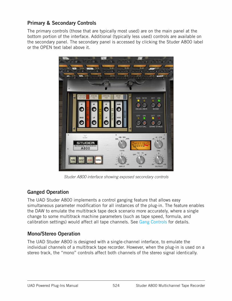
UAD Powered Plug-Ins Manual Studer A800 Multichannel Tape Recorder 524
Primary & Secondary ControlsThe primary controls (those that are typically most used) are on the main panel at the bottom portion of the interface. Additional (typically less used) controls are available on the secondary panel. The secondary panel is accessed by clicking the Studer A800 label or the OPEN text label above it.
Studer A800 interface showing exposed secondary controls
Ganged OperationThe UAD Studer A800 implements a control ganging feature that allows easy simultaneous parameter modification for all instances of the plug-in. The feature enables the DAW to emulate the multitrack tape deck scenario more accurately, where a single change to some multitrack machine parameters (such as tape speed, formula, and calibration settings) would affect all tape channels. See Gang Controls for details.
Mono/Stereo OperationThe UAD Studer A800 is designed with a single-channel interface, to emulate the individual channels of a multitrack tape recorder. However, when the plug-in is used on a stereo track, the “mono” controls affect both channels of the stereo signal identically.
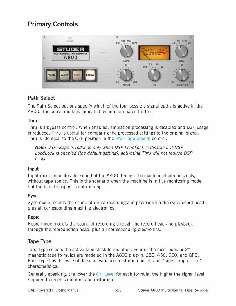
UAD Powered Plug-Ins Manual Studer A800 Multichannel Tape Recorder 525
Primary Controls
Path SelectThe Path Select buttons specify which of the four possible signal paths is active in the A800. The active mode is indicated by an illuminated button.
ThruThru is a bypass control. When enabled, emulation processing is disabled and DSP usage is reduced. Thru is useful for comparing the processed settings to the original signal. Thru is identical to the OFF position in the IPS (Tape Speed) control.
Note: DSP usage is reduced only when DSP LoadLock is disabled. If DSP LoadLock is enabled (the default setting), activating Thru will not reduce DSP usage.
InputInput mode emulates the sound of the A800 through the machine electronics only, without tape sonics. This is the scenario when the machine is in live monitoring mode but the tape transport is not running.
SyncSync mode models the sound of direct recording and playback via the sync/record head, plus all corresponding machine electronics.
ReproRepro mode models the sound of recording through the record head and playback through the reproduction head, plus all corresponding electronics.
Tape TypeTape Type selects the active tape stock formulation. Four of the most popular 2” magnetic tape formulas are modeled in the A800 plug-in: 250, 456, 900, and GP9. Each type has its own subtle sonic variation, distortion onset, and “tape compression” characteristics.
Generally speaking, the lower the Cal Level for each formula, the higher the signal level required to reach saturation and distortion.
UAD Powered Plug-Ins Manual Studer A800 Multichannel Tape Recorder 526
Cal LevelCal Level automatically sets tape calibration/fluxivity. The Cal Level setting takes care of the setup one would need to make under equivalent hardware operation, and sets the reference tape/flux level without disturbing the (unity) gain of the plug-in.
The record, repro, and sync gain trims found on the A800 channel cards are not present on the plug-in. Instead (when Auto Cal is enabled), these controls are amalgamated into this single Cal Level gain control.
As tape formulas advanced, their output level increased, thus lowering relative noise floor. +3, +6 and +9 dB output formulas were available in the 2” format. Under normal use, the machine would be calibrated to the tape’s output level. However, users would sometimes under-calibrate to leave more headroom for a broader sweet or to prevent electronics from clipping. Therefore, the user can go traditional and calibrate to the recommended levels, or select a non-corresponding calibration setting with Cal Level.
As an example, if 456 is the selected Tape Type and when Cal Level is set at +6 (6 dB higher than the NAB tape standard), the reference fluxivity level is 355 nW/m (nanoweber per meter) and is 10 dB below the point where THD reaches 3% (referred to as the maximum operating level). Therefore, with a 1 kHz test tone at -12 dBFS sent to the plug-in, with Tape Type set to 456, Cal Level set to +6, and Auto Cal enabled, output levels of the plug-in will match the input level and fluxivity on the tape will be 355 nW/m.
The manufacturer’s recommended calibration settings for each Tape Type are as follows:
• 250: +3 Calibration (251 nWb/m)
• 456: +6 Calibration (355 nWb/m)
• 900: +9 Calibration (502 nWb/m)
• GP9: +9 Calibration (502 nWb/m)
Note: The noise floor is affected by Cal Level when Noise Enable is active.
Tip: The UAD Studer A800 default bank offers a variety of preset Tape Type, Tape Speed, CAL level, and EQ configurations that are commonly used for the recording of specific genres.
IPS (Tape Speed)The IPS (Inches Per Second) control determines the speed of the tape transport and the associated “head bump.”
(Head bump is bass frequency build-up that occurs with magnetic tape; the dominant frequencies shift according to transport speed.)
15 IPS is considered the favorite for rock and acoustic music due to its low frequency “head bump” (low frequency rise) and warmer sound, while 30 IPS is the norm for classical and jazz due to its lower noise floor, greater fidelity and flatter response. 7.5 IPS is also available for an even more colored experience, with even greater frequency shift.
Tip: Click on the “IPS” text label to stop/start the spinning reels animation.
UAD Powered Plug-Ins Manual Studer A800 Multichannel Tape Recorder 527
The OFF position is a bypass control. When set to OFF, emulation processing is disabled, the VU Meter and control LEDs are dimmed, and DSP usage is reduced. OFF is useful for comparing the processed settings to the original signal. OFF is identical to the Thru position in the Path Select control.
Note: DSP usage is reduced only when DSP LoadLock is disabled. If DSP LoadLock is enabled (the default setting), activating OFF will not reduce DSP usage.
InputInput acts as an outside gain control (like an external console fader), and adjusts the signal level going into the tape circuitry. The available range is -12 dB to +24 dB.
Just like real magnetic tape, lower Input levels will have a cleaner sound, while higher levels result in more harmonic saturation and coloration.
Higher Input levels will also increase the output level from the plug-in. The Output control can be lowered to compensate.
Tip: Click the “0” control label text to return to the Input value to 0.
OutputOutput acts as an outside gain control (like an external console fader) and adjusts the gain at the output of the plug-in. The available range is -24 dB to +12 dB.
Tip: Click the “0” control label text to return to the Output value to 0.
VU MeterThe VU Meter provides a visual representation of the signal levels after the virtual tape. The Input control affects how “hot” the signal is.
Higher VU levels typically indicate more harmonic saturation, coloration, and/or distortion. However, this will depend on the other control values.
The plug-in operates at an internal level of -12 dBFS. Therefore a digital signal with a level of -12 dB below full scale digital (0 dBFS) at the plug-in input will equate to 0 dB on the plug-in meters.
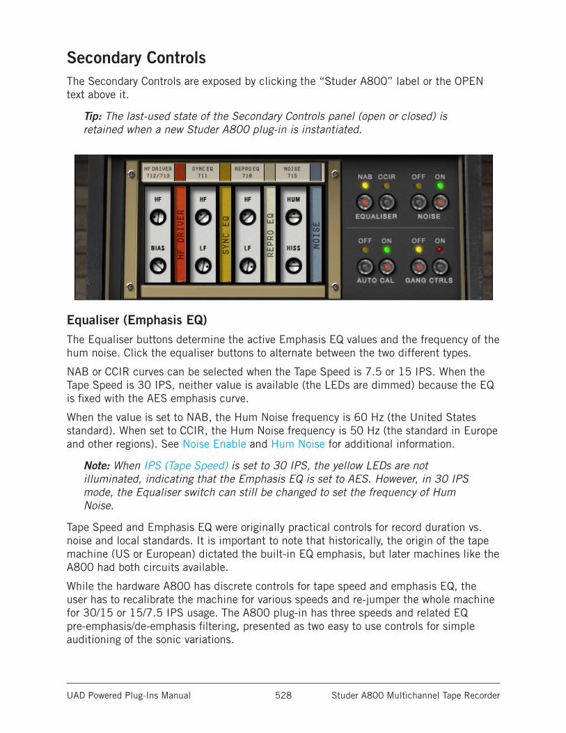
UAD Powered Plug-Ins Manual Studer A800 Multichannel Tape Recorder 528
Secondary ControlsThe Secondary Controls are exposed by clicking the “Studer A800” label or the OPEN text above it.
Tip: The last-used state of the Secondary Controls panel (open or closed) is retained when a new Studer A800 plug-in is instantiated.
Equaliser (Emphasis EQ)The Equaliser buttons determine the active Emphasis EQ values and the frequency of the hum noise. Click the equaliser buttons to alternate between the two different types.
NAB or CCIR curves can be selected when the Tape Speed is 7.5 or 15 IPS. When the Tape Speed is 30 IPS, neither value is available (the LEDs are dimmed) because the EQ is fixed with the AES emphasis curve.
When the value is set to NAB, the Hum Noise frequency is 60 Hz (the United States standard). When set to CCIR, the Hum Noise frequency is 50 Hz (the standard in Europe and other regions). See Noise Enable and Hum Noise for additional information.
Note: When IPS (Tape Speed) is set to 30 IPS, the yellow LEDs are not illuminated, indicating that the Emphasis EQ is set to AES. However, in 30 IPS mode, the Equaliser switch can still be changed to set the frequency of Hum Noise.
Tape Speed and Emphasis EQ were originally practical controls for record duration vs. noise and local standards. It is important to note that historically, the origin of the tape machine (US or European) dictated the built-in EQ emphasis, but later machines like the A800 had both circuits available.
While the hardware A800 has discrete controls for tape speed and emphasis EQ, the user has to recalibrate the machine for various speeds and re-jumper the whole machine for 30/15 or 15/7.5 IPS usage. The A800 plug-in has three speeds and related EQ pre-emphasis/de-emphasis filtering, presented as two easy to use controls for simple auditioning of the sonic variations.
UAD Powered Plug-Ins Manual Studer A800 Multichannel Tape Recorder 529
CCIR (also known as IEC) is the EQ pre-emphasis made famous on British records and is considered the technically superior EQ; many say this EQ was part of the “British sound” during tape’s heyday. NAB (also referred to as IEC2) was the American standard with its own sound. AES is truly standardized for 30 IPS and is the sole EQ found on the Studer A800 for 30 IPS.
Noise EnableThe Noise Enable buttons are a global enable/disable control for the individual hum and hiss components of the A800 model. The amount of hum and hiss noises are continuously variable and are set with the Hum Noise and Hiss Noise controls. Click the Noise buttons to alternate between OFF and ON.
While noise is historically considered a negative, and was the attribute that pushed the technical envelope for better machines and formulas, noise is still an ever-present component of the sound of using tape and tape machines.
Auto CalThe Studer A800 has individual parameters for Bias, HF Record EQ, and Sync/Repro EQ. On the hardware tape machine, these calibration controls are usually adjusted whenever Tape Type, Tape Speed, or Emphasis EQ is changed.
When Auto Cal (Automatic Calibration) is ON in the plug-in, these calibration controls are automatically adjusted to the calibrated values whenever the Tape Type, Tape Speed, and Emphasis EQ are modified. After Auto Calibration occurs, the automatically adjusted parameters can then be modified to any value if desired.
When Auto Cal is OFF, the calibration parameters do not change values when Tape Type, Tape Speed, and Emphasis EQ are modified.
Note: Auto Cal is enabled by default.
Tip: When making manual calibration settings, consider disabling Auto Cal so the manually calibrated settings are not accidentally lost if another control is modified.
UAD Powered Plug-Ins Manual Studer A800 Multichannel Tape Recorder 530
Gang ControlsGang Controls enables global control adjustments of all parameters for all Studer A800 instantiations. This functionality may be accessed from within any active Studer A800 plug-in.
Click the Gang Controls buttons to alternate between the two states. A red flashing LED is present whenever Gang Controls is enabled as a reminder to use this feature with caution.
Important: When Gang Controls is ON and a Studer A800 parameter is modified, the current value of that parameter on all other Studer A800 instantiations will be overwritten and cannot be recovered.
Gang Controls Notes• Gang Controls is a read-only, non-automatable parameter and its current value is
not saved with the session.
• Gang Controls is a static control without the ability to make relative offsets. Disable Gang Controls if offsets between the same control within different instan-tiations is desired.
• If Gang Controls is enabled when Auto Cal is enabled, any adjustments made to Tape Type, Tape Speed or Emphasis EQ causes the Calibration Controls to be automatically adjusted for all instantiations. However, if the Tape Type, Tape Speed or Emphasis EQ values do not already match between instantiations before Gang Controls is active, the resulting calibrated values may not match either.
• When Gang Controls is enabled, there are no audible or visual changes to the other Studer A800 instantiations until a control is actually changed.
• When Gang Controls is enabled and a Studer A800 settings preset is loaded via the UAD Toolbar, the loaded parameter settings are pushed to all Studer A800 instances.
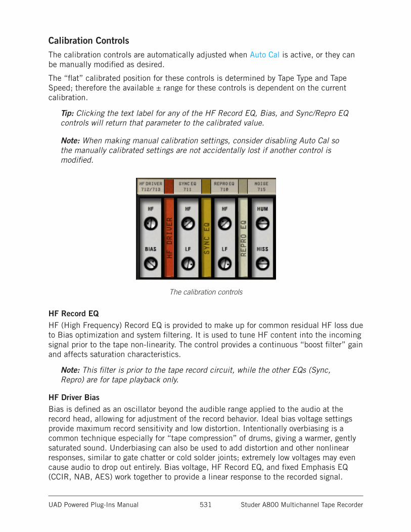
UAD Powered Plug-Ins Manual Studer A800 Multichannel Tape Recorder 531
Calibration ControlsThe calibration controls are automatically adjusted when Auto Cal is active, or they can be manually modified as desired.
The “flat” calibrated position for these controls is determined by Tape Type and Tape Speed; therefore the available ± range for these controls is dependent on the current calibration.
Tip: Clicking the text label for any of the HF Record EQ, Bias, and Sync/Repro EQ controls will return that parameter to the calibrated value.
Note: When making manual calibration settings, consider disabling Auto Cal so the manually calibrated settings are not accidentally lost if another control is modified.
The calibration controls
HF Record EQHF (High Frequency) Record EQ is provided to make up for common residual HF loss due to Bias optimization and system filtering. It is used to tune HF content into the incoming signal prior to the tape non-linearity. The control provides a continuous “boost filter” gain and affects saturation characteristics.
Note: This filter is prior to the tape record circuit, while the other EQs (Sync, Repro) are for tape playback only.
HF Driver BiasBias is defined as an oscillator beyond the audible range applied to the audio at the record head, allowing for adjustment of the record behavior. Ideal bias voltage settings provide maximum record sensitivity and low distortion. Intentionally overbiasing is a common technique especially for “tape compression” of drums, giving a warmer, gently saturated sound. Underbiasing can also be used to add distortion and other nonlinear responses, similar to gate chatter or cold solder joints; extremely low voltages may even cause audio to drop out entirely. Bias voltage, HF Record EQ, and fixed Emphasis EQ (CCIR, NAB, AES) work together to provide a linear response to the recorded signal.
UAD Powered Plug-Ins Manual Studer A800 Multichannel Tape Recorder 532
Sync/Repro EQSync and Repro Playback EQ Controls are available for tape playback calibration. They affect the signal coming out of the tape circuitry.
With the hardware machine, these controls enable compensation for any tape frequency loss or head wear. Under hardware use, the Sync and Repro playback heads are calibrated to normal operating standards and are nearly identical when set correctly. However, they may be tuned incorrectly to achieve a desired sound. Sync EQ and Repro EQ are used as filters to shape the frequency response of the system in maintaining a flat response, but they may be used on their own for high or low frequency adjustment.
Sync HF EQ
Adjusts the high frequency content when Path Select is set to Sync. When Path Select is not set to Sync, the control has no effect.
Sync LF EQ
Adjusts the low frequency content when Path Select is set to Sync. When Path Select is not set to Sync, the control has no effect.
Repro HF EQ
Adjusts the high frequency content when Path Select is set to Repro. When Path Select is not set to Repro, the control has no effect.
Repro LF EQ
Adjusts the low frequency content when See Path Select (See Path Select) is set to Repro. When Path Select is not set to Repro, the control has no effect.
UAD Powered Plug-Ins Manual Studer A800 Multichannel Tape Recorder 533
NoiseThe Noise controls allow the user to control the Hum and Hiss elements found on the original hardware. Separate controls for Hum and Hiss are available and each can be adjusted for creative purposes.
Tip: Click the control label text to return to the Hum or Hiss value to 0.
Hiss affects the signal at the tape head; Hum is added after the tape circuitry. Hum and Hiss values default to comparative levels found on the original hardware. The available range for both controls is ±25 dB.
Note: The global Noise Enable control must be ON for the Hum and Hiss parameters to have any effect.
Hum NoiseThe Hum Noise frequency is dependent on the setting of the Equaliser (Emphasis EQ) control. The frequency is 60 Hz when set to NAB (US) and 50 Hz when set to CCIR (European).
Note: When IPS (Tape Speed) is set to 30 IPS, the yellow Equaliser LEDs are not illuminated, indicating that the Emphasis EQ is set to AES. However, in 30 IPS mode, the Equaliser switch can still be changed to set the frequency of Hum Noise.
Hiss NoiseJust like the hardware, the amount of hiss is dependent on settings of the various controls. Overall Hiss Noise is set with this control, but may change based on the Path Select, Tape Speed, Tape Type, Emphasis EQ, Cal Level, Bias, Playback EQs, and Output Level controls.
Because hiss noise is an element of tape playback, Hiss is disabled when Path Select is to INPUT.
Note: Hiss timbre and level can change with Tape Type.
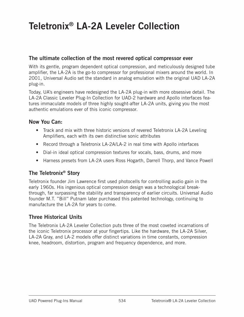
UAD Powered Plug-Ins Manual Teletronix® LA-2A Leveler Collection 534
Teletronix® LA-2A Leveler Collection
The ultimate collection of the most revered optical compressor everWith its gentle, program dependent optical compression, and meticulously designed tube amplifier, the LA-2A is the go-to compressor for professional mixers around the world. In 2001, Universal Audio set the standard in analog emulation with the original UAD LA-2A plug-in.
Today, UA’s engineers have redesigned the LA-2A plug-in with more obsessive detail. The LA-2A Classic Leveler Plug-In Collection for UAD-2 hardware and Apollo interfaces fea-tures immaculate models of three highly sought-after LA-2A units, giving you the most authentic emulations ever of this iconic compressor.
Now You Can:• Track and mix with three historic versions of revered Teletronix LA-2A Leveling
Amplifiers, each with its own distinctive sonic attributes
• Record through a Teletronix LA-2A/LA-2 in real time with Apollo interfaces
• Dial-in ideal optical compression textures for vocals, bass, drums, and more
• Harness presets from LA-2A users Ross Hogarth, Darrell Thorp, and Vance Powell
The Teletronix® StoryTeletronix founder Jim Lawrence first used photocells for controlling audio gain in the early 1960s. His ingenious optical compression design was a technological break-through, far surpassing the stability and transparency of earlier circuits. Universal Audio founder M.T. ”Bill” Putnam later purchased this patented technology, continuing to manufacture the LA-2A for years to come.
Three Historical UnitsThe Teletronix LA-2A Leveler Collection puts three of the most coveted incarnations of the iconic Teletronix processor at your fingertips. Like the hardware, the LA-2A Silver, LA-2A Gray, and LA-2 models offer distinct variations in time constants, compression knee, headroom, distortion, program and frequency dependence, and more.
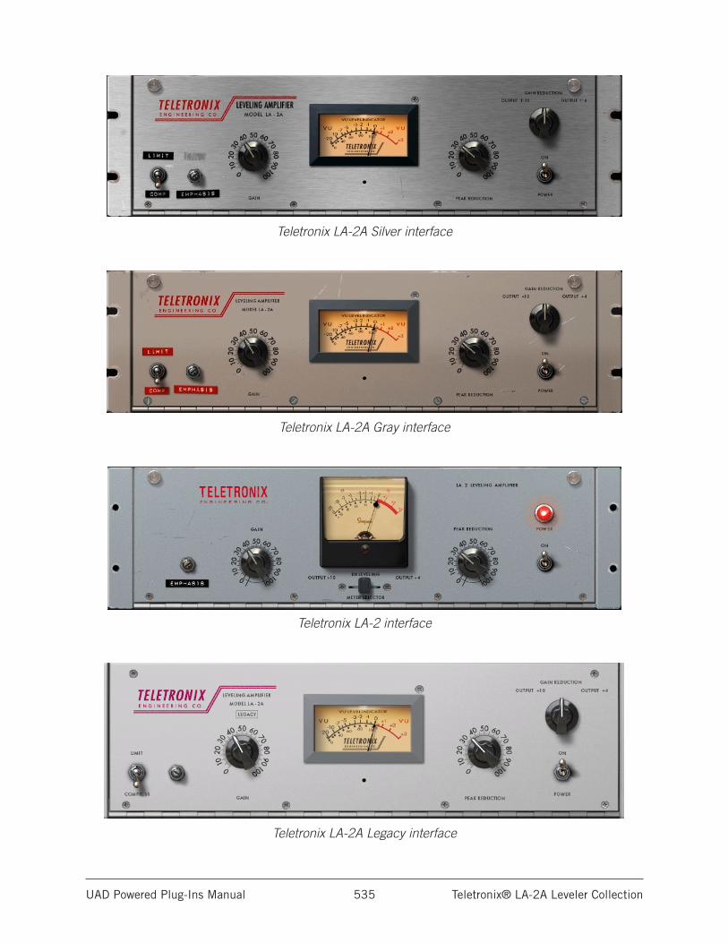
UAD Powered Plug-Ins Manual Teletronix® LA-2A Leveler Collection 535
Teletronix LA-2A Silver interface
Teletronix LA-2A Gray interface
Teletronix LA-2 interface
Teletronix LA-2A Legacy interface
UAD Powered Plug-Ins Manual Teletronix® LA-2A Leveler Collection 536
LA-2A Plug-In FamilyThe complete LA-2A family is comprised of four individual plug-ins, as seen on the previ-ous page. Each variation has its own unique sonic characteristics.
Teletronix LA-2A Leveler CollectionThe newer state-of-the-art algorithms in the Teletronix LA-2A Leveler Collection (intro-duced in UAD v6.5) take full advantage of the extra power available on UAD-2 devices and the design sophistication and expertise gained since the introduction of the legacy LA-2A plug-in in 2001.
Teletronix LA-2A Silver
With a brushed aluminum panel and original T4B gain reduction module, this cherished late-1960s “Silver” version of the LA-2A, manufactured by Bill Putnam, is perhaps the most flexible of the three plug-ins in the collection. Its fast time constant makes it suitable for the widest variety of program material, including transient-rich sources like drums and percussion.
Teletronix LA-2A GrayJim Lawrence’s original mid-1960s “Gray” version the LA-2A maintains a more average time constant, providing a range of “medium-speed” compression.
Teletronix LA-2The exceptionally rare, early 1960s LA-2 unit preceded the LA-2A by several years. It provides the slowest response and a unique “mellowed” sound due to 50 years of lumi-nescent panel aging inside the T4 module. Use the LA-2 with legato tempos and vocal sources for a transparency and sublime mood unlike any other compressor.
Teletronix LA-2A LegacyThe Teletronix LA-2A Legacy plug-in was, along with the UA 1176LN Legacy, the first plug-in available for the UAD platform. This first-generation plug-in runs on UAD-1 and UAD-2 devices. It still has a great sound and is very usable, especially when there are not enough DSP resources to use the second-generation models in the newer Teletronix LA-2A Leveler Collection.
To accommodate the limited DSP resources of the UAD-1, the transformer and I/O distortion characteristics were not modeled in this plug-in. This makes the Teletronix LA-2A Legacy especially useful in situations where less distortion, and less DSP usage, is desirable.
UAD Powered Plug-Ins Manual Teletronix® LA-2A Leveler Collection 537
Operational Overview
ApplicationsIn the 60s and 70s, the LA-2A and 1176 became inextricably linked as the must-have dynamic tools of the day. If the 1176 is to the Stratocaster in terms of immediacy and flexibility, then the LA-2A is to the Gibson Les Paul in terms of warmth and one-of-a-kind, magical sonic distinction. An important characteristic of the T4 photocell response is that it is both program and frequency dependent. The T4 cell has a multi-stage release, and can take a few minutes to fully recover from the incoming signal.
The primary use is as individual inserts for sources that require nominal transparent gain reduction, such as vocals, bass, strings or horns. These tools can also be used to isolate the “color” of the output amplifier by turning off the Peak Reduction control, even to extreme distortion settings. An interesting sidechain distortion can be achieved at the most extreme Peak Reduction settings, which primarily affects low frequencies.
ParametersNo compressor is as easy to operate or instantly satisfying to use as the Teletronix Lev-elers. Peak Reduction applies the compression threshold to the incoming signal up to -40 dB, while Gain amplifies the signal for level matching post Peak Reduction. Set the metering view on any of the units with either +4 or +10 dB Output Gain, or Gain Reduction. Both LA-2A Gray and Silver expose the hardware’s rear Limit/Compress switch, as well as the unit’s “R37 FM Broadcast Emphasis” filter as front panel param-eters. Although not present on the unit originally, the LA-2 was “hot-rodded” to include Emphasis, which is exposed on the front panel. Lastly, Power bypasses all DSP process-ing, providing a handy level matching tool not found on the original hardware.
Artist PresetsThe Teletronix LA-2A Leveler Collection includes artist presets from prominent LA-2A users. The artist presets are in the internal factory bank and are accessed via the host application’s preset menu. The artist presets are also copied to disk by the UAD installer so they can be used within Apollo’s Console application. The presets can be loaded using the Settings menu in the UAD Toolbar (see the “Using UAD Powered Plug-Ins” chapter in the UAD System Manual).
Note: Presets created with the original LA-2A Legacy plug-in are incompatible with the newer Leveler Collection plug-ins.
Reference LevelPlug-ins in the Teletronix LA-2A Leveler Collection operate at an internal reference level of -12 dBFS. This enables more range in the primary controls (Peak Reduction and Gain) before the I/O distortion characteristics become apparent (signals at the input of these plug-ins can be pushed higher before they distort). For related information about internal reference levels, see “Operating Levels” in the UAD System Manual.
UAD Powered Plug-Ins Manual Teletronix® LA-2A Leveler Collection 538
LA-2A ControlsEach model in the LA-2A plug-in collection has the same control set. The parameter descriptions below apply to all models unless otherwise noted.
Peak ReductionThis control sets the amount of signal compression by adjusting the trigger threshold. Increasing the value lowers the threshold, and therefore increases the amount of compression. The available range is 0 dB (fully counter-clockwise) to -40 dB (fully clockwise).
Note: The front panel knob values, which range from 0-100, are arbitrary and do not reflect any particular dB value.
Rotate this control clockwise until the desired amount of compression is achieved. To monitor the amount of Peak Reduction, set the VU Meter knob to Gain Reduction. Peak Reduction should be adjusted independently of the Gain control.
When Peak Reduction is set to its minimum value, no compression (or limiting) occurs but the signal is still colored by the circuitry and the output level can be adjusted with the Gain control.
GainThe Gain knob increases the output level by up to 40 dB to compensate for the reduced level that results from compression. Adjust the Gain control after the desired amount of compression is achieved with the Peak Reduction control. The Gain control does not affect the amount of compression.
Note: The front panel knob values, which range from 0-100, are arbitrary and do not reflect any particular dB value.
Meter KnobThis rotary knob sets the mode of the VU Meter. When set to Gain Reduction, the VU Meter indicates the Gain Reduction level in dB. When set to +10 or +4, the VU Meter indicates the output level in dB (when set to +4, a meter reading of 0 corresponds to an output level of +4 dB).
VU MeterThis is a standard VU meter that displays either the amount of gain reduction, or output level, depending upon the setting of the Meter Function switch.
On/Power SwitchDetermines whether the plug-in is active. When the Power switch is in the Off position, the plug-in is disabled and UAD DSP usage is reduced (unless UAD-2 DSP LoadLock is enabled).
UAD Powered Plug-Ins Manual Teletronix® LA-2A Leveler Collection 539
Compress/LimitThis switch sets the compression ratio of the leveler. When set to Compress, the com-pression ratio is approximately 3:1 and when set to Limit, the ratio is approximately infinity:1. However, the compression ratios are nonlinear and frequency dependent, so these figures are not absolute.
Note: Like the original hardware, this control is unavailable on the Teletronix LA-2 plug-in. The plug-in is “hardwired” in Limit mode.
EmphasisThe (R37) Emphasis “set screw” knob controls a shelf filter circuit in the compressor’s sidechain input, thereby enabling frequency-dependent compression.
When the control is fully clockwise (the default position), the sidechain signal is unfil-tered and all frequencies in the source signal that exceed the compression threshold will trigger gain reduction equally (within the non-linear constraints of the electro-optical characteristics).
Rotating the Emphasis control counter-clockwise increases filtering of the sidechain signal. The Emphasis filter gradually reduces the lower frequency content of the sidechain signal, resulting in compression that is less sensitive to those frequencies, and more sensitive to high frequency content. Therefore, as the sidechain filtering is increased, higher frequencies are compressed more.
Note: Emphasis is unavailable on the Teletronix LA-2A Legacy.
Side-Chain Pre-Emphasis (R37) BackgroundThe LA-2A hardware was designed for use in broadcast applications. The audio signal in FM broadcasting undergoes pre-emphasis and results in a 17 dB boost at 15 kHz. Due to this increase in signal level, transmitters are subject to over-modulation. The LA-2A hardware provides a control (R37) which controls the amount of high-frequency compression.
This potentiometer is factory set for a “flat” side-chain response (clockwise). Increasing the resistance of this potentiometer by turning it counter-clockwise will result in com-pression which is increasingly more sensitive to the higher frequencies.
UAD Powered Plug-Ins Manual Teletronix® LA-2A Leveler Collection 540
Historical BackgroundIn the 1950s while at Parsons Electronics, Electrical Engineer Jim Lawrence was quietly asked to join the Titan Missile Program based at Cal Tech’s Jet Propulsion Lab and was assigned to develop optical sensors for the program. Fortunately for everyone, the tech-nology developed from Lawrence’s work lead back to a more peaceful deployment of the optical sensor, as the detector in his future Leveling Amplifier. The interactions of the luminescent panel with the photo resistors in his T4 design are predominantly what gives the Teletronix Levelers their signature sound.
Lawrence later broke out on his own to start Teletronix, setting up shop in his hometown of Pasadena, California in 1958. Among the Teletronix line of products were transmitter tubes, multiplex generators, to full-scale radio transmitters. Jim’s first pass at his Leveling Amplifier was realized as the Teletronix LA-1; Around 100 units were made. Lawrence then updated the design to the LA-2 with improved specs and circuit layout, then moved quickly to the industry standard LA-2A. In 1965, just three years after the incarnation of the LA-2A, Jim Lawrence sold the company to Babcock Electronics. Enter Bill Putnam. Putnam picked up Babcock’s broadcast division including Teletronix, and rolled it into his parent company, Studio Electronics in 1967. From there, Universal Audio resumed manufacturing of the LA-2A, and Putnam began using the optical detector for new designs.
Whether serendipity or by intent, Jim Lawrence’s Teletronix Levelers and his T4 design had the right musical response that allowed the LA-2A the sonic and technological longevity it still retains. Universal Audio spent a long time getting the T4 right for their hardware LA-2A reissue and the plug-in. But what was special about it wasn’t fully understood until UA began the research to model the LA-2A for the UAD-1. Modern pho-tocells are designed to be as fast as possible, but they don’t have the right multi-stage response they need to sound like a Teletronix design. Our DSP research helped us under-stand how the original T4 worked at the quantum physics level. This not only allowed us to develop an accurate DSP model of the gain reduction behavior, it also helped us make our hardware T4 more consistent. This involved studying the original photocell formula, working with both modern device physicists and the people who developed the original photocells, locating the special equipment originally used to manufacture these back in the ‘60s, and re-qualifying the manufacturer. Whether hardware or DSP, it is this special qualified manufacturing process and “recipe” UA re-established that gives the LA-2A its unique, musical sonic quality to this day.
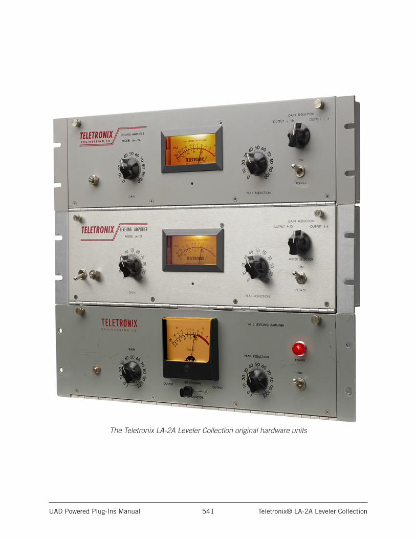
UAD Powered Plug-Ins Manual Teletronix® LA-2A Leveler Collection 541
The Teletronix LA-2A Leveler Collection original hardware units
UAD Powered Plug-Ins Manual Thermionic Culture Vulture 542
Thermionic Culture Vulture
The original boutique, all-valve, studio distortion toolA singular, enigmatic piece of all-valve boutique hardware, the Thermionic Culture Vulture is a distortion hedonist’s malleable plaything. For more than 15 years, this British-made, studio-grade, high-gain valve unit has provided a palette of vivid distortion colors — from sublime thickening textures to demonic growls of perverted mayhem — on countless genre-spanning recordings.
Now — thanks to an intense multi-year engineering effort from Universal Audio — you can track and mix with the only authentic circuit emulation of this one-of-a-kind valve distortion tool with the Thermionic Culture Vulture plug-in.
Now You Can:• Get a full palette of high-gain, studio-grade, dual-stage valve distortion
• Dial-in rich harmonic content with three diverse valve topologies — including UA’s first ever pentode tube emulation
• Record through the Culture Vulture in real time with Apollo Twin, Apollo DUO, Apollo QUAD, or Apollo 16
• Subtly color or utterly destroy existing tracks, buses, or a full mix with the Culture Vulture using any UAD-2 hardware
• Get the same sound and controls as the legendary analog hardware with added features like parallel Dry/Wet processing
• Mix with artist presets from Tony Maserati, Eric “ET” Thorngren, Rik Simpson, Chris Coady, and more
Dominate your Sources with Three Valve TopologiesThe Culture Vulture plug-in faithfully emulates all of the original hardware’s sonic proclivities and diabolical details, including its three distinct all-valve circuit topologies.
Use Triode mode for gentle warming on any source, from a mix bus to a DI bass or synth signal tracking real time through an Apollo interface. Or add more odd-order harmonic edginess to a vocal or rhythm guitar with Pentode 1.
Not enough pain? Tap into the nearly-impossible-to model Pentode 2 mode — a unique, mad-genius circuit that inspires creativity and invites experimentation with its opulent range of demented distortions.
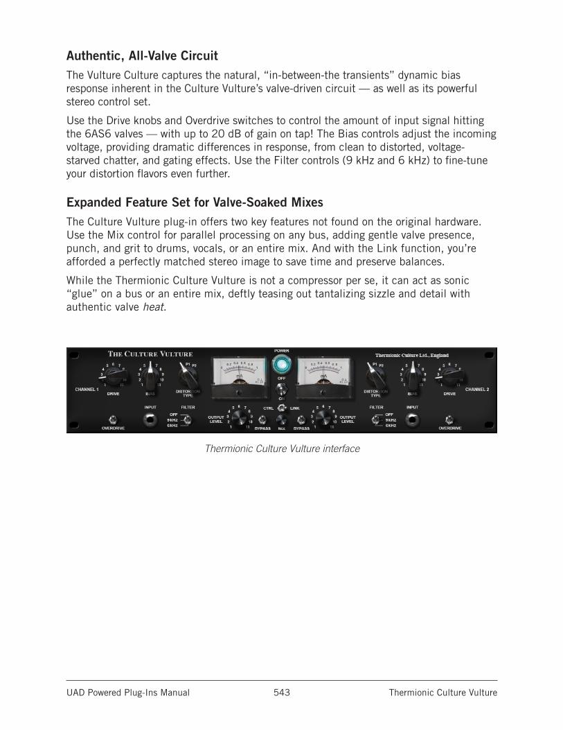
UAD Powered Plug-Ins Manual Thermionic Culture Vulture 543
Authentic, All-Valve CircuitThe Vulture Culture captures the natural, “in-between-the transients” dynamic bias response inherent in the Culture Vulture’s valve-driven circuit — as well as its powerful stereo control set.
Use the Drive knobs and Overdrive switches to control the amount of input signal hitting the 6AS6 valves — with up to 20 dB of gain on tap! The Bias controls adjust the incoming voltage, providing dramatic differences in response, from clean to distorted, voltage-starved chatter, and gating effects. Use the Filter controls (9 kHz and 6 kHz) to fine-tune your distortion flavors even further.
Expanded Feature Set for Valve-Soaked MixesThe Culture Vulture plug-in offers two key features not found on the original hardware. Use the Mix control for parallel processing on any bus, adding gentle valve presence, punch, and grit to drums, vocals, or an entire mix. And with the Link function, you’re afforded a perfectly matched stereo image to save time and preserve balances.
While the Thermionic Culture Vulture is not a compressor per se, it can act as sonic “glue” on a bus or an entire mix, deftly teasing out tantalizing sizzle and detail with authentic valve heat.
Thermionic Culture Vulture interface
UAD Powered Plug-Ins Manual Thermionic Culture Vulture 544
Operational Overview
Two Channel ProcessorThermionic Culture Vulture is a two-channel device capable of running in stereo or dual-mono modes. When used on a stereo signal, the active mode is determined by the Control Link switch. When the plug-in is used in a mono-in/mono-out configuration, the controls for either channels can be used to adjust settings.
Controls LayoutLike the original hardware, the arrangement of the controls for Channels 1 and 2 have a mirror image of each other (the Channel 2 controls have reversed ordering compared to the Channel 1 controls).
Note: Parameter ordering is not mirrored in Controls mode (available in some DAWs) or automation views.
Unorthodox ControlsSome plug-in controls (Bias, Filter, Bypass, Power) are “backwards” when compared to traditional hardware designs. These anomalies are true to the original hardware design.
Expanded Feature SetThe Culture Vulture plug-in offers two key features not found on the original hardware: Mix and Control Link.
The Mix control can be used for parallel processing on any bus, adding gentle valve presence, punch, and grit to drums, vocals, or an entire mix. With the Control Link function, perfectly matched stereo imaging is possible to save time and preserve balances.
Artist PresetsThe Thermionic Culture Vulture plug-in includes artist presets from prominent users. The artist presets are in the internal factory bank and are accessed via the host application’s preset menu. The artist presets are also placed by the UAD installer so they can be used within Apollo’s Console application. The presets can be loaded using the Settings menu in the UAD Toolbar. Also included are additional artist presets that are not available in the internal factory bank. These additional presets can also be accessed using the Settings menu in the UAD Toolbar.
UAD Powered Plug-Ins Manual Thermionic Culture Vulture 545
Thermionic Culture Vulture ControlsControls for Channel 1 and Channel 2 are identical and therefore are only described once. The Link, Mix, and Power controls apply to both channels.
DriveDrive adjusts the amount of input gain (amplified by the EF86 input stage valve), that is sent to the 6AS6 distortion valve. Rotating this control clockwise increases the amount of distortion.
The available Drive range is from 1 to 11. The values are arbitrary and do not represent absolute levels.
BiasBias varies the amount of current passed through the cathode in the 6AS6 distortion valve. The amount of Bias current is displayed by the Meters.
Bias has a significant impact on the distortion characteristics. True to the original hardware, the behavior of this control is reversed.
Clockwise (forward) rotation decreases bias current and generally produces a cleaner and thinner sound. At lower bias currents, the cathode is “starved” and the signal collapses more easily. At the lowest settings, only signal peaks are passed through the valve, resulting in a gating effect.
Counter-clockwise (backward) rotation increases bias current and generally produces a thicker, rounder tone with more harmonic distortion. At higher bias currents, the cathode is “over-fed” and outputs rich, fat distortion.
Medium settings are generally best for gently warming sounds without obvious distortion. The cleanest setting is at approximately 0.25 to 0.3 milliamperes.
The default Bias knob value is 6 for 0.45 milliamperes of bias current. The knob values of 1 to 11 are arbitrary and do not represent absolute levels.
Distortion TypeThe 6AS6 distortion valve can operate in three different operating modes by changing the internal wiring of the tube circuit. Distortion Type switches this mode so different characteristics can be obtained.
This switch interacts extensively with the Drive, Bias, and Overdrive controls. The available distortion types, and their characteristics, are described below.
T (Triode)Triode mode generates more 2nd-order (even) harmonics and is generally the cleanest, smoothest, and “sweetest” mode. Triode mode is great for adding tube warmth to signals without obvious distortion.
UAD Powered Plug-Ins Manual Thermionic Culture Vulture 546
P1 (Pentode 1)Pentode 1 mode generates more 3rd-order (odd) harmonics and has a harder, edgier, and louder sound than Triode mode.
P2 (Pentode 2)Pentode 2 mode has an unusual wiring for a pentode circuit and a particularly aggressive sound, especially with high Bias current and/or when Overdrive is engaged.
This setting can produce some of the most unusual and over-the-top effects such as frequency doubling, gating, and stuttering. It is normal for this mode to be quieter than Triode or Pentode 1 modes.
Interesting phase behaviors can also be induced in this mode. Depending on the source signal, polarity may invert at extreme settings.
OverdriveOverdrive applies 20 dB of additional gain to the 6AS6 distortion valve input for increased distortion.
Note: Exercise caution when engaging Overdrive, as output levels can increase significantly (depending on other control settings).
Overdrive is engaged when the switch is in the down position. The default value is off (up position). Like the Filter, Bypass, and Power switches, the behavior of this control is reversed from typical hardware designs.
The behavior of this switch has a variation from the original hardware. When Overdrive is off (up position), 9 dB of clean gain is added to the input signal. The extra gain is included in the plug-in to compensate for the extreme level changes that occur in the original hardware when Overdrive is engaged (making it easier to quickly compare signals with Overdrive off and on), and also to provide for a more usable range of clean settings.
FilterFilter applies a 12 dB per octave high pass filter at the output of the 6AS6 distortion valve circuit for a smoother sound.
Like the Overdrive, Bypass, and Power switches, the behavior of this control is reversed from typical hardware designs. Filter is engaged when the switch is in the two down positions. The default value is off (up position).
Note: There is a slight rolloff of upper frequencies even when Filter is set to Off. However, this rolloff does not occur when Distortion Type is set to P2.
UAD Powered Plug-Ins Manual Thermionic Culture Vulture 547
Output LevelOutput Level controls the amount of signal going into the output valve (type 5963), which has its own coloration.
Knob values of 8-9 produce the cleanest output. Settings above 9 will overdrive the output valve for increased distortion.
The available range is from 1 to 11 and the default value is maximum. The values are arbitrary and do not represent absolute levels.
BypassBypass disables plug-in processing. If a full bypass is desired to conserve UAD DSP, use the Power switch.
Distortion processing is enabled when the switch is in the down position. Like the Filter, Bypass, and Power switches, the behavior of this control is reversed from typical hardware designs.
Control LinkThis switch causes the controls for Channels 1 and 2 to be stereo linked. When engaged (right position), adjusting a control on one channel will cause the equivalent control on the other channel to move to the same value.
When the plug-in is used in a stereo (or mono-in/stereo-out) configuration, Control Link is engaged by default. Disable the control (left position) for independent dual-mono processing on stereo signals.
When used in a mono configuration, the switch is fixed in the linked position.
Important: When Control Link is engaged, all Channel 1 values are copied to Channel 2, and any control offsets between channels are lost.
MixThe output balance between the signal processed by the plug-in and the original dry source signal can be adjusted with the Mix control. Mix facilitates parallel processing techniques without having to create additional routings in the DAW.
When set to 0% (minimum), only the unprocessed (dry) source signal is output. When set to 100% (the default value), only the processed (wet) signal is output. When set to 50%, an equal blend of both the dry and wet signals is output. The balance is continuously variable and phase accurate throughout the control range.
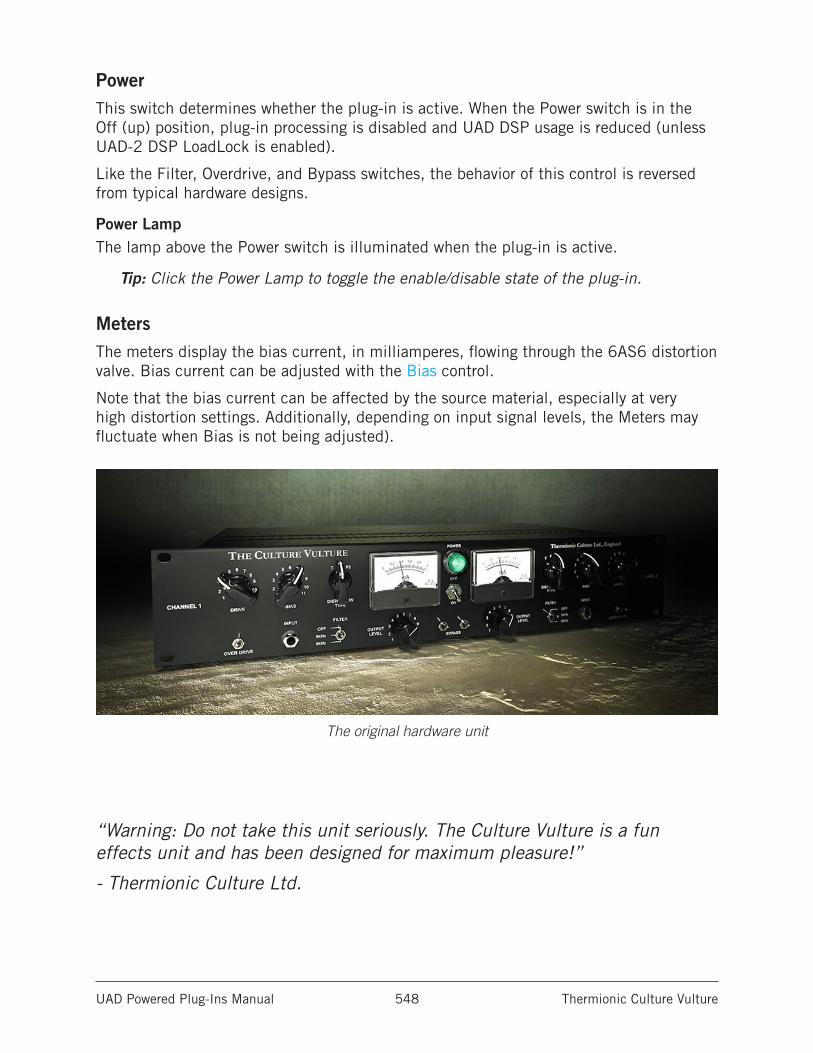
UAD Powered Plug-Ins Manual Thermionic Culture Vulture 548
PowerThis switch determines whether the plug-in is active. When the Power switch is in the Off (up) position, plug-in processing is disabled and UAD DSP usage is reduced (unless UAD-2 DSP LoadLock is enabled).
Like the Filter, Overdrive, and Bypass switches, the behavior of this control is reversed from typical hardware designs.
Power LampThe lamp above the Power switch is illuminated when the plug-in is active.
Tip: Click the Power Lamp to toggle the enable/disable state of the plug-in.
MetersThe meters display the bias current, in milliamperes, flowing through the 6AS6 distortion valve. Bias current can be adjusted with the Bias control.
Note that the bias current can be affected by the source material, especially at very high distortion settings. Additionally, depending on input signal levels, the Meters may fluctuate when Bias is not being adjusted).
The original hardware unit
“Warning: Do not take this unit seriously. The Culture Vulture is a fun effects unit and has been designed for maximum pleasure!”
- Thermionic Culture Ltd.
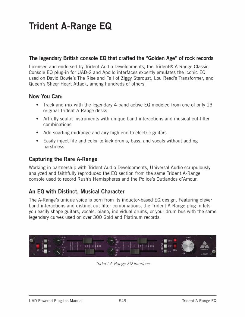
UAD Powered Plug-Ins Manual Trident A-Range EQ 549
Trident A-Range EQ
The legendary British console EQ that crafted the “Golden Age” of rock recordsLicensed and endorsed by Trident Audio Developments, the Trident® A-Range Classic Console EQ plug-in for UAD-2 and Apollo interfaces expertly emulates the iconic EQ used on David Bowie’s The Rise and Fall of Ziggy Stardust, Lou Reed’s Transformer, and Queen’s Sheer Heart Attack, among hundreds of others.
Now You Can:• Track and mix with the legendary 4-band active EQ modeled from one of only 13
original Trident A-Range desks
• Artfully sculpt instruments with unique band interactions and musical cut-filter combinations
• Add snarling midrange and airy high end to electric guitars
• Easily inject life and color to kick drums, bass, and vocals without adding harshness
Capturing the Rare A-RangeWorking in partnership with Trident Audio Developments, Universal Audio scrupulously analyzed and faithfully reproduced the EQ section from the same Trident A-Range console used to record Rush’s Hemispheres and the Police’s Outlandos d’Amour.
An EQ with Distinct, Musical CharacterThe A-Range’s unique voice is born from its inductor-based EQ design. Featuring clever band interactions and distinct cut filter combinations, the Trident A-Range plug-in lets you easily shape guitars, vocals, piano, individual drums, or your drum bus with the same legendary curves used on over 300 Gold and Platinum records.
Trident A-Range EQ interface
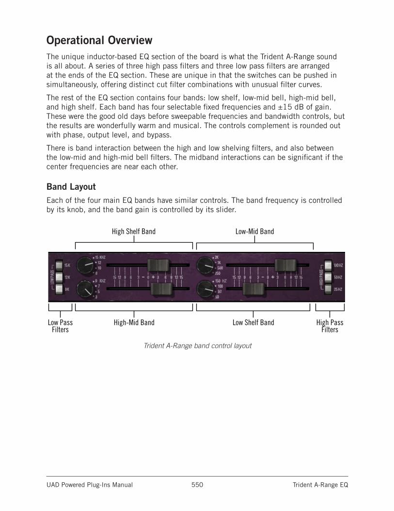
UAD Powered Plug-Ins Manual Trident A-Range EQ 550
Operational OverviewThe unique inductor-based EQ section of the board is what the Trident A-Range sound is all about. A series of three high pass filters and three low pass filters are arranged at the ends of the EQ section. These are unique in that the switches can be pushed in simultaneously, offering distinct cut filter combinations with unusual filter curves.
The rest of the EQ section contains four bands: low shelf, low-mid bell, high-mid bell, and high shelf. Each band has four selectable fixed frequencies and ±15 dB of gain. These were the good old days before sweepable frequencies and bandwidth controls, but the results are wonderfully warm and musical. The controls complement is rounded out with phase, output level, and bypass.
There is band interaction between the high and low shelving filters, and also between the low-mid and high-mid bell filters. The midband interactions can be significant if the center frequencies are near each other.
Band LayoutEach of the four main EQ bands have similar controls. The band frequency is controlled by its knob, and the band gain is controlled by its slider.
Trident A-Range band control layout
Low Pass Filters
High-Mid Band
High Shelf Band Low-Mid Band
High PassFilters
Low Shelf Band
UAD Powered Plug-Ins Manual Trident A-Range EQ 551
Trident A-Range EQ Controls
PhaseThe Phase (Ø) button inverts the polarity of the signal. The signal is inverted when the button is engaged (darker). Leave the button inactive (lighter) for normal phase. Phase is independent of the EQ IN setting.
Low Pass FiltersThree low pass filters are available, and they can be used simultaneously in any combination. The available cutoff frequencies are 15 kHz, 12 kHz, and 9 kHz with a slope of 12 dB per octave. Each filter is active when its button is engaged (darker).
Each low pass filter “adds” to the others. For example, engaging the 15K filter will rolloff frequencies above 15 kHz, but engaging 9K as well will also attenuate frequencies above 15 kHz, even more than if 15K was used by itself.
High Shelf BandThe high shelf offers Trident-A’s famous high frequency shelving EQ.
High Shelving FrequencyThe edge frequency of the high shelf filter is specified by this knob. Four shelf edge frequencies are available: 15 kHz, 12 kHz, 10 kHz, and 8 kHz.
High Shelving GainThe gain for the high shelf filter is specified by the horizontal slider control. The available range is ±15 dB. The gain value is zero when the slider is in the center position.
High-Mid BandThe high-mid EQ offers peak/dip “bell” equalization for the high-to-middle frequencies.
High-Mid FrequencyThe center frequency of the high-mid filter is specified by this knob. Four center frequencies are available: 9 kHz, 7 kHz, 5 kHz, and 3 kHz.
High-Mid GainThe gain for the high-mid filter is specified by the horizontal slider control. The available range is approximately ±15 dB. The gain value is zero when the slider is in the center position.
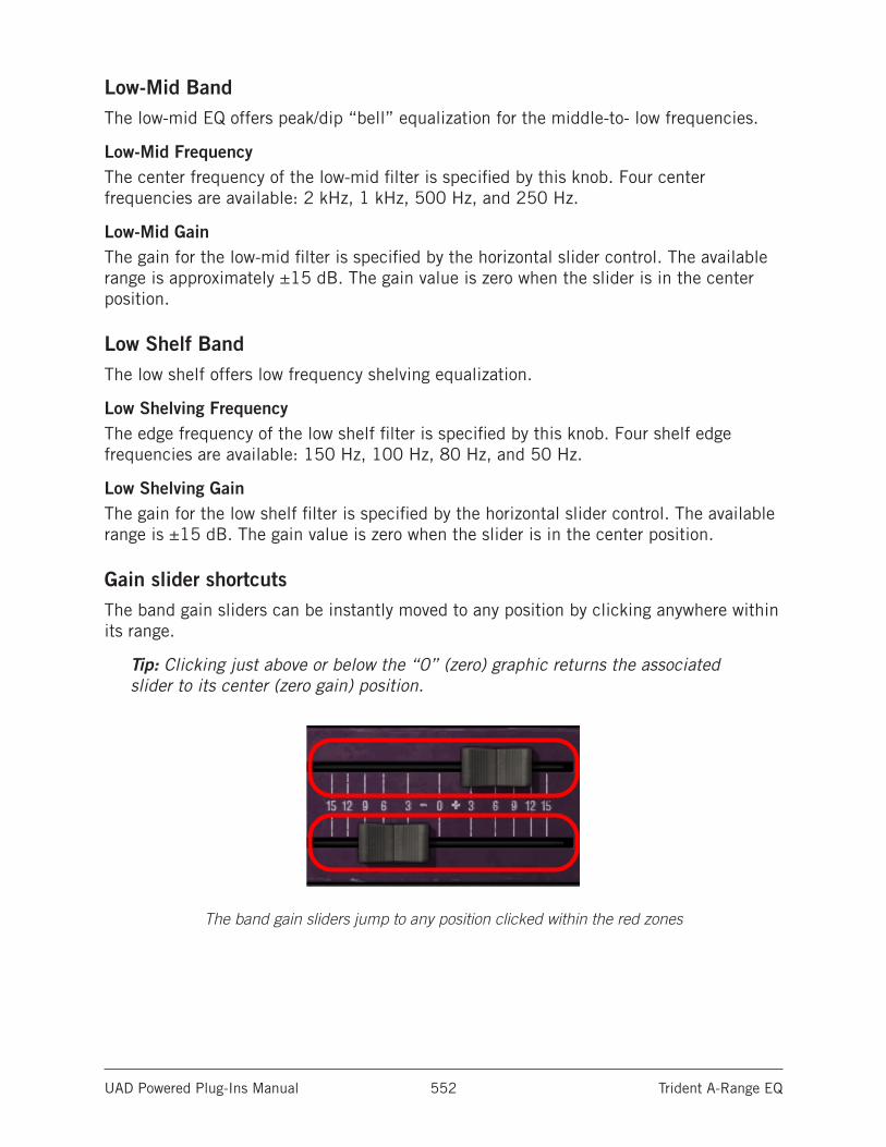
UAD Powered Plug-Ins Manual Trident A-Range EQ 552
Low-Mid BandThe low-mid EQ offers peak/dip “bell” equalization for the middle-to- low frequencies.
Low-Mid FrequencyThe center frequency of the low-mid filter is specified by this knob. Four center frequencies are available: 2 kHz, 1 kHz, 500 Hz, and 250 Hz.
Low-Mid GainThe gain for the low-mid filter is specified by the horizontal slider control. The available range is approximately ±15 dB. The gain value is zero when the slider is in the center position.
Low Shelf BandThe low shelf offers low frequency shelving equalization.
Low Shelving FrequencyThe edge frequency of the low shelf filter is specified by this knob. Four shelf edge frequencies are available: 150 Hz, 100 Hz, 80 Hz, and 50 Hz.
Low Shelving GainThe gain for the low shelf filter is specified by the horizontal slider control. The available range is ±15 dB. The gain value is zero when the slider is in the center position.
Gain slider shortcutsThe band gain sliders can be instantly moved to any position by clicking anywhere within its range.
Tip: Clicking just above or below the “0” (zero) graphic returns the associated slider to its center (zero gain) position.
The band gain sliders jump to any position clicked within the red zones
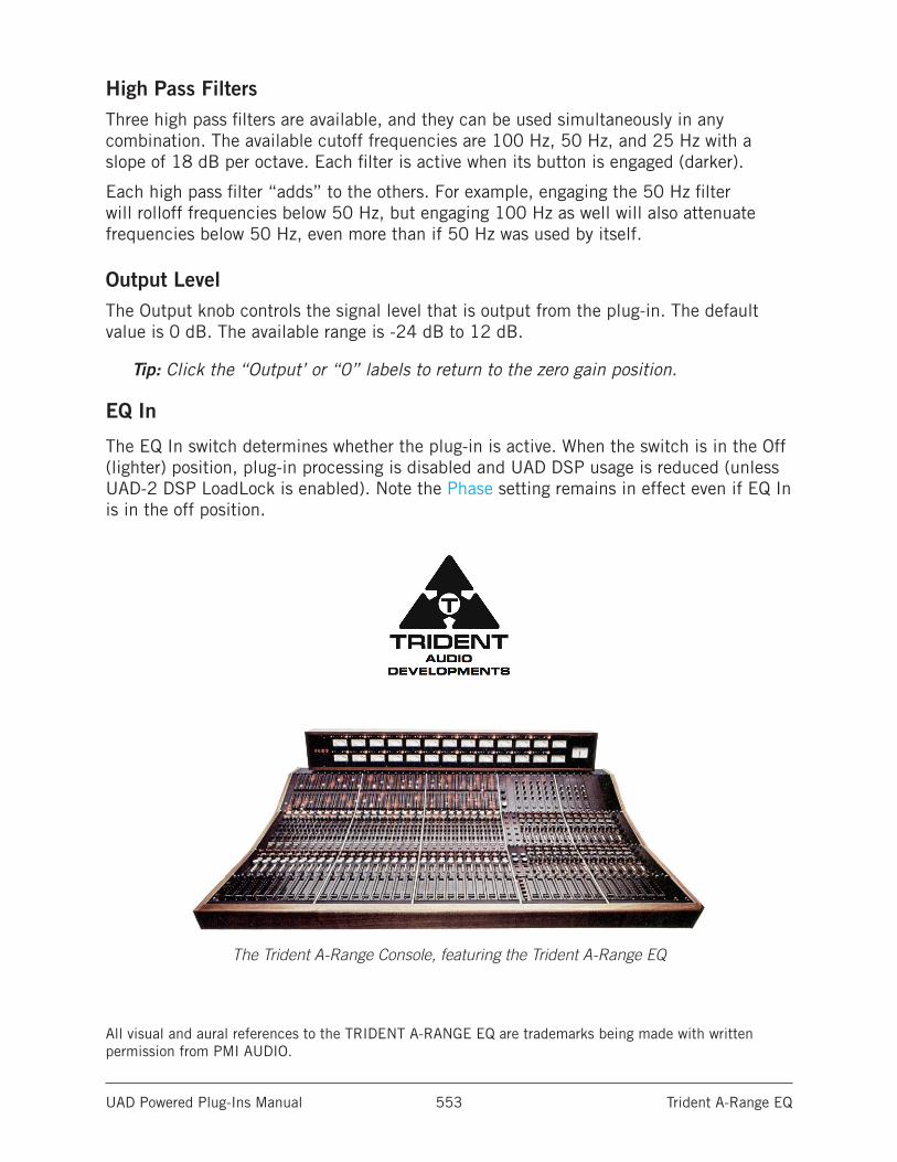
UAD Powered Plug-Ins Manual Trident A-Range EQ 553
High Pass FiltersThree high pass filters are available, and they can be used simultaneously in any combination. The available cutoff frequencies are 100 Hz, 50 Hz, and 25 Hz with a slope of 18 dB per octave. Each filter is active when its button is engaged (darker).
Each high pass filter “adds” to the others. For example, engaging the 50 Hz filter will rolloff frequencies below 50 Hz, but engaging 100 Hz as well will also attenuate frequencies below 50 Hz, even more than if 50 Hz was used by itself.
Output LevelThe Output knob controls the signal level that is output from the plug-in. The default value is 0 dB. The available range is -24 dB to 12 dB.
Tip: Click the “Output’ or “0” labels to return to the zero gain position.
EQ In
The EQ In switch determines whether the plug-in is active. When the switch is in the Off (lighter) position, plug-in processing is disabled and UAD DSP usage is reduced (unless UAD-2 DSP LoadLock is enabled). Note the Phase setting remains in effect even if EQ In is in the off position.
The Trident A-Range Console, featuring the Trident A-Range EQ
All visual and aural references to the TRIDENT A-RANGE EQ are trademarks being made with written permission from PMI AUDIO.
UAD Powered Plug-Ins Manual UA 1176 Classic Limiter Collection 554
UA 1176 Classic Limiter Collection
The Definitive Collection of the World’s Most Famous CompressorsThe original Universal Audio 1176 was designed by UA founder M.T. “Bill” Putnam, and represented a major breakthrough in limiter technology. The first true peak limiter to feature all-transistor circuitry and ultra-fast FET gain reduction, the 1176 has lent its character and punch to some of the greatest recordings in history.
Universal Audio released its first 1176 plug-in emulation in 2001. This plug-in single-handedly launched the UAD platform, and inspired a decade of analog emulation software. Today, we’ve circled back to the 1176, and modeled its entire electronic path from stem to stern — including its transformers and FET and transistor amplifiers, resulting in unrivaled emulations of three distinct 1176 units.
Now You Can:• Track and mix with painstaking emulations of the legendary 1176, the most
popular compressor ever made
• Choose from three famous versions: Rev A, Rev E, and AE — each with their own sonic attributes
• Harness the 1176’s entire electronic path including transformers and FET and transistor amplifiers for colorful distortion
• Add color to signals with “No Ratio” or Attack “Off” yielding 1176 distortion without compression
• Mix with presets from legendary 1176 users such as Andy Johns, Andrew Scheps, Ed Cherney, and Joe Chiccarelli
A Triple ThreatThe 1176 Classic Limiter Plug-In Collection provides three distinct 1176 revisions, representing over 40 years of design iterations to the original 1176. The Rev A “Bluestripe” represents the original Putnam FET limiter design, complete with its higher distortion and unique FET gain amplifier characteristics. The Rev E “Blackface” covers the early ‘70s Brad Plunkett “LN” (Low Noise) era, with variations including a more linear compression response, transistor gain amplification, and a change to the program dependence. The 1176AE provides UA’s rare 1176 40th Anniversary Edition, complete with exclusive mods — including its lower 2:1 compression ratio.
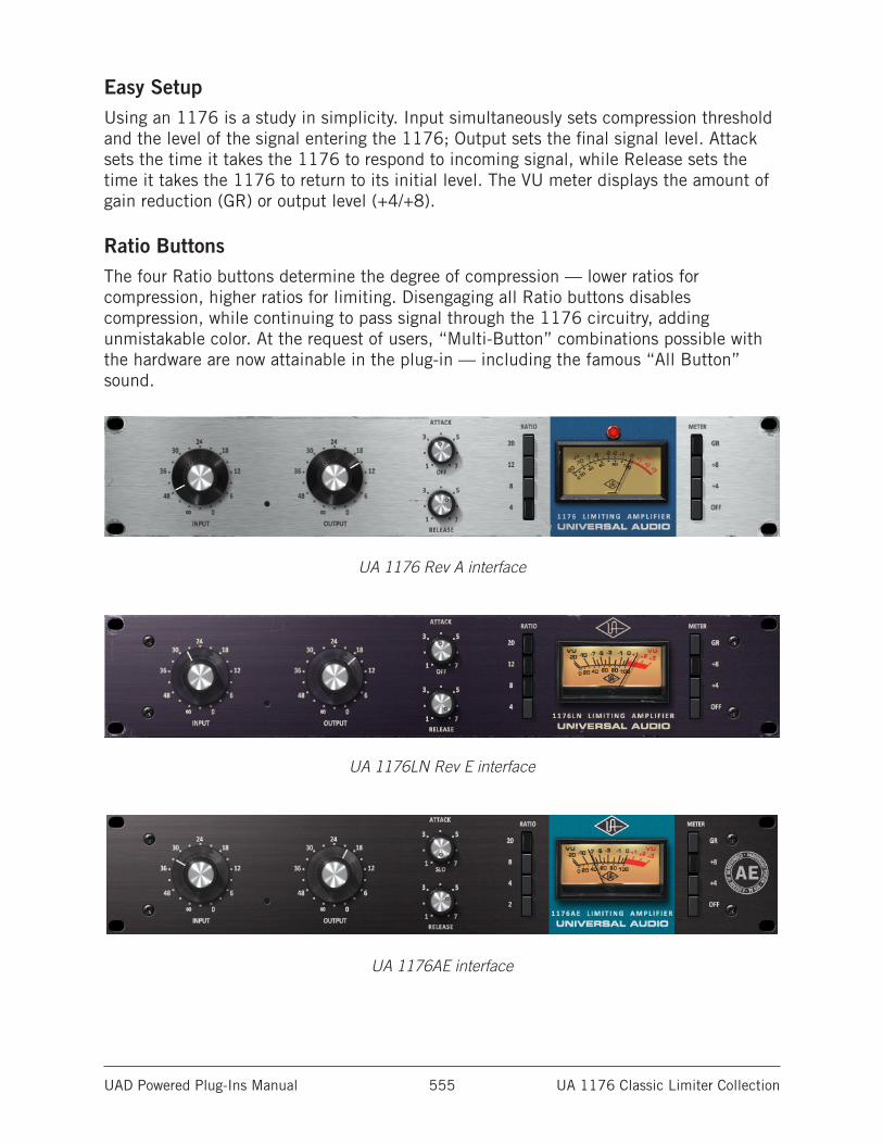
UAD Powered Plug-Ins Manual UA 1176 Classic Limiter Collection 555
Easy SetupUsing an 1176 is a study in simplicity. Input simultaneously sets compression threshold and the level of the signal entering the 1176; Output sets the final signal level. Attack sets the time it takes the 1176 to respond to incoming signal, while Release sets the time it takes the 1176 to return to its initial level. The VU meter displays the amount of gain reduction (GR) or output level (+4/+8).
Ratio ButtonsThe four Ratio buttons determine the degree of compression — lower ratios for compression, higher ratios for limiting. Disengaging all Ratio buttons disables compression, while continuing to pass signal through the 1176 circuitry, adding unmistakable color. At the request of users, “Multi-Button” combinations possible with the hardware are now attainable in the plug-in — including the famous “All Button” sound.
UA 1176 Rev A interface
UA 1176LN Rev E interface
UA 1176AE interface
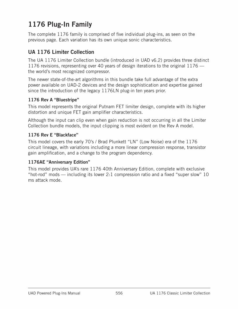
UAD Powered Plug-Ins Manual UA 1176 Classic Limiter Collection 556
1176 Plug-In FamilyThe complete 1176 family is comprised of five individual plug-ins, as seen on the previous page. Each variation has its own unique sonic characteristics.
UA 1176 Limiter CollectionThe UA 1176 Limiter Collection bundle (introduced in UAD v6.2) provides three distinct 1176 revisions, representing over 40 years of design iterations to the original 1176 — the world’s most recognized compressor.
The newer state-of-the-art algorithms in this bundle take full advantage of the extra power available on UAD-2 devices and the design sophistication and expertise gained since the introduction of the legacy 1176LN plug-in ten years prior.
1176 Rev A “Bluestripe”This model represents the original Putnam FET limiter design, complete with its higher distortion and unique FET gain amplifier characteristics.
Although the input can clip even when gain reduction is not occurring in all the Limiter Collection bundle models, the input clipping is most evident on the Rev A model.
1176 Rev E “Blackface”This model covers the early 70’s / Brad Plunkett “LN” (Low Noise) era of the 1176 circuit lineage, with variations including a more linear compression response, transistor gain amplification, and a change to the program dependency.
1176AE “Anniversary Edition”This model provides UA’s rare 1176 40th Anniversary Edition, complete with exclusive “hot-rod” mods — including its lower 2:1 compression ratio and a fixed “super slow” 10 ms attack mode.
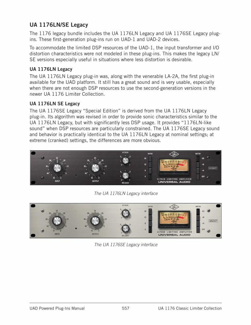
UAD Powered Plug-Ins Manual UA 1176 Classic Limiter Collection 557
UA 1176LN/SE LegacyThe 1176 legacy bundle includes the UA 1176LN Legacy and UA 1176SE Legacy plug-ins. These first-generation plug-ins run on UAD-1 and UAD-2 devices.
To accommodate the limited DSP resources of the UAD-1, the input transformer and I/O distortion characteristics were not modeled in these plug-ins. This makes the legacy LN/SE versions especially useful in situations where less distortion is desirable.
UA 1176LN LegacyThe UA 1176LN Legacy plug-in was, along with the venerable LA-2A, the first plug-in available for the UAD platform. It still has a great sound and is very usable, especially when there are not enough DSP resources to use the second-generation versions in the newer UA 1176 Limiter Collection.
UA 1176LN SE LegacyThe UA 1176SE Legacy “Special Edition” is derived from the UA 1176LN Legacy plug-in. Its algorithm was revised in order to provide sonic characteristics similar to the UA 1176LN Legacy, but with significantly less DSP usage. It provides “1176LN-like sound” when DSP resources are particularly constrained. The UA 1176SE Legacy sound and behavior is practically identical to the UA 1176LN Legacy at nominal settings; at extreme (cranked) settings, the differences are more obvious.
The UA 1176LN Legacy interface
The UA 1176SE Legacy interface
UAD Powered Plug-Ins Manual UA 1176 Classic Limiter Collection 558
Operational Overview
ApplicationsGenerally speaking, the primary use for the 1176 plug-ins are as individual inserts for sources that require compression, such as an individual snare, vocal, or guitar track, or for multi-instrument sources such as a stereo drum buss.
Because the UA 1176 Limiter Collection also models the input and output amplifiers, these models can also be used as “tone boxes” to add 1176 color without compression/limiting by disengaging the ratio control (all Ratio buttons “up”).
ParametersUsing an 1176 is a study in simplicity. Input simultaneously sets compression threshold and the level of the signal entering the 1176; Output sets the final signal level. Attack sets the time it takes the 1176 to respond to incoming signal, while Release sets the time it takes the 1176 to return to its initial level. The VU meter displays the amount of gain reduction (GR) or output level (+4/+8).
The four Ratio buttons determine the degree of compression; lower ratios for compression, higher ratios for limiting. Disengaging all the Ratio buttons (Shift+Click the currently selected ratio) disables compression altogether, but signal continues to pass through the 1176 circuitry. This is commonly used to add the “color” of the 1176LN without any gain reduction. At the request of users, the wide range of “Multi-Button” combinations possible with the hardware is now possible — including the famous “All Button” sound.
Control Response & InteractionsThe UA 1176 Limiter Collection plug-ins are meticulous emulations of the original hardware in every regard, including control responses and interactions. Each 1176 has unique characteristics for gain, threshold, compression knee, distortion onset, and sweet spots. Setting the controls to the same positions on the different plug-ins may yield radically different results, especially depending on the source signals.
This accurate control modeling also applies to the Input and Output control tapers and amplifier levels. The same knob positions on one 1176 could produce a dramatically louder (or softer) levels on another. For this reason (to prevent unexpected and potentially damaging output level jumps), presets are not interchangeable between the 1176 variations.
UAD Powered Plug-Ins Manual UA 1176 Classic Limiter Collection 559
GritA simple 1176 trick is turning the attack and release up all the way to their fastest setting. This has the audible effect of adding compression distortion to the audio source, and is especially pronounced in all-buttons mode. What happens here is the attack and release are happening so fast that minute level fluctuations sound like distortion. It can add a very useful, gritty compression effect.
This effect is useful on bass, where you might need compression and distortion at the same time, and the 1176 can provide both in a unique way. This trick also sounds great on screaming lead vocals.
Artist PresetsThe UA 1176 Limiter Collection includes artist presets from prominent 1176 users. Some of the artist presets are in the internal factory bank and are accessed via the host application’s preset menu. Additional artist presets are copied to disk by the UAD installer. The additional presets can be loaded using the Settings menu in the UAD Toolbar (see the “Using UAD Powered Plug-Ins” chapter in the UAD System Manual).
Note: Presets created with the original 1176LN Legacy and 1176SE Legacy plug-ins are incompatible with the newer Classic Limiter Collection plug-ins.
UAD Powered Plug-Ins Manual UA 1176 Classic Limiter Collection 560
1176 ControlsEach 1176 plug-in variation has the same control set, so they are only detailed once. The parameter descriptions below apply to all models unless otherwise noted.
InputInput adjusts the amount of gain reduction as well as the relative threshold. Rotate the knob clockwise to increase the compression amount.
Like the original hardware, the label values are somewhat arbitrary; the knobs are not calibrated to any particular dB values and levels will vary between the various plug-in models. Even when the Input knob is set to “ ∞ “ signals can still pass into the processor and be compressed.
Note: In the UA 1176 Limiter Collection plug-ins, increasing Input will increase distortion.
OutputOutput determines the final output level of signal leaving the 1176. Once the desired amount of limiting or compression is achieved with the use of the Input control, the Output control can be used to make up any gain lost due to gain reduction.
To monitor the Output level, set the VU Meter to +8 or +4. The Output control does not affect the amount of compression.
Note: In the 1176 Limiter Collection plug-ins, increasing Output will increase distortion.
AttackAttack sets the amount of time it takes the 1176 to respond to an incoming signal and begin gain reduction. The 1176 attack time is adjustable from
20 microseconds to 800 microseconds (both extremely fast).
The attack time is fastest when the Attack knob is in its fully clockwise position, and is slowest when it is in its fully counter-clockwise position. When a fast attack time is selected, gain reduction kicks in almost immediately and catches transient signals of very brief duration, reducing their level and thus “softening” the sound.
Slower attack times allow transients (or partial transients) to pass before limiting or compression begins on the rest of the signal. Note that the actual attack time varies slightly based on the selected ratio and the particular plug-in model in use. Lower ratios will maintain the fastest attack times.
The behavior of the Attack knob varies slightly between the models, as detailed below.
UA 1176AE AttackThe 1176AE offers a unique, fixed 10 ms “SLO” Attack mode when this control is moved to the fully counter-clockwise position.
UAD Powered Plug-Ins Manual UA 1176 Classic Limiter Collection 561
UA 1176 Rev A and UA 1176LN Rev E AttackWhen Attack is in the OFF position the I/O amplifiers remain active while the compression circuit is bypassed. This enables these models to add 1176 color without dynamics processing. This function is identical to disengaging all the Ratio buttons.
Note: To avoid unexpected level changes that can result when compression is dis-engaged, on these models the OFF text label must be clicked to move the Attack knob to the OFF position.
UA 1176LN/SE Legacy AttackThe OFF position is unavailable in these plug-ins. To bypass plug-in processing in these models, use the Meter OFF button.
ReleaseRelease sets the amount of time it takes the 1176 to return to its initial (pre-gain reduction) level. The 1176 release time is adjustable from 50 milliseconds to 1100 milliseconds (1.1 seconds).
Note that the actual release time varies slightly based on the particular plug-in model in use and also partially depends on the program material.
The release time is fastest when the Release knob is in its fully clockwise position, and is slowest when it is in its fully counter-clockwise position. If the release time is fast, “pumping” and “breathing” artifacts can occur, due to the rapid rise of background noise as the gain is restored. If the release time is too slow, however, a loud section of the program may cause gain reduction that persists through a soft section, making the soft section difficult to hear.
About Program-Dependent ReleaseProgram-dependent release is a feature of many compressors. The motivation for having program-dependent release is as follows: After a transient, it is desirable to have a fast release to avoid prolonged dropouts. However, while in a continued state of heavy compression, it is better to have a longer release time to reduce the pumping and harmonic distortion caused by repetitive attack-release cycles.
The 1176 compressor employs a release mechanism that is heavily program-dependent. There are three features to a program-dependent release: A fast release-time, a slow release-time, and a transition-time.
The fast release time is the effective release time after transients; the slow release time is the release time after sustained high-RMS signals. The transition time expresses how long the signal must be “in compression” before the slow release time comes into effect.
The original “Bluestripe” and 1176AE has a different slow release-time and transition-time when compared to the “Blackface” revisions.
UAD Powered Plug-Ins Manual UA 1176 Classic Limiter Collection 562
RatioThe four Ratio pushbutton switches (to the left of the VU Meter) determine the compression ratio of the plug-in. Ratios of 20:1, 12:1, 8:1, and 4:1 are available for all 1176 models except the UA 1176AE, which has 20:1, 8:1, 4:1, and 2:1 modes.
The 20:1 ratio is typically used when peak-limiting is desired, while the lower ratios are typically used for general dynamic range compression.
Multiple Ratio ButtonsOne of the most unique features of the 1176 hardware is the ability to press multiple Ratio buttons in simultaneously to create unusual compression or limiting behavior and increased compression distortion.
All Button ModeEngineers typically use “All Button” mode on drums or on ambience or room mics. It can also be used to make a bass or guitar sound “dirty” or for putting vocals “in your face.” In All-Button mode (sometimes also known as “British Mode”), distortion increases radically due to a lag time on the attack of initial transients.
In All Button mode the ratio goes to somewhere between 12:1 and 20:1, and the bias points change all over the circuit, thus changing the attack and release times as well. The unique and constantly shifting compression curve that results yields a trademark overdriven tone that can only be found in this family of limiter/compressors.
All Button mode is available in all 1176 models.
Multi Button ModesThe UA 1176 Limiter Collection includes the ability to select a variety of “Multi Button” combinations, offering various interpretations of the “All Button” idiosyncrasies. Various button combinations will yield audibly different compression characteristics.
Selecting All/Multi Button Ratio Modes
In UA 1176 Limiter Collection• To select the various combinations of multiple buttons, shift+click the Ratio
buttons.
• Combinations are limited to the modes that actually affect the sound in the hardware. See Available Multi Button Modes for the combinations.
• For the combinations with three or more buttons, the shift-clicking the outer buttons will automatically engage the inner buttons (the inner buttons cannot be disengaged; such combinations don’t affect the sound in the hardware).
• These models can be used as “tone boxes” without compression/limiting by disengaging the Ratio control altogether (all Ratio buttons “up”). This is accomplished by clicking any Ratio button so only one button is engaged, then shift-clicking the engaged button so none are engaged.
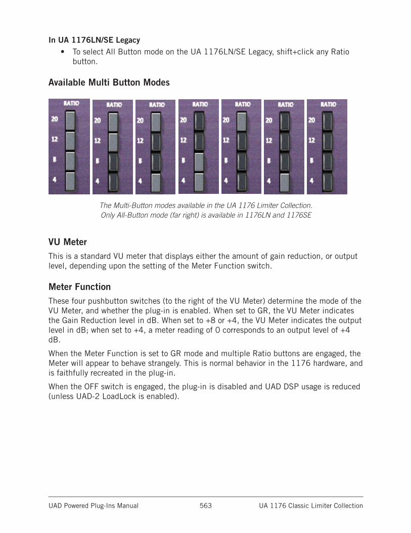
UAD Powered Plug-Ins Manual UA 1176 Classic Limiter Collection 563
In UA 1176LN/SE Legacy• To select All Button mode on the UA 1176LN/SE Legacy, shift+click any Ratio
button.
Available Multi Button Modes
The Multi-Button modes available in the UA 1176 Limiter Collection. Only All-Button mode (far right) is available in 1176LN and 1176SE
VU MeterThis is a standard VU meter that displays either the amount of gain reduction, or output level, depending upon the setting of the Meter Function switch.
Meter FunctionThese four pushbutton switches (to the right of the VU Meter) determine the mode of the VU Meter, and whether the plug-in is enabled. When set to GR, the VU Meter indicates the Gain Reduction level in dB. When set to +8 or +4, the VU Meter indicates the output level in dB; when set to +4, a meter reading of 0 corresponds to an output level of +4 dB.
When the Meter Function is set to GR mode and multiple Ratio buttons are engaged, the Meter will appear to behave strangely. This is normal behavior in the 1176 hardware, and is faithfully recreated in the plug-in.
When the OFF switch is engaged, the plug-in is disabled and UAD DSP usage is reduced (unless UAD-2 LoadLock is enabled).
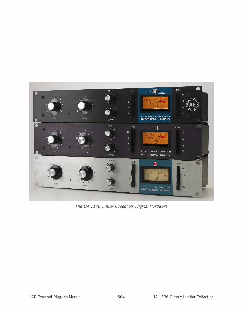
UAD Powered Plug-Ins Manual UA 1176 Classic Limiter Collection 564
The UA 1176 Limiter Collection Original Hardware
UAD Powered Plug-Ins Manual UA 610 Tube Preamp & EQ Collection 565
UA 610 Tube Preamp & EQ Collection
Authentic tube mic preamp modeling – featuring Unison™ technology for Apollo interfacesWhen Universal Audio founder Bill Putnam Sr. introduced the 610 Modular Amplifier preamp in the early ‘60s, it was a milestone in audio recording history. The 610 became famous among record producers for its startling harmonic detail, and rich clipping char-acteristics, and its ability to overdrive in a warm, ultra-musical fashion.
The original 610-A preamp was integral to countless legendary recordings — from the Beach Boys’ Pet Sounds and Johnny Cash’s At Folsom Prison. Its modern variant, the 610-B, helped to create new classics by Adele and Cold War Kids. Today, you can add the same tube presence, warmth, and body to vocals, guitars, bass and more with the UA 610 Tube Preamp & EQ Plug-In Collection for UAD-2 and Apollo interfaces.
Now You Can:• Give your tracks startling three-dimensional tube warmth, presence, and body
• Record “through” the 610-A or 610-B tube preamp models in real time using any Apollo interface that features mic preamps
• Use the 610-A plug-in to get the exclusive sound of the Wally Heider “Green Board,” used to record Neil Young, Ray Charles, Elvis Presley and Jimi Hendrix
• Add Unison™ technology to your Apollo, controlling physical mic preamp gain staging and impedance with Unison-enabled UAD plug-ins
• Mix and saturate signals with any UAD-2 hardware for an iconic tube glow
The First Genuine 610 Tube Preamp EmulationMore than three years in the making, the UA 610 Collection represents the first com-prehensive modeling of the legendary 610-A tube preamp and its modern variant, the 610-B — including their tube and transformer components and all of the unique distor-tion characteristics of the originals.
The 610-A is modeled on a channel from the storied Wally Heider “Green Board,” used to record Neil Young, Ray Charles, Elvis Presley and Jimi Hendrix, and offers simple 10 kHz high-shelf and 100 Hz low-shelf EQ. The modern 610-B offers selectable input impedance, adjustable high- and low-shelf EQ, and expanded gain range.
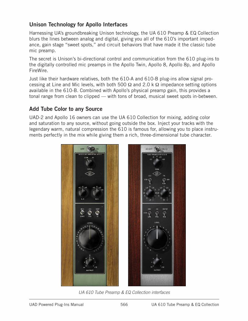
UAD Powered Plug-Ins Manual UA 610 Tube Preamp & EQ Collection 566
Unison Technology for Apollo InterfacesHarnessing UA’s groundbreaking Unison technology, the UA 610 Preamp & EQ Collection blurs the lines between analog and digital, giving you all of the 610’s important imped-ance, gain stage “sweet spots,” and circuit behaviors that have made it the classic tube mic preamp.
The secret is Unison’s bi-directional control and communication from the 610 plug-ins to the digitally controlled mic preamps in the Apollo Twin, Apollo 8, Apollo 8p, and Apollo FireWire.
Just like their hardware relatives, both the 610-A and 610-B plug-ins allow signal pro-cessing at Line and Mic levels, with both 500 Ω and 2.0 k Ω impedance setting options available in the 610-B. Combined with Apollo’s physical preamp gain, this provides a tonal range from clean to clipped — with tons of broad, musical sweet spots in-between.
Add Tube Color to any SourceUAD-2 and Apollo 16 owners can use the UA 610 Collection for mixing, adding color and saturation to any source, without going outside the box. Inject your tracks with the legendary warm, natural compression the 610 is famous for, allowing you to place instru-ments perfectly in the mix while giving them a rich, three-dimensional tube character.
UA 610 Tube Preamp & EQ Collection interfaces
UAD Powered Plug-Ins Manual UA 610 Tube Preamp & EQ Collection 567
The UA 610 Plug-InsThe UA 610 Tube Preamp Collection is comprised of two distinct plug-ins: The vintage UA 610-A, and the modern UA 610-B. Each plug-in has its own modeling and each cap-tures its unique segment in the 610’s sonic history.
The complete signal path is modeled for both 610 plug-ins, including tube amplifiers and transformer components, along with all the phase shift and distortion characteristics that are inherent in each hardware preamp.
Vintage 610-AThe original 610 Modular Amplifier had two versions; the 610 and the 610-A. Besides minor cosmetic differences (such as updates to the panel layout and the UA logo), the only circuit difference between the two was the addition of a +3 dB setting to the 10 kHz High Shelf EQ.
The UA 610-A plug-in models the vintage 610-A module in the original Wally Heider “Green Board” console.
Modern 610-BThe 610-B is the modern Universal Audio preamp design used in our popular hardware products such as the 2-610, LA-610mkII, and 6176.
The UA 610-B plug-in is modeled from the Universal Audio 2-610 Dual Channel Tube Preamplifier hardware, including all the expanded features optimized for modern use.
In UseA primary use for either 610 plug-in is for individual vocal or instrument tracks where colorful tube character and broad EQ strokes are desired. The 610 is widely used as a vocal, bass, horn or strings channel by many modern users, but it sounds great on any source signals, as proven by over five decades of record making.
Tonal RangeFrom clean to clipped, with a broad sweet spot between, extreme tonal flexibility is possible with the 610-A and 610-B. The input and output circuits each have their own tube-driven gain stage, and because each stage imparts its own color, many variations can be obtained by tuning the I/O gain structures. The UA 610 equalizers can also add lots of flavor. Because the EQ has a feedback-style design, it effects the distortion char-acteristics of the output stage.
UAD Powered Plug-Ins Manual UA 610 Tube Preamp & EQ Collection 568
Control DifferencesThe UA 610-A and UA 610-B plug-ins have similar controls and layouts.
For some parameters, the function of these controls is identical for both plug-ins. In the parameter descriptions below, controls and/or descriptions that are common to both plug-ins are detailed at the top of each control name section.
Any differences and/or controls that are unique to each specific plug-in are detailed after the common description.
PresetsThe UA 610 plug-ins include presets in the internal factory bank which are accessed via the host application’s preset menu. The presets are also copied to disk by the UAD installer so they can be used within Apollo’s Console application. The presets can be loaded using the Settings menu in the UAD Toolbar (see “Using UAD Powered Plug-Ins” in the UAD System Manual).
Unison™ IntegrationThe UA 610 plug-ins feature Unison mic preamp technology integration with the mic preamp hardware in Universal Audio’s Apollo audio interfaces. With Unison, Apollo’s ultra-transparent mic preamps inherit all of the unique sonics, input characteristics, and features of the 610 hardware preamps, including the mic, line, and Hi-Z inputs.
Note: Unison is active only when the plug-ins are inserted in the unique INPUT insert within Apollo’s Console application. For complete Unison details, see the Apollo Software Manual.
Realistic Tandem ControlUnison facilitates seamless interactive control of 610 preamp plug-in settings using Apollo’s digitally-controlled panel hardware and/or the plug-in interface. All equivalent preamp controls (gain, pad, polarity, etc.) are mirrored and bi-directional. The preamp controls respond to adjustments with precisely the same interplay behavior as the 610 hardware, including gain levels and clipping points.
Hardware Input ImpedanceAll Apollo mic preamps feature input impedance switching in analog hardware that can be physically switched by Unison plug-ins for physical, microphone-to-preamp resistive interaction. This impedance switching enables Apollo’s preamps to physically match the emulated unit’s input impedance, which can significantly impact the sound of a micro-phone. Because the electrical loading occurs on input, prior to A/D conversion, the realism is faithful to the original target hardware preamp.
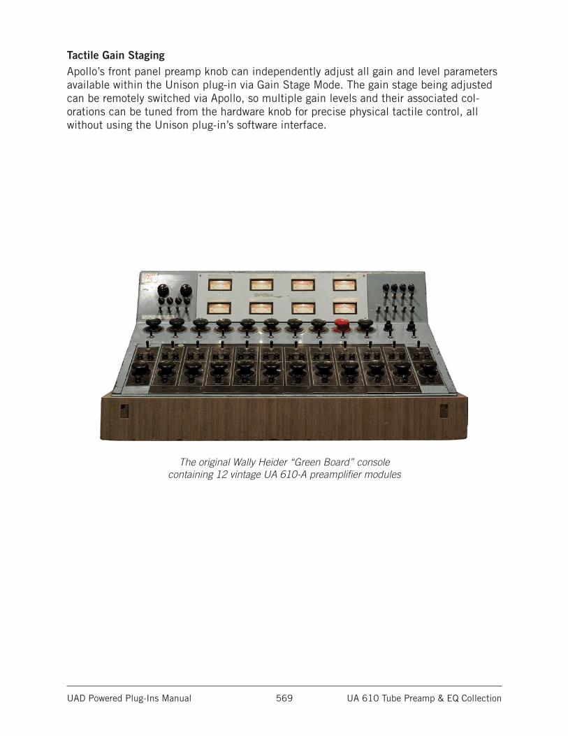
UAD Powered Plug-Ins Manual UA 610 Tube Preamp & EQ Collection 569
Tactile Gain StagingApollo’s front panel preamp knob can independently adjust all gain and level parameters available within the Unison plug-in via Gain Stage Mode. The gain stage being adjusted can be remotely switched via Apollo, so multiple gain levels and their associated col-orations can be tuned from the hardware knob for precise physical tactile control, all without using the Unison plug-in’s software interface.
The original Wally Heider “Green Board” console containing 12 vintage UA 610-A preamplifier modules
UAD Powered Plug-Ins Manual UA 610 Tube Preamp & EQ Collection 570
Input Level ControlsInput levels for the UA 610 plug-ins are controlled by the overall combination of the input select, pad, and gain controls available within each plug-in.
These parameters, which vary per model, control the first tube gain stage in the plug-ins. Generally speaking, higher input gains will produce more color in the signal.
Input SelectThe 610 hardware has both mic and line level inputs. The Input Select control switches between the “virtual input jacks” in the emulated models.
In most mic preamplifiers (including the 610), the difference between the mic and line inputs is simply that the line input is attenuated before entering the preamp circuitry. The gain circuits are not different for the mic and line inputs.
LineWhen set to Line, it’s as if the DAW signal is plugged into the line level input of the emu-lated 610 hardware. Less tube gain is applied, and a cleaner sound is obtained.
MicWhen set to Mic (with UA 610-B, the 500 and 2.0K settings), it’s as if the DAW signal is plugged into the microphone input of the emulated 610 hardware and approximately 30 dB of additional (unattenuated) tube gain is applied. Since the incoming signal in from the DAW is already at line level, this mode will more readily result in the tube color, saturation, and/or clipping associated with overdriving the input.
Important: Use caution when switching to Mic from Line, as signal output levels can increase significantly (as they would with a hardware preamp).
UA 610-AMic and Line inputs are available. The mic input impedance of the 610-A hardware is 600.
UA 610-BMic and Line inputs are available, with the additional availability of input impedance selections for the Mic input. The Mic input can be switched to 500 or 2K; the different input impedances have subtle effects on the signal color and response.
Unison ImpedanceWhen UA 610-A or UA 610-B is used in an INPUT insert within the Apollo Console application, the hardware input impedance of the Apollo mic preamp is switched to match the value in the plug-in for physical, microphone-to-preamp resistive interaction.
With UA 610-B, matching the microphone to the closest impedance value is generally recommended, but this parameter can be used creatively and will not harm equipment connected to the Apollo mic preamp.
Note: For complete Unison details, see the Apollo Software Manual.
UAD Powered Plug-Ins Manual UA 610 Tube Preamp & EQ Collection 571
Input Pad/GainIn addition to the Input Select switch, both plug-in models have Pad and Gain param-eters that control the signal level at the tube input stage.
The Pad controls are used to attenuate incoming signals for less coloration, while the Gain controls increase the signal level for more tube color.
Note: Like the original hardware, values on the control labels may not match actual measured values.
UA 610-A
Input Gain
The two-position LOW/HI rotary switch exposes the little-known internal gain jumpers that are on the circuit boards inside the vintage modules. Setting the switch to the HI position adds approximately 8 dB of gain at the tube input stage and also changes the distortion characteristics. This is a digital-only control unavailable on the original hard-ware module.
Important: Use caution when switching 610-A Gain from LOW to HI, as signal output levels could jump dramatically.
Input Pad
Additional attenuation for the Mic input is available via the two-position Pad switch. Setting the switch to the “-20” (up) position attenuates the Mic signal at the tube input stage by -20 dB. In the down position, no attenuation is applied.
Note: The 610-A Input Pad is not available for line input.
UA 610-B
Input Gain
The 5-position rotary Gain switch changes the level at the tube input stage. The control attenuates the input signal by -10 or -5 dB, or adds +5 or +10 dB of gain. In the center “0” position, neither gain nor attenuation is applied.
Input Pad
Additional attenuation for the Mic input is available via the two-position Pad switch. Setting the switch to the “-15” (up) position attenuates the Mic signal at the tube input stage by -15 dB. In the down position, no attenuation is applied.
Note: The 610-B Input Pad is not available for line input.
UAD Powered Plug-Ins Manual UA 610 Tube Preamp & EQ Collection 572
Output Level Controls
LevelLevel (aka “the big knob”) is used to control the gain of the tube output stage of the preamp. Higher values add more coloration.
The amount of available gain using this control is approximately 61 dB for both plug-in models.
OutputOutput adjusts the signal level at the output of the plug-in without effecting the sonic character of the signal. The range is from -∞ dB (off) to +12 dB.
This control, which does not exist on the original hardware, facilitates the ability to maximize color of the overall signal. For example, Gain and Level can be cranked for more distortion, while lowering Output to normalize levels. This is similar to having the line output of a 610 plugged into a console and using the console fader to pad the output of the 610.
Tip: Click the “0” label text above the control to return Output to 0 dB.
EQThe UA 610 preamps feature high and low frequency boost/cut shelving filters with stepped gain controls. The equalizers utilize a feedback-style design which effects the distortion characteristics of the output stage.
UA 610-AThe low frequency (“L.F.”) shelf EQ has a fixed cutoff frequency of 100 Hz.
Lo EQ Gain
This rotary switch determines the amount of boost or cut applied to the low frequency signal. Fixed values of ±6 dB or 0 dB can be selected. When set to 0 dB, the filter is inactive.
UA 610-BThe low frequency (“LO”) shelf EQ has a selectable cutoff frequency which can be cut or boosted by various amounts.
Lo EQ Frequency
This switch determines the cutoff frequency (70, 100, or 200 Hz) of the low shelf EQ. This switch has no effect if the Lo EQ Gain value is zero.
Note: As with the hardware, low frequency values are not consecutively ordered.
Lo EQ Gain
This rotary switch determines the amount of boost or cut applied to the low frequency signal. Fixed values of plus or minus 9, 6, 4.5, 3, or 1.5 dB can be selected. When set to 0 dB, the filter is inactive.
UAD Powered Plug-Ins Manual UA 610 Tube Preamp & EQ Collection 573
High EQ
UA 610-AThe high frequency (“H.F.”) shelf EQ has a fixed cutoff frequency of 10 kHz.
Hi EQ Gain
This rotary switch determines the amount of boost or cut applied to the high frequency signal. Fixed values of -6, 0, +3, or +6 dB can be selected. When set to 0 dB, the filter is inactive.
UA 610-BThe high frequency (“HI”) shelf EQ has a selectable cutoff frequency which can be cut or boosted by various amounts.
Hi EQ Frequency
This switch determines the cutoff frequency (4.5 kHz, 7 kHz, or 10 kHz) of the high shelf EQ. This switch has no effect if the Hi EQ Gain value is zero.
Note: Like the hardware, high frequency values are not consecutively ordered.
Hi EQ Gain
This rotary switch determines the amount of boost or cut applied to the high frequency signal. Fixed values of plus or minus 9, 6, 4.5, 3, or 1.5 dB can be selected. When set to 0 dB, the filter is inactive.
PolarityThis switch inverts the polarity (“phase”) of the signal. The signal polarity is inverted when the switch is in the up position. Polarity is normal when the switch is in the down position. Polarity inversion can help reduce phase cancellations when more than one microphone is used to record a single source.
When either plug-in is used in an INPUT insert within Apollo’s Console applica-tion, software and hardware control of polarity is mirrored. Polarity can be inverted within the plug-in interface or by using Apollo’s polarity button.
PowerPower is the plug-in bypass control. When set to OFF, emulation processing is disabled and DSP usage is reduced (if DSP LoadLock is inactive).
Power is useful for comparing the processed settings to the original signal.
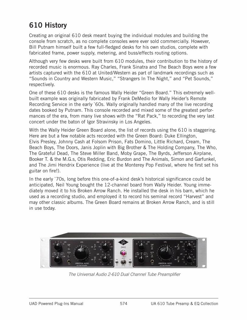
UAD Powered Plug-Ins Manual UA 610 Tube Preamp & EQ Collection 574
610 HistoryCreating an original 610 desk meant buying the individual modules and building the console from scratch, as no complete consoles were ever sold commercially. However, Bill Putnam himself built a few full-fledged desks for his own studios, complete with fabricated frame, power supply, metering, and buss/effects routing options.
Although very few desks were built from 610 modules, their contribution to the history of recorded music is enormous. Ray Charles, Frank Sinatra and The Beach Boys were a few artists captured with the 610 at United/Western as part of landmark recordings such as “Sounds in Country and Western Music,” “Strangers In The Night,” and “Pet Sounds,” respectively.
One of these 610 desks is the famous Wally Heider “Green Board.” This extremely well-built example was originally fabricated by Frank DeMedio for Wally Heider’s Remote Recording Service in the early `60s. Wally originally handled many of the live recording dates booked by Putnam. This console recorded and mixed some of the greatest perfor-mances of the era, from many live shows with the “Rat Pack,” to recording the very last concert under the baton of Igor Stravinsky in Los Angeles.
With the Wally Heider Green Board alone, the list of records using the 610 is staggering. Here are but a few notable acts recorded with the Green Board: Duke Ellington, Elvis Presley, Johnny Cash at Folsom Prison, Fats Domino, Little Richard, Cream, The Beach Boys, The Doors, Janis Joplin with Big Brother & The Holding Company, The Who, The Grateful Dead, The Steve Miller Band, Moby Grape, The Byrds, Jefferson Airplane, Booker T. & the M.G.s, Otis Redding, Eric Burdon and The Animals, Simon and Garfunkel, and The Jimi Hendrix Experience (live at the Monterey Pop Festival, where he first set his guitar on fire!).
In the early `70s, long before this one-of-a-kind desk’s historical significance could be anticipated, Neil Young bought the 12-channel board from Wally Heider. Young imme-diately moved it to his Broken Arrow Ranch. He installed the desk in his barn, which he used as a recording studio, and employed it to record his seminal record “Harvest” and may other classic albums. The Green Board remains at Broken Arrow Ranch, and is still in use today.
The Universal Audio 2-610 Dual Channel Tube Preamplifier
UAD Powered Plug-Ins Manual Additional Latency 575
Additional Latency
Some UAD plug-ins introduce additional latency within the plug-in itself (in addition to hardware I/O buffering latency) to achieve sonic design goals. When these plug-ins are used in a DAW and/or Apollo’s Console, the additional latency is induced in the signal path. Therefore, they require more compensation to remain perfectly synchronized with other tracks, versus UAD plug-ins that do not have additional latency.
Note: Compensating for the additional latency from these UAD plug-ins is performed automatically by the host software application (DAW and/or Apollo’s Console) when the latency delay compensation function is enabled in the host.
Although the latency added by these UAD plug-ins is negligible (typically between 0 – 100 samples, depending on the plug-in and session sample rate), if this extra latency is not compensated, it can affect phase coherency in a session.
The additional latency values, in samples, of UAD plug-ins with additional latency are listed in this chapter for the benefit of users with plug-in host DAWs that do not perform automatic delay compensation.
For related details, see the “Latency & Delay Compensation” chapter in the UAD System Manual, and the “Latency & Apollo” chapter in the Apollo Software Manual.
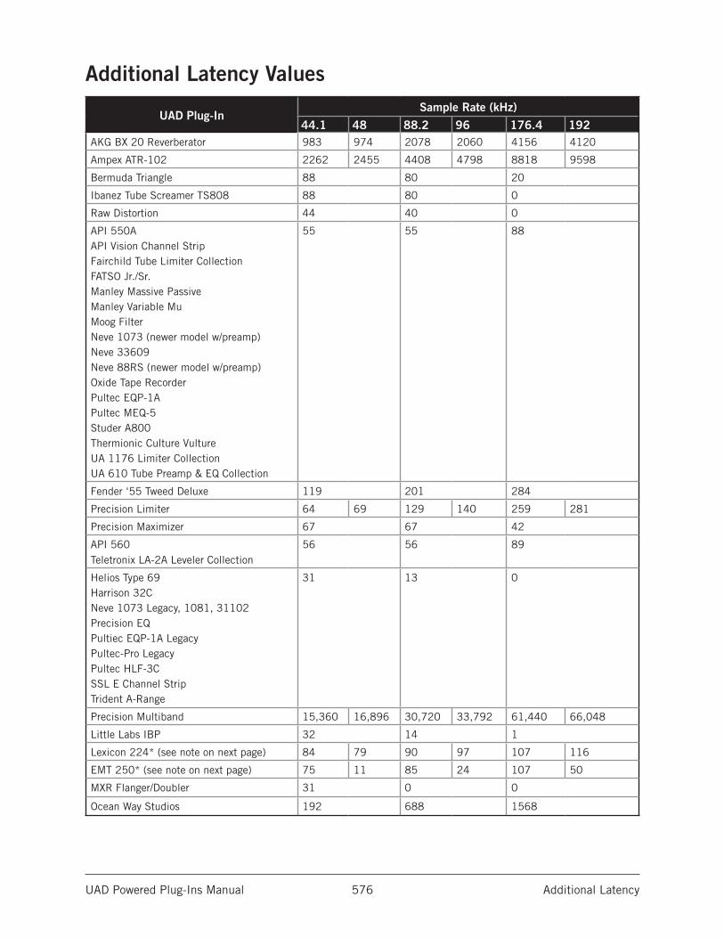
UAD Powered Plug-Ins Manual Additional Latency 576
Additional Latency Values
UAD Plug-InSample Rate (kHz)
44.1 48 88.2 96 176.4 192AKG BX 20 Reverberator 983 974 2078 2060 4156 4120
Ampex ATR-102 2262 2455 4408 4798 8818 9598
Bermuda Triangle 88 80 20
Ibanez Tube Screamer TS808 88 80 0
Raw Distortion 44 40 0
API 550AAPI Vision Channel StripFairchild Tube Limiter CollectionFATSO Jr./Sr.Manley Massive PassiveManley Variable MuMoog FilterNeve 1073 (newer model w/preamp)Neve 33609Neve 88RS (newer model w/preamp)Oxide Tape RecorderPultec EQP-1APultec MEQ-5Studer A800Thermionic Culture VultureUA 1176 Limiter CollectionUA 610 Tube Preamp & EQ Collection
55 55 88
Fender ‘55 Tweed Deluxe 119 201 284
Precision Limiter 64 69 129 140 259 281
Precision Maximizer 67 67 42
API 560Teletronix LA-2A Leveler Collection
56 56 89
Helios Type 69Harrison 32CNeve 1073 Legacy, 1081, 31102Precision EQPultiec EQP-1A LegacyPultec-Pro LegacyPultec HLF-3CSSL E Channel StripTrident A-Range
31 13 0
Precision Multiband 15,360 16,896 30,720 33,792 61,440 66,048
Little Labs IBP 32 14 1
Lexicon 224* (see note on next page) 84 79 90 97 107 116
EMT 250* (see note on next page) 75 11 85 24 107 50
MXR Flanger/Doubler 31 0 0
Ocean Way Studios 192 688 1568
UAD Powered Plug-Ins Manual Additional Latency 577
*NoteThe EMT 250 and Lexicon 224 anti-aliasing filters for their A/D and D/A conversion are not linear-phase filters; therefore the emulations do not have a latency that is the same at all frequencies. Thus, we cannot report to the delay compensation engines a delay that is correct for all frequencies. The reported values are good at low frequencies, but become off at high frequencies.
For example, when the EMT 250 plug-in is in Delay program mode and set with zero delay time and predelay values, the plug-in output will not be completely cancelled when mixing with inverted polarity against an unprocessed track; high frequencies will leak through. However, the latency through the dry side of the wet/dry mix, and the latency when the plug-in is bypassed via the EMT 250 Power switch, do not have this issue and will be fully compensated by the DAW.
UAD Powered Plug-Ins Manual Notices 578
Notices
DisclaimerThe information contained in this manual is subject to change without notice. Universal Audio, Inc. makes no warranties of any kind with regard to this manual, including, but not limited to, the implied warranties of merchantability and fitness for a particular purpose. Universal Audio, Inc. shall not be liable for errors contained herein or direct, indirect, special, incidental, or consequential damages in connection with the furnishing, performance, or use of this material.
End User License AgreementYour rights to the Software are governed by the accompanying End User License Agreement, a copy of which can be found at: www.uaudio.com/eula
TrademarksUniversal Audio, the Universal Audio “diamond” logo, Apollo, Apollo Twin, Apollo 16, Unison technology, UAD, UAD Series, UAD-1, UAD-2, UAD-2 Satellite, Powered Plug-Ins, 1176LN, 1176SE, Teletronix, LA-2A, LA-3A, LA-610, LA-610MkII, 2-1176, 2-610, 6176, 710 Twin-Finity, 2192, 4-710d, Cambridge EQ, DreamVerb, Plate 140, Precision Limiter, RealVerb Pro, Precision Buss Compressor, Precision De-Esser, Precision Maximizer, and “Analog Ears | Digital Minds,” are among the trademarks, trade names, and service marks owned by UA that may appear on the Site, many of which are registered in the United States and other countries. This is not a comprehensive list of all UA trademarks. All UA trademarks inure to the benefit of UA. Other trademarks and trade names that may appear on the Site and which are not owned by UA are owned by the respective owners.
CopyrightCopyright ©2016 Universal Audio, Inc. All rights reserved.
This manual and any associated software, artwork, product designs, and design concepts are subject to copyright protection. No part of this document may be reproduced, in any form, without prior written permission of Universal Audio, Inc.

UAD System Manual Technical Support 579
Technical Support
UA Website & Knowledge BaseThe support area of the Universal Audio website is your complete technical resource for configuring, operating, and troubleshooting UA products.
You can watch helpful support videos, search the Knowledge Base for answers, find updated technical information that may not be available in other publications, and more.
• help.uaudio.com
YouTube Support ChannelThe Universal Audio Support Channel at youtube.com includes helpful support videos for setting up and using UA products.
• Universal Audio YouTube Support Channel
UAD Community ForumsThe unofficial UAD discussion forums are a valuable resource for all Universal Audio product users. This website is independently owned and operated.
• www.uadforum.com
Contact UA SupportUniversal Audio provides free technical support to registered product owners. Support specialists are available to answer technical inquiries via email and telephone.
• help.uaudio.com
Related Documents