Advanced techniques for computer-controlled polishing Markus Schinhaerl ab , Richard Stamp b , Elmar Pitschke ab , Rolf Rascher a , Lyndon Smith b , Gordon Smith b , Andreas Geiss a , Peter Sperber a a University of Applied Sciences Deggendorf, Edlmairstr. 6+8, 94469 Deggendorf, Germany b University of the West of England, Coldharbour Lane, Bristol, England ABSTRACT Computer-controlled polishing has introduced determinism into the finishing of high-quality surfaces, for example those used as optical interfaces. Computer-controlled polishing may overcome many of the disadvantages of traditional polishing techniques. The polishing procedure is computed in terms of the surface error-profile and the material removal characteristic of the polishing tool, the influence function. Determinism and predictability not only enable more economical manufacture but also facilitate considerably increased processing accuracy. However, there are several disadvantages that serve to limit the capabilities of computer-controlled polishing, many of these are considered to be issues associated with determination of the influence function. Magnetorheological finishing has been investigated and various new techniques and approaches that dramatically enhance the potential as well as the economics of computer-controlled polishing have been developed and verified experimentally. Recent developments and advancements in computer-controlled polishing are discussed. The generic results of this research may be used in a wide variety of alternative applications in which controlled material removal is employed to achieve a desired surface specification, ranging from surface treatment processes in technical disciplines, to manipulation of biological surface textures in medical technologies. Keywords: Computer-controlled polishing, CCP, Influence function, Dwell time method, Magnetorheological finishing, MRF 1. INTRODUCTION Specifications for high-quality surfaces, for example precision optical lenses, are becoming more and more strin- gent. Many modern optical systems depend on high-precision aspherical components. 1–4 However, traditional polishing techniques often fail in the production of such complex surfaces. 5–10 Therefore, new production meth- ods have been developed to satisfy these demands. 9, 11–18 Computer-controlled polishing is one of the latest developments in overcoming the disadvantages of conventional polishing, and not only enables the manufacture of complex surfaces but also achieves high quality results and an increase in production economics. 10, 19–24 1.1 Computer-controlled polishing Computer-controlled polishing is a deterministic material removal process. 25, 26 It requires precise computer numerical control (CNC) to operate the polishing tool, the size of which is small compared to the size of the workpiece surface (sub-aperture polishing tool). 27, 28 This allows material to be removed in small, controlled locations from the workpiece surface 4 and thus facilitates error dependent polishing. 29 The dwell time method is an effective and commonly used technique for controlling material removal. 30, 31 It requires detailed knowledge of both the surface error-profile and the material removal characteristic of the polishing tool. 32 Based on a constant material removal rate of the polishing tool during the process, the amount of material removed at the contact location between the polishing tool and the workpiece surface is controlled via variation in the duration of the contact time. 33, 34 The longer the contact time duration, the more material is removed. 35–37 The dwell time of the polishing tool for each particular position on the workpiece surface is calculated in terms of the surface-error profile and the material removal characteristic of the polishing tool. This results in the polishing tool velocity profile. Further author information: (Send correspondence to Markus Schinhaerl) Markus Schinhaerl: E-mail: [email protected], Telephone: +49 (0)991 3615 374 Current Developments in Lens Design and Optical Engineering IX, edited by Pantazis Z. Mouroulis, Warren J. Smith, R. Barry Johnson, Proc. of SPIE Vol. 7060, 70600Q, (2008) 0277-786X/08/$18 · doi: 10.1117/12.808036 Proc. of SPIE Vol. 7060 70600Q-1 2008 SPIE Digital Library -- Subscriber Archive Copy

Welcome message from author
This document is posted to help you gain knowledge. Please leave a comment to let me know what you think about it! Share it to your friends and learn new things together.
Transcript
Advanced techniques for computer-controlled polishing
Markus Schinhaerlab, Richard Stampb, Elmar Pitschkeab, Rolf Raschera, Lyndon Smithb,Gordon Smithb, Andreas Geissa, Peter Sperbera
aUniversity of Applied Sciences Deggendorf, Edlmairstr. 6+8, 94469 Deggendorf, GermanybUniversity of the West of England, Coldharbour Lane, Bristol, England
ABSTRACT
Computer-controlled polishing has introduced determinism into the finishing of high-quality surfaces, for examplethose used as optical interfaces. Computer-controlled polishing may overcome many of the disadvantages oftraditional polishing techniques. The polishing procedure is computed in terms of the surface error-profile and thematerial removal characteristic of the polishing tool, the influence function. Determinism and predictability notonly enable more economical manufacture but also facilitate considerably increased processing accuracy. However,there are several disadvantages that serve to limit the capabilities of computer-controlled polishing, many of theseare considered to be issues associated with determination of the influence function. Magnetorheological finishinghas been investigated and various new techniques and approaches that dramatically enhance the potential aswell as the economics of computer-controlled polishing have been developed and verified experimentally. Recentdevelopments and advancements in computer-controlled polishing are discussed. The generic results of thisresearch may be used in a wide variety of alternative applications in which controlled material removal is employedto achieve a desired surface specification, ranging from surface treatment processes in technical disciplines, tomanipulation of biological surface textures in medical technologies.
Keywords: Computer-controlled polishing, CCP, Influence function, Dwell time method, Magnetorheologicalfinishing, MRF
1. INTRODUCTION
Specifications for high-quality surfaces, for example precision optical lenses, are becoming more and more strin-gent. Many modern optical systems depend on high-precision aspherical components.1–4 However, traditionalpolishing techniques often fail in the production of such complex surfaces.5–10 Therefore, new production meth-ods have been developed to satisfy these demands.9, 11–18 Computer-controlled polishing is one of the latestdevelopments in overcoming the disadvantages of conventional polishing, and not only enables the manufactureof complex surfaces but also achieves high quality results and an increase in production economics.10, 19–24
1.1 Computer-controlled polishing
Computer-controlled polishing is a deterministic material removal process.25, 26 It requires precise computernumerical control (CNC) to operate the polishing tool, the size of which is small compared to the size of theworkpiece surface (sub-aperture polishing tool).27, 28 This allows material to be removed in small, controlledlocations from the workpiece surface4 and thus facilitates error dependent polishing.29 The dwell time method isan effective and commonly used technique for controlling material removal.30, 31 It requires detailed knowledge ofboth the surface error-profile and the material removal characteristic of the polishing tool.32 Based on a constantmaterial removal rate of the polishing tool during the process, the amount of material removed at the contactlocation between the polishing tool and the workpiece surface is controlled via variation in the duration of thecontact time.33, 34 The longer the contact time duration, the more material is removed.35–37 The dwell time ofthe polishing tool for each particular position on the workpiece surface is calculated in terms of the surface-errorprofile and the material removal characteristic of the polishing tool. This results in the polishing tool velocityprofile.
Further author information: (Send correspondence to Markus Schinhaerl)Markus Schinhaerl: E-mail: [email protected], Telephone: +49 (0)991 3615 374
Current Developments in Lens Design and Optical Engineering IX, edited by Pantazis Z. Mouroulis,Warren J. Smith, R. Barry Johnson, Proc. of SPIE Vol. 7060, 70600Q, (2008)
0277-786X/08/$18 · doi: 10.1117/12.808036
Proc. of SPIE Vol. 7060 70600Q-12008 SPIE Digital Library -- Subscriber Archive Copy

level Isaieyrlq
pniiueservl pnirleiIo pniiueservl saiveb saiveb enirlasm
— H eoeiqiow
ineupeeduC pnirIeiIo euoiveiq inemeiueeem eeeooiq inemeiueeem
I I
level eo2 -10110 eashue -10110 eoelu2
iefle eliloiq eioed eliloiq
eIie ,Ioerlo 'iIeup I %aiIeuO
J
-10110 eoeIiue ecu )I301I3 iefle eliloiq
erli o noijeluolsO iou1ieni fl Ilewb Iooi pnirleiloq eliloiq emii
t Iooi pnirIeiIo eoeiq,IioW
oiieiieioeierlo riemoep
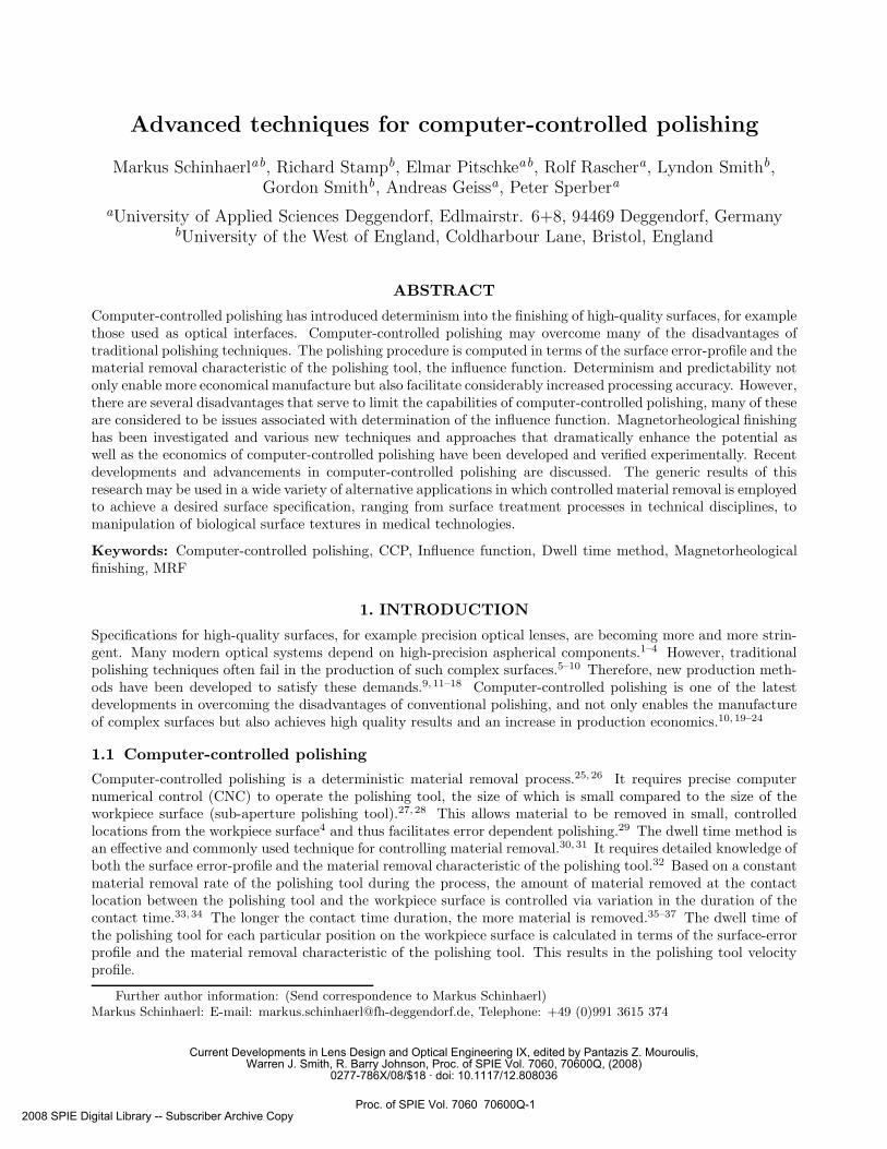
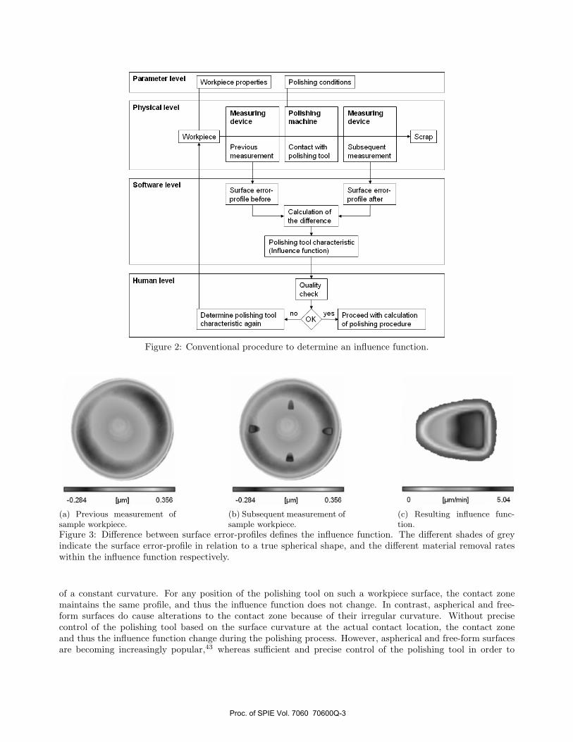
A computer-controlled polishing process normally consists of three steps (see Figure 1).26 The first step ismeasurement of the surface to obtain its error-profile. The second step is the actual polishing procedure. Thecalculated dwell time profile is converted into a CNC program, which controls the polishing machine. The thirdstep is validation; the workpiece surface is re-measured to check its quality. If necessary, the workpiece may bepolished again.
Figure 1: Process schematic of computer-controlled polishing.
1.2 Polishing tool removal characteristic - influence function
The influence function describes the material removal characteristic of the polishing tool for a specific set ofworkpiece properties and polishing conditions and may be considered to be a calibration of the polishing tool.Knowledge of the influence function is essential for calculating a polishing procedure. Currently, the only effectivemethod for determining an influence function is trial-and-error.
Figure 2 shows that material removal is performed and tested on a sample workpiece of identical geometry andmaterial to the actual surface to be polished. Before and after measurement of the polished workpiece surface en-ables influence function quantification.37–39 Typically an average of four readings is taken in magnetorheologicalfinishing.
Figure 3 illustrates the results of the determination procedure of an example influence function in magne-torheological finishing (described later). In the case of magnetorheological finishing, the influence function iscommonly referred to as the Spot ,6, 40 which typically has the shape of a “sideways D”.41, 42 The greatest materialremoval rate is located almost at the centre and amounts to 5.04 µm/min in this example.
1.3 Current limitations of computer-controlled polishing
Currently, there are several, mainly influence function related drawbacks encountered in connection with thedwell time method, which limit the capabilities of computer-controlled polishing.
The dwell time method requires a constant influence function during the process. A basic requirement fora constant influence function is a constant size and shape of the contact zone between the workpiece surfaceand the polishing tool during the process. Flat and spherical surface geometries fulfil this requirement because
Proc. of SPIE Vol. 7060 70600Q-2
enoiiibnoo pnirIeiIo eeiheqoiq eoeiq,how level ieiemmoq
- pnnueseM eaiveb
- - pnirleiIo enhrlasm
- pnnueseM ealveb
level Isaieyrlq
J ineupeeduC inemeiueeem
rijiw ioeinoO Iooi pnirleiloq
euoiveiq inemeiueeem
-10110 eoehu8 -ioiie eoeiu8 iefle elfloiq eioed elfloiq
I_________ o eoneieflib olD
oiieiieioeierlo Iooi pnirIeiIo (noiionifi eaneunni)
level emwflo2
level nomuH yiileuo ,Ioerlo
noijeluolea rijiw beeooi 0V ° Iooi pnirleiloq enimiejea eiubeooiq pnirleiloq o niepe oiieiieioeierlo
0584 Ihuil
a
Is
0584 Ihuil 0 (I1W\UJ!IJ] 2O
Figure 2: Conventional procedure to determine an influence function.
(a) Previous measurement ofsample workpiece.
(b) Subsequent measurement ofsample workpiece.
(c) Resulting influence func-tion.
Figure 3: Difference between surface error-profiles defines the influence function. The different shades of greyindicate the surface error-profile in relation to a true spherical shape, and the different material removal rateswithin the influence function respectively.
of a constant curvature. For any position of the polishing tool on such a workpiece surface, the contact zonemaintains the same profile, and thus the influence function does not change. In contrast, aspherical and free-form surfaces do cause alterations to the contact zone because of their irregular curvature. Without precisecontrol of the polishing tool based on the surface curvature at the actual contact location, the contact zoneand thus the influence function change during the polishing process. However, aspherical and free-form surfacesare becoming increasingly popular,43 whereas sufficient and precise control of the polishing tool in order to
Proc. of SPIE Vol. 7060 70600Q-3
maintain a constant contact zone and thus a constant influence function is difficult to achieve using the mostusual processing machines.
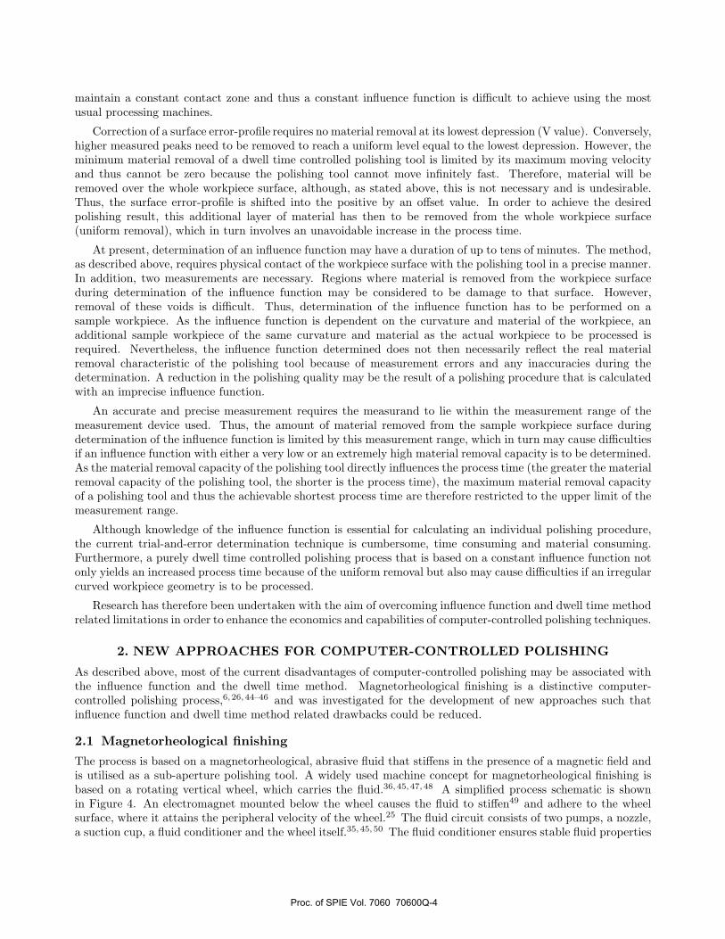
Correction of a surface error-profile requires no material removal at its lowest depression (V value). Conversely,higher measured peaks need to be removed to reach a uniform level equal to the lowest depression. However, theminimum material removal of a dwell time controlled polishing tool is limited by its maximum moving velocityand thus cannot be zero because the polishing tool cannot move infinitely fast. Therefore, material will beremoved over the whole workpiece surface, although, as stated above, this is not necessary and is undesirable.Thus, the surface error-profile is shifted into the positive by an offset value. In order to achieve the desiredpolishing result, this additional layer of material has then to be removed from the whole workpiece surface(uniform removal), which in turn involves an unavoidable increase in the process time.
At present, determination of an influence function may have a duration of up to tens of minutes. The method,as described above, requires physical contact of the workpiece surface with the polishing tool in a precise manner.In addition, two measurements are necessary. Regions where material is removed from the workpiece surfaceduring determination of the influence function may be considered to be damage to that surface. However,removal of these voids is difficult. Thus, determination of the influence function has to be performed on asample workpiece. As the influence function is dependent on the curvature and material of the workpiece, anadditional sample workpiece of the same curvature and material as the actual workpiece to be processed isrequired. Nevertheless, the influence function determined does not then necessarily reflect the real materialremoval characteristic of the polishing tool because of measurement errors and any inaccuracies during thedetermination. A reduction in the polishing quality may be the result of a polishing procedure that is calculatedwith an imprecise influence function.
An accurate and precise measurement requires the measurand to lie within the measurement range of themeasurement device used. Thus, the amount of material removed from the sample workpiece surface duringdetermination of the influence function is limited by this measurement range, which in turn may cause difficultiesif an influence function with either a very low or an extremely high material removal capacity is to be determined.As the material removal capacity of the polishing tool directly influences the process time (the greater the materialremoval capacity of the polishing tool, the shorter is the process time), the maximum material removal capacityof a polishing tool and thus the achievable shortest process time are therefore restricted to the upper limit of themeasurement range.
Although knowledge of the influence function is essential for calculating an individual polishing procedure,the current trial-and-error determination technique is cumbersome, time consuming and material consuming.Furthermore, a purely dwell time controlled polishing process that is based on a constant influence function notonly yields an increased process time because of the uniform removal but also may cause difficulties if an irregularcurved workpiece geometry is to be processed.
Research has therefore been undertaken with the aim of overcoming influence function and dwell time methodrelated limitations in order to enhance the economics and capabilities of computer-controlled polishing techniques.
2. NEW APPROACHES FOR COMPUTER-CONTROLLED POLISHING
As described above, most of the current disadvantages of computer-controlled polishing may be associated withthe influence function and the dwell time method. Magnetorheological finishing is a distinctive computer-controlled polishing process,6, 26, 44–46 and was investigated for the development of new approaches such thatinfluence function and dwell time method related drawbacks could be reduced.
2.1 Magnetorheological finishing
The process is based on a magnetorheological, abrasive fluid that stiffens in the presence of a magnetic field andis utilised as a sub-aperture polishing tool. A widely used machine concept for magnetorheological finishing isbased on a rotating vertical wheel, which carries the fluid.36, 45, 47, 48 A simplified process schematic is shownin Figure 4. An electromagnet mounted below the wheel causes the fluid to stiffen49 and adhere to the wheelsurface, where it attains the peripheral velocity of the wheel.25 The fluid circuit consists of two pumps, a nozzle,a suction cup, a fluid conditioner and the wheel itself.35, 45, 50 The fluid conditioner ensures stable fluid properties
Proc. of SPIE Vol. 7060 70600Q-4

eoeiq,how
quo noiioue
x jinu pninoiiieoq
qmuq
and thus a constant influence function, which is required by the dwell time method. A mixer mounted inside theconditioner stirs the fluid in order to prevent sedimentation and thus to ensure homogeneity of the fluid.5, 6 Apressure sensor and a flow meter are mounted in the fluid circuit. The ratio of both signals yields the viscosityof the fluid.51 To compensate for evaporative losses, a small pump drips water into the fluid in the conditioner,and the control system ensures a constant viscosity.6, 34 In addition, the fluid conditioner is equipped with aheat exchanger to maintain a constant temperature.6
A CNC controlled positioning unit grasps the workpiece, usu-
Figure 4: Schematic of magnetorheologicalfinishing process.
ally with a vacuum chuck,40, 51, 52 and manoeuvres it through theribbon of stiffened fluid on the wheel.6 To ensure a constant im-mersion depth, and thus a constant influence function during thepolishing process, it is necessary to pivot the workpiece about itscentre of curvature in case of a convex or concave shape.6, 53 Twolinear axes (X, Z) and one rotational axis (B), are needed53 inorder to polish the whole surface The workpiece simultaneouslyrotates (axis A) during machining.5, 52
The shear flow of the fluid in the gap between the wheel andthe workpiece41, 54 in the contact zone causes a high pressure ofthe fluid on the workpiece surface.49 The amount of materialremoved from a finite position on the workpiece surface is depen-dent on the calculated dwell time profile, and is controlled viavariation of the relative velocity of the workpiece.
Magnetorheological finishing is capable of polishing flat andspherical shaped surfaces.46, 50 Only the radius of curvature onconcave parts is limited by the radius of the wheel.6 To achievea smooth surface, good conformity of the polishing tool to theworkpiece surface is a fundamental requirement.12 Magnetorhe-ological finishing satisfies this demand, as the fluid, unlike rigid conventional polishing tools, adapts to theworkpiece surface.5, 45, 50 Aspherical and free-form geometries may thus be processed.48 Prismatic parts maybe processed by raster polishing by use of a Y axis, a feature of most modern magnetorheological finishing ma-chines.55, 56 Depending on the fluid type, magnetorheological finishing is applicable to a multitude of differentmaterials, such as optical glasses, dielectric single crystals, polycrystalline materials, semiconductors, metals andplastics,35, 57 infrared materials58 and even ceramics.59
2.2 Influence function quality
Polishing experiments with magnetorheological finishing have shown that, the more precisely an influence functionreflects the actual material removal characteristic of the polishing tool, the greater is the probability that thecalculated polishing procedure yields the desired result.60 However, it is difficult to judge how precisely aninfluence function represents the actual polishing tool characteristic prior to knowledge of the polishing result.Although it is a computer-controlled polishing process, experience of the machine operator is indispensable injudging the quality of an influence function. Nevertheless, subjective judgement is a matter of opinion and thusproblematic.
An automated quality check for influence functions has therefore been developed, which enables the suitabilityof an influence function to be judged objectively prior to processing, based on the symmetry of the influencefunction.60 The more symmetrical an influence function, the higher is its quality, and thus the greater is theprobability for a successful polishing procedure. Objective judgement of the polishing tool characteristic withrespect to a sufficient polishing result may now be based on this quality value.
2.3 Filter algorithm
The question arises as to whether the actual material removal characteristic of the polishing tool might be totallysymmetric and if slight deviations in the symmetry of an influence function may be caused by measurement orother system errors. To clarify this issue, a filter algorithm that renders an influence function symmetrical
Proc. of SPIE Vol. 7060 70600Q-5

has been developed.61 The quality improvement with respect to the peak valley (PV) value of the surfacespolished with the symmetrically rendered influence function was observed to average 14% greater than the PVvalue improvement of surfaces that were polished with the raw, unmodified influence function.61 The PV valueindicates the difference between the maximum positive (peak) deviation and the maximum negative (valley)deviation of the actual surface in relation to the ideal surface and is a value that is commonly used to judge thequality of the surface.15
(a) Original influ-ence function.
(b) Symmetricallyrendered influencefunction.
Figure 5: Magnetorheological finishinginfluence function.
Experimentation has shown that a significant improvement in thepolishing quality is only attainable if a symmetrical influence func-tion of a sufficiently high quality is available. If an influence functionis noted to have a low quality level, then deviations in its symmetrymay be attributed in general to an actual malfunction of the polishingtool, which in turn is the cause of the inadequate polishing quality. Agraphical representation of an influence function, as recorded prior toany modification is depicted in Figure 5a. Figure 5b shows the sameinfluence function after noise cancellation and symmetry adjustment.In the figures the shades of grey indicate the different removal rateswithin the influence function (compare with Figure 3c).
2.4 Minimal process time
The polishing time in computer-controlled polishing is dependentmainly on two parameters: the quantity of material to be removedfrom the workpiece surface and the removal rate. The sum of the ma-terial to be removed is quantified by the surface error-profile and theuniform removal that is attributed by the dwell time method, so as notto exceed the maximum possible contact velocity of the polishing tool(see section 1.3). The amount of material the polishing tool is capable of removing per unit time is referred to asthe influence function volume or the removal capacity of the influence function. Measurement of the workpiecesurface to be processed and determination of the influence function yield both the surface error-profile and theinfluence function volume. The required thickness of the uniform removal is calculated by the dwell time method.
The minimal process time may be calculated from these values, by division of the material to be removed,by the influence function volume. The process time predicted by the dwell time method may then be comparedwith the minimal process time. If the minimal process time is exceeded significantly, the size of the influencefunction is inappropriate. Optimisation of the influence function size by choosing more appropriate polishing toolparameters enabled a 9% reduction in the process time during polishing experiments with magnetorheologicalfinishing.62
In computer-controlled polishing, material removal usually occurs successively, for example line by line (rasterpolishing) or spirally. Thus, the greater the size of a polishing tool, the longer is the clearance length at the rimsof the workpiece surface and therefore the longer is the time to cover this distance. Furthermore, the greater thesize of the polishing tool perpendicular to its moving direction, the greater is the area on the workpiece surfacefrom which material is simultaneously removed. This unwanted but unavoidable simultaneous material removalrequires the dwell time method to increase the thickness of the uniform removal, which in turn causes an increasein the process time. As a result, the smaller the size of a polishing tool, the smaller is the difference betweenthe actual process time and the minimal process time. However, the real process time cannot coincide with theminimal process time because a polishing tool cannot be infinitely small.62
Although the influence function may have a suitable quality value, and may be rendered symmetrical usingthe filter algorithm described above to further enhance the polishing quality, the size of the influence functionmay nevertheless still be inappropriate and thus may needlessly increase the process time. Objective judgementof the influence function size with respect to the process time may now be based on the “Minimal Process Time”technique developed. If the difference between the minimal process time and the actual process time computedby the dwell time method exceeds a definite limit, the polishing tool parameters should be changed in order tooptimise the influence function size in such a manner that the process time reduces.
Proc. of SPIE Vol. 7060 70600Q-6
tbq 111*1 IbFOO — ISL*P ebc4 MltpJ (bixJ
0I Ioc
SSWOra tot (U I
I ,vwGtamJqGbJ 0ow104
0qg -N ouc Ob) I o3
tQ nop) 1152 __________flKie qe (WO) isa _____________
—
___________ ___________ 1191SiJ4 __________________
Lfq,p— —•• • — •—• l E4OJI
flhT!ItjA LsJ M lug, I jI
,o ID 0 0 40 W0
<A 14SM
0 0 400
o-oarI xi4k
20
N (u$1 -l 0 I
AOOJJC OJJJOIOlJ) ooMexaz
btWWflWOIW) a
atoImqrOow) n5
SbOIISLJ (ww) las——
r.uLw (WW)
flue —
ue W9tIrU q,p
SIN &N) lOW)
SIN w4J lOW)
knq,ecocukc)
YIN t (qsM)
SIN flIos i Ic€ooc 1KI
"02* 24l!OvSQ04W Wlfl
2.5 Mathematical influence function model
A mathematical model to calculate the polishing tool characteristic in magnetorheological finishing has beendeveloped and verified experimentally.63–65 The model replaces the present trial-and-error method of determiningan influence function. The model obviates the need to physically test the material removal on a sample workpiecesurface and thus neither a sample workpiece nor a previous and subsequent measurement is required. The modelenables an influence function, which is dependent on the workpiece properties and the polishing conditions, tobe calculated in a few seconds, and thus contributes to enhancement of the production economics.
Without a need for measurement, not only are measurement errors completely eliminated but also the max-imum removal capacity of the polishing tool and thus the achievable process time are no longer limited by ameasurement range. As the influence function model is also not restricted to a particular range, the maximumpossible material removal capacity is therefore limited only by the polishing tool itself. Thus, the influencefunction model facilitates short process times.
Rapid calculation of influence functions in connection with the “Minimal Process Time” technique enables anautomated and thus rapid optimisation of the influence function size in order to approximate the minimal processtime for a particular polishing procedure. The values of the influence function parameters that are determinedby the model may then be used and set at the polishing machine without special knowledge and experience ofthe machine operator.
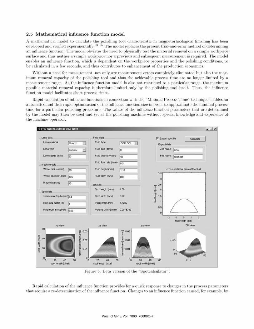
Figure 6: Beta version of the “Spotcalculator”.
Rapid calculation of the influence function provides for a quick response to changes in the process parametersthat require a re-determination of the influence function. Changes to an influence function caused, for example, by
Proc. of SPIE Vol. 7060 70600Q-7
variation in the polishing tool size during processing aspherical or free-form surfaces may therefore be consideredwithin the calculation of the dwell time profile. An enhanced dwell time method may thus enable a higherpolishing quality to be achieved.
A Beta version of the influence function model, which was implemented using MATLAB∗, is shown in Figure 6.The name “Spotcalculator” is derived from the simplified expression “Spot” for an influence function. As shown,the different parameters on which the influence function is dependent are summarised into four groups: lens,machine, spot and fluid parameters. Pressing the “Calculate” button starts computation of the influence function,which is then illustrated graphically as four different views. Important values, such as the size and volume ofthe influence function, are output as numerical values. The checkbox “Export spot file” may be used to convertthe calculated influence function to the machine-specific data format and to export it as a file, which may thenbe read and used by the polishing machine.
2.6 Time-variant influence functions
Within a dwell time based computer-controlled polishing process, the influence function is constant during theprocess (time-invariant influence function) and the material removal from the workpiece surface is controlled viavariation in the moving velocity of the polishing tool.
Another, and new, approach to controlling the material removal is the application of time-variant influencefunctions.66 In a time-variant influence function based computer-controlled polishing process, the polishingtool moves constantly at its maximum possible moving velocity across the surface to be polished. The amountof material removed from the workpiece surface acts in accordance with the material removal capacity of thepolishing tool. The greater the material removal capacity, the greater is the amount of material removed; theconverse is also true. Precise alteration of the material removal capacity during the polishing process (time-variant influence function) enables the surface error-profile to be removed.66
Knowledge of both the surface error-profile and the relationships between the different parameters and theresulting influence function is essential in order to calculate the necessary alterations to the material removalcapacity of the polishing tool during polishing (influence function alteration profile). The mathematical influencefunction model provides the relationships between the different parameters and the resulting influence functionand thus provides the first step towards application of time-variant influence functions. If correction of a surfaceerror-profile requires a material removal capacity that exceeds the maximum possible material removal capacityof the polishing tool, the dwell time method becomes important again. A reduction in the maximum movingvelocity of the polishing tool will cause an increase of its removal capacity. In contrast, as soon as correction ofthe surface error-profile requires no material removal at its lowest point (V value), the material removal capacityof the polishing tool may be set to zero. This is possible because, for example, the polishing tool may be movedaway from the workpiece surface and will thus be out of contact, which in turn causes no material removal.Therefore, a time-variant influence function controlled polishing process requires no uniform removal, comparedwith a purely dwell time controlled polishing process with a time-invariant influence function. A combination ofthe dwell time method and time-variant influence functions resulted in an approximately 35% reduction in theprocess time.66
Furthermore, application of time-variant influence functions not only may significantly reduce the processtime but also may contribute to an enhanced polishing quality if a surface with an irregular curvature (asphericaland free-form surfaces) is to be processed. Variations in the influence function caused by a changing size of thecontact zone between the polishing tool and the workpiece may be considered and incorporated in the calculationof the influence function alteration profile and the dwell time profile in order to control the polishing process.
3. DISCUSSION
Research was undertaken to investigate the use of computer-controlled polishing in the field of high-quality opti-cal lens production. In particular, magnetorheological finishing was used as a platform to develop new techniquesthat improve and extend the capabilities of computer-controlled polishing. A mathematical influence function
∗MATLAB is a numerical computing environment and programming language, created by The MathWorks, Inc.(http://www.mathworks.com).
Proc. of SPIE Vol. 7060 70600Q-8
model for magnetorheological finishing was developed. The advantage of this new model is that it enables preciseand rapid calculation of influence functions, irrespective of the skills and expertise of the machine operator. Thedifferent parameters and their effects on the influence function were researched and used to establish the novelmathematical model. The simulation and modeling techniques developed enable simple modification and adap-tation of the model for material removal processes other than magnetorheological finishing. Influence functioncriteria that are important for high polishing quality and short process times were investigated and were gener-alised for material removal methods that use influence functions for process control. A significant achievementof this study was the development of time-variant influence functions. The results of fundamental research onthis new approach may serve as guidelines for the development of in-process controlled material removal meth-ods. This study contributes to a continuous technology progression and provides improved techniques, toolsand procedures for computer-controlled polishing. The generic results of this research may be used in a widevariety of alternative applications in which controlled material removal is employed to achieve a desired surfacespecification, ranging from mechanical to chemical-based material removal processes in technical disciplines upto optically driven technologies in health care, such as the Laser In Situ Keratomileusis (LASIK) to correctametropia in human eyes. The cornea is measured to determine its error-profile and is then reshaped using alaser beam - a typical computer-controlled, error-dependent, and thus corrective, material removal process.
4. CONCLUSIONS
Satisfying current demands for high-precision surfaces, such as optical lenses, necessitated the development ofnew and innovative polishing techniques. Even though computer-controlled polishing is one answer to overcomingthe disadvantages of traditional polishing, it also creates new deficiencies. Investigation of magnetorheologicalfinishing enabled development of various new techniques in order to enhance computer-controlled polishing. Inparticular, influence function related drawbacks could be reduced tremendously. From the results of practicalapplication of the new approaches and techniques, the following conclusions may be drawn.
• The more symmetrical an influence function, the greater is the probability of a correctly working polishingtool and thus the greater is the probability of achieving a high polishing quality.
• Rendering an influence function symmetrical and filtering noisy data compensate for measurement errorsand inaccuracies in the conventional determination procedure of an influence function and thus enableenhancement of the polishing quality. Surfaces polished with a symmetrically rendered influence functionhad an average 14% greater quality improvement with respect to the PV value than those polished withan unmodified, original influence function.
• A small size of the polishing tool is appropriate in order to approach the minimum process time. Optimi-sation of the influence function size resulted in a 9% reduction in the process time.
• A computer-controlled polishing process that is based on a time-variant influence function will require nouniform removal and thus dramatically reduce process time. Combination of the dwell time method andtime-variant influence functions enabled a reduction in the process time by 35% in tests.
• Artificial calculation of influence functions with a mathematical model not only reduces set-up times butalso facilitates an enhanced polishing quality.
The methods and approaches developed and summarised in this paper provide a new and important contri-bution to the development of techniques for error dependent computer-controlled polishing and not only enableconsiderably improved and more economical manufacture with higher quality to be achieved but also aid pro-duction processes in which computer-controlled machinery is used and for which knowledge of the polishing toolcharacteristic is necessary for series manufacture.
ACKNOWLEDGMENTS
This work was funded by the “High Tech Offensive Zukunft Bayern” of the Bavarian Government, Germany.
Proc. of SPIE Vol. 7060 70600Q-9
REFERENCES1. O. W. Faehnle and H. van Brug, “Novel approaches to generate aspherical optical surfaces,” in Optical
Manufacturing and Testing III, 3782, pp. 170–180, SPIE, 1999.2. D. Golini, H. Pollicove, G. Platt, S. Jacobs, and W. Kordonsky, “Computer control makes asphere production
run of the mill,” Laser Focus World , pp. 83–91, September 1995.3. D. D. Walker, S. W. Kim, R. G. Bingham, D. Brooks, D.-H. Kim, and J. Thirtle, “Computer Controlled Pol-
ishing of Moderate-Sized General Aspherics for Instrumentation,” in Optical Astronomical Instrumentation,3355, pp. 947–954, SPIE, 1998.
4. H. Cheng, Z. Feng, and Y. Wang, “Optimizing parameters for magnetorheological finishing supersmoothsurface,” in Optical Design and Testing II, 5638, pp. 758–765, SPIE, 2005.
5. S. Hill, “Polished performance from MRF,” Materials World 8, pp. 23–24, 2000.6. D. Golini, S. Jacobs, W. Kordonski, and P. Dumas, “Precision optics fabrication using magnetorheological
finishing,” in Advanced Materials for optics and precision structures, pp. 251–274, SPIE, 1997.7. J. Wallace, “Semiflexible tools remove ripples,” Laser Focus World 38, pp. 17–18, 2002.8. G. Paula, “Automatic lens manufacturing,” Mechanical Engineering , pp. 88–91, March 1997.9. H. Pollicove and D. Golini, “Computer Numerically Controlled Optics Fabrication,” in International Trends
in Applied Optics Vol. 5, pp. 125–144, SPIE, 2002.10. S. D. Jacobs, “International innovations in optical finishing,” in Current Developments in Lens Design and
Optical Engineering V, 5523, pp. 264–272, SPIE, 2004.11. R. A. Jones, “Computer simulation of smoothing during computer-controlled optical polishing,” Applied
Optics 34, pp. 1162–1169, 1995.12. W. Rupp and V. Plotsker, “Vacuum activated polishing laps produce smooth aspheric surfaces,” Applied
Optics 32, pp. 1048–1050, 1993.13. M. Tricard, A. Shorey, P. Dumas, and M. DeMarco, “Extending the application of subaperture finishing,” in
2nd International Symposium on Advanced Optical Manufacturing and Testing Technologies: Optical Testand Measurement Technology and Equipment, 6150, p. 61501K ff, SPIE, 2006.
14. M. Tricard, P. Dumas, G. Forbes, and M. DeMarco, “Recent advances in sub-aperture approaches tofinishing and metrology,” in 2nd International Symposium on Advanced Optical Manufacturing and TestingTechnologies: Advanced Optical Manufacturing Technologies, 6149, p. 614903 ff, SPIE, 2006.
15. D. Malacara and B. J. Thompson, Handbook of Optical Engineering, pp. 915–957. Marcel Dekker, Inc.,2001.
16. K.-L. Yiu and H.-Y. Tam, “An alternate approach to free-form surface fabrication,” Journal of MaterialsProcessing Technology 192-193, pp. 465–469, 2007.
17. R. Boerret, A. Kelm, and H. Thiess, “High-speed form preserving polishing of precision aspheres,” in OpticalManufacturing and Testing VII, 6671, p. 667113 ff, SPIE, 2007.
18. R. Boerret, V. Giggel, and H. Wang, “ASPHERO5 - rapid fabrication of precise aspheres,” in OpticalFabrication, Testing, and Metrology II, 5965, p. 59650I ff, SPIE, 2005.
19. S. D. Jacobs, “Innovations in Polishing of Precision Optics Part I,” Convergence 11(1), pp. 1–7, 2003.20. H. Cheng, Z. Feng, and Y. Wu, “Fabrication of Off-Axis Aspherical Mirrors with Loose Abrasive Point-
Contact Machining,” in Key Engineering Materials, 257-258, pp. 153–158, 2004.21. R. A. Jones and W. J. Rupp, “Rapid optical fabrication with computer-controlled optical surfacing,” Optical
Engineering 30, pp. 1962–1968, 1991.22. T. K. Korhonen and T. Lappalainen, “Computer-controlled figuring and testing,” in Advanced Technology
Optical Telescopes IV, 1236, pp. 691–694, SPIE, 1990.23. R. Komanduri, D. A. Lucca, and Y. Tani, “Technological Advances in Fine Abrasive Processes,” Annals of
the CIRP 46, pp. 545–596, 1997.24. D. J. Bajuk, “Computer controlled generation of rotationally symmetric aspheric surfaces,” Optical Engi-
neering 15, pp. 401–406, 1976.25. H. Pollicove and D. Golini, “Deterministic Manufacturing Process for Precision Optical Surfaces,” in Key
Engineering Materials, 238-239, pp. 53–58, 2003.
Proc. of SPIE Vol. 7060 70600Q-10
26. S. D. Jacobs, D. Golini, Y. Hsu, B. E. Puchebner, and D. Strafford, “Magnetorheological finishing: adeterministic process,” in International Conference on Optical Fabrication and Testing, 2576, pp. 372–382,SPIE, 1995.
27. A. Y. Yi, M. Hezlep, and T. Pol, “A computer controlled optical pin polishing machine,” Journal of MaterialsProcessing Technology 146, pp. 156–162, 2004.
28. R. A. Jones, “Optimization of computer controlled polishing,” Applied Optics 16, pp. 218–224, 1977.29. S. Han, J. Choi, S. Lee, and H. Choi, “A Study of an Ultra-Precision CNC Polishing System,” in Key
Engineering Materials, 257-258, pp. 395–400, 2004.30. H. Lee and M. Yang, “Dwell time algorithm for computer-controlled polishing of small axis-symmetrical
aspherical lens mold,” Optical Engineering 40, pp. 1936–1943, 2001.31. T. W. Drueding, T. G. Bifano, and S. C. Fawcett, “Contouring algorithm for ion figuring,” Precision
Engineering 17(1), pp. 10–21, 1995.32. R. Aspden, R. McDonough, and J. Francis R. Nitchie, “Computer assisted optical surfacing,” Applied
Optics 11, pp. 2739–2747, 1972.33. R. G. Bingham, D. D. Walker, D.-H. Kim, D. Brooks, R. Freeman, and D. Riley, “A novel automated
process for aspheric surfaces,” in Current Developments in Lens Design and Optical Systems Engineering,4093, pp. 445–450, SPIE, 2000.
34. W. Kordonski and D. Golini, “Progress Update in Magnetorheological Finishing,” in Proceedings of the 6thInternational Conference on Electro-Rheological Fluids, pp. 837–844, World Scientific, 1998.
35. D. Golini, W. I. Kordonski, P. Dumas, and S. J. Hogan, “Magnetorheological finishing (MRF) in commercialprecision optics manufacturing,” in Optical manufacturing and testing III, 3782, pp. 80–91, SPIE, 1999.
36. S. D. Jacobs, S. R. Arrasmith, I. A. Kozhinova, L. L. Gregg, A. B. Shorey, and H. J. Romanofsky, “MRF:Computer-Controlled Optics Manufacturing,” The American Ceramic Society Bulletin 78, pp. 42–48, 1999.
37. E. Fess, J. Schoen, M. Bechtold, D. Mohring, and C. Bouvier, “UltraForm finishing process for opticalmaterials,” in Optical Manufacturing and Testing VI, 5869, pp. 88–93, SPIE, 2005.
38. D. D. Walker, R. Freeman, G. McCavana, R. Morton, D. Riley, J. Simms, D. Brooks, E. Kim, and A. King,“Zeeko/UCL Process for Polishing Large Lenses and Prisms,” in Large Lenses and Prisms, 4411, pp. 106–111, SPIE, 2002.
39. D. D. Walker, D. Brooks, R. Freeman, A. King, G. McCavana, R. Morton, D. Riley, and J. Simms, “Thefirst Aspheric Form and Texture Results From a Production Machine Embodying the Precession Process,”in Optical Manufacturing and Testing IV, 4451, pp. 267–276, SPIE, 2001.
40. S. R. Arrasmith, S. D. Jacobs, J. C. Lambropoulos, A. Maltsev, D. Golini, and W. I. Kordonski, “TheUse of Magnetorheological Finishing (MRF) to Relieve Residual Stress and Subsurface Damage on LappedSemiconductor Silicon Wafers,” in Optical manufacturing and testing IV, 4451, pp. 286–294, SPIE, 2001.
41. A. B. Shorey, L. L. Gregg, H. J. Romanofsky, S. R. Arrasmith, I. Kozhinova, J. Hubregsen, and S. D. Jacobs,“Study of material removal during magnetorheological finishing,” in Optical manufacturing and testing III,3782, pp. 101–111, SPIE, 1999.
42. J. E. DeGroote, A. E. Marino, J. P. Wilson, A. L. Bishop, and S. D. Jacobs, “The role of nanodiamonds inthe polishing zone during magnetorheological finishing (MRF),” in Optical Manufacturing and Testing VII,6671, p. 66710Z ff, SPIE, 2007.
43. A. Shorey, W. Kordonski, and M. Tricard, “Deterministic precision finishing of domes and conformal optics,”in Window and Dome Technologies and Materials IX, 5786, pp. 310–318, SPIE, 2005.
44. W. I. Kordonski and S. D. Jacobs, “Magnetorheological finishing,” International Journal of Modern PhysicsB 10, pp. 2837–2848, 1996.
45. D. Golini, “Precision optics manufacturing using magnetorheological finishing (MRF),” in Optical fabricationand testing, 3739, pp. 78–85, SPIE, 1999.
46. D. Golini, G. Schneider, P. Flug, and M. DeMarco, “Magnetorheological finishing,” Optics & Photonic News, pp. 20–24, October 2001.
47. B. Hallock, P. Dumas, A. Shorey, and M. Tricard, “Recent advances in deterministic low-cost finishing ofsapphire windows,” in Window and Dome Technologies and Materials IX, 5786, pp. 154–164, SPIE, 2005.
Proc. of SPIE Vol. 7060 70600Q-11

48. M. Tricard, A. Shorey, B. Hallock, and P. Murphy, “Cost-effective subaperture approaches to finishing andtesting astronomical optics,” in Optomechanical Technologies for Astronomy, 6273, p. 62730L ff, SPIE,2006.
49. C. Haobo, W. Yingwei, F. Zhijing, and C. Kai, “Surface roughness and removal rate in magnetorheologicalfinishing of a subsurface damage free surface,” Progress In Natural Science 15(6), pp. 538–544, 2005.
50. D. Golini, “Magnetorheological finishing automates precision optics fabrication,” Laser Focus World 34(9),pp. 187–190, 1998.
51. QED Technologies Q22-x Manual, www.qedmrf.com.52. X. Chen, J. Wang, Q. Xu, and Y. Wang, “A novel manufacturing method of off-axis parabola,” in 2nd
International Symposium on Advanced Optical Manufacturing and Testing Technologies: Advanced OpticalManufacturing Technologies, 6149, p. 61492J ff, SPIE, 2006.
53. W. Kordonski, D. Golini, P. Dumas, and S. Hogan, “Magnetorheological suspension-based finishing tech-nology,” in Industrial and Commercial Applications of Smart Structures Technologies, 3326, pp. 527–535,SPIE, 1998.
54. W. Kordonski and S. Jacobs, “Model of Magnetorheological Finishing,” in Sixth International Conferenceon Adaptive Structures, pp. 63–74, Technomic Publishing Co., 1996.
55. H. M. Pollicove, “Innovations in deterministic optical manufacturing processes,” in Optical ManufacturingTechnologies, 4921, pp. 16–19, SPIE, 2002.
56. I. A. Kozhinova, S. R. Arrasmith, J. C. Lambropoulos, S. D. Jacobs, and H. J. Romanofsky, “Exploringanisotropy in removal rate for single crystal sapphire using MRF,” in Optical Manufacturing and TestingIV, 4451, pp. 277–285, SPIE, 2001.
57. J. E. DeGroote, H. J. Romanofsky, I. A. Kozhinova, J. M. Schoen, and S. D. Jacobs, “Polishing PMMA andother optical polymers with magnetorheological finishing,” in Optical Manufacturing and Testing V, 5180,pp. 123–134, SPIE, 2003.
58. S. D. Jacobs, F. Yang, E. M. Fess, J. B. Feingold, B. E. Gillman, W. I. Kordonski, H. Edwards, andD. Golini, “Magnetorheological finishing of IR materials,” in Optical manufacturing an testing II, 3134,pp. 258–269, SPIE, 1997.
59. F. H. Zhang, G. W. Kang, Z. J. Qiu, and S. Dong, “Magnetorheological Finishing of Glass Ceramic,” inKey Engineering Materials, 257-258, pp. 511–514, 2004.
60. E. Pitschke, M. Schinhaerl, P. Sperber, R. Rascher, R. Stamp, M. Smith, and L. Smith, “Correlationbetween influence-function quality and predictability of a computer-controlled polishing process,” OpticalEngineering 45(6), pp. 063401–1 ff, 2006.
61. M. Schinhaerl, R. Rascher, R. Stamp, G. Smith, L. Smith, E. Pitschke, and P. Sperber, “Filter algorithmfor influence functions in the computer controlled polishing of high-quality optical lenses,” InternationalJournal of Machine Tools and Manufacture 47, pp. 107–111, 2007.
62. M. Schinhaerl, A. Geiss, R. Rascher, P. Sperber, R. Stamp, L. Smith, G. Smith, and E. Pitschke, “Coherencesbetween influence function size, polishing quality and process time in the magnetorheological finishing,” inCurrent Developments in Lens Design and Optical Engineering VII, 6288, p. 62880Q ff, SPIE, 2006.
63. M. Schinhaerl, G. Smith, R. Stamp, R. Rascher, L. Smith, E. Pitschke, P. Sperber, and A. Geiss, “Math-ematical modelling of influence functions in computer-controlled polishing. Part I,” Applied MathematicalModelling , 2007. doi:10.1016/j.apm.2007.10.013, In Press.
64. M. Schinhaerl, G. Smith, R. Stamp, R. Rascher, L. Smith, E. Pitschke, P. Sperber, and A. Geiss, “Math-ematical modelling of influence functions in computer-controlled polishing. Part II,” Applied MathematicalModelling , 2007. doi:10.1016/j.apm.2007.10.012, In Press.
65. M. Schinhaerl, G. Smith, A. Geiss, L. Smith, R. Rascher, P. Sperber, E. Pitschke, and R. Stamp, “Calculationof MRF influence functions,” in Optical Manufacturing and Testing VII, 6671, p. 66710Y ff, SPIE, 2007.
66. M. Schinhaerl, R. Rascher, R. Stamp, L. Smith, G. Smith, P. Sperber, and E. Pitschke, “Utilisation of time-variant influence functions in the computer controlled polishing,” Precision Engineering 32(1), pp. 47–54,2008.
Proc. of SPIE Vol. 7060 70600Q-12
Related Documents