Track–terrain modelling and traversability prediction for tracked vehicles on soft terrain Said Al-Milli * , Lakmal D. Seneviratne, Kaspar Althoefer King’s College London, Department of Mechanical Engineering, The Strand, London WC2R 2LS, United Kingdom Received 10 November 2008; received in revised form 14 January 2010; accepted 4 February 2010 Available online 24 March 2010 Abstract Skid-steered tracked vehicles are the favoured platform for unmanned ground vehicles (UGVs) in poor terrain conditions. However, the concept of skid-steering relies largely on track slippage to allow the vehicle to conduct turning manoeuvres potentially leading to overly high slip and immobility. It is therefore important to predict such vulnerable vehicle states in order to prevent their occurrence and thus paving the way for improved autonomy of tracked vehicles. This paper presents an analytical approach to track–terrain mod- elling and a novel traversability prediction simulator for tracked vehicles conducting steady-state turning manoeuvres on soft terrain. Traversability is identified by predicting the resultant track forces acting on the track–terrain interface and the adopted models are mod- ified to provide an analytical generalised solution. The validity of the simulator has been verified by comparison with available data in the literature and through an in-house experimental study. The developed simulator can be employed as a traversability predictor and also as a design tool to test the performance of tracked vehicles with different vehicle geometries operating on a wide range of soil properties. Ó 2010 ISTVS. Published by Elsevier Ltd. All rights reserved. Keywords: Tracked vehicles; Track-terrain interaction modelling; deformable terrains; Skid-steering 1. Introduction and literature review Unmanned ground vehicles (UGVs) are widely used in industries where repetitive tasks or high risk missions are required such as planetary exploration, military, agricul- ture, mining and construction. Such UGVs usually operate in hostile and rough terrains and therefore skid-steered tracked vehicles are the favoured platforms as they are capable of traversing over a wide range of terrains. How- ever, the concept of skid-steering relies largely on track slip- page to allow the vehicle to conduct turning manoeuvres. Track slippage is the result of the tracks shearing the terrain beneath them which, in turn, causes the vehicle to sink. Currently, the majority of UGVs require continuous human intervention due to insufficient knowledge of vehicle capabilities on unidentified terrains where soil conditions can cause immobility due to excessive track slip. Such inter- vention hinders operational speeds as well as potential applications. It is therefore evident that online predictions of the traversability of such vehicles on soft deformable ter- rains are a vital step towards improved autonomy. In essence traversability prediction is a comparison between the maximum thrust the soil can bare and the thrust needed for a tracked vehicle to conduct a manoeuvre. 1.1. Terramechanics Soil properties play an important role in determining the performance of off-road vehicles. Empirical methods for determining soil strength such as the Cone Index (CI) and the Mean Maximum Pressure (MMP) date back to World War II. These methods provide a simple means to assess the mobility performance on a “go/no go” basis. In [1] most of the empirical models that were developed to assess soil penetration resistance are discussed. Recently, there has been a rising interest in identifying soil properties [KCL Refs]. Most current work is based on a set of tests proposed by Bekker and known as the Bevameter Technique leading to the development of the pressure–sinkage relationship and 0022-4898/$36.00 Ó 2010 ISTVS. Published by Elsevier Ltd. All rights reserved. doi:10.1016/j.jterra.2010.02.001 * Corresponding author. Tel.: +44 020 7848 1862. E-mail address: [email protected] (S. Al-Milli). www.elsevier.com/locate/jterra Available online at www.sciencedirect.com Journal of Terramechanics 47 (2010) 151–160 Journal of Terramechanics

Welcome message from author
This document is posted to help you gain knowledge. Please leave a comment to let me know what you think about it! Share it to your friends and learn new things together.
Transcript

Available online at www.sciencedirect.comJournal
www.elsevier.com/locate/jterra
Journal of Terramechanics 47 (2010) 151–160
ofTerramechanics
Track–terrain modelling and traversability prediction fortracked vehicles on soft terrain
Said Al-Milli *, Lakmal D. Seneviratne, Kaspar Althoefer
King’s College London, Department of Mechanical Engineering, The Strand, London WC2R 2LS, United Kingdom
Received 10 November 2008; received in revised form 14 January 2010; accepted 4 February 2010Available online 24 March 2010
Abstract
Skid-steered tracked vehicles are the favoured platform for unmanned ground vehicles (UGVs) in poor terrain conditions. However,the concept of skid-steering relies largely on track slippage to allow the vehicle to conduct turning manoeuvres potentially leading tooverly high slip and immobility. It is therefore important to predict such vulnerable vehicle states in order to prevent their occurrenceand thus paving the way for improved autonomy of tracked vehicles. This paper presents an analytical approach to track–terrain mod-elling and a novel traversability prediction simulator for tracked vehicles conducting steady-state turning manoeuvres on soft terrain.Traversability is identified by predicting the resultant track forces acting on the track–terrain interface and the adopted models are mod-ified to provide an analytical generalised solution. The validity of the simulator has been verified by comparison with available data in theliterature and through an in-house experimental study. The developed simulator can be employed as a traversability predictor and also asa design tool to test the performance of tracked vehicles with different vehicle geometries operating on a wide range of soil properties.� 2010 ISTVS. Published by Elsevier Ltd. All rights reserved.
Keywords: Tracked vehicles; Track-terrain interaction modelling; deformable terrains; Skid-steering
1. Introduction and literature review
Unmanned ground vehicles (UGVs) are widely used inindustries where repetitive tasks or high risk missions arerequired such as planetary exploration, military, agricul-ture, mining and construction. Such UGVs usually operatein hostile and rough terrains and therefore skid-steeredtracked vehicles are the favoured platforms as they arecapable of traversing over a wide range of terrains. How-ever, the concept of skid-steering relies largely on track slip-page to allow the vehicle to conduct turning manoeuvres.Track slippage is the result of the tracks shearing the terrainbeneath them which, in turn, causes the vehicle to sink.Currently, the majority of UGVs require continuoushuman intervention due to insufficient knowledge of vehiclecapabilities on unidentified terrains where soil conditionscan cause immobility due to excessive track slip. Such inter-vention hinders operational speeds as well as potential
0022-4898/$36.00 � 2010 ISTVS. Published by Elsevier Ltd. All rights reserve
doi:10.1016/j.jterra.2010.02.001
* Corresponding author. Tel.: +44 020 7848 1862.E-mail address: [email protected] (S. Al-Milli).
applications. It is therefore evident that online predictionsof the traversability of such vehicles on soft deformable ter-rains are a vital step towards improved autonomy. Inessence traversability prediction is a comparison betweenthe maximum thrust the soil can bare and the thrust neededfor a tracked vehicle to conduct a manoeuvre.
1.1. Terramechanics
Soil properties play an important role in determining theperformance of off-road vehicles. Empirical methods fordetermining soil strength such as the Cone Index (CI) andthe Mean Maximum Pressure (MMP) date back to WorldWar II. These methods provide a simple means to assessthe mobility performance on a “go/no go” basis. In [1] mostof the empirical models that were developed to assess soilpenetration resistance are discussed. Recently, there hasbeen a rising interest in identifying soil properties [KCLRefs]. Most current work is based on a set of tests proposedby Bekker and known as the Bevameter Technique leading tothe development of the pressure–sinkage relationship and
d.

152 S. Al-Milli et al. / Journal of Terramechanics 47 (2010) 151–160
the tractive effort–slip relationship models [2]. Wong furtherextended these models to allow the prediction of trackmotion resistance as well as the tractive effort and slip of atrack as functions of soil properties [3]:
Rcl ¼bl
ðnþ 1Þðkc=bþ k/Þ1=n
Wbl
� �nþ1=n
; ð1Þ
F þ ðAcþ W tan /Þ 1þ Kil
1� e�ilK
� �� �; ð2Þ
where Rc is the track motion resistance due to soil compac-tion, kc, k/ and n are the pressure–sinkage parameters, W isthe vehicle weight, l and b are the track contact length andwidth respectively, F is the total tractive effort, A is thetrack contact area (A = b � l), c is the cohesion, / is the an-gle of internal shearing friction, K is the shear deformationmodulus and i is the longitudinal track slip. Extending theabove work, an online soil parameter identification algo-rithm has been developed for tracked UGVs [3].
1.2. Kinematics and dynamics of tracked vehicles
Kinematics and dynamics modelling of tracked vehiclesis essential for the prediction of vehicle traversability.Bekker’s research focused on vehicle mobility and vehi-cle–terrain interactions [2]. Steeds studied the mechanicsof skid-steering on firm ground [4]. Wong advanced bothareas of research creating unified theories for tracked vehi-cles operating in different environments [5].
For tracked vehicles on soft terrains, Bekker proposedformulae to compute the required outer and inner trackthrusts for a steady-state turning manoeuvre [2]. Bekker’sequations of motion later allowed Wong to develop a min-imum track design criterion to achieve an “on the spot”steady-state turning manoeuvre that is based on soil condi-tions [5]. Wong also proposed the governing kinematicsequations for tracked vehicles in a steady-state turningmanoeuvre. Kitano and Kuma [6] proposed a kinematicsand dynamics model for tracked vehicles in a non-station-ary turning motion on planar soft terrains. His equations,however, have no correlation between soil propertiesand tractive forces. Furthermore, the coefficients of longi-tudinal and lateral resistances are estimated using the“pull-slip” equation which was originally developed byCrosheck. Crosheck’s “pull-slip” equation, reviewed byChiang in [7], is an empirical formula requiring constantsto be determined by conducting tests on the soil in questionwhich means that it is of limited use for a generic interac-tion dynamics simulator as proposed here. Murakamiet al. [8] adopted a single-body systems approach wherethe tracked vehicle is treated as a rigid body to derivenon-steady spatial equations of motion which include threetranslational and three rotational degrees of freedom. Hismodel also utilised Bekker’s pressure–sinkage and shearstress–shear deformation relationships as well as soil plas-ticity theories to relate the tractive force to track sinkageand slip velocity of a track. The authors however, neglected
to show any simulation results as well as any comparisonsto previously achieved results in the literature.
A number of models were also developed for predictingtrack thrusts on firm ground. The governing equations ofmotion are quite similar to those of soft terrain except whencomputing the longitudinal and lateral resistances. Simula-tion results of some of these models were demonstratedand compared to experimental test results [9]. Wong deriveda General Theory for Skid-Steering on Firm Ground [5] thatanalytically predicts track thrusts as well as longitudinaland lateral moments that are acting on the tracks. Wong’stheory is an expansion to Steeds pioneering work on themechanics of skid-steering of tracked vehicles on firmground. One of the major alterations Wong made was theconsideration of the dependency of shear stress to shear dis-placement whereas Steeds model assumed that the shearstress reaches its maximum value instantly so as to abidewith Coulomb’s law of friction. Moreover, Steeds neglectedthe track width in his model whereas Wong considered thewhole contact area of the track.
It can be seen that there is a vast number of kinematicsand dynamics models developed for tracked vehicles onsoft terrains. These models, however, have either been sim-plified [2,5] or depend on empirical formulae which makethem of no use for online predictions [6]. Moreover, thereseems to be a shortage in experimental data for validatingthese models. The research described in this paper adoptsand further develops Bekker’s and Wong’s kinematicsand dynamics models [2,5] for the prediction of trackedvehicle traversability and manoeuvrability performancedue to their simplicity and popularity.
This paper presents a state of the art simulator that iscapable of accurately predicting the resultant thrusts of atracked vehicle in a steady-state turning manoeuvre basedon soil conditions.
2. Background theory
The chosen models require the following assumptions:
a. The track contact area acts as a rigid footing.b. The terrain is a horizontal plane.c. The vehicle exhibits steady-state motion.
2.1. Dynamics of skid-steering
The forces involved in a tracked vehicle during a skid-steering manoeuvre are shown in Fig. 1. Following the der-ivation given by Wong [5], the resultant thrusts acting onthe track–terrain interface of the outer and inner tracksmay be computed respectively using the following equations:
F o ¼ Ro þ CF long þMr
B; ð3Þ
F i ¼ Ri þ CF long �Mr
B; ð4Þ

Fig. 2. Outer and inner track thrusts vs. turning radius at differentvelocities (lt = 0.45 and lr = 0.076). Note that the thrust values overlapfor velocities 0.0447 m/s and 2.235 m/s.
Fig. 1. Forces acting on a tracked vehicle during a turn at high speeds [2].
S. Al-Milli et al. / Journal of Terramechanics 47 (2010) 151–160 153
F o ¼W2þ hWay
Bg
� �lr þ
Wayso
2gR0þ ltWl
4B1� ay
glt
� �2" #
; ð5Þ
F i ¼W2� hWay
Bg
� �lr þ
Wayso
2gR0� ltWl
4B1� ay
glt
� �2" #
; ð6Þ
where B is the spacing between the centrelines of the twotracks also known as the vehicle tread, h is the height ofcentre of gravity above the track–ground contact area, g
is the acceleration due to gravity, ay is the centrifugalacceleration of the vehicle (=V2/R0), V is the longitudinalvelocity, R0 is the turning radius with slip taken into consid-eration, lr and lt are the coefficients of motion resistance inthe longitudinal and lateral directions respectively, and so isthe shifting of centre of turn which is computed from thefollowing equation [5]:
so ¼lay
2ltg: ð7Þ
Note that the right-hand terms in (5) and (6) are due tothe moment of turning resistance Mr:
Mr ¼ltWl
41� ay
glt
� �2" #
: ð8Þ
The coefficient of longitudinal resistance lr is computedas follows:
lr ¼Rc
W =2; ð9Þ
where Rc is determined from (1). The above formula, how-ever, depends on the availability of the pressure–sinkageparameters, kc, k/ and n which are sometimes not avail-able. In such cases the following empirical equations canbe used as an alternative [10]:
Cn ¼CI � b � l
W =2and lr ¼
0:45
Cnþ 0:045; ð10Þ
where Cn is the track numeric and CI is the cone index [10].
3.2. Kinematics of skid-steering
The sprocket angular velocity ratio Ks for a given turn-ing radius R0 and vehicle velocity V is expressed as follows[5]:
Ks ¼ð2R0 þ BÞð1� iiÞð2R0 � BÞð1� ioÞ
: ð11Þ
Thus
xi ¼2V
r Ksð1� ioÞ þ ð1� iiÞ½ � and xo ¼ Ksxi; ð12Þ
where io and ii are the track slips of the outer and innertracks respectively. The Track slips in this model are dueto track shear displacements in the longitudinal directionand are estimated using (2) such that:
F o;i ¼A2
cþ W2
tan /
� �1� K
io;il1� e�io;il=K� � �
; ð13Þ
where the values of io and ii are iteratively computed forvalues of Fo and Fi which are estimated from (5) and (6).
3. Estimation of the Coefficient of lateral resistance
The analysis made by Wong in [5] considered the coeffi-cient of lateral resistance lt to be constant, neverthelesssuggestions were made in his literature on the dependencyof lt to V and R.
Fig. 2 shows plots of the outer and inner tracks whenusing Eqs. (5) and (6), respectively, in conjunction with aconstant value of lt and with the vehicle parameters given

154 S. Al-Milli et al. / Journal of Terramechanics 47 (2010) 151–160
in Table 1, Appendix. It is evident from the plots that anincrease in turning radius increases the difference of outerand inner thrusts which is unreasonable in real situationsas experimental results show that the difference in thrustsis increased with small turning radii and reduced with largeturning radii [9].
It is suggested that lt is expressed as a function of theturning radius [5,9,10] and vehicle velocity. Kar [10] usedan empirical formula, which was developed by Crosheck[7], to estimate lt as a function of the turning radius. Theformula requires three constants E1, E2, and E3 that aredetermined empirically and although the thrust estimatesare improved with respect to using a constant lt, they con-strain the validity of the formula to the particular vehiclespecifications and operational conditions that were usedin determining the constants. Slip estimates of the tracksare also required as inputs to the Crosheck formula; Karused simple equations to estimate the slip solely as a func-tion of the turning radius whereas in reality slip is a func-tion of track thrust as shown in (13) and track thrust is afunction of turning radius, velocity, and soil properties.Thus a change in vehicle velocity or soil properties hasno effect on the estimation of lt according to Kar’sapproach unless new values of the constants E1, E2, andE3 are reacquired empirically. Fig. 3 shows the trackthrusts based on the models presented by Kar [10]. Notethat the thrust values for the outer and inner tracks overlapfor velocities 0.0447 m/s and 2.235 m/s.
4.1. Modified general theory for skid-steering on soft terrain
It is evident from the review above that a more accuratemethod of estimating lt is needed. Such a method, how-ever, is currently non-existent. On the other hand, Wong’sGeneral Theory for Skid-Steering on Firm Ground uses a dif-ferent approach to analytically predict the longitudinal and
Fig. 3. Outer and inner track thrusts from Kar [2]. Vehicle specificationsand soil properties are shown in Tables 1 and 4 respectively, Appendix. Notethat the thrust values overlap for velocities 0.0447 m/s and 2.235 m/s.
lateral components of the thrusts and the moments that areacting on the tracks without the need of using any coeffi-cients of resistance. Wong outlines that it is possible to esti-mate lt analytically by utilising the general theory [5]although a comprehensive study to validate the accuracyof this claim has not yet been made. Wong’s theory wasoriginally developed for tracked vehicles on firm groundand although claims have also been made of its validityfor soft terrain, such experimental studies to support thisare also non-existent. Thus our research explores theseclaims and extends the principles outlined by Wong to esti-mate lt to create an analytical and generalised solution forskid-steering on soft terrains.
The kinematics involved in a steady-state turn of atracked vehicle is shown in Fig. 4. According to the generaltheory, the shear displacements jXo and jYo at a point(x1, y1) on the outer track in the X- and Y-directionsrespectively, with respect to a fixed frame of referenceXY, are expressed by the following equations [1]:
jXo¼ R00 þB2þcxþx1
� �cosðl=2þcy� so�y1ÞXz
rxo
� ��1
�
�y1 sinðl=2þcy� so�y1ÞXz
rxo
� �;
ð14Þ
jYo ¼ R00 þ B2þ cx þ x1
� �sinðl=2þ cy � so � y1ÞXz
rxo
� �
� l2þ cy � so
� �þ y1 cos
ðl=2þ cy � so � y1ÞXz
rxo
� �;
ð15Þwhere Xz is the angular speed (yaw velocity) about turningcentre O, R00 is the lateral distance between O and centre of
gravity CG and is equal toffiffiffiffiffiffiffiffiffiffiffiffiffiffiffiffiR02 � s2
o
q, cx and cy are the
lateral and longitudinal distances between CG and longitu-dinal and lateral centre lines of the vehicle hull respectively,r is the sprocket radius and xo is the sprocket angularvelocity of the outer track. Thus, the resultant shear dis-placement jo of point (x1, y1) on the outer track is:
Fig. 4. Kinematics of the outer and inner tracks during a steady-stateturn [5].
S. Al-Milli et al. / Journal of Terramechanics 47 (2010) 151–160 155
jo ¼ffiffiffiffiffiffiffiffiffiffiffiffiffiffiffiffiffij2
Xo þ j2Yo
q: ð16Þ
Similarly, the shear displacements jXi and jYi at a point(x2, y2) on the inner track in the X- and Y-directionsrespectively are expressed as follows:
jXi¼ R00 þB2þcxþx2
� �cosðl=2þcy�so�y2ÞXz
rxi
� ��1
�
�y2 sinðl=2þcy�so�y2ÞXz
rxi
� �;
ð17Þ
jYi ¼ R00 þ B2þ cx þ x2
� �sinðl=2þ cy � so � y2ÞXz
rxi
� �
� l2þ cy � so
� �þ y2 cos
ðl=2þ cy � so � y1ÞXz
rxi
� �;
ð18Þwhere xi is the sprocket angular velocity of the inner track.Thus, the resultant shear displacement ji of the point(x2, y2) on the inner track is:
ji ¼ffiffiffiffiffiffiffiffiffiffiffiffiffiffiffiffij2
Xi þ j2Yi
q: ð19Þ
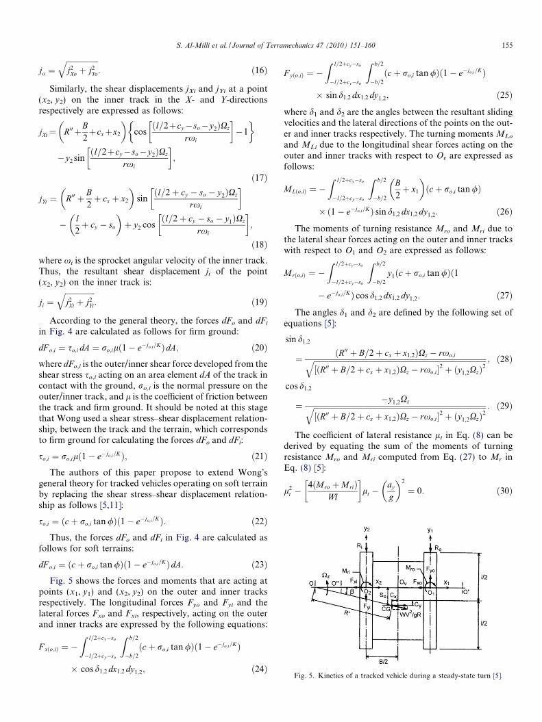
According to the general theory, the forces dFo and dFi
in Fig. 4 are calculated as follows for firm ground:
dF o;i ¼ so;i dA ¼ ro;ilð1� e�jo;i=KÞdA; ð20Þwhere dFo,i is the outer/inner shear force developed from theshear stress so,i acting on an area element dA of the track incontact with the ground, ro,i is the normal pressure on theouter/inner track, and l is the coefficient of friction betweenthe track and firm ground. It should be noted at this stagethat Wong used a shear stress–shear displacement relation-ship, between the track and the terrain, which correspondsto firm ground for calculating the forces dFo and dFi:
so;i ¼ ro;ilð1� e�jo;i=KÞ; ð21ÞThe authors of this paper propose to extend Wong’s
general theory for tracked vehicles operating on soft terrainby replacing the shear stress–shear displacement relation-ship as follows [5,11]:
so;i ¼ ðcþ ro;i tan /Þð1� e�jo;i=KÞ: ð22ÞThus, the forces dFo and dFi in Fig. 4 are calculated as
follows for soft terrains:
dF o;i ¼ ðcþ ro;i tan /Þð1� e�jo;i=KÞdA: ð23ÞFig. 5 shows the forces and moments that are acting at
points (x1, y1) and (x2, y2) on the outer and inner tracksrespectively. The longitudinal forces Fyo and Fyi and thelateral forces Fxo and Fxi, respectively, acting on the outerand inner tracks are expressed by the following equations:
F xðo;iÞ ¼ �Z l=2þcy�so
�l=2þcy�so
Z b=2
�b=2
ðcþ ro;i tan /Þð1� e�jo;i=KÞ
� cos d1;2 dx1;2 dy1;2; ð24Þ
F yðo;iÞ ¼ �Z l=2þcy�so
�l=2þcy�so
Z b=2
�b=2
ðcþ ro;i tan /Þð1� e�jo;i=KÞ
� sin d1;2 dx1;2 dy1;2; ð25Þ
where d1 and d2 are the angles between the resultant slidingvelocities and the lateral directions of the points on the out-er and inner tracks respectively. The turning moments MLo
and MLi due to the longitudinal shear forces acting on theouter and inner tracks with respect to Ov are expressed asfollows:
MLðo;iÞ ¼ �Z l=2þcy�so
�l=2þcy�so
Z b=2
�b=2
B2þ x1
� �ðcþ ro;i tan /Þ
� ð1� e�jo;i=KÞ sin d1;2 dx1;2 dy1;2: ð26Þ
The moments of turning resistance Mro and Mri due tothe lateral shear forces acting on the outer and inner trackswith respect to O1 and O2 are expressed as follows:
Mrðo;iÞ ¼ �Z l=2þcy�so
�l=2þcy�so
Z b=2
�b=2
y1ðcþ ro;i tan /Þð1
� e�jo;i=KÞ cos d1;2 dx1;2 dy1;2: ð27Þ
The angles d1 and d2 are defined by the following set ofequations [5]:
sin d1;2
¼ ðR00 þ B=2þ cx þ x1;2ÞXz � rxo;iffiffiffiffiffiffiffiffiffiffiffiffiffiffiffiffiffiffiffiffiffiffiffiffiffiffiffiffiffiffiffiffiffiffiffiffiffiffiffiffiffiffiffiffiffiffiffiffiffiffiffiffiffiffiffiffiffiffiffiffiffiffiffiffiffiffiffiffiffiffiffiffiffiffiffiffiffiffiffiffiffiffiffiffiffiffiffiffiffiffiffi½ðR00 þ B=2þ cx þ x1;2ÞXz � rxo;i�2 þ ðy1;2XzÞ2
q ; ð28Þ
cos d1;2
¼�y1;2Xzffiffiffiffiffiffiffiffiffiffiffiffiffiffiffiffiffiffiffiffiffiffiffiffiffiffiffiffiffiffiffiffiffiffiffiffiffiffiffiffiffiffiffiffiffiffiffiffiffiffiffiffiffiffiffiffiffiffiffiffiffiffiffiffiffiffiffiffiffiffiffiffiffiffiffiffiffiffiffiffiffiffiffiffiffiffiffiffiffiffiffi
½ðR00 þ B=2þ cx þ x1;2ÞXz � rxo;i�2 þ ðy1;2XzÞ2q : ð29Þ
The coefficient of lateral resistance lt in Eq. (8) can bederived by equating the sum of the moments of turningresistance Mro and Mri computed from Eq. (27) to Mr inEq. (8) [5]:
l2t �
4ðMro þMriÞWl
� �lt �
ay
g
� �2
¼ 0: ð30Þ
Fig. 5. Kinetics of a tracked vehicle during a steady-state turn [5].
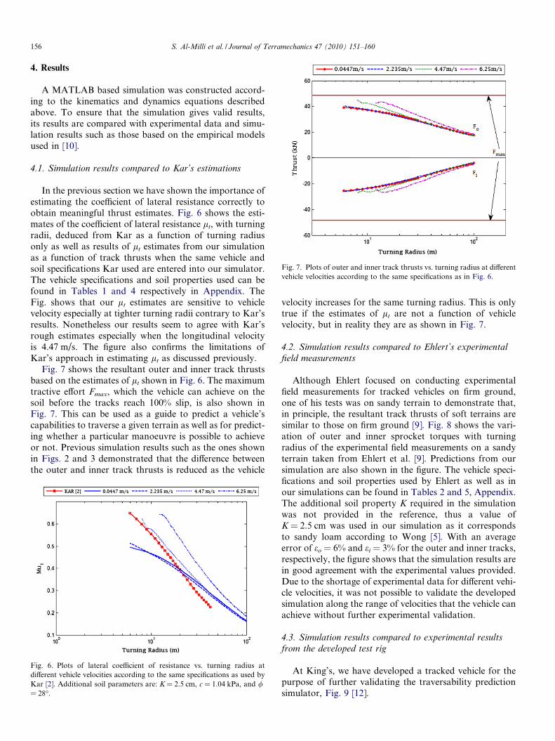
Fig. 7. Plots of outer and inner track thrusts vs. turning radius at differentvehicle velocities according to the same specifications as in Fig. 6.
156 S. Al-Milli et al. / Journal of Terramechanics 47 (2010) 151–160
4. Results
A MATLAB based simulation was constructed accord-ing to the kinematics and dynamics equations describedabove. To ensure that the simulation gives valid results,its results are compared with experimental data and simu-lation results such as those based on the empirical modelsused in [10].
4.1. Simulation results compared to Kar’s estimations
In the previous section we have shown the importance ofestimating the coefficient of lateral resistance correctly toobtain meaningful thrust estimates. Fig. 6 shows the esti-mates of the coefficient of lateral resistance lt, with turningradii, deduced from Kar as a function of turning radiusonly as well as results of lt estimates from our simulationas a function of track thrusts when the same vehicle andsoil specifications Kar used are entered into our simulator.The vehicle specifications and soil properties used can befound in Tables 1 and 4 respectively in Appendix. TheFig. shows that our lt estimates are sensitive to vehiclevelocity especially at tighter turning radii contrary to Kar’sresults. Nonetheless our results seem to agree with Kar’srough estimates especially when the longitudinal velocityis 4.47 m/s. The figure also confirms the limitations ofKar’s approach in estimating lt as discussed previously.
Fig. 7 shows the resultant outer and inner track thrustsbased on the estimates of lt shown in Fig. 6. The maximumtractive effort Fmax, which the vehicle can achieve on thesoil before the tracks reach 100% slip, is also shown inFig. 7. This can be used as a guide to predict a vehicle’scapabilities to traverse a given terrain as well as for predict-ing whether a particular manoeuvre is possible to achieveor not. Previous simulation results such as the ones shownin Figs. 2 and 3 demonstrated that the difference betweenthe outer and inner track thrusts is reduced as the vehicle
Fig. 6. Plots of lateral coefficient of resistance vs. turning radius atdifferent vehicle velocities according to the same specifications as used byKar [2]. Additional soil parameters are: K = 2.5 cm, c = 1.04 kPa, and /= 28�.
velocity increases for the same turning radius. This is onlytrue if the estimates of lt are not a function of vehiclevelocity, but in reality they are as shown in Fig. 7.
4.2. Simulation results compared to Ehlert’s experimental
field measurements
Although Ehlert focused on conducting experimentalfield measurements for tracked vehicles on firm ground,one of his tests was on sandy terrain to demonstrate that,in principle, the resultant track thrusts of soft terrains aresimilar to those on firm ground [9]. Fig. 8 shows the vari-ation of outer and inner sprocket torques with turningradius of the experimental field measurements on a sandyterrain taken from Ehlert et al. [9]. Predictions from oursimulation are also shown in the figure. The vehicle speci-fications and soil properties used by Ehlert as well as inour simulations can be found in Tables 2 and 5, Appendix.The additional soil property K required in the simulationwas not provided in the reference, thus a value ofK = 2.5 cm was used in our simulation as it correspondsto sandy loam according to Wong [5]. With an averageerror of eo = 6% and ei = 3% for the outer and inner tracks,respectively, the figure shows that the simulation results arein good agreement with the experimental values provided.Due to the shortage of experimental data for different vehi-cle velocities, it was not possible to validate the developedsimulation along the range of velocities that the vehicle canachieve without further experimental validation.
4.3. Simulation results compared to experimental results
from the developed test rig
At King’s, we have developed a tracked vehicle for thepurpose of further validating the traversability predictionsimulator, Fig. 9 [12].

Fig. 8. Plots of outer and inner sprocket torques vs. turning radiusaccording to the same specifications as used by Ehlert [9]. Sheardeformation modulus: K = 2.5 cm.
Fig. 10. Plots of the measured outer and inner track torques vs. turningradius at different vehicle velocities according to the experimental datacollected from the developed test rig.
S. Al-Milli et al. / Journal of Terramechanics 47 (2010) 151–160 157
Each track of the vehicle is powered by an independentelectric motor while sensors onboard the vehicle monitorand record the torques generated by the motors. Duringtesting, each track motor is supplied with a constant volt-age such that the vehicle conducts a turning manoeuvreinside a sandpit. With an overhead camera positioned ver-tically above the centre of the sandpit it is possible torecord the vehicle’s trajectory and consequently estimateits instantaneous turning radius and longitudinal velocity.A total of 16 experiments were conducted with the abovetest rig where in each test the vehicle was set to undergo dif-ferent longitudinal velocities and turning radii. It must benoted that a control strategy was not used to eliminate lon-gitudinal accelerations meaning that the vehicle was notalways in a steady-state motion. Nevertheless at somestages of each test the longitudinal accelerations were zeroor close to zero thus resembling steady-state motion. Thevehicle specifications and soil properties used in those testsare shown in Tables 3 and 6, Appendix.
Fig. 9. Image of the test vehicle developed at King’s.
Fig. 11 shows a comparison between the measured tor-ques shown in Fig. 10 and predictions from our simulator.A closer look reveals that the error is usually greater whenthe difference between the outer and inner track torques issmall (i.e. To–Ti) especially at low vehicle velocities; it islikely that this observation is due to friction forces betweenthe moving parts of the tracks, which are unaccounted forin the simulator, being the dominant forces within thetracks. Nevertheless, with the torques of the three highervelocity ranges out of four having average errors ofeo = 14% or less and ei = 17% or less for the outer andinner tracks, the simulator predictions seem to be in goodagreement with the experimental study conducted atKing’s.
4.4. Dimensional analysis
In earlier work by the authors [13], the simulator wasused to investigate the effects of vehicle design and soilproperties on the manoeuvrability performance oftracked vehicles operating on soft terrain as shown inFig. 12.
Fig. 12 shows the variation of the resultant outer andinner track thrusts with turning radii for various valuesof (a) track lengths l e [2.5, 3.1, 4.7, 5.5], (b) vehicle treadsB 2 [1.0, 1.6, 3.0, 3.6], (c) track widths b 2 [0.1, 0.3, 1.0],and (d) heights of centre of gravity h 2 [0.6, 2.0, 2.6].The longitudinal vehicle velocity used in the simulationsis 2 m/s. The remaining vehicle specifications and soilproperties used can be found in Tables 2 and 5 respec-tively in Appendix. Note also that the results from theoriginal vehicle specifications are marked by “Ehlert”.The figure demonstrates the simulator’s capability as adesign tool to predict the manoeuvrability performanceof a prototype vehicle for particular operating conditionsbased on the type of environment in which the vehicle willbe deployed.

Fig. 11. Plots showing comparisons between the measured and predicted outer and inner track torques vs. turning radius for the same velocities as inFig. 10.
158 S. Al-Milli et al. / Journal of Terramechanics 47 (2010) 151–160
5. Conclusion
A simulator based on analytical track–terrain interac-tion modelling principles capable of predicting thetraversability of tracked vehicles over soft terrains duringsteady-state turning manoeuvres is presented. The simula-tor is based on and extends Wong’s general theory fortracked vehicles on firm ground and models the track–terrain interaction taking into account soil properties, vehi-cle dynamic behaviour and track slips. Extending Wong’sgeneral theory also allows the analytical estimation of thecoefficient of lateral resistance as a function of track thrustsfor tracked vehicles operating in soft terrain. According tothe best knowledge of the authors, the modification of thegeneral theory to encompass soft terrain has not beenimplemented elsewhere.
Comparisons have been made between results from oursimulator and available data in the relevant literature.Although there is a shortage of data to fully validate thesimulator, the comparisons made showed that the predic-
tions are in strong agreement with experimental resultsshown in the literature. The proposed simulation approachalso proves to be advancing earlier empirical techniques.Tests employing a miniature tracked vehicle operating ina sand bed show that the torque values predicted by oursimulator were in strong agreement with the torque signalsacquired from our test rig.
The simulator’s ability to analytically predict therequired track thrusts for a given terrain means that onlinetraversability predictions is possible – an important build-ing block for future fully autonomous UGVs.
The developed simulator shows that it has potential notjust as a predictor for traversability but also as a designtool that gives insight into the performance of a vehiclefor a particular environment during the design process.
Future work will focus on further developing the simu-lator to account for longitudinal accelerations as well asimproving the computational time of the predictions suchthat it becomes more suitable for online predictions andrequires less expensive computational resources.
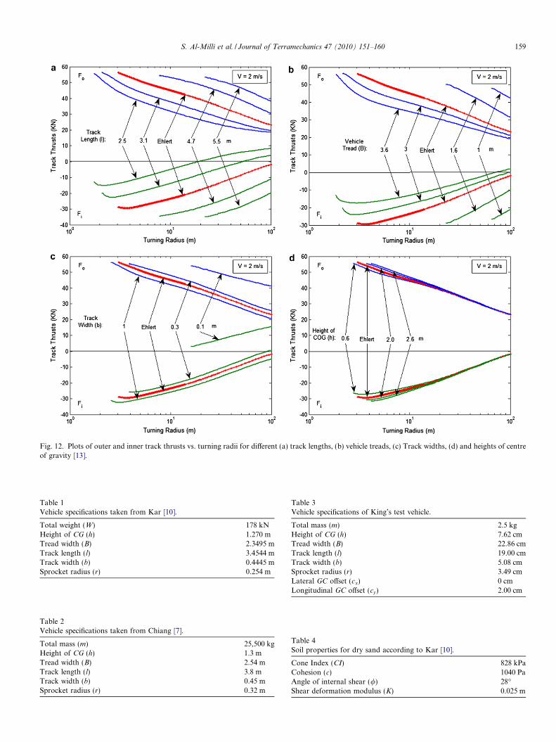
Fig. 12. Plots of outer and inner track thrusts vs. turning radii for different (a) track lengths, (b) vehicle treads, (c) Track widths, (d) and heights of centreof gravity [13].
Table 1Vehicle specifications taken from Kar [10].
Total weight (W) 178 kNHeight of CG (h) 1.270 mTread width (B) 2.3495 mTrack length (l) 3.4544 mTrack width (b) 0.4445 mSprocket radius (r) 0.254 m
Table 3Vehicle specifications of King’s test vehicle.
Total mass (m) 2.5 kgHeight of CG (h) 7.62 cmTread width (B) 22.86 cmTrack length (l) 19.00 cmTrack width (b) 5.08 cmSprocket radius (r) 3.49 cmLateral GC offset (cx) 0 cmLongitudinal GC offset (cy) 2.00 cm
Table 2Vehicle specifications taken from Chiang [7].
Total mass (m) 25,500 kgHeight of CG (h) 1.3 mTread width (B) 2.54 mTrack length (l) 3.8 mTrack width (b) 0.45 mSprocket radius (r) 0.32 m
Table 4Soil properties for dry sand according to Kar [10].
Cone Index (CI) 828 kPaCohesion (c) 1040 PaAngle of internal shear (/) 28�Shear deformation modulus (K) 0.025 m
S. Al-Milli et al. / Journal of Terramechanics 47 (2010) 151–160 159

Table 5Soil properties for dry sandy loam according to Ehlert [9].
Cone Index (CI) 814 kPaCohesion (c) 0 PaAngle of internal shear (/) 25�Shear deformation modulus (K) 0.025 m
Table 6Soil properties of the sand used for the King’s test rig.
n 0.6397kc 6033.43 N/mn+1
k/ 441627.05 N/mn+2
Cohesion (c) 0 PaAngle of internal shear (/) 25�Shear deformation modulus (K) 0.0175 m
160 S. Al-Milli et al. / Journal of Terramechanics 47 (2010) 151–160
Appendix A
Vehicle parameters
Tables 1–3.Soil parametersTables 4–6.
References
[1] Saarilahti M. Development of a protocol for ecoefficient woodharvesting on sensitive sites (ECOWOOD). University of Helsinki,Department of Forest Resource Management; May 2002.
[2] Bekker MG. Theory of land locomotion. University of MichiganPress; 1956.
[3] Song Z, Hutangkabodee S, Zweiri YH, Seneviratne LD, Althoefer K.Identification of soil parameters for unmanned ground vehicles track–terrain interaction dynamics. In: SICE Annual conference, Sapporo;2004.
[4] Steeds W. Tracked vehicles (in three parts). Automobile Engineer;1950. p. 143–148, 187–190, 219–222.
[5] Wong JY. Theory of ground vehicles. 3rd ed. John Wiley & Sons;2001.
[6] Kitano M, Kuma M. An analysis of horizontal plane motion oftracked vehicles. J Terrramech 1977;14(4).
[7] Chiang CF. Handling characteristics of tracked vehicles on non-deformable surfaces. Master thesis, Ottawa-Carleton Institute forMechanical and Aerospace Engineering, Carleton University; 1999.
[8] Murakami H, Watanabe K, Kitano M. A mathematical model forspatial motion of tracked vehicles on soft ground. J Terrramech1992;29(1).
[9] Ehlert W, Hug B, Schmid IC. Field measurements and analyticalmodels as a basis of test stand simulation of the turning resistance oftracked vehicles. J Terrramech 1992;29(1).
[10] Kar MK. Prediction of track forces in skid-steering of militarytracked vehicles. J Terrramech 1987;24(1).
[11] Bekker MG. Introduction to terrain–vehicle systems. Ann Arbor(MI): University of Michigan Press; 1969.
[12] Al-Milli S, Chhaniyara S, Georgiou E, Althoefer K, Dai J,Seneviratne L. Experimental study on track–terrain interactiondynamics in an integrated environment: test rig. In: Internationalconference on climbing and walking robots and the support technol-ogies for mobile machines, Coimbra; 2008.
[13] Al-Milli S, Althoefer K, Seneviratne LD. Maneuverability perfor-mance of tracked vehicles on soft terrains. In: IEEE internationalconference on intelligent robots and systems, Nice; 2008.
Related Documents