Rough Terrain Motion Planning for Actuated, Tracked Robots Michael Brunner, Bernd Br¨ uggemann, and Dirk Schulz Fraunhofer Institute for Communication, Information Processing and Ergonomics FKIE, Wachtberg, Germany {michael.brunner,bernd.brueggemann,dirk.schulz}@fkie.fraunhofer.de Abstract. Traversing challenging structures like boulders, rubble, stairs and steps, mobile robots need a special level of mobility. Robots with reconfigurable chassis are able to alter their configuration to overcome such structures. This paper presents a two-stage motion planning scheme for reconfig- urable robots in rough terrain. First, we consider the robot’s operating limits rather than the complete states to quickly find an initial path in a low dimensional space. Second, we identify path segments which lead through rough areas of the environment and refine those segments using the entire robot state including the actuator configurations. We present a roadmap and a RRT* method to perform the path refinement. Our algorithm does not rely on any detailed structure/terrain catego- rization or on any predefined motion sequences. Hence, our planner can be applied to urban structures, like stairs, as well as rough unstructured environments. Keywords: mobile robot, motion planning, obstacle, rough terrain, re- configurable chassis, sampling-based, RRT* 1 Introduction Many structures which are regularly encountered in robotic tasks are perceived as obstacles for fixed-chassis robots. Steps and stairs are usually untraversable obstacles in urban environments; debris, rubble, rocks or steep inclinations in unstructured outdoor environments are often impossible to traverse with nor- mal fixed-chassis systems. Therefore, these structures and objects have to be circumvented if possible. Using articulated actuators robots with reconfigurable chassis can change their configuration to improve traction and stability or to lift themselves over edges. This provides those systems with an increased mobility compared to fixed- chassis robots and enables them to overcome a wide variety of environments. Fixed-chassis robots are most often unable to traverse the same kind of en- vironments because their ability to negotiate obstacles is limited due to their construction. The challenges they can overcome are restricted by the diameter

Welcome message from author
This document is posted to help you gain knowledge. Please leave a comment to let me know what you think about it! Share it to your friends and learn new things together.
Transcript
Rough Terrain Motion Planning for Actuated,Tracked Robots
Michael Brunner, Bernd Bruggemann, and Dirk Schulz
Fraunhofer Institute for Communication, Information Processing and ErgonomicsFKIE,
Wachtberg, Germany{michael.brunner,bernd.brueggemann,dirk.schulz}@fkie.fraunhofer.de
Abstract. Traversing challenging structures like boulders, rubble, stairsand steps, mobile robots need a special level of mobility. Robots withreconfigurable chassis are able to alter their configuration to overcomesuch structures.This paper presents a two-stage motion planning scheme for reconfig-urable robots in rough terrain. First, we consider the robot’s operatinglimits rather than the complete states to quickly find an initial path ina low dimensional space. Second, we identify path segments which leadthrough rough areas of the environment and refine those segments usingthe entire robot state including the actuator configurations. We presenta roadmap and a RRT* method to perform the path refinement.Our algorithm does not rely on any detailed structure/terrain catego-rization or on any predefined motion sequences. Hence, our planner canbe applied to urban structures, like stairs, as well as rough unstructuredenvironments.
Keywords: mobile robot, motion planning, obstacle, rough terrain, re-configurable chassis, sampling-based, RRT*
1 Introduction
Many structures which are regularly encountered in robotic tasks are perceivedas obstacles for fixed-chassis robots. Steps and stairs are usually untraversableobstacles in urban environments; debris, rubble, rocks or steep inclinations inunstructured outdoor environments are often impossible to traverse with nor-mal fixed-chassis systems. Therefore, these structures and objects have to becircumvented if possible.
Using articulated actuators robots with reconfigurable chassis can changetheir configuration to improve traction and stability or to lift themselves overedges. This provides those systems with an increased mobility compared to fixed-chassis robots and enables them to overcome a wide variety of environments.Fixed-chassis robots are most often unable to traverse the same kind of en-vironments because their ability to negotiate obstacles is limited due to theirconstruction. The challenges they can overcome are restricted by the diameter
2 Rough Terrain Motion Planning for Actuated, Tracked Robots
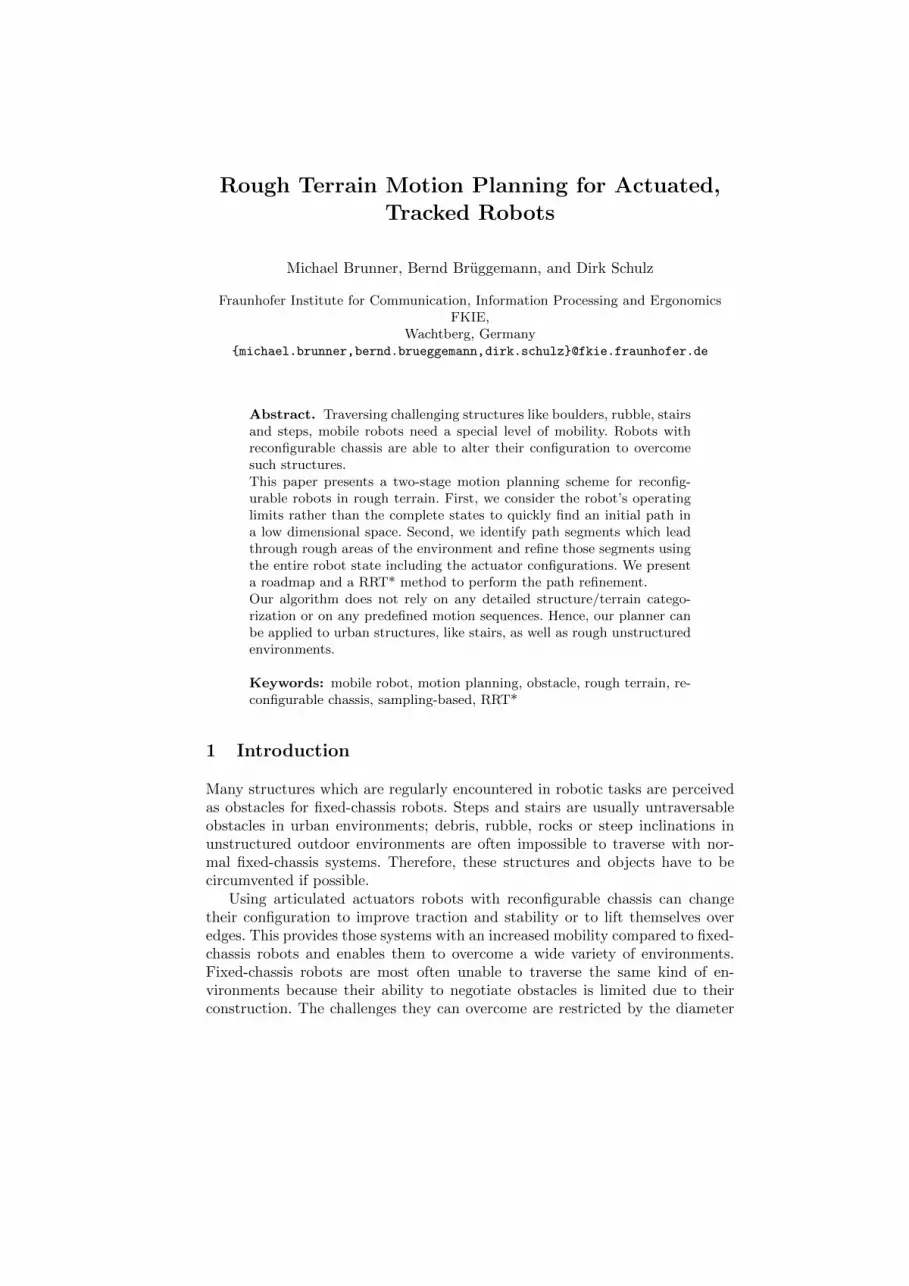
Fig. 1. The Telerob Telemax is 65 cm long, 40 cm wide and weighs about 70 kg. Ithas 4 tracks which can be rotated. Extended, the robot’s length is about 120 cm. Therobot is skid-steered and drives up to 1.2 m
s. Configurations are: (left) folded (actuators
at −90◦), (middle) extended (actuators at 80◦) and (right) maximal ground contact(actuators at 21◦).
of their wheels or their track heights and to some extend to their centers ofmass. The mobility of actuated systems is dominated by the number, length andagility of thier actuators.
Controlling a mobile robot in rough terrain and steering it through difficultsituations is a challenging task even for a trained operator. The operator mustconsider many different aspects to guarantee the safety of the system in suchenvironments. Among those aspects are the robot’s stability as tipping overbecomes increasingly more likely, the inertia and momentum must be kept inmind when operating a system close to its limits, and finally, the system mayreact differently to the same commands because the contacts with the groundcan change often in rough terrain.
In this paper, we present a hierarchical approach to motion planning forreconfigurable robots like the Packbot or the Telemax (Fig. 1). First, we generatean approximate solution and refine it in a subsequent phase. The refinementconcentrates on path segments in rough areas and accounts for the actuators andthe robot’s stability and traction. See Fig. 2 for an overview. Since the algorithmdoes not need a previous terrain/structure classification and does not use anypredefined motion sequences, it can be applied to rough outdoor environmentsas well as structures in urban surroundings. We consider our method to bethe global planning component within a robotic system. The controller whichexecutes the plan and takes care of localization and obstacle avoidance is beyondthe scope of this work.
The remainder of this paper is organized as follows: section 2 names relatedwork in this area of research. Section 3 gives a short overview of our method andnames key differences to related works. In section 4 we introduce the roughnessquantification. Section 5 describes the hierarchical planning scheme including theroadmap planner (A*) and the sampling-based planner (RRT*) (section 5.3). Insection 6 we discuss the parameters and appropriate values. Experiments areprovided in section 7, and we conclude in 8.
Rough Terrain Motion Planning for Actuated, Tracked Robots 3
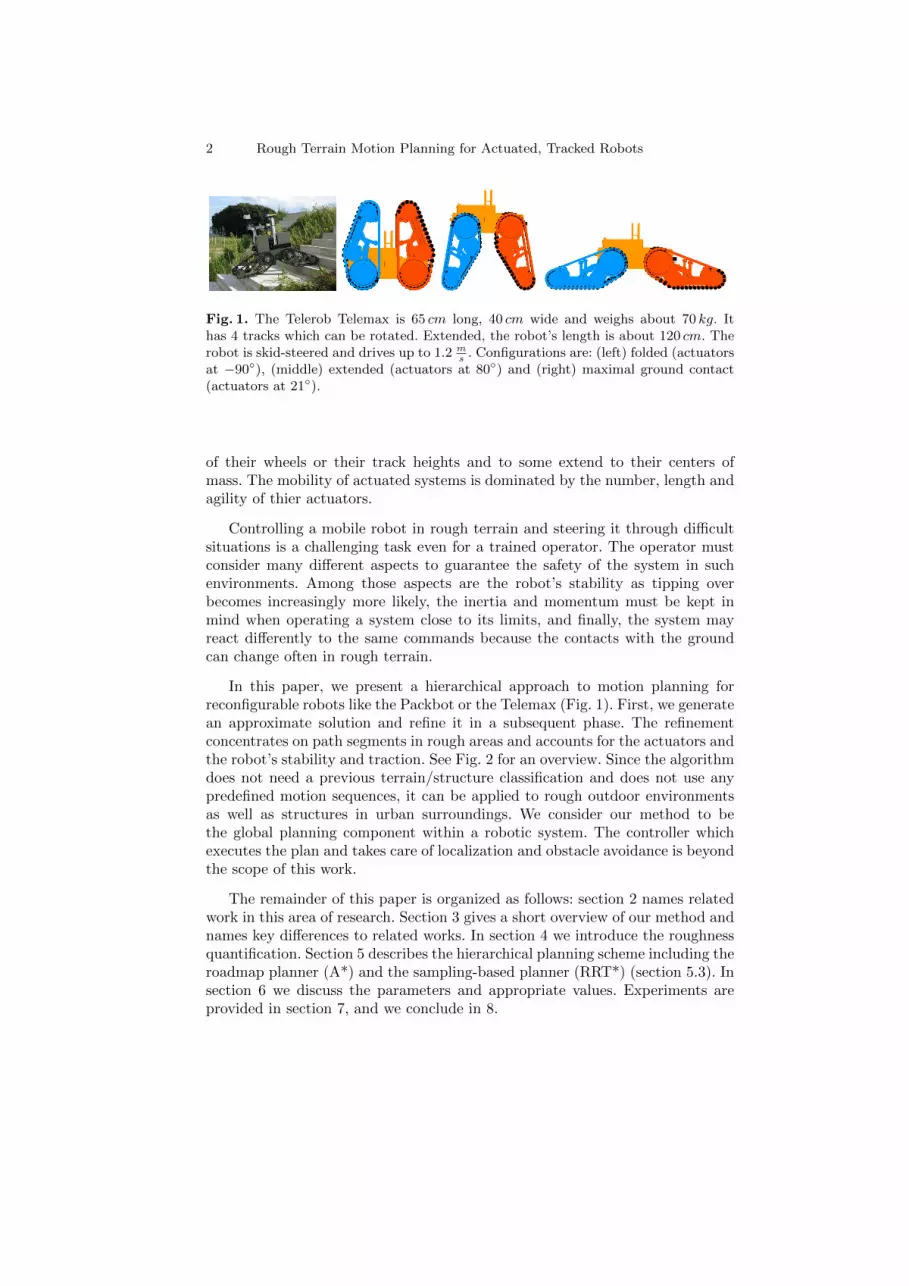
Fig. 2. Method overview: Using filters from image processing we perform a roughnessquantification of the map. The initial path is found within a regular grid performing agraph search. Afterwards the rough segments are identified. For flat segments we applya 2D planning scheme; rough segments are refined by a second planning step using anA*-search or a RRT*-search. Finally the segment plans are merged to provide the finalpath.
2 Related Work
This section focuses on common approaches to rough terrain path planning andon previous work using methods similar to ours, i.e. hierarchical methods, meth-ods applying roadmap and sampling-based algorithms to rough terrain motionplanning for tracked robots.
Many algorithms for traversing rough terrain or climbing structures, likestairs, involve a preceding classification step (e.g. using line detection to identifystairs). This information is used to steer the system during climbing, fixingits heading to the gradient of the staircase [1], [2]. In [3] a two dimensionalA*-search on behavior maps is used to find paths in rough environments for atracked robot, similar to our model. The path represents a sequence of predefinedskills encoded in the behavior maps. Fuzzy rules and Markov random fields areused to classify the environment and facilitate skill selection. A comprehensiveapproach to traverse rough outdoor terrain as well as stairs is presented in [4].The framework includes a mapping component, a terrain classification and atwo-phase planning algorithm. A high-level planner samples a transition graphacross different terrain types and provides an initial path. In the second phasespecialized terrain sub-planners refine the path and return gait primitives fora RHex robot (e.g. stair-climbing gait primitives). The approaches above arelimited to the set of terrain types or structures which are imposed by theirclassification scheme or to the set of motion sequences. On the contrary, ouralgorithm does not rely on such a terrain/structure classification or on a setof motion sequences. Hence, it can be applied to a broader range of differentenvironments.
We utilize a two-phase planning method which produces an initial approx-imate solution followed by a refinement of the initial result. As in [4], other
4 Rough Terrain Motion Planning for Actuated, Tracked Robots
works also use a similar approach. Kalakrishnan and colleagues introduced acontroller for fast quadruped locomotion over rough terrain [5]. The controllerdecomposes the controlling task into several sub-tasks; first, they generate a ter-rain reward map using a learned foothold ranking function and then producean approximate path. In subsequent steps this first solution is improved to en-sure kinematic reachability and a smooth and collision-free trajectory. Like ourmethod, this is a multi-phase algorithm which requires a map and implementsa terrain analysis. However, our terrain analysis relies on a roughness quantifi-cation similar to [6] instead of a ranking function of the actuator contacts. Onthe contrary, the authors of [5] propose a reactive controller to traverse roughterrain rather than a planning algorithm. Also the terrain interaction of trackedrobots is quite distinct compared to the interaction of their legged robot.
Further, path refinement can also be achieved by path optimizing methods.CHOMP [7] is an optimization method for continuous trajectories using covari-ant gradient descent. It can optimize a path over a variety of criteria. Since itis applicable to unfeasible paths, it can be used as a standalone motion planner.STOMP [8] is a stochastic path optimizer using a path integral approach whichdoes not require any gradient information like CHOMP. Therefore, it can over-come local minima and more general costs are applicable. The major drawbackof both methods is the limitation to trajectories of a predefined fixed length. Thismakes them inapplicable for the path refinement within a certain proximity ofthe initial path.
In this work we present a roadmap algorithm for rough terrain path planning.Roadmap methods are commonly applied to this problem in the literature. AnAnytime A*-search is used to find paths in a multi-resolution 4D state lattice forindoor environments [9]. The resolution of the lattice is adjusted with respectto terrain or task characteristics (e.g. narrow passages and goal proximity). Theonline navigation utilizes a precomputation step which determines paths for con-strained areas. In [10] the Fast Marching Method (FMM), a breadth-first searchalgorithm, is used on a 3D lattice to plan stable paths for actively reconfigurablerobots. The system’s stability guides the search on a triangular mesh of the en-vironment. The actuators of the Packbot robot used in this research are activelycontrolled like the actuators of our Telemax platform.
The authors of [11] present an approach to motion planning on rough terrainfor a wheeled robot with passive suspension using an A*-search on a discretizedconfiguration space with heuristics to limit the search space. The algorithmconsiders the robot’s stability, mechanical limits, collisions with the ground, anduncertainties on the terrain model and the robot position. While in [11] they alsouse a graph-search and measure the robot’s stability, their algorithm does nothave to account for actuators due to the robot’s passive suspension. In contrast,we must include the actively controlled actuators during planning.
Magid et al. developed a rough terrain planning algorithm for a tracked robotwith four actively controlled crawlers [12]. They use a graph-search to find motionsequences in a discretizied state space, which also allows for motions of controlledbalance-losing (e.g. insignificant falls from small edges). However, rather than
Rough Terrain Motion Planning for Actuated, Tracked Robots 5
autonomous navigation their application is to reduce the burden on operators ofsearch and rescue missions by proposing paths through rough terrain. Unlike us,they categorize the states to distinguish between different transition types andconsider controlled balance-losing states. However, they also plan on a discretestate space and use a robot with actively controlled crawlers, similar to ourmodel.
Sampling-based methods have also been used to find paths through roughenvironments. [13] presents a RRT-based algorithm which finds routes of lowmechanical work following valleys and saddle points in continuous cost spaces.Their method also includes a mechanism based on stochastic optimization tofilter irrelevant configurations and to control the exploration behavior. In [14]a RRT variant is employed for kinematic path planning for a LittleDog robot.The authors bias the search in the task space and use motion primitives to speedup planning. [15] uses different terrain parameters to guide the RRT expansionsand iteratively increases its roughness tolerance if no solution is found.
3 Overview and Discriminators
We start with a short overview of our algorithm. We employ a hierarchical al-gorithm for motion planning of actively reconfigurable robots in rough environ-ments. Although we developed our algorithm for a tracked robot model, withminor changes it is usable for other articulated robot models with similar loco-motion (e.g. wheeled platforms). Given a map we compute the roughness andslopes of the environment (section 4). In the preliminary planning phase webuild a motion graph according to the robot’s operating limits and perform agraph-search to find an initial path (section 5.1). During the detailed motionplanning step we refine the initial path in rough areas only. To this end, we firstidentify the path segments leading through rough terrain. In flat areas we do notperform a detailed planning and apply default configurations instead. On oneside, the roadmap planner constructs a state graph considering the actuatorsfor a tube-like area around each rough path segment. Using a graph-search wefind sequences of robot states including the actuators. On the other side, thesampling-based planner uses a focused sampling procedure and searches in acontinuous state space for an optimal solution (section 5.3). Consult figure 2 fora scheme of our algorithm.
Our algorithm applies to tracked reconfigurable robots like ours (see figure 1),but not to systems with legged locomotion since the robot-terrain interactionsare very distinct. However, parts may be used across different locomotion models,e.g. the roughness quantification and some of the metrics. Further, looking ata complete robot system, we consider our method to be the global planningcomponent which provides a plan. It must be followed by a feedback controllerwhich takes care of the plan execution using sensor data for localization andobstacle avoidance in potentially dynamic environments. Such a controller isbeyond the scope of this paper.
6 Rough Terrain Motion Planning for Actuated, Tracked Robots
In the following we state how our approach differs from other approaches.First, we distinguish between flat and rough regions, but do not rely on a pre-vious detailed structure/terrain classification or on motion sequences a prioridesigned to overcome specific challenges. Therefore, we are not limited to a pre-viously defined set of terrain classes, a set of structures reliably identifiable withthe robot’s sensors or a set of motion sequences. However, we approximate theterrain through a least-squares plane (similar to [16]), which works reasonablywell on generally continuous surfaces, but not on discontinuous environments.Nevertheless, our algorithm can be applied to traverse rough outdoor environ-ments as well as to overcome challenging structures in urban surroundings.
Second, rather than taking the entire preliminary path to guide the seconddetailed motion planning, we solely consider path segments which lead throughrough areas. Since a detailed motion planning is not necessary for path segmentson flat regions, planning can be significantly simplified. Thus, we are able toreduce planning time.
Further, we use simpler robot and terrain models compared to planetary roverpath planning approaches. They often utilize detailed dynamic and mechanicmodels to capture the robot-terrain interaction in depth [17]. Such models arenot always obtained easily and, thus, not necessarily available for a specific robotmodel.
4 Map and Terrain Roughness
Whether a given structure is traversable or not cannot be determined easily. In2D navigation this is usually addressed with a simple threshold on the heightdifferences; everything above this threshold is untraversable. For rough terrainand challenging structures this question becomes very hard to answer. Whilefor 2D navigation a 2D laser range finder is sufficient to gather the necessaryinformation about the surroundings, even a 3D sensor is often not enough tonavigate through rough environments due to the still limited sensor coverage.
There are several reasons why it seems it is often extremely difficult to reliablydecide on the traversability of challenging structures or rough terrain based on lo-cal sensor information solely. First, the dimensions of rough areas or challengingstructures usually exceed the sensor range; second, some sections of the environ-ment are often occluded; third, the limiting narrow view of sensors mounted on amobile robot makes it difficult to get a sufficient overview; finally, while travers-ing rough terrain, the robot’s state often orients the sensors such that they areunable to cover the environment. For example, consider a flight of stairs; thevery narrow view makes it hard to recognize the stairs especially all the way tothe top. While on the stairs and close to the top the sensors cover very little ofthe ground.
Additionally, the robotic system is exposed to unnecessary risk if it starts totraverse an area which turns out to be ultimately untraversable. A map allows todecide whether an area is likely to be traversable and to assess the risk of a path
Rough Terrain Motion Planning for Actuated, Tracked Robots 7
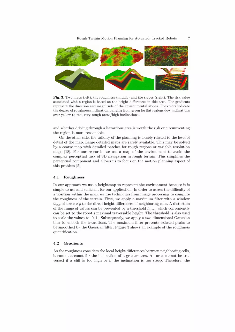
Fig. 3. Two maps (left), the roughness (middle) and the slopes (right). The risk valueassociated with a region is based on the height differences in this area. The gradientsrepresent the direction and magnitude of the environmental slopes. The colors indicatethe degree of roughness/inclination, ranging from green for flat regions/low inclinationsover yellow to red, very rough areas/high inclinations.
and whether driving through a hazardous area is worth the risk or circumventingthe region is more reasonable.
On the other side, the validity of the planning is closely related to the level ofdetail of the map. Large detailed maps are rarely available. This may be solvedby a coarse map with detailed patches for rough regions or variable resolutionmaps [18]. For our research, we use a map of the environment to avoid thecomplex perceptual task of 3D navigation in rough terrain. This simplifies theperceptual component and allows us to focus on the motion planning aspect ofthis problem [5].
4.1 Roughness
In our approach we use a heightmap to represent the environment because it issimple to use and sufficient for our application. In order to assess the difficulty ofa position within the map, we use techniques from image processing to computethe roughness of the terrain. First, we apply a maximum filter with a windowwx,y of size x×y to the direct height differences of neighboring cells. A distortionof the range of values can be prevented by a threshold hmax which convenientlycan be set to the robot’s maximal traversable height. The threshold is also usedto scale the values to [0, 1]. Subsequently, we apply a two dimensional Gaussianblur to smooth the transitions. The maximum filter prevents isolated peaks tobe smoothed by the Gaussian filter. Figure 3 shows an example of the roughnessquantification.
4.2 Gradients
As the roughness considers the local height differences between neighboring cells,it cannot account for the inclination of a greater area. An area cannot be tra-versed if a cliff is too high or if the inclination is too steep. Therefore, the
8 Rough Terrain Motion Planning for Actuated, Tracked Robots
inclination serves as a second criterion to determine the overall roughness of anarea. To compute the gradients at a position within the map, we use the Sobeloperator with a large base of the same size as the previous filters, i.e. x× y. Thevalues are also normalized to [0, 1] using the maximal traversable slope of thegiven robot model.
Using an appropriate kernel size allows us to virtually inflate hazardous areas.This is commonly done in 2D navigation to keep the robot away from obstacles.In contrast, very rough areas are avoided by the robot, but if required, willnot prohibit traversal. Another benefit is the simple and highly parallelizablecomputation.
The overall roughness quantification consists of the roughness r inferred fromthe height difference and the slope s.
R =r + s
2. (1)
The value of the roughness quantification is used in both the initial path searchand the detailed motion planning to adjust the planning according to the diffi-culty of the environment.
5 Motion Planning Algorithm
Driving with actively reconfigurable robots on rough terrain introduces a largeplanning space. Additionally, aspects of the robot state, like the stability, arenot naturally satisfied and must be tested. The robot’s actuators must be incor-porated into the planning process, and the quality of the path must be judgednot only by its length but also by the robot’s stability and traction as well asthe time required for translation, rotation and for actuator movements. First,we employ a initial path search to quickly find an environment-driven path tothe goal. Subsequently, the path is used to focus the search of the detailed plan-ning. This phase determines the final path consisting of the robot configurationsincluding the actuators.
5.1 Initial Path Search
The initial path search utilizes the previously discussed roughness quantificationto force the robot to avoid hazardous areas and to prefer less risky routes. Inflat regions the consideration of the complete state is not necessary, whereasit is essential in rough regions to increase the robot’s safety and ensure suc-cessful traversal. At the beginning we do not know through which parts of theenvironment the path will lead and if considering the complete state is reallynecessary. Therefore, we use the utmost operating limits of the mobile systemsetting the actuators aside. The maximal traversable height and slope of therobot constitute the operating limits. This way we obtain the least restrictivelimit.
Rough Terrain Motion Planning for Actuated, Tracked Robots 9
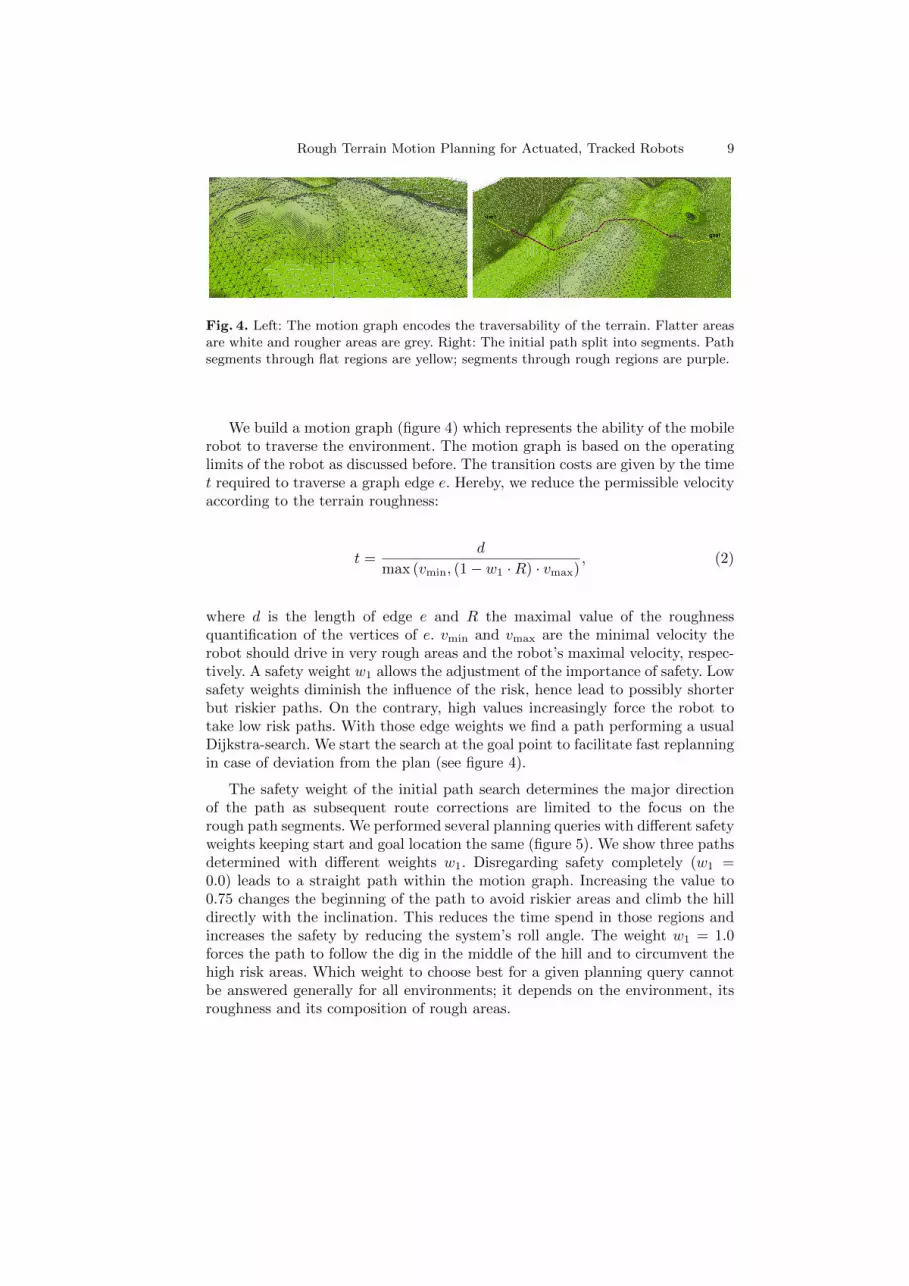
Fig. 4. Left: The motion graph encodes the traversability of the terrain. Flatter areasare white and rougher areas are grey. Right: The initial path split into segments. Pathsegments through flat regions are yellow; segments through rough regions are purple.
We build a motion graph (figure 4) which represents the ability of the mobilerobot to traverse the environment. The motion graph is based on the operatinglimits of the robot as discussed before. The transition costs are given by the timet required to traverse a graph edge e. Hereby, we reduce the permissible velocityaccording to the terrain roughness:
t =d
max (vmin, (1− w1 ·R) · vmax), (2)
where d is the length of edge e and R the maximal value of the roughnessquantification of the vertices of e. vmin and vmax are the minimal velocity therobot should drive in very rough areas and the robot’s maximal velocity, respec-tively. A safety weight w1 allows the adjustment of the importance of safety. Lowsafety weights diminish the influence of the risk, hence lead to possibly shorterbut riskier paths. On the contrary, high values increasingly force the robot totake low risk paths. With those edge weights we find a path performing a usualDijkstra-search. We start the search at the goal point to facilitate fast replanningin case of deviation from the plan (see figure 4).
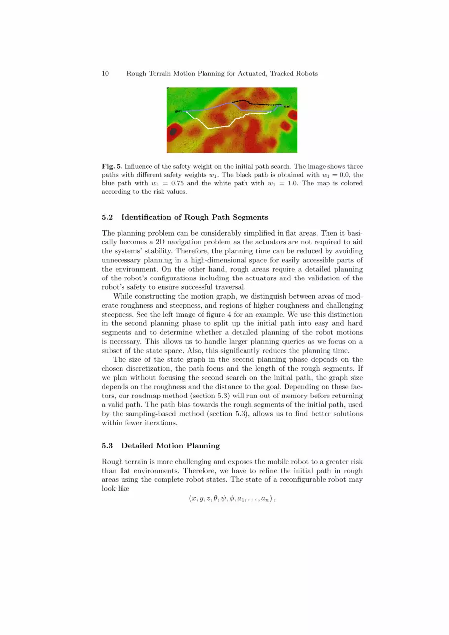
The safety weight of the initial path search determines the major directionof the path as subsequent route corrections are limited to the focus on therough path segments. We performed several planning queries with different safetyweights keeping start and goal location the same (figure 5). We show three pathsdetermined with different weights w1. Disregarding safety completely (w1 =0.0) leads to a straight path within the motion graph. Increasing the value to0.75 changes the beginning of the path to avoid riskier areas and climb the hilldirectly with the inclination. This reduces the time spend in those regions andincreases the safety by reducing the system’s roll angle. The weight w1 = 1.0forces the path to follow the dig in the middle of the hill and to circumvent thehigh risk areas. Which weight to choose best for a given planning query cannotbe answered generally for all environments; it depends on the environment, itsroughness and its composition of rough areas.
10 Rough Terrain Motion Planning for Actuated, Tracked Robots
Fig. 5. Influence of the safety weight on the initial path search. The image shows threepaths with different safety weights w1. The black path is obtained with w1 = 0.0, theblue path with w1 = 0.75 and the white path with w1 = 1.0. The map is coloredaccording to the risk values.
5.2 Identification of Rough Path Segments
The planning problem can be considerably simplified in flat areas. Then it basi-cally becomes a 2D navigation problem as the actuators are not required to aidthe systems’ stability. Therefore, the planning time can be reduced by avoidingunnecessary planning in a high-dimensional space for easily accessible parts ofthe environment. On the other hand, rough areas require a detailed planningof the robot’s configurations including the actuators and the validation of therobot’s safety to ensure successful traversal.
While constructing the motion graph, we distinguish between areas of mod-erate roughness and steepness, and regions of higher roughness and challengingsteepness. See the left image of figure 4 for an example. We use this distinctionin the second planning phase to split up the initial path into easy and hardsegments and to determine whether a detailed planning of the robot motionsis necessary. This allows us to handle larger planning queries as we focus on asubset of the state space. Also, this significantly reduces the planning time.
The size of the state graph in the second planning phase depends on thechosen discretization, the path focus and the length of the rough segments. Ifwe plan without focusing the second search on the initial path, the graph sizedepends on the roughness and the distance to the goal. Depending on these fac-tors, our roadmap method (section 5.3) will run out of memory before returninga valid path. The path bias towards the rough segments of the initial path, usedby the sampling-based method (section 5.3), allows us to find better solutionswithin fewer iterations.
5.3 Detailed Motion Planning
Rough terrain is more challenging and exposes the mobile robot to a greater riskthan flat environments. Therefore, we have to refine the initial path in roughareas using the complete robot states. The state of a reconfigurable robot maylook like
(x, y, z, θ, ψ, φ, a1, . . . , an) ,
Rough Terrain Motion Planning for Actuated, Tracked Robots 11
where the first part describes the 6D pose of the robot. ai are the control valuesof n actuators. Reducing the state to the controllable part leads to
(x, y, θ, a1, . . . , an) .
The controllable parts still result in a large intractable search space. There-fore, we use the initial path to focus the search of the second planning phase.First, we split the path into segments leading through flat areas with low incli-nations and segments through rough regions with higher slopes (see the rightimage of figure 4). For flat segments the stability of the robot system can besafely assumed as done in 2D navigation. Further, any robot configuration maybe applied with little or no risk. This way, we avoid unnecessary planning ina high dimensional space for easily accessible parts of the environment and re-duce planning time. However, rough regions require an additional planning ofthe robot’s actuators to ensure safety and task completion.
The detailed motion planning accounts for the environmental risk, the sys-tem’s stability and its traction, and for the time consumed by translation, rota-tion and actuator movements. Since the robot’s speed is very low when traversinghazardous areas, we put forces and dynamic stability aside. To quantify the sta-bility and the traction we approximate the robot’s footprint by the best fittingplane [16]. This limits the current approach to mainly continuous environments(e.g. hills, stairs, ramps).
Cost Function: The hierarchical approach allows us to use two different costfunctions for the two planning phases. The cost function of the detailed planningstep is more comprehensive compared to the cost function of the initial pathsearch. It considers the robot’s safety csafety and an execution time ctime.
c = w2 · csafety + (1− w2) · ξ · ctime (3)
The normalization factor ξ brings the safety cost and the time cost to the samerange of values. The safety weight w2 allows to control the trade-off betweensafety and time. More safety is gained by adjusting the actuators to the environ-ment; however, this requires more time to move the actuators. This cost functionis only applied in rough regions and may not be applicable in flat areas. In flatareas actuator movements are generally unnecessary and solely introduce costs,and thus should not be favored.
System Safety: The safety of the system is measured by several factors. Theroughness quantification, the robot’s stability and an estimate of the tractioncontribute to the safety value. The safety cost csafety for moving from state xito state xj is given by
csafety(i, j) =Rij + 1
2 (Sij + Tij)
2, (4)
where Rij = max{Ri, Rj} is the maximal value of the roughness quantifica-tion, Sij = max{Si, Sj} the maximal stability cost and Tij = max{Ti, Tj} themaximal traction cost of the involved states.
12 Rough Terrain Motion Planning for Actuated, Tracked Robots
Stability: The Normalized Energy Stability Margin (NESM) [19] is used toassess the stability of the robotic system. In contrast to the commonly used pro-jection of the center of mass onto the supporting polygon, the NESM considersthe actual position of the center of mass and directly provides a notion of quality.The NESM basically indicates the amount of energy required to tip the robotover the “weakest” edge of the supporting polygon. To provide an accurate es-timate of the center of mass and to account for the varying weight distributionsof different configurations, we compute the distributed center of mass.
We touch the basics of the Normalized Energy Stability Margin just verybriefly; a more detailed discussion is given in [19]. Let V be the vector from theborder to the center of mass. Θ depicts the angle between V and the verticalplane, and ψ the inclination of the rotation axis, i.e. the edge of the supportingpolygon. Then the energy stability level for an edge of the supporting polygonis given by
h = |V |(1− cos(Θ)) · cos(ψ). (5)
The NESM is defined as the minimum over the energy levels hi of all edges,s = mini(hi). The stability cost of a robot state x is then given through
S = 1− ξs · s(x), (6)
where ξs = 1smax
is a normalization term to scale the cost to [0, 1]. ξs is given bythe most stable configuration on flat ground.
Traction Estimate: A sufficient traction is necessary to traverse rough terrainand challenging structures. However, we do not want to rely on any terrainproperties because such information is usually unavailable and hard to estimatewith sufficient accuracy. Therefore, we use the actuators’ ground contact as anindicator of the traction since the friction between to objects generally increaseswith the size of the contact area between them. The traction cost T of a state xis given by the average over the actuators’ angles to the surface.
T = ξt ·1
n
n∑k=1
ψ(ak), (7)
where ψ(ak) provides the angle to the surface for actuator ak. ξt = 1π/2 normal-
izes the cost to [0, 1]. The smaller the angle, the greater the estimated tractionand the safer the state x in terms of traction.
Execution Time: The time cost includes the time required for translation tv,rotation tω and for actuator movements ta. We use a triangle inequality to favorsimultaneous execution.
ctime =t2v+t
2ω+t2a
tv+tω+ta(8)
Translation: To measure the time required for translation, we use the samefunction as for the initial path search.
tv = tv(i, j) =dij
max (vmin, (1− w2 ·Ri,j) · vmax), (9)
Rough Terrain Motion Planning for Actuated, Tracked Robots 13
where dij is the distance between xi and xj , and vmin and vmax are the minimaland maximal forward velocity, respectively.
Rotation: The physically possible rotational velocity is influenced by therobot’s ground contact. If the actuators are all flat on the ground, the frictionwill be quite high and the engines must overpower these forces before the robotstarts to rotate. We approximated a function ω(·) which provides the maximalrotational velocity given the actuator configuration. Using this information thetime required for turning from state xi to state xj is given by
tω = tω(i, j) =|θi − θj |
12 (ω(ai) + ω(aj))
, (10)
where θi and θj are the orientations of the two states and ai and aj are theactuator configurations.
Actuators: The cost to move the actuators from one configuration to anotheris defined through the time required to do so.
ta = ta(i, j) = maxk
(|ai,k − aj,k|
vk
), (11)
where ai,k and aj,k are the values of the kth actuator of the two states. vk is thevelocity of the kth actuator.
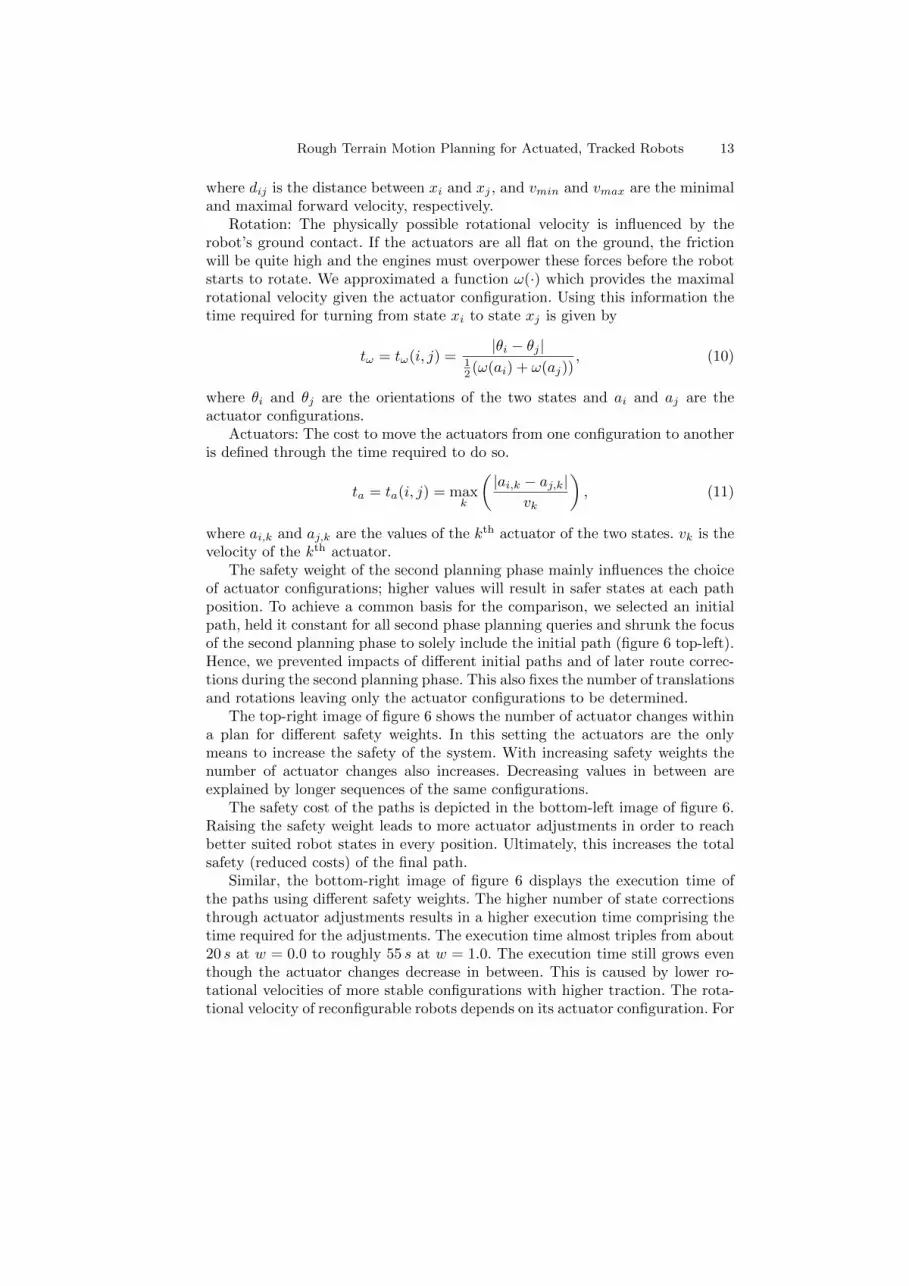
The safety weight of the second planning phase mainly influences the choiceof actuator configurations; higher values will result in safer states at each pathposition. To achieve a common basis for the comparison, we selected an initialpath, held it constant for all second phase planning queries and shrunk the focusof the second planning phase to solely include the initial path (figure 6 top-left).Hence, we prevented impacts of different initial paths and of later route correc-tions during the second planning phase. This also fixes the number of translationsand rotations leaving only the actuator configurations to be determined.
The top-right image of figure 6 shows the number of actuator changes withina plan for different safety weights. In this setting the actuators are the onlymeans to increase the safety of the system. With increasing safety weights thenumber of actuator changes also increases. Decreasing values in between areexplained by longer sequences of the same configurations.
The safety cost of the paths is depicted in the bottom-left image of figure 6.Raising the safety weight leads to more actuator adjustments in order to reachbetter suited robot states in every position. Ultimately, this increases the totalsafety (reduced costs) of the final path.
Similar, the bottom-right image of figure 6 displays the execution time ofthe paths using different safety weights. The higher number of state correctionsthrough actuator adjustments results in a higher execution time comprising thetime required for the adjustments. The execution time almost triples from about20 s at w = 0.0 to roughly 55 s at w = 1.0. The execution time still grows eventhough the actuator changes decrease in between. This is caused by lower ro-tational velocities of more stable configurations with higher traction. The rota-tional velocity of reconfigurable robots depends on its actuator configuration. For
14 Rough Terrain Motion Planning for Actuated, Tracked Robots
Fig. 6. Influence of the safety weight on the detailed motion planning: The path usedfor evaluation is shown in the top-left corner. We fixed the initial path and reduced thefurther path corrections to exactly the initial path, leaving only the actuator config-urations mutable. The curves show the safety costs and the execution time (seconds)of the final state space paths for different weights. As only the actuator configurationsare mutable, we displayed the number of configuration changes in the top-right image.The decrease in actuator changes in between is due to sequences of the same actuatorconfiguration. The increasing execution time for those values of w2 are caused by higherrotation times in stable and high traction configurations.
example, consider the Telemax robot. If the flippers are completely stretched,the robot will be 120 cm long with maximal ground contact. In this configurationrotation takes considerably longer than with all flippers folded.
Ultimately, the planning of the actuator positions is essential to increasethe safety of the robotic system during rough terrain traversal. This leads to asignificant increase of the path’s execution time due to the time needed for theactuator adjustments and the increased duration of rotational maneuvers.
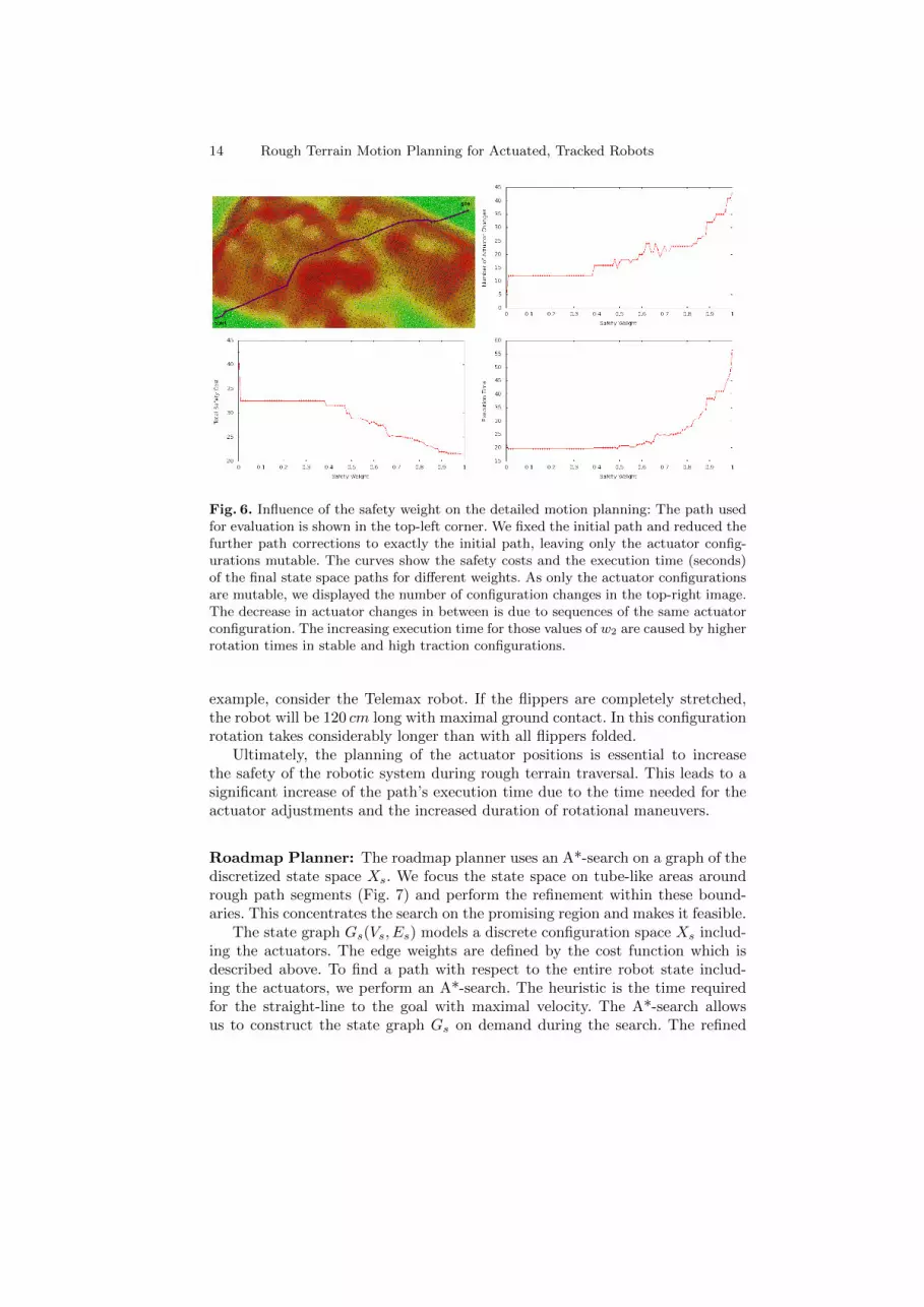
Roadmap Planner: The roadmap planner uses an A*-search on a graph of thediscretized state space Xs. We focus the state space on tube-like areas aroundrough path segments (Fig. 7) and perform the refinement within these bound-aries. This concentrates the search on the promising region and makes it feasible.
The state graph Gs(Vs, Es) models a discrete configuration space Xs includ-ing the actuators. The edge weights are defined by the cost function which isdescribed above. To find a path with respect to the entire robot state includ-ing the actuators, we perform an A*-search. The heuristic is the time requiredfor the straight-line to the goal with maximal velocity. The A*-search allowsus to construct the state graph Gs on demand during the search. The refined
Rough Terrain Motion Planning for Actuated, Tracked Robots 15
Fig. 7. A tube around a rough path segment (blue). The tube is used to focus thesearch of the second planning step.
path considers the difficulty of the environment, the stability and traction of thesystem as well as the time required to execute the plan. If several rough pathsegments exist, the path planning can be parallelized.
RRT*-Planner: The RRT*-planner is an alternative approach to refine theinitial path in rough areas of the environment. It uses a modified version of theasymptotically optimal RRT* algorithm [20]. This planner is able to search acontinuous state space, hence, can consider more different configurations thanthe roadmap planner. We describe a position sampling based on the initial path,a sampling heuristic for the actuator values of robots with several independentactuators and the state rejection mechanism.
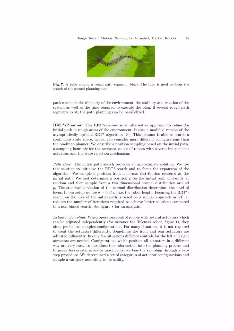
Path Bias: The initial path search provides an approximate solution. We usethis solution to initialize the RRT*-search and to focus the expansion of thealgorithm. We sample a position from a normal distribution centered at theinitial path. We first determine a position p on the initial path uniformly atrandom and then sample from a two dimensional normal distribution aroundp. The standard deviation of the normal distribution determines the level offocus. In our setup we use σ = 0.65m, i.e. the robot length. Focusing the RRT*-search on the area of the initial path is based on a similar approach in [21]. Itreduces the number of iterations required to achieve better solutions comparedto a non-biased search. See figure 8 for an analysis.
Actuator Sampling: When operators control robots with several actuators whichcan be adjusted independently (for instance the Telemax robot, figure 1), theyoften prefer less complex configurations. For many situations it is not requiredto treat the actuators differently. Sometimes the front and rear actuators areadjusted differently. In only few situations different controls for the left and rightactuators are needed. Configurations which position all actuators in a differentway are very rare. To introduce this information into the planning process andto prefer less erratic actuator movements, we bias the sampling through a two-step procedure. We determined a set of categories of actuator configurations andsample a category according to its utility.
16 Rough Terrain Motion Planning for Actuated, Tracked Robots
Fig. 8. The images show exemplary planning queries using no path bias (left), a pathbias of σ = 2.0m (middle) and a path bias of σ = 0.65m (right). The final path costswere determined after 10 000 iterations and averaged over 10 runs for each setup. Usingno path bias the average cost was 29.69 (stdev: 4.43). With a path bias of σ = 2.0m theaverage cost was 17.02 (stdev: 0.36) and with σ = 0.65m the average cost was 15.78(stdev: 0.28). Planning required 7.87 s, 26.64 s and 65.95 s, respectively. The increasingtime requirements are due to a greater number of rewiring options. Because we visualizeonly two dimensions of a 7D state vector, the displayed planning trees do not exhibitthe RRT* characteristic structure in every detail. The path bias increases the samplingdensity in the area around the initial path and enables the algorithm to find a bettersolution within fewer iterations.
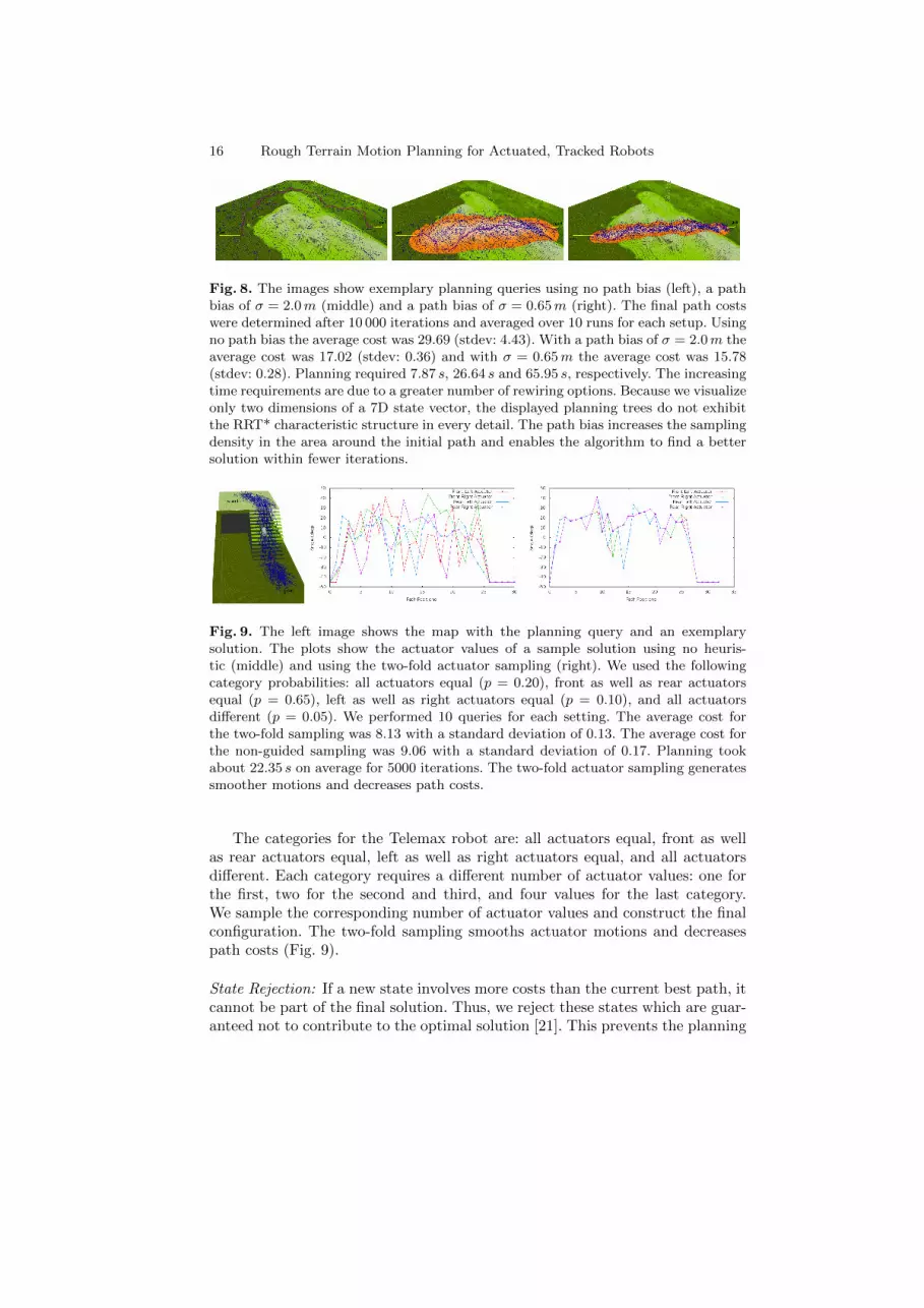
Fig. 9. The left image shows the map with the planning query and an exemplarysolution. The plots show the actuator values of a sample solution using no heuris-tic (middle) and using the two-fold actuator sampling (right). We used the followingcategory probabilities: all actuators equal (p = 0.20), front as well as rear actuatorsequal (p = 0.65), left as well as right actuators equal (p = 0.10), and all actuatorsdifferent (p = 0.05). We performed 10 queries for each setting. The average cost forthe two-fold sampling was 8.13 with a standard deviation of 0.13. The average cost forthe non-guided sampling was 9.06 with a standard deviation of 0.17. Planning tookabout 22.35 s on average for 5000 iterations. The two-fold actuator sampling generatessmoother motions and decreases path costs.
The categories for the Telemax robot are: all actuators equal, front as wellas rear actuators equal, left as well as right actuators equal, and all actuatorsdifferent. Each category requires a different number of actuator values: one forthe first, two for the second and third, and four values for the last category.We sample the corresponding number of actuator values and construct the finalconfiguration. The two-fold sampling smooths actuator motions and decreasespath costs (Fig. 9).
State Rejection: If a new state involves more costs than the current best path, itcannot be part of the final solution. Thus, we reject these states which are guar-anteed not to contribute to the optimal solution [21]. This prevents the planning
Rough Terrain Motion Planning for Actuated, Tracked Robots 17
tree from becoming cluttered with obstructive states. It increases efficiency asthose states are not considered in neighborhood queries and rewiring steps.
6 Parameter Settings
The purpose of this section is to name the parameters of our method and togive guidelines for appropriate values. First of all, many of the quantities usedin our method are determined by the robot model or the general setup, e.g. themaximal traversable height/slope or the maximal velocity.
The kernel size of the filters employed in the roughness quantification shouldbe the diagonal of the robot dimensions. So a cell’s roughness value and slopeis based on the area of the robot’s footprint centered at the cell. As the robotdimensions change with the actuator configurations, we used the average of thesmallest and largest configuration, i.e. for the Telemax a squared window of size100 cm.
We consistently set the resolution of the maps to 5 cm. The resolution ofthe motion graph should be set such that the diagonal edges are shorter thanthe robot length. Using half the robot size (Telemax: 30 cm), we do not needany validity tests between robot positions (i.e. vertices) as the tests at the robotpositions cover the transition edges between them. To distinguish between flatareas and rough areas we specify the maximal height and maximal slope whichcan be traversed using a 2D navigation scheme without utilizing the actuators.We set the value to 9 cm and 15◦ considering the capabilities of the Telemaxwith default actuator configuration.
The minimal velocity vmin used in the cost terms for the translation timespecifies the velocity the robot should drive in the very rough areas. We set thevalue to 0.12ms , i.e. 10% of the robot’s maximal velocity of 1.2ms . The normaliza-tion factors ξs and ξt are determined through the most stable configuration onflat ground and 1
π/2 , the maximal angle to the surface, respectively. ξ normalizes
the time cost with respect to the safety cost and is set to 0.5.The two safety weights w1 for the initial path search and w2 for the detailed
motion planning allow to adjust the importance of the safety for the planningqueries. The former will influence the major direction of the path as it determinesthe initial path. The latter influences the robot configurations and the actuators.Appropriate values depend on the application and the robot model. However,we used values of w1 = 0.75 and w2 = 0.5 in our experiments.
6.1 Roadmap Planner
The size of the tube around rough segments determines the state space expansionfor the detailed motion planning. We required all positions to be less than 75 cmaway from the path. Hence, we include all positions (vertices) which need atmost two edges to reach the path provided a graph resolution of 30 cm (half theTelemax length). We found including two positions to either side of the pathin the tube as a reasonable trade-off between the state space expansion andplanning time.
18 Rough Terrain Motion Planning for Actuated, Tracked Robots
6.2 RRT*-Planner
We use the adaptive ball formulation [20] with the RRT*. The ball determinesthe neighborhood of some node; hence, the radius depicts the size of this neigh-borhood. A large radius means many, potentially too many, neighbors will beincluded and tested for optimal solutions and the runtime increases. If too fewneighbors are considered, the optimal solution may not be found. In our setup, westarted with an radius of r = 0.65m (the length of the Telemax) and decreasedover time.
The path focus helps to find better solutions in less time. However, if thefocus is too loose, the space to be searched becomes too large and the benefitdecreases. If it is too strict, the space may be to small for a reasonable refinementof the initial path. We set σ = 0.65m (the length of the Telemax) for the normaldistribution for all experiments.
The actuator sampling uses a special configuration distribution when usedfor robots with several independent actuators. The probabilities are based on ob-servations of operators, which prefer certain groups of configurations. We foundthe following values to work well for the Telemax robot: p = 0.20 for all actuatorsequal, p = 0.65 for both front and both rear actuators equal, p = 0.10 for theleft and the right actuators equal and p = 0.05 for all actuators different.
The appropriate number of iterations depends on the size of the rough pathsegment. If the segment is short and the number of iterations is high, the neighborqueries will return large numbers of configurations, hence the planning timeincreases. On the other hand, if the number of iterations is too low for a lengthysegment, only a few rewiring options are tested and better solution may bemissed. However, for most queries 10 000 iterations work reasonably well.
7 Experimental Results
We performed tests with the Telemax robot in maps recorded with a laser rangefinder. The environments are shown in figures 10 and 11. Their sizes are 36.4×30.45m and 43.95 × 32.95m, respectively. These are quite large environmentscompared to related works, which usually focus on smaller patches of purelyrough terrain.
We used the following values for the roadmap planner: The resolution of themaps was 0.05m and 0.3m (half the robot length) for the motion graphs. Weconsidered eight orientations in each position (45◦ steps). The actuator valueswere bound to [−45◦, 45◦] in steps of 15◦. Further, both front, respectively bothrear actuators were required to be the same. We chose a folded configurationwith all actuator values equal to −45◦ as default configuration. The defaultconfiguration was applied in flat areas. The maximal ground contact is reachedwith all actuators at 21◦ (see figure 1 right).
To setup the RRT*-planner we used the same map resolution, the same rangeof actuator values and the same safety weight. The additional parameters for theRRT* algorithm were set to r = 0.65m as initial radius size of the adaptive ballformulation.
Rough Terrain Motion Planning for Actuated, Tracked Robots 19
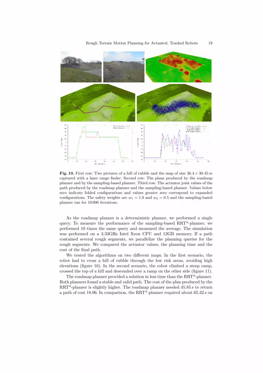
Fig. 10. First row: Two pictures of a hill of rubble and the map of size 36.4 × 30.45mcaptured with a laser range finder. Second row: The plans produced by the roadmapplanner and by the sampling-based planner. Third row: The actuator joint values of thepath produced by the roadmap planner and the sampling-based planner. Values belowzero indicate folded configurations and values greater zero correspond to expandedconfigurations. The safety weights are w1 = 1.0 and w2 = 0.5 and the sampling-basedplanner ran for 10 000 iterations.
As the roadmap planner is a deterministic planner, we performed a singlequery. To measure the performance of the sampling-based RRT*-planner, weperformed 10 times the same query and measured the average. The simulationwas performed on a 3.33GHz Intel Xeon CPU and 12GB memory. If a pathcontained several rough segments, we parallelize the planning queries for therough segments. We compared the actuator values, the planning time and thecost of the final path.
We tested the algorithms on two different maps. In the first scenario, therobot had to cross a hill of rubble through the low risk areas, avoiding highelevations (figure 10). In the second scenario, the robot climbed a steep ramp,crossed the top of a hill and descended over a ramp on the other side (figure 11).
The roadmap planner provided a solution in less time than the RRT*-planner.Both planners found a stable and valid path. The cost of the plan produced by theRRT*-planner is slightly higher. The roadmap planner needed 45.85 s to returna path of cost 18.06. In comparison, the RRT*-planner required about 65.32 s on
20 Rough Terrain Motion Planning for Actuated, Tracked Robots
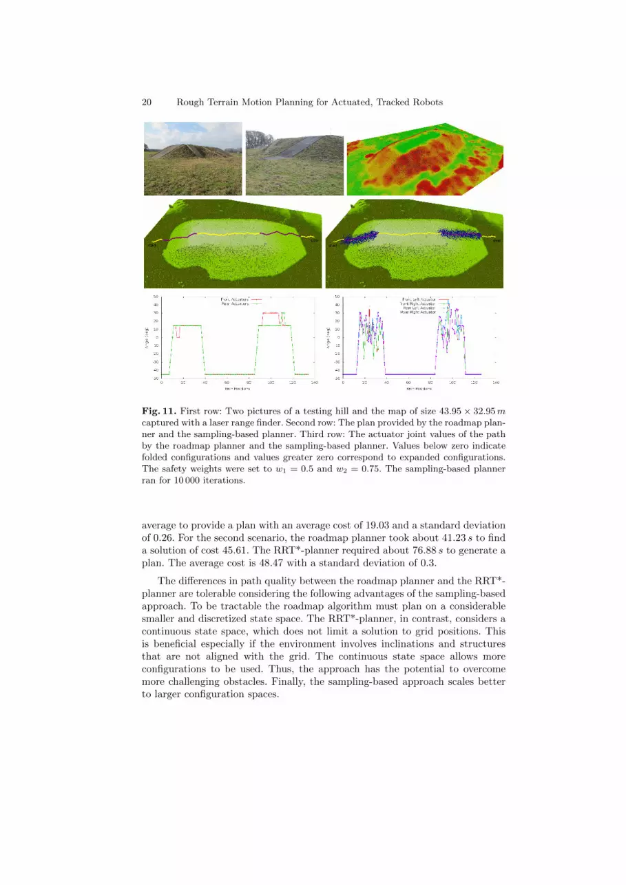
Fig. 11. First row: Two pictures of a testing hill and the map of size 43.95 × 32.95mcaptured with a laser range finder. Second row: The plan provided by the roadmap plan-ner and the sampling-based planner. Third row: The actuator joint values of the pathby the roadmap planner and the sampling-based planner. Values below zero indicatefolded configurations and values greater zero correspond to expanded configurations.The safety weights were set to w1 = 0.5 and w2 = 0.75. The sampling-based plannerran for 10 000 iterations.
average to provide a plan with an average cost of 19.03 and a standard deviationof 0.26. For the second scenario, the roadmap planner took about 41.23 s to finda solution of cost 45.61. The RRT*-planner required about 76.88 s to generate aplan. The average cost is 48.47 with a standard deviation of 0.3.
The differences in path quality between the roadmap planner and the RRT*-planner are tolerable considering the following advantages of the sampling-basedapproach. To be tractable the roadmap algorithm must plan on a considerablesmaller and discretized state space. The RRT*-planner, in contrast, considers acontinuous state space, which does not limit a solution to grid positions. Thisis beneficial especially if the environment involves inclinations and structuresthat are not aligned with the grid. The continuous state space allows moreconfigurations to be used. Thus, the approach has the potential to overcomemore challenging obstacles. Finally, the sampling-based approach scales betterto larger configuration spaces.
Rough Terrain Motion Planning for Actuated, Tracked Robots 21
8 Conclusion and Future Work
In this paper we presented a motion planning algorithm for robots with activelyreconfigurable chassis to find safe paths through rough terrain. We introduceda hierarchical planner which quickly determines an initial path considering onlythe robot’s operating limits rather than the complete states. The initial pathis used to focus the search in the high dimensional state space of the seconddetailed motion planning phase. We plan the robot’s motions in detail only inrough areas where it is really necessary. We described a roadmap method anda RRT* approach to refine the initial path during the second planning phase.Our algorithm does not rely on predefined motion sequences or on a terrainclassification. Hence, it can be applied to urban structures, like stairs, as well asto rough unstructured environments.
Future work will focus on overcoming more challenging obstacles, like boxesor high steps. This will require a more accurate modeling of the robots footprintand the contact points with the environment. Also, we will investigate meth-ods which reuse previous planning results to answer replanning queries to thesame goal if the robot deviates from the previous plan. The current controller issolely based on differential GPS; we are planning to improve the path executionthrough a more sophisticated controller.
References
1. Mourikis, A.I., Trawny, N., Roumeliotis, S.I., Helmick, D.M., Matthies, L.: Au-tonomous Stair Climbing for Tracked Vehicles. Int. J. of Robotics Research 26(7)(2007) 737–758
2. Mihankhah, E., Kalantari, A., Aboosaeedan, E., Taghirad, H., Moosavian, S.A.A.:Autonomous Staircase Detection and Stair Climbing for a Tracked Mobile RobotUsing Fuzzy Controller. In: IEEE Int. Conf. on Robotics and Biomimetics. (2009)
3. Dornhege, C., Kleiner, A.: Behavior maps for online planning of obstacle negotia-tion and climbing on rough terrain. In: IEEE/RSJ Int. Conf. on Intelligent Robotsand Systems. (2007)
4. Rusu, R.B., Sundaresan, A., Morisset, B., Hauser, K., Agrawal, M., Latombe, J.C.,Beetz, M.: Leaving Flatland: Efficient Real-Time Three-Dimensional Perceptionand Motion Planning. J. of Field Robotics 26 (2009) 841–862
5. Kalakrishnan, M., Buchli, J., Pastor, P., Mistry, M., Schaal, S.: Learning, Planning,and Control for Quadruped Locomotion over Challenging Terrain. The Int. J. ofRobotics Research 30 (2010) 236–258
6. Molino, V., Madhavan, R., Messina, E., Downs, A., Balakirsky, S., Jacoff, A.:Traversability metrics for rough terrain applied to repeatable test methods. In:IEEE/RSJ International Conference on Intelligent Robots and Systems. (2007)
7. Ratliff, N., Zucker, M., Bagnell, J.A., Srinivasa, S.: CHOMP: Gradient Optimiza-tion Techniques for Efficient Motion Planning. In: IEEE International Conferenceon Robotics and Automation. (2009)
8. Kalakrishnan, M., Chitta, S., Theodorou, E., Pastor, P., Schaal, S.: STOMP:Stochastic Trajectory Optimization for Motion Planning. In: Int. Conf. Robot.Autom. (2011)
22 Rough Terrain Motion Planning for Actuated, Tracked Robots
9. Rufli, M., Ferguson, D., Siegwart, R.: Smooth Path Planning in Constrained En-vironments. In: IEEE Int. Conf. Robot. and Autom. (2009)
10. Miro, J., Dumonteil, G., Beck, C., Dissanayake, G.: A kyno-dynamic metric to planstable paths over uneven terrain. In: IEEE/RSJ Int. Conf. on Intelligent Robotsand Systems. (2010)
11. Hait, A., Simeon, T., Taix, M.: Algorithms for Rough Terrain Trajectory Planning.Advanced Robotics 16 (2002) 673–699
12. Magid, E., Tusubouchi, T., Koyanagi, E., Yoshida, T., Tadokoro, S.: ControlledBalance Losing in Random Step Environment for Path Planning of a TeleoperatedCrawler-Type Vehicle. J. of Field Robotics 28 (2011) 932–949
13. Jaillet, L., Cortes, J., Simeon, T.: Sampling-Based Path Planning onConfiguration-Space Costmaps. IEEE Transactions on Robotics 26 (2010) 35–646
14. Shkolnik, A., Levashov, M., Manchester, I.R., Tedrake, R.: Bounding on roughterrain with the LittleDog robot. Int. J. of Robotics Research 30(2) (2011) 192–215
15. Ettlin, A., Bleuler, H.: Rough-Terrain Robot Motion Planning based on Obstacle-ness. In: 9th Int. Conf. Control, Autom., Robot. Vis. (2006)
16. Magid, E., Ozawa, K., Tsubouchi, T., Koyanagi, E., Yoshida, T.: Rescue RobotNavigation: Static Stability Estimation in Random Step Environment. LNCS -Simulation, Modeling, and Programming for Autonomous Robots 5325 (2008)305–316
17. Howard, T.M., Kelly, A.: Optimal Rough Terrain Trajectory Generation forWheeled Mobile Robots. International Journal of Robotics Research 26(2) (2007)141–166
18. Araujo, R., Gouveia, G., De Almeida, A.: Learning variable-resolution maps fornavigation in dynamic worlds. In: IEEE Industrial Electronics Society 28th AnnualConference. Volume 3. (2002) 2403–2408 vol.3
19. Hirose, S., Tsukagoshi, H., Yoneda, K.: Normalized Energy Stability Margin and itsContour of Walking Vehicles on Rough Terrain. In: IEEE International Conferenceon Robotics and Automation (ICRA). (2001)
20. Karaman, S., Frazzoli, E.: Sampling-based Algorithms for Optimal Motion Plan-ning. Int. J. of Robotics Research 30(7) (June 2011) 846–894
21. Akgun, B., Stilman, M.: Sampling heuristics for optimal motion planning in highdimensions. In: IEEE/RSJ Int. Conf. on Intelligent Robots and Systems. (2011)2640–2645
Related Documents