Malaysian Institute of Aviation Technology DIGITAL TECH (MECH) AKD 21102 CHAPTER 2 LOGIC CIRCUIT Module 5.2 1 Revision 01 Issue02

Welcome message from author
This document is posted to help you gain knowledge. Please leave a comment to let me know what you think about it! Share it to your friends and learn new things together.
Transcript

Malaysian Institute of Aviation Technology
DIGITAL TECH (MECH)
AKD 21102
CHAPTER 2
LOGIC CIRCUIT
Module 5.2 1Revision 01 Issue02
Malaysian Institute of Aviation Technology
INTRODUCTION
• An ability to make decisions based on a variety
of different factors is crucial to the safe operation
of a modern aircraft.
• It is therefore not surprising that logic systems
are widely used in aircraft today
Module 5.2 2Revision 01 Issue02
Malaysian Institute of Aviation Technology
CHAPTER CONTENT
1. Identification of common logic gate symbol, tables, equivalent circuits and Boolean expression
2. Introduction to :• Application used for aircraft systems
• Interpretation of schematic diagrams
Module 5.2 3Revision 01 Issue02

Malaysian Institute of Aviation Technology
• Allowed 2 binary variables only : 1 & 0
• Represent voltages or logic level
• May represent (in circuit) : ON,CLOSED (logic 1) and
OFF,OPEN (logic 0)
• Only 3 operation in Boolean algebra
• Logical addition (+), Logical Multiplication (•) and
Complementation ( ‾ )
BOOLEAN CONSTANT AND VARIABLE
Module 5.2 4Revision 01 Issue02
Malaysian Institute of Aviation Technology
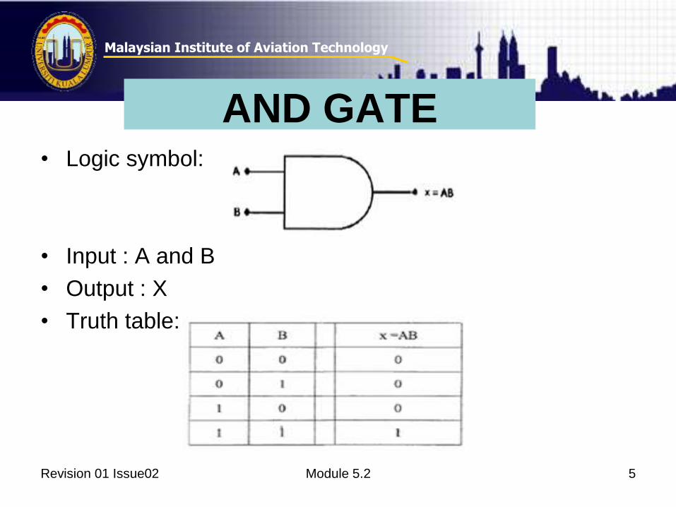
• Logic symbol:
• Input : A and B
• Output : X
• Truth table:
AND GATE
Module 5.2 5Revision 01 Issue02
Malaysian Institute of Aviation Technology
Revision 01 Issue02 Module 5.2
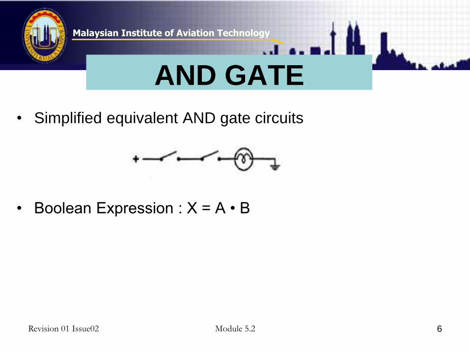
• Simplified equivalent AND gate circuits
• Boolean Expression : X = A • B
6
AND GATE
Malaysian Institute of Aviation Technology
Revision 01 Issue02 Module 5.2
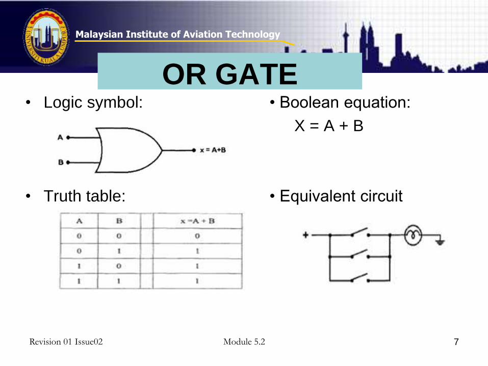
• Logic symbol: • Boolean equation:
X = A + B
• Truth table: • Equivalent circuit
7
OR GATE
Malaysian Institute of Aviation Technology
Revision 01 Issue02 Module 5.2
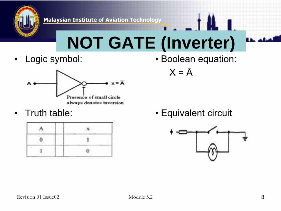
• Logic symbol: • Boolean equation:
X = Ā
• Truth table: • Equivalent circuit
8
NOT GATE (Inverter)

Malaysian Institute of Aviation Technology
Revision 01 Issue02 Module 5.2
• Logic symbol: • Boolean equation:
X = 𝐴𝐵
• Truth table: • Equivalent circuit
9
NAND GATE

Malaysian Institute of Aviation Technology
Revision 01 Issue02 Module 5.2
• Logic symbol: • Boolean equation:
X = 𝐴 + 𝐵
• Truth table: • Equivalent circuit
10
NOR GATE
Malaysian Institute of Aviation Technology
Revision 01 Issue02 Module 5.2
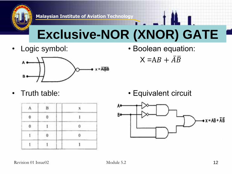
• Logic symbol: • Boolean equation:
X = 𝐴𝐵 + 𝐴 𝐵
• Truth table: • Equivalent circuit
11
Exclusive-OR (XOR) GATE
Malaysian Institute of Aviation Technology
Revision 01 Issue02 Module 5.2
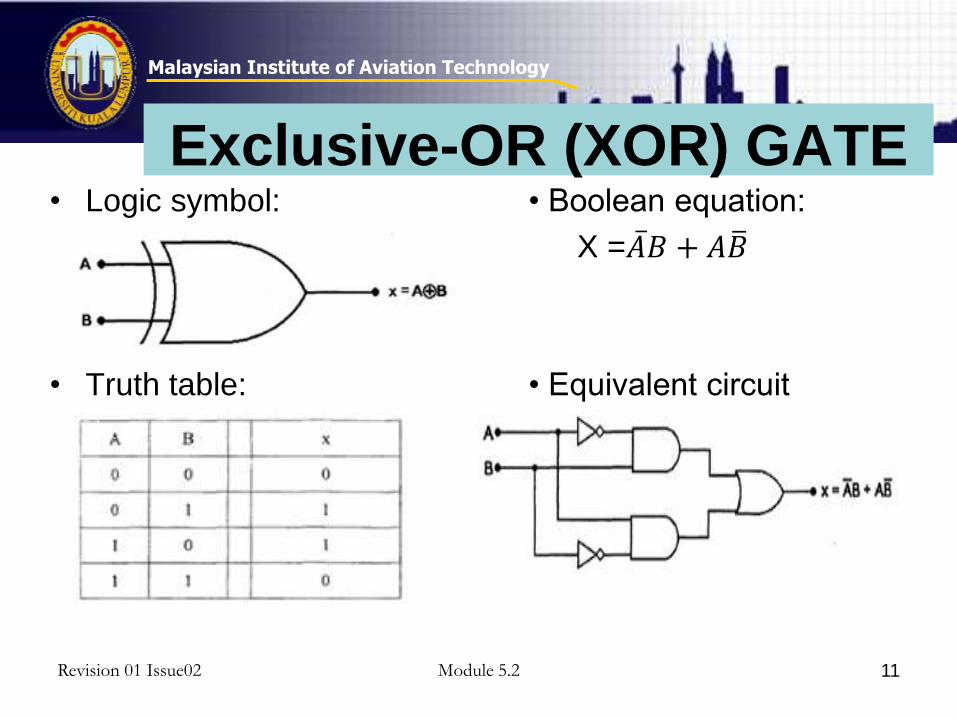
• Logic symbol: • Boolean equation:
X =A𝐵 + 𝐴 𝐵
• Truth table: • Equivalent circuit
12
Exclusive-NOR (XNOR) GATE
Malaysian Institute of Aviation Technology
Revision 01 Issue02 Module 5.2 13
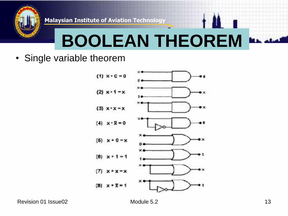
BOOLEAN THEOREM• Single variable theorem

Malaysian Institute of Aviation Technology
Revision 01 Issue02 Module 5.2 14
BOOLEAN THEOREM
• Multi variable theorem

Malaysian Institute of Aviation Technology
Revision 01 Issue02 Module 5.2
APPLICATION
15
Malaysian Institute of Aviation Technology
APPLICATION• Consist of 2 OR gates and an AND gate, with
logic states received from 7 parameters
• When either throttle lever is pushed forward, the switch at that position is made (advance) and there is a logic state 1 to OR gate1.
• 5 other parameters are sensed and logic states sent to OR gate2.
Module 5.2 16Revision 01 Issue02
Malaysian Institute of Aviation Technology
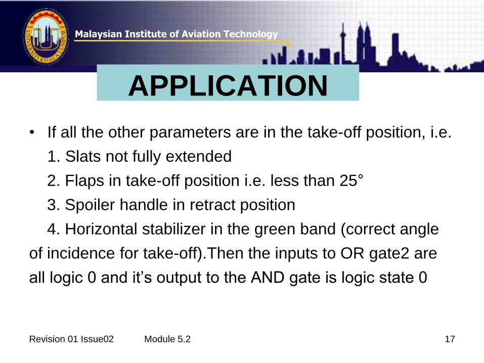
• If all the other parameters are in the take-off position, i.e.
1. Slats not fully extended
2. Flaps in take-off position i.e. less than 25°
3. Spoiler handle in retract position
4. Horizontal stabilizer in the green band (correct angle
of incidence for take-off).Then the inputs to OR gate2 are
all logic 0 and it’s output to the AND gate is logic state 0
Module 5.2 17Revision 01 Issue02
APPLICATION
Malaysian Institute of Aviation Technology
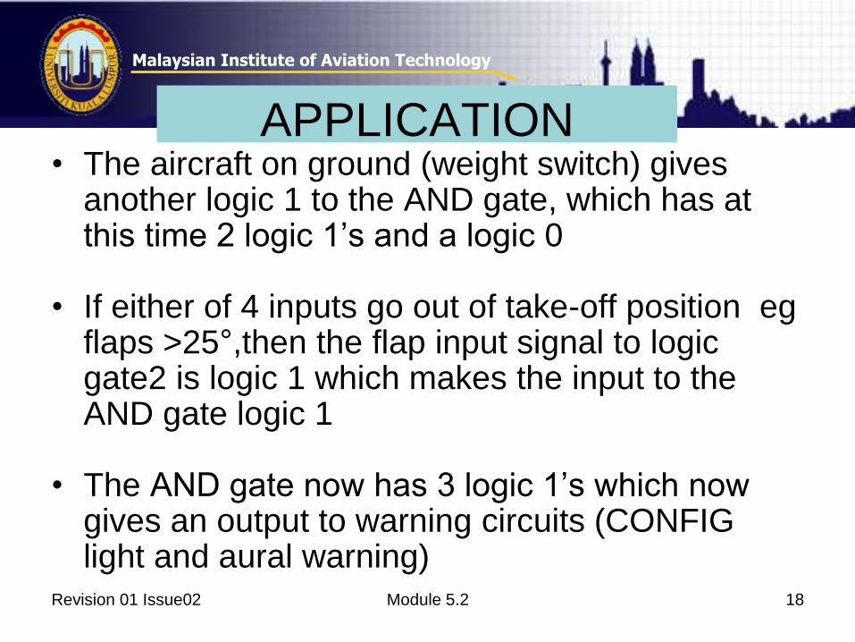
APPLICATION• The aircraft on ground (weight switch) gives
another logic 1 to the AND gate, which has at this time 2 logic 1’s and a logic 0
• If either of 4 inputs go out of take-off position egflaps >25°,then the flap input signal to logic gate2 is logic 1 which makes the input to the AND gate logic 1
• The AND gate now has 3 logic 1’s which now gives an output to warning circuits (CONFIG light and aural warning)
Module 5.2 18Revision 01 Issue02
Malaysian Institute of Aviation Technology
Module 5.2 19Revision 01 Issue02
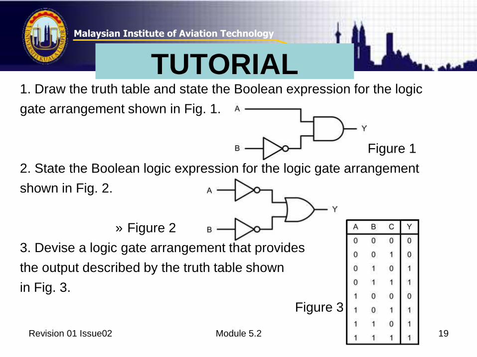
TUTORIAL 1. Draw the truth table and state the Boolean expression for the logic
gate arrangement shown in Fig. 1.
Figure 1
2. State the Boolean logic expression for the logic gate arrangement
shown in Fig. 2.
» Figure 2
3. Devise a logic gate arrangement that provides
the output described by the truth table shown
in Fig. 3.
Figure 3
Related Documents