DESIGN AND FABRICATION OF FIXTURE TO TORQUE AND ASSEMBLY THE DIFFERENTIAL CAGE Industrial & Production engineering department P.E.S.C.E Page1 COMPANY PROFILE

Welcome message from author
This document is posted to help you gain knowledge. Please leave a comment to let me know what you think about it! Share it to your friends and learn new things together.
Transcript
DESIGN AND FABRICATION OF FIXTURE TO TORQUE AND ASSEMBLY THE DIFFERENTIAL CAGE
Industrial & Production engineering department P.E.S.C.E
Pag
e1
COMPANY PROFILE
DESIGN AND FABRICATION OF FIXTURE TO TORQUE AND ASSEMBLY THE DIFFERENTIAL CAGE
Industrial & Production engineering department P.E.S.C.E
Pag
e2
ABOUT THE COMPANY
Es t ab l i shed i n 1981 , Au t o mot i ve Ax l e s L imi t ed ( AAL) i s a j o i n t
ven t u r e o f Ar v i n Mer i t o r Inc . , USA ( fo r mer l y t he au to mot i ve d i v i s i on
o f Rock we l l I n t e r na t i ona l Co r po r a t i on ) , a Fo r t une 500 company , and
t he Ka l yan i Gr oup . Wi t h manu fac t u r i ng f ac i l i t i e s l oca t ed a t Myso r e ,
t he company i s cu r r en t l y t he l a r ge s t i ndependen t manufac t u r e r o f Rea r
Dr i ve Ax l e Assembl i e s i n t he coun t r y . Ove r t he yea r s , AAL ha s
deve l oped an i mp r e s s i ve do mes t i c OEM c l i en t e l e t ha t i nc l udes Ashok
Ley l and , Te l co , Veh i c l e Fac t o r y , J aba l pur , Mah i nd r a & Mah i nd r a ,
Vo l vo and Bha r a t Ea r t h Move r s . AAL expo r t s ax l e pa r t s t o USA, and
I t a l y .
T h e i n f r a s t r u c t u r e a t A A L s p a n s h i g h l y s p e c i a l i z e d m a n u f a c t u r i n g p r o c e s s e s
i n v o l v i n g F r i c t i o n W e l d i n g , C o 2 W e l d i n g , C N C M a c h i n i n g , F l e x i b l e M a c h i n e
DESIGN AND FABRICATION OF FIXTURE TO TORQUE AND ASSEMBLY THE DIFFERENTIAL CAGE
Industrial & Production engineering department P.E.S.C.E
Pag
e3
C e n t r e ’ s a n d a r a n g e o f s p e c i a l l y b u i l t m a c h i n e s f o r p r o d u c t i o n o f A x l e s a n d
B r a k e s . T h e f a c i l i t i e s a l s o c o m p r i s e G l e a s o n G e a r M a n u f a c t u r i n g E q u i p m e n t
b a c k e d b y a m o d e r n H e a t T r e a t m e n t S h o p i n c l u d i n g C o n t i n u o u s C a r b u r i z i n g
a n d S e a l e d Q u e n c h F u r n a c e . W i d e r a n g e o f R e a r D r i v e A x l e s c a t e r i n g t o
c o m m e r c i a l v e h i c l e s r a n g i n g f r o m 6 T o n s t o 3 5 T o n s G C W , S - C a m A c t u a t e d
Q u i c k C h a n g e A i r B r a k e s f o r c o m m e r c i a l v e h i c l e s , a n d T r a i l e r A x l e s f o r 1 0
T o n s t o 1 3 T o n s G V W .
AAL has a Qua l i t y Managemen t Sy s t em t ha t i s c e r t i f i ed t o I SO/ TS
16949 : 2002 s t anda r d and a l so Env i r on men t a l Managemen t Sys t em t ha t
i s c e r t i f i ed t o I SO 14001 : 2004 s t anda r d
HISTORY
1981 - Foundation Stone laid
1981 - Incorporation and commencement of business
1982 - First Annual General meeting of Members
1983 - First Public Issue of equity shares
1984 - Commercial production of Rear Axle Housing
1986 - Commercial production of Brake Assembly
1988 - Commercial production of Axle Assembly for LCV manufacturers
1991 - Entered Export market by exporting prototypes to MB-Germany
1995 - Rights issue in the ratio of 1:4
1996 - Sales cross Rs. 1 billion
1998 - Quality Management System certified to ISO 9001
2000 - Quality System certified to QS 9000
2003 - Sales cross Rs. 2 Billion
2005 - Quality System certified to TS16949
2005 - Sales cross Rs. 3.5 Billion
2005 - Foundation Stone laid for 'Kalyani Nagar' colony of Employees
2006 - Environment Management System Certified to IS14001
2006 - Silver Jubilee year - Sales Cross Rs. 4.5 Billion
2011 - 30th Anniversary
DESIGN AND FABRICATION OF FIXTURE TO TORQUE AND ASSEMBLY THE DIFFERENTIAL CAGE
Industrial & Production engineering department P.E.S.C.E
Pag
e4
DEFINING MOMENTS REFERENCE TO BIFR IN 1989
The company brought in Rockwell's state-of-the-art manufactureing technology to India way
ahead of its time expecting it would be able to penetrate a market segment in which CV
manufacturers were making their own axles. Due to unforeseen delays caused due to various
factors, it took us several years to achieve this objective. We had therefore to be content with
the business of contract manufacturing in which we could barely recover variable costs
resulting in the accumulation of significant losses with interest and depreciation burden
contributing to the erosion of over 50% of the company's net worth which led to its reference
to BIFR.
COMPANY VISION
Be a world class quality supplier of cost competitive products
Retain leadership in Indian markets for Rear Axles
Enhance exports business with ArvinMeritor & Others to 20% of Total Sales
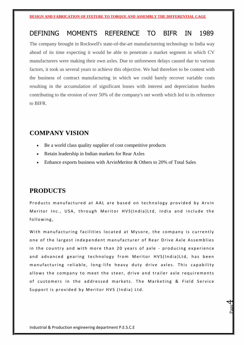
PRODUCTS
P r o d u c t s m a n u f a c t u r e d a t A A L a r e b a s e d o n t e c h n o l o g y p r o v i d e d b y A r v i n
M e r i t o r I n c . , U S A , t h r o u g h M e r i t o r H V S ( I n d i a ) L t d , I n d i a a n d i n c l u d e t h e
f o l l o w i n g ,
W i t h m a n u f a c t u r i n g f a c i l i t i e s l o c a t e d a t M y s o r e , t h e c o m p a n y i s c u r r e n t l y
o n e o f t h e l a r g e s t i n d e p e n d e n t m a n u f a c t u r e r o f R e a r D r i v e A x l e A s s e m b l i e s
i n t h e c o u n t r y a n d w i t h m o r e t h a n 2 0 y e a r s o f a x l e - p r o d u c i n g e x p e r i e n c e
a n d a d v a n c e d g e a r i n g t e c h n o l o g y f r o m M e r i t o r H V S ( I n d i a ) L t d , h a s b e e n
m a n u f a c t u r i n g r e l i a b l e , l o n g - l i f e h e a v y d u t y d r i v e a x l e s . T h i s c a p a b i l i t y
a l l o w s t h e c o m p a n y t o m e e t t h e s t e e r , d r i v e a n d t r a i l e r a x l e r e q u i r e m e n t s
o f c u s t o m e r s i n t h e a d d r e s s e d m a r k e t s . T h e M a r k e t i n g & F i e l d S e r v i c e
S u p p o r t i s p r o v i d e d b y M e r i t o r H V S ( I n d i a ) L t d .
DESIGN AND FABRICATION OF FIXTURE TO TORQUE AND ASSEMBLY THE DIFFERENTIAL CAGE
Industrial & Production engineering department P.E.S.C.E
Pag
e5
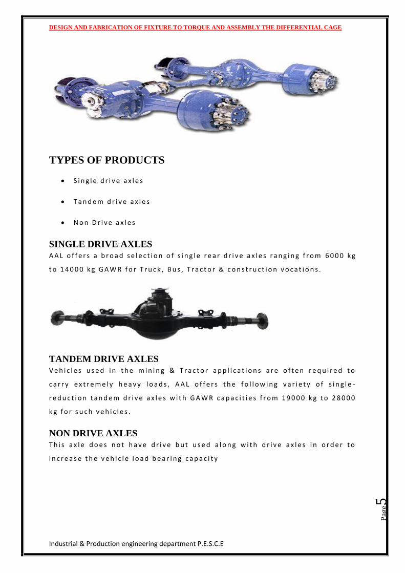
TYPES OF PRODUCTS
S i n g l e d r i v e a x l e s
T a n d e m d r i v e a x l e s
N o n D r i v e a x l e s
SINGLE DRIVE AXLES
A A L o f f e r s a b r o a d s e l e c t i o n o f s i n g l e r e a r d r i v e a x l e s r a n g i n g f r o m 6 0 0 0 k g
t o 1 4 0 0 0 k g G A W R f o r T r u c k , B u s , T r a c t o r & c o n s t r u c t i o n v o c a t i o n s .
TANDEM DRIVE AXLES
V e h i c l e s u s e d i n t h e m i n i n g & T r a c t o r a p p l i c a t i o n s a r e o f t e n r e q u i r e d t o
c a r r y e x t r e m e l y h e a v y l o a d s , A A L o f f e r s t h e f o l l o w i n g v a r i e t y o f s i n g l e -
r e d u c t i o n t a n d e m d r i v e a x l e s w i t h G A W R c a p a c i t i e s f r o m 1 9 0 0 0 k g t o 2 8 0 0 0
k g f o r s u c h v e h i c l e s .
NON DRIVE AXLES
T h i s a x l e d o e s n o t h a v e d r i v e b u t u s e d a l o n g w i t h d r i v e a x l e s i n o r d e r t o
i n c r e a s e t h e v e h i c l e l o a d b e a r i n g c a p a c i t y
DESIGN AND FABRICATION OF FIXTURE TO TORQUE AND ASSEMBLY THE DIFFERENTIAL CAGE
Industrial & Production engineering department P.E.S.C.E
Pag
e6
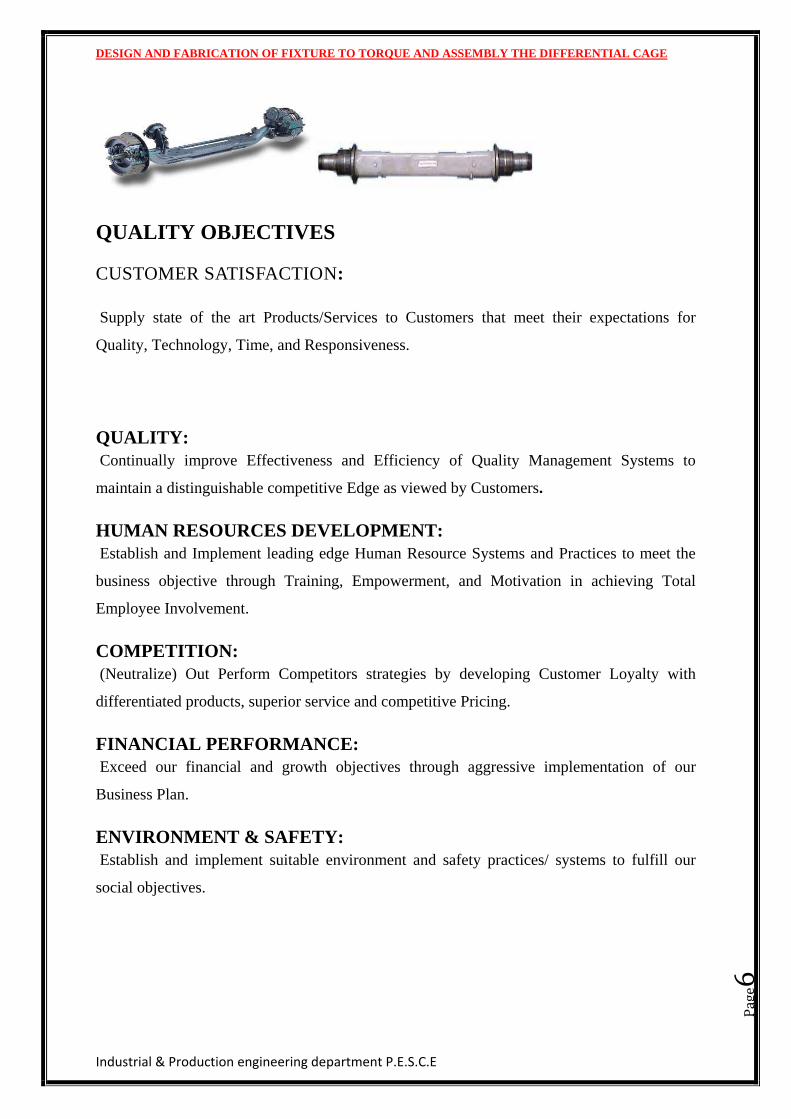
QUALITY OBJECTIVES
CUSTOMER SATISFACTION:
Supply state of the art Products/Services to Customers that meet their expectations for
Quality, Technology, Time, and Responsiveness.
QUALITY:
Continually improve Effectiveness and Efficiency of Quality Management Systems to
maintain a distinguishable competitive Edge as viewed by Customers.
HUMAN RESOURCES DEVELOPMENT:
Establish and Implement leading edge Human Resource Systems and Practices to meet the
business objective through Training, Empowerment, and Motivation in achieving Total
Employee Involvement.
COMPETITION:
(Neutralize) Out Perform Competitors strategies by developing Customer Loyalty with
differentiated products, superior service and competitive Pricing.
FINANCIAL PERFORMANCE:
Exceed our financial and growth objectives through aggressive implementation of our
Business Plan.
ENVIRONMENT & SAFETY:
Establish and implement suitable environment and safety practices/ systems to fulfill our
social objectives.
DESIGN AND FABRICATION OF FIXTURE TO TORQUE AND ASSEMBLY THE DIFFERENTIAL CAGE
Industrial & Production engineering department P.E.S.C.E
Pag
e7
FEATURES
High efficiency gearing
Integral brake to axle design and manufacturing capability.
Wide ratio availability
Weight optionised designs
Driver operated differential locks
Worldwide availability
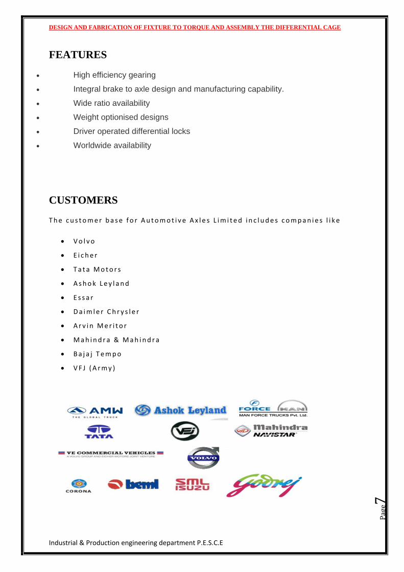
CUSTOMERS
T h e c u s t o m e r b a s e f o r A u t o m o t i v e A x l e s L i m i t e d i n c l u d e s c o m p a n i e s l i k e
V o l v o
E i c h e r
T a t a M o t o r s
A s h o k L e y l a n d
E s s a r
D a i m l e r C h r y s l e r
A r v i n M e r i t o r
M a h i n d r a & M a h i n d r a
B a j a j T e m p o
V F J ( A r m y )
DESIGN AND FABRICATION OF FIXTURE TO TORQUE AND ASSEMBLY THE DIFFERENTIAL CAGE
Industrial & Production engineering department P.E.S.C.E
Pag
e8
CHAPTER 1
INTRODUCTION TO
TOOL DESIGN
DESIGN AND FABRICATION OF FIXTURE TO TORQUE AND ASSEMBLY THE DIFFERENTIAL CAGE
Industrial & Production engineering department P.E.S.C.E
Pag
e9
1.TOOL DESIGN
Tool design is the process of designing and developing the tools, methods and
techniques necessary to improve manufacturing efficiency and productivity. It gives industry
the machines and special tooling needed for today’s high-speed, high-volume production. It
does this at a level of quality and economy that will ensure that the cost of the product is
competitive. Since no single tool or process can serve all forms of manufacturing, tool design
is an ever-changing, growing process of creative problem solving.
1.1 TOOL DESIGN OBJECTIVES
The main objective of tool design is to lower manufacturing costs while maintaining
quality costs while maintaining quality and increased production. To accomplish this, the tool
designer must satisfy the following objective
Provides simple, easy-to-operate tools for maximum efficiency.
Reduce manufacturing expenses by producing parts at the lowest possible
cost.
Design tools that consistently produce parts of high quality.
Increase the rate of production with existing machine tools.
Design the tool so to make it foolproof and to prevent improper use.
Select materials that will give adequate tool life.
Provide protection in the design of the tools for maximum safety of the
operator.
1.2TOOL DESIGN IN MANUFACTURING
Manufacturing for global competitiveness clearly requires the success of concurrent
engineering. Concurrent engineering is a process that allows the design team to be involved
in a comprehensive plan for product design and production. Concurrent engineering allows
the design team member to be involved in product design and production where their
knowledge of fixtures and manufacturing processes will result in fewer design errors.
Concurrent engineering teams consists of product designers, process planning engineers, tool
DESIGN AND FABRICATION OF FIXTURE TO TORQUE AND ASSEMBLY THE DIFFERENTIAL CAGE
Industrial & Production engineering department P.E.S.C.E
Pag
e10
designers, quality control engineers, production management, and machining technicians.
Companies may vary job titles and team compositions to suit their internal company
structure.
Team members contribute based on their area of expertise. The product, a method for
manufacturing, tooling concepts, and a quality plan are developed that suits the selected
manufacturing facility. In this way, problems are not discovered on the production floor, but
are corrected early in the concurrent process. This ultimately saves time and money while
speeding up the process of getting product to market earlier. Concurrent engineering allows a
company to have a distinct economic advantage in a global market.
The tool designer develops a plan for maintaining the concepts developed by the team
with respect to economic guidelines. Expert computer systems are now part of the design
environment. And they support an integrated approach for tracking time and money allocated
for the project and provides immediate information at any point in the concurrent process.
1.3 PLANNING THE DESIGN
The designer is responsible for managing information resource that impacts the tool
design. Product design changes are continuously reviewed to determine tooling changes are
continuously reviewed to determine tooling changes that might be necessary. Last-minute
costly changes are eliminated or minimized. The team meets regularly to provide any
necessary updates or changes in the production plan. This is time wisely spent and results in
an efficient and cost effective tool design. The design process is not as linear as it used to be.
Communication models between team members include e-mail and electronic transfer of
materials and may use of sophisticated technology such as teleconferencing. Team members
may consist of customers, designers, and builders in different locations that may take them
halfway around the world.
1.4 PART DRAWINGS
The tool designer receives a duplicate of the part geometry that will be used to make
the part many part prints are transmitted electronically and may include a solid model. The
solid model allows the designer to view the three-dimensional part geometry. The task of tool
design begins with a more complete understanding of part. A prototype, or a single
manufactured part used for evaluation purposes, can be made available. A prototype goes one
DESIGN AND FABRICATION OF FIXTURE TO TORQUE AND ASSEMBLY THE DIFFERENTIAL CAGE
Industrial & Production engineering department P.E.S.C.E
Pag
e11
more step beyond the solid computer model. The prototype, a single physical part provided
prior to formal production, is a valuable tool for understanding more complex part
geometrics. Prototypes are manufactured using conventional computer numerical control
(CNC) machine tools or some of the newer technologies such as stereo lithography and LOM
develop the part geometry using a system of layering the medium and solidifying or cutting
out that layer with a laser. The result is a solid object made one layer at a time where the
layers may be no more than .003 thick. Whether analyzing the prototype and part drawing or
just the part drawing, the designer must consider the following factors that directly influence
the design choices. These factors are:
Overall size and shape of the part
Type and condition of the material used for the part
Type of machining operation to be performed
Degree of accuracy
Number of pieces to be made
Locating and clamping surfaces
1.5 PRODUCTION PLAN
The production plan is an itemized list of the manufacturing operation and the
sequence of the operation chosen by process planning engineers. The production plan can
take many forms, depending on the needs of each company. At the least, it should include a
brief description of each machining operation and the machine tool designated for these
operations.
The tool designer also uses this plan to assist in the design. The production plan can
include the following:
Type and size of machine tool specified for each operation
Type and size of cutters specified for each operation.
Sequence of operations
Previous machining operations performed on the part
DESIGN AND FABRICATION OF FIXTURE TO TORQUE AND ASSEMBLY THE DIFFERENTIAL CAGE
Industrial & Production engineering department P.E.S.C.E
Pag
e12
In addition to the part drawing and production plan, the tool designer is informed
of the amount of time and money that is available to spend on design. Using this
information and a little creativity and experience, the tool designer begins to
study the design alternatives.
1.6 ALTERNATIVES
One of the first steps in problem solving is determining the alternative solutions. The
same process is used in tool design to ensure that the best method is chosen. During this
phase of design, tool designer must analyze all important information in order to answer the
following questions:
Should special tooling be used or existing equipment modified?
Should multiple-spindle or single –spindle machines be used?
Should the tool be single purpose or multipurpose?
Will the saving justify the cost of the tool?
What type of gauge, if any, should be used to check each operation?
Answering these question and others related to the specific task, the tool designer
develops alternative solution. From these alternative solutions, the most efficient,
dependable, and cost effective design is chosen.
1.7 REQUIREMENTS TO BECOME A TOOL DESIGNER
To perform the function of a tool designer, an individual must have the following
skills:
The ability to make mechanical drawings and sketches
An understanding of modern manufacturing methods, tools and techniques
A creative mechanical ability
An understanding of basic tool making methods
A knowledge of technical mathematics through practical trigonometry
DESIGN AND FABRICATION OF FIXTURE TO TORQUE AND ASSEMBLY THE DIFFERENTIAL CAGE
Industrial & Production engineering department P.E.S.C.E
Pag
e13
CAD drafting skills
File management
Electronic communication skills
Geometric dimensioning and tolerancing
DESIGN AND FABRICATION OF FIXTURE TO TORQUE AND ASSEMBLY THE DIFFERENTIAL CAGE
Industrial & Production engineering department P.E.S.C.E
Pag
e14
CHAPTER 2
JIGS AND FIXTURE
DESIGN AND FABRICATION OF FIXTURE TO TORQUE AND ASSEMBLY THE DIFFERENTIAL CAGE
Industrial & Production engineering department P.E.S.C.E
Pag
e15
2. JIGS AND FIXTURES
Jigs and fixture are production-work holding devices used to manufacture duplicate
parts accurately. The correct relationship and alignment between the cutter, or other tool and
the workpiece must be maintained. To do this, a jig or fixture is designed and built to hold,
support, and locate every part to ensure that each is drilled or machined within the specified
limits.
Jigs and fixtures are so closely related that the terms are sometimes confused or used
interchangeably. The terms are sometimes confused or used interchangeably. The difference
is in the way the tool is guided to the work piece.
A jig is a special device that holds, supports or is placed on a part to be machined. It is
a production tool made so that it not only locates and holds the work piece but also guides the
cutting tool as the operation is performed. Jigs are usually fitted with hardened steel bushings
for guiding drills or other cutting tools
As a rule, small jigs are not fastened to the drill press table. If, however, holes above
.25 inch in diameter are to be drilled, it is usually necessary to fasten the jig to the table
securely.
A fixture is a production tool that locates, holds, and supports the work securely so
the required machining operation can be performed. Set blocks and feeler or thickness gauges
are used with fixtures to references the cutter to be work piece. A fixture should be securely
fastened to the table of machine upon which the work is done. Though largely used on
milling machines, fixtures are also designed to hold work for various operations on most of
the standard machine tools.
Fixtures vary in design from relatively simple tools to expensive, complicated
devices. Fixtures also help to simplify metalworking operations performed on special
equipment.
DESIGN AND FABRICATION OF FIXTURE TO TORQUE AND ASSEMBLY THE DIFFERENTIAL CAGE
Industrial & Production engineering department P.E.S.C.E
Pag
e16
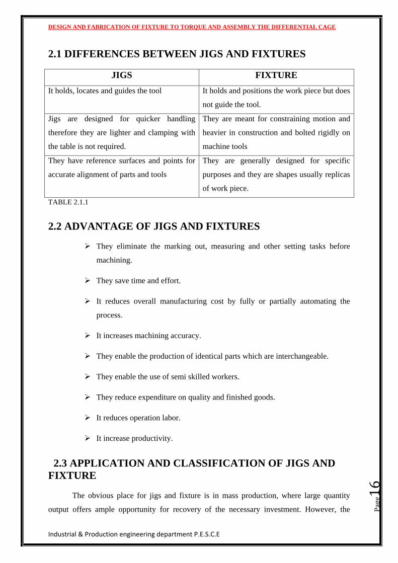
2.1 DIFFERENCES BETWEEN JIGS AND FIXTURES
JIGS FIXTURE
It holds, locates and guides the tool It holds and positions the work piece but does
not guide the tool.
Jigs are designed for quicker handling
therefore they are lighter and clamping with
the table is not required.
They are meant for constraining motion and
heavier in construction and bolted rigidly on
machine tools
They have reference surfaces and points for
accurate alignment of parts and tools
They are generally designed for specific
purposes and they are shapes usually replicas
of work piece.
TABLE 2.1.1
2.2 ADVANTAGE OF JIGS AND FIXTURES
They eliminate the marking out, measuring and other setting tasks before
machining.
They save time and effort.
It reduces overall manufacturing cost by fully or partially automating the
process.
It increases machining accuracy.
They enable the production of identical parts which are interchangeable.
They enable the use of semi skilled workers.
They reduce expenditure on quality and finished goods.
It reduces operation labor.
It increase productivity.
2.3 APPLICATION AND CLASSIFICATION OF JIGS AND
FIXTURE
The obvious place for jigs and fixture is in mass production, where large quantity
output offers ample opportunity for recovery of the necessary investment. However, the
DESIGN AND FABRICATION OF FIXTURE TO TORQUE AND ASSEMBLY THE DIFFERENTIAL CAGE
Industrial & Production engineering department P.E.S.C.E
Pag
e17
advantage in the use of jigs and fixture are so great, and so varied, that these devices have
also naturally found their way into the production of parts in limited quantities as well as into
manufacturing process outside of the metalworking industry. The many problems of
geometry and dimensions encountered within the aircraft and missile industry have greatly
accelerated the expanded use of jigs and fixtures.
Within the machine shop, jigs and fixtures are used for the following operation:
boring, Broaching, Drilling, Grinding, Honing, Lapping, Milling, Planing, profiling, reaming,
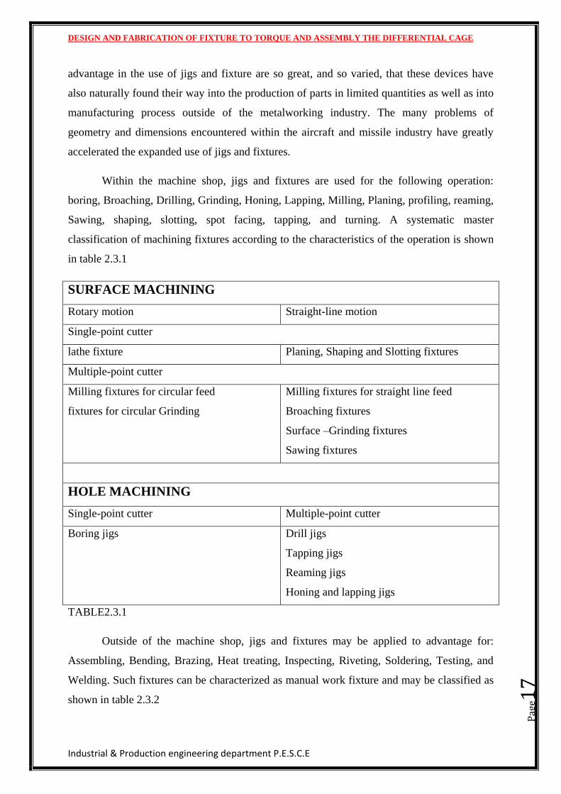
Sawing, shaping, slotting, spot facing, tapping, and turning. A systematic master
classification of machining fixtures according to the characteristics of the operation is shown
in table 2.3.1
SURFACE MACHINING
Rotary motion Straight-line motion
Single-point cutter
lathe fixture Planing, Shaping and Slotting fixtures
Multiple-point cutter
Milling fixtures for circular feed
fixtures for circular Grinding
Milling fixtures for straight line feed
Broaching fixtures
Surface –Grinding fixtures
Sawing fixtures
HOLE MACHINING
Single-point cutter Multiple-point cutter
Boring jigs Drill jigs
Tapping jigs
Reaming jigs
Honing and lapping jigs
TABLE2.3.1
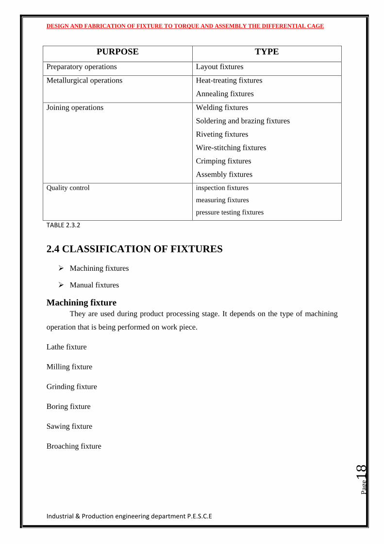
Outside of the machine shop, jigs and fixtures may be applied to advantage for:
Assembling, Bending, Brazing, Heat treating, Inspecting, Riveting, Soldering, Testing, and
Welding. Such fixtures can be characterized as manual work fixture and may be classified as
shown in table 2.3.2
DESIGN AND FABRICATION OF FIXTURE TO TORQUE AND ASSEMBLY THE DIFFERENTIAL CAGE
Industrial & Production engineering department P.E.S.C.E
Pag
e18
PURPOSE TYPE
Preparatory operations Layout fixtures
Metallurgical operations Heat-treating fixtures
Annealing fixtures
Joining operations Welding fixtures
Soldering and brazing fixtures
Riveting fixtures
Wire-stitching fixtures
Crimping fixtures
Assembly fixtures
Quality control inspection fixtures
measuring fixtures
pressure testing fixtures
TABLE 2.3.2
2.4 CLASSIFICATION OF FIXTURES
Machining fixtures
Manual fixtures
Machining fixture
They are used during product processing stage. It depends on the type of machining
operation that is being performed on work piece.
Lathe fixture
Milling fixture
Grinding fixture
Boring fixture
Sawing fixture
Broaching fixture
DESIGN AND FABRICATION OF FIXTURE TO TORQUE AND ASSEMBLY THE DIFFERENTIAL CAGE
Industrial & Production engineering department P.E.S.C.E
Pag
e19
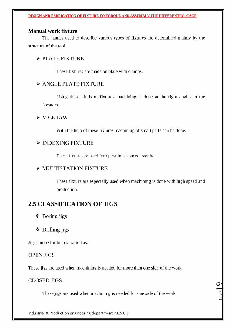
Manual work fixture
The names used to describe various types of fixtures are determined mainly by the
structure of the tool.
PLATE FIXTURE
These fixtures are made on plate with clamps.
ANGLE PLATE FIXTURE
Using these kinds of fixtures machining is done at the right angles to the
locators.
VICE JAW
With the help of these fixtures machining of small parts can be done.
INDEXING FIXTURE
These fixture are used for operations spaced evenly.
MULTISTATION FIXTURE
These fixture are especially used when machining is done with high speed and
production.
2.5 CLASSIFICATION OF JIGS
Boring jigs
Drilling jigs
Jigs can be further classified as:
OPEN JIGS
These jigs are used when machining is needed for more than one side of the work.
CLOSED JIGS
These jigs are used when machining is needed for one side of the work.
DESIGN AND FABRICATION OF FIXTURE TO TORQUE AND ASSEMBLY THE DIFFERENTIAL CAGE
Industrial & Production engineering department P.E.S.C.E
Pag
e20
Some specific jigs are:
TEMPLATE JIGS
These jigs are used when accuracy is needed.
PLATE JIGS
These jigs are used when accuracy is needed.
SANDWICH JIGS
Parts which are very thin and fragile are machined using sandwich jigs.
ANGLE PLATE JIGS
These jigs are used when machining is done at right angles to the locator.
BOX OR TUMBLE JIGS
This jig totally surrounds the part and it looks as a box
CHANNEL JIGS
These jigs are held on two sides and for machining third side.
LEAF JIGS
These jigs are provided with top cast for easier loading.
DESIGN AND FABRICATION OF FIXTURE TO TORQUE AND ASSEMBLY THE DIFFERENTIAL CAGE
Industrial & Production engineering department P.E.S.C.E
Pag
e21
INDEXING JIGS
These jigs are used to space the holes accurately.
MULTISTATION JIGS
They are used multiple speeds for more than one job.
DESIGN AND FABRICATION OF FIXTURE TO TORQUE AND ASSEMBLY THE DIFFERENTIAL CAGE
Industrial & Production engineering department P.E.S.C.E
Pag
e22
CHAPTER 3
HYDRAULIC SYSTEM
DESIGN AND FABRICATION OF FIXTURE TO TORQUE AND ASSEMBLY THE DIFFERENTIAL CAGE
Industrial & Production engineering department P.E.S.C.E
Pag
e23
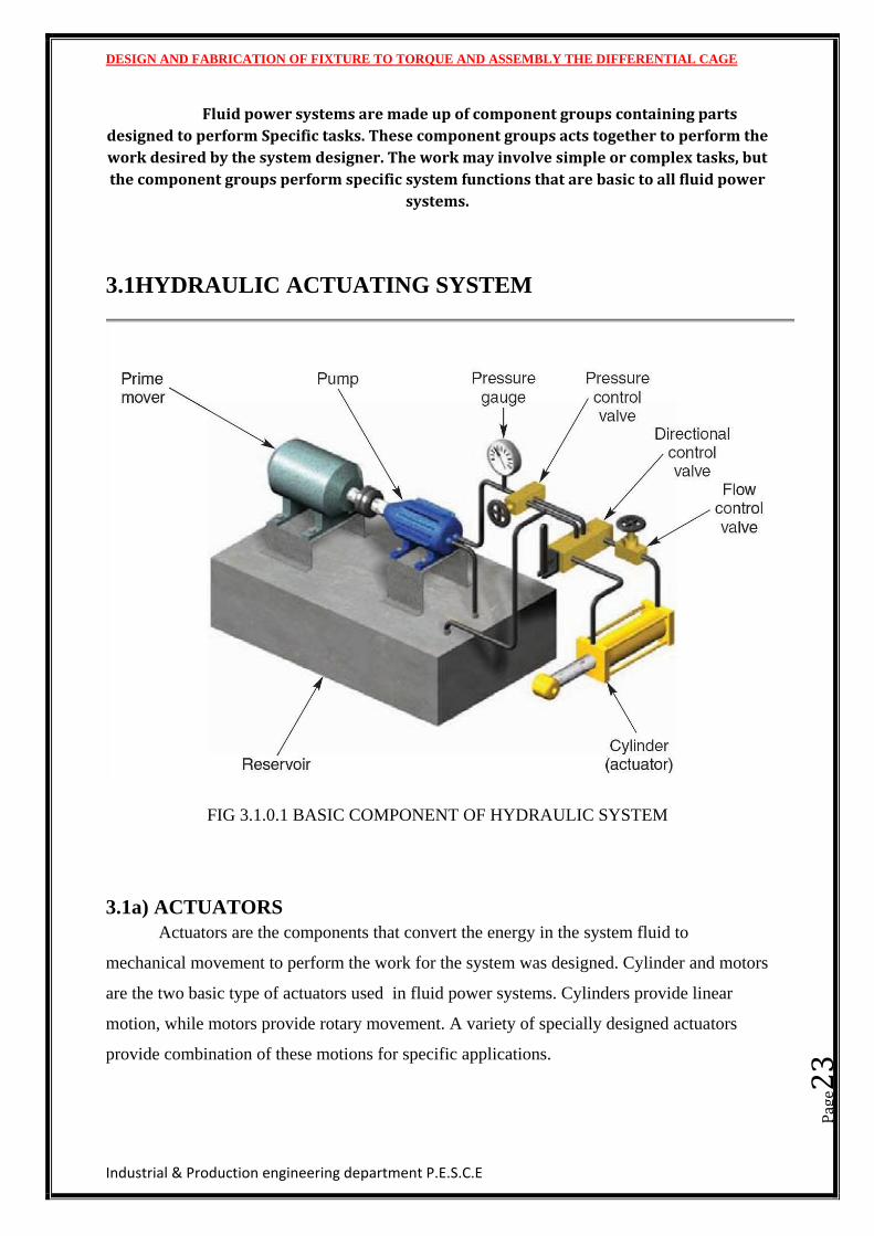
Fluid power systems are made up of component groups containing parts
designed to perform Specific tasks. These component groups acts together to perform the
work desired by the system designer. The work may involve simple or complex tasks, but
the component groups perform specific system functions that are basic to all fluid power
systems.
3.1HYDRAULIC ACTUATING SYSTEM
FIG 3.1.0.1 BASIC COMPONENT OF HYDRAULIC SYSTEM
3.1a) ACTUATORS
Actuators are the components that convert the energy in the system fluid to
mechanical movement to perform the work for the system was designed. Cylinder and motors
are the two basic type of actuators used in fluid power systems. Cylinders provide linear
motion, while motors provide rotary movement. A variety of specially designed actuators
provide combination of these motions for specific applications.
DESIGN AND FABRICATION OF FIXTURE TO TORQUE AND ASSEMBLY THE DIFFERENTIAL CAGE
Industrial & Production engineering department P.E.S.C.E
Pag
e24
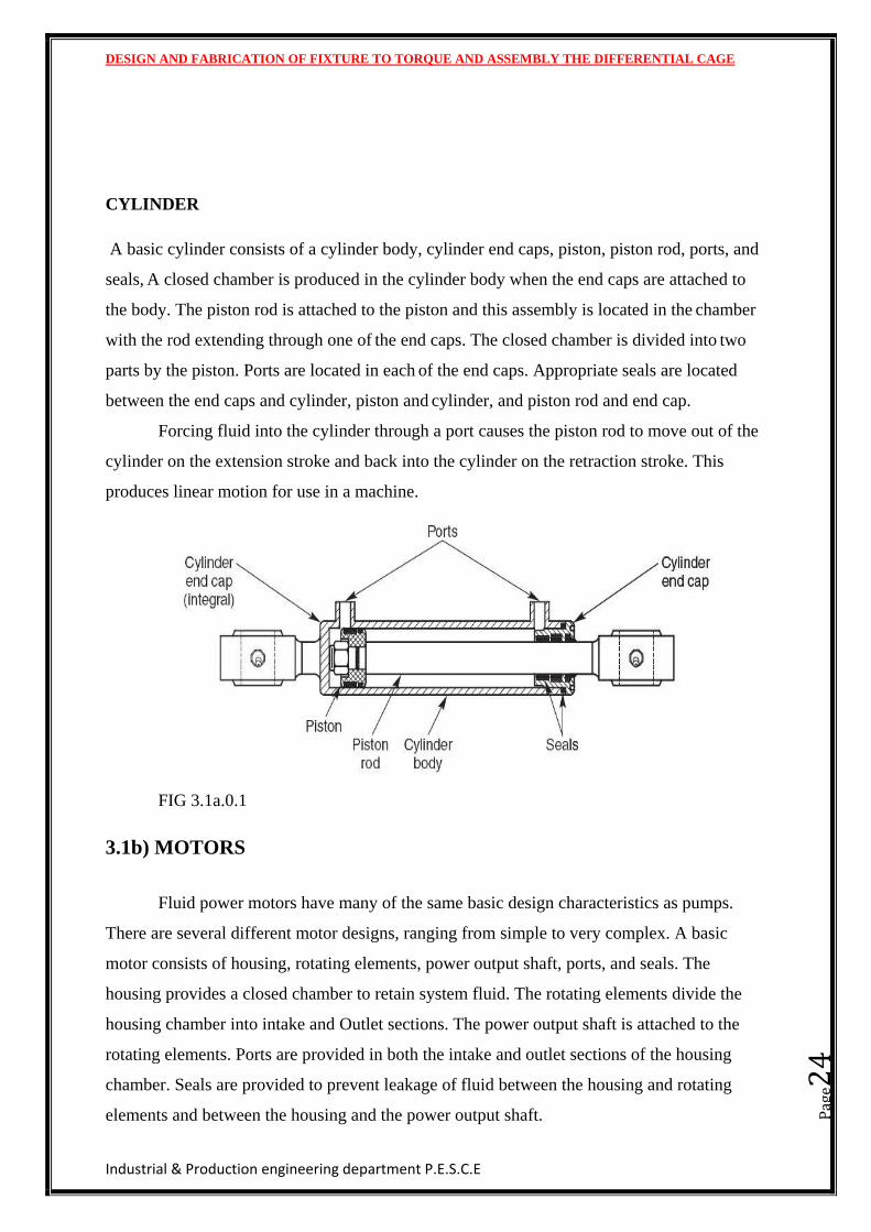
CYLINDER
A basic cylinder consists of a cylinder body, cylinder end caps, piston, piston rod, ports, and
seals, A closed chamber is produced in the cylinder body when the end caps are attached to
the body. The piston rod is attached to the piston and this assembly is located in the chamber
with the rod extending through one of the end caps. The closed chamber is divided into two
parts by the piston. Ports are located in each of the end caps. Appropriate seals are located
between the end caps and cylinder, piston and cylinder, and piston rod and end cap.
Forcing fluid into the cylinder through a port causes the piston rod to move out of the
cylinder on the extension stroke and back into the cylinder on the retraction stroke. This
produces linear motion for use in a machine.
FIG 3.1a.0.1
3.1b) MOTORS
Fluid power motors have many of the same basic design characteristics as pumps.
There are several different motor designs, ranging from simple to very complex. A basic
motor consists of housing, rotating elements, power output shaft, ports, and seals. The
housing provides a closed chamber to retain system fluid. The rotating elements divide the
housing chamber into intake and Outlet sections. The power output shaft is attached to the
rotating elements. Ports are provided in both the intake and outlet sections of the housing
chamber. Seals are provided to prevent leakage of fluid between the housing and rotating
elements and between the housing and the power output shaft.
DESIGN AND FABRICATION OF FIXTURE TO TORQUE AND ASSEMBLY THE DIFFERENTIAL CAGE
Industrial & Production engineering department P.E.S.C.E
Pag
e25
Forcing fluid into the motor causes the rotating elements to turn the power output
shaft. This produces rotary motion for use in a machine.
3.1c) RESERVOIR
The reservoir is the storage area for oil in a hydraulic system. The unit may be a
simple box like container or it may be a cavity in the base of a machine that serves to store
system fluid. A pneumatic system uses a receiver to store compressed air. This unit is usually
a cylindrical tank. The reservoir or receiver also plays other important roles in system
operation, such as contributing to system temperature control and fluid cleaning.
3.1c) CONDUCTORS
Conductors confine the system fluid as it is distributed throughout the system. Pipes,
tubes, and hoses are the three general types of conductors used in fluid power systems.
Special manifolds consisting of multiple passageways are used in systems where space and
weight are important Factors. The type of conductor used depends on the type of fluid,
system pressure, required component movement, and the environment in which the system
operates. This group of components also includes a variety of fittings and adapters to allow
easy assembly while assuring a system free from leaks.
Pipes are rigid conductors commonly used in stationary fluid power installations.
Piping is lower in cost than most other conductors with comparable specifications. The pipe
designed for use in fluid power systems is made from mild steel. It is manufactured as
seamless.
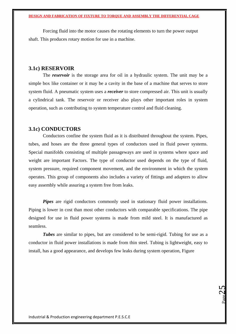
Tubes are similar to pipes, but are considered to be semi-rigid. Tubing for use as a
conductor in fluid power installations is made from thin steel. Tubing is lightweight, easy to
install, has a good appearance, and develops few leaks during system operation, Figure
DESIGN AND FABRICATION OF FIXTURE TO TORQUE AND ASSEMBLY THE DIFFERENTIAL CAGE
Industrial & Production engineering department P.E.S.C.E
Pag
e26
FIG 3.1c.0.1
Hoses are flexible conductors made from layers of materials. They contain system
fluid while withstanding system pressure and allowing easy movement of system
components. Hose construction includes an inner tube to contain the fluid, a middle section of
braided fabric or wire to withstand pressure, and an outer layer of material for protection
from dirt and abrasion, Figure
Hydraulic hose is made using multiple layers of FIG 3.1C.0.2
Synthetic rubber, braided fabric, and wire to provide a
Flexible high pressure conductor.
Fittings and adapters are needed to assemble conductors and other system
components. Fittings are considered the parts needed to assemble similar conductors, while
adapters are required when connecting different types of conductors or when attaching
conductors to system components.
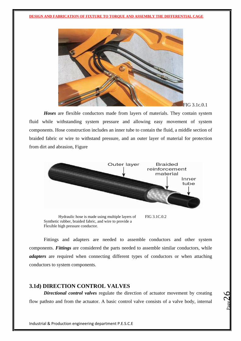
3.1d) DIRECTION CONTROL VALVES
Directional control valves regulate the direction of actuator movement by creating
flow pathsto and from the actuator. A basic control valve consists of a valve body, internal
DESIGN AND FABRICATION OF FIXTURE TO TORQUE AND ASSEMBLY THE DIFFERENTIAL CAGE
Industrial & Production engineering department P.E.S.C.E
Pag
e27
elements that open and close fluid flow paths through the valve, an external device for
shifting the internal elements, ports to connect the valve to the system, and sealing devices to
prevent fluid leakage,
FIG 3.1d.0.1
When a directional control valve is used in a fluid power system, it directs fluid to one
side of the internal elements of an actuator, causing the actuator to move in one direction.
Fluid from the other side of the actuator’s internal elements flows through the valve and is
returned to the system (or atmosphere). Shifting the valve creates a flow path to the opposite
side of the internal elements of the actuator, causing the actuator to move in the opposite
direction.
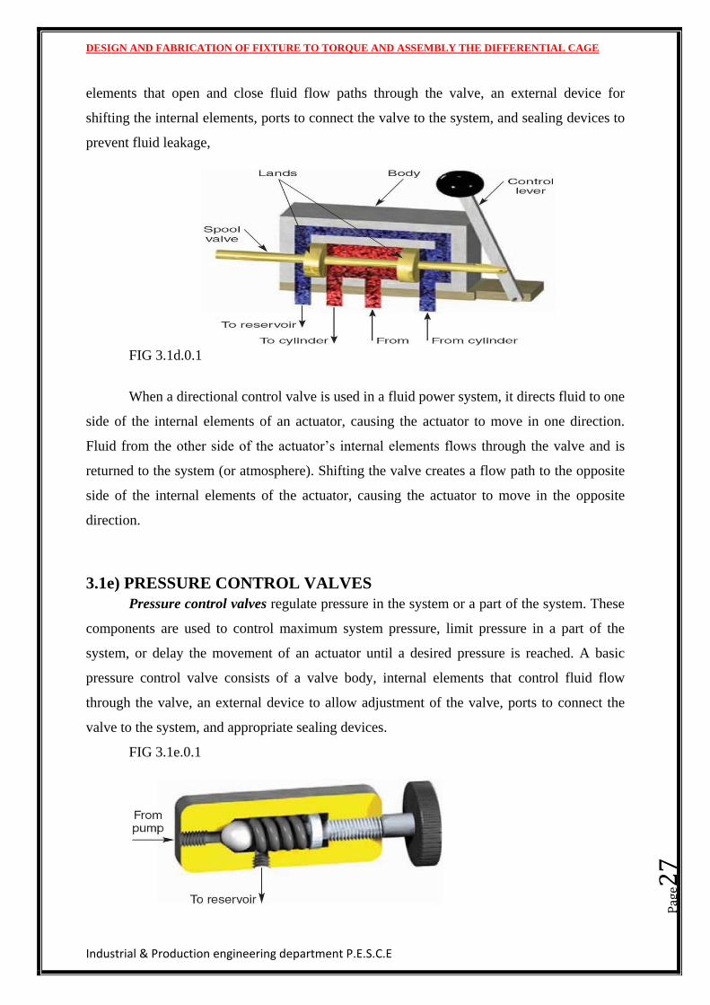
3.1e) PRESSURE CONTROL VALVES
Pressure control valves regulate pressure in the system or a part of the system. These
components are used to control maximum system pressure, limit pressure in a part of the
system, or delay the movement of an actuator until a desired pressure is reached. A basic
pressure control valve consists of a valve body, internal elements that control fluid flow
through the valve, an external device to allow adjustment of the valve, ports to connect the
valve to the system, and appropriate sealing devices.
FIG 3.1e.0.1
DESIGN AND FABRICATION OF FIXTURE TO TORQUE AND ASSEMBLY THE DIFFERENTIAL CAGE
Industrial & Production engineering department P.E.S.C.E
Pag
e28
In a hydraulic system, the basic pressure control device is a closed valve that does not
open to allow fluid to flow through it until a desired pressure is reached, When the system
reaches the desired pressure, the internal elements of the valve move opening a passageway
through the valve. Fluid that is not needed to maintain the desired system pressure then
passes through the valve to a lower-pressure section of the system. The amount of fluid that
passes through the valve varies according to the amount of fluid needed to maintain the
desired system pressure. The smaller the amount of fluid needed to maintain the desired
system pressure, the higher the flow through the valve to the low-pressure section of the
system.
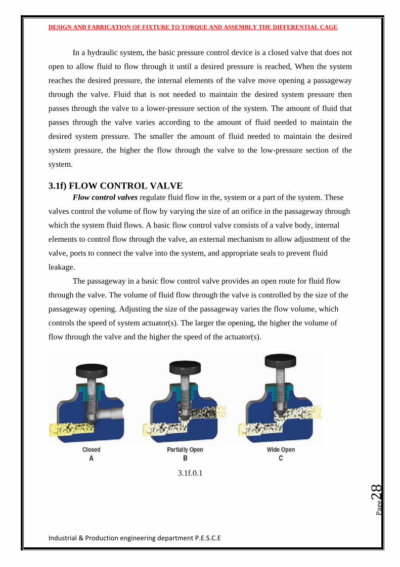
3.1f) FLOW CONTROL VALVE
Flow control valves regulate fluid flow in the, system or a part of the system. These
valves control the volume of flow by varying the size of an orifice in the passageway through
which the system fluid flows. A basic flow control valve consists of a valve body, internal
elements to control flow through the valve, an external mechanism to allow adjustment of the
valve, ports to connect the valve into the system, and appropriate seals to prevent fluid
leakage.
The passageway in a basic flow control valve provides an open route for fluid flow
through the valve. The volume of fluid flow through the valve is controlled by the size of the
passageway opening. Adjusting the size of the passageway varies the flow volume, which
controls the speed of system actuator(s). The larger the opening, the higher the volume of
flow through the valve and the higher the speed of the actuator(s).
3.1f.0.1
DESIGN AND FABRICATION OF FIXTURE TO TORQUE AND ASSEMBLY THE DIFFERENTIAL CAGE
Industrial & Production engineering department P.E.S.C.E
Pag
e29
CHAPTER 4
DESIGN
DESIGN AND FABRICATION OF FIXTURE TO TORQUE AND ASSEMBLY THE DIFFERENTIAL CAGE
Industrial & Production engineering department P.E.S.C.E
Pag
e30
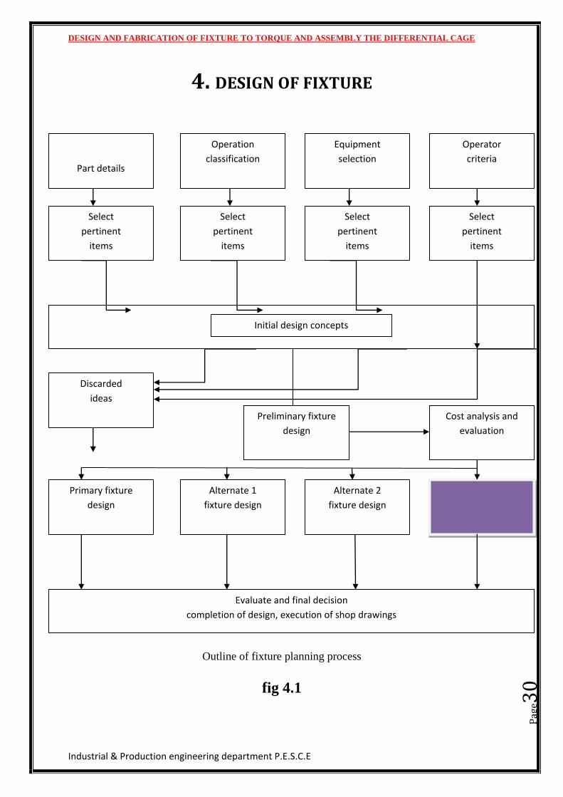
4. DESIGN OF FIXTURE
Outline of fixture planning process
fig 4.1
Part details
Operation
classification
Equipment
selection
Operator
criteria
Select
pertinent
items
Select
pertinent
items
Select
pertinent
items
Select
pertinent
items
Initial design concepts
Discarded
ideas
Preliminary fixture
design
Cost analysis and
evaluation
Primary fixture
design
Alternate 1
fixture design
Alternate 2
fixture design
Evaluate and final decision
completion of design, execution of shop drawings
DESIGN AND FABRICATION OF FIXTURE TO TORQUE AND ASSEMBLY THE DIFFERENTIAL CAGE
Industrial & Production engineering department P.E.S.C.E
Pag
e31
4.1 PRINCIPLE OF FIXTURE DESIGN
LOCATION
It should ensure that work is given in the desire constraint and proper location of
the part should be ensured.
CLAMPING
The clamper should be positioned to give the best resistance to cutting forces.
CLEARANCE
The clamper should be positioned to give the best resistance to cutting forces.
HANDLING
For easier movements of the fixture, it should be made as light as possible.
GENERAL
To avoid complications in the design it should be kept simple to minimize the
cost.
The fixture should provide space for coolant circulation.
The fixture should have enough stability and rigidity.
4.2 LOCATORS
Location refers to the establishment of the desired relationship between the work
pieces and jigs and fixture. Correct location influences the accuracy of finished products. Jigs
and fixture are so designed that all possible movements of the components must be restricted.
The determination of the location points and clamping of the work piece serves to
restrict the movement of the components in any directions while setting it alt the correct
position relative to the jig. The location points are first determined by finding out possible
degree of freedom of work piece which is then restricted by suitable arrangement, which
serves as locations.
DESIGN AND FABRICATION OF FIXTURE TO TORQUE AND ASSEMBLY THE DIFFERENTIAL CAGE
Industrial & Production engineering department P.E.S.C.E
Pag
e32
4.3TYPES OF LOCATORS
FLAT LOCATOR.
They are used for locating flat machined faces of the component. The component
is directly placed on the machine surface of the jig body and undercut provided help in swarf
removal.
CYLINDERICAL LOCATOR.
This is used for locating the components having drilled holes. The cylindrical
locators fitted on the jig body are inserted in the drilled hole of component to locate in
position.
4.4 CLAMPING
It serves the purpose of holding the work piece securely on jigs and fixtures
against the cutting forces to achieve efficient clamping.
FACTORS TO BE CONSIDERED IN CLAMPING
The clamping pressure should not be too much.
The clamping pressure should be exerted on the solid support of the work to avoid
distortion.
The movement of work must be limited.
The clamps must be simple.
The design must be as so as to enable the clamp to be completely lifted out of
work while unloading.
It should prevent the wear of the clamping faces.
TYPES OF CLAMPING ‘
SCREW CLAMP
These types of clamps are used to grip the work on its edges. This type of
clamping arrangement enables the top surfaces of work to be machined without any
DESIGN AND FABRICATION OF FIXTURE TO TORQUE AND ASSEMBLY THE DIFFERENTIAL CAGE
Industrial & Production engineering department P.E.S.C.E
Pag
e33
difficulty. But longer time is required for clamping and unclamping the work. Also the
clamping force changes from component to component.
FLAT CLAMP
This type of clamp supports work by clamp face which is pressured against the
work by tightening the work piece.
PIVOTED CLAMP
This type of clamp is eliminates the use of spanner for clamping purpose. The
work can be gripped quickly by rotating the screw which actuates the pivoted clamp on the
face of the work.
EQUALIZING CLAMP
This type of clamp is employed to exert equal pressure on the two faces of work
by two legs of the clamp.
LATCH CLAMP
It is employed to clamp a work by a latch and pivoted leaf. The leaf is closed on
the work and keeps its position by latch. The clamping pressure is not high but loading and
unloading arrangement is quick.
SWING PLATE CLAMP
It is used for quick loading and unloading purpose for light jobs. The clamp is
operated by swing the swing the plate in the position and locking it by turning.
WEDGE CLAMP
It is employed to grip the work by a wedge block. The wedge block grips the work
against the fixed bottom fitted on the other end of the jig.
MAGNETIC CLAMP
It is employed to grip the work by using magnetic field. It can only be used clamp
magnetic materials. Ferro-magnetic materials can be easily clamped and held in position.
DESIGN AND FABRICATION OF FIXTURE TO TORQUE AND ASSEMBLY THE DIFFERENTIAL CAGE
Industrial & Production engineering department P.E.S.C.E
Pag
e34
4.5 DESIGN
The successful design of fixture is the result of designer’s ability to analyze all the
milling operation to perform on the component to incorporate design features in the fixture
that offset or eliminate the difficulties or problem associated with such operations.
4.5.1 GENERAL CONSIDERATION IN DESIGN
TYPE OF LOAD AND STRESSES CAUSED BY THE LOAD
The load on the component may act in several ways due to which internal stresses
are developed. Based on these stresses one has to fix the dimensions of components
so as to withstand the stresses.
SELECTION OF MATERIAL
It is essential to have a thorough knowledge of the properties of the material and
behavior under working condition. Some of the important characteristics of material
are strength, durability, resistance to heat corrosion and so on.
FROM AND SIZE OF THE PARTS
Form and size of the parts are based on our judgment. The stresses induced on the
parts must be within the availability and its assembly with its meeting parts.
CONVENIENCE AND ECONOMICAL FEATURES
The operation which the component has to perform is studied carefully and cost
for manufacturing is optimized.
USE OF STANDARDS PARTS
The use of standard parts is closely related to cost because the cost of standard or
stock parts is only a fraction of cost of similar parts made to order.
DESIGN AND FABRICATION OF FIXTURE TO TORQUE AND ASSEMBLY THE DIFFERENTIAL CAGE
Industrial & Production engineering department P.E.S.C.E
Pag
e35
4.5.2 MAIN CONSIDERATION IN DESIGN
The primary function of the fixture is to establish proper relative position of the
parts being milled and maintain it through the process.
The fixture should produce parts within the specified tolerance with little or no
distortion.
The fixture should have adequate clearance between the work pieces without
jamming the fixture,
The fixture should be comfortable for the worker to operate it in the height and
length etc.
4.5.3 DESIGN APPROACH
First the overall design of fixture is decided based on the peripheral geometry of
the component being machined. As there are no formula to determine the various
design parameters i.e., height and shape of the fixture, economic analysis is done to
find out these parameters ergonomically analysis is a means of fitting a worker to a
job to find out how much he is comfortable with the job.
When machining operation is being carried out on the fixture, considerable amount of
stresses are developed due to thermal expansion and contribution of the work piece
on the fixture. The clamp should be designed taking thermal stresses into account.
However the magnitude of thermal stresses is negligible compared to the stress
induced due to impact load considered.
DESIGN AND FABRICATION OF FIXTURE TO TORQUE AND ASSEMBLY THE DIFFERENTIAL CAGE
Industrial & Production engineering department P.E.S.C.E
Pag
e36
CHAPTER 5
PROJECT DESCRIPTION
DESIGN AND FABRICATION OF FIXTURE TO TORQUE AND ASSEMBLY THE DIFFERENTIAL CAGE
Industrial & Production engineering department P.E.S.C.E
Pag
e37
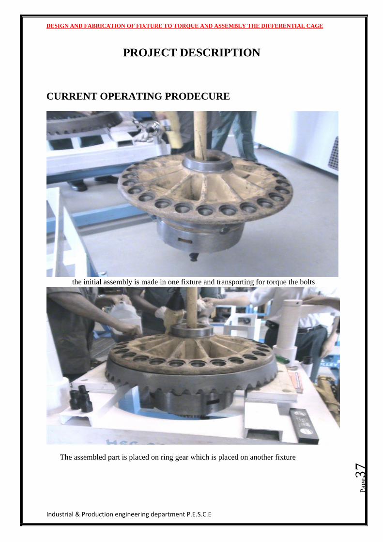
PROJECT DESCRIPTION
CURRENT OPERATING PRODECURE
the initial assembly is made in one fixture and transporting for torque the bolts
The assembled part is placed on ring gear which is placed on another fixture
DESIGN AND FABRICATION OF FIXTURE TO TORQUE AND ASSEMBLY THE DIFFERENTIAL CAGE
Industrial & Production engineering department P.E.S.C.E
Pag
e38
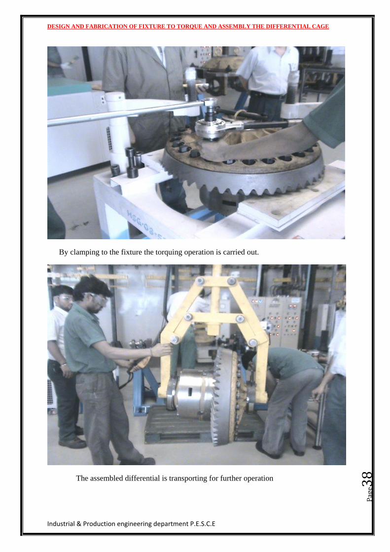
By clamping to the fixture the torquing operation is carried out.
The assembled differential is transporting for further operation
DESIGN AND FABRICATION OF FIXTURE TO TORQUE AND ASSEMBLY THE DIFFERENTIAL CAGE
Industrial & Production engineering department P.E.S.C.E
Pag
e39
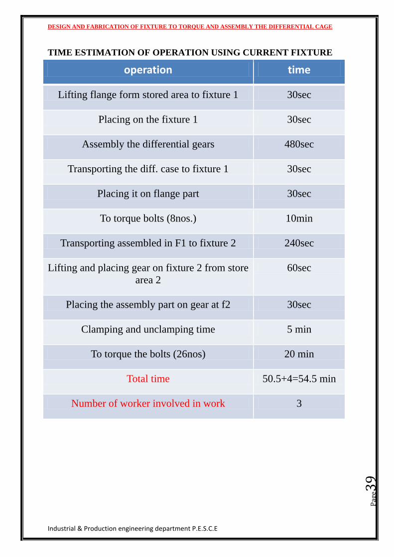
TIME ESTIMATION OF OPERATION USING CURRENT FIXTURE
operation time
Lifting flange form stored area to fixture 1 30sec
Placing on the fixture 1 30sec
Assembly the differential gears 480sec
Transporting the diff. case to fixture 1 30sec
Placing it on flange part 30sec
To torque bolts (8nos.) 10min
Transporting assembled in F1 to fixture 2 240sec
Lifting and placing gear on fixture 2 from store
area 2
60sec
Placing the assembly part on gear at f2 30sec
Clamping and unclamping time 5 min
To torque the bolts (26nos) 20 min
Total time 50.5+4=54.5 min
Number of worker involved in work 3
DESIGN AND FABRICATION OF FIXTURE TO TORQUE AND ASSEMBLY THE DIFFERENTIAL CAGE
Industrial & Production engineering department P.E.S.C.E
Pag
e40
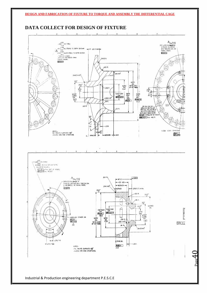
DATA COLLECT FOR DESIGN OF FIXTURE
DESIGN AND FABRICATION OF FIXTURE TO TORQUE AND ASSEMBLY THE DIFFERENTIAL CAGE
Industrial & Production engineering department P.E.S.C.E
Pag
e41
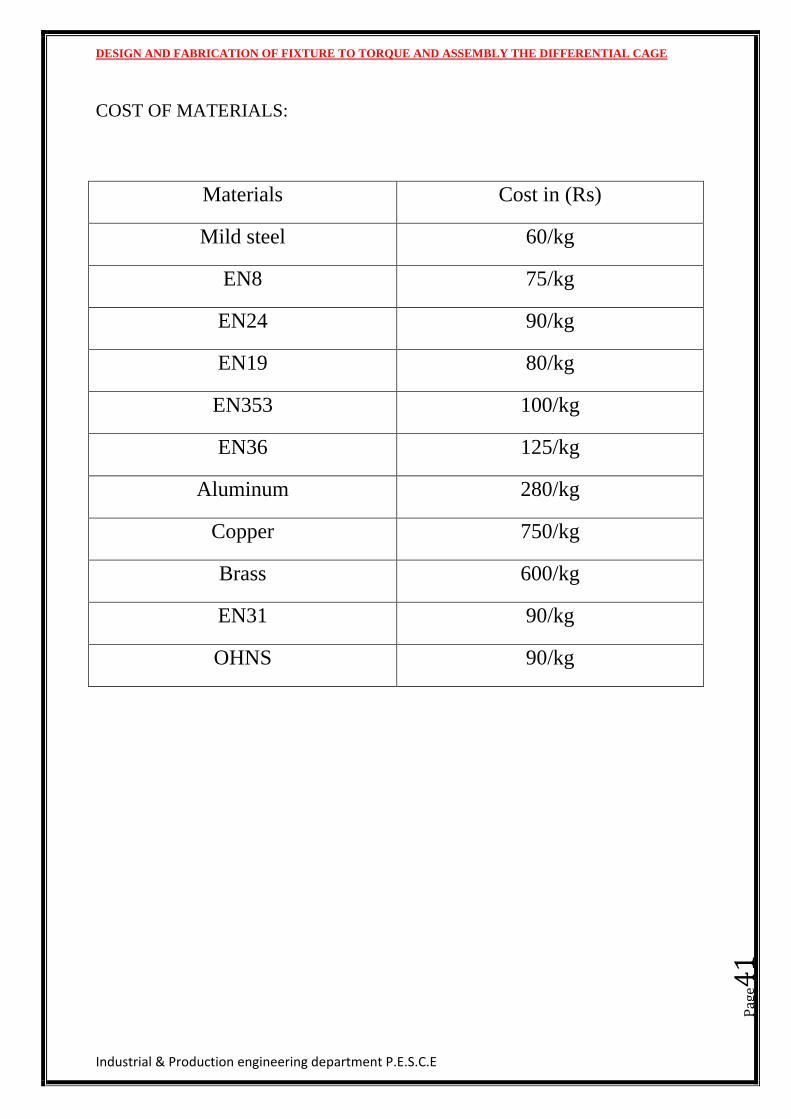
COST OF MATERIALS:
Materials Cost in (Rs)
Mild steel 60/kg
EN8 75/kg
EN24 90/kg
EN19 80/kg
EN353 100/kg
EN36 125/kg
Aluminum 280/kg
Copper 750/kg
Brass 600/kg
EN31 90/kg
OHNS 90/kg
DESIGN AND FABRICATION OF FIXTURE TO TORQUE AND ASSEMBLY THE DIFFERENTIAL CAGE
Industrial & Production engineering department P.E.S.C.E
Pag
e42
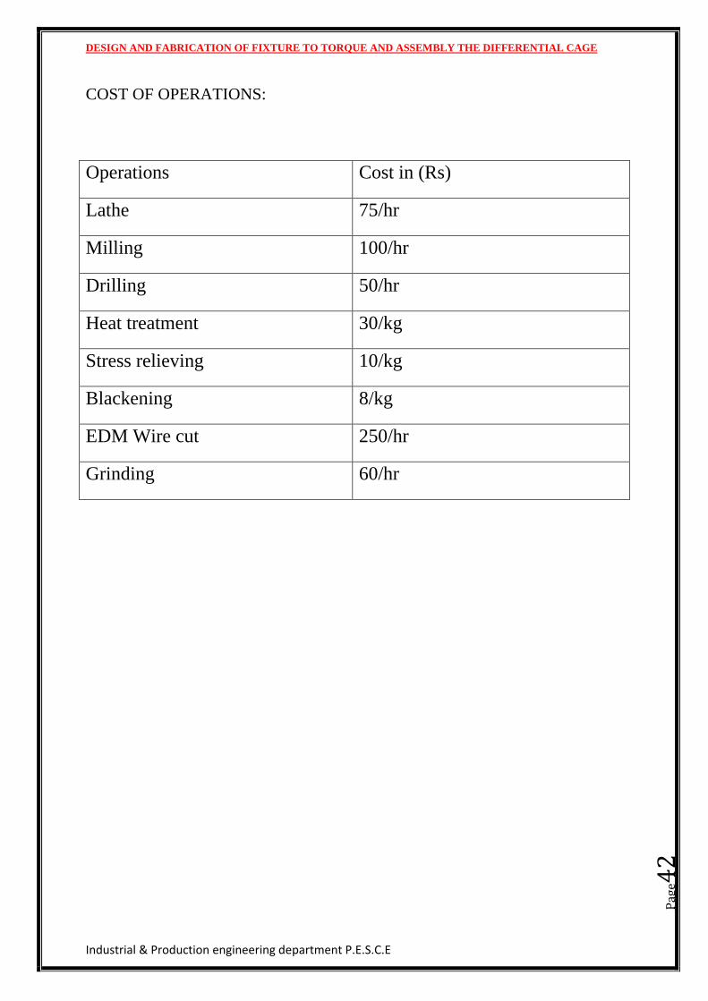
COST OF OPERATIONS:
Operations Cost in (Rs)
Lathe 75/hr
Milling 100/hr
Drilling 50/hr
Heat treatment 30/kg
Stress relieving 10/kg
Blackening 8/kg
EDM Wire cut 250/hr
Grinding 60/hr
DESIGN AND FABRICATION OF FIXTURE TO TORQUE AND ASSEMBLY THE DIFFERENTIAL CAGE
Industrial & Production engineering department P.E.S.C.E
Pag
e43
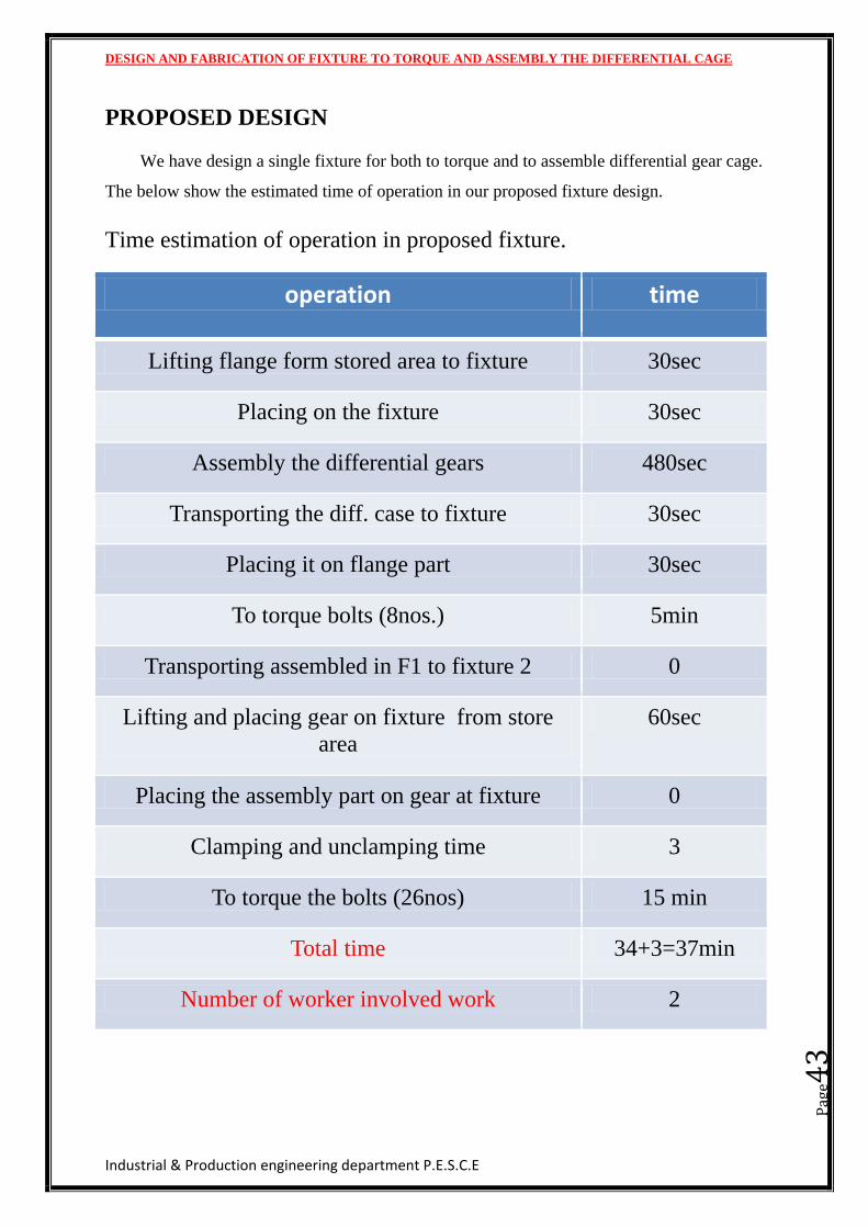
PROPOSED DESIGN
We have design a single fixture for both to torque and to assemble differential gear cage.
The below show the estimated time of operation in our proposed fixture design.
Time estimation of operation in proposed fixture.
operation time
Lifting flange form stored area to fixture 30sec
Placing on the fixture 30sec
Assembly the differential gears 480sec
Transporting the diff. case to fixture 30sec
Placing it on flange part 30sec
To torque bolts (8nos.) 5min
Transporting assembled in F1 to fixture 2 0
Lifting and placing gear on fixture from store
area
60sec
Placing the assembly part on gear at fixture 0
Clamping and unclamping time 3
To torque the bolts (26nos) 15 min
Total time 34+3=37min
Number of worker involved work 2
DESIGN AND FABRICATION OF FIXTURE TO TORQUE AND ASSEMBLY THE DIFFERENTIAL CAGE
Industrial & Production engineering department P.E.S.C.E
Pag
e44
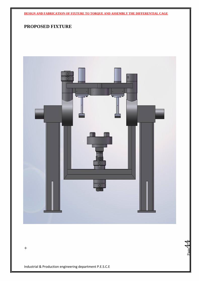
PROPOSED FIXTURE
+
DESIGN AND FABRICATION OF FIXTURE TO TORQUE AND ASSEMBLY THE DIFFERENTIAL CAGE
Industrial & Production engineering department P.E.S.C.E
Pag
e45
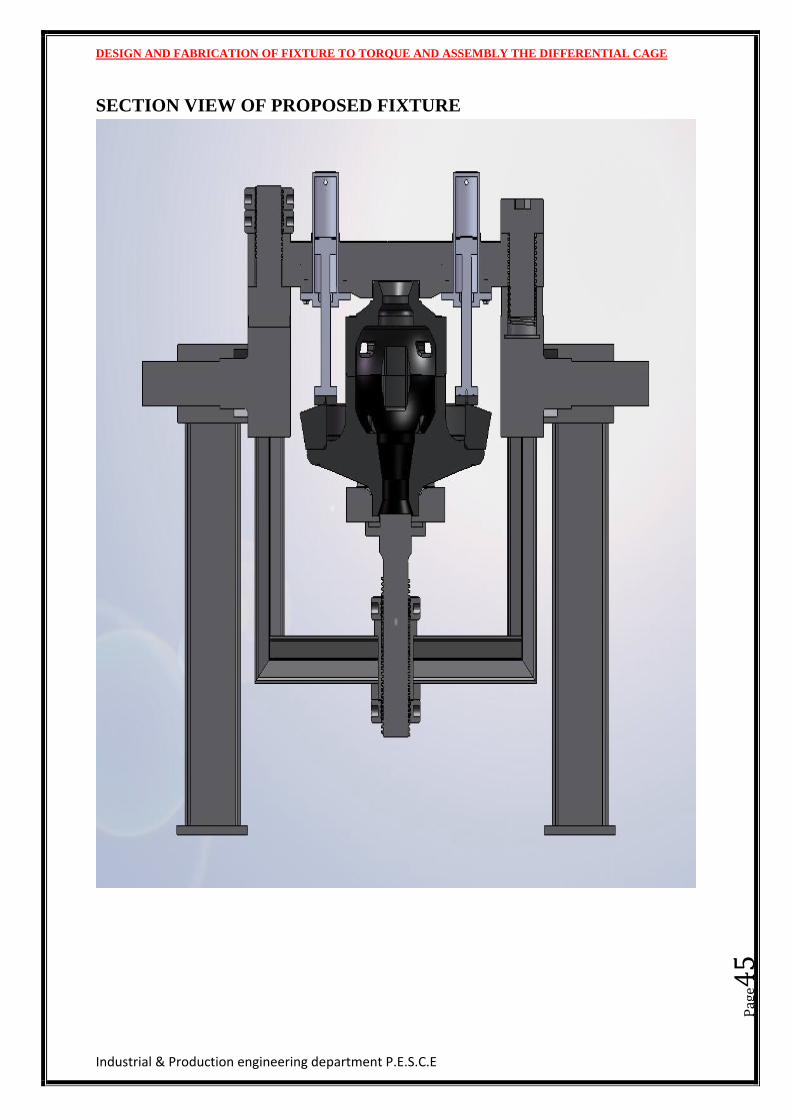
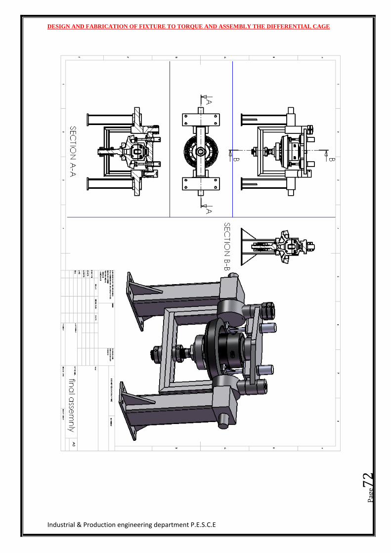
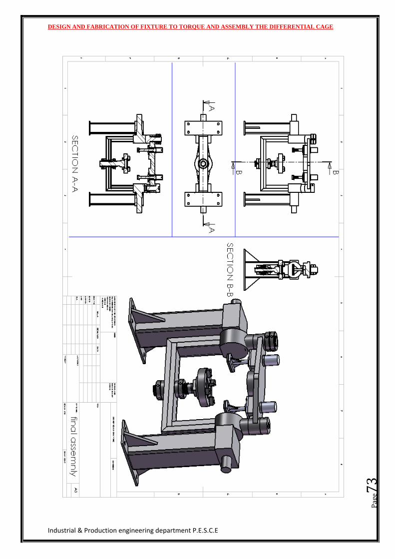
SECTION VIEW OF PROPOSED FIXTURE
DESIGN AND FABRICATION OF FIXTURE TO TORQUE AND ASSEMBLY THE DIFFERENTIAL CAGE
Industrial & Production engineering department P.E.S.C.E
Pag
e46
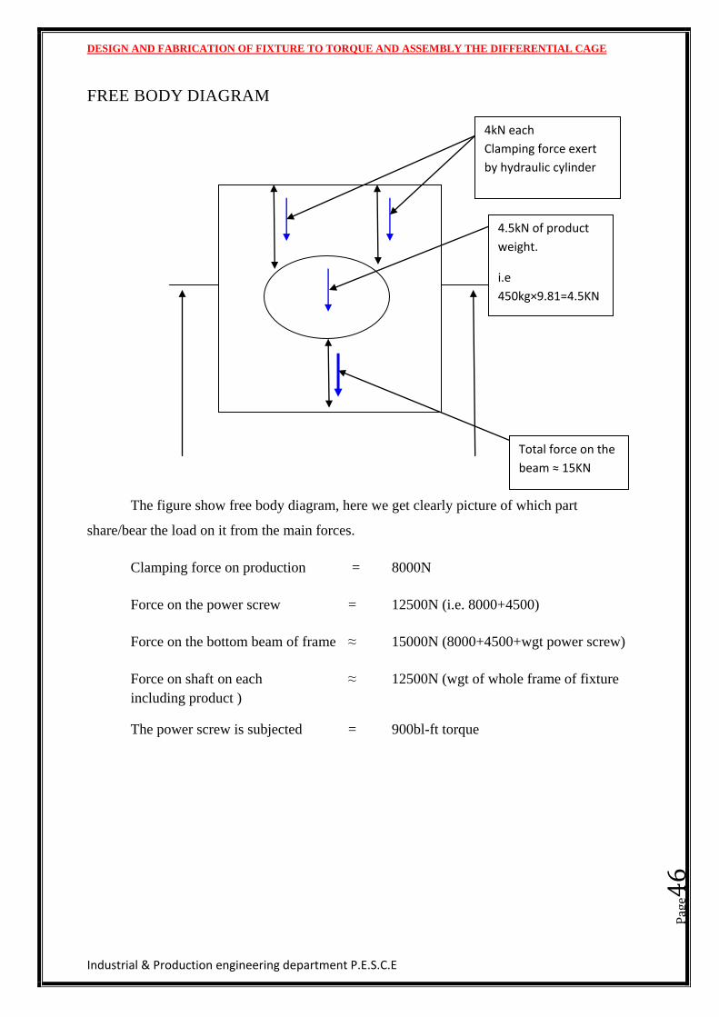
FREE BODY DIAGRAM
The figure show free body diagram, here we get clearly picture of which part
share/bear the load on it from the main forces.
Clamping force on production = 8000N
Force on the power screw = 12500N (i.e. 8000+4500)
Force on the bottom beam of frame ≈ 15000N (8000+4500+wgt power screw)
Force on shaft on each ≈ 12500N (wgt of whole frame of fixture
including product )
The power screw is subjected = 900bl-ft torque
4kN each
Clamping force exert
by hydraulic cylinder
4.5kN of product
weight.
i.e
450kg×9.81=4.5KN
Total force on the
beam ≈ 15KN
DESIGN AND FABRICATION OF FIXTURE TO TORQUE AND ASSEMBLY THE DIFFERENTIAL CAGE
Industrial & Production engineering department P.E.S.C.E
Pag
e47
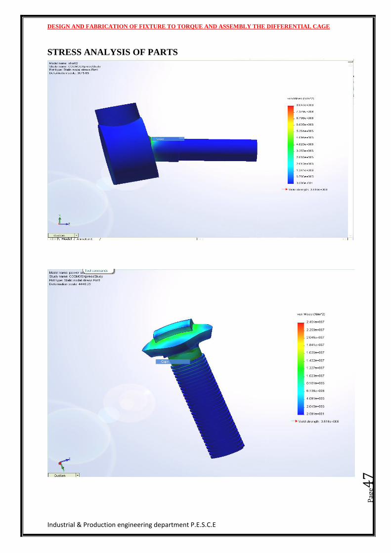
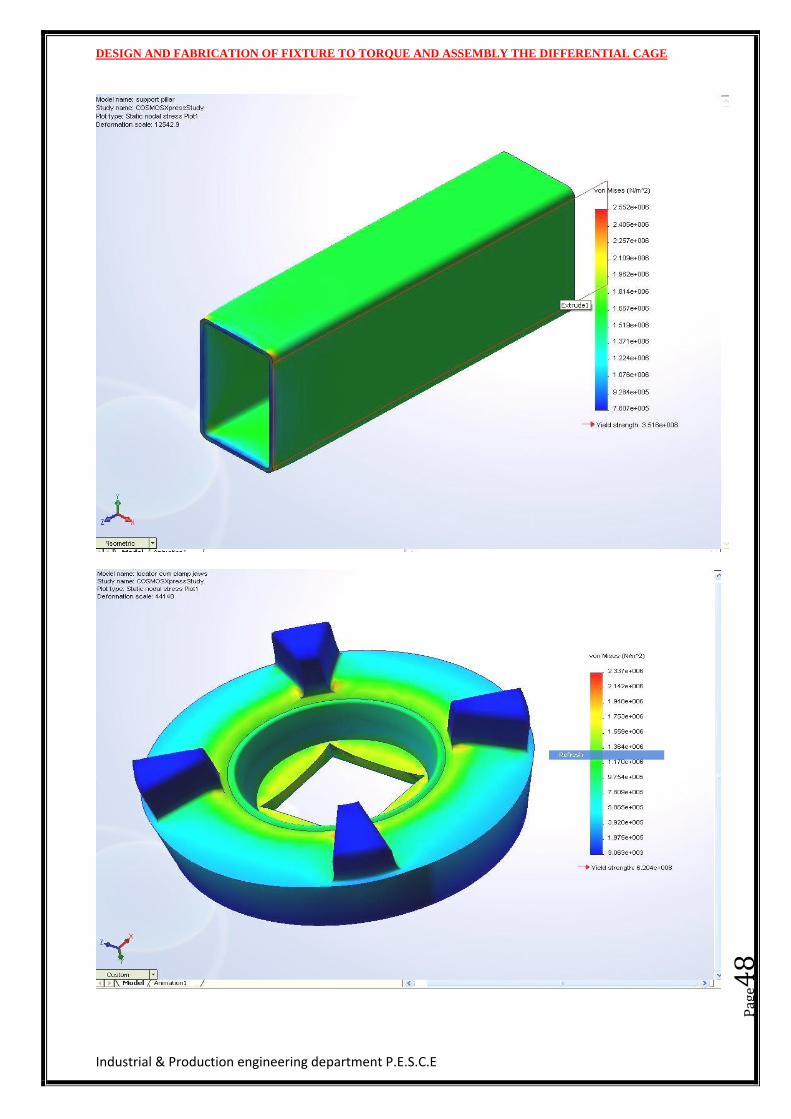
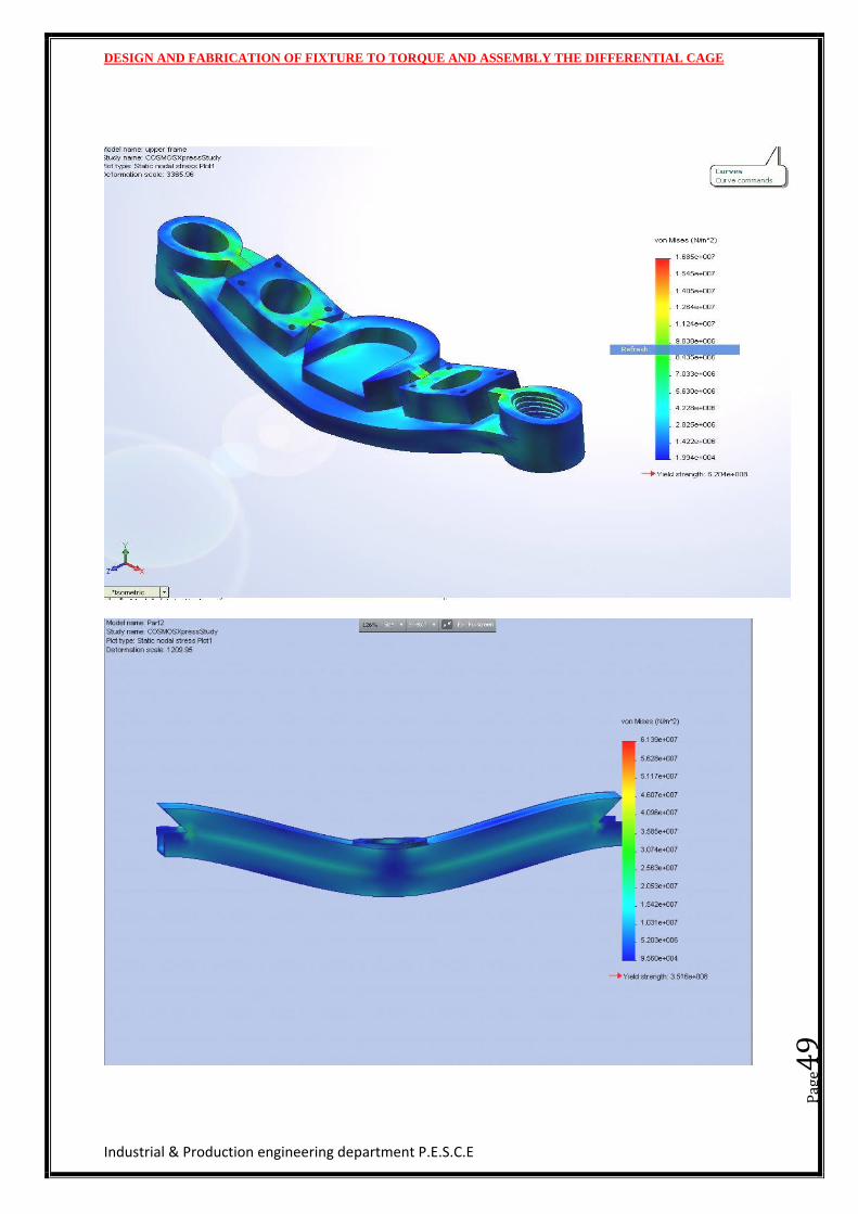
STRESS ANALYSIS OF PARTS
DESIGN AND FABRICATION OF FIXTURE TO TORQUE AND ASSEMBLY THE DIFFERENTIAL CAGE
Industrial & Production engineering department P.E.S.C.E
Pag
e48
DESIGN AND FABRICATION OF FIXTURE TO TORQUE AND ASSEMBLY THE DIFFERENTIAL CAGE
Industrial & Production engineering department P.E.S.C.E
Pag
e49
DESIGN AND FABRICATION OF FIXTURE TO TORQUE AND ASSEMBLY THE DIFFERENTIAL CAGE
Industrial & Production engineering department P.E.S.C.E
Pag
e50
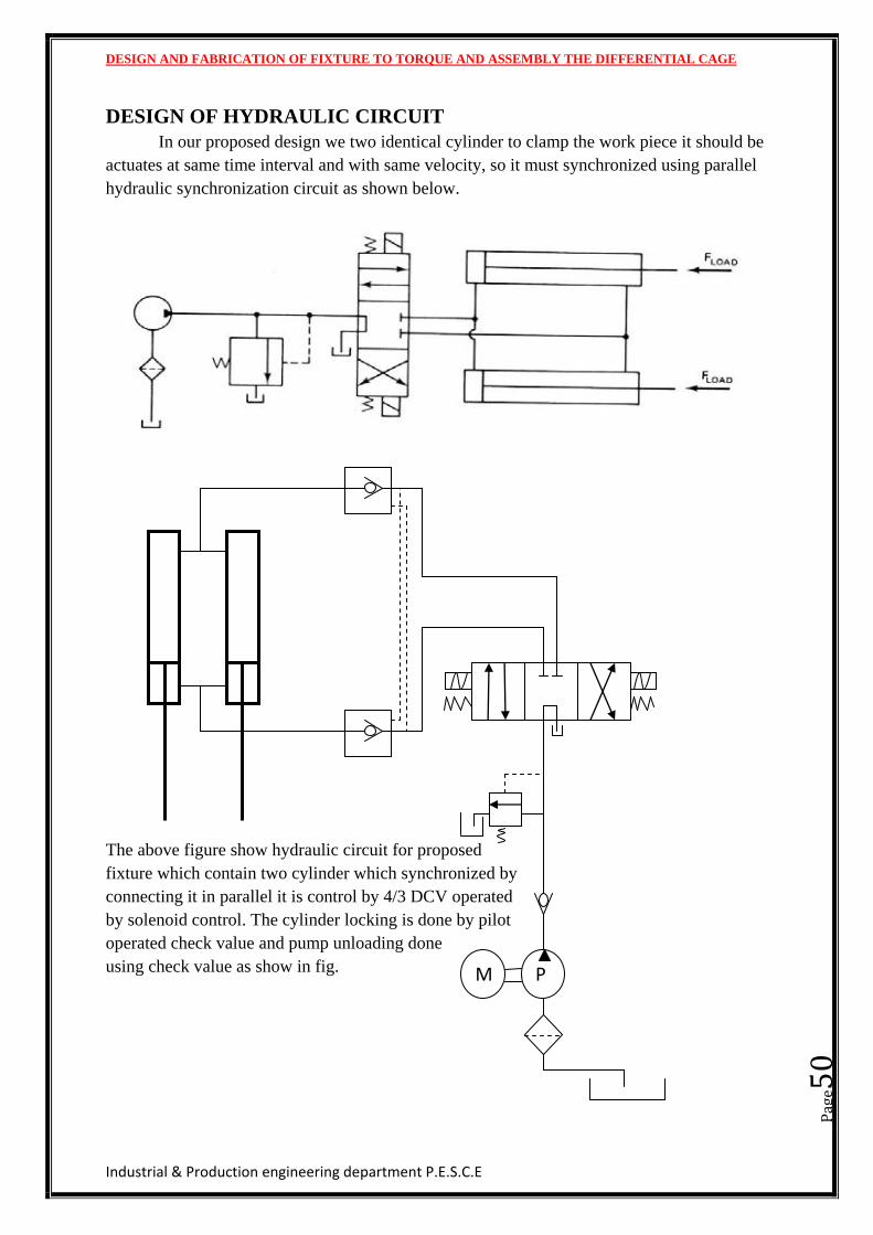
DESIGN OF HYDRAULIC CIRCUIT
In our proposed design we two identical cylinder to clamp the work piece it should be
actuates at same time interval and with same velocity, so it must synchronized using parallel
hydraulic synchronization circuit as shown below.
The above figure show hydraulic circuit for proposed
fixture which contain two cylinder which synchronized by
connecting it in parallel it is control by 4/3 DCV operated
by solenoid control. The cylinder locking is done by pilot
operated check value and pump unloading done
using check value as show in fig.
P M
DESIGN AND FABRICATION OF FIXTURE TO TORQUE AND ASSEMBLY THE DIFFERENTIAL CAGE
Industrial & Production engineering department P.E.S.C.E
Pag
e51
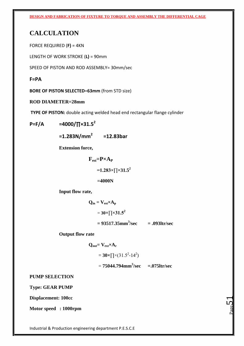
CALCULATION
FORCE REQUIRED (F) = 4KN
LENGTH OF WORK STROKE (L) = 90mm
SPEED OF PISTON AND ROD ASSEMBLY= 30mm/sec
F=PA
BORE OF PISTON SELECTED=63mm (from STD size)
ROD DIAMETER=28mm
TYPE OF PISTON: double acting welded head end rectangular flange cylinder
P=F/A =4000/∏×31.52
=1.283N/mm2 =12.83bar
Extension force,
Fest=P×AP
=1.283×∏×31.52
=4000N
Input flow rate,
Qin = Vest×Ap
= 30×∏×31.52
= 93517.35mm3/sec = .093ltr/sec
Output flow rate
Qout= Vext×Ar
= 30×∏×(31.52-14
2)
= 75044.794mm3/sec =.075ltr/sec
PUMP SELECTION
Type: GEAR PUMP
Displacement: 100cc
Motor speed : 1000rpm
DESIGN AND FABRICATION OF FIXTURE TO TORQUE AND ASSEMBLY THE DIFFERENTIAL CAGE
Industrial & Production engineering department P.E.S.C.E
Pag
e52
Motor efficiency =85%
Load pressure = 30bar
Torque on shaft= pump displacement × load pressure /20×∏=471Nmm
Power in=motor speed × pump displacement × load pressure/(600×motor efficiency)=
5.8kw
Power out= motor speed× pump displacement × load pressure /600=5kw
DESIGN AND FABRICATION OF FIXTURE TO TORQUE AND ASSEMBLY THE DIFFERENTIAL CAGE
Industrial & Production engineering department P.E.S.C.E
Pag
e53
CHAPTER 6
MATERIAL SELECTION
DESIGN AND FABRICATION OF FIXTURE TO TORQUE AND ASSEMBLY THE DIFFERENTIAL CAGE
Industrial & Production engineering department P.E.S.C.E
Pag
e54
Material selection:
When selecting materials for manufacturing a component. The following factors are
to be considered.
Mechanical properties like density, specific heat, thermal expansion and conductivity,
melting point.
Physical properties like density, specific heat, thermal expansion and conductivity,
melting point.
Chemical properties like oxidation, corrosion, general degradation of properties and
flammability of materials.
Cost and availability of raw and processed materials are major manufacturing.
Reliability of supply and demand also affects cost.
Time and service depended factors like wear, fatigue, creep and dimension
considered. friction and corrosion can shorten a products life.
Engineering steels
Steel is an alloy of carbon and iron, with carbon dictating the hardness and grade of
engineering steel. Carbon has consistently proved itself to be the most cost effective alloying
material for iron; however, other materials such as tungsten or manganese can also be used to
bring certain properties. Varying the amount of alloying elements in engineering steel
controls properties such as it’s hardness, ductility and tensile strength.
EN8 Medium carbon engineering steel
EN9 Medium carbon engineering steel (high carbon than EN8)
EN19 Chromium molybdenum high tensile engineering steel. Usually supplied in ‘T’
condition
EN24 Nickel chromium molybdenum high tensile steel. Usually supplied in ‘T’
condition.
EN30B 4¼ nickel steel.
DESIGN AND FABRICATION OF FIXTURE TO TORQUE AND ASSEMBLY THE DIFFERENTIAL CAGE
Industrial & Production engineering department P.E.S.C.E
Pag
e55
EN31 High carbon alloy steel.
EN32 Low case hardening engineering steel.
EN36 Nickel chromium carburizing engineering steel.
EN40B 3% chromium molybdenum nitriding steel.
EN41 Chromium aluminum nitriding steel.
EN43 Medium carbon spring steel specification.
EN45 silicon manganese alloy spring steel.
EN47 Chromium vanadium spring steel.
DESIGN AND FABRICATION OF FIXTURE TO TORQUE AND ASSEMBLY THE DIFFERENTIAL CAGE
Industrial & Production engineering department P.E.S.C.E
Pag
e56
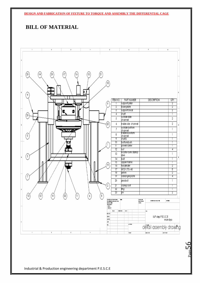
BILL OF MATERIAL
DESIGN AND FABRICATION OF FIXTURE TO TORQUE AND ASSEMBLY THE DIFFERENTIAL CAGE
Industrial & Production engineering department P.E.S.C.E
Pag
e57
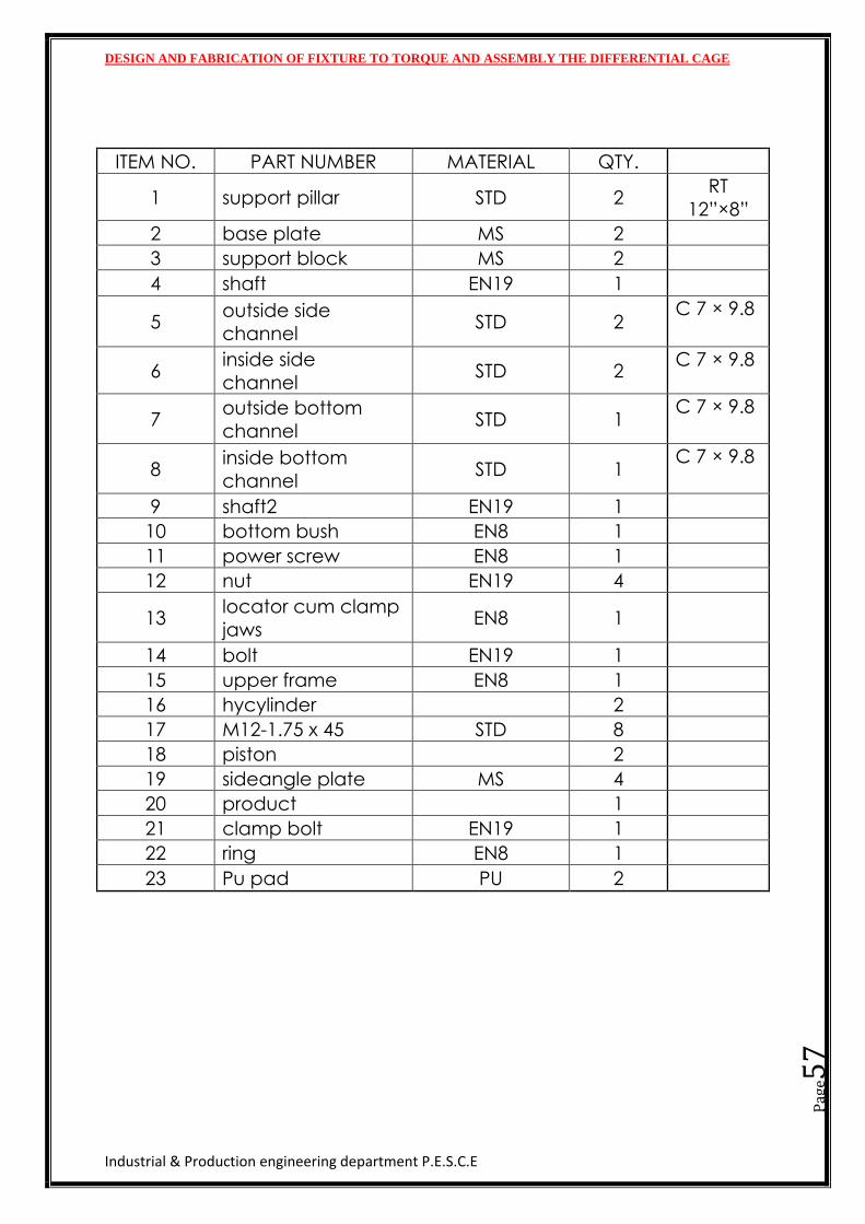
ITEM NO. PART NUMBER MATERIAL QTY.
1 support pillar STD 2 RT
12”×8”
2 base plate MS 2
3 support block MS 2
4 shaft EN19 1
5 outside side channel
STD 2 C 7 × 9.8
6 inside side
channel STD 2
C 7 × 9.8
7 outside bottom channel
STD 1 C 7 × 9.8
8 inside bottom channel
STD 1 C 7 × 9.8
9 shaft2 EN19 1
10 bottom bush EN8 1
11 power screw EN8 1
12 nut EN19 4
13 locator cum clamp
jaws EN8 1
14 bolt EN19 1
15 upper frame EN8 1
16 hycylinder
2
17 M12-1.75 x 45 STD 8
18 piston
2
19 sideangle plate MS 4
20 product
1
21 clamp bolt EN19 1
22 ring EN8 1
23 Pu pad PU 2
DESIGN AND FABRICATION OF FIXTURE TO TORQUE AND ASSEMBLY THE DIFFERENTIAL CAGE
Industrial & Production engineering department P.E.S.C.E
Pag
e58
CHAPTER 7
FABRICATION
DESIGN AND FABRICATION OF FIXTURE TO TORQUE AND ASSEMBLY THE DIFFERENTIAL CAGE
Industrial & Production engineering department P.E.S.C.E
Pag
e59
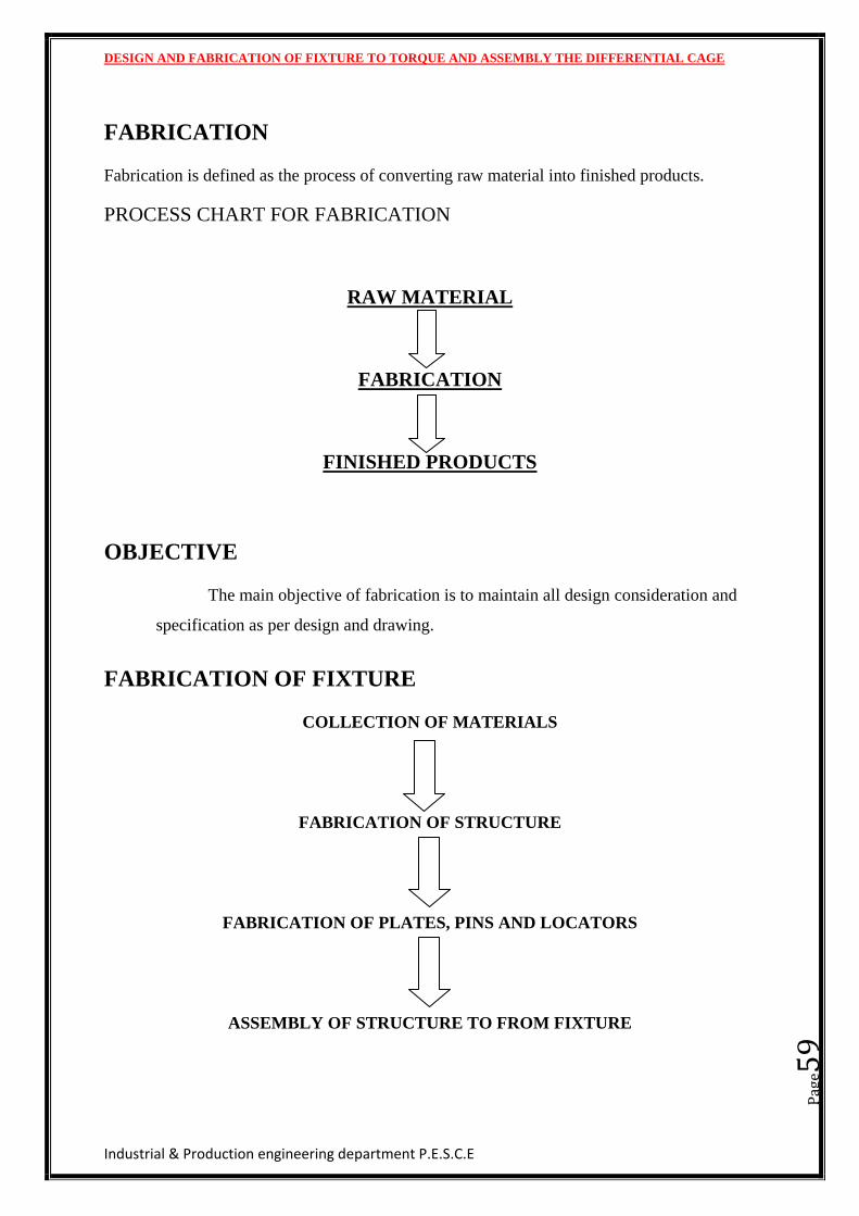
FABRICATION
Fabrication is defined as the process of converting raw material into finished products.
PROCESS CHART FOR FABRICATION
RAW MATERIAL
FABRICATION
FINISHED PRODUCTS
OBJECTIVE
The main objective of fabrication is to maintain all design consideration and
specification as per design and drawing.
FABRICATION OF FIXTURE
COLLECTION OF MATERIALS
FABRICATION OF STRUCTURE
FABRICATION OF PLATES, PINS AND LOCATORS
ASSEMBLY OF STRUCTURE TO FROM FIXTURE
DESIGN AND FABRICATION OF FIXTURE TO TORQUE AND ASSEMBLY THE DIFFERENTIAL CAGE
Industrial & Production engineering department P.E.S.C.E
Pag
e60
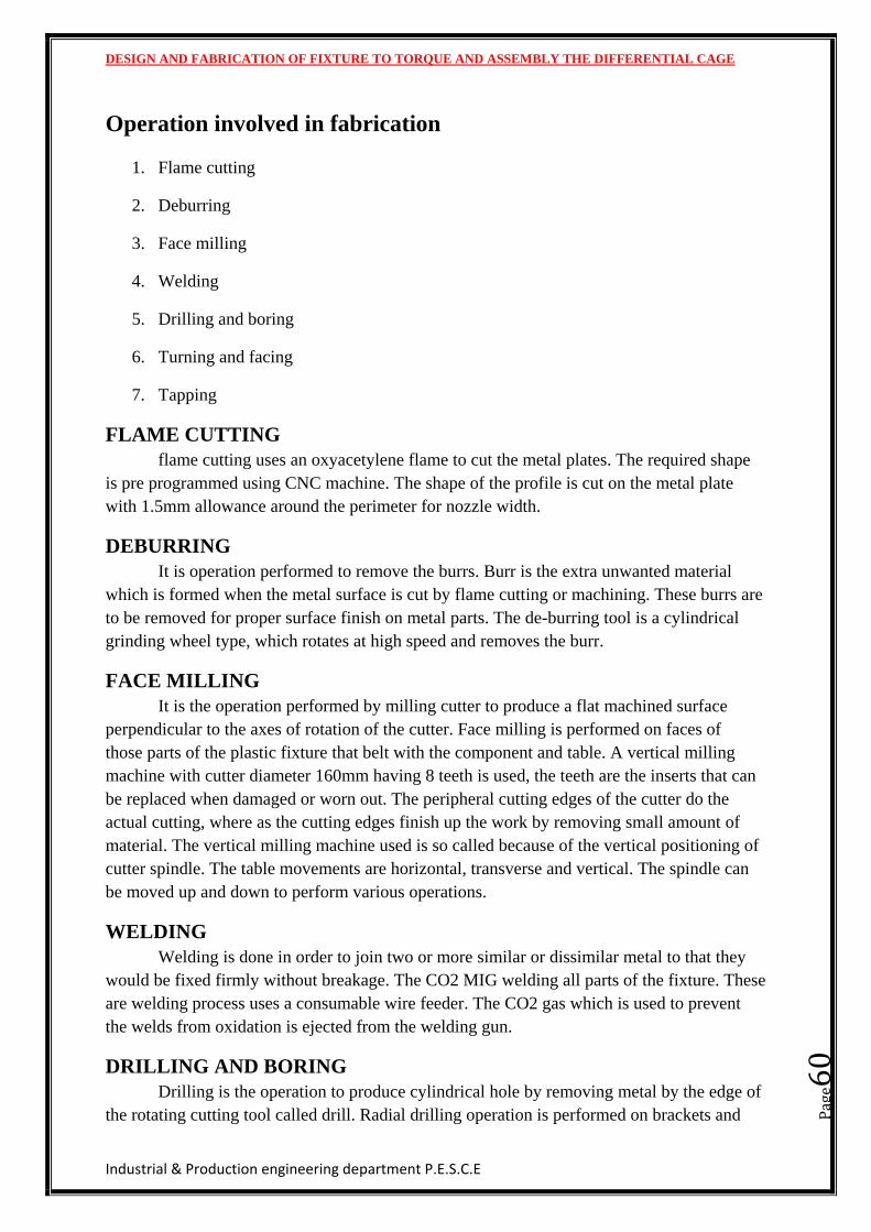
Operation involved in fabrication
1. Flame cutting
2. Deburring
3. Face milling
4. Welding
5. Drilling and boring
6. Turning and facing
7. Tapping
FLAME CUTTING
flame cutting uses an oxyacetylene flame to cut the metal plates. The required shape
is pre programmed using CNC machine. The shape of the profile is cut on the metal plate
with 1.5mm allowance around the perimeter for nozzle width.
DEBURRING
It is operation performed to remove the burrs. Burr is the extra unwanted material
which is formed when the metal surface is cut by flame cutting or machining. These burrs are
to be removed for proper surface finish on metal parts. The de-burring tool is a cylindrical
grinding wheel type, which rotates at high speed and removes the burr.
FACE MILLING
It is the operation performed by milling cutter to produce a flat machined surface
perpendicular to the axes of rotation of the cutter. Face milling is performed on faces of
those parts of the plastic fixture that belt with the component and table. A vertical milling
machine with cutter diameter 160mm having 8 teeth is used, the teeth are the inserts that can
be replaced when damaged or worn out. The peripheral cutting edges of the cutter do the
actual cutting, where as the cutting edges finish up the work by removing small amount of
material. The vertical milling machine used is so called because of the vertical positioning of
cutter spindle. The table movements are horizontal, transverse and vertical. The spindle can
be moved up and down to perform various operations.
WELDING
Welding is done in order to join two or more similar or dissimilar metal to that they
would be fixed firmly without breakage. The CO2 MIG welding all parts of the fixture. These
are welding process uses a consumable wire feeder. The CO2 gas which is used to prevent
the welds from oxidation is ejected from the welding gun.
DRILLING AND BORING
Drilling is the operation to produce cylindrical hole by removing metal by the edge of
the rotating cutting tool called drill. Radial drilling operation is performed on brackets and
DESIGN AND FABRICATION OF FIXTURE TO TORQUE AND ASSEMBLY THE DIFFERENTIAL CAGE
Industrial & Production engineering department P.E.S.C.E
Pag
e61
the channel of the fixture. Also the drilling operation is performed to produce slots in these
parts by the chain drilling operation which would serve for end milling operation to be easier.
Chain is a process by which a series of inline holes with a gap of 1mm between them is
produced. By performing this, the amount of material to be removed by end mill cutter to
produce a slot is very much reduced.
Boring is the process of enlarging the hole to get required dimension. The drilling
process cannot process cannot be used to drill holes of required dimensions. Therefore exiting
hole is enlarged to the diameter by boring.
TURNING AND FACING
Facing is the operation of machining the ends of work to produce the flat surface
square with the axis. This is also used to cut the work to the required length. The operation
involves feeding the tool perpendicular to the axis of rotation of work piece. A properly
ground facing tool is mounted in the tool holder in the post. A regular turning too may be
used for facing a large work piece.
TAPPING
It is a process of creating helical ridges. It is similar to thread cutting but the
difference between them is that in thread cutting helical ridges are formed on the outer side of
cylinder or conical rod whereas in tapping helical ridges are formed on the inner side of a
pre-bored hole of the component.
DESIGN AND FABRICATION OF FIXTURE TO TORQUE AND ASSEMBLY THE DIFFERENTIAL CAGE
Industrial & Production engineering department P.E.S.C.E
Pag
e62
CHAPTER 8
COST ESTIMATION
DESIGN AND FABRICATION OF FIXTURE TO TORQUE AND ASSEMBLY THE DIFFERENTIAL CAGE
Industrial & Production engineering department P.E.S.C.E
Pag
e63
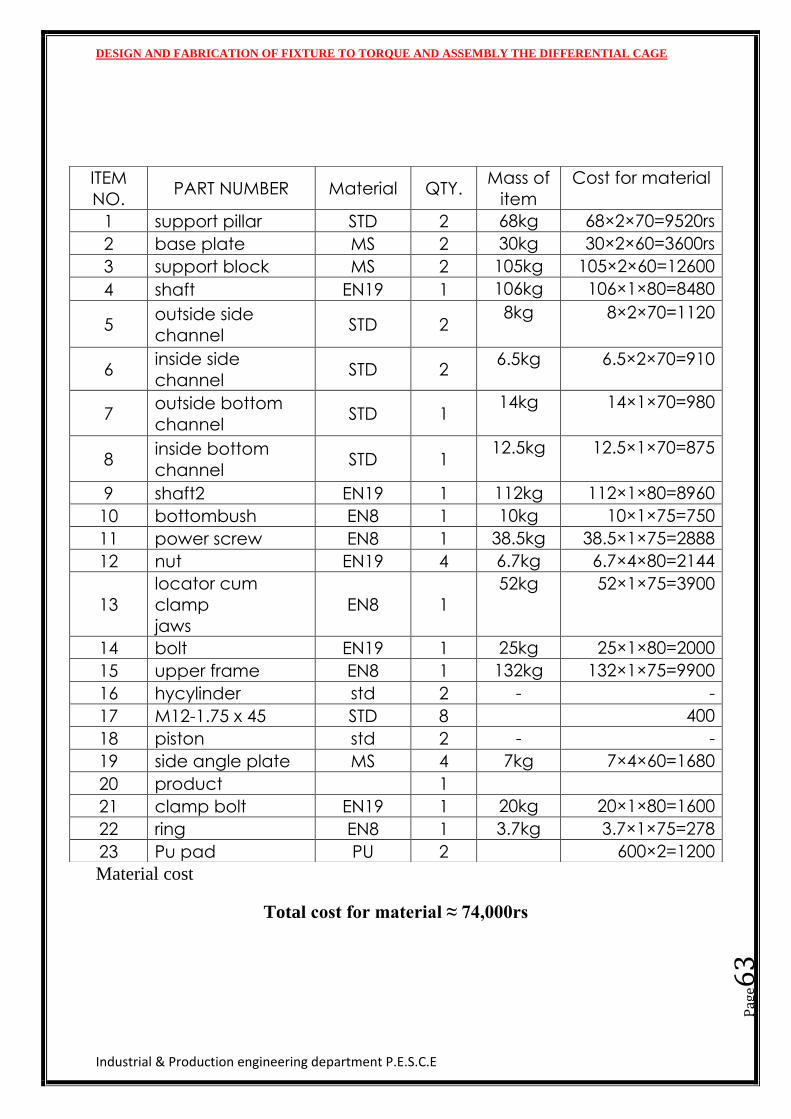
Material cost
Total cost for material ≈ 74,000rs
ITEM
NO. PART NUMBER Material QTY.
Mass of
item
Cost for material
1 support pillar STD 2 68kg 68×2×70=9520rs
2 base plate MS 2 30kg 30×2×60=3600rs
3 support block MS 2 105kg 105×2×60=12600
4 shaft EN19 1 106kg 106×1×80=8480
5 outside side channel
STD 2 8kg 8×2×70=1120
6 inside side
channel STD 2
6.5kg 6.5×2×70=910
7 outside bottom channel
STD 1 14kg 14×1×70=980
8 inside bottom channel
STD 1 12.5kg 12.5×1×70=875
9 shaft2 EN19 1 112kg 112×1×80=8960
10 bottombush EN8 1 10kg 10×1×75=750
11 power screw EN8 1 38.5kg 38.5×1×75=2888
12 nut EN19 4 6.7kg 6.7×4×80=2144
13
locator cum
clamp jaws
EN8 1
52kg 52×1×75=3900
14 bolt EN19 1 25kg 25×1×80=2000
15 upper frame EN8 1 132kg 132×1×75=9900
16 hycylinder std 2 - -
17 M12-1.75 x 45 STD 8 400
18 piston std 2 - -
19 side angle plate MS 4 7kg 7×4×60=1680
20 product
1
21 clamp bolt EN19 1 20kg 20×1×80=1600
22 ring EN8 1 3.7kg 3.7×1×75=278
23 Pu pad PU 2 600×2=1200
DESIGN AND FABRICATION OF FIXTURE TO TORQUE AND ASSEMBLY THE DIFFERENTIAL CAGE
Industrial & Production engineering department P.E.S.C.E
Pag
e64
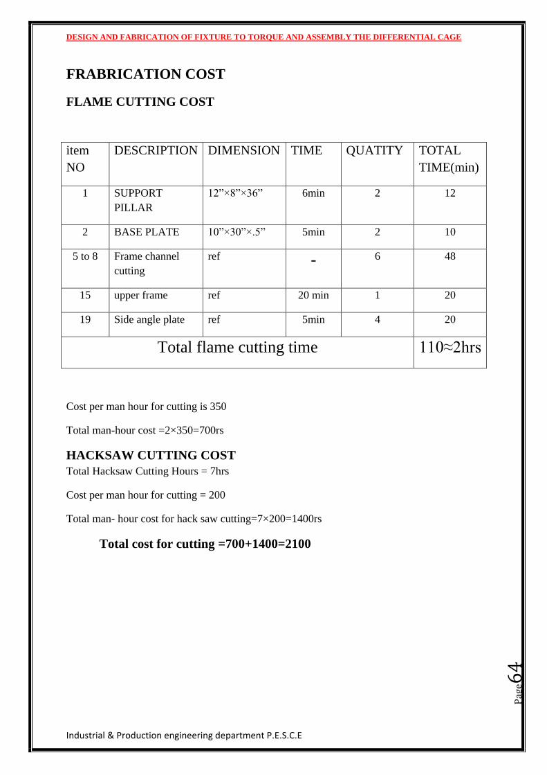
FRABRICATION COST
FLAME CUTTING COST
item
NO
DESCRIPTION DIMENSION TIME QUATITY TOTAL
TIME(min)
1 SUPPORT
PILLAR
12”×8”×36” 6min 2 12
2 BASE PLATE 10”×30”×.5” 5min 2 10
5 to 8 Frame channel
cutting
ref - 6 48
15 upper frame ref 20 min 1 20
19 Side angle plate ref 5min 4 20
Total flame cutting time 110≈2hrs
Cost per man hour for cutting is 350
Total man-hour cost =2×350=700rs
HACKSAW CUTTING COST
Total Hacksaw Cutting Hours = 7hrs
Cost per man hour for cutting = 200
Total man- hour cost for hack saw cutting=7×200=1400rs
Total cost for cutting =700+1400=2100
DESIGN AND FABRICATION OF FIXTURE TO TORQUE AND ASSEMBLY THE DIFFERENTIAL CAGE
Industrial & Production engineering department P.E.S.C.E
Pag
e65
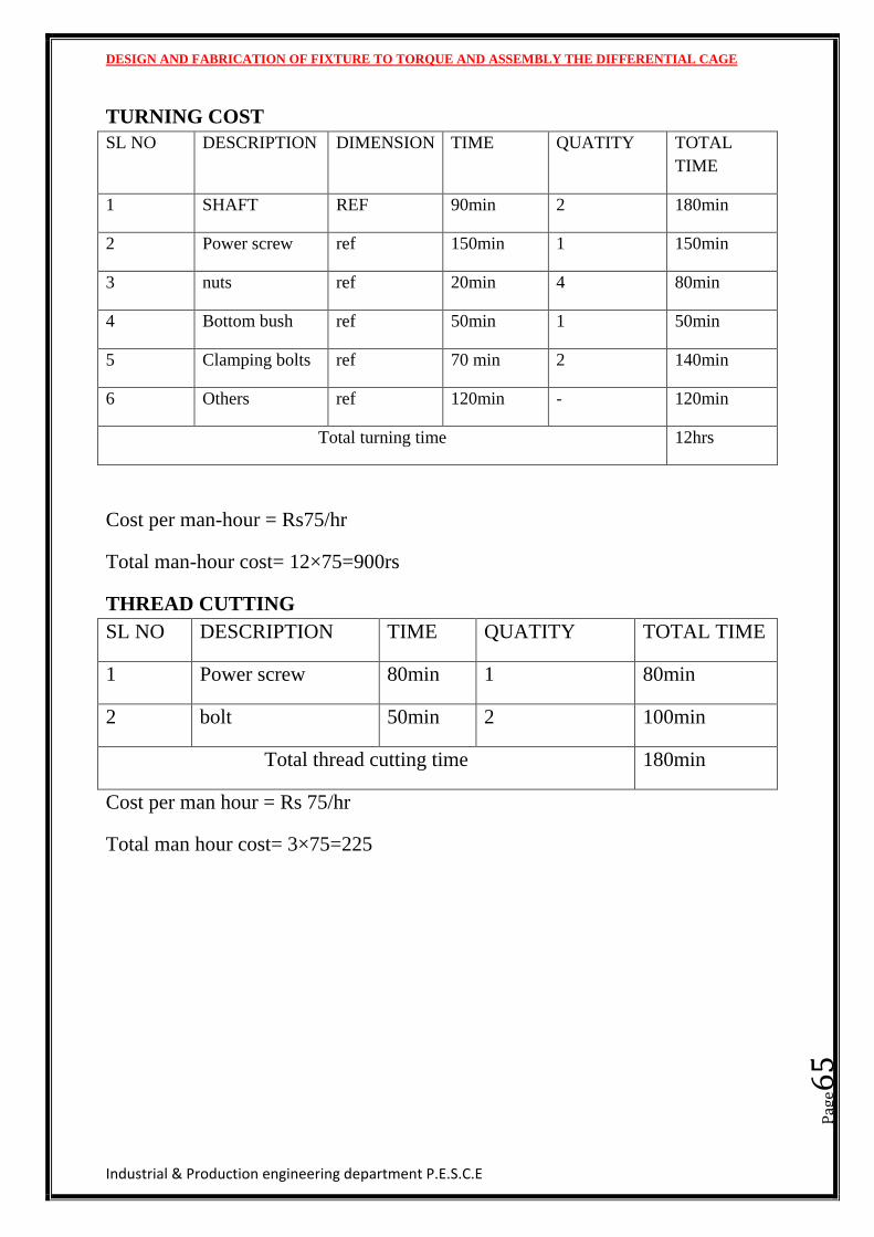
TURNING COST
SL NO DESCRIPTION DIMENSION TIME QUATITY TOTAL
TIME
1 SHAFT REF 90min 2 180min
2 Power screw ref 150min 1 150min
3 nuts ref 20min 4 80min
4 Bottom bush ref 50min 1 50min
5 Clamping bolts ref 70 min 2 140min
6 Others ref 120min - 120min
Total turning time 12hrs
Cost per man-hour = Rs75/hr
Total man-hour cost= 12×75=900rs
THREAD CUTTING
SL NO DESCRIPTION TIME QUATITY TOTAL TIME
1 Power screw 80min 1 80min
2 bolt 50min 2 100min
Total thread cutting time 180min
Cost per man hour = Rs 75/hr
Total man hour cost= 3×75=225
DESIGN AND FABRICATION OF FIXTURE TO TORQUE AND ASSEMBLY THE DIFFERENTIAL CAGE
Industrial & Production engineering department P.E.S.C.E
Pag
e66
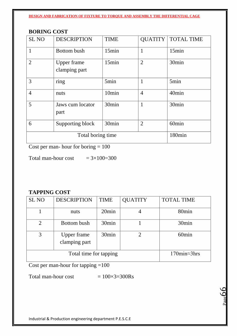
BORING COST
SL NO DESCRIPTION TIME QUATITY TOTAL TIME
1 Bottom bush 15min 1 15min
2 Upper frame
clamping part
15min 2 30min
3 ring 5min 1 5min
4 nuts 10min 4 40min
5 Jaws cum locator
part
30min 1 30min
6 Supporting block 30min 2 60min
Total boring time 180min
Cost per man- hour for boring = 100
Total man-hour cost = 3×100=300
TAPPING COST
SL NO DESCRIPTION TIME QUATITY TOTAL TIME
1 nuts 20min 4 80min
2 Bottom bush 30min 1 30min
3 Upper frame
clamping part
30min 2 60min
Total time for tapping 170min≈3hrs
Cost per man-hour for tapping =100
Total man-hour cost = 100×3=300Rs
DESIGN AND FABRICATION OF FIXTURE TO TORQUE AND ASSEMBLY THE DIFFERENTIAL CAGE
Industrial & Production engineering department P.E.S.C.E
Pag
e67
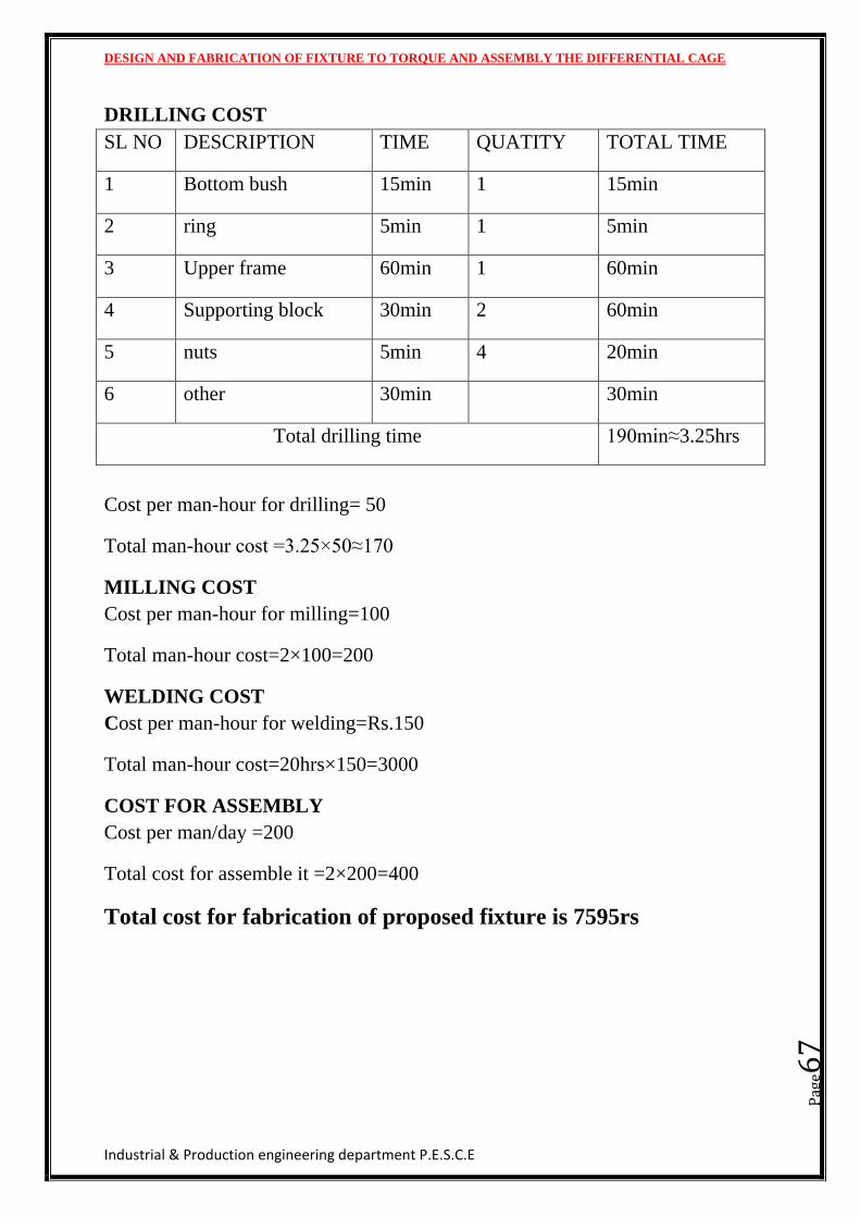
DRILLING COST
SL NO DESCRIPTION TIME QUATITY TOTAL TIME
1 Bottom bush 15min 1 15min
2 ring 5min 1 5min
3 Upper frame 60min 1 60min
4 Supporting block 30min 2 60min
5 nuts 5min 4 20min
6 other 30min 30min
Total drilling time 190min≈3.25hrs
Cost per man-hour for drilling= 50
Total man-hour cost =3.25×50≈170
MILLING COST
Cost per man-hour for milling=100
Total man-hour cost=2×100=200
WELDING COST
Cost per man-hour for welding=Rs.150
Total man-hour cost=20hrs×150=3000
COST FOR ASSEMBLY
Cost per man/day =200
Total cost for assemble it =2×200=400
Total cost for fabrication of proposed fixture is 7595rs
DESIGN AND FABRICATION OF FIXTURE TO TORQUE AND ASSEMBLY THE DIFFERENTIAL CAGE
Industrial & Production engineering department P.E.S.C.E
Pag
e68
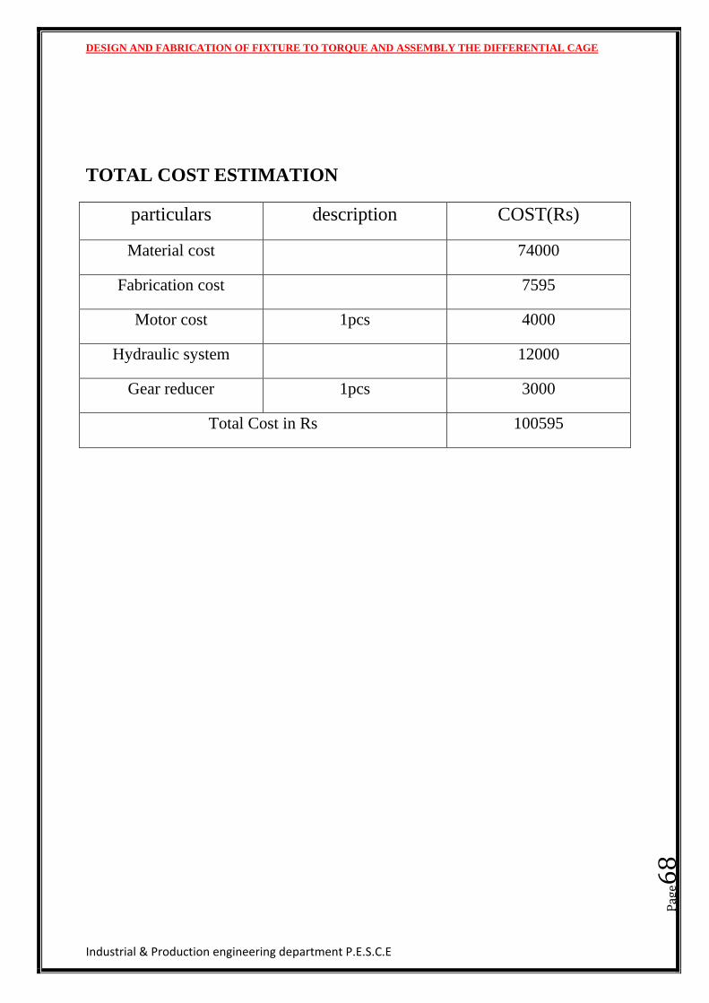
TOTAL COST ESTIMATION
particulars description COST(Rs)
Material cost 74000
Fabrication cost 7595
Motor cost 1pcs 4000
Hydraulic system 12000
Gear reducer 1pcs 3000
Total Cost in Rs 100595
DESIGN AND FABRICATION OF FIXTURE TO TORQUE AND ASSEMBLY THE DIFFERENTIAL CAGE
Industrial & Production engineering department P.E.S.C.E
Pag
e69
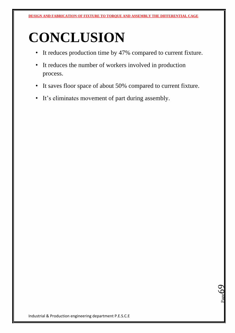
CONCLUSION • It reduces production time by 47% compared to current fixture.
• It reduces the number of workers involved in production
process.
• It saves floor space of about 50% compared to current fixture.
• It’s eliminates movement of part during assembly.
DESIGN AND FABRICATION OF FIXTURE TO TORQUE AND ASSEMBLY THE DIFFERENTIAL CAGE
Industrial & Production engineering department P.E.S.C.E
Pag
e70
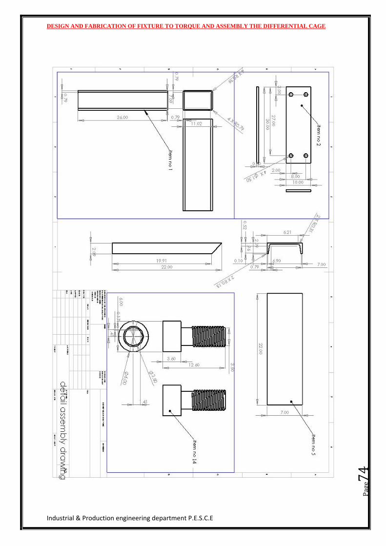
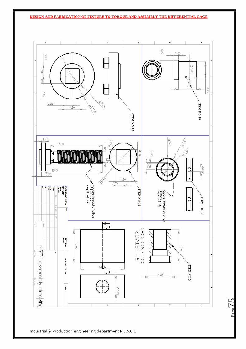
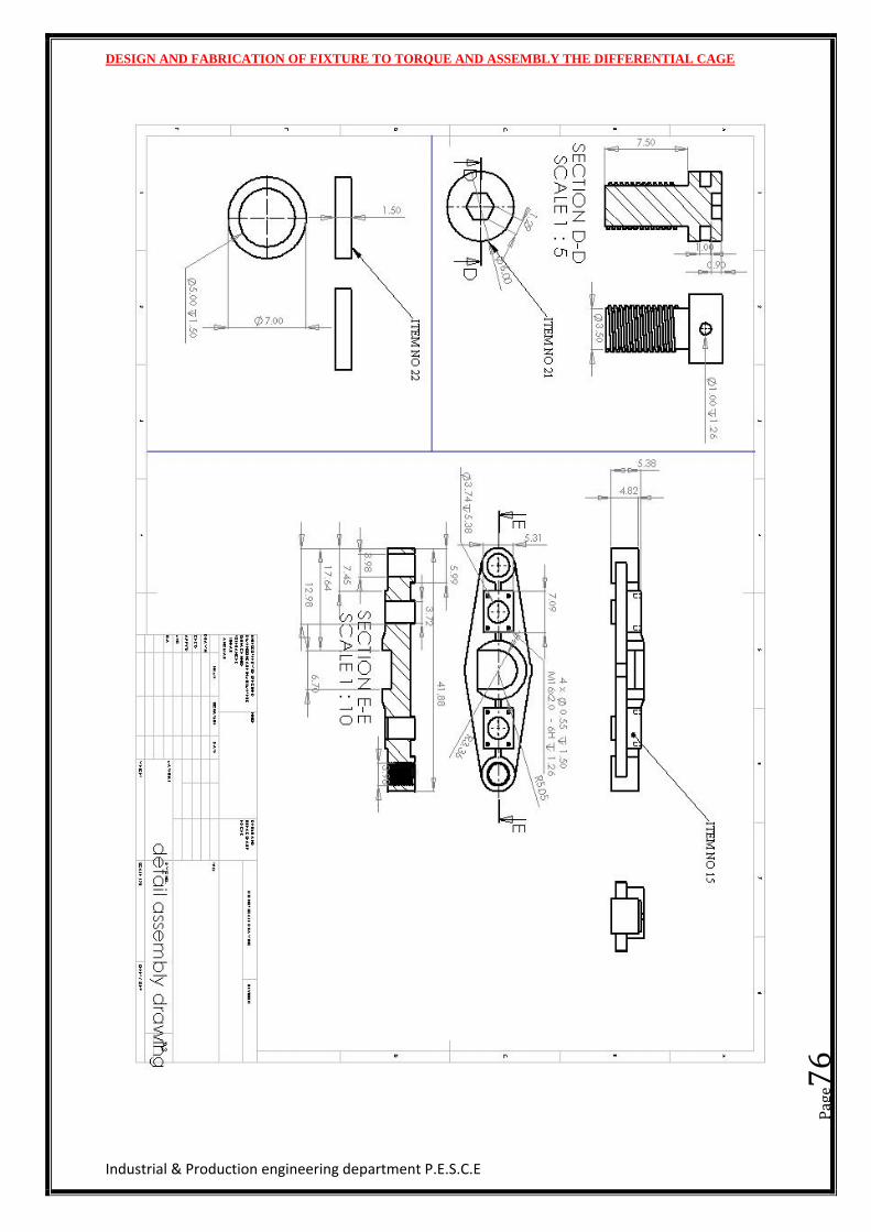
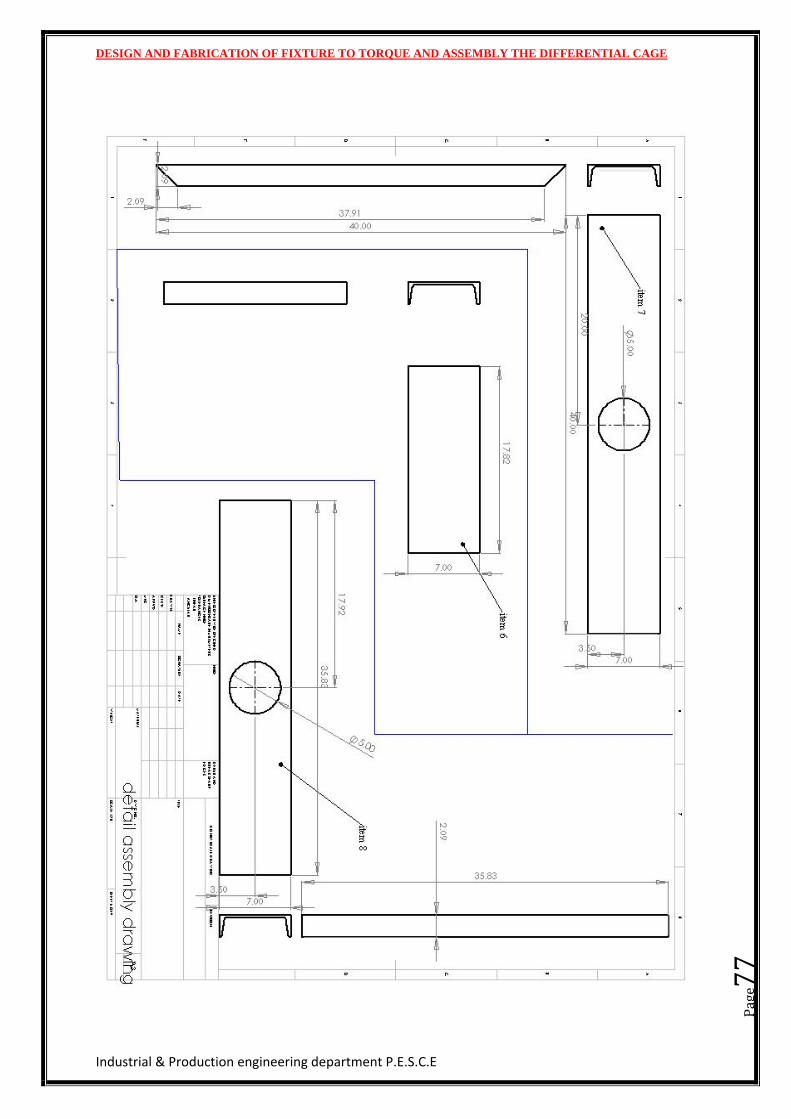
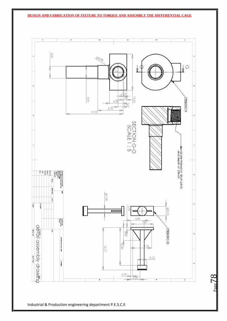
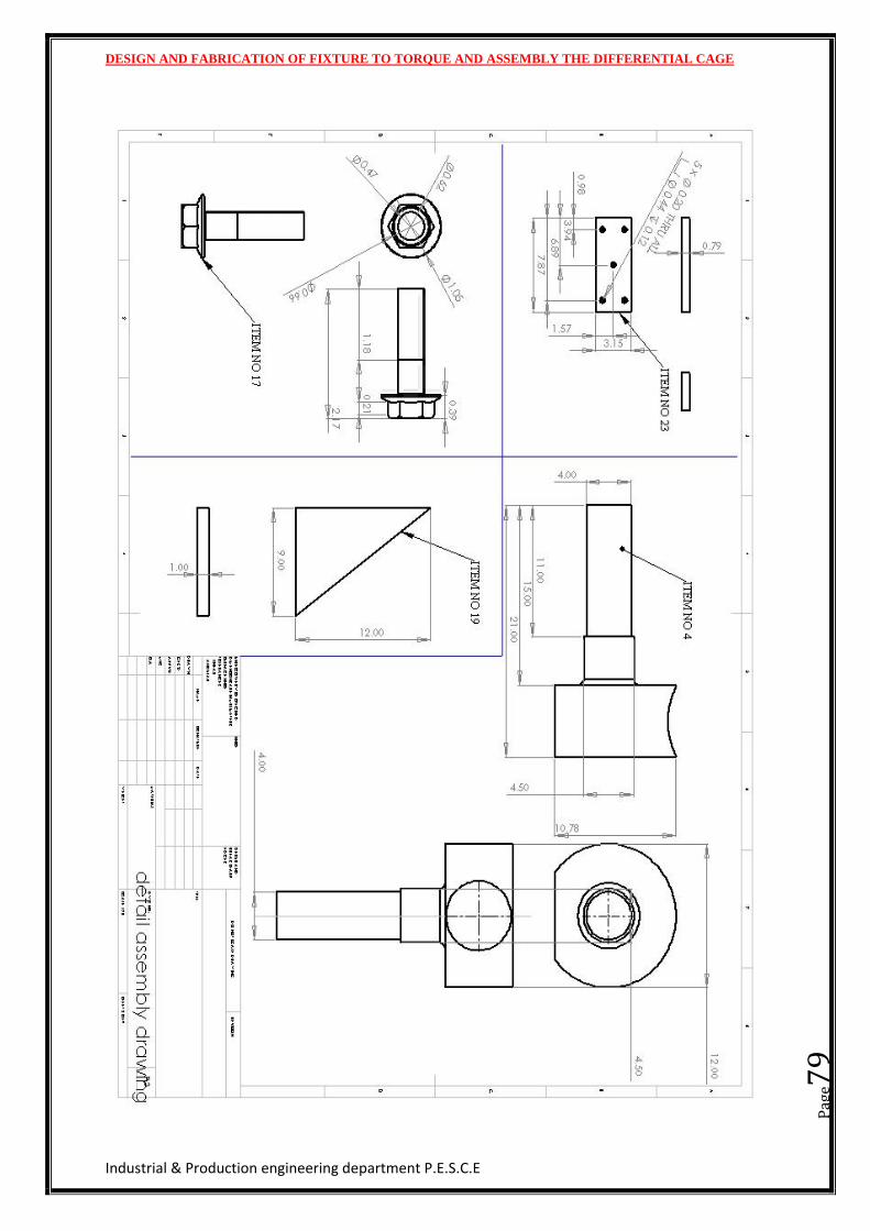
DETAIL DRAWINGS
DESIGN AND FABRICATION OF FIXTURE TO TORQUE AND ASSEMBLY THE DIFFERENTIAL CAGE
Industrial & Production engineering department P.E.S.C.E
Pag
e71
DESIGN AND FABRICATION OF FIXTURE TO TORQUE AND ASSEMBLY THE DIFFERENTIAL CAGE
Industrial & Production engineering department P.E.S.C.E
Pag
e72
DESIGN AND FABRICATION OF FIXTURE TO TORQUE AND ASSEMBLY THE DIFFERENTIAL CAGE
Industrial & Production engineering department P.E.S.C.E
Pag
e73
DESIGN AND FABRICATION OF FIXTURE TO TORQUE AND ASSEMBLY THE DIFFERENTIAL CAGE
Industrial & Production engineering department P.E.S.C.E
Pag
e74
DESIGN AND FABRICATION OF FIXTURE TO TORQUE AND ASSEMBLY THE DIFFERENTIAL CAGE
Industrial & Production engineering department P.E.S.C.E
Pag
e75
DESIGN AND FABRICATION OF FIXTURE TO TORQUE AND ASSEMBLY THE DIFFERENTIAL CAGE
Industrial & Production engineering department P.E.S.C.E
Pag
e76
DESIGN AND FABRICATION OF FIXTURE TO TORQUE AND ASSEMBLY THE DIFFERENTIAL CAGE
Industrial & Production engineering department P.E.S.C.E
Pag
e77
DESIGN AND FABRICATION OF FIXTURE TO TORQUE AND ASSEMBLY THE DIFFERENTIAL CAGE
Industrial & Production engineering department P.E.S.C.E
Pag
e78
DESIGN AND FABRICATION OF FIXTURE TO TORQUE AND ASSEMBLY THE DIFFERENTIAL CAGE
Industrial & Production engineering department P.E.S.C.E
Pag
e79
DESIGN AND FABRICATION OF FIXTURE TO TORQUE AND ASSEMBLY THE DIFFERENTIAL CAGE
Industrial & Production engineering department P.E.S.C.E
Pag
e80
BIBILOGRAPHY Jig and Fixture Design Manual by ERIK KARL HENRIKSEN.
Jig and Fixture Design by EDWARD G. HOFFMAN
http://www.g-w.com/PDF/SampChap/60525_0816_Ch02.pdf
A Textbook of Machine Design by R.S KHURMI AND J K GUPTA
Hydraul ic AND Pneumat ic Cy l inders by D.J .DUNN
http://www.westyorkssteel.com
http://www.precisehydraulic.com/Hydrodynamics-Welded-
cylinders.pdf
DESIGN AND FABRICATION OF FIXTURE TO TORQUE AND ASSEMBLY THE DIFFERENTIAL CAGE
Industrial & Production engineering department P.E.S.C.E
Contents COMPANY PROFILE ........................................................................................................................... 1
ABOUT THE COMPANY ........................................................................................................................ 2
HISTORY .............................................................................................................................................. 3
COMPANY VISION ............................................................................................................................... 4
PRODUCTS ........................................................................................................................................... 4
TYPES OF PRODUCTS ........................................................................................................................... 5
SINGLE DRIVE AXLES ............................................................................................................... 5
TANDEM DRIVE AXLES ............................................................................................................ 5
NON DRIVE AXLES ..................................................................................................................... 5
QUALITY OBJECTIVES .......................................................................................................................... 6
QUALITY: ...................................................................................................................................... 6
HUMAN RESOURCES DEVELOPMENT: .................................................................................. 6
COMPETITION: ............................................................................................................................ 6
FINANCIAL PERFORMANCE: ................................................................................................... 6
ENVIRONMENT & SAFETY: ...................................................................................................... 6
FEATURES ............................................................................................................................................ 7
CUSTOMERS ........................................................................................................................................ 7
CHAPTER 1 ........................................................................................................................................... 8
INTRODUCTION TO TOOL DESIGN1.TOOL DESIGN ........................................................................ 8
1.TOOL DESIGN ....................................................................................................................................... 9
1.1 TOOL DESIGN OBJECTIVES ............................................................................................................ 9
1.2TOOL DESIGN IN MANUFACTURING .............................................................................................. 9
1.3 PLANNING THE DESIGN ............................................................................................................... 10
1.4 PART DRAWINGS ......................................................................................................................... 10
1.5 PRODUCTION PLAN ..................................................................................................................... 11
1.6 ALTERNATIVES ............................................................................................................................. 12
1.7 REQUIREMENTS TO BECOME A TOOL DESIGNER ....................................................................... 12
DESIGN AND FABRICATION OF FIXTURE TO TORQUE AND ASSEMBLY THE DIFFERENTIAL CAGE
Industrial & Production engineering department P.E.S.C.E
CHAPTER 2 ......................................................................................................................................... 14
JIGS AND FIXTURE ........................................................................................................................... 14
2.1 DIFFERENCES BETWEEN JIGS AND FIXTURES .............................................................................. 16
2.2 ADVANTAGE OF JIGS AND FIXTURES ........................................................................................... 16
2.3 APPLICATION AND CLASSIFICATION OF JIGS AND FIXTURE ........................................................ 16
2.4 CLASSIFICATION OF FIXTURES ..................................................................................................... 18
Machining fixture .......................................................................................................................... 18
Manual work fixture ..................................................................................................................... 19
2.5 CLASSIFICATION OF JIGS ............................................................................................................. 19
CHAPTER 3 ......................................................................................................................................... 22
3.1HYDRAULIC ACTUATING SYSTEM ................................................................................................. 23
3.1a) ACTUATORS ..................................................................................................................... 23
3.1b) MOTORS ............................................................................................................................. 24
3.1c) RESERVOIR ....................................................................................................................... 25
3.1c) CONDUCTORS .................................................................................................................. 25
3.1d) DIRECTION CONTROL VALVES ................................................................................... 26
3.1e) PRESSURE CONTROL VALVES ..................................................................................... 27
3.1f) FLOW CONTROL VALVE ................................................................................................ 28
CHAPTER 4 ......................................................................................................................................... 29
DESIGN4. DESIGN OF FIXTURE ............................................................................................................ 29
4. DESIGN OF FIXTURE .......................................................................................................................... 30
4.1 PRINCIPLE OF FIXTURE DESIGN ................................................................................................... 31
LOCATION .................................................................................................................................. 31
CLAMPING .................................................................................................................................. 31
CLEARANCE ............................................................................................................................... 31
HANDLING ................................................................................................................................. 31
GENERAL .................................................................................................................................... 31
4.2 LOCATORS ................................................................................................................................... 31
4.3TYPES OF LOCATORS .................................................................................................................... 32
4.4 CLAMPING ................................................................................................................................... 32
FACTORS TO BE CONSIDERED IN CLAMPING ................................................................... 32
4.5 DESIGN ........................................................................................................................................ 34
DESIGN AND FABRICATION OF FIXTURE TO TORQUE AND ASSEMBLY THE DIFFERENTIAL CAGE
Industrial & Production engineering department P.E.S.C.E
4.5.3 DESIGN APPROACH ......................................................................................................... 35
CHAPTER 5 ......................................................................................................................................... 36
PROJECT DESCRIPTION ................................................................................................................... 36
CURRENT OPERATING PRODECURE .................................................................................................. 37
TIME ESTIMATION OF OPERATION USING CURRENT FIXTURE ................................... 39
DATA COLLECT FOR DESIGN OF FIXTURE ........................................................................ 40
PROPOSED DESIGN ........................................................................................................................... 43
PROPOSED FIXTURE ................................................................................................................ 44
SECTION VIEW OF PROPOSED FIXTURE ............................................................................. 45
STRESS ANALYSIS OF PARTS ................................................................................................ 47
DESIGN OF HYDRAULIC CIRCUIT ........................................................................................ 50
CALCULATION .................................................................................................................................... 51
CHAPTER 6 ......................................................................................................................................... 53
MATERIAL SELECTION ................................................................................................................... 53
Material selection: ............................................................................................................................ 54
Engineering steels ............................................................................................................................. 54
BILL OF MATERIAL ............................................................................................................................. 56
CHAPTER 7 FABRICATION ............................................................................................................. 58
FABRICATION .................................................................................................................................... 59
OBJECTIVE ......................................................................................................................................... 59
FABRICATION OF FIXTURE ................................................................................................................. 59
Operation involved in fabrication ..................................................................................................... 60
FLAME CUTTING ...................................................................................................................... 60
DEBURRING ............................................................................................................................... 60
FACE MILLING .......................................................................................................................... 60
WELDING .................................................................................................................................... 60
DRILLING AND BORING .......................................................................................................... 60
TURNING AND FACING ........................................................................................................... 61
TAPPING ...................................................................................................................................... 61
CHAPTER 8 ......................................................................................................................................... 62
COST ESTIMATION ........................................................................................................................... 62
FLAME CUTTING COST ........................................................................................................... 64
DESIGN AND FABRICATION OF FIXTURE TO TORQUE AND ASSEMBLY THE DIFFERENTIAL CAGE
Industrial & Production engineering department P.E.S.C.E
HACKSAW CUTTING COST ..................................................................................................... 64
TURNING COST ......................................................................................................................... 65
THREAD CUTTING .................................................................................................................... 65
BORING COST ............................................................................................................................ 66
TAPPING COST .......................................................................................................................... 66
DRILLING COST ........................................................................................................................ 67
MILLING COST .......................................................................................................................... 67
WELDING COST ......................................................................................................................... 67
COST FOR ASSEMBLY ............................................................................................................. 67
TOTAL COST ESTIMATION ................................................................................................................. 68
CONCLUSION ..................................................................................................................................... 69
DETAIL DRAWINGS .......................................................................................................................... 70
BIBILOGRAPHY ................................................................................................................................. 80
Related Documents