Reyes-Delgado, P. Mora, M., Duran-Limon H., Rodriguez-Martnez, L., O'Connor, R.V. and Mendoza-Gonzalez, R., The Strengths and Weaknesses of Software Architecture Design in the RUP, MSF, MBASE and RUP-SOA Methodologies: A Conceptual Review, Computer Standards and Interfaces, Vol. 47, pp 24-41, 2016. The Strengths and Weaknesses of Software Architecture Design in the RUP, MSF, MBASE and RUP-SOA Methodologies: A Conceptual Review Paola Y. Reyes-Delgado a , Manuel Mora b , Hector A. Duran-Limon c , Laura C. Rodríguez- Martínez a , Rory V. O'Connor d , Ricardo Mendoza-Gonzalez a a Technology Institute of Aguascalientes, Aguascalientes, México b Autonomous University of Aguascalientes, Aguascalientes, México c CUCEA, University of Guadalajara, Jalisco, México d Dublin City University, Dublin, Ireland ABSTRACT The importance of Software Architecture design has been acknowledged as a very important factor for a high-quality software development. Different efforts in both industry and academia have produced multiple system development methodologies (SDMs) that include SA design activities. In addition, standardization bodies have defined different recommendations regarding Software Architecture design. However, in industry Software Architecture best practices are currently poorly employed. This fact constrains the benefits that industry can potentially obtain from Software Architecture design in software development. In this paper, we analyze the degree to which the four main recognized SDMs – RUP (Rational Unified Process), MSF (Microsoft Solutions Framework), MBASE (Model-Based System Architecting and Software Engineering), and RUP-SOA (Rational Unified Process for Service-oriented Architecture) - adhere to the best practices of Software Architecture design. Our analysis points out some of the most important strengths and weakness regarding Software Architecture design and highlights some of the most relevant issues of Software Architecture design that need to be incorporated into such methodologies. Keywords: Software Architecture design, RUP, MSF, MBASE, RUP-SOA, general model of Software Architecture design. 1. Introduction In the context of modern software engineering, Software Architecture (SA) artifacts are considered first- class artifacts [1-5]. A first-class artifact implies that such an element is a highly important factor and should be considered mandatory to be elaborated in a high-quality system development methodology, and that its omission or partial elaboration can lead to a flawed software design and lately to a wrong software product [3]. A Software Architecture can be defined as “the set of structures needed to reason about the system, which comprises software elements, relations among them, and properties of both” [3, p. 1]. Software Architecture design artifacts were posited in software development methodologies to cope with the increasing complexity of large-scale software design [6, 7]. Given that Software Architecture artifacts are concerned with high-level system structures and system properties [8], Software Architecture artifacts determine the overall quality and performance of software products [9, 10, 5]. A Software Architecture design artifact is expected to be elaborated during the Design activity in a software engineering process (SEP). A software development methodology (SDM) represents a SEP and thus a SDM can be defined as a well-structured process that describes the phases, activities, roles, tools, and expected artifacts for elaborating a software system [11]. The basic requirements of an SDM is that it should fit the needs of the project and aid project success [12] and this need should be informed by the situational context where in the project must operate and therefore, the most suitable software development process is contingent on the context [13, 14]. Although there are several SDMs [15], most of them share the following activities: Project Management, Requirements-Analysis, Design, Codification-Test, and Implementation.

Welcome message from author
This document is posted to help you gain knowledge. Please leave a comment to let me know what you think about it! Share it to your friends and learn new things together.
Transcript

Reyes-Delgado, P. Mora, M., Duran-Limon H., Rodriguez-Martnez, L., O'Connor, R.V. and Mendoza-Gonzalez, R., The Strengths and Weaknesses of Software Architecture Design in the RUP, MSF, MBASE and RUP-SOA Methodologies: A Conceptual Review, Computer Standards and Interfaces, Vol. 47, pp 24-41, 2016.
The Strengths and Weaknesses of Software Architecture Design in the RUP, MSF, MBASE and RUP-SOA Methodologies:
A Conceptual Review
Paola Y. Reyes-Delgadoa, Manuel Morab, Hector A. Duran-Limonc, Laura C. Rodríguez-Martíneza, Rory V. O'Connord, Ricardo Mendoza-Gonzaleza
a Technology Institute of Aguascalientes, Aguascalientes, México
b Autonomous University of Aguascalientes, Aguascalientes, México c CUCEA, University of Guadalajara, Jalisco, México
d Dublin City University, Dublin, Ireland ABSTRACT The importance of Software Architecture design has been acknowledged as a very important factor for a high-quality software development. Different efforts in both industry and academia have produced multiple system development methodologies (SDMs) that include SA design activities. In addition, standardization bodies have defined different recommendations regarding Software Architecture design. However, in industry Software Architecture best practices are currently poorly employed. This fact constrains the benefits that industry can potentially obtain from Software Architecture design in software development. In this paper, we analyze the degree to which the four main recognized SDMs – RUP (Rational Unified Process), MSF (Microsoft Solutions Framework), MBASE (Model-Based System Architecting and Software Engineering), and RUP-SOA (Rational Unified Process for Service-oriented Architecture) - adhere to the best practices of Software Architecture design. Our analysis points out some of the most important strengths and weakness regarding Software Architecture design and highlights some of the most relevant issues of Software Architecture design that need to be incorporated into such methodologies. Keywords: Software Architecture design, RUP, MSF, MBASE, RUP-SOA, general model of Software Architecture design. 1. Introduction In the context of modern software engineering, Software Architecture (SA) artifacts are considered first-class artifacts [1-5]. A first-class artifact implies that such an element is a highly important factor and should be considered mandatory to be elaborated in a high-quality system development methodology, and that its omission or partial elaboration can lead to a flawed software design and lately to a wrong software product [3]. A Software Architecture can be defined as “the set of structures needed to reason about the system, which comprises software elements, relations among them, and properties of both” [3, p. 1]. Software Architecture design artifacts were posited in software development methodologies to cope with the increasing complexity of large-scale software design [6, 7]. Given that Software Architecture artifacts are concerned with high-level system structures and system properties [8], Software Architecture artifacts determine the overall quality and performance of software products [9, 10, 5]. A Software Architecture design artifact is expected to be elaborated during the Design activity in a software engineering process (SEP). A software development methodology (SDM) represents a SEP and thus a SDM can be defined as a well-structured process that describes the phases, activities, roles, tools, and expected artifacts for elaborating a software system [11]. The basic requirements of an SDM is that it should fit the needs of the project and aid project success [12] and this need should be informed by the situational context where in the project must operate and therefore, the most suitable software development process is contingent on the context [13, 14]. Although there are several SDMs [15], most of them share the following activities: Project Management, Requirements-Analysis, Design, Codification-Test, and Implementation.
A considerable amount of research has produced several Software Architecture design methods and best practices [16, 17, 7, 18, 3]. Further, standardization bodies have defined different recommendations regarding Software Architecture design such as the standards IEEE 1471 [19] and ISO 42010 [20]. Importantly, various efforts in both industry and academia have produced several system development methodologies (SDMs) that include Software Architecture design activities [21, 22]. For instance [21] reports MBASE as one of the first SDMs which explicitly included Software Architecture design activities. More concretely, in [21] is reported a set of criteria for evaluating Software Architecture designs based on stakeholder’s concerns. In [22], the Software Architecture design conduced in RUP is improved through the activities reported in the particular Software Architecture design method ADD: Attribute-Driven Design method [9]. However, in industry Software Architecture best practices are considered in overall as poorly employed [10, 23, 24, 25]. One reason of this is the transference “of innovative techniques and methods from research to practice is slow” [10, p. 25]. Additionally, the SDM literature does not highlight the Software Architecture design activity over other ones, and thus, the extensive generated knowledge on Software Architecture design has incorporated little into the practical execution of SDMs [23]. In this paper, we have analyzed the degree to which four rigor-oriented SDMs, namely RUP: Rational Unified Process [26], MSF: Microsoft Solutions Framework [27, 28], MBASE: Model-Based (System) Architecting and Software Engineering [29], and RUP-SOA: Rational Unified Process for Service-Oriented Architecture [30], adhere to best practices of Software Architecture design. These four SDMs can be typified as well-recognized and used in industry (MSF) [31, 32, 33, 34, 35], in academy (MBASE) [21, 36, 37, 38], in both academy-industry (RUP) [39, 31, 32, 33, 34, 35], and as an emergent SDM (RUP-SOA) [30, 40]. RUP [26] is an iterative-incremental based software engineering process and framework. MSF (Microsoft Solutions Framework) [27, 28] is an iterative-milestone process for building and deploying information technology (including software products) solutions. MBASE [29] is a SDM that integrates several models (process, product, property and success) for developing a software system. RUP-SOA [30], is an emergent extension of RUP focused on software systems based on service-oriented computing platforms and languages [40]. A similar analysis for agile-oriented SDMs [41, 42, 43, 44, 45, 46] deserves a particular additional study and is out the scope of this research [47]. It is also important clarifying that our study is focused only on SA design methods for software systems. There are other architectural design methods and frameworks focused on large-scale inter-organizational enterprise business systems named Information Technology (IT) Enterprise Architecture [48, 49]. Software Architecture design methods for software systems and IT Enterprise Architecture methods and frameworks share the same definition on the meaning of Software Architecture. However, their scope is different. In IT Enterprise Architecture approaches, the architecture expected to be designed includes the overall business organization, IT deployed in all organization, the whole set of IT and systems projects, the total of human resources, and other relevant components (e.g. the financial and physical infrastructure). In summary, the IT Enterprise Architecture addresses the totality of IT systems and related human, financial and infrastructure resources in the whole business organization while Software Architecture design methods for software systems have a narrower scope focusing exclusively on the design of software systems [49]. Furthermore, our analysis is centered on the synthesis phase [18] of Software Architecture design methods, which involves architecture design and excludes requirements analysis and architecture evaluation. In this research, our conceptual review is guided by the structure (activities, artifacts, and roles) recommended by a general model of Software Architecture design [18], which emerged from five well-known worldwide industrial Software Architecture design methods. These five Software Architecture design methods were: Attribute-Driven Design (ADD) Method [9], Siemens’ 4 Views (S4V) method [50] , the Rational Unified Process 4 + 1 views (RUP 4 + 1) [51, 26], Business Architecture Process and Organization (BAPO) [52, 53], and Architectural Separation of Concerns (ASC) [54]. Our overall aims are to assess the conformance status among the general model of Software Architecture design and the Software Architecture design activities used in the four SDMs, and elaborate a set of recommendations for the literature and practice based on the review results. We consider that such a review and recommendations can have a positive influence on improving the employment of best practices of
Software Architecture design in industry. Our research is strongly motivated by a seminal [18] research paper. The authors in [18] proposed a general model for architecture design out of the analysis of common practices from different software architecture design methods. Our research employs such a general model to evaluate the software architecture design methods embedded in four SDMs, from which three of them (i.e. MBASE, MSF and RUP-SOA) are not reported in [18]. Our study reveals insights (no previously reported) on how these three SDMs fit the SA design theoretical recommendations from the general model for SA design. Hence, we consider that the main overall contribution of this research is threefold: 1) our research helps to create awareness in academy on the relevance of Software Architecture design for producing high quality software, 2) it reports the degree to which current best practices for Software Architecture design are used in the four reviewed SDMs, and 3) we point out unsolved issues which are venues for future research in software architecture design. The remainder of this paper is organized as follows. In section 2, we report the research method used. A brief description of the four SDMs is reported in Section 3. In Section 4, a review of fundamental concepts in Software Architecture, and the general model of Software Architecture design are explained. In section 5, we report the comparative and conformance review of the four SDMs versus the general model of Software Architecture design. In Section 6, we present the theoretical and practical implications of these comparisons. Finally, in Section 7 we present a summary of findings, contributions, limitations, and recommendations for further research. 2. Research Approach A descriptive and evaluative-interpretive research approach [55, p. 90] was used in this investigation. This research approach can be outlined with the following main steps [56]: i) to define research goals and questions; ii) to collect official literature on target elements to be evaluated; iii) to conduct a selective literature review on similar studies; iv) to select descriptive-interpretative lenses (schemes); v) to conduct a descriptive and interpretative analysis; vi) to review the analysis; and vii) to generate a report. In i), we have defined as core research questions the following: RQ.1 What is the conformance status of the SA design methods used in the four selected SDMs against the general model of Software Architecture design? and RQ.2 What do theoretical and practical recommendations emerge from the conformance results? In ii), we have collected official documents of RUP, MSF, MBASE, RUP-SOA. In iii), we conducted a selective search for similar studies focused on SA design methods used in full SDMs but none was found. Although comparative studies among SDMs are abundant [31, 32, 33, 34, 35, 57, 58], we did not find any studies focused on comparing the Software Architecture design methods included in different SDMs. In iv), we selected Hofmeister et al.’s [18] general model of Software Architecture design as the theoretical lenses for comparing the Software Architecture design methods used in the four SDMs. This general model of Software Architecture design was employed “to analyze other proposed Software Architecture design methods, or even to drive the development of new architecture design methods” [18, p. 121]. In v), the first two authors conducted the comparative analyses by doing a careful joint reading of the official documents and by using the grid evaluation suggested by Hofmeister et al. [18]. This task was conducted with several iterations including discussions on discrepancies until the first two authors achieved an agreement. In vi) the third author conducted a thorough evaluation of the review results produced by authors one and two. The discrepancies found were finally reviewed again and the three authors agreed on a final solution. Finally, as part of this step, the rest of the authors conducted an overall review of the comparative analysis. Only a few minor errors were found and solved jointly by the research team. In vi), we wrote this article. 3. A General Review of RUP, MSF, MBASE and RUP-SOA SDMs Some software Development Methodologies (SDMs) have been extensively studied in the last four decades [59, 35]. According to Avison and Fitzgerald [59, p. 80] a methodology is a “recommended
collection of phases, procedures, rules, techniques, tools, documentation, management, and training used to develop a system”. SDMs (like system development life cycles) provide an organized roadmap for carrying activities required for elaborating high-quality software products. According to Kruchten [26, p. 42] without a well-structured software process (i.e. a SDM) a developer team “will develop in an ad hoc manner, with success relying on the heroic efforts of a few dedicated individual contributors”. An evolution of SDMs has been reported in four major stages: pre-methodologies, rigor-oriented methodologies, agile-oriented methodologies and emergent service-oriented methodologies [60, 61]. From the current available variety of SDMs [35], some of them are well-recognized in the software engineering literature and practice such as: i) Rational Unified Process (RUP) [26]; ii) Microsoft Solutions Framework (MSF) [27, 28]; and iii) Model-Based (System) Architecting and Software Engineering (MBASE) [29]; and RUP-SOA [30], which is considered a relevant emergent SMD. These four SDMs can be classified as rigor-oriented methodologies. Next, we describe the SDMs phases of the four SDMs (RUP, MSF, MBASE and RUP-SOA) related to the SA design activity. Description of RUP: Rational Unified Process (RUP) is a "comprehensive process framework that provides industry-tested practices for software and systems delivery and implementation and for effective project management" [62, p. 1]. The RUP provides “a disciplined approach to assigning tasks and responsibilities within a development organization. Its goal is to ensure the production of high-quality software that meets the needs of its end users within a predictable schedule and budget.” [26, p. 45]. The RUP software development process or SDM can be depicted in two dimensions: phases and iterations (time-based axis), and disciplines and workflows (activity-based axis). Each phase and cycle of iterations ends with a milestone. A milestone is defined as: “a point in time at which certain critical decisions must be made, and therefore key goals must have been achieved” [63, p. 3]. RUP proposes four phases: Inception, Elaboration, Construction and Transition. In each phase, one or more iterations on activity workflows can be performed, until reaching the expected milestone. The extent of realization of each activity into workflows varies according to the type of the phase. There are two groups of workflows: a) core technical and b) managerial supporting ones. The core technical disciplines and workflows are: 1) Business Modeling, 2) Requirements, 3) Analysis and Design, 4) Implementation, 5) Test and Deployment. Managerial supporting workflows are: 1) Configuration and Change Management, 2) Project Management, and 3) Environment [63, 26]. Here we focus only on describing the 2) Requirements workflow and the 3) Analysis and Design workflow as these workflows are more closely related to architecture design activities. The 2) Requirements workflow consists of the following main activities: 1) Analyze the Problem, 2) Understand Stakeholder Needs, 3) Define the System, 4) Manage the Scope of the System, 5) Refine the System Definition, and 6) Manage Changing Requirements. Its main roles are: system analyst, requirements specifier, software architect and requirements reviewer. The main artifacts generated by this workflow are: vision document, use-case model, supplementary specifications, and a project glossary. The 3) Analysis and Design workflow consists of the following activities: 1) Define a Candidate Architecture, 2) Refine the Architecture, 3) Perform Architectural Synthesis (reported as an optional activity), 4) Analyze Behavior, 5) Design Components, and 6) Design the Database. The main roles of this workflow are: software architect, designer, database designer, architecture reviewer and design reviewer. The main artifacts generated by this workflow are: analysis model, design model, and Software Architecture document [63, 26]. Regarding phases, we describe the Inception and the Elaboration phases as they are more closely related to architecture design activities. The Inception phase’s goal is “to achieve concurrence among all stakeholders on the lifecycle objectives for the project” [26, p. 95]. The milestone of the Inception phase is the Lifecycle Objectives (LCO). The main artifacts are: a vision document, the use-case model survey, an initial project glossary, an initial business case, an initial risk assessment and a project plan. The main workflows to be performed in the Inception phase are: project management, business modeling, and requirements. The Elaboration phase’s goals are: “to analyze the problem domain, establish a sound
architectural foundation, develop the project plan, and eliminate the project's highest-risk elements” [26, p. 95]. The milestone of the Elaboration phase is the Lifecycle Architecture (LCA). The main outcomes are: a use-case model, supplementary requirements, a Software Architecture description, an executable architectural prototype, a revised risk list, a revised business case, a development plan for the overall project, an updated development case, and a preliminary user manual (optional). The main workflows to be performed in elaboration phase are: 1) Project Management, 2) Configuration and Change Management, and 3) Analysis and Design. Description of MSF: Microsoft Solutions Framework (MSF) [27, p. 4] is defined as “a deliberate and disciplined approach to technology projects based on a defined set of principles, models, disciplines, concepts, guidelines, and proven practices from Microsoft”. MSF is a popular alternative SDM to RUP. MSF is organized in seven tracks (five technical and two managerial ones) and seven team groups. Tracks are groups of workstreams and activities. Tracks can be executed simultaneously, and each track can have several iterations (cycles) addressing different levels (check-in, daily build, accepted build, iteration, project, and as needed). Technical tracks in MSF are: Envision, Planning, Build (Development), Stabilize and Deploy. Managerial tracks are: Governance, and Operational Management. MSF is based on both phases (tracks) and milestones controls [27]. Phases are “periods of time with an emphasis on certain activities aimed at producing the relevant deliverables for that phase” [27, p. 18]. Milestones are “review and synchronization points for determining whether the objectives of the phase have been met” [27, p. 18]. MSF uses seven types of teams: Program Management, Architecture, Development, Test, Release Management, User Experience, and Product Management. These team groups participate with different intensive levels in the seven tracks. Similarly to the RUP analysis, we focus on describing the tracks related to the Software Architecture design activity: Envision, Planning and Build tracks. In the Envision track, there are two workstreams: 1) Capture Product Vision and Scope, and 2) Establish Project Process. In 1) Capture Product Vision and Scope, the following activities are conducted: 1) Write a Vision Document, 2) Define Personas, 3) Develop a Lifestyle Snapshot and a Review Product Vision. In 2) Establish Project Process, the following activities are conducted: 1) Select a Project Process Template, 2) Tailor to a Project Process, 3) Review the Project Process, 4) Establish a Measurement Plan, 5) Establish a Project Data Management Plan, and 6) Monitor Measurements and Process Assets. The main deliverables are: vision/scope document, risk assessment document, and project structure document. Envision track ends with the vision-scope approved milestone. In the Planning track several activities are conducted for producing the master project plan, the risk management plan, and the system’s functional specifications. In particular, system’s functional specifications are defined in MSF as detailed descriptions on: “how each feature is to look and behave. It also describes the architecture and the design for all the features” [27, p. 26]. Among the main activities are: 1) Define a Plan for the Project, 2) Create QoS Requirements (e.g. a non-functional requirement), 3) Create Scenarios, 4) Create Product Requirements, and 5) Create a Solution Architecture. The planning track ends with the project plans approved milestone. In the Build track, the following deliverables are produced: source code and executables, installation scripts and configuration settings for deployment, frozen functional specification, performance support elements and test specifications and test cases. The main activities conducted are: 1) Plan an Iteration, 2) Manage Change requests, 3) Perform an Analysis, 4) Build a Product, and 5) Test a Customer Requirement. The Build track ends when the planned scope milestone is reached. Description of MBASE: Model-Based (System) Architecting and Software Engineering (MBASE) is based on the "Win-Win Spiral" [29]. MBASE [29, p. 1] "is an approach that integrates process, products, properties and success models, for the development of a software system”. MBASE is an iterative (with refinement) development approach with the following workflows (or phases): 1) Operational Concept Description (OCD), 2) System and Software Requirements Definition (SSRD), 3) System and Software Architecture Description (SSAD), 4) Life Cycle Plan (LCP), 5) Feasibility Rationale Description (FRD), 6) Construction, Transition, and Support (CTS) Plans and Reports, and 7) Risk-driven prototypes (RDP). These workflows can be grouped in Inception-Elaboration phases (OCD, SSRD, SSAD, LCP, and FRD), and Construction-Transition-Support phases (CTS, RDP). Similarly to the previous analysis of RUP and MSF, we only

describe the workflows related to Software Architecture design activities: 1) Operational Concept Description (OCD), 2) System and Software Requirements Definition (SSRD), 3) System and Software Architecture Description (SSAD), and 5) Feasibility Rationale Description (FRD). These workflows are executed by stakeholders and for stakeholders (called performing agents and participating agents, respectively). Stakeholders in MBASE are also classified as operational stakeholders (general public, operators, maintainers, users, and customers) and development stakeholders (managers, analysts, architects, implementers (developers, testers, and marketers)). In the 1) OCD and 2) SSRD workflows, the participating and performing stakeholders are the operational, manager and analyst stakeholders (as a subset of development stakeholders). In the SSAD workflow, the main associated participating and performing stakeholders are users (domain experts), managers, analysts, architects and implementers. In the FRD activity, the manager, development and operational stakeholders are associated. In the 1) OCD workflow, how a planned system will operate in its organizational and technical environment is described (e.g. statement of purpose, project goals and constraints, system capabilities, levels of service goals, changes and effects on the organization for the new system). This workflow also reports the reasons for developing the new system, as well as problems in the current system. Usual visual models (diagrams) employed are: block diagrams, and context diagrams. In 2) SSRD workflows, the fundamental services to be provided by the new system are reported. Functional and non-functional requirements (level of services), as well as mandatory (shall, must, will) and optional (can, could, may) requirements are described. All of these system requirements must be justified with a clear rationality by using Win-Win agreements or options. Usual visual models used are: requirements diagrams, and block (context) diagrams. In the 3) SSAD workflow, the results of analyzing the 1) OCD and 2) SSRD artifacts, designing a system architecture, and designing a system implementation are documented. This workflow is a bridging activity among the initial 1) OCD realized in the Inception phase, with the updated and final 1) OCD reported in Construction phase. In 3) SSAD there are three activities realized: 1) System Analysis, 2) Architecture Design and Analysis, and 3) Implementation Design. The 1) System Analysis activity filters the 1) OCD and 2) SSRD artifacts, for refining the architecturally relevant requirements. This activity uses block (context), collaboration, use case, use case description, activity, and level of services artifacts. 2) Architecture Design and Analysis elaborates a high-level solution (architecture) independently from its final implementation technology. This solution (architecture) describes: components (work units), what these components do, how they are connected, and how they can communicate among them. Usual diagrams used are: class diagram, component diagram, and static-structure package diagram. 3) Implementation Design elaborates a specific technology-based implementation solution derived from the high-level architecture. A technology-based implementation defines types of hardware and operating systems, languages, database managers, utilities and libraries. The usual diagrams generated are: component-stereotyped diagrams and implementation diagrams. A deployment model is also described through component and connector configurations for a working version of the designed software system. For each configuration it must be described the software and hardware component classes used in the configuration, the allocation of software components to the hardware components, and their specific instances. The architecture model is a standard deployment diagram used at this stage. Finally, the 5) FRD activity is carried out at the end of all Inception-Elaboration phases (OCD, SSRD, SSAD, LCP). Its main purpose is to assure the logical consistency and feasibility (economic, technical, operational, legal and organizational) of the system definition elements generated in the OCD, SSRD, SSAD and LCP activities. All of these activities in MBASE –grouped in Inception-Elaboration and Construction-Transition-Support phases- are essentially driven by three completion criteria: Life Cycle Objectives (LCO), Life Cycle Architecture (LCA), and Initial Operational Capability (IOC). LCO refers to the verification of feasible system objectives. LCA is about the verification of a feasible architecture design and plan. Finally, IOC refers to the verification of a product ready for initial operation.
Description of RUP-SOA: RUP-SOA provides “a disciplined approach to assigning tasks and responsibilities within a development organization. Its goal is to ensure the production of high-quality software that meets the needs of its users within a predictable schedule and budget” [30, p. 12]. RUP-SOA is an enhanced version of RUP for software systems built for service-oriented computing platforms. Thus, RUP-SOA has the same phase-discipline structure of RUP (i.e. four phases of Inception, Elaboration, Construction and Transition, with specific disciplines of activities to be conducted within them). The SOA extension is mainly achieved through the IBM Service-oriented Modeling and Architecture (SOMA) methodology [64] which is incorporated in RUP-SOA. The SOMA methodology is essentially used for producing a service model artifact in the Elaboration phase through the identification, specification, realization and deployment of services [30, p. 27; 64, p. 383]. SOA-based applications rely on the essential concept of service that is different from a component or a class/object. A service can be defined as a well-defined, encapsulated, reusable, business-aligned capability [64, p. 378] which is loosely coupled, highly reconfigurable (via orchestration and choreography of services for the case of composite services) and highly platform-independent. Orchestration of composite services refers to the selection of individual services for composing it and in its workflow there is a main service that coordinates the interaction of the remainder ones. Choreography of services refers to the specific timing-based interaction and communication rules between the service consumers and service providers under an autonomous approach (no service has control over the others) [65]. Similarly to the RUP analysis, we focus on describing the phases directly related with the Software Architecture design: Inception and Elaboration. The RUP-SOA core activities in the Inception phase are: 1) Conceive New Project, 2) Prepare Project Environment, 3) Define Requirements, 4) Perform Architectural Proof-of-Concept (activity reported as optional but strongly suggested for any SOA project), and 5) Plan Project. The main roles in the Inception phase are similar to RUP. However, in RUP several roles are not usually played in practice. In contrast RUP-SOA reports its execution (i.e. management reviewer, process engineer, and tool specialist). The main artifacts generated by this workflow are also similar to RUP (i.e. business case, software development plan, risk list, review record, and so on). However, when the activity 4) Perform Architectural Proof-of-Concept is conducted, the following artifacts must be generated: an initial Software Architecture document, an architectural proof-of-concept, and a review record. In RUP-SOA an architectural proof-of-concept “take many forms, such as a sketch of a conceptual model of a solution using a notation, such as Unified Modeling Language (UML), a simulation of a solution, or an executable prototype” [30, p. 40]. This artifact helps to assess the architectural significant requirements. The main activities in the Elaboration phase are: 1) Refine Requirements, 2) Define Candidate Architecture, 3) Refine Architecture, 4) Design Components, and 5) Plan Project. The main roles in the Elaboration phase are very similar to those reported in RUP. However, in RUP-SOA some roles will be required to have technical skills for modeling, programming and testing services. Regarding the main artifacts generated by this workflow there are some similar ones to RUP SDM but there are other new artifacts specific for RUP-SOA such as: 1) SOA signals and events, 2) goal-service model, 3) service model, 4) service components, and 5) a new SOA architectural view with proprietary tables and diagrams. Similar to RUP, in RUP-SOA each phase ends until the number of planned iterations is realized and expected milestones are reached. Table 1 (appendix) reports a summary of phases-workflows in these four SDMs (RUP, MSF, MBASE and RUP-SOA) related to the Software Architecture design activity. 4. Theoretical Background Fundamental Concepts of Software Architecture. Essentially a Software Architecture conveys relevant system’s information on its components, interrelationships and expected fundamental properties [1-5]. Components and interrelationships are fundamental design pieces in any Software Architecture [1-5]. In
turn, the expected fundamental properties of a system are derived from stakeholders’ concerns. Stakeholders involve any entity (individuals, teams, or organizations) which affect and are affected by the system [20]. Typical stakeholders are: customers, users, project manager, architect, builders, operators, and maintainers [3, 20]. A stakeholder’s concern is any “interest in a system relevant to one or more of its stakeholders” [20, p. 2]. Examples of stakeholder’s concerns are: system performance, system functionality, systems cost, system interoperability, among others [20]. Stakeholder’s concerns must be addressed by architecture decisions, which are justified by architecture rationale. An architecture decision can be defined as the selection of a course of action of at least two plausible design alternatives. An architecture rationale is the justification for a specific architecture decision, and corresponds to “records explanation, justification or reasoning about architecture decisions that have been made” [20, p. 7]. Software Architecture designs must be documented in order to be communicated and used by stakeholders. Software Architecture designs are documented in architecture descriptions. An architecture description is an artifact where an architectural design is reported [20]. An architecture description “assists the understanding of the system’s essence and key properties pertaining to its behavior, composition and evolution, which in turn affect concerns such as the feasibility, utility and maintainability of the system”[20, p. iv]. An architecture description includes and defines (among other elements) architecture viewpoints. An architecture viewpoint is a “work product establishing the conventions for the construction, interpretation and use of architecture views to frame specific system concerns” [20, p. 2]. Any stakeholder concern must be framed by at least one architecture viewpoint but several viewpoints are usually used to frame a stakeholder concern. The architecture viewpoints govern the architecture views. An architecture view is a work product “expressing the architecture of a system from the perspective of specific system concerns” [20, p. 2]. An architecture view can be conformed by one or more architecture models, which belong to a model kind. An architecture model can be conceptualized as a specific artifact, which can be represented by a diagram, a textual description, a formal logical description, or a hybrid notation. Architecture models, thus, are the specific artifacts used in architecture views.
The concepts of architectural style and architectural pattern are also important for architectural descriptions. According to Clements [3, p. 492] an architectural style is “specialization of element and relation types, together with a set of constraints on how they can be used”. For Clements [3] an architectural style differs from an architectural pattern in its scope of utilization. Crucially, an architectural pattern describes a more detailed specification for an architecture viewpoint based on the specific context and the specific problem, and thus its scope is more limited than an architectural style. Hence, architecture descriptions serve to three generic purposes [66]: 1) for guiding implementation; 2) for communicating among stakeholders; and 3) for educating new stakeholders. The architecture of a system is not an architecture description. An architecture description documents “the architecture of a system of interest”. The relevance of an adequate Software Architecture design documentation – through high quality architecture descriptions can be highlighted when it is considered that an architecture description represents simply the detailed high-level design and building blueprints. Thus, “if the architecture cannot be understood so that others can build systems from it, analyze it, maintain it, and learn from it, then the effort put into crafting it will by and large have been wasted” [66, p. 1]. General Model of Software Architecture Design. Hofmeister et al. [18] elaborated a general model of Software Architecture design derived from a thorough study on five industrial Software Architecture Design methods: 1) the Attribute-Driven Design (ADD) Method [9]; 2) Siemens’ 4 Views (S4V) method [50]; 3) the Rational Unified Process 4 + 1 views (RUP 4 + 1) [26]; 4) Business Architecture Process and Organization (BAPO) [52], and 5) Architectural Separation of Concerns (ASC) [54]. Their study was motivated by the front-end disparity of used terminology, domains of use, and structure of phases-activities. However, their study showed that essentially these five methods share more commonalities than differences, and consequently a general model of Software Architecture design can be proposed. This method “would help us better understand the strengths and weaknesses of different existing methods as
well as provide a framework for developing new methods better suited to specific application domains” [18, p. 107]. The authors [18] also elaborated a template for analyzing Software Architecture design methods. The template involves: general Software Architecture design activities, generated generic artifacts, performed tasks and the used or recommended techniques. The general model of SA design proposes four main activities, two generic input artifacts, and four generic output artifacts. The four activities are: A0) Backlog Control, A1) Architectural Analysis, A2) Architectural Synthesis, and A3) Architectural Evaluation. The two generic input artifacts are: I1) architectural concerns, and I2) context issues. The four generic output artifacts are: O1) architecturally significant requirements, O2) candidate architectural solutions, O3) validated architecture, and O4) backlog set (a set of smaller needs, issues, problems they need to tackle, as well as ideas they might want to use). The authors [18] indicated that the design of Software Architecture is a complex process, and it cannot be conducted sequentially. Instead of this, an iterative ongoing workflow is recommended among the four activities. The A0) Backlog Control activity coordinates iterations for advancing on not solved issues, additional generated problems, requirements concerns, and design decisions. This activity “drives the workflow, helping the architects determine what to do next” [18, p. 114]. Thus the backlog artifact can be considered a planning document used to distribute the design efforts in several iterations of the General Model of Software Architecture Design. Figure 1 (adapted from [18]) illustrates this general model of Software Architecture design. This figure shows that an iterative incremental approach rather than a sequential one carries out these three activities. In A1) the Architectural Analysis activity, the software architect identifies the specific requirements that are concerned with architectural issues (i.e. to frame the specific problem in the problem space). In this activity it is required as input the following artifacts: the I1) architectural concerns and I2) context issues. This activity generates as output the O1) architecturally significant requirements (ASRs). The I1) architectural concerns artifact collects needs and restrictions, which will affect the Software Architecture (e.g. issues on functionality, performance, reliability, security, distribution and evolvability). These architectural concerns are associated with stakeholders interested in these architectural concerns. The I2) context issues include issues and characteristics on the final software operation environment (e.g. organization issues mainly). Both, an architectural concern and a context issue have an influence on the final Software Architecture designed and implemented. The main difference between these two concepts is that architectural concerns are more technically oriented than context issues, and concerns issues must be addressed with explicit Software Architecture decisions with expected direct effects on the design. In contrast, context issues are more organizationally oriented and their effects can be also generated after the software is operating during an organizational evaluation period. For instance, an architectural concern from a customer stakeholder on security issues for a new e-business platform can be addressed directly on Software Architecture design decisions with immediate effects. Here, the desired level of security is an architectural concern that is a non-functional requirement. A context issue such as the trust perceived by final users of the utilization of this new e-business platform will be assessed after a software evaluation period by end users. Here the context issue is a business goal implying that a certain level of security is required for customers to safely carry out on line transactions. The O1) architecturally significant requirements (ASRs) are requirements strictly identified from the set of total software system requirements with direct effects on the Software Architecture design decisions. Usually, not all the requirements that are part of the set of total software systems requirements are ASRs, and conversely (e.g. not all ASRs are from the initial set of system requirements). This situation implies that some ASRs can emerge until the A1) Architectural Analysis activity is carried out. For instance, the software architect and system users might not be aware of needing a portable software system, however, during the A1) activity it might be elicited a business goal consisting of migrating to an upgraded computational platform. Consequently, this ASR on high portability might be added.
[Insert Figure 1. "Hofmeister et al. [18] general model of Software Architecture design" about here].
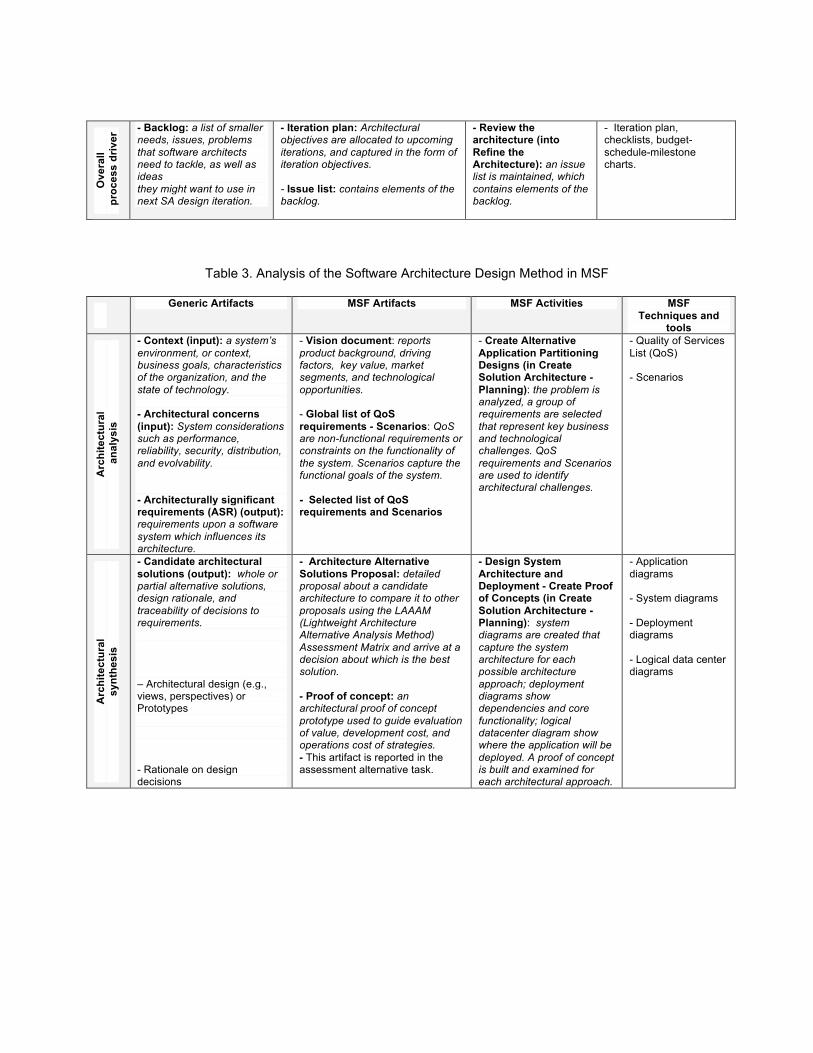
In A2) the Architectural Synthesis activity, the software architect elaborates several candidate architectures to address a sub-set of specific ASRs (e.g. several plausible solutions from the solution space that addresses a sub-set of architectural concerns and context issues). This activity uses the ASRs as input and generates the O2) candidate architectural solutions artifact as output. O2) candidate architectural solutions are the plausible solutions or particular pieces of a solution. Such architectural solutions are usually documented by selecting architecture viewpoints and by using specific architecture views. These solutions must include statements on the rationale of the Software Architecture decisions made on them. Finally, regarding the A3) Architectural Evaluation activity, the set of candidate architectures are evaluated by using as criteria the specific ASRs. This activity has as inputs the O1) architecturally significant requirements and the O2) candidate architectural solutions and generates as output the O3) validated architecture. The O3) validated architecture artifact includes the candidate architectural solutions, which must satisfy the ASRs. This validation activity implies that some solutions will progress toward the definite selected Software Architecture design and other designs or pieces of them, will be discarded or modified. 5. Review of Software Architecture Design Methods of RUP, MSF, MBASE and RUP-SOA The comparative analysis of the SA design methods used in the RUP, MSF, MBASE and RUP-SOA methodologies is reported in Tables 2, 3, 4 and 5. This analysis has been carried out by using the general model of Software Architecture design [18]. We mapped the activities and artifacts used in each SDM to the generic activities and generated artifacts posited by Hofmeister et al. [18]. Review of RUP’s Software Architecture Design Activity: RUP covers the A1) generic activity of Architectural Analysis with the task of the same name into the activity of 1) Define Candidate Architecture. The generic inputs of I1) architectural concerns, and I2) context issues are covered by the vision document and supplementary specifications artifacts. A vision document describes the system goals, functional needs and a rationale of the planned software. This document can include architectural (technical oriented requirements affecting the Software Architecture) and context (of the business organization) related issues, but it is not explicitly reported in RUP. The required O1) architectural significant requirements output is identified in RUP through a transformation, which is driven by use cases and is shaped further by the system's non-functional requirements provided through the supplementary specifications. Next, the A2) generic activity of Architectural Synthesis is covered by RUP through the activities of 1) Define a Candidate Architecture, and 2) Refine Architecture. The 1) Define a Candidate Architecture activity produces an initial baseline architecture usually with a logical view. Such a base line architecture is refined with the tasks included in the 2) Refine Architecture activity. These tasks are: Design Mechanisms, Identify Design Elements, Incorporate Existing Elements (i.e. reusable ones), Design Elements, Describe Runtime Architecture, and Describe Distribution. In this RUP activity, the analyzed elements are translated into design elements (e.g. design classes, component classes, modules, and source code). In RUP the generic output artifact O2) candidate architectural solutions are reported through the Software Architecture Document, which essentially reports the four architectural views (logical, process, implementation, and deployment). A core artifact elaborated in RUP in this A2) activity is an executable architectural prototype.

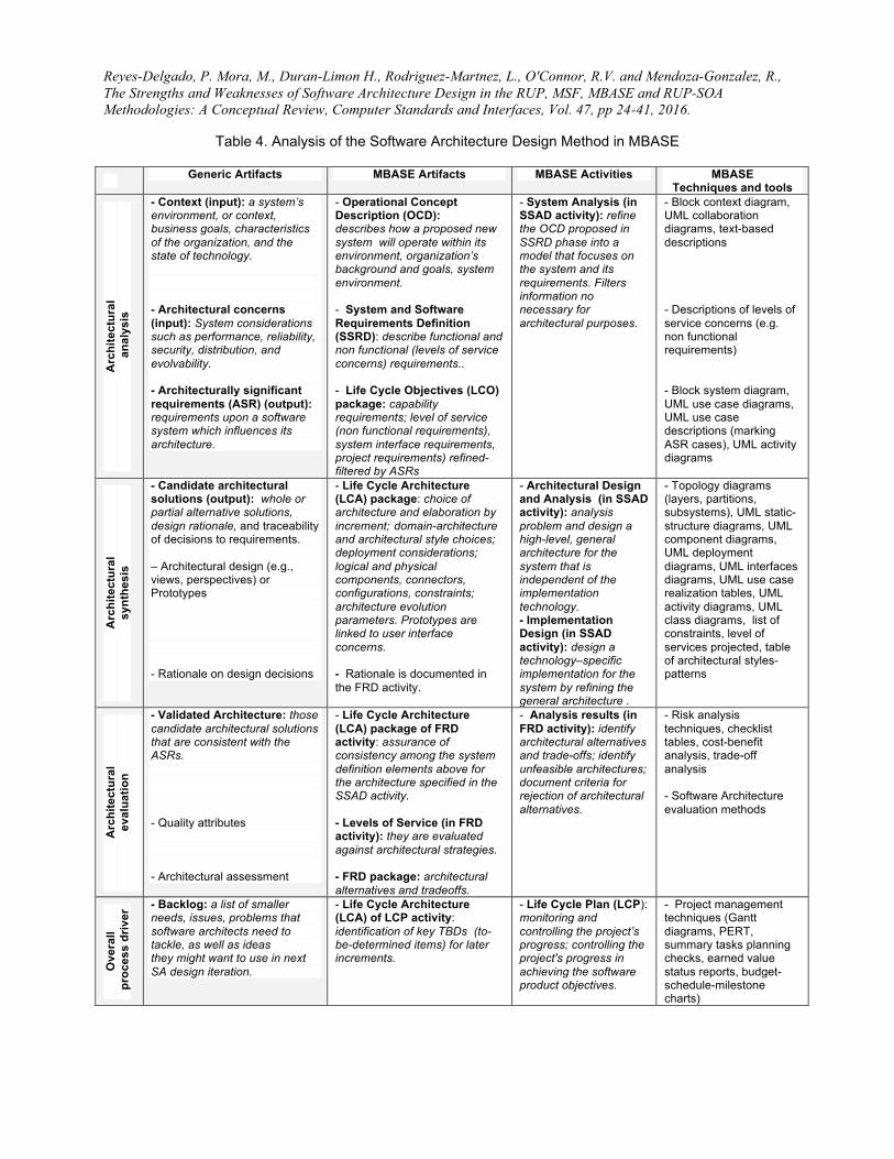
The generic A3) Architectural Evaluation activity is addressed in RUP through the optional activity of 3) Perform Architectural Synthesis. In this RUP activity an architectural proof-of-concept can be built, and its viability, relative to functionality and to non-functional requirements is assessed. Finally, the generic A0) activity of Backlog Control is executed in RUP through the task of Reviewing the Architecture (which is part of Refining the Architecture activity). Here, an issue list of missing elements is maintained. Review of MSF’s Software Architecture Design Activity: MSF covers the first generic activity A1) of Architectural Analysis, through the task of Create Alternative Application Partitioning Designs (by the Create Solution Architecture activity of the Planning track). In this MSF task, the problem is analyzed, a group of requirements that represent key business and technological challenges are selected, and the non-functional requirements and Scenarios are used to identify architectural challenges. MSF covers the two generic inputs of 1) architectural concerns and 2) context issues, as well as the generic output of 1) architectural significant requirements (ASRs). In MSF such artifacts are covered with a document Vision which reports product background, driving factors, key values, market segments, and technological opportunities; and a global list of QoS (Quality of Service) requirements. These requirements involve: 1) scenarios, which help to capture the functional goals of the system; and 2) a selected list of QoS requirements related to architectural issues. The second generic activity 2) Architectural Synthesis, is realized through the tasks of 1) Design System Architecture and Deployment, and 2) Create Proof of Concepts (which are part of the 5) Create Solution Architecture activity of the Planning track) in MSF. In these tasks the system diagrams capture the system architecture for each possible architecture approach; deployment diagrams show dependencies and core functionality; logical datacenter diagrams show where the application will be deployed; and a proof of concept is built and examined for each architectural approach. The generic activity 3) of Architectural Evaluation, is covered by MSF through the tasks of Assess alternatives and Select architecture (into Create Solution Architecture activity, in Planning track). In these tasks, an architecture assessment matrix is created; and the architecture to be used is selected. The architectural concept is also validated against scenarios; the selection justification is written by explaining the decisions behind why the current architecture was selected. Finally, the generic activity A0) Backlog Control, is executed in MSF through the tasks of Select Iteration Backlog and Plan Iteration (in the Build track). Scenarios and the selected list of QoS (quality of services) are assessed, reprioritized and ordered, for being addressed in the next iteration. Review of MBASE’s Software Architecture Design Activity: MBASE covers the A1) Architectural Analysis activity through the System and Software Architecture Description (SSAD), which involves the System Analysis activity. This activity refines the OCD and SSRD artifacts and filters the required information for developers: what must (necessary information) and must not (unnecessary information) know. This activity A1) of the general model proposes two input artifacts: I1) architectural concerns, and I2) context issues, and one output artifact O1) architecturally significant requirements (ASRs). In MBASE, the SSAD activity covers these two types of input artifacts through the Operation Concept Description (OCD) and the Software System Requirements Definition (SSRD) artifacts, which are generated by the activities with the same names: OCD and SSRD. The OCD artifact includes system capabilities where some of them are architectural concerns of the stakeholders, as well as organizational environment issues (i.e. context issues). The SSRD artifact includes: functional and non-functional requirements (called Levels of Service in MBASE), and evolution requirements. The output artifact O1) architectural significant requirements posited in the general model is covered in MBASE through an updated Life Cycle Objectives package (LCO) for relevant architectural requirements. This milestone includes: capability requirements, level of service requirements, system interface requirements and project requirements. In this activity, the models commonly used by MBASE are: block (context) diagrams, collaboration, use case, use case descriptions, activity and level of services diagrams.
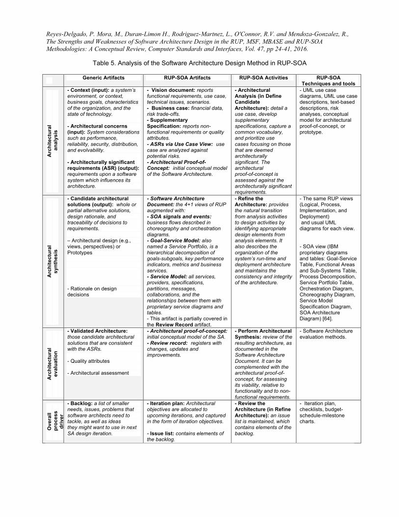
Next, the A2) Architectural Synthesis activity in the general model is also extensively covered by MBASE through the activity System and Software Architecture Description (SSAD): Architecture Design and Analysis. For the A2) generic activity are suggested I1) architecturally significant requirements (ASRs) (as input) and O2) candidate architectural solutions (as output). MBASE covers both through the updated Life Cycle Objectives package document (as input) and the Life-Cycle Architecture (LCA) package (as output). LCA includes: Architecture Design and Analysis, and Implementation Design. Architecture Design and Analysis corresponds to a High-Level Design, and the Implementation Design corresponds to a Low-Level Design. The Architecture Design activity and the Analysis activity in MBASE elaborate a high-level solution (architecture) independently from its final implementation technology. This solution (architecture) describes: components (work units), what these components do, how they are connected, and how they can communicate with each other. The diagrams commonly used by MBASE in this activity are: class diagram, component diagram, and static-structure package diagram. Finally, the Implementation design activity in MBASE elaborates a specific technology-based implementation solution derived from the high-level architecture. A technology-based implementation defines: types of hardware and operating systems, languages, database managers, utilities and libraries. Diagrams typically used are: component-stereotyped diagrams and implementation diagrams. Finally, in the Deployment Model, the physical Software Architecture is described through component and connector configurations for a working version of the designed software system. In this case, MBASE commonly employs the deployment diagram. The generic activity A3) Architectural Evaluation is covered in MBASE through the Feasibility Rationale Description (FRD) activity. This activity is conducted as a control review generic activity executed for each MBASE macro-phase of Inception, Elaboration, Construction and Transition. Thus, a FRD activity is conducted for reviewing the LCA milestone. Finally, MBASE covers partially the A0) generic activity of Backlog Control through the Life Cycle Plan (LCP) activity. This implies that MBASE does not explicitly indicate the iterative internal process for SSAD, instead, MBASE considers the planning of each iteration. Review of RUP-SOA’s Software Architecture Design Activity: RUP-SOA covers the generic activity A1) Architectural Analysis with some tasks included in the activities 2) Define Candidate Architecture, and 3) Refine Requirements into the Elaboration phase. It differs from RUP in that RUP-SOA includes an optional task called 4) Perform Architectural Proof-of-Concept activity conducted in the Inception phase. The required output of O1) architectural significant requirements is partially covered by RUP-SOA through the use-case model and supplementary specifications, but directly addressed through the architectural proof-of-concept when it is elaborated. The generic asked inputs of I1) architectural concerns and I2) context issues can be considered partially covered by the business case artifact and the goal-service model. A business case artifact describes the goals, needs and rationale of the planned software. It can include architectural (technical oriented requirements affecting the Software Architecture) and context (business organizational ones) related issues. A goal-service model “maintains the alignment of services with business goals and refines the subsequent scope of business processes being evaluated as well as existing systems and assets” [64; p. 385]. RUP-SOA includes also other output artifact called architectural proof-of-concept (which can be one or more artifacts) where the Software Architecture’s viability is assessed against the architecturally significant requirements (ASRs). For having this artifact, the activity 4) Perform Architectural Proof-of-Concept must be executed. These ASRs are identified in RUP-SOA through particular use cases and supplementary specifications that represent some significant functionality with a substantial architectural coverage, or stress or illustrate a specific and delicate point of the architecture [30]. This last conceptual architecture design artifact is not reported in RUP in the A1) activity. RUP proposes only an executable architectural prototype but in the A2) activity. Hence, RUP-SOA reinforces a Software Architecture conceptual design before codifying an executable prototype. Next, the A2) generic activity of Architectural Synthesis is covered totally by RUP-SOA through the tasks that are part of 2) Define Candidate Architecture, 3) Refine Architecture, and 4) Design Components activities. The 2) Define Candidate Architecture activity includes the tasks of: 1) Architectural Analysis, 2) Service Analysis, 3) Existing Asset Analysis, and 4) Use-Case Analysis. These tasks produce initial
candidate architectures. Existing software service components assets (for reusing them) are leveraged, architectural SOA patterns are identified, and architecturally significant use cases are realized for each candidate architecture, After a candidate architecture has been defined, the 2) Define Candidate Architecture activity is completed with an iteration of 3) Refine Architecture activity. In 3) Refine Architecture, the following tasks are conducted: 1) Identify Elements of Design, 2) Describe the run-time Architecture, 3) Describe the Distributed Architecture, and 4) Review the Architecture. Identification of analysis elements necessary to describe the behavior of each use case is realized. This analysis of elements will be translated into design elements (e.g. design classes, component classes, modules, and source code). In RUP-SOA the generic output artifact O2) candidate architectural solutions are reported through the Software Architecture document which includes the normal RUP 4+1 views augmented with a SOA view, SOA signals and events diagrams, goal-service model, service model, and service component specifications. For reporting such artifacts RUP-SOA uses proprietary service diagrams and tables such as: Goal-Service Table, Functional Areas and Sub-Systems Table, Process Decomposition, Service Portfolio Table, Orchestration Diagram, Choreography Diagram, Service Model Specification Diagram, and SOA Architecture Diagram [64]. Additionally, similar to RUP, RUP-SOA has the activity 4) Design Components where the detailed design of components is realized according to the iteration plan. Thus, RUP-SOA builds on top of RUP to provide support to SOA systems by offering specific SOA artifacts. In addition, RUP-SOA extends RUP in generating several candidate architectures, which will be compared among them, similar to MBASE and MSF SDMs. In contrast, RUP uses only the traditional 4 views and defines a single candidate architecture that will be refined only if several iterations are conducted. The generic A3) Architectural Evaluation activity is addressed partially in RUP-SOA through the Review of Records activity. It is realized –actually- as a sub-activity in the 3) Refine Architecture activity. This generic A3) activity can be also supported in RUP-SOA through the review of the artifacts generated in the optional activity of 5) Perform Architectural Proof-of-Concept activity conducted in the Inception phase. Finally, the generic activity A0) Backlog Control is partially executed in the RUP-SOA through the 1) Plan the Project (iterated) activity. However, RUP-SOA explicitly considers that the 2) Define Candidate Architecture and 3) Refine Architecture activities conducted iteratively implies an evaluation and improvement of the candidate architecture solutions generated in each iteration.
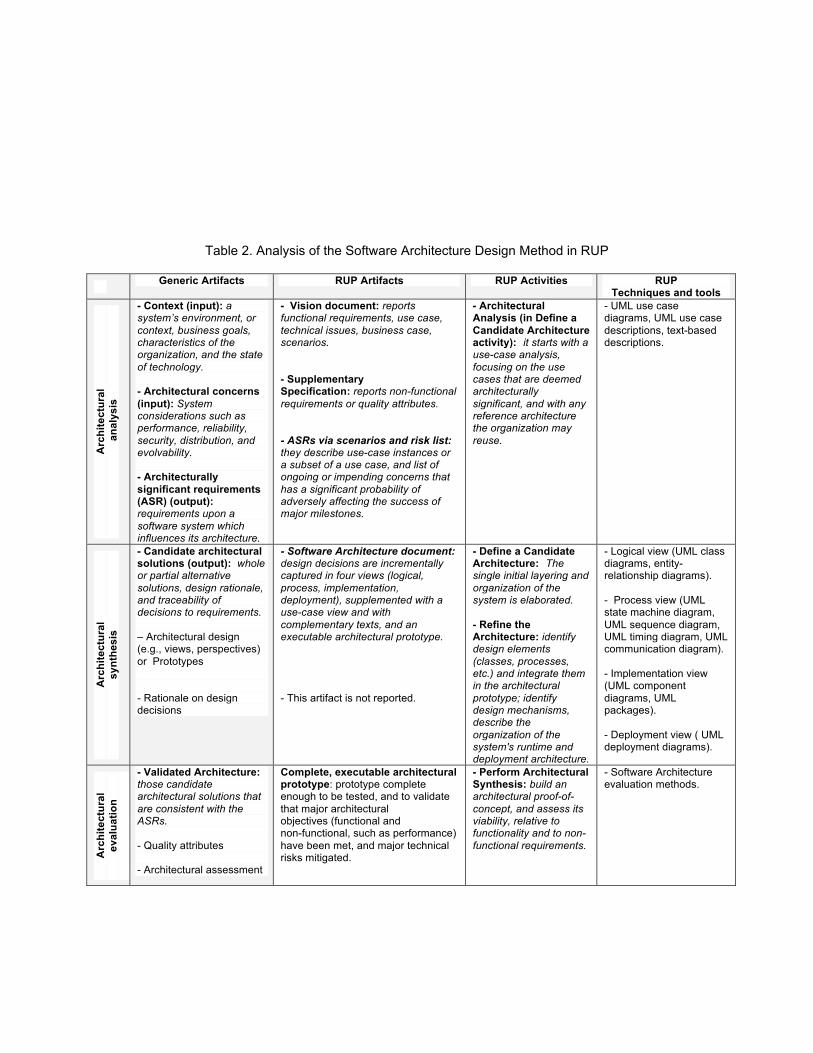
Table 2. Analysis of the Software Architecture Design Method in RUP
Generic Artifacts RUP Artifacts RUP Activities RUP Techniques and tools
Arc
hite
ctur
al
ana
lysi
s
- Context (input): a system’s environment, or context, business goals, characteristics of the organization, and the state of technology. - Architectural concerns (input): System considerations such as performance, reliability, security, distribution, and evolvability. - Architecturally significant requirements (ASR) (output): requirements upon a software system which influences its architecture.
- Vision document: reports functional requirements, use case, technical issues, business case, scenarios. - Supplementary Specification: reports non-functional requirements or quality attributes. - ASRs via scenarios and risk list: they describe use-case instances or a subset of a use case, and list of ongoing or impending concerns that has a significant probability of adversely affecting the success of major milestones.
- Architectural Analysis (in Define a Candidate Architecture activity): it starts with a use-case analysis, focusing on the use cases that are deemed architecturally significant, and with any reference architecture the organization may reuse.
- UML use case diagrams, UML use case descriptions, text-based descriptions.
Arc
hite
ctur
al
synt
hesi
s
- Candidate architectural solutions (output): whole or partial alternative solutions, design rationale, and traceability of decisions to requirements. – Architectural design (e.g., views, perspectives) or Prototypes - Rationale on design decisions
- Software Architecture document: design decisions are incrementally captured in four views (logical, process, implementation, deployment), supplemented with a use-case view and with complementary texts, and an executable architectural prototype. - This artifact is not reported.
- Define a Candidate Architecture: The single initial layering and organization of the system is elaborated. - Refine the Architecture: identify design elements (classes, processes, etc.) and integrate them in the architectural prototype; identify design mechanisms, describe the organization of the system's runtime and deployment architecture.
- Logical view (UML class diagrams, entity-relationship diagrams). - Process view (UML state machine diagram, UML sequence diagram, UML timing diagram, UML communication diagram). - Implementation view (UML component diagrams, UML packages). - Deployment view ( UML deployment diagrams).
Arc
hite
ctur
al
eval
uatio
n
- Validated Architecture: those candidate architectural solutions that are consistent with the ASRs. - Quality attributes - Architectural assessment
Complete, executable architectural prototype: prototype complete enough to be tested, and to validate that major architectural objectives (functional and non-functional, such as performance) have been met, and major technical risks mitigated.
- Perform Architectural Synthesis: build an architectural proof-of-concept, and assess its viability, relative to functionality and to non-functional requirements.
- Software Architecture evaluation methods.
Ove
rall
pro
cess
driv
er - Backlog: a list of smaller
needs, issues, problems that software architects need to tackle, as well as ideas they might want to use in next SA design iteration.
- Iteration plan: Architectural objectives are allocated to upcoming iterations, and captured in the form of iteration objectives. - Issue list: contains elements of the backlog.
- Review the architecture (into Refine the Architecture): an issue list is maintained, which contains elements of the backlog.
- Iteration plan, checklists, budget-schedule-milestone charts.
Table 3. Analysis of the Software Architecture Design Method in MSF
Generic Artifacts MSF Artifacts MSF Activities MSF Techniques and
tools
Arc
hite
ctur
al
ana
lysi
s
- Context (input): a system’s environment, or context, business goals, characteristics of the organization, and the state of technology. - Architectural concerns (input): System considerations such as performance, reliability, security, distribution, and evolvability. - Architecturally significant requirements (ASR) (output): requirements upon a software system which influences its architecture.
- Vision document: reports product background, driving factors, key value, market segments, and technological opportunities. - Global list of QoS requirements - Scenarios: QoS are non-functional requirements or constraints on the functionality of the system. Scenarios capture the functional goals of the system. - Selected list of QoS requirements and Scenarios
- Create Alternative Application Partitioning Designs (in Create Solution Architecture - Planning): the problem is analyzed, a group of requirements are selected that represent key business and technological challenges. QoS requirements and Scenarios are used to identify architectural challenges.
- Quality of Services List (QoS) - Scenarios
Arc
hite
ctur
al
synt
hesi
s
- Candidate architectural solutions (output): whole or partial alternative solutions, design rationale, and traceability of decisions to requirements. – Architectural design (e.g., views, perspectives) or Prototypes - Rationale on design decisions
- Architecture Alternative Solutions Proposal: detailed proposal about a candidate architecture to compare it to other proposals using the LAAAM (Lightweight Architecture Alternative Analysis Method) Assessment Matrix and arrive at a decision about which is the best solution. - Proof of concept: an architectural proof of concept prototype used to guide evaluation of value, development cost, and operations cost of strategies. - This artifact is reported in the assessment alternative task.
- Design System Architecture and Deployment - Create Proof of Concepts (in Create Solution Architecture - Planning): system diagrams are created that capture the system architecture for each possible architecture approach; deployment diagrams show dependencies and core functionality; logical datacenter diagram show where the application will be deployed. A proof of concept is built and examined for each architectural approach.
- Application diagrams - System diagrams - Deployment diagrams - Logical data center diagrams

Arc
hite
ctur
al
eval
uatio
n
- Validated Architecture: those candidate architectural solutions that are consistent with the ASRs. - Quality attributes - Architectural assessment
- Assessed architecture proposals: the different architectural proposals are evaluated and one is selected. - Utility tree: it represents the hierarchical nature of the qualities and provides a basis for prioritization. - LAAAM Assessment Matrix: it helps to evaluate the suitability of strategies against scenarios.
- Assess alternatives - Select architecture (in Create Solution Architecture - Planning): architecture assessment matrix is created. The architecture to be used is selected; the architectural concept is validated against scenarios; the selection justification is written explaining the decisions behind why the current architecture was selected.
- Lightweight Architecture Alternative Analysis Method (LAAAM) - Risk analysis
Ove
rall
pro
cess
dr
iver
- Backlog: a list of smaller needs, issues, problems that software architects need to tackle, as well as ideas they might want to use in next SA design iteration.
- Project Backlog: a general repository for the whole project. Not specific for architecture design.
- Select Iteration Backlog and Plan Iteration (in Build track): from the project backlog, re-assess, reprioritize, and sort the scenarios and QoS.
- Project management techniques (Gantt charts, effort estimation models, etc).
Reyes-Delgado, P. Mora, M., Duran-Limon H., Rodriguez-Martnez, L., O'Connor, R.V. and Mendoza-Gonzalez, R., The Strengths and Weaknesses of Software Architecture Design in the RUP, MSF, MBASE and RUP-SOA Methodologies: A Conceptual Review, Computer Standards and Interfaces, Vol. 47, pp 24-41, 2016.
Table 4. Analysis of the Software Architecture Design Method in MBASE
Generic Artifacts MBASE Artifacts MBASE Activities MBASE Techniques and tools
Arc
hite
ctur
al
ana
lysi
s
- Context (input): a system’s environment, or context, business goals, characteristics of the organization, and the state of technology. - Architectural concerns (input): System considerations such as performance, reliability, security, distribution, and evolvability. - Architecturally significant requirements (ASR) (output): requirements upon a software system which influences its architecture.
- Operational Concept Description (OCD): describes how a proposed new system will operate within its environment, organization’s background and goals, system environment. - System and Software Requirements Definition (SSRD): describe functional and non functional (levels of service concerns) requirements.. - Life Cycle Objectives (LCO) package: capability requirements; level of service (non functional requirements), system interface requirements, project requirements) refined-filtered by ASRs
- System Analysis (in SSAD activity): refine the OCD proposed in SSRD phase into a model that focuses on the system and its requirements. Filters information no necessary for architectural purposes.
- Block context diagram, UML collaboration diagrams, text-based descriptions - Descriptions of levels of service concerns (e.g. non functional requirements) - Block system diagram, UML use case diagrams, UML use case descriptions (marking ASR cases), UML activity diagrams
Arc
hite
ctur
al
synt
hesi
s
- Candidate architectural solutions (output): whole or partial alternative solutions, design rationale, and traceability of decisions to requirements. – Architectural design (e.g., views, perspectives) or Prototypes - Rationale on design decisions
- Life Cycle Architecture (LCA) package: choice of architecture and elaboration by increment; domain-architecture and architectural style choices; deployment considerations; logical and physical components, connectors, configurations, constraints; architecture evolution parameters. Prototypes are linked to user interface concerns. - Rationale is documented in the FRD activity.
- Architectural Design and Analysis (in SSAD activity): analysis problem and design a high-level, general architecture for the system that is independent of the implementation technology. - Implementation Design (in SSAD activity): design a technology–specific implementation for the system by refining the general architecture .
- Topology diagrams (layers, partitions, subsystems), UML static-structure diagrams, UML component diagrams, UML deployment diagrams, UML interfaces diagrams, UML use case realization tables, UML activity diagrams, UML class diagrams, list of constraints, level of services projected, table of architectural styles-patterns
Arc
hite
ctur
al
eval
uatio
n
- Validated Architecture: those candidate architectural solutions that are consistent with the ASRs. - Quality attributes - Architectural assessment
- Life Cycle Architecture (LCA) package of FRD activity: assurance of consistency among the system definition elements above for the architecture specified in the SSAD activity. - Levels of Service (in FRD activity): they are evaluated against architectural strategies. - FRD package: architectural alternatives and tradeoffs.
- Analysis results (in FRD activity): identify architectural alternatives and trade-offs; identify unfeasible architectures; document criteria for rejection of architectural alternatives.
- Risk analysis techniques, checklist tables, cost-benefit analysis, trade-off analysis - Software Architecture evaluation methods
Ove
rall
pro
cess
driv
er - Backlog: a list of smaller
needs, issues, problems that software architects need to tackle, as well as ideas they might want to use in next SA design iteration.
- Life Cycle Architecture (LCA) of LCP activity: identification of key TBDs (to-be-determined items) for later increments.
- Life Cycle Plan (LCP): monitoring and controlling the project’s progress; controlling the project's progress in achieving the software product objectives.
- Project management techniques (Gantt diagrams, PERT, summary tasks planning checks, earned value status reports, budget-schedule-milestone charts)
Reyes-Delgado, P. Mora, M., Duran-Limon H., Rodriguez-Martnez, L., O'Connor, R.V. and Mendoza-Gonzalez, R., The Strengths and Weaknesses of Software Architecture Design in the RUP, MSF, MBASE and RUP-SOA Methodologies: A Conceptual Review, Computer Standards and Interfaces, Vol. 47, pp 24-41, 2016.
Table 5. Analysis of the Software Architecture Design Method in RUP-SOA
Generic Artifacts RUP-SOA Artifacts RUP-SOA Activities RUP-SOA Techniques and tools
Arc
hite
ctur
al
ana
lysi
s
- Context (input): a system’s environment, or context, business goals, characteristics of the organization, and the state of technology. - Architectural concerns (input): System considerations such as performance, reliability, security, distribution, and evolvability. - Architecturally significant requirements (ASR) (output): requirements upon a software system which influences its architecture.
- Vision document: reports functional requirements, use case, technical issues, scenarios. - Business case: financial data, risk trade-offs. - Supplementary Specification: reports non-functional requirements or quality attributes. - ASRs via Use Case View: use case are analyzed against potential risks. - Architectural Proof-of-Concept: initial conceptual model of the Software Architecture.
- Architectural Analysis (in Define Candidate Architecture): detail a use case, develop supplementary specifications, capture a common vocabulary, and prioritize use cases focusing on those that are deemed architecturally significant. The architectural proof-of-concept is assessed against the architecturally significant requirements.
- UML use case diagrams, UML use case descriptions, text-based descriptions, risk analyses, conceptual model for architectural proof-of-concept, or prototype.
Arc
hite
ctur
al
synt
hesi
s
- Candidate architectural solutions (output): whole or partial alternative solutions, design rationale, and traceability of decisions to requirements. – Architectural design (e.g., views, perspectives) or Prototypes - Rationale on design decisions
- Software Architecture Document: the 4+1 views of RUP augmented with: - SOA signals and events: business flows described in choreography and orchestration diagrams. - Goal-Service Model: also named a Service Portfolio, is a hierarchical decomposition of goals-subgoals, key performance indicators, metrics and business services. - Service Model: all services, providers, specifications, partitions, messages, collaborations, and the relationships between them with proprietary service diagrams and tables. - This artifact is partially covered in the Review Record artifact.
- Refine the Architecture: provides the natural transition from analysis activities to design activities by identifying appropriate design elements from analysis elements. It also describes the organization of the system’s run-time and deployment architecture and maintains the consistency and integrity of the architecture.
- The same RUP views (Logical, Process, Implementation, and Deployment) and usual UML diagrams for each view. - SOA view (IBM proprietary diagrams and tables: Goal-Service Table, Functional Areas and Sub-Systems Table, Process Decomposition, Service Portfolio Table, Orchestration Diagram, Choreography Diagram, Service Model Specification Diagram, SOA Architecture Diagram) [64].
Arc
hite
ctur
al
eval
uatio
n
- Validated Architecture: those candidate architectural solutions that are consistent with the ASRs. - Quality attributes - Architectural assessment
- Architectural proof-of-concept: initial conceptual model of the SA. - Review record: registers with changes, updates and improvements.
- Perform Architectural Synthesis: review of the resulting architecture, as documented in the Software Architecture Document. It can be complemented with the architectural proof-of-concept, for assessing its viability, relative to functionality and to non-functional requirements.
- Software Architecture evaluation methods.
Ove
rall
pro
cess
dr
iver
- Backlog: a list of smaller needs, issues, problems that software architects need to tackle, as well as ideas they might want to use in next SA design iteration.
- Iteration plan: Architectural objectives are allocated to upcoming iterations, and captured in the form of iteration objectives. - Issue list: contains elements of the backlog.
- Review the Architecture (in Refine Architecture): an issue list is maintained, which contains elements of the backlog.
- Iteration plan, checklists, budget-schedule-milestone charts.

6. Discussion of Findings and Theoretical and Practical Implications. We have found relevant findings in this comparative review of Software Architecture design methods used in RUP, MSF, MBASE and RUP-SOA A1) Architectural Analysis: Regarding architectural analysis tasks, the four SDMS (RUP, MSF, MBASE and RUP-SOA) include specific and adequate activities. However, their compliance level is different. RUP supports partially well this task through the definition of an initial and single candidate architecture by considering the use cases and scenarios that represent ASRs. Use cases and scenarios accounts for functional requirements. For non-functional requirements, RUP employs supplementary specifications, and a list of risks as input artifacts. MSF supports more adequately architectural analysis tasks than RUP. MSF proposes a partition and selection of ASRs, which are selected against business and technological challenges with architectural implications. MSF also uses adequate input artifacts such as: vision documents, lists of QoS (Quality of Services, e.g. non-functional requirements), and scenarios. In the case of MBASE, this methodology defines a task called architectural analysis. In this task, all elements not affecting Software Architecture design are filtered. In particular in MBASE are addressed the following issues from architectural lenses: services to be provided and to be consumed, interactions of the system with external actors, and system capabilities useful for the organization. MBASE also employs suitable input artifacts such as: OCD (Operational Concept Description), List of Service Levels (e.g. non-functional requirements), and system interfaces. Finally, RUP-SOA also supports very well this generic Software Architecture design task. RUP-SOA proposes an Architectural Analysis task in Define Candidate Architecture activity, where use cases are detailed and prioritized focusing on those with architectural significance. Additionally, an architectural proof-of-concept (which can include one or several proofs) is used to identify architecturally significant requirements (ASRs). Hence, given the aforementioned arguments we assess MSF, MBASE, and RUP-SOA with a high compliance and RUP with a moderate compliance, regarding the expected Software Architecture design prescriptions from the general model. A2) Architectural Synthesis: The architectural synthesis task is performed adequately in the case of MSF, MBASE and RUP-SOA, whereas RUP only provides partial support. RUP elaborates it through a single iterative-incremental design based on the well-known 4+1 views approach (logical, process, implementation, and deployment). These views use well-known UML diagrams. A Software Architecture design is effectively generated in this task through a refinement approach. However, a single candidate architecture (and not several architecture options) is elaborated. Another relevant omission in RUP is the lack of explicit documentation on the rationale of Software Architecture design decisions. RUP uses a classic software design divided in two levels: the high-level design corresponds to Software Architecture design whereas low-level design regards detailed design of components, classes and other artifacts. A positive issue of RUP, from the practitioner perspective, is that RUP provides a straightforward architectural synthesis task. A Software Architecture design, thus, must be elaborated by generating the four expected architecture views (logical, process, implementation, and deployment) and by using the standard UML diagrams. In the case of MSF, architectural synthesis tasks are better supported than RUP. MSF proposes several Software Architecture designs. These Software Architecture designs will compete for a final selection in the architectural evaluation phase. MSF employs suitable input artifacts such as: a proposal for alternative architecture solutions, where several Software Architecture designs are elaborated as well as the rationale of design decisions (reported in the architectural evaluation phase). MSF also proposes to elaborate a prototype (called proof of concept) when a large system demands it. MSF does not distinguish between high- and low-level design as RUP does. However, It can be considered that in MSF a high-level Software Architecture design corresponds to the design of architecture system diagrams whereas low-level Software Architecture design corresponds to architecture deployment and data centered diagrams. MSF uses proprietary architectural diagrams for carrying out Software Architecture design. A detailed software design is elaborated implicitly in the next Build track. Similar to RUP, MSF also provides a straightforward
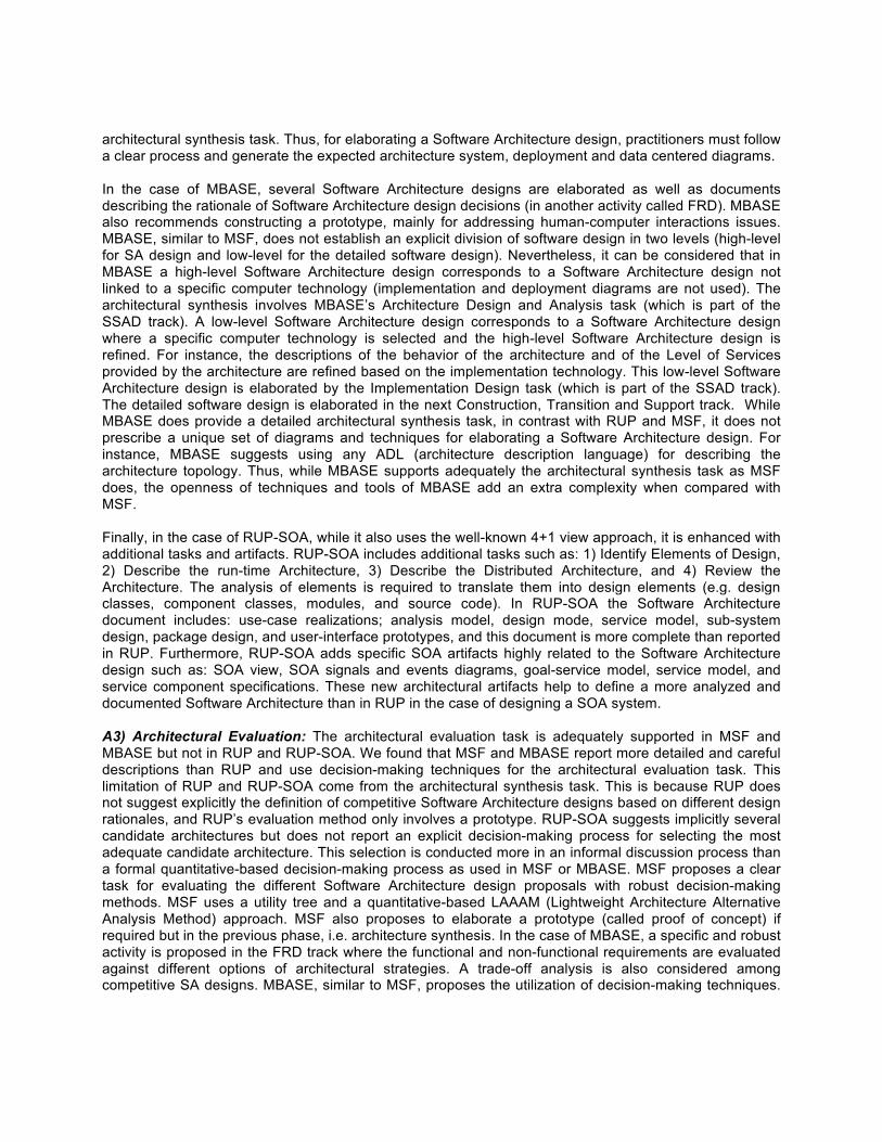
architectural synthesis task. Thus, for elaborating a Software Architecture design, practitioners must follow a clear process and generate the expected architecture system, deployment and data centered diagrams. In the case of MBASE, several Software Architecture designs are elaborated as well as documents describing the rationale of Software Architecture design decisions (in another activity called FRD). MBASE also recommends constructing a prototype, mainly for addressing human-computer interactions issues. MBASE, similar to MSF, does not establish an explicit division of software design in two levels (high-level for SA design and low-level for the detailed software design). Nevertheless, it can be considered that in MBASE a high-level Software Architecture design corresponds to a Software Architecture design not linked to a specific computer technology (implementation and deployment diagrams are not used). The architectural synthesis involves MBASE’s Architecture Design and Analysis task (which is part of the SSAD track). A low-level Software Architecture design corresponds to a Software Architecture design where a specific computer technology is selected and the high-level Software Architecture design is refined. For instance, the descriptions of the behavior of the architecture and of the Level of Services provided by the architecture are refined based on the implementation technology. This low-level Software Architecture design is elaborated by the Implementation Design task (which is part of the SSAD track). The detailed software design is elaborated in the next Construction, Transition and Support track. While MBASE does provide a detailed architectural synthesis task, in contrast with RUP and MSF, it does not prescribe a unique set of diagrams and techniques for elaborating a Software Architecture design. For instance, MBASE suggests using any ADL (architecture description language) for describing the architecture topology. Thus, while MBASE supports adequately the architectural synthesis task as MSF does, the openness of techniques and tools of MBASE add an extra complexity when compared with MSF. Finally, in the case of RUP-SOA, while it also uses the well-known 4+1 view approach, it is enhanced with additional tasks and artifacts. RUP-SOA includes additional tasks such as: 1) Identify Elements of Design, 2) Describe the run-time Architecture, 3) Describe the Distributed Architecture, and 4) Review the Architecture. The analysis of elements is required to translate them into design elements (e.g. design classes, component classes, modules, and source code). In RUP-SOA the Software Architecture document includes: use-case realizations; analysis model, design mode, service model, sub-system design, package design, and user-interface prototypes, and this document is more complete than reported in RUP. Furthermore, RUP-SOA adds specific SOA artifacts highly related to the Software Architecture design such as: SOA view, SOA signals and events diagrams, goal-service model, service model, and service component specifications. These new architectural artifacts help to define a more analyzed and documented Software Architecture than in RUP in the case of designing a SOA system. A3) Architectural Evaluation: The architectural evaluation task is adequately supported in MSF and MBASE but not in RUP and RUP-SOA. We found that MSF and MBASE report more detailed and careful descriptions than RUP and use decision-making techniques for the architectural evaluation task. This limitation of RUP and RUP-SOA come from the architectural synthesis task. This is because RUP does not suggest explicitly the definition of competitive Software Architecture designs based on different design rationales, and RUP’s evaluation method only involves a prototype. RUP-SOA suggests implicitly several candidate architectures but does not report an explicit decision-making process for selecting the most adequate candidate architecture. This selection is conducted more in an informal discussion process than a formal quantitative-based decision-making process as used in MSF or MBASE. MSF proposes a clear task for evaluating the different Software Architecture design proposals with robust decision-making methods. MSF uses a utility tree and a quantitative-based LAAAM (Lightweight Architecture Alternative Analysis Method) approach. MSF also proposes to elaborate a prototype (called proof of concept) if required but in the previous phase, i.e. architecture synthesis. In the case of MBASE, a specific and robust activity is proposed in the FRD track where the functional and non-functional requirements are evaluated against different options of architectural strategies. A trade-off analysis is also considered among competitive SA designs. MBASE, similar to MSF, proposes the utilization of decision-making techniques.

However, while MSF proposes a single specific technique, MBASE is open to propose a myriad of them. For instance, MBASE reports a Top-Level Field Guide to Software Architecture Attribute Analysis Methods, as part of the architectural evaluation tasks. Thus, MBASE provides better support for the architectural evaluation task than RUP and RUP-SOA and a similar level of support than MSF, but with a greater openness and complexity than MSF. Table 6 reports weaknesses and strengths found in these four SDMs. 7. Limitations, Recommendations and Conclusions. This research has studied the Software Architecture design methods included in four well-known rigor-oriented System Development Methodologies: RUP, MSF, MBASE and RUP-SOA. Our study, like any research work, has some methodological limitations. We report them for cautionary interpretative purposes. 1) The analysis was conducted only on four rigor-oriented SDMs and other modern SDMs were not considered (XP, SCRUM, UPEDU, among others) [67, 47]. 2) The analysis was based on the official documents which describe the four SDMs. Data from real software projects using these four SDMs was not available. Thus, while MSF and MBASE are assessed with an overall high adherence to the theoretical prescriptions from modern Software Architecture design literature, their empirical conformance by practitioners could not be assessed. 3) We did not conduct a detailed analysis on the specific contextual domain of applications suitable for each SDM. We can only report that RUP, MSF and MBASE can be considered usable for any type of software of middle or large scale, of business information type being either embedded or industrial cyber-physical systems, and for object-oriented or component-based platforms. In the case of RUP-SOA, it is particularized for service-oriented computational platforms, for business information type and embedded or industrial cyber-physical systems, and for middle and large-scale systems. 4) The assessment of adherence was realized by the first two researchers in the research team, with a careful review for the third author, and the rest of the research team carried out an overall review of the findings. Few discrepancies were found. The demographic profile of the research team was as follows: 1 PhD student in Software Engineering, 1 EngD in Systems Engineering, 1 Post doctorate academician in Software Engineering, and 3 PhD in Software Engineering; an average individual research experience is over 7 years; a joint record of more than 25 publications in journals listed in ISI Web of Science; an average teaching expertise of SDMs for more than 10 years; and an average age range of 45 years. Several theoretical and practical recommendations can also be derived from this research. We consider the following theoretical implications: 1) in general terms, an academic (MBASE), an industrial (MSF), and an emergent (RUP-SOA) SDM include in their software design track of activities adequate Software Architecture design prescriptions according to the core Software Architecture design literature [18]; 2) the most popular SDM both for academic and industrial settings, i.e. RUP, covers partially current Software Architecture design prescriptions, which might result in insufficient support for the complexity of the new software systems demanded in the organizations (e.g. SOA and Cloud-based systems); 3) MBASE, MSF and RUP-SOA provide a shared perspective on the relevance of the Software Architecture design, where their software design tracks correspond totally to Software Architecture design (general and refined Software Architecture designs); 4) RUP-SOA, while little has been reported in literature on its utilization, it is industrially sponsored by a large-scale and relevant worldwide software business (i.e. IBM) and it is expected to become the substitute of RUP in scenarios targeting SOA systems; and 5) MBASE and MSF adequately cover a decision-making processes for evaluating competitive candidate architectural designs, whereas RUP-SOA only supports this with an informal decision-making process and RUP omits it.
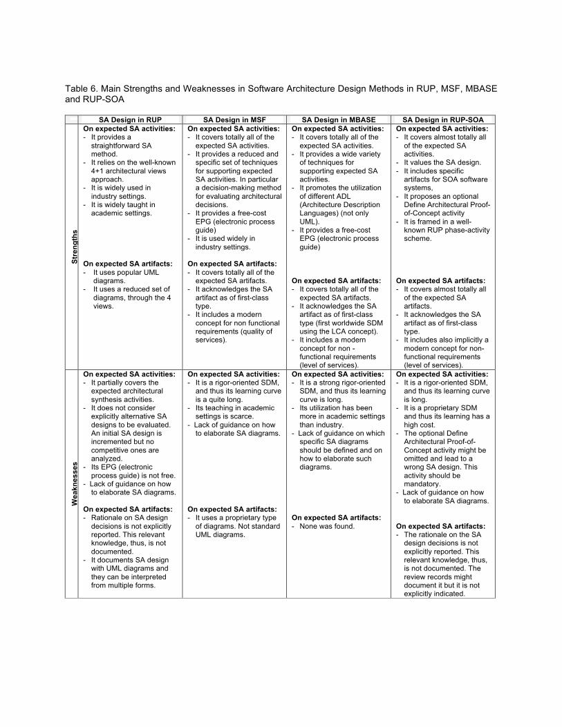
Table 6. Main Strengths and Weaknesses in Software Architecture Design Methods in RUP, MSF, MBASE and RUP-SOA
SA Design in RUP SA Design in MSF SA Design in MBASE SA Design in RUP-SOA
Stre
ngth
s
On expected SA activities: - It provides a
straightforward SA method.
- It relies on the well-known 4+1 architectural views approach.
- It is widely used in industry settings.
- It is widely taught in academic settings.
On expected SA artifacts: - It uses popular UML
diagrams. - It uses a reduced set of
diagrams, through the 4 views.
On expected SA activities: - It covers totally all of the
expected SA activities. - It provides a reduced and
specific set of techniques for supporting expected SA activities. In particular a decision-making method for evaluating architectural decisions.
- It provides a free-cost EPG (electronic process guide)
- It is used widely in industry settings.
On expected SA artifacts: - It covers totally all of the
expected SA artifacts. - It acknowledges the SA
artifact as of first-class type.
- It includes a modern concept for non functional requirements (quality of services).
On expected SA activities: - It covers totally all of the
expected SA activities. - It provides a wide variety
of techniques for supporting expected SA activities.
- It promotes the utilization of different ADL (Architecture Description Languages) (not only UML).
- It provides a free-cost EPG (electronic process guide)
On expected SA artifacts: - It covers totally all of the
expected SA artifacts. - It acknowledges the SA
artifact as of first-class type (first worldwide SDM using the LCA concept).
- It includes a modern concept for non -functional requirements (level of services).
On expected SA activities: - It covers almost totally all
of the expected SA activities.
- It values the SA design. - It includes specific
artifacts for SOA software systems,
- It proposes an optional Define Architectural Proof-of-Concept activity
- It is framed in a well-known RUP phase-activity scheme.
On expected SA artifacts: - It covers almost totally all
of the expected SA artifacts.
- It acknowledges the SA artifact as of first-class type.
- It includes also implicitly a modern concept for non-functional requirements (level of services).
Wea
knes
ses
On expected SA activities: - It partially covers the
expected architectural synthesis activities.
- It does not consider explicitly alternative SA designs to be evaluated. An initial SA design is incremented but no competitive ones are analyzed.
- Its EPG (electronic process guide) is not free.
- Lack of guidance on how to elaborate SA diagrams.
On expected SA artifacts: - Rationale on SA design
decisions is not explicitly reported. This relevant knowledge, thus, is not documented.
- It documents SA design with UML diagrams and they can be interpreted from multiple forms.
On expected SA activities: - It is a rigor-oriented SDM,
and thus its learning curve is a quite long.
- Its teaching in academic settings is scarce.
- Lack of guidance on how to elaborate SA diagrams.
On expected SA artifacts: - It uses a proprietary type
of diagrams. Not standard UML diagrams.
On expected SA activities: - It is a strong rigor-oriented
SDM, and thus its learning curve is long.
- Its utilization has been more in academic settings than industry.
- Lack of guidance on which specific SA diagrams should be defined and on how to elaborate such diagrams.
On expected SA artifacts: - None was found.
On expected SA activities: - It is a rigor-oriented SDM,
and thus its learning curve is long.
- It is a proprietary SDM and thus its learning has a high cost.
- The optional Define Architectural Proof-of-Concept activity might be omitted and lead to a wrong SA design. This activity should be mandatory.
- Lack of guidance on how to elaborate SA diagrams.
On expected SA artifacts: - The rationale on the SA
design decisions is not explicitly reported. This relevant knowledge, thus, is not documented. The review records might document it but it is not explicitly indicated.
From a practitioner’s perspective, we can derive the following implications: 1) given that RUP has some core limitations for Software Architecture design according to modern Software Architecture design prescriptions, the practitioners using RUP and elaborating new complex software systems will need to update this SDM to a modern RUP version (e.g. RUP for SOA [30] to cover modern practices of Software Architecture design); 2) RUP-SOA and MSF can be considered strictly proprietary SDMs, with a high training cost for organizations, so practitioners can pursue MBASE which is an academic free-cost SDM. However, in both cases (RUP-SOA/MSF or MBASE) practitioners interested in using them, can face a hard learning curve; 3) this research was focused on rigor-oriented SDMs, but many practitioners working for small and medium-sized businesses are currently using agile-based SDMs [68, 47], and thus, our research findings might not be useful for such practitioners. In this case it can be reported that both MSF and MBASE have released agile versions (MSF for Agile [69]) and Lean MBASE [70], and thus practitioners might explore these options. Finally, although the four reviewed SDMs represent important efforts to consolidate good practices for Software Architecture design, we believe there is still an important issue that needs to be tackled in the realm of architectural synthesis: the guide for best practices in Software Architecture design is insufficient for the inexperienced practitioner. In the best case, an SDM, such as RUP, RUP-SOA and MBASE, defines the specific diagrams that need to be defined as part of a Software Architecture design. However, no specific guide is given in how these diagrams can be constructed, rather, it is assumed that the practitioner has enough experience to conduct herself in elaborating such diagrams. We believe, one of the main reasons Software Architecture best practices are currently poorly employed in industry is the lack of more specific guidance in current SDMs. Software Architecture best practices are not carried out in many cases when the inexperienced practitioner does not know how to proceed when elaborating Software Architecture designs in a specific domain area. Even for the experienced practitioner, the lack of specific SDM procedures can lead her to obviate such procedures. One of the principal causes of the lack of more specific guidance of current SDMs is the general-purpose nature of such SDMs. Therefore, further efforts are required to define domain-specific SDMs. Although RUP-SOA is an initial effort to address this issue, RUP-SOA still suffers from providing guides on how the prescribed diagrams should be constructed. As a consequence, further efforts are required to define domain-specific SDMs targeting more specific guides on how Software Architecture diagrams can be elaborated, among other more specific Software Architecture design recommendations.
Several recommendations for further research emerge also from this study. 1) To extend this conceptual review to agile SDMs (e.g. MSF for Agile, Lean MBASE, XP, SCRUM, and UPEDU, among others) [47]. 2) To conduct empirical research (via a survey research method or a multi-case study method) on the adherence of SDMs to modern Software Architecture design prescriptions by the utilization of these four SDMs (RUP, MSF, MBASE, and RUP-SOA) in real settings. 3) To conduct empirical research through lab experiments with an adequate sample of practitioners on the differences (if any found) on usability metrics and quality design metrics by using the different Software Architecture design methods (e.g. those posited in RUP, MSF, MBASE, and RUP-SOA). And, 4) to study improvements on the Software Architecture design method used in RUP.
Hence, this study found that MSF and MBASE can be considered with a very high adherence, RUP-SOA with a high level adherence, and RUP with a moderate to low level adherence to the Software Architecture design prescriptions defined by the general model of Software Architecture design. Our findings on RUP weaknesses have also been reported elsewhere. For instance, [71, p. 20] indicated that RUP and UML Software Architecture design methods: “don’t clearly state the architecture’s implications”. However, we have also pointed out that a major weakness of the four reviewed SDMs is that the lack of specific guides on how Software Architecture diagrams can be elaborated has resulted on poorly guiding the inexpert practitioner and discouraging the expert practitioner on employing Software Architecture best practices. Hence, further efforts are needed to develop domain-specific SDMs providing more specific guidance on
Software Architecture design, and in particular for SOA and the emergent cloud-computing paradigm [72, 73]. Finally, we can conclude that: 1) the Software Architecture design artifact is a first-class artifact in modern and complex software systems; 2) some of the reviewed rigor-oriented SDMs (i.e. MSF, MBASE and RUP-SOA) have a clear and high adherence to best and modern Software Architecture design practices; and 3) Software Architecture design activities seem to be still misunderstood and misapplied in industry by the utilization of a popular SDM (i.e. RUP) as well as the other less popular SDMs (i.e. MSF, MBASE or RUP-SOA) with weaknesses on specific detailed guidelines for conducting Software Architecture design. References [1] Kruchten, P. (2004). An Ontology of Architectural Design Decisions in software intensive systems, In:
Proceedings of the 2nd Groningen Workshop on Software Variability Management, Groningen, NL, pp. 1-8
[2] Kruchten, P., Capilla, R., & Dueas, J. C. (2009). The decision view's role in Software Architecture
practice. Software, IEEE, 26(2), 36-42. [3] Clements P., Bachmann, F., Bass, L., Garlan, D., Ivers, J., Little, R., Merson, P., Nord, R., & Stafford,
J. (2011). Documenting Software Architecture: Views and Beyond, Boston, MA, USA: Addison Wesley, pp. 01-517.
[4] Vogel, O., Arnold, I., Chughtai, A., & Kehrer, T. (2011). Software Architecture: a comprehensive
framework and guide for practitioners. Springer Science & Business Media, Heidelberg, Germany, 2011, pp. 1-463.
[5] Aleti, A., Buhnova, B., Grunske, L., Koziolek, A., & Meedeniya, I. (2013). Software Architecture
optimization methods: A systematic literature review. IEEE Transactions on Software Engineering, 39(5), 658-683. doi:10.1109/TSE.2012.64.
[6] Perry, D. E., & Wolf, A. L. (1992). Foundations for the study of Software Architecture. ACM SIGSOFT
Software Engineering Notes, 17(4), 40-52. [7] Shaw, M., & Clements, P. (2006). The golden age of Software Architectures: A comprehensive
survey. TechnicalReport CMU-ISRI-06-101, pp. 1-15,Carnegie-MellonUniversity, USA. [8] Kim, J. S., & Garlan, D. (2010). Analyzing architectural styles. Journal of Systems and Software, 83(7),
1216-1235. [9] Bass, L., Clements, P., & Kazman, R. (2003). Software Architecture in practice (2nd ed.). Boston, MA,
USA: Addison Wesley. [10] Kruchten P., Obbink, H. & Stafford, J. (2006). The past, present, and future for Software
Architecture. Software, IEEE, 23(2), 22-30. [11] Oktaba, H., & Ibargüengoitia, G. (1998). Software process modeled with objects: Static view .
Computation y Sistemas, 1(4), 228-238. [12] Clarke, P., O’Connor, R. V., Leavy, B., & Yilmaz, M. (2015). Exploring the Relationship between
Software Process Adaptive Capability and Organisational Performance. Software Engineering, IEEE Transactions on, 41(12), 1169-1183.
[13] Clarke, P., & O’Connor, R. V. (2012). The situational factors that affect the software development process: Towards a comprehensive reference framework. Information and Software Technology, 54(5), 433-447.
[14] Jeners, S., O'Connor, R., Clarke, P., Lichter, H., Lepmets, M., & Buglione, L. (2013). Harnessing
software development contexts to inform software process selection decisions. Software Quality Professional, 16(1), 35-36.
[15] Mora, M., Gelman, O., O’Connor, R., Alvarez, F., & Macías-Luévano, J. (2009). An Overview of Models
and Standards of Processes in the SE, SwE, and IS Disciplines. Information Communication Technology Standardization for E-Business Sectors: Integrating Supply and Demand Factors: Integrating Supply and Demand Factors, 147.
[16] Garlan, D. (2000). Software Architecture: a roadmap. In Proceedings of the Conference on the Future
of Software Engineering (pp. 91-101). ACM. [17] Garland, J., & Anthony, R. (2003). Large-scale Software Architecture: a practical guide using UML.
John Wiley & Sons. [18] Hofmeister, C., Kruchten, F., Nord, R., Obbink, H., Ran, A. & America, P. (2007). A general model of
Software Architecture design derived from five industrial approaches. Journal of System and Software, 80(1), 106-126.
[19] Maier, M. W., Emery, D., & Hilliard, R. (2001). Software Architecture: introducing IEEE Standard
1471. Computer, 34(4), 107-109. [20] ISO/IEC/IEEE 42010:2011: International Standard, Systems and software engineering - Architecture
description. ISO Organization, Switzerland. [21] Boehm, B., Port, D., Egyed, A., & Abi-Antoun, M. (1999). The MBASE life cycle architecture milestone
package. In: Proceedings of the 1st Working International Conference on Software Architecture, Springer US, (pp. 511-528).
[22] Kazman, R., Kruchten, P., Nord, R., & Tomayko, J. E. (2004). Integrating Software-Architecture-Centric
Methods into the Rational Unified Process. SEI/CMU Technical Report CMU/SEI-2004-TR-011, pp. 1-55.
[23] Lange, C. F., Chaudron, M. R., & Muskens, J. (2006). In practice: UML Software Architecture and
design description. Software, IEEE, 23(2), 40-46 [24] Hoorn, J. F., Farenhorst, R., Lago, P., & van Vliet, H. (2011). The lonesome architect. Journal of
Systems and Software, 84(9), 1424-1435. [25] Weinreich, R., & Buchgeher, G. (2012). Towards supporting the Software Architecture life
cycle. Journal of Systems and Software, 85(3), 546-561. [26] Kruchten, P. (2004). The rational unified process: an introduction. Addison-Wesley Professional. [27] Microsoft (2002). MSF process model v. 3.1. Retrieved from Microsoft Corporation, Download Center
Web site: https://www.microsoft.com/en-us/download/confirmation.aspx?id=13870
[28] Microsoft (2006). MSF for CMMI process improvement: process guidance. Retrieved from Microsoft Corporation, Download Center Web site: https://www.microsoft.com/en-ca/download/details.aspx?id=496
[29] CfSE-USC (2003). Guidelines for Model-Based (System) Architecting and Software Engineering
(MBASE) v2.4. Center for Software Engineering, University of Southern California, pp. 1-353. [30] Péraire C., Edwards, M., Fernandes, A., Mancin, E. & Carroll, K., (2007). The IBM Rational Unified Process for System Z, 1-252, IBM Rational Software, Red Books. [31] Rada, R., & Craparo, J. (2000). Sharing standards: standardizing software projects. Communications
of the ACM, 43(12), 21-25. [32] Bygstad, B., & Munkvold, B. E. (2002). Software engineering and IS implementation research: An
assessment of current SE frameworks. Information Systems Development: Advances in Methodologies, Components and Management. Kluwer Academic/Plenum Publishers, New York. pp. 227-239.
[33] Traa, J. W. (2006). Rational unified process vs. Microsoft solutions framework: A comparative
study. Master of Informatics & Economics), Erasmus University Rotterdam, The Netherlands. [34] Del Maschi, V. F., Spínola, M. M., Costa, I., Esteves, A. L., & Vendramel, W. (2007). Practical
Experience in Customization of a Software Development Process for Small Companies Based on RUP Processes and MSF. In: PICMET 2007 Proceedings, 5-9 August, Portland, Oregon – USA, (pp. 2440-2457).
[35] Liviu, M. (2014). Comparative study on software development methodologies. Database Systems Journal, 5(3), 37-56. [36] Klappholz, D., & Port, D. (2004). Introduction to MBASE (Model-Based (System) Architecting and
Software Engineering). Advances in Computers, 62, 203-248. [37] Valerdi, R., & Madachy, R. (2007). Impact and contributions of MBASE on software engineering
graduate courses. Journal of Systems and Software,80(8), 1185-1190. [38] Frailey, D. J. (2007). Experience teaching Barry Boehm’s techniques in industrial and academic
settings. Journal of Systems and Software, 80(8), 1217-1221. [39] Kruchten, P. (2001). What Is the Rational Unified Process? The Rational Edge Magazine. [40] Ameller, D., Franch, X., Gómez, C., Araujo, J., Berntsson Svensson, R., Biffl, S., & Moreira, A. (2015).
Handling non-functional requirements in Model-Driven Development: An ongoing industrial survey. In Requirements Engineering Conference (RE), 2015 IEEE 23rd International (pp. 208-213). IEEE.
[41] Abrahamsson, P., Babar, M. A., & Kruchten, P. (2010). Agility and architecture: Can they coexist?. Software, IEEE, 27(2), 16-22. [42] Kruchten, P. (2010). Software Architecture and agile software development: a clash of two cultures?.
In Software Engineering, 2010 ACM/IEEE 32nd International Conference on (Vol. 2, pp. 497-498). IEEE.

[43] Tang, A., Gerrits, T., Nacken, P., & van Vliet, H. (2011). On the responsibilities of software architects and software engineers in an agile environment: who should do what?. In Proceedings of the 4th international workshop on Social software engineering (pp. 11-18). ACM, Szeged, Hubgary.
[44] Dingsøyr, T., Nerur, S., Balijepally, V., & Moe, N. B. (2012). A decade of agile methodologies: Towards
explaining agile software development. Journal of Systems and Software, 85(6), 1213-1221. [45] Falessi, D., Cantone, G., Sarcia, S. A., Calavaro, G., Subiaco, P., & D'Amore, C. (2010). Peaceful
coexistence: Agile developer perspectives on Software Architecture. IEEE Software, (2), 23-25. [46] Díaz, J., Pérez, J., & Garbajosa, J. (2014). Agile product-line architecting in practice: A case study in
smart grids. Information and Software Technology,56(7), 727-748. [47] Yang, C., Liang, P., & Avgeriou, P. (2016). A systematic mapping study on the combination of software
architecture and agile development. Journal of Systems and Software, 111, 157-184. [48] Sowa, J. F., & Zachman, J. A. (1992). Extending and formalizing the framework for information
systems architecture. IBM systems journal, 31(3), 590-616. [49] Shan, T. C., & Hua, W. W. (2009). Architecture Methods and Frameworks Overview. In M. Khosrow-
Pour (Ed.), Encyclopedia of Information Science and Technology, Second Edition (2nd ed.) (pp. 218-225). Hershey, PA: Information Science Reference. doi:10.4018/978-1-60566-026-4.ch038.
[50] Hofmeister, C., Nord, R. & Soni, D. (1999). Applied Software Architecture, Boston, USA: Addison-
Wesley, Boston. [51] Kruchten, P. (1995). The 4 + 1 View Model of Architecture. IEEE Software 12 (6), 45–50. [52] America, P., Obbink, H., & Rommes, E. (2003). Multi-view variation modeling for scenario analysis. In:
Proceedings of Fifth International Workshop on Product Family Engineering (PFE-5), Siena, Italy. Springer-Verlag, (pp. 44–65).
[53] Obbink, H., Mu¨ ller, J.K., America, P., van Ommering, R., Muller, G., van der Sterren, W., Wijnstra,
J.G. (2000). COPA: a component-oriented platform architecting method for families of software-intensive electronic products (Tutorial). In: Proceedings of SPLC1, the First Software Product Line Conference, Denver, Colorado.
[54] Ran, A. (2000). ARES conceptual framework for Software Architecture. In: Jazayeri, M., Ran, A., van
der Linden, F. (Eds.), Software Architecture for Product Families Principles and Practice. Addison- Wesley, Boston, pp. 1–29.
[55] Glass, R. L., Ramesh, V., & Vessey, I. (2004). An analysis of research in computing
disciplines. Communications of the ACM, 47(6), 89-94. [56] M. Mora, O. Gelman, D. Paradice, and F. Cervantes. (2008) The case of conceptual research in
information systems. In Proceedings of the International Conference on Information Resources Management (Conf-IRM 2008), pages 1-10, Niagara Falls, Ontario, Canada.
[57] Santos, S., S., (2007). Comparing the Rational Unified Process (RUP) and Microsoft Solutions
Framework (MSF), IBM, Software Group. Retrieved on January 05, 2016, from: http://www.ibm.com/developerworks/rational/library/apr07/santos/
[58] Kendall, J. E., & Kendall, K. E. (1993). ‘Metaphors and methodologies: Living beyond the systems machine’, MIS Quarterly, 149-171.
[59] Avison, D. E., & Fitzgerald, G. (2003). Where now for development methodologies?. Communications
of the ACM, 46(1), 78-82. [60] Boehm, B., & Turner, R. (2004). Balancing agility and discipline: Evaluating and integrating agile and
plan-driven methods. In: Proceedings of the 26th International Conference on Software Engineering (ICSE’04) (pp. 718-719). IEEE.
[61] Rodríguez, L. C., Mora, M., Martin, M. V., O’Connor, R., & Alvarez, F. (2009). Process Models of
SDLCs: Comparison and Evolution. In M. Syed, & S. Syed (Eds.) Handbook of Research on Modern Systems Analysis and Design Technologies and Applications(pp. 76-89). Hershey, PA: Information Science Reference. doi:10.4018/978-1-59904-887-1.ch005
[62] IBM (2013). IBM International Business Machines (IBM) Rational Unified Process (RUP). Retrieved
from IMB, Redbooks Web site: http://www.redbooks.ibm.com/redbooks/pdfs/sg247362.pdf ISO (2011). [63] Rational (2001). Rational unified process: Best Practices for Software Development Teams. Rational
Company, pp. 1-21. [64] Arsanjani, A., Ghosh, S., Allam, A., Abdollah, T., Ganapathy, S. & Holley, K. (2008), ‘SOMA: a Method
for Developing Service-oriented Solutions’, IBM Systems Journal, 47(3), 377-396. [65] Open Group, (2008). ‘Service-Oriented Architecture Ontology’, The Open Group. [66] Clements P., Bachmann, F., Bass, L., Garlan, D., Ivers, J., Little, R., Merson, P., Nord, R., & Stafford,
J. (2002). A Practical Method for Documenting Software Architectures. Retrieved from Carnegie Mellon University’s institutional repository: http://repository.cmu.edu/compsci/671/
[67] Bustard, D., Wilkie, G., & Greer, D. (2013). Towards optimal software engineering: learning from agile
practice. Innovations in Systems and Software Engineering, 9(3), 191-200. [68] Galvan, S., Mora, M., O’Connor, R.V., Acosta, F., & Alvarez, F.(2015). A Compliance Analysis of Agile
Methodologies with the ISO/IEC 29110 Project Management Process. Procedia Computer Science, 64, pp.188-195.
[69] Microsoft, (2006). MSF for agile software development: process guidance. Retrieved from Microsoft
Corporation, Download Center Web site: http://www.microsoft.com/en-us/download/confirmation.aspx?id=5365
[70] Boehm, B., Klappholz, D., Colbert, E., Puri, P., Jain, A., Bhuta, J., & Kitapci, H. (2005). Guidelines for
lean model-based (system) architecting and software engineering (lean MBASE). Center for Software Engineering, University of Southern California.
[71] Tyree, J., & Akerman, A. (2005). Architecture decisions: Demystifying architecture. IEEE Software, (2),
19-27. [72] Sommerville, I. (2013). Teaching cloud computing: a software engineering perspective. Journal of
Systems and Software, 86(9), 2330-2332.
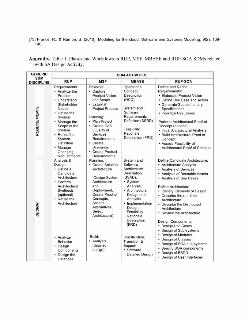
[73] France, R., & Rumpe, B. (2010). Modeling for the cloud. Software and Systems Modeling, 9(2), 139-140.
Appendix. Table 1. Phases and Workflows in RUP, MSF, MBASE and RUP-SOA SDMs related
with SA Design Activity.
GENERIC SDM
DISCIPLINE
SDM ACTIVITIES
RUP MSF MBASE RUP-SOA
REQ
UIR
EMEN
TS
Requirements: • Analyze the
Problem • Understand
Stakeholder Needs
• Define the System
• Manage the Scope of the System
• Refine the System Definition
• Manage Changing Requirements.
Envision: • Capture
Product Vision and Scope
• Establish Project Process
Planning: • Plan Project • Create QoS
(Quality of Service) Requirements
• Create Scenarios
• Create Product Requirements
Operational Concept Description (OCD) System and Software Requirements Definition (SSRD) Feasibility Rationale Description (FRD)
Define and Refine Requirements: • Elaborate Product Vision • Define Use Case and Actors • Generate Supplementary
Specifications • Prioritize Use Cases Perform Architectural Proof-of-Concept (optional): • Initial Architectural Analysis • Build Architectural Proof of
Concept • Assess Feasibility of
Architectural Proof of Concept
DES
IGN
Analysis & Design: • Define a
Candidate Architecture
• Perform Architectural Synthesis (optional)
• Refine the Architecture
• Analyze
Behavior • Design
Components • Design the
Database
Planning: • Create Solution
Architecture (Design System Architecture and Deployment, Create Proof of Concepts, Assess Alternatives, Select Architecture).
Build: • Analysis
(detailed design)
System and Software Architecture Description (SSAD): • System
Analysis • Architecture
Design and Analysis
• Implementation Design
- Feasibility Rationale Description (FRD)
Construction, Transition & Support • Software
Detailed Design
Define Candidate Architecture: • Architecture Analysis • Analysis of Services • Analysis of Reusable Assets • Analysis of Use Cases Refine Architecture: • Identify Elements of Design • Describe the run-time
Architecture • Describe the Distributed
Architecture • Review the Architecture Design Components: • Design Use Cases • Design of Sub-systems • Design of Modules • Design of Classes • Design of SOA sub-systems • Specify SOA components • Design of BBDD • Design of User Interfaces
Related Documents