DAVID R. L YZENGA THE PHYSICAL BASIS FOR ESTIMATING WAVE ENERGY SPECTRA FROM SAR IMAGERY Ocean surface waves are imaged by synthetic aperture radar (SAR) through a combination of the ef- fects of changes in the surface slope, surface roughness, and surface motion. Over a limited range of conditions, each of these effects can be described in terms of a linear modulation-transfer function. In such cases, the wave-height spectrum can be estimated in a straightforward manner from the SAR image- intensity spectrum. The range of conditions over which this assumption of linearity is valid is investigat- ed using a numerical simulation model, and the implications of various departures from linearity are discussed. INTRODUCTION The imaging of ocean surface waves by synthetic aper- ture radar (SAR) has been amply demonstrated by numerous experimental investigations. 1 -7 The relation- ship between the SAR image and the wave spectrum has been investigated during these experiments; it has also been the subject of various theoretical studies of the im- aging process. 8 - 15 As a result of these investigations, the physical mechanisms and effects involved in the SAR imaging of ocean waves have been identified, although there are still uncertainties in the magnitudes of some of the effects. The mechanisms are discussed and esti- mates of their magnitudes are given in the following sec- tion. A numerical model of the imaging process that incorporates the mechanisms is then described and results are presented for several cases. Finally, the prospects for estimating wave-height spectra from SAR images and the conditions under which such estimations mayor may not be possible are discussed in the final section of this article. Monaldo (this issue) describes a spectral estima- tion procedure based on certain linearizing approxima- tions to the model and gives results from a SIR-B experiment. SAR IMAGING MECHANISMS The microwave reflectivity, or radar cross section per unit area of the ocean surface, is influenced by the small- scale roughness of the surface; it is also dependent on the local angle of incidence of the microwave radiation. Thus, changes in the surface roughness as well as the sur- face slope associated with "long" ocean waves cause var- David R. Lyzenga is a research scientist in the Radar Science Laborator y, the En- vironmental Research Institute of Michi- gan, Ann Arbor, MI 48107. Johns Hopkins A PL T echnical Digest, Volume 8, N um ber J (198 7) iations in the backscattered power that are observable by high-resolution radar systems. These sources of variation are referred to as hydrodynamic and tilt modulation, respectively. 14 In the case of SAR, the image intensity is also in- fluenced by the motion of the surface. Motions that are correlated with the phase of the long wave cause varia- tions in the image intensity via the' 'velocity bunching" mechanism. 8 ,9 Random motions, on the other hand, cause a degradation in the effective azimuth resolution that results in the "azimuth falloff" effect described by Beal et al. 6 Each of the modulation mechanisms, over a limited range of conditions, may be assumed to be linear in the sense that a sinusoidal surface wave of a gi ven ampli- tude produces a sinusoidal variation in the backscattered power, or image intensity, with an amplitude that is proportional to the wave amplitude. Under these con- ditions, superposition also applies so that the spectrum of the back scattered power or image intensity is related to the wave-height spectrum via a composite modula- tion-transfer function that is the (vector) sum of the in- dividual modulation-transfer functions due to hydro- dynamic effects, tilt effects, and velocity bunching. The effect of random surface motions may be similarly ac- counted for, in this approximation, by a convolution in the image domain with a resolution function having a width Po in the along-track or azimuth direction. This is equivalent to a multiplication of the image spectrum by a falloff function, j, having a width proportional to 1/ Po in the azimuth wavenumber direction. Combining these effects results in the equation Si (k x , ky) Sw (k x , ky) where Si is the image spectrum, Sw is the wave-height spectrum, kx is the azimuth wavenumber, ky is the range wavenumber, and kL = k; + k; . 65

Welcome message from author
This document is posted to help you gain knowledge. Please leave a comment to let me know what you think about it! Share it to your friends and learn new things together.
Transcript
DAVID R. L YZENGA
THE PHYSICAL BASIS FOR ESTIMATING WAVE ENERGY SPECTRA FROM SAR IMAGERY
Ocean surface waves are imaged by synthetic aperture radar (SAR) through a combination of the effects of changes in the surface slope, surface roughness, and surface motion. Over a limited range of conditions, each of these effects can be described in terms of a linear modulation-transfer function. In such cases, the wave-height spectrum can be estimated in a straightforward manner from the SAR imageintensity spectrum. The range of conditions over which this assumption of linearity is valid is investigated using a numerical simulation model, and the implications of various departures from linearity are discussed.
INTRODUCTION
The imaging of ocean surface waves by synthetic aperture radar (SAR) has been amply demonstrated by numerous experimental investigations. 1-7 The relationship between the SAR image and the wave spectrum has been investigated during these experiments; it has also been the subject of various theoretical studies of the imaging process. 8
-15 As a result of these investigations, the
physical mechanisms and effects involved in the SAR imaging of ocean waves have been identified, although there are still uncertainties in the magnitudes of some of the effects. The mechanisms are discussed and estimates of their magnitudes are given in the following section. A numerical model of the imaging process that incorporates the mechanisms is then described and results are presented for several cases. Finally, the prospects for estimating wave-height spectra from SAR images and the conditions under which such estimations mayor may not be possible are discussed in the final section of this article. Monaldo (this issue) describes a spectral estimation procedure based on certain linearizing approximations to the model and gives results from a SIR-B experiment.
SAR IMAGING MECHANISMS
The microwave reflectivity, or radar cross section per unit area of the ocean surface, is influenced by the smallscale roughness of the surface; it is also dependent on the local angle of incidence of the microwave radiation. Thus, changes in the surface roughness as well as the surface slope associated with "long" ocean waves cause var-
David R. Lyzenga is a research scientist in the Radar Science Laboratory, the Environmental Research Institute of Michigan, Ann Arbor, MI 48107.
Johns Hopkins A PL Technical Digest, Volume 8, N um ber J (1987)
iations in the backscattered micr~wave power that are observable by high-resolution radar systems. These sources of variation are referred to as hydrodynamic and tilt modulation, respectively. 14
In the case of SAR, the image intensity is also influenced by the motion of the surface. Motions that are correlated with the phase of the long wave cause variations in the image intensity via the' 'velocity bunching" mechanism. 8
,9 Random motions, on the other hand, cause a degradation in the effective azimuth resolution that results in the "azimuth falloff" effect described by Beal et al. 6
Each of the modulation mechanisms, over a limited range of conditions, may be assumed to be linear in the sense that a sinusoidal surface wave of a given amplitude produces a sinusoidal variation in the backscattered power, or image intensity, with an amplitude that is proportional to the wave amplitude. Under these conditions, superposition also applies so that the spectrum of the back scattered power or image intensity is related to the wave-height spectrum via a composite modulation-transfer function that is the (vector) sum of the individual modulation-transfer functions due to hydrodynamic effects, tilt effects, and velocity bunching. The effect of random surface motions may be similarly accounted for, in this approximation, by a convolution in the image domain with a resolution function having a width Po in the along-track or azimuth direction. This is equivalent to a multiplication of the image spectrum by a falloff function, j, having a width proportional to 1/ Po in the azimuth wavenumber direction. Combining these effects results in the equation
Si (kx, ky )
Sw (kx, ky )
where Si is the image spectrum, Sw is the wave-height spectrum, kx is the azimuth wavenumber, ky is the range wavenumber, and k L = k; + k; .
65
Lyzenga - The Physical Basis for Estimating Wa ve Energy Spectra from SAR Imagery
The hydrodynamic modulation-transfer function, mh, was originally thought to be dominated by the straining effect of the long-wave orbital motions on the shorter surface waves. 16 An expression for that effect, neglecting the relaxation of the short waves, is given by
(2)
assuming a Phillips-type k - 4 spectrum for the short waves. Measurements of the transfer function indicate magnitudes several times larger than this value, as well as a dependence on wind speed and wavelength that is not predicted by the equation. 17 Other mechanismssuch as a modulation of the air flow across the long waves that in turn modulates the short waves, or nonlinear effects such as wave breaking-may be responsible for the larger observed hydrodynamic modulation.
The tilt modulation-transfer function, m" can be written as
(3)
where (Jo (0) is the radar cross section as a function of the incidence angle 0, and the "i" indicates that the change in radar cross section is 90 degrees out of phase with the surface elevation. 14 Using a Bragg scattering model with a perfectly conducting surface and a Phillipstype short-wave spectrum, this becomes
4 cot 0 1 ± sin 2 0 iky /k (4)
where the plus sign refers to vertical polarization and the minus sign refers to horizontal polarization. For incidence angles less than about 30 degrees, the tilt modulation-transfer function is larger than the hydrodynamic modulation-transfer function given by Eq. 2.
For sufficiently small wave amplitudes, the velocitybunching modulation-transfer function, mv , can be written as
R - w [ - cos 0 + i ( k y / k) sin 0] k x / k , V
(5)
where R is the range, V is the SAR platform velocity, and w = (gk) VI is the radian frequency of the long wave. 14 The conditions under which this linear modulation-transfer function is valid are discussed in the following section.
The azimuth falloff function f(kx ) also involves the R I V ratio as well as the surface velocity distribution. 6,18
An expression for f(kx ) was derived by Beal et al. 6 of the form
(6)
66
where (J3 is the radial velocity variance, which is obtained by integrating the surface velocity spectrum over an appropriate range of wavelengths. The proper limits of the integration are still a matter of debate, however, and consequently the dependence of the azimuth falloff effect on environmental conditions has not been resolved.
NUMERICAL SIMULATION MODELING In order to resolve questions that are difficult to ad
dress analytically, such as the conditions under which the velocity bunching mechanism is linear and the dependence of the azimuth falloff function on the wave spectrum, a numerical simulation of the SAR imaging process is useful. 13,19 The numerical model of the present study uses a Monte Carlo simulation to assign values of the surface velocity and reflectivity to each point on the surface. These values are then used to calculate the SAR image intensity following the procedure described by Hasselmann et al. 15 The predictions of this model appear to agree well with SIR-B observations over a limited parameter range. 19 Nevertheless, the conclusions based on this model must remain tentative until further experimental confirmation can be made.
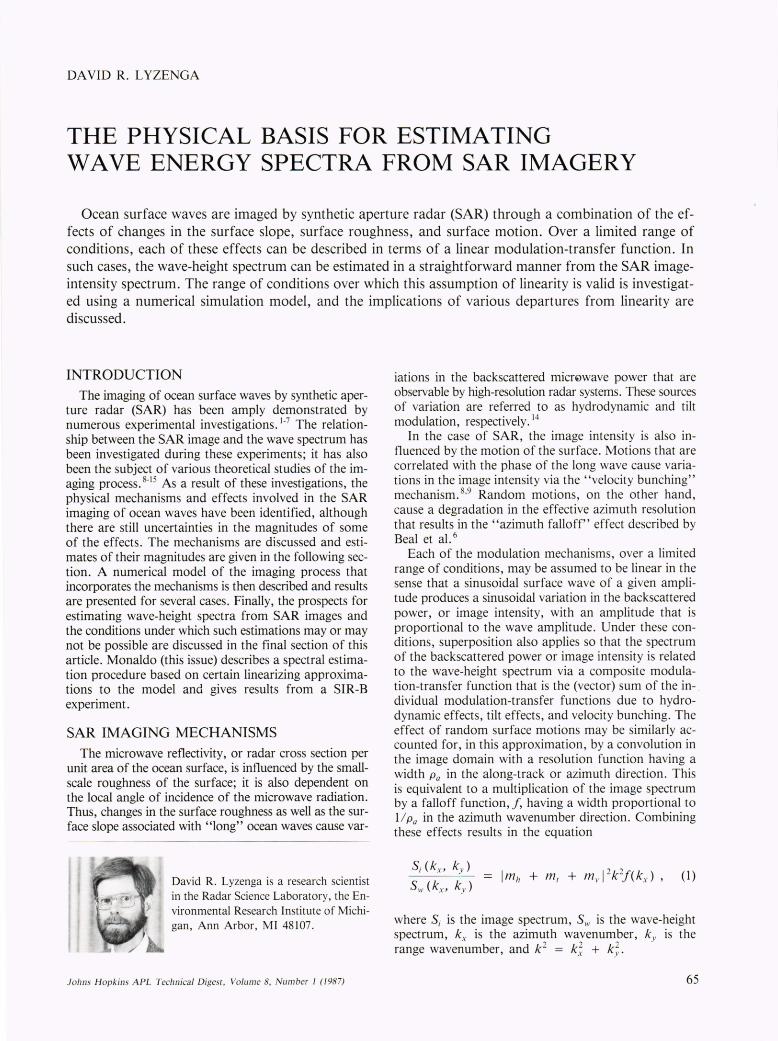
A wave-height spectrum having a peak wavelength of 200 meters at a direction of 45 degrees with respect to the SAR ground track is shown in Fig. 1. This spectrum was scaled to yield a significant wave height of 2, 4, and . 6 meters and was used as an input into the abovementioned SAR simulation model. 19 Additional parametric variations of the R I V ratio and the (tilt) modulation-transfer function were made, as shown in Table 1.
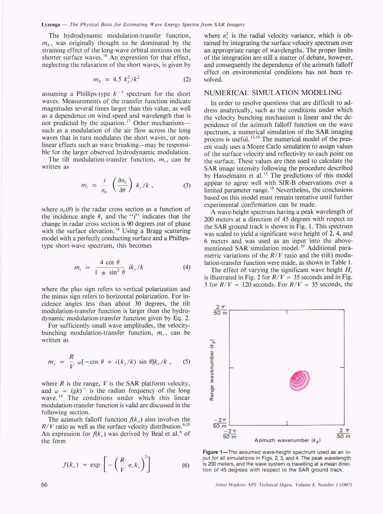
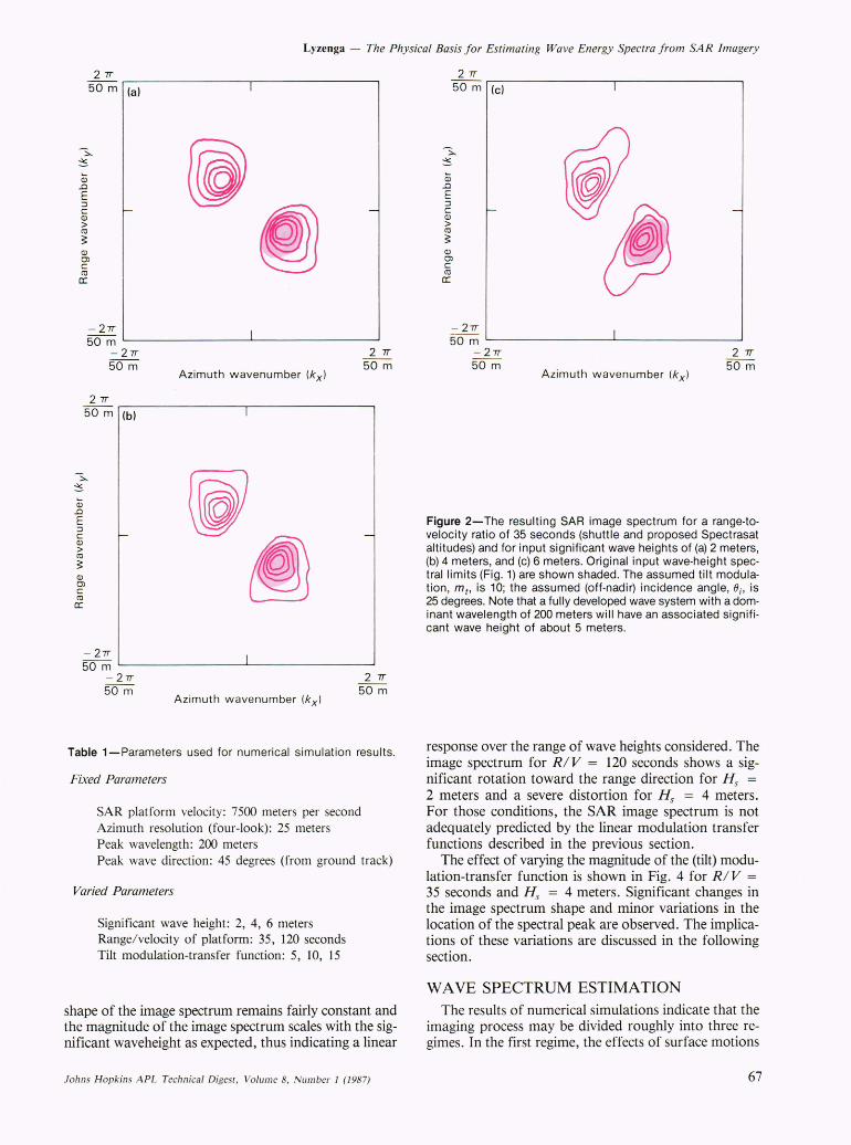
The effect of varying the significant wave height Hs is illustrated in Fig. 2 for R I V = 35 seconds and in Fig. 3 for R I V = 120 seconds. For R I V = 35 seconds, the
27T
50 m I
-~
~
Cii .0
E :::J C - -<ll > co ~ <ll en c co c:
-27T I 50 m L-______________ ~ ____________ ~
-27T 2 7T
50 m 50 m Azimuth wavenumber (kx )
Figure 1-The assumed wave-height spectrum used as an input for all simulations in Figs. 2, 3, and 4. The peak wavelength is 200 meters, and the wave system is travelling at a mean direction of 45 degrees with respect to the SAR ground track.
Johns H opkins APL Technical Digest, Volume 8, Number I (/987)
Lyzenga - The Physical Basis for Estimating Wave Energy Spectra from SAR Imagery
27T 50 m (a)
Q)
.0
E ::J C Q)
> co ~ Q)
OJ C co a:
I
-
- 27T 50 m ~--------------~I--------------~
27T
-27T 50 m
50 m (b)
(j) .0
E ::J C Q)
> co ~ Q)
OJ C co a:
Azimuth wavenumber (kxl
I
27T 50 m
-
- 27T I 50 m ~------------~--------------~
- 27T 50 m
Azimuth wavenumber (kxl
2 7T 50 m
Table 1-Parameters used for numerical simulation results.
Fixed Parameters
SAR platform velocity: 7500 meters per second Azimuth resolution (four-look): 25 meters Peak wavelength: 200 meters Peak wave direction: 45 degrees (from ground track)
Varied Parameters
Significant wave height: 2, 4, 6 meters Range/ velocity of platform: 35, 120 seconds Tilt modulation-transfer function: 5, 10, 15
shape of the image spectrum remains fairly constant and the magnitude of the image spectrum scales with the significant waveheight as expected, thus indicating a linear
Johns H opkins A PL Technical Diges[, Volume 8, Number J (1987)
(j) .0
E ::J C Q)
> co ~ Q)
OJ C co a:
27T 50 m (e)
- 27T 50 m ~ ______________ -L ______________ ~
- 27T 2 7T 50 m 50 m
Azimuth wavenumber (kxl
Figure 2-The resulting SAR image spectrum for a range-tovelocity ratio of 35 seconds (shuttle and proposed Spectrasat altitudes) and for input significant wave heights of (a) 2 meters, (b) 4 meters, and (c) 6 meters. Original input wave-height spectral limits (Fig. 1) are shown shaded. The assumed tilt modulation, m t , is 10; the assumed (off-nadir) incidence angle, 0i, is 25 degrees. Note that a fully developed wave system with a dominant wavelength of 200 meters will have an associated significant wave height of about 5 meters.
response over the range of wave heights considered_ The image spectrum for R I V = 120 seconds shows a significant rotation toward the range direction for H s = 2 meters and a severe distortion for H s = 4 meters. For those conditions, the SAR image spectrum is not adequately predicted by the linear modulation transfer functions described in the previous section.
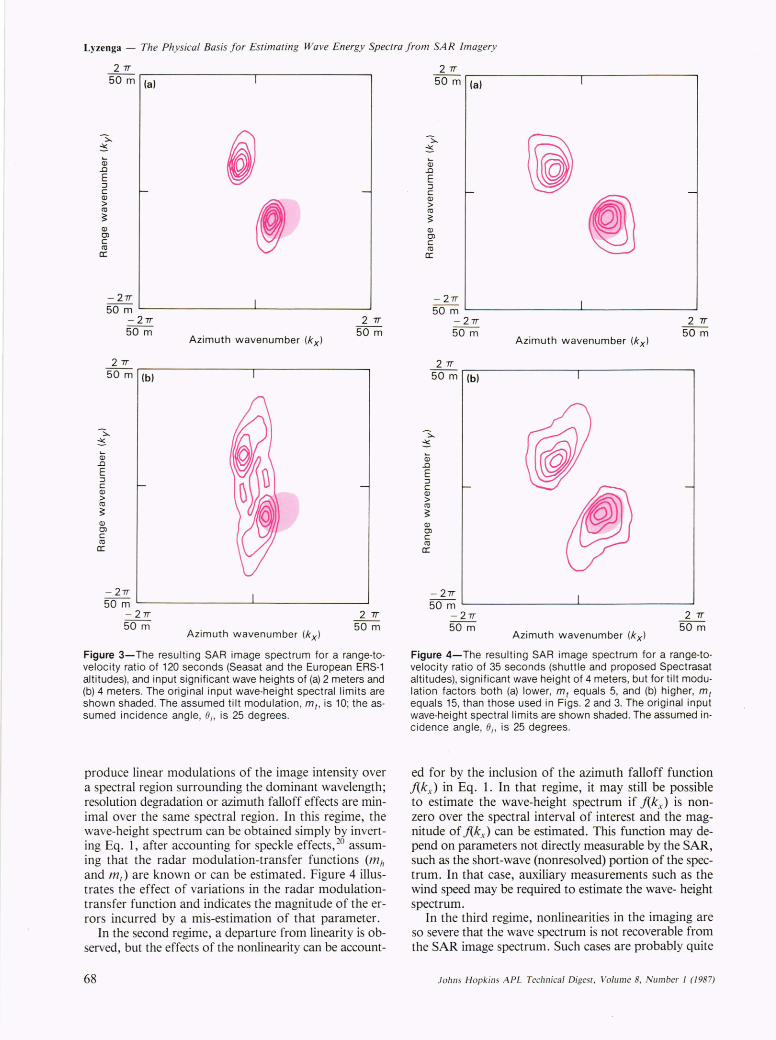
The effect of varying the magnitude of the (tilt) modulation-transfer function is shown in Fig. 4 for R I V = 35 seconds and Hs = 4 meters. Significant changes in the image spectrum shape and minor variations in the location of the spectral peak are observed. The implications of these variations are discussed in the following section.
WAVE SPECTRUM ESTIMATION The results of numerical simulations indicate that the
imaging process may be divided roughly into three regimes_ In the first regime, the effects of surface motions
67
Lyzenga - The Physical Basis for Estimating Wave Energy Spectra from SAR Imagery
27T 50 m (a)
-::::.,.
~
Q) .0 E :::J C -OJ > co ~ OJ OJ C co a::
- 27T 50 m
- 27T
Q) .0 E :::J C OJ > co ~ OJ OJ C co
a::
50 m
27T 50 m (b)
- 27T
I
j -,
I 27T
Azimuth wavenumber (kx ) 50 m
50 m ~--------------~--------------~ - 27T 2 7T 50 m 50 m
Azimuth wavenumber (kxl
Figure 3-The resulting SAR image spectrum for a range-tovelocity ratio of 120 seconds (Seasat and the European ERS-1 altitudes), and input significant wave heights of (a) 2 meters and (b) 4 meters. The original input wave-height spectral limits are shown shaded. The assumed tilt modulation , m t, is 10; the assumed incidence angle, Oi' is 25 degrees.
produce linear modulations of the image intensity over a spectral region surrounding the dominant wavelength; resolution degradation or azimuth falloff effects are minimal over the same spectral region. In this regime, the wave-height spectrum can be obtained simply by inverting Eq. 1, after accounting for speckle effects,20 assuming that the radar modulation-transfer functions (m il and m/) are known or can be estimated. Figure 4 illustrates the effect of variations in the radar modulationtransfer function and indicates the magnitude of the errors incurred by a mis-estimation of that parameter.
In the second regime, a departure from linearity is observed, but the effects of the nonlinearity can be account-
68
27T 50 m (a)
-::::.,.
~
Q) .0 E :::J c OJ > co ~ OJ OJ C co
a::
- 27T 50 m
- 27T 50 m
27T 50 m
Q) .0 E :::J C OJ > co ~ OJ OJ C co
a::
-27T
(b)
I
~ -
~ I
27T
Azimuth wavenumber (kxl 50 m
50 m ~--------------~--------------~ -27T 50 m
Azimuth wavenumber (kxl
27T 50 m
Figure 4-The resulting SAR image spectrum for a range-tovelocity ratio of 35 seconds (shuttle and proposed Spectrasat altitudes), significant wave height of 4 meters, but for tilt modulation factors both (a) lower, mt equals 5, and (b) higher, mt equals 15, than those used in Figs. 2 and 3. The original input wave-height spectral limits are shown shaded. The assumed incidence angle, Oi' is 25 degrees.
ed for by the inclusion of the azimuth falloff function f(k x) in Eq. 1. In that regime, it may still be possible to estimate the wave-height spectrum if f(kx ) is nonzero over the spectral interval of interest and the magnitude of f(kx ) can be estimated. This function may depend on parameters not directly measurable by the SAR, such as the short-wave (nonresolved) portion of the spectrum. In that case, auxiliary measurements such as the wind speed may be required to estimate the wave- height spectrum.
In the third regime, nonlinearities in the imaging are so severe that the wave spectrum is not recoverable from the SAR image spectrum. Such cases are probably quite
Johns H opkins A PL Technica l Digest, Volum e 8, Number I (1987)
Lyzenga - The Physical Basis for Estimating Wave Energy Spectra from SAR Imagery
common for R I V ratios exceeding 100 seconds (such as Seas at or ERS-l) but are relatively rare for RIV ratios on the order of 35 seconds that occur on low-orbit sensors such as SIR-B or the proposed Spectrasat (Beal, this issue).
'REFERENCES
I F. I. Gonzalez, R. C. Beal , W. E. Brown, P. S. DeLeonibus, J. W. Sher man, J. F. R. Gower, D. Lichy, D. B. Ross, C. L. Rufenach, and R. A. Shuchman, "Seasat Synthetic Aperture Radar: Ocean Wave Detection Capabilities," Science 204, 1418-1421 (1979).
2 W. McLeish, D. B. Ross, R. A. Shuchman, P. G. Teleki, S. V. Hsiao, O. H. Shemdin, and W. E. Brown, "Synthetic Aperture Radar Imaging of Ocean Waves: Comparison with Wave Measurements," 1. Geophys. Res. 85 , 5003-5011 (1980).
3 S. S. Pawka, S. V. Hsiao, O. H. Shemdin, and D. L. Inmann, "Comparisons Between Wave Directional Spectra from SAR and Pressure Sensor Arrays," 1. Geophys. Res. 85, 4987-4995 (1980).
4 D. J. Schwab, R. A. Shuchman, and P . L. Liu, " Wind Wave Directions Determined from Synthetic Aperture Radar Imagery and from a Tower in Lake Michigan," 1. Geophys. Res. 86, 2059-2064 (1981).
5 R. A. Shuchman, W. Rosenthal, J. D. Lyden, D. R. Lyzenga, E. S. Kasischke, H. Gunther, and H. Linne, "Analysis of MARSEN X-Band SAR Ocean Wave Data," 1. Geophys. Res. 88, 957-969 (1983).
6 R. C. Beal, D. G. Tilley, and F. M. Monaldo, "Large- and Small-Scale Spatial Evolution of Digitally Processed Ocean Wave Spectra from Seasat Synthetic Aperture Radar," 1. Geophys. Res. 88, 1761 (1983).
7 R. C. Beal, F. M. Monaldo, D. G. Tilley, D. E. Irvine, E. J . Walsh , F. C. Jackson, D. W. Hancock Ill, D. E. Hines, R. . Swift, F. I. Gonzalez, Q .. R. Lyzenga, and L. F. Zambresky, "A Comparison of SIR-B Directional Ocean Wave Spectra with Aircraft Scanning Radar Spectra, " Science 232, 1531-1535 (1986).
8 W. R. Alpers and C. L. Rufenach , "The Effect of Orbital Motions on Syn-
John s Hopkins APL Technical Digesl, Volume 8, Number I (1987)
thetic Aperture Radar Imagery of Ocean Waves," IEEE Trans. Antennas Propag. AP-27, 685-690 (1979).
9 C. T . Swift and L. R. Wilson, "Synthetic Aperture Radar Imaging of Moving Ocean Waves," IEEE Trans. Antennas Propag. AP-27, 725-729 (1979).
to R. O. Harger, "SAR Ocean Imaging Mechanisms," in Spaceborne Synthetic Aperture Radar jor Oceanography, R. C. Beal, P. S. DeLeonibus, and I. Katz, eds., Johns Hopkins Univ. Press, Baltimore, 41-52 (1981).
II A. Jain, "SAR Imaging of Ocean Waves: Theory," IEEE 1. Oceanic Eng. 0E-6, 130-139 (1981).
12 R. K. Raney, "Wave Orbital Velocity, Fade, and SAR Response to Azimuth Waves," IEEE 1. Oceanic Eng. 0E-6, 140-146 (1981).
13 W. Alpers, "Monte Carlo Simulations for Studying the Relationship Between Ocean Wave and Synthetic Aperture Radar Image Spectra," 1. Geophys. Res. 88, 1745-1759 (1983).
14 W. R. Alpers, D. B. Ross, and C. L. Rufenach, "On the Detectability of Ocean Surface Waves by Real and Synthetic Aperture Radar," 1. Geophys. Res. 86, 6481-6498 (1981).
15 K. Hasselmann, R. K. Raney, W. J. Plant, W. Alpers, R. A. Shuchman, D. R. Lyzenga, C. L. Rufenach, and M. J . Tucker, "Theory of SAR Ocean Wave Imaging: A MARSEN View," 1. Geophys. Res. 90,4659-4686 (1985).
16W. C. Keller and J . W . Wright , "Microwave Scattering and the Straining of Wind-Generated Waves," Radio Sci. 10, 139-147 (1975).
17 W . J. Plant, W. C. Keller, and A. Cross, "Parametric Dependence of Ocean Wave-Radar Modulation Transfer Functions," 1. Geophys. Res. 88,9747-9756 (1983).
18 M. J . Tucker, "The Decorrelation Time of Microwave Radar Echoes from the Sea Surface," Int. 1. Remote Sens. 6, 1075-1089 (1985).
19 D. R. Lyzenga, "Numerical Simulation of Synthetic Aperture Radar Image Spectra for Ocean Waves," IEEE Trans. Geosci. Remote Sens. GE-24, 863-87 1 (1986).
2°F. M. Monaldo and D. R. Lyzenga, "On the Estimation of Wave Siope- and Height-Variance Spectra from SAR Imagery," IEEE Trans. "Geosci. Remote Sens. GE-24, 543-550 (1986).
ACKNOWLEDGMENTS- This work was supported by NASA Headquarters under Contract No. NOOOI4-81-C-0692.
69
Related Documents