1

Welcome message from author
This document is posted to help you gain knowledge. Please leave a comment to let me know what you think about it! Share it to your friends and learn new things together.
Transcript

1
�
�
������������������ ��
���������
�

2
�
�� ������������������������������������������������������������������������������������������������������������������������������������� �
���� ��������������������������������������������������������������������������������������������������������������������������������������������������� � ���� ������������������ ���������������������������������������������������������������������������������������������������������������������������� � ���� ������������������������������������������������������������������������������������������������������������������������������������������������������� � ���� ������������������ ���� ��������������������������������������������������������������������������������������������������������������������� � ���� ������������������������������������������������������������������������������������������������������������������������������������� � ���� ������������������������������������������������������������������������������������������������������������������������������������������������������� � ���� ����������������������������� ����������������������������������������������������������������������������������������������������������� � ���� ������������� �� ������� ������������������������������������������������������������������������������������������������������������������� � ��!� ������������������������������������������������������������������������������������������������������������������������������������������������������ !
�
�
3
�
�� ��������������������������������������� ��������������������� �������������������������������������������
���� ������� �!���
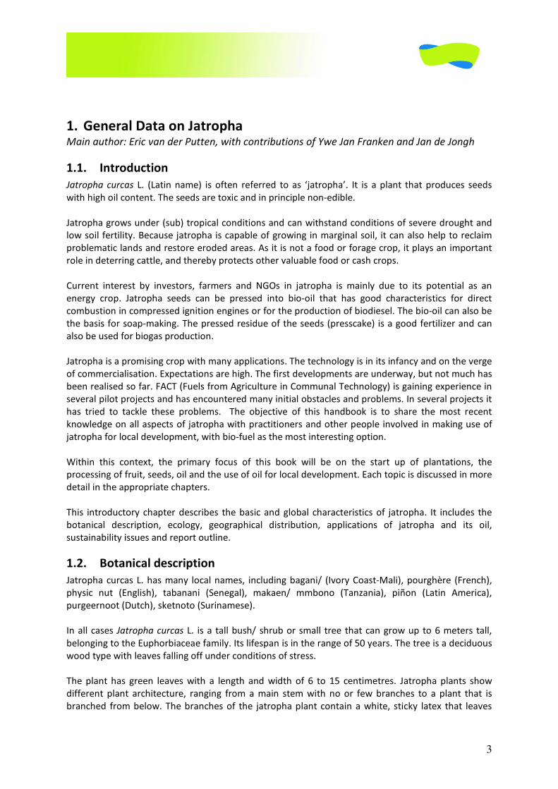
������� � ��� ��� "�#$%&�&#'()� %*� +,$(&� -(,(--(.� $+�#*� /0#$-+12#3�� �$� %*� #�14#&$� $2#$�1-+.56(*� *((.*�
7%$2�2%82�+%4�6+&$(&$���2(�*((.*�#-(�$+9%6�#&.�%&�1-%&6%14(�&+&:(.%;4(���
�
�#$-+12#�8-+7*�5&.(-�"*5;)�$-+1%6#4�6+&.%$%+&*�#&.�6#&�7%$2*$#&.�6+&.%$%+&*�+,�*(<(-(�.-+582$�#&.�
4+7�*+%4�,(-$%4%$=�� (6#5*(�0#$-+12#�%*�6#1#;4(�+,�8-+7%&8�%&�'#-8%�*+%4>� %$�6#&�#4*+�2(41�$+�-(64#%'�
1-+;4('#$%6�4#&.*�#&.�-(*$+-(�(-+.(.�#-(#*���*�%$�%*�&+$�#�,++.�+-�,+-#8(�6-+1>�%$�14#=*�#&�%'1+-$#&$�
-+4(�%&�.($(--%&8�6#$$4(>�#&.�$2(-(;=�1-+$(6$*�+$2(-�<#45#;4(�,++.�+-�6#*2�6-+1*���
�
5--(&$� %&$(-(*$� ;=� %&<(*$+-*>� ,#-'(-*� #&.� ���*� %&� 0#$-+12#� %*� '#%&4=� .5(� $+� %$*� 1+$(&$%#4� #*� #&�
(&(-8=� 6-+1�� �#$-+12#� *((.*� 6#&� ;(� 1-(**(.� %&$+� ;%+:+%4� $2#$� 2#*� 8++.� 62#-#6$(-%*$%6*� ,+-� .%-(6$�
6+';5*$%+&�%&�6+'1-(**(.�%8&%$%+&�(&8%&(*�+-�,+-�$2(�1-+.56$%+&�+,�;%+.%(*(4���2(�;%+:+%4�6#&�#4*+�;(�
$2(�;#*%*�,+-�*+#1:'#?%&8���2(�1-(**(.�-(*%.5(�+,�$2(�*((.*�"1-(**6#?()�%*�#�8++.�,(-$%4%@(-�#&.�6#&�
#4*+�;(�5*(.�,+-�;%+8#*�1-+.56$%+&��
�
�#$-+12#�%*�#�1-+'%*%&8�6-+1�7%$2�'#&=�#114%6#$%+&*���2(�$(62&+4+8=�%*�%&�%$*�%&,#&6=�#&.�+&�$2(�<(-8(�
+,�6+''(-6%#4%*#$%+&���91(6$#$%+&*�#-(�2%82���2(�,%-*$�.(<(4+1'(&$*�#-(�5&.(-7#=>�;5$�&+$�'562�2#*�
;((&�-(#4%*(.�*+�,#-������"�5(4*�,-+'��8-%654$5-(�%&�+''5��(62&+4+8=)�%*�8#%&%&8�(91(-%(&6(�%&�
*(<(-#4�1%4+$�1-+0(6$*�#&.�2#*�(&6+5&$(-(.�'#&=�%&%$%#4�+;*$#64(*�#&.�1-+;4('*���&�*(<(-#4�1-+0(6$*�%$�
2#*� $-%(.� $+� $#6?4(� $2(*(� 1-+;4('*�� � �2(� +;0(6$%<(� +,� $2%*� 2#&.;++?� %*� $+� *2#-(� $2(� '+*$� -(6(&$�
?&+74(.8(�+&�#44�#*1(6$*�+,�0#$-+12#�7%$2�1-#6$%$%+&(-*�#&.�+$2(-�1(+14(�%&<+4<(.�%&�'#?%&8�5*(�+,�
0#$-+12#�,+-�4+6#4�.(<(4+1'(&$>�7%$2�;%+:,5(4�#*�$2(�'+*$�%&$(-(*$%&8�+1$%+&��
�
A%$2%&� $2%*� 6+&$(9$>� $2(� 1-%'#-=� ,+65*� +,� $2%*� ;++?� 7%44� ;(� +&� $2(� *$#-$� 51� +,� 14#&$#$%+&*>� $2(�
1-+6(**%&8�+,�,-5%$>�*((.*>�+%4�#&.�$2(�5*(�+,�+%4�,+-�4+6#4�.(<(4+1'(&$���#62�$+1%6�%*�.%*65**(.�%&�'+-(�
.($#%4�%&�$2(�#11-+1-%#$(�62#1$(-*��
�
�2%*� %&$-+.56$+-=�62#1$(-�.(*6-%;(*� $2(�;#*%6�#&.�84+;#4� 62#-#6$(-%*$%6*�+,� 0#$-+12#�� �$� %&645.(*� $2(�
;+$#&%6#4� .(*6-%1$%+&>� (6+4+8=>� 8(+8-#12%6#4� .%*$-%;5$%+&>� #114%6#$%+&*� +,� 0#$-+12#� #&.� %$*� +%4>�
*5*$#%&#;%4%$=�%**5(*�#&.�-(1+-$�+5$4%&(���
��"� �����! �����# �!��!���
�#$-+12#�65-6#*����2#*�'#&=� 4+6#4�&#'(*>� %&645.%&8�;#8#&%B� "�<+-=�+#*$:�#4%)>�1+5-82C-(� "�-(&62)>�
12=*%6� &5$� "�&84%*2)>� $#;#&#&%� "�(&(8#4)>� '#?#(&B� '';+&+� "�#&@#&%#)>� 1%D+&� "�#$%&� �'(-%6#)>�
15-8((-&++$�"�5$62)>�*?($&+$+�"�5-%&#'(*()��
�
�&�#44�6#*(*� ������� � ��� ��� %*�#� $#44�;5*2B�*2-5;�+-�*'#44� $-((� $2#$�6#&�8-+7�51�$+���'($(-*� $#44>�
;(4+&8%&8�$+�$2(��512+-;%#6(#(�,#'%4=���$*�4%,(*1#&�%*�%&�$2(�-#&8(�+,��E�=(#-*���2(�$-((�%*�#�.(6%.5+5*�
7++.�$=1(�7%$2�4(#<(*�,#44%&8�+,,�5&.(-�6+&.%$%+&*�+,�*$-(**���
�
�2(�14#&$�2#*� 8-((&� 4(#<(*�7%$2� #� 4(&8$2� #&.�7%.$2� +,� �� $+� ��� 6(&$%'($-(*�� �#$-+12#�14#&$*� *2+7�
.%,,(-(&$� 14#&$� #-62%$(6$5-(>� -#&8%&8� ,-+'�#�'#%&� *$('�7%$2� &+� +-� ,(7�;-#&62(*� $+� #�14#&$� $2#$� %*�
;-#&62(.� ,-+'�;(4+7���2(�;-#&62(*�+,� $2(� 0#$-+12#�14#&$� 6+&$#%&�#�72%$(>� *$%6?=� 4#$(9� $2#$� 4(#<(*�
4
;-+7&� *$#%&*>� 72%62� #-(� 2#-.� $+� 7#*2� +5$�� �2(� -++$� *=*$('� ,-+'� &#$5-#4� 0#$-+12#� 14#&$*� %*� 7(44�
.(<(4+1(.>�7%$2�-++$*�8-+7%&8�;+$2�4#$(-#44=�#&.�<(-$%6#44=�%&$+�.((1(-�*+%4�4#=(-*��
�
� �$!%������&�! ����#��'��������������������(�����)���! !��)�����*�� � ��
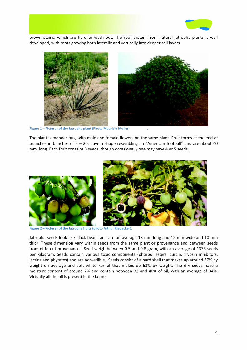
�2(�14#&$�%*�'+&+(6%+5*>�7%$2�'#4(�#&.�,('#4(�,4+7(-*�+&�$2(�*#'(�14#&$���-5%$�,+-'*�#$�$2(�(&.�+,�
;-#&62(*� %&�;5&62(*�+,���F��E>�2#<(�#� *2#1(� -(*(';4%&8�#&�G�'(-%6#&� ,++$;#44H�#&.�#-(�#;+5$��E�
''��4+&8���#62�,-5%$�6+&$#%&*���*((.*>�$2+582�+66#*%+,=�+&(�'#=�2#<(���+-���*((.*����
� �$!%����"�&�! ����#��'��������������'��!�#�(��������������!��� +��*��
�#$-+12#�*((.*� 4++?� 4%?(�;4#6?�;(#&*�#&.�#-(�+&�#<(-#8(����''�4+&8�#&.����''�7%.(�#&.��E�''�
$2%6?�� �2(*(� .%'(&*%+&� <#-=�7%$2%&� *((.*� ,-+'� $2(� *#'(�14#&$� +-� 1-+<(&#&6(� #&.�;($7((&� *((.*�
,-+'�.%,,(-(&$�1-+<(&#&6(*���((.�7(%82�;($7((&�E���#&.�E���8-#'>�7%$2�#&�#<(-#8(�+,������*((.*�
1(-� ?%4+8-#'�� �((.*� 6+&$#%&� <#-%+5*� $+9%6� 6+'1+&(&$*� "12+-;+4� (*$(-*>� 65-6%&>� $-=1*%&� %&2%;%$+-*>�
4(6$%&*�#&.�12=$#$(*)�#&.�#-(�&+&:(.%;4(����((.*�6+&*%*$�+,�#�2#-.�*2(44�$2#$�'#?(*�51�#-+5&.���I�;=�
7(%82$� +&� #<(-#8(� #&.� *+,$� 72%$(� ?(-&(4� $2#$� '#?(*� 51� ��I� ;=� 7(%82$�� �2(� .-=� *((.*� 2#<(� #�
'+%*$5-(� 6+&$(&$� +,� #-+5&.� �I� #&.� 6+&$#%&�;($7((&� ��� #&.� �EI�+,�+%4>�7%$2� #&� #<(-#8(� +,� ��I��
�%-$5#44=�#44�$2(�+%4�%*�1-(*(&$�%&�$2(�?(-&(4��
�
5
�$!%������,��-�� �������'��-�.�/�
���� � ���%0�
�+'(�6+&*%.(-�0#$-+12#�$+�;(�#�7((.���+7(<(->�%$�%*�.(,%&%$(4=�&+$�#&�%&<#*%<(�*1(6%(*�*%&6(�%$�2#-.4=�
1-+1#8#$(*� ;=� %$*(4,�� �((.*� ,-+'� ,-5%$*� $2#$� #-(� 4(,$� +&� $2(� 8-+5&.� *5--+5&.%&8� $2(�'+$2(-� 14#&$�
*(4.+'� 8(-'%&#$(� #&.� .(<(4+1�� �2(� ,-5%$� #&.� *((.*� #-(� 1+%*+&+5*� #&.� &+$� (#$(&� +-� 6+44(6$(.� ;=�
#&%'#4*>��#$-+12#>�$2(-(,+-(>�%*�&+$�&#$5-#44=�.%*1(-*(.����
�
�#$-+12#� %*� #� -(*%4%(&$� 14#&$� $2#$� 6#&� #.#1$� $+�'#&=� (6+4+8%6#4� 6+&.%$%+&*�� �$*� *5-<%<#4�'(62#&%*'�
(&#;4(*�%$�$+�7%$2*$#&.�1(-%+.*�+,�*$-(**�"6+4.�7(#$2(-B�*(<(-(�.-+582$B�4+7�-#.%#$%+&)���$�%*�#;4(�$+�
-($-%(<(�$2(�&5$-%(&$*�,-+'�%$*�4(#<(*�#&.�*$+-(�$2('�%&�$2(�14#&$�*$('�#&.�-++$�*=*$('���2(�4(#<(*�
$2(&� $5-&� =(44+7� #&.� #-(� *5;*(J5(&$4=� *2(.� ;=� $2(� 14#&$�� �2(� *$('� -('#%&*� 8-((&� #&.�
12+$+*=&$2($%6#44=� #6$%<(�� �&� $2%*�.+-'#&$� *$#$(� $2(� 14#&$� 6#&� *5-<%<(�1(-%+.*�+,�'+-(� $2#&�#� =(#-�
7%$2+5$�-#%&���
�
�&� *+'(�6#*(*� 0#$-+12#�&#$5-#44=� ,+-'*�#� *=';%+*%*�7%$2� *+%4�'=6+--2%@#� "#� *1(6%,%6�?%&.�+,� ,5&85*)�
$2#$�%&6-(#*(*�$2(�14#&$3*�51$#?(�+,�&5$-%(&$*�#&.�7#$(-�,-+'�$2(�*+%4�� ��2(�1-(*(&6(�+,�'=6+--2%@#�
%&6-(#*(*� $2(� 14#&$3*� $+4(-#&6(� $+� .-+582$� #&.� 4+7� 4(<(4*� +,� &5$-%(&$*�� �2%*� *=';%+*%*� +665-*�
*+'($%'(*�5&.(-�&#$5-#4�6+&.%$%+&*�;5$�&(<(-�+665-*�%&�14#&$#$%+&*>�5&4(**�#-$%,%6%#44=�%&$-+.56(.��
��1� ���%����! ����!#��!2��!���
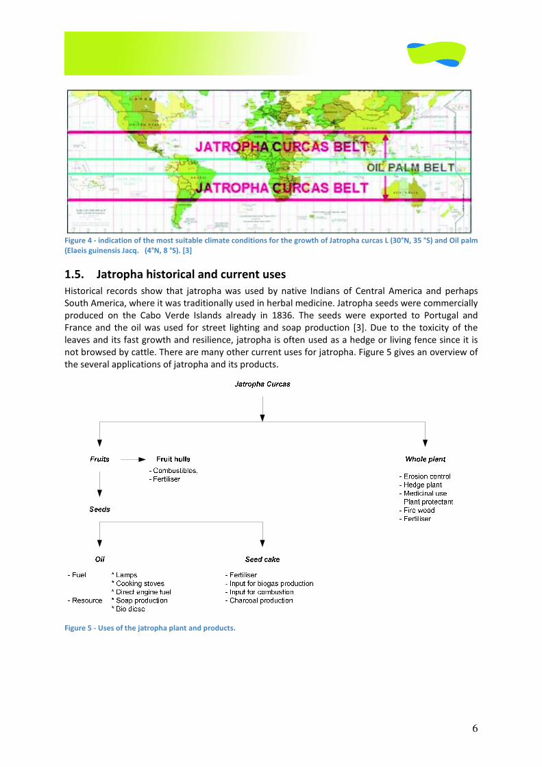
�#$-+12#� 2%*$+-%6#44=� +-%8%&#$(*� ,-+'� (&$-#4� �'(-%6#� #&.� $2(� &+-$2(-&� 1#-$*� +,� �+5$2� �'(-%6#��
�#$-+12#�2#*�;((&�.%*$-%;5$(.�$+�+$2(-�$-+1%6#4�-(8%+&*�;=��5-+1(#&�*(#,#-(-*�#&.�(914+-(-*�,-+'�$2(�
��$2�6(&$5-=�+&7#-.*���-(*(&$4=�%$�8-+7*�%&�$-+1%6#4�#-(#*�7+-4.7%.(�"�5;:�#2#-#&��,-%6#&�6+5&$-%(*>�
�+5$2(#*$��*%#>��&.%#)����
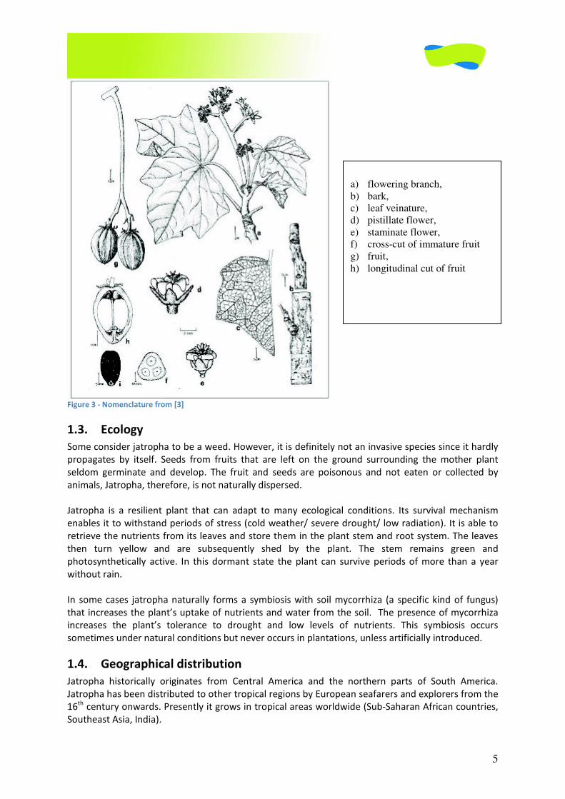
a) flowering branch,
b) bark,
c) leaf veinature,
d) pistillate flower,
e) staminate flower,
f) cross-cut of immature fruit
g) fruit,
h) longitudinal cut of fruit
6
�
�$!%����1�,�!��! ��!����'�����-�#��#�!��2��� �!-���� ���!�!��#�'�������%��3����'���������� �� �#���(�456��7�58*������!�����-�
(����!#�%�!���#!#��� 9����(156�:�58*��.�/�
��7� ����������!#���! ������� ��������#�#�
�%*$+-%6#4� -(6+-.*� *2+7� $2#$� 0#$-+12#�7#*� 5*(.� ;=� &#$%<(� �&.%#&*� +,� (&$-#4� �'(-%6#� #&.� 1(-2#1*�
�+5$2��'(-%6#>�72(-(�%$�7#*�$-#.%$%+,=�5*(.�%&�2(-;#4�'(.%6%&(���#$-+12#�*((.*�7(-(�6+''(-6%#44=�
1-+.56(.� +&� $2(� #;+� �(-.(� �*4#&.*� #4-(#.=� %&� ������ �2(� *((.*� 7(-(� (91+-$(.� $+� �+-$58#4� #&.�
�-#&6(�#&.� $2(�+%4�7#*�5*(.� ,+-� *$-(($� 4%82$%&8�#&.�*+#1�1-+.56$%+&� K�L���5(� $+� $2(� $+9%6%$=�+,� $2(�
4(#<(*�#&.�%$*�,#*$�8-+7$2�#&.�-(*%4%(&6(>�0#$-+12#�%*�+,$(&�5*(.�#*�#�2(.8(�+-�4%<%&8�,(&6(�*%&6(�%$�%*�
&+$�;-+7*(.�;=�6#$$4(���2(-(�#-(�'#&=�+$2(-�65--(&$�5*(*�,+-�0#$-+12#���%85-(���8%<(*�#&�+<(-<%(7�+,�
$2(�*(<(-#4�#114%6#$%+&*�+,�0#$-+12#�#&.�%$*�1-+.56$*���
�$!%����7�,�;#�#��'�����<����������������������� �#��
�
7
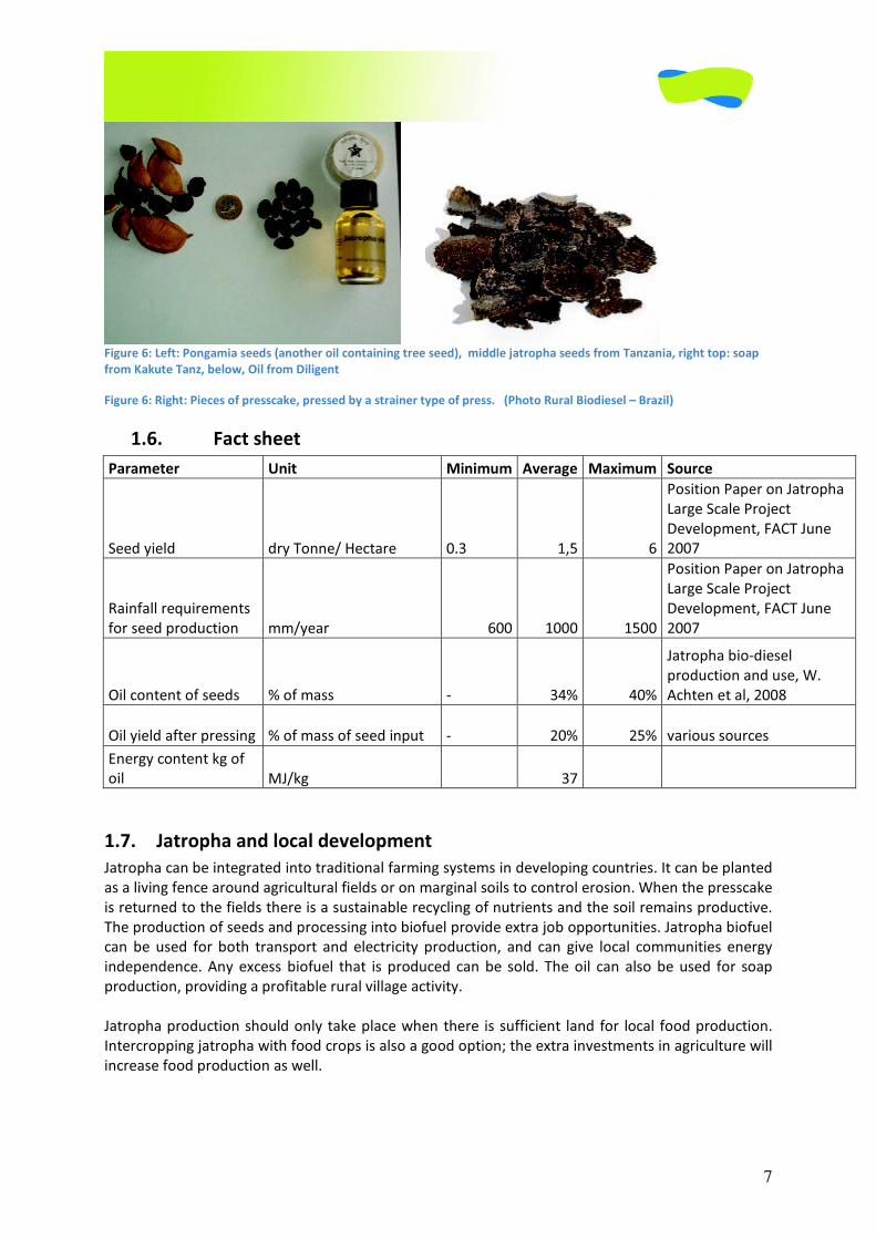
������ �$!%����=>���'�>���%�-!��#���#�(���������!�� ����!�!�%������#���*6��-!�����<��������#���#�'��-����?��!�6��!%������>�#����
'��-� �+�������?6�2���36��!��'��-��!�!%����
$!%����=>��!%��>�!� �#��'����## �+�6����##���20���#���!�����0����'����##����(������������!��!�#���&����?!�*�
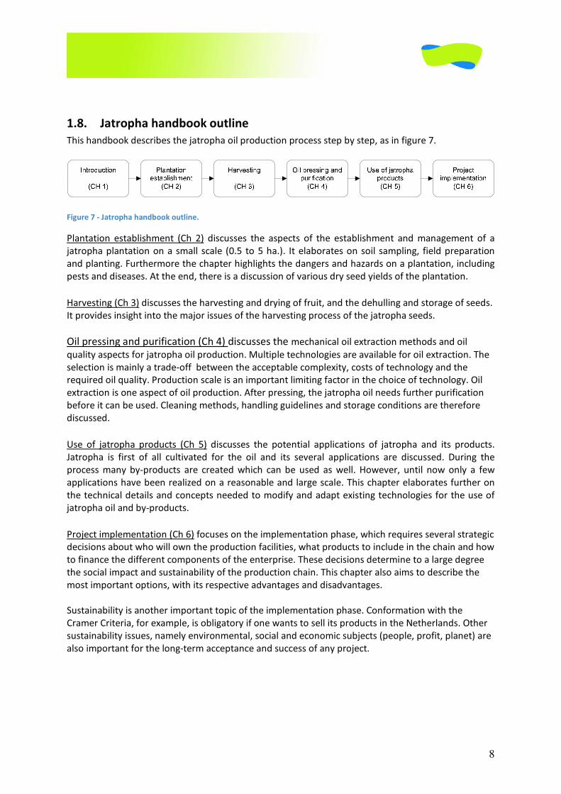
��=� �$� ��#�����
���-����� ;�!�� )!�!-�-� �@���%�� )�A!-�-� 8��� ��
�((.�=%(4.� .-=��+&&(B��(6$#-(� E��� �>�� ��
�+*%$%+&��#1(-�+&��#$-+12#�
�#-8(��6#4(��-+0(6$�
�(<(4+1'(&$>������5&(�
�EE��
�#%&,#44�-(J5%-('(&$*�
,+-�*((.�1-+.56$%+&� ''B=(#-� �EE� �EEE� ��EE�
�+*%$%+&��#1(-�+&��#$-+12#�
�#-8(��6#4(��-+0(6$�
�(<(4+1'(&$>������5&(�
�EE��
�%4�6+&$(&$�+,�*((.*� I�+,�'#**� :� ��I� �EI�
�#$-+12#�;%+:.%(*(4�
1-+.56$%+&�#&.�5*(>�A��
�62$(&�($�#4>��EE��
�%4�=%(4.�#,$(-�1-(**%&8�� I�+,�'#**�+,�*((.�%&15$� :� �EI� ��I� <#-%+5*�*+5-6(*�
�&(-8=�6+&$(&$�?8�+,�
+%4� ��B?8� �� ��� �� ��
�
��B� ��������������� �����@����-����
�#$-+12#�6#&�;(�%&$(8-#$(.�%&$+�$-#.%$%+�,#-'%&8�*=*$('*�%&�.(<(4+1%&8�6+5&$-%(*���$�6#&�;(�14#&$(.�
#*�#�4%<%&8�,(&6(�#-+5&.�#8-%654$5-#4�,%(4.*�+-�+&�'#-8%�*+%4*�$+�6+&$-+4�(-+*%+&��A2(&�$2(�1-(**6#?(�
%*�-($5-&(.�$+�$2(�,%(4.*�$2(-(�%*�#�*5*$#%&#;4(�-(6=64%&8�+,�&5$-%(&$*�#&.�$2(�*+%4�-('#%&*�1-+.56$%<(���
�2(�1-+.56$%+&�+,�*((.*�#&.�1-+6(**%&8�%&$+�;%+,5(4�1-+<%.(�(9$-#�0+;�+11+-$5&%$%(*���#$-+12#�;%+,5(4�
6#&� ;(� 5*(.� ,+-�;+$2� $-#&*1+-$� #&.� (4(6$-%6%$=� 1-+.56$%+&>� #&.� 6#&� 8%<(� 4+6#4� 6+''5&%$%(*� (&(-8=�
%&.(1(&.(&6(���&=�(96(**�;%+,5(4� $2#$� %*� 1-+.56(.� 6#&�;(� *+4.�� �2(�+%4� 6#&�#4*+�;(�5*(.� ,+-� *+#1�
1-+.56$%+&>�1-+<%.%&8�#�1-+,%$#;4(�-5-#4�<%44#8(�#6$%<%$=���
�
�#$-+12#�1-+.56$%+&�*2+54.�+&4=� $#?(�14#6(�72(&�$2(-(� %*�*5,,%6%(&$� 4#&.� ,+-� 4+6#4� ,++.�1-+.56$%+&��
�&$(-6-+11%&8�0#$-+12#�7%$2�,++.�6-+1*�%*�#4*+�#�8++.�+1$%+&M�$2(�(9$-#�%&<(*$'(&$*�%&�#8-%654$5-(�7%44�
%&6-(#*(�,++.�1-+.56$%+&�#*�7(44��
�
�
�
8
�
�
��:� �������������2��+�����!���
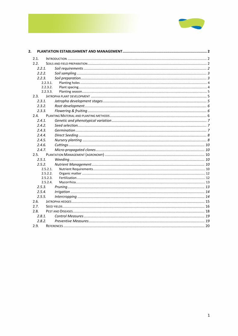
�2%*�2#&.;++?�.(*6-%;(*�$2(�0#$-+12#�+%4�1-+.56$%+&�1-+6(**�*$(1�;=�*$(1>�#*�%&�,%85-(����
�
�$!%����B�,��������������2��+�����!����
�4#&$#$%+&� (*$#;4%*2'(&$� "2� �)� .%*65**(*� $2(� #*1(6$*� +,� $2(� (*$#;4%*2'(&$� #&.�'#('(&$� +,� #�
0#$-+12#�14#&$#$%+&�+&�#�*'#44� *6#4(� "E��� $+���2#�)�� �$�(4#;+-#$(*�+&�*+%4� *#'14%&8>� ,%(4.�1-(1#-#$%+&�
#&.�14#&$%&8���5-$2(-'+-(�$2(�62#1$(-�2%824%82$*�$2(�.#&8(-*�#&.�2#@#-.*�+&�#�14#&$#$%+&>�%&645.%&8�
1(*$*�#&.�.%*(#*(*���$�$2(�(&.>�$2(-(�%*�#�.%*65**%+&�+,�<#-%+5*�.-=�*((.�=%(4.*�+,�$2(�14#&$#$%+&���
�
�#-<(*$%&8�"2��)�.%*65**(*�$2(�2#-<(*$%&8�#&.�.-=%&8�+,�,-5%$>�#&.�$2(�.(2544%&8�#&.�*$+-#8(�+,�*((.*��
�$�1-+<%.(*�%&*%82$�%&$+�$2(�'#0+-�%**5(*�+,�$2(�2#-<(*$%&8�1-+6(**�+,�$2(�0#$-+12#�*((.*���
�
�%4�1-(**%&8�#&.�15-%,%6#$%+&�"2��)�.%*65**(*�$2(�'(62#&%6#4�+%4�(9$-#6$%+&�'($2+.*�#&.�+%4�
J5#4%$=�#*1(6$*�,+-�0#$-+12#�+%4�1-+.56$%+&���54$%14(�$(62&+4+8%(*�#-(�#<#%4#;4(�,+-�+%4�(9$-#6$%+&���2(�
*(4(6$%+&�%*�'#%&4=�#�$-#.(:+,,��;($7((&�$2(�#66(1$#;4(�6+'14(9%$=>�6+*$*�+,�$(62&+4+8=�#&.�$2(�
-(J5%-(.�+%4�J5#4%$=���-+.56$%+&�*6#4(�%*�#&�%'1+-$#&$�4%'%$%&8�,#6$+-�%&�$2(�62+%6(�+,�$(62&+4+8=���%4�
(9$-#6$%+&�%*�+&(�#*1(6$�+,�+%4�1-+.56$%+&���,$(-�1-(**%&8>�$2(�0#$-+12#�+%4�&((.*�,5-$2(-�15-%,%6#$%+&�
;(,+-(�%$�6#&�;(�5*(.��4(#&%&8�'($2+.*>�2#&.4%&8�85%.(4%&(*�#&.�*$+-#8(�6+&.%$%+&*�#-(�$2(-(,+-(�
.%*65**(.���
�
*(� +,� 0#$-+12#� 1-+.56$*� "2� �)� .%*65**(*� $2(� 1+$(&$%#4� #114%6#$%+&*� +,� 0#$-+12#� #&.� %$*� 1-+.56$*���
�#$-+12#� %*� ,%-*$� +,� #44� 654$%<#$(.� ,+-� $2(� +%4� #&.� %$*� *(<(-#4� #114%6#$%+&*� #-(� .%*65**(.�� �5-%&8� $2(�
1-+6(**�'#&=�;=:1-+.56$*� #-(� 6-(#$(.�72%62� 6#&�;(� 5*(.� #*�7(44�� �+7(<(->� 5&$%4� &+7�+&4=� #� ,(7�
#114%6#$%+&*�2#<(�;((&�-(#4%@(.�+&�#�-(#*+&#;4(�#&.�4#-8(�*6#4(���2%*�62#1$(-�(4#;+-#$(*�,5-$2(-�+&�
$2(�$(62&%6#4�.($#%4*�#&.�6+&6(1$*�&((.(.�$+�'+.%,=�#&.�#.#1$�(9%*$%&8�$(62&+4+8%(*�,+-�$2(�5*(�+,�
0#$-+12#�+%4�#&.�;=:1-+.56$*���
�
�-+0(6$�%'14('(&$#$%+&�"2��)�,+65*(*�+&�$2(�%'14('(&$#$%+&�12#*(>�72%62�-(J5%-(*�*(<(-#4�*$-#$(8%6�
.(6%*%+&*�#;+5$�72+�7%44�+7&�$2(�1-+.56$%+&�,#6%4%$%(*>�72#$�1-+.56$*�$+�%&645.(�%&�$2(�62#%&�#&.�2+7�
$+�,%&#&6(�$2(�.%,,(-(&$�6+'1+&(&$*�+,�$2(�(&$(-1-%*(���2(*(�.(6%*%+&*�.($(-'%&(�$+�#�4#-8(�.(8-((�
$2(�*+6%#4�%'1#6$�#&.�*5*$#%&#;%4%$=�+,�$2(�1-+.56$%+&�62#%&���2%*�62#1$(-�#4*+�#%'*�$+�.(*6-%;(�$2(�
'+*$�%'1+-$#&$�+1$%+&*>�7%$2�%$*�-(*1(6$%<(�#.<#&$#8(*�#&.�.%*#.<#&$#8(*��
�
�5*$#%&#;%4%$=�%*�#&+$2(-�%'1+-$#&$�$+1%6�+,�$2(�%'14('(&$#$%+&�12#*(��+&,+-'#$%+&�7%$2�$2(�
-#'(-�-%$(-%#>�,+-�(9#'14(>�%*�+;4%8#$+-=�%,�+&(�7#&$*�$+�*(44�%$*�1-+.56$*�%&�$2(��($2(-4#&.*���$2(-�
*5*$#%&#;%4%$=�%**5(*>�&#'(4=�(&<%-+&'(&$#4>�*+6%#4�#&.�(6+&+'%6�*5;0(6$*�"1(+14(>�1-+,%$>�14#&($)�#-(�
#4*+�%'1+-$#&$�,+-�$2(�4+&8:$(-'�#66(1$#&6(�#&.�*566(**�+,�#&=�1-+0(6$���

9
�
��C� ��'���� �#�
K�L��(44(-�"�!!�)�:��2=*%6�&5$�:�5&.(-5$%4%@(.�*1(6%(*�
K�L�#�F�6�#&.�,�F2�"�1+&$(��(-&#&.(@��!��)M��
K�L�.�#&.�(�,-+'��(28#&��!���"%&��2=*%6�&5$>��+#62%'��(44(->�������:�!!�)�
K�L��+&8*62##1�($�#4�>��EE��
1
2. PLANTATION ESTABLISHMENT AND MANAGEMENT................................................................................ 2
2.1. INTRODUCTION .......................................................................................................................................... 2 2.2. SOILS AND FIELD PREPARATION ...................................................................................................................... 2
2.2.1. Soil requirements .......................................................................................................................... 2 2.2.2. Soil sampling ................................................................................................................................. 3 2.2.3. Soil preparation............................................................................................................................. 3
2.2.3.1. Planting holes ........................................................................................................................................... 4 2.2.3.2. Plant spacing............................................................................................................................................. 4 2.2.3.3. Planting season......................................................................................................................................... 5
2.3. JATROPHA PLANT DEVELOPMENT ................................................................................................................... 5 2.3.1. Jatropha development stages....................................................................................................... 5 2.3.2. Root development......................................................................................................................... 6 2.3.3. Flowering & fruiting ...................................................................................................................... 6
2.4. PLANTING MATERIAL AND PLANTING METHODS ................................................................................................ 6 2.4.1. Genetic and phenotypical variation .............................................................................................. 7 2.4.2. Seed selection................................................................................................................................ 7 2.4.3. Germination .................................................................................................................................. 7 2.4.4. Direct Seeding ............................................................................................................................... 8 2.4.5. Nursery planting ........................................................................................................................... 8 2.4.6. Cuttings ....................................................................................................................................... 10 2.4.7. Micro-propagated clones............................................................................................................ 10
2.5. PLANTATION MANAGEMENT (AGRONOMY) ................................................................................................... 10 2.5.1. Weeding...................................................................................................................................... 10 2.5.2. Nutrient Management ................................................................................................................ 10
2.5.2.1. Nutrient Requirements........................................................................................................................... 10 2.5.2.2. Organic matter ....................................................................................................................................... 12 2.5.2.3. Fertilization............................................................................................................................................. 12 2.5.2.4. Mycorrhiza.............................................................................................................................................. 13
2.5.3. Pruning........................................................................................................................................ 13 2.5.4. Irrigation ..................................................................................................................................... 14 2.5.5. Intercropping .............................................................................................................................. 14
2.6. JATROPHA HEDGES.................................................................................................................................... 15 2.7. SEED YIELDS............................................................................................................................................. 16 2.8. PEST AND DISEASES................................................................................................................................... 18
2.8.1. Control Measures........................................................................................................................ 19 2.8.2. Preventive Measures................................................................................................................... 19
2.9. REFERENCES ............................................................................................................................................ 20
2
2. Plantation Establishment and Management
Main author: Ywe Jan Franken with contributions of Flemming
Nielsen
2.1. Introduction
This chapter discusses the aspects of establishing and managing a jatropha plantation on a
small scale (0.5 to 5 ha.). It elaborates on soil sampling, field preparation and planting. There
are many options for starting a plantation, from seeds to cuttings and different plant-spacing
arrangements. The growth process of the jatropha plant is described here. Subsequently,
plantation management is described. Issues of fertilization and weeding belong to this topic.
Furthermore, this chapter highlights the dangers and hazards on a plantation, including pests
and diseases. At the end, there is a discussion of the various dry seed yields of a plantation.
2.2. Soils and Field Preparation
2.2.1. Soil requirements
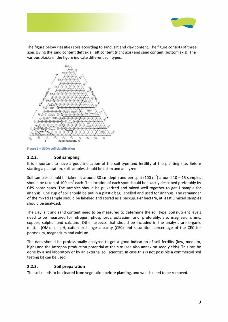
Jatropha prefers well-drained soils with an open well-aerated structure. The soil types mentioned in
the text below refer to figure 2 with the USDA soil classification based on grain size.
Most suitable soils are loam, sandy clay loam and silt loam.
Heavy soils (clay, sandy clay, clay loam, silty clay loam, and silt) are only suitable under relatively dry
conditions when frequent periods of heavy rainfall are absent. In that case jatropha can be quite
productive because these soils usually have a good nutrient supply. Jatropha cannot tolerate
permanent wetness (it becomes waterlogged). Heavy soils, therefore, are only suitable when they
are not saturated with moisture for long periods (maximum one week, which will already have a
negative impact on production). These conditions occur when there are no periods of high rainfall
that lead to water logging and when the groundwater table is out of reach. Heavy soils are not
suitable under conditions where very dry and wet periods quickly follow each other because they
shrink and swell and root formation is impaired.
Sandy soils (sand, loamy sand, and sandy loam) are soils that are prone to drying out quickly (unless
they are very high in organic matter). On these soils jatropha has a comparative advantage over
other crops, because it is drought tolerant. These soils usually are not high in nutrients, so jatropha
will need fertilization or high organic matter application to the soil in order to be productive.
Regardless of the soil, a good pH for jatropha lies between 5.5 and 8.5. Under more acidic or alkaline
conditions jatropha growth is limited. Soil depth should be at least 45 centimeters and soil slope
should not exceed 30°. Jatropha can survive low soil nutrient contents, but in that case growth and
production are limited. Higher nutrient levels in the soil translate into increased production. Soil
organic matter is also favorable to jatropha growth, especially in coarse soils.
3
The figure below classifies soils according to sand, silt and clay content. The figure consists of three
axes giving the sand content (left axis), silt content (right axis) and sand content (bottom axis). The
various blocks in the figure indicate different soil types.
Figure 1 – USDA soil classification
2.2.2. Soil sampling
It is important to have a good indication of the soil type and fertility at the planting site. Before
starting a plantation, soil samples should be taken and analyzed.
Soil samples should be taken at around 30 cm depth and per spot (100 m2) around 10 – 15 samples
should be taken of 100 cm3 each. The location of each spot should be exactly described preferably by
GPS coordinates. The samples should be pulverized and mixed well together to get 1 sample for
analysis. One cup of soil should be put in a plastic bag, labelled and used for analysis. The remainder
of the mixed sample should be labelled and stored as a backup. Per hectare, at least 5 mixed samples
should be analyzed.
The clay, silt and sand content need to be measured to determine the soil type. Soil nutrient levels
need to be measured for nitrogen, phosphorus, potassium and, preferably, also magnesium, zinc,
copper, sulphur and calcium. Other aspects that should be included in the analysis are organic
matter (OM), soil pH, cation exchange capacity (CEC) and saturation percentage of the CEC for
potassium, magnesium and calcium.
The data should be professionally analyzed to get a good indication of soil fertility (low, medium,
high) and the Jatropha production potential at the site (see also annex on seed yields). This can be
done by a soil laboratory or by an external soil scientist. In case this is not possible a commercial soil
testing kit can be used.
2.2.3. Soil preparation
The soil needs to be cleared from vegetation before planting, and weeds need to be removed.
4
2.2.3.1 Planting holes
When planting jatropha only, planting holes should be prepared. These holes can be dug with an axe
or by drilling. On hard or compacted soils, ploughing or deep ripping of the soils is advisable,
especially when considering intercropping, in which case the entire soil need to be prepared.
In case of hard-compacted soils, it is also possible to prepare lines for planting or seeding with a deep
ripper which is a chisel plough with just one hook. A deep ripper should rip from 30-50 cm. deep. This
will allow the root system of the jatropha seedlings to develop well. A ripper cannot be manually
operated but must be used with animal traction or fixed to a tractor.
Holes for planting should ideally have the following minimum dimensions: diameter of 30
centimetres and minimal depth of 45 centimetres.
The holes should be refilled with a mixture of soil and organic matter (compost) in a ratio 1:1.
Artificial fertilizer or manure should be added. The amount of fertilizer added should be about 10- 20
grams of common N:P:K (nitrogen, phosphorus and potassium) fertilizer (from 6:6:6 to 15:15:15 or
variations between these limits). The fertilizer should be mixed evenly. In case animal manure is
used, about 0.5 kg would be sufficient per plant hole. The amount of organic matter can vary
between 20% and 50%. The formula of the mixture then changes into soil: compost: manure in a
ratio 2:1:1. In case of heavier (more clay) soils jatropha cultivation is not advised. However, in that
case sand should be added to the mixture in a ratio of soil: sand: organic matter of 1:1:2.
The mixture should be free from stones and larger objects. Making the holes needs to be done just
before the rainy season. Planting should start when the soils have received the first rains.
More fertilizer can damage the roots of the young seedlings and can best be added after one or two
months. About 50 to 100 grams of the same NPK (see before) needs to be evenly distributed and
mixed with the topsoil in a diameter of about 50 centimetres around the plant.
2.2.3.2. Plant spacing Spacing in plantations can vary. A commonly applied plant spacing is in a rectangular pattern of 3 x
2,5 meters with 1333 plants/ha. When plants grow they need to have enough space for growth and
branching. In this pattern there is enough space for intercropping in the first year and even the
second year when jatropha develops slowly. Wider spacing leads to larger trees that grow taller and
higher, which hinders harvesting and pruning. In a more narrow spacing - 2.5 m x 2.5 m or 2 m x 2 m -
more intensive pruning is necessary to keep the plants from growing into each other. This requires a
lot of extra labour. A more narrow spacing leads to a more intensive agriculture and requires soils
with good nutrient and water supply.
In case of permanent intercropping, the plants should be planted in rows with a larger distance in
between for other crops. The distance between the rows depends on the space needed for
intercropping, usually about 4 meters. The distance between Jatropha plants within a row is 2.5 or 3
meters.
In case mechanized agriculture is considered, e.g. a tractor, there should be at least 4 m spacing in
between the rows, assuming 2 meters for the tractor and 1 meter of branches on each side. The
spacing between plants within a row can be reduced to 1.5 m in this case resulting in an overall
spacing of 4 m x 1.5 m [31].

5
In living fences, plants should be spaced about 25 centimetres apart from each other in a single or in
double rows. For quick establishment it is advisable to start from cuttings in the rainy season.
Monoculture jatropha itself is largely fire-resistant, but the burning of weeds and grasses will kill the
plant. [31]. In fire hazard areas it is advised to split plantations into separate compartments by
making fire lanes of at least 2 metres wide. This will prevent fire from damaging the entire
plantation. These fire lanes should be kept free from weeds, crops and overgrown vegetation.
2.2.3.3. Planting season The best time for planting is at the onset of the rainy season when the soil has taken up the first soil
moisture. When water is available at low costs, it is possible to start planting several weeks up to a
month before the rainy season.
After planting, extra watering of the plants is necessary only when the rains are not sufficient, and it
can cease after 3 months of growth when the plants have developed their root system.
2.3. Jatropha plant development
To apply an optimal management of a jatropha plantation, it is important to understand the
development stages of the jatropha plant.
2.3.1. Jatropha development stages
Starting from seed, jatropha goes through various stages of development.
The first is the juvenile stage. It starts with the seed that soaks up water when planted (imbibition)
and is followed by germination. The small seedling then comes above the ground (emergence) and
starts to develop shoots and roots (establishment). This juvenile stage takes about two and a half
months under optimal conditions.
The second stage is the flower induction sensitive phase. At this stage the right environmental
conditions (high radiation/ high average temperatures/ high minimum temperatures(>18°C) and
sufficient rainfall can trigger flower induction. Flowering is the third stage. After pollination the fruit
start filling and ripening, which is the fourth stage. The time from flower induction to harvest takes
approximately 3 months. After harvest the plant may enter a stage of dormancy where it is
insensitive to flowering or it may enter another flower induction sensitive phase. This depends on
stress conditions, but the exact mechanism is not yet known.
Figure 5 - Jatropha development stages [28]
6
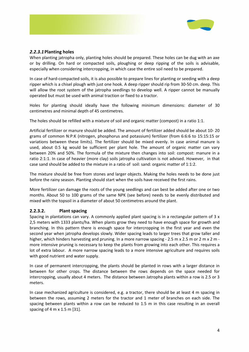
2.1.1. Root development
After germination from seeds jatropha seedlings develop one
taproot and four lateral roots. The root system thus grows both into
the upper and deeper soil layers, provided the soil is deep enough.
Figure 7 shows a jatropha root system where the left plant has
developed a thick taproot growing down vertically.
In case cuttings are used, only lateral roots develop and no taproot.
2.3.3. Flowering and fruiting
Jatropha flowering is a complex matter. It is known that flowering is
induced by stress factors, like temperature fluctuations and
drought, but how exactly and at what thresholds this occurs is still
unknown. For flower induction Jatropha plants need to be exposed
to high solar radiation. Plants that grow shaded under trees or in
clouded conditions do not flower or flower markedly less than
plants in the full sun. In a climate with distinct seasons Jatropha
starts flowering after these periods of stress have ended, which can
be several times per year. In climates with an evenly distributed rainfall and no large seasonal
variation in temperatures Jatropha may flower continuously when there are no other forms of
induced stress.
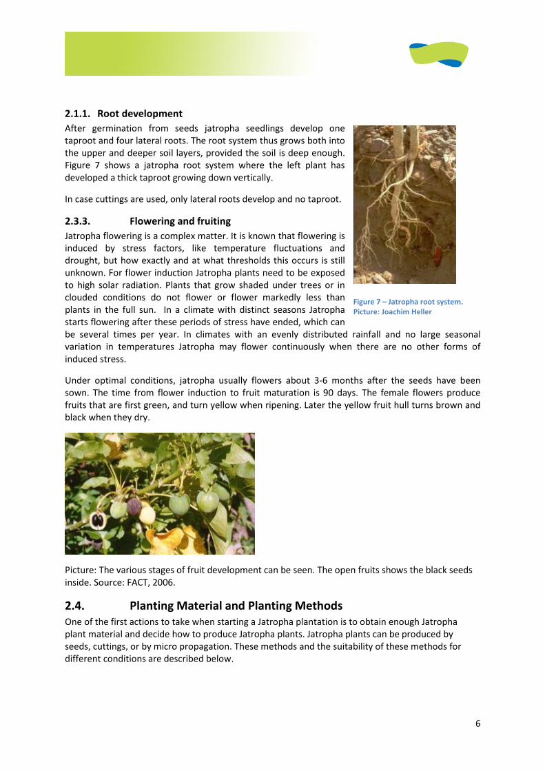
Under optimal conditions, jatropha usually flowers about 3-6 months after the seeds have been
sown. The time from flower induction to fruit maturation is 90 days. The female flowers produce
fruits that are first green, and turn yellow when ripening. Later the yellow fruit hull turns brown and
black when they dry.
Picture: The various stages of fruit development can be seen. The open fruits shows the black seeds
inside. Source: FACT, 2006.
2.4. Planting Material and Planting Methods
One of the first actions to take when starting a Jatropha plantation is to obtain enough Jatropha
plant material and decide how to produce Jatropha plants. Jatropha plants can be produced by
seeds, cuttings, or by micro propagation. These methods and the suitability of these methods for
different conditions are described below.
Figure 7 – Jatropha root system.
Picture: Joachim Heller
7
2.4.1. Genetic and phenotypical variation
Provenance trials and research into the genetics of Jatropha curcas L. has shown that there is some
genetic variation between plants from different provenances (or accessions) that are growing
worldwide. Natural genetic variation between provenances is largest in the centre of origin (Central
America and the Northern parts of South America).
Plants grown from the same seed source can differ considerably in morphological aspects like plant
height and seed production. It is not yet known to what extent this morphological variation can be
attributed to genetic or environmental factors. When seeds from a certain location are collected,
variation can be minimized by selecting seeds (see next part on seed selection).
2.4.2. Seed selection
First of all, it is important to obtain high quality seed material. When ordering seeds one should make
sure they match the following criteria:
• Seeds come from high-yielding provenances that grow under similar agro-ecological
conditions as where the plantation is planned.
• Seeds are a selection of the heaviest and largest seeds from these selected provenances.
• Seeds have a moisture content of around 7%.
• Seeds are young (preferably not older than 6 months).
• Seeds have been stored under cool, dark and dry conditions.
For information on clonal and seed gardens please read the Appendix: Clonal and Seed gardens
Manual.
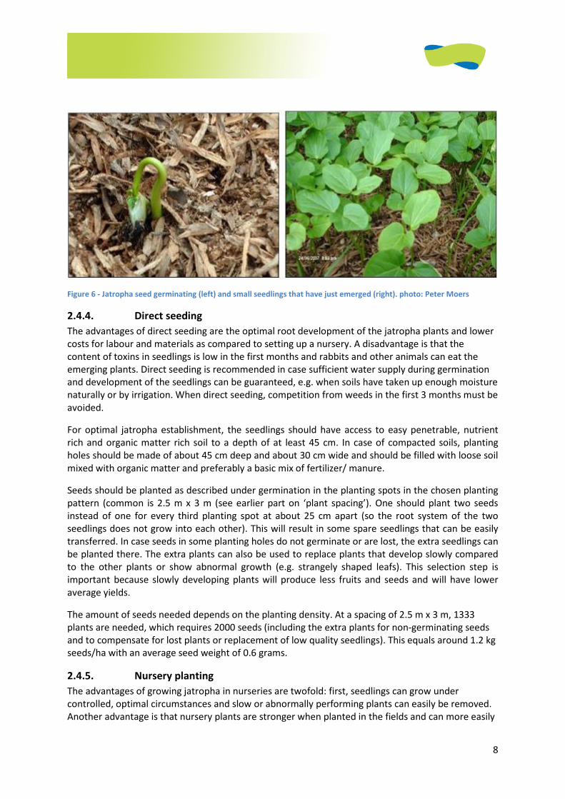
2.4.3. Germination
Jatropha seeds germinate easily when planted in soil at about 2 cm depth and with the white tip of
the seed facing slightly downwards and the rounded side of the seed facing upwards.
Jatropha germinates in any soil with a continuously high humidity and sufficient air supply (in
waterlogged soils jatropha seeds will rot). Pre-treatment of seeds did not show better results in
germination compared to dry seeds directly planted in Mozambique [20]. Seeds with the above-
mentioned characteristics will germinate within 7-8 days under hot (average temperature > 25°C)
and humid conditions. Under cooler conditions germination takes longer. Seeds that germinate
within 10 days are more vigorous and should be used.
Jatropha can be directly seeded in the fields or can be germinated in a nursery, depending on the
factors that will be discussed hereunder.
8
Figure 6 - Jatropha seed germinating (left) and small seedlings that have just emerged (right). photo: Peter Moers
2.4.4. Direct seeding
The advantages of direct seeding are the optimal root development of the jatropha plants and lower
costs for labour and materials as compared to setting up a nursery. A disadvantage is that the
content of toxins in seedlings is low in the first months and rabbits and other animals can eat the
emerging plants. Direct seeding is recommended in case sufficient water supply during germination
and development of the seedlings can be guaranteed, e.g. when soils have taken up enough moisture
naturally or by irrigation. When direct seeding, competition from weeds in the first 3 months must be
avoided.
For optimal jatropha establishment, the seedlings should have access to easy penetrable, nutrient
rich and organic matter rich soil to a depth of at least 45 cm. In case of compacted soils, planting
holes should be made of about 45 cm deep and about 30 cm wide and should be filled with loose soil
mixed with organic matter and preferably a basic mix of fertilizer/ manure.
Seeds should be planted as described under germination in the planting spots in the chosen planting
pattern (common is 2.5 m x 3 m (see earlier part on ‘plant spacing’). One should plant two seeds
instead of one for every third planting spot at about 25 cm apart (so the root system of the two
seedlings does not grow into each other). This will result in some spare seedlings that can be easily
transferred. In case seeds in some planting holes do not germinate or are lost, the extra seedlings can
be planted there. The extra plants can also be used to replace plants that develop slowly compared
to the other plants or show abnormal growth (e.g. strangely shaped leafs). This selection step is
important because slowly developing plants will produce less fruits and seeds and will have lower
average yields.
The amount of seeds needed depends on the planting density. At a spacing of 2.5 m x 3 m, 1333
plants are needed, which requires 2000 seeds (including the extra plants for non-germinating seeds
and to compensate for lost plants or replacement of low quality seedlings). This equals around 1.2 kg
seeds/ha with an average seed weight of 0.6 grams.
2.4.5. Nursery planting
The advantages of growing jatropha in nurseries are twofold: first, seedlings can grow under
controlled, optimal circumstances and slow or abnormally performing plants can easily be removed.
Another advantage is that nursery plants are stronger when planted in the fields and can more easily
9
survive when the conditions for establishment are sub-optimal (drought, weeds, presence of
browsing cattle and insects). There are, however, drawbacks of nursery plants. The root
development of seedlings is hampered because of growing in the smaller containers. This is
especially disadvantageous when the seedlings are not planted timely in the fields (< 1 month).
There are also extra labor and capital requirements, and there is the possibility of spreading pests
and diseases to all seedlings and the field during planting.
A nursery is a good option in case you have very low quality seed material because the best
performing plants/ seeds can be easily selected.
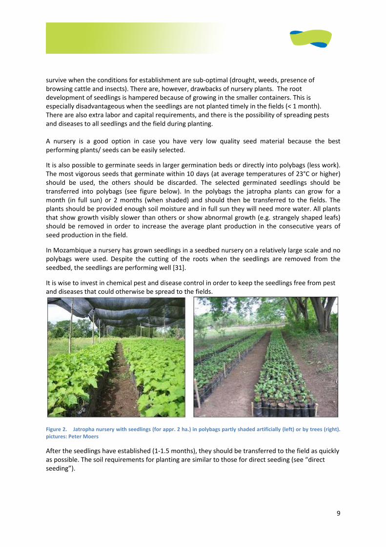
It is also possible to germinate seeds in larger germination beds or directly into polybags (less work).
The most vigorous seeds that germinate within 10 days (at average temperatures of 23°C or higher)
should be used, the others should be discarded. The selected germinated seedlings should be
transferred into polybags (see figure below). In the polybags the jatropha plants can grow for a
month (in full sun) or 2 months (when shaded) and should then be transferred to the fields. The
plants should be provided enough soil moisture and in full sun they will need more water. All plants
that show growth visibly slower than others or show abnormal growth (e.g. strangely shaped leafs)
should be removed in order to increase the average plant production in the consecutive years of
seed production in the field.
In Mozambique a nursery has grown seedlings in a seedbed nursery on a relatively large scale and no
polybags were used. Despite the cutting of the roots when the seedlings are removed from the
seedbed, the seedlings are performing well [31].
It is wise to invest in chemical pest and disease control in order to keep the seedlings free from pest
and diseases that could otherwise be spread to the fields.
Figure 2. Jatropha nursery with seedlings (for appr. 2 ha.) in polybags partly shaded artificially (left) or by trees (right).
pictures: Peter Moers
After the seedlings have established (1-1.5 months), they should be transferred to the field as quickly
as possible. The soil requirements for planting are similar to those for direct seeding (see “direct
seeding”).
10
2.4.6. Cuttings
Cuttings are a fast and cheap way of propagating Jatropha. One advantage is that cuttings are clones
with the same genetic characteristics as the mother plant, and in case a high yielding mother plant is
selected the cuttings have the same properties [31]. The disadvantage is that cuttings develop only
lateral roots and cannot access nutrients and water in deeper soil layers. Cuttings therefore have
limited drought tolerance. We recommend this only for living fences. Using cuttings for a Jatropha
plantation only works on fertile and soils with a good permanent water supply and absence of long
dry periods.
Cuttings are best made from the thickest branches at the base of the jatropha plant. Best is to make
cuttings of at least 30 cm (but 50 cm gives a higher success rate). Cuttings should be placed directly in
wet soil leaving 15 cm or more of branch above the soil. Cuttings can also be produced in a nursery in
polypropylene bags. Soil should be kept wet (therefore the rainy season is the best time for cuttings).
Normally the first shoots appear after 3 to 4 weeks.
2.4.7. Micro-propagated clones
A technologically advanced method of obtaining larger amounts of jatropha plants is by micro-
propagation. The advantage is that you can create large numbers of genetically identical plants of
one mother plant with the desired characteristics. Similar to cuttings, the root system development
is not natural and it requires hormonal stimulation to induce roots to grow vertically instead of
laterally. This method requires sophisticated technologies and chemicals and is costly and as such is
not recommended for smaller scale plantations. However when good quality micro-propagated
plants become available on the market at affordable prices this will be interesting for smaller
plantations as well.
2.5. Plantation management (agronomy)
2.5.1. Weeding
Jatropha usually survives when overgrown by weeds, but growth and production will be minimal
[31]. It is very important to keep the jatropha fields free from weeds. At regular intervals weeds
should be removed and left on the ground to provide organic material to the topsoil. The frequency
of weeding depends on the growth of the weeds. When weeds start to shade the jatropha or grow as
tall as the jatropha plants they should be removed, as well as when they limit access to the space in
between rows. After one to three seasons depending on the agro-climatic conditions the canopies of
Jatropha will be so dense that weed growth is severely suppressed and labour for weeding
consequently drops [31].
In most cases the amount of labour determines the area that can be kept weed-free. In the case of
large-scale plantations with partly mechanized cultivation, around 2 ha/person could be sufficiently
freed from weeds. In case of small-scale cultivation this is closer to 1 ha/person.
2.5.2. Nutrient management
2.5.2.1. Nutrient requirements
Jatropha needs sufficient amounts of nutrients in order to grow into a full size plant and to produce
seeds.
In the first 4 years nutrients are needed to build up a good plant architecture (roots, stems, leaves).
Also in this period an increasing amount of nutrients is needed to produce flowers and fruits. After 4
11
years, when the plants have developed to their final shape and size nutrients are primarily needed
for maintenance of the plant and for fruit production.
The nutrients removed by harvesting jatropha fruit should be returned to the fields after the energy
(mostly lipids consisting of the elements C, H and O and no nutrients) is extracted. Jatropha fruit
shells and presscake (or residue from biogas production) are best returned to the fields as organic
fertilizer, which closes the nutrient cycle. In that case, jatropha plants can continuously produce and
no or little fertilization is necessary.
When fruitshells and presscake (or biogas residue) are not returned to the fields regular fertilization
with NPK (nitrogen/ phosphorus and potassium) and micronutrients will be necessary.
In case of highly fertile soils, jatropha fertilization is not necessary. There are enough nutrients for
plant development and fruit production. In case of poor soils fertilization …..
2.5.2.1.1. Nutrients requirements during jatropha establishment
In the first years, nutrients are needed for maturation and development of high-yielding jatropha
plants. Under conditions of poor soil fertility extra nutrients are required for plantation
establishment and seed production in the first 4 years.
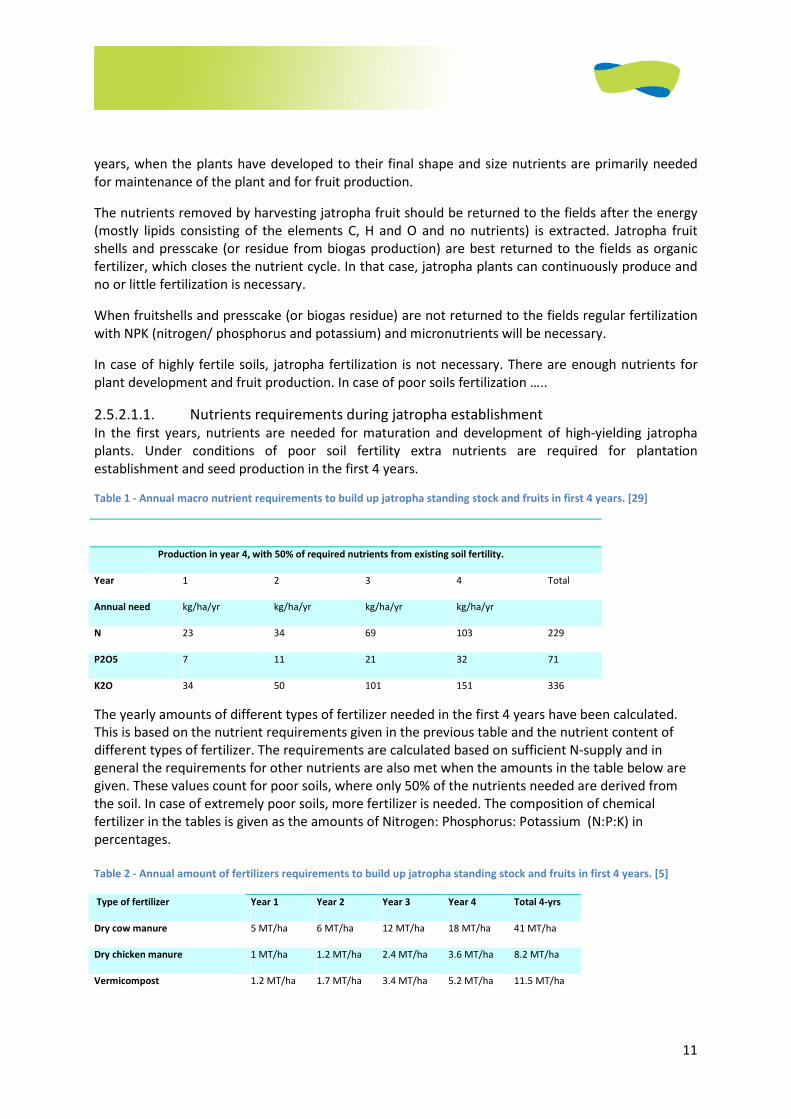
Table 1 - Annual macro nutrient requirements to build up jatropha standing stock and fruits in first 4 years. [29]
Production in year 4, with 50% of required nutrients from existing soil fertility.
Year 1 2 3 4 Total
Annual need kg/ha/yr kg/ha/yr kg/ha/yr kg/ha/yr
N 23 34 69 103 229
P2O5 7 11 21 32 71
K2O 34 50 101 151 336
The yearly amounts of different types of fertilizer needed in the first 4 years have been calculated.
This is based on the nutrient requirements given in the previous table and the nutrient content of
different types of fertilizer. The requirements are calculated based on sufficient N-supply and in
general the requirements for other nutrients are also met when the amounts in the table below are
given. These values count for poor soils, where only 50% of the nutrients needed are derived from
the soil. In case of extremely poor soils, more fertilizer is needed. The composition of chemical
fertilizer in the tables is given as the amounts of Nitrogen: Phosphorus: Potassium (N:P:K) in
percentages.
Table 2 - Annual amount of fertilizers requirements to build up jatropha standing stock and fruits in first 4 years. [5]
Type of fertilizer Year 1 Year 2 Year 3 Year 4 Total 4-yrs
Dry cow manure 5 MT/ha 6 MT/ha 12 MT/ha 18 MT/ha 41 MT/ha
Dry chicken manure 1 MT/ha 1.2 MT/ha 2.4 MT/ha 3.6 MT/ha 8.2 MT/ha
Vermicompost 1.2 MT/ha 1.7 MT/ha 3.4 MT/ha 5.2 MT/ha 11.5 MT/ha
12
Chemical fertilizer (16-4-16) 140 kg/ha 210 kg/ha 430 kg/ha 640 kg/ha 1.4 MT/ha
Urea (46% Nitrogen) 44 kg/ha 74 kg/ha 150 kg/ha 224 kg/ha 492 kg/ha
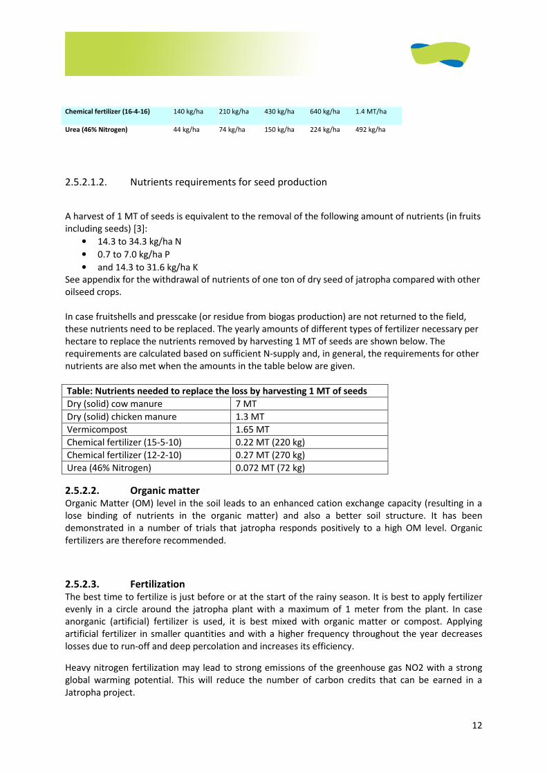
2.5.2.1.2. Nutrients requirements for seed production
A harvest of 1 MT of seeds is equivalent to the removal of the following amount of nutrients (in fruits
including seeds) [3]:
• 14.3 to 34.3 kg/ha N
• 0.7 to 7.0 kg/ha P
• and 14.3 to 31.6 kg/ha K
See appendix for the withdrawal of nutrients of one ton of dry seed of jatropha compared with other
oilseed crops.
In case fruitshells and presscake (or residue from biogas production) are not returned to the field,
these nutrients need to be replaced. The yearly amounts of different types of fertilizer necessary per
hectare to replace the nutrients removed by harvesting 1 MT of seeds are shown below. The
requirements are calculated based on sufficient N-supply and, in general, the requirements for other
nutrients are also met when the amounts in the table below are given.
Table: Nutrients needed to replace the loss by harvesting 1 MT of seeds
Dry (solid) cow manure 7 MT
Dry (solid) chicken manure 1.3 MT
Vermicompost 1.65 MT
Chemical fertilizer (15-5-10) 0.22 MT (220 kg)
Chemical fertilizer (12-2-10) 0.27 MT (270 kg)
Urea (46% Nitrogen) 0.072 MT (72 kg)
2.5.2.2. Organic matter
Organic Matter (OM) level in the soil leads to an enhanced cation exchange capacity (resulting in a
lose binding of nutrients in the organic matter) and also a better soil structure. It has been
demonstrated in a number of trials that jatropha responds positively to a high OM level. Organic
fertilizers are therefore recommended.
2.5.2.3. Fertilization The best time to fertilize is just before or at the start of the rainy season. It is best to apply fertilizer
evenly in a circle around the jatropha plant with a maximum of 1 meter from the plant. In case
anorganic (artificial) fertilizer is used, it is best mixed with organic matter or compost. Applying
artificial fertilizer in smaller quantities and with a higher frequency throughout the year decreases
losses due to run-off and deep percolation and increases its efficiency.
Heavy nitrogen fertilization may lead to strong emissions of the greenhouse gas NO2 with a strong
global warming potential. This will reduce the number of carbon credits that can be earned in a
Jatropha project.
13
2.5.2.4. Mycorrhiza A simple and cheap way of increasing jatropha yields is by the use of mycorrhiza, which are fungi that
live in symbiosis with plant roots. Mycorrhiza taps organic substances from the plant, especially
sugars and B-vitamins. In return mycorrhiza make nutrients in the soil available for the plant and help
in water uptake. Mycorrhiza, combined with moderate fertilization, guarantees a high nutrient
uptake by the plant and minimizes nutrients losses by percolation. The use of mycorrhiza is cheap
(about 5-10 euros/ha). Mycorrhiza are especially effective in poor and dry soils where they can
increase yields by about 30%.
Mycorrhiza are best applied dissolved in water and applied in the plant hole before or during
planting. Mycorrhiza can also be applied to existing jatropha plants by digging a circular pit of around
10-20 cm deep at around 40 cm around the stem and applying the water with mycorrhiza.
Afterwards the pit should be covered with soil. It is also possible to coat seeds with mycorrhiza
before seeding. In addition, they are easy to apply in a nursery when mixed with the water.
2.5.3. Pruning
Jatropha flowers form only at the end of branches, pruning leads to more branches and as such to
more potential for fruit production. Another important reason to prune is to keep the plants in a
manageable size. Under natural conditions jatropha can grow into a tree of about 6 meters tall with a
crown width of 6 meters, which makes it very hard to harvest. In a plantation with a high density
(around 1100 plants/ha), it is important to sufficient keep distance between the plants to avoid
competition for light and space. Plants should be kept low to facilitate manual picking.
With good pruning the jatropha plants should have strong lateral branches that can bear the weight
of the fruits. In the fourth or fifth year after planting and after several rounds of pruning the plants
should ultimately have some 200-250 terminal branches.
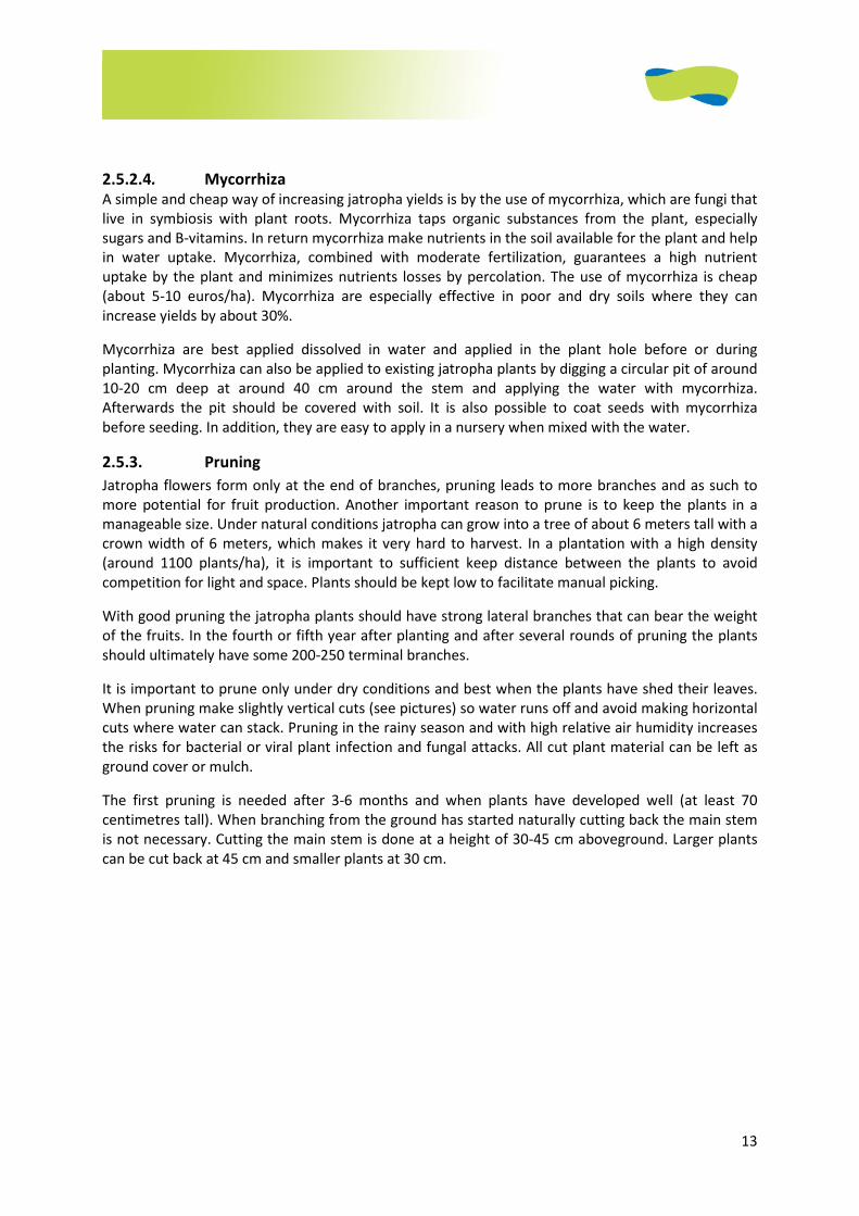
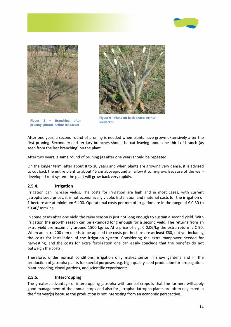
It is important to prune only under dry conditions and best when the plants have shed their leaves.
When pruning make slightly vertical cuts (see pictures) so water runs off and avoid making horizontal
cuts where water can stack. Pruning in the rainy season and with high relative air humidity increases
the risks for bacterial or viral plant infection and fungal attacks. All cut plant material can be left as
ground cover or mulch.
The first pruning is needed after 3-6 months and when plants have developed well (at least 70
centimetres tall). When branching from the ground has started naturally cutting back the main stem
is not necessary. Cutting the main stem is done at a height of 30-45 cm aboveground. Larger plants
can be cut back at 45 cm and smaller plants at 30 cm.
14
After one year, a second round of pruning is needed when plants have grown extensively after the
first pruning. Secondary and tertiary branches should be cut leaving about one third of branch (as
seen from the last branching) on the plant.
After two years, a same round of pruning (as after one year) should be repeated.
On the longer term, after about 8 to 10 years and when plants are growing very dense, it is advised
to cut back the entire plant to about 45 cm aboveground an allow it to re-grow. Because of the well-
developed root system the plant will grow back very rapidly.
2.5.4. Irrigation
Irrigation can increase yields. The costs for irrigation are high and in most cases, with current
jatropha seed prices, it is not economically viable. Installation and material costs for the irrigation of
1 hectare are at minimum € 400. Operational costs per mm of irrigation are in the range of € 0.30 to
€0.40/ mm/ ha.
In some cases after one yield the rainy season is just not long enough to sustain a second yield. With
irrigation the growth season can be extended long enough for a second yield. The returns from an
extra yield are maximally around 1500 kg/ha. At a price of e.g. € 0.06/kg the extra return is € 90.
When an extra 200 mm needs to be applied the costs per hectare are at least €60, not yet including
the costs for installation of the irrigation system. Considering the extra manpower needed for
harvesting, and the costs for extra fertilization one can easily conclude that the benefits do not
outweigh the costs.
Therefore, under normal conditions, irrigation only makes sense in show gardens and in the
production of jatropha plants for special purposes, e.g. high-quality seed production for propagation,
plant breeding, clonal gardens, and scientific experiments.
2.5.5. Intercropping
The greatest advantage of intercropping jatropha with annual crops is that the farmers will apply
good management of the annual crops and also for jatropha. Jatropha plants are often neglected in
the first year(s) because the production is not interesting from an economic perspective.
Figuur 8 – Branching after
pruning. photo: Arthur Riedacker
Figuur 9 – Plant cut back photo: Arthur
Riedacker
15
Growing jatropha in combination with other plants is only possible when sufficient nutrients and
water are available. In dry locations without irrigation, intercropping is not possible due to
competition for water. In soils poor in nutrients, intercropping is only possible with extra fertilization.
It is also possible to grow fodder crops in between the Jatropha plants and allow grazing. In this case
the jatropha plants should be well established and tall to avoid damage caused by animals. Jatropha
should not be intercropped with cassava, since it is a possible host for several cassava diseases.
It is advisable to start intercropping at the same time as planting the jatropha. Jatropha initially might
grow slower than the intercropped species. In that case, and when intercropped species are planted
close to the jatropha plants, it is recommended to plant the intercrops a month later so jatropha is
given a head start. Intercropping with species that provide yield in the first and second year ensures
good management, especially clearing the crops from weeds.
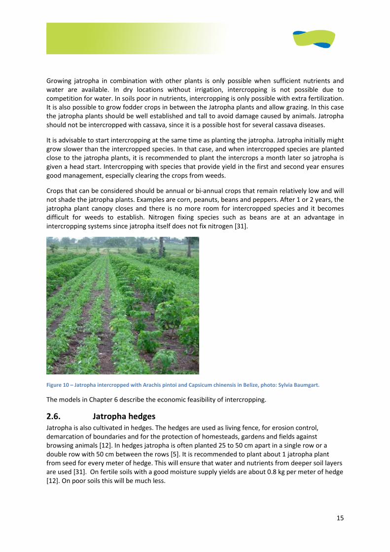
Crops that can be considered should be annual or bi-annual crops that remain relatively low and will
not shade the jatropha plants. Examples are corn, peanuts, beans and peppers. After 1 or 2 years, the
jatropha plant canopy closes and there is no more room for intercropped species and it becomes
difficult for weeds to establish. Nitrogen fixing species such as beans are at an advantage in
intercropping systems since jatropha itself does not fix nitrogen [31].
Figure 10 – Jatropha intercropped with Arachis pintoi and Capsicum chinensis in Belize, photo: Sylvia Baumgart.
The models in Chapter 6 describe the economic feasibility of intercropping.
2.6. Jatropha hedges
Jatropha is also cultivated in hedges. The hedges are used as living fence, for erosion control,
demarcation of boundaries and for the protection of homesteads, gardens and fields against
browsing animals [12]. In hedges jatropha is often planted 25 to 50 cm apart in a single row or a
double row with 50 cm between the rows [5]. It is recommended to plant about 1 jatropha plant
from seed for every meter of hedge. This will ensure that water and nutrients from deeper soil layers
are used [31]. On fertile soils with a good moisture supply yields are about 0.8 kg per meter of hedge
[12]. On poor soils this will be much less.
16
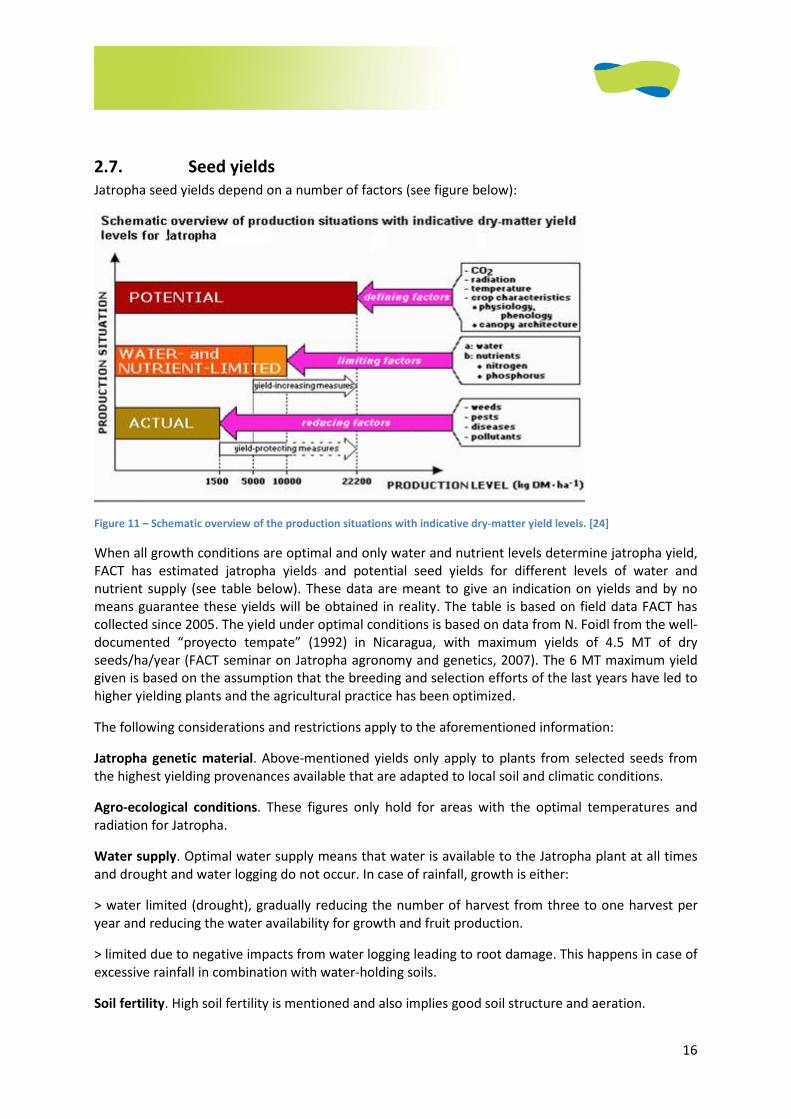
2.7. Seed yields
Jatropha seed yields depend on a number of factors (see figure below):
Figure 11 – Schematic overview of the production situations with indicative dry-matter yield levels. [24]
When all growth conditions are optimal and only water and nutrient levels determine jatropha yield,
FACT has estimated jatropha yields and potential seed yields for different levels of water and
nutrient supply (see table below). These data are meant to give an indication on yields and by no
means guarantee these yields will be obtained in reality. The table is based on field data FACT has
collected since 2005. The yield under optimal conditions is based on data from N. Foidl from the well-
documented “proyecto tempate” (1992) in Nicaragua, with maximum yields of 4.5 MT of dry
seeds/ha/year (FACT seminar on Jatropha agronomy and genetics, 2007). The 6 MT maximum yield
given is based on the assumption that the breeding and selection efforts of the last years have led to
higher yielding plants and the agricultural practice has been optimized.
The following considerations and restrictions apply to the aforementioned information:
Jatropha genetic material. Above-mentioned yields only apply to plants from selected seeds from
the highest yielding provenances available that are adapted to local soil and climatic conditions.
Agro-ecological conditions. These figures only hold for areas with the optimal temperatures and
radiation for Jatropha.
Water supply. Optimal water supply means that water is available to the Jatropha plant at all times
and drought and water logging do not occur. In case of rainfall, growth is either:
> water limited (drought), gradually reducing the number of harvest from three to one harvest per
year and reducing the water availability for growth and fruit production.
> limited due to negative impacts from water logging leading to root damage. This happens in case of
excessive rainfall in combination with water-holding soils.
Soil fertility. High soil fertility is mentioned and also implies good soil structure and aeration.

17
Table. Expected Jatropha seed yields for different water supply and soil fertility [5].
Water supply Soil Fertility Dry Seeds (kg/ha/yr)
Optimal high 6000
,, medium 2500
,, low 750
Normal high 3500
,, medium 1500
,, low 500
Sub-optimal high 1500
,, medium 750
,, low 250

18
2.8. Pest and diseases
Author: Flemming Nielsen
When Jatropha curcas grows as solitary plant in the landscape or in small stands it rarely shows signs
of pests and diseases. However, when cultivated in higher densities in plantations or hedges this
situation changes. Reports of pests and diseases come from all parts of the world in increasing
numbers. In most cases these pests and diseases are not detrimental and so far few are of economic
importance.
When a new crop is introduced and cultivated on a large scale it can take years before the pest and
disease pressure is felt. This effect, for example, is demonstrated with several new agro forestry
species. The low incidence rate of pests and diseases currently observed in most areas can therefore
not be assumed to last [3].
Pests and diseases that have been reported to affect jatropha are listed in the appendix.
Most of the pests are of minor importance. The important pests vary with regions:
• Africa: Flea beetle (Aphthona spp.) eats the leaves and their larvae penetrate the roots (Nielsen
2007, Gagnaux 2008). The yellow flea beetle (Aphthona dilutipes) appears to cause more severe
damage than the golden flea beetle, sometimes resulting in 100% mortality. The author has only
observed the yellow flea beetle in Manica Province in Mozambique and knows only of one other
observation namely from Malawi where it also causes severe damage. (Timothy Mahoney, Pers.
comm.).
• Central and South America: fruit feeding true bugs, Pachycoris klugii Burmeister (Scutelleridae)
and Leptoglossus zonatus (Coreidae) (Grimm and Maes 1997).
• Asia: The scutellarid bug Scutellera nobilis Fabr. which causes flower fall, fruit abortion and
malformation of seeds, and the inflorescence and capsule-borer, Pempelia morosalis that causes
damage by webbing and feeding on inflorescences and in later stages boring into the capsule
(Shanker and Dhyani 2006).
Virus damage is of major concern and appears to be spreading fast in India. In Africa virus presence is
still rare.
There is concern that, for instance, African Cassava Mosaic Virus may be transferred by Jatropha
curcas, although cases have only been reported in Jatropha multifida. L. Münch (1986) states that
cassava superelongation disease (Sphaceloma manihoticola/Elsinoe brasiliensis) can be transmitted
to Jatropha curcas.
For these reasons it is advised not to plant cassava and Jatropha curcas in the same field (Heller
1996).
Common bean (Phaseolus vulgaris) is susceptible to Jatropha Mosaic Virus (Hughes et al 2003). It is
transmitted by whitefly (Bemisia tabaci) (Raj et al 2008).
19
2.8.1. Control Measures
Research on biological control measures is ongoing, but currently there is no knowledge about the
efficiency of various methods, so specific recommendations cannot yet be made (Grimm 1999, Raj et
al 2008). However, methods that work with other crops may be efficient in jatropha too. It is also
likely that local methods can be developed in many cases so experimentation is encouraged.
Chemical pesticides are used successfully against major pests in Jatropha curcas, including:
• Pesticides containing Chlorpyrifos or Cyphenothrin are efficient against Aphthona spp. (flea
beetle) (F Nielsen pers. obs.)
• Captafol at 3000 ppm is recommended as a dip for the eradication of super elongation disease
(Lozano et al 1981) in cassava cuttings. It is likely to be efficient for Jatropha too.
• Collar rot can be controlled with 0.2% Copper Oxy Chloride (COC) or 1% Bordeaux drenching
(FACT Seminar 2007)
• Bark eater (Indrabela sp.) and capsule borer can be controlled with a mixture of vitex, neem, aloe,
Calatropis or Rogor @ 2 ml/lit of water. Alternatively, spraying Endosulfan @ 3 ml/lit of water can
be used (Paramathma et al 2004, FACT Seminar 2007). Many countries have banned endosulfan.
2.8.2. Preventive Measures
1. Use resistant jatropha varieties. Presently there is no systematic knowledge about resistant
varieties. However, non-diseased plants should be selected as "mother plants" for seeds and
cuttings.
2. Don't plant Jatropha curcas when the pest pressure is high. High pest pressure is normally found
towards the end of the rainy season when temperatures and the relative humidity is high. A
recent study (Gagnaux 2007) found that Jatropha curcas planted when the pest pressure was high
showed increased infestation rates years after planting.
3. Sanitary measures:
1. Disinfect tools used for cutting and pruning. Alcohol, chlorine and household cleaners like
Lysol are quite efficient but may not be feasible for small farmers. Cleaning with water,
grass or sand is not very efficient for removing latex but is better than nothing. If a fire is
available flaming may be the most efficient low-cost method.
2. If possible avoid using the same cutting & pruning tools for cassava and jatropha.
3. Uproot diseased plants. Inspection should preferably be done at least weekly during the
first few months. If nurseries are used, inspection and "rogueing" should be part of the
routine. Whiteflies, which are responsible for spreading important viruses, do not feed on
wilted leaves, so they will usually not touch uprooted plants. However, there are other
factors, so it is advisable to dry the uprooted plants at a distance from the field or to bury
or burn them.
4. Minimise damage to the Jatropha plants to reduce the risk of microorganisms entering.
Prune with sharp tools only and always cut at an angle. Avoid creating horizontal cuts
where water will drain slowly.
20
4. Large dense stands of any crop increase the incidence of pest and diseases. Try to use:
1. Wider spacing e.g. 3 by 3 or row planting with at least 4 m apart
2. Many small fields separated and isolated from each other in the landscape
3. Boundary planting instead of plots
4. Mixed cropping
5. Jatropha presscake has pesticidal properties and can be useful as a pesticide to protect recently
established jatropha because young jatropha plants have low levels of toxins.
2.9. References
1. Data on vermicompost. http://assamagribusiness.nic.in/NEDFi/map30.pdf
2. Data on dry cow manure.
www.umaine.edu/animalsci/Issues/Nutrient/Nutrients%20from%20Manure.ppt
3. Achten, W.M.J., Verschot, L., Franken, Y.J.,Mathijs, E.,Singh, V.P., Aerts, R., Muys, B., 2008.
Jatropha bio-diesel production and use. Biomass and Bioenergy 32: 1063-1084.
4. Daey Ouwens, K., Francis, G., Franken, Y.J., Rijssenbeek, W., Riedacker R., Foidl, N., Jongschaap,
R., Bindraban, P., 2007. Position Paper on Jatropha curcas, State of the Art, Small and Large Scale
Project Development. FACT Foundation, Eindhoven, Netherlands.
5. Y.J. Franken, FACT Foundation
6. Gagnaux P. C. A. (2008) Incidência da entomofauna associada à cultura de Jatrofa (Jatropha
curcal L) em Moçambique, Thesis, Universidades Eduardo Mondlane, Mozambique
7. Grimm C, Maes J-M. Arthropod fauna associated with Jatropha curcas L. in Nicaragua: a synopsis
of species, their biology and pest status. In: Gu¨ bitz GM, Mittelbach M, Trabi M, editors. Biofuels
and industrial products from Jatropha curcas—Proceedings from the symposium ‘‘Jatropha 97,’’
Managua, Nicaragua, February 23–27. Graz, Austria: Dbv-Verlag; 1997. p. 31–9.
8. Gübitz, G.M., Mittelbach, M., Trabi, M., 1999. Exploitation of the tropical oil seed plant Jatropha
curcas L. Bioresource Technology 67: 73-82.
9. Grimm, C. (1999). Evaluation of damage to physic nut (Jatropha curcas) by true bugs.
Entomologia Experimentalis et Applicata. Aug. 92(2): 127-136. {a} Institute of Forest Entomology,
Forest Pathology and Forest Protection, University of Agricultural Sciences, Vienna, Austria
10. Heller, J. 1992. Untersuchungen über genotypische Eigenschaften und Vermehrungsund
Anbauverfahren bei der Purgiernuß (Jatropha curcas L.) [Studies on genotypic characteristics and
propagation and cultivation methods for physic nuts (Jatropha curcas L.)]. Dr. Kovac, Hamburg.
21
11. Heller, J., 1996. Physic nut. Jatropha curcas L. Promoting the conservation and use of
underutilized and neglected crops. Institute of Plant Genetics and Crop Plant Research,
Gatersleben/ International Plant Genetic Resources Institute, Rome.
12. Henning, R.K., Jatropha curcas L. 2007. In: van der Vossen, H.A.M. & Mkamilo, G.S. (Editors).
Plant resources of Tropical Africa 14. Vegetable oils. PROTA Foundation, Wageningen,
Netherlands / Backhuys Publishers, Leiden, Netherlands/ CTA Wageningen, Netherlands. pp. 103-
108.
13. Hughes JDA, Shoyinka SA (2003). Overview of viruses of legumes other than groundnut in Africa in
Plant virology in sub-Saharan African, Proceeding of Plant Virology, IITA, Ibadan, Nigeria. Eds
Hughes JDA, Odu. B. pp 553–568.
14. Janssen, B.H., 1991. Nutrients in soil-plant relations (in Dutch: Nutriënten in bodem-plant
relaties). College reader. Wageningen University.
15. Jongschaap, R.E.E., Corré, W.J., Bindraban, P.S., Brandenburg, W.A., 2007. Claims and Facts on
Jatropha curcas L. Plant Research International B.V., Wageningen / Stichting Het Groene Woudt,
Laren.
16. Kar, A.K. and Ashok Das. 1988. New records of fungi from India. Indian Phytopathol. 41(3):505.
17. Lozano, J.D., Bellotti, A., Reyes, J.A. Howeler, R., Leihner, D. and Doll, J. (1981) Field Problems in
Cassava. CIAT, Cali Colombia.
18. Meshram, P.B. and K.C. Joshi. 1994. A new report of Spodoptera litura (Fab.) Boursin
(Lepidoptera: Noctuidae) as a pest of Jatropha curcas Linn. Indian Forester 120(3):273-274.
19. Münch, E. 1986. Die Purgiernuß (Jatropha curcas L.) - Botanik, Ökologie, Anbau. Diploma thesis.
University Hohenheim, Stuttgart.
20. Nielsen F (2007) FNResearch Progress Report No. 1, 2007, Project: “Jatropha oil for local
development in Mozambique” Subtitle: “Biofuel for development and Communal Energy Self-
Supply” Reporting period: January 2007 – July 2007
21. Paramathma,M., Parthiban,K.T. and Neelakantan,K.S. 2004. Jatropha curcas . Forest College &
Research Institute, Tamil Nadu Agricultural University,Coimbatore. 48p.
22. Phillips, S. 1975. A new record of Pestalotiopsis versicolor on the leaves of Jatropha curcas. Indian
Phytopathol 28 (4):546.
23. Raj S. K., Snehi S. K., Kumar S., Hand M. S. and Pathre U. (2008) First molecular identification of a
begomovirus in India that is closely related to Cassava mosaic virus and causes mosaic and
stunting of Jatropha curcas L. Australasian Plant Disease Note pp. 69-72
24. Source: Rudy Rabbinge, presented during FACT seminar May 2008.

22
25. Shanker C., Dhyani S.K. (2006) Insect pests of Jatropha curcas L. and the potential for their
management. Current Science (Bangalore) 91, 162-3. Contact: Shanker, Chitra ; Natl Res Ctr
Agroforestry, Gwalior Rd, Jhansi 284003, Uttar Pradesh, India
26. Singh, I.D. 1983. New leaf spot diseases of two medicinal plants. Madras Agric. J. 70(7):490.
27. U.S. Dept. Agr. Handbook No. 165. 1960. Hardiness zones of the United States and Canada, p. ii.
In Index of Plant Diseases in the United States, U.S. Government Printing Office, Washington, D.C.
28. FACT Foundation, Y.J. Franken
29. W. Rijssenbeek, FACT Foundation
30. Agricultural value of soil types: http://www.recreational-land.co.uk/soil-classification.htm
31. Flemming, Nielsen, FACT Advisor / Banana Hill
1
3. HARVESTING............................................................................................................................................ 2
3.1 INTRODUCTION .......................................................................................................................................... 2 3.2 HARVESTING TECHNOLOGIES......................................................................................................................... 2
3.2.1 Manual Picking of Jatropha seeds..................................................................................................... 2 3.2.2 Mechanical harvesting solutions....................................................................................................... 3
3.2.2.1 Technologies under development ............................................................................................................ 4 3.3 SEED EXTRACTION FROM FRUIT ...................................................................................................................... 5
3.3.1 Dehulling ........................................................................................................................................... 5 3.3.1.1 Small size dehuller of “full belly project”: Universal Nut Sheller (UNS).................................................... 5 3.3.1.2 Large size “industrial” dehuller................................................................................................................. 6
3.3.2 Separation of seeds and fruit shells................................................................................................... 7 3.3.2.1 Small scale (by hand) ................................................................................................................................ 7 3.3.2.2 Large scale (mechanically) ........................................................................................................................ 7
3.3.3 Drying fruit ........................................................................................................................................ 8 3.3.3.1 Drying area parameters............................................................................................................................ 8
3.4 DRYING AND STORAGE OF SEEDS .................................................................................................................... 8 3.4.1 Drying of seeds .................................................................................................................................. 8 3.4.2 Storage area of sacks ........................................................................................................................ 9 3.4.3 Storage conditions............................................................................................................................. 9
3.4.3.1 Seed storage for planting ......................................................................................................................... 9 3.4.3.2 Seed storage for oil extraction ............................................................................................................... 10
3.5 REFERENCES ............................................................................................................................................ 10
2
3. Harvesting
Main author: Winfried Rijssenbeek, with contributions of Titus Galema
3.1. Introduction The harvesting of the jatropha seeds is a difficult process due to the ripening characteristics of the
jatropha fruit. Due to these ripening issues, the harvesting of jatropha is mainly done by hand. The
harvesting process becomes a very labour-intensive process, and has a high impact on the
production costs of jatropha oil. Harvesting, therefore, is an important aspect to consider in the
entire production process. There have been many attempts to improve this process by
mechanisation. These mechanical improvements are still under development, however, and have
been applied only in pilot projects.
To provide insight into the major issues of the harvesting process of jatropha, this chapter discusses
the following aspects: the harvesting and drying of fruit, the dehulling and storage of seeds, and the
basic planning issues of a plantation1. The appendix provides practical tips and rules of thumb
regarding the harvesting practice.
3.2. Harvesting technologies
One of the main impediments to producing bio-oil from the jatropha plant, is the relatively high cost
of harvesting. These high costs, compared to other oil-producing crops, have a number of causes:
• The jatropha fruit ripens over a long period, requiring weekly picking for weeks up to many
months a year.
• The uneven ripening of the fruit means only some of the fruit of a bunch can be harvested at
one time: (i.e. yellow, brown and black fruits are ripe and can be picked).
• The jatropha fruit can so far only be hand-picked. This requires a lot of time, as each fruit is
small (e.g. three seeds in a fruit weigh about 2 grams).
• The production of jatropha fruit on a hectare basis is moderate: i.e. the density of fruits in
the field is low, requiring more transport distances in the field.
All in all, there is a relatively low yield per hectare, a long harvesting season, a small fruit size that
requires a lot of hand picking and transport of the pickers, and thus is very labour intensive.
This section first elaborate on the actual picking rates and a labour cost threshold. Next the possible
mechanical harvesting solutions are discussed, followed by the ongoing technology developments.
3.2.1. Manual picking of jatropha seeds
It is good to first know that the definition of picking is not always well defined. For example, is it the
picking proper? Or does it also include bagging to the drying area? And transport to the pressing
plant? It also is not always clear if it concerns dry seed or fresh seed. Data of general picking rates
1 The term plantation is used for field with jatropha, not in the connotation of Estate plantation. We refer to
the previous chapters on how jatropha can be grown as single crop as hedge or intercropped.
3
are found in a number of studies. The individual data show a large variation, but an average of all
these figures however, provides useful indications, as shown below:
• Nicaragua 50 kg/day to 80 kg. The best pickers in Nicaragua harvest up to 30 kg of fruit/
hour, which would mean approximately 18 kg of seeds/hr, or 144 kg/day.
• Tanzania assumption: Picking seeds. Between 2 and 10 kg of seeds can be picked per hour, (it
depends on the density of the plants).
• Tanzania: collection of seeds: 2 kg of dry seeds in 1 hour.
• Tanzania 52 kg/dry seed per day.
• India assumption: Hours necessary to harvest the seeds 125/MT This comes to 64 kg dry
seed/day
• India: 8 kg of dry seeds/I hr work
• Sudan: 12 kg of dry seeds/ 4 hr work
• Indonesia: 60 kg of dry seeds/ 8 hr day (model based)
• Congo: 40-50 kg of dry seeds/ day
• Brazil: ca 48 kg dry seed /day
• Nicaragua: 64 kg dry seed/day
• Honduras: 40 kg dry seed/day
The examples show that the picking rates vary considerably by country and within a country. Low
figures might be measured in areas of field hedges or low yield plantations, where seed density might
be low and picking difficult because of height. If all the data are analyzed it becomes clear that 1)
there is a large variation in picking efficiency, 2) that picking efficiency varies between wild stands
(low yielding – harvests of 20-30kg per person per day) and well-managed plantations (high yielding –
from 40-70 kg per person per day).
How does this affect costs? In a number of case studies where relatively high picking rates were used
(60kg dry seed/day), the operating costs of a jatropha plantation of approx US$600 per ha per year,
include roughly US$200 in harvesting, more than 30% of the operating cost. Currently, under the
presumption that only manual harvesting is possible, it appears that jatropha is not a good choice for
planting for a country where the labour costs exceed approximately US$4/day. This rule of thumb is
based on experience in several projects over the period 1996-2009. The alternative is mechanical
picking, and although not fully developed, this might bring down costs in the future.
3.2.2. Mechanical harvesting solutions
At the inception of most crop developments, picking was done by hand. But with increasing labour
costs, mechanical systems were developed and allowed for substantial expansion of areas. For
jatropha, this development is also taking place. The obvious way of looking at the problem is
comparing plants with similar size of fruit and ripening patterns and how they are mechanically
harvested. The next step is to try to adapt the technology to jatropha. Plants with similar-sized fruit
are a number of nut trees, like walnut, and fruit trees like apricot and cherry. Also olive and grapes
can be compared, but to a lesser extent.
Jatropha fruit are best harvested when yellow. Seeds from dried fruits have slightly lower oil content,
while green fruit are low in oil. Jatropha seeds build up Free Fatty Acids (FFA) once they have ripened
and lie on the ground. Several mechanical harvesting techniques for plants with a similar fruit size
and shape as jatropha exist. These techniques are discussed below, together with the suitability for
harvesting of the jatropha fruits:
• Tree or stem shakers - A mechanical grip system is put to the stem and then it is shaken so that
all ripe fruits fall down. For jatropha this might work if the grip/tool has the ability to open the
4
fruit when drying, or when the yellow fruit will fall down when shaken. Experience tells that
shaking does not always provide the expected result.
• Nets to prevent fruits falling on the ground - These nets prevent the fruit from bruising and
rotting on the ground. For jatropha, such nets can be interesting if the yellowing or ripe fruit
would easily be shaken off while the green ones would not. Jatropha fruit, once on the ground,
will lose their seeds. Seeds do not easily decay on the ground. Nets need to be relatively small
gauge as the fruit/seeds are of small diameter of less than 6 to 8 mm. The disadvantage of nets
is the collection of leaves and other debris that concentrate especially when the season of
fruiting is long.
• Strippers - In this case the branches are raked and all fruit are stripped off the branches. This
poses a problem in the ripening of the Jatropha fruit. If the fruit ripen over a longer period, the
stripping of the branches is not adequate. The stripping also would require the branches to be
strong and flexible enough not to break. Unless jatropha plants can be designed such that the
ripening is concentrated in one period, this method is not feasible.
• Robots with picking arms - R&D in robots is moving fast and in high-yielding fruit they can be
feasible as the product price allows. For jatropha, robots with picking arms are unlikely to be
successful due to 1) low density of yield over the surface and in time 2) low costs of the end
product.
• Vacuum cleaners - One can also choose to forego the best oil content. In this case, it’s possible
to vacuum clean the soil of the seeds on a regular basis. In this method one should design the
machine such that the suction force allows only the seeds to be lifted and taken, leaving the soil
aggregate behind. Next, using a separator like a cyclone might separate the seeds from other
debris. This method might work for jatropha, if the variety really drops the fruit.
• Other options - There are chemicals that might allow fruit to be less fixed on the terminal. These
might be sprayed, but again the costs might be prohibitive.
• Combinations of these systems - Of the above methods, combinations can be made. These
options might also include the use of handpicking, in which the pickers would be moving on a
chariot along the jatropha bush lines.
It is too early to say what the best methods are and what combinations might work best. If plants are
not selected or modified to concentrate ripening in a short period, it is likely that a manual picking
with tractor chariots might be a step, vacuum cleaning might also develop, or carefully stripping.
Below the recent developments are highlighted.
3.2.2.1. Technologies under development
Research & development into mechanical harvesting has advanced with companies rushing to
develop mechanical harvesters. At JatrophaWorld Miami 2008, a presentation was given by a group
of companies like Viridas PLC and DreamFuels Ltd. DreamFuels Ltd has developed a prototype of a
mechanical harvesting machine for Jatropha plantations, which they plan to use in their newly
established plantation in La Belle, Florida.
Viridas PLC, a Brazilian company, has developed a prototype mechanical harvesting for jatropha
plantations based on the "shakers" used in the olive industry. Based on statistics for the olive
industry, one worker can hand pick just over 4 kilos per hour .With a mechanized “shaker” picker,
one worker can pick 635 kilos per hour. Once mechanical harvesting has been developed, it holds a
tremendous promise to reduce labour intensity and cost.
Recently, at the Hamburg Jatropha seminar, Nov 2008, neither company announced any news, so
the status of their mechanical harvesting developments is unknown.
5
3.3. Seed extraction from fruits
Author: Titus Galema
The next activity after harvesting is dehulling of the jatropha fruit, which is the process of removing
the fruit shell from the seeds. Considering the shape, texture and size of jatropha fruit it can be
concluded that no complicated technology is needed to separate the fruit shells from the seeds
inside. The description given hopefully provides some ideas to handle the dehulling issue with local
solutions. Dehulling can be done manually, semi-mechanized or fully mechanized. Manually dehulling
is a time-consuming activity that can be mechanized easily. The process exists out of two steps:
crushing and separation.
Dehulling can be done with fresh (yellow) fruits or with dry (brown) fruits. The shell of a fresh
jatropha fruit is approximately 5 mm thick, while the shell of the dried fruit is approximately 1 mm
thick. Dehulling the larger sized fresh fruit has the advantage of provoking more friction, which
results in a higher dehulling efficiency than dehulling of dry fruit. The fruit shells come out of the
dehuller mixed with the seeds and they need to be separated.
A few methods are known and discussed below. At this time there is a scope for further development
of technologies in relation to logistics.
3.3.1. Dehulling
The dehulling principle is based on provoking slight pressure and friction on the fruits within the
dehuller that results in the opening and coming loose of the fruit shells. There are different kinds of
dehullers; from manual driven to motor driven. Most of the existing dehullers are designed for
industrial uses and large volumes. Similar dehullers are used for coffee and peanuts. There are also
small, locally made types in use, which are made of local available materials, using manpower.
3.3.1.1. Small size dehuller of “full belly project”: Universal Nut Sheller (UNS)
The first interesting example of a semi-mechanized dehuller is a hand-driven bell shape device made
of concrete and steel designed by Joost Brandis of the Full Belly Project. The friction is provoked by
the vertical turning mill and the outer bell shaped hollow concrete shell. With the adjustable lock nut
on the top of the vertical axe, the UNS can be adjusted to every desired fruit size. The UNS is made
with glass fibre malls, which are to be filled with concrete and upright metal rods. The metal parts
are made in standard sizes and can be found in most developing countries. This simple but effective
device has a capacity of 250 kg of fresh fruit per hour, which is equivalent to 125 kg of dry seeds. It is
about 60 centimetres high and 35 cm. wide and weighs about 40 kilograms
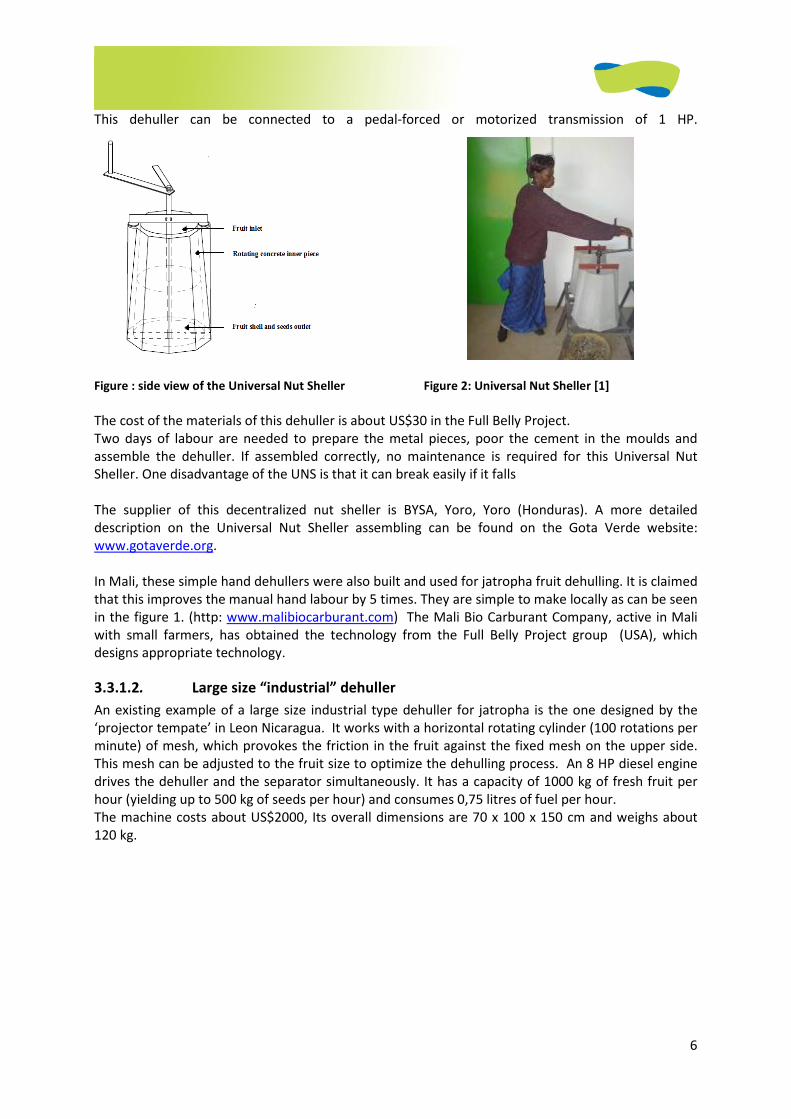
6
This dehuller can be connected to a pedal-forced or motorized transmission of 1 HP.
Figure : side view of the Universal Nut Sheller Figure 2: Universal Nut Sheller [1]
The cost of the materials of this dehuller is about US$30 in the Full Belly Project.
Two days of labour are needed to prepare the metal pieces, poor the cement in the moulds and
assemble the dehuller. If assembled correctly, no maintenance is required for this Universal Nut
Sheller. One disadvantage of the UNS is that it can break easily if it falls
The supplier of this decentralized nut sheller is BYSA, Yoro, Yoro (Honduras). A more detailed
description on the Universal Nut Sheller assembling can be found on the Gota Verde website:
www.gotaverde.org.
In Mali, these simple hand dehullers were also built and used for jatropha fruit dehulling. It is claimed
that this improves the manual hand labour by 5 times. They are simple to make locally as can be seen
in the figure 1. (http: www.malibiocarburant.com) The Mali Bio Carburant Company, active in Mali
with small farmers, has obtained the technology from the Full Belly Project group (USA), which
designs appropriate technology.
3.3.1.2. Large size “industrial” dehuller
An existing example of a large size industrial type dehuller for jatropha is the one designed by the
‘projector tempate’ in Leon Nicaragua. It works with a horizontal rotating cylinder (100 rotations per
minute) of mesh, which provokes the friction in the fruit against the fixed mesh on the upper side.
This mesh can be adjusted to the fruit size to optimize the dehulling process. An 8 HP diesel engine
drives the dehuller and the separator simultaneously. It has a capacity of 1000 kg of fresh fruit per
hour (yielding up to 500 kg of seeds per hour) and consumes 0,75 litres of fuel per hour.
The machine costs about US$2000, Its overall dimensions are 70 x 100 x 150 cm and weighs about
120 kg.
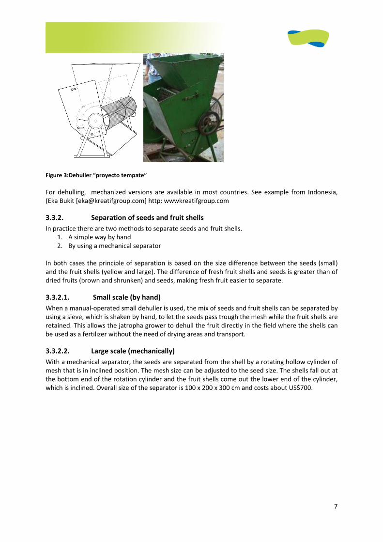
7
Figure 3:Dehuller “proyecto tempate”
For dehulling, mechanized versions are available in most countries. See example from Indonesia,
(Eka Bukit [[email protected]] http: wwwkreatifgroup.com
3.3.2. Separation of seeds and fruit shells
In practice there are two methods to separate seeds and fruit shells.
1. A simple way by hand
2. By using a mechanical separator
In both cases the principle of separation is based on the size difference between the seeds (small)
and the fruit shells (yellow and large). The difference of fresh fruit shells and seeds is greater than of
dried fruits (brown and shrunken) and seeds, making fresh fruit easier to separate.
3.3.2.1. Small scale (by hand)
When a manual-operated small dehuller is used, the mix of seeds and fruit shells can be separated by
using a sieve, which is shaken by hand, to let the seeds pass trough the mesh while the fruit shells are
retained. This allows the jatropha grower to dehull the fruit directly in the field where the shells can
be used as a fertilizer without the need of drying areas and transport.
3.3.2.2. Large scale (mechanically)
With a mechanical separator, the seeds are separated from the shell by a rotating hollow cylinder of
mesh that is in inclined position. The mesh size can be adjusted to the seed size. The shells fall out at
the bottom end of the rotation cylinder and the fruit shells come out the lower end of the cylinder,
which is inclined. Overall size of the separator is 100 x 200 x 300 cm and costs about US$700.
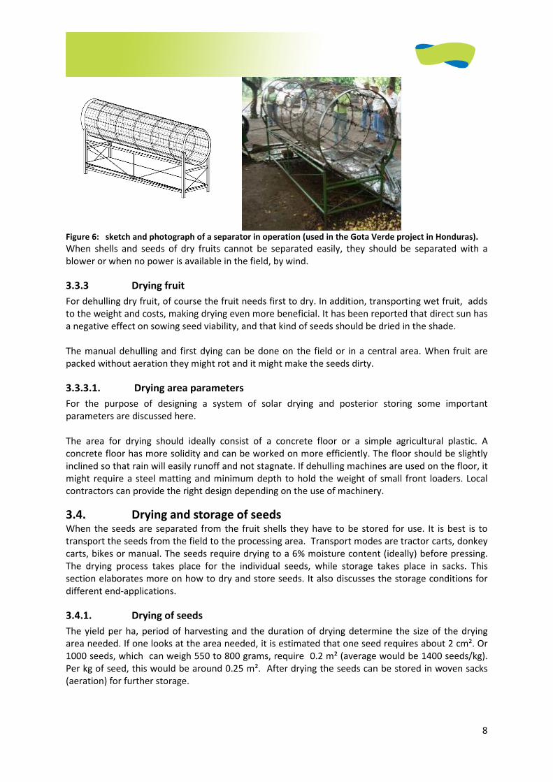
8
Figure 6: sketch and photograph of a separator in operation (used in the Gota Verde project in Honduras).
When shells and seeds of dry fruits cannot be separated easily, they should be separated with a
blower or when no power is available in the field, by wind.
3.3.3 Drying fruit
For dehulling dry fruit, of course the fruit needs first to dry. In addition, transporting wet fruit, adds
to the weight and costs, making drying even more beneficial. It has been reported that direct sun has
a negative effect on sowing seed viability, and that kind of seeds should be dried in the shade.
The manual dehulling and first dying can be done on the field or in a central area. When fruit are
packed without aeration they might rot and it might make the seeds dirty.
3.3.3.1. Drying area parameters
For the purpose of designing a system of solar drying and posterior storing some important
parameters are discussed here.
The area for drying should ideally consist of a concrete floor or a simple agricultural plastic. A
concrete floor has more solidity and can be worked on more efficiently. The floor should be slightly
inclined so that rain will easily runoff and not stagnate. If dehulling machines are used on the floor, it
might require a steel matting and minimum depth to hold the weight of small front loaders. Local
contractors can provide the right design depending on the use of machinery.
3.4. Drying and storage of seeds When the seeds are separated from the fruit shells they have to be stored for use. It is best is to
transport the seeds from the field to the processing area. Transport modes are tractor carts, donkey
carts, bikes or manual. The seeds require drying to a 6% moisture content (ideally) before pressing.
The drying process takes place for the individual seeds, while storage takes place in sacks. This
section elaborates more on how to dry and store seeds. It also discusses the storage conditions for
different end-applications.
3.4.1. Drying of seeds
The yield per ha, period of harvesting and the duration of drying determine the size of the drying
area needed. If one looks at the area needed, it is estimated that one seed requires about 2 cm². Or
1000 seeds, which can weigh 550 to 800 grams, require 0.2 m² (average would be 1400 seeds/kg).
Per kg of seed, this would be around 0.25 m². After drying the seeds can be stored in woven sacks
(aeration) for further storage.
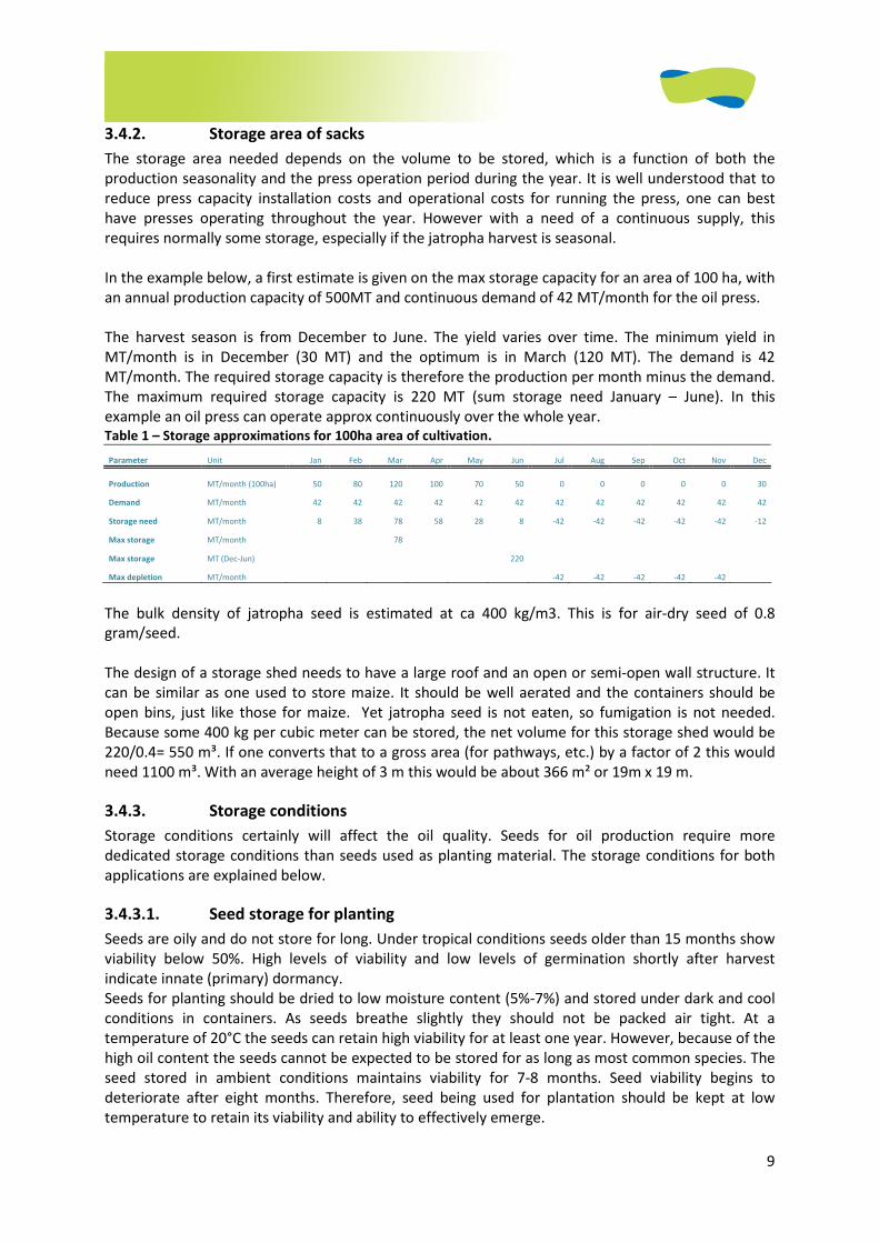
9
3.4.2. Storage area of sacks
The storage area needed depends on the volume to be stored, which is a function of both the
production seasonality and the press operation period during the year. It is well understood that to
reduce press capacity installation costs and operational costs for running the press, one can best
have presses operating throughout the year. However with a need of a continuous supply, this
requires normally some storage, especially if the jatropha harvest is seasonal.
In the example below, a first estimate is given on the max storage capacity for an area of 100 ha, with
an annual production capacity of 500MT and continuous demand of 42 MT/month for the oil press.
The harvest season is from December to June. The yield varies over time. The minimum yield in
MT/month is in December (30 MT) and the optimum is in March (120 MT). The demand is 42
MT/month. The required storage capacity is therefore the production per month minus the demand.
The maximum required storage capacity is 220 MT (sum storage need January – June). In this
example an oil press can operate approx continuously over the whole year. Table 1 – Storage approximations for 100ha area of cultivation.
Parameter Unit Jan Feb Mar Apr May Jun Jul Aug Sep Oct Nov Dec
Production MT/month (100ha) 50 80 120 100 70 50 0 0 0 0 0 30
Demand MT/month 42 42 42 42 42 42 42 42 42 42 42 42
Storage need MT/month 8 38 78 58 28 8 -42 -42 -42 -42 -42 -12
Max storage MT/month 78
Max storage MT (Dec-Jun) 220
Max depletion MT/month -42 -42 -42 -42 -42
The bulk density of jatropha seed is estimated at ca 400 kg/m3. This is for air-dry seed of 0.8
gram/seed.
The design of a storage shed needs to have a large roof and an open or semi-open wall structure. It
can be similar as one used to store maize. It should be well aerated and the containers should be
open bins, just like those for maize. Yet jatropha seed is not eaten, so fumigation is not needed.
Because some 400 kg per cubic meter can be stored, the net volume for this storage shed would be
220/0.4= 550 m³. If one converts that to a gross area (for pathways, etc.) by a factor of 2 this would
need 1100 m³. With an average height of 3 m this would be about 366 m² or 19m x 19 m.
3.4.3. Storage conditions
Storage conditions certainly will affect the oil quality. Seeds for oil production require more
dedicated storage conditions than seeds used as planting material. The storage conditions for both
applications are explained below.
3.4.3.1. Seed storage for planting
Seeds are oily and do not store for long. Under tropical conditions seeds older than 15 months show
viability below 50%. High levels of viability and low levels of germination shortly after harvest
indicate innate (primary) dormancy.
Seeds for planting should be dried to low moisture content (5%-7%) and stored under dark and cool
conditions in containers. As seeds breathe slightly they should not be packed air tight. At a
temperature of 20°C the seeds can retain high viability for at least one year. However, because of the
high oil content the seeds cannot be expected to be stored for as long as most common species. The
seed stored in ambient conditions maintains viability for 7-8 months. Seed viability begins to
deteriorate after eight months. Therefore, seed being used for plantation should be kept at low
temperature to retain its viability and ability to effectively emerge.

10
3.4.3.2. Seed storage for oil extraction
The oil industry requires continuous supply of raw material for oil extraction and esterification. The
seeds containing the oil must be properly stored and prepared for extraction, to maintain high
quality in the final product. The long storage of seeds (more than 8 months) is reported to affect oil
quality and quantity hence long storage should be avoided. Long exposure to sun will also degrade oil
quality. For normal storage 5%-7% of moist air or sun drying is adequate, the period of which
depends on a number of factors such sunshine hours, humidity, temperature, and wind.
The seed storage should be properly aerated. This can be done in silos similar to maize. The drying of
seeds up to 4% moisture enhances storability. However, the dryer the seed the lower the efficiency
of the press. Therefore it is recommended to press the seed at higher moisture content, e.g. between
7%-10%, and prevent long storage of the seed.
3.5 References
[1] www.malibiocarburant.com.
1
JATROPHA HANDBOOK
2D EDITION
JUNE 2009
CHAPTER 4 (OF 6)
Oil pressing and purification
2
4 OIL PRESSING AND PURIFICATION .......................................................................................................... 4
4.1 INTRODUCTION ..............................................................................................................................................4 4.2 MECHANICAL OIL EXTRACTION...........................................................................................................................4
4.2.1 Cleaning and checking of the seeds .................................................................................................5 4.2.2 The pressing process ........................................................................................................................5 4.2.3 Important parameters when pressing..............................................................................................5
4.2.3.1 Oil recovery ........................................................................................................................................... 5 4.2.3.2 Oil quality .............................................................................................................................................. 6
4.3 PRESS TECHNOLOGIES AND EXPELLER TYPES ..........................................................................................................6 4.3.1 Ram presses .....................................................................................................................................7 4.3.2 Expellers ...........................................................................................................................................8
4.3.2.1 Cylinder-hole ......................................................................................................................................... 8 4.3.2.2 Strainer.................................................................................................................................................. 8
4.3.3 Power required .................................................................................................................................9 4.3.4 Suggested models ..........................................................................................................................10 4.3.5 Concluding remark expellers ..........................................................................................................10
4.4 CLEANING OF VEGETABLE OIL ..........................................................................................................................11 4.4.1 Impurities in the oil.........................................................................................................................11 4.4.2 Sedimentation ................................................................................................................................11 4.4.3 Filtration.........................................................................................................................................13
4.4.3.1 Gravity filters....................................................................................................................................... 14 4.4.3.2 Band filter............................................................................................................................................ 15 4.4.3.3 Filter press........................................................................................................................................... 16 4.4.3.4 Pressure leaf filter ............................................................................................................................... 17 4.4.3.5 Bag filters............................................................................................................................................. 18 4.4.3.6 Candle filter ......................................................................................................................................... 18
4.4.4 Centrifuging....................................................................................................................................19 4.4.4.1 Decanter & separator.......................................................................................................................... 19
4.4.5 Concluding remarks oil cleaning.....................................................................................................20 4.5 QUALITY STANDARDS FOR SVO .......................................................................................................................20
4.5.1 Oil degumming...............................................................................................................................21 4.5.2 Oil neutralization............................................................................................................................21
4.6 HANDLING AND STORAGE OF OIL......................................................................................................................22 4.6.1 Handling criteria.............................................................................................................................22 4.6.2 Storage criteria...............................................................................................................................22
4.6.2.1 Cool storage temperature ................................................................................................................... 22 4.6.2.2 Avoiding temperature variations (and hence water condensation).................................................... 22 4.6.2.3 Darkness .............................................................................................................................................. 23 4.6.2.4 Contact with fresh air .......................................................................................................................... 23
4.7 LITERATURE .................................................................................................................................................23

3
ABBREVIATIONS
Oil recovery rate: the percentage of the present that is removed. A recovery rate of 100% means all
the oil is removed from the seed. For jatropha this would be 0,41 liter per kg seed.
SVO (Straight Vegetable Oil): this is oil after pressing and cleaning that is ready to be used various
purposes. Also referred to as PPO (pure plant oil).
Crude oil: Jatropha oil directly after pressing
Bleaching: an adsorptive process that removes all gross impurities such as meals, metal components,
peroxides, products of oxidation, soap residue from alkali refining. Hydratable gums can also be
removed in this step if the level is below 55 ppm [9].
Deodorizing: the only good way to remove Sulphur. In addition it removes some fatty acids [9].
Free fatty acids (FFA): exist in crude plant oils as a deterioration by-product of hydrolysis. In their
free form, they are soluble in oil and insoluble in water and can therefore not easily be separated
from the oil [9].
Hydrolysis: the conversion of glycerides into fatty acids and glycerol.
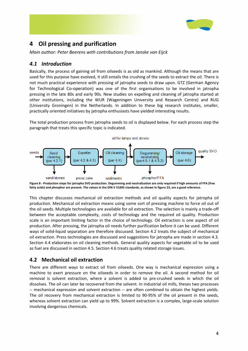
4
4 Oil pressing and purification
Main author: Peter Beerens with contributions from Janske van Eijck
4.1 Introduction
Basically, the process of gaining oil from oilseeds is as old as mankind. Although the means that are
used for this purpose have evolved, it still entails the crushing of the seeds to extract the oil. There is
not much practical experience with pressing of jatropha seeds to draw upon. GTZ (German Agency
for Technological Co-operation) was one of the first organisations to be involved in jatropha
pressing in the late 80s and early 90s. New studies on expelling and cleaning of jatropha started at
other institutions, including the WUR (Wageningen University and Research Centre) and RUG
(University Groningen) in the Netherlands. In addition to these big research institutes, smaller,
practically oriented initiatives by jatropha enthusiasts have yielded interesting results.
The total production process from jatropha seeds to oil is displayed below. For each process step the
paragraph that treats this specific topic is indicated.
Figure 8 - Production steps for jatropha SVO production. Degumming and neutralization are only required if high amounts of FFA (free
fatty acids) and phosphor are present. The values in the DIN V 51605 standards, as shown in figure 23, are a good reference.
This chapter discusses mechanical oil extraction methods and oil quality aspects for jatropha oil
production. Mechanical oil extraction means using some sort of pressing machine to force oil out of
the oil seeds. Multiple technologies are available for oil extraction. The selection is mainly a trade-off
between the acceptable complexity, costs of technology and the required oil quality. Production
scale is an important limiting factor in the choice of technology. Oil extraction is one aspect of oil
production. After pressing, the jatropha oil needs further purification before it can be used. Different
ways of solid-liquid separation are therefore discussed. Section 4.2 treats the subject of mechanical
oil extraction. Press technologies are discussed and suggestions for jatropha are made in section 4.3.
Section 4.4 elaborates on oil cleaning methods. General quality aspects for vegetable oil to be used
as fuel are discussed in section 4.5. Section 4.6 treats quality related storage issues.
4.2 Mechanical oil extraction
There are different ways to extract oil from oilseeds. One way is mechanical expression using a
machine to exert pressure on the oilseeds in order to remove the oil. A second method for oil
removal is solvent extraction, where a solvent is added to pre-crushed seeds in which the oil
dissolves. The oil can later be recovered from the solvent. In industrial oil mills, theses two processes
-- mechanical expression and solvent extraction -- are often combined to obtain the highest yields.
The oil recovery from mechanical extraction is limited to 90-95% of the oil present in the seeds,
whereas solvent extraction can yield up to 99%. Solvent extraction is a complex, large-scale solution
involving dangerous chemicals.
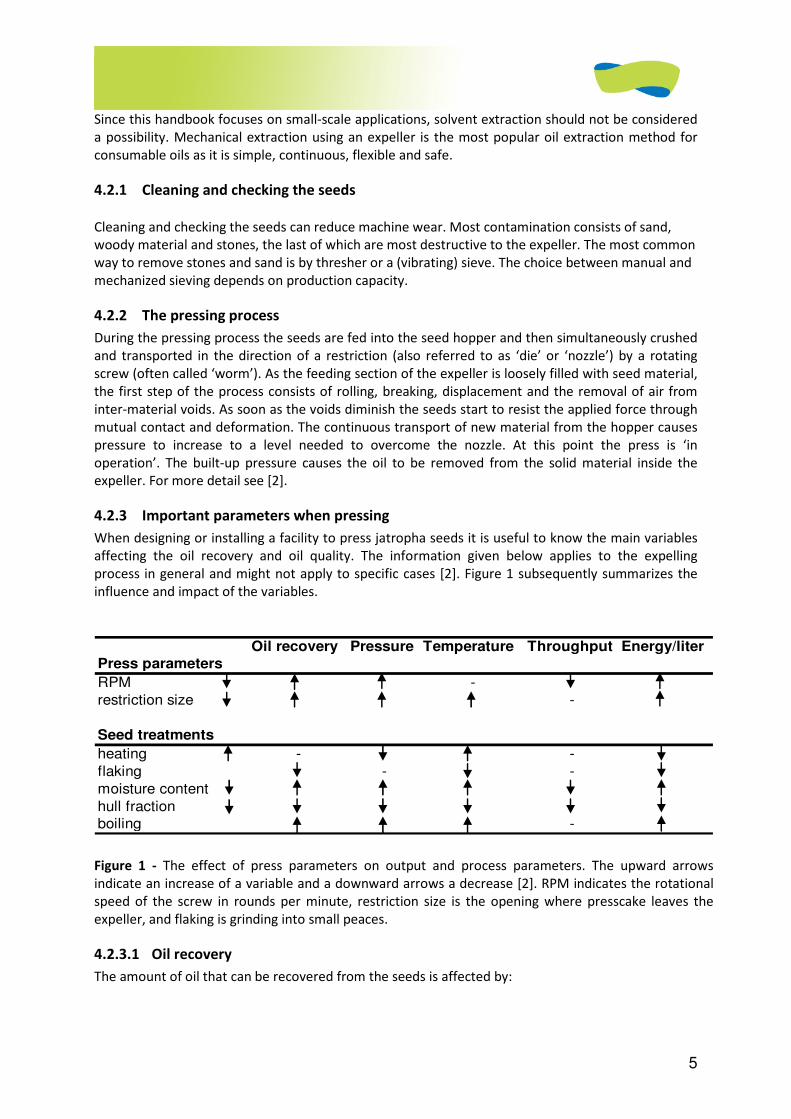
5
Since this handbook focuses on small-scale applications, solvent extraction should not be considered
a possibility. Mechanical extraction using an expeller is the most popular oil extraction method for
consumable oils as it is simple, continuous, flexible and safe.
4.2.1 Cleaning and checking the seeds
Cleaning and checking the seeds can reduce machine wear. Most contamination consists of sand,
woody material and stones, the last of which are most destructive to the expeller. The most common
way to remove stones and sand is by thresher or a (vibrating) sieve. The choice between manual and
mechanized sieving depends on production capacity.
4.2.2 The pressing process
During the pressing process the seeds are fed into the seed hopper and then simultaneously crushed
and transported in the direction of a restriction (also referred to as ‘die’ or ‘nozzle’) by a rotating
screw (often called ‘worm’). As the feeding section of the expeller is loosely filled with seed material,
the first step of the process consists of rolling, breaking, displacement and the removal of air from
inter-material voids. As soon as the voids diminish the seeds start to resist the applied force through
mutual contact and deformation. The continuous transport of new material from the hopper causes
pressure to increase to a level needed to overcome the nozzle. At this point the press is ‘in
operation’. The built-up pressure causes the oil to be removed from the solid material inside the
expeller. For more detail see [2].
4.2.3 Important parameters when pressing
When designing or installing a facility to press jatropha seeds it is useful to know the main variables
affecting the oil recovery and oil quality. The information given below applies to the expelling
process in general and might not apply to specific cases [2]. Figure 1 subsequently summarizes the
influence and impact of the variables.
Oil recovery Pressure Temperature Throughput Energy/liter
Press parameters
RPM -
restriction size -
Seed treatments
heating - -
flaking - -
moisture content
hull fraction
boiling -
Figure 1 - The effect of press parameters on output and process parameters. The upward arrows
indicate an increase of a variable and a downward arrows a decrease [2]. RPM indicates the rotational
speed of the screw in rounds per minute, restriction size is the opening where presscake leaves the
expeller, and flaking is grinding into small peaces.
4.2.3.1 Oil recovery
The amount of oil that can be recovered from the seeds is affected by:
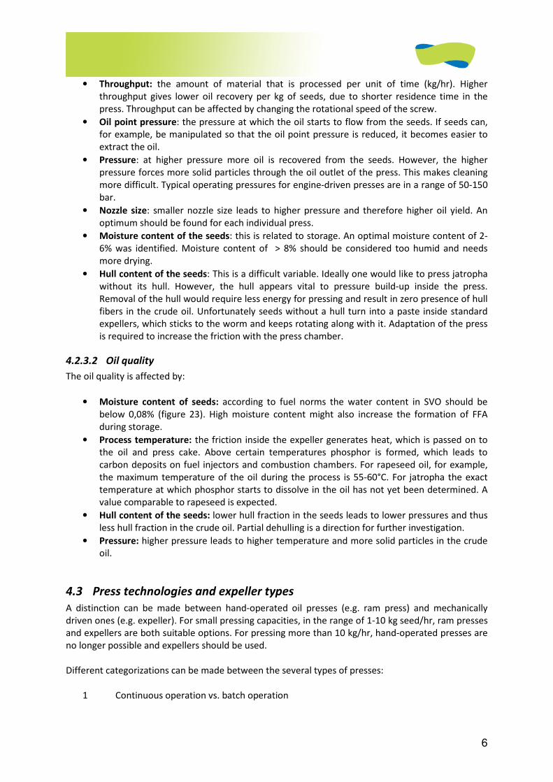
6
• Throughput: the amount of material that is processed per unit of time (kg/hr). Higher
throughput gives lower oil recovery per kg of seeds, due to shorter residence time in the
press. Throughput can be affected by changing the rotational speed of the screw.
• Oil point pressure: the pressure at which the oil starts to flow from the seeds. If seeds can,
for example, be manipulated so that the oil point pressure is reduced, it becomes easier to
extract the oil.
• Pressure: at higher pressure more oil is recovered from the seeds. However, the higher
pressure forces more solid particles through the oil outlet of the press. This makes cleaning
more difficult. Typical operating pressures for engine-driven presses are in a range of 50-150
bar.
• Nozzle size: smaller nozzle size leads to higher pressure and therefore higher oil yield. An
optimum should be found for each individual press.
• Moisture content of the seeds: this is related to storage. An optimal moisture content of 2-
6% was identified. Moisture content of > 8% should be considered too humid and needs
more drying.
• Hull content of the seeds: This is a difficult variable. Ideally one would like to press jatropha
without its hull. However, the hull appears vital to pressure build-up inside the press.
Removal of the hull would require less energy for pressing and result in zero presence of hull
fibers in the crude oil. Unfortunately seeds without a hull turn into a paste inside standard
expellers, which sticks to the worm and keeps rotating along with it. Adaptation of the press
is required to increase the friction with the press chamber.
4.2.3.2 Oil quality
The oil quality is affected by:
• Moisture content of seeds: according to fuel norms the water content in SVO should be
below 0,08% (figure 23). High moisture content might also increase the formation of FFA
during storage.
• Process temperature: the friction inside the expeller generates heat, which is passed on to
the oil and press cake. Above certain temperatures phosphor is formed, which leads to
carbon deposits on fuel injectors and combustion chambers. For rapeseed oil, for example,
the maximum temperature of the oil during the process is 55-60°C. For jatropha the exact
temperature at which phosphor starts to dissolve in the oil has not yet been determined. A
value comparable to rapeseed is expected.
• Hull content of the seeds: lower hull fraction in the seeds leads to lower pressures and thus
less hull fraction in the crude oil. Partial dehulling is a direction for further investigation.
• Pressure: higher pressure leads to higher temperature and more solid particles in the crude
oil.
4.3 Press technologies and expeller types
A distinction can be made between hand-operated oil presses (e.g. ram press) and mechanically
driven ones (e.g. expeller). For small pressing capacities, in the range of 1-10 kg seed/hr, ram presses
and expellers are both suitable options. For pressing more than 10 kg/hr, hand-operated presses are
no longer possible and expellers should be used.
Different categorizations can be made between the several types of presses:
1 Continuous operation vs. batch operation
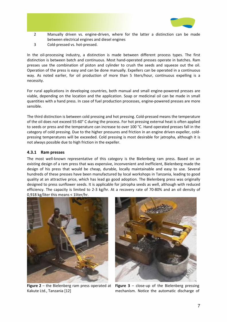
7
2 Manually driven vs. engine-driven, where for the latter a distinction can be made
between electrical engines and diesel engines
3 Cold-pressed vs. hot-pressed.
In the oil-processing industry, a distinction is made between different process types. The first
distinction is between batch and continuous. Most hand-operated presses operate in batches. Ram
presses use the combination of piston and cylinder to crush the seeds and squeeze out the oil.
Operation of the press is easy and can be done manually. Expellers can be operated in a continuous
way. As noted earlier, for oil production of more than 5 liters/hour, continuous expelling is a
necessity.
For rural applications in developing countries, both manual and small engine-powered presses are
viable, depending on the location and the application. Soap or medicinal oil can be made in small
quantities with a hand press. In case of fuel production processes, engine-powered presses are more
sensible.
The third distinction is between cold pressing and hot pressing. Cold-pressed means the temperature
of the oil does not exceed 55-60° C during the process. For hot pressing external heat is often applied
to seeds or press and the temperature can increase to over 100 °C. Hand operated presses fall in the
category of cold pressing. Due to the higher pressures and friction in an engine driven expeller, cold-
pressing temperatures will be exceeded. Cold pressing is most desirable for jatropha, although it is
not always possible due to high friction in the expeller.
4.3.1 Ram presses
The most well-known representative of this category is the Bielenberg ram press. Based on an
existing design of a ram press that was expensive, inconvenient and inefficient, Bielenberg made the
design of his press that would be cheap, durable, locally maintainable and easy to use. Several
hundreds of these presses have been manufactured by local workshops in Tanzania, leading to good
quality at an attractive price, which has lead go good adoption. The Bielenberg press was originally
designed to press sunflower seeds. It is applicable for jatropha seeds as well, although with reduced
efficiency. The capacity is limited to 2-3 kg/hr. At a recovery rate of 70-80% and an oil density of
0,918 kg/liter this means < 1liter/hr.
Figure 2 – the Bielenberg ram press operated at
Kakute Ltd., Tanzania [12]
Figure 3 – close-up of the Bielenberg pressing
mechanism. Notice the automatic discharge of
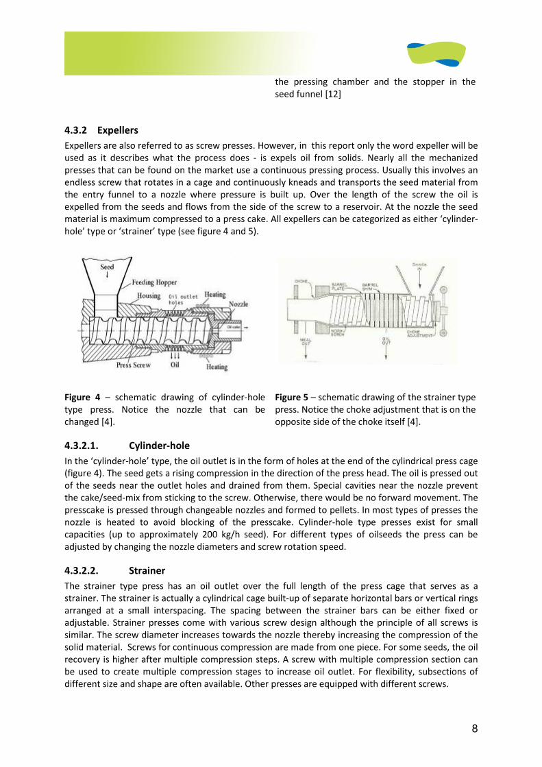
8
the pressing chamber and the stopper in the
seed funnel [12]
4.3.2 Expellers
Expellers are also referred to as screw presses. However, in this report only the word expeller will be
used as it describes what the process does - is expels oil from solids. Nearly all the mechanized
presses that can be found on the market use a continuous pressing process. Usually this involves an
endless screw that rotates in a cage and continuously kneads and transports the seed material from
the entry funnel to a nozzle where pressure is built up. Over the length of the screw the oil is
expelled from the seeds and flows from the side of the screw to a reservoir. At the nozzle the seed
material is maximum compressed to a press cake. All expellers can be categorized as either ‘cylinder-
hole’ type or ‘strainer’ type (see figure 4 and 5).
Figure 4 – schematic drawing of cylinder-hole
type press. Notice the nozzle that can be
changed [4].
Figure 5 – schematic drawing of the strainer type
press. Notice the choke adjustment that is on the
opposite side of the choke itself [4].
4.3.2.1. Cylinder-hole
In the ‘cylinder-hole’ type, the oil outlet is in the form of holes at the end of the cylindrical press cage
(figure 4). The seed gets a rising compression in the direction of the press head. The oil is pressed out
of the seeds near the outlet holes and drained from them. Special cavities near the nozzle prevent
the cake/seed-mix from sticking to the screw. Otherwise, there would be no forward movement. The
presscake is pressed through changeable nozzles and formed to pellets. In most types of presses the
nozzle is heated to avoid blocking of the presscake. Cylinder-hole type presses exist for small
capacities (up to approximately 200 kg/h seed). For different types of oilseeds the press can be
adjusted by changing the nozzle diameters and screw rotation speed.
4.3.2.2. Strainer
The strainer type press has an oil outlet over the full length of the press cage that serves as a
strainer. The strainer is actually a cylindrical cage built-up of separate horizontal bars or vertical rings
arranged at a small interspacing. The spacing between the strainer bars can be either fixed or
adjustable. Strainer presses come with various screw design although the principle of all screws is
similar. The screw diameter increases towards the nozzle thereby increasing the compression of the
solid material. Screws for continuous compression are made from one piece. For some seeds, the oil
recovery is higher after multiple compression steps. A screw with multiple compression section can
be used to create multiple compression stages to increase oil outlet. For flexibility, subsections of
different size and shape are often available. Other presses are equipped with different screws.
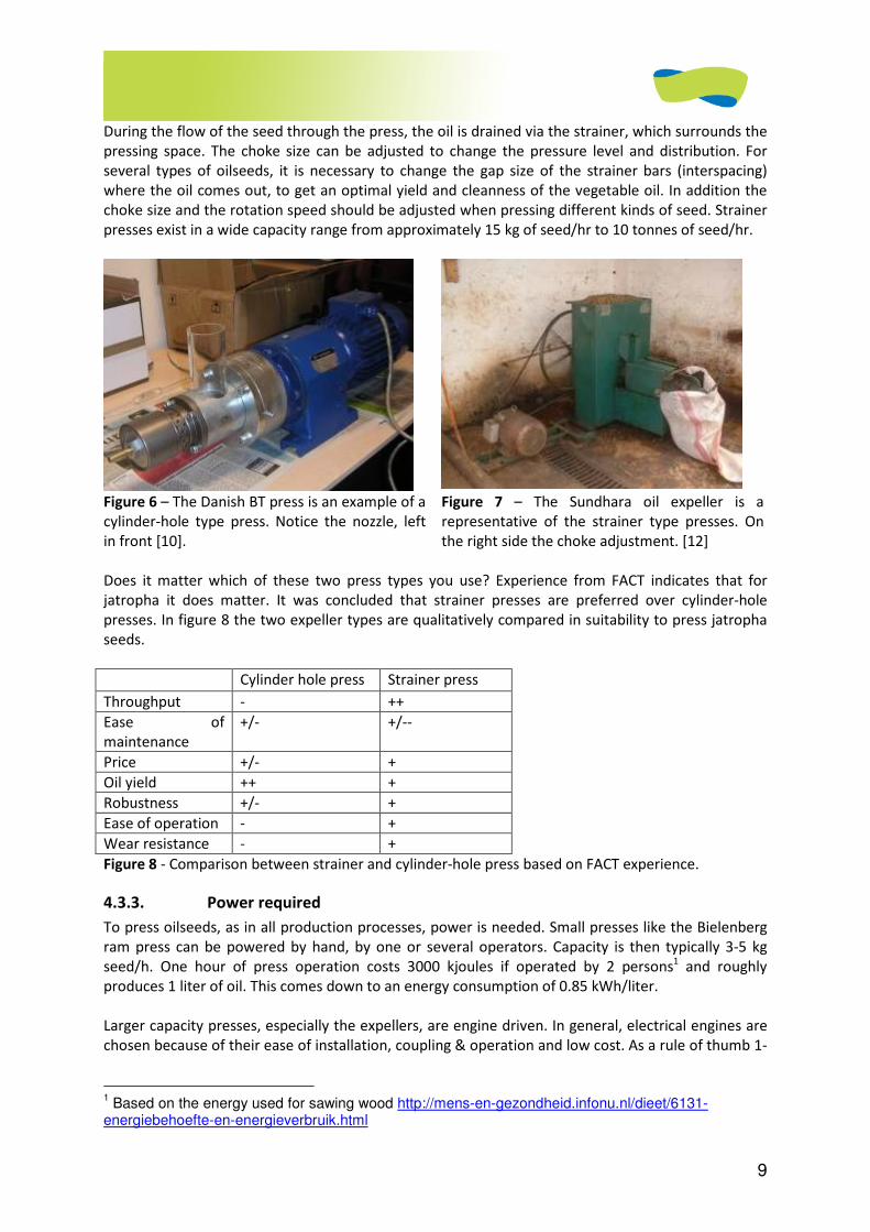
9
During the flow of the seed through the press, the oil is drained via the strainer, which surrounds the
pressing space. The choke size can be adjusted to change the pressure level and distribution. For
several types of oilseeds, it is necessary to change the gap size of the strainer bars (interspacing)
where the oil comes out, to get an optimal yield and cleanness of the vegetable oil. In addition the
choke size and the rotation speed should be adjusted when pressing different kinds of seed. Strainer
presses exist in a wide capacity range from approximately 15 kg of seed/hr to 10 tonnes of seed/hr.
Figure 6 – The Danish BT press is an example of a
cylinder-hole type press. Notice the nozzle, left
in front [10].
Figure 7 – The Sundhara oil expeller is a
representative of the strainer type presses. On
the right side the choke adjustment. [12]
Does it matter which of these two press types you use? Experience from FACT indicates that for
jatropha it does matter. It was concluded that strainer presses are preferred over cylinder-hole
presses. In figure 8 the two expeller types are qualitatively compared in suitability to press jatropha
seeds.
Cylinder hole press Strainer press
Throughput - ++
Ease of
maintenance
+/- +/--
Price +/- +
Oil yield ++ +
Robustness +/- +
Ease of operation - +
Wear resistance - +
Figure 8 - Comparison between strainer and cylinder-hole press based on FACT experience.
4.3.3. Power required
To press oilseeds, as in all production processes, power is needed. Small presses like the Bielenberg
ram press can be powered by hand, by one or several operators. Capacity is then typically 3-5 kg
seed/h. One hour of press operation costs 3000 kjoules if operated by 2 persons1 and roughly
produces 1 liter of oil. This comes down to an energy consumption of 0.85 kWh/liter.
Larger capacity presses, especially the expellers, are engine driven. In general, electrical engines are
chosen because of their ease of installation, coupling & operation and low cost. As a rule of thumb 1-
1 Based on the energy used for sawing wood http://mens-en-gezondheid.infonu.nl/dieet/6131-
energiebehoefte-en-energieverbruik.html
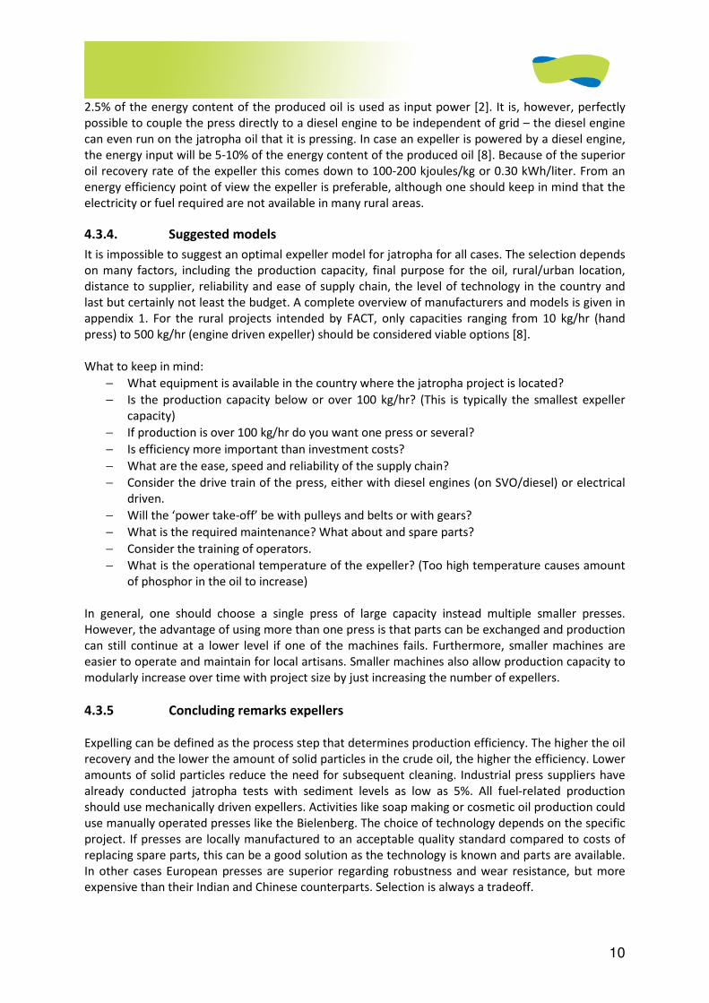
10
2.5% of the energy content of the produced oil is used as input power [2]. It is, however, perfectly
possible to couple the press directly to a diesel engine to be independent of grid – the diesel engine
can even run on the jatropha oil that it is pressing. In case an expeller is powered by a diesel engine,
the energy input will be 5-10% of the energy content of the produced oil [8]. Because of the superior
oil recovery rate of the expeller this comes down to 100-200 kjoules/kg or 0.30 kWh/liter. From an
energy efficiency point of view the expeller is preferable, although one should keep in mind that the
electricity or fuel required are not available in many rural areas.
4.3.4. Suggested models
It is impossible to suggest an optimal expeller model for jatropha for all cases. The selection depends
on many factors, including the production capacity, final purpose for the oil, rural/urban location,
distance to supplier, reliability and ease of supply chain, the level of technology in the country and
last but certainly not least the budget. A complete overview of manufacturers and models is given in
appendix 1. For the rural projects intended by FACT, only capacities ranging from 10 kg/hr (hand
press) to 500 kg/hr (engine driven expeller) should be considered viable options [8].
What to keep in mind:
− What equipment is available in the country where the jatropha project is located?
− Is the production capacity below or over 100 kg/hr? (This is typically the smallest expeller
capacity)
− If production is over 100 kg/hr do you want one press or several?
− Is efficiency more important than investment costs?
− What are the ease, speed and reliability of the supply chain?
− Consider the drive train of the press, either with diesel engines (on SVO/diesel) or electrical
driven.
− Will the ‘power take-off’ be with pulleys and belts or with gears?
− What is the required maintenance? What about and spare parts?
− Consider the training of operators.
− What is the operational temperature of the expeller? (Too high temperature causes amount
of phosphor in the oil to increase)
In general, one should choose a single press of large capacity instead multiple smaller presses.
However, the advantage of using more than one press is that parts can be exchanged and production
can still continue at a lower level if one of the machines fails. Furthermore, smaller machines are
easier to operate and maintain for local artisans. Smaller machines also allow production capacity to
modularly increase over time with project size by just increasing the number of expellers.
4.3.5 Concluding remarks expellers
Expelling can be defined as the process step that determines production efficiency. The higher the oil
recovery and the lower the amount of solid particles in the crude oil, the higher the efficiency. Lower
amounts of solid particles reduce the need for subsequent cleaning. Industrial press suppliers have
already conducted jatropha tests with sediment levels as low as 5%. All fuel-related production
should use mechanically driven expellers. Activities like soap making or cosmetic oil production could
use manually operated presses like the Bielenberg. The choice of technology depends on the specific
project. If presses are locally manufactured to an acceptable quality standard compared to costs of
replacing spare parts, this can be a good solution as the technology is known and parts are available.
In other cases European presses are superior regarding robustness and wear resistance, but more
expensive than their Indian and Chinese counterparts. Selection is always a tradeoff.
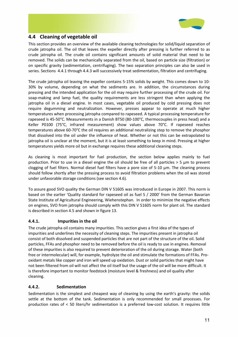
11
4.4 Cleaning of vegetable oil
This section provides an overview of the available cleaning technologies for solid/liquid separation of
crude jatropha oil. The oil that leaves the expeller directly after pressing is further referred to as
crude jatropha oil. The crude oil contains significant amounts of solid material that need to be
removed. The solids can be mechanically separated from the oil, based on particle size (filtration) or
on specific gravity (sedimentation, centrifuging). The two separation principles can also be used in
series. Sections 4.4.1 through 4.4.3 will successively treat sedimentation, filtration and centrifuging.
The crude jatropha oil leaving the expeller contains 5-15% solids by weight. This comes down to 10-
30% by volume, depending on what the sediments are. In addition, the circumstances during
pressing and the intended application for the oil may require further processing of the crude oil. For
soap-making and lamp fuel, the quality requirements are less stringent than when applying the
jatropha oil in a diesel engine. In most cases, vegetable oil produced by cold pressing does not
require degumming and neutralization. However, presses appear to operate at much higher
temperatures when processing jatropha compared to rapeseed. A typical processing temperature for
rapeseed is 45-50°C. Measurements in a Danish BT50 (80-100°C, thermocouples in press head) and a
Keller P0100 (75°C, infrared measurement) show values above 70°C. If rapeseed reaches
temperatures above 60-70°C the oil requires an additional neutralizing step to remove the phosphor
that dissolved into the oil under the influence of heat. Whether or not this can be extrapolated to
jatropha oil is unclear at the moment, but it is at least something to keep in mind. Pressing at higher
temperatures yields more oil but in exchange requires these additional cleaning steps.
As cleaning is most important for fuel production, the section below applies mainly to fuel
production. Prior to use in a diesel engine the oil should be free of all particles > 5 µm to prevent
clogging of fuel filters. Normal diesel fuel filters have a pore size of 5-10 µm. The cleaning process
should follow shortly after the pressing process to avoid filtration problems when the oil was stored
under unfavorable storage conditions (see section 4.6).
To assure good SVO quality the German DIN V 51605 was introduced in Europe in 2007. This norm is
based on the earlier ‘Quality standard for rapeseed oil as fuel 5 / 2000’ from the German Bavarian
State Institute of Agricultural Engineering, Wiehenstephan. In order to minimize the negative effects
on engines, SVO from jatropha should comply with this DIN V 51605 norm for plant oil. The standard
is described in section 4.5 and shown in figure 13.
4.4.1. Impurities in the oil
The crude jatropha oil contains many impurities. This section gives a first idea of the types of
impurities and underlines the necessity of cleaning steps. The impurities present in jatropha oil
consist of both dissolved and suspended particles that are not part of the structure of the oil. Solid
particles, FFAs and phosphor need to be removed before the oil is ready to use in engines. Removal
of these impurities is also required to prevent deterioration of the oil during storage. Water (both
free or intermolecular) will, for example, hydrolyze the oil and stimulate the formations of FFAs. Pro-
oxidant metals like copper and iron will speed up oxidation. Dust or solid particles that might have
not been filtered from oil will not affect the oil itself but the usage of the oil will be more difficult. It
is therefore important to monitor feedstock (moisture level & freshness) and oil quality after
cleaning.
4.4.2. Sedimentation
Sedimentation is the simplest and cheapest way of cleaning by using the earth’s gravity: the solids
settle at the bottom of the tank. Sedimentation is only recommended for small processes. For
production rates of < 50 liters/hr sedimentation is a preferred low-cost solution. It requires little

12
technology and efficiency losses are less important when producing small volumes. It is a cheap
cleaning method because little hardware needs to be purchased… only a storage tank large enough
to keep the oil for about a week with little or no flow. If necessary, the process can be completed in
multiple stages as shown in Figure 9.
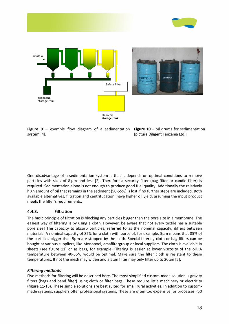
13
Figure 9 – example flow diagram of a sedimentation
system [4].
Figure 10 – oil drums for sedimentation
[picture Diligent Tanzania Ltd.]
One disadvantage of a sedimentation system is that it depends on optimal conditions to remove
particles with sizes of 8 µm and less [2]. Therefore a security filter (bag filter or candle filter) is
required. Sedimentation alone is not enough to produce good fuel quality. Additionally the relatively
high amount of oil that remains in the sediment (50-55%) is lost if no further steps are included. Both
available alternatives, filtration and centrifugation, have higher oil yield, assuming the input product
meets the filter’s requirements.
4.4.3. Filtration
The basic principle of filtration is blocking any particles bigger than the pore size in a membrane. The
easiest way of filtering is by using a cloth. However, be aware that not every textile has a suitable
pore size! The capacity to absorb particles, referred to as the nominal capacity, differs between
materials. A nominal capacity of 85% for a cloth with pores of, for example, 5µm means that 85% of
the particles bigger than 5µm are stopped by the cloth. Special filtering cloth or bag filters can be
bought at various suppliers, like Monopoel, amafiltergroup or local suppliers. The cloth is available in
sheets (see figure 11) or as bags, for example. Filtering is easier at lower viscosity of the oil. A
temperature between 40-55°C would be optimal. Make sure the filter cloth is resistant to these
temperatures. If not the mesh may widen and a 5µm filter may only filter up to 20µm [5].
Filtering methods
Five methods for filtering will be described here. The most simplified custom-made solution is gravity
filters (bags and band filter) using cloth or filter bags. These require little machinery or electricity
(figure 11-13). These simple solutions are best suited for small rural activities. In addition to custom-
made systems, suppliers offer professional systems. These are often too expensive for processes <50
crude oil
sediment storage tank
Safety filter
clean oilstorage tank
crude oil
sediment storage tank
Safety filter
clean oilstorage tank
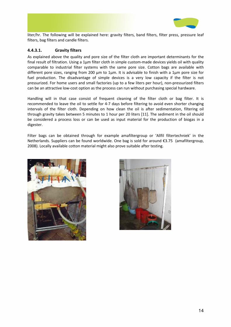
14
liter/hr. The following will be explained here: gravity filters, band filters, filter press, pressure leaf
filters, bag filters and candle filters.
4.4.3.1. Gravity filters
As explained above the quality and pore size of the filter cloth are important determinants for the
final result of filtration. Using a 1µm filter cloth in simple custom-made devices yields oil with quality
comparable to industrial filter systems with the same pore size. Cotton bags are available with
different pore sizes, ranging from 200 µm to 1µm. It is advisable to finish with a 1µm pore size for
fuel production. The disadvantage of simple devices is a very low capacity if the filter is not
pressurized. For home users and small factories (up to a few liters per hour), non-pressurized filters
can be an attractive low-cost option as the process can run without purchasing special hardware.
Handling will in that case consist of frequent cleaning of the filter cloth or bag filter. It is
recommended to leave the oil to settle for 4-7 days before filtering to avoid even shorter changing
intervals of the filter cloth. Depending on how clean the oil is after sedimentation, filtering oil
through gravity takes between 5 minutes to 1 hour per 20 liters [11]. The sediment in the oil should
be considered a process loss or can be used as input material for the production of biogas in a
digester.
Filter bags can be obtained through for example amafiltergroup or ‘Allfil filtertechniek’ in the
Netherlands. Suppliers can be found worldwide. One bag is sold for around €3.75 (amafiltergroup,
2008). Locally available cotton material might also prove suitable after testing.
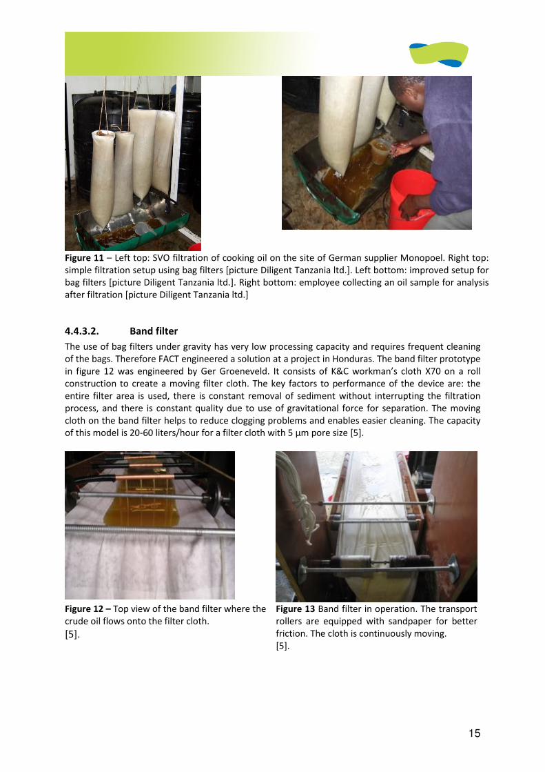
15
Figure 11 – Left top: SVO filtration of cooking oil on the site of German supplier Monopoel. Right top:
simple filtration setup using bag filters [picture Diligent Tanzania ltd.]. Left bottom: improved setup for
bag filters [picture Diligent Tanzania ltd.]. Right bottom: employee collecting an oil sample for analysis
after filtration [picture Diligent Tanzania ltd.]
4.4.3.2. Band filter
The use of bag filters under gravity has very low processing capacity and requires frequent cleaning
of the bags. Therefore FACT engineered a solution at a project in Honduras. The band filter prototype
in figure 12 was engineered by Ger Groeneveld. It consists of K&C workman’s cloth X70 on a roll
construction to create a moving filter cloth. The key factors to performance of the device are: the
entire filter area is used, there is constant removal of sediment without interrupting the filtration
process, and there is constant quality due to use of gravitational force for separation. The moving
cloth on the band filter helps to reduce clogging problems and enables easier cleaning. The capacity
of this model is 20-60 liters/hour for a filter cloth with 5 µm pore size [5].
Figure 12 – Top view of the band filter where the
crude oil flows onto the filter cloth.
[5].
Figure 13 Band filter in operation. The transport
rollers are equipped with sandpaper for better
friction. The cloth is continuously moving.
[5].
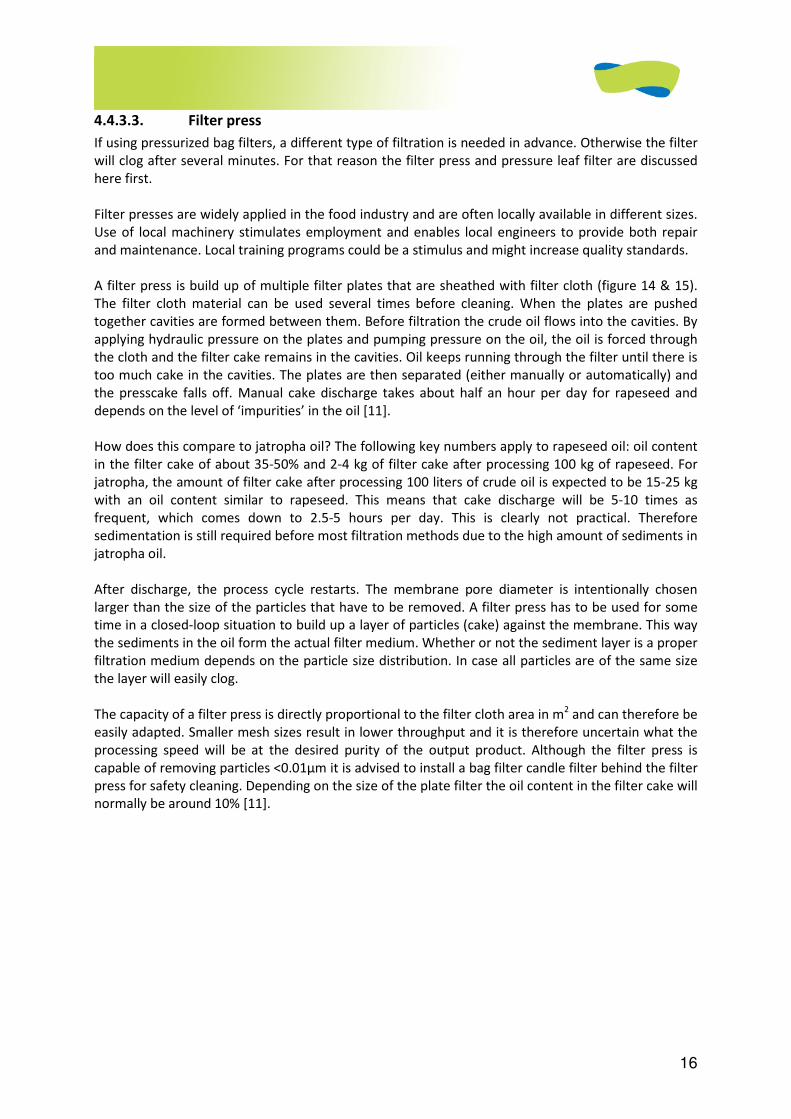
16
4.4.3.3. Filter press
If using pressurized bag filters, a different type of filtration is needed in advance. Otherwise the filter
will clog after several minutes. For that reason the filter press and pressure leaf filter are discussed
here first.
Filter presses are widely applied in the food industry and are often locally available in different sizes.
Use of local machinery stimulates employment and enables local engineers to provide both repair
and maintenance. Local training programs could be a stimulus and might increase quality standards.
A filter press is build up of multiple filter plates that are sheathed with filter cloth (figure 14 & 15).
The filter cloth material can be used several times before cleaning. When the plates are pushed
together cavities are formed between them. Before filtration the crude oil flows into the cavities. By
applying hydraulic pressure on the plates and pumping pressure on the oil, the oil is forced through
the cloth and the filter cake remains in the cavities. Oil keeps running through the filter until there is
too much cake in the cavities. The plates are then separated (either manually or automatically) and
the presscake falls off. Manual cake discharge takes about half an hour per day for rapeseed and
depends on the level of ‘impurities’ in the oil [11].
How does this compare to jatropha oil? The following key numbers apply to rapeseed oil: oil content
in the filter cake of about 35-50% and 2-4 kg of filter cake after processing 100 kg of rapeseed. For
jatropha, the amount of filter cake after processing 100 liters of crude oil is expected to be 15-25 kg
with an oil content similar to rapeseed. This means that cake discharge will be 5-10 times as
frequent, which comes down to 2.5-5 hours per day. This is clearly not practical. Therefore
sedimentation is still required before most filtration methods due to the high amount of sediments in
jatropha oil.
After discharge, the process cycle restarts. The membrane pore diameter is intentionally chosen
larger than the size of the particles that have to be removed. A filter press has to be used for some
time in a closed-loop situation to build up a layer of particles (cake) against the membrane. This way
the sediments in the oil form the actual filter medium. Whether or not the sediment layer is a proper
filtration medium depends on the particle size distribution. In case all particles are of the same size
the layer will easily clog.
The capacity of a filter press is directly proportional to the filter cloth area in m2 and can therefore be
easily adapted. Smaller mesh sizes result in lower throughput and it is therefore uncertain what the
processing speed will be at the desired purity of the output product. Although the filter press is
capable of removing particles <0.01µm it is advised to install a bag filter candle filter behind the filter
press for safety cleaning. Depending on the size of the plate filter the oil content in the filter cake will
normally be around 10% [11].
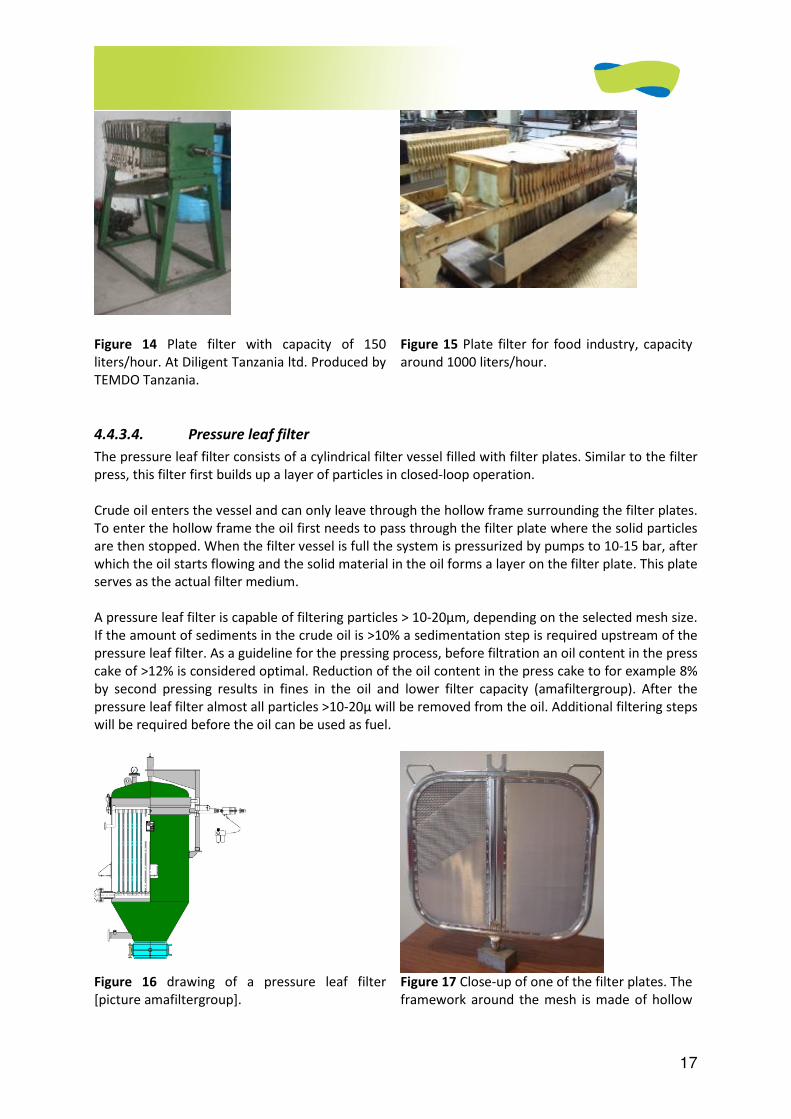
17
Figure 14 Plate filter with capacity of 150
liters/hour. At Diligent Tanzania ltd. Produced by
TEMDO Tanzania.
Figure 15 Plate filter for food industry, capacity
around 1000 liters/hour.
4.4.3.4. Pressure leaf filter
The pressure leaf filter consists of a cylindrical filter vessel filled with filter plates. Similar to the filter
press, this filter first builds up a layer of particles in closed-loop operation.
Crude oil enters the vessel and can only leave through the hollow frame surrounding the filter plates.
To enter the hollow frame the oil first needs to pass through the filter plate where the solid particles
are then stopped. When the filter vessel is full the system is pressurized by pumps to 10-15 bar, after
which the oil starts flowing and the solid material in the oil forms a layer on the filter plate. This plate
serves as the actual filter medium.
A pressure leaf filter is capable of filtering particles > 10-20µm, depending on the selected mesh size.
If the amount of sediments in the crude oil is >10% a sedimentation step is required upstream of the
pressure leaf filter. As a guideline for the pressing process, before filtration an oil content in the press
cake of >12% is considered optimal. Reduction of the oil content in the press cake to for example 8%
by second pressing results in fines in the oil and lower filter capacity (amafiltergroup). After the
pressure leaf filter almost all particles >10-20µ will be removed from the oil. Additional filtering steps
will be required before the oil can be used as fuel.
Figure 16 drawing of a pressure leaf filter
[picture amafiltergroup].
Figure 17 Close-up of one of the filter plates. The
framework around the mesh is made of hollow
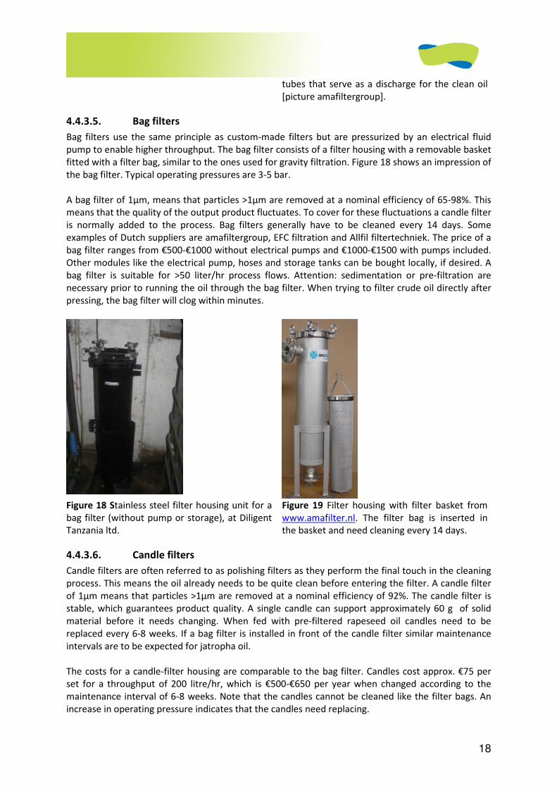
18
tubes that serve as a discharge for the clean oil
[picture amafiltergroup].
4.4.3.5. Bag filters
Bag filters use the same principle as custom-made filters but are pressurized by an electrical fluid
pump to enable higher throughput. The bag filter consists of a filter housing with a removable basket
fitted with a filter bag, similar to the ones used for gravity filtration. Figure 18 shows an impression of
the bag filter. Typical operating pressures are 3-5 bar.
A bag filter of 1µm, means that particles >1µm are removed at a nominal efficiency of 65-98%. This
means that the quality of the output product fluctuates. To cover for these fluctuations a candle filter
is normally added to the process. Bag filters generally have to be cleaned every 14 days. Some
examples of Dutch suppliers are amafiltergroup, EFC filtration and Allfil filtertechniek. The price of a
bag filter ranges from €500-€1000 without electrical pumps and €1000-€1500 with pumps included.
Other modules like the electrical pump, hoses and storage tanks can be bought locally, if desired. A
bag filter is suitable for >50 liter/hr process flows. Attention: sedimentation or pre-filtration are
necessary prior to running the oil through the bag filter. When trying to filter crude oil directly after
pressing, the bag filter will clog within minutes.
Figure 18 Stainless steel filter housing unit for a
bag filter (without pump or storage), at Diligent
Tanzania ltd.
Figure 19 Filter housing with filter basket from
www.amafilter.nl. The filter bag is inserted in
the basket and need cleaning every 14 days.
4.4.3.6. Candle filters
Candle filters are often referred to as polishing filters as they perform the final touch in the cleaning
process. This means the oil already needs to be quite clean before entering the filter. A candle filter
of 1µm means that particles >1µm are removed at a nominal efficiency of 92%. The candle filter is
stable, which guarantees product quality. A single candle can support approximately 60 g of solid
material before it needs changing. When fed with pre-filtered rapeseed oil candles need to be
replaced every 6-8 weeks. If a bag filter is installed in front of the candle filter similar maintenance
intervals are to be expected for jatropha oil.
The costs for a candle-filter housing are comparable to the bag filter. Candles cost approx. €75 per
set for a throughput of 200 litre/hr, which is €500-€650 per year when changed according to the
maintenance interval of 6-8 weeks. Note that the candles cannot be cleaned like the filter bags. An
increase in operating pressure indicates that the candles need replacing.
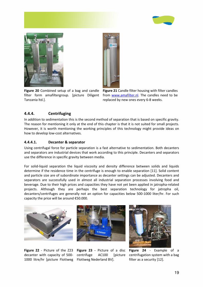
19
Figure 20 Combined setup of a bag and candle
filter form amafiltergroup. [picture Diligent
Tanzania ltd.].
Figure 21 Candle filter housing with filter candles
from www.amafilter.nl. The candles need to be
replaced by new ones every 6-8 weeks.
4.4.4. Centrifuging
In addition to sedimentation this is the second method of separation that is based on specific gravity.
The reason for mentioning it only at the end of this chapter is that it is not suited for small projects.
However, it is worth mentioning the working principles of this technology might provide ideas on
how to develop low-cost alternatives.
4.4.4.1. Decanter & separator
Using centrifugal force for particle separation is a fast alternative to sedimentation. Both decanters
and separators are industrial devices that work according to this principle. Decanters and separators
use the difference in specific gravity between media.
For solid-liquid separation the liquid viscosity and density difference between solids and liquids
determine if the residence time in the centrifuge is enough to enable separation [11]. Solid content
and particle size are of subordinate importance as decanter settings can be adjusted. Decanters and
separators are successfully used in almost all industrial separation processes involving food and
beverage. Due to their high prices and capacities they have not yet been applied in jatropha-related
projects. Although they are perhaps the best separation technology for jatropha oil,
decanters/centrifuges are generally not an option for capacities below 500-1000 liter/hr. For such
capacity the price will be around €50.000.
Figure 22 - Picture of the Z23
decanter with capacity of 500-
1000 litre/hr [picture Flottweg
Figure 23 - Picture of a disc
centrifuge AC100 [picture
Flottweg Nederland BV].
Figure 24 - Example of a
centrifugation system with a bag
filter as a security [12].
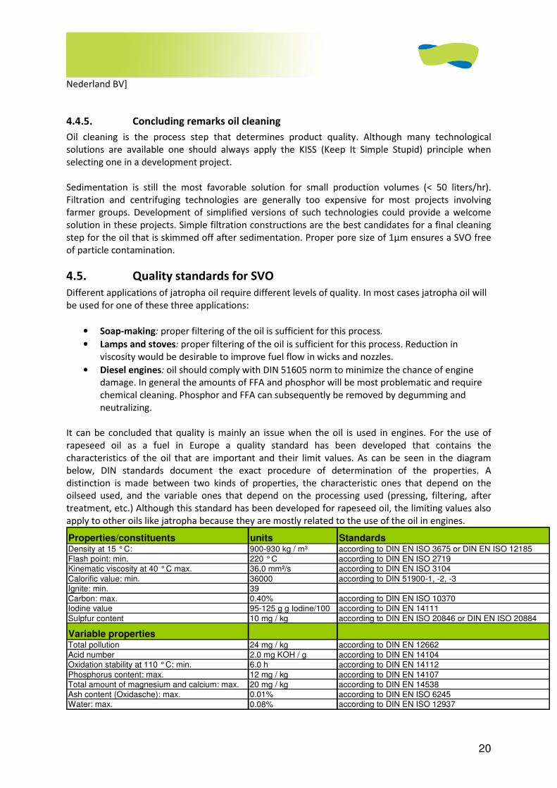
20
Nederland BV]
4.4.5. Concluding remarks oil cleaning
Oil cleaning is the process step that determines product quality. Although many technological
solutions are available one should always apply the KISS (Keep It Simple Stupid) principle when
selecting one in a development project.
Sedimentation is still the most favorable solution for small production volumes (< 50 liters/hr).
Filtration and centrifuging technologies are generally too expensive for most projects involving
farmer groups. Development of simplified versions of such technologies could provide a welcome
solution in these projects. Simple filtration constructions are the best candidates for a final cleaning
step for the oil that is skimmed off after sedimentation. Proper pore size of 1µm ensures a SVO free
of particle contamination.
4.5. Quality standards for SVO
Different applications of jatropha oil require different levels of quality. In most cases jatropha oil will
be used for one of these three applications:
• Soap-making: proper filtering of the oil is sufficient for this process.
• Lamps and stoves: proper filtering of the oil is sufficient for this process. Reduction in
viscosity would be desirable to improve fuel flow in wicks and nozzles.
• Diesel engines: oil should comply with DIN 51605 norm to minimize the chance of engine
damage. In general the amounts of FFA and phosphor will be most problematic and require
chemical cleaning. Phosphor and FFA can subsequently be removed by degumming and
neutralizing.
It can be concluded that quality is mainly an issue when the oil is used in engines. For the use of
rapeseed oil as a fuel in Europe a quality standard has been developed that contains the
characteristics of the oil that are important and their limit values. As can be seen in the diagram
below, DIN standards document the exact procedure of determination of the properties. A
distinction is made between two kinds of properties, the characteristic ones that depend on the
oilseed used, and the variable ones that depend on the processing used (pressing, filtering, after
treatment, etc.) Although this standard has been developed for rapeseed oil, the limiting values also
apply to other oils like jatropha because they are mostly related to the use of the oil in engines.
Properties/constituents units StandardsDensity at 15 ° C: 900-930 kg / m³ according to DIN EN ISO 3675 or DIN EN ISO 12185
Flash point: min. 220 ° C according to DIN EN ISO 2719
Kinematic viscosity at 40 ° C max. 36,0 mm²/s according to DIN EN ISO 3104
Calorific value: min. 36000 according to DIN 51900-1, -2, -3
Ignite: min. 39
Carbon: max. 0.40% according to DIN EN ISO 10370
Iodine value 95-125 g g Iodine/100 according to DIN EN 14111
Sulpfur content 10 mg / kg according to DIN EN ISO 20846 or DIN EN ISO 20884
Variable propertiesTotal pollution 24 mg / kg according to DIN EN 12662
Acid number 2.0 mg KOH / g according to DIN EN 14104
Oxidation stability at 110 ° C: min. 6.0 h according to DIN EN 14112
Phosphorus content: max. 12 mg / kg according to DIN EN 14107
Total amount of magnesium and calcium: max. 20 mg / kg according to DIN EN 14538
Ash content (Oxidasche): max. 0.01% according to DIN EN ISO 6245Water: max. 0.08% according to DIN EN ISO 12937
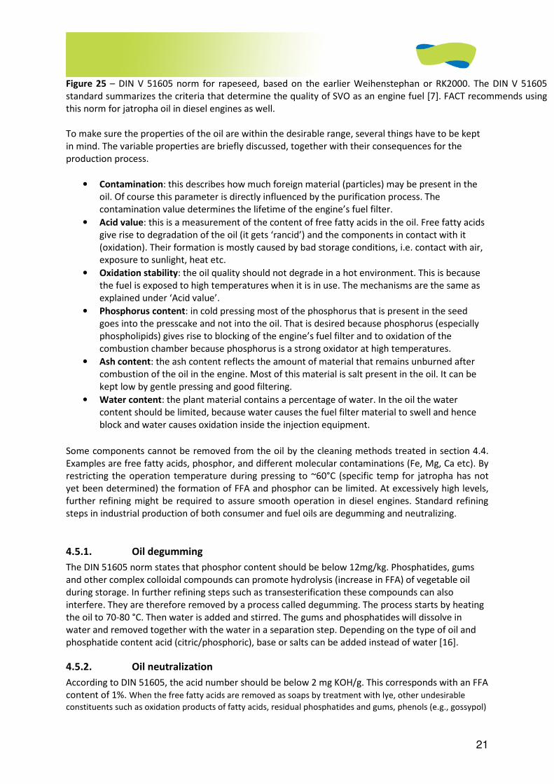
21
Figure 25 – DIN V 51605 norm for rapeseed, based on the earlier Weihenstephan or RK2000. The DIN V 51605
standard summarizes the criteria that determine the quality of SVO as an engine fuel [7]. FACT recommends using
this norm for jatropha oil in diesel engines as well.
To make sure the properties of the oil are within the desirable range, several things have to be kept
in mind. The variable properties are briefly discussed, together with their consequences for the
production process.
• Contamination: this describes how much foreign material (particles) may be present in the
oil. Of course this parameter is directly influenced by the purification process. The
contamination value determines the lifetime of the engine’s fuel filter.
• Acid value: this is a measurement of the content of free fatty acids in the oil. Free fatty acids
give rise to degradation of the oil (it gets ‘rancid’) and the components in contact with it
(oxidation). Their formation is mostly caused by bad storage conditions, i.e. contact with air,
exposure to sunlight, heat etc.
• Oxidation stability: the oil quality should not degrade in a hot environment. This is because
the fuel is exposed to high temperatures when it is in use. The mechanisms are the same as
explained under ‘Acid value’.
• Phosphorus content: in cold pressing most of the phosphorus that is present in the seed
goes into the presscake and not into the oil. That is desired because phosphorus (especially
phospholipids) gives rise to blocking of the engine’s fuel filter and to oxidation of the
combustion chamber because phosphorus is a strong oxidator at high temperatures.
• Ash content: the ash content reflects the amount of material that remains unburned after
combustion of the oil in the engine. Most of this material is salt present in the oil. It can be
kept low by gentle pressing and good filtering.
• Water content: the plant material contains a percentage of water. In the oil the water
content should be limited, because water causes the fuel filter material to swell and hence
block and water causes oxidation inside the injection equipment.
Some components cannot be removed from the oil by the cleaning methods treated in section 4.4.
Examples are free fatty acids, phosphor, and different molecular contaminations (Fe, Mg, Ca etc). By
restricting the operation temperature during pressing to ~60°C (specific temp for jatropha has not
yet been determined) the formation of FFA and phosphor can be limited. At excessively high levels,
further refining might be required to assure smooth operation in diesel engines. Standard refining
steps in industrial production of both consumer and fuel oils are degumming and neutralizing.
4.5.1. Oil degumming
The DIN 51605 norm states that phosphor content should be below 12mg/kg. Phosphatides, gums
and other complex colloidal compounds can promote hydrolysis (increase in FFA) of vegetable oil
during storage. In further refining steps such as transesterification these compounds can also
interfere. They are therefore removed by a process called degumming. The process starts by heating
the oil to 70-80 °C. Then water is added and stirred. The gums and phosphatides will dissolve in
water and removed together with the water in a separation step. Depending on the type of oil and
phosphatide content acid (citric/phosphoric), base or salts can be added instead of water [16].
4.5.2. Oil neutralization
According to DIN 51605, the acid number should be below 2 mg KOH/g. This corresponds with an FFA
content of 1%. When the free fatty acids are removed as soaps by treatment with lye, other undesirable
constituents such as oxidation products of fatty acids, residual phosphatides and gums, phenols (e.g., gossypol)
22
are also “washed out”. During neutralization the oil is again heated to 40-80 °C. NaOH or KOH are added and
stirred, causing the formation of soap. The soap, containing most FFAs, settles at the bottom of the
tank and can be removed [16].
4.6. Handling and storage of oil
Main author: Janske van Eijck
There are several issues to take into account, which affect the oil quality and ease of handling. These
are especially important if the oil is stored at high temperatures in rural areas.
4.6.1. Handling criteria
There are toxic ingredients in jatropha oil (phorbol esters), which make it necessary to handle the oil
with care.
Eye contact causes irritation, whereas ingestion can result into vomiting and diarrhea. Skin contact is
essentially non-hazardous, but wearing safety gear (overalls, goggles and closed shoes) is advisable.
Prevent the oil from entering drains, surface and ground water. Although vegetable oils are
biodegradable, when entering water they cover the surface. This results in a layer that prevents air
exchange with the water, as well as with the creatures living in the water. When in contact with
water the hydrolysis results in the formation of carbon dioxide, which results to carbon imbalance in
water.
Also avoid the inhalation of fumes. Please look at the enclosed Material Safety Data Sheet (MSDS)
(Appendix XXX) on how to minimize the hazards. A MSDS is a form containing data regarding the
properties of a particular substance. It includes instructions for the safe use and potential hazards
associated with a particular material or product
4.6.2. Storage criteria
Store in a cool, dry room, avoiding exposure to light and potential volatile gaseous substances (like
petrol). The container or drum in which the oil is kept should preferably be airtight and filled up to
the maximum. This prevents condensation and thereby water in the oil. Storage containers or drums
can be reused and should therefore be easy to clean. Steel or hard plastic, the normal materials for
these drums, can be used to store or transport the jatropha SVO.
4.6.2.1. Cool storage temperature
Vegetable oils contain enzymes that originated from metabolic activities during the plants growth.
The activity coefficient of enzymes doubles with each 10 degree centigrade increase. This shortens
the life of oil during storage as it promotes auto oxidation of the oil. This will result in fast colour
change and an increase in free fatty acids in the oil.
It is therefore important to keep the storage area cool, in order to prevent instability and an increase
in FFA. Most of the enzymes in the oil become more active at a temperature above 30 degrees
centigrade. Therefore it is advised to store oil at a temperature lower than that.
4.6.2.2. Avoiding temperature variations (and hence water condensation)
If the jatropha oil is kept in a drum, IBC (International Bulk Container, 1000 liters) or other storage
containers, temperature variations can cause condensation of water. This means water will be
dissolved in the oil, which is not good for the quality of the oil.
The temperature should therefore be kept, as much as possible, at the same level. Another way of
avoiding condensation is to keep the container airtight and filled to the maximum.
23
4.6.2.3. Darkness
Vegetable oils are from plants and contain photosensitive compounds like chlorophylls and
carotenoids. Among these compounds, chlorophyll is what causes the oil to appear yellow or red. In
the abundance of light these compounds activities fastens and results in strong color change in the
oil. To avoid this it is recommended to store oil in dark areas or in areas where the light intensity is
low. In general this means selecting a non-transparent storage unit.
4.6.2.4. Contact with fresh air
Under unstable oil storage conditions like elevated temperatures, it is easy for the oxygen present in
air to oxidize the multiple bonded carbon atoms and replace the fatty acid in that area. This will then
form per-oxide compounds. The increase in these compounds results into more unstable oil.
It is difficult to prevent contact of air with oil using the normal container seal cap. In recent times
nitrogen has been used to fill containers holding oil to prevent contact with atmospheric oxygen, as it
is not as reactive to oil. Vacuum systems can also be used, but they are quite expensive.
4.7. Literature
1. Adriaans, T and Jongh, de, J., ‘Jatropha oil quality related to use in diesel engines and refining
methods’, FACT foundation, September 2007. (Available at: www.fact-fuels.org).
2. Beerens, P., ‘Screw-pressing of Jatropha seeds for fuelling purposes in less developed
countries’, Eindhoven University of Technology august 2007. (Available at: www.fact-
fuels.org).
3. Beerens, P., ‘Jatropha under pressure’, Bachelors degree research report, Eindhoven
University of Technology, December 2005.
4. Ferchau, E. and Ansø, N., ‘Equipment for decentralised cold pressing of oil seeds, Folkecenter
for renewable energy, 2000Archive Kakute/Diligent Tanzania Ltd., 2004 (Available at:
www.fact-fuels.org).
5. Groeneveld, G.J., ‘Development of a modification kit for diesel engines suitable for SVO’,
FACT foundation, December 2008. (Will soon be available on: www.fact-fuels.org).
6. Hui, Y.H., ‘Bailey’s industrial oil & fat products, volume 4 Edible Oil & Fat Products: Processing
Technology’, John Wiley & Sons, inc. 1996.
7. Hynd, A. and Smith, A., ‘Meeting a Pressing Need, Project Appraisal of the Oilseed Ram Press
and Approaches to Implementation, Design for Developing Countries’, 2004.
8. Jongh, de, J. and Beerens, P., ‘Note on Jatropha pressing for FACT pilot plants’, FACT
foundation, April 2008. (Available at: www.fact-fuels.org).
9. Wan, P.J., ‘Introduction to Fast and Oils Technology’, American Oil Chemists’ Society,
Champaign Illinois, 1988.
10. Archive Diligent Energy Systems BV, 2005.
11. Archive Diligent Tanazania Ltd., 2008.
12. Archive Dajolka, Niels Ansø, 2005.
13. Archive Kakute/Diligent Tanzania Ltd., 2004.
14. Visit at Flottweg Netherlands, with director P. van Donselaar supplier/manufacturer of
separation technologies.
15. MSDS, Bioshape ltd. 2008.
16. Thomas, A., Fats and Fatty oils, Unimills International, Hamburg, Federal Republic of
Germany, Wiley-VCH Verlag GmbH & Co. KGaA, 2005.
1
JATROPHA HANDBOOK
2D EDITION
JUNE 2009
CHAPTER 5 (OF 6)
Applications of Jatropha products
2
5 APPLICATIONS OF JATROPHA PRODUCTS ................................................................................................ 3
5.1 INTRODUCTION ...............................................................................................................................................3 5.2 APPLICATIONS OF OIL .......................................................................................................................................3
5.2.1 Lamps and cooking stoves ................................................................................................................3 5.2.1.1 Lamps......................................................................................................................................................3 5.2.1.2 Cooking stoves ........................................................................................................................................4
5.2.2 Direct fuel for cars and driving engines for shaft power or electricity generation – PPO (Author:
Niels Ansø).......................................................................................................................................................5 5.2.2.1 Introduction ............................................................................................................................................5 5.2.2.2 PPO fuel properties.................................................................................................................................5 5.2.2.3 Other properties .....................................................................................................................................6 5.2.2.4 Engine conversion/ Engine types ..........................................................................................................8
5.2.2.4.1 Identification of the engine ...............................................................................................................8 5.2.2.4.2 Differences between DI and IDI engines............................................................................................9
5.2.2.5 Engine conversion.................................................................................................................................10 5.2.2.5.1 Realizing and operating 1-tank systems ..........................................................................................11 5.2.2.5.2 Realizing and operating 2-tank systems ..........................................................................................11 5.2.2.5.3 Running on PPO-Diesel mixtures ....................................................................................................14
5.2.2.6 Important technical issues ....................................................................................................................15 5.2.2.6.1 Glow system ....................................................................................................................................15 5.2.2.6.2 Injectors...........................................................................................................................................15 5.2.2.6.3 Timing ..............................................................................................................................................15 5.2.2.6.4 Fuel system ......................................................................................................................................16 5.2.2.6.5 Materials..........................................................................................................................................16 5.2.2.6.6 Lift pump .........................................................................................................................................16 5.2.2.6.7 Fuel heating .....................................................................................................................................17
5.2.2.7 Service and maintenance......................................................................................................................19 5.2.2.8 External components attached to the engine.......................................................................................20 5.2.2.9 Emissions ..............................................................................................................................................21 5.2.2.10 Examples of converted engines ............................................................................................................21
5.2.3. Feedstock for soap production ..................................................................................................22 5.2.4. Feedstock for biodiesel production............................................................................................23
5.2.4.1. Some chemistry ....................................................................................................................................23 5.2.4.2. Type of alcohol......................................................................................................................................23 5.2.4.3. Preparation of PPO feedstock...............................................................................................................24 5.2.4.4. Biodiesel production recipe ..................................................................................................................24 5.2.4.5. Biodiesel refining ..................................................................................................................................25 5.2.4.6. Biodiesel by products............................................................................................................................25
5.2.4.6.1. Glycerine .........................................................................................................................................26 5.2.4.6.2. Water with soap residues................................................................................................................26 5.2.4.6.3. The recuperated alcohol (methanol)...............................................................................................26 5.2.4.6.4. Free Fatty Acids (FFA)......................................................................................................................26
5.2.4.7. Concluding remarks ..............................................................................................................................26 5.3. APPLICATIONS OF OTHER JATROPHA PRODUCTS ..............................................................................................27
5.3.1. Wooden stems and leaves.........................................................................................................27 5.3.2. Presscake...................................................................................................................................27
5.3.2.1. Handling................................................................................................................................................27 5.3.2.2. Presscake as a biogas generation feedstock .........................................................................................27
5.3.2.3.1 Presscake briquettes..............................................................................................................................29 5.3.2.3.2. Charcoal briquettes ........................................................................................................................30
5.3.2.4. Presscake as a fertilizer ........................................................................................................................30 5.3.2.5. Insecticide from oil and/or press cake .................................................................................................31
5.3.3. What is not recommended........................................................................................................31 5.4. REFERENCES ...........................................................................................................................................31
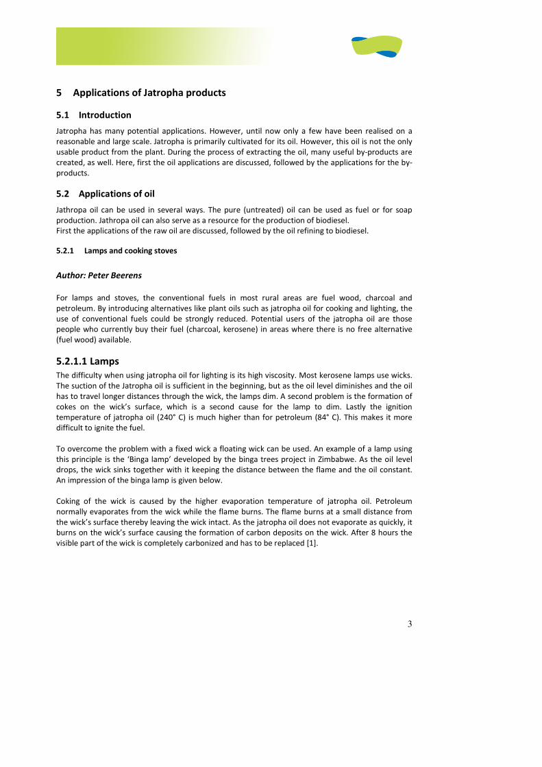
3
5 Applications of Jatropha products
5.1 Introduction
Jatropha has many potential applications. However, until now only a few have been realised on a
reasonable and large scale. Jatropha is primarily cultivated for its oil. However, this oil is not the only
usable product from the plant. During the process of extracting the oil, many useful by-products are
created, as well. Here, first the oil applications are discussed, followed by the applications for the by-
products.
5.2 Applications of oil
Jathropa oil can be used in several ways. The pure (untreated) oil can be used as fuel or for soap
production. Jathropa oil can also serve as a resource for the production of biodiesel.
First the applications of the raw oil are discussed, followed by the oil refining to biodiesel.
5.2.1 Lamps and cooking stoves
Author: Peter Beerens
For lamps and stoves, the conventional fuels in most rural areas are fuel wood, charcoal and
petroleum. By introducing alternatives like plant oils such as jatropha oil for cooking and lighting, the
use of conventional fuels could be strongly reduced. Potential users of the jatropha oil are those
people who currently buy their fuel (charcoal, kerosene) in areas where there is no free alternative
(fuel wood) available.
5.2.1.1 Lamps
The difficulty when using jatropha oil for lighting is its high viscosity. Most kerosene lamps use wicks.
The suction of the Jatropha oil is sufficient in the beginning, but as the oil level diminishes and the oil
has to travel longer distances through the wick, the lamps dim. A second problem is the formation of
cokes on the wick’s surface, which is a second cause for the lamp to dim. Lastly the ignition
temperature of jatropha oil (240° C) is much higher than for petroleum (84° C). This makes it more
difficult to ignite the fuel.
To overcome the problem with a fixed wick a floating wick can be used. An example of a lamp using
this principle is the ‘Binga lamp’ developed by the binga trees project in Zimbabwe. As the oil level
drops, the wick sinks together with it keeping the distance between the flame and the oil constant.
An impression of the binga lamp is given below.
Coking of the wick is caused by the higher evaporation temperature of jatropha oil. Petroleum
normally evaporates from the wick while the flame burns. The flame burns at a small distance from
the wick’s surface thereby leaving the wick intact. As the jatropha oil does not evaporate as quickly, it
burns on the wick’s surface causing the formation of carbon deposits on the wick. After 8 hours the
visible part of the wick is completely carbonized and has to be replaced [1].
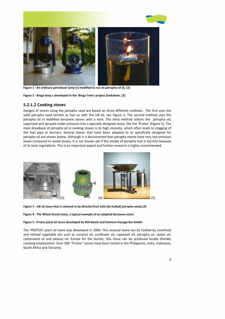
4
Figure 1 - An ordinary petroleum lamp (r) modified to run on jatropha oil (l). [2]
Figure 2 - Binga lamp s developed in the 'Binga Trees' project Zimbabwe. [3]
5.2.1.2 Cooking stoves
Designs of stoves using the jatropha seed are based on three different methods. The first uses the
solid jatropha seed kernels as fuel as with the UB-16, see Figure 3. The second method uses the
jatropha oil in modified kerosene stoves with a wick. The third method utilizes the jatropha oil,
vaporized and sprayed under pressure into a specially designed stove, like the ‘Protos’ (Figure 5). The
main drawback of jatropha oil in cooking stoves is its high viscosity, which often leads to clogging of
the fuel pipe or burners. Several stoves that have been adapted to or specifically designed for
jatropha oil are shown below. Although it is documented that jatropha stoves have very low emission
levels compared to wood stoves, it is not known yet if the smoke of jatropha fuel is harmful because
of its toxic ingredients. This is an important aspect and further research is highly recommended.
(3) (4) (5)
Figure 3 - UB-16 stove that is claimed to be directly fired with (de-hulled) jatropha seeds.[4]
Figure 4 - The Wheel brand stove, a typical example of an adapted kerosene stove.
Figure 5 - Protos plant oil stove developed by BSH Bosch and Siemens Hausgeräte GmbH.
The ‘PROTOS’ plant oil stove was developed in 2004. This unusual stove can be fuelled by unrefined
and refined vegetable oils such as coconut oil, sunflower oil, rapeseed oil, jatropha oil, castor oil,
cottonseed oil and peanut oil. Except for the burner, this stove can be produced locally thereby
creating employment. Over 500 ‘‘Protos’’ stoves have been tested in the Philippines, India, Indonesia,
South Africa and Tanzania.
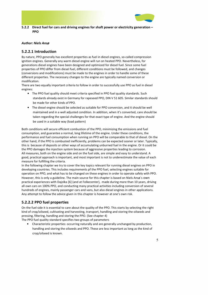
5
5.2.2 Direct fuel for cars and driving engines for shaft power or electricity generation –
PPO
Author: Niels Ansø
5.2.2.1 Introduction
By nature, PPO generally has excellent properties as fuel in diesel engines, so-called compression
ignition engines. Generally any warm diesel engine will run on heated PPO. Nevertheless, for
generations diesel engines have been designed and optimized for diesel fuel. Since some fuel
properties of PPO differ from diesel fuel, different conditions must be followed, and changes
(conversions and modifications) must be made to the engines in order to handle some of these
different properties. The necessary changes to the engine are typically named conversion or
modification.
There are two equally important criteria to follow in order to successfully use PPO as fuel in diesel
engines:
• The PPO fuel quality should meet criteria specified in PPO fuel quality standards. Such
standards already exist in Germany for rapeseed PPO, DIN V 51 605. Similar standards should
be made for other kinds of PPO.
• The diesel engine should be selected as suitable for PPO conversion, and it should be well
maintained and in a well adjusted condition. In addition, when it’s converted, care should be
taken regarding the special challenges for that exact type of engine. And the engine should
be used in a suitable way (load pattern)
Both conditions will secure efficient combustion of the PPO, minimizing the emissions and fuel
consumption, and guarantee a normal, long lifetime of the engine. Under these conditions, the
performance and fuel consumption when running on PPO will be comparable to that of diesel. On the
other hand, if the PPO is combusted inefficiently, problems can be expected sooner or later. Typically,
this is because of deposits or other ways of accumulating unburned fuel in the engine. Or it could be
the PPO damages the injection system because of aggressive properties leading to corrosion.
All measures, both on the engine side and on the fuel side, are simple and easy to understand. A
good, practical approach is important, and most important is not to underestimate the value of each
measure for fulfilling the criteria.
In the following chapter we try to cover the key topics relevant for running diesel engines on PPO in
developing countries. This includes requirements pf the PPO fuel, selecting engines suitable for
operation on PPO, and what has to be changed on these engines in order to operate safely with PPO.
However, this is only a guideline. The main source for this chapter is based on Niels Ansø´s own
practical experiences with Dajolka [6] (and at Folkecenter), made during more than 10 years, driving
all own cars on 100% PPO, and conducting many practical activities including conversion of several
hundreds of engines, mainly passenger cars and vans, but also diesel engines in other applications.
Any attempt to follow the advice given in this chapter is however at one’s own risk.
5.2.2.2 PPO fuel properties
On the fuel side it is essential to care about the quality of the PPO. This starts by selecting the right
kind of crop/oilseed, cultivating and harvesting, transport, handling and storing the oilseeds and
pressing, filtering, handling and storing the PPO. (See chapter 4)
The PPO fuel quality standard specifies two groups of parameters
• Characteristic properties: occurring naturally and are generally unchanged by production,
handling and storing the oilseeds and PPO. These are less important as long as the kind of
crop/oilseed is known.
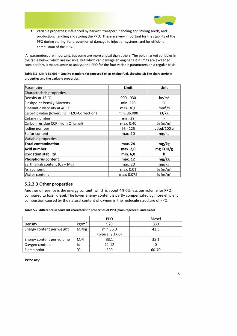
6
• Variable properties: influenced by harvest, transport, handling and storing seeds, and
production, handling and storing the PPO. These are very important for the stability of the
PPO during storing, for prevention of damage to injection systems, and for efficient
combustion of the PPO.
All parameters are important, but some are more critical than others. The bold marked variables in
the table below, which are invisible, but which can damage an engine fast if limits are exceeded
considerably. It makes sense to analyse the PPO for the four variable parameters on a regular basis.
Table 5.1: DIN V 51 605 – Quality standard for rapeseed oil as engine fuel, showing 1): The characteristic
properties and the variable properties.
Parameter Limit Unit
Characteristic properties
Density at 15 °C 900 - 930 kg/m³
Flashpoint Pensky-Martens min. 220 °C
Kinematic viscosity at 40 °C max. 36,0 mm²/s
Calorific value (lower; incl. H2O-Correction) min. 36.000 kJ/kg
Cetane number min. 39 -
Carbon residue CCR (from Original) max. 0,40 % (m/m)
Iodine number 95 - 125 g Jod/100 g
Sulfur content max. 10 mg/kg
Variable properties
Total contamination max. 24 mg/kg
Acid number max. 2,0 mg KOH/g
Oxidation stability min. 6,0 h
Phosphorus content max. 12 mg/kg
Earth alkali content (Ca + Mg) max. 20 mg/kg
Ash content max. 0,01 % (m/m)
Water content max. 0,075 % (m/m)
5.2.2.3 Other properties
Another difference is the energy content, which is about 4%-5% less per volume for PPO,
compared to fossil diesel. The lower energy content is partly compensated by more efficient
combustion caused by the natural content of oxygen in the molecule structure of PPO.
Table 5.2: difference in constant characteristic properties of PPO (from rapeseed) and diesel
PPO Diesel
Density kg/m3 920 830
Energy content per weight MJ/kg min 36,0
(typically 37,0)
42,3
Energy content per volume MJ/l 33,1 35,1
Oxygen content % 11-12 0
Flame point °C 220 60-70
Viscosity
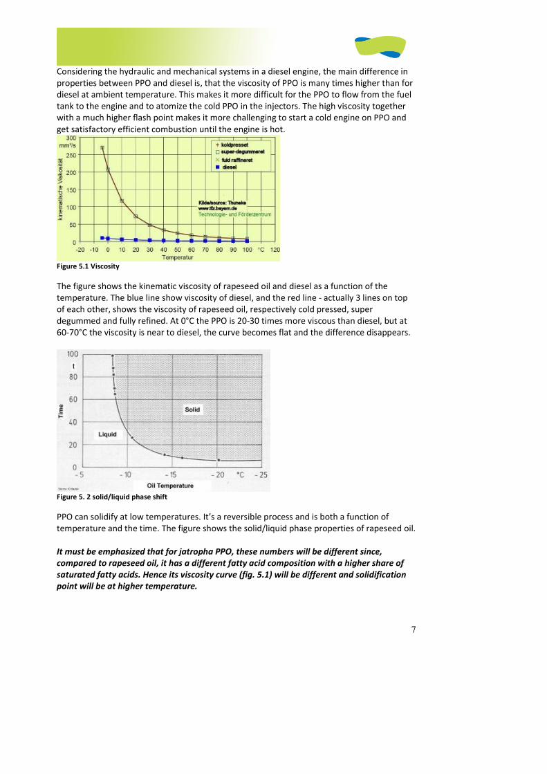
7
Considering the hydraulic and mechanical systems in a diesel engine, the main difference in
properties between PPO and diesel is, that the viscosity of PPO is many times higher than for
diesel at ambient temperature. This makes it more difficult for the PPO to flow from the fuel
tank to the engine and to atomize the cold PPO in the injectors. The high viscosity together
with a much higher flash point makes it more challenging to start a cold engine on PPO and
get satisfactory efficient combustion until the engine is hot.
Figure 5.1 Viscosity
The figure shows the kinematic viscosity of rapeseed oil and diesel as a function of the
temperature. The blue line show viscosity of diesel, and the red line - actually 3 lines on top
of each other, shows the viscosity of rapeseed oil, respectively cold pressed, super
degummed and fully refined. At 0°C the PPO is 20-30 times more viscous than diesel, but at
60-70°C the viscosity is near to diesel, the curve becomes flat and the difference disappears.
Figure 5. 2 solid/liquid phase shift
PPO can solidify at low temperatures. It’s a reversible process and is both a function of
temperature and the time. The figure shows the solid/liquid phase properties of rapeseed oil.
It must be emphasized that for jatropha PPO, these numbers will be different since,
compared to rapeseed oil, it has a different fatty acid composition with a higher share of
saturated fatty acids. Hence its viscosity curve (fig. 5.1) will be different and solidification
point will be at higher temperature.

8
5.2.2.4 Engine conversion/ Engine types
To enable the engine to run safely on PPO the engine must be converted to handle the
different fuel properties of PPO compared with diesel. For example, it’s necessary to heat
the PPO in order to decrease the viscosity, and to modify injectors and glow plugs to enable
the engine to start on PPO.
Because of the large variety of engines combined with different manufactories and
configuration of injection system, this chapter can only serve as a guide to the most basic
things relevant for conversion. Only engines with mechanical controlled injection systems will
be discussed, since engines with electronically controlled injections are still not common in
developing countries, and because the conversion requires more specialized technology,
tools and mechanics trained in these systems.
As mentioned before, generally any warm diesel engine will run fine on heated PPO. The
main challenge is to get the engine started and run it with satisfactory clean combustion until
it reaches normal operating temperature – typically about 80-90°C for a water cooled engine.
5.2.2.4.1 Identification of the engine
Diesel engines exist in many different types and sizes. Most of them can be converted to PPO
in one or the other way. It’s important to first identify and choose a suitable engine, and then
decide how it should be converted. The main question is whether the engine has direct or
indirect injection, and how the engine cooling system is designed. The cooling system is
important because it controls the engine operating temperature, and the expended heat
from the engine is used to heat the PPO.
Generally all diesel engines with InDirect Injection(IDI) are very suitable for conversion to
PPO.
Engines with Direct Injection (DI) can also be converted, but they are more sensitive to the
load pattern and fuel quality, so they require more attention and are typically converted with
a duel-tank (2-tank) system.
It is normally not recommended to convert engines equipped with distributor injection
pumps manufactured by Lucas/CAV/Delphi, Stanadyne or Roto-Diesel. This is because there
is a high risk of damaging the pump, typically when the pump and PPO are cold. Other
engines can have other problems, making them less suitable for conversion, e.g. DI engines
with a bore/stroke ratio > 1.
Therefore, before deciding to convert an engine, it is important to identify the engine, the
type and manufacturer of the injection system, and the typical load pattern for the engine.
Based on these factors, it’s possible to determine if conversion of that engine is feasible.
Initially it is important to determine if the engine has direct or indirect injection, identify
which type of preheating system is available (if any), the kind of injection pump and lift
pump, and to identify the kind of cooling system. It can often be helpful to make a drawing of
the fuel system, showing all components and fuel lines.
For exact identification of the engine it is important to get the following information:
Manufacturer, engine code, year of manufacture, number of cylinders, displacement (cm3),
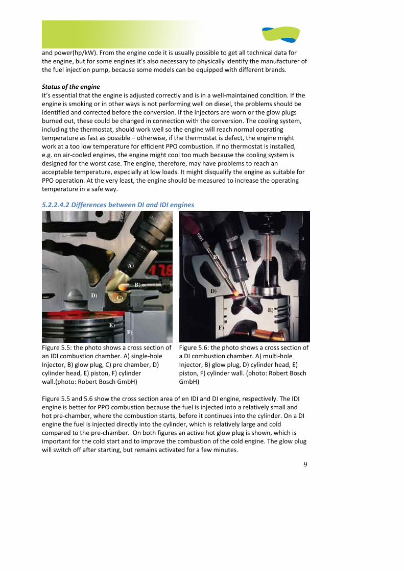
9
and power(hp/kW). From the engine code it is usually possible to get all technical data for
the engine, but for some engines it’s also necessary to physically identify the manufacturer of
the fuel injection pump, because some models can be equipped with different brands.
Status of the engine
It’s essential that the engine is adjusted correctly and is in a well-maintained condition. If the
engine is smoking or in other ways is not performing well on diesel, the problems should be
identified and corrected before the conversion. If the injectors are worn or the glow plugs
burned out, these could be changed in connection with the conversion. The cooling system,
including the thermostat, should work well so the engine will reach normal operating
temperature as fast as possible – otherwise, if the thermostat is defect, the engine might
work at a too low temperature for efficient PPO combustion. If no thermostat is installed,
e.g. on air-cooled engines, the engine might cool too much because the cooling system is
designed for the worst case. The engine, therefore, may have problems to reach an
acceptable temperature, especially at low loads. It might disqualify the engine as suitable for
PPO operation. At the very least, the engine should be measured to increase the operating
temperature in a safe way.
5.2.2.4.2 Differences between DI and IDI engines
Figure 5.5: the photo shows a cross section of
an IDI combustion chamber. A) single-hole
Injector, B) glow plug, C) pre chamber, D)
cylinder head, E) piston, F) cylinder
wall.(photo: Robert Bosch GmbH)
Figure 5.6: the photo shows a cross section of
a DI combustion chamber. A) multi-hole
Injector, B) glow plug, D) cylinder head, E)
piston, F) cylinder wall. (photo: Robert Bosch
GmbH)
Figure 5.5 and 5.6 show the cross section area of en IDI and DI engine, respectively. The IDI
engine is better for PPO combustion because the fuel is injected into a relatively small and
hot pre-chamber, where the combustion starts, before it continues into the cylinder. On a DI
engine the fuel is injected directly into the cylinder, which is relatively large and cold
compared to the pre-chamber. On both figures an active hot glow plug is shown, which is
important for the cold start and to improve the combustion of the cold engine. The glow plug
will switch off after starting, but remains activated for a few minutes.
A)
B)
C) D)
E)
A) B)
D)
E)
F) F)
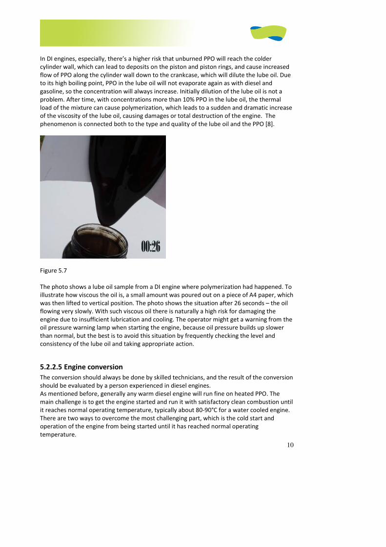
10
In DI engines, especially, there’s a higher risk that unburned PPO will reach the colder
cylinder wall, which can lead to deposits on the piston and piston rings, and cause increased
flow of PPO along the cylinder wall down to the crankcase, which will dilute the lube oil. Due
to its high boiling point, PPO in the lube oil will not evaporate again as with diesel and
gasoline, so the concentration will always increase. Initially dilution of the lube oil is not a
problem. After time, with concentrations more than 10% PPO in the lube oil, the thermal
load of the mixture can cause polymerization, which leads to a sudden and dramatic increase
of the viscosity of the lube oil, causing damages or total destruction of the engine. The
phenomenon is connected both to the type and quality of the lube oil and the PPO [8].
Figure 5.7
The photo shows a lube oil sample from a DI engine where polymerization had happened. To
illustrate how viscous the oil is, a small amount was poured out on a piece of A4 paper, which
was then lifted to vertical position. The photo shows the situation after 26 seconds – the oil
flowing very slowly. With such viscous oil there is naturally a high risk for damaging the
engine due to insufficient lubrication and cooling. The operator might get a warning from the
oil pressure warning lamp when starting the engine, because oil pressure builds up slower
than normal, but the best is to avoid this situation by frequently checking the level and
consistency of the lube oil and taking appropriate action.
5.2.2.5 Engine conversion
The conversion should always be done by skilled technicians, and the result of the conversion
should be evaluated by a person experienced in diesel engines.
As mentioned before, generally any warm diesel engine will run fine on heated PPO. The
main challenge is to get the engine started and run it with satisfactory clean combustion until
it reaches normal operating temperature, typically about 80-90°C for a water cooled engine.
There are two ways to overcome the most challenging part, which is the cold start and
operation of the engine from being started until it has reached normal operating
temperature.
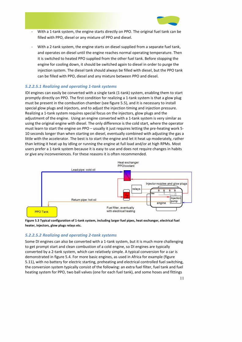
11
- With a 1-tank system, the engine starts directly on PPO. The original fuel tank can be
filled with PPO, diesel or any mixture of PPO and diesel.
- With a 2-tank system, the engine starts on diesel supplied from a separate fuel tank,
and operates on diesel until the engine reaches normal operating temperature. Then
it is switched to heated PPO supplied from the other fuel tank. Before stopping the
engine for cooling down, it should be switched again to diesel in order to purge the
injection system. The diesel tank should always be filled with diesel, but the PPO tank
can be filled with PPO, diesel and any mixture between PPO and diesel.
5.2.2.5.1 Realizing and operating 1-tank systems
IDI engines can easily be converted with a single tank (1-tank) system, enabling them to start
promptly directly on PPO. The first condition for realizing a 1-tank system is that a glow plug
must be present in the combustion chamber (see figure 5.5), and it is necessary to install
special glow plugs and injectors, and to adjust the injection timing and injection pressure.
Realizing a 1-tank system requires special focus on the injectors, glow plugs and the
adjustment of the engine. Using an engine converted with a 1-tank system is very similar as
using the original engine with diesel. The only difference is the cold start, where the operator
must learn to start the engine on PPO – usually it just requires letting the pre-heating work 5-
10 seconds longer than when starting on diesel, eventually combined with adjusting the gas a
little with the accelerator. The best is to start the engine and let it heat up moderately, rather
than letting it heat up by idling or running the engine at full load and/or at high RPMs. Most
users prefer a 1-tank system because it is easy to use and does not require changes in habits
or give any inconveniences. For these reasons it is often recommended.
Figure 5.3 Typical configuration of 1-tank system, including larger fuel pipes, heat exchanger, electrical fuel
heater, injectors, glow plugs relays etc.
5.2.2.5.2 Realizing and operating 2-tank systems
Some DI engines can also be converted with a 1-tank system, but it is much more challenging
to get prompt start and clean combustion of a cold engine, so DI engines are typically
converted by a 2-tank system, which can relatively simple. A typical conversion for a car is
demonstrated in figure 5.4. For more basic engines, as used in Africa for example (figure
5.11), with no battery for electric starting, preheating and electrical controlled fuel switching,
the conversion system typically consist of the following: an extra fuel filter, fuel tank and fuel
heating system for PPO, two ball valves (one for each fuel tank), and some hoses and fittings
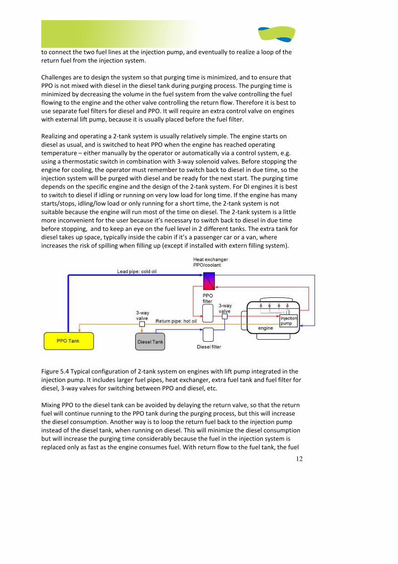
12
to connect the two fuel lines at the injection pump, and eventually to realize a loop of the
return fuel from the injection system.
Challenges are to design the system so that purging time is minimized, and to ensure that
PPO is not mixed with diesel in the diesel tank during purging process. The purging time is
minimized by decreasing the volume in the fuel system from the valve controlling the fuel
flowing to the engine and the other valve controlling the return flow. Therefore it is best to
use separate fuel filters for diesel and PPO. It will require an extra control valve on engines
with external lift pump, because it is usually placed before the fuel filter.
Realizing and operating a 2-tank system is usually relatively simple. The engine starts on
diesel as usual, and is switched to heat PPO when the engine has reached operating
temperature – either manually by the operator or automatically via a control system, e.g.
using a thermostatic switch in combination with 3-way solenoid valves. Before stopping the
engine for cooling, the operator must remember to switch back to diesel in due time, so the
injection system will be purged with diesel and be ready for the next start. The purging time
depends on the specific engine and the design of the 2-tank system. For DI engines it is best
to switch to diesel if idling or running on very low load for long time. If the engine has many
starts/stops, idling/low load or only running for a short time, the 2-tank system is not
suitable because the engine will run most of the time on diesel. The 2-tank system is a little
more inconvenient for the user because it’s necessary to switch back to diesel in due time
before stopping, and to keep an eye on the fuel level in 2 different tanks. The extra tank for
diesel takes up space, typically inside the cabin if it’s a passenger car or a van, where
increases the risk of spilling when filling up (except if installed with extern filling system).
Figure 5.4 Typical configuration of 2-tank system on engines with lift pump integrated in the
injection pump. It includes larger fuel pipes, heat exchanger, extra fuel tank and fuel filter for
diesel, 3-way valves for switching between PPO and diesel, etc.
Mixing PPO to the diesel tank can be avoided by delaying the return valve, so that the return
fuel will continue running to the PPO tank during the purging process, but this will increase
the diesel consumption. Another way is to loop the return fuel back to the injection pump
instead of the diesel tank, when running on diesel. This will minimize the diesel consumption
but will increase the purging time considerably because the fuel in the injection system is
replaced only as fast as the engine consumes fuel. With return flow to the fuel tank, the fuel

13
in the injection system is changed much faster, because the total amount of fuel displaced by
the lift pump over the supply and return lines can be up to 5 times as much as the actual
consumption.
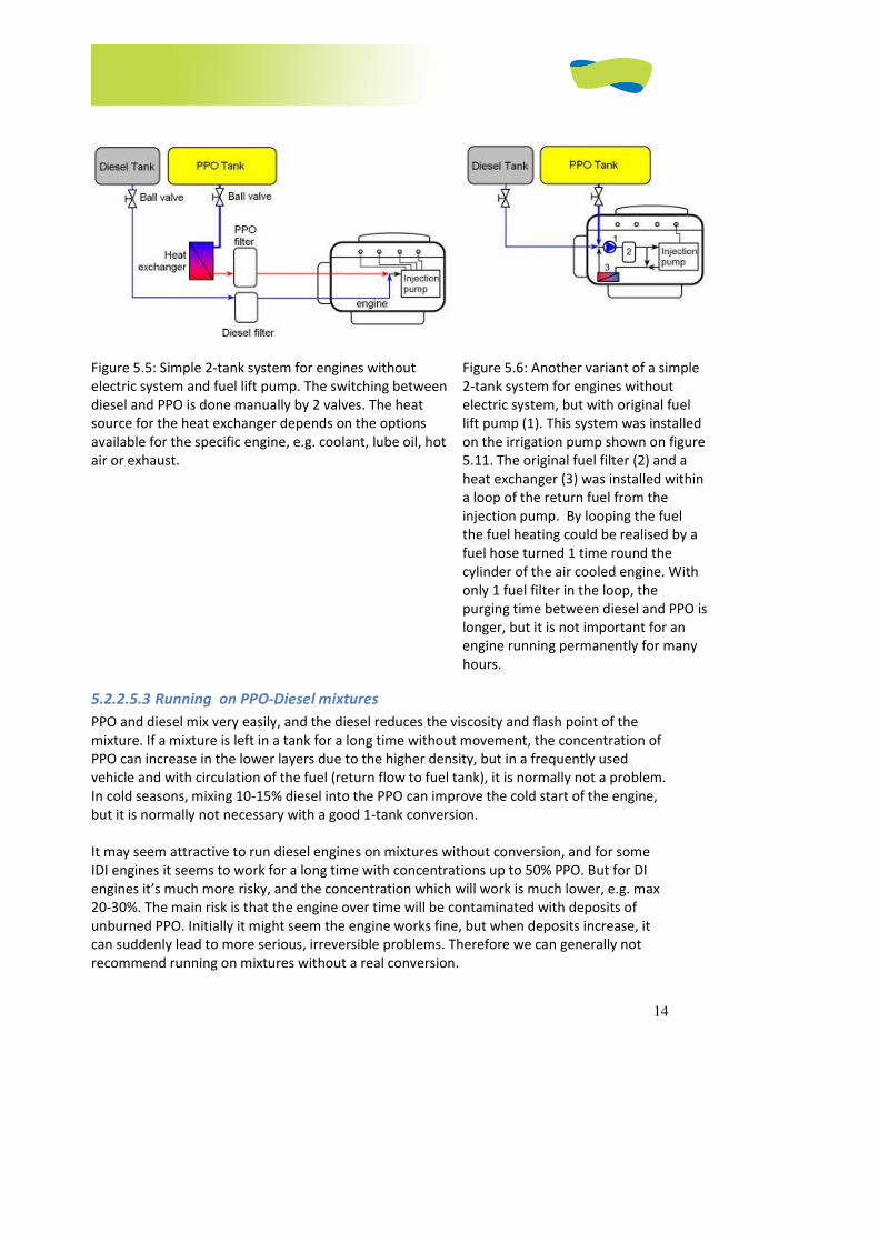
14
Figure 5.5: Simple 2-tank system for engines without
electric system and fuel lift pump. The switching between
diesel and PPO is done manually by 2 valves. The heat
source for the heat exchanger depends on the options
available for the specific engine, e.g. coolant, lube oil, hot
air or exhaust.
Figure 5.6: Another variant of a simple
2-tank system for engines without
electric system, but with original fuel
lift pump (1). This system was installed
on the irrigation pump shown on figure
5.11. The original fuel filter (2) and a
heat exchanger (3) was installed within
a loop of the return fuel from the
injection pump. By looping the fuel
the fuel heating could be realised by a
fuel hose turned 1 time round the
cylinder of the air cooled engine. With
only 1 fuel filter in the loop, the
purging time between diesel and PPO is
longer, but it is not important for an
engine running permanently for many
hours.
5.2.2.5.3 Running on PPO-Diesel mixtures
PPO and diesel mix very easily, and the diesel reduces the viscosity and flash point of the
mixture. If a mixture is left in a tank for a long time without movement, the concentration of
PPO can increase in the lower layers due to the higher density, but in a frequently used
vehicle and with circulation of the fuel (return flow to fuel tank), it is normally not a problem.
In cold seasons, mixing 10-15% diesel into the PPO can improve the cold start of the engine,
but it is normally not necessary with a good 1-tank conversion.
It may seem attractive to run diesel engines on mixtures without conversion, and for some
IDI engines it seems to work for a long time with concentrations up to 50% PPO. But for DI
engines it’s much more risky, and the concentration which will work is much lower, e.g. max
20-30%. The main risk is that the engine over time will be contaminated with deposits of
unburned PPO. Initially it might seem the engine works fine, but when deposits increase, it
can suddenly lead to more serious, irreversible problems. Therefore we can generally not
recommend running on mixtures without a real conversion.

15
5.2.2.6 Important technical issues
5.2.2.6.1 Glow system
A glow plug in the combustion chamber is used to preheat the combustion (pre) chamber
before the cold start of the engine. This is an important device for realizing a 1-tank system.
Typically glow plugs are a few mm longer than the original glow plugs that are installed, in
order to add more heat to the combustion (pre) chamber before the start, and so that the
fuel spray from the injectors reaches the hot tip of the glow plug. It is also an advantage to
combine longer glow plugs with a post glow system, which means that the glow plugs are
activated also a few minutes after the cold start, and thereby improve the combustion of the
cold engine. It requires a special kind of glow plugs designed for post glow applications –
otherwise the glow plugs will burn out rapidly.
There are other kinds of glow systems, such as a glow coil placed in the air intake manifold,
which will ignite a small amount of diesel fuel. Such a system will not work with PPO as fuel,
and cannot work with post glow. So the best is to convert such an engine with a 2-tank
system. If there is no glow system, the engine should always be converted with a 2-tank
system. If the engine is equipped with a fuel-based pre- heating system, typically placed in
the air intake manifold, care should be taken that this system will be supplied with diesel.
5.2.2.6.2 Injectors
There exist many different injectors, and there might be several suitable solutions for the
same engine. 1-tank systems require special injectors and increased injection pressure, but
for a 2-tank system, usually the original injectors are used, and therefore not replaced unless
they are worn. Eventually the injection pressure is increased on 2-tank system depending on
the original configuration. Change of injectors might seem complicated and expensive, but
often it will improve the performance of a used engine, and even extend its lifetime due to
cleaner combustion.
A general rule is that higher injection pressure gives a better atomizing of the fuel and
therefore a better cold start and a cleaner combustion. Therefore, the injection pressure
should be increased, at least to the maximum within the range specified by the engine
manufacturer, or slightly higher. If the injection pressure is increased much higher than the
original pressure, it can result in a delay of the injection start and a decrease in the injected
fuel amount. So it might be necessary to compensate for this by advancing the timing and
increase the fuel quantity respectively.
Another general advantage is to use injectors that inject a small pilot injection before the
main injection. That makes the combustion of the main injection faster and more complete.
Pilot injection can be realized by the shape of the injector needle, or by a 2-spring injector
configuration. This relation was also found by the ACREVO study [7].
5.2.2.6.3 Timing
Correct injection timing is critical to the performance of the engine, especially the cold start.
In general, “early” injection increases the combustion temperature and makes the engine
sound harder, and gives a better cold start, higher torque and more efficient combustion.
Late injection can lead to bad cold start, high exhaust temperature and inefficient
combustion, which also can be noticed by grey smoke with an irritating bad smell of
unburned PPO.
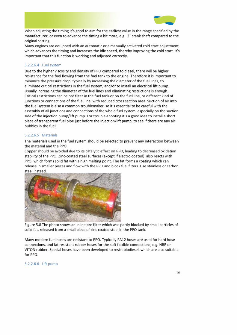
16
When adjusting the timing it’s good to aim for the earliest value in the range specified by the
manufacturer, or even to advance the timing a bit more, e.g. 2° crank shaft compared to the
original setting.
Many engines are equipped with an automatic or a manually activated cold start adjustment,
which advances the timing and increases the idle speed, thereby improving the cold start. It’s
important that this function is working and adjusted correctly.
5.2.2.6.4 Fuel system
Due to the higher viscosity and density of PPO compared to diesel, there will be higher
resistance for the fuel flowing from the fuel tank to the engine. Therefore it is important to
minimize the pressure drop, typically by increasing the diameter of the fuel lines, to
eliminate critical restrictions in the fuel system, and/or to install an electrical lift pump.
Usually increasing the diameter of the fuel lines and eliminating restrictions is enough.
Critical restrictions can be pre filter in the fuel tank or on the fuel line, or different kind of
junctions or connections of the fuel line, with reduced cross section area. Suction of air into
the fuel system is also a common troublemaker, so it’s essential to be careful with the
assembly of all junctions and connections of the whole fuel system, especially on the suction
side of the injection pump/lift pump. For trouble-shooting it’s a good idea to install a short
piece of transparent fuel pipe just before the injection/lift pump, to see if there are any air
bubbles in the fuel.
5.2.2.6.5 Materials
The materials used in the fuel system should be selected to prevent any interaction between
the material and the PPO.
Copper should be avoided due to its catalytic effect on PPO, leading to decreased oxidation
stability of the PPO. Zinc-coated steel surfaces (except if electro-coated) also reacts with
PPO, which forms solid fat with a high melting point. The fat forms a coating which can
release in smaller pieces and flow with the PPO and block fuel filters. Use stainless or carbon
steel instead.
Figure 5.8 The photo shows an inline pre filter which was partly blocked by small particles of
solid fat, released from a small piece of zinc coated steel in the PPO tank.
Many modern fuel hoses are resistant to PPO. Typically PA12 hoses are used for hard hose
connections, and fat resistant rubber hoses for the soft flexible connections, e.g. NBR or
VITON rubber. Special hoses have been developed to resist biodiesel, which are also suitable
for PPO.
5.2.2.6.6 Lift pump

17
On most diesel engines a lift pump is used to suck the fuel from the tank and supply the
correct fuel pressure to the injection pump. It’s typically mechanical pumps, either integrated
in the injection pump or an external device attached to the engine or the injection pump.
Some engines have no lift pump, so the fuel pressure is generated by gravity due to a lifted
fuel tank. On several newer vehicles, an electrical lift pump integrated in the fuel tank
generates the fuel pressure. When converting the engine to PPO, the system should ensure
that both suction and fuel pressure are kept within the limits originally designed for that
engine.
A vane type lift pump integrated in the injection pump usually works within a range of 0.2-0.3
bars suction. If the suction increases, e.g. to 0.4-0.5 bar or more, the injection pump can have
insufficient fuel pressure and fuel quantity, leading to malfunction of the injection and loss of
power. There is also an increased risk of damaging the injection pump. For the conversion
and for trouble-shooting later on, it is useful to measure the vacuum in the fuel line before
the injection/lift pump , using a vacuum meter with scale 0-1 bars.
External / mechanical membrane type lift pumps are usually installed before the fuel filter,
and should overcome the pressure loss through the fuel filter, and still maintain a positive
pressure at the injection pump – typically 0.1-0.5 bars overpressure. The membrane material
may not be suitable for PPO, and therefore requires being changed more frequently. Some
pumps cannot supply enough positive pressure with cold and high viscous PPO. This situation
could be avoided by a 2-tank solution, or modifications could be made to the lift pump, or an
external electrical lift pump could be installed either to assist or replace the original lift
pump. Keep in mind that the supply pressure at the injection pump should be within the
originally specified limits.
5.2.2.6.7 Fuel heating
Heating the PPO is commonly used to reduce the viscosity and eventually melt solid or semi-
solid fats flowing in the liquid part of the cold PPO. The heat is typically introduced before
the fuel filter in order to reduce the pressure drop through the fuel filter, and to prevent the
filter from being blocked with solid fats in the PPO. The reduced viscosity also enables the
injection pump to handle the PPO, and it improves the performance of the injectors
(atomizing). The PPO is typically heated with excess heat from the engine, which always is
available from an internal combustion engine (60-70% of the energy content of the fuel). Fuel
temperatures around 60-70°C are typically reached by water cooled engines, using the
coolant as a heat source, and is self limiting due to the thermostat controlled coolant
temperature. If the engine after the conversion is meant to run on diesel from time to time,
it’s wise not to heat the fuel above 70°C due to the lubricity properties and lower boiling
point of diesel, which can lead to decreased lubricity and fuel steam bubbles in the fuel,
causing wear and mechanical stress in the injection system, and malfunction of the fuel
injection. If the fuel temperature can exceed about 70°C, e.g. using the lube oil or exhaust
gas as heat source, the fuel heating system should be disabled when running on diesel. As
long as the PPO is liquid, heating the fuel tank and the fuel lines is not necessary – and it is
better for the stability of the PPO in the tank.
Water-cooled engines usually reach operating temperature around 80-90°C relatively fast,
and the coolant is a good heat carrier. An easy and good way to heat the PPO is by a coolant-
PPO heat exchanger. It can be homemade, but there are many suitable plate-heat
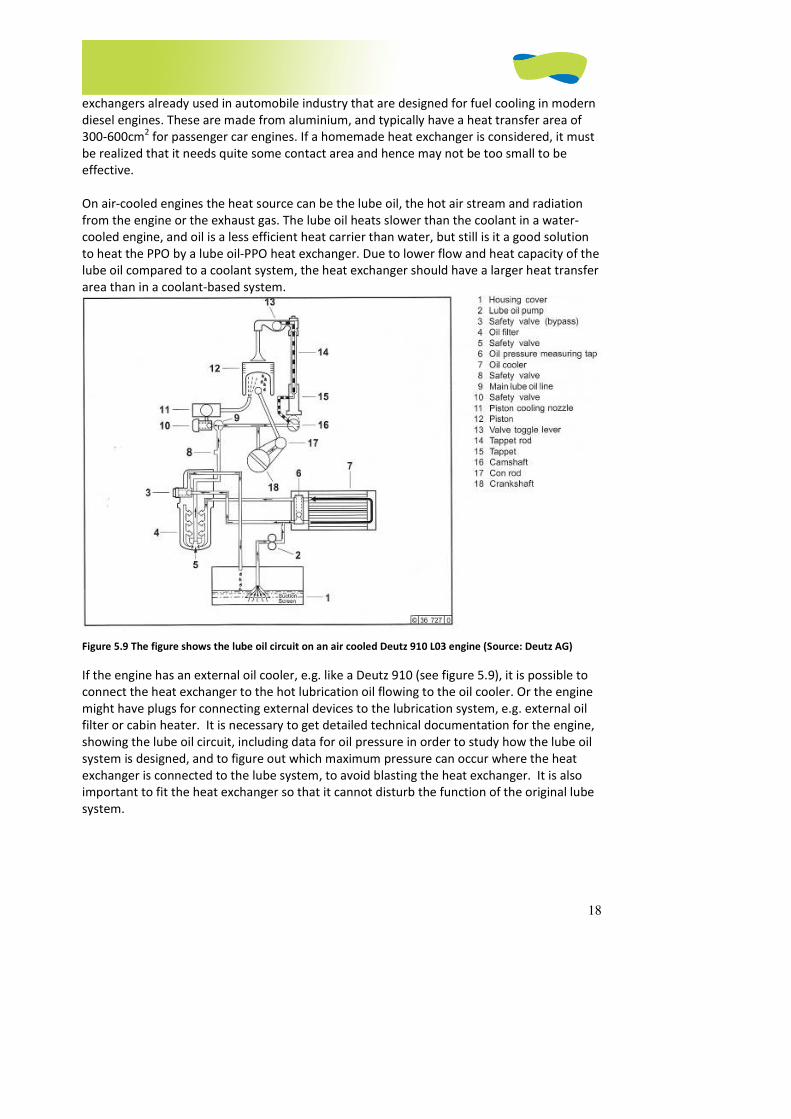
18
exchangers already used in automobile industry that are designed for fuel cooling in modern
diesel engines. These are made from aluminium, and typically have a heat transfer area of
300-600cm2 for passenger car engines. If a homemade heat exchanger is considered, it must
be realized that it needs quite some contact area and hence may not be too small to be
effective.
On air-cooled engines the heat source can be the lube oil, the hot air stream and radiation
from the engine or the exhaust gas. The lube oil heats slower than the coolant in a water-
cooled engine, and oil is a less efficient heat carrier than water, but still is it a good solution
to heat the PPO by a lube oil-PPO heat exchanger. Due to lower flow and heat capacity of the
lube oil compared to a coolant system, the heat exchanger should have a larger heat transfer
area than in a coolant-based system.
Figure 5.9 The figure shows the lube oil circuit on an air cooled Deutz 910 L03 engine (Source: Deutz AG)
If the engine has an external oil cooler, e.g. like a Deutz 910 (see figure 5.9), it is possible to
connect the heat exchanger to the hot lubrication oil flowing to the oil cooler. Or the engine
might have plugs for connecting external devices to the lubrication system, e.g. external oil
filter or cabin heater. It is necessary to get detailed technical documentation for the engine,
showing the lube oil circuit, including data for oil pressure in order to study how the lube oil
system is designed, and to figure out which maximum pressure can occur where the heat
exchanger is connected to the lube system, to avoid blasting the heat exchanger. It is also
important to fit the heat exchanger so that it cannot disturb the function of the original lube
system.

19
Figure 5.10. Three variants of a simplified lube oil circuit of an air-cooled engine. Left: the
engine is prepared for connection of external oil cooler, oil filter or cabin heater (C). Centre:
External oil cooler is installed. Right: a heat exchanger (B) has been connected to the lube oil
pipe between the lube oil pump (A) and the external oil cooler (C)
Using the exhaust as heat source is also an option, which might seem attractive, but it also
has disadvantages. There exists a technical risk that the PPO is overheated because of the
high temperature of the flue gas (up to 500°C) leading to cracking of the fuel, and a fire risk,
especially if diesel fuel is leaking inside or near the exhaust system. Due to very high
difference between fuel and exhaust gas temperature, the system cannot be self-limiting.
The fuel temperature should be controlled by precise design and control of the fuel flow. If
the injection system includes a return line to the fuel tank, the fuel flow will be much higher
than the fuel consumption, and vary a lot depending on the engine speed, load, fuel
temperature, condition of fuel filter etc.
Fuel heating can also be realized electrically, or combined with one of the solutions described
above. Some car brands have electrical fuel heater for diesel, and retrofit solutions exist, but
many of these will switch off before the fuel has reached a temperature suitable for PPO.
Therefore an electrical fuel heater should be well selected and eventually modified for PPO.
Heating PPO with a glow plug may seem attractive, but there is a high risk that the PPO will
crack/burn due to the concentrated heat transfer of high power and a very small area.
Generally it is advised not to use electrical PPO heating alone (or at all) but to use coolant or
lube oil as the main source of heat.
5.2.2.7 Service and maintenance
After the conversion, the engine should generally be serviced and maintained as if it was still
running on diesel.
Fuel filter
Just after the conversion of a used engine, the fuel filter can quickly become blocked because
the PPO can release dirt and deposits in the fuel tank, and due to the higher density, PPO can
lift and move more dirt than diesel fuel. If the PPO fuel is clean, the fuel filters can last as
long as with diesel. Nevertheless, a blocked fuel filter makes more problems with PPO than
with diesel, so it is a good idea to change the fuel filter at least once a year, e.g. before a cold
season.
Lube oil and filter
C)
A)
Engine
C)
A)
Engine
B) Fuel
Lube oil Lube oil
A)
Engine
Lube oil
20
Regarding change of lube oil and filter, it can be kept on the same service interval as for
diesel for IDI engines. For DI engines it is usually recommended to halve the change interval
compared to operation on diesel (change the oil twice as often). That is because DI engines
have a stronger tendency to get PPO diluted in the lube oil, which can lead to polymerization
(see figure 5.7). To prevent this from happening, it’s important to regularly check the level
and consistency of the oil in the engine. If the level has increased it’s a clear indication that
the lube oil has been diluted with PPO. The oil should be changed and the reason for the
increased level should be found. Reasons could be the many starts on PPO or a lot of
idling/low load operation, or it could be caused by inefficient combustion due to low
temperature of the engine, wrong adjustment, bad quality PPO or a defect injector. On some
engines the injection pump is attached to the engine in a way that enables fuel from a defect
gasket to leak into the lube oil.
If the engine consumes some lube oil, it’s possible to get increased PPO concentration
without an increase in oil level, so it is important also to view the consistency of the lube oil
when checking the oil level of the cold engine. If the oil suddenly seems more viscous and
sticky, it’s a sign of beginning polymerization, and the oil and filter should be changed
immediately after running the engine warm.
Injectors
With a good quality, clean PPO the Injectors will last at least as long as with diesel – e.g. 150-
200.000km, or a corresponding amount of operating hours, e.g. 3500-5000h.
Glow plugs
Glow plugs in a 1-tank application will typically last shorter because they are used more.
Typically for a passenger car, good glow plugs last 2-4 years. For 2-tank system, the wear on
the glow plugs are unchanged.
5.2.2.8 External components attached to the engine
The engine can be equipped with different external components, which are relevant for the
operation on PPO. Typical equipment like turbo chargers and catalytic converters is attached
to the exhaust gas system. The relevance to PPO operation is both for the function of the
components, and for the health and lifetime of the engine.
Exhaust Gas Recirculation
Many modern engines are equipped with an EGR system (Exhaust Gas Recirculation), which
leads a part of the exhaust gas back to the intake manifold under medium load, in order to
reduce the emission of NOX. During idling and full load the valve should remain closed. The
EGR control valve has a tendency to get stuck by deposits after years of operation.
Sometimes the valve will hang permanently in open position, and allow exhaust gas to pass
even at idling, which will make the problem with deposit worse, and at full load, will make
the engine smoke due to lack of oxygen. Therefore, it is important to observe if the EGR valve
is working properly, and if not, get it fixed and clean the valve and intake manifold from
deposits.
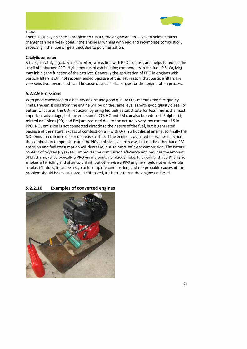
21
Turbo
There is usually no special problem to run a turbo engine on PPO. Nevertheless a turbo
charger can be a weak point if the engine is running with bad and incomplete combustion,
especially if the lube oil gets thick due to polymerization.
Catalytic converter
A flue gas catalyst (catalytic converter) works fine with PPO exhaust, and helps to reduce the
smell of unburned PPO. High amounts of ash building components in the fuel (P,S, Ca, Mg)
may inhibit the function of the catalyst. Generally the application of PPO in engines with
particle filters is still not recommended because of this last reason, that particle filters are
very sensitive towards ash, and because of special challenges for the regeneration process.
5.2.2.9 Emissions
With good conversion of a healthy engine and good quality PPO meeting the fuel quality
limits, the emissions from the engine will be on the same level as with good quality diesel, or
better. Of course, the CO2 reduction by using biofuels as substitute for fossil fuel is the most
important advantage, but the emission of CO, HC and PM can also be reduced. Sulphur (S)
related emissions (SO2 and PM) are reduced due to the naturally very low content of S in
PPO. NOX emission is not connected directly to the nature of the fuel, but is generated
because of the natural excess of combustion air (with O2) in a hot diesel engine, so finally the
NOX emission can increase or decrease a little. If the engine is adjusted for earlier injection,
the combustion temperature and the NOX emission can increase, but on the other hand PM
emission and fuel consumption will decrease, due to more efficient combustion. The natural
content of oxygen (O2) in PPO improves the combustion efficiency and reduces the amount
of black smoke, so typically a PPO engine emits no black smoke. It is normal that a DI engine
smokes after idling and after cold start, but otherwise a PPO engine should not emit visible
smoke. If it does, it can be a sign of incomplete combustion, and the probable causes of the
problem should be investigated. Until solved, it’s better to run the engine on diesel.
5.2.2.10 Examples of converted engines

22
Figure 5.11 Irrigation pump with Lombardini 15 LD 440, (1 cyl 442ccm, 10,5hp) air cooled DI engine with
manual start. Converted with a simple 2-tank system, Honduras October 2008 (Gota Verde Project).
Materials used: 2 m Ø8mm rubber hose, 2 ¼” ball valves, fittings and hose clamps. Total
costs of materials about 20 EURO.
The fuel heating was realized by looping the return fuel and leading it one time around the
hot cylinder and back to the lift pump. After each single pass in the loop, the fuel heats a
little, and after few minutes operating the engine, the fuel temperature reached about 60°C.
Figure 5.12 Toyota Hilux 2,8D (3L). IDI engine. Converted by an ELSBETT 1-tank system, Honduras October
2008 (Gota Verde Project).
Material used: ELSBETT 1-tank kit for this specific engine, including warranty and all materials
needed for the conversion. Price 790EURO. It is estimated that the price for a similar
conversion kit made locally would cost about 300 EURO, excluding profit and allocations for
development, testing, documentation, warranty etc.
A remark on prices: Prices vary a lot depending on the exact engines to be converted, the
quality of the conversion system, user wishes, and how and where the components for the
conversion are purchased.
5.2.3. Feedstock for soap production
Author: Titus Galema
In various countries in Africa, soap is made in villages and sometimes on a small industrial scale, as in
Tanzania (Reinhard Henning, Jatropha curcas L. in Africa, Bagani). The process of soap-making is
relatively easy, and requires only some caustic soda and water as ingredients. If desired, colorant and
perfumes could be added to make the soap more attractive for domestic use. The soap is often made
in simple moulds (e.g from plastic bottles) and after hardening, it is cut into handsome pieces. The
soap can then be sold at a good price, which makes soap-making a profitable small-scale business.
The soap is mainly used for washing hands and since medicinal properties are attributed to the
jatropha soap, the soap can be sold at a good price in Tanzania (R Henning).
In general, soap-making involves dissolving caustic soda in water (ca 150 g of caustic soda in 0,35 liter
of water) and then mixing the oil (1 liter) with the solvent and letting it harden overnight. Adding less
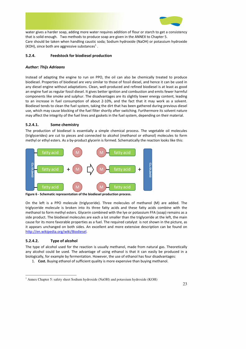
23
water gives a harder soap, adding more water requires addition of flour or starch to get a consistency
that is solid enough. Two methods to produce soap are given in the ANNEX to Chapter 5.
Care should be taken when handling caustic soda; Sodium hydroxide (NaOH) or potassium hydroxide
(KOH), since both are aggressive substances1 .
5.2.4. Feedstock for biodiesel production
Author: Thijs Adriaans
Instead of adapting the engine to run on PPO, the oil can also be chemically treated to produce
biodiesel. Properties of biodiesel are very similar to those of fossil diesel, and hence it can be used in
any diesel engine without adaptations. Clean, well-produced and refined biodiesel is at least as good
an engine fuel as regular fossil diesel. It gives better ignition and combustion and emits fewer harmful
components like smoke and sulphur. The disadvantages are its slightly lower energy content, leading
to an increase in fuel consumption of about 2-10%, and the fact that it may work as a solvent.
Biodiesel tends to clean the fuel system, taking the dirt that has been gathered during previous diesel
use, which may cause blocking of the fuel filter shortly after switching. Furthermore its solvent nature
may affect the integrity of the fuel lines and gaskets in the fuel system, depending on their material.
5.2.4.1. Some chemistry
The production of biodiesel is essentially a simple chemical process. The vegetable oil molecules
(triglycerides) are cut to pieces and connected to alcohol (methanol or ethanol) molecules to form
methyl or ethyl esters. As a by-product glycerin is formed. Schematically the reaction looks like this:
glycerin
fatty acid
fatty acid
fatty acid
M
M
M+
M
M
M
fatty acid
fatty acid
fatty acid +glycerin
Figure 6 - Schematic representation of the biodiesel production process.
On the left is a PPO molecule (triglyceride). Three molecules of methanol (M) are added. The
triglyceride molecule is broken into its three fatty acids and these fatty acids combine with the
methanol to form methyl esters. Glycerin combined with the lye or potassium FFA (soap) remains as a
side product. The biodiesel molecules are each a lot smaller than the triglyceride at the left, the main
cause for its more favorable properties as a fuel. The required catalyst is not shown in the picture, as
it appears unchanged on both sides. An excellent and more extensive description can be found on
http://en.wikipedia.org/wiki/Biodiesel.
5.2.4.2. Type of alcohol
The type of alcohol used for the reaction is usually methanol, made from natural gas. Theoretically
any alcohol could be used. The advantage of using ethanol is that it can easily be produced in a
biologically, for example by fermentation. However, the use of ethanol has four disadvantages:
1. Cost. Buying ethanol of sufficient quality is more expensive than buying methanol.
1 Annex Chapter 5: safety sheet Sodium hydroxide (NaOH) and potassium hydroxide (KOH)
24
2. Processing. The esterification process with ethanol is more complicated and less
straightforward than with methanol. One of the problems is that the ethanol must be free of
water (anhydrous), which is not easily accomplished in a non-industrial setting. The Journey
to Forever website documents why ethyl ester production is such a hassle.
3. Properties. The properties of methyl esters are more favourable than those of ethyl esters.
Especially the cold-related properties like CFPP and viscosity lag behind. Although these are
not of such importance in tropical climates, it is advisable to convert the engine to SVO
instead of going through the hassle of producing ethyl ester since its gain in properties is
marginal.
4. Energy. For the reaction to proceed , the mixture should be heated to a temperature near the
boiling point of the alcohol. The heavier the alcohol molecule (due to more carbon atoms) the
higher the required energy input due to a higher boiling point.
For these reasons only the use of methanol is considered in this case.
5.2.4.3. Preparation of PPO feedstock
PPO can be produced from other resources, but clean, fresh vegetable oil is the easiest and most
straightforward feedstock. However, there are three kinds of properties can cause trouble:
composition, chemical impurities and physical impurities.
Physical impurities (particles, sediment) are most easily removed first. These can be sludge/presscake
from the oil seeds in fresh oil, and sand/dirt. Though the oil can be filtered over cloth, the preferred
option is to leave it alone for some weeks to sediment. Then the oil is decanted from the sludge. Both
the sludge and the water are removed in this way. The water is clean enough to start making
biodiesel if it remains clear upon shaking.
Chemical impurities need not pose problems. If the oil has been pressed fresh from oilseeds like
jatropha or rapeseed according to the guidelines in chapter 4 of this book, the oil should be readily
applicable as a feedstock. Unrefined sunflower oil should be dewaxed. If fresh oil has been standing
longer under unfavourable conditions, it is wise to check the water content and eventually acidity
(FFA, free fatty acids). See appendix for water content and acidity tests.
Finally the composition of the oil/fat is important. (For more information about the contents see
tables in the appendix.) This primarily concerns the temperature below which the oil starts to get
hazy or even to gel/solidify. Fresh oil from jatropha, soy, sunflower or rapeseed will stay clear and
liquid down until temperatures around the freezing point (0°C) or much lower. Palm oil, coconut oil
and animal fats usually solidify at about room temperature. This poses problems for their straight use
in engines but also has consequences for the biodiesel produced. The biodiesel will exhibit the same
behavior as the oil/fat but at lower temperatures. Biodiesel from the latter feedstocks usually only
makes a suitable summer fuel, as the fuel may gel in winter conditions. Since this property cannot be
changed without large efforts, care must be taken to choose a suitable feedstock. The same may hold
for used cooking oil, depending on the oil that was used originally. Storing samples of the used oil in
the fridge or freezer for at least several days may give some information about the temperature
behavior. If the used oil is a mixture, it may solidify partly. If so, let this happen for about a week and
then decant the liquid portion on top. This can be used after testing its behaviour in cold.
5.2.4.4. Biodiesel production recipe
Generally this recipe can be followed to produce biodiesel from fresh PPO and methanol in a base
catalyzed environment. The recipe below is a very much summarized general guideline. Many tips
and tricks and safety recommendations have been left out for the sake of compactness. It is good to
read more about this before starting. If you would like to work with used cooking oil, ethanol or
another catalyst instead, many Internet sites can help you adapt the recipe. Please note that the

25
methanol and lye involved are quite dangerous chemicals. Be sure to know what you are doing, work
in a well ventilated area and wear protective clothes and glasses!
Required materials
The following resources are required (all quantities are expressed per liter of PPO): 1 liter of PPO, the
younger the better; at least 3.5 grams of lye (caustic soda; NaOH (> 95%)); at least 220 ml of
methanol (> 99%). Eventually you could use KOH (> 85%) instead of NaOH; then use at least 5 grams.
Required actions
First dissolve the lye into the methanol. Shake or swirl until all the lye has dissolved. This may take 10
minutes. It is normal that temperature rises. This mixture is called sodium methoxide. Now make sure
the PPO is in a vessel large enough (at least 150% of its volume), preferably with a valve at the
bottom, and heat it to about 60°C, then stop heating. Then add the methoxide mixture and make sure
it is mixed well for at least 10 minutes. Leave the vessel and let the different constituents separate by
sedimentation. The glycerin will settle out at the bottom. After 8 to 24 hours the sedimentation is
complete and the glycerine can be drained off. It is widely advised not to try to speed up the process
by shorting the settling times! What remains is raw biodiesel. If water washing is considered difficult
the biodiesel may be used straight, although its quality may be inferior because of impurities. In this
case additional settling for at least a week is advised to get rid of the majority of soaps.
Magnesium silicate (bleaching earth)
Magnesium silicate is used for the purification process of the biodiesel. It provokes the impurities to
settle and it permits them to be filtered out. Settled magnesium silicate should be handled as
chemical waste.
5.2.4.5. Biodiesel refining
If the biodiesel produced is not clear, water-washing and/or bubble-washing will remove most of
these impurities. Bubble-washing requires less water but needs compressed air and more time.
Water-washing can be applied one or more times. The first time it’s best to add a small amount of
acetic acid (vinegar) before adding the water. The acetic acid brings the pH of the solution closer to
neutral because it neutralizes and drops out any lye suspended in the biodiesel. Add the biodiesel on
top of a layer of water and stir gently. Let settle for at least a day and separate the layers by either
draining the water from the bottom or pouring the biodiesel out gently.
Bubble-washing works with air bubbles formed by compressed air passing through an air stone, for
instance from an aquarium shop. Add about 30 milliliters of vinegar (acetic acid) per 100 liters of
biodiesel and then about 50% water. Then drop in the air stone and switch on the air pump. The air
bubbles rise through the biodiesel, carrying a film of water which washes the biodiesel as it passes
through. At the surface, the bubble bursts, leaving a small drop of water which sinks back down
through the biodiesel, washing again. If the mixture is still cloudy after a couple of hours, add a little
more vinegar. Bubble-wash for 12 hours or longer (up to 24), then drain off the washing water, skim
off any wax floating on top. Repeat the bubble wash two more times; keep the water from the 2nd
and 3rd wash for washing the next batch. For severe soap formations, first heat the biodiesel/soap
mixture to 50°C. Add enough vinegar to bring the pH to slightly below 7. Stir for half an hour, cool and
continue with bubble-drying as usual.
5.2.4.6. Biodiesel by products
The main by-product of the biodiesel process is glycerine. Other by-products of the biodiesel reaction
and purification process are water with soap residues, magnesium silicate with soap residues,
recuperated methanol or ethanol and free fatty acids (FFA). In the following paragraphs a short
description for the applicability of these by-products is given.

26
5.2.4.6.1. Glycerine
Glycerine is the simplest 3-fold alcohol and comes into existence when the vegetable oil molecules
are split into fatty acids and glycerine during the biodiesel process. The fatty acids react with the
methanol to biodiesel. Glycerine is a high viscosity liquid with a high density (1,26 kg/l) [11]. The
name comes from the Greek word glykys meaning sweet. The amount of glycerine that is formed in
the reaction depends on the FFA level of the oil used, but can vary between 10% and 30% of the
amount of oil used. Biodiesel floats on glycerine since its density is lower. Separating the glycerine
from the biodiesel can be easily done by draining off the bottom layer of a gravity drained
decantation tank after a sedimentation time of eight hours after the biodiesel reaction. In a
continuous process, separation is done by a centrifuge based on the density difference.
Glycerine can be used as resource for other products, including soap, organic manure, biogas, fuel,
and recycled alcohol for the biodiesel process. (For details, see appendix.)
5.2.4.6.2. Water with soap residues
If the biodiesel is washed with water, it dissolves the formed soaps and residual methanol. If there
would be no methanol residue present in the crude biodiesel, the wash water could be used directly
as degreasant water for internal industrial purposes. In practice there will be methanol present, so
this must be removed first. A way to do this is by heating an open drum with the washing water in a
well- ventilated area (preferably outdoors) to about 50°C. Don’t inhale the vapors! A better way is to
recover the methanol for reuse by distilling or flashing it off.
5.2.4.6.3. The recuperated alcohol (methanol)
The recuperated alcohol can be used directly in the transesterification process again. Be sure no
water is present in the recuperated alcohol. It is recommended to mix small volumes of recuperated
methanol with fresh alcohol to ensure the quality.
5.2.4.6.4. Free Fatty Acids (FFA)
The residual FFA normally are mixed with the glycerine where they can be converted into soap (see
paragraph on soap). They can also be neutralized and separated to be converted into biodiesel
through an acid/base transesterification process. Large boilers can often handle biofuel with several
percents of acid content, so the FFA could be mixed with (neutral) vegetable oil and fired for energy
generation, though this is not a very common application in developing countries.
5.2.4.7. Concluding remarks
Making biodiesel is something that needs to be practiced. with different feedstock and
circumstances. The observations and procedures may show large variations. With more experience,
one will be able to judge the effects and streamline the processes. Use this section as a guideline and
try to use literature, for instance the excellent Journey to Forever website, to gather more detail
information.
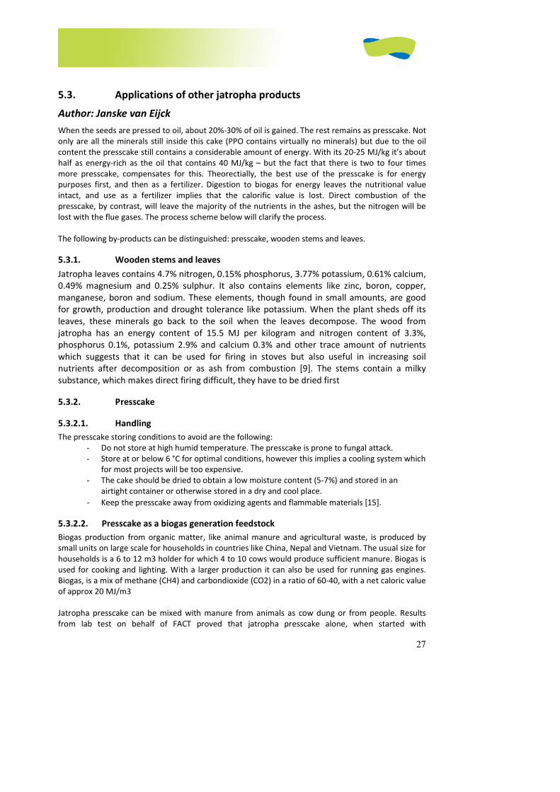
27
5.3. Applications of other jatropha products
Author: Janske van Eijck
When the seeds are pressed to oil, about 20%-30% of oil is gained. The rest remains as presscake. Not
only are all the minerals still inside this cake (PPO contains virtually no minerals) but due to the oil
content the presscake still contains a considerable amount of energy. With its 20-25 MJ/kg it’s about
half as energy-rich as the oil that contains 40 MJ/kg – but the fact that there is two to four times
more presscake, compensates for this. Theorectially, the best use of the presscake is for energy
purposes first, and then as a fertilizer. Digestion to biogas for energy leaves the nutritional value
intact, and use as a fertilizer implies that the calorific value is lost. Direct combustion of the
presscake, by contrast, will leave the majority of the nutrients in the ashes, but the nitrogen will be
lost with the flue gases. The process scheme below will clarify the process.
The following by-products can be distinguished: presscake, wooden stems and leaves.
5.3.1. Wooden stems and leaves
Jatropha leaves contains 4.7% nitrogen, 0.15% phosphorus, 3.77% potassium, 0.61% calcium,
0.49% magnesium and 0.25% sulphur. It also contains elements like zinc, boron, copper,
manganese, boron and sodium. These elements, though found in small amounts, are good
for growth, production and drought tolerance like potassium. When the plant sheds off its
leaves, these minerals go back to the soil when the leaves decompose. The wood from
jatropha has an energy content of 15.5 MJ per kilogram and nitrogen content of 3.3%,
phosphorus 0.1%, potassium 2.9% and calcium 0.3% and other trace amount of nutrients
which suggests that it can be used for firing in stoves but also useful in increasing soil
nutrients after decomposition or as ash from combustion [9]. The stems contain a milky
substance, which makes direct firing difficult, they have to be dried first
5.3.2. Presscake
5.3.2.1. Handling
The presscake storing conditions to avoid are the following:
- Do not store at high humid temperature. The presscake is prone to fungal attack.
- Store at or below 6 °C for optimal conditions, however this implies a cooling system which
for most projects will be too expensive.
- The cake should be dried to obtain a low moisture content (5-7%) and stored in an
airtight container or otherwise stored in a dry and cool place.
- Keep the presscake away from oxidizing agents and flammable materials [15].
5.3.2.2. Presscake as a biogas generation feedstock
Biogas production from organic matter, like animal manure and agricultural waste, is produced by
small units on large scale for households in countries like China, Nepal and Vietnam. The usual size for
households is a 6 to 12 m3 holder for which 4 to 10 cows would produce sufficient manure. Biogas is
used for cooking and lighting. With a larger production it can also be used for running gas engines.
Biogas, is a mix of methane (CH4) and carbondioxide (CO2) in a ratio of 60-40, with a net caloric value
of approx 20 MJ/m3
Jatropha presscake can be mixed with manure from animals as cow dung or from people. Results
from lab test on behalf of FACT proved that jatropha presscake alone, when started with
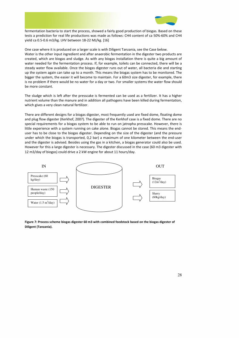
28
fermentation bacteria to start the process, showed a fairly good production of biogas. Based on these
tests a prediction for real life productions was made as follows: CH4 content of ca 50%-60% and CH4
yield ca 0.5-0.6 m3/kg. LHV between 18-22 MJ/kg. [16]
One case where it is produced on a larger scale is with Diligent Tanzania, see the Case below.
Water is the other input ingredient and after anaerobic fermentation in the digester two products are
created, which are biogas and sludge. As with any biogas installation there is quite a big amount of
water needed for the fermentation process. If, for example, toilets can be connected, there will be a
steady water flow available. Once the biogas digester runs out of water, all bacteria die and starting
up the system again can take up to a month. This means the biogas system has to be monitored. The
bigger the system, the easier it will become to maintain. For a 60m3 size digester, for example, there
is no problem if there would be no water for a day or two. For smaller systems the water flow should
be more constant.
The sludge which is left after the presscake is fermented can be used as a fertilizer. It has a higher
nutrient volume than the manure and in addition all pathogens have been killed during fermentation,
which gives a very clean natural fertilizer.
There are different designs for a biogas digester, most frequently used are fixed dome, floating dome
and plug flow digester (Kerkhof, 2007). The digester of the Kerkhof case is a fixed dome. There are no
special requirements for a biogas system to be able to run on jatropha presscake. However, there is
little experience with a system running on cake alone. Biogas cannot be stored. This means the end-
user has to be close to the biogas digester. Depending on the size of the digester (and the pressure
under which the biogas is transported, 0,2 bar) a maximum of one kilometer between the end-user
and the digester is advised. Besides using the gas in a kitchen, a biogas generator could also be used.
However for this a large digester is necessary. The digester discussed in the case (60 m3 digester with
12 m3/day of biogas) could drive a 2 kW engine for about 11 hours/day.
Figure 7: Process scheme biogas digester 60 m3 with combined feedstock based on the biogas digester of
Diligent (Tanzania).
Presscake (60
kg/day)
Human waste (150
people/day)
Water (1.5 m3/day)
IN
Biogas
(12m3/day)
Slurry
(60kg/day)
OUT
DIGESTER
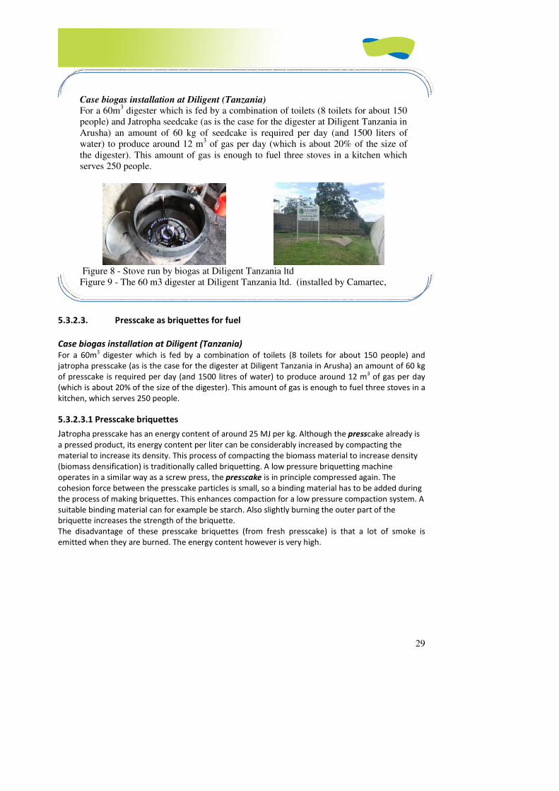
29
5.3.2.3. Presscake as briquettes for fuel
Case biogas installation at Diligent (Tanzania)
For a 60m3 digester which is fed by a combination of toilets (8 toilets for about 150 people) and
jatropha presscake (as is the case for the digester at Diligent Tanzania in Arusha) an amount of 60 kg
of presscake is required per day (and 1500 litres of water) to produce around 12 m3 of gas per day
(which is about 20% of the size of the digester). This amount of gas is enough to fuel three stoves in a
kitchen, which serves 250 people.
5.3.2.3.1 Presscake briquettes
Jatropha presscake has an energy content of around 25 MJ per kg. Although the presscake already is
a pressed product, its energy content per liter can be considerably increased by compacting the
material to increase its density. This process of compacting the biomass material to increase density
(biomass densification) is traditionally called briquetting. A low pressure briquetting machine
operates in a similar way as a screw press, the presscake is in principle compressed again. The
cohesion force between the presscake particles is small, so a binding material has to be added during
the process of making briquettes. This enhances compaction for a low pressure compaction system. A
suitable binding material can for example be starch. Also slightly burning the outer part of the
briquette increases the strength of the briquette.
The disadvantage of these presscake briquettes (from fresh presscake) is that a lot of smoke is
emitted when they are burned. The energy content however is very high.
Case biogas installation at Diligent (Tanzania)
For a 60m3 digester which is fed by a combination of toilets (8 toilets for about 150
people) and Jatropha seedcake (as is the case for the digester at Diligent Tanzania in
Arusha) an amount of 60 kg of seedcake is required per day (and 1500 liters of
water) to produce around 12 m3 of gas per day (which is about 20% of the size of
the digester). This amount of gas is enough to fuel three stoves in a kitchen which
serves 250 people.
Figure 8 - Stove run by biogas at Diligent Tanzania ltd
Figure 9 - The 60 m3 digester at Diligent Tanzania ltd. (installed by Camartec,
Arusha)
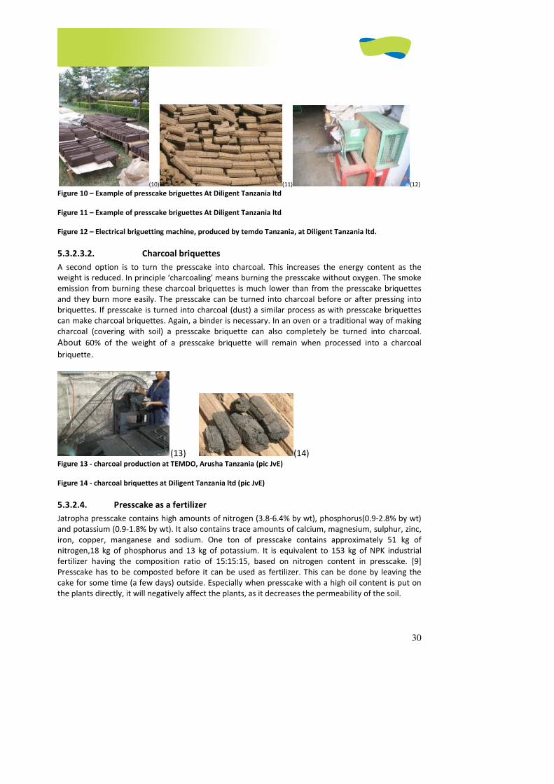
30
(10) (11) (12) Figure 10 – Example of presscake briguettes At Diligent Tanzania ltd
Figure 11 – Example of presscake briguettes At Diligent Tanzania ltd
Figure 12 – Electrical briguetting machine, produced by temdo Tanzania, at Diligent Tanzania ltd.
5.3.2.3.2. Charcoal briquettes
A second option is to turn the presscake into charcoal. This increases the energy content as the
weight is reduced. In principle ‘charcoaling’ means burning the presscake without oxygen. The smoke
emission from burning these charcoal briquettes is much lower than from the presscake briquettes
and they burn more easily. The presscake can be turned into charcoal before or after pressing into
briquettes. If presscake is turned into charcoal (dust) a similar process as with presscake briquettes
can make charcoal briquettes. Again, a binder is necessary. In an oven or a traditional way of making
charcoal (covering with soil) a presscake briquette can also completely be turned into charcoal.
About 60% of the weight of a presscake briquette will remain when processed into a charcoal
briquette.
(13) (14) Figure 13 - charcoal production at TEMDO, Arusha Tanzania (pic JvE)
Figure 14 - charcoal briquettes at Diligent Tanzania ltd (pic JvE)
5.3.2.4. Presscake as a fertilizer
Jatropha presscake contains high amounts of nitrogen (3.8-6.4% by wt), phosphorus(0.9-2.8% by wt)
and potassium (0.9-1.8% by wt). It also contains trace amounts of calcium, magnesium, sulphur, zinc,
iron, copper, manganese and sodium. One ton of presscake contains approximately 51 kg of
nitrogen,18 kg of phosphorus and 13 kg of potassium. It is equivalent to 153 kg of NPK industrial
fertilizer having the composition ratio of 15:15:15, based on nitrogen content in presscake. [9]
Presscake has to be composted before it can be used as fertilizer. This can be done by leaving the
cake for some time (a few days) outside. Especially when presscake with a high oil content is put on
the plants directly, it will negatively affect the plants, as it decreases the permeability of the soil.
31
5.3.2.5. Insecticide from oil and/or press cake
Jatropha oil has also proven to be an effective pesticide. In one study 1.4 liters of jatropha oil was
mixed with 16 liters of water and sprayed on cotton and acted efficiently [10]. An organization in
Tanzania promotes the following process for obtaining insecticide out of jatropha seeds: grind some
jatropha seeds, soak them in water for 24 hours, filter the particles from this mixture, dilute the
mixture in a 1:10 ratio with water.
5.3.3. What is not recommended
When jatropha presscake is pressed directly into briquettes, these briquettes produce a lot of
smoke when burned. Use of these briquettes indoor without proper ventilation is not
recommended. However if they are used in, for example, industrial boilers or in ovens with
chimneys, the smoke will not be inhaled.
Unlike many other oilseeds, the jatropha presscake cannot be used as animal feed, as it is
toxic due to the presence of several components (phorbol esters, curcins, trypsin inhibitors
and others).
5.4. References
[1] (www.jatropha.de).
[2] www.jatropha.de/lamps/protzen2.html
[3] www.jatropha.de/zimbabwe/binga.htm
[4] http://www.fierna.com/English/UB-16.htm[5] www.jatropha.de.
[6] DAJOLKA PPO cars: http://dajolka.dk/en/our_ppo_cars_overv.htm
[7]FAIR-CT95-0627 Advanced Combustion Research for Energy from Vegetable Oils (ACREVO)
http://www.biomatnet.org/secure/Fair/F484.htm
[8] Untersuchung der Wechselwirkungen zwischen Rapsöl als Kraftstoff und dem Motorenöl
in pflanzenöltauglichen Motoren
http://www.tfz.bayern.de/sonstiges/15951/bericht_7.pdf http://www.bsh-group.com/index.php?page=109906
[9] R.E.E. Jongschaap et al. (2007) Claims and Facts on Jatropha curcas L.,Global Jatropha curcas
evaluation, breeding and propagation programme, Plant Research International, Wageningen UR
[10] Milaflor L. Morales a safe and effective pesticide, Cotton Research and Development Institute,
Batac, 2906 Ilocos Norte, Philippines
[11] Binas 1998, NVON commissie, tabel 11
[12] Wikipedia
[13] Source:infopop.biodiesel.cc and jouneytoforever
[14] Source: http://www.biofuelreview.com/content/view/1793/
[15] Groeneveld et al.
[16] T. Adriaans et al. Anearobic digestion of jatropha curcas presscake, FACT publication, January
2007.
Literature used:
• http://www.journeytoforever.org
• Manual D23: Construction, installation and maintenance of a small biodiesel plant, Gota
Verde (2009)
• http://en.wikipedia.org/wiki/Biodiesel
• Begleitforschung zur Standardisierung von Rapsöl als Kraftstoff für
pflanzenöltaugliche Dieselmotoren in Fahrzeugen und BHKW
http://www.tfz.bayern.de/sonstiges/16411/gelbesheft69.pdf
• http://w1.siemens.com/responsibility/en/sustainable/’’Protos’’.htm
Opmerking [J1]: Welke site
Opmerking [J2]: Naam
Opmerking [J3]: Recommended literature?? Of
verwijzingen door de tekst.

32
• Henning (2001) - Manual for Jatropha curcas L in Zambia
• E. Kerkhof, (2007) Jatropha presscake, waste or valuable? An investigation into
possibilities of using Jatropha press cake in Tanzania, Eindhoven Technical University
1
JATROPHA HANDBOOK
2D EDITION
JUNE 2009
CHAPTER 6 (OF 6)
PROJECT IMPLEMENTATION
2
PROJECT IMPLEMENTATION............................................................................................................................. 3
6.1. INTRODUCTION..........................................................................................................................................3 6.2. OWNERSHIP, PRODUCTION AND FINANCE MODELS ...........................................................................................3
6.2.1. Ownership ........................................................................................................................................3 6.2.1.1. Ownership models ................................................................................................................................ 3
6.2.1.1.1. Pure plantation model (model A)..................................................................................................... 4 6.2.1.1.2. Pure out-grower model (model C) ................................................................................................... 4 6.2.1.1.3. Pure farmer-owned enterprise (model E) ........................................................................................ 4 6.2.1.1.4. Plantation with outgrowers (model B)............................................................................................. 5 6.2.1.1.5. Partial farmer participation in processing plant (model D) ............................................................ 5
6.2.1.2. Appropriate ownership models............................................................................................................. 5 6.2.1.2.1. Ownership models B and C .............................................................................................................. 6 6.2.1.2.2. Ownership models D and E .............................................................................................................. 7
6.2.2. Production models: the jatropha value chain ..................................................................................7 6.2.2.1. The basic jatropha biofuel production chain......................................................................................... 7
6.2.2.1.1. Main products of the basic biofuel chain......................................................................................... 7 6.2.2.1.2. Main factors determining feasibility of the basic biofuel chain ....................................................... 8 6.2.2.2. The extended production chain ............................................................................................................ 8 6.2.2.2.1. Biogas............................................................................................................................................... 9 6.2.2.2.2. Biodiesel......................................................................................................................................... 10 6.2.2.2.3. Soap ............................................................................................................................................... 12
6.2.2.2.4. Diversification with edible oils...................................................................................................... 12 6.2.3. Financing models...........................................................................................................................17
6.2.3.1. How to finance farmers’ plantations................................................................................................... 17 6.2.3.1.1. Introduction ................................................................................................................................... 17 6.2.3.1.2. Outgrower finance scheme............................................................................................................ 18 6.2.3.1.3. Joint venture .................................................................................................................................. 19 6.2.3.1.4. Conventional loan scheme............................................................................................................. 20 6.2.3.1.5. Conclusions on farmer financing.................................................................................................... 21
6.2.3.2. How to finance the processing enterprise .......................................................................................... 22 6.2.3.3. How to finance engine adaptations .................................................................................................... 23 6.2.3.4. Project Funding Sources ...................................................................................................................... 24 6.2.3.5. Alternative financing schemes ............................................................................................................ 25
6.3. THE SUSTAINABILITY OF JATROPHA CURCAS ACTIVITIES.....................................................................................29 6.3.1. Introduction.............................................................................................................................................. 29
6.3.2. Sustainability criteria and initiatives ..............................................................................................29 6.3.3. FACT’s tentative criteria for sustainable development for the large production of jatropha: [11] 30 6.3.4. Conclusion.................................................................................................................................31
6.4. REFERENCES............................................................................................................................................33
3
Project implementation
Main author: Peter Moers
6.1. Introduction
Once the feasibility of a jatropha project has been established, the actual project can be realized. This
can be done in many ways and it involves many decisions. A project designer will have to take
important decisions on the ownership model (who owns the plantations? who owns the processing
plant?), on the production model (how will the production chain look like?) and on the financing
model (how are plantations, processing plant etc. financed?). This chapter provides an overview of
the options and indicates which option is more appropriate, given a certain context. Finally, this
chapter offers insight into the main criteria that have to be taken into account if the promoter
intends to design a sustainable jatropha project.
6.2. Ownership, Production and Finance models
Jatropha project designers focusing on the implementation phase will have to make several strategic
decisions about who will own the production facilities, what products to include in the chain and how
to finance the different components of the enterprise. These decisions determine to a large degree
the social impact and sustainability of the production chain to be promoted. This chapter aims to
describe the most important options, with the respective advantages and disadvantages.
As stated before, this manual will only focus on small- and medium-scale initiatives (up to a total of
1000 ha, in smaller parcels) whose main objective is to improve living conditions of small farmers and
their families. This excludes models based on the purchase of large areas of land for jatropha
monocultures, in which the role of the local population is reduced to the supply of cheap labour.
6.2.1. Ownership
Participation of the small producer in the jatropha production chain varies widely among jatropha
projects worldwide. Ownership is in this section defined as the economic participation of small
farmers in the different stages of the production chain. Ownership matters, because it can be the
difference between receiving a fair price or being exploited. But if conditions are not right, ownership
may lead also to corruption, inefficiency and entrepreneurial failure.
This section first gives an overview of the different ownership models, each with its own advantages
and disadvantages. Recommendations about choosing the most appropriate model are also given,
based on the opportunities and constraints that the local context presents.
6.2.1.1. Ownership models
When describing the role of small farmers in the production chain, three pure ownership models and
two hybrid models can be distinguished, based on two criteria: the ownership of the plantations and
he ownership of the processing plant. The following table gives an overview of the ownership
options.
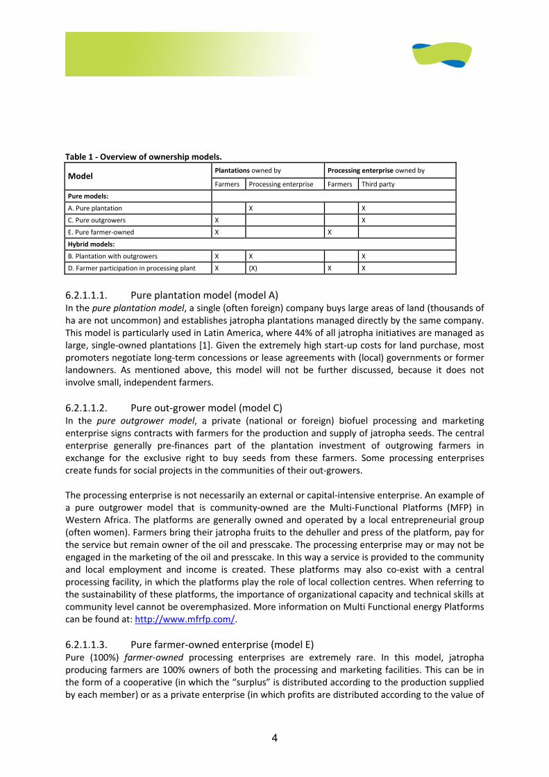
4
Table 1 - Overview of ownership models.
Plantations owned by Processing enterprise owned by Model
Farmers Processing enterprise Farmers Third party
Pure models:
A. Pure plantation X X
C. Pure outgrowers X X
E. Pure farmer-owned X X
Hybrid models:
B. Plantation with outgrowers X X X
D. Farmer participation in processing plant X (X) X X
6.2.1.1.1. Pure plantation model (model A) In the pure plantation model, a single (often foreign) company buys large areas of land (thousands of
ha are not uncommon) and establishes jatropha plantations managed directly by the same company.
This model is particularly used in Latin America, where 44% of all jatropha initiatives are managed as
large, single-owned plantations [1]. Given the extremely high start-up costs for land purchase, most
promoters negotiate long-term concessions or lease agreements with (local) governments or former
landowners. As mentioned above, this model will not be further discussed, because it does not
involve small, independent farmers.
6.2.1.1.2. Pure out-grower model (model C) In the pure outgrower model, a private (national or foreign) biofuel processing and marketing
enterprise signs contracts with farmers for the production and supply of jatropha seeds. The central
enterprise generally pre-finances part of the plantation investment of outgrowing farmers in
exchange for the exclusive right to buy seeds from these farmers. Some processing enterprises
create funds for social projects in the communities of their out-growers.
The processing enterprise is not necessarily an external or capital-intensive enterprise. An example of
a pure outgrower model that is community-owned are the Multi-Functional Platforms (MFP) in
Western Africa. The platforms are generally owned and operated by a local entrepreneurial group
(often women). Farmers bring their jatropha fruits to the dehuller and press of the platform, pay for
the service but remain owner of the oil and presscake. The processing enterprise may or may not be
engaged in the marketing of the oil and presscake. In this way a service is provided to the community
and local employment and income is created. These platforms may also co-exist with a central
processing facility, in which the platforms play the role of local collection centres. When referring to
the sustainability of these platforms, the importance of organizational capacity and technical skills at
community level cannot be overemphasized. More information on Multi Functional energy Platforms
can be found at: http://www.mfrfp.com/.
6.2.1.1.3. Pure farmer-owned enterprise (model E) Pure (100%) farmer-owned processing enterprises are extremely rare. In this model, jatropha
producing farmers are 100% owners of both the processing and marketing facilities. This can be in
the form of a cooperative (in which the “surplus” is distributed according to the production supplied
by each member) or as a private enterprise (in which profits are distributed according to the value of
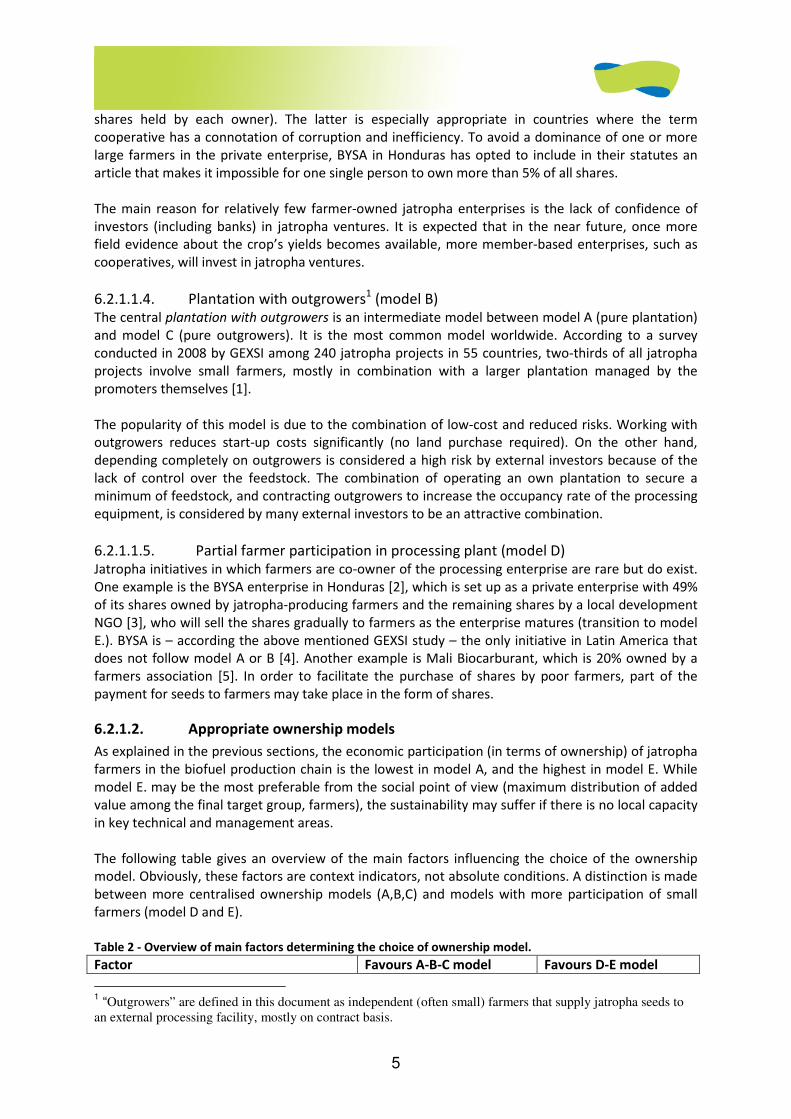
5
shares held by each owner). The latter is especially appropriate in countries where the term
cooperative has a connotation of corruption and inefficiency. To avoid a dominance of one or more
large farmers in the private enterprise, BYSA in Honduras has opted to include in their statutes an
article that makes it impossible for one single person to own more than 5% of all shares.
The main reason for relatively few farmer-owned jatropha enterprises is the lack of confidence of
investors (including banks) in jatropha ventures. It is expected that in the near future, once more
field evidence about the crop’s yields becomes available, more member-based enterprises, such as
cooperatives, will invest in jatropha ventures.
6.2.1.1.4. Plantation with outgrowers1 (model B) The central plantation with outgrowers is an intermediate model between model A (pure plantation)
and model C (pure outgrowers). It is the most common model worldwide. According to a survey
conducted in 2008 by GEXSI among 240 jatropha projects in 55 countries, two-thirds of all jatropha
projects involve small farmers, mostly in combination with a larger plantation managed by the
promoters themselves [1].
The popularity of this model is due to the combination of low-cost and reduced risks. Working with
outgrowers reduces start-up costs significantly (no land purchase required). On the other hand,
depending completely on outgrowers is considered a high risk by external investors because of the
lack of control over the feedstock. The combination of operating an own plantation to secure a
minimum of feedstock, and contracting outgrowers to increase the occupancy rate of the processing
equipment, is considered by many external investors to be an attractive combination.
6.2.1.1.5. Partial farmer participation in processing plant (model D) Jatropha initiatives in which farmers are co-owner of the processing enterprise are rare but do exist.
One example is the BYSA enterprise in Honduras [2], which is set up as a private enterprise with 49%
of its shares owned by jatropha-producing farmers and the remaining shares by a local development
NGO [3], who will sell the shares gradually to farmers as the enterprise matures (transition to model
E.). BYSA is – according the above mentioned GEXSI study – the only initiative in Latin America that
does not follow model A or B [4]. Another example is Mali Biocarburant, which is 20% owned by a
farmers association [5]. In order to facilitate the purchase of shares by poor farmers, part of the
payment for seeds to farmers may take place in the form of shares.
6.2.1.2. Appropriate ownership models
As explained in the previous sections, the economic participation (in terms of ownership) of jatropha
farmers in the biofuel production chain is the lowest in model A, and the highest in model E. While
model E. may be the most preferable from the social point of view (maximum distribution of added
value among the final target group, farmers), the sustainability may suffer if there is no local capacity
in key technical and management areas.
The following table gives an overview of the main factors influencing the choice of the ownership
model. Obviously, these factors are context indicators, not absolute conditions. A distinction is made
between more centralised ownership models (A,B,C) and models with more participation of small
farmers (model D and E).
Table 2 - Overview of main factors determining the choice of ownership model.
Factor Favours A-B-C model Favours D-E model
1 “Outgrowers” are defined in this document as independent (often small) farmers that supply jatropha seeds to
an external processing facility, mostly on contract basis.
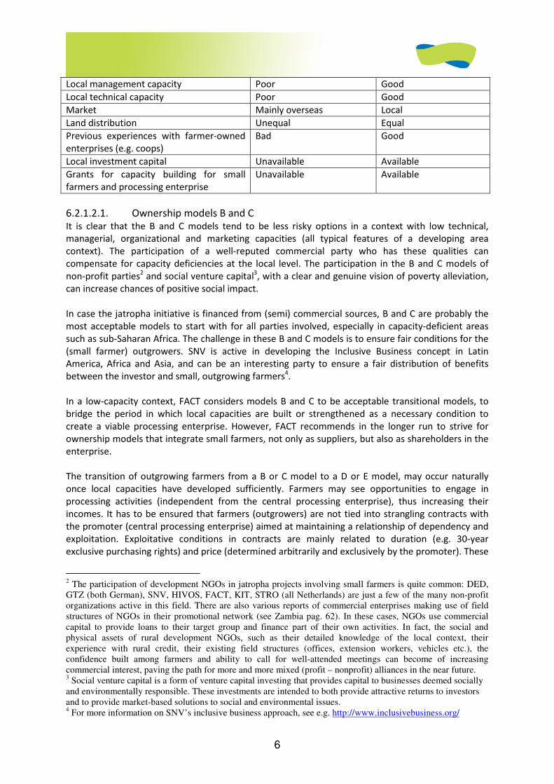
6
Local management capacity Poor Good
Local technical capacity Poor Good
Market Mainly overseas Local
Land distribution Unequal Equal
Previous experiences with farmer-owned
enterprises (e.g. coops) Bad Good
Local investment capital Unavailable Available
Grants for capacity building for small
farmers and processing enterprise Unavailable Available
6.2.1.2.1. Ownership models B and C It is clear that the B and C models tend to be less risky options in a context with low technical,
managerial, organizational and marketing capacities (all typical features of a developing area
context). The participation of a well-reputed commercial party who has these qualities can
compensate for capacity deficiencies at the local level. The participation in the B and C models of
non-profit parties2 and social venture capital3, with a clear and genuine vision of poverty alleviation,
can increase chances of positive social impact.
In case the jatropha initiative is financed from (semi) commercial sources, B and C are probably the
most acceptable models to start with for all parties involved, especially in capacity-deficient areas
such as sub-Saharan Africa. The challenge in these B and C models is to ensure fair conditions for the
(small farmer) outgrowers. SNV is active in developing the Inclusive Business concept in Latin
America, Africa and Asia, and can be an interesting party to ensure a fair distribution of benefits
between the investor and small, outgrowing farmers4.
In a low-capacity context, FACT considers models B and C to be acceptable transitional models, to
bridge the period in which local capacities are built or strengthened as a necessary condition to
create a viable processing enterprise. However, FACT recommends in the longer run to strive for
ownership models that integrate small farmers, not only as suppliers, but also as shareholders in the
enterprise.
The transition of outgrowing farmers from a B or C model to a D or E model, may occur naturally
once local capacities have developed sufficiently. Farmers may see opportunities to engage in
processing activities (independent from the central processing enterprise), thus increasing their
incomes. It has to be ensured that farmers (outgrowers) are not tied into strangling contracts with
the promoter (central processing enterprise) aimed at maintaining a relationship of dependency and
exploitation. Exploitative conditions in contracts are mainly related to duration (e.g. 30-year
exclusive purchasing rights) and price (determined arbitrarily and exclusively by the promoter). These
2 The participation of development NGOs in jatropha projects involving small farmers is quite common: DED, GTZ (both German), SNV, HIVOS, FACT, KIT, STRO (all Netherlands) are just a few of the many non-profit organizations active in this field. There are also various reports of commercial enterprises making use of field structures of NGOs in their promotional network (see Zambia pag. 62). In these cases, NGOs use commercial capital to provide loans to their target group and finance part of their own activities. In fact, the social and physical assets of rural development NGOs, such as their detailed knowledge of the local context, their experience with rural credit, their existing field structures (offices, extension workers, vehicles etc.), the confidence built among farmers and ability to call for well-attended meetings can become of increasing commercial interest, paving the path for more and more mixed (profit – nonprofit) alliances in the near future. 3 Social venture capital is a form of venture capital investing that provides capital to businesses deemed socially and environmentally responsible. These investments are intended to both provide attractive returns to investors and to provide market-based solutions to social and environmental issues. 4 For more information on SNV’s inclusive business approach, see e.g. http://www.inclusivebusiness.org/
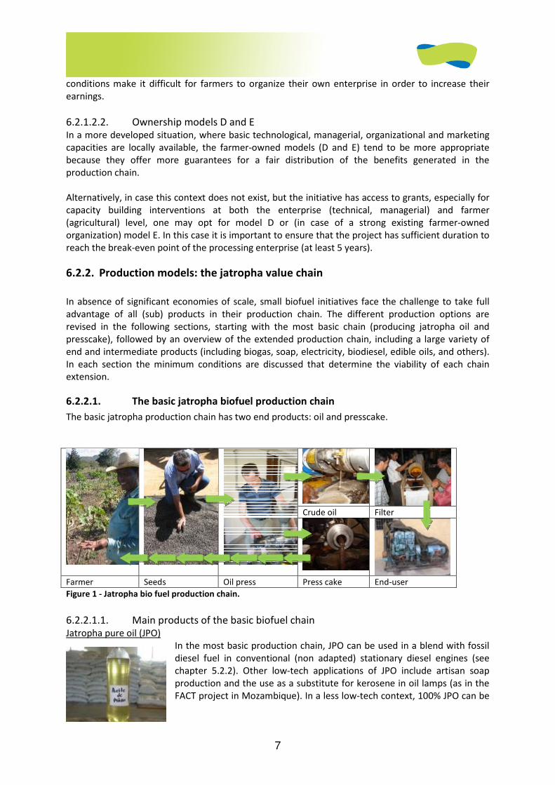
7
conditions make it difficult for farmers to organize their own enterprise in order to increase their
earnings.
6.2.1.2.2. Ownership models D and E In a more developed situation, where basic technological, managerial, organizational and marketing
capacities are locally available, the farmer-owned models (D and E) tend to be more appropriate
because they offer more guarantees for a fair distribution of the benefits generated in the
production chain.
Alternatively, in case this context does not exist, but the initiative has access to grants, especially for
capacity building interventions at both the enterprise (technical, managerial) and farmer
(agricultural) level, one may opt for model D or (in case of a strong existing farmer-owned
organization) model E. In this case it is important to ensure that the project has sufficient duration to
reach the break-even point of the processing enterprise (at least 5 years).
6.2.2. Production models: the jatropha value chain
In absence of significant economies of scale, small biofuel initiatives face the challenge to take full
advantage of all (sub) products in their production chain. The different production options are
revised in the following sections, starting with the most basic chain (producing jatropha oil and
presscake), followed by an overview of the extended production chain, including a large variety of
end and intermediate products (including biogas, soap, electricity, biodiesel, edible oils, and others).
In each section the minimum conditions are discussed that determine the viability of each chain
extension.
6.2.2.1. The basic jatropha biofuel production chain
The basic jatropha production chain has two end products: oil and presscake.
Crude oil Filter
Farmer Seeds Oil press Press cake End-user
Figure 1 - Jatropha bio fuel production chain.
6.2.2.1.1. Main products of the basic biofuel chain Jatropha pure oil (JPO)
In the most basic production chain, JPO can be used in a blend with fossil
diesel fuel in conventional (non adapted) stationary diesel engines (see
chapter 5.2.2). Other low-tech applications of JPO include artisan soap
production and the use as a substitute for kerosene in oil lamps (as in the
FACT project in Mozambique). In a less low-tech context, 100% JPO can be
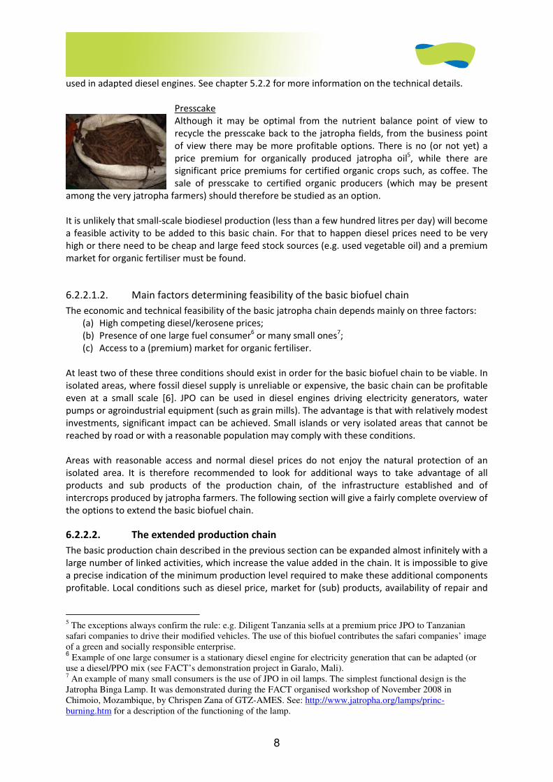
8
used in adapted diesel engines. See chapter 5.2.2 for more information on the technical details.
Presscake
Although it may be optimal from the nutrient balance point of view to
recycle the presscake back to the jatropha fields, from the business point
of view there may be more profitable options. There is no (or not yet) a
price premium for organically produced jatropha oil5, while there are
significant price premiums for certified organic crops such, as coffee. The
sale of presscake to certified organic producers (which may be present
among the very jatropha farmers) should therefore be studied as an option.
It is unlikely that small-scale biodiesel production (less than a few hundred litres per day) will become
a feasible activity to be added to this basic chain. For that to happen diesel prices need to be very
high or there need to be cheap and large feed stock sources (e.g. used vegetable oil) and a premium
market for organic fertiliser must be found.
6.2.2.1.2. Main factors determining feasibility of the basic biofuel chain
The economic and technical feasibility of the basic jatropha chain depends mainly on three factors:
(a) High competing diesel/kerosene prices;
(b) Presence of one large fuel consumer6 or many small ones7;
(c) Access to a (premium) market for organic fertiliser.
At least two of these three conditions should exist in order for the basic biofuel chain to be viable. In
isolated areas, where fossil diesel supply is unreliable or expensive, the basic chain can be profitable
even at a small scale [6]. JPO can be used in diesel engines driving electricity generators, water
pumps or agroindustrial equipment (such as grain mills). The advantage is that with relatively modest
investments, significant impact can be achieved. Small islands or very isolated areas that cannot be
reached by road or with a reasonable population may comply with these conditions.
Areas with reasonable access and normal diesel prices do not enjoy the natural protection of an
isolated area. It is therefore recommended to look for additional ways to take advantage of all
products and sub products of the production chain, of the infrastructure established and of
intercrops produced by jatropha farmers. The following section will give a fairly complete overview of
the options to extend the basic biofuel chain.
6.2.2.2. The extended production chain
The basic production chain described in the previous section can be expanded almost infinitely with a
large number of linked activities, which increase the value added in the chain. It is impossible to give
a precise indication of the minimum production level required to make these additional components
profitable. Local conditions such as diesel price, market for (sub) products, availability of repair and
5 The exceptions always confirm the rule: e.g. Diligent Tanzania sells at a premium price JPO to Tanzanian safari companies to drive their modified vehicles. The use of this biofuel contributes the safari companies’ image of a green and socially responsible enterprise. 6 Example of one large consumer is a stationary diesel engine for electricity generation that can be adapted (or
use a diesel/PPO mix (see FACT’s demonstration project in Garalo, Mali). 7 An example of many small consumers is the use of JPO in oil lamps. The simplest functional design is the Jatropha Binga Lamp. It was demonstrated during the FACT organised workshop of November 2008 in Chimoio, Mozambique, by Chrispen Zana of GTZ-AMES. See: http://www.jatropha.org/lamps/princ-burning.htm for a description of the functioning of the lamp.
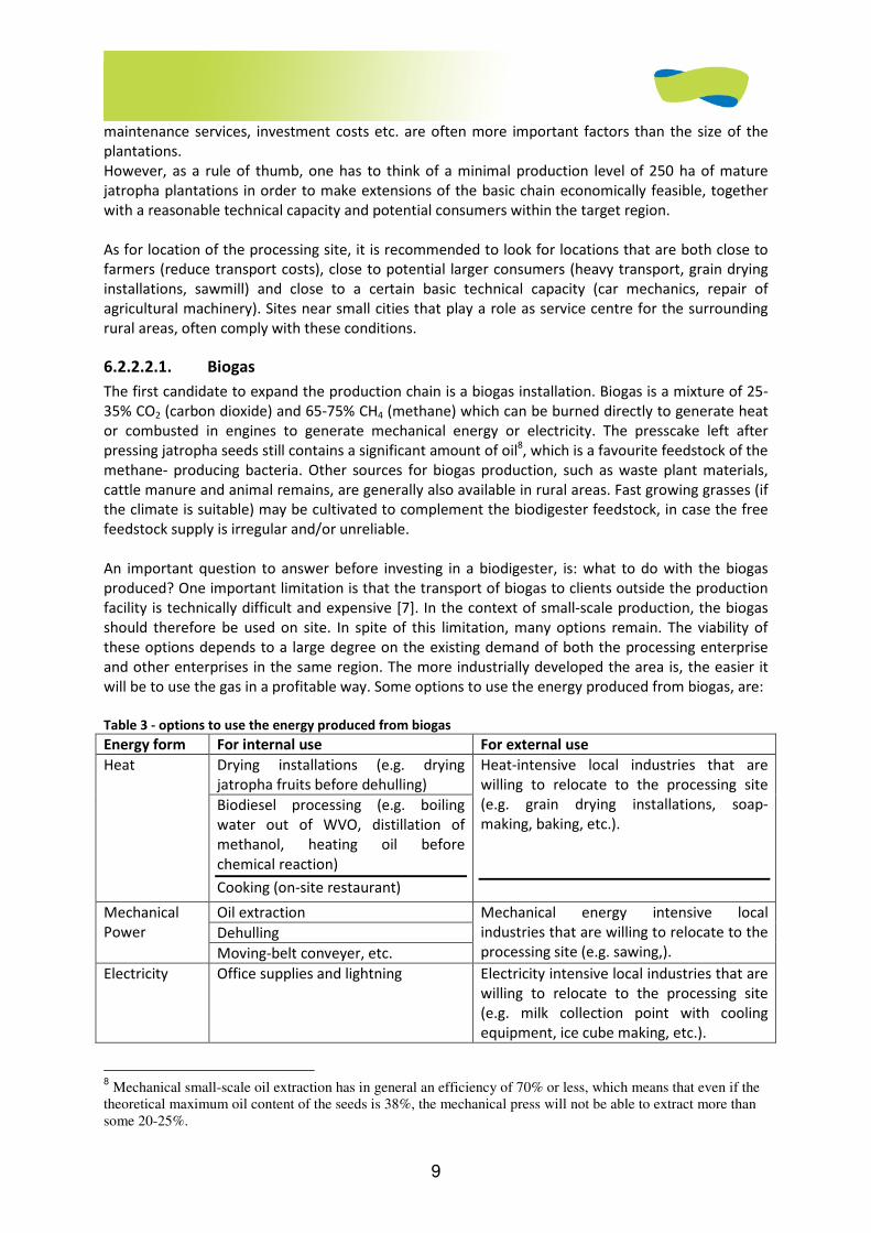
9
maintenance services, investment costs etc. are often more important factors than the size of the
plantations.
However, as a rule of thumb, one has to think of a minimal production level of 250 ha of mature
jatropha plantations in order to make extensions of the basic chain economically feasible, together
with a reasonable technical capacity and potential consumers within the target region.
As for location of the processing site, it is recommended to look for locations that are both close to
farmers (reduce transport costs), close to potential larger consumers (heavy transport, grain drying
installations, sawmill) and close to a certain basic technical capacity (car mechanics, repair of
agricultural machinery). Sites near small cities that play a role as service centre for the surrounding
rural areas, often comply with these conditions.
6.2.2.2.1. Biogas
The first candidate to expand the production chain is a biogas installation. Biogas is a mixture of 25-
35% CO2 (carbon dioxide) and 65-75% CH4 (methane) which can be burned directly to generate heat
or combusted in engines to generate mechanical energy or electricity. The presscake left after
pressing jatropha seeds still contains a significant amount of oil8, which is a favourite feedstock of the
methane- producing bacteria. Other sources for biogas production, such as waste plant materials,
cattle manure and animal remains, are generally also available in rural areas. Fast growing grasses (if
the climate is suitable) may be cultivated to complement the biodigester feedstock, in case the free
feedstock supply is irregular and/or unreliable.
An important question to answer before investing in a biodigester, is: what to do with the biogas
produced? One important limitation is that the transport of biogas to clients outside the production
facility is technically difficult and expensive [7]. In the context of small-scale production, the biogas
should therefore be used on site. In spite of this limitation, many options remain. The viability of
these options depends to a large degree on the existing demand of both the processing enterprise
and other enterprises in the same region. The more industrially developed the area is, the easier it
will be to use the gas in a profitable way. Some options to use the energy produced from biogas, are:
Table 3 - options to use the energy produced from biogas
Energy form For internal use For external use
Drying installations (e.g. drying
jatropha fruits before dehulling) Heat
Biodiesel processing (e.g. boiling
water out of WVO, distillation of
methanol, heating oil before
chemical reaction)
Cooking (on-site restaurant)
Heat-intensive local industries that are
willing to relocate to the processing site
(e.g. grain drying installations, soap-
making, baking, etc.).
Oil extraction
Dehulling
Mechanical
Power
Moving-belt conveyer, etc.
Mechanical energy intensive local
industries that are willing to relocate to the
processing site (e.g. sawing,).
Electricity Office supplies and lightning Electricity intensive local industries that are
willing to relocate to the processing site
(e.g. milk collection point with cooling
equipment, ice cube making, etc.).
8 Mechanical small-scale oil extraction has in general an efficiency of 70% or less, which means that even if the
theoretical maximum oil content of the seeds is 38%, the mechanical press will not be able to extract more than some 20-25%.
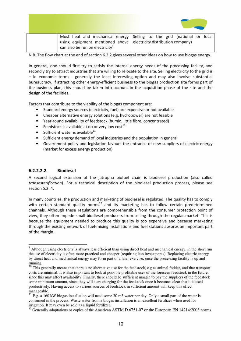
10
Most heat and mechanical energy
using equipment mentioned above
can also be run on electricity9.
Selling to the grid (national or local
electricity distribution company)
N.B. The flow chart at the end of section 6.2.2 gives several other ideas on how to use biogas energy.
In general, one should first try to satisfy the internal energy needs of the processing facility, and
secondly try to attract industries that are willing to relocate to the site. Selling electricity to the grid is
– in economic terms - generally the least interesting option and may also involve substantial
bureaucracy. If attracting other energy-efficient business to the biogas production site forms part of
the business plan, this should be taken into account in the acquisition phase of the site and the
design of the facilities.
Factors that contribute to the viability of the biogas component are:
• Standard energy sources (electricity, fuel) are expensive or not available
• Cheaper alternative energy solutions (e.g. hydropower) are not feasible
• Year-round availability of feedstock (humid, little fibre, concentrated)
• Feedstock is available at no or very low cost10
• Sufficient water is available11
• Sufficient energy demand of local industries and the population in general
• Government policy and legislation favours the entrance of new suppliers of electric energy
(market for excess energy production)
6.2.2.2.2. Biodiesel
A second logical extension of the jatropha biofuel chain is biodiesel production (also called
transesterification). For a technical description of the biodiesel production process, please see
section 5.2. 4.
In many countries, the production and marketing of biodiesel is regulated. The quality has to comply
with certain standard quality norms12 and its marketing has to follow certain predetermined
channels. Although these regulations are comprehensible from the consumer protection point of
view, they often impede small biodiesel producers from selling through the regular market. This is
because the equipment needed to produce this quality is too expensive and because marketing
through the existing network of fuel-mixing installations and fuel stations absorbs an important part
of the margin.
9 Although using electricity is always less efficient than using direct heat and mechanical energy, in the short run
the use of electricity is often more practical and cheaper (requiring less investments). Replacing electric energy by direct heat and mechanical energy may form part of a later exercise, once the processing facility is up and running. 10
This generally means that there is no alternative use for the feedstock, e.g as animal fodder, and that transport costs are minimal. It is also important to look at possible profitable uses of the foreseen feedstock in the future, since this may affect availability. Finally, there should be sufficient margin to pay the suppliers of the feedstock some minimum amount, since they will start charging for the feedstock once it becomes clear that it is used productively. Having access to various sources of feedstock in sufficient amount will keep this effect manageable. 11
E.g. a 160 kW biogas installation will need some 30 m3 water per day. Only a small part of the water is consumed in the process. Waste water from a biogas installation is an excellent fertilizer when used for irrigation. It may even be sold as a liquid fertilizer. 12 Generally adaptations or copies of the American ASTM D 6751-07 or the European EN 14214:2003 norms.
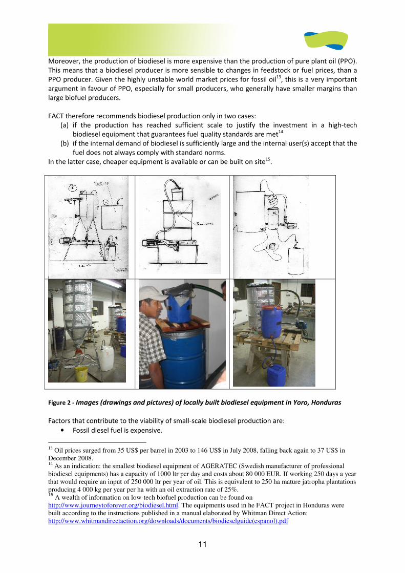
11
Moreover, the production of biodiesel is more expensive than the production of pure plant oil (PPO).
This means that a biodiesel producer is more sensible to changes in feedstock or fuel prices, than a
PPO producer. Given the highly unstable world market prices for fossil oil13, this is a very important
argument in favour of PPO, especially for small producers, who generally have smaller margins than
large biofuel producers.
FACT therefore recommends biodiesel production only in two cases:
(a) if the production has reached sufficient scale to justify the investment in a high-tech
biodiesel equipment that guarantees fuel quality standards are met14
(b) if the internal demand of biodiesel is sufficiently large and the internal user(s) accept that the
fuel does not always comply with standard norms.
In the latter case, cheaper equipment is available or can be built on site15.
Figure 2 - Images (drawings and pictures) of locally built biodiesel equipment in Yoro, Honduras
Factors that contribute to the viability of small-scale biodiesel production are:
• Fossil diesel fuel is expensive.
13 Oil prices surged from 35 US$ per barrel in 2003 to 146 US$ in July 2008, falling back again to 37 US$ in December 2008. 14 As an indication: the smallest biodiesel equipment of AGERATEC (Swedish manufacturer of professional biodiesel equipments) has a capacity of 1000 ltr per day and costs about 80 000 EUR. If working 250 days a year that would require an input of 250 000 ltr per year of oil. This is equivalent to 250 ha mature jatropha plantations producing 4 000 kg per year per ha with an oil extraction rate of 25%. 15
A wealth of information on low-tech biofuel production can be found on http://www.journeytoforever.org/biodiesel.html. The equipments used in he FACT project in Honduras were built according to the instructions published in a manual elaborated by Whitman Direct Action: http://www.whitmandirectaction.org/downloads/documents/biodieselguide(espanol).pdf
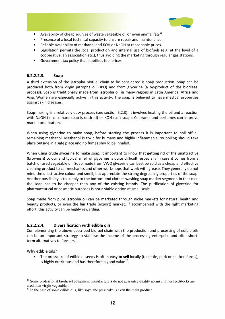
12
• Availability of cheap sources of waste vegetable oil or even animal fats16.
• Presence of a local technical capacity to ensure repair and maintenance.
• Reliable availability of methanol and KOH or NaOH at reasonable prices.
• Legislation permits the local production and internal use of biofuels (e.g. at the level of a
cooperative, an association etc.), thus avoiding the marketing through regular gas stations.
• Government tax policy that stabilizes fuel prices.
6.2.2.2.3. Soap
A third extension of the jatropha biofuel chain to be considered is soap production. Soap can be
produced both from virgin jatropha oil (JPO) and from glycerine (a by-product of the biodiesel
process). Soap is traditionally made from jatropha oil in many regions in Latin America, Africa and
Asia. Women are especially active in this activity. The soap is believed to have medical properties
against skin diseases.
Soap-making is a relatively easy process (see section 5.2.3): it involves heating the oil and a reaction
with NaOH (in case hard soap is desired) or KOH (soft soap). Colorants and perfumes can improve
market acceptation.
When using glycerine to make soap, before starting the process it is important to boil off all
remaining methanol. Methanol is toxic for humans and highly inflammable, so boiling should take
place outside in a safe place and no fumes should be inhaled.
When using crude glycerine to make soap, it important to know that getting rid of the unattractive
(brownish) colour and typical smell of glycerine is quite difficult, especially in case it comes from a
batch of used vegetable oil. Soap made from VWO glycerine can best be sold as a cheap and effective
cleaning product to car mechanics and other workshops that work with grease. They generally do not
mind the unattractive colour and smell, but appreciate the strong degreasing properties of the soap.
Another possibility is to supply to the bottom-end clothes washing soap market segment. In that case
the soap has to be cheaper than any of the existing brands. The purification of glycerine for
pharmaceutical or cosmetic purposes is not a viable option at small scale.
Soap made from pure jatropha oil can be marketed through niche markets for natural health and
beauty products, or even the fair trade (export) market. If accompanied with the right marketing
effort, this activity can be highly rewarding.
6.2.2.2.4. Diversification with edible oils Complementing the above-described biofuel chain with the production and processing of edible oils
can be an important strategy to stabilise the income of the processing enterprise and offer short-
term alternatives to farmers.
Why edible oils?
• The presscake of edible oilseeds is often easy to sell locally (to cattle, pork or chicken farms),
is highly nutritious and has therefore a good value17.
16 Some professional biodiesel equipment manufacturers do not guarantee quality norms if other feedstocks are used than virgin vegetable oil. 17 In the case of some edible oils, like soya, the presscake is even the main product.
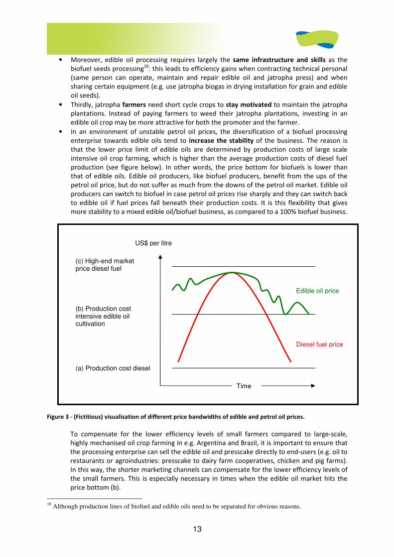
13
• Moreover, edible oil processing requires largely the same infrastructure and skills as the
biofuel seeds processing18: this leads to efficiency gains when contracting technical personal
(same person can operate, maintain and repair edible oil and jatropha press) and when
sharing certain equipment (e.g. use jatropha biogas in drying installation for grain and edible
oil seeds).
• Thirdly, jatropha farmers need short cycle crops to stay motivated to maintain the jatropha
plantations. Instead of paying farmers to weed their jatropha plantations, investing in an
edible oil crop may be more attractive for both the promoter and the farmer.
• In an environment of unstable petrol oil prices, the diversification of a biofuel processing
enterprise towards edible oils tend to increase the stability of the business. The reason is
that the lower price limit of edible oils are determined by production costs of large scale
intensive oil crop farming, which is higher than the average production costs of diesel fuel
production (see figure below). In other words, the price bottom for biofuels is lower than
that of edible oils. Edible oil producers, like biofuel producers, benefit from the ups of the
petrol oil price, but do not suffer as much from the downs of the petrol oil market. Edible oil
producers can switch to biofuel in case petrol oil prices rise sharply and they can switch back
to edible oil if fuel prices fall beneath their production costs. It is this flexibility that gives
more stability to a mixed edible oil/biofuel business, as compared to a 100% biofuel business.
Figure 3 - (Fictitious) visualisation of different price bandwidths of edible and petrol oil prices.
To compensate for the lower efficiency levels of small farmers compared to large-scale,
highly mechanised oil crop farming in e.g. Argentina and Brazil, it is important to ensure that
the processing enterprise can sell the edible oil and presscake directly to end-users (e.g. oil to
restaurants or agroindustries: presscake to dairy farm cooperatives, chicken and pig farms).
In this way, the shorter marketing channels can compensate for the lower efficiency levels of
the small farmers. This is especially necessary in times when the edible oil market hits the
price bottom (b).
18 Although production lines of biofuel and edible oils need to be separated for obvious reasons.
(c) High-end market price diesel fuel
(b) Production cost intensive edible oil cultivation
(a) Production cost diesel
US$ per litre
Time
Diesel fuel price
Edible oil price
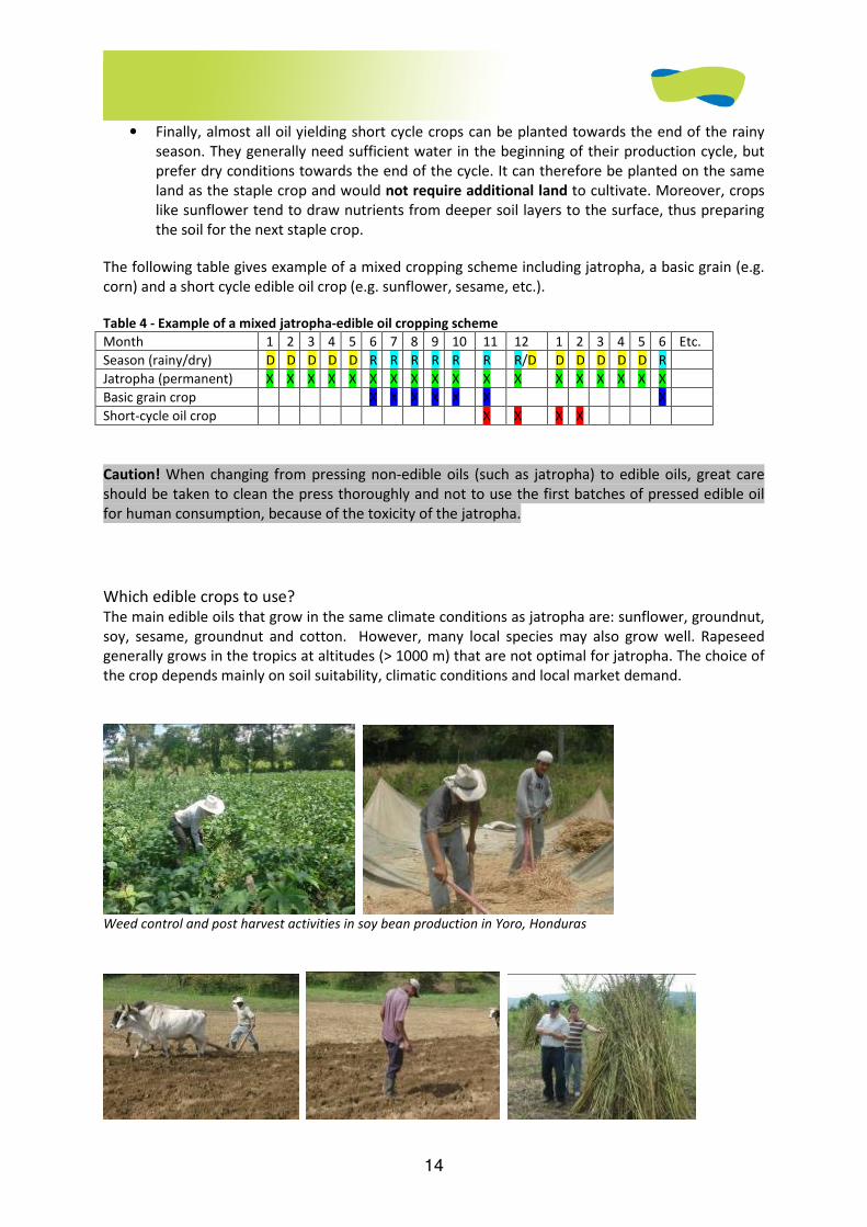
14
• Finally, almost all oil yielding short cycle crops can be planted towards the end of the rainy
season. They generally need sufficient water in the beginning of their production cycle, but
prefer dry conditions towards the end of the cycle. It can therefore be planted on the same
land as the staple crop and would not require additional land to cultivate. Moreover, crops
like sunflower tend to draw nutrients from deeper soil layers to the surface, thus preparing
the soil for the next staple crop.
The following table gives example of a mixed cropping scheme including jatropha, a basic grain (e.g.
corn) and a short cycle edible oil crop (e.g. sunflower, sesame, etc.).
Table 4 - Example of a mixed jatropha-edible oil cropping scheme
Month 1 2 3 4 5 6 7 8 9 10 11 12 1 2 3 4 5 6 Etc.
Season (rainy/dry) D D D D D R R R R R R R/D D D D D D R
Jatropha (permanent) X X X X X X X X X X X X X X X X X X
Basic grain crop X X X X X X X
Short-cycle oil crop X X X X
Caution! When changing from pressing non-edible oils (such as jatropha) to edible oils, great care
should be taken to clean the press thoroughly and not to use the first batches of pressed edible oil
for human consumption, because of the toxicity of the jatropha.
Which edible crops to use? The main edible oils that grow in the same climate conditions as jatropha are: sunflower, groundnut,
soy, sesame, groundnut and cotton. However, many local species may also grow well. Rapeseed
generally grows in the tropics at altitudes (> 1000 m) that are not optimal for jatropha. The choice of
the crop depends mainly on soil suitability, climatic conditions and local market demand.
Weed control and post harvest activities in soy bean production in Yoro, Honduras

15
Land preparation, sowing and harvest of sesame seed
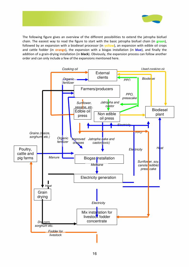
16
The following figure gives an overview of the different possibilities to extend the jatropha biofuel
chain. The easiest way to read the figure to start with the basic jatropha biofuel chain (in green),
followed by an expansion with a biodiesel processor (in yellow), an expansion with edible oil crops
and cattle fodder (in orange), the expansion with a biogas installation (in blue), and finally the
addition of a grain-drying installation (in black). Obviously, the expansion process can follow another
order and can only include a few of the expansions mentioned here.
Biogas installation Sunflower, soy, canola (edible)
press cake
Heat
Electricity
Jatropha and castor
PPO
PPO, presscake
Dry corn, sorghum etc.
Grains (maize, sorghum, etc.)
Non edible oil press
Sunflower,
sesame, etc.
Biodiesel
Manure
Electricity
Heat
Used cooking oil
PPO
Cooking oil
External clients Organic
fertilizer
Jatropha cake and castor(toxic)
Organic fertilizer
Improved grasses
Farmers/producers
Poultry, cattle and pig farms
Grain drying
Electricity generation
Methane
Mix installation for livestock fodder
concentrate production
Fodder for livestock
Edible oil press
Biodiesel plant
Electricity
17
Figure 4 - The integrated biofuel chain
6.2.3. Financing models
6.2.3.1. How to finance farmers’ plantations
6.2.3.1.1. Introduction
The agricultural component is the backbone of the jatropha biofuel chain. Within this component,
the financial scheme offered to farmers is one of the most important factors determining the success
of the undertaking.
Designing viable and acceptable financing schemes for jatropha is a challenge for several reasons. In
the first place, it is a new (cash) crop for many regions. Second, it is a perennial crop that takes
several years to become fully productive. Finally, its price development is uncertain because it
follows the highly volatile oil market. For these reasons, special attention needs to be given to the
way the jatropha introduction is financed.
Promoting jatropha among small farmers requires diligent planning, a well-designed financial
scheme, good knowledge of local customs and production patterns, and - most of all - patience.
Experiences of outgrower promotion schemes show that massive promotion among farmers,
promising large profits, but only contributing seeds and occasional visits by promoters, do not work
[8]. Small farmers expect seed material, fertilizer, support in pest and weed control, an acceptable
loan agreement, a stable market and close guidance.
In this section, three standard schemes to finance the jatropha introduction among farmers will be
described. The three models are:
(a) Outgrower finance scheme
(b) Joint venture between promoter and farmer
(c) Conventional loan scheme
It is not the purpose of this section to give an exhaustive overview of possible finance schemes.
However, it is hoped that by describing these three schemes, the reader will be able to choose the
scheme that best fits the context and adapt it to local conditions. In practice one will find many
variations and hybrids of the mentioned schemes.
In order to be able to compare the models, the following assumptions have been made for all
models:
• The jatropha plant starts producing from year 3 onwards
• The promoter of the system is also (co-) owner of the oil-processing facility (press)
• Promoter has sufficient demand to sell all oil produced
• Technical assistance is provided to the farmers without cost
During the introduction phase (in which many uncertainties still exist), it is recommended that the
technical assistance be provided free of charge. In the expansion phase, technical assistance may be
included in the promoter’s contribution, especially in the case of commercial (non-subsistence)
farmers.
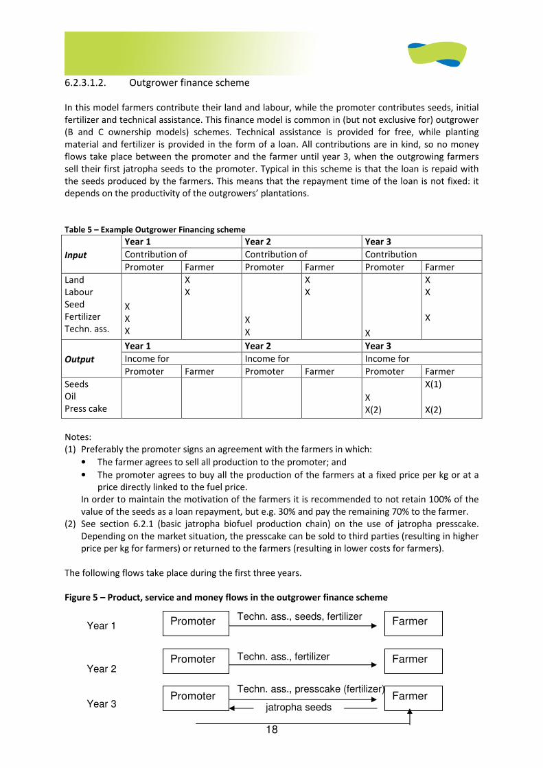
18
6.2.3.1.2. Outgrower finance scheme
In this model farmers contribute their land and labour, while the promoter contributes seeds, initial
fertilizer and technical assistance. This finance model is common in (but not exclusive for) outgrower
(B and C ownership models) schemes. Technical assistance is provided for free, while planting
material and fertilizer is provided in the form of a loan. All contributions are in kind, so no money
flows take place between the promoter and the farmer until year 3, when the outgrowing farmers
sell their first jatropha seeds to the promoter. Typical in this scheme is that the loan is repaid with
the seeds produced by the farmers. This means that the repayment time of the loan is not fixed: it
depends on the productivity of the outgrowers’ plantations.
Table 5 – Example Outgrower Financing scheme
Year 1 Year 2 Year 3
Contribution of Contribution of Contribution
Input
Promoter Farmer Promoter Farmer Promoter Farmer
Land Labour Seed Fertilizer Techn. ass.
X X X
X X
X X
X X
X
X X
X
Year 1 Year 2 Year 3
Income for Income for Income for Output
Promoter Farmer Promoter Farmer Promoter Farmer
Seeds Oil Press cake
X X(2)
X(1)
X(2)
Notes:
(1) Preferably the promoter signs an agreement with the farmers in which:
• The farmer agrees to sell all production to the promoter; and
• The promoter agrees to buy all the production of the farmers at a fixed price per kg or at a
price directly linked to the fuel price.
In order to maintain the motivation of the farmers it is recommended to not retain 100% of the
value of the seeds as a loan repayment, but e.g. 30% and pay the remaining 70% to the farmer.
(2) See section 6.2.1 (basic jatropha biofuel production chain) on the use of jatropha presscake.
Depending on the market situation, the presscake can be sold to third parties (resulting in higher
price per kg for farmers) or returned to the farmers (resulting in lower costs for farmers).
The following flows take place during the first three years.
Figure 5 – Product, service and money flows in the outgrower finance scheme
Techn. ass., seeds, fertilizer
Techn. ass., fertilizer
Techn. ass., presscake (fertilizer)
Promoter Farmer
Promoter Farmer
Promoter Farmer jatropha seeds
Year 1
Year 2
Year 3
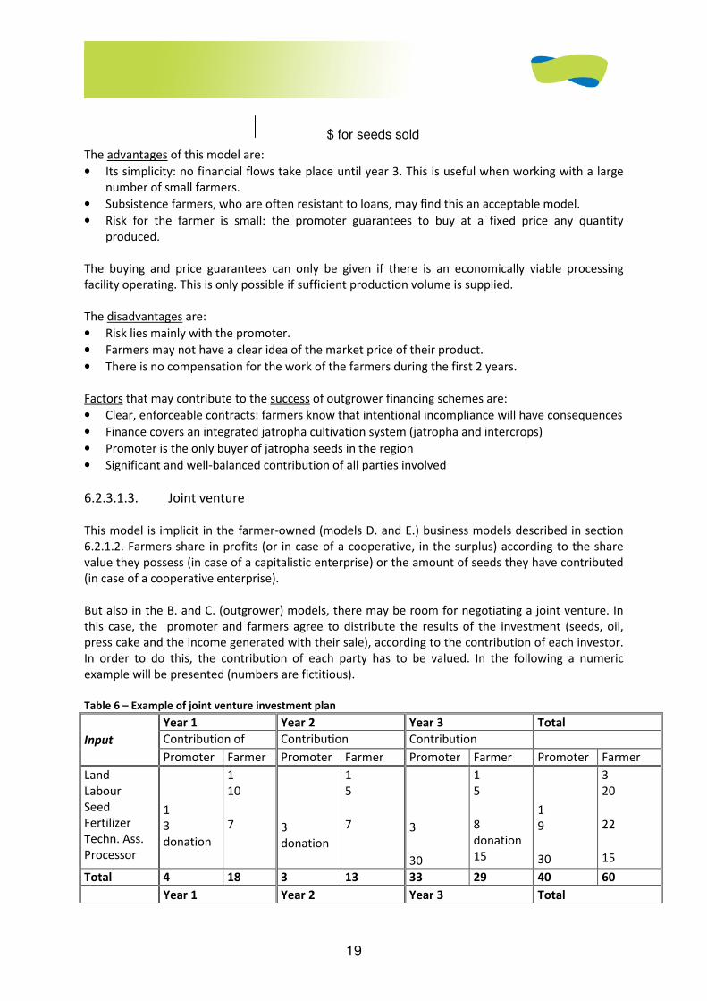
19
The advantages of this model are:
• Its simplicity: no financial flows take place until year 3. This is useful when working with a large
number of small farmers.
• Subsistence farmers, who are often resistant to loans, may find this an acceptable model.
• Risk for the farmer is small: the promoter guarantees to buy at a fixed price any quantity
produced.
The buying and price guarantees can only be given if there is an economically viable processing
facility operating. This is only possible if sufficient production volume is supplied.
The disadvantages are:
• Risk lies mainly with the promoter.
• Farmers may not have a clear idea of the market price of their product.
• There is no compensation for the work of the farmers during the first 2 years.
Factors that may contribute to the success of outgrower financing schemes are:
• Clear, enforceable contracts: farmers know that intentional incompliance will have consequences
• Finance covers an integrated jatropha cultivation system (jatropha and intercrops)
• Promoter is the only buyer of jatropha seeds in the region
• Significant and well-balanced contribution of all parties involved
6.2.3.1.3. Joint venture
This model is implicit in the farmer-owned (models D. and E.) business models described in section
6.2.1.2. Farmers share in profits (or in case of a cooperative, in the surplus) according to the share
value they possess (in case of a capitalistic enterprise) or the amount of seeds they have contributed
(in case of a cooperative enterprise).
But also in the B. and C. (outgrower) models, there may be room for negotiating a joint venture. In
this case, the promoter and farmers agree to distribute the results of the investment (seeds, oil,
press cake and the income generated with their sale), according to the contribution of each investor.
In order to do this, the contribution of each party has to be valued. In the following a numeric
example will be presented (numbers are fictitious).
Table 6 – Example of joint venture investment plan
Year 1 Year 2 Year 3 Total
Contribution of Contribution Contribution
Input
Promoter Farmer Promoter Farmer Promoter Farmer Promoter Farmer
Land Labour Seed Fertilizer Techn. Ass. Processor
1 3 donation
1 10
7
3 donation
1 5
7
3
30
1 5
8 donation 15
1 9
30
3 20
22
15
Total 4 18 3 13 33 29 40 60
Year 1 Year 2 Year 3 Total
$ for seeds sold
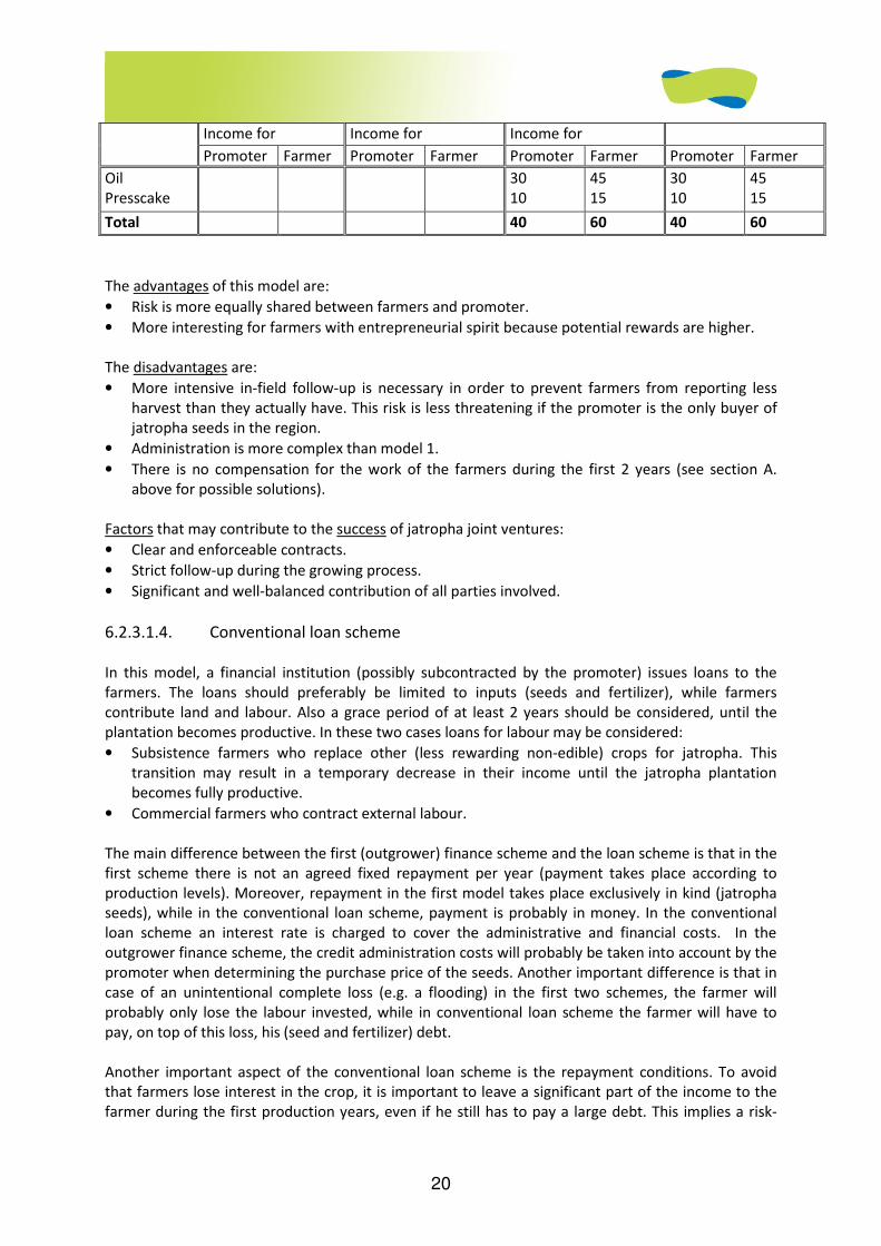
20
Income for Income for Income for
Promoter Farmer Promoter Farmer Promoter Farmer Promoter Farmer
Oil Presscake
30 10
45 15
30 10
45 15
Total 40 60 40 60
The advantages of this model are:
• Risk is more equally shared between farmers and promoter.
• More interesting for farmers with entrepreneurial spirit because potential rewards are higher.
The disadvantages are:
• More intensive in-field follow-up is necessary in order to prevent farmers from reporting less
harvest than they actually have. This risk is less threatening if the promoter is the only buyer of
jatropha seeds in the region.
• Administration is more complex than model 1.
• There is no compensation for the work of the farmers during the first 2 years (see section A.
above for possible solutions).
Factors that may contribute to the success of jatropha joint ventures:
• Clear and enforceable contracts.
• Strict follow-up during the growing process.
• Significant and well-balanced contribution of all parties involved.
6.2.3.1.4. Conventional loan scheme
In this model, a financial institution (possibly subcontracted by the promoter) issues loans to the
farmers. The loans should preferably be limited to inputs (seeds and fertilizer), while farmers
contribute land and labour. Also a grace period of at least 2 years should be considered, until the
plantation becomes productive. In these two cases loans for labour may be considered:
• Subsistence farmers who replace other (less rewarding non-edible) crops for jatropha. This
transition may result in a temporary decrease in their income until the jatropha plantation
becomes fully productive.
• Commercial farmers who contract external labour.
The main difference between the first (outgrower) finance scheme and the loan scheme is that in the
first scheme there is not an agreed fixed repayment per year (payment takes place according to
production levels). Moreover, repayment in the first model takes place exclusively in kind (jatropha
seeds), while in the conventional loan scheme, payment is probably in money. In the conventional
loan scheme an interest rate is charged to cover the administrative and financial costs. In the
outgrower finance scheme, the credit administration costs will probably be taken into account by the
promoter when determining the purchase price of the seeds. Another important difference is that in
case of an unintentional complete loss (e.g. a flooding) in the first two schemes, the farmer will
probably only lose the labour invested, while in conventional loan scheme the farmer will have to
pay, on top of this loss, his (seed and fertilizer) debt.
Another important aspect of the conventional loan scheme is the repayment conditions. To avoid
that farmers lose interest in the crop, it is important to leave a significant part of the income to the
farmer during the first production years, even if he still has to pay a large debt. This implies a risk-
21
sharing agreement between the promoter and the farmer. That is, if production is lower than
expected, the farmer receives less income and the promoter recovers his loan at a slower rate. This
does, of course, not exclude taking action against farmers that deliberately eliminate plantations.
Supporting the farmer in establishing an intercrop next to the jatropha is another important strategy
to maintain the interest of the farmer.
The advantages of the loan model are:
• More price transparency: farmers receive market price for their product.
• No need for intensive monitoring in the field.
• Possibility to give transitional consumptive loans during the first 2 years.
• Less financial risk for the promoter.
The disadvantages are:
• Administrative capacity to administrate loans must be created, if not already existing.
• The loan administration (especially if a financial institution is involved) has a high cost, which in
the end translates to lower prices paid to the farmers.
• Subsistence farmers may be resistant to loans.
• Higher loss for farmers in case of bad harvest.
Important factors that may influence positively the repayment rate of loans:
• Feasibility studies are based on realistic yields.
• Good credit administration capacity (with promoter or financial institution).
• Loans are issued in kind (seeds, fertilizer).
• Repayment in kind (seeds) is accepted.
• Good quality seed is provided.
• Producers with experience in cash crops are selected.
• Technical assistance is provided.
• Regions are selected in which there are no other jatropha seed buyers (avoids the deviation of
returns).
• Farmers introduce jatropha as an additional crop, on top of other, more traditional (cash) crops.
6.2.3.1.5. Conclusions on farmer financing
The choice for a finance scheme 1, 2 or 3 is basically determined by the attitude of the farmers and
the promoter (or financial institutions) towards the risks. The attitude of the farmer towards risk can
often be estimated by such factors as a) access to alternative income sources (the more alternative
income sources the farmer has, the easier the farmer will accept risk of engaging in a new crop), b)
the economic position of the farmers (more income means more capacity to cope with risk) and c)
the growth of the farmer’s operations (subsistence farmers tend to consider security - zero risk – as
more important than income growth).
In general terms, one can expect subsistence farmers to be risk-aversive and inclined to scheme 1
(outgrower). More commercial farmers (small, medium or large), with several income sources and
with an entrepreneurial spirit, may be attracted to model 2 (joint venture). Possibly, these farmers
are also willing to co-invest in the processing facility. Many of these farmers will also be using diesel-
powered equipment. If this is the case, farmers not only generate extra income but also make
important savings on their fuel bill.
22
Scheme 3 (conventional loans) seems to be an appropriate option in the expansion phase when good
seeds are available, yield predictions are reliable and appropriate agricultural practices have been
determined and adapted to the local context.
As mentioned before, within one project different financing schemes may be applied, depending on
the characteristics of the target groups. For example, in order to assure that there is a minimum
production to make a press facility viable, a mixed model may be applied in which one larger farmer
works in a joint venture with the promoter (scheme 2) and a large number of small farmers (out-
growers) have a buying agreement according to scheme 1.
All finance models face the difficulty of how to bridge the first two years of the plantation, when no
significant production can be expected. Practice shows that farmers are tempted to clear plantations
when they see better opportunities, or simply neglect plantations in absence of an immediate
stimulus19. A simple solution is to provide credit (or contract a labour squad) for weeding the
plantations. A better and more productive solution is intercropping: using the empty space between
the jatropha rows to cultivate short-cycle crops. The weeding and fertilizing of the intercrop also
benefits the jatropha plantation. This requires more investment than just weeding, but on the other
hand it generates an immediate income (and thus a loan repayment capacity). The investment may
also be financed from conventional sources of finance if it concerns crops with a track record in the
region. Any of these strategies requires additional investments. However, the cost of not
implementing any of the above strategies is likely to result in a much higher capital loss in the form of
loss of plantations.
The Gota Verde project has developed a number of credit administration documents and tools that
are available upon request through FACT.
6.2.3.2. How to finance the processing enterprise
Many jatropha projects invest too early and too much in the processing facility. This is largely due to
over-optimistic crop yield projections, although the short time horizon of project funders, and their
preference for visible physical field structures and the lack of field information also play a role.
As explained in chapter 2, plantations enter in commercial production from year 3-4 onwards. During
the first 2-3 years a small-scale jatropha initiative (planting up to 150 ha per year), can operate with a
very small processing unit, consisting of one or two small presses, several manual dehullers, a filter
unit and some storage facilities. Two or three engines may be adapted (see next section) for
demonstration purposes that help market introduction in later years.
In chapters 3, 4 and 5 an overview is given of the technical options for each piece of equipment. Total
cost can be limited to less than US$20,000. This excludes the technical assistance needed to install
equipment and train personnel. If the initiative has an ownership structure with farmer participation
(model D. or E.), this technical assistance may be obtained in the form of a grant from development
organizations (see appendix 6.1).
Furthermore, it is recommended to look first for abandoned agroindustrial installations that can be
refurbished and rented. Alternatively, one of the participating farmers may be willing to contribute
19 This problem cannot be underestimated. E.g. in the FACT project in Honduras (Gota Verde), more than 40% of the plantations established during year 1 and 2 were lost by year 3, of which at least half can be attributed to the neglect of farmers (floodings and water logging were other important factors).
23
to the social capital of the enterprise in the form of a temporary or permanent site with existing
buildings.
It is not recommended to buy land and build installations from year 0 onwards, unless the project is
funded by investors with a long-term (10 years or more) vision. Even then, it is more prudent in the
first years to invest in the establishment of the plantations and give incentives to farmers to maintain
them, than in building processing facilities with an overcapacity.
Once commercial operations take off (from year 4 onwards), the processing enterprise will have
accumulated sufficient information and experience to write a convincing business plan that supports
the purchase of its own site and more powerful processing equipment.
For potential funding sources, please see the appendix 6.1.
6.2.3.3. How to finance engine adaptations
As explained in the previous sections, the use of PPO as a diesel substitute reduces considerably the
complexity and the cost of biofuel production. Moreover, most of the technical problems with PPO
technology are related to low outside temperatures, which is obviously less of a problem in tropical
regions that are apt for jatropha cultivation. PPO technology is therefore considered appropriate for
small-scale biofuel initiatives in developing countries. However, the use of PPO as a diesel substitute
requires an engine adaptation (see chapter 5.2.2 for more technical details). Therefore, the
introduction of PPO technology encounters two important barriers: (a) lack of confidence and (b) the
upfront cost for the user.
Ad (a) How to overcome the initial lack of user confidence?
The recommended market introduction strategy is to start early in the project development (before
commercial production takes off in year 4) with adapting engines that are 100% controlled by the
promoter of the project (project or enterprise cars, tractors, trucks, irrigation pumps, etc.). This
allows the enterprise (and/or local technicians) to gain experience in the functioning of the PPO
technology, in solving the most common problems and to start investigating the possibility to
assemble local adaptation kits. If insufficient oil is locally available for these internal experiments,
one can look for local oil sources, such as refined palm oil. The import of industrial quantity vegetable
oil is another possibility to gain experience. Waste vegetable oil of good quality (low acid degree)
may also serve the purpose20.
This period of internal experimentation and capacity building may take 2-3 years (the same period
the plantation takes to become productive), because some technical problems present themselves
only after prolonged use of PPO. If no PPO-diesel expertise exists locally, the enterprise will need to
hire (expensive) foreign expertise to build it locally. Again, this expertise (possibly together with the
experimental kits) may be negotiated without costs from development organizations for enterprises
following the D. and E. ownership model (see appendix 6.1 for organizations with expertise in this
area). During the experimentation phase, local car mechanics need to be trained in the installation,
maintenance and repair of adapted diesel engines. Once the enterprise has built sufficient local
capacity in these areas, it can start commercial market introduction (see point (b) below).
20 Some manufacturers of PPO adaptation kits do not recommend the use of waste vegetable oil (WVO) because it tends to have a higher acid value. The acid value depends mainly on how long the oil has been used and at what temperatures. The acid value can be determined by using the same titration method used in biodiesel production. The following article gives a fairly complete overview of the issues to take into account when using WVO as a diesel substitute http://journeytoforever.org/biodiesel_svo.html.
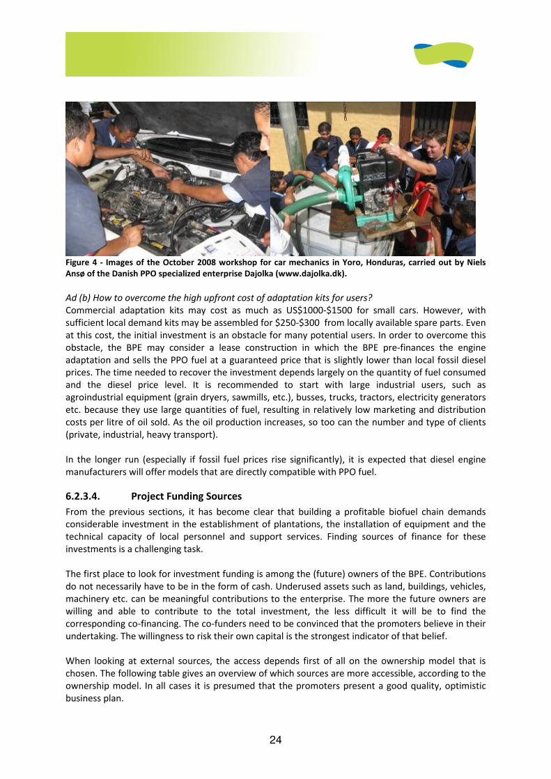
24
Figure 4 - Images of the October 2008 workshop for car mechanics in Yoro, Honduras, carried out by Niels
Ansø of the Danish PPO specialized enterprise Dajolka (www.dajolka.dk).
Ad (b) How to overcome the high upfront cost of adaptation kits for users?
Commercial adaptation kits may cost as much as US$1000-$1500 for small cars. However, with
sufficient local demand kits may be assembled for $250-$300 from locally available spare parts. Even
at this cost, the initial investment is an obstacle for many potential users. In order to overcome this
obstacle, the BPE may consider a lease construction in which the BPE pre-finances the engine
adaptation and sells the PPO fuel at a guaranteed price that is slightly lower than local fossil diesel
prices. The time needed to recover the investment depends largely on the quantity of fuel consumed
and the diesel price level. It is recommended to start with large industrial users, such as
agroindustrial equipment (grain dryers, sawmills, etc.), busses, trucks, tractors, electricity generators
etc. because they use large quantities of fuel, resulting in relatively low marketing and distribution
costs per litre of oil sold. As the oil production increases, so too can the number and type of clients
(private, industrial, heavy transport).
In the longer run (especially if fossil fuel prices rise significantly), it is expected that diesel engine
manufacturers will offer models that are directly compatible with PPO fuel.
6.2.3.4. Project Funding Sources
From the previous sections, it has become clear that building a profitable biofuel chain demands
considerable investment in the establishment of plantations, the installation of equipment and the
technical capacity of local personnel and support services. Finding sources of finance for these
investments is a challenging task.
The first place to look for investment funding is among the (future) owners of the BPE. Contributions
do not necessarily have to be in the form of cash. Underused assets such as land, buildings, vehicles,
machinery etc. can be meaningful contributions to the enterprise. The more the future owners are
willing and able to contribute to the total investment, the less difficult it will be to find the
corresponding co-financing. The co-funders need to be convinced that the promoters believe in their
undertaking. The willingness to risk their own capital is the strongest indicator of that belief.
When looking at external sources, the access depends first of all on the ownership model that is
chosen. The following table gives an overview of which sources are more accessible, according to the
ownership model. In all cases it is presumed that the promoters present a good quality, optimistic
business plan.
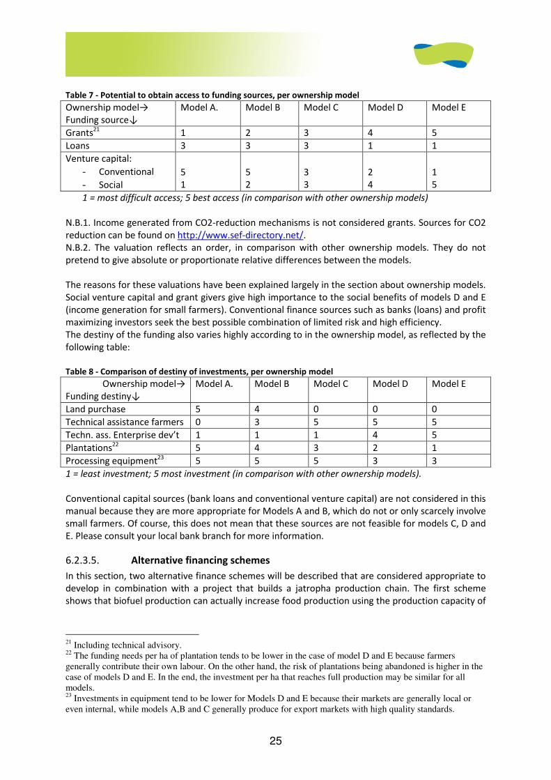
25
Table 7 - Potential to obtain access to funding sources, per ownership model
Ownership model→ Funding source↓
Model A. Model B Model C Model D Model E
Grants21 1 2 3 4 5
Loans 3 3 3 1 1
Venture capital:
- Conventional
- Social
5 1
5 2
3 3
2 4
1 5
1 = most difficult access; 5 best access (in comparison with other ownership models)
N.B.1. Income generated from CO2-reduction mechanisms is not considered grants. Sources for CO2
reduction can be found on http://www.sef-directory.net/.
N.B.2. The valuation reflects an order, in comparison with other ownership models. They do not
pretend to give absolute or proportionate relative differences between the models.
The reasons for these valuations have been explained largely in the section about ownership models.
Social venture capital and grant givers give high importance to the social benefits of models D and E
(income generation for small farmers). Conventional finance sources such as banks (loans) and profit
maximizing investors seek the best possible combination of limited risk and high efficiency.
The destiny of the funding also varies highly according to in the ownership model, as reflected by the
following table:
Table 8 - Comparison of destiny of investments, per ownership model
Ownership model→ Funding destiny↓
Model A. Model B Model C Model D Model E
Land purchase 5 4 0 0 0
Technical assistance farmers 0 3 5 5 5
Techn. ass. Enterprise dev’t 1 1 1 4 5
Plantations22 5 4 3 2 1
Processing equipment23 5 5 5 3 3
1 = least investment; 5 most investment (in comparison with other ownership models).
Conventional capital sources (bank loans and conventional venture capital) are not considered in this
manual because they are more appropriate for Models A and B, which do not or only scarcely involve
small farmers. Of course, this does not mean that these sources are not feasible for models C, D and
E. Please consult your local bank branch for more information.
6.2.3.5. Alternative financing schemes
In this section, two alternative finance schemes will be described that are considered appropriate to
develop in combination with a project that builds a jatropha production chain. The first scheme
shows that biofuel production can actually increase food production using the production capacity of
21 Including technical advisory. 22 The funding needs per ha of plantation tends to be lower in the case of model D and E because farmers generally contribute their own labour. On the other hand, the risk of plantations being abandoned is higher in the case of models D and E. In the end, the investment per ha that reaches full production may be similar for all models. 23 Investments in equipment tend to be lower for Models D and E because their markets are generally local or even internal, while models A,B and C generally produce for export markets with high quality standards.
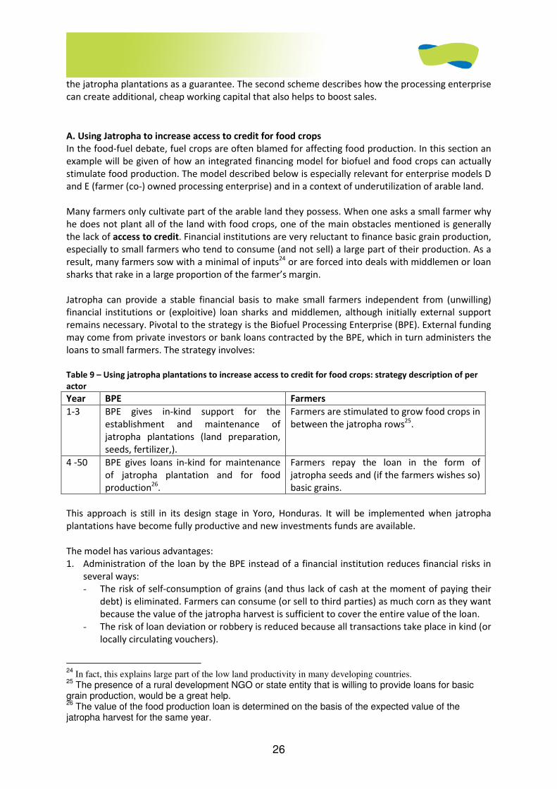
26
the jatropha plantations as a guarantee. The second scheme describes how the processing enterprise
can create additional, cheap working capital that also helps to boost sales.
A. Using Jatropha to increase access to credit for food crops
In the food-fuel debate, fuel crops are often blamed for affecting food production. In this section an
example will be given of how an integrated financing model for biofuel and food crops can actually
stimulate food production. The model described below is especially relevant for enterprise models D
and E (farmer (co-) owned processing enterprise) and in a context of underutilization of arable land.
Many farmers only cultivate part of the arable land they possess. When one asks a small farmer why
he does not plant all of the land with food crops, one of the main obstacles mentioned is generally
the lack of access to credit. Financial institutions are very reluctant to finance basic grain production,
especially to small farmers who tend to consume (and not sell) a large part of their production. As a
result, many farmers sow with a minimal of inputs24 or are forced into deals with middlemen or loan
sharks that rake in a large proportion of the farmer’s margin.
Jatropha can provide a stable financial basis to make small farmers independent from (unwilling)
financial institutions or (exploitive) loan sharks and middlemen, although initially external support
remains necessary. Pivotal to the strategy is the Biofuel Processing Enterprise (BPE). External funding
may come from private investors or bank loans contracted by the BPE, which in turn administers the
loans to small farmers. The strategy involves:
Table 9 – Using jatropha plantations to increase access to credit for food crops: strategy description of per
actor
Year BPE Farmers
1-3 BPE gives in-kind support for the
establishment and maintenance of
jatropha plantations (land preparation,
seeds, fertilizer,).
Farmers are stimulated to grow food crops in
between the jatropha rows25.
4 -50 BPE gives loans in-kind for maintenance
of jatropha plantation and for food
production26.
Farmers repay the loan in the form of
jatropha seeds and (if the farmers wishes so)
basic grains.
This approach is still in its design stage in Yoro, Honduras. It will be implemented when jatropha
plantations have become fully productive and new investments funds are available.
The model has various advantages:
1. Administration of the loan by the BPE instead of a financial institution reduces financial risks in
several ways:
- The risk of self-consumption of grains (and thus lack of cash at the moment of paying their
debt) is eliminated. Farmers can consume (or sell to third parties) as much corn as they want
because the value of the jatropha harvest is sufficient to cover the entire value of the loan.
- The risk of loan deviation or robbery is reduced because all transactions take place in kind (or
locally circulating vouchers).
24
In fact, this explains large part of the low land productivity in many developing countries. 25
The presence of a rural development NGO or state entity that is willing to provide loans for basic grain production, would be a great help. 26
The value of the food production loan is determined on the basis of the expected value of the jatropha harvest for the same year.
27
- The risk of farmers selling jatropha to third parties is small because – at least for the moment
– these third parties do not exists.
Fewer risks can be translated into lower financial costs for the farmers. In order to limit the credit
risk further, the value of the loan can be limited to – for example – 50% of the value of the
expected jatropha harvest of that year.
2. The model gives loan access to farmers that normally are not considered by financial institutions.
The BPE offers a collective guarantee (production capacity, buildings, a well-founded business
plan, assured markets) that individual farmers cannot offer.
3. The BPE can obtain discounts for buying inputs at wholesale prices. The costs of BYSA for
administrating the loans to farmers can be covered largely by this discount.
4. The BPE can also act as a trader for grain for the farmers as an additional task, it only requires
more investment in a storage facility for grain at the BPE
5. In case the BPE also produces animal fodder, basic grains are an important ingredient (as well as
edible oil presscake of possible other crops promoted by the BPE). The added value that derives
from this transformation, puts BYSA in a position to offer higher prices for basic grains than most
middlemen.
A voucher system, as described in the following section, may facilitate these transactions. The BPE
issues loans in the form of vouchers to farmers, who can go to predetermined distribution points to
withdraw their agricultural inputs. This reduces the BPE’s need for (cash) working capital and thus
decreases its financial costs.
B. Vouchers for local economic development
An innovative way for a BPE to raise working capital is the issuing of biofuel-backed vouchers. These
vouchers are basically debt of the BPE to the bearer of the voucher. The voucher gives the bearer the
right to buy biofuels from the BPE for the amount mentioned on the voucher. The BPE can issue the
vouchers in two ways:
(a) Purchases of the BPE: e.g. buying seeds from farmers, paying transport services, payment of
personnel.
(b) Loans of the BPE to farmers (or other local economic players).
In practice the issuance will be a mixture of vouchers and national currency. The proportion of
vouchers that is acceptable for the receiver depends on the expenditure pattern and on incentives
given by the BPE (e.g. bonus payment, lower interest rate on loans etc.). The introduction of
vouchers is only feasible when the production has reached commercial levels and the BPE has gained
a significant level of trust and confidence among the local (economic) players.

28
Example of the local currency issued by the BYSA processing company in Yoro, Honduras.
The advantages of this voucher system for the BPE are multiple:
(a) Increase of the working capital at zero cost (the emission of a voucher is in financial terms
equivalent to receiving a loan at 0% interest).
(b) Increase of sales: each voucher spent into emission is a secured sale in the future.
(c) More security: vouchers are not very popular targets for thieves and assaulters. The vouchers
can only be spent locally, which increases chances of being detected27 if stolen.
(d) More institutional image building. The vouchers draw the attention of users and media,
resulting in free publicity and positive image building.
The financial advantage for the BPE and the impact on the local economy can be enhanced by
promoting a wider local trade network (shops, transport services, hairdressers etc.) that accepts the
vouchers. In that sense, the voucher system can also be considered to be a tool to maximize the
impact on the local economy of the wealth created by the biofuel chain.
For examples of working voucher systems in developing countries, please go to www.stro-ca.org
27 In fact several counterpart organizations of STRO in Central America have been victim of theft and armed assaults. In all cases the vouchers have been left or thrown away.
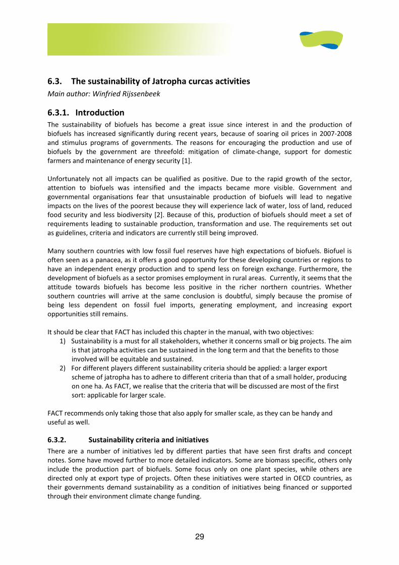
29
6.3. The sustainability of Jatropha curcas activities
Main author: Winfried Rijssenbeek
6.3.1. Introduction
The sustainability of biofuels has become a great issue since interest in and the production of
biofuels has increased significantly during recent years, because of soaring oil prices in 2007-2008
and stimulus programs of governments. The reasons for encouraging the production and use of
biofuels by the government are threefold: mitigation of climate-change, support for domestic
farmers and maintenance of energy security [1].
Unfortunately not all impacts can be qualified as positive. Due to the rapid growth of the sector,
attention to biofuels was intensified and the impacts became more visible. Government and
governmental organisations fear that unsustainable production of biofuels will lead to negative
impacts on the lives of the poorest because they will experience lack of water, loss of land, reduced
food security and less biodiversity [2]. Because of this, production of biofuels should meet a set of
requirements leading to sustainable production, transformation and use. The requirements set out
as guidelines, criteria and indicators are currently still being improved.
Many southern countries with low fossil fuel reserves have high expectations of biofuels. Biofuel is
often seen as a panacea, as it offers a good opportunity for these developing countries or regions to
have an independent energy production and to spend less on foreign exchange. Furthermore, the
development of biofuels as a sector promises employment in rural areas. Currently, it seems that the
attitude towards biofuels has become less positive in the richer northern countries. Whether
southern countries will arrive at the same conclusion is doubtful, simply because the promise of
being less dependent on fossil fuel imports, generating employment, and increasing export
opportunities still remains.
It should be clear that FACT has included this chapter in the manual, with two objectives:
1) Sustainability is a must for all stakeholders, whether it concerns small or big projects. The aim
is that jatropha activities can be sustained in the long term and that the benefits to those
involved will be equitable and sustained.
2) For different players different sustainability criteria should be applied: a larger export
scheme of jatropha has to adhere to different criteria than that of a small holder, producing
on one ha. As FACT, we realise that the criteria that will be discussed are most of the first
sort: applicable for larger scale.
FACT recommends only taking those that also apply for smaller scale, as they can be handy and
useful as well.
6.3.2. Sustainability criteria and initiatives
There are a number of initiatives led by different parties that have seen first drafts and concept
notes. Some have moved further to more detailed indicators. Some are biomass specific, others only
include the production part of biofuels. Some focus only on one plant species, while others are
directed only at export type of projects. Often these initiatives were started in OECD countries, as
their governments demand sustainability as a condition of initiatives being financed or supported
through their environment climate change funding.
30
It is not possible to discuss all of these drafts and notes. The most important ones - the roundtable
discussion on biofuels and the Cramer Criteria - are discussed in the appendix. As a result of this
ongoing discussion, the international expert workshop on jatropha, FACT prepared a position paper
on how business should best move in the field of jatropha. In this position paper the People Planet
and Profit criteria were translated to the production of jatropha [3].
FACT follows the 3-P principle ‘People, Profit, Planet’ in its work, emphasizing the need for food
security, positive impact on the environment and income generation by local producers. A starting
point was the establishment of sustainability criteria developed for the Government of the
Netherlands (the so-called ‘Cramer Criteria’). Under its programme, FACT will monitor the
applicability of these criteria and work towards the further improvement thereof, taking into account
other sustainability criteria under development, such as from RSB and more elaborated NEN 8080
criteria.
6.3.3. FACT’s tentative criteria for sustainable development for the large production
of jatropha: [11]
People:
No destruction of rural communities and villages or social structures.
No infringement of common lands or traditional user rights.
No displacement of people.
Enhancement of local employment or income generation of local people.
Decent wages to be paid.
Preferably no dependency of a sole income source of people (risk avoidance).
Respect for the local people’s livelihoods, resources use, their points of view and traditional rights is
a must. Projects should improve local people’s welfare and well-being. Ideally, they should include
local ownership or partnership in the product chain. Risks of monoculture and only one income
opportunity should be avoided, for both the involved population and the project management.
Planet:
Take care on what is real waste or idle land.
Minimal and no lasting environmental pollution in production by agro-chemicals and fertilizers.
Greenhouse gas balance; net emission reduction compared with fossil reference, inclusive that of the
application.
No monoculture.
No selection of lands with high biodiversity importance.
Intercropping preferable, especially in the earlier years.
A careful analysis should be made on the land use, the nutrients and water uses for a large-scale
project. In many instances, project implementers only find out later that the land planned for
cultivation was already in use, e.g. in shifting cultivation as free pasture land, etc.
The production of biofuels can learn a lot from food production: no monoculture, correct and timely
application of plant nutrients, existing land use and soil classification maps, intercropping, alley
cropping, etc. Biodiversity and conservation areas of today and likely of the future should of course
be avoided.
Profit:
Prepare clear business plans, based on conservative/proven data.
Company profits preferably should be reinvested in the country.

31
Jatropha should be, in the first instance, used to supply internal markets. Local use is more energy
efficient and there is always enough internal demand.
Company profits sharing with farmers, and farmers receiving decent payment.
No excessive company profits.
Income stability is as important as income height: diversification of the biofuel chain (e.g.
intercropping edible oils) can help the enterprise to survive times of low fuel prices.
All the plans should be viable to all stakeholders concerned: a net profit for all stakeholders can be
differently defined for each one. Some will see the profit in employment generation, whereas others
might see the benefits of rural affordable modern energy. Such sustainable viability might require a
sound legislative framework for food and fuel crops that might include minimum prices (safety net
prices), accessible savings and credit schemes and training and extension.
Sustainability of income can also be for a target, by turning producers into stakeholders in the
processing chain of the biofuel crop to a commercial fuel.
The issues are relevant for jatropha, but can also be applied to other biomass.
Biomass options - when applied large scale - can have serious drawbacks. To mitigate their negative
effects, a long set of criteria need to be established.
FACT argues, therefore, that it is more effective to design a biomass operation in developing
countries straightaway for the development of the local economy and adhere to the sustainable
development goals:
• Poverty alleviation
• Biodiversity
• Environment
• Socio-economic development
• Participation of local stakeholders
This will more easily create an operation that is sustainable and, if successful, can be scaled up and
checked regularly for sustainability using the Cramer Criteria or RSB and others.
6.3.4. Conclusion
FACT contributes to the discussion on sustainability from the multi-facetted practise of its pilot
projects. What becomes clear is that “THE” sustainability problem does not exist, nor does “THE”
solution exist. In each context biofuel initiatives result in changes in many areas, some positive, some
negative. Many farmers and local NGOs feel that in small-scale initiatives with farmers the positive
effects seem to outweigh the negative effects, although further investigation is necessary to prove
this point.
General discussions on whether biofuel-driven development is good or bad have limited relevance
without specific information on the region’s land and labour availability, the ownership structure of
the initiative, market situation etc.
In general, it can be concluded that entrepreneurs of large-scale plantations should be much more
aware of the possible impacts of their project during the development phase. Large-scale projects
can more easily do harm to the environment and, on a longer term, the contribution to social and
economic development will not exist unless it’s an objective of the project developers. When
considering starting with jatropha production, feasibility studies based on sufficient, conservative
and reliable data are important. Jatropha under current oil prices is likely to offer minimal margins.

32
Furthermore, yields are often very context dependent. It is therefore recommended to start small
scale to build up the required knowledge for a viable production and market development of
jatropha end products, taking into account the sustainability criteria. Presently, there are
practitioners that state that their jatropha project or business is sustainable. However, independent
verification of these projects’ sustainability has yet to emerge. The verification brings some
complexity, as sustainability criteria are still under development by various players and have not
been tested sufficiently yet.
FACT supports sustainable development of biofuel production placing income generation for small
farmers and the rural population as the highest priority. FACT supports initiatives for local use and
applications. When the market is not for export and only for local use, it should be understood that it
would very hard for these small farmers and local workshops to fulfil the western ISO-based
standards for quality that are now being developed for the Cramer Criteria (e.g. NTA8080). This
group has a very large potential, since about 70% of populations in Sub Sahel Africa live in rural areas
for example. FACT, therefore, strongly recommends that the criteria developed for export-oriented
companies, will not be applied to the farmers. That is, in an out growers scheme it should be the
aggregator or buyer and processor who will have to comply with the sustainability criteria. If these
refer to the outgrowing scheme, the aggregator will have to support the farmers with the necessary
conditions to adhere to those standards
Furthermore, FACT recommends national governments in developing countries should not apply
these export-oriented sustainability standards for local producers under pressure of international
bodies. Of course national governments can set their own standards and FACT recommends these
standards to be feasible for rural people, small farmers and workshops, not imposing them with all
type of conditions that only bring bureaucracy, and no output. To set up projects by local
organisations that are socially, economically, environmentally and technically viable already requires
major efforts. FACT recommends setting standards in the planning phase as some of the standards
can be relatively simply addressed without consequences.
33
6.4. References
[1] GEXSI, http://www.jatropha-platform.org/documents/GEXSI_Global-Jatropha-Study_ABSTRACT.pdf (p.14).
[2] “Biocombustibles Yoro Sociedad Anónima”, a biofuel processing enterprise promoted by the FACT-Gota
Verde project. See www.gotaverde.org and www.fact-fuels.org.
[3] FUNDER (Foundation for the Development of Rural Entrepreneurship). See: www.funder.hn.
[4] GEXSI (2008), “Global Market Study on Jatropha, Final Report – Abstract”, p. 28. http://www.jatropha-
platform.org/documents/GEXSI_Global-Jatropha-Study_ABSTRACT.pdf
[5] See http://www.malibiocarburant.com/
[6] See: www.fact-fuels.org/en?cm=204%2C166&mf_id=202 for a report on the major findings of Chimoio
Workshop, Nov 2008.
[7] Although some literature suggests small-scale biogas bottling is not impossible. See:
www.idosi.org/wasj/wasj1(2)/12.pdf for a feasibility study on a facility in Pakistan.
[8] See for example the experience in Zambia:
http://www.umb.no/statisk/noragric/publications/master/2008_lars_olav_freim.pdf (p. 30)
[9] Perspective: “Jatropha biodiesel fueling sustainability”, WMJ Achten and others, Biofuels, bioproducts &
biorefining, ISSN: 1932-104X, 2007
[10] Small-scale Production and Use of Liquid biofuels in Sub-Saharan Africa: Perspectives for Sustainable
development, Background paper no. 2, UNDESA, Commission on Sustainable Development, New York, 2007
[11] Jatropha literature and perspectives review: Main potential social and environmental impacts arising from
large-scale plantations, May 2008, Proforest ltd.
[12] FACT positioning paper
Recommended literature for sustainability
1 Beleidsnotitie milieu en hernieuwbare energie in ontwikkelingssamenwerking, Ministry of Foreign Affairs,
November 2008
2 FACT reactie op “Heldergroene Biomassa”, Stichting Natuur en Milieu, www.fact-fuels.org, 30 januari 2008
3 Empowering rural communities by planting energy, Roundtable on bioenergy enterprise in developing
regions, background paper, UNEP, 2008
4 Roundtable on Sustainable Biofuels, Global principles and criteria for sustainable biofuels production, version
zero, école polytechnique fédérale de Lausanne, Energy Center, 2008. Title: Version Zero - Principles for
sustainable biofuels Version 0.0 (August 2008) RSB-Steering Board
(http://cgse.epfl.ch/Jahia/site/cgse/op/edit/lang/en/pid/70341)
5 The state of food and agriculture, biofuels: prospects, risks and opportunities, FAO, 2008, ISSN 0081-4539

34
6 Discussion Note: Sustainable Biomass for Poverty Reduction etc, 19/07/07 tbv Food en Energy Workshop WR
7. 2 product philosofy prof. Kees Daey Ouwens
JATROPHA HANDBOOK
2D EDITION
JUNE 2009
APPENDIX TO CHAPTER 2 (OF 6)
Plantation Establishment and Management
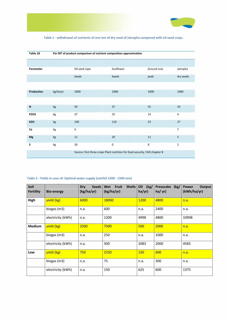
Table 1 - withdrawal of nutrients of one ton of dry seed of Jatropha compared with oil seed crops.
Table 2 - Yields in case of: Optimal water supply (rainfall 1200 - 1500 mm)
Soil
Fertility Bio-energy
Dry Seeds
(kg/ha/yr)
Wet Fruit Shells
(kg/ha/yr)
Oil (kg/
ha/yr)
Presscake (kg/
ha/ yr)
Power Output
(kWh/ha/yr)
High yield (kg) 6000 18000 1200 4800 n.a.
biogas (m3) n.a. 600 n.a. 2400 n.a.
electricity (kWh) n.a. 1200 4998 4800 10998
Medium yield (kg) 2500 7500 500 2000 n.a.
biogas (m3) n.a. 250 n.a. 1000 n.a.
electricity (kWh) n.a. 500 2083 2000 4583
Low yield (kg) 750 2250 150 600 n.a.
biogas (m3) n.a. 75 n.a. 300 n.a.
electricity (kWh) n.a. 150 625 600 1375
Table 18 Per MT of product comparison of nutrient composition approximation
Parameter Oil seed rape Sunflower Ground nuts Jatropha
Seeds Seeds pods dry seeds
Production kg/ha/yr 1000 1000 1000 1000
N kg 93 37 55 33
P2O5 kg 37 25 14 4
K2O kg 100 110 23 27
Ca kg 0
7
Mg kg 11 20 11 5
S kg 26 0 8 2
Source: first three crops Plant nutrition for food security, FAO chapter 8
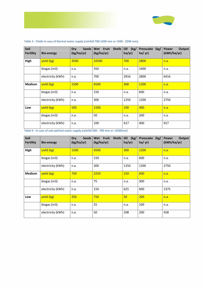
Table 3 - Yields in case of Normal water supply (rainfall 700-1200 mm or 1500 - 2500 mm).
Soil
Fertility Bio-energy
Dry Seeds
(kg/ha/yr)
Wet Fruit Shells
(kg/ha/yr)
Oil (kg/
ha/yr)
Presscake (kg/
ha/ yr)
Power Output
(kWh/ha/yr)
High yield (kg) 3500 10500 700 2800 n.a.
biogas (m3) n.a. 350 n.a. 1400 n.a.
electricity (kWh) n.a. 700 2916 2800 6416
Medium yield (kg) 1500 4500 300 1200 n.a.
biogas (m3) n.a. 150 n.a. 600 n.a.
electricity (kWh) n.a. 300 1250 1200 2750
Low yield (kg) 500 1500 100 400 n.a.
biogas (m3) n.a. 50 n.a. 200 n.a.
electricity (kWh) n.a. 100 417 400 917
Tabel 4 - in case of sub-optimal water supply (rainfall 500 - 700 mm or >2500mm)
Soil
Fertility Bio-energy
Dry Seeds
(kg/ha/yr)
Wet Fruit Shells
(kg/ha/yr)
Oil (kg/
ha/yr)
Presscake (kg/
ha/ yr)
Power Output
(kWh/ha/yr)
High yield (kg) 1500 4500 300 1200 n.a.
biogas (m3) n.a. 150 n.a. 600 n.a.
electricity (kWh) n.a. 300 1250 1200 2750
Medium yield (kg) 750 2250 150 600 n.a.
biogas (m3) n.a. 75 n.a. 300 n.a.
electricity (kWh) n.a. 150 625 600 1375
Low yield (kg) 250 750 50 200 n.a.
biogas (m3) n.a. 25 n.a. 100 n.a.
electricity (kWh) n.a. 50 208 200 458
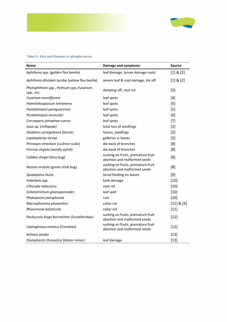
Tabel 5 - Pest and Diseases in Jatropha curcas
Name Damage and symptoms Source
Aphthona spp. (golden flea beetle) leaf damage, larvae damage roots [1] & [2]
Aphthona dilutipes Jacoby (yellow flea beetle) severe leaf & root damage, die off [1] & [2]
Phytophthora spp., Pythium spp.,Fusarium
spp., etc. damping off, root rot [3]
Fusarium moniliforme leaf spots [4]
Helminthosporium tetramera leaf spots [5]
Pestalotiopsis paraguarensis leaf spots [5]
Pestalotiopsis versicolor leaf spots [6]
Cercospora jatrophae-curces leaf spots [7]
Julus sp. (millipede) total loss of seedlings [3]
Oedaleus senegalensis (locust) leaves, seedlings [3]
Lepidopterae larvae galleries in leaves [3]
Pinnaspis strachani (cushion scale) die-back of branches [8]
Ferrisia virgata (woolly aphid) die-back of branches [8]
Calidea dregei (blue bug) sucking on fruits, premature fruit
abortion and malformed seeds [8]
Nezara viridula (green stink bug) sucking on fruits, premature fruit
abortion and malformed seeds [8]
Spodoptera litura larval feeding on leaves [9]
Indarbela spp. bark damage [10]
Clitocybe tabescens root rot [10]
Colletotrichum gloeosporioides leaf spot [10]
Phakopsora jatrophicola rust [10]
Macrophomina phaseolina collar rot [11] & [4]
Rhizoctonia bataticola collar rot [11]
Pachycoris klugii Burmeister (Scutelleridae) sucking on fruits, premature fruit
abortion and malformed seeds [12]
Leptoglossus zonatus (Coreidae) sucking on fruits, premature fruit
abortion and malformed seeds [12]
Achaea janata [13]
Stomphastis thraustica (blister miner) leaf damage [13]
1
JATROPHA HANDBOOK
2D EDITION
JUNE 2009
APPENDIX TO CHAPTER 3 (OF 6)
HARVESTING

2
Harvesting
3.1 Rules of thumb The rules of Thumb for the harvesting process in practice are:
• Measure on spot in existing plantations the yield of dry seed picking per hour, asking a
number of people to pick;
• Look at existing Jatropha fields which are in production, to predict the yield curve over the
year. This can give a good understanding for the prediction of your own fields yield and
storage needs;
• Do not enter in Jatropha production in an area where labor costs exceed € US$4,-/day;
• Most likely it would be more attractive for a farmer to pay labor by the seed collected as by
hour or day;
• Jatropha in high yielding fields will require approximately 8 hours/ person for the collection
of ca 60 kg;
• Provide the pickers with proper tools and baskets and train them on how to pick most
effectively;
• where labor is costly, experimenting with line plantings with tractor passage spacing and
picking carts is worthwhile;
• Bulk density of Jatropha seeds is approx 400 kg/m³;
• One ha can yield 0 to 6 MT of seed per ha/a in the fourth year of establishment, but the high
value is only under optimal nutrient/soil and climate and water conditions and selected high
yielding seed. So it is all about inputs and costs, and balancing the economics of return on
investment!
3.2 Tips and tricks Some tips are given hereunder with relation to post-harvest :
• Careful planning is a must to make Jatropha grow successfully;
• Optimize yields of Jatropha: very high nutrient gifts might not be worthwhile; however when
no nutrients will be given depletion will take place, and yields will gradually go down;
• Looking at experiences in the region with Jatropha, interviewing the farmers and press
owners will give insight in both positive and negative factors in growing Jatropha. Much can
be learnt to prevent the same errors.
JATROPHA HANDBOOK
2D EDITION
JUNE 2009
APPENDIX TO CHAPTER 4 (OF 6)
Oil pressing and purification
1. Practical experience with presses and jatropha
Research institutes, small & medium Enterprises and private parties have gained experience in
mechanical pressing of Jatropha Curcas seeds over the last years. A short overview of the findings
from some activities is presented below [1,5,8]:
1.2. Mali: FACT jatropha projects in Bamako and Garalo, January 2008
In a progress report Mara Wijnker, M.Sc., FACT Team member reports: Currently for tests a small
press with capacity of 14 litres/hour is available. This was locally produced by the military workshop
in Bamako. The press has difficulty with pressing the seeds when they are older (and dryer) and
because of their hardness.
1.3. Honduras: Gota Verde project update January 2008
A Taby 40A press was imported from Sweden in October 2007. The press has been tested in the
CEVER: the press capacity is about 20 kg of dry Jatropha seed per hour. The oil yield obtained was
relatively low (20%). More investigation is necessary to determine if this is due to the low oil content
of the seeds or the efficiency of the press. Moreover, the press head did not hold the pressure and
broke into two parts. The exact reason for this damage is still under investigation.
1.4. Honduras:Gota Verde project
Joost Fokkink from Biofuels BV set up local production and use of a cylinder hole type oil press in
Honduras for the Gota Verde project. The press is based on the Täby and BT designs. The processing
capacity is 8.5 kg/hr at 23% oil yield. Some adaptations have to be made for jatropha as the first
prototype was damaged after pressing a small amount of jatropha seeds.
1.5. Denmark:Dajolka
Niels AnsØ has on behalf of Dajolka been involved in biofuel activities for many years. Niels did some
experiments with Jatropha seeds in a BT50 screw press. His main findings were that the press
operates better when seeds are crushed before they are fed to the press. Furthermore he reported
large quantities of sediments in the oil that came from the press making further treatment of the oil
more difficult.
1.6. Netherlands: Eindhoven University of Technology
In 2007 Peter Beerens did his MSc thesis on screw pressing of Jatropha Curcas for application in
developing countries. From practical tests at Eindhoven University of Technology and at Diligent
Energy Tanzania some significant insights in this process were obtained. Jatropha tests were
conducted with the following presses:
• BT Bio Press Type 50 (cylinder hole press), with a capacity of 12 kg Jatropha/hr
• Sayari expeller (strainer press), with a capacity of 70 kg Jatropha/hr
• KEK Keller P0101 (strainer press), with a capacity of 70 kg Jatropha/hr
• Reinartz AP08 (strainer press), with a capacity of 300 kg Jatropha/hr
The most important findings of the press tests where:
• The strainer press has superior characteristics from an operational point of view. The big size
of the Jatropha seeds and the relatively high amount of hull cause the cylinder-hole press to
yam more frequent. In case of jamming the strainer press is also more easily cleaned than
the cylinder-hole press.
• With proper press settings an oil recovery of around 85% can be achieved. This means that
85 % of the oil present in the seeds is removed, which comes down to 35 liters of raw oil
from 100 kg. After filtering 25-28 liters of ‘ready to use’ clean oil remains. This number is
equal for both strainer presses and cylinder-hole presses.
• All tests revealed a high amount of sediments varying between 20-60%. This sediment
contains approximately 50% of oil. Either a reduction in the amount of sediment or a filtering
method suited to such high amounts of solid material would in potential increase the
amount of clean oil by 10-15 percent points.
• Best efficiencies were achieved at low revolutions (30-40 RPM for the BT50). Off course this
means lower throughput in kg/hr. Optimizing the nozzle size leads to an increase in oil
recovery of around 10% for a cylinder hole press and up to 6% for a strainer press. In
addition to the press settings seed conditioning will also affect the oil recovery. Oil recovery
appeared highest for low seed moisture level (2-4%) and whole seeds without de-hulling.
• No consistent results were found on the effect of moisture level and pressing temperature
on oil quality.
• It is expected that oil temperatures above 70°C increase the amount of phosphor in the oil
and further tests are needed to confirm this.
1.7. Netherlands: Wageningen University and Research centre,
Department Food Technology Centre
The WUR has started a research program for Jatropha pressing at the end of 2007. Their choice to
use a strainer press from De Smet Rosedowns (MINI 200) supports the suggestion by Peter Beerens
that a strainer press is preferred for pressing Jatropha Curcas seeds. Currently WUR commenced
practical testing with the MINI 200 and aims to make an improved Jatropha press design.
1.8. Germany: Maschinenfabrik Reinartz GmbH & Co. KG
In June 2006 Maschinenfabrik Reinartz GmbH & Co. KG conducted test runs on Jatropha together
with Peter Beerens. Results showed an oil recovery of 90% under improved settings.
1.9. Germany: Egon Keller GMBH & Co KG
In June 2006 Egon Keller GMBH CO KG conducted test runs on Jatropha together with Peter Beerens.
Results showed an oil recovery of 80% under normal settings. Tests showing higher oil yield were
also done, however Keller advised not to use these settings as machine wear would drastically
increase due to the high pressures and friction.
1.10. Honduras: FACT pilot project Gota Verde
In April 2008, a press was constructed locally in Honduras, all based on drawings provided by Joost
Fokkink (www.biofuels.nl). The design was based on a Taby Type70, cylinder hole press. During the
first tests the press ran at 50% rated speed, approximately 25Hz. At that speed the press had a
capacity of 8.5 kg Jatropa per hour. At an efficiency of 22.8% clean oil. Using castor a capacity of 13
kg/hr was achieved with an efficiency of 28%.
1.11. Mozambique: FACT pilot project Mozambique with Private farm
EVRETZ in Chimoio
Brendon Evans on behalf of EVRETZ, presses cottonseeds with two 6YL-95 presses type Double
Elephants, made in China. One of them was bought via ATA in Zimbabwe and the other one in South

Africa. The one from Zimbabwe is performing best. His experience with these strainer presses is that
the oil yield is quite low (no specific number available). Crushing the seeds (e.g. with a hammer mill)
appeared to improve the oil recovery. After a short time of operation the bearings were worn out
and Brendon replaced the bearings for SKF ones. He reported in 2008 that the presses perform quite
well. Maintenance is restricted to replacing the complete worm (which is in parts) within one year.
He knows about 10 of these presses with various owners in the region, who are also quite satisfied
about the presses.
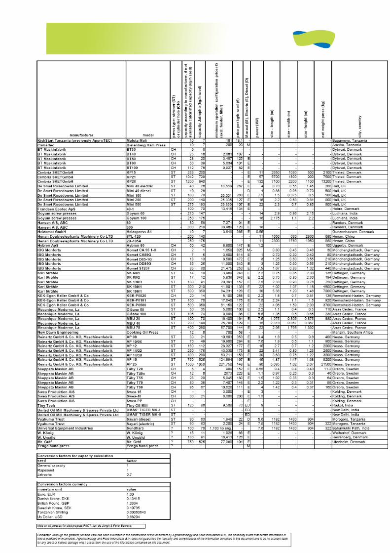
Annex 1 overview press manufacturers
FACT Foundation
1
JATROPHA HANDBOOK
2D EDITION
JUNE 2009
ANNEX TO CHAPTER 5 (OF 6)
Applications of Jatropha products

FACT Foundation
2
ANNEX TO 5.1.1- Stove fact sheets
‘‘Protos’’ plant oil burner
Source: Report: ‘Plant oil cooking stove for developing countries, Elmar Stumpf and Werner Mühlhausen, Institute for Agricultural Engineering in the Tropics and Subtropics, Hohenheim University, Stuttgart, Germany. http://w1.siemens.com/responsibility/en/sustainable/’’Protos’’.htm http://www.bsh-group.com/index.php?page=109906 Introduction:
The ‘‘PROTOS’’ plant oil stove was developed by BSH (Bosch and Siemens Hausgeräte GmbH) in 2004. This unusual stove can be fueled by unrefined and refined vegetable oils such as coconut oil, sunflower oil, rapeseed oil, jatropha oil, castor oil, cottonseed oil and peanut oil. Except for the burner, this stove can be produced locally thereby creating labor. Over 500 ‘Protos’ stoves have been tested in the Philippines, India, Indonesia, Guatemala and Tanzania. The way the plant oil stove works is quite simple. An air pump builds pressure within a tank filled with oil. As a result, the oil is forced into a stainless steel vaporizer tube, where it is vaporized by the application of heat. An ethanol pre-heater is installed below the nozzle as can also be found in most small burners used by hikers. The now-vaporized fuel is channeled through a nozzle, mixes with ambient air in the combustion chamber and produces a blue flame. The oil-air mixture has to be preheated to 180-260°C before ignition occurs. The flame strength can be regulated by means of a valve in the oil line. Disadvantage of the ‘Protos’ stove is the high noise level when burning (‘Pflanzenölkocher sollen den Regenwald retten’, Handelsblatt, 8 juni, 2006)
Specifications:
Supplier’s data: BSH (Bosch and Siemens Hausgeräte GmbH)
Dealers in countries: The ‘Protos’ has been tested in the Philippines, India, Indonesia, South Africa and Tanzania. Capacity: 1.6–3.8 kW, fuel efficiency 40-50%
How is quality of output measured and/or checked? Research by supplier.
Required input power: 2 liters oil per week for a family of 4-5 > 100 liters per year
Operational requirements: 1 person during cooking.
Required maintenance and spare parts: frequent cleaning of the burner each time the burner is used.
Downtime for maintenance: unknown
Overall dimensions: approx 30 x 30 x 30 cm
Costs: intended selling price of € 30 (Elmar Stumpf, BSH Bosch)
Emissions: ten times lower than with high quality kerosene

FACT Foundation
3
Questions:
How many installed? >500, tested in >100 households in Philippines
How many are operational? unknown
Who is supplying this equipment? BSH Bosch and Siemens Hausgeräte GmbH
Ease, speed and reliability of supply chain, for new equipment and for spare parts? Cooking time reduced 30-40% compared to wood fired stoves (‘Protos. The plant oil stove’, BSH Bosch and Siemens Hausgeräte GmbH).
Training of operators possible? Given by whom? BSH Bosch and Siemens Hausgeräte GmbH
User experiences? According to BSH Bosch the introduction in Tanzania was successful as people were positive about the ‘Protos’.

FACT Foundation
4
Kakute stove
Introduction:
The Kakute stove has been developed by Kakute in collaboration with Tirdo (Tanzania Industrial Research and Development Organization). There is no clear information as to whether the stoves have been commercially sold.
GTZ tested the Kakute stoves in Madagascar with Green Mad. The stove was provided by SOLTEC and the oil by ERI located in Fianarantsoa. The main goal of the test was to find wicks that are suitable for jatropha. The best results were obtained with wicks from petroleum lamps and crêpe. Even with these wicks the flame dims after 15-25 minutes. The water temperature in most cases does not increase beyond 80°C (Erik Jan Rodenhuis, Werkgroep Ontwikkelingstechnieken).
Source: http://www.bioenergylists.org/kakutestove
Specifications:
Suppliers data: Kakute together with Tirdo
Dealers in countries: Tanzania. Capacity: unknown
How is quality of output measured and/or checked? unknown
Required input power: unknown
Operational requirements: 1 person during cooking.
Required maintenance and spare parts: unknown
Downtime for maintenance: unknown
Overall dimensions: approx 30 x 30 x 30 cm
Costs: unknown
Questions:
How many installed? none
How many are operational? none
Who is supplying this equipment? Kakute together with Tirdo
Ease, speed and reliability of supply chain, for new equipment and for spare parts? unknown
Training of operators possible? Given by whom? Unknown, probably by Kakute
User experiences? unknown

FACT Foundation
5
UB – 16 Jatropha curcas L seeds stove
Introduction:
This stove is fired with Jatropha seeds instead of its oil. The seed hull has to be removed for better burning as the energy content per unit mass is higher for the seed kernel.
Source: http://www.fierna.com/English/UB-16.htm
Specifications:
Suppliers data: unknown
Dealers in countries: unknown Capacity: maximum 300 gr seeds
How is quality of output measured and/or checked? It needs 8 minutes to boil 1500 ml of water. Energy efficiency has been calculated at 58% based on the heating time for 1 liter of water.
Required input power: 200 g of peeled seeds are able to fire 60 minutes. Based on 10-15 liter water boiling per day per family the total energy can be supplied by 100-150 kg of Jatropha Curcas L seeds per family year.
Operational requirements: 1 person during cooking.
Required maintenance and spare parts: unknown
Downtime for maintenance: unknown
Weight: 12kg
Overall dimensions: 27 x 27x 27 cm
Costs: unknown
Questions:
How many installed? none
How many are operational? none
Who is supplying this equipment? unknown
Ease, speed and reliability of supply chain, for new equipment and for spare parts? unknown
Training of operators possible? Given by whom? unknown
User experiences? unknown
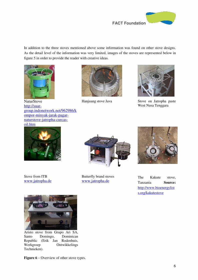
FACT Foundation
6
In addition to the three stoves mentioned above some information was found on other stove designs.
As the detail level of the information was very limited, images of the stoves are represented below in
figure 5 in order to provide the reader with creative ideas.
NaturStove http://suar-group.indonetwork.net/962986/kompor-minyak-jarak-pagar-naturstove-jatropha-curcas-oil.htm
Hanjuang stove Java
Stove on Jatropha paste West Nusa Tenggara
Stove from ITB www.jatropha.de
Butterfly brand stoves www.jatropha.de
The Kakute stove,
Tanzania Source:
http://www.bioenergylist
s.org/kakutestove
Aristo stove from Grupo Ari SA, Santo Domingo, Dominican Republic (Erik Jan Rodenhuis, Werkgroep Ontwikkelings Technieken).
Figure 6 – Overview of other stove types.

FACT Foundation
7
5.1.1.1 Recipe for soap
The outline of the recipe is as follows: · Prepare a solution of the caustic soda by dissolving the soda into the water (never mix these components the other way around – risk of burning!) · Stir until everything has dissolved. The bowl will get hot, cool it using cold water at the outside, or just let it cool down for a while. · Pour the oil into a bowl and put it beside the bowl of caustic soda solution. · Pour the caustic soda solution slowly into the oil, stirring all the time. Immediately the mixture will go white and soon it becomes creamy. · Continue stirring until the mixture is like mayonnaise. This is the moment to add additives like glycerine, perfume etc. · If the mixture is still creamy, pour it into a mould, where it can harden overnight. The moulds can be made from a wooden tray or a cardboard box, lined with a plastic sheet. Alternatively, consider using convenient and attractive shapes like small plastic bowls. · The mixture hardens overnight in tropical temperatures, or in several days in temperate regions. Then it can be released from the mould and cut if necessary. For good sale and use the pieces of soap should not be larger than 150 gram or 6 to 8 to 2 cm. · Even after this first hardening the soap continues to mature for some time. It should be stored for some two weeks on shelf before sale. · Wrapping the soap into a nice paper or clear plastic will add greatly to its sales value! · Last but not least, don’t forget to clean all the used utensils properly, as caustic soda is rather aggressive and Jatropha PPO is toxic.
5.1.1.2 Rural Soap
An other, more rural and worldwide applicable recipe for soap making is as follows1: You would need the following ingredients: (amount in the indicated ratios) Milled Jatropha kernel (100) Nice dry ash (50) Water (20) Three pans (one with a hole in the bottom)
1 This recipe is based on collected information in rural zone of Honduras: Yoro department

FACT Foundation
8
A cloth Fire place Optional: other oils or animal fats The actions are according the following process:
1) Heat up a pot with water; it is not necessary to boil it, but it should be quite hot. 2) Place a cloth on top of the opening of another pan and fill the cloth with ash (Similar to filling
a coffee filter with coffee). 3) Slowly pour the hot water on the cloth with the ash to make a strong abstract of ash-water. It is
important that the abstract is quite strong. This can be checked simply by tasting the spiciness of the abstract by putting a small drop on the tip of your tongue. (Be carefull, don’t swallow)
4) Put the milled jatropha kernel in a pan and put it on a low fire 5) If desired other types of fats can be add to the jatropha kernel. 6) Slowly add the ash abstract to the jatropha kernel 7) Mix slowly 8) The jatropha kernel will slowly absorb the ash liquid. Keep on adding the ash liquid until the
fats are totally converted. This is a patient process which should be done on low fire. 9) After it gets a more solid form, balls can be made. 10) After three days these soap balls are ready to use.
The soap balls are famous for their dandruff curing effect and their general cleaning properties.
Water content test and acid test
1) To test for water content, heat about 0,5 litre of the oil in a saucepan on the stove and monitor the temperature with a thermometer. With more than 30% water in it, it will start to make crackling sounds from about 50 °C. If it’s still not crackling by 60-65 °C there should be no need to dewater it. To remove the water, keep the oil at 60 °C for 15 minutes and then pour the oil into a settling tank. Let it settle for at least 24 hours, allowing the water to sink to the bottom. Then pour or drain the oil from above. Make sure you never empty the settling vessel more than 90%.
2) To test the acid (FFA) content you need to perform a titration of the oil with lye and an indicator. This means you carefully add small drops of lye to prepared oil until all the acid in the test mixture has been neutralized. Then you can calculate how much extra lye will be needed to neutralize the FFA in the conversion. You’ll need some basic kitchen ware as well as a syringe with ml indication and some basic chemicals: de-ionized water, NaOH, isopropanol and phenolphthalein. Here’s how to test: Dissolve 1 gram of pure sodium hydroxide lye (NaOH) in 1 litre of distilled or de-ionized water (0,1% w/v NaOH solution) (weight to volume). In a smaller beaker, dissolve 1 ml of dewatered oil in 10 ml of pure isopropyl alcohol (isopropanol). Warm the beaker gently by standing it in some hot water, stir until all the oil dissolves in the alcohol and the mixture turns clear. Add 2 drops of phenolphthalein solution (acidity indicator). Using a graduated syringe, add the 0,1% NaOH solution drop by drop to the oil-alcohol-phenolphthalein solution, stirring all the time. It might turn a bit cloudy, keep stirring. Keep on carefully adding the lye solution until the solution stays pink (actually magenta) for 15 seconds. Take the number of millilitres of 0,1% lye solution you used and add 3,5 (the basic amount of lye needed for fresh oil). This is the number of grams of lye you'll need per litre of oil to process the oil. For used oil these same precautions and preparations hold, usually used oil’s quality is worse than fresh oil’s, leading to frequent need for dewatering and determination of acidity.
FACT Foundation
9
1.1. Practical experience and potential problems with PPO in engines
Fuel for diesel engines has to comply with a certain quality to prevent operational problems. Without proper oil cleaning the following can occur in a diesel engine [1]:
• Erosion of piston head and inlet port; • Increased wear of piston rings; • Polymerisation of lubrication oil; • Cavitations and corrosion in the injectors due to too much water in the oil; • Incomplete combustion with excess noise, smell and emissions due to high viscosity; • Failure of injectors due to high FFA content; • Abrasive effect on fuel injectors and combustion chambers due to phosphor; • Frequent clogging of engine fuel filter due to phosphor and solids;
Some specific experiences have been outlined below [5]: Netherlands/Mozambique: FACT project
At the end of 2008 Ger Groeneveld from PPO Groeneveld conducted several tests for oil cleaning and engine testing. He has adjusted two engines to run on PPO; a 17 kW Lister ST3 and an 18 kW Feidong 295 GJ. Endurance tests were performed with both engines. A 500 hour test with the Lister on mainly sunflower oil showed no fuel related problems. The viscosity of sunflower (17.1 cS at 38°C) is somewhat lower than that of jatropha (37-54cS at 30°C). The high viscosity of Jatropha oil can cause engines to run short on fuel. Diesel engines have been designed for viscosities of 1.7-2.4 cS. When the engine runs short of fuel this can damage the pistons en injector nozzles will not spray properly or even clog. The viscosity of vegetable oils can be reduced by heating. Viscosities below 5 cS are acceptable for most diesel engines [5]. If the level of FFA is above 3%, there is a risk of engine damage by corrosion. Corrosion problems are relevant for engines that run intermittent. Oxygen then has a change to catalyze corrosion. The acid in the PPO will etch off any protective layers that normally prevent erosion. Michael Allan (2002)
Conducted endurance tests with a Kabota diesel on palm oil. On refined palm oil the engine ran perfectly for over 2000 hours. Refining included deguming and neutralization. On crude palm oil however, the engine broke down after 300 hours and again after 550. Both the inlet port and piston head appeared badly eroded, the piston rings were worn and the lubrication oil had polymerized. These are clearly effects of poor fuel quality [5].
Colombia, Aprotec
Mauricio Gnecco found much carbon on the indirect injection pre-chamber when using well filtered palm oil. Users of another 10HP Lister engine reported a burned heat seal when the engine broke down. Analysis by Mauricio again showed high carbon deposits on the indirect injection pre-chamber throat.
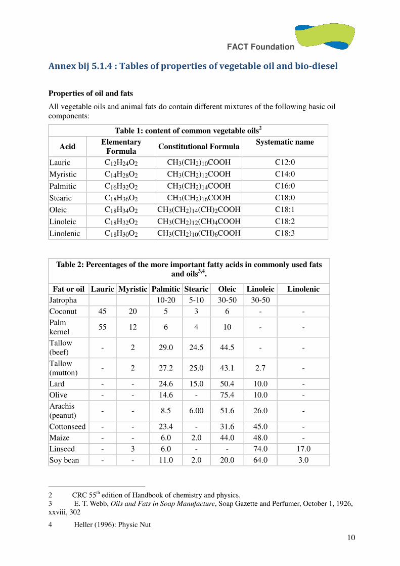
FACT Foundation
10
Annex bij 5.1.4 : Tables of properties of vegetable oil and bio-diesel
Properties of oil and fats
All vegetable oils and animal fats do contain different mixtures of the following basic oil components:
Table 1: content of common vegetable oils2
Acid Elementary
Formula Constitutional Formula
Systematic name
Lauric C12H24O2 CH3(CH2)10COOH C12:0
Myristic C14H28O2 CH3(CH2)12COOH C14:0
Palmitic C16H32O2 CH3(CH2)14COOH C16:0
Stearic C18H36O2 CH3(CH2)16COOH C18:0
Oleic C18H34O2 CH3(CH2)14(CH)2COOH C18:1
Linoleic C18H32O2 CH3(CH2)12(CH)4COOH C18:2
Linolenic C18H30O2 CH3(CH2)10(CH)6COOH C18:3
Table 2: Percentages of the more important fatty acids in commonly used fats
and oils3,4
.
Fat or oil Lauric Myristic Palmitic Stearic Oleic Linoleic Linolenic
Jatropha 10-20 5-10 30-50 30-50
Coconut 45 20 5 3 6 - -
Palm kernel
55 12 6 4 10 - -
Tallow (beef)
- 2 29.0 24.5 44.5 - -
Tallow (mutton)
- 2 27.2 25.0 43.1 2.7 -
Lard - - 24.6 15.0 50.4 10.0 -
Olive - - 14.6 - 75.4 10.0 -
Arachis (peanut)
- - 8.5 6.00 51.6 26.0 -
Cottonseed - - 23.4 - 31.6 45.0 -
Maize - - 6.0 2.0 44.0 48.0 -
Linseed - 3 6.0 - - 74.0 17.0
Soy bean - - 11.0 2.0 20.0 64.0 3.0
2 CRC 55th edition of Handbook of chemistry and physics. 3 E. T. Webb, Oils and Fats in Soap Manufacture, Soap Gazette and Perfumer, October 1, 1926, xxviii, 302
4 Heller (1996): Physic Nut
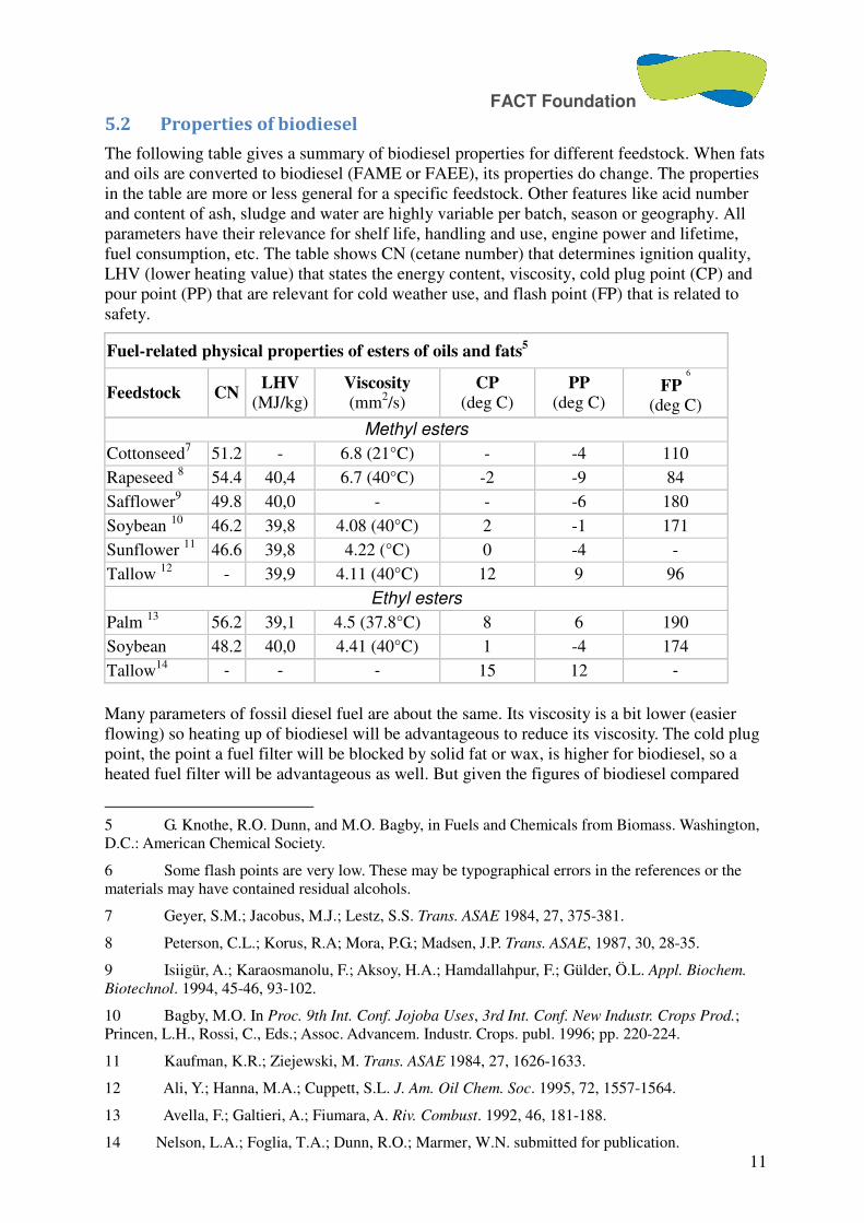
FACT Foundation
11
5.2 Properties of biodiesel
The following table gives a summary of biodiesel properties for different feedstock. When fats and oils are converted to biodiesel (FAME or FAEE), its properties do change. The properties in the table are more or less general for a specific feedstock. Other features like acid number and content of ash, sludge and water are highly variable per batch, season or geography. All parameters have their relevance for shelf life, handling and use, engine power and lifetime, fuel consumption, etc. The table shows CN (cetane number) that determines ignition quality, LHV (lower heating value) that states the energy content, viscosity, cold plug point (CP) and pour point (PP) that are relevant for cold weather use, and flash point (FP) that is related to safety.
Fuel-related physical properties of esters of oils and fats5
Feedstock CN LHV
(MJ/kg) Viscosity (mm2/s)
CP (deg C)
PP (deg C)
FP 6
(deg C)
Methyl esters
Cottonseed7 51.2 - 6.8 (21°C) - -4 110
Rapeseed 8 54.4 40,4 6.7 (40°C) -2 -9 84
Safflower9 49.8 40,0 - - -6 180
Soybean 10 46.2 39,8 4.08 (40°C) 2 -1 171
Sunflower 11 46.6 39,8 4.22 (°C) 0 -4 -
Tallow 12 - 39,9 4.11 (40°C) 12 9 96
Ethyl esters
Palm 13 56.2 39,1 4.5 (37.8°C) 8 6 190
Soybean 48.2 40,0 4.41 (40°C) 1 -4 174
Tallow14 - - - 15 12 -
Many parameters of fossil diesel fuel are about the same. Its viscosity is a bit lower (easier flowing) so heating up of biodiesel will be advantageous to reduce its viscosity. The cold plug point, the point a fuel filter will be blocked by solid fat or wax, is higher for biodiesel, so a heated fuel filter will be advantageous as well. But given the figures of biodiesel compared
5 G. Knothe, R.O. Dunn, and M.O. Bagby, in Fuels and Chemicals from Biomass. Washington, D.C.: American Chemical Society.
6 Some flash points are very low. These may be typographical errors in the references or the materials may have contained residual alcohols.
7 Geyer, S.M.; Jacobus, M.J.; Lestz, S.S. Trans. ASAE 1984, 27, 375-381.
8 Peterson, C.L.; Korus, R.A; Mora, P.G.; Madsen, J.P. Trans. ASAE, 1987, 30, 28-35.
9 Isiigür, A.; Karaosmanolu, F.; Aksoy, H.A.; Hamdallahpur, F.; Gülder, Ö.L. Appl. Biochem.
Biotechnol. 1994, 45-46, 93-102.
10 Bagby, M.O. In Proc. 9th Int. Conf. Jojoba Uses, 3rd Int. Conf. New Industr. Crops Prod.; Princen, L.H., Rossi, C., Eds.; Assoc. Advancem. Industr. Crops. publ. 1996; pp. 220-224.
11 Kaufman, K.R.; Ziejewski, M. Trans. ASAE 1984, 27, 1626-1633.
12 Ali, Y.; Hanna, M.A.; Cuppett, S.L. J. Am. Oil Chem. Soc. 1995, 72, 1557-1564.
13 Avella, F.; Galtieri, A.; Fiumara, A. Riv. Combust. 1992, 46, 181-188.
14 Nelson, L.A.; Foglia, T.A.; Dunn, R.O.; Marmer, W.N. submitted for publication.

FACT Foundation
12
with daily outside temperatures in for example Honduras, no problems regarding cold-weather properties of biodiesel are to be expected.
ANNEX bij 5.1.5 Annex 1
Material Safety Data Sheet Methyl Alcohol, Reagent ACS, 99.8% (GC)
ACC# 95294
Section 1 - Chemical Product and Company Identification
MSDS Name: Methyl Alcohol, Reagent ACS, 99.8% (GC) Catalog Numbers: AC423950000, AC423950010, AC423950020, AC423955000, AC9541632, AC423952 Synonyms: Carbinol; Methanol; Methyl hydroxide; Monohydroxymethane; Pyroxylic spirit; Wood alcohol; Wood naptha; Wood spirit; Monohydroxymethane; Methyl hydrate. Company Identification: Acros Organics N.V. One Reagent Lane Fair Lawn, NJ 07410 For information in North America, call: 800-ACROS-01 For emergencies in the US, call CHEMTREC: 800-424-9300
Section 2 - Composition, Information on Ingredients
CAS# Chemical Name Percent EINECS/ELINCS 67-56-1 Methyl alcohol 99+ 200-659-6
Hazard Symbols: T F Risk Phrases: 11 23/24/25 39/23/24/25
Section 3 - Hazards Identification
EMERGENCY OVERVIEW
Appearance: clear, colorless. Flash Point: 11 deg C. Poison! Cannot be made non-poisonous. Causes eye and skin irritation. May be absorbed through intact skin. This substance has caused adverse reproductive and fetal effects in animals. Danger! Flammable liquid and vapor. Harmful if inhaled. May be fatal or cause blindness if swallowed. May cause central nervous system depression. May cause digestive tract irritation with nausea, vomiting, and diarrhea. Causes respiratory tract irritation. May cause liver, kidney and heart damage. Target Organs: Kidneys, heart, central nervous system, liver, eyes. Potential Health Effects Eye: Produces irritation, characterized by a burning sensation, redness, tearing, inflammation, and possible corneal injury. May cause painful sensitization to light. Skin: Causes moderate skin irritation. May be absorbed through the skin in harmful amounts. Prolonged and/or repeated contact may cause defatting of the skin and dermatitis. Ingestion: May be fatal or cause blindness if swallowed. May cause gastrointestinal irritation with nausea, vomiting and diarrhea. May cause systemic toxicity with acidosis. May cause central nervous system depression, characterized by excitement, followed by headache, dizziness, drowsiness, and nausea. Advanced stages may cause collapse, unconsciousness, coma and possible death due to respiratory failure. May cause cardiopulmonary system effects. Inhalation: Harmful if inhaled. May cause adverse central nervous system effects including headache, convulsions, and possible death. May cause visual impairment and possible permanent blindness.

FACT Foundation
13
Causes irritation of the mucous membrane. Chronic: Prolonged or repeated skin contact may cause dermatitis. Chronic inhalation and ingestion may cause effects similar to those of acute inhalation and ingestion. Chronic exposure may cause reproductive disorders and teratogenic effects. Laboratory experiments have resulted in mutagenic effects. Prolonged exposure may cause liver, kidney, and heart damage.
Section 4 - First Aid Measures
Eyes: Immediately flush eyes with plenty of water for at least 15 minutes, occasionally lifting the upper and lower eyelids. Get medical aid immediately. Skin: Immediately flush skin with plenty of soap and water for at least 15 minutes while removing contaminated clothing and shoes. Get medical aid if irritation develops or persists. Wash clothing before reuse. Ingestion: If victim is conscious and alert, give 2-4 cupfuls of milk or water. Never give anything by mouth to an unconscious person. Get medical aid immediately. Induce vomiting by giving one teaspoon of Syrup of Ipecac. Inhalation: Get medical aid immediately. Remove from exposure to fresh air immediately. If breathing is difficult, give oxygen. Do NOT use mouth-to-mouth resuscitation. If breathing has ceased apply artificial respiration using oxygen and a suitable mechanical device such as a bag and a mask. Notes to Physician: Effects may be delayed. Ethanol may inhibit methanol metabolism.
Section 5 - Fire Fighting Measures
General Information: Containers can build up pressure if exposed to heat and/or fire. As in any fire, wear a self-contained breathing apparatus in pressure-demand, MSHA/NIOSH (approved or equivalent), and full protective gear. Water runoff can cause environmental damage. Dike and collect water used to fight fire. Vapors can travel to a source of ignition and flash back. During a fire, irritating and highly toxic gases may be generated by thermal decomposition or combustion. Flammable Liquid. Can release vapors that form explosive mixtures at temperatures above the flashpoint. Use water spray to keep fire-exposed containers cool. Water may be ineffective. Material is lighter than water and a fire may be spread by the use of water. Vapors may be heavier than air. They can spread along the ground and collect in low or confined areas. May be ignited by heat, sparks, and flame. Extinguishing Media: For small fires, use dry chemical, carbon dioxide, water spray or alcohol-resistant foam. Use water spray to cool fire-exposed containers. Water may be ineffective. For large fires, use water spray, fog or alcohol-resistant foam. Do NOT use straight streams of water.
Section 6 - Accidental Release Measures
General Information: Use proper personal protective equipment as indicated in Section 8. Spills/Leaks: Scoop up with a nonsparking tool, then place into a suitable container for disposal. Use water spray to disperse the gas/vapor. Remove all sources of ignition. Absorb spill using an absorbent, non-combustible material such as earth, sand, or vermiculite. Do not use combustible materials such as saw dust. Provide ventilation. A vapor suppressing foam may be used to reduce vapors. Water spray may reduce vapor but may not prevent ignition in closed spaces.
Section 7 - Handling and Storage
Handling: Wash thoroughly after handling. Remove contaminated clothing and wash before reuse. Ground and bond containers when transferring material. Do not breathe dust, vapor, mist, or gas. Do

FACT Foundation
14
not get in eyes, on skin, or on clothing. Empty containers retain product residue, (liquid and/or vapor), and can be dangerous. Keep container tightly closed. Avoid contact with heat, sparks and flame. Do not ingest or inhale. Use only in a chemical fume hood. Do not pressurize, cut, weld, braze, solder, drill, grind, or expose empty containers to heat, sparks or open flames. Storage: Keep away from heat, sparks, and flame. Keep away from sources of ignition. Store in a cool, dry, well-ventilated area away from incompatible substances. Flammables-area. Keep containers tightly closed. Do not store in aluminum or lead containers.
Section 8 - Exposure Controls, Personal Protection
Engineering Controls: Use explosion-proof ventilation equipment. Facilities storing or utilizing this material should be equipped with an eyewash facility and a safety shower. Use adequate general or local exhaust ventilation to keep airborne concentrations below the permissible exposure limits. Use only under a chemical fume hood. Exposure Limits
Chemical Name ACGIH NIOSH OSHA - Final PELs
Methyl alcohol 200 ppm TWA; 250 ppm STEL; skin - potential for cutaneous absorption
200 ppm TWA; 260 mg/m3 TWA 6000 ppm
IDLH
200 ppm TWA; 260 mg/m3 TWA
OSHA Vacated PELs: Methyl alcohol: 200 ppm TWA; 260 mg/m3 TWA; 250 ppm STEL; 325 mg/m3 STEL Personal Protective Equipment Eyes: Wear chemical goggles. Skin: Wear appropriate protective gloves to prevent skin exposure. Clothing: Wear appropriate protective clothing to prevent skin exposure.
Respirators: A respiratory protection program that meets OSHA's 29 CFR �1910.134 and ANSI
Z88.2 requirements or European Standard EN 149 must be followed whenever workplace conditions warrant a respirator's use.
Section 9 - Physical and Chemical Properties
Physical State: Liquid Appearance: clear, colorless Odor: alcohol-like - weak odor pH: Not available. Vapor Pressure: 128 mm Hg @ 20 deg C Vapor Density: 1.11 (Air=1) Evaporation Rate:5.2 (Ether=1) Viscosity: 0.55 cP 20 deg C Boiling Point: 64.7 deg C @ 760.00mm Hg Freezing/Melting Point:-98 deg C Autoignition Temperature: 464 deg C ( 867.20 deg F) Flash Point: 11 deg C ( 51.80 deg F) Decomposition Temperature:Not available. NFPA Rating: (estimated) Health: 1; Flammability: 3; Reactivity: 0 Explosion Limits, Lower:6.0 vol % Upper: 36.00 vol % Solubility: miscible Specific Gravity/Density:.7910g/cm3 Molecular Formula:CH4O Molecular Weight:32.04
FACT Foundation
15
Section 10 - Stability and Reactivity
Chemical Stability: Stable under normal temperatures and pressures. Conditions to Avoid: High temperatures, incompatible materials, ignition sources, oxidizers. Incompatibilities with Other Materials: Acids (mineral, non-oxidizing, e.g. hydrochloric acid, hydrofluoric acid, muriatic acid, phosphoric acid), acids (mineral, oxidizing, e.g. chromic acid, hypochlorous acid, nitric acid, sulfuric acid), acids (organic, e.g. acetic acid, benzoic acid, formic acid, methanoic acid, oxalic acid), azo, diazo, and hydrazines (e.g. dimethyl hydrazine, hydrazine, methyl hydrazine), isocyanates (e.g. methyl isocyanate), nitrides (e.g. potassium nitride, sodium nitride), peroxides and hydroperoxides (organic, e.g. acetyl peroxide, benzoyl peroxide, butyl peroxide, methyl ethyl ketone peroxide), epoxides (e.g. butyl glycidyl ether), Oxidants (such as barium perchlorate, bromine, chlorine, hydrogen peroxide, lead perchlorate, perchloric acid, sodium hypochlorite)., Active metals (such as potassium and magnesium)., acetyl bromide, alkyl aluminum salts, beryllium dihydride, carbontetrachloride, carbon tetrachloride + metals, chloroform + heat, chloroform + sodium hydroxide, cyanuric chloride, diethyl zinc, nitric acid, potassium-tert-butoxide, chloroform + hydroxide, water reactive substances (e.g. acetic anyhdride, alkyl aluminum chloride, calcium carbide, ethyl dichlorosilane). Hazardous Decomposition Products: Carbon monoxide, irritating and toxic fumes and gases, carbon dioxide, formaldehyde. Hazardous Polymerization: Will not occur.
Section 11 - Toxicological Information
RTECS#: CAS# 67-56-1: PC1400000 LD50/LC50: CAS# 67-56-1: Draize test, rabbit, eye: 40 mg Moderate; Draize test, rabbit, eye: 100 mg/24H Moderate; Draize test, rabbit, skin: 20 mg/24H Moderate; Inhalation, rat: LC50 = 64000 ppm/4H; Oral, mouse: LD50 = 7300 mg/kg; Oral, rabbit: LD50 = 14200 mg/kg; Oral, rat: LD50 = 5628 mg/kg; Skin, rabbit: LD50 = 15800 mg/kg; Carcinogenicity: CAS# 67-56-1: Not listed by ACGIH, IARC, NIOSH, NTP, or OSHA. Epidemiology: Methanol has been shown to produce fetotoxicity in the embr yo or fetus of laboratory animals. Specific developmenta l abnormalities include cardiovascular, musculoskeletal, and urogenital systems. Teratogenicity: Effects on Newborn: Behaviorial, Oral, rat: TDLo=7500 mg/kg (female 17-19 days after conception). Effects on Embryo or Fetus: Fetotoxicity, Inhalation, rat: TCLo=10000 ppm/7H (female 7-15 days after conception). Specific Developmental Abnormalities: Cardiovascular, Musculoskeletal, Urogenital, Inhalation, rat: TCLo=20000 ppm/7H (7-14 days after conception). Reproductive Effects: Paternal Effects: Spermatogenesis: Intraperitoneal, mouse TDLo=5 g/kg ( male 5 days pre-mating). Fertility: Oral, rat: TDLo = 35295 mg/kg (female 1-15 days after conception). Paternal Effects: Testes, Epididymis, Sperm duct: Oral, rat: TDLo = 200 ppm/20H (male 78 weeks pre-mating). Neurotoxicity: No information available. Mutagenicity: DNA inhibition: Human Lymphocyte = 300 mmol/L. DNA damage: Oral, rat = 10 umol/kg. Mutation in microorganisms: Mouse Lymphocyte = 7900 mg/L. Cytogenetic analysis: Oral,
FACT Foundation
16
mouse = 1 gm/kg. Other Studies: Standard Draize Test(Skin, rabbit) = 20 mg/24H (Moderate) S tandard Draize Test: Administration into the eye (rabbit) = 40 mg (Moderate). Standard Draize test: Administration int o the eye (rabbit) = 100 mg/24H (Moderate).
Section 12 - Ecological Information
Ecotoxicity: Fish: Fathead Minnow: 29.4 g/L; 96 Hr; LC50 (unspecified) Goldfish: 250 ppm; 11 Hr; resulted in death Rainbow trout: 8000 mg/L; 48 Hr; LC50 (unspecified) Rainbow trout: LC50 = 13-68 mg/L; 96 Hr.; 12 degrees C Fathead Minnow: LC50 = 29400 mg/L; 96 Hr.; 25 degrees C, pH 7.63 Rainbow trout: LC50 = 8000 mg/L; 48 Hr.; Unspecified ria: Phytobacterium phosphoreum: EC50 = 51,000-320,000 mg/L; 30 minutes; Microtox test No data available. Environmental: Dangerous to aquatic life in high concentrations. Aquatic toxicity rating: TLm 96>1000 ppm. May be dangerous if it enters water intakes. Methyl alcohol is expected to biodegrade in soil and water very rapidly. This product will show high soil mobility and will be degraded from the ambient atmosphere by the reaction with photochemically produced hyroxyl radicals with an estimated half-life of 17.8 days. Bioconcentration factor for fish (golden ide) < 10. Based on a log Kow of -0.77, the BCF value for methanol can be estimated to be 0.2. Physical: No information available. Other: None.
Section 13 - Disposal Considerations
Chemical waste generators must determine whether a discarded chemical is classified as a hazardous waste. US EPA guidelines for the classification determination are listed in 40 CFR Parts 261.3. Additionally, waste generators must consult state and local hazardous waste regulations to ensure complete and accurate classification. RCRA P-Series: None listed. RCRA U-Series: CAS# 67-56-1: waste number U154; (Ignitable waste).
Section 14 - Transport Information
US DOT IATA RID/ADR IMO Canada TDG
Shipping Name: METHANOL METHANOL
Hazard Class: 3 3(6.1)
UN Number: UN1230 UN1230
Packing Group: II II
Additional Info: FLASHPOINT
11 C
Section 15 - Regulatory Information
US FEDERAL TSCA CAS# 67-56-1 is listed on the TSCA inventory. Health & Safety Reporting List None of the chemicals are on the Health & Safety Reporting List. Chemical Test Rules None of the chemicals in this product are under a Chemical Test Rule.

FACT Foundation
17
Section 12b None of the chemicals are listed under TSCA Section 12b. TSCA Significant New Use Rule None of the chemicals in this material have a SNUR under TSCA. SARA Section 302 (RQ) CAS# 67-56-1: final RQ = 5000 pounds (2270 kg) Section 302 (TPQ) None of the chemicals in this product have a TPQ. SARA Codes CAS # 67-56-1: acute, flammable. Section 313 This material contains Methyl alcohol (CAS# 67-56-1, 99%),which is subject to the reporting requirements of Section 313 of SARA Title III and 40 CFR Part 373. Clean Air Act: CAS# 67-56-1 is listed as a hazardous air pollutant (HAP). This material does not contain any Class 1 Ozone depletors. This material does not contain any Class 2 Ozone depletors. Clean Water Act: None of the chemicals in this product are listed as Hazardous Substances under the CWA. None of the chemicals in this product are listed as Priority Pollutants under the CWA. None of the chemicals in this product are listed as Toxic Pollutants under the CWA. OSHA: None of the chemicals in this product are considered highly hazardous by OSHA. STATE CAS# 67-56-1 can be found on the following state right to know lists: California, New Jersey, Florida, Pennsylvania, Minnesota, Massachusetts. California No Significant Risk Level: None of the chemicals in this product are listed. European/International Regulations European Labeling in Accordance with EC Directives Hazard Symbols: T F Risk Phrases: R 11 Highly flammable. R 23/24/25 Toxic by inhalation, in contact with skin and if swallowed. R 39/23/24/25 Toxic : danger of very serious irreversible effects through inhalation, in contact with skin and if swallowed.
Safety Phrases: S 16 Keep away from sources of ignition - No smoking. S 36/37 Wear suitable protective clothing and gloves. S 45 In case of accident or if you feel unwell, seek medical advice immediately (show the label where possible). S 7 Keep container tightly closed.
WGK (Water Danger/Protection) CAS# 67-56-1: 1 Canada CAS# 67-56-1 is listed on Canada's DSL List. CAS# 67-56-1 is listed on Canada's DSL List. This product has a WHMIS classification of B2, D1A, D2B. CAS# 67-56-1 is listed on Canada's Ingredient Disclosure List.

FACT Foundation
18
Exposure Limits CAS# 67-56-1: OEL-ARAB Republic of Egypt:TWA 200 ppm (260 mg/m3);Ski n OEL-AUSTRALIA:TWA 200 ppm (260 mg/m3);STEL 250 ppm;Skin OEL-BELGIU M:TWA 200 ppm (262 mg/m3);STEL 250 ppm;Skin OEL-CZECHOSLOVAKIA:TWA 10 0 mg/m3;STEL 500 mg/m3 OEL-DENMARK:TWA 200 ppm (260 mg/m3);Skin OEL- FINLAND:TWA 200 ppm (260 mg/m3);STEL 250 ppm;Skin OEL-FRANCE:TWA 200 ppm (260 mg/m3);STEL 1000 ppm (1300 mg/m3) OEL-GERMANY:TWA 200 ppm (2 60 mg/m3);Skin OEL-HUNGARY:TWA 50 mg/m3;STEL 100 mg/m3;Skin JAN9 OEL -JAPAN:TWA 200 ppm (260 mg/m3);Skin OEL-THE NETHERLANDS:TWA 200 ppm ( 260 mg/m3);Skin OEL-THE PHILIPPINES:TWA 200 ppm (260 mg/m3) OEL-POLA ND:TWA 100 mg/m3 OEL-RUSSIA:TWA 200 ppm;STEL 5 mg/m3;Skin OEL-SWEDEN :TWA 200 ppm (250 mg/m3);STEL 250 ppm (350 mg/m3);Skin OEL-SWITZERLAN D:TWA 200 ppm (260 mg/m3);STEL 400 ppm;Skin OEL-THAILAND:TWA 200 ppm (260 mg/m3) OEL-TURKEY:TWA 200 ppm (260 mg/m3) OEL-UNITED KINGDOM:TW A 200 ppm (260 mg/m3);STEL 250 ppm;Skin OEL IN BULGARIA, COLOMBIA, JO RDAN, KOREA check ACGIH TLV OEL IN NEW ZEALAND, SINGAPORE, VIETNAM ch eck ACGI TLV
Section 16 - Additional Information
MSDS Creation Date: 7/21/1999 Revision #4 Date: 3/14/2001 The information above is believed to be accurate and represents the best information currently
available to us. However, we make no warranty of merchantability or any other warranty, express or
implied, with respect to such information, and we assume no liability resulting from its use. Users
should make their own investigations to determine the suitability of the information for their particular
purposes. In no event shall Fisher be liable for any claims, losses, or damages of any third party or for
lost profits or any special, indirect, incidental, consequential or exemplary damages, howsoever
arising, even if Fisher has been advised of the possibility of such damages.
FACT Foundation
19
Annex 2 bij 5.1.5
Material Safety Data Sheet Potassium Hydroxide
ACC# 19431
Section 1 - Chemical Product and Company Identification
MSDS Name: Potassium Hydroxide Catalog Numbers: S71978, S71979, S71979-1, S71979-2, P246-3, P250-1, P250-10, P250-3, P250-50, P250-500, P250-50LC, P251-3, P251-50, P251-500, P251-50KG, P25812, P258212, P25850, P25850LC, PFP25050LC, S71977, S72221D Synonyms: Caustic potash, Lye, Potassium hydrate Company Identification: Fisher Scientific 1 Reagent Lane Fair Lawn, NJ 07410 For information, call: 201-796-7100 Emergency Number: 201-796-7100 For CHEMTREC assistance, call: 800-424-9300 For International CHEMTREC assistance, call: 703-527-3887
Section 2 - Composition, Information on Ingredients
CAS# Chemical Name Percent EINECS/ELINCS 1310-58-3 Potassium hydroxide (KOH) 100.0 215-181-3
Hazard Symbols: C Risk Phrases: 22 35
Section 3 - Hazards Identification
EMERGENCY OVERVIEW
Appearance: white or yellow. Danger! Corrosive. Water-Reactive. Harmful if swallowed. Causes severe eye and skin burns. Causes severe digestive and respiratory tract burns. Target Organs: None. Potential Health Effects Eye: Causes severe eye burns. May cause irreversible eye injury. Contact may cause ulceration of the conjunctiva and cornea. Eye damage may be delayed. Skin: Causes skin burns. May cause deep, penetrating ulcers of the skin. Ingestion: Harmful if swallowed. May cause circulatory system failure. May cause perforation of the digestive tract. Causes severe digestive tract burns with abdominal pain, vomiting, and possible death. Inhalation: Harmful if inhaled. Irritation may lead to chemical pneumonitis and pulmonary edema. Causes severe irritation of upper respiratory tract with coughing, burns, breathing difficulty, and possible coma. Chronic: Prolonged or repeated skin contact may cause dermatitis. Prolonged or repeated eye contact may cause conjunctivitis.

FACT Foundation
20
Section 4 - First Aid Measures
Eyes: Immediately flush eyes with plenty of water for at least 15 minutes, occasionally lifting the upper and lower eyelids. Get medical aid immediately. Skin: Get medical aid immediately. Immediately flush skin with plenty of soap and water for at least 15 minutes while removing contaminated clothing and shoes. Discard contaminated clothing in a manner which limits further exposure. Ingestion: Do NOT induce vomiting. If victim is conscious and alert, give 2-4 cupfuls of milk or water. Never give anything by mouth to an unconscious person. Get medical aid immediately. Inhalation: Get medical aid immediately. Remove from exposure to fresh air immediately. If breathing is difficult, give oxygen. If breathing has ceased apply artificial respiration using oxygen and a suitable mechanical device such as a bag and a mask. Notes to Physician: Treat symptomatically and supportively.
Section 5 - Fire Fighting Measures
General Information: As in any fire, wear a self-contained breathing apparatus in pressure-demand, MSHA/NIOSH (approved or equivalent), and full protective gear. Use water with caution and in flooding amounts. Contact with moisture or water may generate sufficient heat to ignite nearby combustible materials. Extinguishing Media: For small fires, use dry chemical, carbon dioxide, water spray or alcohol-resistant foam.
Section 6 - Accidental Release Measures
General Information: Use proper personal protective equipment as indicated in Section 8. Spills/Leaks: Vacuum or sweep up material and place into a suitable disposal container. Avoid generating dusty conditions.
Section 7 - Handling and Storage
Handling: Wash thoroughly after handling. Use with adequate ventilation. Do not allow water to get into the container because of violent reaction. Do not get in eyes, on skin, or on clothing. Do not ingest or inhale. Storage: Store in a tightly closed container. Store in a cool, dry, well-ventilated area away from incompatible substances. Keep away from strong acids. Keep away from water. Keep away from metals. Keep away from flammable liquids. Keep away from organic halogens.
Section 8 - Exposure Controls, Personal Protection
Engineering Controls: Use adequate general or local exhaust ventilation to keep airborne concentrations below the permissible exposure limits. Exposure Limits
Chemical Name ACGIH NIOSH OSHA - Final PELs Potassium hydroxide
(KOH) C 2 mg/m3 none listed none listed
FACT Foundation
21
OSHA Vacated PELs: Potassium hydroxide (KOH): C 2 mg/m3 Personal Protective Equipment Eyes: Wear safety glasses and chemical goggles or face shield if handling liquids. Skin: Wear appropriate gloves to prevent skin exposure. Clothing: Wear appropriate protective clothing to prevent skin exposure. Respirators: Follow the OSHA respirator regulations found in 29CFR 1910.134 or European Standard EN 149. Always use a NIOSH or European Standard EN 149 approved respirator when necessary.
Section 9 - Physical and Chemical Properties
Physical State: Solid Appearance: white or yellow Odor: odorless pH: 13.5 (0.1M solution) Vapor Pressure: Not available. Vapor Density: Not available. Evaporation Rate:Not available. Viscosity: Not available. Boiling Point: 2408 deg F Freezing/Melting Point:680 deg F Autoignition Temperature: Not applicable. Flash Point: Not applicable. Decomposition Temperature:Not available. NFPA Rating: (estimated) Health: 3; Flammability: 0; Reactivity: 1 Explosion Limits, Lower:Not available. Upper: Not available. Solubility: Soluble in water Specific Gravity/Density:2.04 Molecular Formula:KOH Molecular Weight:56.1047
Section 10 - Stability and Reactivity
Chemical Stability: Stable. Readily absorbs carbon dioxide and moisture from the air and deliquesces. Conditions to Avoid: Incompatible materials, moisture, contact with water, acids, metals. Incompatibilities with Other Materials: Generates large amounts of heat when in contact with water and may steam and splatter. Reacts with chlorine dioxide, nitrobenzene, nitromethane, nitrogen trichloride, peroxidized tetrahydrofuran, 2,4,6-trinitrotoluene, bromoform+ crown ethers, acids alcohols, sugars, germanium cyclopentadiene, maleic dicarbide. Corrosive to metals such as aluminum, tin, and zinc to cause formation of flammable hydrogen gas. Hazardous Decomposition Products: Oxides of potassium. Hazardous Polymerization: Has not been reported.
Section 11 - Toxicological Information
RTECS#: CAS# 1310-58-3: TT2100000 LD50/LC50: CAS# 1310-58-3: Draize test, rabbit, skin: 50 mg/24H Severe; Oral, rat: LD50 = 273 mg/kg;
FACT Foundation
22
Carcinogenicity: CAS# 1310-58-3: Not listed by ACGIH, IARC, NIOSH, NTP, or OSHA. Epidemiology: No data available. Teratogenicity: No information reported. Reproductive Effects: No data available. Neurotoxicity: No data available. Mutagenicity: No data available. Other Studies: No data available.
Section 12 - Ecological Information
Ecotoxicity: Fish: Mosquito Fish: LC50 = 80.0 mg/L; 24 Hr.; Unspecified No data available. Environmental: No information found. Physical: No information found. Other: No information available.
Section 13 - Disposal Considerations
Chemical waste generators must determine whether a discarded chemical is classified as a hazardous waste. US EPA guidelines for the classification determination are listed in 40 CFR Parts 261.3. Additionally, waste generators must consult state and local hazardous waste regulations to ensure complete and accurate classification. RCRA P-Series: None listed. RCRA U-Series: None listed.
Section 14 - Transport Information
US DOT IATA RID/ADR IMO Canada TDG
Shipping Name: POTASSIUM HYDROXIDE, SOLID
POTASSIUM HYDROXIDE
Hazard Class: 8 8(9.2)
UN Number: UN1813 UN1813
Packing Group: II II
Section 15 - Regulatory Information
US FEDERAL TSCA CAS# 1310-58-3 is listed on the TSCA inventory. Health & Safety Reporting List None of the chemicals are on the Health & Safety Reporting List. Chemical Test Rules None of the chemicals in this product are under a Chemical Test Rule. Section 12b None of the chemicals are listed under TSCA Section 12b. TSCA Significant New Use Rule None of the chemicals in this material have a SNUR under TSCA.

FACT Foundation
23
SARA Section 302 (RQ) CAS# 1310-58-3: final RQ = 1000 pounds (454 kg) Section 302 (TPQ) None of the chemicals in this product have a TPQ. SARA Codes CAS # 1310-58-3: acute, reactive. Section 313 No chemicals are reportable under Section 313. Clean Air Act: This material does not contain any hazardous air pollutants. This material does not contain any Class 1 Ozone depletors. This material does not contain any Class 2 Ozone depletors. Clean Water Act: CAS# 1310-58-3 is listed as a Hazardous Substance under the CWA. None of the chemicals in this product are listed as Priority Pollutants under the CWA. None of the chemicals in this product are listed as Toxic Pollutants under the CWA. OSHA: None of the chemicals in this product are considered highly hazardous by OSHA. STATE CAS# 1310-58-3 can be found on the following state right to know lists: California, New Jersey, Florida, Pennsylvania, Minnesota, Massachusetts. California No Significant Risk Level: None of the chemicals in this product are listed. European/International Regulations European Labeling in Accordance with EC Directives Hazard Symbols: C Risk Phrases: R 22 Harmful if swallowed. R 35 Causes severe burns.
Safety Phrases: S 26 In case of contact with eyes, rinse immediately with plenty of water and seek medical advice. S 36/37/39 Wear suitable protective clothing, gloves and eye/face protection. S 45 In case of accident or if you feel unwell, seek medical advice immediately (show the label where possible).
WGK (Water Danger/Protection) CAS# 1310-58-3: 1 Canada CAS# 1310-58-3 is listed on Canada's DSL List. CAS# 1310-58-3 is listed on Canada's DSL List. This product has a WHMIS classification of D1B, E. CAS# 1310-58-3 is listed on Canada's Ingredient Disclosure List. Exposure Limits CAS# 1310-58-3: OEL-AUSTRALIA:TWA 2 mg/m3 OEL-BELGIUM:STEL 2 mg/m3 OEL-DENMARK:TWA 2 mg/m3 OEL-FINLAND:TWA 2 mg/m3 OEL-FRANCE:STEL 2 m g/m3 OEL-JAPAN:STEL 2 mg/m3 OEL-THE NETHERLANDS:TWA 2 mg/m3 OEL-SWI TZERLAND:TWA 2 mg/m3 OEL-UNITED KINGDOM:TWA 2 mg/m3;STEL 2 mg/m3 OEL IN BULGARIA, COLOMBIA, JORDAN, KOREA check ACGIH TLV OEL IN NEW ZEAL AND, SINGAPORE, VIETNAM check ACGI TLV
Section 16 - Additional Information
FACT Foundation
24
MSDS Creation Date: 6/21/1999 Revision #3 Date: 10/06/2000 The information above is believed to be accurate and represents the best information currently
available to us. However, we make no warranty of merchantability or any other warranty, express or
implied, with respect to such information, and we assume no liability resulting from its use. Users
should make their own investigations to determine the suitability of the information for their particular
purposes. In no event shall Fisher be liable for any claims, losses, or damages of any third party or for
lost profits or any special, indirect, incidental, consequential or exemplary damages, howsoever
arising, even if Fisher has been advised of the possibility of such damages.
1.1.1.1.1. Purification of glycerine
Glycerine in its pure form is colourless, odourless and it tastes sweet [12]. Avoid tasting glycerine from the biodiesel process though, because it is never pure. Especially not when the biodiesel and glycerine are produced from Jatropha oil with high free fatty acid levels. Then it contains methanol or ethanol, lye (potassium hydroxide KOH or sodium hydroxide NaOH), water, soap residues, biodiesel, free fatty acids and non-reacted mono, di or tri-glicerides. Most of these residues are dissolved in the methanol and can be filtered out of the glycerine, once the methanol has been distilled off. Others have to be neutralized with acids and will be separated by gravity. To get 100% pure Glycerine it should be distilled, nevertheless this is a very costly process since the boiling point of glycerine is 290°C [11]. This cost usually doesn’t make up for the profit unless at large industrial scale.
1.1.1.1.2. Practical applications of biodiesel-glycerine
Applications of pure glycerine are mainly in chemistry and pharmacy. Crude Glycerine can be used in
more practical applications which will be described below.
1.1.1.1.2.1. soap
Soap can either be made by saponification of fats and lye or with fatty acids and a lye. The final product is to be used with water to gain its cleaning effect. Glycerine contains FFA which can be converted into soap. The presence of glycerine makes the soap feel soft and hydrates the skin while using it. For the saponification process the same lye as used during the transesterification process should be used. Sodium hydroxide (NaOH) will give a solid bar soap, potassium hydroxide (KOH) makes liquid soap. Before making soap out of glycerine the alcohol (methanol or ethanol) should be distilled off. In the case of methanol it is important that all the methanol is removed since it is a highly toxic and combustible chemical that has an extremely low flash point, which makes it very easy to inhale by accident15. Then, depending on the FFA level, the amount of lye is to be determined (normally between 40 grams and 80 grams per litre of glycerine). The amount of water to be added is about 40% of the original amount of glycerine. More water makes a more liquid soap. More lye makes the soap feel more corrosive. Then the lye and the water are mixed until the lye is solved totally. Be careful: Sodium hydroxide (NaOH) and potassium hydroxide (KOH) are corrosive substances16 . Add the mixture to the glycerine and mix for 20 minutes. Leave it for three weeks, shaking it daily. In case you are using purified glycerine, colorant and odours can be added for domestic use. Industrial quantities of glycerine soap can be used for car washes or mechanic workshops.
1.1.1.1.2.2. Organic manure
Glycerine is claimed to be an excellent fertilizer. But is this true? The chemical composition of the glycerine depends indirect on the oil quality and the amount of chemicals added in the transesterfication process. The alcohol residues, if methanol, should be distilled off before using glycerine as an organic fertilizer to prevent human health problems. Nevertheless in the environment methanol is bio-degradable. Methyl alcohol is expected to evaporate and biodegrade
15 Annex 1: safety sheet methanol 16 Annex 2: safety sheet Sodium hydroxide (NaOH) and potassium hydroxide (KOH)
FACT Foundation
25
in soil and water very rapidly. This product will show high soil mobility and will be degraded from the ambient atmosphere by the reaction with photochemically produced hyroxyl radicals with an estimated half-life of 17.8 days. It can be dangerous to aquatic life in high concentrations17 Also the pure glycerine and the FFA acids are biodegradable. Potash (K) is one of the main elements for plant growth and sodium(Na) is needed to control humidity in cells, in a smaller quantity. Since the nutrient composition is not in balance with plant requirements, biodiesel glycerine could only serve as an additional fertilizer. Moreover, more economically valuable products can be made out of the glycerine which makes the use of the glycerine as a fertilizer less interesting.
1.1.1.1.2.3. Biogas
Glycerine can also be used as an additional ingredient for biogas production. Biogas is produced within an anaerobic digestion unit. Together with jatropha press cake and fresh cow manure it has shown to be an effective digestible ingredient in the composition of 5% glycerine, 10% jatropha press cake, 35% cow manure and 50% water. More investigation is needed to optimize this anaerobic digestion process. Be careful with the addition of grass as it only digests slowly and can plug the reactor.
1.1.1.1.2.4. Burning
The simplest way to get rid of the bio-glycerine is by burning it. Though, successful burning devices for direct burning of crude glycerine are not available. The high viscosity makes it a difficult fuel for spray burning and for wicks. Mixed with saw dust (16 MJ/kg) it can be pressed into briquettes but well designed furnaces are needed because low combustion temperatures may generate toxic gases like acrolein[13]. At a larger scale Combined Heat and Power (CHP) generators can be considered to generate electricity[14]. Although a PPO converted diesel engine could be able to use some clean glycerine in a fuel mixture with PPO or (bio)diesel, care must be taken that unrefined glycerine is unsuitable for engines because of its high ash content. In large marine diesel engines or steam boilers it would be possible to use it to produce both electricity and hot water or steam.
1.1.1.1.2.5. Applications in biodiesel process
Considering the fact that the glycerine contains high contents of alcohol (methanol or ethanol) it can be used as a partial replacer of the alcohol for the transesterification process. The methanol content in glycerine can go up to 35%. Replacing 30% percent of the alcohol by glycerine may result in a 20% methanol saving [15]. An other application of crude glycerine in the biodiesel process is using it as a liquid to execute a prewash of the biodiesel. Soap residues will dissolve in the crude glycerine which results in less use of water of solid purifiers
1.1.1.1.2.6. Industrial applications
Pure glycerine is used for applications in medicines, personal healthcare, toys, food and chemical industry for the making of for example dynamite.
17 Source: Safety sheet methyl alcohol
1
JATROPHA HANDBOOK
2D EDITION
JUNE 2009
ANNEX TO CHAPTER 6 (OF 6)
Project implementation
2
Multilateral funding agencies
The following multilateral agencies provide programs to accelerate and facilitate investments in renewable energy programs. The support can consist of grants, loans or guarantees. Agency Name Program Website Focus / conditions
ENRTP1 http://ec.europa.eu/europeaid/wher
e/worldwide/environment/working-documents_en.htm
Environmental protection European Commission (EC)
GEEREF http://ec.europa.eu/environment/jrec/energy_fund_en.htm
Renewable energy; fund of funds: no direct project funding
Small Grant Program (SGP)
http://sgp.undp.org/
Projects up to 50 000 US$
Medium-Sized Projects (MSPs)
http://www.gefweb.org/interior_right.aspx?id=16674
Projects up to 1 million US$
Global Environ-ment Facility (GEF)
Full-Sized Projects (FSPs)
http://www.gefweb.org/interior_right.aspx?id=16674
Projects over 1 million US$
World Bank Climate Investment Funds (CIF)
www.worldbank.org/cif
http://go.worldbank.org/58OVAGT860
Global Village Energy Program (GVEP)
http://www.gvepinternational.org/funding/
See website
FINESSE http://finesse-africa.org/ FINancing Energy Services for Small - Scale Energy Users
AfDB (African Development Bank)
Clean Energy In
vestment Frame
work (CEIF)
http://www.afdb.org/en/topics-sectors/sectors/environment/climate-change-mitigation/
See website
ADB (Asian Development Bank)
Clean Eergy Program
http://www.adb.org/Clean-Energy/funds-partnerships.asp
Various funds, see website
FOMIN http://www.iadb.org/mif/We_fund.cfm?lang=en
Latin America, enterprise development, mixed grants/loans possible
IADB (Inter-American Development Bank)
SECCI http://www.iadb.org//secci/ Latin America
BCIE ARECA http://www.bcie.org/spanish/banca-inversion-desarrollo/desarrollo-competitividad/areca.php
Central America, “Acelerando las Inversiones en Energía Renovable en Centroamérica”
SICA AEA http://www.sica.int/energia Central America, grants up to 50 000 EUR
UNEP SEFI http://www.sefi.unep.org/ Organises funders; no direct project funding
UNIDO Renewable and Rural Energy
http://www.unido.org/index.php?id=o24839
See website
Development organisations
The following list gives an overview of development organizations (both private and public) that have funding lines for renewable energy projects in particular. Development organizations generally
1 Thematic Programme for Environment and Sustainable Management of Natural Resources, including
Energy.
3
provide grants. The project must have clear social objectives and innovative elements (pilot project or demonstration project) in order to be successful. For large scale replication, social venture capital may be a more appropriate source. The following gives an overview of some of the many funding sources.
Agency Name Program Website Focus / conditions REEEP http://www.reeep.org/ See website
UN Foundation Clean Energy Development
http://www.unfoundation.org/global-issues/climate-and-energy/clean-energy-development.html
See website
Senternovem (The Netherlands)
Daey Ouwens Fund http://www.senternovem.nl/daeyouwensfund/index.asp
Small-scale renewable energy projects in Least Developed Countries. € 100 000 to 2 500 000. Max 50% of total cost.
Dutch Ministry of Foreign Affairs
Private Sector Investment Program (PSI)
http://www.evd.nl/business/programmes/programmaint_psi.asp?land=psi
Investment subsidy (up to 50-60%) for investments in developing countries
Shell Foundation http://www.shellfoundation.org
See website
Energy Foundation http://www.ef.org/app_guidelines.cfm
Only China (and USA).
Blue Moon Fund Rethinking Consum-ption and Energy
http://www.bluemoonfund.org/ Asia and Latin America
Rockefeller Brothers Fund
Cross-Programmatic Initiative: Energy
http://www.rbf.org/ Only South Africa and China (and USA)
Many development organizations that do not have a particular focus on renewable energy projects, have funded such projects in the past.
Social Venture Capital
The past year the number of private funding institutions that invest in sustainable and socially responsible enterprises in developing countries has increased. Some focus specifically on renewable energy, such as E+Co, Triodos Renewable Energy for Development Fund and the African Bio-Energy Fund. Other finance a broader range of entrepreneurial activities. Large energy companies, pension funds etc. are also known to have co-invested in Jatropha undertakings in developing countries, as part of their Corporate Social Responsibility. These institutions do generally not provide grants but shareholder capital or loans. The list of organizations providing social venture capital is long and growing. For an updated list of organizations with a special focus on sustainable energy, see the Sustainable Energy Finance Directory (http://www.sef-directory.net/). For a member list of the European European Social Investment Forum (Eurosif), see: http://www.eurosif.org/member_affiliates/list_of_member_affiliates. Useful Links: The Sustainable Energy Finance Directory is a free-of-charge online database of lenders and investors who actively provide finance to the sustainable energy (renewable energy and energy efficiency) sector worldwide. Free registration is required. http://www.sef-directory.net/
4
For a list of bilateral development banks and agencies that deal with Renewable Energy projects, see: http://go.worldbank.org/X33QHLOH70 For a list of Ethical Banks that may be interested in investments in ecologically sustainable and socially just enterprises: http://en.wikipedia.org/wiki/Social_Investment_Forum
The World Bank Renewable Energy Toolkit (REToolkit) provides a broad set of tools to improve the design and implementation of renewable energy (RE) projects. http://go.worldbank.org/Y20OGSRGH0 Natural Resources Canada provides the RETScreen Clean Energy Project Analysis Software. This free software that can be used to evaluate the energy production and savings, costs, emission reductions, financial viability and risk for various types of Renewable-energy and Energy-efficient Technologies (RETs). Free registration is required. http://www.retscreen.net/ang/home.php Presentation of Fundraising for renewable energy projects by Judy Siegel, President, Energy & Security Group, April 19, 2006. http://www.abanet.org/environ/committees/renewableenergy/teleconarchives/041906/Siegel_Presentation.pdf “Overview of existing funding schemes for renewable energies” by Dr. Christine Wörlen, Head of Renewable Energy Department, German Energy Agency (DENA). Conference on Renewable Energies for Embassies in Germany, Berlin, June 26, 2007. http://www.dena.de/fileadmin/user_upload/Download/Veranstaltungen/2007/07/2.3._Overview_of_existing_funding_schemes_dena_Dr._Ch_Woerlen.pdf “Innovative Financing Mechanisms for Renewable Energy Systems in Developing Countries”, Norberth Wolgemuth, UNEP Collaborating Centre on Energy and Environment, Denmark http://www.earthscape.org/r2/ES14477/won01.pdf echnical assistance
We hope that this manual contributes to the dissemination of realistic and reliable information on how to design and run a Jatropha project. If you wish more information on specific subjects, the FACT website (www.fact-fuels.org) contains a large and well-selected literature section on many specific subjects related to the jatropha production chain. The wider internet is of course also a powerful information source, but beware for (often commercial) websites that state unrealistic yields and oversimplified descriptions of the biofuel chain. However, even with all this information available, the step from knowing to doing is often big to make alone. The following development organizations may be able to provide free or low-cost technical assistance to initiatives which involve small farmers. For more information, please consult their websites and, if existing, their representative in your country. Organization Area of expertise Website Jatropha pilot projects
DED (Germany) Jatropha cultivation, PPO technology
www.ded.de Honduras, Peru, Sudan

5
GTZ (Germany) Jatropha cultivation, PPO technology
www.gtz.de Africa and Lat. Am.
Engineers without borders (Int’l)
Soap making, engine adaptation, oil filtration
www.ewb-international.org/ Mali, Uganda, Tanzania,
Full Belly project (USA)
Manual Jatropha dehullers
www.fullbellyproject.org
Honduras, Mali
STRO (The Netherlands)
All stages from project formulation to evaluation
www.stro-ca-org
www.gotaverde.org
Central America
Practical Action Technical advisory http://practicalaction.org/practicalanswers/technical_enquiry_service.php
Free online technical enquiry service
The following sites gives an overview of Jatropha projects worldwide and may give orientations for finding technical assistance in your geographical area: http://www.jatropha.org/projects.htm http://www.jatropha-platform.org/ Commercial enterprises engaged in establishment of jatropha plantations may be interesting as a source of information, market for seeds or source of finance (especially ownership models B and C). The five largest are2: Enterprise Website Geographical focus
D1-BP Fuel crops www.d1bpfuelcrops.com Asia and Africa
Mission Biofuels www.missionnewenergy.com Asia
Sunbiofuels
www.sunbiofuels.co.uk Ethiopia, Tanzania
ESV Bio-Africa Lda
www.esvgroup.com Mozambique
GEM Biofuels
www.gembiofuels.com Madagascar
Government promoted National Jatropha Programs
The largest jatropha initiatives at this moment are actually government promoted poverty reduction schemes that generally promote outgrowing schemes target among small farmers selling to regional (public or privately owned) processing firms. The Indian and Chinese schemes are, due to the size of their population, the largest in absolute terms. Some of these schemes are highly controversial due to the food-fuel conflict that rises when planting vast areas with Jatropha as a monocrop. Some programs also have very little funding in comparison to their ambitious targets and have to be considered rather as political statement than as a real driving force. Please inform with your Ministry of Agriculture or Ministry of Energy if such a jatropha program exists in your country and what facilities it offers.
2 Source: http://www.jatropha-platform.org/documents/GEXSI_Global-Jatropha-Study_FULL-REPORT.pdf
6
ANNEX: Sustainability of Jatropha projects
Main author Mara Wijnker
When looking at the sustainability of Jatropha projects, most of the issues mentioned within the sustainability criteria of the Cramer commission and RSB are important. The issues can also be arranged according to the fields that are most commonly used to define sustainability, namely environmental, social and economic issues. Some of the issues belong to two or even three of the fields, but are mentioned in only one. Instead of a conceptualisation as criteria, the issues are here discussed in view of the potential impact on Jatropha projects.
Environmental Social Economic
Biodiversity Workers rights Wages
GHG emission Working relationships Improvement of income
Land use Community involvement Commercial interests
Impact on soil, water, air Land rights Food vs. Fuel
Transport
Table: sustainability aspects of Jatropha projects
“Jatropha projects” need to be explained better. When considering sustainability, a distinction between small scale (up to for ex. 1500 hectares of Jatropha plantations) and large scale, monoculture plantations should be made. Large scale plantations imply making use of economies of scale with higher level of mechanisation and therefore employing fewer people, acting out of commercial interest. As the impacts of large scale, monoculture plantations are much larger, these are discussed here. At the end a comparison is made between the impacts caused by large and small scale plantations Next to the area of the plantations, there are many other characteristics that should be taken into account when looking into detail at Jatropha projects, like the technologies used, number of (local) people involved, organisational system (own plantation, outgrowers or cooperation) etc. This paragraph will give a brief overview of general applicable sustainability aspects of Jatropha projects, as mentioned in the table above.
1.1.1.1. Environmental aspects
1.1.1.1.1. Biodiversity and conservation areas
Biodiversity is an important issue in all plantations made for production of bio fuels as usually this is done in monoculture and after clearing of the land. Therefore, the impact on the biodiversity depends on previous land use and intensity of production. If the land was previously covered with primary natural vegetation it is different as when it was recently
7
cropped before or left some time as bad land. The impact on biodiversity can for most countries be mapped out. In most countries all sort of maps have been prepared with areas with high biodiversity potential. Often this coincides with the countries protection of areas with special nature conservation values, that cannot be used. In fact, often it requires all these high value and protected areas to be projected on one map. As a result the zones left out of the biodiversity/conservation/protection areas might be considered for production. In some cases some of the protected areas however allow for planting of trees for the local population, for animal protection and so on. A case of Tanzania projecting all the claimed areas showed that most area of the country was not available for Jatropha plantations. A good example is the study of Pro Forest ltd. that looked at savannah woodland, miombo
woodland, mopane woodland or dryland forest biodiversity [3]. Biodiversity can be changed positively or negatively when wasteland only covered with little vegetation is replaced by Jatropha. (Ref Kumar on Jatropha workshop of FACT). The Jatropha plants might improve soil structure over time providing a habitat for some species, reducing some others. Biodiversity is about the variety of species in a habitat. In some cases it is difficult to assess the balance.
1.1.1.1.2. GHG emissions
GHG emissions of Jatropha can be in the plant production area, in the conversion to a fuel, in the distribution to the end user in the form of electricity, soap, bio-fertilizer , or other end products. Some of the end products result on more GHG emissions as others. Eg. 90% of the lifecycle GHG emissions of Jatropha biodiesel are a result of the end-use. In each of these production parts of the chain, different conditions can rule per project. It is therefore not possible to refer to one Life Cycle Analysis (LCA) outcome for Jatropha. Each project will have to be done using the typical conditions of the project. In order to compare the different effects of different Jatropha planting projects it is important that one LCA methodology is arrived at over time. This will help the Jatropha practitioners community to choose the best options balancing economics and GHG emission reductions. A number of LCA’s and CO2 emission estimation methods have been developed by different research institutions. Such as University of Leuven, Belgium, EMPA3, which is an interdisciplinary research and services institution for material sciences and technology, Switzerland, Chiang Mai University4, Thailand, etc.. When looking at the LCA’s some factors seem to be more prominent as others. Herunder some will be discussed
3 Simon Gmünder (EMPA)M. Classen, R. Zah P. Mukherjee, S. Bhattacharjee (Winrock India)Life Cycle
Assessment (LCA) of Jatropha-based Rural ElectrificationCase Study: Village Ranidhera, Chhattisgarh
4 Life Cycle Management of Jatropha Bio-Diesel Production in Thailand, Sate Sampattagul1, Chonticha Suttibut,
Sadamichi Yucho and Tanongkiat Kiatsiriroat, Faculty of Engineering, Chiang Mai University Thermal System Laboratory, Department of Mechanical Engineering, Faculty of Engineering, Chiang Mai University, Thailand 50200 Corresponding Author: [email protected]
8
• GHG emissions of changing land-use for Jatropha production should also be taken into account, as the site is cleared of its original growth. Magnitude of contribution to the carbon emissions depends very sharply on the kind of original land. It can be expected that when changing wasteland, the carbon sequestration in the soil will be improved, while changing woodland into Jatropha plantations, GHG emissions are caused.
• Plant nutrients needs to be used in some amount as the soil will become poorer from production of Jatropha plants. It is possible to use the Jatropha press cake as an organic fertilizer, but then the cake will have to be brought back from the processing unit to the land where Jatropha was produced. Depending on the organisation of the project, this is possible or not, with transportation costs as an important parameter. From a sustainability point of view this is a good option. If organic fertilizer can be used, or fertilization with N fixing leguminous cover crops can be applied, this is to be preferred above chemical fertilizer, as especially the production of chemical N fertilizer requires a lot of energy, which today is most fossil based.
• Biodiesel production increases the amount of GHG emissions compared to the production of oil as an additional step is added, in which chemicals and more energy is used. Furthermore, this is also an expensive step in the process and slightly complicated as some processing equipment needs to be used. For these reasons small scale projects in rural areas usually produce only bio-oil. When looking at the energy balance, the production of biodiesel does not gain as much in energy as is used during its production. So, from the energy balance point of view, it’s less beneficial to add this step.
1.1.1.1.3. Impact on soil, water, air
In marginal land Jatropha will have a positive influence on the state of the soil as it will improve the vegetative structure and biodiversity and the roots will provide a structure protecting against soil erosion. The reverse can be expected when woodlands or savannah lands are changed into Jatropha plantations though. Furthermore, when no nutrients are brought back to the plantations after harvesting, the soil will become poorer. So Jatropha’s impact on the soil will be depending on what was the previous vegetation, what are the cultivation techniques of Jatropha, etc. Jatropha can survive in climates with a steady rainfall of at least 600.. To bear fruits more rain is needed though. Depending on the climate no irrigation might be necessary although yields can be improved much through sufficient water supply. Use of water can be limited for Jatropha, it will then shed its leaves, and can resist drought. However with no leaves no serious photo synthesis takes place. Jatropha plantations can be used to introduce water catchment methods as well, such as earth boundaries and small dams on sloping terrain, contributing to a raise in ground water level with all beneficial results. This was a common use of Jatropha in some Sahel countries. Most important impact on air has been discussed in previous the section, but here there relation is to be made with not only the emissions of the agricultural and transport activities for Jatropha establishment and operation, but also in the area of combustion of Jatropha
9
PPO in engines and the processing in Biodiesel and its use as well as in the biogas use from the Jatropha press cake.
1.1.1.2. Social aspects
Because of the labour-intensive way of harvesting Jatropha, jobs can be created for communities. Large scale plantations create work for local inhabitants. When harvesting will be done mechanically though, in the near future, less employment creation can be expected, but higher wages. In the longer run mechanised harvesting is a condition for social progress. Harvesting labour cost is the single most important cost item in jatropha oil production. The low labour productivity in harvesting makes that profitable jatropha production is currently only feasible in very low income countries (< 2,50 US$ per day). This is insufficient to provide decent living standards. Moreover, labour shortages are to be foreseen if plantations expand and other (more productive) economic sectors develop. Job creation does of course not necessarily imply that working conditions are good. If the number of people within the area willing to work within the plantations exceeds the necessary number of people, management of the plantation will have a strong position and doesn’t necessarily have to take care well of his/her personnel in terms of wages, labour conditions etc. Setting-up processing facilities by investors, local or foreign, also can create jobs for communities, and if there is a long term involvement of communities it would ensure long term stability. FACT’s project in Mali is a good example of this as production of Jatropha, production of oil and electricity production and use are integrated in the village area of Garalo, whereby project ownership has been established in the village. Another example is BYSA, the Honduran biofuel processing enterprise that is owned 49% by supplying farmers and 51% by a non-profit rural enterprise development institution (FUNDER). Within small scale projects community ownership and continuous involvement is necessary to make a project sustainable. In large scale projects, the relations with farmers might be less tight, e.g. in the case of seasonal contracting of workers involvement of the community might be minimal.
1.1.1.2.1. Land rights
Because of the large commercial interests of foreign companies influencing governments of Southern countries, sometimes rights of people living in remote areas are ignored. Often the government owns the land and rents it out to foreign companies who might be paying more than sufficiently. People originally living or working at these lands might then evicted. Therefore most sustainability criteria add the land right issue, stating that the local land rights and ownership (formal and informal) should be respected.
1.1.1.3. Economic issues
Most important is the financial susatainablity of a Jatropha project. This depends on a number of issues as the worldmarket price of petrol oil, government policy (e.g. fuel subsidies), the local wage level to be paid to either farmers or seed pickers, costs of transport for seeds and oil/diesel, investment costs of equipment and their efficiency, whether land needs to be cleared, whether irrigation is necessary etc. Furthermore, a
10
reliable and not overoptimistic prediction of the yield is important. Further reference is made to Chapter Economic and Financial aspects (peter)
Wages cannot be high as margins to make a profit out of Jatropha oil are small. Small farmers are usually paid per kilogram of delivered seed. If farmers decide to cultivate Jatropha next to their “normal” crops an increase in income can be expected, creating possibilities for development. If local people are working for large scale plantations, their benefit will mostly likely be reduced to their daily wage. Because of the large interest for use of biofuels in general and Jatropha curcas L. specifically, it is likely that politics will be influenced. Furthermore, if large commercial investors are interested in using for example areas that can be used for foodcrops as well, commercial interests can become more important than social/environmental impacts.
1.1.1.3.1. Food vs Fuel
For farmers it is a decision based on economic reasoning whether they will produce food or fuels. For a country as a whole, or even the world it can become an issue to stimulate farmers to grow food instead of fuels if a lack of food crops exists, see ref [9] On the controversy of fuel and food, it is clear the issue can play in wrongly designed projects that are focussing on large scale production of biofuels which are often geared to export. However, if in projects of biofuels production and use the local population is served, and attention is paid on combining food and fuels including intercropping, improved food seeds, recycling of nutrients, improved agricultural practices, the same acre can deliver more food and also biofuels as in most current low productivity conditions. In e.g. the FACT projects in Honduras, Mozambique and Mali; the Gota Verde, ADDP Mozambique, and with Mali biocarburant company and MFC agricultural extensionists are promoting this approach. Where successful intercropping can be developed, Jatropha production will be able to go hand in hand with food production. Furthermore, Jatropha can grow on marginal land which is not used for food production. Often there are other, more important barriers to (efficient) food production, than just the availability of land. Access to credit is known to be such a barrier in the case of small farmers. In chapter 6 an example is given of how jatropha plantations of small farmers can be used as a collateral in a staple crop financing scheme, even without involvement of financial institutions. The food versus fuel discussion is not very relevant when farmers decide to use land that was not in use before for food production and specifically if this is land that cannot be used properly for food production because of its poor soil. Very small scale plantations as well as use of Jatropha in hedges does not confine to this discussion as well. The discussion becomes relevant when a large amount of fertile land is used and especially when this land used to be cultivated for food production. In the view of FACT it should be left to the farmers to decide what to farm, based on informed choices and their balancing of returns and risks. In some cases farmers might use even a strategy to produce a crop that can be used for both
11
1.1.1.3.2. Transport
In general more transport during each of the steps in the production phase contributes to more GHG emissions as well as to additional costs. It depends very much on the magnitude of the area that is covered within a project and whether seeds are processed solely central or also decentralised/mobile. For large scale production careful planning on the logistics is needed. For smaller plantation activities small, manual dehullers (separating the seeds form the rest of the fruit) are cheap and have a large capacity (see section 3). They permit farmers to add extra value to their product, while at the same time reducing transport costs. Here again a balance is to be found.
1.1.1.3.3. Impacts compared
The Table above provides in short an overview of the impact of small scale and large scale plantations on the different fields that define sustainability. Normally big large scale projects have proportional big impacts, but many small activities might also have a big impact when counting all together. As clear from the above, it is not easy to make general judgements on effects of one big project or many small projects that are producing the same. Normally one large scale production of Jatropha should have positive scale effects, but this might be lost due to less motivated staff, bureaucratic inefficiencies, etc.. Many small projects with motivated small entrepreneurs might also gain benefits of scale effects when buying through e.g. a producers association. The large scale projects that want to be delivering biofuels to the EU market, will have to abide by the sustainability criteria. This will more or less aim to bring them under strict Frame work similar to EU. The extra costs might be compensated by the higher price for sustainanble biofuel. Producers for other markets, local or other regional markets, might not have to abide. Also small farmers might also understand less of the criteria and take wrong decisions, like cutting down forests or enter in conservation areas, to cultivate Jatropha as is was suggested a profit crop. The Round Table on Sustainable Biofuels: This initiative is initiated by the EPFL (École
Polytechnique Fédérale de Lausanne and has both businesses as R&D and practitioners amongst its participants. The principles tough the following aspects of activities in biomass legality, Consultation, Planning and Monitoring, Climate Change and Greenhouse Gas, Rural and social development, Food security, Conservation, Soil, Water, Air, Economic efficiency/ technology/ and continuous improvement, and Land Rights. Details of the criteria can be found in the annex. The WNF has as part of the RSB aimed to set up a working group on Jatropha. In 2008 a first workshop was held in Brussels on this special Jatropha production and convesion sustainability. Reports that are strongly recommended to look at are: Sustainability standards for bioenergy of WWF Roundtable on Sustainable Biomass: Ccriteria on Sustainable Biomass, source WIKK, 2008
Legality
1. Biofuel production shall follow all applicable laws of the country in which they occur, and shall endeavor to follow all international treaties relevant to biofuels’ production to which the relevant country is a party. Key guidance: Includes laws and treaties relating to air quality, water resources, soil conservation, protected areas, biodiversity, labor conditions, agricultural practices, and land rights, including for instance ILO, CBD,
12
UNFCCC, and the Universal Declaration of Human Rights. This standard can go beyond national law, but cannot contradict or contravene national law. Consultation, Planning and Monitoring
2. Biofuels projects shall be designed and operated under appropriate, comprehensive, transparent, consultative, and participatory processes that involve all relevant stakeholders. Key guidance: ‘Biofuel projects’ refers to farms and factories producing biofuels. The intent of this principle is to diffuse conflict situations through an open, transparent process of stakeholder consultation and acceptance, with the scale of consultation proportionate to the scale, scope, and stage of the project, and any potential conflicts. The RSB will develop a scoping process to help determine the extent of the stakeholder consultation based on key criteria. Where many farmers are engaging in the same activity in the same area, there should be flexibility for a group of farmers to combine their work. Climate Change and Greenhouse Gas
3. Biofuels shall contribute to climate change mitigation by significantly reducing GHG emissions as compared to fossil fuels. Key guidance: The aim of this principle is to establish an acceptable standard methodology for comparing the GHG benefits of different biofuels in a way that can be written into regulations and enforced in standards. The overriding requirement is therefore a methodology that is not susceptible to subjective assumptions or manipulation. The fossil fuel reference shall be global, based on IEA projections of fossil fuel mixes. Human and labor rights 4. Biofuel production shall not violate human rights or labor rights, and shall ensure decent work and the well-being of workers. Key guidance: Key international conventions such as the ILO’s core labor conventions and the UN Declaration on Human Rights shall form the basis for this principle. Employees, contracted labour, small outgrowers, and employees of outgrowers shall all be accorded the rights described below. ‘Decent work’, as defined by the ILO, will be the aspirational goal for this principle. Rural and social development
5. Biofuel production shall contribute to the social and economic development of local, rural and indigenous peoples and communities. Food security
6. Biofuel production shall not impair food security. Conservation
7. Biofuel production shall avoid negative impacts on biodiversity, ecosystems, and areas of High Conservation Value. Key guidance: HCV areas, native ecosystems, ecological corridors and public and private biological conservation areas can only be exploited as far as conservation values are left intact and can in no case be converted. Definitions of these terms and an appropriate cut-off date will be developed by the RSB. Soil
8. Biofuel production shall promote practices that seek to improve soil health and minimize degradation. Water
9. Biofuel production shall optimize surface and groundwater resource use, including minimizing contamination or depletion of these resources, and shall not violate existing formal and customary water rights. Air
10. Air pollution from biofuel production and processing shall be minimized along the supply chain. Economic efficiency, technology, and continuous improvement
11. Biofuels shall be produced in the most cost-effective way. The use of technology must improve production efficiency and social and environmental performance in all stages of the biofuel value chain. Land Rights
12. Biofuel production shall not violate land rights.
The Cramer commission has in 2007 produced a report on the topic of biomass sustainability that at the time was considered state of the art. [ref;;;;;] Their report has used sustainability criteria prepared for different biomass sources. For the discussion some essential parts of the report can be highlighted, it becomes clear that:

13
• The commission has searched to link to existing criteria for sustainable development, rather than inventing the wheel again.
• Many of the criteria still need to be elaborated to operational indicators.
• Greenhouse gas balance; net emission reduction compared with fossil reference, inclusive of application, is at least 30% for now, and up o 50% from 2011.
• In the competition with food and other basic needs, the commission assumes that the biomass will be exported rather than used locally. There should be insight into the availability of biomass for food, local energy supply, building materials or medicine.
• Biodiversity is now focussed on plantations not being located close to protected areas; other aspects still to be elaborated.
• Economic prosperity criteria are limited to ensure that no negative effects are generated by biomass production business, but they are not focused on the contribution to the local economy.
• Well being is much more elaborated in 5 sub points, o Aspects on working conditions, o Human rights, o Property rights, o Social effects of the biomass cultivation, o Integrity is countering bribery.
The environment points relate to the inputs (integrated crop management) appropriate use of fertilizers, soil conservation and conservation of water (ground and surface water). So the Cramer commission criteria are applicable to large scale cropping systems, but not on the processing, and not on the effects of market changes or applications due to such large scale biomass production. These points should be included if one wants to consider a chain concept .i.e from a biomass crop to a end product with a market. Based on the Cramer criteria a workgroup of parties in the netherlands including Standards institutes, Power comapnies, Environmental and Development NGO’s have produced a NTA 8080 which is a more specific elaboration of the Cramer criteria. Amazingly the document is in Dutch language. It is well defined but in some cases presumes the existence of data and institutes that are not commonly found in developing countries. http://www2.nen.nl/nen/servlet/dispatcher.Dispatcher?id=274031&parentid=000009
References
2. Perspective: “Jatropha biodiesel fueling sustainability”, WMJ Achten and others, Biofuels, bioproducts & biorefining, ISSN: 1932-104X, 2007
3. Small-scale Production and Use of Liquid biofuels in Sub-Sharan Africa: Perspectives
for Sustainable development, Background paper no. 2, UNDESA, Commission on Sustainable Development, New York, 2007
14
4. Jatropha literature and perspectives review: Main potential social and environmental impacts arising from large scale plantations, May 2008, Proforest ltd.
5. Beleidsnotitie milieu en hernieuwbare energie in ontwikkelingssamenwerking,
Ministry of Foreign Affairs, November 2008
6. FACT reactie op “Heldergroene Biomassa”, Stichting Natuur en Milieu, www.fact-fuels.org, 30 januari 2008
7. Empowering rural communities by planting energy, Roundtable on bioenergy
enterprise in developing regions, background paper, UNEP, 2008
8. Roundtable on Sustainable Biofuels, Global principles and criteria for sustainable biofuels production, version zero, école polytechnique fédérale de Lausanne, Energy Center, 2008. Title: Version Zero - Principles for sustainable biofuels Version 0.0 (August 2008) RSB-Steering Board
(http://cgse.epfl.ch/Jahia/site/cgse/op/edit/lang/en/pid/70341)
9. The state of food and agriculture, biofuels: prospects, risks and opportunities, FAO, 2008, ISSN 0081-4539
10. Discussion Note: Sustainable Biomass for Poverty Reduction etc, 19/07/07 tbv Food en Energy Workshop WR
11. 2 product philosofy prof. Kees Daey Ouwens 12. FACT positioning paper
Related Documents
![FACT Jatropha Handbook - Espanol[1]](https://static.cupdf.com/doc/110x72/5571fd82497959916999432d/fact-jatropha-handbook-espanol1.jpg)