PDHonline Course M162 (1 PDH) 2012 Instructor: Peter Smith, HNC (Mech) PDH Online | PDH Center 5272 Meadow Estates Drive Fairfax, VA 22030-6658 Phone & Fax: 703-988-0088 www.PDHonline.org www.PDHcenter.com An Approved Continuing Education Provider The Function of Ball Valves Used in the Oil & Gas Industry

Welcome message from author
This document is posted to help you gain knowledge. Please leave a comment to let me know what you think about it! Share it to your friends and learn new things together.
Transcript
PDHonline Course M162 (1 PDH)
2012
Instructor: Peter Smith, HNC (Mech)
PDH Online | PDH Center5272 Meadow Estates Drive
Fairfax, VA 22030-6658Phone & Fax: 703-988-0088
www.PDHonline.orgwww.PDHcenter.com
An Approved Continuing Education Provider
The Function of Ball ValvesUsed in the Oil & Gas Industry
Valve Selection Handbook108
Applications
Duty:Stopping and starting flowModerate throttlingFlow diversion
Fluids:GasesLiquidsNon-abrasive slurriesAbrasive slurries for lubricated plug valvesSticky fluids for eccentric and lift plug valvesSanitary handling of pharmaceuticals and food stuffsVacuum
BALL VALVES
Ball valves are a species of plug valves having a ball-shaped closuremember. The seat matching the ball is circular so that the seating stressis circumferentially uniform. Most ball valves are also equipped with softseats that conform readily to the surface of the ball. Thus, from the pointof sealing, the concept of the ball valve is excellent. The valves shown inFigure 3-60 through Figure 3-66 are typical of the ball valves available.
The flow-control characteristic that arises from a round port movingacross a circular seat and from the double pressure drop across the two seatsis very good. However, if the valve is left partially open for an extendedperiod under conditions of a high pressure drop across the ball, the soft seatwill tend to flow around the edge of the ball orifice and possibly lock theball in that position. Ball valves for manual control are therefore best suitedfor stopping and starting flow and moderate throttling. If flow control isautomatic, the ball is continuously on the move, thus keeping this failurefrom normally occurring.
Because the ball moves across the seats with a wiping motion, ball valveswill handle fluids with solids in suspension. However, abrasive solids willdamage the seats and the ball surface. Long, tough fibrous material mayalso present a problem, as the fibers tend to wrap around the ball.
To economize in the valve construction, most ball valves have a reducedbore with a venturi-shaped flow passage of about three-quarters the nominalvalve size. The pressure drop across the reduced-bore ball valve is thereby
Manual Valves 109
so small that the cost of a full-bore ball valve is not normally justified.However, there are applications when a full-bore ball valve is required, asfor example, when the pipeline has to be scraped.
Seat Materials for Ball Valves
The most important seat material for ball valves is PTFE, which is inertto almost all chemicals. This property is combined with a low coefficientof friction, a wide range of temperature application, and excellent sealingproperties. However, the physical properties of PTFE include also a highcoefficient of expansion, susceptibility to cold flow, and poor heat trans-fer. The seat must therefore be designed around these properties. Plasticmaterials for ball valve seats also include filled PTFE, nylon, and manyothers. However, as the seating material becomes harder, the sealing reli-ability tends to suffer, particularly at low-pressure differentials. Elastomerssuch as buna-N are also used for the seats, but they impose restrictionson fluid compatibility and range of temperature application. In addition,elastomers tend to grip the ball, unless the fluid has sufficient lubricity.For services unsuitable for soft seatings, metal and ceramic seatings arebeing used.
Seating Designs
The intimate contact between the seatings of ball valves may be achievedin a number of ways. Some of the ones more frequently used are:
1. By the fluid pressure forcing a floating ball against the seat, as in thevalves shown in Figure 3-60 through Figure 3-63.
2. By the fluid pressure forcing a floating seat ring against a trunnion-supported ball, as in the valve shown in Figure 3-64.
3. By relying mainly on the installed prestress between the seats and atrunnion-supported ball, as in the valve shown in Figure 3-65.
4. By means of a mechanical force, which is introduced to the ball andseat on closing, as in the valve shown in Figure 3-66.
Ball valves are also available in which the seal between the seat and ballis achieved by means of a squeeze ring such as an O-ring.
The first sealing method, in which the seating load is regulated by thefluid pressure acting on the ball, is the most common one. The permissible
Valve Selection Handbook110
operating pressure is limited in this case by the ability of the downstreamseat ring to withstand the fluid loading at the operating temperature withoutpermanent gross deformation.
The seat rings of the valves shown in Figure 3-60 and Figure 3-61 areprovided with a cantilevered lip, which is designed so that the ball contactsinitially only the tip of the lip. As the upstream and downstream seats arepre-stressed on assembly against the ball, the lips deflect and put the seatrings into torsion. When the valve is being closed against the line pressure,the lip of the downstream seat deflects still further until finally the entire seatsurface matches the ball. By this design, the seats have some spring actionthat promotes good sealing action also at low fluid pressures. Furthermore,the resilient construction keeps the seats from being crushed at high fluidloads.
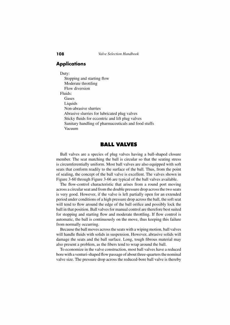
The seat rings of the valve shown in Figure 3-60 are provided withperipheral slots, which are known as pressure-equalizing slots. These slotsreduce the effect of the upstream pressure on the total valve torque. This isachieved by letting the upstream pressure filter by the upstream seat ringinto the valve body cavity so that the upstream seat ring becomes pressurebalanced.
Figure 3-60. Schematic View of Ball Valve with Floating Ball and Torsion Seats,Showing Function of Pressure-Equalizing Slots in Periphery of Seats. (Courtesy ofWorcester Valve Co., Ltd.)
Manual Valves 111
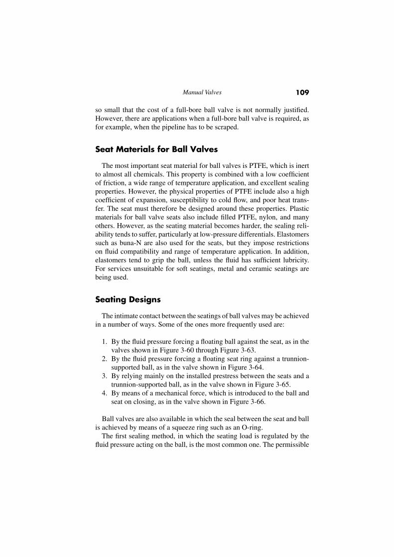
Figure 3-61. Ball Valve with Floating Ball and Torsion Seats, with Axial-Entry Body.(Courtesy of Jamesbury International Corp.)
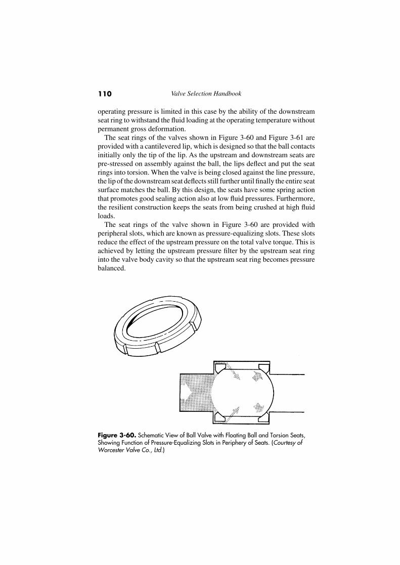
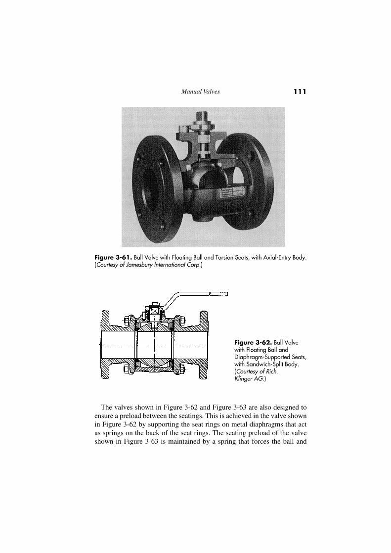
Figure 3-62. Ball Valvewith Floating Ball andDiaphragm-Supported Seats,with Sandwich-Split Body.(Courtesy of Rich.Klinger AG.)
The valves shown in Figure 3-62 and Figure 3-63 are also designed toensure a preload between the seatings. This is achieved in the valve shownin Figure 3-62 by supporting the seat rings on metal diaphragms that actas springs on the back of the seat rings. The seating preload of the valveshown in Figure 3-63 is maintained by a spring that forces the ball and

Valve Selection Handbook112
Figure 3-63. Ball Valvewith Wedge SeatsSpring-Loaded from theTop, with One-PieceTop-Entry Body. (Courtesy ofMcCanna)
Figure 3-64. Ball Valve with Trunnion-Supported Ball and Floating Seats, withOne-Piece Sealed Body. (Courtesy of Cameron Iron Works, Inc.)
seat-ring assembly from the top into wedge-shaped seat ring back faces inthe valve body.
The design of the ball valve shown in Figure 3-64 is based on the secondseating method in which the fluid pressure forces the seat ring against atrunnion-supported ball. The floating seat ring is sealed thereby peripher-ally by an O-ring. Because the pressure-uncompensated area of the seatring can be kept small, the seating load for a given pressure rating canbe regulated to suit the bearing capacity of the seat. These valves may
Manual Valves 113
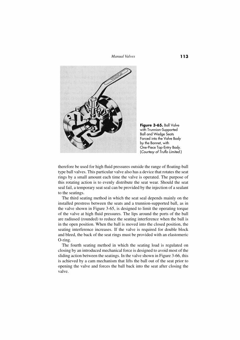
Figure 3-65. Ball Valvewith Trunnion-SupportedBall and Wedge SeatsForced into the Valve Bodyby the Bonnet, withOne-Piece Top-Entry Body.(Courtesy of Truflo Limited.)
therefore be used for high fluid pressures outside the range of floating-balltype ball valves. This particular valve also has a device that rotates the seatrings by a small amount each time the valve is operated. The purpose ofthis rotating action is to evenly distribute the seat wear. Should the seatseal fail, a temporary seat seal can be provided by the injection of a sealantto the seatings.
The third seating method in which the seat seal depends mainly on theinstalled prestress between the seats and a trunnion-supported ball, as inthe valve shown in Figure 3-65, is designed to limit the operating torqueof the valve at high fluid pressures. The lips around the ports of the ballare radiused (rounded) to reduce the seating interference when the ball isin the open position. When the ball is moved into the closed position, theseating interference increases. If the valve is required for double blockand bleed, the back of the seat rings must be provided with an elastomericO-ring.
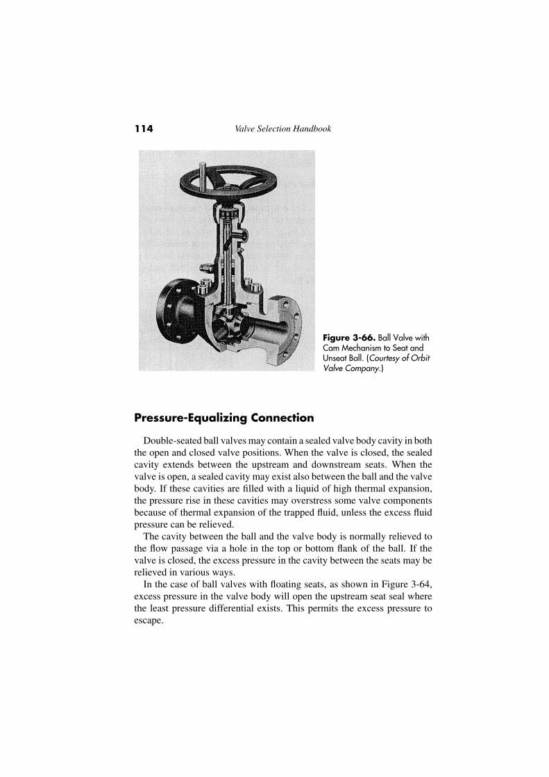
The fourth seating method in which the seating load is regulated onclosing by an introduced mechanical force is designed to avoid most of thesliding action between the seatings. In the valve shown in Figure 3-66, thisis achieved by a cam mechanism that lifts the ball out of the seat prior toopening the valve and forces the ball back into the seat after closing thevalve.
Valve Selection Handbook114
Figure 3-66. Ball Valve withCam Mechanism to Seat andUnseat Ball. (Courtesy of OrbitValve Company.)
Pressure-Equalizing Connection
Double-seated ball valves may contain a sealed valve body cavity in boththe open and closed valve positions. When the valve is closed, the sealedcavity extends between the upstream and downstream seats. When thevalve is open, a sealed cavity may exist also between the ball and the valvebody. If these cavities are filled with a liquid of high thermal expansion,the pressure rise in these cavities may overstress some valve componentsbecause of thermal expansion of the trapped fluid, unless the excess fluidpressure can be relieved.
The cavity between the ball and the valve body is normally relieved tothe flow passage via a hole in the top or bottom flank of the ball. If thevalve is closed, the excess pressure in the cavity between the seats may berelieved in various ways.
In the case of ball valves with floating seats, as shown in Figure 3-64,excess pressure in the valve body will open the upstream seat seal wherethe least pressure differential exists. This permits the excess pressure toescape.
Manual Valves 115
In other double-seated ball valves, however, the fluid pressure mustovercome the prestress between the ball and the upstream seat. If the seatrings are provided with some springing action, as in the valves shownin Figure 3-60 through Figure 3-62, the fluid pressure may be able toopen the upstream seat seal without becoming excessively high. On theother hand, if the seat rings are of a more rigid construction, thermalexpansion of the trapped fluid may create an excessively high pressurein the sealed cavity, depending on the prestress between the upstreamseatings. In this case, the upstream flank of the ball is usually providedwith a pressure-equalizing hole, thus permitting flow through the valvein one direction only. If the valve catalog does not advise on the need forpressure-equalizing connection, the manufacturer should be consulted. Theprovision of a pressure-equalizing connection is not normally standard withball valves except for cryogenic service. The pressure-equalizing connec-tion is necessary in that case because of the rigidity of normally soft plasticsat low temperatures, which tends to resist the opening of the upstreamseat seal.
Antistatic Device
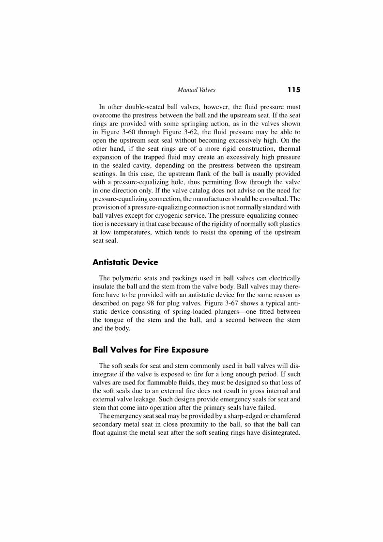
The polymeric seats and packings used in ball valves can electricallyinsulate the ball and the stem from the valve body. Ball valves may there-fore have to be provided with an antistatic device for the same reason asdescribed on page 98 for plug valves. Figure 3-67 shows a typical anti-static device consisting of spring-loaded plungers—one fitted betweenthe tongue of the stem and the ball, and a second between the stemand the body.
Ball Valves for Fire Exposure
The soft seals for seat and stem commonly used in ball valves will dis-integrate if the valve is exposed to fire for a long enough period. If suchvalves are used for flammable fluids, they must be designed so that loss ofthe soft seals due to an external fire does not result in gross internal andexternal valve leakage. Such designs provide emergency seals for seat andstem that come into operation after the primary seals have failed.
The emergency seat seal may be provided by a sharp-edged or chamferedsecondary metal seat in close proximity to the ball, so that the ball canfloat against the metal seat after the soft seating rings have disintegrated.
Valve Selection Handbook116
Figure 3-67. Antistatic Device for Grounding Stem to Ball and Stem to Body.(Courtesy of Worcester Valve Co., Ltd.)
The stuffing box may be fitted with an auxiliary asbestos-based or puregraphite packing, or the packing may be made entirely of an asbestoscompound or pure graphite.
Numerous standards have been established that cover the requirementsfor testing and evaluating the performance of soft-seated ball valves whenexposed to fire. The three basic standards are BS 5146, API 607, and APIRP 6F.
BS 5146 is a derivative of OCMA FA VI, which itself was taken from atest specification created by Esso Petroleum in the U.K. This test differedfrom all former ones by requiring the valve to be in the open position duringthe test and by using a flammable liquid in the valve. The test owes its originto the recognition by Esso that, in an actual plant fire, a significant numberof valves may be in the open position and must be subsequently closed.Moves are under foot by a number of standard organizations to arrive at aninternational fire-test specification.
Besides paying attention to the fire testing of ball valves in systemshandling flammable fluids, similar attention must be paid to the effect offire on the entire fluid handling system including valves other than ballvalves, valve operators, pumps, filters, pressure vessels, and, not least, thepipe flanges, bolting, and gaskets.
Fire-tested ball valves are referred to as fire-safe. However, this term isunacceptable to valve manufacturers from the product liability standpoint.
Manual Valves 117
Multiport Configuration
Ball valves adapt to multiport configurations in a manner similar to plugvalves, previously discussed on page 98.
Ball Valves for Cryogenic Service
Ball valves are used extensively in cryogenic services, but their designmust be adapted for this duty. A main consideration in the design of thesevalves is the coefficient of thermal contraction of the seat ring material,which is normally higher than that of the stainless steel of the ball and valvebody. The seat rings shrink, therefore, on the ball at low temperatures andcause the operating torque to increase. In severe cases, the seat ring maybe overstressed, causing it to split.
This effect of differential thermal contraction between the seats and theball may be combated by reducing the installed prestress between the seatsand the ball by an amount that ensures a correct prestress at the cryogenicoperating temperature. However, the sealing capacity of these valves maynot be satisfactory at low fluid pressures if these valves also have tooperate at ambient temperatures.
Other means of combating the effect of differential thermal contractionbetween the seats and the ball include supporting the seats on flexible metaldiaphragms; choosing a seat-ring material that has a considerably lowercoefficient of contraction than virgin PTFE, such as graphite or carbonfilled PTFE; or making the seat rings of stainless steel with PTFE insertsin which the PTFE contents are kept to a minimum.
Because plastic seat-ring materials become rigid at cryogenic tempera-tures, the surface finish of the seatings and the sphericity of the ball mustbe of a high standard to ensure a high degree of seat tightness. Also, aswith other types of valves for cryogenic service, the extended bonnetshould be positioned no more than 45◦ from the upright to ensure aneffective stem seal.
Variations of Body Construction
Access to the ball valve internals can be provided in various ways.This has led to the development of a number of variations in the bodyconstruction; Figure 3-68 shows the most common variations.
Valve Selection Handbook118
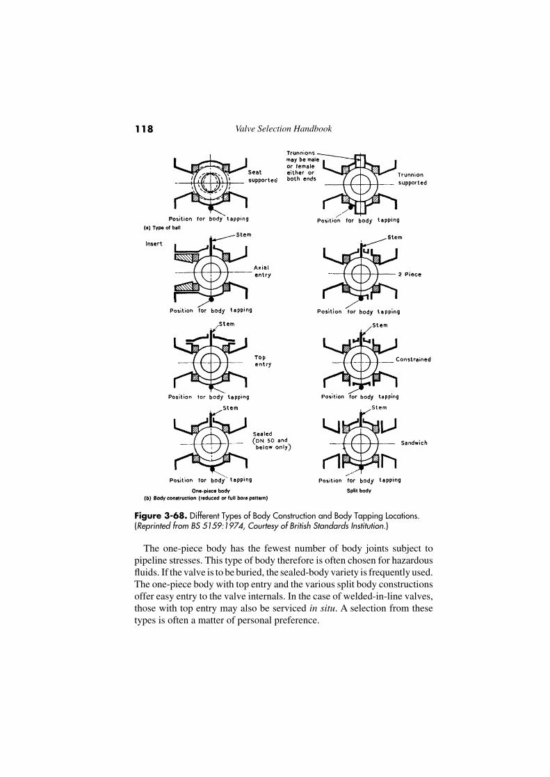
Figure 3-68. Different Types of Body Construction and Body Tapping Locations.(Reprinted from BS 5159:1974, Courtesy of British Standards Institution.)
The one-piece body has the fewest number of body joints subject topipeline stresses. This type of body therefore is often chosen for hazardousfluids. If the valve is to be buried, the sealed-body variety is frequently used.The one-piece body with top entry and the various split body constructionsoffer easy entry to the valve internals. In the case of welded-in-line valves,those with top entry may also be serviced in situ. A selection from thesetypes is often a matter of personal preference.
Manual Valves 119
Face-to-Face Dimensions
The original practice of U.S. manufacturers was to make the face-to-facedimensions of flanged ball valves to the nearest valve standard, which gaveminimum material content. This happened to be the gate valve standard,but the face-to-face dimensions of class 150 and of sizes DN 200 (NPS8) through DN 300 (NPS 12) of class 300 permitted only reduced-boreconstruction.
In 1961, when UK manufacturers also introduced the flanged ball valve,there was an additional demand for full-bore ball valves. When it wasimpossible to accommodate the full-bore ball valve in the confines ofthe face-to-face dimensions of gate valves, the face-to-face dimensionsof regular-pattern plug valves were adopted.
Thus, there is a short and a long series of ball valves for class 150,and in sizes DN 200 (NPS 8) through DN 300 (NPS 12), and for class300—one for reduced-bore and one for full-bore ball valves, respectively.In the case of the higher-pressure ratings, the face-to-face dimensionsof gate valves accommodate both reduced-bore and full-bore ball valvesthroughout.
The master standard for face-to-face dimensions is ISO 5752. Thisstandard includes all the recognized dimensions worldwide that are usedin the piping industry. However, ISO 5752 does not try to define reduced-bore or full-bore except for sizes DN 200 (NPS 8) through DN 300(NPS 12) of class 300.
Standards Pertaining to Ball Valves
Appendix C provides a list of U.S. and British standards pertaining toball valves.
Applications
Duty:Stopping and starting flowModerate throttlingFlow diversion
Service:GasesLiquids
Related Documents