The essential guide of Motor control and Protection 2013

Welcome message from author
This document is posted to help you gain knowledge. Please leave a comment to let me know what you think about it! Share it to your friends and learn new things together.
Transcript
The essential guideof Motor control and Protection2013

Schneider Electric has been leading the way in the motor starter market for more than 80 years. Its TeSys products offer an extensive range of innovative motor protection and power control solutions.
TeSys Protect your machines and installations with TeSys - a comprehensive range of contactors, circuit-breakers, starters, motor starters and power control components.
This document is a selection
of the top selling products.
For more information:
http://www.schneider-electric.com
Contents
Motor control components
Selectionguide................................................................................................................ 2.and.3
TeSyscontactors.............................................................................................................4.to.11. . Contactors.TeSys K, D, F
TeSysprotectioncomponents. . Motor.circuit-breakers.TeSys GV2, GV3, GV7................................................................. 12.to.18. . Fuse.carriers.TeSys DF, LS1, GK1.................................................................................. 19.to.21. . Switch-disconnector-fuses.TeSys GS.............................................................................. 22.to.24. . Thermal.overload.relays.TeSys K, D............................................................................ 25.and.26. . Electronic.thermal.overload.relays.TeSys LR9......................................................................... 27. . Motor.management.system.TeSys T............................................................................ 28.and.29. . Electronic.protection.relays.TeSys LT3, LT6............................................................................. 30. . Switch.disconnectors.Mini Vario and Vario............................................................................. 31
TeSysstarters. . Combination.motor.starters.TeSys GV2/GV3 + LC...................................................... 32.and.33. . Starter-controller.TeSys U............................................................................................. 34.and.35. . Controller.TeSys LUTM................................................................................................. 36.and.37. . Enclosed.motor.starters................................................................................................ 38.and.39
Complementary products selection guides. . Universal.enclosures..................................................................................................... 40.and.41. . Power.distribution.and.connection.systems.................................................................. 42.and.43. . Incoming.protection.and.switching................................................................................ 44.and.45. . Short.circuit.and.overload.protection............................................................................. 46.and.47. . Indication.and.metering................................................................................................. 48.and.49
1
Selection guideMotor protection and control
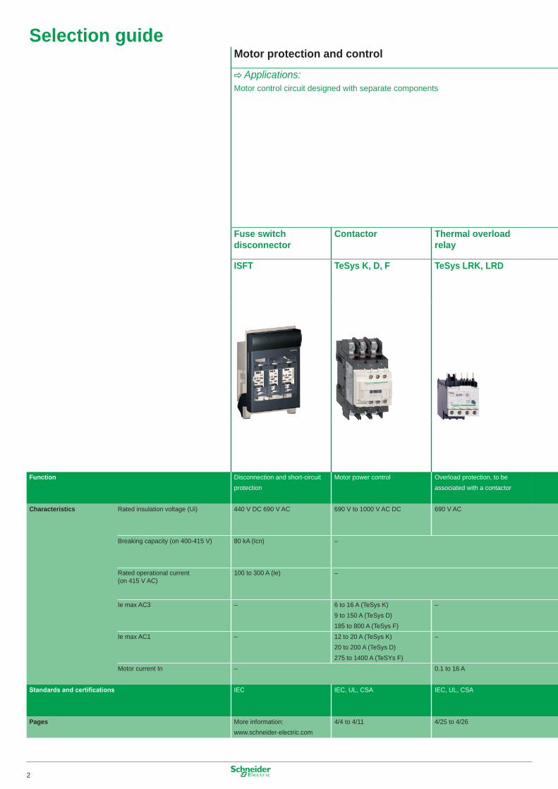
C Applications:Motor control circuit designed with separate components
Fuse switch disconnector
Contactor Thermal overload relay
ISFT TeSys K, D, F TeSys LRK, LRD
Function Disconnection and short-circuit protection
Motor power control Overload protection, to be associated with a contactor
Characteristics Rated insulation voltage (Ui) 440 V DC 690 V AC 690 V to �000 V AC DC 690 V AC
Breaking capacity (on 400-4�5 V) 80 kA (Icn) –
Rated operational current (on 4�5 V AC)
�00 to 300 A (Ie) –
Ie max AC3 – 6 to �6 A (TeSys K) 9 to �50 A (TeSys D) �85 to 800 A (TeSys F)
–
Ie max AC� – �2 to 20 A (TeSys K) 20 to 200 A (TeSys D) 275 to �400 A (TeSYs F)
–
Motor current In – 0.� to �6 A
Standards and certifications IEC IEC, UL, CSA IEC, UL, CSA
Pages More information: www.schneider-electric.com
4/4 to 4/�� 4/25 to 4/26
2
Selection guideMotor protection and control
C Applications:Motor control circuit designed with separate components
Fuse switch disconnector
Contactor Thermal overload relay
ISFT TeSys K, D, F TeSys LRK, LRD
Function Disconnection and short-circuit protection
Motor power control Overload protection, to be associated with a contactor
Characteristics Rated insulation voltage (Ui) 440 V DC 690 V AC 690 V to �000 V AC DC 690 V AC
Breaking capacity (on 400-4�5 V) 80 kA (Icn) –
Rated operational current (on 4�5 V AC)
�00 to 300 A (Ie) –
Ie max AC3 – 6 to �6 A (TeSys K) 9 to �50 A (TeSys D) �85 to 800 A (TeSys F)
–
Ie max AC� – �2 to 20 A (TeSys K) 20 to 200 A (TeSys D) 275 to �400 A (TeSYs F)
–
Motor current In – 0.� to �6 A
Standards and certifications IEC IEC, UL, CSA IEC, UL, CSA
Pages More information: www.schneider-electric.com
4/4 to 4/�� 4/25 to 4/26
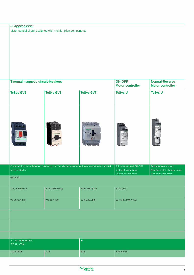
C Applications:Motor control circuit designed with multifunction components
Thermal magnetic circuit-breakers ON-OFF Motor controller
Normal-Reverse Motor controller
TeSys GV2 TeSys GV3 TeSys GV7 TeSys U TeSys U
Disconnection, short-circuit and overload protection. Manual power control, automatic when associated with a contactor
Full protection and ON-OFF control of motor circuit. Communication ability
Full protection Normal, Reverse control of motor circuit. Communication ability
690 V AC
�0 to �00 kA (Icu) 50 to �00 kA (Icu) 35 to 70 kA (Icu) 50 kA (Icu)
0.� to 32 A (Ith) 9 to 65 A (Ith) �2 to 220 A (Ith) �2 to 32 A (400 V AC)
–
–
–
IEC for certain modelsIEC, UL, CSA
IEC
4/�2 to 4/�3 4/�4 4/�6 4/34 to 4/35
3
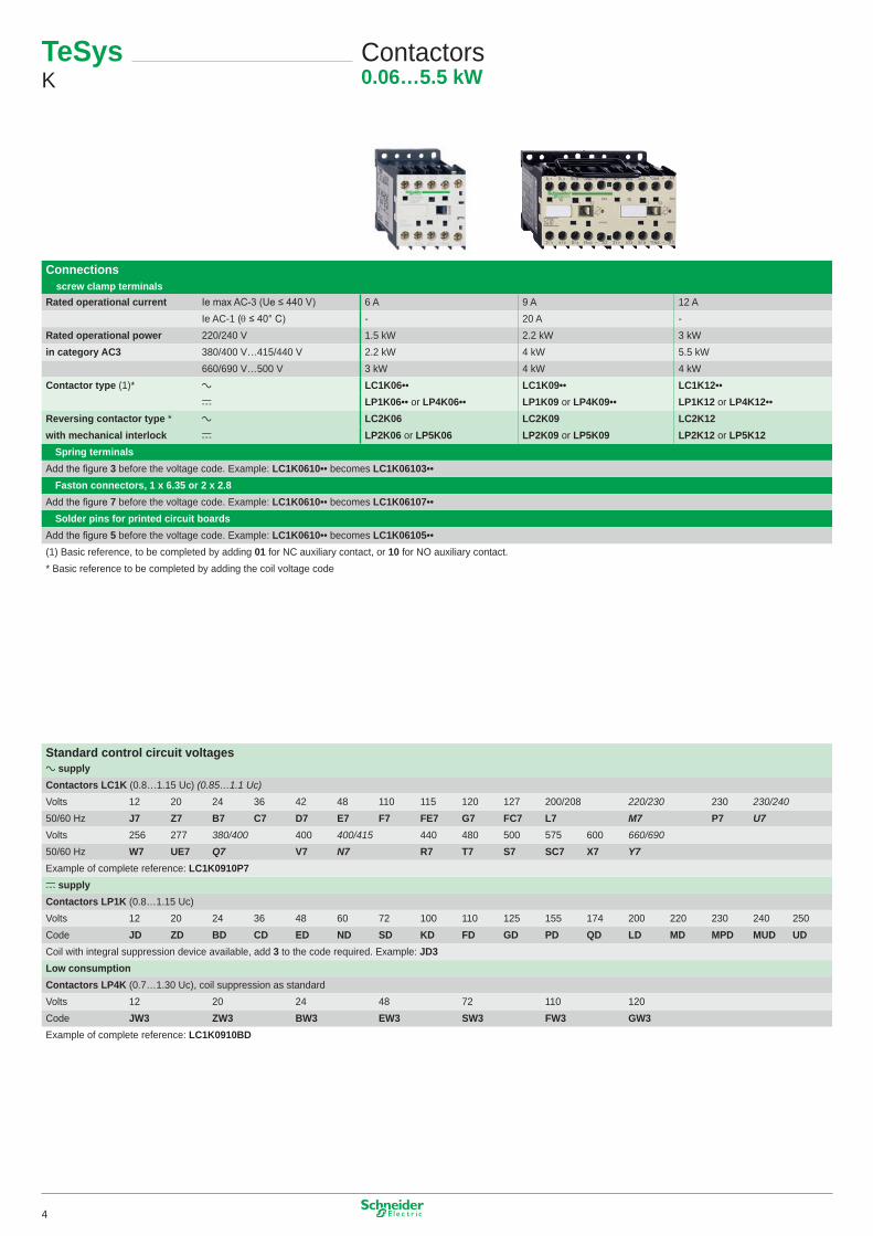
Connections ■ screw clamp terminalsRated operational current Ie max AC-3 (Ue ≤ 440 V) 6 A 9 A �2 A
Ie AC-� (θ ≤ 40° C) - 20 A -Rated operational power 220/240 V �.5 kW 2.2 kW 3 kWin category AC3 380/400 V…4�5/440 V 2.2 kW 4 kW 5.5 kW
660/690 V…500 V 3 kW 4 kW 4 kWContactor type (�)* a LC1K06•• LC1K09•• LC1K12••
c LP1K06•• or LP4K06•• LP1K09 or LP4K09•• LP1K12 or LP4K12••Reversing contactor type * a LC2K06 LC2K09 LC2K12with mechanical interlock c LP2K06 or LP5K06 LP2K09 or LP5K09 LP2K12 or LP5K12b Spring terminalsAdd the figure 3 before the voltage code. Example: LC1K0610•• becomes LC1K06103••b Faston connectors, 1 x 6.35 or 2 x 2.8Add the figure 7 before the voltage code. Example: LC1K0610•• becomes LC1K06107••b Solder pins for printed circuit boardsAdd the figure 5 before the voltage code. Example: LC1K0610•• becomes LC1K06105••(�) Basic reference, to be completed by adding 01 for NC auxiliary contact, or 10 for NO auxiliary contact.* Basic reference to be completed by adding the coil voltage code
Standard control circuit voltagesa supply Contactors LC1K (0.8…�.�5 Uc) (0.85…1.1 Uc)Volts �2 20 24 36 42 48 ��0 ��5 �20 �27 200/208 220/230 230 230/24050/60 Hz J7 Z7 B7 C7 D7 E7 F7 FE7 G7 FC7 L7 M7 P7 U7Volts 256 277 380/400 400 400/415 440 480 500 575 600 660/69050/60 Hz W7 UE7 Q7 V7 N7 R7 T7 S7 SC7 X7 Y7Example of complete reference: LC1K0910P7c supply Contactors LP1K (0.8…�.�5 Uc)Volts �2 20 24 36 48 60 72 �00 ��0 �25 �55 �74 200 220 230 240 250Code JD ZD BD CD ED ND SD KD FD GD PD QD LD MD MPD MUD UDCoil with integral suppression device available, add 3 to the code required. Example: JD3Low consumptionContactors LP4K (0.7…�.30 Uc), coil suppression as standardVolts �2 20 24 48 72 ��0 �20Code JW3 ZW3 BW3 EW3 SW3 FW3 GW3Example of complete reference: LC1K0910BD
TeSysK
Contactors0.06…5.5 kW
4
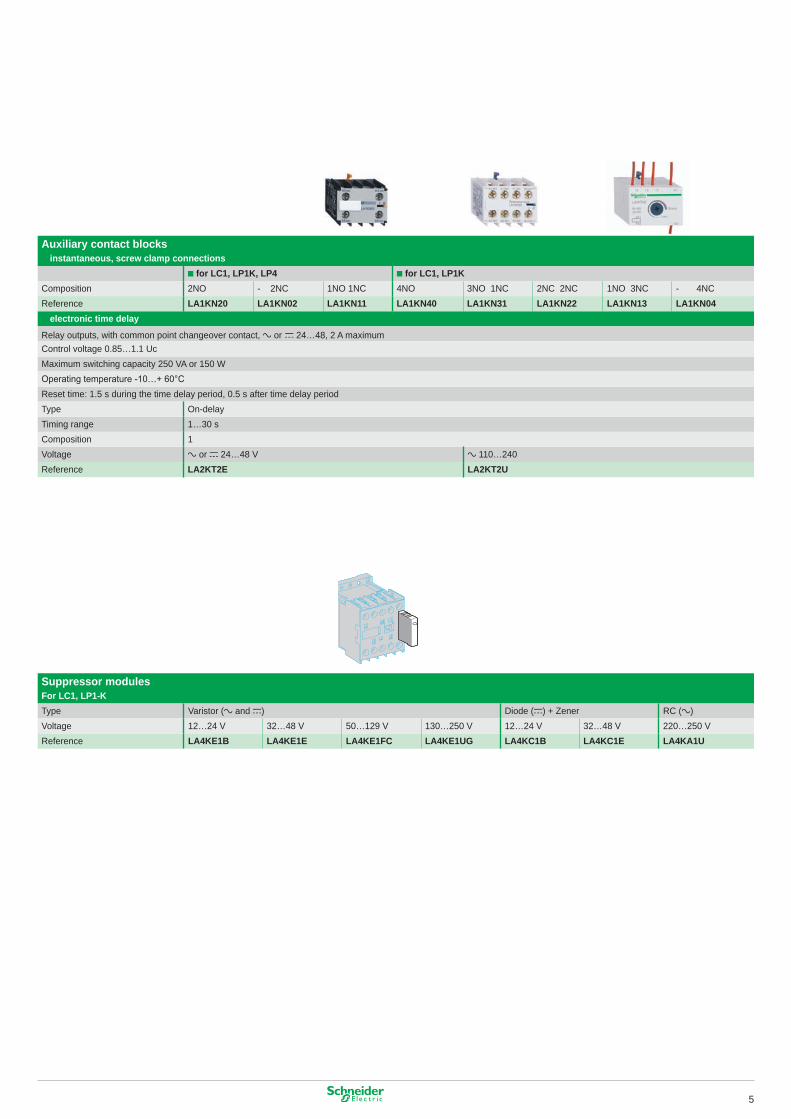
Auxiliary contact blocks■ instantaneous, screw clamp connections
■ for LC1, LP1K, LP4 ■ for LC1, LP1KComposition 2NO - 2NC �NO �NC 4NO 3NO �NC 2NC 2NC �NO 3NC - 4NCReference LA1KN20 LA1KN02 LA1KN11 LA1KN40 LA1KN31 LA1KN22 LA1KN13 LA1KN04■ electronic time delay
Relay outputs, with common point changeover contact, a or c 24…48, 2 A maximumControl voltage 0.85…�.� UcMaximum switching capacity 250 VA or �50 WOperating temperature -10…+ 60°CReset time: �.5 s during the time delay period, 0.5 s after time delay periodType On-delayTiming range �…30 sComposition � Voltage a or c 24…48 V a ��0…240Reference LA2KT2E LA2KT2U
Suppressor modulesFor LC1, LP1-KType Varistor (a and c) Diode (c) + Zener RC (a)Voltage �2…24 V 32…48 V 50…�29 V �30…250 V �2…24 V 32…48 V 220…250 VReference LA4KE1B LA4KE1E LA4KE1FC LA4KE1UG LA4KC1B LA4KC1E LA4KA1U
5
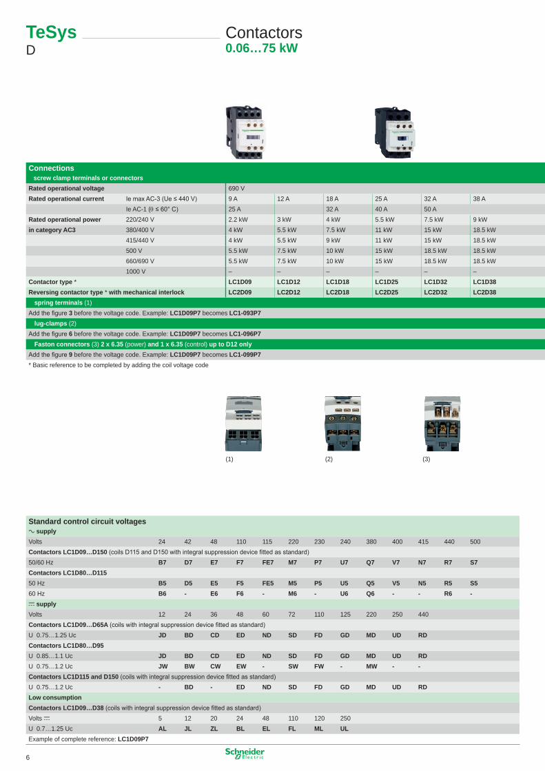
690 V �000 V on a supply, 690 V on c supply40 A 50 A 65 A 80 A 95 A ��5 A �50 A60 A 80 A 80 A �25 A 200 A�� kW �5 kW �8.5 kW 22 kW 25 kW 30 kW 40 kW�8.5 kW 22 kW 30 kW 37 kW 45 kW 55 kW 75 kW22 kW 25 kW 30 kW 45 kW 45 kW 59 kW 80 kW22 kW 30 kW 37 kW 55 kW 55 kW 75 kW 90 kW30 kW 33 kW 37 kW 45 kW 45 kW 80 kW �00 kW– – – 45 kW 45 kW 75 kW 90 kWLC1D40A LC1D50A LC1D65A LC1D80 LC1D95 LC1D115 LC1D150LC2D40A LC2D50A LC2D65A LC2D80 LC2D95 LC2D115 LC2D150
Connections ■ screw clamp terminals or connectorsRated operational voltage 690 VRated operational current Ie max AC-3 (Ue ≤ 440 V) 9 A �2 A �8 A 25 A 32 A 38 A
Ie AC-� (θ ≤ 60° C) 25 A 32 A 40 A 50 ARated operational power 220/240 V 2.2 kW 3 kW 4 kW 5.5 kW 7.5 kW 9 kWin category AC3 380/400 V 4 kW 5.5 kW 7.5 kW �� kW �5 kW �8.5 kW
4�5/440 V 4 kW 5.5 kW 9 kW �� kW �5 kW �8.5 kW500 V 5.5 kW 7.5 kW �0 kW �5 kW �8.5 kW �8.5 kW660/690 V 5.5 kW 7.5 kW �0 kW �5 kW �8.5 kW �8.5 kW�000 V – – – – – –
Contactor type * LC1D09 LC1D12 LC1D18 LC1D25 LC1D32 LC1D38Reversing contactor type * with mechanical interlock LC2D09 LC2D12 LC2D18 LC2D25 LC2D32 LC2D38■ spring terminals (�)Add the figure 3 before the voltage code. Example: LC1D09P7 becomes LC1-093P7■ lug-clamps (2)Add the figure 6 before the voltage code. Example: LC1D09P7 becomes LC1-096P7■ Faston connectors (3) 2 x 6.35 (power) and 1 x 6.35 (control) up to D12 onlyAdd the figure 9 before the voltage code. Example: LC1D09P7 becomes LC1-099P7* Basic reference to be completed by adding the coil voltage code
Standard control circuit voltagesa supply Volts 24 42 48 ��0 ��5 220 230 240 380 400 4�5 440 500Contactors LC1D09…D150 (coils D115 and D150 with integral suppression device fitted as standard)50/60 Hz B7 D7 E7 F7 FE7 M7 P7 U7 Q7 V7 N7 R7 S7Contactors LC1D80…D11550 Hz B5 D5 E5 F5 FE5 M5 P5 U5 Q5 V5 N5 R5 S560 Hz B6 - E6 F6 - M6 - U6 Q6 - - R6 -c supply Volts �2 24 36 48 60 72 ��0 �25 220 250 440Contactors LC1D09…D65A (coils with integral suppression device fitted as standard)U 0.75…�.25 Uc JD BD CD ED ND SD FD GD MD UD RDContactors LC1D80…D95U 0.85…�.� Uc JD BD CD ED ND SD FD GD MD UD RD U 0.75…�.2 Uc JW BW CW EW - SW FW - MW - -Contactors LC1D115 and D150 (coils with integral suppression device fitted as standard)U 0.75…�.2 Uc - BD - ED ND SD FD GD MD UD RDLow consumptionContactors LC1D09…D38 (coils with integral suppression device fitted as standard)Volts c 5 �2 20 24 48 ��0 �20 250U 0.7…�.25 Uc AL JL ZL BL EL FL ML ULExample of complete reference: LC1D09P7
TeSys D
Contactors0.06…75 kW
(�) (3)(2)
6

Mounting accessories for 3-pole reversing contactors
2 identical contactors with screw clamp terminals or connectors, horizontally mountedMechanical interlock Set of connections Mechanical interlock■ with an electrical interlocking kit for the contactors LC�-D09…D38 LAD-9R1V included■ with integral electrical interlockingLC�-D80 and D95 (a) LA9D8069 LA9D4002LC�-D80 and D95 (c) LA9D8069 LA9D8002LC�-D��5 and D�50 LA9D11569 LA9D11502■ without electrical interlocking LC�-D09…D38 LA99R1 includedLC�-D40A…D65A LAD9R3 includedLC�-D80 and D95 (a) LA9D8069 LA9D50978LC�-D80 and D95 (c) LA9D8069 LA9D80978
Mechanical latch blocks
Clip-on front mounting, manual or electrical unlatching controlFor use on contactor Reference Standard control circuit voltagesLC1D09…D65A a or c, LC1DT20…DT80 a or c LAD6K10• B E F M QLC1D80…D150 3P a, LC1D80 and D115 3P a, LC1D115 4P c LA6DK20• B E F M Q
690 V �000 V on a supply, 690 V on c supply40 A 50 A 65 A 80 A 95 A ��5 A �50 A60 A 80 A 80 A �25 A 200 A�� kW �5 kW �8.5 kW 22 kW 25 kW 30 kW 40 kW�8.5 kW 22 kW 30 kW 37 kW 45 kW 55 kW 75 kW22 kW 25 kW 30 kW 45 kW 45 kW 59 kW 80 kW22 kW 30 kW 37 kW 55 kW 55 kW 75 kW 90 kW30 kW 33 kW 37 kW 45 kW 45 kW 80 kW �00 kW– – – 45 kW 45 kW 75 kW 90 kWLC1D40A LC1D50A LC1D65A LC1D80 LC1D95 LC1D115 LC1D150LC2D40A LC2D50A LC2D65A LC2D80 LC2D95 LC2D115 LC2D150
Connections ■ screw clamp terminals or connectorsRated operational voltage 690 VRated operational current Ie max AC-3 (Ue ≤ 440 V) 9 A �2 A �8 A 25 A 32 A 38 A
Ie AC-� (θ ≤ 60° C) 25 A 32 A 40 A 50 ARated operational power 220/240 V 2.2 kW 3 kW 4 kW 5.5 kW 7.5 kW 9 kWin category AC3 380/400 V 4 kW 5.5 kW 7.5 kW �� kW �5 kW �8.5 kW
4�5/440 V 4 kW 5.5 kW 9 kW �� kW �5 kW �8.5 kW500 V 5.5 kW 7.5 kW �0 kW �5 kW �8.5 kW �8.5 kW660/690 V 5.5 kW 7.5 kW �0 kW �5 kW �8.5 kW �8.5 kW�000 V – – – – – –
Contactor type * LC1D09 LC1D12 LC1D18 LC1D25 LC1D32 LC1D38Reversing contactor type * with mechanical interlock LC2D09 LC2D12 LC2D18 LC2D25 LC2D32 LC2D38■ spring terminals (�)Add the figure 3 before the voltage code. Example: LC1D09P7 becomes LC1-093P7■ lug-clamps (2)Add the figure 6 before the voltage code. Example: LC1D09P7 becomes LC1-096P7■ Faston connectors (3) 2 x 6.35 (power) and 1 x 6.35 (control) up to D12 onlyAdd the figure 9 before the voltage code. Example: LC1D09P7 becomes LC1-099P7* Basic reference to be completed by adding the coil voltage code
7
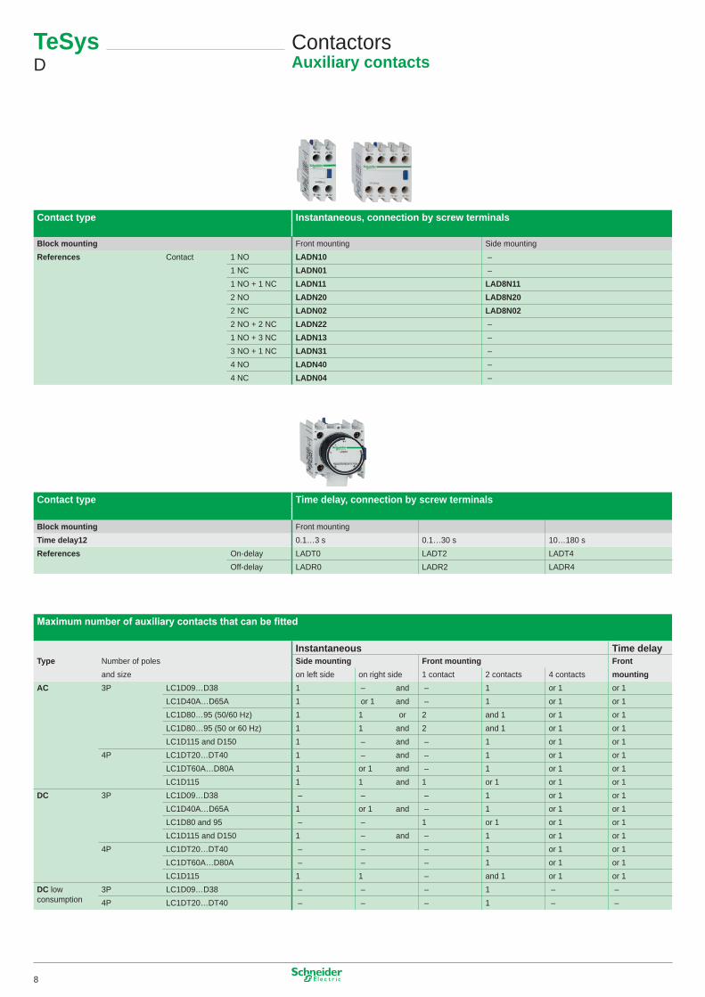
TeSys D
ContactorsAuxiliary contacts
Contact type Instantaneous, connection by screw terminals
Block mounting Front mounting Side mountingReferences Contact � NO LADN10 –
� NC LADN01 –� NO + � NC LADN11 LAD8N112 NO LADN20 LAD8N202 NC LADN02 LAD8N022 NO + 2 NC LADN22 –� NO + 3 NC LADN13 –3 NO + � NC LADN31 –4 NO LADN40 –4 NC LADN04 –
Contact type Time delay, connection by screw terminals
Block mounting Front mountingTime delay12 0.�…3 s 0.�…30 s �0…�80 sReferences On-delay LADT0 LADT2 LADT4
Off-delay LADR0 LADR2 LADR4
Maximum number of auxiliary contacts that can be fitted
Instantaneous Time delayType Number of poles Side mounting Front mounting Front
and size on left side on right side � contact 2 contacts 4 contacts mountingAC 3P LC�D09…D38 � – and – � or � or �
LC�D40A…D65A � or � and – � or � or �LC�D80…95 (50/60 Hz) � � or 2 and � or � or �LC�D80…95 (50 or 60 Hz) � � and 2 and � or � or �LC�D��5 and D�50 � – and – � or � or �
4P LC�DT20…DT40 � – and – � or � or �LC�DT60A…D80A � or � and – � or � or �LC�D��5 � � and � or � or � or �
DC 3P LC�D09…D38 – – – � or � or �LC�D40A…D65A � or � and – � or � or �LC�D80 and 95 – – � or � or � or �LC�D��5 and D�50 � – and – � or � or �
4P LC�DT20…DT40 – – – � or � or �LC�DT60A…D80A – – – � or � or �LC�D��5 � � – and � or � or �
DC lowconsumption
3P LC�D09…D38 – – – � – –4P LC�DT20…DT40 – – – � – –
8
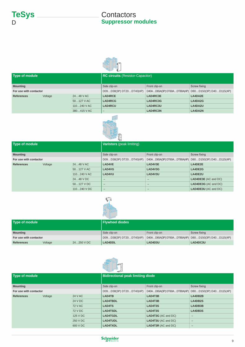
Type of module RC circuits (Resistor-Capacitor)
Mounting Side clip-on Front clip-on Screw fixing
For use with contactor D09…D38(3P) DT20…DT40(4P) D40A…D65A(3P) DT60A…DT80A(4P) D80…D�50(3P) D40…D��5(4P)
References Voltage 24…48 V AC LAD4RCE LAD4RC3E LA4DA2E50…�27 V AC LAD4RCG LAD4RC3G LA4DA2G��0…240 V AC LAD4RCU LAD4RC3U LA4DA2U380…4�5 V AC – LAD4RC3N LA4DA2N
Type of module Varistors (peak limiting)
Mounting Side clip-on Front clip-on Screw fixing
For use with contactor D09…D38(3P) DT20…DT40(4P) D40A…D65A(3P) DT60A…DT80A(4P) D80…D�50(3P) D40…D��5(4P)
References Voltage 24…48 V AC LAD4VE LAD4V3E LA4DE2E50…�27 V AC LAD4VG LAD4V3G LA4DE2G��0…240 V AC LAD4VU LAD4V3U LA4DE2U24…48 V DC – – LAD4DE3E (AC and DC)
50…�27 V DC – – LAD4DE3G (AC and DC)
��0…240 V DC – – LAD4DE3U (AC and DC)
Type of module Flywheel diodes
Mounting Side clip-on Front clip-on Screw fixing
For use with contactor D09…D38(3P) DT20…DT40(4P) D40A…D65A(3P) DT60A…DT80A(4P) D80…D�50(3P) D40…D��5(4P)
References Voltage 24…250 V DC LAD4DDL LAD4D3U LAD4DC3U
Type of module Bidirectional peak limiting diode
Mounting Side clip-on Front clip-on Screw fixing
For use with contactor D09…D38(3P) DT20…DT40(4P) D40A…D65A(3P) DT60A…DT80A(4P) D80…D�50(3P) D40…D��5(4P)
References Voltage 24 V AC LAD4TB LAD4T3B LA4DB2B24 V DC LAD4TBDL LAD4T3B LA4DB2S72 V AC LAD4TS LAD4T3S LA4DB3B72 V DC LAD4TSDL LAD4T3S LA4DB3S�25 V DC LAD4TGDL LAD4T3G (AC and DC) –
250 V DC LAD4TUDL LAD4T3U (AC and DC) –
600 V DC LAD4TXDL LAD4T3R (AC and DC) –
TeSys D
ContactorsSuppressor modules
9
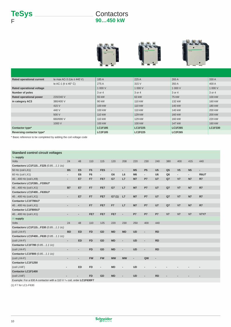
400 A 500 A 630 A 780 A 800 A - -500 A 700 A � 000 A � 600 A � 000 A �260 �400� 000 V � 000 V � 000 V � 000 V � 000 V �000 �0002, 3 or 4 2, 3 or 4 2, 3 or 4 3 or 4 3 3 3��0 kW �47 kW 200 kW 220 kW 250 kW Sans objets Sans objets200 kW 250 kW 335 kW 400 kW 450 kW en AC� en AC�220 kW 280 kW 375 kW 425 kW 450 kW - -250 kW 295 kW 400 kW 425 kW 450 kW - -257 kW 355 kW 400 kW 450 kW 450 kW - -280 kW 335 kW 450 kW 475 kW 475 kW - -�85 kW 335 kW 450 kW 450 kW 450 kW - -LC1F400 LC1F500 LC1F630 LC1F780 LC1F800 LC1F1250 LC1F1400
For customer assembly - -
Rated operational current Ie max AC-3 (Ue ≤ 440 V) �85 A 225 A 265 A 330 AIe AC-� (θ ≤ 40° C) 275 A 3�5 V 350 A 400 A
Rated operational voltage � 000 V � 000 V � 000 V � 000 VNumber of poles 3 or 4 3 or 4 3 or 4 3 or 4Rated operational power 220/240 V 55 kW 63 kW 75 kW �00 kWin category AC3 380/400 V 90 kW ��0 kW �32 kW �60 kW
4�5 V �00 kW ��0 kW �40 kW �80 kW440 V �00 kW ��0 kW �40 kW 200 kW500 V ��0 kW �29 kW �60 kW 200 kW660/690 V ��0 kW �29 kW �60 kW 220 kW�000 V �00 kW �00 kW �47 kW �60 kW
Contactor type* LC1F185 LC1F225 LC1F265 LC1F330Reversing contactor type* LC2F185 LC2F225 LC2F265
* Basic reference to be completed by adding the coil voltage code
Standard control circuit voltagesa supply Volts 24 48 ��0 ��5 �20 208 220 230 240 380 400 4�5 440Contactors LC1F115…F225 (0.85…1.1 Uc)50 Hz (coil LX�) B5 E5 F5 FE5 - - M5 P5 U5 Q5 V5 N5 -60 Hz (coil LX�) - E6 F6 - G6 L6 M6 - U6 Q6 - - R6U740…400 Hz (coil LX9) - E7 F7 FE7 G7 L7 M7 P7 U7 Q7 V7 N7 R7Contactors LC1F265…F330U740…400 Hz (coil LX�) B7 E7 F7 FE7 G7 L7 M7 P7 U7 Q7 V7 N7 R7Contactors LC1F400…F630U740…400 Hz (coil LX�) - E7 F7 FE7 G7 (1) L7 M7 P7 U7 Q7 V7 N7 R7Contactor LC1F780U740…400 Hz (coil LX�) - - F7 FE7 F7 L7 M7 P7 U7 Q7 V7 N7 R7Contactor LC1F800U740…400 Hz (coil LX�) - - FE7 FE7 FE7 - P7 P7 P7 V7 V7 V7 V7Y7c supply Volts 24 48 ��0 �25 220 230 250 400 440Contactors LC1F115…F330 (0.85…1.1 Uc)(coil LX4-F) BD ED FD GD MD MD UD - RDContactors LC1F400…F630 (0.85…1.1 Uc)(coil LX4-F) - ED FD GD MD - UD - RDContactor LC1F780 (0.85…1.1 Uc)(coil LX4-F) - - FD GD MD - UD - RDContactor LC1F800 (0.85…1.1 Uc)(coil LX4-F) - - FW FW MW MW - QW -Contactor LC1F1250(coil LX4F) - ED FD - MD - UD - - - - - -Contactor LC1F1400(coil LX4F) - - FD GD MD - UD - RD - - - -Example: For a 630 A contactor with a ��0 V a coil, order LC1F630F7
(�) F7 for LC�-F630
TeSys F
Contactors90…450 kW
�0
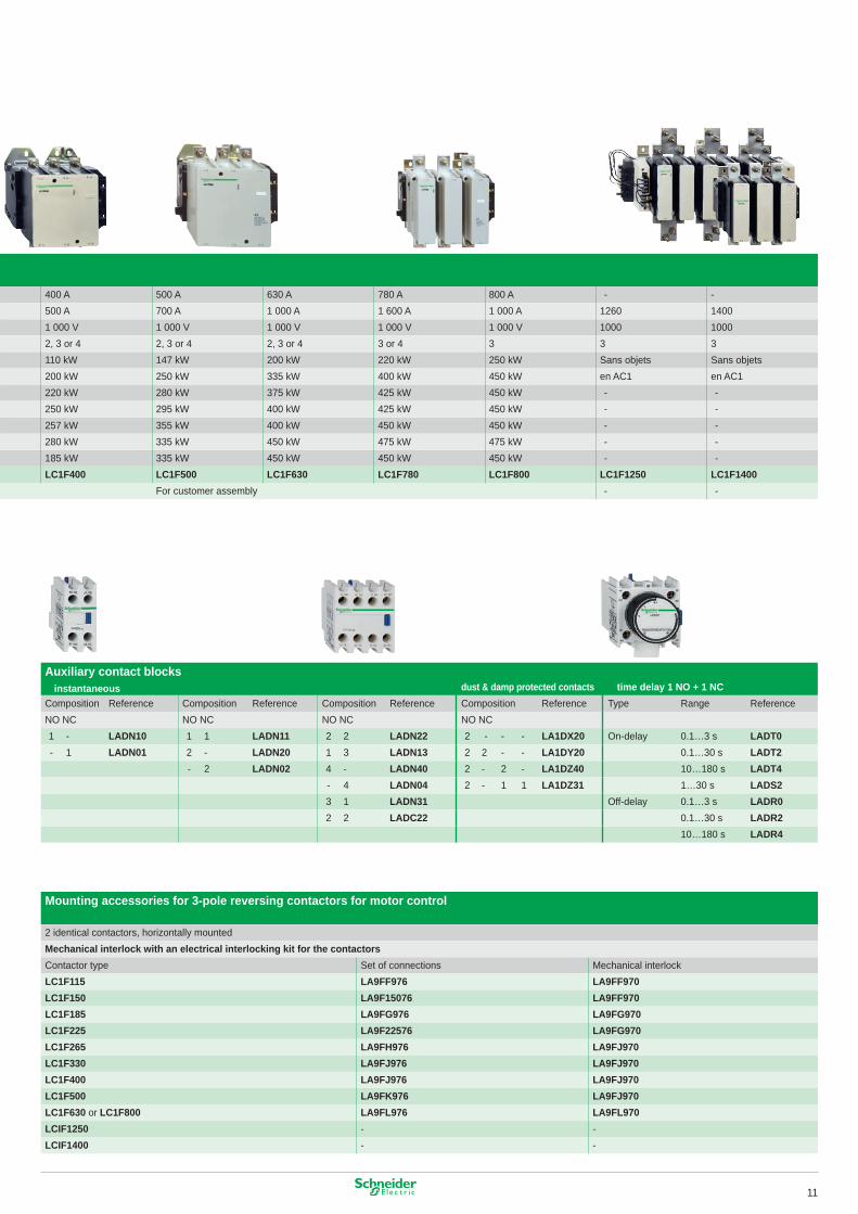
Auxiliary contact blocks■ instantaneous dust & damp protected contacts ■ time delay 1 NO + 1 NCComposition Reference Composition Reference Composition Reference Composition Reference Type Range ReferenceNO NC NO NC NO NC NO NC� - LADN10 � � LADN11 2 2 LADN22 2 - - - LA1DX20 On-delay 0.�…3 s LADT0- � LADN01 2 - LADN20 � 3 LADN13 2 2 - - LA1DY20 0.�…30 s LADT2
- 2 LADN02 4 - LADN40 2 - 2 - LA1DZ40 �0…�80 s LADT4- 4 LADN04 2 - � � LA1DZ31 �…30 s LADS23 � LADN31 Off-delay 0.�…3 s LADR02 2 LADC22 0.�…30 s LADR2
�0…�80 s LADR4
Mounting accessories for 3-pole reversing contactors for motor control
2 identical contactors, horizontally mountedMechanical interlock with an electrical interlocking kit for the contactors Contactor type Set of connections Mechanical interlockLC1F115 LA9FF976 LA9FF970LC1F150 LA9F15076 LA9FF970LC1F185 LA9FG976 LA9FG970LC1F225 LA9F22576 LA9FG970LC1F265 LA9FH976 LA9FJ970LC1F330 LA9FJ976 LA9FJ970LC1F400 LA9FJ976 LA9FJ970LC1F500 LA9FK976 LA9FJ970LC1F630 or LC1F800 LA9FL976 LA9FL970LCIF1250 - -LCIF1400 - -
400 A 500 A 630 A 780 A 800 A - -500 A 700 A � 000 A � 600 A � 000 A �260 �400� 000 V � 000 V � 000 V � 000 V � 000 V �000 �0002, 3 or 4 2, 3 or 4 2, 3 or 4 3 or 4 3 3 3��0 kW �47 kW 200 kW 220 kW 250 kW Sans objets Sans objets200 kW 250 kW 335 kW 400 kW 450 kW en AC� en AC�220 kW 280 kW 375 kW 425 kW 450 kW - -250 kW 295 kW 400 kW 425 kW 450 kW - -257 kW 355 kW 400 kW 450 kW 450 kW - -280 kW 335 kW 450 kW 475 kW 475 kW - -�85 kW 335 kW 450 kW 450 kW 450 kW - -LC1F400 LC1F500 LC1F630 LC1F780 LC1F800 LC1F1250 LC1F1400
For customer assembly - -
Rated operational current Ie max AC-3 (Ue ≤ 440 V) �85 A 225 A 265 A 330 AIe AC-� (θ ≤ 40° C) 275 A 3�5 V 350 A 400 A
Rated operational voltage � 000 V � 000 V � 000 V � 000 VNumber of poles 3 or 4 3 or 4 3 or 4 3 or 4Rated operational power 220/240 V 55 kW 63 kW 75 kW �00 kWin category AC3 380/400 V 90 kW ��0 kW �32 kW �60 kW
4�5 V �00 kW ��0 kW �40 kW �80 kW440 V �00 kW ��0 kW �40 kW 200 kW500 V ��0 kW �29 kW �60 kW 200 kW660/690 V ��0 kW �29 kW �60 kW 220 kW�000 V �00 kW �00 kW �47 kW �60 kW
Contactor type* LC1F185 LC1F225 LC1F265 LC1F330Reversing contactor type* LC2F185 LC2F225 LC2F265
* Basic reference to be completed by adding the coil voltage code
��
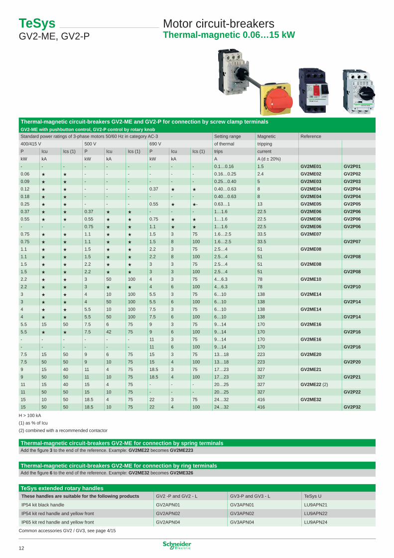
Thermal-magnetic circuit-breakers GV2-ME and GV2-P for connection by screw clamp terminalsGV2-ME with pushbutton control, GV2-P control by rotary knobStandard power ratings of 3-phase motors 50/60 Hz in category AC-3 Setting range Magnetic Reference400/4�5 V 500 V 690 V of thermal trippingP Icu Ics (�) P Icu Ics (�) P Icu Ics (�) trips currentkW kA kW kA kW kA A A (d ± 20%)- - - - - - - - - 0.�…0.�6 �.5 GV2ME01 GV2P010.06 ★ ★ - - - - - - 0.�6…0.25 2.4 GV2ME02 GV2P020.09 ★ ★ - - - - - - 0.25…0.40 5 GV2ME03 GV2P030.�2 ★ ★ - - - 0.37 ★ ★ 0.40…0.63 8 GV2ME04 GV2P040.�8 ★ ★ - - - - - - 0.40…0.63 8 GV2ME04 GV2P040.25 ★ ★ - - - 0.55 ★ ★- 0.63…� �3 GV2ME05 GV2P050.37 ★ ★ 0.37 ★ ★ - - - �…�.6 22.5 GV2ME06 GV2P060.55 ★ ★ 0.55 ★ ★ 0.75 ★ ★ �…�.6 22.5 GV2ME06 GV2P06- - - 0.75 ★ ★ �.� ★ ★ �…�.6 22.5 GV2ME06 GV2P060.75 ★ ★ �.� ★ ★ �.5 3 75 �.6…2.5 33.5 GV2ME070.75 ★ ★ �.� ★ ★ �.5 8 �00 �.6…2.5 33.5 GV2P07�.� ★ ★ �.5 ★ ★ 2.2 3 75 2.5…4 5� GV2ME08�.� ★ ★ �.5 ★ ★ 2.2 8 �00 2.5…4 5� GV2P08�.5 ★ ★ 2.2 ★ ★ 3 3 75 2.5…4 5� GV2ME08�.5 ★ ★ 2.2 ★ ★ 3 3 �00 2.5…4 5� GV2P082.2 ★ ★ 3 50 �00 4 3 75 4…6.3 78 GV2ME102.2 ★ ★ 3 ★ ★ 4 6 �00 4…6.3 78 GV2P103 ★ ★ 4 �0 �00 5.5 3 75 6…�0 �38 GV2ME143 ★ ★ 4 50 �00 5.5 6 �00 6…�0 �38 GV2P144 ★ ★ 5.5 �0 �00 7.5 3 75 6…�0 �38 GV2ME144 ★ ★ 5.5 50 �00 7.5 6 �00 6…�0 �38 GV2P145.5 �5 50 7.5 6 75 9 3 75 9…�4 �70 GV2ME165.5 ★ ★ 7.5 42 75 9 6 �00 9…�4 �70 GV2P16- - - - - - �� 3 75 9…�4 �70 GV2ME16- - - - - - �� 6 �00 9…�4 �70 GV2P167.5 �5 50 9 6 75 �5 3 75 �3…�8 223 GV2ME207.5 50 50 9 �0 75 �5 4 �00 �3…�8 223 GV2P209 �5 40 �� 4 75 �8.5 3 75 �7…23 327 GV2ME219 50 50 �� �0 75 �8.5 4 �00 �7…23 327 GV2P21�� �5 40 �5 4 75 - - - 20…25 327 GV2ME22 (2)�� 50 50 �5 �0 75 - - - 20…25 327 GV2P22�5 �0 50 �8.5 4 75 22 3 75 24…32 4�6 GV2ME32�5 50 50 �8.5 �0 75 22 4 �00 24…32 4�6 GV2P32
H > �00 kA(�) as % of Icu(2) combined with a recommended contactor
Thermal-magnetic circuit-breakers GV2-ME for connection by spring terminalsAdd the figure 3 to the end of the reference. Example: GV2ME22 becomes GV2ME223
Thermal-magnetic circuit-breakers GV2-ME for connection by ring terminalsAdd the figure 6 to the end of the reference. Example: GV2ME32 becomes GV2ME326
TeSys extended rotary handlesThese handles are suitable for the following products GV2 -P and GV2 - L GV3-P and GV3 - L TeSys U
IP54 kit black handle GV2APN0� GV3APN0� LU9APN2�
IP54 kit red handle and yellow front GV2APN02 GV3APN02 LU9APN22
IP65 kit red handle and yellow front GV2APN04 GV3APN04 LU9APN24
Common accessories GV2 / GV3, see page 4/�5
TeSys GV2-ME, GV2-P
Motor circuit-breakersThermal-magnetic 0.06…15 kW
�2
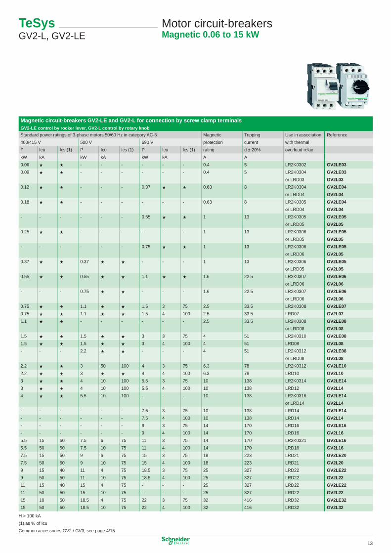
Magnetic circuit-breakers GV2-LE and GV2-L for connection by screw clamp terminalsGV2-LE control by rocker lever, GV2-L control by rotary knobStandard power ratings of 3-phase motors 50/60 Hz in category AC-3 Magnetic Tripping Use in association Reference400/4�5 V 500 V 690 V protection current with thermalP Icu Ics (�) P Icu Ics (�) P Icu Ics (�) rating d ± 20% overload relaykW kA kW kA kW kA A A0.06 ★ ★ - - - - - - 0.4 5 LR2K0302 GV2LE030.09 ★ ★ - - - - - - 0.4 5 LR2K0304 GV2LE03
or LRD03 GV2L030.�2 ★ ★ - - - 0.37 ★ ★ 0.63 8 LR2K0304 GV2LE04
or LRD04 GV2L040.�8 ★ ★ - - - - - - 0.63 8 LR2K0305 GV2LE04
or LRD04 GV2L04- - - - - - 0.55 ★ ★ � �3 LR2K0305 GV2LE05
or LRD05 GV2L050.25 ★ ★ - - - - - - � �3 LR2K0306 GV2LE05
or LRD05 GV2L05- - - - - - 0.75 ★ ★ � �3 LR2K0306 GV2LE05
or LRD06 GV2L050.37 ★ ★ 0.37 ★ ★ - - - � �3 LR2K0306 GV2LE05
or LRD05 GV2L050.55 ★ ★ 0.55 ★ ★ �.� ★ ★ �.6 22.5 LR2K0307 GV2LE06
or LRD06 GV2L06- - - 0.75 ★ ★ - - - �.6 22.5 LR2K0307 GV2LE06
or LRD06 GV2L060.75 ★ ★ �.� ★ ★ �.5 3 75 2.5 33.5 LR2K0308 GV2LE070.75 ★ ★ �.� ★ ★ �.5 4 �00 2.5 33.5 LRD07 GV2L07�.� ★ ★ - - - - - - 2.5 33.5 LR2K0308 GV2LE08
or LRD08 GV2L08�.5 ★ ★ �.5 ★ ★ 3 3 75 4 5� LR2K03�0 GV2LE08�.5 ★ ★ �.5 ★ ★ 3 4 �00 4 5� LRD08 GV2L08- - - 2.2 ★ ★ - - - 4 5� LR2K03�2 GV2LE08
or LRD08 GV2L082.2 ★ ★ 3 50 �00 4 3 75 6.3 78 LR2K03�2 GV2LE102.2 ★ ★ 3 ★ ★ 4 4 �00 6.3 78 LRD�0 GV2L103 ★ ★ 4 �0 �00 5.5 3 75 �0 �38 LR2K03�4 GV2LE143 ★ ★ 4 �0 �00 5.5 4 �00 �0 �38 LRD�2 GV2L144 ★ ★ 5.5 �0 �00 - - - �0 �38 LR2K03�6 GV2LE14
or LRD�4 GV2L14- - - - - - 7.5 3 75 �0 �38 LRD�4 GV2LE14- - - - - - 7.5 4 �00 �0 �38 LRD�4 GV2L14- - - - - - 9 3 75 �4 �70 LRD�6 GV2LE16- - - - - - 9 4 �00 �4 �70 LRD�6 GV2L165.5 �5 50 7.5 6 75 �� 3 75 �4 �70 LR2K032� GV2LE165.5 50 50 7.5 �0 75 �� 4 �00 �4 �70 LRD�6 GV2L167.5 �5 50 9 6 75 �5 3 75 �8 223 LRD2� GV2LE207.5 50 50 9 �0 75 �5 4 �00 �8 223 LRD2� GV2L209 �5 40 �� 4 75 �8.5 3 75 25 327 LRD22 GV2LE229 50 50 �� �0 75 �8.5 4 �00 25 327 LRD22 GV2L22�� �5 40 �5 4 75 - - - 25 327 LRD22 GV2LE22�� 50 50 �5 �0 75 - - - 25 327 LRD22 GV2L22�5 �0 50 �8.5 4 75 22 3 75 32 4�6 LRD32 GV2LE32�5 50 50 �8.5 �0 75 22 4 �00 32 4�6 LRD32 GV2L32
H > �00 kA(�) as % of IcuCommon accessories GV2 / GV3, see page 4/�5
TeSys GV2-L, GV2-LE
Motor circuit-breakersMagnetic 0.06 to 15 kW
�3
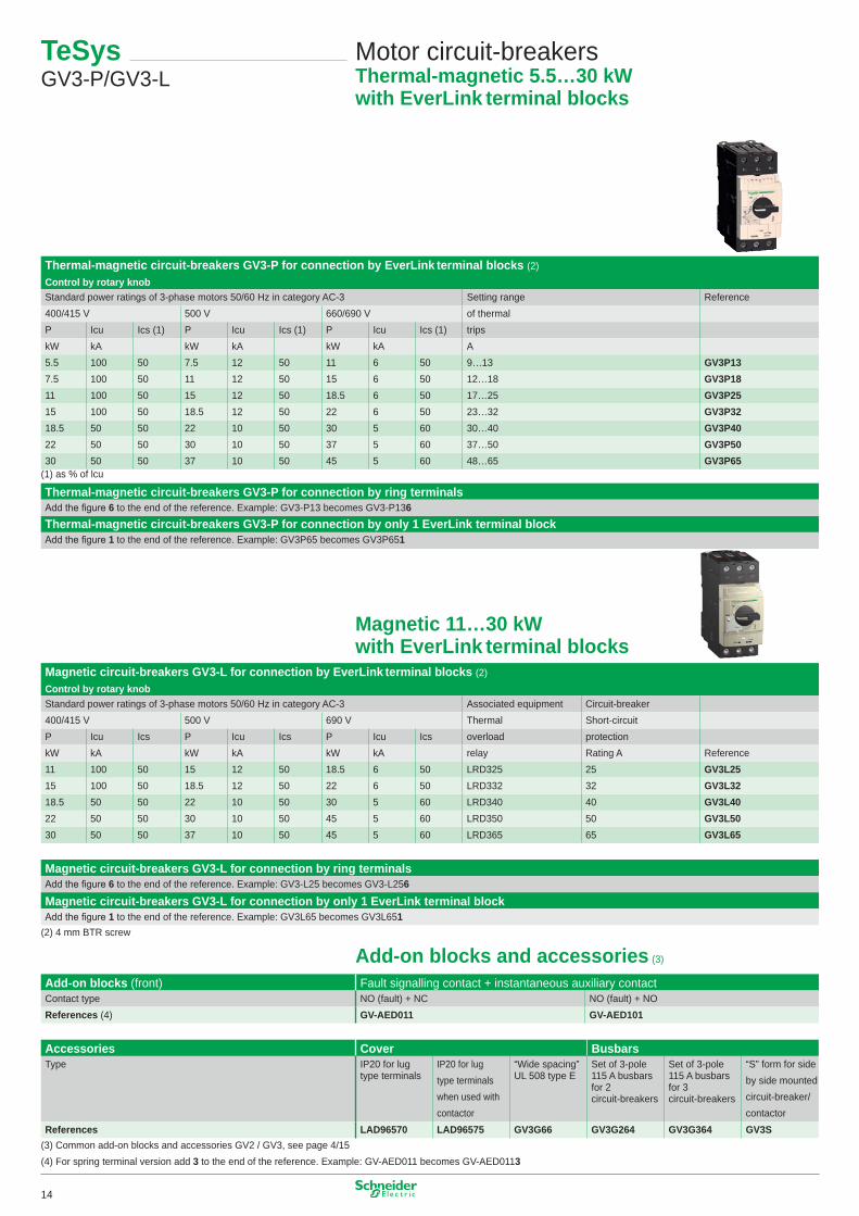
Thermal-magnetic circuit-breakers GV3-P for connection by EverLink terminal blocks (2)Control by rotary knobStandard power ratings of 3-phase motors 50/60 Hz in category AC-3 Setting range Reference400/4�5 V 500 V 660/690 V of thermalP Icu Ics (�) P Icu Ics (�) P Icu Ics (�) tripskW kA kW kA kW kA A5.5 �00 50 7.5 �2 50 �� 6 50 9…�3 GV3P137.5 �00 50 �� �2 50 �5 6 50 �2…�8 GV3P18�� �00 50 �5 �2 50 �8.5 6 50 �7…25 GV3P25�5 �00 50 �8.5 �2 50 22 6 50 23…32 GV3P32�8.5 50 50 22 �0 50 30 5 60 30…40 GV3P4022 50 50 30 �0 50 37 5 60 37…50 GV3P5030 50 50 37 �0 50 45 5 60 48…65 GV3P65
(�) as % of lcu
Thermal-magnetic circuit-breakers GV3-P for connection by ring terminalsAdd the figure 6 to the end of the reference. Example: GV3-P�3 becomes GV3-P�36Thermal-magnetic circuit-breakers GV3-P for connection by only 1 EverLink terminal blockAdd the figure 1 to the end of the reference. Example: GV3P65 becomes GV3P651
Magnetic 11…30 kW with EverLink terminal blocks
Magnetic circuit-breakers GV3-L for connection by EverLink terminal blocks (2)Control by rotary knobStandard power ratings of 3-phase motors 50/60 Hz in category AC-3 Associated equipment Circuit-breaker400/4�5 V 500 V 690 V Thermal Short-circuitP Icu Ics P Icu Ics P Icu Ics overload protectionkW kA kW kA kW kA relay Rating A Reference�� �00 50 �5 �2 50 �8.5 6 50 LRD325 25 GV3L25�5 �00 50 �8.5 �2 50 22 6 50 LRD332 32 GV3L32�8.5 50 50 22 �0 50 30 5 60 LRD340 40 GV3L4022 50 50 30 �0 50 45 5 60 LRD350 50 GV3L5030 50 50 37 �0 50 45 5 60 LRD365 65 GV3L65
Magnetic circuit-breakers GV3-L for connection by ring terminalsAdd the figure 6 to the end of the reference. Example: GV3-L25 becomes GV3-L256
Magnetic circuit-breakers GV3-L for connection by only 1 EverLink terminal blockAdd the figure 1 to the end of the reference. Example: GV3L65 becomes GV3L651
(2) 4 mm BTR screw
Add-on blocks and accessories (3)
Add-on blocks (front) Fault signalling contact + instantaneous auxiliary contactContact type NO (fault) + NC NO (fault) + NOReferences (4) GV-AED011 GV-AED101
Accessories Cover BusbarsType IP20 for lug
type terminalsIP20 for lug type terminals when used with contactor
“Wide spacing” UL 508 type E
Set of 3-pole ��5 A busbars for 2 circuit-breakers
Set of 3-pole ��5 A busbars for 3 circuit-breakers
“S” form for side by side mounted circuit-breaker/contactor
References LAD96570 LAD96575 GV3G66 GV3G264 GV3G364 GV3S(3) Common add-on blocks and accessories GV2 / GV3, see page 4/�5(4) For spring terminal version add 3 to the end of the reference. Example: GV-AED0�� becomes GV-AED0��3
TeSys GV3-P/GV3-L
Motor circuit-breakersThermal-magnetic 5.5…30 kWwith EverLink terminal blocks
�4
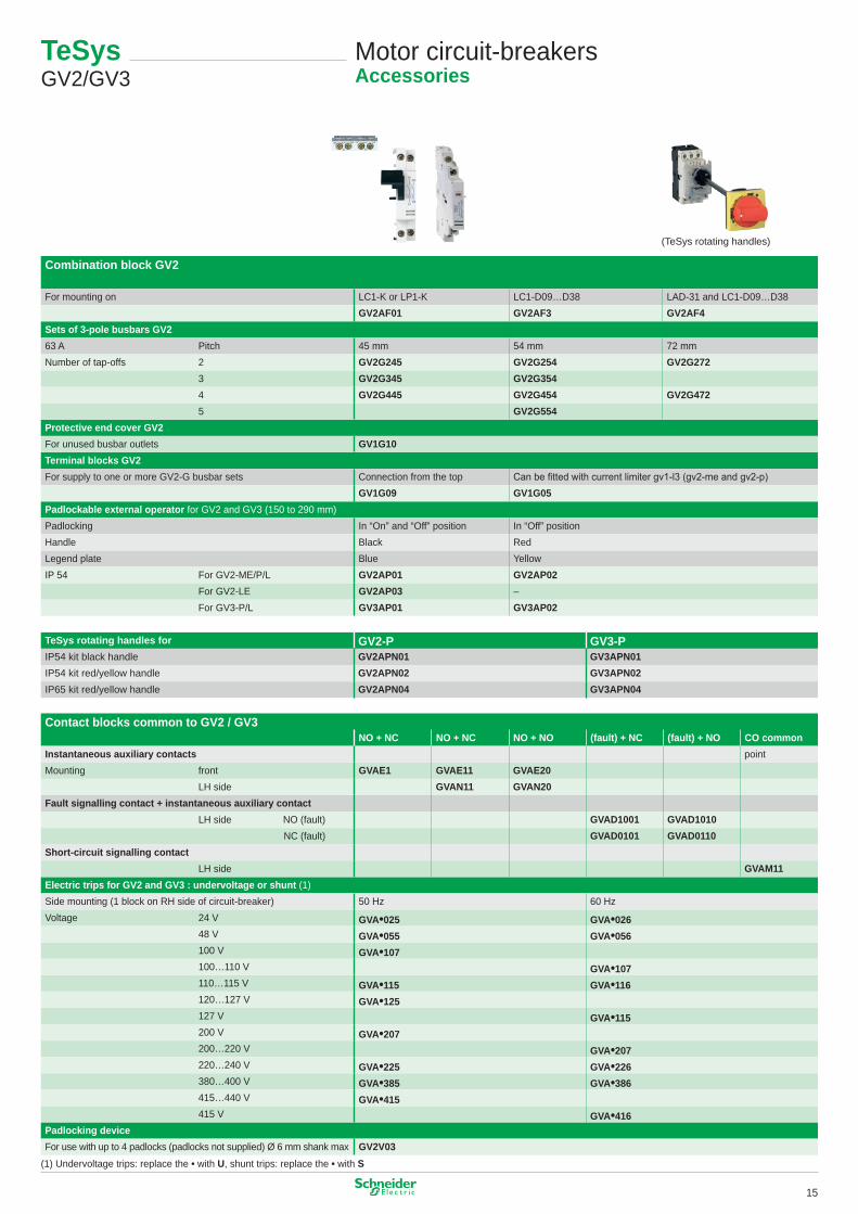
Combination block GV2
For mounting on LC�-K or LP�-K LC�-D09…D38 LAD-3� and LC�-D09…D38GV2AF01 GV2AF3 GV2AF4
Sets of 3-pole busbars GV263 A Pitch 45 mm 54 mm 72 mmNumber of tap-offs 2 GV2G245 GV2G254 GV2G272
3 GV2G345 GV2G354 4 GV2G445 GV2G454 GV2G472 5 GV2G554Protective end cover GV2For unused busbar outlets GV1G10Terminal blocks GV2For supply to one or more GV2-G busbar sets Connection from the top Can be fitted with current limiter gv1-l3 (gv2-me and gv2-p)
GV1G09 GV1G05Padlockable external operator for GV2 and GV3 (�50 to 290 mm)Padlocking In “On” and “Off” position In “Off” position Handle Black RedLegend plate Blue YellowIP 54 For GV2-ME/P/L GV2AP01 GV2AP02
For GV2-LE GV2AP03 –For GV3-P/L GV3AP01 GV3AP02
Contact blocks common to GV2 / GV3NO + NC NO + NC NO + NO (fault) + NC (fault) + NO CO common
Instantaneous auxiliary contacts pointMounting front GVAE1 GVAE11 GVAE20
LH side GVAN11 GVAN20Fault signalling contact + instantaneous auxiliary contact
LH side NO (fault) GVAD1001 GVAD1010 NC (fault) GVAD0101 GVAD0110
Short-circuit signalling contactLH side GVAM11
Electric trips for GV2 and GV3 : undervoltage or shunt (�)Side mounting (� block on RH side of circuit-breaker) 50 Hz 60 HzVoltage 24 V GVA•025 GVA•026
48 V GVA•055 GVA•056�00 V GVA•107�00…��0 V GVA•107��0…��5 V GVA•115 GVA•116�20…�27 V GVA•125�27 V GVA•115200 V GVA•207200…220 V GVA•207220…240 V GVA•225 GVA•226380…400 V GVA•385 GVA•3864�5…440 V GVA•4154�5 V GVA•416
Padlocking deviceFor use with up to 4 padlocks (padlocks not supplied) Ø 6 mm shank max GV2V03
(�) Undervoltage trips: replace the • with U, shunt trips: replace the • with S
TeSys GV2/GV3
Motor circuit-breakersAccessories
TeSys rotating handles for GV2-P GV3-PIP54 kit black handle GV2APN01 GV3APN01IP54 kit red/yellow handle GV2APN02 GV3APN02IP65 kit red/yellow handle GV2APN04 GV3APN04
(TeSys rotating handles)
�5
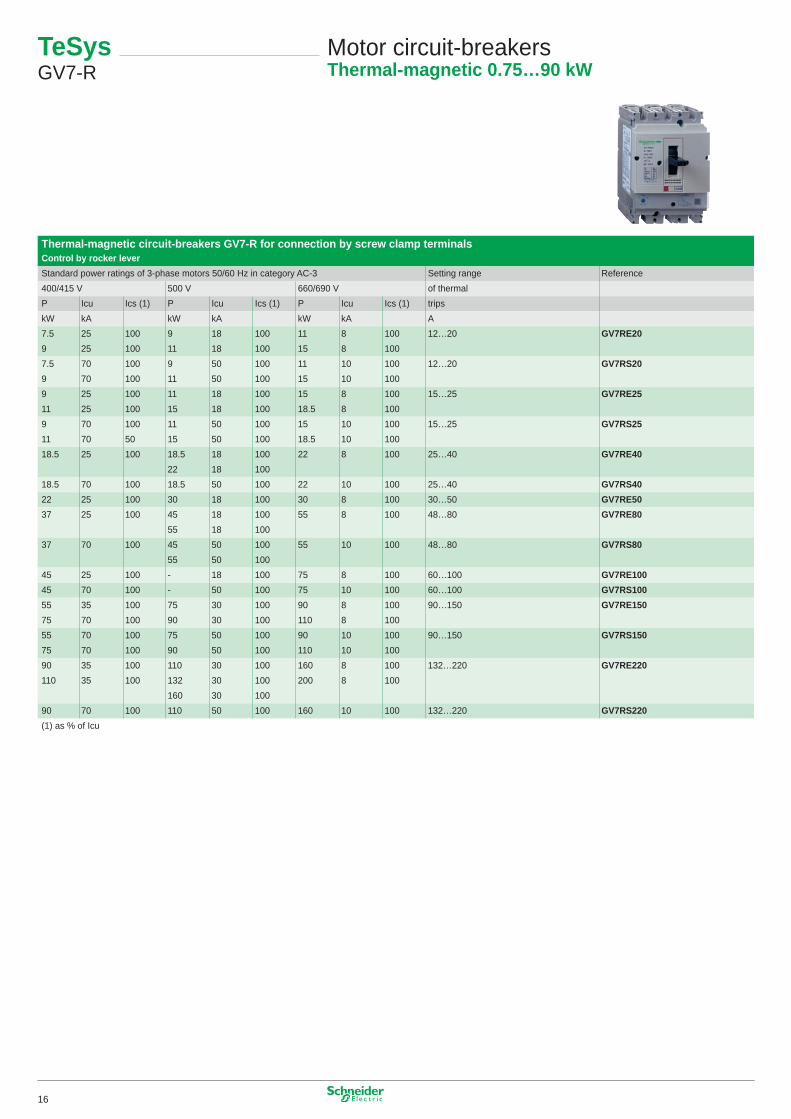
TeSys GV7-R
Motor circuit-breakersThermal-magnetic 0.75…90 kW
Thermal-magnetic circuit-breakers GV7-R for connection by screw clamp terminalsControl by rocker leverStandard power ratings of 3-phase motors 50/60 Hz in category AC-3 Setting range Reference400/4�5 V 500 V 660/690 V of thermalP Icu Ics (�) P Icu Ics (�) P Icu Ics (�) tripskW kA kW kA kW kA A7.5 25 �00 9 �8 �00 �� 8 �00 �2…20 GV7RE209 25 �00 �� �8 �00 �5 8 �007.5 70 �00 9 50 �00 �� �0 �00 �2…20 GV7RS209 70 �00 �� 50 �00 �5 �0 �009 25 �00 �� �8 �00 �5 8 �00 �5…25 GV7RE25�� 25 �00 �5 �8 �00 �8.5 8 �009 70 �00 �� 50 �00 �5 �0 �00 �5…25 GV7RS25�� 70 50 �5 50 �00 �8.5 �0 �00�8.5 25 �00 �8.5 �8 �00 22 8 �00 25…40 GV7RE40
22 �8 �00�8.5 70 �00 �8.5 50 �00 22 �0 �00 25…40 GV7RS4022 25 �00 30 �8 �00 30 8 �00 30…50 GV7RE5037 25 �00 45 �8 �00 55 8 �00 48…80 GV7RE80
55 �8 �0037 70 �00 45 50 �00 55 �0 �00 48…80 GV7RS80
55 50 �0045 25 �00 - �8 �00 75 8 �00 60…�00 GV7RE10045 70 �00 - 50 �00 75 �0 �00 60…�00 GV7RS10055 35 �00 75 30 �00 90 8 �00 90…�50 GV7RE15075 70 �00 90 30 �00 ��0 8 �0055 70 �00 75 50 �00 90 �0 �00 90…�50 GV7RS15075 70 �00 90 50 �00 ��0 �0 �0090 35 �00 ��0 30 �00 �60 8 �00 �32…220 GV7RE220��0 35 �00 �32 30 �00 200 8 �00
�60 30 �0090 70 �00 ��0 50 �00 �60 �0 �00 �32…220 GV7RS220(�) as % of Icu
�6
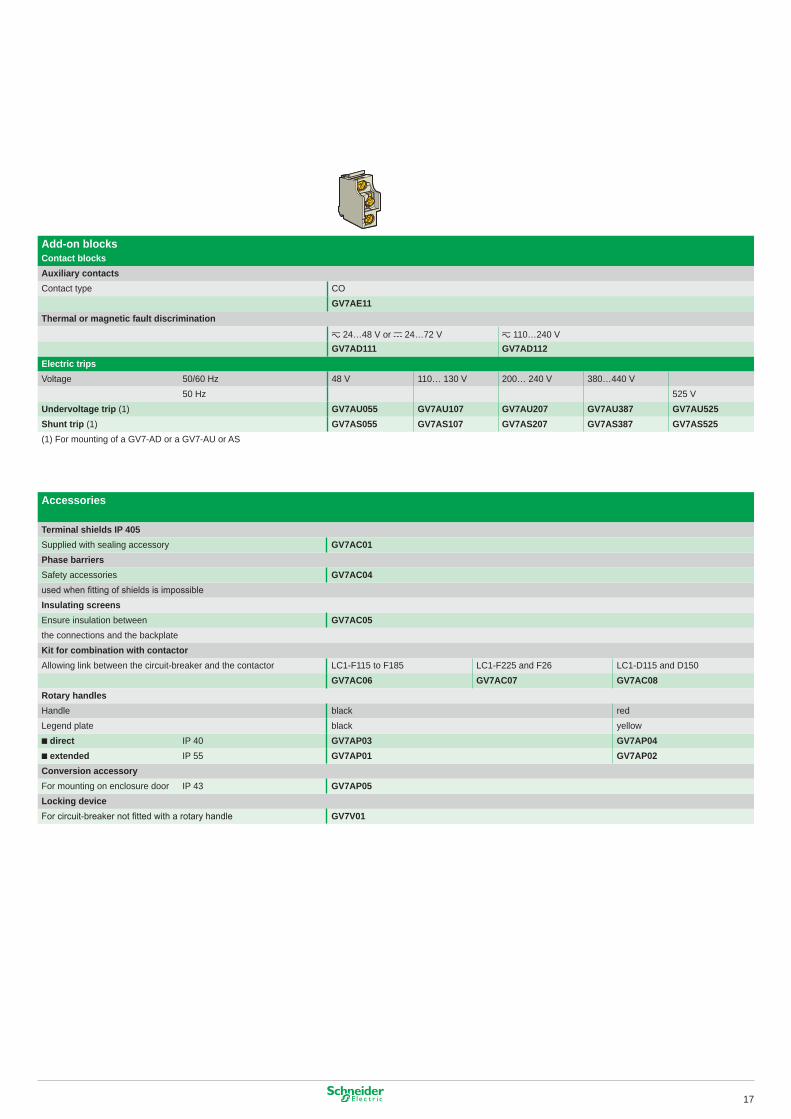
GV7-AE��, AB��GV7-AE��, AB��Add-on blocksContact blocksAuxiliary contactsContact type CO
GV7AE11Thermal or magnetic fault discrimination
z 24…48 V or c 24…72 V z ��0…240 VGV7AD111 GV7AD112
Electric tripsVoltage 50/60 Hz 48 V ��0… �30 V 200… 240 V 380…440 V
50 Hz 525 VUndervoltage trip (�) GV7AU055 GV7AU107 GV7AU207 GV7AU387 GV7AU525Shunt trip (�) GV7AS055 GV7AS107 GV7AS207 GV7AS387 GV7AS525(�) For mounting of a GV7-AD or a GV7-AU or AS
Accessories
Terminal shields IP 405Supplied with sealing accessory GV7AC01Phase barriersSafety accessories GV7AC04used when fitting of shields is impossibleInsulating screensEnsure insulation between GV7AC05the connections and the backplateKit for combination with contactorAllowing link between the circuit-breaker and the contactor LC�-F��5 to F�85 LC�-F225 and F26 LC�-D��5 and D�50
GV7AC06 GV7AC07 GV7AC08Rotary handlesHandle black redLegend plate black yellow■ direct IP 40 GV7AP03 GV7AP04■ extended IP 55 GV7AP01 GV7AP02Conversion accessoryFor mounting on enclosure door IP 43 GV7AP05Locking deviceFor circuit-breaker not fitted with a rotary handle GV7V01
�7
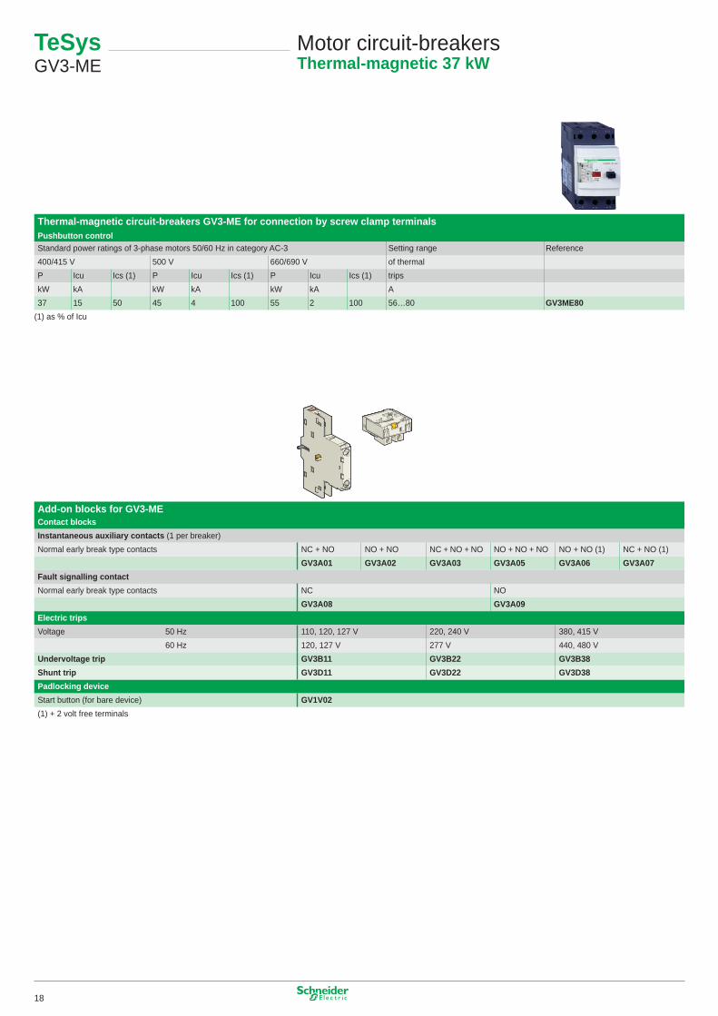
TeSys GV3-ME
Motor circuit-breakersThermal-magnetic 37 kW
Thermal-magnetic circuit-breakers GV3-ME for connection by screw clamp terminalsPushbutton controlStandard power ratings of 3-phase motors 50/60 Hz in category AC-3 Setting range Reference400/4�5 V 500 V 660/690 V of thermalP Icu Ics (�) P Icu Ics (�) P Icu Ics (�) tripskW kA kW kA kW kA A37 �5 50 45 4 �00 55 2 �00 56…80 GV3ME80
(�) as % of Icu
Add-on blocks for GV3-MEContact blocksInstantaneous auxiliary contacts (� per breaker)Normal early break type contacts NC + NO NO + NO NC + NO + NO NO + NO + NO NO + NO (�) NC + NO (�)
GV3A01 GV3A02 GV3A03 GV3A05 GV3A06 GV3A07Fault signalling contactNormal early break type contacts NC NO
GV3A08 GV3A09Electric tripsVoltage 50 Hz ��0, �20, �27 V 220, 240 V 380, 4�5 V
60 Hz �20, �27 V 277 V 440, 480 VUndervoltage trip GV3B11 GV3B22 GV3B38Shunt trip GV3D11 GV3D22 GV3D38Padlocking deviceStart button (for bare device) GV1V02(�) + 2 volt free terminals
�8
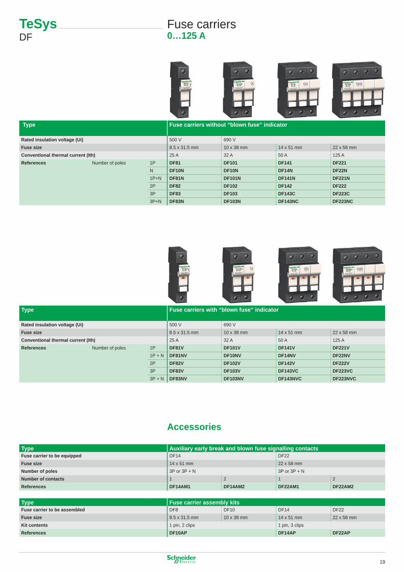
TeSys DF
Fuse carriers0…125 A
Type Fuse carriers without “blown fuse” indicator
Rated insulation voltage (Ui) 500 V 690 VFuse size 8.5 x 3�.5 mm �0 x 38 mm �4 x 5� mm 22 x 58 mmConventional thermal current (Ith) 25 A 32 A 50 A �25 AReferences Number of poles �P DF81 DF101 DF141 DF221
N DF10N DF10N DF14N DF22N�P+N DF81N DF101N DF141N DF221N2P DF82 DF102 DF142 DF2223P DF83 DF103 DF143C DF223C3P+N DF83N DF103N DF143NC DF223NC
Type Fuse carriers with “blown fuse” indicator
Rated insulation voltage (Ui) 500 V 690 VFuse size 8.5 x 3�.5 mm �0 x 38 mm �4 x 5� mm 22 x 58 mmConventional thermal current (Ith) 25 A 32 A 50 A �25 AReferences Number of poles �P DF81V DF101V DF141V DF221V
�P + N DF81NV DF10NV DF14NV DF22NV2P DF82V DF102V DF142V DF222V3P DF83V DF103V DF143VC DF223VC3P + N DF83NV DF103NV DF143NVC DF223NVC
Accessories
Type Auxiliary early break and blown fuse signalling contactsFuse carrier to be equipped DF�4 DF22Fuse size �4 x 5� mm 22 x 58 mmNumber of poles 3P or 3P + N 3P or 3P + NNumber of contacts � 2 � 2References DF14AM1 DF14AM2 DF22AM1 DF22AM2
Type Fuse carrier assembly kitsFuse carrier to be assembled DF8 DF�0 DF�4 DF22Fuse size 8.5 x 3�.5 mm �0 x 38 mm �4 x 5� mm 22 x 58 mmKit contents � pin, 2 clips � pin, 3 clipsReferences DF10AP DF14AP DF22AP
�9
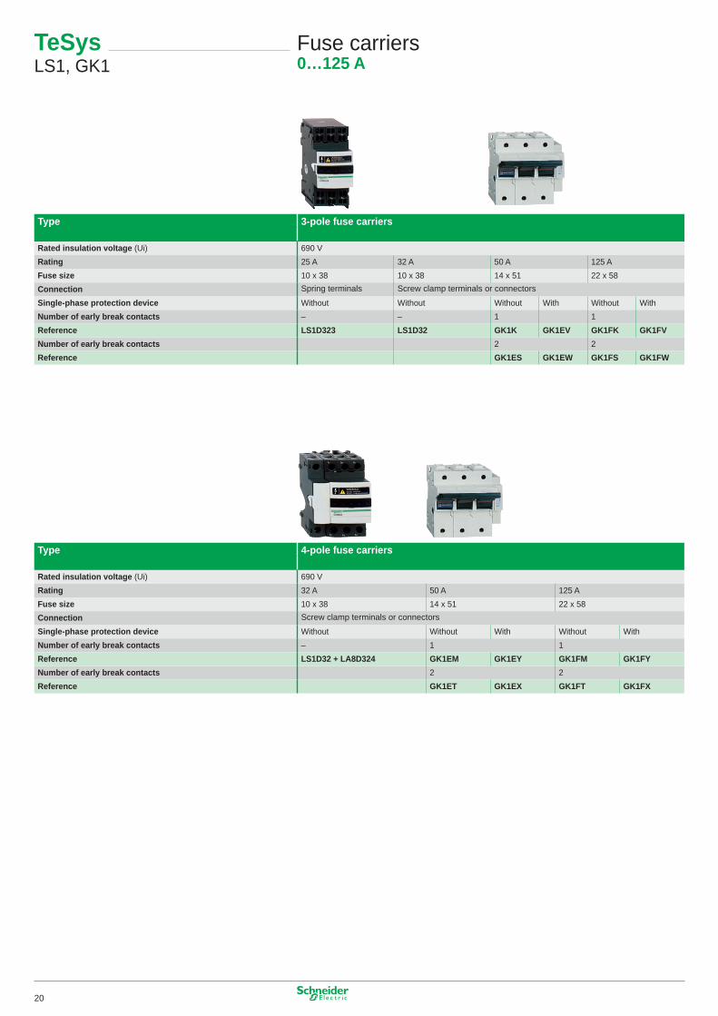
TeSys LS�, GK�
Fuse carriers0…125 A
Type 3-pole fuse carriers
Rated insulation voltage (Ui) 690 VRating 25 A 32 A 50 A �25 AFuse size �0 x 38 �0 x 38 �4 x 5� 22 x 58Connection Spring terminals Screw clamp terminals or connectors
Single-phase protection device Without Without Without With Without WithNumber of early break contacts – – � �Reference LS1D323 LS1D32 GK1K GK1EV GK1FK GK1FVNumber of early break contacts 2 2Reference GK1ES GK1EW GK1FS GK1FW
Type 4-pole fuse carriers
Rated insulation voltage (Ui) 690 VRating 32 A 50 A �25 AFuse size �0 x 38 �4 x 5� 22 x 58Connection Screw clamp terminals or connectors
Single-phase protection device Without Without With Without WithNumber of early break contacts – � �Reference LS1D32 + LA8D324 GK1EM GK1EY GK1FM GK1FYNumber of early break contacts 2 2Reference GK1ET GK1EX GK1FT GK1FX
20
TeSys LS�, GK�
Fuse carriersAccessories
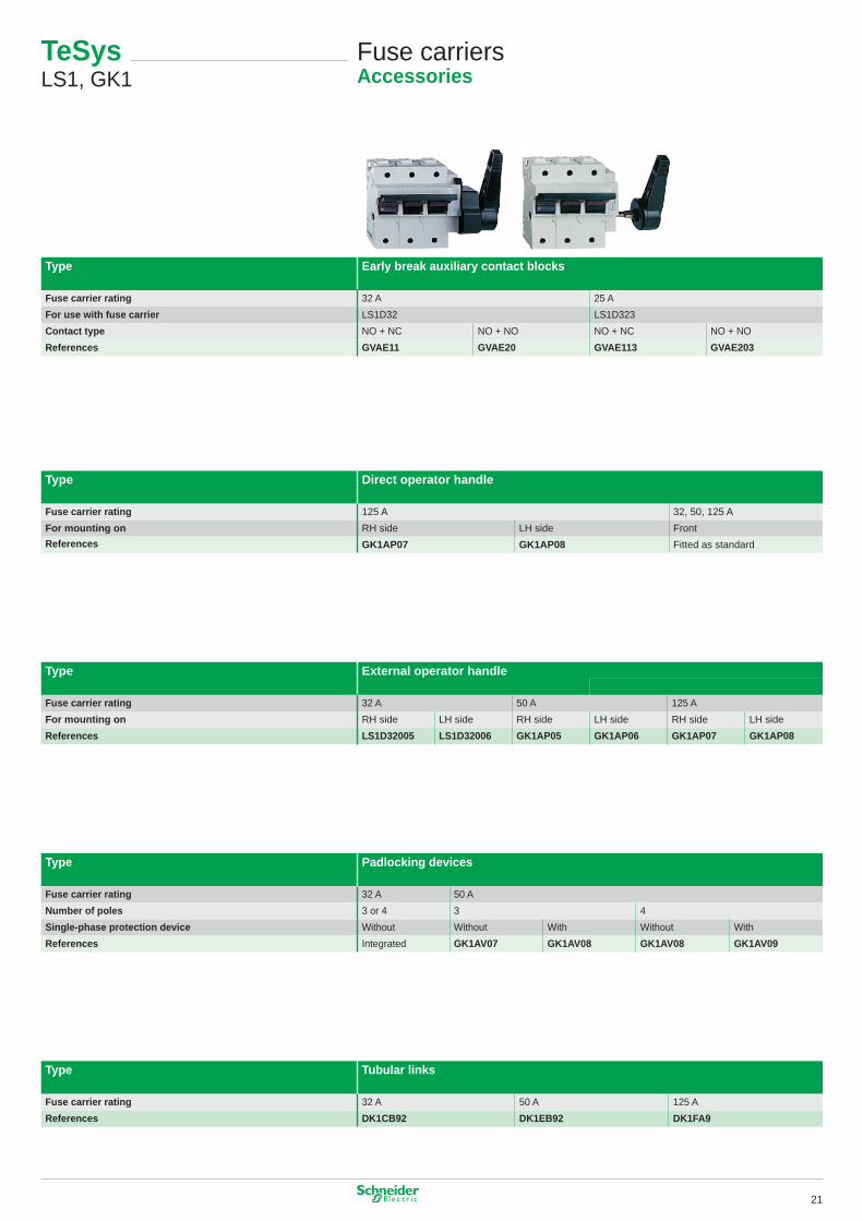
Type Early break auxiliary contact blocks
Fuse carrier rating 32 A 25 AFor use with fuse carrier LS�D32 LS�D323Contact type NO + NC NO + NO NO + NC NO + NOReferences GVAE11 GVAE20 GVAE113 GVAE203
Type Direct operator handle
Fuse carrier rating �25 A 32, 50, �25 AFor mounting on RH side LH side FrontReferences GK1AP07 GK1AP08 Fitted as standard
Type External operator handle
Fuse carrier rating 32 A 50 A �25 AFor mounting on RH side LH side RH side LH side RH side LH sideReferences LS1D32005 LS1D32006 GK1AP05 GK1AP06 GK1AP07 GK1AP08
Type Padlocking devices
Fuse carrier rating 32 A 50 ANumber of poles 3 or 4 3 4Single-phase protection device Without Without With Without WithReferences Integrated GK1AV07 GK1AV08 GK1AV08 GK1AV09
Type Tubular links
Fuse carrier rating 32 A 50 A �25 AReferences DK1CB92 DK1EB92 DK1FA9
2�
TeSys GS
Switch-disconnector-fuses32…1250 A
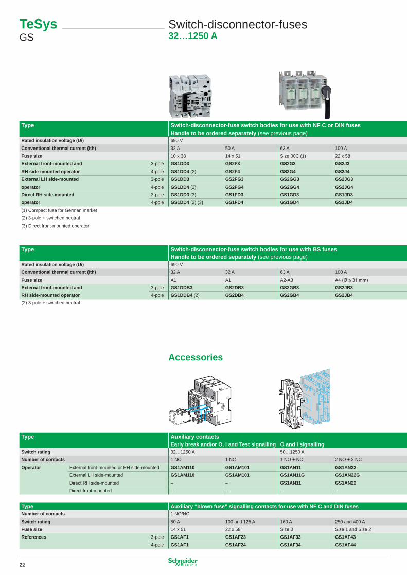
Type Switch-disconnector-fuse switch bodies for use with NF C or DIN fusesHandle to be ordered separately (see previous page)
Rated insulation voltage (Ui) 690 VConventional thermal current (Ith) 32 A 50 A 63 A �00 AFuse size �0 x 38 �4 x 5� Size 00C (�) 22 x 58External front-mounted and 3-pole GS1DD3 GS2F3 GS2G3 GS2J3RH side-mounted operator 4-pole GS1DD4 (2) GS2F4 GS2G4 GS2J4External LH side-mounted 3-pole GS1DD3 GS2FG3 GS2GG3 GS2JG3operator 4-pole GS1DD4 (2) GS2FG4 GS2GG4 GS2JG4Direct RH side-mounted 3-pole GS1DD3 (3) GS1FD3 GS1GD3 GS1JD3operator 4-pole GS1DD4 (2) (3) GS1FD4 GS1GD4 GS1JD4(�) Compact fuse for German market(2) 3-pole + switched neutral(3) Direct front-mounted operator
Type Switch-disconnector-fuse switch bodies for use with BS fusesHandle to be ordered separately (see previous page)
Rated insulation voltage (Ui) 690 VConventional thermal current (Ith) 32 A 32 A 63 A �00 AFuse size A� A� A2-A3 A4 (Ø ≤ 31 mm)External front-mounted and 3-pole GS1DDB3 GS2DB3 GS2GB3 GS2JB3RH side-mounted operator 4-pole GS1DDB4 (2) GS2DB4 GS2GB4 GS2JB4(2) 3-pole + switched neutral
Accessories
Type Auxiliary contactsEarly break and/or O, I and Test signalling O and I signalling
Switch rating 32…�250 A 50…�250 ANumber of contacts � NO � NC � NO + NC 2 NO + 2 NCOperator External front-mounted or RH side-mounted GS1AM110 GS1AM101 GS1AN11 GS1AN22
External LH side-mounted GS1AM110 GS1AM101 GS1AN11G GS1AN22GDirect RH side-mounted – – GS1AN11 GS1AN22Direct front-mounted – – – –
Type Auxiliary “blown fuse” signalling contacts for use with NF C and DIN fusesNumber of contacts � NO/NCSwitch rating 50 A �00 and �25 A �60 A 250 and 400 AFuse size �4 x 5� 22 x 58 Size 0 Size � and Size 2References 3-pole GS1AF1 GS1AF23 GS1AF33 GS1AF43
4-pole GS1AF1 GS1AF24 GS1AF34 GS1AF44
22
Type Switch-disconnector-fuse switch bodies for use with NF C or DIN fusesHandle to be ordered separately (see previous page)
Rated insulation voltage (Ui) 690 VConventional thermal current (Ith) 32 A 50 A 63 A �00 AFuse size �0 x 38 �4 x 5� Size 00C (�) 22 x 58External front-mounted and 3-pole GS1DD3 GS2F3 GS2G3 GS2J3RH side-mounted operator 4-pole GS1DD4 (2) GS2F4 GS2G4 GS2J4External LH side-mounted 3-pole GS1DD3 GS2FG3 GS2GG3 GS2JG3operator 4-pole GS1DD4 (2) GS2FG4 GS2GG4 GS2JG4Direct RH side-mounted 3-pole GS1DD3 (3) GS1FD3 GS1GD3 GS1JD3operator 4-pole GS1DD4 (2) (3) GS1FD4 GS1GD4 GS1JD4(�) Compact fuse for German market(2) 3-pole + switched neutral(3) Direct front-mounted operator
Type Switch-disconnector-fuse switch bodies for use with BS fusesHandle to be ordered separately (see previous page)
Rated insulation voltage (Ui) 690 VConventional thermal current (Ith) 32 A 32 A 63 A �00 AFuse size A� A� A2-A3 A4 (Ø ≤ 31 mm)External front-mounted and 3-pole GS1DDB3 GS2DB3 GS2GB3 GS2JB3RH side-mounted operator 4-pole GS1DDB4 (2) GS2DB4 GS2GB4 GS2JB4(2) 3-pole + switched neutral
Accessories
Type Auxiliary contactsEarly break and/or O, I and Test signalling O and I signalling
Switch rating 32…�250 A 50…�250 ANumber of contacts � NO � NC � NO + NC 2 NO + 2 NCOperator External front-mounted or RH side-mounted GS1AM110 GS1AM101 GS1AN11 GS1AN22
External LH side-mounted GS1AM110 GS1AM101 GS1AN11G GS1AN22GDirect RH side-mounted – – GS1AN11 GS1AN22Direct front-mounted – – – –
Type Auxiliary “blown fuse” signalling contacts for use with NF C and DIN fusesNumber of contacts � NO/NCSwitch rating 50 A �00 and �25 A �60 A 250 and 400 AFuse size �4 x 5� 22 x 58 Size 0 Size � and Size 2References 3-pole GS1AF1 GS1AF23 GS1AF33 GS1AF43
4-pole GS1AF1 GS1AF24 GS1AF34 GS1AF44
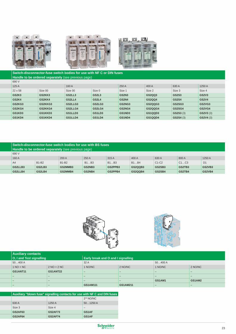
Switch-disconnector-fuse switch bodies for use with NF C or DIN fusesHandle to be ordered separately (see previous page)690 V�25 A �60 A 250 A 400 A 630 A �250 A22 x 58 Size 00 Size 00 Size 0 Size � Size 2 Size 3 Size 4GS2K3 GS2KK3 GS2LL3 GS2L3 GS2N3 GS2QQ3 GS2S3 GS2V3GS2K4 GS2KK4 GS2LL4 GS2L4 GS2N4 GS2QQ4 GS2S4 GS2V4GS2KG3 GS2KKG3 GS2LLG3 GS2LG3 GS2NG3 GS2QQG3 GS2SG3 GS2VG3GS2KG4 GS2KKG4 GS2LLG4 GS2LG4 GS2NG4 GS2QQG4 GS2SG4 GS2VG4GS1KD3 GS1KKD3 GS1LLD3 GS1LD3 GS1ND3 GS1QQD3 GS2S3 (3) GS2V3 (3)GS1KD4 GS1KKD4 GS1LLD4 GS1LD4 GS1ND4 GS1QQD4 GS2S4 (3) GS2V4 (3)
Switch-disconnector-fuse switch bodies for use with BS fusesHandle to be ordered separately (see previous page)690 V�60 A 200 A 250 A 3�5 A 400 A 630 A 800 A �250 AA4 B�-B2 B�-B2 B�…B3 B�…B3 B�…B4 C�-C2 C�…C3 D�GS2LLB3 GS2LB3 GS2MMB3 GS2NB3 GS2PPB3 GS2QQB3 GS2SB3 GS2TB3 GS2VB3GS2LLB4 GS2LB4 GS2MMB4 GS2NB4 GS2PPB4 GS2QQB4 GS2SB4 GS2TB4 GS2VB4
Auxiliary contactsO, I and Test signalling Early break and O and I signalling50…400 A 32 A 50…400 A� NO + NC 2 NO + 2 NC � NO/NC 2 NO/NC � NO/NC 2 NO/NCGS1ANT11 GS1ANT22 – – – –– – – – – –– – – – GS1AM1 GS1AM2– – GS1AM111 GS1AM211 – –
Auxiliary “blown fuse” signalling contacts for use with NF C and DIN fuses2nd NO/NC
630 A �250 A 50…�250 ASize 3 Size 4 –GS2AF63 GS2AF73 GS1AFGS2AF64 GS2AF74 GS1AF
23
TeSys GS
Switch-disconnector-fusesHandles
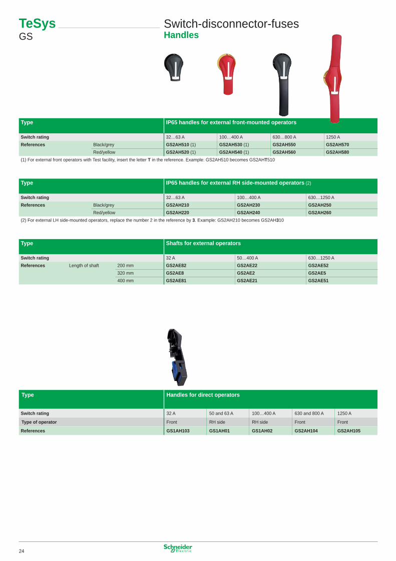
Type IP65 handles for external front-mounted operators
Switch rating 32…63 A �00…400 A 630…800 A �250 AReferences Black/grey GS2AH510 (�) GS2AH530 (�) GS2AH550 GS2AH570
Red/yellow GS2AH520 (�) GS2AH540 (�) GS2AH560 GS2AH580(�) For external front operators with Test facility, insert the letter T in the reference. Example: GS2AH5�0 becomes GS2AHT5�0
Type IP65 handles for external RH side-mounted operators (2)
Switch rating 32…63 A �00…400 A 630…�250 AReferences Black/grey GS2AH210 GS2AH230 GS2AH250
Red/yellow GS2AH220 GS2AH240 GS2AH260(2) For external LH side-mounted operators, replace the number 2 in the reference by 3. Example: GS2AH2�0 becomes GS2AH3�0
Type Shafts for external operators
Switch rating 32 A 50…400 A 630…�250 AReferences Length of shaft 200 mm GS2AE82 GS2AE22 GS2AE52
320 mm GS2AE8 GS2AE2 GS2AE5400 mm GS2AE81 GS2AE21 GS2AE51
Type Handles for direct operators
Switch rating 32 A 50 and 63 A �00…400 A 630 and 800 A �250 A
Type of operator Front RH side RH side Front Front
References GS1AH103 GS1AH01 GS1AH02 GS2AH104 GS2AH105
24
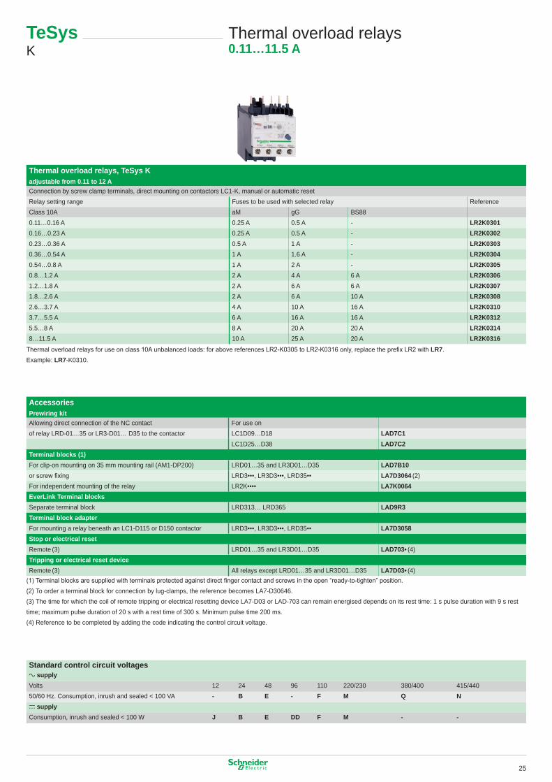
Thermal overload relays, TeSys K adjustable from 0.11 to 12 AConnection by screw clamp terminals, direct mounting on contactors LC�-K, manual or automatic resetRelay setting range Fuses to be used with selected relay ReferenceClass �0A aM gG BS880.��…0.�6 A 0.25 A 0.5 A - LR2K03010.�6…0.23 A 0.25 A 0.5 A - LR2K03020.23…0.36 A 0.5 A � A - LR2K03030.36…0.54 A � A �.6 A - LR2K03040.54…0.8 A � A 2 A - LR2K03050.8…�.2 A 2 A 4 A 6 A LR2K0306�.2…�.8 A 2 A 6 A 6 A LR2K0307�.8…2.6 A 2 A 6 A �0 A LR2K03082.6…3.7 A 4 A �0 A �6 A LR2K03103.7…5.5 A 6 A �6 A �6 A LR2K03125.5…8 A 8 A 20 A 20 A LR2K03148…��.5 A �0 A 25 A 20 A LR2K0316
Thermal overload relays for use on class 10A unbalanced loads: for above references LR2-K0305 to LR2-K0316 only, replace the prefix LR2 with LR7. Example: LR7-K03�0.
Accessories Prewiring kitAllowing direct connection of the NC contact For use onof relay LRD-0�…35 or LR3-D0�… D35 to the contactor LC�D09…D�8 LAD7C1
LC�D25…D38 LAD7C2Terminal blocks (1)For clip-on mounting on 35 mm mounting rail (AM�-DP200) LRD0�…35 and LR3D0�…D35 LAD7B10or screw fixing LRD3•••, LR3D3•••, LRD35•• LA7D3064 (2)For independent mounting of the relay LR2K•••• LA7K0064EverLink Terminal blocksSeparate terminal block LRD3�3… LRD365 LAD9R3Terminal block adapterFor mounting a relay beneath an LC�-D��5 or D�50 contactor LRD3•••, LR3D3•••, LRD35•• LA7D3058Stop or electrical reset Remote (3) LRD0�…35 and LR3D0�…D35 LAD703• (4)Tripping or electrical reset device Remote (3) All relays except LRD0�…35 and LR3D0�…D35 LA7D03• (4)
(1) Terminal blocks are supplied with terminals protected against direct finger contact and screws in the open “ready-to-tighten” position.(2) To order a terminal block for connection by lug-clamps, the reference becomes LA7-D30646.(3) The time for which the coil of remote tripping or electrical resetting device LA7-D03 or LAD-703 can remain energised depends on its rest time: � s pulse duration with 9 s rest time; maximum pulse duration of 20 s with a rest time of 300 s. Minimum pulse time 200 ms.(4) Reference to be completed by adding the code indicating the control circuit voltage.
Standard control circuit voltagesa supplyVolts �2 24 48 96 ��0 220/230 380/400 4�5/44050/60 Hz. Consumption, inrush and sealed < �00 VA - B E - F M Q Nc supplyConsumption, inrush and sealed < �00 W J B E DD F M - -
TeSys K
Thermal overload relays0.11…11.5 A
25
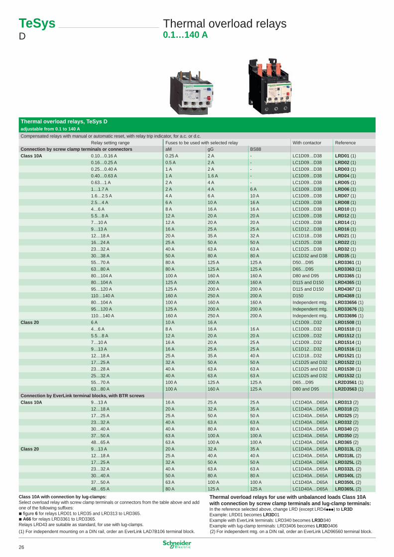
TeSys D
Thermal overload relays0.1…140 A
Thermal overload relays, TeSys D adjustable from 0.1 to 140 ACompensated relays with manual or automatic reset, with relay trip indicator, for a.c. or d.c.
Relay setting range Fuses to be used with selected relay With contactor ReferenceConnection by screw clamp terminals or connectors aM gG BS88Class 10A 0.�0…0.�6 A 0.25 A 2 A - LC�D09…D38 LRD01 (�)
0.�6…0.25 A 0.5 A 2 A - LC�D09…D38 LRD02 (�)0.25…0.40 A � A 2 A - LC�D09…D38 LRD03 (�)0.40…0.63 A � A �.6 A - LC�D09…D38 LRD04 (�)0.63…� A 2 A 4 A - LC�D09…D38 LRD05 (�)�…�.7 A 2 A 4 A 6 A LC�D09…D38 LRD06 (�)�.6…2.5 A 4 A 6 A �0 A LC�D09…D38 LRD07 (�)2.5…4 A 6 A �0 A �6 A LC�D09…D38 LRD08 (�)4…6 A 8 A �6 A �6 A LC�D09…D38 LRD10 (�)5.5…8 A �2 A 20 A 20 A LC�D09…D38 LRD12 (�)7…�0 A �2 A 20 A 20 A LC�D09…D38 LRD14 (�)9…�3 A �6 A 25 A 25 A LC�D�2…D38 LRD16 (�)�2…�8 A 20 A 35 A 32 A LC�D�8…D38 LRD21 (�)�6…24 A 25 A 50 A 50 A LC�D25…D38 LRD22 (�)23…32 A 40 A 63 A 63 A LC�D25…D38 LRD32 (�)30…38 A 50 A 80 A 80 A LC�D32 and D38 LRD35 (�)55…70 A 80 A �25 A �25 A D50…D95 LRD3361 (�)63…80 A 80 A �25 A �25 A D65…D95 LRD3363 (�)80…�04 A �00 A �60 A �60 A D80 and D95 LRD3365 (�)80…�04 A �25 A 200 A �60 A D��5 and D�50 LRD4365 (�)95…�20 A �25 A 200 A 200 A D��5 and D�50 LRD4367 (�)��0…�40 A �60 A 250 A 200 A D�50 LRD4369 (�)80…�04 A �00 A �60 A �60 A Independent mtg. LRD33656 (�)95…�20 A �25 A 200 A 200 A Independent mtg. LRD33676 (�)��0…�40 A �60 A 250 A 200 A Independent mtg. LRD33696 (�)
Class 20 6 A �0 A �6 A LC�D09…D32 LRD1508 (�)4…6 A 8 A �6 A �6 A LC�D09…D32 LRD1510 (�)5.5…8 A �2 A 20 A 20 A LC�D09…D32 LRD1512 (�)7…�0 A �6 A 20 A 25 A LC�D09…D32 LRD1514 (�)9…�3 A �6 A 25 A 25 A LC�D�2…D32 LRD1516 (�)�2…�8 A 25 A 35 A 40 A LC�D�8…D32 LRD1521 (�)�7…25 A 32 A 50 A 50 A LC�D25 and D32 LRD1522 (�)23…28 A 40 A 63 A 63 A LC�D25 and D32 LRD1530 (�)25…32 A 40 A 63 A 63 A LC�D25 and D32 LRD1532 (�)55…70 A �00 A �25 A �25 A D65…D95 LR2D3561 (�)63…80 A �00 A �60 A �25 A D80 and D95 LR2D3563 (�)
Connection by EverLink terminal blocks, with BTR screwsClass 10A 9…�3 A �6 A 25 A 25 A LC�D40A…D65A LRD313 (2)
�2…�8 A 20 A 32 A 35 A LC�D40A…D65A LRD318 (2)�7…25 A 25 A 50 A 50 A LC�D40A…D65A LRD325 (2)23…32 A 40 A 63 A 63 A LC�D40A…D65A LRD332 (2)30…40 A 40 A 80 A 80 A LC�D40A…D65A LRD340 (2)37…50 A 63 A �00 A �00 A LC�D40A…D65A LRD350 (2)48…65 A 63 A �00 A �00 A LC�D40A…D65A LRD365 (2)
Class 20 9…�3 A 20 A 32 A 35 A LC�D40A…D65A LRD313L (2)�2…�8 A 25 A 40 A 40 A LC�D40A…D65A LRD318L (2)�7…25 A 32 A 50 A 50 A LC�D40A…D65A LRD325L (2)23…32 A 40 A 63 A 63 A LC�D40A…D65A LRD332L (2)30…40 A 50 A 80 A 80 A LC�D40A…D65A LRD340L (2)37…50 A 63 A �00 A �00 A LC�D40A…D65A LRD350L (2)48…65 A 80 A �25 A �25 A LC�D40A…D65A LRD365L (2)
Class 10A with connection by lug-clamps: Select overload relay with screw clamp terminals or connectors from the table above and add one of the following suffixes:b figure 6 for relays LRD0� to LRD35 and LRD3�3 to LRD365.b A66 for relays LRD336� to LRD3365.Relays LRD43 are suitable as standard, for use with lug-clamps.
Thermal overload relays for use with unbalanced loads Class 10A with connection by screw clamp terminals and lug-clamp terminals:In the reference selected above, change LRD (except LRD4ppp) to LR3DExample: LRD0� becomes LR3D0�Example with EverLink terminals: LRD340 becomes LR3D340Example with lug-clamp terminals: LRD3406 becomes LR3D3406
(�) For independent mounting on a DIN rail, order an EverLink LAD7B�06 terminal block. (2) For independent mtg. on a DIN rail, order an EverLink LAD96560 terminal block.
26
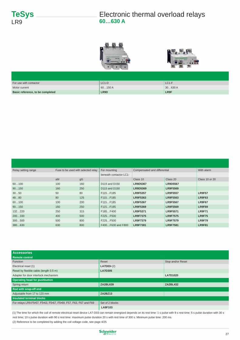
For use with contactor LC�-D LC�-FMotor current 60…�50 A 30…630 ABasic reference, to be completed LR9D LR9F
Relay setting range Fuse to be used with selected relay For mounting Compensated and differential With alarmbeneath contactor LC�-
aM gG Class �0 Class 20 Class �0 or 2060…�00 �00 �60 D��5 and D�50 LR9D5367 LR9D556790…�50 �60 250 D��5 and D�50 LR9D5369 LR9F556930…50 50 80 F��5…F�85 LR9F5357 LR9F5557 LR9F5748…80 80 �25 F��5…F�85 LR9F5363 LR9F5563 LR9F6360…�00 �00 200 F��5…F�85 LR9F5367 LR9F5567 LR9F6790…�50 �60 250 F��5…F�85 LR9F5369 LR9F5569 LR9F69�32…220 250 3�5 F�85…F400 LR9F5371 LR9F5571 LR9F71200…330 400 500 F225…F500 LR9F7375 LR9F7575 LR9F75300…500 500 800 F225…F500 LR9F7379 LR9F7579 LR9F79380…630 630 800 F400…F630 and F800 LR9F7381 LR9F7581 LR9F81
Accessories Remote controlFunction Reset Stop and/or ResetElectrical reset (�) LA7D03• (2)Reset by flexible cable (length 0.5 m) LA7D305Adapter for door interlock mechanism LA7D1020Operating head for pushbutton Spring return ZA2BL639 ZA2BL432Rod with snap-off endAdjustable from �7 to �20 mm ZA2BZ13Insulated terminal blocksFor relays LR9-F5•57, F5•63, F5•67, F5•69, F57, F63, F67 and F69 Set of 2 blocks
LA9F103
(�) The time for which the coil of remote electrical reset device LA7-D03 can remain energised depends on its rest time: � s pulse with 9 s rest time; 5 s pulse duration with 30 s rest time; �0 s pulse duration with 90 s rest time: maximum pulse duration 20 s with rest time of 300 s. Minimum pulse time: 200 ms.(2) Reference to be completed by adding the coil voltage code, see page 4/25
TeSys LR9
Electronic thermal overload relays60…630 A
27
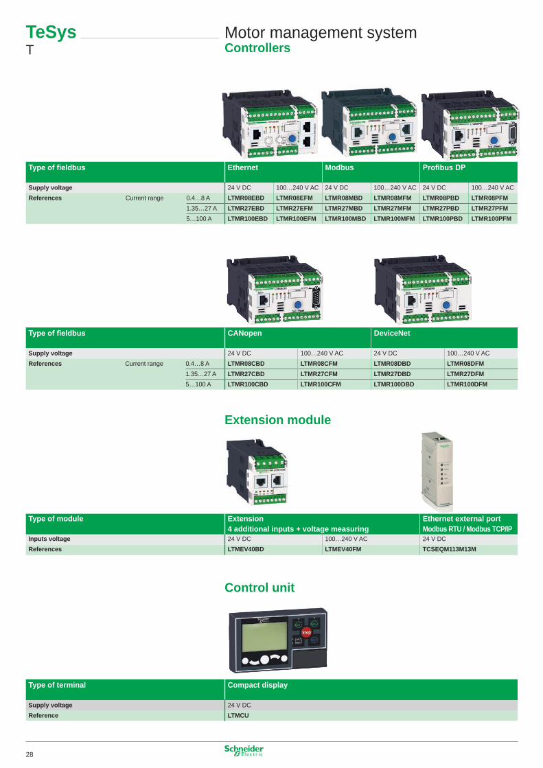
Type of fieldbus Ethernet Modbus Profibus DP
Supply voltage 24 V DC �00…240 V AC 24 V DC �00…240 V AC 24 V DC �00…240 V ACReferences Current range 0.4…8 A LTMR08EBD LTMR08EFM LTMR08MBD LTMR08MFM LTMR08PBD LTMR08PFM
�.35…27 A LTMR27EBD LTMR27EFM LTMR27MBD LTMR27MFM LTMR27PBD LTMR27PFM5…�00 A LTMR100EBD LTMR100EFM LTMR100MBD LTMR100MFM LTMR100PBD LTMR100PFM
Type of fieldbus CANopen DeviceNet
Supply voltage 24 V DC �00…240 V AC 24 V DC �00…240 V ACReferences Current range 0.4…8 A LTMR08CBD LTMR08CFM LTMR08DBD LTMR08DFM
�.35…27 A LTMR27CBD LTMR27CFM LTMR27DBD LTMR27DFM5…�00 A LTMR100CBD LTMR100CFM LTMR100DBD LTMR100DFM
Extension module
Type of module Extension 4 additional inputs + voltage measuring
Ethernet external port Modbus RTU / Modbus TCP/IP
Inputs voltage 24 V DC �00…240 V AC 24 V DCReferences LTMEV40BD LTMEV40FM TCSEQM113M13M
Control unit
Type of terminal Compact display
Supply voltage 24 V DCReference LTMCU
Motor management systemControllers
TeSys T
28
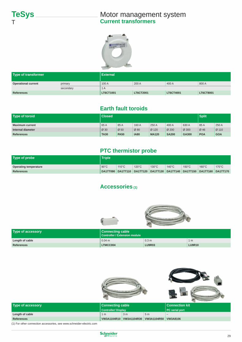
Type of transformer External
Operational current primary �00 A 200 A 400 A 800 Asecondary � A
References LT6CT1001 LT6CT2001 LT6CT4001 LT6CT8001
Earth fault toroidsType of toroid Closed Split
Maximum current 65 A 85 A �60 A 250 A 400 A 630 A 85 A 250 AInternal diameter Ø 30 Ø 50 Ø 80 Ø �20 Ø 200 Ø 300 Ø 46 Ø ��0References TA30 PA50 IA80 MA120 SA200 GA300 POA GOA
PTC thermistor probeType of probe Triple
Operating temperature 90°C 110°C 120°C 130°C 140°C 150°C 160°C 170°CReferences DA1TT090 DA1TT110 DA1TT120 DA1TT130 DA1TT140 DA1TT150 DA1TT160 DA1TT170
Accessories (1)
Type of accessory Connecting cable Controller / Extension module
Length of cable 0.04 m 0.3 m � mReferences LTMCC004 LU9R03 LU9R10
Type of accessory Connecting cable Controller/ Display
Connection kit PC serial port
Length of cable � m 3 m 5 m –References VW3A1104R10 VW3A1104R30 VW3A1104R50 VW3A8106
(�) For other connection accessories, see www.schneider-electric.com
Motor management systemCurrent transformers
TeSys T
29
TeSys LT3, LT6
Electronic protection relays for use with PTC thermistor probes0…800 A
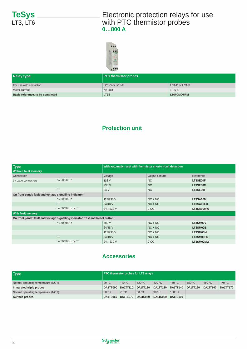
Relay type PTC thermistor probes
For use with contactor LC�-D or LC�-F LC�-D or LC�-FMotor current No limit �…5 ABasic reference, to be completed LT3S LT6P0M0•5FM
Protection unit
Type With automatic reset with thermistor short-circuit detectionWithout fault memoryConnection Voltage Output contact Referenceby cage connectors a 50/60 Hz ��5 V NC LT3SE00F
230 V NC LT3SE00Mc 24 V NC LT3SE00F
On front panel: fault and voltage signalling indicatora 50/60 Hz ��5/230 V NC + NO LT3SA00Mc 24/48 V NC + NO LT3SA00EDa 50/60 Hz or c 24…230 V 2 CO LT3SA00MW
With fault memoryOn front panel: fault and voltage signalling indicator, Test and Reset button
a 50/60 Hz 400 V NC + NO LT3SM00V24/48 V NC + NO LT3SM00E��5/230 V NC + NO LT3SM00M
c 24/48 V NC + NO LT3SM00EDa 50/60 Hz or c 24…230 V 2 CO LT3SM00MW
Accessories
Type PTC thermistor probes for LT3 relays
Normal operating temperature (NOT) 90 °C 110 °C 120 °C 130 °C 140 °C 150 °C 160 °C 170 °CIntegrated triple probes DA1TT090 DA1TT110 DA1TT120 DA1TT130 DA1TT140 DA1TT150 DA1TT160 DA1TT170Normal operating temperature (NOT) 60 °C 70 °C 80 °C 90 °C 100 °CSurface probes DA1TS060 DA1TS070 DA1TS080 DA1TS090 DA1TS100
30
�/L�
2/T�
3/L2
4/T2
5/L3
6/T3
�/L�
2/T�
3/L2
4/T2
5/L3
6/T3
�/L�
2/T�
3/L2
4/T2
5/L3
6/T3
�/L�
2/T�
3/L2
4/T2
5/L3
6/T3
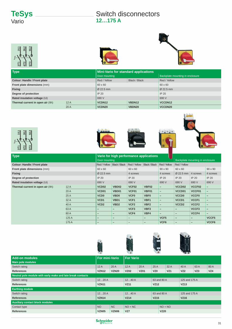
Switch disconnectors12…175 A
Type Mini-Vario for standard applicationsDoor mounting Backplate mounting in enclosure
Colour: Handle / Front plate Red / Yellow Black / Black Red / YellowFront plate dimensions (mm) 60 x 60 60 x 60Fixing Ø 22.5 mm Ø 22.5 mmDegree of protection IP 20 IP 20Rated insulation voltage (Ui) 690 V 690 VThermal current in open air (Ith) �2 A VCDN12 VBDN12 VCCDN12
20 A VCDN20 VBDN20 VCCDN20
Type Vario for high performance applicationsDoor mounting Backplate mounting in enclosure
Colour: Handle / Front plate Red / Yellow Black / Black Red / Yellow Black / Black Red / Yellow Red / YellowFront plate dimensions (mm) 60 x 60 60 x 60 90 x 90 60 x 60 90 x 90Fixing Ø 22.5 mm 4 screws 4 screws Ø 22.5 mm 4 screws 4 screwsDegree of protection IP 20 IP 20 IP 20 IP 20 IP 20 IP 20Rated insulation voltage (Ui) 690 V 690 V 690 V 690 V 690 V 690 VThermal current in open air (Ith) �2 A VCD02 VBD02 VCF02 VBF02 – VCCD02 VCCF02 –
20 A VCD01 VBD01 VCF01 VBF01 – VCCD01 VCCF01 –25 A VCD0 VBD0 VCF0 VBF0 – VCCD0 VCCF0 –32 A VCD1 VBD1 VCF1 VBF1 – VCCD1 VCCF1 –40 A VCD2 VBD2 VCF2 VBF2 – VCCD2 VCCF2 –63 A – – VCF3 VBF3 – – VCCF3 –80 A – – VCF4 VBF4 – – VCCF4 –�25 A – – – – VCF5 – – VCCF5�75 A – – – – VCF6 – – VCCF6
Add-on modules For mini-Vario For VarioMain pole modulesSwitch rating �2 A 20 A �2 A 20 A 25 A 32 A 40 A 63 A 80 AReferences VZN12 VZN20 VZ02 VZ01 VZ0 VZ1 VZ2 VZ3 VZ4Neutral pole module with early make and late break contactsSwitch rating �2…20 A �2…40 A 63 and 80 A �25 and �75 AReferences VZN11 VZ11 VZ12 VZ13Earthing moduleSwitch rating �2…20 A �2…40 A 63 and 80 A �25 and �75 AReferences VZN14 VZ14 VZ15 VZ16Auxiliary contact block modulesContact type NO NC NO + NC NO + NOReferences VZN05 VZN06 VZ7 VZ20
TeSysVario
3�
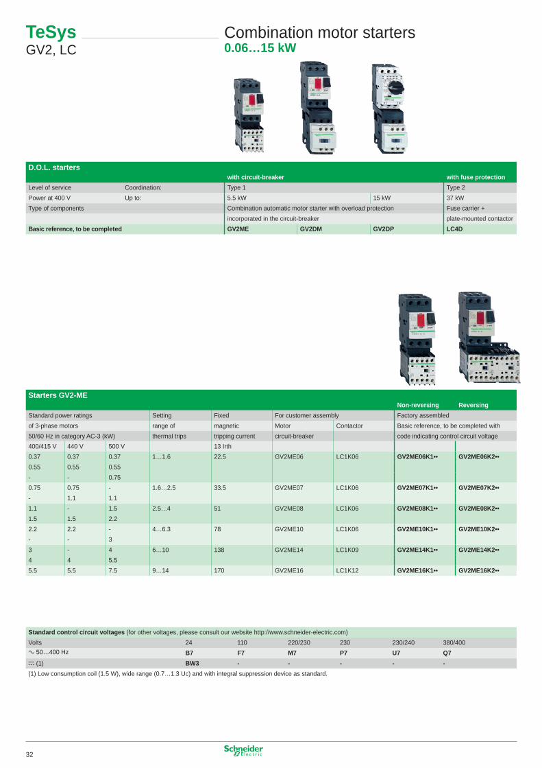
Starters GV2-MENon-reversing Reversing
Standard power ratings Setting Fixed For customer assembly Factory assembledof 3-phase motors range of magnetic Motor Contactor Basic reference, to be completed with50/60 Hz in category AC-3 (kW) thermal trips tripping current circuit-breaker code indicating control circuit voltage400/4�5 V 440 V 500 V �3 Irth0.37 0.37 0.37 �…�.6 22.5 GV2ME06 LC�K06 GV2ME06K1•• GV2ME06K2••0.55 0.55 0.55- - 0.750.75 0.75 - �.6…2.5 33.5 GV2ME07 LC�K06 GV2ME07K1•• GV2ME07K2••- �.� �.��.� - �.5 2.5…4 5� GV2ME08 LC�K06 GV2ME08K1•• GV2ME08K2••�.5 �.5 2.22.2 2.2 - 4…6.3 78 GV2ME�0 LC�K06 GV2ME10K1•• GV2ME10K2••- - 33 - 4 6…�0 �38 GV2ME�4 LC�K09 GV2ME14K1•• GV2ME14K2••4 4 5.55.5 5.5 7.5 9…�4 �70 GV2ME�6 LC�K�2 GV2ME16K1•• GV2ME16K2••
TeSys GV2, LC
Combination motor starters0.06…15 kW
D.O.L. starterswith circuit-breaker with fuse protection
Level of service Coordination: Type � Type 2Power at 400 V Up to: 5.5 kW �5 kW 37 kWType of components Combination automatic motor starter with overload protection Fuse carrier +
incorporated in the circuit-breaker plate-mounted contactorBasic reference, to be completed GV2ME GV2DM GV2DP LC4D
Standard control circuit voltages (for other voltages, please consult our website http://www.schneider-electric.com)Volts 24 ��0 220/230 230 230/240 380/400a 50…400 Hz B7 F7 M7 P7 U7 Q7c (�) BW3 - - - - -(�) Low consumption coil (�.5 W), wide range (0.7…�.3 Uc) and with integral suppression device as standard.
32
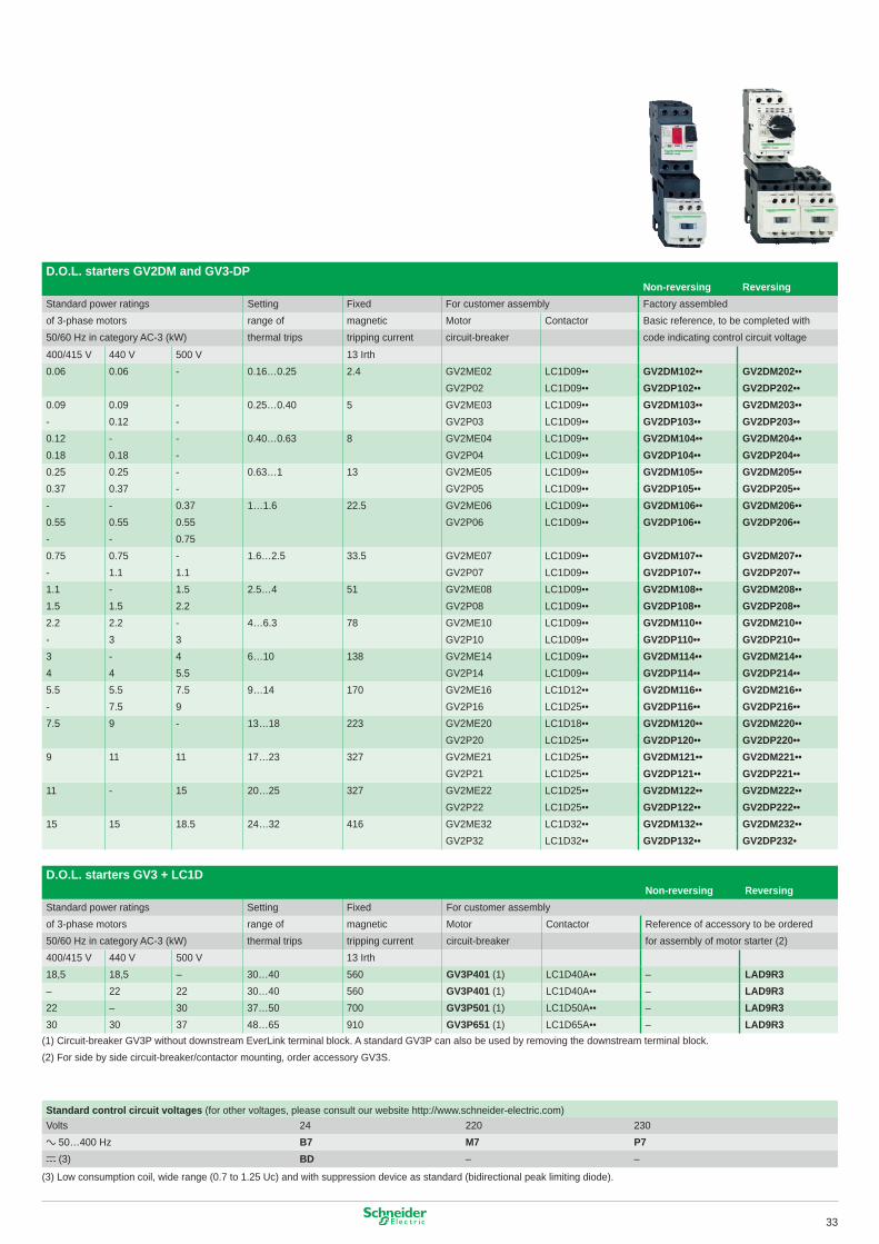
D.O.L. starters GV2DM and GV3-DPNon-reversing Reversing
Standard power ratings Setting Fixed For customer assembly Factory assembledof 3-phase motors range of magnetic Motor Contactor Basic reference, to be completed with50/60 Hz in category AC-3 (kW) thermal trips tripping current circuit-breaker code indicating control circuit voltage
400/4�5 V 440 V 500 V �3 Irth0.06 0.06 - 0.�6…0.25 2.4 GV2ME02 LC�D09•• GV2DM102•• GV2DM202••
GV2P02 LC�D09•• GV2DP102•• GV2DP202••0.09 0.09 - 0.25…0.40 5 GV2ME03 LC�D09•• GV2DM103•• GV2DM203••- 0.�2 - GV2P03 LC�D09•• GV2DP103•• GV2DP203••0.�2 - - 0.40…0.63 8 GV2ME04 LC�D09•• GV2DM104•• GV2DM204••0.�8 0.�8 - GV2P04 LC�D09•• GV2DP104•• GV2DP204••0.25 0.25 - 0.63…� �3 GV2ME05 LC�D09•• GV2DM105•• GV2DM205••0.37 0.37 - GV2P05 LC�D09•• GV2DP105•• GV2DP205••- - 0.37 �…�.6 22.5 GV2ME06 LC�D09•• GV2DM106•• GV2DM206••0.55 0.55 0.55 GV2P06 LC�D09•• GV2DP106•• GV2DP206••- - 0.750.75 0.75 - �.6…2.5 33.5 GV2ME07 LC�D09•• GV2DM107•• GV2DM207••- �.� �.� GV2P07 LC�D09•• GV2DP107•• GV2DP207••�.� - �.5 2.5…4 5� GV2ME08 LC�D09•• GV2DM108•• GV2DM208••�.5 �.5 2.2 GV2P08 LC�D09•• GV2DP108•• GV2DP208••2.2 2.2 - 4…6.3 78 GV2ME�0 LC�D09•• GV2DM110•• GV2DM210••- 3 3 GV2P�0 LC�D09•• GV2DP110•• GV2DP210••3 - 4 6…�0 �38 GV2ME�4 LC�D09•• GV2DM114•• GV2DM214••4 4 5.5 GV2P�4 LC�D09•• GV2DP114•• GV2DP214••5.5 5.5 7.5 9…�4 �70 GV2ME�6 LC�D�2•• GV2DM116•• GV2DM216••- 7.5 9 GV2P�6 LC�D25•• GV2DP116•• GV2DP216••7.5 9 - �3…�8 223 GV2ME20 LC�D�8•• GV2DM120•• GV2DM220••
GV2P20 LC�D25•• GV2DP120•• GV2DP220••9 �� �� �7…23 327 GV2ME2� LC�D25•• GV2DM121•• GV2DM221••
GV2P2� LC�D25•• GV2DP121•• GV2DP221••�� - �5 20…25 327 GV2ME22 LC�D25•• GV2DM122•• GV2DM222••
GV2P22 LC�D25•• GV2DP122•• GV2DP222••�5 �5 �8.5 24…32 4�6 GV2ME32 LC�D32•• GV2DM132•• GV2DM232••
GV2P32 LC�D32•• GV2DP132•• GV2DP232•
Standard control circuit voltages (for other voltages, please consult our website http://www.schneider-electric.com)Volts 24 220 230a 50…400 Hz B7 M7 P7c (3) BD – –
(3) Low consumption coil, wide range (0.7 to �.25 Uc) and with suppression device as standard (bidirectional peak limiting diode).
D.O.L. starters GV3 + LC1DNon-reversing Reversing
Standard power ratings Setting Fixed For customer assemblyof 3-phase motors range of magnetic Motor Contactor Reference of accessory to be ordered50/60 Hz in category AC-3 (kW) thermal trips tripping current circuit-breaker for assembly of motor starter (2)400/4�5 V 440 V 500 V �3 Irth�8,5 �8,5 – 30…40 560 GV3P401 (�) LC�D40A•• – LAD9R3– 22 22 30…40 560 GV3P401 (�) LC�D40A•• – LAD9R322 – 30 37…50 700 GV3P501 (�) LC�D50A•• – LAD9R330 30 37 48…65 9�0 GV3P651 (�) LC�D65A•• – LAD9R3
(�) Circuit-breaker GV3P without downstream EverLink terminal block. A standard GV3P can also be used by removing the downstream terminal block.(2) For side by side circuit-breaker/contactor mounting, order accessory GV3S.
33
+
+
+
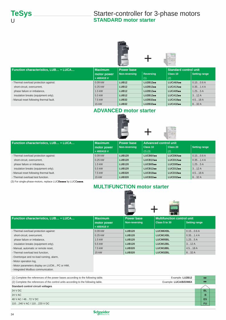
TeSys U
Starter-controller for 3-phase motorsSTANDARD motor starter
Function characteristics, LUB… + LUCA… Maximum Power base Standard control unitmotor power Non-reversing Reversing Class 10 Setting range< 400/415 V (�) (2)
- Thermal overload protection against: 0.09 kW LUB12 LU2B12pp LUCA6Xpp 0.�5…0.6 Ashort-circuit, overcurrent, 0.25 kW LUB12 LU2B12pp LUCA1Xpp 0.35…�.4 Aphase failure or imbalance, �.5 kW LUB12 LU2B12pp LUCA05pp �.25…5 Ainsulation breaks (equipment only). 5.5 kW LUB12 LU2B12pp LUCA12pp 3…�2 A
- Manual reset following thermal fault. 7.5 kW LUB32 LU2B32pp LUCA18pp 4.5…�8 A�5 kW LUB32 LU2B32pp LUCA32pp 8…32 A
Function characteristics, LUB… + LUCA… Maximum Power base Advanced control unitmotor power Non-reversing Class 10 Class 20 Setting range< 400/415 V (2) (3) (2)
- Thermal overload protection against: 0.09 kW LUB120 LUCB6Xpp LUCD6Xpp 0.�5…0.6 Ashort-circuit, overcurrent, 0.25 kW LUB120 LUCB1Xpp LUCD1Xpp 0.35…�.4 Aphase failure or imbalance, �.5 kW LUB120 LUCB05pp LUCD05pp �.25…5 Ainsulation breaks (equipment only). 5.5 kW LUB120 LUCB12pp LUCD12pp 3…�2 A
- Manual reset following thermal fault. 7.5 kW LUB320 LUCB18pp LUCD18pp 4.5…�8 A- Thermal overload test function. �5 kW LUB320 LUCB32pp LUCD32pp 8…32 A
(3) For single-phase-motors, replace LUCBpppp by LUCCpppp.
Function characteristics, LUB… + LUCA…
- Thermal overload protection against:short-circuit, overcurrent,phase failure or imbalance,insulation breaks (equipment only).
- Manual, automatic or remote reset, - Thermal overload test function, - Overtorque and no-load running, alarm, - Motor operation log, - Motor parameters display on LUCM.., PC or HMI,- Integrated Modbus communication.
Maximum Power base Multifunction control unitmotor power Non-reversing Class 5 to 30 Setting range < 400/415 V0.09 kW LUB120 LUCM6XBL 0.�5…0.6 A0.25 kW LUB120 LUCM1XBL 0.35…�.4 A�.5 kW LUB120 LUCM05BL �.25…5 A5.5 kW LUB120 LUCM12BL 3…�2 A7.5 kW LUB320 LUCM18BL 4.5…�8 A�5 kW LUB320 LUCM32BL 8…32 A
(�) Complete the references of the power bases according to the following table. Example: LU2B12 pp
(2) Complete the references of the control units according to the following table. Example: LUCA/B/D/M6X pp
Standard control circuit voltages24 V DC BL24 V AC B48 V AC / 48…72 V DC ES��0…240 V AC / ��0…220 V DC FU
ADVANCED motor starter
MULTIFUNCTION motor starter
34
Communication modules
Contact blocks
TeSys U
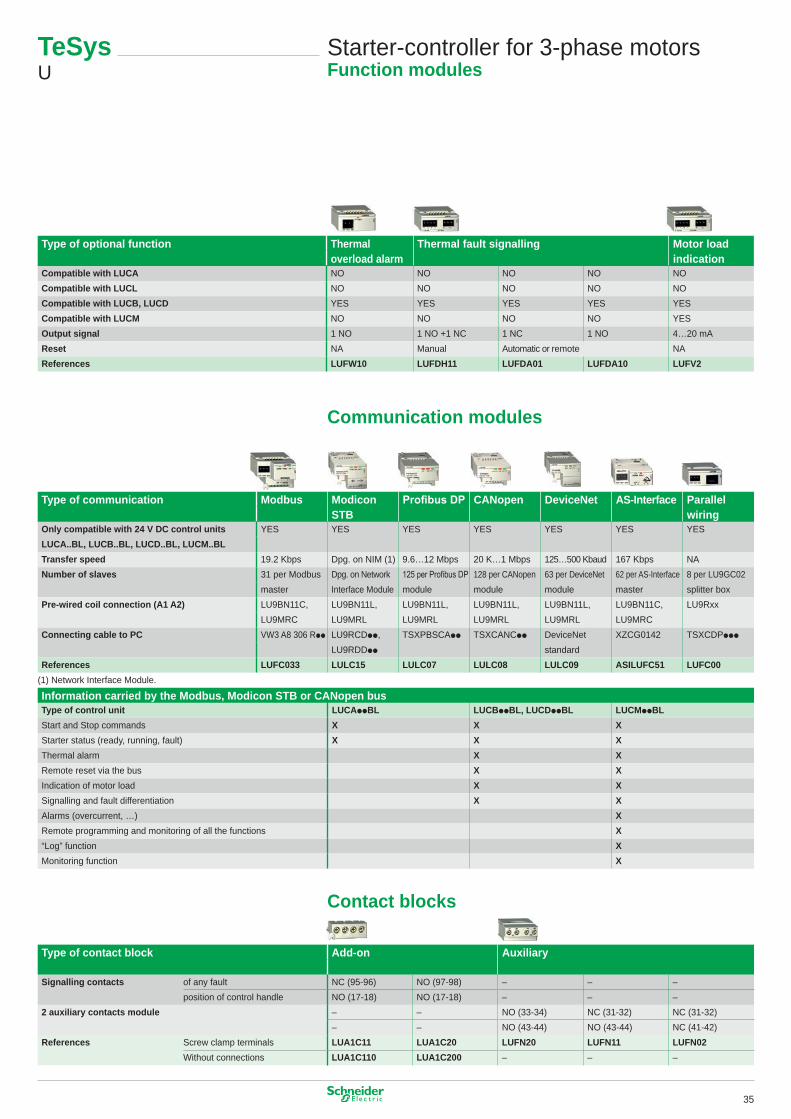
Starter-controller for 3-phase motorsFunction modules
Type of optional function Thermal Thermal fault signalling Motor loadoverload alarm indication
Compatible with LUCA NO NO NO NO NOCompatible with LUCL NO NO NO NO NOCompatible with LUCB, LUCD YES YES YES YES YESCompatible with LUCM NO NO NO NO YESOutput signal � NO � NO +� NC � NC � NO 4…20 mAReset NA Manual Automatic or remote NAReferences LUFW10 LUFDH11 LUFDA01 LUFDA10 LUFV2
Type of communication Modbus Modicon Profibus DP CANopen DeviceNet AS-Interface ParallelSTB wiring
Only compatible with 24 V DC control units YES YES YES YES YES YES YESLUCA..BL, LUCB..BL, LUCD..BL, LUCM..BLTransfer speed �9.2 Kbps Dpg. on NIM (�) 9.6…�2 Mbps 20 K…� Mbps �25…500 Kbaud �67 Kbps NANumber of slaves 3� per Modbus Dpg. on Network 125 per Profibus DP �28 per CANopen 63 per DeviceNet 62 per AS-Interface 8 per LU9GC02
master Interface Module module module module master splitter boxPre-wired coil connection (A1 A2) LU9BN��C, LU9BN��L, LU9BN��L, LU9BN��L, LU9BN��L, LU9BN��C, LU9Rxx
LU9MRC LU9MRL LU9MRL LU9MRL LU9MRL LU9MRCConnecting cable to PC VW3 A8 306 Rpp LU9RCDpp, TSXPBSCApp TSXCANCpp DeviceNet XZCG0�42 TSXCDPppp
LU9RDDpp standardReferences LUFC033 LULC15 LULC07 LULC08 LULC09 ASILUFC51 LUFC00
(�) Network Interface Module.
Information carried by the Modbus, Modicon STB or CANopen busType of control unit LUCAppBL LUCBppBL, LUCDppBL LUCMppBLStart and Stop commands X X XStarter status (ready, running, fault) X X XThermal alarm X XRemote reset via the bus X XIndication of motor load X XSignalling and fault differentiation X XAlarms (overcurrent, …) XRemote programming and monitoring of all the functions X“Log” function XMonitoring function X
Type of contact block Add-on Auxiliary
Signalling contacts of any fault NC (95-96) NO (97-98) – – –position of control handle NO (�7-�8) NO (�7-�8) – – –
2 auxiliary contacts module – – NO (33-34) NC (3�-32) NC (3�-32)– – NO (43-44) NO (43-44) NC (4�-42)
References Screw clamp terminals LUA1C11 LUA1C20 LUFN20 LUFN11 LUFN02Without connections LUA1C110 LUA1C200 – – –
35

= +
TeSys GV3L
TeSys LC1DContactor
Circuit-breakersTeSys GV3L
TeSys LC1DContactor
Circuit-breakers
Current transformers
ADVANCED protection
+
TeSys LUTM
Controller for 3-phase motorsMULTIFUNCTION protection
Function characteristics Control base for use Multifunctionwith contactors control unitTeSys D (LC1D..) TeSys F (LC1F..) Class 5 to 35
- Thermal overload protection against: LUTM10BL LUTM20BL LUCMT1BLshort-circuit, overcurrent,phase failure or imbalance,insulation breaks (equipment only).
- Manual, automatic or remote reset,- Thermal overload test function,- Overtorque and no-load running, alarm,- Motor operation log,- Motor parameters display on LUCM.., PC or HMI,- Integrated Modbus communication.
Function characteristics Control base for use Advancedwith contactors control unitTeSys D (LC1D..) TeSys F (LC1F..) Class 10 Class 20
- Thermal overload protection against: LUTM10BL LUTM20BL LUCBT1BL LUCDT1BLshort-circuit, overcurrent,phase failure or imbalance,insulation breaks (equipment only).
- Manual reset following thermal fault.- Thermal overload test function.
Type of transformer
Supply voltage 24 V DCOperating current Primary 30 A 50 A �00 A 200 A 400 A 800 A
Secondary � AReferences LUTC0301 LUTC0501 LUTC01001 LUTC02001 LUTC04001 LUTC05001
Above 32 A, the TeSys U controller provides a motor starter management system solution identical to that provided by the TeSys U starter-controller.Used in conjunction with a short-circuit protection device and a contactor, it provides a motor starter whose functions are the same as those of a TeSys U starter-controllerand, in particular, provides the following functions: overload protection, motor starter control and application monitoring.It comprises a control unit, whose adjustment range is compatible with the secondary of current transformers, and a control base that also enables the fitting of a function module orcommunication module.It requires a 24 V DC external power supply.
36

=+
Communication modules
TeSys rotating handles for TeSys UIP54 kit black handle LU9APN21IP54 kit red handle and yellow front LU9APN22IP65 kit red handle and yellow front LU9APN24
TeSys LUTM
Controller for 3-phase motorsFunction modules
Type of optional function Thermal overload alarm Motor load indication
Compatible with LUCA NO NOCompatible with LUCL NO NOCompatible with LUCB, LUCD YES YESCompatible with LUCM NO YESOutput signal � NO 4…20 mAReset NA NAReferences LUFW10 LUFV2
Type of communication Modbus Modicon STB CANopen DeviceNet Parallelwiring
Only compatible with 24 V DC control units YES YES YES YES YESLUCA..BL, LUCB..BL, LUCD..BL, LUCM..BLTransfer speed �9.2 Kbps Dpg. on NIM (�) 20 K…� Mbps �25…500 Kbaud NANumber of slaves 3� per Modbus Dpg. on Network �28 per CANopen 63 per DeviceNet 8 per LU9GC02
master Interface Module module module splitter boxPre-wired coil connection (A1 A2) LU9BN��C, LU9BN��L, LU9BN��L, LU9BN��L, LU9Rxx
LU9MRC LU9MRL LU9MRL LU9MRLConnecting cable to PC VW3 A8 306 Rpp LU9RCDpp TSXCANCpp DeviceNet TSXCDPppp
LU9RDDpp standardReferences LUFC033 LULC15 LULC08 LULC09 LUFC00
(�) Transmission speed depending on the Network Interface Module.
Information carried by the Modbus, Modicon STB or CANopen busType of control unit LUCBT1BL, LUCDT1BL LUCMT1BLStart and Stop commands X XStarter status (ready, running, fault) X XThermal alarm X XRemote reset via the bus X XIndication of motor load X XSignalling and fault differentiation X XAlarms (overcurrent, …) XRemote programming and monitoring of all the functions X“Log” function XMonitoring function X
37
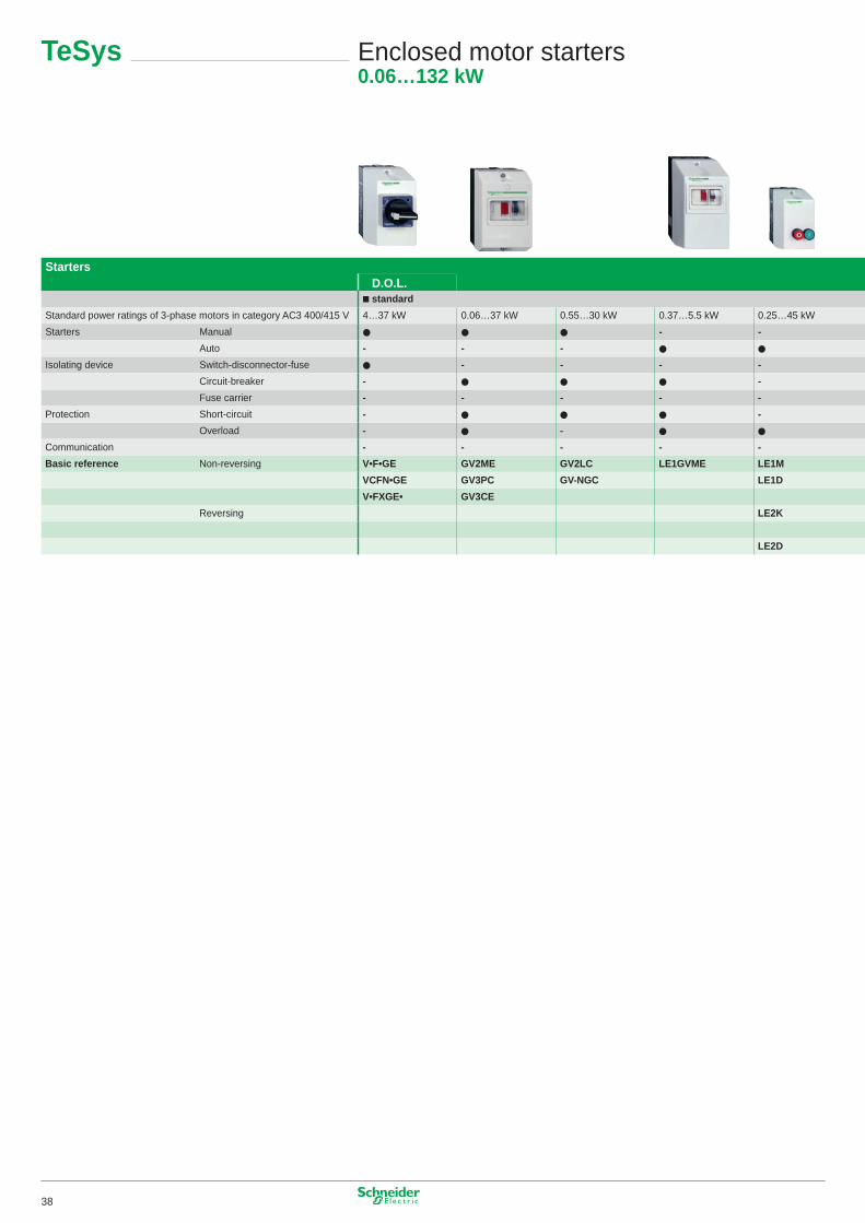
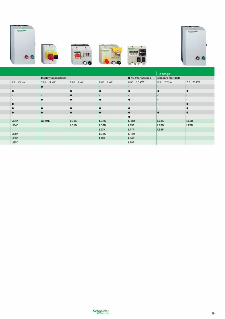
Starters■ D.O.L.■ standard
Standard power ratings of 3-phase motors in category AC3 400/4�5 V 4…37 kW 0.06…37 kW 0.55…30 kW 0.37…5.5 kW 0.25…45 kWStarters Manual ● ● ● - -
Auto - - - ● ●
Isolating device Switch-disconnector-fuse ● - - - -Circuit-breaker - ● ● ● -Fuse carrier - - - - -
Protection Short-circuit - ● ● ● -Overload - ● - ● ●
Communication - - - - -Basic reference Non-reversing V•F•GE GV2ME GV2LC LE1GVME LE1M
VCFN•GE GV3PC GV-NGC LE1DV•FXGE• GV3CE
Reversing LE2K
LE2D
TeSys Enclosed motor starters0.06…132 kW
■ 2 stage■ safety applications ■ AS-Interface bus standard star-delta
2.2…45 kW 0.06…�� kW 0.06…9 kW 0.06…9 kW 0.06…5.5 kW 5.5…�32 kW 7.5…75 kW- ● - - - - -● - ● ● ● ● ●
- - ● - - - -- ● ● ● ● - -● - - - - - ●
● ● ● ● ● - ●
● ● ● ● ● ● ●
- - - - ● - -LE4K GV2ME LG1K LG7K LF3M LE3K LE6DLE4D LG1D LG7D LF3P LE3D LE3D
LJ7K LF7P LE3FLE8K LG8K LF4MLE8D LJ8K LF4PLE2D LF8P
38
Starters■ D.O.L.■ standard
Standard power ratings of 3-phase motors in category AC3 400/4�5 V 4…37 kW 0.06…37 kW 0.55…30 kW 0.37…5.5 kW 0.25…45 kWStarters Manual ● ● ● - -
Auto - - - ● ●
Isolating device Switch-disconnector-fuse ● - - - -Circuit-breaker - ● ● ● -Fuse carrier - - - - -
Protection Short-circuit - ● ● ● -Overload - ● - ● ●
Communication - - - - -Basic reference Non-reversing V•F•GE GV2ME GV2LC LE1GVME LE1M
VCFN•GE GV3PC GV-NGC LE1DV•FXGE• GV3CE
Reversing LE2K
LE2D
■ 2 stage■ safety applications ■ AS-Interface bus standard star-delta
2.2…45 kW 0.06…�� kW 0.06…9 kW 0.06…9 kW 0.06…5.5 kW 5.5…�32 kW 7.5…75 kW- ● - - - - -● - ● ● ● ● ●
- - ● - - - -- ● ● ● ● - -● - - - - - ●
● ● ● ● ● - ●
● ● ● ● ● ● ●
- - - - ● - -LE4K GV2ME LG1K LG7K LF3M LE3K LE6DLE4D LG1D LG7D LF3P LE3D LE3D
LJ7K LF7P LE3FLE8K LG8K LF4MLE8D LJ8K LF4PLE2D LF8P
39
For more information:
http://www.schneider-electric.com
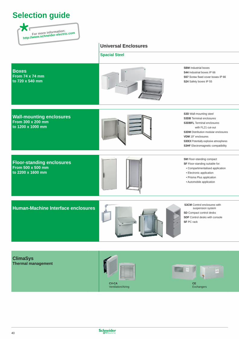
Selection guide
Universal Enclosures
Spacial Steel
BoxesFrom 74 x 74 mmto 720 x 540 mm
Wall-mounting enclosuresFrom 300 x 200 mmto 1200 x 1000 mm
Floor-standing enclosuresFrom 500 x 500 mmto 2200 x 1600 mm
Human-Machine Interface enclosures
ClimaSys Thermal management
SBM Industrial boxesS44 Industrial boxes IP 66S57 Screw fixed cover boxes IP 66S24 Safety boxes IP 55
S3D Wall-mounting steelS3DB Terminal enclosuresS3DBFL Terminal enclosures
with FL2� cut-outS3DM Distribution modular enclosuresVDM �9” enclosuresS3DEX Potentially explosive atmospheresS3HF Electromagnetic compatibility
SM Floor-standing compactSF Floor-standing suitable for:
• Compartimentalised application• Electronic application• Prisma Plus application• Automobile application
S3CM Control enclosures with suspension system
SD Compact control desksSDF Control desks with consoleSF PC rack
CV-CA Ventilation/Airing
CE Exchangers
40
Selection guide
Universal Enclosures
Spacial Steel
BoxesFrom 74 x 74 mmto 720 x 540 mm
Wall-mounting enclosuresFrom 300 x 200 mmto 1200 x 1000 mm
Floor-standing enclosuresFrom 500 x 500 mmto 2200 x 1600 mm
Human-Machine Interface enclosures
ClimaSys Thermal management
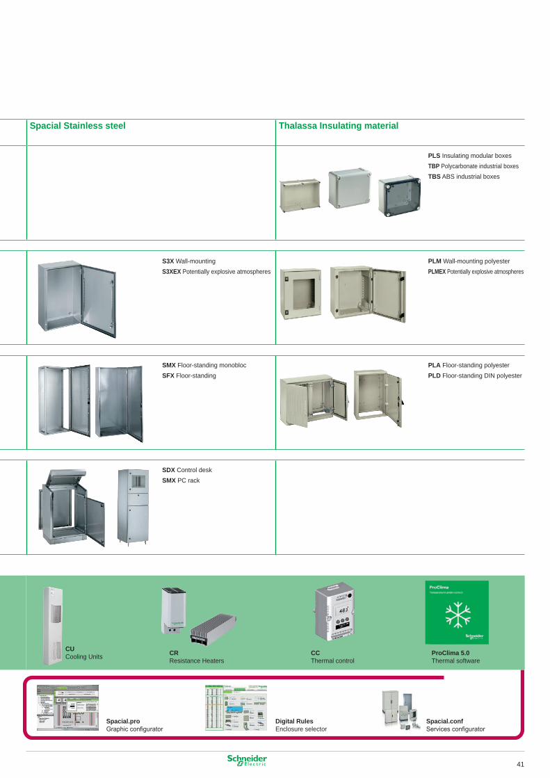
Spacial Stainless steel Thalassa Insulating material
CU Cooling Units CR
Resistance HeatersCC Thermal control
ProClima 5.0 Thermal software
PLS Insulating modular boxesTBP Polycarbonate industrial boxesTBS ABS industrial boxes
PLM Wall-mounting polyesterPLMEX Potentially explosive atmospheres
PLA Floor-standing polyesterPLD Floor-standing DIN polyester
Spacial.proGraphic configurator
Digital RulesEnclosure selector
Spacial.confServices configurator
S3X Wall-mountingS3XEX Potentially explosive atmospheres
SMX Floor-standing monoblocSFX Floor-standing
SDX Control desk SMX PC rack
4�
FH
FT
FM
HK
For more information:
http://www.schneider-electric.com
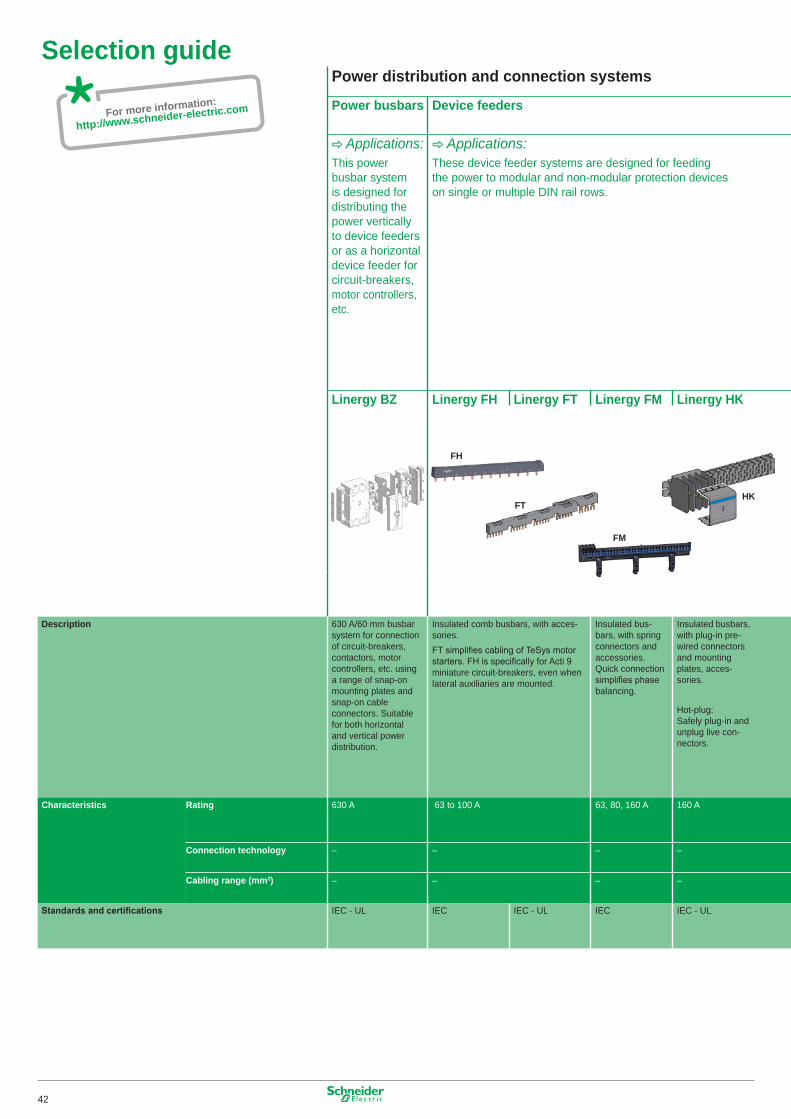
Selection guidePower distribution and connection systems
Power busbars Device feeders
C Applications:This power busbar system is designed for distributing the power vertically to device feeders or as a horizontal device feeder for circuit-breakers, motor controllers, etc.
C Applications:These device feeder systems are designed for feeding the power to modular and non-modular protection devices on single or multiple DIN rail rows.
Linergy BZ Linergy FH Linergy FT Linergy FM Linergy HK
Description 630 A/60 mm busbar system for connection of circuit-breakers, contactors, motor controllers, etc. using a range of snap-on mounting plates and snap-on cable connectors. Suitable for both horizontal and vertical power distribution.
Insulated comb busbars, with acces-sories.FT simplifies cabling of TeSys motor starters. FH is specifically for Acti 9 miniature circuit-breakers, even when lateral auxiliaries are mounted.
Insulated bus-bars, with spring connectors and accessories. Quick connection simplifies phase balancing.
Insulated busbars, with plug-in pre-wired connectors and mounting plates, acces-sories.
Hot-plug: Safely plug-in and unplug live con-nectors.
Characteristics Rating 630 A 63 to �00 A 63, 80, �60 A �60 A
Connection technology – – – –
Cabling range (mm2) – – – –
Standards and certifications IEC - UL IEC IEC - UL IEC IEC - UL
42
Selection guidePower distribution and connection systems
Power busbars Device feeders
C Applications:This power busbar system is designed for distributing the power vertically to device feeders or as a horizontal device feeder for circuit-breakers, motor controllers, etc.
C Applications:These device feeder systems are designed for feeding the power to modular and non-modular protection devices on single or multiple DIN rail rows.
Linergy BZ Linergy FH Linergy FT Linergy FM Linergy HK
Description 630 A/60 mm busbar system for connection of circuit-breakers, contactors, motor controllers, etc. using a range of snap-on mounting plates and snap-on cable connectors. Suitable for both horizontal and vertical power distribution.
Insulated comb busbars, with acces-sories.FT simplifies cabling of TeSys motor starters. FH is specifically for Acti 9 miniature circuit-breakers, even when lateral auxiliaries are mounted.
Insulated bus-bars, with spring connectors and accessories. Quick connection simplifies phase balancing.
Insulated busbars, with plug-in pre-wired connectors and mounting plates, acces-sories.
Hot-plug: Safely plug-in and unplug live con-nectors.
Characteristics Rating 630 A 63 to �00 A 63, 80, �60 A �60 A
Connection technology – – – –
Cabling range (mm2) – – – –
Standards and certifications IEC - UL IEC IEC - UL IEC IEC - UL
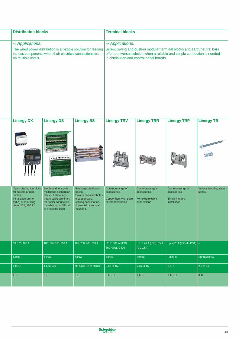
Distribution blocks Terminal blocks
C Applications:The wired power distribution is a flexible solution for feeding various components when their electrical connections are on multiple levels.
C Applications:Screw, spring and push-in modular terminal blocks and earth/neutral bars offer a universal solution when a reliable and simple connection is needed in distribution and control panel boards.
Linergy DX Linergy DS Linergy BS Linergy TRV Linergy TRR Linergy TRP Linergy TB
Quick distribution block, for flexible or rigid cables.Installation on rail (63 A) or mounting plate (�25, �60 A)
Single and four pole multistage distribution blocks. Lateral ups-tream cable terminals for easier connection.Installation on DIN rail or mounting plate
Multistage distribution blocks.Plain or threaded holes in copper bars.Cabling accessories.Horizontal or vertical mounting.
Common range of accessories
Copper bars with plain or threaded holes.
Common range of accessories
For extra reliable connections
Common range of accessories
Single-handed installation
Various lengths, acces-sories.
63, �25, �60 A �00, �25, �60, 250 A �60, 250, 400, 630 A Up to 309 A (IEC), 300 A (UL-CSA)
Up to 76 A (IEC), 85 A (UL-CSA)
Up to 20 A (IEC-UL-CSA) –
Spring Screw Screw Screw Spring Push-in Spring/screw
6 to �6 �.5 to �20 M6 holes, �6 to 50 mm² 0.�8 to �50 0.�6 to �6 2.5, 4 2.5 to �6
IEC IEC IEC IEC - UL IEC - UL IEC - UL IEC
43
For more information:
http://www.schneider-electric.com
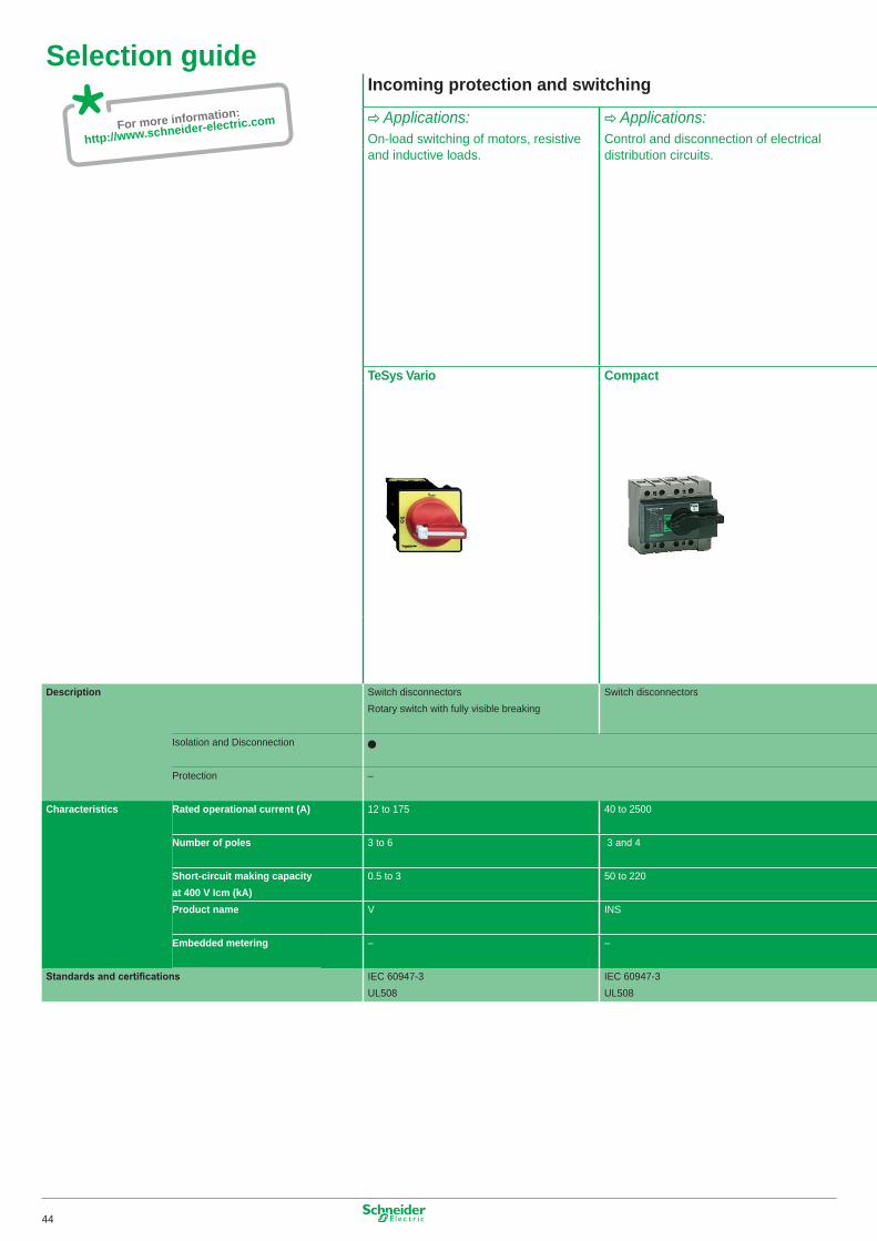
Selection guideIncoming protection and switching
C Applications:On-load switching of motors, resistive and inductive loads.
C Applications:Control and disconnection of electrical distribution circuits.
TeSys Vario Compact
Description Switch disconnectorsRotary switch with fully visible breaking
Switch disconnectors
Isolation and Disconnection
Protection –
Characteristics Rated operational current (A) �2 to �75 40 to 2500
Number of poles 3 to 6 3 and 4
Short-circuit making capacity at 400 V Icm (kA)
0.5 to 3 50 to 220
Product name V INS
Embedded metering – –
Standards and certifications
IEC 60947-3UL508
IEC 60947-3UL508
44
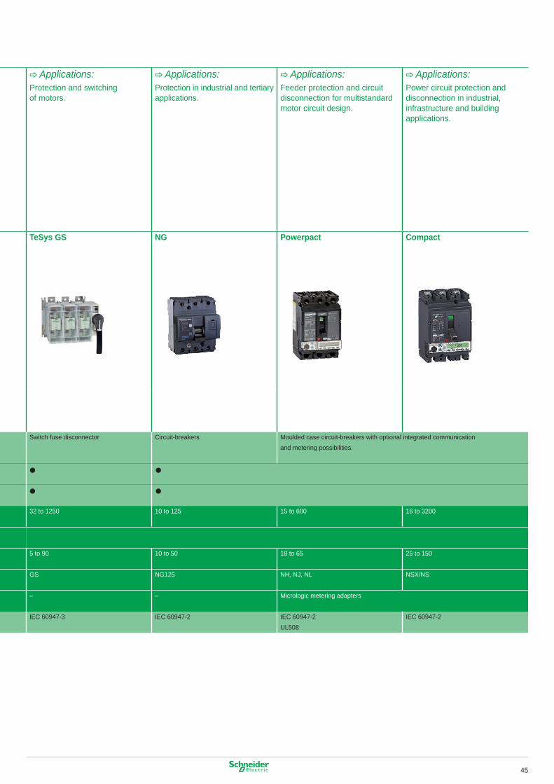
Selection guideIncoming protection and switching
C Applications:On-load switching of motors, resistive and inductive loads.
C Applications:Control and disconnection of electrical distribution circuits.
TeSys Vario Compact
Description Switch disconnectorsRotary switch with fully visible breaking
Switch disconnectors
Isolation and Disconnection
Protection –
Characteristics Rated operational current (A) �2 to �75 40 to 2500
Number of poles 3 to 6 3 and 4
Short-circuit making capacity at 400 V Icm (kA)
0.5 to 3 50 to 220
Product name V INS
Embedded metering – –
Standards and certifications
IEC 60947-3UL508
IEC 60947-3UL508
C Applications:Protection and switching of motors.
C Applications:Protection in industrial and tertiary applications.
C Applications:Feeder protection and circuit disconnection for multistandard motor circuit design.
C Applications:Power circuit protection and disconnection in industrial, infrastructure and building applications.
TeSys GS NG Powerpact Compact
Switch fuse disconnector Circuit-breakers Moulded case circuit-breakers with optional integrated communication and metering possibilities.
32 to �250 �0 to �25 �5 to 600 �6 to 3200
5 to 90 �0 to 50 �8 to 65 25 to �50
GS NG�25 NH, NJ, NL NSX/NS
– – Micrologic metering adapters
IEC 60947-3 IEC 60947-2 IEC 60947-2UL508
IEC 60947-2
45
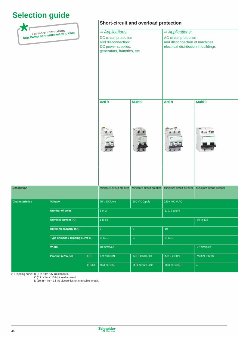
For more information:
http://www.schneider-electric.com
Selection guideShort-circuit and overload protection
C Applications:DC circuit protection and disconnection: DC power supplies, generators, batteries, etc.
C Applications:AC circuit protection and disconnection of machines, electrical distribution in buildings.
Acti 9 Multi 9 Acti 9 Multi 9
Description Miniature circuit-breaker Miniature circuit-breaker Miniature circuit-breaker Miniature circuit-breaker
Characteristics Voltage 60 V DC/pole 250 V DC/pole 230 / 400 V AC
Number of poles � or 2 �, 2, 3 and 4
Nominal current (A) � to 63 80 to �25 Breaking capacity (kA) 6 6 �0
Type of loads / Tripping curve (�) B, C, D C B, C, D
Width �8 mm/pole 27 mm/pole
Product reference IEC Acti 9 iC60N Acti 9 C60H-DC Acti 9 iC60N Multi 9 C�20N
IEC/UL Multi 9 C60N Multi 9 C60H-DC Multi 9 C60N –
(�) Tripping curve: B (3 In < Im < 5 In) standard. C (5 In < Im < �0 In) inrush current. D (�0 In < Im < �4 In) electronics or long cable length.
46
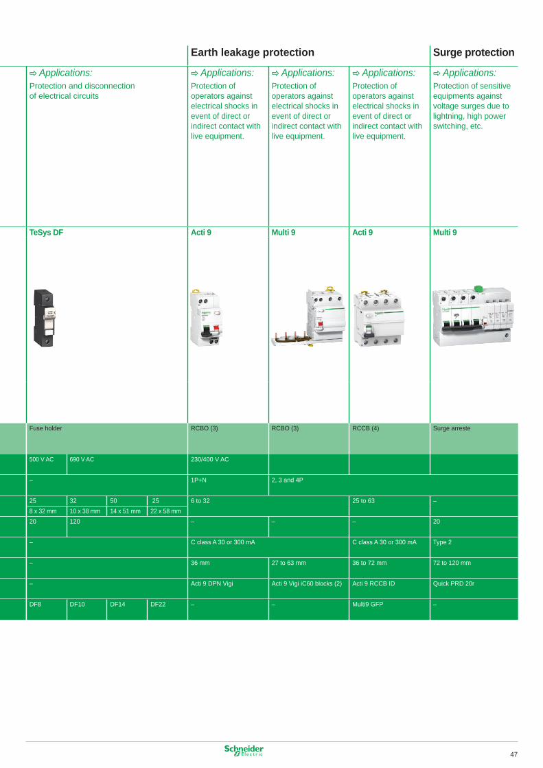
Selection guideShort-circuit and overload protection
C Applications:DC circuit protection and disconnection: DC power supplies, generators, batteries, etc.
C Applications:AC circuit protection and disconnection of machines, electrical distribution in buildings.
Acti 9 Multi 9 Acti 9 Multi 9
Description Miniature circuit-breaker Miniature circuit-breaker Miniature circuit-breaker Miniature circuit-breaker
Characteristics Voltage 60 V DC/pole 250 V DC/pole 230 / 400 V AC
Number of poles � or 2 �, 2, 3 and 4
Nominal current (A) � to 63 80 to �25 Breaking capacity (kA) 6 6 �0
Type of loads / Tripping curve (�) B, C, D C B, C, D
Width �8 mm/pole 27 mm/pole
Product reference IEC Acti 9 iC60N Acti 9 C60H-DC Acti 9 iC60N Multi 9 C�20N
IEC/UL Multi 9 C60N Multi 9 C60H-DC Multi 9 C60N –
(�) Tripping curve: B (3 In < Im < 5 In) standard. C (5 In < Im < �0 In) inrush current. D (�0 In < Im < �4 In) electronics or long cable length.
Earth leakage protection Surge protection
C Applications:Protection and disconnection of electrical circuits
C Applications:Protection of operators against electrical shocks in event of direct or indirect contact with live equipment.
C Applications:Protection of operators against electrical shocks in event of direct or indirect contact with live equipment.
C Applications:Protection of operators against electrical shocks in event of direct or indirect contact with live equipment.
C Applications:Protection of sensitive equipments against voltage surges due to lightning, high power switching, etc.
TeSys DF Acti 9 Multi 9 Acti 9 Multi 9
Fuse holder RCBO (3) RCBO (3) RCCB (4) Surge arreste
500 V AC 690 V AC 230/400 V AC
– �P+N 2, 3 and 4P
25 32 50 25 6 to 32 25 to 63 – 8 x 32 mm �0 x 38 mm �4 x 5� mm 22 x 58 mm20 �20 – – – 20
– C class A 30 or 300 mA C class A 30 or 300 mA Type 2
– 36 mm 27 to 63 mm 36 to 72 mm 72 to �20 mm
– Acti 9 DPN Vigi Acti 9 Vigi iC60 blocks (2) Acti 9 RCCB ID Quick PRD 20r
DF8 DF�0 DF�4 DF22 – – Multi9 GFP –
47
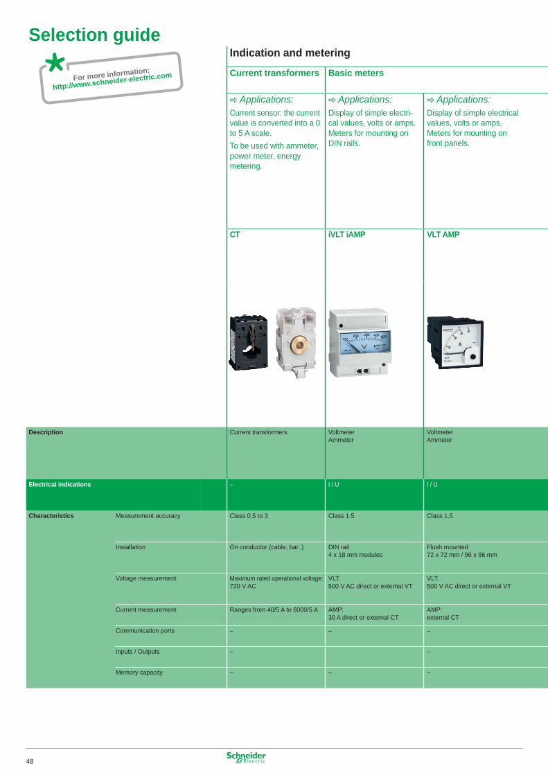
For more information:
http://www.schneider-electric.com
Selection guideIndication and metering
Current transformers Basic meters
C Applications:Current sensor: the current value is converted into a 0 to 5 A scale.To be used with ammeter, power meter, energy metering.
C Applications:Display of simple electri-cal values, volts or amps. Meters for mounting on DIN rails.
C Applications:Display of simple electrical values, volts or amps. Meters for mounting on front panels.
CT iVLT iAMP VLT AMP
Description Current transformers VoltmeterAmmeter
VoltmeterAmmeter
Electrical indications – I / U I / U
Characteristics Measurement accuracy Class 0.5 to 3 Class �.5 Class �.5
Installation On conductor (cable, bar..) DIN rail 4 x �8 mm modules
Flush mounted 72 x 72 mm / 96 x 96 mm
Voltage measurement Maximum rated operational voltage: 720 V AC
VLT: 500 V AC direct or external VT
VLT: 500 V AC direct or external VT
Current measurement Ranges from 40/5 A to 6000/5 A AMP: 30 A direct or external CT
AMP: external CT
Communication ports – – –
Inputs / Outputs – –
Memory capacity – – –
48
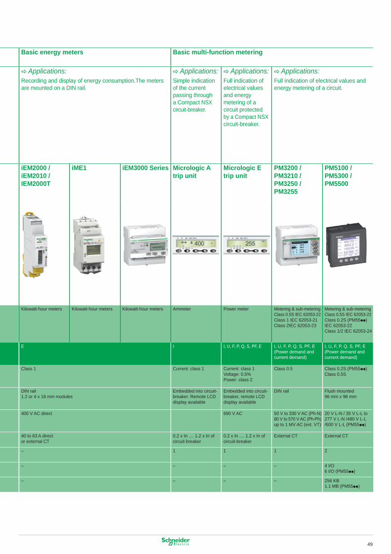
Selection guideIndication and metering
Current transformers Basic meters
C Applications:Current sensor: the current value is converted into a 0 to 5 A scale.To be used with ammeter, power meter, energy metering.
C Applications:Display of simple electri-cal values, volts or amps. Meters for mounting on DIN rails.
C Applications:Display of simple electrical values, volts or amps. Meters for mounting on front panels.
CT iVLT iAMP VLT AMP
Description Current transformers VoltmeterAmmeter
VoltmeterAmmeter
Electrical indications – I / U I / U
Characteristics Measurement accuracy Class 0.5 to 3 Class �.5 Class �.5
Installation On conductor (cable, bar..) DIN rail 4 x �8 mm modules
Flush mounted 72 x 72 mm / 96 x 96 mm
Voltage measurement Maximum rated operational voltage: 720 V AC
VLT: 500 V AC direct or external VT
VLT: 500 V AC direct or external VT
Current measurement Ranges from 40/5 A to 6000/5 A AMP: 30 A direct or external CT
AMP: external CT
Communication ports – – –
Inputs / Outputs – –
Memory capacity – – –
Basic energy meters Basic multi-function metering
C Applications:Recording and display of energy consumption.The meters are mounted on a DIN rail.
C Applications:Simple indication of the current passing through a Compact NSX circuit-breaker.
C Applications:Full indication of electrical values and energy metering of a circuit protected by a Compact NSX circuit-breaker.
C Applications:Full indication of electrical values and energy metering of a circuit.
iEM2000 / iEM2010 / IEM2000T
iME1 iEM3000 Series Micrologic A trip unit
Micrologic E trip unit
PM3200 / PM3210 / PM3250 / PM3255
PM5100 / PM5300 / PM5500
Kilowatt-hour meters Kilowatt-hour meters Kilowatt-hour meters Ammeter Power meter Metering & sub-meteringClass 0.5S IEC 62053-22Class � IEC 62053-2�Class 2IEC 62053-23
Metering & sub-meteringClass 0.5S IEC 62053-22Class 0.2S (PM55pp)IEC 62053-22Class �/2 IEC 62053-24
E I I, U, F, P, Q, S, PF, E I, U, F, P, Q, S, PF, E(Power demand andcurrent demand)
I, U, F, P, Q, S, PF, E(Power demand andcurrent demand)
Class � Current: class � Current: class �Voltage: 0.5% Power: class 2
Class 0.5 Class 0.2S (PM55pp)Class 0.5S
DIN rail�.2 or 4 x �8 mm modules
Embedded into circuit-breaker. Remote LCD display available
Embedded into circuit-breaker, remote LCD display available
DIN rail Flush mounted96 mm x 96 mm
400 V AC direct 690 V AC 50 V to 330 V AC (Ph-N)80 V to 570 V AC (Ph-Ph)up to � MV AC (ext. VT)
20 V L-N / 35 V L-L to 277 V L-N /480 V L-L/600 V L-L (PM55pp)
40 to 63 A director external CT
0.2 x In .... �.2 x In of circuit-breaker
0.2 x In .... �.2 x In of circuit-breaker
External CT External CT
– � � � 2
– – – – 4 I/O6 I/O (PM55pp)
– – – – 256 KB�.� MB (PM55pp)
49

AR
T. 0
0500
6 ©
Sch
neid
er E
lect
ric In
dust
ries
SA
S -
All
right
s re
serv
ed
04/2013
Printed on ecological paper.
The essential guideof Motor control and ProtectionHelping you easilyselect the right product
2013
35, rue Joseph MonierCS 30323F-92506 Rueil Malmaison CedexFrance
RCS Nanterre 954 503 439Capital social 896 313 776 € www.schneider-electric.com
Schneider Electric Industries SAS
As standards, specifications and designs change from time to time, please ask for confirmation of the information given in this publication.
DIA1ED2040401EN
Make the most of your energy™www.schneider-electric.com
Publishing: Schneider Electric Industries SASPhotos: Schneider Electric Industries SASPrinting:
Related Documents


