Project Bellerophon 32 4.0 Detailed Design 4.1 200g Payload 4.1.1 Vehicle Overview The launch vehicle carrying the 200 g payload (Fig. 4.1.1.1) hitches a ride on a balloon up to an altitude of 30 km where the first of three stages is ignited. At 30 km, the rocket launches in a vertical orientation from a gondola that is attached to the balloon. Once the rocket finishes burning the propellant in all three stages, the designed orbit perigee is 486 km. When random uncertainties in vehicle performance characteristics are included in the design (Monte Carlo analysis), the launch vehicle achieves an average perigee of 437 km. Fig. 4.1.1.1: Launch vehicle stack up – 200g payload. Author: Amanda Briden

Welcome message from author
This document is posted to help you gain knowledge. Please leave a comment to let me know what you think about it! Share it to your friends and learn new things together.
Transcript
Project Bellerophon 32
4.0 Detailed Design
4.1 200g Payload
4.1.1 Vehicle Overview
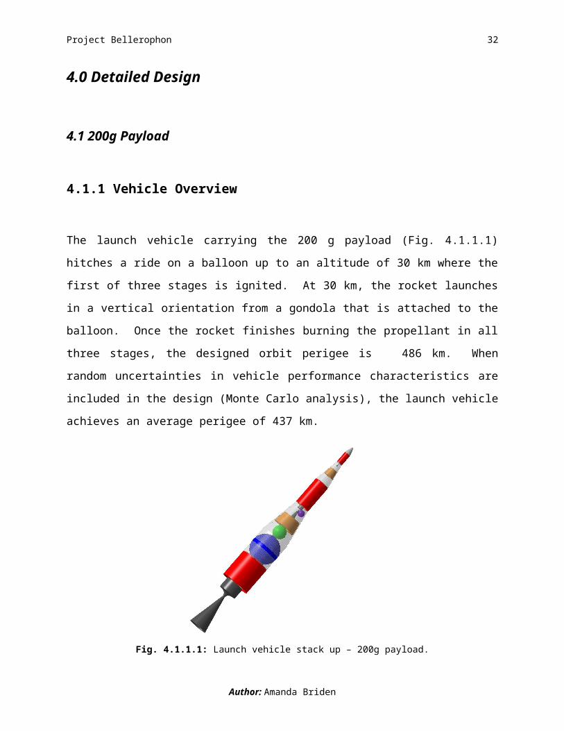
The launch vehicle carrying the 200 g payload (Fig. 4.1.1.1) hitches a ride on a balloon up to an
altitude of 30 km where the first of three stages is ignited. At 30 km, the rocket launches in a
vertical orientation from a gondola that is attached to the balloon. Once the rocket finishes
burning the propellant in all three stages, the designed orbit perigee is 486 km. When random
uncertainties in vehicle performance characteristics are included in the design (Monte Carlo
analysis), the launch vehicle achieves an average perigee of 437 km.
Fig. 4.1.1.1: Launch vehicle stack up – 200g payload.(Daniel Chua)
Author: Amanda Briden
Project Bellerophon 33
4.1.1.1 Launch System Breakdown
4.1.1.1.1 Gondola and Balloon Components
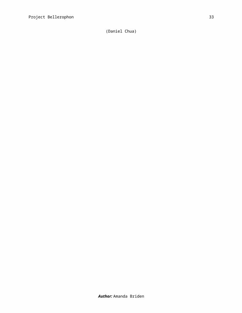
Providing support to the launch vehicle and guidance at take-off, the gondola is an all aluminum
structure. To support the launch vehicle there are three equally spaced, horizontally oriented,
rings that attach to the launch vehicle’s outer structure (Fig. 4.1.1.1.1.1). Also positioned
horizontally are a square frame (at the bottom of the gondola) and flange (at the top of the
gondola). Connecting these rings and frame are four equally spaced, vertically oriented launch
rails that guide the launch vehicle off the gondola at ignition.
Fig. 4.1.1.1.1.1: Launch vehicle and gondola configuration – 200g payload.(CJ Hiu)
The gondola is connected to a spherical balloon, filled with helium, made of polyethylene
plastic. During flight, the gondola carrying the launch vehicle is suspended below the balloon.
We assume that the balloon pops right before the launch vehicle passes through it. As the
balloon rises, the gas expands and the balloon is sized to hold the gas at an altitude of up to 30
km. The battery, that powers the communications with the range safety officer on the ground, is
Author: Amanda Briden
Project Bellerophon 34
attached to the flanges of the gondola. Neither the balloon or gondola are reused. Fig.
4.1.1.1.1.2 puts the size of these components with respect to the launch vehicle into perspective.
Fig. 4.1.1.1.1.2: Size comparison of the gondola, launch vehicle, and balloon – 200g payload.(CJ Hiu)
4.1.1.1.2 First Stage
Fig. 4.1.1.1.2.1 is an exploded view of the launch vehicle. A reference table, summarizing the
sizing and propulsion information for each stage, is also provided. Please refer back to it while
reading the descriptions of each stage.
Author: Amanda Briden

Project Bellerophon 35
Fig. 4.1.1.1.2.1: Exploded view of launch vehicle stack up and parameter summary – 200g payload.(Stephen Bluestone, Amanda Briden, Nicole Bryan, CJ Hiu, Molly Kane, William Ling ,Sarah Shoemaker)
Author: Amanda Briden
BAL
LOO
N S
TRU
CTU
RE
GO
ND
OLA
STR
UC
TUR
EFe
atur
esFe
atur
esM
inim
um v
olum
e:32
37.7
m3
Dim
ensi
ons:
0.87
6[3] x
0.8
76[3
] x 3
.346
[4] m
3
Max
imum
vol
ume:
279,
950
m3
Mat
eria
l:A
lum
inum
M
inim
um d
iam
eter
:18
.354
7 m
Thic
knes
s:0.
04 m
Max
imum
dia
met
er:
81.1
635
mW
eigh
t:17
7.18
8 kg
Mat
eria
l:P
olye
thyl
ene
plas
tic fi
lmPR
OPU
LSIO
NG
as u
sed:
Hel
ium
Feat
ures
Shap
e:S
pher
ical
Prop
ella
nt ty
pe:
STR
UC
TUR
ES
Sta
ge 1
H2O
2 & H
TPB
Feat
ures
S
tage
2H
TPB
/AP
/Al &
H2O
2[5]
Leng
th:
S
tage
3H
TPB
/AP
/AL
S
tage
14.
9929
mPr
opel
lant
am
ount
:
Sta
ge 2
1.76
78 m
S
tage
114
62.0
0 kg
S
tage
30.
9874
m
Sta
ge 2
566.
64 k
gD
iam
eter
:
Sta
ge 3
37.2
6 kg
S
tage
11.
3015
mEn
gine
type
:
Sta
ge 2
0.67
41 m
S
tage
1H
ybrid
S
tage
30.
2721
m
Sta
ge 2
Sol
idIn
ert m
ass:
[1]
S
tage
3S
olid
S
tage
134
9.47
7 kg
Thru
st:
S
tage
215
3.45
59 k
g
Sta
ge 1
3404
5.3
N
Sta
ge 3
14.8
011
kg
Sta
ge 2
8782
.6 N
Mat
eria
l:
Sta
ge 3
625
N
Sta
ge 1
Al
ISP:
S
tage
2A
l
Sta
ge 1
352.
3 se
cond
s
Sta
ge 3
Al
S
tage
230
9.3
seco
nds
Thic
knes
s: [2
]
Sta
ge 3
309.
3 se
cond
s
Sta
ge 1
0.00
37 m
Expa
nsio
n ra
tio:
S
tage
20.
0055
m
Sta
ge 1
60
Sta
ge 3
0.00
22 m
S
tage
260
AVIO
NIC
S
Sta
ge 3
60Fe
atur
esN
OTE
SM
ass:
1. In
ert m
asse
s in
clud
e ta
nk, s
kirt,
and
nos
e co
ne m
asse
s.
Sta
ge 1
6.02
4 kg
2. T
hick
ness
val
ues
perta
in to
the
fuel
tank
s.
Sta
ge 2
30.2
664
kg3.
Gon
dola
squ
are
base
wid
th a
nd le
ngth
.
Sta
ge 3
1.2
kg4.
Gon
dola
hei
ght.
Tota
l sys
tem
pow
er:
200
Wat
ts5.
Use
d fo
r LIT
VC
.

Project Bellerophon 36
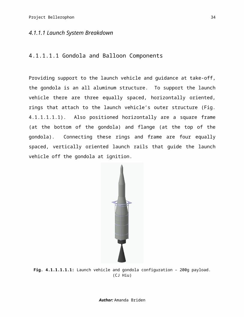
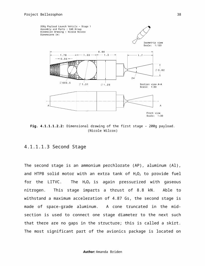
A hybrid first stage with a hydroxy-terminated polybutadiene (HTPB) solid fuel and hydrogen
peroxide (H2O2) liquid oxidizer pairing is pressurized with gaseous nitrogen and provides a thrust
of 34 kN. Part of the first stage propellant is tapped off to support the liquid injection thrust
vector control (LITVC), which is used to steer the rocket. Made out of light-weight space-grade
aluminum, the structure can withstand a maximum acceleration of 4.54 Gs. The first stage is
70.11% of the launch vehicle’s gross liftoff mass (GLOM) and the length of this stage is 6.86 m.
Fig.4.1.1.1.2.2 is a dimensional drawing of the first stage.
Fig. 4.1.1.1.2.2: Dimensional drawing of the first stage – 200g payload.(Nicole Wilcox)
4.1.1.1.3 Second Stage
The second stage is an ammonium perchlorate (AP), aluminum (Al), and HTPB solid motor with
an extra tank of H2O2 to provide fuel for the LITVC. The H2O2 is again pressurized with gaseous
nitrogen. This stage imparts a thrust of 8.8 kN. Able to withstand a maximum acceleration of
Author: Amanda Briden

Project Bellerophon 37
4.87 Gs, the second stage is made of space-grade aluminum. A cone truncated in the mid-section
is used to connect one stage diameter to the next such that there are no gaps in the structure; this
is called a skirt. The most significant part of the avionics package is located on the interior of the
skirt connecting the second and third stages. The avionics package located in the skirt includes a
battery, telecom, central processing unit (CPU), and CPU equipment. These features increase
the avionics mass from the first by a factor of 5, for a total avionics mass on the second stage of
30 kg. The second stage is 27.87% of the launch vehicle’s GLOM. This stage is
3.11 m long and a dimensional drawing is shown in Fig. 4.1.1.1.3.1.
Fig. 4.1.1.1.3.1: Dimensional drawing of the second stage – 200g payload.(Nicole Wilcox)
4.1.1.1.4 Third Stage
Since the avionics is jettisoned along with the second stage at the end of its burn, we spin the
third stage of the launch vehicle to maintain stability. The propellant type and structural material
Author: Amanda Briden
Project Bellerophon 38
are identical to the second stage. The third stage is 2.02% of the launch vehicle’s GLOM. Stage
three is 1.06 m in length and a dimensional drawing follows in Fig. 4.1.1.1.4.1.
Fig. 4.1.1.1.4.1: Dimensional drawing of the third stage – 200g payload.(Nicole Wilcox)
4.1.1.1.5 Nose Cone Component
The nose cone protecting the top of the launch vehicle from extreme heating is made of
aluminum and titanium. An additional feature of the nose cone is a blunted tip made of titanium,
which is a heat resistant material. The nose cone is jettisoned once the vehicle reaches an
altitude of 90 km (out of the Earth’s atmosphere). The nose cone jettison occurs prior to the
separation of the first stage.
Author: Amanda Briden

Project Bellerophon 39
4.1.1.2 Mission Requirements Verification
What are the chances that we reach an orbit with a periapsis of at least 300 km?
There is a 99.99% chance that our launch vehicle reaches a periapsis of 300km. After 10,218
Monte Carlo simulations launch vehicle only fails once (Fig. 4.1.1.2.1). We therefore meet the
mission requirement of 99.86% success rate, considering only non-catastrophic failures. An
average perigee, shown as the peak of the histogram in Fig. 4.1.1.2.1, of 437 km is achieved.
250 300 350 400 450 500 5500
50
100
150
200
Periapsis altitude(km)
num
ber o
f cas
es
Fig. 4.1.1.2.1: 200g periapsis altitude histogram with std = 21.803 km and mean = 437.44 km.(Alfred Lynam)
What are the chances of a failure that results in complete loss of mission?
Accurately predicting the mission success rate, including failures that result in complete loss of
mission, is difficult to do without built and tested hardware. Therefore, we turn to the historical
success rates of the Ariane IV, Ariane V, and Pegasus, to predict ours. We use the success
pattern of Pegasus as it is the only vehicle is air-launched. We predict a 93.84% success rate,
which includes catastrophic failures and is achieved after 24 launches.
Author: Amanda Briden

Project Bellerophon 40
4.1.1.3 Mission Timeline - A Launch in the Life of the 200g Payload Launch Vehicle
T- 1:35:42 to launch
The entire launch system begins its 1 hour and 35 minute ascent to its launch altitude of 30 km.
On average, the system drifts 121 km before reaching the launch altitude. Prior to ignition, a
range safety officer on the ground checks the status of the launch system and has the authority to
proceed with or abort the launch. Fig. 4.1.1.3.1 is a visual representation of the stages of flight
described in the timeline.
T+ 00:00:00 to launch – We are go for launch!
If all systems are go, the first stage is ignited and the launch vehicle is guided off the gondola via
four launch rails. We assume that the balloon pops as the launch vehicle passes through it.
Throughout the course of the burn, the position of the launch vehicle is determined at every
instant by the control system which follows a near optimal steering law. During the first stage
the launch vehicle climbs out of the atmosphere and jettisons the nose cone.
T+ 00:02:17 First Stage Burn-out
Approximately two thirds of the way through the first stage burn, the launch vehicle begins a
pitch over maneuver. This initial maneuver is of the same form of that used in the Apollo
program. After burning for 136.8 s and climbing to an altitude of 97.4 km, the first stage
separates.
T+ 00:05:35 Second Stage Burn-out
During this phase, the launch vehicle continues to pitch over to burn off velocity in the radial
direction. At orbit insertion, radial velocity needs to be zero in order for a circular orbit to be
achieved. With the burn duration of 207.7 s and burn out altitude of 347 km, the second stage
separates, jettisoning the bulk of the system’s avionics.
T+ 00:08:56 Third Stage Burn-out – We’re in orbit!
For the duration of the third stage burn, the launch vehicle uses spin stabilization to maintain its
orientation and does not require avionics control or LITVC. This means that the vehicle’s
Author: Amanda Briden

Project Bellerophon 41
orientation from the end of the second stage burn through the third is maintained. After a 191.9 s
third stage burn time, the launch vehicle ends its ascent and enters an orbit with a perigee of 437
km. The total mission time is 1.7 hours.
Fig. 4.1.1.3.1: Mission Timeline – 200g payload.(Amanda Briden, Kyle Donahue, Jeffrey Stuart)
Author: Amanda Briden

Project Bellerophon 42
4.1.2 Nominal Trajectory
In order for the 200 g launch to be considered successful, the payload must reach an orbit of at
least 200 km according to the design parameters. Since the main consideration during this
project is cost, it’s clear to us that a launch which achieves a nearly circular orbit is required.
Upon reaching the required orbit, optimization occurs to refine the orbit to nearly circular
conditions. We are able to meet these conditions successfully.
Table 4.1.2.1 describes the orbital parameters obtained for the 200g payload launch vehicle.
Table 4.1.2.1 Orbit Parameters
Variable Value UnitsPeriapsis 677.39* kmApoapsis 755.05* kmEccentricity 0.0055 --Inclination 28.5 degSemi-Major Axis 7092.22 kmPeriod 5944.0760 sec
*Values are from the surface of the Earth.
The periapsis of the orbit is 677.39km, this pariapsis exceeds the design requirements by
377.39km. The excess altitude accounts for any errors associated with calculations and allows
for a margin of error for unforeseen conditions during flight. The apoapsis for the orbit is
755.05km, showing that we achieve a nearly circular orbit. An eccentricity of 0 indicates a
perfectly circular orbit and we achieve an eccentricity of 0.0055. The inclination angle indicates
the plane of the orbit that the launch vehicle is launching into relative to the equator. We’re
launching eastward from Kennedy Space Center in Cape Canaveral, FL so our inclination angle
is 28.5 degrees. Kennedy is chosen in part to maximize the contribution of ΔVEarth assist (see
A.6.2.4) The semi-major axis is the distance from the center of an ellipse (center of the Earth) to
the edge of an ellipse, and the semi-major axis for our orbit is 7167.36km. The period of an orbit
is the time it takes for a satellite to make one complete revolution. The period for our orbit is
5944.07640 seconds which is about 1 hour and 40 minutes.
Author: Scott Breitengross
Project Bellerophon 43
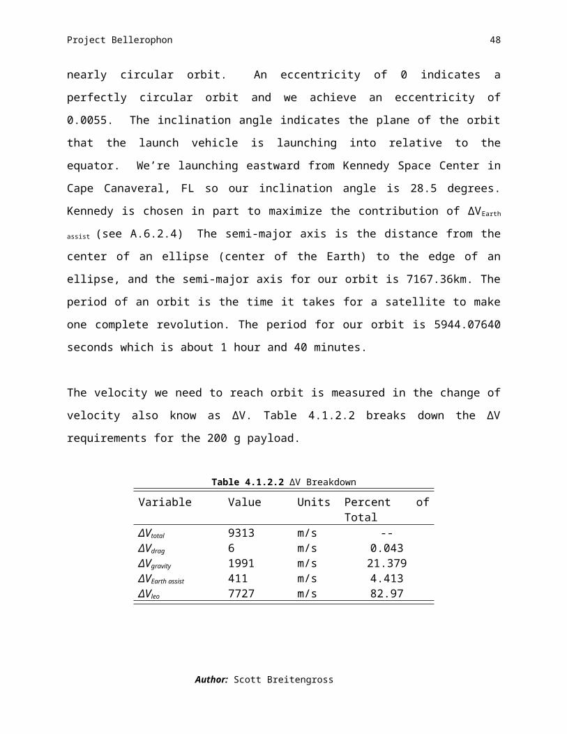
The velocity we need to reach orbit is measured in the change of velocity also know as ΔV.
Table 4.1.2.2 breaks down the ΔV requirements for the 200 g payload.
Table 4.1.2.2 ΔV Breakdown
Variable Value Units Percent of TotalΔVtotal 9313 m/s --ΔVdrag 6 m/s 0.043ΔVgravity 1991 m/s 21.379ΔVEarth assist 411 m/s 4.413ΔVleo 7727 m/s 82.97
ΔVleo is the velocity requirement to maintain our orbit. ΔVdrag refers to the velocity requirement
to overcome the effects of air resistance on the launch vehicle as it travel through Earth’s
atmosphere. The ΔVdrag value is low because the launch vehicle is only in Earth’s atmosphere for
a short period of time. ΔVgravity is the velocity requirement to overcome the effects of gravity on
the launch vehicle. ΔV Earth assist is the velocity gained from launching from Kennedy Space
Center. ΔV Earth assist is calculated from the latitude of the launch location. ΔV Earth assist is larger the
closer to the equation the launch location is. ΔVtotal is the sum total of ΔVdrag, , ΔVleo, ΔVgravity,
minus ΔV Earth assist.
Figure 4.1.2.1 shows the entire orbit mentioned above.
Author: Scott Breitengross
Project Bellerophon 44
Figure 4.1.2.1: Full orbit of 200g payload.(Scott Breitengross)
A steering law is developed to determine the nominal trajectory of the launch vehicle. We create
and use a linear-tangent steering law for each stage. The linear tangent steering law produces the
best trajectory but it is possible to use other steering laws. Since we create a steering law for
each stage, the coefficients of the steering law are optimized and defined for each stage. Table
4.1.2.3 shows the coefficients for the steering law.
Table 4.1.2.3 Coefficients for Steering Law
Variable Valuea1 -2.02785e-1b1 2.8636253e1a2 -6.58045e-3b2 1.80044e0a3 3.22302e-19b3 -4.66308e-1numbers refer to stage number
The linear-tangent steering law is calculated using Eq. (4.1.2.1) below.
Author: Scott Breitengross

Project Bellerophon 45
ϕ=tan−1
( at+b ) Eq. 4.1.2.1
Where φ is the angle the launch vehicle is at, a and b are the constants mentioned above and t is
time in seconds. The constants are determined from the trajectory optimization code.
The solution to the linear tangent steering law various throughout the trajectory. Table 4.1.24
shows the angles, relative to the horizon, that the launch vehicle is in at the end of each stage.
Due to the spin stabilization of the third stage, the third stage is at a constant angle of -25°.
Table 4.1.2.4 Angles from the Steering Law
Variable Value UnitsEnd of 1st stage 42 degEnd of 2nd stage -25 degEnd of 3rd stage -25 degAngles are the nose pointing based on the horizon
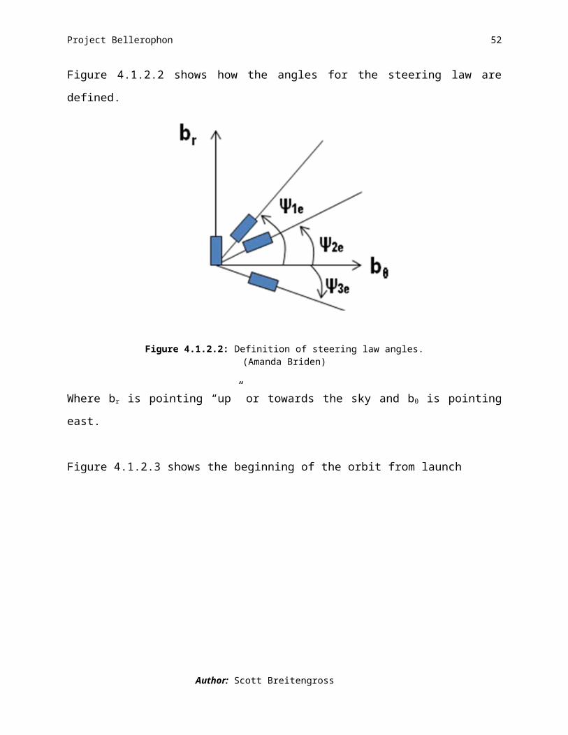
Figure 4.1.2.2 shows how the angles for the steering law are defined.
Figure 4.1.2.2: Definition of steering law angles.(Amanda Briden)
Where br is pointing “up” or towards the sky and bθ is pointing east.
Figure 4.1.2.3 shows the beginning of the orbit from launch
Author: Scott Breitengross

Project Bellerophon 46
Figure 4.1.2.3: Trajectory part of orbit for 200g payload.(Scott Breitengross)
The figure for the trajectory part of the orbit looks the way it does for several reasons. The
yellow dot is the launch site on the surface of the Earth, and the start of the red line should not
correspond to the dot as we are launching from a balloon with an altitude of 30km. The shape of
the trajectory is determined by the steering law which changes the angle. Also, the nominal
trajectory for the 200 g case is shown in Figure 4.1.2.3 but it is not necessarily the path the
launch vehicle will take.
By taking all available data into consideration, we were able to demonstrate that launching a 200
g payload into an orbit with a perigee of at least 300 km is possible. Analysis of all contributions
to ΔV shows us what is needed to achieve the mission requirements. We then use this data as an
input into the trajectory code which optimizes the trajectory. The optimal trajectory produces a
nearly circular orbit well above the mission requirement for perigee while minimizing the cost of
the project.
Author: Scott Breitengross

Project Bellerophon 47
4.1.3 Controlled Trajectory: 200g Payload
We are not able to exactly match the designed trajectory due to many factors. The trajectory
group models the launch vehicle as a point mass to determine the nominal orbit. To arrive at the
controlled trajectory the D&C group models the launch vehicle as a rigid body. Also, the
Trajectory group’s steering law includes sharp corners which are not physically possible. To
keep the launch vehicle under control those corners have to be smoothed out. These factors
combine to make the controlled trajectory differ from the nominal one. At orbit insertion, the
launch vehicle is at a higher altitude which leads to a more eccentric orbit which is illustrated in
the following figures.
Fig. 4.1.3.1: Close up view of launch trajectory; designed orbit (red), and actual controlled orbit (yellow)
(Mike Walker, Alfred Lynam, and Adam Waite)
Author: Albert Chaney
Project Bellerophon 48
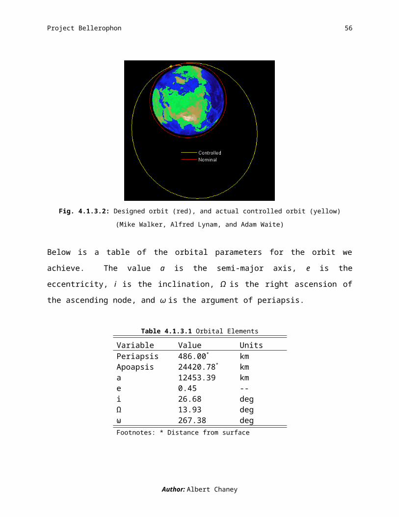
Fig. 4.1.3.2: Designed orbit (red), and actual controlled orbit (yellow)
(Mike Walker, Alfred Lynam, and Adam Waite)
Below is a table of the orbital parameters for the orbit we achieve. The value a is the semi-major
axis, e is the eccentricity, i is the inclination, Ω is the right ascension of the ascending node, and
ω is the argument of periapsis.
Table 4.1.3.1 Orbital Elements
Variable Value UnitsPeriapsis 486.00* kmApoapsis 24420.78* kma 12453.39 kme 0.45 --i 26.68 degΩ 13.93 degω 267.38 degFootnotes: * Distance from surface
Author: Albert Chaney
Project Bellerophon 49
Fig. 4.1.3.3: Ground Track of the controlled portion of the launch
(Mike Walker, Alfred Lynam, and Adam Waite)
Figure 4.1.3.3 is a ground track for the controlled portion of the launch. Ground tracks are
important in the design of ground tracking stations and range safety concerns. The ground track
is vital in the mission planning of the launch.
Author: Albert Chaney

Project Bellerophon 50
4.1.4 Subsystem Details
4.1.4.1 Propulsion
The propellants we selected for the 200 gram payload launch vehicle were a hybrid first stage
and a solid second and third stage. Our selection process involved the use of an optimization
code which gave us the best results for a 200 gram payload launch vehicle. The code gave us a
propulsion system described in the following section.
The first stage of the launch vehicle uses a hybrid rocket motor, with hydrogen peroxide (H2O2)
as the oxidizer and hydroxyl terminated polybutadiene (HTPB) as the solid propellant. The H2O2
tank is pressurized using gaseous nitrogen. The nozzle is a 12º conical nozzle with liquid
injection thrust vector control (LITVC) attached. The LITVC system is composed of four valves
that allow H2O2 to be injected into the nozzle at a 90º angle to the centerline of the nozzle. A
schematic of the LITVC can be seen below in Figure 4.1.4.1.1.
Figure 4.1.4.1.1 LITVC and Nozzle Configuration
In Figure 4.1.4.1.1, the nozzle is shaded grey and all LITVC components are highlighted in
orange. The pipes are run from the H2O2 tank that is used for the hybrid motor, and then is
distributed to each valve. The valves are connected to the controller which relays a signal for a
Author: Stephan Shurn
Project Bellerophon 51
certain valve to open and allow pressurized H2O2 to be injected into the main flow in the nozzle,
which produces a side thrust. This side thrust allows for control of the launch vehicle during its
ascent. The specifics of the propulsion system can be seen in Table 4.1.4.1.1.
Table 4.1.4.1.1 200g Payload Stage 1 Propulsion Specifics
Variable Value UnitsVacuum Specific Impulse 352.30 sChamber Pressure 2,068,000 PaMass Flow Rate 10.69 kg/sPropellant Mass 1,462.00 kgEngine Mass 96.94 kgThrust (vac) 34,045.3 NBurn Time 136.8 sExit Area 0.543 m2
Exit Pressure 2,821.67 Pa
A conical nozzle was chosen because of the solid particles of propellant that will be coming out
of the combustion chamber. The combustion process does not necessarily combust the fuel 100%
and these particles can deteriorate a nozzle if it is let’s say Bell shaped. Some of our early MAT
codes had values based off of a 12° conical nozzle and that is one of the reasons we decided on
this cone angle for the final design. Also having a smaller cone angle reduces the divergence loss
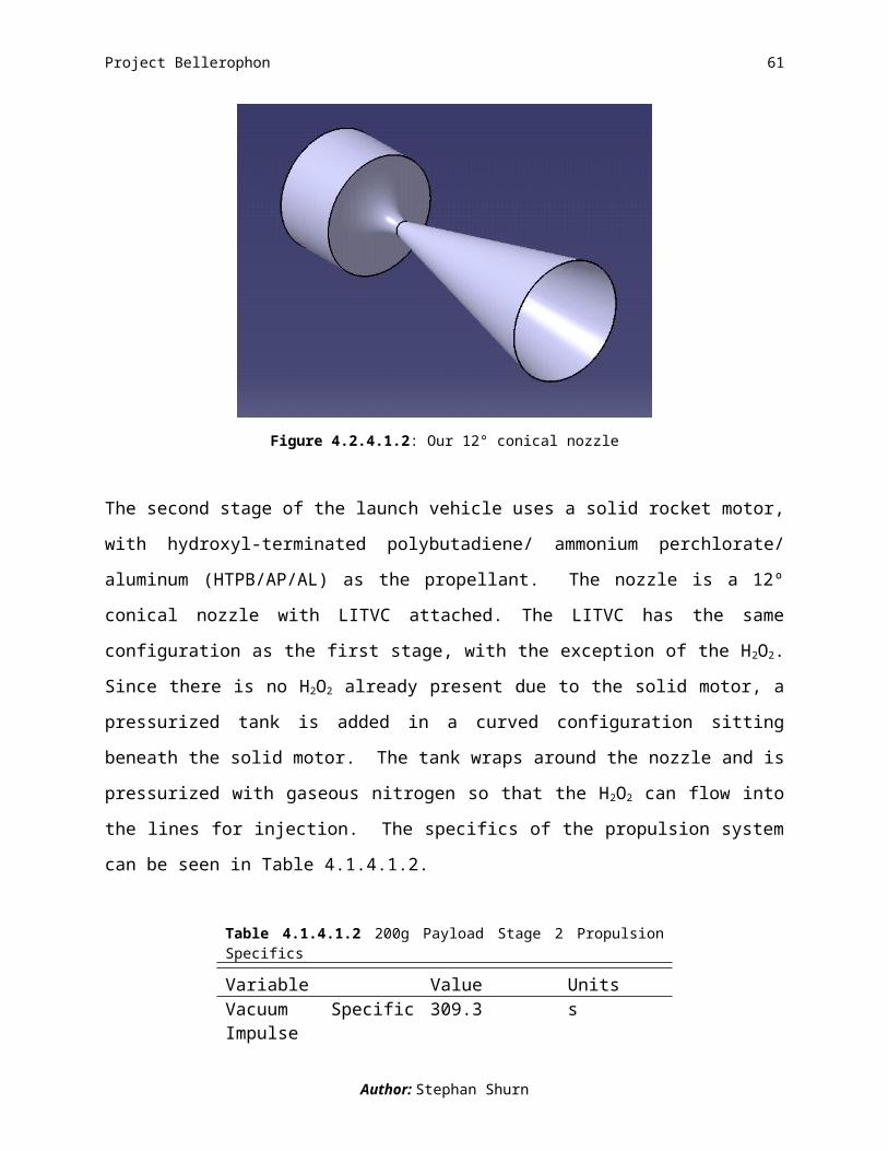
at the exit of the nozzle. A picture of the nozzle can be seen below in Fig. 4.2.4.1.2.
Author: Stephan Shurn
Project Bellerophon 52
Figure 4.2.4.1.2: Our 12° conical nozzle
The second stage of the launch vehicle uses a solid rocket motor, with hydroxyl-terminated
polybutadiene/ ammonium perchlorate/ aluminum (HTPB/AP/AL) as the propellant. The nozzle
is a 12º conical nozzle with LITVC attached. The LITVC has the same configuration as the first
stage, with the exception of the H2O2. Since there is no H2O2 already present due to the solid
motor, a pressurized tank is added in a curved configuration sitting beneath the solid motor. The
tank wraps around the nozzle and is pressurized with gaseous nitrogen so that the H2O2 can flow
into the lines for injection. The specifics of the propulsion system can be seen in Table 4.1.4.1.2.
Table 4.1.4.1.2 200g Payload Stage 2 Propulsion Specifics
Variable Value UnitsVacuum Specific Impulse 309.3 sChamber Pressure 6,000,000 PaMass Flow Rate 2.728 kg/sPropellant Mass 566.64 kgEngine Mass 51.53 kgThrust (vac) 8,782.6 NBurn Time 207.7 sExit Area 0.040 m2
Exit Pressure 11,453.660 Pa
Author: Stephan Shurn

Project Bellerophon 53
The third stage of the launch vehicle uses a solid rocket motor, with hydroxyl-terminated
polybutadiene/ ammonium perchlorate/ aluminum (HTPB/AP/AL) as the propellant. The nozzle
is a 12º conical shape. The specifics of the propulsion system can be seen in Table 4.1.4.1.3.
Author: Stephan Shurn
Table 4.1.4.1.3 200g Payload Stage 2 Propulsion Specifics
Variable Value UnitsVacuum Specific Impulse 309.3 sChamber Pressure 6,000,000 PaMass Flow Rate 0.194 kg/sPropellant Mass 37.26 kgEngine Mass 8.40 kgThrust (vac) 625.0 NBurn Time 191.9 sExit Area 0.003 m2
Exit Pressure 11,453.660 Pa

Project Bellerophon 54
4.1.4.2 Aerothermal
In our aerodynamic analysis, we use linear perturbation theory to determine the aerodynamic
loading on the launch vehicle. Linear perturbation theory is the method in which the pressure
over the top and bottom surfaces of the launch vehicle is integrated to solve for the normal and
axial force coefficients acting on the launch vehicle. It is valid in the subsonic and supersonic
regimes, but falls apart in the transonic regime. For this reason, we have ignored the
aerodynamic outputs in the transonic regime and only pay attention to the outputs in the subsonic
and supersonic regimes. By integrating the change in pressure around the launch vehicle we are
able to solve for bending and pitching moments, drag coefficient, axial forces, normal forces,
shear forces, and the center of pressure location. All of these aerodynamic moments, coefficients,
and forces are based on the final geometry of the launch vehicle as well as the Mach number,
angle of attack, and time spent in the atmosphere.
Mach number, variation in angle of attack, use of LITVC, stage separation, as well as wind gusts
all have a large impact on the aerodynamic loadings of the launch vehicle. As the launch vehicle
makes its way through the atmosphere, the change in density also has a significant effect on the
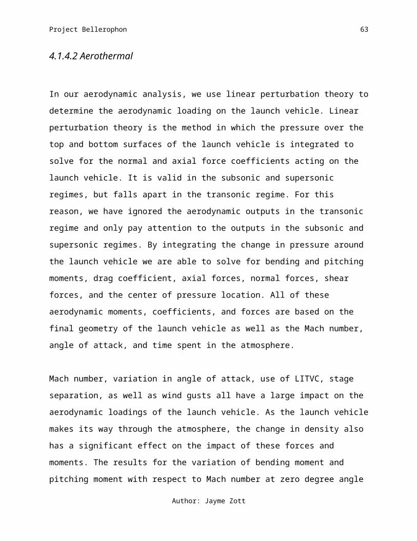
impact of these forces and moments. The results for the variation of bending moment and
pitching moment with respect to Mach number at zero degree angle of attack can be found in
Figs. 4.1.4.2.1 and 4.1.4.2.2 respectively. Once the launch vehicle reaches a speed of Mach 4.7,
it exits the atmosphere. At this point, the first stage has still not separated; therefore, moments
are shown as they act on the entire launch vehicle.
Author: Jayme Zott

Project Bellerophon 55
0 0.5 1 1.5 2 2.5 3 3.5 4 4.5 5
-3500
-3000
-2500
-2000
-1500
-1000
-500
0
Mach
Bend
ing M
omen
t (Nm
)
Fig. 4.1.4.2.1: Variation of bending moment with respect to Mach number at zero angle of attack. 200g.
(Alex Woods, Jayme Zott)
0 0.5 1 1.5 2 2.5 3 3.5 4 4.5 50
200
400
600
800
1000
1200
Mach
Pitc
hing
Mom
ent (
Nm)
Fig. 4.1.4.2.2: Variation of pitching moment with respect to Mach number at zero angle of attack. 200 g.
(Alex Woods, Jayme Zott)
The moments presented in Figs. 4.1.4.2.1 and 4.1.4.2.2 correlate well with the magnitude of
moments expected for a launch vehicle of our size and shape. It is important for us to determine
Author: Jayme Zott
Project Bellerophon 56
these moments because the structures group uses them to determine appropriate materials and
thicknesses for the final launch vehicle design.
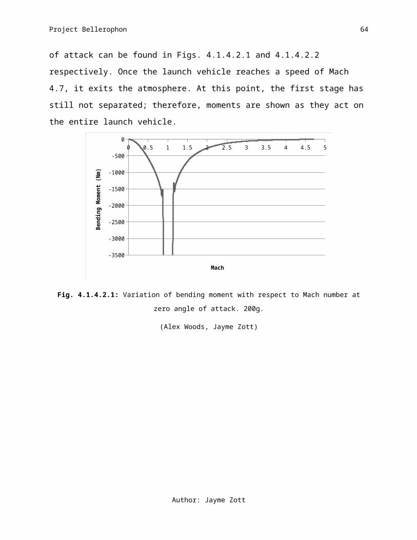
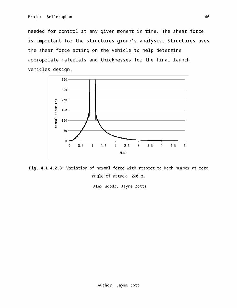
The results for the variation of normal, axial, and shear forces with respect to Mach number at a
zero degree angle of attack can be found in Figs. 4.1.4.2.3, 4.1.4.2.4, and 4.1.4.2.5 respectively.
The normal and axial forces are important for the D&C group’s analysis. D&C uses the normal
and axial forces acting on the launch vehicle to help determine the amount of LITVC needed for
control at any given moment in time. The shear force is important for the structures group’s
analysis. Structures uses the shear force acting on the vehicle to help determine appropriate
materials and thicknesses for the final launch vehicles design.
0 0.5 1 1.5 2 2.5 3 3.5 4 4.5 50
50
100
150
200
250
300
Mach
Norm
al Fo
rce
(N)
Fig. 4.1.4.2.3: Variation of normal force with respect to Mach number at zero angle of attack. 200 g.
(Alex Woods, Jayme Zott)
Author: Jayme Zott

Project Bellerophon 57
0 0.5 1 1.5 2 2.5 3 3.5 4 4.5 50
100
200
300
400
500
600
700
800
900
1000
Mach
Axial
Forc
e (N
)
Fig. 4.1.4.2.4: Variation of axial force with respect to Mach number at zero angle of attack. 200 g.
(Alex Woods, Jayme Zott)
0 0.5 1 1.5 2 2.5 3 3.5 4 4.5 5
-200
-180
-160
-140
-120
-100
-80
-60
-40
-20
0
Mach
Shea
r For
ce (N
)
Fig. 4.1.4.2.5: Variation of shear force with respect to Mach number at zero angle of attack. 200 g.
(Alex Woods, Jayme Zott)
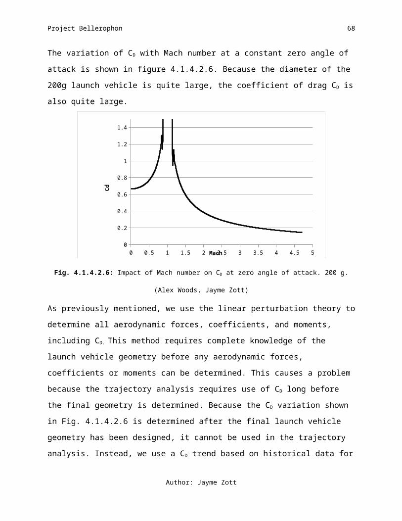
The variation of CD with Mach number at a constant zero angle of attack is shown in figure
4.1.4.2.6. Because the diameter of the 200g launch vehicle is quite large, the coefficient of drag
CD is also quite large.
Author: Jayme Zott

Project Bellerophon 58
0 0.5 1 1.5 2 2.5 3 3.5 4 4.5 50
0.2
0.4
0.6
0.8
1
1.2
1.4
Mach
Cd
Fig. 4.1.4.2.6: Impact of Mach number on CD at zero angle of attack. 200 g.
(Alex Woods, Jayme Zott)
As previously mentioned, we use the linear perturbation theory to determine all aerodynamic
forces, coefficients, and moments, including CD. This method requires complete knowledge of the
launch vehicle geometry before any aerodynamic forces, coefficients or moments can be
determined. This causes a problem because the trajectory analysis requires use of CD long before
the final geometry is determined. Because the CD variation shown in Fig. 4.1.4.2.6 is determined
after the final launch vehicle geometry has been designed, it cannot be used in the trajectory
analysis. Instead, we use a CD trend based on historical data for the trajectory analysis.1,2 While
this historical CD trend is not based on our own geometry, it is based on successful launch
vehicles with geometries similar to our final design. The CD based on historical data at zero angle
of attack is shown in the Fig. 4.1.4.2.7
Author: Jayme Zott

Project Bellerophon 59
0 0.5 1 1.5 2 2.5 3 3.5 4 4.5 50
0.1
0.2
0.3
0.4
0.5
0.6
0.7
0.8
Mach
Cd
Fig. 4.1.4.2.7: Impact of Mach number on CD at zero angle of attack based on historical data. 200 g.
(Jayme Zott)
Given additional time, we could complete a better trajectory analysis by including the correct CD
based on the linear perturbation theory into the trajectory code. If we created an intermediate file
between the initial propulsion sizing output and the trajectory input, a more accurate CD value
could be used within the trajectory code. Fig. 4.1.4.2.8 shows the error caused by the using the
CD trend based on historical geometries, rather than the CD determined directly from our own
geometry.
Author: Jayme Zott

Project Bellerophon 60
0 0.5 1 1.5 2 2.5 3 3.5 4 4.5 5-2.22044604925031E-16
0.2
0.4
0.6
0.8
1
1.2
1.4
Cd (historical)Cd (dimensional)
Mach
Cd
Fig. 4.1.4.2.8: Comparison of CD based on historical data and CD based on dimensional analysis (linear perturbation
theory). 200 g.
(Jayme Zott)
Table 4.1.4.2.1 Summary of Maximum Aerodynamic Loading 200 g.
Aerodynamic Load Subsonic Supersonic Bending Moment [Nm] -1850.7 -1133.1Pitching Moment [Nm] 626.6 383.6Normal Force [N] 146.6 89.8Axial Force [N]Shear Force [N]Center of Pressure [% length]Coefficient of Drag CD
Dynamic Pressure [Pa]CD % error [%]
486.9 -99.4 38.3 1.38
54
298.1 -60.8 38.3 0.85 279 17
(Jayme Zott)
References
1Sutton, George P., and Oscar Biblarz. Rocket Propulsion Elements. New York: John Wiley & Sons, Inc., 2001.
2The Martin Company, “The Vanguard Satellite Launching Vehicle”, Engineering Report No. 11022, April 1960.
Author: Jayme Zott
Project Bellerophon 61
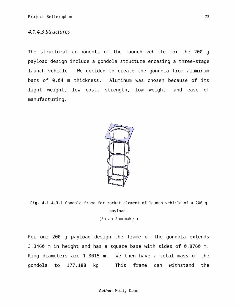
4.1.4.3 Structures
The structural components of the launch vehicle for the 200 g payload design include a gondola
structure encasing a three-stage launch vehicle. We decided to create the gondola from
aluminum bars of 0.04 m thickness. Aluminum was chosen because of its light weight, low cost,
strength, low weight, and ease of manufacturing.
Fig. 4.1.4.3.1 Gondola frame for rocket element of launch vehicle of a 200 g payload.
(Sarah Shoemaker)
For our 200 g payload design the frame of the gondola extends 3.3460 m in height and has a
square base with sides of 0.8760 m. Ring diameters are 1.3015 m. We then have a total mass of
the gondola to 177.188 kg. This frame can withstand the approximately 55 kPa of pressure
exerted on it by our launch vehicle.
The first stage of the rocket is 7.1478 m in length and 1.3015 m in diameter. It is comprised of
an engine, oxidizer tank, fuel tank, pressurant tank, inter-tank structure, and avionics equipment.
The tanks are all made from aluminum and are of various sizes and thicknesses. An inter-stage
“skirt” connects the first and second stages of the rocket. It maintains a 10° slope from the lower
stage to the upper stage. It is also made of aluminum and is reinforced with support stringers and
ring supports. The first inter-stage structure is 1.7789 m in length. We take our upper and lower
Author: Molly Kane

Project Bellerophon 62
diameters from the diameters of the first and second stages. For this design, the maximum
diameter is 1.3015 m and the minimum diameter is 0.6741 m.
The second stage of the rocket consists of an engine, fuel tank, and avionics equipment. This
stage has a diameter of 0.6741 m and a length of 2.5594 m. The fuel tank is also made of
aluminum. The alloy Al-7075 makes all of our tanks because of its historical use and very high
strength to weight ratio. An inter-stage structure connects the second and third stages of the
rocket. This second inter-stage skirt is 1.1400 m in height with diameters ranging from 0.6741
m, maximum, to 0.2721 m, minimum, with a constant slope of 10°.
The third and final stage of the rocket, itself, reaches 0.8945 m in height and is 0.2721 m in
diameter. It is composed of an engine, fuel tank, and avionics equipment. We choose the tank to
be constructed from aluminum. The payload sits atop the thirst stage, protected by a titanium-
tipped nose cone. The nose cone is a simple cone with a blunted nose, and extends 0.3375 m.
The end is made of titanium to protect from heat, and the remainder is made of aluminum.
The inert mass breakdowns of components and stages are summarized in the following table.
Table 4.1.4.3.1: Inert Mass Breakdown of Three-Stage Rocket, 200 g Payload
Stage 1 Stage 2 Stage 3 Totals Units
Fuel Tank 68.05 47.98 3.15 119.19 kg
Ox Tank 56.03 0.00 0.00 56.03 kg
Pressure Tank 12.66 0.00 0.00 12.66 kg
Engine 96.94 51.53 8.40 156.87 kg
Pressure Addition 58.99 0.00 0.00 58.99 kg
Avionics 3.96 23.82 3.96 31.74 kg
Inter-tank 0.31 0.00 0.00 0.31 kg
Skirt/Nose Cone 11.07 3.40 1.75 16.22 kg
Total 308.02 126.73 17.26 452.01 kg
To determine the length of the first stage we take into consideration the lengths of the fist stage
nozzle, engine, fuel tank, oxidizer tank, pressurant tank, inter-tank structure, and first inter-stage
Author: Molly Kane
Project Bellerophon 63
skirt lengths. For the second stage we do not take the nozzle length into consideration because it
rests inside of the inter-stage skirt. We do include the second inter-stage skirt length in the
dimensions of the second stage. The third stage, similarly, does not include the nozzle length,
but has the addition of the nose cone height. This brings the total height of our rocket to 10.6017
m. The following table shows the specifications of each part and each stage.
Table 4.1.4.3.2: Dimensions of the Three-Stage Rocket, 200 g Payload
Stage 1 Stage 2 Stage 3 Totals Units
Nozzle Length 1.7041 0.4645 0.1239 2.2925 m
Engine Length 0.4260 0.1161 0.0310 0.5731 m
Fuel Tank Length 1.3015 1.3033 0.5260 3.1308 m
Fuel Tank Thickness 0.0037 0.0055 0.0022 n/a m
Ox Tank Length 1.3318 0.0000 0.0000 1.3318 m
Ox Tank Thickness 0.0037 0.0000 0.0000 n/a m
Inter-tank Thickness 0.0020 0.0020 0.0020 n/a m
Press. Tank Diam. 0.6055 0.0000 0.0000 0.0000 m
Press. Tank Thick. 0.0039 0.0000 0.0000 n/a m
Nose Cone Length 0.0000 0.0000 0.3375 0.3375 m
Diameter 1.3015 0.6741 0.2721 n/a m
Length of Stage 7.1478 2.5594 0.8945 10.6017 m
The connecting inter-stage skirts are designed to meet the requirements of the main parts of the
launch vehicle. The slope of 10º was chosen because the closer to vertical they are, the more
weight they can withstand. However, they still must provide the transition between the two
different diameters. Choosing this low-angled slope gave us more efficient stringers with less
material needed for each stringer. Ultimately, this reduced the cost of the stringers. The inter-
stage skirt between stages one and two requires a minimum load bearing of 42.380 kN. The
inter-stage skirt between stages two and three calls for a minimum load bearing capability of
2.986 kN. The skirts are reinforced with stringers and ring supports, detailed as follows.
Author: Molly Kane
Project Bellerophon 64
Table 4.1.4.3.3: Details of the Interstage Structure, 200 g PayloadStage 1-2 Stage 2-3 Units
Vertical Length 1.779 1.140 mShell Thickness 0.004 0.004 mMass 11.075 3.399 kgSlope Angle 10.000 10.000 degNo. Stringers 35 14 --Stringer Thickness 0.003 0.003 mStringer Depth 0.020 0.020 mNo. Ring Supports 7 1 --
Author: Molly Kane

Project Bellerophon 65
4.1.4.4 Avionics
We have three subsystems that comprise the avionics portion of the launch vehicle:
telecommunications, power systems and range safety. The telecommunications portion of
avionics consists of the equipment the ground stations and vehicle require to communicate
between the ground and launch vehicle.
The avionics packages are broken up into 2 main locations: those that are placed on the gondola,
and those that are placed on the inside of the skirt between the second and final stages. We place
a battery and some sensors on the gondola to help eliminate some of the avionics weight from
the launch vehicle.
Most of our avionics are commercial grade products instead of space grade. The decision to use
commercial grade components allows us to cut a lot of the cost usually required for additional
testing and safety factors that our mission did not require. When choosing commercial grade
products we do not consider if we need radiation hardening for avionics and other space grade
requirements. Also, we are not able to tell how the loads from the gravitational forces will
impact the accuracy of the electronic components.
Most of the avionics package is independent of small changes in the launch vehicle design. This
is due to most of our avionics basis on the communication requirements for a vehicle and not
physical size dimensions. Since all of our vehicles were following the same rough path and had
the same functions there was little need for variations. Therefore our avionics package is the
same for all 3 launch vehicles.
Author: Danielle Yaple
Project Bellerophon 66
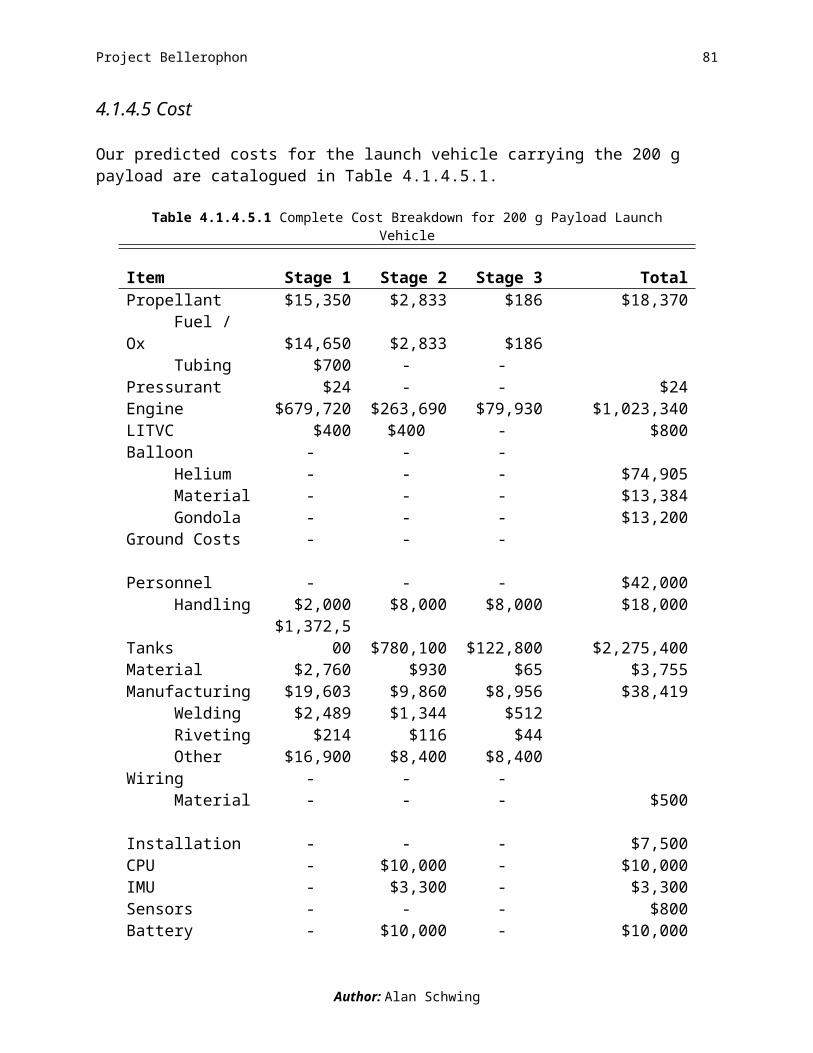
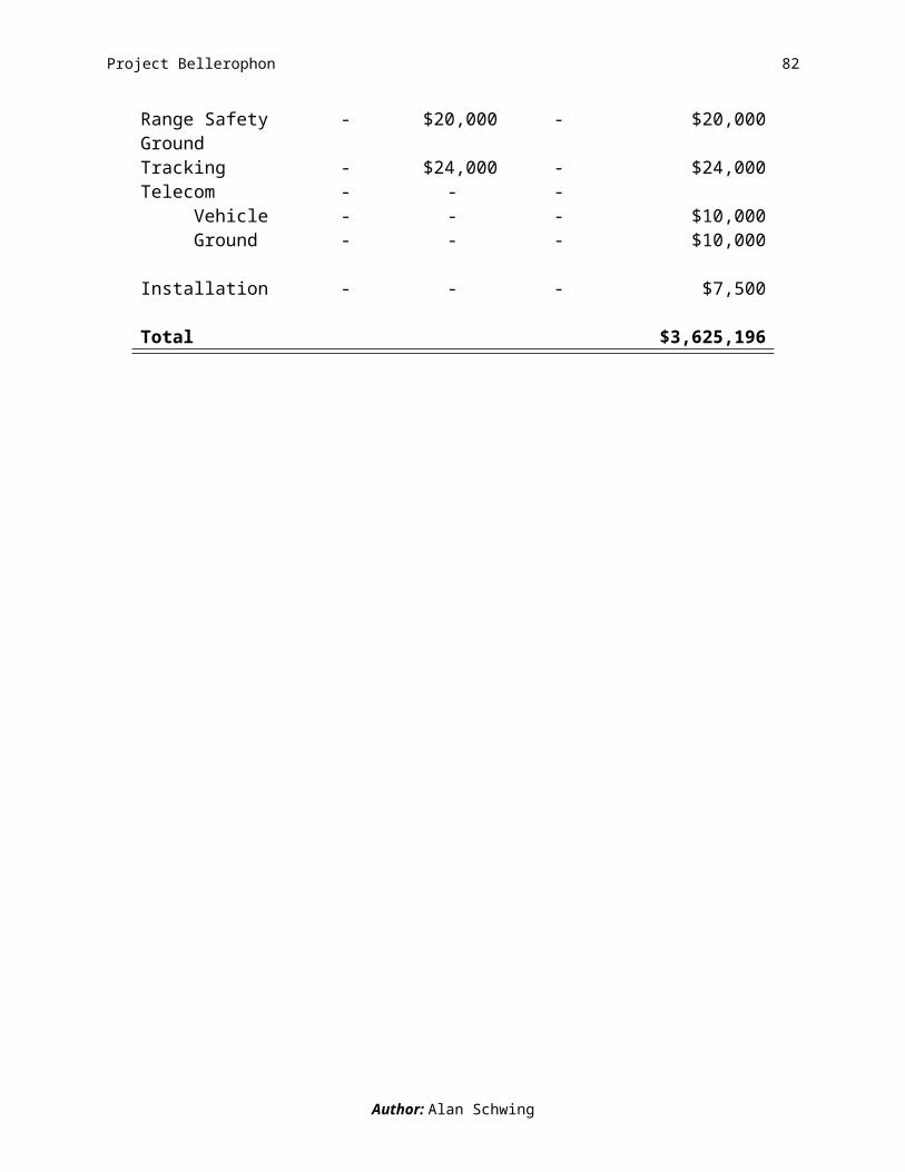
4.1.4.5 Cost
Our predicted costs for the launch vehicle carrying the 200 g payload are catalogued in Table 4.1.4.5.1.
Table 4.1.4.5.1 Complete Cost Breakdown for 200 g Payload Launch Vehicle
Item Stage 1 Stage 2 Stage 3 TotalPropellant $15,350 $2,833 $186 $18,370 Fuel / Ox $14,650 $2,833 $186 Tubing $700 - -Pressurant $24 - - $24Engine $679,720 $263,690 $79,930 $1,023,340LITVC $400 $400 - $800Balloon - - - Helium - - - $74,905 Material - - - $13,384 Gondola - - - $13,200Ground Costs - - - Personnel - - - $42,000 Handling $2,000 $8,000 $8,000 $18,000Tanks $1,372,500 $780,100 $122,800 $2,275,400Material $2,760 $930 $65 $3,755Manufacturing $19,603 $9,860 $8,956 $38,419 Welding $2,489 $1,344 $512 Riveting $214 $116 $44 Other $16,900 $8,400 $8,400Wiring - - - Material - - - $500 Installation - - - $7,500CPU - $10,000 - $10,000IMU - $3,300 - $3,300Sensors - - - $800Battery - $10,000 - $10,000Range Safety - $20,000 - $20,000Ground Tracking - $24,000 - $24,000Telecom - - - Vehicle - - - $10,000 Ground - - - $10,000 Installation - - - $7,500
Total $3,625,196
Author: Alan Schwing
Project Bellerophon 67
4.2 1kg Payload
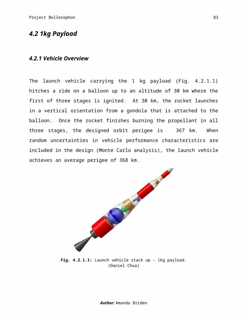
4.2.1 Vehicle Overview
The launch vehicle carrying the 1 kg payload (Fig. 4.2.1.1) hitches a ride on a balloon up to an
altitude of 30 km where the first of three stages is ignited. At 30 km, the rocket launches in a
vertical orientation from a gondola that is attached to the balloon. Once the rocket finishes
burning the propellant in all three stages, the designed orbit perigee is 367 km. When random
uncertainties in vehicle performance characteristics are included in the design (Monte Carlo
analysis), the launch vehicle achieves an average perigee of 368 km.
Fig. 4.2.1.1: Launch vehicle stack up – 1kg payload.(Daniel Chua)
Author: Amanda Briden
Project Bellerophon 68
4.2.1.1 Launch System Breakdown
4.2.1.1.1 Gondola and Balloon Components
Providing support to the launch vehicle and guidance at take-off, the gondola is an all aluminum
structure. To support the launch vehicle there are three equally spaced, horizontally oriented,
rings that attach to the launch vehicle’s outer structure (Fig. 4.2.1.1.1.1). Also positioned
horizontally are a square frame (at the bottom of the gondola) and flange (at the top of the
gondola). Connecting these rings and frame are four equally spaced, vertically oriented launch
rails that guide the launch vehicle off the gondola at ignition.
Fig. 4.2.1.1.1.1: Launch vehicle and gondola configuration – 1kg payload.(CJ Hiu)
The gondola is connected to a spherical balloon, filled with helium, made of polyethylene
plastic. During flight, the gondola carrying the launch vehicle is suspended below the balloon.
We assume that the balloon pops right before the launch vehicle passes through it. As the
balloon rises, the gas expands and the balloon is sized to hold the gas at an altitude of up to 30
km. The battery, that powers the communications with the range safety officer on the ground, is
Author: Amanda Briden

Project Bellerophon 69
attached to the flanges of the gondola. Neither the balloon or gondola are reused. Fig.
4.2.1.1.1.2 puts the size of these components with respect to the launch vehicle into perspective.
Fig. 4.2.1.1.1.2: Size comparison of the gondola, launch vehicle, and balloon – 1kg payload.(CJ Hiu, Sarah Shoemaker)
4.2.1.1.2 First Stage
Fig. 4.2.1.1.2.1 is an exploded view of the launch vehicle. A reference table, summarizing the
sizing and propulsion information for each stage, is also provided. Please refer back to it while
reading the descriptions of each stage.
Author: Amanda Briden

Project Bellerophon 70
Fig. 4.2.1.1.2.1: Exploded view of launch vehicle stack up and and parameter summary – 1kg payload.(Stephen Bluestone, Amanda Briden, Nicole Bryan, CJ Hiu, Molly Kane, William Ling , Sarah Shoemaker)
Author: Amanda Briden
BAL
LOO
N S
TRU
CTU
RE
GO
ND
OLA
STR
UC
TUR
EFe
atur
esFe
atur
esM
inim
um v
olum
e:2,
197.
9 m
3D
imen
sion
s:1[3
] x1[3
] x3.8
49[4
] m3
Max
imum
vol
ume:
190,
040
m3
Mat
eria
l:A
lum
inum
Min
imum
dia
met
er:
16.1
312
mTh
ickn
ess:
0.04
mM
axim
um d
iam
eter
:71
.331
2 m
Wei
ght:
227.
114
kgM
ater
ial:
Pol
yeth
ylen
e pl
astic
film
PRO
PULS
ION
Gas
use
d:H
eliu
mFe
atur
esSh
ape:
Sph
eric
alPr
opel
lant
type
:ST
RU
CTU
RES
S
tage
1H
2O2
& H
TPB
Feat
ures
S
tage
2H
TPB
/AP
/Al &
H2O
2[5]
Leng
th:
S
tage
3H
TPB
/AP
/Al
S
tage
14.
1555
mPr
opel
lant
am
ount
:
Sta
ge 2
1.48
16 m
S
tage
194
7.9
kg
Sta
ge 3
1.05
54 m
S
tage
233
6.92
kg
Dia
met
er:
S
tage
345
.09
kg
Sta
ge 1
1.12
64 m
Engi
ne ty
pe:
S
tage
20.
5669
m
Sta
ge 1
Hyb
rid
Sta
ge 3
0.29
00 m
S
tage
2S
olid
Iner
t Mas
s: [1
]
Sta
ge 3
Sol
id
Sta
ge 1
97.0
893
kgTh
rust
:
Sta
ge 2
30.6
403
kg
Sta
ge 1
2143
5.5
N
Sta
ge 3
5.85
67 k
g
Sta
ge 2
6052
.4 N
Mat
eria
l:
Sta
ge 3
743.
4 N
S
tage
1A
lIS
P:
Sta
ge 2
Al
S
tage
135
2.3
seco
nds
S
tage
3A
l
Sta
ge 2
309.
3 se
cond
sTh
ickn
ess:
[2]
S
tage
330
9.3
seco
nds
S
tage
10.
0032
mEx
pans
ion
ratio
:
Sta
ge 2
0.00
46 m
S
tage
160
S
tage
30.
0024
m
Sta
ge 2
60AV
ION
ICS
S
tage
360
Feat
ures
NO
TES
Mas
s:1.
Iner
t mas
ses
incl
ude
tank
, ski
rt, a
nd n
ose
cone
mas
ses.
S
tage
16.
024
kg2.
Thi
ckne
ss v
alue
s pe
rtain
to th
e fu
el ta
nks.
S
tage
230
.266
4 kg
3. G
ondo
la s
quar
e ba
se w
idth
and
leng
th.
S
tage
31.
2 kg
4. G
ondo
la h
eigh
t.To
tal s
yste
m p
ower
:20
0 W
atts
5. U
sed
for L
ITV
C.

Project Bellerophon 71
A hybrid first stage with a hydroxy-terminated polybutadiene (HTPB) solid fuel and hydrogen
peroxide (H2O2) liquid oxidizer pairing is pressurized with gaseous nitrogen and provides a thrust
of 21 kN. Part of the first stage propellant is tapped off to support the liquid injection thrust
vector control (LITVC), which is used to steer the rocket. Made out of light-weight space-grade
aluminum, the structure can withstand a maximum acceleration of 2.86 Gs. The first stage is
70.48% of the launch vehicle’s gross liftoff mass (GLOM) and the length of this stage is 5.81 m.
Fig.4.2.1.1.2.2 is a dimensional drawing of the first stage.
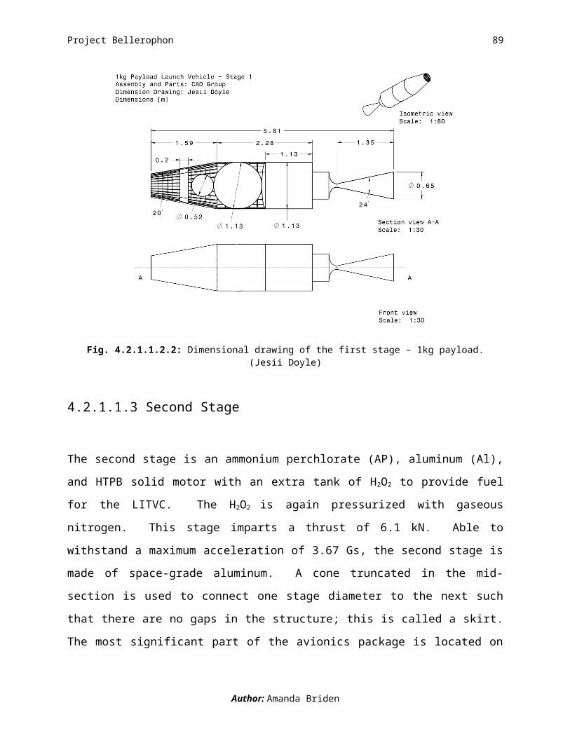
Fig. 4.2.1.1.2.2: Dimensional drawing of the first stage – 1kg payload.(Jesii Doyle)
4.2.1.1.3 Second Stage
The second stage is an ammonium perchlorate (AP), aluminum (Al), and HTPB solid motor with
an extra tank of H2O2 to provide fuel for the LITVC. The H2O2 is again pressurized with gaseous
nitrogen. This stage imparts a thrust of 6.1 kN. Able to withstand a maximum acceleration of
Author: Amanda Briden

Project Bellerophon 72
3.67 Gs, the second stage is made of space-grade aluminum. A cone truncated in the mid-section
is used to connect one stage diameter to the next such that there are no gaps in the structure; this
is called a skirt. The most significant part of the avionics package is located on the interior of the
skirt connecting the second and third stages. The avionics package located in the skirt includes a
battery, telecom, central processing unit (CPU), and CPU equipment. These features increase
the avionics mass from the first by a factor of 5, for a total avionics mass on the second stage of
30 kg. The second stage is 25.97% of the launch vehicle’s GLOM. This stage is
2.44 m long and a dimensional drawing is shown in Fig. 4.2.1.1.3.1.
Fig. 4.2.1.1.3.1: Dimensional drawing of the second stage – 1kg payload.(Jesii Doyle)
Author: Amanda Briden
Project Bellerophon 73
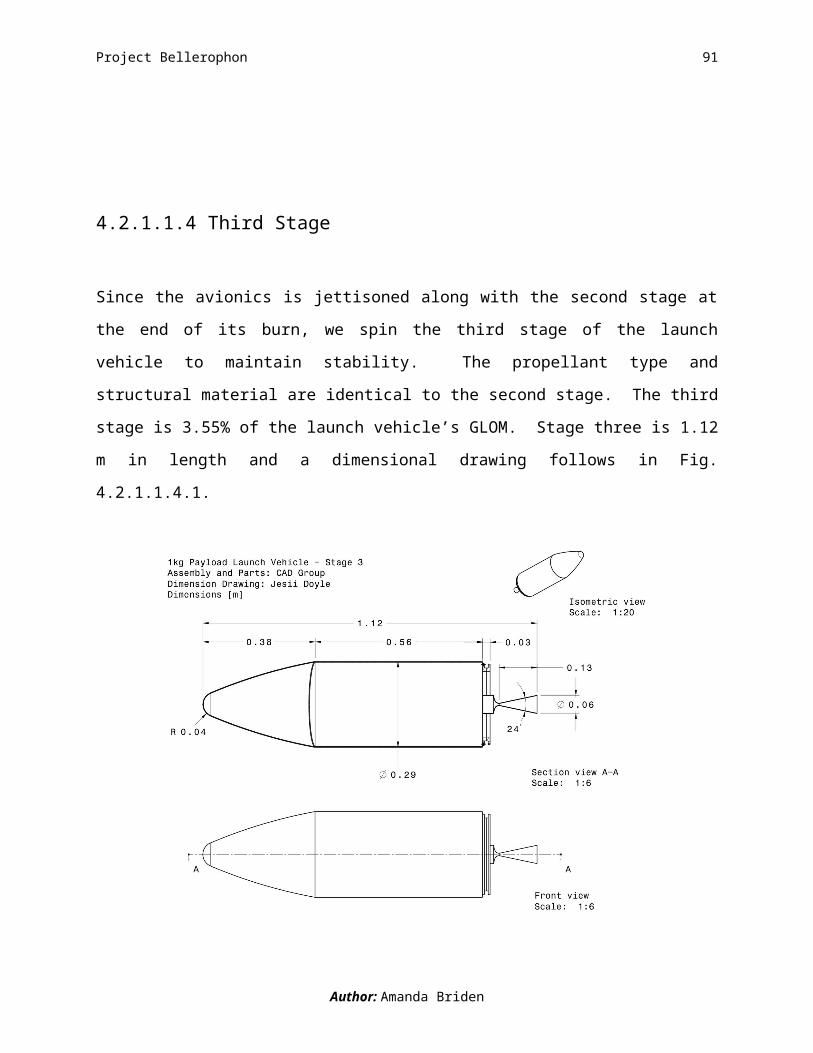
4.2.1.1.4 Third Stage
Since the avionics is jettisoned along with the second stage at the end of its burn, we spin the
third stage of the launch vehicle to maintain stability. The propellant type and structural material
are identical to the second stage. The third stage is 3.55% of the launch vehicle’s GLOM. Stage
three is 1.12 m in length and a dimensional drawing follows in Fig. 4.2.1.1.4.1.
Fig. 4.2.1.1.4.1: Dimensional drawing of the third stage – 1kg payload.(Jesii Doyle)
4.2.1.1.5 Nose Cone Component
The nose cone protecting the top of the launch vehicle from extreme heating is made of
aluminum and titanium. An additional feature of the nose cone is a blunted tip made of titanium,
which is a heat resistant material. The nose cone is jettisoned once the vehicle reaches an
altitude of 90 km (out of the Earth’s atmosphere). The nose cone jettison occurs prior to the
separation of the first stage.
Author: Amanda Briden
Project Bellerophon 74
4.2.1.2 Mission Requirements Verification
What are the chances that we reach an orbit with a periapsis of at least 300 km?
There is a 99.99% chance that our launch vehicle reaches a periapsis of 300km. After 10,000
Monte Carlo simulations launch vehicle only fails once (Fig. 4.2.1.2.1). We therefore meet the
mission requirement of 99.86% success rate, considering only non-catastrophic failures. An
average perigee, shown as the peak of the histogram in Fig. 4.2.1.2.1, of 368 km is achieved.
280 300 320 340 360 380 400 4200
100
200
300
400
Periapsis altitude(km)
num
ber o
f cas
es
Fig. 4.2.1.2.1: 1kg periapsis altitude histogram with std = 15.774 km and mean = 367.727 km.(Alfred Lynam)
What are the chances of a failure that results in complete loss of mission?
Accurately predicting the mission success rate, including failures that result in complete loss of
mission, is difficult to do without built and tested hardware. Therefore, we turn to the historical
success rates of the Ariane IV, Ariane V, and Pegasus, to predict ours. We use the success
pattern of Pegasus as it is the only vehicle is air-launched. We predict a 93.84% success rate,
which includes catastrophic failures and is achieved after 24 launches.
Author: Amanda Briden

Project Bellerophon 75
4.2.1.3 Mission Timeline - A Launch in the Life of the 1kg Payload Launch Vehicle
T- 1:35:34 to launch
The entire launch system begins its 1 hour and 35 minute ascent to its launch altitude of 30 km.
On average, the system drifts 120 km before reaching the launch altitude. Prior to ignition, a
range safety officer on the ground checks the status of the launch system and has the authority to
proceed with or abort the launch. Fig. 4.2.1.3.1 is a visual representation of the stages of flight
described in the timeline.
T+ 00:00:00 to launch – We are go for launch!
If all systems are go, the first stage is ignited and the launch vehicle is guided off the gondola via
four launch rails. We assume that the balloon pops as the launch vehicle passes through it.
Throughout the course of the burn, the position of the launch vehicle is determined at every
instant by the control system which follows a near optimal steering law. During the first stage
the launch vehicle climbs out of the atmosphere and jettisons the nose cone.
T+ 00:02:20 First Stage Burn-out
Approximately two thirds of the way through the first stage burn, the launch vehicle begins a
pitch over maneuver. This initial maneuver is of the same form of that used in the Apollo
program. After burning for 140.8 s and climbing to an altitude of 87.4 km, the first stage
separates.
T+ 00:05:20 Second Stage Burn-out
During this phase, the launch vehicle continues to pitch over to burn off velocity in the radial
direction. At orbit insertion, radial velocity needs to be zero in order for a circular orbit to be
achieved. With the burn duration of 179.2 s and burn out altitude of 257 km, the second stage
separates, jettisoning the bulk of the system’s avionics.
T+ 00:08:35 Third Stage Burn-out – We’re in orbit!
For the duration of the third stage burn, the launch vehicle uses spin stabilization to maintain its
orientation and does not require avionics control or LITVC. This means that the vehicle’s
Author: Amanda Briden

Project Bellerophon 76
orientation from the end of the second stage burn through the third is maintained. After a 195.3 s
third stage burn time, the launch vehicle ends its ascent and enters an orbit with a perigee of 368
km. The total mission time is 1.7 hours.
Fig. 4.2.1.3.1: Mission Timeline – 1kg payload.(Amanda Briden, Kyle Donahue, Jeffrey Stuart)
Author: Amanda Briden

Project Bellerophon 77
4.2.2 Nominal Trajectory
The trajectory given is the best case that coincides with the vehicle designed by the team. The
final decision to use a high altitude balloon to launch from proved to be beneficial. A balloon
launching configuration reduces the amount of drag from the atmosphere which in turn reduces
the ΔV necessary to get into Low Earth Orbit (LEO). Table 4.2.2.1 shows the results of the most
pertinent orbit parameters and other data that describes the final orbit and trajectory the vehicle is
inserted into.
Table 4.2.2.1 Orbit Parameters and Other Important Results
Variable Value UnitsPeriapsis* 406 kmApoapsis* 481 kmEccentricity 0.0054 --Inclination 28.5 degSemi-Major Axis 6,819 kmPeriod 5,604 sFootnotes: *Altitudes are from the surface of the Earth.
Some special notes about Table 4.2.2.1 need to be stated. The mission requirement is to insert
the launch vehicle into a 300 km orbit. Table 4.2.2.1 shows the periapsis of the orbit is well
above the requirement. We choose a trajectory that allows for errors that might propagate
throughout the flight that lowers the resulting periapsis. An important characteristic is the
nominal trajectory is very circular with an eccentricity of 0.0054. Finally, a specific value for
the inclination is not requested of the team; therefore the inclination is not of great importance to
the resulting orbit.
Noted in Table 4.2.2.2 is the ΔV budget necessary for the trajectory. The parameter ΔV total is the
amount of ΔV the launch vehicle needs to deliver to obtain the stated orbit. We used the ΔV total
to size the vehicle.
Author: Allen Guzik

Project Bellerophon 78
Table 4.2.2.2 ΔV Breakdown
Variable Value Units Percent of TotalΔVtotal 9,379 m/s --ΔVdrag 6 m/s 0.043ΔVgravity 2057 m/s 21.745ΔVEarth assist 411 m/s 4.394ΔVleo 7727 m/s 82.606
Figure 4.2.2.1 shows a plot of the resulting trajectory and orbit for the 1 kg payload.
Figure 4.2.2.1: Nominal trajectory and orbit for the 1 kg payload.(Allen Guzik)
Besides the resulting ΔV the trajectory predicts, the other important parameter other we require
is the steering law coefficients. For D&C analysis we need these values to match the nominal
ascending path the trajectory analysis calculates. These steering coefficients are found by
optimizing the ending orientation of the vehicle. The orientation is defined by three angles, Ψ1,
Ψ2, and Ψ3, where they represent and define the orientation of the vehicle at the end of the first,
second, and third stages respectively. Figure 4.2.2.2 depicts how Ψ1, Ψ2, and Ψ3 define the
orientation of the vehicle during the flight. Table 4.2.2.3 shows the steering angles defined for
the nominal trajectory.
Author: Allen Guzik
Project Bellerophon 79
Figure 4.2.2.2: Ψ steering law angle orientation definition.(Amanda Briden)
Table 4.2.2.3 Angles from the Steering Law
Variable Value UnitsEnd of 1st stage 30 degEnd of 2nd stage -10 degEnd of 3rd stage -10 deg
From these steering angles the linear tangent steering law coefficients can be defined. Equation
4.2.2.1 defines the linear tangent steering law Trajectory uses.
ϕ=tan−1
( at+b ) Eq. 4.2.2.1
The D&C analysis uses these coefficients to control the launching vehicle. Table 4.2.2.4 shows
the coefficients used for our launching scenario. Figure 4.2.2.3 shows a close up, view of the
ascending trajectory.
Author: Allen Guzik
Project Bellerophon 80
Table 4.2.2.4 Coefficients for Steering Law
Variable Value Unitsa1 - 1.9900e-1 --b1 2.8636e1 --a2 - 4.0000e-3 --b2 1.1700e0 --a3 8.6720e-20 --b3 - 1.1760e-1 --Footnotes: Values are coefficients so no units.
Figure 4.2.2.3: Close up view of the ascending trajectory for the 1kg launch configuration.(Allen Guzik)
In conclusion, we are very pleased with the resulting nominal trajectory of the 1 kg launch
configuration. Our periapsis is above the required 300km, and the orbit is very circular. The
trajectory also allows for error to be tolerable and still meet the required orbit.
Author: Allen Guzik
Project Bellerophon 81
4.2.3 Controlled Trajectory
We are not able to exactly match the designed trajectory due to many factors. The trajectory
group models the launch vehicle as a point mass to determine the nominal orbit. To arrive at the
controlled trajectory the D&C group models the launch vehicle as a rigid body. Also, the
Trajectory group’s steering law includes sharp corners which are not physically possible. To
keep the launch vehicle under control those corners have to be smoothed out. These factors
combine to make the controlled trajectory differ from the nominal one. At orbit insertion, the
launch vehicle is at a lower altitude which leads to a more eccentric orbit which is illustrated in
the following figures.
Fig. 4.2.3.1: Close up view of launch trajectory; designed orbit (red), and actual controlled orbit (yellow)
(Mike Walker, Alfred Lynam, and Adam Waite)
Author: Albert Chaney
Project Bellerophon 82
Fig. 4.2.3.2: Designed orbit (red), and actual controlled orbit (yellow)
(Mike Walker, Alfred Lynam, and Adam Waite)
Below is a table of the orbital parameters for the orbit we achieve. The value a is the semi-major
axis, e is the eccentricity, i is the inclination, Ω is the right ascension of the ascending node, and
ω is the argument of periapsis.
Table 4.2.3.1 Orbital Elements
Variable Value UnitsPeriapsis 366.96* kmApoapsis 15794.70* kma 8080.83 kme 0.168 --i 26.72 degΩ 15.23 degω 26.17 degFootnotes: * Distance from surface
Author: Albert Chaney
Project Bellerophon 83
Fig. 4.2.3.3: Ground Track of the controlled portion of the launch
(Mike Walker, Alfred Lynam, and Adam Waite)
Figure 4.2.3.3 is a ground track for the controlled portion of the launch. Ground tracks are
important in the design of ground tracking stations and range safety concerns. The ground track
is vital in the mission planning of the launch.
Author: Albert Chaney

Project Bellerophon 84
4.2.4 Subsystem Details
4.2.4.1 Propulsion
The propellants we selected for the 1 kilogram payload launch vehicle were a hybrid first stage
and a solid second and third stage. Our selection process involved the use of an optimization
code which gave us the best results for a 1 kilogram payload launch vehicle. The code gave us a
propulsion system described in the following section.
Our launch vehicles first stage consists of a hybrid fuel rocket motor. This fuel consists of
hydrogen peroxide as the oxidizer and hydroxyl terminated polybutadiene (HTPB) as the solid
propellant. The hydrogen peroxide is first catalyzed and then fed through the grain of the solid
fuel where it combusts and travels through the nozzle. The nozzle is a 12° conical nozzle with
LITVC attached. The LITVC system is composed of four valves that allow H2O2 to be injected
into the nozzle at a 90º angle to the centerline of the nozzle. A schematic of the LITVC can be
seen below in Figure 4.2.4.1.1.
Figure 4.2.4.1.1: LITVC and Nozzle Configuration
Authors: Ricky Hinton, Stephan Shurn

Project Bellerophon 85
In Figure 4.2.4.1.1, the nozzle is shaded grey and all LITVC components are highlighted in
orange. The pipes are run from the H2O2 tank that is used for the hybrid motor, and then is
distributed to each valve. The valves are connected to the controller which relays a signal for a
certain valve to open and allow pressurized H2O2 to be injected into the main flow in the nozzle,
which produces a side thrust. This side thrust allows for control of the launch vehicle during its
ascent. There is only one engine for this stage. The specific values for the first stage can be seen
below in Table 4.2.4.1.1.
Table 4.2.4.1.1 1 kg Payload Stage 1 Propulsion Specifics
Variable Value UnitsVacuum Specific Impulse 352.3 sChamber Pressure 2,068,000 PaMass Flow Rate 6.730 kg/sPropellant Mass 947.9 kgEngine Mass 72.62 kgThrust (vac) 21,435.5 NBurn Time 140.8 sExit Area 0.342 m2
Exit Pressure 2,821.167 Pa
A conical nozzle was chosen because of the solid particles of propellant that will be coming out
of the combustion chamber. The combustion process does not necessarily combust the fuel 100%
and these particles can deteriorate a nozzle if it is let’s say Bell shaped. Some of our early MAT
codes had values based off of a 12° conical nozzle and that is one of the reasons we decided on
this cone angle for the final design. Also having a smaller cone angle reduces the divergence loss
at the exit of the nozzle. A picture of the nozzle can be seen below in Fig. 4.2.4.1.2.
Authors: Ricky Hinton, Stephan Shurn

Project Bellerophon 86
Figure 4.2.4.1.2: Our 12° conical nozzle
For our second stage we chose a solid rocket propellant. The compound for this propellant is
Hydroxyl-terminated Polybutadiene/ Ammonium Perchlorate/ Aluminum (HTPB/AP/AL). The
nozzle once again is a 12° conical nozzle due to the solid propellant. The LITVC system is
attached to the nozzle. The LITVC has the same configuration as the first stage, with the
exception of the H2O2. Since there is no H2O2 already present due to the solid motor, a
pressurized tank is added in a curved configuration sitting beneath the solid motor. The tank
wraps around the nozzle and is pressurized with gaseous nitrogen so that the H2O2 can flow into
the lines for injection. There is again only one engine for this stage. Table 4.2.4.1.2 below shows
the specifics for this stage.
Table 4.2.4.1.2 1 kg Payload Stage 2 Propulsion Specifics
Variable Value UnitsVacuum Specific Impulse 309.3 sChamber Pressure 6,000,000 PaMass Flow Rate 1.880 kg/sPropellant Mass 336.92 kgEngine Mass 36.44 kgThrust (vac) 6,052.4 NBurn Time 179.2 sExit Area 0.028 m2
Exit Pressure 11,453.660 Pa
Authors: Ricky Hinton, Stephan Shurn

Project Bellerophon 87
The third and final stage for this launch vehicle consists of a solid propellant motor. The
propellant for this stage once again is Hydroxyl-terminated Polybutadiene/ Ammonium
Perchlorate/ Aluminum (HTPB/AP/AL). The nozzle is once again a 12° conical nozzle but does
not have LITVC control for this stage. There is a single engine for stage three. The specifics can
be seen in Table 4.2.4.1.3 below for stage three of this one kilogram launch vehicle.
Table 4.2.4.1.2 1 kg Payload Stage 3 Propulsion Specifics
Variable Value UnitsVacuum Specific Impulse 309.3 sChamber Pressure 6,000,000 PaMass Flow Rate 0.231 kg/sPropellant Mass 45.09 kgEngine Mass 9.53 kgThrust (vac) 743.4 NBurn Time 195.3 sExit Area 0.003 m2
Exit Pressure 11,453.660 Pa
Authors: Ricky Hinton, Stephan Shurn

Project Bellerophon 88
4.2.4.2 Aerothermal
In our aerodynamic analysis, we use linear perturbation theory to determine the aerodynamic
loading on the launch vehicle. Linear perturbation theory is the method in which the pressure
over the top and bottom surfaces of the launch vehicle is integrated to solve for the normal and
axial force coefficients acting on the launch vehicle. It is valid in the subsonic and supersonic
regimes, but falls apart in the transonic regime. For this reason, we have ignored the
aerodynamic outputs in the transonic regime and only pay attention to the outputs in the subsonic
and supersonic regimes. By integrating the change in pressure around the launch vehicle we are
able to solve for bending and pitching moments, drag coefficient, axial forces, normal forces,
shear forces, and the center of pressure location. All of these aerodynamic moments, coefficients,
and forces are based on the final geometry of the launch vehicle as well as the Mach number,
angle of attack, and time spent in the atmosphere.
Mach number, variation in angle of attack, use of LITVC, stage separation, as well as wind gusts
all have a large impact on the aerodynamic loadings of the launch vehicle. As the launch vehicle
makes its way through the atmosphere, the change in density also has a significant effect on the
impact of these forces and moments. The results for the variation of bending moment and
pitching moment with respect to Mach number at zero degree angle of attack can be found in
Figs. 4.2.4.2.1 and 4.2.4.2.2 respectively. Once the launch vehicle reaches a speed of Mach 4.5,
it exits the atmosphere. At this point, the first stage has still not separated; therefore, moments
are shown as they act on the entire launch vehicle.
Author: Jayme Zott
Project Bellerophon 89
0 0.5 1 1.5 2 2.5 3 3.5 4 4.5 5
-900
-800
-700
-600
-500
-400
-300
-200
-100
0
Mach
Bend
ing M
omen
t (Nm
)
Fig. 4.2.4.2.1: Variation of bending moment with respect to Mach number at zero angle of attack. 1 Kg.
(Alex Woods, Jayme Zott)
0 0.5 1 1.5 2 2.5 3 3.5 4 4.5 50
50
100
150
200
250
300
350
400
450
Mach
Pitc
hing
Mom
ent (
Nm)
Fig. 4.2.4.2.2: Variation of pitching moment with respect to Mach number at zero angle of attack. 1 Kg.
(Alex Woods, Jayme Zott)
The moments presented in Figs. 4.2.4.2.1 and 4.2.4.2.2 correlate well with the magnitude of
moments expected for a launch vehicle of our size and shape. It is important for us to determine
these moments because the structures group uses them to determine appropriate materials and
thicknesses for the final launch vehicle design.
Author: Jayme Zott

Project Bellerophon 90
The results for the variation of normal, axial, and shear forces with respect to Mach number at a
zero degree angle of attack can be found in Figs. 4.2.4.2.3, 4.2.4.2.4, and 4.2.4.2.5 respectively.
The normal and axial forces are important for the D&C group’s analysis. D&C uses the normal
and axial forces acting on the launch vehicle to help determine the amount of LITVC needed for
control at any given moment in time. The shear force is important for the structures group’s
analysis. Structures uses the shear force acting on the vehicle to help determine appropriate
materials and thicknesses for the final launch vehicles design.
0 0.5 1 1.5 2 2.5 3 3.5 4 4.5 5
-25
-5
15
35
55
75
95
115
Mach
Norm
al Fo
rce
(N)
Fig. 4.2.4.2.3: Variation of normal force with respect to Mach number at zero angle of attack. 1 Kg.
(Alex Woods, Jayme Zott)
Author: Jayme Zott
Project Bellerophon 91
0 0.5 1 1.5 2 2.5 3 3.5 4 4.5 50
50
100
150
200
250
300
350
400
Mach
Axial
Forc
e (N
)
Fig. 4.2.4.2.4: Variation of axial force with respect to Mach number at zero angle of attack. 1 Kg.
(Alex Woods, Jayme Zott)
0 0.5 1 1.5 2 2.5 3 3.5 4 4.5 5
-50
-45
-40
-35
-30
-25
-20
-15
-10
-5
0
Mach
Shea
r For
ce (N
)
Fig. 4.2.4.2.5: Variation of shear force with respect to Mach number at zero angle of attack. 1 Kg.
(Alex Woods, Jayme Zott)
Author: Jayme Zott

Project Bellerophon 92
The variation of CD with Mach number at a constant zero angle of attack is shown in Fig.
4.2.4.2.6. Because the diameter of the 1 kg launch vehicle is quite large, the coefficient of drag
CD is also quite large.
0 0.5 1 1.5 2 2.5 3 3.5 4 4.5 50
0.2
0.4
0.6
0.8
1
1.2
1.4
1.6
Mach
Cd
Fig. 4.1.4.2.6: Impact of Mach number on CD at zero angle of attack. 1 Kg.
(Alex Woods, Jayme Zott)
As previously mentioned, we use the linear perturbation theory to determine all aerodynamic
forces, coefficients, and moments, including CD. This method requires complete knowledge of the
launch vehicle geometry before any aerodynamic forces, coefficients or moments can be
determined. This causes a problem because the trajectory analysis requires use of CD long before
the final geometry is determined. Because the CD variation shown in Fig. 4.2.4.2.6 is determined
after the final launch vehicle geometry has been designed, it cannot be used in the trajectory
analysis. Instead, we use a CD trend based on historical data for the trajectory analysis.1,2 While
this historical CD trend is not based on our own geometry, it is based on successful launch
vehicles with geometries similar to our final design. The CD based on historical data at zero angle
of attack is shown in the Fig. 4.2.4.2.7
Author: Jayme Zott

Project Bellerophon 93
0 0.5 1 1.5 2 2.5 3 3.5 4 4.5 50
0.1
0.2
0.3
0.4
0.5
0.6
0.7
0.8
Mach
Cd
Fig. 4.2.4.2.7: Impact of Mach number on CD at zero angle of attack based on historical data. 1 Kg.
(Jayme Zott)
Given additional time, we could complete a better trajectory analysis by including the correct CD
based on the linear perturbation theory into the trajectory code. If we created an intermediate file
between the initial propulsion sizing output and the trajectory input, a more accurate CD value
could be used within the trajectory code. Fig. 4.1.4.2.8 shows the error caused by the using the
CD trend based on historical geometries, rather than the CD determined directly from our own
geometry.
Author: Jayme Zott

Project Bellerophon 94
0 0.5 1 1.5 2 2.5 3 3.5 4 4.5 50
0.2
0.4
0.6
0.8
1
1.2
1.4
1.6
Cd (historical)
Cd (dimensional)
Mach
Cd
Fig. 4.2.4.2.8: Comparison of CD based on historical data and CD based on dimensional analysis (linear perturbation theory). 1 Kg.
(Alex Woods, Jayme Zott)
Table 4.1.4.2.1 Summary of Maximum Aerodynamic Loading 1 Kg.
Aerodynamic Load Subsonic Supersonic Bending Moment [Nm] -773.0 -388.7Pitching Moment [Nm] 357.8 179.9Normal Force [N] 94.2 47.3Axial Force [N]Shear Force [N]Center of Pressure [% length]Coefficient of Drag CD
Dynamic Pressure [Pa]CD % error [%]
335.7 -43.0 40.0 1.44
63
168.9 -21.6 40.0 0.81 240 21
(Jayme Zott)
References:1Sutton, George P., and Oscar Biblarz. Rocket Propulsion Elements. New York: John Wiley & Sons, Inc., 2001.
2The Martin Company, “The Vanguard Satellite Launching Vehicle”, Engineering Report No. 11022, April 1960.
Author: Jayme Zott

Project Bellerophon 95
4.2.4.3 Structures
Our launch vehicle, designed to deliver 1kg of payload into low earth orbit, consists of a three-
stage rocket lifted to an altitude with a balloon and gondola. Bars of aluminum, 0.04 m thick,
provide the necessary strength required for the launch vehicle. This gondola is able to with stand
the approximately 31 kPa of pressure from launch.
Fig. 4.2.4.3.1 Gondola frame for rocket element of launch vehicle of a 1 kg payload.
(Sarah Shoemaker)
The gondola is an aluminum frame which extends 3.849 m in height. We made the base is
square in shape with sides of 1.0 m and support ring diameters are 1.1264 m. The total mass of
our gondola is then 227.114 kg.
The first stage of our rocket contains an engine, oxidizer tank, fuel tank, pressurant tank, inter-
tank structure, and avionics equipment. This stage is 6.0803 m in length and 1.1264 m in
diameter. We make all tanks from aluminum and they are of various sizes and thicknesses. The
Al-7075 alloy that we employ is proven historically and also has a very high strength to weight
ratio. The second stage is made up of an engine, fuel tank, and avionics equipment. It extends
1.9776 m in length with a constant diameter of 0.5669 m. As with the first stage, the fuel tank is
made from aluminum. The third stage is 0.8540 m long and has a diameter of 1.0554 m. This is
Author: Molly Kane
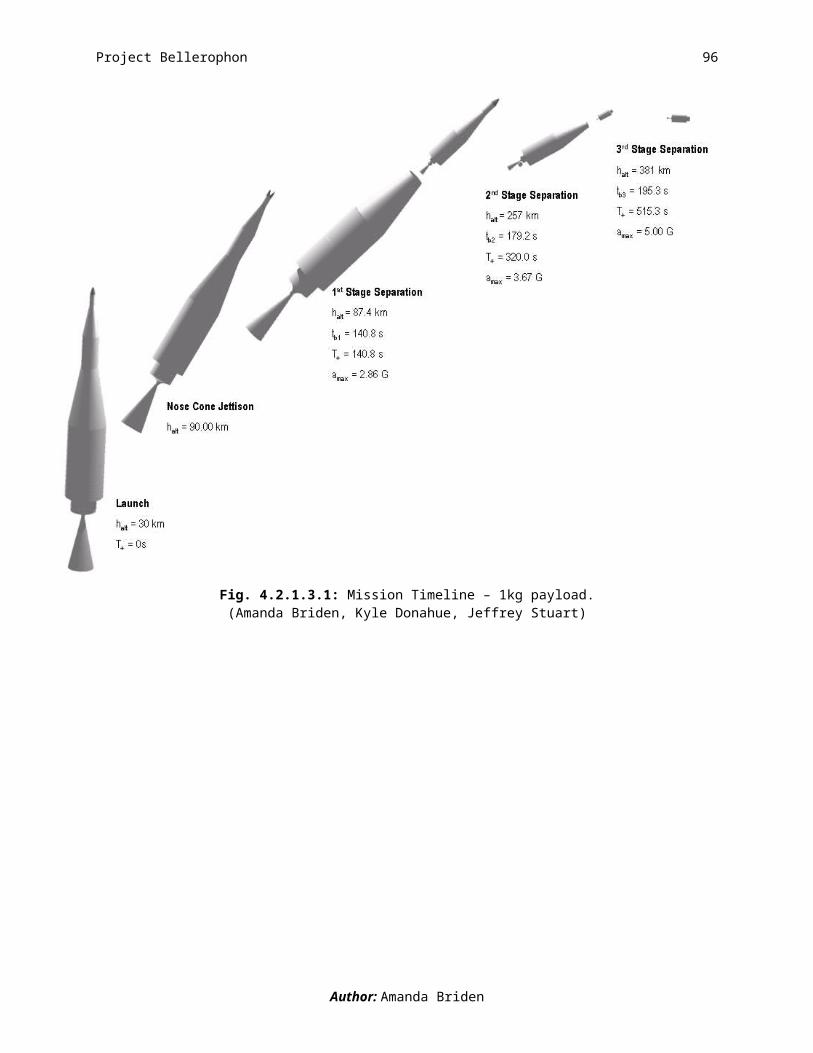
Project Bellerophon 96
the final stage of the rocket element for the launch vehicle. Above the third stage is a nose cone,
0.3596 m long and made of titanium. It protects the 1 kg payload that sits over the third stage.
Inert masses of the components vary between stages as follows.
Table 4.2.4.3.1: Inert Mass Breakdown of Three-Stage Rocket, 1 kg Payload
Stage 1 Stage 2 Stage 3 Totals UnitsFuel Tank 44.1164 28.5201 3.8132 76.4497 kgOx Tank 36.2949 0 0 36.2949 kgPressure Tank 8.2112 0 0 8.2112 kgEngine 72.6207 36.4391 9.5344 118.5942 kgPressure Addition 38.2475 0 0 38.2475 kgAvionics 3.96 23.82 3.96 31.74 kgInter-tank 0.5677 0 0 0.5677 kgSkirt/Nose Cone 8.4667 2.1202 2.0435 12.6304 kgTotal 212.4851 90.8994 19.3511 322.7356 kg
Dimensions are shown in the following table. We measured the total length of the rocket to be
from the end of the first stage nozzle to the tip of the nose cone. This length is found to be
8.9119 m.
Table 4.2.4.3.2: Dimensions of the Three-Stage Rocket, 1 kg Payload
Stage 1 Stage 2 Stage 3 Totals UnitsNozzle Length 1.3522 0.3856 0.1352 1.873 mEngine Length 0.3381 0.0964 0.0338 0.46825 mFuel Tank Length 1.1264 1.096 0.5606 2.783 mFuel Tank Thickness 0.0032 0.0046 0.0024 0.0102 mOx Tank Length 1.1527 0 0 1.1527 mOx Tank Thickness 0.0032 0 0 0.0032 mIntertank Thickness 0.002 0.002 0.002 0.006 mPress. Tank Diam. 0.5242 0 0 0.5242 mPress. Tank Thick. 0.0034 0 0 0.0034 mNose Cone Length 0 0 0.3596 0.3596 mDiameter 1.1264 0.5669 0.29 1.9833 mLength of Stage 6.0803 1.9776 0.854 8.9119 m
Inter-stage “skirts” are required to connect and transition from one stage to another. The two
skirts lay between the first and second stages and the second and third stages. The first skirt has
Author: Molly Kane
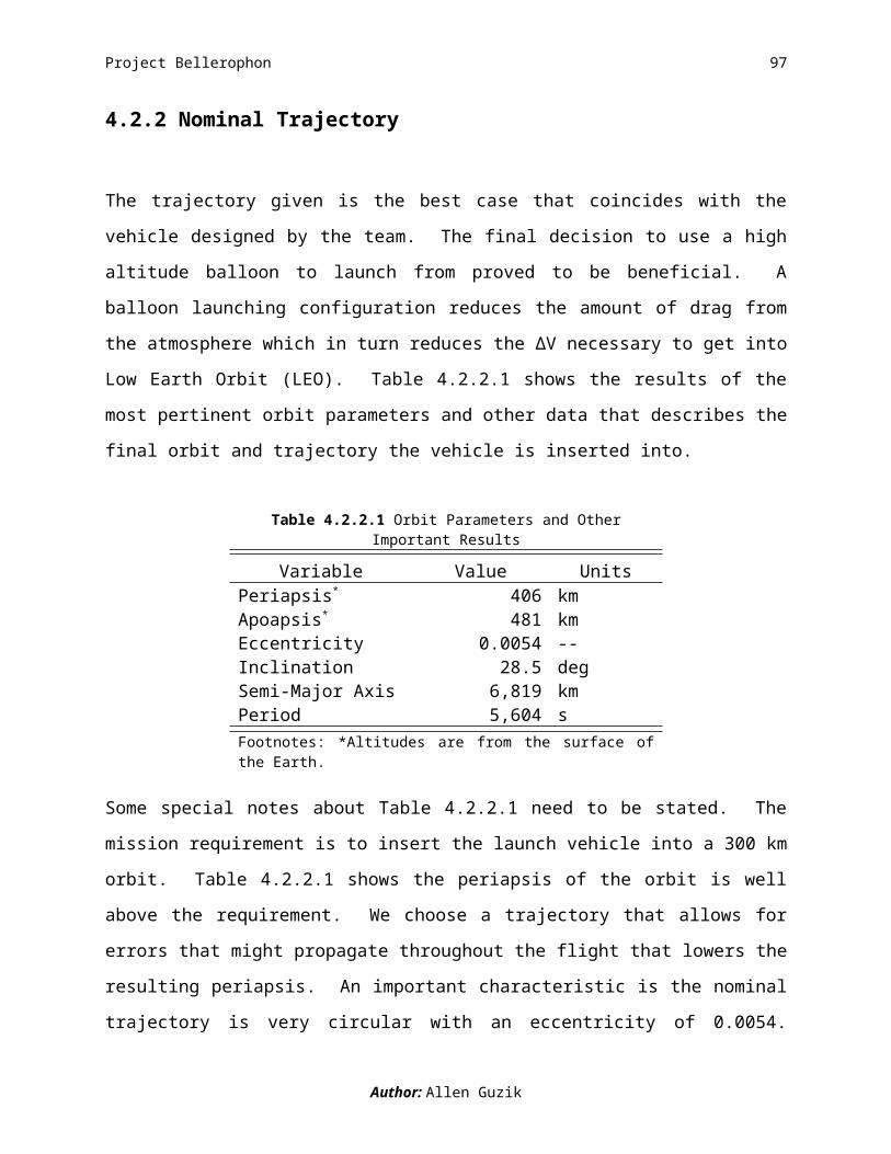
Project Bellerophon 97
a vertical height of 1.5867 m at a constant 10° slope. Similarly, the second skirt connects the
second and third stages and has a constant 10°, but with a vertical height of 0.7852 m.
The slope of 10º was chosen because the closer to vertical they are, the more weight they can
withstand. However, they still must provide the transition between the two different diameters.
Choosing this low-angled slope gave us more efficient stringers with less material needed for
each stringer. Ultimately, this reduced the cost of the stringers. The inter-stage skirt between
stages one and two requires a minimum load bearing of 27.390 kN. The inter-stage skirt
between stages two and three calls for a minimum load bearing capability of 3.618 kN. The
skirts are reinforced with stringers and ring supports, detailed as follows.
Table 4.2.4.3.3: Details of the Inter-stage Structure, 1 kg PayloadStage 1-2 Stage 2-3 Units
Vertical Length 1.5867 0.7852 mShell Thickness 0.004 0.004 mMass 8.4667 2.1202 kgSlope Angle 10 10 degNo. Stringers 29 15 --Stringer Thickness 0.003 0.003 mStringer Depth 0.02 0.02 mNo. Ring Supports 6 1 --
Author: Molly Kane

Project Bellerophon 98
4.2.4.4 Avionics
We have three subsystems that comprise the avionics portion of the launch vehicle:
telecommunications, power systems and range safety. The telecommunications portion of
avionics consists of the equipment the ground stations and vehicle require to communicate
between the ground and launch vehicle.
The avionics packages are broken up into 2 main locations: those that are placed on the gondola,
and those that are placed on the inside of the skirt between the second and final stages. We place
a battery and some sensors on the gondola to help eliminate some of the avionics weight from
the launch vehicle.
Most of our avionics are commercial grade products instead of space grade. The decision to use
commercial grade components allows us to cut a lot of the cost usually required for additional
testing and safety factors that our mission did not require. When choosing commercial grade
products we do not consider if we need radiation hardening for avionics and other space grade
requirements. Also, we are not able to tell how the loads from the gravitational forces will
impact the accuracy of the electronic components.
Most of the avionics package is independent of small changes in the launch vehicle design. This
is due to most of our avionics basis on the communication requirements for a vehicle and not
physical size dimensions. Since all of our vehicles were following the same rough path and had
the same functions there was little need for variations. Therefore our avionics package is the
same for all 3 launch vehicles.
Author: Danielle Yaple

Project Bellerophon 99
4.2.4.5 Cost
Our predicted costs for the launch vehicle carrying the 1 kg payload are catalogued in Table 4.2.4.5.1.
Table 4.2.4.5.1 Complete Cost Breakdown for 1 kg Payload Launch Vehicle
Item Stage 1 Stage 2 Stage 3 TotalPropellant $10,089 $1,680 $225 $11,994 Fuel / Ox $9,500 $1,680 $225 Tubing $589 - -Pressurant $38 - - $38Engine $634,090 $209,930 $86,860 $930,880LITVC $400 $400 - $800Balloon - - - Helium - - - $53,213 Material - - - $9,200 Gondola - - - $13,200Ground Costs - - - Personnel - - - $42,000 Handling $2,000 $8,000 $8,000 $18,000Tanks $1,188,600 $633,100 $149,800 $1,971,500Material $1,853 $560 $78 $2,490Manufacturing $14,952 $9,580 $8,992 $33,525 Welding $2,166 $1,087 $545 Riveting $186 $94 $47 Other $12,600 $8,400 $8,400Wiring - - - Material - - - $500 Installation - - - $7,500CPU - $10,000 - $10,000IMU - $3,300 - $3,300Sensors - - - $800Battery - $10,000 - $10,000Range Safety - $20,000 - $20,000Ground Tracking - $24,000 - $24,000Telecom - - - Vehicle - - - $10,000 Ground - - - $10,000 Installation - - - $7,500
Total $3,178,447
Author: Alan Schwing

Project Bellerophon 100
4.3 5kg Payload
4.3.1 Vehicle Overview
The launch vehicle carrying the 5 kg payload (Fig. 4.3.1.1) hitches a ride on a balloon up to an
altitude of 30 km where the first of three stages is ignited. At 30 km, the rocket launches in a
vertical orientation from a gondola that is attached to the balloon. Once the rocket finishes
burning the propellant in all three stages, the designed orbit perigee is 513 km. When random
uncertainties in vehicle performance characteristics are included in the design (Monte Carlo
analysis), the launch vehicle achieves an average perigee of 516 km.
Fig. 4.3.1.1: Launch vehicle stack up – 5kg payload.(Daniel Chua)
Author: Amanda Briden

Project Bellerophon 101
4.3.1.1 Launch System Breakdown
4.3.1.1.1 Gondola and Balloon Components
Providing support to the launch vehicle and guidance at take-off, the gondola is an all aluminum
structure. To support the launch vehicle there are three equally spaced, horizontally oriented,
rings that attach to the launch vehicle’s outer structure (Fig. 4.3.1.1.1.1). Also positioned
horizontally are a square frame (at the bottom of the gondola) and flange (at the top of the
gondola). Connecting these rings and frame are four equally spaced, vertically oriented launch
rails that guide the launch vehicle off the gondola at ignition.
Fig. 4.3.1.1.1.1: Launch vehicle and gondola configuration – 5kg payload.(CJ Hiu)
The gondola is connected to a spherical balloon, filled with helium, made of polyethylene
plastic. During flight, the gondola carrying the launch vehicle is suspended below the balloon.
We assume that the balloon pops right before the launch vehicle passes through it. As the
balloon rises, the gas expands and the balloon is sized to hold the gas at an altitude of up to 30
km. The battery, that powers the communications with the range safety officer on the ground, is
Author: Amanda Briden

Project Bellerophon 102
attached to the flanges of the gondola. Neither the balloon or gondola are reused. Fig.
4.3.1.1.1.2 puts the size of these components with respect to the launch vehicle into perspective.
Fig. 4.3.1.1.1.2: Size comparison of the gondola, launch vehicle, and balloon – 5kg payload.(Jeffrey Stuart)
4.3.1.1.2 First Stage
Fig. 4.3.1.1.2.1 is an exploded view of the launch vehicle. A reference table, summarizing the
sizing and propulsion information for each stage, is also provided. Please refer back to it while
reading the descriptions of each stage.
Author: Amanda Briden

Project Bellerophon 103
Fig. 4.3.1.1.2.1: Exploded view of launch vehicle stack up and parameter summary – 5kg payload.(Stephen Bluestone, Amanda Briden, Nicole Bryan, Jeffrey Stuart, Molly Kane, William Ling ,Sarah Shoemaker)
Author: Amanda Briden
BAL
LOO
N S
TRU
CTU
RE
GO
ND
OLA
STR
UC
TUR
EFe
atur
esFe
atur
esM
inim
um v
olum
e:6,
894.
5 m
3D
imen
sion
s:0.
138[3
] x 0
.138
[3] x
5.1
33[4
] m3
Max
imum
vol
ume:
596,
130
m3
Mat
eria
l:A
lum
inum
M
inim
um d
iam
eter
:23
.613
9 m
Thic
knes
s:0.
04 m
Max
imum
dia
met
er:
104.
4193
mW
eigh
t:33
8.32
kg
Mat
eria
l:P
olye
thyl
ene
plas
tic fi
lmPR
OPU
LSIO
NG
as u
sed:
Hel
ium
Feat
ures
Shap
e:S
pher
ical
Prop
ella
nt ty
pe:
STR
UC
TUR
ES
Sta
ge 1
H2O
2 & H
TPB
Feat
ures
S
tage
2H
TPB
/AP
/Al &
H2O
2[5]
Leng
th:
S
tage
3H
TPB
/AP
/Al
S
tage
17.
0714
mPr
opel
lant
am
ount
:
Sta
ge 2
2.19
21 m
S
tage
141
22.8
5 kg
S
tage
31.
0025
m
Sta
ge 2
1009
.33
kgD
iam
eter
:
Sta
ge 3
38.3
7 kg
S
tage
11.
8386
mEn
gine
type
:
Sta
ge 2
0.81
72 m
S
tage
1H
ybrid
S
tage
30.
2748
m
Sta
ge 2
Sol
idIn
ert m
ass:
[1]
S
tage
3S
olid
S
tage
140
7.48
22 k
gTh
rust
:
Sta
ge 2
90.7
999
kg
Sta
ge 1
7507
3.2
N
Sta
ge 3
5.03
69 k
g
Sta
ge 2
1525
6.9
NM
ater
ial:
S
tage
369
2.4
N
Sta
ge 1
Al
ISP:
S
tage
2A
l
Sta
ge 1
352.
3 se
cond
s
Sta
ge 3
Al
S
tage
230
9.3
seco
nds
Thic
knes
s: [2
]
Sta
ge 3
309.
3 se
cond
s
Sta
ge 1
0.00
52 m
Expa
nsio
n ra
tio:
S
tage
20.
0067
m
Sta
ge 1
60
Sta
ge 3
0.00
22 m
S
tage
260
AVIO
NIC
S
Sta
ge 3
60Fe
atur
esN
OTE
SM
ass:
1. In
ert m
asse
s in
clud
e ta
nk, s
kirt,
and
nos
e co
ne m
asse
s.
Sta
ge 1
6.02
4 kg
2. T
hick
ness
val
ues
perta
in to
the
fuel
tank
s.
Sta
ge 2
30.2
664
kg3.
Gon
dola
squ
are
base
wid
th a
nd le
ngth
.
Sta
ge 3
1.2
kg4.
Gon
dola
hei
ght.
Tota
l sys
tem
pow
er:
200
Wat
ts5.
Use
d fo
r LIT
VC
.

Project Bellerophon 104
A hybrid first stage with a hydroxy-terminated polybutadiene (HTPB) solid fuel and hydrogen
peroxide (H2O2) liquid oxidizer pairing is pressurized with gaseous nitrogen and provides a thrust
of 75 kN. Part of the first stage propellant is tapped off to support the liquid injection thrust
vector control (LITVC), which is used to steer the rocket. Made out of light-weight space-grade
aluminum, the structure can withstand a maximum acceleration of 3.68 Gs. The first stage is
78.95% of the launch vehicle’s gross liftoff mass (GLOM) and the length of this stage is 10.22
m. Fig.4.3.1.1.2.2 is a dimensional drawing of the first stage.
Fig. 4.3.1.1.2.2: Dimensional drawing of the first stage – 5kg payload.(Jesii Doyle)
4.3.1.1.3 Second Stage
The second stage is an ammonium perchlorate (AP), aluminum (Al), and HTPB solid motor with
an extra tank of H2O2 to provide fuel for the LITVC. The H2O2 is again pressurized with gaseous
nitrogen. This stage imparts a thrust of 15 kN. Able to withstand a maximum acceleration of
5.15 Gs, the second stage is made of space-grade aluminum. A cone truncated in the mid-section
Author: Amanda Briden

Project Bellerophon 105
is used to connect one stage diameter to the next such that there are no gaps in the structure; this
is called a skirt. The most significant part of the avionics package is located on the interior of the
skirt connecting the second and third stages. The avionics package located in the skirt includes a
battery, telecom, central processing unit (CPU), and CPU equipment. These features increase
the avionics mass from the first by a factor of 5, for a total avionics mass on the second stage of
30 kg. The second stage is 20.2% of the launch vehicle’s GLOM. This stage is
4 m long and a dimensional drawing is shown in Fig. 4.3.1.1.3.1.
Fig. 4.3.1.1.3.1: Dimensional drawing of the second stage – 5kg payload.(Jesii Doyle)
4.3.1.1.4 Third Stage
Since the avionics is jettisoned along with the second stage at the end of its burn, we spin the
third stage of the launch vehicle to maintain stability. The propellant type and structural material
are identical to the second stage. The third stage is 0.85% of the launch vehicle’s GLOM. Stage
three is 1.07 m in length and a dimensional drawing follows in Fig. 4.3.1.1.4.1.
Author: Amanda Briden

Project Bellerophon 106
Fig. 4.3.1.1.4.1: Dimensional drawing of the third stage – 5kg payload.(Jesii Doyle)
4.3.1.1.5 Nose Cone Component
The nose cone protecting the top of the launch vehicle from extreme heating is made of
aluminum and titanium. An additional feature of the nose cone is a blunted tip made of titanium,
which is a heat resistant material. The nose cone is jettisoned once the vehicle reaches an
altitude of 90 km (out of the Earth’s atmosphere). The nose cone jettison occurs prior to the
separation of the first stage.
Author: Amanda Briden
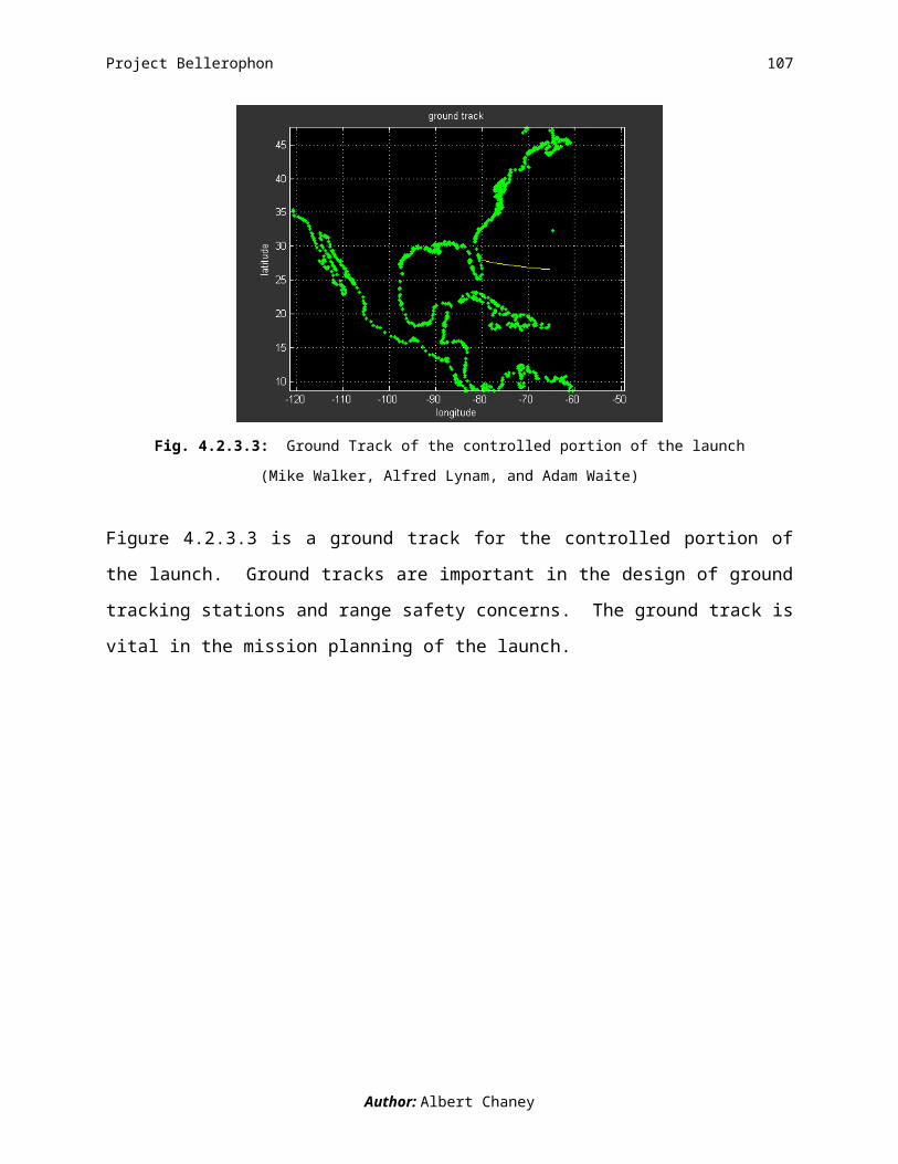
Project Bellerophon 107
4.3.1.2 Mission Requirements Verification
What are the chances that we reach an orbit with a periapsis of at least 300 km?
There is a 100.00% chance that our launch vehicle reaches a periapsis of 300km. After 10,297
Monte Carlo simulations the launch vehicle never fails (Fig. 4.3.1.2.1). We therefore meet the
mission requirement of 99.86% success rate, considering only non-catastrophic failures. An
average perigee, shown as the peak of the histogram in Fig. 4.3.1.2.1, of 516 km is achieved.
450 500 550 6000
50
100
150
200
250
Periapsis altitude(km)
num
ber o
f cas
es
Fig. 4.3.1.2.1: 5kg Periapsis altitude histogram with std 20.215 km and mean = 516.546 km.(Alfred Lynam)
What are the chances of a failure that results in complete loss of mission?
Accurately predicting the mission success rate, including failures that result in complete loss of
mission, is difficult to do without built and tested hardware. Therefore, we turn to the historical
success rates of the Ariane IV, Ariane V, and Pegasus, to predict ours. We use the success
pattern of Pegasus as it is the only vehicle is air-launched. We predict a 93.84% success rate,
which includes catastrophic failures and is achieved after 24 launches.
Author: Amanda Briden

Project Bellerophon 108
4.3.1.3 Mission Timeline - A Launch in the Life of the 5kg Payload Launch Vehicle
T- 1:36:00 to launch
The entire launch system begins its 1 hour and 36 minute ascent to its launch altitude of 30 km.
On average, the system drifts 121 km before reaching the launch altitude. Prior to ignition, a
range safety officer on the ground checks the status of the launch system and has the authority to
proceed with or abort the launch. Fig. 4.3.1.3.1 is a visual representation of the stages of flight
described in the timeline.
T+ 00:00:00 to launch – We are go for launch!
If all systems are go, the first stage is ignited and the launch vehicle is guided off the gondola via
four launch rails. We assume that the balloon pops as the launch vehicle passes through it.
Throughout the course of the burn, the position of the launch vehicle is determined at every
instant by the control system which follows a near optimal steering law. During the first stage
the launch vehicle climbs out of the atmosphere and jettisons the nose cone.
T+ 00:02:55 First Stage Burn-out
Approximately two thirds of the way through the first stage burn, the launch vehicle begins a
pitch over maneuver. This initial maneuver is of the same form of that used in the Apollo
program. After burning for 174.9 s and climbing to an altitude of 129 km, the first stage
separates.
T+ 00:06:28 Second Stage Burn-out
During this phase, the launch vehicle continues to pitch over to burn off velocity in the radial
direction. At orbit insertion, radial velocity needs to be zero in order for a circular orbit to be
achieved. With the burn duration of 213 s and burn out altitude of 406 km, the second stage
separates, jettisoning the bulk of the system’s avionics.
T+ 00:09:26 Third Stage Burn-out – We’re in orbit!
For the duration of the third stage burn, the launch vehicle uses spin stabilization to maintain its
orientation and does not require avionics control or LITVC. This means that the vehicle’s
Author: Amanda Briden
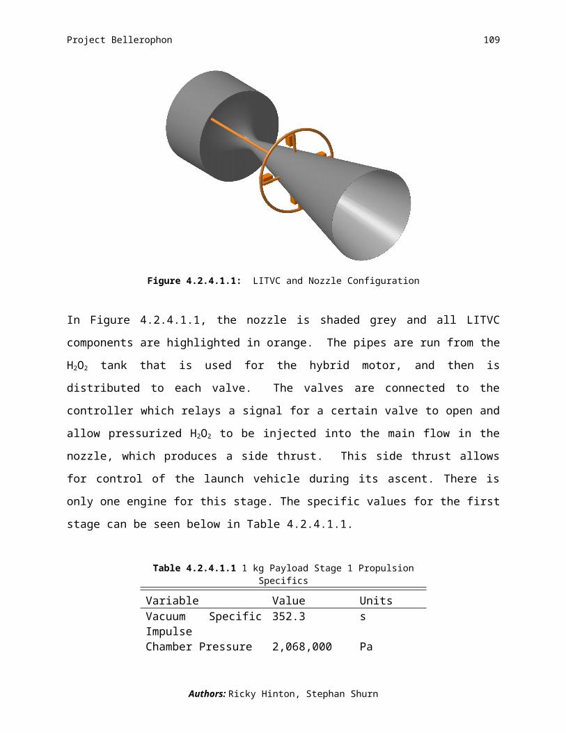
Project Bellerophon 109
orientation from the end of the second stage burn through the third is maintained. After a 178.4 s
third stage burn time, the launch vehicle ends its ascent and enters an orbit with a perigee of 516
km. The total mission time is 1.8 hours.
Fig. 4.3.1.3.1: Mission Timeline – 5kg payload.(Amanda Briden, Kyle Donahue, Jeffrey Stuart)
Author: Amanda Briden

Project Bellerophon 110
4.3.2 Nominal Trajectory
The nominal trajectory and orbit for the 5 kg payload is directly related to lowering the cost of
the launch vehicle. If the launch vehicle does not try to follow a nominal trajectory it will be over
designed and over built. The mission requirements for project Bellerophone are to place a 5 kg
payload into an orbit with a minimum altitude of 300 km. We meet the requirement of a
minimum altitude and create an orbit which is near to circular. The final design uses a balloon as
a launch platform which reduces the drag on the launch vehicle and this reduces the total velocity
needed to get into Low Earth Orbit (LEO).
The following table describes the orbital parameters necessary to understand what orbit this
vehicle is in.
Table 4.3.2.1 Orbit Parameters
Variable Value UnitsPeriapsis 773.14* kmApoapsis 809.57* kmEccentricity 0.0025 --Inclination 28.5 degSemi-Major Axis
7167.36 km
Period 6038.7878 sec*Values are from the surface of the Earth.
The periapsis of an orbit is closest approach to the surface of the Earth once it is in its orbit. For
our vehicle the periapsis is 473.14 km above the desired altitude. The apoapsis is the furthest
distance from the surface of the Earth in which the vehicle will experience. For the mission a
given apoapsis was not specified. The eccentricity is a measure on how circular the orbit is. For a
circular orbit the eccentricity should be zero. This translates into a constraint on apoapsis, so we
have an apoapsis difference of 36.43 km. Project Bellerophon did not have a specified inclination
to the orbit. Since we are launching from the Kennedy Space Center in Cape Canaveral, FL and
launching directly east our orbit has an inclination of 28.5o. The semi-major axis is the distance
from the center of the ellipse (center of the Earth) to the edge of the ellipse, and the semi-major
Author: Kyle Donahue

Project Bellerophon 111
axis for our orbit is 7167.36 km. The period of an orbit is the time it takes for the satellite to
make one complete revolution and the period for our orbit is 6038.7878 seconds which is about 1
hour and 40 minutes.
The velocity needed to reach our orbit is measured in the change of velocity also know as ΔV.
Table 4.3.2.2 breaks down the ΔV budget for the 5 kg case of Project Bellerophon.
Table 4.3.2.2 ΔV Breakdown
Variable Value Units Percent of ΔVtotal
ΔVtotal 9354 m/s --ΔVdrag 4 m/s 0.043ΔVgravity 2034 m/s 21.745ΔVEarth assist 411 m/s -4.394ΔVleo 7727 m/s 82.606
The ΔVtotal is a combination of all the other ΔVs which are: ΔVdrag, ΔVgravity, ΔVEarth assist, ΔVleo.
ΔVdrag refers to the velocity needed to overcome the drag which we will experience. This value
seems incredibly low, and it should be that way because we are launching from a balloon at an
altitude of 30 km. Since we are launching from so high in the atmosphere the air density is
relatively low and does not cause much resistance to the launch vehicle. ΔVgravity is the velocity
needed to overcome gravity drag. ΔVEarth assist refers to the velocity the Earth’s spin is helping the
launch vehicle reach orbit. This is the only ΔV which is helping us, the other ΔVs are velocities
we need to overcome. ΔVleo is the velocity needed to achieve our orbit.
Author: Kyle Donahue
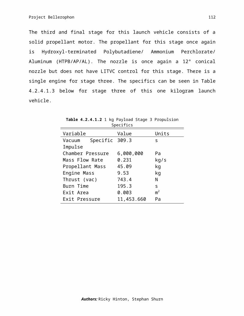
Project Bellerophon 112
Figure 4.3.2.1 shows the entire orbit mentioned above.
Fig 4.3.2.1: Full orbit of 5kg payload.(Kyle Donahue)
In order to obtain any orbit a steering law is needed to put the rocket on the correct path. We
created and used a linear-tangent steering law for each stage. There are many other types of
steering laws besides linear-tangent. Other types of steering laws include linear with any of the
trigonometric functions along with polynomial with any of the trigonometric functions. The
linear-tangent steering law we used is calculated using Eq. (4.3.2.1) below.
ϕ=tan−1
( at+b ) Eq. 4.3.2.1
Where φ is the angle the launch vehicle is at, a is the constant mentioned above, t is time in
seconds, and b is the other constant mentioned above.
Since we are using a linear-tangent law we have two coefficients for each part of the law. Table
4.3.2.3 has the values of the two coefficients (a and b) for each stage.
Author: Kyle Donahue

Project Bellerophon 113
These coefficients stay constant for each stage, but the angles in which they create change over
time. In order to better understand the steering law and what the coefficients do Table 4.3.2.4
describes the angles in which the vehicle is pointing at the end of each stage.Table 4.3.2.4 Angles from the Steering Law
Variable Value UnitsEnd of 1st stage 24 degEnd of 2nd stage -32 degEnd of 3rd stage -32 degAngles are the nose pointing based on the horizon
The angles in Table 4.3.2.4 refer to the angle at which the nose of the rocket is pointing relative
to the horizon. For example if the rocket were pointing directly east and parallel to the surface of
the Earth then the angle would be 0o. Figure 4.3.2.2 shows how the angles for the steering law
are defined.
Fig 4.3.2.2: Definition of steering law angles.
Author: Kyle Donahue
Table 4.3.2.3 Coefficients for Steering Law
Variable Valuea1 -1.6117015e-1b1 2.8636253e1a2 -5.0248315e-3b2 1.3241455e0a3 2.8623095e-19b3 -6.2486935e-1numbers refer to stage number

Project Bellerophon 114
(Amanda Briden)
Where br is pointing “up” or towards the sky and bθ is pointing east.
Figure 4.3.2.3 is the trajectory part of the orbit mentioned.
Fig 4.3.2.3: Trajectory part of orbit for 5kg payload.(Kyle Donahue)
The yellow dot is the launch site on the surface of the Earth, and the start of the red line should
not correspond to that as we are launching from a balloon with an altitude of 30km. The shape of
the trajectory is determined by the steering law which changes the angle. The figure shows the
nominal trajectory for the rocket but not necessarily the path the rocket will take.
The trajectory meets the mission requirement of an orbit with a periapsis altitude of at least
300km. We accomplish our mission using a linear-tangent steering law and launching from a
balloon.
Author: Kyle Donahue

Project Bellerophon 115
4.3.3 Controlled Trajectory
We are not able to exactly match the designed trajectory due to many factors. The trajectory
group models the launch vehicle as a point mass to determine the nominal orbit. To arrive at the
controlled trajectory the D&C group models the launch vehicle as a rigid body. Also, the
Trajectory group’s steering law includes sharp corners which are not physically possible. To
keep the launch vehicle under control those corners have to be smoothed out. These factors
combine to make the controlled trajectory differ from the nominal one. At orbit insertion, the
launch vehicle is at a lower altitude which leads to a more eccentric orbit which is illustrated in
the following figures.
Figure 4.3.3.1: Nominal (red) and controlled (yellow) trajectories, 5 kg(Authors: Mike Walker, Alfred Lynam, Adam Waite)
Author: Jeffrey Stuart

Project Bellerophon 116
Figure 4.3.3.2: Nominal (red) and controlled (yellow) orbits, 5 kg(Authors: Mike Walker, Alfred Lynam, Adam Waite)
Below is a table of the orbital parameters for the orbit we achieve. The value a is the semi-major
axis, e is the eccentricity, i is the inclination, Ω is the right ascension of the ascending node, and
ω is the argument of periapsis.
Table 4.3.3.1 Orbital Elements
Variable Value UnitsPeriapsis 513.00* kmApoapsis 24700.57* kma 12606.78 kme 0.4551 --i 26.89 degΩ 15.80 degω 280.33 degFootnotes: * Distance from surface
Author: Jeffrey Stuart
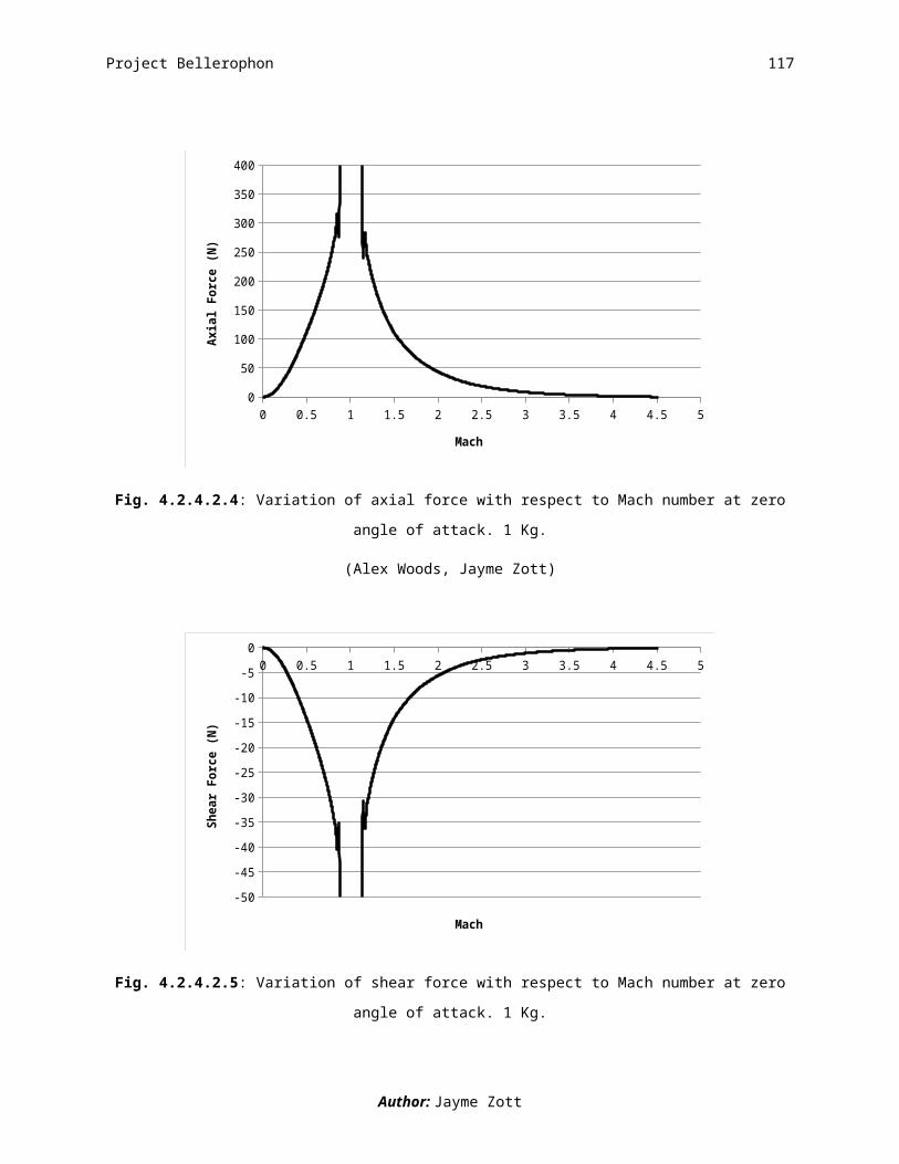
Project Bellerophon 117
Figure 4.3.3.3: Launch trajectory ground track, 5kg(Authors: Mike Walker, Alfred Lynam, Adam Waite)
Figure 4.3.3.3 is a ground track for the controlled portion of the launch. Ground tracks are
important in the design of ground tracking stations and range safety concerns. The ground track
is vital in the mission planning of the launch.
Author: Jeffrey Stuart

Project Bellerophon 118
4.3.4 Subsystem Details
4.3.4.1 Propulsion
The propellants we selected for the 5 kilogram payload launch vehicle were a hybrid first stage
and a solid second and third stage. Our selection process involved the use of an optimization
code which gave us the best results for a 5 kilogram payload launch vehicle. The code gave us a
propulsion system described in the following section.
The first stage of the launch vehicle uses a hybrid rocket motor, with hydrogen peroxide (H2O2)
as the oxidizer and hydroxyl terminated polybutadiene (HTPB) as the solid propellant. The H2O2
tank is pressurized using gaseous nitrogen. The nozzle is a 12º conical nozzle with liquid
injection thrust vector control (LITVC) attached. The LITVC system is composed of four valves
that allow H2O2 to be injected into the nozzle at a 90º angle to the centerline of the nozzle. A
schematic of the LITVC can be seen below in Figure 4.3.4.1.1.
Figure 4.3.4.1.1 LITVC and Nozzle Configuration
In Figure 4.3.4.1.1, the nozzle is shaded grey and all LITVC components are highlighted in
orange. The pipes are run from the H2O2 tank that is used for the hybrid motor, and then is
distributed to each valve. The valves are connected to the controller which relays a signal for a
Authors: Stephan Shurn, Ricky Hinton, Jerald A. Balta

Project Bellerophon 119
certain valve to open and allow pressurized H2O2 to be injected into the main flow in the nozzle,
which produces a side thrust. This side thrust allows for control of the launch vehicle during its
ascent. The specifics of the propulsion system can be seen in Table 4.3.4.1.1.
Table 4.3.4.1.1 5kg Payload Stage 1 Propulsion Specifics
Variable Value UnitsVacuum Specific Impulse 352.3 sChamber Pressure 2,068,000 PaMass Flow Rate 23.571 kg/sPropellant Mass 4122.85 kgEngine Mass 193.49 kgThrust (vac) 75073.2 NBurn Time 174.9 sExit Area 1,198 m2
Exit Pressure 2,821.167 Pa
A conical nozzle was chosen because of the solid particles of propellant that will be coming out
of the combustion chamber. The combustion process does not necessarily combust the fuel 100%
and these particles can deteriorate a nozzle if it is let’s say Bell shaped. Some of our early MAT
codes had values based off of a 12° conical nozzle and that is one of the reasons we decided on
this cone angle for the final design. Also having a smaller cone angle reduces the divergence loss
at the exit of the nozzle. A picture of the nozzle can be seen below in Fig. 4.3.4.1.1.
Authors: Stephan Shurn, Ricky Hinton, Jerald A. Balta

Project Bellerophon 120
Figure 4.3.4.1.1: Our 12° conical nozzle
The second stage of the launch vehicle uses a solid rocket motor, with hydroxyl-terminated
polybutadiene/ ammonium perchlorate/ aluminum (HTPB/AP/AL) as the propellant. The nozzle
is a 12º conical nozzle with LITVC attached. The LITVC has the same configuration as the first
stage, with the exception of the H2O2. Since there is no H2O2 already present due to the solid
motor, a pressurized tank is added in a curved configuration sitting beneath the solid motor. The
tank wraps around the nozzle and is pressurized with gaseous nitrogen so that the H2O2 can flow
into the lines for injection. The specifics of the propulsion system can be seen in Table 4.3.4.1.2.
Table 4.3.4.1.2 5kg Payload Stage 2 Propulsion Specifics
Variable Value UnitsVacuum Specific Impulse 309.3 sChamber Pressure 6,000,000 PaMass Flow Rate 4.739 kg/sPropellant Mass 1009.33 kgEngine Mass 75.72 kgThrust (vac) 15256.9 NBurn Time 213.0 sExit Area 0.070 m2
Exit Pressure 11,453.660 Pa
Authors: Stephan Shurn, Ricky Hinton, Jerald A. Balta

Project Bellerophon 121
The third stage of the launch vehicle uses a solid rocket motor, with hydroxyl-terminated
polybutadiene/ ammonium perchlorate/ aluminum (HTPB/AP/AL) as the propellant. The nozzle
is a 12º conical shape. The specifics of the propulsion system can be seen in Table 4.3.4.1.3.
Table 4.3.4.1.3 5kg Payload Stage 3 Propulsion Specifics
Variable Value UnitsVacuum Specific Impulse 309.3 sChamber Pressure 6,000,000 PaMass Flow Rate 0.215 kg/sPropellant Mass 38.37 kgEngine Mass 8.56 kgThrust (vac) 692.4 NBurn Time 178.4 sExit Area 0.003 m2
Exit Pressure 11,453.660 Pa
Authors: Stephan Shurn, Ricky Hinton, Jerald A. Balta

Project Bellerophon 122
4.3.4.2 Aerothermal
In our aerodynamic analysis, we use linear perturbation theory to determine the aerodynamic
loading on the launch vehicle. Linear perturbation theory is the method in which the pressure
over the top and bottom surfaces of the launch vehicle is integrated to solve for the normal and
axial force coefficients acting on the launch vehicle. It is valid in the subsonic and supersonic
regimes, but falls apart in the transonic regime. For this reason, we have ignored the
aerodynamic outputs in the transonic regime and only pay attention to the outputs in the subsonic
and supersonic regimes. By integrating the change in pressure around the launch vehicle we are
able to solve for bending and pitching moments, drag coefficient, axial forces, normal forces,
shear forces, and the center of pressure location. All of these aerodynamic moments, coefficients,
and forces are based on the final geometry of the launch vehicle as well as the Mach number,
angle of attack, and time spent in the atmosphere.
Mach number, variation in angle of attack, use of LITVC, stage separation, as well as wind gusts
all have a large impact on the aerodynamic loadings of the launch vehicle. As the launch vehicle
makes its way through the atmosphere, the change in density also has a significant effect on the
impact of these forces and moments. The results for the variation of bending moment and
pitching moment with respect to Mach number at zero degree angle of attack can be found in
Figs. 4.3.4.2.1 and 4.3.4.2.2 respectively. Once the launch vehicle reaches a speed of Mach 4.4,
it exits the atmosphere. At this point, the first stage has still not separated; therefore, moments
are shown as they act on the entire launch vehicle.
Author: Jayme Zott

Project Bellerophon 123
0 0.5 1 1.5 2 2.5 3 3.5 4 4.5 5
-10000
-9000
-8000
-7000
-6000
-5000
-4000
-3000
-2000
-1000
0
Mach
Bend
ing M
omen
t (Nm
)
Fig. 4.3.4.2.1: Variation of bending moment with respect to Mach number at zero angle of attack. 5 Kg.
(Alex Woods, Jayme Zott)
0 0.5 1 1.5 2 2.5 3 3.5 4 4.5 50
200
400
600
800
1000
1200
1400
1600
1800
2000
Mach
Pitc
hing
Mom
ent (
Nm)
Fig. 4.3.4.2.2: Variation of pitching moment with respect to Mach number at zero angle of attack. 5 Kg.
(Alex Woods, Jayme Zott)
The moments presented in Figs. 4.3.4.2.1 and 4.3.4.2.2 correlate well with the magnitude of
moments expected for a launch vehicle of our size and shape. It is important for us to determine
these moments because the structures group uses them to determine appropriate materials and
thicknesses for the final launch vehicle design.
Author: Jayme Zott
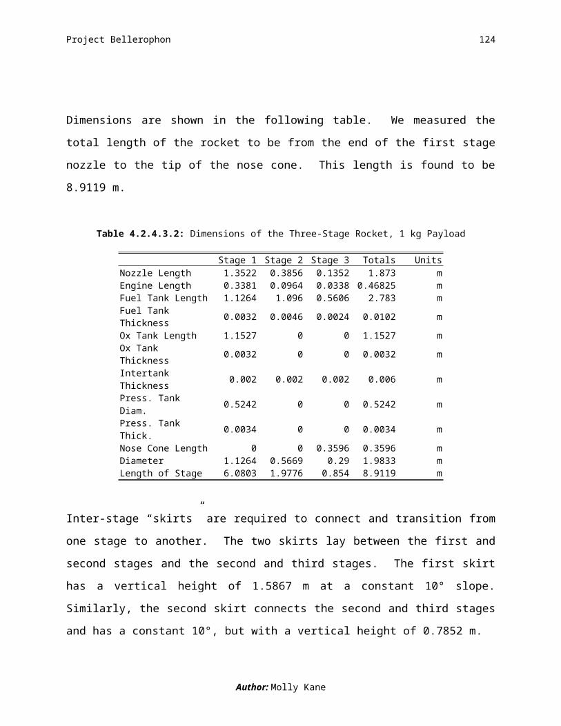
Project Bellerophon 124
The results for the variation of normal, axial, and shear forces with respect to Mach number at a
zero degree angle of attack can be found in Figs. 4.3.4.2.3, 4.3.4.2.4, and 4.3.4.2.5 respectively.
The normal and axial forces are important for the D&C group’s analysis. D&C uses the normal
and axial forces acting on the launch vehicle to help determine the amount of LITVC needed for
control at any given moment in time. The shear force is important for the structures group’s
analysis. Structures uses the shear force acting on the vehicle to help determine appropriate
materials and thicknesses for the final launch vehicles design.
0 0.5 1 1.5 2 2.5 3 3.5 4 4.5 50
50
100
150
200
250
300
350
Mach
Norm
al Fo
rce
(N)
Fig. 4.3.4.2.3: Variation of normal force with respect to Mach number at zero angle of attack. 5 Kg.
(Alex Woods, Jayme Zott)
Author: Jayme Zott

Project Bellerophon 125
0 0.5 1 1.5 2 2.5 3 3.5 4 4.5 50
200
400
600
800
1000
1200
Mach
Axial
Forc
e (N
)
Fig. 4.3.4.2.4: Variation of axial force with respect to Mach number at zero angle of attack. 5 Kg.
(Alex Woods, Jayme Zott)
0 0.5 1 1.5 2 2.5 3 3.5 4 4.5 5
-600
-500
-400
-300
-200
-100
0
Mach
Shea
r For
ce (N
)
Fig. 4.3.4.2.5: Variation of shear force with respect to Mach number at zero angle of attack. 5 Kg.
(Alex Woods, Jayme Zott)
Author: Jayme Zott

Project Bellerophon 126
The variation of CD with Mach number at a constant zero angle of attack is shown in Fig.
4.3.4.2.6. Because the diameter of the 1 Kg launch vehicle is quite large, the coefficient of drag
CD is also quite large.
0 0.5 1 1.5 2 2.5 3 3.5 4 4.5 50
0.2
0.4
0.6
0.8
1
1.2
1.4
1.6
Mach
Cd
Fig. 4.3.4.2.6: Impact of Mach number on CD at zero angle of attack. 5 Kg.
(Alex Woods, Jayme Zott)
As previously mentioned, we use the linear perturbation theory to determine all aerodynamic
forces, coefficients, and moments, including CD. This method requires complete knowledge of the
launch vehicle geometry before any aerodynamic forces, coefficients or moments can be
determined. This causes a problem because the trajectory analysis requires use of CD long before
the final geometry is determined. Because the CD variation shown in Fig. 4.3.4.2.6 is determined
after the final launch vehicle geometry has been designed, it cannot be used in the trajectory
analysis. Instead, we use a CD trend based on historical data for the trajectory analysis.1,2 While
this historical CD trend is not based on our own geometry, it is based on successful launch
vehicles with geometries similar to our final design. The CD based on historical data at zero angle
of attack is shown in the Fig. 4.3.4.2.7.
Author: Jayme Zott

Project Bellerophon 127
0 0.5 1 1.5 2 2.5 3 3.5 4 4.5 50
0.1
0.2
0.3
0.4
0.5
0.6
0.7
0.8
Mach
Cd
Fig. 4.3.4.2.7: Impact of Mach number on CD at zero angle of attack based on historical data. 5 Kg.
(Jayme Zott)
Given additional time, we could complete a better trajectory analysis by including the correct CD
based on the linear perturbation theory into the trajectory code. If we created an intermediate file
between the initial propulsion sizing output and the trajectory input, a more accurate CD value
could be used within the trajectory code. Fig. 4.1.4.2.8 shows the error caused by the using the
CD trend based on historical geometries, rather than the CD determined directly from our own
geometry.
Author: Jayme Zott
Project Bellerophon 128
0 0.5 1 1.5 2 2.5 3 3.5 4 4.5 50
0.2
0.4
0.6
0.8
1
1.2
1.4
1.6
Cd (dimensional)Cd (historical)
Mach
Cd
Fig. 4.3.4.2.8: Comparison of CD based on historical data and CD based on dimensional analysis (linear perturbation theory). 5 Kg.
(Alex Woods, Jayme Zott)
Table 4.3.4.2.1 Summary of Maximum Aerodynamic Loading 5 Kg.
Aerodynamic Load Subsonic Supersonic Bending Moment [Nm] -6505.0 -3346.0Pitching Moment [Nm] 1246.0 640.9Normal Force [N] 215.9 111.0Axial Force [N]Shear Force [N]Center of Pressure [% length]Coefficient of Drag CD
Dynamic Pressure [Pa]CD % error [%]
760.0 -407.4 38.2 1.31
62.5
390.9 -209.6 38.2 0.78 225 19.5
(Jayme Zott)
References:1Sutton, George P., and Oscar Biblarz. Rocket Propulsion Elements. New York: John Wiley & Sons, Inc., 2001.
2The Martin Company, “The Vanguard Satellite Launching Vehicle”, Engineering Report No. 11022, April 1960.
Author: Jayme Zott

Project Bellerophon 129
4.3.4.3 Structures
The launch vehicle for the 5 kg payload design is comprised of a three-stage rocket carried by a
gondola and balloon. The gondola is made of aluminum bars, 0.04 m thick.
Fig. 4.3.4.3.1 Gondola frame for rocket element of launch vehicle of a 5 kg payload.
(Sarah Shoemaker)
We mad the frame 5.133 m tall with a square base of sides 1.38 m long. The ring supports have
a diameter of 1.8386 m. The mass of the gondola add up to 338.32 kg. The material properties
and dimensions give the structure the ability to withstand the approximately 36 kPa of pressure it
experiences during launch.
The first stage of our rocket is 10.6004 m in length and 1.8386 m in diameter. An engine,
oxidizer tank, fuel tank, pressurant tank, inter-tank structure, and avionics equipment make up
this first stage. All of our tanks are created from aluminum, but have different sizes and
thicknesses. An inter-stage “skirt” connects the first and second stages of the rocket. It has a
constant 10° slope from the lower stage to the upper stage. We also made this of aluminum and
it is reinforced with aluminum support stringers and rings. Between the first and second stages is
a 2.8965 m inter-stage structure. Its maximum diameter is that of the third stage 1.8386 m, and
the minimum diameter is the diameter of the second stage 0.8172 m.
Author: Molly Kane

Project Bellerophon 130
Only an engine, fuel tank, and avionics equipment make up the second stage of the rocket. This
stage has a diameter of 0.8172 m and a length of 3.2709 m. The second stage fuel tank is also
made from aluminum. The inter-stage structure connects the second and third stages of the
rocket, having a constant slope of 10° and vertical length of 1.5380 m.
The third stage is 0.9046 m in length and is 0.2748 m in diameter. It is also composed of an
engine, fuel tank, and avionics equipment. The fuel tank is constructed from aluminum. The 5
kg payload sits above the third stage and is protected by the nose cone. The nose cone is 0.3408
m in length and has a mass of 1.7927 kg.
The inert mass breakdowns of components and stages are summarized in the following table.
Table 4.3.4.3.1: Inert Mass Breakdown of Three-Stage Rocket, 5 kg PayloadStage 1 Stage 2 Stage 3 Totals Units
Fuel Tank 191.9896 85.5083 3.2442 280.7421 kgOx Tank 155.5405 0.0000 0.0000 155.5405 kgPressure Tank 35.7067 0.0000 0.0000 35.7067 kgEngine 193.4741 75.7181 8.5610 277.7532 kgPressure Addition 166.3206 0.0000 0.0000 166.3206 kgAvionics 3.9600 23.8200 3.9600 31.7400 kgInter-tank 0.0697 0.0000 0.0000 0.0697 kgSkirt/Nose Cone 24.2454 5.2916 1.7927 31.3297 kgTotal 771.3066 190.3380 17.5579 979.2025 kg
We have determined the total height of this rocket to be 14.7759 m. This value indicates the
length from the end of the first stage nozzle to the tip of the nose cone. The following table
shows the specifications of each part and each stage.
Author: Molly Kane

Project Bellerophon 131
Table 4.3.4.3.2: Dimensions of the Three-Stage Rocket, 5 kg Payload
Stage 1 Stage 2 Stage 3 Totals UnitsNozzle Length 2.5304 0.6122 0.1304 3.2730 mEngine Length 0.6326 0.1531 0.0326 0.8183 mFuel Tank Length 1.8386 1.5798 0.5312 3.9496 mFuel Tank Thickness 0.0052 0.0067 0.0022 n/a mOx Tank Length 1.8472 0.0000 0.0000 1.8472 mOx Tank Thickness 0.0052 0.0000 0.0000 n/a mInter-tank Thickness 0.0020 0.0020 0.0020 n/a mPress. Tank Diam. 0.8552 0.0000 0.0000 n/a mPress. Tank Thick. 0.0056 0.0000 0.0000 n/a mNose Cone Length 0.0000 0.0000 0.3408 0.3408 mDiameter 1.8386 0.8172 0.2748 n/a mLength of Stage 10.6004 3.2709 0.9046 14.7759 m
The connecting inter-stage skirts are designed to meet the requirements of the main parts of our
launch vehicle. The skirts are reinforced with stringers and ring supports, detailed as follows.
Table 4.3.4.3.3: Details of the Inter-stage Structure, 5 kg PayloadStage 1-2 Stage 2-3 Units
Vertical Length 2.897 1.538 mShell Thickness 0.004 0.004 mMass 24.245 5.292 kgSlope Angle 10.000 10.000 degNo. Stringers 42 14 --Stringer Thickness 0.005 0.003 mStringer Depth 0.020 0.020 mNo. Ring Supports 8 1 --
The slope of 10º was chosen because the closer to vertical they are, the more weight they can
withstand. However, they still must provide the transition between the two different diameters.
Choosing this low-angled slope gave us more efficient stringers with less material needed for
each stringer. Ultimately, this reduced the cost of the stringers. The inter-stage skirt between
stages one and two requires a minimum load bearing of 72.530 kN. The inter-stage skirt
between stages two and three calls for a minimum load bearing capability of 3.352 kN. The
skirts are reinforced with stringers and ring supports, detailed as follows.
Author: Molly Kane
Project Bellerophon 132
4.3.4.4 Avionics
We have three subsystems that comprise the avionics portion of the launch vehicle:
telecommunications, power systems and range safety. The telecommunications portion of
avionics consists of the equipment the ground stations and vehicle require to communicate
between the ground and launch vehicle.
The avionics packages are broken up into 2 main locations: those that are placed on the gondola,
and those that are placed on the inside of the skirt between the second and final stages. We place
a battery and some sensors on the gondola to help eliminate some of the avionics weight from
the launch vehicle.
Most of our avionics are commercial grade products instead of space grade. The decision to use
commercial grade components allows us to cut a lot of the cost usually required for additional
testing and safety factors that our mission did not require. When choosing commercial grade
products we do not consider if we need radiation hardening for avionics and other space grade
requirements. Also, we are not able to tell how the loads from the gravitational forces will
impact the accuracy of the electronic components.
Most of the avionics package is independent of small changes in the launch vehicle design. This
is due to most of our avionics basis on the communication requirements for a vehicle and not
physical size dimensions. Since all of our vehicles were following the same rough path and had
the same functions there was little need for variations. Therefore our avionics package is the
same for all 3 launch vehicles.
Author: Danielle Yaple

Project Bellerophon 133
4.3.4.5 Cost
Our predicted costs for the launch vehicle carrying the 5 kg payload are catalogued in Table 4.3.4.5.1.
Table 4.3.4.5.1 Complete Cost Breakdown for 5 kg Payload Launch Vehicle
Item Stage 1 Stage 2 Stage 3 TotalPropellant $42,322 $5,047 $192 $47,561 Fuel / Ox $41,320 $5,047 $192 Tubing $1,002 - -Pressurant $166 - - $166Engine $1,138,700 $339,700 $80,900 $1,559,300LITVC $400 $400 - $800Balloon - - - Helium - - - $152,320 Material - - - $31,577 Gondola - - - $13,200Ground Costs - - - Personnel - - - $42,000 Handling $2,000 $8,000 $8,000 $18,000Tanks $1,808,600 $943,500 $127,000 $2,879,100Material $6,036 $1,692 $67 $7,795Manufacturing $29,123 $10,212 $8,961 $48,296 Welding $3,612 $1,668 $517 Riveting $311 $144 $45 Other $25,200 $8,400 $8,400Wiring - - - Material - - - $500 Installation - - - $7,500CPU - $10,000 - $10,000IMU - $3,300 - $3,300Sensors - - - $800Battery - $10,000 - $10,000Range Safety - $20,000 - $20,000Ground Tracking - $24,000 - $24,000Telecom - - - Vehicle - - - $10,000 Ground - - - $10,000 Installation - - - $7,500
Total $4,672,258
Author: Alan Schwing
Related Documents