Technical Note 1966-30 P. Rosen R. V. Wood, Jr. B. E. Nichols Lincoln Experimental Terminal 11 May 1966 Lincoln Laboratory JSTITI ••• 01 on, Massac

Welcome message from author
This document is posted to help you gain knowledge. Please leave a comment to let me know what you think about it! Share it to your friends and learn new things together.
Transcript
Technical Note 1966-30
P. Rosen
R. V. Wood, Jr. B. E. Nichols
Lincoln Experimental Terminal
11 May 1966
Lincoln Laboratory JSTITI ••• 01
on, Massac
•
The work reported in this document was performed at Lincoln Laboratory, a center for research operated by Massachusetts Institute of Technology, with the support of the U.S. Air Force under Contract AF 19(628)-5167.
This report may be reproduced to satisfy needs of U.S. Government agencies.
Distribution of this document is unlimited.
45
MASSACHUSETTS INSTITUTE OF TECHNOLOGY
LINCOLN LABORATORY
LINCOLN EXPERIMENTAL TERMINAL
P. ROSEN
R. V. WOOD, JR.
B. E. NICHOLS
Group 62
TECHNICAL NOTE 1966-30
11 MAY 1966
LEXINGTON MASSACHUSETTS
ABSTRACT
The LincoLn Experimental Terminal (LET) is a complete,
self-contained air-transportable ground terminal for testing and demonstrating evolving space communication techniques
in a realistic environment. Its present equipment comple- ment permits efficient, highly reliable, multiplexed digital
communication of voice and record traffic using a variety of channels, includingthe moon and active satellites. Its modu-
lation system, using a 16-symbol alphabet frequency-hopped over a 20-Mcps band, together with efficient coding, provides multiple-access use of a wide-band satellite.
Accepted for the Air Force Franklin C. Hudson Chief, Lincoln Laboratory Office
CONTENTS
Abstract ii
I. Introduction 1
II. General Description of Terminal 1
III. System Considerations in Signal-Processing Design 2
IV. Antenna and Feed System 5
V. Antenna Vehicle 5
VI. RF Transmitter 5
VII. RF Receiver 6
VIII. Prime Power 6
IX. Electronics Vehicle 9
X. Test Operations 11
P30o-ioe
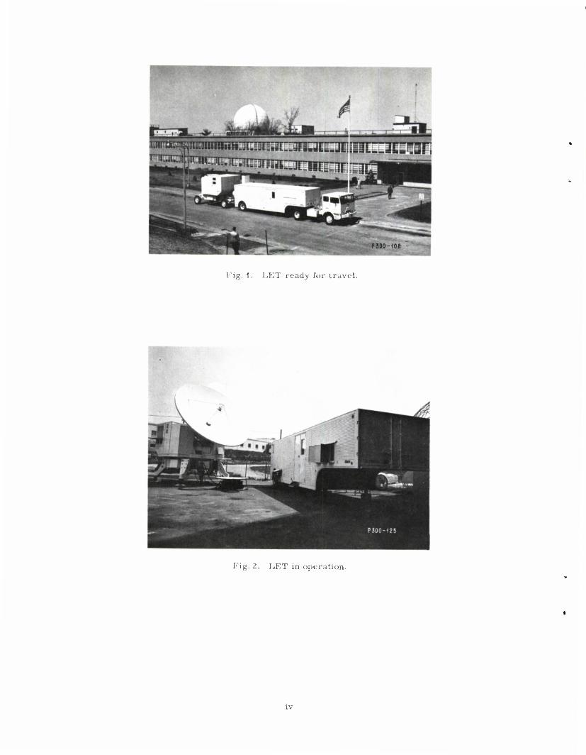
Fig. 1. LET ready for travel.
Fig. 2. LET in operation.
LINCOLN EXPERIMENTAL TERMINAL
I. INTRODUCTION
For a number of years, the M.I.T. Lincoln Laboratory has worked on various techniques
applicable to the solution of space communication problems. In addition to microwave techno-
logy and components such as cooled X-band parametric amplifiers and rapidly switchable fre- quency synthesizers, these techniques have included: modulation and demodulation for disper- sive channels such as the troposphere, Moon and West Ford belt; digitized narrow-band speech processing with emphasis on speaker recognizability; and practical realization of coding and
decoding schemes which are economically competitive with more conventional means of achiev- ing greater information rates on a given channel.
Some results of this work have been combined to produce an experimental air transportable
terminal, called the Lincoln Experimental Terminal (LET), which has a number of desirable and unique features, particularly from a military communications viewpoint. The terminal will
work efficiently on both coherent and time-varying dispersive channels; it provides good quality
digital speech with speaker recognizability in a reasonably narrow band; and it permits multiple
access of a broad-band satellite by spectrum spreading, without the severe synchronization prob- lems commonly associated with the use of a pseudo-noise carrier for this purpose.
II. GENERAL DESCRIPTION OF TERMINAL
A photograph of the terminal is shown in Fig. 1. The terminal is self-contained in two trailers. One of these, the so-called electronics vehicle, is a modified low-bed commercial van which contains the signal-processing equipment, a communications and antenna control con-
sole, a prime power generator and its fuel, an air conditioner, and storage for the antenna panels. The second trailer, which we call the antenna vehicle, contains the transmitter and its heat exchanger, a refrigerated parametric-amplifier receiver, low-level microwave equipment, the
antenna back-up structure, feeds and servo-mechanism equipment. Figure 2 shows the terminal in operation-
The terminal has the following gross characteristics:
Transmitter frequency ~8000Mcps Receiver frequency ~8000Mcps Transmitter power 1 0 kw CW System bandwidth 20Mcps System noise temperature 100°K Antenna diameter 15ft Antenna pointing Computer-aided autotracking Information rates Up to 9600 bits/sec Information types Multiplexed vocoded voice,
teletype and data
III. SYSTEM CONSIDERATIONS IN SIGNAL-PROCESSING DESIGN
The specific implementation of the techniques mentioned previously stems from a number
of self-imposed specifications. These may be listed roughly as:
(a) The terminal should be able to operate on almost any channel, passive or active, coherent or dispersive.
(b) The terminal should continue to operate with high efficiency in the presence of fortuitous or deliberate interference.
(c) The terminal should operate with very high efficiency, i.e., it should provide very reliable, highly accurate output with low-input signal-to- noise ratio.
(d) The terminal should provide digitized, good quality (speaker recognizable) vocoded voice.
(e) The terminal should be usable with a variety of inputs ranging from record traffic to voice, easily and flexibly multiplexed.
A conventional way of meeting the requirement that a terminal continue to operate under
severe interfering conditions is to use a pseudo-noise carrier in a broad-band system. Unfor-
tunately, the ability to do so is in conflict with the desire to operate on dispersive channels.
However, a frequency-hopped modulation scheme which minimizes intersymbol interference, and is therefore well suited for high-rate modulation on dispersive channels, can also have
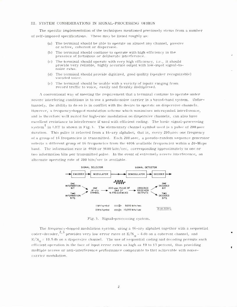
excellent resistance to interference if used with efficient coding. The basic signal-processing system in LET is shown in Fig. 3. The elementary channel symbol used is a pulse of 200(JLSCC
duration. This pulse is selected from a 16-ary alphabet; that is, every 200 u.sec one frequency of a group of 16 frequencies is transmitted. Each 200 fxsec, a pseudo-random sequence generator selects a different group of 16 frequencies from the 4096'available frequencies within a 20-Mcps
band. The information rate is 4800 or 9600 bits/sec, corresponding approximately to one or
two information bits per transmitted pulse. In the event of extremely severe interference, an
alternate operating rate of 200 bits/sec is available.
SIGNAL SELECTOR SIGNAL DETECTOR
ENCODER MODULATOR DEMODULATOR DECODER
c IN FOR
S
T INFOF
B
NE MATION . IIT ^
WO / MATION ITS
* ONE 2<
16-ary ^ SYMBOL IC
Mm- >0-Msec PULSE
ONE OF FREQUENCE
OF ORDERE »• RECEIVE
S OUTPUT
D R
S •s
ONI — DECOt
y BIT
\ TW * DECOt
BIT
ED
3 )ED s
1 bit/symbol >• 5000 bits/j«c
2 bits/symbol ;- 10,000 bits/sac |j-DO-2029-t|
Fig. 3. Signal-processing system.
The frequency-hopped modulation system, using a 16-ary alphabet together with a sequential 2 3 coder-decoder, ' provides very low error rates at E/N = 6 db on a coherent channel, and
E/N = 10.5db on a dispersive channel. The use of sequential coding and decoding permits such efficient operation in the face of input error rates as high as 10 to 15 percent, thus providing
multiple access or anti-interference performance comparable to that achievable with noise- carrier modulation.
Digitized speech (multiplexed with two 100-wpm teletype) may be transmitted at either the 4
4800- or 9600-bits/sec rate by using an experimental vocoder designed as part of the terminal.
The vocoder, whose design reflects emphasis on speaker recognition, operates in a pitch-excited mode with high quality input when used at the lower rate. At the higher rate, the vocoder is used
in a voice-excited mode, allowing the use of degraded input, including a "phone patch" connec-
tion to the commercial telephone plant. A small, general-purpose digital computer (UNIVAC 1218) is used as an integral part of the
communication terminal, and performs several simultaneous functions. Given the orbital para-
meters of the satellite to be used, it computes pointing commands for the antenna during the
satellite acquisition phase; it also simultaneously computes and delivers Doppler and range in- formation to the communication system control. Concurrent with its orbital computations, the computer is also used to multiplex and demultiplex the terminal input data which consist of digital voice, teletype and high speed data. Although the computer is programmed at present to multiplex
(and demultiplex) one voice channel, two teletype channels, and data up to a total of 9600 bits/sec, the mixture of inputs may be changed with relatively minor program changes rather than by ex-
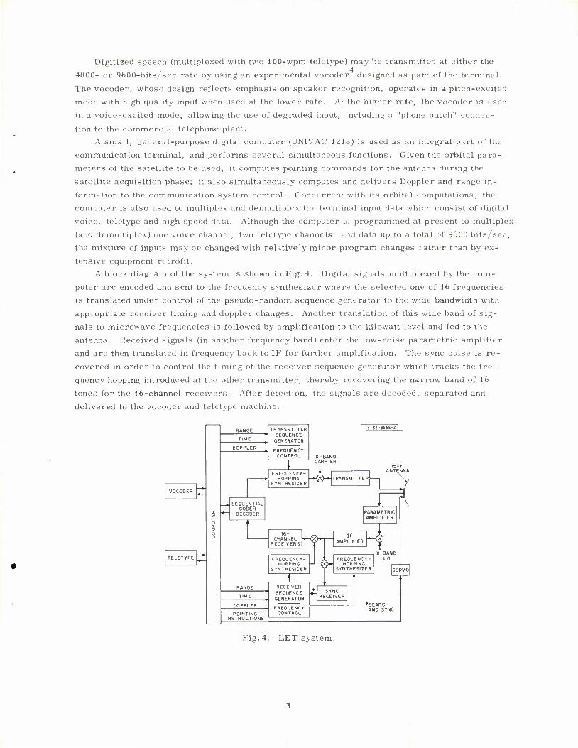
tensive equipment retrofit. A block diagram of the system is shown in Fig. 4. Digital signals multiplexed by the com-
puter are encoded and sent to the frequency synthesizer where the selected one of 16 frequencies is translated under control of the pseudo-random sequence generator to the wide bandwidth with
appropriate receiver timing and doppler changes. Another translation of this wide band of sig-
nals to microwave frequencies is followed by amplification to the kilowatt level and fed to the antenna. Received signals (in another frequency band) enter the low-noise parametric amplifier and are then translated in frequency back to IF for further amplification. The sync pulse is re-
covered in order to control the timing of the receiver sequence generator which tracks the fre-
quency hopping introduced at the other transmitter, thereby recovering the narrow band of 16
tones for the 16-channel receivers. After detection, the signals are decoded, separated and
delivered to the vocoder and teletype machine.
TRANSMITTER SEQUENCE
GENERATOR
FREQUENCY CONTROL -BAND
CARRIER
FREQUE HOPPI
SYNTHESIZER
NCY-I i ING -*Qy-» TRANSMITTER
15- ft ANTENNA
h. SEQUENTIAL
CODER DECODER PARAMETRIC
AMPLIFIER
16- CHANNEL
RECEIVERS *H»
FREQUENCY HOPPING H
SYNTHESIZER
IF AMPLIFIER
INSTRUCTIONS
RECEIVER SEQUENCE GENERATOR
FREQUENCY CONTROL
FREQUENCY- HOPPING
SYNTHESIZER
SYNC RECEIVER
X-BAND LO
*SEARCH AND SYNC
Fig. 4. LET system.
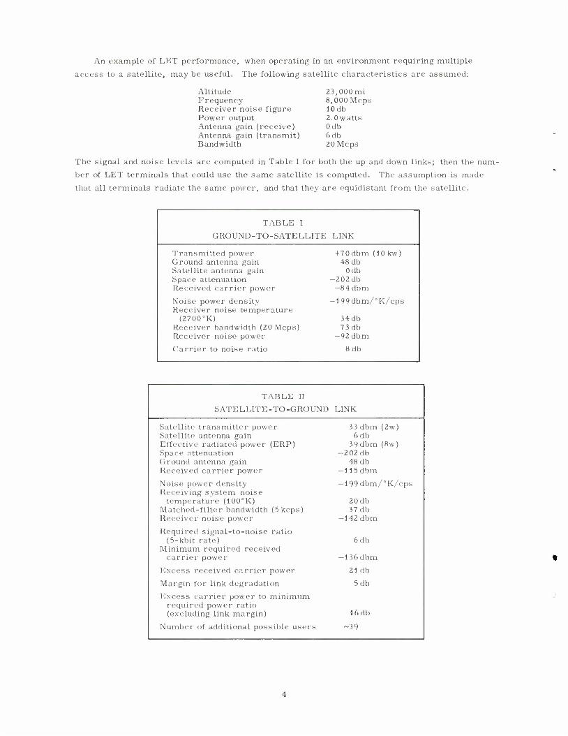
An example of LET performance, when operating in an environment requiring multiple
access to a satellite, may be useful. The following satellite characteristics are assumed:
Altitude Frequency Receiver noise figure Power output Antenna gain (receive) Antenna gain (transmit) Bandwidth
23,000mi 8,0OOMcps 10 db 2.0 watts Odb 6db 20Mcps
The signal and noise levels are computed in Table I for both the up and down links; then the num-
ber of LET terminals that could use the same satellite is computed. The assumption is made
that all terminals radiate the same power, and that they are equidistant from the satellite.
TABLE 1
GROUND-TO-SATELLITE LINK
Transmitted power + 70dbm (lOkw) Ground antenna gain 48 db Satellite antenna gain Odb Space attenuation -202db Received carrier power -84 dbm
Noise power density -199dbm/°K/cps Receiver noise temperature
(2700°K) 34 db Receiver bandwidth (20 Mcps 7 3db Receiver noise power -92dbm
Carrier to noise ratio 8db
TABLE II
SATELLITE -TO-GROUND LINK
Satellite transmitter power Satellite antenna gain Effective radiated power (ERP) Space attenuation Ground antenna gain Received carrier power
3 3 dbm (2w) 6db
39dbm (8w) -202db
48 db -115 dbm
Noise power density Receiving system noise
temperature (100°K) Matched-filter bandwidth Receiver noise power
(5 kcps)
-199dbm/°K/cps
20 db 37 db
-142 dbm
Required signal-to-noise (5-kbit rate)
ratio 6db
Minimum required received carrier power -136 dbm
Excess received carrier power 21 db
Margin for link degradation 5db
Excess carrier power to minimum required power ratio (excluding link margin) 16 db
Number of additional pos sible users -39
From Table II, it may be seen that LET needs only about 63 mw of the 8 watts ERP available
from the satellite. The implication is that even under degraded link conditions (5db) as many as
40 users (20 duplex circuits) could communicate simultaneously, provided that they used the
satellite power intelligently by spreading their signals across the 20-Mcps satellite band. One
may then ask how much the effective receiving system noise temperature rises under the cir-
cumstances postulated above. The worst case, i.e., where all the satellite power appears at
the receiver as interfering noise, is computed as
Received carrier power — 11 5 dbm Satellite bandwidth 7 3db Interfering noise power density —188dbm/cps
Receiving system noise power density —179dbm/cps
Interference-to-receiver noise ratio —9db
Increase in receiving system noise ~12.7°K
where it is seen that the effective receiving system noise temperature is increased by only 12.7°K.
IV. ANTENNA AND FEED SYSTEM5
The LET antenna is a 15-ft-diameter paraboloid employing a Cassegrainian feed system.
Some of the more common antenna and feed parameters are given below.
Antenna gain (50% efficiency) including losses 48 db Half-power beamwidth 0.58° First side lobes >20db Transmission polarization RHCP Receiving polarization LHCP Isolation between transmit and receive modes >20db Axial ratio <2 db Operating frequency band 7200 to 8400 Mcps
V. ANTENNA VEHICLE
The antenna vehicle is basically an elevation-azimuth pedestal carrying an equipment shelter-
as well as the antenna. The shelter contains the antenna drive system, the RF receiver, the
transmitter and its power supply, receiver and transmitter cooling, microwave excitation equip-
ment and test equipment. Road transportability is achieved by attaching a fixed wheel and axle
assembly to one end of the pedestal base and a steerable wheel and axle assembly to the opposite
end. During over-the-road travel, the antenna is disassembled and stowed inside the forward
compartment of the electronics van. The equipment shelter mounted on the pedestal is about
8 x 10 ft and rotates with the antenna in azimuth. Prime power and signal frequencies up to the
IF (60-Mcps) are brought into and taken out of the equipment shelter through slip rings.
VI. RF TRANSMITTER
The LET transmitter, designed to operate at X-band with an instantaneous bandwidth of
20 Mcps, develops 10 kw of CW power. Its tube, a Varian type 885 B klystron, has a tuning
range of 7700 to 8400 Mcps. Modulating signals from the electronics van are sent via coaxial
cable at the 60-Mcps IF to the antenna vehicle, where these signals are translated to X-band in
the transmitter driver. The transmitter power supply has an output capacity of 38 kw at output
voltage of 16 kv, and various taps permit transmitter outputs of 10, 5, 2-1/2 and 1.25 kw, re-
spectively. A Varian type 849 klystron operating at a fixed frequency can also be used in this
transmitter with no change in power supply. Control of the functions involved in adjusting or
tuning the transmitter are carried out in the antenna trailer shelter. RF drive and monitoring
of transmitter operation are accomplished in the electronics van. Hence, an operator is needed
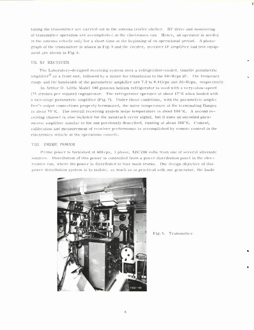
in the antenna vehicle only for a short time at the beginning of an operational period. A photo-
graph of the transmitter is shown in Fig. 5 and the exciter, receiver IF amplifier and test equip-
ment are shown in Fig. 6.
VII. RF RECEIVER
The Laboratory-designed receiving system uses a refrigerator-cooled, tunable parametric
amplifier as a front end, followed by a mixer for translation to the 60-Mcps IF. The frequency
range and the bandwidth of the parametric amplifier are 7.2 to 8.4Gcps and 20-Mcps, respectively.
An Arthur D. Little Model 340 gaseous helium refrigerator is used with a very-slow-speed
(75 strokes per minute) regenerator. The refrigerator operates at about 17°K when loaded with
a two-stage parametric amplifier (Fig. 7). Under these conditions, with the parametric ampli-
fier's output connections properly terminated, the noise temperature at the terminating flanges is about 55°K. The overall receiving system noise temperature is about 100°K. A second re- ceiving channel is also included for the autotrack error signal, but it uses an uncooled para- metric amplifier similar to the one previously described, running at about 300°K. Control,
calibration and measurement of receiver performance is accomplished by remote control in the
electronics vehicle at the operations console.
VIII. PRIME POWER
Prime power is furnished at 400 cps, i phase, 120/208 volts from one of several alternate
sources. Distribution of this power is controlled from a power distribution panel in the elec-
tronics van, where the power is distributed to four main trunks. One design objective of this
power distribution system is to isolate, as much as is practical with one generator, the loads
Fig. 5. Transmitter.
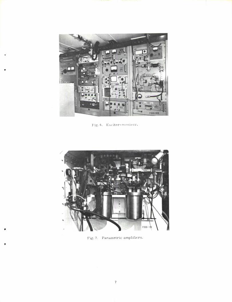
Fig. 6. Exciter-receiver.
Fig. 7. Parametric amplifiers.
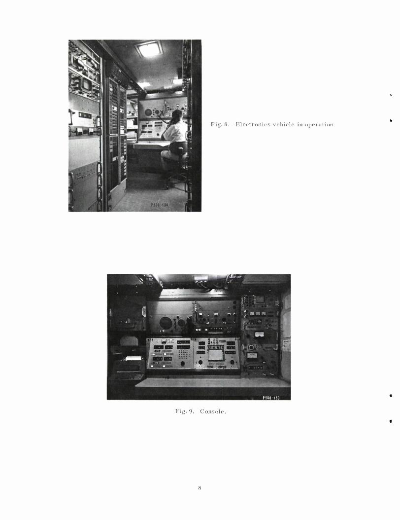
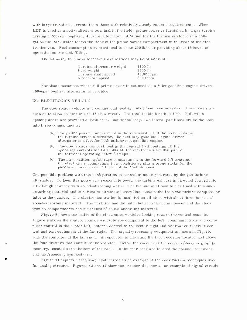
Fig. 8. Electronics vehicle in operation.
B^ "TJ"" MHL.. ^*U*
/ HUM • '•^B__ _MFV 'fi? ' rl
••Q.ii-Wf
j C3 §' fOT WN HMMI
i^at
P300-1 JO
Fig. 9. Console.
with large transient currents from those with relatively steady current requirements. When
LET is used as a self-sufficient terminal in the field, prime power is furnished by a gas turbine driving a 100-kw, 3-phase, 400-cps alternator. JP4 fuel for the turbine is stored in a 350-
gallon fuel tank which forms the floor of the prime mover compartment in the rear of the elec-
tronics van. Fuel consumption at rated load is about 23 0 lb/hour providing about 15 hours of operation on one tank filling.
The following turbine-alternator specifications may be of interest:
Turbine alternator weight 1100 lb Fuel weight 2450 lb Turbine shaft speed 40,000 rpm Alternator speed 6000 rpm
For those occasions where full prime power is not needed, a 5-kw gasoline-engine-driven 400-cps, 3-phase alternator is provided.
IX. ELECTRONICS VEHICLE
The electronics vehicle is a commercial quality, 30-ft 6-in. semi-trailer. Dimensions are
such as to allow loading in a C-130 E aircraft. The total inside length is 30ft. Full width
opening doors are provided at both ends. Inside the body, two lateral partitions divide the body into three compartments:
(a) The prime power compartment in the rearward 8 ft of the body contains the turbine driven alternator, the auxiliary gasoline-engine-driven alternator and fuel for both turbine and gasoline engine.
(b) The electronics compartment in the central 15 ft contains all the operating controls for LET plus all the electronics for that part of the terminal operating below 60Mcps.
(c) The air conditioning/storage compartment in the forward 7ft contains the electronics compartment air conditioner plus storage racks for the panels and secondary reflector of the 15-ft antenna.
One possible problem with this configuration is control of noise generated by the gas turbine
alternator. To keep this noise at a reasonable level, the turbine exhaust is directed upward into a 6-ft-high chimney with sound-absorbing walls. The turbine inlet manifold is lined with sound-
absorbing material and is baffled to eliminate direct line sound paths from the turbine compressor
inlet to the outside. The electronics trailer is insulated on all sides with about three inches of sound-absorbing material. The partition and the hatch between the prime power and the elec- tronics compartments has six inches of sound-absorbing material.
Figure 8 shows the inside of the electronics vehicle, looking toward the control console.
Figure 9 shows the control console with teletype equipment to the left, communications and com- puter control in the center left, antenna control in the center right and microwave receiver con-
trol and test equipment at the far right. The signal-processing equipment is shown in Fig. 10,
with the computer at the far right. An operator is adjusting the tape recorder located just above
the four drawers that constitute the vocoder. Below the vocoder is the encoder/decoder plus its
memory, located at the bottom of the rack. In the rear rack are located the channel receivers and the frequency synthesizers.
Figure 11 depicts a frequency synthesizer as an example of the construction techniques used
for analog circuits. Figures 12 and 13 show the encoder-decoder as an example of digital circuit
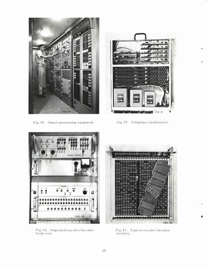
Fig. 10. Signal-processing equipment. Fig. 11. Frequency synthesizer.
P300-165
Fig.12. Sequential encoder/decoder front view.
Fig.13. Typical encoder/decoder circuitry.
10
construction techniques which use integrated circuits. Packaging in this manner allowed the
entire system including test equipment to fit into four racks.
X. TEST OPERATIONS 7-8 Since the completion of the terminal in May 1965, a great many tests have been made with
9 the terminal (1) by itself on "back-to-back" basis, (2) up to a satellite and back to itself, and
(3) via a satellite, the moon, or the tropospheric scatter mode to another station with duplicate
signal-processing equipment. System performance was essentially as predicted.
REFERENCES
1. P. R. Drouilhet, Jr., "The Lincoln Experimental Terminal Signal Pro- cessing System," Conference Record of First IEEE Annual Communica- tions Convention, Boulder, Colorado (7-9 June 1965), pp. 335-338.
2. J. M. Wozencraft and B. Reiffen, Sequential Decoding (M.I.T. Press, Cambridge and John Wiley, New York, 1961).
3. I. L. Lebow, "Sequential Decoding for Efficient Channel Utilization," Conference Record of First IEEE Annual Communications Convention, Boulder, Colorado (7-9 June 1965), pp. 47-53.
4. J. Tierney and J.N. Harris, "The Lincoln Laboratory Experimental Terminal Channel Vocoder," Conference Record of First IEEE Annual Communications Convention, Boulder, Colorado (7-9 June 1965), pp.531-534.
5. B.F. LaPage, "Lincoln Experimental Terminal Antenna System," Technical Report 404, Lincoln Laboratory, M.I.T. (4 October 1965), DDC 630702.
6. L.W. Bowles, "Parametric Amplifiers in the Lincoln Experimental Terminal," NEREM Record (November 1965).
7. K. L. Jordan, Jr., "The Performance of Sequential Decoding in Con- junction with Efficient Modulation," IEEE, Trans. Commun. Tech. (June 1966).
8. P. Rosen and B.E. Nichols, "Results of Experiments with the Lincoln Experimental Terminal Using a Variety of Channel Types," NEREM Record (November 1965).
9. H. Sherman, D.C. MacLellan, R. M. Lerner and P. Waldron, "The Lincoln Experimental Satellite Program (LES-1, 2, 3, 4) A Progress Report," Conference Record of AIAA Communications Satellite Systems Conference, Washington, D.C. ('.-4 May 1966).
11
UNCLASSIFIED Security Classification
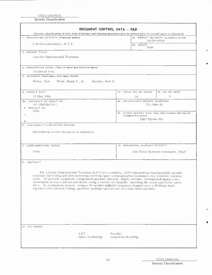
DOCUMENT CONTROL DATA - R&D (Security classification of title, body of abstract and indexing annotation must be entered when the overall report is classified)
I. ORIGINATING ACTIVITY (Corporate author)
Lincoln Laboratory, M.I.T.
Za. REPORT SECURITY CLASSIFICATION
Unclassified
2b. GROUP None
3. REPORT TITLE
Lincoln Experimental Terminal
4. DESCRIPTIVE NOTES (Type of report and inclusive dates)
Technical Note
5. AUTHOR(S) (Last name, first name, initial)
Rosen. Paul Wood. Ralph V., Jr. Nichols, Burt E
6. REPORT DATE
11 May 1966
la. TOTAL NO. OF PAGES
16
7b. NO. OF REFS
9
8a. CONTRACT OR GRANT NO.
AF 19(628)-5167 b. PROJECT NO.
649L
d.
9a. ORIGINATOR'S REPORT NUMEER(S)
TN-1966-30
9b. OTHER REPORT NOISI (Any other numbers that may be assigned this report)
ESD-TR-66-206
10. AVAILABILITY/LIMITATION NOTICES
Distribution of this document is unlimited.
11. SUPPLEMENTARY NOTES
None
12. SPONSORING MILITARY ACTIVITY
Air Force Systems Command, USAF
13. ABSTRACT
The Lincoln Experimental Terminal (LET) is a complete, self-contained air-transportable ground terminal for testing and demonstrating evolving space communication techniques in a realistic environ- ment. Its present equipment complement permits efficient, highly reliable, multiplexed digital com- munication of voice and record traffic using a variety of channels, including the moon and active satel- lites. Its modulation system, using a 16-symbol alphabet frequency-hopped over a 20-Mcps band, together with efficient coding, provides multiple-access use of a wide-band satellite.
KEY WORDS
LET space technology
Vocoder sequential decoding
12 UNCLASSIFIED Security Classification
Related Documents


