Field Engineering Education Student Self-Study Course IBM Confidential

Welcome message from author
This document is posted to help you gain knowledge. Please leave a comment to let me know what you think about it! Share it to your friends and learn new things together.
Transcript

Field Engineering Education Student Self-Study Course
IBM Confidential
Field Engineering Education Student Self-Study Course
IBM Confidential
This document contains information of a proprietary nature. ALL INFORMATION CONTAINED HEREIN SHALL BE KEPT IN CONFIDENCE. None of this information shall be divulged to persons other than: IBM employees authorized by the nature of their duties to receive such information or individuals or organizations authorized by the Field Engineering Division in accordance with existing policy regarding release of company information.
Introduction to Teleprocessing
PREFACE
This course is provided to acquaint Customer Engineers with some of the important concepts of Teleprocessing which differ from those of usual Data Processing.
Address comments concerning the contents of this publication to: ffiM Corporation, Field Engineering Education, Dept. 911, Poughkeepsie, N. Y. 12602
IBM CONFIDENTIAL
SESSION I, INTRODUCTION. IBM Teleprocessing Review Questions ..... .
SESSION 2, COMMUNICATION CONCEPTS Review Questions •.......
SESSION 3, DATA TRANSMISSION Review Questions ..•..•.•
SESSION 4, COMMUNICATIONS CHANNELS Types of Channels • • Signaling Methods Frequency Spectrum Carrier Systems . . • Modulation. . . . . • Grades of Channels
Broad Band Channels Voice Grade Channels • Subvoice Grade Channels. Telegraph Grade Channels
Line Quality . . • • . Data Sets ••••••
Reference Sources Review Questions. . •
SESSION 5, COMMUNICATIONS SYST EM CONTROL • Message Switching .•...•
Manual Torn-tape Switching Semi -automatic Switching Automatic Switching. . . •
Circuit Switching. . • . . . Selective Calling and Polling Line Control .
Intercept. Editing .. Priorities Logging . Error Control. Terminal Operating Modes.
Review Questions. . • . . . •
SESSION 6, IMPLEMENTATION SERD ES and Shift Registers
Transmit Operation Receive Operation. . .
CONTENTS
5 5
10
11 15
17 21
23 25 26 28 28 29 30 30 30 31 31 31 32 34 35
37 38 38 38 38 38 38 38 39 39 39 39 39 39 40
41 41 42
43
Shift Registers. . . . . • • • Shift Register - Transmit Shift Register - Receive
Review Questions. . . . . .
SESSION 7, IBM LINE ADAPTER Review Questions. . . . . • • . •
SESSION 8, DATA CONTROL OF MODEMS (DATA SETS) .• Bi-Polar Mode •• Uni - Polar Mode Current Mode
Review Questions .
SESSION 9, COMMUNICATIONS FACILITIES Communications Common Carriers ... The Federal Communications Commission . • State Utility Commission •..••••• The International Telecommunications Union The Bell System. . • • • • • • • . . • • • General Telephone and Electronics Corporation • Independent Telephone Companies • . . • Western Union. . • • • • • . . • . • • American Cable and Radio Corporation. RCA Communications, Inc. . . . • . • • Privately Owned Communications Systems • Review Questions . • • . • • . • • . •
APPENDIX - TELEPROCESSING GLOSSARY •
ANSWERS TO REVIEW QUESTIONS Session 1 Session 2 • Session 3 • Session 4 • Session 5 • Session 6 Session 7 • Session 8 Session 9
IBM CONFIDENTIAL
43 43 45 50
51 53
55 55 55 55 56
57 57 57 58 58 58 59 59 59 60 60 61 62
63
88 88 88 88 89 89 90 90 90 90


SESSION 1
INTRODUCTION
In this session, you should learn why the field of Teleprocessing exists, how IBM has contributed to its growth, and how a typical system is configured.
Highlights
• Teleprocessing provides a means of obtaining timely, accurate reporting of information with reduced time, effort, and expense.
o Since 1941, IBM developments have increased transmission rates of data from three cards per minute to approximately 20,000 card equivalents per minute.
o Future of Teleprocessing is as unlimited as human imagination. • Existing Telephone and Telegraph facilities feed information to computers.
The history of data communications can be traced back to biblical times. The Book of Esther relates that the delivery of orders from King Ahasuerus to his provincial governors involved a delay of eleven months. Later, history states that the author Aeneas described a system, used during war, in which a 5 x 5 matrix and a display of torches were used to indicate coordinates of the letter desired. By the 15th century, a postal system had been introduced in France by which the use of relay teams speeded the communication of the written form. Paul Revere's lantern signals and Reuter's carrier pigeons were steps in the development of communications systems which led finally to the land and overseas telegraph. The telegraph, followed by the telephone and radio, has made possible data communication as we know it today, and the field of Teleprocessing. '
With the increasing complexity of business, the need of management for up-to-date information has outgrown the facilities of normal postal services, even air mail. The present need is for centralized, immediately accessible information on diverse operations. Teleprocessing takes a giant step toward fulfilling this need. The specific objectives of Teleprocessing are:
1. To provide rapid transfer of information from the source to the data processing location.
2. To provide accurate and timely reports for management information and decision making.
3. To accomplish the foregoing with reduced effort, time, and expense.
IBM TELEPROCESSING
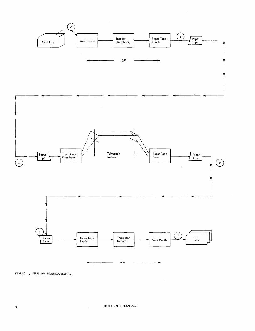
IBM's first development in this field was the introduction, in 1941, of the IBM 057 and IBM 040. Figure 1 traces the necessary operations:
First, the cards were processed through the 057 and the data punched into paper tape. This involved handling the cards twice. Next, the paper tape had to be removed and transferred to a telegraphic type reader for transmission. At the receiving location, the paper tape was transferred from the telegraph perforator to the 040 to generate punched cards. The procedure required intervention at points A, B, C, D, E, and F. When the cards were converted to tape, the maximum rate of transmission was about three cards per minute. Today, the IBM 063 and IBM 047 perform corresponding functions. In this publication, the term "cards per minute" re'furStO 80-column punched IBM cards.
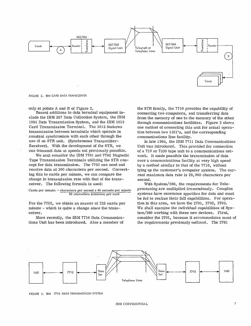
To reduce the manual intervention required, the IBM Card Data Transceiver was introduced in 1954. This equipment allows several configurations (see Figure 2): printing or nonprinting card reader punches can be used on either telephone or telegraph facilities. With the IBM 67 Telegraph Signal Unit, three transmission rates are possible: 60, 75, or 100 words per minute., This corresponds approximately to 3, 4, or 5 cards per minute, respectively. Transmission of 10 to 12 cards per minute is possible' using the IBM 068 Telephone Signal Unit, depending on whether the 066 or 065 punching unit is employed. Note that intervention is now necessary
IBM CONFIDENTIA L 5
Encoder Card Reader {Translator}
... 057
, ... ... ...
1
j
L Tape Reader Telegraph Distributor System
0
l ... ...
1
FIGURE 1. FIRST IBM TELEPROCESSING
6
Paper Tape Reader
~'------
Translator Decoder
040
IBM CONFIDENTIAL
Paper Tape Punch
~ 1 !
... ... ~
Paper Tape Punch
8 1
.. .--J
Card Punch
065/066 I (;
~-"7"'--=:--~ Reader I .2 I § I .=
FIGURE 2. IBM CARD DATA TRANSCEIVER
only at points A and B of Figure 2.
067/068 Signal Unit
Recent additions to data terminal equipment in-clude the IBM 357 Data Collection System, the IBM 1001 Data Transmission System, and the IBM 1013 Card Transmission Terminal. The 1013 features transmission between terminals which operate in constant synchronism with each other through the use of an STR unit. (Synchronous TransmitterReceiver). With the development of the STR, we can transmit data at speeds not previously possible.
We next consider the IBM 7701 and 7702 Magnetic Tape Transmission Terminals utilizing the STR concept for data transmission. The 7702 can send and receive data at 300 characters per second. Converting this to cards per minute, we can compare the change in transmission rate with that of the transceiver. The following formula is used:
Cards per minute: = characters per second x 60 seconds per minute 80 characters (columns) per card
For the 7702, we obtain an answer of 225 cards per minute - which is quite a change since the transceiver.
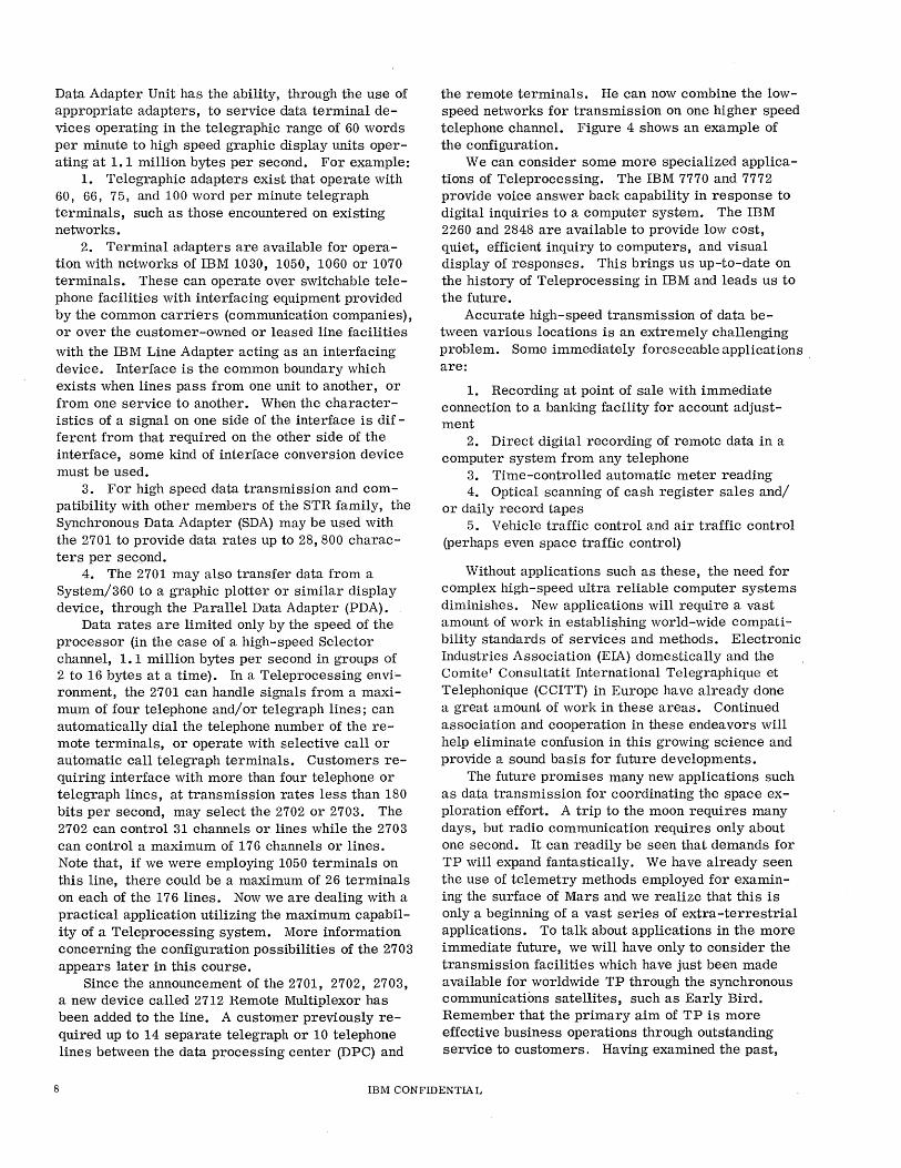
More recently, the IBM 7710 Data Communications Unit has been introduced. Also a member of
1401 nlO 14----~ Data Set
Telegraph or Telephone Lines
067/068 Signal Unit
(; I
i : Reader 1-----, C I .=
the STR family, the 7710 provides the capability of connecting two computers, and transferring data from the memory of one to the memory of the other through communications facilities. Figure 3 shows one method of connecting this unit for actual operation between two 1401's, and the corresponding communications line facility.
In late 1964, the IBM 7711 Data Communications Unit was introduced. This provided for connection of a 729 or 7330 tape unit to a communications network. It made possible the transmission of data over a communications facility at very high speed by a method similar to that of the 7710, without tying up the customer's computer system. The current maximum data rate is 28,800 characters per second.
With System/360, the requirements for Teleprocessing are multiplied tremendously. Complex systems have enormous appetites for data and must be fed to realize their full capabilities. For operation in this area, we have the 2701, 2702, 2703. We shall examine the individual capabilities of System/360 working with these new devices. First, consider the 2701, because it accommodates most of the requirements previously outlined. The 2701
Data 14----~ Set
n10 1401
Telephone Lines
FIGURE 3. IBM nlO DATA TRANSMISSION SYSTEM
IBM CONFIDENTIAL 7
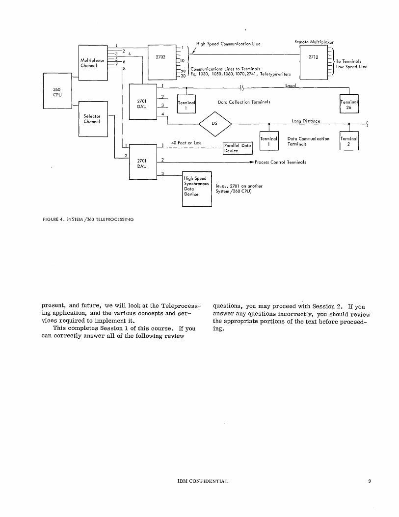
Data Adapter Unit has the ability, through the use of appropriate adapters, to service data terminal devices operating in the telegraphic range of 60 words per minute to high speed graphic display units operating at 1.1 million bytes per second. For example:
1. Telegraphic adapters exist that operate with 60, 66, 75, and 100 word per minute telegraph terminals, such as those encountered on existing networks.
2. Terminal adapters are available for operation with networks of IBM 1030, 1050, 1060 or 1070 terminals. These can operate over switchable telephone facilities with interfacing equipment provided by the common carriers (communication companies), or over the customer-owned or leased line facilities
with the IBM Line Adapter acting as an interfacing device. Interface is the common boundary which exists when lines pass from one unit to another, or from one service to another. When the characteristics of a signal on one side of the interface is different from that required on the other side of the interface, some kind of interface conversion device must be used.
3. For high speed data transmission and compatibility with other members of the STR family, the Synchronous Data Adapter (SDA) may be used with the 2701 to provide data rates up to 28,800 characters per sec.ond.
4. The 2701 may also transfer data from a System/360 to a graphic plotter or similar display device, through the Parallel Data Adapter (PDA).
Data rates are limited only by the speed of the processor (in the case of a high-speed Selector channel, 1. 1 million bytes per second in groups of 2 to 16 bytes at a time). In a Teleprocessing envi'ronment, the 2701 can handle signals from a maximum of four telephone and/or telegraph lines; can automatically dial the telephone number of the remote terminals, or operate with selective call or automatic call telegraph terminals. Customers requiring interface with more than four telephone or telegraph lines, at transmission rates less than 180 bits per second, may select the 2702 or 2703. The 2702 can control 31 channels or lines while the 2703 can control a maximum of 176 channels or lines. Note that, if we were employing 1050 terminals on this line, there could be a maximum of 26 terminals on each of the 176 lines. Now we are dealing with a practical application utilizing the maximum capability of a Teleprocessing system. More information concerning the configuration possibilities of the 2703 appears later in this course.
Since the announcement of the 2701, 2702, 2703, a new device called 2712 Remote Multiplexor has been added to the line. A customer previously required up to 14 separate telegraph or 10 telephone lines between the data processing center (DPC) and
the remote terminals. He can now combine the lowspeed networks for transmission on one higher speed telephone channel. Figure 4 shows an example of the configuration.
We can consider some more specialized applications of Teleprocessing. The IBM 7770 and 7772 provide voice answer back capability in response to digital inquiries to a computer system. The IBM 2260 and 2848 are available to provide low cost, quiet, efficient inquiry to computers, and visual display of responses. This brings us up-to-date on the history of Teleprocessing in IBM and leads us to the future.
Accurate high-speed transmission of data between various locations is an extremely challenging problem. Some immediately foreseeable applications . are:
1. Recording at point of sale with immediate connection to a banking facility for account adjustment
2. Direct digital recording of remote data in a computer system from any telephone
3. Time-controlled automatic meter reading 4. Optical scanning of cash register sales and/
or daily record tapes 5. Vehicle traffic control and air traffic control
(perhaps even space traffic control)
Without applications such as these, the need for complex high-speed ultra reliable computer systems diminishes. New applications will require a vast amount of work in establishing world-wide compatibility standards of services and methods. Electronic Industries Association (EIA) domestically and the Comite' Consultatit International Telegraphique et Telephonique (CCITT) in Europe have already done a great amount of work in these areas. Continued association and cooperation in these endeavors will help eliminate confusion in this growing science and provide a sound basis for future developments.
The future promises many new applications such as data transmission for coordinating the space exploration effort. A trip to the moon requires many days, but radio communication requires only about one second. It can readily be seen that demands for TP will expand fantastically. We have already seen the use of telemetry methods employed for examining the surface of Mars and we realize that this is only a beginning of a vast series of extra-terrestrial applications. To talk about applications in the more immediate future, we will have only to consider the transmission facilities which have just been made available for worldwide TP through the synchronous communications satellites, such as Early Bird. Remember that the primary aim of TP is more effective business operations through outstanding service to customers . Having examined the past,
8 IBM CONFIDENTIAL
360 CPU
Multiplexor Channel
Selector Channel
3 2 4
5 6 7
8
2
FIGURE 4. SYSTEM /360 TELEPROCESSING
2701 DAU
2701 DAU
2702
2
3
High Speed Communication Line
1\/ 10 f
Remote Multiplexor
2712 f-t-
:= To Terminals
29 } Communications Lines to Terminals 30 Ex; 1030, 1050,1060,1070,2741, Teletypewriters
f-}' ~ Low Speed Line
t-
40 Feet or Less
Data Collection Terminals
Terminal 1
Local
Long Distance
Data Communication Terminals
1--'2=--_____________ --1 .. Process Control Terminals
3 High Speed Synchronous Data Device
(e.g., 2701 on another System /360 CPU)
present, and future, we will look at the Teleprocessing application, and the various concepts and services required to implement it.
This completes Session 1 of this course. If you can correctly answer all of the following review
questions, you may proceed with Session 2. If you answer any questions incorrectly, you should review the appropriate portions of the text before proceeding.
IBM CONFIDENTIAL 9
REVIEW QUESTIONS
1. When did IBM enter the field of Teleprocessing?
2. What are the three objects of Teleprocessing?
3. What existing communications facility provided the connecting link between IBM Card Transceivers using type: 068 Signal Units? _____________ _ 067 Signal Units? _____________ _
4. What are the three transmission rates in Words p~r Minute when utilizing the IBM Card Data Transceiver with an 067 Signal Unit? _____ _ _____________ and ________ __
5. If a Word is equal to six characters, and each IBM Card Data Transceiver Character is made up of 8 possible bits, what would be the transmission rates of question #4 in terms of Bits per Second?
________________ ~_and
6. What is the approximate maxi?lum transmission rate of the IBM 7711 Data Communications Unit handling magnetic tape if we express it in terms of
cards per minute? (For the purposes of the question, ignore any delays due to answer back or error procedures.) cards per minute.
7. The four general types of remote terminals through which a System/360 Computer may communicate, using an IBM 2701 Data Adapter Unit, are:
__________________ and _________ _
8. If you wanted a remote terminal from which you could interrogate a computer, and receive answers on a television-type display, which IBM Teleprocessing Terminals would you select? ___ _
9. Which IBM Teleprocessing devices are capable of answering an inquiry with voice responses?
10. Draw a diagram showing how a System/360 computer could be connected to five terminals of the IBM 1050 type, where three of the terminals are in the same building with the computer and two are located apprOximately 5 miles away. You are limited in this problem to using communications facilities that the customer already has installed and further, each of the terminals must be able to communicate with the others.
10 IBM CONFIDENTIAL
SESSION 2
COMMUNICA TION CONCEPTS
As a result of completing this session you should: 1. Become familiar with the important factors to be considered in Communication
System design. 2. Learn how to represent a system diagrammatically. 3. Learn how one type of customer utilizes these services. 4. Be able to define Teleprocessing.
Highlights
• Design factors: Purpose, number and size of messages, priority of messages, accuracy and cost.
• Network: System of devices capable of intercommunication according to certain rules.
• Teleprocessing provides our customer with a way to improve service to their customers and, at the same time, improve their own operating efficiency.
o Airline Reservation System remote terminal hookup to Data Processing center. o Teleprocessing defined.
The history of rapid communications from smoke signals to sattellites reflects the continual growth in man's ability to convey information beyond the range of the human voice. In less than a hundred years, the electrical communications industry has developed from the first manually-keyed telegraph to complex television systems. Messages have been sent and received over a million miles of space, and television programs have been transmitted from the United States to Europe by way of a communications satellite. With all of these technological advances, the basic considerations in a modern communication system are not too different from those in a primitive society using drums or smoke signals to send messages between related villages.
Some of the imnortant factors which must be considered in communication system design are:
1. The purpose of the communication system 2. The number and size of the messages 3. The priority of the messages 4. The accuracy and cost of the system
The following description of a data communication system introduces some of the terms and illustrates the scope of the material covered in succeeding sessions.
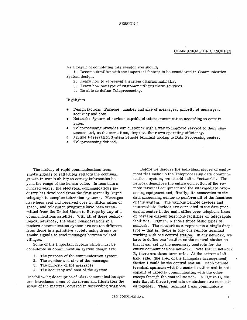
Before we discuss the individual pieces of equipment that make up the Teleprocessing data communications system, we should define "network". The network describes the entire connection of the remote terminal eqUipment and the intermediate processing equipment and, finally, its connection to the data processing center to perform all of the functions of this system. The various remote devices and intermediate devices are connected to the data processing center in the main office over telephone lines or perhaps dial-up telephone facilities or telegraphic facilities. Figure. 5 shows three basic types of network. The network at A represents a single droptype - that is, there is only one remote terminal working with one control station. In any network, we have to define one location as the control station so that it can set up the necessary controls for the entire communications network. Note that in network B, there are three terminals. At the extreme lefthand side, (the apex of the triangular arrangement) Station 1 could be the control station. Each remote terminal operates with the control station and is not capable of directly communicating with the other except through the control station. In Figure C, we note that all three t~rminals or stations are connected together. Thus, terminal 1 can communicate
IBM CONFIDENTIAL 11
2 2
o 0 A 2 3 C 3
FIGURE 5. BASIC NETWORKS
with terminal 2, 2 with 3, or 3 with 1, each independent of the other. Networks Band C are representative multidrop networks, since the control station works with more than one other terminal.
The connecting lines between these terminals represent the communication channel or circuit
. (also called lines). This channel or circuit can be a wire, or a cable, or it can be a radio or microwave link. To review what we have learned about networks:
In the figure at A, terminal 1 may communicate with terminal 2. In the figure at B, terminal 1 can communicate with 2 or with 3. However, if terminal 3 wishes to communicate with 2, it must first communicate with terminal 1. Terminal 1 may then relay the message to terminal 2. Here we have an ideal example of "Message Switching". The message must first be sent from 3 to 1, then rerouted from 1 to 2. In the Figure at C, we find that terminals 1, 2 and 3 may each communicate directly without requiring another station to perform any switching function for them. The process by which the desired terminal receives or transmits the message is analogous to the concept of circuit switching operation. More about circuit switching and message switching appears in later Sessions.
In summary, the four main factors to be considered in a communication system design are: purpose, number and size of messages; priority or urgency of messages; the accuracy of the system; and cost of the system. The Airlines Reservation System handles some of these factors in the following manner:
1. Improved customer service through: (a) Reliable reservation control (b) Advance hotel reservations for passen
gers (c) Advance car rental arrangements at
destination (d) Special dietary instructions if necessary
(e) Arranging for wheelchairs, etc. to meet arri ving passengers who may require them
2. Improved airline efficiency thru: (a) Timely maintenance scheduling (b) Fewer unused seats on flying aircraft (c) Accurate crew time-logging (d) Advance weather information accurately
logged and constantly available (e) Accurate control of arrival and departure
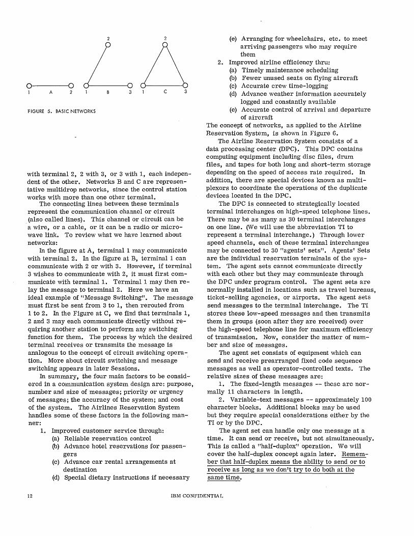
of aircraft The concept of networks, as applied to the Airline Reservation System, is shown in Figure 6.
The Airline Reservation System consists of a data processing center (DPC). This DPC contains computing equipment including disc files, drum files, and tapes for both long and short...;.term storage depending on the speed of access rate required. In addition, there are special devices known as multiplexors to coordinate the operations of the duplicate devices located in the DPC.
The DPC is connected to strategically located terminal interchanges on high-speed telephone lines . There may be as many as 30 terminal interchanges on one line. (We will use the abbreviation TI to represent a terminal interchange.) Through lower speed channels, each of these terminal interchanges may be connected to 30 "agents' sets". Agents' Sets are the individual reservation terminals of the system. The agent sets cannot communicate directly with each other but they may communicate through the DPC under program control. The agent sets are normally installed in locations such as travel bureaus, ticket-selling agencies, or airports. The agent sets send messages to the terminal interchange. The TI stores these low-speed messages and then transmits them in groups (soon after they are received) over the high-speed telephone line for maximum efficiency of transmission. Now, consider the matter of number and size of messages.
The agent set consists of equipment which can send and receive prearranged fixed code sequence messages as well as operator-controlled texts. The relative sizes of these messages are:
1. The fixed-length messages -- these are normally 11 characters in length.
2. Variable-text messages -- approximately 100 character blocks. Additional blocks may be used but they require special considerations either by the TI or by the DPC.
The agent set can handle only one message at a time. It can send or receive, but not simultaneously. This is called a "half-duplex" operation. We will cover the half-duplex concept again later. Remember that half-duplex means the ability to send or to receive as long as we don't try to do both at the same time.
12 IBM CONFIDENTIA L
TI = Terminal Interchange AS = Agents Set Terminal
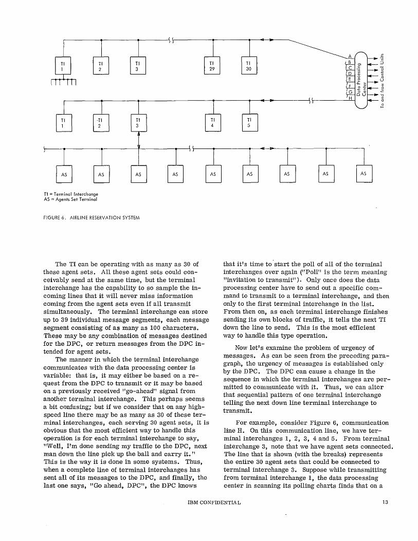
FIGURE 6. AIRLINE RESERVATION SYSTEM
The TI can be operating with as many as 30 of these agent sets. All these agent sets could conceivably send at t~e same time, but the terminal interchange has the capability to so sample the incoming lines that it will never miss information coming from the agent sets even if all transmit simultaneously. The terminal interchange can store up to 39 individual message segments, each message segment consisting of as many as 100 characters. These may be any combination of messages destined for the DPC, or return messages from the DPC intended for agent sets.
The manner in which the terminal interchange communicates with the data processing center is variable: that is, it may either be based on a request from the DPC to transmit or it may be based on a previously received "go-ahead" signal from another' terminal interchange. This perhaps seems a bit confusing; but if we consider that on any highspeed line there may be as many as 30 of these terminal interchanges, each serving 30 agent sets, it is obvious that the most efficient way to handle this operation is for each terminal interchange to say, "Well, I'm done sending my traffic to the DPC, next man down the line pick up the ball and carry it. " This is the way it is done in some systems. Thus, when a complete line of terminal interchanges has sent all of its messages to the DPC, and finally, the last one says, "Go ahead, DPC", the DPC lmows
e c o
U E
.g -0 c: a o
f-
that it's time to 'start the poll of all of the terminal interchanges over again ("Poll" is the term meaning "invitation to transmit" ). Only once does the data processing center have to send out a specific command to transmit to a terminal interchange, and then only to the first terminal interchange in the list. From then on, as each terminal interchange finishes sending its own blocks of traffic, it tells the next TI down the line to send. This is the most efficient way to handle this type operation.
Now let's examine the problem of urgency of messages. As can be seen from the preceding paragraph, the urgency of messages is established only by the DPC. The DPC can cause a change in the sequence in which the terminal interchanges are permitted to communicate with it. Thus, we can alter that sequential pattern of one terminal interchange telling the next down line terminal interchange to transmit.
For example, consider Figure 6, communication line H. On this communication line, we have terminal interchanges 1, 2, 3, 4 and 5. From terminal interchange 3, note that we have agent sets connected. The line that is shown (with the breaks) represents the entire 30 agent sets that could be connected to terminal interchange 3. Suppose while transmitting from terminal interchange 1, the data processing center in scanning its polling charts finds that on a
IBM CONFIDENTIAL 13
normal basis, at this time of day, terminal interchange 4 will be piling up a lot more messages than it can possibly handle. The DPC can send a message called a "change next interchange address" message to terminal interchange 1 which will cause terminal interchange 1 to tell terminal interchange 4 to go ahead instead of 2. This method of changing the polling sequence permits maximum utilization of network facilities. The configuration of the network can vary considerably from that shown in Figure 6. The following particulars could vary, depending upon the need for capacity and the demand for accuracy of the particular system:
1. Number of lines 2. Number of terminal interchanges per line 3. Number of agent sets per line into the ter
minal interchanges 4. Complexity of the computing portion of the
DPC Let's talk a little more about this problem of
accuracy and cost. To eliminate errors, many checks are made as the data is handled. Some of these are:
1. Each character sent from or received by the agent set is parity checked
2. Each character received by the terminal interchange is parity checked
3. Each message is checked for a specific count agreement on transfer between the terminal interchange and the data processing center. Any disagreement in the count constitutes an error somewhere in the message.
Communication facilities are available to cover the entire range from fast to slow • Microwave channels can carry great amounts of information quickly but are considerably more expensive than a relatively slow, telegraph-rate, channel. Depending upqn customer requirements, the Airline Reservation System agent set may use telegraph facilities or some type of telephone channels. Between the terminal interchange and DPC, transmission occurs at about 3 milliseconds per character. This requires higher speed telephone-type channels. In order satisfactorily to establish a cost for the system, a cus~omer m~st weigh the advantages of the system against not having the system. The most efficient configurations and the most economical communication channel consistent with required data rate and
accuracy are also important factors for consideration. The completed network must be examined and considered relative to its purpose, the volume of work, the required response times and, finally, in terms of cost. While cost is important, it is extremely unwise to attempt to plan a network based on meeting a pre-established price. This -course will not deal with specific costs of facilities or equipment but the customer engineer should be aware that this is an important consideration. Publications, covering detail cost of required services, are available from various common carrier companies, the Federal Communications Commission, and some state utility commissions. These are called "Tariffs," and represent the standard prices charged for given services.
This completes the self-study portion of text for Session 2. Additional information on any of the initial concepts presented here, can be found in the following publications:
1. Data Communications, Form 320-0903. This book is a detailed review of the development and application of Teleprocessing equipment in IBM.
2. Reference Manual IBM 9000 Series Airline Reservation Systems Remote Equipment, Form A22-6640.
3. Teleprocessing Systems Summary, Form A24-3090. This book will outline the basic characteristics of many of the Teleprocessing devices marketed by IBM.
At this point, you have probably derived a definition of Teleprocessing. Teleprocessing as it concerns IBM designates IBM products used for transmitting and receiving data at separately located data processing offices. Teleprocessing equipment consists of transmitting terminals and receiving terminals that utilize transmission facilities such as telegraph lines, telephone lines, and microwave radio signals.
The next section of this course consists of study questions. for review to find out how much you learned from what you read, and how well you understand the principles presented.
If you can answer the following review questions correctly, you may go on to Session 3. If you answer any questions incorrectly, review the appropriate sections of the text before proceeding.
14 IBM CONFIDENTIAL
REVIEW QUESTIONS:
1. The four main factors to be considered in the design of a communication system are:
(a) ______________ _ (b) _____________ _
(c) ______________ _ (d) ____________ _
2. (a) Utilizing the principles of Figure 5, draw a similar schematic representation of the network consisting of a large Data Processing Center (DPC) connected to two smaller DPCs (A & B). Each of the small DPCs is connected with its own network of five remote terminal devices. Each of the terminal devices on either DPC-A or DPC-B is capable of communicating with any other terminal but only through one or more of the DPCs.
(b) Repeat as above, except that the terminals connected to DPC-B all communicate among themselves without assistance of the DPC. Show only the portion of the network that must be reconfigured.
3. When the terminals of DPC-B wish to communicate with each other, is Message Switching or Circuit Switching utilized, as configured in question #2 (a)? ________________ ___
~)?------------------4. The terminal systems of question #2a would be
considered as (a) Single drop ~) Multi -drop
5. A multiplexor coordinates the operation of multiple devices utilizing shared facilities. (True, False)
6.· How many Agents sets could be serviced on one high-speed telephone line if the maximum number of terminal interchanges was employed?
70 List four areas in which the Airline Reservation System has made it possible for Airlines to improve the service they render to their customers.
(a) _______________ _
~)-------------------------(c) _______________ _ (d) ____________ _
8. List four ways in which the efficiency of the Airline has been improved through the use of the system.
(a) ______________ _
~)--------------(c) _______________ _ (d) _____________ _
9. Can Agents sets communicate with each other directly, i. e. without intervention by DPC?
10. Which governmental agencies regulate communications?
11. Define Teleprocessing, as you understand it.
IBM CONFIDENTIAL 15

SESSION 3
DATA TRANSMISSION
This session presents the functions of data transmission and control through analogies to normal data processing methods.
Highlights
o Keypunch and Summary Punch as examples of data transmission. o Data Flow in a typical Teleprocessing environment. o Serial versus Parallel transmission. • Interface defined. • Input/Output media available. • Message component sequence, including control signals.
The objective of Teleprocessing is the efficient, accurate, and economical transmission of data from one place to another. Teleprocessing requires originating and terminating equipment, a communications facility, and equipment to convert data into a form that may be handled by the communications channel.
The simplest form of data transmission, familiar to most customer engineers, is the keyboard of an IBM keypunch. This device translates the mechanical keystroke of the operator into electrically coded impulses to punch the required pattern into an IBM card. Through mechanical means, the depression of the key is converted into closures of certain contacts in the keyboard. These contacts provide electrical signals to be transmitted over the cable connecting the keyboard to the remainder of the machine. Control signals are also sent to tell the punch drive when all of the information has been transmitted to the punch unit, and to perform the mechanical action of punching the code into the card. A return acknowledgment signal unlocks the keyboard and permits the next character to be keyed in. This is a form of asynchronous transmission as it requires a stop and a start signal to control the beginning and end of each character handled.
Another form of data transmission is summary punching. In this case, the carrier facility or channel is the summary punch cable connecting the accounting machine to the summary punch. The accounting machine sends a signal at "total time" to the summary punch to inform the punch that it wishes
to communicate. The summary punch starts to run if all operational requirements are met, and it sends a timed series of pulses to query the accounting machine. The contents of the selected counters and storage units are transferred to the summary punch and punched into the summary cards. The summary punch then returns an acknowledment signal, in this case the "summary punch end" shot to the accounting machine. Again, the accounting machine reverts to processing data to make another record available to the summary punch. During processing time, the summary punch is idle. The initial call of the accounting machine to the summary punch could be called an inquiry; and it is a turn-around command. This means that the accounting machine will not take any further action until given permission to do so by the return signal from the summary punch at summary punch end time. The signal from the summary punch at summary punch end time is a turn-around command from the summary punch to the accounting machine, and the accounting machine again begins processing. This same concept is used throughout the field of data transmission and the terms most frequently encountered have been introduced here.
In order to convert this operation to a true Teleprocessing operation, we might hook the previously discuss~d summary punch to the accounting machine by a mile-long cable. This wouldn't be very practical for several reasons. The most important reason is that a cable a mile long has considerable resistance and the si.gnal to the punch magnets would decay or deteriorate in quality sufficiently to cause a failure
IBM CONFIDENTIA L 17
to punch. This operation could be carried out if the square wave impulses were converted to alternating current impulses before they were sent; then amplified back to their original levels upon receipt by the summary punch; finally, converted back to DC to energize the interposer magnets. This conversion process is modulation; it will be used extensively in Teleprocessing, and covered in more detail later in the course.
In order to use existing telephone and telegraph networks for data transmission, data processing equipment must prepare suitable input for network terminals, or be connected to the network. In addition, data processing codes and signals must be converted to signals acceptable to the circuits or channels used.
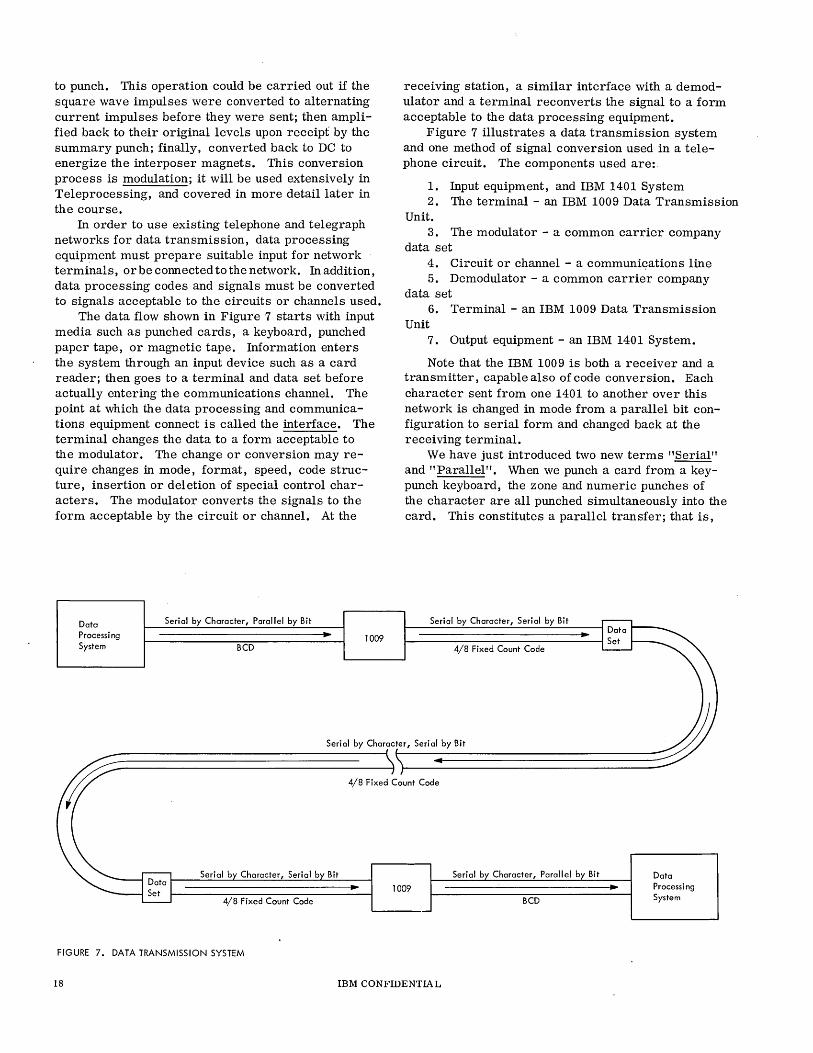
The data flow shown in Figure 7 starts with input media such as punched cards, a keyboard, punched paper tape, or magnetic tape. Information enters the system through an input device such as a card reader; then goes to a terminal and data set before actually entering the communications channel. The point at which the data processing and communications equipment connect is called the interface. The terminal changes the data to a form acceptable to the modulator. The change or conversion may require changes in mode, format, speed, code structure, insertion or deletion of special control characters. The modulator converts the signals to the form acceptable by the circuit or channel. At the
Data Processing System
Serial by Character, Parallel by Bit
BCD 1009
receiving station, a similar interface with a demodulator and a terminal reconverts the signal to a form acceptable to the data processing equipment.
Figure 7 illustrates a data transmission system and one method of signal conversion used in a telephone circuit. The components used are:.
1. Input equipment, and IBM 1401 System 2. The terminal - an IBM 1009 Data Transmission
Unit. 3. The modulator - a common carrier company
data set 4. Circuit or channel - a communiqations line 5. Demodulator - a common carrier company
data set 6. Terminal - an IBM 1009 Data Transmission
Unit 7. Output equipment - an IBM 1401 System.
Note that the IBM 1009 is both a receiver and a transmitter, capable also of code conversion. Each character sent from one 1401 to another over this network is changed in mode from a parallel bit configuration to serial form and changed back at the receiving terminal.
We have just introduced two new terms "Serial" and "Parallel". When we punch a card from a keypunch keyboard, the zone and numeric punches of the character are all punched simultaneously into the card. This constitutes a parallel transfer; that is,
Serial by Character, Serial by Bit
4/8 Fixed Count Code
Seri 01 by Character, Seri 01 by Bit
-----------------------------------------; • 4/8 Fixed Count Code
Bit
1009
4/8 Fixed Count Code
FIGURE 7. DATA TRANSMISSION SYSTEM
18 IBM CONFIDENTIAL
Serial b Character, Parallel b Bit
BCD
Data Processing System
all of the bits or pieces malting up a character are handled at one time. However, when we summary punch a card using, for example, a 407 and a 514, we punch the digits in the card in the order of 12 punches, 11 punches, 0 punches, etc., down through the 9 numeric punch. If we punch just one column of the card on a summary punching operation, we are serially punching the character into the card; that is, if the character represented is an A, we punch first the 12 punch, skip the 11, skip the 0, another punch at 1 time, and skip the remaining punching positions 2 through 9. Thus, scanning a storage unit in the 407 accounting machine where the letter A was stored, we have converted the character from its parallel format in the storage unit to one bit at a time transmission over the summary punch cable to the 514.
Another application of data handling is the magnetic tape unit in which characters are written one at a time, in parallel format, across the width of the magnetic tape. In this application, we have parallel characters recorded serially; that is, one full character at a time. The manner in which we transfer data to a tape drive is referred to as "serial-bycharacter, parallel-by-bit". The data processing system in Figure 7 transfers information to the 1009 by this method. In the 1009, the characters received from the data processing system in binary coded decimal are converted to a fixed count 4 of 8 code. For comparison of BCD with 4 of 8 codes, see Figure 7. In addition to converting the code, the 1009 takes each character, after it has been converted to 4 of 8 code, and instead of transmitting that character in one swat over the communication line, it transmits the character one bit at a time (like the A from 407 to 514). The data is still in a form unacceptable to the communications facility. Thus, we require the service of the data set between the communications line and the 1009.
The data set will perform an interface conversion function of changing the fixed-count 4 of 8 code bits from the 1009, which are still in DC pulses, into a form that the line facility will accept. The data set is modulating the line signal in accordance with data being presented by the 1009. The data appears on the line in serial by character, serial by bit format in 4 of 8 fixed-count code. As it is received by the data set at the receiving end, it will be received serial-by-bit, serial-by-character and delivered in 4 of 8 fixed-count code to the 1009 in DC pulses. The 1009 will accumulate these bits one at a time until it has a full character, and then transfer the characters one at a time to the data processing system. A conversion from serial-by-bit, serialby-character, to parallel-by-bit, serial-by-character has been effected. We have also translated the
character from 4 of 8 fixed-count code back to binarycoded decimal, which is the operating code of the data processing system.
In Figure 7, we have considered the data processing system to be a 1401. This data processing system could actually be anything from a data transceiver to a full System/360 operational complex. Some of the available input/output choices are: cards, magnetic tape, punched tape, printed copy, visual display in lights or visual display of characters on a television-type tube. In addition, data being handled could come from a disk or drum file of one computer system to the main memory of another system.
The connection of the data processing system to the communication equipment is called the "Interface". In the case of data transmission, the interface or demarcation strip provides a dividing line between the responsibility of IBM and that of the communication company. For this reason, each manufacturer or supplier of communications equipment for attachment to business machines provides a publication called "Interface Specifications". This publication defines what signals the business machine must provide for the communications equipment and describes the nature of signals which the communications equipment will return to the business machine.
In Figure 7, the interfaces that exist are from the data proceSSing system to 1009, from the 1009 to the data set. On the receiving end, from the data set to a 1009, and from the 1009 back to the data processing system.
Besides handling data ("text" of the transmission), this type of system sends and receives coordinating signals. The most common of these are listed in the sequence of their normal use: 1. Inquiry The transmitting end checks the
receiving end to see if it is ready to receive.
2. Turn-around Both ends switch their sending and receiving functions. (Time required may be up to 200 milliseconds. )
3. Acknowledge By this control signal, the receiv-
J
4. Turn -around 5. Start of
Record
6. End of Trans-mission or End of Message
ing end becomes a transmitter and signals the transmitting end to proceed. is repeated. Sending end begins transmission with proper heading control, followed by full text of that record. This control signal follows the last character of the record. It usually includes an LRC (Longitudinal Redundancy Check)
IBM CONFIDENTlA L 19
auuurnulaLiuIl uf Lhe LexL irnrneuiately preceding.
An LRC is essentially an odd/ even count of the bits transmitted in the preceding message. It constitutes a turn-around command and causes the sending end to await reply from the receiving end.
7. Acknowledge is repeated if the message has been received without error and the LRC agrees with that which the receiving end has accumulated. (Some acknowledgment signals permit the sending end to ascertain whether the message was successfully received or whether it should be repeated.)
8. TUl'n-arUWld is again repeated and sequence continues from 5.
In handling data flow on this communication network, we spoke of parallel-by-bit, serial-by-character processing which was then converted to serial-bybit, serial-by-character. The process of converting data from parallel-by-bit to serial-by-bit is also called "serialization". The reverse process on receiving (i. e., receiving one bit at a time and converting it into a full character) is called "Deserialization". Having covered the requirements of the terminal equipment, we turn to the communications channel.
This completes the text for Session 3. If you can answer all of the following review questions correctly, you may go to Session 4. If you answer any questions incorrecey, review the appropriate sections of the text before proceeding.
20 IBM CONFIDENTIAL
R:EVIEW QUESTIONS
1. When a character is transferred from the KeypWlch keyboard to the punching Wlit (serial/parallel) mode transmission is employed. (Underline choice. )
2. Summary punching is an example of (serial/ parallel) transmission. (Underline choice.)
3. Briefly describe what is meant by a "turnaroWld command".
4. What is modulation, and why is it used?
5. Data transfer from the IBM 1401 in the text figure to the IBM 1009 is in serial-by-character. ________________ bilform.
6. Data transfer from the IBM 1009 to the Data Set is in serial-by-character, _________ __
bit. 7. The signal on the line is ________ _
by the data stream from the IBM 1009 to the Data Set (when transmitting).
8. On the receiving end, the Data Set ____ _ ______ the line signal and provides ____ _ _______ bit, serial-by-character input to the IBM 1009.
9. Between the receiving IBM 1009 and the IBM 1401, the received characters are transferred serially in bit form and, at the same time, are translated from code to code.
10. List 6 choices of input and output media available for this operation.
(a) ______________ _ (b) _____________ _ (c) ______________ _ (d) _____________ _
(e) _______________ _
(~---------------11. The function of an interface or demarcation
strip is: __________________ ___
12. To what would you refer if you wanted complete information regarding signals exchanged between a data terminal and a common carrier data set? ____________________ _
13. Converting data from serial-by-character, parallel-by-bit to serial-by-character, serial-by-bit is called ____________ _
14. The process of receiving characters serialby-bit and then transferring them in parallel-by-bit form is called ___________ _
15. Why is an LRC exchanged between the sending and receiving terminal?
16. What control signal usually indicates the be-ginning of the Text portion of a message? ____ _
17. What control signal is sent by the transmitting terminal to the receiving terminal to check whether or not it is ready to receive? _________ _
18. What reply is expected by the transmitting terminal of question 17 ? ___________ ___
19. List 3 control signals which are considered as turn-around commands.
(a) ______________ ___
(b) _______________ _ (c) _______________ _
IBM CONFIDENTIAL 21

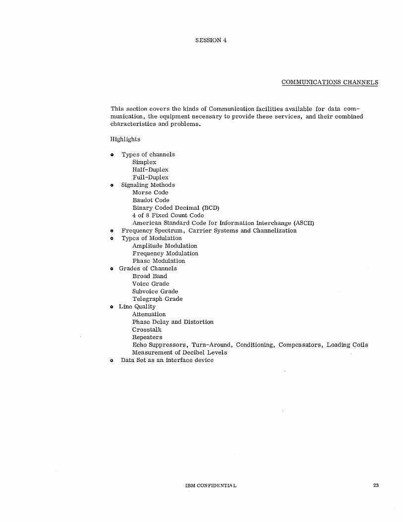
SESSION 4
COMMUNICATIONS CHANNELS
This section covers the kinds of Communication facilities available for data communication, the equipment necessary to provide these services, and their combined characteristics and problems.
Highlights
• Types of channels Simplex Half-Duplex Full-Duplex
• Signaling Methods Morse Code Baudot Code Binary Coded Decimal (BCD) 4 of 8 Fixed Count Code American Standard Code for Information Interchange (ASCII)
., Frequency Spectrum, Carrier Systems and Channelization o Types of Modulation
Amplitude Modulation Frequency Modulation Phase Modulation
o Grades of Channels Broad Band Voice Grade Subvoice Grade Telegraph Grade
• Line Quality Attenuation Phase Delay and Distortion Crosstalk Repeaters Echo Suppressors, Turn-Around, Conditioning, Compensators, Loading Coils Measurement of Decibel Levels
o Data Set as an interface device
IBM CONFIDENTIAL 23
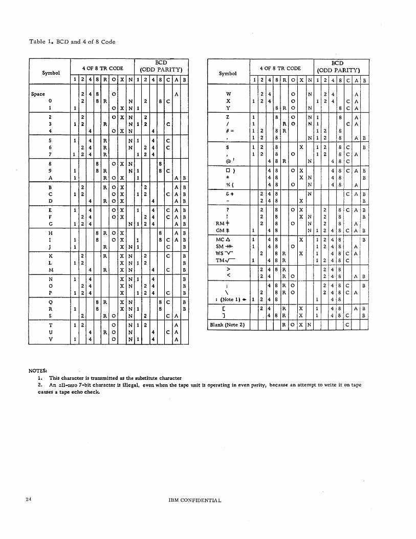
Table 1. BCD and 4 of 8 Code
.. BCD BCD
4 OF 8 TR CODE (ODD PARITY) Symbol
4 OF 8 TR CODE (ODD PARITY) Symbol
1 2 4 8 R 0 X N 1 2 4 8 C A B 1 2 4 8 R 0 X N 1 2 4 8 C A
Space 2 4 8 0 A W 2 4 0 N 2 4 A 0 2 8 R N 2 8 C X 1 2 4 0 1 2 4 C A 1 1 0 X N 1 Y 8 R 0 N 8 C A
2 2 0 X N 2 Z 1 8 0 N 1 8 A 3 1 2 R N 1 2 C / 1 l\ 0 N 1 C A
4 4 0 X N 4 #= 1 2 8 R 1 2 8
5 1 4 R N 1 4 C 1 2 8 N 1 2 8 A
6 2 4 R N 2 4 C $ 1 2 8 X 1 2 8 C 7 1 2 4 R 1 2 4 , 1 2 8 0 1 2 8 C A
8 8 0 X N 8 (W' 4 8 R N 4 8 C
9 1 8 R N 1 8 C o ) 4 8 0 X 4 8 C A
A 1 R 0 X 1 A B * 4 8 X N 4 8
B 2 R 0 X 2 A B %( 4 8 0 N 4 8 A
C 1 2 0 X 1 2 C A B &+ 2 4 8 N C A
D 4 R 0 X 4 A B - 2 4 8 X
E 1 4 0 X 1 4 C A B 7 2 8 0 X 2 8 C A
F 2 4 0 X 2 4 C A B ! 2 8 X N 2 8 G 1 2 4 N 1 2 4 A B RM:f 2 8 0 N 2 8 A
H 8 R 0 X 8 A B GM$ 1 4 8 N 1 2 4 8 C A
I 1 8 0 X 1 8 C A B MCiJ. 1 4 8 X 1 2 4 8
J 1 R X N 1 C B SM -tt+- 1 4 8 0 1 2 4 8 A
K 2 R X N 2 C B WS-V- 2 8 R X 1 4 8 C A
L 1 2 X N 1 2 B TM";- 1 4 8 R 1 2 4 8 C
M 4 R X N 4 C B > 2 4 8 R 2 4 8
N 1 4 X N 1 4 B < 2 4 R 0 2 4 8 A
0 2 4 X N 2 4 B j 4 8 R 0 2 4 8 C
P 1 2 4 X 1 2 4 C B \ 2 8 R 0 2 4 8 C A
Q 8 R X N 8 C B : (Note 1) .. 1 2 4 8 1 4 8
R 1 8 X N 1 8 B [ 2 4 R X 1 4 8 A
S 2 R 0 N 2 C A ] 4 8 R X 1 4 8 C
T 1 2 0 N 1 2 A Blank (Note 2) R 0 X N C
U 4 R 0 N 4 C A
V 1 4 0 N 1 4 A
NOTES:
1. This character is transmitted as the substitute character 2. An :lll-..ero 7-bit character is illegal, even when the tape unit is operating in even parity, because an attempt to write it on tape causes a tape echo check.
24 IBM CONFIDENTIAL
B
B
B
B
B
B
B
B B
B
B
B
B
B B
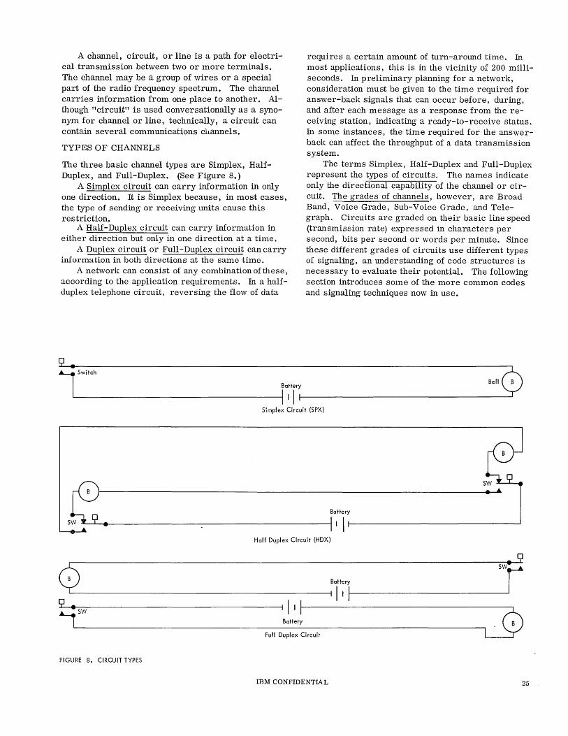
A channel, circuit, or line is a path for electrical transmission between two or more terminals. The channel may be a group of wires or a special part of the radio frequency spectrum. The channel carries information from one place to another. Although "circuit" is used conversationally as a synonym for channel or line, technically, a circuit can contain several communications channels.
TYPES OF CHANNELS
The three basic channel types are Simplex, HalfDuplex, and Full-Duplex. (See Figure 8.)
A Simplex circuit can carry information in only one direction. It is Simplex because, in most cases, the type of sending or receiving units cause this restriction.
A Half-Duplex circuit can carry information in either direction but only in one direction at a time.
A Duplex circuit or Full-Duplex circuit can carry information in both directions at the same time.
A network can consist of any combination of these, according to the application requirements. In a halfduplex telephone circuit, reversing the flow of data
1 SwH,h
Battery
II II
requires a certain amount of turn-around time. In most applications, this is in the vicinity of 200 milliseconds. In preliminary planning for a network, consideration must be given to the time required for answer-back signals that can occur before, during, and after each message as a response from thereceiving station, indicating a ready-to-receive status. In some instances, the time required for the answerback can affect the throughput of a data transmission system.
The terms Simplex, Half-Duplex and Full-Duplex represent the types of circuits. The names indicate only the directional c~pabi1ity of the channel or circuit. The grades of channels, however, are Broad Band, Voice Grade, Sub-Voice Grade, and Telegraph. Circuits are graded on their basic line speed (transmission rate) expressed in characters per second, bits per second or words per minute. Since these different grades of circuits use different types of signaling, an understanding of code structures is necessary to evaluate their potential. The following section introduces some of the more common codes and signaling techniques now in use.
',rr0 Simplex Circuit (SPX)
S~. • A
Battery
II I ' Half Duplex Circuit (HDX)
swr 0 Battery
I II I ~sw I II I
L9 Battery
Full Duplex Circuit
FIGURE 8. CIRCUIT TYPES
IBM CONFIDENTIAL 25
SIGNALING METHODS
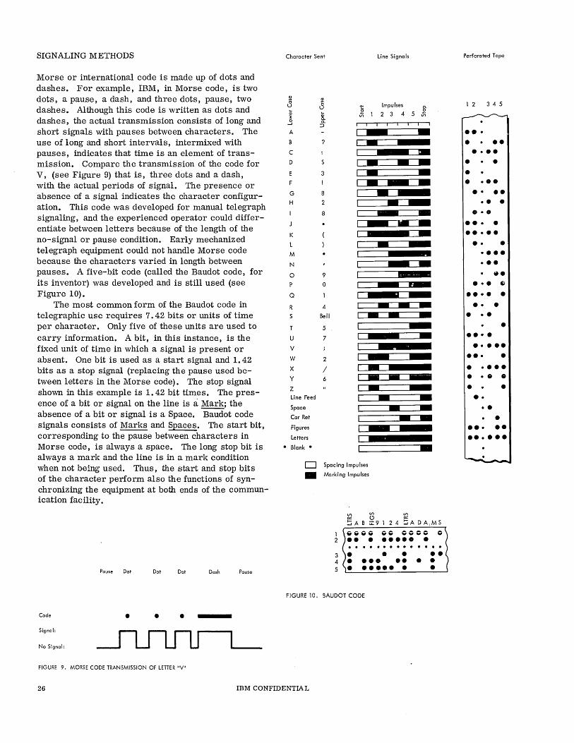
Morse or international code is made up of dots and dashes. For example, IBM, in Morse code, is two dots, a pause, a dash, and three dots, pause, two dashes. Although this code is written as dots and dashes, the actual transmission consists of long and short signals with pauses between characters. The use of long and short intervals, intermixed with pauses, indicates that time is an element of transmission. Compare the transmission of the code for V, (see Figure 9) that is, three dots and a dash, with the actual periods of signal. The presence or absence of a signal indicates the character configuration. This code was developed for manual telegraph signaling, and the experienced operator could differentiate between letters because of the length of the no-signal or pause condition. Early mechanized telegraph equipment could not handle Morse code because the characters varied in length between pauses. A five-bit code (called the Baudot code, for its inventor) was developed and is still used (see Figure 10).
The most common form of the Baudot code in telegraphic use requires 7.42 bits or units of time per character. Only five of these units are used to carry information. A bit, in this instance, is the fixed unit of time in which a signal is present or absent. One bit is used as a start signal and 1. 42 bits as a stop signal (replacing the pause used between letters in the Morse code). The stop signal shown in this example is 1. 42 bit times. The presence of a bit or signal on the line is a: Mark; the absence of a bit or signal is a Space. Baudot code signals consists of Marks and Spaces. The start bit, corresponding to the pause between characters in Morse code, is always a space. The long stop bit is always a mark and the line is in a mark condition when not being used. Thus, the start and stop bits of the character perform also the functions of synchronizing the equipment at both ends of the communication facility.
Pause Dot Dot Dot Dash Pause
Code • • • Signal:
No Signal:
FIGURE 9. MORSE CODE TRANSMISSION OF LETTER "V"
Character Sent Line Signals
Impulses a.
~12345Ji
,
---- - ---------------- -- ---
-D Spacing Impulses
• Marking Impulses
VI VI VI 0::: (!) 0:::
!:iAB U:9124 !:iADA,MS
GGGG GO 0000 0 ••••••••• . . . .......... . 3. •• ••
4 • ••• • ••• 5 ~. ___ ._. __ ._. __ • __ • ______ • __ ~
FIGURE 10. BAUDOT CODE
26 IBM CONFIDENTIA L
Perforated Tape
1 2 3 4 5
••• • •• ••••
• • • • ••• •••• •••
0·0
•••• ••••• •• • ••••
••• 8.
••• Iii
•••• • • • • • • • •
•••• •••••
••• • • •••• • • • • • • ••
• • • ••• ••
••••••
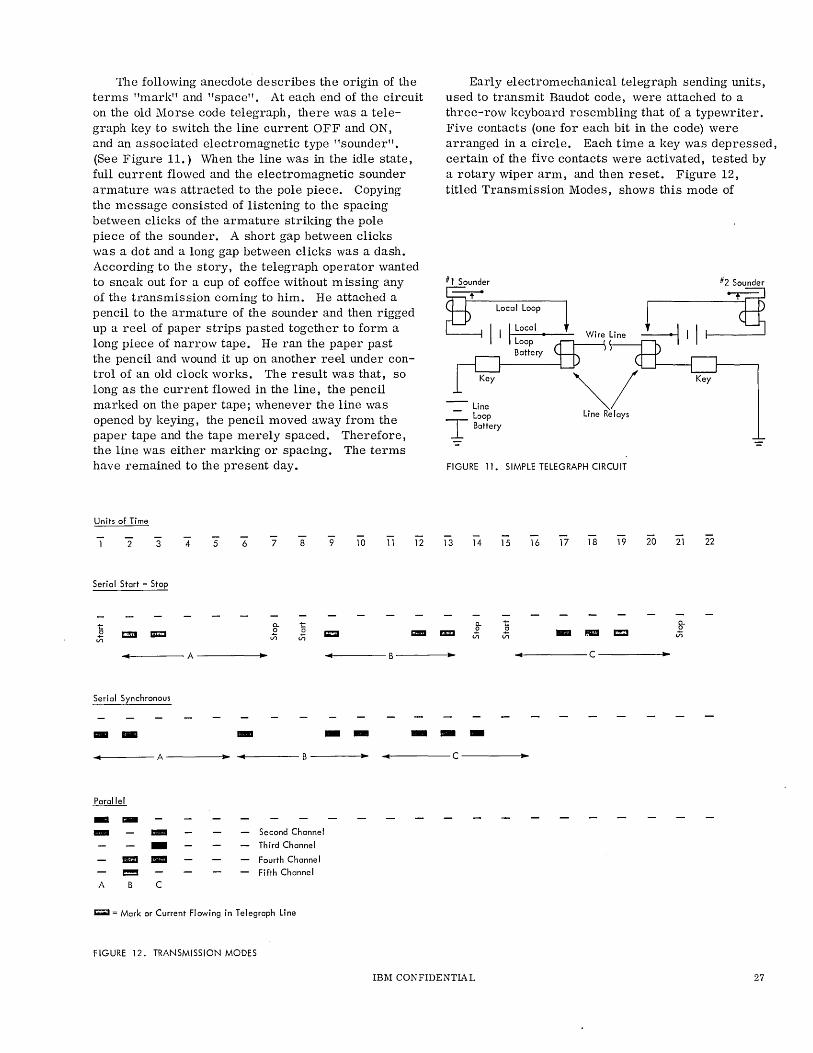
The following anecdote describes the origin of the terms "mark" and "space". At each end of the circuit on the old Morse code telegraph, there was a telegraph key to switch the line current OFF and ON, and an associated electromagnetic type "sounder". (See Figure 11.) When the line was in the idle state, full current flowed and the electromagnetic sounder armature was attracted to the pole piece. Copying the message consisted of listening to the spacing between clicks of the armature striking the pole piece of the sounder. A short gap between clicks was a dot and a long gap between clicks was a dash. According to the story, the telegraph operator wanted to sneak out for a cup of coffee without missing any of the transmission coming to him. He attached a pencil to the armature of the sounder and then rigged up a reel of paper strips pasted together to form a long piece of narr.ow tape. He ran the paper past the pencil and wound it up on another reel under control of an old clock works. The result was that, so long as the current flowed in the line, the pencil marked on the paper tape; whenever the line was opened by keying, the pencil moved away from the paper tape and the tape merely spaced. Therefore, the line was either marking or spacing. The terms have remained to the present day.
Units of Time
2 3 4 5 6 7 8 9 10 11
Serial Start - Stop
Cl.
12
.E 0 0 ClIlI Iii.ii:t:I Vi Vi m::IiI CIIIII
VI
III A ~ III
Serial Synchronous
-- .. -- -.. A ~ .. ~ -4
Parallel --- - Second Channel - Third Channel
ED - Fourth Channe I ~ Fifth Channel
A C
WiOiiiI = Mark or Current Flowing in Telegraph line
FIGURE 12. TRANSMISSION MODES
Early electromechanical telegraph sending units, used to transmit Baudot code, were attached to a three-row keyboard resembling that of a typewriter. Five contacts (one for each bit in the code) were arranged in a circle. Each time a key was depressed, certain of the five contacts were activated, tested by a rotary wiper arm, and then reset. Figure 12, titled Transmission Modes, shows this mode of
#1 Sounder #2 Sounder
~
line - Loop T Battery
FIGURE 11. SIMPLE TELEGRAPH CIRCUIT
13 14 15 16 17 18 19 20 21 22
a. C Cl.
0 .. I!!IIIII CI:Cl 0
&113 Vi Vi Vi
~ ... C ..
--C ~
IBM CONFIDENTIAL 27
transmission under a classification mown as Serial Start-Stop (also called asynchronous). For example, the letter A, when depressed, activated only the first and second contacts of the five. As the rotary wiper started testing the five contacts, it sent an automatic no signal or space indicating the start of the character, then marks from the first two contacts, spaces from the remaining three, and finally, a long mark for the end of character or stop signal. Conceivably, if the sending and receiving term.inals were controlled by the same timing pulse, the start and stop bits could be eliminated. Characters would be detected on the basis of every five bit times. The serial start-stop Baudot code requires 7.42 units of time for each character of 7.42 bits. Without start and stop bits, however, the character requires only five units of time for the five actual intelligence bits. Transmission without start and stop signals is termed Synchronous.
In synchronous signaling, a special pattern of bits is sent periodically to keep the terminals operating in unison. In most IBM applications, these are called idle characters. They are generated automatically and sent as required by the system.
In addition to the serial start-stop and synchronous methods of transmission, the figure also shows how the same characters can be sent over five channels simultaneoulsy, allowing one channel for each bit in the code structure. This is called Parallel Transmission. It is much the same as the keyboard of the key punch transmitting data to the punching unit.
In summary, a network may include Simplex, Half-Duplex, or Duplex channels. The transmission mode may be Serial Asynchronous, Serial Synchronous, or Parallel. In addition, depending on the rate of transmittion necessary, it may require a Broad Band, Voice Grade, Sub-voice Grade, or Telegraph Grade channel.
FREQUENCY SPECTRUM
The basic method of transmission in telegraphy is the use of the key, a switch or a rotor to interrupt periodically the flow of direct current (dc). Various~
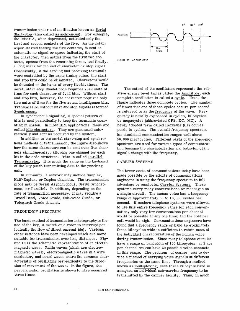
other methods have been developed which are more suitable for transmission over long distances. Figure 13 is the schematic representation of an electromagnetic wave. Radio waves (which are electromagnetic waves), electromagnetic waves in a wire conductor, and sound waves share the common characteristic of oscillating perpendicular to the direction of movement of the wave. In the figure, the perpendicular oscillation is shown to have occurred three times.
Amplitude
I I I I I r----- h Y\ H 1
I \JI~ U I I I I 1 I- One -I I 1 I Cycle I I I
FIGURE 13. AC SINE WAVE
The extend of the oscillation represents the relative energy level and is called the Amplitude; each complete oscillation is called a cycle. Thus, the figure indicates three complete cycles. The number of times that one of these cycles occurs per second is referred to as the frequency of the wave. Frequency is usually expressed in cycles, kilocycles, or megacycles (abbreviated CPS, KC, MC). A newly adopted term called Herzians (Hz) corresponds to cycles. The overall frequency spectrum for electrical communication ranges well above 30,000 megacycles. Different parts of the frequency spectrum are used for various types of communication because the characteristics and behavior of the signals change with the frequency.
CARRIER SYSTEMS
The lower costs of communications today have been made possible by the efforts of communications engineers in using the frequency spectrum to full advantage by employing Carrier Systems. These systems carry many conversations or messages on a single circuit. The human voice has a frequency range of approximately 50 to 16,000 cycles per second. If modern telephone systems were allowed to use this entire frequency range for each conversation, only very few conversations per channel would be possible at anyone time; and the cost per call would be high. Communications engineers have found that a frequency range or band approximately three kilocycles wide is sufficient to retain most of the individual characteristics of the human voice during transmis sion. Since many telephone circuits have a range or bandwidth of 150 kilocycles, at 3 kcs per channel we can have 50 possible voice channels in this range. The problem, of course, was to device a method of carrying voice signals at different frequencies on the same line. Through a method mown as multiplexing, each three kilocycle band is assigned an individual sub-carrier frequency to be transmitted by the carrier facility. Thus, in much
28 IBM CONFIDENTIAL
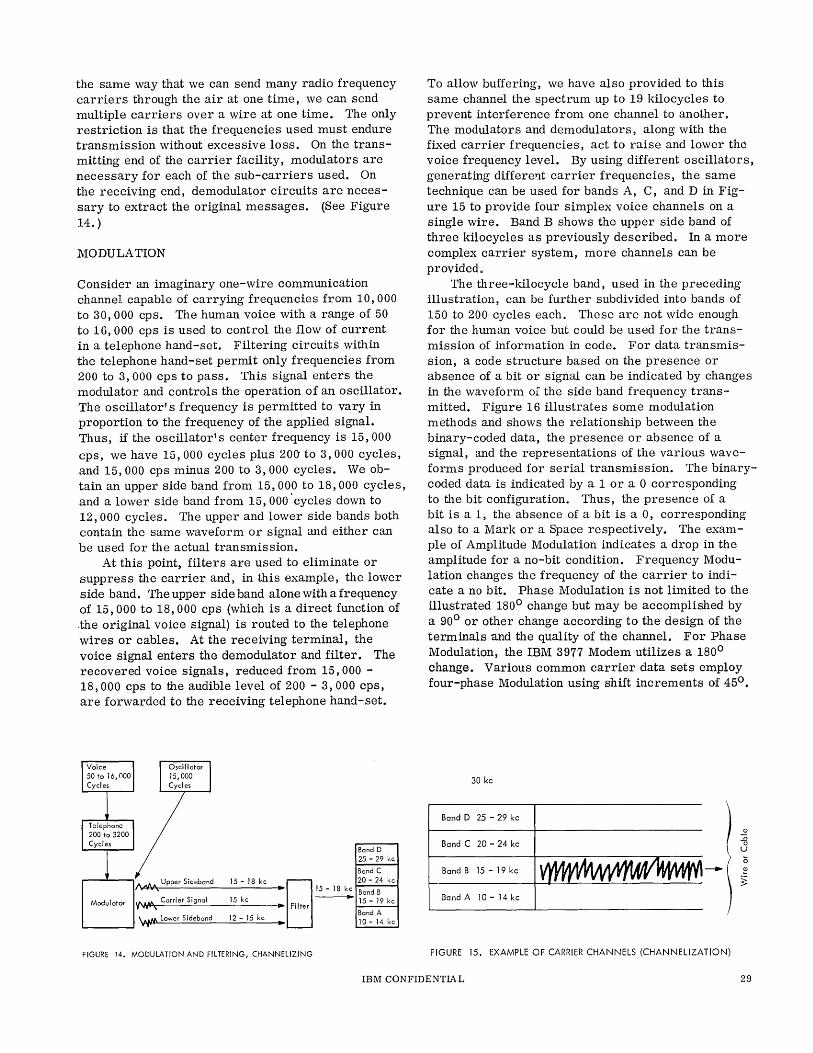
the same way that we can send many radio frequency carriers through the air at one time, we can send multiple carriers over a wire at one time. The only restriction is that the frequencies used must endure transmission without excessive loss. On the transmitting end of the carrier facility, modulators are necessary for each of the sub-carriers used. On the receiving end, demodulator circuits are necessary to extract the original messages. (See Figure 14. )
MODULATION
Consider an imaginary one-wire communication channel capable of carrying frequencies from 10,000 to 30,000 cps. The human voice with a range of 50 to 16,000 cps is used to control the flow of current in a telephone hand-set. Filtering circuits within the telephone hand-set permit only frequencies from 200 to 3, 000 cps to pass. This signal enters the modulator and controls the operation of an oscillator. The oscillator's frequency is permitted to vary in proportion to the frequency of the applied signal. Thus, if the oscillator'S center frequency is 15,000 cps, we have 15,000 cycles plus 200'to 3,000 cycles, and 15,000 cps minus 200 to 3,000 cycles. We obtain an upper side band from 15,000 to 18,000 cycles, and a lower side band from 15,000 'cycles down to 12,000 cycles. The upper and lower side bands both contain the same waveform or signal and either can be used for the actual transmission.
At this point, filters are used to eliminate or suppress the carrier and, in this example, the lower side band. The upper side band alone with a frequency of 15,000 to 18,000 cps (which is a direct function of .the original voice signal) is routed to the telephone wires or cables. At the receiving terminal, the voice signal enters the demodulator and filter. The recovered voice signals, reduced from 15,000 -18,000 cps to the audible level of 200 - 3,000 cps, are forwarded to the receiving telephone hand-set.
Band D 25 - 29 kc
Band C 20 - 24 kc
Band B 15 - 19 kc
Band A 10-14 kc
/I,.qI'j,,'V-A,<-, U-'p-'-pe_r_Si_de_b_an_d __ 15_-_1_8_k_c_. EJ 15 - 18 kc
Modulator '( .... tlt', Carrier Signal 15 kc ~ Filter -
'v.,ft., Lower Sideband 12 - 15 kc
FIGURE 14. MODULATION AND FILTERING, CHANNELIZING
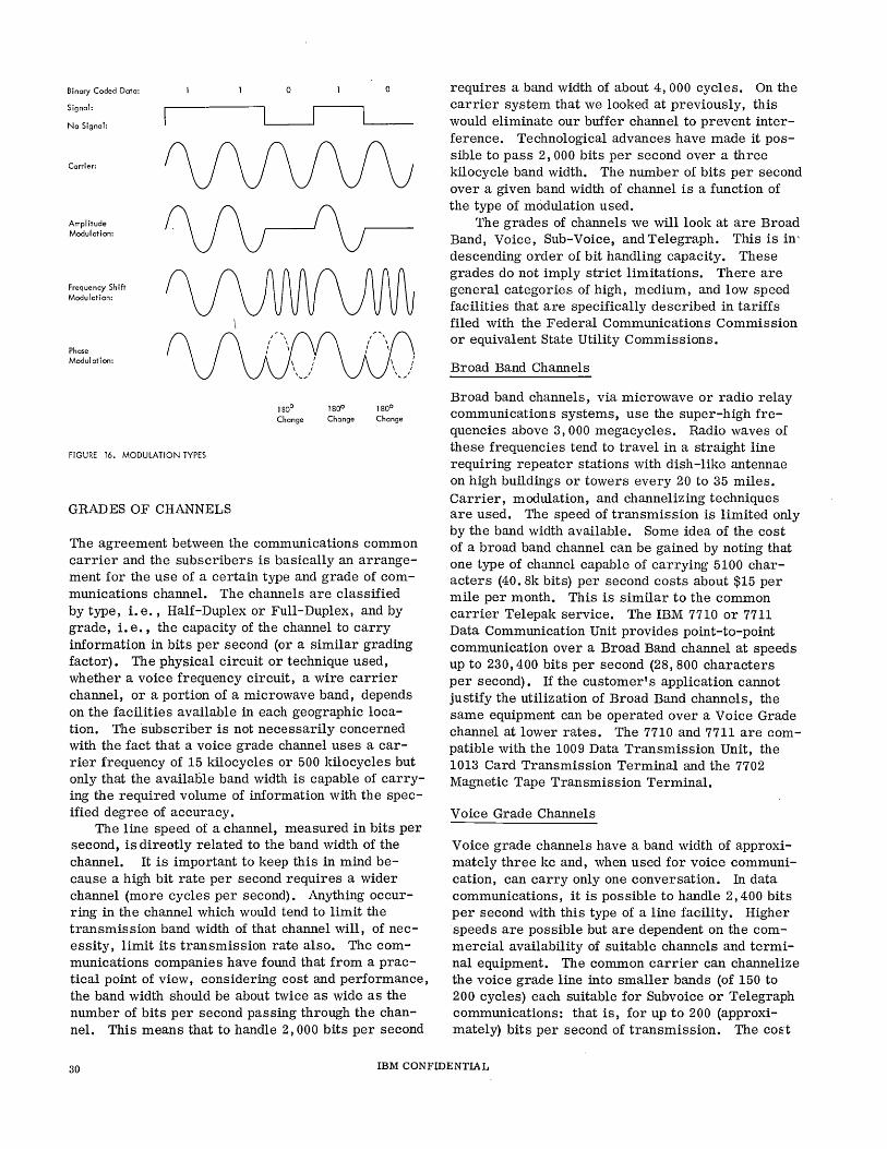
To allow buffering, we have also provided to this same channel the spectrum up to 19 kilocycles to prevent interference from one channel to another. The modulators and demodulators, along with the fixed carrier frequencies, act to raise and lower the voice frequency level. By using different oscillators, generating different carrier frequencies, the same technique can be used for bands A, C, and D in Figure 15 to provide four simplex voice channels on a single wire. Band B shows the upper side band of three kilocycles as previously described. In a more complex carrier system, more channels can be provided.
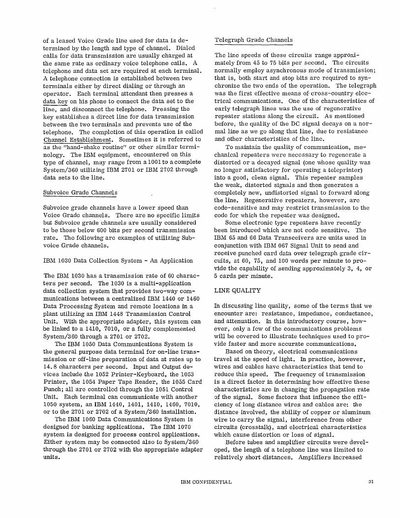
The three-kilocycle band, used in the preceding illustration, can be further subdivided into bands of 150 to 200 cycles each. These are not wide enough for the human voice but could be used for the transmission of information in code. For data transmission, a code structure based on the presence or absence of a bit or Signal can be indicated by changes in the waveform of the side band frequency transmitted. Figure 16 illustrates some modulation methods and shows the relationship between the binary-coded data, the presence or absence of a signal, and the representations of the various waveforms produced for serial transmission. The binarycoded data is indicated by a 1 or a 0 corresponding to the bit configuration. Thus, the presence of a bit is aI, the absence of a bit is a 0, corresponding also to a Mark or a Space respectively. The example of Amplitude Modulation indicates a drop in the amplitude for a no-bit conditiqn. Frequency Modulation changes the frequency of the carrier to indicate a no bit. Phase Modulation is not limited to the illustrated 1800 change but may be accomplished by a 900 or other change according to the design of the terminals and the quality of the channel. For Phase Modulation, the IBM 3977 Modem utilizes a 1800
change. Various common carrier data sets employ four-phase Modulation using shift increments of 450 •
30 kc
Band D 25 - 29 kc ! ~ Band C 20 - 24 kc :0
0 u
-\ (;
Band B 15-19kc ~
~ Band A 10 - 14 kc
FIGURE 15. EXAMPLE OF CARRIER CHANNELS (CHANNELIZATION)
IBM CONFIDENTIAL 29
Binary Coded Data:
Signal:
No Signal:
Carrier:
Amplitude Modulation:
Frequency Shift Modulation:
Phase Modulation:
FIGURE 16. MODULATION TYPES
GRADES OF CHANNELS
o
1 800 1800 1 800
Change Change Change
The agreement between the communications common carrier and the subscribers is basically an arrangement for the use of a certain type and grade of communications channel. The channels are classified by type, i. e., Half-Duplex or Full-Duplex, and by grade, i. e., the capacity of the channel to carry information in bits per second (or a similar grading factor). The physical circuit or technique used, whether a voice frequency circuit, a wire carrier channel, or a portion of a microwave band, depends on the facilities available in each geographic location. The subscriber is not necessarily concerned with the fact that a voice grade channel uses a carrier frequency of 15 kilocycles or 500 kilocycles but only that the available band width is capable of carrying the required volume of information with the specified degree of accuracy.
The line speed of a channel, measured in bits per second, is direotly related to the band width of the channel. It is important to keep this in mind because a high bit rate per second requires a wider channel (more cycles per second). Anything occurring in the channel which would tend to limit the transmission band width of that channel will, of necessity, limit its transmission rate also. The communications companies have found that from a practical point of view, considering cost and performance, the band width should be about twice as wide as the number of bits per second passing through the channel. This means that to handle 2, 000 bits per second
requires a band width of about 4,000 cycles. On the carrier system that we looked at previously, this would eliminate our buffer channel to prevent interference. Technological advances have made it possible to pass 2, 000 bits per second over a three kilocycle band width. The number of bits per second over a given band width of channel is a function of the type of modulation used.
The grades of channels we will look at are Broad Band, Voice, Sub-Voice, and Telegraph. This is in' descending order of bit handling capacity. These grades do not imply strict limitations. There are general categories of high, medium, and low speed facilities that are specifically described in tariffs filed with the Federal Communications Commission or equivalent State utility Commissions.
Broad Band Channels
Broad band channels, via microwave or radio relay communications systems, use the super-high frequencies above 3,000 megacycles. Radio waves of these frequencies tend to travel in a straight line requiring repeater stations with dish -like antennae on high buildings or towers every 20 to 35 miles. Carrier, modulation, and channelizing techniques are used. The speed of transmission is limited only by the band width available. Some idea of the cost of a broad band channel can be gained by noting that one type of channel capable of carrying 5100 characters (40. 8k bits) per second costs about $15 per mile per month. This is similar to the common carrier Telepak service. The IBM 7710 or 7711 Data Communication Unit provides point-to-point communication over a Broad Band channel at speeds up to 230,400 bits per second (28,800 characters per second). If the customer's application cannot justify the utilization of Broad Band channels, the same equipment can be operated over a Voice Grade channel at lower rates. The 7710 and 7711 are compatible with the 1009 Data Transmission Unit, the 1013 Card Transmission Terminal and the 7702 Magnetic Tape Transmission Terminal.
Voice Grade Channels
Voice grade channels have a band width of approximately three kc and, when used for voice communication, can carry only one conversation. In data communications, it is possible to handle 2,400 bits per second with this type of a line facility. Higher speeds are possible but are dependent on the commercial availability of suitable channels and terminal equipment. The common carrier can channelize the voice grade line into smaller bands (of 150 to 200 cycles) each suitable for Subvoice or Telegraph communications: that is, for up to 200 (approximately) bits per second of transmission. The co:::t
30 IBM CONFIDENTIAL
of a leased Voice Grade line used for data is determined by the length and type of channel. Dialed calls for data transmission are usually charged at the same rate as ordinary voice telephone calls. A telephone and data set are required at each terminal. A telephone connection is established between two terminals either by direct dialing or through an operator. Each terminal attendant then presses a data key on his phone to connect the data set to the line, and disconnect the telephone. Pressing the key establishes a direct line for data transmission between the two terminals and prevents use of the telephone. The completion of this operation is called Channel Establishment. Sometimes it is referred to as the "hand-shake routine" or other similar terminology. The IBM equipment, encountered on this type of channel, may range from a 1001 to a complete System/360 utilizing IBM 2701 or IBM 2702 through data sets to the line.
~ubvoice Grade Channel s
Subvoice grade channels have a lower speed than Voice Grade channels. There are no specific limits but Subvoice grade channels are usually considered to be those below 600 bits per second transmission rate. The following are examples of utilizing Subvoice Grade channels.
IBM 1030 Data Collection System - An Application
The IBM 1030 has a transmission rate of 60 characters per second. The 1030 is a multi-application data collection system that provides two-way communications between a centralized IBM 1440 or 1460 Data Processing System and remote locations in a plant utilizing an IBM 1448 Transmission Control Unit. With the appropriate adapter, this system can be linked to a 1410, 7010, or a fully complemented System/360 through a 2701 or 2702.
The IBM 1050 Data Communications System is the general purpose data terminal for on-line transmission or off-line preparation of data at rates up to 14.8 characters per second. Input and Output devices include the 1052 Printer-Keyboard, the 1053 Printer, the 1054 Paper Tape Reader, the 1055 Card Punch; all are controlled through the 1051 Control Unit. Each terminal can communicate with another 1050 system, an IBM 1440, 1401, 1410, 1460, 7010, or to the 2701 or 2702 of a System/360 installation.
The IBM 1060 Data Communications System is designed for banking applications. The IBM 1070 system is designed for process control applications. Either system may be connected also to System/360 through the 2701 or 2702 with the appropriate adapter units.
Telegraph Grade Channels
The line speeds of these circuits range approximately from 45 to 75 bits per second. The circuits normally employ asynchronous mode of transmission; that is, both start and stop bits are required to synchronize the two ends of the operation. The telegraph was the first effective means of cross-country electrical communications. One of the characteristics of early telegraph lines was the use of regenerative repeater stations along the circuit. As mentioned before, the quality of the DC signal decays on a normal line as we go along that line, due to resistance and other characteristics of the line.
To maintain the quality of communication, mechanical repeaters were necessary to regenerate a distorted or a decayed signal (one whose quality was no longer satisfactory for operating a teleprinter) into a good, clean signal. This repeater samples the weak, distorted signals and then generates a completely new, undistorted signal to forward along the line. Regenerative repeaters, however, are code-sensitive and may restrict transmission to the code for which the repeater was designed.
Some electronic type repeaters have recently been introduced which are not code sensitive. The IBM 65 and 66 Data Transceivers are units used in conjunction with IBM 067 Signal Unit to send and receive punched card data over telegraph grade circuits, at 60, 75, and 100 words per minute to provide the capability of sending approximately 3, 4, or 5 cards per minute.
LINE QUALITY
In discussing line quality, some of the terms that we encounter are: resistance, impedance, conductance, and attenuation. In this introductory course, however, only a few of the communications problems will be covered to illustrate techniques used to provide faster and more accurate communications.
Based on theory, electrical communications travel at the speed of light. In practice, however, wires and cables have characteristics that tend to reduce this speed. The frequency of transmission is a direct factor in determining how effective these characteristics are in changing the propagation rate of the signal. Some factors that influence the efficiency of long distance wires and cables are: the distance involved, the ability of copper or aluminum wire to carry the signal, interference from other circuits (crosstalk), and electrical characteristics which cause distortion or loss of signal.
Before tubes and amplifier circuits were developed, the length of a telephone line was limited to relatively short distances. Amplifiers increased
IBM CONFIDENTIAL 31
the signal strength and the useful length of a line but required additional feedback in the amplifiers (for this particular application, called repeaters) to prevent howling noises. Their function was to build up the line signal and prevent loss of signal along the telephone line.
A problem in long-distance voice lines is a succession of echoes of diminishing volume that is disturbing to the person speaking. To solve this problem, an echo suppressor was developed. The echo suppressor takes effect just after speaking starts, and drops out just after speaking stops. The slight delay is unnoticeable in a conversation and the echo problem is elimated. The delay required for the echo suppressor to drop out is known as "Drop-out Time" or "Turn-around Time" and must be taken into consideration when using a Voice Grade line for data transmission. If a terminal begins to transmit too soon after receivin~, data bits could be lost.
Devices designed specifically to compress the volume range of the human voice for economical transmission and to prevent crosstalk and noise are called Companders. Compander is a contraction of the words "compressor" and "expander". Effectively" soft sounds are amplified to a higher power level, and loud sounds are amplified to a lesser degree. The pr.ocedure is reversed by expansion at the receiving end. The common carrier normally removes companders from circuits used for data transmission.
It is possible for a common carrier to provide lines of especially high quality at additional cost. These specially conditioned lines permit data transmission at lower error rates or higher rates of transmission than would otherwise be possible. One disadvantage of conditioned lines is that alternate routes may not be readily available should they be required. Usually, loading coils are inserted into the line at proper intervals. These are inductive loads to compensate for the capacity of the line. They will, in some cases, cause unwanted distortion of the data signals. Loading coils are sometimes combined with resistance and capacity to correct delay or attenuation characteristics of the line. When used in this manner, they are referred to as compensators.
The signal levels on telephone lines are measured in a unit called the "decibel", abbreviated db. In telephone m:> rk, specifically where the line impedances are based on 600 ohms, the db changes to dbm (decibel milliwatt). The ·reference level for this measurement is 0 dbm equals 1 milliwatt dissipated in a load of 600 ohms. The formula for determining
. P-out db IS: dbm = 10 Log 10 P-;cl
If we use 0 db as the reference, the reference power is .001 watts, or 1 milliwatt, and we can measure relative to other signals either above or below this level and obtain + or - db readings.
The common carrier personnel talk about power levels and signal levels on telephone lines in terms of decibels. Your readings, however, using an IBM Line Adapter, and injecting a signal on a leased-line facility, will be in peak-to-peak volts from your oscilloscope.
The reference, 0 dbm, is equal to 1 milliwatt in a load of 600 ohms. This would correspond to a voltage level of .775 volts RMS or 2.2 volts peak-topeak. Figure 17 provides a graph for rapid conversion of db levels from +10 to -50 db in terms of peakto-peak voltage readings that you obtain from your oscilloscope.
In summary, we are interested in attenuation of a line as measured in a unit called the decibel; we have explained companders, echo suppressors, compensators, and repeaters. Having covered some of the concepts of types of channels, grades of channels, the quality of a particular channel, channelization methods, and the kind of equipment used on lines, we know that a telephone line consists of a lot more than just two pieces of wire strung across the country, and we are ready to look at data sets.
DATA SETS
Data sets are mown also as subsets or modems. The word modem is a contraction of modulator-demodulator. Data sets perform the necessary interface conversion between data processing equipment and communications facilities. They are used at each termination of the communications channel at its interface with the data processing equipment. The basic function of a data set is modulation and demodulation for data transmission. Following is an examination of typical data set specifications:
1. .Equipment: - Transmitter Receiver - It is not implied that the device is an original input or output device but that it functions both as a modulator and demodulator. One is required at each ter-minal in a network.
2. Transmission: Binary Serial 3. Input-Output: Binary - Conforms to EIA
RS-232-A. This designation indicates that a binary code representation, meeting the current recommended standards of the Electronic Industries Association, must be used by the data processing equipment with the appropriate hardware adapter. (For availability of documentation on RS-232-A, see references at end of session.)
4. Modulation: FM - Frequency modulation is used. Frequency modulation in telephone work can be either straight FM (e. g., frequency shifting) or it can be phase modulation.
5. Bit rate: 150 to 1200 bits per second - The bit per second range over which the data set can operate.
32 IBM CONFIDENTIAL
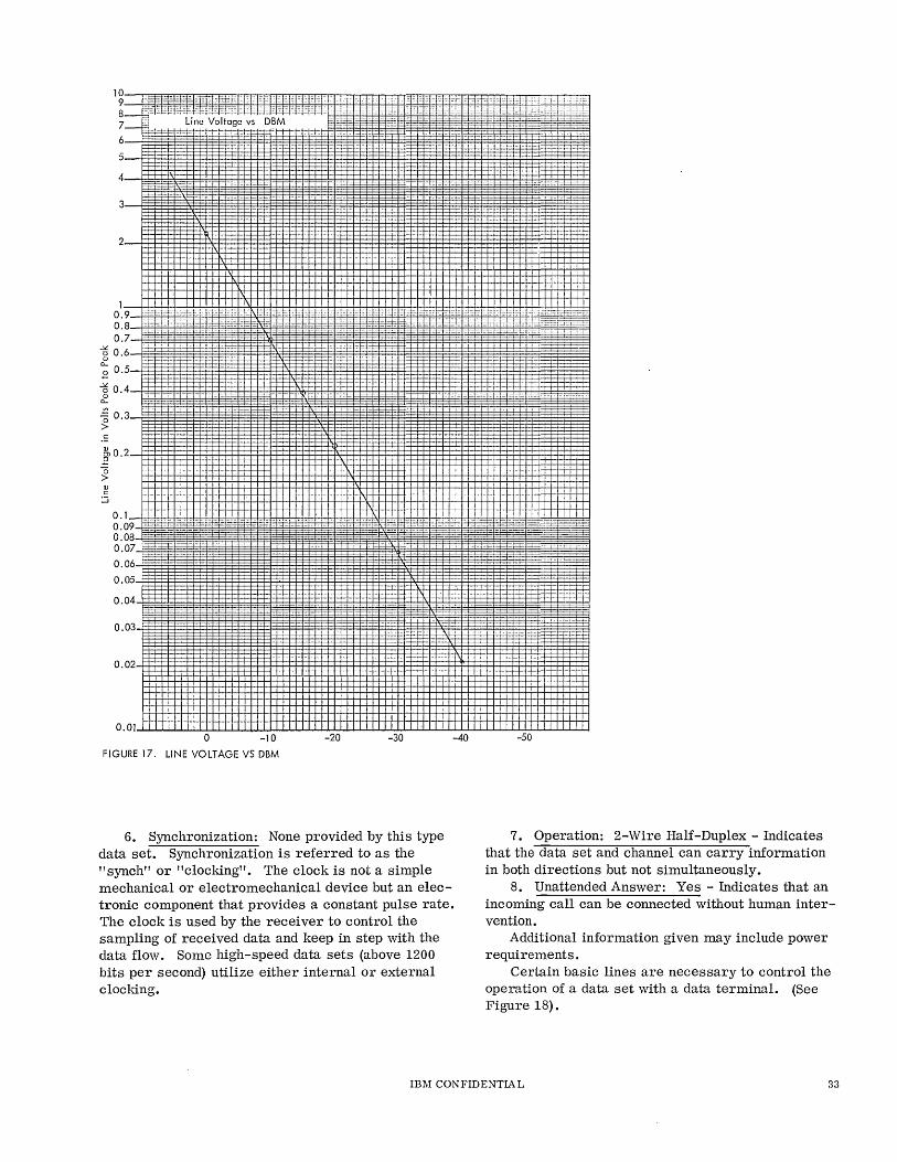
3
2
0~-9-+_±;~~·ct~~.H~t~~!_±~~1rb~_±_~~~hH++~~~~~~_++_~_~++~.~~hH'~,j+_~+'_+:_~clH~!H;!~~l+~~.b;C·~,_,HC~_F~-~+~~~ o . 8 i=E =f= . =i • - ::r:-:=:==._ ,. 0.7
--5 0.6 <lJ
~ 0.5
--50.4
.:: ~0.2 E "0 > ~ ::i
0.1
0.08 0.07 0.06
0.05
0.04
0.03
0.02
O.Ol~~~wu~~wu~~wu~~~~~~~~~~~~~~~~~~~~~ o -10 -20 -30 -40 -50
FIGURE 17. LINE VOLTAGE VS DBM
6. Synchronization: None provided by this type data set. Synchronization is referred to as the "synch" or "clocking". The clock is not a simple mechanical or electromechanical device but an electronic component that provides a constant pulse rate. The clock is used by the receiver to control the sampling of received data and keep in step with the data flow. Some high-speed data sets (above 1200 bits per second) utilize either internal or external clocking.
7. Operation: 2-Wire Half-Duplex - Indicates that the data set and channel can carry information in both directions but not simultaneously.
8. Unattended Answer: Yes - Indicates that an inCOming call can be connected without human intervention.
Additional information given may include power requirements.
Certain basic lines are necessary to control the operation of a data set with a data terminal. (See Figure 18).
IBM CONFIDENTIAL 33
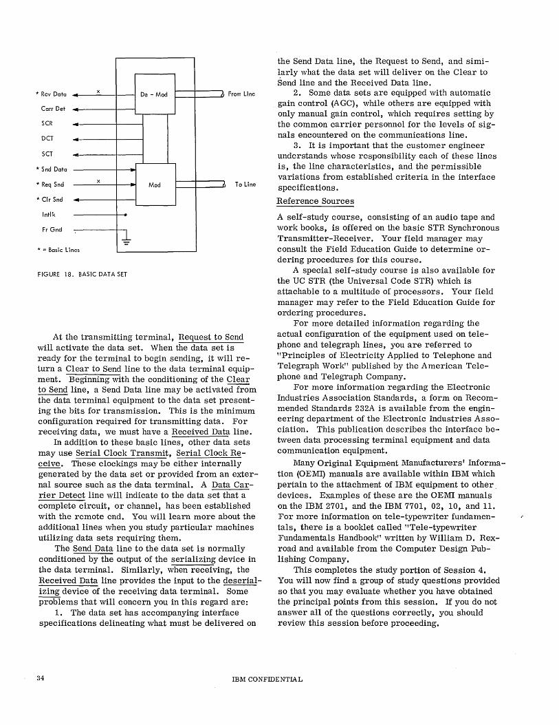
* Rev Data x De - Mod IJ From line
Carr Det
SCR
DCT
SCT
* Snd Data
X - Mod IJ To Line * Req Snd
* Clr Snd
Intlk
Fr Gnd
~ * = Basic Lin es
FIGURE 18. BASIC DATA SET
At the transmitting terminal, Request to Send will activate the data set. When the data set is ready for the terminal to begin sending, it will return a Clear to Send line to the data terminal equipment. Beginning with the conditioning of the Clear to Send line, a Send Data line may be activated from the data terminal equipment to the data set presenting the bits for transmission. This is the minimum configuration required for transmitting data. For receiving data, we must have a Received Data line.
In addition to these basic lines, other data sets may use Serial Clock Transmit, Serial Clock Receive. These clockings may be either internally generated by the data set or provided from an external source such as the data terminal. A Data Carrier Detect line will indicate to the data set that a complete circuit, or channel, has been established with the remote end. You will learn more about the additional lines when you study particular machines utilizing data sets requiring them.
The Send Data line to the data set is normally conditioned by the output of the serializing device in the data terminal. Similarly, when receiving, the Received Data line provides the input to the des erializing device of the receiving data terminal. Some problems that will concern you in this regard are:
1. The data set has accompanying interface specifications delineating what must be delivered on
the Send Data line, the Request to Send, and simi~arly what the data set will deliver on the Clear to Send line and the Received Data line.
2. Some data sets are equipped with automatic gain control (A GC), while others are equipped with only manual gain control, which requires setting by the common carrier personnel for the levels of signals encountered on the communications line.
3. It is important that the customer engineer understands whose responsibility each of these lines is, the line characteristics, and the permissible variations from established criteria in the interface specifications.
Reference Sources
A self-study course, consisting of an audio tape and work books, is offered on the basic STR Synchronous Transmitter-Receiver. Your field manager may consult the Field Education Guide to determine ordering procedures for this course.
A special self-study course is also available for the UC STR (the Universal Code STR) which is attachable to a multitude of processors. Your field manager may refer to the Field Education Guide for ordering procedures.
For more detailed information regarding the actual configuration of the equipment used on telephone and telegraph lines, you are referred to "Principles of Electricity Applied to Telephone and Telegraph Work" published by the American Telephone and Telegraph Company.
For more information regarding the Electronic Industries Association Standards, a form on Recommended Standards 232A is available from the engineering department of the Electronic Industries Association. This publication describes the interface between data processing terminal equipment and data communication equipment.
Many Original Equipment Manufacturers' Information (OEMI) manuals are available within IBM which pertain to the attachment of IBM equipment to other. devices. Examples of these are the OEMI manuals on the IBM 2701, and the IBM 7701, 02, 10, and 1I. For more information on tele-typewriter fundamentals, there is a booklet called "Tele-typewriter Fundamentals Handbook" written by William D. Rexroad and available from the Computer Design Publishing Company.
This completes the study portion of Session 4. You will now find a group of study questions provided so that you may evaluate whether you have obtained the principal points from this session. If you do not answer all of the questions correctly, you should review this session before proceeding.
34 IBM CONFIDENTIAL
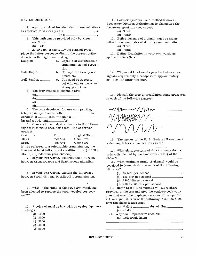
REVIEW QUESTIONS
1. A path provided for electrical communications is referred to variously as a a ___________ or a ________ _
2. This path can be provided only by wires. (a) True (b) False
3. After each of the following channel types, place the letter corresponding to the correct definition from the right hand listing. Simplex a. Capable of simultaneous
transmission and reception.
Half-Duplex ___ _ b. Can operate in only one direction.
Full-Duplex c. Can send or receive, but only one or the other at any given time.
4. The four grades of channels are: (a) __________ _
(b)-------------------(c) __________ _
(d) __________________ _
5. The code developed for use with printing telegraphic systems is called and consists of ___ data bits plus a ______ _ bit and a 1. 42 unit bit.
6. Cross out the undesired terms in the following chart to make each horizontal line of entries correct. Condition Mark Space
Bit Yes/No Yes/No
Logical State One/Zero One/Zero
If this referred to a telegraphic transmission, the line would be at fullcurrent condition for a (SPACE/ MARK). (Underline your choice.)
7. In your own words, describe the difference between Asynchronous and Synchronous signaling.
8. In your own words, explain the difference between Serial-Bit and Parallel-Bit transmission.
9. What is the name of the new term which has been adopted to replace the term "cycles per second" ?
10. A voice channel is how wide in cycles (approx-imately) ?
(a) 1000 (b) 2000 (c) 3000 (d) 4000 (e) 5000
11. Carrier systems use a method lmown as Frequency Division Multiplexing to channelize the frequency spectrum they occupy.
(a) True (b) False
12. Both sidebands of a signal must be transmitted to accomplish satisfactory communication.
(a) True (0) False
13. Define Modulation in your own words as applied to Data Sets.
14. Why are 4 kc channels provided when voice signals require only a bandpass of approximately 200-3000 Hz after filtering?
15. Identify the type of Modulation being presented in each of the following figures:
16. The agency of the U. S. Federal Government which regulates communications is the
17. What characteristic of data transmission is primarily limited by the bandwidth (in Hz) of the channel? ___________________ __
18. What minimum grade of channel would be required to transmit data at each of the following bit rates?
(a) 45 bits per second ________ _
(b) 135 bits per second ---------(c) 1800 bits per second _________ _
(d) 200 to 600 bits per second -----_ 19. Refer to the Line Voltage vs. DBM chart
provided in the text and give the peak-to-peak voltages that would be displayed on an oscilloscope for a 1 kc signal at each of the following levels on a 600 ohm telephone leased line.
(a) 0 dbm (b) -6 dbm ___ _ (c) -8 dbm ___________ _
20. Why are "Repeaters" used on: (a) Telegraph lines: __________ _
IBM CONFIDENTIA L 35
21. The device provided in long distance telephone lines to eliminate the annoyance of hearing your own voice coming back to you is called an ____________ " This device injects a problem of Turn-Around time into design of a communications system. What is meant by Turn-Aroundtime? ____________________________ __
How may Turn-Around time affect the throughput of a system ? __________________ _
22. What two undesirable characteristics of telephone lines are eliminated (or at least improved) through the use of Companders?
(1) _____________ _ (2) _____________ _
23. A compander provides (little/great) amplification of weak signals and (little/great) amplification of strong signals, on the sending end which constitutes (Compression/Expansion) of the signal level on the line. (Underline your choices.)
24. Loading Coils are placed in a telephone line to compensate for the ____________ _
capacity of the line. 25. When capacitive, resistive, and/or inductive
components are added to a telephone line to improve its characteristics from the standpoint of attenuation and/or phase distortion, the components thus added are referred to as __________ _
26. The reference of decibels as used in tele-phone work is ____ watts dissipated in a load of ______ ohms.
27. What is the advantage of a "Conditioned" telephone line over an unconditioned line? ___ _
28. The Data Set converts the output of a Business Machine (Data Terminal) to a form which will be accepted by the _____________ _
when sending. 29. The two principal functions of a Data Set are
___________ and ________________ __
36 IBM CONFIDENTIAL
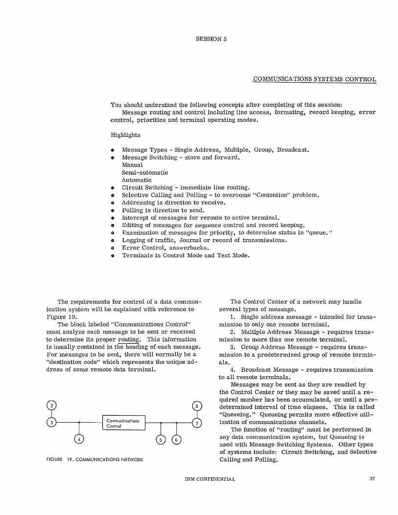
SESSION 5
,COMMUNICATIONS SYSTEMS CONTROL
You should understand the following concepts after completing of this session: Message routing and control including line access, formating, record keeping, error
control, priorities and terminal operating modes.
Highlights
• Message Types - Single Address, Multiple, Group, Broadcast. o Message Switching - store and forward.
Manual Semi -automatic Automatic
o Circuit Switching - immediate line routing. o Selective Calling and Polling - to overcome "Contention" problem. o Addressing is direction to receive. • Polling is direction to send. • Intercept of messages for reroute to active terminal. G Editing of messages for sequence control and record keeping. o Examination of messages for priority, to determine status in "queue. " o Logging of traffic, Journal or record of transmissions. o Error Control, answerbacks. o Terminals in Control Mode and Text Mode.
The requirements for control of a data communication system will be explained with reference to Figure 19.
The block labeled "Communications Control" must analyze each message to be sent or received to determine its proper routing. This information is usually contained in the heading of -each message. For messages to be sent, there will normally be a "destination code" which represents the unique address of some remote data terminal.
Communications Control
FIGURE 19. COMMUNICATIONS NETWORK
The Control Center of a network may handle several types of message.
1. Single address message - intended for transmission to only one remote terminal.
2. Multiple Address Message - requires transmission to more than one remote terminal.
3. Group Address Message - requires transmission to a predetermined group of remote terminals.
4. Broadcast Message - requires transmission to all remote terminals.
Messages may be sent as they are readied by the Control Center or they may be saved until a required number has been accumulated, or until a predetermined interval of time elapses. This is called "Queueing." Queueing permits more effective utilization of communications channels.
The function of "routing" must be performed in any data communication system, but Queueing is used with Message Switching Systems. Other types of systems include: Circuit Switching, and Selective Calling and Polling.
IBM CONFIDENTIAL 37
MESSAGE SWITCHING
Mes'sage Switching is used by the Control Center to transfer messages from one channel or circuit to another. In Figure 10, a message from terminal 8 to terminal 2 would require that the Control Center completely receive the message from terminal 8 and then retransmit it to terminal 2 on a different channel. This method of switching is also referred to as "store and forward." In telegraph-oriented systems, three versions of this are employed:
1. Manual Torn-Tape Switching 2. Semiautomatic Switching 3. Automatic Switching
Manual Torn -Tape Switching
In a data communications system using this form of switching, a message is received in punched paper tape at the Control Center. The Origin and Destination codes are examined and the tape is then transferred by the operator to a tape reader for transmission on the proper outgoing line.
Semi -automatic Switching
In data communications systems using this form of switching, an operator checks the destination code preceding each paper tape message and, by pressing the proper keys on a control unit, causes the message to be relayed to the proper destination as it is received by the Control Center.
Automatic Switching
In systems utilizing this form of switching, an incoming message is perforated in paper tape and automatically routed through a tape reader to analyze the destination address. Circuits are then conditioned to assign the message to the proper outgoing line as it passes through the reader.
CIRCUIT SWITCHING
Circuit Switching (also called line switching) does not require the receipt and retransmission of messages. The Control Center provides a direct connection between the terminals desiring to communicate under the Control of an operator or automatic switching equipment. One common example of Circuit Switching is the use of the dial telephone. In this application, dialing the required digits sets automatic equipment in operation to connect your line directly with the line of the called party. Compare this with the Message Switching counterpart of sending a telegram which must be received, printed, and then delivered to the addressee.
SELECTIVE CALLING AND POLLING
When two or more terminals are operating on the same circuit; all terminals will receive all messages whether intended for them or not. This problem can be overcome through "Selective Calling." This means that only the called terminal will copy the message. If more than one terminal tries to send at the same time, a condition called "Contention" arises. That is, multiple terminals are contending for the facilities of the Circuit or Channel. This problem can be eliminated by "polling" which is a controlled invitation to send.
Some systems have automatic mechanical polling devices which will sequentially permit each terminal to send. This function can also be performed through programming by a computer. Each terminal as it is polled is expected to answer. If the terminal does not have any message to send, it will answer with a "negative" response. If the terminal has messages (also called traffic) to send, it will respond to the poll by sending its queued messages. Failure of a terminal to respond to a poll, indicates that it is inoperative or nonexistent. The programmer and the Computer Control Center may elect to try again and/ or delete the terminal from the polling table or, he may leave the terminal in the list and, after waiting a predetermined length of time, go on polling the rest of the terminals.
LINE CONTROL
In a message control network, each communications line to the control center is shared by many terminals. Since only one terminal can use a line at a given time, terminals will contend for the use of the line, unless some form of supervision is imposed. The control of the lines and terminals is a function of the control center.
Polling is the systematic interrogation of terminals in the network by the control center. Each terminal has a unique address, and can be started and stopped by the control center. A table of terminal addresses is used by the center as a polling sequence. When a terminal is polled, a signal is sent back to the control center indicating the status of the terminal. This response, known as an answerback, indicates that the terminal is ready to send, ready to receive, or not ready to send or receive. The control center, in response to the answerback, accepts messages that are ready, sends messages that have been waiting at the center, and proceeds to poll the next terminal.
With terminal and line control responsibility, the control center can restrict or stop polling when necessary. For example, if during the normal operational day a momentary burst of traffic exceeds the
38 IBM CONFIDENTIAL

handling and queueing capacity of the system, the control center recognizes this overload and restricts polling to limit the number of incoming messages. This procedure allows the total systems traffic to be processed, although some delays will be encountered during this period because of the system's "flattening" of the traffic peaks.
The concepts to be derived here are: 1. Polling invites a terminal to send. 2. Addressing commands a terminal to receive.
Intercept
In some cases, messages may be intercepted by the control center. This means they are prevented from reaching their desired destination. This may occur under program control for the following reasons:
1. Message contains errors. 2. Message has incorrect format or heading. 3. Addressed terminal is inoperative. Control
center reroutes to an alternate terminal at a nearby location.
4. Due to passing from one time zone to another, the addressed terminal is not yet in operation. The control center will hold the message queued until the proper terminal comes on line.
Editing
The control center may edit incoming messages prior to reroute, such as:
1. Add control center sequence number, date and time to the header.
2. Receive from an IBM terminal device and change heading for required address to print out messages on a telegraphic printer.
Priorities
The control center can examine header information in messages to determine priority or initial or retransmis sion.
There are several methods for handling priority messages:
1. Flagging - Priority traffic can be flagged during the header analysis and before the placement of the message in the queue. On testing the queue for traffic to be transmitted, the queue can be scanned for priority traffic to be sent before normal messages.
2. Hetention of priority addresses in core storage - In this method, a priority message is placed in its normal queue position, but the sequence number and address location of the message are retained in core storage.
3. Transmission prior to logging - This method is based upon recognizing that a message is priority type. The message is transmitted to its destination immediately and logged later.
4. Priority queues - In this method, special queues are established for priority traffic.
Logging
Some systems utilize long and short term "Journals" for retaining messages handled. Retrieval may require special identification "Keys" to prove authorization for access to the Journal.
Long term Journals are usually Magnetic Tape; intermediate term on disk files; short term in memory, data cell, or drum files. This method helps in determining where an error entered a message and in repeating messages.
Error Control
Normally, procedures will be provided for receiving terminals to answer back to the sending terminal acknowledging correct or incorrect receipt of a message. If the answer-back indicates incorrect receipt, procedures usually exist to provide for retransmis sion.
Terminal Operating Modes
There are normally two modes of operation: 1. Control mode 2. Text mode Control mode is in operation for polling and ad
dressing while text mode indicates the data handling portion of the terminal operating procedures. Some terminal devices also revert to control mode for acknowledgment sequences between messages. The division between control and text mode usually occurs when addressing is ended.
This completes the text for Session 5. Answer the following study questions. If you get them all correct, you have conquered the main points of the section. If you get any questions wrong, you should review the necessary material before proceding to the next session.
IBM CONFIDENTIAL 39
REVIEW QUESTIONS
1. In your own words, define the term "Queueing."
2. In your own words, compare the concepts of Message Switching and Circuit Switching.
3. If more than one termi.nal tries to send on the same line at the same time, what term is applied to this situation?
4. What is the difference in terminal operation when being Polled from terminal operation when being Addressed?
5. If a terminal has traffic for the Control Center, what constitutes a positive answer to a Poll ?
6. If the Control Center has Polled a given terminal twice in succession, what should it do?
(a) Continue trying until an answer is received.
(b) Skip that terminal and proceed to process the remainder of the Polling List. .
(c) Stop and wait for operator intervention. 7. The terminals on a given line must be polled
and/ or addressed sequentrally by their physical locations on the line.
(a) True (b) False
8. If a terminal yields a negative answerback to a Poll, the Control Center should drop that terminal from its Polling List.
(a) True (b) False
9. The Control Center must always follow the same sequence of polling terminals on a line. Spec-ifyWHY. --
(a) True (b) False
10. If the terminal for which a message is intended happens to be inoperative, there is no way to send the message to its destination. Specify WHY.
(a) True (b) False
11. In a Message Switching system, the Control Center can add other information to a message before it is forwarded to the required addressee.
(a) True (b) False
12. The Control Center of a Message Switching system must send all messages it has received for terminals in the same sequence in which they were received. Specify WHY.
(a) True (b) False
13. What four methods may be used for processing priority messages in a Message Switching system?
(a) _______________ _
(b)--------------------------(c) ______________ _ (d) _____________ _
14. Why is a Journal or Log maintained?
15. Anyone can access all of the messages in the Journal. Specify WHY.
(a) True (b) False
16. Describe the difference between Control Mode and Text Mode.
40 IBM CONFIDENTIAL
SESSION 6
IMPL EMENTATION
SERDES AND SHIFT REGISTERS
In this session you will learn in more detail the methods of serializing and deserializing data for transmission and receiving, respectively.
Highlights
o SERDES is a Contraction of Serialize/Deserialize. o Use of "Storage Elements," "Store Control" blocks. o Line Control "Storage Element" and "Bit Timer." o Register is a group of Storage Elements. o In transmit, characters are converted from Bit Parallel to Bit Serial. o In receive, characters are converted from Bit Serial to Bit Parallel. o Characters are TRANSLATED from BCD to 4 of 8 Code on transmit operation. o Characters are TRANSLATED from 4 of 8 Code to BCD on receive operation. o Shift Register moves character up through it while presenting the character one
bit at a time to the line instead of leaving the character stationary and sampling it one bit at a time to the line as in SERDES.
o "OR Control" accepts either input ON to activate one leg of a Store Control block. o Line over a designated bit means "NOT" or logical zero condition of that bit.
(Example: N)
This section deals with two methods of serializing and deserializing data, and describes how a data set or modem responds to data bits.
SERDES
SERDES is a contraction of "Serialize/Deserialize." A SERDES device is capable of loading a character bit-parallel, then dismantling the character and presenting it one bit at a time to the data set for transmission. This is Serializing. On the receiving end, the SERDES will accumulate bits, one at a time, until a complete character is assembled. This is Deserialize. When a complete character has been assembled, it can be transferred bit-parallel to other circuitry.
Figures 20 and 21 show the machine circuitry necessary to perform these functions.
First, examine the notations we are using. The letter "T" represents a storage element. This element can be a relay, a magnetic core system, an electronic latch, or an electronic trigger. The
device can be signaled to go into either of its two states and will stay that way until signaled to change. Thus, we require a line to turn the device on, and one to turn it off. The output line from its upper half is then considered plus (+) if the device is on, and negative (-) if it is off. The store control block merely indicates that a plus (+) condition is necessary on both of its inputs (left hand side) in order to condition its output (right side) plus (+) to perform a turn on function to a Storage Element (T) or present a plus (+) level to the data set interface. The blocks labeled "Delay" serve only to provide a difference in time between the input of the block going plus and the output going plus. This enables us to do certain operations at points within a single bit-time period. The bit times provide a source of sequential pulses of plus polarity and properly spaced to time the operation. (Comparable to the distributor of an automobile ignition system or to a digit selector of an accounting machine when the digit selector is wired as a digit emitter.)
IBM CONFIDENTIAL 41
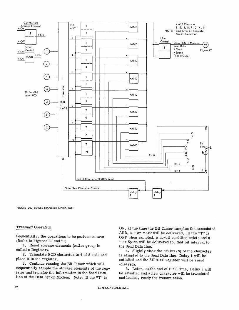
Conventions ,.....---
+On Storage Element T
» -Off 1----
1 -
2 + Off T
~---
0- 2 ----....:......--
4
T
0- ~---
4 >---
8
0- T ----
8
0- C5 R ~-"0 -Bit Parallel -;;;
c: T Input BCD c .= f----
0- R BCD ~----to 0
4 of 8 T
0- ----0 ----X
0- T 1-- --
X ~L---
N
T 1---
N ~
"---r-
End of Character SERDES Reset
Gate New Character Control
FIGURE 20. SERDES TRANSMIT OPERATION
Transmit Operation
Sequentially, the operations to be performed are: (Refer to Figures 20 and 21)
1. Reset storage elements (entire group is called a Register).
2. Translate BCD character to 4 of 8 code and place it in the register.
3. Continue running the Bit Timer which will sequentially sample the storage elements of the register and transfer the information to the Send Data line of the Data Set or Modem. Note: If the "T" is
+ 4 of 8 Char = A
I+AND[ 1,2,4,8, R, 0, x, N NOTE: Line Over bit Indicates '--------'
No-Bit Condition
-a- Line
+ Control Serial Bits to Modem ~
Send Data ·W T
f----+Mark Figure 29 - Space
-Fr ~ (4 of 8 Code)
'--------'
-
~ +a-+M .--
34 '8 ---7
-
J:r ·V
6 Bit Time~
5 r-±.
1'--------' f"\ ~V Bit 8 4
..("\
I 3
Bit2 v
2 1 ' Bit 1
Delay -- Delay 2 1
ON, at the time the Bit Timer samples the associated AND, a + or Mark will be delivered. If the "T" is OFF when sampled, a no-bit condition exists and a - or Space will be delivered for that bit interval to the Send Data line.
4. Slightly after the 8th bit (N) of the character is sampled to the Send Data line, Delay 1 will be satisfied and the SERD ES register will be reset (cleared).
5. Later, at the end of Bit 8 time, Delay 2 will be satisfied and a new character will be translated and loaded, ready for transmission.
42 IBM CONFIDENTIAL
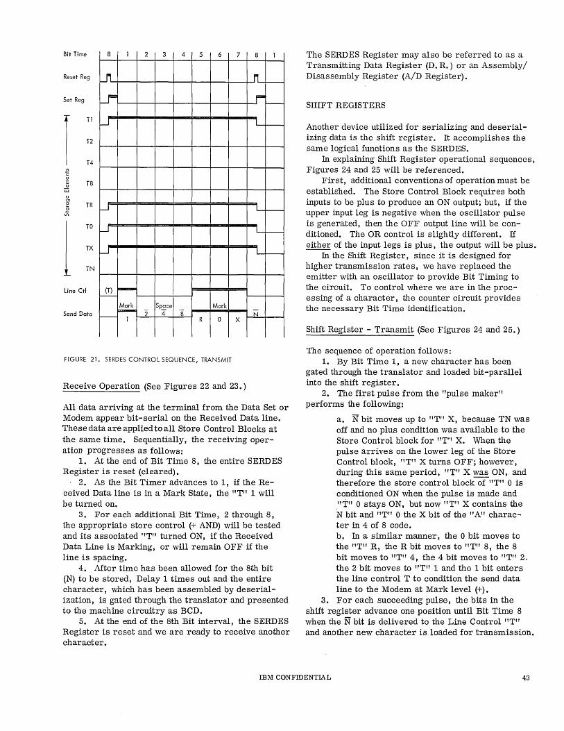
Bit Time 8 1 2 3 4 5 6 7 8 1
Reset Reg -.n. ~ I-
Set Reg ~ r== I-
r TI
T2
T4
.-J L
C (l)
E T8 (l)
W (l) m 0 TR £ --.J I
VI
1 TO
TX
TN
~ I
W I
line Ctl (T) F-r--
Send Data Mark Sp~ce Mark ~ 2 4 8" N I- 1 R 0 X
FIGURE 21. SEROES CONTROL SEQUENCE, TRANSMIT
Receive Operation (See Figures 22 and 23.)
All data arriving at the terminal from the Data Set or Modem appear bit-serial on the Received Data line. These data are applied to all Store Control Blocks at the same time. Sequentially, the receiving operation progresses as follows:
1. At the end of Bit Time 8, the entire SERD ES Register is reset (cleared).
2. As the Bit Timer advances to 1, if the Received Data line is in a Mark State, the "T" 1 will be turned on.
3. For each additional Bit Time, 2 through 8, the appropriate store control (+ AND) will be tested and its associated "T" turned ON, if the Received Data Line is Marking, or will remain OFF if the line is spacing.
4. Mter time has been allowed for the 8th bit (N) to be stored, Delay 1 times out and the entire character, which has been assembled by deserialization, is gated through the translator and presented to the machine circuitry as BCD.
5. At the end of the 8th Bit interval, the SERDES Register is reset and we are ready to receive another character.
The SERDES Register may also be referred to as a Transmitting Data Register (D. R.) or an Assembly/ Disassembly Register (A/D Register).
SHIFT REGISTERS
Another device utilized for serializing and deserializing data is the shift register. It accomplishes the same logical functions as the SERDES.
In explaining Shift Register operational sequences, Figures 24 and 25 will be referenced.
First, additional conventions of operation must be established. The Store Control Block requires both inputs to be plus to produce an ON output; but, if the upper input leg is negative when the oscillator pulse is generated, then the OFF output line will be conditioned. The OR control is slightly different. If either of the input legs is plus, the output will be plUS.
In the Shift Register, since it is designed for higher transmission rates, we have replaced the emitter with an oscillator to provide Bit Timing to the circuit. To control where we are in the processing of a character, the counter circuit provides the necessary Bit Time identification.
Shift Register - Transmit (See Figures 24 and 25.)
The sequence of operation follows: 1. By Bit Time 1, a new character has been
gated through the translator and loaded bit-parallel into the shift register.
2. The first pulse from the "pulse maker" performs the following:
a. N bit moves up to "T" X, because TN was off and no plus condition was available to the Store Control block for "T" X. When the pulse arrives on the lower leg of the Store Control block, "T" X turns OFF; however, during this same period, "T" X was ON, and therefore the store control block of "T" 0 is conditioned ON when the pulse is made and ."1''' 0 stays ON, but now "T" X contains the N bit and "T" 0 the X bit of the "A" character in 4 of 8 code. b. In a similar manner, the 0 bit moves to the "T" R, the R bit moves to "T" 8, the 8 bit moves to "T" 4, the 4 bit moves to "T" 2. the 2 bit moves to "T" 1 and the 1 bit enters the line control T to condition the send data line to the Modem at Mark level (+).
3. For each succeeding pulse, the bits in the shift register advance one position until Bit Time 8 when the N bit is delivered to the Line Control "T" and another new character is loaded for transmission.
IBM CONFIDENTIAL 43
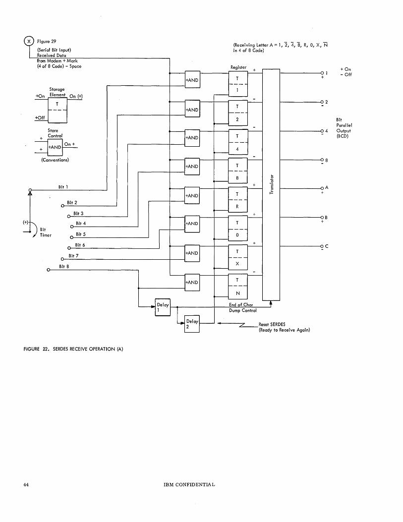
Figure 29
(Serial Bit Input) Received Data /Tom Modem + Mark (4 of 8 Code) - Space
Storage
IT Store
+ Control
~ (Conventions)
Bit 1
Bit 2
Bit Timer
Bit 8
Bit 3
Bit 4
Bit 5
Bit 6
Bit 7
FIGURE 22. SERDES RECEIVE OPERATION (A)
44 IBM CONFIDENTIA L
(Receiving Letter A = 1, 2, 4, 8, R, 0, x, N in 4 of 8 Code)
Register +
T
T
2
T
4
T
8
+
T
R
+
T
0
+
T
x
T
N
End of. Char Dump Control
5
~ c e I-
~------ol +
2
4
8
I----------CA +
~--------<l B +
~-------oC
-----2--"7 Reset SERDES (Ready to Receive Again)
+On - Off
Bit Parallel Output (BCD)
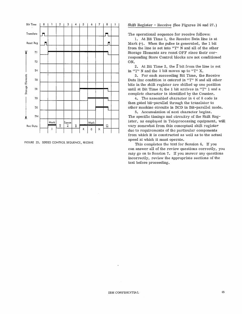
Bit Time 8 1 2 3 4 5 6
Translate ~
Reset Reg ~
I TI
T2
T4
f-----
i: OJ
T8 E OJ
W OJ m
TR 0
~ V)
1 TO
TX
TN
Mark Space Mark Rec Data ~ 2" 4 "8 - 1 R 0
FIGURE 23. SERDES CONTROL SEQUENCE, RECEIVE
7
X
8 1
.M...-I-
II f-----
L f-----
L f-----
L f-----
L f-----
-N
Shift Register - Receive (See Figures 26 and 27.)
The operational sequence for receive follows: 1. At Bit Time 1, the Receive Data line is at
Mark (+). When the pulse is generated, the 1 bit from the line is set into "T" N and all of the other Storage Elements are reset OFF since their corresponding Store Control blocks are not conditioned ON.
2. At Bit Time 2, the 2" bit from the line is set in "T" N and the 1 hit moves up to "T" X.
3. For each succeeding Bit Time, the Receive Data line condition is entered in "T" N and all other bits in the shift register are shifted up one position until at Bit Time 8; the 1 bit arrives in "T" 1 and a complete character is identified by the Counter.
4. The assembled character in 4 of 8 code is then gated bit-parallel through the translator to other machine circuits in BCD in Bit-parallel mode.
5. Accumulation of next character begins. The specific timings and circuitry of the Shift Register, as employed in Teleprocessing equipment, will vary somewhat from this conceptual shift register due to requirements of the particular components from which it is constructed as well as to the actual speed at which it must operate.
This completes the text for Session 6. If you can answer all of the review questions correctly, you may go on to Session 7. If you answer any questions incorrectly, review the appropriate sections of the text before proceeding.
IBM CONFIDENTIA L 45
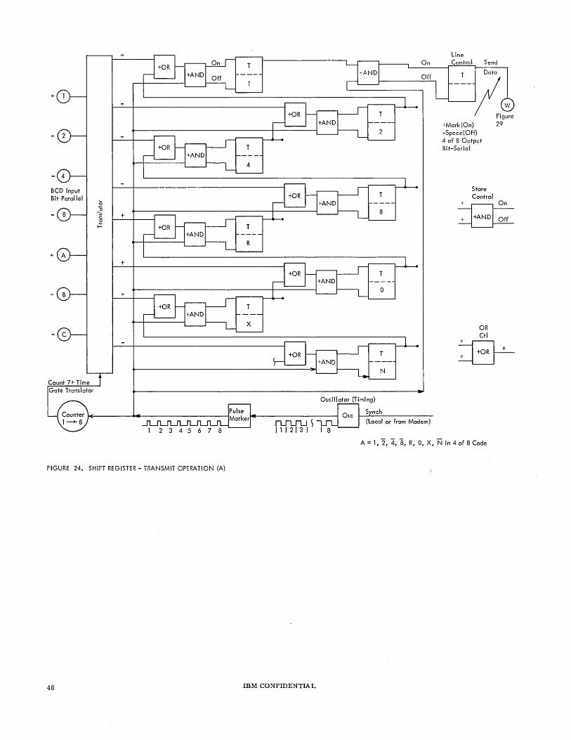
+
BCD Input Bit Parallel
+
Count 7+ Time Gate Translator
+
0 "0 v; + c:
0
~
+
+
FIGURE 24. SHIFT REGISTER - TRANSMIT OPERATION (A)
46
T On
Off
T
4
T
R
Oscillator (Timing)
(Local or from Modem) n..JU1..J ~ 11 1 21 3 I I 8
Line Control Send
T Data
---Y<g:, +Mark(On} 29 -Space(Off} 4 of 8 Output Bit-Serial
Store Control
+ On
~
OR Ctl
~ ~
A = 1, 2, 4, 8, R, 0, x, N in 4 of 8 Code
IBM CONFIDENTIAL
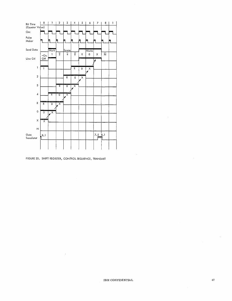
Bit Time (Caunter Va
Osc
Pulse Maker
Send Data
Line Ctl
2
3
4
R
o
X
N
Gate Translator
l 8 lue}
~
IL-!----
-On Off I--
~ 1
-
R
0
~ X
8.1
1 2
r-L rL
lL-L I Mark
1 2 ~
R
R 0
I
0 ~X I
[IX
3 4 5 6 7 8 1
M-iL rt.-IL M-~ M-L L M-IL-tL-L L Space Marks
4 8 R 0 X N
~ I
R 0 X jI
R 0 IX /
0 [IX I
IjIX
7·F8.1
FIGURE 25. SHIFT REGISTER, CONTROL SEQUENCE, TRANSMIT
IBM CONFIDENTIAL 47
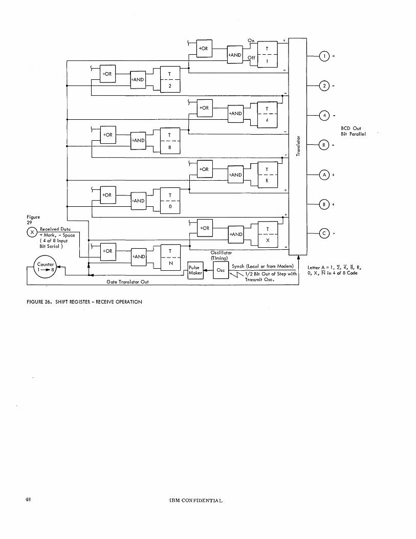
T
8
Figure 29
X Received Data + Mark, - Space ( 4 of 8 Input Bit Serial)
Osc
Gate Translator Out
FIGURE 26. SHIFT REGISTER - RECEIVE OPERATION
48 'IBM CONFIDENTIAL
R
+
+
T
X
Synch (Local or from Modem)
~ 1/2 Bit Out of Step with Transmit Osc.
+
+
BCD Out Bit Parallel
Letter A = I, 2, 4, 8, R, 0, X, N in 4 of 8 Code
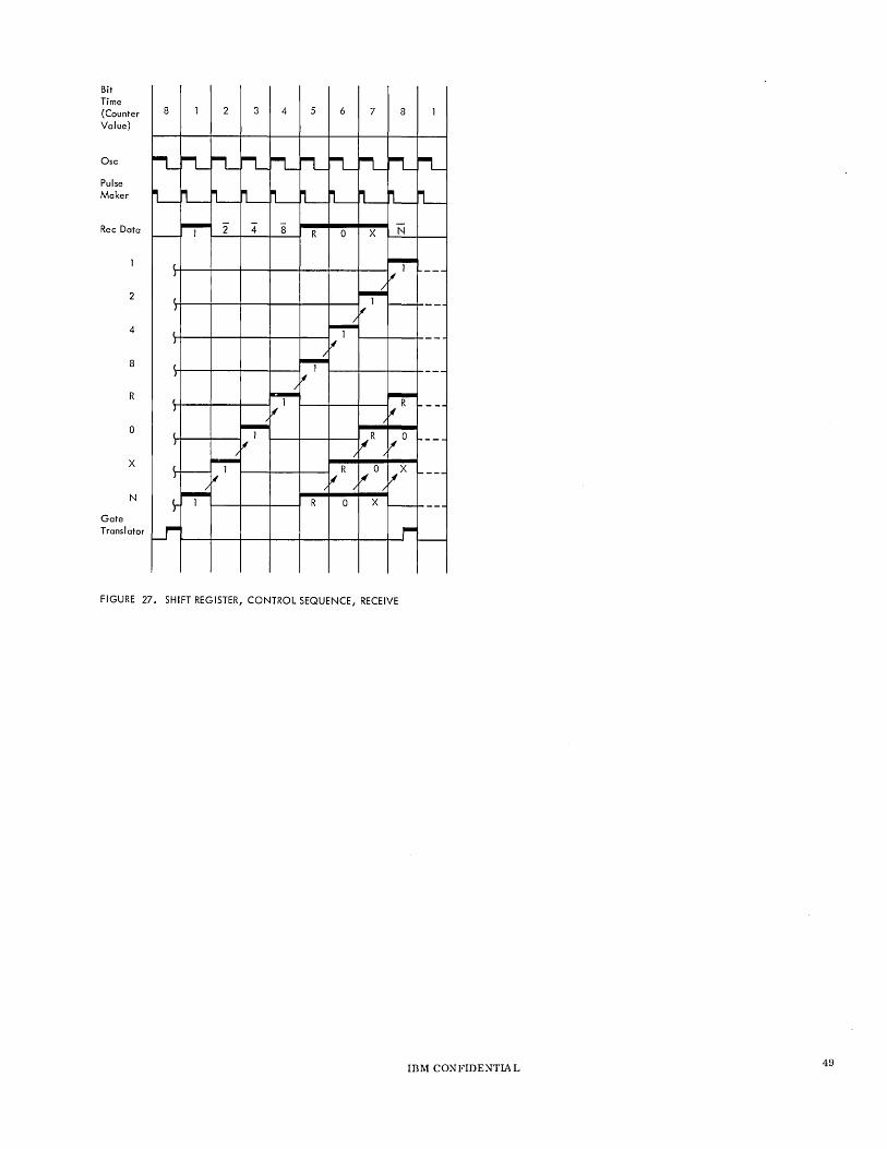
Bit Time (Counter Value)
Osc
Pulse Maker
Rec Data
2
4
8
R
o
x
N
Gate Translator
8 2 3 4 5 6 7
FIGURE 27. SHIFT REGISTER, CONTROL SEQUENCE, RECEIVE
8
IBM CONFIDENTIAL 49
REVIEW QUESTIONS
1. What does SERD ES stand for? _____ _
2. The primary function of SERDES when trans-mitting is to convert characters from _____ _ bit to bit format.
3. The primary function of SERDES when receiving is to convert characters from __ -----_ bit to bit format.
4. If a Store Control block has only one of its input legs ON, the output will be (ON/OFF). (Underline choice.)
5. If a Storage Element is turned ON when a character is loaded for transmission, at what Bit Time will it be turned OFF ? _________ _
6. Briefly describe why the Line Control Storage Element is necessary. ____________ _
7. The Translator used in the example in the text converts code to. ______ _ code on transmit operation.
8. Why is Delay 1 provided in transmit? __ _
9. Why is Delay 2 provided in transmit? __ _
10. The line is a (Mark/Space) at Bit Time 7. (Underline choice. )
11. Shortly after the beginning of Bit Time __ , the completely assembled (deserialized) character is transferred in bit form through the to the remainder of the ma-chine circuits on receiving operation.
12. If both input legs are ON or only one input leg is ON, of an OR Control block, the output will be (ON/OFF). (Underline your choice.)
13. How does the Shift Register know it has transmitted a whole character and that it is time to load a new one? ________________ _
14. In which Storage Element is the "X" bit of the character "A" (In 4 of 8 code) at Bit Time 3 on Transmit? _________________ __
15. At Bit Time 3, the Send Data line will be at (Mark/Space) and represents the _______ _ bit of the "A" character in transmit operation.
16. At Bit Time 3, in receive operation, the "1" bit of the "A" character is in the _______ _ Storage Element and the Received Data line is at (Mark/Space) representing the bit of the "A" character.
17. How does the Shift Register recognize that a complete character has been assembled and is ready for Bit Parallel transfer through the Translator to the rest of the machine? ___________ _
18. Briefly describe the difference in the way the SERDES and the Shift Register accomplish Serialization on Transmit.
~9. Briefly describe the difference in the way the SERDES and the Shift Register accomplish Deserialization on receive.
50 IBM CONFIDENTIAL
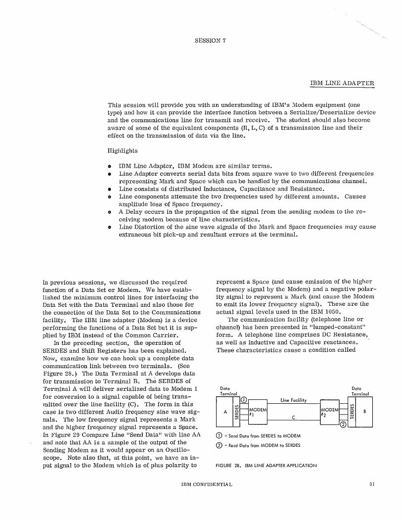
SESSION 7
IBM LINE ADAPTER
This session will provide you with an understanding of IBM's Modem equipment (one type) and how it can provide the interface function between a Serialize/Deserialize device and the communications line for transmit and receive. The student should also become aware of some of the equivalent components (R, L, C) of a transmission line and their effect on the transmission of data via the line.
Highlights
• IBM Line Adapter, IBM Modem are similar terms. • Line Adapter converts serial data bits from square wave to two different frequencies
representing Mark and Space which can be handled by the communications channel. • Line consists of distributed Inductance, Capacitance and Resistance. o Line components attenuate the two frequencies used by different amounts. Causes
amplitude loss of Space frequency. o A Delay occurs in the propagation of the signal from the sending modem to the re
ceiving modem because of line characteristics. o Line Distortion of the sine wave signals of the Mark and Space frequencies may cause
extraneous bit pick-up and resultant errors at the terminal.
In previous sessions, we discussed the required function of a Data Set or Modem. We have established the minimum control lines for interfacing the Data Set with the Data Terminal and also those for the connection of the Data Set to the Communications facility. The IBM line adapter (Modem) is a device performing the functions of a Data Set but it is supplied by IBM instead of the Common Carrier.
In the preceding section, the operation of SERDES and Shift Registers has been explained. Now, examine how we can hook up a complete data communication link between two terminals. (See Figure 28.) The Data Terminal at A develops data for transmission to Terminal B. The SERDES of Terminal A will deliver serialized data to Modem 1 for conversion to a signal capable of being transmitted over the line facility (C). The form in this case is two different Audio frequency sine wave signals. The low frequency signal represents a Mark and the higher frequency signal represents a Space. In Figure 29 Compare Line "Send Data" with line AA and note that AA is a sample of the output of the Sending Modem as it would appear on an Oscilloscope. Note also that, at this point, we have an input signal to the Modem which is of plus polarity to
represent a Space (and cause emission of the higher frequency signal by the Modem) and a negative polarity signal to represent a Mark (and cause the Modem to emit its lower frequency signal). These are the actual signal levels used in the IBM 1050.
The communication facility (telephone line or channel) has been presented in "lumped-constant" form. A telephone line comprises DC Resistance, as well as Inductive and Capacitive reactances. These characteristics cause a condition called
Data Terminal
A
Vl W Cl a:: w Vl
CD MODEM #1
Line Facility
C
CD = Send Data from SERDES to MODEM
(]) = Recd Data from MODEM to SERDES
FIGURE 28. IBM LINE ADAPTER APPLICATION
MODEM #2
Data Terminal
Vl \.U
~ B \.U Vl
IBM CONFIDENTIAL 51
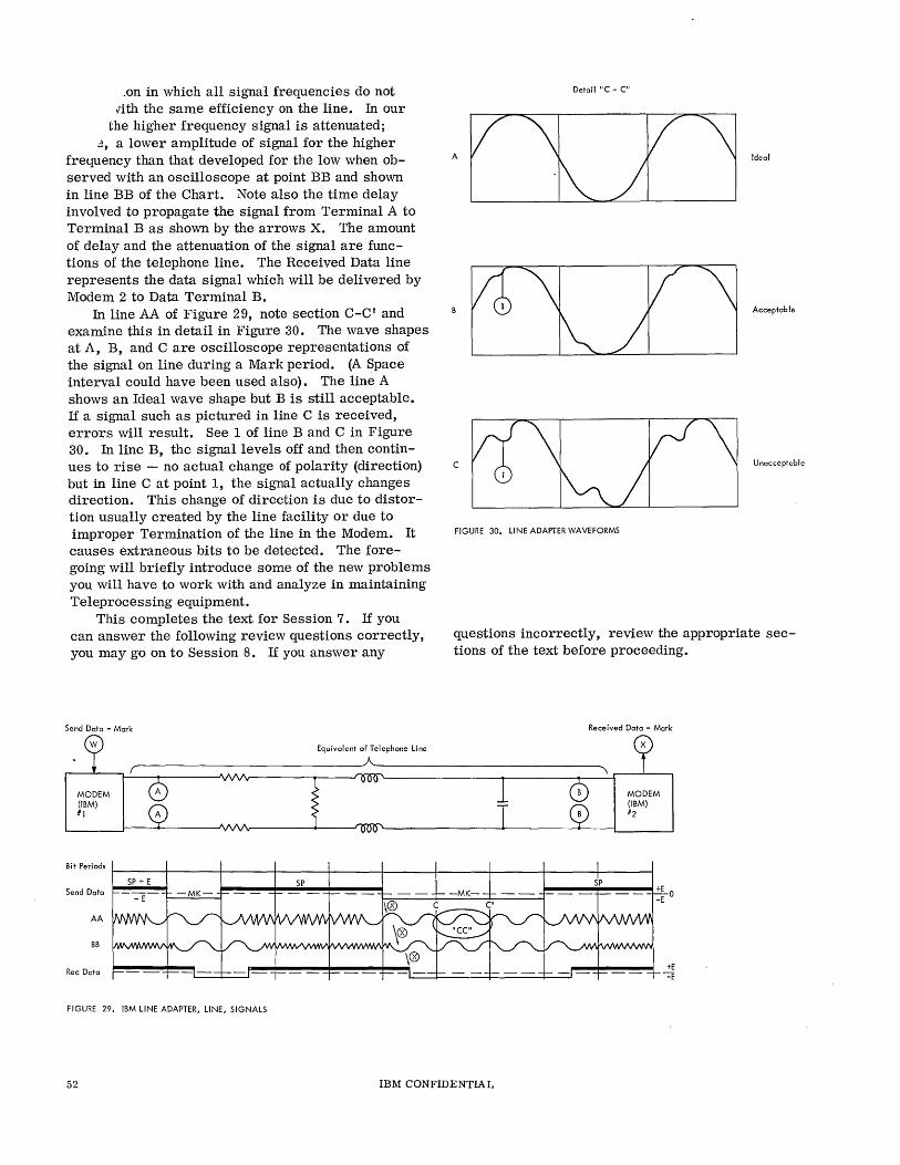
.on in which all signal frequencies do not vith the same efficiency on the line. In our
the higher frequency signal is attenuated; ~, a lower amplitude of signal for the higher
frelJ.uency than that developed for the low when observed with an oscilloscope at point BB and shown in line BB of the Chart. Note also the time delay involved to propagate the signal from Terminal A to Terminal B as shown by the arrows X. The amount of delay and the attenuation of the signal are functions of the telephone line. The Received Data line represents the data signal which will be delivered by Modem 2 to Data Terminal B.
In line AA of Figure 29, note section C-C' and examine this in detail in Figure 30. The wave shapes at A, B, and C are oscilloscope representations of the signal on line during a Mark period. (A Space interval could have been used also). The line A shows an Ideal wave shape but B is still acceptable. If a signal such as pictured in line C is received, errors will result. See 1 of line Band C in Figure 30. In line B, the signal levels off and then continues to rise - no actual change of polarity (direction) but in line C at point 1, the signal actually changes direction. This change of direction is due to distortion usually created by the line facility or due to improper Termination of the line in the Modem. It causes extraneous bits to be detected. The foregoing will briefly introduce some of the new problems you will have to work with and analyze in maintaining Teleprocessing equipment.
Detail "C - C"
Acceptable
C Unacceptable
FIGURE 30. LINE ADAPTER WAVEFORMS
This completes the text for Session 7. If you can answer the following review questions correctly, you may go on to Session 8. If you answer any
questions incorrectly, review the appropriate sections of the text before proceeding.
Send Data - Mark Received Data - Mark
Equivalent af Telephane line ~ __________________________ ~A ____________________________ ~
MODEM (IBM) #1
MODEM (IBM) #2
Bit Periads r----j----+-----1f----+---4----I------t----t.----+----Send Data
AA
BB
Rec Dala
FIGURE 29. IBM LINE ADAPTER, LINE, SIGNALS
52
~----.. ------~+EO ~---+-~-~--~ -E
IBM CONFIDENTIAL
+E -=E
REVIEW QUESTIONS
1. When used with customer owned or leased lines, the IBM Line Adapter performs the same function as a common carrier ________ _
2. The bits and no bits of the data stream produced by the SERDES on transmit are presented to the communications line as two different ____ _
3. The low frequency of the Modem corresponds to a condition of the signal from the SERDES.
4. The loss in amplitude of the Space frequency as compared to the Mark frequency is partly due to ________ distortion of the line.
5. If the signal shown in Figure 30, line C is presented to the receiving modem (line adapter), __ _ ___________ will probably result.
6. As delivered to the SERDES on receive, the signals on the Received Data line are ______ _ polarity for Space and polarity for Mark.
IBM CONFIDENTIAL 53

SESSION 8
DATA CONTROL OF MODEMS (DATA SETS)
This session will familiarize you with the modes of Data Set control as far as input and output signals between the data set and the data terminal are concerned.
Highlights
o Bi-Polar-signals relative to Signal Ground. o Uni-Polar-Single Polarity relative to Signal Ground. o Current-Change in current instead of voltage.
Basically, there are three methods of presenting data to, and receiving data from a Modem:
1. Bi -polar mode 2. Uni-polar mode 3. Current mode
Bi - Polar Mode
Bi-polar mode indicates that the data lines between the Terminal and the Modem swing plus and minus symmetrically with respect to a zero reference. Example: ±E relative to 0 Volts for IBM Modem.
Uni -Polar Mode
This mode indicates that the data line swings from zero reference to a single voltage level (either plus or minus polarity) to represent Marks and Spaces. Example: 0 Volts (signal ground) could be a Space while +6 Volts could represent a Mark.
Current Mode
ill current mode data delivery, the presence of Marks and Spaces is indicated by a change in current level exchanged between the data terminal and the
Modem. Example: (1) 0 current equals Space, 62 Milliamperes equals a Mark, (2) 20 Milliamperes equals a Space, 5 :Milliamperes equals a Mark.
Various types of Data Sets will use different versions of these basic modes.
This completes your text material on Implementation which has included SERDES, Shift Registers, IBM Line Adapter and Data Control of Modems. This material represents the practical applications of the concepts developed in the preceding sections and is intended to familiarize you with some of the different concepts you will be working with in maintaining Teleprocessing equipment.
Teleprocessing is a field of unlimited development and capable of presenting an unending challenge to the Customer Engineer who wants to stay abreast of technological developments of space age communication.
This completes the text portion of Session 8. Answer the review questions and proceed to Session 9. The following review questions are provided so that you may determine for yourself whether or not you have learned the principles presented in this section. If you give any wrong answers, you should review the necessary sub-topics.
IBM CONFIDENTIAL 55
REVIEW QUESTIONS
1. A signal input or output which swings positive and negative around a reference is considered as mode of operation.
2. A signal which swings in only one direction relative to reference is considered a _____ _ __ mode operation.
3. If the signal condition representing a Mark is denoted as 62.5 milliamperes of current and a Space is 0 milliamperes, then mode is indicated.
56 IBM CONFIDENTIAL
SESSION 9
COMMUNICATIONS FACILITIES
This session is provided to familiarize you with some of the available facilities for communications, by whom they are provided, and the agencies that control these offerings.
Highlights'
• Common Carriers defined. o The Federal Communications Commission controls domestic interstate and interna-
tional communications. • State Utilities Commissions control intrastate communications. o International Telecommunications Union, of which CCITT and CCIR are portions,
provides international efforts aimed at standardization and coordination. o Common Carriers and their services:
Bell System General Telephone and Electronics Independent Telephone Companies Western Union American Cable and Radio Corporation. RCA Communications, Inc., Privately Owned Communications Systems
COMMUNICATIONS COMMON CARRIERS
Communications common carriers are companies which furnish communications services to the public. They are regulated by the Federal Communications Commission or appropriate state agencies. Their services include communications facilities for VOice, data, facsimile and printed messages, as well as appropriate communications channels for television, telemetry and telephoto. In the United States approximately 2, 800 companies are recognized as communications common carriers. These companies can provide complete communications services to the subscriber including channels, modulating equipment, and the necessary terminating arrangements. Alternatively, the customer may lease only the channels and provide purchased or leased terminals equipment for data communications.
The services mentioned in this section are presented as a survey of some of the communications facilities available today. The representatives of the communications companies should be consulted in order to obtain current information on rates,
availability of service, billing arrangements, channels and related devices pertinent to data transmission.
THE FEDERAL COMMUNICATIONS COMMISSION
The Federal Communications Commission, an independent federal agency, regulates interstate and internatiorial communications originating in the United States, such as radio, telephone, telegraph, facsimile, telephoto and other broadcast program transmissions by wire, cable or radiO.
The Communications Act, establishing the Federal Communications Commission, requires that every subject common carrier furnish service at reasonable charges upon reasonable request. No carrier may construct, acquire or operate interstate or foreign facilities originating in the United States without the approval of the commission.
Under the provisions of the Communications Act every common carrier must file with the commission schedules showing all charges, practices, classifications and regulations for interstate communications services offered to the public. These
IBM CONFIDENTIA L 57
schedules, lmown as tariffs, are normally filed at least 30 days before their terms become effective. The tariffs form a significant part of the machinery by which the commission enforces the duties and prohibitions imposed on the common carriers for the benefit of the public. They are also the basic contract between the common carrier and the user. Telephone and telegraph companies are not required to file tariffs of their own if they concur in the tariffs filed by other common carriers. Due to local conditions, however, tariffs may vary from company to company.
One example of a tariff with a high degree of concurrence among a large number of telephone companies is tariff #245 filed with the Federal Communications Commission by the American Telephone and Telegraph Company. This tariff covers the V-H Measuring Plan. It establishes the basis for determining the cost of a telephone call by providing a uniform means of calculating the distance between the calling station and the receiving station. In the V -H Measuring Plan, each area in the United States and Canada is assigned a mathematical coordinate on a vertical. (V) and a horizontal (H) basis. This divides the entire area into a series of small squares, each having an equivalent of latitude and longitude. The distance for billing purposes in airline miles between any two points can then be calculated from these coordinates.
STATE UTILITY COM].'.1ISSION
Intrastate common carrier communications service is subject to regulation by state commissions similar in function to the Federal Communications Commission.
INTERNATIONAL TELECOMMUNICATIONS UNION
The International Telecommunications Union is an administrative international organization responsible for the allocation, registration and utilization of the radio frequency spectrum. The main objective of the union is to maintain and develop international cooperation for the improvement and rational use of communications. The union undertakes studies and issues recommendations for the benefit of all members, as well as participating in the Technical Assistance Programs of the United Nations. Within the ITU, the Consultive Committee on International Telephone and Telegraph (CCITT) and the Consultive Committee on International Radio (CCIR) are actively engaged in the standardization and coordination of international worldwide communications facilities.
THE BELL SYSTEM
The parent company of the Bell System is the American Telephone and Telegraph Company, incorporated in 1885, which owns all or part of the stock of 23 associated operating telephone companies and the Western Electric Company. Together with Western Electric, AT&T owns the Bell Telephone Laboratories. Western Electric manufactures, purchases, distributes and installs equipment to fit the needs of the Bell System. The Bell Telephone Laboratories carryon centralized research for the Bell System.
The people of the Bell Telephone System design, build, operate and maintain facilities for approximately 67 million telephones in 48 of the states and the District of Columbia. Bell System lines connect with telephone systems in all 50 states of this country and throughout the world.
The Bell System provides a wide range of products and services to fit specific communications needs, from the basic telephone instrument to DATAPHONE* Service which enables business machines to communicate via the telephone network in the same way people do. The technological contributions of the Bell System Include the invention of the transistor and the solar battery, as well as the designing and building of the Telstar satellites. Touch-Tone calling which will replace the rotary dial with push buttons, and completely electronic telephone call switching are being developed to improve the service of the Bell System to its customers.
Some of the communications services of the Bell System are Wide Area Telephone Service (W A TS), Telpak, Teletypewriter Exchange Service (TWX) and DATA-PHONE Service.
WA TS. -- Wide Area Telephone Service is arranged for subscribers who make many outgoing long distance calls to many points. Monthly charges are based on the size of the area in which the calls are placed, not on the number or length of calls. Under the WATS arrangement, the United States is divided into six zones. The subscriber is billed a flat rate according to the zones to be called on a full-time or measured-time basis. This can be an advantageous arrangement for data transmission.
TELPAK. -- Telpak service is a pricing arrangement that makes available wide band communications channels of various sizes suitable for large-volume point-to-point transmission of data, voice, teletypewriter, facsimile, or other services for a flat-rate regardless of usage. Telpak can be used as a single large channel or a group of smaller channels. For
*Trademark of American Telephone and Telegraph Company
58 IBM CONFIDENTIA L
example, a Telpak "A" channel may be divided into 12 voice grade channels.
Teletypewriter Exchange Service. -- Teletypewriter Exchange Service (TWX) provides direct dial pointto-point connections using input/output equipment such as page printers, keyboards, paper tape readers and paper tape punches.
DATA-PHONE Service. -- DATA-PHONE Service provides for the transmission of data between a variety of business machines, using regular local or long distance telephone networks, or WATS lines. The cost to the customer is the same as an ordinary telephone call in addition to a monthly rate for the DATA-PHONE data set.
Other Services. -- In addition to the familiar dial telephone services, voice grade and telegraph grade lines can be leased for the exclusive use of the subscriber.
GENERAL TELEPHONE AND ELECTRONICS CORPORATION
General Telephone and Electronics Corporation is a highly diversified communications and manufacturing enterprise whose operations throughout the United States and abroad are known as the "General System". GT&E provides communications services ranging from telephone service for the home and office to highly complex voice and data systems for industry and national defense. The company has approximately 5-1/2 million telephones in more than 30 domestic telephone operation subsidiaries and three international subsidiaries located in British Columbia, the Dominican Republic and Haiti.
Automatic Electric Company, a subsidiary of GT&E, produces communications equipment for the independent telephone industry. Lenkurt Electric Company, Incorporated, another subsidiary, manufacturers data sets, microwave radio, and carrier multiplexing equipment for commercial and military communications.
The General System has had broad and extensive experience in the data communications field. Over the years, it has provided a wide variety of services making use of channels ranging from narrow band telegraph up to four-megacycle video channels. Its services include teletypewriter services in its operating territories and direct dial TWX operations.
It is the General System's intention to offer, under tariffs, all data services of the common carriers including wide band Telpak channels. The terminal and hardware equipment utilized in providing data communications will be developed and manufactured by GT&E subsidiaries where practicable.
Western Electric equipment will be used in most instances where GT&E does not manufacture equivalent equipment. GT&E equipment will be compatible with the equivalent Bell System equipment, where required, to allow direct interconnection of services. Special arrangements will be available when required to meet individual requirements.
INDEPENDENT TELEPHONE COMPANIES
The General System and balance of the 2,800 telephone companies operating 13 million telephones in the United States provide services that interconnect with the Bell System and each other. Over 150 independent telephone companies have more than 10,000 subscribers, and another 100 have more than 5,000 subscribers.
The United States Independent Telephone Association (USITA), with headquarters in Washington, D. C., represents many of the independent telephone companies. It provides guidance to its members and coordinates their practices through committees. "Telephony Magazine", published weekly by the Telephony Publishing Corporation of Chicago, and "Telephone Engineer and Management", published semi-monthly by the Telephone Engineering Publishing Corporation of Chicago, are important vehicles for distributing information about the telephone industry. Both companies publish annual directories indicating the corporate structure and pertinent statistics about telephone companies in the United States.
WESTERN UNION
The Western Union Telegraph Company, incorporated in 1851, has played a vital role in the development of communications in the United States.
The company furnishes communications services by wire and microwave radio throughout the United States and by ocean cable between the United States and foreign countries. It provides the only national telegraph message service. It also furnishes custombuilt private wire systems and facsimile systems on a leased basis and Telex, a direct-dial teleprinter service.
Western Union leases more than 2,000 private wire systems of varying sizes and speeds for industry and government. It recently placed in service for the Department of Defense the world's largest and most advanced digitar data network with a capacity of 7,000,000 punched cards, or the equivalent of 100,000,000 words daily.
Western Union recently expanded its offerings of leased wire facilities to include a full range of voice, alternate voice-record, Telpak and voicedata services. It also leases circuits and equipment
IBM CONFIDENTIA L 59
to speed communications by facsimile. Scheduled for operation by Western Union in 1964
is a new coast-to-coast microwave system which will be capable of accommodating all modern forms of communication at high speeds and in large volume .. It will be used to transmit vOice, facsimile, and high-speed data as well as public message and private wire services.
AMERICAN CABLE & RADIO CORPORATION
American Cable & Radio Corporation (AC&R), a subsidiary of International Telephone and Telegraph, owns and operates an international telegraph system with both cable and radio facilities. AC&R was formed when the operations of four IT&T affiliates, All America Cables and Radio, The Commerical Cable Company, Mackay Radio and Telegraph Company, and Sociedad Anonima Radio Argentina (Buenos Aires) were consolidated. The company later acquired control of Globe Wireless, Incorporated.
AC&R, in addition to its operating centers located in New York, Washington, and San Francisco, maintains and staffs more than 110 overseas traffic offices, as well as seven marine radio stations. In the three "gateway" cities of New York, Washington, and San Francisco, the public deals with AC&R directly. Customers outside these cities use AC&R international facilities through the intermediate telegraph or teleprinter services of the domestic carriers, Western Union and the TWX Bell System. This applies to telegraph and Telex service, as well as to leased channel operation.
AC&R's communications network now includes more than 500 cable and radio channels, extending across the Atlantic to Europe, down through the Caribbean, Central and South American areas, and out to the Far East. Through the cable network, its own radio facilities, and by connection with foreign cable and telegraph companies, the IT&T/ AC&R Communications System not only connects the United States with practically all countries of the world but also furnishes communications between countries outside the United States.
This worldwide network provides customers with regular message service, press-cast service radiotelephone service, Telex, Datatelex and leased channel service.
AC&R technical activity in the communications field is demonstrated by its installation of the first automatic Telex switching centers in the United States. AC&R Telex customers may call direct to
suhscribers in London or Paris, for example, without any operator intervention whatsoever.
RCA COMMUNICATIONS, INC.
The Radio Corporation of America was created in 1919 to provide international communications facilities. Ten years later RCA organized a wholly owned subsidiary company, RCA Communications, Inc., to concentrate on the further development of international radio communications. In recent years RCA has augmented its global radio facilities with coaxial cable channels to Europe, Puerto Rico, Hawaii, Bermuda, and Jamaica. Since 1962 the company has significantly added to its cable facilities across the Atlantic and has acquired extensive facilities throughout the Pacific. RCA also plans to expand its cable facilities to South and Central America in the very near future.
Today RCA's global communications network comprises almost 1000 radio and coaxial cable channels providing telegraph service to the entire world, Telex service to 105 countries, and Radiophoto service to 53 foreign terminals. In addition, RCA operates the terminals of 14 radiotelephone circuits in the Pacific area and provides two-way Program Transmission Service for broadcasters to almost any point on the globe. The company also maintains facilities for communication with ocean-going vessels and ships plying inland waterways.
RCA Communications furnishes private leasedchannel communication services to all parts of the world for commercial and governmental customers. More than 210 such channels for teletypewriter, telephone, facsimile, and data communications are in use. New facilities are being designed to meet the needs of proposed transoceanic data processing systems. In New York a wholly automated telegraph terminal will electronically route, process, and transmit telegrams. RCA now provides automatic Telex service between the United States and Belgium, Japan, the Netherlands, Switzerland, United Kingdom, and West Germany. Subscribers to the RCA Telex network simply dial the number of their overseas correspondent after dialing an area code as in direct distance dialing in the United States. Tll Telex, however, the calls are on a teleprinter. These international connections are now established, subscriber to subscriber, within seconds. Datatelex service provides for data communications between the United States and Great Britain on a call-up basis. RCA has recently extended Datatelex service to Hawaii ~nd plans to make it available to other overseas points when the demand arises.
60 IBM CONFIDENTIAL
PRIVATELY OWNED COMMUNICATIONS SYSTEMS
The federal government and some industries purchase, maintain and operate some of their communications facilities. Examples of these private systems are telegraph and telephone systems owned by railroads and pipeline companies operating in remote areas. Licenses can be obtained to operate private radio and microwave systems under certain circum stance s.
IBM CONFIDENTIAL 61
REVIEW QUESTIONS
1. Define Communications Common Carrier.
2. Schedules showing charges, practices, regulations and other particulars for interstate communications services must be filed with and approved bythe __________________________________ _
3. If the communications service is limited specifically to intrastate service, the regulating agency becomes the ______________ _
4. The schedules referred to in question 2 are known as ___________ ___
5. The CCITT and the CCIR work to provide _______________ and ________________ __
of world wide communications systems.
6. What do the following abbreviations stand for? (a) WATS ____________ _ (b) TWX ______________ _
7. What kind of service is Telex?
8. How many voice channels can be multiplexed on one Telpak "A" service? ______________ _
9. Photolex provides a means for __________ __ transmis sion.
This completes the text of Introduction to Teleprocessing. Contact your course Administrator for the final examination. Your grade on the examination will be your grade for the course. No reference material is to be used and you will have 1. 0 hour to complete the examination.
62 IBM CONFIDENTIAL
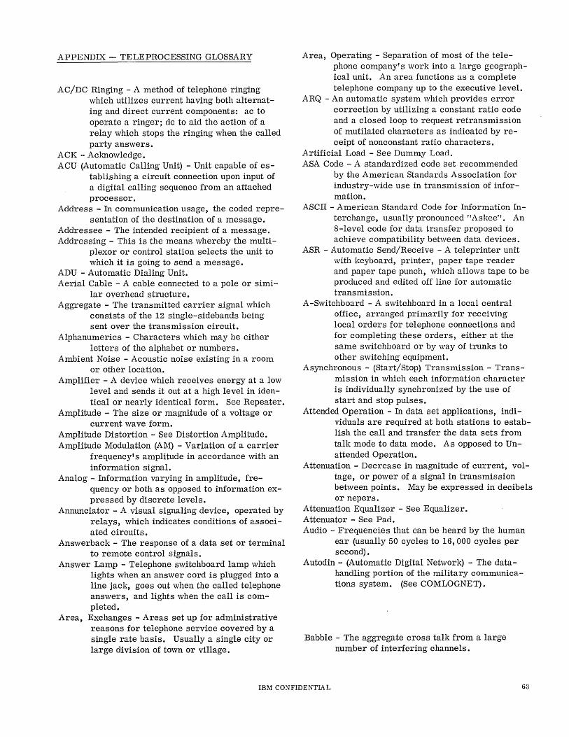
APPENDIX - TELEPROCESSING GLOSSARY
AC/DC Ringing - A method of telephone ringing which utilizes current having both alternating and direct current components: ac to operate a ringer; dc to aid the action of a relay which stops the ringing when the called party answers.
ACK - Aclmowledge. ACU (Automatic Calling Unit) - Unit capable of es
tablishing a circuit connection upon input of a digital calling sequence from an attached processor.
Address - In communication usage, the coded representation of the destination of a message.
Addressee - The intended recipient of a message. Addressing - This is the means whereby the multi
plexor or control station selects the unit to which it is going to send a message.
ADU - Automatic Dialing Unit. Aerial Cable - A cable connected to a pole or simi
lar overhead structure. Aggregate - The transmitted carrier signal which
consists of the 12 single-sidebands being sent over the transmission circuit.
Alphanumerics - Characters which may be either letters of the alphabet or numbers.
Ambient Noise - Acoustic noise existing in a room or other location.
Amplifier - A device which receives energy at a low level and sends it out at a high level in identical or nearly identical form. See Repeater.
Amplitude - The size or magnitude of a voltage or current wave form.
Amplitude Distortion - See Distortion Amplitude. Amplitude Modulation (AM) - Variation of a carrier
frequency's amplitude in accordance with an information signal.
Analog - Information varying in amplitude, frequency or both as opposed to information expressed by discrete levels.
Annunciator - A visual signaling device, operated by relays, which indicates conditions of associated circuits.
Answerback - The response of a data set or terminal to remote control Signals.
Answer Lamp - Telephone switchboard lamp which lights when an answer cord is plugged into a line jack, goes out when the called telephone answers, and lights when the call is completed.
Area, Exchanges - Areas set up for administrative reasons for telephone service covered by a single rate basis. Usually a single city or large division of town or village.
Area, Operating - Separation of most of the telephone company's work into a large geographical unit. An area functions as a complete telephone company up to the executive level.
ARQ - An automatic system which provides error correction by utilizing a constant ratio code and a closed loop to request retransmission of mutilated characters as indicated by receipt of nonconstant ratio characters.
Artificial Load - See Dummy Load. ASA Code - A standardized code set recommended
by the American Standards Association for industry-wide use in transmission of information.
ASCII - American Standard Code for Information Interchange, usually pronounced "Askee". An 8-level code for data transfer proposed to achieve compatibility between data devices.
ASR - Automatic Send/Receive - A teleprinter unit with keyboard, printer, paper tape reader and paper tape punch, which allows tape to be produced and edited off line for automatic transmission.
A-Switchboard - A switchboard in a local central office, arranged primarily for receiving local orders for telephone connections and for completing these orders, either at the same switchboard or by way of trunks to other switching equipment.
Asynchronous - (Start/Stop) Transmission - Transmission in which each information character is individually synchronized by the use of start and stop pulses.
Attended Operation - In data set applications, individuals are required at both stations to establish the call and transfer the data sets from talk mode to data mode. As opposed to Unattended Operation.
Attenuation - Decrease in magnitude of current, voltage, or power of a signal in transmission between points. May be expressed in decibels or nepers.
Attenuation Equalizer - See Equalizer. Attenuator - See Pad. Audio - Frequencies that can be heard by the human
ear (usually 50 cycles to 16,000 cycles per second) •
Autodin - (Automatic Digital Network) - The datahandling portion of the military communications system. (See COMLOGNET).
Babble - The aggregate cross talk from a large number of interfering channels.
IBM CONFIDENTIAL 63
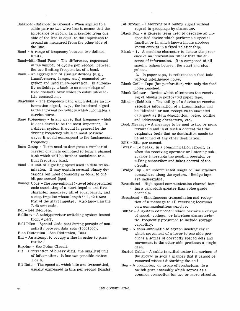
Balanced-Balanced to Ground - When applied to a cable pair or two wire line it means that the impedance to ground as measured from one side of the line is equal to the impedance to ground as measured from the other side of the line.
Band - A range of frequency between two defined limits.
Bandwidth-Band Pass - The difference, expressed in the number of cycles per second, between the two limiting frequencies of a band.
Bank - An aggregation of similar devices (e. g. , transformers, lamps, etc.) connected together and used in co-operation. In automatic switching, a bank is 'an assemblage of fixed contacts over which to establish electric connections.
Baseband - The frequency band which defines an information signal, e. g., the baseband signal is the information vehicle which modulates a carrier wave.
Base Frequency - In any wave, that frequency which is considered to be the most important. In a driven system it would in general be the driving frequency while in most periodic waves it would correspond to the fundamental frequency.
Base Group - Term used to designate a number of carrier channels combined to form a channel bank which will be further modulated to a final frequency band.
Baud - A unit of signaling speed used in data transmission. It may contain several binary decisions but most commonly is equal to one bit per second (bps).
Baudot Code - The conventional5-level teletypewriter code consisting of a start impulse and five character impulses, all of equal length, and a stop impulse whose length is 1. 42 times that of the start impulse. Also !mown. as the 7.42 unit code.
Bel - See Decibels. Bellfast - A teletypewriter switching system leased
from AT&T. Bell Idles - Special Code sent during periqds of non
activity between data sets (10001000). Bias Distortion - See Distortion, Bias. Bid - An attempt to occupy a line in order to pass
traffic. Bipolar - See Polar Circuit. Bit - Contraction of binary digit, the smallest unit
of information. It has two possible states: 1 or O.
Bit Rate - The speed at which bits are transmitted, usually expressed in bits per second (bauds).
Bit Stream - Referring to a binary signal without regard to groupings by character.
Black Box - A generic term used to describe an unspecified device which performs a special function or in which !mown inputs produce !mown outputs in a fixed relationship.
Blank - 1. A machine character to denote the presence of no information rather than the absence of information. It is composed of all spacing pulses between the start and stop pulses. 2. In paper tape, it references a feed hole
without intelligence holes. Blank Coil - Tape (for perforation) with only the feed
holes punched. Blank Deleter - Device which eliminates the receiv
ing of blanks in perforated paper tape. Blind - (Unblind) - The ability of a device to receive
selective information of a transmission and be "blinded" or non-receptive to unwanted data such as item description, price, polling and addressing characters, etc.
Book Message - A message to be sent to two or more terminals and is of such a content that the originator feels that no destination needs to be informed of any other destination.
BPS - Bits per second. Break - To break, in a communication circuit, is
when the receiving operator or listening subscriber interrupts the sending operator or talking subscriber and takes control of the circuit.
Bridge Tap - An unterminated length of line attached somewhere along the system. Bridge taps are undesirable.
Broadband - High speed communication channel ha ving a bandwidth greater than voice grade channels.
Broadcast - Simultaneous transmission and reception of a message to all receiving locations on a communications service.
Buffer - A system component which permits a change of speed, voltage, or interface characteristic; frequently presumed to include storage capability.
Bug - A semi-automatic telegraph sending key in which movement of a lever to one side produces a series of correctly spaced dots and movement to the other side produces a single dash.
Buried Cable - A cable installed under the surface of the ground in such a manner that it cannot be removed without dif:lturbing the soil.
Bus - A conductor, or group of conductors, in a switch gear assembly which serves as a common connection for two or more circuits.
64 IBM CONFlDENTIA L
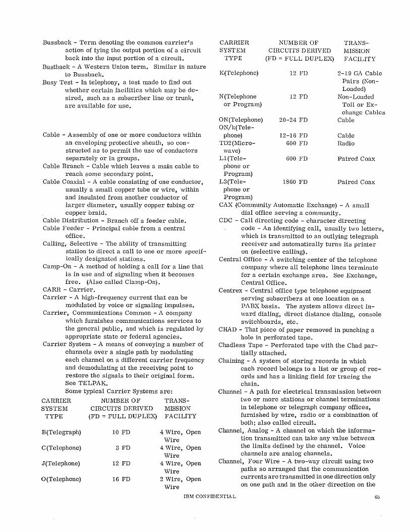
Bussback - Term denoting the common carrier's action of tying the output portion of a circuit back into the input portion of a circuit.
Bustback - A Western Union term. Similar in nature to Bussback.
Busy Test - In telephony, a test made to find out whether certain facilities which may be desired, such as a subscriber line or trunk, are available for use.
Cable - Assembly of one or more conductors within an enveloping protective sheath, so constructed as to permit the use of conductors separately or in groups.
Cable Branch - Cable which leaves a main cable to reach some secondary point.
Cable Coaxial - A cable consisting of one conductor, usually a small copper tube or wire, within and insulated from another conductor of larger diameter, usually copper tubing or copper braid.
Cable Distribution - Branch off a feeder cable. Cable Feeder - Principal cable from a central
office. Calling, Selective - The ability of transmitting
station to direct a call to 'one or more specifically designated stations.
Camp-On - A method of holding a call for a line that is in use and of signaling when it becomes free. (Also called Clamp-On).
CARR - Carrier. Carrier - A high-frequency current that can be
modulated by voice or signaling impulses. Carrier, Communications Common - A company
which furnishes communications services to the general public, and which is regulated by appropriate state or federal agencies.
Carrier System - A means of conveying a number of channels over a single path by modulating each channel on a different carrier frequency and demodulating at the receiving point to restore the signals to their original form. See TELPAK. Some typical Carrier Systems are:
CARRIER NUMBER OF TRANS-SYSTEM CIRCUITS DERIVED MISSION
TYPE (FD = FULL DUPLEX) FACILITY
B(Telegraph) 10 FD 4 Wire, Open Wire
C(Telephone) 3 FD 4 Wire, Open Wire
J (Telephone) 12 FD 4 Wire, Open Wire
o (Telephone) 16 FD 2 Wire, Open Wire
CARRIER SYSTEM
TYPE
K(Telephone)
N (Telephone or Program)
ON (Telephone) ON/k(Tele-
phone) TD2(Micro-
wave) L1(Tele-
phone or Program)
L3(Tele-phone or Program)
NUMBER OF TRANS-CIRCUITS DERIVED MISSION
(FD = FULL DUPLEX) FACILITY
12 FD 2-19 GA Cable Pairs (Non-Loaded)
12 FD Non-Loaded Toll or Ex-change Cables
20-24 FD Cable
12-16 FD Cable 600 FD Radio
600 FD Paired Coax
1860 FD Paired Coax
CAX (Community Automatic Exchange) - A small dial office serving a community.
CDC - Call directing code - character directing code - An identifying call, usually two letters, which is transmitted to an outlying telegraph receiver and automatically turns its printer on (selective calling).
Central Office - A switching center of the telephone company where all telephone lines terminate for a certain exchange area. See Exchange, Central Office.
Centrex - Central office type telephone equipment serving subscribers at one location on a PABX basis. The system allows direct inward dialing, direct distance dialing, console switchboards, etc.
CHAD - That piece of paper removed in punching a hole in perforated tape.
Chadless Tape - Perforated tape with the Chad partially attached.
Chaining - A system of storing records in which each record belongs to a list or group of records and has a linking field for tracing the chain.
Channel - A path for electrical transmission between two or more stations or channel terminations in telephone or telegraph company offices, furnished by wire, radio or a combination of both; also called circuit.
Channel,. Analog - A channel on which the information transmitted can take any value between the limits defined by the channel. Voice channels are analog channels.
Channel, Four Wire - A two-way circuit using two paths so arranged that the communication currents are transmitted in one direction only on one path and in the other direction on the
IBM CONFIDENTIA L 65
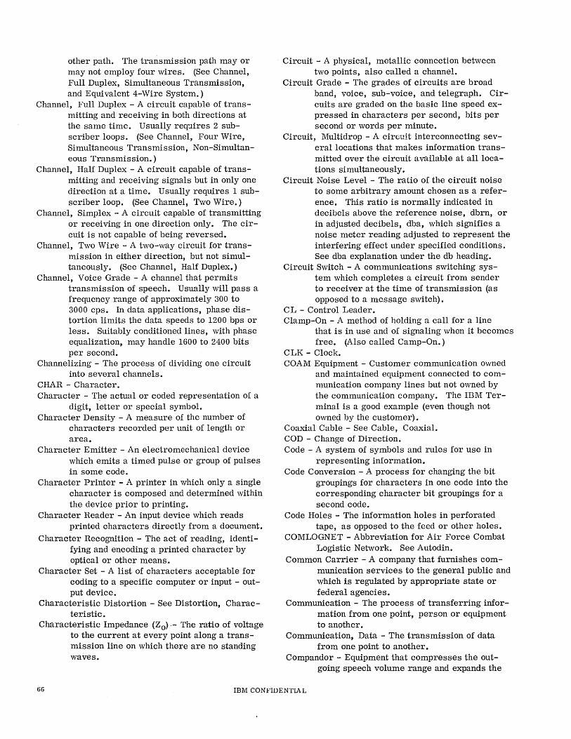
other path. The transmission path mayor may not employ four wires. (See Channel, Full Duplex, Simultaneous Transmission, and Equivalent 4-Wire System.)
Channel, Full Duplex - A circuit capable of transmitting and receiving in both directions at the same time. Usually req:l.ires 2 subscriber loops. (See Channel, Four Wire, Simultaneous Transmission, Non-Simultaneous Transmission.)
Channel, Half Duplex - A circuit capable of transmitting and receiving signals but in only one direction at a time. Usually requires 1 subscriber loop. (See Channel, Two Wire.)
Channel, Simplex - A circuit capable of transmitting or receiving in one direction only. The circuit is not capable of being reversed.
Channel, Two Wire - A two-way circuit for transmission in either direction, but not simultaneously. (See Channel, Half Duplex.)
Channel, Voice Grade - A channel that permits transmission of speech. Usually will pass a frequency range of approximately 300 to 3000 cps. In data applications, phase distortion limits the data speeds to 1200 bps or less. Suitably conditioned lines, with phase equalization, may handle 1600 to 2400 bits per second.
Channelizing - The process of dividing one circuit into several channels.
CHAR - Character. Character - T~e actual or coded representation of a
digit, letter or special symbol. Character Density - A measure of the number of
characters recorded per unit of length or area.
Character Emitter - An electromechanical device which emits a timed pulse or group of pulses in some code.
Character Printer - A printer in which only a single character is composed and determined within the device prior to printing.
Character Reader - An input device which reads printed characters directly from a document.
Character Recognition - The act of reading, identifying and encoding a printed character by optical or other means.
Character Set - A list of characters acceptable for coding to a specific computer or input - output device.
Characteristic Distortion - See Distortion, Characteristic.
Characteristic Impedance (Zo)·- The ratio of voltage to the current at every point along a transmission line on which there are no standing waves.
Circuit - A physical, metallic connection between two points, also called a channel.
Circuit Grade - The grades of circuits are broad band, voice, sub-voice, and telegraph. Circuits are graded on the basic line speed expressed in characters per second, bits per second or words per minute.
Circuit, Multidrop - A circuit interconnecting several locations that makes information transmitted over the circuit available at alliocations simultaneously.
Circuit Noise Level - The ratio of the circuit noise to some arbitrary amount chosen as a reference. This ratio is normally indicated in decibels above the reference noise, dbrn, or in adjusted decibels, dba, which signifies a noise meter reading adjusted to represent the interfering effect under specified conditions. See dba explanation under the db heading.
Circuit Switch - A communications switching system which completes a circuit from sender to receiver at the time of transmission (as opposed to a message switch).
C L - Control Leader. Clamp-On - A method of holding a call for a line
that is in use and of signaling when it becomes free. (Also called Camp-On.)
CLK - Clock. COAM Equipment - Customer communication owned
and maintained equipment connected to communication company lines but not owned by the communication company. The IBM Terminal is a good example (even though not owned by the customer).
Coaxial Cable - See Cable, Coaxial. COD - Change of Direction. Code - A system of symbols and rules for use in
representing information. Code Conversion - A process for changing the bit
groupings for characters in one code into the corresponding character bit groupings for a second code.
Code Holes - The information holes in perforated tape, as opposed to the feed or other holes.
COMLOGNET - Abbreviation for Air Force Combat Logistic Network. See Autodin.
Common Carrier - A company that furnishes communication services to the general public and which is regulated by appropriate state or federal agencies.
Communication - The process of transferring information from one point, person or equipment to another.
Communication, Data - The transmission of data from one point to another.
Compandor - Equipment that compresses the outgoing speech volume range and expands the
66 IBM CONFIDENTIAL

incoming speech volume range on a long distance telephone circuit.
Composite - To composite a pair of wires used for voice communication is to apply "compositing" equipment to the pair. It is a means of getting two dc telegraph channels in addition to the voice channel on a single pair of wires.
Compressor - Electrical device which compresses the volume range of a signal.
Comprise Net (Network) - Network, used in conjunction with a hybrid coil to balance a subscriber's loop, that is adjusted for an average loop length or an average subscriber's set or both, to secure compromise (not precision) isolation between the two directional paths of the hybrid. '
Constant Ratio Code - A code in which all characters are represented by combinations having a fixed ratio of ones.
Contention - 1. A condition on a multidrop communication channel when two or more locations try to transmit at the same time.
2. Unregulated bidding for a line by multiple users.
Continuous Loading - The practice of wrapping a cable conductor with a permalloy tape or wire. Seldom done because of high cost.
Control Character - A character used to cause functions such as line feed, carriage return, etc., to occur.
Control Switching Points - Collectively, the class 1, 2, 3 offices (Regional, Sectional, and Primary Centers) needed for nationwide dialing. The greatest number of long distance toll links required for any subscriber-to-subscriber connection is 7. The average number of links required is 3 or 4.
Converter - A device capable of converting impulses from one mode to another, such as analog to digital or parallel to serial.
CPS - Abbreviation for "characters per second" and "cycles per second".
Crossbar - Switching system using mechanisms called crossbar switches, consisting of rectangular fields of contact springs operated in co-ordination by horizontal and vertical members. Crossbar No.1, the earliest type, is a local
telephone switching system for use in metropolitan areas where there is a high percentage of interoffice calls.
Crossbar No.5, the most recent type, was designed primarily to serve the residential sections of large cities and the fringe areas around these cities.
Crossbar Exchange - An exchange in which switching is done by crossbar apparatus.
Cross Fire - Interference between telegraph circuits that cause the faulty operation of the relays in a telephone circuit.
Crosstalk - Interference from adjacent communication channels.
Crypto - Cryptographic - Usually pertains to military equipment used for the transmission of classified documents.
CT - Control Trailer. CTS - Clear to send (return from data set in re
sponse to request to send). Customer Station Equipment - Telephone company
equipment located on the customer's premises. Such as a telephone instrument or data set.
Cutting Through - See Switching Through.
Data, Analog - A physical representation of information such that the representation bears an exact relationship to the original information. The electrical signals on a telephone channel are analog data representation of the original voice.
Data Collection - The act of bringing data from one or more points to a central point. May be in-plant or out-plant.
Data Digital - Information represented by a code consisting of a sequence of discrete elements.
Data Gathering - See Data Collection. Data Link - D/L - Electronic equipment to perform
automatic transmission of digital information.
Data Origination - The translation of information from its original form into a machine -readable form or directly into electrical signals.
Data Phone - Both a service mark and a trade mark of the Bell System. As the service mark it indicates the use of the Bell System message network for the transmission of data. As a trade mark it identifies the branch of data sets designed and manufactured for DATA PHONE service.
Data Set - A modulation/demodulation device designed to provide compatibility between, input/ output equipment and communication facilities. It is also referred to as line adapter, modem and subset. Some manufacturers of data sets are:
American Telephone & Telegraph General System Collins Radio
IBM CONFIDENTIAL 67
Lenkurt Electric Western Union
Classes of Data Sets: Data sets can be classified according to type (analogue or digital), speed in bits/ second, characters/second or bandwidth in kilocycles, synchronous or non-synchronous and transmission mode (serial or parallel). These are defined in the following list of definitions. Speed:
Low - Below 200 bits per second on a voice channel or more narrow band facilities. In general, use of voice channels is always preferable where distances are short, or where this bandwidth permits the simplified design of the data set. Medium - 200 to about 2000 bits per second on voice channels. New data sets under development will probably extend this to about 2400 bits per second. High - Above 2400 bits per second on broad band facilities such as:
TELPAK A 48 kc TELPAK C TELPAKD
Video Channel
240 kc 1000 kc (or 1/2 TD
2 Channel)
NOTE: The bandwidths shown above are carrier system bandwidths and the customer signals (baseband) must be limited to more narrow spectrums, due to filter characteristics and pilot tones.
Non-Synchronous - A non-synchronous data set will accept any rate of input up to its designed limit and will deliver at the same rate on output. Synchronous - Synchronous data sets will accept only one specified rate of input and will deliver only at that rate on output.
Type: Analogue - Signals which may assume' any amplitude for any period within a generally restricted range and are of a continuous rather than pulsed nature. (Speech waves are analogue waves. ) Digital - Signals made up of pulses of discrete durations, amplitudes and periods. (Teletypewriter, etc.)
Transmission Mode: Serial - Where each pulse is sent separately, one after the other. The data speeds are usually referred to as bits per second. Parallel - Where all the pulses comprising a character are sent simultaneously or in
parallel. Here, the data speeds are usually referred to as characters per second. (Bits per second = characters per second times bits per character.)
Data Set Clocking - This term identifies the service where the data set (common carrier) supplies the time base oscillator for the bit rate of transmission. This, is also referred to by IBM as "external clocking" and by the common carrier as "internal clocking". To avoid confusion use "Data Set Clocking" or "Business Machine Clocking".
DB - See Decibel. DB Meter - A meter having a scale calibrated to
read directly in decibel values at a reference level that must be specified (usually 1 milliwatt equals zero db). Used in audio-frequency amplifier circuits of broadcast stations, public-address systems, and receiver output circuits to indicate volume level.
D Code - Control characters are sometimes identified by this term. They have the configuration, 1 and R and X and not 0 or 0 and not X and not N. D=l. R. (OX + XO). N
DCT - Dibit Clock Transmit (data set interface). Dead Line - A telephone circuit disconnected from a
central office. Decibel - 1/10 Bel - The unit used to express power
ratio: db = 10 log P 1/P2, where PI and P2 are the two powers being compared; for example, 3 db down (-3 db) means a 50 percent loss of power. Decibel is = 1/10 bel or 0.1151 neper. It requires a known refe:cence level, and impedance. For example; db usually in telephone work means dbm where o db is 1 milliwatt in 600 ohm. Another common value is db6m where the reference of 0 db is 6 milliwatts in 500 ohm. This value is used principally in audio amplifier work where 500 ohm lines are used. Dbv is used in measuring the open-circuit output of devices such as microphones where the reference is 0 db = 1 volt with an infinite impedance. Dba, decibels adjusted, this is used as a base for noise measurements. It references 85 dbm at 1000 cycles. Dba replaces the obsoleted value dbrn. Some other references which have been used are 10, 12.5 and 50 milliwatts with impedances of 52, 75, 100, 125, 150, 250, 300 ohm. Therefore, unless the reference and impedance are known, the term db is of little or no value except to get an idea of the relative gain or loss in a circuit between points. Decineper - 1/10 neper.
68 IBM CONFIDENTIAL
Dedicated Service - See Leased Channel and Private Line.
Delay Distortion - See Distortion, Delay. Delay Equalizer - A corrective network which is de
signed to make the phase delay or envelope delay of a circuit or system substantially constant over a desired frequency range. See Equalizer.
Demarcation Strip - Usually refers to a terminal board acting as an interface between the business machine and the common carrier.
Demodulation - The process of retrieving an original signal from a modulated carrier wave. This technique is used to make communication signals compatible with business machines signals.
DFT - Diagnostic Function Test - A program to test over-all system reliability.
Dial Exchange - An exchange where all subscribers can originate their calls by dialing.
Dialing, Direct Distance - An exchange service which enables a telephone user to select subscribers outside the user's local area.
Dial Pulse - An interruption in the DC loop of a calling telephone. It is produced by the brealting and malting of the dial pulse contacts of a calling telephone caused by the dialing of a digit. The loop current is interrupted as many times as the digit units dialed.
Dial-Up - The service whereby a dial telephone can be used to initiate and effect a station-tostation telephone call.
Dibit - A group of two binary bits; in 4-phase modu-1ation' each possible dibit is encoded as one of four unique carrier phase shifts.
Digital Data - Information represented by a code consisting of a series of bits.
Digital Subset - See Data Set. Direct Distance Dialing - DDD - Service which en
ables the caller to dial toll calls without operator intervention.
Director - A type of crossbar equipment used- to make cross-office selection and connection from an input to an output in accordance with CDC's. (Telegraph applications.)
Direct-Point Repeater - A telegraph operator in which the receiving relay controlled by the signals received over a line repeats corresponding signals directly into another line or lines without the interposition of any other repeating or transmitting apparatus.
Disconnect (Release) - To disengage the apparatus used in a telephone connection and to restore it to its condition when not in use.
Disconnect Signal - A signal transmitted from one end of a subscriber line or trunk to indicate at the other end that the established connection should be released.
Display Unit - Device which provides a visual representation of data.
Distortion - Lack of similarity between a signal received over a transmission line and the signal put on the line at the transmitting end. Usually measured in percent. Amplitude - (Frequency - Harmonic) - Dis
tortion caused by unequal attenuation or amplification of different frequencies by a transmission line, filter, or other circuit.
Bias - In teletypewriter applications, this is defined as marks or spaces consistently too long or too short. If an alternate mark space test pattern were transmitted with an equal amount of time between transitions, the received signal will probably have a percentage of marking or spacing bias. This may be caused by the characteristics of the terminal, data set, or by an unequal rate of transmission. When the mark pulses appear lengthened, the space pulses will be shortened. This condition is called MARKING or POSITIVE Bias. When the mark pulses appear shortened, the space pulses will be lengthened. This condition is called SPACING or NEGATIVE Bias.
Characteristic - The normal and predictable distortion of data bits produced by characteristics of a given circuit at a particular transmission speed.
Delay - (Envelope Delay, Phase Delay) -Distortion of a signal resulting from unequal propagation time for different frequencies over a transmission line, through a filter, or other circuit.
End - In start-stop teletypewriter signals, the shifting of the end of all marlting pulses from their proper positions in relation to the beginning of the start pulse. A marlting end distortion denotes a lengthening of the marlting bit. A spacing end distortion denotes a lengthening of the spacing bit (mark bit shortened).
Fortuitous - A type of distortion which results in the signals being intermittently shortened or lengthened. This distortion is entirely random in nature and can be caused by battery fluctuations, hits on the line, power induction, etc. See Jitter.
IBM CONFIDENTIAL 69
Frequency - See Amplitude Distortion. Harmonic - See Amplitude Distortion. Jitter - Peak Jitter - Random variation in bit
length due to noise, modulation process, etc. This results in a varying signal duration caused by the non-constant switching time in the transition of a signal level. Jitter for the most part cannot be adjusted. It becomes more frequent at the higher rates of transmission. Also mown as the combined effect of characteristic and fortuitous distortion.
Marking - See Bias Distortion. Negative - See Bias Distortion. Positive - See Bias Distortion. Spacing - See Bias Distortion. Teletypewriter Signal - In start-stop tele-
typewriter signals, the shifting of the transition points of the signal pulses from their proper positions relative to the beginning of the start pulse. The magnitude of the distortion is expressed in percent of a perfect unit pulse length. See Bias, End, Fortuitous Distortion.
Distributing Frame - A structure for terminating permanent wires of a central office, private branch exchange, or private exchange and for permitting the easy change of connections between them by means of cross-connecting wires.
DLT - Data Loop Transceiver - Western Union's low-speed data set.
Dot Cycles Per Second - One dot cycle is a mark and 'space. The speed of transmission of a system in dot cycles per second is numerically equal to half the speed of transmission expressed in bits per second or bauds.
DR - Data Register. Drop Relay - A relay actuated by a ringing current
and used to call on operator's attention to a subscriber's line.
Drop, Subscriber's - The line from a cable termination to a subscriber's location.
Dry Contact - Term indicating a contact closure only. Used where one vendor controls by contact closure another vendor's voltage/ current loop.
Dry Reed Contact - Term usually used to differentiate from mercury wetted type.
DS - Data Set. Dummy Load - A device in which the output power
can be absorbed, used for simulating conditions of operation for test purposes. In modem applications, a resistor, 8. 2K, which may be substituted on the line for a modem. A dummy load counts as one modern.
Duplex - Term used to indicate that a channel or system can be used for communication in two directions. See Half Duplex and Full Duplex definitions.
Duplex System - Having two distinct and separate machine facilities each of which is capable of assuming the proceSSing function while the other assumes a standby.status. Usually, both systems are identical in nature. Duplex':" ing is utilized for greater reliablilty.
EAX - Electronic Automatic Exchange - A high speed semi-automatic switching office now undergOing development by General Telephone.
Echo Check - A check which transmits received information back to the source and compares it with the original.
Echo Suppressor - A line device used to prevent energy being reflected back (echoed) to the transmitter. It attenuates the transmission path in one direction while signals are being passed in the other direction.
Effective Speed - Speed (less than rated) which can be sustained over a significant period of time and which reflects slowing effects of control codes, timing codes, error detection, retransmission, tabbing, etc.
EIA Interface - A set of signal characteristics (time duration, voltage and current) specified by the Electronic Industries Assn. for business machine/data set connections.
Eight Level - A telegraph code which utilizes eight impulses, in addition to the start and stop impulses, for describing a character.
End Distortion - See Distortion, End. End Office - Class 5 office - local telephone ex
change where subscriber's loop terminates -See Exchange, Central.
End of Message - The specific set of characters which indicates the termination of a message.
End to End Test - Dynamic test - a Bell System test utilizing the 900 series test equipment. Requires Bell maintenance personnel at each end of the circuit.
Energy Level Diagram - A line drawing that shows increases and decreases of electrical power as current intensities rise and fall along a channel of signal communications.
EOI - End of Idles. EOM - End of Message. EOT - End of Transmission. EOTR - End of Transmittal Record. Equalization - The process of reducing frequency
and/ or phase distortion of a circuit by the
70 IBM CONFIDENTIA L
introduction of networks to compensate for the difference in attenuation and/or time delay at the various frequencies in the transmission band.
Equalizer - Any combination (usually adjustable) of coils, capacitors, and/or resistors inserted in transmission or amplifier circuit to improve its frequency response.
Equivalent 4-Wire System - A term applied to a carrier on repeater system using only one pair of wires but different frequencies for each direction of transmission.
ERR - Error.
Error Rate - A measure of quality of circuit or equipment; the number of erroneous bits or character in a sample, frequently taken per 100,000 char.
ESS - Electronic Switching System - Bell Systems new electronic switching center utilizing high speed computers.
Exchange - Exchange, Central Office - An office in a telephone system that provides service to the general public where orders fo.r, or signals, controlling telephone connections are received and connections established. See End Office.
Exchange Classes of -Class 1 - See Regional Center Class 2 - See Sectional Center Class 3 - See Primary Center Class 4 - See Toll Center Class 5 - See End Office
Exchange, Dial - An exchange where all subscribers originate their calls by dialing.
Exchange, Manual - An exchange where calls are completed by an operator.
Exchange, Private Automatic (PAX) - A dial exchange that provides private telephone service to an organization and that does not allow calls to be transmitted to or from the public telephone network.
Exchange, Private Automatic Branch (PABX) - A private automatic exchange that provides for the transmission of calls to and from the public telephone network.
Exchange, Private Branch (PBX) - A manual or dial exchange, connected to the public telephone network often located on a customer's premises and operated by his employees.
Exchange, Service - A service permitting interconnection of any two customers' telephones through switching equipment.
Exchange, Toll - A toll office where customer's calls are connected to toll circuits or toll circuits are interconnected. An exchange where toll or long-distance connections are made.
Exchange, Trunk - An exchange primarily devoted to handling trunk calls.
Expander - A transducer which for a given amplitude range of input voltages produces a larger range of output voltages. One important type of expander employs the envelope of speech signals to expand their volume. range.
Extension - 1. Additional telephone set on the same line but at a different location other than the main station.
2. PBX station. Extension, PBX, Outside - PBX station on premises
separated from the PBX. Sometimes called Long Distance Locals.
Extension Station - A telephone station associated with a main station through connection to the same subscriber line and having the same call number designation as the associated main station.
External Clocking - This term is used by IBM to identify the service where the data set (common carrier) supplies the time base oscillator for the bit rate of transmission. See Data Set Clocking - the preferred term.
Facsimile (FAX) - A system for the transmission of fixed images. Type A facsimile is a system of facsimile communication in which images are built up of lines or dots of constant intensity. Type B facsimile (telephotography, photoradio, etc.) is a system of facsimile communication in which images are built up of lines or dots of varying intensity.
Facsimile-Signal Level - An expression of the maximum signal power or voltage created by the scanning of the subject copy as measured at any point in a facsimile system. According to whether the system employs positive or negative modulation, this will correspond to picture white or black, respectively. It may be expressed in decibels with respect to some standard value such as 1 milliwatt or 1 volt.
Far-End Cross Talk - Cross talk which travels along the disturbed circuit in the direction in which the signals travel in that circuit. To determine the far-end cross talk between two pairs, 1 and 2, signals are transmitted on pair 1 at station A, and the cross talk level is measured on pair 2 at station B. See Near-End Cross Talk.
FCC - Federal Communications Commission - A board of seven commissioners appointed by the President under the Communications Act of 1934, having the power to regulate all electrical communication systems originating in the United States.
IBM CONFIDENTIAL 71
FD or FDX - Full Duplex. FDM - Frequency Division Multiplex. Feed Holes - Holes punched in a tape to enable it to
be driven by a sprocket wheel. Feed Pitch - The distance between the centers of
feed holes. Fieldata Code - A standardized military data trans
mission code, 7-data plus 1-parity bits. Figure Shift - A control character in the Baudot
code after which characters are interpreted as belonging to the grouping containing numerics, punctu.ation and special symbols (upper case).
FINAC - A leased automatic teletypewriter system provided by AT&T.
Five Level - A telegraph code which utilizes five impulses, in addition to the start and stop impulses for describing a character.
Foreign Exchange Service - A service which connects a customer's telephone to a telephone company central office normally not serving the customer's location (such as tie lines).
Fortuitous Distortion - See Distortion, Fortuitous. Four-Row Keyboard - Used for origination of 8-level
codes eliminating the need for figures/letters case shifts. As opposed to three row.
Four-Wire Circuit - See Channel, Four-Wire. Four-Wire, Half Duplex - IBM term only, does not
refer to communication line services. Four-Wire Repeater - Repeater which provides for
transmission in opposite directions on two transmission paths.
Four-Wire Terminating Set - Hybrid arrangement by which 4-wire circuits are terminated on a 2-wire basis for interconnection with 2-wire circuits.
Fox Message - A standard mesflage which is usen for testing telegraph circuits and machines because it includes all the alphanumerics as well as most of the function characters.
Frame, Type A - Distributing frame carrying on one side (horizontal) all outside lines, and on the other side (vertical) the terminations of the central office equipment and protective devices for them.
Frame, Type B (Main) - Distributing frame carrying on one side (vertical) all outside lines and protective devices for those lines and on the other (horizontal) all connections of the outside lines toward the central office equipment.
Framing - The process of selecting the bit groupings representing one or more characters from a continuous stream of bits.
Framing Bits - Non-information carrying bits used to make possible the separation of characters in a bit stream.
Free Routing - That method of traffic handling wherein messages are forwarded toward their destination over any available channel, normally the most direct without depending on a predetermined routing doctrine.
Frequency Division Multiplex - See Multiplexing. Frequency Modulation - Variation of a carrier fre
quency in accordance with an information signal.
Frequency-Shift Keying (FSK) - Frequency-Shift Transmission - A system of automatic code transmission and reception that shifts the the carrier frequency back and forth between two distinct frequencies to designate mark and space, instead of keying the carrier on and off •.
FTS - Federal Telecommunications System. Full Duplex - See Channel, Full Duplex. Full Speed - Referring to transmission of data in
teleprinter systems at the full rated speed of the equipment.
Fully Perforated Tape - Perforated paper tape in which the perforations are complete. That is, the punch makes a complete hole in the tape (as opposed to chadless tape where the hole is not completely punched out).
Function Key - A term associated with specific keys on a teletypewriter (for example, "CR", "LF", "LTRS", "FIGS", etc.) which, when operated, cause the teletypewriter to perform mechanical functions so that a message may be received in proper form.
GM - Group Mark. Group - In telegraphic usage - a word. Group Mark - Any indicator to signal the end of a
word or other unit of data.
Half Duplex - See Channel, Half Duplex. Half Speed - Referring to transmission of data in
teleprinter systems at half the rated speed of the associated equipment.
Hand Shaking - Exchange of predetermined codes and signals when a connection is established between two data terminals.
Hard Copy - A machine printed document, such as a message, order or invoice.
Harmonic Distortion - See Distortion, Amplitude. Harmonic Telephone Ringer - A telephone ringer
which responds only to alternating current within a very narrow frequency band .. A number of such ringers, each responding to a different frequency, are used in one type of selective ringing.
72 IBM CONFIDENTIAL
HD or HDX - Half Duplex. Header - The initial characters of a mes,sage desig
nating addressee, routing, time of origination, etc.
Hits - Hit on the Line - Momentary line disturbances which could result in mutilation of characters being transmitted.
Hollerith Code - The 12-unit code used in conventional punched tabulating machine cards.
Home Loop - Data path, allowing off-line use of terminal components.
HSSTR - High Speed Synchronous Transmitter Receiver.
Hybrid Coil - Four-winding coil wound and connected so that incoming and outgoing currents in a 2-wire path are separated and kept from interfering with each other.
ICA - Industrial Communications Association. Idles - Bit Code 1 8 R 0 set when no other trans
mission is called for by the STR. Incoming Trunk - Trunk coming into a central office. Indicator, Routing - A group of letters, engineered
and assigned to identity a station within a teletypewriter network.
Induction Coil - Coupling transformer. Information Bit - One of those bits which are used to
specify the characters of a given code group (opposed to framing bits).
In-Line Processing - Processing in order of receipt, without prior grouping or sorting, of transactions.
In-Plant System - A system whose parts, including remote terminals, are all situated in one building or localized area.
INQ - Inquiry. Intercepting - Routing of a call placed to a discon
nected or nonexisting telephone number, to a operator or to a machine answering device.
Intercepting, Operator - Answering an intercepted call by an operator who asks, "What number did you call, please?" and is then given instructions on completing the call.
Intercepting Trunk - A trunk to which a call for a vacant number or changed number or a line out of order is connected fo:c action by an operator.
Intercommunicating System - A privately owned system without a switchboard capable of twoway communication. It is normally a single unit, building or plant. Stations mayor may not be equipped for originating a call, but they can answer any call.
Inter-Exchange Channel - Channel connecting two different metropolitan areas.
Interface - A common boundary - for example, physical connection between two systems or two devices.
Intermediate Distributing Frame (IDF) - A distributing frame in a local central office, the primary purpose of which is to cross-connect the subscriber line multiple to the subscriber line circuit. In a private exchange, the intermediate distributing frame is for similar purposes.
Internal Clocking - This term is used by IBM to identify the service where the business machine supplies the time base oscillator for the bit rate of transmission. See Non Data Set Clocldng - the preferred term.
International Telecommunication Union (ITU) - A civil international organization established to provide standardized communication procedures and practices including frequency allocation and radio regulations on a world-wide basis.
Interoffice Trunk - A direct trunk between local central offices in the same exchange.
Interpreting - Printing the symbol or meaning of holes in the same paper tape or cards in which they are punched.
Intertoll Dialing - Dialing over intertoll trunks. Intertoll Trunk - A trunk between toll switchboards
in different offices. Inverse Neutral Telegraph Transmission - That
form of transmission in which marlting signals are zero current intervals and spacing signals are current pulses of either polarity.
Jitter - See Distortion, Jitter. Joint Use - The simultaneous use of a pole, line, or
plant. Facilities by two or more kinds of utilities.
Junction Pole (S-Pole) - A pole at the end of a transposition section of an open-wire line or the pole common to two adjacent transposition sections.
Key Click - Those components of telegraphic radiation that are set up as transients by the opening or closing of the signaling key but are not essential for communication.
Key-Click Filter - A filter that attenuates the surges produced each time the keying circuit of a transmitter is opened or closed by the key.
Key Pulse - System of signaling where numbered keys are depressed instead of using a dial.
IBM CONFIDENTIAL 73

Keying - The forming of signals, such as those employed in telegraph transmission, by the modulation of a direct current or other carrier between discrete' values of some
. characteristic. Keying Chirps - Sounds accompanying code signals
when the transmitter is unstable and shifts slightly in frequency each time the sending key is closed.
Keying Wave - The emission that takes place in telegraphic communication while the active portions of the code characters are being transmitted. Also called Marking Wave.
KSR - Keyboard Send/Receive - A teleprinter unit with keyboard and printer.
Lag (In Telegraph System) - The time elapsing between the operation of the transmitting device and the response of the receiving device.
Landline - A telegraph or telephone line passing over land, as opposed to submarine cables.
LD - Long Distance. LD Line - A telephone line or channel between two
central offices in different exchanges. LD Office - A central office primarily arranged for
terminating LD lines, switching trunks, recording trunks, and recording-completing trunks and for their interconnection with each other.
LD Switching Center - An LD office that serves as a switching point between local exchanges and the long distance telephone network.
LD Switching Trunk - A trunk extending from an LD office to a local central office for connecting LD lines to user lines.
Leased Channel - A point-to-point channel reserved for sole use of a single leasing customer. See Private Line Circuit.
Letters Shift - A control character in the Baudot code after which all characters are interpreted as belonging to the group containing letters (lower case).
Level Compensator - An automatic gain control device used in the receiving equipment of a telegraph circuit.
Line - See Circuit. Line Adapter - See Data Set. Linear Distortion - Amplitude ·distortion wherein
the output signal envelope is not proportional to the input signal envelope but no alien frequencies are involved.
Line Hit - An electrical interference causing the introduction of spurious signals on a circuit.
Line, In-House - A privately owned or leased line that does not cross a public right of way.
Line Level - The signal level in decibels at a particular position on a transmission line.
Line Loop - See Local Loop . Line Loop Resistance - The metallic resistance of
the line wires that extend from an individual telephone set to the dial central office. Often called loop resistance.
Line Noise - Noise originating in a transmission line.
Line Printer - A printer in which all characters across an entire line of type are printed in one printing cycle.
Line Relay - A relay which is controlled over a subscriber line or trunk line.
Line Speed - The maximum rate at which signals may be transmitted over a given channel; usually in baud or bits/sec.
Line Stretcher - An impedance matching device for coaxial transmission lines.
Link - 1. In dial central offices, a complete talking path. 2. Any combination of switches to accomplish that path, such as a linefinder and connector tied together.
Link Group - Those links that employ the same multiplex terminal equipments.
Load - 1. A resistor or other impedance which can replace some circuit element temporarily or permanently removed. 2. The power that a machine or apparatus delivers. 3. The device used to absorb power and convert it into the desired useful form.
Load and Go - A computer operation and compiling technique in which the pseudo language is directly converted to machine language and the program run without an output machine -language program being created.
Loaded Lines - (Loaded Cable) - A transmission line or cable pair which has had inductance (load coils) added in series with each conductor, usually at definite spaced intervals. Common load coil spacings are:
B 3000 feet D 4500 feet H 6000 feet M 9000 feet
Loaded cable pairs are usually designated by an alphanumeric code as follows: Two digits representing the wire gauge, a letter denoting the load coil spacing and two or three digits representing the load coil inductance in millihenries.
74 IBM CONFIDENTIAL
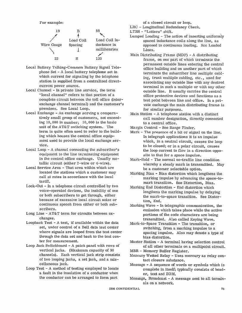
For example:
19 B 88
/ + ,
Load Coil Load Coil In-Wire Gauge Spacing ductance in
\ 1 millihenries
/ 22 H 135
Local Battery Talking-Common Battery Signal Telephone Set - A local battery telephone set in which current for signaling by the telephone station is supplied from a centralized directcurrent power source.
Local Channel - In private line service, the term "local channel" refers to that portion of a complete circuit between the toll office (interexchange channel terminal) and the customer's premises. See Local Loop.
Local Exchange - An exchange serving a comparatively small group of customers, not exceeding 10, 000 in number; 10, 000 is the basic unit of the A T&T switching" system. The term is quite often used to refer to the building which houses the central office equipment used to provide the local exchange service.
Local Loop - A channel connecting the subscriber's equipment to the line terminating equipment in the central office exchange. Usually metallic circuit (either 2-wire or 4-wire).
Local Service Area - That area within which are located the stations which a customer may call at rates in accordance with the local tariff.
Lock-Out - In a telephone circuit controlled by two voice-operated devices, the inability of one or both subscribers to get through, either because of excessive local circuit noise or continuous speech from either or both subscribers.
Long Line - A T&T term for circuits between exchanges.
Loopback Test - A test, if available within the data set, under control of a Bell data test center where signals are looped from the test center through the data set and back to the test center for measurement.
Loop Jack Switchboard - A patch panel with rows of vertical jacks. (Maximum capacity of 90 channels). Each vertical jack strip consists of two looping jacks, a set jack, and a miscellaneous jack.
Loop Test - A method of testing employed to locate a fault in the insulation of a conductor when the conductor can be arranged to form part
of a closed circuit or loop. LRC - Longitudinal Redundancy Check. LTRS - "Letters" shift. . Lumped Loading - The action of inserting uniformly
spaced inductance coils along the line, as opposed to continuous loading. See Loaded Lines.
Main Distributing Frame (MDF) - A distributing frame, on one part of which terminate the permanent outside lines entering the central office building and on another part of which terminate the subscriber line multiple cabling, trunk multiple cabling, etc., used for associating any outside line with any desired terminal in such a multiple or with any other outside line. It usually carries the central office protective devices and functions as a test point between line and office. In a private exchange the main distributing frame is for similar purposes.
Main Station - A telephone station with a distinct call number designation, directly connected to a central office.
Margin Control - See Range Finder. Mark - The presence of a bit or signal on the line.
In telegraph applications it is an impulse which, in a neutral circuit, causes the loop to be closed; or in a polar circuit, causes the loop current to flow in a direction opposite to that for a space impulse.
Mark-Hold - The normal no-traffic line condition whereby a steady mark is transmitted. May be a customer selectable option.
Marking Bias - Bias distortion which lengthens the marking impulse by advancing the space-tomark transition. See Distortion, Bias.
Marking End Distortion - End distortion which lengthens the marldng impulse by delaying the mark-to-space transition. See Distortion, End.
Marking Wave - In telegraphic communication, the emission which takes place while the active portions of the code characters are being transmitted. Also called Keying Wave.
Mark-to-Space Transition - The transition, or switching, from a marking impulse to a spacing impulse. Also may denote a type of bias distortion.
Master Station - A terminal having selection control of all other terminals on a multipoint circuit.
MBR - Memory Buffer Register. . Mercury Wetted Relay - Uses mercury as relay con
tact closure substance. Message - A sequence of words or symbols which is
complete in itself; typically consists of header, text and EO M.
Message, Broadcast - A message sent to all terminals ona network.
IBM CONFIDENTIAL 75
Message Circuit - A long distance telephone circuit used in furnishing regular long distance or toll service to the general public. The term is used to differentiate these circuits from circuits used for private line service.
Message, Multiple Address - A message to be delivered to more than one destination.
Message, Single Address - A message to be delivered to only one destination.
Message, Switching - A system'in which messages between stations are routed through a central point having a storage media. Messages are stored and forwarded when the appropriate outgoing circuit becomes available.
Microwave - An electromagnetic wave in the superhigh frequency radio spectrum ranging from 1, 000 to 300, 000 megacycles per second.
Miscellaneous Intercept - The act of intercepting single-address messages containing a nonvalid CDC and/or the action of intercepting multiple-address messages without a proper multiple-address code. See Willful Intercept.
Mod/Demod - Abbreviated form for modulating and demodulating units. See Data Set.
Modem - Contraction of modulator - demodulator. See Data Set.
Modulation - The process by which some characteristic of one wave is varied in accordance with another wave.
Multidrop-Multipoint - So named because several terminals are connected to a single line. These terminals mayor may not have the ability to communicate with each other. The prime application for this circuit configuration would be a low traffic circuit. A savings in line cost can be realized when using the multidrop configuration.
Multiplexing - Multiplexing is any means whatsoever whereby two or more signals (or the output of two or more system elements) share the same physical transmission facility, circuit element or system component. Multiplexing can be subdivided into two categories using method as a criterion. A. Time Division Multiplexing or Time
Sharing. This method can be applied to sharing of a transmission line or sharing of a centrally located computer by several input/output units or sharing of anyone system component among several other components. Time multiplexing is generally accomplished by switching techniques. In this method, the various signals or system components take turns in having exclusive use of the transmission line or common system component. Examples - pulse
code modulation systems wherein the instantaneous amplitudes of several signals are sampled and codes corresponding to these amplitudes transmitted in turn, telemetering schemes wherein meter readings from many different locations are "read" one at a time by a central recording device. Time division multiplexing may be effected either of two ways:
1. Sequential Servicing - The input/output Units are served in a fixed sequence. The two examples of time sharing given above are of this type.
2. Demand Servicing - The input/output units are served on a demand basis. A dial telephone exchange uses this type of servicing. Th~ common switching equipment is connected to a subscriber's line on demand, the demand being ,indicated when the subscriber lifts the handset off the "hook".
B. Frequency Division Multiplexing - This method is generally applied in getting several signals over one transmission line. rt is accomplished by having the various signals modulate different carrier frequencies using mixing and filtering techniques. In this method all signals may be "ON" simultaneously. Examples - two or more IBM transceiver chanr..els on one line, radio broadcasting, telephone carrier systems.
Multipoint - Private line arrangement having more than two terminals connected by the same line.
Near-End Cross Talk - Cross talk which is propagated in a disturbed channel in the direction opposite to the direction of propagation of the current in the disturbing channel. The terminal of the disturbed channel at which the near-end cross talk is present is ordinarily near or coincides with the energized terminal of the disturbing channel. See Far-End.
N eper - A unit of the same nature as the decibel but differing from it in magnitude. One neper is equivalent to 8.686 decibels.
Network - 1. Communication term: An organization of stations capable of intercommunication but not necessarily on the same channel.
2. Engineering term: Two or more interrelated circuits.
Network, Balancing - Lumped circuit elements (inductances, capacitances, and resistances) connected so as to simulate the impedance of a uniform cable or open -wire circuit over a band of frequencies.
76 IBM CONFIDENTIA L
Network, Equalizing - Network connected to a transmission circuit to correct, control, or alter the response of the circuit in a desired way; particularly to equalize the response over a frequency range. See Equalization.
Network, Leased Line or Private Wire - A series of points interconnected by communications channels, and reserved for the exclusive use of one customer.
Network, Private Telegraph - A series of points interconnected by telegraph or telephone channels and reserved for the exclusive use of one customer.
Network, Private Telephone - A series of points interconnected by leased voice-grade telephone lines, with a customer operated exchange.
Neutral Circuit - A telegraph circuit in which current flows in only one direction. The circuit is closed during the marking condition and open during the spacing condition. Also called Unipolar.
Noise - Random electrical signals introduced by circuit components or natural disturbances which tend to degrade the performance of a communications channel.
Noise Killer - An electric network inserted in a telegraph circuit, usually at the sending end, for the purpose of reducing interference with other communication circuits.
Nominal (Rated) Speed - Maximum speed or data rate of terminal which makes no allowance for necessary delaying functions as checking, tabbing, etc.
Non Data Set Clocking - This term identifies the service where the business machine supplies the time base oscillator for the bit rate of transmission. This is also referred to by IBM as Internal Clocking and by the common carrier as External Clocking. To avoid confusion use Non Data Set Clocking or Data Set Clocking.
Non Loaded Lines - (Non-Loaded Cable Pairs) -Cable pai rs or transmission lines with no added inductive loading. As opposed to Loaded Lines.
Non Simultaneous Transmission - A communication device capable of transmitting on one pair of a Full Duplex Circuit, but not capable of receiving on the other pair at the same time.
Off-Hook - Unit activated. Off-Line - In the Teleprocessing Systems sense,
off-line describes that kind of system in which human operations are required between
the original recording functions and the ultimate data processing function. This includes conversion operations as well as the necessary loading and unloading operations incident to the use of point-to-point or datagathering systems. In the telegraph sense, off-line means not in the loop. Paper tapes frequently are punched "off-line" and then transmitted using a paper tape transmitter.
On-Demand System - A system from which timely information or service is available on request.
One-Way Trunk - A trunk between central exchanges where traffic can originate on only one end.
On-Hook - Unit de-activated (hung-up). On-Line - In the Teleprocessing Systems sense, an
on-line system eliminates the need for human intervention between source recording and the ultimate processing by a computer. In the telegraph sense, it means in the loop.
Open-Circuit Jack - A jack that normally leaves its circuit open. The circuit can be closed only through a circuit connected to the plug that is inserted in the jack.
Open Wire - A conductor separately supported above the surface of the ground, and separately supported on insulators.
Open-Wire Line - A pole line whose conductors are principally in the form of open wire.
OPM - Operations Per Minute - Equivalent to characters per minute when control functions are included.
Options - Usually refers to the strapping options (features) available within data sets. These options are wired in during installation. Some typical options are: Originate - Data set always is in originate
frequency mode. Answer - Data set always is in answer
frequency mode. Remote - Business machine controls the data
set's operation in either the originate or answer frequency mode.
Mark Hold - Quiescent condition of the line is is in a mark condition.
Space Hold - Quiescent condition of the line is in a space condition.
Orientation (Teletypewriter) - An adjustment of the time the receiving apparatus starts selection, with respect to the start signal. See Range Finder.
Out-of-Service Jack - Jack associated with a test jack which removes the circuit from service when a shorted plug is inserted.
Out-Plant System - A data transmission system consisting of one or more centrally located terminals and one or more terminals located at some distance.
IBM CONFIDENTIAL 77
PABX - Private Automatic Branch Exchange. Pad - Device which introduces transmission loss
into a circuit. It may be inserted to introduce loss or to match impedances.
Pad Switching - Transmission loss pad automatically cut in and out of a toll circuit for different desired operating conditions.
Page Printer - A printer printing characters one at a time in page format.
Paper Tape Reader - A device which senses and translates the holes in perforated tape into internal form.
Parallel-By-Bit - or Parallel Transmission -System where the bits of each character occur simultaneously. Implies as many lines or wires as there are bits in a character.
Parity Check - Addition of non-information bits to data, making the number of ones in a grouping of bits either always even or always odd. This permits detection of bit groupings which contain single errors. It may be applied to characters, blocks, or any convenient bit grouping.
PAX - Private Automatic Exchange. PBX - Private Branch Exchange. Peak Jitter - See Distortion, Jitter. Perforated - A more suitable word to use in com
bination with paper tape than the word punched, e. g., perforated tape includes punched paper tape.
Perforator - A paper tape punch which is controlled manually. It is used for punching tape offline.
PH - Phase. Phantom Circuit - A superimposed circuit derived
from two suitably arranged pairs of wires called side circuits, with each pair of wires being a circuit in itself and at the same time acting as one conductor of the phantom circuit.
Phase Distortion - See Distortion, Delay. Phase Modulation - Control of the phase, or timing,
of a carrier signal by an information signal. Plant (As Used by Bell System) - The local facility
of Bell System consisting of the switching equipment, local service department, and central office personnel.
Plantman - See Plant. Point-to-Point Transmission - Transmission of data
directly between two points without the use of any intermediate terminal or computer.
Polar Circuit - In telegraph applications a circuit in which current flows in one direction on a marking impulse and in the opposite direction during a spacing impulse. Also called Bipolar.
Polar Relay - A relay containing a permanent magnet that centers the armature. The direction of
movement of the armature is governed by the direction of current flow.
Poll - A flexible, systematic method, centrally controlled, for permitting stations on a multipoint circuit to transmit without contending for the line.
Polling - Orderly selection, one at a time, of multiple terminals to allow transmission of traffic. The action whereby the multiplexor or control station says effectively to the terminal, "Do you have anything for me?"
Power Level (dbm) - The ratio of the power at that point to some arbitrary amount of power chosen as a reference. This ratio is usually expressed either in decibels referred to 1 milliwatt, abbreviated dbm, or in decibels referred to 1 watt, abbreviated dbw. See Decibel.
Primary Center - A control center connecting toll centers together - a class 3 office. Can also serve as a toll center for its local end offices.
Primary Jack - Terminate line conductors in a long lines testboard in one direction and central office equipment in the other.
Priority Indicators - Groups of characters which indicate the relative urgency of a message.
Private Automatic Branch } See listing Exchange - P ABX
under Private Automatic Exchange - PAX
Exchange Private Branch Exchange - PBX Private Lme Circuit - A circuit assigned to one
particular customer for his exclusive use. Tie line.
Private Line Service - Communication service used exclusively by one particular customer. Also, the whole process of providing private line circuits.
Processing, Batch - A method of processing in which a number of similar input items are accumulated and grouped.
Processing, In-Line - A method of processing in which individual input transactions are completely processed and all pertinent records are updated without previously having been grouped.
Pulse Modulation - Transmission of information by modulation of a pulsed, or intermittent, carrier; pulse width, count, phase, and/or amplitude may be the varied characteristic.
Quad - A structural unit employed in cable, consisting of four separately insulated conductors twisted together.
Quarter-Speed - Refers to transmission of data in teleprinter systems at one fourth the rated
78 IBM CONFIDENTIAL
speed of the associated equipment. Queue - 1. A waiting line generated by the time
required to move through channels, e. g. , traffic at a toll booth, a line at a ticket window.
2. To arrange in or form a queue.
Rain Barrel Effect - Sound noted on an over compensated line.
Range Finder - An adjustable mechanism on a teletypewriter receiver which allows the receiver -distributor face to be moved through an arc corresponding to the length of a unit segment. It is adjusted normally for best results under operating line conditions. See Receiving Margin.
Rate Center - A point of measurement from which the telephone company bases its mileage rates.
Rated Speed - See Nominal Speed. RCD - Record. RCL - Receive Control Leader. RDC - Receive Data Condition. Real-Time Operation - Concurrent operations for
data processing (computing) and physical processing in such a way that the results of the computing operations are available whenever needed by the physical processing operations, and vice versa.
Receiving- End Cross Fire - The cross fire in a telegraph channel introduced from one or more adjacent channels at the terminal end remote from the transmitter.
Receiving Margin - In telegraph applications, the usable range over which the range finder may be adjusted. The normal range for a properly adjusted machine is approximately 75 points on a 120 point scale. Sometimes referred to as range or operating range.
Record - A group of related facts or fields of information treated as a unit.
Recording Trunk - A trunk from a local central office or private branch exchange to a long distance office, which is used only for communication between operators.
Redundancy - In the transmission of information, redundancy is the fraction of the gross information content of a message which can be eliminated without loss of essential information. Numerically, it is one minus the ratio of the net information content to the gross information content, expressed in percent.
Redundancy Check - A check which uses extra bits. Reference Level - The level used as a starting point
when designating the value of an alternating quantity or a change in the quantity by means
of decibel units. For sound loudness, the reference level is usually the threshold of hearing. For communication receivers, the commonly used level is 60 microwatts. A common reference in electronics is 1 milliwatt and power is stated as decibels above or below 1 milliwatt (dbm). See Decibel.
Reference Noise - The magnitude of circuit noise that will produce a circuit noise meter reading equal to that produced by 10 micromicrowatts of electric power at 1, 000 cycles per second.
Reference Volume - That magnitude of a complex electric wave,' such as that corresponding to speech or music, which gives a reading of zero vu on a standard volume indicator. The sensitivity of the volume indicator is adjusted so that reference volume or zero vu is read when the instrument is connected across a 600-ohm resistance to which there is delivered a powe-r of 1 milliwatt at 1,000 cycles per second.
Regenerative Repeaters - See Repeaters, Regenerative.
Regional Center - A control center connecting sectional centers together. Every pair of regional centers in the United States has a direct circuit group between them.
Relative Transmission Level - The ratio of the testtone power at that point to the test-tone power at some point in the system chosen as a reference point. The ratio shall be expressed in db. The transmission level at the transmitting switchboard is frequently taken as the zero level reference point. See Zero Transmission Level Reference Point.
Relay Center - Synonymous with message switching center.
Repeaters - A combination of apparatus for the reception and transmission of either l"";way or 2-way communication signals and delivering corresponding singals which are either amplified or reshaped or both. A repeater for I-way communication is termed a "I-way repeater" and for 2-way communication impulses a "2-way repeater". Normally a repeater is part of an echo suppressor. Some types of repeaters are:
Type 22 - Maximum 18 db gain: triode operating with all equalization and balancing equipment included. Type 44 - Maximum 42 db gain: similar to Type 22 but used on four-wire circuits. Type E - 8 to 10 db gain: a negative impedance repeater or converter which is line connected through a single, doublewound transformer.
IBM CONFIDENTIAL 79
Type V - Maximum 25 db gain: this is the most universal type of repeater in use. It is independent of the hybrid filters, equalizers, and line equipment which are associated with the line. This permits complete interchangeability. .
Repeater, Regenerative - Also called "Regens". Normally a repeater utiliz ed in telegraph applications. Its function is to retime and repower (retransmit) the received signal impulses. These repeaters are speed and code sensitive and are intended for use with standard telegraph codes.
Repeater, Single Line - A telegraph repeater utilizing a pair of cross-coupled polar relays which are inserted in series with a circuit to repower the signal.
Repeating Coil - A 1 to 1 ratio audio-frequency transformer for transferring energy from one electrical circuit to another and to permit, in wire communication work, the formation of simplex and phantom circuits.
Reperforator - A paper tape punch which is controlled electrically. It is used for punching tape on-line. Reperforators, in some cases, may be used as perforators for manually punching tape, as well as for producing a tape from on-line traffic.
Reperforator /Transmitter - Trade names used by AT&T to indicate a teletypewriter receiver -transmitter consisting of a reperforator and a tape distributor, each of which is independent of the other. It is used as a relaying device and is especially suitable for transforming the incoming speed to a different outgoing speed.
Retard Coil - Choke coil. Reverse Battery Supervision - A form of supervision
in which supervisory signals are furnished from the terminating end of the originating end by reversing the direction of current flow over the trunk.
Ring - 1. A ring-shaped contacting part, usually placed immediately in back of the tip. 2. The negative or battery side of a telephone line.
Ringdown - Signaling methods used to operate receiver's ringer.
Ringing - The production of an audible or visible signal at a station or switchboard by means of an alternating or pulsating current.
Ringing Tone - Tone sent to a caller to indicate that that called line is being signaled.
Ring Side - That conductor of a circuit which is associated with the ring of a plug or the ring spring of a jack.
NOTE: By extension, it is common practice to designate by these terms the conductors having similar functions or arrangements in circuits where plugs or jacks may not be involved.
RM - Record Mark. RO - Receive Only - A receive only page printer. ROPP - Receive Only Page Printer - A teleprinter
unit with prjnter only for stations which do not generate messages.
Rotor - Phonetic term for ROTR. ROTR - Receive Only Typing Reperforator - A paper
tape punch which also types the received character on the edge of the tape.
Routing - The assignment of the communications path by which a message or telephone call will reach its destination.
Routing, Alternate - Assignment of a secondary communications path to a destination when the primary path is unavailable.
Routing, Indicator - An address, or group of characters, in the header of a message defining the final circuit or terminal to which the message has to be delivered.
Routing, Message - The function of selecting the route, or alternate route, if required, by which a message will proceed to its destination. Sometimes used in place of message switching.
RPT - Repeat. RS - Request to Send (to Data Set, elicits response
of Clear to Send - CTS). RT - Reperforator /Transmitter - An integrated unit
consisting of paper tape punch and paper tape reader for temporary storage of traffic for retransmission.
RTL - Receive Transmit Leader. RTTY - Radio telecommunications. A method of
telegraph communication using a radio link. Running Open - In telegraph applications, a term
used to describe a machine connected to an open line or a line without battery. A telegraph receiver under such a condition appears to be running, as the type hammer continually strikes the type box but does not move across the page.
SCL - Send Control Leader. SCR - Serial Clock Receive (data set interface). SCT - Serial Clock Transmit (data set interface). SCU - Station Control Unit. SDC - Send Data Condition. Sectional Center - A control center connecting pri
mary centers together - a class 2 office.
80 IBM CONFlDENTIA L
Seizure - A term used in automatic (dial) telephony to indicate the establishment of an electrical connection through the operation of the first switch.
Selective Calling - A form of telegraph communications system. One loop may include several machines but, with selective calling, only the machine selected will respond. The device that controls the individual machines in response to a selective call (CDC) is called a stunt box.
Selector - In automatic (dial) telephony, a switch which in response to dial pulses, hunts for and chooses an idle circuit to extend a call.
Selector Permanent - A permanent condition in a selector caused by a short circuit in the calling line loop or by failure of the calling telephone user to operate the dial immediately after hearing dial tone.
Semiautomatic Switching - Transfer of traffic from incoming to outgoing circuits under operator control (usually push -button).
Serial-By-Bit or Serial Transmis sion - Used to identify a system wherein the bits of a character occur serially in time. Implies only a single transmission line.
Serialize - To change from parallel-by-bit to serialby-bit.
Service, Extended Area - An exchange service without toll charges, which extends over an area where there is a community of interest in return for a somewhat higher exchange service rate.
Service, Private Line (Wire) - See Private Line, Service.
Sideband - Frequency band above and below the carrier frequency produced as a result of modulation.
Side Circuit - A circuit arranged for deriving a phantom circuit. In 2-wire side circuits, the conductors of each side circuit are placed in parallel to form a side of the phantom circuit. In 4-wire side circuits, the lines of the two side circuits, which are arranged for transmission in the same direction, provide a I-way phantom channel for transmission in that same direction; the two conductors of each line are placed in parallel to provide a side for that phantom channel. Similarly the conductors of the other two lines provide a phantom channel for transmission in the opposite direction.
Side-Circuit Loading Coil - A loading coil for introducing a desired amount of inductance in a side circuit and minimum amount of inductance in the associated phantom circuit.
Side-Circuit Repeating Coil (Side-Circuit Repeat Coil) - A repeating coil that functions simultaneously as a transformer at a terminal of a side circuit and as a device for superposing one side of a phantom circuit on that side . circuit.
Signal to Noise Ratio (SiN) - Relative power of signal to the noise in a channel.
Simplex Channel - See Channel, Simplex. Simplex Circuit - A circuit derived from an existing
wire circuit by the use of center-tapped repeating coil. This additional circuit must use another wire conductor or ground return to complete its path.
Simplex Operation - 1. A communication system or network capable of transmitting or receiving in one direction only. Not capable of being reversed.
2. (Obsolete) A method of operation in which communication, i. e. , transmit-receive operations, take place in one direction at a time. This meaning now synonymous with Half Duplex.
Simultaneously - Occurring at substantially the same instant of time. To be meaningful, the minimum time interval to be considered must be specified.
Simultaneous Transmission - A communication device capable of transmitting control characters or data on one pair of a Full Duplex Circuit and receiving information on the other pair at the same time.
Singing - Unstable oscillations on the line. Single-Office Exchange - An exchange served by a
single central office. Single Operation (Simplex Operation) - Operation of
a telegraph system in only one direction at a time.
Single-Wire Line - A transmission line that utilizes the ground as one side of the circuit.
Slice - To remove those parts of a wave form lying outside two given amplitude limits on the same side of the zero axis.
Slicer - A circuit which effectively amplifies a portion of the incoming pulses lying between two closely spaced amplitude levels.
Smoothline - See Non-Loaded Lines. SOTUS - In 8 1 D 1 systems, a station control device
located at each station on a multi-station line. It is the selecting device at each station.
Source Recording - The recording of data in punched cards, punched paper tape, magnetic tapes, etc. Once in this form, the data may be transmitted, processed or reused without rekeying.
IBM CONFIDENTIAL 81
SND - Send. Sneak Current - A leakage current that gets into
telephone circuits from other circuits. It is too weak to cause immediate damage, but can produce harmful heating effects if allowed to continue.
SNG - Sending. Solid State - Utilizing transistors, diodes, and
pressure components only; excludes tubes, relays, and other electromechanical devices.
Sounder - A telegraph receiving instrument in which an electromagnet attracts an armature each time a pulse arrives. The armature makes an audible sound as it hits against its stops at the beginning and end of each current impulse, and the intervals between these sounds are translated from code into the received message by the operator.
Space - The absence of a bit or signal on the line. In telegraph applications, it is an impulse, which in a neutral circuit, causes the loop to open; or in a polar circuit, causes the loop current to flow in a direction opposite to that for a mark impulse.
Space-Hold - The normal no-traffic line condition whereby a steady space is transmitted. May be a customer selectable option.
Spacing Bias - Bias distortion which lengthens the spacing impulse by delaying the space-tomark transition. See Distortion, Bias.
Spacing End Distortion - End distortion which lengthens the spacing impulse by advancing the mark-to-space transition. See Distortion, End.
Space-to-Mark Transition - The transition, or switching, from a spacing impulse to a marking impulse. Also may denote a type of bias distortion.
SPX - Simplex. Standard Test-Tone Power - 1 milliwatt (0 dbm) at
1,000 cps. Standby - Condition of equipment which will permit
complete stable operation within a short period of time.
Start Element - The first element of a character in certain serial transmission, used to permit synchronization.
Start-Stop Transmission - Asynchronous signaling utilizing a start bit preceding the character and a stop bit following the character for synchronization purposes.
Station Battery - The electrical power source for signaling in telegraphy.
Step-by-Step Automatic Telephone System - A switching system characterized by the use of successive step-by-step selector switches actuated by current impulses produced by
rotation of a telephone call. The selectors are electromagnetically operated and contain a number of tiers of fixed contacts with each tier arranged in a semicircle. A moving contact arm first rises to the height of the desired tier, then swings around horizontally and stops over the required contact.
STL - Send Transmit Leader. Stop Element - Stop Bit - The last element of a
character in asynchronous serial transmissions, used to insure recognition of next start element. In telegraph applications, it is 1. 42 times as long as the unit data bit.
Store and Forward - The interruption of data flow from the originating terminal to the designated receiver by storing the information enroute, in physical media (punched card or tape, etc.) and forwarding it at a later time. See Switching Message.
STR - Synchronous Transmitter Receiver - This is the transmitted receiver section of the 1009, 1013, 7702, Autodin and other medium speed IBM Teleprocessing equipment.
Stunt Box - A device used in telegraph terminals to perform nonreadout functions such as carriage return, line feed, ring singal bell, answer CDC's and TSC's, etc.
SUB RCD - Substitute Record (Replaces Characters of Bad Parity).
Subscriber's Loop - See Local Loop Subset - 1. In communications, a subscriber set,
such as a telephone. 2. A modulation and demodulation device.
See Data Set. Sub-Voice Grade - Denotes a communications channel
wider than telegraph but narrower than voice grade channels. Considered capable of transmitting data at from 180 to 600 bits/second.
Superposed Circuit - An additional channel obtained from one or more circuits, normally provided for other channels, in such a manner that all the chann~ls can be used simultaneously without mutual interference.
Superposed (Superimposed) Ringing - Party-line ringing in which a combination of alternating and direct currents is utilized, the direct currents, of both polarities, being provided for selective ringing.
Supervisory Control - A system for the selective control and automatic indication of the operation of remotely located units by electrical means, over a relatively small number of common transmission lines. Carrier current channels on power line can be used for this purpose.
Supervisory Relay - A relay which, during a call, is controlled by the transmitter current supplied
82 IBM CONFIDENTIAL
to a subscriber line to receive from the associated station signals that control the actions of operators or switching mechanisms.
Supervisory Signal - A signal for attracting the attention of an attendant to a duty.
Suppressed Carrier Transmission - That method of communication in which the carrier frequency is suppressed either partially or to the maxi~um degree possible. One or both of the sidebands may be transmitted.
Switch Hook - A switch on a telephone set, associated with the structure supporting the receiver or handset. It is operated by the removal or replacement of the receiver or handset on the support.
Switching Center - Location where incoming data from one circuit is transferred to the proper outgoing circuit.
Switching Center, Automatic Message - A location where an incoming message is automatically directed to one or more outgoing circuits according to intelligence contained in the message.
Switching Center, Semi-Automatic Message - A location where an incoming message is displayed to an operator who directs the message to one or more outgoing circuits according to information read from the message.
Switching Center, Torn Tape - A location where operators tear off the incoming printed and punched paper tape and transfer it manually to the proper outgoing circuit.
Switching Central - An installation in a wire system where telephone or teletypewriter switchboards are installed to interconnect telephone or teletypewriter circuits.
Switching, Circuit or Line - A switching technique where the connection is made between the calling party and the called party, prior to the start of a communication.
Switching, Message - The technique of receiving a message, storing it until the proper outgoing circuit is available, and then retransmitting it.
Switching Through - Extension of a calling line loop, clear of attachments, through one switch to a succeeding switch of a switch train. Sometimes referred to as Cutting Through, or Cut-Through.
Switching-Through Relay - A control relay of a linefinder, selector, connector, or other stepping switch, which extends the loop 9f a calling telephone through to the succeeding switch in a switch train. Usually designated relay D.
Switching Trunk (LD) - Trunk from a long distance office to a local exchange office used for
completing a long distance call. Switch Room - That part of a central office building
that houses switching mechanisms and associated apparatus.
Switch Train - In telephone, a sequence of switches through which connection must be made to establish a circuit between a calling telephone and a called telephone.
Synchronize - To lock one element of a system into step with another. Usually refers to locking a receiver to a transmitter, or can refer to locking data terminal equipment bit rate to data set frequency.
Synchronous - Having a constant time interval between successive bits, characters or events.
Synchronous Transmission - Continuous bit-stream transmission, with no start-of-character identification.
System - An over-all term used to describe communication facilities from an engineering aspect, including all the associated equipment.
Tandem - Method of interconnecting central offices by trunks when the central offices do not have trunks directly to each other.
Tandem Central Office - A central office primarily used as a switching point for traffic between other central offices.
Tandem Completing Trunk - A trunk, extending from a tandem office, used as part of a telephone connection between stations.
Tandem Office - A central office used exclusively for interconnection of other end offices within the same exchange and near-by exchanges. Handles no direct connection to subscribers. A class 5 exchange.
Tandem Trunk - A trunk, extending from a central office to a tandem office, used as part of a telephone connection between stations.
Tape Chadless - A tape used in printing telegraphy / teletypewriter operation. The perforations are not completely severed from the tape, thereby permitting the characters representing the perforations in the tape to be printed on the same tape.
Tape Relay - A method of receiving and retransmitting messages in tape form.
Tariff - 1. The published rate for a particular approved commercial service of a common carrier.
2. A list of the specifications for a service. TD - Transmitter - Distributor - The device in a
telegraph terminal which makes and breaks the line in timed sequence. Modern usage of
IBM CONFIDENTIAL 83
the term refers to a paper tape transmitter. TEL - Request for coordinating communication be
tween terminals. Telautograph - A writing telegraph instrument, in
which movement of a pen in the transmitting apparatus varies the current in two circuits in such a way as to cause corresponding movement of a pen at the remote receiving instrument. Also called Telewriter.
Telecommunication - Transmission or reception of signals, writing, sounds, or intelligence of any nature, by wire, radio, visual or other electromagnetic systems. Often used interchangeably with Communication.
Telectrograph - A system of phototelegraphy in which the original subject copy is composed of lines on a metal base, prepared by photograph through a single screen of parallel lines. A metal stylUS moving over the plate makes contact with the metal base only in regions corresponding to dark areas of the picture, so that current flows for dark portions. At the receiver, this current makes a colored mark by electrolytic action on paper moving synchronously.
Telegraph - System of communication by coded signals. As used today, hand sending and ear receiving are usually implied.
Telegraph Channel - A channel suitable for the transmission of telegraph signals. NOTE: Three basically different kinds of telegraph channels used in multichannel telegraph transmission are: 1. One of a number of paths for simultaneous
transmission in the same frequency range as in bridge duplex, differential duplex, and quadruplex telegraphy.
2. One of a number of paths for simultaneous transmission in different frequency ranges, as in carrier telegraphy.
3. One of a number of paths for successive transmission, as in multiplex printing telegraphy. Combinations of these three types may be used on the same circuit.
Telegraph Circuit - The complete circuit over which signal currents flow between transmitting and receiving apparatus in a telegraph system: It sometimes consists of an overhead wire or cable and a return path through the ground.
Telegraph Equipment Abbreviations·-ASR Automatic Send and Receive KSR RO ROTR
R/T
Keyboard Send and Receive Receive Only Receive Only Typing Reper
forator Reperforator /Tran smitter
Telegraph Switching Systems - Some of the existing switching systems are: AT&T 81D1 Full Duplex 83B2 Half Duplex FINAC Full Duplex SCATS Semiautomatic System Western Union Plan 57 Full Duplex Plan 111 Contention Plan 115 Half Duplex Plan 117 Full Duplex
Telegraph Transmission Speed - The rate at which signals are transmitted, and may be measured by the equivalent number of dot-cycles per second or by the average number of letters or words transmitted and received per minute. NOTE: A given speed in dot-cycles per second (often abbreviated to dots per second) may be converted to bauds by multiplying by 2. The baud is the unit of signaling transmission speed recommended by the International Consultative Committee on Telegraph Communication. Where words per minute are used as a measure of transmission speed, five letters and·a space per word are assumed.
Telemeter - To transmit digital and/or analog data by radio waves, e. g. , data can be telemetered from a missile and recorded at a ground station.
Telephony - The transmission of speech current over wires, by means of which two persons can converse effectively over a distance.
Teleprinter - Trade name used by Western Union to refer to its telegraph terminal equipment.
Teletype - Trademark of the Teletype Corporation. A system for transmitting messages over some distance employing keyboard or paper tape sending and printing receiving.
Teletypewriter - Trade name used by AT&T to refer to its telegraph terminal equipment.
Teletypewritcr Exchange Service (TWX) - A forn1 of teletypewriter service in which suitably arranged teletypewriter stations are provided with lines to a central office where connections can be established between any such stations and any similar station (in the same city or in other cities) under control of the subscriber -provided by AT&T.
Telewriter - See Telautograph. Telex (TEX) - An automatic Teletype Exchange
Service provided by Western Union. Telpak - Telpak service makes available wide-band
communication channels of various sizes
84 IBM CONFIDENTIAL
suitable for large-volume point-to-point transmission of data, voice, teletypewriter, facsimile, or other services for a flat rate regardless of usage. Telpak can be used as a single large channel or a group of smaller channels. For example, a Telpak "A" channel may be divided into 12 voice-grade channels. See Carrier System.
Terminal, Job Oriented - A terminal specially designed to receive source data in an environment associated with the job to be performed, and capable of transmission to and from the system of which it is a part.
Terminal Repeater - A repeater for use at the end of a trunk or line.
Terminal Room - A room, associated with a central office, private branch exchange or private exchange, which contains distributing frames, relays, and similar apparatus except that mounted in the switchboard sections.
Terminal Unit - Communication-channel equipment that can be used for either input or output.
Terminated Line - A transmission line terminated in a resistance equal to the characteristic impedance of the line, so there is no reflection and no standing waves.
Test Board - Switchboard equipped with apparatus for making tests and for temporary interconnection and rearrangement of circuits.
Test, Busy - Test to determine if circuits are available and may be taken for use.
Test Desk - In exchange testing, a board with trunks to distributing frames and testing apparatus for testing users' lines, switching trunks, and cable pairs.
Test Handset (Hand Test Set) - A handset used for test purposes in a central office or in the outside plant. It may contain in the handle other components in addition to the transducer; for example, a dial, keys, capacitors, and resistors.
Test Tone - Tone used in identifying circuits or for trouble location.
Test-Tone Power, Standard - See Standard Test-Tone Power.
TEX - See Telex. Text - The information portion of a message. Three-Row Keyboard - Utilized for transmission of
5-level codes and requiring figures/letters shifts. As opposed to four row.
Tie Line - A leased channel, usually voice-gr~de. Tie Trunk - A telephone line or channel directly
connecting two branch exchanges. Tip - The tip of a plug is the contacting part at the
end of the plug. Tip Side (Tip Wire) - That conductor of a circuit
which is associated with the tip of a plug, or
the tip spring of a jack. NOTE: By extension, it is common practice to designate by these terms the conductors having similar functions or arrangements in circuits where plugs or jacks may not be involved.
TL - Transmit Leader. Toll - 1. A charge made for a connection beyond an
exchange boundary. 2. By extension, any part of telephone plant, circuits, or service for which toll charges are made.
Toll Center - Toll Office - Toll Point - Basic toll switching entity. A central office where channels and toll message circuits terminate. Usually this is one particular central office in a city; however, larger cities may have several central offices where toll message circuits terminate. A class 4 office.
Torn Tape Switching - Manual transfer of incoming messages in the form of punched paper tape to outgoing circuits for retransmission to their destination. See Switching Center, Torn Tape.
Touch-Tone Dialing - The use of keys or pushbuttons instead of a rotary dial to generate a sequence of digits to establish a circuit connection.
TR - Transmit. Traffic (Communication) - All transmitted and
received messages. Train - Sequence of pieces of apparatus joined to- \
gether to forward or complete a call. See Switch Train.
TRAN - Transmit. Transceiver - A terminal which is capable of both
transmitting and receiving traffic. Translator - Devices used in cross-bar systems
which change information coded by one system to equivalent information coded by .another system. It may convert a multifrequency dialing code to a cross-bar marker code, a 3-digit area code to a special local code, or an equipment number to a telephone number.
Transmission - The electrical transfer of a signal, message, or other form of intelligence from one location to another.
Transmission Level - The transmission level of the signal power at any point in a transmission system is the ratio of the power of that point to the power at some point in the system chosen as a reference point. This ratio is usually expressed in decibels. The transmission level at the transmitting switchboard is frequently taken as the zero level reference point. See Decibel.
Transmission Section (Communications) - One of two or more portions of a long message, each of
IBM CONFIDENTIAL 85

which is transmitted separately. All transmission sections of the same complete message use the same date-time group'.
Transition - The instance of switching from one state (e. g. , positive voltage) to a second state (negative) in a serial transmission.
Translators - Code conversion devices which may generate a character sequence in response to a single character, e. g., $ = dlrs.
Transposition - Interchanging the position of open wire conductors to reduce noise and interference.
Transposition Section - A length of open-wire line to which a fundamental transposition design or pattern is applied as a unit.
Transverse Cross Talk Coupling - Between a disturbing and a disturbed circuit in any given section, the vector summation of the direct couplings between adjacent short lengths of the two circuits, without dependence on intermediate flow in other nearby circuits.
Triplex System - A telegraph system in which two messages in one direction and one message in the other direction can be sent simultaneously over a single circuit.
Trouble, Ticket - In testboard work, a small form for reporting any circuit condition that requires a testboardman' s attention.
Trouble, Unit (LD) - Weighting figure applied to circuits or circuit to indicate their expected performance in a given period of time.
Trunk - A channel connecting switching centers or exchanges, as opposed to local loops.
Trunk Group - Consists of those trunks between two pOints both of which are switching centers and/or individual message distribution points, and which employ the same multiplex terminal equipments.
Trunk Hunting - A method of switching incoming calls to the next consecutive number if the first called number is busy.
TSC - Transmitter Start Code - Usually a two-letter call that is sent to an outlying telegraph terminal which automatically turns its. tape transmitter on.
TT - Transmit Trailer. TTY - Teletypewriter equipment. Turn Around Time - The actual time required to
reverse the direction of transmission of a haU-duplex channel, data set and terminal. (Nominally 200 milliseconds.)
Two-Tone Keying - See Frequency Shift. Two-Wire - See Channel, Two Wire. Two-Way Trunk - Traffic originating either end. TWX Service - See Teletypewriter Exchange Service.
Unattended Operation - A data set option allowing a data call to be automatically answered by the receiving station. As opposed to attended operation.
Unbalanced to Ground - When applied to a cable pair , or two wire line it means that the impedance
to ground as measured from one side of the line is not equal to the impedance to ground as measured from the other side of the line. Unbalanced to ground in cable pairs can make the unbalanced pairs susceptible to noise and cross talk and can cause the unbalanced pairs to cross talk to other pairs.
Unipolar - See Neutral Circuit. User's Set - Apparatus located on the premises of a
user of a communication or signaling service and designed to function with other parts of a system.
Validity Check - A check for accuracy of character representation.
Variolosser I - A device whose loss can be controlled by a voltage or current.
VOGAD - Voice-Operated Gain-Adjusting Device -A device somewhat similar to a compandor and used on some long radio systems. A voice-operated device which removes fluctuation from input speech, and sends it out at a constant level. No restoring device is needed at the receiving end.
Voice-Frequency Carrier Telegraphy - That form of carrier telegraphy in which the carrier currents have frequencies such that the modulated currents may be transmitted over a voicefrequency telephone channel.
Voice-Frequency Telegraph System - A telegraph system permitting use of up to 18 channels on a single circuit. A different audio frequency generated by a tuning-fork-controlled vacuumtube oscillator is used for each channel, being keyed in the conventional manner. The various audio frequencies at the receiving end are separated by suitable filter circuits and fed to their respective receiving circuits.
Voice-Grade Channel - A channel which permits transmission of speech.
Voice-Operated Device - A device used on a telephone circuit, the object of which is to permit the presence or some quality of the telephone currents to effect a desired control. This device is used in most echo suppressors.
VRC - Vertical Redundancy Check.
86 IBM CONFIDENTIAL
VU - Voice Units - The gross amplitude of an electrical speech or program wave is called its volume and is expressed in VU' s. The reference volume is usually 0 VU which is one millivolt of steady sine wave into 600-ohm resistive load. A good volume is usually between -10 to -30 VUe Anything over 0 VU is definitely too loud; anything under -55 VU is definitely too soft. Readings will depend on the meter's frequency response and calibration criteria.
WATS - See Wide-Area Telephone Service. Way Station - Western Union terminology for a
station on a multipoint circuit. Wide-Area Telephone Service (WATS) - This service
is arranged for subscribers who make many outgoing long distance calls to many points. Monthly charges are based on the size of the area in which the calls are placed, not on the number or length of calls. Under the WATS arrangement, the United States is divided into six zones. The subscriber is billed a flat rate according to the zones to be called on a full time or measured time basis. This can be an advantageous arrangement for data transmission.
Willful Intercept - The act of intercepting messages intended for stations having equipment or line trouble. See Miscellaneous Intercept.
WM - Word Mark. Word - 1. In telegraph, six operations or characters
(five characters plus one space). (Group is also used in place of word.) 2. In computing, an ordered set of characters which is the normal unit in which information may be stored, transmitted, or operated upon within a computer.
WPM - Words Per Minute - Generally six characters (including space) per word.
WRS - Working Reference System - An actual system working under specified conditions and used as a reference for other telephone systems.
Zero Transmission Level Reference Point - An arbitrarily chosen point in a circuit to which all relative transmission levels are referred. The transmission level at the transmitting switchboard is frequently taken as the zero transmission level reference point. See Relative Transmission Level.
Miscellaneous Grouping
o - Phase. 4W/HD - Four Wire Half Duplex - IBM term only.
Does not refer to communication line serviees. L21A - Transmission Measuring Set. WE2B - Noise Measuring Set - A device for measur
ing noise in telephone channels. It is speech related and employs weighted networks to simulate the action of the ear.
901 Data Test Set - This is an interface adapter designed to make out-of-service installation and routine tests on all Bell System data sets to date. The 901 Data Test Set includes an "adapter" which also permits in-service monitoring and measuring of signals in the interface between the data set and business machine.
902 Data Test Set - This is a portable test set designed primarily for the measurement of peak distortion, and for the detection of transmission errors in serial data sets. The 902 data set is intended to be connected to, and operated in conjunction with, the 903 Data Test Set (63-bit word generator).
903 Data Test Set - This is a self-contained, portable signal generator used to simulate business machine outputs. It provides a 63-bit binary word suitable for testing binary serial-type data sets. The 903 Data Test Set also generates alternating-mark space signals called a dot pattern.
Acknow ledgements
The following sources were utilized in preparing this material: Electrical Communications Systems Engineering
Definitions and Abbreviations. Department of the Army Technical Manual, TMll-486-11. Department of the Army, Washington 25, D. C., 18 January 1957.
"Glossary", Data Systems Design Vol, 1, No. 11, November, 1964. Pages 4, 8.
Holmes, James E. Communications Dictionary. New York. John F. Rider Publishers, Inc., a Division of Hayden Publishing Company, Inc., 1962.
McKenzie, Alexander A. "New Era in Telephony: Electronic Switching," Electronics, October 19, 1964, Pages 72-85.
Rexroad, William D. Teletypewriter Fundamental Handbook. West Concord, Massachusetts. Computer Design Publishing Company, 1965.
Miscellaneous IBM Publications.
IBM CONFIDENTIAL 87
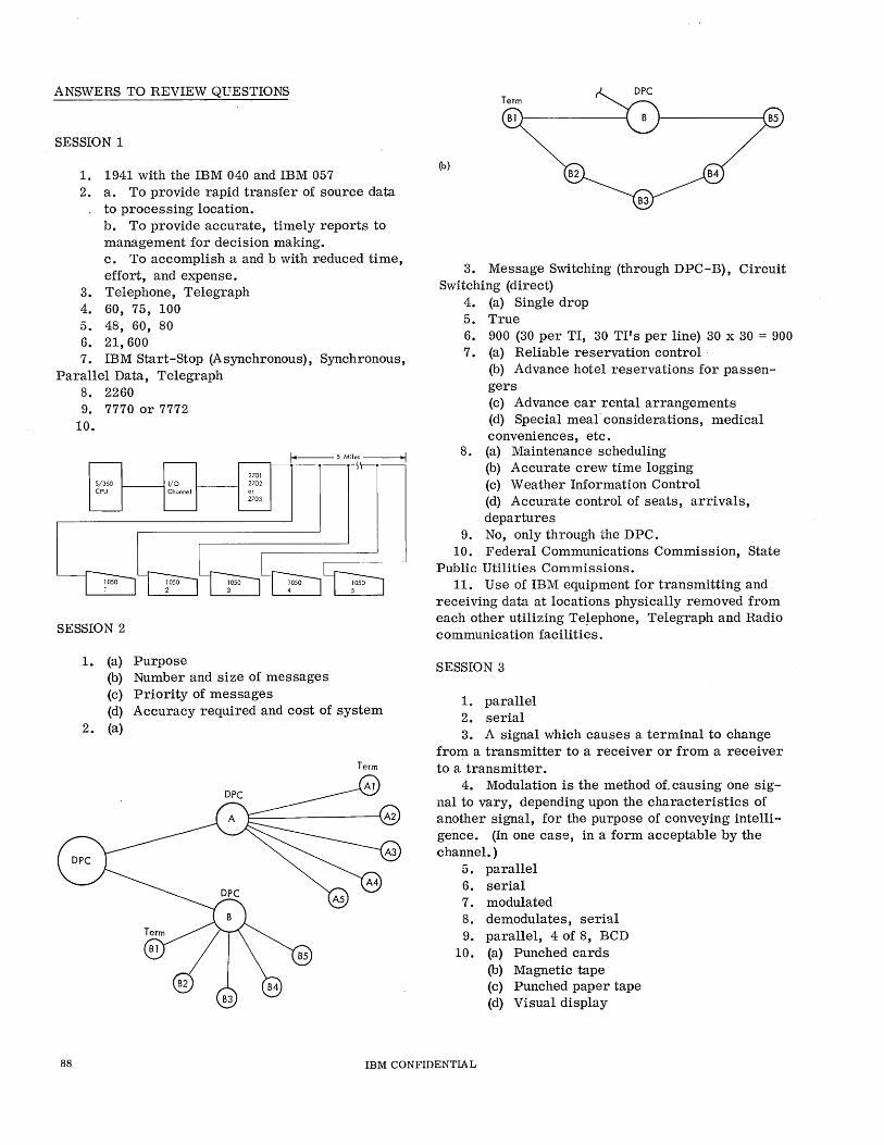
ANSWERS TO REVIEW QUESTIONS
SESSION 1
1. 1941 with the IBM 040 and IBM 057 2. a. To provide rapid transfer of source data
to processing location. b. To provide accurate, timely reports to management for decision making. c. To accomplish a and b with r.educed time, effort, and expense.
3. Telephone, Telegraph 4. 60, 75, 100 5. 48, 60, 80 6. 21,600 7. IBM Start-Stop (Asynchronous), Synchronous,
Parallel Data, Telegraph 8. 2260 9. 7770 or 7772
10.
f--- 5 Miles ------l
5/360 CPU
1-----11/0 Channel
SESSION 2
1. (a) Purpose
2701 2702 or
2703
(b) Number and size of messages (c) Priority of messages (d) Accuracy required and cost of system
2. (a)
Term
Term
Blr-----------~ r-----------~B5
(b)
3. Message Switching (through DPC-B), Circuit Switching (direct)
4. (a) Single drop 5. True 6. 900 (30 per TI, 30 TI's per line) 30 x 30 = 900 7. (a) Reliable reservation control
(b) Advance hotel reservations for passengers (c) Advance car rental arrangements (d) Special meal' considerations, medical conveniences, etc.
8. (a) Maintenance scheduling (b) Accurate crew time logging (c) Weather Information Control (d) Accurate control of seats, arrivals, departures
9. No, only through the DPC. 10. Federal Communications Commission, State
Public Utilities Commissions. 11. Use of IBM equipment for transmitting and
receiving data at locations physically removed from each other utilizing Te~ephone, Telegraph and Radio communication facilities.
SESSION 3
1. parallel 2. serial 3. A signal which causes a terminal to change
from a transmitter to a receiver or from a receiver to a transmitter.
4. Modulation is the method of. causing one signal to vary, depending upon the characteristics of another signal, for the purpose of conveying intelligence. (In one case, in a form acceptable by the channel. )
5. parallel 6. serial 7. modulated 8. demodulates, serial 9. parallel, 4 of 8, BCD
10. (a) Punched cards (b) Magnetic tape (c) Punched paper tape (d) Visual display
88 IBM CONFIDENTIA L

(e) Printed copy (f) Disk or drum file
11. to provide a dividing line of responsibility 12. Interface specifications publication from
data set manufacturer 13. serialization 14. de serialization 15. For the purpose of checking validity by
agreement of odd/even count of bits in message character
16. start of record 17. inquiry 18. acknowledgement 19. (a) Inquiry
(b) End of transmission or message (c) Aclmowledgement
SESSION 4
1. Channel, circuit, line 2. False 3. b, c, a 4. Telegraphic, Subvoice, Voice, Broadband 5. Baudot, 5, start, stop 6. Yes, one
No, . Zero Mark
7. Asynchronous signaling requires th..:.t each character be prefixed by a Start bit and followed by a Stop bit while special clocking circuits make this wasteful use of time unnecessary by controlling beginning and ending of characters based on a count.
8. Serial bit transmission disassembles a character and sends it one bit at a time over one circuit, while parallel-bit transmission requires one circuit for each bit value and sends the entire character at once.
9. Herzians - abbreviated Hz 10. 3,000 11. True 12. False, see Figure 14 for example. 13. Modulation is the process of causing one
signal to vary its form, dependent upon the characteristics of another signal.
14. To provide a buffer zone between channels to minimize the possibility of interference between channels (crosstalk)
15. a. Amplitude, b. Frequency (FSK or FSM), c. Phase (PSK or PSM), specifically t,his is 2 phase
16. Federal Communications Commission 17. Bit rate (speed) 18. a. Telegraphic, b. Subvoice, c. Voice
grade, d. Subvoice 19. 2.2V P-P, 1.1V P-P, 0.87V P-P 20. a. To regenerate distorted signals into good
quality signals
b. To improve signal to noise ratio and compensate for line loss
21. Echo suppressors. The time required from end of sending in one direction until transmission may begin in the opposite direction. Reduces throughput due to idle line time.
22. 1. Crosstalk by maintaining more uniform signal levels on line 2. Noise effects reduced
23. great, little, compression 24. Distributed 25. Compensators 26. .001, 600 27. Low noise, low or no echo problem, better
frequency response, handle slightly higher data rates with a lower error rate than ordinary lines.
28. Channel 29. Modulation, De-modulation
SESSION 5
1. Queueing is the procedure of holding messages in a programmed sequence ready to be forwarded to another destination.
2. Message switching is store and forward while circuit switching is initial routing control to addressee direct without intermediate receive and retransmit.
3. Contention 4. Polling is direction for the terminal to send
to the control station. Addressing is direction from control station to terminal to receive messages.
5. The message itself 6. b. skip that terminal and proceed to process
the remainder of the Polling List. 7. False - Customer may establish sequence 8. False 9. False - May vary to meet priority or peak
load requirements 10. False - Use intercept procedure to route to
nearest active terminal 11. False - Sequence and Journal Control 12. False - Priority coding can alter Queue
handling 13. a. Flagging
b. Retention of priority addresses in main storage, c. Transmit prior to logging, d. Priority Queues
14. a. Source of error check information b. Retrieval file if message gets lost
15. False - Must have proper access key. Example: Normally, production department should not be able to have access to Payroll data
IBM CONFIDENTIAL 89
16. While terminals are being addressed or polled they are in control mode and such data is usually not stored. Usually begin accumulating LRC in text mode and in storing or outputting data.
SESSION 6
1. Serialize - Deserialize 2. Parallel, Serial 3. Serial, Parallel 4. Off 5. Slightly after bit time 8 (delay Ion) 6. So last bit will be still on line while new
character is being loaded (after T's are all reset at about 8.4 time)
7. BCD, 4 of 8 8. To allow time to place last bit of character
in Line Control before resetting register. 9. To make sure old character is cleared before
a new one is loaded 10. Mark 11. 8, parallel, tran slator 12. On 13. Counter Circuit reaches 8 14. 8 15. Space, 4 16. Zero, space, 4 17. Counter circuit at 8 18. SERDES holds character and permits each
bit to be sampled to the line while shift register moves character up through the registers while ·presenting the character one bit at a time to the line.
19. SERDES through bit timer permits each storage element a definite period during which it may be turned On or left Off under control of the condition existing on the Receive Data Line. The
Shift Register sequentially samples each bit interval of the Receive Data Line to the TN while stepping the previously sampled bits and no bits up through the register until the counter circuit informs the machine that adequate time has been allowed and a complete character is in the register.
SESSION 7
1. Data Set 2. Frequencies 3. Mark 4. Phase 5. Bit errors 6. + (Plus), - (negative)
SESSION 8
1. Bi-Polar 2. Uni-Polar 3. Current
SESSION 9
1. Provide communication circuits for public use in accordance with prescribed schedules and rates.
2. Federal Communications Commission 3. State Public Utilities Commission 4. Tariffs 5. Standardization, Coordination 6. a. Wide Area Telephone Service, b. Sub-
scriber Teletypewriter Exchange 7. A subscriber teletypewriter service 8. 12 9. facsimile
90 IBM CONFIDENTIAL
INTRODUCTION TO TELEPROCESSING
COURSE EVALUATION
Please fill in the following blanks:
Rate of Understanding
Excellent Good Fair Poor
List any technical errors you found in this manual
Were you given your own copy of this manual to write in and keep '?
How many hours were required to complete this course? Were you interrupted during this time?
Did you require assistance during this course? If so, state in which area you required help.
List any additional comments you may have pertaining to this course.
Name
Branch Office Date
Date of Employment
Fold and staple or tape and return via IBM mail For Form Z25-2522-0
Man No.
Area
IBM Corporation FE Education Department 911, Bldg 005-3 Poughkeepsie, N. Y. 12602
L ____ ....I
I I I , I I, 1('11 I» ,:u IJ:
('11
l:u ('11
Fe
FO
, ('11
,~ IJ: 1('11 1:0 ,('11
I , , , I

Related Documents