66260 R E E O R P D E E R S A X E T F O E T A T S N I G N E L A N O I S S E F R E T S I G SUGAR LAND MEDICAL SUGAR LAND, TX 77479 OFFICES 16926 SOUTHWEST FWY S1.0 GENERAL NOTES GENERAL NOTES I. CODES AND SPECIFICATIONS A. GENERAL BUILDING CODE 1. International Building Code 2006. B. CONCRETE CODES 1. ACI 318, American Concrete Institute Building Code. 2. ACI 301, Specifications for Structural Concrete for Buildings. 3. CRSI- Manual of Standard Practice. C. STRUCTURAL STEEL CODES 1. AISC - Load and Resistance Factor Design, Third Edition. 2. AISC - Steel Construction Manual, Thirteenth Edition 2. ANSI/AWS D1.1, American Welding Society - Steel. D. COLD FORMED STEEL (LIGHT GAGE METAL) CODE 1. American Iron and Steel Institute (AISI) “Specification for the Design of Cold Formed Steel Structural Members”, Latest Edition. E. CONFLICTS IN STRUCTURAL REQUIREMENTS 1. Where conflict exists among the various parts of the Structural and architectural Contract Documents, (Structural Drawings, General Notes, Specifications) the strictest requirements shall govern. All Codes and Specifications listed above shall include all amendments and addenda in force at the date of the contract documents. II. TYPICAL DETAILS A. Details labeled “Typical Details” on the Drawings shall apply to all situations occurring on the Project that are the same or similar to those specifically detailed. Such details shall apply whether or not they are keyed in at each location. Questions regarding applicability of Typical Details shall be determined by the Engineer . III. DESIGN CRITERIA A. DEAD LOADS 1. Dead loads. Dead load materials assumed in the design are shown on the Architectural and Structural Drawings. B. LIVE LOADS CATEGORY UNIFORM CONCENTRATED LOAD (PSF) LOAD (#) Roof 20 N/A Live loads have been reduced on any member based on the Code cited in CODES AND SPECIFICATIONS, Paragraph I. A. C. WIND LOADS 1. Wind pressure based on the requirements of Code cited in CODES AND SPECIFICATIONS, Paragraph I. A. 2. V = 110 mph, Exposure: B, I = 1.10 IV. FOUNDATION - GENERAL A. GEOTECHNICAL REPORT Foundation design is based on the following geotechnical report: Proposed "Report of Geotechnical Investigation for the proposed commercial building on US 59 and First Colony Boulevard, Sugar Land, Texas”. Prepared by: Associates Testing Lab, Inc. Report No.: G11-148 Dated: May 20, 2011 All recommendations therein that relate to the work shown on these drawings shall be followed. B. FOUNDATION APPROVAL AND INSPECTION BY AUTHORIZED INSPECTOR 1. The General Contractor shall notify the Geotechnical Engineer or other authorized inspector for review of foundation bearing surface, inspection of foundation installation, and placement of reinforcing steel. The contractor shall not place concrete without inspector's approval. 2. The Contractor shall notify the authorized inspector 24 hours in advance of any major foundation pour. C. GRADE BEAMS 1. Grade Beam Side Forms. a. Form exposed faces of grade beams. 2. Grade beam bottom steel shall be chaired at 5 foot maximum centers using beam bolsters providing 3 inch bottom cover to reinforcing steel. Beam bolsters used shall be intended for support on soil. 3. Bottom bars of grade beam shall be spliced (where required) at the piers only. Top bars shall be spliced (where required) at the midspan of the grade beams. Lap length shall be 44 times bar diameter unless specified otherwise. Provide corner bars to match top and bottom steel. D. SLAB-ON-GRADE CONSTRUCTION 1. Slab on grade construction shall follow the recommendations of Guide for Concrete Floor and Slab Construction ACI 302.1R. 2. Subgrade Preparation shall conform to the soils report noted above. If report does not specify the amount of select fill, provide fill as required above to reduce PVR to 1 inch. E. VAPOR RETARDER 1. Vapor retarder shall have no more than 0.01 perms when tested in accordance with ASTM E-96; meet or exceed the requirements of ASTM E-1745, Class C; and be no less than 15mils thick in accordance with ACI 302.1R-96. Acceptable products include: a. STEGO WRAP VAPOR BARRIER (15 mil) by Stego Industries LLC (281)367-0040 b. Griffolyn T-85 by Reef Industries c. Rufco D16WB by Raven Industries d. Barrier-Bac VB-350 (16mil) Vapor Retarder 2. All seams shall be overlapped a minimum of 6 inches and taped with polyethylene tape. All penetrations, block-outs, and openings shall be sealed using a combination of the vapor retarder and polyethylene tape. V. DRILLED PIER FOUNDATION A. DESIGN SOIL PRESSURES Allowable Pressure = 2400 psf under sustained loads = 3600 psf for total (dead + live) loads B. FIELD INSPECTION OF BEARING STRATUM 1. The bearing stratum of each drilled pier shall be inspected and approved by the Geotechnical Engineer or other authorized inspector prior to pouring of concrete. 2. The bottom elevation of piers is shown on the Drawings for bid proposes. The actual required bearing elevation may vary as required to provide proper capacity as determined by the geotechnical engineer. Footings shall be poured immediately after excavation. 3. Provide and install 1/8 inch steel templates to accurately set vertical pier reinforcing steel, and anchor bolts for steel columns. VI. CONCRETE A. CLASSES OF CONCRETE 1. All concrete shall conform to the requirements as specified in the table below unless noted otherwise on the Drawings: USAGE 28 DAY COMP. TYPE MAX. SIZE CONC. AGGREGATE STRENGTH (PSI) Footings, Grade Beams, Plinths 3000 NW 1 1/2" Slab-on-Grade 3000 NW 1 1/2” Drilled Piers (under reamed) 3000 NW 1 1/2" Note: NW = Normal weight concrete LW = Lightweight concrete slab (Density = 115 pcf max.) 2. There shall be no horizontal cold joint in any concrete pour. 3. Admixtures used shall be compatible with floor treatments. 4. Concrete for slab-on-grade shall have a maximum water-cement ratio of 0.50. 5. Concrete shall comply with the requirements of ACI 301 and ACI 318. 6. Fly ash conforming to ASTM C618, Type F, may be used unless noted otherwise. The maximum amount of fly ash shall be 25% of the total cementitious material by weight. 7. Concrete shall comply with the requirements of ACI 301 and ACI 318. VII. REINFORCING STEEL A. SPECIFICATION 1. ASTM A 615 Grade 60 unless noted otherwise on the drawings. Welded Reinforcing Steel - ASTM A 706. 2. Welded Wire Fabric: Welded smooth wire fabric, ASTM A 185, yield strength 65,000 psi. Welded deformed wire fabric for ASTM A 497, yield strength 70,000 psi. All welded wire fabric shall be furnished in flat sheets only. Wherever welded wire fabric is specified as reinforcement, it shall be continuous across the entire concrete surface and not interrupted by beams or girders and properly lapped one cross wire spacing plus 2 inches. B. REINFORCING STEEL COVERAGE Cover in structural members not specified below shall conform to the requirements of ACI 318 Section 7.7 unless specified otherwise on the drawings. 1. Foundation Members a. Grade Beams 1 1/2" top, 3" bottom, 3" sides b. Drilled Piers 3” sides c. Interior Slab-on-Grade see details VIII. STRUCTURAL STEEL A. MATERIAL 1. All hot rolled steel plates, shapes and bars shall be new steel conforming to ASTM Specification A6-84c. 2. All wide flanged beams shall conform to ASTM A992, Grade 50. 3. All wide flanged columns shall conform to ASTM A992, Grade 50. 4. All tubes shall conform to ASTM A500 Grade B. 5. All pipe columns shall conform to ASTM A53, Grade B or ASTM A501. 6. All connection material shall conform to ASTM A36 unless stronger required. B. CONNECTIONS 1. Typical connection details are indicated on the Drawings. 2. The design of all steel connections shall be performed under the direct supervision of a registered professional engineer in the state where the project is located, employed by the fabricator. Calculations sealed by the fabricator's professional engineer must be submitted if requested. 3. It is the intention of the plans and specifications that shop connections be welded or bolted and that field connections be bolted, unless detailed otherwise on the Drawings. 4. All typical beam simple connections shall be standard double angle or single angle framed beam connections. Shear tab connections may be used at locations where double angle connections are not possible. Seated beam connections shall not be used unless indicated on the Drawings. Provide full depth shear tab if beam frames on only one side of a girder. 5. Beam Reactions a. Non-Composite beams: Design connections to support a reaction R (unless specified otherwise) equal to one half the total uniform load capacity from the table of Uniform Load Constants in the AISC Manual. 6. Bracing connections shall develop full tensile forces at each end of the bracing member unless bracing forces are specified on the Drawings. 7. MC = Moment Connections 8. Welds: a. All welds shall conform to the American Welding Society (AWS) standards. b. All welding shall be performed by a welder certified in accordance to the AWS standards. 9. Bolts: a. All bolts shall conform to ASTM A325 Type 1, High Strength Bolts. All bolts shall be designed as bearing bolts with threads included in the shear plane. Minimum bolt diameter shall be 3/4 inch. All bolts shall be tightened to a snug-tight position, unless noted below. b. All bolts at braces and moment connections shall be tightened using load indicating washers or tension bolts. c. All bolts shall be new and shall not be re-used. C. GALVANIZING 1. All steel exposed to weather or outside the building's waterproofing, such as brick shelf angles, shall be hot-dipped galvanized after fabrication. 2. All steel surfaces to be hot dip galvanized shall be prepared as specified by the Steel Structures Painting Council (SSPC). 3. The zinc coating for steel shapes and plates shall average not less than 2.3 oz. with no individual thickness less than 2.0 oz. 4. Galvanize all nuts, bolts, and washers used in the connection of galvanized steel. 5. Protect all field welded connections with “Z.R.C. Cold Galvanizing Compound” as manufactured by Z.R.C. Product Company. IX. NON-SHRINK GROUT FOR BASE PLATES AND BEARING PLATES A. SPECIFICATIONS 1. Grout for base plates and bearing plates shall be a non-metallic, shrinkage resistant, premixed, non-corrosive, non-staining product containing Portland cement, silica sands, shrinkage compensating agents, and fluidity improving compounds. 2. Grout shall conform to Corps of Engineers Specification for Non-Shrink Grout, CE-CRD-C621. Twenty-eight day compressive strength as determined by grout cube tests, shall be 5,000 PSI. Minimum thickness of grout under all base plates and bearing plates shall be 1 inch, unless specified otherwise on the drawings. 3. Grout shall be placed in a fluid flowable state under base plates that have a form built around them for grout confinement. Grout should be cured according to manufacturer's recommendations. X. OPEN WEB STEEL JOISTS A. SPECIFICATIONS 1. Open web steel joists shall be designed, manufactured and erected per the Steel Joist Institute (SJI) Specifications. 2. Joists shall be cambered for realistic dead load. Provide Standard SJI camber unless specified otherwise on the Drawings. 3. Provide top chord extensions where shown on the Drawings. 4. Provide flat bearing for all joists. Provide minimum end bearing of 2 1/2 inches for K-series joists and 5 inches for LH and DLH joists. If sufficient bearing does not exist, stagger the end of each joist and center bearing over center of support. Provide 5" seats at K-series joists bearing on the same beam As LH and DLH joists. 5. Provide horizontal and diagonal bridging as required by SJI Specifications. 6. Provide SJI standard depth of bearing for all joists. 7. Coordination of all joist seat depths with structural steel elevations shall be the responsibility of the contractor and steel fabricator. 8. Top chord of joists shall be double angles or tees. 9. Provide minimum end anchorage to steel and masonry as required by SJI Specifications. 10. Joists shall be shop painted per Architectural specifications. 11. Joists with bottom chord extensions shall not have end connections made until after full dead load is applied. 12. Provide additional steel, bridging, etc. as required to comply with all OSHA requirements. B. DESIGN 1. The design of all open web joists shall conform to the codes and specifications cited above. 2. All joists shall carry the design loads as specified in the SJI load tables as the minimum requirement. Additionally, the joists shall be designed to carry any other load types and patterns as indicated on the structural drawings. Examine the structural drawings for any other loads required to be carried by any joist. 3. Roof joists shall be designed for a net uplift pressure = 25 PSF. C. SUBMITTAL 1. Joist manufacturer shall submit the following for Engineer's review and approval: a. Produce certification letter that joists and joist girders comply with all documents noted in these general notes. b. Shop drawings showing joists layout, bridging and other accessories. c. Design calculations for all joists showing load carrying capacity. Calculations shall be signed and sealed by a registered Engineer. Calculations are for Owner's record only. XI. STEEL ROOF DECK (WITH RIGID INSULATION BOARD) A. SCHEDULE 1. Roof deck shall be 1.5B (22 gauge) as manufactured by Vulcraft, or equivalent. B. SPECIFICATION 1. The design, fabrication, and erection of all roof deck shall conform to the Steel Deck Institute Design Manual for Composite Decks, Form Decks, and Roof Decks as published by the Steel Deck Institute (SDI). 2. Steel deck shall be manufactured from steel conforming to ASTM A 653-94 structural quality grade 33 or higher. 3. Steel deck shall be galvanized with a protective zinc coating conforming to ASTM A 653-94 G90 class. C. ATTACHMENT 1. Roof deck units shall be welded to each structural support member using 5/8 inch diameter puddle welds at all ribs where sides lap and each rib in between (36/7 pattern). Weld metal shall penetrate all layers of deck material at end laps and side joints and shall have good fusion to the supporting members. At perimeter, deck shall be welded at 6” o.c. 2. Side laps of adjacent units shall be fastened by sheet metal screws so that spacing between supports and fasteners does not exceed 12 inches. 3. Provide a minimum end bearing of 2 inches over supports. 4. End laps of sheets shall be a minimum of two inches and shall occur over supports. 5. Provide roof deck construction which is listed and conforms to the UL Fire Resistance Directory and Building Materials Directory. Deck attachment shall be increased above the minimum specified herein as required to achieve a Class 90 uplift rating. D. DECK SPANS 1. Metal deck spans shall not exceed the maximum center to center spans as required by SDI criteria. Where possible, all metal deck shall extend over three or more supports. Two span deck shall be used only where deck layout does not permit the use of three spans. Single span deck is not permitted. E. ACCESSORIES 1. Provide minimum 20 gauge ridge and valley plates, minimum 20 gauge cant strips, minimum 14 gauge sump pans, minimum 20 gauge inside or outside closure channels, minimum 20 gauge butt strips at change of deck directions, minimum 20 gauge filler sheets, and rubber closures as required to provide a finished surface for the application of insulation and roofing. F. ROOF OPENINGS 1. Roof openings less than 6 inch square or diameter require no reinforcement. Openings 6 inch to 10 inch inclusive shall be reinforced with a 20 gauge galvanized plate welded to the deck at each corner and 6 inch maximum centers with a 5/8 inch diameter puddle weld or sheet metal screws. Unless indicated otherwise on the drawings, openings over 10 inch wide or diameter shall be reinforced with an angle 2 1/2 x 2 1/2 x 1/4 framing each side of the opening and spanning between supports for spans 4 feet or less and L 3 x 3 x 1/4 for spans greater than 4 feet but less than 6 feet unless specified otherwise on drawings. Larger openings shall be referred to the Engineer for framing. XII. SUBMITTALS A. SHOP DRAWINGS 1. The General Contractor shall submit for Engineer review shop drawings for the following items: a. Structural Steel (*) b. Reinforcing Steel c. Metal Deck d. Concrete Mix Designs e. Bar Joists (*) f. Miscellaneous Steel g. Curtain Wall (*,#) Items marked (*) shall have shop drawings sealed by a registered engineer in the state where the project is located. Items marked (#) shall be submitted to Engineer for Owner's record only and will not have Engineer's shop drawing stamp. 2. All shop drawings must be reviewed and sealed by the General Contractor prior to submittal. 3. Contractor shall submit one set of sepias and two sets of blueline prints for all shop drawings specified to be returned by the Engineer. 4. The omission from the shop drawings of any material required by the Contract Documents to be furnished shall not relieve the contractor of the responsibility of furnishing and installing such materials, regardless of whether the shop drawings have been reviewed and approved. B. MANUFACTURER'S LITERATURE 1. Submit two copies of manufacturer's literature for all materials and products used in construction on the project. C. REPRODUCTION 1. The use of reproductions of these Contract Documents by any contractor, subcontractor, erector, fabricator, or material supplier in lieu of preparation of shop drawings signifies his acceptance of all information shown hereon as correct, and obligates himself to any job expense, real or implied, arising due to any errors that may occur hereon. XIII. MISCELLANEOUS A. CONTRACT DOCUMENTS 1. It is the responsibility of the General Contractor to obtain all Contract Documents and latest addenda and to submit such documents to all subcontractors and material suppliers prior to the submittal of shop drawings, fabrication of any structural members, and erection in the field. B. DRAWING CONFLICTS 1. The General Contractor shall compare the Architectural and Structural drawings and report any discrepancy between each set of drawings and within each set of drawings to the Architect and Engineer prior to the fabrication and installation of any structural members. C. EXISTING CONDITIONS 1. The General Contractor shall verify all dimensions and existing conditions at the job site and report any discrepancies from assumed conditions shown on the drawings to the Architect and Engineer prior to the fabrication and erection of any members. D. RESPONSIBILITY OF THE CONTRACTOR FOR STABILITY OF THE STRUCTURE DURING CONSTRUCTION 1. All structural elements of the project have been designed by the Structural Engineer to resist the required code vertical and lateral forces that could occur in the final completed structure only. It is the responsibility of the Contractor to provide all required bracing during construction to maintain the stability and safety of all structural elements during the construction process until the structure is tied together and completed. E. HORIZONTAL CONSTRUCTION JOINTS IN CONCRETE POURS 1. There shall be no horizontal construction joints in any concrete pours unless shown on the drawings. All deviations or additional joints shall be approved in writing by the Architect/Engineer. XIV. SITE OBSERVATION BY THE STRUCTURAL ENGINEER A. GENERAL 1. The contract structural drawings and specifications represent the finished structure, and except where specifically shown, do not indicate the method or means of construction. The Contractor shall supervise and direct the work and shall be solely responsible for all construction means, methods, and procedures, techniques, and sequence. 2. The Engineer shall not have control or charge of, and shall not be responsible for, construction means, methods, techniques, sequences, or procedures, for safety precautions and programs in connection with the work, for the acts or omission of the Contractor, Subcontractor, or any other persons performing any of the work, or for the failure of any of them to carry out the work in accordance with the contract documents. 3. Periodic site observation by field representatives are solely for the purpose of determining if the work of the Contractor is proceeding in accordance with the structural contract documents. This limited site observation should not be construed as exhaustive or continuous to check the quality or quantity of the work, but rather periodic in an effort to guard the Owner against defects or deficiencies in the work of the Contractor. XV. LIGHT GAGE METAL A. SPECIFICATIONS 1. All structural members and connections shall be designed and erected per the American Iron and Steel Institute (AISI) Specifications noted above. 2. All studs and/or joists and accessories shall be of the type, size, gauge and spacing shown on the Drawings. All joists and studs shall have 1 5/8" flange with 1/2" return unless specified otherwise. 3. All framing members shall be manufactured from corrosion resistant steel conforming to ASTM A 653 (G60) with a minimum yield strength of 50 ksi for studs and joist members and 33 ksi for runner and track members and flat strap bracings. 4. Prior to fabrication, the contractor shall submit erection drawings to structural engineer for review and approval. 5. All framing components shall be cut squarely for attachment to perpendicular members, or as required for an angular fit against abutting members. B. DESIGN 1. Fastening of components shall be with self-drilling screws or welding of sufficient size to ensure the strength of the connection. 2. Studs shall have full bearing against inside track web, prior to stud and track attachment. 3. Splices in framing components except runners track shall not be permitted. 4. For non-load bearing studs, connections shall consider the deflection (1/2”) of structural members to which the studs are attached. Provide slide clips and/or deflection slip tracks. 5. The design of all light gage metal shall be performed by the light gage metal contractor. The design shall include member sizes and connections. The design shall consider member dimensions noted in the drawings. The light gage contractor shall supply drawings sealed by an engineer registered in the State where the project is located showing light gage framing members and connection. The out plane deflection of studs shall be limited to H/600 (H = unsupported height of studs) if used for masonry or stone backup. For other conditions deflection shall be limited to H/360. C. ERECTION 1. Erect framing and panels plumb, level and square in strict accordance to approved shop drawings. 2. Track shall be securely anchored to the supporting structure. Proposed connection to be submitted for approval unless specified otherwise on drawings. Abutting pieces of track shall be securely spliced together. 3. Jack studs or cripples shall be installed below window sills, above window and door heads, and elsewhere to furnish support, and shall be securely attached to connecting members. 4. Provide horizontal bridging in all stud systems at four feet on centers vertically for axially loaded studs, and at six feet on centers vertically for non-load bearing studs. Weld at each stud intersection. 5. Provide diagonal steel straps of size and location shown on the drawings. Extend straps from the bottom track to the top track inclined 45 degrees unless shown otherwise and connected to each stud. 6. Provide stud bracing during construction as required for studs to carry construction loads. 7. At the load bearing walls supporting floor or roof joists, locate studs directly under the joists or provide load distributing member between studs to support joists. XVI. CONCRETE MASONRY A. SPECIFICATION 1. All masonry materials and construction shall conform to the recommendations of the Brick Institute of America (BIA) and National Concrete Masonry Association (NCMA) and masonry codes noted in these general notes. 2. All concrete masonry units (CMU) shall conform to ASTM C90, Type 1, Grade N. Unless specified otherwise, CMU shall be lightweight (less than 105 PCF, oven dry unit weight). The minimum compressive strength of masonry (f'm) shall be 1,500 psi as determined by the unit strength method or by the prism test method. All masonry units shall be placed in running bond. 3. Mortar: a. Unless specified otherwise, all mortars and the materials therein shall conform to the standard specifications of Masonry Units, ASTM C270, Type S except for masonry in contact with the earth shall be Type M. b. Mortar shall have minimum average strength of 1900 psi for Type M, or S. 4. Grout: a. All Grout shall be fine grout containing sand, Portland cement, and lime (optional) for grout spaces less than 2 inches in any horizontal direction, unless specified otherwise. b. Grout shall attain a minimum 28 days compressive strength of 2500 psi tested according to ASTM C476. 5. Control Joints shall be located per Architectural drawings and specifications or at a maximum spacing of 40 feet on centers. B. REINFORCEMENT 1. Provide horizontal reinforcing (truss or ladder type, 9 gauge) at 16 inches on center for all CMU walls. Reinforcement shall conform to ASTM A82 and shall be hot dip galvanized. 2. All horizontal reinforcing steel in bond beams and lintel block units shall be continuous. Units shall be solidly grouted. Provide 48 times bar diameter lap for horizontal reinforcing in bond beams. No splices shall be provided for horizontal reinforcing in block lintels. 3. Grout cells solid where vertical bars are shown on the drawings. Vertical bars shall extend from bottom to the top of the wall. Provide 48 times bar diameter splice for vertical bars where required and/or shown on the Drawings. 4. All reinforced masonry walls with openings up to four (4) feet wide, shall have one vertical bar minimum at each side of openings. For openings larger that 4 feet wide, provide two (2) vertical bars at each side of openings. Reinforcing at edges of opening shall match typical vertical wall reinforcing (unless noted otherwise) and shall extend to the top of wall. 5. All reinforced masonry wall corners and intersections shall have one vertical bar (minimum) in grouted cell. Reinforcing shall match typical wall vertical reinforcement. 6. Provide one vertical bar (minimum) in the first cell each side of control joints. Reinforcing shall match typical vertical wall reinforcing (unless noted otherwise) and shall extend to the top of wall. 7. Provide a bond beam at the top of all CMU walls reinforced with (2) - #5 continuous unless noted otherwise. C. INTERIOR (NON-LOAD BEARING) CMU WALL REINFORCING 1. See typical details for interior wall height, bracings and reinforcing requirements. D. SPECIAL INSPECTION 1. Special inspection, in accordance with the building code referenced above, shall be provided for all CMU walls.

Welcome message from author
This document is posted to help you gain knowledge. Please leave a comment to let me know what you think about it! Share it to your friends and learn new things together.
Transcript
66260 RE
E
OR
P
DEE
R
SAXETFOETATS
NIGNELANOISSEF RETSIG
SUG
AR L
AND
MED
ICAL
SU
GA
R L
AND
, TX
7747
9
OFF
ICES
1692
6 S
OU
THW
EST
FW
Y
S1.0
GENERAL NOTES
GENERAL NOTES
I. CODES AND SPECIFICATIONS
A. GENERAL BUILDING CODE 1. International Building Code 2006.
B. CONCRETE CODES 1. ACI 318, American Concrete Institute Building Code. 2. ACI 301, Specifications for Structural Concrete for Buildings. 3. CRSI- Manual of Standard Practice.
C. STRUCTURAL STEEL CODES 1. AISC - Load and Resistance Factor Design, Third Edition. 2. AISC - Steel Construction Manual, Thirteenth Edition 2. ANSI/AWS D1.1, American Welding Society - Steel.
D. COLD FORMED STEEL (LIGHT GAGE METAL) CODE 1. American Iron and Steel Institute (AISI) “Specification for the Design of Cold Formed Steel Structural Members”, Latest Edition.
E. CONFLICTS IN STRUCTURAL REQUIREMENTS 1. Where conflict exists among the various parts of the Structural and architectural Contract Documents, (Structural Drawings, General Notes, Specifications) the strictest requirements shall govern.
All Codes and Specifications listed above shall include all amendments and addenda in force at the date of the contract documents.
II. TYPICAL DETAILS
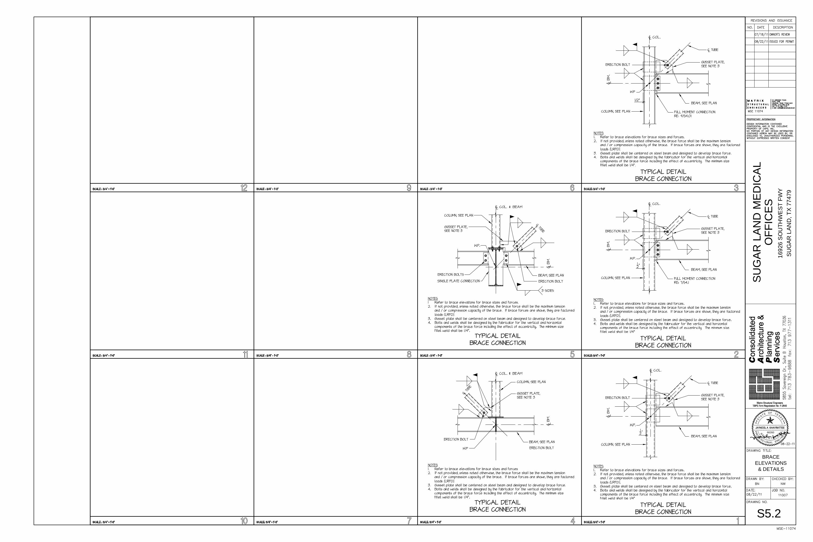
A. Details labeled “Typical Details” on the Drawings shall apply to all situations occurring on the Project that are the same or similar to those specifically detailed. Such details shall apply whether or not they are keyed in at each location. Questions regarding applicability of Typical Details shall be determined by the Engineer .
III. DESIGN CRITERIA
A. DEAD LOADS 1. Dead loads. Dead load materials assumed in the design are shown on the Architectural and Structural Drawings.
B. LIVE LOADS
CATEGORY UNIFORM CONCENTRATED LOAD (PSF) LOAD (#) Roof 20 N/A
Live loads have been reduced on any member based on the Code cited in CODES AND SPECIFICATIONS, Paragraph I. A.
C. WIND LOADS 1. Wind pressure based on the requirements of Code cited in CODES AND SPECIFICATIONS, Paragraph I. A. 2. V = 110 mph, Exposure: B, I = 1.10
IV. FOUNDATION - GENERAL
A. GEOTECHNICAL REPORT Foundation design is based on the following geotechnical report: Proposed "Report of Geotechnical Investigation for the proposed commercial building on US 59 and First Colony Boulevard, Sugar Land, Texas”. Prepared by: Associates Testing Lab, Inc. Report No.: G11-148 Dated: May 20, 2011
All recommendations therein that relate to the work shown on these drawings shall be followed.
B. FOUNDATION APPROVAL AND INSPECTION BY AUTHORIZED INSPECTOR 1. The General Contractor shall notify the Geotechnical Engineer or other authorized inspector for review of foundation bearing surface, inspection of foundation installation, and placement of reinforcing steel. The contractor shall not place concrete without inspector's approval. 2. The Contractor shall notify the authorized inspector 24 hours in advance of any major foundation pour.
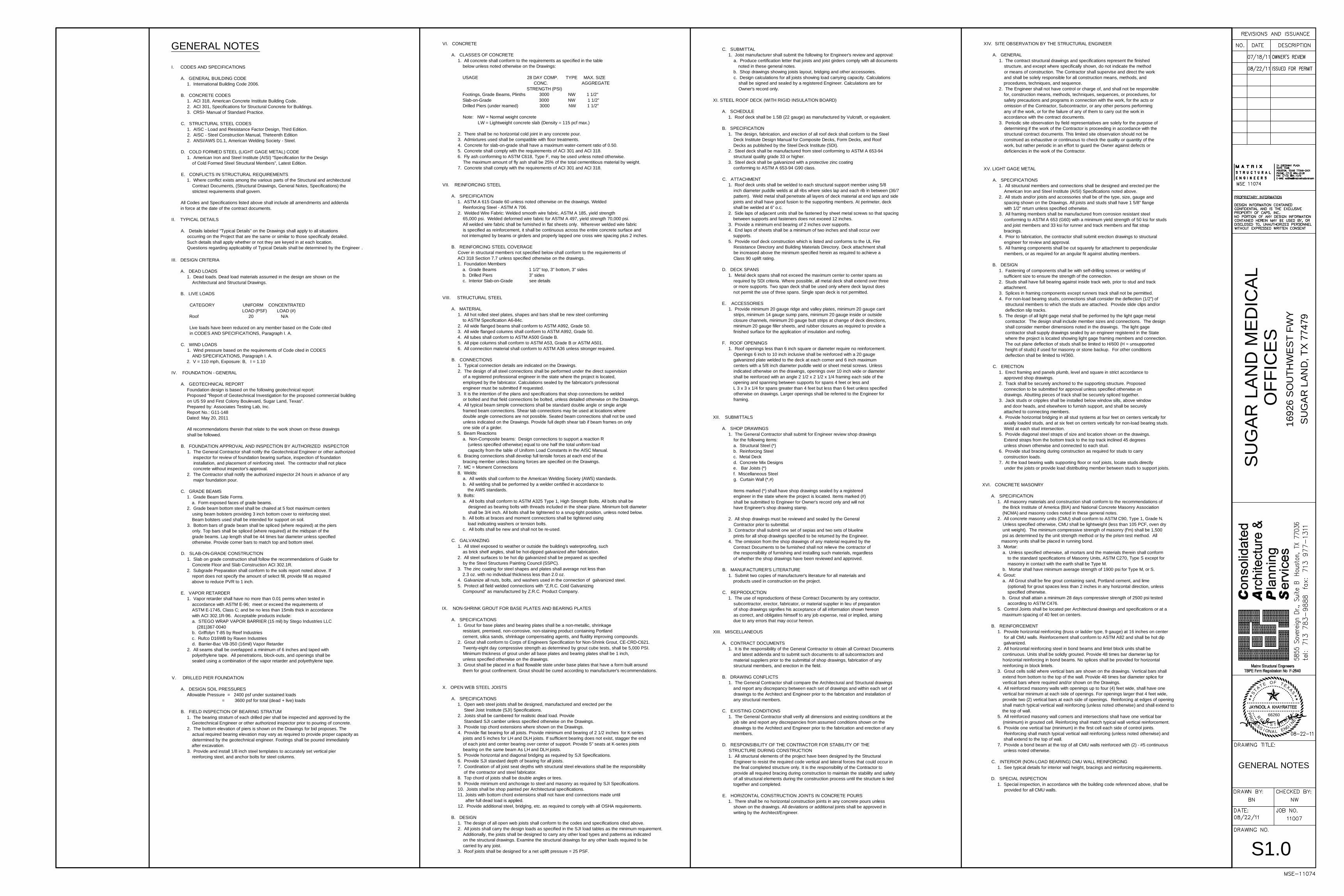
C. GRADE BEAMS 1. Grade Beam Side Forms. a. Form exposed faces of grade beams. 2. Grade beam bottom steel shall be chaired at 5 foot maximum centers using beam bolsters providing 3 inch bottom cover to reinforcing steel. Beam bolsters used shall be intended for support on soil. 3. Bottom bars of grade beam shall be spliced (where required) at the piers only. Top bars shall be spliced (where required) at the midspan of the grade beams. Lap length shall be 44 times bar diameter unless specified otherwise. Provide corner bars to match top and bottom steel.
D. SLAB-ON-GRADE CONSTRUCTION 1. Slab on grade construction shall follow the recommendations of Guide for Concrete Floor and Slab Construction ACI 302.1R. 2. Subgrade Preparation shall conform to the soils report noted above. If report does not specify the amount of select fill, provide fill as required above to reduce PVR to 1 inch.
E. VAPOR RETARDER 1. Vapor retarder shall have no more than 0.01 perms when tested in accordance with ASTM E-96; meet or exceed the requirements of ASTM E-1745, Class C; and be no less than 15mils thick in accordance with ACI 302.1R-96. Acceptable products include: a. STEGO WRAP VAPOR BARRIER (15 mil) by Stego Industries LLC (281)367-0040 b. Griffolyn T-85 by Reef Industries c. Rufco D16WB by Raven Industries d. Barrier-Bac VB-350 (16mil) Vapor Retarder 2. All seams shall be overlapped a minimum of 6 inches and taped with polyethylene tape. All penetrations, block-outs, and openings shall be sealed using a combination of the vapor retarder and polyethylene tape.
V. DRILLED PIER FOUNDATION
A. DESIGN SOIL PRESSURES Allowable Pressure = 2400 psf under sustained loads = 3600 psf for total (dead + live) loads
B. FIELD INSPECTION OF BEARING STRATUM 1. The bearing stratum of each drilled pier shall be inspected and approved by the Geotechnical Engineer or other authorized inspector prior to pouring of concrete. 2. The bottom elevation of piers is shown on the Drawings for bid proposes. The actual required bearing elevation may vary as required to provide proper capacity as determined by the geotechnical engineer. Footings shall be poured immediately after excavation. 3. Provide and install 1/8 inch steel templates to accurately set vertical pier reinforcing steel, and anchor bolts for steel columns.
VI. CONCRETE
A. CLASSES OF CONCRETE 1. All concrete shall conform to the requirements as specified in the table below unless noted otherwise on the Drawings:
USAGE 28 DAY COMP. TYPE MAX. SIZE CONC. AGGREGATE STRENGTH (PSI) Footings, Grade Beams, Plinths 3000 NW 1 1/2" Slab-on-Grade 3000 NW 1 1/2” Drilled Piers (under reamed) 3000 NW 1 1/2"
Note: NW = Normal weight concrete LW = Lightweight concrete slab (Density = 115 pcf max.)
2. There shall be no horizontal cold joint in any concrete pour. 3. Admixtures used shall be compatible with floor treatments. 4. Concrete for slab-on-grade shall have a maximum water-cement ratio of 0.50. 5. Concrete shall comply with the requirements of ACI 301 and ACI 318. 6. Fly ash conforming to ASTM C618, Type F, may be used unless noted otherwise.
The maximum amount of fly ash shall be 25% of the total cementitious material by weight. 7. Concrete shall comply with the requirements of ACI 301 and ACI 318.
VII. REINFORCING STEEL
A. SPECIFICATION 1. ASTM A 615 Grade 60 unless noted otherwise on the drawings. Welded Reinforcing Steel - ASTM A 706. 2. Welded Wire Fabric: Welded smooth wire fabric, ASTM A 185, yield strength 65,000 psi. Welded deformed wire fabric for ASTM A 497, yield strength 70,000 psi. All welded wire fabric shall be furnished in flat sheets only. Wherever welded wire fabric
is specified as reinforcement, it shall be continuous across the entire concrete surface and not interrupted by beams or girders and properly lapped one cross wire spacing plus 2 inches.
B. REINFORCING STEEL COVERAGE Cover in structural members not specified below shall conform to the requirements of ACI 318 Section 7.7 unless specified otherwise on the drawings. 1. Foundation Members a. Grade Beams 1 1/2" top, 3" bottom, 3" sides b. Drilled Piers 3” sides c. Interior Slab-on-Grade see details
VIII. STRUCTURAL STEEL
A. MATERIAL 1. All hot rolled steel plates, shapes and bars shall be new steel conforming to ASTM Specification A6-84c. 2. All wide flanged beams shall conform to ASTM A992, Grade 50. 3. All wide flanged columns shall conform to ASTM A992, Grade 50. 4. All tubes shall conform to ASTM A500 Grade B. 5. All pipe columns shall conform to ASTM A53, Grade B or ASTM A501. 6. All connection material shall conform to ASTM A36 unless stronger required.
B. CONNECTIONS 1. Typical connection details are indicated on the Drawings. 2. The design of all steel connections shall be performed under the direct supervision
of a registered professional engineer in the state where the project is located, employed by the fabricator. Calculations sealed by the fabricator's professional engineer must be submitted if requested.
3. It is the intention of the plans and specifications that shop connections be welded or bolted and that field connections be bolted, unless detailed otherwise on the Drawings.
4. All typical beam simple connections shall be standard double angle or single angle framed beam connections. Shear tab connections may be used at locations where double angle connections are not possible. Seated beam connections shall not be used unless indicated on the Drawings. Provide full depth shear tab if beam frames on only one side of a girder.
5. Beam Reactions a. Non-Composite beams: Design connections to support a reaction R (unless specified otherwise) equal to one half the total uniform load capacity from the table of Uniform Load Constants in the AISC Manual. 6. Bracing connections shall develop full tensile forces at each end of the bracing member unless bracing forces are specified on the Drawings. 7. MC = Moment Connections 8. Welds: a. All welds shall conform to the American Welding Society (AWS) standards. b. All welding shall be performed by a welder certified in accordance to the AWS standards. 9. Bolts: a. All bolts shall conform to ASTM A325 Type 1, High Strength Bolts. All bolts shall be
designed as bearing bolts with threads included in the shear plane. Minimum bolt diameter shall be 3/4 inch. All bolts shall be tightened to a snug-tight position, unless noted below.
b. All bolts at braces and moment connections shall be tightened using load indicating washers or tension bolts. c. All bolts shall be new and shall not be re-used.
C. GALVANIZING 1. All steel exposed to weather or outside the building's waterproofing, such as brick shelf angles, shall be hot-dipped galvanized after fabrication. 2. All steel surfaces to be hot dip galvanized shall be prepared as specified by the Steel Structures Painting Council (SSPC). 3. The zinc coating for steel shapes and plates shall average not less than 2.3 oz. with no individual thickness less than 2.0 oz. 4. Galvanize all nuts, bolts, and washers used in the connection of galvanized steel. 5. Protect all field welded connections with “Z.R.C. Cold Galvanizing Compound” as manufactured by Z.R.C. Product Company.
IX. NON-SHRINK GROUT FOR BASE PLATES AND BEARING PLATES
A. SPECIFICATIONS 1. Grout for base plates and bearing plates shall be a non-metallic, shrinkage resistant, premixed, non-corrosive, non-staining product containing Portland cement, silica sands, shrinkage compensating agents, and fluidity improving compounds. 2. Grout shall conform to Corps of Engineers Specification for Non-Shrink Grout, CE-CRD-C621.
Twenty-eight day compressive strength as determined by grout cube tests, shall be 5,000 PSI. Minimum thickness of grout under all base plates and bearing plates shall be 1 inch,
unless specified otherwise on the drawings. 3. Grout shall be placed in a fluid flowable state under base plates that have a form built around them for grout confinement. Grout should be cured according to manufacturer's recommendations.
X. OPEN WEB STEEL JOISTS
A. SPECIFICATIONS 1. Open web steel joists shall be designed, manufactured and erected per the Steel Joist Institute (SJI) Specifications. 2. Joists shall be cambered for realistic dead load. Provide Standard SJI camber unless specified otherwise on the Drawings. 3. Provide top chord extensions where shown on the Drawings. 4. Provide flat bearing for all joists. Provide minimum end bearing of 2 1/2 inches for K-series
joists and 5 inches for LH and DLH joists. If sufficient bearing does not exist, stagger the end of each joist and center bearing over center of support. Provide 5" seats at K-series joists bearing on the same beam As LH and DLH joists.
5. Provide horizontal and diagonal bridging as required by SJI Specifications. 6. Provide SJI standard depth of bearing for all joists. 7. Coordination of all joist seat depths with structural steel elevations shall be the responsibility of the contractor and steel fabricator. 8. Top chord of joists shall be double angles or tees. 9. Provide minimum end anchorage to steel and masonry as required by SJI Specifications. 10. Joists shall be shop painted per Architectural specifications. 11. Joists with bottom chord extensions shall not have end connections made until
after full dead load is applied. 12. Provide additional steel, bridging, etc. as required to comply with all OSHA requirements.
B. DESIGN 1. The design of all open web joists shall conform to the codes and specifications cited above. 2. All joists shall carry the design loads as specified in the SJI load tables as the minimum requirement.
Additionally, the joists shall be designed to carry any other load types and patterns as indicated on the structural drawings. Examine the structural drawings for any other loads required to be carried by any joist.
3. Roof joists shall be designed for a net uplift pressure = 25 PSF.
C. SUBMITTAL 1. Joist manufacturer shall submit the following for Engineer's review and approval: a. Produce certification letter that joists and joist girders comply with all documents noted in these general notes. b. Shop drawings showing joists layout, bridging and other accessories. c. Design calculations for all joists showing load carrying capacity. Calculations shall be signed and sealed by a registered Engineer. Calculations are for Owner's record only.
XI. STEEL ROOF DECK (WITH RIGID INSULATION BOARD)
A. SCHEDULE 1. Roof deck shall be 1.5B (22 gauge) as manufactured by Vulcraft, or equivalent.
B. SPECIFICATION 1. The design, fabrication, and erection of all roof deck shall conform to the Steel Deck Institute Design Manual for Composite Decks, Form Decks, and Roof Decks as published by the Steel Deck Institute (SDI). 2. Steel deck shall be manufactured from steel conforming to ASTM A 653-94 structural quality grade 33 or higher. 3. Steel deck shall be galvanized with a protective zinc coating conforming to ASTM A 653-94 G90 class.
C. ATTACHMENT 1. Roof deck units shall be welded to each structural support member using 5/8 inch diameter puddle welds at all ribs where sides lap and each rib in between (36/7 pattern). Weld metal shall penetrate all layers of deck material at end laps and side joints and shall have good fusion to the supporting members. At perimeter, deck shall be welded at 6” o.c. 2. Side laps of adjacent units shall be fastened by sheet metal screws so that spacing between supports and fasteners does not exceed 12 inches. 3. Provide a minimum end bearing of 2 inches over supports. 4. End laps of sheets shall be a minimum of two inches and shall occur over supports. 5. Provide roof deck construction which is listed and conforms to the UL Fire Resistance Directory and Building Materials Directory. Deck attachment shall be increased above the minimum specified herein as required to achieve a Class 90 uplift rating.
D. DECK SPANS 1. Metal deck spans shall not exceed the maximum center to center spans as required by SDI criteria. Where possible, all metal deck shall extend over three or more supports. Two span deck shall be used only where deck layout does not permit the use of three spans. Single span deck is not permitted.
E. ACCESSORIES 1. Provide minimum 20 gauge ridge and valley plates, minimum 20 gauge cant strips, minimum 14 gauge sump pans, minimum 20 gauge inside or outside closure channels, minimum 20 gauge butt strips at change of deck directions, minimum 20 gauge filler sheets, and rubber closures as required to provide a finished surface for the application of insulation and roofing.
F. ROOF OPENINGS 1. Roof openings less than 6 inch square or diameter require no reinforcement. Openings 6 inch to 10 inch inclusive shall be reinforced with a 20 gauge galvanized plate welded to the deck at each corner and 6 inch maximum centers with a 5/8 inch diameter puddle weld or sheet metal screws. Unless indicated otherwise on the drawings, openings over 10 inch wide or diameter shall be reinforced with an angle 2 1/2 x 2 1/2 x 1/4 framing each side of the opening and spanning between supports for spans 4 feet or less and L 3 x 3 x 1/4 for spans greater than 4 feet but less than 6 feet unless specified otherwise on drawings. Larger openings shall be referred to the Engineer for framing.
XII. SUBMITTALS
A. SHOP DRAWINGS 1. The General Contractor shall submit for Engineer review shop drawings for the following items: a. Structural Steel (*) b. Reinforcing Steel c. Metal Deck d. Concrete Mix Designs e. Bar Joists (*) f. Miscellaneous Steel g. Curtain Wall (*,#)
Items marked (*) shall have shop drawings sealed by a registered engineer in the state where the project is located. Items marked (#) shall be submitted to Engineer for Owner's record only and will not have Engineer's shop drawing stamp.
2. All shop drawings must be reviewed and sealed by the General Contractor prior to submittal. 3. Contractor shall submit one set of sepias and two sets of blueline prints for all shop drawings specified to be returned by the Engineer. 4. The omission from the shop drawings of any material required by the Contract Documents to be furnished shall not relieve the contractor of the responsibility of furnishing and installing such materials, regardless of whether the shop drawings have been reviewed and approved.
B. MANUFACTURER'S LITERATURE 1. Submit two copies of manufacturer's literature for all materials and products used in construction on the project.
C. REPRODUCTION 1. The use of reproductions of these Contract Documents by any contractor, subcontractor, erector, fabricator, or material supplier in lieu of preparation of shop drawings signifies his acceptance of all information shown hereon as correct, and obligates himself to any job expense, real or implied, arising due to any errors that may occur hereon.
XIII. MISCELLANEOUS
A. CONTRACT DOCUMENTS 1. It is the responsibility of the General Contractor to obtain all Contract Documents and latest addenda and to submit such documents to all subcontractors and material suppliers prior to the submittal of shop drawings, fabrication of any structural members, and erection in the field.
B. DRAWING CONFLICTS 1. The General Contractor shall compare the Architectural and Structural drawings and report any discrepancy between each set of drawings and within each set of drawings to the Architect and Engineer prior to the fabrication and installation of any structural members.
C. EXISTING CONDITIONS 1. The General Contractor shall verify all dimensions and existing conditions at the job site and report any discrepancies from assumed conditions shown on the drawings to the Architect and Engineer prior to the fabrication and erection of any members.
D. RESPONSIBILITY OF THE CONTRACTOR FOR STABILITY OF THE STRUCTURE DURING CONSTRUCTION 1. All structural elements of the project have been designed by the Structural Engineer to resist the required code vertical and lateral forces that could occur in the final completed structure only. It is the responsibility of the Contractor to provide all required bracing during construction to maintain the stability and safety of all structural elements during the construction process until the structure is tied together and completed.
E. HORIZONTAL CONSTRUCTION JOINTS IN CONCRETE POURS 1. There shall be no horizontal construction joints in any concrete pours unless shown on the drawings. All deviations or additional joints shall be approved in writing by the Architect/Engineer.
XIV. SITE OBSERVATION BY THE STRUCTURAL ENGINEER
A. GENERAL 1. The contract structural drawings and specifications represent the finished structure, and except where specifically shown, do not indicate the method or means of construction. The Contractor shall supervise and direct the work and shall be solely responsible for all construction means, methods, and procedures, techniques, and sequence. 2. The Engineer shall not have control or charge of, and shall not be responsible for, construction means, methods, techniques, sequences, or procedures, for safety precautions and programs in connection with the work, for the acts or omission of the Contractor, Subcontractor, or any other persons performing any of the work, or for the failure of any of them to carry out the work in accordance with the contract documents. 3. Periodic site observation by field representatives are solely for the purpose of determining if the work of the Contractor is proceeding in accordance with the structural contract documents. This limited site observation should not be construed as exhaustive or continuous to check the quality or quantity of the work, but rather periodic in an effort to guard the Owner against defects or deficiencies in the work of the Contractor.
XV. LIGHT GAGE METAL
A. SPECIFICATIONS 1. All structural members and connections shall be designed and erected per the American Iron and Steel Institute (AISI) Specifications noted above. 2. All studs and/or joists and accessories shall be of the type, size, gauge and spacing shown on the Drawings. All joists and studs shall have 1 5/8" flange with 1/2" return unless specified otherwise. 3. All framing members shall be manufactured from corrosion resistant steel conforming to ASTM A 653 (G60) with a minimum yield strength of 50 ksi for studs and joist members and 33 ksi for runner and track members and flat strap bracings. 4. Prior to fabrication, the contractor shall submit erection drawings to structural engineer for review and approval. 5. All framing components shall be cut squarely for attachment to perpendicular members, or as required for an angular fit against abutting members.
B. DESIGN 1. Fastening of components shall be with self-drilling screws or welding of sufficient size to ensure the strength of the connection. 2. Studs shall have full bearing against inside track web, prior to stud and track attachment. 3. Splices in framing components except runners track shall not be permitted. 4. For non-load bearing studs, connections shall consider the deflection (1/2”) of structural members to which the studs are attached. Provide slide clips and/or deflection slip tracks. 5. The design of all light gage metal shall be performed by the light gage metal contractor. The design shall include member sizes and connections. The design shall consider member dimensions noted in the drawings. The light gage contractor shall supply drawings sealed by an engineer registered in the State where the project is located showing light gage framing members and connection. The out plane deflection of studs shall be limited to H/600 (H = unsupported height of studs) if used for masonry or stone backup. For other conditions deflection shall be limited to H/360.
C. ERECTION 1. Erect framing and panels plumb, level and square in strict accordance to approved shop drawings. 2. Track shall be securely anchored to the supporting structure. Proposed connection to be submitted for approval unless specified otherwise on drawings. Abutting pieces of track shall be securely spliced together. 3. Jack studs or cripples shall be installed below window sills, above window and door heads, and elsewhere to furnish support, and shall be securely attached to connecting members. 4. Provide horizontal bridging in all stud systems at four feet on centers vertically for axially loaded studs, and at six feet on centers vertically for non-load bearing studs. Weld at each stud intersection. 5. Provide diagonal steel straps of size and location shown on the drawings. Extend straps from the bottom track to the top track inclined 45 degrees unless shown otherwise and connected to each stud. 6. Provide stud bracing during construction as required for studs to carry construction loads. 7. At the load bearing walls supporting floor or roof joists, locate studs directly under the joists or provide load distributing member between studs to support joists.
XVI. CONCRETE MASONRY
A. SPECIFICATION 1. All masonry materials and construction shall conform to the recommendations of the Brick Institute of America (BIA) and National Concrete Masonry Association (NCMA) and masonry codes noted in these general notes. 2. All concrete masonry units (CMU) shall conform to ASTM C90, Type 1, Grade N. Unless specified otherwise, CMU shall be lightweight (less than 105 PCF, oven dry unit weight). The minimum compressive strength of masonry (f'm) shall be 1,500 psi as determined by the unit strength method or by the prism test method. All masonry units shall be placed in running bond. 3. Mortar: a. Unless specified otherwise, all mortars and the materials therein shall conform to the standard specifications of Masonry Units, ASTM C270, Type S except for masonry in contact with the earth shall be Type M. b. Mortar shall have minimum average strength of 1900 psi for Type M, or S. 4. Grout: a. All Grout shall be fine grout containing sand, Portland cement, and lime (optional) for grout spaces less than 2 inches in any horizontal direction, unless specified otherwise. b. Grout shall attain a minimum 28 days compressive strength of 2500 psi tested according to ASTM C476. 5. Control Joints shall be located per Architectural drawings and specifications or at a maximum spacing of 40 feet on centers.
B. REINFORCEMENT 1. Provide horizontal reinforcing (truss or ladder type, 9 gauge) at 16 inches on center for all CMU walls. Reinforcement shall conform to ASTM A82 and shall be hot dip galvanized. 2. All horizontal reinforcing steel in bond beams and lintel block units shall be continuous. Units shall be solidly grouted. Provide 48 times bar diameter lap for horizontal reinforcing in bond beams. No splices shall be provided for horizontal reinforcing in block lintels. 3. Grout cells solid where vertical bars are shown on the drawings. Vertical bars shall extend from bottom to the top of the wall. Provide 48 times bar diameter splice for vertical bars where required and/or shown on the Drawings. 4. All reinforced masonry walls with openings up to four (4) feet wide, shall have one vertical bar minimum at each side of openings. For openings larger that 4 feet wide, provide two (2) vertical bars at each side of openings. Reinforcing at edges of opening shall match typical vertical wall reinforcing (unless noted otherwise) and shall extend to the top of wall. 5. All reinforced masonry wall corners and intersections shall have one vertical bar (minimum) in grouted cell. Reinforcing shall match typical wall vertical reinforcement. 6. Provide one vertical bar (minimum) in the first cell each side of control joints. Reinforcing shall match typical vertical wall reinforcing (unless noted otherwise) and shall extend to the top of wall. 7. Provide a bond beam at the top of all CMU walls reinforced with (2) - #5 continuous unless noted otherwise.
C. INTERIOR (NON-LOAD BEARING) CMU WALL REINFORCING 1. See typical details for interior wall height, bracings and reinforcing requirements.
D. SPECIAL INSPECTION 1. Special inspection, in accordance with the building code referenced above, shall be provided for all CMU walls.

66260 RE
E
OR
P
DEE
R
SAXETFOETATS
NIGNELANOISSEF RETSIG
SUG
AR L
AND
MED
ICAL
SU
GA
R L
AND
, TX
7747
9
OFF
ICES
1692
6 S
OU
THW
EST
FW
Y
S2.1
FOUNDATIONPLAN

5 8
F
H
66260 RE
E
OR
P
DEE
R
SAXETFOETATS
NIGNELANOISSEF RETSIG
SUG
AR L
AND
MED
ICAL
SU
GA
R L
AND
, TX
7747
9
OFF
ICES
1692
6 S
OU
THW
EST
FW
Y
S2.2
FRAMING ROOF PLAN
66260 RE
E
OR
P
DEE
R
SAXETFOETATS
NIGNELANOISSEF RETSIG
SUG
AR L
AND
MED
ICAL
SU
GA
R L
AND
, TX
7747
9
OFF
ICES
1692
6 S
OU
THW
EST
FW
Y
S3.1
TYPICALFOUNDATION
DETAILS

66260 RE
E
OR
P
DEE
R
SAXETFOETATS
NIGNELANOISSEF RETSIG
SUG
AR L
AND
MED
ICAL
SU
GA
R L
AND
, TX
7747
9
OFF
ICES
1692
6 S
OU
THW
EST
FW
Y
S3.2
FOUNDATIONDETAILS
66260 RE
E
OR
P
DEE
R
SAXETFOETATS
NIGNELANOISSEF RETSIG
SUG
AR L
AND
MED
ICAL
SU
GA
R L
AND
, TX
7747
9
OFF
ICES
1692
6 S
OU
THW
EST
FW
Y
S3.3
FOUNDATIONDETAILS

66260 RE
E
OR
P
DEE
R
SAXETFOETATS
NIGNELANOISSEF RETSIG
SUG
AR L
AND
MED
ICAL
SU
GA
R L
AND
, TX
7747
9
OFF
ICES
1692
6 S
OU
THW
EST
FW
Y
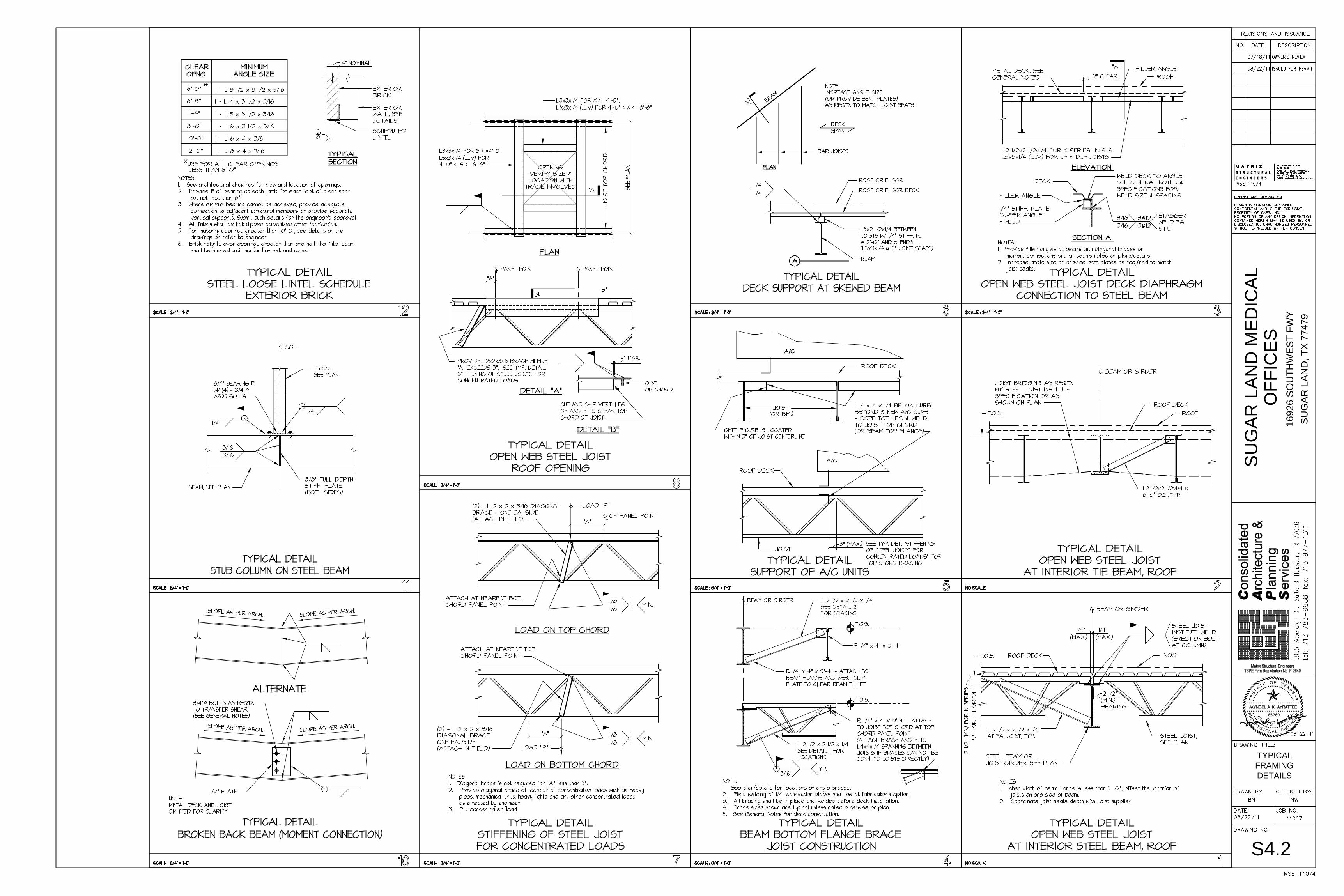
S4.1
TYPICALFRAMINGDETAILS
66260 RE
E
OR
P
DEE
R
SAXETFOETATS
NIGNELANOISSEF RETSIG
SUG
AR L
AND
MED
ICAL
SU
GA
R L
AND
, TX
7747
9
OFF
ICES
1692
6 S
OU
THW
EST
FW
Y
S4.2
TYPICALFRAMINGDETAILS
66260 RE
E
OR
P
DEE
R
SAXETFOETATS
NIGNELANOISSEF RETSIG
SUG
AR L
AND
MED
ICAL
SU
GA
R L
AND
, TX
7747
9
OFF
ICES
1692
6 S
OU
THW
EST
FW
Y
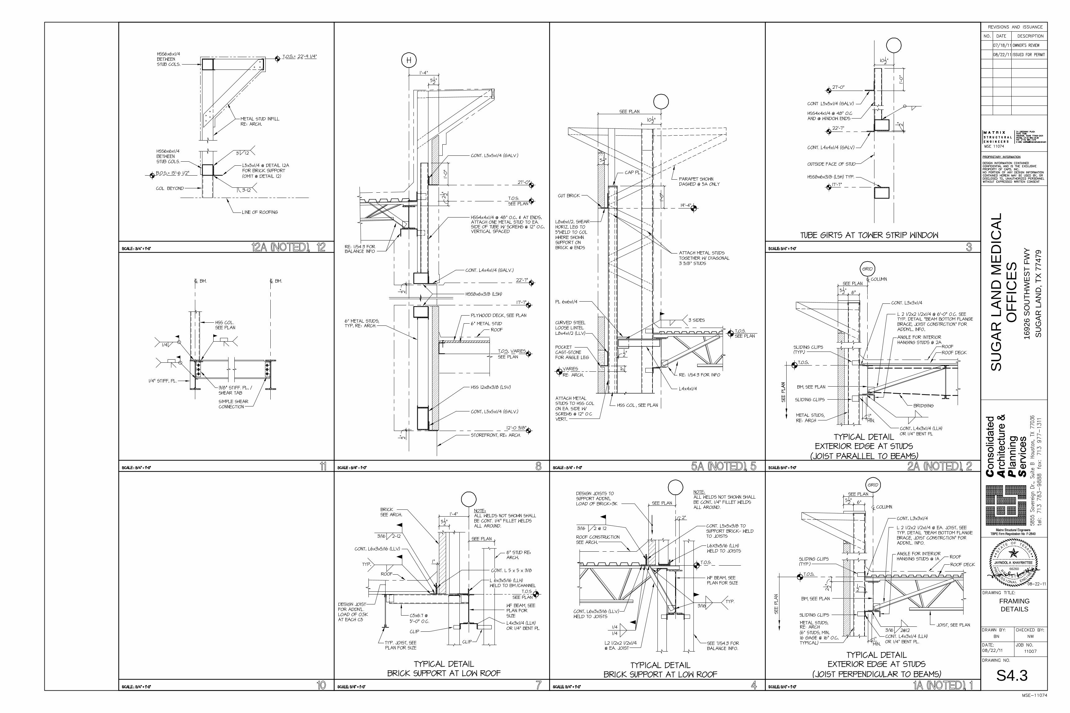
S4.3
FRAMINGDETAILS
66260 RE
E
OR
P
DEE
R
SAXETFOETATS
NIGNELANOISSEF RETSIG
SUG
AR L
AND
MED
ICAL
SU
GA
R L
AND
, TX
7747
9
OFF
ICES
1692
6 S
OU
THW
EST
FW
Y
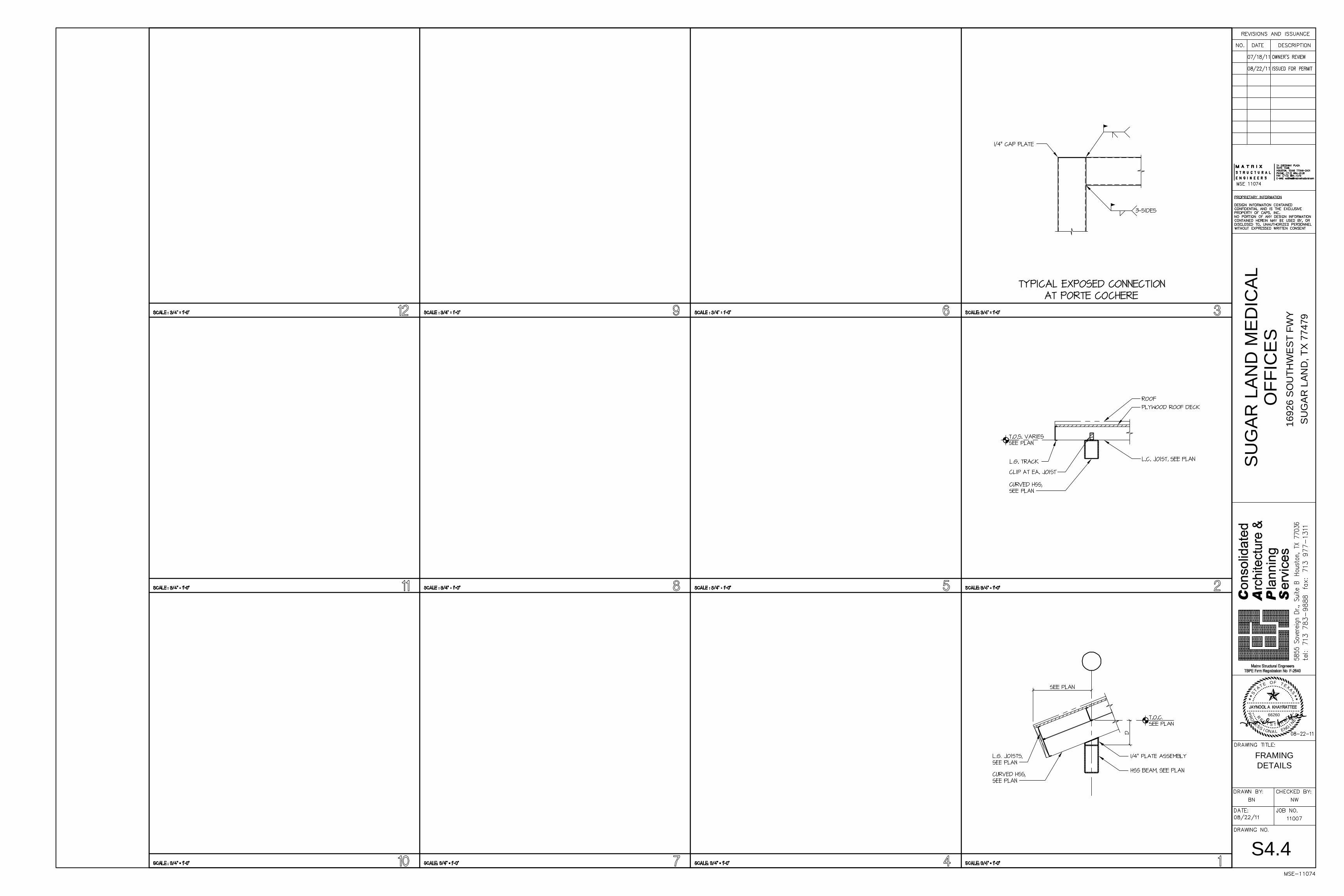
S4.4
FRAMINGDETAILS
66260 RE
E
OR
P
DEE
R
SAXETFOETATS
NIGNELANOISSEF RETSIG
SUG
AR L
AND
MED
ICAL
SU
GA
R L
AND
, TX
7747
9
OFF
ICES
1692
6 S
OU
THW
EST
FW
Y
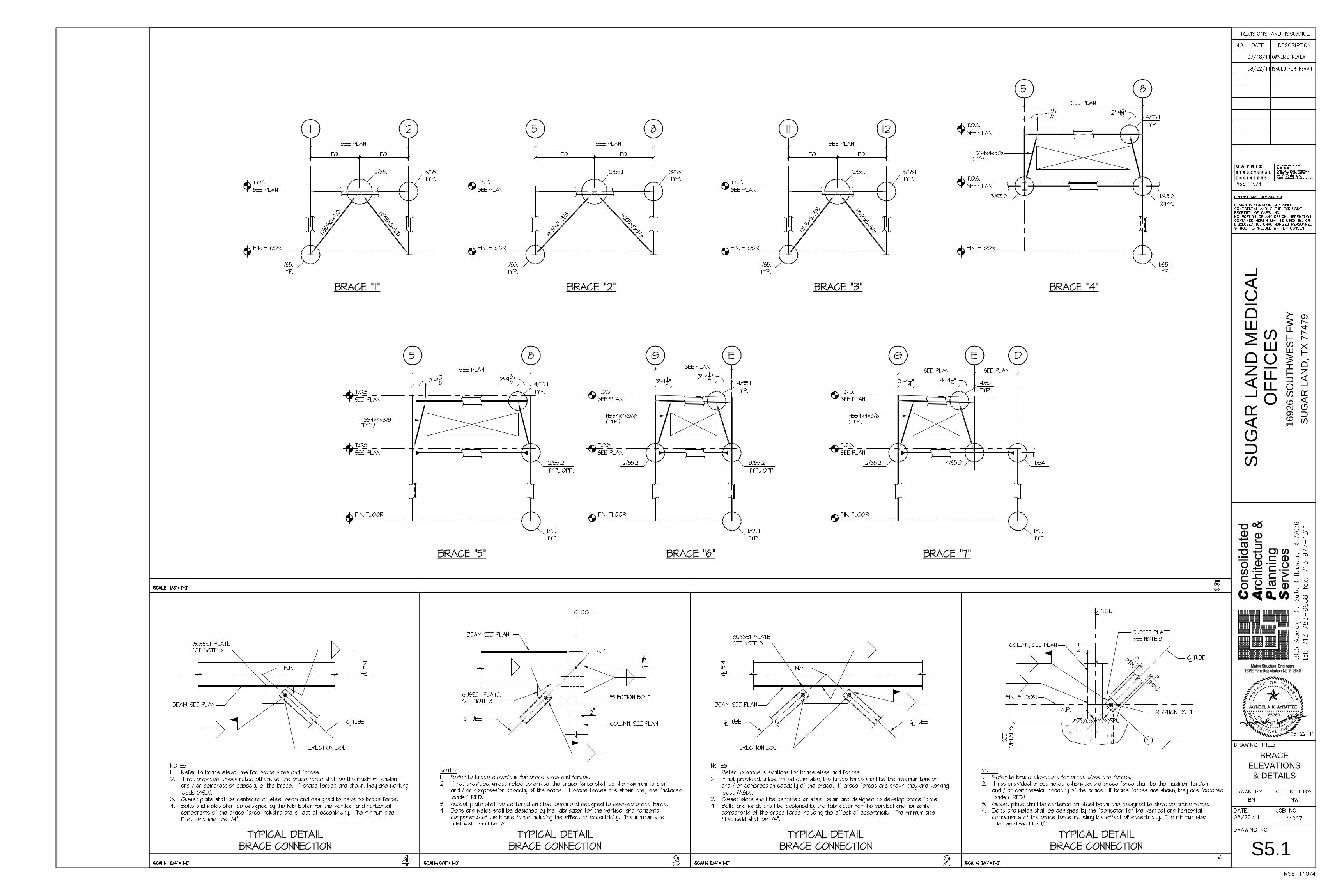
S5.1
BRACEELEVATIONS
& DETAILS
66260 RE
E
OR
P
DEE
R
SAXETFOETATS
NIGNELANOISSEF RETSIG
SUG
AR L
AND
MED
ICAL
SU
GA
R L
AND
, TX
7747
9
OFF
ICES
1692
6 S
OU
THW
EST
FW
Y
S5.2
BRACEELEVATIONS
& DETAILS
Related Documents