1 | Page CITY OF SUGAR LAND Design Standards JULY 2019

Welcome message from author
This document is posted to help you gain knowledge. Please leave a comment to let me know what you think about it! Share it to your friends and learn new things together.
Transcript

1 | P a g e
CITY OF SUGAR LAND
Design Standards
JULY 2019
2 | P a g e
TABLE OF CONTENTS
1.0 GENERAL AND PROCEDURAL REQUIREMENTS ........................................... 11
1.1 General .................................................................................................................... 11
1.1.1 Purpose ............................................................................................................. 11
1.1.2 Definitions ......................................................................................................... 11
1.1.3 Approval Required............................................................................................. 13
1.1.4 Construction Plans Required ............................................................................. 13
1.1.5 Compliance with City Ordinances Required ...................................................... 13
1.1.6 Compliance with Other Laws and Regulations .................................................. 14
1.1.7 Preliminary Meeting ........................................................................................... 14
1.1.8 Right-of-Way and Utility Service Coordination .................................................. 14
1.1.9 Capacity Allocations .......................................................................................... 15
1.2 Design Review Procedures for Public Infrastructure Projects .................................. 16
1.2.1. Initial Submittal / Final Submittal / Final Approval ............................................ 16
1.2.2. Approval Letters ............................................................................................... 16
1.2.2 Recording .......................................................................................................... 16
1.3 Construction Procedure Requirements for Public Infrastructure Projects ................ 16
1.3.1 Pre-Construction Meeting Required .................................................................. 16
1.3.2 Start of Construction .......................................................................................... 17
1.3.3 Construction Representation Required ............................................................. 17
1.3.4 Progress Notifications ....................................................................................... 17
1.3.5 Plan Revision Requests .................................................................................... 17
1.3.6 Record Drawings ............................................................................................... 18
1.3.7 Other Records ................................................................................................... 18
1.4 Approval and Acceptance of Public Infrastructure Projects ..................................... 18
1.4.1 Approval Required before placement in Service ............................................... 18
1.4.2 Initial Acceptance .............................................................................................. 18
1.4.3 Final Acceptance ............................................................................................... 19
1.5 Right-of-Way Use Permits ...................................................................................... 19
1.5.1 Right-of-Way Use Permit Requirements .......................................................... 19
3 | P a g e
1.5.2 Project Plans Required ..................................................................................... 19
1.5.3 Private Facilties ................................................................................................ 19
1.6 Easements ............................................................................................................. 19
1.7 Abandonment of Facilities ...................................................................................... 20
1.7.1 Mains ................................................................................................................ 20
1.7.2 Manholes .......................................................................................................... 20
1.7.3 Lift Stations ...................................................................................................... 20
1.7.4 Other Utility Facilities ........................................................................................ 20
1.8 Variances, Specific Approvals, and Approved Products List .................................. 20
1.8.1 Maintenance & Amendments ........................................................................... 20
1.8.2 Specific Approvals ............................................................................................ 21
1.8.3 Approved Products List .................................................................................... 22
2.0 CONSTRUCTION PLAN SHEETS AND GRAPHICS REQUIREMENTS ............ 23
2.1 Construction Plan Set ............................................................................................. 23
2.1.1 Required Sheets............................................................................................... 23
2.1.2 Sheets to be included as Applicable ................................................................. 23
2.2 Drawing Requirements ........................................................................................... 24
2.2.1 Drawing Size .................................................................................................... 24
2.2.2 Engineering Certification .................................................................................. 24
2.2.3 Standard Scales .............................................................................................. 24
2.2.4 Survey Control ................................................................................................. 25
2.2.5 Stationing ........................................................................................................ 25
2.2.6 North Arrow ..................................................................................................... 25
2.2.7 Legend Required ............................................................................................. 25
2.2.8 Property Boundaries Required ........................................................................ 25
2.2.9 City Standard Details ......................................................................................... 25
2.3 Features ................................................................................................................. 26
2.3.1 Roadways ........................................................................................................ 26
2.3.2 Utility Lines ...................................................................................................... 26
2.3.3 Ditches & Culverts ........................................................................................... 26
2.3.4 Natural Ground & Profiles ................................................................................ 27
4 | P a g e
2.3.5 Special Structures ........................................................................................... 27
2.4 Graphic Standards.................................................................................................. 27
2 . 4 . 1 Electronic Submittals .................................................................................... 27
2.4.2 City of Sugar Land AUTOCAD Drawing Layer Descriptions ............................ 28
3.0 GENERAL DESIGN REQUIREMENTS ............................................................... 30
3.1 Utility Locations ...................................................................................................... 30
3.2 Cement Stabilized Sand for Bedding and Backfill .................................................. 30
3.3 Private Facility Locations ........................................................................................ 30
3.4 Crossings ............................................................................................................... 31
3.4.1 Highway Crossings - All State and County Roads ........................................... 31
3.4.2 Crossings of City Streets ................................................................................. 31
3.4.3 Railroad and Pipeline Crossings ...................................................................... 32
3.4.4 Elevated Stream and Ditch Crossings ............................................................. 32
3.4.5 Underground Stream and Ditch Crossings ...................................................... 32
3.5 Construction Safety ................................................................................................ 33
3.6 Street Lighting ........................................................................................................ 33
3.7 Bench Marks .......................................................................................................... 33
3.8 Flood Plain ............................................................................................................. 34
3.9 Geotechnical Requirements ................................................................................... 34
3.9.1 Investigation Recommendations ...................................................................... 35
3.9.2 Other Requirements ........................................................................................ 35
3.9.3 Boring and Sampling Requirements ................................................................ 36
3.9.4 Laboratory Testing .......................................................................................... 37
3.9.5 Site Restoration ............................................................................................... 38
3.9.6 Abandonment of Borings and Piezometers ..................................................... 38
3.9.7 Geotechnical Report ........................................................................................ 39
4.0 WATER SYSTEM DESIGN REQUIREMENTS ................................................... 40
4.1 General ................................................................................................................... 40
4.2 Overall System Layout ........................................................................................... 40
4.3 Water Main Sizing and Materials ............................................................................ 41
4.3.1 Single Family Residential Areas ....................................................................... 41
5 | P a g e
4.3.2 Dead-End Mains .............................................................................................. 41
4.4 Location of Water Mains ......................................................................................... 42
4.5 Clearance of Water Lines from Other Utilities ........................................................ 42
4.5.1 Water Mains in proximity to New Utilities ......................................................... 43
4.5.2 Water Mains in Proximity to Existing Utilities ................................................... 43
4.6 Depth of Cover ....................................................................................................... 44
4.7 Valves ..................................................................................................................... 45
4.7.1 Valve Types ..................................................................................................... 45
4.7.2 Valve Spacing ................................................................................................. 45
4.7.3 Valve Location ................................................................................................. 45
4.8 Fire Hydrants .......................................................................................................... 46
4.8.1 Fire Hydrant Spacing ....................................................................................... 46
4.8.2 Fire Hydrant Locations..................................................................................... 46
4.9 Fittings and Appurtenances .................................................................................... 47
4.10 Water Line Offsets ................................................................................................ 48
4.11 Crossings .............................................................................................................. 48
4.12 Water Service Connections .................................................................................. 48
4.12.1 Water Service Connections in Single Family Residential Areas ...................... 48
4.12.2 Water Service Connections in Multi-Family Residential, Commercial, and Industrial Areas .......................................................................................................... 49
4.12.3 Fire Lines in Multi-Family Residential, Commercial, and Industrial Areas ..... 50
4.13 Additional Standards ............................................................................................. 51
4.13.1 Special Construction Features ........................................................................ 51
4.13.2 Bore & Jack Sections ...................................................................................... 51
4.13.3 Open Cuts ....................................................................................................... 52
4.13.4 Site Restoration ............................................................................................... 52
4.13.5 Barricades and Signs ...................................................................................... 52
4.14 Public Water Supply Wells and Potable Water Treatment Plant Requirements .... 52
4.14.2 Water Well Requirements ................................................................................ 54
4.14.3 Booster Pumps ................................................................................................ 55
4.14.4 Headers and Yard Piping ................................................................................. 56
6 | P a g e
4.14.5 Booster Pump Buildings .................................................................................. 59
4.14.6 Monitoring and Control Systems ..................................................................... 62
4.14.7 Hydropneumatic Tanks .................................................................................... 65
4.14.8 Potable Water Storage Tanks ......................................................................... 65
4.14.9 Emergency Power ........................................................................................... 70
4.14.10 Disinfection Systems .................................................................................... 70
4.14.11 Initial Water Plants ....................................................................................... 73
5.0 SANITARY SEWER DESIGN REQUIREMENTS ................................................ 74
5.1 General ................................................................................................................... 74
5.2 Sewer Design and Materials ................................................................................... 74
5.2.1 Minimum Size Criteria ..................................................................................... 74
5.2.2 Materials of Construction ................................................................................. 75
5.2.3 Location of Sanitary Sewers ............................................................................ 75
5.2.4 Design Requirements ...................................................................................... 75
5.3 LIFT STATIONS ..................................................................................................... 78
5.3.1 Engineering Report and Shop Drawings Required .......................................... 79
5.3.2 City Operation and Maintenance Acceptance ................................................. 79
5.3.3 Lift Station Design Criteria ............................................................................... 79
5.4 Service Connections ............................................................................................... 89
5.4.1 Single-Family Residential Lots ........................................................................ 89
5.4.2 Multi-Family Residential, Commercial, and Office Developments ..................... 90
5.4.3 Service Connections at Manholes ..................................................................... 90
5.5 Building Sites without Sanitary Sewer Service ....................................................... 91
6.0 DRAINAGE DESIGN REQUIREMENTS ............................................................. 91
6.1 General ................................................................................................................... 91
6.1.1 Definitions ......................................................................................................... 92
6.2 Storm Sewer Materials ........................................................................................... 96
6.3 Location of Storm Sewer ........................................................................................ 97
6.3.1 Public Street Right-of-Way ................................................................................ 97
6.3.2 Storm Sewer Easement .................................................................................... 98
6.3.3 Drainage Channel and Swale Easements ......................................................... 98
7 | P a g e
6.3.4 Utility Conflicts ................................................................................................... 98
6.4 Construction Plan Requirements ............................................................................. 98
6.4.1 Drainage Area Map .......................................................................................... 98
6.4.2 Other Requirements .......................................................................................... 99
6.5 Design Requirements ............................................................................................. 99
6.5.1 Pipe Requirements ............................................................................................ 99
6.5.2 Utility Clearance .............................................................................................. 100
6.5.3 Runoff Calculations ......................................................................................... 100
6.5.4 Storm Sewer Hydraulic Requirements ............................................................ 105
6.5.5 Roadside Ditch Hydraulic Requirements ........................................................ 107
6.5.6 Drainage Channel Hydraulic Requirements .................................................... 108
6.5.7 Bridges ........................................................................................................... 110
6.5.8 Commercial Parking/Paved Areas ................................................................... 110
6.6 Appurtenances ...................................................................................................... 110
6.6.1 Manholes ........................................................................................................ 110
6.6.2 Inlets ............................................................................................................... 110
6.6.3 Safety End Treatments (SET) ......................................................................... 111
6.7 Storm Water Detention Requirements ................................................................... 111
6.7.1 General Design Requirements ........................................................................ 111
6.7.2 Dry Detention Basin: ....................................................................................... 113
6.7.3 Wet Pond/Amenity Lake ................................................................................. 113
6.7.4 Detention Volume ............................................................................................ 114
6.7.5 Landscape Design Principles for Storm Water Detention Basins .................... 117
6.7.6 Calculation of Outlet Size ................................................................................ 181
6.7.7 Pumped Detention ...................................................................................... 181
7.0 ROADWAY DESIGN REQUIREMENTS ........................................................... 183
7.1 General .............................................................................................................. 183
7.2 Roadway Types ..................................................................................................... 183
7.3 Geometric Street Design Standards ...................................................................... 183
7.3.1 Vertical Curves ................................................................................................ 184
7.3.2 Sight Distances ............................................................................................... 184
8 | P a g e
7.3.3 Right-of-Way Clips .......................................................................................... 184
7.3.4 Horizontal Curvature ....................................................................................... 184
7.3.5 Obstruction Clearances ................................................................................... 185
7.3.6 Tangent Length ............................................................................................... 186
7.3.7 Intersections .................................................................................................... 186
7.3.8 Cul-de-sac bulbs ............................................................................................ 187
7.3.9 On Street Parking ........................................................................................... 188
7.4 Pavement Structure Requirements....................................................................... 188
7.5 Pavement Materials .............................................................................................. 190
7.6 Grading and Layout Requirements ....................................................................... 190
7.7 Traffic Control Devices ......................................................................................... 191
7.7.1 Traffic Signs (Ordinance No. 1148, Section 5, 1998) ..................................... 191
7.7.2 Pavement Markings ....................................................................................... 192
7.7.3 Multi-Way Stop Signs .................................................................................... 192
7.7.4 Traffic Signal System Design Guidelines....................................................... 192
7.8 Pedestrian and Bicycle Facilities .......................................................................... 198
7.8.1 Easements ..................................................................................................... 198
7.8.2 Sidewalks and Crosswalks ............................................................................ 199
7.8.3 Sidepaths and Shared Use Paths .................................................................. 199
7.8.4 Bike Lanes and On-street Facilities ............................................................... 199
7.9 Alleys .................................................................................................................... 200
7.10 Roundabout Design Standards ........................................................................... 201
7.10.1 Definitions ...................................................................................................... 201
7.10.2 Procedure for Design and Approval .............................................................. 202
7.10.3 Roundabout Operations ................................................................................ 205
7.10.4 Roundabout Planning ................................................................................... 207
7.10.5 Geometric Design ......................................................................................... 209
7.10.6 Signage and Pavement Markings ................................................................. 215
7.10.7 Bicycle and Pedestrian Access ..................................................................... 217
7.10.8 Landscaping, Drainage, and Visibility ........................................................... 219
7.11 Midblock Crossings ............................................................................................ 222
9 | P a g e
7.11.1 Definitions .................................................................................................... 222
7.11.2 Reference Documents .................................................................................. 224
7.11.3 Need for Midblock Crossings ....................................................................... 224
7.11.4 Midblock Crossing Design Considerations ................................................... 224
7.11.5 Midblock Crossing Treatments ...................................................................... 228
7.11.6 Midblock Crossing Design ............................................................................. 232
7.11.7 Selecting an Appropriate Midblock Crossing Treatment ................................ 235
8.0 SITE DEVELOPMENT REQUIREMENTS ......................................................... 236
8.1 General ................................................................................................................. 236
8.2 Building Slab Elevations ....................................................................................... 236
8.3 Water Service ....................................................................................................... 237
8.4 Sanitary Sewer Service ........................................................................................ 237
8.5 Site Drainage Requirements ................................................................................ 237
8.6 Electronic Submittal of Approved Site Plans ........................................................ 238
8.7 Fire Lanes ............................................................................................................ 238
9.0 GUIDELINES FOR BEST MANAGEMENT PRACTICES .................................. 239
9.1 General ................................................................................................................ 239
9.2 Definitions ............................................................................................................ 239
9.3 Erosion Control Requirements .......................................................................... 241
9.4 Best Management Practices ................................................................................. 242
9.5 Post-Construction Storm Water Management in New and Redevelopments ....... 245
9.6 Post-Construction Storm Water Maintenance and Record Retention ................... 246
10.0 LOW IMPACT DEVELOPMENT and GREEN INFRUSTRUCTURE DESIGN CRITERIA FOR STORM WATER MANAGEMENT ..................................................... 247
10.1 Background ......................................................................................................... 247
10.2 Approval Process and LID-based Projects ......................................................... 248
10.2.1 Acceptable LID Integrated Management Practices (IMP) ............................. 248
10.2.2 Acceptable LID Practices ............................................................................. 249
10.2.3 Pre-Project Meeting Requirements .............................................................. 250
10.2.4 Detention and Hydrograph Requirements .................................................... 250
10.3 LID IMP Design Criteria ..................................................................................... 252
10 | P a g e
10.3.1 Disconnection ............................................................................................... 252
10.3.2 Vegetated Filter Strip .................................................................................... 253
10.3.3 Vegetated Swale .......................................................................................... 255
10.3.4 Rainwater Harvesting ................................................................................... 256
10.3.5 Biorentention Systems ................................................................................. 257
10.3.6 Permeable Pavement ................................................................................... 268
10.3.7 Tree Box Filter .............................................................................................. 270
10.3.8 Storm Water Planter Box .............................................................................. 271
10.4 Specific Project Types ........................................................................................ 272
10.4.1 Roadways .................................................................................................... 272
10.4.2 Commercial Development ............................................................................ 273
10.5 LID Landscaping Design Considerations ............................................................ 273
10.5.1 Soil Amendment ........................................................................................... 274
10.5.2 Mulching ....................................................................................................... 275
10.5.3 Plant Species Selection ................................................................................ 275
10.6 Maintenance ....................................................................................................... 275
10.7 Putting LID into Practice ..................................................................................... 276
10.8 Construction ........................................................................................................ 276
10.8.1 Training ........................................................................................................ 277
10.8.2 Communication ............................................................................................ 277
10.8.3 Erosion and Sediment Control...................................................................... 277
10.8.4 Tree Protection ............................................................................................. 278
10.8.5 Construction Sequencing ............................................................................. 279
11.0 LID - Appendix A ............................................................................................... 280
12.0 LID – Appendix B – Maintenance Declaration ................................................... 287
13.0 LID – Appendix C - References ........................................................................ 290
14.0 LID – Appendix D - Resources .......................................................................... 291
15.0 LID – Appendix E - Acronyms ............................................................................ 292
16.0 LID – Appendix F – Geometric Design .............................................................. 293
City of Sugar Land Design Standards
11 | P a g e
1.0 GENERAL AND PROCEDURAL REQUIREMENTS
1.1 General
1.1.1 Purpose
These Standards describe the general requirements, procedures and technical
standards for the preparation of construction plans and supporting documents
required to gain project approval from the City of Sugar Land.
These Standards are intended to represent the minimum level of engineering practice required for projects in the City and provide a starting point for rational engineering design. The City Engineer may require specific design elements, in addition to those contained in these Standards, to address unique public safety or other issues at a specific project site.
1.1.2 Definitions
Unless specifically defined below, all words and terms used in this document carry
their commonly associated meanings relative to the context in which they are used.
When consistent with the context, words used in the present tense include the future,
words in the plural include the singular, words in the singular include the plural, and
terms expressing gender include the gender not stated.
Access Easement. An easement designated on the final plat which provides access
to platted tracts excepting single-family and Two-family Residential. The easement
shall be privately maintained.
City Engineer. The City official granted this title as defined in the Development Code
or their authorized representatives.
Collector Streets. Street routes that have short travel distances and collect traffic,
from inner-city streets and funnel it into arterials or other collector streets as identified
in the Master Thoroughfare plan or an approved TIA.
Commercial Driveway Approach. The portion of a driveway within the public right-
of-way that provides access to property on which an office, retail, commercial
center, or a building having more than three dwelling units is located or any driveway
approach which accesses property that is primarily used for a non-residential purpose.
Dead End Street. A street, other than a cul-de-sac, with only one outlet.

City of Sugar Land Design Standards
12 | P a g e
Dead-End Waterline. Any waterline having only one tie-in to another waterline.
Waterlines that loop and tie back into themselves are still considered dead end
waterlines.
Design Analysis. The narratives and calculations necessary to explain and support
a project design.
Design Engineer. The Professional Engineer in responsible charge of the design of
a public infrastructure or other project within the City or its ETJ.
Development. A planning or construction project involving substantial property and
usually including the subdivision of land and a change in land use character.
Development Review Coordinator. The City staff person responsible for accepting
and tracking plats, construction plans and other submittals related to the City’s
approval of a proposed project.
Drawings. Plan, profile, detail, and other graphic sheets to be used in a construction
contract which define the character and scope of the project.
Easement. This term shall mean an encumbrance on private property that entitles
an entity to specific uses and rights.
Final Plat. A map or drawing of a proposed subdivision prepared to meet all of the
requirements for approval by the Planning and Zoning Commission. Distances shall
be accurate to the nearest hundredth of a foot. The final plat of any lot, tract, or
parcel of land shall be recorded in the records of Fort Bend County, Texas. An
amended plat is also a final plat.
Pavement Width. The portion of a street available for vehicular traffic from back
of curb to back of curb.
Professional Engineer. An engineer currently licensed and in good standing with
the Texas Board of Professional Engineers.
Professional Land Surveyor. A surveyor currently registered and in good standing
with State of Texas Board of Professional Land Surveying.
Regulatory Entity. A regulatory entity is a state or local governmental entity whose
regulations or requirements may affect a project’s design and/or construction. These
entities may include but are not limited to Fort Bend County, water authorities, river
authorities, subsidence districts, levee districts, and municipal utility districts.
Review Authorities. The authorized representatives of the City’s departments,
divisions, or sections responsible for reviewing and approving calculations and
City of Sugar Land Design Standards
13 | P a g e
drawings for public infrastructure projects including design and construction contracts
with the City.
Specific Approval. A written approval from the City Engineer for a deviation from
these standards in the design and/or construction plans for a project within the City
or its extraterritorial jurisdiction.
1.1.3 Approval Required
Construction plans for projects within the City’s limits or extraterritorial jurisdiction shall
be approved by the City Engineer.
All approvals required in these Standards are the responsibility of the project owner.
Failure to obtain appropriate approvals may be grounds for suspension of construction
until appropriate approvals are granted.
1.1.4 Construction Plans Required
Construction plans for all infrastructure projects that connect to, affect or effect the
public infrastructure shall be approved by the City of Sugar Land as required by City
ordinance.
1.1.5 Compliance with City Ordinances Required
All projects that are required to conform to these Standards shall also be in compliance
with all applicable ordinances in the City. Projects should be reviewed for compliance
with the following list of ordinances as applicable:
A. Subdivision
B. Zoning
C. Flood Plain Management
D. Traffic Sign
E. Water and Sewer
It is the responsibility of the Design Engineer to review and determine the applicability
of City ordinances to the project. It is the responsibility of the City Engineer to review
the project and advise the Design Engineer of non-compliance with applicable City
ordinances and these Standards. The City Engineer has the discretion to require

City of Sugar Land Design Standards
14 | P a g e
compliance with any existing City ordinance before approving the project’s
construction plans.
1.1.6 Compliance with Other Laws and Regulations
All construction plans and supporting documentation shall conform to the
requirements of these Standards and the regulations of all Federal, State, County, and
Local entities having jurisdiction.
1.1.7 Preliminary Meeting
The Development Review Committee and City staff will make themselves available
for a preliminary meeting to discuss a proposed project with the Design Engineer
and owner. This preliminary meeting may be scheduled with the Development
Review Coordinator prior to submittal of any documents for review. The purpose of
this meeting is to discuss the project concepts and to establish the status of
requirements and issues that may be pertinent to the project. A preliminary meeting
is not required.
1.1.8 Right-of-Way and Utility Service Coordination
The Design Engineer is responsible for researching all right-of-way utility service providers with an interest in the project site. The Design Engineer or owner is responsible for proper coordination with each utility service provider with an interest in the project site. All rights of way and utility service easements must be properly reflected on plats and construction plans. Rights of way holders and utility service providers at a project site may include, but not be limited to, the following entities:
A. City of Sugar Land
B. Fort Bend County Engineer
C. Fort Bend County Drainage District
D. Texas Department of Transportation
E. Telephone / communication companies
F. Center Point Energy (electric and gas)
G. Reliant Energy
H. Municipal Utility Districts
I. Levee Improvement Districts

City of Sugar Land Design Standards
15 | P a g e
J. Cable television companies
K. Railroad companies
L. Pipeline companies
1.1.9 Capacity Allocations
1.1.9.1 Water and Wastewater Services
The owner or Design Engineer will notify the City of a development’s water and wastewater capacity requirements, expressed in equivalent single-family connections (ESFC). If the City determines that a development’s capacity requirements will have a significant impact on the City’s water or wastewater system, the City may require the owner to do additional analysis of those impacts to determine if mitigation measures are necessary. Alternatively, the owner will reimburse the City for its costs associated with having the City’s consultant calculate the impact. Mitigation will be required in order for the City to maintain adequate levels of water or wastewater service, including flow rates, pressure, and other service characteristics, or to comply with the City’s regulations, City master plans, or other governmental laws and regulations. The required additional analysis may include running hydraulic models or determining the impact to the downstream sanitary system from increased flows, as required by the City. Implementation of the mitigation measures will be the responsibility of the owner.
1.1.9.2 Drainage
Prior to beginning construction of a project, a current commitment of drainage capacity for the proposed development, including the status of any drainage fees that may be due or have been paid, will be required. The commitment shall be issued by the Fort Bend County Drainage District (projects within the ETJ) or the City and a copy must be furnished to the City Engineer.
1.1.9.3 Traffic Impact Analysis
The City may require trip estimates for proposed development. The trip estimates shall be based on the latest version of the Institute of Transportation Engineers’ “TRIP GENERATION MANUAL”. If the trip estimates exceed the th resho ld during peak hours, the City may require a traffic impact analysis to determine necessary traffic mitigation measures to maintain the required intersection level of service. The City may also require a traffic impact analysis if the City Engineer determines that one is justified by special conditions. See the City’s Traffic Impact Analysis Guidelines.

City of Sugar Land Design Standards
16 | P a g e
1.2 Design Review Procedures for Public Infrastructure Projects
1.2.1. Initial Submittal / Final Submittal / Final Approval
Submit construction plans and supporting documentation to the Development Review Coordinator for review. Plans will be circulated to appropriate Departments and comments will be returned to the Design Engineer per the Development Review process. Initial submittal, final submittal, and final approval will be coordinated through the Development Review Coordinator.
1.2.2. Approval Letters
1.2.2.1 Utilities
Submit approval letters for all plats from all public and private utilities and other entities affected by the project. The approval letter shall state that service will be available to the project, where appropriate, and that there is no objection to the project. It is the responsibility of the design engineer to coordinate with public and private utilities to address conflicts with existing utilities.
1.2.2.2 Government Agencies
Confirmation in writing of preliminary approval by the Fort Bend County Engineer, the Fort Bend County Drainage District Engineer and any other affected agency shall be provided to the City, when a facility is within the City’s ETJ or infrastructure within the City’s ETJ. Other government agencies may be required such as Federal Aviation Administration (FAA), TxDOT Aviation, or as applicable.
1.2.2 Recording
All separate or special easements that may be required for construction shall be recorded in the Fort Bend County Official Records, subject to the surety clause requirements of the City of Sugar Land’s Development Code Subdivision Regulations.
1.3 Construction Procedure Requirements for Public Infrastructure Projects
1.3.1 Pre-Construction Meeting Required
Prior to the start of construction, a pre-construction meeting must be conducted for each project. The Design Engineer must request that the City schedule a pre-construction meeting. The City will conduct the pre-construction meeting within 5
City of Sugar Land Design Standards
17 | P a g e
working days of the request. A City representative must attend the pre-construction meeting.
1.3.2 Start of Construction
Construction shall not begin until construction plans are signed by the City of Sugar Land. Construction shall not begin within an existing easement or right-of-way until all permits and/or any right-of-way use agreements are negotiated between the parties.
The Design Engineer or contractor shall notify the City at least forty-eight (48) hours prior to beginning construction. The City will make periodic inspections of the construction.
1.3.3 Construction Representation Required
Full time construction representation by the Design Engineering firm or its project team shall be provided during construction of public utilities in accordance with the requirements of the creation ordinance for any utility district.
1.3.4 Progress Notifications
The City shall be notified at least one City working day or twenty-four (24) hours, whichever is earlier, prior to each time concrete is placed on the project, all pipe/manhole inspection tests, bacteriological tests and other tests including sub-grade and concrete, that may be required.
The City shall be notified at least forty-eight (48) hours or two city working days, whichever is earlier, prior to initial and final inspection of the project. The City staff will be present during all initial and final inspections.
1.3.5 Plan Revision Requests
Design changes from approved construction plans shall be approved by the City Engineer (or designee). The Design Engineer will submit plan revision requests in writing to the Development Review Coordinator. In lieu of this process, the City Engineer may, at discretion, allow plan revisions to be reflected on record drawings.
City of Sugar Land Design Standards
18 | P a g e
1.3.6 Record Drawings
Coordinate submittal of record drawings and acceptance of public infrastructure through the Engineering Department to ensure the information in the Acceptance Package check list is provided.
1.3.7 Other Records
For all projects, all delivery tickets for all materials (e.g., concrete, cement stabilized sand) shall be maintained by the contractor and shall be made available for review by the City. These delivery tickets shall be maintained for a minimum of one year from initial acceptance of the project.
1.4 Approval and Acceptance of Public Infrastructure Projects
1.4.1 Approval Required before placement in Service
Public Infrastructure projects shall have received final approval of the City prior to placing any project facilities in service for use by public.
1.4.2 Initial Acceptance
Initial acceptance by the City shall be granted in writing when the following items are complete:
A. Construction is completed in accordance with the approved construction plans and the outstanding punch list items have been completed;
B. Follow-up inspections of all public infrastructures shall be scheduled within 60 days of the initial inspection. A complete re-inspection and a new punch list may be required after the sixty (60) day period.
C. All record drawings in the specified GIS, PDF and DWG (AutoCAD) Exchange) format as specified in Section 2.4.2, has been submitted to the City and the Design Engineer has certified the record drawings are complete and correct;
D. All bond requirements, as detailed in 1.4.3, for the project have been met and copies of the bonds have been provided to the City;
E. All other public entities having jurisdiction over the project have given their approval of the project with copies of the approvals provided to the City, and
F. The City has received a certification from the Design Engineer that all materials installed in the project are complete in place in accordance with approved plans and specifications.
City of Sugar Land Design Standards
19 | P a g e
G. The City has received the final cost documentation including all bid component and field changes.
1.4.3 Final Acceptance
Public infrastructure projects within the City of Sugar Land and extraterritorial jurisdiction will be subject to a minimum one (1) year maintenance period. An inspection prior to the end of this maintenance period will be scheduled and conducted by the City and all other entities having jurisdiction. The developer must furnish a street light layout to the City as a condition for final acceptance. All facilities, including street lighting, shall be operational and in good condition at the time of this inspection.
The City will grant final acceptance to a project in writing after this inspection and all punch list items identified in the inspection are completed.
1.5 Right-of-Way Use Permits
1.5.1 Right-of-Way Use Permit Requirements
The requirements for Right-of-Way use permits are outlined in the City of Sugar Land’s Code of Ordinances.
1.5.2 Project Plans Required
The owner or authorized agent shall submit project plans and supporting documents in order to receive a Right-of-Way use permit. The owner of a project shall be responsible for location of all facilities in the area of construction. The Right-of-Way use permit will specify the requirements during and after construction.
1.5.3 Private Facilities
Private facilities permitted within a public Right-of-Way shall be the maintenance
responsibility of the private entity. If private facilities are not maintained in good order, the
permit shall be void and the facilities shall be removed at the expense of the private entity.
Upon request of the City of Sugar Land, or entity having jurisdiction, facilities shall be
removed, relocated or replaced at no cost to the City of Sugar Land.
1.6 Easements
Minimum easement requirements are set for in the Sugar Land Development Code Subdivision Regulations.
City of Sugar Land Design Standards
20 | P a g e
1.7 Abandonment of Facilities
If a new project will abandon existing facilities, the plans shall provide for the appropriate abandonment of these facilities.
1.7.1 Mains
Abandonment of utility mains in private easements shall consist of filling the main with grout or slurry. The grout or slurry must be capable of being pumped into place. The construction plans shall include details of the method proposed for abandoning all other mains.
1.7.2 Manholes
All abandoned manholes shall be removed to a level not less than four feet below grade. All inlets and outlets shall be securely plugged and the structure filled with stabilized sand.
1.7.3 Lift Stations
Lift stations shall be abandoned by removal of all pumps, motors, couplings, valves, and controls from the dry well and all appurtenances above finished grade. Both the wet well and dry well shall be cut down five feet below grade, filled with cement stabilized sand, and covered with top soil to grade. The associated force main shall be properly abandoned, including cutting and plugging both ends and grouting the main. The lift station site shall be re-vegetated.
1.7.4 Other Utility Facilities
All other utility facilities to be abandoned shall be noted on the construction plans and the procedures for abandonment included in the Construction notes.
1.8 Variances, Specific Approvals, and Approved Products List
1.8.1 Maintenance & Amendments
These Design Standards shall be maintained, amended, and kept current by the City Engineer in accordance with the requirements of the Sugar Land Development Code Subdivision Regulations.

City of Sugar Land Design Standards
21 | P a g e
1.8.2 Specific Approvals
Plans that do not conform to the requirements of these Standards shall not be approved without first obtaining a Specific Approval for each deviation. Specific Approvals must be approved by both the City Engineer and the City Manager.
Requests for Specific Approvals shall be submitted to the City Engineer in a detailed written request and shall only be authorized in writing. A request for Specific Approval shall be submitted with the project plans and must include sufficient supporting documentation to allow the City Engineer to make a well-informed decision. If additional information is needed, the City Engineer will inform the Applicant or Design Engineer of the additional information required, and may require such additional information or data to be signed and sealed by a Registered Professional Engineer to support the request, if necessary. The City Engineer will have fifteen (15) business days to respond to the applicant’s request, either with a decision on the merits of the request, a request for more information, or a notice detailing when action will be taken on the applicant’s request.
The City Engineer shall evaluate each request in accordance to the following criteria:
A. The performance of the proposed design is equal to or better than the design required by the Design Standards.
B. The performance of the proposed design requested for Specific Approval accomplishes the intent of the Design Standards.
C. The Specific Approval must be consistent with current engineering best practices; and
D. The Specific Approval will not be detrimental to the public safety.
After review, the City Engineer will issue a Letter of Specific Approval or a letter of denial for each Specific Approval request.
An applicant may appeal the determination of the City Engineer to the Executive Director of Community Development. All appeals must be prepared and sealed by a Professional Engineer Registered with the Texas Board of Professional Engineers. The Executive Director can either uphold the determination of the City Engineer or may require the City Engineer to reconsider the determination in light of specific points raised by the Executive Director. Decisions of the Executive Director can be appealed to the City Manager in the same manner as appeals from the City Engineer. The City Manager's determination is final. When considering an appeal, the Executive Director or City Manager will each have fifteen (15) business days to respond to the applicant’s request, either with a decision on the merits of the request, a request for more information, or a notice detailing when action will be taken on the applicant’s request.
Construction work related to any Specific Approval item shall not begin until the City has granted approval in writing. Any work that proceeds without a written Specific
City of Sugar Land Design Standards
22 | P a g e
Approval will be subject to removal and replacement in accordance with these Standards.
1.8.3 Approved Products List
The City Engineering Department will maintain an Approved Products List. The Approved Products List will contain materials and manufactured items that have received prior Specific Approval for use in construction of a project. Items not appearing on the Approved Products List shall not be used for construction of projects within the City or its extraterritorial jurisdiction without a Specific Approval unique to that project.
The Approved Products List may be expanded to include additional items at the discretion of the City Engineer.
New products proposed for approval shall be locally available from a reputable supplier. A complete submittal of information regarding the proposed approved product and samples of the product shall be submitted to the City Engineer for review. The City Engineer and Public Works Department will review the product information and make a determination on inclusion of the proposed product. If recommended for inclusion, the final approval of the product for inclusion on the Approved Products List will be granted by the City Engineer.
City of Sugar Land Design Standards
23 | P a g e
2.0 CONSTRUCTION PLAN SHEETS AND GRAPHICS REQUIREMENTS
2.1 Construction Plan Set
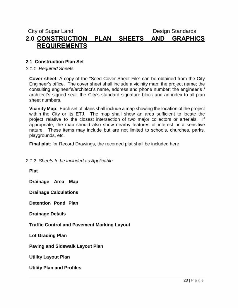
2.1.1 Required Sheets
Cover sheet: A copy of the “Seed Cover Sheet File” can be obtained from the City Engineer’s office. The cover sheet shall include a vicinity map; the project name; the consulting engineer’s/architect’s name, address and phone number; the engineer’s / architect’s signed seal; the City’s standard signature block and an index to all plan sheet numbers.
Vicinity Map: Each set of plans shall include a map showing the location of the project within the City or its ETJ. The map shall show an area sufficient to locate the project relative to the closest intersection of two major collectors or arterials. If appropriate, the map should also show nearby features of interest or a sensitive nature. These items may include but are not limited to schools, churches, parks, playgrounds, etc.
Final plat: for Record Drawings, the recorded plat shall be included here.
2.1.2 Sheets to be included as Applicable
Plat Drainage Area Map
Drainage Calculations
Detention Pond Plan
Drainage Details
Traffic Control and Pavement Marking Layout Lot Grading Plan Paving and Sidewalk Layout Plan Utility Layout Plan Utility Plan and Profiles

City of Sugar Land Design Standards
24 | P a g e
Erosion Control Plan Specific Construction Details
Key Drawings: In addition to plan and profile sheets, each set of construction drawings should include paving and utility key drawings indexing specific plan and profile sheets if the project is of sufficient size.
2.2 Drawing Requirements
2.2.1 Drawing Size
Drawing sizes shall conform to the requirements outlined in the Development Review process. Coordinate with Engineering Department prior to submitting plans.
2.2.2 Engineering Certification
The seal, date, and original signature of the Design Engineer responsible for preparation of the plans is required on each sheet in accordance with the rules and regulations of the Texas State Board of Professional Engineers. The engineer’s certification must be in accordance with the rules and in a format that will reproduce on prints.
2.2.3 Standard Scales
The standard scales permitted for plans and profiles are as follows: A. Arterials or Collectors or special intersections/ situations:
A. Arterials: 1" = 4' Vertical; 1" = 40' Horizontal
B. Collectors:
(a 1” = 2’ Vertical; 1” = 20’ Horizontal scale may be required by the City to show sufficient detail).
C. Minor streets and utility projects: 1" = 5' Vertical; 1" = 50' Horizontal or 1" = 4' Vertical; 1" = 40' Horizontal
D. Key Drawings (Index Layouts):
1" = 100' or 1" = 200' (Horizontal)
The scales described above are the minimum allowable. Larger scales may be used to show details of construction as required or approved. Deviations to these
City of Sugar Land Design Standards
25 | P a g e
scales must receive Specific Approval of the City Engineer.
2.2.4 Survey Control
At a minimum, a bench mark elevation and description is required on each plan and/or profile sheet to indicate the ability to maintain appropriate spatial control of the work. Owners/Design Engineers shall utilize GPS Technology (survey grade GPS) to acquire permanent benchmarks for all development. See City of Sugar Land website for Geodetic Network Information.
2.2.5 Stationing
Stationing must run from left to right except for short streets or lines originating from a major intersection where the full length can be shown on one sheet. Do not place match lines in intersections.
2.2.6 North Arrow
A north arrow is required on all plan sheets and shall be oriented either upward or to the right.
2.2.7 Legend Required
All plans shall include a legend describing standard symbols.
2.2.8 Property Boundaries Required
All property ownership and easement information must be shown on the construction plans. When ownership, easement, and right-of-way recording information is not shown on the plat included in the plans, this information will be shown on the construction plan sheets. Show all lot lines, property lines, right-of-way lines, and easement lines for all easements, existing and proposed.
2.2.9 City Standard Details
Standard City details shall be used for all applicable situations unless a Specific Approval or Variance is approved by the City Engineer.
City of Sugar Land Design Standards
26 | P a g e
2.3 Features
2.3.1 Roadways
If a roadway exists where plans are being prepared to improve or construct new pavement or to construct a utility, this roadway shall be labeled as to its existing width, type of surfacing, and base thickness, if available.
Roadway plans shall be drawn to accurate scale and show proposed pavement typical cross- sections and details, lines and grades, and all existing topography within the street right-of-way. At intersections, the cross street shall be shown for a sufficient distance in each direction along the cross street to depict the design of adequate street crossings.
Grades shall be labeled for the top of curb except at railroad crossings. Curb return elevations and grades for turnouts shall show in the profile.
Gutter elevations are required for vertical curves where a railroad track is being crossed.
The surface elevation at the property line of all existing driveways shall be shown in the profile. Station all esplanade noses affected by proposed construction, both existing and proposed. Stationing shall be provided for all points of curvature, points of tangency, radius returns and grade change points of intersection in the plan view. Additionally, stationing shall be provided for all radius returns and grade change points of intersection in the profile view. The elevations of all stationed points must also be provided in the profile view.
2.3.2 Utility Lines
All utility lines four inches (4") in diameter or larger within the right-of-way or construction easement shall be shown in the profile view. All utility lines, regardless of size, shall be shown in the plan view. Resolve all known conflicts of proposed utilities with existing utilities.
2.3.3 Ditches & Culverts
Show flow line elevations and direction of flow of all existing ditches and related driveway culverts.
City of Sugar Land Design Standards
27 | P a g e
2.3.4 Natural Ground & Profiles
Show natural ground profiles along the centerline of each right-of-way or easement line except as required below. When there is a difference of 0.50 feet or more from one right-of-way or easement line to the other, show dual right-of-way profiles.
2.3.5 Special Structures
Details of special structures not covered by approved Standard Details, such as stream and gully crossings, shall be submitted in advance to the Engineering Department for approval. Once approved, special structures shall be detailed and noted on the plans.
2.4 Graphic Standards
The graphic standards for the City of Sugar Land are described in this section. Additional more detailed information related to the graphic standards can be found in Appendix A.
2 . 4 . 1 Electronic Submittals
The City requires electronic submittals of all project plans and plats. All electronic submittals are to be provided electronically and comply with the following:
A. GIS FORMAT:
GIS submittal shall be in the format being used by the City’s Information Technology (IT) Department at the time of submission, including all attribute fields. Contact the City of Sugar Land Engineering Department for current GIS format requirements.
B. PDF FORMAT:
PDF image submittal shall be in full size, 300 dpi image. Contact the City of Sugar Land Engineering Department for current PDF format requirements.
C. AUTOCAD FORMAT:
1. Drawings are to be provided in AutoCAD drawing (.dwg)
2. Data Layers shall be structured as outlined in the City’s Drawing Layer Descriptions (Section 2.4.2). Each layer shall only include line work and text pertaining to that layer. Files not structured as requested will not be accepted.
3. All data shall be provided in true scale (1:1 ratio)
4. All data shall be geo-referenced using either benchmarks or GPS points within the data.
5. All coordinate data shall be in Texas South Central Zone (4204), State Plane, North American Datum 1983, survey feet.
City of Sugar Land Design Standards
28 | P a g e
6. Reference Section 3.7 for vertical datum requirements.
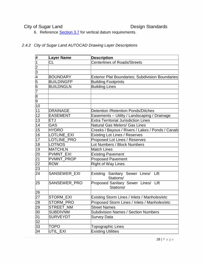
2.4.2 City of Sugar Land AUTOCAD Drawing Layer Descriptions
# Layer Name Description 1 CL Centerlines of Roads/Streets
2
3
4 BOUNDARY Exterior Plat Boundaries; Subdivision Boundaries
5 BUILDINGFP Building Footprints
6 BUILDNGLN Building Lines
7
8
9 10
11 DRAINAGE Detention /Retention Ponds/Ditches
12 EASEMENT Easements – Utility / Landscaping / Drainage
13 ETJ Extra Territorial Jurisdiction Lines
14 GAS Natural Gas Meters/ Gas Lines
15 HYDRO Creeks / Bayous / Rivers / Lakes / Ponds / Canals
16 LOTLINE_EXI Existing Lot Lines / Reserves
17 LOTLINE_PRO Proposed Lot Lines / Reserves
18 LOTNOS Lot Numbers / Block Numbers
19 MATCHLN Match Lines
20 PVMNT_EXI Existing Pavement
21 PVMNT_PROP Proposed Pavement
22 ROW Right of Way Lines
23
24 SANSEWER_EXI Existing Sanitary Sewer Lines/ Lift Stations/ Stacks/Manholes/etc 25 SANSEWER_PRO Proposed Sanitary Sewer Lines/ Lift Stations/ Stacks/Manholes/etc 26
27 STORM_EXI Existing Storm Lines / Inlets / Manholes/etc
28 STORM_PRO Proposed Storm Lines / Inlets / Manholes/etc
29 STREET_NM Street Names
30 SUBDIVNM Subdivision Names / Section Numbers
31 SURVEYDT Survey Data
32
33 TOPO Topographic Lines
34 UTIL_EXI Existing Utilities

City of Sugar Land Design Standards
29 | P a g e
35 UTIL_PROP Proposed Utilities
36 WATER_EXI Existing Water Lines /Hydrants / Valves /T’s/etc
37 WATER_PRO Proposed Water Lines /Hydrants / Valves /T’s/etc
City of Sugar Land Design Standards
30 | P a g e
3.0 GENERAL DESIGN REQUIREMENTS
3.1 Utility Locations
All utilities shall be underground with the exception of electric primary lines. The electric primary lines (defined as feeders or three phase lines) shall be located around the subdivision perimeter whenever possible. See Chapters 4, 5, and 6 for detailed design standards related to Water, Sanitary Sewer, and Drainage utilities.
3.2 Cement Stabilized Sand for Bedding and Backfill
Cement Stabilized Sand that complies with the following is to be used for bedding and backfill of utility lines within the City. The Sand must:
A. Be Portland Cement, Type I, ASTM C150.
B. Be clean, durable sand, with less than 0.5 percent clay lumps, ASTM C142; with less than 0.5 percent lightweight pieces, ASTM C123; with organic impurities, ASTM C40, and a plasticity index of less than six (6) when tested in accordance with ASTM D423 and ASTM D424.
C. Compact to ninety-five percent (95%) Standard Proctor Density (ASTM D2922-78 and ASTM D3017-78) in lifts of eight inches (8") thick. Actual testing may be required by the City Engineer.
D. Consist of at least one and one-half (1-1/2) sacks of cement per cubic yard of sand. The cement-sand mixture shall have a minimum unconfined compressive strength of one hundred pounds per square inch (100 psi) in forty-eight (48) hours, when compacted to ninety-five percent (95%) of Standard Proctor Density (ASTM D2922-78 and ASTM D3017-78), without additional moisture control, cured and tested in accordance with ASTM C31.
3.3 Private Facility Locations
Private facilities shall not conflict with other facilities in the right-of-way and must be permitted in accordance with 1.5.1
All private facilities in the right-of-way shall be located at least two feet (2') behind the curb and all underground facilities in the right-of-way shall be located at least two and one-half feet (2.5') below the top of curb on a public street. Landscape irrigation facilities may be located a minimum of twelve inches (12”) below the top of curb.
Landscaping within the public right-of-way or adjoining easements shall not affect public utilities or traffic visibility.
City of Sugar Land Design Standards
31 | P a g e
3.4 Crossings
3.4.1 Highway Crossings - All State and County Roads
State Highway crossings shall be constructed in conformance with the requirements of the Texas Department of Transportation.
All utilities, except storm sewers, shall be encased in a steel pipe casing extending at least five feet (5') from the outside edge of each service road or outside edge of pavement, across the right- of-way to a similar location on the other side of the highway. For highway or roadway crossings with open ditches, the casings shall extend from right-of-way to right-of-way.
Where additional right-of-way has been acquired or will be required for future widening, the casing, where required, shall be carried to within ten feet (10') of each future right-of-way line.
3.4.2 Crossings of City Streets
All pressurized utility crossings must be encased under the following conditions:
Bored under any existing roadway.
Crossing under a new street classified as an arterial or greater.
The encasement shall be a minimum of PVC pipe, SDR 26, as shown on the City of Sugar Land Standard Details. Welded steel pipe may be substituted by Specific Approval.
Crossings under existing concrete streets, other than arterials or larger, shall be constructed by boring and jacking. PVC pipe shall be jacked into place using equipment designed for that purpose. Water may be used to facilitate the boring and jacking operations. Jetting the pipe main into place will not be permitted. Flowable fill should be utilized to fill any annular space between the casing and the native material.
When conditions warrant an open cut across an existing street, a Specific Approval for the open cut is required. All open cut installations under existing or proposed streets shall be backfilled in accordance with the City’s Standard Details. The cement stabilized sand backfill shall meet the requirements of Section 3.2.
Bore, Jack, and Tunnel procedures and operations shall be in accordance with the Texas Department of Transportation’s current Standard Specification.
City of Sugar Land Design Standards
32 | P a g e
3.4.3 Railroad and Pipeline Crossings
All utility railroad and pipeline crossings shall have the approval of the easement holder and the pipeline or railroad owner if not the same. All crossings shall be designed in accordance with any design conditions contained in the applicable approvals. Copies of the approvals are to be submitted with the construction plans in accordance with Section 1.2.2.1.
3.4.4 Elevated Stream and Ditch Crossings
All elevated utility stream and ditch crossings shall be steel pipe and extend a minimum of fifteen feet (15') beyond the last bend or to the right-of-way line, whichever is greater. The Design Engineer must perform hydraulic calculations to prove that the crossing does not increase the water surface elevation of the stream or ditch.
Elevated support structures must be located a minimum of ten feet (10') from any existing or proposed structure. Supporting lines on existing or proposed bridges is acceptable if it is demonstrated that adequate structural capacity and sufficient clearance exists for installation under the bridge.
Design elevated crossings with the elevation of the bottom of the line above the low chord of the nearest adjacent bridge or a minimum one and one-half feet (1-1/2') above the 100-Year Flood Plain elevation, whichever is greater. When crossing a ditch, approval letters from the controlling authority must be obtained and submitted in accordance with Section 1.2.2.1.
All elevated crossings shall include air release valves, at the highest point of the line, and pedestrian pipe guards. The Design Engineer shall provide sufficient span length to accommodate the cross section of future widening of the stream or ditch, if information on ultimate design is available. For separate line support structures, support the line on columns spaced to accommodate the structural capacity of the pipeline considering deflection and loading. The column support design must consider at least the following factors soil bearing capacity, column spacing, and dead and live loadings. The Design Engineer must submit the design calculations for support columns and their spacing.
3.4.5 Underground Stream and Ditch Crossings
All underground stream and ditch crossings require a Specific Approval. At underground crossings, provide a minimum five (5') feet of clearance above the top of the pipe to the ultimate flow line of the ditch. The crossing shall have a sufficient cased length to accommodate the ultimate future development of the stream or ditch. All lines shall be approved material with all joints mechanically restrained and shall
City of Sugar Land Design Standards
33 | P a g e
extend a minimum of fifteen feet (15') beyond the last bend or to the right-of-way line, whichever is greater.
3.5 Construction Safety
All construction within the City and its extraterritorial jurisdiction shall conform to the latest revision of all applicable OSHA regulations.
3.6 Street Lighting
A. The installation of street lighting is required by the Sugar Land Development Code, Sec. 5-35(b)(4)
B. The location of street lights will be designed by Center Point Energy and reviewed and approved by the City of Sugar Land.
C. Private lighting systems are not permitted within the City of Sugar Land and its extraterritorial jurisdiction
D. Street lights shall be designed in accordance with the requirements set out in Appendix E.
3.7 Bench Marks
An iron rod benchmark shall be placed within every subdivision that is less than five (5) acres in size with X and Y coordinates (3rd order or better). An existing National Geodetic monument shall be identified as a reference point. If there is an existing rod which meets these requirements, that rod may be used to satisfy this design requirement.
A permanent benchmark shall be set in every subdivision five (5) acres in size or greater with X, Y and Z coordinates. Every effort shall be made to create the monument such that it can be GPS observable (no trees or overhead obstructions). An existing National Geodetic monument shall be identified as a reference point and indicated upon the City of Sugar Land Survey Sheet. The bench mark shall have an elevation based on the National Geodetic Vertical Datum of 1929, 1973, and adjusted to the most current datum.
A permanent bench mark shall be required near the entrance of the subdivision. The concrete footing for the bench mark shall be eight inches (8") in diameter and three feet (3') deep. Concrete shall be reinforced with two number four (2 - #4) steel rebar. Alternately the disc may be set in a spillway, headwall, or lift station. All permanent bench mark locations shall be provided with ties to existing monuments including X, Y, Z coordinates using the Texas State Plane Coordinate System, South Central Zone, Datum NAD 83 and NAVD 88. The benchmark shall be located in an area that allows public access, is out of the path of traffic, and is near an area that a surveyor/engineer can safely park a vehicle. All permanent bench mark elevation
City of Sugar Land Design Standards
34 | P a g e
and horizontal location data shall be certified by a registered professional land surveyor, and meet the Texas Society of Professional Surveyor Association standards for a Category 8 TSA Third Order Vertical Control Survey. The benchmark installation requires a Specific Approval.
Construction plans, record drawings, and digital CAD data must clearly identify locations of existing permanent benchmarks and iron rod benchmarks. Construction plans, record drawings, and digital CAD data must also contain a complete description, with coordinates, elevations, datum, and adjustment dates of each permanent and iron rod benchmark.
3.8 Flood Plain
All construction projects shall comply with the requirements of the National Flood Insurance Program and the City’s Flood Damage Prevention Regulations contained in Section 8 of the Development Code as well as the regulations of all other Regulatory Entities having jurisdiction.
All construction within the regulatory floodplain must apply for a floodplain development permit. Construction within the floodplain is prohibited until this permit is approved by the City's Floodplain Administrator. Any work completed in the City’s ETJ must be approved by the Fort Bend County Floodplain Administrator.
Questions related to flood maps, map revisions, etc. are to be addressed to the City’s Flood Plain Administrator.
3.9 Geotechnical Requirements
This section describes the minimum geotechnical investigation requirements for design of utilities and streets within the City and its ETJ. Data from earlier project design activities can be used if the data is sufficient and of a reliable nature. Geotechnical firms should be A3LA accredited.
A geotechnical investigation by borings is required for design of:
Underground utilities using open cut methods.
Underground utilities to be bored beneath existing streets, pipelines or other obstructions or structures.
Street paving.
Construction which could affect the integrity of adjacent structures, with the exception of utilities at a depth less than 5 feet, interconnections such as service connections, and meter vault installations.
Detention ponds, lakes and/or dual amenity facilities.
City of Sugar Land Design Standards
35 | P a g e
When necessary based on project type and requirements, investigations shall include the installation of piezometers when boring logs indicate water-bearing layers. When piezometers are installed the Design Engineer must ensure:
At a minimum, that water levels are measured 24-hours after initial installation and just prior to removal and grouting,
That piezometers are spaced no greater than 2500 feet apart, and
That piezometers are abandoned in accordance with all applicable regulations.
3.9.1 Investigation Recommendations
The findings and recommendations that are to result from a geotechnical investigation are dependent upon the project type and shall consist of at least the following:
A. Open-cut Trenches: Bedding, backfill, excavation wall and bottom stability, thrust
restraint, ground water control requirements at boring locations, dewatering
method, and flexible pipe design parameters.
B. Auger Installation: Soil design parameters, ground stability, auger pit excavation
stability, and dewatering recommendation.
C. Appurtenance: Bearing capacity, lateral earth pressures, excavation stability,
and dewatering.
D. Open Channel: Slope angle or slope ratio, setback distance, and erosion
protection.
E. Rigid paving: pavement thickness, minimum steel reinforcing, and Lime Series
tests with recommended sub grade treatment.
F. Flexible paving: design Structural Number (SN), pavement section thickness,
and Lime series tests with recommended sub grade treatment.
G. Pavement Overlay: recommendations for rehabilitation.
H. Detention Ponds: Slope stability analysis, seepage/permeability analysis.
3.9.2 Other Requirements
All projects requiring a geotechnical investigation shall include a reconnaissance fault study to evaluate the potential for known active faults that may impact the project. If the project is part of a larger tract for which a reconnaissance fault study is available, the results of the study on the larger tract may satisfy this requirement.
For privately funded subdivisions in the City or subdivision developments in the ETJ, provide representative soil borings for all utility lines that conform to the spacing and minimum number requirements below. I n cases where a development has conducted
City of Sugar Land Design Standards
36 | P a g e
an area wide geotechnical investigation, borings that are located within 250 feet of the proposed lines may be used in lieu of specific project borings.
Borehole sampling and testing for granular and cohesive soils shall include obtaining undisturbed Shelby Tube samples in cohesive soils and Standard Penetration Test Split-Barrel samples in granular soils. Continuous sampling shall be performed to a minimum depth of 10 feet, and at 5-foot intervals below that depth. Additional samples shall be obtained at strata changes encountered within the standard 5-foot sampling intervals.
3.9.3 Boring and Sampling Requirements
3.9.3.1 Water Main, Sanitary Sewer, Storm Sewer, and Box Culverts
The following are minimum requirements for frequency and depth of borings for water main, sanitary sewer, storm sewer and box culvert projects.
A. Frequency: For Open-Cut Construction and Auger Pits, soil borings shall be
made at a spacing of not greater than 500 feet with additional borings at closer
spacing to better define areas of inconsistent stratigraphy. Make borings
within an offset distance of no more than 20 feet from the centerline alignment
of the utility line or at the location of the proposed structure.
B. Depth: For Open-Cut Construction, boring depths shall be:
1. Trench depth plus five feet for trenches up to 10 feet deep.
2. Trench depth plus ten feet for trenches from 10 to 25 feet deep.
3. One and one half times trench depth for trenches greater than 25 feet deep.
4. Bore an additional 5 feet if the last planned sample is in water-bearing sand,
C. For Auger Pits, boring depth shall be auger pit depth plus five feet.
3.9.3.2 Lift Station Projects
In addition to spacing and boring depth requirements of Section 3.9.3.1, at least one boring must be made within 20 feet of the proposed center of a lift station. For lift stations 30 feet in diameter or larger, make one boring at the center and add borings around the periphery at a maximum spacing of 50 feet.
For projects within the City, the boring shall extend to:
1. A depth of B below the bottom of the lift station, or
2. A depth of 0.75 D below the bottom of the lift station.
City of Sugar Land Design Standards
37 | P a g e
Whichever is greater, where: B is the width or diameter of the lift station, and D is the depth of the lift station or excavation.
For projects within the City’s ETJ, the boring shall be to a minimum depth of 10 feet below the base of the structure.
Install a piezometer within 20 feet of the center of the lift station. Read water levels 24 hours after drilling and again at 30 days after initial installation.
3.9.3.3 Open Channels.
Soil borings shall be made at a spacing of not greater than 500 feet with additional borings at closer spacing to better define areas of inconsistent stratigraphy.
For channel a depth less than or equal to 10 feet, extend borings feet below the ditch bottom to a depth equal to the channel depth.
For a channel depth greater than 10 feet and less than or equal to 20 feet, extend borings 10 feet below the ditch bottom.
For a channel depth greater than 20 feet, establish the boring depth to provide sufficient geotechnical information for design.
Soils information required for the design of culverts in roadside ditches less than five feet in depth shall be obtained from soil borings made for the paving design.
3.9.3.4 Street Paving
Soil borings shall be spaced not more than 500 feet apart.
The depth of borings shall be at least 5 feet below the top of the curb for curb-and- gutter sections and 5 feet below the crown of the road for open ditch sections, or 5 feet below ditch invert, whichever is greater.
3.9.4 Laboratory Testing
Laboratory testing should be conducted on soil samples collected from borings at appropriate intervals as determined by the Geotechnical Engineer. These tests should be conducted by a laboratory that is accredited by the American Association for Laboratory Accreditation (A2LA) using the ASTM or similar standard testing methods recommended by the Geotechnical Engineer.
City of Sugar Land Design Standards
38 | P a g e
Laboratory Tests may include but not be limited to the following:
ASTM D 4318 – Liquid Limit, Plastic Limit and Plasticity Index of Soils
ASTM D 1140 – Amount of Material in Soils Finer Than the No. 200 Sieve
ASTM D 2216 – Laboratory Determination of Water Content of Soil, Rock and S
Soil Aggregate Mixture
ASTM D 422 – Particle Size Analysis of Soils
ASTM D 2487 – Classification of Soils for Engineering Purposes
ASTM D 2166 – Unconfined Compressive Strength of Cohesive Soils
ASTM D 2850 Unconsolidated Undrained Compressive Strength of Cohesive
Soils in Tri-axial Compression
ASTM D 2435 – One Dimensional Consolidation Properties of Soils
ASTM D 698 – Laboratory Compaction Characteristics of Soils Using Standard
Effort
ASTM D 1883 – CBR (California Bearing Ratio) of Laboratory Compacted Soils
3.9.5 Site Restoration
Clean boring sites along the developed right-of-way by removing cuttings and mud and other debris. Fill ruts or pits in the ground to original conditions and elevation.
3.9.6 Abandonment of Borings and Piezometers
Piezometers shall be abandoned in accordance with TCEQ Rules. At a minimum, backfill boreholes with cement grout, using the tremie method if required. Boreholes or piezometers installed in known contaminated areas, or in which contamination otherwise has been detected, shall be abandoned in accordance with the applicable solid waste provisions of the TCEQ’s Rules.
3.9.6.1 Restoration of cores through pavement
Boreholes or other cored penetrations of pavements shall be restored with the same or equivalent materials as the existing pavement. Larger penetrations shall be repaired following City’s Standard Details for pavement repair. Do not restore the pavement until the borehole grout has taken initial set to allow for settlement or shrinkage of the grout.
City of Sugar Land Design Standards
39 | P a g e
3.9.7 Geotechnical Report
If a geotechnical investigation is conducted, a report on the investigation must be prepared by a Geotechnical Engineer licensed in the State of Texas and employed by a company that is accredited by the American Association for Laboratory Accreditation (A2LA) and a copy of the report provided to the City.
An example Table of Contents for a typical geotechnical engineering report is as follows:
1. Introduction
2. Field Investigation
3. Laboratory Testing
4. Site and Subgrade Characterization
5. Design Criteria and Recommendations
6. Construction Considerations and Monitoring
7. Earthwork Recommendations Attachments
City of Sugar Land Design Standards
40 | P a g e
4.0 WATER SYSTEM DESIGN REQUIREMENTS
4.1 General
Water system design requirements are established based on land uses as established in this section.
Construction and sizing of all water mains and appurtenances shall meet or exceed the requirements of the Texas Commission on Environmental Quality (TCEQ), and conform to the City of Sugar Land Water Master Plan.
No more than one water line tap shall be allowed for each property, unless approved by the City Engineer. The domestic water and irrigation line may be separately metered off the single tap. All far side service leads larger than two (2) inches in diameter or longer than 80 feet shall be installed by the developer. All domestic and irrigation meters shall be installed on the side of the street nearest the property within a public easement or right-of-way. All fire vaults shall be located on private property adjacent to the public right-of-way. If a fire vault is required, an isolation valve shall be installed on the property line.
The Public Water System shall not extend beyond the water meter. All construction to the meter shall conform to these Standards. All private construction beyond the meter shall conform to the requirements of the latest version of the building code adopted by the City of Sugar Land.
4.2 Overall System Layout
The layout and size of all water mains shall be consistent with the overall layout and phasing of the current Water Master Plan for the City of Sugar Land. The layout of the overall system and of all water mains within the City's extraterritorial jurisdiction shall be approved by the City Engineer. The overall water system shall be designed to maintain adequate pressure throughout the system and shall provide maximum circulation of water to prevent future problems related to odor, taste, or color due to stagnant water.
A source of fresh water shall be provided at each end or at multiple points in a subdivision. Provide adequate circulation and place valves and fire hydrants, so that flushing of all mains will be simplified.
Where a water main is stubbed out for future extensions, place a valve to isolate the dead-end and provide no customer services from the dead-end until it is extended. Provide at least one full joint, and a standard two-inch (2") blow off at the end of the main. For mains larger than 12- inches, two full joints may be required at the stub out.
When system layout reaches 25 lots a second feed line shall be constructed unless demonstrated that a second feed line will become available during a subsequent
City of Sugar Land Design Standards
41 | P a g e
phase of the development. Unless the development is within a MUD, the developer must provide a surety bond to provide for design and construction of second feed. Surety expires when second feed is constructed. The City may require the Design Engineer to verify that pressures and water supply can be maintained.
4.3 Water Main Sizing and Materials
The City does not permit water mains and appurtenances in the following sizes:
three-inch (3"),
ten-inch (10"),
fourteen-inch (14"), and
eighteen inch (18”)
4.3.1 Single Family Residential Areas
Water mains in Single Family Residential Areas shall have a minimum size as follows:
A. Two-inch (2") mains may serve a maximum of two (2) domestic, residential
service connections. Two-inch (2") mains shall not exceed two hundred feet
(200') in length and shall be installed with a blow off at the end of the line. All
two-inch (2") mains require a Specific Approval.
B. Four-inch (4") mains may serve a maximum of twenty (20) lots when supported
on both ends by a larger main.
C. Six-inch (6") mains shall be a maximum of one thousand five hundred feet
(1,500') long when supported on both ends by eight-inch (8") mains or larger and
shall have no more than two (2) intermediate fire hydrants.
D. Eight-inch (8") mains are required for mains over one thousand five hundred feet
(1,500') long, or when three (3) or more intermediate fire hydrants are required.
E. Twelve-inch (12") and larger mains will be required at locations established by
the Engineering Department.
4.3.2 Dead-End Mains
Dead-end lines will not be allowed without Specific Approval.
City of Sugar Land Design Standards
42 | P a g e
4.4 Location of Water Mains
The recommended location for water mains within the right-of-way is five feet (5') from the curb.
Water mains shall be placed along a uniform alignment within the right-of-way. When necessary, the water main may be deflected at a fire hydrant location to accommodate proper installation of the fire hydrant. At all locations where a water main changes alignment, the location of the water main shall be clearly shown on the construction plans. A minimum distance of two feet (2') shall be maintained from the right-of-way line to the outside edge of the water line. Easements which contain multiple water lines shall maintain a minimum separation of five feet (5’) between lines.
For new construction, any water main, except at a flush valve, located less than five feet (5') from the road right-of-way line and within the right-of-way shall have a water line easement adjoining the right-of-way. Water line easements adjoining a right-of-way for mains smaller than twelve inches (12") shall have a minimum width of five feet (5'). For mains twelve inches (12") and greater in diameter, the easement adjoining the right-of-way shall have a minimum width of ten feet (10').
Water mains may be located within the esplanade section of boulevard type streets with a Specific Approval. Mains shall be located as near the centerline as possible to avoid conflicts with future pavement widening.
Along streets with open ditch drainage, all twelve-inch (12") and smaller water mains may be located five feet (5') from the right-of-way line, and sixteen inch (16") and larger water mains shall be subject to a Specific Approval.
4.5 Clearance of Water Lines from Other Utilities
Water mains shall be designed and located to conform to the regulations of the Texas Commission on Environmental Quality (TCEQ), Water Utilities Division “Rules and Regulations for Public Water Systems.” (30 TAC Chapter 290)
The minimum horizontal clearance between water mains and other utility lines is four (4) feet, except for sanitary sewers where the desired clearance is nine (9) feet. The City recognizes that it will not always be possible to achieve these clearances and has developed the following standards to address the most commonly encountered exceptions for water main installation in the proximity of new utilities and in proximity to existing utilities. Water main installations that do not fit any of these standards require a Specific Approval.
City of Sugar Land Design Standards
43 | P a g e
4.5.1 Water Mains in proximity to New Utilities
When a water main is to be placed approximately parallel to a new sanitary sewer, if the desired clearance of nine (9) feet cannot be provided, the sanitary sewer within nine (9) feet of the water main must be constructed of pressure type pipe (ductile iron or PVC meeting AWWA specifications, having a minimum working pressure rating of one hundred fifty pounds per square inch 150 psi or greater) and equipped watertight joints as used in water main construction. The water main and sanitary sewer shall be separated by a minimum vertical distance of two (2) feet, and a minimum horizontal distance of four (4) feet, measured between the nearest outside diameters of the pipes, and the water main shall be located above the sewer.
Where the water main crosses a sanitary sewer, and that portion of the sewer within nine feet (9') of the water main is constructed as described above with pressure type pipe, the water main may be placed no closer than six inches (6") from the sewer. The separation distance must be measured between the nearest outside pipe diameters. The water line shall be located at a higher elevation than the sewer, and one (1) joint, a minimum of eighteen (18) feet long, of the water main must be centered on the line.
When a water main crosses a utility other than sanitary sewer, and the desired clearance of four (4) feet cannot be provided, a minimum of six (6) inches of clearance must be maintained, and the water main shall have one joint of pipe, a minimum of eighteen (18) feet long, centered on the other utility.
4.5.2 Water Mains in Proximity to Existing Utilities
Where water mains are installed in proximity to existing sanitary sewers, every effort shall be made to maintain nine feet (9') of separation between the outside pipe diameters of the two lines. Where this separation cannot be achieved, the reasons must be fully documented in submittals to the City Engineer. In these instances, the following standards are applicable.
Where a new water line is to cross or be installed approximately parallel with an existing sanitary sewer, and the sewer has been constructed of pressure type pipe as described in Section 4.5.1, the standard described in the given section apply.
Where a new water main is to be installed approximately parallel with existing clay, truss, or concrete gravity sewer showing no evidence of leakage and the water line is installed above the sewer a minimum of two (2) feet vertically and four (4) feet horizontally, the sanitary sewer need not be disturbed. Should the excavation for the water line produce evidence that the sewer is leaking, the sewer must be repaired.
Where a new water main is to cross an existing clay, truss, or concrete gravity sewer showing no evidence of leakage, the sewer need not be disturbed if the water line is to be installed at least twenty-four (24) inches above the existing sewer. A full joint of
City of Sugar Land Design Standards
44 | P a g e
the water main, at least eighteen (18) feet long, shall be centered over the sewer crossing.
Existing clay, truss, or concrete sewer pipe which shows no evidence of leakage and must remain at a higher elevation than a proposed crossing water main, or within two (2) feet of the water main, may remain undisturbed if the water main is installed in a joint of pressure type encasement pipe at least eighteen (18) feet long and two (2) nominal sizes larger than the water main. The encasement pipe shall be centered on the sewer crossing and both ends are to be sealed with cement grout. In lieu of this procedure, that portion of the sewer within nine (9) feet of the water line may be replaced with pressure type pipe as described in Section 4.5.1.
Unless sanitary sewer manholes and the connecting sewer can be made completely watertight and tested for leakage, the water main must be installed so as to provide a minimum of nine (9) feet of horizontal clearance. Encasement of the water line in a pressure type pipe is possible with a Specific Approval and the approval of the TCEQ.
When water mains are installed in proximity to existing utilities other than sanitary sewers, the desired four (4) feet of clearance shall be provided or the standard in Section 4.5.1 may be used.
4.6 Depth of Cover
The minimum depth of cover for water mains shall be as follows:
Twelve-inch (12") and smaller mains shall have a minimum cover of four feet (4') from the top of curb. For open ditch roadway sections, twelve-inch (12") and smaller mains shall be installed at least three feet (3') below the ultimate flow line of ditch or six feet (6') below natural ground at the right-of-way line, whichever is deeper.
Sixteen-inch (16") and larger mains shall have a minimum cover of five feet (5') from the top of curb. For open ditch roadway sections, sixteen-inch (16") and larger mains shall be installed at least three feet (3') below the flow line of ditch or seven feet (7') below natural ground at the right-of-way line, whichever is deeper.
Where depths of cover exceed 8-feet, all joints of pipe shall be mechanically restrained. All fittings shall be mechanically restrained.
Where conflicts are encountered with utilities or other underground facilities, the depth of cover may be reduced to 2-feet from top of curb. Changes in grade may be made by deflecting the pipe up to one half of the manufacturers allowed deflection. Vertical deflections made with bends are not permitted except by Specific Approval.
City of Sugar Land Design Standards
45 | P a g e
4.7 Valves
4.7.1 Valve Types
All water system valves shall conform to AWWA standards and shall be listed on the City’s Approved Products List.
A. Two-inch (2") through twelve-inch (12") valves shall be gate valves, counter-
clockwise opening with push-on joints. Valves shall have a complete coating on
all iron parts in the valve interior to eliminate corrosion.
B. Sixteen-inch (16") and larger valves may be butterfly valves with complete
interior coating to avoid corrosion of all iron parts. All butterfly valves shall be
installed in a vault of adequate size and construction.
C. Cast iron valve boxes are required on all gate valves less than or equal to
sixteen-inch (16"). Valve vaults are required on all valves larger than sixteen-
inch (16").
D. All valves shall be sized equal to the size of the main on which it is located.
4.7.2 Valve Spacing
Valves shall be set at maximum distances along the main as follows:
A. Four-inch (4") through twelve-inch (12") mains, inclusive - one thousand five hundred feet (1500’).
B. Sixteen-inch (16") and larger mains - two thousand feet (2,000').
C. All main intersections shall have a minimum of one (1) less valve than the number of mains at the intersection.
D. At the discretion of the City Engineer, additional valves may be required on any public water main for maintenance purposes.
4.7.3 Valve Location
Valves shall be located as follows:
A. All mains shall have their valves within the street right-of-way. Valves shall not be placed under or within two feet (2') of ultimate pavement.
B. Valves are normally located on the projection of intersecting street right-of-way lines or at the curb return adjoining a paved street across the main. Tapping sleeves and valves are excluded from this requirement.
City of Sugar Land Design Standards
46 | P a g e
C. All valves on water mains must include a sixteen inch by sixteen inch (16”x16”) concrete pad at grade level. Line size and direction must be marked within the concrete per the construction detail.
D. All fire hydrants shall be isolated from the service main with a valve located in the fire hydrant lead.
E. Intermediate valves not located on the projection of intersecting street right-of-way lines may be located at lot line projections or five feet (5') from fire hydrants.
F. Valves shall be placed at the end of all mains that are to be extended in the future, and the main shall be extended a minimum of twenty feet (20') past the valve. For mains larger than 12”, the main shall be extended forty feet (40’) past the valve.
G. In cases where the main leaves the right-of-way or easement adjacent to the right-of-way a valve shall be placed at the point of intersection of the main and right-of-way line.
4.8 Fire Hydrants
Fire hydrants shall be of a type listed on the City’s Approved Products List.
4.8.1 Fire Hydrant Spacing
Fire hydrants shall be spaced along all mains six inches (6") and larger as follows:
A. Single Family Residential Areas - Five Hundred Foot (500') Spacing.
B. Multi-Family Residential, Commercial, and Industrial Areas - Three Hundred Foot (300') Spacing and at all street intersections.
C. Fire hydrants shall be set at street intersections when possible while satisfying the spacing requirements above.
4.8.2 Fire Hydrant Locations
Fire hydrants shall be located as follows:
A. Fire hydrants shall be located between two and one-half feet (2-1/2') to three and one-half feet (3-1/2') behind the back of curb or projected future curb and be set at the point of curvature (PC) of the intersection curb radius. A parallel tee may be used for a fire hydrant lead at the water main when specifically approved by the Engineering Department. Fire hydrants may be located in the esplanade section of City streets only with specific approval.
B. On all State Highways and open-ditch roadways, set the fire hydrants or flushing valves within three feet (3') of the right-of-way.
City of Sugar Land Design Standards
47 | P a g e
C. Fire hydrants located between right-of-way intersections shall be set at a lot line, however, this location may be adjusted five feet (5') either way to miss driveways or other obstructions, in which case the fire hydrants shall not be closer than three feet (3') from curbed driveways or five feet (5') from non-curbed driveways.
D. All fire hydrants shall be located in protected, but easily accessible areas.
E. Fire hydrant elevation shall be measured from the bottom of the flange to final grade and shall be a maximum clearance of six inches (6") with a minimum clearance of two inches (2").
F. The depth of bury for all fire hydrants shall be established such that the bury line on the fire hydrant is installed at the ground line at each location or at the finished ground after pavement construction is completed. The depth of bury for fire hydrants shall be shown on the construction plans. Minimum cover for fire hydrant leads shall be four feet (4') and shall be shown on construction plans.
G. The minimum clearance between a fire hydrant and a sanitary sewer line or appurtenance shall not be less than nine (9') feet.
H. Six-inch (6") fire hydrant leads shall not exceed one hundred and twenty feet (120').
I. Fire hydrants (flushing valves) shall be color coded on the fire hydrant, bonnet and cap. All fire hydrants shall be blasted to near white metal, primed with 3 mil DFT inorganic zinc (carbon-zinc 11 or approved equal) and final coated with rust type enamel as per specification. The color-coded paint shall be as follows:
4.9 Fittings and Appurtenances
All fittings, tees and bends on a waterline must be restrained joint. These fittings must be Megalug or an approved equal.
All fittings and appurtenances shall be listed on the City’s Approved Products List and appropriate for the application. All fittings shall be identified and described on the construction plans. Fittings are not permitted in fire hydrant leads without a Specific Approval. All plugs shall be provided with retention clamps.
Polyethylene tube encasement shall conform to the minimum requirements of "Polyethylene Encasement for Gray and Ductile Cast-Iron Piping for Water and Other Liquids", ANSI/AWWA C105, current revision. Soils within the project shall be tested
City of Sugar Land Design Standards
48 | P a g e
in accordance with Appendix A of ANSI/AWWA C105 to adequately determine the requirements for encasement.
Concrete thrust blocking shall be required on all bends, tees, plugs and c ombinations thereof. Refer to the City’s Standard Details. Bends shall be wrapped in plastic.
The maximum allowable size of a tapping sleeve and valve on an existing pipe is one size smaller than the pipe diameter of the main to be tapped.
4.10 Water Line Offsets
PVC pipe is required for offset assemblies. Refer to the City’s Standard Details regarding offset assemblies.
Ductile iron pipe with approved restrained joints is an acceptable alternative.
All ductile iron and PVC products used must be listed on the City’s Approved Product List.
4.11 Crossings
Installation of a water main across a proposed or existing highway, county road, public street, railroad, pipeline, or drainage way shall conform to the requirements of Section 3.4.4.
4.12 Water Service Connections
4.12.1 Water Service Connections in Single Family Residential Areas
Water service connections from the main to the curb stop shall be installed using materials from the Approved Products List. All water service leads shall be located at the opposite corner of the sanitary sewer service leads for each property. If it is not possible for both the water and sanitary leads to be located at the corner, then the sanitary lead may deviate from the corner to meet minimum separation requirements. (See Fig. 4-1)
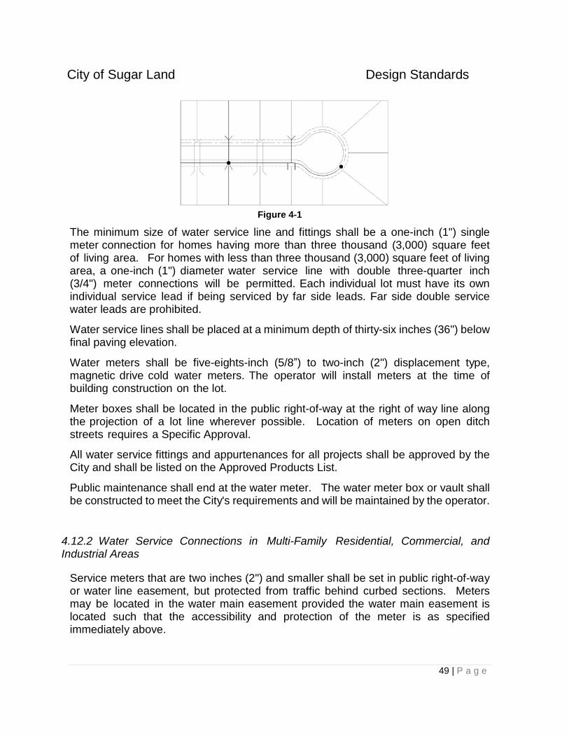
City of Sugar Land Design Standards
49 | P a g e
Figure 4-1
The minimum size of water service line and fittings shall be a one-inch (1") single meter connection for homes having more than three thousand (3,000) square feet of living area. For homes with less than three thousand (3,000) square feet of living area, a one-inch (1") diameter water service line with double three-quarter inch (3/4") meter connections will be permitted. Each individual lot must have its own individual service lead if being serviced by far side leads. Far side double service water leads are prohibited.
Water service lines shall be placed at a minimum depth of thirty-six inches (36") below final paving elevation.
Water meters shall be five-eights-inch (5/8”) to two-inch (2") displacement type, magnetic drive cold water meters. The operator will install meters at the time of building construction on the lot.
Meter boxes shall be located in the public right-of-way at the right of way line along the projection of a lot line wherever possible. Location of meters on open ditch streets requires a Specific Approval.
All water service fittings and appurtenances for all projects shall be approved by the City and shall be listed on the Approved Products List.
Public maintenance shall end at the water meter. The water meter box or vault shall be constructed to meet the City's requirements and will be maintained by the operator.
4.12.2 Water Service Connections in Multi-Family Residential, Commercial, and Industrial Areas
Service meters that are two inches (2") and smaller shall be set in public right-of-way or water line easement, but protected from traffic behind curbed sections. Meters may be located in the water main easement provided the water main easement is located such that the accessibility and protection of the meter is as specified immediately above.
City of Sugar Land Design Standards
50 | P a g e
Service meters that are three inches (3") and larger shall be set in an exclusive water meter easement, preferably a greenbelt area, with minimum dimensions of ten feet by twenty feet (10' X 20') and shall be located in easily accessible areas, adjoining a public right-of-way or water line easement, but protected from traffic behind curbed sections.
The location of the service line tee, valve, valve box and temporary plug shall be designated on the construction plans in the appropriate location to serve the "future meter."
All Commercial developments that have a single property owner shall have master meters sized adequately to serve the entire development. Commercial developments that are intended to have multiple property owners may have individual meters that are served by a public water system. Exceptions to this policy require a Specific Approval. Meters shall be installed in compliance with the City’s Standard Details.
Public maintenance shall end at the meter. The meter and meter vaults shall be constructed to meet the City’s requirements and will be maintained by the City.
All apartments shall have master meters sized adequately to serve the entire development. Exceptions to this policy require a Specific Approval. Meters shall be installed in compliance with the City’s Standard Details and shall include Reduced Pressure Zone (RPZ) Valves.
Residential water service leads shall be installed and tested before the installation of paving. All service leads shall be included in all hydrostatic and bacteriological testing.
4.12.3 Fire Lines in Multi-Family Residential, Commercial, and Industrial Areas
A back flow preventer/detector check assembly shall be required on fire lines.
Detector check assemblies shall include double check valves, a leak detection meter and isolation valves. It is recommended that the detector check assembly be installed in a vault. Refer to the City’s Standard Details.
Detector check assemblies shall be installed in an access easement adequately sized to allow utility personnel to read the meters and shall be located at the end of City maintenance responsibility, on private property and as close to the right-of-way line as possible.
All detector check assemblies within the City of Sugar Land will be installed by Contractor and maintained by the property owner. In the extraterritorial jurisdiction, all detector check assemblies will be reviewed by the City of Sugar Land, installed by Contractor, and maintained by the property owner.
All fire lines shall be equipped with isolation valves. Fire lines served by a near-side water service shall have an isolation valve at the point of connection to the
City of Sugar Land Design Standards
51 | P a g e
public water main. Fire lines served by a far-side water service shall have an isolation valve at the point of connection to the public water main and at the point the fire line intersects the property line of the property being served.
Public maintenance for fire lines served by a near-side water service connection shall end at the isolation valve at the point of connection to the public main. Public maintenance for fire lines served by a far-side water service shall end at the isolation valve located at the property line.
4.13 Additional Standards
4.13.1 Special Construction Features
In conjunction with the design, the engineer shall determine the extent of, and fully exemplify on the plans, all special construction features required to complete the project in a manner of safety, convenience, and economics.
4.13.2 Bore & Jack Sections
Bore and jack sections shall be clearly shown on plans by location and footage. The following criteria are generally used as a basis for setting bore and jack sections.
A. Public Streets - All public streets are to be bored and jacked regardless of
surface.
B. Driveways - Whenever it is cost effective, concrete driveways in good condition
shall be bored and jacked. Where driveways cross culvert pipe sections along
open ditch streets and the proposed water main is in close proximity and
parallel to the culvert pipe, the length of bore shall be the same as the length of
culvert pipe.
C. Sidewalks - When the water line crosses under a sidewalk four feet (4') or more
in width and in good condition, the sidewalk shall either be bored and jacked or
the sidewalk shall be removed and replaced to the City of Sugar Land criteria,
whenever it is cost effective. Bore and jack length shall be at least the width of
the sidewalk. The proposed type of construction shall be noted on the plans.
D. Trees - When saving trees and shrubs are a consideration, all trees six inches
(6") and larger in diameter within ten feet (10') of the centerline of the water
main must be noted on the plans. The water main shall be bored and jacked
within the drip line of any tree larger than six inches (6") in diameter.
E. Bore Pits - Bore pits shall be at least five feet (5') from back of curb. Bore
pits in highway, county road, or railroad right-of-way shall conform to these
City of Sugar Land Design Standards
52 | P a g e
requirements and to the requirements of the crossing permit and/or use
agreement.
4.13.3 Open Cuts
Where open cuts are required in street paving, plans shall call for steel plate covers to be installed and maintained over the cut during periods when contractor is not actively engaged in work at the site. Streets that are open cut shall be "saw cut".
4.13.4 Site Restoration
All existing developed areas shall be restored to original condition after construction.
4.13.5 Barricades and Signs
Proper barricades and signs, conforming to the Texas Manual of Uniform Traffic Control Devices, are required on all projects. Adequate signs for vehicular and pedestrian traffic shall be installed.
4.14 Public Water Supply Wells and Potable Water Treatment Plant Requirements
These standards describe the general requirements for public water supply wells and potable water treatment plants. Public water wells and potable water treatment plants shall be owned and operated by either the City or a municipal utility district approved by the City.
4.14.1 Site Requirements
A. Properties for water plants, wells, and tank sites shall be conveyed in fee to the City of Sugar Land or the approved municipal utility district.
B. Sites shall meet at least one of the following conditions for access:
1. Have 60 feet or more of frontage directly on at least one public street having a right-of-way width not less than 50 feet.
2. Have at least a 60-foot-wide fee strip access from a public street having a right-of- way width not less than 50 feet.
C. Sites must comply with current State regulations related to public water supplies in all respects. These regulations are currently contained in 30 TAC Chapter 290.
City of Sugar Land Design Standards
53 | P a g e
D. The minimum site size shall be 6,400 square feet; the site must be of a size and shape such that all necessary wells, equipment, appurtenances and zoning buffers are located wholly within the site.
E. Access Road:
1. Provide an all-weather road of not less than 12 feet (12') in width to the site. The road shall be constructed as a concrete road with curb within public right-of-way.
2. Inside the site, an all-weather surface shall be provided for reasonable access to wells, booster pumps, chlorine rooms, fuel tanks, and all other areas requiring proximate vehicle access.
3. An access control gate shall be placed a minimum of (20) twenty feet from the edge of pavement of the adjacent public street.
F. Internal Site Horizontal Spacing:
1. Wells: a. Locate wells a minimum of 40 feet from the site boundary. Provide
60 feet by 40 feet of open area on one quadrant of the well for laying out drill pipe during well repair.
b. No public street right-of-way, utility easement, or power company aerial easement shall encroach on the area within 40 feet of the well. No physical obstructions shall be located within 30 feet of the well with the exception of equipment and appurtenances directly related to the well’s operation.
c. Where space permits, locate well discharge piping and auxiliary power at right angles to the direction of well access
2. Elevated Storage Tanks:
a. No site boundary, public street right-of-way, utility easement or power company aerial easement shall be located within 40 feet of the outer perimeter of the elevated tank at its maximum section.
3. Ground Storage Tanks:
a. Locate ground storage tanks a minimum of 20 feet from any site boundary, public street right-of-way, utility easement, or power company aerial easement.
b. Locate ground storage tanks a minimum of 20 feet from plant structures and equipment.
c. Provide at least 10 feet of clearance between ground storage tanks and centerline of plant piping, except where segments of piping are routed directly to the tank.
4. Yard Piping:
a. Underground yard piping larger than 6 inches shall be separated at least 4 feet between nominal outside diameters. Provide a minimum of 3 feet
City of Sugar Land Design Standards
54 | P a g e
(3') of clearance for above-ground yard piping to include all flanges, valves, activators, supports and appurtenances.
b. The centerline of yard piping shall be a minimum of 6 feet from site boundaries and utility easements.
c. Locate underground yard piping so that thrust blocking, if any, will be located wholly within the site boundary and does not encroach upon an easement outside the site boundary. Encroachment upon access fee strips is permitted.
G. All water plant sites shall be fenced in accordance with the City of Sugar Land Zoning Ordinance Requirements. Fencing shall be located on the property line. All vehicle gates shall have a minimum clear opening of 15 feet in width.
H. Grading and Drainage:
1. Use drainage swales, sidewalks and driveways, culverts, storm sewers, or a combination thereof for internal site drainage.
2. If an offsite storm sewer or major drainage channel is available, site drainage shall be collected into an internal storm sewer system before leaving the site.
3. Internal storm sewer system shall be sized for site drainage and shall have capacity for water well blow off, tank overflow, and drainage.
4. Vegetation shall be established on all unsurfaced areas of the site and access strip.
4.14.2 Water Well Requirements
All Public Water Supply wells must be constructed in accordance with applicable TCEQ and Fort Bend County Subsidence district rules and regulations. The well casing and screens shall be designed to a minimum of 1,500 gpm regardless of pump size. The casing and liner (interior casing) diameters shall be sized to allow the pump to be lowered into the liner based on the manufacturer's minimum clearances between the pump and the liner. The Design Engineer shall demonstrate that sufficient piezometric head is available above the casing/screening lap to allow for lowering the pump to a sufficient depth to provide capacity for a twenty-year period based on the most current available 10-year draw down data from the Fort Bend County Subsidence District.
Design well piping so that the well will discharge directly to ground or elevated storage tanks. The well may have a direct pipe connection, including disinfection, into the distribution system by Specific Approval. Design this direct connection to allow emergency operation of the well independent of booster pumps, ground storage tanks, or pressure tanks. The well and disinfection system shall be designed to operate under such conditions. Size the pump column pipe to provide a minimum velocity of 4 feet per second to raise any sand to the surface.
City of Sugar Land Design Standards
55 | P a g e
The aboveground piping shall be sized for proper operation of the check valve and water meter. Normal velocities shall be 4 to 8 feet per second. Provide a sample tap and an air release valve and a pressure gauge between the check valve and flow meter. Provide 10 pipe diameters of straight pipe leading into the water meter and a minimum of 2 pipe diameters of straight pipe downstream of the water meter or install in accordance with the meter manufacturer's recommendations, whichever is greater. See the City’s Standard Details for water meter installation.
All other equipment installed in relation to the well shall be on the City’s Approved Products List and installed in accordance with the City’s Standard Details.
4.14.3 Booster Pumps
A. The minimum booster pump sizes shall be based upon: 1. Minimum combined pump and motor efficiency shall not be less than 75
percent.
2. Pumps shall be installed in combinations that will allow for flexibility of operations. Options include:
a. The use of a small capacity "jockey" pump for low demand situations to minimize wear on larger pump starting equipment.
b. The use of controls that allow alternate operation.
c. Other pumps sized as required to meet actual design flows and pressures required.
d. The use of variable speed pumps and equipment for facilities with less than three booster pumps.
3. Pumps at the same location shall be designed for the same discharge pressure.
B. Only pumps listed on the City’s Approved Products list are acceptable.
C. Booster Pump operations shall satisfy the following:
1. Pump speed shall not be greater than 1,800 rpm.
2. The minimum rated design discharge pressure shall be 60 psi or as demonstrated by hydraulic modeling that a lower pressure at the booster would allow the system to maintain a minimum pressure of 45 psi under all operating conditions with the exception of emergency conditions.
3. Pump operation shall be controlled by pressure differentials as a function of system demand. Pressure sensing shall be in accordance with Section 4.14.6.3 of these Standards.
4. Booster pumps shall be locked out of operation by activation of ground storage tank low-level cut-off alarm circuit.
City of Sugar Land Design Standards
56 | P a g e
D. Motors:
1. Electric motors of less than 300 horsepower shall be 3-phase, 460-volt operation.
2. Motors of 300 horsepower and larger may operate at higher voltages. Booster pumps at a plant shall be three phase and shall operate at the same voltage as the other booster pumps. Motor voltages >460 shall include diagnosing equipment that will allow for remote measurement of V, A, PF, W, Ph-Ph.
3. Size electric motors to accommodate the maximum design-operating load of the booster pump without using motor service factor.
4. Service factor on motors shall be 1.15 minimum.
5. Motor enclosures may be open drip-proof, WP-1, or totally enclosed fan cooled.
6. It is recommended that motors of 150 horsepower or greater have reduced voltage, auto-transformer starting, 65 percent tap.
7. Electric Motors greater than 50 horsepower must be power factor corrected to 95%. Documentation supporting the power factor correction shall be provided.
8. Include space heaters on motors that are not located within buildings.
4.14.4 Headers and Yard Piping
All headers and yard piping shall be constructed using materials on the City’s Approved Products List and appropriate for the application based on good industry practice.
4.14.4.1 Design Velocities
The design velocities in headers and yard piping shall conform to the following:
1. Suction Headers:
a. Flow velocity in suction piping, before any reducers, shall not exceed 4 feet per second.
b. Flow velocity in suction headers shall not exceed 4 feet per second. 2. Discharge Headers:
a. Flow velocity in discharge piping shall not exceed 6 feet per second. b. Flow velocity in discharge header shall not exceed 5 feet per second.
3. Yard piping: Velocity in yard piping shall not be less than 2 feet per second or more than 8 feet per second.
4. Calculate velocities assuming both suction feeds are open and both distribution lines are open from the discharge header (i.e., one-half of total
City of Sugar Land Design Standards
57 | P a g e
flow in each direction).
Do not include the capacity of stand-by pumps in the calculation of peak flow maximum velocities.
4.14.4.2 Anchorage and Blocking
Anchorage and blocking is required as follows: 1. Provide reaction blocking, anchors, joint harnesses, or other acceptable
means for preventing movement of piping caused by forces in or on buried piping tees, wyes, plugs, or bends. Refer to the City’s Standard Details.
2. Place concrete blocking so that it extends from fitting into solid undisturbed earth wall. Concrete blocks shall not cover pipe joints.
4.14.4.3 Suction and Discharge Headers
Suction and discharge headers shall conform to the following:
1. Headers located next to walls or structures shall be a minimum of 3 feet to the outside of the pipe from such walls, structures, to allow for access to valves and fittings.
2. Provide adequate space and access between headers, piping, pumps and motors to allow proper clearances and access for maintenance and repair. Specific requirements will depend upon actual physical layout and sizes of components.
3. Suction headers shall be supplied from two sources, preferably one at each end. Provide cut-off valves to allow for isolation of header from each supply source. Provide at least one intermediate cut-off valve in the header to allow for at least one pump to be supplied at all times.
4. Discharge headers shall feed the distribution system through two separate supply lines. Provide cut-off valves to allow each distribution line to be isolated. Provide at least one intermediate cut-off valve in the discharge header to allow at least one pump to supply either distribution line at all times.
5. Suction piping from the suction header to pump suction nozzles shall be as short and direct as possible and shall be larger in diameter than pump suction nozzles to minimize suction head loss. Reducers used in suction piping shall be eccentric reducers installed with the flat side on top to reduce air pockets trapped in the suction lines.
6. Pump suction piping should be as straight as practical. Avoid placing 90-degree bends directly in front of pump suction and discharge nozzles.
City of Sugar Land Design Standards
58 | P a g e
4.14.4.4 Suction and Discharge Header Valves
Suction and discharge header valves must conform to the following:
1. Provide cut-off valves on suction piping and discharge piping of each pump for isolation from header.
2. Provide a slow closing check valve or other control valve on discharge pipe of each pump between the pump and the cut-off valve to limit reverse flow from the pressure system into the ground storage tank when the pump stops.
3. Use check valves with controlled rate of closure as may be needed to reduce water hammer potential on discharge piping.
4.14.4.5 Yard Piping
Yard piping design shall meet the following requirements:
1. Clearance between waterlines and sanitary sewers shall conform to requirements set forth for water distribution systems in the "Rules and Regulations" for Public Water Systems published by the TCEQ.
2. Locate yard piping in areas easily accessible for maintenance.
3. Yard piping shall have two points of interconnection with distribution system lines and a feed to the hydropneumatic tanks, if supplied.
4. Yard piping shall be considered to end at the point of connection to the distribution system line.
5. Standard sizes noted in AWWA Standards may be used except 10-inch, 14-inch, and 18-inch unless already in place.
6. Between discharge header and distribution system, provide a minimum of 20 pipe diameters of straight pipe to allow future discharge meters installation. If piping is below grade, provide a vault for the future meter.
4.14.4.6 Yard Piping Valves
Yard Piping Valves must meet the following:
1. Install valves in a manner that will allow easy access and operation.
2. Valves installed below ground shall have valve boxes and shall be located outside paved areas and other areas normally traveled by vehicles.
3. Size and type:
City of Sugar Land Design Standards
59 | P a g e
a. Gate valves shall be used for 2-inch through 12-inch diameters unless 14- inch diameter is already in place.
b. Use butterfly valves on lines 16 inches and larger in diameter, unless otherwise approved.
c. The use of gate valves on lines larger than 12 inches in diameter must be approved by the City Engineer.
4.14.4.7 Testing Requirements
Test piping as follows:
1. Test piping systems upon completion of piping and prior to application of insulation on exposed piping or covering concealed or buried piping.
2. Isolate equipment that may be damaged by the specified pressure test conditions.
3. Perform pressure test using calibrated pressure gauges and calibrated volumetric measuring equipment to determine leakage rates.
4. Completely assemble and test new piping systems prior to connection to existing pipe systems.
5. Test pipe at 1.5 times the maximum working pressure or 125 psi, whichever is greater in accordance with AWWA Manual M23.
4.14.5 Booster Pump Buildings
4.14.5.1 General
Booster Pump Building design must comply with the following:
1. Do not put chlorination equipment or store chlorine bottles in the same room as pumps, motors, and electrical equipment. Provide a separate room specifically for chlorination.
2. Locate controls and electrical equipment in a room separate from piping, pumps, and motors. The floor of the electrical/control room shall be raised above the pump room floor level or all electrical and control equipment shall be installed on raised housekeeping pads.
4. Locate buildings a minimum of 20 feet from plant site property lines to help eliminate vandalism and to facilitate access for maintenance and repair.
5. Buildings shall conform to applicable local, state, and federal building codes and requirements, including OSHA requirements.
6. Concrete work shall conform to the latest revision of ACI 318, ACI 301, and other applicable ACI specifications.
City of Sugar Land Design Standards
60 | P a g e
7. A soils investigation with recommendations for foundation design shall be performed by a geotechnical engineer.
8. Pump buildings shall be constructed of fire-proof reinforced concrete or reinforced masonry construction; do not use metal buildings. Building and roof shall have a minimum design life of 25 years.
9. Wiring shall conform to the most current revision of the National Electric Code requirements for commercial or industrial wiring. Materials and equipment shall be approved and listed by Underwriters Laboratory.
10. Building interior spaces shall be sufficiently lighted to allow for safe and convenient operation and maintenance of equipment including pumps, motors, motor control centers, and auto sensory equipment. Provide exterior lighting at exterior doors, walkways, driveways, and work areas around the buildings. Follow lighting requirements contained in OSHA standards.
4.14.5.2 Size of Buildings and Clearances
Booster Pump Buildings shall comply with the following size and clearance requirements.
1. Building size shall depend on specific piping layouts, number of pumps and space allotted for future expansion. Building size shall be adequate to allow access to pumps, motors, piping, valves and electrical controls to allow for proper maintenance and removal of equipment or installation of future equipment.
3. Provide 3 feet minimum clearance between walls and piping, valves, and fittings to facilitate bolt removal and tightening.
4. Space pumps and motors to allow for maintenance of equipment.
5. Provide steps, ladders and walkways as required for access to aboveground equipment and valves. Provide safety handrails on walkways, ladders, and steps in accordance with OSHA regulations.
6. Provide outside access to the pump room through double doors or roll-up type garage doors. Doors are to be sized to allow removal and replacement of pumps and motors.
7. Provide control/electrical room with one exterior door and one door into the pump room.
8. Provide sidewalks, steps, and/or ramps as necessary to provide paved access to exterior doors as required by ADA.
9. Provide adequate vertical clearance inside the pump room to allow pumps to be pulled for service. Clearance shall allow pumps to be removed from the building over piping, pumps, and other equipment.
City of Sugar Land Design Standards
61 | P a g e
10. Provide a traveling crane or monorail inside the building. Size the crane to easily handle large pump equipment. For smaller pumps, provide access suitable for manual lifting devices.
11. Slab elevation shall be a minimum of 6 inches above grade to allow for proper drainage.
4.14.5.3 Ventilation
Ventilation systems for Booster Pump Buildings must meet the following requirements:
1. Provide louvers of adequate size and number for proper ventilation of the pump room. Locate louvers so that good air circulation is maintained. Provide power roof fans, wall fans, or ventilators if necessary.
1. 2. Provide louvers and fans in the control/electrical room sufficient to dissipate heat generated from motor control centers and switchgear. Consider use of dehumidifiers and heaters in control rooms if warranted.
2. Provide bird screening over louver and fan openings. Screening shall be 316 stainless steel, #16 mesh.
4.14.5.4 Piping
Piping related to Booster Pump Buildings shall be designed in accordance with the following:
1. Piping arrangements and sizes will depend upon initial equipment installed, proposed future expansions, and ultimate design capacity of the plant.
2. Piping shall be adequately supported and properly braced to restrain thrust forces.
3. Provide sleeves for piping passing through walls. Line sleeves with expansion joint material to allow for minor movements of piping and buildings. Do not use building walls to support piping.
4.14.5.5 Roof
The roof of the Booster Pump Building must be either:
1. A pitched roof with a minimum 5 on 12 slope with standing seam roofing of pre- coated galvanized steel or fiberglass asphalt shingles, or
City of Sugar Land Design Standards
62 | P a g e
2. A minimum 4-ply hot applied built-up roof with 15-year service life adequately sloped for drainage.
Slope the roof to drain away from entrance doors. Provide a minimum 2-foot overhang on all sides of the building.
4.14.5.6 Floor
The Booster Pump Building floor must be a minimum 6-inch thick concrete floor, coated with non-skid, chemical resistant material.
4.14.6 Monitoring and Control Systems
4.14.6.1 General
Public Water Supply Wells and Potable Water Treatment Plant electrical, monitoring, and control systems shall comply with the provisions of this Section. The general requirements are:
1. The water plant shall be provided with electrical controls and equipment to enable it to operate manually and automatically. Provide sufficient control and electrical equipment so that the water plant can operate automatically without direct operator control.
2. As a minimum, water plants shall be equipped with the systems as described herein. At the discretion of the Engineer, more capable systems may be provided.
3. Provide a time delay system to start large motors sequentially. Large motors shall not start simultaneously.
4.14.6.2 Well Control System
Well control systems shall comply with the following:
1. Water wells shall be controlled based on the levels in ground or elevated storage tanks, if provided.
2. Interlock well controls with the well pump motor electrical equipment so that the well pump motor is activated and deactivated automatically in response to tank level. Time delay on the well pump motor shall reset in the event of a power disruption.
3. Tank level shall be sensed by a wet tap on the lower tank shell, internal tank probes, an electronic pressure transmitter, or an ultrasonic transmitter.
4. Unless approved by the City, control equipment shall be one of the following types:
City of Sugar Land Design Standards
63 | P a g e
a. Mercury-type pressure switches with conventional relays.
b. Electronic pressure switches with either conventional electrical relays or a programmable controller.
5. Provide a high-pressure mercury switch with manual reset on well discharge.
6. Chlorination control shall be in accordance with TCEQ requirements.
4.14.6.3 Booster Pump Control System
All booster pump control systems shall comply with the following:
A. Systems without elevated tanks:
1. Control of booster pumps shall be based on the pressure in the distribution system and/or elevation in EST.
2. Interlock booster pump controls with pump motor electrical equipment so that successive pumps are activated on falling system pressure and deactivated on rising system pressure.
3. Make distribution pressure tap in either the water or air portions of the hydropneumatic tank or in the discharge line.
4. Unless approved by the City Engineer, control equipment shall be one of the following types:
a. Mercury-type pressure switches with conventional electrical relays.
b. Electronic pressure switches or pressure transmitters with either conventional electrical relays or programmable controller.
5. The following control features are required:
a. Booster pumps shall be deactivated on low ground storage tank level with a manual override provided.
b. Booster pump controls and hydropneumatic tank controls shall be interlocked to ensure that the proper air-water ratio is automatically maintained in the tank.
B. Systems with elevated tanks:
1. Booster pumps can be controlled based on distribution system pressure as described above for systems without elevated tanks or on the water level in the elevated tank.
2. If the booster pumps are controlled by the elevated tank water level, the following are applicable:
City of Sugar Land Design Standards
64 | P a g e
a. If the elevated tank is at a different location than the booster pumps, the tank water level shall be transmitted to the water plant via telemetry.
b. Interlock booster pump controls with motor electrical equipment so that successive pumps are activated on falling tank level and deactivated on rising tank level.
c. Unless approved by the City Engineer, control equipment shall be one of the following types:
i. Mercury-type pressure switches with conventional electrical relays.
ii. Pressure transmitter with either conventional electrical relays or programmable controller.
d. Provide a backup control system to automatically control the booster pumps in the event of loss of telemetry signal from the elevated tank.
e. Booster pumps shall be deactivated on low ground storage tank level with a manual override provided.
4.14.6.4 Telemetry
Telemetry equipment must be provided to allow control communication between a water plant and an offsite well or elevated tank. The telemetry equipment may utilize hard wire connection, telephone lines, radio communication, or microwave.
4.14.6.5 Water Plant Monitoring Systems
As a minimum, water plant monitoring systems shall include the following:
a. Propeller-type flow meter located at the water well. Meter shall have a totalizer that cannot be reset. Do not use battery-powered meters.
b. Panel-mounted, 4-1/2-inch diameter pressure gauge or LED readout indicating the plant distribution pressure, located in the electrical/control room.
c. A minimum of 20 pipe diameters of straight pipe between the booster pump discharge header and the distribution system tie-in to allow for future installation of discharge meters. If below grade, provide a vault for the future meters.
The following may be required by the City Engineer:
a. 7-day recorders sized such that peak conditions do not exceed 95 percent of full scale. Distribution pressure, elevated storage and ground storage
City of Sugar Land Design Standards
65 | P a g e
tank levels, and/or plant discharge flows may be recorded. Strip recorders are not to be used.
b. Alarm lights and audible and visual alarm systems to indicate abnormal conditions.
4.14.6.6 Water Plant Restroom Requirements
Restroom facilities shall be provided at water plants. A temporary facility with provisions for a permanent sanitary sewer connection to be constructed later will be adequate.
4.14.7 Hydropneumatic Tanks
All hydropneumatic tanks shall be listed on the City’s Approved Products List. Valves shall be provided as appropriate to isolate each hydropneumatic tank from other portions of the system. The following appurtenances shall be furnished with each tank:
1. Provide automatically functioning facilities for maintaining the air- water volume at the design water level and working pressure.
2. Provide a pressure release device and an easily readable pressure gauge for each tank.
3. Provide a sight gauge for reading water level in each tank.
4. Provide tanks with a means for completely draining the tank.
5. Air compressors shall be sized for a minimum of 0.25 cfm per 1,000 gallon tank capacity at 150 psi.
6. Tanks shall have an access port for periodic inspections.
7. Provide freeze protection for tank appurtenances.
8. Specifications shall include tank capacity dimensions, appurtenances, pressure rating, disinfection procedures, and air compressor capacity.
4.14.8 Potable Water Storage Tanks
4.14.8.1 Ground Storage Tanks
1. Types of construction: a. Design welded steel tanks in accordance with the current revision of
ANSI/AWWA D100. Steel fabrication dimensional tolerances shall be in accordance with API standards.
b. Design bolted steel tanks in accordance with the current revision of AWWA D103.
City of Sugar Land Design Standards
66 | P a g e
c. Design concrete tanks in accordance with current revision of AWWA D110.
d. A complete soils investigation with recommendation for foundation design shall be performed by a geotechnical engineer.
2. Additional design requirements for steel ground storage tanks:
a. Tank inlets: One or more per tank located in the sidewall of the tank and at least 45 degrees from a tank outlet. Direct flow shall have a 45-degree bend away from the nearest outlet. Tank inlets shall be top fill.
b. Tank outlets: On single tank installations, two per tank located at least 90 degrees apart and 45 degrees from a tank inlet. On multiple tank installations, dual outlets are required on the first tank only. Outlets for booster pump suction shall be fitted with an internal 90-degree fitting turned downward. Diameter shall be equal to or larger than the suction line. The fitting shall be a ductile iron flange and flare, a ductile iron 90 degree long radius ell, or a welded steel mitered fitting. Provide outlets with a minimum 12-inch clearance from the tank bottom.
c. Overflow: Provide an internal overflow weir inlet with an external overflow pipe. The overflow assembly shall be sized to handle the maximum tank influent rate with a maximum water level rise over the inlet weir of 6 inches. The overflow pipe discharge shall terminate above ground, not be subject to submergence, and be fitted with a hinged flap valve. The top of the overflow weir shall be a minimum of one foot below the bottom of any roof rafter.
d. Tank drain: Locate one or more drains, not less than four inches in diameter and fitted with a valve, at the minimum practical distance above the tank floor to the flow line of the drain. For example, a 4 or 6-inch drain would be placed six inches above the tank floor. Larger drain sizes may be placed further from the floor. Alternatively, the Design Engineer may use a flush type drain in accordance with API 650 (Section 3.7.8, Figure 3-10). The drain may be connected to the overflow discharge pipe outside the tank.
e. Interconnect lines between tanks: Interconnect lines are required for plants with more than one tank. The lines shall be sized the same as the tank inlet, or if combined with a tank outlet, sized the same as the tank outlet, whichever is larger. Interconnect lines shall be provided with isolation valves. Three valves on a tee are required if combined with a tank outlet. Interconnect lines are to be located a minimum of 12 inches above the tank bottom with an isolation valve, 90-degree bend and buried four feet (4’) deep between the tanks.
f. Roof vents: One or more with one vent located at or near the center of the roof at the highest point practical. Size vents for maximum influent and effluent rates. Only the effective (net) screen opening shall be considered to pass airflow. Vents are to be double gooseneck type with openings protected by 316 stainless steel screen, #16 mesh.
City of Sugar Land Design Standards
67 | P a g e
g. Foundation: Support the tank bottom on a concrete ring-wall a minimum of 12-inches wide. The top of the foundation shall be at least 12 inches above finished grade. The tank bottom shall rest on a minimum of 6 inches of clean sand, free from clay, lumps, shale, loam, organic matter and other deleterious materials, with soluble ionic (salt) content limited in accordance with ASTM D4940. Slope the tank bottom at least 1 inch in 10 feet from the tank center to the outside edge.
h. Connections: Connections 3-inches and larger shall be flanged. Connections 2-inches and smaller may be threaded couplings.
3. Additional design requirements for pre-stressed concrete ground storage tanks:
a. Tank inlets: At least one per tank located at least 45 degrees from a tank outlet. Make inlet connections through the top of the tank and above the overflow
b. Tank outlets: Number and plan location is the same as for steel tanks. Make outlet connections through the tank bottom and provide a minimum 4-inch silt stop.
c. Tank overflow: Provide an internal overflow weir with an external overflow pipe. Size the overflow assembly to handle the maximum tank influent rate with a maximum water level rise over the weir of 6 inches. Where multiple tanks, all overflows must be of the same elevation.
d. Tank drain: One or more with an isolation valve. Make drain connections through the tank bottom and terminate in an open top concrete drain box connected to a storm sewer system or adequate site drainage swale.
e. Interconnect lines between tanks: Interconnect lines are required between tanks at multiple tank installations.
f. Roof Vents: One or more with one vent located at or near the center of the roof at the highest point practical. Size the vent for maximum influent and effluent rates. Only the effective (net) screen opening shall be considered to pass airflow. Vents shall be of the gravity type with openings protected by 316 stainless steel screen, #16 mesh.
g. Foundation: The design of the tank foundation shall be the responsibility of the tank manufacturer and the foundation shall be constructed in accordance with the tank manufacturer’s design. The tank bottom may be below natural ground level.
4. Required accessories:
a. Roof hatch: Primary and secondary roof hatches are required. The primary roof hatch shall have a minimum size of 30-inch diameter with a 4-
City of Sugar Land Design Standards
68 | P a g e
inch curb and shall have a cover with 2-inch downward overlap and provisions for locking. The primary hatch location shall be offset from the exterior tank ladder centerline and located over the interior ladder. T he secondary roof hatch shall be located over the tank overflow.
b. Ladders: Provide an exterior steel ladder extending the full height of the tank. Provide exterior ladders with safety cage and lockable access. Interior ladders shall be provided and offset from the external ladder by at least 2 feet.
c. Roof guard rails: Provide guard rails (handrails) along the roof edge for a distance of 10 feet either side of the exterior ladder and 5 feet either side of any perimeter tank appurtenance.
d. Shell manholes:
1. Welded steel tanks - Provide at least two manholes. One manhole shall be 30 inches in diameter with a hinged cover per AWWA standards. One manhole shall be a 48 inch x 48-inch flush-type cleanout per API standards complete with hinge or davit arm. Locate the manholes approximately 180 degrees apart.
2. Bolted steel tanks - Provide two flush-type cleanouts per API standards. Cleanouts shall be a minimum of 24 inches wide by 48 inches high and located approximately 180 degrees apart.
3. Concrete Tanks - Provide at least two manholes spaced approximately 180 degrees apart. The manhole shape shall be elliptical 24 inches by 18 inches minimum. Provide two flush type cleanouts per API Standards sized 48-inch by 48-inch.
e. Miscellaneous accessories: One sample cock located 3 feet above tank bottom and one pressure gauge calibrated in feet of water located 3 feet above tank bottom.
f. Roof Walkways: Provide non-skid walkways on the roof of steel tanks to reach any appurtenance.
4.14.8.2 Elevated Storage Tanks
Elevated storage tanks shall be constructed in a manner consistent with AWWA D100, with no restriction on the style of tank.
Elevated storage tanks must satisfy the following design requirements:
a. Tank overflow: Provide an internal overflow weir and drain pipe. Size the overflow assembly to handle the maximum tank influent rate with a maximum water level rise over the weir of 6 inches. The overflow pipe shall be piped to grade and shall be fitted with a hinged flap valve. The top of the overflow funnel shall be a minimum of 1 foot below the bottom of any roof rafter.
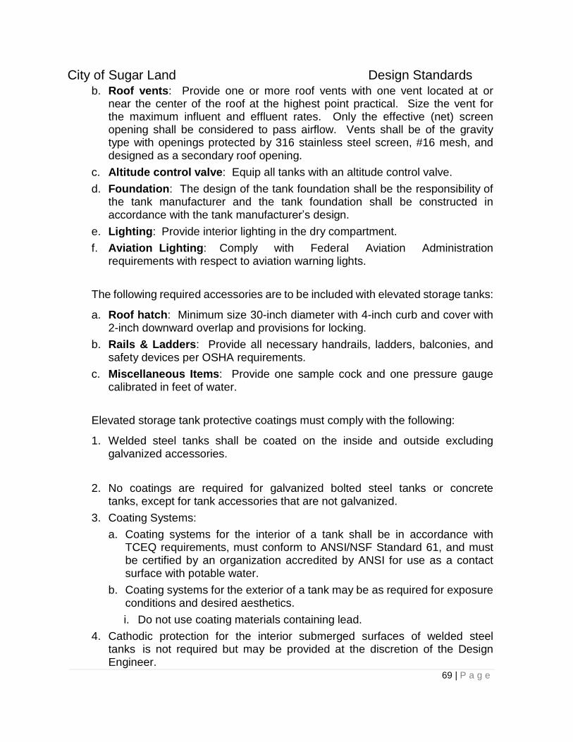
City of Sugar Land Design Standards
69 | P a g e
b. Roof vents: Provide one or more roof vents with one vent located at or near the center of the roof at the highest point practical. Size the vent for the maximum influent and effluent rates. Only the effective (net) screen opening shall be considered to pass airflow. Vents shall be of the gravity type with openings protected by 316 stainless steel screen, #16 mesh, and designed as a secondary roof opening.
c. Altitude control valve: Equip all tanks with an altitude control valve.
d. Foundation: The design of the tank foundation shall be the responsibility of the tank manufacturer and the tank foundation shall be constructed in accordance with the tank manufacturer’s design.
e. Lighting: Provide interior lighting in the dry compartment.
f. Aviation Lighting: Comply with Federal Aviation Administration requirements with respect to aviation warning lights.
The following required accessories are to be included with elevated storage tanks:
a. Roof hatch: Minimum size 30-inch diameter with 4-inch curb and cover with 2-inch downward overlap and provisions for locking.
b. Rails & Ladders: Provide all necessary handrails, ladders, balconies, and safety devices per OSHA requirements.
c. Miscellaneous Items: Provide one sample cock and one pressure gauge calibrated in feet of water.
Elevated storage tank protective coatings must comply with the following:
1. Welded steel tanks shall be coated on the inside and outside excluding galvanized accessories.
2. No coatings are required for galvanized bolted steel tanks or concrete tanks, except for tank accessories that are not galvanized.
3. Coating Systems:
a. Coating systems for the interior of a tank shall be in accordance with TCEQ requirements, must conform to ANSI/NSF Standard 61, and must be certified by an organization accredited by ANSI for use as a contact surface with potable water.
b. Coating systems for the exterior of a tank may be as required for exposure conditions and desired aesthetics.
i. Do not use coating materials containing lead.
4. Cathodic protection for the interior submerged surfaces of welded steel tanks is not required but may be provided at the discretion of the Design Engineer.

City of Sugar Land Design Standards
70 | P a g e
5. The type of coating systems and cathodic protection systems to be used shall be included in the Specifications if they are to be used.
4.14.9 Emergency Power
Provide emergency power as required by TCEQ regulations. A generator is the preferred type of emergency power for booster pumps. A right angle drive is the preferred type of emergency power for a well. If the Engineer selects an alternate method, the reasons for the use of the alternate method must be presented with the drawings. If a right angle drive is utilized, the drive shall be diesel powered and/or natural gas powered. Right angle drives shall be sized accordingly to the handle weight of the down hole pumping assembly without the motor or short shaft.
When used, an emergency power generator shall operate the following items as a minimum:
a. The controls, air compressor, panel lights, and exterior lights;
b. The booster pumps, or
The fuel tanks related to emergency power systems shall comply with the following:
1. For diesel engines, a fuel tank shall be provided which allows 24 hours of operation at full load if system is interconnected or multiple plants are in the system.
2. Aboveground tanks shall be used and must be Underwriters Laboratories (UL) listed (Do not use underground fuel tanks). A UL label shall be affixed to the tank.
3. Provide concrete or steel containment for the fuel tank in accordance with NFPA 30 and Federal and State regulations. Containment shall have a drain line with a lockable valve. A double walled fuel tank can be utilized in lieu of the containment structure.
4. Use black steel piping for fuel tank connections. Do not use galvanized steel piping.
4.14.10 Disinfection Systems
4.14.10.1 General
A chlorination system for all groundwater plants must be provided. Water must be chlorinated before it enters the ground storage tank (pre-chlorination). Provisions for post - chlorination prior to entering the distribution system shall be provided at the discretion of the City Engineer with TCEQ approval.
Disinfection methods shall be approved by the City Engineer.

City of Sugar Land Design Standards
71 | P a g e
4.14.10.2 Types of Systems
1. Pre-chlorination:
a. Chlorination of the plant’s groundwater supply shall be accomplished by providing a fixed rate chlorinator for each well feeding the plant.
b. Chlorination Points:
1) Add chlorine solution to the aboveground well collection pipe downstream of the well flow meter, prior to entering the ground storage tank and prior to reaching the well connection to the distribution system.
2) Chlorination connections for 1-inch and smaller solution lines shall to be a corporation cock type connection with check valve. Connections for 1½ inch through 3-inch solution lines shall be a pipe tap connection utilizing a service saddle with a shut-off valve and check valve. The diffusion tube shall project into the pipe approximately one-third the pipe diameter.
c. Control Methods:
1) Chlorinators shall operate automatically whenever there is flow of water into the ground storage tanks.
2) Single well, fixed feed rate chlorinators shall be controlled by an electric solenoid valve in the injector water supply line. The solenoid valve shall open automatically when there is well flow.
3) Multiple well variable feed rate chlorinators shall be controlled by an electric solenoid valve in the injector water supply line. The solenoid valve shall open automatically when there is well flow. A flow meter with flow rate transmitter is required in the common well collection line for control of the chlorine feed rate.
4) Multiple well/multiple fixed rate chlorinators function as single well fixed rate chlorinators with a separate solenoid for each well tied to that well’s fixed rate chlorinator.
2. Post-chlorination:
a. Chlorination of water after leaving the ground storage tanks shall be accomplished by a variable rate chlorinator.
b. Chlorination points:
1) Add chlorine solution to the booster pump suction piping. If possible, make chlorination connections to aboveground pipe. Connections to buried pipe shall be made inside a vault-type structure.
2) Chlorination connections shall be the same as those required for pre-chlorination.
c. Control methods:
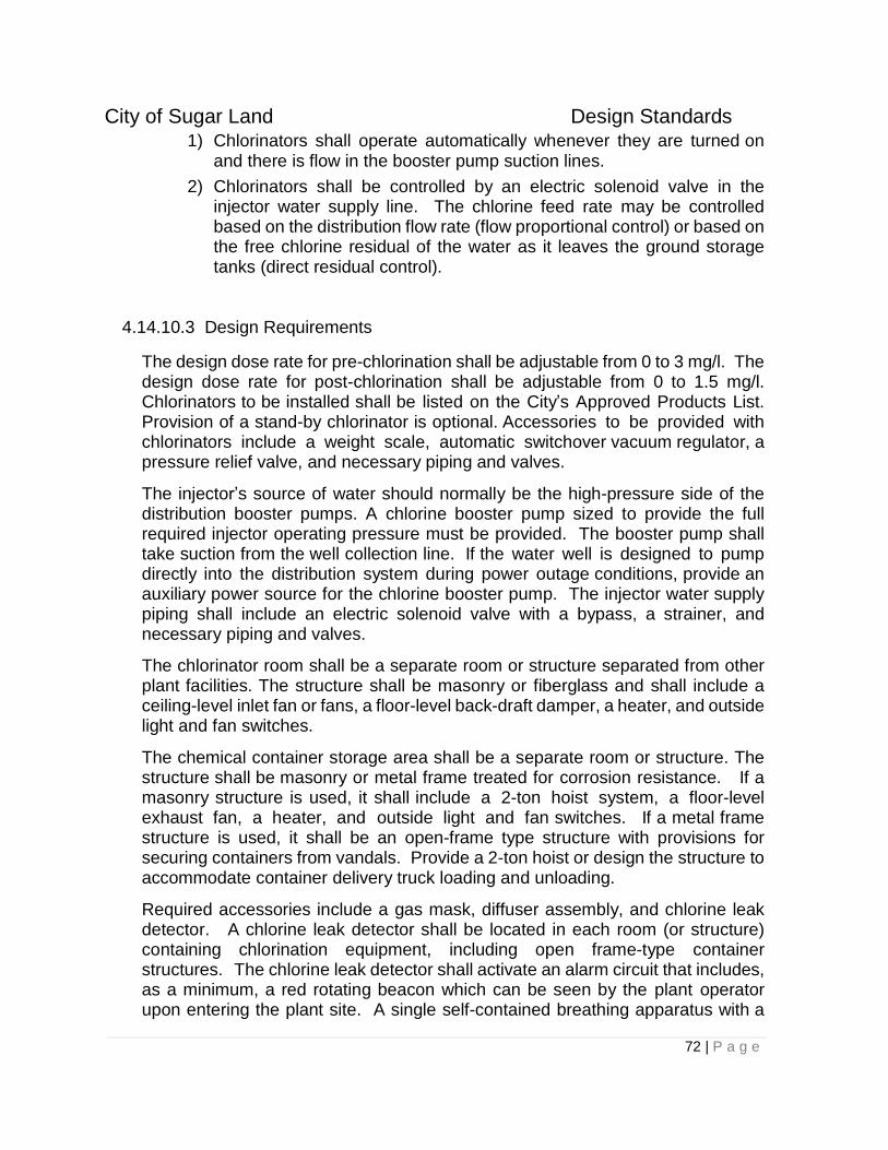
City of Sugar Land Design Standards
72 | P a g e
1) Chlorinators shall operate automatically whenever they are turned on and there is flow in the booster pump suction lines.
2) Chlorinators shall be controlled by an electric solenoid valve in the injector water supply line. The chlorine feed rate may be controlled based on the distribution flow rate (flow proportional control) or based on the free chlorine residual of the water as it leaves the ground storage tanks (direct residual control).
4.14.10.3 Design Requirements
The design dose rate for pre-chlorination shall be adjustable from 0 to 3 mg/l. The design dose rate for post-chlorination shall be adjustable from 0 to 1.5 mg/l. Chlorinators to be installed shall be listed on the City’s Approved Products List. Provision of a stand-by chlorinator is optional. Accessories to be provided with chlorinators include a weight scale, automatic switchover vacuum regulator, a pressure relief valve, and necessary piping and valves.
The injector’s source of water should normally be the high-pressure side of the distribution booster pumps. A chlorine booster pump sized to provide the full required injector operating pressure must be provided. The booster pump shall take suction from the well collection line. If the water well is designed to pump directly into the distribution system during power outage conditions, provide an auxiliary power source for the chlorine booster pump. The injector water supply piping shall include an electric solenoid valve with a bypass, a strainer, and necessary piping and valves.
The chlorinator room shall be a separate room or structure separated from other plant facilities. The structure shall be masonry or fiberglass and shall include a ceiling-level inlet fan or fans, a floor-level back-draft damper, a heater, and outside light and fan switches.
The chemical container storage area shall be a separate room or structure. The structure shall be masonry or metal frame treated for corrosion resistance. If a masonry structure is used, it shall include a 2-ton hoist system, a floor-level exhaust fan, a heater, and outside light and fan switches. If a metal frame structure is used, it shall be an open-frame type structure with provisions for securing containers from vandals. Provide a 2-ton hoist or design the structure to accommodate container delivery truck loading and unloading.
Required accessories include a gas mask, diffuser assembly, and chlorine leak detector. A chlorine leak detector shall be located in each room (or structure) containing chlorination equipment, including open frame-type container structures. The chlorine leak detector shall activate an alarm circuit that includes, as a minimum, a red rotating beacon which can be seen by the plant operator upon entering the plant site. A single self-contained breathing apparatus with a
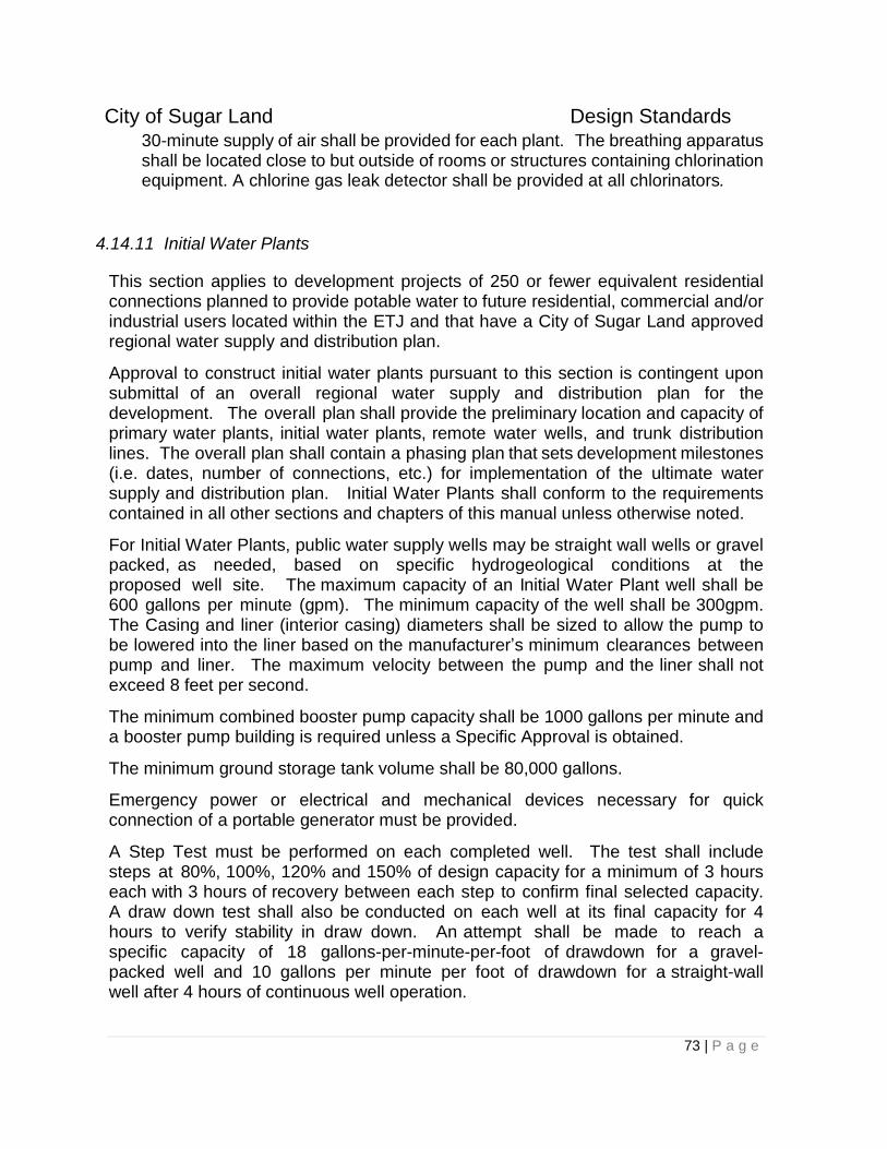
City of Sugar Land Design Standards
73 | P a g e
30-minute supply of air shall be provided for each plant. The breathing apparatus shall be located close to but outside of rooms or structures containing chlorination equipment. A chlorine gas leak detector shall be provided at all chlorinators.
4.14.11 Initial Water Plants
This section applies to development projects of 250 or fewer equivalent residential connections planned to provide potable water to future residential, commercial and/or industrial users located within the ETJ and that have a City of Sugar Land approved regional water supply and distribution plan.
Approval to construct initial water plants pursuant to this section is contingent upon submittal of an overall regional water supply and distribution plan for the development. The overall plan shall provide the preliminary location and capacity of primary water plants, initial water plants, remote water wells, and trunk distribution lines. The overall plan shall contain a phasing plan that sets development milestones (i.e. dates, number of connections, etc.) for implementation of the ultimate water supply and distribution plan. Initial Water Plants shall conform to the requirements contained in all other sections and chapters of this manual unless otherwise noted.
For Initial Water Plants, public water supply wells may be straight wall wells or gravel packed, as needed, based on specific hydrogeological conditions at the proposed well site. The maximum capacity of an Initial Water Plant well shall be 600 gallons per minute (gpm). The minimum capacity of the well shall be 300gpm. The Casing and liner (interior casing) diameters shall be sized to allow the pump to be lowered into the liner based on the manufacturer’s minimum clearances between pump and liner. The maximum velocity between the pump and the liner shall not exceed 8 feet per second.
The minimum combined booster pump capacity shall be 1000 gallons per minute and a booster pump building is required unless a Specific Approval is obtained.
The minimum ground storage tank volume shall be 80,000 gallons.
Emergency power or electrical and mechanical devices necessary for quick connection of a portable generator must be provided.
A Step Test must be performed on each completed well. The test shall include steps at 80%, 100%, 120% and 150% of design capacity for a minimum of 3 hours each with 3 hours of recovery between each step to confirm final selected capacity. A draw down test shall also be conducted on each well at its final capacity for 4 hours to verify stability in draw down. An attempt shall be made to reach a specific capacity of 18 gallons-per-minute-per-foot of drawdown for a gravel-packed well and 10 gallons per minute per foot of drawdown for a straight-wall well after 4 hours of continuous well operation.
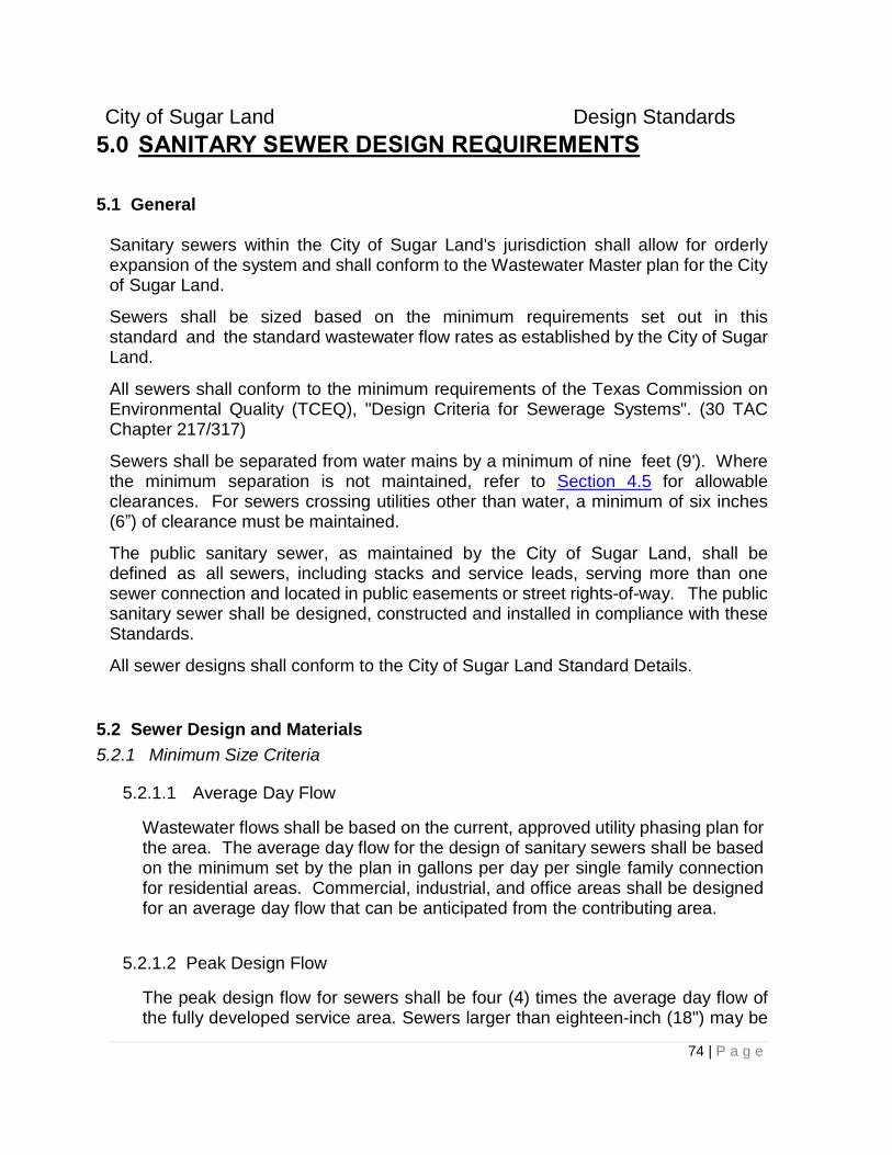
City of Sugar Land Design Standards
74 | P a g e
5.0 SANITARY SEWER DESIGN REQUIREMENTS
5.1 General
Sanitary sewers within the City of Sugar Land's jurisdiction shall allow for orderly expansion of the system and shall conform to the Wastewater Master plan for the City of Sugar Land.
Sewers shall be sized based on the minimum requirements set out in this standard and the standard wastewater flow rates as established by the City of Sugar Land.
All sewers shall conform to the minimum requirements of the Texas Commission on Environmental Quality (TCEQ), "Design Criteria for Sewerage Systems". (30 TAC Chapter 217/317)
Sewers shall be separated from water mains by a minimum of nine feet (9'). Where the minimum separation is not maintained, refer to Section 4.5 for allowable clearances. For sewers crossing utilities other than water, a minimum of six inches (6”) of clearance must be maintained.
The public sanitary sewer, as maintained by the City of Sugar Land, shall be defined as all sewers, including stacks and service leads, serving more than one sewer connection and located in public easements or street rights-of-way. The public sanitary sewer shall be designed, constructed and installed in compliance with these Standards.
All sewer designs shall conform to the City of Sugar Land Standard Details.
5.2 Sewer Design and Materials
5.2.1 Minimum Size Criteria
5.2.1.1 Average Day Flow
Wastewater flows shall be based on the current, approved utility phasing plan for the area. The average day flow for the design of sanitary sewers shall be based on the minimum set by the plan in gallons per day per single family connection for residential areas. Commercial, industrial, and office areas shall be designed for an average day flow that can be anticipated from the contributing area.
5.2.1.2 Peak Design Flow
The peak design flow for sewers shall be four (4) times the average day flow of the fully developed service area. Sewers larger than eighteen-inch (18") may be
City of Sugar Land Design Standards
75 | P a g e
sized using a peaking factor of less than four (4) with approval of the City Engineer.
5.2.1.3 Minimum Size Criteria
A. The minimum size public sewer shall be eight-inch (8"). The maximum number of single family connections shall be 400.
B. The minimum size sewer service lead shall be six-inch (6") and shall not serve more than two (2) residential services.
C. A commercial sewer service lead shall be six-inch (6") pipe or larger and shall not serve more than one (1) commercial connection.
D. A Specific Approval shall be required for service leads less than six inches (6").
5.2.2 Materials of Construction
Sewers will be constructed of materials specified in the City of Sugar Land Approved Products List.
Cement Stabilized Sand for Bedding and Backfill shall meet the criteria described in Section 3.2 of these Standards.
5.2.3 Location of Sanitary Sewers
5.2.3.1 Street Right-of-Way
Sanitary sewers with a maximum depth of ten feet (10'), measured from finished grade, shall be placed within the right-of-way at least five feet (5') from the right-of-way line, except as provided herein. All sewers that are deeper than ten feet (10') shall be centered in an exclusive variable width easement parallel and adjoining the right-of-way. Where required in accordance with Section 1.6.2, an additional ten foot (10’) level easement shall be provided adjoining the right-of-way to provide required clearances.
5.2.4 Design Requirements
5.2.4.1 Allowable Depths
Sewers shall be designed to meet or exceed the pipe manufacturer's recommendations for depth. The minimum depth of a sewer main shall be four feet (4') below finished grade or top of curb, whichever is lower.
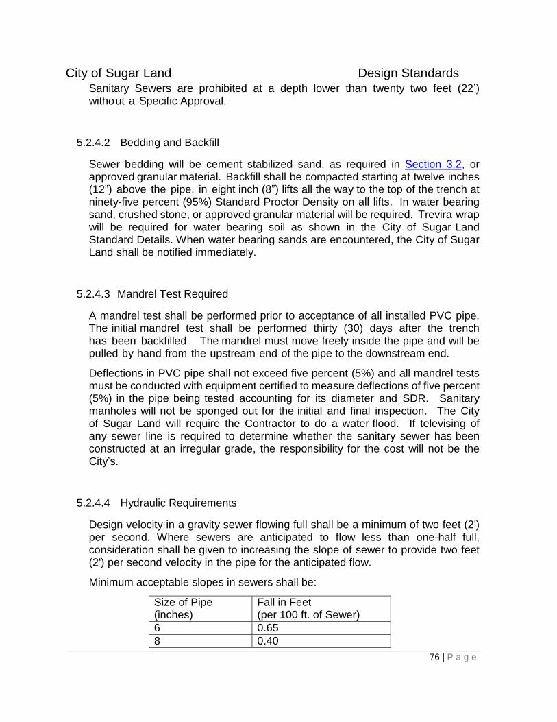
City of Sugar Land Design Standards
76 | P a g e
Sanitary Sewers are prohibited at a depth lower than twenty two feet (22’) without a Specific Approval.
5.2.4.2 Bedding and Backfill
Sewer bedding will be cement stabilized sand, as required in Section 3.2, or approved granular material. Backfill shall be compacted starting at twelve inches (12”) above the pipe, in eight inch (8”) lifts all the way to the top of the trench at ninety-five percent (95%) Standard Proctor Density on all lifts. In water bearing sand, crushed stone, or approved granular material will be required. Trevira wrap will be required for water bearing soil as shown in the City of Sugar Land Standard Details. When water bearing sands are encountered, the City of Sugar Land shall be notified immediately.
5.2.4.3 Mandrel Test Required
A mandrel test shall be performed prior to acceptance of all installed PVC pipe. The initial mandrel test shall be performed thirty (30) days after the trench has been backfilled. The mandrel must move freely inside the pipe and will be pulled by hand from the upstream end of the pipe to the downstream end.
Deflections in PVC pipe shall not exceed five percent (5%) and all mandrel tests must be conducted with equipment certified to measure deflections of five percent (5%) in the pipe being tested accounting for its diameter and SDR. Sanitary manholes will not be sponged out for the initial and final inspection. The City of Sugar Land will require the Contractor to do a water flood. If televising of any sewer line is required to determine whether the sanitary sewer has been constructed at an irregular grade, the responsibility for the cost will not be the City’s.
5.2.4.4 Hydraulic Requirements
Design velocity in a gravity sewer flowing full shall be a minimum of two feet (2') per second. Where sewers are anticipated to flow less than one-half full, consideration shall be given to increasing the slope of sewer to provide two feet (2') per second velocity in the pipe for the anticipated flow.
Minimum acceptable slopes in sewers shall be:
Size of Pipe (inches)
Fall in Feet (per 100 ft. of Sewer)
6 0.65
8 0.40
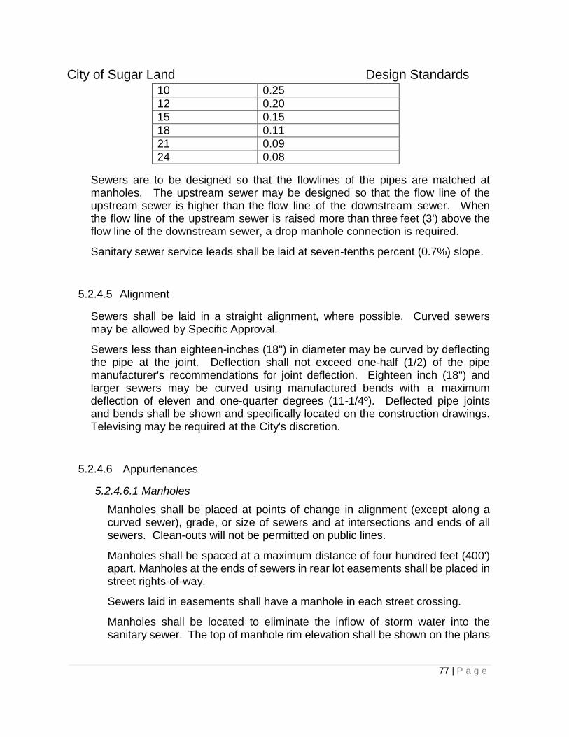
City of Sugar Land Design Standards
77 | P a g e
10 0.25
12 0.20
15 0.15
18 0.11
21 0.09
24 0.08
Sewers are to be designed so that the flowlines of the pipes are matched at manholes. The upstream sewer may be designed so that the flow line of the upstream sewer is higher than the flow line of the downstream sewer. When the flow line of the upstream sewer is raised more than three feet (3') above the flow line of the downstream sewer, a drop manhole connection is required.
Sanitary sewer service leads shall be laid at seven-tenths percent (0.7%) slope.
5.2.4.5 Alignment
Sewers shall be laid in a straight alignment, where possible. Curved sewers may be allowed by Specific Approval.
Sewers less than eighteen-inches (18") in diameter may be curved by deflecting the pipe at the joint. Deflection shall not exceed one-half (1/2) of the pipe manufacturer's recommendations for joint deflection. Eighteen inch (18") and larger sewers may be curved using manufactured bends with a maximum deflection of eleven and one-quarter degrees (11-1/4º). Deflected pipe joints and bends shall be shown and specifically located on the construction drawings. Televising may be required at the City's discretion.
5.2.4.6 Appurtenances
5.2.4.6.1 Manholes
Manholes shall be placed at points of change in alignment (except along a curved sewer), grade, or size of sewers and at intersections and ends of all sewers. Clean-outs will not be permitted on public lines.
Manholes shall be spaced at a maximum distance of four hundred feet (400') apart. Manholes at the ends of sewers in rear lot easements shall be placed in street rights-of-way.
Sewers laid in easements shall have a manhole in each street crossing.
Manholes shall be located to eliminate the inflow of storm water into the sanitary sewer. The top of manhole rim elevation shall be shown on the plans
City of Sugar Land Design Standards
78 | P a g e
for all sanitary sewer manholes, except in paved areas. Sealed manholes may be permitted, within the 100-year flood plain by Specific Approval.
Manholes shall be constructed in accordance with the City of Sugar Land Standard Details. Compaction around sanitary sewer manholes shall be 95% Standard Proctor Density or better.
A drop manhole shall be constructed for any sewer twelve-inch (12") diameter or less that enters a manhole greater than thirty-six inches (36") above the invert of the manhole. Sewers larger than twelve inches (12") shall be designed to accommodate a drop at the manhole using standard pipe fittings. The drop will be installed on the outside of the manhole and sealed inside and out. Steps in manholes will not be permitted.
Fiberglass manholes are not allowed as part of public sanitary sewer systems. All manholes within public rights-of-way and public easements shall be pre-cast or cast-in-place manholes.
Manhole covers shall be cast iron, traffic bearing type ring and cover in accordance with the City’s Standard Details. All man hole covers 32” or greater shall be ductile iron.
All manhole adjustments shall be made with pre-cast concrete rings.
Manholes shall be coated in accordance with the City of Sugar Land Construction Details and shall be vacuum tested in accordance with current TCEQ criteria.
All sanitary manholes shall be fitted with an inflow protector to prevent storm water intrusion to the sanitary sewer collection system.
All commercial developments with a far side (across the street) sanitary service lead shall provide a six (6) inch riser and cleanout on the property side. Public maintenance of the far side lead shall end at this riser.
5.2.4.6.2 Stacks
Stacks shall be constructed for connections to sewers that are more than eight feet (8') below finished grade. Stacks shall be provided during the initial construction of the sewer.
5.3 LIFT STATIONS
City of Sugar Land Design Standards
79 | P a g e
5.3.1 Engineering Report and Shop Drawings Required
Prior to design, a detailed engineering report shall be submitted to the Development Review Coordinator for review and approval of the lift station and all related line work. The Development Review Coordinator will specify the number of copies of the report to be submitted.
The engineering report shall include the following:
1. A master development plan for the service area of the proposed lift station. This plan shall include a map showing the location of the lift station, the service area, the boundaries of the drainage basin it is in and the location of the nearest existing wastewater interceptor within that basin.
2. Engineering calculations and data as required by Section 5.3.3.
3. The Engineering Report shall be approved by the City prior to beginning preparation of the plans and specifications.
For projects not in MUDs, once the engineering report and the construction plans and specifications have been approved, shop drawing submittals shall be provided to the City. These submittals shall contain complete detailed information and drawings for all lift station equipment and components. The City Engineer will specify the number of copies of each submittal that will be required.
5.3.2 City Operation and Maintenance Acceptance
The City of Sugar Land may accept a lift station with a firm pumping capacity greater than 25 gpm for operation and maintenance, provided an agreement is negotiated with the City.
5.3.3 Lift Station Design Criteria
Lift stations are discouraged and will be allowed only where conventional gravity service is not feasible. Feasibility is to be determined by a life-cycle cost comparison of a gravity system and the lift station project for a 30-year project life. All lift stations shall utilize submersible pumps.
5.3.3.1 Flow Development
Calculation of wastewater flow shall be based on the following formula:
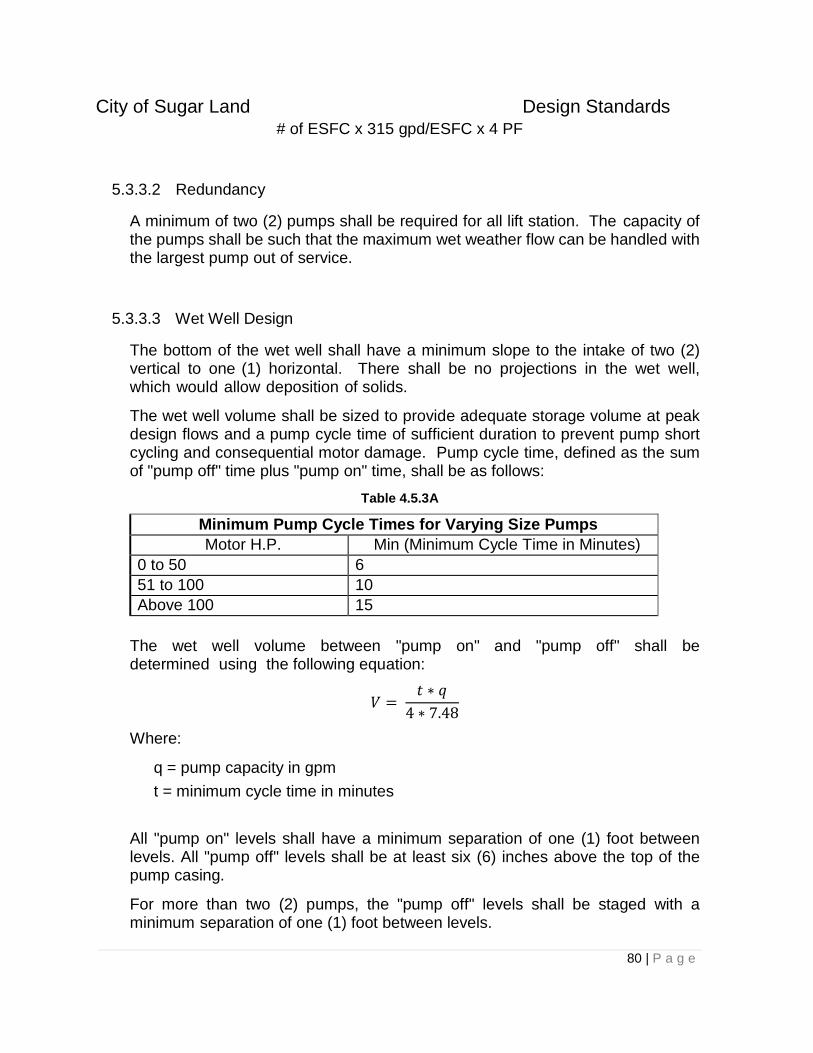
City of Sugar Land Design Standards
80 | P a g e
# of ESFC x 315 gpd/ESFC x 4 PF
5.3.3.2 Redundancy
A minimum of two (2) pumps shall be required for all lift station. The capacity of the pumps shall be such that the maximum wet weather flow can be handled with the largest pump out of service.
5.3.3.3 Wet Well Design
The bottom of the wet well shall have a minimum slope to the intake of two (2) vertical to one (1) horizontal. There shall be no projections in the wet well, which would allow deposition of solids.
The wet well volume shall be sized to provide adequate storage volume at peak design flows and a pump cycle time of sufficient duration to prevent pump short cycling and consequential motor damage. Pump cycle time, defined as the sum of "pump off" time plus "pump on" time, shall be as follows:
Table 4.5.3A
Minimum Pump Cycle Times for Varying Size Pumps
Motor H.P. Min (Minimum Cycle Time in Minutes)
0 to 50 6
51 to 100 10
Above 100 15
The wet well volume between "pump on" and "pump off" shall be determined using the following equation:
𝑉 = 𝑡 ∗ 𝑞
4 ∗ 7.48
Where:
q = pump capacity in gpm
t = minimum cycle time in minutes
All "pump on" levels shall have a minimum separation of one (1) foot between levels. All "pump off" levels shall be at least six (6) inches above the top of the pump casing.
For more than two (2) pumps, the "pump off" levels shall be staged with a minimum separation of one (1) foot between levels.
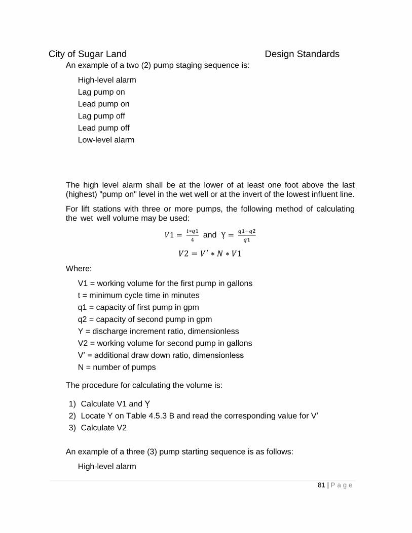
City of Sugar Land Design Standards
81 | P a g e
An example of a two (2) pump staging sequence is:
High-level alarm
Lag pump on
Lead pump on
Lag pump off
Lead pump off
Low-level alarm
The high level alarm shall be at the lower of at least one foot above the last (highest) "pump on" level in the wet well or at the invert of the lowest influent line.
For lift stations with three or more pumps, the following method of calculating the wet well volume may be used:
𝑉1 = 𝑡∗𝑞1
4 and Ỵ =
𝑞1−𝑞2
𝑞1
𝑉2 = 𝑉′ ∗ 𝑁 ∗ 𝑉1
Where:
V1 = working volume for the first pump in gallons
t = minimum cycle time in minutes
q1 = capacity of first pump in gpm
q2 = capacity of second pump in gpm
Y = discharge increment ratio, dimensionless
V2 = working volume for second pump in gallons
V’ = additional draw down ratio, dimensionless
N = number of pumps
The procedure for calculating the volume is:
1) Calculate V1 and Ỵ
2) Locate Y on Table 4.5.3 B and read the corresponding value for V’
3) Calculate V2
An example of a three (3) pump starting sequence is as follows:
High-level alarm
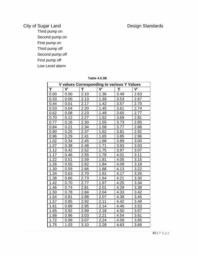
City of Sugar Land Design Standards
82 | P a g e
Third pump on
Second pump on
First pump on
Third pump off
Second pump off
First pump off
Low Level alarm
Table 4.5.3B
V values Corresponding to various Y Values
Ỵ V' Ỵ V' Ỵ V'
0.00 0.00 2.10 1.36 3.49 2.63
0.33 0.00 2.13 1.39 3.53 2.67
0.44 0.01 2.17 1.42 3.57 2.70
0.53 0.04 2.20 1.45 3.61 2.74
0.62 0.08 2.23 1.49 3.65 2.77
0.70 0.12 2.27 1.52 3.69 2.81
0.77 0.16 2.30 1.55 3.73 2.85
0.84 0.21 2.34 1.58 3.77 2.88
0.90 0.25 2.37 1.62 3.81 2.92
0.96 0.29 2.41 1.65 3.85 2.96
1.02 0.34 2.45 1.68 3.89 3.00
1.07 0.38 2.48 1.71 3.93 3.03
1.12 0.42 2.52 1.75 3.97 3.07
1.17 0.46 2.55 1.78 4.01 3.11
1.22 0.51 2.59 1.81 4.05 3.15
1.26 0.55 2.62 1.84 4.09 3.18
1.30 0.59 2.66 1.88 4.13 3.22
1.34 0.63 2.70 1.91 4.17 3.26
1.38 0.66 2.73 1.94 4.21 3.30
1.42 0.70 2.77 1.97 4.25 3.34
1.46 0.74 2.81 2.01 4.29 3.38
1.50 0.78 2.84 2.04 4.33 3.42
1.54 0.81 2.88 2.07 4.38 3.45
1.57 0.85 2.92 2.11 4.42 3.49
1.61 0.89 2.95 2.14 4.46 3.53
1.65 0.92 2.99 2.18 4.50 3.57
1.68 0.96 3.03 2.21 4.54 3.61
1.72 0.99 3.07 2.24 4.58 3.65
1.75 1.03 3.10 2.28 4.63 3.69
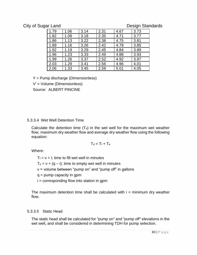
City of Sugar Land Design Standards
83 | P a g e
1.79 1.06 3.14 2.31 4.67 3.73
1.82 1.09 3.18 2.35 4.71 3.77
1.86 1.13 3.22 2.38 4.75 3.81
1.89 1.16 3.26 2.42 4.79 3.85
1.92 1.19 3.29 2.45 4.84 3.89
1.96 1.23 3.33 2.49 4.88 3.93
1.99 1.26 3.37 2.52 4.92 3.97
2.03 1.29 3.41 2.56 4.96 4.01
2.06 1.33 3.45 2.59 5.01 4.05
Y = Pump discharge (Dimensionless)
V' = Volume (Dimensionless)
Source: ALBERT PINCINE
5.3.3.4 Wet Well Detention Time
Calculate the detention time (Td) in the wet well for the maximum wet weather flow, maximum dry weather flow and average dry weather flow using the following equation:
Td = Tf + Te
Where:
Tf = v + i; time to fill wet well in minutes
Te = v + (q – i); time to empty wet well in minutes
v = volume between “pump on” and “pump off” in gallons
q = pump capacity in gpm
i = corresponding flow into station in gpm
The maximum detention time shall be calculated with i = minimum dry weather flow.
5.3.3.5 Static Head
The static head shall be calculated for "pump on" and "pump off" elevations in the wet well, and shall be considered in determining TDH for pump selection.
City of Sugar Land Design Standards
84 | P a g e
5.3.3.6 Net Positive Suction Head
The net positive suction head (NPSH) required by the pump selected shall be compared with the NPSH available in the system at the eye of the impeller. The engineer shall consult the pump manufacturer for the NPSH required values for that pump and compare them with calculated values for the NPSH available. The NPSH available should be greater than the NPSH required for a flooded suction pump. The following equation may be used for calculating the NPSH available:
NPSHA = PB + HS – PV - Hfs
Where:
PB = barometric pressure in feet absolute
Hs = minimum static suction head in feet
Pv = vapor pressure of liquid in feet absolute
Hfs = friction loss in suction in feet (where applicable)
For lift stations in the City of Sugar Land's service area, a barometric pressure of 33.4 feet and a vapor pressure of one and four-tenths (1.4) feet may be used. These values are based on the following assumptions: an altitude of 500 feet above sea level, a water temperature of 85ºF and a specific gravity of water of 0.996 at 85ºF.
5.3.3.7 Suction Piping Design
All suction piping shall be flanged ductile iron and have a minimum diameter of four (4) inches. Each pump shall have a separate suction pipe.
Suction piping shall have a velocity of three (3) to five (5) fps.
5.3.3.8 Force Main Design
Except for force mains connected to grinder pump lift stations, all force mains shall be PVC or ductile iron with non-corrosive lining and a minimum diameter of four (4) inches. Force main pipe within the station shall be flanged. Flexible fittings shall be provided at the exit wall.
Force mains shall be sized so that the flow velocity is between three (2.0) and six (6.0) feet per second at ultimate development. The maximum time required to flush the force main shall be calculated on the basis of pump capacity.
City of Sugar Land Design Standards
85 | P a g e
Odor and corrosion control shall be provided for the force main if the force main detention time exceeds 30-minutes. Alternately, a dual force main approach may be used to reduce the detention time.
Air release valves are only permitted when there are no feasible alternatives. The location and size of all air release valves shall be evaluated for potential to create an odor nuisance to adjacent property by the Design Engineer.
Lift stations including their associated force main systems shall be evaluated for their sulfide generation potential and ability to achieve scouring velocities during average dry weather flow periods. If the evaluation indicates that sulfide concentrations of greater than 2 ppm and solids deposition are likely, the design shall:
1. Define a workable sulfide control technique that will minimize sulfide formation in the force main,
2. Include "pig" launching stations and recovery points to allow cleaning of the force main, and
3. Protect the gravity main and manholes downstream of the force main from corrosion.
The force main shall discharge into its own distinct manhole. Multiple force mains shall not discharge into a single manhole.
5.3.3.9 Head Loss Curves
Data points for the system capacity curve shall be provided in tabular form and graphed with the pump head capacity curve on the same graph. Two system capacity curves shall be plotted using the Hazen Williams coefficient values of C = 100 and C = 140.
Pump output in gallons per minute (gpm) at the maximum and minimum heads shall be clearly shown on the system curve for each pump and combination of pumps.
For stations with two (2) or more pumps operating in parallel, multiple pump and single pump operation points shall be plotted on the system curve.
Pumps shall be selected so that their efficiency is maximized at all operating points.
If pumps are equipped with smaller impellers during initial development phases to handle flows less than the ultimate design flow, the ultimate impeller size shall also be provided.
City of Sugar Land Design Standards
86 | P a g e
5.3.3.10 Buoyancy Calculations
The lift station design shall include a complete analysis of buoyant forces on the entire lift station structure.
5.3.3.11 Water Hammer
Calculation of the maximum pressures resulting from water hammer, expected to occur upon total power failure while pumping, is required for all lift stations.
The following equations are to be used.
P = a*V + Poperating*2.31*g
Where:
P = water hammer pressure (psi)
a = pressure wave velocity (ft/s)
w = specific weight of water (62.4 lb/ft3)
g = acceleration of gravity (32.2 ft/s2)
k = bulk modulus of water (300,000 psi)
d = inside diameter of pipe (in)
E = Young’s modulus of pipe (psi)
t = pipe wall thickness (in)
v = flow velocity in pipe (ft/s)
Surge control measures shall be provided when pressures, including those due to water hammer, exceed the pressure rating of the pipe.
5.3.3.12 Suction Specific Speed (If Applicable)
The suction specific speed of the pumps shall be calculated using the following formula:
𝑁𝑆𝑆 = 𝜔 ∗ 𝑞1/2
𝑁𝑃𝑆𝐻𝑅1/2
Where:
NSS = Suction Specific Speed
= pump shaft rotational speed in rpm
q = flow rate capacity in m3/min

City of Sugar Land Design Standards
87 | P a g e
NPSHR = Required Net Positive Suction Head (m)
The suction specific speed should be below 9,000 rpm to prevent cavitation due to internal recirculation.
5.3.3.13 Stiffness Ratio
In order to ensure that the pump shaft does not bend an excessive amount, the Design Engineer shall calculate the stiffness ratio of the shaft using the following equation:
Stiffness Ratio = 𝐿3
𝐷4
Where:
L = distance between centerlines of impeller and inboard bearing (in)
D = diameter of shaft (in)
The stiffness ratio shall not exceed 60.
5.3.3.14 Energy Calculations
Energy costs shall be calculated using the following equations:
a. Calculate the water horsepower required.
P = (Q)(h)(8.34 lb/gal) = 33,000 ft-lb min/hp
where:
P = water horsepower (hp) Q = flow, gallons per minute (gpm) H = head, feet (ft)
b. Calculate the brake horsepower required.
Bhp = P / pump efficiency*
where:
Bhp = brake horsepower (hp) P = water horsepower (hp)
* Use the most efficient pumps for the application.
City of Sugar Land Design Standards
88 | P a g e
c. Calculate the electrical horsepower required
Ehp = Bhp / motor efficiency
where:
Ehp = electrical horsepower (hp) Bhp = brake horsepower (hp)
* Use the most efficient motors for the application
d. Calculate the power required in kilowatts.
EkW=(Ehp )(0.746 Kw/hp) e. Calculate daily power consumption in kilowatt-hours.
E = [(EkW1)(t1) + (EkW2)(t2) + (E kW3)(t3)...]
where:
E = total power consumption, kilowatt hours (kWh) per day EkWn = power required, kilowatts for pumps 1,2,...,n tn = estimated pump run time in hours per day for pumps 1,2,...,n
5.3.3.15 Stress and Thrust Calculations
Stress and thrust calculations for internal station piping and bends shall be provided for stations with flows over 1000 gpm.
5.3.3.16 Specific Station Requirements
All stations will be required to have an equipment-lifting device. For submersible pumps, lifting chains with slide rails are adequate.
A manhole must be constructed on the influent side of the lift station within 30 feet of the wet well for purposes of operating bypass pumps.
At the time of final inspection, all pumps must be pulled by the contractor to do a routine check for potential problems covered under the manufacturer's warranty.
Stations with motors 75 hp and larger shall have reduced voltage starters of the auto transformer or solid-state soft start type. Part winding starters and motors are not acceptable. Motors larger than 75 hp shall be designed with a maximum temperature rise not to exceed 80°C over a 40°C ambient temperature. Motors larger than 300 hp may require a higher temperature rise and a Specific Approval.
City of Sugar Land Design Standards
89 | P a g e
Entrance hatches larger than 40 inches in diameter or heavier than 25 pounds shall be spring loaded.
Valves higher than six (6) feet above the floor shall have chain operators.
Any potable water supply below the overflow elevation of the wet well shall be protected by an air gap.
All lift stations shall have an emergency by-pass connection.
All access hatches must be traffic grade, non-skid aluminum.
The minimum site size is 50-feet by 50-feet. A larger site may be required for stations with three or more pumps.
Where fencing of the station is specified, stations shall have an enclosure that is a minimum of eight feet (8’) tall, the material of which must comply with the Development Code. A minimum 12-foot wide gate opening shall be provided at the access drive.
All stations require an access drive that terminates at the center of the wet well.
Submersible dry-pits shall be no deeper than five feet unless removable grating is used over the dry pit to provide access.
5.4 Service Connections
Sewer service leads shall not exceed one hundred and fifty feet (150') in length. Near side double sewer service leads shall not exceed fifteen feet (15’) in length and shall be located within a public right-of-way or easement.
5.4.1 Single-Family Residential Lots
Both far side service connections and near side connections shall be installed at the time of construction of the sewer. Double sewer service leads shall be located within a public right-of- way or easement.
All sanitary sewer service leads shall be located at the opposite corner of the water service leads for each property. If it is not possible for both the water and sanitary leads to be located at the corner, then the sanitary lead may deviate from the corner to meet minimum separation requirements. (See Fig. 5-1)
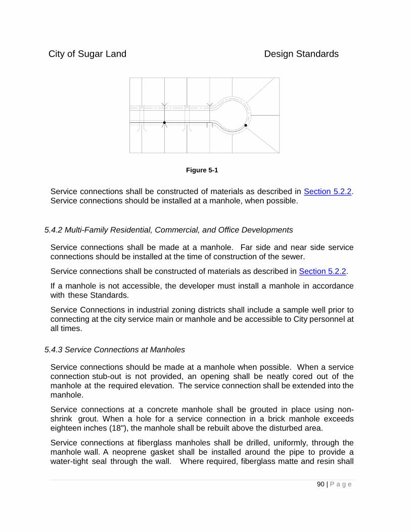
City of Sugar Land Design Standards
90 | P a g e
Figure 5-1
Service connections shall be constructed of materials as described in Section 5.2.2. Service connections should be installed at a manhole, when possible.
5.4.2 Multi-Family Residential, Commercial, and Office Developments
Service connections shall be made at a manhole. Far side and near side service connections should be installed at the time of construction of the sewer.
Service connections shall be constructed of materials as described in Section 5.2.2.
If a manhole is not accessible, the developer must install a manhole in accordance with these Standards.
Service Connections in industrial zoning districts shall include a sample well prior to connecting at the city service main or manhole and be accessible to City personnel at all times.
5.4.3 Service Connections at Manholes
Service connections should be made at a manhole when possible. When a service connection stub-out is not provided, an opening shall be neatly cored out of the manhole at the required elevation. The service connection shall be extended into the manhole.
Service connections at a concrete manhole shall be grouted in place using non-shrink grout. When a hole for a service connection in a brick manhole exceeds eighteen inches (18"), the manhole shall be rebuilt above the disturbed area.
Service connections at fiberglass manholes shall be drilled, uniformly, through the manhole wall. A neoprene gasket shall be installed around the pipe to provide a water-tight seal through the wall. Where required, fiberglass matte and resin shall
City of Sugar Land Design Standards
91 | P a g e
be used, in accordance with the manufacturer's recommendations, to repair wall openings.
Service connections entering a manhole three feet (3') or more above the flow line of the manhole shall include a drop pipe with fittings outside the manhole. The drop shall be installed adjoining and anchored to the wall of the manhole.
Adequate markings shall be provided on site, and on record drawings, to facilitate recovery of the service connection stub-out at the time the connection to the service is made. Connections to the public sewer system shall be inspected by a representative of the City within the City’s limits or approved by the District Operator in the extraterritorial jurisdiction.
Service connections that are installed after initial construction of a sewer shall be constructed using a PVC saddle with gasket and stainless steel straps.
5.5 Building Sites without Sanitary Sewer Service
Building sites without sanitary sewer service are not permitted within the City’s limits or ETJ. Sanitary sewer shall be extended to all building sites prior to development. On-site sewage facilities that comply with all TCEQ requirements require Specific Approval.
6.0 DRAINAGE DESIGN REQUIREMENTS
6.1 General
All drainage plans and construction shall meet or exceed the requirements of the City of Sugar Land, Fort Bend County Drainage District (FBCDD), and all other entities having jurisdiction. All storm sewers constructed within the City of Sugar Land and its extraterritorial jurisdictional (ETJ) areas shall meet or exceed the requirements of this Design Standard. All storm sewer construction shall conform to the City of Sugar Land Standard Details.
The intent of these drainage standards is to reduce structural flooding and street ponding as a result of storm events up to the 100-year storm through the implementation of this criterion in design of storm sewers, roadside ditches, detention facilities, open channels and management of overland (sheet) flow as singular components or as part of a combined system.
In regards to development within the 100-year mapped FEMA floodplain, consult with the City of Sugar Land Floodplain Administrator for additional design criteria and structural requirements.
In regards to the development which incorporates a levee system, the Design Engineer shall coordinate directly with the City Engineer and use as a basis of the
City of Sugar Land Design Standards
92 | P a g e
levee design the criteria detailed in the FBCDD Drainage Criteria Manual, including requirements for the coincidental rainfall event.
6.1.1 Definitions
Within this Division, the listed terms shall be construed to mean the following:
24-Hour Design Storm IsoHyetograph – the rainfall type to be utilized within hydrologic modeling software such as HEC-HMS.
Backslope Drain - A drain or swale located along the high bank of drainage channels and detention basins that collect overland runoff from adjacent property areas not draining into the storm sewer collection system. Installation of backslope drains assist in preventing overland drainage from eroding the sides of a ditch or basin.
Benchmark - A point of established elevation, set and used by Surveyors as a reference to obtain elevations on other points of unknown elevation. The known elevation is usually based on “mean sea level”, and is referenced to a “Year of Adjustment”. All plans submitted to the City of Sugar Land shall provide a reference to the benchmark system referenced to the City of Sugar Land benchmark system (NAVD 88, 2001 Adjustment).
Coefficient of Roughness - A number used to measure and compare the roughness of pipe interior or open channel sides and bottom.
Commercial - Development of real estate for any purpose other than “residential” as defined herein.
Conduit – An enclosed pipe or device for conveying flowing water.
Continuity Equation – Q = VA
Where:
Q = discharge (cfs)
V = velocity (ft/s)
A = cross-sectional area of conduit (sq. ft.)
Contour Line - A line on a map, chart or plan that follows a continuous line of a certain known elevation.
Design Storm Event – Rainfall intensity and duration upon which the drainage facility will be sized.
Detention Control Structure - The outlet pipe or weir, and high-level spillway that limits the rate of discharge from a detention facility.
City of Sugar Land Design Standards
93 | P a g e
Detention Facility - A reservoir, dam, basin or other area where storm water collects and is held temporarily, “detained”. The collected storm water is released at a calculated rate through a detention control structure.
Development - A tract of land that has been improved exclusive of land being used and continuing to be used for agricultural purposes. Improvement of land includes grading, paving, building structures, or otherwise changing the runoff characteristics of the land.
Drainage Area Map – Area map of a watershed which is subdivided to show each area served by a respective drainage feature or system.
Drainage Arteries - Natural or man-made ditches or channels that intercept and convey storm water to a larger creek, bayou or stream.
Drainage Report - An engineering representation describing the results of analyses of existing and/or proposed drainage conditions that may take the form of letter reports or more extensive and formal bound reports. Reports may be submitted as a basis for better understanding of existing conditions to support a request for approval of construction documents for a proposed facility or to serve as a plan for future conditions. It will contain details on the systems that will be used to convey, detain or otherwise control runoff for the proposed conditions.
Drainage Channel – A drainage feature to collect and convey storm water runoff from a watershed, which exceeds a depth of four feet.
Drainage System - A series of swales, storm sewers, conduits, ditches and creeks which function to collect and convey storm water runoff in a watershed.
Easement - An area dedicated to a party for a specific use, but ownership of the area remains the property of the owner who granted the easement, their heirs and assigns. The uses may be for drainage, maintenance, access, future widening of channel or ditch, or other specific uses.
Excess Runoff - The portion of the precipitation on the land that ultimately reaches the drainage system.
FBCDD – Fort Bend County Drainage District.
FEMA – Federal Emergency Management Agency.
FIRM - Flood Insurance Rate Maps published by the FEMA.
FIS – Flood Insurance Study issued by the Federal Emergency Management Agency.
Hydraulic Analysis - The study and/or definition of the movement of stormwater through a drainage system.
Hydraulic Grade Line (HGL) – A line representing the pressure head available at any given point within the drainage system.
City of Sugar Land Design Standards
94 | P a g e
Hydrologic Analysis - The study and/or definition of the amount, properties, distribution and circulation of storm water runoff over land or in the soil.
Hydro-mulching - A process used to establish vegetation on disturbed soil which helps to prevent erosion of the soil.
Impact - The effect of a proposed development on the hydrology and/or hydraulics of a subarea or watershed as defined by an increase or decrease in peak discharges (cfs) or water surface elevations (feet). Impacts shall be measured and reported to two decimal places (i.e., xx.00).
Impact Data - Data required to be contained within a Drainage Report which supports the conclusions of the analysis which defines the effects that the proposed development will have on the rainfall runoff rates, rainfall concentration times and the water surface level of the affected creek, stream, gully, drainage channel, storm sewer system or ditch into which proposed development runoff drains.
Impervious Cover - A land surface cover which does not allow the infiltration of storm water into the underlying soil. Used in hydrologic analysis to calculate the excess runoff from an area.
In-fill Development – Development of open tracts of land in areas where the storm drainage infrastructure is already in place
Metering Device - A device or structure containing pipe, V-notch weir, slots and other configurations designed to measure or regulate the outflow.
NGVD - National Geodetic Vertical Datum, pertaining to base elevations. (Typically 1929)
NAVD – North American Vertical Datum, pertaining to base elevations. (Typically 1988)
One-Lane-Passable – Width required on major thoroughfares and major collectors allowing passage of vehicular traffic during the 100-year storm event in the drainage system. The passable width shall be considered the pavement free from ponding water for a design water surface elevation (HGL) at the top of the outside curb of the roadway.
Outfall Structures - A structure made to contain the outfall pipe or peak discharge, with necessary weir, slope paving, riprap, or other methods to control velocity and prevent erosion, and may contain the metering device.
Outflow - The final peak discharge from the development drainage system into another or existing drainage system.
Overflow - The portion of the peak discharge that will not pass through the design pipe or structure, and shall be conveyed through a weir or some other relief structure.

City of Sugar Land Design Standards
95 | P a g e
Peak Discharge - The maximum rate of storm water runoff as determined from the maximum point of the calculated hydrograph for the study area in cubic feet per second (cfs).
Public Storm Sewers – Conduits and appurtenant structures that provide drainage for a public right-of-way or more than one private tract and are located in a public right-of-way or easement.
Private Storm Sewers - Provide internal drainage for a single reserve, development, or other tract.
Rainfall Data - Data pertaining to the amount of rainfall in a certain area and occurring over a certain specified period of time.
Rainfall Frequency – A rainfall event of defined characteristics related to the probability of occurrence in any given year.
For the purpose of storm drainage design, the following frequencies are applicable:
2-year frequency – a rainfall intensity having a 50 percent probability of occurrence in any given year.
3-year frequency – a rainfall intensity having a 33 percent probability of occurrence in any given year.
5-year frequency – a rainfall intensity having a 20 percent probability of occurrence in any given year.
10-year frequency – a rainfall intensity having a 10 percent probability of occurrence in any given year.
25-year frequency – a rainfall intensity having a 4 percent probability of occurrence in any given year.
100-year frequency – a rainfall intensity having a 1 percent probability of occurrence in any given year.
500-year frequency – a rainfall intensity having a 0.20 percent probability of occurrence in any given year.
Rational Formula – A method for calculating the peak run-off for a drainage system. The method uses the following equation:
Q = C*i*A
Where:
C = watershed runoff coefficient
i = rainfall intensity (in/hr)
A = area (acres)
Redevelopment – A change in land use that alters the impervious cover of a tract.
City of Sugar Land Design Standards
96 | P a g e
Regional Detention Facility- A detention facility that collects and holds storm water from more than one development or from major creeks or tributaries.
Residential - Of or pertaining to single family detached dwelling(s) not including multi-family townhomes, condominiums, or apartments.
Right-Of-Way - Land that is set aside and reserved for certain purposes including drainage and maintenance, and possibly future widening of a drainage channel.
Runoff Coefficient - A factor reflecting the ratio of runoff to rainfall intensity that is determined based on land use, impervious cover, soil type, slopes, vegetation and improvements.
Sheet Flow – Overland storm water run-off that is not conveyed in a defined conduit; it may be in excess of the capacity of a conduit where the hydraulic grade line extends above the gutter line or surface of the ground.
Spillway - The part of the outfall structure that allows and controls the “overflow” that does not go through principal discharge point of the structure.
Subdivide - To divide a tract of land into two or more smaller tracts or building lots.
Subdivision - A tract of land which has been separated from surrounding tracts and has been divided into two or more lots or reserves.
Swale - A shallow ditch that usually has gradually sloping sides, in some cases not much more that a small depression that conveys runoff.
Variance - A one-time formal exception to a particular rule or rules granted for extenuating circumstances, by the City Engineer.
Watershed - A region or area bounded peripherally by a ridge of higher elevation and draining ultimately to a particular watercourse or body of water.
6.2 Storm Sewer Materials
Storm sewer and culvert pipe shall be pre-cast reinforced Class III concrete pipe. Concrete pipe and box culverts shall be on the City’s Approved Products List and appropriate for the application. The Design Engineer shall provide for increased pipe strength when conditions of the proposed installation exceed the allowable load for Class III pipe. All concrete pipes shall have O-ring rubber gasketed joints. Pipe joints for box culverts shall be sealed with Ram Neck or equivalent.
Storm sewer outfalls into open channels shall be constructed using corrugated steel pipe or Reinforced Concrete Pipe. Corrugated steel pipe shall be on the City’s Approved Products List and appropriate for the application. Polypropylene pipe (PP) can be used in areas that are not subjected to traffic loads. High Density Polyethylene (HDPE) pipe shall not be utilized for public storm sewers.
City of Sugar Land Design Standards
97 | P a g e
Storm sewer outfalls shall have slope protection to prevent erosion. Slope protection shall be constructed of reinforced concrete pavement. Refer to the City of Sugar Land Standard Details for minimum dimensions.
6.3 Location of Storm Sewer
Public storm sewers shall be located within a public street right-of-way or a storm sewer easement, dedicated to the public and adjoining a public street right-of-way. In instances where it is impractical to place storm sewer adjoining a public street right-of-way, a permanent access right-of-way shall be dedicated (as drainage easement) 10-foot in width adjacent to the storm sewer easement for access.
All residential lots shall drain to a public right-of-way directly adjoining the lot, generally in a back to front pattern. Drainage from a residential lot to a public right-of-way at the rear or side of a lot may be permitted, provided the drainage system has been properly designed to accept the flow. Drainage from a residential lot to an adjoining greenbelt or golf course shall require a public drainage easement to be maintained by the Homeowner's Association or appropriate private entity. Drainage to a private easement shall require a Specific Approval and must be noted on the recorded subdivision plat. Drainage to a Fort Bend County drainage easement shall be approved by the FBCDD.
Private storm sewer connections to public storm sewers shall occur at a manhole or at the back of an inlet. Private drainage systems cannot discharge over public sidewalks or onto adjacent properties, except to existing ditches, creeks, streets or into public storm sewers located in public rights-of-way or easements. Private drainage into Texas Department of Transportation (TxDOT) ditch, road, or storm sewer, must be approved or documented with a permit, letter or note of no objection by TxDOT attached with the construction plans for final approval from the City of Sugar Land.
6.3.1 Public Street Right-of-Way
For all storm sewers located in a public street right-of-way, a minimum distance of five feet (5’) shall be maintained inside the right-of-way line to the outside edge of the storm sewer unless accompanied by an adjacent easement.
Storm sewers, other than inlet leads, shall be located to provide a minimum five feet (5’) from the back of curb to the wall of the pipe, and are permitted in the esplanade or median.
City of Sugar Land Design Standards
98 | P a g e
6.3.2 Storm Sewer Easement
Refer to the City of Sugar Land Development Code Chapter 5, Article III, Sec. 5-21 (3) for details regarding storm sewer easement requirements.
6.3.3 Drainage Channel and Swale Easements
Drainage Channels shall conform to the size requirements in Section 6.5.6 of this Standard and have dedicated right-of-way or easement width equal to the distance of the channel top width, plus the width for the required maintenance berms and back slope drainage systems on either side. All drainage channels constructed within the City of Sugar Land which discharge into a FBCDD easement or right-of-way shall be dedicated to FBCDD. FBCDD may require additional width.
Where a public road is adjacent to a channel, a back slope system is not needed, provided the maintenance berm drains to the road. A minimum width of 15-feet is satisfactory unless more distance is needed for public safety. The primary access to channels for inspection, maintenance, and modifications is at bridge and culvert crossings. In many cases, a guardrail or wing walls physically blocks access. Provide a minimum 15-foot wide unobstructed vehicular access around existing and future guardrails, walls, and plantings at crossings within a road right-of- way or public drainage easements.
Drainage swales for conveyance of sheet flow shall be placed in drainage easements. Drainage easements shall have a minimum width of the top width of the swale plus 2-feet on either side.
6.3.4 Utility Conflicts
The Design Engineer shall account for all utility conflicts with a storm sewer including water lines, sanitary sewers, street lighting, and all other utilities. See Section 6.5.3 for additional criteria.
6.4 Construction Plan Requirements
6.4.1 Drainage Area Map
A drainage area map and supporting data sheets shall be included in the construction plans. The drainage area map shall include:
A. Drainage areas, including areas draining from off-site onto or adjoining the project.
B. Design storm runoff.
City of Sugar Land Design Standards
99 | P a g e
C. 100-year storm runoff.
D. Route of overland flow including the overflow to a drainage way sized to accommodate the 100-year flow (Sheet Flow analysis).
E. Elevations for the 25-year and 100-year storms in the outfall channel.
F. Design discharge per inlet.
G. Maximum 100-year ponding elevation at each inlet.
6.4.2 Other Requirements
Detailed drainage calculations shall be submitted with the construction plans.
The Hydraulic Grade Line (HGL) for the design storm shall be shown on the construction drawings. Calculations for the elevation of the HGL shall be provided with the design storm drainage calculations.
6.5 Design Requirements
The minimum depth of a storm sewer (measured to the top of pipe) shall be twenty-four inches (24") below top of curb or finished grade, whichever is lower. The minimum size storm sewer for mains and inlet leads shall be twenty-four inch (24") inside diameter, and two-foot by two- foot (2’x2’) for reinforced concrete box culverts. At locations of pipe diameter change, the storm sewer shall match soffits of the pipe. To match flow lines at these locations, specific approval by variance shall be requested.
Storm sewers shall be constructed on a straight horizontal and vertical alignment between manholes. Storm sewers greater than or equal to forty-two inches (42") in diameter may be laid along a curve using manufactured bends of less than or equal to 11-1/4º. Camera inspection may be required on storm sewers constructed along a curve. Storm sewers greater than or equal to fifty-four inches (54”) in diameter may be constructed in the center of the street if approved by the City Engineer.
Storm sewers shall be bedded using cement stabilized sand that complies with the City of Sugar Land Standard Details.
6.5.1 Pipe Requirements
6.5.1.1 Reinforced Concrete Pipe
Reinforced concrete pipe shall be installed in compliance with the following cover restrictions:
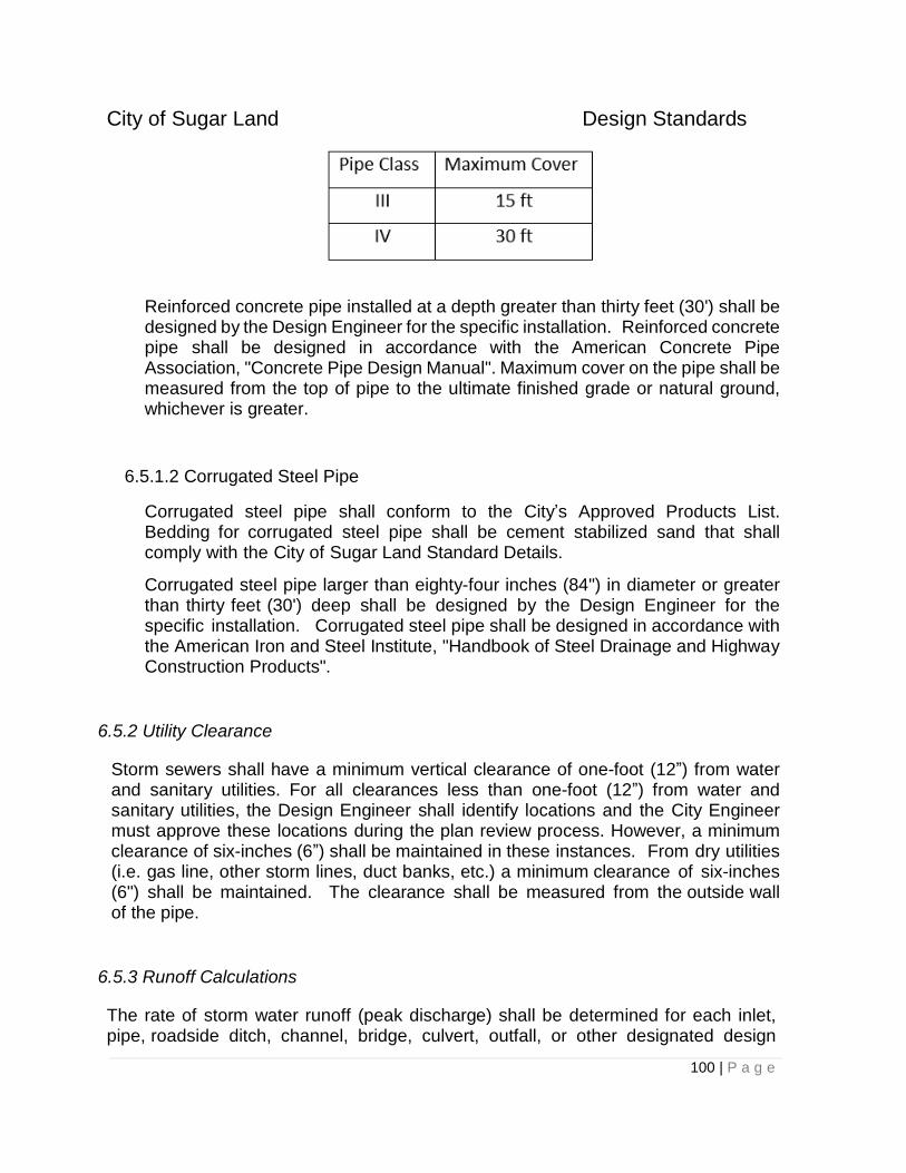
City of Sugar Land Design Standards
100 | P a g e
Reinforced concrete pipe installed at a depth greater than thirty feet (30') shall be designed by the Design Engineer for the specific installation. Reinforced concrete pipe shall be designed in accordance with the American Concrete Pipe Association, "Concrete Pipe Design Manual". Maximum cover on the pipe shall be measured from the top of pipe to the ultimate finished grade or natural ground, whichever is greater.
6.5.1.2 Corrugated Steel Pipe
Corrugated steel pipe shall conform to the City’s Approved Products List. Bedding for corrugated steel pipe shall be cement stabilized sand that shall comply with the City of Sugar Land Standard Details.
Corrugated steel pipe larger than eighty-four inches (84") in diameter or greater than thirty feet (30') deep shall be designed by the Design Engineer for the specific installation. Corrugated steel pipe shall be designed in accordance with the American Iron and Steel Institute, "Handbook of Steel Drainage and Highway Construction Products".
6.5.2 Utility Clearance
Storm sewers shall have a minimum vertical clearance of one-foot (12”) from water and sanitary utilities. For all clearances less than one-foot (12”) from water and sanitary utilities, the Design Engineer shall identify locations and the City Engineer must approve these locations during the plan review process. However, a minimum clearance of six-inches (6”) shall be maintained in these instances. From dry utilities (i.e. gas line, other storm lines, duct banks, etc.) a minimum clearance of six-inches (6") shall be maintained. The clearance shall be measured from the outside wall of the pipe.
6.5.3 Runoff Calculations
The rate of storm water runoff (peak discharge) shall be determined for each inlet, pipe, roadside ditch, channel, bridge, culvert, outfall, or other designated design
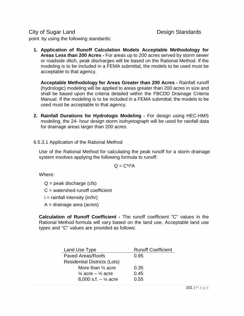
City of Sugar Land Design Standards
101 | P a g e
point by using the following standards:
1. Application of Runoff Calculation Models Acceptable Methodology for
Areas Less than 200 Acres - For areas up to 200 acres served by storm sewer or roadside ditch, peak discharges will be based on the Rational Method. If the modeling is to be included in a FEMA submittal, the models to be used must be acceptable to that agency. Acceptable Methodology for Areas Greater than 200 Acres - Rainfall runoff (hydrologic) modeling will be applied to areas greater than 200 acres in size and shall be based upon the criteria detailed within the FBCDD Drainage Criteria Manual. If the modeling is to be included in a FEMA submittal; the models to be used must be acceptable to that agency.
2. Rainfall Durations for Hydrologic Modeling - For design using HEC-HMS modeling, the 24- hour design storm isohyetograph will be used for rainfall data for drainage areas larger than 200 acres.
6.5.3.1 Application of the Rational Method
Use of the Rational Method for calculating the peak runoff for a storm drainage system involves applying the following formula to runoff:
Q = C*i*A
Where:
Q = peak discharge (cfs)
C = watershed runoff coefficient
i = rainfall intensity (in/hr)
A = drainage area (acres)
Calculation of Runoff Coefficient - The runoff coefficient "C" values in the Rational Method formula will vary based on the land use. Acceptable land use types and "C" values are provided as follows:
Land Use Type Runoff Coefficient
Paved Areas/Roofs 0.95
Residential Districts (Lots)
More than ½ acre 0.35
¼ acre – ½ acre 0.45
8,000 s.f. – ¼ acre 0.55
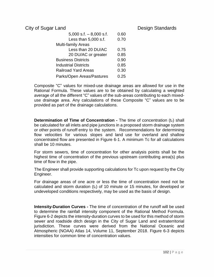
City of Sugar Land Design Standards
102 | P a g e
5,000 s.f. – 8,000 s.f. 0.60
Less than 5,000 s.f. 0.70
Multi-family Areas
Less than 20 DU/AC 0.75
20 DU/AC or greater 0.85
Business Districts 0.90
Industrial Districts 0.85
Railroad Yard Areas 0.30
Parks/Open Areas/Pastures 0.25
Composite “C” values for mixed-use drainage areas are allowed for use in the Rational Formula. These values are to be obtained by calculating a weighted average of all the different “C” values of the sub-areas contributing to each mixed-use drainage area. Any calculations of these Composite “C” values are to be provided as part of the drainage calculations.
Determination of Time of Concentration - The time of concentration (tc) shall be calculated for all inlets and pipe junctions in a proposed storm drainage system or other points of runoff entry to the system. Recommendations for determining flow velocities for various slopes and land use for overland and shallow concentrated flow are presented in Figure 6-1. A minimum Tc for all calculations shall be 10 minutes.
For storm sewers, time of concentration for other analysis points shall be the highest time of concentration of the previous upstream contributing area(s) plus time of flow in the pipe.
The Engineer shall provide supporting calculations for Tc upon request by the City Engineer.
For drainage areas of one acre or less the time of concentration need not be calculated and storm duration (tc) of 10 minute or 15 minutes, for developed or undeveloped conditions respectively, may be used as the basis of design.
Intensity-Duration Curves - The time of concentration of the runoff will be used to determine the rainfall intensity component of the Rational Method Formula. Figure 6-2 depicts the intensity-duration curves to be used for this method of storm sewer and roadside ditch design in the City of Sugar Land and extraterritorial jurisdiction. These curves were derived from the National Oceanic and Atmospheric (NOAA) Atlas 14, Volume 11, September 2018. Figure 6-3 depicts intensities for common time of concentration values.
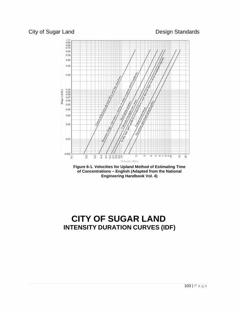
City of Sugar Land Design Standards
103 | P a g e
CITY OF SUGAR LAND INTENSITY DURATION CURVES (IDF)
Figure 6-1. Velocities for Upland Method of Estimating Time of Concentrations – English (Adapted from the National
Engineering Handbook Vol. 4)
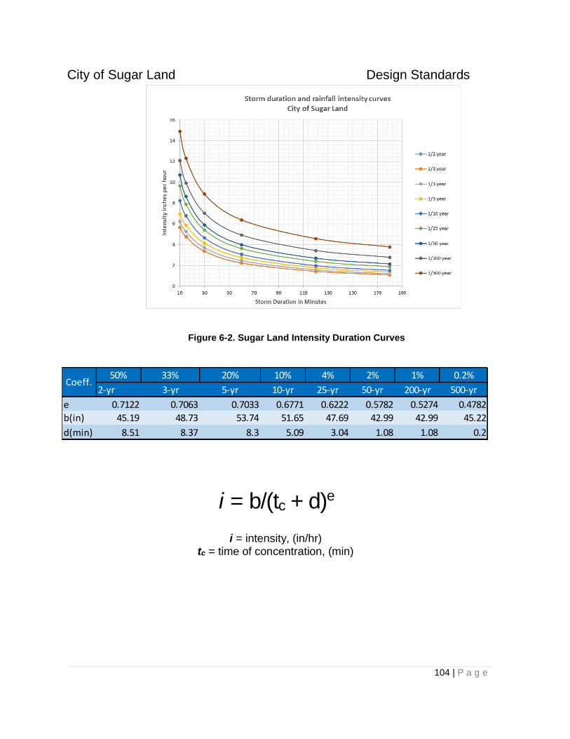
City of Sugar Land Design Standards
104 | P a g e
Figure 6-2. Sugar Land Intensity Duration Curves
i = b/(tc + d)e
i = intensity, (in/hr) tc = time of concentration, (min)
50% 33% 20% 10% 4% 2% 1% 0.2%
2-yr 3-yr 5-yr 10-yr 25-yr 50-yr 200-yr 500-yr
e 0.7122 0.7063 0.7033 0.6771 0.6222 0.5782 0.5274 0.4782
b(in) 45.19 48.73 53.74 51.65 47.69 42.99 42.99 45.22
d(min) 8.51 8.37 8.3 5.09 3.04 1.08 1.08 0.2
Coeff.
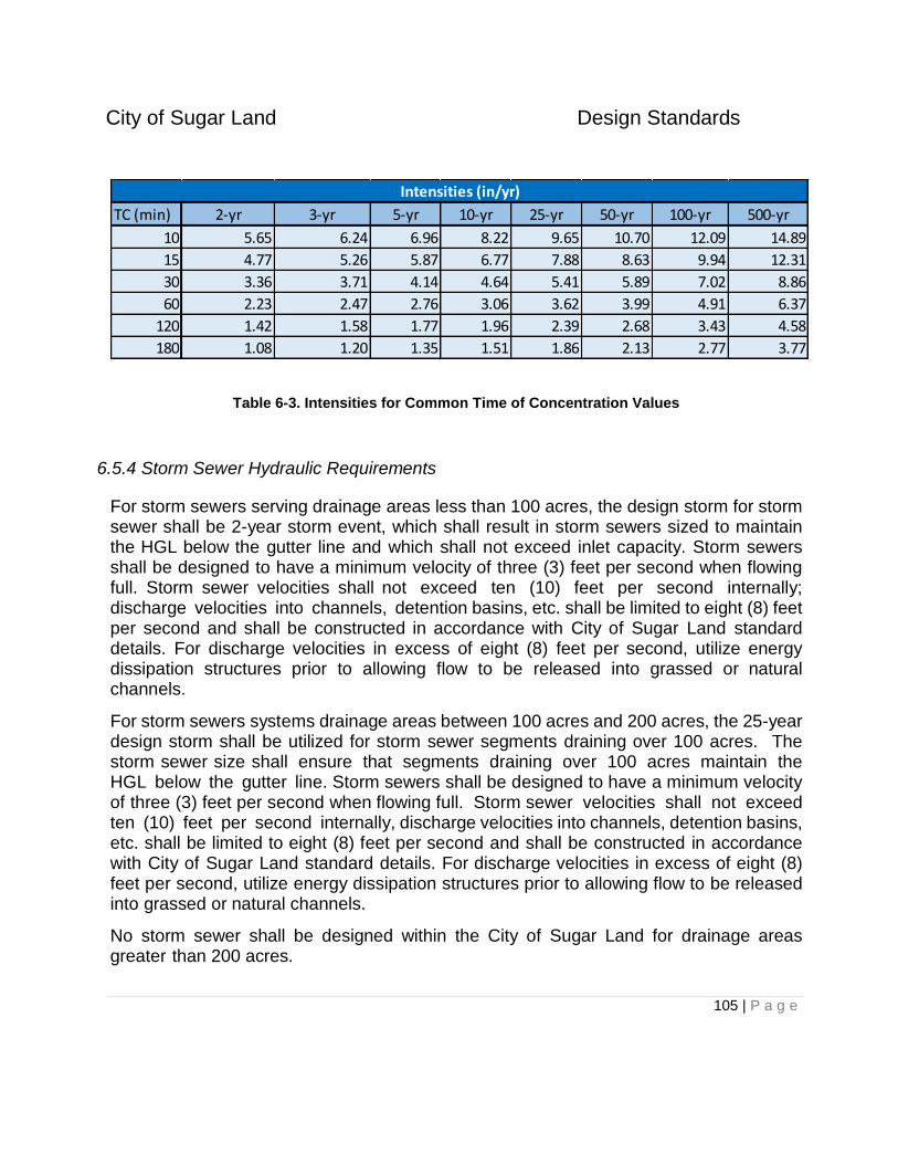
City of Sugar Land Design Standards
105 | P a g e
Table 6-3. Intensities for Common Time of Concentration Values
6.5.4 Storm Sewer Hydraulic Requirements
For storm sewers serving drainage areas less than 100 acres, the design storm for storm sewer shall be 2-year storm event, which shall result in storm sewers sized to maintain the HGL below the gutter line and which shall not exceed inlet capacity. Storm sewers shall be designed to have a minimum velocity of three (3) feet per second when flowing full. Storm sewer velocities shall not exceed ten (10) feet per second internally; discharge velocities into channels, detention basins, etc. shall be limited to eight (8) feet per second and shall be constructed in accordance with City of Sugar Land standard details. For discharge velocities in excess of eight (8) feet per second, utilize energy dissipation structures prior to allowing flow to be released into grassed or natural channels.
For storm sewers systems drainage areas between 100 acres and 200 acres, the 25-year design storm shall be utilized for storm sewer segments draining over 100 acres. The storm sewer size shall ensure that segments draining over 100 acres maintain the HGL below the gutter line. Storm sewers shall be designed to have a minimum velocity of three (3) feet per second when flowing full. Storm sewer velocities shall not exceed ten (10) feet per second internally, discharge velocities into channels, detention basins, etc. shall be limited to eight (8) feet per second and shall be constructed in accordance with City of Sugar Land standard details. For discharge velocities in excess of eight (8) feet per second, utilize energy dissipation structures prior to allowing flow to be released into grassed or natural channels.
No storm sewer shall be designed within the City of Sugar Land for drainage areas greater than 200 acres.
TC (min) 2-yr 3-yr 5-yr 10-yr 25-yr 50-yr 100-yr 500-yr
10 5.65 6.24 6.96 8.22 9.65 10.70 12.09 14.89
15 4.77 5.26 5.87 6.77 7.88 8.63 9.94 12.31
30 3.36 3.71 4.14 4.64 5.41 5.89 7.02 8.86
60 2.23 2.47 2.76 3.06 3.62 3.99 4.91 6.37
120 1.42 1.58 1.77 1.96 2.39 2.68 3.43 4.58
180 1.08 1.20 1.35 1.51 1.86 2.13 2.77 3.77
Intensities (in/yr)
City of Sugar Land Design Standards
106 | P a g e
Manning's Equation should be used to compute the size of the storm sewer. The following Manning's coefficient, n, is to be used for designs; 0.013 for concrete pipe; 0.024 for corrugated metal pipe with 2-2/3 x 1 corrugation; and 0.027 for corrugated metal pipe with 3x1 or 5x1 corrugations.
STARTING HYDRAULIC GRADE a. The hydraulic gradient shall be calculated assuming the top of the outfall pipe as
the starting water surface elevation, unless under submerged outfall conditions, then the static water surface at the outfall shall be considered the starting water surface elevation.
b. At drops in pipe invert, should the upstream pipe be higher than the hydraulic grade line, then the hydraulic grade line shall be recalculated from the top of the upstream pipe.
c. For storm sewer segments for which the 25-year design storm is utilized, the starting tailwater condition shall be the 25-year water surface within the outfall waterway.
d. For 100-year storm event analysis the starting hydraulic grade shall be the 25- year water surface within the outfall waterway.
The City Engineers may request confirmation that the timing of discharges from storm sewer systems does not adversely impact the discharge hydrograph of the receiving stream.
For any public street, the top of curb elevation shall be at or above the 100-year floodplain elevation based on the most current published FIRM panel maps or the best available data. For all public streets, the maximum ponding elevation calculated for the 100-year, 24-hour design storm, is to be the lowest of the following:
12” above the natural ground or abutting lots,
9” above top of the street curb, or
12” below the lowest slab elevation of buildings on abutting lots.
It is desirable that the maximum ponding elevation shall be confined to the public street right-of-way.
City of Sugar Land Design Standards
107 | P a g e
By Specific Approval, if the City has approved a development with reduced building setbacks and the imposition of these drainage standards would result in the streets, sidewalks, or public parking violating federal or state disabled accessibility requirements, the Design Engineer shall increase the size of the storm sewer to provide for street ponding and flow levels that are no less than five inches below the lowest building slab elevation on abutting lots. Without regard to any other provision of these Standards, building slab elevations on the abutting lots must be at least one foot above the adjacent gutter. (Ordinance No. 1324, Section 1, 2001)
The additional criteria of one-lane-passable shall apply to all major collectors and major thoroughfares for the 100-year, 24-hour storm event on the HGL of the storm sewer.
6.5.5 Roadside Ditch Hydraulic Requirements
The use of roadside ditches is allowed in redeveloped areas or in specific instances allowed by the City Engineer, and shall be in conformance with this standard. Outfall drainage to an existing roadside ditch shall be limited to tracts with frontage along the roadside ditch. If no frontage to the roadside ditch exists, but in review of detailed topographic data which shows the subject tract currently drains to the roadside ditch, an outfall will be allowed with full retention of discharges (1 acre-foot per acre detention). Maximum discharge rate into a roadside ditch shall be the flow rate defined by a previously approved drainage report and/or drainage area map, the rate of runoff from the front one hundred-fifty (150) feet of the tract calculated by the Rational Method assuming a runoff coefficient “C” of 0.2, or calculated based upon the pro-rata share of the existing capacity of the roadside ditch at the point of outfall. Capacity of the roadside ditch shall be computed using detailed topographic survey of the ditch and Manning’s Equation.
The design storm for roadside ditches shall be 2-year storm event and shall provide for the design water surface elevations to be maintained no higher than six (6) inches below the edge of pavement or the natural ground at the right-of-way line. The design shall ensure that during the 100-year storm event (24-hour) that no habitable structures will be flooded. Storm water discharges from a roadside ditch into a storm sewer system must be received by use of an appropriate structure (i.e., stubs with ring grates or type “E” inlet manholes).
City of Sugar Land Design Standards
108 | P a g e
Design parameters for roadside ditches are as follows:
a. Grass lined ditches shall have a maximum design velocity of four (4) feet per second (fps). For conditions where velocities will exceed four (4) feet per second, erosion control methods shall be utilized.
b. Grass lined ditches shall have side slopes not steeper than four horizontal to one vertical (4:1). Steeper grades will be allowed if slope paving is utilized and as approved by the City Engineer.
c. The minimum depth of a roadside ditch shall be eighteen inches (18”) and the maximum depth of a roadside ditch shall not exceed four (4) feet from the edge of pavement. If conditions warrant a deeper section, approval must be obtained from the City Engineer.
d. Grass lined ditches shall have a minimum design bottom width of two (2) feet. If conditions warrant a narrower section, approval must be obtained from the City Engineer.
e. Grass lined or paved ditches shall maintain a minimum of two (2) feet between the right-of-way line and the adjacent top bank.
f. Grass lined ditches shall have a minimum grade of 0.1 feet per 100 feet (0.1%).
g. Calculation of velocity shall be performed based upon a Manning’s roughness coefficient of 0.040 for earthen sections and 0.015 for paved inverts or sections.
The installation of culverts in roadside ditches to facilitate driveway and roadway crossings shall be permitted with approval of the City Engineer. Culverts shall be concrete (in compliance with Section 6.5.1.1 of this standard) and placed at crossings with a 3:1 end slope and protection with a safety end treatment (per City of Sugar Land Standard Detail or appropriate TxDOT standard). Culverts shall be designed assuming either inlet or outlet control, whichever situation governs. Culverts within roadside ditches shall be sized based upon the drainage area for the two (2) year storm event or the ditch capacity, whichever is greater (calculations to be provided), and shall have a minimum diameter of twenty-four (24) inches. The maximum allowable headloss through the culvert shall not exceed 0.20 feet greater than the normal depth water surface profile without the culvert.
6.5.6 Drainage Channel Hydraulic Requirements
New drainage channels shall be designed to contain the 100-year, 24-hour storm event for the proposed watershed conditions. When channel modifications are necessary to accommodate a proposed storm sewer outfall or to offset increased flows from a proposed development, design the modifications such that the 25-year and 100-year, 24-hour storm event water surface profiles upstream or downstream are not increased above existing
City of Sugar Land Design Standards
109 | P a g e
conditions. Hydraulic analysis of channels (modeling) shall utilize steady state methods consistent with guidance in the FBCDD Drainage Criteria Manual, unless prior approval from the City Engineer is obtained. Channels shall be designed based upon the following criteria and provide water surface elevations for the 25-year and 100-year design storms:
a. Minimum slope 0.05%, maximum slope shall limit velocities to 3 fps for sandy soils and 6 fps for clayey soils for grass lined channels and 12 fps for concrete lined or riprap lined channels.
b. Provide 1-foot (1’) of freeboard between the top of bank and the 100-year water surface elevation.
c. Channels shall have minimum bottom width of 6 feet and be trapezoidal shaped.
d. Side slopes on channels shall be no steeper than 4:1 for grass lined and 2:1 for concrete lined.
e. Channels shall have a center depression (pilot channel) of at least 0.5 foot for channel bottom widths between 6 and 20 feet, 1.0 foot for channel widths from 20 to 60 bottom foot, and utilize a 1% minimum cross slope for the bottom widths in excess of 60-foot. For bottom widths of 6 feet shall have a minimum 0.2 feet center depression.
f. Maintenance berm widths for grass lined channels 7 feet in depth or greater shall be 30- foot in width. Berm widths for grass lined channels less than 7 feet in depth or concrete lined shall be 15 foot in width. Berm widths for channels partially lined with concrete, articulating concrete blocks or riprap shall follow the requirements for grass lined channels.
g. All grass lined channels (including channels with pilot channels with concrete or other armoring) shall utilize backslope swale drainage systems; backslope drains shall outfall 1 foot above the channel bottom at the toe of slope.
h. Manning’s coefficient for channels shall be 0.04 for grass lined and riprap sections, and 0.015 for concrete lined sections.
i. Construction of concrete, riprap or articulating block lined channels and backslope drainage systems shall confirm to the City of Sugar Land Standard Details.
j. Design details regarding backslope interceptors, bends, curves, and other design elements shall be consistent with guidance in the FBCDD Drainage Criteria Manual unless otherwise detailed as more restrictive herein.
Geotechnical reports shall be prepared for drainage channels design which provides recommendations on side slopes, slope stability, soil erodibility, groundwater information and soil properties. A minimum of one (1) boring shall be provided for every 800 linear feet of channel. Depths of borings shall at a minimum extend five (5) feet below the excavation.
City of Sugar Land Design Standards
110 | P a g e
6.5.7 Bridges
All bridges shall have a low chord elevation a minimum of eighteen-inches (18") above the 100- year water surface elevation as defined by the FEMA FIS, provided by the City Engineer, or determined from an approved hydraulic analysis prepared by an Engineer.
For existing bridges which are replaced, coordinate with the City Engineer on the low chord elevation requirements.
6.5.8 Commercial Parking/Paved Areas
For commercial parking/paved areas greater than five (5) acres in size (including acreage of green spaces, forested areas within parking/paved area) shall require a high capacity storm sewer system. The internal storm drainage system for these areas shall be sized for a conduit capacity capable of maintaining hydraulic design conditions below parking lot elevations during a 10-year storm utilizing a top of pipe starting water surface elevation at the outfall.
6.6 Appurtenances
6.6.1 Manholes
Manholes shall be placed at all changes in alignment, grade and size of storm sewers (except bends as provided in Section 6.5); at the intersection of two or more storm sewers; at all inlet leads; and at the end of all storm sewers not intended to be extended. The maximum spacing between manholes shall be six hundred feet (600').
Manhole covers shall be cast iron, traffic bearing type, ring and cover with the words "City of Sugar Land Storm Sewer" cast into the cover, see the City’s Standard Detail.
6.6.2 Inlets
Inlet capacity for the design storm shall be computed using a maximum water surface elevation equal to the top of curb at the inlet. Design capacity for a Type B-B or H-2 inlet with a six-inch (6") standard curb shall be five (5) cubic feet per second. Design capacity for a Type B inlet shall not exceed two and one-half (2.5) cubic feet per second.
The maximum travel distance of water in the street to a curb inlet shall be three hundred feet (300') on a major collector or arterial and in commercial areas. The maximum travel
City of Sugar Land Design Standards
111 | P a g e
distance of water in the street permitted in a single-family residential area shall be four hundred feet (400').
Curb inlets shall be located on the intersecting side street at an intersection with a major collector or arterial.
Grated inlets may be permitted in an open ditch only with specific approval of the City Engineer. Back slope swale interceptors shall be placed in accordance with the requirements of FBCDD. Inlets must be backfilled with cement stabilized sand (1.5 sacks per cubic yard) placed to the bottom of pavement sub grade elevation. (Ordinance No. 1148, Section 2, 1998)
6.6.3 Safety End Treatments (SET)
Safety End Treatments (SET) must be placed on drainage culverts for commercial driveways, public streets, and residential driveways that cross open ditches located in the public right-of- way that are adjacent to and parallel to the public street. Safety End Treatments (SET) shall meet Texas Department of Transportation requirements. (Ordinance No. 1382, Section 2, 2003)
6.7 Storm Water Detention Requirements
6.7.1 General Design Requirements
A licensed engineer shall provide calculations for the peak runoff rate and required storage volume in accordance with these standards or FBCDD Drainage Criteria Manual whichever is more restrictive. The intent of storm water detention is to mitigate the effect of the new development on an existing drainage system. Detention is required for all areas which are being developed or redeveloped as defined in Section 6.1.1 of this standard.
The use of on-site detention is required for all new developments unless regional detention facilities are built to accommodate the subject development. To utilize a regional detention facility the Engineer shall document that the tract is located within the regional detention service area and that flows can be conveyed from the subject tract to the regional facility without adversely impacting property owners adjacent to or along the path of conveyance.
Private parking areas, private streets, and private storm sewers may be used for detention provided the maximum depth of flooding does not exceed six inches (6”) directly over the inlet in a parking lot and is in compliance with the ponding levels established in Section 6.5.4. Underground detention facilities may be utilized. Construction drawings shall document that structural design was performed for the structural components providing
City of Sugar Land Design Standards
112 | P a g e
the storage volume and the anticipated use of the surface area above the underground detention facility. Provisions must be included to inspect, clean and maintain underground detention facilities.
In addition to a pipe outlet, the detention basin shall be provided with an extreme event overflow that will provide a controlled bypass for flows should the detention basin be overtopped.
Detention ponds shall maintain a minimum of one foot (1-foot) of freeboard between the top of bank and the 100-year water surface elevation.
Geotechnical reports shall be prepared for detention basins which provide recommendations on side slopes, slope stability, soil erodability, groundwater information and soil properties. A minimum of one (1) boring for every 800 linear feet of channel and three (3) borings for detention basins less than 5-acres is size are required. Depths of borings shall at a minimum extend five (5) feet below the excavation. Please consult with the City Engineer for large detention basins, outfalls in the Brazos River and Oyster Creek, and for levees.
A maintenance easement shall be dedicated around detention facilities in accordance with the Development Code (exterior edge of maintenance berm). The width of the berm around the detention basin may vary based on the depth of the facility.
Depth of Basin
(ft) Maintenance Berm Width
(ft)
≤ 7 ft 15 ft
> 7 ft 30 ft
For maintenance berms adjacent to public rights-of-way, the berm width regardless of depth may be 15-feet.
Where overland flow is directed to the detention basin, the basin shall be designed to include a backslope interceptor and swale system to intercept offsite flows. When overland flow is not directed to the detention basin, the design of the basin is not required to include a backslope interceptor and swale system. In all cases, where the detention basins has side slopes of 5H: 1V or greater, a backslope interceptor system is not required.
Gravity drained detention basins should be designed to drain in 24 hours following the storm event when possible, with a maximum 48 hour (2-days) draw down period. Pumped detention basin shall drain in less than 96 hours (4-days).
City of Sugar Land Design Standards
113 | P a g e
The following plants/trees are permitted to be used for shading and screening of detention ponds:
Ligustrum
Wax Myrtle
Yaupon Holly
Red Tip Photinea
Oleander
Coppertone Loquat
Vitex (deciduous)
Pampas Grass
Refer to the Development Code Section 3-10(c)(9) for screening requirements.
6.7.2 Dry Detention Basin:
The basin shall be designed to minimize standing water on the bottom of the basin. The side slopes of the basin shall be a maximum 4H:1V (horizontal to vertical) unless geotechnical recommendations allow for slopes steeper, in no instance shall earthen side slopes be steeper than 3H:1V. The basin shall be designed with a minimum cross-slope across the bottom of 1.0%. A concrete pilot channel with a minimum width of 6 feet and minimum depth of 6 inches shall be constructed within the basin for each storm sewer outfall. The minimum slope of the pilot channel shall be 0.10%. Concrete side slopes or vertical walls may be utilized in dry detention basins, with approval of the City Engineer.
6.7.3 Wet Pond/Amenity Lake
The facility shall be designed to provide detention storage necessary to serve the development above the normal pool elevation of the facility.
A maintenance berm around the wet pond/amenity lake shall be provided within the dedicated drainage easement. The maintenance berm shall be located so that one foot of freeboard is provided above the 100-year water surface elevation within the wet pond/amenity lake. If a sidepath is provided, it must meet minimum design standard of six feet (6’) wide.
The maintenance berm shall provide for a maintenance strip between the edge of the permanent pool and toe of the side slope of the portion of basin providing detention, the
City of Sugar Land Design Standards
114 | P a g e
minimum width of the maintenance strip is 15 feet and shall be sloped from the toe of the side slope to the edge of the permanent pool at 1%. The strip is not required when the side slope is 5H:1V or flatter.
6.7.4 Detention Volume
The design storms for hydrologic routing of detention basins shall be the 10, 25 and 100 year storm events. Runoff volumes for use in hydrologic routing may be developed from guidance provided in Chapter 2 of the FBCDD Drainage Criteria Manual. In no instance shall the detention storage rate for a developed area be less than 0.45 acre-feet per acre. For developments composed of large lots, or containing significant amounts of green space or of limited development (such as recreational facilities) the City Engineer may grant a variance on the minimum detention rate requirement.
A) For drainage areas less than 2 acres:
1. In areas where regional detention is not available or where flows cannot be conveyed to the regional facility, on-site detention shall be required at a storage rate of 0.85 acre-feet per acre of developed area.
2. The use of runoff hydrographs or routing of runoff is not required. 3. The design discharge from the facility shall not exceed the existing condition flow
rates (Q) for the design storms as determined in Section 6.5.3 of this Standard. 4. For tracts which are for a single family residence and where all improvements
result in an overall tract imperviousness of no greater than 70%, no detention is required.
B) For drainage area 2 acres and up to 50 acres:
1. On-site detention shall be provided at a storage rate of 0.75 acre-feet per acre of developed area, unless a detailed hydrologic and hydraulic analysis is performed and reflects a lower storage rate is required. However any reduced storage rate shall be greater than the minimum stated in this standard.
2. The use of runoff hydrographs or routing of runoff is not required. 3. The design discharge from the facility shall not exceed the existing condition flow
rates (Q) for the design storms as determined in Section 6.5.3 of this Standard.
C) For drainage areas 50 acres and up to 200 acres: 1. On-site detention shall be provided at the rate determined from a detailed
hydrologic and hydraulic analysis (routing) based upon the specific site conditions and not as part of a larger watershed. The methodology to be followed for the hydrologic and hydraulic analysis shall be Malcolm’s Method or other methodology acceptable to the City Engineer.
2. The design discharge from the facility shall not exceed the existing condition flow
City of Sugar Land Design Standards
115 | P a g e
rates (Q) for the design storms as determined in Section 6.5.3 of this Standard. D) For drainage areas larger than 200 acres:
1. Existing and proposed condition flow rates, detention storage requirements and evaluation of the impacts to the watershed for the subject development shall be evaluated on a Watershed Basis utilizing methods established in Section 2.2.3 and Section 6.4.3 of the FBCDD Design Manual.
Figure 6-4 provides a guide for estimating the detention rate based upon acreage of the site to be developed in accordance with the requirements of this section. The actual detention rate for site larger than 50 acres shall be based upon the detailed hydrologic and hydraulic calculations.
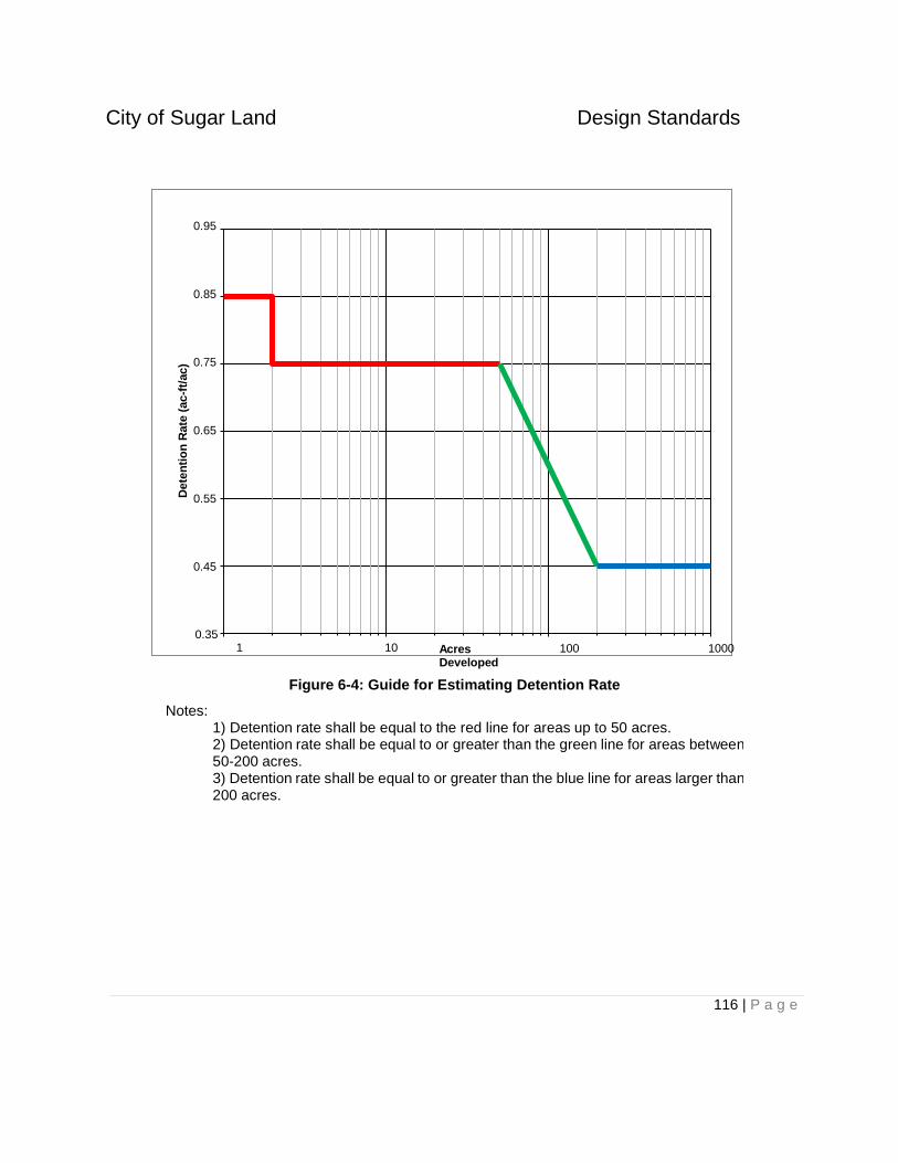
City of Sugar Land Design Standards
116 | P a g e
Dete
nti
on
Rate
(ac-f
t/ac)
0.95
0.85
0.75
0.65
0.55
0.45
0.35 1 10
Acres Developed
100 1000
Figure 6-4: Guide for Estimating Detention Rate
Notes: 1) Detention rate shall be equal to the red line for areas up to 50 acres. 2) Detention rate shall be equal to or greater than the green line for areas between 50-200 acres. 3) Detention rate shall be equal to or greater than the blue line for areas larger than 200 acres.

City of Sugar Land Design Standards
117 | P a g e
6.7.5 Landscape Design Principles for Storm Water Detention Basins
Detention ponds (basins) shall be designed as an integral part of the overall site plan and shall be considered a natural landscape feature.
The following standards shall be considered minimum requirements for the landscaping of detention ponds/basins:
1. Earth Sculpting
These ponds shall be “free form”, following the natural landforms to the greatest extent possible. If such natural landforms do not exist, the basin should be shaped to emulate a naturally formed depression.
2. Planting
A specific plant list of native and adaptive species is not specified within these criteria in order to allow greater creativity and flexibility; however a Registered Landscape Architect should design and specify all plant materials to ensure that the plant selection meets the nutrient, pollutant, growth conditions, and water factors of the system.
3. Maintenance
The landscape plan shall include the required maintenance access given in section 6.7.1 of these standards and the planting plan shall be designed to prevent obstruction of the access by trees and shrubs. Any above ground mechanical structures necessary for pond operation shall be identified on the landscape plan and shall be fully screened with trees or shrubs as designed by a Landscape Architect. The screening vegetation shall not inhibit future maintenance access to the structure.
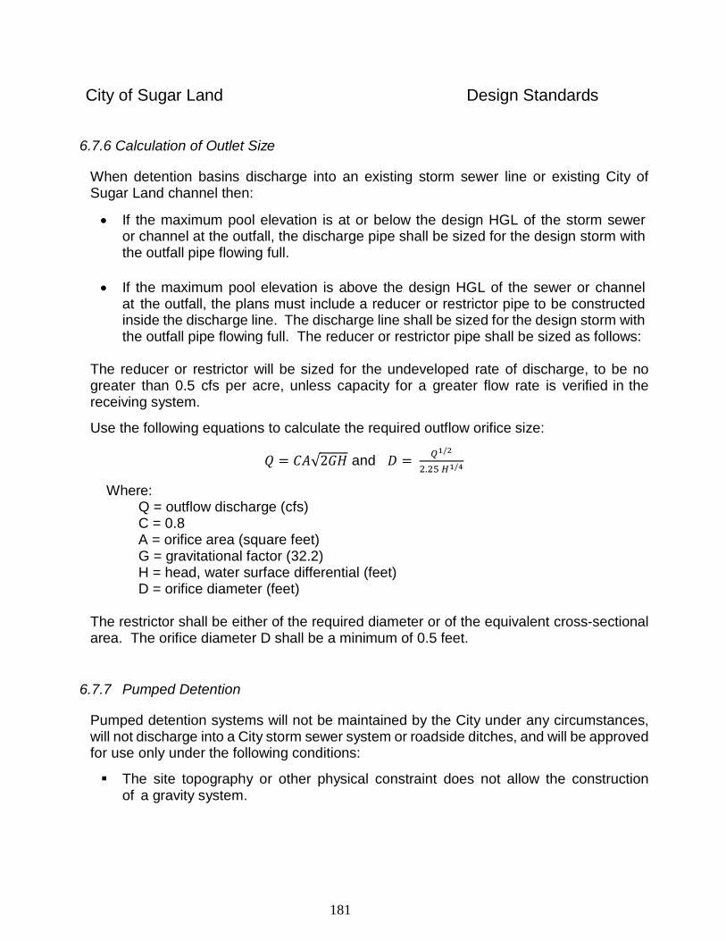
181
City of Sugar Land Design Standards
6.7.6 Calculation of Outlet Size
When detention basins discharge into an existing storm sewer line or existing City of Sugar Land channel then:
If the maximum pool elevation is at or below the design HGL of the storm sewer or channel at the outfall, the discharge pipe shall be sized for the design storm with the outfall pipe flowing full.
If the maximum pool elevation is above the design HGL of the sewer or channel
at the outfall, the plans must include a reducer or restrictor pipe to be constructed inside the discharge line. The discharge line shall be sized for the design storm with the outfall pipe flowing full. The reducer or restrictor pipe shall be sized as follows:
The reducer or restrictor will be sized for the undeveloped rate of discharge, to be no greater than 0.5 cfs per acre, unless capacity for a greater flow rate is verified in the receiving system.
Use the following equations to calculate the required outflow orifice size:
𝑄 = 𝐶𝐴√2𝐺𝐻 and 𝐷 = 𝑄1/2
2.25 𝐻1/4
Where:
Q = outflow discharge (cfs) C = 0.8 A = orifice area (square feet) G = gravitational factor (32.2) H = head, water surface differential (feet) D = orifice diameter (feet)
The restrictor shall be either of the required diameter or of the equivalent cross-sectional area. The orifice diameter D shall be a minimum of 0.5 feet.
6.7.7 Pumped Detention
Pumped detention systems will not be maintained by the City under any circumstances, will not discharge into a City storm sewer system or roadside ditches, and will be approved for use only under the following conditions:
The site topography or other physical constraint does not allow the construction of a gravity system.
182
City of Sugar Land Design Standards
The system is designed to pump the design flow rate with at least one pump out of service. No single pump installations will be permitted. .
The selected design outflow rate must not aggravate downstream flooding. For example, a pump system designed to discharge at the existing 100-year flow rate each time the system comes on-line would aggravate flooding for more frequent storm events and would therefore not be allowed. Design discharge rates shall be limited to existing condition flow rates for the given storm event, and additionally analyzed for the 5-year storm event.
Drawdown requirement as stated in Section 6.7.1.
Fencing of the control panel is provided to prevent unauthorized operation and vandalism.
Adequate assurance is provided that the system will be operated and maintained on a continuous basis. Facility must be maintained by Municipal Utility District or other governmental entity.
An emergency source of power is provided.
If the Engineer believes a pumped detention facility will be required, at the conceptual design stage the Engineer shall request a meeting with the City Engineer to review the concepts and ensure agreement on the methods and requirements.
183
City of Sugar Land Design Standards
7.0 ROADWAY DESIGN REQUIREMENTS
7.1 General
All paving plans and construction shall be approved by the City of Sugar Land for all streets within the City of Sugar Land and its extraterritorial jurisdiction.
All paving plans and construction within the ETJ shall also be approved by the Fort Bend County Engineer.
All public streets shall be concrete with curb and gutter.
All street designs shall conform to all applicable planning tools, such as the City of Sugar Land Subdivision Ordinance, the Texas Manual on Uniform Traffic Control Devices (TMUTCD), major thoroughfare plans, master plans, etc. Other considerations for design shall include street function, street capacity, service levels, traffic safety, pedestrian safety, and utility locations.
All street designs shall conform to the City of Sugar Land Standard Details. Aspects of design not specifically addressed in these Standards and the Standard Details are to be constructed consistent with national standards as identified in manuals such as AASHTO, TMUTCD, etc. The Design Engineer shall cite the standards used as the basis of his design.
7.2 Roadway Types
For purposes of determining the City’s street requirements, streets are classified as follows: (Ordinance. No. 1423, 3/2/04)
P8D – Principal Arterial, Eight Lanes, Divided. P6D – Principal Arterial, Six Lanes, Divided. P4D – Principal Arterial, Four Lanes, Divided. C4D – Major Collector, Four Lanes, Divided. C4U – Industrial Collector, Four Lanes,
Undivided. C2U – Minor Collector, Two Lanes, Undivided. L2U – Local, Two Lanes, Undivided
7.3 Geometric Street Design Standards
Minimum geometric street design standards for the number of lanes, lane widths, right-of-way widths, median widths, and parkway widths shall conform to Appendix F.
The design speeds for all roadways shall conform to Appendix F. The design speed does not necessarily indicate the posted speed.
184
City of Sugar Land Design Standards
The maximum grade refers to the vertical slope of the street and shall conform to Appendix F.
7.3.1 Vertical Curves
Vertical curves shall be designed when an algebraic difference in grades exceeds one percent (1%). Elevations shall be shown on the construction plans at ten-foot (10’) intervals through vertical curves. The gradient for tangents to vertical curves at railroad crossings shall be a maximum of three and one-half percent (3.5%). The length of all crest vertical curves shall be determined by sight distance requirements for the design speed. The minimum design speed on any vertical curve shall be based on the street classification.
7.3.2 Sight Distances
Intersections and curves shall be evaluated for adequate sight distances. Minimum sight distances shall conform to Appendix F.
7.3.3 Right-of-Way Clips
Right-of-way clips shall be established at all intersections. Unless larger clips are indicated at a particular intersection, a twenty-foot by twenty-foot (20’ X 20’) triangular public open space corner clip, measured at the property line, is required on each corner of the intersection of two local streets. A twenty-five foot by twenty-five foot (25’ x 25’) triangular public open space corner clip, measured at the property line, is required at any intersections with collector streets or greater.
7.3.4 Horizontal Curvature
Horizontal curvature is defined as the centerline radius of the street right-of-way. Horizontal curvature shall conform to Appendix F. If roadways cannot comply with the minimum standards, a Specific Approval to design to AASHTO minimum standards, latest version, may be considered by the City Engineer.
7.3.4.1 Arterials
Arterials with a centerline radius, of the right-of-way, less than two thousand feet (2,000’) shall be designed considering recommendations for super-elevation in
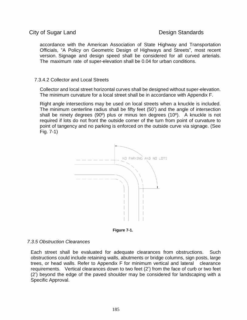
185
City of Sugar Land Design Standards
accordance with the American Association of State Highway and Transportation Officials, “A Policy on Geometric Design of Highways and Streets”, most recent version. Signage and design speed shall be considered for all curved arterials. The maximum rate of super-elevation shall be 0.04 for urban conditions.
7.3.4.2 Collector and Local Streets
Collector and local street horizontal curves shall be designed without super-elevation. The minimum curvature for a local street shall be in accordance with Appendix F.
Right angle intersections may be used on local streets when a knuckle is included. The minimum centerline radius shall be fifty feet (50’) and the angle of intersection shall be ninety degrees (90º) plus or minus ten degrees (10º). A knuckle is not required if lots do not front the outside corner of the turn from point of curvature to point of tangency and no parking is enforced on the outside curve via signage. (See Fig. 7-1)
7.3.5 Obstruction Clearances
Each street shall be evaluated for adequate clearances from obstructions. Such obstructions could include retaining walls, abutments or bridge columns, sign posts, large trees, or head walls. Refer to Appendix F for minimum vertical and lateral clearance requirements. Vertical clearances down to two feet (2’) from the face of curb or two feet (2’) beyond the edge of the paved shoulder may be considered for landscaping with a Specific Approval.
Figure 7-1.
186
City of Sugar Land Design Standards
7.3.6 Tangent Length
Tangent length is defined as the distance between the point of tangency and the point of curvature of two adjacent curves along the centerline of the street right-of-way. The minimum tangent length between reverse curves shall be one hundred feet (100’).
7.3.7 Intersections
Curb radii, measured from the face of curb, shall be twenty-five feet (25') minimum on local streets and thirty feet (30') minimum on residential major collectors, arterials or larger roadways, except as provided in Section 7.3.8. An evaluation of vehicular types and volumes in commercial or industrial areas may require increased radii. Radii should be increased at skewed intersections.
Streets and traffic lanes shall be properly aligned across an intersection. Proposed streets shall be aligned with existing streets.
When turnouts are provided at an existing street, the ultimate cross section is required to the end of curb return. Pavement transition is required to reduce the pavement width to the existing cross section.
Intersections shall be designed as a high point in the drainage system, when possible.
Streets intersecting major arterials or larger roadways shall maintain a minimum of three hundred feet (300’) of separation. Separation is defined as the distance from pavement face of curb to face of curb. Streets intersecting collector streets shall maintain a minimum of two hundred and fifty feet (250’) of clearance. Local streets shall maintain a minimum separation of one hundred and fifty feet (150’).
Offset intersections are not permitted on any arterial if the offset distance (or clearance between streets) is less than three hundred feet (300’). The minimum allowable offset shall be two hundred and fifty feet (250’) on collector streets and eighty feet (80’) on local streets.
Lane drop tapers shall conform to Appendix F.
Except where existing conditions will not permit, all streets, major and minor, shall intersect at a ninety-degree (90º) angle. Variations of more than ten degrees (10º) on secondary and local streets and more than five degrees (5º) on arterials may be allowed by Specific Approval.
Right turn lanes at arterial and collector intersections shall be designed and built in accordance with Appendix F.
187
City of Sugar Land Design Standards
Where local streets intersect arterial streets, the local street must have a minimum radius of 35 feet and a minimum width of 28 feet, measured from the back of each curb.
Pavement width transitions shall conform to Appendix F. Transition lengths shall meet or exceed requirements of the Texas Manual of Uniform Traffic Control Devices.
Left turn lanes must conform to Appendix F. The City may require that the specified minimum bay storage lengths be increased based on a traffic analysis. New middle block median openings to serve private driveways shall include left turn lanes in accordance with Appendix F. (Ordinance No. 1278, Section 5, 2001)
Median openings shall conform to Appendix F. On major arterials and larger roadways, when areas adjoining the right-of-way are not planned for immediate development, esplanade openings may be spaced one thousand feet (1,000’) apart with a Specific Approval.
7.3.8 Cul-de-sac bulbs
For Cul-de-sacs and their variants located in single family residential areas the pavement radius measured to the face of curb shall be at least forty feet (40') and all turns including the cul-de-sac itself must accommodate a SU-30 turning path.
For multi-family residential, commercial, and industrial areas, the pavement radius of cul-de-sacs measured to the face of curb shall be a minimum of fifty feet (50').
The right-of-way radius shall be clear of permanent obstructions. Unpaved medians on modified cul-de-sacs may be allowed by Specific Approval when the request is accompanied by verification that the modification can accommodate a SU-30 turning path.
The distance from the face of curb of a cul-de-sac to the right-of-way line shall be a minimum of ten feet (10').
Curb radii at the transition to the cul-de-sac shall have a minimum radius of twenty-five feet (25') in single family residential areas and thirty-five feet (35') in other areas, measured at the face of curb.
The length of a cul-de-sac street is defined as the distance from the centerline of the intersecting pavement to the center of the cul-de-sac bulb measured along the centerline of the street right-of- way. (Ordinance No. 1161, Section 6, 1999). The maximum length of cul-de-sac streets for residential subdivisions shall be one thousand two hundred feet (1,200’) or the cul-de-sac may serve a maximum of twenty-five (25) residential lots, whichever is less.
The maximum length of cul-de-sac streets for commercial or industrial developments shall be five hundred feet (500’). A traffic analysis may be required in commercial or industrial areas, high traffic volumes may result in a reduced maximum cul-de-sac length.
188
City of Sugar Land Design Standards
7.3.9 On Street Parking
Guidelines for permitting on-street parking are given in Appendix F.
7.4 Pavement Structure Requirements
The pavement structure for each roadway shall be designed based on soil data from the site and based on the anticipated traffic volume, loading and service life of the proposed pavement structure as identified in the geotechnical report
Water reducers and concrete additives are prohibited when the ambient temperature is less than 90 degrees.
Local residential streets (L2U) shall have a minimum thickness of six inches (6") with number four (#4) rebar spaced at twenty-four inches (24") measured center to center of the rebar.
Residential, collector streets (C2U and C4D) and all streets in multi-family residential, or commercial, or industrial areas shall have a minimum thickness of seven inches (7") with number four (#4) rebar spaced at eighteen inches (18") measured center to center of the rebar.
Vehicles of all types are prohibited from driving on new pavement for three (3) days after the concrete pour and until the concrete has reached a minimum compressive strength of 3,000 psi. Pavement protection such as a dirt layer of at least 12 inches is required for track equipment at pavement crossings.
Industrial areas and arterials (C4U, P4D, P6D, and P8D) and larger roadways shall have a minimum thickness of eight inches (8") with number four (#4) rebar spaced at eighteen inches (18") measured center to center of the rebar.
The Design Engineer is responsible for designing the pavement structure to withstand the anticipated loads on the roadway. Soil borings shall not be spaced at a distance greater than five hundred feet (500’) and shall extend a minimum of five feet (5’) below the proposed top of curb.
Hot-mix asphaltic concrete pavement shall be designed for each individual project based on a geotechnical analysis prepared by a registered engineer. Minimum requirements shall include three inches (3”) of surface course and, six inches (6”) of stabilized base, and eight inches (8”) of lime stabilized sub grade.
Sub grade beneath concrete and hot-mix asphaltic concrete pavements shall be stabilized with a minimum six percent (6%) lime by weight, or a blend of fly-ash and lime to achieve a soil P.I. between 10 and 20. If a P.I. of less than 20 cannot be obtained, then the lime
189
City of Sugar Land Design Standards
treated soils must obtain a pH of 12.4, eight inches (8”) thick and compacted to ninety-five percent (95%) standard proctor density. Alternate sub grade stabilization may be substituted when specific recommendations are made by the geotechnical engineer for the project. The sub-grade stabilization shall extend a minimum of two feet (2’) behind the back of curb.
Concrete pavement thickness design is required for all industrial areas and on major collectors and arterials. Concrete pavement thickness design shall be based on American Association of State Highway and Transportation Officials design procedures for rigid pavements.
Any tie-in connection to an existing concrete roadway other than an existing doweled expansion joint or existing pavement header shall be made by making a full depth saw-cut along the face of the curb.
Dowels shall be number four (#4) bars, twenty-four inches (24") long, embedded twelve inches (12”) secured by epoxy and spaced in accordance with this section.
Dead-end streets or ends of concrete slabs designed to be extended in the future shall have paving headers and fifteen inches (15") of reinforcing steel exposed beyond the pavement, coated with asphalt and wrapped with burlap or paving headers and a dowel type expansion joint for future pavement tie.
Pavement extensions shall connect to the existing pavement with a pavement undercut and a minimum steel overlap of ten inches (10”). Refer to the City of Sugar Land Standard Details.
All concrete to be removed shall be removed either to an existing joint or a sawed joint.
The slump for concrete without a water reducer shall be no more than five (5) inches. The slump for concrete using a water reducer shall be no more than six (6) inches.
Any standing water or "bird baths" remaining more than eight (8) hours after flooding the street shall be considered unacceptable and a remedy will be required. Grinding of pavement up to 1/8-inch thickness is an acceptable remedy. For areas requiring adjustment greater than 1/8-inch, foam lifting or other remedies are required. If the pavement is removed and replaced, the pavement must be removed and replaced to a construction joint.
All concrete streets and bridge surfaces shall have a "Baker Broom" finish, while sidewalks and driveways shall have a medium broom finish.
In lieu of mechanically controlled vibrators controlled by a slip-form paving machine, hand- manipulated mechanical vibrators shall be used for proper consolidation of concrete in all pavement areas (along forms, at joints, etc.)
190
City of Sugar Land Design Standards
7.5 Pavement Materials
The following materials are to be used for pavement construction:
A. Concrete: five and a half (5½) sacks cement per cubic yard concrete; 3,500 psi unconfined compressive strength at twenty-eight (28) days.
B. Reinforcing steel Grade 60, ASTM A615, current.
All materials and workmanship shall conform to the Texas Department of Transportation Standard Specifications and the Texas Manual on Uniform Traffic Control Devices, latest revisions.
All special, non-standard materials, such as concrete pavers, and special signage require a Specific Approval. The City will not accept any non-standard materials for maintenance and any incidental maintenance of non-standard items by the City of Sugar Land will be done using standard materials and methods.
7.6 Grading and Layout Requirements
The minimum gradient on a street gutter line shall be 0.35 percent. All streets shall be cleaned, flooded and inspected for surface cracks and birdbaths prior to initial and final acceptance.
Inlet spacing shall be as defined in Section 6.6.2.
The maximum earth cut measured from finished grade at the right-of-way line to top of curb shall be 1.75 feet. The maximum slope for driveways shall be ten (10) to one (1) (10%).
The minimum grade shall be one percent (1%) fall around all intersection turnouts.
All streets must have at least a four-inch (4”) high concrete curb or a roll over curb. (Ordinance No. 1148, Section 4, 1998)
The minimum slope for the gutter of a cul-de-sac or of the long radius of an elbow shall be 0.60 percent.
The amount of cross slope over the pavement section is provided on the City of Sugar Land Construction Details.
When connecting to an existing curbed street, the gutter lines for the proposed and existing streets shall be matched.
The proposed top of curb elevations shall be designed to match the top of the curb at an existing inlet.
191
City of Sugar Land Design Standards
The top of curb elevations shall be shown on the construction plans.
Gutter elevations are required for vertical curves where a railroad track is being crossed.
Where railroad crossings are not at right angles to the pavement slab, vertical curves shall be calculated for each curb line and shall be provided at ten-foot (10') intervals in the profile.
7.7 Traffic Control Devices
Traffic control devices shall be installed as warranted by a traffic study.
Type III barricades must be permanently installed at the end of all dead-end streets not terminating in a cul-de-sac and at all turnouts. Barricades must meet the requirements of the Texas Manual of Uniform Traffic Control Devices (TMUCTD) for Type III barricades.
Traffic and street signage locations shall be shown on the paving site plan in the construction plans. Traffic signs shall conform to the requirements of the Texas Manual of Uniform Traffic Control Devices. All signage shall be installed in accordance with the approved construction plans.
7.7.1 Traffic Signs (Ordinance No. 1148, Section 5, 1998)
Standard sign blanks must be aluminum conforming to ASTM B209; alloy 5052-H38. Preparation of aluminum sign blanks must conform to specification MIL-C-5541C. The coating material must be included on the OPL-81706-10 list or subsequent additions thereto. Sheeting for signs must be Diamond Grade. Visual Impact Performance (VIP) Diamond Grade Sheeting must be used on all traffic signs on public roadways. Signs must be mounted on 2 3/8-inch diameter by twelve-foot (12') long galvanized tubular posts with vandal-proof mounting brackets. (For equals, refer to the City of Sugar Land Approved Products List).
For letter height measurements for street names signs and overhead signs, refer to the City of Sugar Land construction details.
All permanent and temporary (construction zone) traffic control devices must conform to the TMUTCD and TxDOT standards (where applicable), latest revision.
All posts must be mounted in concrete eighteen inches (18") deep with a minimum of three inches (3") in diameter of concrete surrounding the post. All sign poles and signs must remain in their natural condition with no painting or coating allowed.
192
City of Sugar Land Design Standards
7.7.2 Pavement Markings
Pavement markings must be shown on the approved construction plans. All pavement markings must be retro-reflective material applied to the road surface in a molten state by screed/extrusion, suspended extrusion or spray means, with a surface application of glass beads. For lane delineation, reflectors must be used on all roadways classified as a collector street or greater. The City Engineer may approve variations of types of materials due to phasing, temporary construction, etc. All pavement markings must comply with the TMUTCD, latest revision. (Ordinance No. 1382, Section 4, 2003)
Tabs, tape or buttons shall be used for all temporary traffic control striping. Permanent paint or thermoplastic striping is prohibited for temporary uses.
The removal of existing traffic control striping shall be performed using water blasting, sand blasting or shot blasting. Removal of striping by any methods other than the methods approved by the City is prohibited.
7.7.3 Multi-Way Stop Signs
Unwarranted multi-way stop signs shall not be installed. Installation of multi-way stop signs shall be based on criteria outlined in the TMUTCD, latest revision.
7.7.4 Traffic Signal System Design Guidelines
7.7.4.1 General
Prior to beginning design, the Design Engineer shall contact the City of Sugar Land to determine special design criteria, which may include pole types, interconnection with existing signals, detection, etc. The ground boxes located next to the traffic controllers should be Type II ground boxes. In addition, a service agreement from Center Point for the proposed meter/service locations for all signals must be obtained by the Design Engineer and submitted to the City.
All new traffic signals shall be mast arm signals with video detection as listed in the City Traffic Specifications. All traffic signals that are subject to modification or reconstruction to the degree that the modification or reconstruction is greater than 50% of the value of the traffic signal poles and equipment shall be reconstructed as mast arm signals with video detection.
All traffic signals shall be designed in accordance with the City of Sugar Land latest specifications and construction details.
All traffic signal designs shall be in accordance with the latest Texas Manual on Uniform Traffic Control Devices and acceptable engineering practices in order to provide safe and efficient operation. All traffic signals shall be designed to comply
193
City of Sugar Land Design Standards
with the latest state-of-the-art operational and functional features for traffic signal systems required by the City of Sugar Land. The Design Engineer shall contact the City of Sugar Land, Information Technology Department to obtain an IP address for the signal cabinet equipment. Once the equipment has been installed and communications have been established with the Traffic Management Center, The IT Department will commission the communication link.
All plans shall provide the information required to properly represent existing conditions and the proposed work. Plans showing interim phases as well as the ultimate design are required if necessary to adequately communicate the design.
The Design Engineer shall provide all design criteria to the City Engineer.
7.7.4.2 Wiring Requirements
All wiring shall follow the latest version of the City Traffic Specifications.
7.7.4.3 Conduit
All conduit shall follow the latest version of the City Traffic Specifications.
7.7.4.4 Construction Plan Requirements
Construction Plans for Traffic Signals shall conform to the City’s graphic standards. The basic set of signal system construction drawings shall include, but is not limited to the following:
1. Title Sheet and/or Index of Sheets
2. General Construction and Utility Notes
3. Basis of estimate
4. Condition Layout
5. Paving Layout (when applicable)
6. Pavement Marking and Signing Layout
7. Plan Layout
8. Legend for Plan Layout
9. Signal Elevations (when applicable)
10. Anchor Bolt Details (when applicable)
11. Signal Interconnect Sheet (when applicable)
194
City of Sugar Land Design Standards
12. Pedestrian Walkway Details
13. Notes for Plan Layout
14. Standard Detail Sheets (all required and latest)
15. Traffic Control Plan
7.7.4.4.1 Title Sheet and/or Index of Sheets
The title Sheet and/or index sheets shall include as applicable:
A. Intersection(s) and street name(s)
B. Design Engineer,
C. The City of Sugar Land Logo
D. The date when the plans were completed
E. A vicinity map/key map with the signal location specified
F. An index of sheets included in the plan set
G. The project title including project scope and proper road names
H. The source of funding for construction
I. Any special notes.
J. A site map with north arrow
7.7.4.4.2 General Construction and Utility Notes
This sheet shall provide all utility notes for all known utilities including contact information, services located within the project, and all other pertinent information. The Service Outlet and Data Statement from the power company should be prominently noted.
7.7.4.4.3 Basis of Estimate
This sheet includes all wires and cables, conduits, ground boxes, span wires, etc. and their calculated quantities.
The estimated quantities shall be detailed by location or specific system. Provide all items detailed an item number and a reference. Bid items will be discussed under bid documents.
Identify materials to be furnished by the City of Sugar Land or others (when applicable). Quantities are for estimate purposes only.
195
City of Sugar Land Design Standards
7.7.4.4.4 Condition Layout
The Design Engineer shall completely represent the conditions existing at the project site prior to the planned construction on this plan. At a minimum the plan should depict all existing signage (including speed limits on all approaches), joints in pavement, types of pavement, condition of pavement (for loops), utility locations, street geometry, and any existing signal equipment.
7.7.4.4.5 Paving Plan (when applicable)
Depict the proposed design showing required wheelchair ramps/landings to access pedestrian push buttons. These paving improvements must comply with the current Texas Accessibility Standards (TAS) of the Architectural Barriers Act.
Provide applicable construction notes and/or paving details including ramp/landing dimensions.
7.4.4.6 Pavement Making and Signing Layout
This plan shall show all proposed paving improvements as existing and include all existing signing and striping.
The plan shall depict the proposed design of all applicable pavement markings. “Signal Ahead” signs are typically provided on all approaches. At a minimum the plan should depict all:
Rights-of-way
Roadway geometry
Utilities Existing Sign details (complete) Proposed Sign details (complete) Construction signing Stop bars Crosswalks, if required Wheelchair ramps, if required Special notes
7.7.4.4.7 Plan Layout Sheet
This plan shall show all proposed paving improvements, signing and striping as existing. The westbound left turn is signal head 1 and continues clockwise. The northwest corner pedestrian signal for westbound is P1 and continues clockwise. Provide separate pole for the service meter with an enclosure and photoelectric
196
City of Sugar Land Design Standards
cell. Locate the controller and cabinet at the nearest service if possible. Locate the controller and cabinet so as not to restrict the sight distance for right turns on red.
Install the communications ground box with 3 inch PVC and bare wire for future use near the cabinet if there is no existing hardwire interconnect system.
Two (2) Luminaires are required and are to be located in the far right corners along the major street.
Video loop detection typically uses one camera per approach.
Multiple pulse loop detectors (6’x6’ one per lane) are required on major streets based on posted speed.
Loop Detector or Detector Zone placement is as follows:
Distance From Back of Stop Bar to Front of Loop (Loop distance in feet)
MPH 1st Detector
Stop Bar 2nd Detector
6' X 6' 3rd Detector
6' X 6' 4th Detector
6' X 6'
35 6' X 20' 90 190 n/a
40 6' X 20' 110 240 n/a
45 6' X 20' 175 290 n/a
50 6' X 20' 220 350 n/a
55 6' X 20' 225 320 415
60 6' X 20' 275 375 475
65 6' X 20' 320 430 540
70 6' X 20' 350 475 600
Additional Loop Detector Locations:
All approach lanes will provide a 6'x20' loop (front of loop located 5' in front of center of stop bar).
Left turn lanes provide a second 6'x20' presence loop with a 6’ gap behind the front loop. One (1) loop per lane will be wired and labeled as a “counter” loop, and must be individually connected in the cabinet for use in data collection.
Loop sizes and locations are subject to change due to pavement joints, broken pavement, manholes, etc.
No loop shall be cut through pavement joints. Loops are identified by phase.
Signal Head Mounting shall comply with the following:
1. Span Wire: 2 brackets for 4 section and larger traffic signal heads
197
City of Sugar Land Design Standards
2. Mast Arm: See latest version City Traffic Specifications
7.7.4.4.8 Legend for Plan Layout
Provide signal head schedule illustrating all vehicle signal heads and signs attached to signal heads.
Provide sign schedule and dimensions showing all overhead signs.
Symbol legend, including pole descriptions and equipment attached to poles. Electrical schedule and notes. Provide various notes to contractor. Any additional notes or details.
7.7.4.4.9 Signal Elevations (for strain pole type design only)
Span wire signal system shall be allowed on a temporary basis during construction only. Poles, signals and pedestrian signals numbered and details.
Show video detection or any other directional devices in their proper place. Elevation views for all approaches and proper callout. Electrical schedule callouts and guy wire details. Show all conduits in foundations and call out what conduit runs serve. Add note: “For Legend and Callouts See Traffic Signal Layout Sheet”. Luminaire locations. Centerline of street. Special notes or details.
7.7.4.4.10 Anchor Bolt Orientation Details (for strain pole type design only)
Provide detail per City standards.
7.7.4.4.11 Signal Interconnect Sheet
Show all existing/proposed intersections involved. Design notes for connections. Electrical chart for interconnect cable(s).
Add Note: “Refer to Intersection Layouts and Legends for Plan Layout Sheets for Additional Information Regarding Communication Cable”. All required details and elevation details. Intersection locations for interconnect system.
7.7.4.4.12 Pedestrian Walkway Details
Current pedestrian walkway details with the following plan layout details: Existing intersection condition. Proposed pole locations and identified. Proposed pedestrian walkway design layout.
198
City of Sugar Land Design Standards
7.7.4.4.13 Notes for Plan Layout
Callouts for all signals and sign types. Callouts for all signs and all sign types. Notes to reference specific sheet(s). Any note pertaining to signal design shall be included. Special VIVDS specification if required. Special equipment descriptions. Maintenance of existing traffic signals and operation parameters.
7.7.4.4.14 Standard Detail Sheets
Any details pertaining to the proposed signal design shall be included.
The details shall be the latest available from the City of Sugar Land and TxDOT. Any necessary quantities, i.e. pole and foundation details, shall be filled out.
7.7.4.5 Approved Products
All equipment and materials utilized on traffic signals within the City of Sugar Land shall conform to the latest Approved Products list and shall be subject to the approval of the City Engineer.
7.8 Pedestrian and Bicycle Facilities
Minimum requirements for pedestrian and bicycle facilities shall be as recommended by the COSL Pedestrian and Bicycle Master Plan. (Note: recommendations shall adhere to applicable TMUTCD, ADA and AASHTO standards)
7.8.1 Easements
The minimum width of an access easement for a public pedestrian facility not located within the right-of-way shall be ten feet (10’) or when the facility does not fit in the right-of-way.
Pedestrian and/or bicycle access easements for off-street facilities shall include a minimum of two feet (2’) of clear space on both sides of the required facility. (Ordinance No. 1265, Section 2,
2001) Clear space may not include vertical obstructions such as trees, structures, walls fences or landscaping with a mature height above eighteen inches (18”). A minimum vertical clearance zone of ten feet (10’) is required, but may be reduced to eight feet (8’)
199
City of Sugar Land Design Standards
for short distances if site constraints exist. Fixed objects shall not protrude into the vertical or horizontal clear space of a facility.
7.8.2 Sidewalks and Crosswalks
Sidewalks shall be a minimum of five feet (5’) wide on local streets and six feet (6’) wide on streets categorized in the Master Thoroughfare Plan as a Minor Collector, Major Collector, Arterial, State Highway, or Freeway. Sidewalks shall be placed a minimum of four feet (4’) from the adjacent back of curb, however, if not feasible due to site constraints sidewalks may be placed a minimum of two feet (2’) from the adjacent back of curb.
Sidewalks adjacent to water bodies or in parks must be a minimum of six feet (6’) in width. Construction of a sidewalk will be deferred until a lot is improved.
Crosswalks constructed through an esplanade shall be a minimum of six feet (6') wide.
All sidewalks and ramps are to be constructed in accordance with the City of Sugar Land Standard Details and in accordance with ADA requirements.
Where concrete curb and gutter streets are not present or where the potential for future roadway widening exists, a sidewalk easement shall be provided along the existing road right-of-way.
7.8.3 Sidepaths and Shared Use Paths
Sidepaths shall be a minimum of ten feet (10’) wide. A Sidepath may narrow to a minimum of eight feet (8’) to avoid existing trees or other existing obstructions. Sidepaths shall be placed a minimum of five feet (2’) from the adjacent back of curb.
Shared Use Paths or Trails shall be a minimum of ten (10’) feet wide. A Shared Use Path may narrow to a minimum of eight feet (8’) to avoid existing trees or other existing obstructions.
7.8.4 Bike Lanes and On-street Facilities
Bike Lanes shall be a minimum of five feet (5’) wide, as measured from the center of the bicycle lane stripe to the adjacent curb facing.
Buffered Bike Lanes shall be a minimum of five feet (5’) wide, as measured from the center of the bicycle lane stripe to the adjacent curb facing, with a designated buffer area at least 18-24 inches wide. Where a Buffered Bike Lane is replacing a vehicular lane, the bicycle lane shall be a minimum of six feet (6’) wide with a minimum buffer area of five feet (5’).
200
City of Sugar Land Design Standards
Shared Lane Markings on streets with on-street parallel parking shall be placed so that the center of the marking is at least twelve feet (12’) from the face of the curb. Shared Lane Markings on streets without on-street parking, that have a travel lane less than fourteen feet (14’) wide, shall be placed so that the center of the marking is at least five feet (5’) from the face of the curb.
Wide Shoulders shall be a minimum of four feet (4’) wide along roadways with speeds under 45 mph. Wide Shoulders shall be a minimum of six feet (6’) wide along roadways with speeds over 45 mph, streets with high volumes of traffic, or streets with significant truck or bus traffic.
On-street facility striping shall be four inches (4”) wide.
Cycle Tracks are bicycle lanes that are physically separated from vehicular traffic, typically with a raised curb, planters, or other physical separation. A one-way cycle track shall be a minimum of five feet (5’) wide. A two-way cycle track shall be a minimum of eight feet (8’) wide.
Additional design guidance is detailed in the adopted Pedestrian and Bicycle Master Plan. Should these requirements not be able to be followed due to site constraints as verified and approved by the City Engineer or his/her designee, then at minimum these facilities shall be designed in accordance with TMUTCD, ADA, and AASHTO standards.
7.9 Alleys
Service alleys in commercial and industrial districts shall have a minimum right-of-way width of twenty feet (20’) and a minimum concrete pavement width of fifteen feet (15’). An easement may be substituted upon approval by the City if the easement is also a fire lane easement. (Refer to Section 8.7 for fire lane requirements.) In residential districts, alleys shall be parallel, or approximately parallel to the frontage of the street. Alleys in residential districts shall have a minimum of eighteen feet (18’) of right-of-way and twelve feet (12’) of concrete pavement.
Alleys for commercial and industrial districts shall have a minimum thickness of seven inches (7”) with number four (#4) rebar spaced at eighteen inches (18”) measured center to center of the rebar. Residential alleys shall have a minimum thickness of six inches (6”) with number four (#4) rebar spaced at twenty-four inches (24”) measured center to center of the rebar.
Alleys shall have a minimum gradient on gutter line of 0.50 percent.
Alleys shall be constructed as a “V” section with cross slopes of three-eights-inch (3/8”). Refer to the Standard Detail.
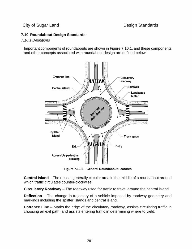
201
City of Sugar Land Design Standards
7.10 Roundabout Design Standards
7.10.1 Definitions
Important components of roundabouts are shown in Figure 7.10.1, and these components and other concepts associated with roundabout design are defined below.
Figure 7.10.1 – General Roundabout Features
Central Island – The raised, generally circular area in the middle of a roundabout around which traffic circulates counter-clockwise.
Circulatory Roadway – The roadway used for traffic to travel around the central island.
Deflection – The change in trajectory of a vehicle imposed by roadway geometry and markings including the splitter islands and central island.
Entrance Line – Marks the edge of the circulatory roadway, assists circulating traffic in choosing an exit path, and assists entering traffic in determining where to yield.
202
City of Sugar Land Design Standards
Inscribed Circle Diameter – The maximum diameter of the curve defining the outside edge of the circulatory roadway and one of the principal roundabout design components that impact traffic operations.
Landscape Buffer – Separates the sidewalk from the roadway. Provides a buffer against traffic and assists visually impaired pedestrians in safely navigating the roundabout.
Mini Roundabout – Application of a roundabout with a small, traversable central island, usually on low- volume neighborhood streets.
Multilane Roundabout – A roundabout with two or more lanes in the circulating roadway and two or more lanes on at least one entry.
Path Overlap – Conflict between the natural paths of vehicles in a roundabout, usually due to improper geometry.
Single Lane Roundabout – A roundabout with a one-lane circulatory roadway and one-lane entries.
Splitter Island – The raised or painted area between entering and exiting traffic at each
approach. Provides deflection for entering traffic and refuge for pedestrians to make two-
stage crossings of the approach.
Truck Apron – Part of the central island that is raised above the circulatory roadway to enable trucks to negotiate the roundabout while also discouraging excessive speeds by other vehicles.
7.10.2 Procedure for Design and Approval
7.10.2.1 Reference Documents
All roundabouts constructed in the City of Sugar Land must comply with the latest editions of all relevant national, state, and local standards that pertain to roadway and intersection design, including but not limited to:
Texas Manual on Uniform Traffic Control Devices (TMUTCD)
NCHRP Report 672: Roundabouts: An Informational Guide
A Policy on Geometric Design of Highways and Streets (Green Book)
City of Sugar Land Neighborhood Design Policy, City of Sugar Land
7.10.2.2 Pre-Design Meeting
A pre-design meeting shall be held between parties interested in constructing a roundabout and officials from the City of Sugar Land. The purpose of this meeting is
to ensure that fundamental design criteria for the proposed roundabout are
203
City of Sugar Land Design Standards
determined before significant design resources are expended. The meeting will discuss:
Appropriateness of a roundabout at the proposed location
Scope of required Pre-Design Report, including scope of data collection and traffic counts
Design vehicle(s) for roundabout geometry
Availability of and potential impacts to public right-of-way
Location of and potential impacts to public utilities
7.10.2.3 Pre-Design Report
Prior to the design of a roundabout, a traffic analysis shall be performed and a summary report prepared and submitted to the City of Sugar Land for review. The full scope for the summary report will be defined in the pre-design meeting. The traffic analysis shall include morning and afternoon weekday peak hour turning movement counts as well as any other counts as defined in the scoping meeting. Capacity analyses using accepted methodology defined in this document shall be conducted for existing traffic volumes and for projected traffic volumes. The report shall include at minimum the following information:
Existing turning movement counts
Projected turning movement counts
Description of existing traffic control
Description of adjacent land uses
Description of roadway network in vicinity of intersection, including adjacent traffic signals.
Identification of year at which a single lane roundabout will no longer function at an acceptable LOS
Description of proposed ultimate roundabout geometry (number of entry lanes,
exit lanes, and circulating lanes)
Capacity analysis reports including LOS, queue length, and delay per vehicle for future volumes and proposed ultimate roundabout geometry
Identification of proposed design vehicle for each approach to the roundabout
The 50% submittal, as described in Section 7.10.2.4, may be submitted as part
of the pre-design report
204
City of Sugar Land Design Standards
7.10.2.4 Design Submittals
The roundabout design plan shall include, at minimum, a 50% submittal and a 100% submittal. The components of each submittal are listed below:
o 50% submittal
A preliminary roundabout schematic showing exterior curb lines, central island, truck apron, and splitter islands. The schematics should be drawn on an aerial photograph that shows existing pavement, driveways, and other fixed geometric features that may be impacted by roundabout construction. A preliminary pavement marking plan should be included.
Schematics showing fastest paths for the left-turn movement, the through-movement, and the right-turn movement for each approach. The fastest paths should be constructed utilizing the methodology detailed in NCHRP 672: Roundabouts: An Informational Guide. As many schematics as needed should be produced to show these fastest paths clearly. A table that lists the radii of the component curves of each fastest path and the corresponding design speed for the curve as listed in A Policy on Geometric Design of Highways and Streets (AASHTO, latest edition) should accompany the schematics.
o 100% submittal
Includes all components specified in the Construction Plan Requirements section.
7.10.2.5 Construction Plan Requirements
Construction Plans for Roundabouts shall conform to the City’s graphic standards. The basic set of roundabout construction drawings shall include, but is not limited to, the following:
Title Sheet and/or Index of Sheets
General Construction and Utility Notes
Basis of Estimate
Existing Conditions Layout
Paving Layout
Drainage Layout
Pavement Marking and Signing Layout
Pedestrian Walkway Details
Landscaping Plans
Illumination Drawing
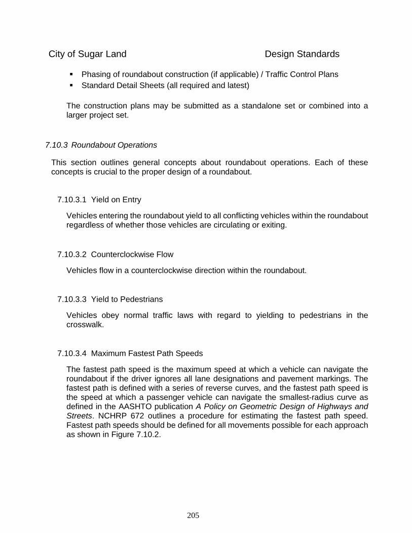
205
City of Sugar Land Design Standards
Phasing of roundabout construction (if applicable) / Traffic Control Plans
Standard Detail Sheets (all required and latest)
The construction plans may be submitted as a standalone set or combined into a larger project set.
7.10.3 Roundabout Operations
This section outlines general concepts about roundabout operations. Each of these concepts is crucial to the proper design of a roundabout.
7.10.3.1 Yield on Entry
Vehicles entering the roundabout yield to all conflicting vehicles within the roundabout regardless of whether those vehicles are circulating or exiting.
7.10.3.2 Counterclockwise Flow
Vehicles flow in a counterclockwise direction within the roundabout.
7.10.3.3 Yield to Pedestrians
Vehicles obey normal traffic laws with regard to yielding to pedestrians in the crosswalk.
7.10.3.4 Maximum Fastest Path Speeds
The fastest path speed is the maximum speed at which a vehicle can navigate the roundabout if the driver ignores all lane designations and pavement markings. The fastest path is defined with a series of reverse curves, and the fastest path speed is the speed at which a passenger vehicle can navigate the smallest-radius curve as defined in the AASHTO publication A Policy on Geometric Design of Highways and Streets. NCHRP 672 outlines a procedure for estimating the fastest path speed. Fastest path speeds should be defined for all movements possible for each approach as shown in Figure 7.10.2.
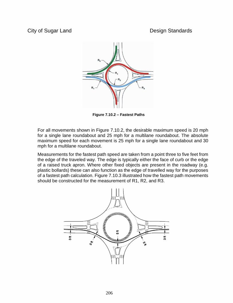
206
City of Sugar Land Design Standards
Figure 7.10.2 – Fastest Paths
For all movements shown in Figure 7.10.2, the desirable maximum speed is 20 mph for a single lane roundabout and 25 mph for a multilane roundabout. The absolute maximum speed for each movement is 25 mph for a single lane roundabout and 30 mph for a multilane roundabout.
Measurements for the fastest path speed are taken from a point three to five feet from the edge of the traveled way. The edge is typically either the face of curb or the edge of a raised truck apron. Where other fixed objects are present in the roadway (e.g. plastic bollards) these can also function as the edge of travelled way for the purposes of a fastest path calculation. Figure 7.10.3 illustrated how the fastest path movements should be constructed for the measurement of R1, R2, and R3.
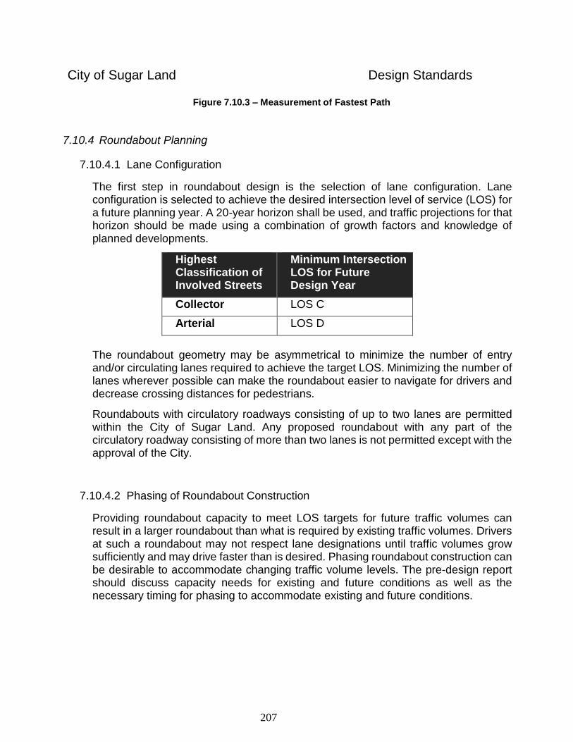
207
City of Sugar Land Design Standards
Figure 7.10.3 – Measurement of Fastest Path
7.10.4 Roundabout Planning
7.10.4.1 Lane Configuration
The first step in roundabout design is the selection of lane configuration. Lane configuration is selected to achieve the desired intersection level of service (LOS) for a future planning year. A 20-year horizon shall be used, and traffic projections for that horizon should be made using a combination of growth factors and knowledge of planned developments.
Highest Classification of Involved Streets
Minimum Intersection LOS for Future Design Year
Collector LOS C
Arterial LOS D
The roundabout geometry may be asymmetrical to minimize the number of entry and/or circulating lanes required to achieve the target LOS. Minimizing the number of lanes wherever possible can make the roundabout easier to navigate for drivers and decrease crossing distances for pedestrians.
Roundabouts with circulatory roadways consisting of up to two lanes are permitted within the City of Sugar Land. Any proposed roundabout with any part of the circulatory roadway consisting of more than two lanes is not permitted except with the approval of the City.
7.10.4.2 Phasing of Roundabout Construction
Providing roundabout capacity to meet LOS targets for future traffic volumes can result in a larger roundabout than what is required by existing traffic volumes. Drivers at such a roundabout may not respect lane designations until traffic volumes grow sufficiently and may drive faster than is desired. Phasing roundabout construction can be desirable to accommodate changing traffic volume levels. The pre-design report should discuss capacity needs for existing and future conditions as well as the necessary timing for phasing to accommodate existing and future conditions.
208
City of Sugar Land Design Standards
7.10.4.3 Capacity Analysis
Various methodologies and software packages are available for roundabout capacity analysis. These include the 2010 Highway Capacity Manual (HCM), SIDRA Intersection, RODEL, Synchro, and VISSIM. The Highway Capacity Manual methodology and Synchro Software are typically sufficient for minor intersections with standard geometries. SIDRA Intersection is appropriate for intersections with more complex geometries. VISSIM is appropriate for analyzing roundabout capacity when a complex network of intersections, driveways, and other factors in the vicinity of the roundabout may impact roundabout operations. The capacity analysis methodology to be used for a given intersection will be selected during the pre-design meeting.
7.10.4.4 Design Vehicle
Selecting an appropriate design vehicle is a critical step in the design of a proper roundabout. Selecting an inappropriately large design vehicle can result in an unnecessarily large roundabout that encourages higher speeds than desirable and creates crossing challenges for pedestrians. On the other hand, selecting an inappropriately small design vehicle can result in a roundabout that is too small to accommodate trucks and fire trucks, which may damage curbs and other roundabout features as they attempt to navigate the roundabout. Capacity can also be decreased below acceptable levels if a large number of trucks require multiple lanes to negotiate the curves.
The selection of the design vehicle should be sensitive to the context of the roadway network and adjacent development. Typical design vehicles for various roadway types are shown below; however, the ultimate design vehicle will be selected during the pre-design meeting.
Roadway Classification
Circulatory Roadway
Truck Apron
Collector WB-67 BUS
Arterial WB-50 BUS
Local No truck apron BUS
Rural WB-67 BUS
Each roundabout design should be checked to ensure that fire trucks and school buses can navigate the roundabout without any use of the truck apron.
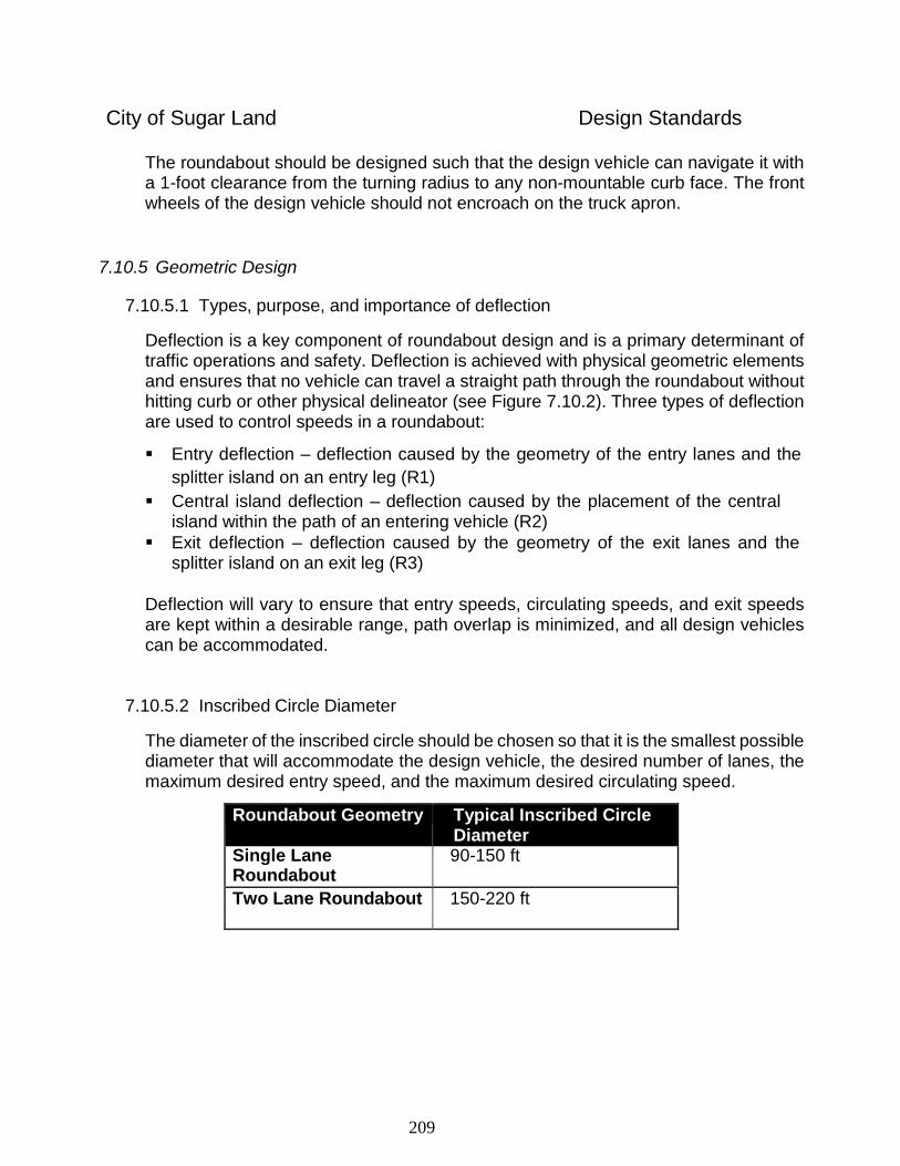
209
City of Sugar Land Design Standards
The roundabout should be designed such that the design vehicle can navigate it with a 1-foot clearance from the turning radius to any non-mountable curb face. The front wheels of the design vehicle should not encroach on the truck apron.
7.10.5 Geometric Design
7.10.5.1 Types, purpose, and importance of deflection
Deflection is a key component of roundabout design and is a primary determinant of traffic operations and safety. Deflection is achieved with physical geometric elements and ensures that no vehicle can travel a straight path through the roundabout without hitting curb or other physical delineator (see Figure 7.10.2). Three types of deflection are used to control speeds in a roundabout:
Entry deflection – deflection caused by the geometry of the entry lanes and the
splitter island on an entry leg (R1)
Central island deflection – deflection caused by the placement of the central island within the path of an entering vehicle (R2)
Exit deflection – deflection caused by the geometry of the exit lanes and the splitter island on an exit leg (R3)
Deflection will vary to ensure that entry speeds, circulating speeds, and exit speeds are kept within a desirable range, path overlap is minimized, and all design vehicles can be accommodated.
7.10.5.2 Inscribed Circle Diameter
The diameter of the inscribed circle should be chosen so that it is the smallest possible diameter that will accommodate the design vehicle, the desired number of lanes, the maximum desired entry speed, and the maximum desired circulating speed.
Roundabout Geometry Typical Inscribed Circle Diameter
Single Lane Roundabout
90-150 ft
Two Lane Roundabout 150-220 ft
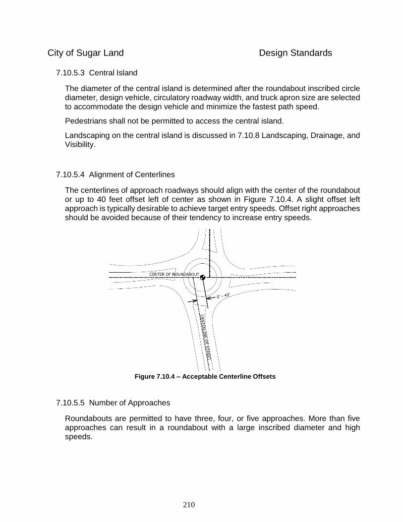
210
City of Sugar Land Design Standards
7.10.5.3 Central Island
The diameter of the central island is determined after the roundabout inscribed circle diameter, design vehicle, circulatory roadway width, and truck apron size are selected to accommodate the design vehicle and minimize the fastest path speed.
Pedestrians shall not be permitted to access the central island.
Landscaping on the central island is discussed in 7.10.8 Landscaping, Drainage, and Visibility.
7.10.5.4 Alignment of Centerlines
The centerlines of approach roadways should align with the center of the roundabout or up to 40 feet offset left of center as shown in Figure 7.10.4. A slight offset left approach is typically desirable to achieve target entry speeds. Offset right approaches should be avoided because of their tendency to increase entry speeds.
Figure 7.10.4 – Acceptable Centerline Offsets
7.10.5.5 Number of Approaches
Roundabouts are permitted to have three, four, or five approaches. More than five approaches can result in a roundabout with a large inscribed diameter and high speeds.
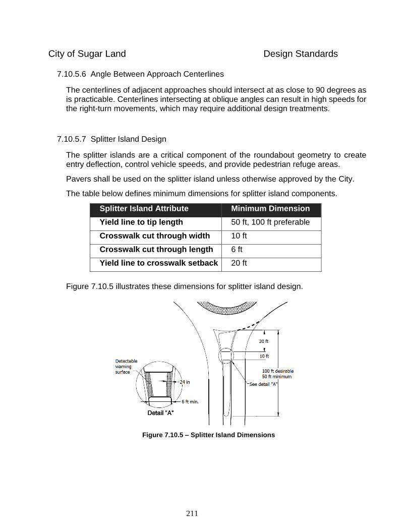
211
City of Sugar Land Design Standards
7.10.5.6 Angle Between Approach Centerlines
The centerlines of adjacent approaches should intersect at as close to 90 degrees as is practicable. Centerlines intersecting at oblique angles can result in high speeds for the right-turn movements, which may require additional design treatments.
7.10.5.7 Splitter Island Design
The splitter islands are a critical component of the roundabout geometry to create entry deflection, control vehicle speeds, and provide pedestrian refuge areas.
Pavers shall be used on the splitter island unless otherwise approved by the City.
The table below defines minimum dimensions for splitter island components.
Splitter Island Attribute Minimum Dimension
Yield line to tip length 50 ft, 100 ft preferable
Crosswalk cut through width 10 ft
Crosswalk cut through length 6 ft
Yield line to crosswalk setback 20 ft
Figure 7.10.5 illustrates these dimensions for splitter island design.
Figure 7.10.5 – Splitter Island Dimensions
212
City of Sugar Land Design Standards
7.10.5.8 Truck Apron
Truck aprons should be designed to provide enough room for the design vehicle to pass without running up on a curb. Depending on the design vehicle, a truck apron may not be necessary. Where truck volumes are low, trucks may be assumed to utilize two lanes of a multi-lane roundabout.
The roundabout shall be designed such that transit vehicles, school buses, fire trucks, and passenger vehicles do not have to use the truck apron to navigate around the roundabout.
The truck apron should usually fall within a range of 3 to 15 feet, although the ultimate need for and width of a truck apron will be determined by analysis of the design vehicle and roundabout performance metrics.
The cross slope of the truck apron shall be 2% down from the central island.
The outside edge of the truck apron shall be 4 inches above the circulatory roadway.
An 18” mountable curb shall be used between the truck apron and the circulatory roadway.
The truck apron shall be constructed of an 8” Portland cement base overlaid with pavers, as shown in the City of Sugar Land Standard Construction Details.
If no truck apron is necessary, a 3’ mow strip shall be provided around the central island.
7.10.5.9 Entry Width
Entry width is measured from the point where the entrance line intersects the left edge of traveled way, along a line perpendicular to the right curb line. Entry width is chosen to control speed and accommodate design vehicles. Exceeding the recommended entry widths can encourage higher speeds and can encourage drivers to treat the entry as having more lanes than is intended. Recommended maximum entry widths are shown in the table below.
Roundabout Geometry Maximum Entry Width
Single Lane Approach 16 ft desirable; 20 ft max
Two-lane Approach 28 ft desirable; 32 ft max
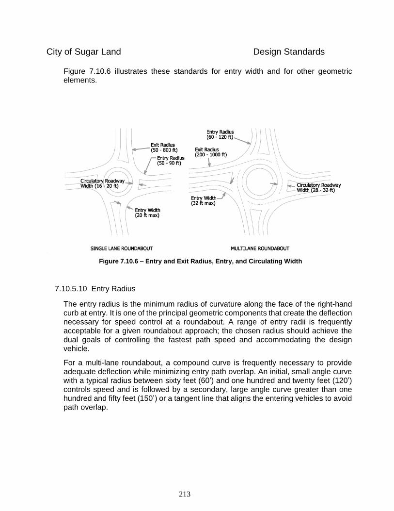
213
City of Sugar Land Design Standards
Figure 7.10.6 illustrates these standards for entry width and for other geometric elements.
Figure 7.10.6 – Entry and Exit Radius, Entry, and Circulating Width
7.10.5.10 Entry Radius
The entry radius is the minimum radius of curvature along the face of the right-hand curb at entry. It is one of the principal geometric components that create the deflection necessary for speed control at a roundabout. A range of entry radii is frequently acceptable for a given roundabout approach; the chosen radius should achieve the dual goals of controlling the fastest path speed and accommodating the design vehicle.
For a multi-lane roundabout, a compound curve is frequently necessary to provide adequate deflection while minimizing entry path overlap. An initial, small angle curve with a typical radius between sixty feet (60’) and one hundred and twenty feet (120’) controls speed and is followed by a secondary, large angle curve greater than one hundred and fifty feet (150’) or a tangent line that aligns the entering vehicles to avoid path overlap.
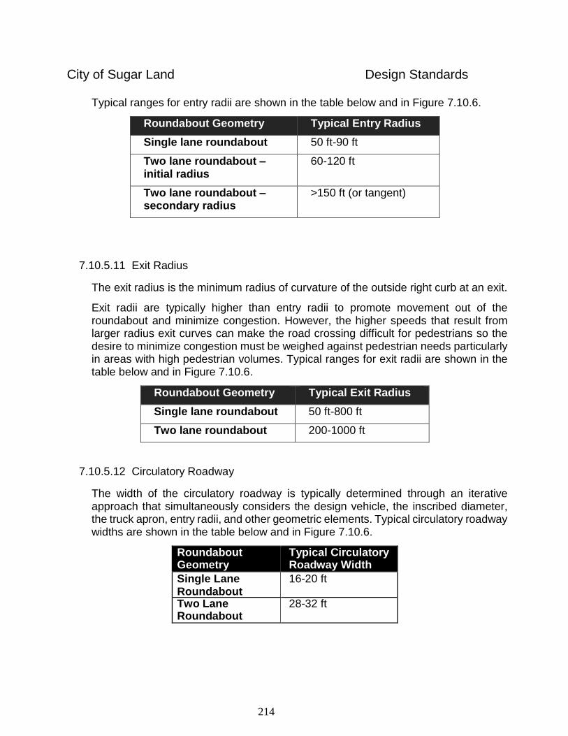
214
City of Sugar Land Design Standards
Typical ranges for entry radii are shown in the table below and in Figure 7.10.6.
Roundabout Geometry Typical Entry Radius
Single lane roundabout 50 ft-90 ft
Two lane roundabout – initial radius
60-120 ft
Two lane roundabout – secondary radius
>150 ft (or tangent)
7.10.5.11 Exit Radius
The exit radius is the minimum radius of curvature of the outside right curb at an exit.
Exit radii are typically higher than entry radii to promote movement out of the roundabout and minimize congestion. However, the higher speeds that result from larger radius exit curves can make the road crossing difficult for pedestrians so the desire to minimize congestion must be weighed against pedestrian needs particularly in areas with high pedestrian volumes. Typical ranges for exit radii are shown in the table below and in Figure 7.10.6.
Roundabout Geometry Typical Exit Radius
Single lane roundabout 50 ft-800 ft
Two lane roundabout 200-1000 ft
7.10.5.12 Circulatory Roadway
The width of the circulatory roadway is typically determined through an iterative approach that simultaneously considers the design vehicle, the inscribed diameter, the truck apron, entry radii, and other geometric elements. Typical circulatory roadway widths are shown in the table below and in Figure 7.10.6.
Roundabout Geometry
Typical Circulatory Roadway Width
Single Lane Roundabout
16-20 ft
Two Lane Roundabout
28-32 ft
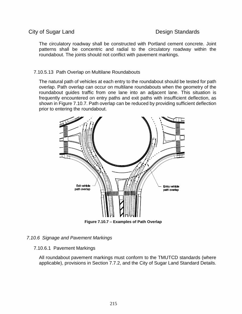
215
City of Sugar Land Design Standards
The circulatory roadway shall be constructed with Portland cement concrete. Joint patterns shall be concentric and radial to the circulatory roadway within the roundabout. The joints should not conflict with pavement markings.
7.10.5.13 Path Overlap on Multilane Roundabouts
The natural path of vehicles at each entry to the roundabout should be tested for path overlap. Path overlap can occur on multilane roundabouts when the geometry of the roundabout guides traffic from one lane into an adjacent lane. This situation is frequently encountered on entry paths and exit paths with insufficient deflection, as shown in Figure 7.10.7. Path overlap can be reduced by providing sufficient deflection prior to entering the roundabout.
Figure 7.10.7 – Examples of Path Overlap
7.10.6 Signage and Pavement Markings
7.10.6.1 Pavement Markings
All roundabout pavement markings must conform to the TMUTCD standards (where applicable), provisions in Section 7.7.2, and the City of Sugar Land Standard Details.
216
City of Sugar Land Design Standards
Lane Markings are crucial to the successful and safe operation of a multilane roundabout. Proper dashed and solid markings shall be provided on each entry lane prior to the entry crosswalk and on each lane of the circulatory roadway past each exit, as shown in the City of Sugar Land Standard Details.
A wide dotted pavement marking shall delineate the edge of the circulatory roadway at each entry. Yield triangles shall be used to mark the location at which drivers must yield to circulating traffic. For each approach lane, the yield markings shall extend from the point at which the edge of the inside lane line intersects the circulatory roadway to a point that is perpendicular to the edge of the outside lane line. Supplemental “YIELD” pavement marking may be required where field observations indicate a significant number of vehicles do not yield.
Yellow edge lines shall be placed along the left edge of the entry and exit of each approach roadway along the edge of the splitter islands. Splitter island curbs may be painted yellow in lieu of painted edge lines.
White edge lines are required along the portion of the splitter island which outlines the outside of the circulatory roadway.
For roundabout exists, install retroreflective yellow paint on splitter island curbs.
7.10.6.2 Signage
All roundabout signage must conform to the TMUTCD standards (where applicable), latest revision and as provided for in Section 7.7.1.
Generally, signage should be minimized to reduce visual clutter and focus driver concentration on potential conflicts and the geometry of the roundabout.
Advance roundabout warning signs (W2-6) with cross street name signs are required on all approaches to the roundabout.
Yield signs shall be placed on both the right and left sides of the road at all single-lane and multilane roundabout approaches. The signs should be placed at the point where vehicles are to yield when entering the roundabout. “YIELD” pavement marking may be required where field observation warrants.
Lane assignment signs depicting the lanes maneuvering around the roundabout shall be provided on all multi-lane approaches, including single lane approaches with auxiliary turn lanes, one hundred seventy five feet (175’) to two hundred feet (200’) from the yield line. These signs should be accompanied by lane use pavement markings.
Street name signs with a minimum of 6” lettering shall be placed on the splitter islands oriented toward traffic on the circulatory roadway.
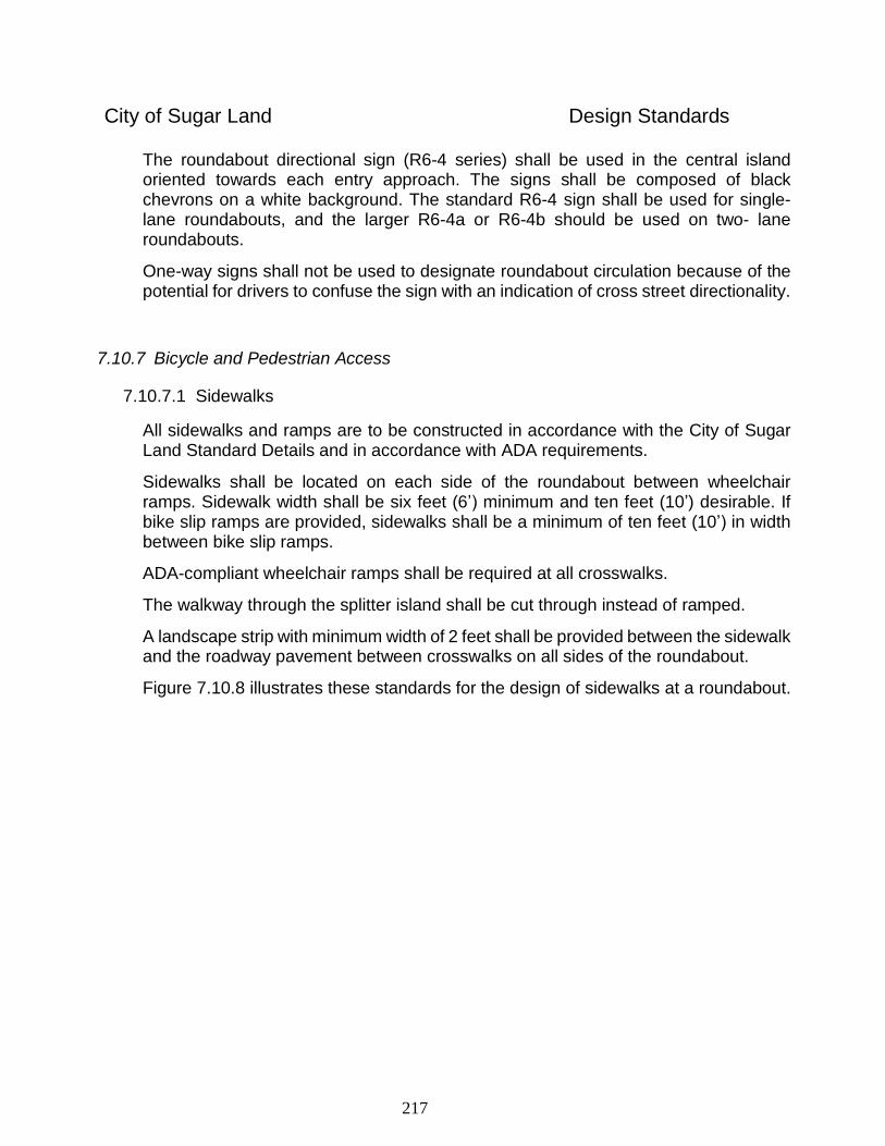
217
City of Sugar Land Design Standards
The roundabout directional sign (R6-4 series) shall be used in the central island oriented towards each entry approach. The signs shall be composed of black chevrons on a white background. The standard R6-4 sign shall be used for single-lane roundabouts, and the larger R6-4a or R6-4b should be used on two- lane roundabouts.
One-way signs shall not be used to designate roundabout circulation because of the potential for drivers to confuse the sign with an indication of cross street directionality.
7.10.7 Bicycle and Pedestrian Access
7.10.7.1 Sidewalks
All sidewalks and ramps are to be constructed in accordance with the City of Sugar Land Standard Details and in accordance with ADA requirements.
Sidewalks shall be located on each side of the roundabout between wheelchair ramps. Sidewalk width shall be six feet (6’) minimum and ten feet (10’) desirable. If bike slip ramps are provided, sidewalks shall be a minimum of ten feet (10’) in width between bike slip ramps.
ADA-compliant wheelchair ramps shall be required at all crosswalks.
The walkway through the splitter island shall be cut through instead of ramped.
A landscape strip with minimum width of 2 feet shall be provided between the sidewalk and the roadway pavement between crosswalks on all sides of the roundabout.
Figure 7.10.8 illustrates these standards for the design of sidewalks at a roundabout.
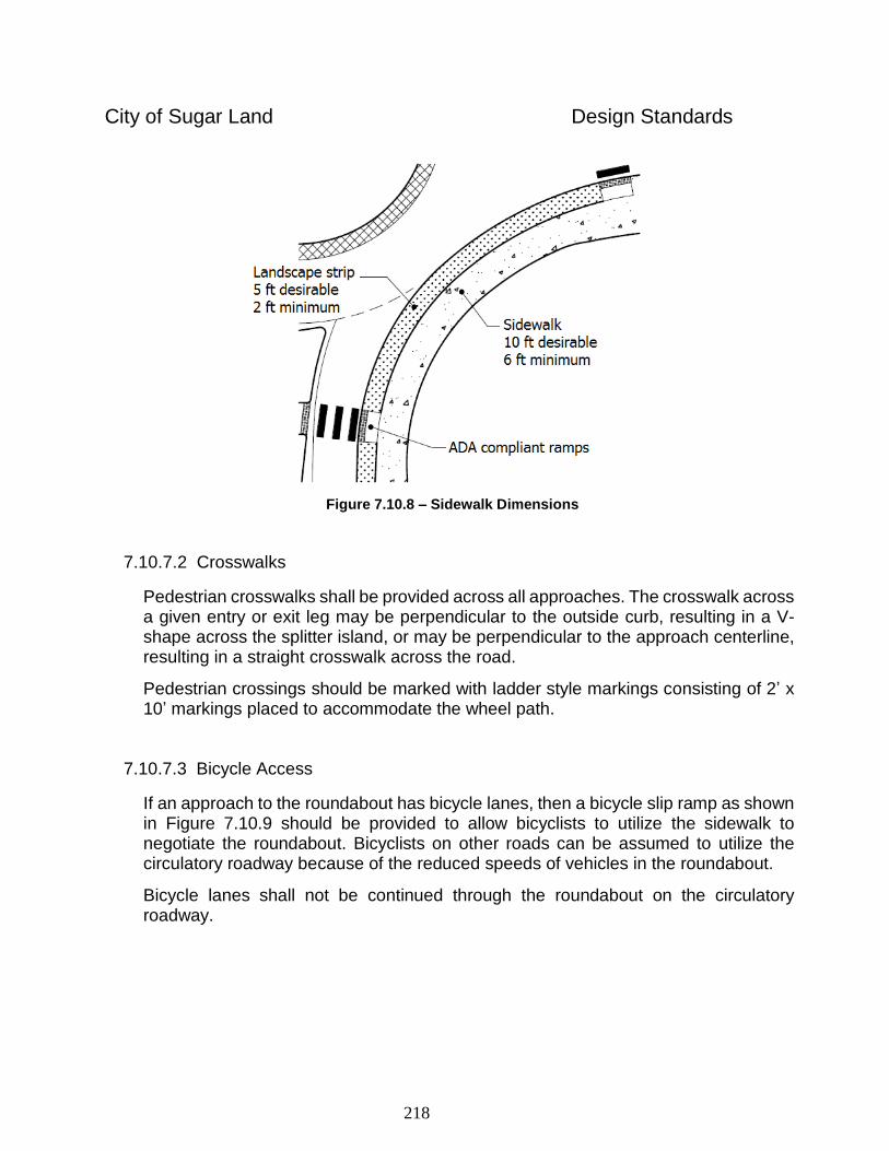
218
City of Sugar Land Design Standards
Figure 7.10.8 – Sidewalk Dimensions
7.10.7.2 Crosswalks
Pedestrian crosswalks shall be provided across all approaches. The crosswalk across a given entry or exit leg may be perpendicular to the outside curb, resulting in a V-shape across the splitter island, or may be perpendicular to the approach centerline, resulting in a straight crosswalk across the road.
Pedestrian crossings should be marked with ladder style markings consisting of 2’ x 10’ markings placed to accommodate the wheel path.
7.10.7.3 Bicycle Access
If an approach to the roundabout has bicycle lanes, then a bicycle slip ramp as shown in Figure 7.10.9 should be provided to allow bicyclists to utilize the sidewalk to negotiate the roundabout. Bicyclists on other roads can be assumed to utilize the circulatory roadway because of the reduced speeds of vehicles in the roundabout.
Bicycle lanes shall not be continued through the roundabout on the circulatory roadway.
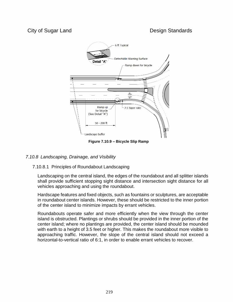
219
City of Sugar Land Design Standards
Figure 7.10.9 – Bicycle Slip Ramp
7.10.8 Landscaping, Drainage, and Visibility
7.10.8.1 Principles of Roundabout Landscaping
Landscaping on the central island, the edges of the roundabout and all splitter islands shall provide sufficient stopping sight distance and intersection sight distance for all vehicles approaching and using the roundabout.
Hardscape features and fixed objects, such as fountains or sculptures, are acceptable in roundabout center islands. However, these should be restricted to the inner portion of the center island to minimize impacts by errant vehicles.
Roundabouts operate safer and more efficiently when the view through the center island is obstructed. Plantings or shrubs should be provided in the inner portion of the center island; where no plantings are provided, the center island should be mounded with earth to a height of 3.5 feet or higher. This makes the roundabout more visible to approaching traffic. However, the slope of the central island should not exceed a horizontal-to-vertical ratio of 6:1, in order to enable errant vehicles to recover.
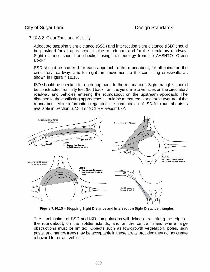
220
City of Sugar Land Design Standards
7.10.8.2 Clear Zone and Visibility
Adequate stopping sight distance (SSD) and intersection sight distance (ISD) should be provided for all approaches to the roundabout and for the circulatory roadway. Sight distance should be checked using methodology from the AASHTO “Green Book.”
SSD should be checked for each approach to the roundabout, for all points on the circulatory roadway, and for right-turn movement to the conflicting crosswalk, as shown in Figure 7.10.10.
ISD should be checked for each approach to the roundabout. Sight triangles should be constructed from fifty feet (50’) back from the yield line to vehicles on the circulatory roadway and vehicles entering the roundabout on the upstream approach. The distance to the conflicting approaches should be measured along the curvature of the roundabout. More information regarding the computation of ISD for roundabouts is available in Section 6.7.3.4 of NCHRP Report 672.
Figure 7.10.10 – Stopping Sight Distance and Intersection Sight Distance triangles
The combination of SSD and ISD computations will define areas along the edge of the roundabout, on the splitter islands, and on the central island where large obstructions must be limited. Objects such as low-growth vegetation, poles, sign posts, and narrow trees may be acceptable in these areas provided they do not create a hazard for errant vehicles.
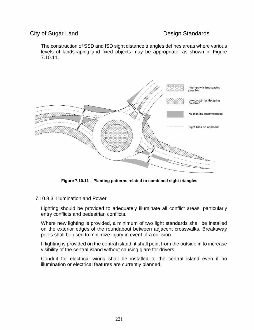
221
City of Sugar Land Design Standards
The construction of SSD and ISD sight distance triangles defines areas where various levels of landscaping and fixed objects may be appropriate, as shown in Figure 7.10.11.
Figure 7.10.11 – Planting patterns related to combined sight triangles
7.10.8.3 Illumination and Power
Lighting should be provided to adequately illuminate all conflict areas, particularly entry conflicts and pedestrian conflicts.
Where new lighting is provided, a minimum of two light standards shall be installed on the exterior edges of the roundabout between adjacent crosswalks. Breakaway poles shall be used to minimize injury in event of a collision.
If lighting is provided on the central island, it shall point from the outside in to increase visibility of the central island without causing glare for drivers.
Conduit for electrical wiring shall be installed to the central island even if no illumination or electrical features are currently planned.
222
City of Sugar Land Design Standards
7.10.8.4 Drainage
Roundabouts should be designed to drain away from the central island. A 2% cross slope is typical. In addition to drainage, a 2% cross slope away from the central island also helps to regulate vehicle speeds. Drainage inlets will typically be located along the outer curb line.
Inlets and low points should be located upstream of the crosswalks.
7.10.8.5 Irrigation and Plant Materials
Irrigation or piping for future irrigation shall be provided along the outside perimeter of the roundabout and to the central island regardless of whether or not vegetative landscaping is planned for those locations.
Note: Figures 7.10.1-3, 7.10.5, and 7.10.7-10 have been adapted from NCHRP 672, Roundabouts: An Informational Guide. Figure 7.10.11 has been adapted from the Washington State Department of Transportation Design Manual.
7.11 Midblock Crossings
All midblock crossing plans and construction shall meet the requirements of the City of Sugar Land, Americans with Disabilities Act (ADA) accessibility standards, and the Texas Manual on Uniform Traffic Control Devices (TMUTCD), latest revision.
The purpose of these midblock crossing standards is to provide guidance for the implementation of midblock crossings in the City of Sugar Land and provide uniformity of such designs.
Midblock crossings are locations between intersections where a marked crosswalk is provided. In general, midblock crossings are installed at locations with a high volume of pedestrian traffic. They are typically used near major pedestrian destinations, such as schools or bike trails, where people might otherwise cross at unmarked locations. Traffic control devices and other key elements related to midblock crossings are defined below.
7.11.1 Definitions
Midblock crossing treatments and components associated with midblock crossing design are defined below.
Americans with Disabilities Act (ADA) Accessibility Standards – Accessible design standards that should be met when providing midblock crossing facilities.
223
City of Sugar Land Design Standards
Average Annual Daily Traffic (AADT) – Total volume on a highway or roadway for a year divided by 365 days.
Curb Bulb-Out – Curbed section that reduces the effective cross-section of a roadway to provide a shorter crossing distance for pedestrians.
Detectable Warning Surface – Raised surface used to alert pedestrians at the edge of a roadway.
Grade Separation – Separation of converging traffic flows of any mode at an interchange by varying the elevation of each crossing travel way to eliminate conflicts between traffic flows.
HAWK Signal – High-Intensity Activated CrossWalK (HAWK) signal. See Pedestrian hybrid beacons (PHB).
In-Pavement Warning Lights (IRWL) / In-Pavement Crosswalk Lights – Lights installed in the roadway to alert drivers of pedestrian presence in or near a midblock crossing.
Pedestrian hybrid beacon (PHB) – Midblock crossing treatment used to provide actuated signal control for pedestrian at a midblock crossing. This treatment provides passive signalized control for both the pedestrians and vehicular traffic. Typically considered at locations with both high pedestrian volumes and high vehicular volumes.
Pedestrian Refuge Island – Area within a raised median section used as an interim area for pedestrians to wait for gaps in vehicular traffic. Provides a refuge area to allow pedestrians to negotiate traffic in only one direction at a time.
PELICAN Signal – Pedestrian Light Control Activated (PELICAN) signal.
Raised Crosswalk Table – Raised table at the location of a crosswalk.
Rectangular Rapid Flashing Beacon (RRFB) – Pedestrian actuated beacon mounted below a pedestrian crossing warning sign to alert drivers of pedestrian presence in or near a midblock crossing.
TOUCAN Signal – Pedestrian signal such that “Two” travel modes “Can” cross the roadway – pedestrians and bicyclists.
Yield Lines – Pavement markings used to designate the location for drivers to stop their vehicles when yielding to conflicting movements. In the case of midblock crossings, the yield lines designate the location drivers should stop when yielding to the pedestrian crossing area.
Z-Crossing – Midblock crossing treatment with median refuge that directs crossing users to face on- coming traffic prior to negotiating the crossing.
224
City of Sugar Land Design Standards
7.11.2 Reference Documents
All midblock crossing infrastructure construction in the City of Sugar Land must comply with the latest editions of all relevant national, state, and local standards that pertain to roadway and pedestrian facility design, including but not limited to:
Texas Manual on Uniform Traffic Control Devices (TMUTCD)
Americans with Disabilities Act (ADA) Accessibility Standards
American Association of State Highway and Transportation Officials (AASHTO),
A Policy on Geometric Design of Highways and Streets (AASHTO Green Book)
City of Sugar Land Neighborhood Traffic Policy, City of Sugar Land
7.11.3 Need for Midblock Crossings
Midblock crossings shall not be installed indiscriminately. A midblock crossing treatment should not be implemented unless an engineering study indicates that the crossing will improve the access and mobility for its users safely. Inappropriate midblock crossings can give pedestrians an unwarranted sense of security and may increase the number of crashes at a site. An engineering study shall be completed and submitted to the City of Sugar Land for approval prior to implementation. An engineering study of traffic conditions, pedestrian characteristics, and physical characteristics of the location shall be performed to determine whether implementation of a midblock crossing treatment is justified at a particular location.
For midblock crossing treatments that require signalization, such as, pedestrian traffic signals, HAWK, PELICAN, or TOUCAN, Warrant 4, Pedestrian Volume should be satisfied, per TMUCTD, as part of a traffic signal warrant analysis. These provide various degrees of passive traffic signal control for both vehicular and pedestrian traffic.
Consideration of the proposed location will be dependent on the need for pedestrian access and mobility across the roadway and nearby attraction points of interest.
7.11.4 Midblock Crossing Design Considerations
The following design considerations should be included as part of the engineering study.
7.11.4.1 Roadway Cross-section and Median Width
The cross-section of a roadway will dictate the effective pedestrian crossing distance. If the crossing distance is too long or traverses too many lanes, crossing pedestrians will have increased exposure to vehicular traffic. A location with a median at least 6
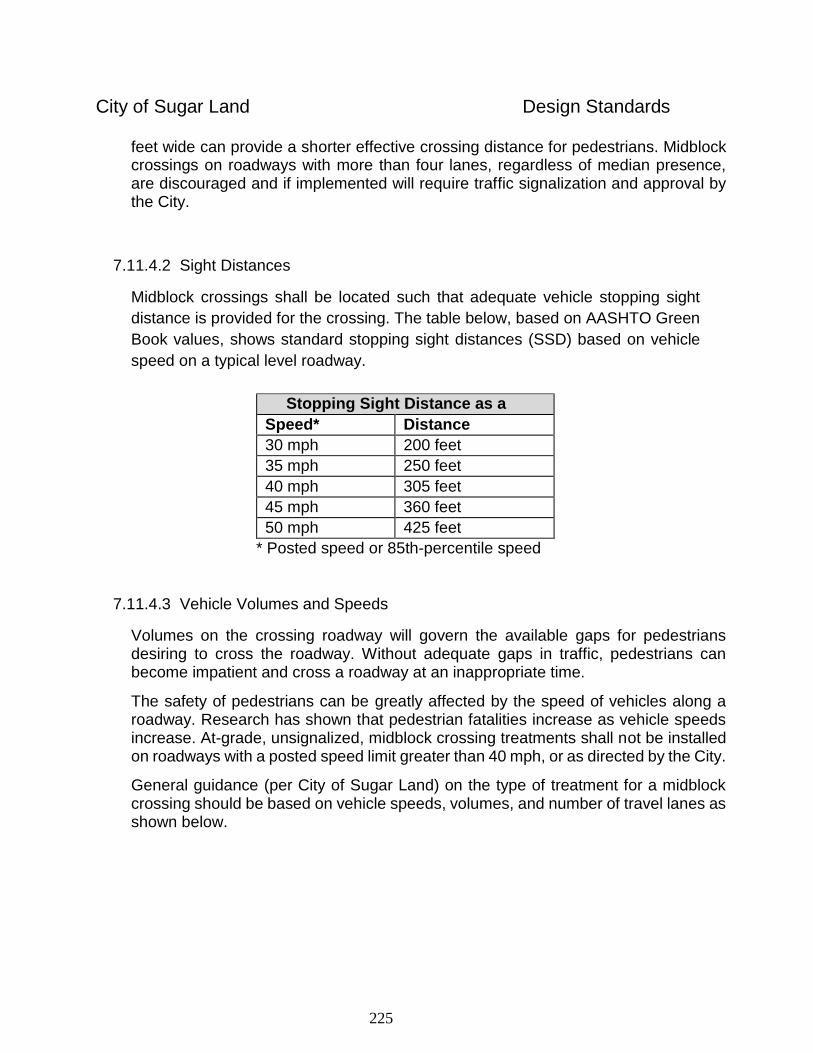
225
City of Sugar Land Design Standards
feet wide can provide a shorter effective crossing distance for pedestrians. Midblock crossings on roadways with more than four lanes, regardless of median presence, are discouraged and if implemented will require traffic signalization and approval by the City.
7.11.4.2 Sight Distances
Midblock crossings shall be located such that adequate vehicle stopping sight
distance is provided for the crossing. The table below, based on AASHTO Green
Book values, shows standard stopping sight distances (SSD) based on vehicle
speed on a typical level roadway.
Stopping Sight Distance as a
Function of Speed Speed* Distance
30 mph 200 feet
35 mph 250 feet
40 mph 305 feet
45 mph 360 feet
50 mph 425 feet
* Posted speed or 85th-percentile speed
7.11.4.3 Vehicle Volumes and Speeds
Volumes on the crossing roadway will govern the available gaps for pedestrians desiring to cross the roadway. Without adequate gaps in traffic, pedestrians can become impatient and cross a roadway at an inappropriate time.
The safety of pedestrians can be greatly affected by the speed of vehicles along a roadway. Research has shown that pedestrian fatalities increase as vehicle speeds increase. At-grade, unsignalized, midblock crossing treatments shall not be installed on roadways with a posted speed limit greater than 40 mph, or as directed by the City.
General guidance (per City of Sugar Land) on the type of treatment for a midblock crossing should be based on vehicle speeds, volumes, and number of travel lanes as shown below.
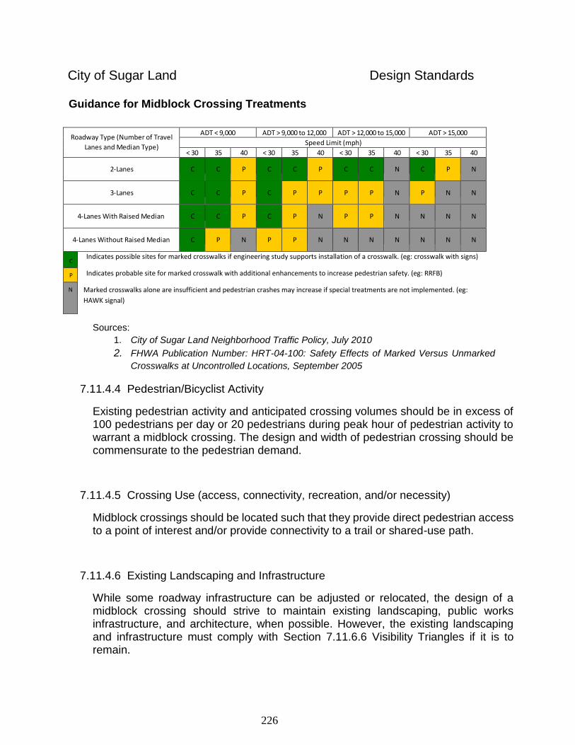
226
City of Sugar Land Design Standards
Roadway Type (Number of Travel
Lanes and Median Type)
ADT < 9,000 ADT > 9,000 to 12,000 ADT > 12,000 to 15,000 ADT > 15,000
Speed Limit (mph)
< 30 35 40 < 30 35 40 < 30 35 40 < 30 35 40
2-Lanes
C
C
P
C
C
P
C
C
N
C
P
N
3-Lanes
C
C
P
C
P
P
P
P
N
P
N
N
4-Lanes With Raised Median
C
C
P
C
P
N
P
P
N
N
N
N
4-Lanes Without Raised Median
C
P
N
P
P
N
N
N
N
N
N
N
C Indicates possible sites for marked crosswalks if engineering study supports installation of a crosswalk. (eg: crosswalk with signs)
Indicates probable site for marked crosswalk with additional enhancements to increase pedestrian safety. (eg: RRFB)
Marked crosswalks alone are insufficient and pedestrian crashes may increase if special treatments are not implemented. (eg:
HAWK signal)
P
N
Guidance for Midblock Crossing Treatments
Sources:
1. City of Sugar Land Neighborhood Traffic Policy, July 2010
2. FHWA Publication Number: HRT-04-100: Safety Effects of Marked Versus Unmarked
Crosswalks at Uncontrolled Locations, September 2005
7.11.4.4 Pedestrian/Bicyclist Activity
Existing pedestrian activity and anticipated crossing volumes should be in excess of 100 pedestrians per day or 20 pedestrians during peak hour of pedestrian activity to warrant a midblock crossing. The design and width of pedestrian crossing should be commensurate to the pedestrian demand.
7.11.4.5 Crossing Use (access, connectivity, recreation, and/or necessity)
Midblock crossings should be located such that they provide direct pedestrian access to a point of interest and/or provide connectivity to a trail or shared-use path.
7.11.4.6 Existing Landscaping and Infrastructure
While some roadway infrastructure can be adjusted or relocated, the design of a midblock crossing should strive to maintain existing landscaping, public works infrastructure, and architecture, when possible. However, the existing landscaping and infrastructure must comply with Section 7.11.6.6 Visibility Triangles if it is to remain.
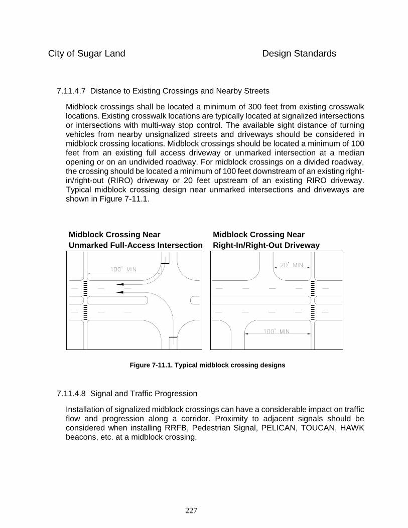
227
City of Sugar Land Design Standards
7.11.4.7 Distance to Existing Crossings and Nearby Streets
Midblock crossings shall be located a minimum of 300 feet from existing crosswalk locations. Existing crosswalk locations are typically located at signalized intersections or intersections with multi-way stop control. The available sight distance of turning vehicles from nearby unsignalized streets and driveways should be considered in midblock crossing locations. Midblock crossings should be located a minimum of 100 feet from an existing full access driveway or unmarked intersection at a median opening or on an undivided roadway. For midblock crossings on a divided roadway, the crossing should be located a minimum of 100 feet downstream of an existing right-in/right-out (RIRO) driveway or 20 feet upstream of an existing RIRO driveway. Typical midblock crossing design near unmarked intersections and driveways are shown in Figure 7-11.1.
Midblock Crossing Near Midblock Crossing Near
Unmarked Full-Access Intersection Right-In/Right-Out Driveway
Figure 7-11.1. Typical midblock crossing designs
7.11.4.8 Signal and Traffic Progression
Installation of signalized midblock crossings can have a considerable impact on traffic flow and progression along a corridor. Proximity to adjacent signals should be considered when installing RRFB, Pedestrian Signal, PELICAN, TOUCAN, HAWK beacons, etc. at a midblock crossing.
228
City of Sugar Land Design Standards
7.11.5 Midblock Crossing Treatments
The following midblock crossing treatments can be considered depending on the existing conditions and design consideration listed above.
7.11.5.1 Raised Crosswalk
Raised crosswalks improve the visibility of and accessibility for pedestrians by providing a raised platform across a roadway. These are to be implemented as directed by the City and care must be taken to accommodate drainage when used. Use of drainage slots are not allowed.
7.11.5.2 Grade Separation
The placement of shared-use paths and trails along bayous and levees often causes them to intersect the roadways that traverse the drainage facility. On such occasions, a grade-separated crossing can be considered by passing under the bridge. Pedestrian bridges to cross a roadway are not a generally acceptable means of grade separation.
The following considerations should be incorporated into the design of the crossing under the bridge:
Under bridge lighting
Minimum clearance of 8 feet
Drainage design
Design Vehicle (for maintenance)
A pedestrian bridge involves considerable cost and design implications and would be allowed only in specific instances upon approval from the City.
7.11.5.3 Textured / Colored Pavement
To enhance visibility of a midblock crossing during the day, textured or colored pavement can be used. When brick pavers are used, they shall be approved by the City and must meet City standards. Use of either textured or colored pavement does not eliminate the requirement for TMUTCD- compliant crosswalk pavement markings at the midblock crossing location.
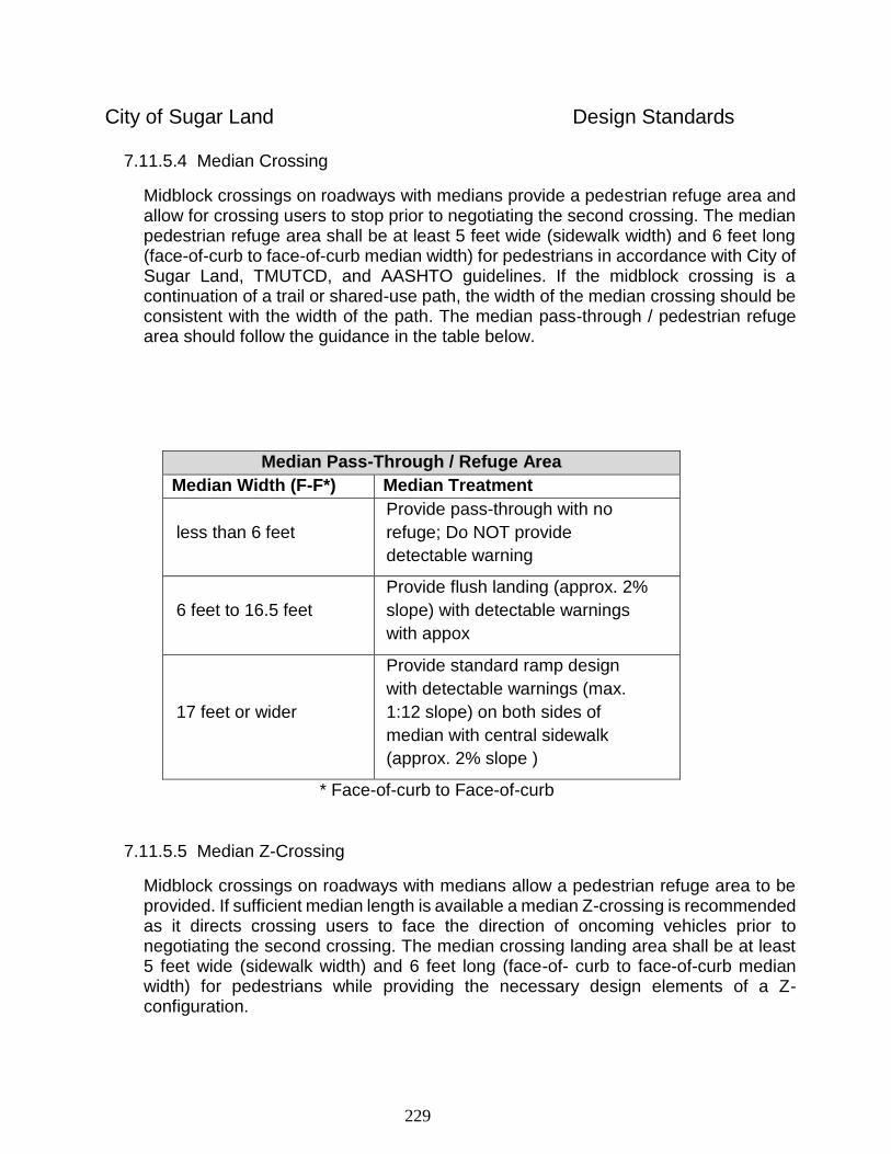
229
City of Sugar Land Design Standards
7.11.5.4 Median Crossing
Midblock crossings on roadways with medians provide a pedestrian refuge area and allow for crossing users to stop prior to negotiating the second crossing. The median pedestrian refuge area shall be at least 5 feet wide (sidewalk width) and 6 feet long (face-of-curb to face-of-curb median width) for pedestrians in accordance with City of Sugar Land, TMUTCD, and AASHTO guidelines. If the midblock crossing is a continuation of a trail or shared-use path, the width of the median crossing should be consistent with the width of the path. The median pass-through / pedestrian refuge area should follow the guidance in the table below.
Median Pass-Through / Refuge Area
Median Width (F-F*) Median Treatment
less than 6 feet
Provide pass-through with no
refuge; Do NOT provide
detectable warning
6 feet to 16.5 feet
Provide flush landing (approx. 2%
slope) with detectable warnings
with appox
17 feet or wider
Provide standard ramp design
with detectable warnings (max.
1:12 slope) on both sides of
median with central sidewalk
(approx. 2% slope )
* Face-of-curb to Face-of-curb
7.11.5.5 Median Z-Crossing
Midblock crossings on roadways with medians allow a pedestrian refuge area to be provided. If sufficient median length is available a median Z-crossing is recommended as it directs crossing users to face the direction of oncoming vehicles prior to negotiating the second crossing. The median crossing landing area shall be at least 5 feet wide (sidewalk width) and 6 feet long (face-of- curb to face-of-curb median width) for pedestrians while providing the necessary design elements of a Z-configuration.
230
City of Sugar Land Design Standards
The median sidewalk can be parallel with the roadway or angled. The Z-configuration shall be oriented such that crossing users face oncoming vehicular traffic as they travel along the sidewalk within the median.
7.11.5.6 Curb Extension/ Bulb-Outs
Curb extensions and bulb-outs reduce the effective crossing distance at midblock crossing locations. The implementation of curb extensions and bulb-outs is typically along low-speed (35 mph or less), low-volume (400 AADT or less) roadways. Transitions for curb extension/bulb outs should follow TMUTCD and AASHTO guidelines. Minimum lane widths should be maintained when bulb-outs are used. Such applications are appropriate only in specific instances and shall require City of Sugar Land approval. Curb extensions are typically only used when on-street parking is present.
7.11.5.7 Midblock Crossing Pedestrian Signals
For midblock crossing treatments that require signalization, TMUTCD Warrant 4, Pedestrian Volume should be satisfied as part of a traffic signal warrant analysis. If adequate gaps in the traffic flow are available for pedestrians, pedestrian signal control is not permitted. The standard two-phase traffic signal for a pedestrian crossing is the more conventional type of signal treatment in most instances. This type of signalization is preferred by the City. However, there are several types of midblock crossing signal design that are available for consideration. Some of the more common types of midblock crossing signal designs include HAWK, PELICAN, and TOUCAN signals.
Two-Phase Traffic Signal
A two-phase traffic signal can be used to provide pedestrian actuated warning signals for pedestrians at a midblock crossing. The signal functions as a traditional traffic signal with yellow, red, and green indications for vehicles at the crossing. The two-phase signal should only be used at locations with a high pedestrian volume. Two-phase traffic signals are the recommended treatment for midblock crossing signal designs within the City of Sugar Land and shall require a traffic engineering study and City of Sugar Land approval prior to installation.
High-Intensity Activated Crosswalk (HAWK) Signal
231
City of Sugar Land Design Standards
High-intensity Activated crossWalK (HAWK) signals can be used to provide actuated warning signals for pedestrians at a midblock crossing. This treatment alerts drivers to the presence of pedestrians in or near the crosswalk using flashing signal heads. HAWK signal should only be considered at locations with both high pedestrian volumes and high vehicular volumes. A HAWK signal shall require City of Sugar Land approval.
PELICAN Signal
Pedestrian Light Control Activated (PELICAN) signals can be used to provide actuated signal control for pedestrians at a midblock crossing. This treatment provides signalized control for both the pedestrians and vehicular traffic. PELICAN signals can be considered at locations with both high pedestrian volumes and high vehicular volumes. PELICAN signals are generally not recommended within the City of Sugar Land. Only under unique conditions should a pelican signal be considered and shall require City of Sugar Land approval.
TOUCAN Signal
TOUCAN signals are named such that “two” travel modes “can” cross the roadway – pedestrians and bicyclists. TOUCAN signal control provides separate pedestrian and bicycle signal heads to allow for varying crossing times. TOUCAN signals are generally not recommended within the City of Sugar Land. Only under unique conditions should a TOUCAN signal be considered and shall require City of Sugar Land approval.
7.11.5.8 Rectangular Rapid Flashing Beacon
Rectangular Rapid Flashing Beacons (RRFB) are mounted on a pedestal with pedestrian crossing signs at a midblock crossing. RRFB are used at actuated pedestrian signal crossings to increase driver awareness of the presence of pedestrian in or near a midblock crossing. RRFB is an intermediate treatment between crosswalks with static signage and signalization.
7.11.5.9 Pedestrian Accessibility
Pedestrian design elements shall meet ADA guidelines and be incorporated into the midblock crossing design. These elements include, but are not limited to, width of the accessible path, walkway and ramp slopes, and detectable warning surfaces.
232
City of Sugar Land Design Standards
7.11.5.10 Electrical Considerations
Pedestrian signals and RRFB require power to function. Availability of power and electrical sources should be considered as part of design. Solar power can also be considered if the location has adequate exposure to sunlight.
7.11.6 Midblock Crossing Design
7.11.6.1 Ramps and Median Landings
The ramps and median landings shall meet all applicable City of Sugar Land and ADA guidelines. The midblock crossing ramp and landing width should be a minimum of 5 feet wide. If the midblock crossing is a continuation of a trail or shared-use path, the width of the internal sidewalk, ramps, and landings, should be consistent with the width of the trail. The median landings shall be relatively flush with the roadway and have a minimum 2% slope for drainage.
7.11.6.2 Pavement Markings
Crosswalk pavement marking should generally be the same width as the ramp and landing widths. Twenty-four inch (24”) continental pavement markings shall be used for all midblock crossings. Yield line pavement markings shall be installed minimum 20 feet and maximum 50 feet upstream of the crosswalk.
All pavement markings shall be multipolymer Epoplex grades 65 or above. City of Sugar Land Standard Detail SL-37 provides size requirements for midblock crossing pavement markings.
7.11.6.3 In-Roadway Warning Lights
In-roadway warning lights (IRWL) are installed in the roadway surface to warn approaching motorists that they may need to slow down or stop. In-roadway warning lights can be used at actuated pedestrian signal crossings to increase driver awareness of the presence of pedestrians in or near a midblock crossing. IRWL should only be used as directed by the City and with actuated control. In addition, use of IRWL shall be for specific crosswalk locations that require extra attention from motorists and shall require City of Sugar Land approval.
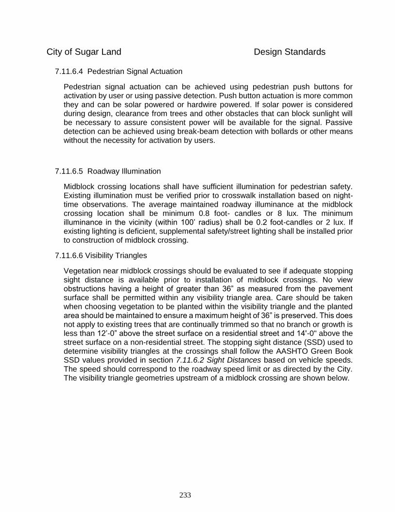
233
City of Sugar Land Design Standards
7.11.6.4 Pedestrian Signal Actuation
Pedestrian signal actuation can be achieved using pedestrian push buttons for activation by user or using passive detection. Push button actuation is more common they and can be solar powered or hardwire powered. If solar power is considered during design, clearance from trees and other obstacles that can block sunlight will be necessary to assure consistent power will be available for the signal. Passive detection can be achieved using break-beam detection with bollards or other means without the necessity for activation by users.
7.11.6.5 Roadway Illumination
Midblock crossing locations shall have sufficient illumination for pedestrian safety. Existing illumination must be verified prior to crosswalk installation based on night-time observations. The average maintained roadway illuminance at the midblock crossing location shall be minimum 0.8 foot- candles or 8 lux. The minimum illuminance in the vicinity (within 100’ radius) shall be 0.2 foot-candles or 2 lux. If existing lighting is deficient, supplemental safety/street lighting shall be installed prior to construction of midblock crossing.
7.11.6.6 Visibility Triangles
Vegetation near midblock crossings should be evaluated to see if adequate stopping sight distance is available prior to installation of midblock crossings. No view obstructions having a height of greater than 36” as measured from the pavement surface shall be permitted within any visibility triangle area. Care should be taken when choosing vegetation to be planted within the visibility triangle and the planted area should be maintained to ensure a maximum height of 36” is preserved. This does not apply to existing trees that are continually trimmed so that no branch or growth is less than 12’-0” above the street surface on a residential street and 14'-0" above the street surface on a non-residential street. The stopping sight distance (SSD) used to determine visibility triangles at the crossings shall follow the AASHTO Green Book SSD values provided in section 7.11.6.2 Sight Distances based on vehicle speeds. The speed should correspond to the roadway speed limit or as directed by the City. The visibility triangle geometries upstream of a midblock crossing are shown below.
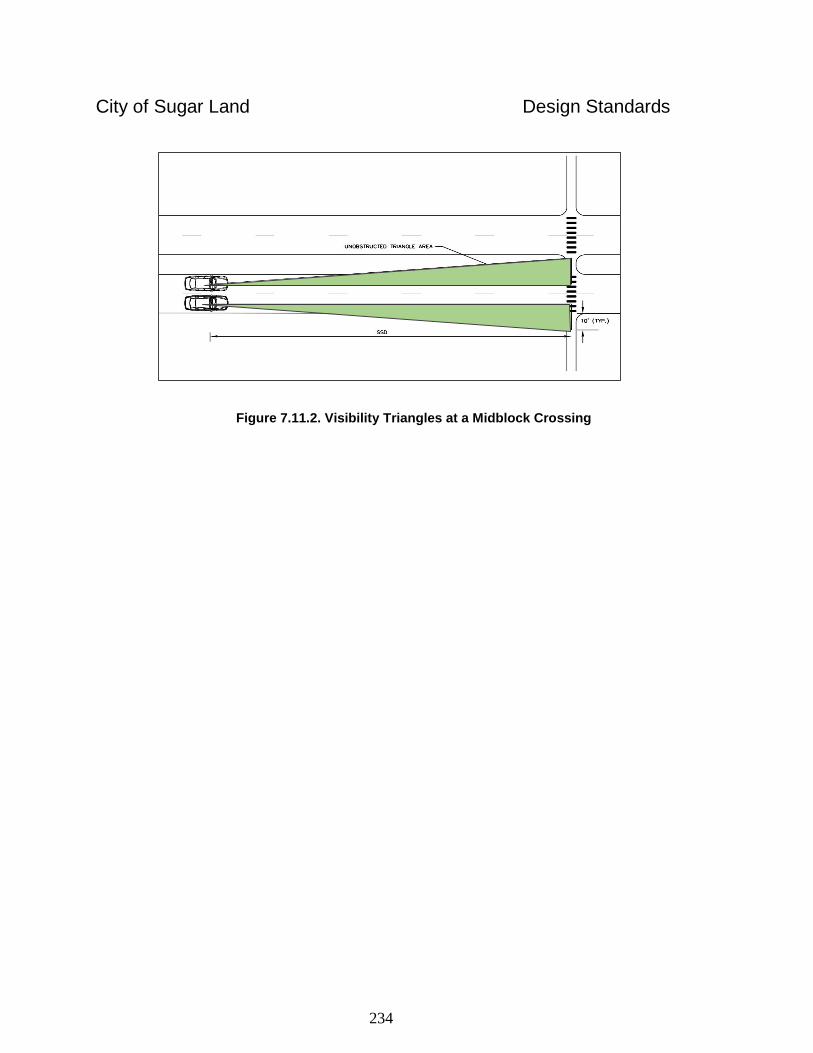
234
City of Sugar Land Design Standards
Figure 7.11.2. Visibility Triangles at a Midblock Crossing
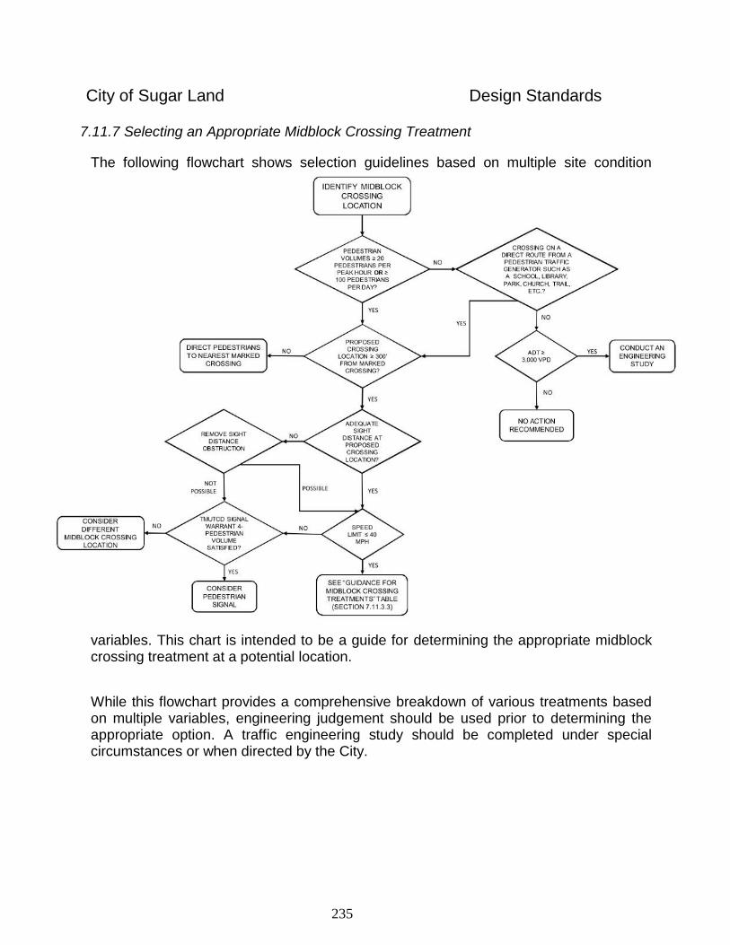
235
City of Sugar Land Design Standards
7.11.7 Selecting an Appropriate Midblock Crossing Treatment
The following flowchart shows selection guidelines based on multiple site condition
variables. This chart is intended to be a guide for determining the appropriate midblock crossing treatment at a potential location.
While this flowchart provides a comprehensive breakdown of various treatments based on multiple variables, engineering judgement should be used prior to determining the appropriate option. A traffic engineering study should be completed under special circumstances or when directed by the City.
236
City of Sugar Land Design Standards
8.0 SITE DEVELOPMENT REQUIREMENTS
8.1 General
Site development plans for all site developments within the City of Sugar Land and its extraterritorial jurisdiction shall be approved by the City Engineer prior to construction.
Site developments, not including single family residential, shall include any project that affects public water, wastewater, storm drainage, or paving facilities.
All site developments shall conform to the requirements of these Standards, the current adopted Building Code, and applicable rules and regulations of the City of Sugar Land.
All wastewater, drainage and paving related site development improvements shall be privately owned, operated and maintained up to and including the connection to the public system. All potable water related site development improvements shall be privately owned, operated and maintained up to but not including the meter and meter vault.
Site development improvements which serve more than one private party, are located within public street rights-of-way or easements, are located within the City’s limits, and meet the design standards set forth herein, may be accepted by the City of Sugar Land for operation and maintenance.
Site development plans shall include:
A. Traffic Control Plan that is in conformance with the latest version of the TX-MUTCD standards.
B. Storm Water Pollution Prevention Plan that complies with the TCEQ Best Management Practice.
8.2 Building Slab Elevations
Minimum building slab elevations within the City’s limits shall be set at or above (1) the elevation required by the recorded plat, (2a) twenty-four inches (24") above the Atlas 14 100-year flood plain elevation and maximum ponded elevation, (2b) twenty-four (24”) above the Atlas 14 maximum ponding elevation within Levee Improvement Districts (LIDs), (3) eighteen inches (18") above natural ground, or (4) twelve inches (12") above the top of curb at the front of the lot, whichever is higher. Building slabs shall conform to the City’s Ordinance No. 595 or latest edition on flood damage prevention. Minimum building slab elevations within the extraterritorial jurisdiction of the City of Sugar Land shall conform to the requirements of Fort Bend County. Minimum slab elevations shall be shown on the Overall Plan and/or lot grading plan in accordance with Chapter 6.
237
City of Sugar Land Design Standards
8.3 Water Service
Water service lines and meters shall be sized in accordance with requirements set out in Section 4.0 of these Standards.
8.4 Sanitary Sewer Service
Sanitary sewer service leads are normally installed during construction of the public sanitary sewer. When a sanitary sewer service lead is to be installed for a site development, refer to requirements set out in Section 5.0 of these Standards. All lots, tracts, or reserves shall be connected directly to a public sanitary sewer by a single lead, except as specifically approved by the City Engineer. The City Engineer shall be contacted for all sanitary sewer connections for commercial projects within the City and its extraterritorial jurisdiction. All commercial sanitary sewer service connections shall tie-in to a manhole by core.
Tie-in to the manhole shall be cored. If a drop service connection is to be made, the drop tie-in will be made on the outside of the manhole. The connection shall be sealed with non-shrink grout inside and out. A drop service connection is required for any tie-in over three (3) feet above the flow line.
8.5 Site Drainage Requirements
All commercial, industrial, office, recreational, and multi-family tracts deeper than one hundred feet (100') measured from the right-of-way line shall have an internal drainage system. The internal drainage system shall collect all site runoff beyond one hundred feet (100') from the right-of-way line into a storm sewer system that shall connect to the public drainage facilities in the area, except with specific approval. The one hundred foot (100') area adjacent to the right-of- way may sheet flow to the roadway drainage system if the roadway system is designed to accommodate the additional sheet flow from development.
The internal site storm sewer shall be connected to a public storm sewer at a manhole or at an inlet adjoining the site. The site drainage outfall shall be connected to the nearest existing drainage system with adequate capacity to serve the drainage area. Where extension of the existing drainage system is required, all costs for extension shall be the responsibility of the development.
All internal site storm sewers extended into a public right-of-way or easement shall be reinforced concrete pipe sized to drain the site. Only one connection will be allowed into the back of a curb inlet. Storm sewers shall be reinforced concrete pipe, ASTM C-76, Class III, with rubber gasket joints, ASTM C-443.
238
City of Sugar Land Design Standards
All internal facilities shall be designed by a registered professional engineer and shall be sized to drain the site in accordance with these Standards.
Drainage calculations shall be submitted with all site development plans. Other supporting data may be required by the City Engineer.
Calculate the maximum ponding elevation based on the extreme event for each new inlet being constructed on-site within the paved areas. The ponding shall not exceed six inches (6") in a parking space or nine inches (9”) in all other areas.
When the site drains directly into a Fort Bend County drainage facility, or into a highway right- of-way, the appropriate governmental entity shall approve the site development connection to public facilities.
8.6 Electronic Submittal of Approved Site Plans
Approved site plans, with signed City of Sugar Land approval block, shall be submitted on CD ROM or DVD as specified in section 2.4.1 Electronic Submittals, B. Scanned Image Format.
8.7 Fire Lanes
Fire lane easements shall be created on all multi-family and non-residential tracts. All fire lane easements must have access to public roadways and shall be located so that no building is greater than one hundred and fifty feet (150’) from either a fire lane or a public street right-of-way.
Fire lanes shall be either twenty feet (20’) wide with twenty-five foot (25’) radii or twenty-four feet (24’) wide with twenty-foot (20’) radii.
Fire lanes shall be constructed using the same pavement structural requirements as public pavement.
Fire lanes shall be designed to drain in compliance with the site development requirements.
239
City of Sugar Land Design Standards
9.0 GUIDELINES FOR BEST MANAGEMENT PRACTICES
9.1 General
The purpose of this document is to provide minimum design parameters for certain Best Management Practices (BMPs) for storm water quality features for new development and significant redevelopment. Use of the BMPs presented here does not guarantee acceptance of a particular Storm Water Pollution Prevention Plan ( SWP3) or the effectiveness of the BMP to reduce pollutants. Other BMPs may be acceptable on a case-by-case basis. The SWP3 should include the implementation and maintenance of structural and non-structural best management practices to reduce pollutants in storm water runoff from residential, commercial and industrial areas and construction sites. The SWP3 and BMPs shall be prepared and designed in accordance with TCEQ and other regulatory guidelines. The BMPs described in the document are intended to facilitate the plan review process for new development and significant redevelopment projects within the City of Sugar Land.
9.2 Definitions
Best Management Practices (BMPs) - means activities, practices, and procedures to prevent or reduce the discharge of pollutants directly or indirectly into the municipal storm sewer system, waters in the state, and waters of the United States. Best management practices include:
A. Public education;
B. Treatment facilities to remove pollutants from storm water; (3) Operating and maintenance procedures;
C. Facility management practices to control:
(a) waste containment and disposal;
(b) spillage or leaks of non-storm water;
(c) drainage from materials storage, and
(d) storm water runoff;
D. Erosion and sediment control practices for any land disturbing or construction activities;
and
E. (6) Prohibition of specific activities, practices, and procedures identified in this article and the federal and state laws, rules and regulations
Construction Site Operator - The person or persons associated with a small or large construction project that meets either of the following two criteria:
240
City of Sugar Land Design Standards
A. the person or persons that have operational control over construction plans and specifications (including approval of revisions) to the extent necessary to meet the requirements and conditions of this general permit; or
B. the person or persons that have day to day operational control of those activities at a construction site that are necessary to ensure compliance with a storm water pollution prevention plan for the site or other permit conditions (e.g. they are authorized to direct workers at a site to carry out activities required by the Storm Water Pollution Prevention Plan or comply with other permit conditions).
Final Stabilization - A construction site where either of the following conditions are met:
A. All soil disturbing activities at the site have been completed and a uniform (e.g. evenly distributed, without large bare areas) perennial vegetative cover with a density of 70% of the native background vegetative cover for the area has been established on all unpaved areas and areas not covered by permanent structures, or equivalent permanent stabilization measures (such as the use of riprap, gabions, or geotextiles) have been employed.
B. For individual lots in a residential construction site by either:
1. The homebuilder completing final stabilization as specified in condition A. above; or
2. the homebuilder establishing temporary stabilization for an individual lot prior to the time of transfer of the ownership of the home to the buyer and after informing the homeowner of the need for, and benefits of, final stabilization.
C. For construction activities on land used for agricultural purposes (e.g. pipelines across crop or range land), final stabilization may be accomplished by returning the disturbed land to its preconstruction agricultural use. Areas disturbed that were not previously used for agricultural activities, such as buffer strips immediately adjacent to a surface water and areas which are not being returned to their preconstruction agricultural use must meet the final stabilization conditions of condition (a) above.
Illicit Connection - Any manmade conveyance connecting an illicit discharge directly to a municipal separate storm sewer.
Illicit Discharge - Any non-storm water discharge to a municipal separate storm sewer system, except discharges pursuant to a NPDES Permit, TPDES Permit, or separate authorization, or discharges resulting from emergency fire-fighting activities.
Outfall - For the purpose of this permit, a point source at the point where a municipal separate storm sewer discharges to waters of the United States (U.S.) and does not include open conveyances connecting two municipal separate storm sewers, or pipes, tunnels, or other conveyances that connect segments of the same stream or other waters of the U.S. and are used to convey waters of the U.S.
241
City of Sugar Land Design Standards
Point Source - any discernible, confined, and discrete conveyance, including but not limited to, any pipe, ditch, channel, tunnel, conduit, well, discrete fissure, container, rolling stock, concentrated animal feeding operation, landfill leachate collection system, vessel or other floating craft from which pollutants are or may be discharged. This term does not include return flows from irrigated agriculture or agricultural storm water runoff.
Storm Water and Storm Water Runoff - any surface flow, runoff, and drainage consisting entirely of water from any form of precipitation or irrigation and resulting from such precipitation or irrigation.
Storm Water Associated with Construction Activity - Storm water runoff from an area where there is either a large construction activity or a small construction activity.
Structural Control (or Practice) - A pollution prevention practice that requires the construction of a device, or the use of a device, to capture or prevent pollution in storm water runoff. Structural controls and practices may include but are not limited to: wet ponds, bioretention, infiltration basins, storm water wetlands, silt fences, earthen dikes, drainage swales, vegetative lined ditches, vegetative filter strips, sediment traps, check dams, subsurface drains, storm drain inlet protection, rock outlet protection, reinforced soil retaining systems, gabions, and temporary or permanent sediment basins.
9.3 Erosion Control Requirements
An erosion control plan shall contain at a minimum the following items:
a. The proposed location of Refuse Area
b. The proposed location of Concrete Washout Area
c. The proposed location of Chemical Storage Area
d. The proposed location of Portable Toilets
e. The proposed location of BMPs
f. The size of Affected Area
g. The location of All Outfalls for Stormwater Discharge
h. The depiction of Drainage area and Flow Pattern
i. Label the Total Number of Acreage
j. A Vicinity Map
k. Contact information for the person responsible for the preparation of the plan.
242
City of Sugar Land Design Standards
9.4 Best Management Practices
The SWP3 shall be prepared in accordance with TCEQ guidelines and should include the implementation and maintenance of structural and non-structural best management practices to reduce pollutants in storm water runoff from residential, commercial, industrial and construction sites. Below are recommended best management practices that may include but are not limited to:
a. Reinforced Silt Fence
b. Stone construction entrance
c. Curb Inlet Protection
d. Rock Berm
e. Wye Inlet Protection
f. Erosion Control Blankets
g. Dewatering Controls
h. Filter Tube Controls
i. Concrete Washout Controls
All protective measures identified in the SWP3 must be maintained in effective operating condition. If, through inspections or other means, the construction site operator determines that BMPs are not operating effectively, then the construction site operator shall perform maintenance as necessary to maintain the continued effectiveness of storm water controls, and prior to the next rain event if feasible. Erosion and sediment controls that have been intentionally disabled, run-over, removed, or otherwise rendered ineffective must be replaced or corrected immediately upon discovery. If periodic inspections or other information indicates a control has been used incorrectly, is performing inadequately, or is damaged, then the operator must replace or modify the control as soon as practicable after making the discovery. If sediment escapes the site, accumulations must be removed at a frequency that minimizes off-site impacts, and prior to the next rain event, if feasible. If the construction site operator does not own or operate the off- site conveyance, then the permittee must to work with the owner or operator of the property to remove the sediment.
Rock Berm Maintenance - The rock berm shall be inspected every two weeks or after each 1/2" rain event and shall be replaced when the structure ceases to function as intended due to silt accumulation among the rocks, washout, construction traffic damage, etc. When silt reaches a depth equal to one-third of the height of the berm or one foot, whichever is less, the silt shall be removed and disposed of properly. When the site is completely stabilized, the berm and accumulated silt shall be removed and disposed of in an approved manner.
Temporary Stone Construction Entrance/Exit Maintenance - When sediment has substantially clogged the void area between the rocks, the aggregate mat must be washed down or replaced. Periodic re-grading and top dressing with additional stone must be done to keep the efficiency of the entrance from diminishing.
243
City of Sugar Land Design Standards
Curb Inlet Protection Maintenance - Inspection shall be made by the contractor and silt accumulation must be removed when depth reaches 2". Contractor shall monitor the performance of inlet protection during each rainfall event and immediately remove the inlet protections if the stormwater beings to overtop the curb. Inlet protection shall be removed as soon as the site has reached final stabilized.
Silt Fence Maintenance - Inspection shall be made every two weeks and after each 1/2" rainfall. Repair or replacement shall be made promptly as needed. Silt fence shall be removed when the site is completely stabilized so as not to block or impede storm flow or drainage. Accumulated silt shall be removed when it reaches a depth of half the height of the fence. The silt shall be disposed of at an approved site and in such a manner as to not contribute to additional siltation.
Erosion Control Blanket Maintenance - Erosion control blankets should be inspected regularly for bare spots caused by weather or other events. Missing or loosened blankets must be replaced or re-anchored. Check for excess sediment deposited from runoff. Remove sediment and/or replace blanket as necessary. In addition, determine the source of excess sediment and implement appropriate measures to control the erosion. Also check for rill erosion developing under the blankets. If found, repair the eroded area. Determine the source of water causing the erosion and add controls to prevent its reoccurrence.
Dewatering Controls Maintenance - Dewatering controls should be inspected regularly. Dewatering discharge points should be checked for erosion. Eroded areas should be repaired, and erosion controls should be installed to prevent future erosion. Dewatering pumps and sediment controls should be monitored, at least hourly, while pumps are in operation to prevent unauthorized discharge and to catch erosion problems or control failure. Conventional sediment controls should be inspected at least weekly when used for continuous dewatering, because they will become overcome with sediment more quickly than when used to control runoff from storm events. The controls shall be maintained according to the criteria in their respective sections. They should be replaced when they no longer provide the necessary level of sediment removal. Sediment filter bags should be checked to determine if they need replacing. The bags cannot be cleaned or reused. They should be used until they reach the manufacturer’s recommended capacity. The entire bag with sediment can be disposed of as solid waste. If a controlled location onsite or a spoil site is available, the bag can be cut open and the sediment spread on the ground. Only the bag is waste in this case.
Filter Tubes Maintenance - Organic filter tubes should be inspected regularly. The filter tube should be checked to ensure that it is in continuous contact with the soil at the bottom of the embedment trench. Closely check for rill erosion that may develop under the filter tubes. Eroded spots must be repaired and monitored to prevent reoccurrence. If erosion under the tube continues, additional controls are needed. Staking shall be checked to ensure that the filter tubes are not moving due to stormwater runoff. Repair and re-stake slumping filter tubes. Tubes that are split, torn or unraveling shall be repaired or replaced. Check the filter tube material to make sure that it has not become clogged with sediment or debris. Clogged filter tubes usually lead to standing water behind the filter tube after the rain event. Sediment shall
244
City of Sugar Land Design Standards
be removed from behind the filter tube before it reaches half the height of the exposed portion of the tube. When sediment control is no longer needed on the site, the tubes may be split open and the filter material may be used for mulching during establishment of vegetation for final stabilization.
Concrete Washout Maintenance - Concrete waste management controls should be inspected regularly for proper handling of concrete waste. Check concrete washout pits and make repairs as needed. Washout pits should not be allowed to overflow. Maintain a schedule to regularly remove concrete waste and prevent over-filling. If illicit dumping of concrete is found, remove the waste and reinforce proper disposal methods through education of employees.
Per TCEQ requirements, erosion control and stabilization measures must be initiated as soon as practicable in portions of the site where construction activities have temporarily ceased. Stabilization measures that provide a protective cover must be initiated as soon as practicable in portions of the site where construction activities have permanently ceased. Except as provided in (A) through (D) below, these measures must be initiated no more than 14 days after the construction activity in that portion of the site has temporarily or permanently ceased:
A. Where the initiation of stabilization measures by the 14th day after construction activity temporarily or permanently ceased is precluded by snow cover or frozen ground conditions, stabilization measures must be initiated as soon as practicable
B. Where construction activity on a portion of the site has temporarily ceased, and earth disturbing activities will be resumed within 21 days, temporary erosion control and stabilization measures are not required on that portion of site.
C. In arid areas, semiarid areas, and areas experiencing droughts where the initiation of stabilization measures by the 14th day after construction activity has temporarily or permanently ceased or is precluded by arid conditions, erosion control and stabilization measures must be initiated as soon as practicable. Where vegetative controls are not feasible due to arid conditions, the operator shall install non-vegetative erosion controls. If non-vegetative controls are not feasible, the operator shall install temporary sediment controls as required in Paragraph (D) below.
D. In areas where temporary stabilization measures are infeasible, the operator may alternatively utilize temporary perimeter controls. The operator must document in the SWP3 the reason why stabilization measures are not feasible, and must demonstrate that the perimeter controls will retain sediment on site to the extent practicable. The operator must continue to inspect the BMPs at the frequency established in Section III.F.7(a) for unstabilized sites.
245
City of Sugar Land Design Standards
9.5 Post-Construction Storm Water Management in New and Redevelopments
Post-construction storm water management in new and redevelopments should include minimum control measures to control post-construction runoff. The minimum control measures below are acceptable and others may be considered on the case-by-case basis.
Minimum Control Measures:
A. Alternative Turnarounds - Dead end streets in residential subdivisions are usually required to have an acceptable option for vehicles to turnaround, with the circular cul-de- sac being the most common. The amount of impervious cover can be reduced from the standard impervious cul-de-sac. It is acceptable to place a landscaped island in the center of the cul-de-sac turnaround as long as it maintains an acceptable turning radius. Alternative turnarounds can be applied in the design of residential, commercial, and mixed-use development. They may be combined with alternative pavers, biorentention areas, and other techniques in an effort to reduce the runoff from the site.
B. Grassed Swales - A grass swale is a stable turf, parabolic or trapezoidal channel used for water quality or to convey stormwater runoff, which does not rely on the permeability of the soil as a pollutant removal mechanism. Grass swales are used to reduce particulate pollutants due to settling and filtration. Particulate pollutant removal occurs when the low velocities and shallow depths allow particulate settling and the grass blades act to filter runoff from the water quality design storm. Grass swales are best suited to transport and treat stormwater runoff generated from impervious surfaces with small drainage areas. Grass swales can be used wherever soil conditions and slopes permit the establishment and maintenance of a dense stand of vegetative cover. Typically, swales have a minimum bottom width of 2 feet to 10 feet and have a recommended side slope of 4:1.
C. Catch Basin Insert - Catch basins, also known as storm drain inlets and curb inlets, are inlets to the storm drain system. Inserts can be designed to improve water quality by removing oil and grease, trash, debris, and sediment can improve the efficiency of catch basins. Some inserts are designed to drop directly into existing catch basins, while others may require retrofit construction.
D. Wet Ponds - Wet ponds (a.k.a. stormwater ponds, wet retention ponds, wet extended detention ponds) are constructed basins that have a permanent pool of water throughout the year (or at least throughout the wet season). Ponds treat incoming stormwater runoff by allowing particles to settle and algae to take up nutrients. The primary removal mechanism is settling as stormwater runoff resides in this pool, and pollutant uptake, particularly of nutrients, also occurs through biological activity in the pond. Wet ponds are generally on-line, end-of-pipe BMPs. The primary pollutant removal mechanism in a water pond is sedimentation. Significant loads of suspended pollutants, such as metals, nutrients, sediments, and organics, can be removed by sedimentation. Wet ponds can be used at residential, commercial and industrial sites. Wet ponds may be single-purpose facilities, providing only runoff treatment, or they may be incorporated into an extended storage or a detention pond design to also provide flow control.
246
City of Sugar Land Design Standards
9.6 Post-Construction Storm Water Maintenance and Record Retention
For new development and redevelopment of sites that discharge into the City’s municipal separate storm sewer system (MS4) and disturb one acre or more, including projects that disturb less than one acre that are part of a larger common plan of development or sale; storm water discharges must be controlled as required by the City’s small MS4 permit. Storm water discharges will be controlled through different structural or non-structural best management practices (BMPs). All post-construction structural control measures must be maintained by the owner or operator of a new development or redeveloped site under a maintenance plan.
The maintenance plan must be developed by the submittal date of any City plan reviews, but is not required to be included as part of the plan review submittal. The owner or operator will acknowledge the plan has been developed when applying for a City Land Disturbance Permit. The maintenance plan must be filed in the real property records of Fort Bend County. The owner or operator of any new development or redeveloped site is required to develop and implement a maintenance plan addressing maintenance requirements for any structural control measures or BMPs installed on site. Operation and maintenance activities performed must be documented and retained on site (e.g. at the office of the owner or operator) and made available for review by the City or other regulatory agencies when requested, along with a copy of the Land Disturbance Permit.
247
City of Sugar Land Design Standards
10.0 LOW IMPACT DEVELOPMENT AND GREEN INFRUSTRUCTURE DESIGN CRITERIA FOR STORM WATER MANAGEMENT
10.1 Background
This document is intended to provide a set of guidelines for the use of Low Impact Development (LID) and Green Infrastructure (GI) techniques (hereinafter “LID,” collectively) on developments within the City of Sugar Land, Texas (City). The City has approved use of the LID techniques in applications on private property and developments; i.e. those that will not be maintained by the City. Over the last couple of years there has been an increased public interest in the regulatory adoption of LID and GI techniques as a potential land development option to address drainage and storm water quality requirements. The Environmental Protection Agency (EPA) is also strongly encouraging the use and implementation of LID and GI techniques.
These criteria do not require a potential project to follow these requirements, nor do they intend for every project to be a LID project; however, these requirements shall apply to any new development or re-development project choosing to incorporate LID practices for the purpose of satisfying current City requirements for detention, infrastructure, stormwater quality, or other applicable requirements on private developments.
Illustrations have been included in this document to aid in the understanding of the criteria. These illustrations are intended to provide visual reference to the concepts addressed in the criteria; however, they are not construction details and should not be used as such. The Integrated Management Practices (IMPs) used under this document are to be designed to meet the criteria as applicable to the development intended.
It should be the goal of the developer or site owner utilizing LID and GI techniques to follow the current City of Sugar Land Design Standards (Design Standards) wherever practical. These criteria are to be used as a supplement to the existing criteria and guide for implementing LID practices into a site.
Although the City does not currently have a storm water quality program that requires the property owner to submit a management plan, the City recognizes and encourages the benefits that LID provides to the overall quality of the storm water run-off which enhances the water quality of the bodies of water within the City.
Final approval of the use of any LID techniques shall not include a maintenance responsibility for City of Sugar Land, Texas, unless otherwise discussed with and approved in writing by the City.
248
City of Sugar Land Design Standards
10.2 Approval Process and LID-based Projects
A LID-based project is one which takes a comprehensive site planning and engineering design approach with the goal of maintaining, as the minimum, the pre-development hydrologic regime in a watershed without solely using conventional drainage and detention basin techniques. These projects are typically characterized by the use of distributed IMPs rather than centralized pipe and detention basin approaches to meet these goals. The LID analysis and design approach focuses on the following hydrologic analysis and design components:
Time of Concentration (Tc): Maintaining the pre-development Tc by minimizing the increase of the peak runoff rate after development by lengthening and flattening flow paths and reducing the length of the highly efficient conveyance systems. Whenever possible, calculation of Tc should follow the procedures outlined in the City of Sugar Land Design Standards, Section 6.5.3.1 Application of the Rational Method.
Retention: The storage of stormwater for an indefinite period of time. A retention feature does not have an outlet structure, but relies on infiltration, often supplemented by amended soils to improve the infiltration characteristics.
Detention: The temporary storage of storm water. A detention feature temporarily detains stormwater with an outlet that restricts the outflow to a pre-project development rate. For LID projects, the goal is to drain within 24 hours, but no more than 48 hours, in the 100-year event.
Change in Impervious Cover: Minimizing changes in impervious areas and preserving more natural areas to reduce the storage requirements to maintain the predevelopment runoff volume.
Disconnection: Distributing concentrated flow through landscape in a manner intended to promote slower velocities (two (2) to three (3) feet per second) and increase infiltration.
10.2.1 Acceptable LID Integrated Management Practices (IMP)
Although the LID toolbox is virtually unlimited, the practices described below are believed to be the most likely to be used in this area, in combination or alone, to achieve the goals of a LID-based project design. The table below presents the variety of runoff management functions provided by LID IMPs. Others may be considered on a case by case basis, as approved in writing by the City.
Table 10-1. LID IMP Runoff Management Functions
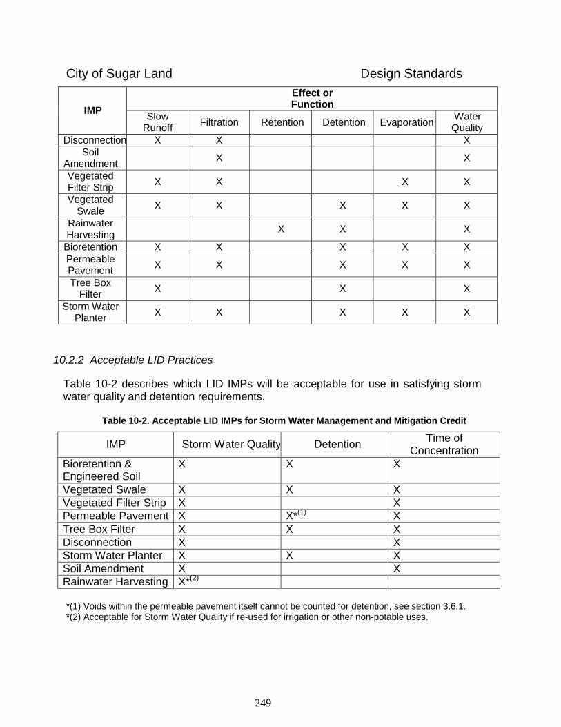
249
City of Sugar Land Design Standards
IMP
Effect or Function
Slow Runoff
Filtration
Retention
Detention
Evaporation
Water Quality
Disconnection X X X
Soil Amendment
X
X
Vegetated Filter Strip
X
X
X
X
Vegetated Swale
X
X
X
X
X
Rainwater Harvesting
X
X
X
Bioretention X X X X X
Permeable Pavement
X
X
X
X
X
Tree Box Filter
X
X
X
Storm Water Planter
X
X
X
X
X
10.2.2 Acceptable LID Practices
Table 10-2 describes which LID IMPs will be acceptable for use in satisfying storm water quality and detention requirements.
Table 10-2. Acceptable LID IMPs for Storm Water Management and Mitigation Credit
IMP
Storm Water Quality
Detention Time of
Concentration
Bioretention & Engineered Soil
X X X
Vegetated Swale X X X
Vegetated Filter Strip X X
Permeable Pavement X X*(1) X
Tree Box Filter X X X
Disconnection X X
Storm Water Planter X X X
Soil Amendment X X
Rainwater Harvesting X*(2) *(1) Voids within the permeable pavement itself cannot be counted for detention, see section 3.6.1. *(2) Acceptable for Storm Water Quality if re-used for irrigation or other non-potable uses.
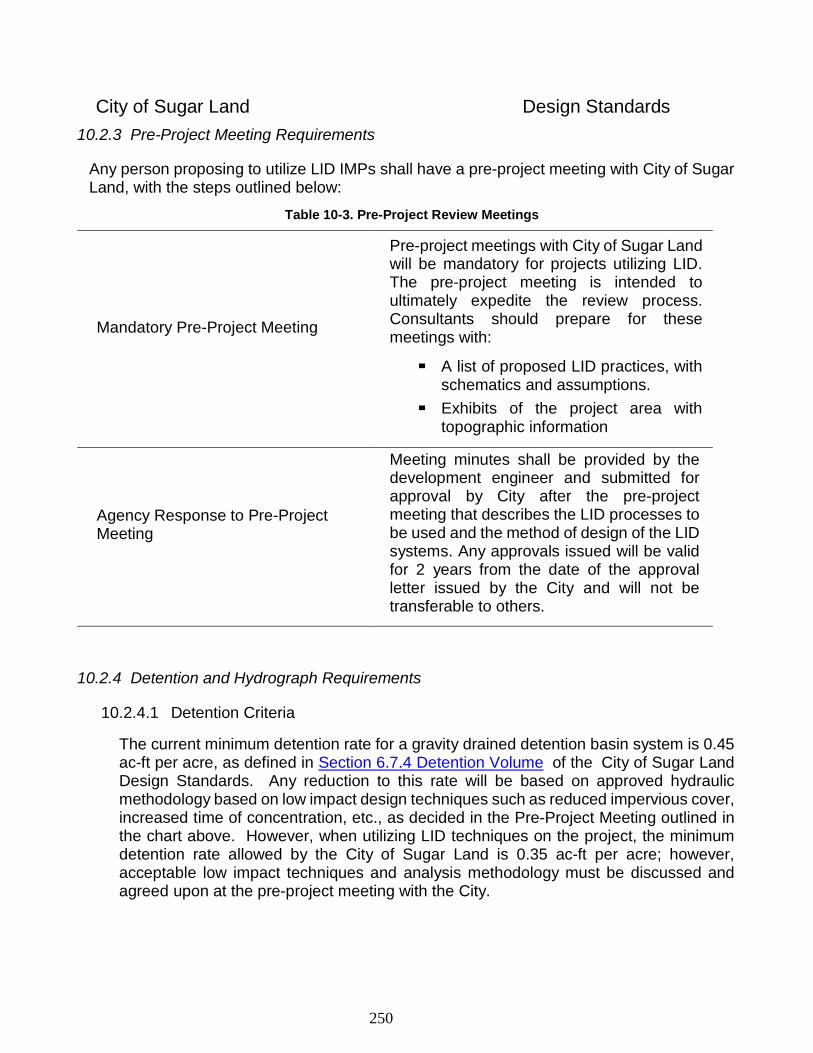
250
City of Sugar Land Design Standards
10.2.3 Pre-Project Meeting Requirements
Any person proposing to utilize LID IMPs shall have a pre-project meeting with City of Sugar Land, with the steps outlined below:
Table 10-3. Pre-Project Review Meetings
Mandatory Pre-Project Meeting
Pre-project meetings with City of Sugar Land will be mandatory for projects utilizing LID. The pre-project meeting is intended to ultimately expedite the review process. Consultants should prepare for these meetings with:
A list of proposed LID practices, with schematics and assumptions.
Exhibits of the project area with topographic information
Agency Response to Pre-Project Meeting
Meeting minutes shall be provided by the development engineer and submitted for approval by City after the pre-project meeting that describes the LID processes to be used and the method of design of the LID systems. Any approvals issued will be valid for 2 years from the date of the approval letter issued by the City and will not be transferable to others.
10.2.4 Detention and Hydrograph Requirements
10.2.4.1 Detention Criteria
The current minimum detention rate for a gravity drained detention basin system is 0.45 ac-ft per acre, as defined in Section 6.7.4 Detention Volume of the City of Sugar Land Design Standards. Any reduction to this rate will be based on approved hydraulic methodology based on low impact design techniques such as reduced impervious cover, increased time of concentration, etc., as decided in the Pre-Project Meeting outlined in the chart above. However, when utilizing LID techniques on the project, the minimum detention rate allowed by the City of Sugar Land is 0.35 ac-ft per acre; however, acceptable low impact techniques and analysis methodology must be discussed and agreed upon at the pre-project meeting with the City.
251
City of Sugar Land Design Standards
10.2.4.2 Monitoring
The City reserves the right to monitor, test and/or inspect any LID IMP and may choose to coordinate with the owner for the design elements the agencies might need for future monitoring.
10.2.4.3 Peak Flow
The LID design must show that the post-project condition has an equal or lower peak flow than the pre-project condition peak flow.
10.2.4.4 Hydrologic Calculations and Acceptable Modeling Techniques
Techniques will be driven by project size (see Section 2.3.1), although multiple methods may be accepted. Design should conform to Section 6.5.3 Runoff Calculations of the Design Standards.
10.2.4.5 Location Relative to Flood Risk Zone
Developments in a regulatory floodplain will abide by current floodplain regulations.
10.2.4.6 Eligible LID Practices
Various LID practices will be considered, so long as sufficient volume reductions and the design approach are proven. In general, LID practices which can be shown to result in the following benefits will be considered:
Reduced impervious cover Disconnected impervious cover Increased time of concentration, including cumulatively, over the entire development
site. Increased losses in effective rainfall through storage, interception, etc. Dispersed storage
A factor of safety of 1.25 for engineered soil void space calculations is required.
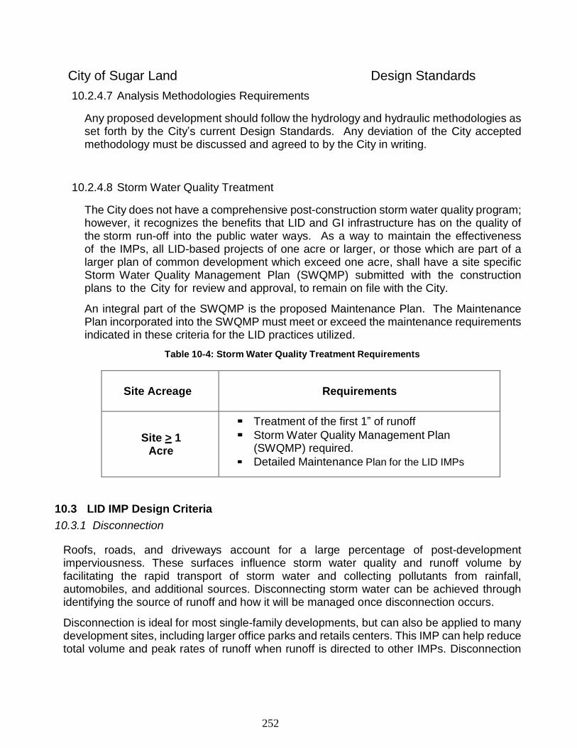
252
City of Sugar Land Design Standards
10.2.4.7 Analysis Methodologies Requirements
Any proposed development should follow the hydrology and hydraulic methodologies as set forth by the City’s current Design Standards. Any deviation of the City accepted methodology must be discussed and agreed to by the City in writing.
10.2.4.8 Storm Water Quality Treatment
The City does not have a comprehensive post-construction storm water quality program; however, it recognizes the benefits that LID and GI infrastructure has on the quality of the storm run-off into the public water ways. As a way to maintain the effectiveness of the IMPs, all LID-based projects of one acre or larger, or those which are part of a larger plan of common development which exceed one acre, shall have a site specific Storm Water Quality Management Plan (SWQMP) submitted with the construction plans to the City for review and approval, to remain on file with the City.
An integral part of the SWQMP is the proposed Maintenance Plan. The Maintenance Plan incorporated into the SWQMP must meet or exceed the maintenance requirements indicated in these criteria for the LID practices utilized.
Table 10-4: Storm Water Quality Treatment Requirements
Site Acreage Requirements
Site > 1 Acre
Treatment of the first 1” of runoff
Storm Water Quality Management Plan (SWQMP) required.
Detailed Maintenance Plan for the LID IMPs
10.3 LID IMP Design Criteria
10.3.1 Disconnection
Roofs, roads, and driveways account for a large percentage of post-development imperviousness. These surfaces influence storm water quality and runoff volume by facilitating the rapid transport of storm water and collecting pollutants from rainfall, automobiles, and additional sources. Disconnecting storm water can be achieved through identifying the source of runoff and how it will be managed once disconnection occurs.
Disconnection is ideal for most single-family developments, but can also be applied to many development sites, including larger office parks and retails centers. This IMP can help reduce total volume and peak rates of runoff when runoff is directed to other IMPs. Disconnection
253
City of Sugar Land Design Standards
can help reduce runoff volume and peak rates; to the extent that it is absorbed via amended soils or captured in rain gardens, otherwise it is only slowed down before reaching the receiving conveyance system.
10.3.1.1 Disconnecting Impervious Surfaces
Reductions in peak flows may be gained by redirecting and dissipating concentrated flows from impervious areas onto vegetated surfaces. Strategies for accomplishing this include: directing flows from small swales to stabilized vegetated areas; breaking up flow directions from large paved surfaces; and encouraging sheet flow through vegetated areas.
10.3.1.2 Disconnecting Roof Runoff
Minimize storm water volume by disconnecting roof leaders. In addition to directing runoff to vegetated areas, runoff may also be discharged to non-vegetated IMPs, such rainwater harvesting systems, for storm water irrigation and water planning purposes. Disconnection of small runoff flows can be accomplished in a variety of ways:
Encourage shallow sheet flow through vegetated areas.
Direct roof leader flow into BMPs designed specifically to receive and convey rooftop runoff.
Direct flows into stabilized vegetated areas, including swales and bioretention areas.
Rooftop runoff may also be directed to onsite depression storage areas.
The entire vegetated “disconnection” area should have a maximum slope of five percent.
Roof downspouts or curb cuts should be at least 10 feet away from the nearest connected impervious surface to discourage “re-connections.”
Limit the contributing impervious area to a maximum of 1,000 sq. ft. per discharge point.
Limit the contributing rooftop area to a maximum of 1,000 sq. f t. per downspout, where pervious area receiving runoff must be at least twice this size.
10.3.2 Vegetated Filter Strip
A vegetated Filter Strip is a band of dense vegetation, usually grasses, planted between a pollution source (e.g., roadway, rooftop downspout, etc.) and a downstream receiving water body or conveyance. They function by slowing runoff, trapping sediment and pollutants, and in some cases infiltrating a portion of the runoff into the ground. Filter strips are a sensible and cost- effective storm water management pretreatment option applicable to a variety of development sites including roads and highways. Given that vegetation is the key functional
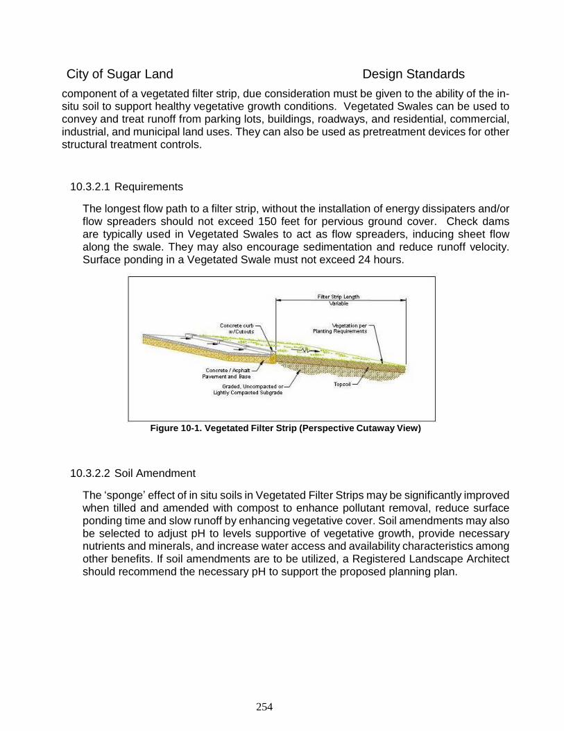
254
City of Sugar Land Design Standards
component of a vegetated filter strip, due consideration must be given to the ability of the in-situ soil to support healthy vegetative growth conditions. Vegetated Swales can be used to convey and treat runoff from parking lots, buildings, roadways, and residential, commercial, industrial, and municipal land uses. They can also be used as pretreatment devices for other structural treatment controls.
10.3.2.1 Requirements
The longest flow path to a filter strip, without the installation of energy dissipaters and/or flow spreaders should not exceed 150 feet for pervious ground cover. Check dams are typically used in Vegetated Swales to act as flow spreaders, inducing sheet flow along the swale. They may also encourage sedimentation and reduce runoff velocity. Surface ponding in a Vegetated Swale must not exceed 24 hours.
Figure 10-1. Vegetated Filter Strip (Perspective Cutaway View)
10.3.2.2 Soil Amendment
The ‘sponge’ effect of in situ soils in Vegetated Filter Strips may be significantly improved when tilled and amended with compost to enhance pollutant removal, reduce surface ponding time and slow runoff by enhancing vegetative cover. Soil amendments may also be selected to adjust pH to levels supportive of vegetative growth, provide necessary nutrients and minerals, and increase water access and availability characteristics among other benefits. If soil amendments are to be utilized, a Registered Landscape Architect should recommend the necessary pH to support the proposed planning plan.
255
City of Sugar Land Design Standards
10.3.2.3 Vegetation Considerations
Given that vegetation is the key functional component of a vegetated swale, due consideration must be given to the ability of the in-situ soil to support healthy vegetative growth conditions. A soil profile which has been cut to create the swale will often expose soils which are not capable of supporting growth without significant, ongoing use of fertilizers which is unlikely to be carried out over the long term. A layer of topsoil (typically three (3) to six (6) inches) retained from the site during the grading phase or imported, and placed over the cut slopes, may alleviate the problem. Vegetation is not restricted to grasses, but regardless of the plant material selected, native or adapted plants are preferred. A soil analysis is highly recommended for any Vegetated Swale design, to determine what, if any, amendments may be needed to encourage and ensure proper vegetative growth.
10.3.2.4 Maintenance Requirements
Proper maintenance includes mowing/pruning, weed control, removal of trash and debris, and reseeding of non-vegetated areas/replacement of plant material. Inspect Vegetated Swales at least twice annually for damage to vegetation, erosion, and sediment accumulation. Sediments should be removed when depths exceed 3 inches. If hazardous materials spill and contaminate soils in vegetated swales, the affected soils should be removed, properly disposed of, and replaced.
The City reserves the right to enforce this maintenance requirement as if it were a nuisance contained in the Sugar Land Code of Ordinances.
10.3.3 Vegetated Swale
Vegetated Swales are broad, shallow channels designed to convey and filter storm water runoff while slowing runoff and removing gross pollutants. They handle runoff from small drainage areas at low velocities. The bottom and sides of the swale are vegetated, with side vegetation at a height greater than the maximum design depth. Storm water runoff is conveyed along the length of the low slope channel, and the vegetation traps sediments, decreases the velocity of overland flows, and reduces erosion. Vegetated Swales treat runoff by filtering sediments and associated pollutants through the vegetation, and by infiltration into underlying soils if in situ soils are conducive to infiltration. Check dams are typically used in Vegetated Swales to act as flow spreaders, inducing sheet flow along the swale. They may also be used as a storm water detention mechanism, to encourage sedimentation and to reduce runoff velocity. Any proposed check dams must meet current City of Sugar Land Design Standards, which require the check dam to be wrapped in PVC coated wire mesh.
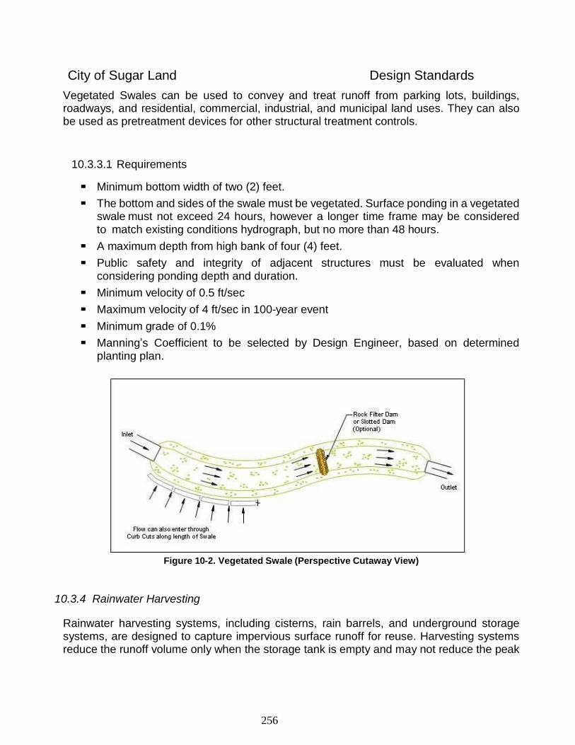
256
City of Sugar Land Design Standards
Vegetated Swales can be used to convey and treat runoff from parking lots, buildings, roadways, and residential, commercial, industrial, and municipal land uses. They can also be used as pretreatment devices for other structural treatment controls.
10.3.3.1 Requirements
Minimum bottom width of two (2) feet.
The bottom and sides of the swale must be vegetated. Surface ponding in a vegetated swale must not exceed 24 hours, however a longer time frame may be considered to match existing conditions hydrograph, but no more than 48 hours.
A maximum depth from high bank of four (4) feet.
Public safety and integrity of adjacent structures must be evaluated when considering ponding depth and duration.
Minimum velocity of 0.5 ft/sec
Maximum velocity of 4 ft/sec in 100-year event
Minimum grade of 0.1%
Manning’s Coefficient to be selected by Design Engineer, based on determined planting plan.
Figure 10-2. Vegetated Swale (Perspective Cutaway View)
10.3.4 Rainwater Harvesting
Rainwater harvesting systems, including cisterns, rain barrels, and underground storage systems, are designed to capture impervious surface runoff for reuse. Harvesting systems reduce the runoff volume only when the storage tank is empty and may not reduce the peak
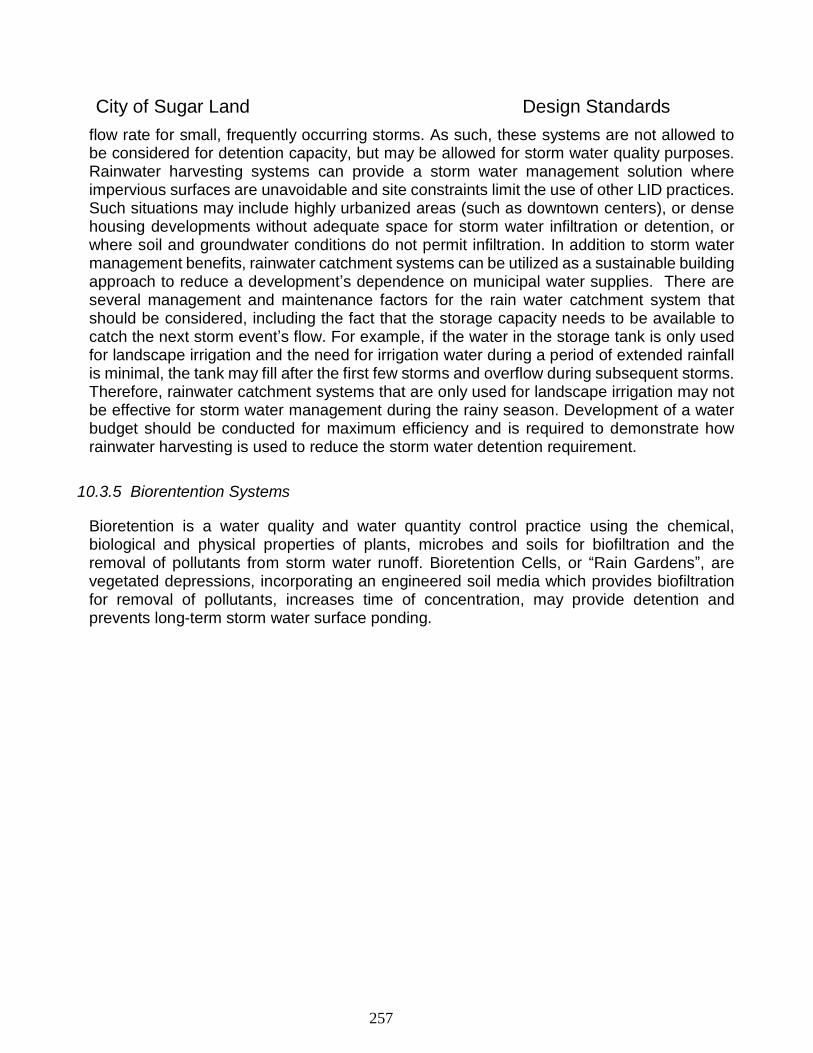
257
City of Sugar Land Design Standards
flow rate for small, frequently occurring storms. As such, these systems are not allowed to be considered for detention capacity, but may be allowed for storm water quality purposes. Rainwater harvesting systems can provide a storm water management solution where impervious surfaces are unavoidable and site constraints limit the use of other LID practices. Such situations may include highly urbanized areas (such as downtown centers), or dense housing developments without adequate space for storm water infiltration or detention, or where soil and groundwater conditions do not permit infiltration. In addition to storm water management benefits, rainwater catchment systems can be utilized as a sustainable building approach to reduce a development’s dependence on municipal water supplies. There are several management and maintenance factors for the rain water catchment system that should be considered, including the fact that the storage capacity needs to be available to catch the next storm event’s flow. For example, if the water in the storage tank is only used for landscape irrigation and the need for irrigation water during a period of extended rainfall is minimal, the tank may fill after the first few storms and overflow during subsequent storms. Therefore, rainwater catchment systems that are only used for landscape irrigation may not be effective for storm water management during the rainy season. Development of a water budget should be conducted for maximum efficiency and is required to demonstrate how rainwater harvesting is used to reduce the storm water detention requirement.
10.3.5 Biorentention Systems
Bioretention is a water quality and water quantity control practice using the chemical, biological and physical properties of plants, microbes and soils for biofiltration and the removal of pollutants from storm water runoff. Bioretention Cells, or “Rain Gardens”, are vegetated depressions, incorporating an engineered soil media which provides biofiltration for removal of pollutants, increases time of concentration, may provide detention and prevents long-term storm water surface ponding.
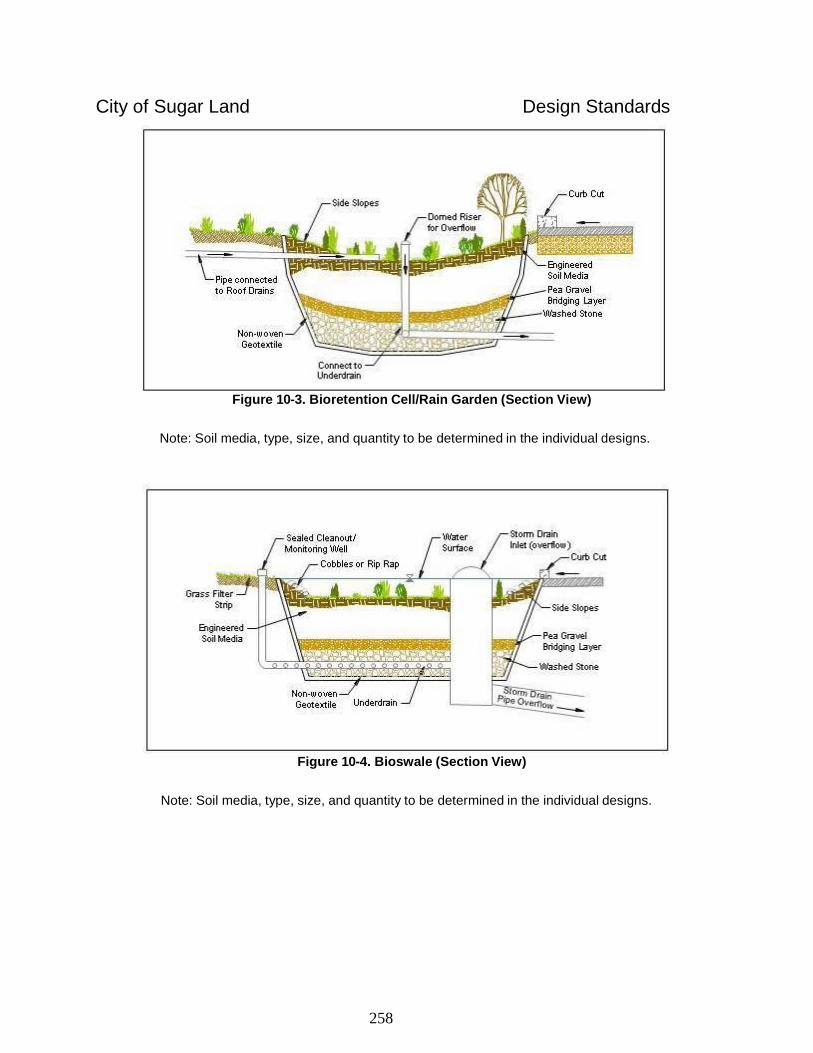
258
City of Sugar Land Design Standards
Figure 10-3. Bioretention Cell/Rain Garden (Section View)
Note: Soil media, type, size, and quantity to be determined in the individual designs.
Figure 10-4. Bioswale (Section View)
Note: Soil media, type, size, and quantity to be determined in the individual designs.
259
City of Sugar Land Design Standards
10.3.5.1 Design Considerations
A typical bioretention system design includes a depressed ponding area (at a grade below adjacent impervious surfaces), an engineered soil mix, and an underdrain or underground detention or water harvesting system. Bioretention facilities are typically excavated to a minimum depth of one (1) foot and a maximum of four (4) feet. Deeper excavation allows for additional storage in the engineered soil, gravel layers, underdrain or underground detention/storage structures. Unless the system is being constructed without an underdrain, a layer of geotextile filter fabric or an impermeable liner (if surrounding infrastructure dictates) should be placed along the sides and bottom of the excavation to separate the engineered soils from the existing site soils. Engineered soil media occupies the remaining excavated space above the underdrain system, leaving room for the desired amount of surface ponding. The area is then mulched and planted with shrubs, perennials, grasses, and small trees. When shrubs and flowers are used as the plant material, a 2 to 3 inch layer of mulch is used on top of the media. The mulch acts as a pretreatment device to protect the underlying media and helps to retain some water in the media for the health of the plant. Runoff is ponded to a maximum depth of approximately twenty-four (24) inches and then gradually filters through the engineered soil media, where it is retained in the porous soils, utilized by plants evapotranspired, and either infiltrated into the underlying soils (when applicable), or drained into an underdrain or underground storage system over a period of hours. The layout of a Bioretention system should be determined based on site constraints such as location of utilities, underlying soil conditions, existing vegetation, and drainage patters. The plant selection and layout should consider aesthetics, maintenance, native-versus-non-native, invasive species, and regional landscaping practices. It should be noted that ideal plants for a typical Bioretention system are drought and inundation tolerant.
An important design factor to consider when applying Bioretention to development sites is the scale at which it will be applied. Typical system scales:
Bioretention Cells or Rain Gardens are small, distributed practices designed to treat runoff from small areas. Inflow is typically sheet flow, or can be concentrated flow with energy dissipation.
Bioretention Basins are larger systems treating parking lots and/or commercial rooftops, or other large areas, usually in commercial or institutional areas. Inflow can be either sheet flow or concentrated flow. Bioretention basins may also be distributed throughout a residential subdivision for instance, but in this case they should be located in common areas or within drainage easements, to treat a combination of roadway and lot runoff.
Urban Bioretention structures include systems such as Tree Filters, Curb Extensions, and Planter Box Filters.
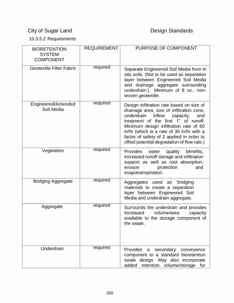
260
City of Sugar Land Design Standards
10.3.5.2 Requirements
BIORETENTION SYSTEM
COMPONENT
REQUIREMENT PURPOSE OF COMPONENT
Geotextile Filter Fabric required Separate Engineered Soil Media from in situ soils. (Not to be used as separation layer between Engineered Soil Media and drainage aggregate surrounding underdrain.) Minimum of 8 oz., non-woven geotextile.
Engineered/Amended Soil Media
required Design infiltration rate based on size of drainage area, size of infiltration zone, underdrain inflow capacity, and treatment of the first 1” of runoff. Minimum design infiltration rate of 60 in/hr (which is a rate of 30 in/hr with a factor of safety of 2 applied in order to offset potential degradation of flow rate.)
Vegetation required Provides water quality benefits, increased runoff storage and infiltration support as well as root absorption, erosion protection and evapotranspiration.
Bridging Aggregate required Aggregates used as ‘bridging materials to create a separation layer between Engineered Soil Media and underdrain aggregate.
Aggregate required Surrounds the underdrain and provides increased volume/area capacity available to the storage component of the swale.
Underdrain required Provides a secondary conveyance component to a standard bioretention swale design. May also incorporate added retention volume/storage for
261
City of Sugar Land Design Standards
rainwater recycle. Underdrain must be sized to accommodate inflow and assuming 50% blockage of orifices by aggregate. Minimum diameter of the underdrain is 4-inches.
*Required, unless in situ soils are proven viable for direct infiltration.
Observation/Cleanout Standpipe
required Installed at both ends of the system and at all bends, and at 50’ intervals, if run exceeds 100’. Made of min. 6” PVC pipe and capped.
Positive Overflow required Safely convey excessive runoff from extreme storm events. Grate must be sloped or otherwise designed to prevent clogging by mulch and debris.
Storage Chamber Products
required
Provides the highest volume/area capacity available to the storage component of the bioretention swale.
Outfall Structure required
Controls the rate of flow off the project site and maintains the extreme event discharge requirements.
Surface Ponding required Maximum surface ponding depth of 2ft for the 2yr event and 4ft for the 100yr event. Ponding duration not to exceed 24 hours. Ponding depth & duration shall be discussed at the pre-project meeting.
10.3.5.3 Sizing a Bioretention System
For a Bioretention System with an underdrain, the calculations for Water Quality Volume (Vwq) and Required Surface Area (Af) are as follows:
𝑉𝑤𝑞 = 𝑃
12∗ 𝐴
Where
262
City of Sugar Land Design Standards
Vwq = water quality volume in cubic feet
P = depth of runoff to treat (1” under these guidelines)
A = drainage area in square feet
𝑘 =(24 ∗ 𝑖)
24
Where
k = coefficient of permeability of engineered soil bed
i = infiltration rate of engineered soil media in inches per hour
𝐴𝑓 = 𝑉𝑤𝑞 ∗ 𝐷𝑓
𝑘 ∗ (𝐻 + 𝐷𝑓) ∗ 𝑇𝑓
Where
Af = required surface area of Engineered Soil Media in Square Feet
Vwq = water quality volume in Cubic Feet
Df = engineered soil media depth in Feet (typically 1.5 – 2.0)
H = maximum ponding depth over Engineered Soil Media in Feet
Tf = Drawdown time in days
10.3.5.4 Engineered Soil Media
The infiltration rate of Engineered Soil Media in a bioretention facility must be designed to treat the first 1” of runoff volume from the drainage area it serves. The Engineered Soil Media shall be placed and graded using low ground-contact pressure equipment or by excavators and/or backhoes operating on the ground adjacent to the bioretention facility. No heavy equipment shall be used within the perimeter of the bioretention facility before, during, or after placement of the media. The Engineered Soil Media shall be placed in horizontal layers not to exceed 12 inches for the entire area of the bioretention facility. It shall be compacted by saturating the entire area of the bioretention facility after each lift is placed until water flows from the underdrain. Water for saturation shall be applied by spraying or sprinkling. An appropriate sediment control device shall be used to treat any sediment-laden water discharged from the underdrain. Final grading of the Engineered Soil Media shall be performed after a 24-hour settling period. Engineered Soil Media may be designed by the project engineer and proposed to be mixed on- site by the contractor or may be supplied by a proprietary source. For quality control purposes, the supplier of the Engineered Soil Media must provide a certificate which indicates the infiltration rate of the media on delivery to the project site. Owner is
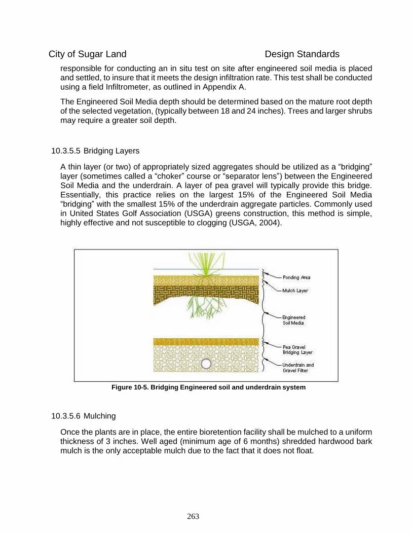
263
City of Sugar Land Design Standards
responsible for conducting an in situ test on site after engineered soil media is placed and settled, to insure that it meets the design infiltration rate. This test shall be conducted using a field Infiltrometer, as outlined in Appendix A.
The Engineered Soil Media depth should be determined based on the mature root depth of the selected vegetation, (typically between 18 and 24 inches). Trees and larger shrubs may require a greater soil depth.
10.3.5.5 Bridging Layers
A thin layer (or two) of appropriately sized aggregates should be utilized as a “bridging” layer (sometimes called a “choker” course or “separator lens”) between the Engineered Soil Media and the underdrain. A layer of pea gravel will typically provide this bridge. Essentially, this practice relies on the largest 15% of the Engineered Soil Media “bridging” with the smallest 15% of the underdrain aggregate particles. Commonly used in United States Golf Association (USGA) greens construction, this method is simple, highly effective and not susceptible to clogging (USGA, 2004).
Figure 10-5. Bridging Engineered soil and underdrain system
10.3.5.6 Mulching
Once the plants are in place, the entire bioretention facility shall be mulched to a uniform thickness of 3 inches. Well aged (minimum age of 6 months) shredded hardwood bark mulch is the only acceptable mulch due to the fact that it does not float.
264
City of Sugar Land Design Standards
10.3.5.7 Underdrain
The role of an underdrain in the bioretention facility is to ensure proper drainage for the plants and to ensure proper infiltration rates occur so as to avoid standing water for extended periods. Underdrains are configured in many different ways and typically include a washed gravel/stone "blanket" encompassing a horizontal, perforated discharge pipe or other perforated drainage system. A pea gravel bridging layer, as described in Section 2.5.5, shall be used between the under drain’s aggregate blanket and the Engineered Soil Media to protect the underdrain from blocking. Underdrains keep the soil at an adequate aerobic state, allowing plants to flourish.
Underdrain structures, including subsurface detention or storage structures which are used under Bioretention systems, must have a total opening area which exceeds the expected flow capacity of the underdrain itself.
𝑄𝑝𝑒𝑟𝑓𝑜𝑟𝑎𝑡𝑖𝑜𝑛𝑠 = 𝐶 ∗ 𝐴(2𝑔ℎ
𝐵)5
Where:
Qperformations = flow discharge (cfs)
g = Acceleration due to gravity (32.2 ft/s2)
A= total area of all of the perforations (ft2)
h = effective head on the perforations (ft) (measured from CL of pipe to water surface)
C = orifice coefficient (0.61 recommended)
B = blockage factor (2)
To estimate the capacity of flows through the perforations, orifice flow conditions are assumed and a sharp-edged orifice equation can be used. First, the number and size of perforations needs to be determined (typically from the manufacturer’s specifications) and used to estimate the flow rate into the pipes using the head of the Engineered Soil Media depth plus the ponding depth. Second, it is conservative but reasonable to use a blockage factor to account for partial blockage of the perforations by the drainage layer media. A safety factor of two is required.
The aggregate layer surrounding the underdrain should consist of washed aggregate ½”-1½” in diameter. Placement of the gravel over the underdrain must be done with care. Avoid dropping the gravel from a backhoe or front-end loader bucket. Spill directly over underdrain and spread manually.
Underdrains must discharge into an adequate conveyance system. The underdrain system should be sized to support the flow rate of the engineered soils and the volume
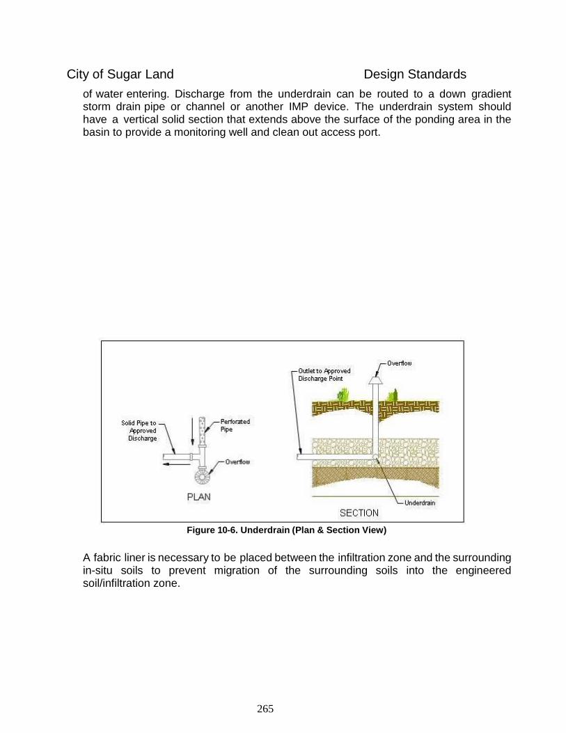
265
City of Sugar Land Design Standards
of water entering. Discharge from the underdrain can be routed to a down gradient storm drain pipe or channel or another IMP device. The underdrain system should have a vertical solid section that extends above the surface of the ponding area in the basin to provide a monitoring well and clean out access port.
Figure 10-6. Underdrain (Plan & Section View)
A fabric liner is necessary to be placed between the infiltration zone and the surrounding in-situ soils to prevent migration of the surrounding soils into the engineered soil/infiltration zone.
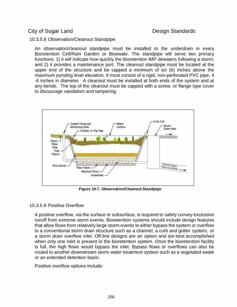
266
City of Sugar Land Design Standards
10.3.5.8 Observation/Cleanout Standpipe
An observation/cleanout standpipe must be installed to the underdrain in every Bioretention Cell/Rain Garden or Bioswale. The standpipe will serve two primary functions: 1) it will indicate how quickly the bioretention IMP dewaters following a storm; and 2) it provides a maintenance port. The cleanout standpipe must be located at the upper end of the structure and be capped a minimum of six (6) inches above the maximum ponding level elevation. It must consist of a rigid, non-perforated PVC pipe, 4 -6 inches in diameter. A cleanout must be installed at both ends of the system and at any bends. The top of the cleanout must be capped with a screw, or flange type cover to discourage vandalism and tampering.
Figure 10-7. Observation/Cleanout Standpipe
10.3.5.9 Positive Overflow
A positive overflow, via the surface or subsurface, is required to safely convey excessive runoff from extreme storm events. Bioretention systems should include design features that allow flows from relatively large storm events to either bypass the system or overflow to a conventional storm drain structure such as a channel, a curb and gutter system, or a storm drain overflow inlet. Off-line designs are an option and are best accomplished when only one inlet is present in the bioretention system. Once the bioretention facility is full, the high flows would bypass the inlet. Bypass flows or overflows can also be routed to another downstream storm water treatment system such as a vegetated swale or an extended detention basin.
Positive overflow options include:
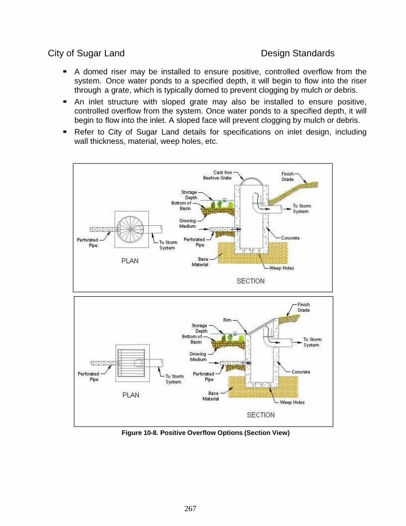
267
City of Sugar Land Design Standards
A domed riser may be installed to ensure positive, controlled overflow from the
system. Once water ponds to a specified depth, it will begin to flow into the riser through a grate, which is typically domed to prevent clogging by mulch or debris.
An inlet structure with sloped grate may also be installed to ensure positive, controlled overflow from the system. Once water ponds to a specified depth, it will begin to flow into the inlet. A sloped face will prevent clogging by mulch or debris.
Refer to City of Sugar Land details for specifications on inlet design, including wall thickness, material, weep holes, etc.
Figure 10-8. Positive Overflow Options (Section View)
268
City of Sugar Land Design Standards
10.3.5.10 Required Maintenance
Once plants are established, only minimal plant maintenance and occasional removal of sediment and debris is necessary, as determined by the Owner. The mulch layer should be removed and replaced on an annual basis. Other considerations include:
Upon installation and during the first year, Bioretention systems should be inspected monthly for potential erosion and/or extended ponding.
Key inspection/maintenance areas include inlet and overflow areas for potential
erosion, the ponding area for trash and debris, and the Observation/Cleanout
Standpipe for potential early signs of stagnant water in the system if an underdrain
system is included.
Inspections can be reduced to a semi-annual schedule once the system has
proven to work properly and vegetation is well established
An evaluation of the health of the plants, trees and shrubs should be conducted
biannually.
Pruning, weeding and trash removal should be conducted as necessary.
Mulch removal and replacement is generally required every year.
If ponding is observed to exceed 24 hours, particularly during the primary
mosquito breeding season (June through October), the reason for the extended
ponding should be determined and mitigated.
If a spill occurs and hazardous materials contaminate soils in landscape
detention areas, the affected materials should be removed immediately and the
appropriate engineered soil media and materials replaced as soon as possible.
The City reserves the right to enforce this section by any and all legal means
available at the time of the violation.
10.3.6 Permeable Pavement
Permeable pavement includes a wide range of paved or load-bearing surfaces that allow water to pass rapidly through the surface and into the sub-grade that serves as a reservoir, a filter bed, and a load-bearing layer. Permeable pavement decreases the runoff volume and peak flow rate and captures pollutants. These systems allow for infiltration of storm water while providing a stable load-bearing surface for walking and driving. Porous pavement detention can be used as a substitute for conventional pavement, but should be limited to parking areas and low traffic volume roadways where little to no truck traffic is anticipated.
Example applications include residential street parking lanes, parking stalls in commercial or retail parking lots, overflow parking areas, maintenance walkways/trails, emergency vehicle and fire access lanes, equipment storage areas, and patios. Permeable pavements may not currently be used on residential driveways.

269
City of Sugar Land Design Standards
Permeable pavement treats rainfall that falls directly on the surface, as well as runoff from adjacent impervious areas. These systems contain void spaces to provide infiltration of runoff into their underlying engineered porous materials and then into existing site soils. Generally, underlying engineered materials consist of clean sands or gravels separated from existing site soils by a synthetic filter fabric. Underlying engineered materials detain and filter pollutants prior to infiltration into underlying soils or discharge to a conventional storm drain system through an underdrain system. With these systems, it is important to note that the load-bearing sub-grade must be sufficiently thick to support the design load from the intended use and provide storage for volume or detention control. Porous paving systems can preserve natural drainage patterns, enhance groundwater recharge and soil moisture, and can help establish and maintain roadside vegetation. Although a good substitute for conventional concrete and asphalt in certain applications such as parking lots or long private driveways, porous paving systems are not suitable in high-traffic areas.
All installations of permeable pavement systems should be carried out according to manufacturer’s specifications. There are several types of Permeable Pavement systems, including:
Open Celled Block Pavers
Open Jointed Block Pavers
Porous Asphalt Pavement
Porous Concrete Pavement
Open-Celled Concrete Grids (avoid plastic products)
Alternative materials may be permitted pending product approval by the City Engineer or his/her designee.
10.3.6.1 Requirements
Permeable pavement systems must be designed to incorporate an underdrain, or a subsurface detention or retention system with the capacity to drain the surface of the system within 24 hours.
Storage in aggregate or underground structures may be located beneath the paving system to provide detention volume, but these systems must include a liner.
Permeable pavements are not allowed on driveway aprons, or public streets.
Voids in the permeable concrete itself may not be counted as detention volume.
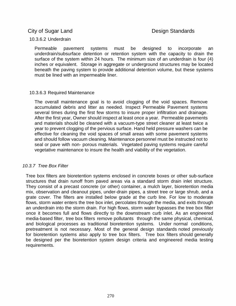
270
City of Sugar Land Design Standards
10.3.6.2 Underdrain
Permeable pavement systems must be designed to incorporate an underdrain/subsurface detention or retention system with the capacity to drain the surface of the system within 24 hours. The minimum size of an underdrain is four (4) inches or equivalent. Storage in aggregate or underground structures may be located beneath the paving system to provide additional detention volume, but these systems must be lined with an impermeable liner.
10.3.6.3 Required Maintenance
The overall maintenance goal is to avoid clogging of the void spaces. Remove accumulated debris and litter as needed. Inspect Permeable Pavement systems several times during the first few storms to insure proper infiltration and drainage. After the first year, Owner should inspect at least once a year. Permeable pavements and materials should be cleaned with a vacuum-type street cleaner at least twice a year to prevent clogging of the pervious surface. Hand held pressure washers can be effective for cleaning the void spaces of small areas with some pavement systems and should follow vacuum cleaning. Maintenance personnel must be instructed not to seal or pave with non- porous materials. Vegetated paving systems require careful vegetative maintenance to insure the health and viability of the vegetation.
10.3.7 Tree Box Filter
Tree box filters are bioretention systems enclosed in concrete boxes or other sub-surface structures that drain runoff from paved areas via a standard storm drain inlet structure. They consist of a precast concrete (or other) container, a mulch layer, bioretention media mix, observation and cleanout pipes, under-drain pipes, a street tree or large shrub, and a grate cover. The filters are installed below grade at the curb line. For low to moderate flows, storm water enters the tree box inlet, percolates through the media, and exits through an underdrain into the storm drain. For high flows, storm water bypasses the tree box filter once it becomes full and flows directly to the downstream curb inlet. As an engineered media-based filter, tree box filters remove pollutants through the same physical, chemical, and biological processes as traditional bioretention systems. Under normal conditions, pretreatment is not necessary. Most of the general design standards noted previously for bioretention systems also apply to tree box filters. Tree box filters should generally be designed per the bioretention system design criteria and engineered media testing requirements.
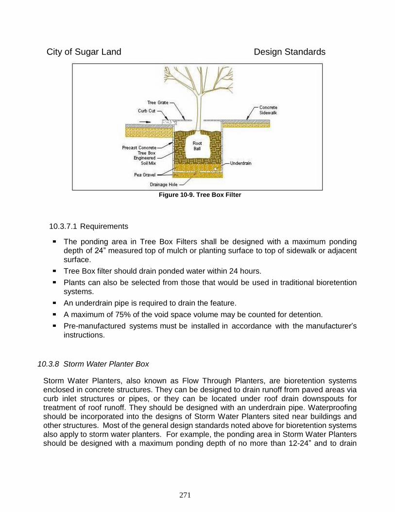
271
City of Sugar Land Design Standards
Figure 10-9. Tree Box Filter
10.3.7.1 Requirements
The ponding area in Tree Box Filters shall be designed with a maximum ponding depth of 24” measured top of mulch or planting surface to top of sidewalk or adjacent surface.
Tree Box filter should drain ponded water within 24 hours.
Plants can also be selected from those that would be used in traditional bioretention systems.
An underdrain pipe is required to drain the feature.
A maximum of 75% of the void space volume may be counted for detention.
Pre-manufactured systems must be installed in accordance with the manufacturer’s instructions.
10.3.8 Storm Water Planter Box
Storm Water Planters, also known as Flow Through Planters, are bioretention systems enclosed in concrete structures. They can be designed to drain runoff from paved areas via curb inlet structures or pipes, or they can be located under roof drain downspouts for treatment of roof runoff. They should be designed with an underdrain pipe. Waterproofing should be incorporated into the designs of Storm Water Planters sited near buildings and other structures. Most of the general design standards noted above for bioretention systems also apply to storm water planters. For example, the ponding area in Storm Water Planters should be designed with a maximum ponding depth of no more than 12-24” and to drain
272
City of Sugar Land Design Standards
ponded water within 24 hours. Plants can also be selected from those that would be used in traditional bioretention systems.
10.3.8.1 Requirements
Storm Water Planters shall be designed with an underdrain pipe.
Waterproofing shall be incorporated into the designs of Storm Water Planters sited near buildings and other structures.
The ponding area in Storm Water Planters shall be designed with a maximum ponding depth of 24” and to drain ponded water within 24 hours.
Plants can also be selected from those that would be used in traditional bioretention systems.
Pre-manufactured systems must be installed in accordance with the manufacturer’s instructions.
Figure 10-10. Storm Water Planter Box (Section View)
10.4 Specific Project Types
10.4.1 Roadways
Currently, the City of Sugar Land does not allow implementation of LID features to handle the storm water run-off of public streets. Private streets, not maintained by the City, may utilize LID or GI techniques outlined previously and under Section 3.2 Commercial Development.
273
City of Sugar Land Design Standards
10.4.2 Commercial Development
10.4.2.1 Location and Maintenance of LID IMP’s
LID practices shall be maintained by the property owner and maintained as the Storm Water Quality Management Plan dictates. This maintenance generally consists of familiar landscape maintenance and pavement sweeping activities.
Proposed LID site plan will be required to show, at a minimum, the following:
Identify all LID features with elevations, where appropriate
Sheet flow direction arrows, including identifying positive overflow locations
Storm Water Ponding elevations for the 10-yr and 100-yr storm events
Show all appropriate drainage calculations
Finished slab elevations of all proposed buildings
Outfall location with allowable and post-development flow rates
Show detailed landscape plan
Proposed location of drainage & maintenance easements covering the LID/GI features
10.5 LID Landscaping Design Considerations
Landscaping is a critical component of LID because of the natural ability for plant material to treat pollutants in urban storm water. The integration of landscaping also sets bioretention apart from other integrated management practices by allowing the storm water practice to be distributed throughout the site - closer to the pollution sources - while improving the site aesthetics. With the proper landscaping application of bioretention, most people interacting with the built environment will tend to admire the sites aesthetics and not even be aware that storm water management exists on the site.
Key factors in the design of LID facilities are careful selection of plant materials that can tolerate highly variable hydrologic changes and an overall planting plan that ecologically and aesthetically blends the facility into the landscape. Designing for ease of maintenance is also a critical element of any landscape plan. Consider interactions with adjacent plant communities including the potential to provide links to wildlife corridors. Adjacent plant communities should be evaluated for compatibility with any proposed bioretention area species. Nearby existing vegetated areas dominated by non-native invasive species pose a threat to adjacent bioretention areas. Invasive species typically develop into monocultures by out-competing other species. Mechanisms to avoid encroachment of undesirable species include providing a soil breach between the invasive communities for those species that spread through rhizomes and providing annual removal of seedlings from wind borne seed dispersal. It is equally important to determine if there is existing disease or insect infestations
274
City of Sugar Land Design Standards
associated with existing species on site or in the general area that may affect the bioretention plantings.
10.5.1 Soil Amendment
The ‘sponge’ effect of in situ soils may be significantly improved when tilled to depth of at least 6” and incorporating at minimum of 2” of compost within the root zone to improve soil quality, plant viability and soil hydraulic conductivity, which enhances time of concentration, provides enhanced pollutant removal and reduces surface ponding time. This practice is typically utilized for Vegetated Swales and Vegetated Filter Strips, but should be strongly considered for general landscape and turf areas.
Prior to soil amendment, existing soils must be sampled and evaluated to determine amendment quantities and plan the amending process. In addition to compost, soil analysis may reveal the need for other soil amendments, such as lime, gypsum and specific nutrients. Compost shall be mature, stable, weed free, and produced by aerobic decomposition of organic matter. The product must not contain any visible refuse or other physical contaminants, substances toxic to plants, or over 5% sand, silt, clay or rock material by dry weight. The moisture level shall be such that no visible water or dust is produced when handling the material. The results of compost analysis shall be provided by the compost supplier. Before delivery of the compost, the supplier must provide the following documentation:
Feedstock percentage in the final compost product
Statement that the compost meets federal and state health and safety regulations
Statement that the composting process has met time and temperature requirements
Copy of the lab analysis, less than four months old, performed by a Seal of Testing Assurance Certified Laboratory verifying that the compost meets the physical requirements as described.
Compost shall uniformly be applied over the entire area to a depth of two (2) inches, and incorporated into the soil to a minimum depth of six (6) inches. Where tree roots or other natural features limit the maximum depth of incorporation, compost quantities should be adjusted. Required volume of compost may be estimated using the following approximation: one (1) inch compost spread over 1000 square feet = three (3) cubic yards. The Designer may specify different compost application rates depending upon soil conditions.
275
City of Sugar Land Design Standards
10.5.2 Mulching
Once the plants are in place, the entire bioretention facility shall be mulched to a uniform thickness of three (3) inches. Well aged (minimum age of six [6] months) shredded hardwood bark mulch is the only acceptable mulch.
10.5.3 Plant Species Selection
There are several roles of plant species in the bioretention system; they bind nutrients and other pollutants by plant uptake; remove water through evapotranspiration; and create pathways for infiltration through root development and plant growth. Root growth provides a media that fosters bacteriologic growth, which in turn develops a healthy soil structure. A variable plant community structure is preferred to avoid monoculture susceptibility to insect and disease infestation and to create a microclimate, which ameliorates urban environmental stresses including heat and drying winds. Parking lot island bioretention is particularly susceptible to extended dry conditions. There are many potential side benefits to the use of planting systems other than water quality and quantity treatment. Planting systems, if designed properly, can improve the value of the site; provide shade and wind breaks; improve aesthetics; support wildlife; and absorb noise.
Achieving any of these results requires the use of native or adaptive plant species which can tolerate and thrive in extreme conditions. No plant can survive without water. Although an irrigation system is necessary for establishment and severe drought periods, native and adaptive plant species can tolerate lower rainfall rates and contribute to a project life-cycle cost savings due to reduction in irrigation requirements.
Plant materials used in bioretention areas must also be able to tolerate water submersion for the 24-hour period that the bioretention cell is holding storm water before the system is drained through the engineered soil media. A specific plant list of native and adaptive species is not specified within these criteria in order to allow greater creativity and flexibility; however a Registered Landscape Architect should design and specify all plant materials in bioretention areas to ensure that the plant selection meets the nutrient, pollutant, growth conditions, and water factors of the system. To assist in determining plant selection that is appropriate to this area, please visit the website for the Ladybird Johnson Wildflower Center at http://www.wildflower.org/ladybird/.
10.6 Maintenance
All landscape treatments require maintenance. Landscapes designed to perform storm water management functions are not necessarily more maintenance intensive than highly manicured conventional landscapes. A concave lawn requires the same mowing, fertilizing and weeding as a convex one and less irrigation after rain is filtered into the underlying soil. Sometimes infiltration basins may require a different kind of maintenance than conventionally

276
City of Sugar Land Design Standards
practiced. Typical maintenance activities include periodic inspection of surface drainage systems to ensure clear flow lines, repair of eroded surfaces, adjustment or repair of drainage structures, soil cultivation or aeration, care of plant materials, replacement of dead plants, replenishment of mulch cover, irrigation, fertilizing, pruning and mowing. Landscape maintenance can have a significant impact on soil permeability and its ability to support plant growth. Most plants concentrate the majority of their small absorbing roots in the upper 6 inches of the soil surface if the surface is protected by a mulch or forest litter. If the soil is exposed or bare, it can become so hot that surface roots will not grow in the upper 8 to 10 inches. The common practice of removing all leaf litter and detritus with leaf blowers creates a hard crusted soil surface of low permeability and high heat conduction. Proper mulching of the soil surface improves water retention and infiltration, while protecting the surface root zone from temperature extremes. In addition to impacting permeability, landscape maintenance practices can have adverse effects on water quality. Because commonly used fertilizers and herbicides are a source of organic compounds, it is important to keep these practices to a minimum, and prevent over watering. Over watering can be a significant contributor to run off and dry weather flows. Watering should only occur to accommodate plant health when necessary. When well-maintained and designed, landscaped concave surfaces, bioretention systems, vegetated swales and other LID IMPs can add aesthetic value while providing the framework for environmentally sound, comprehensive storm water management systems.
10.7 Putting LID into Practice
Successful sustainable design is inherently a collaborative process. Collaboration by integrated design teams representing all the key areas of the design, permitting, construction, and development process must work together to insure an ideal outcome. While this has become standard operating procedure in green building, it has not always translated into site development. This Guide, and the collaborative permitting process which it informs, seeks to insure a process in which all parties benefit from the opportunities to learn as we determine the best adaptations, applications and implementations of Low Impact Development and Green Infrastructure practices in our community.
10.8 Construction
The effectiveness of LID systems is a function of the design and the construction techniques employed. Of these two parameters, construction is perhaps more critical at achieving quality results. Poor construction techniques will cause the best designed IMP to fail prematurely, usually from sedimentation and/or clogging.
277
City of Sugar Land Design Standards
10.8.1 Training
It is very important that contractors, vendors, and inspectors be properly trained in the design specification and construction requirements for all LID practices employed. The success of many LID techniques depends on accurately following the grading plan; the use of proper materials and the appropriate location of practices. Due to the complexities of the practice, it may be necessary for vendors, contractors, and permit personnel to participate in training classes. For example, the design and construction of bioretention cells requires the knowledge of several disciplines including engineering, landscape architecture, and soil science to ensure the proper design and construction of the project.
10.8.2 Communication
LID uses innovative techniques, unique strategies and various combinations of practices. Consequently, each development results in a unique design with its own set of issues and challenges. It is vital that everyone involved in the LID project (contractors, vendors, design engineers, and inspectors) understands the unique details of the LID project. A pre-construction meeting is the most useful approach to ensure that the project goals and issues are effectively communicated. Ideally the contractor, vendor, design engineer, and inspector should hold a meeting to go over the plans and discuss all aspects of the project. During the pre-construction meeting, the inspector may evaluate the proposed sequence of construction, sediment control requirements, and indicate when inspection points during construction of the LID practices are required as identified in the design manual.
Throughout the construction process, there must be effective communication. No construction project takes place without unforeseen problems and the need to make some field adjustments. Proper lines of communication must be in place throughout the construction phase between the general contractor, site engineer, inspector, and permit staff to address required changes. Designers must also make it a priority to make construction sequencing and details conspicuous on plans.
10.8.3 Erosion and Sediment Control
Proper erosion and sediment control during construction is vital for LID practices. If existing vegetation is to be used for treatment (bioretention, swales or buffers), then these areas must be protected from sedimentation. Areas that may be used for biofiltration must be protected to prevent sediment from clogging soils with silts and clays. Preventing damage from sedimentation is less expensive than cleaning or rehabilitating an area.
278
City of Sugar Land Design Standards
10.8.3.1 SWPPP During Construction
The clearing, grubbing and scalping (mass clearing or grading) of excessively large areas of land at one time promotes erosion and sedimentation problems. On the areas where disturbance takes place the site designer should consider staging construction, temporary seeding and /or temporary mulching as a technique to reduce erosion. Staging construction involves stabilizing one part of the site before disturbing another. In this way the entire site is not disturbed at once and the duration of soil exposure is minimized. Temporary seeding and mulching involves seeding or mulching areas that would otherwise lie open for long periods of time. The time of exposure is limited and therefore the erosion hazard is reduced. Two methods of sediment control are typically applied to bioretention facilities as follows.
The first method (most typical) is to direct all drainage away from the locations of IMPs to avoid excessive sedimentation. Flow can be directed away from the bioretention IMP by utilizing silt fencing materials, wattles and temporary diversion swales.
The second method of erosion and sediment control design allows the area proposed for the bioretention IMP to be used as a temporary sediment control structure. If a sediment control structure is to become a bioretention IMP, the sediment materials shall be removed prior to constructing the bioretention IMP and placing the Engineered Soil Media.
10.8.4 Tree Protection
Care must be taken to protect tree conservation areas during construction. Tree conservation areas are ineffective if the trees die shortly after the project is completed.
In order to effectively protect trees, it is important to consider the following during any construction process:
All types of construction equipment can cause mechanical injury to roots, trunks, or branches. This can weaken a tree’s resistance to a number of diseases and insect infestation. Trees should be clearly marked and given wide clearance. Excavation around trees should not be within the drip line of the tree.
Soil compaction squeezes the air and water out of the soil making it difficult for a tree to absorb oxygen and water. No construction equipment should be allowed to run over the roots within the drip line of the tree.
Grading practices that deposit soil over the roots of trees eventually suffocates those roots. More than an inch or two of soil over the roots is enough to potentially suffocate the roots of trees and compromise the health of the tree. Measures can be taken to improve soil aeration around tree roots if it is necessary to add fill within the critical root zone (see Figure 6-1).
Grading practices that divert too much runoff to a mature stand of trees can result in
279
City of Sugar Land Design Standards
damage. As a tree matures its ability to adapt to changes decreases. Additionally, if a stand of trees is located in a normally dry area that suddenly becomes very wet, the additional water may kill the trees. An arborist should be consulted these situations to determine the trees’ tolerance to a change in hydrology.
A tree protection plan with written recommendations for the health and long-term welfare of the trees during the pre-construction, demolition, construction, and post-construction development phases, should be developed. The tree protection plan should include specifics about avoiding injury, information about treatment for damage and specifics about required inspections of protected trees. The tree protection plan should also provide information about caring for damaged trees.
10.8.5 Construction Sequencing
Construction sequencing is important to avoid problems while constructing LID projects. Proper sequencing decreases the likelihood of damage to the BMP during construction and helps to ensure optimal performance of each IMP. Each LID practice is somewhat different; therefore information should be provided to the contractor on the proper sequencing. The construction drawings should clearly state the designer's intentions and an appropriate sequence of construction should be shown on the plans. This sequence should then be the topic of a detailed discussion at the pre-construction meeting (that must include the on-site responsible construction personnel) and then enforced by an appropriate inspection program throughout the construction period.
Conservation areas must be identified and protected before any major site grading takes place. Most of the engineered LID practices (bioretention, infiltration trenches, and infiltration swales) should be constructed at the end of the site development process, and preferably when most of the site is stabilized. Any LID practice that relies on filtration or infiltration must be protected throughout the construction phase from sedimentation and should not be activated until the contributing drainage area is stabilized. For example, bioretention systems should be constructed at the time of final grading and landscaping, and/or these areas should be protected from sedimentation until the drainage routes to the facility are stabilized.
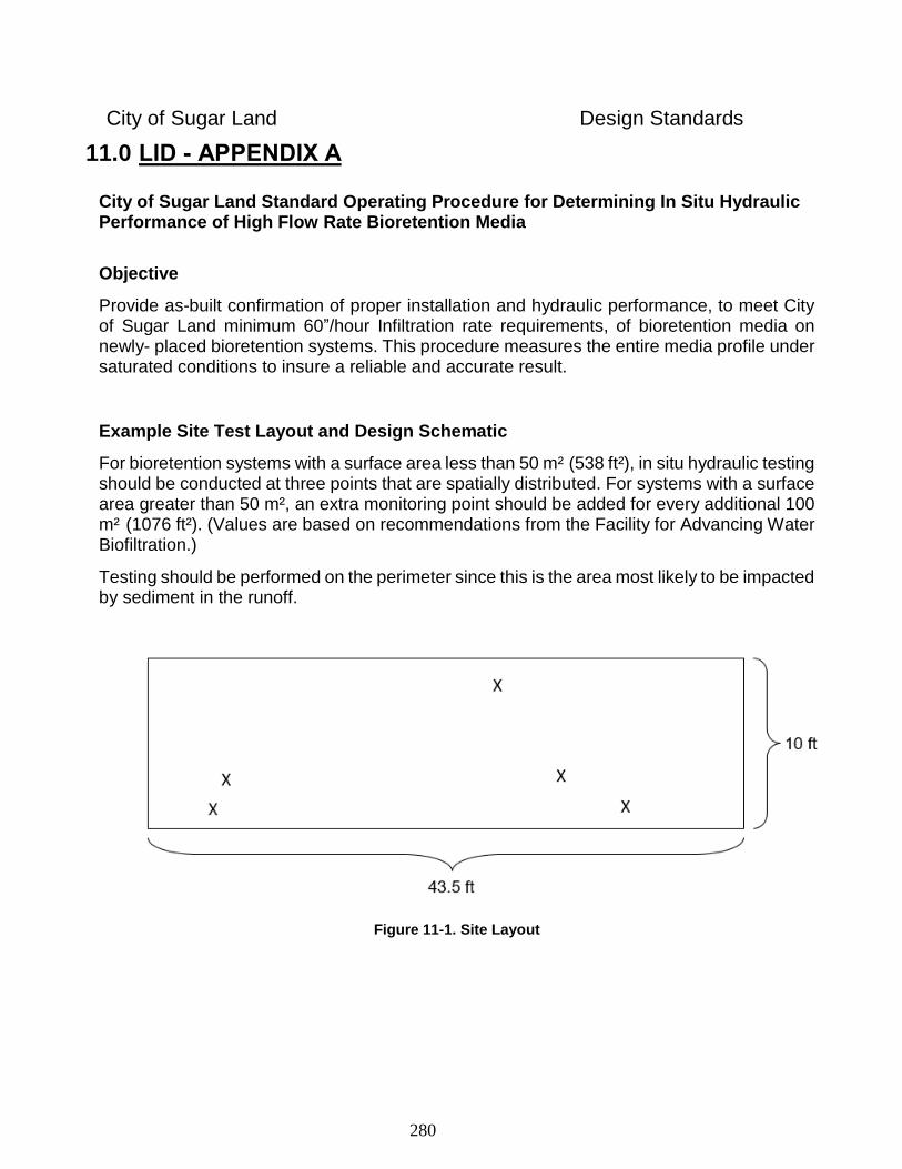
280
City of Sugar Land Design Standards
11.0 LID - APPENDIX A
City of Sugar Land Standard Operating Procedure for Determining In Situ Hydraulic Performance of High Flow Rate Bioretention Media
Objective
Provide as-built confirmation of proper installation and hydraulic performance, to meet City of Sugar Land minimum 60”/hour Infiltration rate requirements, of bioretention media on newly- placed bioretention systems. This procedure measures the entire media profile under saturated conditions to insure a reliable and accurate result.
Example Site Test Layout and Design Schematic
For bioretention systems with a surface area less than 50 m² (538 ft²), in situ hydraulic testing should be conducted at three points that are spatially distributed. For systems with a surface area greater than 50 m², an extra monitoring point should be added for every additional 100 m² (1076 ft²). (Values are based on recommendations from the Facility for Advancing Water Biofiltration.)
Testing should be performed on the perimeter since this is the area most likely to be impacted by sediment in the runoff.
Figure 11-1. Site Layout
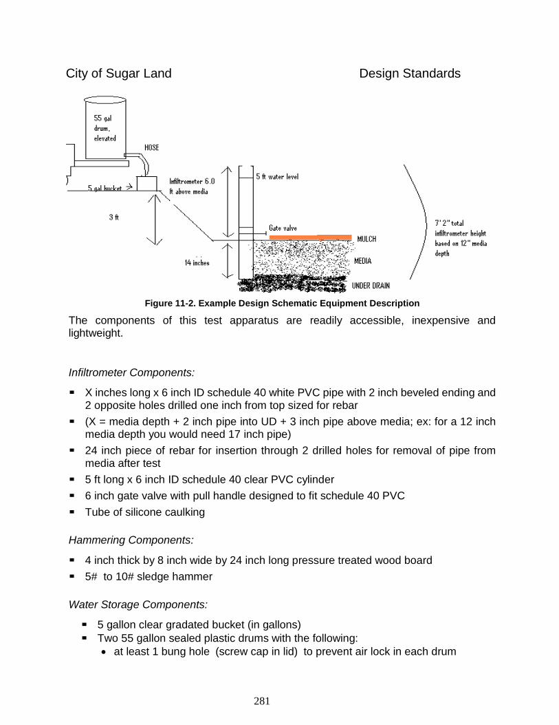
281
City of Sugar Land Design Standards
Figure 11-2. Example Design Schematic Equipment Description
The components of this test apparatus are readily accessible, inexpensive and lightweight.
Infiltrometer Components:
X inches long x 6 inch ID schedule 40 white PVC pipe with 2 inch beveled ending and 2 opposite holes drilled one inch from top sized for rebar
(X = media depth + 2 inch pipe into UD + 3 inch pipe above media; ex: for a 12 inch media depth you would need 17 inch pipe)
24 inch piece of rebar for insertion through 2 drilled holes for removal of pipe from media after test
5 ft long x 6 inch ID schedule 40 clear PVC cylinder
6 inch gate valve with pull handle designed to fit schedule 40 PVC
Tube of silicone caulking
Hammering Components:
4 inch thick by 8 inch wide by 24 inch long pressure treated wood board
5# to 10# sledge hammer
Water Storage Components:
5 gallon clear gradated bucket (in gallons)
Two 55 gallon sealed plastic drums with the following:
at least 1 bung hole (screw cap in lid) to prevent air lock in each drum
282
City of Sugar Land Design Standards
plastic barb with gasket placed at bottom of each drum for water discharge
plastic shut off valve placed at end of hose to control flow at test location
garden hose connector attached to barb in drums to control flow and connect hose
garden hose with screw-on shut off valve at flow end
An acceptable alternative to this is a simple low-cost water supply system. Other Materials
Water
Manhole lifter or crow bar for use on rebar to remove pipe from media after test completion
Light weight oil or petroleum jelly with dry wipes for application
Level
Stopwatch
Rake/shovel
Measuring tape
Large stones (~2 inch; see Figure 6)
Flashlight
Clipboard with pencil and Table 1 from this document
Assembly: Insert 5 ft long x 6 inch clear PVC cylinder into topside opening of gate valve. Apply silicone caulking to outside area where cylinder and gate valve meet. Smooth out caulking to create leak proof seal. Let dry according to directions on tube. Test Methodology
1. Carefully scrape away any surface covering (e.g. mulch, gravel, leaves) without disturbing the soil filter media surface.
2. In an area near the test location, confirm media profile depth by using a shovel to dig to under drain stone and place measuring tape in hole to determine depth from top of under drain stone to top of media bed. A flash light may be needed to ensure the under drain stone has been reached before a depth measurement is taken.
3. At the test location which has been cleared of mulch, locate the six (6) inch wide white PVC pipe (beveled end down) on the surface of the media. Ensure testing is not too close to vegetation. Place the wooden board over the pipe and then gently pound with the sledge hammer on top of the board (Figure 3). Hammer the PVC pipe into the entire media profile based on the depth previously determined until it is approximately 3 inches above the media (Figure 4). Check with level to insure that the pipe is plumb. Note: It is important that the pipe is driven in slowly and carefully to minimize disturbance of the filter media profile. The media may slightly move downward in the pipe during hammering, but not more than 1 inch, and will not significantly affect hydraulic performance.
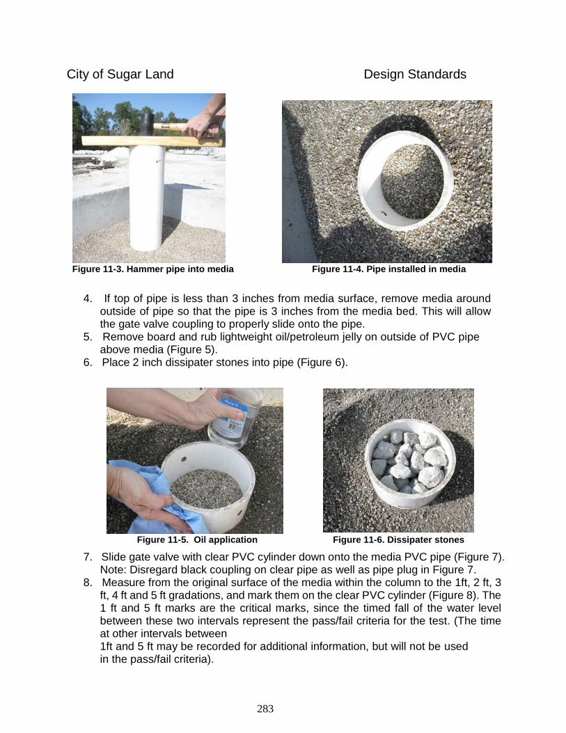
283
City of Sugar Land Design Standards
Figure 11-3. Hammer pipe into media Figure 11-4. Pipe installed in media
4. If top of pipe is less than 3 inches from media surface, remove media around
outside of pipe so that the pipe is 3 inches from the media bed. This will allow the gate valve coupling to properly slide onto the pipe.
5. Remove board and rub lightweight oil/petroleum jelly on outside of PVC pipe above media (Figure 5).
6. Place 2 inch dissipater stones into pipe (Figure 6).
Figure 11-5. Oil application Figure 11-6. Dissipater stones
7. Slide gate valve with clear PVC cylinder down onto the media PVC pipe (Figure 7). Note: Disregard black coupling on clear pipe as well as pipe plug in Figure 7.
8. Measure from the original surface of the media within the column to the 1ft, 2 ft, 3 ft, 4 ft and 5 ft gradations, and mark them on the clear PVC cylinder (Figure 8). The 1 ft and 5 ft marks are the critical marks, since the timed fall of the water level between these two intervals represent the pass/fail criteria for the test. (The time at other intervals between 1ft and 5 ft may be recorded for additional information, but will not be used in the pass/fail criteria).
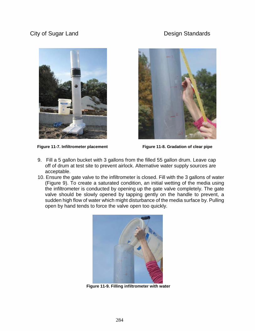
284
City of Sugar Land Design Standards
Figure 11-7. Infiltrometer placement Figure 11-8. Gradation of clear pipe
9. Fill a 5 gallon bucket with 3 gallons from the filled 55 gallon drum. Leave cap
off of drum at test site to prevent airlock. Alternative water supply sources are acceptable.
10. Ensure the gate valve to the infiltrometer is closed. Fill with the 3 gallons of water (Figure 9). To create a saturated condition, an initial wetting of the media using the infiltrometer is conducted by opening up the gate valve completely. The gate valve should be slowly opened by tapping gently on the handle to prevent, a sudden high flow of water which might disturbance of the media surface by. Pulling open by hand tends to force the valve open too quickly.
Figure 11-9. Filling infiltrometer with water
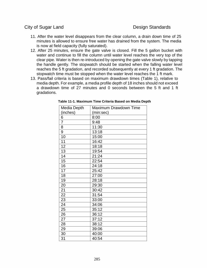
285
City of Sugar Land Design Standards
11. After the water level disappears from the clear column, a drain down time of 25 minutes is allowed to ensure free water has drained from the system. The media is now at field capacity (fully saturated).
12. After 25 minutes, ensure the gate valve is closed. Fill the 5 gallon bucket with water and continue to fill the column until water level reaches the very top of the clear pipe. Water is then re-introduced by opening the gate valve slowly by tapping the handle gently. The stopwatch should be started when the falling water level reaches the 5 ft gradation, and recorded subsequently at every 1 ft gradation. The stopwatch time must be stopped when the water level reaches the 1 ft mark.
13. Pass/fail criteria is based on maximum drawdown times (Table 1), relative to media depth. For example, a media profile depth of 18 inches should not exceed a drawdown time of 27 minutes and 0 seconds between the 5 ft and 1 ft gradations.
Table 11-1. Maximum Time Criteria Based on Media Depth
Media Depth (inches)
Maximum Drawdown Time (min:sec)
6 8:00
7 9:48
8 11:30
9 13:18
10 15:00
11 16:42
12 18:18
13 19:54
14 21:24
15 22:54
16 24:18
17 25:42
18 27:00
19 28:18
20 29:30
21 30:42
22 31:54
23 33:00
24 34:06
25 35:12
26 36:12
27 37:12
28 38:12
29 39:06
30 40:00
31 40:54
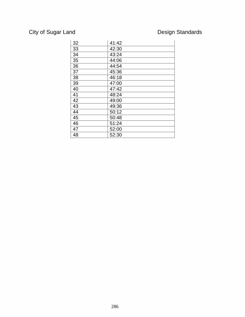
286
City of Sugar Land Design Standards
32 41:42
33 42:30
34 43:24
35 44:06
36 44:54
37 45:36
38 46:18
39 47:00
40 47:42
41 48:24
42 49:00
43 49:36
44 50:12
45 50:48
46 51:24
47 52:00
48 52:30
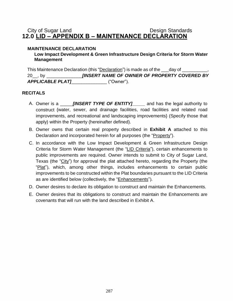
287
City of Sugar Land Design Standards
12.0 LID – APPENDIX B – MAINTENANCE DECLARATION MAINTENANCE DECLARATION
Low Impact Development & Green Infrastructure Design Criteria for Storm Water Management
This Maintenance Declaration (this “Declaration”) is made as of the ___day of __________,
20__, by ______________[INSERT NAME OF OWNER OF PROPERTY COVERED BY
APPLICABLE PLAT]______________ (“Owner”).
RECITALS
A. Owner is a _____[INSERT TYPE OF ENTITY]_____ and has the legal authority to
construct {water, sewer, and drainage facilities, road facilities and related road
improvements, and recreational and landscaping improvements} (Specify those that
apply) within the Property (hereinafter defined).
B. Owner owns that certain real property described in Exhibit A attached to this
Declaration and incorporated herein for all purposes (the “Property”).
C. In accordance with the Low Impact Development & Green Infrastructure Design
Criteria for Storm Water Management (the “LID Criteria”), certain enhancements to
public improvements are required. Owner intends to submit to City of Sugar Land,
Texas (the “City”) for approval the plat attached hereto, regarding the Property (the
“Plat”), which, among other things, includes enhancements to certain public
improvements to be constructed within the Plat boundaries pursuant to the LID Criteria
as are identified below (collectively, the “Enhancements”).
D. Owner desires to declare its obligation to construct and maintain the Enhancements.
E. Owner desires that its obligations to construct and maintain the Enhancements are
covenants that will run with the land described in Exhibit A.
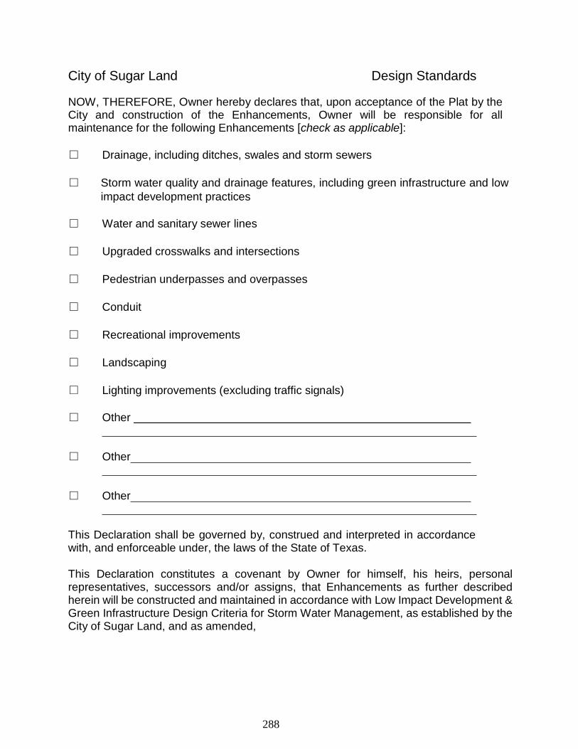
288
City of Sugar Land Design Standards
NOW, THEREFORE, Owner hereby declares that, upon acceptance of the Plat by the City and construction of the Enhancements, Owner will be responsible for all maintenance for the following Enhancements [check as applicable]:
□ Drainage, including ditches, swales and storm sewers
□ Storm water quality and drainage features, including green infrastructure and low
impact development practices
□ Water and sanitary sewer lines
□ Upgraded crosswalks and intersections
□ Pedestrian underpasses and overpasses
□ Conduit
□ Recreational improvements
□ Landscaping
□ Lighting improvements (excluding traffic signals)
□ Other
□ Other
□ Other
This Declaration shall be governed by, construed and interpreted in accordance with, and enforceable under, the laws of the State of Texas. This Declaration constitutes a covenant by Owner for himself, his heirs, personal representatives, successors and/or assigns, that Enhancements as further described herein will be constructed and maintained in accordance with Low Impact Development & Green Infrastructure Design Criteria for Storm Water Management, as established by the City of Sugar Land, and as amended,
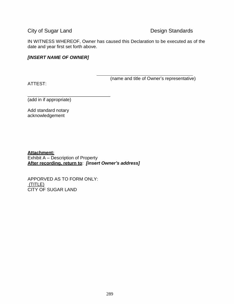
289
City of Sugar Land Design Standards
IN WITNESS WHEREOF, Owner has caused this Declaration to be executed as of the date and year first set forth above.
[INSERT NAME OF OWNER]
ATTEST:
(add in if appropriate)
Add standard notary acknowledgement
(name and title of Owner’s representative)
Attachment: Exhibit A – Description of Property After recording, return to: [insert Owner’s address]
APPORVED AS TO FORM ONLY: (TITLE) CITY OF SUGAR LAND
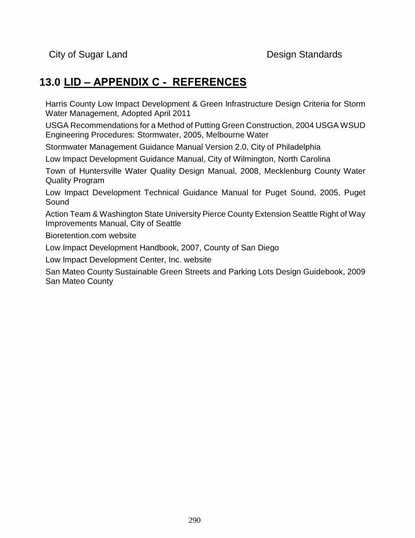
290
City of Sugar Land Design Standards
13.0 LID – APPENDIX C - REFERENCES Harris County Low Impact Development & Green Infrastructure Design Criteria for Storm Water Management, Adopted April 2011
USGA Recommendations for a Method of Putting Green Construction, 2004 USGA WSUD Engineering Procedures: Stormwater, 2005, Melbourne Water
Stormwater Management Guidance Manual Version 2.0, City of Philadelphia
Low Impact Development Guidance Manual, City of Wilmington, North Carolina
Town of Huntersville Water Quality Design Manual, 2008, Mecklenburg County Water Quality Program
Low Impact Development Technical Guidance Manual for Puget Sound, 2005, Puget Sound
Action Team & Washington State University Pierce County Extension Seattle Right of Way Improvements Manual, City of Seattle
Bioretention.com website
Low Impact Development Handbook, 2007, County of San Diego
Low Impact Development Center, Inc. website
San Mateo County Sustainable Green Streets and Parking Lots Design Guidebook, 2009 San Mateo County
291
City of Sugar Land Design Standards
14.0 LID – APPENDIX D - RESOURCES San Mateo County Sustainable Green Streets and Parking Lots Design Guidebook, First Edition, January 2009 (http://www.flowstobay.org/ms_sustainable_guidebook.php)
The Low Impact Development Center, Inc. (http://www.lowimpactdevelopment.org)
Low Impact Development Urban Design Tools Website (http://www.lid- stormwater.net/index.html)
Runoff Reduction Method, Virginia Department of Conservation & Recreation (http://www.princegeorgescountymd.gov/Government/AgencyIndex/DER/ESG/manuals.asp)
USGA Recommendations for a Method of Putting Green Construction (http://www.usga.org/course_care/articles/construction/greens/USGA-Recommendations-For-A- Method-Of-Putting-Green-Construction(2)/)
WSUD Water Sensitive Urban Design Program (http://www.wsud.org)
WSUD Engineering Procedures: Stormwater, 2005, Melbourne Water (http://wsud.melbournewater.com.au/)
Stormwater Management Guidance Manual Version 2.0, City of Philadelphia (http://www.phillyriverinfo.org/WICLibrary/PSMGM%20V2.0.pdf)
Low Impact Development Guidance Manual, City of Wilmington, North Carolina (http://www.nhcgov.com/planningandinspections/Documents/LID%20Manual.pdf)
Town of Huntersville Water Quality Design Manual, 2008, Mecklenburg County Water Quality Program (http://www.huntersville.org/Planning%20Info/Huntersville%20Design%20Manual%20January
%201,%202008%20Version.pdf)
Low Impact Development Technical Guidance Manual for Puget Sound, 2005, Puget Sound (http://www.psparchives.com/publications/our_work/stormwater/lid/LID_manual2005.pdf)
Seattle Right of Way Improvements Manual, City of Seattle (http://www.seattle.gov/util/About_SPU/Drainage_&_Sewer_System/GreenStormwaterInfrastru cture/index.htm)
Bioretention.com website (http://www.bioretention.com)
Low Impact Development Handbook, 2007, County of San Diego (http://www.co.san- diego.ca.us/dplu/docs/LID-Handbook.pdf)
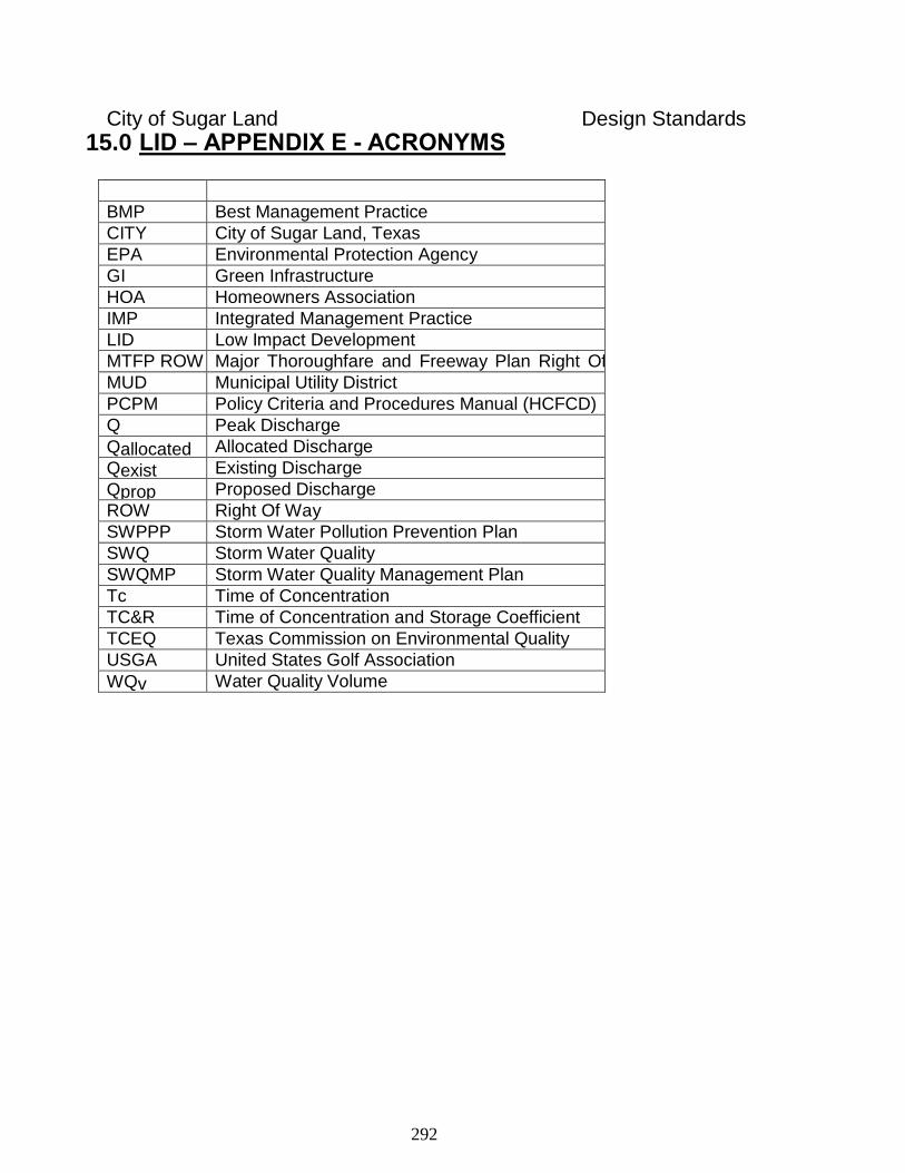
292
City of Sugar Land Design Standards
15.0 LID – APPENDIX E - ACRONYMS
BMP Best Management Practice
CITY City of Sugar Land, Texas
EPA Environmental Protection Agency
GI Green Infrastructure
HOA Homeowners Association
IMP Integrated Management Practice
LID Low Impact Development
MTFP ROW Major Thoroughfare and Freeway Plan Right Of Way MUD Municipal Utility District
PCPM Policy Criteria and Procedures Manual (HCFCD)
Q Peak Discharge
Qallocated Allocated Discharge
Qexist Existing Discharge
Qprop Proposed Discharge
ROW Right Of Way
SWPPP Storm Water Pollution Prevention Plan
SWQ Storm Water Quality
SWQMP Storm Water Quality Management Plan
Tc Time of Concentration
TC&R Time of Concentration and Storage Coefficient
TCEQ Texas Commission on Environmental Quality
USGA United States Golf Association
WQv Water Quality Volume
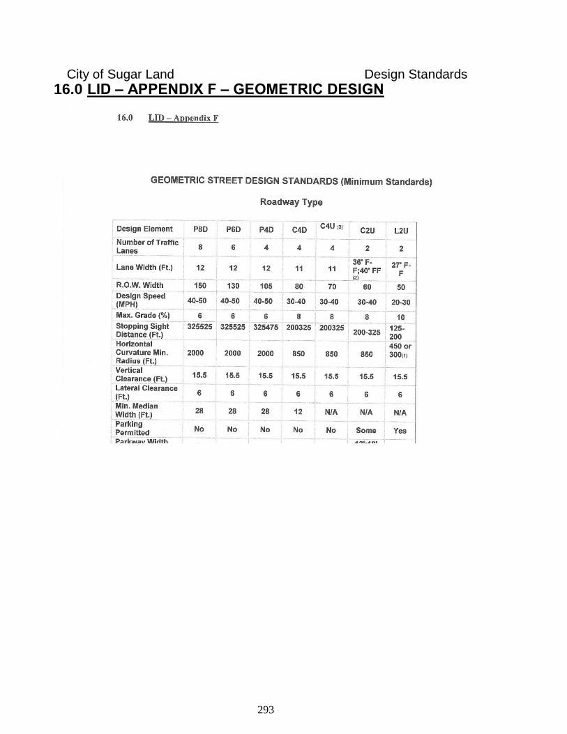
293
City of Sugar Land Design Standards
16.0 LID – APPENDIX F – GEOMETRIC DESIGN
Related Documents