STRONG FRAME ® MOMENT FRAMES • Special Moment Frames • One- and Two-Story Ordinary Moment Frames • Custom Solutions C-SF13 (800) 999‑5099 www.strongtie.com

Welcome message from author
This document is posted to help you gain knowledge. Please leave a comment to let me know what you think about it! Share it to your friends and learn new things together.
Transcript
Strong Frame®
moment FrameS
• Special moment Frames
• one- and two-Story ordinary
moment Frames
• Custom Solutions
C-SF13
(800) 999‑5099www.strongtie.com
Strong Frame®
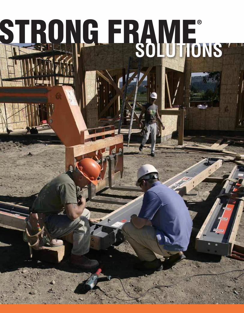
For years, Simpson Strong‑Tie®
lateral systems solutions have set
the standard for innovation and
high quality. Since the introduction
of the Strong Frame® ordinary
moment frame and then the two‑
story ordinary moment frame,
Simpson Strong‑Tie has been the
choice for Designers requiring high
lateral‑force resistance when wall
space is small and openings are large.
Our special moment frames feature
Yield‑Link™ structural fuses and
100% bolted connections that provide
greater performance and easier
installation into older buildings.
Strong Frame special moment frame
is the only moment frame solution
on the market with a link assembly
designed to yield speciically at
the connection in a seismic event.
The ability to go into a building
after an event replacing only the
fuse instead of the entire beam
offers signiicant cost savings.
We’ve been on enough jobsites to
know that no two projects are exactly
the same—especially in custom
homes or retroit applications.
By introducing the Strong Frame®
special moment frame and
Strong Frame Selector software,
Simpson Strong‑Tie has extended its
technology leadership by delivering
new, code‑listed solutions to suit
virtually any project. By picking out
standard sizes out of this catalog or
leveraging our software, Designers
can easily select a moment frame
that best resists seismic lateral loads
in applications, such as soft‑story
retroit of mid‑rise wood structures or
buildings built over tuck‑under parking.
Think you have a project that
could beneit from a Strong Frame
moment frame? Give us a call at
(800) 999‑5099.
Strong Frame®
C‑S
F13 ©
2013 S
IMP
SO
N S
TR
ON
G‑T
IE C
OM
PA
NY
IN
C.
4
Strong Frame Selector Software
What's new
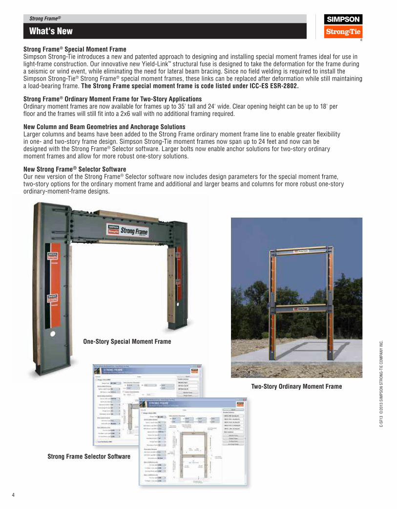
Strong Frame® Special Moment Frame Simpson Strong‑Tie introduces a new and patented approach to designing and installing special moment frames ideal for use in light‑frame construction. Our innovative new Yield‑Link™ structural fuse is designed to take the deformation for the frame during a seismic or wind event, while eliminating the need for lateral beam bracing. Since no field welding is required to install the Simpson Strong‑Tie® Strong Frame® special moment frames, these links can be replaced after deformation while still maintaining a load‑bearing frame. The Strong Frame special moment frame is code listed under ICC‑ES ESR‑2802.
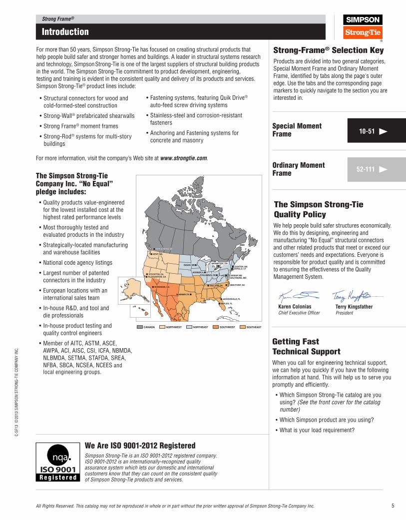
Strong Frame® Ordinary Moment Frame for Two‑Story Applications Ordinary moment frames are now available for frames up to 35' tall and 24' wide. Clear opening height can be up to 18' per floor and the frames will still fit into a 2x6 wall with no additional framing required.
New Column and Beam Geometries and Anchorage Solutions Larger columns and beams have been added to the Strong Frame ordinary moment frame line to enable greater flexibility in one‑ and two‑story frame design. Simpson Strong‑Tie moment frames now span up to 24 feet and now can be designed with the Strong Frame® Selector software. Larger bolts now enable anchor solutions for two‑story ordinary moment frames and allow for more robust one‑story solutions.
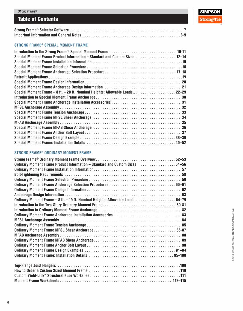
New Strong Frame® Selector Software Our new version of the Strong Frame® Selector software now includes design parameters for the special moment frame, two‑story options for the ordinary moment frame and additional and larger beams and columns for more robust one‑story ordinary‑moment‑frame designs.
One‑Story Special Moment Frame
Two‑Story Ordinary Moment Frame
Strong Frame®C
‑SF1
3 ©
2013 S
IMP
SO
N S
TR
ON
G‑T
IE C
OM
PA
NY
IN
C.
5
Introduction
We help people build safer structures economically. We do this by designing, engineering and manufacturing “No Equal” structural connectors and other related products that meet or exceed our customers’ needs and expectations. Everyone is responsible for product quality and is committed to ensuring the effectiveness of the Quality Management System.
the Simpson Strong-tie
Quality Policy
All Rights Reserved. This catalog may not be reproduced in whole or in part without the prior written approval of Simpson Strong‑Tie Company Inc.
getting Fast
technical Support
When you call for engineering technical support, we can help you quickly if you have the following information at hand. This will help us to serve you promptly and efficiently.
•Which Simpson Strong‑Tie catalog are you using? (See the front cover for the catalog number)
•Which Simpson product are you using?
•What is your load requirement?
Simpson Strong‑Tie is an ISO 9001‑2012 registered company. ISO 9001‑2012 is an internationally‑recognized quality assurance system which lets our domestic and international customers know that they can count on the consistent quality of Simpson Strong‑Tie products and services.
We are ISo 9001-2012 registered
For more than 50 years, Simpson Strong‑Tie has focused on creating structural products that help people build safer and stronger homes and buildings. A leader in structural systems research and technology, Simpson Strong‑Tie is one of the largest suppliers of structural building products in the world. The Simpson Strong‑Tie commitment to product development, engineering, testing and training is evident in the consistent quality and delivery of its products and services. Simpson Strong‑Tie® product lines include:
•Structural connectors for wood and cold‑formed‑steel construction
•Strong-Wall® prefabricated shearwalls
•StrongFrame® moment frames
•Strong-Rod® systems for multi‑story buildings
•Fasteningsystems,featuringQuikDrive® auto‑feed screw driving systems
•Stainless-steelandcorrosion-resistantfasteners
•AnchoringandFasteningsystemsforconcrete and masonry
the Simpson Strong-tie Company Inc. “no equal” pledge includes:
•Qualityproductsvalue-engineeredfor the lowest installed cost at the highest rated performance levels
•Mostthoroughlytestedandevaluated products in the industry
•Strategically-locatedmanufacturingand warehouse facilities
•Nationalcodeagencylistings
•Largestnumberofpatentedconnectors in the industry
•Europeanlocationswithaninternational sales team
• In-houseR&D,andtoolanddie professionals
• In-houseproducttestingandquality control engineers
•MemberofAITC,ASTM,ASCE,AWPA, ACI, AISC, CSI, ICFA, NBMDA, NLBMDA, SETMA, STAFDA, SREA, NFBA, SBCA, NCSEA, NCEES and local engineering groups.
Terry KingsfatherPresident
Karen ColoniasChief Executive Officer
Strong-Frame® Selection Key
Products are divided into two general categories, Special Moment Frame and Ordinary Moment Frame, identiied by tabs along the page's outer edge. Use the tabs and the corresponding page markers to quickly navigate to the section you are interested in.
10‑51
52‑111ordinary moment Frame
Special moment Frame
For more information, visit the company’s Web site at www.strongtie.com.
Strong Frame®
C‑S
F13 ©
2013 S
IMP
SO
N S
TR
ON
G‑T
IE C
OM
PA
NY
IN
C.
6
table of Contents
Strong Frame® Selector Software. . . . . . . . . . . . . . . . . . . . . . . . . . . . . . . . . . . . . . . . . . . . . . . . . . . 7
Important Information and General Notes . . . . . . . . . . . . . . . . . . . . . . . . . . . . . . . . . . . . . . . . . . . . 8‑9
STRONG FRAME® SpECIAl MOMENT FRAME
Introduction to the Strong Frame® Special Moment Frame . . . . . . . . . . . . . . . . . . . . . . . . . . . . . . 10‑11
Special Moment Frame product Information – Standard and Custom Sizes . . . . . . . . . . . . . . . . . . 12–14
Special Moment Frame Installation Information . . . . . . . . . . . . . . . . . . . . . . . . . . . . . . . . . . . . . . . .15
Special Moment Frame Selection procedure . . . . . . . . . . . . . . . . . . . . . . . . . . . . . . . . . . . . . . . . . . .16
Special Moment Frame Anchorage Selection procedure. . . . . . . . . . . . . . . . . . . . . . . . . . . . . . . . 17–18
Retrofit Applications . . . . . . . . . . . . . . . . . . . . . . . . . . . . . . . . . . . . . . . . . . . . . . . . . . . . . . . . . . . .19
Special Moment Frame Design Information. . . . . . . . . . . . . . . . . . . . . . . . . . . . . . . . . . . . . . . . . . . 20
Special Moment Frame Anchorage Design Information . . . . . . . . . . . . . . . . . . . . . . . . . . . . . . . . . . 21
Special Moment Frame – 8 ft. – 20 ft. Nominal Heights: Allowable loads.. . . . . . . . . . . . . . . . . . .22–29
Introduction to Special Moment Frame Anchorage . . . . . . . . . . . . . . . . . . . . . . . . . . . . . . . . . . . . . . 30
Special Moment Frame Anchorage Installation Accessories . . . . . . . . . . . . . . . . . . . . . . . . . . . . . . . 31
MFSl Anchorage Assembly . . . . . . . . . . . . . . . . . . . . . . . . . . . . . . . . . . . . . . . . . . . . . . . . . . . . . . 32
Special Moment Frame Tension Anchorage . . . . . . . . . . . . . . . . . . . . . . . . . . . . . . . . . . . . . . . . . . . 33
Special Moment Frame MFSl Shear Anchorage. . . . . . . . . . . . . . . . . . . . . . . . . . . . . . . . . . . . . . . . 34
MFAB Anchorage Assembly . . . . . . . . . . . . . . . . . . . . . . . . . . . . . . . . . . . . . . . . . . . . . . . . . . . . . . 35
Special Moment Frame MFAB Shear Anchorage . . . . . . . . . . . . . . . . . . . . . . . . . . . . . . . . . . . . . . . 36
Special Moment Frame Anchor Bolt layout . . . . . . . . . . . . . . . . . . . . . . . . . . . . . . . . . . . . . . . . . . . 37
Special Moment Frame Design Example . . . . . . . . . . . . . . . . . . . . . . . . . . . . . . . . . . . . . . . . . . .38–39
Special Moment Frame: Installation Details . . . . . . . . . . . . . . . . . . . . . . . . . . . . . . . . . . . . . . . .40–52
STRONG FRAME® ORDINARy MOMENT FRAME
Strong Frame® Ordinary Moment Frame Overview. . . . . . . . . . . . . . . . . . . . . . . . . . . . . . . . . . . .52–53
Ordinary Moment Frame product Information – Standard and Custom Sizes . . . . . . . . . . . . . . . . .54–56
Ordinary Moment Frame Installation Information. . . . . . . . . . . . . . . . . . . . . . . . . . . . . . . . . . . . . . . 57
Bolt‑Tightening Requirements . . . . . . . . . . . . . . . . . . . . . . . . . . . . . . . . . . . . . . . . . . . . . . . . . . . . 58
Ordinary Moment Frame Selection procedure . . . . . . . . . . . . . . . . . . . . . . . . . . . . . . . . . . . . . . . . . 59
Ordinary Moment Frame Anchorage Selection procedures . . . . . . . . . . . . . . . . . . . . . . . . . . . . . .60–61
Ordinary Moment Frame Design Information . . . . . . . . . . . . . . . . . . . . . . . . . . . . . . . . . . . . . . . . . . 62
Anchorage Design Information . . . . . . . . . . . . . . . . . . . . . . . . . . . . . . . . . . . . . . . . . . . . . . . . . . . . 63
Ordinary Moment Frame – 8 ft. – 19 ft. Nominal Heights: Allowable loads . . . . . . . . . . . . . . . . . .64–79
Introduction to the Two‑Story Ordinary Moment Frame. . . . . . . . . . . . . . . . . . . . . . . . . . . . . . . . . 80‑81
Introduction to Ordinary Moment Frame Anchorage . . . . . . . . . . . . . . . . . . . . . . . . . . . . . . . . . . . . . 82
Ordinary Moment Frame Anchorage Installation Accessories . . . . . . . . . . . . . . . . . . . . . . . . . . . . . . 83
MFSl Anchorage Assembly . . . . . . . . . . . . . . . . . . . . . . . . . . . . . . . . . . . . . . . . . . . . . . . . . . . . . . 84
Ordinary Moment Frame Tension Anchorage . . . . . . . . . . . . . . . . . . . . . . . . . . . . . . . . . . . . . . . . . . 85
Ordinary Moment Frame MFSl Shear Anchorage. . . . . . . . . . . . . . . . . . . . . . . . . . . . . . . . . . . . . 86‑87
MFAB Anchorage Assembly . . . . . . . . . . . . . . . . . . . . . . . . . . . . . . . . . . . . . . . . . . . . . . . . . . . . . . 88
Ordinary Moment Frame MFAB Shear Anchorage. . . . . . . . . . . . . . . . . . . . . . . . . . . . . . . . . . . . . . . 89
Ordinary Moment Frame Anchor Bolt layout . . . . . . . . . . . . . . . . . . . . . . . . . . . . . . . . . . . . . . . . . . 90
Ordinary Moment Frame Design Examples . . . . . . . . . . . . . . . . . . . . . . . . . . . . . . . . . . . . . . . . .91–94
Ordinary Moment Frame: Installation Details . . . . . . . . . . . . . . . . . . . . . . . . . . . . . . . . . . . . . . 95–108
Top‑Flange Joist Hangers . . . . . . . . . . . . . . . . . . . . . . . . . . . . . . . . . . . . . . . . . . . . . . . . . . . . . . .109
How to Order a Custom Sized Moment Frame . . . . . . . . . . . . . . . . . . . . . . . . . . . . . . . . . . . . . . . . .110
Custom yield‑link™ Structural Fuse Worksheet . . . . . . . . . . . . . . . . . . . . . . . . . . . . . . . . . . . . . . . .111
Moment Frame Worksheets . . . . . . . . . . . . . . . . . . . . . . . . . . . . . . . . . . . . . . . . . . . . . . . . . . 112–115
Strong Frame®C
‑SF1
3 ©
2013 S
IMP
SO
N S
TR
ON
G‑T
IE C
OM
PA
NY
IN
C.
7
Design a Moment Frame to Meet your Speciications
The Strong Frame® Selector software is designed to help Designers select an appropriate Simpson Strong‑Tie® Strong Frame moment frame quickly. The program enables Designers to easily design an ordinary or special moment frame to meet their speciic geometry and loading requirements.
Input Geometry
Only minimum input geometries are required for the Strong Frame Selector software to select an appropriate frame for the available space.
Based on input geometry, the software will generate a list of possible solutions ranked from the least expensive solution.
If the opening dimensions are outside of standard Strong Frame moment frame sizes, the Designer can enter their speciic opening dimensions and the Strong Frame Selector software will provide possible custom solutions.
Download the Strong Frame Selector software free at www.strongtie.com/sfsoftware
Strong Frame Selector Software
loading
An easy‑to‑use input screen and drop‑down buttons make it simple for the Designer to input lateral and gravity loads.
Both wind and seismic loads can be entered and the Strong Frame Selector software will determine possible frame sizes that meet the Designer’s input requirements.
Uniform, partial uniform as well as point loads can be placed anywhere along the span of the beam.
Output
The output is in a concise format containing the important information needed for moment frame design. More detailed outputs are also available if desired.
• Minimal input is required for anchorage design
• Foundation forces are summarized to aid the Designer in designing their own foundations
• Projects generated can be saved, printed or emailed
Strong Frame®
C‑S
F13 ©
2013 S
IMP
SO
N S
TR
ON
G‑T
IE C
OM
PA
NY
IN
C.
8
Important Information and general notes
The following Warnings, Notes, Instructions and product information apply only to the specific products listed in this catalog. If you use any other Simpson Strong‑Tie Company Inc. products, read the Warnings, Notes, Instructions and product information in the applicable catalog and consult www.strongtie.com for the latest catalogs, bulletins and product information.
Simpson Strong‑Tie Company Inc. structural connectors, anchors, and other products are designed and tested to provide specified design loads. To obtain optimal performance from Simpson Strong‑Tie Company Inc. products and achieve maximum allowable design load, the products must be properly installed and used in accordance with the installation instructions and design limits provided by Simpson Strong‑Tie Company Inc. To ensure proper installation and use, designers and installers must carefully read the following General Notes, General Instructions For The Installer and General Instructions For The Designer, as well as consult the applicable catalog pages for specific product installation instructions and notes.
Proper product installation requires careful attention to all notes and instructions, including these basic rules:
a. Be familiar with the application and correct use of the product.
b. Install all required fasteners per installation instructions provided by Simpson Strong‑Tie Company Inc.: a) use proper fastener type; b) use proper fastener quantity; c) fill all fastener holes as specified; d) ensure screws are completely driven; and e) ensure bolts are completely tightened.
In addition to following the basic rules provided above as well as all notes, warnings and instructions provided in the catalog, installers, designers, engineers and consumers should consult the Simpson Strong‑Tie Company Inc.
website at www.strongtie.com to obtain additional design and installation information, including:
• Instructional builder/contractor training kits containing an instructional video, an instructor guide and a student guide in both English and Spanish
• Information on workshops Simpson Strong‑Tie conducts at various training centers throughout the country
• Product specific installation videos
• Specialty catalogs
• Code reports
• Technical fliers and bulletins
• Master format specifications
• Material safety data sheets
• Corrosion information
• Simpson Strong‑Tie® Autocad® menu
• Answers to frequently asked questions and technical topics.
Failure to follow fully all of the notes and instructions provided by Simpson Strong‑Tie Company Inc. may result in improper installation of products. Improperly installed products may not perform to the specifications set forth in this catalog and may reduce a structure’s ability to resist the movement, stress, and loading that occurs from gravity loads and loading from events such as earthquakes and high velocity winds.
Simpson Strong‑Tie Company Inc. does not guarantee the performance or safety of products that are modified, improperly installed or not used in accordance with the design and load limits set forth in this catalog.
Autocad is a registered trademark of Autodesk.
a. Simpson Strong‑Tie Company Inc. reserves the right to change specifications, designs, and models without notice or liability for such changes.
b. Steel used for each Simpson Strong‑Tie® product is individually selected based on the product’s steel specifications, including strength, thickness, formability, finish, and weldability. Contact Simpson Strong‑Tie for steel information on specific products.
c. Unless otherwise noted, dimensions are in inches, loads are in pounds.
d. 8d (0.131"x2½"), 10d (0.148"x3"), and 16d (0.162"x3½") specify common nails that meet the requirements of ASTM F1667.
e. Do Not Overload. Do not exceed catalog allowable loads, which would jeopardize the product.
f. All references to bolts or machine bolts (MBs), unless otherwise noted, are for structural quality through bolts (not lag screws or carriage bolts) equal
to or better than ASTM Standard A307, Grade A. Anchor rods for MFSL, MFAB, MF‑ATR5EXT‑LS and MF‑ATR5EXT‑LSG are ASTM F1554 Grade 36 or A36; MFSL‑HS, MFAB‑HS MF‑ATR5EXT‑HS and MF‑ATR5EXT‑HSG are ASTM A449; bolts for OMF beam‑to‑column and SMF link‑to‑column connection are ASTM A325. SMF beam‑to‑shear tab connections are ASTM A325 bolts. Link‑to‑beam connections are ASTM A490 (F2280) tension‑control bolts.
g. Wood shrinks and expands as it loses or gains moisture. Dimensions given to the face of wood nailers in this catalog may vary slightly due to moisture content. Capacities provided that include wood nailers are based on a moisture content of less than 19 percent at time of fastener installation, and a minimum specific gravity of 0.50. Nailers are DF #2.
h. Some model configurations may differ from those shown in this catalog. Contact Simpson Strong‑Tie for details.
These general notes are provided to ensure proper installation of Simpson Strong‑Tie Company Inc. products and must be followed fully.
Warning
general notes
a. Provide temporary diagonal bracing of Strong Frame® as required until frame is tied in to the floor or roof framing above.
b. All specified fasteners must be installed according to the instructions in this catalog. Incorrect fastener quantity, size, placement, type, material, or finish may cause the connection to fail.
c. Fill all fastener holes as specified in the installation instructions for that product. Some pre‑installed items may not use all holes.
d. Use the materials specified in the installation instructions. Substitution of or failure to use specified materials may cause the product to fail.
e. Do not add holes or otherwise modify Simpson Strong‑Tie Company Inc. products except as noted in this catalog. The performance of modified products may be substantially weakened. Simpson Strong‑Tie will not warrant or guarantee the performance of such modified products.
f. Install products in the position specified in the catalog.
g. Do not alter installation procedures from those set forth in this catalog.
h. Install all specified fasteners before loading the frame.
i. Use proper safety equipment.
j. Nuts shall be installed such that the end of the threaded rod or bolt is at least flush with the top of the nut.
k. Local and/or regional building codes may require meeting special conditions. Building codes often require special inspection of anchors installed in concrete and masonry. For compliance with these requirements, it is necessary to contact the local and/or regional building authority. Except where mandated by code or code listed, Simpson Strong‑Tie® products do not require special inspection.
l. High‑strength bolts in fully pre‑tensioned Strong Frame ordinary moment frame beam to column connections may require special inspection to verify installation pre‑tension. For compliance with these requirements, it is necessary to contact the local and/or regional building authority. Direct Tension Indicating (DTI) washers are included in the Strong Frame installation kits to help verify installation pre‑tension. Contact Simpson Strong‑Tie for Fastener Assembly Certificates of Conformity.
m. See installation detail sheets for field modifications options.
general Instructions for the Installer
These general instructions for the installer are provided to ensure proper selection and installation of Simpson Strong‑Tie Company Inc. products and must be followed carefully. These general instructions are in addition to the specific installation instructions and notes provided for each particular product, all of which should be consulted prior to and during installation of Simpson Strong‑Tie Company Inc. products.
Strong Frame®C
‑SF1
3 ©
2013 S
IMP
SO
N S
TR
ON
G‑T
IE C
OM
PA
NY
IN
C.
9
Important Information and general notes
Simpson Strong‑Tie Company Inc. warrants catalog products to be free from defects in material or manufacturing. Simpson Strong‑Tie Company Inc. products are further warranted for adequacy of design when used in accordance with design limits in this catalog and when properly specified, installed, and maintained. This warranty does not apply to uses not in compliance with specific applications and installations set forth in this catalog, or to non‑catalog or modified products, or to deterioration due to environmental conditions.
Simpson Strong‑Tie® connectors are designed to enable structures to resist the movement, stress, and loading that results from impact events such as earthquakes and high velocity winds. Other Simpson Strong‑Tie products are designed to the load capacities and uses listed in this catalog. Properly‑installed Simpson Strong‑Tie products will perform in accordance with the specifications set forth in the applicable Simpson Strong‑Tie catalog. Additional performance limitations for specific products may be listed on the applicable catalog pages.
Due to the particular characteristics of potential impact events, the specific design and location of the structure, the building materials used, the quality of
construction, and the condition of the soils involved, damage may nonetheless result to a structure and its contents even if the loads resulting from the impact event do not exceed Simpson Strong‑Tie catalog specifications and Simpson Strong‑Tie connectors are properly installed in accordance with applicable building codes.
All warranty obligations of Simpson Strong‑Tie Company Inc. shall be limited, at the discretion of Simpson Strong‑Tie Company Inc., to repair or replacement of the defective part. These remedies shall constitute Simpson Strong‑Tie Company Inc.’s sole obligation and sole remedy of purchaser under this warranty. In no event will Simpson Strong‑Tie Company Inc. be responsible for incidental, consequential, or special loss or damage, however caused.
This warranty is expressly in lieu of all other warranties, expressed or implied, including warranties of merchantability or fitness for a particular purpose, all such other warranties being hereby expressly excluded. This warranty may change periodically – consult our website www.strongtie.com for current information.
Limited Warranty
terms and Conditions of Sale
product Use
Products in this catalog are designed and manufactured for the specific purposes shown, and should not be used with other connectors not approved by a qualified Designer. Modifications to products or changes in installations should only be made by a qualified Designer. The performance of such modified products or altered installations is the sole responsibility of the Designer.
Indemnity
Customers or Designers modifying products or installations, or designing non‑catalog products for fabrication by Simpson Strong‑Tie Company Inc. shall, regardless of specific instructions to the user, indemnify, defend, and hold harmless Simpson Strong‑Tie Company Inc. for any and all claimed loss or damage occasioned in whole or in part by non‑catalog or modified products.
Non‑Catalog and Modified products
Consult Simpson Strong‑Tie Company Inc. for applications for which there is no catalog product, or for connectors for use in hostile environments, with excessive wood shrinkage, or with abnormal loading or erection requirements.
Non‑catalog products must be designed by the customer and will be fabricated by Simpson Strong‑Tie in accordance with customer specifications.
Simpson Strong‑Tie cannot and does not make any representations regarding the suitability of use or load‑carrying capacities of non‑catalog products. Simpson Strong‑Tie provides no warranty, express or implied, on non‑catalog products. F.O.B. Shipping Point unless otherwise specified. See installation sheets for protected zone for SMF and no welding zone for OMF.
general Instructions for the Designer
a. Design for Strong Frame® moment frames are in accordance with the following:
•2012, 2009 and 2006 International Building Code•AISC Specification for Structural Steel Buildings (ANSI/AISC 360‑05,
360‑10)•AISC Seismic Provisions (ANSI/AISC 341‑05, 341‑10)•RCSC Specification for Structural Joints Using ASTM A325 or A490 Bolts•Building Code Requirements for Structural Concrete (ACI 318‑08,
ACI 318‑11) Moment frames are designed using Load and Resistance Factored Design
(LRFD) methodology for determining frame drift and strength limits. Allowable Stress Design (ASD) shear and drift are determined as VASD = 0.7 x VLRFD and driftASD = 0.7 x driftLRFD for seismic load combinations and VASD = VLRFD/1.6 for wind load combinations.
b. Building codes have specific design requirements for use of steel moment frames. Designer shall verify structural design meets the applicable code requirements. See design examples or contact Simpson Strong‑Tie for more information.
c. Strong Frame moment frames provide a key component of a structure’s lateral force resisting system only when incorporated into a continuous load‑transfer path. The Designer must specify the required components of the complete load transfer path including diaphragms, shear transfer, chords and collectors and foundations.
d. The term “Designer” used throughout this catalog is intended to mean a licensed/certified building design professional, a licensed professional engineer, or a licensed architect.
e. All connected members and related elements shall be designed by the Designer.
f. All installations should be designed only in accordance with the allowable load values set forth in this catalog.
g. Simpson Strong‑Tie® will provide upon request code testing data on all products that have been code tested.
h. Local and/or regional building codes may require meeting special conditions. Building codes often require special inspection of anchors installed in concrete and masonry. For compliance with these requirements, it is necessary to contact the local and/or regional building authority. Except where mandated by code or code listing, Simpson Strong‑Tie® products do not require special inspection.
i. High‑strength bolts in fully pre‑tensioned Strong Frame ordinary moment frame beam to column connections may require special inspection to verify installation pre‑tension. For compliance with these requirements, it is necessary to contact the local and/or regional building authority. Direct Tension Indicating (DTI) washers are included in the Strong Frame installation kits to verify installation pre‑tension. Contact Simpson Strong‑Tie for Fastener Assembly Certificates of Conformity.
j. Welding shall be in accordance with AWS D1.1 and AWS D1.8 (as applicable for seismic). Welds shall be as specified by the Designer. Provide welding special inspection as required by local building department.
k. Holes in base plates are oversized holes for erection tolerance. Designer must evaluate effects of oversized holes and provide plate washer with standard‑size holes welded to base plate where required.
l. Design of Strong Frame moment frames assumes a pinned condition at the base of columns.
m. See design information on pages 20–21 and 62–63 for additional information.
These general instructions for the Designer are provided to ensure proper selection and installation of Simpson Strong‑Tie Company Inc. products and must be followed carefully. These general instructions are in addition to the specific design and installation instructions and notes provided for each particular product, all of which should be consulted prior to and during the design process.
Strong Frame®
C‑S
F13 ©
2013 S
IMP
SO
N S
TR
ON
G‑T
IE C
OM
PA
NY
IN
C.
10
Introduction to the Strong Frame® Special moment Frame
Features
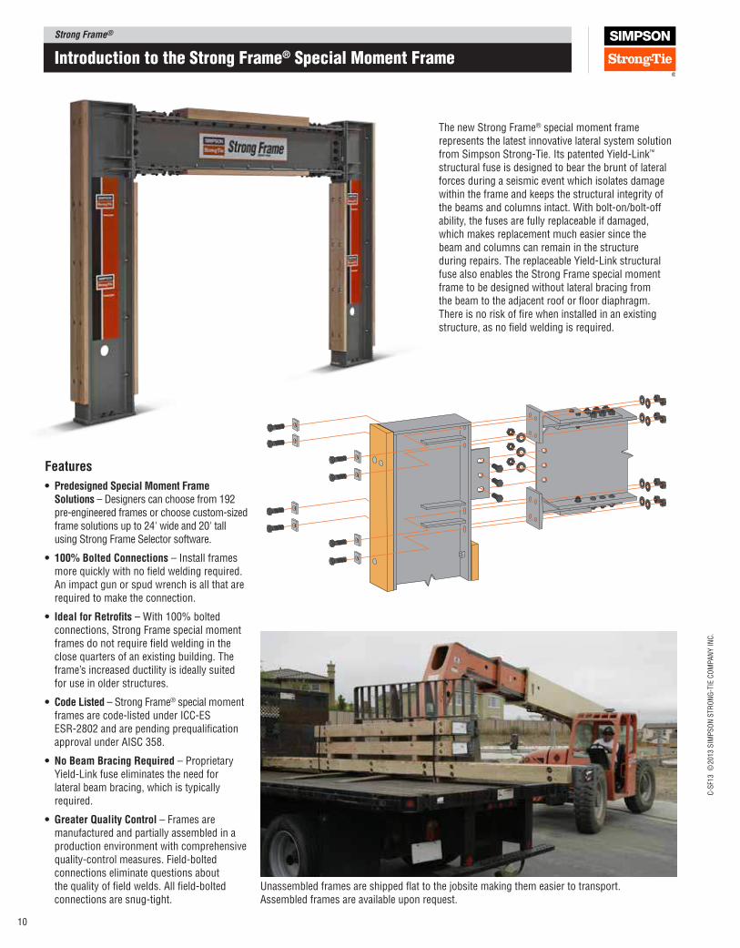
• PredesignedSpecialMomentFrameSolutions – Designers can choose from 192 pre‑engineered frames or choose custom‑sized frame solutions up to 24' wide and 20' tall using Strong Frame Selector software.
• 100%BoltedConnections – Install frames more quickly with no ield welding required. An impact gun or spud wrench is all that are required to make the connection.
• IdealforRetroits – With 100% bolted connections, Strong Frame special moment frames do not require ield welding in the close quarters of an existing building. The frame’s increased ductility is ideally suited for use in older structures.
• CodeListed – Strong Frame® special moment frames are code-listed under ICC-ES ESR-2802 and are pending prequaliication approval under AISC 358.
• NoBeamBracingRequired – Proprietary Yield-Link fuse eliminates the need for lateral beam bracing, which is typically required.
• GreaterQualityControl – Frames are manufactured and partially assembled in a production environment with comprehensive quality-control measures. Field-bolted connections eliminate questions about the quality of ield welds. All ield-bolted connections are snug-tight.
The new Strong Frame® special moment frame represents the latest innovative lateral system solution from Simpson Strong-Tie. Its patented Yield-Link™ structural fuse is designed to bear the brunt of lateral forces during a seismic event which isolates damage within the frame and keeps the structural integrity of the beams and columns intact. With bolt-on/bolt-off ability, the fuses are fully replaceable if damaged, which makes replacement much easier since the beam and columns can remain in the structure during repairs. The replaceable Yield- Link structural fuse also enables the Strong Frame special moment frame to be designed without lateral bracing from the beam to the adjacent roof or loor diaphragm. There is no risk of ire when installed in an existing structure, as no ield welding is required.
Unassembled frames are shipped lat to the jobsite making them easier to transport. Assembled frames are available upon request.
Strong Frame®C
-SF1
3 ©
2013 S
IMP
SO
N S
TR
ON
G-T
IE C
OM
PA
NY
IN
C.
11
Introduction to the Strong Frame® Special moment Frame
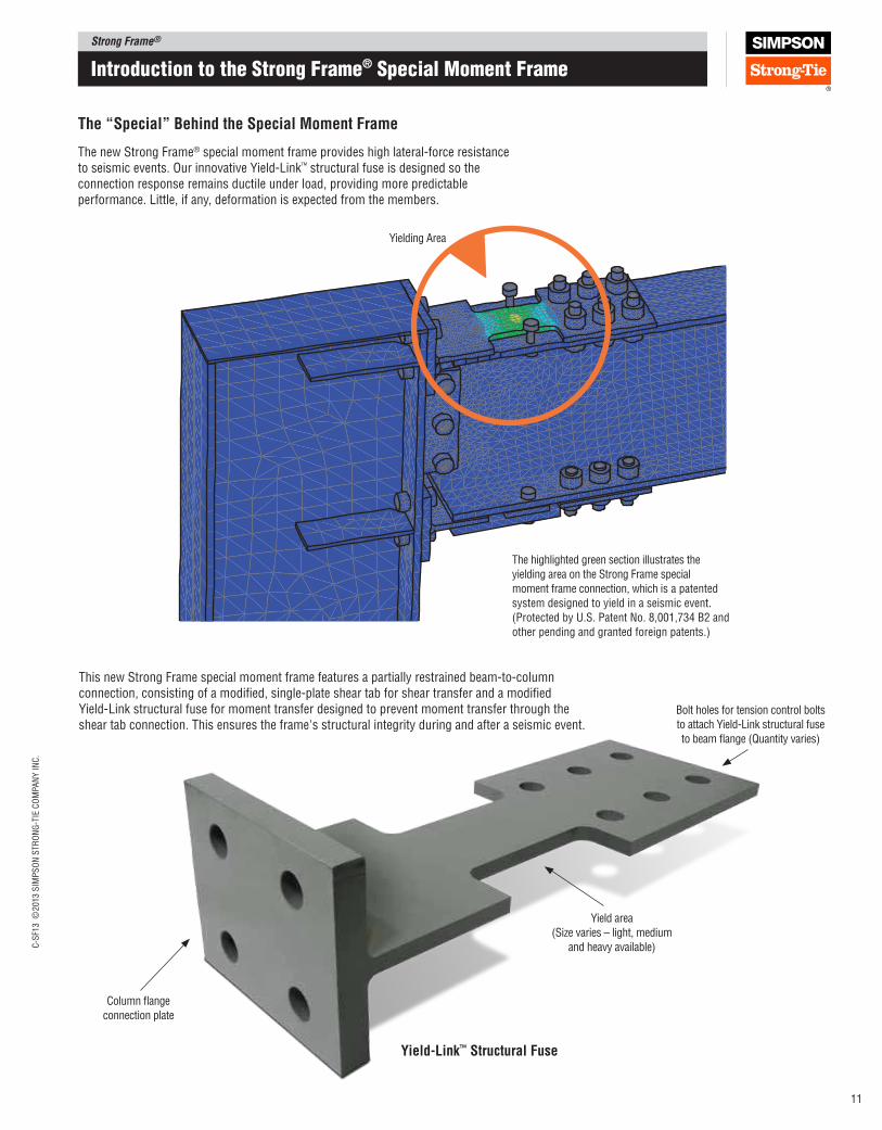
The new Strong Frame® special moment frame provides high lateral-force resistance to seismic events. Our innovative Yield-Link™ structural fuse is designed so the connection response remains ductile under load, providing more predictable performance. Little, if any, deformation is expected from the members.
The “Special” Behind the Special Moment Frame
The highlighted green section illustrates the
yielding area on the Strong Frame special
moment frame connection, which is a patented
system designed to yield in a seismic event.
(Protected by U.S. Patent No. 8,001,734 B2 and
other pending and granted foreign patents.)
Yield area
(Size varies – light, medium
and heavy available)
Bolt holes for tension control bolts
to attach Yield-Link structural fuse
to beam lange (Quantity varies)
Column lange
connection plate
Yielding Area
This new Strong Frame special moment frame features a partially restrained beam-to-column connection, consisting of a modiied, single‑plate shear tab for shear transfer and a modiied Yield‑ Link structural fuse for moment transfer designed to prevent moment transfer through the shear tab connection. This ensures the frame's structural integrity during and after a seismic event.
yield‑link™ Structural Fuse
Strong Frame®
C-S
F13 ©
2013 S
IMP
SO
N S
TR
ON
G-T
IE C
OM
PA
NY
IN
C.
12
2x ield installedtop plate
4x8 beamtop nailer
Field installed inill block(included)
2x8 beambottom nailer
Anchorage assembly
Clear opening width – wood to wood
2x8 ield installednailer as required
2x8 wood nailerat column, typ.
Beam
Colu
mn
Colu
mnW1
H1
(Top
of
conc
rete
to
top
of i
eld-
inst
alle
d
top
plat
e, a
ssum
ed 1
1⁄2"
for
gro
ut)
All heights assume 11⁄2" non-shrink grout
H3
(Cle
ar o
peni
ng h
eigh
t, t
op o
f co
ncre
teto
bot
tom
of
field
-ins
talle
d na
iler)
W2
H2
(Top
of
conc
rete
to
top
of b
eam
nai
ler)
Outside width – wood to wood
C10 13 1∕2"
7 1∕4"
C12
7 1∕4"
15 1∕2"
7 1∕4"
C14
7 1∕4"
C16
17 1∕8"
19 3∕8"B12 Beam1
1 ∕2"
3 1 ∕2
"
17
1 ∕2"
12
1 ∕2"
7 1∕4"
1 1 ∕2
"
B16 Beam
16
1∕8"
3 1 ∕2
"
21
1∕8"
7 1∕4"
Assembly Elevation
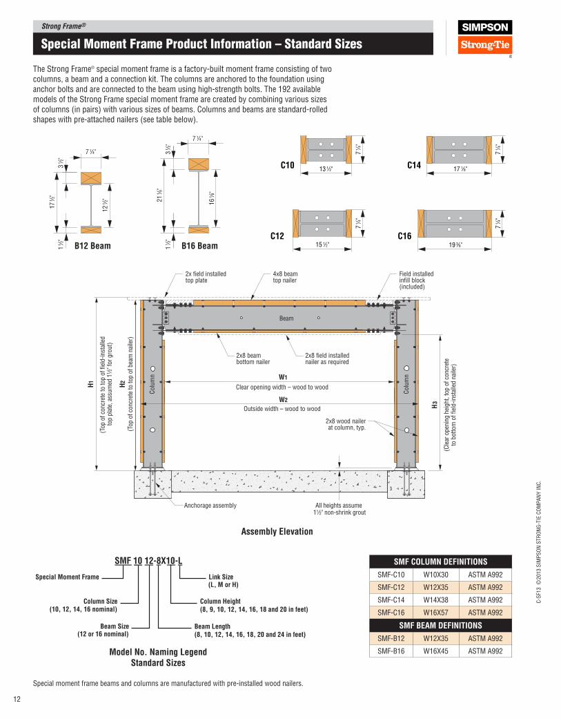
The Strong Frame® special moment frame is a factory-built moment frame consisting of two columns, a beam and a connection kit. The columns are anchored to the foundation using anchor bolts and are connected to the beam using high-strength bolts. The 192 available models of the Strong Frame special moment frame are created by combining various sizes of columns (in pairs) with various sizes of beams. Columns and beams are standard-rolled shapes with pre-attached nailers (see table below).
Special moment Frame Product Information – Standard Sizes
Special moment frame beams and columns are manufactured with pre-installed wood nailers.
SMF 10 12‑8X10‑l
Special Moment Frame
Column Size(10, 12, 14, 16 nominal)
Beam Size(12 or 16 nominal)
link Size(l, M or H)
Column Height(8, 9, 10, 12, 14, 16, 18 and 20 in feet)
Beam length(8, 10, 12, 14, 16, 18, 20 and 24 in feet)
Model No. Naming legendStandard Sizes
SMF COlUMN DEFINITIONS
SMF-C10 W10X30 ASTM A992
SMF-C12 W12X35 ASTM A992
SMF-C14 W14X38 ASTM A992
SMF-C16 W16X57 ASTM A992
SMF BEAM DEFINITIONS
SMF-B12 W12X35 ASTM A992
SMF-B16 W16X45 ASTM A992
Strong Frame®C
-SF1
3 ©
2013 S
IMP
SO
N S
TR
ON
G-T
IE C
OM
PA
NY
IN
C.
13
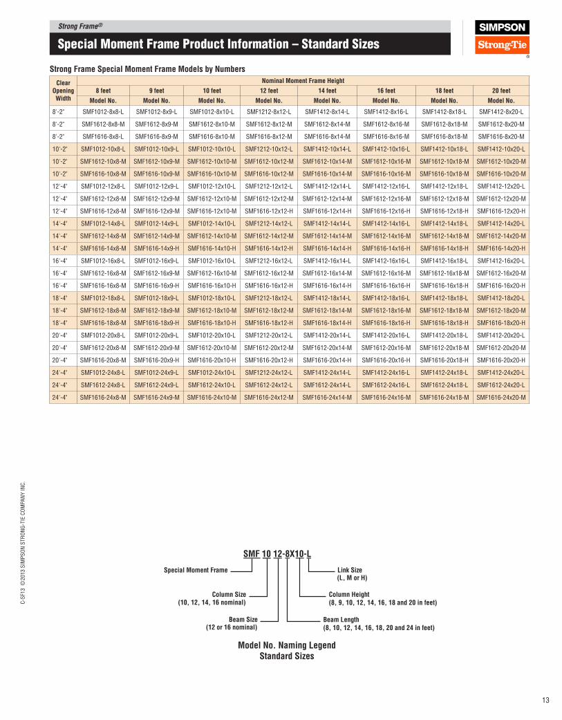
Strong Frame Special Moment Frame Models by Numbers
Clear Opening Width
Nominal Moment Frame Height
8 feet 9 feet 10 feet 12 feet 14 feet 16 feet 18 feet 20 feet
Model No. Model No. Model No. Model No. Model No. Model No. Model No. Model No.
8'-2" SMF1012-8x8-L SMF1012-8x9-L SMF1012-8x10-L SMF1212-8x12-L SMF1412-8x14-L SMF1412-8x16-L SMF1412-8x18-L SMF1412-8x20-L
8'-2" SMF1612-8x8-M SMF1612-8x9-M SMF1612-8x10-M SMF1612-8x12-M SMF1612-8x14-M SMF1612-8x16-M SMF1612-8x18-M SMF1612-8x20-M
8'-2" SMF1616-8x8-L SMF1616-8x9-M SMF1616-8x10-M SMF1616-8x12-M SMF1616-8x14-M SMF1616-8x16-M SMF1616-8x18-M SMF1616-8x20-M
10'-2" SMF1012-10x8-L SMF1012-10x9-L SMF1012-10x10-L SMF1212-10x12-L SMF1412-10x14-L SMF1412-10x16-L SMF1412-10x18-L SMF1412-10x20-L
10'-2" SMF1612-10x8-M SMF1612-10x9-M SMF1612-10x10-M SMF1612-10x12-M SMF1612-10x14-M SMF1612-10x16-M SMF1612-10x18-M SMF1612-10x20-M
10'-2" SMF1616-10x8-M SMF1616-10x9-M SMF1616-10x10-M SMF1616-10x12-M SMF1616-10x14-M SMF1616-10x16-M SMF1616-10x18-M SMF1616-10x20-M
12'-4" SMF1012-12x8-L SMF1012-12x9-L SMF1012-12x10-L SMF1212-12x12-L SMF1412-12x14-L SMF1412-12x16-L SMF1412-12x18-L SMF1412-12x20-L
12'-4" SMF1612-12x8-M SMF1612-12x9-M SMF1612-12x10-M SMF1612-12x12-M SMF1612-12x14-M SMF1612-12x16-M SMF1612-12x18-M SMF1612-12x20-M
12'-4" SMF1616-12x8-M SMF1616-12x9-M SMF1616-12x10-M SMF1616-12x12-H SMF1616-12x14-H SMF1616-12x16-H SMF1616-12x18-H SMF1616-12x20-H
14'-4" SMF1012-14x8-L SMF1012-14x9-L SMF1012-14x10-L SMF1212-14x12-L SMF1412-14x14-L SMF1412-14x16-L SMF1412-14x18-L SMF1412-14x20-L
14'-4" SMF1612-14x8-M SMF1612-14x9-M SMF1612-14x10-M SMF1612-14x12-M SMF1612-14x14-M SMF1612-14x16-M SMF1612-14x18-M SMF1612-14x20-M
14'-4" SMF1616-14x8-M SMF1616-14x9-H SMF1616-14x10-H SMF1616-14x12-H SMF1616-14x14-H SMF1616-14x16-H SMF1616-14x18-H SMF1616-14x20-H
16'-4" SMF1012-16x8-L SMF1012-16x9-L SMF1012-16x10-L SMF1212-16x12-L SMF1412-16x14-L SMF1412-16x16-L SMF1412-16x18-L SMF1412-16x20-L
16'-4" SMF1612-16x8-M SMF1612-16x9-M SMF1612-16x10-M SMF1612-16x12-M SMF1612-16x14-M SMF1612-16x16-M SMF1612-16x18-M SMF1612-16x20-M
16'-4" SMF1616-16x8-M SMF1616-16x9-H SMF1616-16x10-H SMF1616-16x12-H SMF1616-16x14-H SMF1616-16x16-H SMF1616-16x18-H SMF1616-16x20-H
18'-4" SMF1012-18x8-L SMF1012-18x9-L SMF1012-18x10-L SMF1212-18x12-L SMF1412-18x14-L SMF1412-18x16-L SMF1412-18x18-L SMF1412-18x20-L
18'-4" SMF1612-18x8-M SMF1612-18x9-M SMF1612-18x10-M SMF1612-18x12-M SMF1612-18x14-M SMF1612-18x16-M SMF1612-18x18-M SMF1612-18x20-M
18'-4" SMF1616-18x8-M SMF1616-18x9-H SMF1616-18x10-H SMF1616-18x12-H SMF1616-18x14-H SMF1616-18x16-H SMF1616-18x18-H SMF1616-18x20-H
20'-4" SMF1012-20x8-L SMF1012-20x9-L SMF1012-20x10-L SMF1212-20x12-L SMF1412-20x14-L SMF1412-20x16-L SMF1412-20x18-L SMF1412-20x20-L
20'-4" SMF1612-20x8-M SMF1612-20x9-M SMF1612-20x10-M SMF1612-20x12-M SMF1612-20x14-M SMF1612-20x16-M SMF1612-20x18-M SMF1612-20x20-M
20'-4" SMF1616-20x8-M SMF1616-20x9-H SMF1616-20x10-H SMF1616-20x12-H SMF1616-20x14-H SMF1616-20x16-H SMF1616-20x18-H SMF1616-20x20-H
24'-4" SMF1012-24x8-L SMF1012-24x9-L SMF1012-24x10-L SMF1212-24x12-L SMF1412-24x14-L SMF1412-24x16-L SMF1412-24x18-L SMF1412-24x20-L
24'-4" SMF1612-24x8-L SMF1612-24x9-L SMF1612-24x10-L SMF1612-24x12-L SMF1612-24x14-L SMF1612-24x16-L SMF1612-24x18-L SMF1612-24x20-L
24'-4" SMF1616-24x8-M SMF1616-24x9-M SMF1616-24x10-M SMF1616-24x12-M SMF1616-24x14-M SMF1616-24x16-M SMF1616-24x18-M SMF1616-24x20-M
Special moment Frame Product Information – Standard Sizes
SMF 10 12‑8X10‑l
Special Moment Frame
Column Size(10, 12, 14, 16 nominal)
Beam Size(12 or 16 nominal)
link Size(l, M or H)
Column Height(8, 9, 10, 12, 14, 16, 18 and 20 in feet)
Beam length(8, 10, 12, 14, 16, 18, 20 and 24 in feet)
Model No. Naming legendStandard Sizes
Strong Frame®
C-S
F13 ©
2013 S
IMP
SO
N S
TR
ON
G-T
IE C
OM
PA
NY
IN
C.
14
Special moment Frame Product Information – Custom Sizes
C10 13 1∕2"
7 1∕4"
C12
7 1∕4"
15 1∕2"
7 1∕4"
C14
7 1∕4"
C16
17 1∕8"
19 3∕8"
2x field installedtop plate
4x8 beamtop nailer
Field installed infill block(included)
2x8 beambottom nailer
Anchorage assembly
Clear opening width – wood to wood
2x8 field installednailer as required
2x8 wood nailerat column, typ.
Beam
Colu
mn
Colu
mnW1
H1
(Top
of
conc
rete
to
top
of fi
eld-
inst
alle
d
top
plat
e, a
ssum
ed 1
1⁄2"
for
gro
ut)
All heights assume 11⁄2" non-shrink grout
H3
(Cle
ar o
peni
ng h
eigh
t, t
op o
f co
ncre
teto
bot
tom
of
field
-ins
talle
d na
iler)
W2
H2
(Top
of
conc
rete
to
top
of b
eam
nai
ler)
Outside width – wood to wood
B12 Beam1 1 ∕2
"3
1 ∕2"
17
1 ∕2"
12
1 ∕2"
7 1∕4"
1 1 ∕2
"
B16 Beam
16
1∕8"
3 1 ∕2
"
21
1∕8"
7 1∕4"
Assembly Elevation
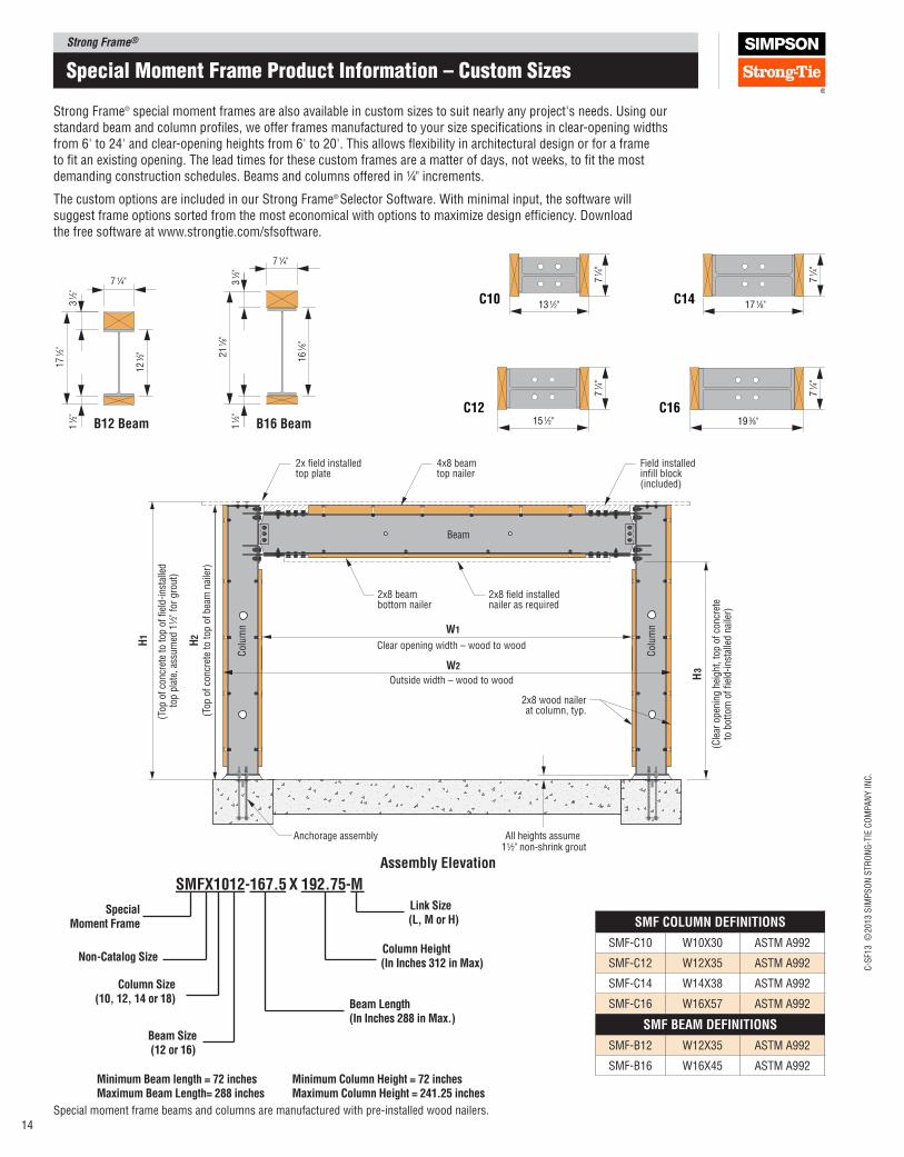
Strong Frame® special moment frames are also available in custom sizes to suit nearly any project's needs. Using our standard beam and column proiles, we offer frames manufactured to your size speciications in clear‑opening widths from 6' to 24' and clear‑opening heights from 6' to 20'. This allows lexibility in architectural design or for a frame to it an existing opening. The lead times for these custom frames are a matter of days, not weeks, to it the most demanding construction schedules. Beams and columns offered in 1⁄4" increments.
The custom options are included in our Strong Frame® Selector Software. With minimal input, the software will suggest frame options sorted from the most economical with options to maximize design eficiency. Download the free software at www.strongtie.com/sfsoftware.
Special moment frame beams and columns are manufactured with pre‑installed wood nailers.
SMFX1012‑167.5 X 192.75‑M
Special Moment Frame
Non‑Catalog Size
Column Size(10, 12, 14 or 18)
Beam Size(12 or 16)
link Size(l, M or H)
Column Height(In Inches 312 in Max)
Beam length(In Inches 288 in Max.)
Minimum Beam length = 72 inchesMaximum Beam length= 288 inches
Minimum Column Height = 72 inchesMaximum Column Height = 241.25 inches
SMF COlUMN DEFINITIONS
SMF‑C10 W10X30 ASTM A992
SMF‑C12 W12X35 ASTM A992
SMF‑C14 W14X38 ASTM A992
SMF‑C16 W16X57 ASTM A992
SMF BEAM DEFINITIONS
SMF‑B12 W12X35 ASTM A992
SMF‑B16 W16X45 ASTM A992
Strong Frame®C
-SF1
3 ©
2013 S
IMP
SO
N S
TR
ON
G-T
IE C
OM
PA
NY
IN
C.
15
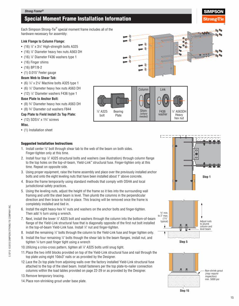
Suggested Installation Instructions
1. Install center 7⁄8" bolt through shear tab to the web of the beam on both sides. Finger-tighten only at this time.
2. Install four top 7⁄8" A325 structural bolts and washers (see illustration) through column lange to the top holes on the top-of-beam, Yield-Link™ structural fuse. Finger-tighten only at this time. Repeat on opposite side.
3. Using proper equipment, raise the frame assembly and place over the previously installed anchor bolts and onto the eight leveling nuts that have been installed about 1" above concrete.
4. Brace the frame temporarily using standard methods that comply with OSHA and local jurisdictional safety practices.
5. Using the leveling nuts, adjust the height of the frame so it ties into the surrounding wall framing and until the steel beam is level. Then plumb the columns in the perpendicular direction and then brace to hold in place. This bracing will be removed once the frame is completely installed and tied in.
6. Install the eight heavy-hex 3⁄4" nuts and washers on the anchor bolts and inger‑tighten. Then add ½ turn using a wrench.
7. Next, install the lower 7⁄8" A325 bolt and washers through the column into the bottom‑of‑beam lange of the Yield‑Link structural fuse that is diagonally opposite of the irst nut bolt installed in the top‑of‑beam Yield‑Link fuse. Install 7⁄8" nut and inger‑tighten.
8. Install the remaining 7⁄8" bolts through the column to the Yield‑Link fuse and inger tighten only.
9. Install the four remaining 7⁄8" bolts though the shear tab to the beam langes, install nut, and tighten ¼ turn past inger tight using a wrench
10. Utilizing a criss‑cross pattern, tighten all 7⁄8" A325 bolts until snug tight.
11. Place the two inill blocks provided on top of the Yield‑Link structural fuse and nail through the top plate using eight 10dx3" nails or as provided by the Designer.
12. Lace the 2x top plate from adjoining walls over the factory installed Yield‑Link structural fuse attached to the top of the steel beam. Install fasteners per the top plate‑to‑nailer connection columns within the load tables provided on page 22‑29 or as provided by the Designer.
13. Remove temporary bracing.
14. Place non‑shrinking grout under base plate.
Each Simpson Strong‑Tie® special moment frame includes all of the
hardware necessary for assembly:
Non-shrink grout(may require inspection)min. 5000 psi
Step 15
Adjust nuts to plumb column and level beam
¾" min.to 2" max.
(1½" typical)
Step 5
link Flange to Column Flange:
• (16) 7⁄8" x 31⁄4" High‑strength bolts A325
• (16) 7⁄8" Diameter heavy hex nuts A563 DH
• (16) 7⁄8" Diameter F436 washers type 1
• (16) Finger shims
• (16) BP7/8‑2
• (1) 0.015" Feeler gauge
Beam Web to Shear Tab:
• (6) 7⁄8" x 21⁄8" Machine bolts A325 type 1
• (6) 7⁄8" Diameter heavy hex nuts A563 DH
• (12) 7⁄8" Diameter washers F436 type 1
Base plate to Anchor Bolt:
• (8) ¾" Diameter heavy hex nuts A563 DH
• (8) ¾" Diameter cut washers F844
Cap plate to Field Install 2x Top plate:
• (12) SDS1⁄4" x 13⁄4" screws
Misc.
• (1) Installation sheet
7∕8" A563DHHeavy
hex nut
BearingPlate
Shim(whereneeded)
7∕8" A325bolt
F436 washer
Column Link
Step 1
Special moment Frame Installation Information
Strong Frame®
C-S
F13 ©
2013 S
IMP
SO
N S
TR
ON
G-T
IE C
OM
PA
NY
IN
C.
16
Frame Selection
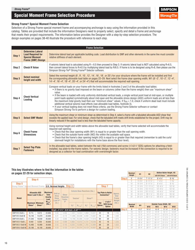
Step 1
Determine lateral load Required for Special Moment Frame (SMF) Design
Determine lateral load per applicable building code. Load distribution to SMF and other elements in the same line must consider relative stiffness of each element.
Step 2 Check R ValueIf seismic lateral load is calculated using R = 6.5 then proceed to Step 3. If seismic lateral load is NOT calculated using R=6.5, then convert lateral forces to R=6.5 by multiplying lateral load by R/6.5. If frame is to be designed using R=8, then please use the Simpson Strong‑Tie® Strong Frame® Selector software.
Step 3Select nominal height and width
Select the nominal height (8', 9', 10', 12', 14', 16', 18', or 20') for your structure where the frame will be installed and ind the corresponding allowable load table on pages 22–29. Next select the frame clear opening width, W1 (8'–2", 10'–2", 12'–4", 14'–4", 16'–4", 18'–4", 20'–4", or 24'–4") that will accommodate the required wall opening.
Step 4Check Vertical loading
Compare vertical loads on your frame with the limits listed in footnotes 2 and 3 of the allowable load tables:• If there is no gravity load imposed on the beam or columns (other than the frame weight) then use “maximum shear”
value.• If the beam is loaded with only uniformly distributed vertical loads, a single vertical point load at mid‑span, or multiple
point loads applied symmetrically about mid‑span and the allowable stress design (ASD) uniform loads are all less than the maximum total gravity load then use “minimum shear” values. If SDS > 1.0, check if uniform dead load must include additional vertical seismic load effects (see allowable load tables, footnote 3).
• If your vertical loading does not meet these criteria, use the Strong Frame Selector software or contact Simpson Strong‑Tie to perform a design for custom loading.
Step 5 Select SMF ModelUsing the maximum shear or minimum shear as determined in Step 4, select a frame with a tabulated allowable ASD shear that exceeds the applied load. For wind design, check that the tabulated drift meets drift limits established for the project. Drift may be linearly reduced if the applied load is less than the tabulated frame capacity.
Step 6Check Frame Dimensions
Using nominal height and width tables above the allowable load tables, verify that frame selected will accommodate the required wall opening:
• Check that the clear opening width (W1) is equal to or greater than the wall opening width.• Check that the outside frame width (W2) its within the available wall space.• Check that the frame’s clear opening height (H3) is equal to or greater than that required (remember to add the curb/
stemwall height for installations with the frame base above the loor level).
Step 7Select Top plate Fasteners
In the allowable load tables, select between the nail (16d commons) and screw (1⁄4"x3 1⁄2" SDS) options for attaching a ield‑installed, top plate‑to‑the‑frame nailers. For seismic design, fasteners must be increased if the connection is required to be designed as a collector for load combination with overstrength factor.
Strong Frame® Special Moment Frame Selection
Special moment Frame Selection Procedure
Selection of a Strong Frame special moment frame and accompanying anchorage is easy using the information provided in this catalog. Tables are provided that include the information Designers need to properly select, specify and detail a frame and anchorage that meets their project requirements. The information below provides the Designer with a step‑by‑step selection procedure. The design examples on pages 38‑40 illustrate the procedure with reference to each step.
This key illustrates where to ind the information in the tables on pages 22‑29 for selection steps.
Step 6
Nominal Height
H1 H2Bottom Nailer Height, H3
with W12 Beam with W16 Beam
8' 8'‑0 ¾" 7'‑11 ¼" 6'‑4 ¼" 6'‑5⁄8"9' 9'‑0 ¾" 8'‑11 ¼" 7'‑4 ¼" 7'‑5⁄8"
10' 10'‑0 ¾" 9'‑11 ¼" 8'‑4 ¼" 8'‑5⁄8"12' 12'‑0 ¾" 11'‑11 ¼" 10'‑4 ¼" 10'‑5⁄8"14' 14'‑0 ¾" 13'‑11 ¼" 12'‑4 ¼" 12'‑5⁄8"16' 16'‑0 ¾" 15'‑11 ¼" 14'‑4 ¼" 14'‑5⁄8"18' 18'‑2 ¾" 18'‑1 ¼" 16'‑4 ¼" 16'‑5⁄8"20' 20'‑2 ¾" 20'‑1 ¼" 18'‑4 ¼" 18'‑5⁄8"
Step 6
Nominal Width
W1Outside Frame Width, W2
W10 W12 W14 W18
8' 8'‑2" 10'‑5" 10'‑9" 11'‑¼" 11'‑8"
10' 10'‑2" 12'‑5" 12'‑9" 13'‑¼" 13'‑8"
12' 12'‑4" 14'‑7" 14'‑11" 15'‑2 ¼" 15'‑10"
14' 14'‑4" 16'‑7" 16'‑11" 17'‑2 ¼" 17'‑10"
16' 16'‑4" 18'‑7" 18'‑11" 19'‑2 ¼" 19'‑10"
18' 18'‑4" 20'‑7" 20'‑11" 21'‑2 ¼" 21'‑10"
20' 20'‑4" 22'‑7" 22'‑11" 23'‑2 ¼" 23'‑10"
24' 24'‑4" 26'‑7" 26'‑11" 27'‑2 ¼" 27'‑10"
Strong Frame® Special Moment Frame – 8 ft. Nominal Heights
Model
Allowable ASD Shear load V (lbs.) 1
Maximum Total
Gravity load, Wmax
3 (lbs.)
Drift at Allow Shear
load V10 (in.)
Shear Reaction Factor,
X6
Column Base Reactions (lbs.)Top plate to Nailer
Connection 6Approx.
Total Frame Weight (lbs.)
Tension7 Shear6,8
Maximum Shear 2
Minimum Shear 3
16d Option
¼"x3½" SDS Screw
OptionRT
4 RT_max5 RV
4 RV_max5
Height = 8'‑0 ¾", Drift limit = 0.42" 9,10
SMF1012‑8x8‑L 9,715 9,575 22,665 0.42 0.064 7,449 16,934 4,868 10,847 44 18 1,145
SMF1812‑8x8‑M 16,140 14,070 22,665 0.41 0.112 11,596 20,038 8,092 13,507 72 30 1,540
SMF1816‑8x8‑L 21,040 19,640 26,665 0.34 0.093 14,798 25,586 10,561 17,618 94 39 1,575
SMF1012‑10x8‑L 9,440 9,250 30,665 0.42 0.088 5,956 13,512 4,731 10,546 42 18 1,235
SMF1812‑10x8‑M 15,480 10,990 30,665 0.42 0.143 9,255 15,956 7,761 12,984 69 29 1,625
SMF1816‑10x8‑M 20,180 16,100 38,665 0.33 0.123 11,811 20,374 10,131 16,937 90 38 1,715
Step 5Step 3 Step 7
Step 4
Strong Frame®C
-SF1
3 ©
2013 S
IMP
SO
N S
TR
ON
G-T
IE C
OM
PA
NY
IN
C.
17
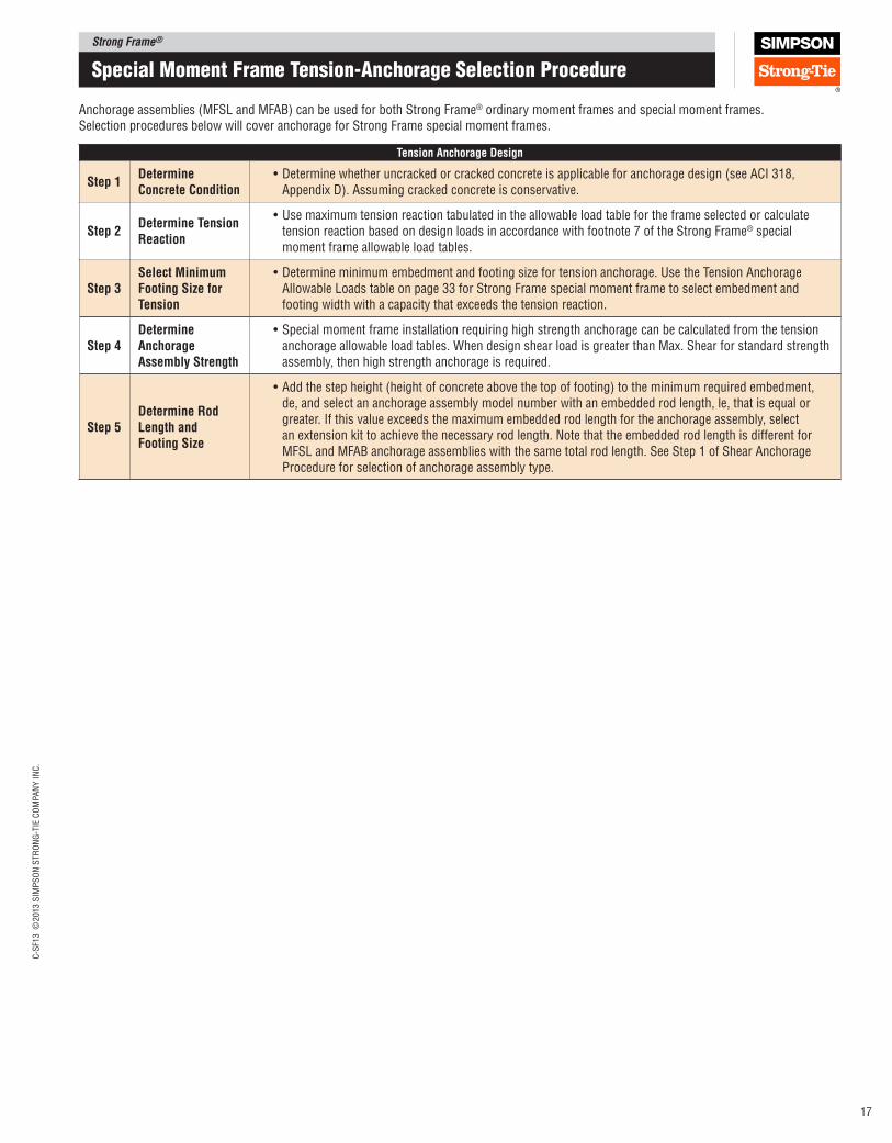
Tension Anchorage Design
Step 1Determine Concrete Condition
•Determine whether uncracked or cracked concrete is applicable for anchorage design (see ACI 318, Appendix D). Assuming cracked concrete is conservative.
Step 2Determine Tension Reaction
•Use maximum tension reaction tabulated in the allowable load table for the frame selected or calculate tension reaction based on design loads in accordance with footnote 7 of the Strong Frame® special moment frame allowable load tables.
Step 3Select Minimum Footing Size for Tension
•Determine minimum embedment and footing size for tension anchorage. Use the Tension Anchorage Allowable Loads table on page 33 for Strong Frame special moment frame to select embedment and footing width with a capacity that exceeds the tension reaction.
Step 4Determine Anchorage Assembly Strength
•Special moment frame installation requiring high strength anchorage can be calculated from the tension anchorage allowable load tables. When design shear load is greater than Max. Shear for standard strength assembly, then high strength anchorage is required.
Step 5Determine Rod length and Footing Size
•Add the step height (height of concrete above the top of footing) to the minimum required embedment, de, and select an anchorage assembly model number with an embedded rod length, le, that is equal or greater. If this value exceeds the maximum embedded rod length for the anchorage assembly, select an extension kit to achieve the necessary rod length. Note that the embedded rod length is different for MFSL and MFAB anchorage assemblies with the same total rod length. See Step 1 of Shear Anchorage Procedure for selection of anchorage assembly type.
Special moment Frame tension-anchorage Selection Procedure
Anchorage assemblies (MFSL and MFAB) can be used for both Strong Frame® ordinary moment frames and special moment frames. Selection procedures below will cover anchorage for Strong Frame special moment frames.
Strong Frame®
C-S
F13 ©
2013 S
IMP
SO
N S
TR
ON
G-T
IE C
OM
PA
NY
IN
C.
18
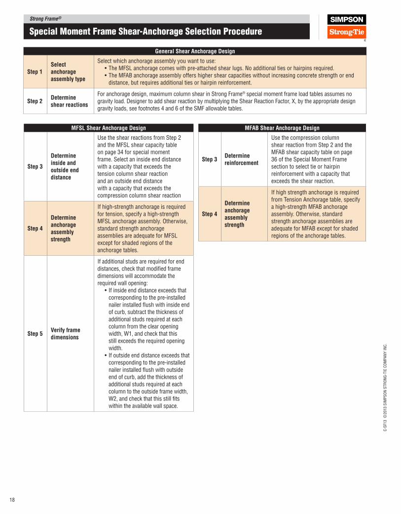
Special moment Frame Shear-anchorage Selection Procedure
General Shear Anchorage Design
Step 1Select anchorage assembly type
Select which anchorage assembly you want to use:•The MFSL anchorage comes with pre-attached shear lugs. No additional ties or hairpins required.•The MFAB anchorage assembly offers higher shear capacities without increasing concrete strength or end
distance, but requires additional ties or hairpin reinforcement.
Step 2Determine shear reactions
For anchorage design, maximum column shear in Strong Frame® special moment frame load tables assumes no gravity load. Designer to add shear reaction by multiplying the Shear Reaction Factor, X, by the appropriate design gravity loads, see footnotes 4 and 6 of the SMF allowable tables.
MFSl Shear Anchorage Design
Step 3
Determine inside and outside end distance
Use the shear reactions from Step 2 and the MFSL shear capacity table on page 34 for special moment frame. Select an inside end distance with a capacity that exceeds the tension column shear reaction and an outside end distance with a capacity that exceeds the compression column shear reaction
Step 4
Determine anchorage assembly strength
If high‑strength anchorage is required for tension, specify a high‑strength MFSL anchorage assembly. Otherwise, standard strength anchorage assemblies are adequate for MFSL except for shaded regions of the anchorage tables.
Step 5Verify frame dimensions
If additional studs are required for end distances, check that modiied frame dimensions will accommodate the required wall opening:
• If inside end distance exceeds that corresponding to the pre‑installed nailer installed lush with inside end of curb, subtract the thickness of additional studs required at each column from the clear opening width, W1, and check that this still exceeds the required opening width.
• If outside end distance exceeds that corresponding to the pre‑installed nailer installed lush with outside end of curb, add the thickness of additional studs required at each column to the outside frame width, W2, and check that this still its within the available wall space.
MFAB Shear Anchorage Design
Step 3Determine reinforcement
Use the compression column shear reaction from Step 2 and the MFAB shear capacity table on page 36 of the Special Moment Frame section to select tie or hairpin reinforcement with a capacity that exceeds the shear reaction.
Step 4
Determine anchorage assembly strength
If high strength anchorage is required from Tension Anchorage table, specify a high‑strength MFAB anchorage assembly. Otherwise, standard strength anchorage assemblies are adequate for MFAB except for shaded regions of the anchorage tables.
Strong Frame®C
-SF1
3 ©
2013 S
IMP
SO
N S
TR
ON
G-T
IE C
OM
PA
NY
IN
C.
19
retrofit applications
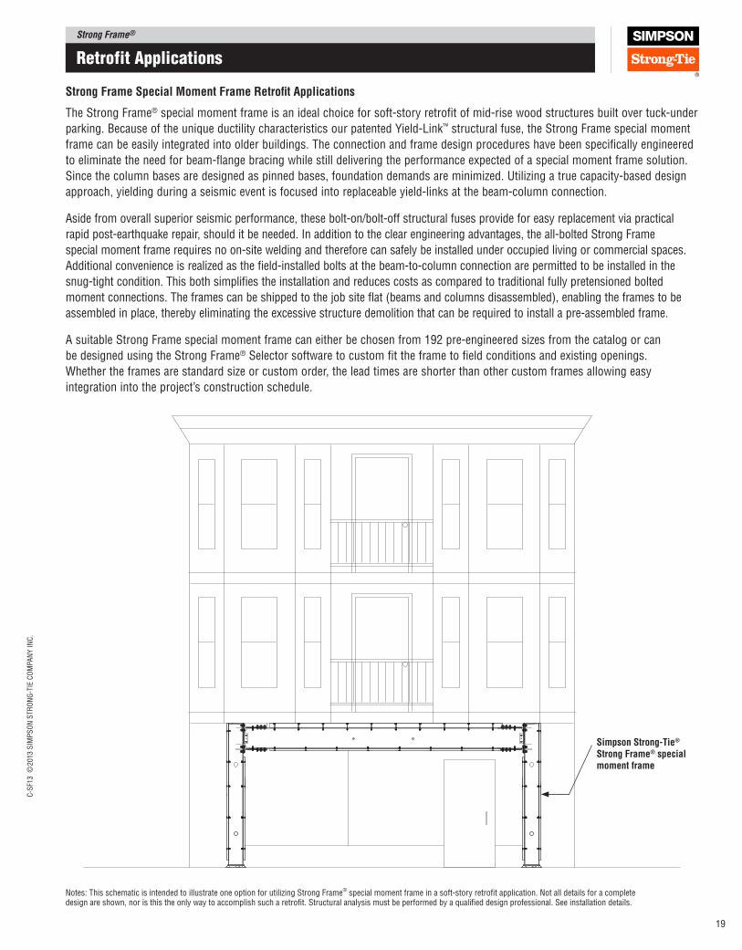
Strong Frame Special Moment Frame Retroit Applications
The Strong Frame® special moment frame is an ideal choice for soft-story retroit of mid‑rise wood structures built over tuck‑under
parking. Because of the unique ductility characteristics our patented Yield‑Link™ structural fuse, the Strong Frame special moment
frame can be easily integrated into older buildings. The connection and frame design procedures have been speciically engineered
to eliminate the need for beam‑lange bracing while still delivering the performance expected of a special moment frame solution.
Since the column bases are designed as pinned bases, foundation demands are minimized. Utilizing a true capacity‑based design
approach, yielding during a seismic event is focused into replaceable yield‑links at the beam‑column connection.
Aside from overall superior seismic performance, these bolt‑on/bolt‑off structural fuses provide for easy replacement via practical
rapid post‑earthquake repair, should it be needed. In addition to the clear engineering advantages, the all‑bolted Strong Frame
special moment frame requires no on‑site welding and therefore can safely be installed under occupied living or commercial spaces.
Additional convenience is realized as the ield‑installed bolts at the beam‑to‑column connection are permitted to be installed in the
snug‑tight condition. This both simpliies the installation and reduces costs as compared to traditional fully pretensioned bolted
moment connections. The frames can be shipped to the job site lat (beams and columns disassembled), enabling the frames to be
assembled in place, thereby eliminating the excessive structure demolition that can be required to install a pre‑assembled frame.
A suitable Strong Frame special moment frame can either be chosen from 192 pre‑engineered sizes from the catalog or can
be designed using the Strong Frame® Selector software to custom it the frame to ield conditions and existing openings.
Whether the frames are standard size or custom order, the lead times are shorter than other custom frames allowing easy
integration into the project’s construction schedule.
Notes: This schematic is intended to illustrate one option for utilizing Strong Frame® special moment frame in a soft‑story retroit application. Not all details for a complete design are shown, nor is this the only way to accomplish such a retroit. Structural analysis must be performed by a qualiied design professional. See installation details.
Simpson Strong‑Tie® Strong Frame® special moment frame
Strong Frame®
C-S
F13 ©
2013 S
IMP
SO
N S
TR
ON
G-T
IE C
OM
PA
NY
IN
C.
20
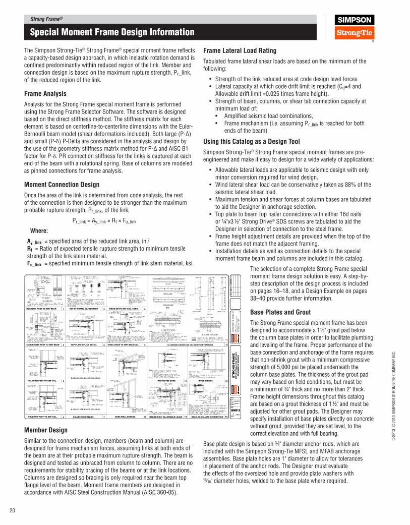
The Simpson Strong‑Tie® Strong Frame® special moment frame relects a capacity‑based design approach, in which inelastic rotation demand is conined predominantly within reduced region of the link. Member and connection design is based on the maximum rupture strength, Pr_link, of the reduced region of the link.
Frame Analysis
Analysis for the Strong Frame special moment frame is performed using the Strong Frame Selector Software. The software is designed based on the direct stiffness method. The stiffness matrix for each element is based on centerline‑to‑centerline dimensions with the Euler‑Bernoulli beam model (shear deformations included). Both large (P‑Δ) and small (P‑δ) P‑Delta are considered in the analysis and design by the use of the geometry stiffness matrix method for P‑Δ and AISC B1 factor for P‑δ. PR connection stiffness for the links is captured at each end of the beam with a rotational spring. Base of columns are modeled as pinned connections for frame analysis.
Moment Connection Design
Once the area of the link is determined from code analysis, the rest of the connection is then designed to be stronger than the maximum probable rupture strength, Pr_link, of the link,
Pr_link = Ay_link × Rt × Fu_link
Where:
Ay_link = speciied area of the reduced link area, in.2 Rt = Ratio of expected tensile rupture strength to minimum tensile strength of the link stem material.Fu_link = speciied minimum tensile strength of link stem material, ksi.
Member Design
Similar to the connection design, members (beam and column) are designed for frame mechanism forces, assuming links at both ends of the beam are at their probable maximum rupture strength. The beam is designed and tested as unbraced from column to column. There are no requirements for stability bracing of the beams or at the link locations. Columns are designed so bracing is only required near the beam top lange level of the beam. Moment frame members are designed in accordance with AISC Steel Construction Manual (AISC 360‑05).
Special moment Frame Design Information
Frame lateral load Rating
Tabulated frame lateral shear loads are based on the minimum of the following:
• Strength of the link reduced area at code design level forces• Lateral capacity at which code drift limit is reached (Cd=4 and
Allowable drift limit =0.025 times frame height).• Strength of beam, columns, or shear tab connection capacity at
minimum load of:• Ampliied seismic load combinations,• Frame mechanism (i.e. assuming Pr_link is reached for both
ends of the beam)
Using this Catalog as a Design Tool
Simpson Strong‑Tie® Strong Frame special moment frames are pre‑engineered and make it easy to design for a wide variety of applications:
• Allowable lateral loads are applicable to seismic design with only minor conversion required for wind design.
• Wind lateral shear load can be conservatively taken as 88% of the seismic lateral shear load.
• Maximum tension and shear forces at column bases are tabulated to aid the Designer in anchorage selection.
• Top plate to beam top nailer connections with either 16d nails or ¼"x3 ½" Strong Drive® SDS screws are tabulated to aid the Designer in selection of connection to the steel frame.
• Frame height adjustment details are provided when the top of the frame does not match the adjacent framing.
• Installation details as well as connection details to the special moment frame beam and columns are included in this catalog.
The selection of a complete Strong Frame special moment frame design solution is easy. A step‑by‑step description of the design process is included on pages 16–18, and a Design Example on pages 38–40 provide further information.
Base plates and Grout
The Strong Frame special moment frame has been designed to accommodate a 1½" grout pad below the column base plates in order to facilitate plumbing and leveling of the frame. Proper performance of the base connection and anchorage of the frame requires that non‑shrink grout with a minimum compressive strength of 5,000 psi be placed underneath the column base plates. The thickness of the grout pad may vary based on ield conditions, but must be a minimum of ¾" thick and no more than 2" thick. Frame height dimensions throughout this catalog are based on a grout thickness of 1 ½" and must be adjusted for other grout pads. The Designer may specify installation of base plates directly on concrete without grout, provided they are set level, to the correct elevation and with full bearing.
Base plate design is based on ¾" diameter anchor rods, which are included with the Simpson Strong‑Tie MFSL and MFAB anchorage assemblies. Base plate holes are 1" diameter to allow for tolerances in placement of the anchor rods. The Designer must evaluate the effects of the oversized hole and provide plate washers with 13⁄16" diameter holes, welded to the base plate where required.
1
2
HOLDOWN POST TO SMF BEAM
6x HOLDOWN POST TO SMF BEAM
3HOLDOWN POST TO SMF COL.
4HOLDOWN POST TO SMF COL.
TOP OF FRAME ADJUSTMENT 5
6TOP PLATE SPLICE DETAIL
7COLLECTOR DETAILS
WOOD BM TO SMF COL. CONN. 8
9STEEL BEAM TO SMF BEAM/COL.
10RAKE WALL DETAILS
13WOOD INFILLS
BEAM-TO-COLUMN CONNECTION 15NAILER BOLT ALLOWABLE LOADS 14
11PROTECTED ZONE
ALLOWABLE BEAM AND COLUMN PENETRATIONS 12
ST
RO
NG
-FR
AM
ES
MF
IN
ST
AL
LA
TIO
N D
ET
AIL
S
EN
GIN
EE
RE
D D
ES
IG
NS
SMF3

Strong Frame®C
-SF1
3 ©
2013 S
IMP
SO
N S
TR
ON
G-T
IE C
OM
PA
NY
IN
C.
21
Special moment Frame anchorage Design Information
Anchorage DesignSimpson Strong‑Tie offers pre‑engineered anchorage solutions to simplify the design process. Pages 33‑36 provide solutions for both tension and shear anchorage for the Strong Frame® special moment frame models.
• Tension Anchorage Anchorage solutions for tension loads provide minimum anchor rod embedment and footing size. The tension anchorage table provides solutions for both wind and seismic loads. All that is needed for sizing the footing and embedment depth for anchorages is to select a solution with a capacity that exceeds the tension reaction.
• MFSl and MFAB Anchorage Assemblies Simpson Strong‑Tie offers two different pre‑assembled anchorage assemblies. The MFSL anchorage assembly comes with pre‑ attached shear lug, so no ield bent ties or hairpins are required. The MFAB provides higher shear capacities but requires additional ties or hair pins.
• Flexible Anchorage Solutions After selecting a frame, determine the required anchorage is using the maximum reactions tabulated in the allowable‑load tables to ind the required anchorage with a capacity that exceeds the reactions. For an even more economical solution, select the anchorage solution by using reactions calculated for project‑speciic loads as described in the footnotes of the allowable‑load tables.
• Anchorage Design Notes The steel‑strength calculations for anchor shear and anchor tension are per ACI 318‑08. Tension and shear anchorage are designed as follows:
Element Code Section
Anchor rod strength in tension ACI 318, D.5.1
Anchor breakout strength in tension ACI 318, D.5.2
Anchor pullout strength in tension ACI 318, D.5.3
Anchor rod strength in shear ACI 318, D.6.1
Embedded plate bending strength AISC Chapter F
Concrete shear strength – shear lug AISC Design Guide 1
Concrete shear strength – tied anchorage ACI 318, chapter 10
Anchorage Designs are based on LRFD loads. For designs under the 2012 and 2009 IBC, tension anchorage for seismic loads complies with ACI 318 Appendix D; design includes application of 0.75 factor on concrete strengths (Section D.3.3.3) and the strength is governed by a ductile steel element (Section D.3.3.4) or is based on 2.5 x factored loads (Section D.3.3.5 with modiications contained in 2012 and 2009 IBC section 1908.1.16). For designs under the 2009 IBC, tension anchorage for seismic loads complies with ACI 318‑08 Appendix D; design includes application of 0.75 factor on concrete strengths (Section D.3.3.3), and strength is governed by a ductile steel element (Section D.3.3.4) or is based on 2.5 x factored loads (Section D.3.3.6).
Anchorage designs are based on embedment for tension into the foundation, while shear design is based on resistance within the curb or slab. For other conditions, the Designer must consider the interaction of tension and shear concrete failure surfaces.
InspectionsInspection requirements for the Strong Frame moment frames are no different than for any other steel moment frame. The Designer must designate what inspections are required in accordance with the local code, based on building occupancy, concrete strength, requirements of the local building oficial, and other considerations.
Because the Strong Frame moment frame includes pre‑manufactured components, all welding inspections are completed during the manufacturing process. Welding of the frame members is performed on the premises of a fabricator registered and approved in accordance with the requirements of IBC Section 1704.2.2 for fabricator approval, so special inspections contained in IBC Section 1704 are not required. Special inspection for seismic resistance required by IBC Section 1707 for welding is completed during the manufacturing process.
Strong Frame special moment frame link assembly‑to‑beam lange bolting is completed during the assembly process. High‑strength bolting conirms to AISC 360‑10 chapter N requirements. Contact Simpson Strong‑Tie for certiicate of conirmity for the fastener assemblies when required.
Additional InformationFor additional information on the design and use of Strong Frame special moment frames, see Installation Details on pages 41‑52, and Frequently Asked Questions in the Strong Frame moment frame section at www.strongtie.com.
Strong Frame®
C-S
F13 ©
2013 S
IMP
SO
N S
TR
ON
G-T
IE C
OM
PA
NY
IN
C.
22
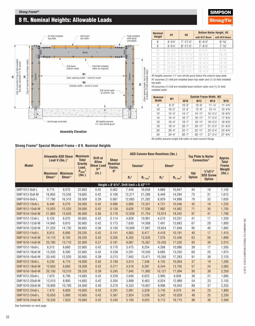
8 ft. nominal Heights: allowable Loads
Strong Frame® Special Moment Frame – 8 ft. Nominal Heights
Model
Allowable ASD Shear load V (lbs.) 1
Maximum Total
Gravity load, pmax
3 (lbs.)
Drift at Allow
Shear load V10
(in.)
Shear Reaction Factor,
X6
ASD Column Base Reactions (lbs.)Top plate to Nailer
Connection 8Approx.
Total Frame Weight (lbs.)
Tension7 Shear6
Maximum Shear 2
Minimum Shear 3
16d Option
¼"x3½" SDS Screw
OptionRT4 RT_max
5 RV4 RV_max
5
Height = 8'‑0 ¾", Drift limit = 0.42" 9,10
SMF1012-8x8-L 9,715 9,570 22,665 0.42 0.062 7,449 16,658 4,868 10,847 44 18 1,145
SMF1612-8x8-M 16,850 15,530 19,665 0.42 0.108 12,271 21,288 8,448 14,594 75 31 1,615
SMF1616-8x8-L 17,790 16,310 28,000 0.29 0.087 12,683 21,282 8,929 14,898 79 33 1,650
SMF1012-10x8-L 9,440 9,270 28,000 0.42 0.086 5,956 13,331 4,731 10,546 42 18 1,235
SMF1612-10x8-M 15,920 12,520 28,000 0.42 0.139 9,626 17,036 7,982 14,062 71 30 1,705
SMF1616-10x8-M 21,860 13,620 36,000 0.36 0.118 12,939 21,754 10,974 18,342 97 41 1,790
SMF1012-12x8-L 9,120 8,070 30,665 0.42 0.114 4,828 10,961 4,570 10,331 41 17 1,330
SMF1612-12x8-M 14,940 9,810 30,665 0.42 0.173 7,630 14,008 7,491 13,683 67 28 1,800
SMF1616-12x8-M 21,220 14,730 38,665 0.36 0.150 10,609 17,887 10,654 17,848 95 40 1,905
SMF1012-14x8-L 8,815 6,690 29,335 0.42 0.141 4,063 9,417 4,418 10,191 40 17 1,415
SMF1612-14x8-M 14,110 8,150 29,335 0.42 0.205 6,303 12,035 7,076 13,436 63 26 1,890
SMF1616-14x8-M 20,780 13,710 32,000 0.37 0.181 9,087 15,367 10,435 17,526 93 39 2,015
SMF1012-16x8-L 8,515 6,660 22,665 0.42 0.170 3,475 8,254 4,268 10,086 38 17 1,505
SMF1612-16x8-M 13,330 8,390 22,665 0.42 0.238 5,291 10,550 6,685 13,250 60 25 1,975
SMF1616-16x8-M 20,440 12,020 30,665 0.38 0.213 7,942 13,471 10,265 17,283 91 38 2,125
SMF1012-18x8-L 8,230 6,710 18,000 0.42 0.199 3,013 7,348 4,125 10,004 37 19 1,595
SMF1612-18x8-M 12,650 8,660 18,000 0.42 0.271 4,518 9,391 6,344 13,105 57 24 2,065
SMF1616-18x8-M 20,150 10,510 29,335 0.39 0.245 7,045 11,992 10,121 17,094 90 38 2,250
SMF1012-20x8-L 7,970 6,790 14,665 0.42 0.229 2,646 6,622 3,995 9,938 36 21 1,685
SMF1612-20x8-M 12,010 8,900 14,665 0.42 0.304 3,898 8,463 6,024 12,989 54 23 2,155
SMF1616-20x8-M 19,900 10,700 24,000 0.40 0.278 6,323 10,807 9,996 16,943 89 37 2,355
SMF1012-24x8-L 7,470 6,800 10,665 0.42 0.291 2,091 5,529 3,745 9,370 34 25 1,860
SMF1612-24x8-L 10,650 5,880 10,665 0.42 0.367 2,924 5,538 5,342 10,029 48 25 2,330
SMF1616-24x8-M 19,330 7,620 16,665 0.42 0.345 5,195 9,025 9,712 16,715 86 36 2,560
See footnotes on next page
2x field installedtop plate
4x8 beamtop nailer
Field installed infill block(included)
2x8 beambottom nailer
Anchorage assembly
Clear opening width – wood to wood
2x8 field installednailer as required
2x8 wood nailerat column, typ.
Beam
Colu
mn
Colu
mnW1
H1
(Top
of
conc
rete
to
top
of fi
eld-
inst
alle
d
top
plat
e, a
ssum
ed 1
1⁄2"
for
gro
ut)
All heights assume 11⁄2" non-shrink grout
H3
(Cle
ar o
peni
ng h
eigh
t, t
op o
f co
ncre
teto
bot
tom
of
field
-ins
talle
d na
iler)
W2
H2
(Top
of
conc
rete
to
top
of b
eam
nai
ler)
Outside width – wood to wood
Assembly Elevation
Nominal Height
H1 H2Bottom Nailer Height, H3
with W12 Beam with W16 Beam
8' 8'-0 ¾" 7'-11 ¼" 6'-4 ¼" 6'-5⁄8"9' 9'-0 ¾" 8'-11 ¼" 7'-4 ¼" 7'-5⁄8"10' 10'-0 ¾" 9'-11 ¼" 8'-4 ¼" 8'-5⁄8"12' 12'-0 ¾" 11'-11 ¼" 10'-4 ¼" 10'-5⁄8"14' 14'-0 ¾" 13'-11 ¼" 12'-4 ¼" 12'-5⁄8"16' 16'-0 ¾" 15'-11 ¼" 14'-4 ¼" 14'-5⁄8"18' 18'-2 ¾" 18'-1 ¼" 16'-4 ¼" 16'-5⁄8"20' 20'-2 ¾" 20'-1 ¼" 18'-4 ¼" 18'-5⁄8"
All heights assume 1 1⁄2" non-shrink grout below the column base plate
H1 assumes (1) 4x8 pre-installed beam top nailer and (1) 2x ield installed top plate
H3 assumes (1) 2x8 pre‑installed beam bottom nailer and (1) 2x ield installed nailer
Nominal Width
W1Outside Frame Width, W2
W10 W12 W14 W16
8' 8'‑2" 10'‑5" 10'‑9" 11'‑¼" 11'‑4 3⁄4"
10' 10'‑2" 12'‑5" 12'‑9" 13'‑¼" 13'‑4 3⁄4"
12' 12'‑4" 14'‑7" 14'‑11" 15'‑2 ¼" 15'‑6 3⁄4"
14' 14'‑4" 16'‑7" 16'‑11" 17'‑2 ¼" 17'‑6 3⁄4"
16' 16'‑4" 18'‑7" 18'‑11" 19'‑2 ¼" 19'‑6 3⁄4"
18' 18'‑4" 20'‑7" 20'‑11" 21'‑2 ¼" 21'‑6 3⁄4"
20' 20'‑4" 22'‑7" 22'‑11" 23'‑2 ¼" 23'‑6 3⁄4"
24' 24'‑4" 26'‑7" 26'‑11" 27'‑2 ¼" 27'‑6 3⁄4"
All widths assume single 2x8 nailer on each column lange

Strong Frame®C
-SF1
3 ©
2013 S
IMP
SO
N S
TR
ON
G-T
IE C
OM
PA
NY
IN
C.
23
9 ft. nominal Heights: allowable Loads
Strong Frame® Special Moment Frame – 9 ft. Nominal Heights
Model
Allowable ASD Shear load V (lbs.) 1
Maximum Total
Gravity load, pmax
3 (lbs.)
Drift at Allow
Shear load V10
(in.)
Shear Reaction Factor,
X6
ASD Column Base Reactions (lbs.)Top plate to Nailer
Connection 8Approx.
Total Frame Weight (lbs.)
Tension7 Shear6
Maximum Shear 2
Minimum Shear 3
16d Option
¼"x3½" SDS Screw
OptionRT4 RT_max
5 RV4 RV_max
5
Height = 9'‑0 ¾", Drift limit = 0.48" 9,10
SMF1012-8x9-L 7,875 7,730 22,665 0.48 0.051 6,886 16,658 3,945 9,512 35 15 1,215
SMF1612-8x9-M 14,200 13,670 19,665 0.48 0.093 11,792 21,288 7,115 12,798 63 27 1,740
SMF1616-8x9-M 19,910 18,190 36,000 0.43 0.076 16,229 27,183 9,984 16,649 89 37 1,805
SMF1012-10x9-L 7,675 7,500 28,000 0.48 0.071 5,522 13,331 3,845 9,248 35 15 1,305
SMF1612-10x9-M 13,450 11,050 28,000 0.48 0.119 9,274 17,036 6,739 12,331 60 25 1,830
SMF1616-10x9-M 19,140 15,540 38,665 0.43 0.100 12,953 21,754 9,599 16,042 85 36 1,915
SMF1012-12x9-L 7,425 7,240 30,665 0.48 0.095 4,482 10,961 3,719 9,059 33 14 1,400
SMF1612-12x9-M 12,630 8,690 30,665 0.48 0.149 7,356 14,008 6,329 11,999 56 24 1,925
SMF1616-12x9-M 18,580 13,070 38,665 0.43 0.128 10,621 17,887 9,320 15,610 83 35 2,030
SMF1012-14x9-L 7,190 6,100 29,335 0.48 0.118 3,779 9,417 3,602 8,937 32 15 1,490
SMF1612-14x9-M 11,950 7,240 29,335 0.48 0.177 6,087 12,035 5,988 11,782 53 22 2,015
SMF1616-14x9-H 20,350 14,320 36,000 0.48 0.159 10,174 18,033 10,209 17,994 91 38 2,140
SMF1012-16x9-L 6,965 6,040 22,665 0.48 0.143 3,241 8,254 3,489 8,837 31 17 1,575
SMF1612-16x9-M 11,310 7,430 22,665 0.48 0.206 5,119 10,550 5,668 11,619 51 21 2,100
SMF1616-16x9-H 19,530 13,570 30,665 0.48 0.186 8,676 15,807 9,798 17,745 87 36 2,260
SMF1012-18x9-L 6,745 5,900 18,665 0.48 0.168 2,816 7,331 3,379 8,533 30 19 1,665
SMF1612-18x9-M 10,730 7,440 18,665 0.48 0.235 4,370 9,391 5,377 11,492 48 20 2,190
SMF1616-18x9-H 18,740 12,220 29,335 0.48 0.215 7,491 14,071 9,403 17,551 84 35 2,375
SMF1012-20x9-L 6,535 6,110 14,665 0.48 0.194 2,474 6,493 3,274 8,245 29 21 1,755
SMF1612-20x9-M 10,210 7,860 14,665 0.48 0.264 3,779 8,463 5,117 11,390 46 21 2,280
SMF1616-20x9-H 18,000 12,360 24,000 0.48 0.243 6,540 12,680 9,032 17,395 80 34 2,480
SMF1012-24x9-L 6,150 6,080 10,665 0.48 0.247 1,963 5,248 3,081 7,716 28 25 1,930
SMF1612-24x9-L 9,070 5,200 10,665 0.48 0.319 2,840 5,538 4,546 8,794 41 25 2,455
SMF1616-24x9-M 16,190 7,420 16,665 0.48 0.296 4,975 9,025 8,125 14,619 72 30 2,685
1. Allowable shear loads assume pinned-based column, SDS= 1.0 and are applicable to seismic designs utilizing R = 6.5 and wind designs. For wind design, reduce shear load by 0.875. For seismic designs with R=8, see the Strong Frame Selector Software.
2. Maximum Shear is allowable horizontal shear force, V, applied with no gravity loads (other than frame selfweight).
3. Minimum Shear is allowable horizontal shear force, V, applied in combination with the maximum total vertical load, Pmax, which may be applied as a single point load at mid-span, P=Pmax, as multiple point loads applied symmetrically about mid-span of the beam, P1+P2+…+Pi=Pmax, or as a uniform distributed load, wmax = Pmax/Lbeam. P shall be determined based on the governing load combination of the applicable building code, and shall include Ev for seismic loads. In addition design Dead load and Live load ratio shall be in between 1⁄3 and 3.
4. Column reactions are based on Maximum Shear with no gravity loads. Reactions RT and RV are applicable to wind design and seismic design using R<=3.0. Anchorage Reactions for seismic design with R>3 can be calculated by amplifying RT and RV by the applicable Ωo value, or just use RT_max and RV_max. See footnotes 6 and 7 to include the effects of gravity loads.
5. RT_max and RV_max correspond to the lesser of column tension and shear reactions ampliied by Ωo =3.0 or the maximum forces that can be developed by the frame.
7. Reduced tension reactions may be calculated by including the dead load resistance determined based on the governing load combination of the applicable building code.
Compression Column:
RH = (V/2) + X(P)
or
RH = (V/2) + X(2/3wL)
Tension Column:
RH = (V/2)
V = Design Frame Shear (lbs.)
P = Midspan Point Load (lbs.), based on governing load combination
w = Uniform Load (lbs/ft), based on governing load combination
L = Column Centerline Dimension, W1 + 3" + Column Depth (ft)
X = Frame Shear Reaction Factor (no units)
8. Fastening is minimum nailing or Simpson Strong‑Tie® Strong‑Drive® SDS screws to achieve the full allowable shear load. For seismic designs (SDC C through F, except 1 and 2 family dwellings in SDC C), designer shall evaluate if top plate to nailer connection is required to be designed for overstrength force levels and increase fastening as required for Em level loading. Top plate splice design, as required, shall be by designer.
9. Drift at allowable shear is applicable to both Maximum Shear and Minimum Shear with maximum total load, Wmax. Drift may be linearly reduced for shear loads less than allowable shear.
10. Drift limit is calculated based on LRFD loads with Cd=4.0 and allowable drift limit of 0.025×H1, then converted to an equivalent ASD allowable story drift.
11. Vertical beam delections due to unfactored ASD gravity loads do not exceed the following:
T = (V × h)/L ‑ Tr V = Design Frame Shear, or Design Frame Shear × Ωo for R>3, (lbs.)
T = resisting dead load from the governing load combination, (lbs.)
h = (H1 ‑ 3")/12, (ft)
Dead load L/360 Dead Load + loor live load L/240
Floor live load L/360 Wmax (Point Load) L/240
SMF 10 12‑8X8‑l
Special Moment Frame
Column Size(10, 12, 14, 16 nominal)
Beam Size(12 or 16 nominal)
link Size(l, M or H)
Column Height(8, 9, 10, 12, 14, 16, 18 and 20 in feet)
Beam length(8, 10, 12, 14, 16, 18, 20 and 24 in feet)
Model No. Naming legendStandard Sizes
6. Horizontal column shear reactions can be solved by the equations below. Maximum horizontal shear reactions occur at the compression column. Designer shall determine governing load combinations based on the applicable building code. When R>3 substitute Ωo×V for V .
12. See pages 30‑36 for anchorage solutions.

Strong Frame®
C-S
F13 ©
2013 S
IMP
SO
N S
TR
ON
G-T
IE C
OM
PA
NY
IN
C.
24
10 ft. nominal Heights: allowable Loads
See footnotes on next page
Nominal Width
W1Outside Frame Width, W2
W10 W12 W14 W16
8' 8'-2" 10'-5" 10'-9" 11'-1⁄4" 11'-4 3⁄4"
10' 10'-2" 12'-5" 12'-9" 13'-1⁄4" 13'-4 3⁄4"
12' 12'-4" 14'-7" 14'-11" 15'-2 1⁄4" 15'-6 3⁄4"
14' 14'-4" 16'-7" 16'-11" 17'-2 ¼" 17'-6 3⁄4"
16' 16'-4" 18'-7" 18'-11" 19'-2 ¼" 19'-6 3⁄4"
18' 18'-4" 20'-7" 20'-11" 21'-2 ¼" 21'-6 3⁄4"
20' 20'-4" 22'-7" 22'-11" 23'-2 ¼" 23'-6 3⁄4"
24' 24'-4" 26'-7" 26'-11" 27'-2 ¼" 27'-6 3⁄4"
All widths assume single 2x8 nailer on each column lange
Nominal Height
H1 H2Bottom Nailer Height, H3
with W12 Beam with W16 Beam
8' 8'-0 ¾" 7'-11 ¼" 6'-4 ¼" 6'-5⁄8"9' 9'-0 ¾" 8'-11 ¼" 7'-4 ¼" 7'-5⁄8"10' 10'-0 ¾" 9'-11 ¼" 8'-4 ¼" 8'-5⁄8"12' 12'-0 ¾" 11'-11 ¼" 10'-4 ¼" 10'-5⁄8"14' 14'-0 ¾" 13'-11 ¼" 12'-4 ¼" 12'-5⁄8"16' 16'-0 ¾" 15'-11 ¼" 14'-4 ¼" 14'-5⁄8"18' 18'-2 ¾" 18'-1 ¼" 16'-4 ¼" 16'-5⁄8"20' 20'-2 ¾" 20'-1 ¼" 18'-4 ¼" 18'-5⁄8"
All heights assume 1 1⁄2" non-shrink grout below the column base plate
H1 assumes (1) 4x8 pre-installed beam top nailer and (1) 2x ield installed top plate
H3 assumes (1) 2x8 pre‑installed beam bottom nailer and (1) 2x ield installed nailer
Strong Frame® Special Moment Frame – 10 ft. Nominal Heights
Model
Allowable ASD Shear load V (lbs.) 1
Maximum Total
Gravity load, pmax
3 (lbs.)
Drift at Allow
Shear load V10
(in.)
Shear Reaction Factor,
X6
ASD Column Base Reactions (lbs.)Top plate to Nailer
Connection 8Approx.
Total Frame Weight (lbs.)
Tension7 Shear6
Maximum Shear 2
Minimum Shear 3
16d Option
¼"x3½" SDS Screw
OptionRT4 RT_max
5 RV4 RV_max
5
Height = 10'‑0 ¾", Drift limit = 0.53" 9,10
SMF1012‑8x10‑L 6,520 6,380 22,665 0.53 0.043 6,403 16,227 3,265 8,443 29 12 1,285
SMF1612‑8x10‑M 12,200 12,090 19,665 0.53 0.081 11,378 21,288 6,110 11,395 55 23 1,865
SMF1616‑8x10‑M 17,700 16,650 26,665 0.50 0.065 16,236 27,183 8,871 14,794 79 33 1,930
SMF1012‑10x10‑L 6,370 6,200 28,000 0.53 0.060 5,148 13,105 3,190 8,194 29 12 1,375
SMF1612‑10x10‑M 11,570 9,910 28,000 0.53 0.104 8,959 17,036 5,795 10,980 52 22 1,955
SMF1616‑10x10‑M 17,020 13,960 38,665 0.50 0.086 12,963 21,754 8,531 14,255 76 32 2,040
SMF1012‑12x10‑L 6,170 5,990 30,665 0.53 0.081 4,183 10,713 3,090 7,895 28 13 1,470
SMF1612‑12x10‑M 10,890 7,810 30,665 0.53 0.131 7,123 14,008 5,454 10,684 49 21 2,050
SMF1616‑12x10‑M 16,520 11,780 38,665 0.50 0.110 10,628 17,887 8,281 13,871 74 31 2,155
SMF1012‑14x10‑L 5,990 5,620 29,335 0.53 0.101 3,536 9,111 3,000 7,636 27 15 1,560
SMF1612‑14x10‑M 10,310 6,520 29,335 0.53 0.156 5,898 12,035 5,164 10,491 46 19 2,140
SMF1616‑14x10‑H 17,270 12,900 36,000 0.53 0.137 9,717 18,033 8,658 15,989 77 32 2,265
SMF1012‑16x10‑L 5,810 5,540 22,665 0.53 0.122 3,037 7,880 2,910 7,381 26 17 1,645
SMF1612‑16x10‑M 9,770 6,680 22,665 0.53 0.181 4,966 10,550 4,894 10,346 44 18 2,225
SMF1616‑16x10‑H 16,590 12,210 30,665 0.53 0.162 8,295 15,807 8,317 15,768 74 31 2,385
SMF1012‑18x10‑L 5,640 5,410 18,665 0.53 0.144 2,645 6,918 2,824 7,144 25 19 1,740
SMF1612‑18x10‑M 9,280 6,680 18,665 0.53 0.207 4,244 9,391 4,649 10,233 42 19 2,315
SMF1616‑18x10‑H 15,940 11,010 29,335 0.53 0.187 7,171 14,071 7,992 15,595 71 30 2,500
SMF1012‑20x10‑L 5,475 5,380 14,665 0.53 0.166 2,328 6,143 2,742 6,914 25 21 1,825
SMF1612‑20x10‑M 8,830 7,040 14,665 0.53 0.233 3,671 8,463 4,423 10,142 40 21 2,405
SMF1616‑20x10‑H 15,330 11,120 24,000 0.53 0.212 6,268 12,680 7,686 15,457 68 29 2,605
SMF1012‑24x10‑L 5,165 5,100 10,665 0.53 0.213 1,851 4,985 2,587 6,484 23 25 2,000
SMF1612‑24x10‑L 7,860 4,650 10,665 0.53 0.281 2,764 5,538 3,937 7,831 35 25 2,580
SMF1616‑24x10‑M 13,830 7,200 16,665 0.53 0.259 4,783 9,025 6,935 12,990 62 26 2,810
2x field installedtop plate
4x8 beamtop nailer
Field installed infill block(included)
2x8 beambottom nailer
Anchorage assembly
Clear opening width – wood to wood
2x8 field installednailer as required
2x8 wood nailerat column, typ.
Beam
Colu
mn
Colu
mnW1
H1
(Top
of
conc
rete
to
top
of fi
eld-
inst
alle
d
top
plat
e, a
ssum
ed 1
1 ⁄2" f
or g
rout
)
All heights assume 11⁄2" non-shrink grout
H3
(Cle
ar o
peni
ng h
eigh
t, t
op o
f co
ncre
teto
bot
tom
of
field
-ins
talle
d na
iler)
W2
H2
(Top
of
conc
rete
to
top
of b
eam
nai
ler)
Outside width – wood to wood
Assembly Elevation

Strong Frame®C
-SF1
3 ©
2013 S
IMP
SO
N S
TR
ON
G-T
IE C
OM
PA
NY
IN
C.
25
12 ft. nominal Heights: allowable Loads
Strong Frame® Special Moment Frame – 12 ft. Nominal Heights
Model
Allowable ASD Shear load V (lbs.) 1
Maximum Total
Gravity load, pmax
3 (lbs.)
Drift at Allow
Shear load V10
(in.)
Shear Reaction Factor,
X6
ASD Column Base Reactions (lbs.)Top plate to Nailer
Connection 8Approx.
Total Frame Weight (lbs.)
Tension7 Shear6
Maximum Shear 2
Minimum Shear 3
16d Option
¼"x3½" SDS Screw
OptionRT4 RT_max
5 RV4 RV_max
5
Height = 12'‑0 ¾", Drift limit = 0.63" 9,10
SMF1212-8x12-L 6,245 6,110 22,665 0.63 0.042 7,345 16,661 3,127 7,072 28 12 1,555
SMF1612-8x12-M 9,370 9,260 19,665 0.63 0.064 10,655 21,288 4,691 9,347 42 18 2,115
SMF1616-8x12-M 13,890 13,730 26,665 0.63 0.049 15,581 27,183 6,957 12,098 62 26 2,180
SMF1212-10x12-L 6,060 5,890 28,000 0.63 0.058 5,884 13,334 3,034 6,854 27 12 1,645
SMF1612-10x12-M 8,910 8,220 28,000 0.63 0.083 8,412 17,036 4,460 9,006 40 17 2,205
SMF1616-10x12-M 13,520 11,630 38,665 0.63 0.066 12,592 21,754 6,772 11,657 60 25 2,290
SMF1212-12x12-L 5,840 5,160 30,665 0.63 0.077 4,768 10,964 2,923 6,698 26 13 1,740
SMF1612-12x12-M 8,420 6,530 30,665 0.63 0.104 6,715 14,008 4,215 8,763 38 16 2,300
SMF1616-12x12-H 13,470 12,050 38,665 0.63 0.088 10,597 20,991 6,747 13,316 60 25 2,420
SMF1212-14x12-L 5,630 4,250 29,335 0.63 0.094 4,008 9,419 2,818 6,597 25 15 1,830
SMF1612-14x12-M 7,980 5,470 29,335 0.63 0.124 5,566 12,035 3,995 8,605 36 15 2,385
SMF1616-14x12-H 12,980 10,810 36,000 0.63 0.107 8,931 18,033 6,502 13,075 58 24 2,530
SMF1212-16x12-L 5,440 4,230 22,665 0.63 0.113 3,434 8,257 2,723 6,521 25 17 1,915
SMF1612-16x12-M 7,580 5,580 22,665 0.63 0.145 4,698 10,550 3,795 8,486 34 17 2,490
SMF1616-16x12-H 12,500 10,230 30,665 0.63 0.127 7,642 15,807 6,261 12,894 56 23 2,635
SMF1212-18x12-L 5,250 4,140 18,665 0.63 0.132 2,976 7,351 2,628 6,462 24 19 2,005
SMF1612-18x12-M 7,220 5,560 18,665 0.63 0.166 4,026 9,391 3,614 8,393 33 19 2,580
SMF1616-18x12-H 12,050 9,250 29,335 0.63 0.147 6,629 14,071 6,036 12,753 54 23 2,750
SMF1212-20x12-L 5,070 4,310 14,665 0.63 0.152 2,608 6,624 2,538 6,414 23 21 2,095
SMF1612-20x12-M 6,880 5,840 14,665 0.63 0.187 3,487 8,463 3,444 8,319 31 21 2,670
SMF1616-20x12-H 11,610 9,310 24,000 0.63 0.167 5,805 12,680 5,816 12,640 52 22 2,855
SMF1212-24x12-L 4,745 4,320 10,665 0.63 0.192 2,060 5,532 2,375 5,969 22 25 2,270
SMF1612-24x12-L 6,150 3,880 10,665 0.63 0.227 2,637 5,538 3,079 6,423 28 25 2,830
SMF1616-24x12-M 10,530 6,490 16,665 0.63 0.205 4,453 9,025 5,275 10,623 47 25 3,060
1. Allowable shear loads assume pinned-based column, SDS= 1.0 and are applicable to seismic designs utilizing R = 6.5 and wind designs. For wind design, reduce shear load by 0.875. For seismic designs with R=8, see the Strong Frame Selector Software.
2. Maximum Shear is allowable horizontal shear force, V, applied with no gravity loads (other than frame selfweight).
3. Minimum Shear is allowable horizontal shear force, V, applied in combination with the maximum total vertical load, Pmax, which may be applied as a single point load at mid-span, P=Pmax, as multiple point loads applied symmetrically about mid-span of the beam, P1+P2+…+Pi=Pmax, or as a uniform distributed load, wmax = Pmax/Lbeam. P shall be determined based on the governing load combination of the applicable building code, and shall include Ev for seismic loads. In addition design Dead load and Live load ratio shall be in between 1⁄3 and 3.
4. Column reactions are based on Maximum Shear with no gravity loads. Reactions RT and RV are applicable to wind design and seismic design using R<=3.0. Anchorage Reactions for seismic design with R>3 can be calculated by amplifying RT and RV by the applicable Ωo value, or just use RT_max and RV_max. See footnotes 6 and 7 to include the effects of gravity loads.
5. RT_max and RV_max correspond to the lesser of column tension and shear reactions ampliied by Ωo =3.0 or the maximum forces that can be developed by the frame.
7. Reduced tension reactions may be calculated by including the dead load resistance determined based on the governing load combination of the applicable building code.
Compression Column:
RH = (V/2) + X(P)
or
RH = (V/2) + X(2/3wL)
Tension Column:
RH = (V/2)
V = Design Frame Shear (lbs.)
P = Midspan Point Load (lbs.), based on governing load combination
w = Uniform Load (lbs/ft), based on governing load combination
L = Column Centerline Dimension, W1 + 3" + Column Depth (ft)
X = Frame Shear Reaction Factor (no units)
8. Fastening is minimum nailing or Simpson Strong‑Tie® Strong‑Drive® SDS screws to achieve the full allowable shear load. For seismic designs (SDC C through F, except 1 and 2 family dwellings in SDC C), designer shall evaluate if top plate to nailer connection is required to be designed for overstrength force levels and increase fastening as required for Em level loading. Top plate splice design, as required, shall be by designer.
9. Drift at allowable shear is applicable to both Maximum Shear and Minimum Shear with maximum total load, Wmax. Drift may be linearly reduced for shear loads less than allowable shear.
10. Drift limit is calculated based on LRFD loads with Cd=4.0 and allowable drift limit of 0.025×H1, then converted to an equivalent ASD allowable story drift.
11. Vertical beam delections due to unfactored ASD gravity loads do not exceed the following:
T = (V × h)/L ‑ Tr V = Design Frame Shear, or Design Frame Shear × Ωo for R>3, (lbs.)
T = resisting dead load from the governing load combination, (lbs.)
h = (H1 ‑ 3")/12, (ft)
Dead load L/360 Dead Load + loor live load L/240
Floor live load L/360 Wmax (Point Load) L/240
SMF 10 12‑8X8‑l
Special Moment Frame
Column Size(10, 12, 14, 16 nominal)
Beam Size(12 or 16 nominal)
link Size(l, M or H)
Column Height(8, 9, 10, 12, 14, 16, 18 and 20 in feet)
Beam length(8, 10, 12, 14, 16, 18, 20 and 24 in feet)
Model No. Naming legendStandard Sizes
6. Horizontal column shear reactions can be solved by the equations below. Maximum horizontal shear reactions occur at the compression column. Designer shall determine governing load combinations based on the applicable building code. When R>3 substitute Ωo×V for V .
12. See pages 30–36 for anchorage solutions.
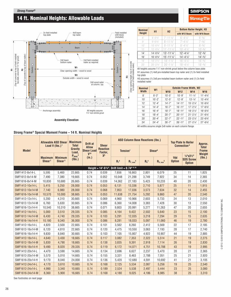
Strong Frame®
C-S
F13 ©
2013 S
IMP
SO
N S
TR
ON
G-T
IE C
OM
PA
NY
IN
C.
26
14 ft. nominal Heights: allowable Loads
See footnotes on next page
Nominal Width
W1Outside Frame Width, W2
W10 W12 W14 W16
8' 8'-2" 10'-5" 10'-9" 11'-¼" 11'-4 3⁄4"
10' 10'-2" 12'-5" 12'-9" 13'-¼" 13'-4 3⁄4"
12' 12'-4" 14'-7" 14'-11" 15'-2 ¼" 15'-6 3⁄4"
14' 14'-4" 16'-7" 16'-11" 17'-2 ¼" 17'-6 3⁄4"
16' 16'-4" 18'-7" 18'-11" 19'-2 ¼" 19'-6 3⁄4"
18' 18'-4" 20'-7" 20'-11" 21'-2 ¼" 21'-6 3⁄4"
20' 20'-4" 22'-7" 22'-11" 23'-2 ¼" 23'-6 3⁄4"
24' 24'-4" 26'-7" 26'-11" 27'-2 ¼" 27'-6 3⁄4"
All widths assume single 2x8 nailer on each column lange
Nominal Height
H1 H2Bottom Nailer Height, H3
with W12 Beam with W16 Beam
8' 8'-0 ¾" 7'-11 ¼" 6'-4 ¼" 6'-5⁄8"9' 9'-0 ¾" 8'-11 ¼" 7'-4 ¼" 7'-5⁄8"10' 10'-0 ¾" 9'-11 ¼" 8'-4 ¼" 8'-5⁄8"12' 12'-0 ¾" 11'-11 ¼" 10'-4 ¼" 10'-5⁄8"14' 14'-0 ¾" 13'-11 ¼" 12'-4 ¼" 12'-5⁄8"16' 16'-0 ¾" 15'-11 ¼" 14'-4 ¼" 14'-5⁄8"18' 18'-2 ¾" 18'-1 ¼" 16'-4 ¼" 16'-5⁄8"20' 20'-2 ¾" 20'-1 ¼" 18'-4 ¼" 18'-5⁄8"
All heights assume 1 1⁄2" non-shrink grout below the column base plate
H1 assumes (1) 4x8 pre-installed beam top nailer and (1) 2x ield installed top plate
H3 assumes (1) 2x8 pre‑installed beam bottom nailer and (1) 2x ield installed nailer
Strong Frame® Special Moment Frame – 14 ft. Nominal Heights
Model
Allowable ASD Shear load V (lbs.) 1
Maximum Total
Gravity load, pmax
3 (lbs.)
Drift at Allow
Shear load V10
(in.)
Shear Reaction Factor,
X6
ASD Column Base Reactions (lbs.)Top plate to Nailer
Connection 8Approx.
Total Frame Weight (lbs.)
Tension7 Shear6
Maximum Shear 2
Minimum Shear 3
16d Option
¼"x3½" SDS Screw
OptionRT4 RT_max
5 RV4 RV_max
5
Height = 14'‑0 ¾", Drift limit = 0.74" 9,10
SMF1412‑8x14‑L 5,595 5,460 22,665 0.74 0.039 7,656 16,663 2,801 6,079 25 11 1,825
SMF1612‑8x14‑M 7,490 7,380 19,665 0.74 0.052 10,048 21,288 3,749 7,922 34 14 2,365
SMF1616‑8x14‑M 10,830 10,680 26,665 0.74 0.039 14,362 27,183 5,423 10,233 49 20 2,430
SMF1412‑10x14‑L 5,415 5,250 28,000 0.74 0.053 6,131 13,336 2,710 5,877 25 11 1,915
SMF1612‑10x14‑M 7,140 6,980 28,000 0.74 0.068 7,953 17,036 3,573 7,634 32 14 2,455
SMF1616‑10x14‑M 10,570 10,000 38,665 0.74 0.053 11,638 21,754 5,292 9,860 47 20 2,540
SMF1412‑12x14‑L 5,200 4,310 30,665 0.74 0.069 4,960 10,966 2,603 5,733 24 13 2,010
SMF1612‑12x14‑M 6,760 5,630 30,665 0.74 0.086 6,360 14,008 3,383 7,428 30 13 2,550
SMF1616‑12x14‑H 10,540 10,310 38,665 0.74 0.071 9,803 20,991 5,277 11,263 47 20 2,655
SMF1412‑14x14‑L 5,000 3,510 29,335 0.74 0.085 4,164 9,422 2,502 5,640 23 15 2,100
SMF1612‑14x14‑M 6,430 4,740 29,335 0.74 0.103 5,291 12,035 3,218 7,294 29 15 2,635
SMF1616‑14x14‑H 10,180 9,340 36,000 0.74 0.086 8,281 18,033 5,097 11,060 46 19 2,780
SMF1412‑16x14‑L 4,820 3,500 22,665 0.74 0.101 3,562 8,260 2,412 5,569 22 17 2,185
SMF1612‑16x14‑M 6,120 4,810 22,665 0.74 0.120 4,475 10,550 3,063 7,193 28 17 2,740
SMF1616‑16x14‑H 9,830 8,840 30,665 0.74 0.103 7,105 15,807 4,922 10,907 44 19 2,885
SMF1412‑18x14‑L 4,640 3,430 18,665 0.74 0.117 3,082 7,353 2,322 5,514 21 19 2,275
SMF1612‑18x14‑M 5,830 4,790 18,665 0.74 0.138 3,835 9,391 2,918 7,114 26 19 2,830
SMF1616‑18x14‑H 9,490 8,020 29,335 0.74 0.119 6,172 14,071 4,751 10,788 43 19 2,995
SMF1412‑20x14‑L 4,470 3,590 14,665 0.74 0.134 2,696 6,627 2,237 5,470 20 21 2,365
SMF1612‑20x14‑M 5,570 5,010 14,665 0.74 0.155 3,331 8,463 2,788 7,051 25 21 2,920
SMF1616‑20x14‑H 9,170 8,040 24,000 0.74 0.136 5,420 12,680 4,591 10,692 41 21 3,105
SMF1412‑24x14‑L 4,170 3,610 10,665 0.74 0.168 2,125 5,534 2,087 5,256 19 25 2,540
SMF1612‑24x14‑L 4,990 3,340 10,665 0.74 0.189 2,524 5,538 2,497 5,444 23 25 3,080
SMF1616‑24x14‑M 8,360 5,900 16,665 0.74 0.168 4,180 9,025 4,186 8,985 38 25 3,310
2x field installedtop plate
4x8 beamtop nailer
Field installed infill block(included)
2x8 beambottom nailer
Anchorage assembly
Clear opening width – wood to wood
2x8 field installednailer as required
2x8 wood nailerat column, typ.
Beam
Colu
mn
Colu
mnW1
H1
(Top
of
conc
rete
to
top
of fi
eld-
inst
alle
d
top
plat
e, a
ssum
ed 1
1⁄2"
for
gro
ut)
All heights assume 11⁄2" non-shrink grout
H3
(Cle
ar o
peni
ng h
eigh
t, t
op o
f co
ncre
teto
bot
tom
of
field
-ins
talle
d na
iler)
W2
H2
(Top
of
conc
rete
to
top
of b
eam
nai
ler)
Outside width – wood to wood
Assembly Elevation

Strong Frame®C
-SF1
3 ©
2013 S
IMP
SO
N S
TR
ON
G-T
IE C
OM
PA
NY
IN
C.
27
16 ft. nominal Heights: allowable Loads
Strong Frame® Special Moment Frame – 16 ft. Nominal Heights
Model
Allowable ASD Shear load V (lbs.) 1
Maximum Total
Gravity load, pmax
3 (lbs.)
Drift at Allow
Shear load V10
(in.)
Shear Reaction Factor,
X6
ASD Column Base Reactions (lbs.)Top plate to Nailer
Connection 8Approx.
Total Frame Weight (lbs.)
Tension7 Shear6
Maximum Shear 2
Minimum Shear 3
16d Option
¼"x3½" SDS Screw
OptionRT4 RT_max
5 RV4 RV_max
5
Height = 16'‑0 ¾", Drift limit = 0.84" 9,10
SMF1412-8x16-L 4,505 4,370 22,665 0.84 0.032 7,104 16,663 2,255 5,275 20 9 2,000
SMF1612-8x16-M 6,150 6,040 19,665 0.84 0.043 9,508 21,288 3,078 6,875 28 12 2,615
SMF1616-8x16-M 8,710 8,560 26,665 0.84 0.032 13,331 27,183 4,361 8,867 39 17 2,680
SMF1412-10x16-L 4,370 4,210 28,000 0.84 0.044 5,702 13,336 2,187 5,100 20 11 2,090
SMF1612-10x16-M 5,880 5,720 28,000 0.84 0.057 7,547 17,036 2,942 6,624 27 11 2,705
SMF1616-10x16-M 8,520 8,300 38,665 0.84 0.043 10,827 21,754 4,265 8,543 38 16 2,790
SMF1412-12x16-L 4,210 3,850 30,665 0.84 0.057 4,628 10,966 2,107 4,975 19 13 2,185
SMF1612-12x16-M 5,580 4,960 30,665 0.84 0.072 6,050 14,008 2,792 6,446 25 13 2,800
SMF1616-12x16-H 8,500 8,280 38,665 0.84 0.058 9,124 20,991 4,255 9,759 38 16 2,905
SMF1412-14x16-L 4,060 3,170 29,335 0.84 0.070 3,897 9,422 2,032 4,894 18 15 2,270
SMF1612-14x16-M 5,320 4,190 29,335 0.84 0.087 5,045 12,035 2,662 6,329 24 15 2,885
SMF1616-14x16-H 8,230 8,020 36,000 0.84 0.072 7,727 18,033 4,120 9,583 37 16 3,015
SMF1412-16x16-L 3,920 3,140 22,665 0.84 0.084 3,339 8,260 1,962 4,833 18 17 2,360
SMF1612-16x16-M 5,070 4,240 22,665 0.84 0.102 4,272 10,550 2,537 6,242 23 17 2,990
SMF1616-16x16-H 7,970 7,790 30,665 0.84 0.085 6,649 15,807 3,989 9,450 36 17 3,135
SMF1412-18x16-L 3,780 3,070 18,665 0.84 0.098 2,894 7,353 1,891 4,785 17 19 2,450
SMF1612-18x16-M 4,840 4,210 18,665 0.84 0.117 3,669 9,391 2,422 6,174 22 19 3,080
SMF1616-18x16-H 7,710 7,100 29,335 0.84 0.099 5,787 14,071 3,859 9,347 35 19 3,245
SMF1412-20x16-L 3,650 3,200 14,665 0.84 0.112 2,537 6,627 1,826 4,643 17 21 2,540
SMF1612-20x16-M 4,630 4,390 14,665 0.84 0.132 3,190 8,463 2,317 5,890 21 21 3,170
SMF1616-20x16-H 7,460 7,100 24,000 0.84 0.114 5,089 12,680 3,734 9,264 34 21 3,355
SMF1412-24x16-L 3,410 3,190 10,665 0.84 0.142 2,002 5,518 1,706 4,306 16 25 2,715
SMF1612-24x16-L 4,170 2,930 10,665 0.84 0.161 2,430 5,538 2,086 4,724 19 25 3,330
SMF1616-24x16-M 6,830 5,400 16,665 0.84 0.141 3,941 9,025 3,419 7,785 31 25 3,560
1. Allowable shear loads assume pinned-based column, SDS= 1.0 and are applicable to seismic designs utilizing R = 6.5 and wind designs. For wind design, reduce shear load by 0.875. For seismic designs with R=8, see the Strong Frame Selector Software.
2. Maximum Shear is allowable horizontal shear force, V, applied with no gravity loads (other than frame selfweight).
3. Minimum Shear is allowable horizontal shear force, V, applied in combination with the maximum total vertical load, Pmax, which may be applied as a single point load at mid-span, P=Pmax, as multiple point loads applied symmetrically about mid-span of the beam, P1+P2+…+Pi=Pmax, or as a uniform distributed load, wmax = Pmax/Lbeam. P shall be determined based on the governing load combination of the applicable building code, and shall include Ev for seismic loads. In addition design Dead load and Live load ratio shall be in between 1⁄3 and 3.
4. Column reactions are based on Maximum Shear with no gravity loads. Reactions RT and RV are applicable to wind design and seismic design using R<=3.0. Anchorage Reactions for seismic design with R>3 can be calculated by amplifying RT and RV by the applicable Ωo value, or just use RT_max and RV_max. See footnotes 6 and 7 to include the effects of gravity loads.
5. RT_max and RV_max correspond to the lesser of column tension and shear reactions ampliied by Ωo =3.0 or the maximum forces that can be developed by the frame.
7. Reduced tension reactions may be calculated by including the dead load resistance determined based on the governing load combination of the applicable building code.
Compression Column:
RH = (V/2) + X(P)
or
RH = (V/2) + X(2/3wL)
Tension Column:
RH = (V/2)
V = Design Frame Shear (lbs.)
P = Midspan Point Load (lbs.), based on governing load combination
w = Uniform Load (lbs/ft), based on governing load combination
L = Column Centerline Dimension, W1 + 3" + Column Depth (ft)
X = Frame Shear Reaction Factor (no units)
8. Fastening is minimum nailing or Simpson Strong‑Tie® Strong‑Drive® SDS screws to achieve the full allowable shear load. For seismic designs (SDC C through F, except 1 and 2 family dwellings in SDC C), designer shall evaluate if top plate to nailer connection is required to be designed for overstrength force levels and increase fastening as required for Em level loading. Top plate splice design, as required, shall be by designer.
9. Drift at allowable shear is applicable to both Maximum Shear and Minimum Shear with maximum total load, Wmax. Drift may be linearly reduced for shear loads less than allowable shear.
10. Drift limit is calculated based on LRFD loads with Cd=4.0 and allowable drift limit of 0.025×H1, then converted to an equivalent ASD allowable story drift.
11. Vertical beam delections due to unfactored ASD gravity loads do not exceed the following:
T = (V × h)/L ‑ Tr V = Design Frame Shear, or Design Frame Shear × Ωo for R>3, (lbs.)
T = resisting dead load from the governing load combination, (lbs.)
h = (H1 ‑ 3")/12, (ft)
Dead load L/360 Dead Load + loor live load L/240
Floor live load L/360 Wmax (Point Load) L/240
SMF 10 12‑8X8‑l
Special Moment Frame
Column Size(10, 12, 14, 16 nominal)
Beam Size(12 or 16 nominal)
link Size(l, M or H)
Column Height(8, 9, 10, 12, 14, 16, 18 and 20 in feet)
Beam length(8, 10, 12, 14, 16, 18, 20 and 24 in feet)
Model No. Naming legendStandard Sizes
6. Horizontal column shear reactions can be solved by the equations below. Maximum horizontal shear reactions occur at the compression column. Designer shall determine governing load combinations based on the applicable building code. When R>3 substitute Ωo×V for V .
12. See pages 30–36 for anchorage solutions.

Strong Frame®
C-S
F13 ©
2013 S
IMP
SO
N S
TR
ON
G-T
IE C
OM
PA
NY
IN
C.
28
18 ft. nominal Heights: allowable Loads
See footnotes on next page
Nominal Width
W1Outside Frame Width, W2
W10 W12 W14 W16
8' 8'-2" 10'-5" 10'-9" 11'-¼" 11'-4 3⁄4"
10' 10'-2" 12'-5" 12'-9" 13'-¼" 13'-4 3⁄4"
12' 12'-4" 14'-7" 14'-11" 15'-2 ¼" 15'-6 3⁄4"
14' 14'-4" 16'-7" 16'-11" 17'-2 ¼" 17'-6 3⁄4"
16' 16'-4" 18'-7" 18'-11" 19'-2 ¼" 19'-6 3⁄4"
18' 18'-4" 20'-7" 20'-11" 21'-2 ¼" 21'-6 3⁄4"
20' 20'-4" 22'-7" 22'-11" 23'-2 ¼" 23'-6 3⁄4"
24' 24'-4" 26'-7" 26'-11" 27'-2 ¼" 27'-6 3⁄4"
All widths assume single 2x8 nailer on each column lange
Nominal Height
H1 H2Bottom Nailer Height, H3
with W12 Beam with W16 Beam
8' 8'-0 ¾" 7'-11 ¼" 6'-4 ¼" 6'-5⁄8"9' 9'-0 ¾" 8'-11 ¼" 7'-4 ¼" 7'-5⁄8"10' 10'-0 ¾" 9'-11 ¼" 8'-4 ¼" 8'-5⁄8"12' 12'-0 ¾" 11'-11 ¼" 10'-4 ¼" 10'-5⁄8"14' 14'-0 ¾" 13'-11 ¼" 12'-4 ¼" 12'-5⁄8"16' 16'-0 ¾" 15'-11 ¼" 14'-4 ¼" 14'-5⁄8"18' 18'-2 ¾" 18'-1 ¼" 16'-4 ¼" 16'-5⁄8"20' 20'-2 ¾" 20'-1 ¼" 18'-4 ¼" 18'-5⁄8"
All heights assume 1 1⁄2" non-shrink grout below the column base plate
H1 assumes (1) 4x8 pre-installed beam top nailer and (1) 2x ield installed top plate
H3 assumes (1) 2x8 pre‑installed beam bottom nailer and (1) 2x ield installed nailer
Strong Frame® Special Moment Frame – 18 ft. Nominal Heights
Model
Allowable ASD Shear load V (lbs.) 1
Maximum Total
Gravity load, pmax
3 (lbs.)
Drift at Allow
Shear load V10
(in.)
Shear Reaction Factor,
X6
ASD Column Base Reactions (lbs.)Top plate to Nailer
Connection 8Approx.
Total Frame Weight (lbs.)
Tension7 Shear6
Maximum Shear 2
Minimum Shear 3
16d Option
¼"x3½" SDS Screw
OptionRT4 RT_max
5 RV4 RV_max
5
Height = 18'‑2 ¾", Drift limit = 0.96" 9,10
SMF1412‑8x18‑L 3,655 3,520 22,665 0.96 0.026 6,589 16,663 1,830 4,614 17 9 2,190
SMF1612‑8x18‑M 5,090 4,980 19,665 0.96 0.037 8,996 21,288 2,547 6,013 23 10 2,885
SMF1616‑8x18‑M 7,070 6,920 26,665 0.96 0.026 12,387 27,183 3,540 7,746 32 13 2,950
SMF1412‑10x18‑L 3,555 3,390 28,000 0.96 0.036 5,303 13,336 1,779 4,461 16 11 2,275
SMF1612‑10x18‑M 4,880 4,720 28,000 0.96 0.048 7,161 17,036 2,442 5,794 22 11 2,975
SMF1616‑10x18‑M 6,920 6,710 38,665 0.96 0.036 10,066 21,754 3,464 7,463 31 13 3,060
SMF1412‑12x18‑L 3,430 3,260 30,665 0.96 0.048 4,311 10,966 1,717 4,352 16 13 2,370
SMF1612‑12x18‑M 4,640 4,410 30,665 0.96 0.061 5,751 14,008 2,322 5,638 21 13 3,070
SMF1616‑12x18‑H 6,920 6,690 38,665 0.96 0.048 8,503 20,991 3,464 8,525 31 13 3,175
SMF1412‑14x18‑L 3,320 2,870 29,335 0.96 0.059 3,643 9,422 1,661 4,281 15 15 2,460
SMF1612‑14x18‑M 4,430 3,730 29,335 0.96 0.074 4,803 12,035 2,216 5,536 20 15 3,160
SMF1616‑14x18‑H 6,710 6,500 36,000 0.96 0.060 7,211 18,033 3,358 8,371 30 15 3,300
SMF1412‑16x18‑L 3,210 2,840 22,665 0.96 0.070 3,126 8,260 1,606 4,131 15 17 2,550
SMF1612‑16x18‑M 4,240 3,770 22,665 0.96 0.087 4,084 10,550 2,121 5,454 19 17 3,245
SMF1616‑16x18‑H 6,510 6,330 30,665 0.96 0.071 6,217 15,807 3,258 8,256 29 17 3,405
SMF1412‑18x18‑L 3,105 2,770 18,665 0.96 0.083 2,717 7,299 1,554 3,978 14 19 2,640
SMF1612‑18x18‑M 4,050 3,730 18,665 0.96 0.100 3,510 9,391 2,026 5,187 18 19 3,335
SMF1616‑18x18‑H 6,310 6,140 29,335 0.96 0.083 5,422 14,071 3,158 8,098 28 19 3,520
SMF1412‑20x18‑L 3,000 2,860 14,665 0.96 0.095 2,384 6,482 1,501 3,827 14 21 2,730
SMF1612‑20x18‑M 3,880 3,800 14,665 0.96 0.113 3,057 8,330 1,941 4,950 18 21 3,440
SMF1616‑20x18‑H 6,120 5,980 24,000 0.96 0.096 4,779 12,680 3,063 7,826 28 21 3,625
SMF1412‑24x18‑L 2,820 2,760 10,665 0.96 0.120 1,893 5,287 1,411 3,569 13 25 2,905
SMF1612‑24x18‑L 3,500 2,600 10,665 0.96 0.138 2,332 5,538 1,751 4,132 16 25 3,600
SMF1616‑24x18‑M 5,620 4,930 16,665 0.96 0.119 3,712 9,025 2,812 6,801 25 25 3,845
2x field installedtop plate
4x8 beamtop nailer
Field installed infill block(included)
2x8 beambottom nailer
Anchorage assembly
Clear opening width – wood to wood
2x8 field installednailer as required
2x8 wood nailerat column, typ.
Beam
Colu
mn
Colu
mnW1
H1
(Top
of
conc
rete
to
top
of fi
eld-
inst
alle
d
top
plat
e, a
ssum
ed 1
1 ⁄2" f
or g
rout
)
All heights assume 11⁄2" non-shrink grout
H3
(Cle
ar o
peni
ng h
eigh
t, t
op o
f co
ncre
teto
bot
tom
of
field
-ins
talle
d na
iler)
W2
H2
(Top
of
conc
rete
to
top
of b
eam
nai
ler)
Outside width – wood to wood
Assembly Elevation
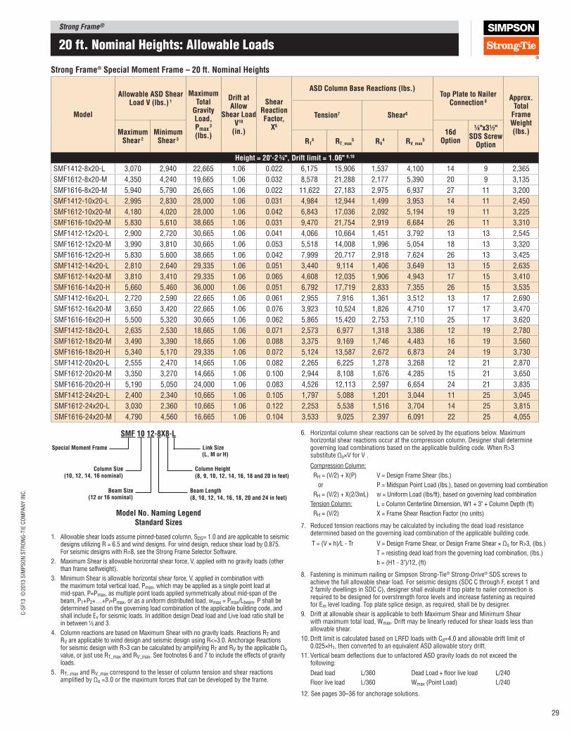
Strong Frame®C
-SF1
3 ©
2013 S
IMP
SO
N S
TR
ON
G-T
IE C
OM
PA
NY
IN
C.
29
20 ft. nominal Heights: allowable Loads
Strong Frame® Special Moment Frame – 20 ft. Nominal Heights
Model
Allowable ASD Shear load V (lbs.) 1
Maximum Total
Gravity load, pmax
3 (lbs.)
Drift at Allow
Shear load V10
(in.)
Shear Reaction Factor,
X6
ASD Column Base Reactions (lbs.)Top plate to Nailer
Connection 8Approx.
Total Frame Weight (lbs.)
Tension7 Shear6
Maximum Shear 2
Minimum Shear 3
16d Option
¼"x3½" SDS Screw
OptionRT4 RT_max
5 RV4 RV_max
5
Height = 20'‑2 ¾", Drift limit = 1.06" 9,10
SMF1412-8x20-L 3,070 2,940 22,665 1.06 0.022 6,175 15,906 1,537 4,100 14 9 2,365
SMF1612-8x20-M 4,350 4,240 19,665 1.06 0.032 8,578 21,288 2,177 5,390 20 9 3,135
SMF1616-8x20-M 5,940 5,790 26,665 1.06 0.022 11,622 27,183 2,975 6,937 27 11 3,200
SMF1412-10x20-L 2,995 2,830 28,000 1.06 0.031 4,984 12,944 1,499 3,953 14 11 2,450
SMF1612-10x20-M 4,180 4,020 28,000 1.06 0.042 6,843 17,036 2,092 5,194 19 11 3,225
SMF1616-10x20-M 5,830 5,610 38,665 1.06 0.031 9,470 21,754 2,919 6,684 26 11 3,310
SMF1412-12x20-L 2,900 2,720 30,665 1.06 0.041 4,066 10,664 1,451 3,792 13 13 2,545
SMF1612-12x20-M 3,990 3,810 30,665 1.06 0.053 5,518 14,008 1,996 5,054 18 13 3,320
SMF1616-12x20-H 5,830 5,600 38,665 1.06 0.042 7,999 20,717 2,918 7,624 26 13 3,425
SMF1412-14x20-L 2,810 2,640 29,335 1.06 0.051 3,440 9,114 1,406 3,649 13 15 2,635
SMF1612-14x20-M 3,810 3,410 29,335 1.06 0.065 4,608 12,035 1,906 4,943 17 15 3,410
SMF1616-14x20-H 5,660 5,460 36,000 1.06 0.051 6,792 17,719 2,833 7,355 26 15 3,535
SMF1412-16x20-L 2,720 2,590 22,665 1.06 0.061 2,955 7,916 1,361 3,512 13 17 2,690
SMF1612-16x20-M 3,650 3,420 22,665 1.06 0.076 3,923 10,524 1,826 4,710 17 17 3,470
SMF1616-16x20-H 5,500 5,320 30,665 1.06 0.062 5,865 15,420 2,753 7,110 25 17 3,620
SMF1412-18x20-L 2,635 2,530 18,665 1.06 0.071 2,573 6,977 1,318 3,386 12 19 2,780
SMF1612-18x20-M 3,490 3,390 18,665 1.06 0.088 3,375 9,169 1,746 4,483 16 19 3,560
SMF1616-18x20-H 5,340 5,170 29,335 1.06 0.072 5,124 13,587 2,672 6,873 24 19 3,730
SMF1412-20x20-L 2,555 2,470 14,665 1.06 0.082 2,265 6,225 1,278 3,268 12 21 2,870
SMF1612-20x20-M 3,350 3,270 14,665 1.06 0.100 2,944 8,108 1,676 4,285 15 21 3,650
SMF1616-20x20-H 5,190 5,050 24,000 1.06 0.083 4,526 12,113 2,597 6,654 24 21 3,835
SMF1412-24x20-L 2,400 2,340 10,665 1.06 0.105 1,797 5,088 1,201 3,044 11 25 3,045
SMF1612-24x20-L 3,030 2,360 10,665 1.06 0.122 2,253 5,538 1,516 3,704 14 25 3,815
SMF1616-24x20-M 4,790 4,560 16,665 1.06 0.104 3,533 9,025 2,397 6,091 22 25 4,055
1. Allowable shear loads assume pinned-based column, SDS= 1.0 and are applicable to seismic designs utilizing R = 6.5 and wind designs. For wind design, reduce shear load by 0.875. For seismic designs with R=8, see the Strong Frame Selector Software.
2. Maximum Shear is allowable horizontal shear force, V, applied with no gravity loads (other than frame selfweight).
3. Minimum Shear is allowable horizontal shear force, V, applied in combination with the maximum total vertical load, Pmax, which may be applied as a single point load at mid-span, P=Pmax, as multiple point loads applied symmetrically about mid-span of the beam, P1+P2+…+Pi=Pmax, or as a uniform distributed load, wmax = Pmax/Lbeam. P shall be determined based on the governing load combination of the applicable building code, and shall include Ev for seismic loads. In addition design Dead load and Live load ratio shall be in between 1⁄3 and 3.
4. Column reactions are based on Maximum Shear with no gravity loads. Reactions RT and RV are applicable to wind design and seismic design using R<=3.0. Anchorage Reactions for seismic design with R>3 can be calculated by amplifying RT and RV by the applicable Ωo value, or just use RT_max and RV_max. See footnotes 6 and 7 to include the effects of gravity loads.
5. RT_max and RV_max correspond to the lesser of column tension and shear reactions ampliied by Ωo =3.0 or the maximum forces that can be developed by the frame.
7. Reduced tension reactions may be calculated by including the dead load resistance determined based on the governing load combination of the applicable building code.
Compression Column:
RH = (V/2) + X(P)
or
RH = (V/2) + X(2/3wL)
Tension Column:
RH = (V/2)
V = Design Frame Shear (lbs.)
P = Midspan Point Load (lbs.), based on governing load combination
w = Uniform Load (lbs/ft), based on governing load combination
L = Column Centerline Dimension, W1 + 3" + Column Depth (ft)
X = Frame Shear Reaction Factor (no units)
8. Fastening is minimum nailing or Simpson Strong‑Tie® Strong‑Drive® SDS screws to achieve the full allowable shear load. For seismic designs (SDC C through F, except 1 and 2 family dwellings in SDC C), designer shall evaluate if top plate to nailer connection is required to be designed for overstrength force levels and increase fastening as required for Em level loading. Top plate splice design, as required, shall be by designer.
9. Drift at allowable shear is applicable to both Maximum Shear and Minimum Shear with maximum total load, Wmax. Drift may be linearly reduced for shear loads less than allowable shear.
10. Drift limit is calculated based on LRFD loads with Cd=4.0 and allowable drift limit of 0.025×H1, then converted to an equivalent ASD allowable story drift.
11. Vertical beam delections due to unfactored ASD gravity loads do not exceed the following:
T = (V × h)/L ‑ Tr V = Design Frame Shear, or Design Frame Shear × Ωo for R>3, (lbs.)
T = resisting dead load from the governing load combination, (lbs.)
h = (H1 ‑ 3")/12, (ft)
Dead load L/360 Dead Load + loor live load L/240
Floor live load L/360 Wmax (Point Load) L/240
SMF 10 12‑8X8‑l
Special Moment Frame
Column Size(10, 12, 14, 16 nominal)
Beam Size(12 or 16 nominal)
link Size(l, M or H)
Column Height(8, 9, 10, 12, 14, 16, 18 and 20 in feet)
Beam length(8, 10, 12, 14, 16, 18, 20 and 24 in feet)
Model No. Naming legendStandard Sizes
6. Horizontal column shear reactions can be solved by the equations below. Maximum horizontal shear reactions occur at the compression column. Designer shall determine governing load combinations based on the applicable building code. When R>3 substitute Ωo×V for V .
12. See pages 30–36 for anchorage solutions.
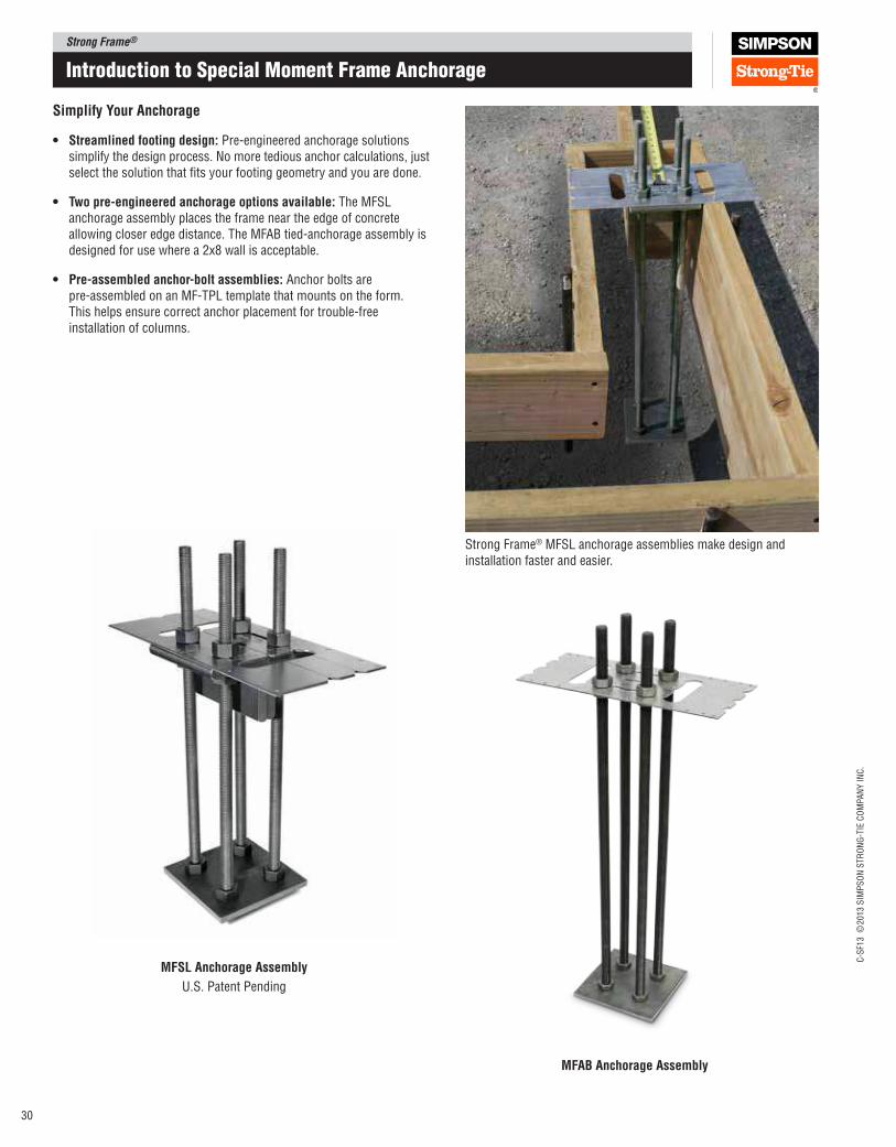
Strong Frame®
C-S
F13 ©
2013 S
IMP
SO
N S
TR
ON
G-T
IE C
OM
PA
NY
IN
C.
30
Introduction to Special moment Frame anchorage
Simplify your Anchorage
• Streamlined footing design: Pre-engineered anchorage solutions simplify the design process. No more tedious anchor calculations, just select the solution that its your footing geometry and you are done.
• Two pre‑engineered anchorage options available: The MFSL anchorage assembly places the frame near the edge of concrete allowing closer edge distance. The MFAB tied‑anchorage assembly is designed for use where a 2x8 wall is acceptable.
• pre‑assembled anchor‑bolt assemblies: Anchor bolts are pre‑assembled on an MF‑TPL template that mounts on the form. This helps ensure correct anchor placement for trouble‑free installation of columns.
Strong Frame® MFSL anchorage assemblies make design and installation faster and easier.
MFSl Anchorage Assembly
U.S. Patent Pending
MFAB Anchorage Assembly
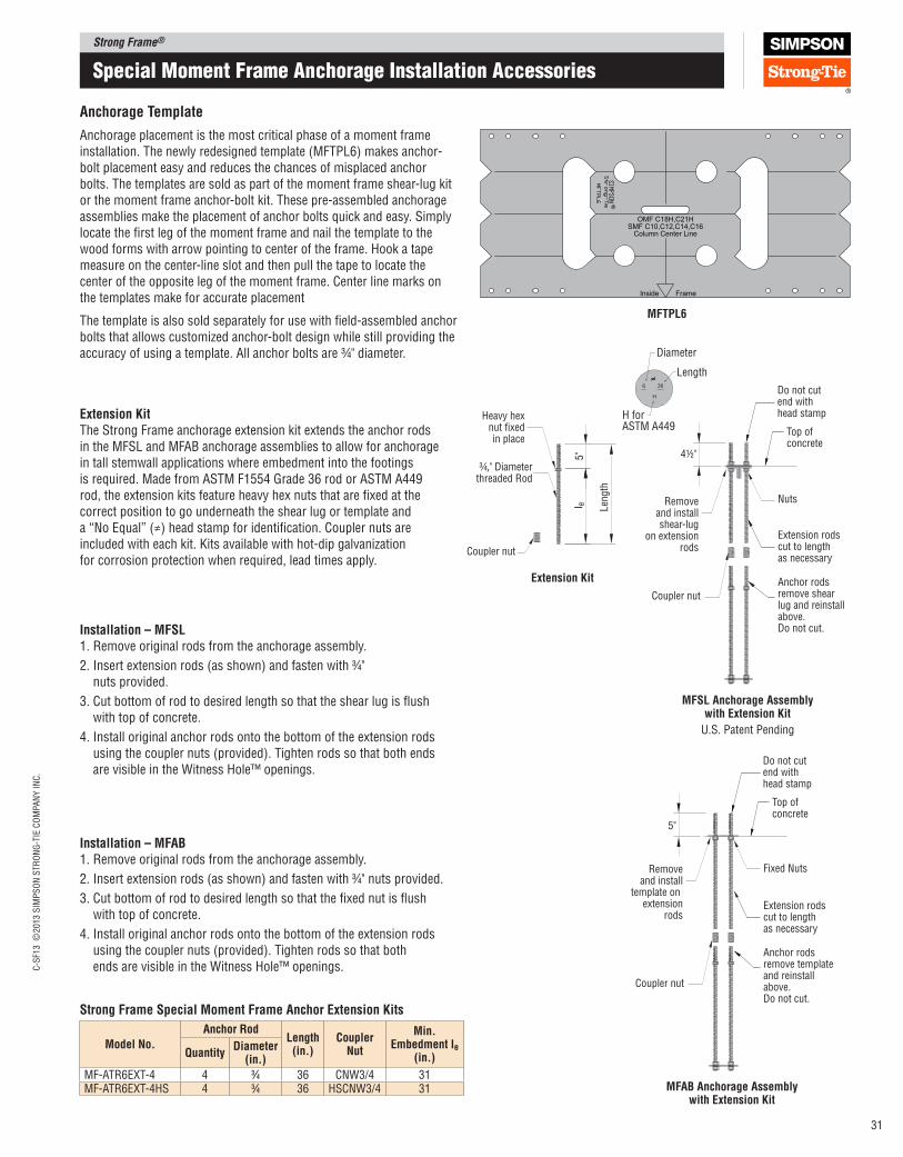
Strong Frame®C
-SF1
3 ©
2013 S
IMP
SO
N S
TR
ON
G-T
IE C
OM
PA
NY
IN
C.
31
Special moment Frame anchorage Installation accessories
Extension Kit The Strong Frame anchorage extension kit extends the anchor rods in the MFSL and MFAB anchorage assemblies to allow for anchorage in tall stemwall applications where embedment into the footings is required. Made from ASTM F1554 Grade 36 rod or ASTM A449 rod, the extension kits feature heavy hex nuts that are ixed at the correct position to go underneath the shear lug or template and a “No Equal” (≠) head stamp for identiication. Coupler nuts are included with each kit. Kits available with hot‑dip galvanization for corrosion protection when required, lead times apply.
Heavy hexnut fixedin place
Removeand installshear-lug
on extensionrods
¾," Diameterthreaded Rod
Top of concrete
Do not cut end withhead stamp
Extension rodscut to lengthas necessary
Nuts
Anchor rods remove shear lug and reinstall above.Do not cut.
Len
gth
5" 4½"
l e
Coupler nut
Coupler nut
Extension Kit
MFSl Anchorage Assembly with Extension Kit
U.S. Patent Pending
Removeand install
template on extension
rods
Top of concrete
Do not cut end withhead stamp
Extension rodscut to lengthas necessary
Anchor rods remove template and reinstall above.Do not cut.
5"
Coupler nut
Fixed Nuts
MFAB Anchorage Assembly with Extension Kit
Installation – MFSl1. Remove original rods from the anchorage assembly.
2. Insert extension rods (as shown) and fasten with 3⁄4" nuts provided.
3. Cut bottom of rod to desired length so that the shear lug is lush with top of concrete.
4. Install original anchor rods onto the bottom of the extension rods using the coupler nuts (provided). Tighten rods so that both ends are visible in the Witness Hole™ openings.
Installation – MFAB1. Remove original rods from the anchorage assembly.
2. Insert extension rods (as shown) and fasten with 3⁄4" nuts provided.
3. Cut bottom of rod to desired length so that the ixed nut is lush with top of concrete.
4. Install original anchor rods onto the bottom of the extension rods using the coupler nuts (provided). Tighten rods so that both ends are visible in the Witness Hole™ openings.
OMF C18H,C21H
FrameInside
Column Center LineSMF C10,C12,C14,C16
Anchorage Template
Anchorage placement is the most critical phase of a moment frame installation. The newly redesigned template (MFTPL6) makes anchor‑bolt placement easy and reduces the chances of misplaced anchor bolts. The templates are sold as part of the moment frame shear‑lug kit or the moment frame anchor‑bolt kit. These pre‑assembled anchorage assemblies make the placement of anchor bolts quick and easy. Simply locate the irst leg of the moment frame and nail the template to the wood forms with arrow pointing to center of the frame. Hook a tape measure on the center‑line slot and then pull the tape to locate the center of the opposite leg of the moment frame. Center line marks on the templates make for accurate placement
The template is also sold separately for use with ield‑assembled anchor bolts that allows customized anchor‑bolt design while still providing the accuracy of using a template. All anchor bolts are ¾" diameter.
MFTpl6
Strong Frame Special Moment Frame Anchor Extension Kits
Model No.
Anchor Rod length
(in.)Coupler
Nut
Min. Embedment le
(in.)QuantityDiameter
(in.)
MF‑ATR6EXT‑4 4 3⁄4 36 CNW3/4 31MF‑ATR6EXT‑4HS 4 3⁄4 36 HSCNW3/4 31
Len
gth
36
H
6
Diameter
Length
H forASTM A449
≠
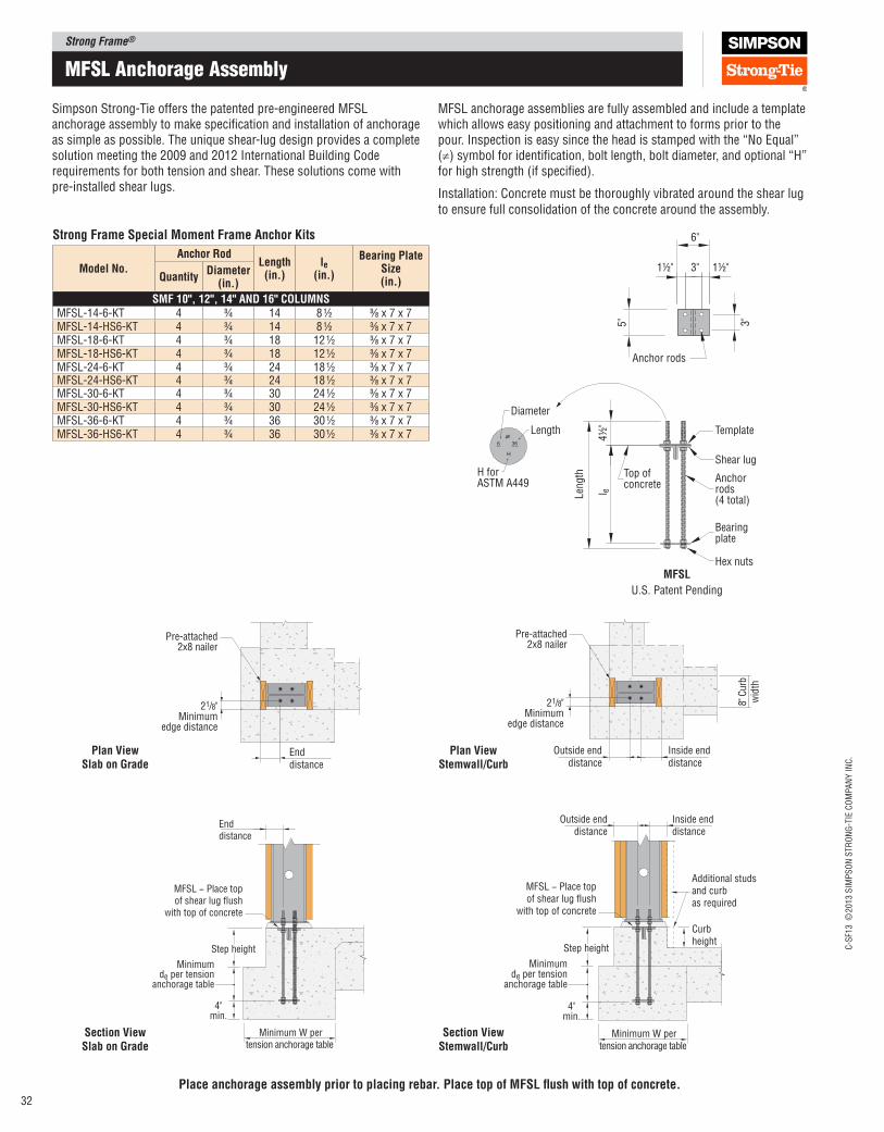
Strong Frame®
C-S
F13 ©
2013 S
IMP
SO
N S
TR
ON
G-T
IE C
OM
PA
NY
IN
C.
32
21/8"Minimum
edge distance
Pre-attached2x8 nailer
Enddistance
6"
1½" 3" 1½"
5" 3"
Anchor rods
Shear lug
Template
4½
"
Top of concrete
Anchorrods(4 total)
Bearingplate
Hex nuts
Len
gth
l e
36
H
6
Diameter
Length
H forASTM A449
≠
MFSl
U.S. Patent Pending
Simpson Strong‑Tie offers the patented pre‑engineered MFSL anchorage assembly to make speciication and installation of anchorage as simple as possible. The unique shear‑lug design provides a complete solution meeting the 2009 and 2012 International Building Code requirements for both tension and shear. These solutions come with pre‑installed shear lugs.
MFSL − Place top of shear lug flush
with top of concrete
Step height
4"min.
Minimum de per tension
anchorage table
Outside enddistance
Inside enddistance
Additional studsand curbas required
Curbheight
Minimum W pertension anchorage table
Enddistance
MFSL − Place top of shear lug flush
with top of concrete
4"min.
Minimum de per tension
anchorage table
Step height
Minimum W pertension anchorage table
plan View Slab on Grade
Section View Slab on Grade
8" C
urb
wid
thOutside end
distanceInside enddistance
21/8"Minimum
edge distance
Pre-attached2x8 nailer
plan View Stemwall/Curb
Section View Stemwall/Curb
MFSL anchorage assemblies are fully assembled and include a template which allows easy positioning and attachment to forms prior to the pour. Inspection is easy since the head is stamped with the “No Equal” (≠) symbol for identiication, bolt length, bolt diameter, and optional “H” for high strength (if speciied).
Installation: Concrete must be thoroughly vibrated around the shear lug to ensure full consolidation of the concrete around the assembly.
mFSL anchorage assembly
place anchorage assembly prior to placing rebar. place top of MFSl lush with top of concrete.
Strong Frame Special Moment Frame Anchor Kits
Model No.
Anchor Rod length
(in.)le
(in.)
Bearing plate Size (in.)Quantity
Diameter (in.)
SMF 10", 12", 14" AND 16" COlUMNSMFSL‑14‑6‑KT 4 3⁄4 14 8 1⁄2 3⁄8 x 7 x 7MFSL‑14‑HS6‑KT 4 3⁄4 14 8 1⁄2 3⁄8 x 7 x 7MFSL‑18‑6‑KT 4 3⁄4 18 12 1⁄2 3⁄8 x 7 x 7MFSL‑18‑HS6‑KT 4 3⁄4 18 12 1⁄2 3⁄8 x 7 x 7MFSL‑24‑6‑KT 4 3⁄4 24 18 1⁄2 3⁄8 x 7 x 7MFSL‑24‑HS6‑KT 4 3⁄4 24 18 1⁄2 3⁄8 x 7 x 7MFSL‑30‑6‑KT 4 3⁄4 30 24 1⁄2 3⁄8 x 7 x 7MFSL‑30‑HS6‑KT 4 3⁄4 30 24 1⁄2 3⁄8 x 7 x 7MFSL‑36‑6‑KT 4 3⁄4 36 30 1⁄2 3⁄8 x 7 x 7MFSL‑36‑HS6‑KT 4 3⁄4 36 30 1⁄2 3⁄8 x 7 x 7
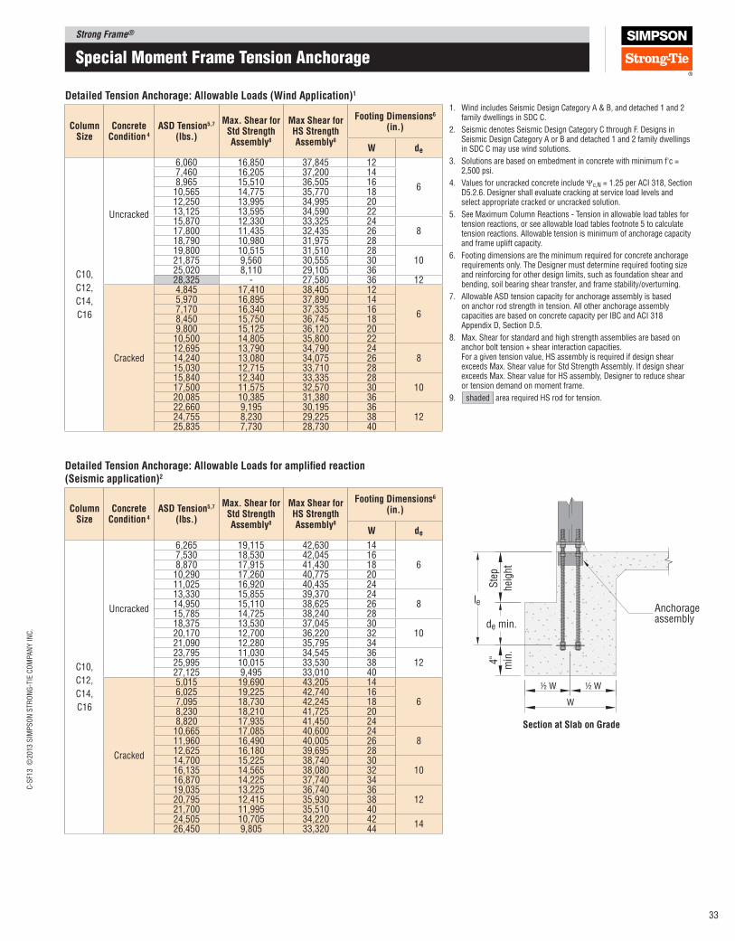
Strong Frame®C
-SF1
3 ©
2013 S
IMP
SO
N S
TR
ON
G-T
IE C
OM
PA
NY
IN
C.
33
Special moment Frame tension anchorage
1. WindincludesSeismicDesignCategoryA&B,anddetached1and2family dwellings in SDC C.
2. Seismic denotes Seismic Design Category C through F. Designs in Seismic Design Category A or B and detached 1 and 2 family dwellings in SDC C may use wind solutions.
3. Solutions are based on embedment in concrete with minimum f'c = 2,500 psi.
4. Values for uncracked concrete include Ψc,N = 1.25 per ACI 318, Section D5.2.6. Designer shall evaluate cracking at service load levels and select appropriate cracked or uncracked solution.
5. See Maximum Column Reactions - Tension in allowable load tables for tension reactions, or see allowable load tables footnote 5 to calculate tension reactions. Allowable tension is minimum of anchorage capacity and frame uplift capacity.
6. Footing dimensions are the minimum required for concrete anchorage requirements only. The Designer must determine required footing size and reinforcing for other design limits, such as foundation shear and bending, soil bearing shear transfer, and frame stability/overturning.
7. Allowable ASD tension capacity for anchorage assembly is based on anchor rod strength in tension. All other anchorage assembly capacities are based on concrete capacity per IBC and ACI 318 Appendix D, Section D.5.
8. Max. Shear for standard and high strength assemblies are based on anchor bolt tension + shear interaction capacities. For a given tension value, HS assembly is required if design shear exceeds Max. Shear value for Std Strength Assembly. If design shear exceeds Max. Shear value for HS assembly, Designer to reduce shear or tension demand on moment frame.
9. shaded area required HS rod for tension.
Detailed Tension Anchorage: Allowable loads (Wind Application)1
Column Size
Concrete Condition 4
ASD Tension5,7 (lbs.)
Max. Shear for Std Strength Assembly8
Max Shear for HS Strength Assembly8
Footing Dimensions6 (in.)
W de
C10,
C12,
C14,
C16
Uncracked
6,060 16,850 37,845 12
6
7,460 16,205 37,200 148,965 15,510 36,505 1610,565 14,775 35,770 1812,250 13,995 34,995 2013,125 13,595 34,590 2215,870 12,330 33,325 24
817,800 11,435 32,435 2618,790 10,980 31,975 2819,800 10,515 31,510 28
1021,875 9,560 30,555 3025,020 8,110 29,105 3628,325 - 27,580 36 12
Cracked
4,845 17,410 38,405 12
6
5,970 16,895 37,890 147,170 16,340 37,335 168,450 15,750 36,745 189,800 15,125 36,120 2010,500 14,805 35,800 2212,695 13,790 34,790 24
814,240 13,080 34,075 2615,030 12,715 33,710 2815,840 12,340 33,335 28
1017,500 11,575 32,570 3020,085 10,385 31,380 3622,660 9,195 30,195 36
1224,755 8,230 29,225 3825,835 7,730 28,730 40
Anchorageassembly
Ste
p
hei
ght
de min.
4"
min
.
½ W ½ W
W
le
Section at Slab on Grade
Detailed Tension Anchorage: Allowable loads for ampliied reaction(Seismic application)2
Column Size
Concrete Condition 4
ASD Tension5,7 (lbs.)
Max. Shear for Std Strength Assembly8
Max Shear for HS Strength Assembly8
Footing Dimensions6 (in.)
W de
C10,
C12,
C14,
C16
Uncracked
6,265 19,115 42,630 14
67,530 18,530 42,045 168,870 17,915 41,430 1810,290 17,260 40,775 2011,025 16,920 40,435 2413,330 15,855 39,370 24
814,950 15,110 38,625 2615,785 14,725 38,240 2818,375 13,530 37,045 30
1020,170 12,700 36,220 3221,090 12,280 35,795 3423,795 11,030 34,545 36
1225,995 10,015 33,530 3827,125 9,495 33,010 40
Cracked
5,015 19,690 43,205 14
66,025 19,225 42,740 167,095 18,730 42,245 188,230 18,210 41,725 208,820 17,935 41,450 2410,665 17,085 40,600 24
811,960 16,490 40,005 2612,625 16,180 39,695 2814,700 15,225 38,740 30
1016,135 14,565 38,080 3216,870 14,225 37,740 3419,035 13,225 36,740 36
1220,795 12,415 35,930 3821,700 11,995 35,510 4024,505 10,705 34,220 42
1426,450 9,805 33,320 44
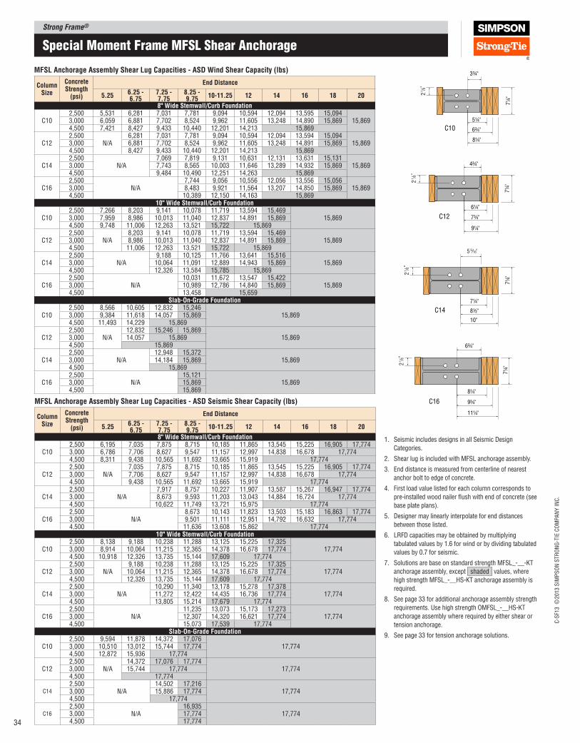
Strong Frame®
C-S
F13 ©
2013 S
IMP
SO
N S
TR
ON
G-T
IE C
OM
PA
NY
IN
C.
34
Special moment Frame mFSL Shear anchorage
MFSl Anchorage Assembly Shear lug Capacities ‑ ASD Wind Shear Capacity (lbs)
Column Size
Concrete Strength
(psi)
End Distance
5.256.25 ‑ 6.75
7.25 ‑ 7.75
8.25 ‑ 9.75
10‑11.25 12 14 16 18 20
8" Wide Stemwall/Curb Foundation
C102,500 5,531 6,281 7,031 7,781 9,094 10,594 12,094 13,595 15,094
15,8693,000 6,059 6,881 7,702 8,524 9,962 11,605 13,248 14,890 15,8694,500 7,421 8,427 9,433 10,440 12,201 14,213 15,869
C122,500
N/A6,281 7,031 7,781 9,094 10,594 12,094 13,594 15,094
15,8693,000 6,881 7,702 8,524 9,962 11,605 13,248 14,891 15,8694,500 8,427 9,433 10,440 12,201 14,213 15,869
C142,500
N/A7,069 7,819 9,131 10,631 12,131 13,631 15,131
15,8693,000 7,743 8,565 10,003 11,646 13,289 14,932 15,8694,500 9,484 10,490 12,251 14,263 15,869
C162,500
N/A7,744 9,056 10,556 12,056 13,556 15,056
15,8693,000 8,483 9,921 11,564 13,207 14,850 15,8694,500 10,389 12,150 14,163 15,869
10" Wide Stemwall/Curb Foundation
C102,500 7,266 8,203 9,141 10,078 11,719 13,594 15,469
15,8693,000 7,959 8,986 10,013 11,040 12,837 14,891 15,8694,500 9,748 11,006 12,263 13,521 15,722 15,869
C122,500
N/A8,203 9,141 10,078 11,719 13,594 15,469
15,8693,000 8,986 10,013 11,040 12,837 14,891 15,8694,500 11,006 12,263 13,521 15,722 15,869
C142,500
N/A9,188 10,125 11,766 13,641 15,516
15,8693,000 10,064 11,091 12,889 14,943 15,8694,500 12,326 13,584 15,785 15,869
C162,500
N/A10,031 11,672 13,547 15,422
15,8693,000 10,989 12,786 14,840 15,8694,500 13,458 15,659
Slab‑On‑Grade Foundation
C102,500 8,566 10,605 12,832 15,246
15,8693,000 9,384 11,618 14,057 15,8694,500 11,493 14,229 15,869
C122,500
N/A12,832 15,246 15,869
15,8693,000 14,057 15,8694,500 15,869
C142,500
N/A12,948 15,372
15,8693,000 14,184 15,8694,500 15,869
C162,500
N/A15,121
15,8693,000 15,8694,500 15,869
MFSl Anchorage Assembly Shear lug Capacities ‑ ASD Seismic Shear Capacity (lbs)
Column Size
Concrete Strength
(psi)
End Distance
5.256.25 ‑ 6.75
7.25 ‑ 7.75
8.25 ‑ 9.75
10‑11.25 12 14 16 18 20
8" Wide Stemwall/Curb Foundation
C102,500 6,195 7,035 7,875 8,715 10,185 11,865 13,545 15,225 16,905 17,7743,000 6,786 7,706 8,627 9,547 11,157 12,997 14,838 16,678 17,7744,500 8,311 9,438 10,565 11,692 13,665 15,919 17,774
C122,500
N/A7,035 7,875 8,715 10,185 11,865 13,545 15,225 16,905 17,774
3,000 7,706 8,627 9,547 11,157 12,997 14,838 16,678 17,7744,500 9,438 10,565 11,692 13,665 15,919 17,774
C142,500
N/A7,917 8,757 10,227 11,907 13,587 15,267 16,947 17,774
3,000 8,673 9,593 11,203 13,043 14,884 16,724 17,7744,500 10,622 11,749 13,721 15,975 17,774
C162,500
N/A8,673 10,143 11,823 13,503 15,183 16,863 17,774
3,000 9,501 11,111 12,951 14,792 16,632 17,7744,500 11,636 13,608 15,862 17,774
10" Wide Stemwall/Curb Foundation
C102,500 8,138 9,188 10,238 11,288 13,125 15,225 17,325
17,7743,000 8,914 10,064 11,215 12,365 14,378 16,678 17,7744,500 10,918 12,326 13,735 15,144 17,609 17,774
C122,500
N/A9,188 10,238 11,288 13,125 15,225 17,325
17,7743,000 10,064 11,215 12,365 14,378 16,678 17,7744,500 12,326 13,735 15,144 17,609 17,774
C142,500
N/A10,290 11,340 13,178 15,278 17,378
17,7743,000 11,272 12,422 14,435 16,736 17,7744,500 13,805 15,214 17,679 17,774
C162,500
N/A11,235 13,073 15,173 17,273
17,7743,000 12,307 14,320 16,621 17,7744,500 15,073 17,539 17,774
Slab‑On‑Grade Foundation
C102,500 9,594 11,878 14,372 17,076
17,7743,000 10,510 13,012 15,744 17,7744,500 12,872 15,936 17,774
C122,500
N/A14,372 17,076 17,774
17,7743,000 15,744 17,7744,500 17,774
C14
2,500N/A
14,502 17,21617,7743,000 15,886 17,774
4,500 17,774
C16
2,500N/A
16,93517,7743,000 17,774
4,500 17,774
1. Seismic includes designs in all Seismic Design
Categories.
2. Shear lug is included with MFSL anchorage assembly.
3. End distance is measured from centerline of nearest
anchor bolt to edge of concrete.
4. First load value listed for each column corresponds to
pre-installed wood nailer lush with end of concrete (see
base plate plans).
5. Designer may linearly interpolate for end distances
between those listed.
6. LRFD capacities may be obtained by multiplying
tabulated values by 1.6 for wind or by dividing tabulated
values by 0.7 for seismic.
7. Solutions are base on standard strength MFSL_-__-KT
anchorage assembly, except shaded values, where
high strength MFSL_-__HS-KT anchorage assembly is
required.
8. See page 33 for additional anchorage assembly strength
requirements. Use high strength OMFSL_-__HS-KT
anchorage assembly where required by either shear or
tension anchorage.
9. See page 33 for tension anchorage solutions.
C10
1 /8"
2
3¾"
5¼"
6¾"
8¼"
7¼
"
C12
4¾"
1 /8"
2
7¼
"
6¼"
7¾"
9¼"
1 /8"
2
9/16"5
7¼"
7¼
"
8½"
10"
C14
6¾"
7¼
"
1 /8"
2
8¼"
9¾"
11¼"
C16
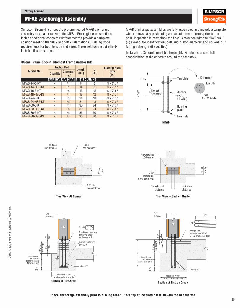
Strong Frame®C
-SF1
3 ©
2013 S
IMP
SO
N S
TR
ON
G-T
IE C
OM
PA
NY
IN
C.
35
mFaB anchorage assembly
Simpson Strong‑Tie offers the pre‑engineered MFAB anchorage assembly as an alternative to the MFSL. Pre‑engineered solutions include additional concrete reinforcement to provide a complete solution meeting the 2009 and 2012 International Building Code requirements for both tension and shear. These solutions require ield‑installed ties or hairpins.
MFAB anchorage assemblies are fully assembled and include a template which allows easy positioning and attachment to forms prior to the pour. Inspection is easy since the head is stamped with the “No Equal” (≠) symbol for identiication, bolt length, bolt diameter, and optional “H” for high strength (if speciied).
Installation: Concrete must be thoroughly vibrated to ensure full consolidation of the concrete around the assembly.
Section at Curb/Stem
Minimum W pertension anchorage table
End
distance
12
" m
ax.
step
hei
gh
t
2"clear
MFAB-KT
Vertical reinforcingper tables
#3 ties
Number and spacingper MFAB shear anchorage table
112"
clea
r
112"
max
.
de minimum per tension
anchorage table(12" minimum)
4"min.
Enddistance
2"
12" m
ax.
step
hei
ght
MFAB-KT
#3
Hairpin tiesnumber per MFAB shear anchorage table
112"
clea
r
18"
de minimum per tension
anchorage table
4"min.
le
Section at Slab on Grade
Minimum W pertension anchorage table
8"m
in.
curb
Outsideend distance
Insideend distance
2 min.1/8"
edge distance
MFAB
Template5"
Top of concrete
Anchorrods(4 total)
Bearingplate
Hex nuts
Len
gth
l e
36
H
6
Diameter
Length
H forASTM A449
≠
place anchorage assembly prior to placing rebar. place top of the ixed nut lush with top of concrete.
Strong Frame Special Moment Frame Anchor Kits
Model No.
Anchor Rod length
(in.)le
(in.)
Bearing plate Size (in.)Quantity
Diameter (in.)
SMF 10", 12", 14" AND 16" COlUMNSMFAB‑14‑6‑KT 4 3⁄4 14 8 3⁄8 x 7 x 7MFAB‑14‑HS6‑KT 4 3⁄4 14 8 3⁄8 x 7 x 7MFAB‑18‑6‑KT 4 3⁄4 18 12 3⁄8 x 7 x 7MFAB‑18‑HS6‑KT 4 3⁄4 18 12 3⁄8 x 7 x 7MFAB‑24‑6‑KT 4 3⁄4 24 18 3⁄8 x 7 x 7MFAB‑24‑HS6‑KT 4 3⁄4 24 18 3⁄8 x 7 x 7MFAB‑30‑6‑KT 4 3⁄4 30 24 3⁄8 x 7 x 7MFAB‑30‑HS6‑KT 4 3⁄4 30 24 3⁄8 x 7 x 7MFAB‑36‑6‑KT 4 3⁄4 36 30 3⁄8 x 7 x 7MFAB‑36‑HS6‑KT 4 3⁄4 36 30 3⁄8 x 7 x 7
8" C
urb
wid
th
Outside enddistance
Inside enddistance
21/8"Minimum
edge distance
Pre-attached2x8 nailer
plan View – Slab on Gradeplan View At Corner
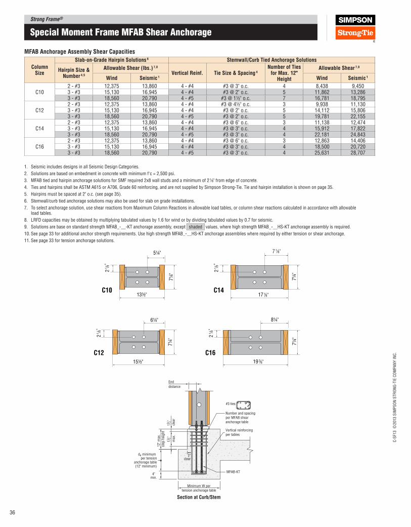
Strong Frame®
C-S
F13 ©
2013 S
IMP
SO
N S
TR
ON
G-T
IE C
OM
PA
NY
IN
C.
36
C10
1 /8"
2
5¼"
13½"
7¼
"
C12
6¼"
1 /8"
2
7¼
"
15½"
1 /8"
2
1/8"7
7¼
"C14
8¼"
7¼
"
1 /8"
2
C16
17
19 3/8"
1/8"
Special moment Frame mFaB Shear anchorage
MFAB Anchorage Assembly Shear Capacities
Column Size
Slab‑on‑Grade Hairpin Solutions 6 Stemwall/Curb Tied Anchorage Solutions
Hairpin Size & Number 4,5
Allowable Shear (lbs.) 7,8
Vertical Reinf. Tie Size & Spacing 4Number of Ties
for Max. 12" Height
Allowable Shear 7,8
Wind Seismic 1 Wind Seismic 1
C102 - #3 12,375 13,860 4 - #4 #3 @ 3" o.c. 4 8,438 9,4503 - #3 15,130 16,945 4 - #4 #3 @ 2" o.c. 5 11,862 13,2863 - #3 18,560 20,790 4 - #5 #3 @ 1½" o.c. 7 16,781 18,795
C122 - #3 12,375 13,860 4 - #4 #3 @ 4½" o.c. 3 9,938 11,1303 - #3 15,130 16,945 4 - #4 #3 @ 2" o.c. 5 14,112 15,8063 - #3 18,560 20,790 4 - #5 #3 @ 2" o.c. 5 19,781 22,155
C142 - #3 12,375 13,860 4 - #4 #3 @ 6" o.c. 3 11,138 12,4743 - #3 15,130 16,945 4 - #4 #3 @ 3" o.c. 4 15,912 17,8223 - #3 18,560 20,790 4 - #5 #3 @ 3" o.c. 4 22,181 24,843
C162 - #3 12,375 13,860 4 - #4 #3 @ 6" o.c. 3 12,863 14,4063 - #3 15,130 16,945 4 - #4 #3 @ 3" o.c. 4 18,500 20,7203 - #3 18,560 20,790 4 - #5 #3 @ 3" o.c. 4 25,631 28,707
1. Seismic includes designs in all Seismic Design Categories.
2. Solutions are based on embedment in concrete with minimum f'c = 2,500 psi.
3. MFAB tied and hairpin anchorage solutions for SMF required 2x8 wall studs and a minimum of 2 1⁄8" from edge of concrete.
4. Ties and hairpins shall be ASTM A615 or A706, Grade 60 reinforcing, and are not supplied by Simpson Strong‑Tie. Tie and hairpin installation is shown on page 35.
5. Hairpins must be spaced at 2" o.c. (see page 35).
6. Stemwall/curb tied anchorage solutions may also be used for slab on grade installations.
7. To select anchorage solution, use shear reactions from Maximum Column Reactions in allowable load tables, or column shear reactions calculated in accordance with allowable load tables.
8. LRFD capacities may be obtained by multiplying tabulated values by 1.6 for wind or by dividing tabulated values by 0.7 for seismic.
9. Solutions are base on standard strength MFAB_‑__‑KT anchorage assembly, except shaded values, where high strength MFAB_‑__HS‑KT anchorage assembly is required.
10. See page 33 for additional anchor strength requirements. Use high strength MFAB_‑__HS‑KT anchorage assemblies where required by either tension or shear anchorage.
11. See page 33 for tension anchorage solutions.
Section at Curb/Stem
Minimum W pertension anchorage table
End
distance
12
" m
ax.
step
hei
gh
t
2"clear
MFAB-KT
Vertical reinforcingper tables
#3 ties
Number and spacingper MFAB shear anchorage table
112"
clea
r
112"
max
.
de minimum per tension
anchorage table(12" minimum)
4"min.
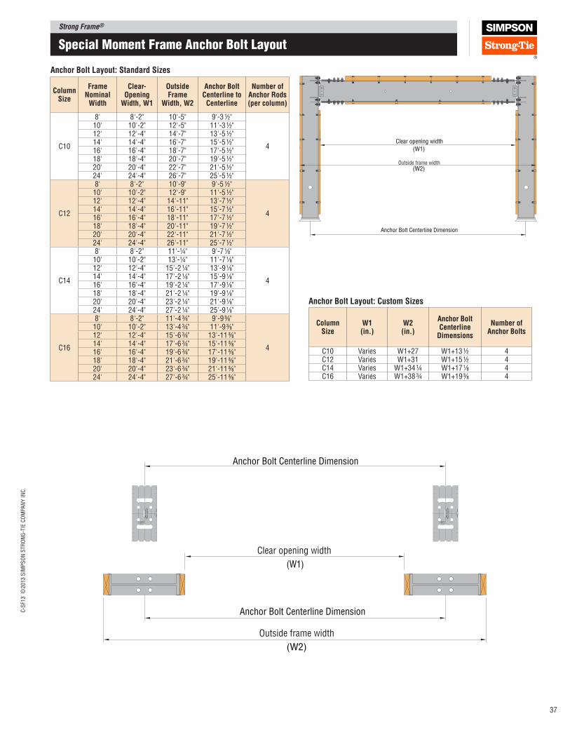
Strong Frame®C
-SF1
3 ©
2013 S
IMP
SO
N S
TR
ON
G-T
IE C
OM
PA
NY
IN
C.
37
Special moment Frame anchor Bolt Layout
Anchor Bolt layout: Standard Sizes
Column Size
Frame Nominal
Width
Clear‑Opening
Width, W1
Outside Frame
Width, W2
Anchor Bolt Centerline to
Centerline
Number of Anchor Rods (per column)
C10
8' 8'-2" 10'-5" 9'-3 ½"
4
10' 10'-2" 12'-5" 11'-3 ½"12' 12'-4" 14'-7" 13'-5 ½"14' 14'-4" 16'-7" 15'-5 ½"16' 16'-4" 18'-7" 17'-5 ½"18' 18'-4" 20'-7" 19'-5 ½"20' 20'-4" 22'-7" 21'-5 ½"24' 24'-4" 26'-7" 25'-5 ½"
C12
8' 8'-2" 10'-9" 9'-5 ½"
4
10' 10'-2" 12'-9" 11'-5 ½"12' 12'-4" 14'-11" 13'-7 ½"14' 14'-4" 16'-11" 15'-7 ½"16' 16'-4" 18'-11" 17'-7 ½"18' 18'-4" 20'-11" 19'-7 ½"20' 20'-4" 22'-11" 21'-7 ½"24' 24'-4" 26'-11" 25'-7 ½"
C14
8' 8'-2" 11'-¼" 9'-7 1⁄8"
4
10' 10'-2" 13'-¼" 11'-7 1⁄8"12' 12'-4" 15'-2 ¼" 13'-9 1⁄8"14' 14'-4" 17'-2 ¼" 15'-9 1⁄8"16' 16'-4" 19'-2 ¼" 17'-9 1⁄8"18' 18'-4" 21'-2 ¼" 19'-9 1⁄8"20' 20'-4" 23'-2 ¼" 21'-9 1⁄8"24' 24'-4" 27'-2 ¼" 25'-9 1⁄8"
C16
8' 8'-2" 11'-4 ¾" 9'-9 3⁄8"
4
10' 10'-2" 13'-4 ¾" 11'-9 3⁄8"12' 12'-4" 15'-6 ¾" 13'-11 3⁄8"14' 14'-4" 17'-6 ¾" 15'-11 3⁄8"16' 16'-4" 19'-6 ¾" 17'-11 3⁄8"18' 18'-4" 21'-6 ¾" 19'-11 3⁄8"20' 20'-4" 23'-6 ¾" 21'-11 3⁄8"24' 24'-4" 27'-6 ¾" 25'-11 3⁄8"
Column Size
W1 (in.)
W2 (in.)
Anchor Bolt Centerline
Dimensions
Number of Anchor Bolts
C10 Varies W1+27 W1+13 ½ 4C12 Varies W1+31 W1+15 ½ 4C14 Varies W1+34 ¼ W1+17 1⁄8 4C16 Varies W1+38 ¾ W1+19 3⁄8 4
Anchor Bolt layout: Custom Sizes
Anchor Bolt Centerline Dimension
(W1)
Clear opening width
Outside frame width(W2)
Anchor Bolt Centerline Dimension
(W1)
(W2)
Anchor Bolt Centerline Dimension
Clear opening width
Outside frame width
OM
F C
18
H,C
21
H
Fra
me
Insid
e
Co
lum
n C
en
ter
Lin
eS
MF
C1
0,C
12
,C1
4,C
16
OM
F C
18
H,C
21
H
Fra
me
Insid
e
Co
lum
n C
en
ter
Lin
eS
MF
C1
0,C
12
,C1
4,C
16

Strong Frame®
C-S
F13 ©
2013 S
IMP
SO
N S
TR
ON
G-T
IE C
OM
PA
NY
IN
C.
38
Special moment Frame Design example
SMF Example #1: 1st of 3‑Story Seismic Application
Given
2009 or 2012 IBC, Seismic Design, 3,000 psi concrete
Seismic Design Category D, R = 6.5, Ωo = 2.5
SDS =1.5 g
20-ftFloor&20-ftRoofSpanTributarytoFrame Apartment building, wood-frame construction
Vertical Loads:
Roof – 25 psf Dead, 20 psf Live
Floor – 18 psf Dead, 40 psf Live
Wall Weight = 12 psf
Clear opening = 16'-0" wide x 7'-0" tall
Use Simpson Strong Frame special moment frame.
Note: OMFs cannot be used when height > 35' or when either the loor or roof dead load > 20 psf in SDC-D
Select Frame
Step 1: Determine lateral load
Total ASD Force to Frame, Vframe = 5,500 + 4,500 + 3,500 = 13,500 lbs
Step 2: Check R Value
Since seismic loads are calculated using R=6.5, no load conversion is required.
Vframe = 13,500 lbs
Note: Simpson Strong‑Tie® Strong Frame special moment frame meets all the criteria of a steel special moment frame, a R value of 8 can be used for design. However, per ASCE 7 Section 12.2.3.1, when the upper system has a lower R value, the Design Coeficients (R, Ωo, Cd) for the upper system shall be used for both systems.
Step 3: Select Nominal Height and Width
Nominal frame height: 9 ft.
Nominal frame width: 16 ft.
This narrows down to 3 possible SMF models (SMF1012‑16x9‑L, SMF1612‑16x9‑M or SMF1616‑16x9‑H).
Step 4: Check Vertical loading
Since SDS = 1.5 g > 1.0 g, include additional vertical seismic load effects in dead load check (footnote 2, page 23):
WDL = (25 psf x 20'/2) + (2 x 18 psf x 20'/2) + (12 psf x 14' x 2) = 946 plf
DL = (1.0 + 0.14SDS)WDL = (1.0 + (0.14x1.5))x(946 plf) = 1145 plf
WRLL= 20 psf x 20'/2 = 200 plf
WFLL= 2 x 40 psf x 20'/2 = 800 plf
Wu= DL+ 0.75 LL + 0.75 Lr = (1145 + 0.75 x 800 + 0.75x 200) = 1895 plf,
Note: Designer must determine governing load combination per applicable code.
DL/LL = 946 plf /800 plf = 1.18 > 0.33 and less than 3 OK
Pu= 1,895 plf x 16 ft = 30,320 lbs.
Step 5: Select Special Moment Frame Model
With Vframe = 13,500 lbs. and Pu= 30,320 lbs.
For SMF1616‑16x9‑H: Allowable ASD shear = 13,570 lbs. > 13,500 lbs, Shear OK
Allowable Pu = 30,665 lbs. > 30,320 lbs. Gravity OK
Step 6: Check Frame Dimensions
Using tables at the top of page 22:
Clear opening width: W1 = 16'‑4" > 16'‑ 0", OK
Outside frame width: W2 = 19'‑6 3⁄4" < 20 ft", OK
Clear opening height: H3 = 7'‑5⁄8" > 7'‑ 0", OK
Step 7: Select Top plate Fasteners
In Seismic Design Category D, design connection of top plate to SMF for load combinations with overstrength. Assume half of load shear is delivered through collector:
Emh = ΩoE = 2.5 x 13,500 lbs./2 = 16,875 lbs.
SDS screw allowable shear = 1.6 x 340 lbs. = 544 lbs.
Number of screws = (16,875 lbs.)/(544 lbs.) = 31
Select (32) ‑ ¼" x 3½" SDS screws (2 rows @ 10" o.c.) staggered)
Tension Anchorage DesignStep 1: Determine Concrete Condition
Concrete is cracked
Note: Designer must determine whether cracked or uncracked concrete is applicable based on the project conditions in accordance with ACI318 Appendix D.
5500 lbs
4500 lbs
3500 lbs
14'-
0"
14'-
0"
9'-
0"
16'-0"
MFAB-KT
Hairpin ties
10"
de
4"min.
½ W ½ W
le
W
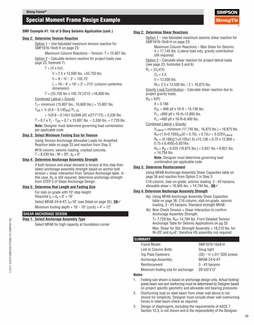
Strong Frame®C
-SF1
3 ©
2013 S
IMP
SO
N S
TR
ON
G-T
IE C
OM
PA
NY
IN
C.
39
Special moment Frame Design example
Step 2: Determine Shear Reactions
Option 1 – Use tabulated maximum seismic shear reaction for SMF1616-16x9-H on page 23:
Maximum Column Reactions – Max Shear for Seismic: V = 17,745 lbs. (Lateral load only, gravity contribution still required)
Option 2 – Calculate shear reaction for project lateral loads (see page 23, footnotes 5 and 6)
RL = (ΩoV/2)
Ωo = 2.5
V = 13,500 lbs.
RL= 2.5 x 13,500 lbs. / 2 = 16,875 lbs.
Gravity Load Contribution – Calculate shear reaction due to project gravity loads.
RG = X(P)
X = 0.186
PDL = 946 plf x 16-ft = 15,136 lbs.
PLL =800 plf x 16-ft=12,800 lbs.
PLr =400 plf x 16-ft=6,400 lbs.
Combined Lateral + Gravity:
VLateral = minimum (17,745 lbs., 16,875 lbs.) = 16,875 lbs.
RH=(1.0+0.105SDS)D + 0.75L + 0.75Lr + 0.525VLateral
RG = (0.186)[(1+0.105x1.5) x15,136 + 0.75 x 12,800 + 0.75 x 6,400]=5,937lbs.
RH = RG + 0.525 (16,875 lbs.) = 5,937 lbs + 8,857 lbs. = 14,794 lbs.
Note: Designer must determine governing load combination per applicable code
Step 3: Determine Reinforcement
Using MFAB Anchorage Assembly Shear Capacities table on page 36 and reaction from Option 2 in Step 3:
C16 column, slab-on-grade, seismic loading: 3 - #3 hairpins, allowable shear = 16,945 lbs. > 14,794 lbs., OK
Step 4: Determine Anchorage Assembly Strength
4a) Using MFAB Anchorage Assembly Shear Capacities table on page 36: C16 column, slab-on-grade, seismic loading, 3 - #3 hairpins: Standard strength MFAB.
4b) Now Check Tension + Shear Interaction to conirm Anchorage Assembly Strength:
T= 7,729 lbs, RH= 14,794 lbs. From Detailed Tension Anchorage Table for Seismic Applications on pg 33.
Max. Shear for Std. Strength Assembly = 18,210 lbs. for W=20" and de=6", therefore HS assembly not required.
SUMMARy
Frame Model: SMF1616‑16x9‑H
Link to Column Bolts: Snug tight
Top Plate Fasteners: (32) ‑ ¼" x 3½" SDS screws
Anchorage Assembly: MFAB‑24‑6‑KT
Reinforcement: 3 ‑ #3 hairpins
Minimum footing size for anchorage: 20"x20"x12"
Notes:
1. Footing size shown is based on anchorage design only. Actual footing/grade beam size and reinforcing must be determined by Designer based on project speciic geometry and allowable soil bearing pressures.
2. Overturning load on steel beam from shear wall above is not shown for simplicity; Designer must include shear wall overturning forces in steel beam check as required.
3. Design of diaphragms, including the requirements of ASCE 7 Section 12.3, is not shown and is the responsibility of the Designer.
SMF Example #1: 1st of 3‑Story Seismic Application (cont.)
Step 2: Determine Tension Reaction
Option 1 – Use tabulated maximum tension reaction for SMF1616‑16x9‑H on page 23:
Maximum Column Reactions – Tension: T = 15,807 lbs.
Option 2 – Calculate tension reaction for project loads (see page 23, footnote 7)
T = (V x h)/L
V = 2.5 x 13,500 lbs. =33,750 lbs.
h = 9'– ¾" ‑ 3" = 105.75"
L = 16'– 4" + 16" + 3" = 215" (column centerline dimension)
T = (33,750 lbs x 105.75")/215" =16,600 lbs.
Combined Lateral + Gravity
TL= minimum (15,807 lbs., 16,600 lbs.) = 15,807 lbs.
TGR = ½ (0.6 – 0.14SDS) Pu_DL
= ½(0.6 – 0.14x1.5)(946 plf) x(217"/12) = 3,336 lbs.
T = 0.7 x TL ‑ TGR = 0.7 x 15,807 lbs. – 3,336 lbs. = 7,729 lbs.
Note: Designer must determine governing load combination per applicable code
Step 3: Select Minimum Footing Size for Tension
Using Tension Anchorage Allowable Loads for Ampliied Reaction table on page 33 and reaction from Step 3:
W16 column, seismic loading, cracked concrete, T = 8,230 lbs.: W = 20", de = 6"
Step 4: Determine Anchorage Assembly Strength
If both tension and shear demand is known at this step then select anchorage assembly strength based on anchor bolt tension + shear interaction from Tension Anchorage table. In this case, RH is still required, determine anchorage strength from STEP 5 of Shear Anchorage Design.
Step 5: Determine Rod length and Footing Size
For slab on grade with 10" step height: Required le = de + 6" = 16"
Select MFAB‑24‑6‑KT, le=18" (see Detail on page 35), OK
Minimum footing depth = 18" ‑ 10" (curb) + 4" = 12"
SHEAR ANCHORAGE DESIGN
Step 1: Select Anchorage Assembly Type
Select MFAB for high capacity at foundation corner
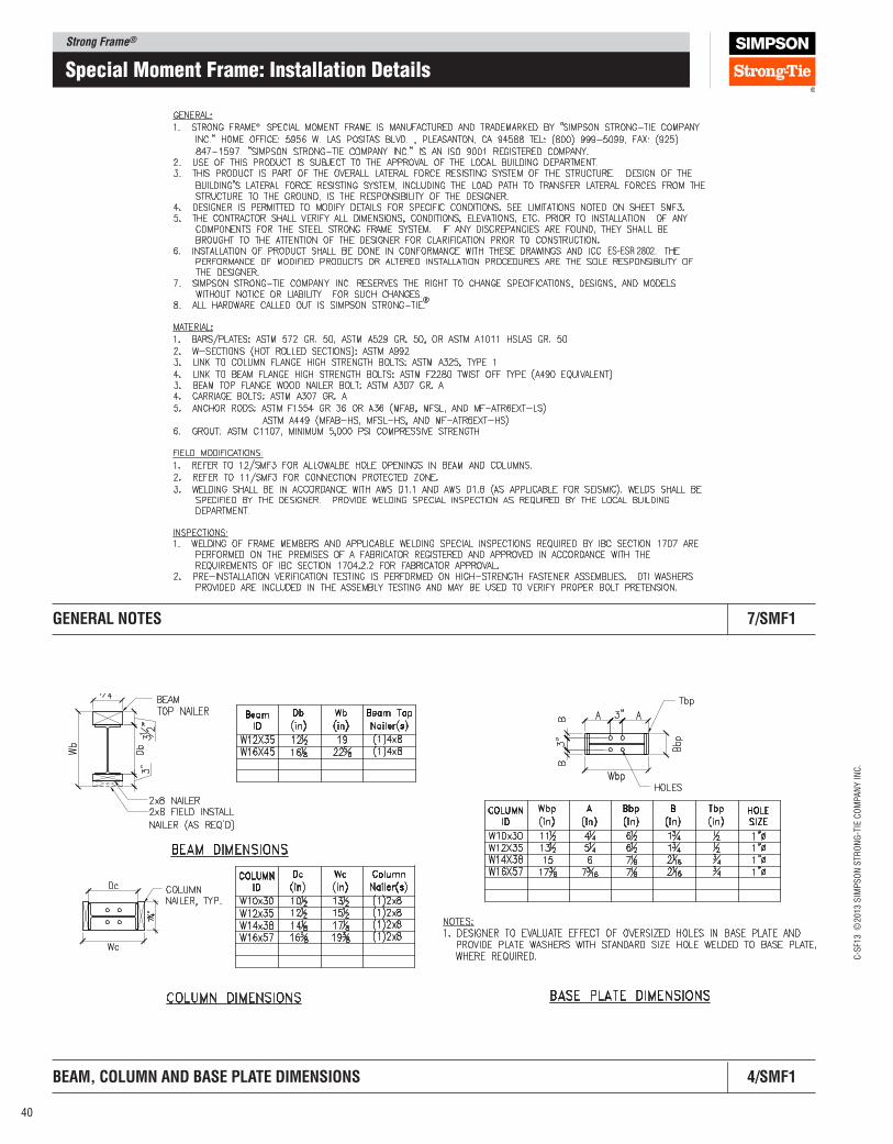
Strong Frame®
C-S
F13 ©
2013 S
IMP
SO
N S
TR
ON
G-T
IE C
OM
PA
NY
IN
C.
40
Special moment Frame: Installation Details
®
ES-ESR 2802.
GENERAl NOTES 7/SMF1
BEAM, COlUMN AND BASE plATE DIMENSIONS 4/SMF1
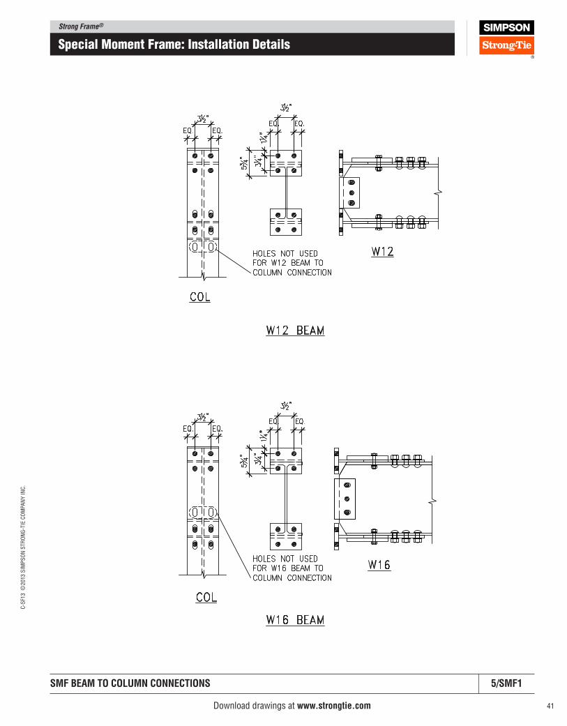
Strong Frame®C
-SF1
3 ©
2013 S
IMP
SO
N S
TR
ON
G-T
IE C
OM
PA
NY
IN
C.
41
Special moment Frame: Installation Details
Download drawings at www.strongtie.com
SMF BEAM TO COlUMN CONNECTIONS 5/SMF1
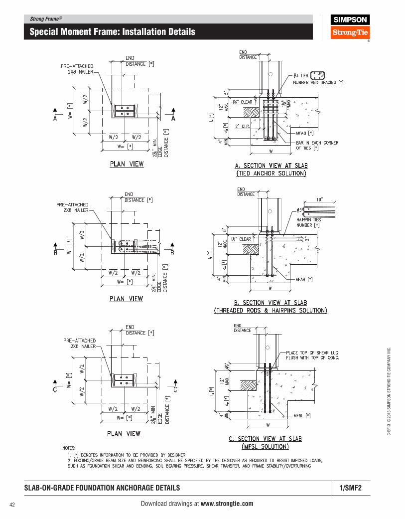
Strong Frame®
C-S
F13 ©
2013 S
IMP
SO
N S
TR
ON
G-T
IE C
OM
PA
NY
IN
C.
42
Special moment Frame: Installation Details
Download drawings at www.strongtie.com
SlAB‑ON‑GRADE FOUNDATION ANCHORAGE DETAIlS 1/SMF2
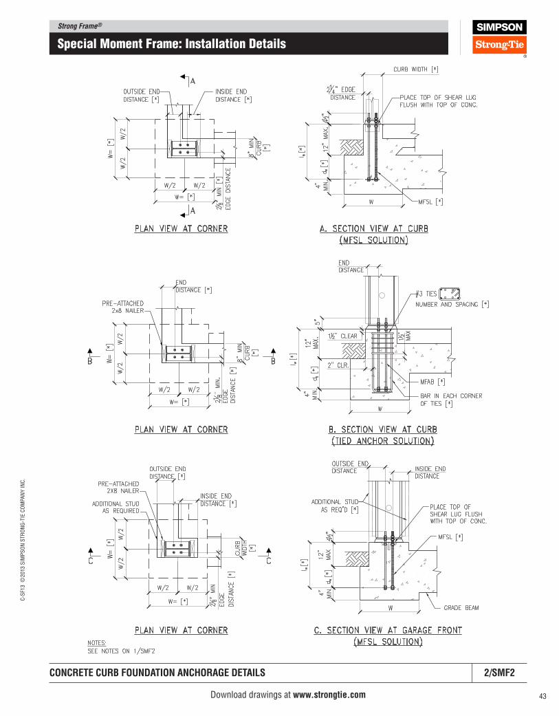
Strong Frame®C
-SF1
3 ©
2013 S
IMP
SO
N S
TR
ON
G-T
IE C
OM
PA
NY
IN
C.
43
Special moment Frame: Installation Details
CONCRETE CURB FOUNDATION ANCHORAGE DETAIlS 2/SMF2
Download drawings at www.strongtie.com
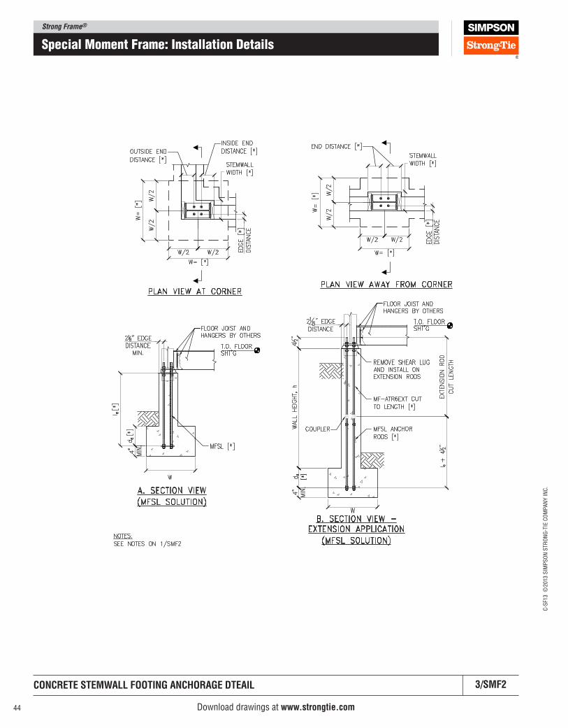
Strong Frame®
C-S
F13 ©
2013 S
IMP
SO
N S
TR
ON
G-T
IE C
OM
PA
NY
IN
C.
44
Special moment Frame: Installation Details
CONCRETE STEMWAll FOOTING ANCHORAGE DTEAIl 3/SMF2
Download drawings at www.strongtie.com
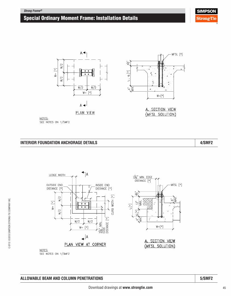
Strong Frame®C
-SF1
3 ©
2013 S
IMP
SO
N S
TR
ON
G-T
IE C
OM
PA
NY
IN
C.
45
Special ordinary moment Frame: Installation Details
AllOWABlE BEAM AND COlUMN pENETRATIONS 5/SMF2
Download drawings at www.strongtie.com
INTERIOR FOUNDATION ANCHORAGE DETAIlS 4/SMF2
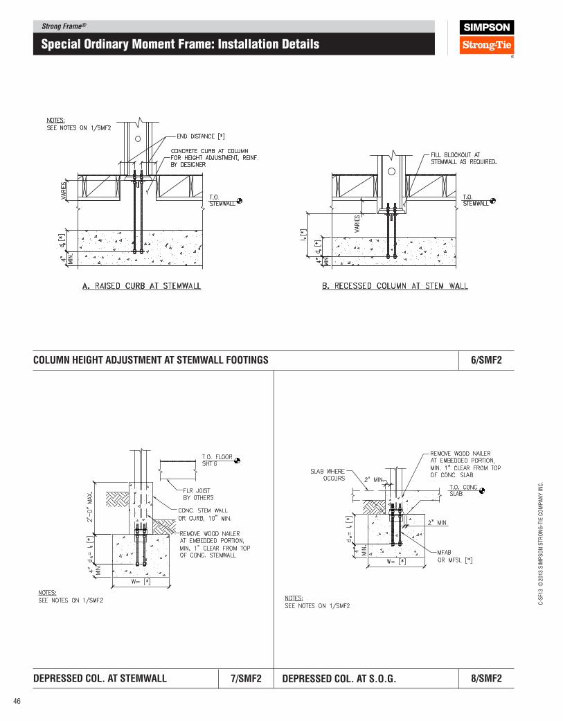
Strong Frame®
C-S
F13 ©
2013 S
IMP
SO
N S
TR
ON
G-T
IE C
OM
PA
NY
IN
C.
46
DEpRESSED COl. AT STEMWAll 8/SMF2
COlUMN HEIGHT ADJUSTMENT AT STEMWAll FOOTINGS 6/SMF2
7/SMF2 DEpRESSED COl. AT S.O.G.
Special ordinary moment Frame: Installation Details
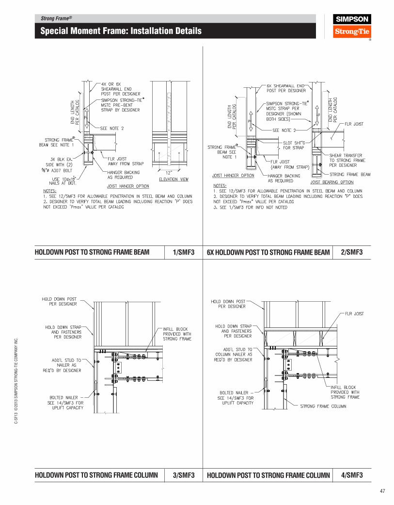
Strong Frame®C
-SF1
3 ©
2013 S
IMP
SO
N S
TR
ON
G-T
IE C
OM
PA
NY
IN
C.
47
HOlDOWN pOST TO STRONG FRAME COlUMN 4/SMF33/SMF3 HOlDOWN pOST TO STRONG FRAME COlUMN
HOlDOWN pOST TO STRONG FRAME BEAM 2/SMF31/SMF3 6X HOlDOWN pOST TO STRONG FRAME BEAM
Special moment Frame: Installation Details
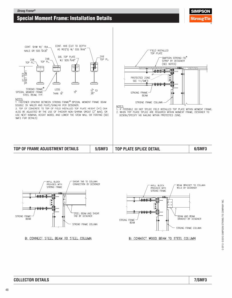
Strong Frame®
C-S
F13 ©
2013 S
IMP
SO
N S
TR
ON
G-T
IE C
OM
PA
NY
IN
C.
48
TOp OF FRAME ADJUSTMENT DETAIlS 6/SMF35/SMF3 TOp plATE SplICE DETAIl
COllECTOR DETAIlS 7/SMF3
Special moment Frame: Installation Details
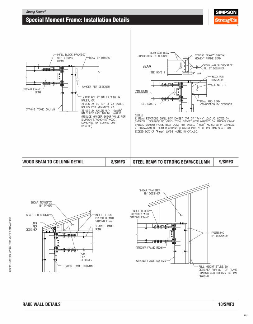
Strong Frame®C
-SF1
3 ©
2013 S
IMP
SO
N S
TR
ON
G-T
IE C
OM
PA
NY
IN
C.
49
WOOD BEAM TO COlUMN DETAIl 9/SMF38/SMF3 STEEl BEAM TO STRONG BEAM/COlUMN
RAKE WAll DETAIlS 10/SMF3
Special moment Frame: Installation Details
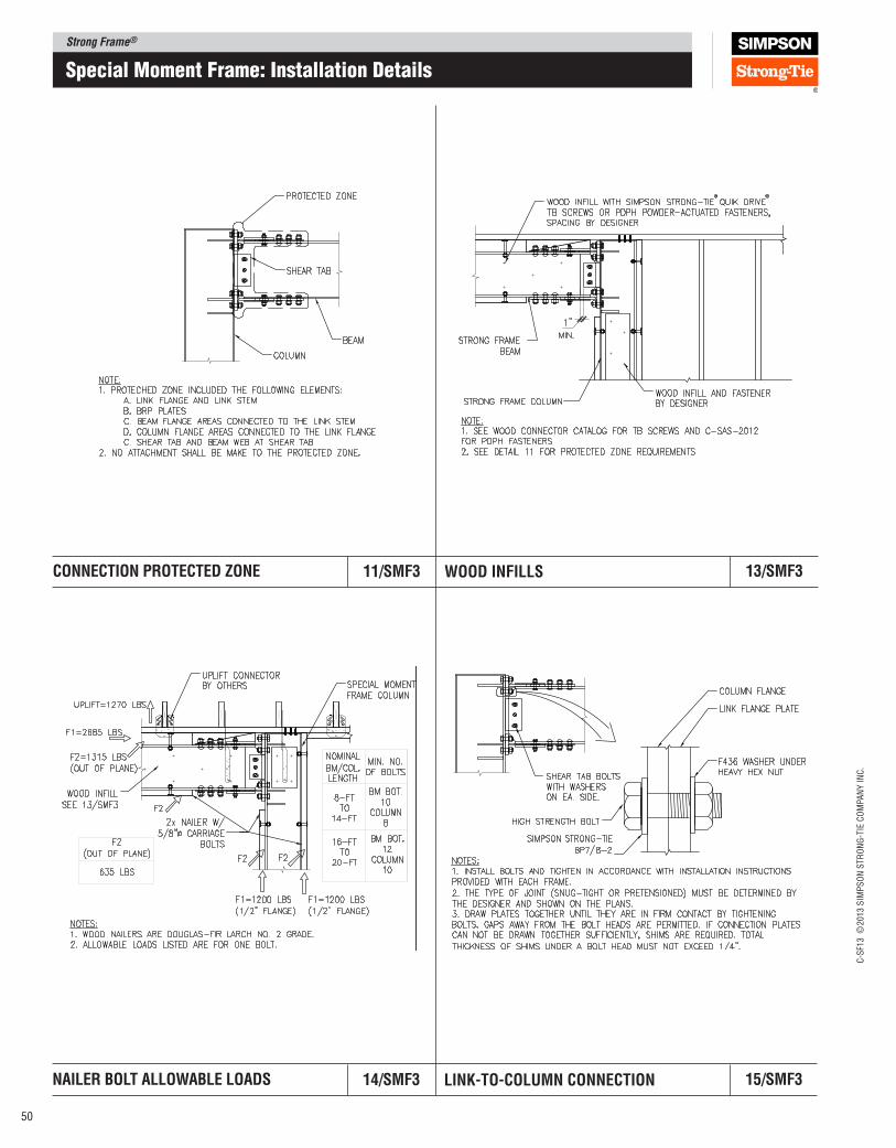
Strong Frame®
C-S
F13 ©
2013 S
IMP
SO
N S
TR
ON
G-T
IE C
OM
PA
NY
IN
C.
50
Special moment Frame: Installation Details
CONNECTION pROTECTED ZONE 13/SMF311/SMF3 WOOD INFIllS
NAIlER BOlT AllOWABlE lOADS 15/SMF314/SMF3 lINK‑TO‑COlUMN CONNECTION
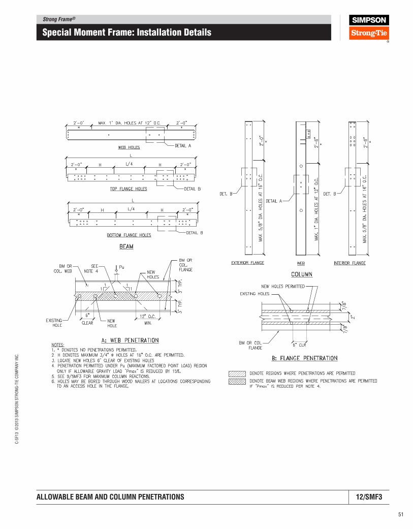
Strong Frame®C
-SF1
3 ©
2013 S
IMP
SO
N S
TR
ON
G-T
IE C
OM
PA
NY
IN
C.
51
Special moment Frame: Installation Details
AllOWABlE BEAM AND COlUMN pENETRATIONS 12/SMF3
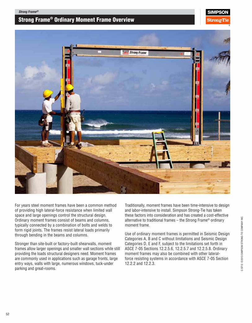
Strong Frame®
C-S
F13 ©
2013 S
IMP
SO
N S
TR
ON
G-T
IE C
OM
PA
NY
IN
C.
52
Strong Frame® ordinary moment Frame overview
For years steel moment frames have been a common method of providing high lateral-force resistance when limited wall space and large openings control the structural design. Ordinary moment frames consist of beams and columns, typically connected by a combination of bolts and welds to form rigid joints. The frames resist lateral loads primarily through bending in the beams and columns.
Stronger than site-built or factory-built shearwalls, moment frames allow larger openings and smaller wall sections while still providing the loads structural designers need. Moment frames are commonly used in applications such as garage fronts, large entry ways, walls with large, numerous windows, tuck-under parking and great-rooms.
Traditionally, moment frames have been time-intensive to design and labor-intensive to install. Simpson Strong-Tie has taken these factors into consideration and has created a cost-effective alternative to traditional frames – the Strong Frame® ordinary moment frame.
Use of ordinary moment frames is permitted in Seismic Design Categories A, B and C without limitations and Seismic Design Categories D, E and F, subject to the limitations set forth in ASCE 7-05 Sections 12.2.5.6, 12.2.5.7 and 12.2.5.8. Ordinary moment frames may also be combined with other lateral-force resisting systems in accordance with ASCE 7-05 Section 12.2.2 and 12.2.3.
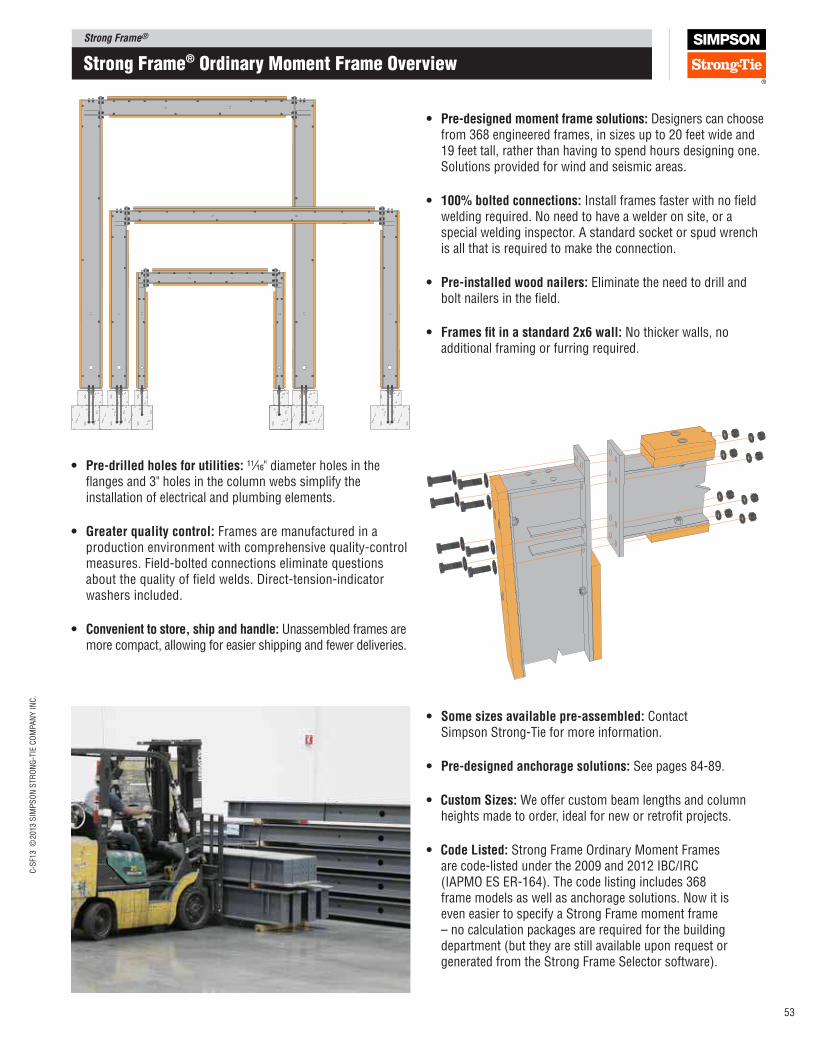
Strong Frame®C
-SF1
3 ©
2013 S
IMP
SO
N S
TR
ON
G-T
IE C
OM
PA
NY
IN
C.
53
Strong Frame® ordinary moment Frame overview
• pre‑designed moment frame solutions: Designers can choose from 368 engineered frames, in sizes up to 20 feet wide and 19 feet tall, rather than having to spend hours designing one. Solutions provided for wind and seismic areas.
• 100% bolted connections: Install frames faster with no ield welding required. No need to have a welder on site, or a special welding inspector. A standard socket or spud wrench is all that is required to make the connection.
• pre‑installed wood nailers: Eliminate the need to drill and bolt nailers in the ield.
• Frames it in a standard 2x6 wall: No thicker walls, no additional framing or furring required.
• pre‑drilled holes for utilities: 11⁄16" diameter holes in the langes and 3" holes in the column webs simplify the installation of electrical and plumbing elements.
• Greater quality control: Frames are manufactured in a production environment with comprehensive quality‑control measures. Field‑bolted connections eliminate questions about the quality of ield welds. Direct‑tension‑indicator washers included.
• Convenient to store, ship and handle: Unassembled frames are more compact, allowing for easier shipping and fewer deliveries.
• Some sizes available pre‑assembled: Contact Simpson Strong‑Tie for more information.
• pre‑designed anchorage solutions: See pages 84‑89.
• Custom Sizes: We offer custom beam lengths and column heights made to order, ideal for new or retroit projects.
• Code listed: Strong Frame Ordinary Moment Frames are code‑listed under the 2009 and 2012 IBC/IRC (IAPMO ES ER‑164). The code listing includes 368 frame models as well as anchorage solutions. Now it is even easier to specify a Strong Frame moment frame – no calculation packages are required for the building department (but they are still available upon request or generated from the Strong Frame Selector software).
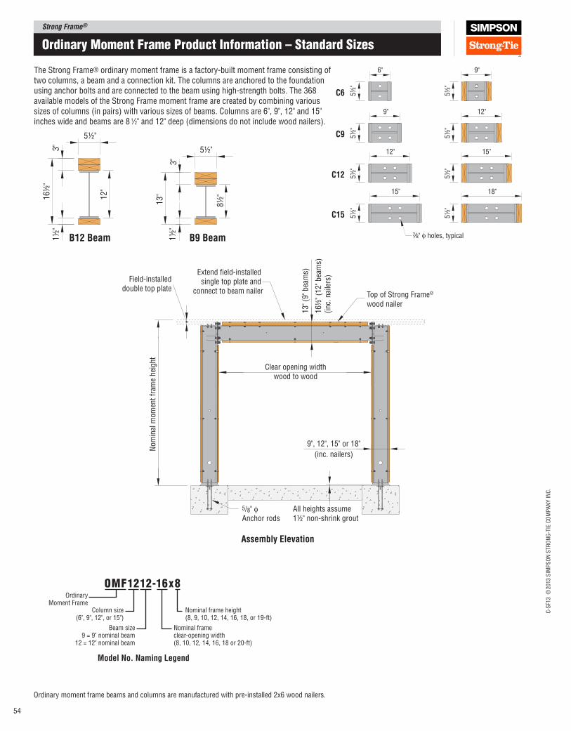
Strong Frame®
C-S
F13 ©
2013 S
IMP
SO
N S
TR
ON
G-T
IE C
OM
PA
NY
IN
C.
54
Clear opening widthwood to wood
Extend field-installed single top plate and
connect to beam nailer Top of Strong Frame®
wood nailer
5/8" φAnchor rods
All heights assume 1½" non-shrink grout
13" (9
" bea
ms)
16½
" (1
2" bea
ms)
(inc.
nai
lers
)
Field-installeddouble top plate
9", 12", 15" or 18"
(inc. nailers)
Nom
inal
mom
ent
fram
e hei
ght
C6
C9
C12
C15
6" 9"
9" 12"
12" 15"
" φ holes, typical
18"15"
5½
"5
½"
5½
"5
½"
5½
"5
½"
5½
"5
½"
7 8/B9 BeamB12 Beam
5½"
1½
"3
"
8½
"
13
"
1½
"3
"1
6½
"
12
"
5½"
Assembly Elevation
The Strong Frame® ordinary moment frame is a factory-built moment frame consisting of two columns, a beam and a connection kit. The columns are anchored to the foundation using anchor bolts and are connected to the beam using high-strength bolts. The 368 available models of the Strong Frame moment frame are created by combining various sizes of columns (in pairs) with various sizes of beams. Columns are 6", 9", 12" and 15" inches wide and beams are 8 1⁄2" and 12" deep (dimensions do not include wood nailers).
ordinary moment Frame Product Information – Standard Sizes
Ordinary moment frame beams and columns are manufactured with pre-installed 2x6 wood nailers.
Ordinary Moment Frame
Column size(6", 9", 12", or 15")
Beam size9 = 9" nominal beam
12 = 12" nominal beam
omF1212-16x8
Nominal frame height(8, 9, 10, 12, 14, 16, 18, or 19-ft)
Nominal frame clear-opening width(8, 10, 12, 14, 16, 18 or 20-ft)
Model No. Naming legend
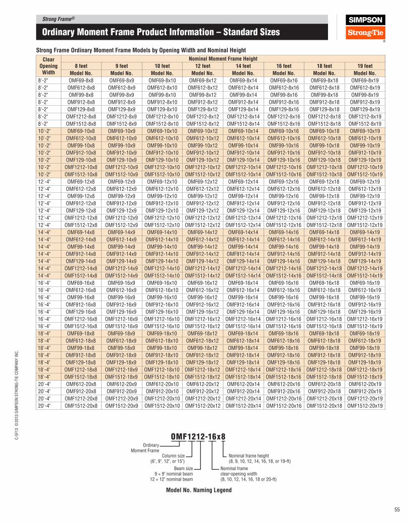
Strong Frame®C
-SF1
3 ©
2013 S
IMP
SO
N S
TR
ON
G-T
IE C
OM
PA
NY
IN
C.
55
ordinary moment Frame Product Information – Standard Sizes
Ordinary Moment Frame
Column size(6", 9", 12", or 15")
Beam size9 = 9" nominal beam
12 = 12" nominal beam
omF1212-16x8
Nominal frame height(8, 9, 10, 12, 14, 16, 18, or 19-ft)
Nominal frame clear-opening width(8, 10, 12, 14, 16, 18 or 20-ft)
Model No. Naming legend
Strong Frame Ordinary Moment Frame Models by Opening Width and Nominal Height
Clear Opening Width
Nominal Moment Frame Height
8 feet 9 feet 10 feet 12 feet 14 feet 16 feet 18 feet 19 feet
Model No. Model No. Model No. Model No. Model No. Model No. Model No. Model No.
8'-2" OMF69-8x8 OMF69-8x9 OMF69-8x10 OMF69-8x12 OMF69-8x14 OMF69-8x16 OMF69-8x18 OMF69-8x19
8'-2" OMF612-8x8 OMF612-8x9 OMF612-8x10 OMF612-8x12 OMF612-8x14 OMF612-8x16 OMF612-8x18 OMF612-8x19
8'-2" OMF99-8x8 OMF99-8x9 OMF99-8x10 OMF99-8x12 OMF99-8x14 OMF99-8x16 OMF99-8x18 OMF99-8x19
8'-2" OMF912-8x8 OMF912-8x9 OMF912-8x10 OMF912-8x12 OMF912-8x14 OMF912-8x16 OMF912-8x18 OMF912-8x19
8'-2" OMF129-8x8 OMF129-8x9 OMF129-8x10 OMF129-8x12 OMF129-8x14 OMF129-8x16 OMF129-8x18 OMF129-8x19
8'-2" OMF1212-8x8 OMF1212-8x9 OMF1212-8x10 OMF1212-8x12 OMF1212-8x14 OMF1212-8x16 OMF1212-8x18 OMF1212-8x19
8'-2" OMF1512-8x8 OMF1512-8x9 OMF1512-8x10 OMF1512-8x12 OMF1512-8x14 OMF1512-8x16 OMF1512-8x18 OMF1512-8x19
10'-2" OMF69-10x8 OMF69-10x9 OMF69-10x10 OMF69-10x12 OMF69-10x14 OMF69-10x16 OMF69-10x18 OMF69-10x19
10'-2" OMF612-10x8 OMF612-10x9 OMF612-10x10 OMF612-10x12 OMF612-10x14 OMF612-10x16 OMF612-10x18 OMF612-10x19
10'-2" OMF99-10x8 OMF99-10x9 OMF99-10x10 OMF99-10x12 OMF99-10x14 OMF99-10x16 OMF99-10x18 OMF99-10x19
10'-2" OMF912-10x8 OMF912-10x9 OMF912-10x10 OMF912-10x12 OMF912-10x14 OMF912-10x16 OMF912-10x18 OMF912-10x19
10'-2" OMF129-10x8 OMF129-10x9 OMF129-10x10 OMF129-10x12 OMF129-10x14 OMF129-10x16 OMF129-10x18 OMF129-10x19
10'-2" OMF1212-10x8 OMF1212-10x9 OMF1212-10x10 OMF1212-10x12 OMF1212-10x14 OMF1212-10x16 OMF1212-10x18 OMF1212-10x19
10'-2" OMF1512-10x8 OMF1512-10x9 OMF1512-10x10 OMF1512-10x12 OMF1512-10x14 OMF1512-10x16 OMF1512-10x18 OMF1512-10x19
12'-4" OMF69-12x8 OMF69-12x9 OMF69-12x10 OMF69-12x12 OMF69-12x14 OMF69-12x16 OMF69-12x18 OMF69-12x19
12'-4" OMF612-12x8 OMF612-12x9 OMF612-12x10 OMF612-12x12 OMF612-12x14 OMF612-12x16 OMF612-12x18 OMF612-12x19
12'-4" OMF99-12x8 OMF99-12x9 OMF99-12x10 OMF99-12x12 OMF99-12x14 OMF99-12x16 OMF99-12x18 OMF99-12x19
12'-4" OMF912-12x8 OMF912-12x9 OMF912-12x10 OMF912-12x12 OMF912-12x14 OMF912-12x16 OMF912-12x18 OMF912-12x19
12'-4" OMF129-12x8 OMF129-12x9 OMF129-12x10 OMF129-12x12 OMF129-12x14 OMF129-12x16 OMF129-12x18 OMF129-12x19
12'-4" OMF1212-12x8 OMF1212-12x9 OMF1212-12x10 OMF1212-12x12 OMF1212-12x14 OMF1212-12x16 OMF1212-12x18 OMF1212-12x19
12'-4" OMF1512-12x8 OMF1512-12x9 OMF1512-12x10 OMF1512-12x12 OMF1512-12x14 OMF1512-12x16 OMF1512-12x18 OMF1512-12x19
14'-4" OMF69-14x8 OMF69-14x9 OMF69-14x10 OMF69-14x12 OMF69-14x14 OMF69-14x16 OMF69-14x18 OMF69-14x19
14'-4" OMF612-14x8 OMF612-14x9 OMF612-14x10 OMF612-14x12 OMF612-14x14 OMF612-14x16 OMF612-14x18 OMF612-14x19
14'-4" OMF99-14x8 OMF99-14x9 OMF99-14x10 OMF99-14x12 OMF99-14x14 OMF99-14x16 OMF99-14x18 OMF99-14x19
14'-4" OMF912-14x8 OMF912-14x9 OMF912-14x10 OMF912-14x12 OMF912-14x14 OMF912-14x16 OMF912-14x18 OMF912-14x19
14'-4" OMF129-14x8 OMF129-14x9 OMF129-14x10 OMF129-14x12 OMF129-14x14 OMF129-14x16 OMF129-14x18 OMF129-14x19
14'-4" OMF1212-14x8 OMF1212-14x9 OMF1212-14x10 OMF1212-14x12 OMF1212-14x14 OMF1212-14x16 OMF1212-14x18 OMF1212-14x19
14'-4" OMF1512-14x8 OMF1512-14x9 OMF1512-14x10 OMF1512-14x12 OMF1512-14x14 OMF1512-14x16 OMF1512-14x18 OMF1512-14x19
16'-4" OMF69-16x8 OMF69-16x9 OMF69-16x10 OMF69-16x12 OMF69-16x14 OMF69-16x16 OMF69-16x18 OMF69-16x19
16'-4" OMF612-16x8 OMF612-16x9 OMF612-16x10 OMF612-16x12 OMF612-16x14 OMF612-16x16 OMF612-16x18 OMF612-16x19
16'-4" OMF99-16x8 OMF99-16x9 OMF99-16x10 OMF99-16x12 OMF99-16x14 OMF99-16x16 OMF99-16x18 OMF99-16x19
16'-4" OMF912-16x8 OMF912-16x9 OMF912-16x10 OMF912-16x12 OMF912-16x14 OMF912-16x16 OMF912-16x18 OMF912-16x19
16'-4" OMF129-16x8 OMF129-16x9 OMF129-16x10 OMF129-16x12 OMF129-16x14 OMF129-16x16 OMF129-16x18 OMF129-16x19
16'-4" OMF1212-16x8 OMF1212-16x9 OMF1212-16x10 OMF1212-16x12 OMF1212-16x14 OMF1212-16x16 OMF1212-16x18 OMF1212-16x19
16'-4" OMF1512-16x8 OMF1512-16x9 OMF1512-16x10 OMF1512-16x12 OMF1512-16x14 OMF1512-16x16 OMF1512-16x18 OMF1512-16x19
18'-4" OMF69-18x8 OMF69-18x9 OMF69-18x10 OMF69-18x12 OMF69-18x14 OMF69-18x16 OMF69-18x18 OMF69-18x19
18'-4" OMF612-18x8 OMF612-18x9 OMF612-18x10 OMF612-18x12 OMF612-18x14 OMF612-18x16 OMF612-18x18 OMF612-18x19
18'-4" OMF99-18x8 OMF99-18x9 OMF99-18x10 OMF99-18x12 OMF99-18x14 OMF99-18x16 OMF99-18x18 OMF99-18x19
18'-4" OMF912-18x8 OMF912-18x9 OMF912-18x10 OMF912-18x12 OMF912-18x14 OMF912-18x16 OMF912-18x18 OMF912-18x19
18'-4" OMF129-18x8 OMF129-18x9 OMF129-18x10 OMF129-18x12 OMF129-18x14 OMF129-18x16 OMF129-18x18 OMF129-18x19
18'-4" OMF1212-18x8 OMF1212-18x9 OMF1212-18x10 OMF1212-18x12 OMF1212-18x14 OMF1212-18x16 OMF1212-18x18 OMF1212-18x19
18'-4" OMF1512-18x8 OMF1512-18x9 OMF1512-18x10 OMF1512-18x12 OMF1512-18x14 OMF1512-18x16 OMF1512-18x18 OMF1512-18x19
20'-4" OMF612-20x8 OMF612-20x9 OMF612-20x10 OMF612-20x12 OMF612-20x14 OMF612-20x16 OMF612-20x18 OMF612-20x19
20'-4" OMF912-20x8 OMF912-20x9 OMF912-20x10 OMF912-20x12 OMF912-20x14 OMF912-20x16 OMF912-20x18 OMF912-20x19
20'-4" OMF1212-20x8 OMF1212-20x9 OMF1212-20x10 OMF1212-20x12 OMF1212-20x14 OMF1212-20x16 OMF1212-20x18 OMF1212-20x19
20'-4" OMF1512-20x8 OMF1512-20x9 OMF1512-20x10 OMF1512-20x12 OMF1512-20x14 OMF1512-20x16 OMF1512-20x18 OMF1512-20x19

Strong Frame®
C-S
F13 ©
2013 S
IMP
SO
N S
TR
ON
G-T
IE C
OM
PA
NY
IN
C.
56
C6
C9
C12
C15
6" 9"
9" 12"
12" 15"
18"15"
5½
"5½
"5½
"5½
"
5½
"5½
"5½
"5½
"
18"
C18H
5½
"
5½
"
21"
C21H
5½
"
21"
5½
"
24"
" ϕ holes, typical78/
1" ϕ holes for C18H and C21H
Strong Frame® ordinary moment frames are now available in custom sizes to suit almost any project. Using our standard Strong Frame column and beam proiles, we now offer frames manufactured to your size speciications in clear‑opening widths ranging from 6' to 24'‑4" and frame heights from 6' to 21'‑0". You can have the exact size you need on your next project. Beams and columns offered in 1⁄4" increments.
And to make frame selection easier, our custom sizes are included in our Strong Frame Selector software. Just enter the desired frame size and required loads and the software will suggest frame options to suit your project. Download the software free at www.strongtie.com/sfsoftware.
ordinary moment Frame Product Information – Custom Sizes
W1(clear-opening width)
Extend field-installed single top plate and
connect to beam nailer Top of Strong Frame®
wood nailer
Anchor rods All heights assume 1½" non-shrink grout
Bea
m D
epth
s
(inc.
nai
lers
)Field-installed
double top plate
Column width
(inc. nailers)
Mom
ent
fram
e co
lum
n h
eight
(H1 -
6")
(H1-5
.5" fo
r C
18H
and C
21H
)
H1
(Top
of
conc
rete
to
top
of fi
eld-
inst
alle
d to
p pl
ate)
Beam lengthsteel to steel
(W1 + 3")(W1+6" for C18H and C21H)
Assembly Elevation
B9 BeamB12 Beam
5½"
1½
"3"
8½
"
13"
1½
"3"
16½
"
12"
5½"
1½
"
B16 Beam
15½
"
3"
20"
5½"
1½
"
B19 Beam
3"
23½
"
5½"
19"
Custom Naming legend
Ordinary Moment Frame
Column size(6", 9", 12", 15", 18" or 21")
Custom size moment frame
Beam size(9", 12", 16", or 19")
omFX1212-140.00x96.50Column height, bottom of base plate to top of cap plate(78" to 247")
Beam length (63" to 291")
When specifying or ordering use the following nomenclature:
Note: Heavy beams (B12H, B16H and B19H) have (1) 4x6 beam top nailer.
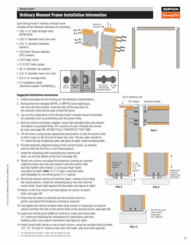
Strong Frame®C
-SF1
3 ©
2013 S
IMP
SO
N S
TR
ON
G-T
IE C
OM
PA
NY
IN
C.
57
Suggested Installation Instructions
1. Install anchorage into the footing per the Designer’s speciications.
2. Remove the form template MFTPL or MFTPL6 and install heavy hex nuts onto the anchors, lowering them all the way down to the concrete; these will be used to level the frame.
3. Lay out the components of the Strong Frame® moment frame horizontally for assembly prior to positioning onto the anchor bolts.
4. Bolt the columns and beam together using high‑strength bolts and washers (included) in accessible holes. DTI washers are also included and should be used (see page 58). DO NOT FULLY TIGHTEN AT THIS TIME.
5. Lift the frame (using proper equipment) and position it onto the anchor bolts, so that it rests on the irst set of heavy hex nuts. The top nailer should be 1 1⁄2" below the top of adjoining walls (see igure at right). Install remaining bolts.
6. Provide temporary diagonal bracing of the moment frame, as required, until it is tied into the loor or roof framing above.
7. Install the remaining bolts connecting the columns and beam, do not fully tighten at this time (see page 58).
8. Plumb one column and adjust the temporary bracing as required. Install the heavy hex nuts and washers onto the anchor bolts and fully tighten with wrench (1⁄2 turn past inger tight) (see igure at right). Note: A 3⁄4"–2" gap is required under each baseplate for non‑shrink grout (1 1⁄2" typical)
9. Plumb the second column and level the beam, making sure to keep the column plumb. Install the remaining heavy hex nuts onto the anchor bolts, inger‑tight against the base plate (see igure at right).
10. Return to the irst column and fully tighten all column‑to‑beam bolts (see page 58).
11. Check that the beam is still level and the second column is plumb, and adjust the temporary bracing as required.
12. Fully tighten the column‑to‑beam bolts using wrench or impact gun on second column and then the nuts on the anchor bolts on the second column (see page 60).
13. Install non‑shrink grout (5000 psi minimum) under each base plate (3⁄4" minimum) following the manufacturer’s instructions and local building codes (may require inspection) (see igure at right).
14. Install wood nailer blocks on top of each column, using the carriage bolts provided (12", 15", 18" and 21" columns have four bolt holes, only two bolts required).
Each Strong Frame® ordinary moment frame includes all the hardware necessary for assembly:
Block not included
Non-shrink grout(may require inspection)min. 5000 psi
Step 13
Adjust nuts to plumb column and level beam
Adjust nuts to plumb column
¾" min.to 2" max.(1½" typical)
Step 8 Step 9
• (16) 7⁄8"x3" high‑strength bolts ASTM A3251
• (16) 7⁄8" diameter heavy hex nuts1
• (16) 7⁄8" diameter hardened washers1
• (16) Direct Tension Indicator (DTI) washers
• (16) Finger shims
• (1) 0.015" feeler gauge
• (8) 5⁄8" diameter cut washers2
• (12) 5⁄8" diameter heavy hex nuts2
• (4) 5⁄8"x3" carriage bolts
• (1) Installation sheet (Technical bulletin T‑SFINSTALL) Heavy
hex nutHardenedwasher
Shim(whereneeded)
DTI washer(silicone side
facing steel beam)
⁷₈" A325bolt
Top of adjoining wall
Hardened washerDTI washer
Step 4
ordinary moment Frame Installation Information
1. For C18H and C21H columns, 1" bolts, nuts and washers are used
2. For C18H and C21H columns, ¾" bolts, nuts and washers are used.
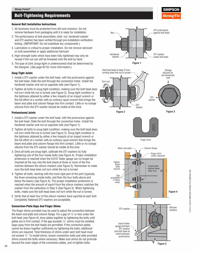
Strong Frame®
C-S
F13 ©
2013 S
IMP
SO
N S
TR
ON
G-T
IE C
OM
PA
NY
IN
C.
58
Bolt-tightening requirements
general Bolt Installation Instructions
1. All hardware must be protected from dirt and moisture. Do not remove hardware from packaging until it is ready for installation.
2. The performance of bolt assemblies (bolt, nut, hardened washer and DTI washer) has been veriied through pre‑installation veriication testing. (IMPORTANT: Do not substitute any components.)
3. Lubrication is critical to proper installation. Do not remove lubricant on bolt assemblies or apply additional lubricant.
4. High‑strength bolts which have been fully tightened may only be reused if the nut can still be threaded onto the bolt by hand.
5. The type of joint (snug‑tight or pretensioned) shall be determined by the Designer. (See page 62 for more information.)
Snug-tight Joints
1. Install a DTI washer under the bolt head, with the protrusions against the bolt head. Slide the bolt through the connection holes. Install the hardened washer and nut on opposite side (see Figure 1).
2. Tighten all bolts to snug‑tight condition, making sure the bolt head does not turn while the nut is turned (see Figure 2). Snug‑tight condition is the tightness attained by either a few impacts of an impact wrench or the full effort of a worker with an ordinary spud wrench that brings the beam end plate and column lange into irm contact. Little or no orange silicone from the DTI washer should be visible at this time.
Pretensioned Joints
1. Install a DTI washer under the bolt head, with the protrusions against the bolt head. Slide the bolt through the connection holes. Install the hardened washer and nut on opposite side (see Figure 1).
2. Tighten all bolts to snug‑tight condition, making sure the bolt head does not turn while the nut is turned (see Figure 2). Snug‑tight condition is the tightness attained by either a few impacts of an impact wrench or the full effort of a worker with an ordinary spud wrench that brings the beam end plate and column lange into irm contact. Little or no orange silicone from the DTI washer should be visible at this time.
3. Once all bolts are snug‑tight, calibrate the DTI washers by fully tightening one of the four inside bolts (see Figure 4). Proper installation pretension is reached when the 0.015" feeler gauge can no longer be inserted all the way into the bolt shank at three or more of the ive notches between the silicon markers (see Figure 5). Remember to make sure the bolt head does not turn while the nut is turned.
4. Tighten all bolts, starting with the most rigid part of the joint (typically the three remaining inside bolts, and then the four bolts above and below the beam) (see Figure 4). The proper installation pretension is reached when the amount of squirt from the silicon markers matches the washer from the calibration in Step 3 (See Figure 3). When tightening bolts, make sure the bolt head does not turn while the nut is turned.
5. Verify that at least four of the silicon markers have squirted at each bolt. Completely lattened DTI washers are acceptable.
Column flangeBeam end plate
Finger shim(when required)
Gapacceptable
in theseareas
Tightenthesebolts
second
Inside bolts:tighten thesebolts first
Figure 4
Siliconemarkers
DTI washer
Insert feelergauge between
DTI washerand bolt head at
notch betweenprotrusions
0.015
Figure 5
DTI protrusionsagainst bolt head
DTI washerunder bolt head
Nut
Hardenedwasher
Figure 1
Hold bolt head to keep it from turning when the nut is turned
Turn nut
DTIwasher
Figure 2
DTIwasher
Orangesilicone for
pre-tensioned bolt
Figure 3
Connection-Plate gaps and Finger Shims
The inger shims provided may be used to adjust the connection between the beam end plate and column lange. For a gap of 1⁄8" or less under the bolt head (see Figure 4), draw plates together by tightening the bolts until plates are in irm contact. If the gap exceeds 1⁄8", shims must be installed. Gaps away from the bolt heads are permitted. If the connection plates cannot be drawn together suficiently by tightening the bolts, additional shims are required. Total thickness of shims under each bolt head must not exceed 1⁄4". To install shims, loosen connection bolts and slide provided shims around the bolts where necessary. Make sure shims do not protrude beyond the outer edges of the connection plates, and re‑tighten bolts.
Finger shim
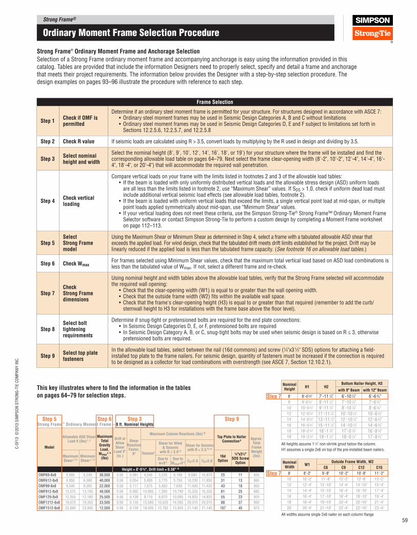
Strong Frame®C
-SF1
3 ©
2013 S
IMP
SO
N S
TR
ON
G-T
IE C
OM
PA
NY
IN
C.
59
Frame Selection
Step 1Check if OMF is permitted
Determine if an ordinary steel moment frame is permitted for your structure. For structures designed in accordance with ASCE 7:•Ordinary steel moment frames may be used in Seismic Design Categories A, B and C without limitations•Ordinary steel moment frames may be used in Seismic Design Categories D, E and F subject to limitations set forth in
Sections 12.2.5.6, 12.2.5.7, and 12.2.5.8
Step 2 Check R value If seismic loads are calculated using R > 3.5, convert loads by multiplying by the R used in design and dividing by 3.5.
Step 3Select nominal height and width
Select the nominal height (8', 9', 10', 12', 14', 16', 18', or 19') for your structure where the frame will be installed and ind the corresponding allowable load table on pages 64–79. Next select the frame clear‑opening width (8'‑2", 10'‑2", 12'‑4", 14'‑4", 16'‑4", 18'‑4", or 20'‑4") that will accommodate the required wall penetration.
Step 4Check vertical loading
Compare vertical loads on your frame with the limits listed in footnotes 2 and 3 of the allowable load tables:• If the beam is loaded with only uniformly distributed vertical loads and the allowable stress design (ASD) uniform loads
are all less than the limits listed in footnote 2, use “Maximum Shear” values. If SDS > 1.0, check if uniform dead load must include additional vertical seismic load effects (see allowable load tables, footnote 2).
• If the beam is loaded with uniform vertical loads that exceed the limits, a single vertical point load at mid‑span, or multiple point loads applied symmetrically about mid‑span, use “Minimum Shear" values.
• If your vertical loading does not meet these criteria, use the Simpson Strong‑Tie® Strong Frame™ Ordinary Moment Frame Selector software or contact Simpson Strong‑Tie to perform a custom design by completing a Moment Frame worksheet on page 112–113.
Step 5Select Strong Frame model
Using the Maximum Shear or Minimum Shear as determined in Step 4, select a frame with a tabulated allowable ASD shear that exceeds the applied load. For wind design, check that the tabulated drift meets drift limits established for the project. Drift may be linearly reduced if the applied load is less than the tabulated frame capacity. (See footnote 16 on allowable load tables.)
Step 6 Check WmaxFor frames selected using Minimum Shear values, check that the maximum total vertical load based on ASD load combinations is less than the tabulated value of Wmax. If not, select a different frame and re‑check.
Step 7Check Strong Frame dimensions
Using nominal height and width tables above the allowable load tables, verify that the Strong Frame selected will accommodate the required wall opening:
• Check that the clear‑opening width (W1) is equal to or greater than the wall opening width.• Check that the outside frame width (W2) its within the available wall space.• Check that the frame's clear‑opening height (H3) is equal to or greater than that required (remember to add the curb/
stemwall height to H3 for installations with the frame base above the loor level).
Step 8Select bolt tightening requirements
Determine if snug‑tight or pretensioned bolts are required for the end plate connections:• In Seismic Design Categories D, E, or F, pretensioned bolts are required• In Seismic Design Category A, B, or C, snug‑tight bolts may be used when seismic design is based on R ≤ 3, otherwise
pretensioned bolts are required.
Step 9Select top plate fasteners
In the allowable load tables, select between the nail (16d commons) and screw (1⁄4"x3 1⁄2" SDS) options for attaching a ield‑installed top plate to the frame nailers. For seismic design, quantity of fasteners must be increased if the connection is required to be designed as a collector for load combinations with overstrength (see ASCE 7, Section 12.10.2.1).
Strong Frame® Ordinary Moment Frame and Anchorage Selection
ordinary moment Frame Selection Procedure
Selection of a Strong Frame ordinary moment frame and accompanying anchorage is easy using the information provided in this catalog. Tables are provided that include the information Designers need to properly select, specify and detail a frame and anchorage that meets their project requirements. The information below provides the Designer with a step‑by‑step selection procedure. The design examples on pages 93–96 illustrate the procedure with reference to each step.
This key illustrates where to ind the information in the tables on pages 64–79 for selection steps.
Strong Frame™ Ordinary Moment Frame – 8 ft. Nominal Heights
Model
Allowable ASD Shear load V (lbs) 1, 8
Maximum Total
Gravity load,
Wmax 3, 9
(lbs)
Drift at Allow Shear
load V7 (in.)
Shear Reaction Factor,
X4
Maximum Column Reactions (lbs) 10
Top plate to Nailer Connection 6
Approx. Total
Frame Weight (lbs)
Tension5
Shear for Wind & Seismic
with R ≤ 3.0 13
Shear for Seismic with R = 3.5 14,15
Maximum Shear 2,12
Minimum Shear 3, 12
16d Option
¼"x3½" SDS Screw
OptionDue to w+V 4
Due to Wmax+V 4
Ωo=2.5 Ωo=3.0
Height = 8'‑0 ¾", Drift limit = 0.56" 16
OMF69‑8x8 5,585 5,245 38,500 0.56 0.081 4,545 3,235 6,190 9,580 10,870 25 11 835
OMF612‑8x8 6,950 6,580 40,000 0.56 0.054 5,695 3,770 5,750 10,230 11,850 31 13 865
OMF99‑8x8 9,540 9,395 22,000 0.56 0.117 7,675 5,420 7,630 11,435 11,435 43 18 850
OMF912‑8x8 13,575 13,195 40,000 0.56 0.092 10,995 7,300 10,790 15,335 15,335 61 25 885
OMF129‑8x8 12,355 12,160 25,500 0.56 0.138 9,710 6,970 10,095 14,825 14,825 55 23 920
OMF1212‑8x8 19,670 19,355 33,500 0.56 0.120 15,580 10,525 14,265 20,015 20,015 88 37 950
OMF1512‑8x8 23,940 23,905 12,500 0.56 0.139 18,505 12,785 13,925 21,140 21,140 107 45 975
Step 5 Step 6 Step 3 Step 9
Nominal Height
H1 H2Bottom Nailer Height, H3
with 9" Beam with 12" Beam
8' 8'‑0 3⁄4" 7'‑11 1⁄4" 6'‑10 1⁄4" 6'‑6 3⁄4"9' 9'‑0 3⁄4" 8'‑11 1⁄4" 7'‑10 1⁄4" 7'‑6 3⁄4"
10' 10'‑0 3⁄4" 9'‑11 1⁄4" 8'‑10 1⁄4" 8'‑6 3⁄4"12' 12'‑0 3⁄4" 11'‑11 1⁄4" 10'‑10 1⁄4" 10'‑6 3⁄4"14' 14'‑0 3⁄4" 13'‑11 1⁄4" 12'‑10 1⁄4" 12'‑6 3⁄4"16' 16'‑0 3⁄4" 15'‑11 1⁄4" 14'‑10 1⁄4" 14'‑6 3⁄4"18' 18'‑2 3⁄4" 18'‑1 1⁄4" 17'‑0 1⁄4" 16'‑8 3⁄4"19' 19'‑2 3⁄4" 19'‑1 1⁄4" 18'‑0 1⁄4" 17'‑8 3⁄4"
All heights assume 1 1⁄2" non‑shrink grout below the column.
H1 assumes a single 2x6 on top of the pre‑installed beam nailers.
Step 7
Nominal Width
W1Outside Frame Width, W2
C6 C9 C12 C15
8' 8'‑2" 9'‑8" 10'‑2" 10'‑8" 11'‑2"
10' 10'‑2" 11'‑8" 12'‑2" 12'‑8" 13'‑2"
12' 12'‑4" 13'‑10" 14'‑4" 14'‑10" 15'‑4"
14' 14'‑4" 15'‑10" 16'‑4" 16'‑10" 17'‑4"
16' 16'‑4" 17'‑10" 18'‑4" 18'‑10" 19'‑4"
18' 18'‑4" 19'‑10" 20'‑4" 20'‑10" 21'‑4"
20' 20'‑4" 21'‑10" 22'‑4" 22'‑10" 23'‑4"
All widths assume single 2x6 nailer on each column lange
Step 7
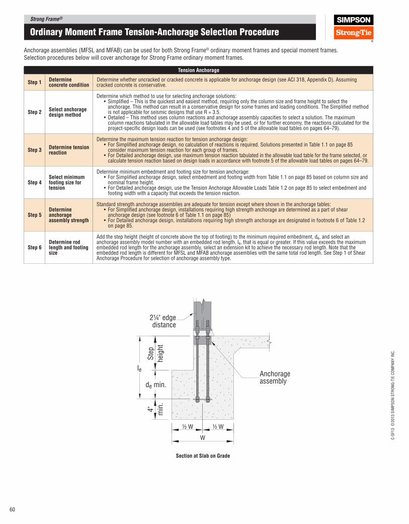
Strong Frame®
C-S
F13 ©
2013 S
IMP
SO
N S
TR
ON
G-T
IE C
OM
PA
NY
IN
C.
60
ordinary moment Frame tension-anchorage Selection Procedure
Anchorage assemblies (MFSL and MFAB) can be used for both Strong Frame® ordinary moment frames and special moment frames. Selection procedures below will cover anchorage for Strong Frame ordinary moment frames.
Tension Anchorage
Step 1Determine concrete condition
Determine whether uncracked or cracked concrete is applicable for anchorage design (see ACI 318, Appendix D). Assuming cracked concrete is conservative.
Step 2Select anchorage design method
Determine which method to use for selecting anchorage solutions:• Simpliied – This is the quickest and easiest method, requiring only the column size and frame height to select the
anchorage. This method can result in a conservative design for some frames and loading conditions. The Simpliied method is not applicable for seismic designs that use R = 3.5.
•Detailed – This method uses column reactions and anchorage assembly capacities to select a solution. The maximum column reactions tabulated in the allowable load tables may be used, or for further economy, the reactions calculated for the project‑speciic design loads can be used (see footnotes 4 and 5 of the allowable load tables on pages 64–79).
Step 3Determine tension reaction
Determine the maximum tension reaction for tension anchorage design:• For Simpliied anchorage design, no calculation of reactions is required. Solutions presented in Table 1.1 on page 85
consider maximum tension reaction for each group of frames.• For Detailed anchorage design, use maximum tension reaction tabulated in the allowable load table for the frame selected, or
calculate tension reaction based on design loads in accordance with footnote 5 of the allowable load tables on pages 64–79.
Step 4Select minimum footing size for tension
Determine minimum embedment and footing size for tension anchorage:• For Simpliied anchorage design, select embedment and footing width from Table 1.1 on page 85 based on column size and
nominal frame height.• For Detailed anchorage design, use the Tension Anchorage Allowable Loads Table 1.2 on page 85 to select embedment and
footing width with a capacity that exceeds the tension reaction.
Step 5Determine anchorage assembly strength
Standard strength anchorage assemblies are adequate for tension except where shown in the anchorage tables:• For Simpliied anchorage design, installations requiring high strength anchorage are determined as a part of shear
anchorage design (see footnote 6 of Table 1.1 on page 85)• For Detailed anchorage design, installations requiring high strength anchorage are designated in footnote 6 of Table 1.2
on page 85.
Step 6Determine rod length and footing size
Add the step height (height of concrete above the top of footing) to the minimum required embedment, de, and select an anchorage assembly model number with an embedded rod length, le, that is equal or greater. If this value exceeds the maximum embedded rod length for the anchorage assembly, select an extension kit to achieve the necessary rod length. Note that the embedded rod length is different for MFSL and MFAB anchorage assemblies with the same total rod length. See Step 1 of Shear Anchorage Procedure for selection of anchorage assembly type.
Anchorageassembly
Ste
p
hei
ght
de min.
4"
min
.
½ W ½ W
W
le
2¼" edgedistance
Section at Slab on Grade
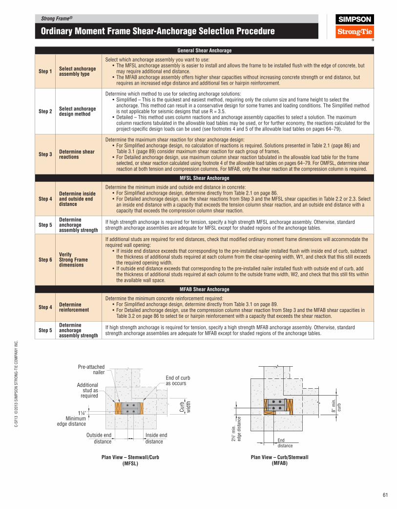
Strong Frame®C
-SF1
3 ©
2013 S
IMP
SO
N S
TR
ON
G-T
IE C
OM
PA
NY
IN
C.
61
ordinary moment Frame Shear-anchorage Selection Procedure
General Shear Anchorage
Step 1Select anchorage assembly type
Select which anchorage assembly you want to use:• The MFSL anchorage assembly is easier to install and allows the frame to be installed lush with the edge of concrete, but
may require additional end distance.• The MFAB anchorage assembly offers higher shear capacities without increasing concrete strength or end distance, but
requires an increased edge distance and additional ties or hairpin reinforcement.
Step 2Select anchorage design method
Determine which method to use for selecting anchorage solutions:• Simpliied – This is the quickest and easiest method, requiring only the column size and frame height to select the
anchorage. This method can result in a conservative design for some frames and loading conditions. The Simpliied method is not applicable for seismic designs that use R = 3.5.
•Detailed – This method uses column reactions and anchorage assembly capacities to select a solution. The maximum column reactions tabulated in the allowable load tables may be used, or for further economy, the reactions calculated for the project‑speciic design loads can be used (see footnotes 4 and 5 of the allowable load tables on pages 64–79).
Step 3Determine shear reactions
Determine the maximum shear reaction for shear anchorage design:• For Simpliied anchorage design, no calculation of reactions is required. Solutions presented in Table 2.1 (page 86) and
Table 3.1 (page 89) consider maximum shear reaction for each group of frames.• For Detailed anchorage design, use maximum column shear reaction tabulated in the allowable load table for the frame
selected, or shear reaction calculated using footnote 4 of the allowable load tables on pages 64–79. For OMFSL, determine shear reaction at both tension and compression columns. For MFAB, only the shear reaction at the compression column is required.
MFSl Shear Anchorage
Step 4Determine inside and outside end distance
Determine the minimum inside and outside end distance in concrete:• For Simpliied anchorage design, determine directly from Table 2.1 on page 86.• For Detailed anchorage design, use the shear reactions from Step 3 and the MFSL shear capacities in Table 2.2 or 2.3. Select
an inside end distance with a capacity that exceeds the tension column shear reaction, and an outside end distance with a capacity that exceeds the compression column shear reaction.
Step 5Determine anchorage assembly strength
If high strength anchorage is required for tension, specify a high strength MFSL anchorage assembly. Otherwise, standard strength anchorage assemblies are adequate for MFSL except for shaded regions of the anchorage tables.
Step 6Verify Strong Frame dimensions
If additional studs are required for end distances, check that modiied ordinary moment frame dimensions will accommodate the required wall opening:
• If inside end distance exceeds that corresponding to the pre‑installed nailer installed lush with inside end of curb, subtract the thickness of additional studs required at each column from the clear‑opening width, W1, and check that this still exceeds the required opening width.
• If outside end distance exceeds that corresponding to the pre‑installed nailer installed lush with outside end of curb, add the thickness of additional studs required at each column to the outside frame width, W2, and check that this still its within the available wall space.
MFAB Shear Anchorage
Step 4Determine reinforcement
Determine the minimum concrete reinforcement required:• For Simpliied anchorage design, determine directly from Table 3.1 on page 89.• For Detailed anchorage design, use the compression column shear reaction from Step 3 and the MFAB shear capacities in
Table 3.2 on page 86 to select tie or hairpin reinforcement with a capacity that exceeds the shear reaction.
Step 5Determine anchorage assembly strength
If high strength anchorage is required for tension, specify a high strength MFAB anchorage assembly. Otherwise, standard strength anchorage assemblies are adequate for MFAB except for shaded regions of the anchorage tables.
Outside enddistance
Inside enddistance
Pre-attachednailer
Additionalstud as
required
End of curb as occurs
1¼"Minimum
edge distance
Cu
rbw
idth
plan View – Stemwall/Curb (MFSl)
2½
" m
in.
edge
dis
tance
8"
min
.cu
rb
Enddistance
plan View – Curb/Stemwall (MFAB)
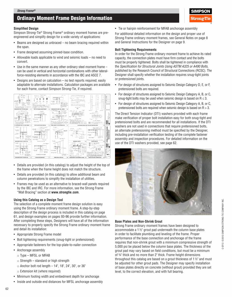
Strong Frame®
C-S
F13 ©
2013 S
IMP
SO
N S
TR
ON
G-T
IE C
OM
PA
NY
IN
C.
62
Simpliied DesignSimpson Strong‑Tie® Strong Frame® ordinary moment frames are pre‑engineered and simplify design for a wide variety of applications:
• Beams are designed as unbraced – no beam bracing required within the span.
• Frame designed assuming pinned‑base condition.
• Allowable loads applicable to wind and seismic loads – no need to convert.
• Use in the same manner as any other ordinary steel moment frame – can be used in vertical and horizontal combinations with other lateral‑force‑resisting elements in accordance with the IBC and ASCE 7.
• Designs are based on calculation – no test reports required; easily adaptable to alternate installations. Calculation packages are available for each frame, contact Simpson Strong‑Tie, if required.
• Details are provided (in this catalog) to adjust the height of the top of the frame when the frame height does not match the structure.
• Details are provided (in this catalog) to allow additional beam and column penetrations to simplify the installation of utilities.
• Frames may be used as an alternative to braced‑wall panels required by the IBC and IRC. For more information, see the Strong Frame “Wall Bracing” section at www.strongtie.com.
Using this Catalog as a Design ToolThe selection of a complete moment frame design solution is easy using the Strong Frame ordinary moment frame. A step‑by‑step description of the design process is included in this catalog on page 61, and design examples on pages 93‑96 provide further information. After completing these steps, Designers will have all of the information necessary to properly specify the Strong Frame ordinary moment frame and detail its installation:
• Appropriate Strong Frame model
• Bolt tightening requirements (snug‑tight or pretensioned)
• Appropriate fasteners for the top‑plate‑to‑nailer connection
• Anchorage assembly
o Type – MFSL or MFAB
o Strength – standard or high strength
o Anchor bolt rod length – 14", 18", 24", 30", or 36"
o Extension kit (where required)
• Minimum footing width and embedment depth for anchorage
• Inside and outside end distances for MFSL anchorage assembly
ordinary moment Frame Design Information
• Tie or hairpin reinforcement for MFAB anchorage assembly
For additional detailed information on the design and proper use of Strong Frame ordinary moment frames, see General Notes on page 8 and General Instructions for the Designer on page 9.
Bolt Tightening RequirementsIn order for the Strong Frame ordinary moment frame to achieve its rated capacity, the connection plates must have irm contact and the bolts must be properly tightened. Bolts shall be tightened in compliance with the Speciication for Structural Joints Using ASTM A325 or A490 Bolts, published by the Research Council of Structural Connections (RCSC). The Designer shall specify whether the installation requires snug‑tight joints or pretensioned joints.
• For design of structures assigned to Seismic Design Category D, E, or F, pretensioned bolts are required.
• For design of structures assigned to Seismic Design Category A, B, or C, snug‑tight bolts may be used when seismic design is based on R ≤ 3.
• For design of structures assigned to Seismic Design Category A, B, or C, pretensioned bolts are required when seismic design is based on R > 3.
The Direct Tension Indicator (DTI) washers provided with each frame make veriication of proper bolt installation easy for both snug‑tight and pretensioned bolts and are recommended for all installations. If the DTI washers are not used in connections that require pretensioned bolts, an alternate pretensioning method must be speciied by the Designer, including pre‑installation veriication testing of the complete fastener assembly and inspection procedures. For detailed information on the use of the DTI washers provided, see page 62.
Base plates and Non‑Shrink GroutStrong Frame ordinary moment frames have been designed to accommodate a 1 ½" grout pad underneath the column base plates in order to facilitate plumbing and leveling of the frame. Proper performance of the base connection and anchorage of the frame requires that non‑shrink grout with a minimum compressive strength of 5,000 psi be placed below the column base plates. The thickness of the grout pad may vary based on ield conditions, but must be a minimum of ¾" thick and no more than 2" thick. Frame height dimensions throughout this catalog are based on a grout thickness of 1 ½" and must be adjusted for other grout pads. The Designer may specify installation of base plates directly on concrete (without grout) provided they are set level, to the correct elevation, and with full bearing.
db
+
db
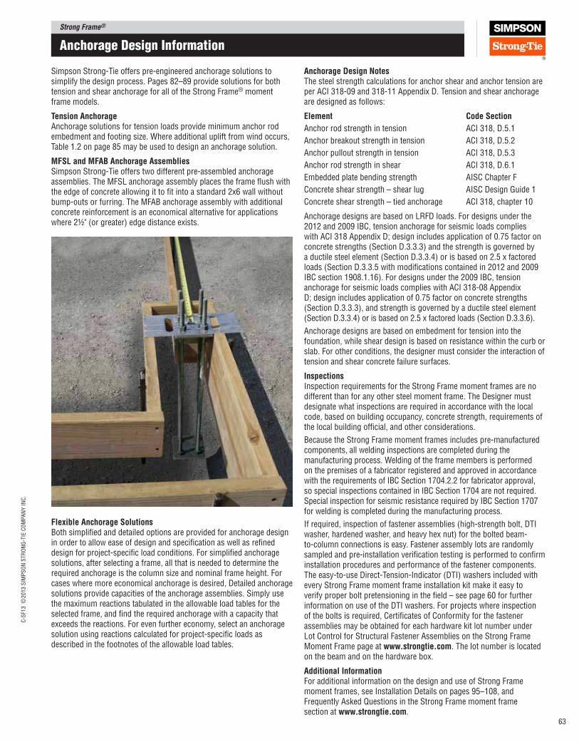
Strong Frame®C
-SF1
3 ©
2013 S
IMP
SO
N S
TR
ON
G-T
IE C
OM
PA
NY
IN
C.
63
anchorage Design Information
Simpson Strong‑Tie offers pre‑engineered anchorage solutions to simplify the design process. Pages 82–89 provide solutions for both tension and shear anchorage for all of the Strong Frame® moment frame models.
Tension Anchorage Anchorage solutions for tension loads provide minimum anchor rod embedment and footing size. Where additional uplift from wind occurs, Table 1.2 on page 85 may be used to design an anchorage solution.
MFSl and MFAB Anchorage Assemblies Simpson Strong‑Tie offers two different pre‑assembled anchorage assemblies. The MFSL anchorage assembly places the frame lush with the edge of concrete allowing it to it into a standard 2x6 wall without bump‑outs or furring. The MFAB anchorage assembly with additional concrete reinforcement is an economical alternative for applications where 2½" (or greater) edge distance exists.
Flexible Anchorage Solutions Both simpliied and detailed options are provided for anchorage design in order to allow ease of design and speciication as well as reined design for project‑speciic load conditions. For simpliied anchorage solutions, after selecting a frame, all that is needed to determine the required anchorage is the column size and nominal frame height. For cases where more economical anchorage is desired, Detailed anchorage solutions provide capacities of the anchorage assemblies. Simply use the maximum reactions tabulated in the allowable load tables for the selected frame, and ind the required anchorage with a capacity that exceeds the reactions. For even further economy, select an anchorage solution using reactions calculated for project‑speciic loads as described in the footnotes of the allowable load tables.
Anchorage Design NotesThe steel strength calculations for anchor shear and anchor tension are per ACI 318‑09 and 318‑11 Appendix D. Tension and shear anchorage are designed as follows:
Element Code Section
Anchor rod strength in tension ACI 318, D.5.1
Anchor breakout strength in tension ACI 318, D.5.2
Anchor pullout strength in tension ACI 318, D.5.3
Anchor rod strength in shear ACI 318, D.6.1
Embedded plate bending strength AISC Chapter F
Concrete shear strength – shear lug AISC Design Guide 1
Concrete shear strength – tied anchorage ACI 318, chapter 10
Anchorage designs are based on LRFD loads. For designs under the 2012 and 2009 IBC, tension anchorage for seismic loads complies with ACI 318 Appendix D; design includes application of 0.75 factor on concrete strengths (Section D.3.3.3) and the strength is governed by a ductile steel element (Section D.3.3.4) or is based on 2.5 x factored loads (Section D.3.3.5 with modiications contained in 2012 and 2009 IBC section 1908.1.16). For designs under the 2009 IBC, tension anchorage for seismic loads complies with ACI 318‑08 Appendix D; design includes application of 0.75 factor on concrete strengths (Section D.3.3.3), and strength is governed by a ductile steel element (Section D.3.3.4) or is based on 2.5 x factored loads (Section D.3.3.6).
Anchorage designs are based on embedment for tension into the foundation, while shear design is based on resistance within the curb or slab. For other conditions, the designer must consider the interaction of tension and shear concrete failure surfaces.
InspectionsInspection requirements for the Strong Frame moment frames are no different than for any other steel moment frame. The Designer must designate what inspections are required in accordance with the local code, based on building occupancy, concrete strength, requirements of the local building oficial, and other considerations.
Because the Strong Frame moment frames includes pre‑manufactured components, all welding inspections are completed during the manufacturing process. Welding of the frame members is performed on the premises of a fabricator registered and approved in accordance with the requirements of IBC Section 1704.2.2 for fabricator approval, so special inspections contained in IBC Section 1704 are not required. Special inspection for seismic resistance required by IBC Section 1707 for welding is completed during the manufacturing process.
If required, inspection of fastener assemblies (high‑strength bolt, DTI washer, hardened washer, and heavy hex nut) for the bolted beam‑to‑column connections is easy. Fastener assembly lots are randomly sampled and pre‑installation veriication testing is performed to conirm installation procedures and performance of the fastener components. The easy‑to‑use Direct‑Tension‑Indicator (DTI) washers included with every Strong Frame moment frame installation kit make it easy to verify proper bolt pretensioning in the ield – see page 60 for further information on use of the DTI washers. For projects where inspection of the bolts is required, Certiicates of Conformity for the fastener assemblies may be obtained for each hardware kit lot number under Lot Control for Structural Fastener Assemblies on the Strong Frame Moment Frame page at www.strongtie.com. The lot number is located on the beam and on the hardware box.
Additional InformationFor additional information on the design and use of Strong Frame moment frames, see Installation Details on pages 95–108, and Frequently Asked Questions in the Strong Frame moment frame section at www.strongtie.com.
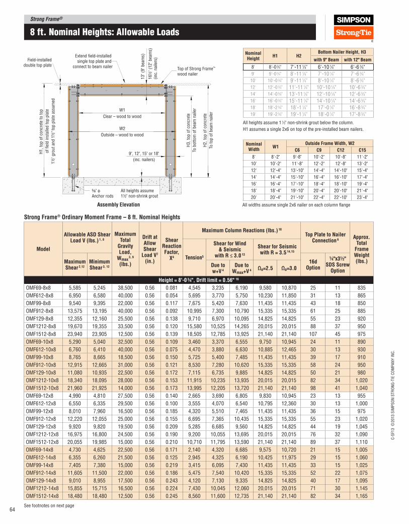
Strong Frame®
C-S
F13 ©
2013 S
IMP
SO
N S
TR
ON
G-T
IE C
OM
PA
NY
IN
C.
64
8 ft. nominal Heights: allowable Loads
See footnotes on next page
Strong Frame® Ordinary Moment Frame – 8 ft. Nominal Heights
Model
Allowable ASD Shear load V (lbs.) 1, 8
Maximum Total
Gravity load,
Wmax 3, 9
(lbs.)
Drift at Allow Shear
load V7 (in.)
Shear Reaction Factor,
X4
Maximum Column Reactions (lbs.) 10
Top plate to Nailer Connection 6
Approx.Total
Frame Weight (lbs.)
Tension5
Shear for Wind & Seismic
with R ≤ 3.0 13
Shear for Seismic with R = 3.5 14,15
Maximum Shear 2,12
Minimum Shear 3, 12
16d Option
¼"x3½" SDS Screw
OptionDue to w+V 4
Due to Wmax+V 4
Ωo=2.5 Ωo=3.0
Height = 8'‑0 ¾", Drift limit = 0.56" 16
OMF69-8x8 5,585 5,245 38,500 0.56 0.081 4,545 3,235 6,190 9,580 10,870 25 11 835
OMF612-8x8 6,950 6,580 40,000 0.56 0.054 5,695 3,770 5,750 10,230 11,850 31 13 865
OMF99-8x8 9,540 9,395 22,000 0.56 0.117 7,675 5,420 7,630 11,435 11,435 43 18 850
OMF912-8x8 13,575 13,195 40,000 0.56 0.092 10,995 7,300 10,790 15,335 15,335 61 25 885
OMF129-8x8 12,355 12,160 25,500 0.56 0.138 9,710 6,970 10,095 14,825 14,825 55 23 920
OMF1212-8x8 19,670 19,355 33,500 0.56 0.120 15,580 10,525 14,265 20,015 20,015 88 37 950
OMF1512-8x8 23,940 23,905 12,500 0.56 0.139 18,505 12,785 13,925 21,140 21,140 107 45 975
OMF69-10x8 5,290 5,040 32,500 0.56 0.109 3,460 3,370 6,555 9,750 10,945 24 11 890
OMF612-10x8 6,760 6,410 40,000 0.56 0.075 4,470 3,880 6,630 10,885 12,465 30 13 930
OMF99-10x8 8,765 8,665 18,500 0.56 0.150 5,725 5,400 7,485 11,435 11,435 39 17 910
OMF912-10x8 12,915 12,665 31,000 0.56 0.121 8,530 7,280 10,620 15,335 15,335 58 24 950
OMF129-10x8 11,080 10,935 22,500 0.56 0.172 7,115 6,735 9,885 14,825 14,825 50 21 980
OMF1212-10x8 18,340 18,095 28,000 0.56 0.153 11,915 10,235 13,935 20,015 20,015 82 34 1,020
OMF1512-10x8 21,960 21,925 14,000 0.56 0.173 13,995 12,205 13,720 21,140 21,140 98 41 1,040
OMF69-12x8 4,990 4,810 27,500 0.56 0.140 2,665 3,690 6,805 9,830 10,945 23 13 955
OMF612-12x8 6,550 6,335 29,500 0.56 0.100 3,555 4,070 6,540 10,795 12,360 30 13 1,000
OMF99-12x8 8,010 7,960 16,500 0.56 0.185 4,320 5,510 7,465 11,435 11,435 36 15 975
OMF912-12x8 12,220 12,055 25,000 0.56 0.155 6,695 7,365 10,435 15,335 15,335 55 23 1,020
OMF129-12x8 9,920 9,820 19,500 0.56 0.209 5,285 6,685 9,560 14,825 14,825 44 19 1,045
OMF1212-12x8 16,975 16,800 24,500 0.56 0.190 9,200 10,055 13,695 20,015 20,015 76 32 1,090
OMF1512-12x8 20,055 19,985 15,000 0.56 0.210 10,710 11,795 13,590 21,140 21,140 89 37 1,110
OMF69-14x8 4,730 4,625 22,500 0.56 0.171 2,140 4,320 6,685 9,575 10,720 21 15 1,005
OMF612-14x8 6,355 6,260 21,500 0.56 0.125 2,945 4,325 6,190 10,425 11,975 29 15 1,060
OMF99-14x8 7,405 7,380 15,000 0.56 0.219 3,415 6,095 7,430 11,435 11,435 33 15 1,025
OMF912-14x8 11,605 11,500 22,000 0.56 0.186 5,475 7,540 10,420 15,335 15,335 52 22 1,075
OMF129-14x8 9,010 8,955 17,500 0.56 0.243 4,120 7,130 9,335 14,825 14,825 40 17 1,095
OMF1212-14x8 15,855 15,715 16,500 0.56 0.224 7,430 10,045 12,060 20,015 20,015 71 30 1,145
OMF1512-14x8 18,480 18,480 12,500 0.56 0.245 8,560 11,600 12,735 21,140 21,140 82 34 1,165
W1
W2
Clear – wood to wood
Extend field-installed single top plate and
connect to beam nailer Top of Strong Frame™
wood nailer
⁵⁄₈" φAnchor rods
All heights assume 1½" non-shrink grout
13" (9
" bea
ms)
16½
" (1
2" bea
ms)
(inc.
nai
lers
)
Field-installeddouble top plate
Outside – wood to wood
9", 12", 15" or 18"
(inc. nailers)
H1, to
p o
f co
ncr
ete
to t
op
of
fiel
d in
stal
led t
op p
late
1½
" gro
ut
and 1
½" to
p p
late
ass
um
ed
H3, to
p o
f co
ncr
ete
To b
ott
om
of
bea
m n
aile
r
H2, to
p o
f co
ncr
ete
To t
op o
f bea
m n
aile
r
Assembly Elevation
Nominal Height
H1 H2Bottom Nailer Height, H3
with 9" Beam with 12" Beam
8' 8'-0 3⁄4" 7'-11 1⁄4" 6'-10 1⁄4" 6'-6 3⁄4"9' 9'-0 3⁄4" 8'-11 1⁄4" 7'-10 1⁄4" 7'-6 3⁄4"
10' 10'-0 3⁄4" 9'-11 1⁄4" 8'-10 1⁄4" 8'-6 3⁄4"12' 12'-0 3⁄4" 11'-11 1⁄4" 10'-10 1⁄4" 10'-6 3⁄4"14' 14'-0 3⁄4" 13'-11 1⁄4" 12'-10 1⁄4" 12'-6 3⁄4"16' 16'-0 3⁄4" 15'-11 1⁄4" 14'-10 1⁄4" 14'-6 3⁄4"18' 18'-2 3⁄4" 18'-1 1⁄4" 17'-0 1⁄4" 16'-8 3⁄4"19' 19'-2 3⁄4" 19'-1 1⁄4" 18'-0 1⁄4" 17'-8 3⁄4"
All heights assume 1 1⁄2" non-shrink grout below the column.
H1 assumes a single 2x6 on top of the pre-installed beam nailers.
Nominal Width
W1Outside Frame Width, W2
C6 C9 C12 C15
8' 8'-2" 9'-8" 10'-2" 10'-8" 11'-2"
10' 10'-2" 11'-8" 12'-2" 12'-8" 13'-2"
12' 12'-4" 13'-10" 14'-4" 14'-10" 15'-4"
14' 14'-4" 15'-10" 16'-4" 16'-10" 17'-4"
16' 16'-4" 17'-10" 18'-4" 18'-10" 19'-4"
18' 18'-4" 19'-10" 20'-4" 20'-10" 21'-4"
20' 20'-4" 21'-10" 22'-4" 22'-10" 23'-4"
All widths assume single 2x6 nailer on each column lange
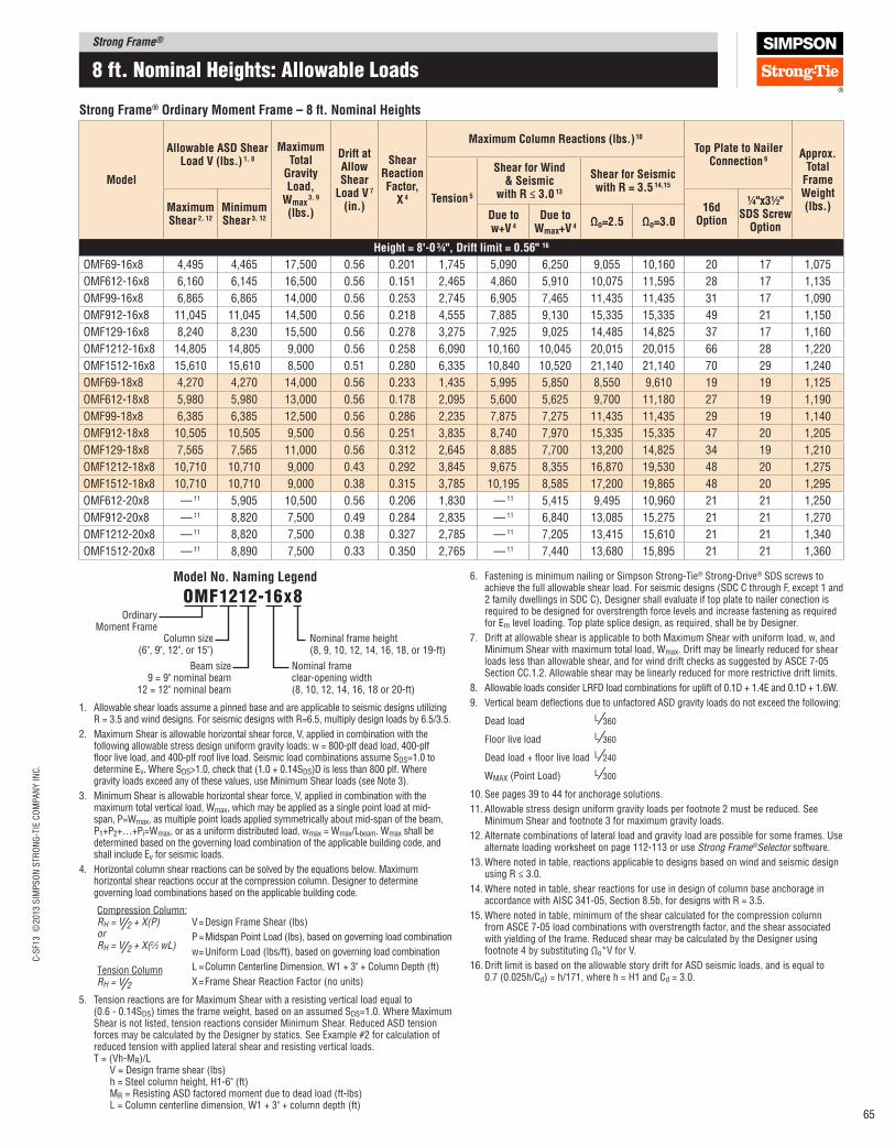
Strong Frame®C
-SF1
3 ©
2013 S
IMP
SO
N S
TR
ON
G-T
IE C
OM
PA
NY
IN
C.
65
8 ft. nominal Heights: allowable Loads
Strong Frame® Ordinary Moment Frame – 8 ft. Nominal Heights
Model
Allowable ASD Shear load V (lbs.) 1, 8
Maximum Total
Gravity load,
Wmax 3, 9
(lbs.)
Drift at Allow Shear
load V 7 (in.)
Shear Reaction Factor,
X 4
Maximum Column Reactions (lbs.) 10
Top plate to Nailer Connection 6
Approx.Total
Frame Weight (lbs.)
Tension 5
Shear for Wind & Seismic
with R ≤ 3.0 13
Shear for Seismic with R = 3.5 14,15
Maximum Shear 2, 12
Minimum Shear 3, 12
16d Option
¼"x3½" SDS Screw
OptionDue to w+V 4
Due to Wmax+V 4
Ωo=2.5 Ωo=3.0
Height = 8'‑0 ¾", Drift limit = 0.56" 16
OMF69-16x8 4,495 4,465 17,500 0.56 0.201 1,745 5,090 6,250 9,055 10,160 20 17 1,075
OMF612-16x8 6,160 6,145 16,500 0.56 0.151 2,465 4,860 5,910 10,075 11,595 28 17 1,135
OMF99-16x8 6,865 6,865 14,000 0.56 0.253 2,745 6,905 7,465 11,435 11,435 31 17 1,090
OMF912-16x8 11,045 11,045 14,500 0.56 0.218 4,555 7,885 9,130 15,335 15,335 49 21 1,150
OMF129-16x8 8,240 8,230 15,500 0.56 0.278 3,275 7,925 9,025 14,485 14,825 37 17 1,160
OMF1212-16x8 14,805 14,805 9,000 0.56 0.258 6,090 10,160 10,045 20,015 20,015 66 28 1,220
OMF1512-16x8 15,610 15,610 8,500 0.51 0.280 6,335 10,840 10,520 21,140 21,140 70 29 1,240
OMF69-18x8 4,270 4,270 14,000 0.56 0.233 1,435 5,995 5,850 8,550 9,610 19 19 1,125
OMF612-18x8 5,980 5,980 13,000 0.56 0.178 2,095 5,600 5,625 9,700 11,180 27 19 1,190
OMF99-18x8 6,385 6,385 12,500 0.56 0.286 2,235 7,875 7,275 11,435 11,435 29 19 1,140
OMF912-18x8 10,505 10,505 9,500 0.56 0.251 3,835 8,740 7,970 15,335 15,335 47 20 1,205
OMF129-18x8 7,565 7,565 11,000 0.56 0.312 2,645 8,885 7,700 13,200 14,825 34 19 1,210
OMF1212-18x8 10,710 10,710 9,000 0.43 0.292 3,845 9,675 8,355 16,870 19,530 48 20 1,275
OMF1512-18x8 10,710 10,710 9,000 0.38 0.315 3,785 10,195 8,585 17,200 19,865 48 20 1,295
OMF612-20x8 — 11 5,905 10,500 0.56 0.206 1,830 — 11 5,415 9,495 10,960 21 21 1,250
OMF912-20x8 — 11 8,820 7,500 0.49 0.284 2,835 — 11 6,840 13,085 15,275 21 21 1,270
OMF1212-20x8 — 11 8,820 7,500 0.38 0.327 2,785 — 11 7,205 13,415 15,610 21 21 1,340
OMF1512-20x8 — 11 8,890 7,500 0.33 0.350 2,765 — 11 7,440 13,680 15,895 21 21 1,360
6. Fastening is minimum nailing or Simpson Strong‑Tie® Strong‑Drive® SDS screws to achieve the full allowable shear load. For seismic designs (SDC C through F, except 1 and 2 family dwellings in SDC C), Designer shall evaluate if top plate to nailer conection is required to be designed for overstrength force levels and increase fastening as required for Em level loading. Top plate splice design, as required, shall be by Designer.
7. Drift at allowable shear is applicable to both Maximum Shear with uniform load, w, and Minimum Shear with maximum total load, Wmax. Drift may be linearly reduced for shear loads less than allowable shear, and for wind drift checks as suggested by ASCE 7‑05 Section CC.1.2. Allowable shear may be linearly reduced for more restrictive drift limits.
8. Allowable loads consider LRFD load combinations for uplift of 0.1D + 1.4E and 0.1D + 1.6W.
9. Vertical beam delections due to unfactored ASD gravity loads do not exceed the following:
Dead load L ⁄360
Floor live load L ⁄360
Dead load + loor live load L ⁄240
WMAX (Point Load) L ⁄300
10. See pages 39 to 44 for anchorage solutions.
11. Allowable stress design uniform gravity loads per footnote 2 must be reduced. See Minimum Shear and footnote 3 for maximum gravity loads.
12. Alternate combinations of lateral load and gravity load are possible for some frames. Use alternate loading worksheet on page 112‑113 or use Strong Frame®Selector software.
13. Where noted in table, reactions applicable to designs based on wind and seismic design using R ≤ 3.0.
14. Where noted in table, shear reactions for use in design of column base anchorage in accordance with AISC 341‑05, Section 8.5b, for designs with R = 3.5.
15. Where noted in table, minimum of the shear calculated for the compression column from ASCE 7‑05 load combinations with overstrength factor, and the shear associated with yielding of the frame. Reduced shear may be calculated by the Designer using footnote 4 by substituting Ωo*V for V.
16. Drift limit is based on the allowable story drift for ASD seismic loads, and is equal to 0.7 (0.025h/Cd) = h/171, where h = H1 and Cd = 3.0.
Ordinary Moment Frame
Column size(6", 9", 12", or 15")
Beam size9 = 9" nominal beam
12 = 12" nominal beam
omF1212-16x8
Nominal frame height(8, 9, 10, 12, 14, 16, 18, or 19‑ft)
Nominal frame clear‑opening width(8, 10, 12, 14, 16, 18 or 20‑ft)
Model No. Naming legend
1. Allowable shear loads assume a pinned base and are applicable to seismic designs utilizing R = 3.5 and wind designs. For seismic designs with R=6.5, multiply design loads by 6.5/3.5.
2. Maximum Shear is allowable horizontal shear force, V, applied in combination with the following allowable stress design uniform gravity loads: w = 800‑plf dead load, 400‑plf loor live load, and 400‑plf roof live load. Seismic load combinations assume SDS=1.0 to determine Ev. Where SDS>1.0, check that (1.0 + 0.14SDS)D is less than 800 plf. Where gravity loads exceed any of these values, use Minimum Shear loads (see Note 3).
3. Minimum Shear is allowable horizontal shear force, V, applied in combination with the maximum total vertical load, Wmax, which may be applied as a single point load at mid‑span, P=Wmax, as multiple point loads applied symmetrically about mid‑span of the beam, P1+P2+…+Pi=Wmax, or as a uniform distributed load, wmax = Wmax/Lbeam. Wmax shall be determined based on the governing load combination of the applicable building code, and shall include Ev for seismic loads.
4. Horizontal column shear reactions can be solved by the equations below. Maximum horizontal shear reactions occur at the compression column. Designer to determine governing load combinations based on the applicable building code.
V = Design Frame Shear (lbs)
P = Midspan Point Load (lbs), based on governing load combination
w = Uniform Load (lbs/ft), based on governing load combination
L = Column Centerline Dimension, W1 + 3" + Column Depth (ft)
X = Frame Shear Reaction Factor (no units)
5. Tension reactions are for Maximum Shear with a resisting vertical load equal to (0.6 ‑ 0.14SDS) times the frame weight, based on an assumed SDS=1.0. Where Maximum Shear is not listed, tension reactions consider Minimum Shear. Reduced ASD tension forces may be calculated by the Designer by statics. See Example #2 for calculation of reduced tension with applied lateral shear and resisting vertical loads. T = (Vh‑MR)/L V = Design frame shear (lbs) h = Steel column height, H1‑6" (ft) MR = Resisting ASD factored moment due to dead load (ft‑lbs) L = Column centerline dimension, W1 + 3" + column depth (ft)
Compression Column:RH = V⁄2 + X(P)orRH = V⁄2 + X(2⁄3 wL)
Tension ColumnRH = V⁄2

Strong Frame®
C-S
F13 ©
2013 S
IMP
SO
N S
TR
ON
G-T
IE C
OM
PA
NY
IN
C.
66
9 ft. nominal Heights: allowable Loads
See footnotes on next page
Strong Frame® Ordinary Moment Frame – 9 ft. Nominal Heights
Model
Allowable ASD Shear load V (lbs.)1, 8
Maximum Total
Gravity load,
Wmax 3, 9
(lbs.)
Drift at Allow Shear
load V7 (in.)
Shear Reaction Factor,
X4
Maximum Column Reactions (lbs.) 10
Top plate to Nailer Connection6
Approx.Total
Frame Weight (lbs.)
Tension5
Shear for Wind & Seismic
with R ≤ 3.013
Shear for Seismic with R = 3.514,15
Maximum Shear 2, 12
Minimum Shear 3, 12
16d Option
¼"x3½" SDS Screw
OptionDue to w+V4
Due to Wmax+V4 Ωo=2.5 Ωo=3.0
Height = 9'‑0 ¾", Drift limit = 0.63 16
OMF69-8x9 4,390 4,060 38,000 0.63 0.067 4,010 2,560 4,930 7,515 8,510 20 9 905
OMF612-8x9 5,350 4,980 40,000 0.63 0.043 4,920 2,910 4,465 7,825 9,050 24 10 935
OMF99-8x9 7,730 7,530 26,500 0.63 0.099 7,010 4,415 6,755 10,045 10,045 35 15 920
OMF912-8x9 10,690 10,325 40,000 0.63 0.076 9,765 5,770 8,620 13,435 13,435 48 20 955
OMF129-8x9 10,220 9,990 29,500 0.63 0.119 9,065 5,790 8,990 13,020 13,020 46 19 995
OMF1212-8x9 15,850 15,490 40,000 0.63 0.101 14,175 8,505 12,360 17,535 17,535 71 30 1,030
OMF1512-8x9 19,585 19,455 20,500 0.63 0.118 17,105 10,485 12,490 18,515 18,515 87 37 1,055
OMF69-10x9 4,170 3,925 32,000 0.63 0.090 3,050 2,685 5,260 7,710 8,680 19 11 965
OMF612-10x9 5,210 4,865 40,000 0.63 0.061 3,855 3,005 5,195 8,395 9,590 24 11 1,005
OMF99-10x9 7,125 6,995 21,500 0.63 0.127 5,240 4,425 6,615 10,045 10,045 32 14 980
OMF912-10x9 10,215 9,875 39,500 0.63 0.101 7,600 5,790 9,475 13,435 13,435 46 19 1,020
OMF129-10x9 9,200 9,030 25,500 0.63 0.148 6,655 5,630 8,830 13,020 13,020 41 17 1,055
OMF1212-10x9 14,835 14,545 34,500 0.63 0.130 10,875 8,320 12,375 17,535 17,535 66 28 1,095
OMF1512-10x9 18,040 17,925 19,500 0.63 0.148 12,985 10,070 12,255 18,515 18,515 80 34 1,120
OMF69-12x9 3,950 3,775 27,500 0.63 0.117 2,350 2,995 5,560 7,865 8,795 18 13 1,030
OMF612-12x9 5,055 4,855 29,000 0.63 0.081 3,060 3,175 5,115 8,335 9,535 23 13 1,075
OMF99-12x9 6,540 6,470 18,500 0.63 0.158 3,960 4,555 6,575 10,045 10,045 29 13 1,045
OMF912-12x9 9,695 9,470 31,000 0.63 0.129 5,975 5,895 9,300 13,435 13,435 43 18 1,090
OMF129-12x9 8,265 8,155 21,500 0.63 0.181 4,955 5,625 8,510 13,020 13,020 37 16 1,120
OMF1212-12x9 13,795 13,570 29,500 0.63 0.161 8,430 8,230 12,205 17,535 17,535 62 26 1,165
OMF1512-12x9 16,530 16,450 19,000 0.63 0.181 9,960 9,785 12,135 18,515 18,515 74 31 1,190
OMF69-14x9 3,755 3,660 22,000 0.63 0.143 1,885 3,540 5,410 7,670 8,575 17 15 1,080
OMF612-14x9 4,910 4,825 21,000 0.63 0.102 2,530 3,390 4,850 8,105 9,295 22 15 1,130
OMF99-14x9 6,060 6,025 16,500 0.63 0.188 3,135 5,120 6,540 10,045 10,045 27 15 1,100
OMF912-14x9 9,245 9,115 24,000 0.63 0.156 4,900 6,080 8,830 13,435 13,435 41 17 1,145
OMF129-14x9 7,525 7,470 19,000 0.63 0.211 3,865 6,075 8,305 13,020 13,020 34 15 1,170
OMF1212-14x9 12,910 12,850 18,500 0.63 0.191 6,815 8,260 10,445 17,535 17,535 58 24 1,220
OMF1512-14x9 15,295 15,280 15,000 0.63 0.211 7,985 9,680 11,245 18,515 18,515 68 29 1,245
W1
W2
Clear – wood to wood
Extend field-installed single top plate and
connect to beam nailer Top of Strong Frame™
wood nailer
⁵⁄₈" φAnchor rods
All heights assume 1½" non-shrink grout
13" (9
" bea
ms)
16½
" (1
2" bea
ms)
(inc.
nai
lers
)
Field-installeddouble top plate
Outside – wood to wood
9", 12", 15" or 18"
(inc. nailers)
H1, to
p o
f co
ncr
ete
to t
op
of
fiel
d in
stal
led t
op p
late
1½
" gro
ut
and 1
½" to
p p
late
ass
um
ed
H3, to
p o
f co
ncr
ete
To b
ott
om
of
bea
m n
aile
r
H2, to
p o
f co
ncr
ete
To t
op o
f bea
m n
aile
r
Assembly Elevation
Nominal Width
W1Outside Frame Width, W2
C6 C9 C12 C15
8' 8'-2" 9'-8" 10'-2" 10'-8" 11'-2"
10' 10'-2" 11'-8" 12'-2" 12'-8" 13'-2"
12' 12'-4" 13'-10" 14'-4" 14'-10" 15'-4"
14' 14'-4" 15'-10" 16'-4" 16'-10" 17'-4"
16' 16'-4" 17'-10" 18'-4" 18'-10" 19'-4"
18' 18'-4" 19'-10" 20'-4" 20'-10" 21'-4"
20' 20'-4" 21'-10" 22'-4" 22'-10" 23'-4"
All widths assume single 2x6 nailer on each column lange
Nominal Height
H1 H2Bottom Nailer Height, H3
with 9" Beam with 12" Beam
8' 8'-0 3⁄4" 7'-11 1⁄4" 6'-10 1⁄4" 6'-6 3⁄4"9' 9'-0 3⁄4" 8'-11 1⁄4" 7'-10 1⁄4" 7'-6 3⁄4"10' 10'-0 3⁄4" 9'-11 1⁄4" 8'-10 1⁄4" 8'-6 3⁄4"12' 12'-0 3⁄4" 11'-11 1⁄4" 10'-10 1⁄4" 10'-6 3⁄4"14' 14'-0 3⁄4" 13'-11 1⁄4" 12'-10 1⁄4" 12'-6 3⁄4"16' 16'-0 3⁄4" 15'-11 1⁄4" 14'-10 1⁄4" 14'-6 3⁄4"18' 18'-2 3⁄4" 18'-1 1⁄4" 17'-0 1⁄4" 16'-8 3⁄4"19' 19'-2 3⁄4" 19'-1 1⁄4" 18'-0 1⁄4" 17'-8 3⁄4"
All heights assume 1 1⁄2" non-shrink grout below the column.
H1 assumes a single 2x6 on top of the pre-installed beam nailers.

Strong Frame®C
-SF1
3 ©
2013 S
IMP
SO
N S
TR
ON
G-T
IE C
OM
PA
NY
IN
C.
67
9 ft. nominal Heights: allowable Loads
Strong Frame® Ordinary Moment Frame – 9 ft. Nominal Heights
Model
Allowable ASD Shear load V (lbs.) 1, 8
Maximum Total
Gravity load,
Wmax 3, 9
(lbs.)
Drift at Allow Shear
load V 7 (in.)
Shear Reaction Factor,
X 4
Maximum Column Reactions (lbs.) 10
Top plate to Nailer Connection 6
Approx. Total
Frame Weight (lbs.)
Tension 5
Shear for Wind & Seismic
with R ≤ 3.0 13
Shear for Seismic with R = 3.5 14,15
Maximum Shear 2, 12
Minimum Shear 3, 12
16d Option
¼"x3½" SDS Screw
OptionDue to w+V 4
Due to Wmax+V 4
Ωo=2.5 Ωo=3.0
Height = 9'‑0 ¾", Drift limit = 0.63" 16
OMF69-16x9 3,575 3,550 17,000 0.63 0.169 1,530 4,200 5,055 7,295 8,175 17 17 1,145
OMF612-16x9 4,770 4,765 16,000 0.63 0.123 2,115 3,875 4,635 7,865 9,045 22 17 1,205
OMF99-16x9 5,640 5,640 15,000 0.63 0.217 2,520 5,835 6,530 10,045 10,045 25 17 1,165
OMF912-16x9 8,820 8,805 16,500 0.63 0.184 4,075 6,460 7,860 13,435 13,435 40 17 1,220
OMF129-16x9 6,900 6,890 16,500 0.63 0.241 3,075 6,780 7,980 12,475 13,020 31 17 1,240
OMF1212-16x9 12,115 12,115 11,500 0.63 0.220 5,600 8,415 8,945 17,480 17,535 54 23 1,295
OMF1512-16x9 14,205 14,205 8,000 0.63 0.241 6,515 9,720 9,305 18,515 18,515 63 27 1,320
OMF69-18x9 3,400 3,400 13,500 0.63 0.196 1,250 4,980 4,720 6,920 7,745 19 19 1,195
OMF612-18x9 4,635 4,635 12,500 0.63 0.146 1,790 4,495 4,400 7,580 8,730 21 19 1,260
OMF99-18x9 5,260 5,260 13,500 0.63 0.247 2,050 6,690 6,425 9,850 10,045 24 19 1,215
OMF912-18x9 8,415 8,415 11,000 0.63 0.212 3,435 7,210 6,865 12,990 13,435 38 19 1,275
OMF129-18x9 6,350 6,350 12,000 0.63 0.271 2,480 7,635 6,885 11,230 12,755 29 19 1,290
OMF1212-18x9 9,940 9,940 9,000 0.55 0.250 4,035 8,580 7,540 15,390 17,535 45 19 1,350
OMF1512-18x9 9,940 9,940 9,000 0.48 0.272 3,975 9,065 7,760 15,705 18,175 45 19 1,375
OMF612-20x9 — 11 4,605 10,500 0.63 0.169 1,565 — 11 4,330 7,450 8,595 21 21 1,325
OMF912-20x9 — 11 8,120 7,500 0.63 0.240 2,950 — 11 6,115 11,870 13,435 21 21 1,340
OMF1212-20x9 — 11 8,120 7,500 0.47 0.281 2,895 — 11 6,460 12,190 14,210 21 21 1,415
OMF1512-20x9 — 11 8,225 7,500 0.42 0.303 2,895 — 11 6,700 12,490 14,540 21 21 1,440
6. Fastening is minimum nailing or Simpson Strong‑Tie® Strong‑Drive® SDS screws to achieve the full allowable shear load. For seismic designs (SDC C through F, except 1 and 2 family dwellings in SDC C), Designer shall evaluate if top plate to nailer connection is required to be designed for overstrength force levels and increase fastening as required for Em level loading. Top plate splice design, as required, shall be by Designer.
7. Drift at allowable shear is applicable to both Maximum Shear with uniform load, w, and Minimum Shear with maximum total load, Wmax. Drift may be linearly reduced for shear loads less than allowable shear, and for wind drift checks as suggested by ASCE 7‑05 Section CC.1.2. Allowable shear may be linearly reduced for more restrictive drift limits.
8. Allowable loads consider LRFD load combinations for uplift of 0.1D + 1.4E and 0.1D + 1.6W.
9. Vertical beam delections due to unfactored ASD gravity loads do not exceed the following:
Dead load L ⁄360
Floor live load L ⁄360
Dead load + loor live load L ⁄240
WMAX (Point Load) L ⁄300
10. See pages 39 to 44 for anchorage solutions.
11. Allowable stress design uniform gravity loads per footnote 2 must be reduced. See Minimum Shear and footnote 3 for maximum gravity loads.
12. Alternate combinations of lateral load and gravity load are possible for some frames. Use alternate loading worksheet on page 112‑113 or use Strong Frame® Selector software.
13. Where noted in table, reactions applicable to designs based on wind and seismic design using R ≤ 3.0.
14. Where noted in table, shear reactions for use in design of column base anchorage in accordance with AISC 341‑05, Section 8.5b, for designs with R = 3.5.
15. Where noted in table, minimum of the shear calculated for the compression column from ASCE 7‑05 load combinations with overstrength factor, and the shear associated with yielding of the frame. Reduced shear may be calculated by the Designer using footnote 4 by substituting Ωo*V for V.
16. Drift limit is based on the allowable story drift for ASD seismic loads, and is equal to 0.7 (0.025h/Cd) = h/171, where h = H1 and Cd = 3.0.
1. Allowable shear loads assume a pinned base and are applicable to seismic designs utilizing R = 3.5 and wind designs. For seismic designs with R=6.5, multiply design loads by 6.5/3.5.
2. Maximum Shear is allowable horizontal shear force, V, applied in combination with the following allowable stress design uniform gravity loads: w = 800‑plf dead load, 400‑plf loor live load, and 400‑plf roof live load. Seismic load combinations assume SDS=1.0 to determine Ev. Where SDS>1.0, check that (1.0 + 0.14SDS)D is less than 800 plf. Where gravity loads exceed any of these values, use Minimum Shear loads (see Note 3).
3. Minimum Shear is allowable horizontal shear force, V, applied in combination with the maximum total vertical load, Wmax, which may be applied as a single point load at mid‑span, P=Wmax, as multiple point loads applied symmetrically about mid‑span of the beam, P1+P2+…+Pi=Wmax, or as a uniform distributed load, wmax = Wmax/Lbeam. Wmax shall be determined based on the governing load combination of the applicable building code, and shall include Ev for seismic loads.
4. Horizontal column shear reactions can be solved by the equations below. Maximum horizontal shear reactions occur at the compression column. Designer to determine governing load combinations based on the applicable building code.
V = Design Frame Shear (lbs)
P = Midspan Point Load (lbs), based on governing load combination
w = Uniform Load (lbs/ft), based on governing load combination
L = Column Centerline Dimension, W1 + 3" + Column Depth (ft)
X = Frame Shear Reaction Factor (no units)
5. Tension reactions are for Maximum Shear with a resisting vertical load equal to (0.6 ‑ 0.14SDS) times the frame weight, based on an assumed SDS=1.0. Where Maximum Shear is not listed, tension reactions consider Minimum Shear. Reduced ASD tension forces may be calculated by the Designer by statics. See Example #2 for calculation of reduced tension with applied lateral shear and resisting vertical loads. T = (Vh‑MR)/L V = Design frame shear (lbs) h = Steel column height, H1‑6" (ft) MR = Resisting ASD factored moment due to dead load (ft‑lbs) L = Column centerline dimension, W1 + 3" + column depth (ft)
Compression Column:RH = V⁄2 + X(P)orRH = V⁄2 + X(2⁄3 wL)
Tension ColumnRH = V⁄2
Ordinary Moment Frame
Column size(6", 9", 12", or 15")
Beam size9 = 9" nominal beam
12 = 12" nominal beam
omF1212-16x8
Nominal frame height(8, 9, 10, 12, 14, 16, 18, or 19‑ft)
Nominal frame clear‑opening width(8, 10, 12, 14, 16, 18 or 20‑ft)
Model No. Naming legend

Strong Frame®
C-S
F13 ©
2013 S
IMP
SO
N S
TR
ON
G-T
IE C
OM
PA
NY
IN
C.
68
10 ft. nominal Heights: allowable Loads
See footnotes on next page
Strong Frame® Ordinary Moment Frame – 10 ft. Nominal Heights
Model
Allowable ASD Shear load V (lbs.)1, 8
Maximum Total
Gravity load,
Wmax 3, 9
(lbs.)
Drift at Allow Shear
load V7 (in.)
Shear Reaction Factor,
X4
Maximum Column Reactions (lbs.) 10
Top plate to Nailer Connection6
Approx. Total
Frame Weight (lbs.)
Tension5
Shear for Wind & Seismic
with R ≤ 3.013
Shear for Seismic with R = 3.514,15
Maximum Shear 2, 12
Minimum Shear 3, 12
16d Option
¼"x3½" SDS Screw
OptionDue to w+V4
Due to Wmax+V4 Ωo=2.5 Ωo=3.0
Height = 10'‑0 ¾", Drift limit = 0.70 16
OMF69-8x10 3,535 3,215 37,500 0.70 0.056 3,565 2,070 4,010 6,025 6,815 16 9 975
OMF612-8x10 4,230 3,870 40,000 0.70 0.035 4,305 2,305 3,550 6,150 7,095 19 9 1,010
OMF99-8x10 6,385 6,145 31,000 0.70 0.085 6,435 3,670 6,085 8,955 8,955 29 12 995
OMF912-8x10 8,630 8,280 40,000 0.70 0.064 8,765 4,670 7,050 11,950 11,950 39 16 1,025
OMF129-8x10 8,615 8,350 33,500 0.70 0.104 8,500 4,900 8,135 11,605 11,605 39 16 1,075
OMF1212-8x10 13,050 12,705 40,000 0.70 0.087 12,995 7,020 10,310 15,600 15,600 58 24 1,110
OMF1512-8x10 16,350 16,140 28,000 0.70 0.102 15,915 8,775 11,340 16,475 16,475 73 31 1,135
OMF69-10x10 3,370 3,135 31,500 0.70 0.076 2,715 2,190 4,305 6,240 7,015 15 11 1,035
OMF612-10x10 4,130 3,785 40,000 0.70 0.050 3,370 2,395 4,170 6,635 7,565 19 11 1,075
OMF99-10x10 5,915 5,755 24,500 0.70 0.110 4,825 3,705 5,950 8,955 8,955 27 11 1,055
OMF912-10x10 8,275 7,940 40,000 0.70 0.085 6,835 4,715 7,860 11,950 11,950 37 16 1,090
OMF129-10x10 7,790 7,605 27,500 0.70 0.130 6,265 4,800 7,880 11,605 11,605 35 15 1,135
OMF1212-10x10 12,255 11,920 40,000 0.70 0.112 9,995 6,905 11,055 15,600 15,600 55 23 1,175
OMF1512-10x10 15,135 14,970 24,500 0.70 0.129 12,130 8,480 11,080 16,475 16,475 68 28 1,200
OMF69-12x10 3,200 3,030 26,500 0.70 0.099 2,085 2,485 4,520 6,395 7,140 15 13 1,100
OMF612-12x10 4,010 3,820 28,500 0.70 0.067 2,670 2,540 4,095 6,615 7,560 18 13 1,145
OMF99-12x10 5,450 5,355 21,000 0.70 0.138 3,650 3,860 5,970 8,955 8,955 25 13 1,115
OMF912-12x10 7,885 7,635 33,500 0.70 0.110 5,390 4,830 8,010 11,950 11,950 35 15 1,165
OMF129-12x10 7,015 6,895 23,500 0.70 0.159 4,665 4,820 7,700 11,605 11,605 32 13 1,200
OMF1212-12x10 11,440 11,195 33,500 0.70 0.139 7,770 6,870 10,920 15,600 15,600 51 22 1,245
OMF1512-12x10 13,915 13,790 22,500 0.70 0.158 9,330 8,285 10,940 16,475 16,475 62 26 1,270
OMF69-14x10 3,045 2,960 21,500 0.70 0.122 1,665 2,960 4,465 6,265 6,995 15 15 1,150
OMF612-14x10 3,900 3,825 20,500 0.70 0.085 2,195 2,725 3,890 6,460 7,405 18 15 1,200
OMF99-14x10 5,070 5,020 18,500 0.70 0.163 2,895 4,380 5,955 8,955 8,955 23 15 1,165
OMF912-14x10 7,530 7,415 24,500 0.70 0.133 4,415 5,005 7,430 11,950 11,950 34 15 1,220
OMF129-14x10 6,410 6,340 20,500 0.70 0.185 3,645 5,265 7,505 11,605 11,605 29 15 1,250
OMF1212-14x10 10,740 10,660 20,500 0.70 0.165 6,290 6,935 9,195 15,600 15,600 48 20 1,300
OMF1512-14x10 12,905 12,875 16,500 0.70 0.184 7,490 8,230 9,905 16,475 16,475 58 24 1,325
W1
W2
Clear – wood to wood
Extend field-installed single top plate and
connect to beam nailer Top of Strong Frame™
wood nailer
⁵⁄₈" φAnchor rods
All heights assume 1½" non-shrink grout
13" (9
" bea
ms)
16½
" (1
2" bea
ms)
(inc.
nai
lers
)
Field-installeddouble top plate
Outside – wood to wood
9", 12", 15" or 18"
(inc. nailers)
H1, to
p o
f co
ncr
ete
to t
op
of
fiel
d in
stal
led t
op p
late
1½
" gro
ut
and 1
½" to
p p
late
ass
um
ed
H3, to
p o
f co
ncr
ete
To b
ott
om
of
bea
m n
aile
r
H2, to
p o
f co
ncr
ete
To t
op o
f bea
m n
aile
r
Assembly Elevation
Nominal Width
W1Outside Frame Width, W2
C6 C9 C12 C15
8' 8'-2" 9'-8" 10'-2" 10'-8" 11'-2"
10' 10'-2" 11'-8" 12'-2" 12'-8" 13'-2"
12' 12'-4" 13'-10" 14'-4" 14'-10" 15'-4"
14' 14'-4" 15'-10" 16'-4" 16'-10" 17'-4"
16' 16'-4" 17'-10" 18'-4" 18'-10" 19'-4"
18' 18'-4" 19'-10" 20'-4" 20'-10" 21'-4"
20' 20'-4" 21'-10" 22'-4" 22'-10" 23'-4"
All widths assume single 2x6 nailer on each column lange
Nominal Height
H1 H2Bottom Nailer Height, H3
with 9" Beam with 12" Beam
8' 8'-0 3⁄4" 7'-11 1⁄4" 6'-10 1⁄4" 6'-6 3⁄4"9' 9'-0 3⁄4" 8'-11 1⁄4" 7'-10 1⁄4" 7'-6 3⁄4"
10' 10'-0 3⁄4" 9'-11 1⁄4" 8'-10 1⁄4" 8'-6 3⁄4"12' 12'-0 3⁄4" 11'-11 1⁄4" 10'-10 1⁄4" 10'-6 3⁄4"14' 14'-0 3⁄4" 13'-11 1⁄4" 12'-10 1⁄4" 12'-6 3⁄4"16' 16'-0 3⁄4" 15'-11 1⁄4" 14'-10 1⁄4" 14'-6 3⁄4"18' 18'-2 3⁄4" 18'-1 1⁄4" 17'-0 1⁄4" 16'-8 3⁄4"19' 19'-2 3⁄4" 19'-1 1⁄4" 18'-0 1⁄4" 17'-8 3⁄4"
All heights assume 1 1⁄2" non-shrink grout below the column.
H1 assumes a single 2x6 on top of the pre-installed beam nailers.

Strong Frame®C
-SF1
3 ©
2013 S
IMP
SO
N S
TR
ON
G-T
IE C
OM
PA
NY
IN
C.
69
10 ft. nominal Heights: allowable Loads
Strong Frame® Ordinary Moment Frame – 10 ft. Nominal Heights
Model
Allowable ASD Shear load V (lbs.) 1, 8
Maximum Total
Gravity load,
Wmax 3, 9
(lbs.)
Drift at Allow Shear
load V 7 (in.)
Shear Reaction Factor,
X 4
Maximum Column Reactions (lbs.) 10
Top plate to Nailer Connection 6
Approx. Total
Frame Weight (lbs.)
Tension 5
Shear for Wind & Seismic
with R ≤ 3.0 13
Shear for Seismic with R = 3.5 14,15
Maximum Shear 2, 12
Minimum Shear 3, 12
16d Option
¼"x3½" SDS Screw
OptionDue to w+V 4
Due to Wmax+V 4
Ωo=2.5 Ωo=3.0
Height = 10'‑0 ¾", Drift limit = 0.70" 16
OMF69-16x10 2,905 2,885 16,500 0.70 0.145 1,345 3,535 4,165 5,985 6,700 17 17 1,220
OMF612-16x10 3,795 3,795 15,500 0.70 0.103 1,830 3,165 3,715 6,300 7,240 17 17 1,275
OMF99-16x10 4,725 4,710 16,500 0.70 0.189 2,325 5,020 5,915 8,955 8,955 21 17 1,235
OMF912-16x10 7,205 7,180 17,500 0.70 0.157 3,680 5,400 6,730 11,620 11,950 32 17 1,295
OMF129-16x10 5,885 5,865 17,000 0.70 0.212 2,900 5,900 7,045 10,875 11,605 27 17 1,320
OMF1212-16x10 10,110 10,110 13,000 0.70 0.192 5,180 7,125 7,895 14,980 15,600 45 19 1,375
OMF1512-16x10 12,005 12,005 10,000 0.70 0.211 6,115 8,295 8,415 16,475 16,475 54 23 1,400
OMF69-18x10 2,770 2,770 13,500 0.70 0.168 1,095 4,215 3,975 5,795 6,365 19 19 1,265
OMF612-18x10 — 11 3,750 12,500 0.70 0.122 1,575 — 11 3,615 6,145 7,075 19 19 1,330
OMF99-18x10 4,415 4,415 14,000 0.70 0.216 1,890 5,780 5,645 8,500 8,955 20 19 1,285
OMF912-18x10 6,895 6,895 12,000 0.70 0.182 3,100 6,065 5,935 10,755 11,950 31 19 1,345
OMF129-18x10 5,425 5,425 12,500 0.70 0.239 2,335 6,665 6,120 9,740 11,085 25 19 1,365
OMF1212-18x10 9,100 9,100 9,000 0.67 0.218 4,115 7,635 6,785 13,940 15,600 41 19 1,430
OMF1512-18x10 9,170 9,170 9,000 0.57 0.239 4,090 8,120 7,030 14,325 16,475 41 19 1,455
OMF612-20x10 — 11 3,695 10,000 0.70 0.142 1,355 — 11 3,470 6,005 6,920 21 21 1,395
OMF912-20x10 — 11 6,735 8,500 0.70 0.207 2,695 — 11 5,370 10,095 11,765 21 21 1,410
OMF1212-20x10 — 11 7,525 7,500 0.58 0.245 2,990 — 11 5,855 11,175 13,040 21 21 1,495
OMF1512-20x10 — 11 7,560 7,500 0.50 0.266 2,960 — 11 6,050 11,385 13,260 21 21 1,520
6. Fastening is minimum nailing or Simpson Strong‑Tie® Strong‑Drive® SDS screws to achieve the full allowable shear load. For seismic designs (SDC C through F, except 1 and 2 family dwellings in SDC C), Designer shall evaluate if top plate to nailer connection is required to be designed for overstrength force levels and increase fastening as required for Em level loading. Top plate splice design, as required, shall be by Designer.
7. Drift at allowable shear is applicable to both Maximum Shear with uniform load, w, and Minimum Shear with maximum total load, Wmax. Drift may be linearly reduced for shear loads less than allowable shear, and for wind drift checks as suggested by ASCE 7‑05 Section CC.1.2. Allowable shear may be linearly reduced for more restrictive drift limits.
8. Allowable loads consider LRFD load combinations for uplift of 0.1D + 1.4E and 0.1D + 1.6W.
9. Vertical beam delections due to unfactored ASD gravity loads do not exceed the following:
Dead load L ⁄360
Floor live load L ⁄360
Dead load + loor live load L ⁄240
WMAX (Point Load) L ⁄300
10. See pages 39 to 44 for anchorage solutions.
11. Allowable stress design uniform gravity loads per footnote 2 must be reduced. See Minimum Shear and footnote 3 for maximum gravity loads.
12. Alternate combinations of lateral load and gravity load are possible for some frames. Use alternate loading worksheet on page 112‑113 or use Strong Frame® Selector software.
13. Where noted in table, reactions applicable to designs based on wind and seismic design using R ≤ 3.0.
14. Where noted in table, shear reactions for use in design of column base anchorage in accordance with AISC 341‑05, Section 8.5b, for designs with R = 3.5.
15. Where noted in table, minimum of the shear calculated for the compression column from ASCE 7‑05 load combinations with overstrength factor, and the shear associated with yielding of the frame. Reduced shear may be calculated by the Designer using footnote 4 by substituting Ωo*V for V.
16. Drift limit is based on the allowable story drift for ASD seismic loads, and is equal to 0.7 (0.025h/Cd) = h/171, where h = H1 and Cd = 3.0.
1. Allowable shear loads assume a pinned base and are applicable to seismic designs utilizing R = 3.5 and wind designs. For seismic designs with R=6.5, multiply design loads by 6.5/3.5.
2. Maximum Shear is allowable horizontal shear force, V, applied in combination with the following allowable stress design uniform gravity loads: w = 800‑plf dead load, 400‑plf loor live load, and 400‑plf roof live load. Seismic load combinations assume SDS=1.0 to determine Ev. Where SDS>1.0, check that (1.0 + 0.14SDS)D is less than 800 plf. Where gravity loads exceed any of these values, use Minimum Shear loads (see Note 3).
3. Minimum Shear is allowable horizontal shear force, V, applied in combination with the maximum total vertical load, Wmax, which may be applied as a single point load at mid‑span, P=Wmax, as multiple point loads applied symmetrically about mid‑span of the beam, P1+P2+…+Pi=Wmax, or as a uniform distributed load, wmax = Wmax/Lbeam. Wmax shall be determined based on the governing load combination of the applicable building code, and shall include Ev for seismic loads.
4. Horizontal column shear reactions can be solved by the equations below. Maximum horizontal shear reactions occur at the compression column. Designer to determine governing load combinations based on the applicable building code.
V = Design Frame Shear (lbs)
P = Midspan Point Load (lbs), based on governing load combination
w = Uniform Load (lbs/ft), based on governing load combination
L = Column Centerline Dimension, W1 + 3" + Column Depth (ft)
X = Frame Shear Reaction Factor (no units)
5. Tension reactions are for Maximum Shear with a resisting vertical load equal to (0.6 ‑ 0.14SDS) times the frame weight, based on an assumed SDS=1.0. Where Maximum Shear is not listed, tension reactions consider Minimum Shear. Reduced ASD tension forces may be calculated by the Designer by statics. See Example #2 for calculation of reduced tension with applied lateral shear and resisting vertical loads. T = (Vh‑MR)/L V = Design frame shear (lbs) h = Steel column height, H1‑6" (ft) MR = Resisting ASD factored moment due to dead load (ft‑lbs) L = Column centerline dimension, W1 + 3" + column depth (ft)
Compression Column:RH = V⁄2 + X(P)orRH = V⁄2 + X(2⁄3 wL)
Tension ColumnRH = V⁄2
Ordinary Moment Frame
Column size(6", 9", 12", or 15")
Beam size9 = 9" nominal beam
12 = 12" nominal beam
omF1212-16x8
Nominal frame height(8, 9, 10, 12, 14, 16, 18, or 19‑ft)
Nominal frame clear‑opening width(8, 10, 12, 14, 16, 18 or 20‑ft)
Model No. Naming legend
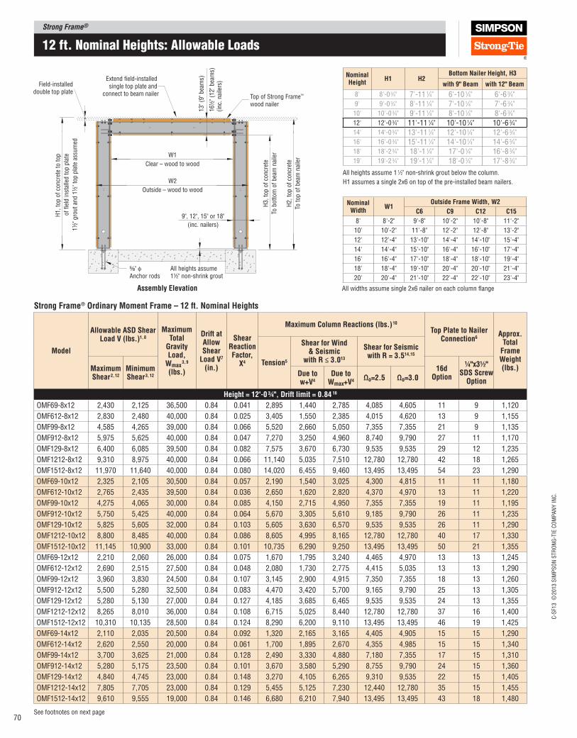
Strong Frame®
C-S
F13 ©
2013 S
IMP
SO
N S
TR
ON
G-T
IE C
OM
PA
NY
IN
C.
70See footnotes on next page
12 ft. nominal Heights: allowable Loads
Strong Frame® Ordinary Moment Frame – 12 ft. Nominal Heights
Model
Allowable ASD Shear load V (lbs.)1, 8
Maximum Total
Gravity load,
Wmax 3, 9
(lbs.)
Drift at Allow Shear
load V7 (in.)
Shear Reaction Factor,
X4
Maximum Column Reactions (lbs.) 10
Top plate to Nailer Connection6
Approx. Total
Frame Weight (lbs.)
Tension5
Shear for Wind & Seismic
with R ≤ 3.013
Shear for Seismic with R = 3.514,15
Maximum Shear 2, 12
Minimum Shear 3, 12
16d Option
¼"x3½" SDS Screw
OptionDue to w+V4
Due to Wmax+V4 Ωo=2.5 Ωo=3.0
Height = 12'‑0 ¾", Drift limit = 0.84 16
OMF69-8x12 2,430 2,125 36,500 0.84 0.041 2,895 1,440 2,785 4,085 4,605 11 9 1,120
OMF612-8x12 2,830 2,480 40,000 0.84 0.025 3,405 1,550 2,385 4,015 4,620 13 9 1,155
OMF99-8x12 4,585 4,265 39,000 0.84 0.066 5,520 2,660 5,050 7,355 7,355 21 9 1,135
OMF912-8x12 5,975 5,625 40,000 0.84 0.047 7,270 3,250 4,960 8,740 9,790 27 11 1,170
OMF129-8x12 6,400 6,085 39,500 0.84 0.082 7,575 3,670 6,730 9,535 9,535 29 12 1,235
OMF1212-8x12 9,310 8,975 40,000 0.84 0.066 11,140 5,035 7,510 12,780 12,780 42 18 1,265
OMF1512-8x12 11,970 11,640 40,000 0.84 0.080 14,020 6,455 9,460 13,495 13,495 54 23 1,290
OMF69-10x12 2,325 2,105 30,500 0.84 0.057 2,190 1,540 3,025 4,300 4,815 11 11 1,180
OMF612-10x12 2,765 2,435 39,500 0.84 0.036 2,650 1,620 2,820 4,370 4,970 13 11 1,220
OMF99-10x12 4,275 4,065 30,000 0.84 0.085 4,150 2,715 4,950 7,355 7,355 19 11 1,195
OMF912-10x12 5,750 5,425 40,000 0.84 0.064 5,670 3,305 5,610 9,185 9,790 26 11 1,235
OMF129-10x12 5,825 5,605 32,000 0.84 0.103 5,605 3,630 6,570 9,535 9,535 26 11 1,290
OMF1212-10x12 8,800 8,485 40,000 0.84 0.086 8,605 4,995 8,165 12,780 12,780 40 17 1,330
OMF1512-10x12 11,145 10,900 33,000 0.84 0.101 10,735 6,290 9,250 13,495 13,495 50 21 1,355
OMF69-12x12 2,210 2,060 26,000 0.84 0.075 1,670 1,795 3,240 4,465 4,970 13 13 1,245
OMF612-12x12 2,690 2,515 27,500 0.84 0.048 2,080 1,730 2,775 4,415 5,035 13 13 1,290
OMF99-12x12 3,960 3,830 24,500 0.84 0.107 3,145 2,900 4,915 7,350 7,355 18 13 1,260
OMF912-12x12 5,500 5,280 32,500 0.84 0.083 4,470 3,420 5,700 9,165 9,790 25 13 1,305
OMF129-12x12 5,280 5,130 27,000 0.84 0.127 4,185 3,685 6,465 9,535 9,535 24 13 1,355
OMF1212-12x12 8,265 8,010 36,000 0.84 0.108 6,715 5,025 8,440 12,780 12,780 37 16 1,400
OMF1512-12x12 10,310 10,135 28,500 0.84 0.124 8,290 6,200 9,110 13,495 13,495 46 19 1,425
OMF69-14x12 2,110 2,035 20,500 0.84 0.092 1,320 2,165 3,165 4,405 4,905 15 15 1,290
OMF612-14x12 2,620 2,550 20,000 0.84 0.061 1,700 1,895 2,670 4,355 4,985 15 15 1,340
OMF99-14x12 3,700 3,625 21,000 0.84 0.128 2,490 3,330 4,880 7,180 7,355 17 15 1,310
OMF912-14x12 5,280 5,175 23,500 0.84 0.101 3,670 3,580 5,290 8,755 9,790 24 15 1,360
OMF129-14x12 4,840 4,745 23,000 0.84 0.148 3,270 4,105 6,265 9,310 9,535 22 15 1,405
OMF1212-14x12 7,805 7,705 23,000 0.84 0.129 5,455 5,125 7,230 12,440 12,780 35 15 1,455
OMF1512-14x12 9,610 9,555 19,000 0.84 0.146 6,680 6,210 7,940 13,495 13,495 43 18 1,480
W1
W2
Clear – wood to wood
Extend field-installed single top plate and
connect to beam nailer Top of Strong Frame™
wood nailer
⁵⁄₈" φAnchor rods
All heights assume 1½" non-shrink grout
13" (9
" bea
ms)
16½
" (1
2" bea
ms)
(inc.
nai
lers
)
Field-installeddouble top plate
Outside – wood to wood
9", 12", 15" or 18"
(inc. nailers)
H1, to
p o
f co
ncr
ete
to t
op
of
fiel
d in
stal
led t
op p
late
1½
" gro
ut
and 1
½" to
p p
late
ass
um
ed
H3, to
p o
f co
ncr
ete
To b
ott
om
of
bea
m n
aile
r
H2, to
p o
f co
ncr
ete
To t
op o
f bea
m n
aile
r
Assembly Elevation
Nominal Width
W1Outside Frame Width, W2
C6 C9 C12 C15
8' 8'-2" 9'-8" 10'-2" 10'-8" 11'-2"
10' 10'-2" 11'-8" 12'-2" 12'-8" 13'-2"
12' 12'-4" 13'-10" 14'-4" 14'-10" 15'-4"
14' 14'-4" 15'-10" 16'-4" 16'-10" 17'-4"
16' 16'-4" 17'-10" 18'-4" 18'-10" 19'-4"
18' 18'-4" 19'-10" 20'-4" 20'-10" 21'-4"
20' 20'-4" 21'-10" 22'-4" 22'-10" 23'-4"
All widths assume single 2x6 nailer on each column lange
Nominal Height
H1 H2Bottom Nailer Height, H3
with 9" Beam with 12" Beam
8' 8'-0 3⁄4" 7'-11 1⁄4" 6'-10 1⁄4" 6'-6 3⁄4"9' 9'-0 3⁄4" 8'-11 1⁄4" 7'-10 1⁄4" 7'-6 3⁄4"10' 10'-0 3⁄4" 9'-11 1⁄4" 8'-10 1⁄4" 8'-6 3⁄4"12' 12'-0 3⁄4" 11'-11 1⁄4" 10'-10 1⁄4" 10'-6 3⁄4"14' 14'-0 3⁄4" 13'-11 1⁄4" 12'-10 1⁄4" 12'-6 3⁄4"16' 16'-0 3⁄4" 15'-11 1⁄4" 14'-10 1⁄4" 14'-6 3⁄4"18' 18'-2 3⁄4" 18'-1 1⁄4" 17'-0 1⁄4" 16'-8 3⁄4"19' 19'-2 3⁄4" 19'-1 1⁄4" 18'-0 1⁄4" 17'-8 3⁄4"
All heights assume 1 1⁄2" non-shrink grout below the column.
H1 assumes a single 2x6 on top of the pre-installed beam nailers.
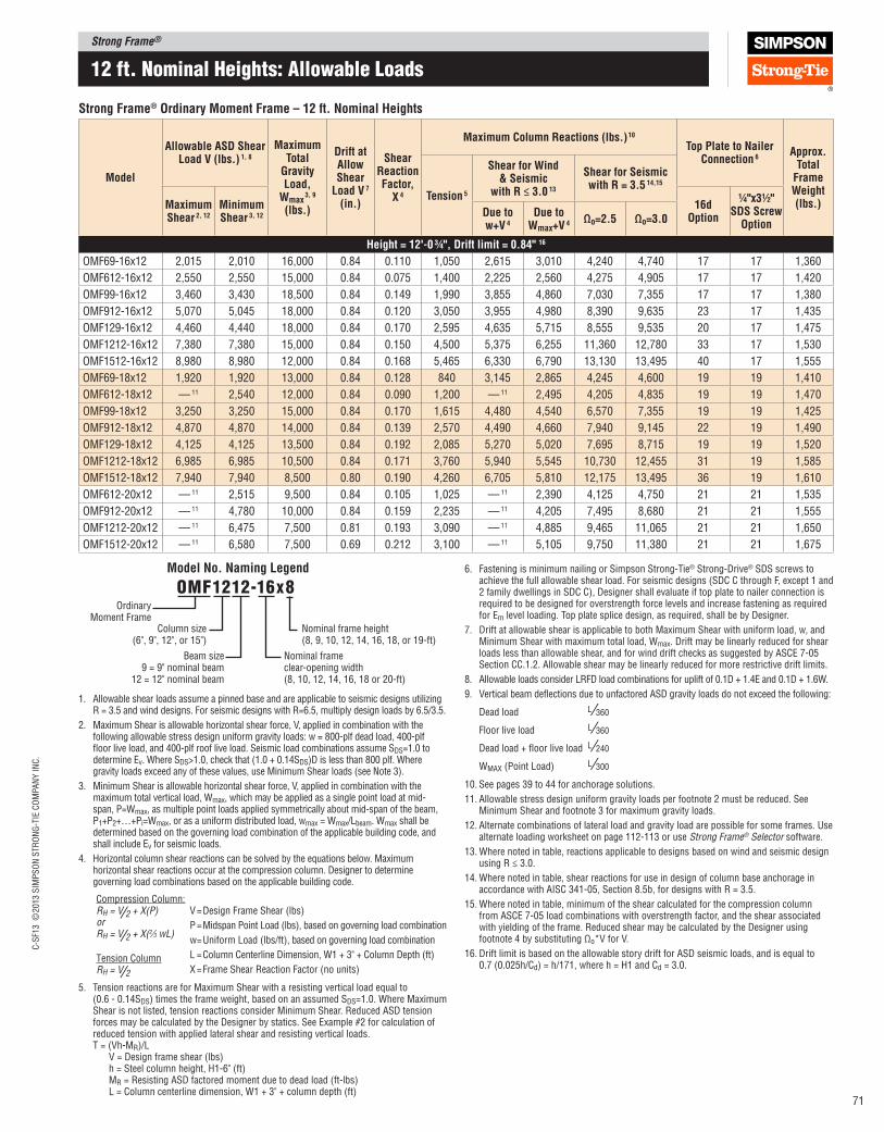
Strong Frame®C
-SF1
3 ©
2013 S
IMP
SO
N S
TR
ON
G-T
IE C
OM
PA
NY
IN
C.
71
12 ft. nominal Heights: allowable Loads
Strong Frame® Ordinary Moment Frame – 12 ft. Nominal Heights
Model
Allowable ASD Shear load V (lbs.) 1, 8
Maximum Total
Gravity load,
Wmax 3, 9
(lbs.)
Drift at Allow Shear
load V 7 (in.)
Shear Reaction Factor,
X 4
Maximum Column Reactions (lbs.) 10
Top plate to Nailer Connection 6
Approx. Total
Frame Weight (lbs.)
Tension 5
Shear for Wind & Seismic
with R ≤ 3.0 13
Shear for Seismic with R = 3.5 14,15
Maximum Shear 2, 12
Minimum Shear 3, 12
16d Option
¼"x3½" SDS Screw
OptionDue to w+V 4
Due to Wmax+V 4
Ωo=2.5 Ωo=3.0
Height = 12'‑0 ¾", Drift limit = 0.84" 16
OMF69-16x12 2,015 2,010 16,000 0.84 0.110 1,050 2,615 3,010 4,240 4,740 17 17 1,360
OMF612-16x12 2,550 2,550 15,000 0.84 0.075 1,400 2,225 2,560 4,275 4,905 17 17 1,420
OMF99-16x12 3,460 3,430 18,500 0.84 0.149 1,990 3,855 4,860 7,030 7,355 17 17 1,380
OMF912-16x12 5,070 5,045 18,000 0.84 0.120 3,050 3,955 4,980 8,390 9,635 23 17 1,435
OMF129-16x12 4,460 4,440 18,000 0.84 0.170 2,595 4,635 5,715 8,555 9,535 20 17 1,475
OMF1212-16x12 7,380 7,380 15,000 0.84 0.150 4,500 5,375 6,255 11,360 12,780 33 17 1,530
OMF1512-16x12 8,980 8,980 12,000 0.84 0.168 5,465 6,330 6,790 13,130 13,495 40 17 1,555
OMF69-18x12 1,920 1,920 13,000 0.84 0.128 840 3,145 2,865 4,245 4,600 19 19 1,410
OMF612-18x12 — 11 2,540 12,000 0.84 0.090 1,200 — 11 2,495 4,205 4,835 19 19 1,470
OMF99-18x12 3,250 3,250 15,000 0.84 0.170 1,615 4,480 4,540 6,570 7,355 19 19 1,425
OMF912-18x12 4,870 4,870 14,000 0.84 0.139 2,570 4,490 4,660 7,940 9,145 22 19 1,490
OMF129-18x12 4,125 4,125 13,500 0.84 0.192 2,085 5,270 5,020 7,695 8,715 19 19 1,520
OMF1212-18x12 6,985 6,985 10,500 0.84 0.171 3,760 5,940 5,545 10,730 12,455 31 19 1,585
OMF1512-18x12 7,940 7,940 8,500 0.80 0.190 4,260 6,705 5,810 12,175 13,495 36 19 1,610
OMF612-20x12 — 11 2,515 9,500 0.84 0.105 1,025 — 11 2,390 4,125 4,750 21 21 1,535
OMF912-20x12 — 11 4,780 10,000 0.84 0.159 2,235 — 11 4,205 7,495 8,680 21 21 1,555
OMF1212-20x12 — 11 6,475 7,500 0.81 0.193 3,090 — 11 4,885 9,465 11,065 21 21 1,650
OMF1512-20x12 — 11 6,580 7,500 0.69 0.212 3,100 — 11 5,105 9,750 11,380 21 21 1,675
6. Fastening is minimum nailing or Simpson Strong‑Tie® Strong‑Drive® SDS screws to achieve the full allowable shear load. For seismic designs (SDC C through F, except 1 and 2 family dwellings in SDC C), Designer shall evaluate if top plate to nailer connection is required to be designed for overstrength force levels and increase fastening as required for Em level loading. Top plate splice design, as required, shall be by Designer.
7. Drift at allowable shear is applicable to both Maximum Shear with uniform load, w, and Minimum Shear with maximum total load, Wmax. Drift may be linearly reduced for shear loads less than allowable shear, and for wind drift checks as suggested by ASCE 7‑05 Section CC.1.2. Allowable shear may be linearly reduced for more restrictive drift limits.
8. Allowable loads consider LRFD load combinations for uplift of 0.1D + 1.4E and 0.1D + 1.6W.
9. Vertical beam delections due to unfactored ASD gravity loads do not exceed the following:
Dead load L ⁄360
Floor live load L ⁄360
Dead load + loor live load L ⁄240
WMAX (Point Load) L ⁄300
10. See pages 39 to 44 for anchorage solutions.
11. Allowable stress design uniform gravity loads per footnote 2 must be reduced. See Minimum Shear and footnote 3 for maximum gravity loads.
12. Alternate combinations of lateral load and gravity load are possible for some frames. Use alternate loading worksheet on page 112‑113 or use Strong Frame® Selector software.
13. Where noted in table, reactions applicable to designs based on wind and seismic design using R ≤ 3.0.
14. Where noted in table, shear reactions for use in design of column base anchorage in accordance with AISC 341‑05, Section 8.5b, for designs with R = 3.5.
15. Where noted in table, minimum of the shear calculated for the compression column from ASCE 7‑05 load combinations with overstrength factor, and the shear associated with yielding of the frame. Reduced shear may be calculated by the Designer using footnote 4 by substituting Ωo*V for V.
16. Drift limit is based on the allowable story drift for ASD seismic loads, and is equal to 0.7 (0.025h/Cd) = h/171, where h = H1 and Cd = 3.0.
1. Allowable shear loads assume a pinned base and are applicable to seismic designs utilizing R = 3.5 and wind designs. For seismic designs with R=6.5, multiply design loads by 6.5/3.5.
2. Maximum Shear is allowable horizontal shear force, V, applied in combination with the following allowable stress design uniform gravity loads: w = 800‑plf dead load, 400‑plf loor live load, and 400‑plf roof live load. Seismic load combinations assume SDS=1.0 to determine Ev. Where SDS>1.0, check that (1.0 + 0.14SDS)D is less than 800 plf. Where gravity loads exceed any of these values, use Minimum Shear loads (see Note 3).
3. Minimum Shear is allowable horizontal shear force, V, applied in combination with the maximum total vertical load, Wmax, which may be applied as a single point load at mid‑span, P=Wmax, as multiple point loads applied symmetrically about mid‑span of the beam, P1+P2+…+Pi=Wmax, or as a uniform distributed load, wmax = Wmax/Lbeam. Wmax shall be determined based on the governing load combination of the applicable building code, and shall include Ev for seismic loads.
4. Horizontal column shear reactions can be solved by the equations below. Maximum horizontal shear reactions occur at the compression column. Designer to determine governing load combinations based on the applicable building code.
V = Design Frame Shear (lbs)
P = Midspan Point Load (lbs), based on governing load combination
w = Uniform Load (lbs/ft), based on governing load combination
L = Column Centerline Dimension, W1 + 3" + Column Depth (ft)
X = Frame Shear Reaction Factor (no units)
5. Tension reactions are for Maximum Shear with a resisting vertical load equal to (0.6 ‑ 0.14SDS) times the frame weight, based on an assumed SDS=1.0. Where Maximum Shear is not listed, tension reactions consider Minimum Shear. Reduced ASD tension forces may be calculated by the Designer by statics. See Example #2 for calculation of reduced tension with applied lateral shear and resisting vertical loads. T = (Vh‑MR)/L V = Design frame shear (lbs) h = Steel column height, H1‑6" (ft) MR = Resisting ASD factored moment due to dead load (ft‑lbs) L = Column centerline dimension, W1 + 3" + column depth (ft)
Compression Column:RH = V⁄2 + X(P)orRH = V⁄2 + X(2⁄3 wL)
Tension ColumnRH = V⁄2
Ordinary Moment Frame
Column size(6", 9", 12", or 15")
Beam size9 = 9" nominal beam
12 = 12" nominal beam
omF1212-16x8
Nominal frame height(8, 9, 10, 12, 14, 16, 18, or 19‑ft)
Nominal frame clear‑opening width(8, 10, 12, 14, 16, 18 or 20‑ft)
Model No. Naming legend
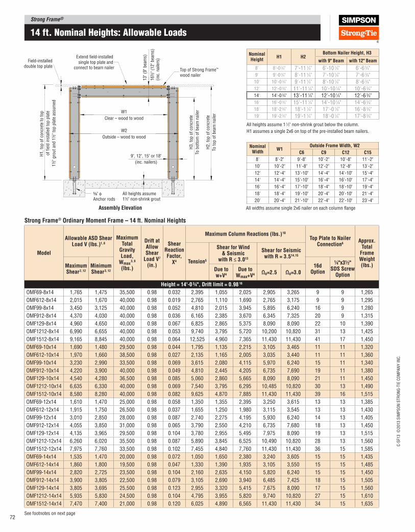
Strong Frame®
C-S
F13 ©
2013 S
IMP
SO
N S
TR
ON
G-T
IE C
OM
PA
NY
IN
C.
72See footnotes on next page
14 ft. nominal Heights: allowable Loads
Strong Frame® Ordinary Moment Frame – 14 ft. Nominal Heights
Model
Allowable ASD Shear load V (lbs.)1, 8
Maximum Total
Gravity load,
Wmax 3, 9
(lbs.)
Drift at Allow Shear
load V7 (in.)
Shear Reaction Factor,
X4
Maximum Column Reactions (lbs.) 10
Top plate to Nailer Connection6
Approx. Total
Frame Weight (lbs.)
Tension5
Shear for Wind & Seismic
with R ≤ 3.013
Shear for Seismic with R = 3.514,15
Maximum Shear 2, 12
Minimum Shear 3, 12
16d Option
¼"x3½" SDS Screw
OptionDue to w+V4
Due to Wmax+V4 Ωo=2.5 Ωo=3.0
Height = 14'‑0 ¾", Drift limit = 0.98 16
OMF69-8x14 1,765 1,475 35,500 0.98 0.032 2,395 1,055 2,025 2,905 3,265 9 9 1,265
OMF612-8x14 2,015 1,670 40,000 0.98 0.019 2,765 1,110 1,690 2,765 3,175 9 9 1,295
OMF99-8x14 3,450 3,125 40,000 0.98 0.052 4,810 2,015 3,945 5,895 6,240 16 9 1,280
OMF912-8x14 4,370 4,030 40,000 0.98 0.036 6,165 2,385 3,670 6,345 7,325 20 9 1,315
OMF129-8x14 4,960 4,650 40,000 0.98 0.067 6,825 2,865 5,375 8,090 8,090 22 10 1,390
OMF1212-8x14 6,990 6,655 40,000 0.98 0.053 9,740 3,795 5,720 10,200 10,820 31 13 1,425
OMF1512-8x14 9,165 8,845 40,000 0.98 0.064 12,525 4,960 7,365 11,430 11,430 41 17 1,450
OMF69-10x14 1,690 1,480 29,500 0.98 0.044 1,795 1,135 2,215 3,105 3,465 11 11 1,320
OMF612-10x14 1,970 1,660 38,500 0.98 0.027 2,135 1,165 2,005 3,035 3,440 11 11 1,360
OMF99-10x14 3,230 2,990 33,500 0.98 0.069 3,615 2,080 4,115 5,970 6,240 15 11 1,340
OMF912-10x14 4,220 3,900 40,000 0.98 0.049 4,810 2,445 4,205 6,735 7,690 19 11 1,380
OMF129-10x14 4,540 4,280 36,500 0.98 0.085 5,060 2,860 5,665 8,090 8,090 21 11 1,450
OMF1212-10x14 6,635 6,330 40,000 0.98 0.069 7,540 3,795 6,295 10,485 10,820 30 13 1,490
OMF1512-10x14 8,580 8,280 40,000 0.98 0.082 9,625 4,870 7,885 11,430 11,430 39 16 1,515
OMF69-12x14 1,610 1,470 25,000 0.98 0.058 1,350 1,355 2,395 3,250 3,615 13 13 1,385
OMF612-12x14 1,915 1,750 26,500 0.98 0.037 1,655 1,250 1,980 3,115 3,545 13 13 1,430
OMF99-12x14 3,010 2,850 28,000 0.98 0.087 2,740 2,275 4,195 5,930 6,240 14 13 1,405
OMF912-12x14 4,055 3,850 31,000 0.98 0.065 3,790 2,550 4,210 6,735 7,680 18 13 1,450
OMF129-12x14 4,135 3,965 29,500 0.98 0.104 3,780 2,955 5,495 7,975 8,090 19 13 1,515
OMF1212-12x14 6,260 6,020 35,500 0.98 0.087 5,890 3,845 6,525 10,490 10,820 28 13 1,560
OMF1512-12x14 7,975 7,760 33,500 0.98 0.102 7,455 4,840 7,760 11,430 11,430 36 15 1,585
OMF69-14x14 1,535 1,470 20,000 0.98 0.072 1,050 1,650 2,380 3,240 3,605 15 15 1,435
OMF612-14x14 1,860 1,800 19,500 0.98 0.047 1,330 1,390 1,935 3,105 3,550 15 15 1,485
OMF99-14x14 2,820 2,725 23,500 0.98 0.104 2,160 2,635 4,150 5,820 6,240 15 15 1,450
OMF912-14x14 3,900 3,805 22,500 0.98 0.079 3,105 2,690 3,940 6,485 7,425 18 15 1,505
OMF129-14x14 3,805 3,695 25,500 0.98 0.123 2,955 3,320 5,415 7,675 8,090 17 15 1,560
OMF1212-14x14 5,935 5,830 24,500 0.98 0.104 4,795 3,955 5,820 9,740 10,820 27 15 1,610
OMF1512-14x14 7,470 7,400 21,000 0.98 0.120 6,025 4,890 6,565 11,430 11,430 34 15 1,635
W1
W2
Clear – wood to wood
Extend field-installed single top plate and
connect to beam nailer Top of Strong Frame™
wood nailer
⁵⁄₈" φAnchor rods
All heights assume 1½" non-shrink grout
13" (9
" bea
ms)
16½
" (1
2" bea
ms)
(inc.
nai
lers
)
Field-installeddouble top plate
Outside – wood to wood
9", 12", 15" or 18"
(inc. nailers)
H1, to
p o
f co
ncr
ete
to t
op
of
fiel
d in
stal
led t
op p
late
1½
" gro
ut
and 1
½" to
p p
late
ass
um
ed
H3, to
p o
f co
ncr
ete
To b
ott
om
of
bea
m n
aile
r
H2, to
p o
f co
ncr
ete
To t
op o
f bea
m n
aile
r
Assembly Elevation
Nominal Width
W1Outside Frame Width, W2
C6 C9 C12 C15
8' 8'-2" 9'-8" 10'-2" 10'-8" 11'-2"
10' 10'-2" 11'-8" 12'-2" 12'-8" 13'-2"
12' 12'-4" 13'-10" 14'-4" 14'-10" 15'-4"
14' 14'-4" 15'-10" 16'-4" 16'-10" 17'-4"
16' 16'-4" 17'-10" 18'-4" 18'-10" 19'-4"
18' 18'-4" 19'-10" 20'-4" 20'-10" 21'-4"
20' 20'-4" 21'-10" 22'-4" 22'-10" 23'-4"
All widths assume single 2x6 nailer on each column lange
Nominal Height
H1 H2Bottom Nailer Height, H3
with 9" Beam with 12" Beam
8' 8'-0 3⁄4" 7'-11 1⁄4" 6'-10 1⁄4" 6'-6 3⁄4"9' 9'-0 3⁄4" 8'-11 1⁄4" 7'-10 1⁄4" 7'-6 3⁄4"10' 10'-0 3⁄4" 9'-11 1⁄4" 8'-10 1⁄4" 8'-6 3⁄4"12' 12'-0 3⁄4" 11'-11 1⁄4" 10'-10 1⁄4" 10'-6 3⁄4"14' 14'-0 3⁄4" 13'-11 1⁄4" 12'-10 1⁄4" 12'-6 3⁄4"16' 16'-0 3⁄4" 15'-11 1⁄4" 14'-10 1⁄4" 14'-6 3⁄4"18' 18'-2 3⁄4" 18'-1 1⁄4" 17'-0 1⁄4" 16'-8 3⁄4"19' 19'-2 3⁄4" 19'-1 1⁄4" 18'-0 1⁄4" 17'-8 3⁄4"
All heights assume 1 1⁄2" non-shrink grout below the column.
H1 assumes a single 2x6 on top of the pre-installed beam nailers.

Strong Frame®C
-SF1
3 ©
2013 S
IMP
SO
N S
TR
ON
G-T
IE C
OM
PA
NY
IN
C.
73
Strong Frame® Ordinary Moment Frame – 14 ft. Nominal Heights
Model
Allowable ASD Shear load V (lbs.) 1, 8
Maximum Total
Gravity load,
Wmax 3, 9
(lbs.)
Drift at Allow Shear
load V 7 (in.)
Shear Reaction Factor,
X 4
Maximum Column Reactions (lbs.) 10
Top plate to Nailer Connection 6
Approx. Total
Frame Weight (lbs.)
Tension 5
Shear for Wind & Seismic
with R ≤ 3.0 13
Shear for Seismic with R = 3.5 14,15
Maximum Shear 2, 12
Minimum Shear 3, 12
16d Option
¼"x3½" SDS Screw
OptionDue to w+V 4
Due to Wmax+V 4
Ωo=2.5 Ωo=3.0
Height = 14'‑0 ¾", Drift limit = 0.98" 16
OMF69-16x14 1,465 1,465 15,500 0.98 0.087 815 2,015 2,265 3,140 3,505 17 17 1,505
OMF612-16x14 1,810 1,810 14,500 0.98 0.057 1,080 1,645 1,850 3,065 3,510 17 17 1,565
OMF99-16x14 2,650 2,615 18,500 0.98 0.122 1,725 3,080 3,875 5,515 6,160 17 17 1,525
OMF912-16x14 3,755 3,735 17,500 0.98 0.095 2,575 3,035 3,760 6,260 7,180 17 17 1,580
OMF129-16x14 3,515 3,485 19,000 0.98 0.141 2,335 3,775 4,800 6,965 7,825 17 17 1,630
OMF1212-16x14 5,630 5,620 16,500 0.98 0.122 3,955 4,225 5,095 8,950 10,335 25 17 1,690
OMF1512-16x14 7,005 7,005 13,500 0.98 0.138 4,935 5,065 5,630 10,525 11,430 32 17 1,715
OMF69-18x14 1,400 1,400 12,500 0.98 0.102 640 2,450 2,150 3,245 3,505 19 19 1,550
OMF612-18x14 — 11 1,825 11,500 0.98 0.069 925 — 11 1,810 3,040 3,490 19 19 1,615
OMF99-18x14 2,490 2,490 15,000 0.98 0.139 1,385 3,600 3,630 5,170 5,785 19 19 1,570
OMF912-18x14 3,610 3,610 14,000 0.98 0.111 2,155 3,470 3,570 5,985 6,880 19 19 1,630
OMF129-18x14 3,260 3,260 14,000 0.98 0.160 1,875 4,315 4,180 6,290 7,095 19 19 1,675
OMF1212-18x14 5,345 5,345 11,500 0.98 0.139 3,300 4,705 4,500 8,310 9,630 24 19 1,740
OMF1512-18x14 6,585 6,585 9,000 0.98 0.157 4,095 5,545 4,900 10,070 11,430 30 19 1,765
OMF612-20x14 — 11 1,815 9,500 0.98 0.081 780 — 11 1,780 3,000 3,450 21 21 1,680
OMF912-20x14 — 11 3,570 11,000 0.98 0.127 1,880 — 11 3,375 5,800 6,680 21 21 1,695
OMF1212-20x14 — 11 5,210 8,000 0.98 0.157 2,860 — 11 4,040 7,695 8,985 21 21 1,805
OMF1512-20x14 — 11 5,600 7,500 0.87 0.175 3,060 — 11 4,300 8,245 9,630 21 21 1,830
14 ft. nominal Heights: allowable Loads
6. Fastening is minimum nailing or Simpson Strong‑Tie® Strong‑Drive® SDS screws to achieve the full allowable shear load. For seismic designs (SDC C through F, except 1 and 2 family dwellings in SDC C), Designer shall evaluate if top plate to nailer connection is required to be designed for overstrength force levels and increase fastening as required for Em level loading. Top plate splice design, as required, shall be by Designer.
7. Drift at allowable shear is applicable to both Maximum Shear with uniform load, w, and Minimum Shear with maximum total load, Wmax. Drift may be linearly reduced for shear loads less than allowable shear, and for wind drift checks as suggested by ASCE 7‑05 Section CC.1.2. Allowable shear may be linearly reduced for more restrictive drift limits.
8. Allowable loads consider LRFD load combinations for uplift of 0.1D + 1.4E and 0.1D + 1.6W.
9. Vertical beam delections due to unfactored ASD gravity loads do not exceed the following:
Dead load L ⁄360
Floor live load L ⁄360
Dead load + loor live load L ⁄240
WMAX (Point Load) L ⁄300
10. See pages 39 to 44 for anchorage solutions.
11. Allowable stress design uniform gravity loads per footnote 2 must be reduced. See Minimum Shear and footnote 3 for maximum gravity loads.
12. Alternate combinations of lateral load and gravity load are possible for some frames. Use alternate loading worksheet on page 112‑113 or use Strong Frame® Selector software.
13. Where noted in table, reactions applicable to designs based on wind and seismic design using R ≤ 3.0.
14. Where noted in table, shear reactions for use in design of column base anchorage in accordance with AISC 341‑05, Section 8.5b, for designs with R = 3.5.
15. Where noted in table, minimum of the shear calculated for the compression column from ASCE 7‑05 load combinations with overstrength factor, and the shear associated with yielding of the frame. Reduced shear may be calculated by the Designer using footnote 4 by substituting Ωo*V for V.
16. Drift limit is based on the allowable story drift for ASD seismic loads, and is equal to 0.7 (0.025h/Cd) = h/171, where h = H1 and Cd = 3.0.
1. Allowable shear loads assume a pinned base and are applicable to seismic designs utilizing R = 3.5 and wind designs. For seismic designs with R=6.5, multiply design loads by 6.5/3.5.
2. Maximum Shear is allowable horizontal shear force, V, applied in combination with the following allowable stress design uniform gravity loads: w = 800‑plf dead load, 400‑plf loor live load, and 400‑plf roof live load. Seismic load combinations assume SDS=1.0 to determine Ev. Where SDS>1.0, check that (1.0 + 0.14SDS)D is less than 800 plf. Where gravity loads exceed any of these values, use Minimum Shear loads (see Note 3).
3. Minimum Shear is allowable horizontal shear force, V, applied in combination with the maximum total vertical load, Wmax, which may be applied as a single point load at mid‑span, P=Wmax, as multiple point loads applied symmetrically about mid‑span of the beam, P1+P2+…+Pi=Wmax, or as a uniform distributed load, wmax = Wmax/Lbeam. Wmax shall be determined based on the governing load combination of the applicable building code, and shall include Ev for seismic loads.
4. Horizontal column shear reactions can be solved by the equations below. Maximum horizontal shear reactions occur at the compression column. Designer to determine governing load combinations based on the applicable building code.
V = Design Frame Shear (lbs)
P = Midspan Point Load (lbs), based on governing load combination
w = Uniform Load (lbs/ft), based on governing load combination
L = Column Centerline Dimension, W1 + 3" + Column Depth (ft)
X = Frame Shear Reaction Factor (no units)
5. Tension reactions are for Maximum Shear with a resisting vertical load equal to (0.6 ‑ 0.14SDS) times the frame weight, based on an assumed SDS=1.0. Where Maximum Shear is not listed, tension reactions consider Minimum Shear. Reduced ASD tension forces may be calculated by the Designer by statics. See Example #2 for calculation of reduced tension with applied lateral shear and resisting vertical loads. T = (Vh‑MR)/L V = Design frame shear (lbs) h = Steel column height, H1‑6" (ft) MR = Resisting ASD factored moment due to dead load (ft‑lbs) L = Column centerline dimension, W1 + 3" + column depth (ft)
Compression Column:RH = V⁄2 + X(P)orRH = V⁄2 + X(2⁄3 wL)
Tension ColumnRH = V⁄2
Ordinary Moment Frame
Column size(6", 9", 12", or 15")
Beam size9 = 9" nominal beam
12 = 12" nominal beam
omF1212-16x8
Nominal frame height(8, 9, 10, 12, 14, 16, 18, or 19‑ft)
Nominal frame clear‑opening width(8, 10, 12, 14, 16, 18 or 20‑ft)
Model No. Naming legend
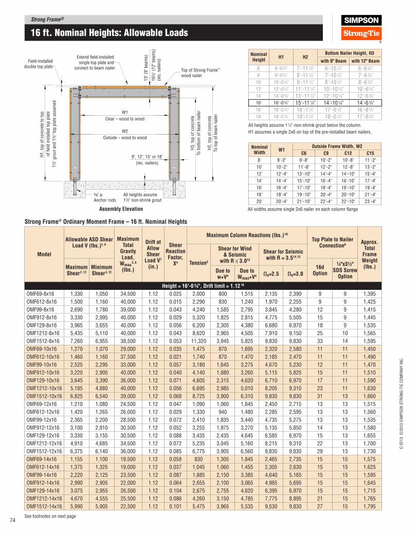
Strong Frame®
C-S
F13 ©
2013 S
IMP
SO
N S
TR
ON
G-T
IE C
OM
PA
NY
IN
C.
74See footnotes on next page
16 ft. nominal Heights: allowable Loads
Strong Frame® Ordinary Moment Frame – 16 ft. Nominal Heights
Model
Allowable ASD Shear load V (lbs.)1, 8
Maximum Total
Gravity load,
Wmax 3, 9
(lbs.)
Drift at Allow Shear
load V7 (in.)
Shear Reaction Factor,
X4
Maximum Column Reactions (lbs.) 10
Top plate to Nailer Connection6
Approx. Total
Frame Weight (lbs.)
Tension5
Shear for Wind & Seismic
with R ≤ 3.013
Shear for Seismic with R = 3.514,15
Maximum Shear 2, 12
Minimum Shear 3, 12
16d Option
¼"x3½" SDS Screw
OptionDue to w+V4
Due to Wmax+V4 Ωo=2.5 Ωo=3.0
Height = 16'‑0 ¾", Drift limit = 1.12 16
OMF69-8x16 1,330 1,050 34,500 1.12 0.025 2,000 800 1,515 2,135 2,390 9 9 1,395
OMF612-8x16 1,500 1,160 40,000 1.12 0.015 2,290 830 1,240 1,970 2,255 9 9 1,425
OMF99-8x16 2,690 1,780 39,000 1.12 0.043 4,240 1,585 2,795 3,845 4,280 12 9 1,415
OMF912-8x16 3,330 2,995 40,000 1.12 0.029 5,320 1,825 2,815 4,775 5,505 15 9 1,445
OMF129-8x16 3,965 3,655 40,000 1.12 0.056 6,200 2,305 4,380 6,680 6,970 18 9 1,535
OMF1212-8x16 5,435 5,110 40,000 1.12 0.043 8,620 2,965 4,505 7,910 9,150 25 10 1,565
OMF1512-8x16 7,260 6,955 38,500 1.12 0.053 11,320 3,945 5,825 9,830 9,830 33 14 1,595
OMF69-10x16 1,270 1,070 29,000 1.12 0.035 1,475 870 1,695 2,320 2,580 11 11 1,450
OMF612-10x16 1,460 1,160 37,500 1.12 0.021 1,740 870 1,470 2,185 2,470 11 11 1,490
OMF99-10x16 2,525 2,295 33,000 1.12 0.057 3,180 1,645 3,275 4,670 5,230 12 11 1,470
OMF912-10x16 3,220 2,905 40,000 1.12 0.040 4,140 1,880 3,260 5,115 5,825 15 11 1,510
OMF129-10x16 3,645 3,390 36,000 1.12 0.071 4,605 2,315 4,620 6,710 6,970 17 11 1,590
OMF1212-10x16 5,185 4,880 40,000 1.12 0.056 6,695 2,985 5,010 8,205 9,310 23 11 1,630
OMF1512-10x16 6,825 6,540 39,000 1.12 0.068 8,725 3,900 6,310 9,830 9,830 31 13 1,660
OMF69-12x16 1,210 1,080 24,500 1.12 0.047 1,090 1,060 1,845 2,450 2,715 13 13 1,515
OMF612-12x16 1,420 1,265 26,000 1.12 0.029 1,330 940 1,480 2,285 2,595 13 13 1,560
OMF99-12x16 2,365 2,200 28,500 1.12 0.072 2,410 1,835 3,440 4,735 5,275 13 13 1,535
OMF912-12x16 3,100 2,910 30,500 1.12 0.052 3,255 1,975 3,270 5,135 5,850 14 13 1,580
OMF129-12x16 3,330 3,155 30,500 1.12 0.088 3,435 2,435 4,645 6,585 6,970 15 13 1,655
OMF1212-12x16 4,910 4,685 34,500 1.12 0.072 5,235 3,045 5,160 8,215 9,310 22 13 1,700
OMF1512-12x16 6,375 6,140 36,000 1.12 0.085 6,775 3,905 6,560 9,830 9,830 29 13 1,730
OMF69-14x16 1,155 1,100 19,500 1.12 0.058 830 1,305 1,845 2,465 2,735 15 15 1,575
OMF612-14x16 1,375 1,325 19,000 1.12 0.037 1,045 1,060 1,455 2,305 2,630 15 15 1,625
OMF99-14x16 2,220 2,125 23,500 1.12 0.087 1,885 2,150 3,385 4,640 5,165 15 15 1,595
OMF912-14x16 2,990 2,905 22,000 1.12 0.064 2,655 2,100 3,065 4,985 5,695 15 15 1,645
OMF129-14x16 3,075 2,955 26,500 1.12 0.104 2,675 2,755 4,620 6,395 6,970 15 15 1,715
OMF1212-14x16 4,670 4,555 25,500 1.12 0.086 4,260 3,150 4,785 7,775 8,895 21 15 1,765
OMF1512-14x16 5,990 5,905 22,500 1.12 0.101 5,475 3,965 5,535 9,530 9,830 27 15 1,795
W1
W2
Clear – wood to wood
Extend field-installed single top plate and
connect to beam nailer Top of Strong Frame™
wood nailer
⁵⁄₈" φAnchor rods
All heights assume 1½" non-shrink grout
13" (9
" bea
ms)
16½
" (1
2" bea
ms)
(inc.
nai
lers
)
Field-installeddouble top plate
Outside – wood to wood
9", 12", 15" or 18"
(inc. nailers)
H1, to
p o
f co
ncr
ete
to t
op
of
fiel
d in
stal
led t
op p
late
1½
" gro
ut
and 1
½" to
p p
late
ass
um
ed
H3, to
p o
f co
ncr
ete
To b
ott
om
of
bea
m n
aile
r
H2, to
p o
f co
ncr
ete
To t
op o
f bea
m n
aile
r
Assembly Elevation
Nominal Width
W1Outside Frame Width, W2
C6 C9 C12 C15
8' 8'-2" 9'-8" 10'-2" 10'-8" 11'-2"
10' 10'-2" 11'-8" 12'-2" 12'-8" 13'-2"
12' 12'-4" 13'-10" 14'-4" 14'-10" 15'-4"
14' 14'-4" 15'-10" 16'-4" 16'-10" 17'-4"
16' 16'-4" 17'-10" 18'-4" 18'-10" 19'-4"
18' 18'-4" 19'-10" 20'-4" 20'-10" 21'-4"
20' 20'-4" 21'-10" 22'-4" 22'-10" 23'-4"
All widths assume single 2x6 nailer on each column lange
Nominal Height
H1 H2Bottom Nailer Height, H3
with 9" Beam with 12" Beam
8' 8'-0 3⁄4" 7'-11 1⁄4" 6'-10 1⁄4" 6'-6 3⁄4"9' 9'-0 3⁄4" 8'-11 1⁄4" 7'-10 1⁄4" 7'-6 3⁄4"
10' 10'-0 3⁄4" 9'-11 1⁄4" 8'-10 1⁄4" 8'-6 3⁄4"12' 12'-0 3⁄4" 11'-11 1⁄4" 10'-10 1⁄4" 10'-6 3⁄4"14' 14'-0 3⁄4" 13'-11 1⁄4" 12'-10 1⁄4" 12'-6 3⁄4"16' 16'-0 3⁄4" 15'-11 1⁄4" 14'-10 1⁄4" 14'-6 3⁄4"18' 18'-2 3⁄4" 18'-1 1⁄4" 17'-0 1⁄4" 16'-8 3⁄4"19' 19'-2 3⁄4" 19'-1 1⁄4" 18'-0 1⁄4" 17'-8 3⁄4"
All heights assume 1 1⁄2" non-shrink grout below the column.
H1 assumes a single 2x6 on top of the pre-installed beam nailers.
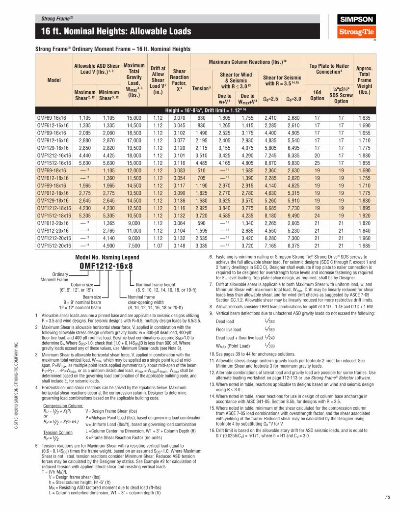
Strong Frame®C
-SF1
3 ©
2013 S
IMP
SO
N S
TR
ON
G-T
IE C
OM
PA
NY
IN
C.
75
16 ft. nominal Heights: allowable Loads
Strong Frame® Ordinary Moment Frame – 16 ft. Nominal Heights
Model
Allowable ASD Shear load V (lbs.) 1, 8
Maximum Total
Gravity load,
Wmax 3, 9
(lbs.)
Drift at Allow Shear
load V 7 (in.)
Shear Reaction Factor,
X 4
Maximum Column Reactions (lbs.) 10
Top plate to Nailer Connection 6
Approx. Total
Frame Weight (lbs.)
Tension 5
Shear for Wind & Seismic
with R ≤ 3.0 13
Shear for Seismic with R = 3.5 14,15
Maximum Shear 2, 12
Minimum Shear 3, 12
16d Option
¼"x3½" SDS Screw
OptionDue to w+V 4
Due to Wmax+V 4
Ωo=2.5 Ωo=3.0
Height = 16'‑0 ¾", Drift limit = 1.12" 16
OMF69-16x16 1,105 1,105 15,000 1.12 0.070 630 1,605 1,755 2,410 2,680 17 17 1,635
OMF612-16x16 1,335 1,335 14,500 1.12 0.045 830 1,265 1,415 2,285 2,610 17 17 1,690
OMF99-16x16 2,085 2,060 18,500 1.12 0.102 1,490 2,525 3,175 4,400 4,905 17 17 1,655
OMF912-16x16 2,880 2,870 17,000 1.12 0.077 2,195 2,405 2,930 4,835 5,540 17 17 1,710
OMF129-16x16 2,850 2,820 19,500 1.12 0.120 2,115 3,155 4,075 5,805 6,495 17 17 1,775
OMF1212-16x16 4,440 4,425 18,000 1.12 0.101 3,510 3,425 4,290 7,245 8,335 20 17 1,830
OMF1512-16x16 5,630 5,630 15,000 1.12 0.116 4,485 4,165 4,805 8,670 9,830 25 17 1,855
OMF69-18x16 — 11 1,105 12,000 1.12 0.083 510 — 11 1,685 2,360 2,630 19 19 1,690
OMF612-18x16 — 11 1,360 11,500 1.12 0.054 705 — 11 1,390 2,285 2,620 19 19 1,755
OMF99-18x16 1,965 1,965 14,500 1.12 0.117 1,190 2,970 2,915 4,140 4,625 19 19 1,710
OMF912-18x16 2,775 2,775 13,500 1.12 0.090 1,825 2,770 2,780 4,630 5,315 19 19 1,775
OMF129-18x16 2,645 2,645 14,500 1.12 0.136 1,680 3,625 3,570 5,260 5,910 19 19 1,830
OMF1212-18x16 4,230 4,230 12,500 1.12 0.116 2,925 3,840 3,775 6,685 7,730 19 19 1,895
OMF1512-18x16 5,305 5,305 10,500 1.12 0.132 3,720 4,585 4,235 8,180 9,490 24 19 1,920
OMF612-20x16 — 11 1,365 9,000 1.12 0.064 590 — 11 1,340 2,265 2,605 21 21 1,820
OMF912-20x16 — 11 2,765 11,000 1.12 0.104 1,595 — 11 2,685 4,550 5,230 21 21 1,840
OMF1212-20x16 — 11 4,140 9,000 1.12 0.132 2,535 — 11 3,420 6,280 7,300 21 21 1,960
OMF1512-20x16 — 11 4,900 7,500 1.07 0.148 3,035 — 11 3,720 7,165 8,375 21 21 1,985
6. Fastening is minimum nailing or Simpson Strong‑Tie® Strong‑Drive® SDS screws to achieve the full allowable shear load. For seismic designs (SDC C through F, except 1 and 2 family dwellings in SDC C), Designer shall evaluate if top plate to nailer connection is required to be designed for overstrength force levels and increase fastening as required for Em level loading. Top plate splice design, as required, shall be by Designer.
7. Drift at allowable shear is applicable to both Maximum Shear with uniform load, w, and Minimum Shear with maximum total load, Wmax. Drift may be linearly reduced for shear loads less than allowable shear, and for wind drift checks as suggested by ASCE 7‑05 Section CC.1.2. Allowable shear may be linearly reduced for more restrictive drift limits.
8. Allowable loads consider LRFD load combinations for uplift of 0.1D + 1.4E and 0.1D + 1.6W.
9. Vertical beam delections due to unfactored ASD gravity loads do not exceed the following:
Dead load L ⁄360
Floor live load L ⁄360
Dead load + loor live load L ⁄240
WMAX (Point Load) L ⁄300
10. See pages 39 to 44 for anchorage solutions.
11. Allowable stress design uniform gravity loads per footnote 2 must be reduced. See Minimum Shear and footnote 3 for maximum gravity loads.
12. Alternate combinations of lateral load and gravity load are possible for some frames. Use alternate loading worksheet on page 112‑113 or use Strong Frame® Selector software.
13. Where noted in table, reactions applicable to designs based on wind and seismic design using R ≤ 3.0.
14. Where noted in table, shear reactions for use in design of column base anchorage in accordance with AISC 341‑05, Section 8.5b, for designs with R = 3.5.
15. Where noted in table, minimum of the shear calculated for the compression column from ASCE 7‑05 load combinations with overstrength factor, and the shear associated with yielding of the frame. Reduced shear may be calculated by the Designer using footnote 4 by substituting Ωo*V for V.
16. Drift limit is based on the allowable story drift for ASD seismic loads, and is equal to 0.7 (0.025h/Cd) = h/171, where h = H1 and Cd = 3.0.
1. Allowable shear loads assume a pinned base and are applicable to seismic designs utilizing R = 3.5 and wind designs. For seismic designs with R=6.5, multiply design loads by 6.5/3.5.
2. Maximum Shear is allowable horizontal shear force, V, applied in combination with the following allowable stress design uniform gravity loads: w = 800‑plf dead load, 400‑plf loor live load, and 400‑plf roof live load. Seismic load combinations assume SDS=1.0 to determine Ev. Where SDS>1.0, check that (1.0 + 0.14SDS)D is less than 800 plf. Where gravity loads exceed any of these values, use Minimum Shear loads (see Note 3).
3. Minimum Shear is allowable horizontal shear force, V, applied in combination with the maximum total vertical load, Wmax, which may be applied as a single point load at mid‑span, P=Wmax, as multiple point loads applied symmetrically about mid‑span of the beam, P1+P2+…+Pi=Wmax, or as a uniform distributed load, wmax = Wmax/Lbeam. Wmax shall be determined based on the governing load combination of the applicable building code, and shall include Ev for seismic loads.
4. Horizontal column shear reactions can be solved by the equations below. Maximum horizontal shear reactions occur at the compression column. Designer to determine governing load combinations based on the applicable building code.
V = Design Frame Shear (lbs)
P = Midspan Point Load (lbs), based on governing load combination
w = Uniform Load (lbs/ft), based on governing load combination
L = Column Centerline Dimension, W1 + 3" + Column Depth (ft)
X = Frame Shear Reaction Factor (no units)
5. Tension reactions are for Maximum Shear with a resisting vertical load equal to (0.6 ‑ 0.14SDS) times the frame weight, based on an assumed SDS=1.0. Where Maximum Shear is not listed, tension reactions consider Minimum Shear. Reduced ASD tension forces may be calculated by the Designer by statics. See Example #2 for calculation of reduced tension with applied lateral shear and resisting vertical loads. T = (Vh‑MR)/L V = Design frame shear (lbs) h = Steel column height, H1‑6" (ft) MR = Resisting ASD factored moment due to dead load (ft‑lbs) L = Column centerline dimension, W1 + 3" + column depth (ft)
Compression Column:RH = V⁄2 + X(P)orRH = V⁄2 + X(2⁄3 wL)
Tension ColumnRH = V⁄2
Ordinary Moment Frame
Column size(6", 9", 12", or 15")
Beam size9 = 9" nominal beam
12 = 12" nominal beam
omF1212-16x8
Nominal frame height(8, 9, 10, 12, 14, 16, 18, or 19‑ft)
Nominal frame clear‑opening width(8, 10, 12, 14, 16, 18 or 20‑ft)
Model No. Naming legend
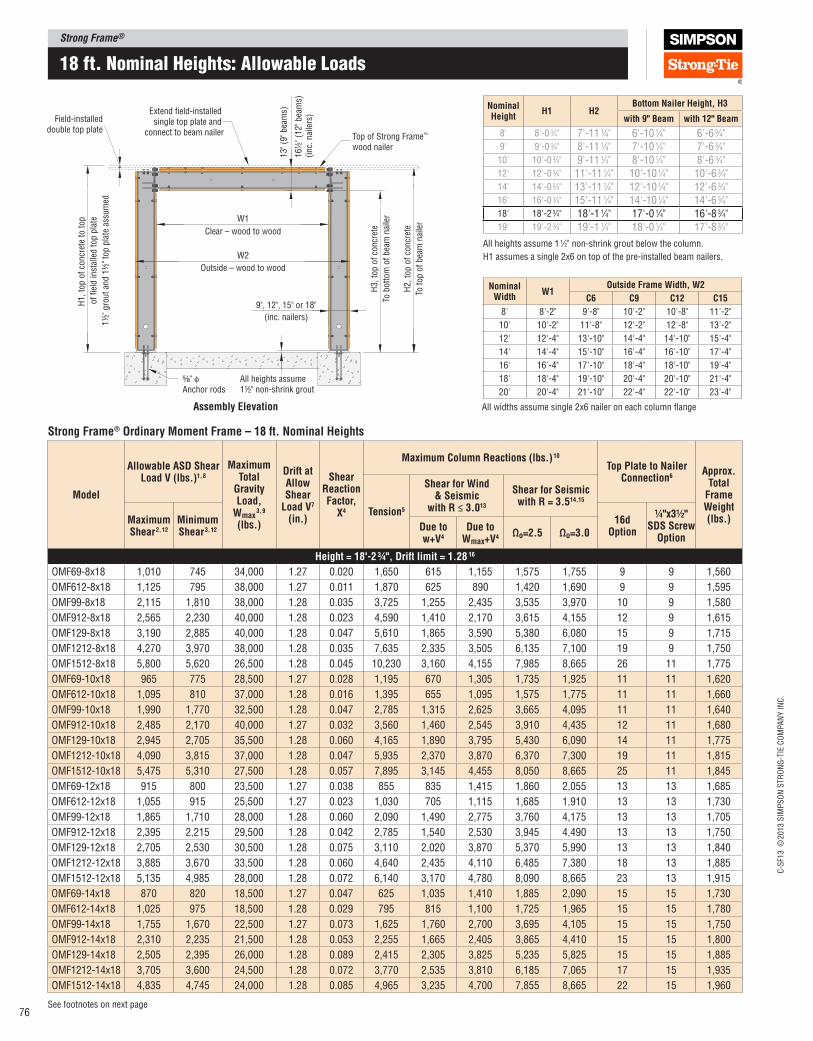
Strong Frame®
C-S
F13 ©
2013 S
IMP
SO
N S
TR
ON
G-T
IE C
OM
PA
NY
IN
C.
76See footnotes on next page
18 ft. nominal Heights: allowable Loads
Strong Frame® Ordinary Moment Frame – 18 ft. Nominal Heights
Model
Allowable ASD Shear load V (lbs.)1, 8
Maximum Total
Gravity load,
Wmax 3, 9
(lbs.)
Drift at Allow Shear
load V7 (in.)
Shear Reaction Factor,
X4
Maximum Column Reactions (lbs.) 10
Top plate to Nailer Connection6
Approx. Total
Frame Weight (lbs.)
Tension5
Shear for Wind & Seismic
with R ≤ 3.013
Shear for Seismic with R = 3.514,15
Maximum Shear 2, 12
Minimum Shear 3, 12
16d Option
¼"x3½" SDS Screw
OptionDue to w+V4
Due to Wmax+V4 Ωo=2.5 Ωo=3.0
Height = 18'‑2 ¾", Drift limit = 1.28 16
OMF69-8x18 1,010 745 34,000 1.27 0.020 1,650 615 1,155 1,575 1,755 9 9 1,560
OMF612-8x18 1,125 795 38,000 1.27 0.011 1,870 625 890 1,420 1,690 9 9 1,595
OMF99-8x18 2,115 1,810 38,000 1.28 0.035 3,725 1,255 2,435 3,535 3,970 10 9 1,580
OMF912-8x18 2,565 2,230 40,000 1.28 0.023 4,590 1,410 2,170 3,615 4,155 12 9 1,615
OMF129-8x18 3,190 2,885 40,000 1.28 0.047 5,610 1,865 3,590 5,380 6,080 15 9 1,715
OMF1212-8x18 4,270 3,970 38,000 1.28 0.035 7,635 2,335 3,505 6,135 7,100 19 9 1,750
OMF1512-8x18 5,800 5,620 26,500 1.28 0.045 10,230 3,160 4,155 7,985 8,665 26 11 1,775
OMF69-10x18 965 775 28,500 1.27 0.028 1,195 670 1,305 1,735 1,925 11 11 1,620
OMF612-10x18 1,095 810 37,000 1.28 0.016 1,395 655 1,095 1,575 1,775 11 11 1,660
OMF99-10x18 1,990 1,770 32,500 1.28 0.047 2,785 1,315 2,625 3,665 4,095 11 11 1,640
OMF912-10x18 2,485 2,170 40,000 1.27 0.032 3,560 1,460 2,545 3,910 4,435 12 11 1,680
OMF129-10x18 2,945 2,705 35,500 1.28 0.060 4,165 1,890 3,795 5,430 6,090 14 11 1,775
OMF1212-10x18 4,090 3,815 37,000 1.28 0.047 5,935 2,370 3,870 6,370 7,300 19 11 1,815
OMF1512-10x18 5,475 5,310 27,500 1.28 0.057 7,895 3,145 4,455 8,050 8,665 25 11 1,845
OMF69-12x18 915 800 23,500 1.27 0.038 855 835 1,415 1,860 2,055 13 13 1,685
OMF612-12x18 1,055 915 25,500 1.27 0.023 1,030 705 1,115 1,685 1,910 13 13 1,730
OMF99-12x18 1,865 1,710 28,000 1.28 0.060 2,090 1,490 2,775 3,760 4,175 13 13 1,705
OMF912-12x18 2,395 2,215 29,500 1.28 0.042 2,785 1,540 2,530 3,945 4,490 13 13 1,750
OMF129-12x18 2,705 2,530 30,500 1.28 0.075 3,110 2,020 3,870 5,370 5,990 13 13 1,840
OMF1212-12x18 3,885 3,670 33,500 1.28 0.060 4,640 2,435 4,110 6,485 7,380 18 13 1,885
OMF1512-12x18 5,135 4,985 28,000 1.28 0.072 6,140 3,170 4,780 8,090 8,665 23 13 1,915
OMF69-14x18 870 820 18,500 1.27 0.047 625 1,035 1,410 1,885 2,090 15 15 1,730
OMF612-14x18 1,025 975 18,500 1.28 0.029 795 815 1,100 1,725 1,965 15 15 1,780
OMF99-14x18 1,755 1,670 22,500 1.27 0.073 1,625 1,760 2,700 3,695 4,105 15 15 1,750
OMF912-14x18 2,310 2,235 21,500 1.28 0.053 2,255 1,665 2,405 3,865 4,410 15 15 1,800
OMF129-14x18 2,505 2,395 26,000 1.28 0.089 2,415 2,305 3,825 5,235 5,825 15 15 1,885
OMF1212-14x18 3,705 3,600 24,500 1.28 0.072 3,770 2,535 3,810 6,185 7,065 17 15 1,935
OMF1512-14x18 4,835 4,745 24,000 1.28 0.085 4,965 3,235 4,700 7,855 8,665 22 15 1,960
W1
W2
Clear – wood to wood
Extend field-installed single top plate and
connect to beam nailer Top of Strong Frame™
wood nailer
⁵⁄₈" φAnchor rods
All heights assume 1½" non-shrink grout
13" (9
" bea
ms)
16½
" (1
2" bea
ms)
(inc.
nai
lers
)
Field-installeddouble top plate
Outside – wood to wood
9", 12", 15" or 18"
(inc. nailers)
H1, to
p o
f co
ncr
ete
to t
op
of
fiel
d in
stal
led t
op p
late
1½
" gro
ut
and 1
½" to
p p
late
ass
um
ed
H3, to
p o
f co
ncr
ete
To b
ott
om
of
bea
m n
aile
r
H2, to
p o
f co
ncr
ete
To t
op o
f bea
m n
aile
r
Assembly Elevation
Nominal Width
W1Outside Frame Width, W2
C6 C9 C12 C15
8' 8'-2" 9'-8" 10'-2" 10'-8" 11'-2"
10' 10'-2" 11'-8" 12'-2" 12'-8" 13'-2"
12' 12'-4" 13'-10" 14'-4" 14'-10" 15'-4"
14' 14'-4" 15'-10" 16'-4" 16'-10" 17'-4"
16' 16'-4" 17'-10" 18'-4" 18'-10" 19'-4"
18' 18'-4" 19'-10" 20'-4" 20'-10" 21'-4"
20' 20'-4" 21'-10" 22'-4" 22'-10" 23'-4"
All widths assume single 2x6 nailer on each column lange
Nominal Height
H1 H2Bottom Nailer Height, H3
with 9" Beam with 12" Beam
8' 8'-0 3⁄4" 7'-11 1⁄4" 6'-10 1⁄4" 6'-6 3⁄4"9' 9'-0 3⁄4" 8'-11 1⁄4" 7'-10 1⁄4" 7'-6 3⁄4"
10' 10'-0 3⁄4" 9'-11 1⁄4" 8'-10 1⁄4" 8'-6 3⁄4"12' 12'-0 3⁄4" 11'-11 1⁄4" 10'-10 1⁄4" 10'-6 3⁄4"14' 14'-0 3⁄4" 13'-11 1⁄4" 12'-10 1⁄4" 12'-6 3⁄4"16' 16'-0 3⁄4" 15'-11 1⁄4" 14'-10 1⁄4" 14'-6 3⁄4"18' 18'-2 3⁄4" 18'-1 1⁄4" 17'-0 1⁄4" 16'-8 3⁄4"19' 19'-2 3⁄4" 19'-1 1⁄4" 18'-0 1⁄4" 17'-8 3⁄4"
All heights assume 1 1⁄2" non-shrink grout below the column.
H1 assumes a single 2x6 on top of the pre-installed beam nailers.

Strong Frame®C
-SF1
3 ©
2013 S
IMP
SO
N S
TR
ON
G-T
IE C
OM
PA
NY
IN
C.
77
18 ft. nominal Heights: allowable Loads
Strong Frame® Ordinary Moment Frame – 18 ft. Nominal Heights
Model
Allowable ASD Shear load V (lbs.) 1, 8
Maximum Total
Gravity load,
Wmax 3, 9
(lbs.)
Drift at Allow Shear
load V 7 (in.)
Shear Reaction Factor,
X 4
Maximum Column Reactions (lbs.) 10
Top plate to Nailer Connection 6
Approx. Total
Frame Weight (lbs.)
Tension 5
Shear for Wind & Seismic
with R ≤ 3.0 13
Shear for Seismic with R = 3.5 14,15
Maximum Shear 2, 12
Minimum Shear 3, 12
16d Option
¼"x3½" SDS Screw
OptionDue to w+V 4
Due to Wmax+V 4
Ωo=2.5 Ωo=3.0
Height = 18'‑2 ¾", Drift limit = 1.28" 16
OMF69-16x18 830 830 14,500 1.27 0.058 445 1,285 1,365 1,850 2,055 17 17 1,805
OMF612-16x18 990 990 14,000 1.27 0.036 600 980 1,070 1,715 1,960 17 17 1,860
OMF99-16x18 1,650 1,635 17,500 1.27 0.086 1,270 2,085 2,525 3,525 3,930 17 17 1,825
OMF912-16x18 2,230 2,225 16,500 1.28 0.063 1,850 1,920 2,305 3,770 4,315 17 17 1,880
OMF129-16x18 2,320 2,285 20,000 1.27 0.102 1,890 2,650 3,480 4,860 5,420 17 17 1,960
OMF1212-16x18 3,530 3,505 18,500 1.28 0.085 3,095 2,795 3,540 5,890 6,750 17 17 2,015
OMF1512-16x18 4,565 4,565 16,000 1.28 0.099 4,070 3,455 4,085 7,195 8,315 21 17 2,045
OMF69-18x18 — 11 850 11,500 1.28 0.068 365 — 11 1,315 1,840 2,045 19 19 1,845
OMF612-18x18 — 11 1,030 11,000 1.27 0.043 520 — 11 1,060 1,740 1,990 19 19 1,910
OMF99-18x18 1,555 1,555 14,500 1.27 0.099 995 2,470 2,405 3,350 3,705 19 19 1,865
OMF912-18x18 2,150 2,150 13,000 1.28 0.074 1,530 2,230 2,175 3,610 4,140 19 19 1,930
OMF129-18x18 2,160 2,160 15,000 1.28 0.116 1,495 3,065 3,070 4,435 4,965 19 19 2,000
OMF1212-18x18 3,365 3,365 13,500 1.27 0.098 2,570 3,155 3,185 5,475 6,300 19 19 2,065
OMF1512-18x18 4,310 4,310 11,000 1.28 0.112 3,370 3,825 3,565 6,700 7,760 20 19 2,090
OMF612-20x18 — 11 1,035 9,000 1.27 0.051 415 — 11 1,045 1,730 1,985 21 21 1,975
OMF912-20x18 — 11 2,165 10,500 1.28 0.086 1,340 — 11 2,110 3,585 4,120 21 21 1,995
OMF1212-20x18 — 11 3,320 9,500 1.28 0.111 2,240 — 11 2,860 5,155 5,970 21 21 2,130
OMF1512-20x18 — 11 4,200 7,500 1.28 0.126 2,915 — 11 3,180 6,135 7,170 21 21 2,155
6. Fastening is minimum nailing or Simpson Strong‑Tie® Strong‑Drive® SDS screws to achieve the full allowable shear load. For seismic designs (SDC C through F, except 1 and 2 family dwellings in SDC C), Designer shall evaluate if top plate to nailer connection is required to be designed for overstrength force levels and increase fastening as required for Em level loading. Top plate splice design, as required, shall be by Designer.
7. Drift at allowable shear is applicable to both Maximum Shear with uniform load, w, and Minimum Shear with maximum total load, Wmax. Drift may be linearly reduced for shear loads less than allowable shear, and for wind drift checks as suggested by ASCE 7‑05 Section CC.1.2. Allowable shear may be linearly reduced for more restrictive drift limits.
8. Allowable loads consider LRFD load combinations for uplift of 0.1D + 1.4E and 0.1D + 1.6W.
9. Vertical beam delections due to unfactored ASD gravity loads do not exceed the following:
Dead load L ⁄360
Floor live load L ⁄360
Dead load + loor live load L ⁄240
WMAX (Point Load) L ⁄300
10. See pages 39 to 44 for anchorage solutions.
11. Allowable stress design uniform gravity loads per footnote 2 must be reduced. See Minimum Shear and footnote 3 for maximum gravity loads.
12. Alternate combinations of lateral load and gravity load are possible for some frames. Use alternate loading worksheet on page 112‑113 or use Strong Frame® Selector software.
13. Where noted in table, reactions applicable to designs based on wind and seismic design using R ≤ 3.0.
14. Where noted in table, shear reactions for use in design of column base anchorage in accordance with AISC 341‑05, Section 8.5b, for designs with R = 3.5.
15. Where noted in table, minimum of the shear calculated for the compression column from ASCE 7‑05 load combinations with overstrength factor, and the shear associated with yielding of the frame. Reduced shear may be calculated by the Designer using footnote 4 by substituting Ωo*V for V.
16. Drift limit is based on the allowable story drift for ASD seismic loads, and is equal to 0.7 (0.025h/Cd) = h/171, where h = H1 and Cd = 3.0.
1. Allowable shear loads assume a pinned base and are applicable to seismic designs utilizing R = 3.5 and wind designs. For seismic designs with R=6.5, multiply design loads by 6.5/3.5.
2. Maximum Shear is allowable horizontal shear force, V, applied in combination with the following allowable stress design uniform gravity loads: w = 800‑plf dead load, 400‑plf loor live load, and 400‑plf roof live load. Seismic load combinations assume SDS=1.0 to determine Ev. Where SDS>1.0, check that (1.0 + 0.14SDS)D is less than 800 plf. Where gravity loads exceed any of these values, use Minimum Shear loads (see Note 3).
3. Minimum Shear is allowable horizontal shear force, V, applied in combination with the maximum total vertical load, Wmax, which may be applied as a single point load at mid‑span, P=Wmax, as multiple point loads applied symmetrically about mid‑span of the beam, P1+P2+…+Pi=Wmax, or as a uniform distributed load, wmax = Wmax/Lbeam. Wmax shall be determined based on the governing load combination of the applicable building code, and shall include Ev for seismic loads.
4. Horizontal column shear reactions can be solved by the equations below. Maximum horizontal shear reactions occur at the compression column. Designer to determine governing load combinations based on the applicable building code.
V = Design Frame Shear (lbs)
P = Midspan Point Load (lbs), based on governing load combination
w = Uniform Load (lbs/ft), based on governing load combination
L = Column Centerline Dimension, W1 + 3" + Column Depth (ft)
X = Frame Shear Reaction Factor (no units)
5. Tension reactions are for Maximum Shear with a resisting vertical load equal to (0.6 ‑ 0.14SDS) times the frame weight, based on an assumed SDS=1.0. Where Maximum Shear is not listed, tension reactions consider Minimum Shear. Reduced ASD tension forces may be calculated by the Designer by statics. See Example #2 for calculation of reduced tension with applied lateral shear and resisting vertical loads. T = (Vh‑MR)/L V = Design frame shear (lbs) h = Steel column height, H1‑6" (ft) MR = Resisting ASD factored moment due to dead load (ft‑lbs) L = Column centerline dimension, W1 + 3" + column depth (ft)
Compression Column:RH = V⁄2 + X(P)orRH = V⁄2 + X(2⁄3 wL)
Tension ColumnRH = V⁄2
Ordinary Moment Frame
Column size(6", 9", 12", or 15")
Beam size9 = 9" nominal beam
12 = 12" nominal beam
omF1212-16x8
Nominal frame height(8, 9, 10, 12, 14, 16, 18, or 19‑ft)
Nominal frame clear‑opening width(8, 10, 12, 14, 16, 18 or 20‑ft)
Model No. Naming legend
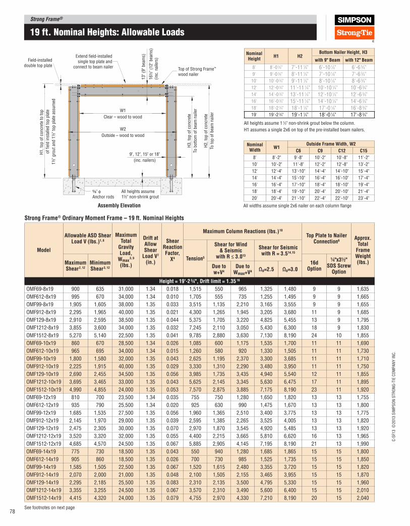
Strong Frame®
C-S
F13 ©
2013 S
IMP
SO
N S
TR
ON
G-T
IE C
OM
PA
NY
IN
C.
78See footnotes on next page
19 ft. nominal Heights: allowable Loads
Strong Frame® Ordinary Moment Frame – 19 ft. Nominal Heights
Model
Allowable ASD Shear load V (lbs.)1, 8
Maximum Total
Gravity load,
Wmax 3, 9
(lbs.)
Drift at Allow Shear
load V7 (in.)
Shear Reaction Factor,
X4
Maximum Column Reactions (lbs.) 10
Top plate to Nailer Connection6
Approx. Total
Frame Weight (lbs.)
Tension5
Shear for Wind & Seismic
with R ≤ 3.013
Shear for Seismic with R = 3.514,15
Maximum Shear 2, 12
Minimum Shear 3, 12
16d Option
¼"x3½" SDS Screw
OptionDue to w+V4
Due to Wmax+V4 Ωo=2.5 Ωo=3.0
Height = 19'‑2 ¾", Drift limit = 1.35 16
OMF69-8x19 900 635 31,000 1.34 0.018 1,515 550 965 1,325 1,480 9 9 1,635
OMF612-8x19 995 670 34,000 1.34 0.010 1,705 555 735 1,255 1,495 9 9 1,665
OMF99-8x19 1,905 1,605 38,000 1.35 0.033 3,515 1,135 2,210 3,165 3,555 9 9 1,655
OMF912-8x19 2,295 1,965 40,000 1.35 0.021 4,300 1,265 1,945 3,205 3,680 11 9 1,685
OMF129-8x19 2,910 2,595 38,500 1.35 0.044 5,375 1,705 3,220 4,825 5,455 13 9 1,795
OMF1212-8x19 3,855 3,600 34,000 1.35 0.032 7,245 2,110 3,050 5,430 6,300 18 9 1,830
OMF1512-8x19 5,270 5,140 22,500 1.35 0.041 9,785 2,880 3,630 7,130 8,190 24 10 1,855
OMF69-10x19 860 670 28,500 1.34 0.026 1,085 600 1,175 1,535 1,700 11 11 1,690
OMF612-10x19 965 695 34,000 1.34 0.015 1,260 580 920 1,330 1,505 11 11 1,730
OMF99-10x19 1,800 1,580 32,000 1.35 0.043 2,625 1,195 2,370 3,300 3,685 11 11 1,710
OMF912-10x19 2,225 1,915 40,000 1.35 0.029 3,330 1,310 2,290 3,480 3,950 11 11 1,750
OMF129-10x19 2,690 2,455 34,500 1.35 0.056 3,985 1,735 3,435 4,940 5,540 12 11 1,855
OMF1212-10x19 3,695 3,465 33,000 1.35 0.043 5,625 2,145 3,345 5,630 6,475 17 11 1,895
OMF1512-10x19 4,990 4,855 24,000 1.35 0.053 7,570 2,875 3,885 7,175 8,190 23 11 1,920
OMF69-12x19 810 700 23,500 1.34 0.035 755 750 1,280 1,650 1,820 13 13 1,755
OMF612-12x19 935 790 25,500 1.34 0.020 925 630 990 1,475 1,670 13 13 1,800
OMF99-12x19 1,685 1,535 27,500 1.35 0.056 1,960 1,365 2,510 3,400 3,775 13 13 1,775
OMF912-12x19 2,145 1,970 29,000 1.35 0.039 2,595 1,385 2,265 3,525 4,005 13 13 1,820
OMF129-12x19 2,475 2,305 30,000 1.35 0.070 2,970 1,870 3,545 4,920 5,485 13 13 1,920
OMF1212-12x19 3,520 3,320 32,000 1.35 0.055 4,400 2,215 3,665 5,810 6,620 16 13 1,965
OMF1512-12x19 4,685 4,570 24,500 1.35 0.067 5,885 2,905 4,145 7,195 8,190 21 13 1,990
OMF69-14x19 775 730 18,500 1.35 0.043 550 940 1,280 1,685 1,865 15 15 1,800
OMF612-14x19 905 860 18,500 1.35 0.026 700 730 985 1,525 1,735 15 15 1,850
OMF99-14x19 1,585 1,505 22,500 1.35 0.067 1,520 1,615 2,480 3,355 3,720 15 15 1,820
OMF912-14x19 2,070 2,000 21,000 1.35 0.048 2,100 1,505 2,155 3,465 3,955 15 15 1,870
OMF129-14x19 2,295 2,185 25,500 1.35 0.083 2,310 2,135 3,500 4,795 5,330 15 15 1,960
OMF1212-14x19 3,355 3,255 24,500 1.35 0.067 3,570 2,310 3,490 5,600 6,400 15 15 2,010
OMF1512-14x19 4,415 4,320 24,000 1.35 0.079 4,755 2,970 4,330 7,210 8,190 20 15 2,040
W1
W2
Clear – wood to wood
Extend field-installed single top plate and
connect to beam nailer Top of Strong Frame™
wood nailer
⁵⁄₈" φAnchor rods
All heights assume 1½" non-shrink grout
13" (9
" bea
ms)
16½
" (1
2" bea
ms)
(inc.
nai
lers
)
Field-installeddouble top plate
Outside – wood to wood
9", 12", 15" or 18"
(inc. nailers)
H1, to
p o
f co
ncr
ete
to t
op
of
fiel
d in
stal
led t
op p
late
1½
" gro
ut
and 1
½" to
p p
late
ass
um
ed
H3, to
p o
f co
ncr
ete
To b
ott
om
of
bea
m n
aile
r
H2, to
p o
f co
ncr
ete
To t
op o
f bea
m n
aile
r
Assembly Elevation
Nominal Width
W1Outside Frame Width, W2
C6 C9 C12 C15
8' 8'-2" 9'-8" 10'-2" 10'-8" 11'-2"
10' 10'-2" 11'-8" 12'-2" 12'-8" 13'-2"
12' 12'-4" 13'-10" 14'-4" 14'-10" 15'-4"
14' 14'-4" 15'-10" 16'-4" 16'-10" 17'-4"
16' 16'-4" 17'-10" 18'-4" 18'-10" 19'-4"
18' 18'-4" 19'-10" 20'-4" 20'-10" 21'-4"
20' 20'-4" 21'-10" 22'-4" 22'-10" 23'-4"
All widths assume single 2x6 nailer on each column lange
Nominal Height
H1 H2Bottom Nailer Height, H3
with 9" Beam with 12" Beam
8' 8'-0 3⁄4" 7'-11 1⁄4" 6'-10 1⁄4" 6'-6 3⁄4"9' 9'-0 3⁄4" 8'-11 1⁄4" 7'-10 1⁄4" 7'-6 3⁄4"10' 10'-0 3⁄4" 9'-11 1⁄4" 8'-10 1⁄4" 8'-6 3⁄4"12' 12'-0 3⁄4" 11'-11 1⁄4" 10'-10 1⁄4" 10'-6 3⁄4"14' 14'-0 3⁄4" 13'-11 1⁄4" 12'-10 1⁄4" 12'-6 3⁄4"16' 16'-0 3⁄4" 15'-11 1⁄4" 14'-10 1⁄4" 14'-6 3⁄4"18' 18'-2 3⁄4" 18'-1 1⁄4" 17'-0 1⁄4" 16'-8 3⁄4"19' 19'-2 3⁄4" 19'-1 1⁄4" 18'-0 1⁄4" 17'-8 3⁄4"
All heights assume 1 1⁄2" non-shrink grout below the column.
H1 assumes a single 2x6 on top of the pre-installed beam nailers.

Strong Frame®C
-SF1
3 ©
2013 S
IMP
SO
N S
TR
ON
G-T
IE C
OM
PA
NY
IN
C.
79
Strong Frame® Ordinary Moment Frame – 19 ft. Nominal Heights
Model
Allowable ASD Shear load V (lbs.) 1, 8
Maximum Total
Gravity load,
Wmax 3, 9
(lbs.)
Drift at Allow Shear
load V 7 (in.)
Shear Reaction Factor,
X 4
Maximum Column Reactions (lbs.) 10
Top plate to Nailer Connection 6
Approx. Total
Frame Weight (lbs.)
Tension 5
Shear for Wind & Seismic
with R ≤ 3.0 13
Shear for Seismic with R = 3.5 14,15
Maximum Shear 2, 12
Minimum Shear 3, 12
16d Option
¼"x3½" SDS Screw
OptionDue to w+V 4
Due to Wmax+V 4
Ωo=2.5 Ωo=3.0
Height = 19'‑2 ¾", Drift limit = 1.35" 16
OMF69-16x19 730 730 14,500 1.34 0.053 370 1,165 1,235 1,650 1,830 17 17 1,875
OMF612-16x19 870 870 14,000 1.35 0.033 510 880 955 1,515 1,730 17 17 1,935
OMF99-16x19 1,495 1,475 17,500 1.35 0.079 1,180 1,920 2,320 3,200 3,565 17 17 1,895
OMF912-16x19 2,000 1,995 16,000 1.35 0.058 1,710 1,745 2,060 3,385 3,875 17 17 1,955
OMF129-16x19 2,130 2,095 20,000 1.35 0.096 1,800 2,465 3,230 4,480 4,995 17 17 2,035
OMF1212-16x19 3,200 3,180 18,500 1.35 0.079 2,925 2,565 3,245 5,365 6,145 17 17 2,095
OMF1512-16x19 4,170 4,170 16,500 1.35 0.092 3,890 3,190 3,815 6,645 7,670 19 17 2,125
OMF69-18x19 — 11 755 11,500 1.34 0.063 300 — 11 1,195 1,650 1,835 19 19 1,915
OMF612-18x19 — 11 910 11,000 1.34 0.039 440 — 11 950 1,545 1,770 19 19 1,980
OMF99-18x19 1,405 1,405 14,000 1.35 0.092 915 2,280 2,165 3,080 3,370 19 19 1,940
OMF912-18x19 1,925 1,925 13,000 1.34 0.068 1,405 2,030 1,975 3,245 3,720 19 19 2,000
OMF129-18x19 1,980 1,980 15,500 1.34 0.109 1,415 2,855 2,915 4,115 4,605 19 19 2,080
OMF1212-18x19 3,055 3,055 14,000 1.35 0.091 2,430 2,905 2,975 5,030 5,780 19 19 2,140
OMF1512-18x19 3,940 3,940 11,500 1.34 0.105 3,220 3,535 3,345 6,150 7,120 19 19 2,170
OMF612-20x19 — 11 920 9,000 1.34 0.047 345 — 11 940 1,545 1,770 21 21 2,045
OMF912-20x19 — 11 1,955 10,500 1.35 0.079 1,240 — 11 1,925 3,235 3,720 21 21 2,065
OMF1212-20x19 — 11 3,020 10,000 1.35 0.103 2,115 — 11 2,685 4,745 5,485 21 21 2,205
OMF1512-20x19 — 11 3,855 8,000 1.35 0.118 2,795 — 11 3,005 5,680 6,630 21 21 2,235
19 ft. nominal Heights: allowable Loads
6. Fastening is minimum nailing or Simpson Strong‑Tie® Strong‑Drive® SDS screws to achieve the full allowable shear load. For seismic designs (SDC C through F, except 1 and 2 family dwellings in SDC C), Designer shall evaluate if top plate to nailer connection is required to be designed for overstrength force levels and increase fastening as required for Em level loading. Top plate splice design, as required, shall be by Designer.
7. Drift at allowable shear is applicable to both Maximum Shear with uniform load, w, and Minimum Shear with maximum total load, Wmax. Drift may be linearly reduced for shear loads less than allowable shear, and for wind drift checks as suggested by ASCE 7‑05 Section CC.1.2. Allowable shear may be linearly reduced for more restrictive drift limits.
8. Allowable loads consider LRFD load combinations for uplift of 0.1D + 1.4E and 0.1D + 1.6W.
9. Vertical beam delections due to unfactored ASD gravity loads do not exceed the following:
Dead load L ⁄360
Floor live load L ⁄360
Dead load + loor live load L ⁄240
WMAX (Point Load) L ⁄300
10. See pages 39 to 44 for anchorage solutions.
11. Allowable stress design uniform gravity loads per footnote 2 must be reduced. See Minimum Shear and footnote 3 for maximum gravity loads.
12. Alternate combinations of lateral load and gravity load are possible for some frames. Use alternate loading worksheet on page 112‑113 or use Strong Frame® Selector software.
13. Where noted in table, reactions applicable to designs based on wind and seismic design using R ≤ 3.0.
14. Where noted in table, shear reactions for use in design of column base anchorage in accordance with AISC 341‑05, Section 8.5b, for designs with R = 3.5.
15. Where noted in table, minimum of the shear calculated for the compression column from ASCE 7‑05 load combinations with overstrength factor, and the shear associated with yielding of the frame. Reduced shear may be calculated by the Designer using footnote 4 by substituting Ωo*V for V.
16. Drift limit is based on the allowable story drift for ASD seismic loads, and is equal to 0.7 (0.025h/Cd) = h/171, where h = H1 and Cd = 3.0.
1. Allowable shear loads assume a pinned base and are applicable to seismic designs utilizing R = 3.5 and wind designs. For seismic designs with R=6.5, multiply design loads by 6.5/3.5.
2. Maximum Shear is allowable horizontal shear force, V, applied in combination with the following allowable stress design uniform gravity loads: w = 800‑plf dead load, 400‑plf loor live load, and 400‑plf roof live load. Seismic load combinations assume SDS=1.0 to determine Ev. Where SDS>1.0, check that (1.0 + 0.14SDS)D is less than 800 plf. Where gravity loads exceed any of these values, use Minimum Shear loads (see Note 3).
3. Minimum Shear is allowable horizontal shear force, V, applied in combination with the maximum total vertical load, Wmax, which may be applied as a single point load at mid‑span, P=Wmax, as multiple point loads applied symmetrically about mid‑span of the beam, P1+P2+…+Pi=Wmax, or as a uniform distributed load, wmax = Wmax/Lbeam. Wmax shall be determined based on the governing load combination of the applicable building code, and shall include Ev for seismic loads.
4. Horizontal column shear reactions can be solved by the equations below. Maximum horizontal shear reactions occur at the compression column. Designer to determine governing load combinations based on the applicable building code.
V = Design Frame Shear (lbs)
P = Midspan Point Load (lbs), based on governing load combination
w = Uniform Load (lbs/ft), based on governing load combination
L = Column Centerline Dimension, W1 + 3" + Column Depth (ft)
X = Frame Shear Reaction Factor (no units)
5. Tension reactions are for Maximum Shear with a resisting vertical load equal to (0.6 ‑ 0.14SDS) times the frame weight, based on an assumed SDS=1.0. Where Maximum Shear is not listed, tension reactions consider Minimum Shear. Reduced ASD tension forces may be calculated by the Designer by statics. See Example #2 for calculation of reduced tension with applied lateral shear and resisting vertical loads. T = (Vh‑MR)/L V = Design frame shear (lbs) h = Steel column height, H1‑6" (ft) MR = Resisting ASD factored moment due to dead load (ft‑lbs) L = Column centerline dimension, W1 + 3" + column depth (ft)
Compression Column:RH = V⁄2 + X(P)orRH = V⁄2 + X(2⁄3 wL)
Tension ColumnRH = V⁄2
Ordinary Moment Frame
Column size(6", 9", 12", or 15")
Beam size9 = 9" nominal beam
12 = 12" nominal beam
omF1212-16x8
Nominal frame height(8, 9, 10, 12, 14, 16, 18, or 19‑ft)
Nominal frame clear‑opening width(8, 10, 12, 14, 16, 18 or 20‑ft)
Model No. Naming legend
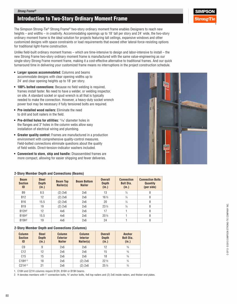
Strong Frame®
C-S
F13 ©
2013 S
IMP
SO
N S
TR
ON
G-T
IE C
OM
PA
NY
IN
C.
80
Introduction to two-Story ordinary moment Frame
The Simpson Strong‑Tie® Strong Frame® two‑story ordinary moment frame enables Designers to reach new heights – and widths – in creativity. Accommodating openings up to 18' tall per story and 24' wide, the two‑story ordinary moment frame is the ideal solution for projects featuring tall ceilings, expansive windows and other customized designs with space constraints or load requirements that exceed other lateral‑force‑resisting options for traditional light‑frame construction.
Unlike ield‑built ordinary moment frames – which are time‑intensive to design and labor‑intensive to install – the new Strong Frame two‑story ordinary moment frame is manufactured with the same value‑engineering as our single‑story Strong Frame moment frame, making it a cost‑effective alternative to traditional frames. And our quick turnaround time in delivering your customized frame means no interruptions in the project construction schedule.
2‑Story Member Depth and Connections (Columns)
ColumnSection
ID
SteelDepth(in.)
Column ExteriorNailer
Column Interior
Nailer(s)
OverallDepth(in.)
AnchorBolt Dia.
(in.)
C9 9 2x6 2x6 12 5⁄8
C12 12 2x6 2x6 15 5⁄8
C15 15 2x6 2x6 18 5⁄8
C18H1,2 18 2x6 (2) 2x6 22 ½ 3⁄4
C21H1,2 21 2x6 (2) 2x6 25 ½ 3⁄4
2‑Story Member Depth and Connections (Beams)
BeamSection
ID
SteelDepth(in.)
Beam TopNailer(s)
Beam BottomNailer
OverallDepth(in.)
ConnectionBolt Dia.
(in.)
Connection Bolts Quantity
(per side)
B9 8.5 (2) 2x6 2x6 13 7⁄8 8
B12 12 (2) 2x6 2x6 16 ½ 7⁄8 8
B16 15.5 (2) 2x6 2x6 20 7⁄8 8
B19 19 (2) 2x6 2x6 23 ½ 7⁄8 8
B12H2 12 4x6 2x6 17 1 8
B16H2 15.5 4x6 2x6 20 ½ 1 8
B19H2 19 4x6 2x6 24 1 8
• larger spaces accommodated: Columns and beams accommodate designs with clear opening widths up to 24' and clear opening heights up to 18' per story.
• 100% bolted connections: Because no ield welding is required, frames install faster. No need to have a welder, or welding inspector, on site. A standard socket or spud wrench is all that is typically needed to make the connection. However, a heavy‑duty socket wrench power tool may be necessary if fully tensioned bolts are required.
• pre‑installed wood nailers: Eliminate the need to drill and bolt nailers in the ield.
• pre‑drilled holes for utilities: 11⁄16" diameter holes in the langes and 3" holes in the column webs allow easy installation of electrical wiring and plumbing.
• Greater quality control: Frames are manufactured in a production environment with comprehensive quality‑control measures. Field‑bolted connections eliminate questions about the quality of ield welds. Direct‑tension‑indicator washers included.
• Convenient to store, ship and handle: Disassembled frames are more compact, allowing for easier shipping and fewer deliveries.
1. C18H and C21H columns require B12H, B16H or B19H beams.
2. H denotes members with 1" connection bolts, ¾" anchor bolts, 4x6 top nailers and (2) 2x6 inside nailers, and thicker end plates.
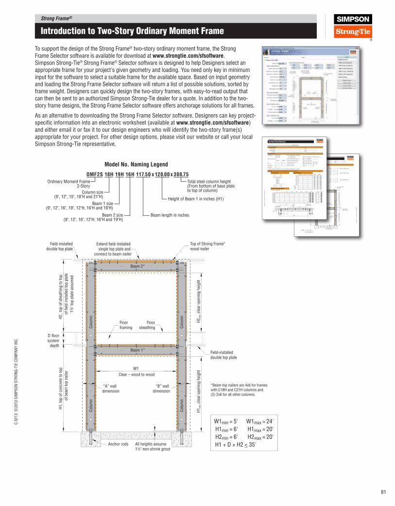
Strong Frame®C
-SF1
3 ©
2013 S
IMP
SO
N S
TR
ON
G-T
IE C
OM
PA
NY
IN
C.
81
To support the design of the Strong Frame® two-story ordinary moment frame, the Strong Frame Selector software is available for download at www.strongtie.com/sfsoftware. Simpson Strong‑Tie® Strong Frame® Selector software is designed to help Designers select an appropriate frame for your project's given geometry and loading. You need only key in minimum input for the software to select a suitable frame for the available space. Based on input geometry and loading the Strong Frame Selector software will return a list of possible solutions, sorted by frame weight. Designers can quickly design the two‑story frames, with easy‑to‑read output that can then be sent to an authorized Simpson Strong‑Tie dealer for a quote. In addition to the two‑story frame designs, the Strong Frame Selector software offers anchorage solutions for all frames.
As an alternative to downloading the Strong Frame Selector software, Designers can key project‑speciic information into an electronic worksheet (available at www.strongtie.com/sfsoftware)and either email it or fax it to our design engineers who will identify the two‑story frame(s) appropriate for your project. For other design options, please visit our website or call your local Simpson Strong‑Tie representative.
Extend field-installed single top plate and
connect to beam nailer
Top of Strong Frame®
wood nailerField-installed
double top plate
H2
, to
p o
f sh
eath
ing t
o t
op
of
fiel
d in
stal
led t
op p
late
1½
" to
p p
late
ass
um
ed
H2 m
in c
lear
open
ing h
eight
H1 m
in c
lear
open
ing h
eightW1
Clear – wood to wood
Anchor rods All heights assume 1½" non-shrink grout
H1,
top o
f co
ncr
ete
to t
op
of
bea
m t
op n
aile
r
Field-installeddouble top plate
Floorframing
Floorsheathing
D floor system
depthBeam 1*
Beam 2*
Colu
mn
Colu
mn
Colu
mn
Colu
mn
“A” wall dimension
“B” wall dimension
*Beam top nailers are 4x6 for frames with C18H and C21H columns and (2) 2x6 for all other columns.
W1min = 5' W1max = 24'
H1min = 6' H1max = 20'
H2min = 6' H2max = 20'
H1 + D + H2 < 35'
Strong Frame™
F-S
F20M
FWS
11 ©
2011 S
IMP
SO
N S
TR
ON
G-T
IE C
OM
PA
NY
IN
C.
two-Story Frame Worksheet
4. Frame Geometry
Project Name:
Engineer
Date:
Phone:
Minimum Clear Opening Width:
Wall Width at Left Column:
Wall Width at Right Column:
Top of Concrete to Top of Beam Nailer:
Minimum Clear Opening Height:
Extend field-installed single top plate and
over beam nailer Top of Strong Frame™
wood nailer
Field-installeddouble top plate
H2
, to
p o
f sh
eath
ing
to
to
p
of
fiel
d-i
nst
alle
d t
op
pla
te
1½
" as
sum
ed
H2
min c
lear
op
enin
g h
eig
ht
H1 m
in c
lear
op
enin
g h
eig
htW1
Clear – wood to wood
All heights assume 1½" non-shrink grout
H1,
to
p o
f co
ncr
ete
to t
op
of
do
ub
le t
op
nai
ler
Field-installed double top plate
Floorframing
Floorsheathing
D floor system depth
Beam 1
Beam 2
Co
lum
nC
olu
mn
Co
lum
nC
olu
mn
“A” wall dimension
“B” wall dimension
(Min.=5'0", Max.=24'0")
(Min.=6'0", Max.=20'0")
(Min.=6'0", Max=20'0")
H1 + H2 + D < 35'0"
H1 - H1min must be > 13"
H2 - H2min must be > 13"
NOTE:
4.1 First Story
4.2 Secdond Story
Floor System Depth:
Top of Sheathing to Top of Plate:
Minimum Clear Opening Height:
W1 =
A =
B =
H1 =
H1min =
in.
in.
in.
in.
in.
D =
H2 =
H2min =
in.
in.
in.
Strong Frame™
F-S
F20M
FWS
11 ©
2011 S
IMP
SO
N S
TR
ON
G-T
IE C
OM
PA
NY
IN
C.
two-Story Frame Worksheet
F F
Complete this form and email it to us, or print it and fax it to us at (925) 847‑1605.
1. project Information
2. Design Criteria
3. loading (Provide all loads at ASD level. Negative values for uplift direction)
3.1 lateral loads 3.2 Uniform loads
3.3 Vertical point loads on Beam
Project Name:
Project Address:
Engineer:
Date:
Phone:
e-mail:
Design Code1:
Beam Delection Limits
2006 IBC
2009 IBC
Response Modiication Coeficient,
R, for OMF Design:
Delection Amplication Factor, Cd:
System Overstrength Factor, Ωo:
Siesmic Importance Factor, I:
Seismic Drift Limit:
Seismic SDS Value:
R=3.5
Cd=3.0
Ωo=3.0
I=1.00
0.025h
SDS =
R=3.0
Other:
Ωo=2.5
I=1.25
0.020h
R<3.0
I=1.50
0.015h
R =
1 Design is also based on ASCE 7-05 for both the 2006 and 2009 editions of the IBC.
Beam 2
L/
L/
L/
Beam 1
L/
L/
L/
h/
LL:
DL + LL:
Snow/Wind:
Wind Drift
Load (plf) XL (ft) XR (ft)
WDL1
WDL2
WDL3
WRLL1
WRLL2
WLL1
WLL2
WLL3
Snow
Wind
Rain
DL LL RLL Snow Rain Wind Seismic
P1(lbs)
P2(lbs)
P3(lbs)
P4(lbs)
P5(lbs)
P6(lbs)
P7(lbs)
P8(lbs)
X1
X2
X3
X4
X5
X6
X7
X8
Xi (ft)
(Include Ωo as applicable)
g
1
1
1
1
1
1
1
1
2
2
2
2
2
2
2
2
1
1
1
1
1
1
1
1
1
1
1
2
2
2
2
2
2
2
2
2
2
2
To RCC Beam
Beam
R=3.5
R=6.5
R=8.0
Other:
FEQ1= lbs
FEQ2= lbs
R used to calculate FEQ:
FWind1= lbs
FWind2= lbs
To RCC
OMF2S 18H 19H 16H 117.50 x 120.00 x 300.75
Ordinary Moment Frame2-Story
Total steel column height(From bottom of base plate to top of column)
Height of Beam 1 in inches (H1)
Beam length in inches
Column size(9", 12", 15", 18"H and 21"H)
Beam 1 size(9", 12", 16", 19", 12"H, 16"H and 19"H)
Beam 2 size(9", 12", 16", 12"H, 16"H and 19"H)
Model No. Naming legend
Introduction to two-Story ordinary moment Frame
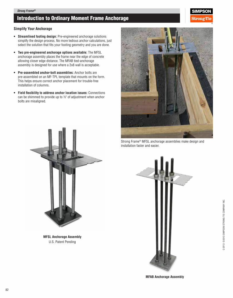
Strong Frame®
C-S
F13 ©
2013 S
IMP
SO
N S
TR
ON
G-T
IE C
OM
PA
NY
IN
C.
82
Introduction to ordinary moment Frame anchorage
Simplify your Anchorage
• Streamlined footing design: Pre-engineered anchorage solutions simplify the design process. No more tedious anchor calculations, just select the solution that its your footing geometry and you are done.
• Two pre‑engineered anchorage options available: The MFSL anchorage assembly places the frame near the edge of concrete allowing closer edge distance. The MFAB tied‑anchorage assembly is designed for use where a 2x8 wall is acceptable.
• pre‑assembled anchor‑bolt assemblies: Anchor bolts are pre‑assembled on an MF‑TPL template that mounts on the form. This helps ensure correct anchor placement for trouble‑free installation of columns.
• Field lexibility to address anchor location issues: Connections can be shimmed to provide up to ½" of adjustment when anchor bolts are misaligned.
Strong Frame® MFSL anchorage assemblies make design and installation faster and easier.
MFSl Anchorage Assembly
U.S. Patent Pending
MFAB Anchorage Assembly
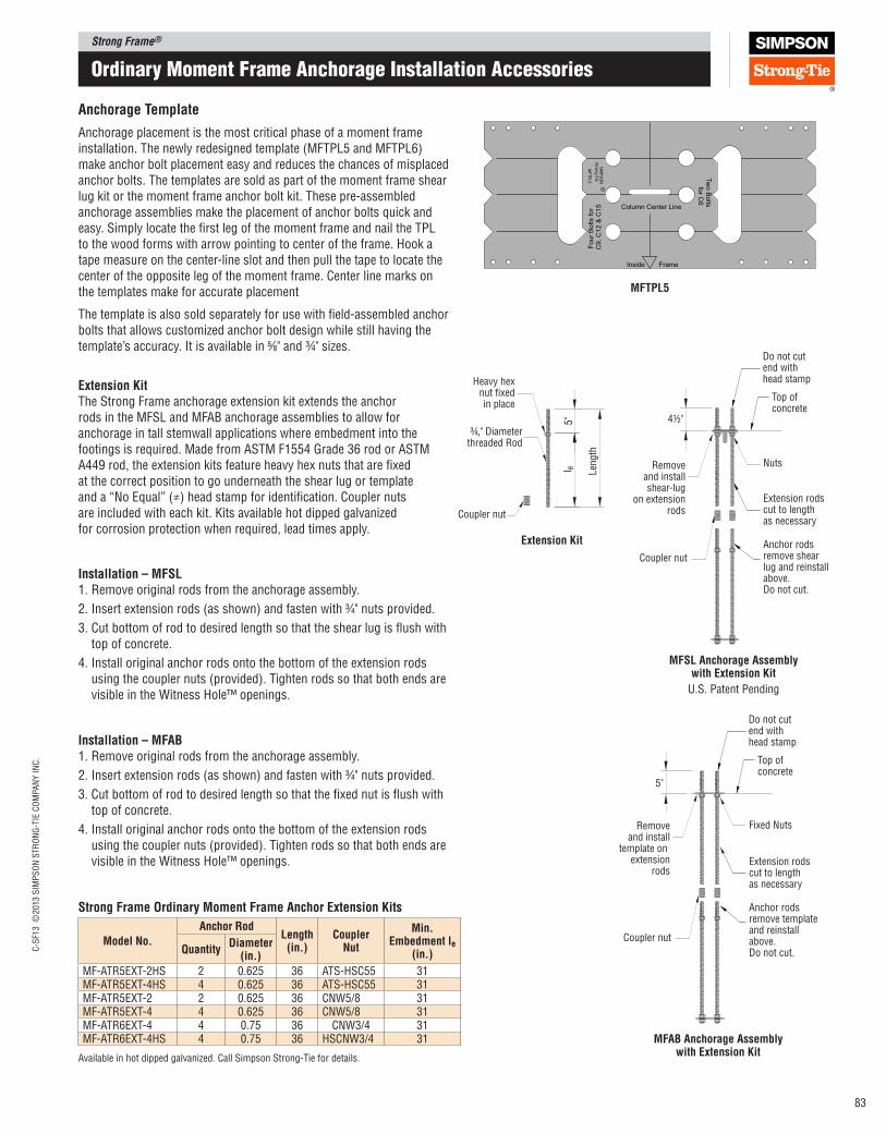
Strong Frame®C
-SF1
3 ©
2013 S
IMP
SO
N S
TR
ON
G-T
IE C
OM
PA
NY
IN
C.
83
ordinary moment Frame anchorage Installation accessories
Extension Kit The Strong Frame anchorage extension kit extends the anchor rods in the MFSL and MFAB anchorage assemblies to allow for anchorage in tall stemwall applications where embedment into the footings is required. Made from ASTM F1554 Grade 36 rod or ASTM A449 rod, the extension kits feature heavy hex nuts that are ixed at the correct position to go underneath the shear lug or template and a “No Equal” (≠) head stamp for identiication. Coupler nuts are included with each kit. Kits available hot dipped galvanized for corrosion protection when required, lead times apply.
Heavy hexnut fixedin place
Removeand installshear-lug
on extensionrods
¾," Diameterthreaded Rod
Top of concrete
Do not cut end withhead stamp
Extension rodscut to lengthas necessary
Nuts
Anchor rods remove shear lug and reinstall above.Do not cut.
Len
gth
5" 4½"
l e
Coupler nut
Coupler nut
Extension Kit
MFSl Anchorage Assembly with Extension Kit
U.S. Patent Pending
Removeand install
template on extension
rods
Top of concrete
Do not cut end withhead stamp
Extension rodscut to lengthas necessary
Anchor rods remove template and reinstall above.Do not cut.
5"
Coupler nut
Fixed Nuts
MFAB Anchorage Assembly with Extension Kit
Installation – MFSl1. Remove original rods from the anchorage assembly.
2. Insert extension rods (as shown) and fasten with 3⁄4" nuts provided.
3. Cut bottom of rod to desired length so that the shear lug is lush with top of concrete.
4. Install original anchor rods onto the bottom of the extension rods using the coupler nuts (provided). Tighten rods so that both ends are visible in the Witness Hole™ openings.
Installation – MFAB1. Remove original rods from the anchorage assembly.
2. Insert extension rods (as shown) and fasten with 3⁄4" nuts provided.
3. Cut bottom of rod to desired length so that the ixed nut is lush with top of concrete.
4. Install original anchor rods onto the bottom of the extension rods using the coupler nuts (provided). Tighten rods so that both ends are visible in the Witness Hole™ openings.
R
SIM
PS
ON
Stro
ng
-Tie
MF
TP
L5
Column Center Line
Inside Frame
for C
6Tw
o B
olts
Four
Bolts for
C9, C
12 &
C15
Anchorage Template
Anchorage placement is the most critical phase of a moment frame installation. The newly redesigned template (MFTPL5 and MFTPL6) make anchor bolt placement easy and reduces the chances of misplaced anchor bolts. The templates are sold as part of the moment frame shear lug kit or the moment frame anchor bolt kit. These pre‑assembled anchorage assemblies make the placement of anchor bolts quick and easy. Simply locate the irst leg of the moment frame and nail the TPL to the wood forms with arrow pointing to center of the frame. Hook a tape measure on the center‑line slot and then pull the tape to locate the center of the opposite leg of the moment frame. Center line marks on the templates make for accurate placement
The template is also sold separately for use with ield‑assembled anchor bolts that allows customized anchor bolt design while still having the template’s accuracy. It is available in 5⁄8" and ¾" sizes.
MFTpl5
Strong Frame Ordinary Moment Frame Anchor Extension Kits
Model No.
Anchor Rod length
(in.)Coupler
Nut
Min. Embedment le
(in.)QuantityDiameter
(in.)
MF‑ATR5EXT‑2HS 2 0.625 36 ATS‑HSC55 31MF‑ATR5EXT‑4HS 4 0.625 36 ATS‑HSC55 31MF‑ATR5EXT‑2 2 0.625 36 CNW5/8 31MF‑ATR5EXT‑4 4 0.625 36 CNW5/8 31MF‑ATR6EXT‑4 4 0.75 36 CNW3/4 31MF‑ATR6EXT‑4HS 4 0.75 36 HSCNW3/4 31
Available in hot dipped galvanized. Call Simpson Strong‑Tie for details.

Strong Frame®
C-S
F13 ©
2013 S
IMP
SO
N S
TR
ON
G-T
IE C
OM
PA
NY
IN
C.
84
6"
1½" 3" 1½"
5" 3"
Anchor rods
Shear lug
Template
4½
"
Top of concrete
Anchorrods(4 total)
Bearingplate
Hex nuts
Len
gth
l e
≠
MFSl‑XX‑SKT‑4For all other columns
U.S. Patent Pending
36
H
5
1½"
3"
1½"
Anchor rods
Shear lug
Template
Anchorrods(2 total)
Diameter
Length
H forASTM A449
≠
3"
MFSl‑XX‑SKT‑2Use for 6" columns
U.S. Patent Pending
Simpson Strong‑Tie offers the patented pre‑engineered MFSL anchorage assembly to make speciication and installation of anchorage as simple as possible. The unique shear‑lug design provides a complete solution meeting the 2009 and 2012 International Building Code requirements for both tension and shear. These solutions come with pre‑installed shear lugs.
Pre-attachednailer
1¼"Minimum
edge distance
Enddistance
plan View Slab on Grade
Enddistance
MFSL − Place top of shear lug flush
with top of concrete
4"min.
Minimum de per tension
anchorage table
Step height
Minimum W pertension anchorage table
Section View Slab on Grade
Outside enddistance
Inside enddistance
Pre-attachednailer
Additionalstud as
required
End of curb as occurs
1¼"Minimum
edge distance
Curb
wid
th
plan View Stemwall/Curb
MFSL − Place top of shear lug flush
with top of concrete
Step height
4"min.
Minimum de per tension
anchorage table
Outside enddistance
Inside enddistance
Additional studsand curbas required
Curbheight
Minimum W pertension anchorage table
Section View Stemwall/Curb
MFSL anchorage assemblies are fully assembled and include a template that allows easy positioning and attachment to forms prior to the pour. Inspection is easy since the head is stamped with the “No Equal” (≠) symbol for identiication, bolt length, bolt diameter and optional “H” for high strength (if speciied).
Installation: Concrete must be thoroughly vibrated around the shear lug to ensure full consolidation of the concrete around the assembly.
mFSL anchorage assembly
place anchorage assembly prior to placing rebar. place top of MFSl lush with top of concrete.
Strong Frame Ordinary Moment Frame Anchor Kits
Model No.
Anchor Rod length
(in.)le
(in.)
Bearing plate Size (in.)Quantity
Diameter (in.)
OMF 6" COlUMNSMFSL‑14‑5‑KT‑2 2 5⁄8 14 8 1⁄2 3⁄8 x 3 x 7MFSL‑14HS‑5‑KT‑2 2 5⁄8 14 8 1⁄2 3⁄8 x 3 x 7MFSL‑18‑5‑KT‑2 2 5⁄8 18 12 1⁄2 3⁄8 x 3 x 7MFSL‑18HS‑5‑KT‑2 2 5⁄8 18 12 1⁄2 3⁄8 x 3 x 7MFSL‑24‑5‑KT‑2 2 5⁄8 24 18 1⁄2 3⁄8 x 3 x 7MFSL‑24HS‑5‑KT‑2 2 5⁄8 24 18 1⁄2 3⁄8 x 3 x 7MFSL‑30‑5‑KT‑2 2 5⁄8 30 24 1⁄2 3⁄8 x 3 x 7MFSL‑30HS‑5‑KT‑2 2 5⁄8 30 24 1⁄2 3⁄8 x 3 x 7MFSL‑36‑5‑KT‑2 2 5⁄8 36 30 1⁄2 3⁄8 x 3 x 7MFSL‑36HS‑5‑KT‑2 2 5⁄8 36 30 1⁄2 3⁄8 x 3 x 7
OMF 9", 12" AND 15" COlUMNSMFSL‑18‑5‑KT 4 5⁄8 18 12 1⁄2 3⁄8 x 7 x 7MFSL‑18‑HS5‑KT 4 5⁄8 18 12 1⁄2 3⁄8 x 7 x 7MFSL‑24‑5‑KT 4 5⁄8 24 18 1⁄2 3⁄8 x 7 x 7MFSL‑24‑HS5‑KT 4 5⁄8 24 18 1⁄2 3⁄8 x 7 x 7MFSL‑30‑5‑KT 4 5⁄8 30 24 1⁄2 3⁄8 x 7 x 7MFSL‑30‑HS5‑KT 4 5⁄8 30 24 1⁄2 3⁄8 x 7 x 7MFSL‑36‑5‑KT 4 5⁄8 36 30 1⁄2 3⁄8 x 7 x 7MFSL‑36‑HS5‑KT 4 5⁄8 36 30 1⁄2 3⁄8 x 7 x 7
OMF 18" AND 21" COlUMNSMFSL‑14‑6‑KT 4 3⁄4 14 8 1⁄2 3⁄8 x 7 x 7MFSL‑14‑HS6‑KT 4 3⁄4 14 8 1⁄2 3⁄8 x 7 x 7MFSL‑18‑6‑KT 4 3⁄4 18 12 1⁄2 3⁄8 x 7 x 7MFSL‑18‑HS6‑KT 4 3⁄4 18 12 1⁄2 3⁄8 x 7 x 7MFSL‑24‑6‑KT 4 3⁄4 24 18 1⁄2 3⁄8 x 7 x 7MFSL‑24‑HS6‑KT 4 3⁄4 24 18 1⁄2 3⁄8 x 7 x 7MFSL‑30‑6‑KT 4 3⁄4 30 24 1⁄2 3⁄8 x 7 x 7MFSL‑30‑HS6‑KT 4 3⁄4 30 24 1⁄2 3⁄8 x 7 x 7MFSL‑36‑6‑KT 4 3⁄4 36 30 1⁄2 3⁄8 x 7 x 7MFSL‑36‑HS6‑KT 4 3⁄4 36 30 1⁄2 3⁄8 x 7 x 7
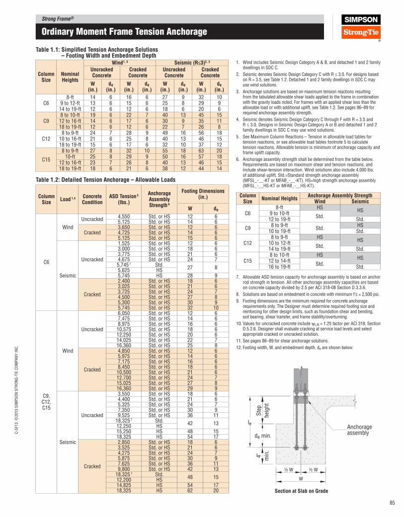
Strong Frame®C
-SF1
3 ©
2013 S
IMP
SO
N S
TR
ON
G-T
IE C
OM
PA
NY
IN
C.
85
ordinary moment Frame tension anchorage
Table 1.1: Simpliied Tension Anchorage Solutions – Footing Width and Embedment Depth
Column Size
Nominal Heights
Wind1, 3 Seismic (R≤3)2, 3
Uncracked Concrete
Cracked Concrete
Uncracked Concrete
Cracked Concrete
W (in.)
de (in.)
W (in.)
de (in.)
W (in.)
de (in.)
W (in.)
de (in.)
C68-ft 14 6 16 6 27 9 32 10
9 to 12-ft 13 6 15 6 25 8 29 914 to 19-ft 12 6 12 6 18 6 20 6
C98 to 10-ft 19 6 22 7 40 13 45 1512 to 16-ft 14 6 17 6 30 9 35 1118 to 19-ft 12 6 12 6 22 7 26 8
C128 to 9-ft 24 7 28 9 49 16 56 18
10 to 16-ft 21 6 25 8 40 13 46 1518 to 19-ft 15 6 17 6 32 10 37 12
C15
8 to 9-ft 27 8 32 10 55 18 63 2010-ft 25 8 29 9 50 16 57 18
12 to 16-ft 23 7 26 8 40 13 46 1518 to 19-ft 18 6 21 6 38 12 44 14
Table 1.2: Detailed Tension Anchorage – Allowable loads
Column Size
load 1,4 Concrete Condition
ASD Tension 5 (lbs.)
Anchorage Assembly Strength 6
Footing Dimensions (in.)
W de
C6
Wind
Uncracked4,550 Std. or HS 12 65,125 Std. or HS 14 6
Cracked3,650 Std. or HS 12 64,725 Std. or HS 14 65,125 Std. or HS 15 6
Seismic
Uncracked
1,525 Std. or HS 12 63,000 Std. or HS 18 63,775 Std. or HS 21 64,675 Std. or HS 24 75,745 7 Std.
27 85,625 HS5,745 HS 28 9
Cracked
2,400 Std. or HS 18 63,025 Std. or HS 21 63,725 Std. or HS 24 74,500 Std. or HS 27 85,300 Std. or HS 30 95,745 Std. or HS 32 10
C9, C12, C15
Wind
Uncracked
6,050 Std. or HS 12 67,475 Std. or HS 14 68,975 Std. or HS 16 610,575 Std. or HS 18 612,250 Std. or HS 20 614,025 Std. or HS 22 716,360 Std. or HS 25 8
Cracked
4,850 Std. or HS 12 65,975 Std. or HS 14 67,175 Std. or HS 16 68,450 Std. or HS 18 610,500 Std. or HS 21 612,700 Std. or HS 24 715,025 Std. or HS 27 816,360 Std. or HS 29 9
Seismic
Uncracked
3,550 Std. or HS 18 64,400 Std. or HS 21 65,325 Std. or HS 24 77,350 Std. or HS 30 99,525 Std. or HS 36 11
18,325 7 Std.42 13
12,250 HS15,250 HS 48 1518,325 HS 54 17
Cracked
2,850 Std. or HS 18 63,525 Std. or HS 21 64,275 Std. or HS 24 75,875 Std. or HS 30 97,625 Std. or HS 36 119,800 Std. or HS 42 13
18,325 7 Std.48 15
12,200 HS14,825 HS 54 1718,325 HS 62 20
1. WindincludesSeismicDesignCategoryA&B,anddetached1and2familydwellings in SDC C.
2. Seismic denotes Seismic Design Category C with R ≤ 3.0. For designs based on R = 3.5, see Table 1.2. Detached 1 and 2 family dwellings in SDC C may use wind solutions.
3. Anchorage solutions are based on maximum tension reactions resulting from the tabulated allowable shear loads applied to the frame in combination with the gravity loads noted. For frames with an applied shear less than the allowable load or with additional uplift, see Table 1.2. See pages 86–89 for required anchorage assembly strength.
4. Seismic denotes Seismic Design Category C through F with R = 3.5 and R ≤ 3.0. Designs in Seismic Design Category A or B and detached 1 and 2 family dwellings in SDC C may use wind solutions.
5. See Maximum Column Reactions – Tension in allowable load tables for tension reactions, or see allowable load tables footnote 5 to calculate tension reactions. Allowable tension is minimum of anchorage capacity and frame uplift capacity.
6. Anchorage assembly strength shall be determined from the table below. Requirements are based on maximum shear and tension reactions, and include shear-tension interaction. Wind solutions also include 4,000 lbs. of additional uplift. Std.=Standard strength anchorage assembly (MFSL_-__-KT or MFAB_-__-KT). HS=high strength anchorage assembly (MFSL_-__HS-KT or MFAB_-__HS-KT).
7. Allowable ASD tension capacity for anchorage assembly is based on anchor rod strength in tension. All other anchorage assembly capacities are based on concrete capacity divided by 2.5 per ACI 318-08 Section D.3.3.6.
8. Solutions are based on embedment in concrete with minimum f'c = 2,500 psi.
9. Footing dimensions are the minimum required for concrete anchorage requirements only. The Designer must determine required footing size and reinforcing for other design limits, such as foundation shear and bending, soil bearing, shear transfer, and frame stability/overturning.
10. Values for uncracked concrete include ψc,N = 1.25 factor per ACI 318, Section D.5.2.6. Designer shall evaluate cracking at service load levels and select appropriate cracked or uncracked solution.
11. See pages 86–89 for shear anchorage solutions.
12. Footing width, W, and embedment depth, de are shown below:
Column Size
Nominal HeightsAnchorage Assembly Strength
Wind Seismic
C68-ft HS
HS9 to 10-ft
Std.12 to 19-ft Std.
C98 to 9-ft
Std.HS
10 to 19-ft Std.
C128 to 9-ft HS
HS10 to 12-ft
Std.14 to 19-ft Std.
C158 to 10-ft HS
HS12 to 14-ft
Std.16 to 19-ft Std.
Anchorageassembly
Ste
p
hei
ght
de min.
4"
min
.
½ W ½ W
W
le
Section at Slab on Grade

Strong Frame®
C-S
F13 ©
2013 S
IMP
SO
N S
TR
ON
G-T
IE C
OM
PA
NY
IN
C.
86
ordinary moment Frame mFSL Shear anchorage
Table 2.1: Simpliied MFSl Shear Anchorage – Minimum Required End Distance
Column Size
Nominal Heights
Wind and Seismic with R ≤ 31
Maximum Shear w/ Uniform load2 Minimum Shear with Max. Total Gravity load2
8" Curb/Stemwall 10" Curb/Stemwall Slab‑On‑Grade
8" Curb/Stemwall 10" Curb/Stemwall Slab‑On‑GradeOutside Inside Outside Inside Outside Inside Outside Inside
C6
8-ft 7½" 6" 6" 6" 6" 9" 4½" 7½" 4½" 7½"9-ft 6" 4½" 6" 4½" 6" 7½" 4½" 6" 4½" 6"10-ft 6" 4½" 4½" 4½" 4½" 6" 4½" 6" 4½" 6"
12 to 19-ft 4½" 4½" 4½" 4½" 4½" 4½" 4½" 4½" 4½" 4½"
C9
8-ft 9" 7½" 7½" 6" 6" 12" 6" 9" 4½" 6"9-ft 7½" 6" 4½" 4½" 4½" 10½" 4½" 7½" 4½" 6"10-ft 6" 4½" 4½" 4½" 4½" 7½" 4½" 6" 4½" 6"12-ft 4½" 4½" 4½" 4½" 4½" 6" 4½" 4½" 4½" 4½"
14 to 19-ft 4½" 4½" 4½" 4½" 4½" 4½" 4½" 4½" 4½" 4½"
C12
8-ft 12" 12" 9" 9" 7½" 16½" 10½" 12" 7½" 7½"9-ft 9" 9" 7½" 7½" 6" 13½" 7½" 10½" 6" 7½"10-ft 7½" 7½" 6" 6" 6" 12" 6" 9" 6" 6"12-ft 6" 6" 6" 6" 6" 9" 6" 6" 6" 6"
14 to 19-ft 6" 6" 6" 6" 6" 6" 6" 6" 6" 6"
C15
8-ft 15" 15" 12" 10½" 7½" 16½" 13½" 12" 10½" 7½"9-ft 12" 12" 9" 9" 7½" 15" 10½" 10½" 7½" 7½"10-ft 10½" 9" 7½" 7½" 7½" 12" 9" 9" 7½" 7½"12-ft 7½" 7½" 7½" 7½" 7½" 10½" 7½" 7½" 7½" 7½"
14 to 19-ft 7½" 7½" 7½" 7½" 7½" 7½" 7½" 7½" 7½" 7½"
1. Anchorage solutions applicable to wind design and seismic design in Seismic Design Category A, B, or C using R ≤ 3.0. For designs based on R = 3.5, see Table 2.3.
2. See footnotes 2 and 3 of Allowable Load tables for explanation of Maximum Shear and Minimum Shear, and corresponding gravity loads.
3. Solutions are based on embedment in concrete with minimum f'c = 2,500 psi.
4. Solutions are based on standard strength MFSL_-__-KT anchorage assembly, except shaded values, where high strength MFSL_-__HS-KT anchorage assembly is required.
5. Shear lug is included with MFSL anchorage assembly.
6. End distance is measured from centerline of nearest anchor bolt to edge of concrete.
7. Outside End Distance and Inside End Distance are shown on page 84.
8. See page Table 2.2 or 2.3 for additional solutions with MFSL anchorage assembly. See Tables 3.1 and 3.2 for solutions with MFAB anchorage assembly.
9. Anchorage solutions are based on maximum shear and tension reactions resulting from the tabulated allowable shear load applied to the frame in combination with the gravity loads noted. For frames with an applied shear less than the allowable load or with additional uplift, see Table 2.2 or 2.3.
Table 2.2: Detailed MFSl Shear Anchorage – Shear lug Capacities, lbs. (Wind)
Column Size
Concrete Strength
(psi)
End Distances 3,4,5
4½" 6" 7½" 9" 10½" 12" 13½" 15" 16½" 18"
8" Stemwall/Curb Foundations 8
C62,500 3,095 4,220 5,345 6,470 7,595
7,9353,000 3,390 4,620 5,855 7,0857,935
4,500 4,150 5,660 7,170 7,935
C92,500 4,970 6,095 7,220 8,345 9,470 10,595 11,720 12,845 13,970 15,0953,000 5,445 6,675 7,910 9,140 10,370 11,605 12,835 14,070 15,300
15,8704,500 6,665 8,175 9,685 11,195 12,705 14,215 15,720 15,870 15,870
C122,500
NA6,095 7,220 8,345 9,470 10,595 11,720 12,845 13,970 15,095
3,000 6,675 7,910 9,140 10,370 11,605 12,835 14,070 15,30015,870
4,500 8,175 9,685 11,195 12,705 14,215 15,720 15,870 15,870
C152,500
NA NA7,220 8,345 9,470 10,595 11,720 12,845 13,970 15,095
3,000 7,910 9,140 10,370 11,605 12,835 14,070 15,30015,870
4,500 9,685 11,195 12,705 14,215 15,720 15,870 15,87010" Stemwall/Curb Foundations 9
C62,500 3,235 5,450 7,030
7,9353,000 3,545 5,970 7,7004,500 4,340 7,310 7,935
C92,500 6,565 7,970 9,375 10,780 12,190 13,595 15,000
15,8703,000 7,190 8,730 10,270 11,810 13,350 14,89015,870
4,500 8,805 10,690 12,580 14,465 15,870 15,870
C122,500
NA7,970 9,375 10,780 12,190 13,595 15,000
15,8703,000 8,730 10,270 11,810 13,350 14,89015,870
4,500 10,690 12,580 14,465 15,870 15,870
C152,500
NA NA9,375 10,780 12,190 13,595 15,000
15,8703,000 10,270 11,810 13,350 14,89015,870
4,500 12,580 14,465 15,870 15,870Slab‑On‑Grade Foundations
C62,500 3,235 5,450
7,9353,000 3,545 5,9704,500 4,340 7,310
C92,500 7,160 10,080 13,420
15,8703,000 7,845 11,040 14,7004,500 9,605 13,520 15,870
C122,500
NA10,080 13,420
15,8703,000 11,040 14,7004,500 13,520 15,870
C152,500
NA NA13,420
15,8703,000 14,7004,500 15,870
See footnotes on next page.
C12
C15
C6
4½" 4½"
C9
4½" 3" 4½"
6" 6"3"
7½" 7½"3"
Base plate plans
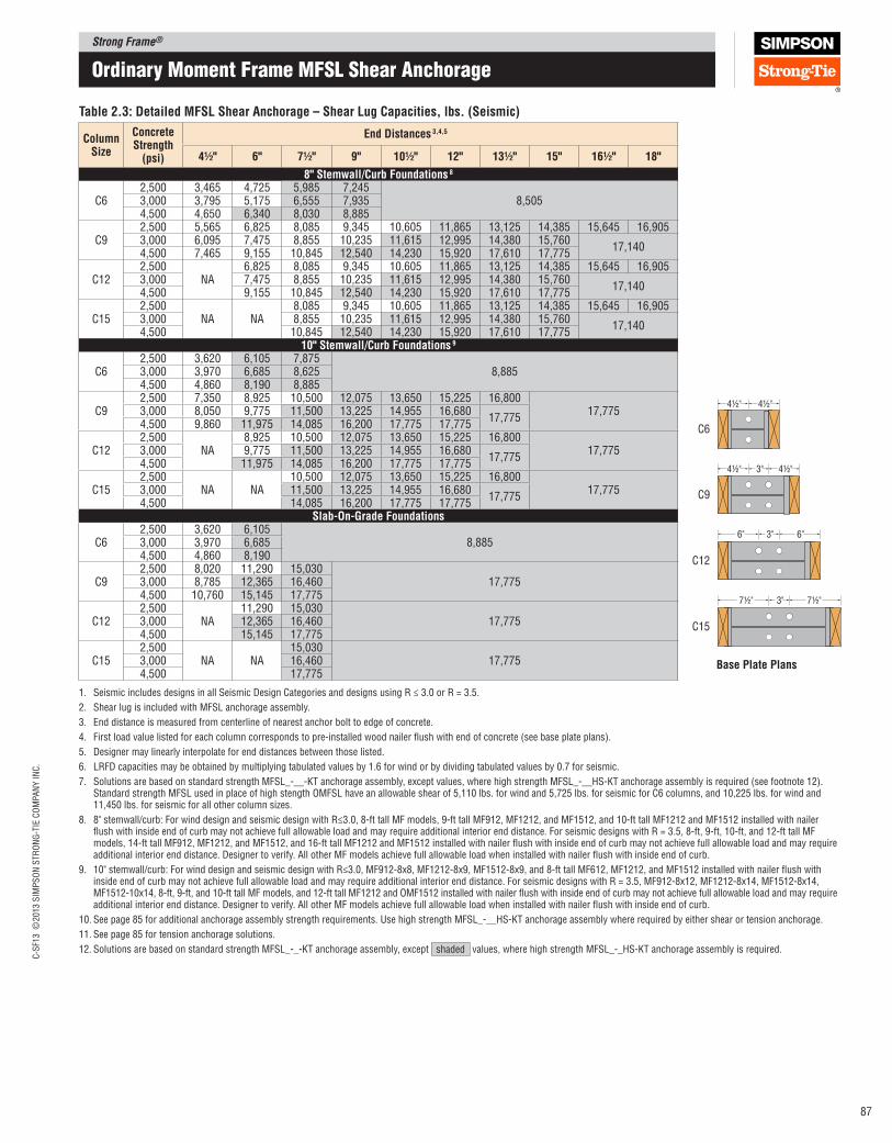
Strong Frame®C
-SF1
3 ©
2013 S
IMP
SO
N S
TR
ON
G-T
IE C
OM
PA
NY
IN
C.
87
ordinary moment Frame mFSL Shear anchorage
Table 2.3: Detailed MFSl Shear Anchorage – Shear lug Capacities, lbs. (Seismic)
Column Size
Concrete Strength
(psi)
End Distances 3,4,5
4½" 6" 7½" 9" 10½" 12" 13½" 15" 16½" 18"
8" Stemwall/Curb Foundations 8
C62,500 3,465 4,725 5,985 7,245
8,5053,000 3,795 5,175 6,555 7,9354,500 4,650 6,340 8,030 8,885
C92,500 5,565 6,825 8,085 9,345 10,605 11,865 13,125 14,385 15,645 16,9053,000 6,095 7,475 8,855 10,235 11,615 12,995 14,380 15,760
17,1404,500 7,465 9,155 10,845 12,540 14,230 15,920 17,610 17,775
C122,500
NA6,825 8,085 9,345 10,605 11,865 13,125 14,385 15,645 16,905
3,000 7,475 8,855 10,235 11,615 12,995 14,380 15,76017,140
4,500 9,155 10,845 12,540 14,230 15,920 17,610 17,775
C152,500
NA NA8,085 9,345 10,605 11,865 13,125 14,385 15,645 16,905
3,000 8,855 10,235 11,615 12,995 14,380 15,76017,140
4,500 10,845 12,540 14,230 15,920 17,610 17,77510" Stemwall/Curb Foundations 9
C62,500 3,620 6,105 7,875
8,8853,000 3,970 6,685 8,6254,500 4,860 8,190 8,885
C92,500 7,350 8,925 10,500 12,075 13,650 15,225 16,800
17,7753,000 8,050 9,775 11,500 13,225 14,955 16,68017,775
4,500 9,860 11,975 14,085 16,200 17,775 17,775
C122,500
NA8,925 10,500 12,075 13,650 15,225 16,800
17,7753,000 9,775 11,500 13,225 14,955 16,68017,775
4,500 11,975 14,085 16,200 17,775 17,775
C152,500
NA NA10,500 12,075 13,650 15,225 16,800
17,7753,000 11,500 13,225 14,955 16,68017,775
4,500 14,085 16,200 17,775 17,775Slab‑On‑Grade Foundations
C62,500 3,620 6,105
8,8853,000 3,970 6,6854,500 4,860 8,190
C92,500 8,020 11,290 15,030
17,7753,000 8,785 12,365 16,4604,500 10,760 15,145 17,775
C122,500
NA11,290 15,030
17,7753,000 12,365 16,4604,500 15,145 17,775
C152,500
NA NA15,030
17,7753,000 16,4604,500 17,775
1. Seismic includes designs in all Seismic Design Categories and designs using R ≤ 3.0 or R = 3.5.
2. Shear lug is included with MFSL anchorage assembly.
3. End distance is measured from centerline of nearest anchor bolt to edge of concrete.
4. First load value listed for each column corresponds to pre-installed wood nailer lush with end of concrete (see base plate plans).
5. Designer may linearly interpolate for end distances between those listed.
6. LRFD capacities may be obtained by multiplying tabulated values by 1.6 for wind or by dividing tabulated values by 0.7 for seismic.
7. Solutions are based on standard strength MFSL_-__-KT anchorage assembly, except values, where high strength MFSL_-__HS-KT anchorage assembly is required (see footnote 12). Standard strength MFSL used in place of high stength OMFSL have an allowable shear of 5,110 lbs. for wind and 5,725 lbs. for seismic for C6 columns, and 10,225 lbs. for wind and 11,450 lbs. for seismic for all other column sizes.
8. 8" stemwall/curb: For wind design and seismic design with R≤3.0, 8-ft tall MF models, 9-ft tall MF912, MF1212, and MF1512, and 10-ft tall MF1212 and MF1512 installed with nailer lush with inside end of curb may not achieve full allowable load and may require additional interior end distance. For seismic designs with R = 3.5, 8-ft, 9-ft, 10-ft, and 12-ft tall MF models, 14-ft tall MF912, MF1212, and MF1512, and 16-ft tall MF1212 and MF1512 installed with nailer lush with inside end of curb may not achieve full allowable load and may require additional interior end distance. Designer to verify. All other MF models achieve full allowable load when installed with nailer lush with inside end of curb.
9. 10" stemwall/curb: For wind design and seismic design with R≤3.0, MF912-8x8, MF1212-8x9, MF1512-8x9, and 8-ft tall MF612, MF1212, and MF1512 installed with nailer lush with inside end of curb may not achieve full allowable load and may require additional interior end distance. For seismic designs with R = 3.5, MF912-8x12, MF1212-8x14, MF1512-8x14, MF1512-10x14, 8-ft, 9-ft, and 10-ft tall MF models, and 12-ft tall MF1212 and OMF1512 installed with nailer lush with inside end of curb may not achieve full allowable load and may require additional interior end distance. Designer to verify. All other MF models achieve full allowable load when installed with nailer lush with inside end of curb.
10. See page 85 for additional anchorage assembly strength requirements. Use high strength MFSL_-__HS-KT anchorage assembly where required by either shear or tension anchorage.
11. See page 85 for tension anchorage solutions.
12. Solutions are based on standard strength MFSL_-_-KT anchorage assembly, except shaded values, where high strength MFSL_-_HS-KT anchorage assembly is required.
C12
C15
C6
4½" 4½"
C9
4½" 3" 4½"
6" 6"3"
7½" 7½"3"
Base plate plans
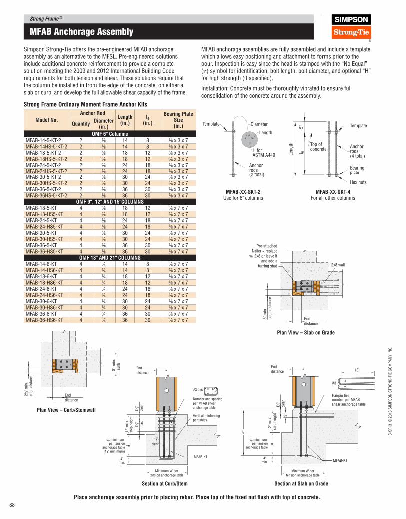
Strong Frame®
C-S
F13 ©
2013 S
IMP
SO
N S
TR
ON
G-T
IE C
OM
PA
NY
IN
C.
88
mFaB anchorage assembly
Simpson Strong‑Tie offers the pre‑engineered MFAB anchorage assembly as an alternative to the MFSL. Pre‑engineered solutions include additional concrete reinforcement to provide a complete solution meeting the 2009 and 2012 International Building Code requirements for both tension and shear. These solutions require that the column be installed in from the edge of the concrete, on either a slab or curb, and develop the full allowable shear capacity of the frame.
MFAB anchorage assemblies are fully assembled and include a template which allows easy positioning and attachment to forms prior to the pour. Inspection is easy since the head is stamped with the “No Equal” (≠) symbol for identiication, bolt length, bolt diameter, and optional “H” for high strength (if speciied).
Installation: Concrete must be thoroughly vibrated to ensure full consolidation of the concrete around the assembly.
Minimum W pertension anchorage table
End
distance
12
" m
ax.
step
hei
gh
t
2"clear
MFAB-KT
Vertical reinforcingper tables
#3 ties
Number and spacingper MFAB shear anchorage table
112"
clea
r
112"
max
.
de minimum per tension
anchorage table(12" minimum)
4"min.
Enddistance
2"
12" m
ax.
step
hei
ght
MFAB-KT
#3
Hairpin tiesnumber per MFAB shear anchorage table
112"
clea
r
18"
de minimum per tension
anchorage table
4"min.
le
Minimum W pertension anchorage table
2½
" m
in.
edg
e d
ista
nce
8"
min
.cu
rb
Enddistance
Enddistance
3" m
in.
edge
dis
tance
Pre-attachedNailer − replace
w/ 2x8 or leave itand add a
furring stud 2x8 wall
MFAB‑XX‑SKT‑4For all other columns
36
H
5
Template
Anchorrods(2 total)
Diameter
Length
H forASTM A449
≠
Template5"
Top of concrete
Anchorrods(4 total)
Bearingplate
Hex nuts
Len
gth
l e
≠
MFAB‑XX‑SKT‑2Use for 6" columns
place anchorage assembly prior to placing rebar. place top of the ixed nut lush with top of concrete.
Strong Frame Ordinary Moment Frame Anchor Kits
Model No.
Anchor Rod length
(in.)le
(in.)
Bearing plate Size (in.)Quantity
Diameter (in.)
OMF 6" ColumnsMFAB‑14‑5‑KT‑2 2 5⁄8 14 8 3⁄8 x 3 x 7MFAB‑14HS‑5‑KT‑2 2 5⁄8 14 8 3⁄8 x 3 x 7MFAB‑18‑5‑KT‑2 2 5⁄8 18 12 3⁄8 x 3 x 7MFAB‑18HS‑5‑KT‑2 2 5⁄8 18 12 3⁄8 x 3 x 7MFAB‑24‑5‑KT‑2 2 5⁄8 24 18 3⁄8 x 3 x 7MFAB‑24HS‑5‑KT‑2 2 5⁄8 24 18 3⁄8 x 3 x 7MFAB‑30‑5‑KT‑2 2 5⁄8 30 24 3⁄8 x 3 x 7MFAB‑30HS‑5‑KT‑2 2 5⁄8 30 24 3⁄8 x 3 x 7MFAB‑36‑5‑KT‑2 2 5⁄8 36 30 3⁄8 x 3 x 7MFAB‑36HS‑5‑KT‑2 2 5⁄8 36 30 3⁄8 x 3 x 7
OMF 9", 12" AND 15"COlUMNSMFAB‑18‑5‑KT 4 5⁄8 18 12 3⁄8 x 7 x 7MFAB‑18‑HS5‑KT 4 5⁄8 18 12 3⁄8 x 7 x 7MFAB‑24‑5‑KT 4 5⁄8 24 18 3⁄8 x 7 x 7MFAB‑24‑HS5‑KT 4 5⁄8 24 18 3⁄8 x 7 x 7MFAB‑30‑5‑KT 4 5⁄8 30 24 3⁄8 x 7 x 7MFAB‑30‑HS5‑KT 4 5⁄8 30 24 3⁄8 x 7 x 7MFAB‑36‑5‑KT 4 5⁄8 36 30 3⁄8 x 7 x 7MFAB‑36‑HS5‑KT 4 5⁄8 36 30 3⁄8 x 7 x 7
OMF 18" AND 21" COlUMNSMFAB‑14‑6‑KT 4 3⁄4 14 8 3⁄8 x 7 x 7MFAB‑14‑HS6‑KT 4 3⁄4 14 8 3⁄8 x 7 x 7MFAB‑18‑6‑KT 4 3⁄4 18 12 3⁄8 x 7 x 7MFAB‑18‑HS6‑KT 4 3⁄4 18 12 3⁄8 x 7 x 7MFAB‑24‑6‑KT 4 3⁄4 24 18 3⁄8 x 7 x 7MFAB‑24‑HS6‑KT 4 3⁄4 24 18 3⁄8 x 7 x 7MFAB‑30‑6‑KT 4 3⁄4 30 24 3⁄8 x 7 x 7MFAB‑30‑HS6‑KT 4 3⁄4 30 24 3⁄8 x 7 x 7MFAB‑36‑6‑KT 4 3⁄4 36 30 3⁄8 x 7 x 7MFAB‑36‑HS6‑KT 4 3⁄4 36 30 3⁄8 x 7 x 7
Section at Slab on GradeSection at Curb/Stem
plan View – Slab on Grade
plan View – Curb/Stemwall
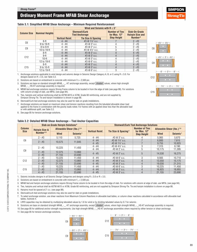
Strong Frame®C
-SF1
3 ©
2013 S
IMP
SO
N S
TR
ON
G-T
IE C
OM
PA
NY
IN
C.
89
ordinary moment Frame mFaB Shear anchorage
C12
C15
C6
4½" 4½"
C9
4½" 3" 4½"
6" 6"3"
7½" 7½"3"
C6
4½" 4½"
C9
4½" 3" 4½"
C12
C15
6" 6"3"
7½" 7½"3"
Table 3.1: Simpliied MFAB Shear Anchorage – Minimum Required Reinforcement
Column Size Nominal Heights
Wind and Seismic with R ≤ 3 1
Stemwall/Curb Tied Anchorage
Number of Ties for Max. 12" Step Height
Slab‑On‑Grade Hairpin Size and
Number 6Vertical Reinf. Tie Size & Spacing
C68-ft 4 - #4 #3 @ 1½" o.c. 7 2 - #3
9 to 19-ft 4 - #4 #3 @ 3" o.c. 4 2 - #3
C98 to 9-ft 4 - #4 #3 @ 2" o.c. 5 2 - #3
10 to 19-ft 4 - #4 #3 @ 4½" o.c. 3 2 - #3
C12
8-ft 4 - #4 #3 @ 3" o.c. 4 4 - #39-ft 4 - #4 #3 @ 3" o.c. 4 2 - #310-ft 4 - #4 #3 @ 3" o.c. 4 2 - #3
12 to 19-ft 4 - #4 #3 @ 6" o.c. 3 2 - #3
C158-ft 4 - #4 #3 @ 3" o.c. 4 4 - #3
9 to 10-ft 4 - #4 #3 @ 3" o.c. 4 2 - #312 to 19-ft 4 - #4 #3 @ 6" o.c. 3 2 - #3
1. Anchorage solutions applicable to wind design and seismic design in Seismic Design Category A, B, or C using R ≤ 3.0. For designs based on R = 3.5, see Table 3.2.
2. Solutions are based on embedment in concrete with minimum f'c = 2,500 psi.
3. Solutions are base on standard strength MFAB_-__-KT anchorage assembly, except shaded values, where high strength MFAB_-__HS-KT anchorage assembly is required.
4. MFAB tied anchorage solutions require Strong Frame column to be located in from the edge of slab (see page 88). For solutions with column at edge of slab, use MFSL (see page 84).
5. Ties, hairpins and vertical reinforcing shall be ASTM A615 or A706, Grade 60 reinforcing, and are not supplied by Simpson Strong‑Tie. Tie and hairpin installation is shown in page 88.
6. Stemwall/Curb tied anchorage solutions may also be used for slab on grade installations.
7. Anchorage solutions are based on maximum shear and tension reactions resulting from the tabulated allowable shear load applied to the frame in combination with the gravity loads noted. For frames with an applied shear less than the allowable load or with additional uplift, see Table 3.2.
8. See page 85 for tension anchorage solutions.
Table 3.2: Detailed MFAB Shear Anchorage – Tied Anchor Capacities
Column Size
Slab‑on‑Grade Hairpin Solutions 6 Stemwall/Curb Tied Anchorage Solutions
Hairpin Size & Number 4,5
Allowable Shear (lbs.) 7,8
Vertical Reinf. Tie Size & Spacing 4Number of Ties
for Max. 12" Step Height
Allowable Shear (lbs.) 7,8
Wind Seismic 1 Wind Seismic 1
C62 ‑ #3 5,110 5,725 4 ‑ #4 #3 @ 3" o.c. 4 5,065 5,670
2 ‑ #3 10,575 11,8454 ‑ #4 #3 @ 1½" o.c. 7 6,800 7,6154 ‑ #5 #3 @ 1½" o.c. 7 9,755 10,925
C92 ‑ #3 10,225 11,450
4 ‑ #4 #3 @ 4½" o.c. 3 7,315 8,1904 ‑ #4 #3 @ 2" o.c. 5 10,175 11,395
2 ‑ #3 12,375 13,8604 ‑ #5 #3 @ 2" o.c. 5 14,530 16,275
4 ‑ #3 21,155 23,690
C122 ‑ #3 10,225 11,450 4 ‑ #4 #3 @ 6" o.c. 3 9,565 10,7102 ‑ #3 12,375 13,860 4 ‑ #4 #3 @ 3" o.c. 4 13,550 15,1754 ‑ #3 21,155 23,690 4 ‑ #5 #3 @ 3" o.c. 4 19,030 21,315
C152 ‑ #3 10,225 11,450 4 ‑ #4 #3 @ 6" o.c. 3 10,225 11,4502 ‑ #3 12,375 13,860 4 ‑ #4 #3 @ 3" o.c. 4 16,925 18,9554 ‑ #3 21,155 23,690 4 ‑ #5 #3 @ 3" o.c. 4 21,155 23,690
1. Seismic includes designs in all Seismic Design Categories and designs using R ≤ 3.0 or R = 3.5.
2. Solutions are based on embedment in concrete with minimum f'c = 2,500 psi.
3. MFAB tied and hairpin anchorage solutions require Strong Frame column to be located in from the edge of slab. For solutions with column at edge of slab, use MFSL (see page 84).
4. Ties, hairpins and vertical shall be ASTM A615 or A706, Grade 60 reinforcing, and are not supplied by Simpson Strong‑Tie. Tie and hairpin installation is shown on page 88.
5. Hairpins must be spaced at 2" o.c. (see page 88).
6. Stemwall/curb tied anchorage solutions may also be used for slab on grade installations.
7. To select anchorage solution, use shear reactions from Maximum Column Reactions in allowable load tables, or column shear reactions calculated in accordance with allowable load tables, footnote 4.
8. LRFD capacities may be obtained by multiplying tabulated values by 1.6 for wind or by dividing tabulated values by 0.7 for seismic.
9. Solutions are base on standard strength MFAB_‑__‑KT anchorage assembly, except shaded values, where high strength MFAB_‑__HS‑KT anchorage assembly is required.
10. See page 85 for additional anchor strength requirements. Use high strength MFAB_‑__HS‑KT anchorage assemblies where required by either tension or shear anchorage.
11. See page 85 for tension anchorage solutions.
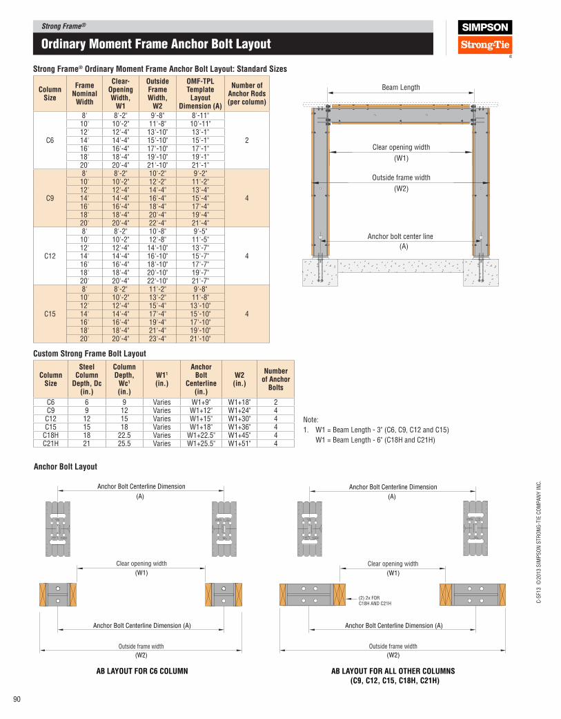
Strong Frame®
C-S
F13 ©
2013 S
IMP
SO
N S
TR
ON
G-T
IE C
OM
PA
NY
IN
C.
90
R
SIMPSONStrong-Tie
OMF-TPL
Co
lum
n C
ente
r L
ine
Insi
de
Fram
e
for C6Two Bolts
Four Bolts for C9, C12 & C15
Anchor Bolt Centerline Dimension (A)
(W2)
Outside frame width
(W1)
Clear opening width
AB lAyOUT FOR All OTHER COlUMNS(C9, C12, C15, C18H, C21H)
Anchor Bolt Centerline Dimension
R
SIMPSONStrong-Tie
OMF-TPL
Co
lum
n C
enter L
ine
Insid
e Fram
e
for C6Two Bolts
Four Bolts for C9, C12 & C15
R
SIMPSONStrong-Tie
OMF-TPL
Co
lum
n C
ente
r L
ine
Insi
de
Fram
e
for C6Two Bolts
Four Bolts for C9, C12 & C15
Anchor Bolt Centerline Dimension
(W1)
Clear opening width
Anchor Bolt Centerline Dimension (A)
(W2)
Outside frame width
R
SIMPSONStrong-Tie
OMF-TPL
Co
lum
n C
enter L
ine
Insid
e Fram
e
for C6Two Bolts
Four Bolts for C9, C12 & C15
AB lAyOUT FOR C6 COlUMN
(2) 2x FORC18H AND C21H
(A)(A)
Anchor Bolt layout
ordinary moment Frame anchor Bolt Layout
(W1)
Clear opening width
(W2)
Outside frame width
Anchor bolt center line
(A)
Beam LengthColumn Size
Frame Nominal
Width
Clear‑Opening Width,
W1
Outside Frame Width,
W2
OMF‑Tpl Template
layout Dimension (A)
Number of Anchor Rods (per column)
C6
8' 8'-2" 9'-8" 8'-11"
2
10' 10'-2" 11'-8" 10'-11"12' 12'-4" 13'-10" 13'-1"14' 14'-4" 15'-10" 15'-1"16' 16'-4" 17'-10" 17'-1"18' 18'-4" 19'-10" 19'-1"20' 20'-4" 21'-10" 21'-1"
C9
8' 8'-2" 10'-2" 9'-2"
4
10' 10'-2" 12'-2" 11'-2"12' 12'-4" 14'-4" 13'-4"14' 14'-4" 16'-4" 15'-4"16' 16'-4" 18'-4" 17'-4"18' 18'-4" 20'-4" 19'-4"20' 20'-4" 22'-4" 21'-4"
C12
8' 8'-2" 10'-8" 9'-5"
4
10' 10'-2" 12'-8" 11'-5"12' 12'-4" 14'-10" 13'-7"14' 14'-4" 16'-10" 15'-7"16' 16'-4" 18'-10" 17'-7"18' 18'-4" 20'-10" 19'-7"20' 20'-4" 22'-10" 21'-7"
C15
8' 8'-2" 11'-2" 9'-8"
4
10' 10'-2" 13'-2" 11'-8"12' 12'-4" 15'-4" 13'-10"14' 14'-4" 17'-4" 15'-10"16' 16'-4" 19'-4" 17'-10"18' 18'-4" 21'-4" 19'-10"20' 20'-4" 23'-4" 21'-10"
Column Size
Steel Column
Depth, Dc (in.)
Column Depth,
Wc1
(in.)
W11 (in.)
Anchor Bolt
Centerline (in.)
W2 (in.)
Number of Anchor
Bolts
C6 6 9 Varies W1+9" W1+18" 2C9 9 12 Varies W1+12" W1+24" 4C12 12 15 Varies W1+15" W1+30" 4C15 15 18 Varies W1+18" W1+36" 4
C18H 18 22.5 Varies W1+22.5" W1+45" 4C21H 21 25.5 Varies W1+25.5" W1+51" 4
Custom Strong Frame Bolt layout
Strong Frame® Ordinary Moment Frame Anchor Bolt layout: Standard Sizes
Note:
1. W1 = Beam Length - 3" (C6, C9, C12 and C15)
W1 = Beam Length - 6" (C18H and C21H)
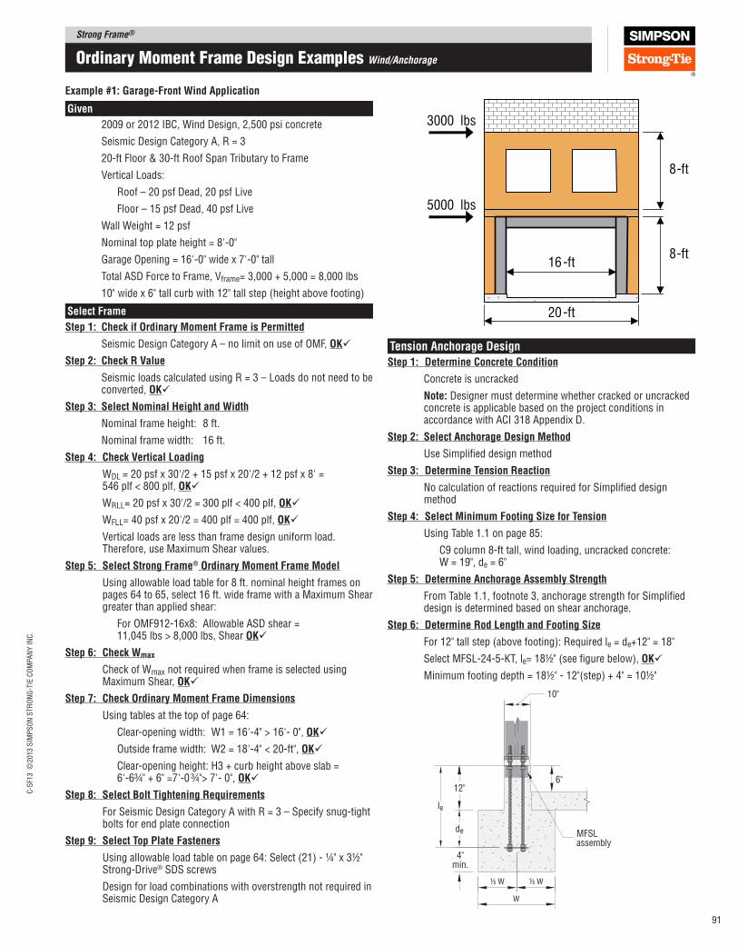
Strong Frame®C
-SF1
3 ©
2013 S
IMP
SO
N S
TR
ON
G-T
IE C
OM
PA
NY
IN
C.
91
3000 lbs
5000 lbs
20-ft
16-ft 8-ft
8-ft
1
8
ordinary moment Frame Design examples Wind/Anchorage
Example #1: Garage‑Front Wind Application
Given
2009 or 2012 IBC, Wind Design, 2,500 psi concrete
Seismic Design Category A, R = 3
20-ftFloor&30-ftRoofSpanTributarytoFrame
Vertical Loads:
Roof – 20 psf Dead, 20 psf Live
Floor – 15 psf Dead, 40 psf Live
Wall Weight = 12 psf
Nominal top plate height = 8'-0"
Garage Opening = 16'-0" wide x 7'-0" tall
Total ASD Force to Frame, Vframe= 3,000 + 5,000 = 8,000 lbs
10" wide x 6" tall curb with 12" tall step (height above footing)
Select Frame
Step 1: Check if Ordinary Moment Frame is permitted
Seismic Design Category A – no limit on use of OMF, OK
Step 2: Check R Value
Seismic loads calculated using R = 3 – Loads do not need to be converted, OK
Step 3: Select Nominal Height and Width
Nominal frame height: 8 ft.
Nominal frame width: 16 ft.
Step 4: Check Vertical loading
WDL = 20 psf x 30'/2 + 15 psf x 20'/2 + 12 psf x 8' = 546 plf < 800 plf, OK
WRLL= 20 psf x 30'/2 = 300 plf < 400 plf, OK
WFLL= 40 psf x 20'/2 = 400 plf = 400 plf, OK
Vertical loads are less than frame design uniform load. Therefore, use Maximum Shear values.
Step 5: Select Strong Frame® Ordinary Moment Frame Model
Using allowable load table for 8 ft. nominal height frames on pages 64 to 65, select 16 ft. wide frame with a Maximum Shear greater than applied shear:
For OMF912-16x8: Allowable ASD shear = 11,045 lbs > 8,000 lbs, Shear OK
Step 6: Check Wmax
Check of Wmax not required when frame is selected using Maximum Shear, OK
Step 7: Check Ordinary Moment Frame Dimensions
Using tables at the top of page 64:
Clear-opening width: W1 = 16'-4" > 16'- 0", OK
Outside frame width: W2 = 18'-4" < 20-ft", OK
Clear-opening height: H3 + curb height above slab = 6'-6¾" + 6" =7'-0 ¾"> 7'- 0", OK
Step 8: Select Bolt Tightening Requirements
For Seismic Design Category A with R = 3 – Specify snug-tight bolts for end plate connection
Step 9: Select Top plate Fasteners
Using allowable load table on page 64: Select (21) - ¼" x 3½" Strong-Drive® SDS screws
Design for load combinations with overstrength not required in Seismic Design Category A
Tension Anchorage Design
Step 1: Determine Concrete Condition
Concrete is uncracked
Note: Designer must determine whether cracked or uncracked concrete is applicable based on the project conditions in accordance with ACI 318 Appendix D.
Step 2: Select Anchorage Design Method
Use Simpliied design method
Step 3: Determine Tension Reaction
No calculation of reactions required for Simpliied design method
Step 4: Select Minimum Footing Size for Tension
Using Table 1.1 on page 85:
C9 column 8‑ft tall, wind loading, uncracked concrete: W = 19", de = 6"
Step 5: Determine Anchorage Assembly Strength
From Table 1.1, footnote 3, anchorage strength for Simpliied design is determined based on shear anchorage.
Step 6: Determine Rod length and Footing Size
For 12" tall step (above footing): Required le = de+12" = 18"
Select MFSL‑24‑5‑KT, le= 18½" (see igure below), OK
Minimum footing depth = 18½" ‑ 12"(step) + 4" = 10½"
10"
MFSLassembly
4"min.
de
12"6"
½ W ½ W
W
le
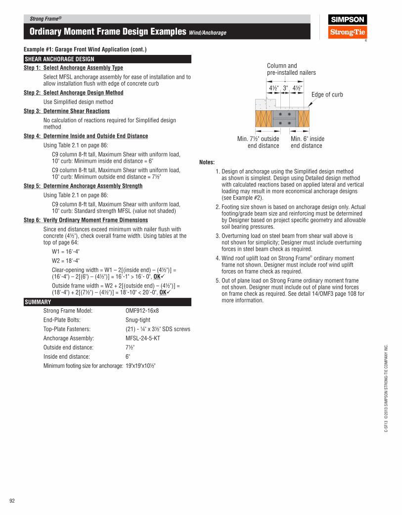
Strong Frame®
C-S
F13 ©
2013 S
IMP
SO
N S
TR
ON
G-T
IE C
OM
PA
NY
IN
C.
92
ordinary moment Frame Design examples Wind/Anchorage
Example #1: Garage Front Wind Application (cont.)
SHEAR ANCHORAGE DESIGN
Step 1: Select Anchorage Assembly Type
Select MFSL anchorage assembly for ease of installation and to allow installation lush with edge of concrete curb
Step 2: Select Anchorage Design Method
Use Simpliied design method
Step 3: Determine Shear Reactions
No calculation of reactions required for Simpliied design method
Step 4: Determine Inside and Outside End Distance
Using Table 2.1 on page 86:
C9 column 8‑ft tall, Maximum Shear with uniform load, 10" curb: Minimum inside end distance = 6"
C9 column 8‑ft tall, Maximum Shear with uniform load, 10" curb: Minimum outside end distance = 7½"
Step 5: Determine Anchorage Assembly Strength
Using Table 2.1 on page 86:
C9 column 8‑ft tall, Maximum Shear with uniform load, 10" curb: Standard strength MFSL (value not shaded)
Step 6: Verify Ordinary Moment Frame Dimensions
Since end distances exceed minimum with nailer lush with concrete (4½"), check overall frame width. Using tables at the top of page 64:
W1 = 16'‑4"
W2 = 18'‑4"
Clear‑opening width = W1 – 2[(inside end) – (4½")] = (16'‑4") – 2[(6") – (4½")] = 16'‑1" > 16'‑ 0", OK
Outside frame width = W2 + 2[(outside end) – (4½")] = (18'‑4") + 2[(7½") – (4½")] = 18'‑10" < 20'‑0", OK
SUMMARy
Strong Frame Model: OMF912‑16x8
End‑Plate Bolts: Snug‑tight
Top‑Plate Fasteners: (21) ‑ ¼" x 3½" SDS screws
Anchorage Assembly: MFSL‑24‑5‑KT
Outside end distance: 7½"
Inside end distance: 6"
Minimum footing size for anchorage: 19"x19"x10½"
Notes:
1. Design of anchorage using the Simpliied design method as shown is simplest. Design using Detailed design method with calculated reactions based on applied lateral and vertical loading may result in more economical anchorage designs (see Example #2).
2. Footing size shown is based on anchorage design only. Actual footing/grade beam size and reinforcing must be determined by Designer based on project speciic geometry and allowable soil bearing pressures.
3. Overturning load on steel beam from shear wall above is not shown for simplicity; Designer must include overturning forces in steel beam check as required.
4. Wind roof uplift load on Strong Frame® ordinary moment frame not shown. Designer must include roof wind uplift forces on frame check as required.
5. Out of plane load on Strong Frame ordinary moment frame not shown. Designer must include out of plane wind forces on frame check as required. See detail 14/OMF3 page 108 for more information.
4½" 4½"3"
Column and pre-installed nailers
Min. 7½" outsideend distance
Min. 6" insideend distance
Edge of curb
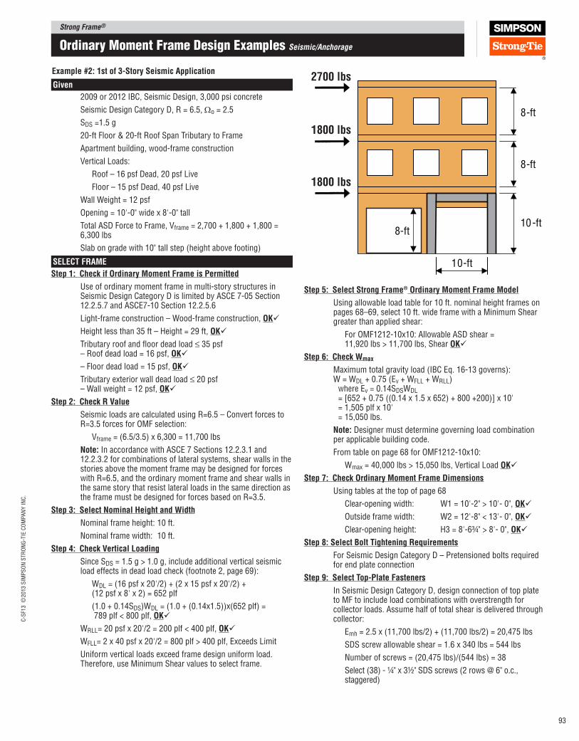
Strong Frame®C
-SF1
3 ©
2013 S
IMP
SO
N S
TR
ON
G-T
IE C
OM
PA
NY
IN
C.
93
Example #2: 1st of 3‑Story Seismic Application
Given
2009 or 2012 IBC, Seismic Design, 3,000 psi concrete
Seismic Design Category D, R = 6.5, Ωo = 2.5
SDS =1.5 g
20-ftFloor&20-ftRoofSpanTributarytoFrame Apartment building, wood-frame construction
Vertical Loads:
Roof – 16 psf Dead, 20 psf Live
Floor – 15 psf Dead, 40 psf Live
Wall Weight = 12 psf
Opening = 10'-0" wide x 8'-0" tall
Total ASD Force to Frame, Vframe = 2,700 + 1,800 + 1,800 = 6,300 lbs
Slab on grade with 10" tall step (height above footing)
SElECT FRAME
Step 1: Check if Ordinary Moment Frame is permitted
Use of ordinary moment frame in multi-story structures in Seismic Design Category D is limited by ASCE 7-05 Section 12.2.5.7 and ASCE7-10 Section 12.2.5.6
Light-frame construction – Wood-frame construction, OK
Height less than 35 ft – Height = 29 ft, OK
Tributary roof and loor dead load ≤ 35 psf – Roof dead load = 16 psf, OK
– Floor dead load = 15 psf, OK
Tributary exterior wall dead load ≤ 20 psf – Wall weight = 12 psf, OK
Step 2: Check R Value
Seismic loads are calculated using R=6.5 – Convert forces to R=3.5 forces for OMF selection:
Vframe = (6.5/3.5) x 6,300 = 11,700 lbs
Note: In accordance with ASCE 7 Sections 12.2.3.1 and 12.2.3.2 for combinations of lateral systems, shear walls in the stories above the moment frame may be designed for forces with R=6.5, and the ordinary moment frame and shear walls in the same story that resist lateral loads in the same direction as the frame must be designed for forces based on R=3.5.
Step 3: Select Nominal Height and Width
Nominal frame height: 10 ft.
Nominal frame width: 10 ft.
Step 4: Check Vertical loading
Since SDS = 1.5 g > 1.0 g, include additional vertical seismic load effects in dead load check (footnote 2, page 69):
WDL = (16 psf x 20'/2) + (2 x 15 psf x 20'/2) + (12 psf x 8' x 2) = 652 plf
(1.0 + 0.14SDS)WDL = (1.0 + (0.14x1.5))x(652 plf) = 789 plf < 800 plf, OK
WRLL= 20 psf x 20'/2 = 200 plf < 400 plf, OK
WFLL= 2 x 40 psf x 20'/2 = 800 plf > 400 plf, Exceeds Limit
Uniform vertical loads exceed frame design uniform load. Therefore, use Minimum Shear values to select frame.
Step 5: Select Strong Frame® Ordinary Moment Frame Model
Using allowable load table for 10 ft. nominal height frames on pages 68–69, select 10 ft. wide frame with a Minimum Shear greater than applied shear:
For OMF1212-10x10: Allowable ASD shear = 11,920 lbs > 11,700 lbs, Shear OK
Step 6: Check Wmax
Maximum total gravity load (IBC Eq. 16-13 governs): W = WDL + 0.75 (Ev + WFLL + WRLL) where Ev = 0.14SDSWDL = [652 + 0.75 ((0.14 x 1.5 x 652) + 800 +200)] x 10' = 1,505 plf x 10' = 15,050 lbs.
Note: Designer must determine governing load combination per applicable building code.
From table on page 68 for OMF1212-10x10:
Wmax = 40,000 lbs > 15,050 lbs, Vertical Load OK
Step 7: Check Ordinary Moment Frame Dimensions
Using tables at the top of page 68
Clear-opening width: W1 = 10'-2" > 10'- 0", OK
Outside frame width: W2 = 12'-8" < 13'- 0", OK
Clear-opening height: H3 = 8'-6¾" > 8'- 0", OK
Step 8: Select Bolt Tightening Requirements
For Seismic Design Category D – Pretensioned bolts required for end plate connection
Step 9: Select Top‑plate Fasteners
In Seismic Design Category D, design connection of top plate to MF to include load combinations with overstrength for collector loads. Assume half of total shear is delivered through collector:
Emh = 2.5 x (11,700 lbs/2) + (11,700 lbs/2) = 20,475 lbs
SDS screw allowable shear = 1.6 x 340 lbs = 544 lbs
Number of screws = (20,475 lbs)/(544 lbs) = 38
Select (38) - ¼" x 3½" SDS screws (2 rows @ 6" o.c., staggered)
ordinary moment Frame Design examples Seismic/Anchorage
10-ft
8-ft
10-ft
8-ft
8-ft
2700 lbs
1800 lbs
1800 lbs

Strong Frame®
C-S
F13 ©
2013 S
IMP
SO
N S
TR
ON
G-T
IE C
OM
PA
NY
IN
C.
94
Example #2: 1st of 3‑Story Seismic Application (cont.)
TENSION ANCHORAGE DESIGN
Step 1: Determine Concrete Condition
Concrete is cracked
Note: Designer must determine whether cracked or uncracked concrete is applicable based on the project conditions in accordance with ACI 318 Appendix D.
Step 2: Select Anchorage Design Method
Use Detailed design method
Step 3: Determine Tension Reaction
Option 1 – Use tabulated maximum tension reaction for OMF1212-10x10 on page 68:
Maximum Column Reactions – Tension: T = 9,995 lbs
Option 2 – Calculate tension reaction for project loads (see page 69, footnote 5)
T = (V x h - MR)/L
V = 11,700 lbs,
h = 10'-¾" - 6" = 9'-6¾"
L = 10'-2" + 12" + 3" = 11'-5" (column centerline dimension)
MR = ½ (0.6 – 0.14SDS)wL2 = ½(0.6 – 0.14x1.5)(652 plf) (11'-5")2 = 16,570 ft-lbs
T = ((11,700 lbs x 9'-6¾") – 16,570 ft-lbs) / 11'-5" = 8,350 lbs
Step 4: Select Minimum Footing Size for Tension
Using Table 1.2 on page 87 and reaction from Option 2 in Step 3:
C12 column, seismic loading, cracked concrete, T = 8,350 lbs: W = 42", de = 13"
Step 5: Determine Anchorage Assembly Strength
Using Table 1.2 on page 85, footnote 6:
C12 column, 10 ft tall, seismic loading: High strength anchorage assembly required
Step 6: Determine Rod length and Footing Size
For slab on grade with 10" step height: Required le = de + 10" = 23"
Select MFAB-30-HSS-KT, le=24" (see igure below), OK
Minimum footing depth = 24" ‑ 10" (curb) + 4" = 18"
SHEAR ANCHORAGE DESIGN
Step 1: Select Anchorage Assembly Type
Select MFAB for high capacity at foundation corner
Step 2: Select Anchorage Design Method
Use Detailed design method
Step 3: Determine Shear Reactions
Option 1 – Use tabulated maximum seismic shear reaction for OMF1212‑10x10 on page 68:
Maximum Column Reactions – Shear for Seismic with R=3.5, Ωo=2.5: V = 15,600 lbs
Option 2 – Calculate shear reaction for project loads (see page 69, footnotes 15 and 4)
RH = (ΩoV/2) + X(2/3wL)
Ωo = 2.5
V = 11,700 lbs
X = 0.112
w = WDL + Ev = 789 plf Note: Designer must determine governing load combination per applicable code.
L = (10'‑2") + (3") + (12") = 11'‑5"
RH = (2.5)(11,700 lbs / 2) + (0.112)(2/3)(789 plf)(11'‑5") = 15,300 lbs
Step 4: Determine Reinforcement
Using Table 3.2 on page 89 and reaction from Option 2 in Step 3:
C12 column, slab‑on‑grade, seismic loading: 4 ‑ #3 hairpins, allowable shear = 23,690 lbs > 15,300 lbs, OK
Step 5: Determine Anchorage Assembly Strength
Using Table 3.2 on page 89:
C12 column, slab‑on‑grade, seismic loading, 4 ‑ #3 hairpins: High strength MFAB (value shaded)
SUMMARy
Strong Frame Model: OMF1212‑10x10
End‑Plate Bolts: Pretensioned
Top‑Plate Fasteners: (38) ‑ ¼" x 3½" SDS screws
Anchorage Assembly: MFAB‑30‑HSS‑KT
Reinforcement: 4 ‑ #3 hairpins
Minimum footing size for anchorage: 42"x42"x18"
Notes:
1. Footing size shown is based on anchorage design only. Actual footing/grade beam size and reinforcing must be determined by Designer based on project speciic geometry and allowable soil bearing pressures.
2. Overturning load on steel beam from shear wall above is not shown for simplicity; Designer must include shear wall overturning forces in steel beam check as required.
3. Design of diaphragms, including the requirements of ASCE 7‑05 Section 12.2.3.2, is not shown and is the responsibility of the Designer.MFAB9-30HS-KT
4 - #3 Hairpin ties
10"
de
4"min.
½ W ½ W
le
W
ordinary moment Frame Design examples Seismic/Anchorage
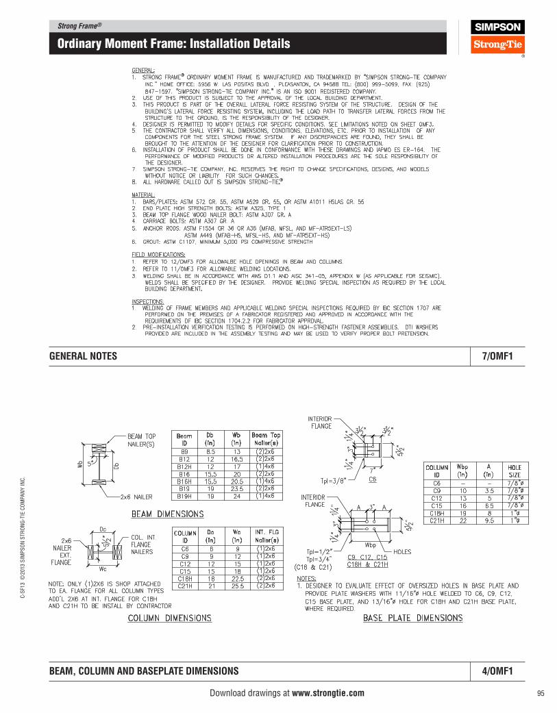
Strong Frame®C
-SF1
3 ©
2013 S
IMP
SO
N S
TR
ON
G-T
IE C
OM
PA
NY
IN
C.
95
ordinary moment Frame: Installation Details
BEAM, COlUMN AND BASEplATE DIMENSIONS 4/OMF1
GENERAl NOTES 7/OMF1
Download drawings at www.strongtie.com
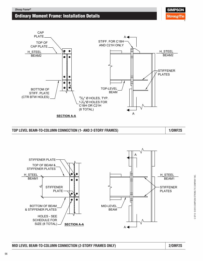
Strong Frame®
C-S
F13 ©
2013 S
IMP
SO
N S
TR
ON
G-T
IE C
OM
PA
NY
IN
C.
96
ordinary moment Frame: Installation Details
TOp lEVEl BEAM‑TO‑COlUMN CONNECTION (1‑ AND 2‑STORy FRAMES) 1/OMF2S
MID lEVEl BEAM‑TO‑COlUMN CONNECTION (2‑STORy FRAMES ONly) 2/OMF2S
CAP
PLATE
TOP OF
CAP PLATE
BOTTOM OF
STIFF. PLATE
(CTR BTW HOLES) 1516" Ø HOLES, TYP.
1-116"Ø HOLES FORC18H OR C21H
(8 TOTAL)
A
A
STIFFENER
PLATES
SECTION A-A
STIFF. FOR C18H
AND C21H ONLY
H_STEEL
BEAM2
H_STEEL
BEAM2
TOP-LEVELBEAM
TOP OF BEAM &
STIFFENER PLATES
BOTTOM OF BEAM
& STIFFENER PLATES
STIFFENER PLATE
STIFFENER
PLATE
HOLES - SEE
SCHEDULE FOR
SIZE (8 TOTAL) SECTION A-A
STIFFENER
PLATES
db
A
A
H_STEEL
BEAM1
H_STEEL
BEAM1
MID-LEVELBEAM
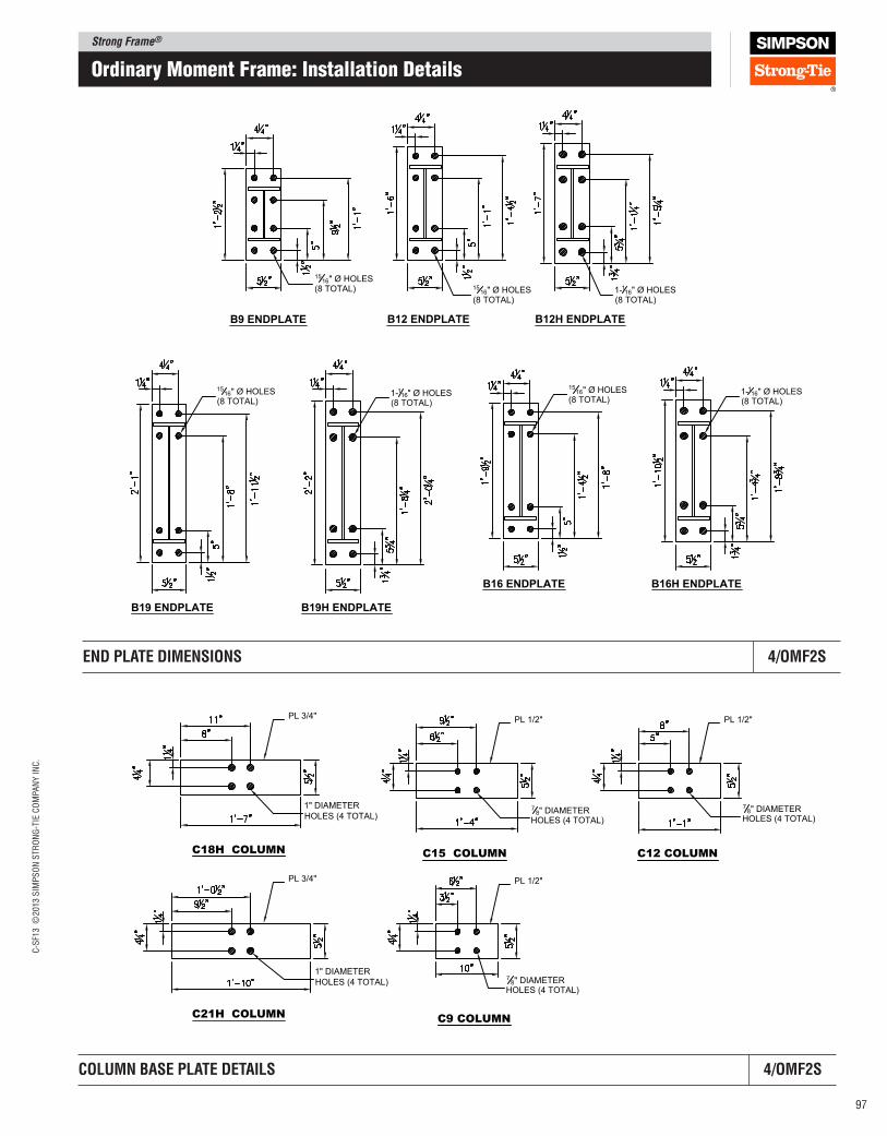
Strong Frame®C
-SF1
3 ©
2013 S
IMP
SO
N S
TR
ON
G-T
IE C
OM
PA
NY
IN
C.
97
END plATE DIMENSIONS 4/OMF2S
ordinary moment Frame: Installation Details
COlUMN BASE plATE DETAIlS 4/OMF2S
B9 ENDPLATE B12 ENDPLATE
1516" Ø HOLES
(8 TOTAL)
1516" Ø HOLES
(8 TOTAL)
B12H ENDPLATE
1-116" Ø HOLES
(8 TOTAL)
B16 ENDPLATE B16H ENDPLATE
B19 ENDPLATE B19H ENDPLATE
1-116" Ø HOLES
(8 TOTAL)
1516" Ø HOLES
(8 TOTAL)1-116" Ø HOLES
(8 TOTAL)
1516" Ø HOLES
(8 TOTAL)
C12 COLUMN
C9 COLUMN
78" DIAMETER
HOLES (4 TOTAL)
78" DIAMETER
HOLES (4 TOTAL)
C15 COLUMN
78" DIAMETER
HOLES (4 TOTAL)
C18H COLUMN
1" DIAMETER
HOLES (4 TOTAL)
C21H COLUMN
1" DIAMETER
HOLES (4 TOTAL)
PL 3/4"
PL 3/4"
PL 1/2" PL 1/2"
PL 1/2"
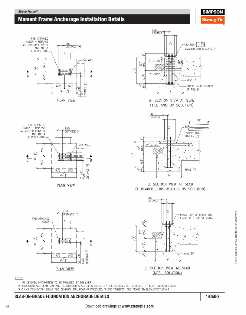
Strong Frame®
C-S
F13 ©
2013 S
IMP
SO
N S
TR
ON
G-T
IE C
OM
PA
NY
IN
C.
98
moment Frame anchorage Installation Details
SlAB‑ON‑GRADE FOUNDATION ANCHORAGE DETAIlS 1/OMF2
Download drawings at www.strongtie.com

Strong Frame®C
-SF1
3 ©
2013 S
IMP
SO
N S
TR
ON
G-T
IE C
OM
PA
NY
IN
C.
99
CONCRETE CURB FOUNDATION ANCHORAGE DETAIlS 2/OMF2
moment Frame anchorage Installation Details
Download drawings at www.strongtie.com
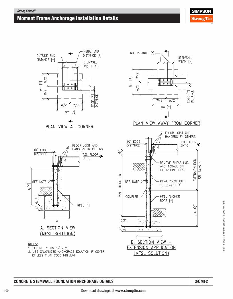
Strong Frame®
C-S
F13 ©
2013 S
IMP
SO
N S
TR
ON
G-T
IE C
OM
PA
NY
IN
C.
100
moment Frame anchorage Installation Details
CONCRETE STEMWAll FOUNDATION ANCHORAGE DETAIlS 3/OMF2
Download drawings at www.strongtie.com
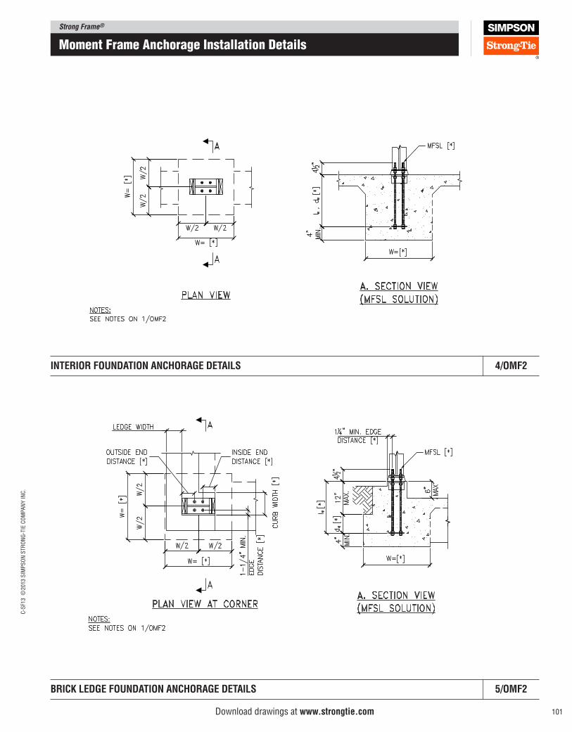
Strong Frame®C
-SF1
3 ©
2013 S
IMP
SO
N S
TR
ON
G-T
IE C
OM
PA
NY
IN
C.
101
moment Frame anchorage Installation Details
INTERIOR FOUNDATION ANCHORAGE DETAIlS 4/OMF2
BRICK lEDGE FOUNDATION ANCHORAGE DETAIlS 5/OMF2
Download drawings at www.strongtie.com
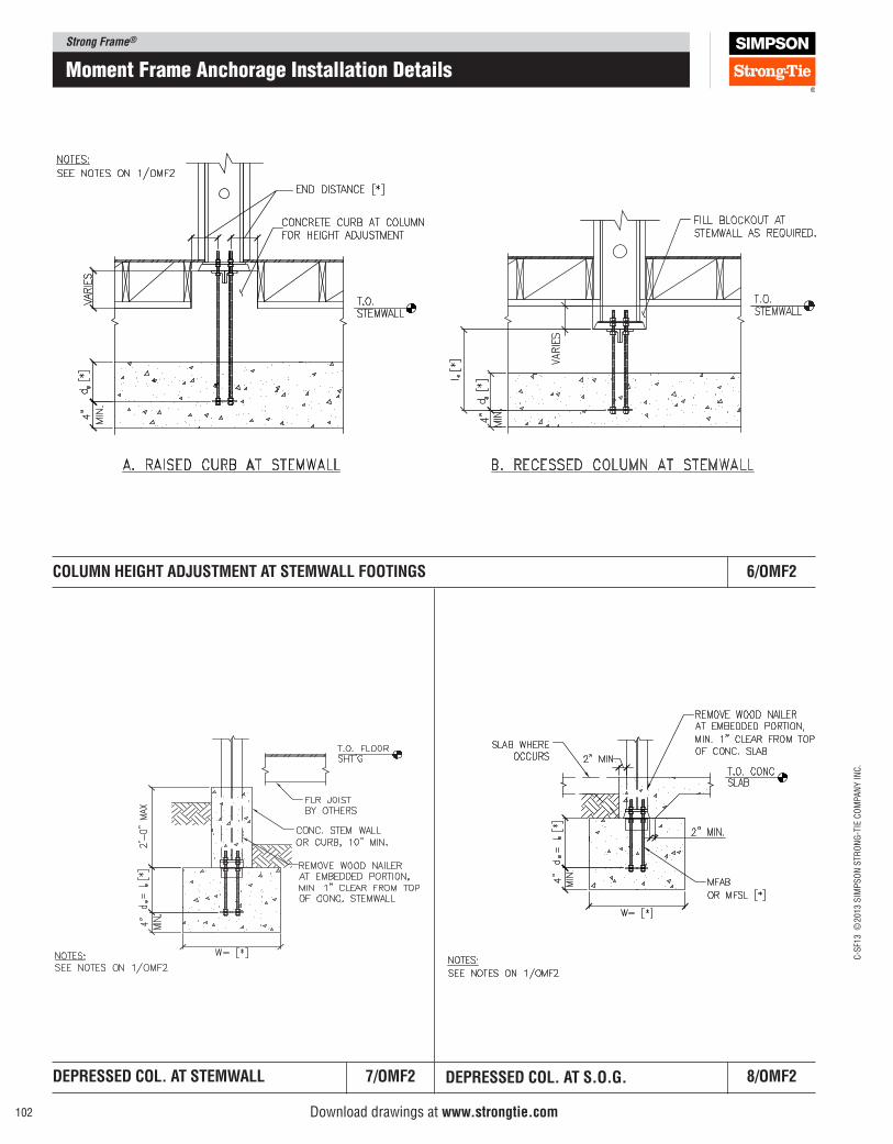
Strong Frame®
C-S
F13 ©
2013 S
IMP
SO
N S
TR
ON
G-T
IE C
OM
PA
NY
IN
C.
102
moment Frame anchorage Installation Details
COlUMN HEIGHT ADJUSTMENT AT STEMWAll FOOTINGS 6/OMF2
DEpRESSED COl. AT STEMWAll 7/OMF2 DEpRESSED COl. AT S.O.G. 8/OMF2
Download drawings at www.strongtie.com
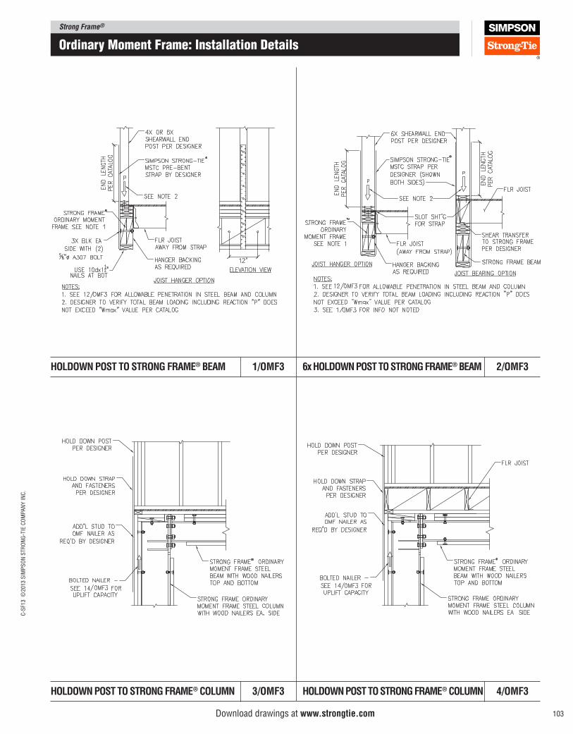
Strong Frame®C
-SF1
3 ©
2013 S
IMP
SO
N S
TR
ON
G-T
IE C
OM
PA
NY
IN
C.
103
6x HOlDOWN pOST TO STRONG FRAME® BEAM 2/OMF3HOlDOWN pOST TO STRONG FRAME® BEAM 1/OMF3
HOlDOWN pOST TO STRONG FRAME® COlUMN 4/OMF3HOlDOWN pOST TO STRONG FRAME® COlUMN 3/OMF3
ordinary moment Frame: Installation Details
Download drawings at www.strongtie.com
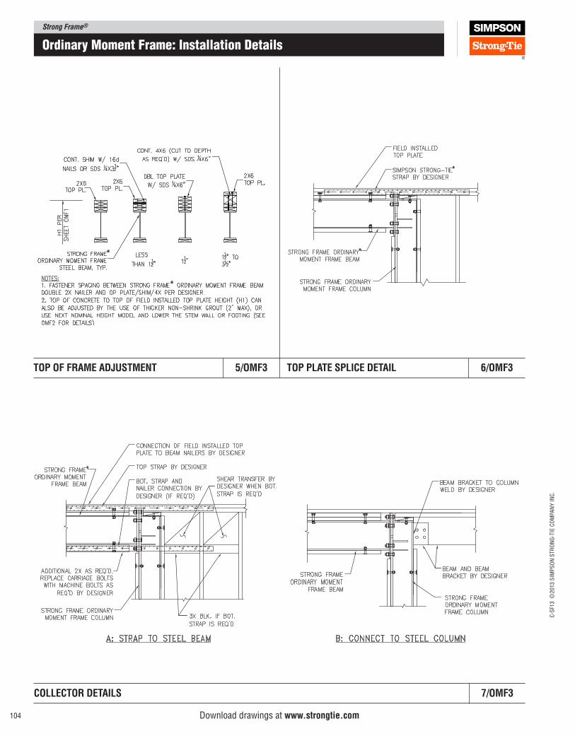
Strong Frame®
C-S
F13 ©
2013 S
IMP
SO
N S
TR
ON
G-T
IE C
OM
PA
NY
IN
C.
104
ordinary moment Frame: Installation Details
TOp plATE SplICE DETAIl 6/OMF3TOp OF FRAME ADJUSTMENT 5/OMF3
Download drawings at www.strongtie.com
COllECTOR DETAIlS 7/OMF3
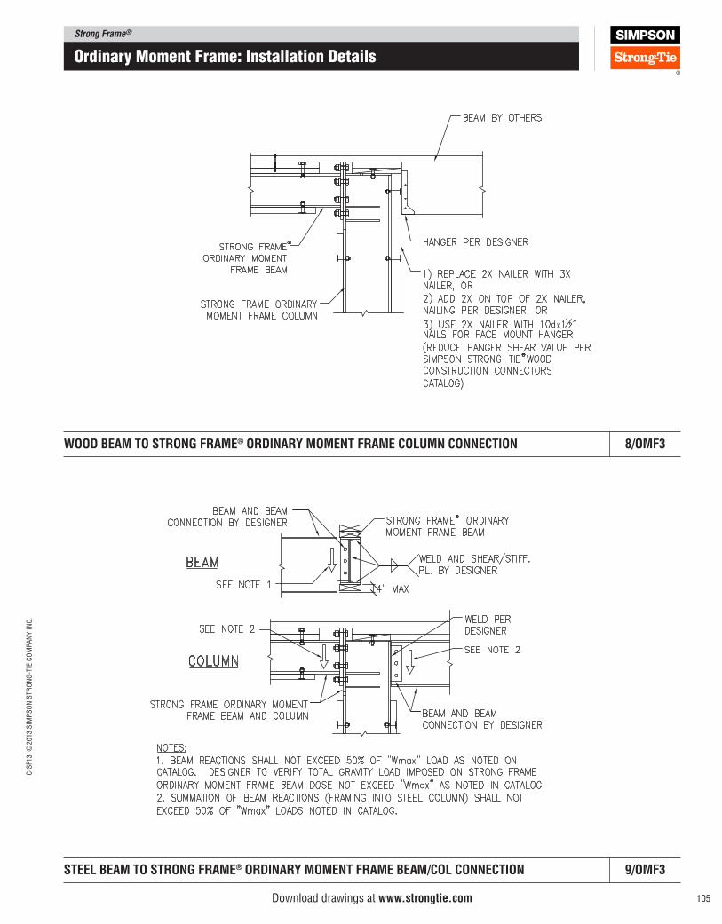
Strong Frame®C
-SF1
3 ©
2013 S
IMP
SO
N S
TR
ON
G-T
IE C
OM
PA
NY
IN
C.
105
ordinary moment Frame: Installation Details
WOOD BEAM TO STRONG FRAME® ORDINARy MOMENT FRAME COlUMN CONNECTION 8/OMF3
STEEl BEAM TO STRONG FRAME® ORDINARy MOMENT FRAME BEAM/COl CONNECTION 9/OMF3
Download drawings at www.strongtie.com
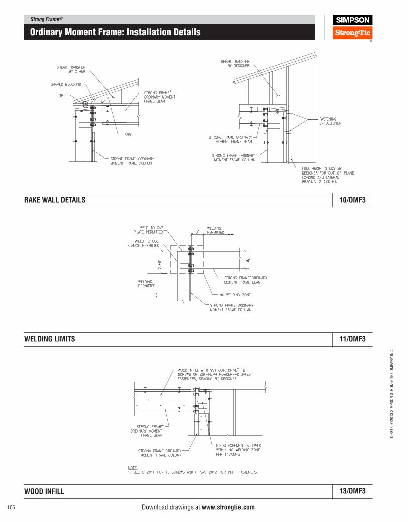
Strong Frame®
C-S
F13 ©
2013 S
IMP
SO
N S
TR
ON
G-T
IE C
OM
PA
NY
IN
C.
106
ordinary moment Frame: Installation Details
RAKE WAll DETAIlS 10/OMF3
db+
db
WElDING lIMITS 11/OMF3
WOOD INFIll 13/OMF3
Download drawings at www.strongtie.com
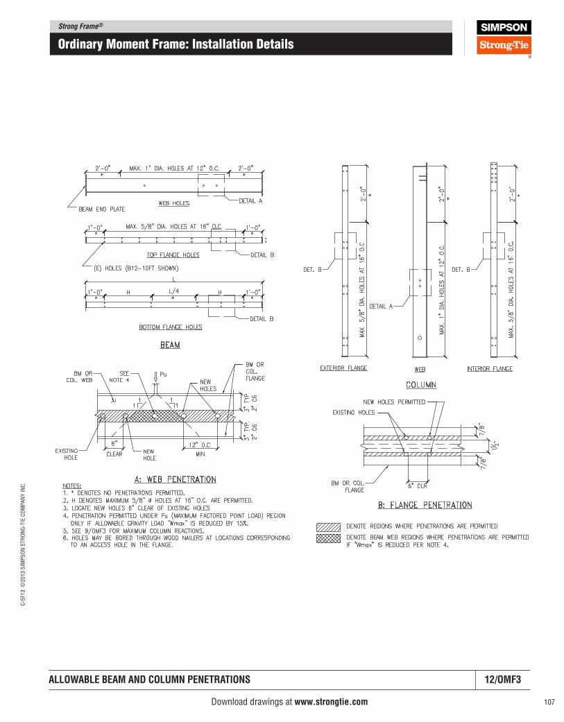
Strong Frame®C
-SF1
3 ©
2013 S
IMP
SO
N S
TR
ON
G-T
IE C
OM
PA
NY
IN
C.
107
ordinary moment Frame: Installation Details
AllOWABlE BEAM AND COlUMN pENETRATIONS 12/OMF3
Download drawings at www.strongtie.com
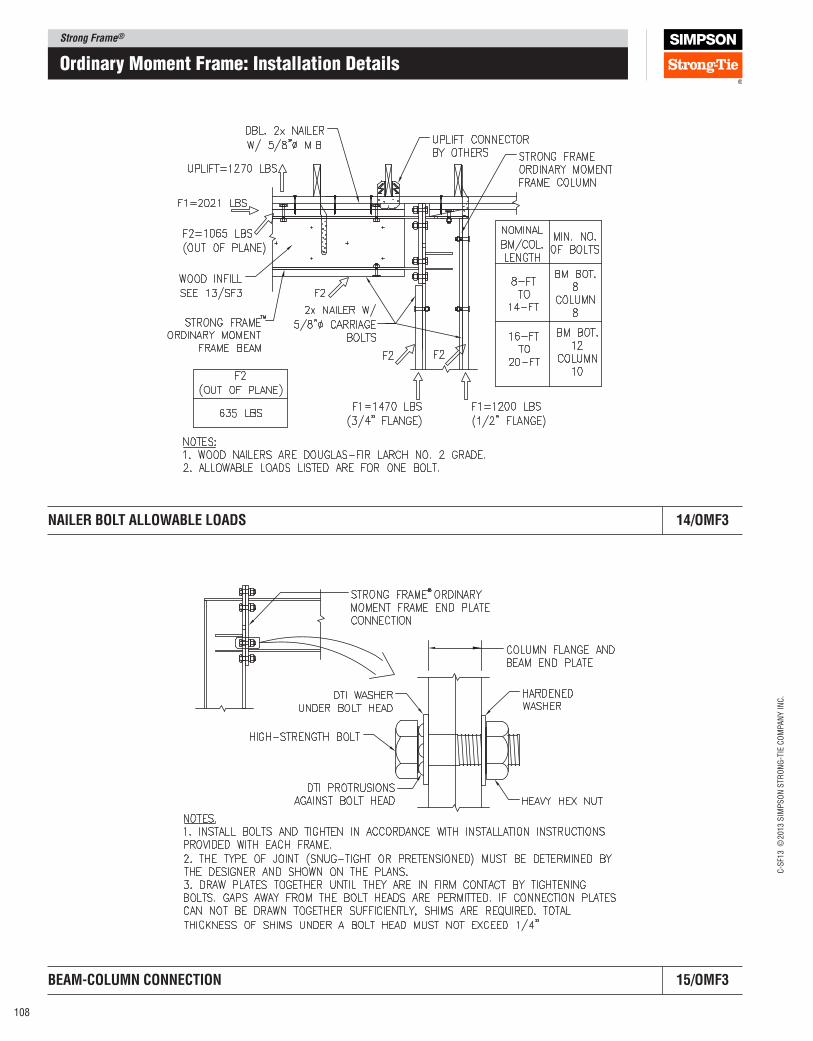
Strong Frame®
C-S
F13 ©
2013 S
IMP
SO
N S
TR
ON
G-T
IE C
OM
PA
NY
IN
C.
108
ordinary moment Frame: Installation Details
NAIlER BOlT AllOWABlE lOADS 14/OMF3
BEAM‑COlUMN CONNECTION 15/OMF3
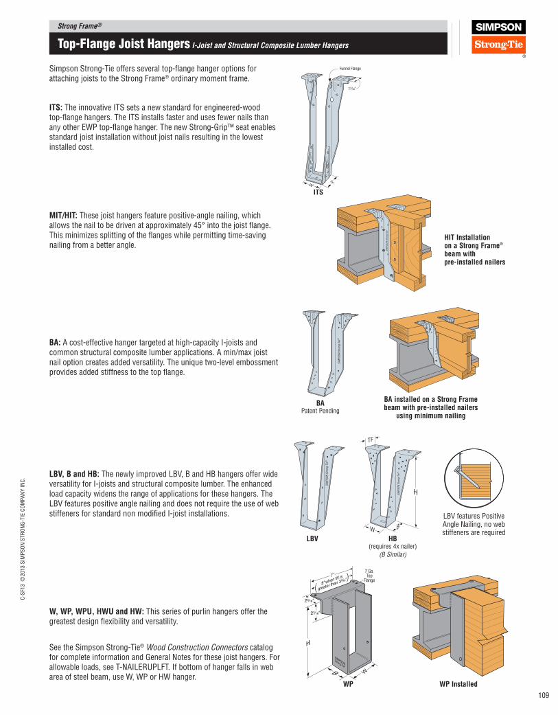
Strong Frame®C
-SF1
3 ©
2013 S
IMP
SO
N S
TR
ON
G-T
IE C
OM
PA
NY
IN
C.
109
top-Flange Joist Hangers I‑Joist and Structural Composite Lumber Hangers
See the Simpson Strong-Tie® Wood Construction Connectors catalog for complete information and General Notes for these joist hangers. For allowable loads, see T-NAILERUPLFT. If bottom of hanger falls in web area of steel beam, use W, WP or HW hanger.
MIT/HIT: These joist hangers feature positive-angle nailing, which allows the nail to be driven at approximately 45° into the joist lange. This minimizes splitting of the langes while permitting time-saving nailing from a better angle.
lBV HB (requires 4x nailer)
(B Similar)
BAPatent Pending
BA: A cost-effective hanger targeted at high-capacity I-joists and common structural composite lumber applications. A min/max joist nail option creates added versatility. The unique two-level embossment provides added stiffness to the top lange.
W, Wp, WpU, HWU and HW: This series of purlin hangers offer the greatest design lexibility and versatility.
Simpson Strong-Tie offers several top-lange hanger options for attaching joists to the Strong Frame® ordinary moment frame.
ITS: The innovative ITS sets a new standard for engineered-wood top-lange hangers. The ITS installs faster and uses fewer nails than any other EWP top-lange hanger. The new Strong-Grip™ seat enables standard joist installation without joist nails resulting in the lowest installed cost.
ITS
Funnel Flange
W
1⁷⁄₁₆"
2"
HIT Installation on a Strong Frame® beam with pre‑ installed nailers
7 Ga.Top
Flange
Wp
lBV, B and HB: The newly improved LBV, B and HB hangers offer wide versatility for I-joists and structural composite lumber. The enhanced load capacity widens the range of applications for these hangers. The LBV features positive angle nailing and does not require the use of web stiffeners for standard non modiied I‑joist installations. LBV features Positive
Angle Nailing, no web stiffeners are required
BA installed on a Strong Frame beam with pre‑installed nailers
using minimum nailing
Wp Installed
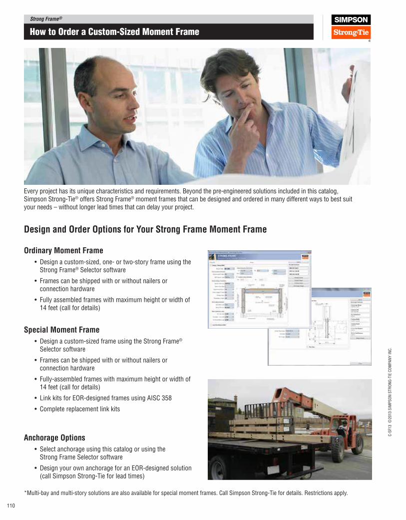
Strong Frame®
C-S
F13 ©
2013 S
IMP
SO
N S
TR
ON
G-T
IE C
OM
PA
NY
IN
C.
110
How to order a Custom-Sized moment Frame
Every project has its unique characteristics and requirements. Beyond the pre-engineered solutions included in this catalog, Simpson Strong-Tie® offers Strong Frame® moment frames that can be designed and ordered in many different ways to best suit your needs – without longer lead times that can delay your project.
Design and Order Options for your Strong Frame Moment Frame
Ordinary Moment Frame
• Design a custom-sized, one- or two-story frame using the Strong Frame® Selector software
• Frames can be shipped with or without nailers or connection hardware
• Fully assembled frames with maximum height or width of 14 feet (call for details)
Special Moment Frame
• Design a custom-sized frame using the Strong Frame® Selector software
• Frames can be shipped with or without nailers or connection hardware
• Fully-assembled frames with maximum height or width of 14 feet (call for details)
• Link kits for EOR-designed frames using AISC 358
• Complete replacement link kits
Anchorage Options
• Select anchorage using this catalog or using the Strong Frame Selector software
• Design your own anchorage for an EOR-designed solution (call Simpson Strong-Tie for lead times)
*Multi-bay and multi-story solutions are also available for special moment frames. Call Simpson Strong-Tie for details. Restrictions apply.
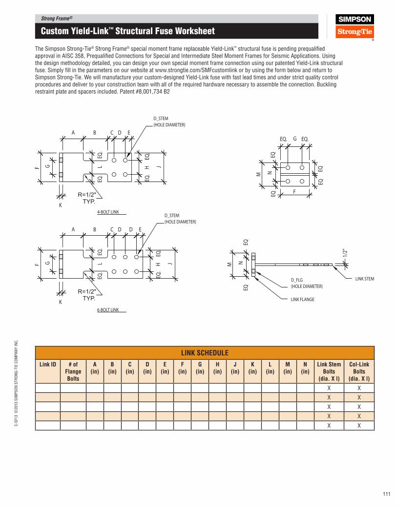
Strong Frame®C
-SF1
3 ©
2013 S
IMP
SO
N S
TR
ON
G-T
IE C
OM
PA
NY
IN
C.
111
Custom Yield-Link™ Structural Fuse Worksheet
The Simpson Strong‑Tie® Strong Frame® special moment frame replaceable Yield‑Link™ structural fuse is pending prequaliied approval in AISC 358, Prequaliied Connections for Special and Intermediate Steel Moment Frames for Seismic Applications. Using the design methodology detailed, you can design your own special moment frame connection using our patented Yield‑Link structural fuse. Simply ill in the parameters on our website at www.strongtie.com/SMFcustomlink or by using the form below and return to Simpson Strong‑Tie. We will manufacture your custom‑designed Yield‑Link fuse with fast lead times and under strict quality control procedures and deliver to your construction team with all of the required hardware necessary to assemble the connection. Buckling restraint plate and spacers included. Patent #8,001,734 B2
D_FLG
(HOLE DIAMETER)
D_STEM
(HOLE DIAMETER)
LINK STEM
LINK FLANGE
D_STEM
(HOLE DIAMETER)
4-BOLT LINK
6-BOLT LINK
A B
JHF L M
EQN
1/2"EQ
.EQ
.
K
G
EQ.
EQ.
M
EQN
GEQ. EQ.
F
EQ
A B
JHF LEQ
.EQ
.
K
G
EQ.
EQ.
C D E
C D ED
EQ
EQ
EQ
R=1/2"TYP.
R=1/2"TYP.
lINK SCHEDUlE
link ID # of Flange Bolts
A (in)
B (in)
C (in)
D (in)
E (in)
F (in)
G (in)
H (in)
J (in)
K (in)
l (in)
M (in)
N (in)
link Stem Bolts
(dia. X l)
Col‑link Bolts
(dia. X l)
X X
X X
X X
X X
X X
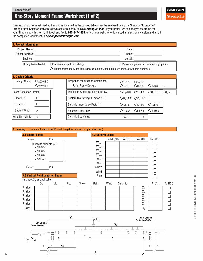
Strong Frame®
C-S
F13 ©
2013 S
IMP
SO
N S
TR
ON
G-T
IE C
OM
PA
NY
IN
C.
112
3. loading
Project Name: Date:
Phone: Project Address:
e-mail:Engineer:
Please analyse and let me know my options Preliminary size from catalog-
Custom height and width frame (Please submit Custom Frame Worksheet with this worksheet)
Design Code: 2009 IBC Response Modifcation Coefficient,
2012 IBC R, for Frame Design: R=3.5 R=3.0 R<3.0 R =
Beam Deflection Limits: Deflection Amplification Factor, Cd: C d=3.0 Cd=4.0
Floor LL: L/ System Overstrength Factor, Ω o: Ω o=3.0 Ω o=2.5
DL + LL: L/ I=1.00 I=1.25 I=1.50
Snow / Wind: L/ 0.025h 0.020h 0.015h
Wind Drift Limit: h/ Seismic SDS Value: S DS = g
Frames that do not meet loading limitations included in the catalog tables may be analyzed using the Simpson Strong-Tie®
Strong Frame Selector software (download a free copy at www.strongtie.com). If you prefer, we can analyze the frame foryou. Simply copy this form, fill it out and fax to 925‑847‑1605, or visit our website to download an electronic version and email the completed worksheet to [email protected].
1. project Information
2. Design Criteria
Provide all loads at ASD level. Negative values for uplift direction)
3.2 Uniform loads
V EQ = )flp( daoL sbl XL (ft) X R (ft) To RCC
R used to calculate VEQ : W DL1
R=3.5 W DL2
R=6.5 W DL3
R=8.0 W RLL
Other: W LL1
W LL2
V Wind = wonSsbl
Wind
3.3 Vertical point loads on Beam Rain
(Include Ω ο as applicable)
DL LL RLL Snow Rain Wind Seismic X i (ft)
P 1 (lbs) X1
P 2 (lbs) X2
P 3 (lbs) X3
P 4 (lbs) X4
P 5 (lbs) X5
P 6 (lbs) X6
3.1 lateral loads
W
Pi
V , VEQ W
X i
X L
X R
Left ColumnCenterline (LCC)
Right ColumnCenterline (RCC)
W
Pi
V , VEQ W
X i
X L
X R
Left ColumnCenterline (LCC)
Right ColumnCenterline (RCC)
R=8.0 R=6.5
C d =5.5
To RCC
C =d
Strong Frame Model:
Seismic Importance Factor, I:
Seismic Drift Limit:
one-Story moment Frame Worksheet (1 of 2)
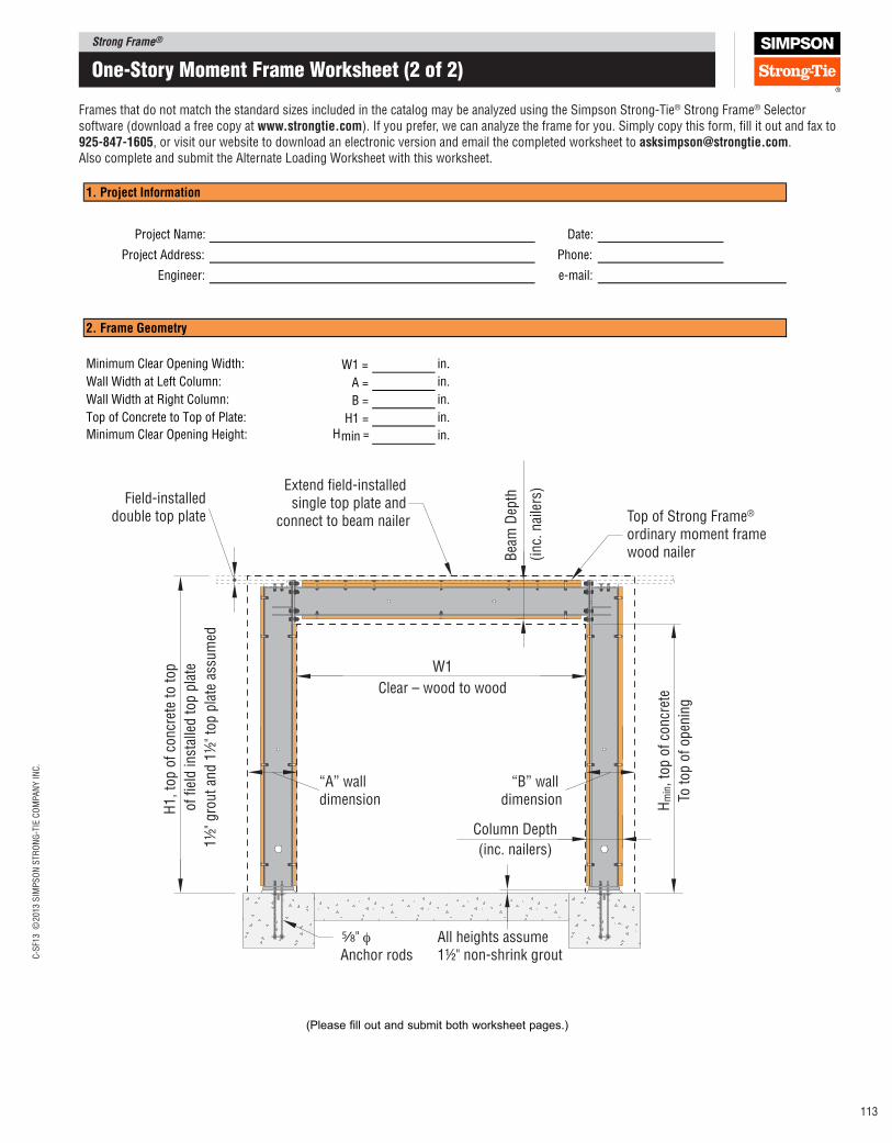
Strong Frame®C
-SF1
3 ©
2013 S
IMP
SO
N S
TR
ON
G-T
IE C
OM
PA
NY
IN
C.
113
one-Story moment Frame Worksheet (2 of 2)
Date:Project Name:
Phone:Project Address:
e-mail:Engineer:
Minimum Clear Opening Width: W1 = in.
Wall Width at Left Column: A = in.
Wall Width at Right Column: B = in.
Top of Concrete to Top of Plate: H1 = in.
Minimum Clear Opening Height: Hmin = in.
1. project Information
2. Frame Geometry
(Please fill out and submit both worksheet pages.)
W1
Clear – wood to wood
Extend field-installed single top plate and
connect to beam nailer Top of Strong Frame®
ordinary moment framewood nailer
" φAnchor rods
All heights assume 1½" non-shrink grout
Bea
m D
epth
(inc.
nai
lers
)
Field-installeddouble top plate
“A” wall dimension
“B” wall dimension
Column Depth
(inc. nailers)
H1, to
p o
f co
ncr
ete
to t
op
of
fiel
d in
stal
led t
op p
late
1½
" gro
ut
and 1
½" to
p p
late
ass
um
ed
Hm
in, to
p o
f co
ncr
ete
To t
op o
f open
ing
5/8
Frames that do not match the standard sizes included in the catalog may be analyzed using the Simpson Strong‑Tie® Strong Frame® Selector software (download a free copy at www.strongtie.com). If you prefer, we can analyze the frame for you. Simply copy this form, ill it out and fax to 925‑847‑1605, or visit our website to download an electronic version and email the completed worksheet to [email protected]. Also complete and submit the Alternate Loading Worksheet with this worksheet.
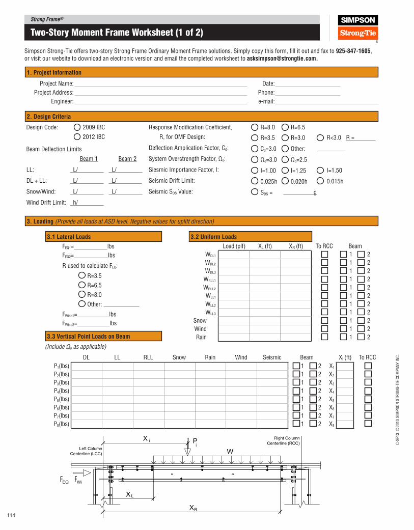
Strong Frame®
C-S
F13 ©
2013 S
IMP
SO
N S
TR
ON
G-T
IE C
OM
PA
NY
IN
C.
114
two-Story moment Frame Worksheet (1 of 2)
Simpson Strong‑Tie offers two‑story Strong Frame Ordinary Moment Frame solutions. Simply copy this form, ill it out and fax to 925‑847‑1605, or visit our website to download an electronic version and email the completed worksheet to [email protected].
F F
1. project Information
2. Design Criteria
3. loading (Provide all loads at ASD level. Negative values for uplift direction)
3.1 lateral loads 3.2 Uniform loads
3.3 Vertical point loads on Beam
Project Name:
Project Address:
Engineer:
Date:
Phone:
e‑mail:
Design Code:
Beam Delection Limits
2009 IBC
2012 IBC
Response Modiication Coeficient,
R, for OMF Design:
Delection Amplication Factor, Cd:
System Overstrength Factor, Ωo:
Siesmic Importance Factor, I:
Seismic Drift Limit:
Seismic SDS Value:
R=8.0
R=3.5
Cd=3.0
Ωo=3.0
I=1.00
0.025h
SDS =
R=6.5
R=3.0
Other:
Ωo=2.5
I=1.25
0.020h
R<3.0
I=1.50
0.015h
R =
Beam 2
L/
L/
L/
Beam 1
L/
L/
L/
h/
LL:
DL + LL:
Snow/Wind:
Wind Drift Limit:
Load (plf) XL (ft) XR (ft)
WDL1
WDL2
WDL3
WRLL1
WRLL2
WLL1
WLL2
WLL3
Snow
Wind
Rain
DL LL RLL Snow Rain Wind Seismic
P1(lbs)
P2(lbs)
P3(lbs)
P4(lbs)
P5(lbs)
P6(lbs)
P7(lbs)
P8(lbs)
X1
X2
X3
X4
X5
X6
X7
X8
Xi (ft)
(Include Ωo as applicable)
g
1
1
1
1
1
1
1
1
2
2
2
2
2
2
2
2
1
1
1
1
1
1
1
1
1
1
1
2
2
2
2
2
2
2
2
2
2
2
To RCC Beam
Beam
R=3.5
R=6.5
R=8.0
Other:
FEQ1= lbs
FEQ2= lbs
R used to calculate FEQ:
FWind1= lbs
FWind2= lbs
To RCC
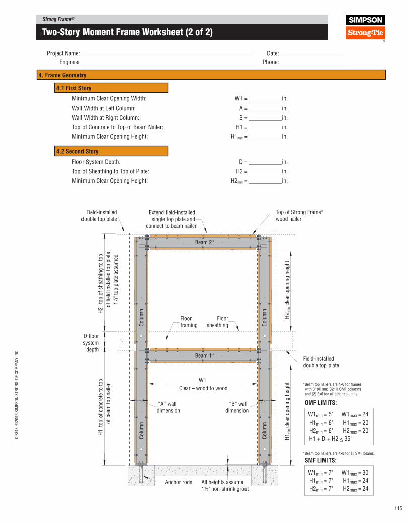
Strong Frame®C
-SF1
3 ©
2013 S
IMP
SO
N S
TR
ON
G-T
IE C
OM
PA
NY
IN
C.
115
two-Story moment Frame Worksheet (2 of 2)
Extend field-installed single top plate and
connect to beam nailer
Top of Strong Frame®
wood nailerField-installed
double top plate
H2
, to
p o
f sh
eath
ing t
o t
op
of
fiel
d in
stal
led t
op p
late
1½
" to
p p
late
ass
um
ed
H2 m
in c
lear
open
ing h
eight
H1 m
in c
lear
open
ing h
eightW1
Clear – wood to wood
Anchor rods All heights assume 1½" non-shrink grout
H1,
top o
f co
ncr
ete
to t
op
of
bea
m t
op n
aile
r
Field-installeddouble top plate
Floorframing
Floorsheathing
D floor system
depthBeam 1*
Beam 2*
Colu
mn
Colu
mn
Colu
mn
Colu
mn
“A” wall dimension
“B” wall dimension
*Beam top nailers are 4x6 for frames with C18H and C21H OMF columns and (2) 2x6 for all other columns.
W1min = 5' W1max = 24'
H1min = 6' H1max = 20'
H2min = 6' H2max = 20'
H1 + D + H2 < 35'
4. Frame Geometry
Project Name:
Engineer
Date:
Phone:
Minimum Clear Opening Width:
Wall Width at Left Column:
Wall Width at Right Column:
Top of Concrete to Top of Beam Nailer:
Minimum Clear Opening Height:
4.1 First Story
4.2 Second Story
Floor System Depth:
Top of Sheathing to Top of Plate:
Minimum Clear Opening Height:
W1 =
A =
B =
H1 =
H1min =
in.
in.
in.
in.
in.
D =
H2 =
H2min =
in.
in.
in.
OMF lIMITS:
*Beam top nailers are 4x8 for all SMF beams.
W1min = 7' W1max = 30'
H1min = 7' H1max = 24'
H2min = 7' H2max = 24'
SMF lIMITS:
®
Every day we work hard to earn your business, blending the
talents of our people with the quality of our products and services
to exceed your expectations. This is our pledge to you.
Wood Construction ConnectorsIncludes specifications and installation instructions on wood-to-wood and wood-to- concrete structural connectors. Includes load tables and material specifications.
Anchoring and Fastening Systems for Concrete and MasonryIncludes application information, specifications and load values for adhesive and mechanical anchors,powder&gas-actuatedfastening and carbide drill bits.
Strong‑Wall ® ShearwallsAll the information on our Strong-Wall shearwalls is now in one easy to use catalog: techni-cal data, installation information, structural details and more. The catalog also features new solu-tions for two-story and balloon frame applications as well as an extensive section on braced frame requirements under the various building codes.
High Wind Framing Connection GuideDeveloped for designers and engineers as a companion totheAF&PAWoodFrameConstruction Manual.
Anchor Tiedown SystemsThis system is designed to provide the over-turning holdown capacity for multi-story commercial buildings. This holdown application is easy to specify, install and inspect.Fastening Systems
A complete line of labor- saving auto-feed systems and specialty fasteners for a wide range of commercial and residential construction applications.
Code Compliant Repair and Protection GuideDeveloped for building professionals to help explain products and techniques related to the installation of utilities in wood frame construction.
printed in U.S.A. ©2013 Simpson Strong‑Tie Company Inc. C‑SF13 12/12 exp. 6/17
Free Simpson Strong‑Tie CD‑ROMOur CD-ROM features our latest catalogs, fliers, technical bulletins, code reports, product list prices, UPC information, and the Simpson Strong‑Tie Connector Selector program. It also includes the Drawing Library.
Home Office 5956 W. Las Positas Blvd. Pleasanton, CA 94588 Tel: 925/560‑9000 Fax: 925/847‑1603
Northwest U.S.A. 5151 S. Airport Way Stockton, CA 95206 Tel: 209/234‑7775 Fax: 209/234‑3868
Southwest U.S.A. 12246 Holly Street Riverside, CA 92509 Tel: 714/871‑8373 Fax: 951/369‑2889
Northeast U.S.A. 2600 International Street Columbus, OH 43228 Tel: 614/876‑8060 Fax: 614/876‑0636
Southeast U.S.A. 2221 Country Lane McKinney, TX 75069 Tel: 972/542‑0326 Fax: 972/542‑5379
Eastern Canada 5 Kenview Boulevard Brampton, ON L6T 5G5 Tel: 905/458‑5538 Fax: 905/458‑7274
Western Canada 11476 Kingston Street Maple Ridge, B.C. V2X 0Y5 Tel: 604/465‑0296 Fax: 604/465‑0297
Warehouses and Manufacturing Eagan, MN; Enfield, CT Gallatin, TN; High Point, NC Jacksonville, FL; Kent, WA Langley, B.C.
INTERNATIONAl FACIlITIES Please visit our website for address and contact information for our international facilities.
Related Documents