NAVIGATING THE REQUIREMENTS OF MOMENT FRAME DESIGN SOLUTIONS Strong Frame ® Design Guide (800) 999-5099 | strongtie.com

Welcome message from author
This document is posted to help you gain knowledge. Please leave a comment to let me know what you think about it! Share it to your friends and learn new things together.
Transcript
NAVIGATING THE REQUIREMENTS OF MOMENT FRAME DESIGN SOLUTIONS
Strong Frame® Design Guide
(800) 999-5099 | strongtie.com

Prefabricated is better
Choosing prefabricated versus site-built
moment frames may save time and
mitigate risk on the jobsite. Prefabricated
frames have better quality control. Bolted
assemblies simplify installation and
reduce the risk of harmful fumes or fire.
Your installation will be easier, and your
jobsite safer.

Strong Frame® is the smart solution
Simpson Strong-Tie® Strong Frame
moment frames arrive ready for installation.
Preattached wood nailers allow for quick
connection to a light-frame structure, and
no field welding means no onsite weld
inspection is required. Strong Frame is the
quick, easy and economical moment frame
solution to your design challenges.
(800) 999-5099 | strongtie.com
4 | Strong Frame® Design Guide (800) 999-5099 | strongtie.com F-L-SFDG20 © 2020 Simpson Strong-Tie Company Inc.
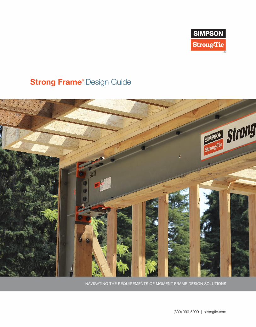
Company Profile
Maple Ridge, BC
Kent, WA
Stockton, CAPleasanton, CA
Eagan, MN
Columbus, OH
Kansas City, KS
Gallatin, TN
Jacksonville, FL
High Point, NC
Jessup, MD
Enfield, CT
Riverside, CA
Chandler, AZ
McKinney, TX
Houston, TX
Canada Northwest Northeast Southwest Southeast
Brampton, ON
W. Chicago, IL
For more than 60 years, Simpson Strong-Tie has focused on creating structural products that help people build safer and stronger homes and buildings. A leader in structural systems research and technology, Simpson Strong-Tie is one of the largest suppliers of structural building products in the world. The Simpson Strong-Tie commitment to product development, engineering, testing and training is evident in the consistent quality and delivery of its products and services.
For more information, visit the company’s website at strongtie.com.
The Simpson Strong-Tie Company Inc. No-Equal® pledge includes:
• Quality products value-engineered for the lowest installed cost at the highest-rated performance levels
• The most thoroughly tested and evaluated products in the industry
• Strategically located manufacturing and warehouse facilities
• National code agency listings
• The largest number of patented connectors in the industry
• Global locations with an international sales team
• In-house R&D and tool and die professionals
• In-house product testing and quality control engineers
• Support of industry groups including AISI, AITC, ASTM, ASCE, AWC, AWPA, ACI, AISC, CSI, CFSEI, ICFA, NBMDA, NLBMDA, SDI, SETMA, SFA, SFIA, STAFDA, SREA, NFBA, TPI, WDSC, WIJMA, WTCA and local engineering groups
Getting Fast Technical SupportWhen you call for engineering technical support, we can help you quickly if you have the following information at hand.
• Which Simpson Strong-Tie literature piece are you using? (See the back cover for the form number.)
• Which Simpson Strong-Tie product or system are you inquiring about?
• What is your load requirement?
The Simpson Strong -Tie Quality PolicyWe help people build safer structures economically. We do this by designing, engineering and manufacturing No-Equal® structural connectors and other related products that meet or exceed our customers’ needs and expectations. Everyone is responsible for product quality and is committed to ensuring the effectiveness of the Quality Management System.
Karen ColoniasChief Executive Officer
We Are ISO 9001:2015 Registered
Simpson Strong-Tie is an ISO 9001:2015 registered company. ISO 9001:2015 is an internationally-recognized quality assurance system that lets our domestic and international customers know they can count on the consistent quality of Simpson Strong-Tie® products and services.
We Are an AISC-Certified FabricatorThe Simpson Strong-Tie Riverside location is an AISC-certified facility. AISC Certification Programs set the quality standard for the structural steel industry and are the most recognized national quality certification program for the industry. The program(s) focus on the entire process of fabrication and erection. Our goal is to build quality structures from the start by focusing on error prevention rather than error correction.
AMER
ICAN
IN
STITUTE OF STEEL CONSTRUCTION
FOUNDED 1921
F-L-SFDG20 © 2020 Simpson Strong-Tie Company Inc. (800) 999-5099 | strongtie.com Strong Frame® Design Guide | 5
Table of Contents
How to Use the Design Guide . . . . . . . . . . . . . . . . . . . . . . . . . 6
Important Information and General Notes . . . . . . . . . . . . . . . . 8
Features and Benefits of Simpson Strong-Tie® Strong Frame® Special Moment Frames Using the Yield-Link® Moment Connection Compared to Other Moment Frame Connections 12
Steel Moment Frame Design OverviewDifferent Types of Moment Frames . . . . . . . . . . . . . . . . . . . . 15
ASCE Design Requirements for Moment Frames, R-Value for Horizontal Combinations, R-Value for Vertical Combinations, and the Exceptions . . . . . . . . . . . . . . . . . . . . 16
History of Special Moment Frame Development . . . . . . . . . . 17
Introduction to Simpson Strong-Tie® Strong Frame® Special Moment Frames . . . . . . . . . . . . . . . . . . . . . . . . . . . . 18
Design Requirements and Considerations . . . . . . . . . . . . . . . 20
A1. Frame Geometry and Space Restrictions . . . . . . . . . . 21A2. Member Geometries . . . . . . . . . . . . . . . . . . . . . . . . . . 22A3. Connection Modeling . . . . . . . . . . . . . . . . . . . . . . . . . 22A4. Base Fixity Modeling . . . . . . . . . . . . . . . . . . . . . . . . . . 23A5. Load Combinations . . . . . . . . . . . . . . . . . . . . . . . . . . . 23
Strong Frame® Special Moment FramesDesign Requirements and Considerations . . . . . . . . . . . . . . . 25
Moment Frame Design Requirements and Assumptions . . . . 26
D1. Drift Check . . . . . . . . . . . . . . . . . . . . . . . . . . . . . . . . . 26D2. Panel Zone Check . . . . . . . . . . . . . . . . . . . . . . . . . . . . 28D3. Strong Column/Weak Beam Check . . . . . . . . . . . . . . 29D4a. Beam Bracing . . . . . . . . . . . . . . . . . . . . . . . . . . . . . . 30D4b. Protected Zones . . . . . . . . . . . . . . . . . . . . . . . . . . . . 33D4c. Connection Design . . . . . . . . . . . . . . . . . . . . . . . . . . 35D5. Member Design . . . . . . . . . . . . . . . . . . . . . . . . . . . . . . 37D6. Nailer to Steel Beam Connection Design . . . . . . . . . . . 38D7. Base Fixity Design . . . . . . . . . . . . . . . . . . . . . . . . . . . . 40D8. Anchorage Design . . . . . . . . . . . . . . . . . . . . . . . . . . . . 41
Simpson Strong-Tie® Strong Frames Special Moment Frame Product and Service Offering . . . . . . . . . . . . . . . . . . . . . . . . . 45
1. SMF Beam Sections . . . . . . . . . . . . . . . . . . . . . . . . . . . 452. SMF Column Sections . . . . . . . . . . . . . . . . . . . . . . . . . . 462. Yield-Link Structural Fuse . . . . . . . . . . . . . . . . . . . . . . . 473. Strong Frames . . . . . . . . . . . . . . . . . . . . . . . . . . . . . . . . 48
Design-Built Strong Frame Design Options . . . . . . . . . . . . . . 50
Fixed-Column Base Design Option . . . . . . . . . . . . . . . . . . 50Spliced-Column Design Option . . . . . . . . . . . . . . . . . . . . . 50
Strong Frame® SpecificationWhy It’s Best to Specify a Strong Frame Moment Frame at the Beginning of the Design Process . . . . . . . . . . . 52
From Specification to Ordering . . . . . . . . . . . . . . . . . . . . . . . . 52
Submittal Process . . . . . . . . . . . . . . . . . . . . . . . . . . . . . . . . . 52
Methods of Specifying . . . . . . . . . . . . . . . . . . . . . . . . . . . . . . 53
Method 1: Use Our Moment Frame Selector Software to Select a Frame . . . . . . . . . . . . . . . . 53Method 2: Contact Simpson Strong-Tie. . . . . . . . . . . . . . . 54Method 3: Calculate the Design Yourself . . . . . . . . . . . . . . 54Design Information Required . . . . . . . . . . . . . . . . . . . . . . . 55
AnchorageIntroduction to Moment Frame Anchorage . . . . . . . . . . . . . . 58
MFSL Anchorage Assembly . . . . . . . . . . . . . . . . . . . . . . . . . . 59
Moment Frame Anchorage Installation Accessories . . . . . . . . 62
Strong Frame® Connections1. Connection to Column Flange/Web . . . . . . . . . . . . . . . . 642. Connection to Beam Flange/Web . . . . . . . . . . . . . . . . . 653. Anchor Bolt to Beam or Column . . . . . . . . . . . . . . . . . . 65
Top-Flange Joist Hangers — I-Joist and Structural Composite Lumber Hangers . . . . . . . . . . . . . . . . . 66
HSLQ Heavy Shear Transfer Angle . . . . . . . . . . . . . . . . . . . . . 67
HU / HUC Welded onto Steel Members . . . . . . . . . . . . . . . . . 68
Installer OverviewStrong Frame® Solutions vs. Site-Built Frames . . . . . . . . . . . . 70
Strong Frame Ordering Process . . . . . . . . . . . . . . . . . . . . . . 71
Strong Frame® Ordering Options . . . . . . . . . . . . . . . . . . . . . . 71
Dimension Verification Process . . . . . . . . . . . . . . . . . . . . . . . 72
MFSL Anchorage Installation . . . . . . . . . . . . . . . . . . . . . . . . . 74
Anchorage Extension Kit Installation . . . . . . . . . . . . . . . . . . . 76
Column with Standard Base Plate Installation Sequence . . . . . . . . . . . . . . . . . . . . . . . . . . . . . . . 77
Embedded Fixed-Base Column Installation . . . . . . . . . . . . . . 78
Strong Frame Installation . . . . . . . . . . . . . . . . . . . . . . . . . . . . 79
Additional ResourcesStrong Frame Moment Frame Selector Software . . . . . . . . . . 82
Dedicated Soft-Story Retrofit . . . . . . . . . . . . . . . . . . . . . . . . 83
Weak Story Tool with Simpson Strong-Tie® Strong Frame® Moment Frames . . . . . . . . . . . . . . . . . . . . . . . 84
Strong Frame® Moment Frames Worksheets . . . . . . . . . . . . 85
Strong Frame® Moment Frames Installation Sheets and Details . . . . . . . . . . . . . . . . . . . . . . . . . . . . . . . . 85
Strong Frame® Moment Frames MasterFormat® Specifications and Revit Files . . . . . . . . . . . . . . . . . . . . . . . . . 86
Seismic Performance Prediction Program . . . . . . . . . . . . . . . 87
Strong Frame® Moment Frames Videos . . . . . . . . . . . . . . . . . 88
Strong Frame Moment Frames Additional Literature . . . . . . . 88
How to Use the Design Guide
6 | Strong Frame® Design Guide (800) 999-5099 | strongtie.com F-L-SFDG20 © 2020 Simpson Strong-Tie Company Inc.
The Simpson Strong-Tie® Strong Frame® Design Guide is intended to help designers and specifiers understand the Strong Frame design process, the important considerations and the services that Simpson Strong-Tie provides. It also provides installers with an overview of the ordering process. The Design Guide comprises seven main sections.
1
Steel Moment Frame Design Overview — a brief overview of steel moment frame design requirements.
2
Strong Frame Special Moment Frame — offerings, design requirements and options.
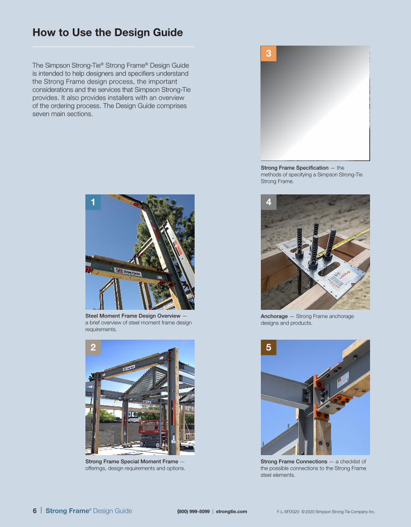
Strong Frame Specification — the methods of specifying a Simpson Strong-Tie Strong Frame.
4
Anchorage — Strong Frame anchorage designs and products.
5
Strong Frame Connections — a checklist of the possible connections to the Strong Frame steel elements.
3
F-L-SFDG20 © 2020 Simpson Strong-Tie Company Inc. (800) 999-5099 | strongtie.com Strong Frame® Design Guide | 7
Additional Resources — a vast array of resources to assist designers and contractors with specifying and installing Strong Frame moment frames in projects.
7
F-L-SFDG20 © 2020 Simpson Strong-Tie Company Inc. (800) 999-5099 | strongtie.com
Steel Moment Frame Design Overview
Strong Frame® Special Moment Frames
Section Selection KeyThis guide is divided into seven sections, identified by tabs along each page’s outer edge.
14–23
Installer Overview 69–80
24–50
51–56
57–62
Strong Frame® Specification
Anchorage
63–68Strong Frame® Connections
81–88Additional Resources
6
Installer Overview — frame opening measurement; installed costs; ordering and lead time; special inspections; and what is included with a Strong Frame order.
8 | Strong Frame® Design Guide (800) 999-5099 | strongtie.com F-L-SFDG20 © 2020 Simpson Strong-Tie Company Inc.
Important Information and General Notes
The following warnings, notes, instructions and product information apply to the specific products listed in this design guide, calculations and drawings supplied by Simpson Strong-Tie. If you use any other Simpson Strong-Tie Company Inc. products, read the warnings, notes, instructions and product information in the applicable catalog and consult strongtie.com for the latest catalogs, bulletins and product information.
Strong Frame® Moment Connection is prequalified for use in special moment frame (SMF) and intermediate moment frame (IMF) systems according to AISC 358-16 provisions. To obtain optimal performance from Simpson Strong-Tie Strong Frame Moment Connection and achieve maximum allowable design load, the connection components must be properly installed and used in accordance with the installation instructions and Design limits provided by Simpson Strong-Tie Company Inc. To ensure proper installation and use, designers and installers must carefully read the following General Notes, General Instructions for the Installer and General Instructions for the Designer, as well as consult the applicable catalog pages for specific product, installation instructions and notes.
Proper product installation requires careful attention to all notes and instructions, including these basic rules:
a. Be familiar with the application and correct use of the product.
b. Install all required fasteners per installation instructions provided by Simpson Strong-Tie Company Inc.: a) use proper fastener type; b) use proper fastener quantity; c) fill all fastener holes as specified; d) ensure screws are completely driven; and e) ensure bolts are completely tightened.
In addition to following the basic rules provided above as well as all notes, warnings and instructions provided in the design guide, installers, designers, engineers and consumers should consult the Simpson Strong-Tie Company Inc. website at strongtie.com to obtain additional design and installation information, including:
• Instructional builder/contractor training kits containing an instructional video, an instructor guide and a student guide in both English and Spanish
• Information on workshops Simpson Strong-Tie conducts at various training centers throughout the country
• Product specific installation videos
• Specialty catalogs
• Code reports
• Technical fliers and bulletins
• Master format specifications
• Material safety data sheets
• Corrosion information
• Simpson Strong-Tie® Autocad® menu
• Answers to frequently asked questions and technical topics.
Failure to follow fully all of the notes and instructions provided by Simpson Strong-Tie Company Inc. may result in improper installation of products. Improperly installed products may not perform to the specifications set forth in this design guide and may reduce a structure’s ability to resist the movement, stress, and loading that occurs from gravity loads and loading from events such as earthquakes and high-velocity winds.
Simpson Strong-Tie Company Inc. does not guarantee the performance or safety of products that are modified, improperly installed or not used in accordance with the design and load limits set forth in this design guide.
Autocad is a registered trademark of Autodesk.
Warning
F-L-SFDG20 © 2020 Simpson Strong-Tie Company Inc. (800) 999-5099 | strongtie.com Strong Frame® Design Guide | 9
Important Information and General Notes
a. Simpson Strong-Tie Company Inc. reserves the right to change specifications, designs, and models without notice or liability for such changes.
b. Steel used for each Simpson Strong-Tie® product is individually selected based on the product’s steel specifications, including strength, thickness, formability, finish and weldability. Contact Simpson Strong-Tie for steel information on specific products.
c. Unless otherwise noted, dimensions are in inches, loads are in pounds.
d. 8d (0.131" x 2½"), 10d (0.148" x 3") and 16d (0.162" x 3½") specify common nails that meet the requirements of ASTM F1667.
e. Do not overload. Do not exceed catalog allowable loads, which would jeopardize the product.
f. All references to bolts or machine bolts (MBs), unless otherwise noted, are for structural quality through bolts (not lag screws or
carriage bolts) equal to or better than ASTM Standard A307, Grade A. Anchor rods for MFSL, MFAB, MF-ATR5EXT-LS and MF-ATR5EXT-LSG are ASTM F1554 Grade 36 or A36; MFSL-HS, MFAB-HS MF-ATRXEXT-HS and MF-ATRXEXT-HSG are ASTM A449; Yield-Link®-to-column connections are ASTM A325. Strong Frame® beam-to-shear tab connections are ASTM A325 bolts. Yield-Link-to-beam connections are ASTM A490 (F2280) tension-control bolts.
g. Wood shrinks and expands as it loses or gains moisture. Dimensions given to the face of wood nailers in this design guide may vary slightly due to moisture content. Capacities provided that include wood nailers are based on a moisture content of less than 19 percent at time of fastener installation, and a minimum specific gravity of 0.50. Nailers are DF #2.
h. Some model configurations may differ from those shown in this design guide. Contact Simpson Strong-Tie for details.
These general notes are provided to ensure proper installation of Simpson Strong-Tie Company Inc. products and must be followed fully.
General Notes
a. Provide temporary diagonal bracing of Strong Frame as required until frame is tied in to the floor or roof framing above.
b. All specified fasteners must be installed according to the instructions in this design guide. Incorrect fastener quantity, size, placement, type, material or finish may cause the connection to fail.
c. Fill all fastener holes as specified in the installation instructions for that product. Some preinstalled items may not use all holes.
d. Use the materials specified in the installation instructions. Substitution of or failure to use specified materials may cause the product to fail.
e. Do not add holes or otherwise modify Simpson Strong-Tie Company Inc. products except as noted in this design guide. The performance of modified products may be substantially weakened. Simpson Strong-Tie will not warrant or guarantee the performance of such modified products.
f. Install products in the position specified in the design guide.
g. Do not alter installation procedures from those set forth in this design guide.
h. Install all specified fasteners before loading the frame.
i. Use proper safety equipment.
j. Nuts shall be installed such that the end of the threaded rod or bolt is at least flush with the top of the nut.
k. Local and/or regional building codes may require meeting special conditions. Building codes often require special inspection of anchors installed in concrete and masonry. For compliance with these requirements, it is necessary to contact the local and/or regional building authority. Except where mandated by code or code listed, Simpson Strong-Tie products do not require special inspection.
l. High-strength bolts in fully pretensioned Yield-Link stem-to-beam flange connections may require special inspection to verify installation pretension. For compliance with these requirements, it is necessary to contact the local and/or regional building authority. Where applicable, Direct Tension Indicating (DTI) washers or twist-off-type bolts are included in the Strong Frame installation kits to help verify installation pretension. Contact Simpson Strong-Tie for Fastener Assembly Certificates of Conformity.
m. See installation detail sheets for field modification options.
General Instructions for the InstallerThese general instructions for the installer are provided to ensure proper selection and installation of Simpson Strong-Tie Company Inc. products and must be followed carefully. These general instructions are in addition to the specific installation instructions and notes provided for each particular product, all of which should be consulted prior to and during installation of Simpson Strong-Tie Company Inc. products.
10 | Strong Frame® Design Guide (800) 999-5099 | strongtie.com F-L-SFDG20 © 2020 Simpson Strong-Tie Company Inc.
Important Information and General Notes
General Instructions for the Designer
a. Design for Strong Frame® moment frames are in accordance with the following:
• 2018, 2015, 2012 and 2009 International Building Code
• AISC Specification for Structural Steel Buildings (ANSI/AISC 360-10, 360-16)
• AISC Seismic Provisions (ANSI/AISC 341-10, 341-16)
• RCSC Specification for Structural Joints Using ASTM A325 or A490 Bolts
• Building Code Requirements for Structural Concrete (ACI 318-11, ACI 318-14)
• AISC Prequalified Connections for Special and Intermediate Steel Moment Frames for Seismic Applications (ANSI/AISC 358-16)
Moment frames are designed using Load and Resistance Factored Design (LLRFD) methodology for determining frame drift and strength limits. Allowable Stress Design (ASD) shear is determined as VASD = 0.7 x VLRFD for seismic load combinations and VASD = VLRFD/1.6 for wind load combinations.
b. Building codes have specific design requirements for use of steel moment frames. Designer shall verify structural design meets the applicable code requirements. Contact Simpson Strong-Tie for more information.
c. Strong Frame moment frames provide a key component of a structure’s lateral force resisting system only when incorporated into a continuous load-transfer path. The designer must specify the required components of the complete load transfer path including diaphragms, shear transfer, chords and collectors and foundations.
d. The term “designer” used throughout this design guide is intended to mean a licensed/certified building design professional, a licensed professional engineer or a licensed architect.
e. All connected members and related elements shall be designed by the designer.
f. All installations should be designed only in accordance with the allowable load values set forth in this design guide.
g. Local and/or regional building codes may require meeting special conditions. Building codes often require special inspection of anchors installed in concrete and masonry. For compliance with these requirements, it is necessary to contact the local and/or regional building authority. Except where mandated by code or code listed, Simpson Strong-Tie® products do not require special inspection.
h. High-strength bolts in fully pretensioned Yield-Link stem-to-beam flange connections may require special inspection to verify installation pretension. For compliance with these requirements, it is necessary to contact the local and/or regional building authority. Where applicable, Direct Tension Indicating (DTI) washers or twist-off-type bolts are included in the Strong Frame installation kits to verify installation pretension. Contact Simpson Strong-Tie for Fastener Assembly Certificates of Conformity.
i. Welding shall be in accordance with AWS D1.1 and AWS D1.8 (as applicable for seismic). Welds shall be as specified by the designer. Provide welding special inspection as required by local building department.
j. Holes in base plates are oversized holes for erection tolerance. Designer must evaluate effects of oversized holes and provide plate washer with standard-size holes welded to base plate where required.
k. Design of Strong Frame moment frames assumes a pinned condition at the base of columns. Fixed base design option available, contact Simpson Strong-Tie for more information.
These general instructions for the designer are provided to ensure proper selection and installation of Simpson Strong-Tie Company Inc. products and must be followed carefully. These general instructions are in addition to the specific design and installation instructions and notes provided for each particular product, all of which should be consulted prior to and during the design process.
F-L-SFDG20 © 2020 Simpson Strong-Tie Company Inc. (800) 999-5099 | strongtie.com Strong Frame® Design Guide | 11
Important Information and General Notes
Simpson Strong-Tie Company Inc. warrants catalog products to be free from defects in material or manufacturing. Simpson Strong-Tie Company Inc. products are further warranted for adequacy of design when used in accordance with design limits in this design guide and when properly specified, installed, and maintained. This warranty does not apply to uses not in compliance with specific applications and installations set forth in this design guide, or to modified products, or to deterioration due to environmental conditions.
Simpson Strong-Tie® connectors are designed to enable structures to resist the movement, stress, and loading that results from impact events such as earthquakes and high velocity winds. Other Simpson Strong-Tie products are designed to the load capacities and uses listed in this design guide. Properly-installed Simpson Strong-Tie products will perform in accordance with the specifications set forth in the applicable Simpson Strong-Tie catalog. Additional performance limitations for specific products may be listed on the applicable catalog pages.
Due to the particular characteristics of potential impact events, the specific design and location of the structure, the building materials
used, the quality of construction, and the condition of the soils involved, damage may nonetheless result to a structure and its contents even if the loads resulting from the impact event do not exceed Simpson Strong-Tie catalog specifications and Simpson Strong-Tie products are properly installed in accordance with applicable building codes.
All warranty obligations of Simpson Strong-Tie Company Inc. shall be limited, at the discretion of Simpson Strong-Tie Company Inc., to repair or replacement of the defective part. These remedies shall constitute Simpson Strong-Tie Company Inc.’s sole obligation and sole remedy of purchaser under this warranty. In no event will Simpson Strong-Tie Company Inc. be responsible for incidental, consequential, or special loss or damage, however caused.
This warranty is expressly in lieu of all other warranties, expressed or implied, including warranties of merchantability or fitness for a particular purpose, all such other warranties being hereby expressly excluded. This warranty may change periodically — consult our website strongtie.com for current information.
Limited Warranty
Terms and Conditions of SaleProduct UseProducts in this design guide are designed and manufactured for the specific purposes shown, and should not be used with other products not approved by a qualified designer. Modifications to products or changes in installations should only be made by a qualified designer. The performance of such modified products or altered installations is the sole responsibility of the designer. Prior to use, contractor shall protect products from the sun and water. Provide blocks to keep bundled frames out of mud and water.
IndemnityCustomers or designers modifying products or installations, shall, regardless of specific instructions to the user, indemnify, defend, and hold harmless Simpson Strong-Tie Company Inc. for any and all claimed loss or damage occasioned in whole or in part by modified products.
Modified ProductsConsult Simpson Strong-Tie Company Inc. for applications for which there is modification to the product, or for products for use in hostile environments, with excessive wood shrinkage, or with abnormal loading or erection requirements.
Modification to the product must be designed by the customer and will be fabricated by Simpson Strong-Tie in accordance with customer specifications.
Simpson Strong-Tie cannot and does not make any representations regarding the suitability of use or load-carrying capacities of modification to the product. Simpson Strong-Tie provides no warranty, express or implied, on modified products. F.O.B. Shipping Point unless otherwise specified.
12 | Strong Frame® Design Guide (800) 999-5099 | strongtie.com F-L-SFDG20 © 2020 Simpson Strong-Tie Company Inc.
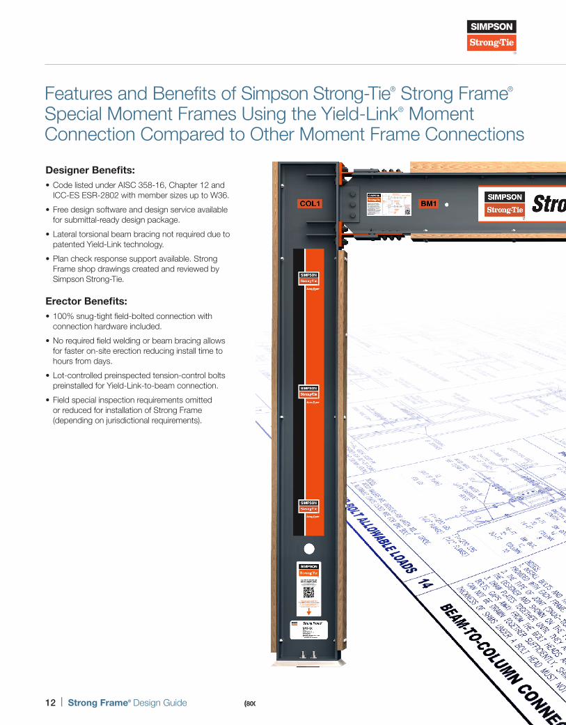
Features and Benefits of Simpson Strong-Tie® Strong Frame® Special Moment Frames Using the Yield-Link® Moment Connection Compared to Other Moment Frame Connections
Designer Benefits: • Code listed under AISC 358-16, Chapter 12 and ICC-ES ESR-2802 with member sizes up to W36.
• Free design software and design service available for submittal-ready design package.
• Lateral torsional beam bracing not required due to patented Yield-Link technology.
• Plan check response support available. Strong Frame shop drawings created and reviewed by Simpson Strong-Tie.
Erector Benefits: • 100% snug-tight field-bolted connection with connection hardware included.
• No required field welding or beam bracing allows for faster on-site erection reducing install time to hours from days.
• Lot-controlled preinspected tension-control bolts preinstalled for Yield-Link-to-beam connection.
• Field special inspection requirements omitted or reduced for installation of Strong Frame (depending on jurisdictional requirements).
F-L-SFDG20 © 2020 Simpson Strong-Tie Company Inc. (800) 999-5099 | strongtie.com Strong Frame® Design Guide | 13
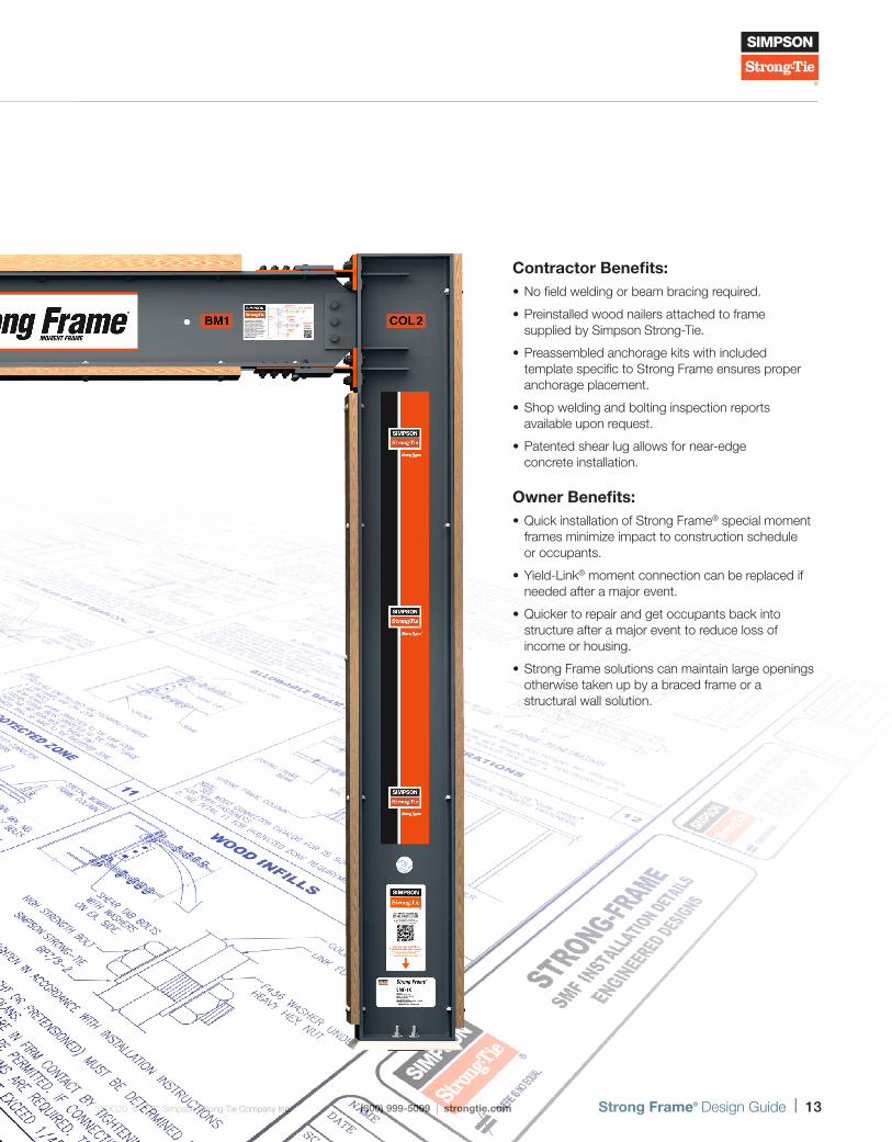
Contractor Benefits: • No field welding or beam bracing required.
• Preinstalled wood nailers attached to frame supplied by Simpson Strong-Tie.
• Preassembled anchorage kits with included template specific to Strong Frame ensures proper anchorage placement.
• Shop welding and bolting inspection reports available upon request.
• Patented shear lug allows for near-edge concrete installation.
Owner Benefits: • Quick installation of Strong Frame® special moment frames minimize impact to construction schedule or occupants.
• Yield-Link® moment connection can be replaced if needed after a major event.
• Quicker to repair and get occupants back into structure after a major event to reduce loss of income or housing.
• Strong Frame solutions can maintain large openings otherwise taken up by a braced frame or a structural wall solution.
For additional details on the uses and benefits of Strong Frame moment frames, visit strongtie.com/strongframe.
Steel Moment Frame Design Overview
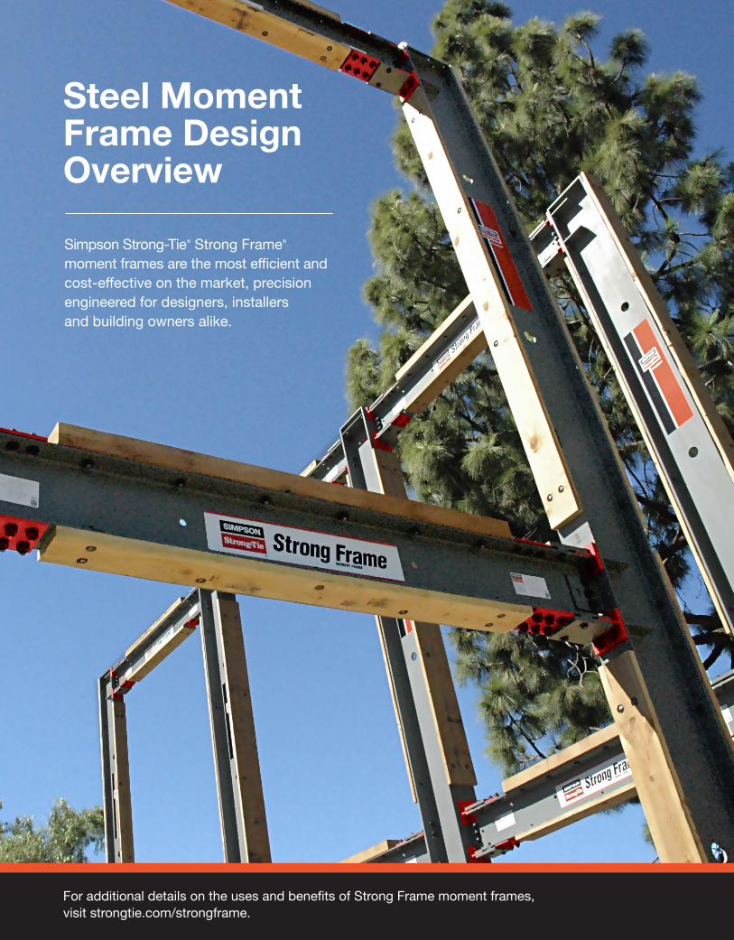
Simpson Strong-Tie® Strong Frame® moment frames are the most efficient and cost-effective on the market, precision engineered for designers, installers and building owners alike.
F-L-SFDG20 © 2020 Simpson Strong-Tie Company Inc. (800) 999-5099 | strongtie.com Strong Frame® Design Guide | 15
Steel Moment Frame Design Overview
Ste
el M
om
ent
Fram
e
Des
ign
Ove
rvie
w
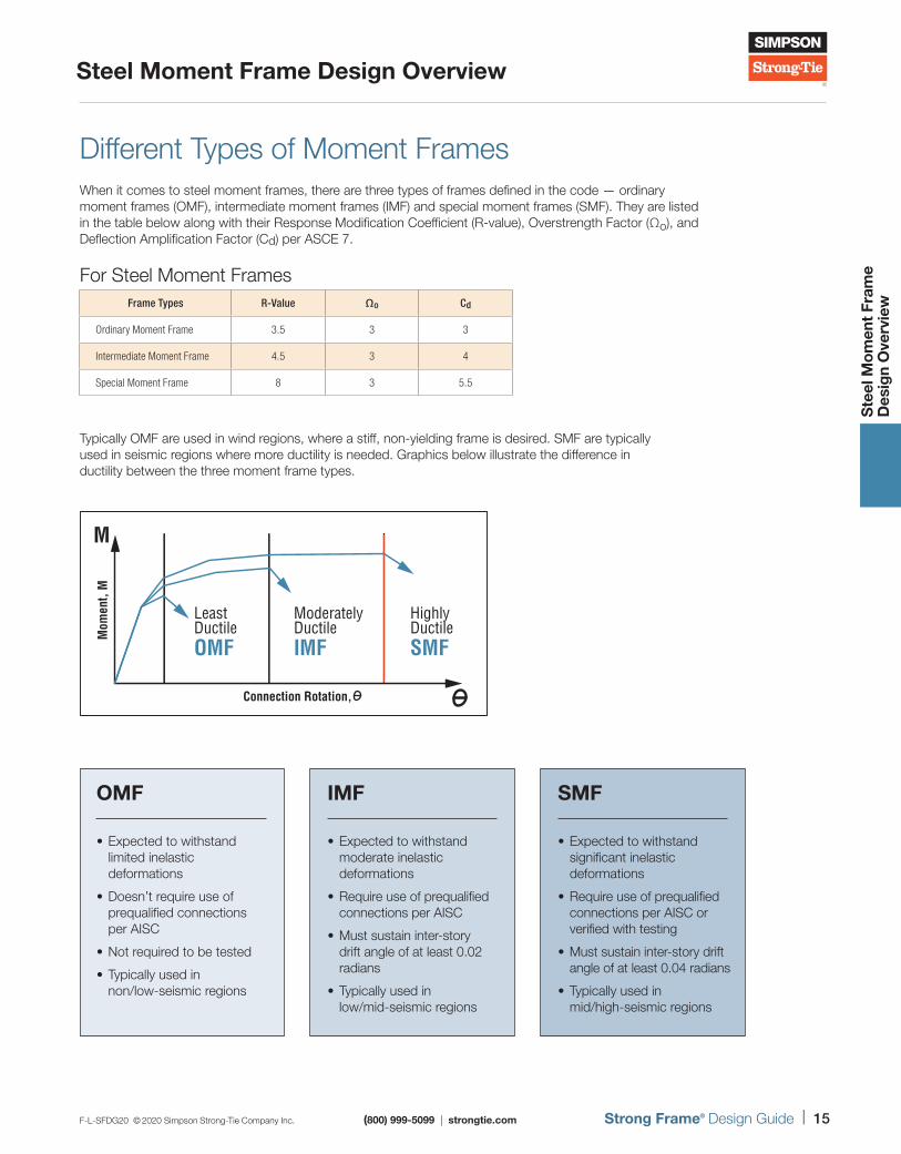
Different Types of Moment FramesWhen it comes to steel moment frames, there are three types of frames defined in the code — ordinary moment frames (OMF), intermediate moment frames (IMF) and special moment frames (SMF). They are listed in the table below along with their Response Modification Coefficient (R-value), Overstrength Factor (Ωo), and Deflection Amplification Factor (Cd) per ASCE 7.
Typically OMF are used in wind regions, where a stiff, non-yielding frame is desired. SMF are typically used in seismic regions where more ductility is needed. Graphics below illustrate the difference in ductility between the three moment frame types.
For Steel Moment FramesFrame Types R-Value Ωo Cd
Ordinary Moment Frame 3.5 3 3
Intermediate Moment Frame 4.5 3 4
Special Moment Frame 8 3 5.5
M
ModeratelyDuctile
LeastDuctile
HighlyDuctile
OMF IMF SMF
Mom
ent,
M
Connection Rotation,
OMF
• Expected to withstand limited inelastic deformations
• Doesn’t require use of prequalified connections per AISC
• Not required to be tested
• Typically used in non/low-seismic regions
IMF
• Expected to withstand moderate inelastic deformations
• Require use of prequalified connections per AISC
• Must sustain inter-story drift angle of at least 0.02 radians
• Typically used in low/mid-seismic regions
SMF
• Expected to withstand significant inelastic deformations
• Require use of prequalified connections per AISC or verified with testing
• Must sustain inter-story drift angle of at least 0.04 radians
• Typically used in mid/high-seismic regions
16 | Strong Frame® Design Guide (800) 999-5099 | strongtie.com F-L-SFDG20 © 2020 Simpson Strong-Tie Company Inc.
Steel Moment Frame Design Overview
Ste
el M
om
ent
Fram
e
Des
ign
Ove
rvie
w
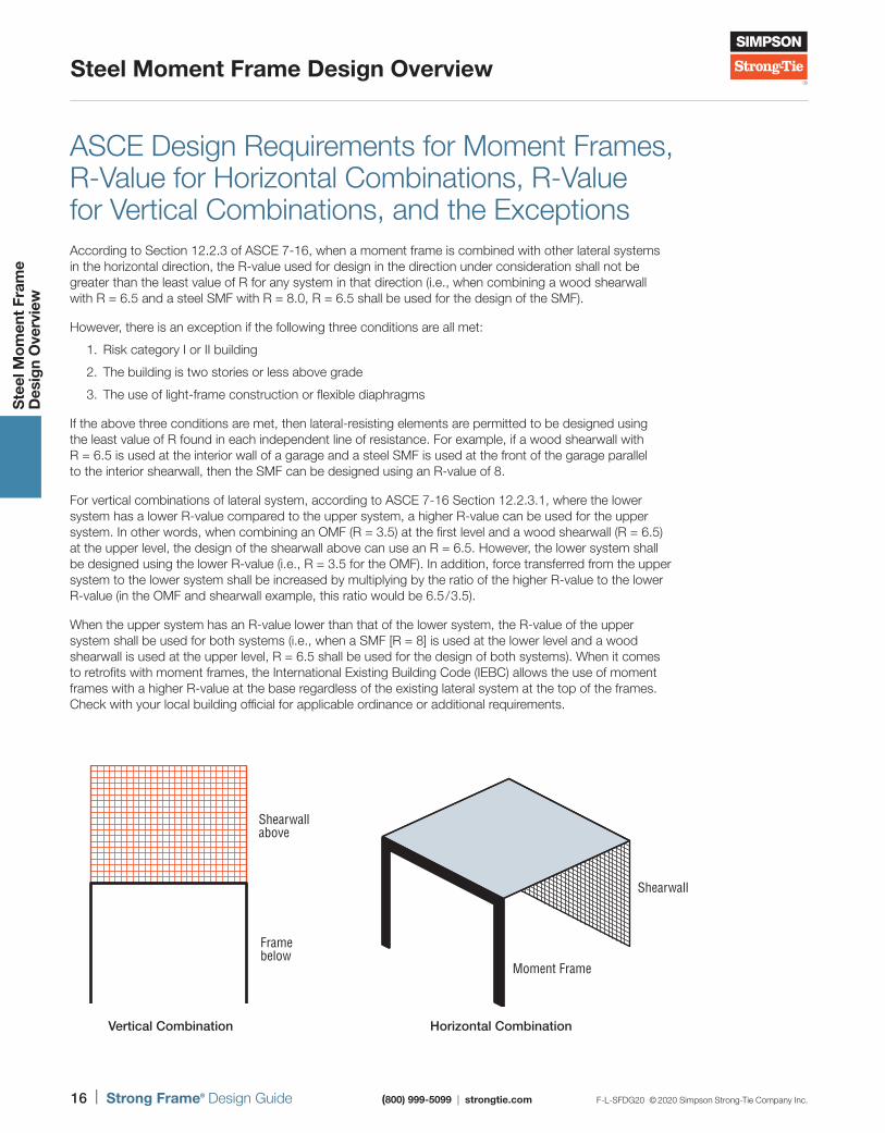
ASCE Design Requirements for Moment Frames, R-Value for Horizontal Combinations, R-Value for Vertical Combinations, and the ExceptionsAccording to Section 12.2.3 of ASCE 7-16, when a moment frame is combined with other lateral systems in the horizontal direction, the R-value used for design in the direction under consideration shall not be greater than the least value of R for any system in that direction (i.e., when combining a wood shearwall with R = 6.5 and a steel SMF with R = 8.0, R = 6.5 shall be used for the design of the SMF).
However, there is an exception if the following three conditions are all met:
1. Risk category I or II building
2. The building is two stories or less above grade
3. The use of light-frame construction or flexible diaphragms
If the above three conditions are met, then lateral-resisting elements are permitted to be designed using the least value of R found in each independent line of resistance. For example, if a wood shearwall with R = 6.5 is used at the interior wall of a garage and a steel SMF is used at the front of the garage parallel to the interior shearwall, then the SMF can be designed using an R-value of 8.
For vertical combinations of lateral system, according to ASCE 7-16 Section 12.2.3.1, where the lower system has a lower R-value compared to the upper system, a higher R-value can be used for the upper system. In other words, when combining an OMF (R = 3.5) at the first level and a wood shearwall (R = 6.5) at the upper level, the design of the shearwall above can use an R = 6.5. However, the lower system shall be designed using the lower R-value (i.e., R = 3.5 for the OMF). In addition, force transferred from the upper system to the lower system shall be increased by multiplying by the ratio of the higher R-value to the lower R-value (in the OMF and shearwall example, this ratio would be 6.5/ 3.5).
When the upper system has an R-value lower than that of the lower system, the R-value of the upper system shall be used for both systems (i.e., when a SMF [R = 8] is used at the lower level and a wood shearwall is used at the upper level, R = 6.5 shall be used for the design of both systems). When it comes to retrofits with moment frames, the International Existing Building Code (IEBC) allows the use of moment frames with a higher R-value at the base regardless of the existing lateral system at the top of the frames. Check with your local building official for applicable ordinance or additional requirements.
Framebelow
Shearwallabove
Vertical Combination
Shearwall
Moment Frame
Horizontal Combination
F-L-SFDG20 © 2020 Simpson Strong-Tie Company Inc. (800) 999-5099 | strongtie.com Strong Frame® Design Guide | 17
Steel Moment Frame Design Overview
Ste
el M
om
ent
Fram
e
Des
ign
Ove
rvie
w
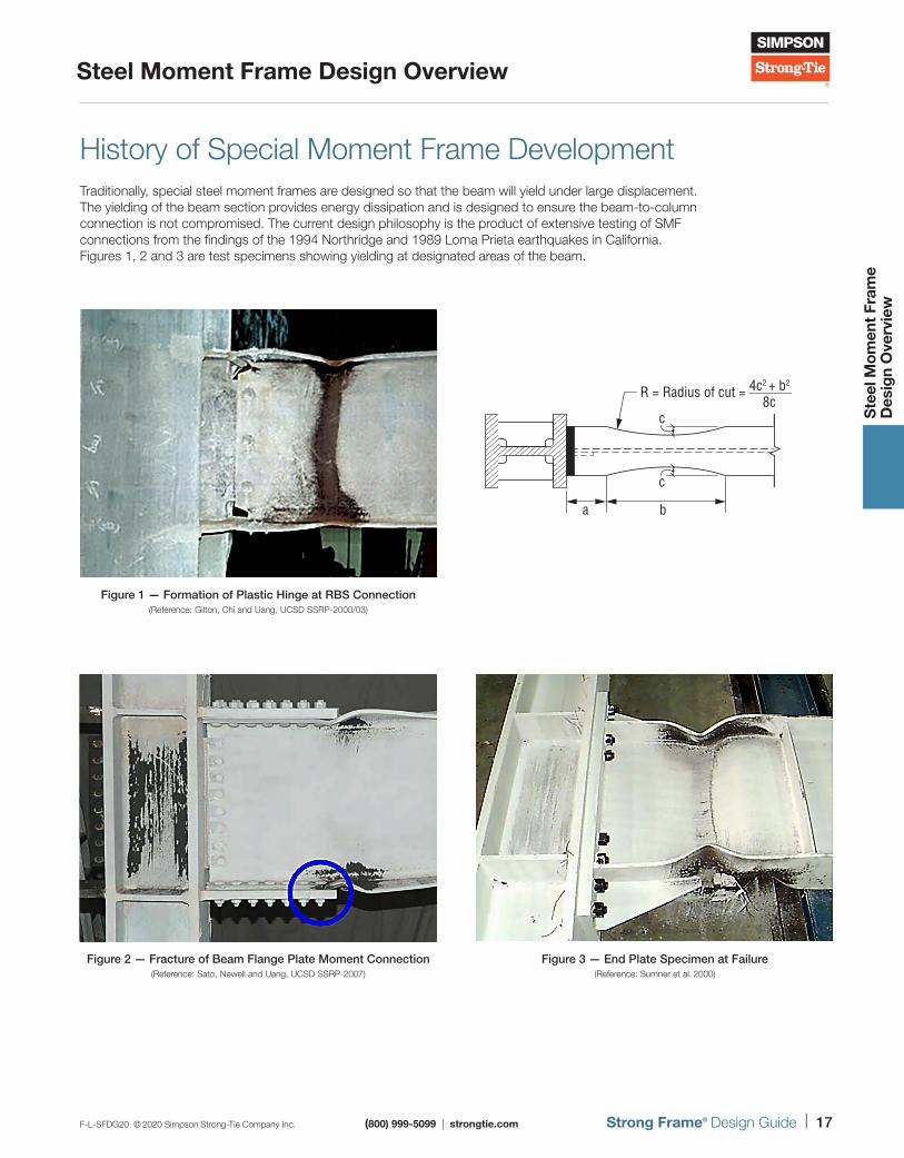
History of Special Moment Frame Development Traditionally, special steel moment frames are designed so that the beam will yield under large displacement. The yielding of the beam section provides energy dissipation and is designed to ensure the beam-to-column connection is not compromised. The current design philosophy is the product of extensive testing of SMF connections from the findings of the 1994 Northridge and 1989 Loma Prieta earthquakes in California. Figures 1, 2 and 3 are test specimens showing yielding at designated areas of the beam.
Figure 1 — Formation of Plastic Hinge at RBS Connection(Reference: Gilton, Chi and Uang, UCSD SSRP-2000/03)
c
ba
cR = Radius of cut = 4c2 + b2
8c
Figure 2 — Fracture of Beam Flange Plate Moment Connection(Reference: Sato, Newell and Uang, UCSD SSRP-2007)
Figure 3 — End Plate Specimen at Failure(Reference: Sumner et al. 2000)
18 | Strong Frame® Design Guide (800) 999-5099 | strongtie.com F-L-SFDG20 © 2020 Simpson Strong-Tie Company Inc.
Steel Moment Frame Design Overview
Ste
el M
om
ent
Fram
e
Des
ign
Ove
rvie
w
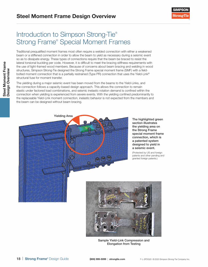
Introduction to Simpson Strong-Tie® Strong Frame® Special Moment Frames Traditional prequalified moment frames most often require a welded connection with either a weakened beam or a stiffened connection in order to allow the beam to yield as necessary during a seismic event so as to dissipate energy. These types of connections require that the beam be braced to resist the lateral torsional buckling per code. However, it is difficult to meet the bracing stiffness requirements with the use of light-framed wood members. Because of concerns about beam bracing and welding in wood structures, Simpson Strong-Tie designed the Strong Frame special moment frame (SMF) with a field-bolted moment connection that is a partially restrained (Type PR) connection that uses the Yield-Link® structural fuse for moment transfer.
The yielding during a major seismic event has been moved from the beams to the Yield-Links, and the connection follows a capacity-based design approach. This allows the connection to remain elastic under factored load combinations, and seismic inelastic rotation demand is confined within the connection when yielding is experienced from severe events. With the yielding confined predominantly to the replaceable Yield-Link moment connection, inelastic behavior is not expected from the members and the beam can be designed without beam bracing.
PEEQEnvelope (max abs)(AVG: 75%)
+7.389e-02+6.773e-02+6.158e-02+5.542e-02+4.926e-02+4.310e-02+3.695e-02+3.079e-02+2.463e-02+1.847e-02+1.232e-02+6.158e-03+0.000e+00
The highlighted green section illustrates the yielding area on the Strong Frame special moment frame connection, which is a patented system designed to yield in a seismic event. (Protected by US and foreign patents and other pending and granted foreign patents.)
Yielding Area
Sample Yield-Link Compression and Elongation from Testing
F-L-SFDG20 © 2020 Simpson Strong-Tie Company Inc. (800) 999-5099 | strongtie.com Strong Frame® Design Guide | 19
Steel Moment Frame Design Overview
Ste
el M
om
ent
Fram
e
Des
ign
Ove
rvie
w
Special Moment Frame ApplicationsThere are several benefits to using the Simpson Strong-Tie® Yield-Link® moment connection for new and retrofit projects. In new construction, the frame can be incorporated into the early stages of design. Simpson Strong-Tie can provide design options for the customer without charge. The field-bolted connections allow for quicker frame erection and installation. In retrofit designs, the bolted connection means the frame can be erected in the interior conditions of light-frame construction without the risk of fire. The beam and columns can be erected in parts, making the SMF much easier to handle than a fully welded frame.
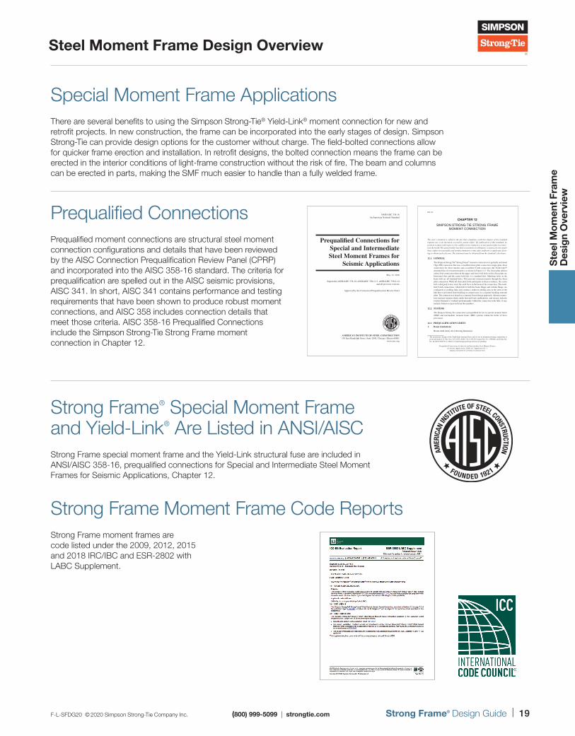
Prequalified ConnectionsPrequalified moment connections are structural steel moment connection configurations and details that have been reviewed by the AISC Connection Prequalification Review Panel (CPRP) and incorporated into the AISC 358-16 standard. The criteria for prequalification are spelled out in the AISC seismic provisions, AISC 341. In short, AISC 341 contains performance and testing requirements that have been shown to produce robust moment connections, and AISC 358 includes connection details that meet those criteria. AISC 358-16 Prequalified Connections include the Simpson Strong-Tie Strong Frame moment connection in Chapter 12.
ANSI/AISC 358-16 An American National Standard
Prequalified Connections for Special and Intermediate Steel Moment Frames for
Seismic Applications
May 12, 2016
Supersedes ANSI/AISC 358-10, ANSI/AISC 358s1-11, ANSI/AISC 358s2-14and all previous versions
Approved by the Connection Prequalification Review Panel
AMERICAN INSTITUTE OF STEEL CONSTRUCTION130 East Randolph Street, Suite 2000, Chicago, Illinois 60601
www.aisc.org
Covers_A358-16.indd 1 10/24/16 9:10 PM
9.2-112
Prequalified Connections for Special and Intermediate Steel Moment Frames for Seismic Applications, 2016, incl. Supplement No. 1
American Institute of Steel Construction
CHAPTER 12
SIMPSON STRONG-TIE STRONG FRAME MOMENT CONNECTION
The user’s attention is called to the fact that compliance with this chapter of the standard requires use of an invention covered by patent rights.* By publication of this standard, no position is taken with respect to the validity of any claim(s) or of any patent rights in connec-tion therewith. The patent holder has filed a statement of willingness to grant a license under these rights on reasonable and nondiscriminatory terms and conditions to applicants desir-ing to obtain such a license. The statement may be obtained from the standard’s developer.
12.1. GENERAL
The Simpson Strong-Tie® Strong Frame® moment connection is a partially restrained (Type PR) connection that uses a modified shear plate connection (single-plate shear connection) for shear transfer and a modified T-stub connection (the yield-link™ structural fuse) for moment transfer, as shown in Figure 12.1. The shear plate utilizes a three-bolt connection wherein the upper and lower bolt holes in the shear plate are horizontal slots and the center bolt hole is a standard hole. Matching holes in the beam web are all standard holes. This prevents moment transfer through the shear plate connection. While all shear plate bolts participate in shear resistance, the center bolt is designed to also resist the axial force in the beam at the connection. The modi-fied T-stub connections, which bolt to both the beam flange and column flange, are configured as yielding links and contain a reduced yielding area in the stem of the link that is prevented from buckling in compression via a separate buckling restraint plate. The connection is based on a capacity-based design approach, wherein connec-tion response remains elastic under factored load combinations, and seismic inelastic rotation demand is confined predominantly within the connection with little, if any, inelastic behavior expected from the members.
12.2. SYSTEMS
The Simpson Strong-Tie connection is prequalified for use in special moment frame (SMF) and intermediate moment frame (IMF) systems within the limits of these provisions.
12.3. PREQUALIFICATION LIMITS
1. Beam Limitations
Beams shall satisfy the following limitations:
* The proprietary design of the yield-link structural fuse and its use in moment-resisting connections is protected under U.S. Pat. Nos. 8,375,652; 8,001,734; 8,763,310; Japan Pat. No. 5398980; and China Pat. No. Zl200710301531.4. Other U.S and foreign patent protection are pending.
Strong Frame® Special Moment Frame and Yield-Link® Are Listed in ANSI/AISCStrong Frame special moment frame and the Yield-Link structural fuse are included in ANSI/AISC 358-16, prequalified connections for Special and Intermediate Steel Moment Frames for Seismic Applications, Chapter 12.
Strong Frame Moment Frame Code ReportsStrong Frame moment frames are code listed under the 2009, 2012, 2015 and 2018 IRC/IBC and ESR-2802 with LABC Supplement.
20 | Strong Frame® Design Guide (800) 999-5099 | strongtie.com F-L-SFDG20 © 2020 Simpson Strong-Tie Company Inc.
Steel Moment Frame Design Overview
Ste
el M
om
ent
Fram
e
Des
ign
Ove
rvie
w
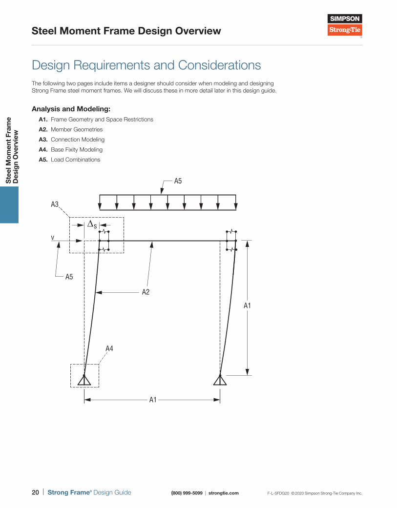
Design Requirements and Considerations The following two pages include items a designer should consider when modeling and designing Strong Frame steel moment frames. We will discuss these in more detail later in this design guide.
Analysis and Modeling: A1. Frame Geometry and Space Restrictions
A2. Member Geometries
A3. Connection Modeling
A4. Base Fixity Modeling
A5. Load Combinations
A1
A4
A5
v
A3
∆s
A5
A1
A2
F-L-SFDG20 © 2020 Simpson Strong-Tie Company Inc. (800) 999-5099 | strongtie.com Strong Frame® Design Guide | 21
Steel Moment Frame Design Overview
Ste
el M
om
ent
Fram
e
Des
ign
Ove
rvie
w
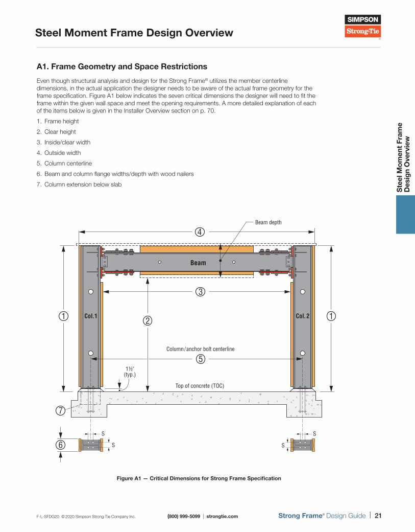
A1. Frame Geometry and Space Restrictions
Even though structural analysis and design for the Strong Frame® utilizes the member centerline dimensions, in the actual application the designer needs to be aware of the actual frame geometry for the frame specification. Figure A1 below indicates the seven critical dimensions the designer will need to fit the frame within the given wall space and meet the opening requirements. A more detailed explanation of each of the items below is given in the Installer Overview section on p. 70.
1. Frame height
2. Clear height
3. Inside/clear width
4. Outside width
5. Column centerline
6. Beam and column flange widths/depth with wood nailers
7. Column extension below slab
Col.1
Beam
Beam depth
Col.2
1½"(typ.)
Column/anchor bolt centerline
Top of concrete (TOC)
S
S
S
S
4
3
5
11
6
7
2
Figure A1 — Critical Dimensions for Strong Frame Specification
22 | Strong Frame® Design Guide (800) 999-5099 | strongtie.com F-L-SFDG20 © 2020 Simpson Strong-Tie Company Inc.
Steel Moment Frame Design Overview
Ste
el M
om
ent
Fram
e
Des
ign
Ove
rvie
w
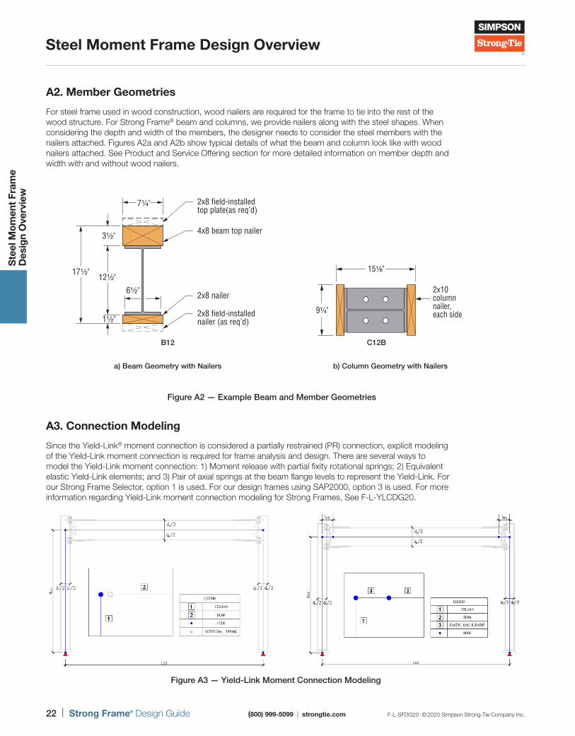
A2. Member Geometries
For steel frame used in wood construction, wood nailers are required for the frame to tie into the rest of the wood structure. For Strong Frame® beam and columns, we provide nailers along with the steel shapes. When considering the depth and width of the members, the designer needs to consider the steel members with the nailers attached. Figures A2a and A2b show typical details of what the beam and column look like with wood nailers attached. See Product and Service Offering section for more detailed information on member depth and width with and without wood nailers.
A3. Connection Modeling
Since the Yield-Link® moment connection is considered a partially restrained (PR) connection, explicit modeling of the Yield-Link moment connection is required for frame analysis and design. There are several ways to model the Yield-Link moment connection: 1) Moment release with partial fixity rotational springs; 2) Equivalent elastic Yield-Link elements; and 3) Pair of axial springs at the beam flange levels to represent the Yield-Link. For our Strong Frame Selector, option 1 is used. For our design frames using SAP2000, option 3 is used. For more information regarding Yield-Link moment connection modeling for Strong Frames, See F-L-YLCDG20.
Figure A2 — Example Beam and Member Geometries
Figure A3 — Yield-Link Moment Connection Modeling
B12
6½"
4x8 beam top nailer
2x8 field-installedtop plate(as req’d)
2x8 nailer
2x8 field-installednailer (as req’d)
17½"
3½"
12½"
1½"
7¼"
b) Column Geometry with Nailersa) Beam Geometry with Nailers
C12B
2x10columnnailer, each side9¼"
15⅛"
F-L-SFDG20 © 2020 Simpson Strong-Tie Company Inc. (800) 999-5099 | strongtie.com Strong Frame® Design Guide | 23
Steel Moment Frame Design Overview
Ste
el M
om
ent
Fram
e
Des
ign
Ove
rvie
w
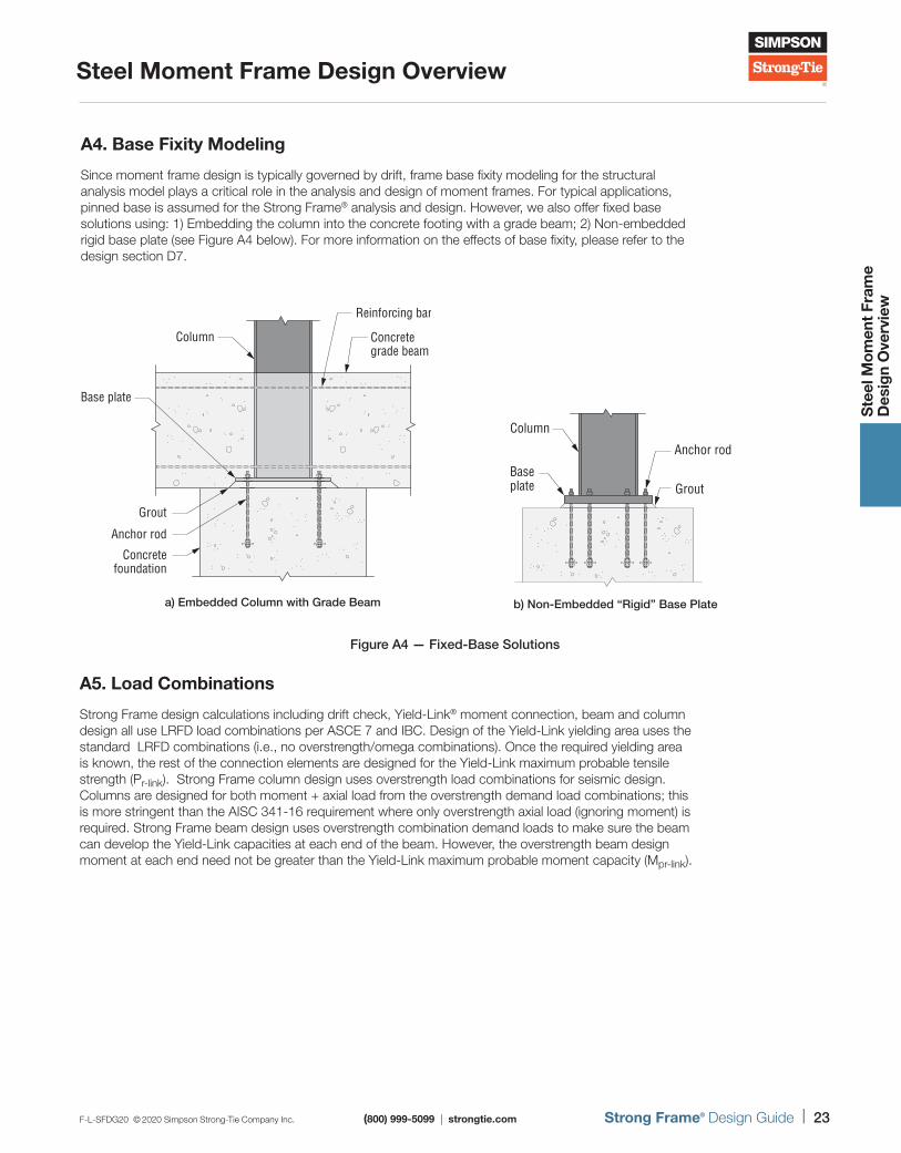
A4. Base Fixity Modeling
Since moment frame design is typically governed by drift, frame base fixity modeling for the structural analysis model plays a critical role in the analysis and design of moment frames. For typical applications, pinned base is assumed for the Strong Frame® analysis and design. However, we also offer fixed base solutions using: 1) Embedding the column into the concrete footing with a grade beam; 2) Non-embedded rigid base plate (see Figure A4 below). For more information on the effects of base fixity, please refer to the design section D7.
A5. Load Combinations
Strong Frame design calculations including drift check, Yield-Link® moment connection, beam and column design all use LRFD load combinations per ASCE 7 and IBC. Design of the Yield-Link yielding area uses the standard LRFD combinations (i.e., no overstrength/omega combinations). Once the required yielding area is known, the rest of the connection elements are designed for the Yield-Link maximum probable tensile strength (Pr-link). Strong Frame column design uses overstrength load combinations for seismic design. Columns are designed for both moment + axial load from the overstrength demand load combinations; this is more stringent than the AISC 341-16 requirement where only overstrength axial load (ignoring moment) is required. Strong Frame beam design uses overstrength combination demand loads to make sure the beam can develop the Yield-Link capacities at each end of the beam. However, the overstrength beam design moment at each end need not be greater than the Yield-Link maximum probable moment capacity (Mpr-link).
Figure A4 — Fixed-Base Solutions
Reinforcing bar
Concretegrade beam
Column
Base plate
Grout
Anchor rod
Concretefoundation
Column
Baseplate Grout
Anchor rod
a) Embedded Column with Grade Beam b) Non-Embedded “Rigid” Base Plate
Strong Frame® Special Moment Frames
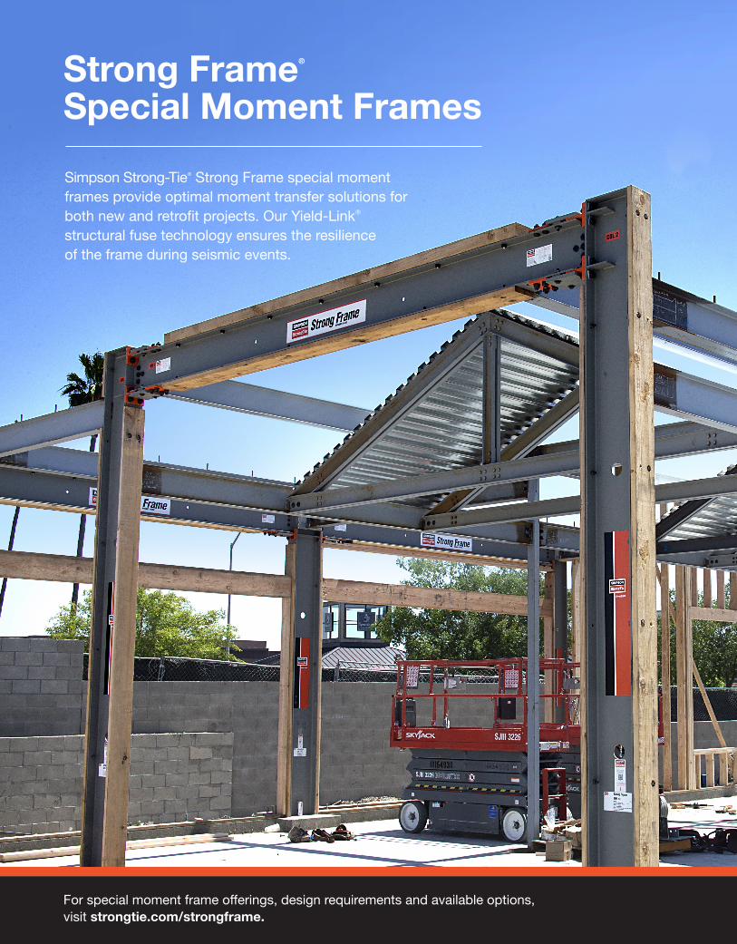
Simpson Strong-Tie® Strong Frame special moment frames provide optimal moment transfer solutions for both new and retrofit projects. Our Yield-Link® structural fuse technology ensures the resilience of the frame during seismic events.
For special moment frame offerings, design requirements and available options, visit strongtie.com/strongframe.
F-L-SFDG20 © 2020 Simpson Strong-Tie Company Inc. (800) 999-5099 | strongtie.com Strong Frame® Design Guide | 25
Strong Frame® Special Moment Frames
Str
ong
Fra
me
S
pec
ial M
om
ent
Fram
es
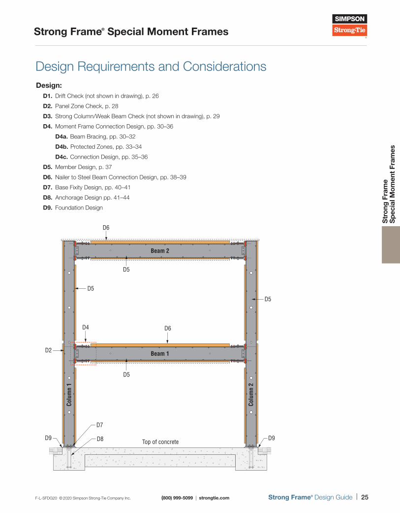
Design Requirements and ConsiderationsDesign: D1. Drift Check (not shown in drawing), p. 26
D2. Panel Zone Check, p. 28
D3. Strong Column/Weak Beam Check (not shown in drawing), p. 29
D4. Moment Frame Connection Design, pp. 30–36
D4a. Beam Bracing, pp. 30–32
D4b. Protected Zones, pp. 33–34
D4c. Connection Design, pp. 35–36
D5. Member Design, p. 37
D6. Nailer to Steel Beam Connection Design, pp. 38–39
D7. Base Fixity Design, pp. 40–41
D8. Anchorage Design pp. 41–44
D9. Foundation Design
D5
Beam 1
Beam 2
D5
D4 D6
D6
D5
D2
D9D9
D7
D8
Colu
mn
1
Colu
mn
2
Top of concrete
D5
26 | Strong Frame® Design Guide (800) 999-5099 | strongtie.com F-L-SFDG20 © 2020 Simpson Strong-Tie Company Inc.
Strong Frame® Special Moment Frames
Str
ong
Fra
me
S
pec
ial M
om
ent
Fram
es
Moment Frame Design Requirements and Assumptions
D1. Drift Check
Drift Check for Seismic Loads
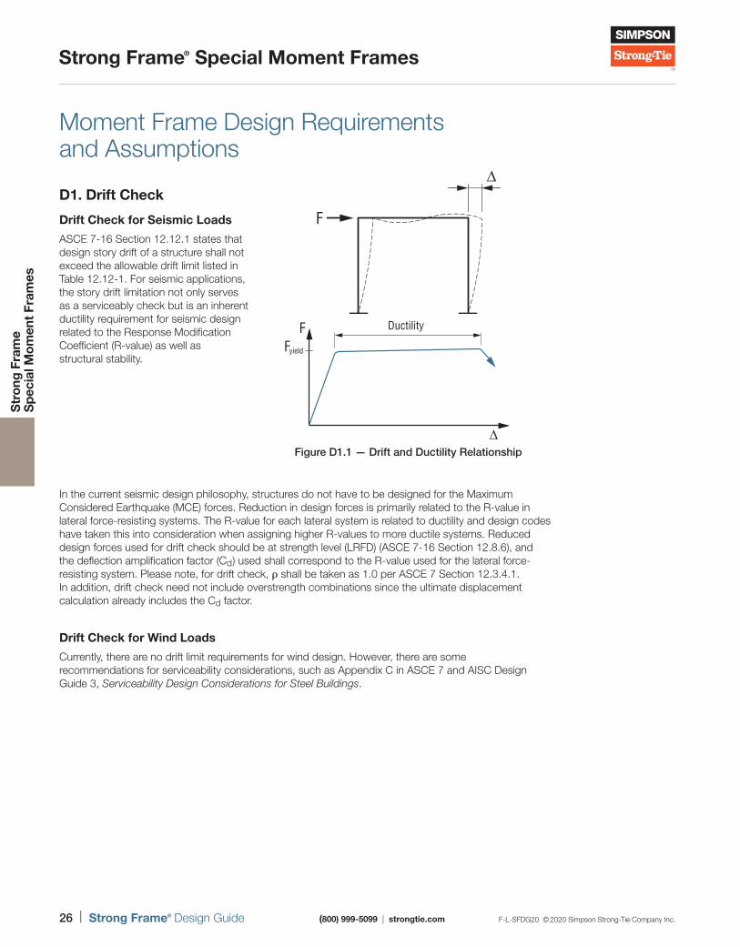
ASCE 7-16 Section 12.12.1 states that design story drift of a structure shall not exceed the allowable drift limit listed in Table 12.12-1. For seismic applications, the story drift limitation not only serves as a serviceably check but is an inherent ductility requirement for seismic design related to the Response Modification Coefficient (R-value) as well as structural stability.
In the current seismic design philosophy, structures do not have to be designed for the Maximum Considered Earthquake (MCE) forces. Reduction in design forces is primarily related to the R-value in lateral force-resisting systems. The R-value for each lateral system is related to ductility and design codes have taken this into consideration when assigning higher R-values to more ductile systems. Reduced design forces used for drift check should be at strength level (LRFD) (ASCE 7-16 Section 12.8.6), and the deflection amplification factor (Cd) used shall correspond to the R-value used for the lateral force-resisting system. Please note, for drift check, ρ shall be taken as 1.0 per ASCE 7 Section 12.3.4.1. In addition, drift check need not include overstrength combinations since the ultimate displacement calculation already includes the Cd factor.
Drift Check for Wind Loads
Currently, there are no drift limit requirements for wind design. However, there are some recommendations for serviceability considerations, such as Appendix C in ASCE 7 and AISC Design Guide 3, Serviceability Design Considerations for Steel Buildings.
F
∆
DuctilityFFyield
∆Figure D1.1 — Drift and Ductility Relationship
F-L-SFDG20 © 2020 Simpson Strong-Tie Company Inc. (800) 999-5099 | strongtie.com Strong Frame® Design Guide | 27
Strong Frame® Special Moment Frames
Str
ong
Fra
me
S
pec
ial M
om
ent
Fram
es
Moment Frame Design Requirements and Assumptions (cont.)Strong Frame® Special Moment Frame Drift Check
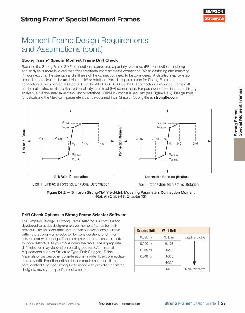
Because the Strong Frame SMF connection is considered a partially restrained (PR) connection, modeling and analysis is more involved than for a traditional moment frame connection. When designing and analyzing PR connections, the strength and stiffness of the connection need to be considered. A detailed step-by-step procedure to calculate the axial Yield-Link® or rotational Yield-Link parameters for Strong-Frame moment connection is documented in Chapter 12 of the AISC 358-16. Once the PR connection is modeled, frame drift can be calculated similar to the traditional fully restrained (FR) connections. For pushover or nonlinear time history analysis, a full nonlinear axial Yield-Link or rotational Yield-Link model is required (see Figure D1.2). Design tools for calculating the Yield-Link parameters can be obtained from Simpson Strong-Tie at strongtie.com.
Drift Check Options in Strong Frame Selector Software
The Simpson Strong-Tie Strong Frame selector is a software tool developed to assist designers to size moment frames for their projects. The adjacent table lists the various selections available within the Strong Frame selector for considerations of drift for seismic and wind design. These are provided from least restrictive to more restrictive as you move down the table. The appropriate drift selection may depend on building code and/or material requirements such as Structure Type, Risk Category, Finish Materials or various other considerations in order to accommodate the story drift. For other drift/deflection requirements not listed here, contact Simpson Strong-Tie to assist with providing a tailored design to meet your specific requirements.
Pr_link
Pr_link
Pye_link
Link Axial Deformation
Case 1: Link Axial Force vs. Link Axial Deformation
Link
Axi
al F
orce
Pye_link
∆y
–∆y–∆0.04–∆0.07
∆0.04 ∆0.07
Mpr_link
Mpr_link
Mye_link
Connection Rotation (Radians)
Case 2: Connection Moment vs. Rotation
Conn
ectio
n M
omen
t Mye_link
–Θy
Θy
–0.070.070.04
–0.04
Figure D1.2 — Simpson Strong-Tie® Yield-Link Modeling Parameters Connection Moment (Ref: AISC 358-16, Chapter 12)
Seismic Drift Wind Drift
0.025 hx No Limit Least restrictive
0.020 hx H/175
0.015 hx H/250
0.010 hx H/300
H/350
H/400 More restrictive
28 | Strong Frame® Design Guide (800) 999-5099 | strongtie.com F-L-SFDG20 © 2020 Simpson Strong-Tie Company Inc.
Strong Frame® Special Moment Frames
Str
ong
Fra
me
S
pec
ial M
om
ent
Fram
es
Moment Frame Design Requirements and Assumptions (cont.)D2. Panel Zone Check
Other than drift check, the second limit state that governs the design of a moment frame is the connection panel zone shear capacity for the column. The capacity of the panel zone depends mostly on the thickness of the column web. When design limits are exceeded, many engineers tend to increase the thickness of the column web by welding a doubler plate to increase the shear capacity. However, many fabricators are aware that increasing the column web thickness by increasing column weight approximately up to 75 plf (e.g., from a W14x74 to, say, a W14x145) can result in a less expensive frame due to the elimination of the welding cost and inspection cost of the doubler plate.
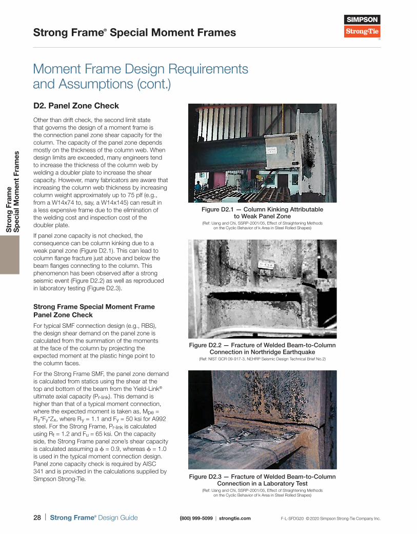
If panel zone capacity is not checked, the consequence can be column kinking due to a weak panel zone (Figure D2.1). This can lead to column flange fracture just above and below the beam flanges connecting to the column. This phenomenon has been observed after a strong seismic event (Figure D2.2) as well as reproduced in laboratory testing (Figure D2.3).
Strong Frame Special Moment Frame Panel Zone Check
For typical SMF connection design (e.g., RBS), the design shear demand on the panel zone is calculated from the summation of the moments at the face of the column by projecting the expected moment at the plastic hinge point to the column faces.
For the Strong Frame SMF, the panel zone demand is calculated from statics using the shear at the top and bottom of the beam from the Yield-Link® ultimate axial capacity (Pr-link). This demand is higher than that of a typical moment connection, where the expected moment is taken as, Mpe = Ry*Fy*Zx, where Ry = 1.1 and Fy = 50 ksi for A992 steel. For the Strong Frame, Pr-link is calculated using Rt = 1.2 and Fu = 65 ksi. On the capacity side, the Strong Frame panel zone’s shear capacity is calculated assuming a ϕ = 0.9, whereas ϕ = 1.0 is used in the typical moment connection design. Panel zone capacity check is required by AISC 341 and is provided in the calculations supplied by Simpson Strong-Tie.
Figure D2.1 — Column Kinking Attributable to Weak Panel Zone
(Ref: Uang and Chi, SSRP-2001 /05, Effect of Straightening Methods on the Cyclic Behavior of k Area in Steel Rolled Shapes)
Figure D2.2 — Fracture of Welded Beam-to-Column Connection in Northridge Earthquake
(Ref: NIST GCR 09-917-3, NEHRP Seismic Design Technical Brief No.2)
Figure D2.3 — Fracture of Welded Beam-to-Column Connection in a Laboratory Test
(Ref: Uang and Chi, SSRP-2001 /05, Effect of Straightening Methods on the Cyclic Behavior of k Area in Steel Rolled Shapes)
F-L-SFDG20 © 2020 Simpson Strong-Tie Company Inc. (800) 999-5099 | strongtie.com Strong Frame® Design Guide | 29
Strong Frame® Special Moment Frames
Str
ong
Fra
me
S
pec
ial M
om
ent
Fram
es
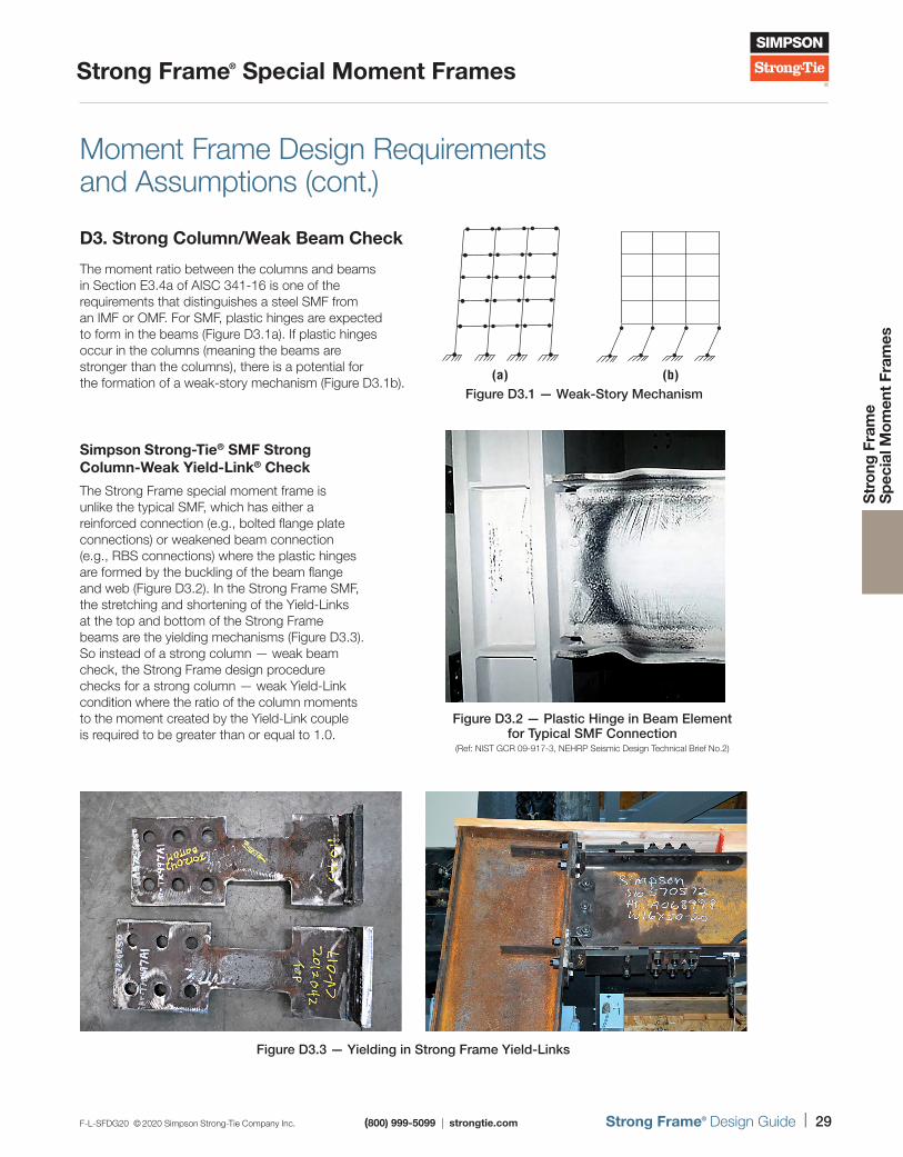
Figure D3.3 — Yielding in Strong Frame Yield-Links
Moment Frame Design Requirements and Assumptions (cont.)
D3. Strong Column/Weak Beam Check
The moment ratio between the columns and beams in Section E3.4a of AISC 341-16 is one of the requirements that distinguishes a steel SMF from an IMF or OMF. For SMF, plastic hinges are expected to form in the beams (Figure D3.1a). If plastic hinges occur in the columns (meaning the beams are stronger than the columns), there is a potential for the formation of a weak-story mechanism (Figure D3.1b).
Simpson Strong-Tie® SMF Strong Column-Weak Yield-Link® Check
The Strong Frame special moment frame is unlike the typical SMF, which has either a reinforced connection (e.g., bolted flange plate connections) or weakened beam connection (e.g., RBS connections) where the plastic hinges are formed by the buckling of the beam flange and web (Figure D3.2). In the Strong Frame SMF, the stretching and shortening of the Yield-Links at the top and bottom of the Strong Frame beams are the yielding mechanisms (Figure D3.3). So instead of a strong column — weak beam check, the Strong Frame design procedure checks for a strong column — weak Yield-Link condition where the ratio of the column moments to the moment created by the Yield-Link couple is required to be greater than or equal to 1.0.
(b)(a)Figure D3.1 — Weak-Story Mechanism
Figure D3.2 — Plastic Hinge in Beam Element for Typical SMF Connection
(Ref: NIST GCR 09-917-3, NEHRP Seismic Design Technical Brief No.2)
30 | Strong Frame® Design Guide (800) 999-5099 | strongtie.com F-L-SFDG20 © 2020 Simpson Strong-Tie Company Inc.
Strong Frame® Special Moment Frames
Str
ong
Fra
me
S
pec
ial M
om
ent
Fram
es
Moment Frame Design Requirements and Assumptions (cont.)
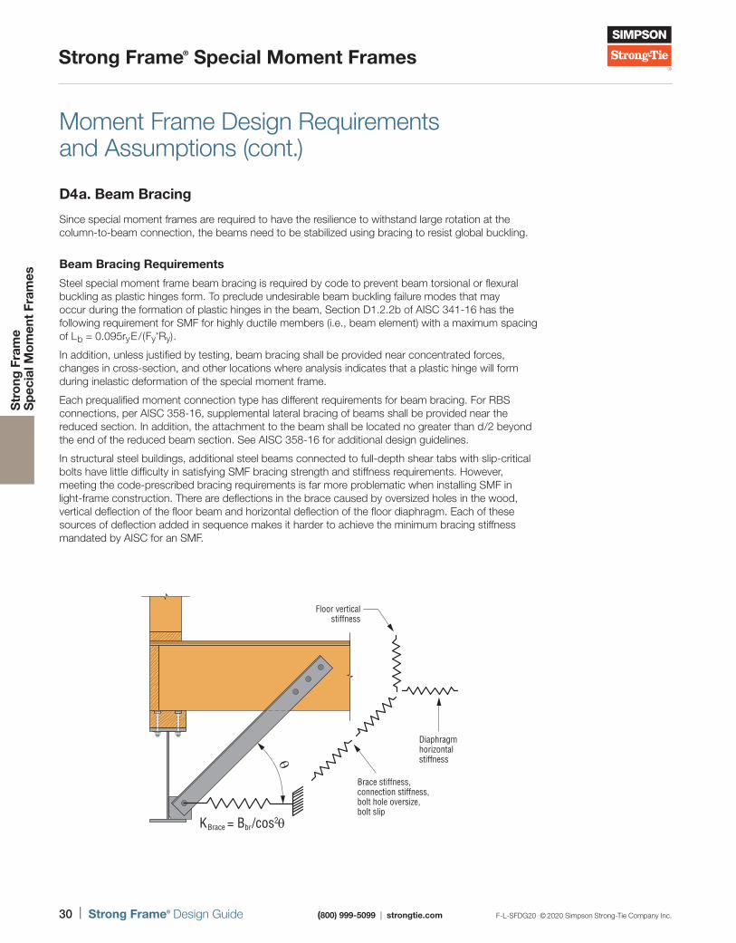
D4a. Beam Bracing
Since special moment frames are required to have the resilience to withstand large rotation at the column-to-beam connection, the beams need to be stabilized using bracing to resist global buckling.
Beam Bracing Requirements
Steel special moment frame beam bracing is required by code to prevent beam torsional or flexural buckling as plastic hinges form. To preclude undesirable beam buckling failure modes that may occur during the formation of plastic hinges in the beam, Section D1.2.2b of AISC 341-16 has the following requirement for SMF for highly ductile members (i.e., beam element) with a maximum spacing of Lb = 0.095ryE/(Fy*Ry).
In addition, unless justified by testing, beam bracing shall be provided near concentrated forces, changes in cross-section, and other locations where analysis indicates that a plastic hinge will form during inelastic deformation of the special moment frame.
Each prequalified moment connection type has different requirements for beam bracing. For RBS connections, per AISC 358-16, supplemental lateral bracing of beams shall be provided near the reduced section. In addition, the attachment to the beam shall be located no greater than d/2 beyond the end of the reduced beam section. See AISC 358-16 for additional design guidelines.
In structural steel buildings, additional steel beams connected to full-depth shear tabs with slip-critical bolts have little difficulty in satisfying SMF bracing strength and stiffness requirements. However, meeting the code-prescribed bracing requirements is far more problematic when installing SMF in light-frame construction. There are deflections in the brace caused by oversized holes in the wood, vertical deflection of the floor beam and horizontal deflection of the floor diaphragm. Each of these sources of deflection added in sequence makes it harder to achieve the minimum bracing stiffness mandated by AISC for an SMF.
Diaphragmhorizontalstiffness
Brace stiffness,connection stiffness,bolt hole oversize,bolt slip
θ
Floor verticalstiffness
KBrace = Bbr/cos2θ
F-L-SFDG20 © 2020 Simpson Strong-Tie Company Inc. (800) 999-5099 | strongtie.com Strong Frame® Design Guide | 31
Strong Frame® Special Moment Frames
Str
ong
Fra
me
S
pec
ial M
om
ent
Fram
es
Moment Frame Design Requirements and Assumptions (cont.)
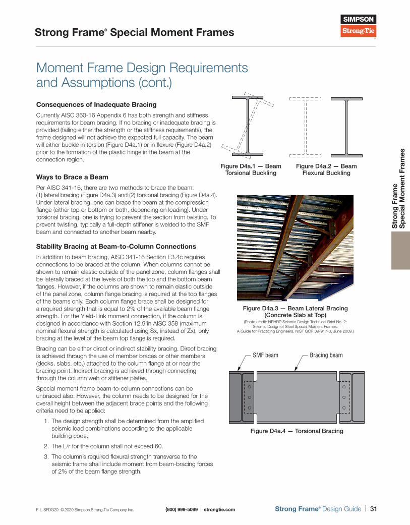
Consequences of Inadequate Bracing
Currently AISC 360-16 Appendix 6 has both strength and stiffness requirements for beam bracing. If no bracing or inadequate bracing is provided (failing either the strength or the stiffness requirements), the frame designed will not achieve the expected full capacity. The beam will either buckle in torsion (Figure D4a.1) or in flexure (Figure D4a.2) prior to the formation of the plastic hinge in the beam at the connection region.
Ways to Brace a Beam
Per AISC 341-16, there are two methods to brace the beam: (1) lateral bracing (Figure D4a.3) and (2) torsional bracing (Figure D4a.4). Under lateral bracing, one can brace the beam at the compression flange (either top or bottom or both, depending on loading). Under torsional bracing, one is trying to prevent the section from twisting. To prevent twisting, typically a full-depth stiffener is welded to the SMF beam and connected to another beam nearby.
Stability Bracing at Beam-to-Column Connections
In addition to beam bracing, AISC 341-16 Section E3.4c requires connections to be braced at the column. When columns cannot be shown to remain elastic outside of the panel zone, column flanges shall be laterally braced at the levels of both the top and the bottom beam flanges. However, if the columns are shown to remain elastic outside of the panel zone, column flange bracing is required at the top flanges of the beams only. Each column flange brace shall be designed for a required strength that is equal to 2% of the available beam flange strength. For the Yield-Link moment connection, if the column is designed in accordance with Section 12.9 in AISC 358 (maximum nominal flexural strength is calculated using Sx, instead of Zx), only bracing at the level of the beam top flange is required.
Bracing can be either direct or indirect stability bracing. Direct bracing is achieved through the use of member braces or other members (decks, slabs, etc.) attached to the column flange at or near the bracing point. Indirect bracing is achieved through connecting through the column web or stiffener plates.
Special moment frame beam-to-column connections can be unbraced also. However, the column needs to be designed for the overall height between the adjacent brace points and the following criteria need to be applied:
1. The design strength shall be determined from the amplified seismic load combinations according to the applicable building code.
2. The L/r for the column shall not exceed 60.
3. The column’s required flexural strength transverse to the seismic frame shall include moment from beam-bracing forces of 2% of the beam flange strength.
Figure D4a.1 — Beam Torsional Buckling
Figure D4a.2 — Beam Flexural Buckling
SMF beam Bracing beam
Figure D4a.4 — Torsional Bracing
Figure D4a.3 — Beam Lateral Bracing (Concrete Slab at Top)
(Photo credit: NEHRP Seismic Design Technical Brief No. 2: Seismic Design of Steel Special Moment Frames:
A Guide for Practicing Engineers, NIST GCR 09-917-3, June 2009.)
32 | Strong Frame® Design Guide (800) 999-5099 | strongtie.com F-L-SFDG20 © 2020 Simpson Strong-Tie Company Inc.
Strong Frame® Special Moment Frames
Str
ong
Fra
me
S
pec
ial M
om
ent
Fram
es
Figure D4a.5 — Equivalent Plastic Strain of Simpson Strong-Tie® Strong Frame Special Moment Frame at 0.04 Radians
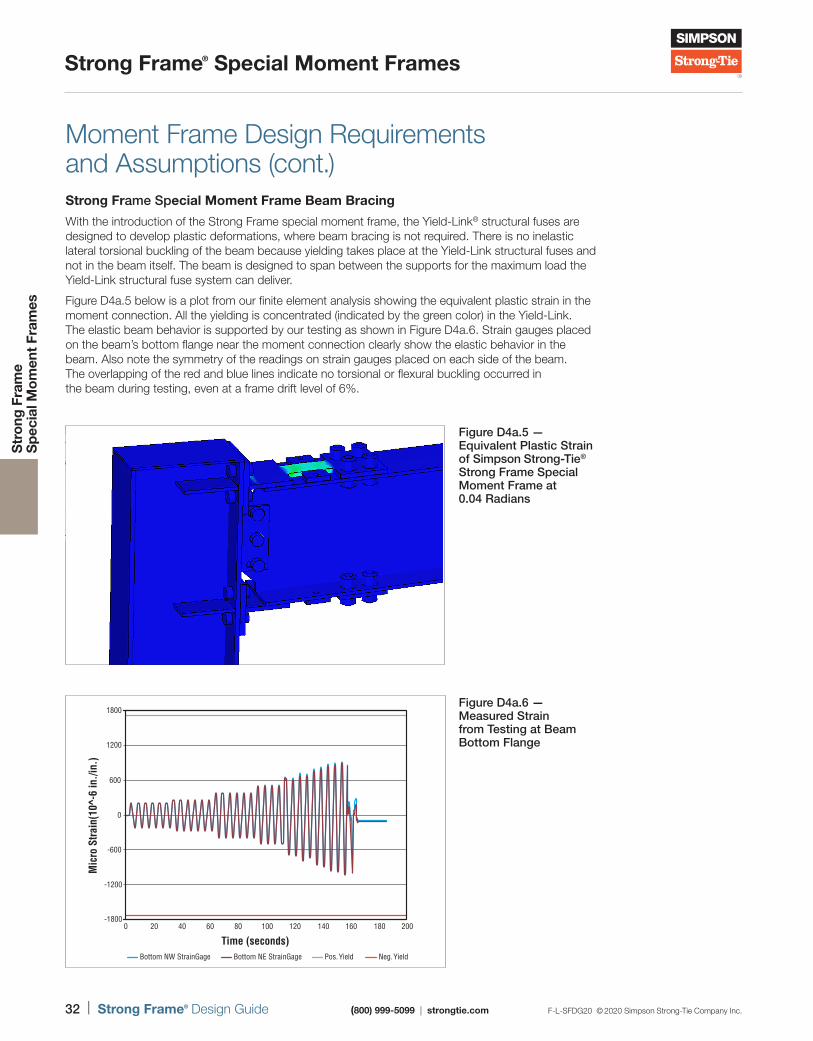
Moment Frame Design Requirements and Assumptions (cont.)Strong Frame Special Moment Frame Beam Bracing
With the introduction of the Strong Frame special moment frame, the Yield-Link® structural fuses are designed to develop plastic deformations, where beam bracing is not required. There is no inelastic lateral torsional buckling of the beam because yielding takes place at the Yield-Link structural fuses and not in the beam itself. The beam is designed to span between the supports for the maximum load the Yield-Link structural fuse system can deliver.
Figure D4a.5 below is a plot from our finite element analysis showing the equivalent plastic strain in the moment connection. All the yielding is concentrated (indicated by the green color) in the Yield-Link. The elastic beam behavior is supported by our testing as shown in Figure D4a.6. Strain gauges placed on the beam’s bottom flange near the moment connection clearly show the elastic behavior in the beam. Also note the symmetry of the readings on strain gauges placed on each side of the beam. The overlapping of the red and blue lines indicate no torsional or flexural buckling occurred in the beam during testing, even at a frame drift level of 6%.
-1800
-1200
-600
600
1200
1800
0
0 20 40 60 80 100
Time (seconds)
Mic
ro S
train
(10^
-6 in
./in.
)
Bottom NW StrainGage Bottom NE StrainGage Pos. Yield Neg. Yield
120 140 160 180 200
Figure D4a.6 — Measured Strain from Testing at Beam Bottom Flange
F-L-SFDG20 © 2020 Simpson Strong-Tie Company Inc. (800) 999-5099 | strongtie.com Strong Frame® Design Guide | 33
Strong Frame® Special Moment Frames
Str
ong
Fra
me
S
pec
ial M
om
ent
Fram
es
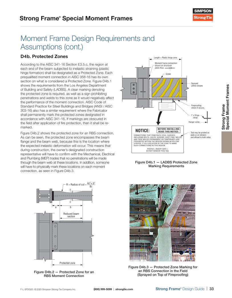
D4b. Protected Zones
According to the AISC 341-16 Section E3.5.c, the region at each end of the beam subjected to inelastic straining (plastic hinge formation) shall be designated as a Protected Zone. Each prequalified moment connection in AISC 358-16 has its own section on what is considered a Protected Zone. Figure D4b.1 shows the requirements from the Los Angeles Department of Building and Safety (LADBS). A clear marking denoting the protected zone is required, as well as a sign prohibiting penetrations and welds to this zone as it would negatively affect the performance of the moment connection. AISC Code of Standard Practice for Steel Buildings and Bridges (ANSI / AISC 303-16) also has a similar requirement where the Fabricator shall permanently mark the protected zones designated in accordance with AISC 341-16. If markings are obscured in the field after application of fire protection, then it shall be re-marked.
Figure D4b.2 shows the protected zone for an RBS connection. As can be seen, the protected zone encompasses the beam flange and the beam web, because this is the location where the expected inelastic deformation will occur. This means that during construction, the owner’s designated construction representative will have to confirm with the Mechanical, Electrical and Plumbing (MEP) trades that no penetrations will be made through the beam web at these locations. In addition, someone will have to physically mark these locations on each moment connection, as seen in Figure D4b.3.
NOTICE:CONNECTIONS THAT PENETRATE STEEL SURFACE,INCLUDING BOLTS, HOLES, SCREWS, SHOT PINS, WELDS,AND TACK WELDS (PERMANENT OR TEMPORARY) AREPROHIBITED WITHIN THE REGION SHOWN W/YELLOWSTRIPES. IT IS A VIOLATION OF THE CODE TO MAKESUCH CONNECTIONS IN THIS REGION
POSTED ( INSERT DATE )DO NOT REMOVE THIS TAG
BEFORE INSTALLINGREAD THIS NOTICE:
Length = Plastic hinge zone
Moment frame connectionshown on structuralplans thus:
Girder
Sprayed yellow stripes
Fireproofingwhere it occurs
Hanger wires
1" x 16 ga.strap
Text may be printed onplate or on stickersand affixed to both sides
Figure D4b.1 — LADBS Protected Zone Marking Requirements
Figure D4b.3 — Protected Zone Marking for an RBS Connection in the Field (Sprayed on Top of Fireproofing)
c
ba
Reduced beamsection
Protected zone
cR = Radius of cut = 4c2 + b2
8c
Figure D4b.2 — Protected Zone for an RBS Moment Connection
Moment Frame Design Requirements and Assumptions (cont.)
34 | Strong Frame® Design Guide (800) 999-5099 | strongtie.com F-L-SFDG20 © 2020 Simpson Strong-Tie Company Inc.
Strong Frame® Special Moment Frames
Str
ong
Fra
me
S
pec
ial M
om
ent
Fram
es
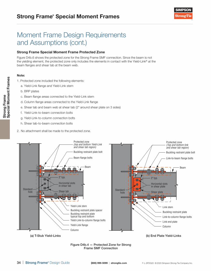
Strong Frame Special Moment Frame Protected Zone
Figure D4b.6 shows the protected zone for the Strong Frame SMF connection. Since the beam is not the yielding element, the protected zone only includes the elements in contact with the Yield-Link® at the beam flanges and shear tab at the beam web.
Moment Frame Design Requirements and Assumptions (cont.)
Note:
1. Protected zone included the following elements:
a. Yield-Link flange and Yield-Link stem
b. BRP plates
c. Beam flange areas connected to the Yield-Link stem
d. Column flange areas connected to the Yield-Link flange
e. Shear tab and beam web at shear tab (2" around shear plate on 3 sides)
f. Yield-Link-to-beam connection bolts
g. Yield-Link-to-column connection bolts
h. Shear tab-to-beam connection bolts
2. No attachment shall be made to the protected zone.
(b) End Plate Yield-Links(a) T-Stub Yield-Links
Protected zone(Top and bottom linkand shear tab region)
Buckling restraint plate bolt
Link-to-beam flange bolts
Beam
Link stem
Buckling restraint plate
Link end plate
Link-to-column flange bolts
Column
Horizontal slotsin shear plate
Shear plateStandard
hole
2" typ.
Protected zone(top and bottom Yield-Linkand shear tab region)
Buckling restraint plate bolt
Beam flange bolts
Beam
Horizontal slotsin shear tab
2" typ.
Shear tabStandard
hole
Yield-Link stem
Buckling restraint platetypical top and bottom
Buckling restraint plate spacer
Yield-Link flange
Yield-Link-to-column flange bolts
Column
Figure D4b.4 — Protected Zone for Strong Frame SMF Connection
F-L-SFDG20 © 2020 Simpson Strong-Tie Company Inc. (800) 999-5099 | strongtie.com Strong Frame® Design Guide | 35
Strong Frame® Special Moment Frames
Str
ong
Fra
me
S
pec
ial M
om
ent
Fram
es
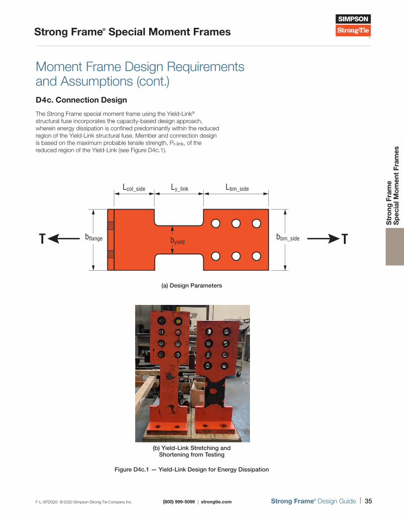
Moment Frame Design Requirements and Assumptions (cont.)D4c. Connection Design
The Strong Frame special moment frame using the Yield-Link® structural fuse incorporates the capacity-based design approach, wherein energy dissipation is confined predominantly within the reduced region of the Yield-Link structural fuse. Member and connection design is based on the maximum probable tensile strength, Pr-link, of the reduced region of the Yield-Link (see Figure D4c.1).
byield
Ly_linkLcol_side Lbm_side
bbm_sidebflangeT T
(a) Design Parameters
(b) Yield-Link Stretching and Shortening from Testing
Figure D4c.1 — Yield-Link Design for Energy Dissipation
36 | Strong Frame® Design Guide (800) 999-5099 | strongtie.com F-L-SFDG20 © 2020 Simpson Strong-Tie Company Inc.
Strong Frame® Special Moment Frames
Str
ong
Fra
me
S
pec
ial M
om
ent
Fram
es
Moment Frame Design Requirements and Assumptions (cont.)The following are steps for the Strong Frame connection design:
1. Model and analyze moment frame with Yield-Link® moment connections to get demand loads (moment, shear and axial) using code level forces.
2. Design Yield-Link yielding area to resist the maximum axial force from all the standard LRFD load combinations. This means our Yield-Links are designed to remain elastic under code force load combinations including lateral plus gravity loads.
3. Once the yielding area is known, calculate the maximum rupture strength, Pr-link , of the Yield-Link as:
Pr-link = Ay-link x Rt x Fu-link
Where:
Ay-link = area of reduced Yield-Link section, in.2
Rt = ratio of expected tensile strength to minimum specified tensile strength of the Yield-Link stem material, 1.2
Fu-link = specified minimum tensile strength of Yield-Link stem material, 65 ksi
It is worthwhile to point out that we are using Rt and Fu for this calculation where other SMF connections typically use Ry, Fy and a Cpr factor that is less than or equal to 1.2. Using Ry of 1.1, Rt of 1.2, Fy of 50 ksi, Fu of 65 ksi and Cpr of 1.2. The difference in demand can be seen below:
Simpson Strong-Tie® Strong Frame SMF Connection Design Demand: 1.2 x 65 ksi = 78 ksi
Standard SMF Connection Design Demand: 1.1 x 50 ksi x 1.2 = 66 ksi
The reason for this approach is to truly capture the ultimate strength of our Yield-Link structural fuse, since we want to make sure this is the only region where inelastic action occurs.
4. After Pr-link has been determined, design the rest of the connection to exceed this Pr-link demand load:
a. Yield-Link stem-to-beam flange connection bolts
b. Yield-Link flange-to-column flange connection bolts
c. Yield-Link-flange thickness to prevent prying
d. Beam-to-column shear tab connection
e. Column panel zone
f. Column flange thickness
g. Stiffener/continuity plate (if required)
F-L-SFDG20 © 2020 Simpson Strong-Tie Company Inc. (800) 999-5099 | strongtie.com Strong Frame® Design Guide | 37
Strong Frame® Special Moment Frames
Str
ong
Fra
me
S
pec
ial M
om
ent
Fram
es
Moment Frame Design Requirements and Assumptions (cont.)
D5. Member Design
Similar to the connection design, members (beam and column) are designed for frame mechanism forces, assuming Yield-Links at both ends of the beam are at their maximum probable tensile strength. The beam is designed and tested as unbraced from column to column. There are no requirements for stability bracing of the beams at the Yield-Link® locations. Columns are designed so bracing is only required near the top flange of the beam. Since the frame members are not dissipating energy (i.e., beam plastic hinges do not form), members are designed in accordance with AISC Steel Construction Manual (AISC 360). This means b/t and h/tw ratios in AISC 341 are not applicable to our beam and column members in the frame when designed using a pinned-base design. However, if the base is designed as fixed or partially fixed, i.e., so the columns may yield at the base, then AISC 341 slenderness ratios will be met for the columns at the base level. Please note, for the Strong Frame column design, the demand forces are from overstrength load combinations. This is similar to other SMF column design, however, for Strong Frame columns, axial + moment interaction check is required, whereas typical SMF column design is permitted to ignore the bending moment (unless the moment results from loads applied between points of support).
Base Plate Design
The capacity design approach also extends to the design of the column base plates. Pinned column base connection demand loads (axial and shear) are calculated from the lesser of the frame mechanism forces and the forces from code overstrength load combinations.
Design capacity for the base plate is calculated from AISC Design Guide #1 (DG #1) and Design Guide #16 (DG #16). Base plate compressive capacity is calculated per DG #1, whereas base plate tension capacity is calculated assuming two-way action using the method in DG #16. Welds in the base plate are checked for shear and tension interaction using capacity-level loads as noted above.
Oversized holes in base plates are required for erection tolerance. Per DG #1 Section 3.5, AISC recommends use of oversized holes for anchor rods. For the Strong Frame, the column base plate holes typically exceed the anchor rod diameter by ¼". When oversized holes are used for erection, considerable slip in the base plate may occur before the plate bears against the anchor rods. In addition, due to anchor placement tolerance and potential for anchor movement during concrete placement, it is not likely that all the anchor rods will resist the same load. AISC DG #1 Section 3.5.3 has two separate recommendations for shear load transfer from the base plate with oversized holes to the anchor rods:
1. Use half of all anchor rods to transfer the shear force at each column.
2. Weld a plate washer with standard oversized holes (+1/16") to the top of the base plate.
In order to minimize welding at the jobsite, Simpson Strong-Tie currently uses the first approach in our design for the anchor rods in shear. However, the designer can coordinate with Simpson Strong-Tie if they prefer to use the second method. Please note that, for this option, welding and welding inspection are required in the field. The effect of oversized holes in the frame and structural movement shall be evaluated by the designer.
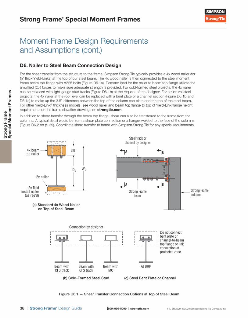
38 | Strong Frame® Design Guide (800) 999-5099 | strongtie.com F-L-SFDG20 © 2020 Simpson Strong-Tie Company Inc.
Strong Frame® Special Moment Frames
Str
ong
Fra
me
S
pec
ial M
om
ent
Fram
es
Moment Frame Design Requirements and Assumptions (cont.)
D6. Nailer to Steel Beam Connection Design
For the shear transfer from the structure to the frame, Simpson Strong-Tie typically provides a 4x wood nailer (for 1/2" thick Yield-Links) at the top of our steel beam. The 4x wood nailer is then connected to the steel moment frame beam top flange with A325 bolts (Figure D6.1a). Demand load for the nailer to beam top flange utilizes the amplified (Ωo) forces to make sure adequate strength is provided. For cold-formed steel projects, the 4x nailer can be replaced with light-gauge stud tracks (Figure D6.1b) at the request of the designer. For structural steel projects, the 4x nailer at the roof level can be replaced with a bent plate or a channel section (Figure D6.1b and D6.1c) to make up the 3.5" difference between the top of the column cap plate and the top of the steel beam. For other Yield-Link® thickness models, see wood nailer and beam top flange to top of Yield-Link flange height requirements on the frame elevation drawings on strongtie.com.
In addition to shear transfer through the beam top flange, shear can also be transferred to the frame from the columns. A typical detail would be from a shear plate connection or a hanger welded to the face of the columns (Figure D6.2 on p. 39). Coordinate shear transfer to frame with Simpson Strong-Tie for any special requirements.
3½"
Db
4x beamtop nailer
2x fieldinstall nailer
(as req’d)
2x nailer
Wb
(a) Standard 4x Wood Naileron Top of Steel Beam
(a) Standard 4x Wood Nailer on Top of Steel Beam
A
A B
B
Beam withCFS track
Connection by designerDo not connect bent plate or channel-to-beam top flange or link connection at protected zone.
(b) Cold-Formed Steel Stud (c) Steel Bent Plate or Channel
Beam withMC
At BRP
Section A-ABeam Top Connection
Section B-BBearing Connection at Link Region
Beam withCFS track
Strong Framecolumn
Strong Framebeam
Steel track orchannel by designer
(b) Cold-Formed Steel Stud (c) Steel Bent Plate or Channel
Figure D6.1 — Shear Transfer Connection Options at Top of Steel Beam
Strong Framecolumn
A
Strong Framebeam
Steel track orchannel by designer
A B
B
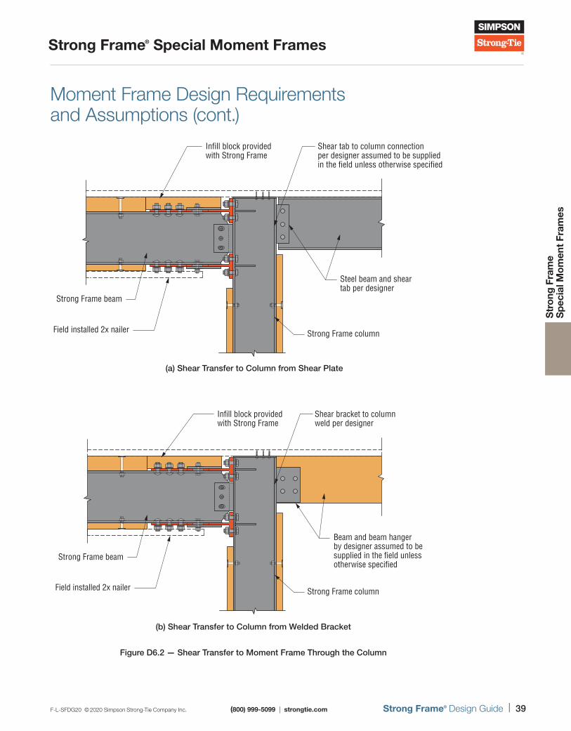
F-L-SFDG20 © 2020 Simpson Strong-Tie Company Inc. (800) 999-5099 | strongtie.com Strong Frame® Design Guide | 39
Strong Frame® Special Moment Frames
Str
ong
Fra
me
S
pec
ial M
om
ent
Fram
es
Moment Frame Design Requirements and Assumptions (cont.)
Infill block provided with Strong Frame
Shear tab to column connection per designer assumed to be supplied in the field unless otherwise specified
Steel beam and sheartab per designer
Strong Frame column
Strong Frame beam
Field installed 2x nailer
(a) Shear Transfer to Column from Shear Plate(a) Shear Transfer to Column from Shear Plate
Infill block provided with Strong Frame
Shear bracket to columnweld per designer
Beam and beam hanger by designer assumed to be supplied in the field unless otherwise specified
Strong Frame column
Strong Frame beam
Field installed 2x nailer
(b) Shear Transfer to Column from Welded Bucket(b) Shear Transfer to Column from Welded Bracket
Figure D6.2 — Shear Transfer to Moment Frame Through the Column
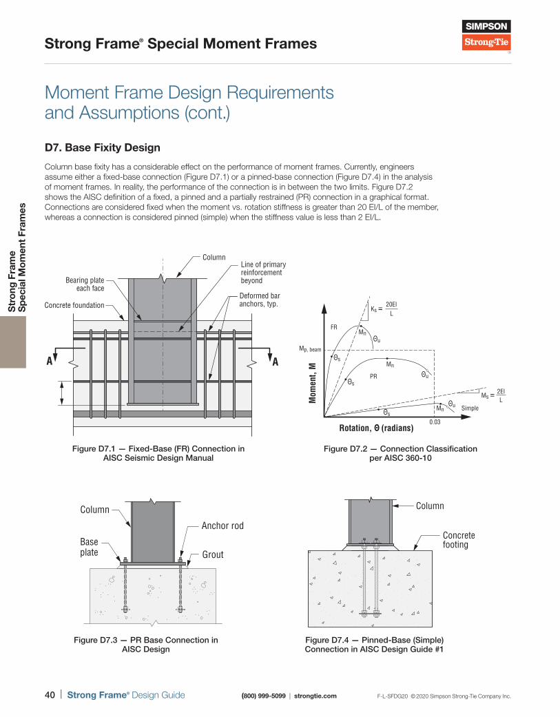
40 | Strong Frame® Design Guide (800) 999-5099 | strongtie.com F-L-SFDG20 © 2020 Simpson Strong-Tie Company Inc.
Strong Frame® Special Moment Frames
Str
ong
Fra
me
S
pec
ial M
om
ent
Fram
es
Moment Frame Design Requirements and Assumptions (cont.)
D7. Base Fixity Design
Column base fixity has a considerable effect on the performance of moment frames. Currently, engineers assume either a fixed-base connection (Figure D7.1) or a pinned-base connection (Figure D7.4) in the analysis of moment frames. In reality, the performance of the connection is in between the two limits. Figure D7.2 shows the AISC definition of a fixed, a pinned and a partially restrained (PR) connection in a graphical format. Connections are considered fixed when the moment vs. rotation stiffness is greater than 20 EI/L of the member, whereas a connection is considered pinned (simple) when the stiffness value is less than 2 EI/L.
Figure D7.1 — Fixed-Base (FR) Connection in AISC Seismic Design Manual
A A
Deformed bar anchors, typ.
Bearing plateeach face
Concrete foundation
ColumnLine of primaryreinforcement beyond
Rotation, Θ (radians)
Mom
ent,
M
Θs
Θu
Θu
Θu
Θs
Θs
Mn
Mn
Mn
0.03
Mp, beam
FR
PR
Simple
2ElL
Ms =
20ElL
Ks =
Figure D7.2 — Connection Classification per AISC 360-10
Figure D7.4 — Pinned-Base (Simple)Connection in AISC Design Guide #1
Column
Concrete footing
Column
Baseplate Grout
Anchor rod
Figure D7.3 — PR Base Connection in AISC Design
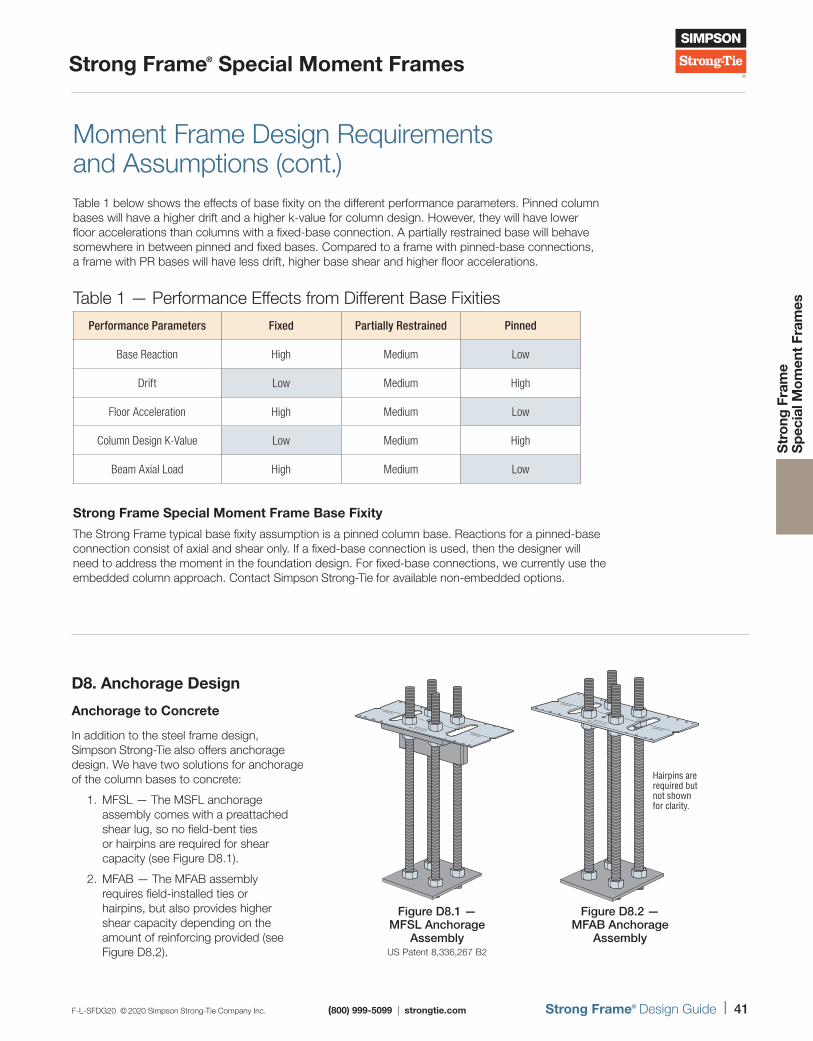
F-L-SFDG20 © 2020 Simpson Strong-Tie Company Inc. (800) 999-5099 | strongtie.com Strong Frame® Design Guide | 41
Strong Frame® Special Moment Frames
Str
ong
Fra
me
S
pec
ial M
om
ent
Fram
es
D8. Anchorage Design
Anchorage to Concrete
In addition to the steel frame design, Simpson Strong-Tie also offers anchorage design. We have two solutions for anchorage of the column bases to concrete:
1. MFSL — The MSFL anchorage assembly comes with a preattached shear lug, so no field-bent ties or hairpins are required for shear capacity (see Figure D8.1).
2. MFAB — The MFAB assembly requires field-installed ties or hairpins, but also provides higher shear capacity depending on the amount of reinforcing provided (see Figure D8.2).
CENTER LINE
OMF C18H, C21HSMF C10, C12, C14,C16
CENTER LINE
SIMPSON
Strong-Tie
MFTPL6-3
Figure D8.1 —MFSL Anchorage
AssemblyUS Patent 8,336,267 B2
CENTER LINE
OMF C18H, C21HSMF C10, C12, C14,C16
CENTER LINE
SIMPSON
Strong-Tie
MFTPL6-3
Hairpins arerequired butnot shownfor clarity.
Figure D8.2 — MFAB Anchorage
Assembly
Moment Frame Design Requirements and Assumptions (cont.)
Table 1 — Performance Effects from Different Base Fixities
Performance Parameters Fixed Partially Restrained Pinned
Base Reaction High Medium Low
Drift Low Medium High
Floor Acceleration High Medium Low
Column Design K-Value Low Medium High
Beam Axial Load High Medium Low
Strong Frame Special Moment Frame Base Fixity
The Strong Frame typical base fixity assumption is a pinned column base. Reactions for a pinned-base connection consist of axial and shear only. If a fixed-base connection is used, then the designer will need to address the moment in the foundation design. For fixed-base connections, we currently use the embedded column approach. Contact Simpson Strong-Tie for available non-embedded options.
Table 1 below shows the effects of base fixity on the different performance parameters. Pinned column bases will have a higher drift and a higher k-value for column design. However, they will have lower floor accelerations than columns with a fixed-base connection. A partially restrained base will behave somewhere in between pinned and fixed bases. Compared to a frame with pinned-base connections, a frame with PR bases will have less drift, higher base shear and higher floor accelerations.
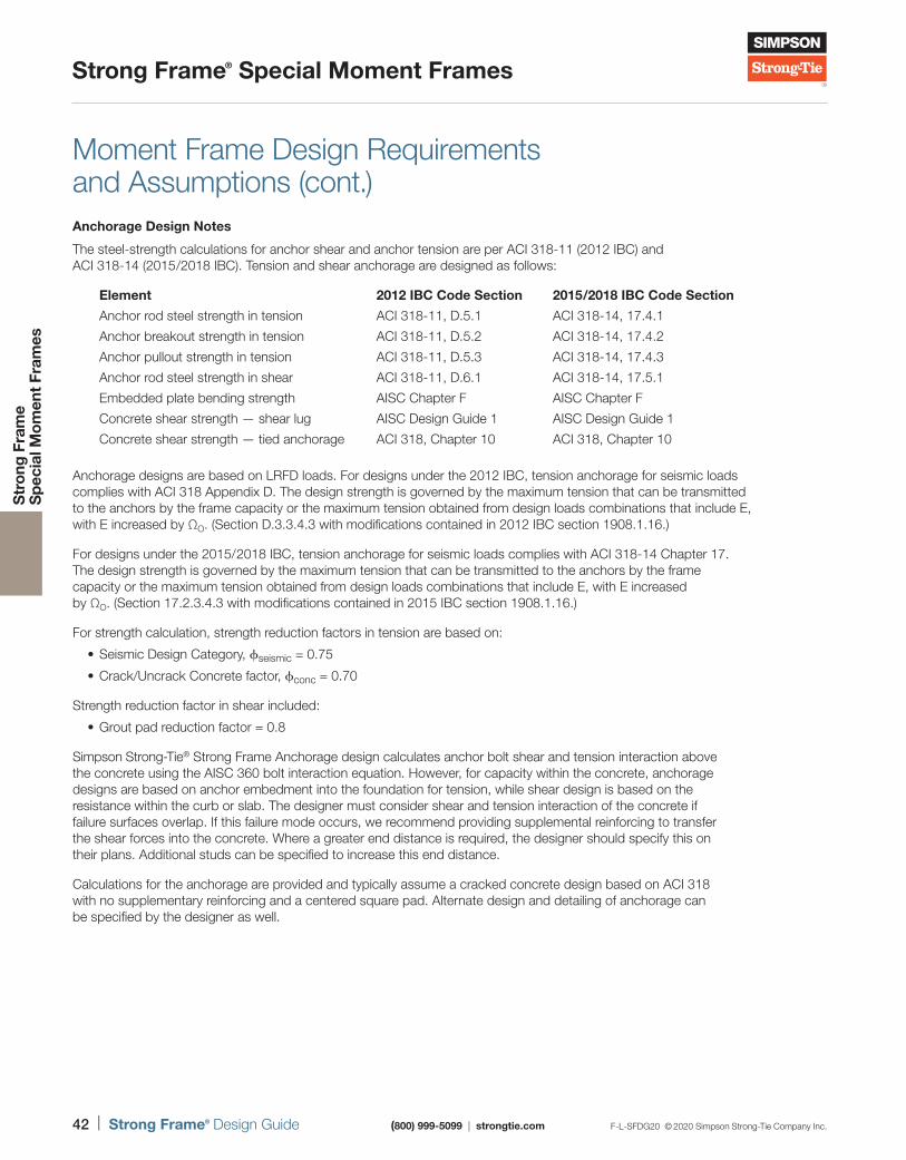
42 | Strong Frame® Design Guide (800) 999-5099 | strongtie.com F-L-SFDG20 © 2020 Simpson Strong-Tie Company Inc.
Strong Frame® Special Moment Frames
Str
ong
Fra
me
S
pec
ial M
om
ent
Fram
es
Moment Frame Design Requirements and Assumptions (cont.)Anchorage Design Notes
The steel-strength calculations for anchor shear and anchor tension are per ACI 318-11 (2012 IBC) and ACI 318-14 (2015 /2018 IBC). Tension and shear anchorage are designed as follows:
Element 2012 IBC Code Section 2015 /2018 IBC Code Section
Anchor rod steel strength in tension ACI 318-11, D.5.1 ACI 318-14, 17.4.1
Anchor breakout strength in tension ACI 318-11, D.5.2 ACI 318-14, 17.4.2
Anchor pullout strength in tension ACI 318-11, D.5.3 ACI 318-14, 17.4.3
Anchor rod steel strength in shear ACI 318-11, D.6.1 ACI 318-14, 17.5.1
Embedded plate bending strength AISC Chapter F AISC Chapter F
Concrete shear strength — shear lug AISC Design Guide 1 AISC Design Guide 1
Concrete shear strength — tied anchorage ACI 318, Chapter 10 ACI 318, Chapter 10
Anchorage designs are based on LRFD loads. For designs under the 2012 IBC, tension anchorage for seismic loads complies with ACI 318 Appendix D. The design strength is governed by the maximum tension that can be transmitted to the anchors by the frame capacity or the maximum tension obtained from design loads combinations that include E, with E increased by ΩO. (Section D.3.3.4.3 with modifications contained in 2012 IBC section 1908.1.16.)
For designs under the 2015/ 2018 IBC, tension anchorage for seismic loads complies with ACI 318-14 Chapter 17. The design strength is governed by the maximum tension that can be transmitted to the anchors by the frame capacity or the maximum tension obtained from design loads combinations that include E, with E increased by ΩO. (Section 17.2.3.4.3 with modifications contained in 2015 IBC section 1908.1.16.)
For strength calculation, strength reduction factors in tension are based on:
• Seismic Design Category, ϕseismic = 0.75
• Crack/Uncrack Concrete factor, ϕconc = 0.70
Strength reduction factor in shear included:
• Grout pad reduction factor = 0.8
Simpson Strong-Tie® Strong Frame Anchorage design calculates anchor bolt shear and tension interaction above the concrete using the AISC 360 bolt interaction equation. However, for capacity within the concrete, anchorage designs are based on anchor embedment into the foundation for tension, while shear design is based on the resistance within the curb or slab. The designer must consider shear and tension interaction of the concrete if failure surfaces overlap. If this failure mode occurs, we recommend providing supplemental reinforcing to transfer the shear forces into the concrete. Where a greater end distance is required, the designer should specify this on their plans. Additional studs can be specified to increase this end distance.
Calculations for the anchorage are provided and typically assume a cracked concrete design based on ACI 318 with no supplementary reinforcing and a centered square pad. Alternate design and detailing of anchorage can be specified by the designer as well.
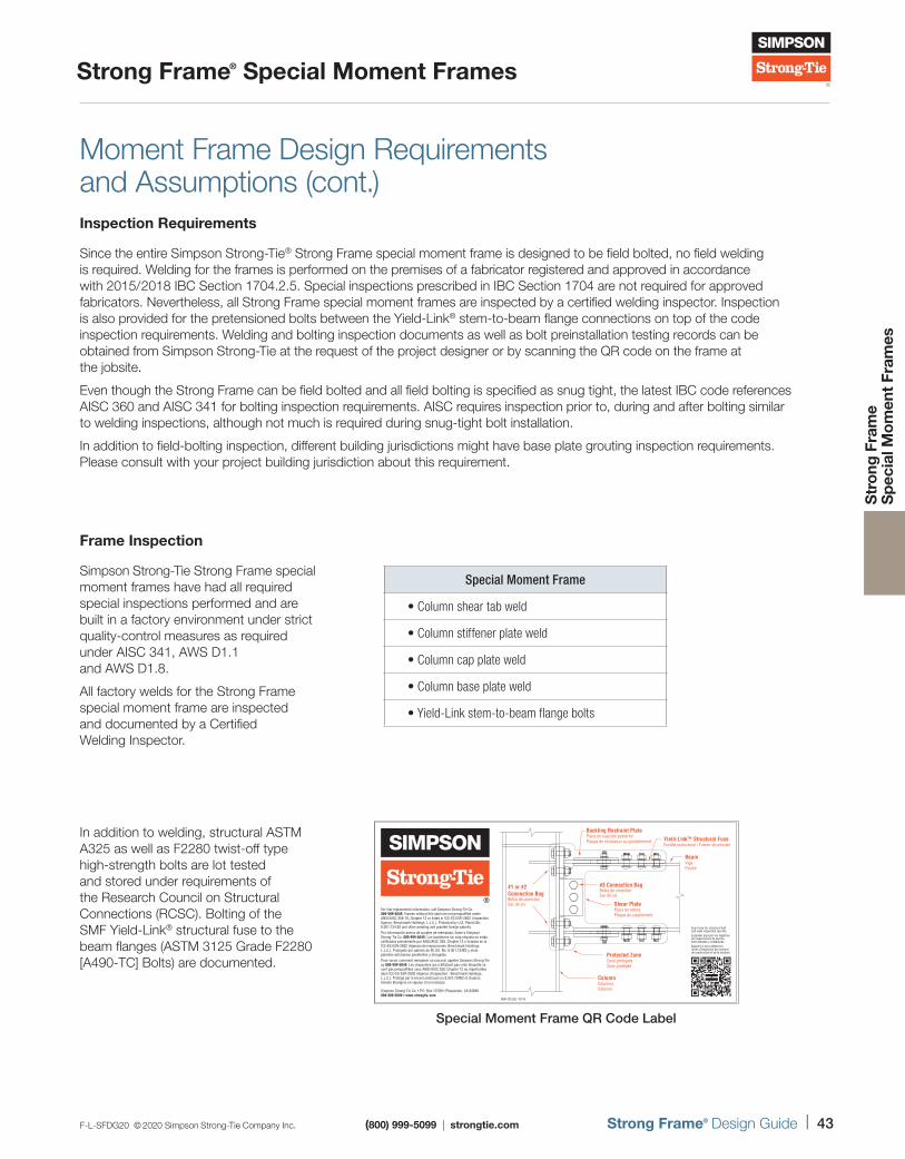
F-L-SFDG20 © 2020 Simpson Strong-Tie Company Inc. (800) 999-5099 | strongtie.com Strong Frame® Design Guide | 43
Strong Frame® Special Moment Frames
Str
ong
Fra
me
S
pec
ial M
om
ent
Fram
es
Moment Frame Design Requirements and Assumptions (cont.)Inspection Requirements
Since the entire Simpson Strong-Tie® Strong Frame special moment frame is designed to be field bolted, no field welding is required. Welding for the frames is performed on the premises of a fabricator registered and approved in accordance with 2015/ 2018 IBC Section 1704.2.5. Special inspections prescribed in IBC Section 1704 are not required for approved fabricators. Nevertheless, all Strong Frame special moment frames are inspected by a certified welding inspector. Inspection is also provided for the pretensioned bolts between the Yield-Link® stem-to-beam flange connections on top of the code inspection requirements. Welding and bolting inspection documents as well as bolt preinstallation testing records can be obtained from Simpson Strong-Tie at the request of the project designer or by scanning the QR code on the frame at the jobsite.
Even though the Strong Frame can be field bolted and all field bolting is specified as snug tight, the latest IBC code references AISC 360 and AISC 341 for bolting inspection requirements. AISC requires inspection prior to, during and after bolting similar to welding inspections, although not much is required during snug-tight bolt installation.
In addition to field-bolting inspection, different building jurisdictions might have base plate grouting inspection requirements. Please consult with your project building jurisdiction about this requirement.
Frame Inspection
Simpson Strong-Tie Strong Frame special moment frames have had all required special inspections performed and are built in a factory environment under strict quality-control measures as required under AISC 341, AWS D1.1 and AWS D1.8.
All factory welds for the Strong Frame special moment frame are inspected and documented by a Certified Welding Inspector.
Special Moment Frame
• Column shear tab weld
• Column stiffener plate weld
• Column cap plate weld
• Column base plate weld
• Yield-Link stem-to-beam flange bolts
In addition to welding, structural ASTM A325 as well as F2280 twist-off type high-strength bolts are lot tested and stored under requirements of the Research Council on Structural Connections (RCSC). Bolting of the SMF Yield-Link® structural fuse to the beam flanges (ASTM 3125 Grade F2280 [A490-TC] Bolts) are documented.
Simpson Strong-Tie Co. • P.O. Box 10789 • Pleasanton, CA 94588800-999-5099 • www.strongtie.com
Buckling Restraint PlatePlaca de sujeción posteriorPlaque de résistance au gondolement
Shear PlatePlaca de roturaPlaque de cisaillement
#1 or #2Connection BagBolsa de conexiónSac de vis
#3 Connection BagBolsa de conexiónSac de vis
BeamVigaPoutre
Protected ZoneZona protegidaZone protégée
ColumnColumnaColonne
SMF-ICCLBL 03/16
Yield-Link™ Structural FuseFusible estructural / Fusion structurale
For link-replacement information, call Simpson Strong-Tie Co. 800-999-5049. Frames without this label are not prequalified under ANSI/AISC 358-16, Chapter 12 or listed in ICC-ES ESR-2802 (Inspection Agency: Benchmark Holdings, L.L.C.). Protected by U.S. Patent No. 8,001,734 B2 and other pending and granted foreign patents.Por información acerca de acoples de reemplazo, llame a Simpson Strong-Tie Co. 800-999-5049. Los bastidores sin esta etiqueta no están calificados previamente por ANSI/AISC 358, Chapter 12 o listados en la ICC-ES ESR-2802 (Agencia de inspecciones: Benchmark Holdings, L.L.C.). Protegido por patente de EE.UU. No. 8.001.734B2 y otras patentes extranjeras pendientes y otorgadas.Pour savoir comment remplacer un raccord, appeler Simpson Strong-Tie au 800-999-5049. Les charpentes qui n’affichent pas cette étiquette ne sont pas préqualifiées sous ANSI/AISC 358, Chapter 12 ou répertoriées dans ICC-ES ESR-2802 (Agence d’inspection : Benchmark Holdings, L.L.C.). Protégé par le brevet américain no 8,001,734B2 et d’autres brevets étrangers en vigueur et en instance.
Scan here for structural bolt and weld inspection records.Escanear aquí por los registros de inspecciones de pernos estructurales y soldaduras.Balayer ici pour obtenir les fiches d’inspection des boulons de construction et de la soudure.
Special Moment Frame QR Code Label
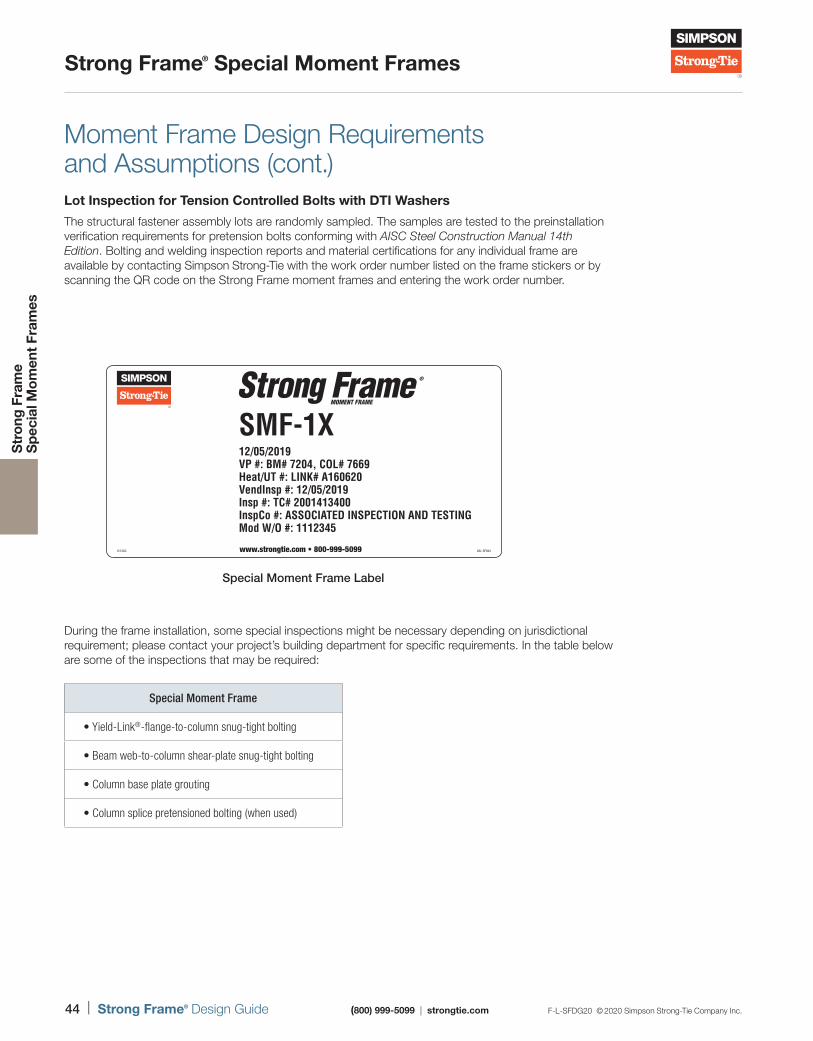
44 | Strong Frame® Design Guide (800) 999-5099 | strongtie.com F-L-SFDG20 © 2020 Simpson Strong-Tie Company Inc.
Strong Frame® Special Moment Frames
Str
ong
Fra
me
S
pec
ial M
om
ent
Fram
es
SMF-1X12/05/2019VP #: BM# 7204, COL# 7669Heat/UT #: LINK# A160620VendInsp #: 12/05/2019Insp #: TC# 2001413400InspCo #: ASSOCIATED INSPECTION AND TESTINGMod W/O #: 1112345
6/12AC www.strongtie.com • 800-999-5099 LBL-SF8X4
Special Moment Frame Label
During the frame installation, some special inspections might be necessary depending on jurisdictional requirement; please contact your project’s building department for specific requirements. In the table below are some of the inspections that may be required:
Special Moment Frame
• Yield-Link®-flange-to-column snug-tight bolting
• Beam web-to-column shear-plate snug-tight bolting
• Column base plate grouting
• Column splice pretensioned bolting (when used)
Moment Frame Design Requirements and Assumptions (cont.)Lot Inspection for Tension Controlled Bolts with DTI Washers
The structural fastener assembly lots are randomly sampled. The samples are tested to the preinstallation verification requirements for pretension bolts conforming with AISC Steel Construction Manual 14th Edition. Bolting and welding inspection reports and material certifications for any individual frame are available by contacting Simpson Strong-Tie with the work order number listed on the frame stickers or by scanning the QR code on the Strong Frame moment frames and entering the work order number.
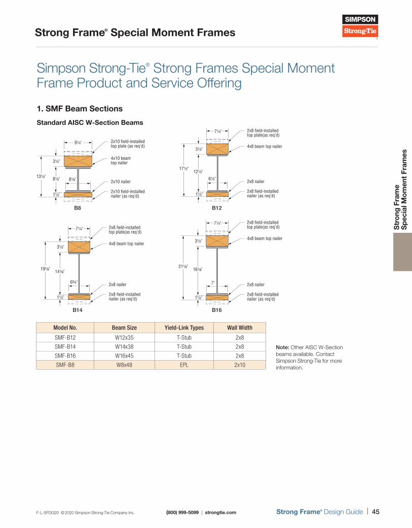
F-L-SFDG20 © 2020 Simpson Strong-Tie Company Inc. (800) 999-5099 | strongtie.com Strong Frame® Design Guide | 45
Strong Frame® Special Moment Frames
Str
ong
Fra
me
S
pec
ial M
om
ent
Fram
es
Simpson Strong-Tie® Strong Frames Special Moment Frame Product and Service Offering
1. SMF Beam Sections
Standard AISC W-Section Beams
Model No. Beam Size Yield-Link Types Wall Width
SMF-B12 W12x35 T-Stub 2x8
SMF-B14 W14x38 T-Stub 2x8
SMF-B16 W16x45 T-Stub 2x8
SMF-B8 W8x48 EPL 2x10
Note: Other AISC W-Section beams available. Contact Simpson Strong-Tie for more information.
B8
B14
B12
B16
8⅛"
4x10 beam top nailer
2x10 field-installedtop plate (as req’d)
2x10 nailer
2x10 field-installednailer (as req’d)
13½"
3½"
8½"
1½"
9¼"
6½"
4x8 beam top nailer
2x8 field-installedtop plate(as req’d)
2x8 nailer
2x8 field-installednailer (as req’d)
17½"
3½"
12½"
1½"
7¼"
7"
4x8 beam top nailer
2x8 nailer
2x8 field-installednailer (as req’d)
21⅛"
3½"
16⅛"
1½"
7¼" 2x8 field-installedtop plate(as req’d)
6¾"
4x8 beam top nailer
2x8 nailer
2x8 field-installednailer (as req’d)
19⅛"
3½"
14⅛"
1½"
7¼" 2x8 field-installedtop plate(as req’d)
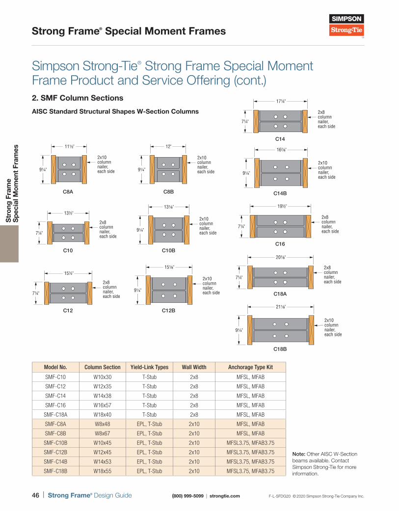
46 | Strong Frame® Design Guide (800) 999-5099 | strongtie.com F-L-SFDG20 © 2020 Simpson Strong-Tie Company Inc.
Strong Frame® Special Moment Frames
Str
ong
Fra
me
S
pec
ial M
om
ent
Fram
es
Simpson Strong-Tie® Strong Frame Special Moment Frame Product and Service Offering (cont.)2. SMF Column Sections
AISC Standard Structural Shapes W-Section Columns
Model No. Column Section Yield-Link Types Wall Width Anchorage Type Kit
SMF-C10 W10x30 T-Stub 2x8 MFSL, MFAB
SMF-C12 W12x35 T-Stub 2x8 MFSL, MFAB
SMF-C14 W14x38 T-Stub 2x8 MFSL, MFAB
SMF-C16 W16x57 T-Stub 2x8 MFSL, MFAB
SMF-C18A W18x40 T-Stub 2x8 MFSL, MFAB
SMF-C8A W8x48 EPL, T-Stub 2x10 MFSL, MFAB
SMF-C8B W8x67 EPL, T-Stub 2x10 MFSL, MFAB
SMF-C10B W10x45 EPL, T-Stub 2x10 MFSL3.75, MFAB3.75
SMF-C12B W12x45 EPL, T-Stub 2x10 MFSL3.75, MFAB3.75
SMF-C14B W14x53 EPL, T-Stub 2x10 MFSL3.75, MFAB3.75
SMF-C18B W18x55 EPL, T-Stub 2x10 MFSL3.75, MFAB3.75
Note: Other AISC W-Section beams available. Contact Simpson Strong-Tie for more information.
C8A
C10
C12
C8B
C10B
C12B
C14
C14B
C16
C18A
C18B
9¼"
2x10columnnailer,each side
11½"
2x10columnnailer, each side9¼"
12"
2x8columnnailer, each side
7¼"
13½"2x10columnnailer, each side9¼"
13⅛"
2x8columnnailer, each side
7¼"
15½"2x10columnnailer, each side9¼"
15⅛"
2x8columnnailer, each side
7¼"
17¼"
2x10columnnailer, each side
9¼"
16⅞"
2x8columnnailer, each side
7¼"
19½"
2x8columnnailer, each side
7¼"
20⅞"
2x10columnnailer, each side
21⅛"
9¼"
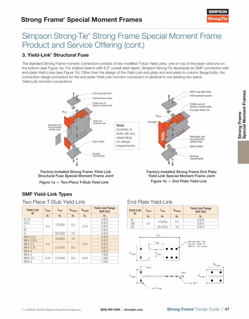
F-L-SFDG20 © 2020 Simpson Strong-Tie Company Inc. (800) 999-5099 | strongtie.com Strong Frame® Design Guide | 47
Strong Frame® Special Moment Frames
Str
ong
Fra
me
S
pec
ial M
om
ent
Fram
es
Simpson Strong-Tie® Strong Frame Special Moment Frame Product and Service Offering (cont.)3. Yield-Link® Structural Fuse
The standard Strong Frame moment connection consists of two modified T-stub Yield-Links; one on top of the beam and one on the bottom (see Figure 1a). For shallow beams with 8.5" overall steel depth, Simpson Strong-Tie developed an SMF connection with end-plate Yield-Links (see Figure 1b). Other than the design of the Yield-Link end-plate and end-plate-to-column flange bolts, the connection design procedure for the end-plate Yield-Link moment connection is identical to our existing two-piece Yield-Link moment connections.
Note: Quantity of bolts will vary depending on design requirements.
Spacer plates
Buckling restraint plate
Shearplate with top and bottom slotted holes
A325 snug-tight bolts
F436 hardened washer
F2280 twist-off(tension control) bolts
Yield-Linkstructural fuse
Wyield
Factory-Installed Strong Frame Yield-Link Structural Fuse Special Moment Frame Joint
Figure 1a — Two-Piece T-Stub Yield-Link
Spacer plates
Buckling restraint plate
Shearplate withtop and bottom slotted holes
End plate
A325 snug-tight bolts
F436 hardened washer
F2280 twist-off(tension control) boltsEnd plate Yield-Link
Wyield
Factory-Installed Strong Frame End Plate Yield-Link Special Moment Frame Joint
Figure 1b — End Plate Yield-Link
SMF Yield-Link Types
Two Piece T-Stub Yield-LinkYield-Link
IDtstem Llink bflange hflange
Yield-Link Flange Bolt Size
in. in. in. in. in.X1.75
0.517.6250 6.5
5.75
0.875X2.0 0.875L 0.875M 0.875H 20.3750 7.0 0.875MF4-2.25
0.5
18.6250 7.0
5.75
0.875MF4-2.875 0.875MF4-3.5
21.3750 8.00.875
MF4-3.75 0.875MF4-4 0.875MF6-3
0.75 27.5000 8.0 9.251.000
MF6-3.5 1.000MF6-4 1.250
End Plate Yield-LinkYield-Link
IDtstem Llink bflange
Yield-Link Flange Bolt Size
in. in. in. in.EL
0.517.6250 6.5
0.875EM 0.875EH 20.3750 7.0 0.875
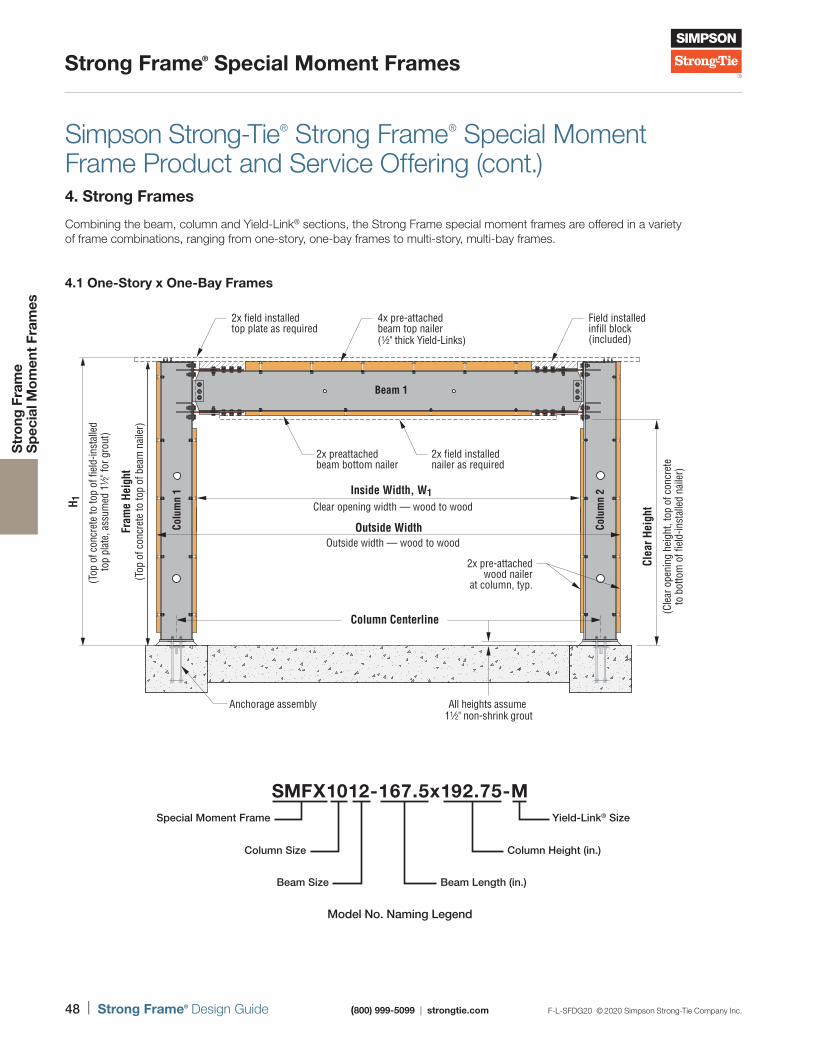
48 | Strong Frame® Design Guide (800) 999-5099 | strongtie.com F-L-SFDG20 © 2020 Simpson Strong-Tie Company Inc.
Strong Frame® Special Moment Frames
Str
ong
Fra
me
S
pec
ial M
om
ent
Fram
es
Simpson Strong-Tie® Strong Frame® Special Moment Frame Product and Service Offering (cont.)4. Strong Frames
Combining the beam, column and Yield-Link® sections, the Strong Frame special moment frames are offered in a variety of frame combinations, ranging from one-story, one-bay frames to multi-story, multi-bay frames.
4.1 One-Story x One-Bay Frames
2x field installedtop plate as required
4x pre-attached beam top nailer(1⁄2" thick Yield-Links)
Field installed infill block(included)
2x preattached beam bottom nailer
Anchorage assembly
Clear opening width — wood to wood
2x field installednailer as required
2x pre-attachedwood nailer
at column, typ.
Beam 1
Colu
mn
2
Colu
mn
1 Inside Width, W1
H 1(T
op o
f con
cret
e to
top
of fi
eld-
inst
alle
d to
p pl
ate,
ass
umed
11 ⁄2
" for
gro
ut)
All heights assume 11⁄2" non-shrink grout
Clea
r Hei
ght
(Cle
ar o
peni
ng h
eigh
t, to
p of
con
cret
eto
bot
tom
of fi
eld-
inst
alle
d na
iler)
Outside Width
Column Centerline
Fram
e He
ight
(Top
of c
oncr
ete
to to
p of
bea
m n
aile
r)
Outside width — wood to wood
Model No. Naming Legend
Special Moment Frame
Column Size Column Height (in.)
Beam Size Beam Length (in.)
Yield-Link® Size
SMFX1012-167.5x192.75-M
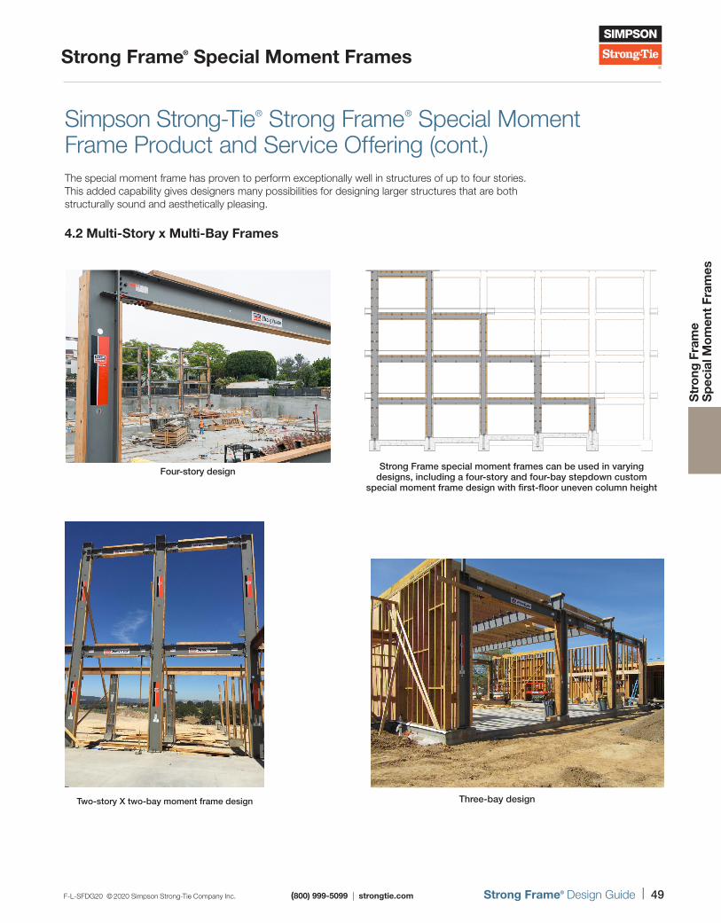
F-L-SFDG20 © 2020 Simpson Strong-Tie Company Inc. (800) 999-5099 | strongtie.com Strong Frame® Design Guide | 49
Strong Frame® Special Moment Frames
Str
ong
Fra
me
S
pec
ial M
om
ent
Fram
es
Simpson Strong-Tie® Strong Frame® Special Moment Frame Product and Service Offering (cont.)The special moment frame has proven to perform exceptionally well in structures of up to four stories. This added capability gives designers many possibilities for designing larger structures that are both structurally sound and aesthetically pleasing.
4.2 Multi-Story x Multi-Bay Frames
Four-story design Strong Frame special moment frames can be used in varying designs, including a four-story and four-bay stepdown custom
special moment frame design with first-floor uneven column height
Three-bay designTwo-story X two-bay moment frame design
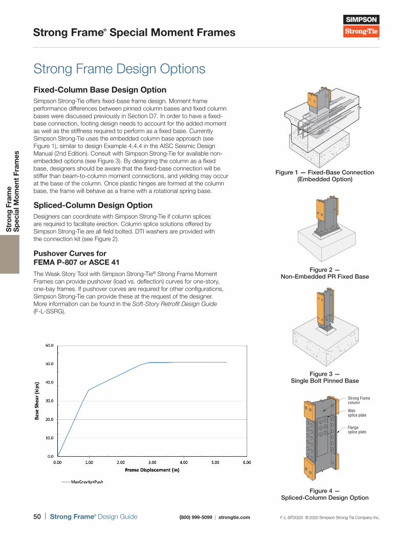
50 | Strong Frame® Design Guide (800) 999-5099 | strongtie.com F-L-SFDG20 © 2020 Simpson Strong-Tie Company Inc.
Strong Frame® Special Moment Frames
Str
ong
Fra
me
S
pec
ial M
om
ent
Fram
es
Strong Frame Design OptionsFixed-Column Base Design OptionSimpson Strong-Tie offers fixed-base frame design. Moment frame performance differences between pinned column bases and fixed column bases were discussed previously in Section D7. In order to have a fixed-base connection, footing design needs to account for the added moment as well as the stiffness required to perform as a fixed base. Currently Simpson Strong-Tie uses the embedded column base approach (see Figure 1), similar to design Example 4.4.4 in the AISC Seismic Design Manual (2nd Edition). Consult with Simpson Strong-Tie for available non-embedded options (see Figure 3). By designing the column as a fixed base, designers should be aware that the fixed-base connection will be stiffer than beam-to-column moment connections, and yielding may occur at the base of the column. Once plastic hinges are formed at the column base, the frame will behave as a frame with a rotational spring base.
Spliced-Column Design OptionDesigners can coordinate with Simpson Strong-Tie if column splices are required to facilitate erection. Column splice solutions offered by Simpson Strong-Tie are all field bolted. DTI washers are provided with the connection kit (see Figure 2).
Pushover Curves for FEMA P-807 or ASCE 41The Weak Story Tool with Simpson Strong-Tie® Strong Frame Moment Frames can provide pushover (load vs. deflection) curves for one-story, one-bay frames. If pushover curves are required for other configurations, Simpson Strong-Tie can provide these at the request of the designer. More information can be found in the Soft-Story Retrofit Design Guide (F-L-SSRG).
Figure 1 — Fixed-Base Connection(Embedded Option)
Figure 4 — Spliced-Column Design Option
Strong Framecolumn
Websplice plate
Flangesplice plate
Figure 2 —Non-Embedded PR Fixed Base
Figure 3 —Single Bolt Pinned Base
Pushover Curve

Strong Frame® Special Moment Frames
Str
ong
Fra
me
S
pec
ial M
om
ent
Fram
es
For more on how to specify your Strong Frame design, visit strongtie.com/strongframe
Strong Frame®
Specification
The Strong Frame moment frame selector software helps you specify a moment frame to meet your project’s geometry and design requirements. Or let Simpson Strong-Tie® Engineering Services design a solution based on your exact criteria.
SF
S Strong Frame®
Moment FrameSelector
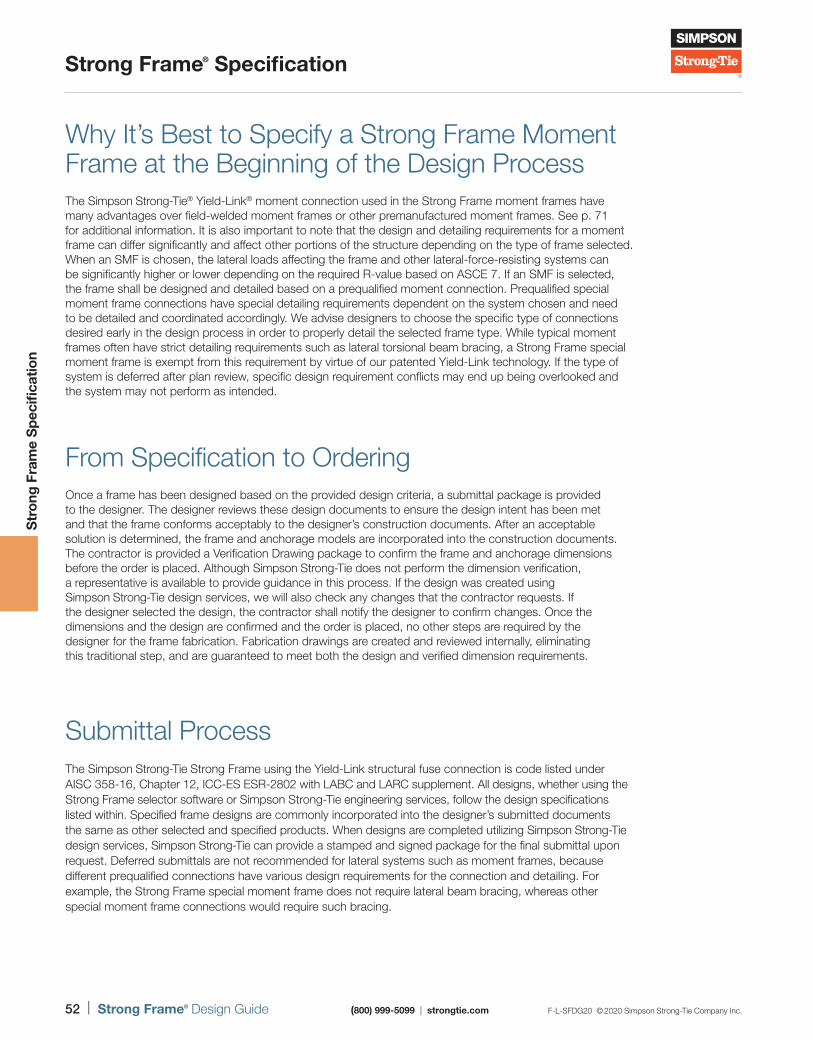
52 | Strong Frame® Design Guide (800) 999-5099 | strongtie.com F-L-SFDG20 © 2020 Simpson Strong-Tie Company Inc.
Strong Frame® Specification
Str
ong
Fra
me
Sp
ecifi
catio
n
Why It’s Best to Specify a Strong Frame Moment Frame at the Beginning of the Design ProcessThe Simpson Strong-Tie® Yield-Link® moment connection used in the Strong Frame moment frames have many advantages over field-welded moment frames or other premanufactured moment frames. See p. 71 for additional information. It is also important to note that the design and detailing requirements for a moment frame can differ significantly and affect other portions of the structure depending on the type of frame selected. When an SMF is chosen, the lateral loads affecting the frame and other lateral-force-resisting systems can be significantly higher or lower depending on the required R-value based on ASCE 7. If an SMF is selected, the frame shall be designed and detailed based on a prequalified moment connection. Prequalified special moment frame connections have special detailing requirements dependent on the system chosen and need to be detailed and coordinated accordingly. We advise designers to choose the specific type of connections desired early in the design process in order to properly detail the selected frame type. While typical moment frames often have strict detailing requirements such as lateral torsional beam bracing, a Strong Frame special moment frame is exempt from this requirement by virtue of our patented Yield-Link technology. If the type of system is deferred after plan review, specific design requirement conflicts may end up being overlooked and the system may not perform as intended.
From Specification to OrderingOnce a frame has been designed based on the provided design criteria, a submittal package is provided to the designer. The designer reviews these design documents to ensure the design intent has been met and that the frame conforms acceptably to the designer’s construction documents. After an acceptable solution is determined, the frame and anchorage models are incorporated into the construction documents. The contractor is provided a Verification Drawing package to confirm the frame and anchorage dimensions before the order is placed. Although Simpson Strong-Tie does not perform the dimension verification, a representative is available to provide guidance in this process. If the design was created using Simpson Strong-Tie design services, we will also check any changes that the contractor requests. If the designer selected the design, the contractor shall notify the designer to confirm changes. Once the dimensions and the design are confirmed and the order is placed, no other steps are required by the designer for the frame fabrication. Fabrication drawings are created and reviewed internally, eliminating this traditional step, and are guaranteed to meet both the design and verified dimension requirements.
Submittal Process The Simpson Strong-Tie Strong Frame using the Yield-Link structural fuse connection is code listed under AISC 358-16, Chapter 12, ICC-ES ESR-2802 with LABC and LARC supplement. All designs, whether using the Strong Frame selector software or Simpson Strong-Tie engineering services, follow the design specifications listed within. Specified frame designs are commonly incorporated into the designer’s submitted documents the same as other selected and specified products. When designs are completed utilizing Simpson Strong-Tie design services, Simpson Strong-Tie can provide a stamped and signed package for the final submittal upon request. Deferred submittals are not recommended for lateral systems such as moment frames, because different prequalified connections have various design requirements for the connection and detailing. For example, the Strong Frame special moment frame does not require lateral beam bracing, whereas other special moment frame connections would require such bracing.
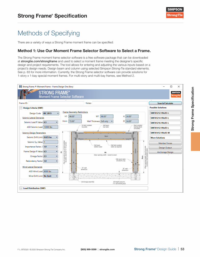
F-L-SFDG20 © 2020 Simpson Strong-Tie Company Inc. (800) 999-5099 | strongtie.com Strong Frame® Design Guide | 53
Strong Frame® Specification
Str
ong
Fra
me
Sp
ecifi
catio
n
Methods of SpecifyingThere are a variety of ways a Strong Frame moment frame can be specified:
Method 1: Use Our Moment Frame Selector Software to Select a Frame.
The Strong Frame moment frame selector software is a free software package that can be downloaded at strongtie.com/strongframe and used to select a moment frame meeting the designer’s specific design and project requirements. The tool allows for entering and adjusting the various inputs based on a project’s design needs. Design beam and column using selected Simpson Strong-Tie standard elements. See p. 83 for more information. Currently, the Strong Frame selector software can provide solutions for 1-story x 1-bay special moment frames. For multi-story and multi-bay frames, see Method 2.
- -
--
-
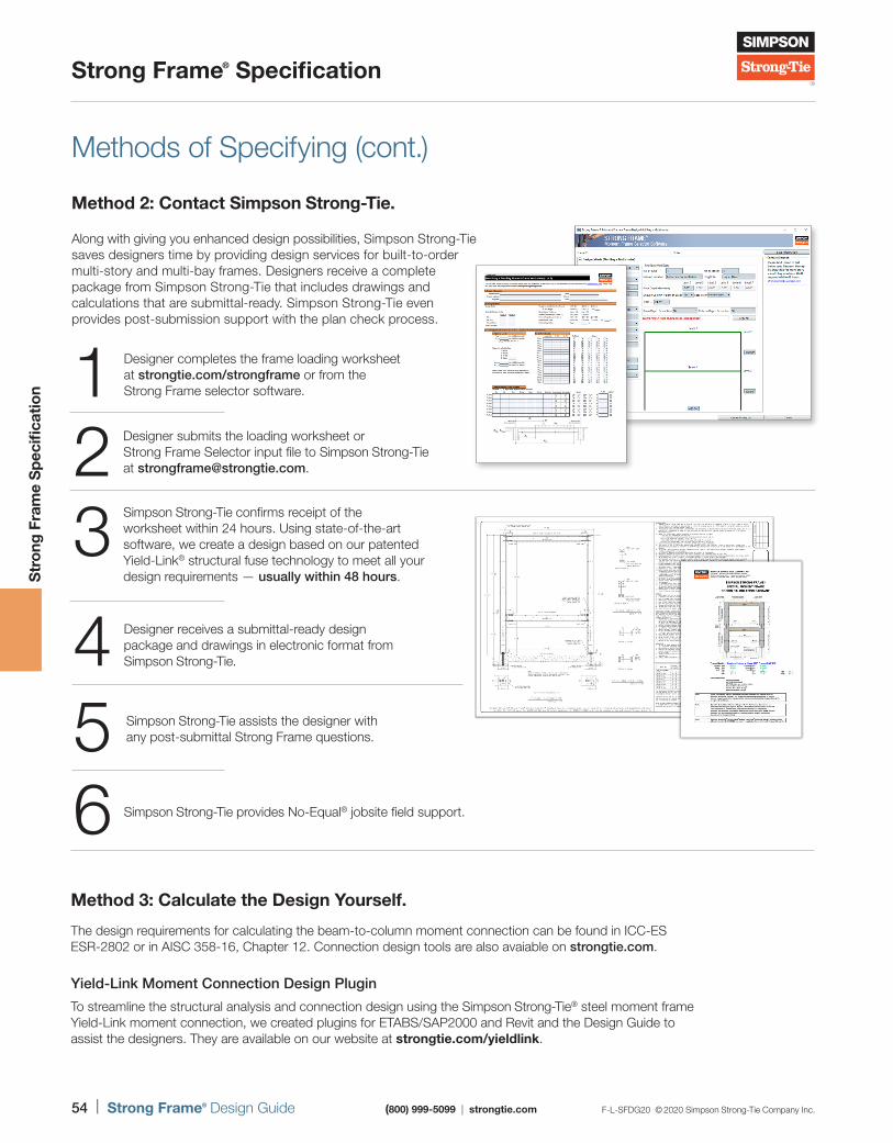
54 | Strong Frame® Design Guide (800) 999-5099 | strongtie.com F-L-SFDG20 © 2020 Simpson Strong-Tie Company Inc.
Strong Frame® Specification
Str
ong
Fra
me
Sp
ecifi
catio
n
Methods of Specifying (cont.)
Method 2: Contact Simpson Strong-Tie.
Along with giving you enhanced design possibilities, Simpson Strong-Tie saves designers time by providing design services for built-to-order multi-story and multi-bay frames. Designers receive a complete package from Simpson Strong-Tie that includes drawings and calculations that are submittal-ready. Simpson Strong-Tie even provides post-submission support with the plan check process.
Designer completes the frame loading worksheet at strongtie.com/strongframe or from the Strong Frame selector software.1
Simpson Strong-Tie confirms receipt of the worksheet within 24 hours. Using state-of-the-art software, we create a design based on our patented Yield-Link® structural fuse technology to meet all your design requirements — usually within 48 hours.
3
Designer submits the loading worksheet or Strong Frame Selector input file to Simpson Strong-Tie at [email protected]
Designer receives a submittal-ready design package and drawings in electronic format from Simpson Strong-Tie.4
Simpson Strong-Tie provides No-Equal® jobsite field support.6
Simpson Strong-Tie assists the designer with any post-submittal Strong Frame questions.5
Method 3: Calculate the Design Yourself.
The design requirements for calculating the beam-to-column moment connection can be found in ICC-ES ESR-2802 or in AISC 358-16, Chapter 12. Connection design tools are also avaiable on strongtie.com.
Yield-Link Moment Connection Design Plugin
To streamline the structural analysis and connection design using the Simpson Strong-Tie® steel moment frame Yield-Link moment connection, we created plugins for ETABS/SAP2000 and Revit and the Design Guide to assist the designers. They are available on our website at strongtie.com/yieldlink.
F-L-SFDG20 © 2020 Simpson Strong-Tie Company Inc. (800) 999-5099 | strongtie.com Strong Frame® Design Guide | 55
Strong Frame® Specification
Str
ong
Fra
me
Sp
ecifi
catio
n
Methods of Specifying (cont.)
Design Information Required
When providing the loading sheets or the input form within the Strong Frame moment frame selector software, the user needs to provide the necessary lateral load and gravity load as well as the frame height and width.
The following are helpful guidelines when providing design criteria:
1. Input loads are all nominal loads (no load factors applied, such as DL, LL, E, and ASD input for Wind). Simpson Strong-Tie then goes through the ASD or LRFD combination and combine the loads for frame and anchorage design.
2. Redundancy Factor (ρ) — When inputting ASD Seismic Lateral Load, set ρ equal to 1.0. If ρ = 1.3 for your structure, then select/mark ρ = 1.3 in the form and Excel file input. The reason for the separate input is so ρ = 1.0 can be used for drift check as permitted in ASCE 7.
3. Beam depth includes beam top and bottom nailers as well as 2x field-installed top plate and bottom plate at the upper frame level (see Figure 1). For multi-story frames, mid-level beam depths include the preinstalled beam top and bottom nailers and bottom field-installed 2x plate, but no 2x field-installed top plate (see item 4 below).
4. Floor depth at floor for multi-story frames — If the structure has a floor system bearing on top of the beam top nailer, indicate the floor system depth on the worksheets. If no floor system is present, then just indicate the sheathing thickness on top of the 4x nailer.
5. Omega (Ωo) load on beam — If there is a shearwall post or another beam that is resting on top of the SMF beam, indicate on the form or loading sheet (see Figure 3).
Beam depth
Link Link
Beam
Figure 1 — Beam Depth at Roof Level
Beam
Beam depth
Link Link
Figure 2 — Beam Depth at Floor Level
Figure 3 — Point Loads on Top of Beam
56 | Strong Frame® Design Guide (800) 999-5099 | strongtie.com F-L-SFDG20 © 2020 Simpson Strong-Tie Company Inc.
Strong Frame® Specification
Str
ong
Fra
me
Sp
ecifi
catio
n
Methods of Specifying (cont.)Whichever method you use for specifying a Strong Frame moment frame, it is important to provide a complete model number and/or frame elevation drawing in the design construction documents. Model numbers are typically listed for one-story, two-story or two-bay frames. For other configurations, an elevation drawing will be necessary. It is also important to provide a model for the anchorage required at each individual column base. Anchorage models are not tied to a frame model and shall be specified by the designer. Strong Frame moment frame selector software or Simpson Strong-Tie design services will help provide an anchorage solution based on the frame base reactions, supplied foundation design criteria and ACI 318 anchorage calculations.
DesignerReview
and confirmSimpson
Strong-Tie®Verification
drawing packageContractor
Frame submittal package
Confirmand order
Require changes
(If designer selected the design)
Require changes
(If using Simpson Strong-Tie design services)
Specification Options
A typical Strong Frame moment frame is delivered to the jobsite with main structural components installed (welded plates and shear tabs, Yield-Link® fuse-to-beam connections), wood nailers preinstalled, holes predrilled for utilities, grey paint and identification/instruction sticker labels. Beams and columns are bundled together and can be easily field bolted and set on the installed moment frame anchorage kits. However, certain instances occur where the typical components need to be adjusted to meet specific jobsite or design requirements. For a frame installed in a CFS or structural steel building, wood nailers may not be necessary and can be omitted. Where a ledger of infill is required in the web of the beam or column, additional predrilled web holes can be specified based on the designer’s specification. Or where the columns may be left visible in the structure, the nailers, primer, holes and stickers may need to be omitted so that the finishes can be applied at the site. Hot-dip galvanization may also be available where the steel might be exposed to weather. See p. 72 for additional options and considerations.
Strong Frame® Specification
For more on anchorage options and accessories, see strongtie.com/strongframe.
Anchorage
Simpson Strong-Tie offers moment frame anchorage options to fit your job design. Preassembled anchor bolt templates make for quick installation.
58 | Strong Frame® Design Guide (800) 999-5099 | strongtie.com F-L-SFDG20 © 2020 Simpson Strong-Tie Company Inc.
Anchorage
Anc
hora
ge
Introduction to Moment Frame Anchorage
Simplify Your Anchorage • Streamlined Footing Design Preengineered anchorage solutions simplify the design process. No more tedious anchor calculations, just select the solution that fits your footing geometry.
• Two Types of Preengineered Anchorage Options Available The MFSL anchorage assembly places the frame near the edge of concrete allowing closer edge distance. The MFAB tied-anchorage assembly is designed for use where a 2x8 wall is acceptable.
• Preassembled Anchor-Bolt Assemblies Anchor bolts are preassembled on an anchorage template that mounts on the form. This helps ensure correct anchor placement for trouble-free installation of columns. Strong Frame® MFSL anchorage assemblies make design
and installation faster and easier.
CENTER LINE
OMF C18H, C21HSMF C10, C12, C14,C16
CENTER LINE
SIMPSON
Strong-Tie
MFTPL6-3
CENTER LINE
OMF C18H, C21HSMF C10, C12, C14,C16
CENTER LINE
SIMPSON
Strong-Tie
MFTPL6-3
Hairpins arerequired butnot shownfor clarity.
MFSL Anchorage Assembly
US Patent 8,336,267
MFAB Anchorage Assembly
F-L-SFDG20 © 2020 Simpson Strong-Tie Company Inc. (800) 999-5099 | strongtie.com Strong Frame® Design Guide | 59
Anchorage
Anc
hora
ge
MFSL Anchorage AssemblySimpson Strong-Tie offers the patented preengineered MFSL shear-lug anchorage assembly to make specification and installation of anchorage as simple as possible. The unique shear-lug design provides a complete solution meeting the 2009, 2012, 2015 and 2018 International Building Code® requirements for both tension and shear. These solutions come with preinstalled shear lugs.
MFSL anchorage assemblies are fully assembled and include a template which allows easy positioning and attachment to forms prior to the concrete placement. Inspection is easy since the head is stamped with the No-Equal® (≠) symbol for identification, bolt length, bolt diameter, and optional “H” for high strength (if specified). Models using high-strength anchors are designated with -HS.
Installation: Concrete must be thoroughly vibrated around the shear lug to ensure full consolidation of the concrete around the assembly.
MFSL Anchorage KitsMFSL Model No. MFSL3.75 Model No. Anchor Rod Length
(in.)Le
(in.)Bearing Plate Size
(in.)Column Group 31 Column Group 42 Quantity Diameter (in.)
3/4" Diameter
MFSL-14-6 MFSL3.75-14-6 4 3/4 14 8 1/2 3/8 x 7 x 7
MFSL-14-HS6 MFSL3.75-14-HS6 4 3/4 14 8 1/2 3/8 x 7 x 7
MFSL-18-6 MFSL3.75-18-6 4 3/4 18 12 1/2 3/8 x 7 x 7
MFSL-18-HS6 MFSL3.75-18-HS6 4 3/4 18 12 1/2 3/8 x 7 x 7
MFSL-24-6 MFSL3.75-24-6 4 3/4 24 18 1/2 3/8 x 7 x 7
MFSL-24-HS6 MFSL3.75-24-HS6 4 3/4 24 18 1/2 3/8 x 7 x 7
MFSL-30-6 MFSL3.75-30-6 4 3/4 30 24 1/2 3/8 x 7 x 7
MFSL-30-HS6 MFSL3.75-30-HS6 4 3/4 30 24 1/2 3/8 x 7 x 7
MFSL-36-6 MFSL3.75-36-6 4 3/4 36 30 1/2 3/8 x 7 x 7
MFSL-36-HS6 MFSL3.75-36-HS6 4 3/4 36 30 1/2 3/8 x 7 x 7
1" Diameter
MFSL-14-HS8 MFSL3.75-14-HS8 4 1 14 8 1/2 1/2 x 7 x 7
MFSL-18-HS8 MFSL3.75-18-HS8 4 1 18 12 1/2 1/2 x 7 x 7
MFSL-24-HS8 MFSL3.75-24-HS8 4 1 24 18 1/2 1/2 x 7 x 7
MFSL-30-HS8 MFSL3.75-30-HS8 4 1 30 24 1/2 1/2 x 7 x 7
MFSL-36-HS8 MFSL3.75-36-HS8 4 1 36 30 1/2 1/2 x 7 x 7
1. Column Group 3 — SMF Columns: C8A, C8B, C10, C12, C14, C16 and C18A.2. Column Group 4 — SMF Columns: C10B, C12B, C14B and C18B; and other engineered design (“z”) sections.
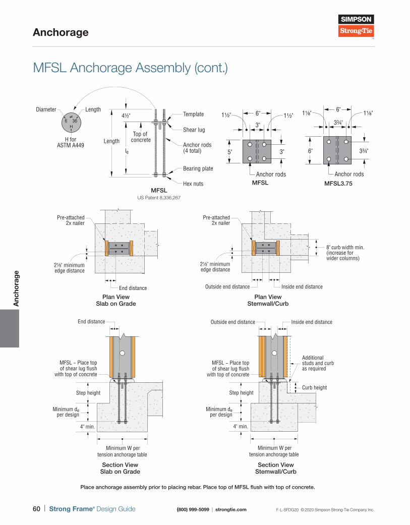
60 | Strong Frame® Design Guide (800) 999-5099 | strongtie.com F-L-SFDG20 © 2020 Simpson Strong-Tie Company Inc.
Anchorage
Anc
hora
ge
MFSL
5"
6"
3"
3"
1½" 1½"
Anchor rodsMFSL3.75
6" 3¾"
3¾"
1⅛" 1⅛"6"
Anchor rods
MFSL Anchorage Assembly (cont.)
36H
6≠
Shear lug
Template4½"
Top of concrete
Anchor rods(4 total)
Bearing plate
Hex nuts
Length
le
Diameter Length
H forASTM A449
MFSLUS Patent 8,336,267
End distance
MFSL − Place top of shear lug flush
with top of concrete
4" min.
Minimum deper design
Step height
Minimum W pertension anchorage table
Section View Slab on Grade
21⁄8" minimumedge distance
Pre-attached2x nailer
End distance
Plan View Slab on Grade
8" curb width min. (increase for wider columns)
Outside end distance Inside end distance
Pre-attached2x nailer
21⁄8" minimumedge distance
Plan View Stemwall/Curb
MFSL − Place top of shear lug flush
with top of concrete
Outside end distance Inside end distance
Additional studs and curbas required
Curb height
Minimum W pertension anchorage table
4" min.
Minimum deper design
Step height
Section View Stemwall/Curb
Place anchorage assembly prior to placing rebar. Place top of MFSL flush with top of concrete.
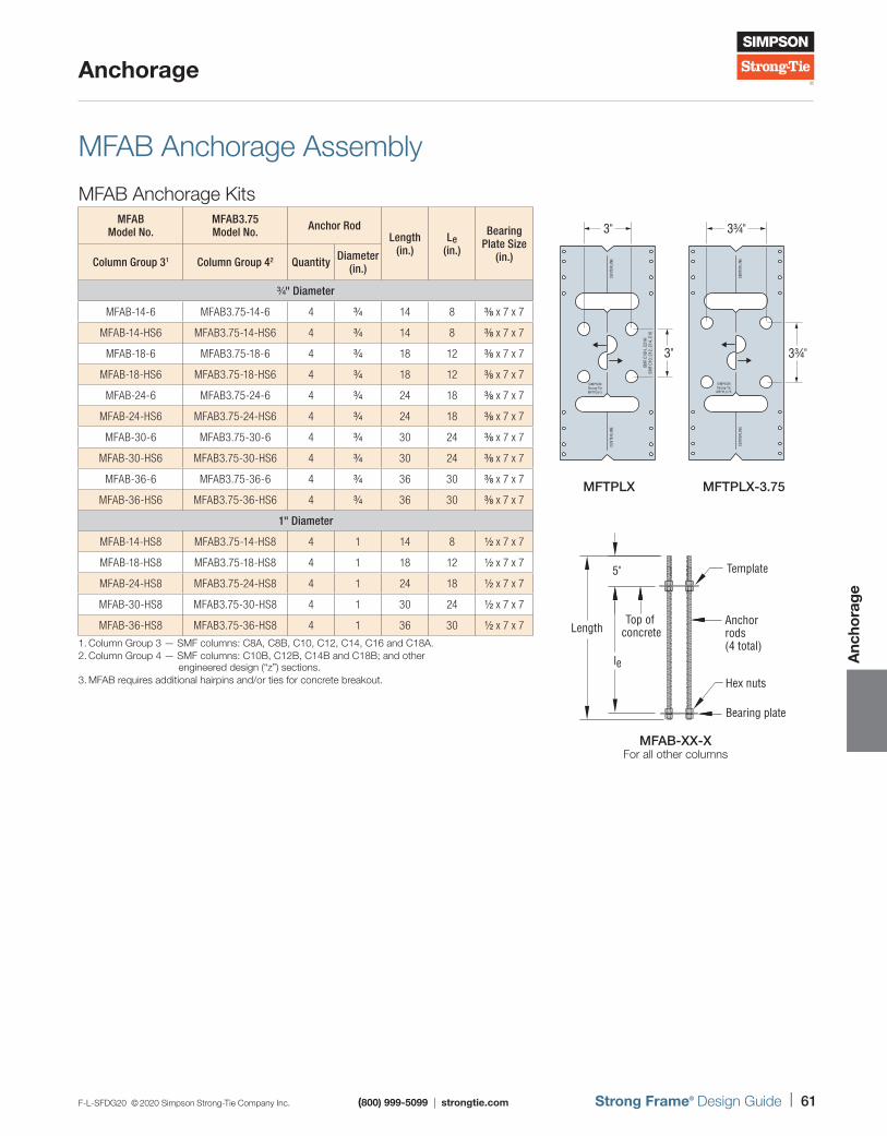
F-L-SFDG20 © 2020 Simpson Strong-Tie Company Inc. (800) 999-5099 | strongtie.com Strong Frame® Design Guide | 61
Anchorage
Anc
hora
ge
MFAB Anchorage Assembly
MFAB Anchorage KitsMFAB
Model No.MFAB3.75 Model No. Anchor Rod
Length (in.)
Le (in.)
Bearing Plate Size
(in.)Column Group 31 Column Group 42 Quantity Diameter (in.)
3/4" Diameter
MFAB-14-6 MFAB3.75-14-6 4 3/4 14 8 3/8 x 7 x 7
MFAB-14-HS6 MFAB3.75-14-HS6 4 3/4 14 8 3/8 x 7 x 7
MFAB-18-6 MFAB3.75-18-6 4 3/4 18 12 3/8 x 7 x 7
MFAB-18-HS6 MFAB3.75-18-HS6 4 3/4 18 12 3/8 x 7 x 7
MFAB-24-6 MFAB3.75-24-6 4 3/4 24 18 3/8 x 7 x 7
MFAB-24-HS6 MFAB3.75-24-HS6 4 3/4 24 18 3/8 x 7 x 7
MFAB-30-6 MFAB3.75-30-6 4 3/4 30 24 3/8 x 7 x 7
MFAB-30-HS6 MFAB3.75-30-HS6 4 3/4 30 24 3/8 x 7 x 7
MFAB-36-6 MFAB3.75-36-6 4 3/4 36 30 3/8 x 7 x 7
MFAB-36-HS6 MFAB3.75-36-HS6 4 3/4 36 30 3/8 x 7 x 7
1" Diameter
MFAB-14-HS8 MFAB3.75-14-HS8 4 1 14 8 1/2 x 7 x 7
MFAB-18-HS8 MFAB3.75-18-HS8 4 1 18 12 1/2 x 7 x 7
MFAB-24-HS8 MFAB3.75-24-HS8 4 1 24 18 1/2 x 7 x 7
MFAB-30-HS8 MFAB3.75-30-HS8 4 1 30 24 1/2 x 7 x 7
MFAB-36-HS8 MFAB3.75-36-HS8 4 1 36 30 1/2 x 7 x 7
MFAB-XX-XFor all other columns
Template5"
Top of concrete
Anchorrods(4 total)
Bearing plate
Hex nuts
Length
le
CENT
ERLI
NE
SIMPSONStrong-TieMFTPL6-3
CENT
ERLI
NE
OMF
C18H
, C21
HSM
F C1
0, C
12, C
14, C
16
3"
3"
CENT
ERLI
NE
SIMPSONStrong-TieMFTPL3.75
CENT
ERLI
NE
3¾"
3¾"
MFTPLX MFTPLX-3.75
1. Column Group 3 — SMF columns: C8A, C8B, C10, C12, C14, C16 and C18A.2. Column Group 4 — SMF columns: C10B, C12B, C14B and C18B; and other
engineered design (“z”) sections.3. MFAB requires additional hairpins and/or ties for concrete breakout.
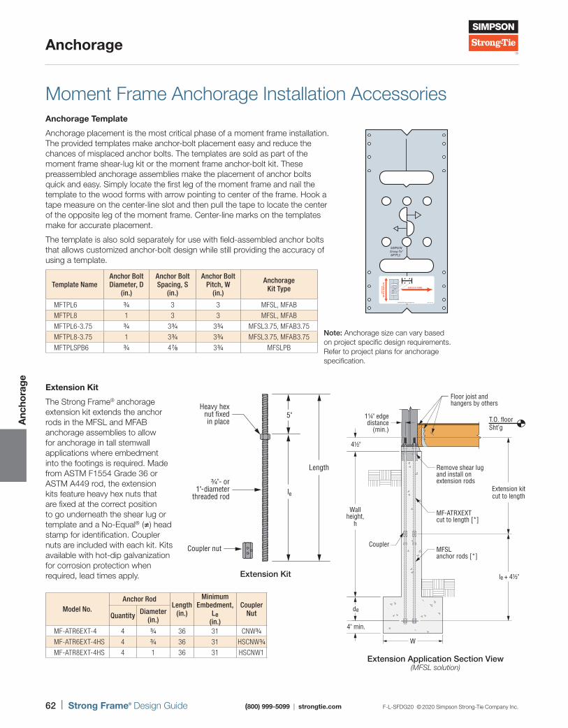
62 | Strong Frame® Design Guide (800) 999-5099 | strongtie.com F-L-SFDG20 © 2020 Simpson Strong-Tie Company Inc.
Anchorage
Anc
hora
ge
Template NameAnchor BoltDiameter, D
(in.)
Anchor BoltSpacing, S
(in.)
Anchor BoltPitch, W
(in.)
Anchorage Kit Type
MFTPL6 3/4 3 3 MFSL, MFAB
MFTPL8 1 3 3 MFSL, MFAB
MFTPL6-3.75 3/4 3 3/4 3 3/4 MFSL3.75, MFAB3.75
MFTPL8-3.75 1 3 3/4 3 3/4 MFSL3.75, MFAB3.75
MFTPLSPB6 3/4 4 7/8 3 3/4 MFSLPB
Moment Frame Anchorage Installation AccessoriesAnchorage Template
Anchorage placement is the most critical phase of a moment frame installation. The provided templates make anchor-bolt placement easy and reduce the chances of misplaced anchor bolts. The templates are sold as part of the moment frame shear-lug kit or the moment frame anchor-bolt kit. These preassembled anchorage assemblies make the placement of anchor bolts quick and easy. Simply locate the first leg of the moment frame and nail the template to the wood forms with arrow pointing to center of the frame. Hook a tape measure on the center-line slot and then pull the tape to locate the center of the opposite leg of the moment frame. Center-line marks on the templates make for accurate placement.
The template is also sold separately for use with field-assembled anchor bolts that allows customized anchor-bolt design while still providing the accuracy of using a template.
SIMPSONStrong-Tie®
MFTPL5
SIMPSONStrong-Tie®
MFTPL5
Note: Anchorage size can vary based on project specific design requirements. Refer to project plans for anchorage specification.
Extension Kit
The Strong Frame® anchorage extension kit extends the anchor rods in the MFSL and MFAB anchorage assemblies to allow for anchorage in tall stemwall applications where embedment into the footings is required. Made from ASTM F1554 Grade 36 or ASTM A449 rod, the extension kits feature heavy hex nuts that are fixed at the correct position to go underneath the shear lug or template and a No-Equal® (≠) head stamp for identification. Coupler nuts are included with each kit. Kits available with hot-dip galvanization for corrosion protection when required, lead times apply.
Model No.Anchor Rod
Length (in.)
Minimum Embedment,
Le (in.)
Coupler NutQuantity Diameter
(in.)
MF-ATR6EXT-4 4 3/4 36 31 CNW3/4
MF-ATR6EXT-4HS 4 3/4 36 31 HSCNW3/4
MF-ATR8EXT-4HS 4 1 36 31 HSCNW1
4" min.
W
4½"
de
le + 4½"
Coupler
Wallheight,
h
Extension kitcut to length
MFSL anchor rods [*]
MF-ATRXEXT cut to length [*]
Remove shear lugand install onextension rods
Floor joist andhangers by others
1¼" edgedistance
(min.)T.O. floorSht’g
Extension Application Section View(MFSL solution)
Heavy hexnut fixedin place
¾"- or1"-diameter
threaded rod
Length
5"
le
Coupler nut
Extension Kit
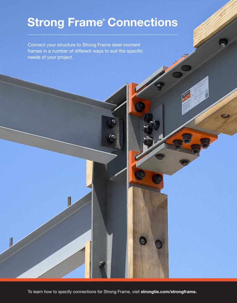
To learn how to specify connections for Strong Frame, visit strongtie.com/strongframe.
Strong Frame® Connections
Connect your structure to Strong Frame steel moment frames in a number of different ways to suit the specific needs of your project.
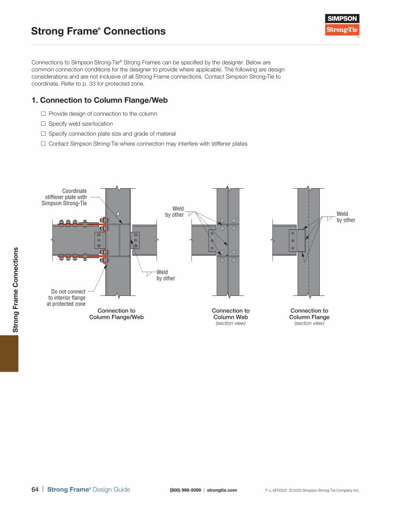
64 | Strong Frame® Design Guide (800) 999-5099 | strongtie.com F-L-SFDG20 © 2020 Simpson Strong-Tie Company Inc.
Strong Frame® Connections
Str
ong
Fra
me
Co
nnec
tions
Connections to Simpson Strong-Tie® Strong Frames can be specified by the designer. Below are common connection conditions for the designer to provide where applicable. The following are design considerations and are not inclusive of all Strong Frame connections. Contact Simpson Strong-Tie to coordinate. Refer to p. 33 for protected zone.
1. Connection to Column Flange/Web
Provide design of connection to the column
Specify weld size/location
Specify connection plate size and grade of material
Contact Simpson Strong-Tie where connection may interfere with stiffener plates
Connection to Column Web(section view)
Connection to Column Flange/Web
Connection to Column Flange
(section view)
Do not connectto interior flange
at protected zoneConnection toColumn Web(section view)
Connection toColumn Flange/Web
Connection toColumn Flange(section view)
Coordinatestiffener plate with
Simpson Strong-TieWeld
by other Weldby other
Weldby other
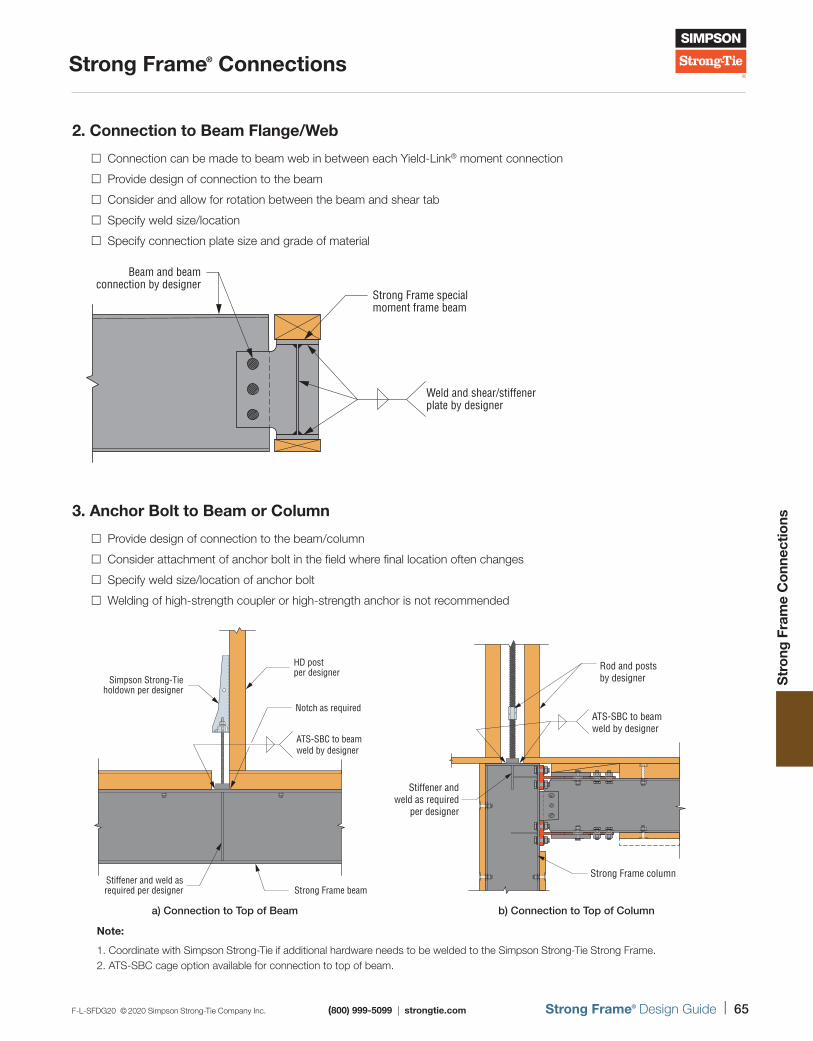
F-L-SFDG20 © 2020 Simpson Strong-Tie Company Inc. (800) 999-5099 | strongtie.com Strong Frame® Design Guide | 65
Strong Frame® Connections
Str
ong
Fra
me
Co
nnec
tions
2. Connection to Beam Flange/Web
Connection can be made to beam web in between each Yield-Link® moment connection
Provide design of connection to the beam
Consider and allow for rotation between the beam and shear tab
Specify weld size/location
Specify connection plate size and grade of material
3. Anchor Bolt to Beam or Column
Provide design of connection to the beam/column
Consider attachment of anchor bolt in the field where final location often changes
Specify weld size/location of anchor bolt
Welding of high-strength coupler or high-strength anchor is not recommended
Note:
1. Coordinate with Simpson Strong-Tie if additional hardware needs to be welded to the Simpson Strong-Tie Strong Frame.2. ATS-SBC cage option available for connection to top of beam.
Strong Frame specialmoment frame beam
Weld and shear/stiffenerplate by designer
Beam and beamconnection by designer
HD postper designer
Simpson Strong-Tieholdown per designer
Stiffener and weld asrequired per designer Strong Frame beam
ATS-SBC to beam weld by designer
Notch as required
a) Connection to Top of Beam
ATS-SBC to beam weld by designer
Rod and postsby designer
Strong Frame column
Stiffener andweld as required
per designer
b) Connection to Top of Column
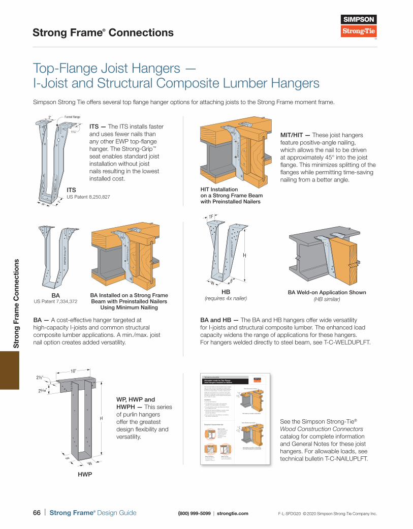
66 | Strong Frame® Design Guide (800) 999-5099 | strongtie.com F-L-SFDG20 © 2020 Simpson Strong-Tie Company Inc.
Strong Frame® Connections
Str
ong
Fra
me
Co
nnec
tions
Top-Flange Joist Hangers — I-Joist and Structural Composite Lumber HangersSimpson Strong Tie offers several top flange hanger options for attaching joists to the Strong Frame moment frame.
See the Simpson Strong-Tie® Wood Construction Connectors catalog for complete information and General Notes for these joist hangers. For allowable loads, see technical bulletin T-C-NAILUPLFT.
ITS — The ITS installs faster and uses fewer nails than any other EWP top-flange hanger. The Strong-Grip™ seat enables standard joist installation without joist nails resulting in the lowest installed cost.
Funnel flange
W
17⁄16"
2"
2"
ITSUS Patent 8,250,827
MIT/HIT — These joist hangers feature positive-angle nailing, which allows the nail to be driven at approximately 45° into the joist flange. This minimizes splitting of the flanges while permitting time-saving nailing from a better angle.
HIT Installation on a Strong Frame Beam with Preinstalled Nailers
BA and HB — The BA and HB hangers offer wide versatility for I-joists and structural composite lumber. The enhanced load capacity widens the range of applications for these hangers. For hangers welded directly to steel beam, see T-C-WELDUPLFT.
HB(requires 4x nailer)
BA — A cost-effective hanger targeted at high-capacity I-joists and common structural composite lumber applications. A min./max. joist nail option creates added versatility.
BAUS Patent 7,334,372
BA Installed on a Strong Frame Beam with Preinstalled Nailers
Using Minimum Nailing
WP, HWP and HWPH — This series of purlin hangers offer the greatest design flexibility and versatility.
B
25⁄16"
10"2½"
W
H
HWP
BA Weld-on Application Shown(HB similar)
This technical bulletin provides allowable loads, including uplift, for many common top-flange joist hangers when installed on wood nailers. Wood nailers may be attached to the top of a steel I-beam, concrete or masonry wall.
Uplift tests were performed on nominal 8" wide nailers attached to a steel beam, bolted along the centerline of the nailer for application of joist hangers that are spaced 24" (or wider) on center.
Installation:
• Use specified fasteners
• The attachment of the nailer to the supporting member is the responsibility of the Designer
• The edge distance of the nailer attachment should be no greater than 3 5⁄8"
• Optional nail holes are available on several models and may be used to increase uplift capacity (requires web stiffener)
• Some models require web stiffeners; see table for web-stiffener requirements
1½"
35/8" max.
Nailer attachment per Designer
BA Installed on 2x Nailer on Steel Beam
35/8" max.
Nailer attachment per Designer
2½"
BA Installed on 3x Nailer on Steel Beam with Optional Nailing for Increased Uplift
Examples of Improper Nailer Size
Nailer Too WideThe loading may cause cross-grain bending. As a general rule, the maximum allowable overhang is 1⁄4", depending on nailer thickness.
Nailer Too ThinOr the wrong hanger is used for the application.
Nailer Too NarrowA maximum mismatch of 1⁄8" for normal installations is allowed.
TECHNICAL BULLETIN
Allowable Loads for Top-Flange Joist Hangers Installed on Nailers
© 2019 Simpson Strong-Tie Company Inc. T-C-NAILUPLFT19
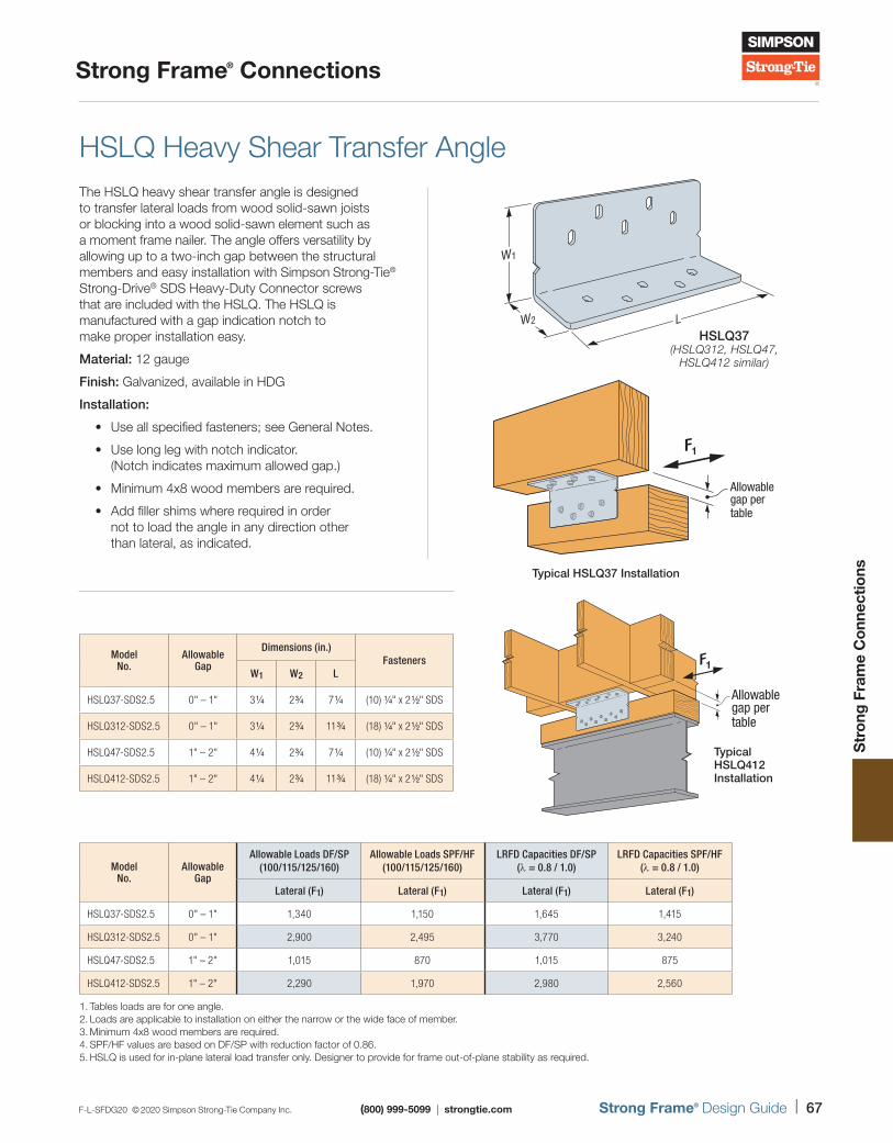
F-L-SFDG20 © 2020 Simpson Strong-Tie Company Inc. (800) 999-5099 | strongtie.com Strong Frame® Design Guide | 67
Strong Frame® Connections
Str
ong
Fra
me
Co
nnec
tions
HSLQ Heavy Shear Transfer AngleThe HSLQ heavy shear transfer angle is designed to transfer lateral loads from wood solid-sawn joists or blocking into a wood solid-sawn element such as a moment frame nailer. The angle offers versatility by allowing up to a two-inch gap between the structural members and easy installation with Simpson Strong-Tie® Strong-Drive® SDS Heavy-Duty Connector screws that are included with the HSLQ. The HSLQ is manufactured with a gap indication notch to make proper installation easy.
Material: 12 gauge
Finish: Galvanized, available in HDG
Installation:
• Use all specified fasteners; see General Notes.
• Use long leg with notch indicator. (Notch indicates maximum allowed gap.)
• Minimum 4x8 wood members are required.
• Add filler shims where required in order not to load the angle in any direction other than lateral, as indicated.
W1
W2 LHSLQ37
(HSLQ312, HSLQ47, HSLQ412 similar)
Model No.
Allowable Gap
Dimensions (in.)Fasteners
W1 W2 L
HSLQ37-SDS2.5 0" – 1" 3 1/4 2 3/4 7 1/4 (10) 1/4" x 2 1/2" SDS
HSLQ312-SDS2.5 0" – 1" 3 1/4 2 3/4 11 3/4 (18) 1/4" x 2 1/2" SDS
HSLQ47-SDS2.5 1" – 2" 4 1/4 2 3/4 7 1/4 (10) 1/4" x 2 1/2" SDS
HSLQ412-SDS2.5 1" – 2" 4 1/4 2 3/4 11 3/4 (18) 1/4" x 2 1/2" SDS
Model No.
Allowable Gap
Allowable Loads DF/SP (100/115/125/160)
Allowable Loads SPF/HF (100/115/125/160)
LRFD Capacities DF/SP (λ = 0.8 / 1.0)
LRFD Capacities SPF/HF (λ = 0.8 / 1.0)
Lateral (F1) Lateral (F1) Lateral (F1) Lateral (F1)
HSLQ37-SDS2.5 0" – 1" 1,340 1,150 1,645 1,415
HSLQ312-SDS2.5 0" – 1" 2,900 2,495 3,770 3,240
HSLQ47-SDS2.5 1" – 2" 1,015 870 1,015 875
HSLQ412-SDS2.5 1" – 2" 2,290 1,970 2,980 2,560
1. Tables loads are for one angle.2. Loads are applicable to installation on either the narrow or the wide face of member.3. Minimum 4x8 wood members are required.4. SPF/HF values are based on DF/SP with reduction factor of 0.86. 5. HSLQ is used for in-plane lateral load transfer only. Designer to provide for frame out-of-plane stability as required.
S2.5
S2.5
S2.5
S2.5
S2.5
S2.5
S2.5 S2.5
S2.5 S2.5
F1
Allowable gap per table
Typical HSLQ37 Installation
S2.5
S2.5
S2.5
S2.5
S2.5
S2.5
S2.5
S2.5
S2.5
S2.5
S2.5
S2.5
S2.5S2.5
S2.5S2.5
S2.5S2.5
F1
Allowable gap per table
Typical HSLQ412 Installation
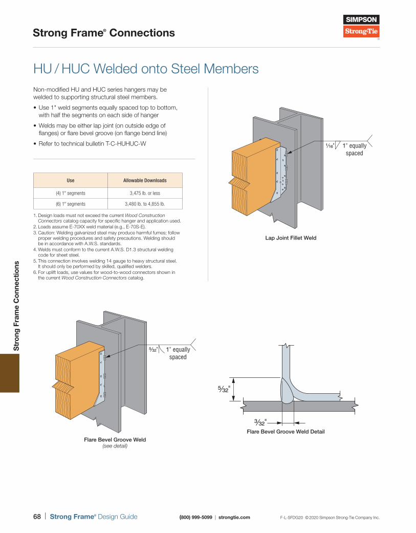
68 | Strong Frame® Design Guide (800) 999-5099 | strongtie.com F-L-SFDG20 © 2020 Simpson Strong-Tie Company Inc.
Strong Frame® Connections
Str
ong
Fra
me
Co
nnec
tions
HU / HUC Welded onto Steel MembersNon-modified HU and HUC series hangers may be welded to supporting structural steel members.
• Use 1" weld segments equally spaced top to bottom, with half the segments on each side of hanger
• Welds may be either lap joint (on outside edge of flanges) or flare bevel groove (on flange bend line)
• Refer to technical bulletin T-C-HUHUC-W
Flare Bevel Groove Weld Detail
3⁄32"
5⁄32"
Flare Bevel Groove Weld(see detail)
5⁄32" 1" equallyspaced
1⁄16" 1" equallyspaced
Lap Joint Fillet Weld
1. Design loads must not exceed the current Wood Construction Connectors catalog capacity for specific hanger and application used.
2. Loads assume E-70XX weld material (e.g., E-70S-E).3. Caution: Welding galvanized steel may produce harmful fumes; follow
proper welding procedures and safety precautions. Welding should be in accordance with A.W.S. standards.
4. Welds must conform to the current A.W.S. D1.3 structural welding code for sheet steel.
5. This connection involves welding 14 gauge to heavy structural steel. It should only be performed by skilled, qualified welders.
6. For uplift loads, use values for wood-to-wood connectors shown in the current Wood Construction Connectors catalog.
Use Allowable Downloads
(4) 1" segments 3,475 lb. or less
(6) 1" segments 3,480 lb. to 4,855 lb.
To learn how to measure and order frames, visit strongtie.com/strongframe.
Installer Overview
Strong Frame® moment frames are designed for fast and easy installation. Our simple, streamlined dimension verification and ordering process keep your job moving ahead.
70 | Strong Frame® Design Guide (800) 999-5099 | strongtie.com F-L-SFDG20 © 2020 Simpson Strong-Tie Company Inc.
Installer Overview
Inst
alle
r O
verv
iew
Strong Frame® Solutions vs. Site-Built FramesConstruction costs are always one of the biggest concerns of any project. Finding ways to be competitive is always a challenge, especially when installing structural steel. The cost concern is even more acute in light-frame construction projects where steel is used less frequently and has inherent supply and installation hurdles. The Strong Frame moment frames were designed with these issues in mind, and several of these difficulties have been addressed in our product offering.
Some of the most difficult aspects of moment-frame installation have already been factored into the Strong Frame before it even arrives at your jobsite, making for a fast and easy installation that saves you time and money. These considerations make the Strong Frame the most economical solution on the market. The inspection report is available upon request.
Construction Needs Site Built Strong Frame
100% field-bolted connections No delays due to failed weld inspection No lateral beam bracing installation Preattached wood nailers Connection hardware included All fabrication inspection included Factory quality control Preassembled anchorage kits available Moment frame shop drawing review included
F-L-SFDG20 © 2020 Simpson Strong-Tie Company Inc. (800) 999-5099 | strongtie.com Strong Frame® Design Guide | 71
Installer Overview
Inst
alle
r O
verv
iew
Strong Frame® Ordering Options Strong Frame moment frames will be delivered to the jobsite bundled together with all the necessary installation components. A typical Strong Frame product will have Yield-Link® structural fuses installed to the beam (SMF), or end plates attached to the beam, preinstalled nailers, predrilled holes for utilities, grey paint and label stickers for easy assembly. During the design and verification process, many options can be specified to meet the individual needs of your project, such as the following:
Omit nailers on the columns, beams or both.
Omit holes in beam or column flanges when nailers are omitted.
Frame to be utilized in cold-formed steel or steel structure. Options for beam top nailers can be provided to meet specific detailing requirements.
Omit predrilled utility holes in beam or column webs.
Additional or larger holes in beam or column flanges and webs. Size, location, and evaluation of elements shall be provided by the designer. Simpson Strong-Tie can assist.
Hot-dip galvanized columns and beam. Yield-Links cannot be hot-dip galvanized.
Omit grey primer and/or sticker labels for field finishing or protection of steel, when required.
Treated lumber for nailers.
Preassembled frames. (Contact Simpson Strong-Tie for availability depending on location and DOT limitations.)
Preattached components such as shear tabs or buckets may be installed during fabrication when required. Design and detailing shall be provided by the designer, and exact locations provided and confirmed by the contractor.
Other options may be available as required to meet job specific requirements. Contact Simpson Strong-Tie to discuss options and availability.
Strong Frame Ordering Process Ordering a Strong Frame moment frame is a simple process similar to ordering a special connector or any other Simpson Strong-Tie product. Here are the steps:
1. Obtain the designer’s submittal documents specifying Strong Frame products.
2. Locate the specified Strong Frame and anchorage model numbers in the designer’s documents.
3. Request pricing by providing the model numbers to your preferred Simpson Strong-Tie product dealer.
4. Pricing will be provided along with a dimension verification submittal package for the contractor to confirm overall frame and anchorage dimensions.
5. Confirm/modify dimensions as needed and place order. Quoted lead time begins once Simpson Strong-Tie receives a purchase order and signed dimensional verification submittal package.
72 | Strong Frame® Design Guide (800) 999-5099 | strongtie.com F-L-SFDG20 © 2020 Simpson Strong-Tie Company Inc.
Installer Overview
Inst
alle
r O
verv
iew
Dimension Verification ProcessThe Strong Frame moment frame ordering and installation process has been developed with the installer in mind. With a simplified dimension verification process and the option to order the frame from your local Simpson Strong-Tie dealer, nothing out of the ordinary is required. From the simplified placement of the preassembled anchorage kits using the punched centerline tape grooves, to the erection of the beams and columns.
When verifying the frame dimensions, the following determinations are vital in helping you specify frames that will fit your building. These items should be verified at this point to ensure a successful installation.
1 Frame Height — Dimensions are provided for each column from the top of concrete to the top of the nailer/column cap plate. A 1 1/2" grout pad is assumed between the top of the concrete and bottom of column base plate for leveling. The top of the column will be flush with the top of the beam top nailer. Be sure to check with the design drawings to confirm whether any other element needs to be considered in the frame height such as a 2x field installed top nailer over the frame. The top of the frame will typically be placed at the underside of the framing or horizontal diaphragm.
2 Clear Height — Where the frame spans over an opening with a required height, confirm that the clear height is adequate. Where additional height is required, the top of frame may need to be raised or beam size may need to be revised if possible. The Strong Frame beams come standard with a preinstalled 2x nailer on the underside of the beam with an additional field installed 2x nailer assumed in the clear height. If the 2x bottom beam nailers are requested to be omitted, consideration should be taken at the locations of the Yield-Link® moment connection adjacent to the columns where the plates and bolts extend approximately 2" below bottom of steel beam.
3 Inside/Clear Width — For locations where the inside width is the crucial dimension, such as a large door, window, or drive area, the inside clear width will need to be confirmed to meet the opening requirements. Typical columns come with preinstalled 2x wood nailers and the clear width would be considered between the nailers. Special consideration should be taken when the opening requires additional framing or trim elements, such as a 16' garage door typically needs 16'–4" between structural framing members to allow for finishing.
4 Outside Width — When the overall width dictates the extent of the frame. Consider the size of the columns and required opening width. Contact Simpson Strong-Tie and/or the project designer when considering using narrower column widths. When column nailers are omitted, special consideration should be given to the column baseplate size, which typically extends 1/2" past the outside flanges of the columns.
5 Column Centerline — Determining column centerline is a crucial step in order to properly locate the column anchor bolts. This dimension is provided during the frame design and dimension verification process. The provided column centerline can be used to accurately determine the required location of the anchor bolt kits using the anchor kit template centerline notches.
6 Beam and Column Flange Widths/Nailer Widths — Select beam and column sizes have been paired by Simpson Strong-Tie for common frame designs for various wall widths. SMF member sizes have been designed for framing solutions to fit within wall assemblies ranging from 2x6 to 2x10. These new sizes will offer more design flexibility ranging from common 2x6 wall assembly to higher capacity sections intended to fit within a 2x10 wall. See pp. 45–47 for nailer and member sizes. Where needed, Simpson Strong-Tie can provide larger AISC W sections using 2x12 or 2x14 framing to meet the designer’s project specifications.
7 Extending Columns Below Slab — In certain instances, the columns need to be extended below the top of slab for reasons such as a fixed base design or for finishing purposes. In these cases, the columns would typically be set on an erecting pad. The height of this pad will likely be determined by the project designer’s details as well as building/site requirements. When verifying dimensions, careful attention should be made to confirm the height of the erecting pad to meet design requirements and ensure proper column length during fabrication. This will be reflected in the frame’s verification sheet.
After checking your framing dimensions and providing them to us, we’ll provide a verification sheet for you to sign.
F-L-SFDG20 © 2020 Simpson Strong-Tie Company Inc. (800) 999-5099 | strongtie.com Strong Frame® Design Guide | 73
Installer Overview
Inst
alle
r O
verv
iew
Col.1
Beam
Beam depth
Col.2
1½"(typ.)
Column/anchor bolt centerline
Top of concrete (TOC)
S
S
S
S
4
3
5
11
6
7
2
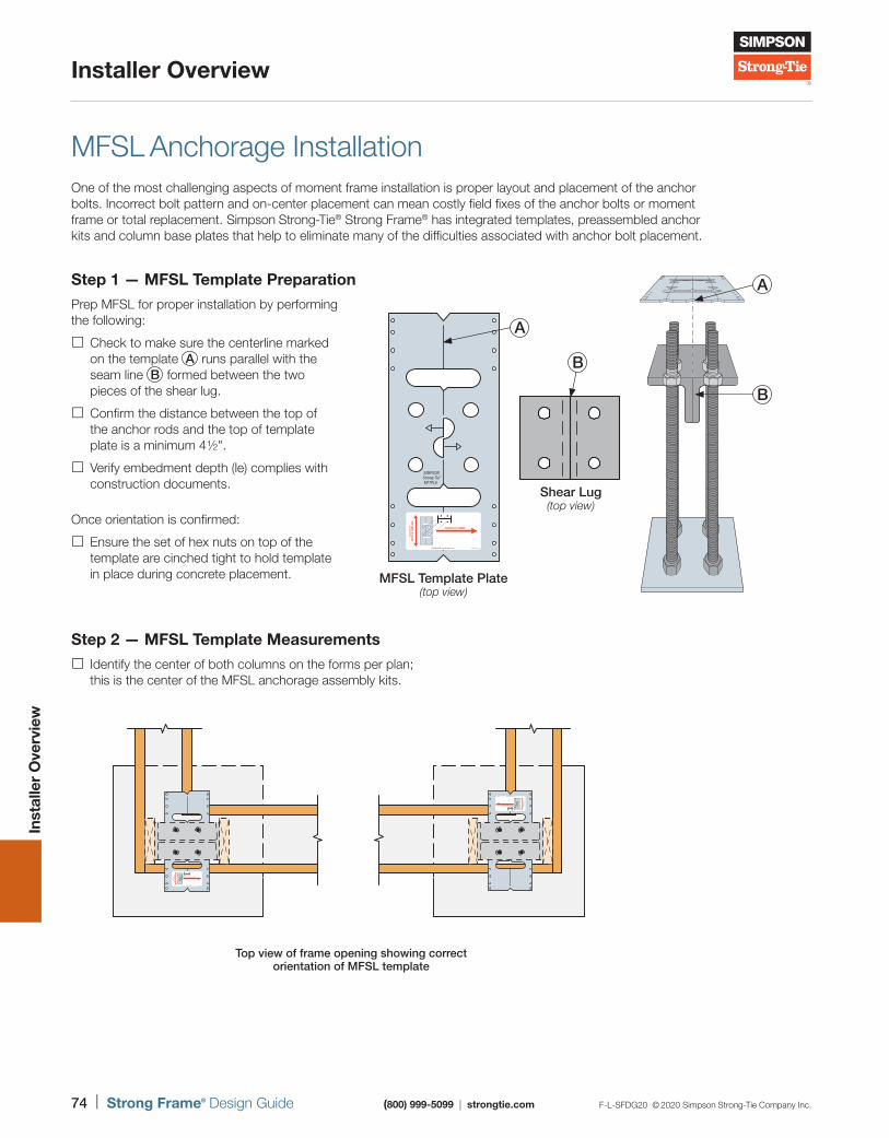
74 | Strong Frame® Design Guide (800) 999-5099 | strongtie.com F-L-SFDG20 © 2020 Simpson Strong-Tie Company Inc.
Installer Overview
Inst
alle
r O
verv
iew
MFSL Anchorage InstallationOne of the most challenging aspects of moment frame installation is proper layout and placement of the anchor bolts. Incorrect bolt pattern and on-center placement can mean costly field fixes of the anchor bolts or moment frame or total replacement. Simpson Strong-Tie® Strong Frame® has integrated templates, preassembled anchor kits and column base plates that help to eliminate many of the difficulties associated with anchor bolt placement.
Step 2 — MFSL Template Measurements Identify the center of both columns on the forms per plan; this is the center of the MFSL anchorage assembly kits.
Shear Lug(top view)
SIMPSONStrong-Tie®
MFTPL6
MFSL Template Plate(top view)
A
B
B
A
Top view of frame opening showing correct orientation of MFSL template
Step 1 — MFSL Template PreparationPrep MFSL for proper installation by performing the following:
Check to make sure the centerline marked on the template A runs parallel with the seam line B formed between the two pieces of the shear lug.
Confirm the distance between the top of the anchor rods and the top of template plate is a minimum 4 ½".
Verify embedment depth (le) complies with construction documents.
Once orientation is confirmed:
Ensure the set of hex nuts on top of the template are cinched tight to hold template in place during concrete placement.
F-L-SFDG20 © 2020 Simpson Strong-Tie Company Inc. (800) 999-5099 | strongtie.com Strong Frame® Design Guide | 75
Installer Overview
Inst
alle
r O
verv
iew
MFSL Anchorage Installation (cont.)Step 3 — MFSL Template Form Board AttachmentPrep MFSL for proper installation by performing the following:
Place MFSL shear lug assemblies at the center of each frame column location according to measurements taken in Step 2; attach to form boards using duplex nails or screws.
• Half moons in middle of the template can be used to pull your tape to confirm the measurements of the center of each frame column location.
• Call Simpson Strong-Tie at (800) 999-5099 with questions concerning the MFSL template placement to help troubleshoot any issues before concrete pour.
Step 4 — Concrete Placement Pour and thoroughly vibrate concrete around the shear lug to ensure full consolidation of the concrete around the assembly. Concrete should be flush with top of shear lug and bottom of template.
Step 5 — MFSL Template Removal When the concrete has thoroughly cured to allow for construction, remove duplex nails or screws, unscrew the top set of four hex nuts from the anchor bolts to remove the MFSL template plate.
Note: MFAB template installation similar to MFSL template installation.
Top View of MFSL Template Sticker
To ensure proper orientation of the MFSL, the template should be placed where the sticker’s CENTER OF FRAME arrow is pointing in the direction of the frame opening and corresponding column. The template is reversible when flipped on the sticker side only.
76 | Strong Frame® Design Guide (800) 999-5099 | strongtie.com F-L-SFDG20 © 2020 Simpson Strong-Tie Company Inc.
Installer Overview
Inst
alle
r O
verv
iew
Anchorage Extension Kit Installation (where required)MFSL Installation
1. Remove shear lug and template from the anchorage assembly.
2. Insert extension rods and fasten with nuts provided.
3. Cut bottom of rod to desired length so that the shear lug is flush with top of concrete.
4. Install original anchor rods onto the bottom of the extension rods using the coupler nuts (provided). Tighten rods so that both ends are visible in the Witness Hole™ openings.
MFAB Installation
1. Remove template from the anchorage assembly.
2. Insert extension rods and fasten with nuts provided.
3. Cut bottom of rod to desired length so that the fixed nut is flush with top of concrete.
4. Install original anchor rods onto the bottom of the extension rods using the coupler nuts (provided). Tighten rods so that both ends are visible in the Witness Hole openings.
Refer to p. 57 for more anchorage information.
Heavy hexnut fixedin place
¾"- or1"-diameter
threaded rod
Length
5"
le
Coupler nut
Extension Kit
Removeand install
template onextension
rods
Top of concrete
Do not cut end withhead stamp
Extension rodscut to lengthas necessary
Anchor rods remove template and reinstall above.Do not cut.
5"
Coupler nut
Fixed nuts
MFAB Anchorage Assembly with Extension Kit
36H
6≠
Diameter Length
H forASTM A449
MFSL Anchorage Assembly with Extension KitUS Patent 8,336,267 B2
Removeand install
shear lug onextension rods
Top of concrete
Do not cut end withhead stamp
Extension rodscut to lengthas necessary
Nuts
Anchor rods remove shear lug and reinstall above.Do not cut.
4½"
Coupler nut
F-L-SFDG20 © 2020 Simpson Strong-Tie Company Inc. (800) 999-5099 | strongtie.com Strong Frame® Design Guide | 77
Installer Overview
Inst
alle
r O
verv
iew
SIMPSON
Strong-Tie
MFTP6-3
OMF C18H, C12H
SMF C10, C12, C14,C16
CENTERLINE
CENTERLINE
1 23
45
67
89 10 11 12 13 14 15 16 17 18 19 20 21 22
2
3
6
4
7
15
Column with Standard Base Plate Installation Sequence 1 Locate column line by using centerline of anchorage template.
2 Install anchorage kit for each column and place concrete footing.
3 Remove anchorage template (MFTPL) and reinstall four (4) leveling nuts.
4 Lower columns onto anchor bolts.
5 Level columns by raising or lowering the leveling nuts under base plate.
6 Secure columns in place by tightening the nuts above base plate, provided with columns.
7 Place 5,000 psi (min.) non-shrink grout under base plate prior to loading frame.
Refer to pp. 79–80 for additional frame installation information.
78 | Strong Frame® Design Guide (800) 999-5099 | strongtie.com F-L-SFDG20 © 2020 Simpson Strong-Tie Company Inc.
Installer Overview
Inst
alle
r O
verv
iew
Embedded Fixed-Base Column Installation 1 Locate column line using centerline of anchorage template.
2 Install anchorage kit and place concrete pad for column support.
3 Remove anchorage template and reinstall four (4) leveling nuts.
4 Lower column onto anchor bolts.
5 Level columns by raising or lowering the leveling nuts under base plate.
6 Secure columns in place by tightening the nuts above base plate.
7 Install rebar through the holes in column as shown on drawings (confirm with approved design documents). Some conditions may require installation of rebar through the flange holes prior to securing column in place.
8 Place 5,000 psi (min.) non-shrink grout under base plate.
9 Place concrete for grade beam prior to loading frame.
Refer to pp. 79 – 80 for additional frame installation information.
SIMPSON
Strong-Tie
MFTP6-3
OMF C18H, C12H
SMF C10, C12, C14,C16
CENTERLINE
CENTERLINE
1 2 3 4 5 6 7 8 9 10 11 12 13 14 15 16 17 18 19 20 21
2
3
4
6
5
9
8
7
1
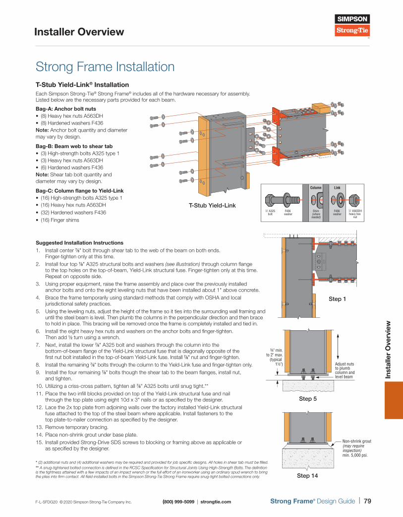
F-L-SFDG20 © 2020 Simpson Strong-Tie Company Inc. (800) 999-5099 | strongtie.com Strong Frame® Design Guide | 79
Installer Overview
Inst
alle
r O
verv
iew
Strong Frame InstallationT-Stub Yield-Link® InstallationEach Simpson Strong-Tie® Strong Frame® includes all of the hardware necessary for assembly. Listed below are the necessary parts provided for each beam.
Bag-A: Anchor bolt nuts • (8) Heavy hex nuts A563DH • (8) Hardened washers F436
Note: Anchor bolt quantity and diameter may vary by design.
Bag-B: Beam web to shear tab • (3) High-strength bolts A325 type 1 • (3) Heavy hex nuts A563DH • (6) Hardened washers F436
Note: Shear tab bolt quantity and diameter may vary by design.
Bag-C: Column flange to Yield-Link • (16) High-strength bolts A325 type 1 • (16) Heavy hex nuts A563DH • (32) Hardened washers F436 • (16) Finger shims
Suggested Installation Instructions1. Install center 7/8" bolt through shear tab to the web of the beam on both ends.
Finger-tighten only at this time.2. Install four top 7/8" A325 structural bolts and washers (see illustration) through column flange
to the top holes on the top-of-beam, Yield-Link structural fuse. Finger-tighten only at this time. Repeat on opposite side.
3. Using proper equipment, raise the frame assembly and place over the previously installed anchor bolts and onto the eight leveling nuts that have been installed about 1" above concrete.
4. Brace the frame temporarily using standard methods that comply with OSHA and local jurisdictional safety practices.
5. Using the leveling nuts, adjust the height of the frame so it ties into the surrounding wall framing and until the steel beam is level. Then plumb the columns in the perpendicular direction and then brace to hold in place. This bracing will be removed once the frame is completely installed and tied in.
6. Install the eight heavy hex nuts and washers on the anchor bolts and finger-tighten. Then add 1/2 turn using a wrench.
7. Next, install the lower 7/8" A325 bolt and washers through the column into the bottom-of-beam flange of the Yield-Link structural fuse that is diagonally opposite of the first nut bolt installed in the top-of-beam Yield-Link fuse. Install 7/8" nut and finger-tighten.
8. Install the remaining 7/8" bolts through the column to the Yield-Link fuse and finger-tighten only.9. Install the four remaining 7/8" bolts though the shear tab to the beam flanges, install nut,
and tighten.10. Utilizing a criss-cross pattern, tighten all 7/8" A325 bolts until snug tight.**11. Place the two infill blocks provided on top of the Yield-Link structural fuse and nail
through the top plate using eight 10d x 3" nails or as specified by the designer.12. Lace the 2x top plate from adjoining walls over the factory installed Yield-Link structural
fuse attached to the top of the steel beam where applicable. Install fasteners to the top plate-to-nailer connection as specified by the designer.
13. Remove temporary bracing.14. Place non-shrink grout under base plate.15. Install provided Strong-Drive SDS screws to blocking or framing above as applicable or
as specified by the designer.
* (2) additional nuts and (4) additional washers may be required and provided for job specific designs. All holes in shear tab must be filled.** A snug-tightened bolted connection is defined in the RCSC Specification for Structural Joints Using High-Strength Bolts. The definition is the tightness attained with a few impacts of an impact wrench or the full effort of an ironworker using an ordinary spud wrench to bring the plies into firm contact. All field-installed bolts in the Simpson Strong-Tie Strong Frame require snug-tight bolted connections only.
7∕8" A563DHheavy hex
nut
Shim(whereneeded)
7∕8" A325bolt
F436 washer
F436 washer
Column Link
T-Stub Yield-Link
Non-shrink grout(may require inspection)min. 5,000 psi.
Step 14
Adjust nuts to plumb column and level beam
¾" min.to 2" max.
(typical 1½")
Step 5
Step 1Step 1
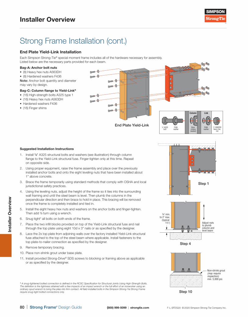
80 | Strong Frame® Design Guide (800) 999-5099 | strongtie.com F-L-SFDG20 © 2020 Simpson Strong-Tie Company Inc.
Installer Overview
Inst
alle
r O
verv
iew
Strong Frame Installation (cont.)End Plate Yield-Link InstallationEach Simpson Strong-Tie® special moment frame includes all of the hardware necessary for assembly. Listed below are the necessary parts provided for each beam.
Bag-A: Anchor bolt nuts • (8) Heavy hex nuts A563DH • (8) Hardened washers F436
Note: Anchor bolt quantity and diameter may vary by design.
Bag-C: Column flange to Yield-Link®
• (16) High-strength bolts A325 type 1 • (16) Heavy hex nuts A563DH • Hardened washers F436 • (16) Finger shims
* A snug-tightened bolted connection is defined in the RCSC Specification for Structural Joints Using High-Strength Bolts. The definition is the tightness attained with a few impacts of an impact wrench or the full effort of an ironworker using an ordinary spud wrench to bring the plies into firm contact. All field-installed bolts in the Simpson Strong-Tie Strong Frame require snug-tight bolted connections only.
Suggested Installation Instructions
1. Install 7/8" A325 structural bolts and washers (see illustration) through column flange to the Yield-Link structural fuse. Finger-tighten only at this time. Repeat on opposite side.
2. Using proper equipment, raise the frame assembly and place over the previously installed anchor bolts and onto the eight leveling nuts that have been installed about 1" above concrete.
3. Brace the frame temporarily using standard methods that comply with OSHA and local jurisdictional safety practices.
4. Using the leveling nuts, adjust the height of the frame so it ties into the surrounding wall framing and until the steel beam is level. Then plumb the columns in the perpendicular direction and then brace to hold in place. This bracing will be removed once the frame is completely installed and tied in.
5. Install the eight heavy hex nuts and washers on the anchor bolts and finger-tighten. Then add 1/2 turn using a wrench.
6. Snug tight* all bolts on both ends of the frame.
7. Place the two infill blocks provided on top of the Yield-Link structural fuse and nail through the top plate using eight 10d x 3" nails or as specified by the designer.
8. Lace the 2x top plate from adjoining walls over the factory installed Yield-Link structural fuse attached to the top of the steel beam where applicable. Install fasteners to the top plate-to-nailer connection as specified by the designer.
9. Remove temporary bracing.
10. Place non-shrink grout under base plate.
11. Install provided Strong-Drive® SDS screws to blocking or framing above as applicable or as specified by the designer.
7∕8" A563DHheavy hex
nut
Shim(whereneeded)
7∕8" A325bolt
F436 washer
F436 washer
Column Link
End Plate Yield-Link
Non-shrink grout(may require inspection)min. 5,000 psi.
Step 10
Adjust nuts to plumb column and level beam
¾" min.to 2" max.
(typical 1½")
Step 4
Step 1Step 1

To see how our software and materials can work to get your project moving, visit strongtie.com/strongframe.
Additional Resources
Our abundance of online resources — software tools, load and installation sheets, videos, code reports and drawings — are available to help you select or design the ideal moment frame.
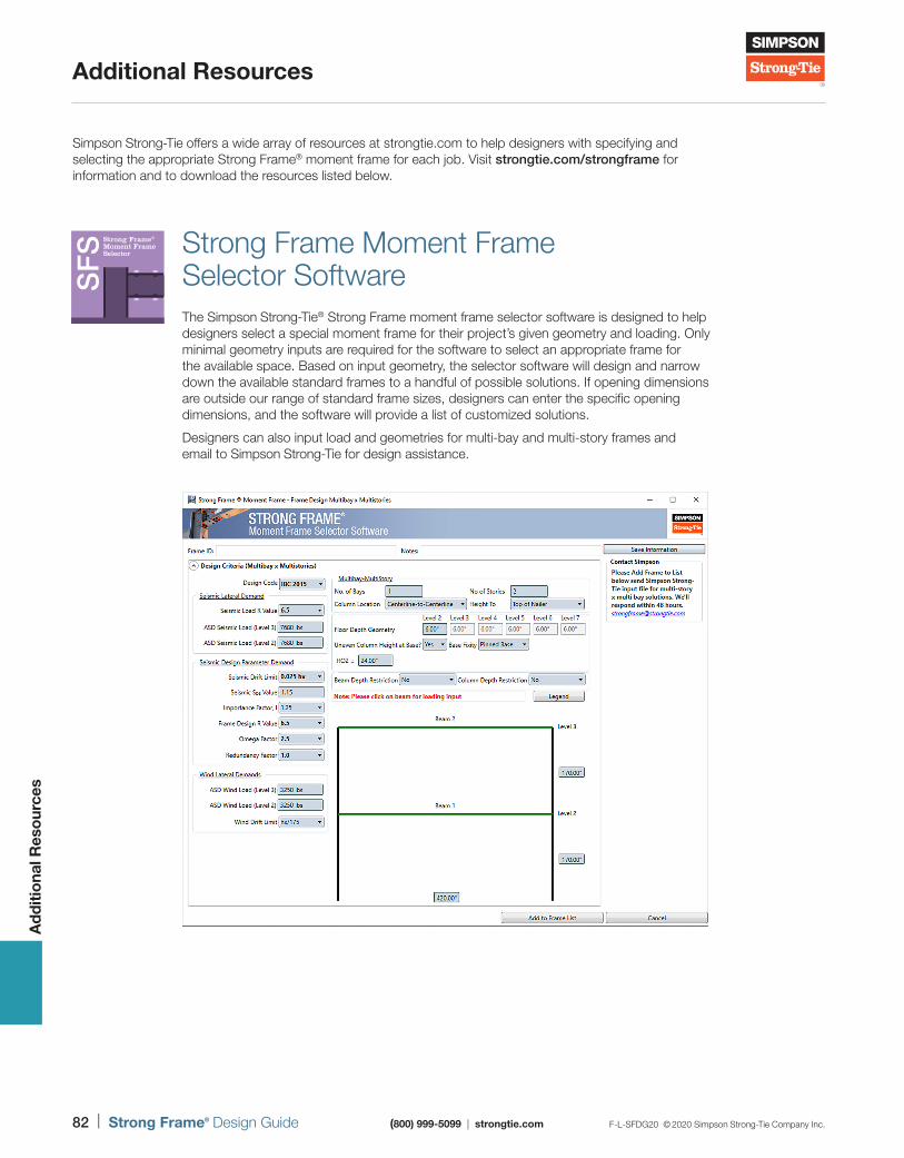
82 | Strong Frame® Design Guide (800) 999-5099 | strongtie.com F-L-SFDG20 © 2020 Simpson Strong-Tie Company Inc.
Additional Resources
Ad
diti
ona
l Res
our
ces
Simpson Strong-Tie offers a wide array of resources at strongtie.com to help designers with specifying and selecting the appropriate Strong Frame® moment frame for each job. Visit strongtie.com/strongframe for information and to download the resources listed below.
Strong Frame Moment Frame Selector SoftwareThe Simpson Strong-Tie® Strong Frame moment frame selector software is designed to help designers select a special moment frame for their project’s given geometry and loading. Only minimal geometry inputs are required for the software to select an appropriate frame for the available space. Based on input geometry, the selector software will design and narrow down the available standard frames to a handful of possible solutions. If opening dimensions are outside our range of standard frame sizes, designers can enter the specific opening dimensions, and the software will provide a list of customized solutions.
Designers can also input load and geometries for multi-bay and multi-story frames and email to Simpson Strong-Tie for design assistance.
SF
S Strong Frame®
Moment FrameSelector
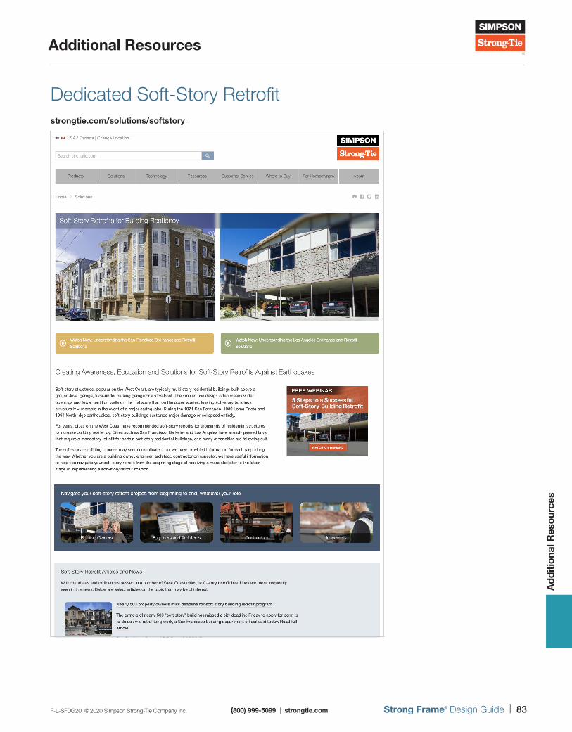
F-L-SFDG20 © 2020 Simpson Strong-Tie Company Inc. (800) 999-5099 | strongtie.com Strong Frame® Design Guide | 83
Additional Resources
Ad
diti
ona
l Res
our
ces
Dedicated Soft-Story Retrofit strongtie.com/solutions/softstory.
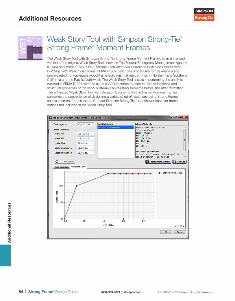
84 | Strong Frame® Design Guide (800) 999-5099 | strongtie.com F-L-SFDG20 © 2020 Simpson Strong-Tie Company Inc.
Additional Resources
Ad
diti
ona
l Res
our
ces
Weak Story Tool with Simpson Strong-Tie® Strong Frame® Moment FramesThe Weak Story Tool with Simpson Strong-Tie Strong Frame Moment Frames is an enhanced version of the original Weak Story Tool shown in The Federal Emergency Management Agency (FEMA) document FEMA P-807, Seismic Evaluation and Retrofit of Multi-Unit Wood-Frame Buildings with Weak First Stories. FEMA P-807 describes procedures for the analysis and seismic retrofit of vulnerable wood-frame buildings that are common in Northern and Southern California and the Pacific Northwest. The Weak Story Tool assists in performing the analysis outlined in FEMA P-807 with the aid of a CAD interface to account for the locations and structural properties of the various lateral-load-resisting elements before and after retrofitting. The enhanced Weak Story Tool with Simpson Strong-Tie Strong Frame Moment Frames combines the convenience of designing a variety of retrofit solutions using Strong Frame special moment frames menu. Contact Simpson Strong-Tie for pushover curve for frame options not included in the Weak Story Tool.
WS
T Weak-StoryTool
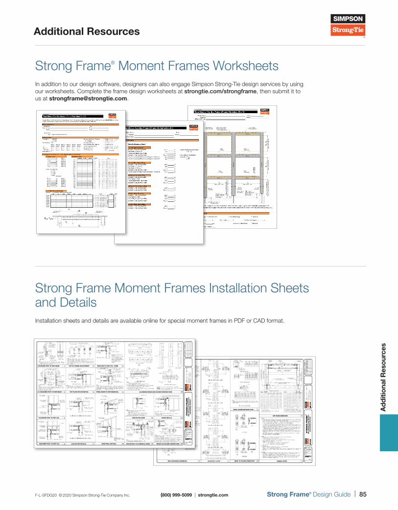
F-L-SFDG20 © 2020 Simpson Strong-Tie Company Inc. (800) 999-5099 | strongtie.com Strong Frame® Design Guide | 85
Additional Resources
Ad
diti
ona
l Res
our
ces
Strong Frame® Moment Frames Worksheets In addition to our design software, designers can also engage Simpson Strong-Tie design services by using our worksheets. Complete the frame design worksheets at strongtie.com/strongframe, then submit it to us at [email protected].
Strong Frame Moment Frames Installation Sheets and Details Installation sheets and details are available online for special moment frames in PDF or CAD format.
36H
5
36H
5
Fram
eIns
ide
COLU
MN C
enter
Line
Fram
eIns
ide
COLU
MN C
enter
Line
2X8 WOOD NAILERAT COL, TYP.
4X8 BEAMTOP NAILER
2X8 BEAMBOT. NAILER
2X FIELDINSTALLED NAILER
2X8 FIELD INSTALLEDNAILER AS REQ'D
CO
LUM
N
BEAM
CO
LUM
N
BLOCKING(PROVIDED)
ST
RO
NG
FR
AM
ES
MF
INS
TA
LLA
TIO
N D
ET
AIL
SE
NG
INE
ER
ED
DE
SIG
NS
SMF1
1
2
HOLDOWN POST TO SMF BEAM
6x HOLDOWN POST TO SMF BEAM
3HOLDOWN POST TO SMF COL.
4HOLDOWN POST TO SMF COL.
TOP OF FRAME ADJUSTMENT 5
6TOP PLATE SPLICE DETAIL
7COLLECTOR DETAILS
WOOD BM TO SMF COL. CONN. 8
9STEEL BEAM TO SMF BEAM/COL.
10RAKE WALL DETAILS
13WOOD INFILLS
BEAM-TO-COLUMN CONNECTION 15NAILER BOLT ALLOWABLE LOADS 14
11PROTECTED ZONE
ALLOWABLE BEAM AND COLUMN PENETRATIONS 12
ST
RO
NG
-FR
AM
ES
MF
INS
TA
LLA
TIO
N D
ET
AIL
SE
NG
INE
ER
ED
DE
SIG
NS
SMF3
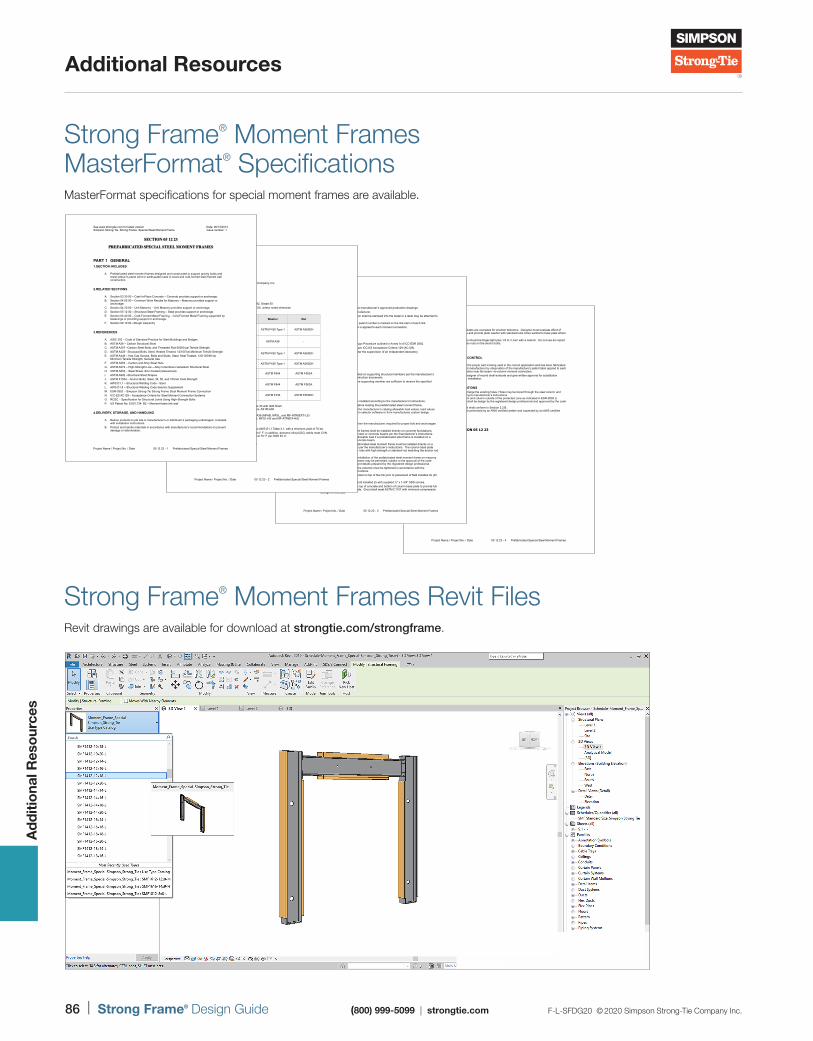
86 | Strong Frame® Design Guide (800) 999-5099 | strongtie.com F-L-SFDG20 © 2020 Simpson Strong-Tie Company Inc.
Additional Resources
Ad
diti
ona
l Res
our
ces
M. Holes in base plates are oversized for erection tolerance. Designer must evaluate effect of oversized holes and provide plate washer with standard-size holes welded to base plate where required.
N. Anchor bolt nuts should be finger-tight plus 1/3 to ½ turn with a wrench. Do not use an impact wrench to tighten nuts on the anchor bolts.
3. FIELD QUALITY CONTROL
A. Determine that the proper part is being used in the correct application and has been fabricated by the approved manufacturer by observation of the manufacture’s patent label applied to each moment connection near the beam –to-column moment connection.
B. The engineer/designer of record shall evaluate and give written approval for substitution request prior to installation.
4. FIELD MODIFICATIONS A. Do not cut or enlarge the existing holes. Holes may be bored through the steel column and
beams according to manufacturer’s instructions B. Welding to beam and column outside of the protected zone as indicated in ESR-2802 is
allowed. Weld shall be design by the registered design professional and approved by the code official.
C. Weld filler metal shall conform to Section 2.2.B. D. Welding shall be performed by an AWS certified welder and inspected by an AWS certified
inspector.
END OF SECTION 05 12 23
Project Name / Project No. / Date 05 12 23 - Prefabricated Special Steel Moment Frames4
3. FABRICATION
A. Shop assembly to occur per the manufacturer’s approved production drawings. B. Fabrication tolerances per manufacturer. C. The manufacturer’s identification shall be stamped into the metal or a label may be attached to
the part with adhesive. D. The manufacture’s connection patent number is marked on the link-stem of each link. E. The manufacture’s patent label is applied to each moment connection.
4. DESIGN AND TESTING
A. Frame design shall be per Design Procedure outlined in Annex A of ICC-ESR 2802. B. Testing shall be performed as per ICC-ES Acceptance Criteria 129 (AC129). C. Testing shall be conducted under the supervision of an independent laboratory.
PART 3 EXECUTION 1. EXAMINATION
A. Moment Frames shall be installed on supporting structural members per the manufacturer’s instructions or Engineer’s construction documents.
B. Verify that the dimensions of the supporting member are sufficient to receive the specified frame columns.
2. INSTALLATION
A. All specified fasteners must be installed according to the manufacturer’s instructions. B. Install all specified fasteners before loading the prefabricated steel moment frame. C. Do not overload by exceeding the manufacturer’s catalog allowable load values, load values
obtained from the manufacture’s selector software or from manufactures custom design calculation packages.
D. Use proper safety equipment. E. Choose the correct template, from the manufacturer, required for proper bolt and anchorages
placement. F. The prefabricated steel moment frames shall be installed directly on concrete foundations,
masonry foundations or walls, steel or concrete beams per the manufacturer’s instructions. There may be a reduction of allowable load if a prefabricated steel frame is installed on a masonry foundation or steel/concrete beam.
G. Concrete installation: The prefabricated steel moment frame must be installed directly on a concrete foundation/wall/beam per the manufacturer’s instructions. The column base plate must be secured to the anchor rods with high strength or standard nut matching the anchor rod grade.
H. Masonry or steel installation: Installation of the prefabricated steel moment frame on masonry walls or foundations or steel beams may be permitted, subject to the approval of the code official based on calculations and details prepared by the registered design professional.
I. Bolts connecting the beam to the columns must be tightened in accordance with the manufacturer’s installation instructions.
J. Install infill wood blocking provided on top of the link prior to placement of field installed 2x (for wood construction)
K. Connect column cap plate to field installed 2x with supplied ½” x 1-3/4” SDS screws. L. Grout shall be placed between top of concrete and bottom of column base plate to provide full
bearing of the column base plate. Grout shall meet ASTM C1107 with minimum compression strength of 5000 psi.
Project Name / Project No. / Date 05 12 23 - Prefabricated Special Steel Moment Frames3
Strong Frame® Moment Frames MasterFormat® SpecificationsMasterFormat specifications for special moment frames are available.
Strong Frame® Moment Frames Revit FilesRevit drawings are available for download at strongtie.com/strongframe.
PART 2 PRODUCTS 1. MANUFACTURERS
A. Manufacturer: Simpson Strong-Tie® Company, Inc.
2. MATERIALS
A. Steel: 1. Wide Flange Beams: ASTM A992, Grade 50 2. Bars/Plates: ASTM A572, grade 50, unless noted otherwise 3. Bolts, Washers and Nuts:
4. Finger Shims: ASTM A653 Grade 33 with G90 finish. 5. Shear Lug Anchorage Assemblies: ASTM A36 6. Anchor Rods:
i. ASTM F1554 Gr 36 or A36 (MFAB, MFSL, and MF-ATR6EXT-LS) ii. ASTM A449 (MFAB-HS, MFSL-HS and MF-ATR6EX-HS)
B. Weld Filler Metal: 1. Low hydrogen type conforming to AWS D1.1 Table 3.1, with a minimum yield of 70 ksi. 2. Notch toughness meet 20-lb-ft at 0° F; in addition, demand critical (DC) welds meet CVN
toughness of 40-lb-ft at 70° F per AWS D1.8. C. Wood Nailers:
1. Douglas fir, No 2 grade or better D. Finishes:
1. Gray Primer
Connection Location Bolt Washer Nut
Link- to-Column flange bolts (Beam side)
ASTM A325, Type 1 ASTM F436 Type 1 ASTM A563DH
Link- to-Column flange bolts
(bearing plate)- ASTM A36 -
Link –to-Beam flange bolts
ASTM F2280, Twist off type
(A490 Equivalent)ASTM F436 Type 1 ASTM A563DH
BRP-to-Beam flange bolts ASTM A325, Type 1 ASTM F436 Type 1 ASTM A563DH
Beam top flange nailer bolts ASTM A307 Gr. A ASTM F844 ASTM F563A
Beam bottom/column nailer carriage bolts
ASTM A307 Gr. A ASTM F844 ASTM F563A
Column Base Plate to Anchorage
F1554 GR 36/A36 ASTM A449 ASTM F436 ASTM F563DH
Project Name / Project No. / Date 05 12 23 - Prefabricated Special Steel Moment Frames2
See www.strongtie.com for latest version Date: 06/13/2014 Simpson Strong-Tie, Strong Frame, Special Steel Moment Frame Issue number: 1
SECTION 05 12 23
PREFABRICATED SPECIAL STEEL MOMENT FRAMES
PART 1 GENERAL 1.SECTION INCLUDES
A. Prefabricated steel moment frames designed and constructed to support gravity loads and resist lateral in-plane wind or earthquake loads in wood and cold-formed steel framed wall construction.
2.RELATED SECTIONS
A. Section 03 30 00 – Cast-In-Place Concrete – Concrete provides support or anchorage. B. Section 04 05 00 – Common Work Results for Masonry – Masonry provides support or
anchorage. C. Section 04 20 00 – Unit Masonry – Unit Masonry provides support or anchorage. D. Section 05 12 00 – Structural Steel Framing – Steel provides support or anchorage. E. Section 05 40 00 – Cold-Formed Metal Framing – Cold-Formed Metal Framing supported by
fastenings or providing support or anchorage. F. Section 06 10 00 –Rough Carpentry
3.REFERENCES
A. AISC 303 – Code of Standard Practice for Steel Buildings and Bridges B. ASTM A36 – Carbon Structural Steel C. ASTM A307 –Carbon Steel Bolts, and Threaded Rod 60000 psi Tensile Strength D. ASTM A325– Structural Bolts, Steel, Heated Treated, 12/105 ksi Minimum Tensile Strength E. ASTM A449 – Hex Cap Screws, Bolts and Studs, Steel, Heat Treated, 120/105/90 ksi
Minimum Tensile Strength, General Use F. ASTM A563 – Carbon and Alloy Steel Nuts G. ASTM A572 – High-Strength Low – Alloy Columbium-Vanadium Structural Steel H. ASTM A653 – Steel Sheet, Zinc-Coated (Galvanized) I. ASTM A992 –Structural Steel Shapes J. ASTM F1554 – Anchor Bolts, Steel, 36, 55, and 105-ksi Yield Strength K. AWS D1.1 – Structural Welding Code - Steel L. AWS D1.8 – Structural Welding Code Seismic Supplement M. ESR-2802 – Simpson Strong-Tie Strong Frame Steel Moment Frame Connection N. ICC-ES AC129 – Acceptance Criteria for Steel Moment Connection Systems O. RCSC – Specification for Structural Joints Using High-Strength Bolts P. US Patent No. 8,001,734 B2 – Moment frame link wall
4.DELIVERY, STORAGE, AND HANDLING
A. Deliver products to job site in manufacturer’s or distributor’s packaging undamaged, complete with installation instructions.
B. Protect and handle materials in accordance with manufacturer’s recommendations to prevent damage or deterioration.
Project Name / Project No. / Date 05 12 23 - Prefabricated Special Steel Moment Frames1
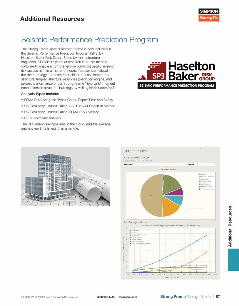
F-L-SFDG20 © 2020 Simpson Strong-Tie Company Inc. (800) 999-5099 | strongtie.com Strong Frame® Design Guide | 87
Additional Resources
Ad
diti
ona
l Res
our
ces
Seismic Performance Prediction ProgramThe Strong Frame special moment frame is now included in the Seismic Performance Prediction Program (SP3) by Haselton Baker Risk Group. Used by most structural engineers, SP3 distills years of research into user-friendly software to enable a comprehensive building-specific seismic risk assessment in a matter of hours. You can learn about the methodology and research behind the assessment, the structural fragility, structural response prediction engine, and seismic performance of our Strong Frame Yield-Link® moment connections in structural buildings by visiting hbrisk.com/sp3.
Analysis Types Include:
• FEMA P-58 Analysis: Repair Costs, Repair Time and Safety
• US Resiliency Council Rating: ASCE 31 /41 Checklist Method
• US Resiliency Council Rating: FEMA P-58 Method
• REDi Downtime Analysis
The SP3 analysis engine runs in the cloud, and the average analysis run time is less than a minute.

88 | Strong Frame® Design Guide (800) 999-5099 | strongtie.com F-L-SFDG20 © 2020 Simpson Strong-Tie Company Inc.
Additional Resources
Ad
diti
ona
l Res
our
ces
Strong Frame® Moment Frames Videos Visit the Simpson Strong-Tie® video library at strongtie.com/video to see installation and jobsite videos.
How to Install a Special Moment Frame in Soft-Story Building Retrofits
Bessemer Soft-Story Retrofit Case Study
Multi-Story Special Moment Frame
Harland Case Study
Strong Frame Moment Frames Additional LiteratureAdditional literature pieces, such as installation and technical fliers, are available at strongtie.com to assist our customers in specifying and installing our Strong Frame moment frames.
Strong Frame Special Moment Frame Multi-Story
and Multi-Bay Designs
Strong Frame® Special Moment Frame Multi-Story and Multi-Bay Designs
(800) 999-5099 | strongtie.com
F-L-SMF18.indd 1 6/19/18 9:19 AM
Soft-Story Retrofit Guide
Increase Your Structure’s Resiliency
Soft-Story Retrofit Guide
(800) 999-5099 | strongtie.com
DESIGN SOLUTIONS FOR INCREASING RESILIENCE IN SOFT-STORY RETROFITS
F-L-SSRG16.indd 1 9/19/16 12:35 PM
Yeild-Link® Moment Connection Design Guide
MOMENT CONNECTIONS FOR THE STRUCTURAL STEEL DESIGNS
Yield-Link® Moment Connection Design Guide
(800) 999-5099 | strongtie.com

F-L-SFDG20 © 2020 Simpson Strong-Tie Company Inc. (800) 999-5099 | strongtie.com Strong Frame® Design Guide | 89
Notes

90 | Strong Frame® Design Guide (800) 999-5099 | strongtie.com F-L-SFDG20 © 2020 Simpson Strong-Tie Company Inc.
Notes

F-L-SFDG20 © 2020 Simpson Strong-Tie Company Inc. (800) 999-5099 | strongtie.com Strong Frame® Design Guide | 91
Notes
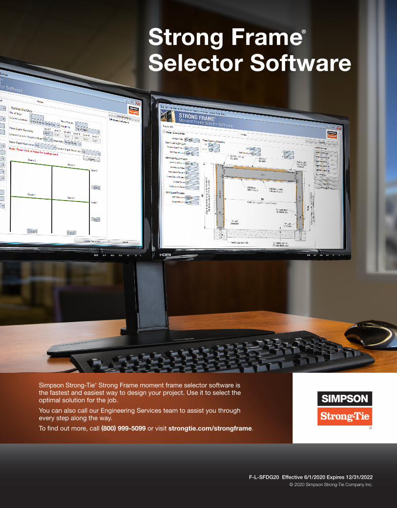
Strong Frame® Selector Software
F-L-SFDG20 Effective 6/1/2020 Expires 12/31/2022© 2020 Simpson Strong-Tie Company Inc.
Simpson Strong-Tie® Strong Frame moment frame selector software is the fastest and easiest way to design your project. Use it to select the optimal solution for the job.
You can also call our Engineering Services team to assist you through every step along the way.
To find out more, call (800) 999-5099 or visit strongtie.com/strongframe.
Related Documents