1 A systematic approach for improving performance while obtaining superior results with stronger, more attractive heatseals. STEPS TO HEATSEALING PERFECTION

Welcome message from author
This document is posted to help you gain knowledge. Please leave a comment to let me know what you think about it! Share it to your friends and learn new things together.
Transcript

1
A systematic approach for improving performance while obtaining superior results with stronger, more attractive heatseals.
STEPS TO HEATSEALING PERFECTION

Copyright ©2021 by TOSS Machine Components, Inc.
The TOSS® logo and TOSS Alloy20® are Registered Trademarks of TOSS Machine Components, Inc., USA. - PIREG®, Durit®, Siglaha®, and NOREX® are Registered Trademarks of TOSS GMBH & CO. KG INDUSTRIEPRODUKTE, Germany, EtherNet/IP™ is a trademark of ODVA, Inc.
All rights reserved. No part of this publication may be reproduced or transmitted in any form without the prior written permission of TOSS Machine Components, Inc.
$19.95 USD
9 STEPS TO HEATSEALING PERFECTION 2
Closed Loop Heat Sealing System

3
with the TOSS® PIREG® Heatseal Temperature Controller is the key to HEATSEALING PERFECTION. The system is designed expressly for high response precision temperature control, and delivers consistent and repeatable Perfect Seals… Every Time.
Technology
PIREG®-545 PANEL MOUNT
PIREG®-C2-220 ETHERNET/IP™
PIREG®-C2-200 ANALOG

9 STEPS TO HEATSEALING PERFECTION 4
These companies work together to make the best Heatsealing Technology available to the industry. TuOuSu S specializes in the development and distribution of Heatsealing components for users and machine builders, whereas PackworldUSA utilizes the components and technology to construct the best in Heatsealing machines.
The Optimum Sealing System has been developed to provide systems that produce predictable sealing of plastic pouch packaging and related products. The growth of high technology products that are delicate or perishable has created an increasing demand for superior packaging to protect the quality of the product as well as the integrity of the immediate environment that surrounds the product. TuOuSu S TECHNOLOGY provides control of the sealing process with the instantaneous feedback required to attain the desired sealing temperature within milliseconds and regulates the selected temperature and sealing time with repeated precision. The result is higher productivity, fewer rejects, superior seals, reduced cost — and...
Manufacturer and distributor of precision Heatsealing machines that consistently produce superior validatable seals; Packworld provides the means to seal and/or cut plastic pouch packaging materials and related products utilizing TuOuSu S TECHNOLOGY for precise control of the Heatsealing process. The result is...
with Validation Capability
AND

5
For more information visit:
www.tossheatseal.com TOSS MACHINE COMPONENTS, INC.
539 South Main Street Phone: 610-759-8883 Nazareth, PA 18064 USA FAX: 610-759-1766
email:[email protected]
Our Experience and Technology Today …Your Progress and Profit Tomorrow.
Engineering The Perfect Heat Seal Has Never Been Easier

9 STEPS TO HEATSEALING PERFECTION 6
All Packworld USA Medical Heat Sealers come equipped with TuOuSu S TECHNOLOGY and the advanced PIREG® Heatseal Temperature Controller.
PW3316 Touch Screen • Touch Screen Interface • Vertical Orientation • Stand (available)
AVAILABLE WORLDWIDE
PW5548 Touch Screen • Touch Screen Interface • Bag Stretcher • Vacuum (optional)
PW4424 Touch Screen • Touch Screen Interface • Vacuum (optional)
PW3416 Touch Screen • Touch Screen Interface • Horizontal Orientation • Stand Mounted (as shown) • Vacuum (optional)
www.packworldusa.com

7
PW3016 • Vertical Orientation • Stand (available)
PW2512 For custom contour heatseal
shapes with standard PIREG®
interface.
PW3116 Standard Interface • Horizontal Orientation • Stand (available)
AVAILABLE WORLDWIDE
www.packworldusa.com
All Packworld Medical Heat Sealers meet the standards of ISO 11607-2 and Packworld’s entire Touch-Screen line is compliant to 21 CFR Part 11.

9 STEPS TO HEATSEALING PERFECTION 8
Every enterprise should have a clear sense and understanding of its purpose and its obligation to provide service. In order to succeed, a business enterprise must meet a need and provide service that is of value. Further, the management must be able to clearly convey that message to its people and its clientele. It is to this end that this booklet is dedicated.
The packaging industry uses plastic films, sheets, and composite structures to protect, preserve, and display a multitude of products for consumers and industrial users. These packages must be produced, shaped, and sealed into pouches and containers with unerring precision and integrity, often at high speeds. As the commercial world expands, distribution networks are stretched to reach into distant markets and packaging must be made to withstand the rigors of transport and handling. Medical and healthcare products must remain sterile, electronics and instruments undamaged, and fresh foods crisp and delectable. Plastic film producers continue to create unimaginable packaging materials with superior properties for the protection and display of products. These products must be sealed with integrity in order for them to be useful.
This booklet is offered as an aid to those persons that are charged with the challenge of producing good packaging and . . .
andare dedicated to providing superior heat sealing
capability to the packaging industry.
Foreword
Charles H.Trillich Co-Founder
9
Contents STEP 1. Heatseal Configuration . . . . . . . . . . . . . . . . . . . . . . . . . 10
STEP 2. Heatseal Band Selection . . . . . . . . . . . . . . . . . . . . . . . . 12
STEP 3. Modes of Sealing . . . . . . . . . . . . . . . . . . . . . . . . . . . . . 17
STEP 4. Heatseal Jaw Design. . . . . . . . . . . . . . . . . . . . . . . . . . . 19
STEP 5. Heatseal Band Back-Ups & Jaw Facings . . . . . . . . . . . . . 24
STEP 6. Anti-Stick Provisions . . . . . . . . . . . . . . . . . . . . . . . . . . 27
STEP 7. Timing . . . . . . . . . . . . . . . . . . . . . . . . . . . . . . . . . . . . 32
STEP 8. Transformer Selection . . . . . . . . . . . . . . . . . . . . . . . . . 36
STEP 9. Controller Selection . . . . . . . . . . . . . . . . . . . . . . . . . . . 39
Certified Performance and Validation . . . . . . . . . . . . . . . . . . . . . 42
Summary. . . . . . . . . . . . . . . . . . . . . . . . . . . . . . . . . . . . . . . . . 44
Charts . . . . . . . . . . . . . . . . . . . . . . . . . . . . . . . . . . . . . . . . 44-47
Our Experience and Technology Today... Your Progress and Profit Tomorrow

9 STEPS TO HEATSEALING PERFECTION 10
What does one expect from a heat seal? Wide, narrow, shaped, or just seal or seal and cut? Before a satisfactory sealing system can be designed it is necessary to decide what seal configuration is desired. Is this to be a high integrity seal that will hold liquid under pressure or is a nominal seal good enough? High integrity seals with good appearance cannot be made as fast as nominal seals and as in any design problem, trade-offs must be made between cost (production rate) and performance. Some considerations follow.
P E E L O R S E A L
Most commonly, heat seals are made straight to create the side, top, or bottom of a bag or other package. Shaped seals can also be made to seal the top of containers, to join vacuum formed containers, or to produce shaped items like disposable garments or inflatable products. The width of the seal is usually a function of the appearance to be created or the need to resist the possibility of peeling open under stress. Some seals are designed to peel open for customer convenience or to open under pressure to permit mixing of products from one sealed chamber to another. Many possibilities exist, and it is important to understand the desired function and characteristics of the seal before proceeding.
S E A L W I D T H
Wider seals tend to ensure the integrity of the seal and minimize the risk of leaking; however, in theory at least, a properly made seal that is wider than the material is thick should be as strong as the base material. Wider seals reduce the risk of
1STEP Heatseal Configuration Determine what is expected from the seal.

11
leaking in the event the seal is imperfect; however, more power and greater jaw force is required to make wider seals.
Z I P P E R F A I L U R E S
Seals, if not well made, may fail along the edge of the seal. The polymeric materials may be well bonded but the material may have been thinned out along the edge of the seal during the sealing process. This common failure is called a “zipper failure” and it is caused by excessive heat or pressure while making the seal or the use of the wrong Heatseal Band. The TuOuSu S Tapered Band was developed to solve this problem. (See STEP 2. Heatseal Band Selection).
S E A L I N G L I Q U I D S
Sealing liquid and slurry products can create difficulty, especially if the product is oily. Products that adhere to the plastic film surface in the seal area can interfere with the ability of the film structures to unite. Seals of this nature can often be better made by using a Heatseal Band with a crowned face such as the TuOuSu S Reflex Band. As the Reflex Band presses into the film the product is squeezed out of the seal area thereby clearing the way for satisfactory bonding.
C U T A N D S E A L
Cut and seal is another option. This can be easily done with most simple films whereas composite film structures often contain barrier or structural materials that can only be cut with a knife. When using cut and seal bands like the TuOuSu S Beaded Band, T-Profile Band, Custom Seal Cut (CSC) Band or a Tapered Band in conjunction with a “cold” Cut Wire, care must be taken to select the best combination of Heatseal Band, cover stock, and resilient pad for the opposing jaw. More about this later.
Once the film material has been specified and the Heatseal configuration is determined, one can move on to Heatseal Band Selection.

9 STEPS TO HEATSEALING PERFECTION 12
Selection of the best Heatseal Band for any given application involves several considerations. The band must be of the correct width and configuration to produce the desired seal or cut/seal. In
addition, the band must be thick enough (have sufficient mass) to store the heat energy required for delivery to the material being sealed. When creating an impulse seal, it is desirable to terminate the heating cycle as soon as possible and begin cooling. Remember, the seal is not finally made until the seal area is cool enough to be dimensionally stable. If the Heatseal Band is too thick or the heat energy delivered is too great, the cooling time will be prolonged, thus prolonging the total cycle and limiting production rate.
Ideal Heatseal Band selection is a function of many variables including material composition, material thickness, heat absorption of the jaw, and the nature of the cover strip used over the Heatseal Band. In general, the thicker the material to be sealed, the thicker the Heatseal Band that should be used. Most materials, 1 mil to 6 mil can be sealed efficiently with Heatseal Bands in the thickness range of 0.1 mm to 0.25 mm. With very thick seals (multi-layers to totals of 15 mils or more) it may be well to use thicker bands or consider the possibility of applying heat from both sides.
Sealing through unequal thicknesses as in the case of closing a gusseted pouch can be accomplished even when the material is thick. Two layers of 6 mil material equals 12 mils, whereas four layers would be 24 mils. This is a very significant difference. Seals of this kind can be made with heat from only one side providing
2STEP Heatseal Band Selection Select the proper Heatseal Band for the job.

13
that the sealing temperature range of the film is not exceeded and sufficient time is allowed for the heat to penetrate through the multi-layers to effect a bond. The two layer portion of the seal will not be damaged or burned through as long as the Heatseal Band temperature does not exceed the optimum sealing temperature of the material. Sealing time can be reduced by applying heat simultaneously from both sides. When heated from both sides, cooling will be slower, but cooling can be accelerated by the use of water-cooled jaws or air blown on the seal area and/or the jaw.
H E A T S E A L B A N D D E S I G N S
TuOuSu S Alloy-20® Heatseal Bands come in a wide variety of shapes, each one designed for a specific purpose. The most common of these are Tapered-edge Band, Reflex Band, Beaded Band, T-Profile Band and Cutting Wire. In addition, there are other less common bands such as Double Seam Band and Custom Seal Cut (CSC) Band.
Heatseal Bands come in various widths to produce seals of various widths, but, they come in various thicknesses as well. Effective sealing at optimum speeds can only be made with a band of the correct thickness and mass. TuOuSu S Alloy-20® Heatseal Bands are available in standard widths from 2 mm to 25 mm and thicknesses from .1 mm to .5 mm. A complete list of over 300 bands is available upon request.

9 STEPS TO HEATSEALING PERFECTION 14
F L A T B A N D
The common Flat Band is an old stand-by configuration that was originally developed to make seals with widths wider
than that which could be made with round wire. In most applications, the Flat Band has been replaced by the Tapered-edge Band or the Reflex Band. The Flat Band has the major disadvantage of sharp square edges that cut into and weaken the film along the edge of the seal. Failures of this kind are called “zipper failures”; the seal itself is well secured and appears good, but the package is dangerously weakened.
T A P E R E D E D G E B A N D
This band, usually called Tapered Band, is the contemporary version of the Flat Band. On this band the edges have been tapered
down to a very thin edge. This produces two advantages. The tapering removes the sharp outer edge that cuts into the film while heating. It also acts to reduce the temperature of the band along its outer edges. Without a tapered edge the band will cut into the film along the edge of the seal and weaken the package. (See FLAT BAND above).
R E F L E X B A N D
This is an excellent band for thick materials, hard to seal materials, and vacuum packaging. Because of the convex
configuration of the band, it only makes edge contact with the underlayment backing. This limited contact minimizes heat loss and provides more energy for the sealing of the film. The Reflex Band is also excellent for liquid sealing because the convex face acts to squeeze the liquid out of the seal zone as the seal is made.
15
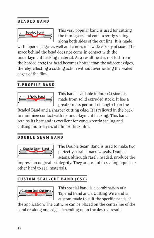
B E A D E D B A N D
This very popular band is used for cutting the film layers and concurrently sealing along both sides of the cut line. It is made
with tapered edges as well and comes in a wide variety of sizes. The space behind the bead does not come in contact with the underlayment backing material. As a result heat is not lost from the beaded area; the bead becomes hotter than the adjacent edges, thereby, effecting a cutting action without overheating the sealed edges of the film.
T- P R O F I L E B A N D
This band, available in four (4) sizes, is made from solid extruded stock. It has a greater mass per unit of length than the
Beaded Band and a sharper cutting edge. It is relieved in the back to minimize contact with its underlayment backing. This band retains its heat and is excellent for concurrently sealing and cutting multi-layers of film or thick film.
D O U B L E S E A M B A N D
The Double Seam Band is used to make two perfectly parallel narrow seals. Double seams, although rarely needed, produce the
impression of greater integrity. They are useful in sealing liquids or other hard to seal materials.
C U S T O M S E A L - C U T B A N D ( C S C )
This special band is a combination of a Tapered Band and a Cutting Wire and is custom made to suit the specific needs of
the application. The cut wire can be placed on the centerline of the band or along one edge, depending upon the desired result.

9 STEPS TO HEATSEALING PERFECTION 16
C U T T I N G W I R E
Round cutting wire is often used as an inexpensive means of cutting polymer films, these wires are available in sizes from
0.3 mm to 1.2 mm both in rolls or made into pre-cut lengths with or without copper plating at the ends. As with bands, best performance is obtained with brass end connectors brazed to the ends. When cutting through two or more layers, the layers of film will be sealed with a very narrow seal along the edge.
O V A L P R O F I L E W I R E
The Oval Profile Wire, available in two (2) sizes is larger in cross section than the round Cutting Wire. It is most useful for
making narrow seals on thick or stacked materials. It is not very effective as a cutting wire.
H A L F R O U N D W I R E
Half Round Wire is another variation on the Round cutting wire. Though rearely used, it is available in two (2) sizes and
function much as the Oval wire except that it has a better cutting action than the Oval Profile wire.
Z E B R A B A N D S
Heatseal Bands can be constructed with segments
along their length that remain cool while other segments reach sealing temperatures. These so called “Zebra” bands can have one or many hot and cool zones.

17
Heat sealing can be accomplished with the TOSS® PIREG® Heatseal Temperature Controller in two basic modes; constant heat or impulse. The choice of mode and the correct timing of the heat and cool cycles will be finally determined by practical tests with the machine, the product, and the film. There are some guidelines however.
I M P U L S E S E A L I N G
In the impulse sealing mode the heating cycle is synchronized with the rhythm of the machine. Every heating phase is followed by a cooling phase while the jaws remain closed for a brief interval. Cooling is effected with jaws closed so that the seal has already set and has good strength and appearance when the jaws open. This method is preferred when sealing time is available because the bond that is formed during the cooling phase creates a strong seal with superior appearance. This is especially important when working with shrink films.
R E S T H E A T M O D E ( for opt imum performance)
This variation of Impulse Sealing is very desirable and highly recommended whenever possible. Rest Heat sealing requires precision in band sizing and timing. (For more information, see STEP 7. Timing.)
3STEP Modes of Sealing Which sealing mode is best for this application?
9 STEPS TO HEATSEALING PERFECTION 18
C O N S T A N T H E A T
The Heatseal Band is continuously energized for the duration of the machine use. The band temperature is constantly monitored and maintained at the pre-set temperature. During the sealing phase the controller automatically compensates for the “lost” heat by adjusting the voltage supplied to the band. During pauses between cycles, the controller releases only a small amount of energy to compensate for the heat lost into the environment. When the jaws are open, the controller will restrict the energy delivered and overheating is not possible. The constant heat feature is usually used for speeds over 50-60 cycles/minute when the interval between seal cycles is very short. The seal must cool or be cooled after the jaws have opened. This mode can effectively be employed for the high speed making of empty bags and similar applications. Constant heat mode is rarely satisfactory in form/fill/seal applications because the contents of the package tends to force the seal open or disfigure it before the seal has cooled and set.
The advantages of this Constant heat method are that the Heatseal Band is not repetitively cycled on and off and the demand during the initial heating phase can be less than that required for the impulse process. The constant temperature minimizes the stress on the Heatseal Band because the band remains in its expanded condition when heated. The disadvantage of the constant heat is the loss of controlled cooling while the jaws continue to grip the seal. Seals tend to shrink or deform if the jaws are opened while the film is still hot. Generally, when operating with constant heat, the seal is cooled immediately after jaw opening by use of cooling air or a quenching jaw.
When in “Constant Heat” mode, a fast cool down of the Heatseal element is not called for; therefore, good thermal insulation between the Heatseal Band and the jaw is helpful. Less heat will be lost into the jaws and less total energy will be consumed. The result is less demand on the Transformer and the Heatseal Controller.

19
Heatseal jaw design is relatively simple. It is made even easier by the use of TuOuSu S components that are available to facilitate the construction.
Good sealing depends upon equal and even contact between the jaws for the full length of the
jaws. This means that the jaw bars must be straight and evenly loaded to avoid bowing of the jaws during the sealing process. When building long jaws, it may be necessary to utilize a supplementary bar as a stiffening back-up member.
Sealing is accomplished when the seal area cools, therefore, the ability of the jaw bar to absorb heat is important (See STEP 3. Modes of Sealing). Aluminum is usually used in Heatseal Bars because it has a high specific heat and thermal conductivity as well as being light and easy to machine. Jaw Bars offered by TuOuSu S include a cooling passage for the full length of the jaw bar. In most cases it is not needed, but additional cooling can shorten the cycle time by one or more seconds. This time saving can be very important in high speed production.
4STEP Heatseal Jaw Design How to make a functioning Heatseal Jaw?

9 STEPS TO HEATSEALING PERFECTION 20
J A W B A R S A N D J A W E N D K I T S
TuOuSu S supplies custom made Heatseal Jaw Bars which include Jaw End Blocks for attaching the Heatseal Band to the bar. Heatseal Jaw End Kits are also available for making ones own jaw bar assemblies. These kits contain the jaw end tension blocks together with the springs, spring plungers, attaching swing bolts, and installation instructions.
J A W F O R C E
The force required to effect a good seal or cut is a function of the material composition, the band shape, the hardness of the underlayment back-up material, the hardness and thickness of the elastomeric pad on the opposite jaw, and the desired result. The optimum force required can only be determined empirically and optimum results can only be attained by testing. As a starting point, one should set-up using a minimum unit force equal to 50#/sq.in. of Heatseal Band surface. More force may be needed to get a clean cut on hard materials or non-woven fabrics and less might be desirable on delicate materials.
H E A T S E A L B A N D T E N S I O N
Heatseal Bands expand when they are heated; therefore, a means must be provided to take up the slack or the Heatseal Band will buckle and break prematurely. The Heatseal Band is also an electrical conductor so the band must be electrically insulated from the bar. The bar must, therefore, be fitted with end connector blocks that can provide tension on the band and remain electrically insulated. TuOuSu S offers several different Jaw End Kits for Heatseal Bands and cut wires that can be conveniently mounted on the ends of the jaw bars to serve this function. TuOuSu S Jaw End Kits are designed to fit on to the ends of 8 mm x 40 mm, 12 mm x 40 mm, 3/4" x 2" or larger bars. This is usually a convenient cross-section for jaw bars and it provides a reasonable amount of heatsink capacity for most applications.

21
I N S U L A T I O N
The face of the jaw bar must also be electrically insulated. This can be done with a variety of materials. The most convenient of these materials are PTFE Tape, Durit, and Siglaha that are available from TuOuSu S with self adhesive backing to facilitate attachment. The proper selection is a function of the sealing mode (See STEP 5. Back-Up Materials, for more information).
R E S I L I E N T F A C I N G
The jaw bar that opposes the Heatseal Band can also be fitted with a Heatseal Band or not, usually not. Either way, the opposing jaw is usually faced with a silicone rubber strip that is covered with PTFE tape. It is important to have a resilient component on one of the two jaw bar faces in order to absorb the shock of fast closing jaws and to provide some forgiveness and compensate for minor misalignment or distortion of the bars.
J A W C O O L I N G
To cool or not to cool, this is sometimes the question. Some systems use water-cooled jaws as a means of maintaining the jaw at a relatively constant temperature. These systems then, may demand an excessive amount of energy to overcome the heat loss into the cooled jaw. When water chillers are utilized, excessive cooling is often the case. Cooling below the dew point will result in undesirable moisture condensation on the jaws, particularly in humid environments.
When using high response temperature control, the controller supplies only enough heat to make the seal. Much of the heat is carried away by the material that has been sealed, the remainder is not too great and will be absorbed by the mass of the aluminum Heatseal Jaw Bar. If the jaw bar gets warmer during prolonged operation, the controller will continue to sense only the actual temperature of the Heatseal Band and will automatically reduce the
9 STEPS TO HEATSEALING PERFECTION 22
amount of energy to the band; thereby assuring that the band temperature during each impulse cycle is always the same.
When doing impulse sealing at high speeds, 50-60 or more seals per minute, cooling of the Heatseal Jaws can be helpful in accelerating the cooling cycle. This reduces the time required for the seal to set and permits operation at higher speeds. Some polymeric materials, like polypropylene, may become embritteled when cooled too rapidly. It is, therefore, important to know the character of the film before developing a processing protocol for sealing it. The skillful use of water that is temperature controlled can be a valuable aid when the investment is justified by greater productivity. A cooling passage is included in TuOuSu S Heatseal Jaw Bars as a standard feature. It is there if it is needed.
In any event, if one elects to use cooling water, it is imperative that the Heatseal Jaw not be over-cooled. A carefully calculated balance must be maintained between the time required to heat the seal and the time required to cool it. Care must be exercised to maintain the jaw temperature above the dew point of the environment or condensation will collect on the jaw and cause electrical leakage and corrosion.
Air cooling is occasionally employed to accelerate the cooling of the heatsealed material. This technique is more often utilized to cool seals that have been made by the constant heat mode.
M U LT I - B A N D D E S I G N S
Some applications require two or more Heatseal Bands physically mounted in parallel on either one or both jaws. Using Heatseal Bands on both jaws may be useful in the case of sealing thick or multiple layers of materials that can be sealed more effectively with heat from both sides.
More than one band can often be powered by one controller/ transformer set. This can be done as long as the total power requirement of the combination does not exceed the capacity of the controller (See STEP 9. Temperature Controller Selection).

23
If more than one band is mounted in parallel on a single jaw, it is imperative that each band be mounted to individual Jaw End Blocks so that each Heatseal Band will be individually tensioned. In addition, if two or more Heatseal Bands are mounted physically in parallel, it is best if they are also wired electrically in parallel. When done correctly, the electrical potential (voltage) at any point along the length of the one Heatseal Band will be the same as the potential at the corresponding point on the second band. Then, if the bands come in contact with each other, no damage will be done. The situation is the same in the case of Heatseal Bands that are mounted on opposing jaws.
C U T A N D S E A L W I T H T W O S E PA R A T E B A N D S
A typical application for this is where it is necessary to seal the top of a plastic pouch with a conventional seal and concurrently make a second seal/cut to remove excess material from the top of the pouch. In this instance, a TuOuSu S Tapered Band can be mounted in parallel with a TuOuSu S Cutting Band of equal length and cross-section. The bands are then wired in parallel and energized by a single control system. The heat can be adjusted to provide a perfect seal with the Tapered Band. The Cutting Band, by its nature, can be designed to run slightly hotter and, therefore, effect a cutting action. Cutting may not work too well on composite structures depending upon the character of the composition. Again, it is always well to be knowledgeable about the structure and the sealability of plastic films before proceeding to process them.

9 STEPS TO HEATSEALING PERFECTION 24
As previously described in STEP 4, it is necessary to provide a back-up material behind the Heatseal Band when it is mounted on the Heatseal Jaw Bar or platen. It is also necessary to provide a cushion or facing on the opposite jaw bar or platen face. The selection of the best combination of these components may require some testing to determine which combination of these elements is most effective with the film to be processed. There are several considerations in making the selection and the following information should be considered.
B A C K - U P M A T E R I A L S
It is essential that the Heatseal Band be both electrically and thermally insulated from the jaw bar. The most common materials used for this purpose are, PTFE tape, Siglaha®, and Durit®.
P T F E - S A T A P E (Sel f -Adhesive)
Commonly called “PTFE Tape”, this versatile material is used in many ways in heat sealing set-ups. It is sometimes used beneath the Heatseal Band on the Heatseal Jaw face. When 3 mil Cover Strip (see STEP 6. Anti-Stick Provisions) is used, it has the advantage of providing marginally adequate electrical insulation and minimal thermal insulation. This is good when rapid cooling is desired as in high speed automatic machines. The jaw bar should be anodized and PTFE SA Tape must be replaced frequently to assure that it is not worn through and allow the Heatseal Band to become grounded to the jaw. Other materials are safer and more durable for this application.
5STEP Heatseal Band Back-Ups and Jaw Facings Select a facing for the jaw.

25
S I G L A H A®
This material, pronounced si-gla-ha, is named as a contraction for “silicone-glass-hard”. It is 1 mm thick and available with a self-adhesive backing in standard widths of 12 and 15 mm. Other widths are available on special order. This material is a very good electrical insulator and a reasonably good thermal conductor. It is durable and works well for temperatures up to 280° C. It is often preferred for backing beneath Beaded Bands, T-Profile Bands, and Cutting Wires because it provides maximum hardness and support to enhance cutting action. It is hard enough to be surface ground after being adhered to the face of the jaw should such precision be necessary.
D U R I T®
Also available with self-adhesive backing, 1 mm thick, both 12 and 15 mm widths are standard. This material can be had in other widths as well. Durit® is less hard and more pliable than Siglaha®. It has an operating temperature range of up to 400° C, it is a good insulator, and has lower thermal conductivity than Siglaha® or Cover Strip. It is durable and a good choice for machines operating with long heating cycles or constant heat or where cool-down rate is not critical.
O P P O S I N G J A W S A N D P L A T E N S
The treatment of the face of the opposing jaw is very important in obtaining a perfect seal. The thickness and hardness of the jaw face can make the difference between a perfect seal or cut and a worthless seal or cut. Misalignment of the jaws or platens by as little as a few thousandths of an inch can make the difference between a perfect seal and an unacceptable one.
The face of the opposing jaw must be soft enough to deform and compensate for any deviation or deformation in the alignment or flatness of the face of the Heatseal Jaw. In addition, the jaw facing must be covered with PTFE-SA Tape to assure a clean release of the film after sealing.

9 STEPS TO HEATSEALING PERFECTION 26
When sealing with a band such as a Tapered Band, the opposing jaw face must be soft enough to conform to the shape of the band, thereby assuring contact and equal force being distributed over the area to be sealed. It must also be hard enough to present a firm face so that the jaw force is directed principally on the band and not on the adjacent surfaces of the soft face. For general applications a strip of self-adhesive, 30° durometer silicone rubber, 2 mm thick and 15 mm wide is satisfactory.
Durometers of up to 60° Shore Hardness or Durit are often used for cutting and work well, even on thin films.
The selection is a little more difficult when using bands that both cut and provide a wider seal. Bands such as Beaded Bands and T-Profile Bands require a silicon pad on the opposite jaw that will deform enough to force the plastic film to conform to the face of the band while concurrently providing sufficient firmness to allow the ridge on the band to cut. Depending upon the composition and the thickness of the film, the silicone face may need to be up to 60° Durometer in hardness and perhaps up to 6 mm thick. This is still a little more art than science, but the people at TuOuSu S can help you with your specific applications.

27
When making heat seals on plastic materials the softened plastic will tend to adhere to the Heatseal Band, Heated Seal Bar, or Platen. This can damage the seal, foul the seal bar, and prevent the material from moving freely through the machine. It is, therefore, necessary to provide a means of assuring the easy release of the material after sealing.
V A R I O U S M E A N S
There are various means to achieve a satisfactory release of the plastic material after sealing. PTFE Cover Strip to cover the Heatseal Band or a PTFE coating on the band itself will provide release if used in conjunction with precise time and temperature control.
T I M E A N D T E M P E R A T U R E
In spite of the best efforts, chronic sticking may occur if the Heatseal Jaw is opened too early or too late. If opened too soon the plastic material may be gummy and tend to adhere. Too late may be worse because the plastic material has not only cooled to be firm but also hardened and adhered to the microscopic pores of the release coating. If sticking occurs after a prolonged cooling cycle, it can usually be remedied by opening the jaws a few milliseconds sooner while the seal is still warmer and slightly pliable.
6STEP Anti-Stick Provisions Keep the hot plastic from sticking.

9 STEPS TO HEATSEALING PERFECTION 28
P T F E I M P R E G N A T E D F I B E R G L A S S T A P E
“PTFE Tape” is primarily used as a covering over Heatseal Bands to prevent the hot plastic material from sticking to the band as well as over the silicone elastomers on the opposing jaw. It is occasionally used as an electrical insulator between the Heatseal Band and the jaw when a minimum thermal insulation is desired. The proper selection of thickness and style is imperative if good consistent seals are to be obtained.
P T F E T A P E T H I C K N E S S
After quality, thickness is the most important consideration in selecting a “PTFE Tape” for heatsealing applications. Although the tapes are available in thicknesses of 3 to 10 mil (.003" to .010") the most popular thicknesses for heatseal applications are 3, 5, and 6 mil.
Thin material, 3 mil, has the advantage of permitting the heat to flow faster from the Heatseal Band through the tape and into the plastic material to be sealed thus reducing sealing time and permitting higher production rates. The use of thick tapes to cover the Heatseal Band is undesirable because Heatseal Band temperatures must be increased by as much as 35° C to compensate for the insulating affect of the tape. It is true that thin tapes must be replaced more frequently, but when thick tapes are used, the Heatseal Bands must be replaced more frequently because they must be operated at higher temperatures for a prolonged heating cycle to allow for the slower heat flow through the tape during both heating and cooling. A 6 mil, self adhesive tape is appropriate for covering the silicone elastomer that is mounted on the jaw face opposite the Heatseal Band.
P T F E T A P E W I D T H
“PTFE Tape” can be supplied in virtually any width, but standard sizes are more readily available. When determining the width, it is important to allow an adequate width of tape that is not adhesive coated in the zone that comes in contact with the Heatseal Band. Adhesive in contact with the Heatseal Band impedes free movement

29
as the band expands and contracts with temperature change. Adhesive on the tape can cause the Heatseal Band to buckle and distort or cause the tape to wrinkle. Either way, the quality of the heat seal is adversely affected. See Cover Strip (below).
P T F E T A P E G R A D E
For heat sealing applications, standard grade is commonly used; however, Premium grade is available in most configurations. Premium grade (Grade A) is made with a heavier coating of PTFE which produces a smoother surface and better release characteristics at the expense of slightly slower heat transfer. Premium grade 3 mil Cover Strip is the best selection for covering Heatseal Bands.
P T F E C L O T H (Non-adhesive)
This material is most commonly used to cover special profile bands and platens or irregular shapes where a self adhesive (pressure sensitive) tape cannot be used because of adhesive contact with the Heatseal Band.
P T F E S A T A P E (Sel f -adhesive)
Provided with about 1.5 mils of adhesive on the back these tapes are used for covering the opposing unheated jaw and for various general purposes such as covering machine surfaces and web formers to reduce friction or to cover silicone elastomers for anti-stick purposes. 3 to 6 mil tapes of premium grade are usually best in these applications.
P T F E C O V E R S T R I P
This most popular tape has an adhesive free zone down the center. It is excellent in the 3 mil thickness as an anti-stick cover for Heatseal Bands because it allows free movement when the band is expanding and contracting. Cover strip

9 STEPS TO HEATSEALING PERFECTION 30
is premium grade PTFE tape with a specific width of silicone adhesive along the edges. The uncoated zone, the “effective area”, can be as narrow as 10 mm and the adhesive width can be as wide or as narrow as needed. The adhesive has adequate adherence and strips away clean when removed for replacement. This style has found numerous applications where configurations or space limitations demand a tape that is custom designed to fit. The most common size is 3 mil, 35 mm wide with 12 mm adhesive free in the center. Other widths and thicknesses are available on special order.
P T F E K B T A P E
This is a composite tape made up of PTFE cloth tape to which a paper or glass filament adhesive strips have been adhered along the edges. The adhesive strips are covered with a peelable backing strip. Supplied routinely in
premium grade of 3, 5 and 6 mil, with adhesive strips extending 12 mm beyond the edges of the PTFE cloth. This KB tape can be supplied slit to the customer specifications. The effective width of KB tape is the distance measured between the inside edges of the adhesive strips, and must be specified when ordering.
P T F E Z O N E T A P E
Available in premium grade of any width greater than 40 mm wide, and any thickness, this tape is PTFE cloth strip to which a 12 mm wide strip of double back adhesive has been adhered along each edge. Excellent for demanding
applications where additional holding power is needed or for uneven surfaces where the thicker adhesive layer can conform to the surface. The effective width is always 24 mm less than the full width of the PTFE cloth strip.

31
P O LY I M I D E
Polyimide is a tough film that exhibits desirable release characteristics and the ability to resist temperatures up to 752˚F. (400˚C.). Polyimide films are used in high temperature applications that exceed the operating temperature limits of PTFE.
P O LY I M I D E T A P E
Available in a thickness of 2 mil, the self adhesive polyimide tape is used to cover the opposing jaw bar or surface when heat sealing and as an insulator between the jaw bar and heatseal band. The tape is available in widths of ½, ¾, 1, and 2 inches wide.
P O LY I M I D E Z O N E T A P E
Specially treated to enhance its release characteristics, polyimide zone tape is used to cover heatseal bands. Zone Tape has a 5 mil thickness and is available in widths of 1 ½” and 2” with a ½ inch wide band of silicone adhesive along each edge. The adhesive free zone down the center allows the heatseal band to move freely when expanding during the heating cycle.
P T F E A N D O T H E R C O A T I N G S
Surface coatings can be applied directly to the Heatseal Bands as a means of producing an anti-stick surface. PTFE coatings come in a variety of compositions, some with fillers such as Silverstone. Direct coating of Heatseal Bands produces a very effective band with minimal heat loss through the coating, however, the coatings are not hard and the anti-stick quality of the coating may not last very long. Care must be exercised to assure that the band temperature does not exceed the limits of the coating. The upper temperature limit for safe operation with most all PTFE coatings is 250° C as with all PTFE products.

9 STEPS TO HEATSEALING PERFECTION 32
It is very important that temperature, time and pressure are very carefully synchronized. The following diagram shows an example of the timely setting of temperature and jaw movement with the aid of the TOSS® PIREG® Controller. High performance and productivity with perfection require close coordination between the Heatseal impulse and the jaw action. The timing chart on page 33 illustrates the relationships of (A) Impulse Start (B) Heatseal Band Temperature, (C) Heatseal Jaw action and (D) Power Output. Notice that it is possible to energize the Heatseal Band prior to jaw closing because the temperature controller eliminates the risk of overheating.
I M P U L S E T I M I N G
A. The pre-set temperature should always be attained before the sealing jaws are completely closed. This allows the sealing element to expand without restraint and avoids over-stressing of the ends of the Heatseal Band (PHASE 2).
B. The system should be designed to drive the Heatseal Band to the pre-set temperature in minimum time. However, the maximum rate of temperature rise should not exceed 1° C/mSec. The total system, principally the secondary voltage, must be optimized to achieve the best result. Application Engineers at TuOuSu S will give you the necessary data for your special application (See STEP 8. Transformer Selection).
C. The ability to cool the seal while still under the force of the jaws is the main advantage of impulse sealing (PHASE 5). After
7STEP Timing When to heat and when to cool.

33
turning off the energy, most of the excess heat is absorbed by the jaws. Cooling of the jaws is sometimes recommended so that they can absorb enough heat from the seal and the Heatseal Band quickly. Contrary to operating in the constant heat mode, good thermal conductivity between the sealing element and the jaws must be assured by using a relatively thin, thermally conductive, backup material behind the Heatseal Band.
PHASE 1 — Power is “off.” Jaws are “open” and the heatseal band is cooling from a previous cycle.
PHASE 2 — Power is “on.” Heatseal band temperature rises to the “set-point.” Jaws are closing.
PHASE 3 — Power output is controlled. Temperature remains at “set-point.” Jaws become completely closed.
PHASE 4 — Power output is controlled. Jaws are closed. Heat is being transferred into the material being sealed.
PHASE 5 — Power “off.” Heatseal band cools as remaining heat is drawn off into the mass of the jaws. Jaws remain closed.
PHASE 6 — Jaws are opening. Heatseal band continues to cool.
9 STEPS TO HEATSEALING PERFECTION 34
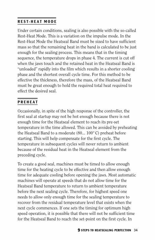
R E S T- H E A T M O D E
Under certain conditions, sealing is also possible with the so-called Rest-Heat Mode. This is a variation on the impulse mode. In the Rest-Heat Mode the Heatseal Band must be sized to have sufficient mass so that the remaining heat in the band is calculated to be just enough for the sealing process. This means that in the timing sequence, the temperature drops in phase 4. The current is cut off when the jaws touch and the retained heat in the Heatseal Band is “unloaded” rapidly into the film which results in a shorter cooling phase and the shortest overall cycle time. For this method to be effective the thickness, therefore the mass, of the Heatseal Band must be great enough to hold the required total heat required to effect the desired seal.
P R E H E A T
Occasionally, in spite of the high response of the controller, the first seal at startup may not be hot enough because there is not enough time for the Heatseal element to reach its pre-set temperature in the time allowed. This can be avoided by preheating the Heatseal Band to a moderate (80... 100° C) preheat before starting. This will help compensate for the first cycle. The temperature in subsequent cycles will never return to ambient because of the residual heat in the Heatseal element from the preceding cycle.
To create a good seal, machines must be timed to allow enough time for the heating cycle to be effective and then allow enough time for adequate cooling before opening the jaws. Most automatic machines will operate at speeds that do not allow time for the Heatseal Band temperature to return to ambient temperature before the next sealing cycle. Therefore, for highest speed one needs to allow only enough time for the sealing temperature to recover from the residual temperature level that exists when the next cycle commences. If one sets the timing for optimum high speed operation, it is possible that there will not be sufficient time for the Heatseal Band to reach the set-point on the first cycle. In

35
this situation one can proceed with the expectation that the first one or two seals may be sub-standard or alternately employ the preheat capability of the TOSS® PIREG® Controller. By using the Preheat feature, one can set a minimum temperature level for the Heatseal Band that will be maintained when the machine is in operation. This minimum temperature threshold assures the ability to obtain perfect sealing the first seal and every seal, even when the allowable sealing and cooling times have been reduced to the bare minimum or when the machine is run intermittently.

9 STEPS TO HEATSEALING PERFECTION 36
Transformers are an important part of the total system. Step-down transformers are used to reduce maximum voltage to a safe operating level as well as electrically isolate the heatsealing circuit from possible ground loops that could affect the performance of the system. Power transformer size and voltage tap selection depend upon the length, cross-section, and number of Heatseal Bands being controlled by one system. One system consists of one controller and one power transformer.
P O W E R A N D V O LT A G E R E Q U I R E M E N T S
As the length of the Heatseal Band increases, the electrical resistance of the Heatseal Band increases. In order to get proper performance, the secondary voltage output of the transformer must be selected to produce the correct level of total power. The temperature of the Heatseal Band should ramp up at a rate not to exceed 1° C/mSec. If the secondary voltage supply is too high, the ramp-up rate will be too rapid and the controller will not respond properly.
“ T H U M B R U L E S ” F O R V O LT A G E A N D P O W E R
VOLTAGE
Optimum voltage selection depends on several variables. Application Engineers at TuOuSu S can assist you by calculating the preferred set-up using TuOuSu S computer programs. This service is offered free of charge to the TOSS® PIREG® Heatseal Temperature Controller users. Call 610-759-8883.
8STEP Transformer Selection Size the transformer.

37
A “Rule-of-Thumb” for determining voltage is 1 to 1.5 volts/inch of band length. Wider and thicker bands should be calculated closer to 1 volt/inch.
POWER — TRANSFORMER SIZE IN KVA Once the voltage is determined, the power required at peak load (heat-up) can be calculated by use of the following formula.
Power (KVA) = Voltage2 ————————— Total Resistance X 1000
Total Resistance = Length of Band (inches) X Band Resistance (Ohms/inch)
Heatseal Band resistance is found on the chart pages 46 and 47.
NOTE — Maximum allowable KVA for TOSS® PIREG® Controllers: at 400 volt primary power supply is 8.0 KVA at 230 volt primary power supply is 4.4 KVA at 115 volt primary power supply is 2.2 KVA
Applications that require more power can be operated by use of a Booster System. Please contact the TuOuSu S Application Engineering Staff for assistance.
The transformer’s secondary voltage selection is very important because the controller will go full “ON” when the controller is first activated. If the secondary voltage is too low, the ramp-up will be slow and the time required to reach the pre-set temperature will be too long. Alternatively, if the voltage is too high, the ramp-up rate may exceed 1° C/mSec. In this case, the controller will go into a switching mode, control will be unsatisfactory, and damage to the controller may result.
It is important not to exceed the recommended KVA rating of a transformer. The selection of a transformer that is not oversized will provide some protection against the possibility of damage in the event that an oversized Heatseal Band is installed.

9 STEPS TO HEATSEALING PERFECTION 38
T O S S H E A T S E A L P O W E R T R A N S F O R M E R S
TuOuSu S offers special Heatseal Power Transformers with 115V, 230V, and 400V primary ratings. These specially wound multi-tap transformers provide a selection of secondary voltages to suit every need. Developed for high response, the transformers are designed to complement the TOSS® PIREG® Heatseal Temperature Controllers assuring trouble-free performance and easy system design and installation.

39
TOSS® PIREG® Heatseal Temperature Controllers are designed specifically for controlling heatsealing operations. They are not general purpose controllers. The functions and features are precisely those needed for heatsealing perfection. With the TOSS® PIREG® Heatseal Temperature Controllers every sealing cycle is provided with exactly the amount of energy needed to create the perfect seal. Since the temperature can be controlled, it is possible to energize the Heatseal Band before the jaws are closed without danger of overheating. Heatseal Bands and Cover Strip material last longer and every seal is the same without adjustment, day in and day out. The question is, “Which Temperature Controller is right for the application?”
TOSS® PIREG® Heatseal Temperature Controllers utilize digital technology and are universally adaptable to almost every heat sealing application. The models PIREG-C2 & C2 EtherNet/IP™ are designed for “in cabinet” mounting to protect the controller from such hazards as untrained personnel and chemical washdown. The PIREG-545 is panel mounted for easy access and visibility.
Standard TOSS® PIREG® Controllers are somewhat limited in power, but Booster Systems are available for loads as high as 15 KVA. Applications with heavy loads or prolonged sealing cycles require special consideration. Please consult the Application Engineers at TuOuSu S for assistance in your system design.
9STEP Controller Selection Pick the right controller for the job.

9 STEPS TO HEATSEALING PERFECTION 40
C O N T R O L L E R S F O R M O U N T I N G I N S I D E T H E C O N T R O L C A B I N E T
PIREG-C2-200 This versatile controller can interface with your PLC controls. It will respond to both “START” and analog “Temperature Control” signals and will feedback actual heatseal band temperature in real time. Important features include Auto-calibration and Fault Detection including Heatseal Band break, parallel band break, and ground fault detection. An overheat detection circuit activates an “Alarm” which, in turn, will shut down the system in the event of fault. A 24 VDC auxiliary power supply is required.
PIREG-C2-220 ETHERNET/IP™ This controller utilizes an EtherNet/IP™ interface which is a standard for industrial networking in automated packaging equipment. Through the EtherNet/IP™ interface, all sealing parameters and functions can be controlled by means of the machine’s PLC control system. This interface also allows for easy capturing and storing of critical sealing cycle data.

41
PA N E L M O U N T E D C O N T R O L L E R S
PIREG-545 Most useful, this panel mounted controller has a key-pad and displays Pre-heat Temperature, Seal Temperature, Heating and Cooling Time, as well as Alarms and Fault Descriptions. Other features include; AutoCal, Analog Temperature Output, Preheat and Booster Modes, selectable Temperature Ranges, and programmable time sequence.
C O N T R O L L E R S E L E C T I O N
On page 45, a list of controllers is provided to illustrate some of the various models that are available. When designing a system it is best to consult TuOuSu S for assistance in making the final selection. Please call TuOuSu S Applications Engineering for assistance.
PIREG 545 FEATURES
Recipe Storage •
Multilevel Password Protection •
Batch Counter •
Extra K Relay •
Measurement Pause •
Download/Upload configuration settings to new units •
RS-232 Communication Port along with Command Protocols •
Free Visualization Software •
UL and CE Certified•

9 STEPS TO HEATSEALING PERFECTION 42
Certified Performance and Validation More and more high quality packaging is being done with plastic film materials that can be conveniently and inexpensively joined by the use of impulse heat sealing because the impulse method provides control over the cooling cycle. The final bond is made during cooling and no other system can provide a controlled cooling capability.
The integrity of the package is important in most applications and is critical when packaging certain products such as food, pharmaceuticals, medical devices, and electronic components where the integrity of the package is no greater than the integrity of the package seals.
Making packages of high integrity becomes increasingly important when the need for extended shelf life and worldwide distribution create the demand for superior packages. The challenge becomes even greater when using high-speed automatic packaging machines because the time available for sealing is reduced to seconds or milliseconds.
Individual product inspection is expensive, subject to human error, and sometimes virtually impossible to accomplish. It therefore follows that the sealing process must be controlled to the highest possible level to reduce the risk of defective seals and the attendant rejects, loss of product, production efficiency, and worst of all the loss of a customer.
It was in response to the need for seal integrity that TuOuSu S - “The Optimum Sealing System” was developed, and is now available wherever perfect heat seals are required, be it product or package.
When TuOuSu S TECHNOLOGY is employed, machines can be Certified to produce consistent and repeatable results thereby minimizing the risk of failure and reducing the dependence on inspection to assure perfection.
43
The sealing system must be fast with controlled heating and cooling cycles that are predictable and repeatable regardless of changes in the local environment and power fluctuations. In addition, the system must have built in monitors to detect deviations from prescribed protocol and activate alarms.
This is easily done on new or existing machines by installing TuOuSu S, the Certifiable sealing system that has been designed by experts skilled in the art of producing high integrity seals.
The most certain way to attain maximum efficiency and highest production rates is to call upon the experts at Toss Machine Components to get a custom designed, plug and play, system that is recognized in the industry, and accepted by monitoring agencies.
The “Heart” of TuOuSu S is the TOSS® PIREG® Heatseal Temperature Controller that is Certified to conform to NIST standards. The Controller with its digital display and keypad can easily set-up a time- temperature program that is optimized for the material being sealed. Upper and lower limits can then be set that will activate an “Alarm” in the event the limits are exceeded. These features and more are built-in to assure safe and Certifiable performance.
TuOuSu S operates by using TuOuSu S Alloy-20®. Heatseal Bands that have the unique ability to be the heat source for sealing while concurrently sending an instantaneous feedback signal to the Controller for temperature regulation. This method eliminates the need for thermocouples and the inherent error and feedback delay encountered with their use.
Validation is easy with TuOuSu S because the Certified components are guaranteed to be consistent and repeatable and the heat generated over the length of the seal must be absolutely uniform as a consequence of the design. In order to facilitate machine validation Toss Machine Components can provide a helpful Validation/Certification Manual that outlines the procedure and provides necessary detailed information.
Contact Toss Machine Components today to learn more about the unique abilities of TuOuSu S - “The Optimum Sealing System”

9 STEPS TO HEATSEALING PERFECTION 44
Properties of Selected Polymers TENSILE YIELD MELT SPECIFIC STRENGTH, STRENGTH, MATERIALS POINT, °C GRAVITY P.S.I. P.S.I.
Polytetrafluorethelene—PTFE 327 2.14-2.20 3000-5000 Polyamide—Nylon 6 210-220 1.12-1.14 6000-24000 13000 Polyamide—Nylon 66 255-265 1.13-1.15 11000 300 Polyester—PET 220-267 1.30-1.38 8200-8700 8200-8700 Polyethelene Copolymers— PE
Linear Low & Medium—LLDPE 112-124 .918-.940 1900-4000 1400-2800 Ethylene Vinyl Acetate—EVA 103-110 .922-.943 2200-4000 1200-6000
Polyethelene, High Density—HDPE 125-135 .939-.960 2500-6500 2800-4800 Polypropylene Copolymer—PP 150-175 .890-.905 4000-5500 3000-4300 Polyurethane 75-137 1.12-1.24 45000-9000 7800-11000 Vinyl Polymers & Copolymers—PVC 75-105 1.16-1.35 1500-3500 900-1700
Summary Designing a high performance Heatseal System is not simple, but it is not difficult if one has some guidelines. We have tried to provide information that will aid in understanding the elements of the system that one must consider. If you are engaged in a Heatseal System design and desire assistance, call the people at TuOuSu S. The people at TuOuSu S are specialists in plastic heat sealing technology, equipment and related devices. They can assist you in developing improved heat seal performance on your machines, old or new. They do it every day.
With TuOuSu S TECHNOLOGY — it’s easy to achieve
HEATSEAL PERFECTION!

45
Models of the TOSS® PIREG® Controllers
Accessories These accessories include all of the components that are needed to complete a total heat sealing system. The people at TOSS are specialists in plastic heat sealing technology, equipment and related devices. Call a TOSS application engineer today about your application.
BoosterATR
Temperature MeterPD
Potentiometer
Line FilterCurrent
TransformerPower Transformers
Extra K Relay | Single-Point CalibrationBatch Counter | Communicate via RS232 or USB
PIREG-545Features Applications
With Timer Function,Simple Control Functions
can be Realized
Display Multilingual OLED-Display
Control Loop Primary
Auto Zero Calibration Keypad or 24VDC Signal
Auto Optimization Yes
Auto Freq. Adjustment 47… 63Hz Yes
Set Point Selection Keypad orIsolated Analog Adjustment
Analog Outputfor Actual Temp. Yes - Isolated
Temperature Range 200˚C/300˚C/400˚C/500˚CSelectable via Keypad
Heatsealing Band Alloy
A20C @ 1235ppmA20K @ 862ppm
L @ 746ppmNorex® @ 4830ppm
Variable from 400... 9999
Alarm Indication Display + I/O
Alarm Output & Fault Diagnosis Yes
Alarm Output Invertable Yes
Alarm Reset Keypad or 24VDC Signal
Preheat Function Yes - via 24VDC Signal
Relay Output Yes - Configuration via Keypad
Timer Function Yes
“Temperature OK” Signal Yes - Isolated
Compatible With RES-440 & RES-445
Languages English, German, French, Italian,Spanish, and Russian
Password Protection 3 Levels
Recipe Storage Store up to 9 recipes
Controller Type PIREG-C2 PIREG-C2EtherNet/IP
Features Applications PLC Interface EtherNet/IP Interface
Control Loop Primary Primary
Auto Zero Calibration via PLC Interface EtherNet/IP Interface
Auto Optimization Yes Yes
Auto Freq. Adjustment 47… 63Hz Yes Yes
Set Point Selection via PLC Interface EtherNet/IP Interface
Analog Output for Actual Temp. Yes Yes
Temperature Range 300˚C/500˚C Fixed 300˚C/500˚C Fixed
Heatsealing Band Alloy
A20C @ 1235ppmA20K @ 862ppm
L @ 746ppmNorex® @ 4830ppm
Variable from 400... 9999
A20C @ 1235ppmA20K @ 862ppm
L @ 746ppmNorex® @ 4830ppm
Variable from 400... 9999
Alarm Indication LED LED
Alarm Output & Fault Diagnosis Yes Yes
Alarm Output Invertable Yes Yes
Modifications Available Yes Yes
Preheat Function Via analog command Via EtherNet/IP Command
Compatible with RES-5007 / RES-5027 RES-407 + MOD26 RES-5011
Line voltages:115VAC, 230VAC, 400VAC

9 STEPS TO HEATSEALING PERFECTION 46
Toss Alloy-20® Heatseal Bands Resistance Chart
CROSS MILLIOHMS OHMS SIZE-MM SECTION PER PER AREA METER INCH 2 x 0.10 0.200 4400 0.112 2 x 0.12 0.240 3667 0.093 2 x 0.15 0.300 2933 0.075 2 x 0.20 0.400 2200 0.056 2 x 0.25 0.500 1760 0.045 2 x 0.30 0.600 1467 0.037 2 x 0.40 0.800 1100 0.028 2.5 x 0.15 0.375 2347 0.060 2.5 x 0.20 0.500 1760 0.045 2.5 x 0.25 0.625 1408 0.036 2.5 x 0.30 0.750 1173 0.030 2.5 x 0.40 1.000 880 0.022 2.5 x 0.50 1.250 704 0.018 3 x 0.10 0.300 2933 0.075 3 x 0.15 0.450 1956 0.050 3 x 0.20 0.600 1467 0.037 3 x 0.25 0.750 1173 0.030 3 x 0.30 0.900 978 0.025 3 x 0.40 1.200 733 0.019 3 x 0.50 1.500 587 0.015 4 x 0.10 0.400 2200 0.056 4 x 0.15 0.600 1467 0.037 4 x 0.20 0.800 1100 0.022 4 x 0.25 1.000 850 0.022 4 x 0.30 1.200 733 0.019 4 x 0.40 1.600 550 0.014 4 x 0.50 2.000 440 0.011 5 x 0.10 0.500 1760 0.045 5 x 0.15 0.750 1173 0.030 5 x 0.20 1.000 880 0.022 5 x 0.25 1.250 704 0018 5 x 0.30 1.500 587 0.015 5 x 0.40 2.000 440 0.011 5 x 0.50 2.500 352 0.009
CROSS MILLIOHMS OHMS SIZE-MM SECTION PER PER AREA METER INCH 6 x 0.10 0.600 1467 0.037 6 x 0.15 0.900 978 0.025 6 x 0.20 1.200 733 0.019 6 x 0.25 1.500 587 0.015 6 x 0.30 1.800 489 0.012 6 x 0.40 2.400 367 0.009 6 x 0.50 3.000 293 0.007 8 x 0.10 0.800 1100 0.028 8 x 0.15 1.200 733 0.019 8 x 0.20 1.600 550 0.014 8 x 0.25 2.000 440 0.011 8 x 0.30 2.400 367 0.009 8 x 0.40 3.200 275 0.007 8 x 0.50 4.000 220 0.006 10 x 0.10 1.000 880 0.022 10 x 0.15 1.500 587 0.015 10 x 0.20 2.000 440 0.011 10 x 0.25 2.500 352 0.009 10 x 0.30 3.000 293 0.007 10 x 0.40 4.000 220 0.006 10 x 0.50 5.000 176 0.004 12 x 0.15 1.800 489 0.012 12 x 0.20 2.400 367 0.009 12 x 0.25 3.000 293 0.007 15 x 0.15 2.250 391 0.010 15 x 0.20 3.000 293 0.007 15 x 0.25 3.750 235 0.006 20 x 0.15 3.000 293 0.007 20 x 0.20 4.000 220 0.006 20 x 0.25 5.000 176 0.004 25 x 0.15 3.750 235 0.006 25 x 0.20 5.000 176 0.004 25 x 0.25 6.250 141 0.004
47
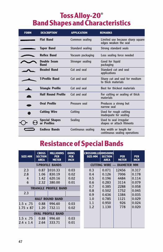
Toss Alloy-20® Band Shapes and Characteristics
Flat Band Common sealing Limited use because sharp square edges weaken the seal
Taper Band Standard sealing Strong standard seals
Reflex Band Vacuum packaging Less sealing force needed
Double Seam Stronger sealing Good for liquid Band packaging Beaded Band Cut and seal Standard cut and seal
applications
T-Profile Band Cut and seal Sharp cut and seal for medium to thick materials
Triangle Profile Cut and seal Best for thickest materials
Half Round Profile Cut and seal For cutting or sealing of thick materials
Oval Profile Pressure seal Produces a strong but narrow seal
Cutting Wire Cutting Used for rough cutting inadequate for sealing
Special Shapes Sealing Used to seal irregular or Profiles shapes or attach fitments
Endless Bands Continuous sealing Any width or length for continuous sealing operations
FORM DESCRIPTION` APPLICATION REMARKS
Resistance of Special Bands CROSS MILLIOHMS OHMS SIZE-MM SECTION PER PER AREA METER INCH
T-PROFILE BANDS
2.3 0.87 1010.33 0.03 2.8 1.06 830.19 0.02 4 1.42 620.16 0.02 6 2.32 380.00 0.01
TRIANGLE PROFILE BAND
2.3
HALF ROUND BAND
1.5 x .75 0.88 996.60 0.03 1.75 x 87 1.20 732.11 0.02
OVAL PROFILE BAND
1.5 x .75 0.88 996.60 0.03 2.4 x 1.4 2.64 333.71 0.01
CROSSMILLIOHMSOHMS SIZE-MM SECTION PER PER AREA METER INCH
CUTTING WIRE — DIAMETER MM
0.3 0.071 12456 0.317 0.4 0.126 7006 0.178 0.5 0.196 4484 0.114 0.6 0.283 3114 0.079 0.7 0.385 2288 0.058 0.8 0.502 1752 0.045 0.9 0.636 1384 0.035 1.0 0.785 1121 0.029 1.1 0.950 926 0.024 1.2 1.130 778 0.020

9 STEPS TO HEATSEALING PERFECTION 48
Contact us for the following information and resources:
n Controller Specifications
n Heatseal Band & Supplies
n Instruction Manual
n Installation Guide
n Troubleshooting Guide
n 9 Steps to Heatsealing Perfection Guide
TOSS MACHINE COMPONENTS, INC. 539 South Main Street • Nazareth, PA 18064 USA
Phone: 610-759-8883 • FAX: 610-759-1766 email: [email protected]
Or visit us at www.tossheatseal.com
Related Documents