DESIGNED TO PERFECTION

Welcome message from author
This document is posted to help you gain knowledge. Please leave a comment to let me know what you think about it! Share it to your friends and learn new things together.
Transcript

DESIGNED TO PERFECTION
2
A Q U A L L I N E P R O D U C T S
A Q U A L L I N E P R O D U C T S
The products and technical data presented in this catalogue are based on the information available at the
time of printing. For the most up-to-date information on our product range, product datasheets, and our
warnings and instructions for use, please revert to our website at www.globalropefittings.com.
A Q U A L L I N E P R O D U C T S
3
A Q U A L L I N E P R O D U C T S
ContentsOur Story ..........................................................................................................................................................4
Our Philosophy ................................................................................................................................................5
Quality, Standardization and Certification .....................................................................................................9
Industries and Applications ..........................................................................................................................12
AQUALLINE Range .......................................................................................................................................13
Specials ...........................................................................................................................................................16
Warnings and Instructions for Use ...............................................................................................................20
Product Datasheets
Adjustable Closed Turnbuckle Sockets (eye) (ACTS) .......................................................................26
Adjustable Open Turnbuckle Sockets (jaw) (AOTS) .........................................................................28
Adjustable Open Spelter Sockets (AOSS) ........................................................................................30
Anchor Pendant Sockets (APS) ..........................................................................................................32
Closed Spelter Sockets (CSS) ............................................................................................................34
Closed Wedge Sockets (CWS) ..........................................................................................................36
Fast Connector Sockets (FCS) ...........................................................................................................38
Heavy Duty Triangle Plates (HDTP) ...................................................................................................40
Mobile Harbor Crane Sockets (MHCS) .............................................................................................42
Open DIN Sockets (ODS) ...................................................................................................................44
Open JIS Sockets (OJS) .....................................................................................................................46
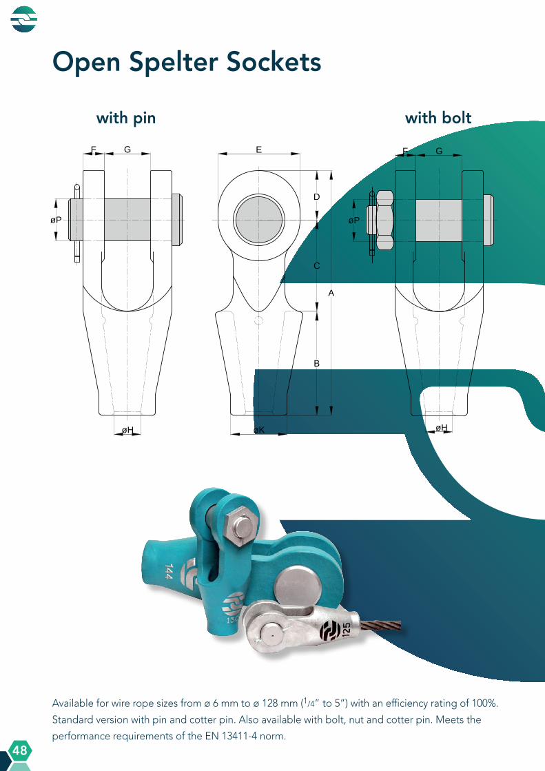
Open Spelter Sockets (OSS) ..............................................................................................................48
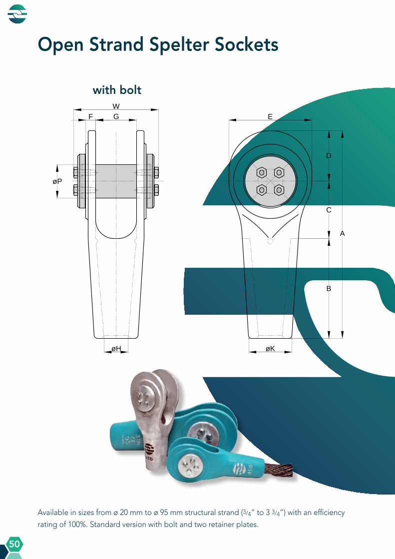
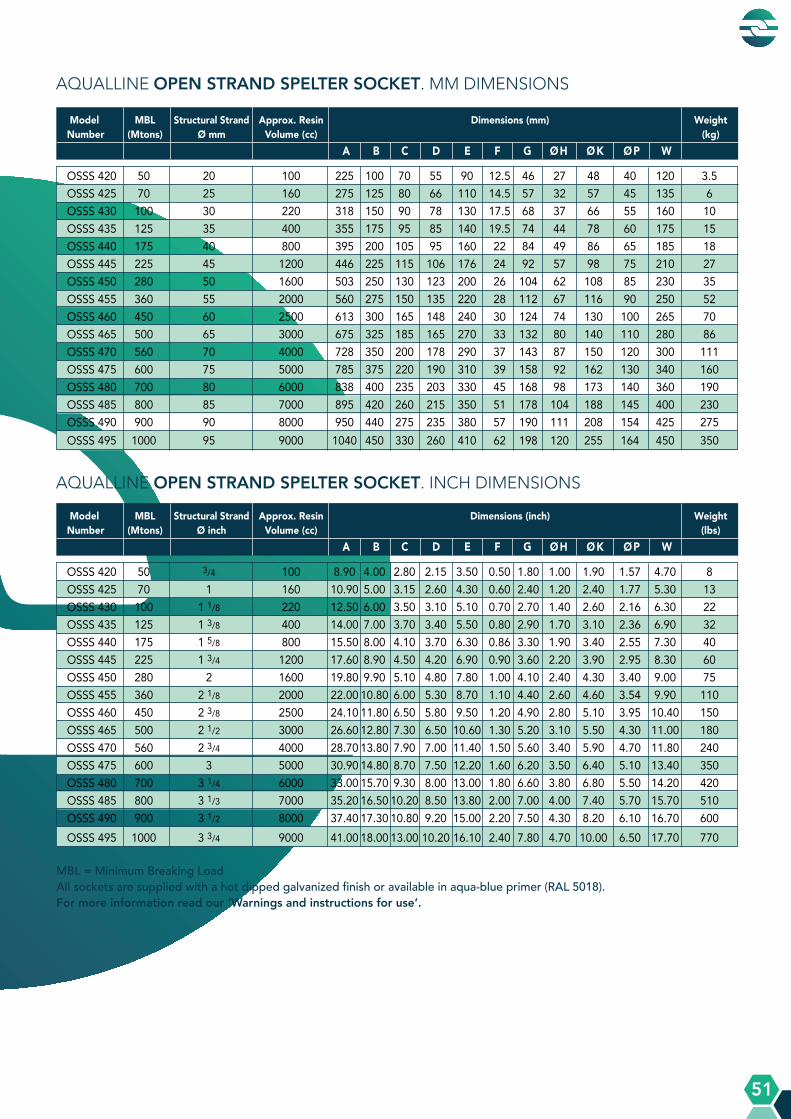
Open Strand Spelter Sockets (OSSS) ................................................................................................50
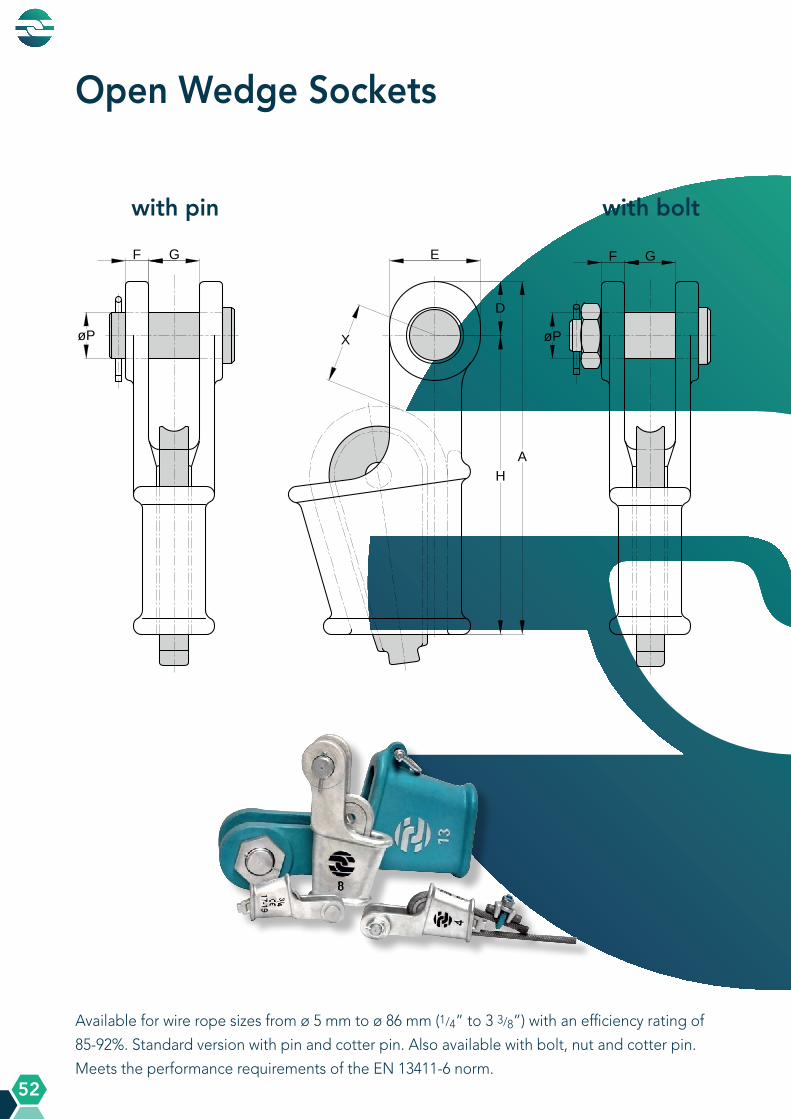
Open Wedge Sockets (OWS) ............................................................................................................52
Open Wedge Sockets with Integrated Tail Clamp (OWS ITC) .......................................................54
Solid Wire Rope Thimbles (SWRT) ....................................................................................................56
Wire Rope Clips (WRC) ......................................................................................................................58

A Q U A L L I N E P R O D U C T S
A Q U A L L I N E P R O D U C T S
4
Our StoryGlobal Rope Fittings was founded in October 2010 as a producer and stockholder of
(custom-made) wire rope fittings. Our experiences in this field date back more than a few
decades. We even stood at the base of the first socket designs in the European market
many years ago…
These experiences have not only led to a re-design of the existing sockets, but also to
great knowledge of the market. We believe in long term relationships with our customers
and strive to find constructive solutions to product challenges. Either by drawing from our
extensive AQUALLINE product range or by designing new, custom-made wire rope fittings.
From our 2000 m² warehouse in Germany we supply customers worldwide. We are very
proud that we have a large and loyal customer base, operating in different industries,
varying from crane building, mining, and heavy lifting, to wire rope factories and rigging
companies.
A Q U A L L I N E P R O D U C T S
A Q U A L L I N E P R O D U C T S
5
Designed to perfection. This philosophy characterizes our approach. We continuously seek to improve, resulting in changes to the existing products in the market and in completely new product designs. We aim for an increased technical performance and design our products with efficiency, longer lifespan, safety, and usability in mind. Not only for the sockets, but also for the wire rope itself.
All our AQUALLINE sockets, thimbles and triangle plates are made from alloy cast steel, a higher grade material, that is suitable for low temperature environments of up to -46°C (Anchor Pendant Sockets up to -40°C).
Our products have some progressive design features that offer interesting benefits in comparison to the standard socket designs in the market.
Adjustable Turnbuckle Series+ Two products combined into oneBy combining a spelter socket with a turnbuckle, we have engineered a product that has fewer separate parts, is easier to handle and is more cost-effective.
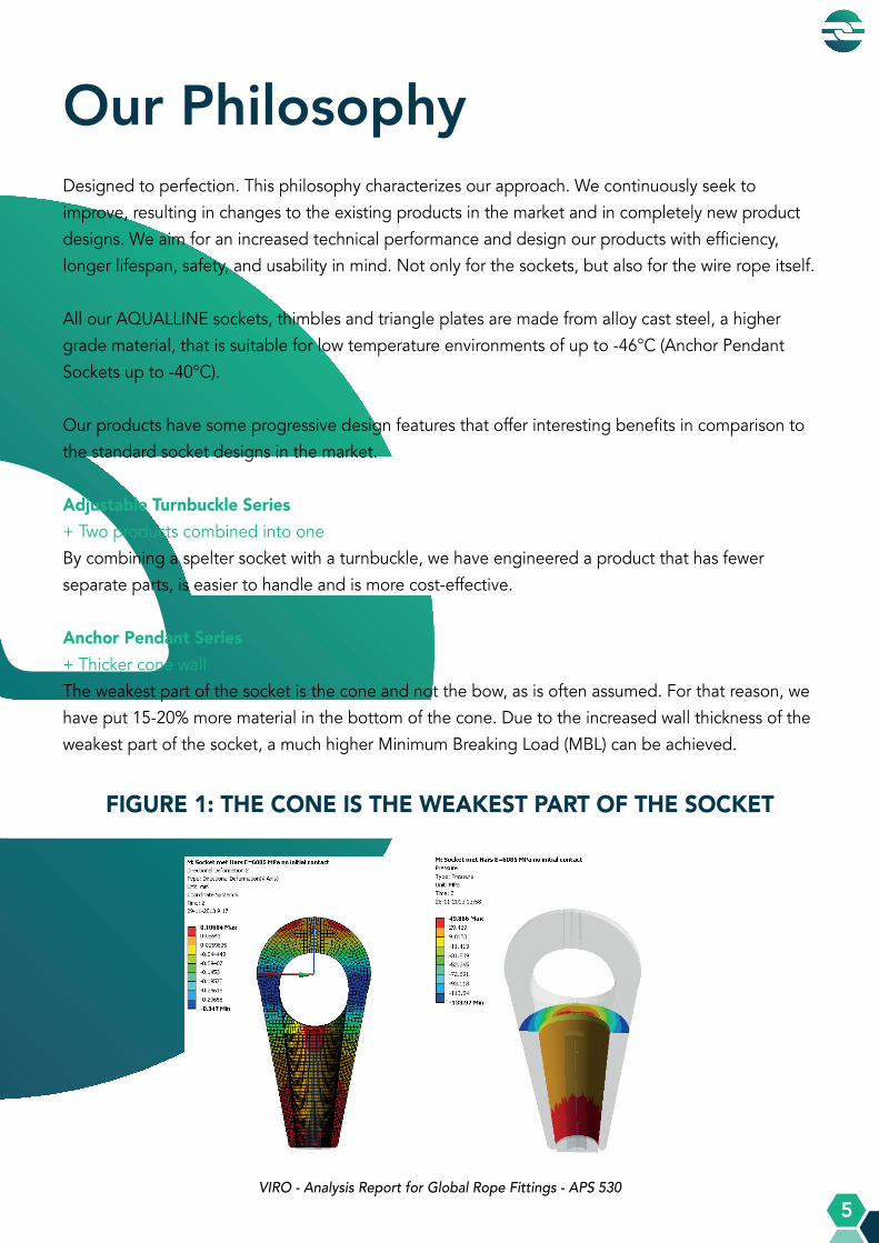
Anchor Pendant Series+ Thicker cone wall The weakest part of the socket is the cone and not the bow, as is often assumed. For that reason, we have put 15-20% more material in the bottom of the cone. Due to the increased wall thickness of the weakest part of the socket, a much higher Minimum Breaking Load (MBL) can be achieved.
Our Philosophy
Project : 09047 Document number : 09047_0004 Revision : 01 Status : For Comment Page : 27 of 28
Figure 36 shows the contact pressure between the Resin and the Socket. In the left image, visible is that the highest pressure is occurs at the underside of the Socket and decreases at higher locations. A negative contact pressure is visible in the right image. This indicates a tensile stress which can occur in the bonded contacts.
Figure 36: Contact pressure between the Resin and the Socket.
Radial deformation of the Socket is demonstrated in Figure 37. Again an outward deformation is visible at the bottom and an inward deformation is visible at the middle of the eye of the Socket.
Figure 37: Radial deformation in the Socket.
FIGURE 1: THE CONE IS THE WEAKEST PART OF THE SOCKET
VIRO - Analysis Report for Global Rope Fittings - APS 530

A Q U A L L I N E P R O D U C T S
6
A Q U A L L I N E P R O D U C T S
FIGURE 2: PRESSURE DISTRIBUTION IN THE CONE
Fast Connector Series+ Compact design+ Rotating & non-rotating device + Cap with eyeThe connector fitting that slides into our Fast Connector Socket has one of the smallest designs in today’s market, leaving plenty of room for easy reeving. A cap with an added eye also facilitates the reeving process. A rotating & non-rotating device can be selected in accordance with the used wire rope.
Japanese Series+ Thicker jaws+ Reinforced base+ Increased conus angleRemodelling the original Open Spelter JIS Socket (e.g. more material in the jaws, reinforced base, increased conus angle), has resulted in a product with a 20-30% higher MBL.
Open DIN Series+ Thicker jaws+ Reinforced base+ Increased conus angleWith a slightly modified design (more material in the jaws, reinforced base, increased conus angle), we achieve a 30-40% higher MBL than with the standard DIN sockets, making it very suitable for the current generation of steel wire ropes.
Courtesy of J.M. Dodd B.Sc - Millfield Enterprises - Resin Socketing of Steel Wire Rope
A Q U A L L I N E P R O D U C T S
7
A Q U A L L I N E P R O D U C T S
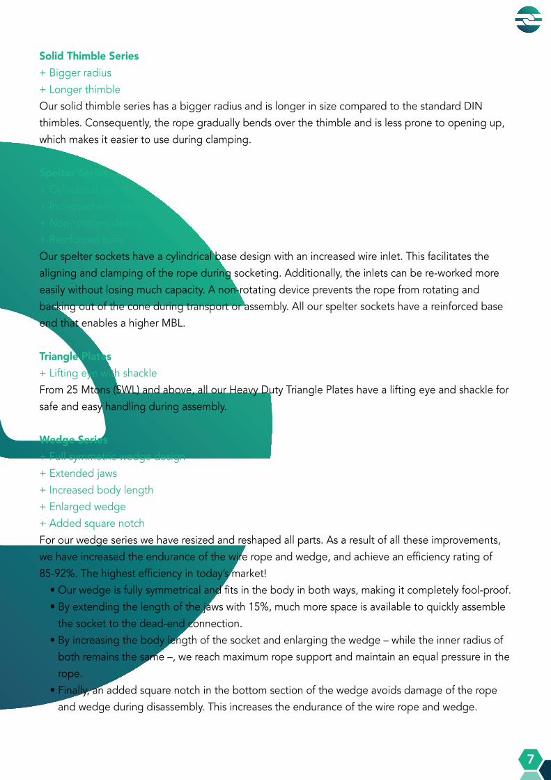
Solid Thimble Series+ Bigger radius + Longer thimbleOur solid thimble series has a bigger radius and is longer in size compared to the standard DIN thimbles. Consequently, the rope gradually bends over the thimble and is less prone to opening up, which makes it easier to use during clamping.
Spelter Series+ Cylindrical design + Increased wire inlet+ Non-rotating device + Reinforced base Our spelter sockets have a cylindrical base design with an increased wire inlet. This facilitates the aligning and clamping of the rope during socketing. Additionally, the inlets can be re-worked more easily without losing much capacity. A non-rotating device prevents the rope from rotating and backing out of the cone during transport or assembly. All our spelter sockets have a reinforced base end that enables a higher MBL.
Triangle Plates+ Lifting eye with shackleFrom 25 Mtons (SWL) and above, all our Heavy Duty Triangle Plates have a lifting eye and shackle for safe and easy handling during assembly.
Wedge Series+ Full symmetric wedge design+ Extended jaws + Increased body length + Enlarged wedge+ Added square notch For our wedge series we have resized and reshaped all parts. As a result of all these improvements, we have increased the endurance of the wire rope and wedge, and achieve an efficiency rating of 85-92%. The highest efficiency in today’s market!
• Our wedge is fully symmetrical and fits in the body in both ways, making it completely fool-proof. • By extending the length of the jaws with 15%, much more space is available to quickly assemble
the socket to the dead-end connection. • By increasing the body length of the socket and enlarging the wedge – while the inner radius of
both remains the same –, we reach maximum rope support and maintain an equal pressure in the rope.
• Finally, an added square notch in the bottom section of the wedge avoids damage of the rope and wedge during disassembly. This increases the endurance of the wire rope and wedge.

A Q U A L L I N E P R O D U C T S
A Q U A L L I N E P R O D U C T S
8
FIGURE 3: OUR SPECIAL WEDGE SOCKET DESIGN
FIGURE 4: MAXIMUM ROPE SUPPORT
NEW SITUATION GRF200° CABLE SUPPORT
OTHER SUPPLIERS90° CABLE SUPPORT
SOCKET
ROPE
WEDGE
GRF SOCKET ON THE LEFT GRF WEDGE ON THE LEFT
A Q U A L L I N E P R O D U C T S
A Q U A L L I N E P R O D U C T S
9
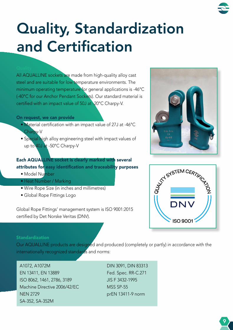
QualityAll AQUALLINE sockets are made from high-quality alloy cast
steel and are suitable for low temperature environments. The
minimum operating temperature for general applications is -46°C
(-40°C for our Anchor Pendant Sockets). Our standard material is
certified with an impact value of 50J at -20°C Charpy-V.
On request, we can provide• Material certification with an impact value of 27J at -46°C
Charpy-V
• Special high alloy engineering steel with impact values of
up to 40J at -50°C Charpy-V
Each AQUALLINE socket is clearly marked with several attributes for easy identification and traceability purposes
• Model Number
• Heat Number / Marking
• Wire Rope Size (in inches and millimetres)
• Global Rope Fittings Logo
Global Rope Fittings’ management system is ISO 9001:2015
certified by Det Norske Veritas (DNV).
StandardizationOur AQUALLINE products are designed and produced (completely or partly) in accordance with the
internationally recognized standards and norms:
A1072, A1072M DIN 3091, DIN 83313
EN 13411, EN 13889 Fed. Spec. RR-C.271
ISO 8062, 1461, 2786, 3189 JIS F 3432-1995
Machine Directive 2006/42/EC MSS SP-55
NEN 2729 prEN 13411-9 norm
SA-352, SA-352M
Quality, Standardization and Certification
A Q U A L L I N E P R O D U C T S
A Q U A L L I N E P R O D U C T S
10
All load-bearing parts and products are ultrasonically inspected according to ASTM SA609
edition 2007, by level II qualified personnel. Magnetic Particle Inspection is carried out according
to ASME BPV Section V - 2013.
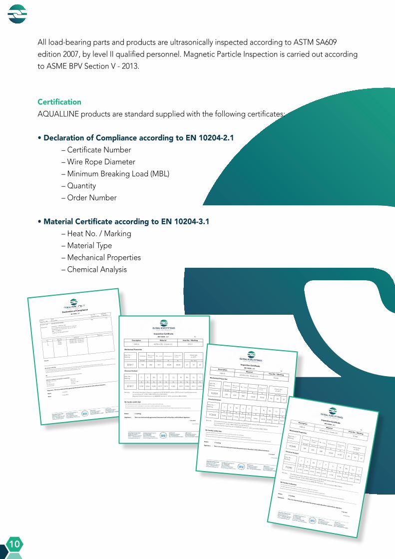
CertificationAQUALLINE products are standard supplied with the following certificates:
• Declaration of Compliance according to EN 10204-2.1 – Certificate Number
– Wire Rope Diameter
– Minimum Breaking Load (MBL)
– Quantity
– Order Number
• Material Certificate according to EN 10204-3.1 – Heat No. / Marking
– Material Type
– Mechanical Properties
– Chemical Analysis
ClientName
S.O. No. 5205235
Your P.O. No. PO number
Shipping Date 17.06.2021
Product code
Qty.15
Description
Qty.Heat No.
3EF017
2FC034
10FC040
Remarks:
Declaration is according to the regulations of the Machine Directive 2006/42/EC.
MSS SP-55
EN 13411
NEN 2729
SA-352/SA352M
DIN 83313, 3091
A1072/A1072M
JIS F3432
Name:J.Lenting
Date:17.06.2021
Declaration of Compliance
EN 10204 - 2.1
Material
Marking
ASTM A-352 - Grade LCC
Z2OWS2W3B3N0080
AqualLine - OWS No. 8 B
Incl. wedge No. 8 and bolt ø 63 mm and nut
Suitable for wire rope ø 34 - 36 mm (1 3/8")
MBL : 130 Mtons
Coating : hot dip galvanized
ASTM A-352 - Grade LCC
Signature : This is an electronically generated document and is therefore valid without signature.
We hereby certify that:
The manufacturer declares that the mentioned products are in accordance with the requirements and specifications of this order.
In case you resell these as a part of a product manufactured by yourself, take our warning and instruction for use into account and make these known to your
customers (download the latest version online at www.globalropefittings.com).
CE:
ISO 8062, 1461, 3189Reference standards used (partly or completely):
ASTM A-352 - Grade LCC
R3
Magnetic Particle Inspection acc to ASME BPV Section V - 2013, procedure MM 21900 E.
Name: J. Lenting
Signature: This is an electronically generated document and is therefore valid without signature.
30,00
Inspection Certificate
17.06.2021
Heat No. / Marking
OWS 8 ASTM A-352 - Grade LCC EF017
We hereby certify that:
Description Material
V
% % % %
P
Mechanical Properties
Chemical Analysis
Heat No. /Marking
Heat No. /Marking
C Si
EF017
Hardness
Brinell
186
Rm (Tensile strength)
(N/mm²)
582
Mo
0,0040,017
Mn S Cu
0,0170,843
%
NiCr
- The reported values are strictly in accordance with the original mill certificates.
Remarks: All sockets have been ultrasonic inspected, acc ASTM SA609, edition 2007 by level II qualified personnel, acc procedure UT 12145 / MM 41400 E from 02.02.2012.
0,011
%
0,065 0,017 0,006
% % % %
EF017 0,203 0,465
Impact test at -20°C
min: 42J
61 59 62
EN 10204 - 3.1
- The heat treatment of the materials is in accordance with the applicable material specification.
- The above mentioned materials have been tested and inspected in accordance with the specifications and have met the requirements.
CASH197B73
Re (Yield)
(N/mm²)
431
A (Elongation)
%
Z (Reduction of area)
%
58,00
R3
Magnetic Particle Inspection acc to ASME BPV Section V - 2013, procedure MM 21900 E.
Name: J. Lenting
Signature: This is an electronically generated document and is therefore valid without signature.
23,00
Inspection Certificate
17.06.2021
Heat No. / MarkingOWS 8
ASTM A-352 - Grade LCCFC034
We hereby certify that:
DescriptionMaterial
V% % % %
P
Mechanical Properties
Chemical Analysis
Heat No. /Marking
Heat No. /Marking
C Si
FC034
Hardness
Brinell
201
Rm (Tensile strength)
(N/mm²)
659
Mo
0,0050,020
Mn S
Cu
0,0181,038 %
NiCr
- The reported values are strictly in accordance with the original mill certificates.
Remarks: All sockets have been ultrasonic inspected, acc ASTM SA609, edition 2007 by level II qualified personnel,
acc procedure UT 12145 / MM 41400 E from 02.02.2012.
0,009%
0,062 0,019 0,004
% % % %FC034 0,208 0,509
Impact test at -20°C
min: 42J
54 58 59
EN 10204 - 3.1
- The heat treatment of the materials is in accordance with the applicable material specification.
- The above mentioned materials have been tested and inspected in accordance with the specifications and have met the requirements.
CASH207B24
Re (Yield)
(N/mm²)
488
A (Elongation)
%
Z (Reduction of area)
%
59,00
R3
Magnetic Particle Inspection acc to ASME BPV Section V - 2013, procedure MM 21900 E.
Name:J. Lenting
Signature: This is an electronically generated document and is therefore valid without signature.
24,00
Inspection Certificate
17.06.2021
Heat No. / Marking
OWS 8
ASTM A-352 - Grade LCC
FC040
We hereby certify that:
Description
Material
V%
%%
%
P
Mechanical Properties
Chemical Analysis
Heat No. /Marking
Heat No. /Marking
CSi
FC040
Hardness
Brinell
189
Rm (Tensile strength)
(N/mm²)
622
Mo
0,0050,019
MnS
Cu
0,019
0,919
%
NiCr
- The reported values are strictly in accordance with the original mill certificates.
Remarks: All sockets have been ultrasonic inspected, acc ASTM SA609, edition 2007 by level II qualified personnel,
acc procedure UT 12145 / MM 41400 E from 02.02.2012.
0,010%0,154 0,054 0,010
%%
%%
FC0400,193 0,540
Impact test at -20°C
min: 42J
50 55 57
EN 10204 - 3.1
- The heat treatment of the materials is in accordance with the applicable material specification.
- The above mentioned materials have been tested and inspected in accordance with the specifications and have met the requirements.
CASH207B24
Re (Yield)
(N/mm²)
438
A (Elongation)
%
Z (Reduction of area)
%
62,00
A Q U A L L I N E P R O D U C T S
A Q U A L L I N E P R O D U C T S
11
On request, we can also offer:
• Material Certificate according to EN 10204-3.2
• EC Declaration according to Machine Directive 2006/42/EC
• Manufacturer’s Test Certificate according to ILO Convention No. 152
• NDT Inspection Report
• Witness or survey certificate by official classification body
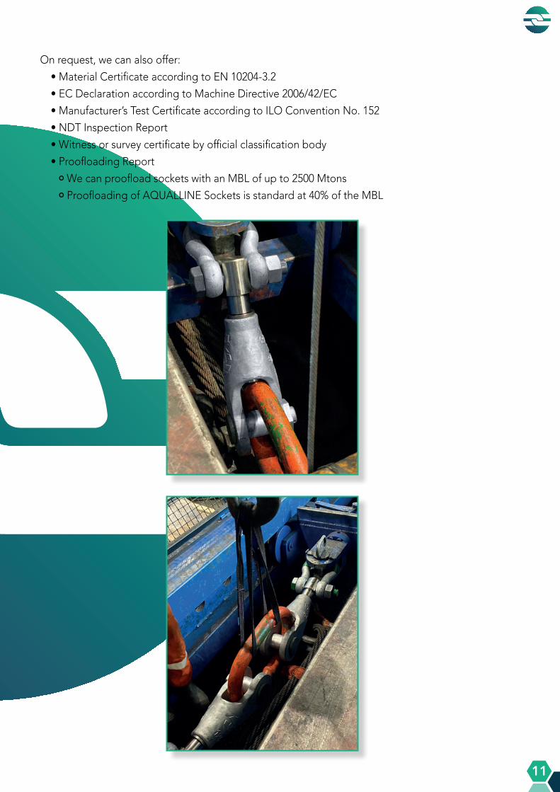
• Proofloading Report
• We can proofload sockets with an MBL of up to 2500 Mtons
• Proofloading of AQUALLINE Sockets is standard at 40% of the MBL

A Q U A L L I N E P R O D U C T S
A Q U A L L I N E P R O D U C T S
12
We offer product solutions for many different industries and for a wide variety of applications
from our standard AQUALLINE product range or by custom-design.
Industries and Applications
INDUSTRY / APPLICATION PRODUCTS
General Engineering OSS / CSS / OWS / SWRT
Heavy Lifting OSS / CSS / OWS / HDTP
Crane Industry OSS / CSS / OWS / OWS-ITC / ODS / OJS / FCS / MHCS / SJT*
Container Handling OSS / AOSS / ACTS / AOTS
Onshore / Maritime OSS / APS / OJS / HDTP / OMS*
Offshore OSS / CSS / APS
Dredging CWS / SSH*
Mining OSS / OSSS
Architecture & Civil Engineering OSS / OSSS / CSS / OWS / AOSS / ACTS / AOTS / AOBS* / ODS /
TKK* / TUAC* / TWS*
Energy OSS / CSS / ACTS / AOTS / TUAC*
* Custom-designed, see the ‘Specials‘ section in our catalogue
A Q U A L L I N E P R O D U C T S
A Q U A L L I N E P R O D U C T S
13
AQUALLINE Range
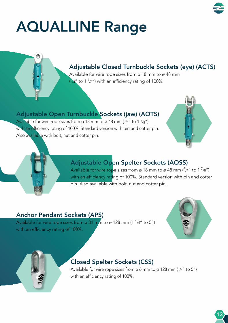
Adjustable Closed Turnbuckle Sockets (eye) (ACTS)Available for wire rope sizes from ø 18 mm to ø 48 mm
(3/4” to 1 7/8”) with an efficiency rating of 100%.
Adjustable Open Spelter Sockets (AOSS)Available for wire rope sizes from ø 18 mm to ø 48 mm (3/4” to 1 7/8”)
with an efficiency rating of 100%. Standard version with pin and cotter
pin. Also available with bolt, nut and cotter pin.
Adjustable Open Turnbuckle Sockets (jaw) (AOTS)Available for wire rope sizes from ø 18 mm to ø 48 mm (3/4” to 1 7/8”)
with an efficiency rating of 100%. Standard version with pin and cotter pin.
Also available with bolt, nut and cotter pin.
Closed Spelter Sockets (CSS)Available for wire rope sizes from ø 6 mm to ø 128 mm (1/4” to 5”)
with an efficiency rating of 100%.
Anchor Pendant Sockets (APS)Available for wire rope sizes from ø 31 mm to ø 128 mm (1 1/4” to 5”)
with an efficiency rating of 100%.

A Q U A L L I N E P R O D U C T S
A Q U A L L I N E P R O D U C T S
14
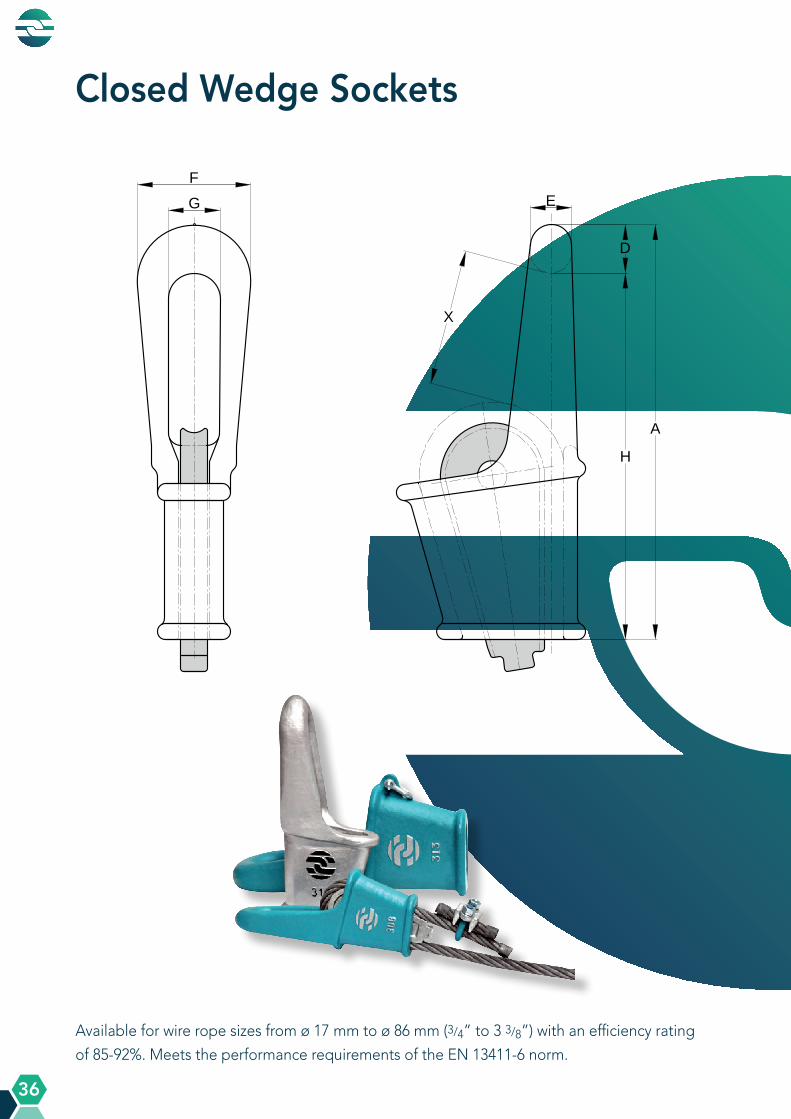
Closed Wedge Sockets (CWS)Available for wire rope sizes from ø 17 mm to ø 86 mm (3/4” to
3 3/8”) with an efficiency rating of 85-92%.
Fast Connector Sockets (FCS)Available for wire rope sizes from ø 11 mm to ø 52 mm (7/16” to 2”)
with an efficiency rating of 100%. Standard version with pin and cotter
pin. Also available with bolt, nut and cotter pin. Each Fast Connector
Socket contains a Connector Fitting with a non-rotating device.
Heavy Duty Triangle Plates (HDTP) Available from size HDTP 9.5 to HDTP 500. From HDTP 25 and
above, all triangle plates have a lifting eye and shackle for safe
and easy handling during assembly. Suitable for commercial bow
shackles that are designed according to EN 13889 or Fed. Spec.
RR-C.271.
Open DIN Sockets (ODS)Available for wire rope sizes from ø 12 mm to ø 68 mm (1/2“ to
2 5/8“) with an efficiency rating of 100%. Standard with bolt, nut
and cotter pin.
Mobile Harbor Crane Sockets (MHCS)Available for wire rope sizes from ø 31 mm to ø 54 mm with an efficiency
rating of 100%. Standard with bolt, nut and cotter pin. Also available with
Roller.
Open JIS Sockets (OJS)Available for wire rope sizes from ø 15 mm to ø 43 mm (5/8” to 1 5/8”) with
an efficiency rating of 100%. Standard with bolt, nut and cotter pin.

A Q U A L L I N E P R O D U C T S
A Q U A L L I N E P R O D U C T S
15
Open Spelter Sockets (OSS)Available for wire rope sizes from ø 6 mm to ø 128 mm (1/4” to 5”)
with an efficiency rating of 100%. Standard version with pin and
cotter pin. Also available with bolt, nut and cotter pin.
Open Strand Spelter Sockets (OSSS)Available in sizes from ø 20 mm to ø 95 mm structural strand (3/4” to
3 3/4”) with an efficiency rating of 100%. Standard version with bolt and
two retainer plates.
Open Wedge Sockets (OWS)Available for wire rope sizes from ø 5 mm to ø 86 mm (1/4” to 3 3/8”)
with an efficiency rating of 85-92%. Standard version with pin and
cotter pin. Also available with bolt, nut and cotter pin.
Solid Wire Rope Thimbles (SWRT)Available for wire rope sizes from ø 7 mm to ø 80 mm (5/16” to 3”)
with an efficiency rating of 90%.
Open Wedge Sockets with Integrated Tail Clamp (OWS ITC)Available for wire rope sizes from ø 5 mm to ø 36 mm (1/4” to 1 3/8”) with
an efficiency rating of 85-92%. Standard version with pin and cotter pin.
Also available with bolt, nut and cotter pin.
Wire Rope Clips (WRC)Available for wire rope sizes from ø 3 mm to ø 90 mm (1/8” to 3 1/2”).

A Q U A L L I N E P R O D U C T S
A Q U A L L I N E P R O D U C T S
16
Sometimes our standard AQUALLINE products do not offer a solution to a challenge in the
field. In this case, our engineers will design a custom-made solution in close collaboration with
the customer. Our speciality! This varies from modifying our standard sockets, designing an
alternative for an existing product solution, to engineering a completely new product.
CSS with tube modification
Variety of end fittings with stopper plates
SWRT with bronze bushing
OSS with security plate & adjusted jaw width
OSS with cover plates & security bolt
Modification of our standard sockets
Specials
Open Mooring Socket (OMS)
A Q U A L L I N E P R O D U C T S
A Q U A L L I N E P R O D U C T S
17
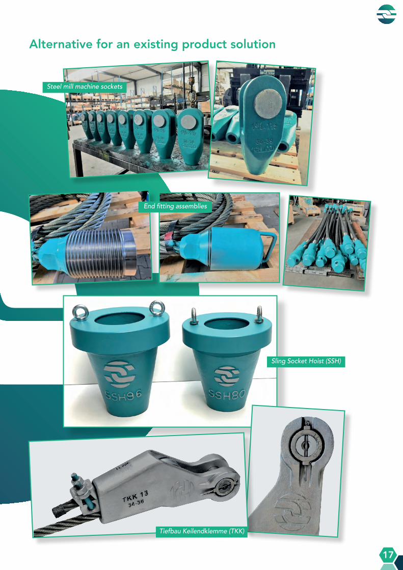
Steel mill machine sockets
End fitting assemblies
Sling Socket Hoist (SSH)
Tiefbau Keilendklemme (TKK)
Alternative for an existing product solution

A Q U A L L I N E P R O D U C T S
A Q U A L L I N E P R O D U C T S
18
Completely new design
George Washington Bridge Socket (GWBS)
Stainless steel lock door sockets
Boom pendant sockets
OSS with ring for a lock

A Q U A L L I N E P R O D U C T S
A Q U A L L I N E P R O D U C T S
19
Completely new design
Take Up Assembly Closed (TUAC)
Adjustable Open Bridge Socket (AOBS)
Solid Jaw Thimble (SJT)
Tiefbau Wedge Socket (TWS)

A Q U A L L I N E P R O D U C T S
A Q U A L L I N E P R O D U C T S
20
GeneralOur AQUALLINE products are among the strongest and most efficient in today’s market and therefore the best choice for a wire rope termination. The installation and operation of our products should always be carried out by qualified and competent personnel. The pouring, installation, operation, and inspection are the sole responsibility of the user.
For the correct and safe implementation of our products, it is essential that the warnings and instructions listed here are closely followed. Incorrect use may create an unsafe situation, which could result in damage to equipment, inflict serious injury, or even cause death.
Generally, for all AQUALLINE products the following guidelines must be observed• Always carefully inspect all products and parts before use. • Never use a product showing nicks, gouges, cracks, sharp edges, or any signs of wear and tear of
more than 5% of the nominal dimensions to the bow, pin holes, pins, bolts, or other parts of the AQUALLINE product. This includes discoloration from excessive heating.
• Make sure all markings are legible as these contain essential information regarding the use, such as wire rope size and traceability, e.g. batch number.
• Never use a product after being overloaded, side-loaded or shock-loaded.• Only original (spare) parts should be used in an AQUALLINE socket assembly (i.e. AQUALLINE
wedges, pins, bolts, etcetera). • Never interchange AQUALLINE products and parts with non-AQUALLINE products and parts.• Do not modify or re-use any part. Never do any repairs, reshaping, or welding on an AQUALLINE
product. Always consult Global Rope Fittings.
Spelter SocketsOur AQUALLINE Spelter Socket terminations have an efficiency rating of 100%, based on the nominal strength of the wire rope. This is limited by the Minimum Breaking Load (MBL) of the sockets. The MBL values are specified in our product datasheets, which can be downloaded from our website at www.globalropefittings.com or can be requested by email at [email protected].
Warnings and Instructions for UseWIU_rev.04_09.09.2021
Always check our website www.globalropefittings.com to make sure that you have the latest version of our Warnings and Instructions for Use.

A Q U A L L I N E P R O D U C T S
A Q U A L L I N E P R O D U C T S
21
All AQUALLINE Spelter Sockets are made from high-quality cast steel and are suitable for low temperature environments. The minimum operating temperature for general applications is -46°C (-40°C for our Anchor Pendant Sockets). The material has an impact value of 50J at -20°C Charpy-V.
Never use a wire rope with a diameter that deviates from that stated in the product datasheets.
Key considerations for socketing• Socketing should be carried out by qualified and competent specialists.• When using white metal or zinc, pre-heat the socket basket, but never expose a socket to a
temperature of more than 350°C (660°F).• Always read and fully understand the instructions and the warnings provided by the resin manufacturer.
• Sockets should be at ambient (or room) temperature. Do not heat the sockets prior to pouring.
• Poured sockets should not be moved for at least 15 minutes after the resin in the socket has gelled.
• If possible, we recommend the assembly to be proof tested at 40% of the MBL of the used wire rope at least 1 hour after the resin in the socket has gelled.
• For a complete overview of the minimum requirements for socketing we refer to DIN EN 13411-4:2011-06 and ISO 17558:2006-09.
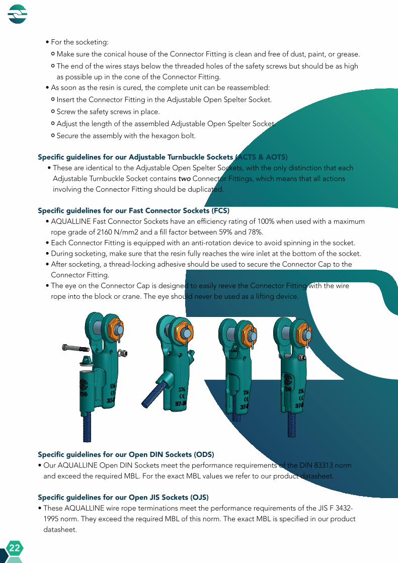
Specific guidelines for our Adjustable Open Spelter Sockets (AOSS)• Before installation, always grease the Connector Fitting’s threading, by lubricating it through the
grease nipple on the front of the Adjustable Open Spelter Socket (1).• Use lubricant for high-pressure contact surfaces (EP3 or EP4).• Re-grease after every 100 hours of use.• Regularly check if all safety screws, bolts, and nuts are still properly in place.• For disassembly, first remove the Connector Fitting from the socket (see images below):
• Remove the hexagon bolt on the side of the socket by unscrewing the nyloc nut with washers (2).
• Then, turn the Connector Fitting just enough to see the two safety screws through the slot hole (3).
• Unscrew the safety screws.
• Make sure to keep all parts together and handle the Connector Fitting with care to avoid damages to the thread.
1 2 3
A Q U A L L I N E P R O D U C T S
A Q U A L L I N E P R O D U C T S
22
• For the socketing:
• Make sure the conical house of the Connector Fitting is clean and free of dust, paint, or grease.
• The end of the wires stays below the threaded holes of the safety screws but should be as high as possible up in the cone of the Connector Fitting.
• As soon as the resin is cured, the complete unit can be reassembled:
• Insert the Connector Fitting in the Adjustable Open Spelter Socket.
• Screw the safety screws in place.
• Adjust the length of the assembled Adjustable Open Spelter Socket.
• Secure the assembly with the hexagon bolt.
Specific guidelines for our Adjustable Turnbuckle Sockets (ACTS & AOTS) • These are identical to the Adjustable Open Spelter Sockets, with the only distinction that each
Adjustable Turnbuckle Socket contains two Connector Fittings, which means that all actions involving the Connector Fitting should be duplicated.
Specific guidelines for our Fast Connector Sockets (FCS)• AQUALLINE Fast Connector Sockets have an efficiency rating of 100% when used with a maximum
rope grade of 2160 N/mm2 and a fill factor between 59% and 78%.• Each Connector Fitting is equipped with an anti-rotation device to avoid spinning in the socket.• During socketing, make sure that the resin fully reaches the wire inlet at the bottom of the socket.• After socketing, a thread-locking adhesive should be used to secure the Connector Cap to the
Connector Fitting.• The eye on the Connector Cap is designed to easily reeve the Connector Fitting with the wire
rope into the block or crane. The eye should never be used as a lifting device.
Specific guidelines for our Open DIN Sockets (ODS)• Our AQUALLINE Open DIN Sockets meet the performance requirements of the DIN 83313 norm
and exceed the required MBL. For the exact MBL values we refer to our product datasheet.
Specific guidelines for our Open JIS Sockets (OJS)• These AQUALLINE wire rope terminations meet the performance requirements of the JIS F 3432-
1995 norm. They exceed the required MBL of this norm. The exact MBL is specified in our product datasheet.

A Q U A L L I N E P R O D U C T S
A Q U A L L I N E P R O D U C T S
23
Wedge SocketsOur AQUALLINE Wedge Socket terminations have an efficiency rating of 85-92%, based on the nominal strength of the wire rope. They meet and exceed the performance requirements of the EN 13411-6 norm.
All AQUALLINE Wedge Sockets are made from high-quality cast steel and are suitable for low temperature environments. The minimum operating temperature for general applications is -46°C. The material has an impact value of 50J at -20°C Charpy-V.
Make sure to select the correct AQUALLINE Wedge Socket for the required wire rope size. This information is specified in our product datasheets, which can be downloaded from our website at www.globalropefittings.com or can be requested by email at [email protected]. In case of intermediate rope sizes, always choose the next larger size AQUALLINE Wedge Socket.
Do not use a different wedge size in our AQUALLINE Wedge Socket than the size recommended for the required wire rope size. Never interchange AQUALLINE Wedge Sockets and AQUALLINE Wedges with other brands.
Instructions for the use of the wedge sockets• The loaded wire rope should always be mounted in the centre line of the pin (see image of correct
installation below).• Secure the dead end of the rope with a wire rope clip. Do not attach it to the loaded wire rope or to
any other elements of the assembly.• The length of the dead end should be a minimum of 6x the wire rope diameter, but never less than
150 mm (6”) for standard 6-8 strand wire rope. For rotation-resistant wire rope, the dead end should be a minimum of 20x the wire rope diameter and not less than 150 mm (6”).
• The socket must be fixed to prevent rotation.• Before the first load, the wire rope and wedge should be hammered into the socket as deep as
possible. This should be done with care and no steel hammer should be used as to avoid damage to the rope.
• After the first load, check that the wire rope and wedge are fully seated in the socket, as the rope may slip if the wedge of the socket is not properly installed.
CORRECT INCORRECT INCORRECT

A Q U A L L I N E P R O D U C T S
A Q U A L L I N E P R O D U C T S
24
Specific guidelines for our Open Wedge Sockets with Integrated Tail Clamp (OWS ITC)• Only use special AQUALLINE ITC-Wedges with our Open Wedge Socket range. Never replace
these with wedges from other brands.• Existing AQUALLINE Open Wedge Sockets can be retrofitted with an AQUALLINE ITC-Wedge.• After the first load, check that the wire rope and wedge are fully seated in the socket and
retighten the nuts from the Wire Rope Clip to the correct torque value. For the correct torque values, see our Wire Rope Clip product datasheet, which can be downloaded from our website at www.globalropefittings.com or can be requested by email at [email protected].
Solid Wire Rope ThimblesOur AQUALLINE Solid Wire Rope Thimbles (SWRT) have an efficiency rating of 90% and meet the performance requirements of the prEN 13411-9 norm.
All AQUALLINE Solid Wire Rope Thimbles are made from high-quality cast steel and are suitable for low temperature environments. The minimum operating temperature for general applications is -46°C. The material has an impact value of 50J at -20°C Charpy-V.
Select the correct AQUALLINE Solid Wire Rope Thimble for the required wire rope size; the wire rope should fit properly into the groove of the thimble. For the relevant data, download the product datasheet from our website at www.globalropefittings.com or request by email at [email protected].
A Q U A L L I N E P R O D U C T S
A Q U A L L I N E P R O D U C T S
25
Wire Rope ClipsAll AQUALLINE Wire Rope Clips (WRC) are forged and meet the performance requirements of the EN 13411-5 norm (Type B / Grip 2). They are suitable for the fastening and securing of static loads but should never be used for lifting applications.
Select the AQUALLINE Wire Rope Clip with the correct dimension for the required wire rope size. In case of intermediate nominal diameters of rope, always use the next larger size AQUALLINE Wire Rope Clip. More detailed information is specified in our product datasheet, which can be downloaded from our website at www.globalropefittings.com or can be requested by email at [email protected].
The clips must be installed correctly and must be tightened to the correct torque value by using a torque wrench.
• The bridge of the Wire Rope Clip should always be placed on the load bearing part of the rope, except when used on an AQUALLINE ITC-Wedge or when securing a dead end of a rope for a wedge socket.
• The U-bolt must be placed on the rope tail (dead-end). • Make sure to turn back sufficient wire rope length to ensure that the required number of Wire Rope
Clips can be installed. For more detailed information on the required number of clips we refer to the EN 13411-5 norm (Table B.2.).
• For the correct torque values, see our product datasheet, which can be downloaded from our website at www.globalropefittings.com or can be requested by email at [email protected].
• The first time after installation, load the assembly with a load that is equal or greater than the load in operation with a maximum of 1.25 times the Working Load Limit (WLL). Then check the torque value again and adjust it to the correct torque value specified in our product datasheet.
Heavy Duty Triangle PlatesOur AQUALLINE Heavy Duty Triangle Plates (HDTP) are suitable for commercial bow shackles that are designed according to EN 13889 or Fed. Spec. RR-C.271.
All AQUALLINE Heavy Duty Triangle Plates are made from high-quality cast steel and are suitable for low temperature environments. The minimum operating temperature for general applications is -46°C. The material has an impact value of 50J at -20°C Charpy-V.
Select the correct AQUALLINE Heavy Duty Triangle Plate based on the required Safe Working Load (SWL). Download the product datasheet from our website at www.globalropefittings.com or request by email at [email protected] for more detailed information.
• AQUALLINE Triangle Plates should never be side-loaded.• The lifting eye and shackle are added for easy handling during assembly but should never be used as a
lifting device in operation.

A Q U A L L I N E P R O D U C T S
A Q U A L L I N E P R O D U C T S
26
Adjustable Closed Turnbuckle Sockets (eye)
Available for wire rope sizes from ø 18 mm to ø 48 mm (3/4” to 1 7/8”) with an efficiency
rating of 100%.
A Q U A L L I N E P R O D U C T S
A Q U A L L I N E P R O D U C T S
27
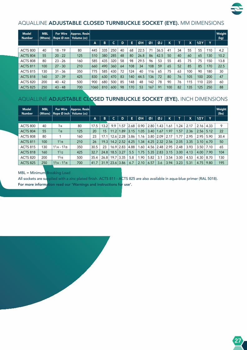
MBL = Minimum Breaking LoadAll sockets are supplied with a zinc plated finish. ACTS 811 - ACTS 825 are also available in aqua-blue primer (RAL 5018).For more information read our ‘Warnings and instructions for use’.
AQUALLINE ADJUSTABLE CLOSED TURNBUCKLE SOCKET (EYE). MM DIMENSIONS
AQUALLINE ADJUSTABLE CLOSED TURNBUCKLE SOCKET (EYE). INCH DIMENSIONS
Model MBL For Wire Approx. Resin WeightNumber (Mtons) Rope Ø mm Volume (cc) (kg) A B C D E Ø H Ø I Ø J K T X 1/2 Y Y
Model MBL For Wire Approx. Resin WeightNumber (Mtons) Rope Ø inch Volume (cc) (lbs) A B C D E Ø H Ø I Ø J K T X 1/2 Y Y
ACTS 800 40 18 - 19 80 445 335 250 40 68 22.5 71 36.5 41 34 55 55 110 4.2ACTS 804 55 20 - 22 125 510 380 285 48 80 26.8 86 42.5 50 40 60 65 130 10.2ACTS 808 80 23 - 26 160 585 435 320 58 98 29.5 96 53 55 45 75 75 150 13.8ACTS 811 100 27 - 30 210 660 490 360 64 108 34 108 59 65 52 85 85 170 22.5ACTS 815 130 31 - 36 350 775 585 430 72 124 40 116 65 75 63 100 90 180 30ACTS 818 160 37 - 39 425 830 630 470 83 140 44.5 136 72 80 76 105 100 200 47ACTS 820 200 40 - 42 500 900 680 500 85 148 48 142 78 90 76 115 110 220 60ACTS 825 250 43 - 48 700 1060 810 600 98 170 53 167 91 100 82 135 125 250 88
ACTS 800 40 3/4 80 17.5 13.2 9.9 1.57 2.68 0.90 2.80 1.43 1.61 1.24 2.17 2.16 4.33 9ACTS 804 55 7/8 125 20 15 11.2 1.89 3.15 1.05 3.40 1.67 1.97 1.57 2.36 2.56 5.12 22ACTS 808 80 1 160 23 17.1 12.6 2.28 3.86 1.16 3.80 2.09 2.17 1.77 2.95 2.95 5.90 30.4ACTS 811 100 11/8 210 26 19.3 14.2 2.52 4.25 1.34 4.25 2.32 2.56 2.05 3.35 3.10 6.70 50ACTS 815 130 11/4 - 13/8 350 30.5 23 16.9 2.83 4.88 1.60 4.56 2.48 2.95 2.48 3.93 3.50 7.10 65ACTS 818 160 11/2 425 32.7 24.8 18.5 3.27 5.5 1.75 5.35 2.83 3.15 3.00 4.13 4.00 7.90 104ACTS 820 200 15/8 500 35.4 26.8 19.7 3.35 5.8 1.90 5.82 3.1 3.54 3.00 4.53 4.30 8.70 130ACTS 825 250 13/4 - 17/8 700 41.7 31.9 23.6 3.86 6.7 2.10 6.57 3.6 3.94 3.23 5.31 4.75 9.80 195
A Q U A L L I N E P R O D U C T S
A Q U A L L I N E P R O D U C T S
28
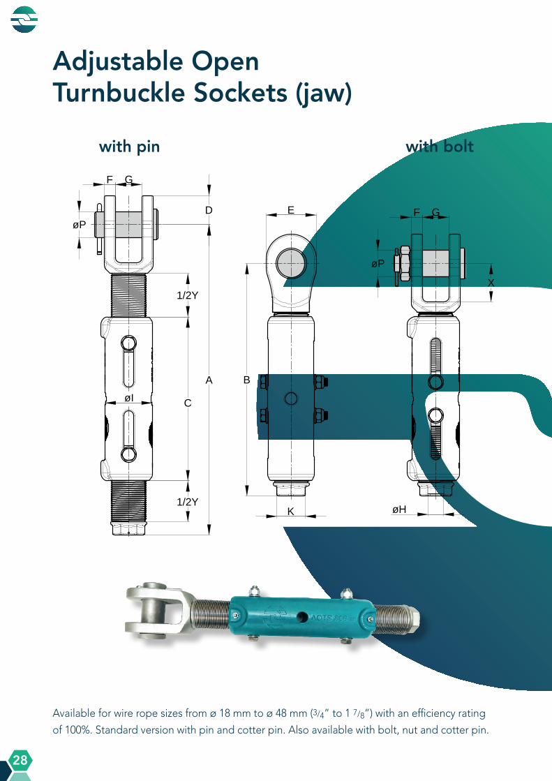
Adjustable Open Turnbuckle Sockets (jaw)
Available for wire rope sizes from ø 18 mm to ø 48 mm (3/4” to 1 7/8”) with an efficiency rating
of 100%. Standard version with pin and cotter pin. Also available with bolt, nut and cotter pin.
with pin with bolt
A Q U A L L I N E P R O D U C T S
A Q U A L L I N E P R O D U C T S
29
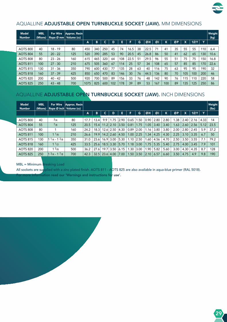
MBL = Minimum Breaking LoadAll sockets are supplied with a zinc plated finish. AOTS 811 - AOTS 825 are also available in aqua-blue primer (RAL 5018).For more information read our ‘Warnings and instructions for use’.
AQUALLINE ADJUSTABLE OPEN TURNBUCKLE SOCKET (JAW). MM DIMENSIONS
AQUALLINE ADJUSTABLE OPEN TURNBUCKLE SOCKET (JAW). INCH DIMENSIONS
Model MBL For Wire Approx. Resin WeightNumber (Mtons) Rope Ø mm Volume (cc) (kg) A B C D E F G Ø H Ø I K Ø P X 1/2 Y Y
AOTS 800 40 18 - 19 80 450 340 250 45 74 16.5 38 22.5 71 41 35 55 55 110 6.4AOTS 804 55 20 - 22 125 520 390 285 53 90 20.5 45 26.8 86 50 41 62 65 130 10.6AOTS 808 80 23 - 26 160 615 465 320 64 108 22.5 51 29.5 96 55 51 75 75 150 16.8AOTS 811 100 27 - 30 210 675 505 360 67 114 25 57 34 108 65 57 85 85 170 22.6AOTS 815 130 31 - 36 350 790 600 430 77 135 28 63 40 116 75 63 95 95 190 32AOTS 818 160 37 - 39 425 850 650 470 83 146 30 76 44.5 136 80 70 105 100 200 46AOTS 820 200 40 - 42 500 920 700 500 89 156 33 76 48 142 90 76 115 110 220 58AOTS 825 250 43 - 48 700 1075 825 600 102 178 39 89 53 167 100 89 135 125 250 86
Model MBL For Wire Approx. Resin WeightNumber (Mtons) Rope Ø inch Volume (cc) (lbs) A B C D E F G Ø H Ø I K Ø P X 1/2 Y Y
AOTS 800 40 3/4 80 17.7 13.4 9.9 1.75 2.90 0.65 1.50 0.90 2.80 2.80 1.38 2.40 2.16 4.33 14AOTS 804 55 7/8 125 20.5 15.4 11.2 2.10 3.50 0.81 1.75 1.05 3.40 3.40 1.63 2.60 2.56 5.12 23.5AOTS 808 80 1 160 24.2 18.3 12.6 2.50 4.30 0.89 2.00 1.16 3.80 3.80 2.00 2.80 2.45 5.9 37.2AOTS 811 100 1 1/8 210 26.6 19.9 14.2 2.60 4.50 1.00 2.25 1.34 4.25 4.30 2.25 3.10 3.35 6.7 50AOTS 815 130 1 1/4 - 1 3/8 350 31.0 23.6 16.9 3.00 5.30 1.10 2.50 1.60 4.56 4.70 2.50 3.50 3.55 7.1 79.2AOTS 818 160 1 1/2 425 33.5 25.6 18.5 3.30 5.70 1.18 3.00 1.75 5.35 5.40 2.75 4.00 3.45 7.9 101AOTS 820 200 1 5/8 500 36.2 27.6 19.7 3.50 6.15 1.30 3.00 1.90 5.82 5.60 3.00 4.30 4.35 8.7 128AOTS 825 250 1 3/4 - 1 7/8 700 42.3 32.5 23.6 4.00 7.00 1.50 3.50 2.10 6.57 6.60 3.50 4.75 4.9 9.8 190

A Q U A L L I N E P R O D U C T S
A Q U A L L I N E P R O D U C T S
30
Adjustable Open Spelter Sockets
Available for wire rope sizes from ø 18 mm to ø 48 mm (3/4” to 1 7/8”) with an efficiency
rating of 100%. Standard version with pin and cotter pin. Also available with bolt, nut and
cotter pin.
with pin with bolt
A Q U A L L I N E P R O D U C T S
A Q U A L L I N E P R O D U C T S
31
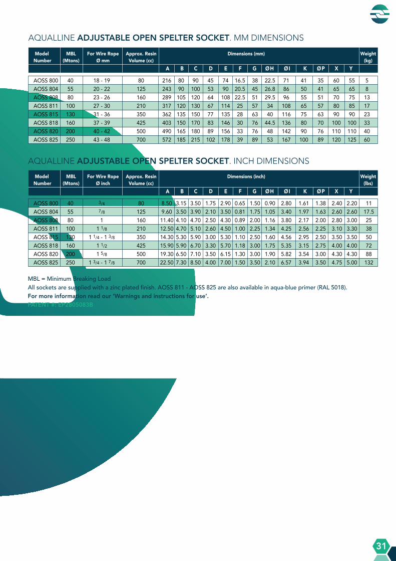
Model MBL For Wire Rope Approx. Resin Dimensions (mm) WeightNumber (Mtons) Ø mm Volume (cc) (kg) A B C D E F G Ø H Ø I K Ø P X Y
AQUALLINE ADJUSTABLE OPEN SPELTER SOCKET. MM DIMENSIONS
AOSS 800 40 18 - 19 80 216 80 90 45 74 16.5 38 22.5 71 41 35 60 55 5 AOSS 804 55 20 - 22 125 243 90 100 53 90 20.5 45 26.8 86 50 41 65 65 8 AOSS 808 80 23 - 26 160 289 105 120 64 108 22.5 51 29.5 96 55 51 70 75 13 AOSS 811 100 27 - 30 210 317 120 130 67 114 25 57 34 108 65 57 80 85 17 AOSS 815 130 31 - 36 350 362 135 150 77 135 28 63 40 116 75 63 90 90 23 AOSS 818 160 37 - 39 425 403 150 170 83 146 30 76 44.5 136 80 70 100 100 33 AOSS 820 200 40 - 42 500 490 165 180 89 156 33 76 48 142 90 76 110 110 40 AOSS 825 250 43 - 48 700 572 185 215 102 178 39 89 53 167 100 89 120 125 60
Model MBL For Wire Rope Approx. Resin Dimensions (inch) WeightNumber (Mtons) Ø inch Volume (cc) (lbs) A B C D E F G Ø H Ø I K Ø P X Y
AQUALLINE ADJUSTABLE OPEN SPELTER SOCKET. INCH DIMENSIONS
AOSS 800 40 3/4 80 8.50 3.15 3.50 1.75 2.90 0.65 1.50 0.90 2.80 1.61 1.38 2.40 2.20 11 AOSS 804 55 7/8 125 9.60 3.50 3.90 2.10 3.50 0.81 1.75 1.05 3.40 1.97 1.63 2.60 2.60 17.5AOSS 808 80 1 160 11.40 4.10 4.70 2.50 4.30 0.89 2.00 1.16 3.80 2.17 2.00 2.80 3.00 25 AOSS 811 100 1 1/8 210 12.50 4.70 5.10 2.60 4.50 1.00 2.25 1.34 4.25 2.56 2.25 3.10 3.30 38 AOSS 815 130 1 1/4 - 1 3/8 350 14.30 5.30 5.90 3.00 5.30 1.10 2.50 1.60 4.56 2.95 2.50 3.50 3.50 50 AOSS 818 160 1 1/2 425 15.90 5.90 6.70 3.30 5.70 1.18 3.00 1.75 5.35 3.15 2.75 4.00 4.00 72 AOSS 820 200 1 5/8 500 19.30 6.50 7.10 3.50 6.15 1.30 3.00 1.90 5.82 3.54 3.00 4.30 4.30 88 AOSS 825 250 1 3/4 - 1 7/8 700 22.50 7.30 8.50 4.00 7.00 1.50 3.50 2.10 6.57 3.94 3.50 4.75 5.00 132
MBL = Minimum Breaking LoadAll sockets are supplied with a zinc plated finish. AOSS 811 - AOSS 825 are also available in aqua-blue primer (RAL 5018).For more information read our ‘Warnings and instructions for use’. PATENT #: EP2805083B

A Q U A L L I N E P R O D U C T S
A Q U A L L I N E P R O D U C T S
32
Anchor Pendant Sockets
Available for wire rope sizes from ø 31 mm to ø 128 mm (1 1/4” to 5”) with an efficiency
rating of 100%.

A Q U A L L I N E P R O D U C T S
A Q U A L L I N E P R O D U C T S
33
MBL = Minimum Breaking LoadAll sockets are supplied with a hot dipped galvanized finish. APS 522 - APS 540 are also available in aqua-blue primer (RAL 5018). For more information read our ‘Warnings and instructions for use’.
Model MBL For Wire Rope Approx. Resin Dimensions (inch) WeightNumber (Mtons) Ø inch Volume (cc) (lbs) A B C D E F G Ø H Ø K
Model MBL For Wire Rope Approx. Resin Dimensions (mm) WeightNumber (Mtons) Ø mm Volume (cc) (kg) A B C D E F G Ø H Ø K
AQUALLINE ANCHOR PENDANT SOCKET. INCH DIMENSIONS
AQUALLINE ANCHOR PENDANT SOCKET. MM DIMENSIONS
APS 512 130 1 1/4 - 1 3/8 350 10.60 5.60 3.50 1.60 1.40 5.50 3.20 1.60 2.40 15APS 517 160 1 1/2 - 1 5/8 500 12.16 6.38 4.00 1.73 1.57 6.00 3.62 1.80 2.64 24APS 519 200 1 3/4 - 1 7/8 700 14.50 7.60 4.84 2.10 1.90 6.93 4.33 2.10 2.91 36APS 522 250 2 - 2 1/8 1250 16.00 8.27 5.50 2.28 2.20 7.87 4.92 2.30 3.27 48APS 524 320 2 1/4 - 2 3/8 1425 17.80 9.06 6.18 2.56 2.28 8.90 5.50 2.70 3.78 68APS 526 400 2 1/2 - 2 5/8 1850 19.60 9.84 6.85 2.95 2.60 9.84 6.14 3.00 4.20 92APS 527 500 2 3/4 - 2 7/8 2300 21.70 11.00 7.50 3.15 2.76 10.80 6.73 3.15 4.50 119APS 528 600 3 - 3 1/8 3400 23.30 12.16 7.70 3.38 3.00 11.40 7.10 3.50 4.90 155APS 529 700 3 1/4 - 3 3/8 4100 25.30 13.10 8.30 3.94 3.54 12.00 7.40 3.70 5.20 187APS 530 800 3 1/2 - 3 5/8 5200 27.00 14.20 8.70 4.10 3.74 13.10 8.25 3.90 5.60 260APS 531 900 3 3/4 - 4 7700 28.40 14.80 9.25 4.40 4.00 14.40 8.70 4.33 6.20 310APS 533 1000 4 1/4 - 4 1/2 10500 32.20 16.50 10.60 5.00 4.40 16.00 9.50 5.00 7.10 480APS 540 1200 4 3/4 - 5 14000 36.20 19.30 11.40 5.50 5.00 17.70 10.90 5.50 7.90 710
APS 512 130 31 - 36 350 270 141 88 40 36 140 82 41 60 7APS 517 160 37 - 42 500 309 162 103 44 40 152 92 46 67 11 APS 519 200 43 - 48 700 369 193 123 53 48 176 110 53 74 16 APS 522 250 49 - 54 1250 408 210 140 58 52 200 125 58.5 83 22 APS 524 320 55 - 60 1425 452 230 157 65 58 226 140 68 96 31 APS 526 400 61 - 68 1850 499 250 174 75 66 250 156 76 107 42 APS 527 500 69 - 75 2300 551 280 191 80 70 275 171 80 115 54 APS 528 600 76 - 80 3400 591 309 196 86 76 290 180 89 125 70 APS 529 700 81 - 86 4100 643 332 211 100 90 304 188 94 133 85 APS 530 800 87 - 93 5200 685 360 220 105 95 332 210 99 142 118 APS 531 900 94 - 102 7700 722 375 235 112 101 366 220 110 157 142 APS 533 1000 108 - 115 10500 818 420 270 126 112 405 240 128 180 220 APS 540 1200 120 - 128 14000 920 490 290 140 126 450 276 140 200 320
A Q U A L L I N E P R O D U C T S
A Q U A L L I N E P R O D U C T S
34
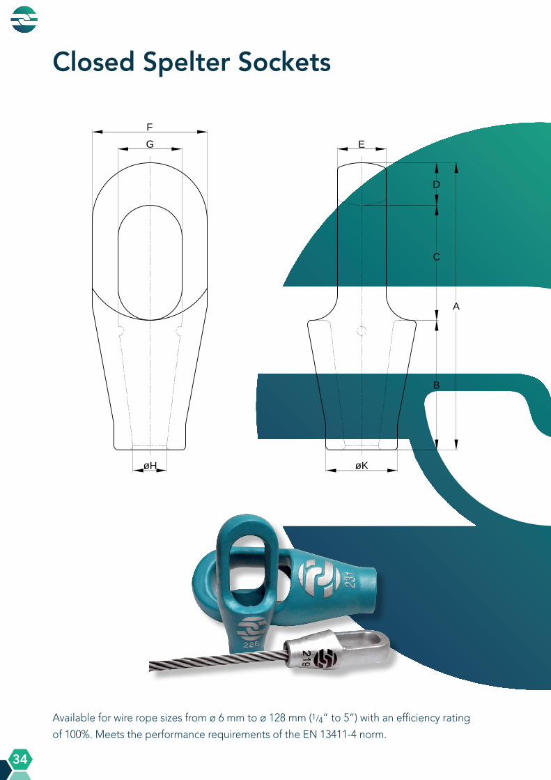
Closed Spelter Sockets
Available for wire rope sizes from ø 6 mm to ø 128 mm (1/4” to 5”) with an efficiency rating
of 100%. Meets the performance requirements of the EN 13411-4 norm.

A Q U A L L I N E P R O D U C T S
A Q U A L L I N E P R O D U C T S
35
AQUALLINE CLOSED SPELTER SOCKET. MM DIMENSIONS
AQUALLINE CLOSED SPELTER SOCKET. INCH DIMENSIONS
Model MBL For Wire Rope Structural Approx. Resin Dimensions (mm) WeightNumber (Mtons) Ø mm Strand Ø mm Volume (cc) (kg) A B C D E F G Ø H Ø K
CSS 296 8 6 - 7 - 10 102 46 45 11 14 38 22 10 20 0.3 CSS 297 12 8 - 10 - 20 120 54 52 14 17.5 44 24 13.5 26 0.5 CSS 298 20 11 - 13 - 35 140 64 59 17 23 53 30 15 30 0.7 CSS 299 25 14 - 16 12 - 13 50 162 76 65 21 26 67 36 18.5 38.5 1.3 CSS 200 40 18 - 19 14 - 16 80 194 89 78 27 32 77 42 22.5 46 2.1 CSS 201 55 20 - 22 18 - 19 125 224 101 90 33 38 92 50 26.8 55 3.6 CSS 204 80 23 - 26 20 - 22 160 253 114 103 36 45 101 57 29.5 62 5.1 CSS 207 100 27 - 30 24 - 26 210 282 127 116 39 51 114 65 34 70 7 CSS 212 130 31 - 36 27 - 28 350 312 139 130 43 57 127 71 40 83 10.4 CSS 215 160 37 - 39 30 - 32 425 358 152 155 51 63 140 80 44.5 90 15 CSS 217 200 40 - 42 33 - 35 500 390 165 171 54 70 148 84 48 97 18.5 CSS 219 250 43 - 48 36 - 40 700 443 190 198 55 76 171 95 53 112 27.5 CSS 222 300 49 - 54 42 - 45 1250 502 216 224 62 82 193 111 58.5 125 39.5 CSS 224 375 55 - 60 46 - 48 1425 550 229 248 73 92 219 125 68.5 135 51 CSS 226 450 61 - 68 50 - 54 1850 597 248 270 79 102 241 140 77.5 150 67 CSS 227 500 69 - 75 56 - 62 2300 644 279 286 79 124 273 159 83 160 96 CSS 228 600 76 - 80 64 - 67 3400 689 305 298 86 133 292 171 89 170 118 CSS 229 650 81 - 86 70 - 73 4100 736 330 311 95 146 311 184 95 180 142 CSS 230 750 87 - 93 76 - 80 5200 788 356 330 102 159 330 197 99 200 175 CSS 231 900 94 - 102 83 - 92 7700 845 381 356 108 178 362 216 110 215 230 CSS 233 1200 108 - 115 96 - 108 10500 965 440 400 125 190 405 235 128 250 315 CSS 240 1400 120 - 128 112 - 121 14000 1070 490 450 130 205 450 260 143 270 390
Model MBL For Wire Rope Structural Approx. Resin Dimensions (inch) WeightNumber (Mtons) Ø inch Strand Ø inch Volume (cc) (lbs) A B C D E F G Ø H Ø K
CSS 296 8 1/4 - 10 4.00 1.81 1.77 0.43 0.55 1.50 0.87 0.39 0.78 0.7 CSS 297 12 5/16 - 3/8 - 20 4.70 2.16 2.00 0.55 0.69 1.74 0.95 0.53 1.02 1.1 CSS 298 20 7/16 - 1/2 - 35 5.50 2.52 2.32 0.67 0.91 2.10 1.18 0.60 1.18 1.6 CSS 299 25 9/16 - 5/8 1/2 50 6.40 3.00 2.56 0.83 1.02 2.52 1.42 0.73 1.52 3 CSS 200 40 3/4 9/16 - 5/8 80 7.60 3.50 3.07 1.06 1.26 2.95 1.65 0.89 1.81 4.5 CSS 201 55 7/8 1 1/16 - 3/4 125 8.80 4.00 3.54 1.30 1.50 3.54 1.97 1.05 2.17 8 CSS 204 80 1 1 3/16 - 7/8 160 10.00 4.50 4.05 1.42 1.77 4.00 2.24 1.16 2.44 11 CSS 207 100 1 1/8 15/16 - 1 210 11.10 5.00 4.60 1.54 2.00 4.50 2.56 1.39 2.76 15 CSS 212 130 1 1/4 - 1 3/8 1 1/16 - 1 1/8 350 12.30 5.50 5.12 1.70 2.24 5.00 2.80 1.57 3.27 23 CSS 215 160 1 1/2 1 3/16 - 1 1/4 425 14.10 6.00 6.10 2.00 2.48 5.60 3.10 1.75 3.50 33 CSS 217 200 1 5/8 1 5/16 - 1 3/8 500 15.40 6.50 6.70 2.13 2.76 5.90 3.20 1.90 3.80 41 CSS 219 250 1 3/4 - 1 7/8 1 7/16 - 1 5/8 700 17.40 7.50 7.80 2.17 3.00 6.70 3.74 2.10 4.40 61 CSS 222 300 2 - 2 1/8 1 11/16 - 1 3/4 1250 19.80 8.50 8.50 2.40 3.23 7.60 4.37 2.30 4.90 87 CSS 224 375 2 1/4 - 2 3/8 1 13/16 - 1 7/4 1425 21.70 9.00 9.76 2.87 3.63 8.60 4.92 2.70 5.30 112 CSS 226 450 2 1/2 - 2 5/8 1 15/16 - 2 1/8 1850 23.50 9.76 10.60 3.10 4.00 9.50 5.50 3.05 5.90 148 CSS 227 500 2 3/4 -2 7/8 2 3/16 - 2 7/16 2300 25.40 11.00 11.30 3.10 4.90 10.70 6.30 3.25 6.30 211 CSS 228 600 3 - 3 1/8 2 1/2 - 2 5/8 3400 27.10 12.00 11.70 3.40 5.20 11.50 6.70 3.50 6.70 258 CSS 229 650 3 1/4 - 3 3/8 2 3/4 - 2 7/8 4100 29.00 13.00 12.20 3.70 5.70 12.30 7.20 3.75 7.10 312 CSS 230 750 3 1/2 - 3 5/8 3 - 3 1/8 5200 31.00 14.00 13.00 4.00 6.50 13.00 7.80 3.90 7.90 385 CSS 231 900 3 3/4 - 4 3 1/4 - 3 3/8 7700 33.30 15.00 14.00 4.30 7.00 14.30 8.50 4.33 8.50 506 CSS 233 1200 4 1/4 - 4 1/2 3 3/4 - 4 1/4 10500 38.00 17.30 15.70 5.00 7.50 16.00 9.30 5.00 9.80 695 CSS 240 1400 4 3/4 - 5 4 7/16 - 4 3/4 14000 42.00 19.30 17.70 5.10 8.10 17.70 10.30 5.60 10.60 860
MBL = Minimum Breaking Load All sockets are supplied with a hot dipped galvanized finish. CSS 207 - CSS 240 are also available in aqua-blue primer (RAL 5018). For more information read our ‘Warnings and instructions for use’.
A Q U A L L I N E P R O D U C T S
A Q U A L L I N E P R O D U C T S
36
Closed Wedge Sockets
Available for wire rope sizes from ø 17 mm to ø 86 mm (3/4” to 3 3/8”) with an efficiency rating
of 85-92%. Meets the performance requirements of the EN 13411-6 norm.

A Q U A L L I N E P R O D U C T S
A Q U A L L I N E P R O D U C T S
37
Available for wire rope sizes from ø 17 mm to ø 86 mm (3/4” to 3 3/8”) with an efficiency rating
of 85-92%. Meets the performance requirements of the EN 13411-6 norm.
AQUALLINE CLOSED WEDGE SOCKET. MM DIMENSIONS
AQUALLINE CLOSED WEDGE SOCKET. INCH DIMENSIONS
Model MBL For Wire Rope Dimensions (mm) WeightNumber (Mtons) Ø mm (kg) A D E F G H X
CWS 303 40 17 - 19 317 40 36 100 42 277 100 7 CWS 304 55 20 - 22 368 45 40 115 50 323 110 9 CWS 305 80 23 - 26 422 52 45 130 60 370 125 14 CWS 306 100 27 - 29 473 58 50 150 65 415 140 22 CWS 307 120 30 - 32 519 62 55 160 72 457 160 30 CWS 308 130 34 - 36 580 66 60 168 76 514 175 38 CWS 309 160 37 - 39 620 72 66 175 82 548 190 49 CWS 310 200 40 - 42 665 80 72 195 90 585 210 65 CWS 311 250 43 - 48 750 90 80 220 100 660 240 110 CWS 312 300 49 - 52 820 100 90 242 110 720 260 140 CWS 313 375 54 - 58 890 106 95 255 120 784 280 170 CWS 314 450 60 - 68 1045 120 105 280 130 925 330 240 CWS 315 600 72 - 76 1200 140 120 330 150 1060 400 380 CWS 316 650 81 - 86 1340 155 130 375 170 1185 475 490
Model MBL For Wire Rope Dimensions (inch) WeightNumber (Mtons) Ø inch (lbs) A D E F G H X
CWS 303 40 3/4 12.50 1.60 1.40 4.00 1.65 10.90 4.00 15.5 CWS 304 55 7/8 14.50 1.80 1.60 4.50 2.00 12.70 4.30 20 CWS 305 80 1 16.60 2.00 1.80 5.10 2.30 14.60 5.00 31 CWS 306 100 1 1/8 18.60 2.30 2.00 5.90 2.60 16.30 5.50 49 CWS 307 120 1 1/4 20.50 2.50 2.15 6.30 2.80 18.00 6.30 66 CWS 308 130 1 3/8 22.80 2.60 2.50 6.60 3.00 20.20 7.00 84 CWS 309 160 1 1/2 24.40 2.80 2.60 6.90 3.20 21.60 7.50 108 CWS 310 200 1 5/8 26.20 3.15 2.80 7.70 3.50 23.00 8.25 145 CWS 311 250 1 3/4 - 1 7/8 29.50 3.50 3.15 8.70 4.00 26.00 9.50 240 CWS 312 300 2 32.30 4.00 3.50 9.50 4.30 28.30 10.25 310 CWS 313 375 2 1/4 35.00 4.20 3.70 10.00 4.70 30.80 11.00 370 CWS 314 450 2 1/2 41.10 4.70 4.10 11.00 5.10 36.40 13.00 530 CWS 315 600 3 47.20 5.50 4.70 13.00 5.90 41.70 15.75 840 CWS 316 650 3 1/4 - 3 3/8 52.80 6.10 5.10 14.80 6.70 46.60 18.70 1180
MBL = Minimum Breaking Load X = Depending on the actual wire rope diameter, rope construction and fill factor All sockets are supplied with a hot dipped galvanized finish or available in aqua-blue primer (RAL 5018). For more information read our ‘Warnings and instructions for use’.

A Q U A L L I N E P R O D U C T S
A Q U A L L I N E P R O D U C T S
38
Fast Connector Sockets
Available for wire rope sizes from ø 11 mm to ø 52 mm (7/16” to 2”) with an efficiency rating
of 100%. Standard version with pin and cotter pin. Also available with bolt, nut and cotter
pin. Each Fast Connector Socket contains a Connector Fitting with a non-rotating device.
with pin with bolt

A Q U A L L I N E P R O D U C T S
A Q U A L L I N E P R O D U C T S
39
MBL = Minimum Breaking LoadAll sockets are supplied with a zinc plated finish. FCS 704 - FCS 712 are also available in aqua-blue primer (RAL 5018).For more information read our ‘Warnings and instructions for use’.
AQUALLINE FAST CONNECTOR SOCKET. MM DIMENSIONS
AQUALLINE FAST CONNECTOR SOCKET. INCH DIMENSIONS
Model MBL For Wire Approx. Dimensions (mm) WeightNumber (Mtons) Rope Resin (kg) Ø mm Volume (cc) A B C D E F G K M Ø P X Ø H L Ø N
Model MBL For Wire Approx. Dimensions (inch) WeightNumber (Mtons) Rope Resin (lbs) Ø inch Volume (cc) A B C D E F G K M Ø P X Ø H L Ø N
FCS 701 20 11 - 13 35 190 65 97 28 48 12.5 26 40 47 25 45 15 70 26 1.7FCS 702 25 13 - 16 50 227 80 115 32 56 14.5 32 50 58 30 58 19 84 32 2.6FCS 703 40 17 - 19 80 260 90 130 40 68 16.5 38 60 70 35 64 22 98 39 3.9FCS 704 55 20 - 22 125 303 110 145 48 80 20.5 45 69 80 41 82 26.5 117 45 6.7FCS 705 80 23 - 26 160 365 125 182 58 98 22.5 51 80 93 51 95 29.5 138 52 10.5FCS 706 100 27 - 29 210 400 140 195 65 110 25 57 90 104 57 97 33.5 157 58 13.5FCS 707 120 30 - 32 350 426 150 205 72 124 28 63 98 111 63 100 36.5 170 64 19FCS 708 130 33 - 36 425 465 170 220 76 132 28 70 102 117 63 110 40 183 68 23FCS 709 160 37 - 39 500 502 182 240 80 140 30 76 110 125 70 115 43 207 76 41FCS 710 200 40 - 42 700 550 200 265 85 148 33 76 126 142 76 125 48 230 85 50FCS 711 250 43 - 48 1250 620 225 300 98 170 39 89 140 157 89 135 56 260 95 65FCS 712 300 49 - 52 1425 685 240 335 108 186 46 101 157 175 95 150 60 285 104 80
FCS 701 20 7/16 - 1/2 35 7.50 2.60 3.80 1.10 1.90 0.50 1.00 1.60 1.90 1.00 1.80 0.60 2.80 1.03 3.8FCS 702 25 1/2 - 5/8 50 8.90 3.10 4.50 1.30 2.20 0.57 1.26 2.00 2.30 1.18 2.30 0.75 3.30 1.26 5.8FCS 703 40 2/3 - 3/4 80 10.20 3.50 5.10 1.60 2.70 0.65 1.50 2.36 2.80 1.38 2.50 0.85 3.90 1.50 8.6FCS 704 55 7/8 125 11.90 4.30 5.70 1.90 3.10 0.81 1.77 2.70 3.10 1.60 3.20 1.05 4.60 1.77 15FCS 705 80 1 160 14.40 4.90 7.20 2.30 3.60 0.89 2.00 3.10 3.70 2.00 3.70 1.16 5.40 2.00 23FCS 706 100 1 1/8 210 15.70 5.50 7.70 2.60 4.30 1.00 2.25 3.50 4.10 2.25 3.80 1.32 6.20 2.30 30FCS 707 120 1 1/4 350 16.80 5.90 8.10 2.80 4.90 1.10 2.50 3.90 4.40 2.50 3.90 1.44 6.70 2.50 42FCS 708 130 1 3/8 425 18.30 6.70 8.70 3.00 5.20 1.10 2.75 4.00 4.60 2.50 4.30 1.58 7.20 2.70 51FCS 709 160 1 1/2 500 19.80 7.20 9.50 3.10 5.50 1.20 3.00 4.30 4.90 2.75 4.50 1.70 8.20 3.00 90FCS 710 200 1 5/8 700 21.70 7.90 10.40 3.30 5.80 1.30 3.00 5.00 5.60 3.00 4.90 1.90 9.10 3.30 110FCS 711 250 1 3/4 - 1 7/8 1250 24.40 8.90 11.80 3.90 6.70 1.53 3.50 5.50 6.20 3.50 5.30 2.20 10.20 3.70 145FCS 712 300 2 1425 27.00 9.50 13.20 4.30 7.30 1.81 4.00 6.20 6.90 3.75 5.90 2.36 11.20 4.10 175
A Q U A L L I N E P R O D U C T S
A Q U A L L I N E P R O D U C T S
40
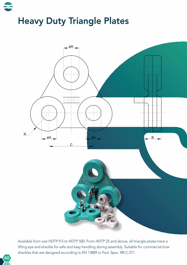
Heavy Duty Triangle Plates
Available from size HDTP 9.5 to HDTP 500. From HDTP 25 and above, all triangle plates have a
lifting eye and shackle for safe and easy handling during assembly. Suitable for commercial bow
shackles that are designed according to EN 13889 or Fed. Spec. RR-C.271.

A Q U A L L I N E P R O D U C T S
A Q U A L L I N E P R O D U C T S
41
SWL = Safe Working LoadMBL = Minimum Breaking LoadAll heavy duty triangle plates are supplied with a hot dipped galvanized finish. HDTP 25 – HDTP 500 are also available in aqua-blue primer (RAL 5018).For more information read our ‘Warnings and instructions for use‘.
AQUALLINE HEAVY DUTY TRIANGLE PLATE. MM DIMENSIONS
AQUALLINE HEAVY DUTY TRIANGLE PLATE. INCH DIMENSIONS
Model SWL MBL Dimensions (mm) WeightNumber (Mtons) (Mtons) (kg) Ø A B C R
Model SWL MBL Dimensions (inch) WeightNumber (Mtons) (Mtons) (lbs) Ø A B C R
HDTP 9.5 9.5 50 35 40 110 45 5HDTP 12 12 70 38 42 120 48 6.5HDTP 13.5 13.5 80 41 48 130 50 8HDTP 17 17 100 46 52 140 55 10.5HDTP 25 25 125 54 60 155 65 16.5HDTP 35 35 175 62 70 175 75 25HDTP 55 55 275 76 90 210 90 46HDTP 85 85 425 88 100 240 105 69HDTP 120 120 600 100 118 280 120 107HDTP 150 150 750 115 142 310 135 163HDTP 200 200 1000 140 150 380 170 260HDTP 250 250 1250 150 160 425 180 345HDTP 300 300 1500 160 178 450 193 435HDTP 400 400 2000 186 205 480 215 680HDTP 500 500 2500 200 225 510 240 860
HDTP 9.5 9.5 50 1.38 1.57 4.3 1.77 11HDTP 12 12 70 1.5 1.65 4.7 1.9 14HDTP 13.5 13.5 80 1.6 1.9 5.1 1.97 17HDTP 17 17 100 1.8 2 5.5 2.2 22HDTP 25 25 125 2.1 2.4 6.1 2.6 36HDTP 35 35 175 2.4 2.8 6.9 3 55HDTP 55 55 275 3 3.5 8.3 3.5 102HDTP 85 85 425 3.5 3.9 9.5 4.1 152HDTP 120 120 600 3.9 4.7 11 4.7 235HDTP 150 150 750 4.5 5.6 12.2 5.3 360HDTP 200 200 1000 5.5 5.9 15 6.7 570HDTP 250 250 1250 5.9 6.3 16.7 7.1 760HDTP 300 300 1500 6.3 7 17.7 7.6 950HDTP 400 400 2000 7.3 8.1 18.9 8.5 1500HDTP 500 500 2500 7.9 8.9 20 9.5 1900

A Q U A L L I N E P R O D U C T S
A Q U A L L I N E P R O D U C T S
42
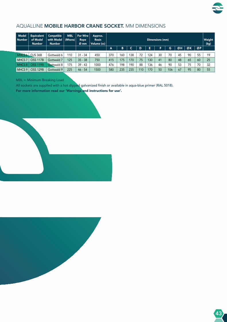
Mobile Harbor Crane Sockets
Available for wire rope sizes from ø 31 mm to ø 54 mm with an efficiency rating of 100%.
Standard with bolt, nut and cotter pin. Also available with Roller.
with bolt
A Q U A L L I N E P R O D U C T S
A Q U A L L I N E P R O D U C T S
43
MBL = Minimum Breaking LoadAll sockets are supplied with a hot dipped galvanized finish or available in aqua-blue primer (RAL 5018).For more information read our ‘Warnings and instructions for use’.
AQUALLINE MOBILE HARBOR CRANE SOCKET. MM DIMENSIONS
Equivalent Compatible MBL For Wire Approx. of Model with Model (Mtons) Rope Resin Dimensions (mm) Weight Number Number Ø mm Volume (cc) (kg) A B C D E F G Ø H Ø K Ø P
Model Number
OJS 36B Gottwald 6 110 31 - 34 450 370 160 138 72 124 30 70 45 90 55 19OSS 117B Gottwald 7 125 35 - 38 750 415 175 170 75 130 41 80 48 65 60 25OSS 119B Gottwald 8 175 39 - 43 1000 476 198 190 88 136 46 90 53 75 70 32OSS 129B Gottwald 9 225 46 - 54 1500 580 235 235 110 170 50 106 67 95 80 55
MHCS 6MHCS 7MHCS 8MHCS 9

A Q U A L L I N E P R O D U C T S
A Q U A L L I N E P R O D U C T S
44
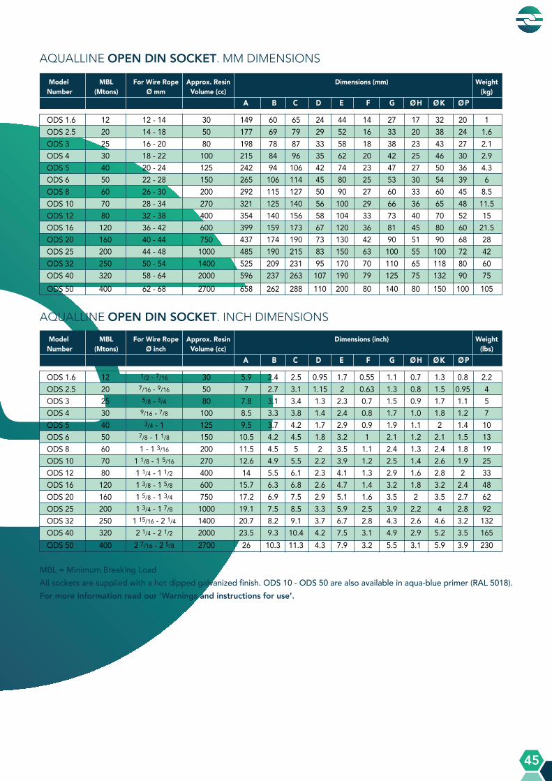
Open DIN Sockets
Available for wire rope sizes from ø 12 mm to ø 68 mm (1/2“ to 2 5/8“) with an efficiency rating
of 100%. Standard with bolt, nut and cotter pin. Meets the performance requirements of the DIN
83313 norm and exceeds the required MBL.
with bolt
A Q U A L L I N E P R O D U C T S
A Q U A L L I N E P R O D U C T S
45
MBL = Minimum Breaking LoadAll sockets are supplied with a hot dipped galvanized finish. ODS 10 - ODS 50 are also available in aqua-blue primer (RAL 5018).For more information read our ‘Warnings and instructions for use’.
AQUALLINE OPEN DIN SOCKET. MM DIMENSIONS
AQUALLINE OPEN DIN SOCKET. INCH DIMENSIONS
Model MBL For Wire Rope Approx. Resin Dimensions (mm) WeightNumber (Mtons) Ø mm Volume (cc) (kg) A B C D E F G Ø H Ø K Ø P
ODS 1.6 12 12 - 14 30 149 60 65 24 44 14 27 17 32 20 1ODS 2.5 20 14 - 18 50 177 69 79 29 52 16 33 20 38 24 1.6ODS 3 25 16 - 20 80 198 78 87 33 58 18 38 23 43 27 2.1ODS 4 30 18 - 22 100 215 84 96 35 62 20 42 25 46 30 2.9ODS 5 40 20 - 24 125 242 94 106 42 74 23 47 27 50 36 4.3ODS 6 50 22 - 28 150 265 106 114 45 80 25 53 30 54 39 6ODS 8 60 26 - 30 200 292 115 127 50 90 27 60 33 60 45 8.5ODS 10 70 28 - 34 270 321 125 140 56 100 29 66 36 65 48 11.5ODS 12 80 32 - 38 400 354 140 156 58 104 33 73 40 70 52 15ODS 16 120 36 - 42 600 399 159 173 67 120 36 81 45 80 60 21.5ODS 20 160 40 - 44 750 437 174 190 73 130 42 90 51 90 68 28ODS 25 200 44 - 48 1000 485 190 215 83 150 63 100 55 100 72 42ODS 32 250 50 - 54 1400 525 209 231 95 170 70 110 65 118 80 60ODS 40 320 58 - 64 2000 596 237 263 107 190 79 125 75 132 90 75ODS 50 400 62 - 68 2700 658 262 288 110 200 80 140 80 150 100 105
Model MBL For Wire Rope Approx. Resin Dimensions (inch) WeightNumber (Mtons) Ø inch Volume (cc) (lbs) A B C D E F G Ø H Ø K Ø P
ODS 1.6 12 1/2 - 7/16 30 5.9 2.4 2.5 0.95 1.7 0.55 1.1 0.7 1.3 0.8 2.2ODS 2.5 20 7/16 - 9/16 50 7 2.7 3.1 1.15 2 0.63 1.3 0.8 1.5 0.95 4ODS 3 25 5/8 - 3/4 80 7.8 3.1 3.4 1.3 2.3 0.7 1.5 0.9 1.7 1.1 5ODS 4 30 9/16 - 7/8 100 8.5 3.3 3.8 1.4 2.4 0.8 1.7 1.0 1.8 1.2 7ODS 5 40 3/4 - 1 125 9.5 3.7 4.2 1.7 2.9 0.9 1.9 1.1 2 1.4 10ODS 6 50 7/8 - 1 1/8 150 10.5 4.2 4.5 1.8 3.2 1 2.1 1.2 2.1 1.5 13ODS 8 60 1 - 1 3/16 200 11.5 4.5 5 2 3.5 1.1 2.4 1.3 2.4 1.8 19ODS 10 70 1 1/8 - 1 5/16 270 12.6 4.9 5.5 2.2 3.9 1.2 2.5 1.4 2.6 1.9 25ODS 12 80 1 1/4 - 1 1/2 400 14 5.5 6.1 2.3 4.1 1.3 2.9 1.6 2.8 2 33ODS 16 120 1 3/8 - 1 5/8 600 15.7 6.3 6.8 2.6 4.7 1.4 3.2 1.8 3.2 2.4 48ODS 20 160 1 5/8 - 1 3/4 750 17.2 6.9 7.5 2.9 5.1 1.6 3.5 2 3.5 2.7 62ODS 25 200 1 3/4 - 1 7/8 1000 19.1 7.5 8.5 3.3 5.9 2.5 3.9 2.2 4 2.8 92ODS 32 250 1 15/16 - 2 1/4 1400 20.7 8.2 9.1 3.7 6.7 2.8 4.3 2.6 4.6 3.2 132ODS 40 320 2 1/4 - 2 1/2 2000 23.5 9.3 10.4 4.2 7.5 3.1 4.9 2.9 5.2 3.5 165ODS 50 400 2 7/16 - 2 5/8 2700 26 10.3 11.3 4.3 7.9 3.2 5.5 3.1 5.9 3.9 230

A Q U A L L I N E P R O D U C T S
A Q U A L L I N E P R O D U C T S
46
Open JIS Sockets
Available for wire rope sizes from ø 15 mm to ø 43 mm (5/8” to 1 5/8”) with an efficiency rating of
100%. Standard with bolt, nut and cotter pin. Meets the performance requirements of the
JIS F 3432-1995 norm and exceeds the required MBL.
with bolt

A Q U A L L I N E P R O D U C T S
A Q U A L L I N E P R O D U C T S
47
AQUALLINE OPEN JIS SOCKET. MM DIMENSIONS
AQUALLINE OPEN JIS SOCKET. INCH DIMENSIONS
Model MBL For Wire Rope Approx. Resin Dimensions (mm) WeightNumber (Mtons) Ø mm Volume (cc) (kg) A B C D E F G Ø H Ø K Ø P
OJS 16 24 15 - 16 50 183 76 75 32 56 13 32 20 39 25 1.7 OJS 18 30 17 - 18 80 207 89 80 38 64 15 38 23 45 28 2.6 OJS 20 36 19 - 20 125 220 95 85 40 70 16.5 42 25 48 31 3.6 OJS 22 40 21 - 22 160 235 101 89 45 80 20.5 45 30 58 34 5.1 OJS 24 48 23 - 24 175 264 114 101 49 86 22.5 51 32 62 37 6.7 OJS 25 60 25 - 26 200 276 120 105 51 90 22.5 51 34 65 40 7.5 OJS 28 72 27 - 28 230 299 127 114 58 100 25 57 36 70 43 10 OJS 30 80 29 - 30 300 313 135 118 60 104 25 57 38 75 46 11 OJS 32 90 31 - 32 350 331 139 127 65 110 28 63 41 83 49 14.2 OJS 34 100 33 - 34 400 347 150 130 67 114 28 63 43 83 52 16 OJS 36 110 35 - 36 450 370 160 138 72 124 30 70 45 90 55 19 OJS 38 120 37 - 38 500 389 170 145 74 128 30 72 47 90 58 22 OJS 40 135 39 - 40 600 406 175 155 76 130 33.5 76 50 97 61 27 OJS 42 150 41 - 43 700 430 191 160 79 136 39 80 53 100 65 36
Model MBL For Wire Rope Approx. Resin Dimensions (inch) WeightNumber (Mtons) Ø inch Volume (cc) (lbs) A B C D E F G Ø H Ø K Ø P
OJS 16 24 5/8 50 7.20 3.00 3.00 1.26 2.20 0.50 1.26 0.80 1.50 1.00 3.8 OJS 18 30 11/16 80 8.15 3.50 3.15 1.50 2.50 0.60 1.50 0.90 1.80 1.10 5.7 OJS 20 36 3/4 125 8.70 3.75 3.35 1.60 2.75 0.65 1.65 1.00 1.90 1.20 8OJS 22 40 7/8 160 9.25 4.00 3.50 1.80 3.15 0.80 1.77 1.20 2.30 1.34 11.2 OJS 24 48 15/16 175 10.40 4.50 4.00 1.90 3.40 0.90 2.00 1.26 2.40 1.46 14.8 OJS 25 60 1 200 10.90 4.75 4.14 2.00 3.50 0.90 2.00 1.34 2.60 1.57 16.5 OJS 28 72 1 1/8 230 11.80 5.00 4.50 2.30 4.00 1.00 2.25 1.42 2.80 1.70 22 OJS 30 80 1 3/16 300 12.30 5.30 4.65 2.40 4.10 1.00 2.25 1.50 3.00 1.80 24 OJS 32 90 1 1/4 350 13.00 5.50 5.00 2.50 4.30 1.10 2.50 1.61 3.30 1.93 31 OJS 34 100 1 5/16 400 13.70 5.90 5.10 2.60 4.50 1.10 2.50 1.70 3.30 2.00 35 OJS 36 110 1 3/8 450 14.60 6.30 5.40 2.80 4.90 1.20 2.75 1.77 3.50 2.17 42 OJS 38 120 1 1/2 500 15.30 6.70 5.70 2.90 5.00 1.20 2.80 1.85 3.50 2.30 48 OJS 40 135 1 9/16 600 16.00 6.90 6.10 3.00 5.10 1.32 3.00 1.97 3.80 2.40 60 OJS 42 150 1 5/8 700 16.90 7.50 6.30 3.10 5.40 1.53 3.15 2.10 4.00 2.60 80
MBL = Minimum Breaking LoadAll sockets are supplied with a hot dipped galvanized finish. For more information read our ‘Warnings and instructions for use’.
A Q U A L L I N E P R O D U C T S
A Q U A L L I N E P R O D U C T S
48
Open Spelter Sockets
Available for wire rope sizes from ø 6 mm to ø 128 mm (1/4” to 5”) with an efficiency rating of 100%.
Standard version with pin and cotter pin. Also available with bolt, nut and cotter pin. Meets the
performance requirements of the EN 13411-4 norm.
with pin with bolt

A Q U A L L I N E P R O D U C T S
A Q U A L L I N E P R O D U C T S
49
MBL = Minimum Breaking LoadAll sockets are supplied with a hot dipped galvanized finish. OSS 111 - OSS 150 are also available in aqua-blue primer (RAL 5018).For more information read our ‘Warnings and instructions for use’.
Model MBL For Wire Rope Structural Approx. Resin Dimensions (mm) WeightNumber (Mtons) Ø mm Strand Ø mm Volume (cc) (kg) A B C D E F G Ø H Ø K Ø P
Model MBL For Wire Rope Structural Approx. Resin Dimensions (inch) WeightNumber (Mtons) Ø inch Strand Ø inch Volume (cc) (lbs) A B C D E F G Ø H Ø K Ø P
AQUALLINE OPEN SPELTER SOCKET. INCH DIMENSIONS
AQUALLINE OPEN SPELTER SOCKET. MM DIMENSIONS
OSS 196 8 6 - 7 - 10 105 46 40 19 34 9 18 10 20 17.5 0.4 OSS 197 12 8 - 10 - 20 122 54 45 23 40 11.2 20.6 13.5 26 20.6 0.8 OSS 198 20 11 - 13 - 35 142 64 51 27 48 12.7 25.6 15 30 25.4 1.1 OSS 199 25 14 - 16 12 - 13 50 171 76 63 32 56 14.5 32 18.5 38.5 30 1.9 OSS 100 40 18 - 19 14 - 16 80 205 89 76 40 68 16.5 38 22.5 46 35 3.2 OSS 104 55 20 - 22 18 - 19 125 238 101 89 48 80 20.5 45 26.8 55 41 5.3 OSS 108 80 23 - 26 20 - 22 160 273 114 101 58 98 22.5 51 29.5 62 51 8.4 OSS 111 100 27 - 30 24 - 26 210 306 127 114 65 110 25 57 34 70 57 11.3 OSS 115 130 31 - 36 27 - 28 350 338 139 127 72 124 28 63 40 83 63 16 OSS 118 160 37 - 39 30 - 32 425 394 152 162 80 140 30 76 44.5 90 70 23 OSS 120 200 40 - 42 33 - 35 500 415 165 165 85 148 33.5 76 48 97 76 29 OSS 125 250 43 - 48 36 - 40 700 467 191 178 98 170 39 89 53 112 89 43 OSS 128 300 49 - 54 42 - 45 1250 552 216 228 108 186 46 101 58.5 125 95 64 OSS 130 375 55 - 60 46 - 48 1425 603 229 254 120 210 53 113 68.5 135 108 85 OSS 132 450 61 - 68 50 - 54 1850 654 248 273 133 230 60 127 77.5 150 121 119 OSS 135 500 69 - 75 56 - 62 2300 696 279 279 138 240 73 133 83 160 127 158 OSS 138 600 76 - 80 64 - 67 3400 736 305 286 145 250 76 146 89 170 133 186 OSS 140 650 81 - 86 70 - 73 4100 790 330 300 160 275 79 159 95 180 140 227 OSS 142 750 87 - 93 76 - 80 5200 849 356 318 175 300 82 172 99 200 152 280 OSS 144 900 94 - 102 88 - 96 7700 922 381 343 198 336 89 191 110 215 178 375OSS 145 1000 103 - 108 98 - 102 9000 995 406 381 208 356 95 203 118 240 185 435OSS 146 1200 108 - 115 104 - 111 10500 1110 440 450 220 370 100 205 128 250 195 525OSS 150 1400 120 - 128 112 - 121 14000 1185 490 440 255 430 113 225 143 270 220 680
OSS 196 8 1/4 - 10 4.13 1.81 1.60 0.75 1.34 0.35 0.71 0.39 0.78 0.69 0.9 OSS 197 12 5/16 - 3/8 - 20 4.80 2.16 1.80 0.90 1.57 0.44 0.81 0.53 1.02 0.81 1.8 OSS 198 20 7/6 - 1/2 - 35 5.60 2.52 2.00 1.10 1.89 0.50 1.00 0.60 1.18 1.00 2.4 OSS 199 25 9/16 - 5/8 1/2 50 6.70 3.00 2.50 1.30 2.20 0.57 1.26 0.73 1.52 1.19 4.2 OSS 100 40 3/4 9/16 - 5/8 80 8.10 3.50 3.00 1.60 2.76 0.65 1.50 0.89 1.81 1.38 7 OSS 104 55 7/8 11/16 - 3/4 125 9.40 4.00 3.50 1.90 3.15 0.81 1.75 1.05 2.17 1.63 11.7 OSS 108 80 1 13/16 - 7/8 160 10.70 4.50 4.00 2.30 4.00 0.89 2.00 1.16 2.44 2.00 18 OSS 111 100 1 1/8 15/16 - 1 210 12.00 5.00 4.50 2.60 4.33 1.00 2.25 1.39 2.76 2.25 25 OSS 115 130 1 1/4 - 1 3/8 1 1/16 - 1 1/8 350 13.30 5.50 5.00 2.80 4.80 1.10 2.50 1.57 3.27 2.50 35 OSS 118 160 1 1/2 1 3/16 - 1 1/4 425 15.50 6.00 6.40 3.15 5.52 1.18 3.00 1.75 3.50 2.75 51 OSS 120 200 1 5/8 1 5/16 - 1 3/8 500 16.30 6.50 6.50 3.35 5.90 1.30 3.00 1.90 3.80 3.00 64 OSS 125 250 1 3/4 - 1 7/8 1 7/16 - 1 5/8 700 18.40 7.50 7.00 3.86 6.70 1.53 3.50 2.10 4.40 3.50 95 OSS 128 300 2 - 2 1/8 1 11/16 - 1 3/4 1250 21.70 8.50 9.00 4.25 7.30 1.81 4.00 2.30 4.90 3.75 141 OSS 130 375 2 1/4 - 2 3/8 1 13/16 - 1 7/8 1425 23.70 9.00 10.00 4.72 8.27 2.10 4.50 2.70 5.30 4.25 190 OSS 132 450 2 1/2 - 2 5/8 1 15/16 - 2 1/8 1850 25.70 9.70 10.70 5.23 9.10 2.36 5.00 3.05 5.90 4.75 260 OSS 135 500 2 3/4 - 2 7/8 2 3/16 - 2 7/16 2300 27.40 11.00 11.00 5.43 9.45 2.90 5.25 3.25 6.30 5.00 348 OSS 138 600 3 - 3 1/8 2 1/2 - 2 5/8 3400 29.00 12.00 11.30 5.70 9.84 3.00 5.75 3.50 6.70 5.25 410 OSS 140 650 3 1/4 - 3 3/8 2 3/4 - 2 7/8 4100 31.10 13.00 11.80 6.30 10.83 3.12 6.25 3.75 7.10 5.50 500 OSS 142 750 3 1/2 - 3 5/8 3 - 3 1/8 5200 33.40 14.00 12.50 6.90 11.80 3.25 6.75 3.90 7.90 6.00 615 OSS 144 900 3 3/4 - 4 3 1/2 - 3 3/4 7700 36.30 15.00 13.50 7.80 13.20 3.50 7.50 4.33 8.50 7.00 825OSS 145 1000 4 - 4 1/4 3 7/8 - 4 9000 39.20 16.00 15.00 8.20 14.00 3.75 8.00 4.65 9.50 7.28 960OSS 146 1200 4 1/4 - 4 1/2 4 1/8 - 4 3/8 10500 43.70 17.30 17.70 8.70 14.60 4.00 8.10 5.00 9.80 7.70 1150OSS 150 1400 4 3/4 - 5 4 7/16 - 4 3/4 14000 46.70 19.30 17.30 10.00 17.00 4.40 8.90 8.60 10.60 8.70 1500
A Q U A L L I N E P R O D U C T S
A Q U A L L I N E P R O D U C T S
50
Open Strand Spelter Sockets
Available in sizes from ø 20 mm to ø 95 mm structural strand (3/4” to 3 3/4”) with an efficiency
rating of 100%. Standard version with bolt and two retainer plates.
with bolt
A Q U A L L I N E P R O D U C T S
A Q U A L L I N E P R O D U C T S
51
AQUALLINE OPEN STRAND SPELTER SOCKET. MM DIMENSIONS
AQUALLINE OPEN STRAND SPELTER SOCKET. INCH DIMENSIONS
MBL = Minimum Breaking Load All sockets are supplied with a hot dipped galvanized finish or available in aqua-blue primer (RAL 5018). For more information read our ‘Warnings and instructions for use’.
Model MBL Structural Strand Approx. Resin Dimensions (mm) WeightNumber (Mtons) Ø mm Volume (cc) (kg) A B C D E F G Ø H Ø K Ø P W
Model MBL Structural Strand Approx. Resin Dimensions (inch) WeightNumber (Mtons) Ø inch Volume (cc) (lbs) A B C D E F G Ø H Ø K Ø P W
OSSS 420 50 20 100 225 100 70 55 90 12.5 46 27 48 40 120 3.5 OSSS 425 70 25 160 275 125 80 66 110 14.5 57 32 57 45 135 6 OSSS 430 100 30 220 318 150 90 78 130 17.5 68 37 66 55 160 10 OSSS 435 125 35 400 355 175 95 85 140 19.5 74 44 78 60 175 15 OSSS 440 175 40 800 395 200 105 95 160 22 84 49 86 65 185 18 OSSS 445 225 45 1200 446 225 115 106 176 24 92 57 98 75 210 27 OSSS 450 280 50 1600 503 250 130 123 200 26 104 62 108 85 230 35 OSSS 455 360 55 2000 560 275 150 135 220 28 112 67 116 90 250 52 OSSS 460 450 60 2500 613 300 165 148 240 30 124 74 130 100 265 70 OSSS 465 500 65 3000 675 325 185 165 270 33 132 80 140 110 280 86 OSSS 470 560 70 4000 728 350 200 178 290 37 143 87 150 120 300 111 OSSS 475 600 75 5000 785 375 220 190 310 39 158 92 162 130 340 160 OSSS 480 700 80 6000 838 400 235 203 330 45 168 98 173 140 360 190 OSSS 485 800 85 7000 895 420 260 215 350 51 178 104 188 145 400 230 OSSS 490 900 90 8000 950 440 275 235 380 57 190 111 208 154 425 275 OSSS 495 1000 95 9000 1040 450 330 260 410 62 198 120 255 164 450 350
OSSS 420 50 3/4 100 8.90 4.00 2.80 2.15 3.50 0.50 1.80 1.00 1.90 1.57 4.70 8 OSSS 425 70 1 160 10.90 5.00 3.15 2.60 4.30 0.60 2.40 1.20 2.40 1.77 5.30 13 OSSS 430 100 1 1/8 220 12.50 6.00 3.50 3.10 5.10 0.70 2.70 1.40 2.60 2.16 6.30 22 OSSS 435 125 1 3/8 400 14.00 7.00 3.70 3.40 5.50 0.80 2.90 1.70 3.10 2.36 6.90 32 OSSS 440 175 1 5/8 800 15.50 8.00 4.10 3.70 6.30 0.86 3.30 1.90 3.40 2.55 7.30 40 OSSS 445 225 1 3/4 1200 17.60 8.90 4.50 4.20 6.90 0.90 3.60 2.20 3.90 2.95 8.30 60 OSSS 450 280 2 1600 19.80 9.90 5.10 4.80 7.80 1.00 4.10 2.40 4.30 3.40 9.00 75 OSSS 455 360 2 1/8 2000 22.00 10.80 6.00 5.30 8.70 1.10 4.40 2.60 4.60 3.54 9.90 110 OSSS 460 450 2 3/8 2500 24.10 11.80 6.50 5.80 9.50 1.20 4.90 2.80 5.10 3.95 10.40 150 OSSS 465 500 2 1/2 3000 26.60 12.80 7.30 6.50 10.60 1.30 5.20 3.10 5.50 4.30 11.00 180 OSSS 470 560 2 3/4 4000 28.70 13.80 7.90 7.00 11.40 1.50 5.60 3.40 5.90 4.70 11.80 240 OSSS 475 600 3 5000 30.90 14.80 8.70 7.50 12.20 1.60 6.20 3.50 6.40 5.10 13.40 350 OSSS 480 700 3 1/4 6000 33.00 15.70 9.30 8.00 13.00 1.80 6.60 3.80 6.80 5.50 14.20 420 OSSS 485 800 3 1/3 7000 35.20 16.50 10.20 8.50 13.80 2.00 7.00 4.00 7.40 5.70 15.70 510 OSSS 490 900 3 1/2 8000 37.40 17.30 10.80 9.20 15.00 2.20 7.50 4.30 8.20 6.10 16.70 600 OSSS 495 1000 3 3/4 9000 41.00 18.00 13.00 10.20 16.10 2.40 7.80 4.70 10.00 6.50 17.70 770
A Q U A L L I N E P R O D U C T S
A Q U A L L I N E P R O D U C T S
52
Open Wedge Sockets
Available for wire rope sizes from ø 5 mm to ø 86 mm (1/4” to 3 3/8”) with an efficiency rating of
85-92%. Standard version with pin and cotter pin. Also available with bolt, nut and cotter pin.
Meets the performance requirements of the EN 13411-6 norm.
with pin with bolt
A Q U A L L I N E P R O D U C T S
A Q U A L L I N E P R O D U C T S
53
AQUALLINE OPEN WEDGE SOCKET. MM DIMENSIONS
AQUALLINE OPEN WEDGE SOCKET. INCH DIMENSIONS
Model MBL For Wire Rope Dimensions (mm) WeightNumber (Mtons) Ø mm (kg) A D E F G H Ø P X
Model MBL For Wire Rope Dimensions (inch) WeightNumber (Mtons) Ø inch (lbs) A D E F G H Ø P X
OWS 0,15 5 5 - 6 101 17 30 8 17 84 16 35 0,5OWS 0.25 8 7 - 8 130 20 34 9 18 110 17.5 40 0.7 OWS 0.5 12 9 - 10 150 23 40 11 20.5 125 20.6 45 1.2 OWS 1 20 11 - 13 183 27 48 12.7 25.6 156 25.4 60 2.3 OWS 2 25 14 - 16 224 32 56 14.5 32 192 30 65 3.6 OWS 3 40 17 - 19 272 40 68 16.5 38 232 35 70 6.3 OWS 4 55 20 - 22 312 48 80 20.5 45 264 41 80 10.3 OWS 5 80 23 - 26 370 58 100 22.5 51 312 51 90 16OWS 6 100 27 - 29 413 65 110 25 57 348 57 100 21.5 OWS 7 120 30 - 32 455 72 124 28 63 384 63 110 30 OWS 8 130 34 - 36 508 76 132 28 70 432 63 125 36 OWS 9 160 37 - 39 548 80 140 30 76 468 70 140 50 OWS 10 200 40 - 42 589 85 150 33 76 504 76 155 60 OWS 11 250 43 - 48 674 98 170 39 89 576 89 175 90 OWS 12 300 49 - 52 733 108 186 46 101 625 95 195 125 OWS 13 375 54 - 58 816 120 210 53 113 696 108 220 175 OWS 14 450 60 - 68 950 133 230 60 127 817 121 250 250 OWS 15 600 72 - 76 1057 145 250 76 146 912 133 280 400
OWS 16 650 81 - 86 1160 160 275 79 159 1000 140 330 515
OWS 0,15 5 1/4 4 0,67 1,18 0,31 0,67 3,3 0,63 1,38 1,2OWS 0.25 8 5/16 5.12 0.80 1.34 0.35 0.70 4.30 0.69 1.60 1.6 OWS 0.5 12 3/8 5.90 0.90 1.60 0.43 0.83 4.92 0.81 1.77 2.6 OWS 1 20 7/16 - 1/2 7.20 1.06 1.90 0.50 1.00 6.14 1.00 2.36 4.6 OWS 2 25 9/16 - 5/8 8.80 1.26 2.20 0.57 1.26 7.56 1.18 2.56 8OWS 3 40 3/4 10.70 1.58 2.76 0.65 1.50 9.13 1.38 2.76 14 OWS 4 55 7/8 12.30 1.90 3.15 0.81 1.77 10.40 1.60 3.15 22.5 OWS 5 80 1 14.60 2.28 3.94 0.89 2.00 12.30 2.00 3.54 35 OWS 6 100 1 1/8 16.30 2.60 4.33 1.00 2.25 13.70 2.25 3.94 47.5 OWS 7 120 1 1/4 17.90 2.80 4.80 1.10 2.50 15.10 2.50 4.33 66 OWS 8 130 1 3/8 20.00 3.00 5.20 1.10 2.75 17.00 2.50 4.92 79 OWS 9 160 1 1/2 21.50 3.15 5.50 1.20 3.00 18.40 2.75 5.50 110 OWS 10 200 1 5/8 23.20 3.35 5.90 1.30 3.00 19.85 3.00 6.10 132 OWS 11 250 1 3/4 - 1 7/8 26.50 3.86 6.70 1.53 3.50 22.70 3.50 6.90 198 OWS 12 300 2 28.90 4.25 7.32 1.81 4.00 24.60 3.75 7.70 275 OWS 13 375 2 1/4 32.10 4.70 8.26 2.10 4.50 27.40 4.25 8.66 385 OWS 14 450 2 1/2 37.40 5.24 9.10 2.36 5.00 32.10 4.75 9.84 550 OWS 15 600 3 41.60 5.70 9.84 3.00 5.75 35.90 5.25 11.00 880 OWS 16 650 3 1/4 - 3 3/8 45.70 10.80 10.80 3.10 6.25 39.40 5.50 13.00 1130
MBL = Minimum Breaking Load X = Depending on the actual wire rope diameter, rope construction and fill factor All sockets are supplied with a hot dipped galvanized finish. OWS 4 - OWS 16 are also available in aqua-blue primer (RAL 5018).For more information read our ‘Warnings and instructions for use’.
A Q U A L L I N E P R O D U C T S
A Q U A L L I N E P R O D U C T S
54
Open Wedge Sockets with Integrated Tail Clamp
Available for wire rope sizes from ø 5 mm to ø 36 mm (1/4” to 1 3/8”) with an efficiency rating
of 85-92%. Standard version with pin and cotter pin. Also available with bolt, nut and cotter pin.
Meets the performance requirements of the EN 13411-6 norm.
with pin with bolt

A Q U A L L I N E P R O D U C T S
A Q U A L L I N E P R O D U C T S
55
MBL = Minimum Breaking LoadB & X = Depending on the actual wire rope diameter, rope construction and fill factorAll sockets are supplied with a hot dipped galvanized finish. OWS ITC 4 - OWS ITC 8 are also available in aqua-blue primer (RAL 5018).For more information read our ‘Warnings and instructions for use’.
Model MBL For Wire Rope Dimensions (mm) WeightNumber (Mtons) Ø mm (kg) A B C D E F G H Ø P X
Model MBL For Wire Rope Dimensions (inch) WeightNumber (Mtons) Ø inch (lbs) A B C D E F G H Ø P X
AQUALLINE OPEN WEDGE SOCKET WITH INTEGRATED TAIL CLAMP. MM DIMENSIONS
AQUALLINE OPEN WEDGE SOCKET WITH INTEGRATED TAIL CLAMP. INCH DIMENSIONS
OWS ITC 0.15 5 5 - 6 101 35 37 17 30 8 17 84 16 35 0.5OWS ITC 0.25 8 7 - 8 130 40 43 20 34 9 18 110 17.5 40 0.8OWS ITC 0.5 12 9 - 10 150 50 50 23 40 11 20.5 125 20.6 45 1.6OWS ITC 1 20 11 - 13 183 55 58 27 48 12.7 25.6 156 25.4 60 2.7OWS ITC 2 25 14 - 16 224 60 64 32 56 14.5 32 192 30 65 4.3OWS ITC 3 40 17 - 19 272 65 72 40 68 16.5 38 232 35 70 7.3OWS ITC 4 55 20 - 22 312 75 80 48 80 20.5 45 264 41 80 11.5OWS ITC 5 80 23 - 26 370 80 88 58 100 22.5 51 312 51 90 17OWS ITC 6 100 27 - 29 413 85 91 65 110 25 57 348 57 100 22.5OWS ITC 7 120 30 - 32 455 90 105 72 124 28 63 384 63 110 32OWS ITC 8 130 34 - 36 508 95 106 76 132 28 70 432 63 125 39
OWS ITC 0.15 5 1/4 4 1.38 1.46 0.67 1.18 0.31 0.67 3.30 0.63 1.38 1.1OWS ITC 0.25 8 5/16 5.12 1.57 1.69 0.80 1.34 0.35 0.70 4.30 0.69 1.60 1.8OWS ITC 0.5 12 3/8 5.90 1.97 1.97 0.90 1.60 0.43 0.83 4.92 0.81 1.77 3.5OWS ITC 1 20 7/16 - 1/2 7.20 2.17 2.28 1.06 1.90 0.50 1.00 6.14 1.00 2.36 5.9OWS ITC 2 25 9/16 - 5/8 8.80 2.36 2.52 1.26 2.20 0.57 1.26 7.56 1.18 2.56 9.5OWS ITC 3 40 3/4 10.70 2.56 2.83 1.58 2.76 0.65 1.50 9.13 1.38 2.76 16.1OWS ITC 4 55 7/8 12.30 2.95 3.15 1.90 3.15 0.81 1.77 10.40 1.60 3.15 25.3OWS ITC 5 80 1 14.60 3.15 3.46 2.28 3.94 0.89 2.00 12.30 2.00 3.54 37.5OWS ITC 6 100 1 1/8 16.30 3.35 3.58 2.60 4.33 1.00 2.25 13.70 2.25 3.94 50OWS ITC 7 120 1 1/4 17.90 3.54 4.13 2.80 4.80 1.10 2.50 15.10 2.50 4.33 70OWS ITC 8 130 1 3/8 20.00 3.74 4.17 3.00 5.20 1.10 2.75 17.00 2.50 4.92 86
OWS Model Number 0.15 0.25 0.5 1 2 3 4 5 6 7 8WRC Model Number 005 008 010 013 016 019 022 026 029 032 035MM Dimensions 5 - 6 7 - 8 9 - 10 11 - 13 14 - 16 17 - 19 20 - 22 23 - 26 27 - 29 30 - 32 35 - 36Inch Dimensions 3/16 5/16 3/8 1/2 5/8 3/4 7/8 1 1 1/8 1 1/4 1 3/8
Torque Nm 10 41 61 88 130 177 306 306 306 490 490Torque ft-lbs 7.5 30 45 65 95 130 225 225 225 360 360
A Q U A L L I N E P R O D U C T S
A Q U A L L I N E P R O D U C T S
56
Solid Wire Rope Thimbles
Available for wire rope sizes from ø 7 mm to ø 80 mm (5/16” to 3”) with an efficiency rating of 90%.
Meets the performance requirements of the prEN 13411-9 norm.
A Q U A L L I N E P R O D U C T S
A Q U A L L I N E P R O D U C T S
57
AQUALLINE SOLID WIRE ROPE THIMBLE. MM DIMENSIONS
AQUALLINE SOLID WIRE ROPE THIMBLE. INCH DIMENSIONS
Model For Wire Rope Dimensions (mm) WeightNumber Ø mm (kg) A B C D E F Ø G Ø H Ø K
Model For Wire Rope Dimensions (inch) WeightNumber Ø inch (lbs) A B C D E F Ø G Ø H Ø K
SWRT 8 7 - 8 74 40 32 15.5 9 14 28 14 22 0.2 SWRT 10 9 - 10 92 50 40 18 11 16.5 32 18 27 0.35 SWRT 12 11 - 12 110 60 48 20.5 13 19 40 21 34 0.55 SWRT 14 13 - 14 128 70 56 24 16 22.5 45 25 38 0.9 SWRT 16 15 - 16 146 80 64 27 18 25 50 28 43 1 SWRT 18 17 - 18 167 90 72 29 20 27 54 31 49 1.4 SWRT 20 19 - 20 181 100 80 32 22 30 58 35 52 2 SWRT 22 21 - 22 204 110 88 34 24 32 65 40 59 2.4 SWRT 24 23 - 24 222 120 96 37 26 35 70 42 62 3 SWRT 26 25 - 26 235 130 104 40 29 37 75 45 68 4 SWRT 28 27 - 28 259 140 112 43 31 40 80 48 72 5 SWRT 32 30 - 32 297 160 128 47 35 44 90 53 82 7 SWRT 36 34 - 36 334 180 144 54 40 51 100 60 90 11 SWRT 40 38 - 40 366 200 160 60 44 56 118 65 105 15 SWRT 44 42 - 44 403 220 176 64 48 60 125 70 112 19.2 SWRT 48 46 - 48 440 240 192 70 53 66 140 76 125 24.6 SWRT 52 50 - 52 476 260 208 75 57 71 150 82 135 30.4 SWRT 56 54 - 56 514 280 224 82 62 78 160 88 145 39.4 SWRT 64 58 - 64 586 320 256 92 70 88 180 95 165 50 SWRT 72 68 - 72 659 360 288 103 78 98 200 105 180 70 SWRT 80 76 - 80 720 400 320 115 88 109 220 115 200 100
SWRT 8 5/16 2.90 1.60 1.25 0.60 0.35 0.55 1.10 0.55 0.86 0.45 SWRT 10 3/8 3.60 2.00 1.60 0.70 0.43 0.65 1.25 0.70 1.06 0.8 SWRT 12 1/2 4.30 2.40 1.90 0.80 0.50 0.75 1.60 0.80 1.34 1.2 SWRT 14 9/16 5.00 2.75 2.20 0.95 0.63 0.90 1.80 1.00 1.50 2 SWRT 16 5/8 5.75 3.15 2.50 1.06 0.70 1.00 2.00 1.10 1.70 2.2 SWRT 18 11/16 6.60 3.50 2.80 1.14 0.80 1.06 2.10 1.20 1.90 3 SWRT 20 3/4 7.10 4.00 3.15 1.26 0.86 1.18 2.30 1.40 2.00 4.4 SWRT 22 7/8 8.00 4.30 3.50 1.34 0.95 1.26 2.60 1.60 2.30 5.3 SWRT 24 15/16 8.70 4.70 3.80 1.46 1.00 1.40 2.75 1.65 2.40 6.6 SWRT 26 1 9.20 5.10 4.10 1.60 1.15 1.46 3.00 1.77 2.70 8.8 SWRT 28 1 1/8 10.20 5.50 4.40 1.70 1.22 1.60 3.15 1.90 2.80 11 SWRT 32 1 1/4 11.70 6.30 5.00 1.80 1.40 1.70 3.50 2.10 3.20 15.4 SWRT 36 1 3/8 13.10 7.10 5.70 2.10 1.60 2.00 4.00 2.40 3.50 24.3 SWRT 40 1 1/2 14.40 7.90 6.30 2.40 1.70 2.20 4.60 2.60 4.10 33 SWRT 44 1 3/4 15.90 8.70 7.00 2.50 1.90 2.40 4.90 2.80 4.40 42.3 SWRT 48 1 7/8 17.30 9.50 7.50 2.60 2.10 2.60 5.50 3.00 5.00 54.2 SWRT 52 2 18.70 10.20 8.20 3.00 2.30 2.80 5.90 3.20 5.30 67 SWRT 56 2 1/4 20.20 11.00 8.80 3.20 2.40 3.10 6.30 3.50 5.70 86.9 SWRT 64 2 1/2 23.00 12.60 10.00 3.60 2.75 3.50 7.10 3.80 6.50 110.2 SWRT 72 2 3/4 26.00 14.20 11.30 4.00 3.00 3.90 7.90 4.10 7.10 154.3 SWRT 80 3 28.30 15.70 12.60 4.50 3.50 4.30 8.70 4.50 7.90 220.5
K = Maximum machined diameterAll solid wire rope thimbles are supplied with a hot dipped galvanized finish. SWRT 26 - SWRT 80 are also available in aqua-blue primer (RAL 5018).For more information read our ‘Warnings and instructions for use’.
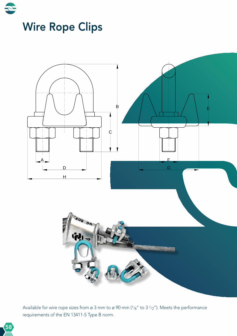
A Q U A L L I N E P R O D U C T S
A Q U A L L I N E P R O D U C T S
58
Wire Rope Clips
Available for wire rope sizes from ø 3 mm to ø 90 mm (1/8” to 3 1/2”). Meets the performance
requirements of the EN 13411-5 Type B norm.
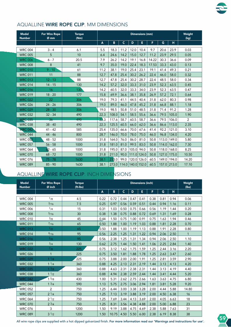
A Q U A L L I N E P R O D U C T S
A Q U A L L I N E P R O D U C T S
59
AQUALLINE WIRE ROPE CLIP. MM DIMENSIONS
AQUALLINE WIRE ROPE CLIP. INCH DIMENSIONS
Model For Wire Rope Torque Dimensions (mm) WeightNumber Ø mm (Nm) (kg) A B C D E F G H
Model For Wire Rope Torque Dimensions (inch) WeightNumber Ø inch (ft-lbs) (lbs) A B C D E F G H
WRC 004 3 - 4 6.1 5.5 18.3 11.2 12.0 10.4 9.7 20.6 23.9 0.03 WRC 005 5 10 6.4 24.6 14.2 15.0 12.7 11.2 23.9 29.5 0.05 WRC 006 6 - 7 20.5 7.9 26.2 14.2 19.1 16.8 14.22 30.3 36.6 0.09 WRC 008 8 41 9.7 35.0 19.0 22.4 18.3 17.53 33.3 43.0 0.13 WRC 010 9 - 10 61 11.2 38.1 19.0 25.4 23.1 19.1 41.4 49.3 0.21 WRC 011 11 88 12.7 47.8 25.4 30.2 26.2 22.4 46.0 58.0 0.32 WRC 013 12 - 13 88 12.7 47.8 25.4 30.2 28.7 22.4 48.5 58.0 0.34 WRC 014 14 - 15 130 14.2 57.2 32.0 33.3 31.0 23.9 52.3 63.5 0.45 WRC 016 16 130 14.2 60.5 32.0 33.3 34.0 23.9 52.3 63.5 0.47 WRC 019 18 - 20 177 15.8 69.9 36.6 38.1 35.8 26.9 57.2 72.1 0.64 WRC 022 22 306 19.0 79.3 41.1 44.5 40.4 31.8 62.0 80.3 0.98 WRC 026 24 - 26 306 19.0 89.0 46.0 47.8 45.2 31.8 66.8 88.1 1.18 WRC 029 28 - 30 306 19.0 98.5 50.8 51.0 48.5 31.8 71.4 91.2 1.28 WRC 032 32 - 34 490 22.3 108.0 54.1 58.5 55.6 36.6 79.5 105.0 1.90 WRC 035 36 490 22.3 117.6 58.7 60.5 58.7 36.6 79.5 106.0 2 WRC 038 38 - 40 490 22.3 125.5 60.5 66.0 62.0 36.6 86.6 113.0 2.35 WRC 042 41 - 42 585 25.4 135.0 66.6 70.0 67.6 41.4 92.2 121.0 3.10 WRC 044 44 - 46 800 28.7 146.0 70.0 78.0 75.0 46.0 96.8 134.0 4.20 WRC 052 48 - 52 1000 31.8 164.0 76.0 86.0 81.0 50.8 113.0 149.0 5.80 WRC 057 56 - 58 1000 31.8 181.0 81.0 99.5 83.0 50.8 114.0 162.0 7.30 WRC 064 62 - 65 1000 31.8 195.0 87.0 105.0 94.0 50.8 118.0 168.0 8.25 WRC 070 68 - 72 1000 31.8 211.0 90.0 111.0 124.0 50.8 127.0 175.0 10.50 WRC 076 75 - 78 1630 38.1 233.0 99.0 120.0 126.0 60.5 149.0 194.0 14.20 WRC 089 85 - 90 1630 38.1 273.0 114.0 140.0 152.0 60.5 157.0 213.0 17.10
WRC 004 1/8 4.5 0.22 0.72 0.44 0.47 0.41 0.38 0.81 0.94 0.06 WRC 005 3/16 7.5 0.25 0.97 0.56 0.59 0.51 0.44 0.94 1.16 0.11 WRC 006 1/4 15 0.31 1.03 0.50 0.75 0.66 0.56 1.19 1.44 0.20 WRC 008 5/16 30 0.38 1.38 0.75 0.88 0.72 0.69 1.31 1.69 0.28 WRC 010 3/8 45 0.44 1.50 0.75 1.00 0.91 0.75 1.63 1.94 0.46 WRC 011 7/16 65 0.50 1.88 1.00 1.19 1.03 0.88 1.81 2.28 0.70 WRC 013 1/2 65 0.50 1.88 1.00 1.19 1.13 0.88 1.91 2.28 0.80 WRC 014 9/16 95 0.56 2.25 1.25 1.31 1.22 0.94 2.06 2.50 1 WRC 016 5/8 95 0.56 2.38 1.25 1.31 1.34 0.94 2.06 2.50 1.10 WRC 019 3/4 130 0.62 2.75 1.44 1.50 1.41 1.06 2.25 2.84 1.40 WRC 022 7/8 225 0.75 3.12 1.62 1.75 1.59 1.25 2.44 3.16 2.20 WRC 026 1 225 0.75 3.50 1.81 1.88 1.78 1.25 2.63 3.47 2.60 WRC 029 1 1/8 225 0.75 3.88 2.00 2.00 1.91 1.25 2.81 3.59 2.90 WRC 032 1 1/4 360 0.88 4.25 2.13 2.31 2.19 1.44 3.13 4.13 4.20 WRC 035 1 3/8 360 0.88 4.63 2.31 2.38 2.31 1.44 3.13 4.19 4.40 WRC 038 1 1/2 360 0.88 4.94 2.38 2.59 2.44 1.44 3.41 4.44 5.20 WRC 042 1 5/8 430 1.00 5.31 2.62 2.75 2.66 1.63 3.63 4.75 6.80 WRC 044 1 3/4 590 1.13 5.75 2.75 3.06 2.94 1.81 3.81 5.28 9.20 WRC 052 2 750 1.25 6.44 3.00 3.38 3.28 2.00 4.44 5.88 14.80 WRC 057 2 1/4 750 1.25 7.13 3.19 3.88 3.19 2.00 4.50 6.38 16 WRC 064 2 1/2 750 1.25 7.69 3.44 4.13 3.69 2.00 4.05 6.63 18 WRC 070 2 3/4 750 1.25 8.31 3.56 4.38 4.88 2.00 5.00 6.88 23 WRC 076 3 1200 1.50 9.19 3.88 4.75 4.69 2.38 5.88 7.63 31 WRC 089 3 1/2 1200 1.50 10.75 4.50 5.50 6.00 2.38 6.19 8.38 38
All wire rope clips are supplied with a hot dipped galvanized finish. For more information read our ‘Warnings and instructions for use’.
Global Rope Fittings GmbHStockholmer Strasse 11 ❚ 48455 Bad Bentheim ❚ Germany
Phone +49 (0) 5924 299 470
www.globalropefittings.com
Copyright 2021, published by Global Rope Fittings GmbH, Bad Bentheim, Germany. We reserve the right to make amendments on specifications mentioned in the catalogue. Chamber of Commerce Osnabrück; HRB 203937. VAT Number DE268763009. For general business terms and conditions contact Global Rope Fittings GmbH.
(V1.0_09.2021)
Related Documents