Status of Systems Code Development Zoran Dragojlovic, Rene Raffray, Charles E. Kessel ARIES Meeting in Atlanta, GA, December 2007

Welcome message from author
This document is posted to help you gain knowledge. Please leave a comment to let me know what you think about it! Share it to your friends and learn new things together.
Transcript
Status of Systems Code Development
Zoran Dragojlovic, Rene Raffray, Charles E. Kessel
ARIES Meeting in Atlanta, GA, December 2007
Overview of Most Recent Updates
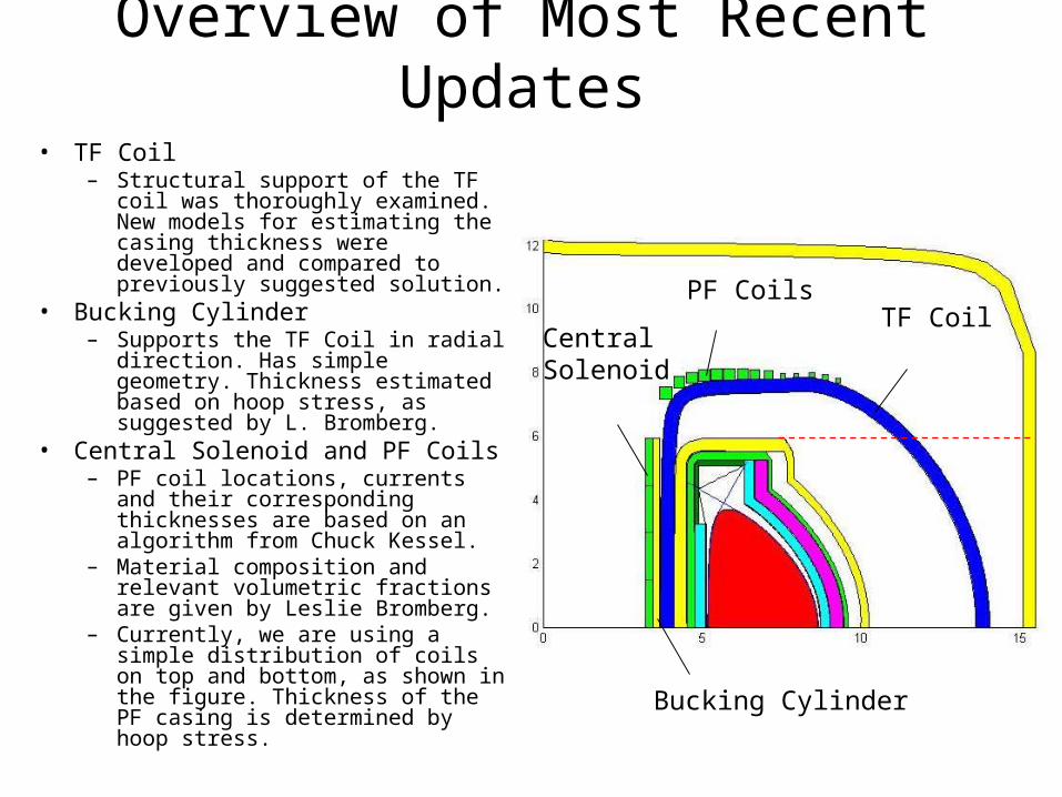
• TF Coil– Structural support of the TF coil was
thoroughly examined. New models for estimating the casing thickness were developed and compared to previously suggested solution.
• Bucking Cylinder– Supports the TF Coil in radial
direction. Has simple geometry. Thickness estimated based on hoop stress, as suggested by L. Bromberg.
• Central Solenoid and PF Coils– PF coil locations, currents and their
corresponding thicknesses are based on an algorithm from Chuck Kessel.
– Material composition and relevant volumetric fractions are given by Leslie Bromberg.
– Currently, we are using a simple distribution of coils on top and bottom, as shown in the figure. Thickness of the PF casing is determined by hoop stress.
PF CoilsTF Coil
CentralSolenoid
Bucking Cylinder

Topic 1: Structural Support of PF Coil
• Equations for TF coil structural support suggested by Leslie Bromberg at a previous meeting (General Atomics, June 2007) were examined due to his own assertion that the cross sectional thickness of the casing was too low.
• We determined that these equations were consistent with a “picture frame” model of the TF coil. In this model, the coil is envisioned as a frame-like composition of straight beams that are subjected to bending and compression due to an approximated effective magnetic force acting on top and bottom of the coil.– The only discrepancy between the equations mentioned above and the
“picture frame” model is that the top thickness defined by the equations is exactly 4 times smaller than the one predicted by the model.
• We explored more realistic variants of the same model and came up with several alternatives to the original equations, which all provide a considerably thicker cross section of the magnet structure. These alternatives and the final choice of the structural support model will be discussed in the following slides.
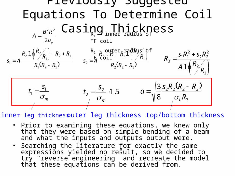
Previously Suggested Equations To Determine Coil Casing Thickness
• Prior to examining these equations, we knew only that they were based on simple bending of a beam and what the inputs and outputs output were.
• Searching the literature for exactly the same expressions yielded no result, so we decided to try “reverse engineering” and recreate the model that these equations can be derived from.
o
TRBA2
22
121
121
22
1
ln
RRR
RRRRR
As
122
1
2112
2
ln
RRR
RRRRR
As
m
st
1
1 5.122
m
st
1
2
222
211
3
ln RRA
RsRsR
3
3222
8
3
R
RRRsa
b
inner leg thickness outer leg thickness top/bottom thickness
R1 – inner radius of TF coil
R2 – outer radius of TF coil
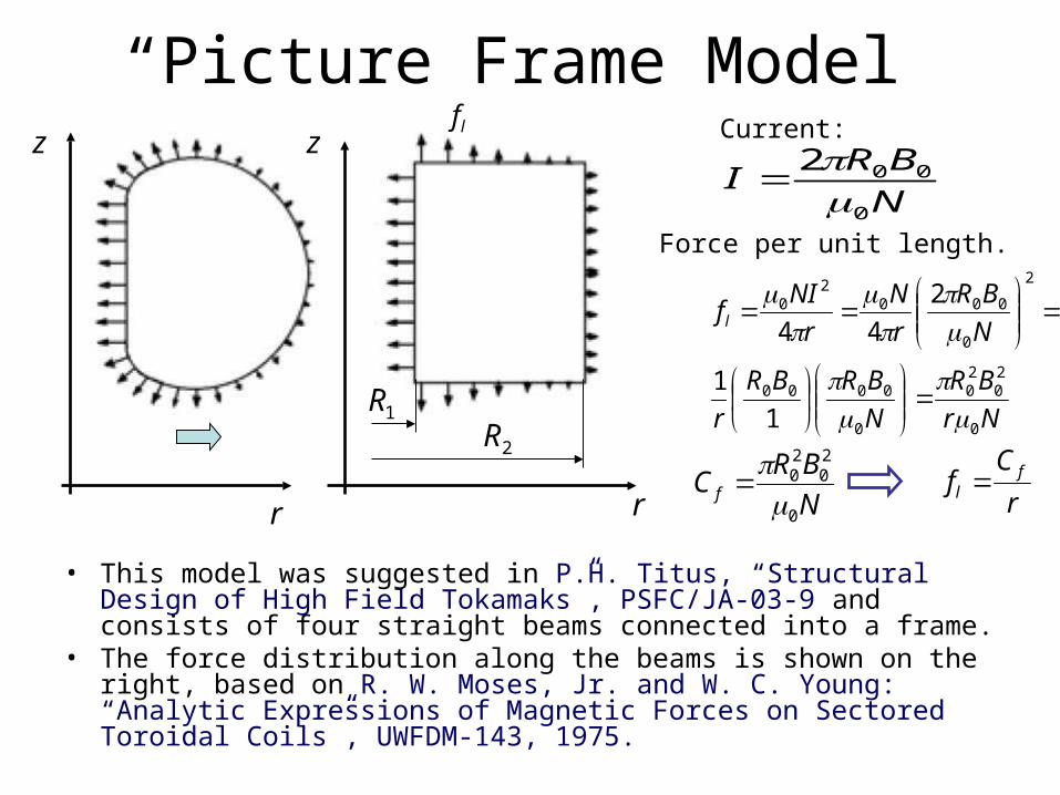
“Picture Frame Model”
• This model was suggested in P.H. Titus, “Structural Design of High Field Tokamaks”, PSFC/JA-03-9 and consists of four straight beams connected into a frame.
• The force distribution along the beams is shown on the right, based on R. W. Moses, Jr. and W. C. Young: “Analytic Expressions of Magnetic Forces on Sectored Toroidal Coils”, UWFDM-143, 1975.
1R2R
r
z
r
z
N
BRI
0
002
Nr
BR
N
BRBR
r
N
BR
r
N
r
NIf l
0
20
20
0
0000
2
0
0002
0
1
1
2
44
Force per unit length.
Current:
N
BRC f
0
20
20
r
Cf fl
lf
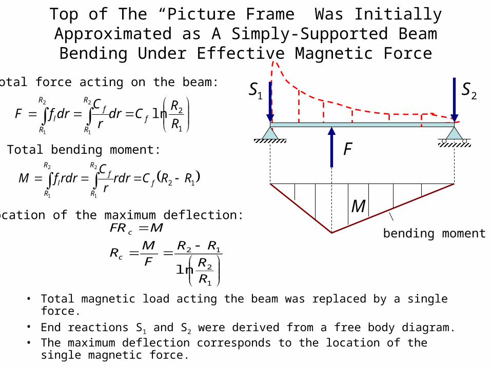
Top of The “Picture Frame” Was Initially Approximated as A Simply-Supported Beam Bending Under Effective Magnetic
Force
• Total magnetic load acting the beam was replaced by a single force.• End reactions S1 and S2 were derived from a free body diagram.• The maximum deflection corresponds to the location of the single
magnetic force.
1S 2S
F
M
bending moment
1
2ln2
1
2
1R
RCdr
r
CdrfF f
R
R
fR
R
l
Total force acting on the beam:
12
2
1
2
1
RRCrdrr
CrdrfM f
R
R
fR
R
l
Total bending moment:
Location of the maximum deflection:
1
2
12
lnR
R
RR
F
MR
MFR
c
c
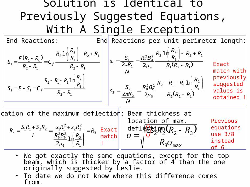
Solution is Identical to Previously Suggested Equations, With A Single Exception
• We got exactly the same equations, except for the top beam, which is thicker by a factor of 4 than the one originally suggested by Leslie.
• To date we do not know where this difference comes from.
12
121
22
12
21
ln
RR
RRRR
R
CRR
RRFS f
c
12
1
2112
12
ln
RR
R
RRRR
CSFS f
End Reactions:
122
1
2112
0
20
20
2
22
121
121
22
0
20
20
1
11
ln
22
ln
22
RRR
R
RRRR
BR
N
RS
s
RRR
RRR
RR
BR
N
RS
s
End Reactions per unit perimeter length:
Exact match with previously suggested values is obtained !
3
1
2
0
20
20
222
2112211
ln2
R
RRBR
RsRs
F
RSRSRc
Location of the maximum deflection:
Exact match!
max3
32226
RRRRs
a
Beam thickness at location of max. deflection Previous
equations use 3/8 instead of 6.
Improvements of the “Picture Frame Model”
• In order to obtain a more realistic solution and explain the discrepancy related to the thickness of the top coil, we made several improvements to the “Picture Frame” model, including
1. Replacing the single magnetic force by a continuous load.
2. Replacing the simply-supported beams by the fixed-end beams. This results in a less flexible frame, which is closer to the actual TF coil.
3. Taking the hoop stress into account, in addition to bending.
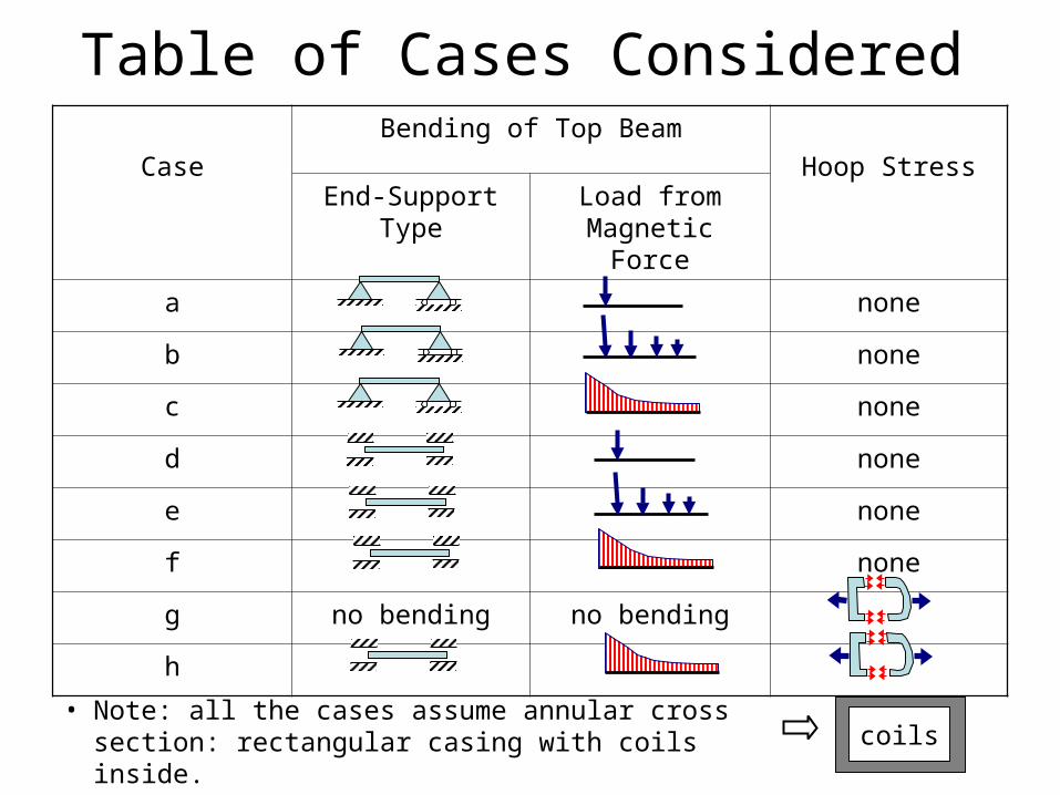
Table of Cases Considered
Case
Bending of Top Beam
Hoop StressEnd-Support Type Load from
Magnetic Force
a none
b none
c none
d none
e none
f none
g no bending no bending
h
• Note: all the cases assume annular cross section: rectangular casing with coils inside.
coils
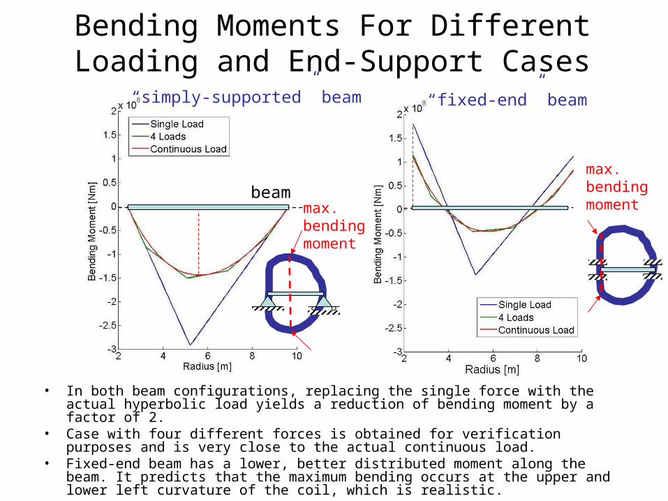
Bending Moments For Different Loading and End-Support Cases
• In both beam configurations, replacing the single force with the actual hyperbolic load yields a reduction of bending moment by a factor of 2.
• Case with four different forces is obtained for verification purposes and is very close to the actual continuous load.
• Fixed-end beam has a lower, better distributed moment along the beam. It predicts that the maximum bending occurs at the upper and lower left curvature of the coil, which is realistic.
“simply-supported” beam “fixed-end” beam
max. bendingmoment
max. bending moment
beam
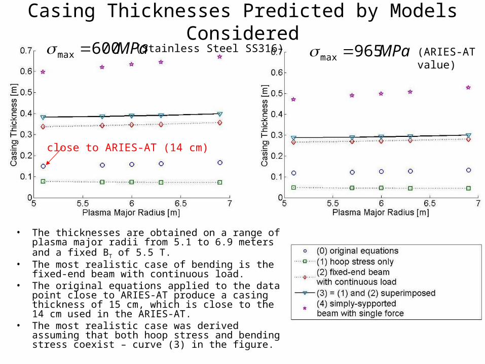
Casing Thicknesses Predicted by Models Considered
close to ARIES-AT (14 cm)
• The thicknesses are obtained on a range of plasma major radii from 5.1 to 6.9 meters and a fixed BT of 5.5 T.
• The most realistic case of bending is the fixed-end beam with continuous load.
• The original equations applied to the data point close to ARIES-AT produce a casing thickness of 15 cm, which is close to the 14 cm used in the ARIES-AT.
• The most realistic case was derived assuming that both hoop stress and bending stress coexist – curve (3) in the figure.
MPa600max MPa965max (ARIES-AT value)
(Stainless Steel SS316)
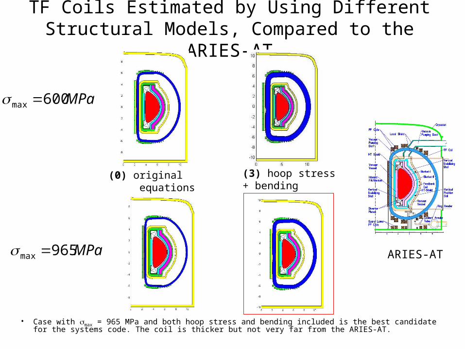
TF Coils Estimated by Using Different Structural Models, Compared to the ARIES-AT
• Case with max = 965 MPa and both hoop stress and bending included is the best candidate for the systems code. The coil is thicker but not very far from the ARIES-AT.
(0) original equations
(3) hoop stress+ bending
ARIES-AT
MPa600max
MPa965max
Further Improvements of the Model
• In order to take into account the effect of the TF coil curvature, we considered the following improvements:– Scaling of the straight beam to achieve the
same maximum stress as in the equivalent arched beam. Two examples are shown in the following slides.
– Solving for the bending moment on a half a circle, which is closest to the D-shaped coil. This would be the most accurate treatment and may require some numerical integration.
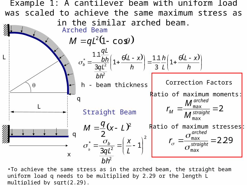
Example 1: A cantilever beam with uniform load was scaled to achieve the same maximum stress as in the similar arched beam.
L
q
q
22
Lxq
M
x
2
2
2* 1
3
L
x
bh
qLb
b
cos12 qLM
L
h
xL
L
h
h
xL
bhqLbhqL
b
61
3
1.161
3
1.1
2
2*
h - beam thickness
Arched Beam
Straight Beam
Correction Factors
Ratio of maximum moments:
2max
max straight
arched
M M
Mr
Ratio of maximum stresses:
29.2max
max straight
arched
r
•To achieve the same stress as in the arched beam, the straight beam uniform load q needs to be multiplied by 2.29 or the length L multiplied by sqrt(2.29).

Example 2: Scaling of a fixed-end beam.
L
q
q
x
L
h - beam thickness
Arched Beam
Straight Beam
Correction Factors
Ratio of maximum moments:
64.1max
max straight
arched
M M
Mr
Ratio of maximum stresses:
35.2max
max straight
arched
r
•The scaling ratio for the fixed-end beam is very close to the cantilever beam, however we expect this number to be much smaller when the uniform load is replaced by the hyperbolic one. Solving the actual bending of the arched coil is the best option.
2212
22 qxx
qLqLM
2
2
2*
6
13 L
x
L
x
bh
qLb
b
sincos4
2
2qRM
sincos4
33
1.1
sincos43
13
1.1
2
2*
L
h
h
L
bh
qLbh
qL
b
TF Coil Structural Support – Summary and Future Plans
• We tested the previously suggested equations for TF coil casing thickness by adopting a simple “picture frame” model and comparing several different variants of this model between each other and against the results obtained by the original equations. A simple hoop stress model was added to the analysis, as well.
• The comparison indicates that the original equations indeed provide a casing that is thin, judged by comparison with the case that takes into account hoop stress only. A model of coil that includes a combination of hoop stress and bending was considered instead. It predicts a casing that is comparable to the one used in ARIES-AT provided that the same maximum stress in the material was used.
• We are planning to improve our model by taking into account the actual coil shape and test it by finite element method.

Topic 2: Addition of Central Solenoid and PF Coil Algorithm
• Outline of the algorithm:1. Determine the PF coil currents at given q95 and scale to
plasma current.2. Calculate the flux swing required to ramp up to Ip.3. Calculate the forward and back bias coil currents.4. Determine the maximum current in each PF coil.5. Calculate the coil thickness based on the superconductor
current density jSC. • Assumed the maximum allowed magnetic field in coil to be
18T.• Calculated the area fractions of different components based
on Leslie Bromberg’s recommendations for PF coil.6. Define the end-point of PF coil distribution to allow room
for the maintenance port and pumping duct.7. If the PF coils are too thick to allow for the maintenance
port and pumping duct, reject the data point.8. Generate the contours of the PF coils. 9. Calculate the volume for the costing analysis.
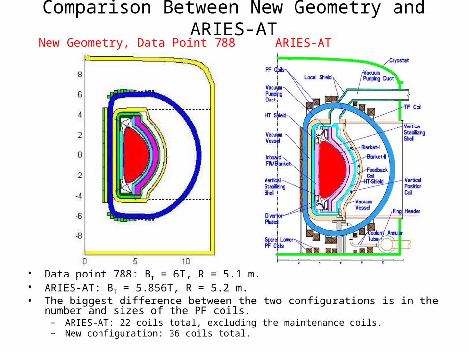
Comparison Between New Geometry and ARIES-AT
• Data point 788: BT = 6T, R = 5.1 m.• ARIES-AT: BT = 5.856T, R = 5.2 m.• The biggest difference between the two configurations is in the number and sizes of
the PF coils.– ARIES-AT: 22 coils total, excluding the maintenance coils.– New configuration: 36 coils total.
New Geometry, Data Point 788 ARIES-AT
Elimination of Operating Data Points Based on Power Core Design
• The Systems Code is programmed to eliminate any data point that doesn’t allow a reasonable configuration and function of the power core.
• Current criteria for elimination:– Central Solenoid or Bucking Cylinder: inner radius less than
zero. All data points pass.– TF Coil: BTmax out of range defined by the superconductor
material properties. Rejected 7 points.– PF Coil: Maximum magnetic field at the PF coil greater than 18T,
rejected 21 points.– PF Coil: Coil size too big to allow room for the maintenance port
and pumping duct. rejected 12 points.
• Total rejected: 40 data points.
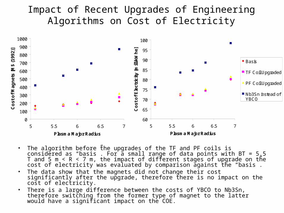
Impact of Recent Upgrades of Engineering Algorithms on Cost of Electricity
• The algorithm before the upgrades of the TF and PF coils is considered as “basis”. For a small range of data points with BT = 5.5 T and 5 m < R < 7 m, the impact of different stages of upgrade on the cost of electricity was evaluated by comparison against the “basis”.
• The data show that the magnets did not change their cost significantly after the upgrade, therefore there is no impact on the cost of electricity.
• There is a large difference between the costs of YBCO to Nb3Sn, therefore switching from the former type of magnet to the latter would have a significant impact on the COE.
60
65
70
75
80
85
90
95
100
5 5.5 6 6.5 7
Plasma Major RadiusC
ost
of
Ele
ctri
city
[m
ill/k
Wh
e]
Basis
TF Coil Upgraded
PF Coil Upgraded
Nb3Sn instead ofYBCO
0
100
200
300
400
500
600
700
800
900
1000
5 5.5 6 6.5 7
Plasma Major Radius
Co
st o
f M
agn
ets
[M$
(199
2)]
Conclusions and Future Work• Even though the recent engineering upgrades do not
make a significant impact on the cost of electricity, they were made in an effort to have valid engineering and physics in the code.– We recommend an additional level of refinement in the model of
TF coil structure by taking the coil curvature into account and by including the out of plane loads. However, costing analysis can be done independently of this work since small changes in the casing thickness do not impact the cost.
– Number and size of PF coils seems very different from the ARIES-AT. Is this reasonable?
• Les Waganer has recently completed the power core costing algorithm and rearranged the overall costing accounts into more logical units. The impact of his work on the systems code will be addressed at the next meeting.
Related Documents