SM Cirius SHC Digital Microwave Radio Hybrid IP Digital Microwave Indoor Unit User’s Manual

Welcome message from author
This document is posted to help you gain knowledge. Please leave a comment to let me know what you think about it! Share it to your friends and learn new things together.
Transcript
SM Cirius SHC Digital Microwave Radio
Hybrid IP Digital Microwave Indoor Unit
User’s Manual

Star Microwave Cirius SHC , 2016
This is an unpublished work the copyright in which vests in Star Microwave
Service Corporation ("Star Microwave Service Corporation"). All rights are
reserved.
The information contained herein is confidential and the property of Star
Microwave Service Corporation and is supplied without liability for errors or
omissions. No part may be reproduced, disclosed or used except as authorised by
contract or other written permission. The copyright and the foregoing restriction
on reproduction and use extends to all media in which the information may be
reproduced.
Star Microwave Cirius SHC , 2016
0.1 CONTENTS
Section Page
0.1 CONTENTS ................................................................................................................. 3
0.2 HISTORY .................................................................................................................... 6
0.3 SAFETY NOTICES AND ADMONISHMENTS ....................................................................... 7
0.4 GLOSSARY OF TERMS .................................................................................................. 8
1 SYSTEM SPECIFICATION ............................................................................................... 9
1.1 IDU ........................................................................................................................... 9
1.1.1 IDU INTERFACE DESCRIPTION ...................................................................................... 9
1.1.2 DC POWER ............................................................................................................... 10
1.1.3 CIT........................................................................................................................... 10
1.1.4 ETH ......................................................................................................................... 11
2 SYSTEM SOFTWARE .................................................................................................. 13
2.1 NMS SOFTWARE ........................................................................................................ 13
2.2 IDU SOFTWARE ........................................................................................................ 13
2.3 ODU SOFTWARE ...................................................................................................... 13
3 CONFIGURATION IN WEB GRAPHIC USER INTERFACE .................................................... 14
3.1 LOGIN ...................................................................................................................... 14
3.2 BRIEF DESCRIPTION .................................................................................................. 15
3.2.1 SYSTEM COMPOSITION .............................................................................................. 15
3.2.2 INFORMATION ........................................................................................................... 17
3.2.3 ALARM ..................................................................................................................... 19
3.3 GUIDE ...................................................................................................................... 20
3.3.1 QUICK CONFIGURATION ............................................................................................. 20
3.4 CONFIGURATION WINDOW ......................................................................................... 23
3.4.1 SWITCH .................................................................................................................... 23
3.4.1.1 PORT ....................................................................................................................... 23
3.4.1.1.1 ETHERNET PORT SPEED RATE CONFIGURATION ........................................................... 24
3.4.1.1.2 ETHERNET PORT DISABLE .......................................................................................... 24
3.4.1.1.3 ETHERNET PORT FLOW CONTROL CONFIGURATION ...................................................... 24
3.4.1.1.4 ETHERNET PORT ALLOW MTU CONFIGURATION ............................................................ 24
3.4.1.2 AGGREGATION .......................................................................................................... 25
3.4.1.2.1 AGGREGATION GROUP MENBER CONFIGURATION ......................................................... 26
3.4.1.2.2 AGGREGATION GROUP ALGORITHM CONFIGURATION .................................................... 27
3.4.1.3 SPANNING TREE ........................................................................................................ 27
3.4.1.4 MAC TABLE ............................................................................................................... 28
3.4.1.4.1 MAC TABLE AGING TIME CONFIGURATION ..................................................................... 29
3.4.1.4.2 DISABLE MAC TABLE AGING TIME................................................................................. 29
3.4.1.4.3 DISABLE PORT MAC LEARNING FUNCTION .................................................................... 29
3.4.1.4.4 ADD STATIC MAC TO PORT MAC TABLE ......................................................................... 29
3.4.1.4.5 DELETE STATIC MAC ADDRESS.................................................................................... 29
3.4.1.5 VLANS - VLANS MEMBERSHIP ..................................................................................... 30
Star Microwave Cirius SHC , 2016
3.4.1.5.1 ADD NEW VLAN ENTRY ............................................................................................... 30
3.4.1.5.2 DELETE VLAN ENTRY ................................................................................................. 30
3.4.2 MRU ......................................................................................................................... 31
3.4.2.1 SYSTEM - INFORMATION ............................................................................................. 31
3.4.2.1.1 CHANGE SYSTEM MODE ............................................................................................. 31
3.4.2.1.2 CHANGE SYSTEM TIME............................................................................................... 31
3.4.2.2 SYSTEM - IP .............................................................................................................. 32
3.4.2.3 MODEM .................................................................................................................... 32
3.4.2.3.1 SELECT BANDWIDTH AND MODULATION ....................................................................... 33
3.4.2.3.2 ACM CONFIGURATION ................................................................................................ 33
3.4.2.4 ODU ....................................................................................................................... 33
3.4.2.4.1 MUTE THE RADIO ....................................................................................................... 34
3.4.2.4.2 TX POWER CONFIGURATION ....................................................................................... 34
3.4.2.4.3 FREQUENCY CONFIGURATION .................................................................................... 34
3.4.3 SRU ......................................................................................................................... 35
3.4.3.1 MODEM .................................................................................................................... 35
3.4.3.2 ODU ....................................................................................................................... 35
3.4.4 MSU ......................................................................................................................... 37
3.4.4.1 CHANNEL SWITCH ..................................................................................................... 37
3.4.4.1.1 T1 CONFIGURATION .................................................................................................. 37
3.4.4.1.2 STM-1 CONFIGURATION ............................................................................................ 37
3.5 MONITOR .................................................................................................................. 38
3.5.1 SWITCH .................................................................................................................... 38
3.5.1.1 PORT - STATUS.......................................................................................................... 38
3.5.1.2 TRAFFIC OVERVIEW ................................................................................................... 38
3.5.1.3 QOS STATISTICS ........................................................................................................ 39
3.5.1.4 DETAILED STATISTICS ................................................................................................ 40
3.5.1.5 MAC TABLE ............................................................................................................... 41
3.5.1.6 VLAN MEMBERSHIP ................................................................................................... 41
3.5.2 MRU ......................................................................................................................... 42
3.5.2.1 SYSTEM - INFORMATION ............................................................................................. 42
3.5.2.2 SYSTEM - SYSTEM LOG .............................................................................................. 42
3.5.2.3 SYSTEM -RSL LOG ..................................................................................................... 43
3.5.2.4 TEMPERATURE .......................................................................................................... 43
3.5.2.5 MODEM .................................................................................................................... 44
3.5.2.6 IF ............................................................................................................................. 44
3.5.2.7 ODU ....................................................................................................................... 44
3.5.2.8 ALARM ..................................................................................................................... 45
3.5.3 SRU ......................................................................................................................... 46
3.5.3.1 SYSTEM - RSL LOG .................................................................................................... 46
3.5.3.2 MODEM .................................................................................................................... 46
3.5.3.3 IF ............................................................................................................................. 46
3.5.3.4 ODU ....................................................................................................................... 47
3.5.3.5 ALARM ..................................................................................................................... 47
3.5.4 MSU ......................................................................................................................... 48
3.6 SECURITY WINDOW ................................................................................................... 49

Star Microwave Cirius SHC , 2016
3.6.1 SWITCH .................................................................................................................... 49
3.6.1.1 PASSWORD ............................................................................................................... 49
3.6.1.2 AUTHENTICATION METHOD ......................................................................................... 49
3.6.1.3 SSH ......................................................................................................................... 50
3.6.1.4 HTTPS ...................................................................................................................... 50
3.6.1.5 ACCESS MANAGEMENT .............................................................................................. 51
3.6.2 NETWORK ................................................................................................................ 51
3.6.2.1 ACL - PORTS ............................................................................................................. 51
3.6.2.2 ACL - RATE LIMITERS ................................................................................................. 52
3.6.2.3 ACCESS MANAGEMENT STATISTICS ............................................................................. 53
3.7 DIAGNOSTIC ............................................................................................................. 54
3.7.1 PING ........................................................................................................................ 54
3.7.2 VERIPHY................................................................................................................... 54
3.7.3 DEBUG ..................................................................................................................... 55
3.7.3.1 DEBUG - MRU ............................................................................................................ 55
3.7.3.2 DEBUG - SRU ............................................................................................................ 55
3.7.3.3 DEBUG - MSU ............................................................................................................ 56
3.8 MAITENANCE ............................................................................................................ 57
3.8.1 RESTART DEVICE ...................................................................................................... 57
3.8.2 FACTORY DEFAULTS .................................................................................................. 57
3.8.3 SOFTWARE ............................................................................................................... 57
3.8.4 CONFIGURATION ....................................................................................................... 57
3.9 APPENDIX B: RMA (RETURN MATERIAL AUTHORIZATION) FORM ...................................... 58

Star Microwave Cirius SHC , 2016
0.2 HISTORY
Change No. ENU Details Of Change
1 1-0-0 Initial document released in Sep 2012.
2 1-0-1 Revised the description format, and update the Web GUI screen capture in September 2013.
Star Microwave Cirius SHC , 2016
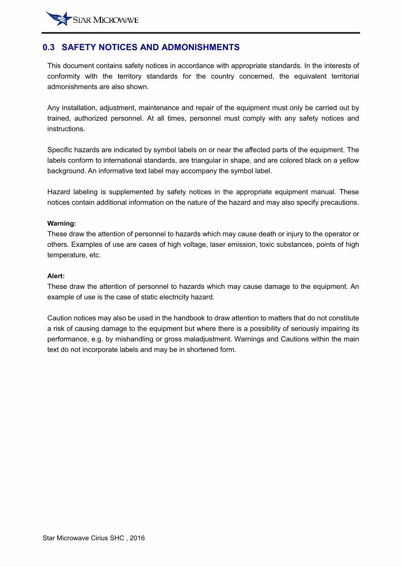
0.3 SAFETY NOTICES AND ADMONISHMENTS
This document contains safety notices in accordance with appropriate standards. In the interests of
conformity with the territory standards for the country concerned, the equivalent territorial
admonishments are also shown.
Any installation, adjustment, maintenance and repair of the equipment must only be carried out by
trained, authorized personnel. At all times, personnel must comply with any safety notices and
instructions.
Specific hazards are indicated by symbol labels on or near the affected parts of the equipment. The
labels conform to international standards, are triangular in shape, and are colored black on a yellow
background. An informative text label may accompany the symbol label.
Hazard labeling is supplemented by safety notices in the appropriate equipment manual. These
notices contain additional information on the nature of the hazard and may also specify precautions.
Warning:
These draw the attention of personnel to hazards which may cause death or injury to the operator or
others. Examples of use are cases of high voltage, laser emission, toxic substances, points of high
temperature, etc.
Alert:
These draw the attention of personnel to hazards which may cause damage to the equipment. An
example of use is the case of static electricity hazard.
Caution notices may also be used in the handbook to draw attention to matters that do not constitute
a risk of causing damage to the equipment but where there is a possibility of seriously impairing its
performance, e.g. by mishandling or gross maladjustment. Warnings and Cautions within the main
text do not incorporate labels and may be in shortened form.
Star Microwave Cirius SHC , 2016
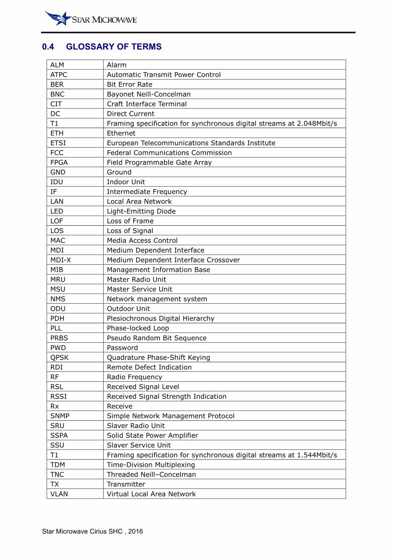
0.4 GLOSSARY OF TERMS
ALM Alarm
ATPC Automatic Transmit Power Control
BER Bit Error Rate
BNC Bayonet Neill-Concelman
CIT Craft Interface Terminal
DC Direct Current
T1 Framing specification for synchronous digital streams at 2.048Mbit/s
ETH Ethernet
ETSI European Telecommunications Standards Institute
FCC Federal Communications Commission
FPGA Field Programmable Gate Array
GND Ground
IDU Indoor Unit
IF Intermediate Frequency
LAN Local Area Network
LED Light-Emitting Diode
LOF Loss of Frame
LOS Loss of Signal
MAC Media Access Control
MDI Medium Dependent Interface
MDI-X Medium Dependent Interface Crossover
MIB Management Information Base
MRU Master Radio Unit
MSU Master Service Unit
NMS Network management system
ODU Outdoor Unit
PDH Plesiochronous Digital Hierarchy
PLL Phase-locked Loop
PRBS Pseudo Random Bit Sequence
PWD Password
QPSK Quadrature Phase-Shift Keying
RDI Remote Defect Indication
RF Radio Frequency
RSL Received Signal Level
RSSI Received Signal Strength Indication
Rx Receive
SNMP Simple Network Management Protocol
SRU Slaver Radio Unit
SSPA Solid State Power Amplifier
SSU Slaver Service Unit
T1 Framing specification for synchronous digital streams at 1.544Mbit/s
TDM Time-Division Multiplexing
TNC Threaded Neill–Concelman
TX Transmitter
VLAN Virtual Local Area Network
Star Microwave Cirius SHC , 2016
1 SYSTEM SPECIFICATION
1.1 IDU
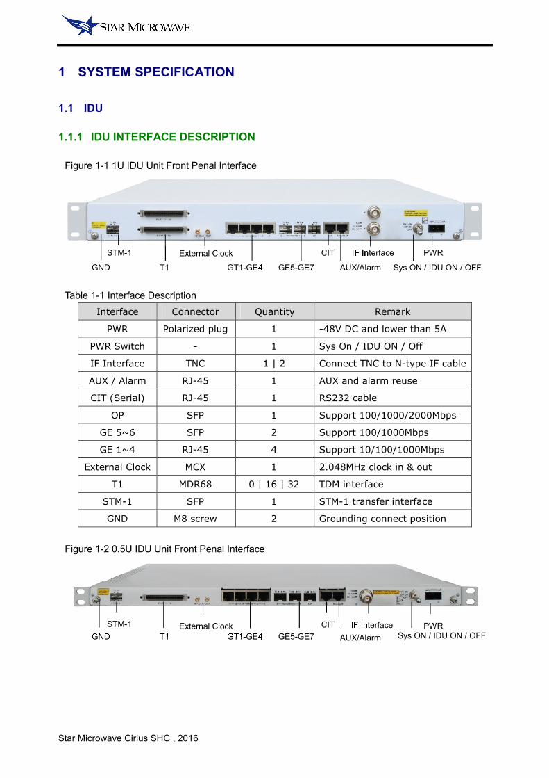
1.1.1 IDU INTERFACE DESCRIPTION
Figure 1-1 1U IDU Unit Front Penal Interface
Table 1-1 Interface Description
Interface Connector Quantity Remark
PWR Polarized plug 1 -48V DC and lower than 5A
PWR Switch - 1 Sys On / IDU ON / Off
IF Interface TNC 1 | 2 Connect TNC to N-type IF cable
AUX / Alarm RJ-45 1 AUX and alarm reuse
CIT (Serial) RJ-45 1 RS232 cable
OP SFP 1 Support 100/1000/2000Mbps
GE 5~6 SFP 2 Support 100/1000Mbps
GE 1~4 RJ-45 4 Support 10/100/1000Mbps
External Clock MCX 1 2.048MHz clock in & out
T1 MDR68 0 | 16 | 32 TDM interface
STM-1 SFP 1 STM-1 transfer interface
GND M8 screw 2 Grounding connect position
Figure 1-2 0.5U IDU Unit Front Penal Interface
GND
STM-1
GT1-GE4 GE5-GE7
IF Interface PWR CIT
AUX/Alarm Sys ON / IDU ON / OFF T1
External Clock
GND
STM-1
GT1-GE4 GE5-GE7
IF Interface PWR CIT
AUX/Alarm Sys ON / IDU ON / OFF T1
External Clock
Star Microwave Cirius SHC , 2016
Table 1-2 IDU LED Indicator Instruction
Indicator Status Description
RUN
flash (Green) System on boot
On (Green) System operates normal
Off No power in or system boot failure
IDU ALM On (Red) The system detect a IDU alarm
Off IDU normal operation
ODU ALM On (Red) The system detect a ODU alarm
Off ODU normal operation
Table 1-3 IDU Chassis Mechanical
Parameter Description
Dimension 438×280×44 (W×D×H, mm)
Weight 4.5Kg
1.1.2 DC POWER
IDU required -48V DC power source which maximum current does not exceed 5A, and the power
positive electrode must connect to ground.
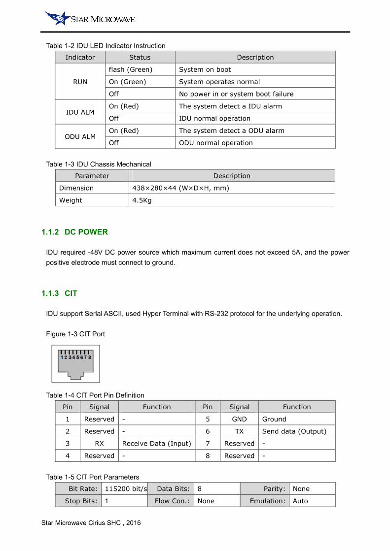
1.1.3 CIT
IDU support Serial ASCII, used Hyper Terminal with RS-232 protocol for the underlying operation.
Figure 1-3 CIT Port
Table 1-4 CIT Port Pin Definition
Pin Signal Function Pin Signal Function
1 Reserved - 5 GND Ground
2 Reserved - 6 TX Send data (Output)
3 RX Receive Data (Input) 7 Reserved -
4 Reserved - 8 Reserved -
Table 1-5 CIT Port Parameters
Bit Rate: 115200 bit/s Data Bits: 8 Parity: None
Stop Bits: 1 Flow Con.: None Emulation: Auto
Star Microwave Cirius SHC , 2016
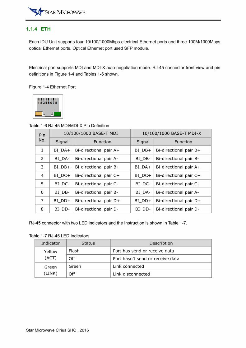
1.1.4 ETH
Each IDU Unit supports four 10/100/1000Mbps electrical Ethernet ports and three 100M/1000Mbps
optical Ethernet ports. Optical Ethernet port used SFP module.
Electrical port supports MDI and MDI-X auto-negotiation mode. RJ-45 connector front view and pin
definitions in Figure 1-4 and Tables 1-6 shown.
Figure 1-4 Ethernet Port
Table 1-6 RJ-45 MDI/MDI-X Pin Definition
Pin
No.
10/100/1000 BASE-T MDI 10/100/1000 BASE-T MDI-X
Signal Function Signal Function
1 BI_DA+ Bi-directional pair A+ BI_DB+ Bi-directional pair B+
2 BI_DA- Bi-directional pair A- BI_DB- Bi-directional pair B-
3 BI_DB+ Bi-directional pair B+ BI_DA+ Bi-directional pair A+
4 BI_DC+ Bi-directional pair C+ BI_DC+ Bi-directional pair C+
5 BI_DC- Bi-directional pair C- BI_DC- Bi-directional pair C-
6 BI_DB- Bi-directional pair B- BI_DA- Bi-directional pair A-
7 BI_DD+ Bi-directional pair D+ BI_DD+ Bi-directional pair D+
8 BI_DD- Bi-directional pair D- BI_DD- Bi-directional pair D-
RJ-45 connector with two LED indicators and the Instruction is shown in Table 1-7.
Table 1-7 RJ-45 LED Indicators
Indicator Status Description
Yellow
(ACT)
Flash Port has send or receive data
Off Port hasn’t send or receive data
Green
(LINK)
Green Link connected
Off Link disconnected
Star Microwave Cirius SHC , 2016
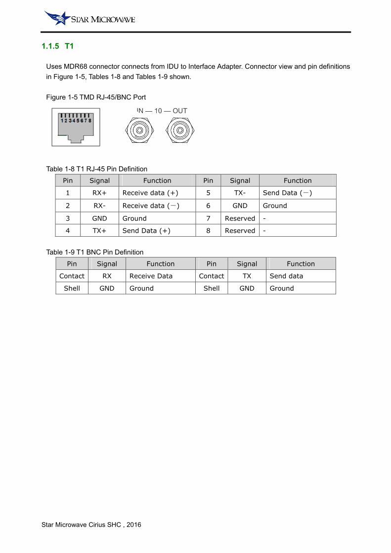
1.1.5 T1
Uses MDR68 connector connects from IDU to Interface Adapter. Connector view and pin definitions
in Figure 1-5, Tables 1-8 and Tables 1-9 shown.
Figure 1-5 TMD RJ-45/BNC Port
Table 1-8 T1 RJ-45 Pin Definition
Pin Signal Function Pin Signal Function
1 RX+ Receive data (+) 5 TX- Send Data (-)
2 RX- Receive data (-) 6 GND Ground
3 GND Ground 7 Reserved -
4 TX+ Send Data (+) 8 Reserved -
Table 1-9 T1 BNC Pin Definition
Pin Signal Function Pin Signal Function
Contact RX Receive Data Contact TX Send data
Shell GND Ground Shell GND Ground
IN — 10 — OUT
Star Microwave Cirius SHC , 2016
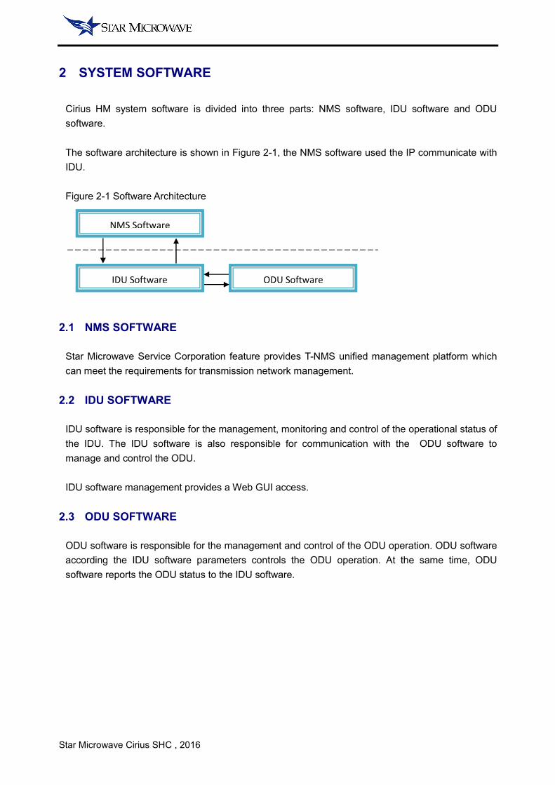
2 SYSTEM SOFTWARE
Cirius HM system software is divided into three parts: NMS software, IDU software and ODU
software.
The software architecture is shown in Figure 2-1, the NMS software used the IP communicate with
IDU.
Figure 2-1 Software Architecture
2.1 NMS SOFTWARE
Star Microwave Service Corporation feature provides T-NMS unified management platform which
can meet the requirements for transmission network management.
2.2 IDU SOFTWARE
IDU software is responsible for the management, monitoring and control of the operational status of
the IDU. The IDU software is also responsible for communication with the ODU software to
manage and control the ODU.
IDU software management provides a Web GUI access.
2.3 ODU SOFTWARE
ODU software is responsible for the management and control of the ODU operation. ODU software
according the IDU software parameters controls the ODU operation. At the same time, ODU
software reports the ODU status to the IDU software.
NMS Software
IDU Software ODU Software
Star Microwave Cirius SHC , 2016
3 CONFIGURATION IN WEB GRAPHIC USER INTERFACE
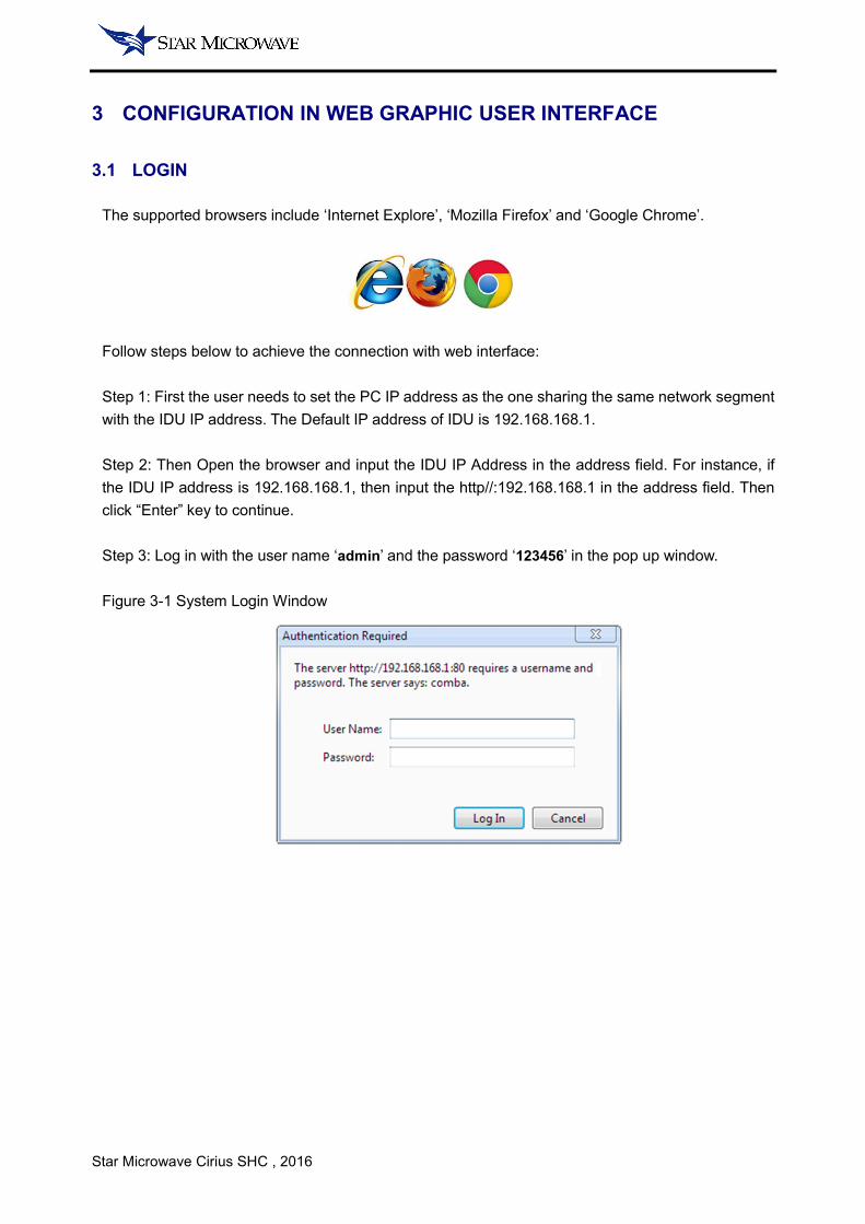
3.1 LOGIN
The supported browsers include ‘Internet Explore’, ‘Mozilla Firefox’ and ‘Google Chrome’.
Follow steps below to achieve the connection with web interface:
Step 1: First the user needs to set the PC IP address as the one sharing the same network segment
with the IDU IP address. The Default IP address of IDU is 192.168.168.1.
Step 2: Then Open the browser and input the IDU IP Address in the address field. For instance, if
the IDU IP address is 192.168.168.1, then input the http//:192.168.168.1 in the address field. Then
click “Enter” key to continue.
Step 3: Log in with the user name ‘admin’ and the password ‘123456’ in the pop up window.
Figure 3-1 System Login Window
Star Microwave Cirius SHC , 2016
3.2 BRIEF DESCRIPTION
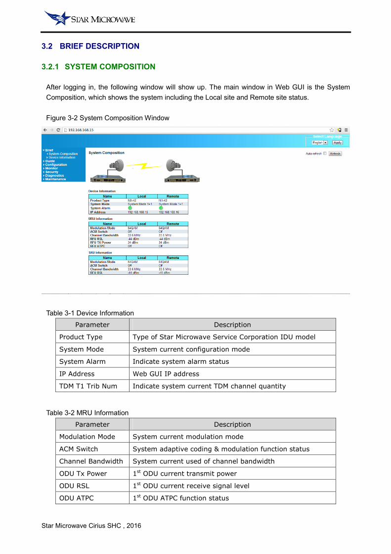
3.2.1 SYSTEM COMPOSITION
After logging in, the following window will show up. The main window in Web GUI is the System
Composition, which shows the system including the Local site and Remote site status.
Figure 3-2 System Composition Window
Table 3-1 Device Information
Parameter Description
Product Type Type of Star Microwave Service Corporation IDU model
System Mode System current configuration mode
System Alarm Indicate system alarm status
IP Address Web GUI IP address
TDM T1 Trib Num Indicate system current TDM channel quantity
Table 3-2 MRU Information
Parameter Description
Modulation Mode System current modulation mode
ACM Switch System adaptive coding & modulation function status
Channel Bandwidth System current used of channel bandwidth
ODU Tx Power 1st ODU current transmit power
ODU RSL 1st ODU current receive signal level
ODU ATPC 1st ODU ATPC function status
Star Microwave Cirius SHC , 2016
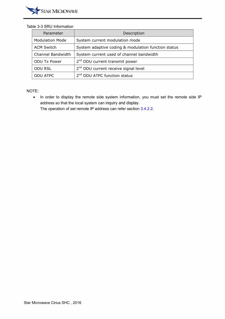
Table 3-3 SRU Information
Parameter Description
Modulation Mode System current modulation mode
ACM Switch System adaptive coding & modulation function status
Channel Bandwidth System current used of channel bandwidth
ODU Tx Power 2nd ODU current transmit power
ODU RSL 2nd ODU current receive signal level
ODU ATPC 2nd ODU ATPC function status
NOTE:
• In order to display the remote side system information, you must set the remote side IP
address so that the local system can inquiry and display.
The operation of set remote IP address can refer section 3.4.2.2.
Star Microwave Cirius SHC , 2016
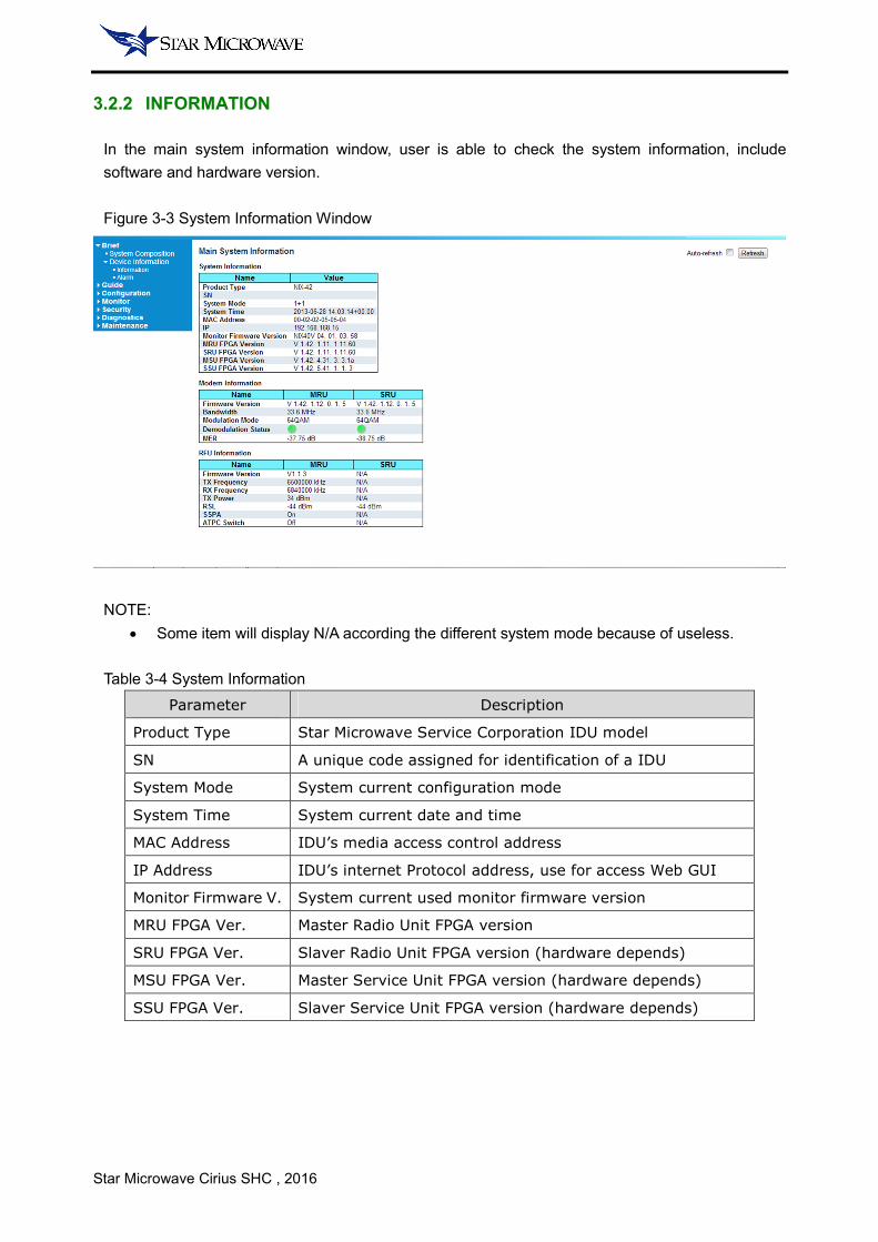
3.2.2 INFORMATION
In the main system information window, user is able to check the system information, include
software and hardware version.
Figure 3-3 System Information Window
NOTE:
• Some item will display N/A according the different system mode because of useless.
Table 3-4 System Information
Parameter Description
Product Type Star Microwave Service Corporation IDU model
SN A unique code assigned for identification of a IDU
System Mode System current configuration mode
System Time System current date and time
MAC Address IDU’s media access control address
IP Address IDU’s internet Protocol address, use for access Web GUI
Monitor Firmware V. System current used monitor firmware version
MRU FPGA Ver. Master Radio Unit FPGA version
SRU FPGA Ver. Slaver Radio Unit FPGA version (hardware depends)
MSU FPGA Ver. Master Service Unit FPGA version (hardware depends)
SSU FPGA Ver. Slaver Service Unit FPGA version (hardware depends)

Star Microwave Cirius SHC , 2016
Table 3-5 Modem Information
Parameter Description
Firmware Version System current modem firmware version
Bandwidth System current used of channel bandwidth
Modulation Mode System current modulation mode
Demodulation State Shown whether the modem demodulation normal
MER Used to measure the Modulation Error Ratio
Table 3-6 ODU Information
Parameter Description
Firmware Version System current ODU firmware version
Tx Frequency ODU transmitter transmitted frequency
Rx Frequency ODU receiver received frequency
Tx Power ODU current transmit power
RSL ODU current receive signal level
SSPA Indicate whether the ODU working or mute
ATPC Switch Indicate whether the ATPC function on or off

Star Microwave Cirius SHC , 2016
3.2.3 ALARM
In the alarm window, user is able to check the system current important alarm. When the alarms are
inactive, corresponding icon will display green. Once the alarms had be active, icon will display red
and IDU front panel alarm LED indicator will turn on.
Figure 3-4 Alarm Window
Table 3-7 System Alarm Information
Parameter Description
MRU Modem Alarm MRU modulation or demodulation status abnormality
MRU IF Alarm IDU and MRU IF communication error
MRU ODU Alarm IDU and 1st ODU communication error
SRU Modem Alarm SRU modulation or demodulation status abnormality
SRU IF Alarm IDU and SRU IF communication error
SRU ODU Alarm IDU and 2nd ODU communication error

Star Microwave Cirius SHC , 2016
3.3 GUIDE
3.3.1 QUICK CONFIGURATION
User can use the system quick configuration window to achieve a quick start of the microwave link.
The quick configuration can set the radio parameters and a few system settings. The system can
provide basic services such as simple Ethernet service after the quick configuration is completed.
Figure 3-5 Quick Configuration - Step 1
Parameter Range Default Remark
System Time - - YYYY-MM-DD hh-mm-ss
System Mode - - Model and license depends
IP Address - - Default: 192.168.168.1
IP Mask - - -
Remote IP Address - - Used to inquiry remote info
<Next Step>: Save current page setting and continue, setting do not active until Step 4 finish.
<Reset the Step>: Rest current page setting. This operation doesn’t affect the previous page setting.
Figure 3-6 Quick Configuration - Step 2
Parameter Range Default Remark
MRU ACM Switch On | Off Off License dependent
MRU Modulation M. QPSK ~ 256QAM - License dependent
MRU Bandwidth ETSI | FCC - -
Star Microwave Cirius SHC , 2016
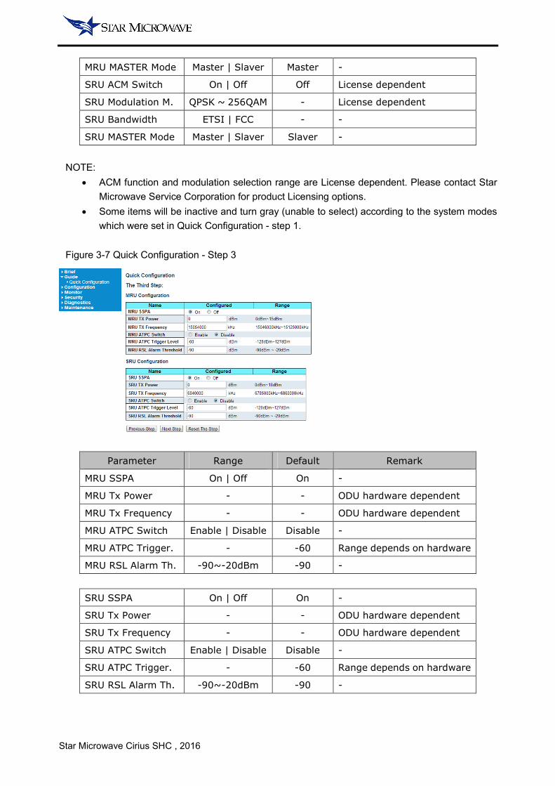
MRU MASTER Mode Master | Slaver Master -
SRU ACM Switch On | Off Off License dependent
SRU Modulation M. QPSK ~ 256QAM - License dependent
SRU Bandwidth ETSI | FCC - -
SRU MASTER Mode Master | Slaver Slaver -
NOTE:
• ACM function and modulation selection range are License dependent. Please contact Star
Microwave Service Corporation for product Licensing options.
• Some items will be inactive and turn gray (unable to select) according to the system modes
which were set in Quick Configuration - step 1.
Figure 3-7 Quick Configuration - Step 3
Parameter Range Default Remark
MRU SSPA On | Off On -
MRU Tx Power - - ODU hardware dependent
MRU Tx Frequency - - ODU hardware dependent
MRU ATPC Switch Enable | Disable Disable -
MRU ATPC Trigger. - -60 Range depends on hardware
MRU RSL Alarm Th. -90~-20dBm -90 -
SRU SSPA On | Off On -
SRU Tx Power - - ODU hardware dependent
SRU Tx Frequency - - ODU hardware dependent
SRU ATPC Switch Enable | Disable Disable -
SRU ATPC Trigger. - -60 Range depends on hardware
SRU RSL Alarm Th. -90~-20dBm -90 -
Star Microwave Cirius SHC , 2016
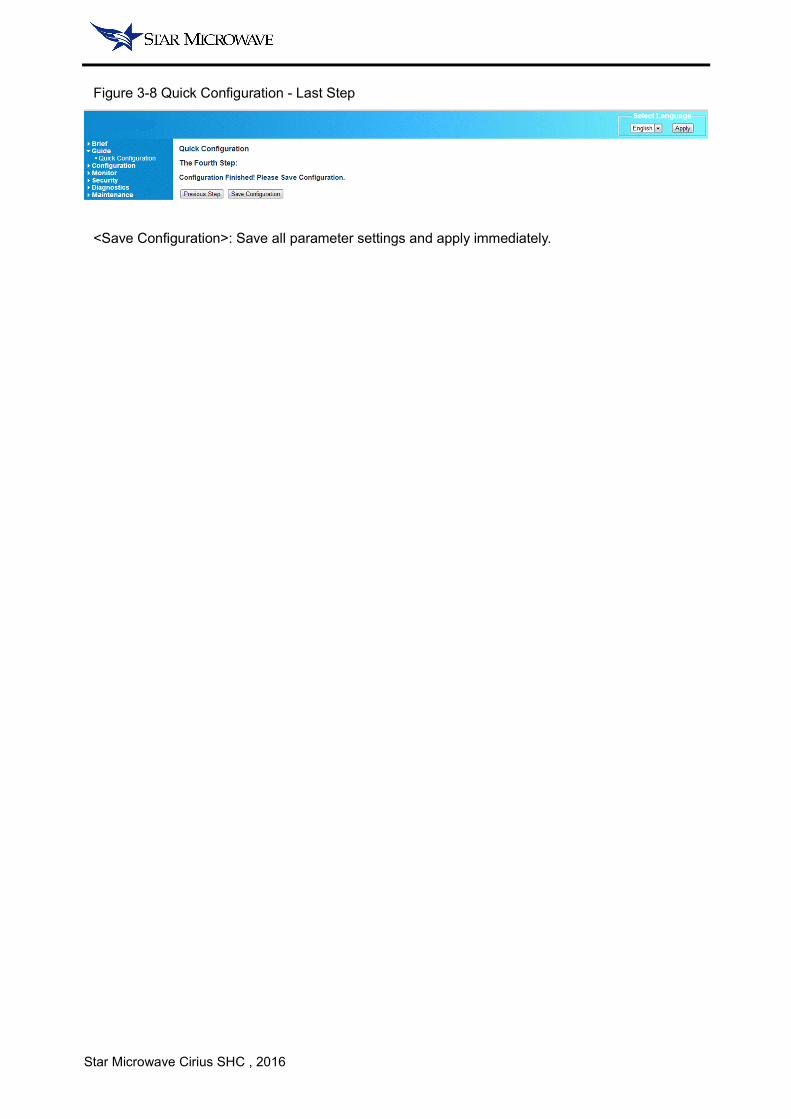
Figure 3-8 Quick Configuration - Last Step
<Save Configuration>: Save all parameter settings and apply immediately.

Star Microwave Cirius SHC , 2016
3.4 CONFIGURATION WINDOW
3.4.1 SWITCH
3.4.1.1 PORT
In the ports window user can read/configure the parameters of Ethernet ports.
Port 1~4 corresponds to front panel electrical Ethernet ports 1~4, and Port 5~7 corresponds front
panel optical Ethernet ports 5~7. Port 8~11 are system internal ports only… please keep these ports
at their default setting.
NOTE:
• Changing the internal communication ports may cause system errors.
Figure 3-9 Ethernet Ports Window
Table 3-9 Ethernet Port
Port Speed Rate Parameter Duplex Port Disable
Port 1~4 Auto | 10M |100M | 1000M Full | Half Support
Port 5~7 Auto | 100M | 1G Full Support
Table 3-9 Ethernet Port Parameters
Parameter Range Default Remark
Link - - Connect or disconnect
Speed – Current Speed | Down - Speed range refer Table 4-7
Speed - Configured - - Speed range refer Table 4-7
Flow Control Enable | Disable Disable Compliance IEEE 802.3x
Max Frame Size ~9600 9600 The MTU allows pass
NOTE:
• The bold option is the default parameter of the Ethernet port.
Star Microwave Cirius SHC , 2016
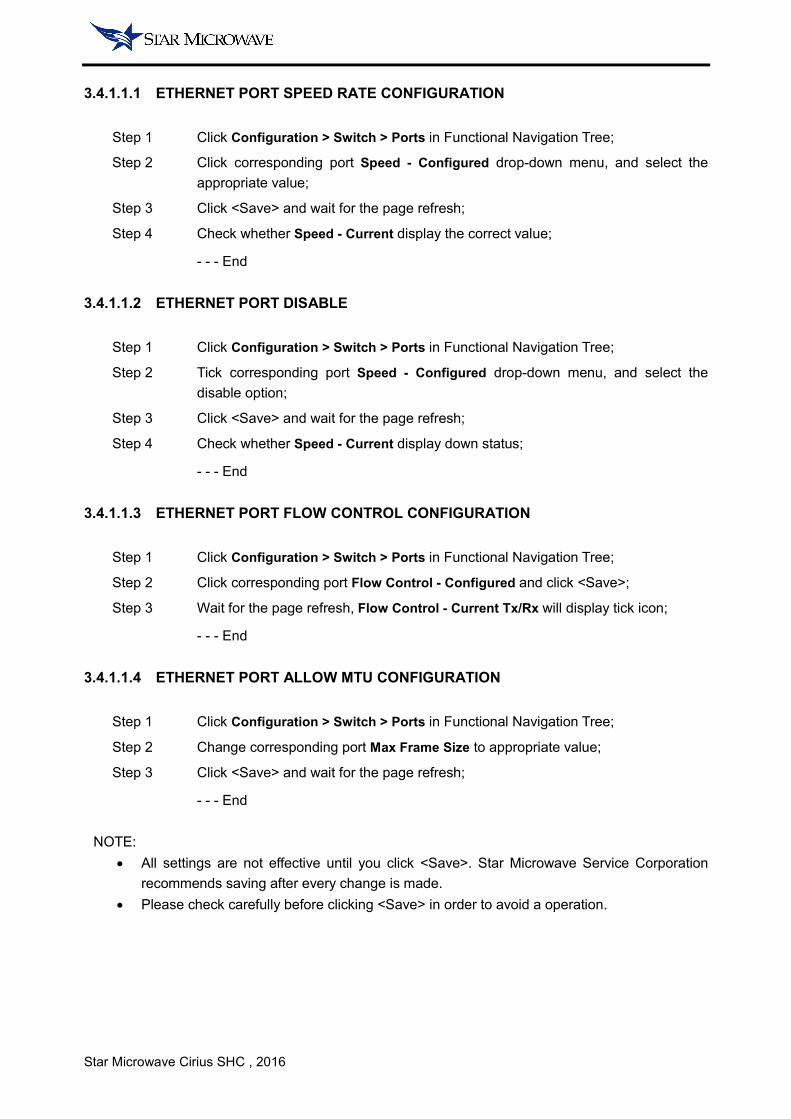
3.4.1.1.1 ETHERNET PORT SPEED RATE CONFIGURATION
Step 1 Click Configuration > Switch > Ports in Functional Navigation Tree;
Step 2 Click corresponding port Speed - Configured drop-down menu, and select the
appropriate value;
Step 3 Click <Save> and wait for the page refresh;
Step 4 Check whether Speed - Current display the correct value;
- - - End
3.4.1.1.2 ETHERNET PORT DISABLE
Step 1 Click Configuration > Switch > Ports in Functional Navigation Tree;
Step 2 Tick corresponding port Speed - Configured drop-down menu, and select the
disable option;
Step 3 Click <Save> and wait for the page refresh;
Step 4 Check whether Speed - Current display down status;
- - - End
3.4.1.1.3 ETHERNET PORT FLOW CONTROL CONFIGURATION
Step 1 Click Configuration > Switch > Ports in Functional Navigation Tree;
Step 2 Click corresponding port Flow Control - Configured and click <Save>;
Step 3 Wait for the page refresh, Flow Control - Current Tx/Rx will display tick icon;
- - - End
3.4.1.1.4 ETHERNET PORT ALLOW MTU CONFIGURATION
Step 1 Click Configuration > Switch > Ports in Functional Navigation Tree;
Step 2 Change corresponding port Max Frame Size to appropriate value;
Step 3 Click <Save> and wait for the page refresh;
- - - End
NOTE:
• All settings are not effective until you click <Save>. Star Microwave Service Corporation
recommends saving after every change is made.
• Please check carefully before clicking <Save> in order to avoid a operation.

Star Microwave Cirius SHC , 2016
3.4.1.2 AGGREGATION
In aggregation window, user can configure the aggregation group and algorithm.
Figure 3-10 Aggregation Window
Hash Code Contributors: allows selecting hash code contributors for making a key, including Source
MAC Address, Destination MAC Address, IP address, TCP/UDP port number four type.
Base on the network demand, user can use of combinations of different algorithms to build up the
aggregation network.
Figure 3-11 Aggregation Algorithms in OSI
<Source MAC Address>: allows Ethernet data with different source MAC address to be arranged to
transmit in different links evenly.
<Destination MAC Address>: allows Ethernet data with different destination MAC address to be
arranged to transmit in different links evenly.
Payload
TCP/UDP
IP
Mac
IP Packet
Header
PayloadTCP/UDP
Packet Header
PayloadEthernet Frame
Header
Source MAC
Destination MAC
IP Address
TCP/UDP Port Number
Star Microwave Cirius SHC , 2016
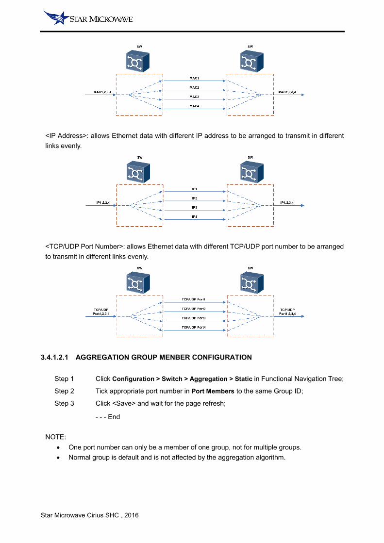
<IP Address>: allows Ethernet data with different IP address to be arranged to transmit in different
links evenly.
<TCP/UDP Port Number>: allows Ethernet data with different TCP/UDP port number to be arranged
to transmit in different links evenly.
3.4.1.2.1 AGGREGATION GROUP MENBER CONFIGURATION
Step 1 Click Configuration > Switch > Aggregation > Static in Functional Navigation Tree;
Step 2 Tick appropriate port number in Port Members to the same Group ID;
Step 3 Click <Save> and wait for the page refresh;
- - - End
NOTE:
• One port number can only be a member of one group, not for multiple groups.
• Normal group is default and is not affected by the aggregation algorithm.

Star Microwave Cirius SHC , 2016
3.4.1.2.2 AGGREGATION GROUP ALGORITHM CONFIGURATION
Step 1 Click Configuration > Switch > Aggregation > Static in Functional Navigation Tree;
Step 2 Tick appropriate algorithms according to the network plan;
Step 3 Click <Save> and wait for the page refresh;
- - - End
NOTE:
• The algorithms will take effect to the entire aggregation group, and do not support
independent algorithms for each aggregation group.
3.4.1.3 SPANNING TREE
In spanning tree window, user can enable/disable the Spanning Tree Protocol (STP) for each port.
Figure 3-12 Spanning Tree Window
Parameter Range Default Remark
Port 1~11 Enable | Disable Disable -
NOTE:
• STP enable can effectively avoid broadcast storms, but STP Enable will cause unpredictable
issues within the Ethernet test.
Star Microwave Cirius SHC , 2016
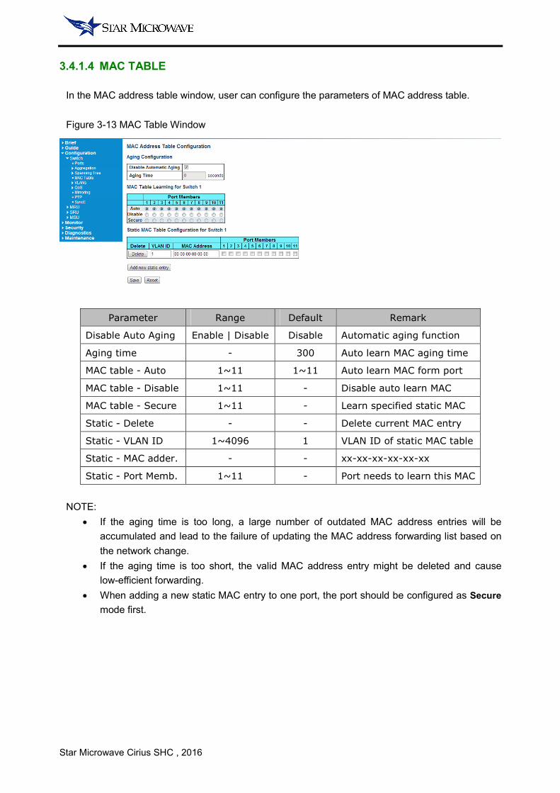
3.4.1.4 MAC TABLE
In the MAC address table window, user can configure the parameters of MAC address table.
Figure 3-13 MAC Table Window
Parameter Range Default Remark
Disable Auto Aging Enable | Disable Disable Automatic aging function
Aging time - 300 Auto learn MAC aging time
MAC table - Auto 1~11 1~11 Auto learn MAC form port
MAC table - Disable 1~11 - Disable auto learn MAC
MAC table - Secure 1~11 - Learn specified static MAC
Static - Delete - - Delete current MAC entry
Static - VLAN ID 1~4096 1 VLAN ID of static MAC table
Static - MAC adder. - - xx-xx-xx-xx-xx-xx
Static - Port Memb. 1~11 - Port needs to learn this MAC
NOTE:
• If the aging time is too long, a large number of outdated MAC address entries will be
accumulated and lead to the failure of updating the MAC address forwarding list based on
the network change.
• If the aging time is too short, the valid MAC address entry might be deleted and cause
low-efficient forwarding.
• When adding a new static MAC entry to one port, the port should be configured as Secure
mode first.
Star Microwave Cirius SHC , 2016
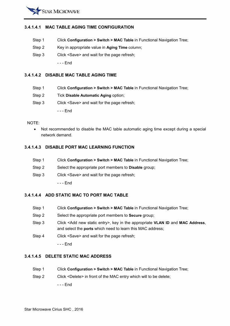
3.4.1.4.1 MAC TABLE AGING TIME CONFIGURATION
Step 1 Click Configuration > Switch > MAC Table in Functional Navigation Tree;
Step 2 Key in appropriate value in Aging Time column;
Step 3 Click <Save> and wait for the page refresh;
- - - End
3.4.1.4.2 DISABLE MAC TABLE AGING TIME
Step 1 Click Configuration > Switch > MAC Table in Functional Navigation Tree;
Step 2 Tick Disable Automatic Aging option;
Step 3 Click <Save> and wait for the page refresh;
- - - End
NOTE:
• Not recommended to disable the MAC table automatic aging time except during a special
network demand.
3.4.1.4.3 DISABLE PORT MAC LEARNING FUNCTION
Step 1 Click Configuration > Switch > MAC Table in Functional Navigation Tree;
Step 2 Select the appropriate port members to Disable group;
Step 3 Click <Save> and wait for the page refresh;
- - - End
3.4.1.4.4 ADD STATIC MAC TO PORT MAC TABLE
Step 1 Click Configuration > Switch > MAC Table in Functional Navigation Tree;
Step 2 Select the appropriate port members to Secure group;
Step 3 Click <Add new static entry>, key in the appropriate VLAN ID and MAC Address,
and select the ports which need to learn this MAC address;
Step 4 Click <Save> and wait for the page refresh;
- - - End
3.4.1.4.5 DELETE STATIC MAC ADDRESS
Step 1 Click Configuration > Switch > MAC Table in Functional Navigation Tree;
Step 2 Click <Delete> in front of the MAC entry which will to be delete;
- - - End
Star Microwave Cirius SHC , 2016
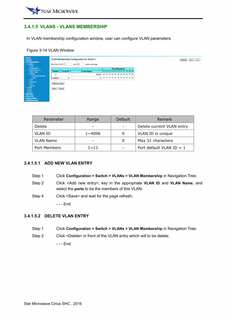
3.4.1.5 VLANS - VLANS MEMBERSHIP
In VLAN membership configuration window, user can configure VLAN parameters.
Figure 3-14 VLAN Window
Parameter Range Default Remark
Delete - - Delete current VLAN entry
VLAN ID 1~4096 0 VLAN ID is unique
VLAN Name - 0 Max 31 characters
Port Members 1~11 - Port default VLAN ID = 1
3.4.1.5.1 ADD NEW VLAN ENTRY
Step 1 Click Configuration > Switch > VLANs > VLAN Membership in Navigation Tree;
Step 2 Click <Add new entry>, key in the appropriate VLAN ID and VLAN Name, and
select the ports to be the members of this VLAN;
Step 4 Click <Save> and wait for the page refresh;
- - - End
3.4.1.5.2 DELETE VLAN ENTRY
Step 1 Click Configuration > Switch > VLANs > VLAN Membership in Navigation Tree;
Step 2 Click <Delete> in front of the VLAN entry which will to be delete;
- - - End

Star Microwave Cirius SHC , 2016
3.4.2 MRU
3.4.2.1 SYSTEM - INFORMATION
Figure 3-15 System Information Window
Parameter Range Default Remark
System Time - - YYYY-MM-DD hh-mm-ss
System Mode - - License dependent
NOTE:
• Most of the system parameters are the same and relate with Quick Configuration. If the
Quick Configuration was completed, some system parameters setting can be skipped.
3.4.2.1.1 CHANGE SYSTEM MODE
Step 1 Click Configuration > MRU > System > Information in Function Navigation Tree;
Step 2 Click the drop-down menu and select the appropriate value in System Mode;
Step 3 Click <Save> and wait for the page refresh;
- - - End
NOTE:
• Some pages will display different item based on system mode.
3.4.2.1.2 CHANGE SYSTEM TIME
Step 1 Click Configuration > MRU > System > Information in Function Navigation Tree;
Step 2 Key in the appropriate value in System Time;
Step 3 Click <Save> and wait for the page refresh;
- - - End
Star Microwave Cirius SHC , 2016
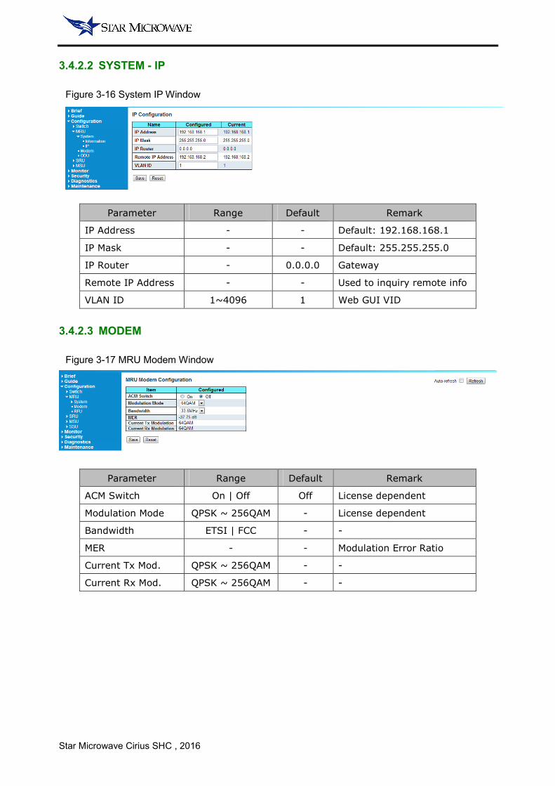
3.4.2.2 SYSTEM - IP
Figure 3-16 System IP Window
Parameter Range Default Remark
IP Address - - Default: 192.168.168.1
IP Mask - - Default: 255.255.255.0
IP Router - 0.0.0.0 Gateway
Remote IP Address - - Used to inquiry remote info
VLAN ID 1~4096 1 Web GUI VID
3.4.2.3 MODEM
Figure 3-17 MRU Modem Window
Parameter Range Default Remark
ACM Switch On | Off Off License dependent
Modulation Mode QPSK ~ 256QAM - License dependent
Bandwidth ETSI | FCC - -
MER - - Modulation Error Ratio
Current Tx Mod. QPSK ~ 256QAM - -
Current Rx Mod. QPSK ~ 256QAM - -
Star Microwave Cirius SHC , 2016
3.4.2.3.1 SELECT BANDWIDTH AND MODULATION
Step 1 Click Configuration > MRU > Modem in Function Navigation Tree;
Step 2 Click the drop-down menu and select the appropriate value in Bandwidth and
Modulation Mode;
Step 3 Click <Save> and wait for the page refresh;
- - - End
3.4.2.3.2 ACM CONFIGURATION
Step 1 Click Configuration > MRU > Modem in Function Navigation Tree;
Step 2 Select On or Off in ACM Switch;
Step 3 Click <Save> and wait for the page refresh;
- - - End
NOTE:
• Once the ACM function has been enabled, the modulation mode will lock (auto mode).
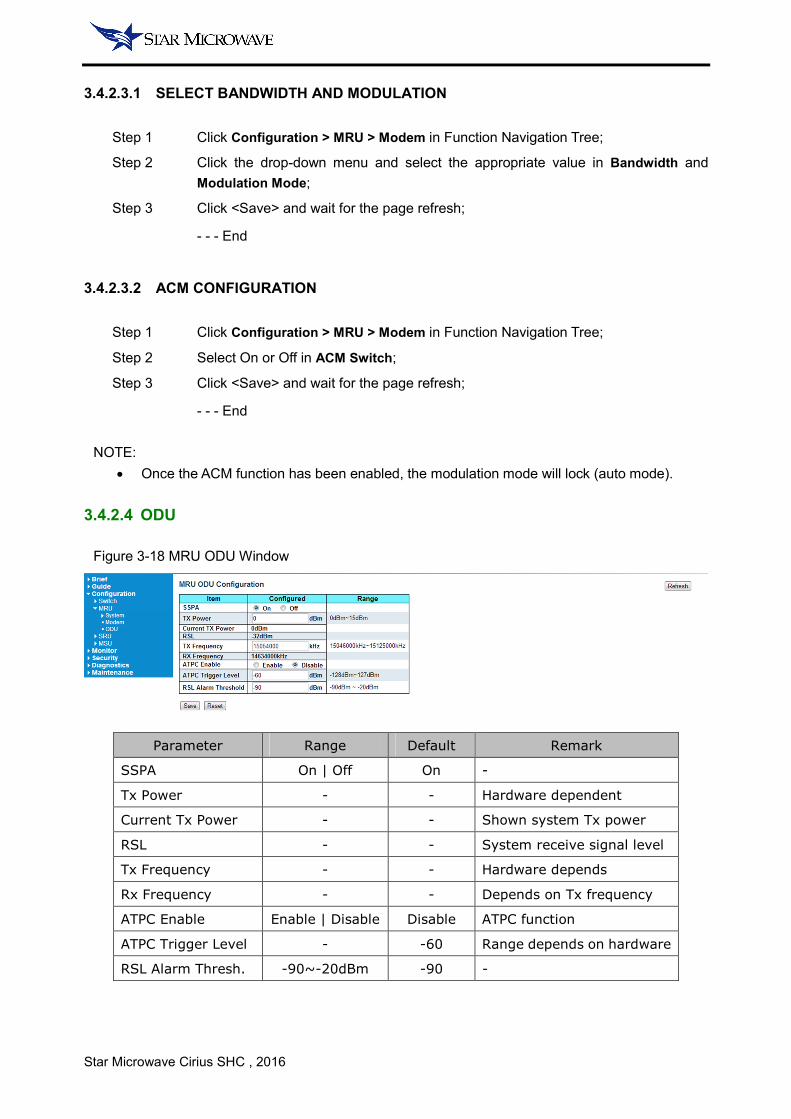
3.4.2.4 ODU
Figure 3-18 MRU ODU Window
Parameter Range Default Remark
SSPA On | Off On -
Tx Power - - Hardware dependent
Current Tx Power - - Shown system Tx power
RSL - - System receive signal level
Tx Frequency - - Hardware depends
Rx Frequency - - Depends on Tx frequency
ATPC Enable Enable | Disable Disable ATPC function
ATPC Trigger Level - -60 Range depends on hardware
RSL Alarm Thresh. -90~-20dBm -90 -
Star Microwave Cirius SHC , 2016
3.4.2.4.1 MUTE THE RADIO
Step 1 Click Configuration > MRU > ODU in Function Navigation Tree;
Step 2 Select Off in SSPA;
Step 3 Click <Save> and wait for the page refresh;
- - - End
3.4.2.4.2 TX POWER CONFIGURATION
Step 1 Click Configuration > MRU > ODU in Function Navigation Tree;
Step 2 Key in the appropriate value in Tx Power according the Tx power range;
Step 3 Click <Save> and wait for the page refresh;
- - - End
3.4.2.4.3 FREQUENCY CONFIGURATION
Step 1 Click Configuration > MRU > ODU in Function Navigation Tree;
Step 2 Key in the appropriate value in Tx Frequency according the Tx frequency range;
Step 3 Base on the system, set ODU is High (Prime) or Low (Non-Prime);
Step 4 Key in the appropriate value in Tx Spacing;
Step 5 Click <Save> and wait for the page refresh;
- - - End
NOTE:
• If you want to change the ODU to High (Prime) or Low (Non-Prime), you must set the Tx
Spacing to be 0. Otherwise the change will fail.
Star Microwave Cirius SHC , 2016
3.4.3 SRU
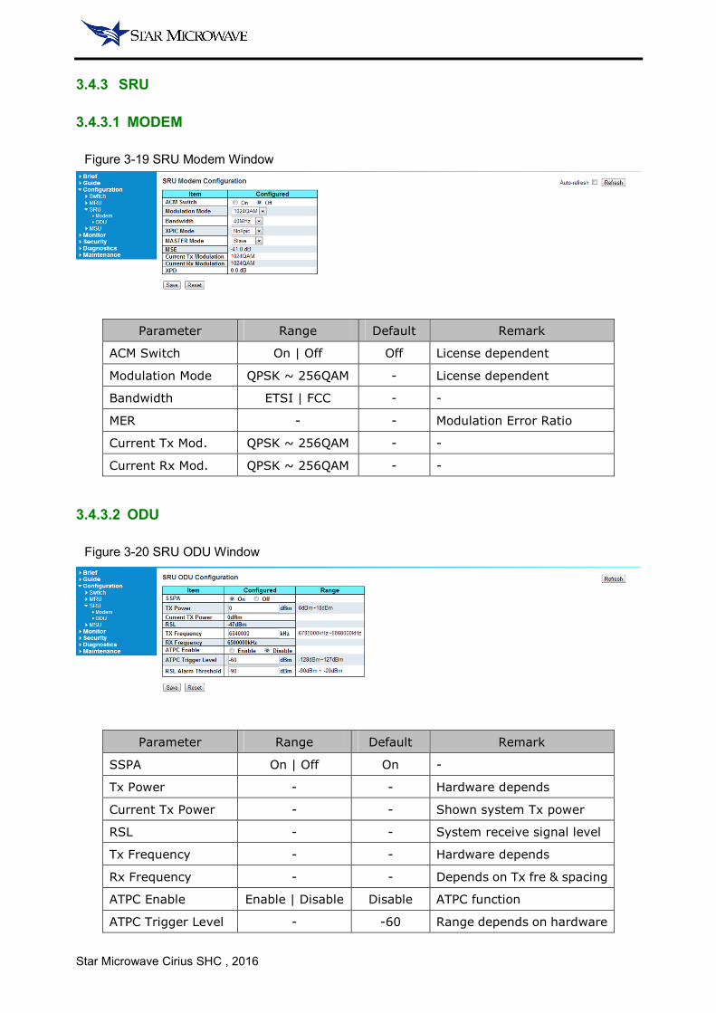
3.4.3.1 MODEM
Figure 3-19 SRU Modem Window
Parameter Range Default Remark
ACM Switch On | Off Off License dependent
Modulation Mode QPSK ~ 256QAM - License dependent
Bandwidth ETSI | FCC - -
MER - - Modulation Error Ratio
Current Tx Mod. QPSK ~ 256QAM - -
Current Rx Mod. QPSK ~ 256QAM - -
3.4.3.2 ODU
Figure 3-20 SRU ODU Window
Parameter Range Default Remark
SSPA On | Off On -
Tx Power - - Hardware depends
Current Tx Power - - Shown system Tx power
RSL - - System receive signal level
Tx Frequency - - Hardware depends
Rx Frequency - - Depends on Tx fre & spacing
ATPC Enable Enable | Disable Disable ATPC function
ATPC Trigger Level - -60 Range depends on hardware

Star Microwave Cirius SHC , 2016
RSL Alarm Thresh. -90~-20dBm -90 -
NOTE:
• The SRU page displays items and parameters that change based on the system mode (as
1+1 HSB / SD / FD or 2+0).
Star Microwave Cirius SHC , 2016
3.4.4 MSU
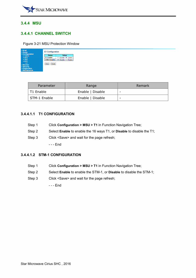
3.4.4.1 CHANNEL SWITCH
Figure 3-21 MSU Protection Window
Parameter Range Remark
T1 Enable Enable | Disable -
STM-1 Enable Enable | Disable -
3.4.4.1.1 T1 CONFIGURATION
Step 1 Click Configuration > MSU > T1 in Function Navigation Tree;
Step 2 Select Enable to enable the 16 ways T1, or Disable to disable the T1;
Step 3 Click <Save> and wait for the page refresh;
- - - End
3.4.4.1.2 STM-1 CONFIGURATION
Step 1 Click Configuration > MSU > T1 in Function Navigation Tree;
Step 2 Select Enable to enable the STM-1, or Disable to disable the STM-1;
Step 3 Click <Save> and wait for the page refresh;
- - - End

Star Microwave Cirius SHC , 2016
3.5 MONITOR
3.5.1 SWITCH
3.5.1.1 PORT - STATUS
In ports status, shown are the seven Ethernet ports which correspond to the IDU front panel.
When the Ethernet is connected, the port icon will turn green. If port is black this means this port is
disconnected. User can click the port icon to entry to the detail traffic statistics for this port.
Figure 3-22 Port Status Window
3.5.1.2 TRAFFIC OVERVIEW
Figure 3-23 Traffic Overview Window
Parameter Description
Port Support click in to check the port detail statistics
Packets - Rx Count received quantity of packet
Packets - Tx Count transmitted quantity of packet
Bytes - Rx Count received quantity of Bytes
Bytes - Tx Count transmitted quantity of Bytes
Errors - Rx Count received quantity of error packets
Errors - Tx Count transmitted quantity of error packets
Drops - Rx Count the drop packets of this port received
Drops - Tx Count the drop packets of this port transmitted
Star Microwave Cirius SHC , 2016
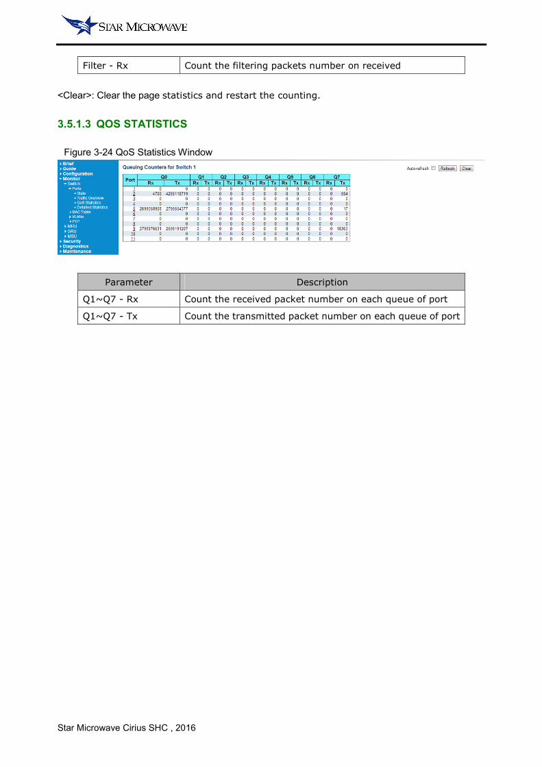
Filter - Rx Count the filtering packets number on received
<Clear>: Clear the page statistics and restart the counting.
3.5.1.3 QOS STATISTICS
Figure 3-24 QoS Statistics Window
Parameter Description
Q1~Q7 - Rx Count the received packet number on each queue of port
Q1~Q7 - Tx Count the transmitted packet number on each queue of port

Star Microwave Cirius SHC , 2016
3.5.1.4 DETAILED STATISTICS
Figure 3-25 Port Statistics Window
Parameter Description
Receive Total Count the total received packets of port
Transmit Total Count the total transmitted packets of port
Rx Size Counters Count the total received numbers of different frame sizes
Tx Size Counters Count the total transmitted numbers of different frame sizes
Rx Queue Counters Count the total received packet numbers of queue
Tx Queue Counters Count the total transmitted packet numbers of queue
Rx Errors Counters Count the total received error packets
Tx Errors Counters Count the total transmitted error packets
NOTE:
• Each counter provides more detailed information of port statistics. Those statistics can help
analyze network status.

Star Microwave Cirius SHC , 2016
3.5.1.5 MAC TABLE
Figure 3-26 MAC Table Window
Parameter Description
Type Indicate type of MAC address (include static and dynamic)
VLAN VLAN ID of MAC address
MAC Address The details of MAC address
Port Members Indicate which ports had learned this MAC entry
3.5.1.6 VLAN MEMBERSHIP
Figure 3-27 VLAN Window
Parameter Description
VLAN ID -
Port Members Indicate which ports had this VLAN ID entry

Star Microwave Cirius SHC , 2016
3.5.2 MRU
3.5.2.1 SYSTEM - INFORMATION
Figure 3-28 MRU Information Window
3.5.2.2 SYSTEM - SYSTEM LOG
Figure 3-29 System Log Window
Parameter Description
ID The ID of system event
Level System defined event level as Info, Warning, Error
Time The date event happened
Message The details of system event
<Clear>: Clear the all the system events.
NOTE:
• User can use the event level filter to quickly find an event.
Star Microwave Cirius SHC , 2016
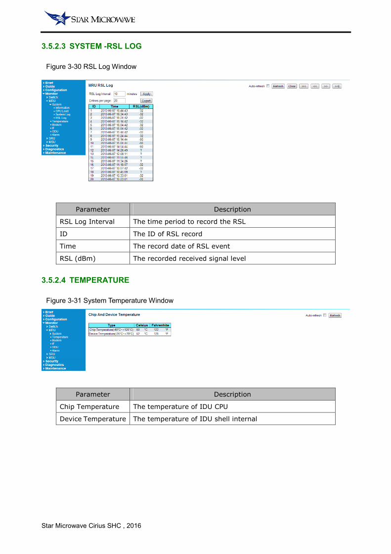
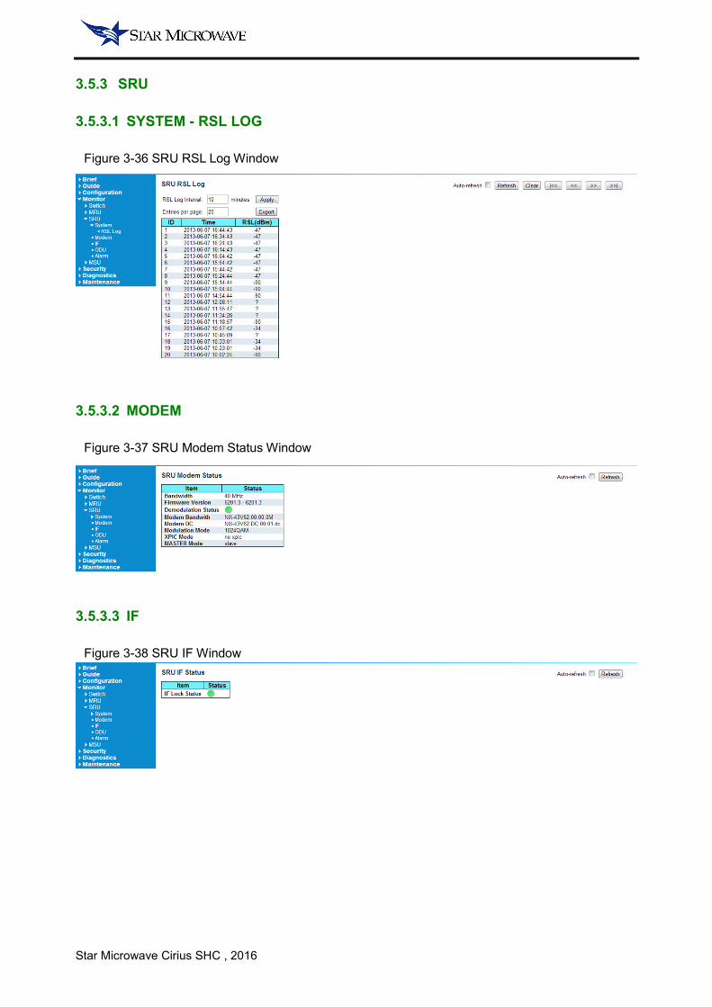
3.5.2.3 SYSTEM -RSL LOG
Figure 3-30 RSL Log Window
Parameter Description
RSL Log Interval The time period to record the RSL
ID The ID of RSL record
Time The record date of RSL event
RSL (dBm) The recorded received signal level
3.5.2.4 TEMPERATURE
Figure 3-31 System Temperature Window
Parameter Description
Chip Temperature The temperature of IDU CPU
Device Temperature The temperature of IDU shell internal
Star Microwave Cirius SHC , 2016
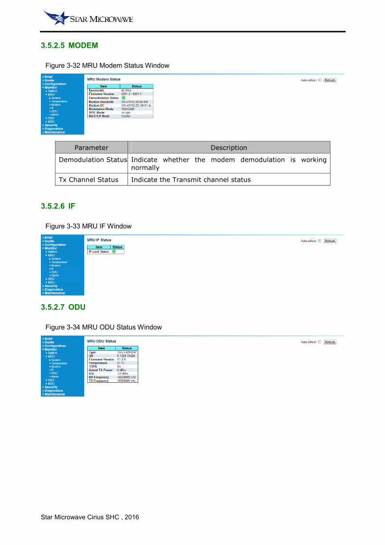
3.5.2.5 MODEM
Figure 3-32 MRU Modem Status Window
Parameter Description
Demodulation Status Indicate whether the modem demodulation is working
normally
Tx Channel Status Indicate the Transmit channel status
3.5.2.6 IF
Figure 3-33 MRU IF Window
3.5.2.7 ODU
Figure 3-34 MRU ODU Status Window

Star Microwave Cirius SHC , 2016
3.5.2.8 ALARM
Figure 3-35 MRU Alarm Window
Star Microwave Cirius SHC , 2016
3.5.3 SRU
3.5.3.1 SYSTEM - RSL LOG
Figure 3-36 SRU RSL Log Window
3.5.3.2 MODEM
Figure 3-37 SRU Modem Status Window
3.5.3.3 IF
Figure 3-38 SRU IF Window
Star Microwave Cirius SHC , 2016
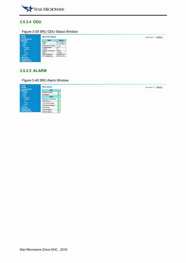
3.5.3.4 ODU
Figure 3-39 SRU ODU Status Window
3.5.3.5 ALARM
Figure 3-40 SRU Alarm Window
Star Microwave Cirius SHC , 2016
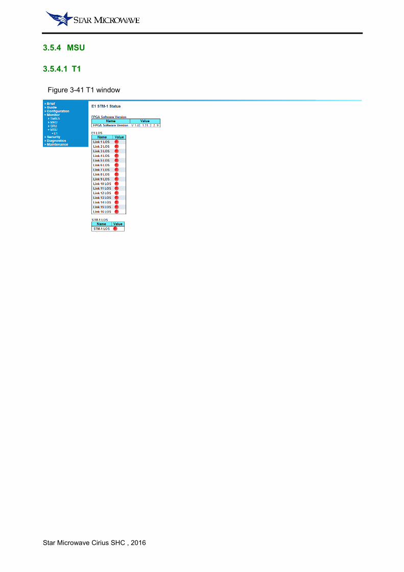
3.5.4 MSU
3.5.4.1 T1
Figure 3-41 T1 window

Star Microwave Cirius SHC , 2016
3.6 SECURITY WINDOW
3.6.1 SWITCH
3.6.1.1 PASSWORD
Figure 3-42 System Password Window
Parameter Description
Old password Key in the old password
New password Key in the new password
Confirm new PSW New password confirm, change fail when PSW mismatched
NOTE:
• Password can be any number or letter and the length should be less than 31 characters.
3.6.1.2 AUTHENTICATION METHOD
In the authentication method configuration window, user can configure the authentication method of
the client side.
Figure 3-43 System Authentication Window
Parameter Range Default Remark
Telnet Local | None Local Allow/deny telnet access
SSH Local | None Local Allow/deny SSH access
Web Local | None Local Allow/deny Web access
NOTE:
• When then Web configuration is None, the Web GUI login will fail.

Star Microwave Cirius SHC , 2016
3.6.1.3 SSH
Figure 3-44 System SSH Window
Parameter Range Default Remark
Mode Enable | Disable Enable Enable/disable SSH mode
3.6.1.4 HTTPS
Figure 3-45 System HTTPS Window
Parameter Range Default Remark
Mode Enable | Disable Enable Enble/disable https mode
Automatic Redirect Enable | Disable Disable Enable/disable auto redirect
NOTE:
• HTTPS access mode will be activated when both Mode and Automatic Redirect are enabled.

Star Microwave Cirius SHC , 2016
3.6.1.5 ACCESS MANAGEMENT
Figure 3-46 Access Management Window
Parameter Range Default Remark
Mode Enable | Disable Enable Access management
Start IP Address - - IP address for access client
End IP Address - - IP address for access client
HTTP/HTTPS Enable | Disable Disable Enable/disable this function
TELNET/SSH Enable | Disable Disable Enable/disable this function
3.6.2 NETWORK
3.6.2.1 ACL - PORTS
In the ACL ports configuration window, user can limit port speed and configure port copy.
Figure 3-47 System ACL Ports Window
Parameter Range Default Remark
Port 1~11 - -
Action Permit | Deny Permit Data transmission function
Rate Limiter ID Disable | 1~16 Disable 1~16 defined in 4.6.2.2
Port Copy Disable | 1~11 Disable The port which will be copied
Star Microwave Cirius SHC , 2016
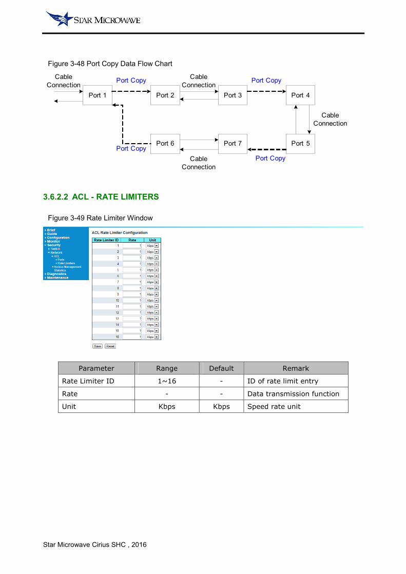
Figure 3-48 Port Copy Data Flow Chart
Port 1 Port 2 Port 3 Port 4
Port 5Port 7Port 6
Cable
Connection
Cable
Connection
Cable
Connection
Cable
Connection
Port Copy Port Copy
Port Copy
Port Copy
3.6.2.2 ACL - RATE LIMITERS
Figure 3-49 Rate Limiter Window
Parameter Range Default Remark
Rate Limiter ID 1~16 - ID of rate limit entry
Rate - - Data transmission function
Unit Kbps Kbps Speed rate unit
Star Microwave Cirius SHC , 2016
3.6.2.3 ACCESS MANAGEMENT STATISTICS
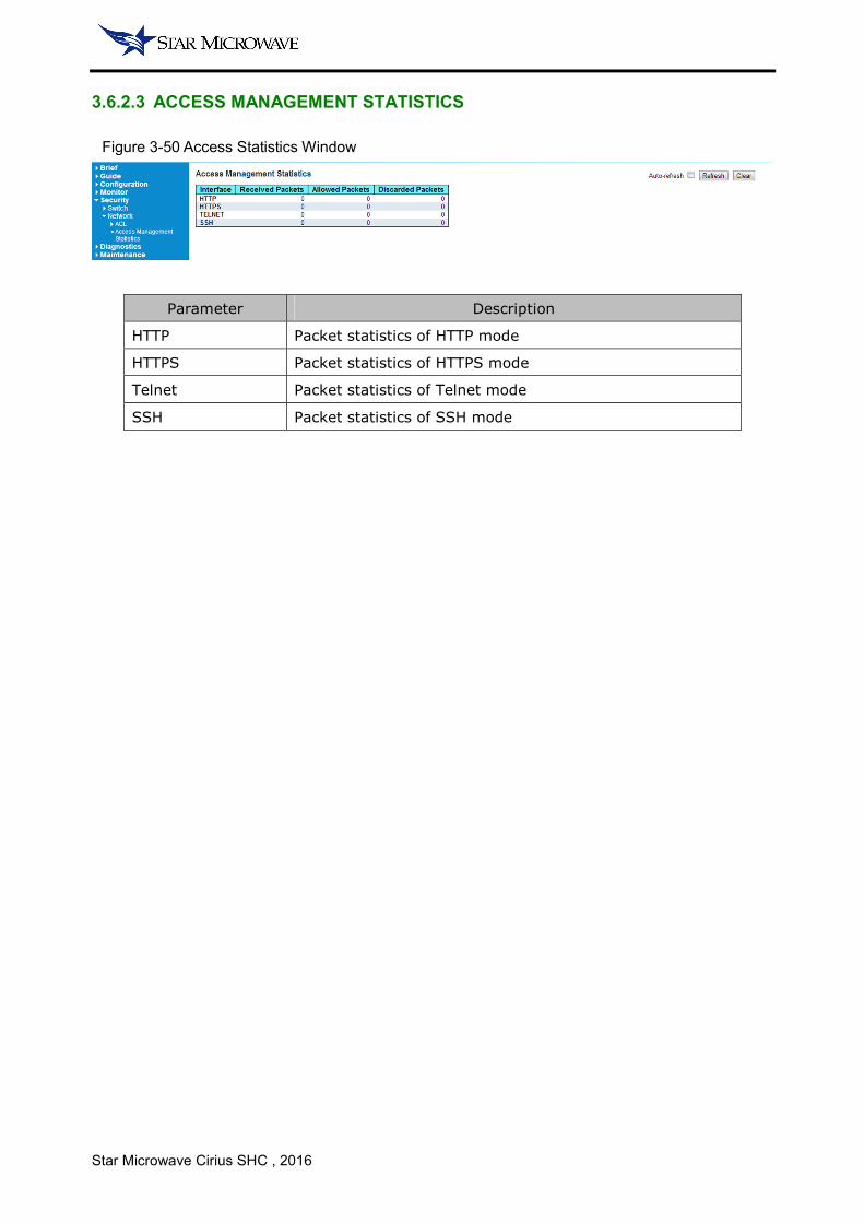
Figure 3-50 Access Statistics Window
Parameter Description
HTTP Packet statistics of HTTP mode
HTTPS Packet statistics of HTTPS mode
Telnet Packet statistics of Telnet mode
SSH Packet statistics of SSH mode

Star Microwave Cirius SHC , 2016
3.7 DIAGNOSTIC
3.7.1 PING
In this page the system provides the ICMP Ping function the same as Microsoft Window OS. Operator
can use to inspect the Ethernet link status between the IDU and a target device.
Figure 3-51 Ping Window
3.7.2 VERIPHY
VeriPHY are used for verify the Ethernet PHY layer status and measure the length of cable which
connects to port 1~4 electrical Ethernet port in the IDU front panel.
Figure 3-52 VeriPHY Window
NOTE:
• VeriPHY can measure the cable length which should be less than 7m.
Star Microwave Cirius SHC , 2016
3.7.3 DEBUG
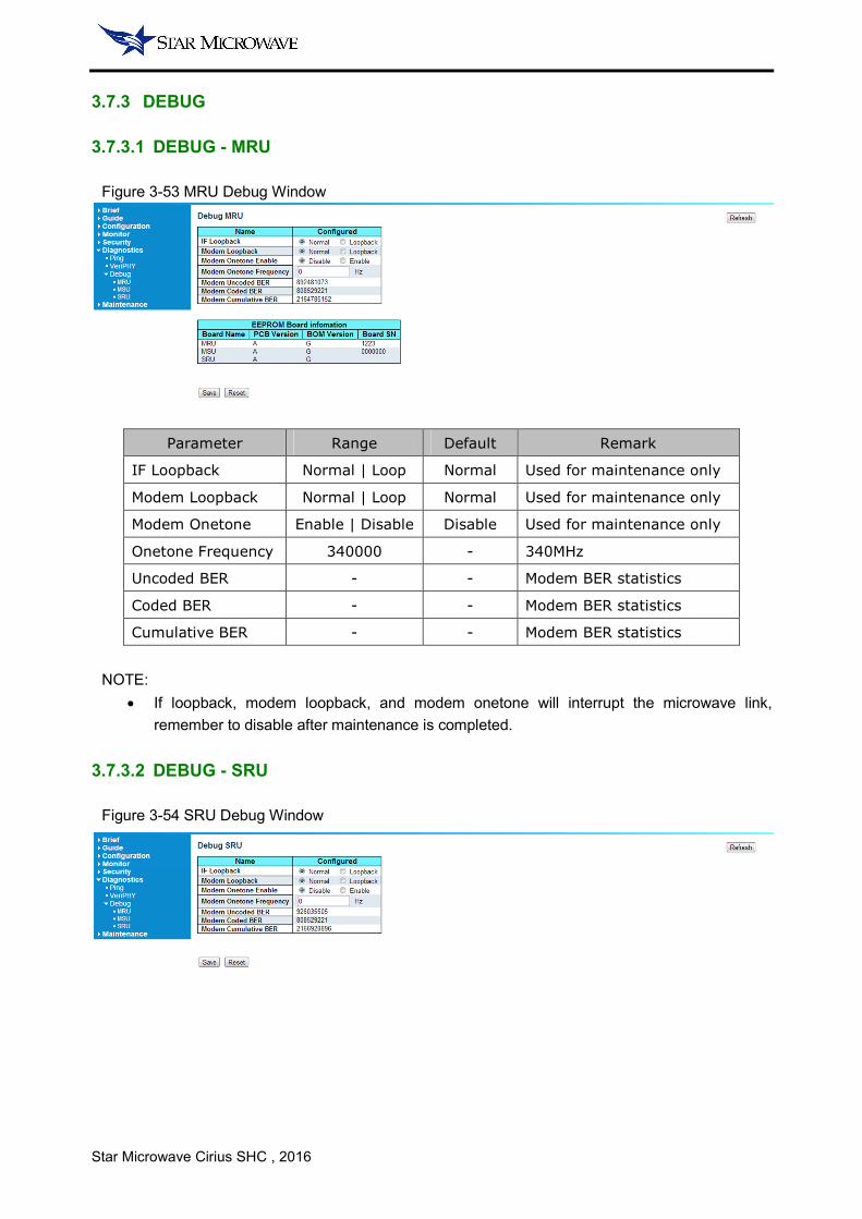
3.7.3.1 DEBUG - MRU
Figure 3-53 MRU Debug Window
Parameter Range Default Remark
IF Loopback Normal | Loop Normal Used for maintenance only
Modem Loopback Normal | Loop Normal Used for maintenance only
Modem Onetone Enable | Disable Disable Used for maintenance only
Onetone Frequency 340000 - 340MHz
Uncoded BER - - Modem BER statistics
Coded BER - - Modem BER statistics
Cumulative BER - - Modem BER statistics
NOTE:
• If loopback, modem loopback, and modem onetone will interrupt the microwave link,
remember to disable after maintenance is completed.
3.7.3.2 DEBUG - SRU
Figure 3-54 SRU Debug Window
Star Microwave Cirius SHC , 2016
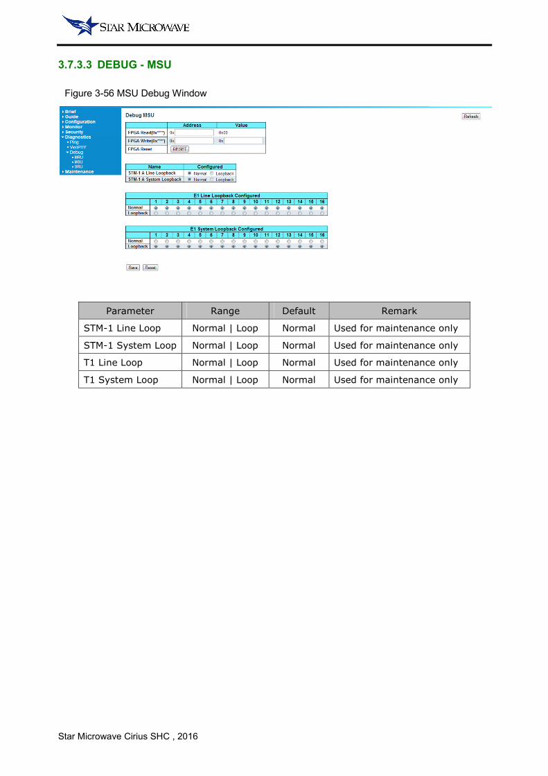
3.7.3.3 DEBUG - MSU
Figure 3-56 MSU Debug Window
Parameter Range Default Remark
STM-1 Line Loop Normal | Loop Normal Used for maintenance only
STM-1 System Loop Normal | Loop Normal Used for maintenance only
T1 Line Loop Normal | Loop Normal Used for maintenance only
T1 System Loop Normal | Loop Normal Used for maintenance only
Star Microwave Cirius SHC , 2016
3.8 MAITENANCE
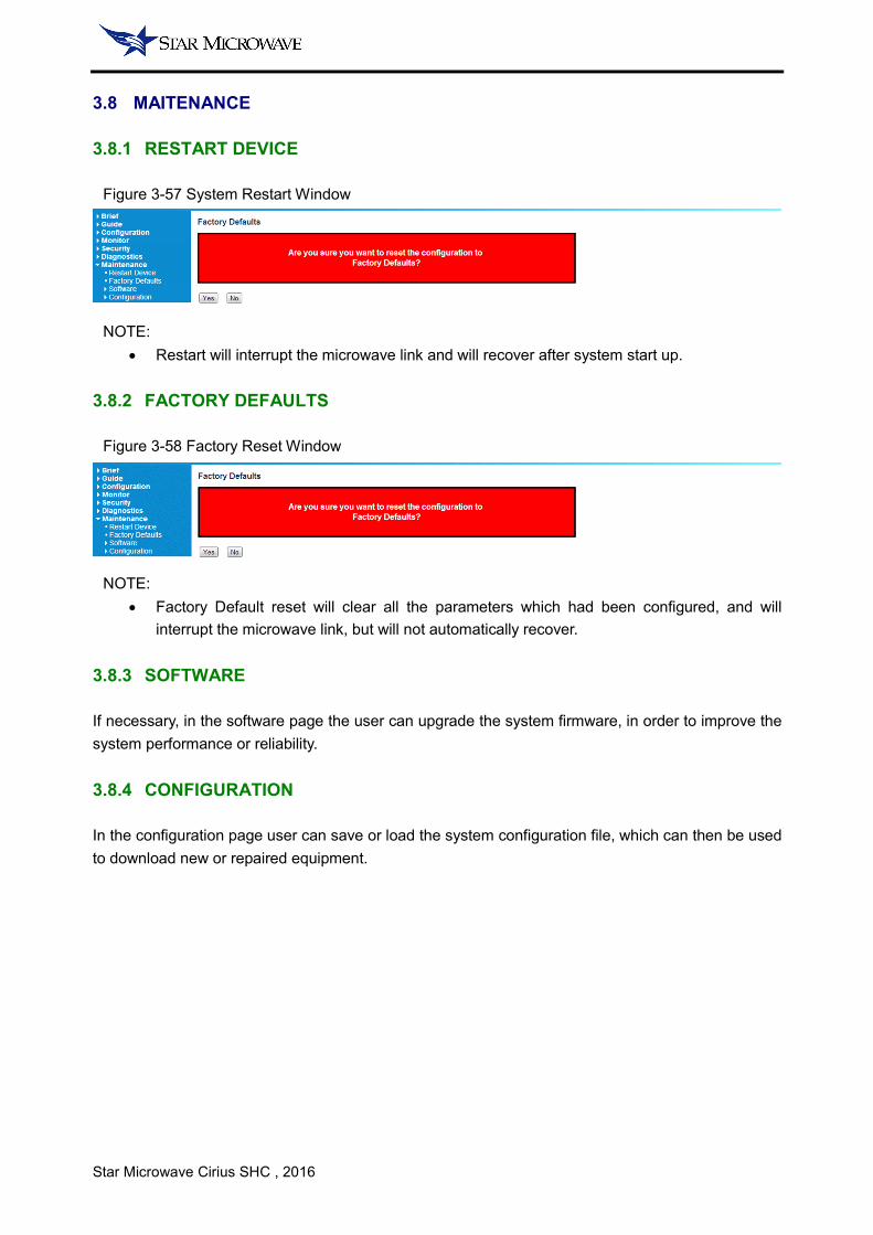
3.8.1 RESTART DEVICE
Figure 3-57 System Restart Window
NOTE:
• Restart will interrupt the microwave link and will recover after system start up.
3.8.2 FACTORY DEFAULTS
Figure 3-58 Factory Reset Window
NOTE:
• Factory Default reset will clear all the parameters which had been configured, and will
interrupt the microwave link, but will not automatically recover.
3.8.3 SOFTWARE
If necessary, in the software page the user can upgrade the system firmware, in order to improve the
system performance or reliability.
3.8.4 CONFIGURATION
In the configuration page user can save or load the system configuration file, which can then be used
to download new or repaired equipment.
Star Microwave Cirius SHC , 2016
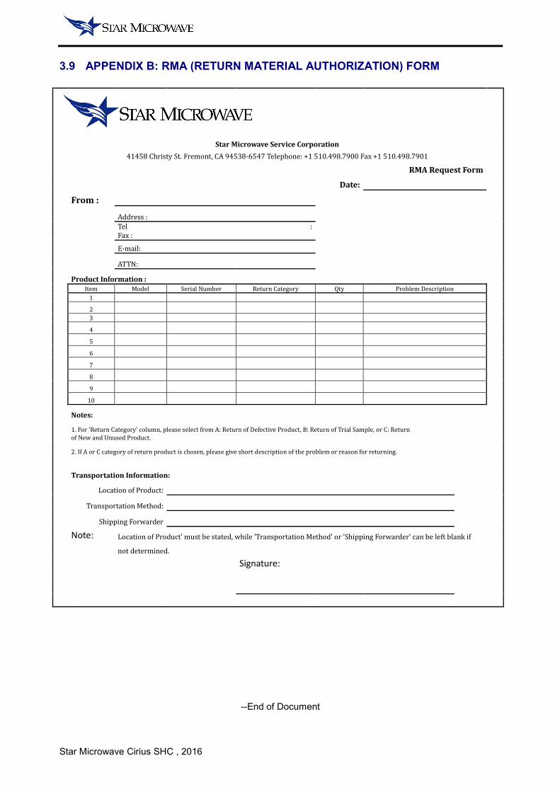
3.9 APPENDIX B: RMA (RETURN MATERIAL AUTHORIZATION) FORM
Star Microwave Service Corporation
41458 Christy St. Fremont, CA 94538-6547 Telephone: +1 510.498.7900 Fax +1 510.498.7901
RMA Request Form
Date:
From :
Address :
Tel :
Fax :
E-mail:
ATTN:
Product Information :
Item Model Serial Number Return Category Qty Problem Description
1
2
3
4
5
6
7
8
9
10
Notes:
1. For 'Return Category' column, please select from A: Return of Defective Product, B: Return of Trial Sample, or C: Return
of New and Unused Product.
2. If A or C category of return product is chosen, please give short description of the problem or reason for returning.
Transportation Information:
Location of Product:
Transportation Method:
Shipping Forwarder
Note: Location of Product' must be stated, while 'Transportation Method' or 'Shipping Forwarder' can be left blank if
not determined.
Signature:
--End of Document

Star Microwave Cirius SHC , 2016
Star Microwave Service Corporation
41458 Christy St.
Fremont, CA. 94538
Tel: +1 510.498.7900
Fax: +1 510.498.7901
Related Documents