materials Article Stability of Weld Pool and Elimination of Weld Defects in Aluminum Alloy Plasma Arc Keyhole Welding at Continuously Varying Positions Wei Cheng 1,2 , Xinqiang Ma 1,2 , Junlin Zhang 3 , Zhaoyang Yan 1,4, *, Fan Jiang 1,4 and Shujun Chen 1,4 Citation: Cheng, W.; Ma, X.; Zhang, J.; Yan, Z.; Jiang, F.; Chen, S. Stability of Weld Pool and Elimination of Weld Defects in Aluminum Alloy Plasma Arc Keyhole Welding at Continuously Varying Positions. Materials 2021, 14, 5898. https://doi.org/10.3390/ma14195898 Academic Editor: Sergei Yu Tarasov Received: 16 September 2021 Accepted: 7 October 2021 Published: 8 October 2021 Publisher’s Note: MDPI stays neutral with regard to jurisdictional claims in published maps and institutional affil- iations. Copyright: © 2021 by the authors. Licensee MDPI, Basel, Switzerland. This article is an open access article distributed under the terms and conditions of the Creative Commons Attribution (CC BY) license (https:// creativecommons.org/licenses/by/ 4.0/). 1 Faculty of Materials and Manufacturing, Beijing University of Technology, Beijing 100124, China; [email protected] (W.C.); [email protected] (X.M.); [email protected] (F.J.); [email protected] (S.C.) 2 Laser Institute, Qilu University of Technology (Shandong Academy of Sciences), Jinan 250353, China 3 Department of Spacecraft Environmental Engineering, China Academy of Space Technology, Beijing 100124, China; [email protected] 4 Engineering Research Centre of Advanced Manufacturing Technology for Automotive Components, Ministry of Education, Beijing University of Technology, Beijing 100124, China * Correspondence: [email protected] Abstract: Mathematical statistics were used to study the stability of weld pool and the elimination of weld defects in aluminum alloy plasma arc keyhole welding at continuously varying positions. In the mathematical model, the mass transfer position and spatial welding position were taken as the input, and the shape of the welded joints (symmetry/deviation) was taken as the output. The results showed that the fitted curves of the front, back, and average deviations of the weld seam were all similar to the actual curves. According to the optimum results obtained in the experiment and the mathematical models, the mass transfer position only needs to be adjusted once (near to 30 ◦ ) during the continuously varying positions, from vertical-up to horizontal welding. A breakthrough from fixed environmental variables to dynamic environmental variables in the process control of the keyhole weld pool was realized, which enabled the Al-alloy keyhole weld pool to resist the disturbance caused by gravity during variable position welding. The deviation of the welded joints of the whole plate was smaller than 0.5 mm, and the mechanical properties of the weld reached at least 85% compared to those of the base material, thus meeting the requirements of Al-alloy welding. Keywords: VPPA; weld defects; keyhole welding; aluminum alloy; tensile strength 1. Introduction As a high-performance metal for lightweight equipment, aluminum alloys are widely used in manufacturing applications in the aerospace and automotive industries due to their high specific strength and good thermal stability [1,2]. The development of Al-alloy manufacturing industries is inseparable from the processing technologies used, especially the joining process of welding [3]. Combining the advantages of high energy beams and variable polarity gas tungsten arcs, variable polarity plasma arc (VPPA) welding is a “zero-defect” process for Al-alloy welding [4–6]. However, application of VPPA is limited in vertical-up welding. Based on the specific problems of high-precision spacecraft manufacturing and the increasing size of welded structures, the development of in situ welding technologies to ensure prioritization of the posture of workpieces is urgent. VPPA vertical-up welding has several advantages: (1) the plasma jet creates a key- hole through the entire work-piece that increases the gas-liquid interface of the weld pool, thereby greatly increasing the possibility of gas escaping; (2) the keyhole weld pool avoids the high temperature zone of the heat source when the plasma jet pushes away the metal, and the gas-liquid interface of the weld pool remains within a stable temperature zone, which is favorable for ensuring that the liquid at the rear side of the weld pool Materials 2021, 14, 5898. https://doi.org/10.3390/ma14195898 https://www.mdpi.com/journal/materials

Welcome message from author
This document is posted to help you gain knowledge. Please leave a comment to let me know what you think about it! Share it to your friends and learn new things together.
Transcript
materials
Article
Stability of Weld Pool and Elimination of Weld Defects inAluminum Alloy Plasma Arc Keyhole Welding at ContinuouslyVarying Positions
Wei Cheng 1,2, Xinqiang Ma 1,2, Junlin Zhang 3, Zhaoyang Yan 1,4,*, Fan Jiang 1,4 and Shujun Chen 1,4
�����������������
Citation: Cheng, W.; Ma, X.;
Zhang, J.; Yan, Z.; Jiang, F.; Chen, S.
Stability of Weld Pool and
Elimination of Weld Defects in
Aluminum Alloy Plasma Arc Keyhole
Welding at Continuously Varying
Positions. Materials 2021, 14, 5898.
https://doi.org/10.3390/ma14195898
Academic Editor: Sergei Yu Tarasov
Received: 16 September 2021
Accepted: 7 October 2021
Published: 8 October 2021
Publisher’s Note: MDPI stays neutral
with regard to jurisdictional claims in
published maps and institutional affil-
iations.
Copyright: © 2021 by the authors.
Licensee MDPI, Basel, Switzerland.
This article is an open access article
distributed under the terms and
conditions of the Creative Commons
Attribution (CC BY) license (https://
creativecommons.org/licenses/by/
4.0/).
1 Faculty of Materials and Manufacturing, Beijing University of Technology, Beijing 100124, China;[email protected] (W.C.); [email protected] (X.M.); [email protected] (F.J.);[email protected] (S.C.)
2 Laser Institute, Qilu University of Technology (Shandong Academy of Sciences), Jinan 250353, China3 Department of Spacecraft Environmental Engineering, China Academy of Space Technology,
Beijing 100124, China; [email protected] Engineering Research Centre of Advanced Manufacturing Technology for Automotive Components,
Ministry of Education, Beijing University of Technology, Beijing 100124, China* Correspondence: [email protected]
Abstract: Mathematical statistics were used to study the stability of weld pool and the eliminationof weld defects in aluminum alloy plasma arc keyhole welding at continuously varying positions.In the mathematical model, the mass transfer position and spatial welding position were taken asthe input, and the shape of the welded joints (symmetry/deviation) was taken as the output. Theresults showed that the fitted curves of the front, back, and average deviations of the weld seam wereall similar to the actual curves. According to the optimum results obtained in the experiment andthe mathematical models, the mass transfer position only needs to be adjusted once (near to 30◦)during the continuously varying positions, from vertical-up to horizontal welding. A breakthroughfrom fixed environmental variables to dynamic environmental variables in the process control ofthe keyhole weld pool was realized, which enabled the Al-alloy keyhole weld pool to resist thedisturbance caused by gravity during variable position welding. The deviation of the welded jointsof the whole plate was smaller than 0.5 mm, and the mechanical properties of the weld reached atleast 85% compared to those of the base material, thus meeting the requirements of Al-alloy welding.
Keywords: VPPA; weld defects; keyhole welding; aluminum alloy; tensile strength
1. Introduction
As a high-performance metal for lightweight equipment, aluminum alloys are widelyused in manufacturing applications in the aerospace and automotive industries due totheir high specific strength and good thermal stability [1,2]. The development of Al-alloymanufacturing industries is inseparable from the processing technologies used, especiallythe joining process of welding [3]. Combining the advantages of high energy beamsand variable polarity gas tungsten arcs, variable polarity plasma arc (VPPA) weldingis a “zero-defect” process for Al-alloy welding [4–6]. However, application of VPPA islimited in vertical-up welding. Based on the specific problems of high-precision spacecraftmanufacturing and the increasing size of welded structures, the development of in situwelding technologies to ensure prioritization of the posture of workpieces is urgent.
VPPA vertical-up welding has several advantages: (1) the plasma jet creates a key-hole through the entire work-piece that increases the gas-liquid interface of the weldpool, thereby greatly increasing the possibility of gas escaping; (2) the keyhole weld poolavoids the high temperature zone of the heat source when the plasma jet pushes away themetal, and the gas-liquid interface of the weld pool remains within a stable temperaturezone, which is favorable for ensuring that the liquid at the rear side of the weld pool
Materials 2021, 14, 5898. https://doi.org/10.3390/ma14195898 https://www.mdpi.com/journal/materials
Materials 2021, 14, 5898 2 of 19
integrates steadily and forms a weld seam [7–10]. In nonvertical-up welding, the lack ofgravity-assisted molten pool flow can cause asymmetric metal flows [11–14], resulting inasymmetric welds and a decreased weld quality.
Studies have shown that by reasonably adjusting and matching the thermal output ofthe VPPA, the requirements of welding assemblies in multiple fixed positions (e.g., hor-izontal welding, vertical-up welding, and flat welding) can be realized, which greatlybroadens the application scope of this type of welding [11–13,15,16]. However, whenthe position is continuously changed during welding, gravity dynamically influences thekeyhole weld pool and makes it difficult to maintain the quasi-stable state of fixed positionwelding, which becomes unstable during welding, and the metal melt behind the weldpool fluctuates greatly, which can cause intermittent closure or even a lack of closure, thusresulting in uneven weld morphologies and continuous cutting [17]. In addition, in theprocess of welding, continuously changing the spatial position of the keyhole weld poolnegatively impacts the escape of gas, leading to defects in enrichment that severely affectthe strength of the entire structure.
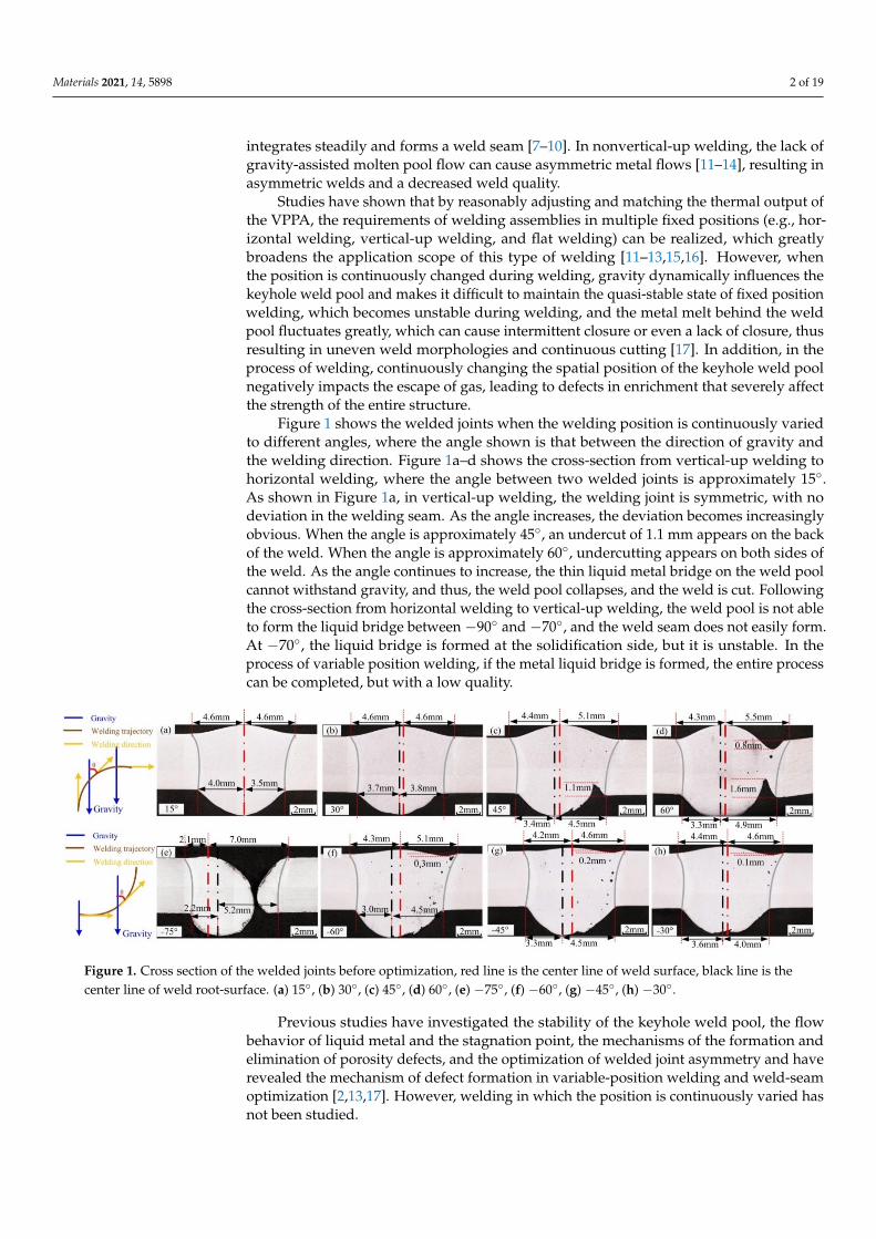
Figure 1 shows the welded joints when the welding position is continuously variedto different angles, where the angle shown is that between the direction of gravity andthe welding direction. Figure 1a–d shows the cross-section from vertical-up welding tohorizontal welding, where the angle between two welded joints is approximately 15◦.As shown in Figure 1a, in vertical-up welding, the welding joint is symmetric, with nodeviation in the welding seam. As the angle increases, the deviation becomes increasinglyobvious. When the angle is approximately 45◦, an undercut of 1.1 mm appears on the backof the weld. When the angle is approximately 60◦, undercutting appears on both sides ofthe weld. As the angle continues to increase, the thin liquid metal bridge on the weld poolcannot withstand gravity, and thus, the weld pool collapses, and the weld is cut. Followingthe cross-section from horizontal welding to vertical-up welding, the weld pool is not ableto form the liquid bridge between −90◦ and −70◦, and the weld seam does not easily form.At −70◦, the liquid bridge is formed at the solidification side, but it is unstable. In theprocess of variable position welding, if the metal liquid bridge is formed, the entire processcan be completed, but with a low quality.
Materials 2021, 14, 5898 2 of 19
avoids the high temperature zone of the heat source when the plasma jet pushes away the metal, and the gas-liquid interface of the weld pool remains within a stable temper-ature zone, which is favorable for ensuring that the liquid at the rear side of the weld pool integrates steadily and forms a weld seam [7–10]. In nonvertical-up welding, the lack of gravity-assisted molten pool flow can cause asymmetric metal flows [11–14], re-sulting in asymmetric welds and a decreased weld quality.
Studies have shown that by reasonably adjusting and matching the thermal output of the VPPA, the requirements of welding assemblies in multiple fixed positions (e.g., horizontal welding, vertical-up welding, and flat welding) can be realized, which greatly broadens the application scope of this type of welding [11–13,15,16]. However, when the position is continuously changed during welding, gravity dynamically influences the keyhole weld pool and makes it difficult to maintain the quasi-stable state of fixed posi-tion welding, which becomes unstable during welding, and the metal melt behind the weld pool fluctuates greatly, which can cause intermittent closure or even a lack of clo-sure, thus resulting in uneven weld morphologies and continuous cutting [17]. In addi-tion, in the process of welding, continuously changing the spatial position of the keyhole weld pool negatively impacts the escape of gas, leading to defects in enrichment that severely affect the strength of the entire structure.
Figure 1 shows the welded joints when the welding position is continuously varied to different angles, where the angle shown is that between the direction of gravity and the welding direction. Figure 1a–d shows the cross-section from vertical-up welding to horizontal welding, where the angle between two welded joints is approximately 15°. As shown in Figure 1a, in vertical-up welding, the welding joint is symmetric, with no de-viation in the welding seam. As the angle increases, the deviation becomes increasingly obvious. When the angle is approximately 45°, an undercut of 1.1 mm appears on the back of the weld. When the angle is approximately 60°, undercutting appears on both sides of the weld. As the angle continues to increase, the thin liquid metal bridge on the weld pool cannot withstand gravity, and thus, the weld pool collapses, and the weld is cut. Following the cross-section from horizontal welding to vertical-up welding, the weld pool is not able to form the liquid bridge between −90° and −70°, and the weld seam does not easily form. At −70°, the liquid bridge is formed at the solidification side, but it is unstable. In the process of variable position welding, if the metal liquid bridge is formed, the entire process can be completed, but with a low quality.
Figure 1. Cross section of the welded joints before optimization, red line is the center line of weld surface, black line is the center line of weld root-surface. (a) 15°, (b) 30°, (c) 45°, (d) 60°, (e) −75°, (f) −60°, (g) −45°, (h) −30°
Previous studies have investigated the stability of the keyhole weld pool, the flow behavior of liquid metal and the stagnation point, the mechanisms of the formation and elimination of porosity defects, and the optimization of welded joint asymmetry and have revealed the mechanism of defect formation in variable-position welding and
Figure 1. Cross section of the welded joints before optimization, red line is the center line of weld surface, black line is thecenter line of weld root-surface. (a) 15◦, (b) 30◦, (c) 45◦, (d) 60◦, (e) −75◦, (f) −60◦, (g) −45◦, (h) −30◦.
Previous studies have investigated the stability of the keyhole weld pool, the flowbehavior of liquid metal and the stagnation point, the mechanisms of the formation andelimination of porosity defects, and the optimization of welded joint asymmetry and haverevealed the mechanism of defect formation in variable-position welding and weld-seamoptimization [2,13,17]. However, welding in which the position is continuously varied hasnot been studied.
Materials 2021, 14, 5898 3 of 19
In this paper, the method of mathematical statistics was used. More specifically, theresponse surface methodology (RSM), based on a central composite design (CCD) andthe Design-Expert software (V12.0) were used to design the experiment and establishmathematical models to verify the applicability of continuously varying the weldingposition [18–21]. Weld undercut and cutting, porosity, and asymmetric welds are the mainproblems in VPPA Al-alloy keyhole welding when the welding position is continuouslyvaried. The formation of welds and porosity can be solved via parameter optimization,and asymmetric weld performance is currently the most challenging problem. Thus,an asymmetric welded joint was taken as the main research object in this study. In themathematical model, the mass transfer position and spatial welding position were taken asthe input, and the shape of the welded joints (symmetry/deviation) was taken as the output.Based on the mathematical model, the optimal symmetry of welded joints was determined.Finally, the process optimization strategy obtained in this study was implemented in thevariable position welding of a 5A06 Al-alloy, and the mechanical properties of the weldedjoints were analyzed. The results provide a theoretical basis for eliminating the influence ofa continuously varying gravitational force on the weld pool in variable position welding.
2. Materials and Methods
5A06 Al-alloy with good corrosion resistance, machinability, and weldability, is one ofthe mostly widely used materials for automotive, aerospace, and other industries [22,23].In this paper, plates with a size of 750 mm × 400 mm × 5 mm were selected as the basematerial (BM), which was provided by Weihai Jindi Non-ferrous Metals Co., Ltd. (Weihai,China) [23], the chemical compositions are shown in Table 1. The wire used in this paperwas ER5183 and the diameter was 1.2 mm, which has a similar chemical composition incomparison with the BM [22]; the chemical compositions are shown in Table 1.
Table 1. Chemical composition of 5A06 and ER5183 (wt.%) [22,23].
Materials Mg% Mn% Cr% Fe% Si% Zn% Cu% Al%
5A06 plate 5.80~6.80 0.50~0.80 – <0.40 ≤0.40 ≤0.20 ≤0.10 Bal.ER5183 4.30~5.00 0.50~1.00 ≤0.1 ≤0.40 ≤0.40 ≤0.25 ≤0.10 Bal.
2.1. Experimental Setup
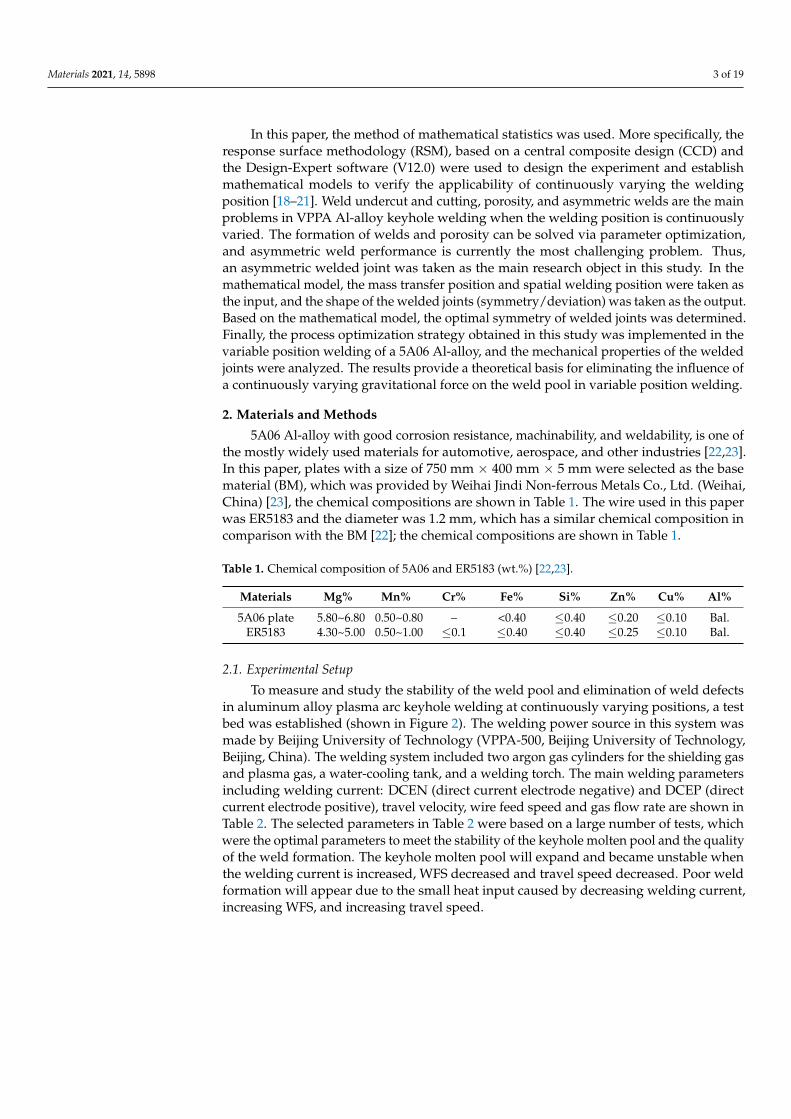
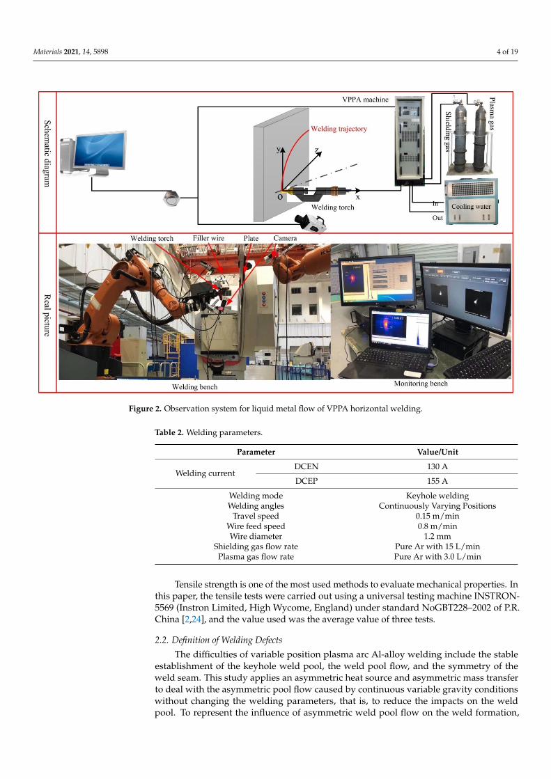
To measure and study the stability of the weld pool and elimination of weld defectsin aluminum alloy plasma arc keyhole welding at continuously varying positions, a testbed was established (shown in Figure 2). The welding power source in this system wasmade by Beijing University of Technology (VPPA-500, Beijing University of Technology,Beijing, China). The welding system included two argon gas cylinders for the shielding gasand plasma gas, a water-cooling tank, and a welding torch. The main welding parametersincluding welding current: DCEN (direct current electrode negative) and DCEP (directcurrent electrode positive), travel velocity, wire feed speed and gas flow rate are shown inTable 2. The selected parameters in Table 2 were based on a large number of tests, whichwere the optimal parameters to meet the stability of the keyhole molten pool and the qualityof the weld formation. The keyhole molten pool will expand and became unstable whenthe welding current is increased, WFS decreased and travel speed decreased. Poor weldformation will appear due to the small heat input caused by decreasing welding current,increasing WFS, and increasing travel speed.
Materials 2021, 14, 5898 4 of 19
Materials 2021, 14, 5898 4 of 19
STRON-5569 (Instron Limited, High Wycome, England) under standard NoGBT228–2002 of P.R. China [2,24], and the value used was the average value of three tests.
Figure 2. Observation system for liquid metal flow of VPPA horizontal welding.
Table 2. Welding parameters.
Parameter Value/Unit
Welding current DCEN 130 A DCEP 155 A
Welding mode Keyhole welding Welding angles Continuously Varying Positions
Travel speed 0.15 m/min Wire feed speed 0.8 m/min Wire diameter 1.2 mm
Shielding gas flow rate Pure Ar with 15 L/min Plasma gas flow rate Pure Ar with 3.0 L/min
2.2. Definition of Welding Defects The difficulties of variable position plasma arc Al-alloy welding include the stable
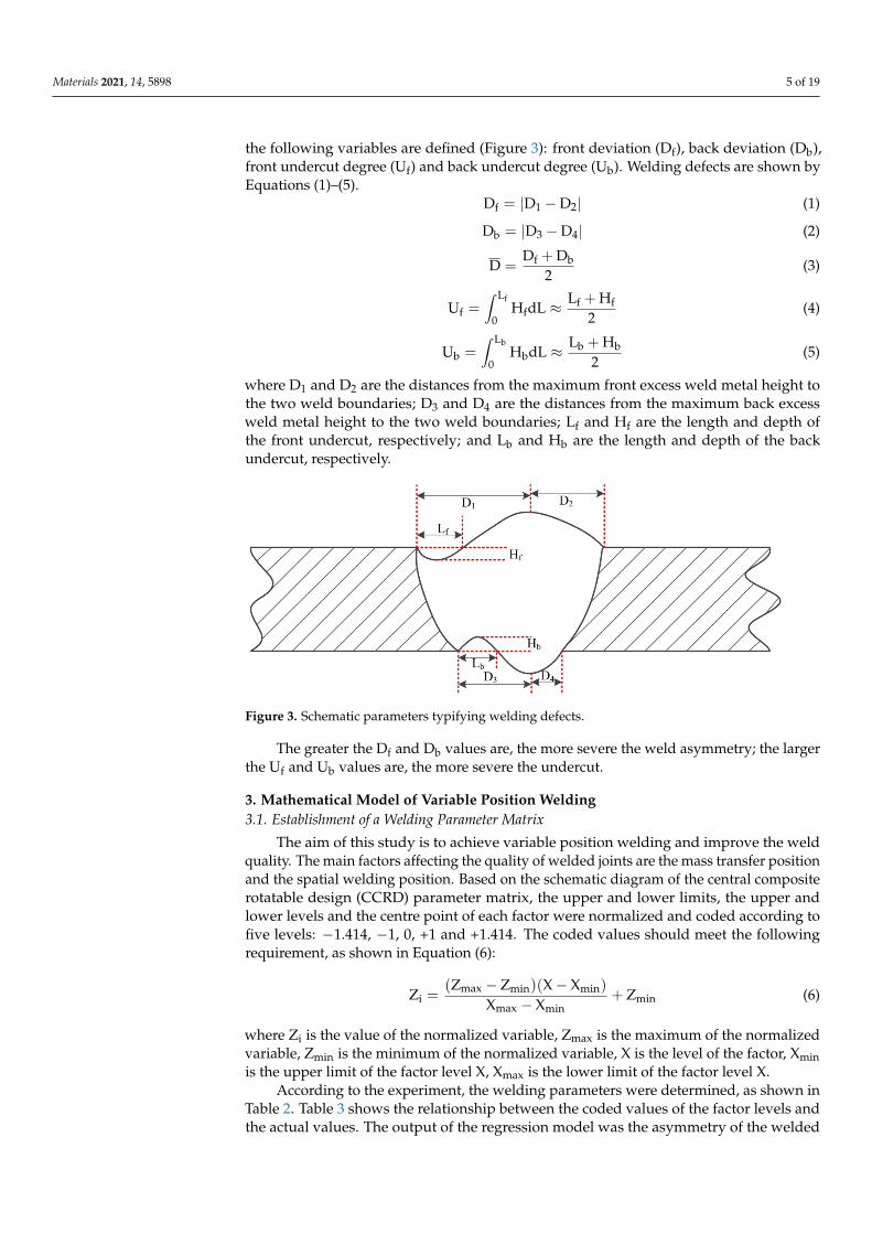
establishment of the keyhole weld pool, the weld pool flow, and the symmetry of the weld seam. This study applies an asymmetric heat source and asymmetric mass transfer to deal with the asymmetric pool flow caused by continuous variable gravity conditions without changing the welding parameters, that is, to reduce the impacts on the weld pool. To represent the influence of asymmetric weld pool flow on the weld formation, the following variables are defined (Figure 3): front deviation (Df), back deviation (Db), front undercut degree (Uf) and back undercut degree (Ub). Welding defects are shown by Equations (1)–(5).
Figure 2. Observation system for liquid metal flow of VPPA horizontal welding.
Table 2. Welding parameters.
Parameter Value/Unit
Welding currentDCEN 130 A
DCEP 155 A
Welding mode Keyhole weldingWelding angles Continuously Varying Positions
Travel speed 0.15 m/minWire feed speed 0.8 m/minWire diameter 1.2 mm
Shielding gas flow rate Pure Ar with 15 L/minPlasma gas flow rate Pure Ar with 3.0 L/min
Tensile strength is one of the most used methods to evaluate mechanical properties. Inthis paper, the tensile tests were carried out using a universal testing machine INSTRON-5569 (Instron Limited, High Wycome, England) under standard NoGBT228–2002 of P.R.China [2,24], and the value used was the average value of three tests.
2.2. Definition of Welding Defects
The difficulties of variable position plasma arc Al-alloy welding include the stableestablishment of the keyhole weld pool, the weld pool flow, and the symmetry of theweld seam. This study applies an asymmetric heat source and asymmetric mass transferto deal with the asymmetric pool flow caused by continuous variable gravity conditionswithout changing the welding parameters, that is, to reduce the impacts on the weldpool. To represent the influence of asymmetric weld pool flow on the weld formation,
Materials 2021, 14, 5898 5 of 19
the following variables are defined (Figure 3): front deviation (Df), back deviation (Db),front undercut degree (Uf) and back undercut degree (Ub). Welding defects are shown byEquations (1)–(5).
Df = |D1 −D2| (1)
Db = |D3 −D4| (2)
D =Df + Db
2(3)
Uf =∫ Lf
0HfdL ≈ Lf + Hf
2(4)
Ub =∫ Lb
0HbdL ≈ Lb + Hb
2(5)
where D1 and D2 are the distances from the maximum front excess weld metal height tothe two weld boundaries; D3 and D4 are the distances from the maximum back excessweld metal height to the two weld boundaries; Lf and Hf are the length and depth ofthe front undercut, respectively; and Lb and Hb are the length and depth of the backundercut, respectively.
Materials 2021, 14, 5898 5 of 19
f 1 2D D D= − (1)
b 3 4D D D= − (2)
f bD + DD2
= (3)
fL f ff f0
L + HU H dL2
= ≈ (4)
bL b bb b0
L + HU H dL2
= ≈ (5)
where D1 and D2 are the distances from the maximum front excess weld metal height to the two weld boundaries; D3 and D4 are the distances from the maximum back excess weld metal height to the two weld boundaries; Lf and Hf are the length and depth of the front undercut, respectively; and Lb and Hb are the length and depth of the back under-cut, respectively.
The greater the Df and Db values are, the more severe the weld asymmetry; the larger the Uf and Ub values are, the more severe the undercut.
Figure 3. Schematic parameters typifying welding defects.
3. Mathematical Model of Variable Position Welding 3.1. Establishment of a Welding Parameter Matrix
The aim of this study is to achieve variable position welding and improve the weld quality. The main factors affecting the quality of welded joints are the mass transfer po-sition and the spatial welding position. Based on the schematic diagram of the central composite rotatable design (CCRD) parameter matrix, the upper and lower limits, the upper and lower levels and the centre point of each factor were normalized and coded according to five levels: −1.414, −1, 0, +1 and +1.414. The coded values should meet the following requirement, as shown in Equation (6):
( ) ( )max min mini min
max min
Z - Z X- XZ Z
X - X= + (6)
where Zi is the value of the normalized variable, Zmax is the maximum of the normalized variable, Zmin is the minimum of the normalized variable, X is the level of the factor, Xmin is the upper limit of the factor level X, Xmax is the lower limit of the factor level X.
According to the experiment, the welding parameters were determined, as shown in Table 2. Table 3 shows the relationship between the coded values of the factor levels and the actual values. The output of the regression model was the asymmetry of the welded joints, i.e., the deviation of the front excess weld metal height, the deviation of the back excess weld metal height, and the average deviation.
Figure 3. Schematic parameters typifying welding defects.
The greater the Df and Db values are, the more severe the weld asymmetry; the largerthe Uf and Ub values are, the more severe the undercut.
3. Mathematical Model of Variable Position Welding3.1. Establishment of a Welding Parameter Matrix
The aim of this study is to achieve variable position welding and improve the weldquality. The main factors affecting the quality of welded joints are the mass transfer positionand the spatial welding position. Based on the schematic diagram of the central compositerotatable design (CCRD) parameter matrix, the upper and lower limits, the upper andlower levels and the centre point of each factor were normalized and coded according tofive levels: −1.414, −1, 0, +1 and +1.414. The coded values should meet the followingrequirement, as shown in Equation (6):
Zi =(Zmax − Zmin)(X− Xmin)
Xmax − Xmin+ Zmin (6)
where Zi is the value of the normalized variable, Zmax is the maximum of the normalizedvariable, Zmin is the minimum of the normalized variable, X is the level of the factor, Xminis the upper limit of the factor level X, Xmax is the lower limit of the factor level X.
According to the experiment, the welding parameters were determined, as shown inTable 2. Table 3 shows the relationship between the coded values of the factor levels andthe actual values. The output of the regression model was the asymmetry of the welded
Materials 2021, 14, 5898 6 of 19
joints, i.e., the deviation of the front excess weld metal height, the deviation of the backexcess weld metal height, and the average deviation.
Table 3. Coded values and factor levels.
Factor UnitValue
−1.414 −1 0 1 1.414
Spatial welding position ◦ 90 75 45 30 0Mass transfer position mm −0.5 0 1.5 2.5 3.5
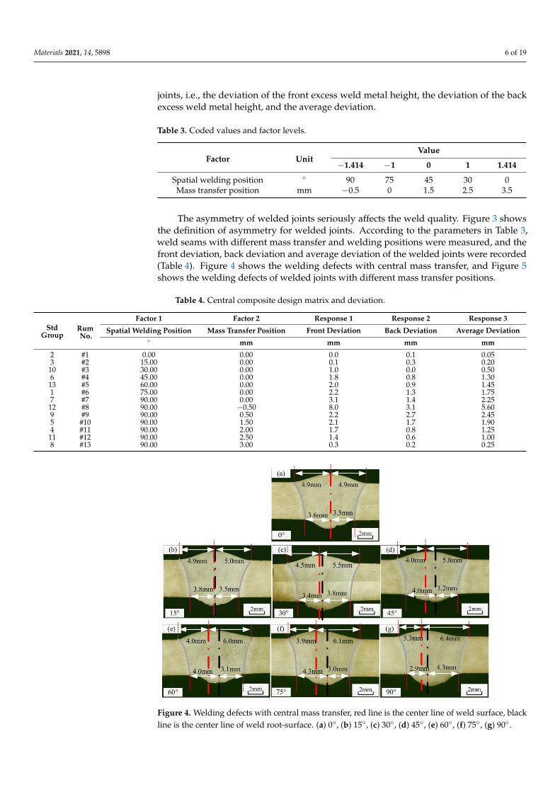
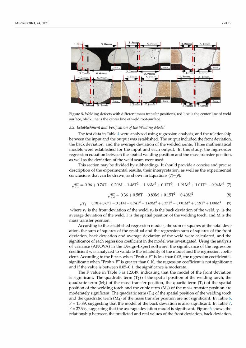
The asymmetry of welded joints seriously affects the weld quality. Figure 3 showsthe definition of asymmetry for welded joints. According to the parameters in Table 3,weld seams with different mass transfer and welding positions were measured, and thefront deviation, back deviation and average deviation of the welded joints were recorded(Table 4). Figure 4 shows the welding defects with central mass transfer, and Figure 5shows the welding defects of welded joints with different mass transfer positions.
Table 4. Central composite design matrix and deviation.
StdGroup
RumNo.
Factor 1 Factor 2 Response 1 Response 2 Response 3
Spatial Welding Position Mass Transfer Position Front Deviation Back Deviation Average Deviation◦ mm mm mm mm
2 #1 0.00 0.00 0.0 0.1 0.053 #2 15.00 0.00 0.1 0.3 0.2010 #3 30.00 0.00 1.0 0.0 0.506 #4 45.00 0.00 1.8 0.8 1.3013 #5 60.00 0.00 2.0 0.9 1.451 #6 75.00 0.00 2.2 1.3 1.757 #7 90.00 0.00 3.1 1.4 2.2512 #8 90.00 −0.50 8.0 3.1 5.609 #9 90.00 0.50 2.2 2.7 2.455 #10 90.00 1.50 2.1 1.7 1.904 #11 90.00 2.00 1.7 0.8 1.2511 #12 90.00 2.50 1.4 0.6 1.008 #13 90.00 3.00 0.3 0.2 0.25
Materials 2021, 14, 5898 6 of 19
Table 3. Coded values and factor levels.
Factor Unit Value
−1.414 −1 0 1 1.414 Spatial welding position ° 90 75 45 30 0 Mass transfer position mm −0.5 0 1.5 2.5 3.5
The asymmetry of welded joints seriously affects the weld quality. Figure 3 shows the definition of asymmetry for welded joints. According to the parameters in Table 3, weld seams with different mass transfer and welding positions were measured, and the front deviation, back deviation and average deviation of the welded joints were record-ed (Table 4). Figure 4 shows the welding defects with central mass transfer, and Figure 5 shows the welding defects of welded joints with different mass transfer positions.
Figure 4. Welding defects with central mass transfer, red line is the center line of weld surface, black line is the center line of weld root-surface. (a) 0°, (b) 15°, (c) 30°, (d) 45°, (e) 60°, (f) 75°, (g) 90°
Figure 5. Welding defects with different mass transfer positions, red line is the center line of weld surface, black line is the center line of weld root-surface.(a) −0.5mm, (b) 0mm, (c) 0.5mm, (d) 1.3mm, (e) 2.5mm , (f) 3.5mm
Figure 4. Welding defects with central mass transfer, red line is the center line of weld surface, blackline is the center line of weld root-surface. (a) 0◦, (b) 15◦, (c) 30◦, (d) 45◦, (e) 60◦, (f) 75◦, (g) 90◦.
Materials 2021, 14, 5898 7 of 19
Materials 2021, 14, 5898 6 of 19
Table 3. Coded values and factor levels.
Factor Unit Value
−1.414 −1 0 1 1.414 Spatial welding position ° 90 75 45 30 0 Mass transfer position mm −0.5 0 1.5 2.5 3.5
The asymmetry of welded joints seriously affects the weld quality. Figure 3 shows the definition of asymmetry for welded joints. According to the parameters in Table 3, weld seams with different mass transfer and welding positions were measured, and the front deviation, back deviation and average deviation of the welded joints were record-ed (Table 4). Figure 4 shows the welding defects with central mass transfer, and Figure 5 shows the welding defects of welded joints with different mass transfer positions.
Figure 4. Welding defects with central mass transfer, red line is the center line of weld surface, black line is the center line of weld root-surface. (a) 0°, (b) 15°, (c) 30°, (d) 45°, (e) 60°, (f) 75°, (g) 90°
Figure 5. Welding defects with different mass transfer positions, red line is the center line of weld surface, black line is the center line of weld root-surface.(a) −0.5mm, (b) 0mm, (c) 0.5mm, (d) 1.3mm, (e) 2.5mm , (f) 3.5mm
Figure 5. Welding defects with different mass transfer positions, red line is the center line of weldsurface, black line is the center line of weld root-surface.
3.2. Establishment and Verification of the Welding Model
The test data in Table 4 were analyzed using regression analysis, and the relationshipbetween the input and the output was established. The output included the front deviation,the back deviation, and the average deviation of the welded joints. Three mathematicalmodels were established for the input and each output. In this study, the high-orderregression equation between the spatial welding position and the mass transfer position,as well as the deviation of the weld seam were used:
This section may be divided by subheadings. It should provide a concise and precisedescription of the experimental results, their interpretation, as well as the experimentalconclusions that can be drawn, as shown in Equations (7)–(9).
√y1 = 0.96+ 0.74T− 0.20M− 1.46T2− 1.66M2 + 0.17T3− 1.91M3 + 1.01T4 + 0.94M4 (7)
√y2 = 0.36 + 0.58T− 0.89M + 0.15T2 − 0.40M2 (8)
√y3 = 0.78 + 0.67T− 0.81M− 0.74T2 − 1.69M2 + 0.27T3 − 0.001M3 + 0.59T4 + 1.88M4 (9)
where y1 is the front deviation of the weld, y2 is the back deviation of the weld, y3 is theaverage deviation of the weld, T is the spatial position of the welding torch, and M is themass transfer position.
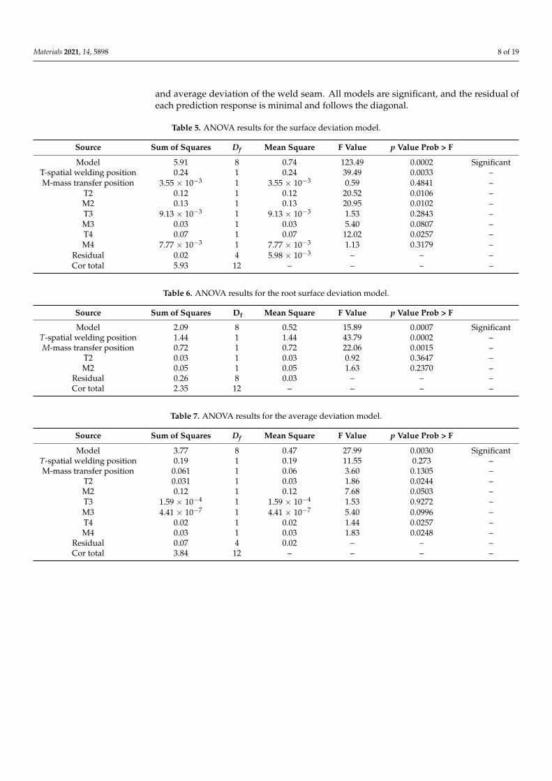
According to the established regression models, the sum of squares of the total devi-ation, the sum of squares of the residual and the regression sum of squares of the frontdeviation, back deviation and average deviation of the weld were calculated, and thesignificance of each regression coefficient in the model was investigated. Using the analysisof variance (ANOVA) in the Design-Expert software, the significance of the regressioncoefficient was analyzed to validate the reliability of the model and the regression coeffi-cient. According to the F-test, when “Prob > F” is less than 0.05, the regression coefficient issignificant; when “Prob > F” is greater than 0.10, the regression coefficient is not significant;and if the value is between 0.05–0.1, the significance is moderate.
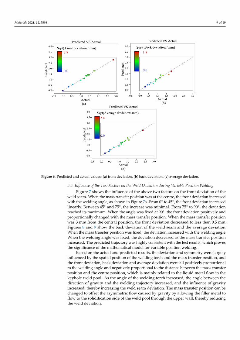
The F value in Table 5 is 123.49, indicating that the model of the front deviationis significant. The quadratic term (T2) of the spatial position of the welding torch, thequadratic term (M2) of the mass transfer position, the quartic term (T4) of the spatialposition of the welding torch and the cubic term (M3) of the mass transfer position aremoderately significant. The quadratic term (T3) of the spatial position of the welding torchand the quadratic term (M4) of the mass transfer position are not significant. In Table 6,F = 15.89, suggesting that the model of the back deviation is also significant. In Table 7,F = 27.99, suggesting that the average deviation model is significant. Figure 6 shows therelationship between the predicted and real values of the front deviation, back deviation,
Materials 2021, 14, 5898 8 of 19
and average deviation of the weld seam. All models are significant, and the residual ofeach prediction response is minimal and follows the diagonal.
Table 5. ANOVA results for the surface deviation model.
Source Sum of Squares Df Mean Square F Value p Value Prob > F
Model 5.91 8 0.74 123.49 0.0002 SignificantT-spatial welding position 0.24 1 0.24 39.49 0.0033 –M-mass transfer position 3.55 × 10⁻³ 1 3.55 × 10⁻³ 0.59 0.4841 –
T2 0.12 1 0.12 20.52 0.0106 –M2 0.13 1 0.13 20.95 0.0102 –T3 9.13 × 10⁻³ 1 9.13 × 10⁻³ 1.53 0.2843 –M3 0.03 1 0.03 5.40 0.0807 –T4 0.07 1 0.07 12.02 0.0257 –M4 7.77 × 10⁻³ 1 7.77 × 10⁻³ 1.13 0.3179 –
Residual 0.02 4 5.98 × 10⁻³ – – –Cor total 5.93 12 – – – –
Table 6. ANOVA results for the root surface deviation model.
Source Sum of Squares Df Mean Square F Value p Value Prob > F
Model 2.09 8 0.52 15.89 0.0007 SignificantT-spatial welding position 1.44 1 1.44 43.79 0.0002 –M-mass transfer position 0.72 1 0.72 22.06 0.0015 –
T2 0.03 1 0.03 0.92 0.3647 –M2 0.05 1 0.05 1.63 0.2370 –
Residual 0.26 8 0.03 – – –Cor total 2.35 12 – – – –
Table 7. ANOVA results for the average deviation model.
Source Sum of Squares Df Mean Square F Value p Value Prob > F
Model 3.77 8 0.47 27.99 0.0030 SignificantT-spatial welding position 0.19 1 0.19 11.55 0.273 –M-mass transfer position 0.061 1 0.06 3.60 0.1305 –
T2 0.031 1 0.03 1.86 0.0244 –M2 0.12 1 0.12 7.68 0.0503 –T3 1.59 × 10⁻⁴ 1 1.59 × 10⁻⁴ 1.53 0.9272 –M3 4.41 × 10⁻⁷ 1 4.41 × 10⁻⁷ 5.40 0.0996 –T4 0.02 1 0.02 1.44 0.0257 –M4 0.03 1 0.03 1.83 0.0248 –
Residual 0.07 4 0.02 – – –Cor total 3.84 12 – – – –
Materials 2021, 14, 5898 9 of 19Materials 2021, 14, 5898 9 of 19
Figure 6. Predicted and actual values: (a) front deviation, (b) back deviation, (c) average deviation.
3.3. Influence of the Two Factors on the Weld Deviation during Variable Position Welding Figure 7 shows the influence of the above two factors on the front deviation of the
weld seam. When the mass transfer position was at the centre, the front deviation in-creased with the welding angle, as shown in Figure 7a. From 0° to 45°, the front devia-tion increased linearly. Between 45° and 75°, the increase was minimal. From 75° to 90°, the deviation reached its maximum. When the angle was fixed at 90°, the front deviation positively and proportionally changed with the mass transfer position. When the mass transfer position was 3 mm from the central position, the front deviation decreased to less than 0.5 mm. Figures 8 and 9 show the back deviation of the weld seam and the av-erage deviation. When the mass transfer position was fixed, the deviation increased with the welding angle. When the welding angle was fixed, the deviation decreased as the mass transfer position increased. The predicted trajectory was highly consistent with the test results, which proves the significance of the mathematical model for variable posi-tion welding.
Based on the actual and predicted results, the deviation and symmetry were largely influenced by the spatial position of the welding torch and the mass transfer position, and the front deviation, back deviation and average deviation were all positively pro-portional to the welding angle and negatively proportional to the distance between the mass transfer position and the centre position, which is mainly related to the liquid met-al flow in the keyhole weld pool. As the angle of the welding torch increased, the angle between the direction of gravity and the welding trajectory increased, and the influence of gravity increased, thereby increasing the weld seam deviation. The mass transfer po-sition can be changed to offset the asymmetric flow caused by gravity by allowing the filler metal to flow to the solidification side of the weld pool through the upper wall, thereby reducing the weld deviation.
Figure 6. Predicted and actual values: (a) front deviation, (b) back deviation, (c) average deviation.
3.3. Influence of the Two Factors on the Weld Deviation during Variable Position Welding
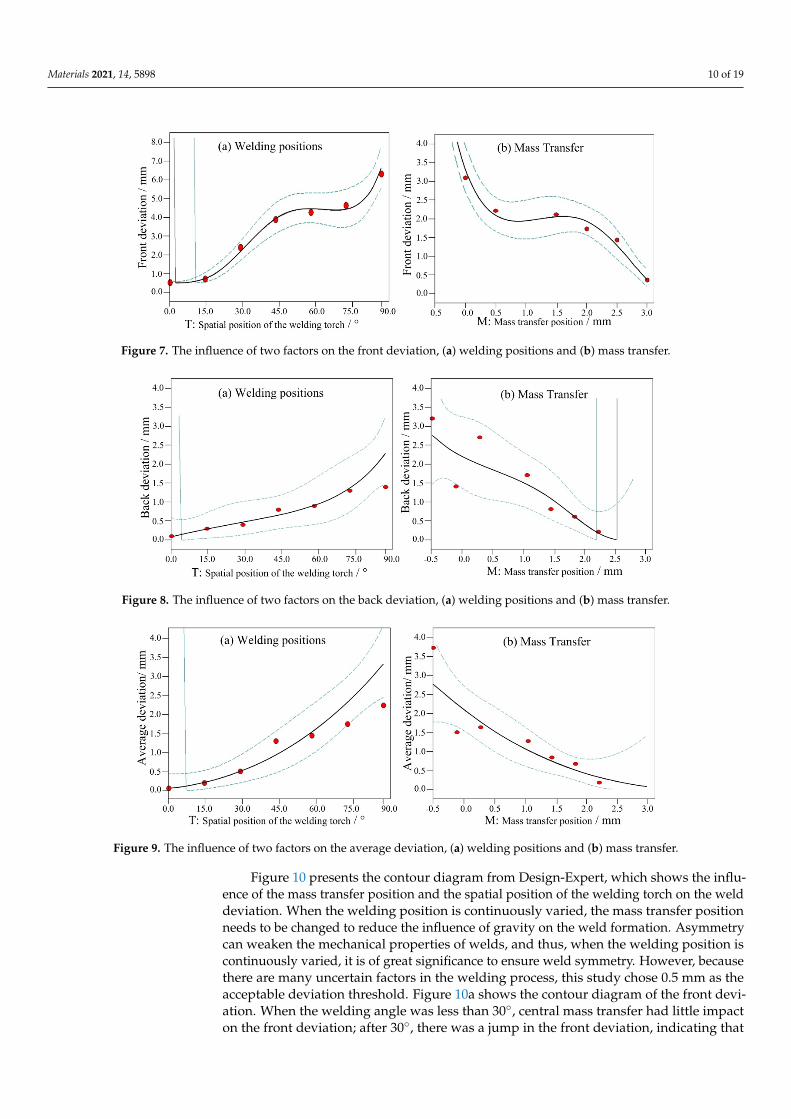
Figure 7 shows the influence of the above two factors on the front deviation of theweld seam. When the mass transfer position was at the centre, the front deviation increasedwith the welding angle, as shown in Figure 7a. From 0◦ to 45◦, the front deviation increasedlinearly. Between 45◦ and 75◦, the increase was minimal. From 75◦ to 90◦, the deviationreached its maximum. When the angle was fixed at 90◦, the front deviation positively andproportionally changed with the mass transfer position. When the mass transfer positionwas 3 mm from the central position, the front deviation decreased to less than 0.5 mm.Figures 8 and 9 show the back deviation of the weld seam and the average deviation.When the mass transfer position was fixed, the deviation increased with the welding angle.When the welding angle was fixed, the deviation decreased as the mass transfer positionincreased. The predicted trajectory was highly consistent with the test results, which provesthe significance of the mathematical model for variable position welding.
Based on the actual and predicted results, the deviation and symmetry were largelyinfluenced by the spatial position of the welding torch and the mass transfer position, andthe front deviation, back deviation and average deviation were all positively proportionalto the welding angle and negatively proportional to the distance between the mass transferposition and the centre position, which is mainly related to the liquid metal flow in thekeyhole weld pool. As the angle of the welding torch increased, the angle between thedirection of gravity and the welding trajectory increased, and the influence of gravityincreased, thereby increasing the weld seam deviation. The mass transfer position can bechanged to offset the asymmetric flow caused by gravity by allowing the filler metal toflow to the solidification side of the weld pool through the upper wall, thereby reducingthe weld deviation.
Materials 2021, 14, 5898 10 of 19Materials 2021, 14, 5898 10 of 19
Figure 7. The influence of two factors on the front deviation, (a) welding positions and (b) mass transfer.
Figure 8. The influence of two factors on the back deviation, (a) welding positions and (b) mass transfer.
Figure 9. The influence of two factors on the average deviation, (a) welding positions and (b) mass transfer.
Figure 10 presents the contour diagram from Design-Expert, which shows the in-fluence of the mass transfer position and the spatial position of the welding torch on the weld deviation. When the welding position is continuously varied, the mass transfer po-sition needs to be changed to reduce the influence of gravity on the weld formation. Asymmetry can weaken the mechanical properties of welds, and thus, when the weld-ing position is continuously varied, it is of great significance to ensure weld symmetry. However, because there are many uncertain factors in the welding process, this study chose 0.5 mm as the acceptable deviation threshold. Figure 10a shows the contour dia-gram of the front deviation. When the welding angle was less than 30°, central mass transfer had little impact on the front deviation; after 30°, there was a jump in the front deviation, indicating that maintaining central mass transfer can seriously affect the weld symmetry. According to the mathematical model, to keep the welded joints symmetric
Figure 7. The influence of two factors on the front deviation, (a) welding positions and (b) mass transfer.
Materials 2021, 14, 5898 10 of 19
Figure 7. The influence of two factors on the front deviation, (a) welding positions and (b) mass transfer.
Figure 8. The influence of two factors on the back deviation, (a) welding positions and (b) mass transfer.
Figure 9. The influence of two factors on the average deviation, (a) welding positions and (b) mass transfer.
Figure 10 presents the contour diagram from Design-Expert, which shows the in-fluence of the mass transfer position and the spatial position of the welding torch on the weld deviation. When the welding position is continuously varied, the mass transfer po-sition needs to be changed to reduce the influence of gravity on the weld formation. Asymmetry can weaken the mechanical properties of welds, and thus, when the weld-ing position is continuously varied, it is of great significance to ensure weld symmetry. However, because there are many uncertain factors in the welding process, this study chose 0.5 mm as the acceptable deviation threshold. Figure 10a shows the contour dia-gram of the front deviation. When the welding angle was less than 30°, central mass transfer had little impact on the front deviation; after 30°, there was a jump in the front deviation, indicating that maintaining central mass transfer can seriously affect the weld symmetry. According to the mathematical model, to keep the welded joints symmetric
Figure 8. The influence of two factors on the back deviation, (a) welding positions and (b) mass transfer.
Materials 2021, 14, 5898 10 of 19
Figure 7. The influence of two factors on the front deviation, (a) welding positions and (b) mass transfer.
Figure 8. The influence of two factors on the back deviation, (a) welding positions and (b) mass transfer.
Figure 9. The influence of two factors on the average deviation, (a) welding positions and (b) mass transfer.
Figure 10 presents the contour diagram from Design-Expert, which shows the in-fluence of the mass transfer position and the spatial position of the welding torch on the weld deviation. When the welding position is continuously varied, the mass transfer po-sition needs to be changed to reduce the influence of gravity on the weld formation. Asymmetry can weaken the mechanical properties of welds, and thus, when the weld-ing position is continuously varied, it is of great significance to ensure weld symmetry. However, because there are many uncertain factors in the welding process, this study chose 0.5 mm as the acceptable deviation threshold. Figure 10a shows the contour dia-gram of the front deviation. When the welding angle was less than 30°, central mass transfer had little impact on the front deviation; after 30°, there was a jump in the front deviation, indicating that maintaining central mass transfer can seriously affect the weld symmetry. According to the mathematical model, to keep the welded joints symmetric
Figure 9. The influence of two factors on the average deviation, (a) welding positions and (b) mass transfer.
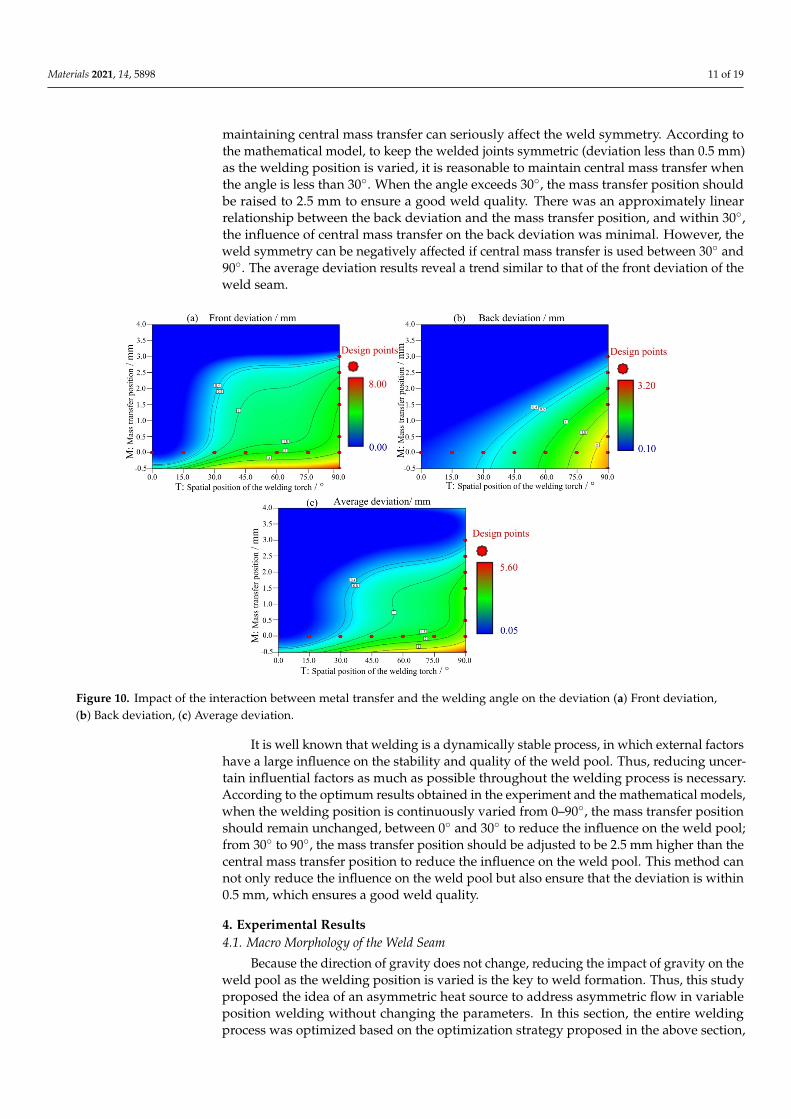
Figure 10 presents the contour diagram from Design-Expert, which shows the influ-ence of the mass transfer position and the spatial position of the welding torch on the welddeviation. When the welding position is continuously varied, the mass transfer positionneeds to be changed to reduce the influence of gravity on the weld formation. Asymmetrycan weaken the mechanical properties of welds, and thus, when the welding position iscontinuously varied, it is of great significance to ensure weld symmetry. However, becausethere are many uncertain factors in the welding process, this study chose 0.5 mm as theacceptable deviation threshold. Figure 10a shows the contour diagram of the front devi-ation. When the welding angle was less than 30◦, central mass transfer had little impacton the front deviation; after 30◦, there was a jump in the front deviation, indicating that
Materials 2021, 14, 5898 11 of 19
maintaining central mass transfer can seriously affect the weld symmetry. According tothe mathematical model, to keep the welded joints symmetric (deviation less than 0.5 mm)as the welding position is varied, it is reasonable to maintain central mass transfer whenthe angle is less than 30◦. When the angle exceeds 30◦, the mass transfer position shouldbe raised to 2.5 mm to ensure a good weld quality. There was an approximately linearrelationship between the back deviation and the mass transfer position, and within 30◦,the influence of central mass transfer on the back deviation was minimal. However, theweld symmetry can be negatively affected if central mass transfer is used between 30◦ and90◦. The average deviation results reveal a trend similar to that of the front deviation of theweld seam.
Materials 2021, 14, 5898 11 of 19
(deviation less than 0.5 mm) as the welding position is varied, it is reasonable to main-tain central mass transfer when the angle is less than 30°. When the angle exceeds 30°, the mass transfer position should be raised to 2.5 mm to ensure a good weld quality. There was an approximately linear relationship between the back deviation and the mass transfer position, and within 30°, the influence of central mass transfer on the back deviation was minimal. However, the weld symmetry can be negatively affected if cen-tral mass transfer is used between 30° and 90°. The average deviation results reveal a trend similar to that of the front deviation of the weld seam.
Figure 10. Impact of the interaction between metal transfer and the welding angle on the deviation (a) Front deviation, (b) Back deviation, (c) Average deviation.
It is well known that welding is a dynamically stable process, in which external factors have a large influence on the stability and quality of the weld pool. Thus, reduc-ing uncertain influential factors as much as possible throughout the welding process is necessary. According to the optimum results obtained in the experiment and the math-ematical models, when the welding position is continuously varied from 0–90°, the mass transfer position should remain unchanged, between 0° and 30° to reduce the influence on the weld pool; from 30° to 90°, the mass transfer position should be adjusted to be 2.5 mm higher than the central mass transfer position to reduce the influence on the weld pool. This method can not only reduce the influence on the weld pool but also ensure that the deviation is within 0.5 mm, which ensures a good weld quality.
4. Experimental Results 4.1. Macro Morphology of the Weld Seam
Because the direction of gravity does not change, reducing the impact of gravity on the weld pool as the welding position is varied is the key to weld formation. Thus, this study proposed the idea of an asymmetric heat source to address asymmetric flow in variable position welding without changing the parameters. In this section, the entire welding process was optimized based on the optimization strategy proposed in the above section, that is, by using an asymmetric heat source and asymmetric mass transfer to reduce the asymmetric weld pool flow caused by gravity during variable position
Figure 10. Impact of the interaction between metal transfer and the welding angle on the deviation (a) Front deviation,(b) Back deviation, (c) Average deviation.
It is well known that welding is a dynamically stable process, in which external factorshave a large influence on the stability and quality of the weld pool. Thus, reducing uncer-tain influential factors as much as possible throughout the welding process is necessary.According to the optimum results obtained in the experiment and the mathematical models,when the welding position is continuously varied from 0–90◦, the mass transfer positionshould remain unchanged, between 0◦ and 30◦ to reduce the influence on the weld pool;from 30◦ to 90◦, the mass transfer position should be adjusted to be 2.5 mm higher than thecentral mass transfer position to reduce the influence on the weld pool. This method cannot only reduce the influence on the weld pool but also ensure that the deviation is within0.5 mm, which ensures a good weld quality.
4. Experimental Results4.1. Macro Morphology of the Weld Seam
Because the direction of gravity does not change, reducing the impact of gravity on theweld pool as the welding position is varied is the key to weld formation. Thus, this studyproposed the idea of an asymmetric heat source to address asymmetric flow in variableposition welding without changing the parameters. In this section, the entire weldingprocess was optimized based on the optimization strategy proposed in the above section,
Materials 2021, 14, 5898 12 of 19
that is, by using an asymmetric heat source and asymmetric mass transfer to reduce theasymmetric weld pool flow caused by gravity during variable position welding. The resultsprovide technical support for the actual application of variable position welding.
The specific steps of applying the asymmetric heat source are as follows: The heatsource is at an angle (15◦) relative to the thickness direction during variable positionwelding, which is the angle between the axis of the welding torch and the welding direction,and the welding torch pushes the liquid metal and moves it forward. The asymmetric heatsource, without changing the welding parameters, can ensure keyholing on the moltenside, reduce the curvature radius of the hole on the solidification side, and enhance thesurface tension between the radial force of the plasma arc and the liquid metal, whichreduces the influence of gravity on the weld pool flow and the direct influence of the axialforce of the arc. In addition, the large thermal gradient on the solidification side ensuresthat the metal easily solidifies and forms the welds, providing an optimal heat source forvariable position welding. The asymmetric heat source enables the welding position to bevaried with a reliable and stable thermal environment, yet the asymmetric flow caused bythe change in the direction of gravity is not changed.
The specific steps of asymmetric mass transfer are as follows: Asymmetric weldpool flow can result in an uneven thermal distribution, thereby affecting the mechanicalproperties of welded joints. During variable position welding, liquid metal with a hightemperature flows to the lower side of the weld pool, causing a difference in the thermalcycle curve between the two sides of the weld, and the highest temperature of the thermalcycle on the lower side is higher than that on the upper side of the weld pool. Therefore,during variable position welding, asymmetric mass transfer is introduced to solve thisproblem. The wires should be higher than the stagnation point on the molten side of theweld pool so that most molten metal flows from the upper wall of the weld pool to thesolidification side, thereby reducing the asymmetric flow due to the influence of gravityand reducing the difference in the thermal cycle on both sides of the weld. The followingresults were obtained. According to the optimum results obtained in the experiment andthe mathematical model, as the welding position continuously varies from 0–90◦, the masstransfer position should remain unchanged between 0◦ and 30◦ to reduce the influences onthe weld pool; from 30◦ to 90◦, the mass transfer position should be adjusted to be 2.5 mmhigher than the central mass transfer position to reduce the influence on the weld pool.This method can not only reduce the influence on the weld pool but also ensure that thedeviation is within 0.5 mm, which ensures good weld quality.
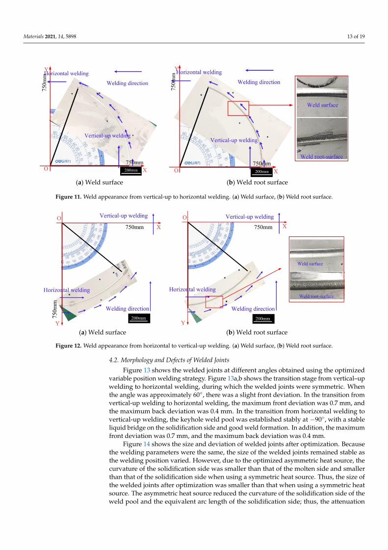
Figure 11 shows the results of variable position welding for a 5 mm plate from avertical-up to a horizontal position using the asymmetric heat source and the optimizedmass transfer position. The welding started with the stable vertical-up welding andended when the angle between the direction of gravity and the welding direction was 70◦.During the entire welding process, the weld appearance was good, without obvious defects.Figure 12 shows the results of variable position welding for 5 mm and 3 mm plates from avertical-up to a horizontal position using the asymmetric heat source and asymmetric masstransfer. As Figure 12 shows, in the initial stage, the liquid bridge was stably establishedon the solidification side of the weld pool, and the weld appearance was good.
Materials 2021, 14, 5898 13 of 19Materials 2021, 14, 5898 13 of 19
(a) Weld surface (b) Weld root surface
Figure 11. Weld appearance from vertical-up to horizontal welding. (a) Weld surface, (b) Weld root surface
(a) Weld surface (b) Weld root surface
Figure 12. Weld appearance from horizontal to vertical-up welding. (a) Weld surface, (b) Weld root surface
4.2. Morphology and Defects of Welded Joints Figure 13 shows the welded joints at different angles obtained using the optimized
variable position welding strategy. Figure 13a,b shows the transition stage from vertical–up welding to horizontal welding, during which the welded joints were symmetric. When the angle was approximately 60°, there was a slight front deviation. In the transi-tion from vertical-up welding to horizontal welding, the maximum front deviation was 0.7 mm, and the maximum back deviation was 0.4 mm. In the transition from horizontal welding to vertical-up welding, the keyhole weld pool was established stably at −90°, with a stable liquid bridge on the solidification side and good weld formation. In addi-tion, the maximum front deviation was 0.7 mm, and the maximum back deviation was 0.4 mm.
Figure 14 shows the size and deviation of welded joints after optimization. Because the welding parameters were the same, the size of the welded joints remained stable as the welding position varied. However, due to the optimized asymmetric heat source, the curvature of the solidification side was smaller than that of the molten side and smaller than that of the solidification side when using a symmetric heat source. Thus, the size of the welded joints after optimization was smaller than that when using a symmetric heat source. The asymmetric heat source reduced the curvature of the solidification side of the weld pool and the equivalent arc length of the solidification side; thus, the attenua-
Figure 11. Weld appearance from vertical-up to horizontal welding. (a) Weld surface, (b) Weld root surface.
Materials 2021, 14, 5898 13 of 19
(a) Weld surface (b) Weld root surface
Figure 11. Weld appearance from vertical-up to horizontal welding. (a) Weld surface, (b) Weld root surface
(a) Weld surface (b) Weld root surface
Figure 12. Weld appearance from horizontal to vertical-up welding. (a) Weld surface, (b) Weld root surface
4.2. Morphology and Defects of Welded Joints Figure 13 shows the welded joints at different angles obtained using the optimized
variable position welding strategy. Figure 13a,b shows the transition stage from vertical–up welding to horizontal welding, during which the welded joints were symmetric. When the angle was approximately 60°, there was a slight front deviation. In the transi-tion from vertical-up welding to horizontal welding, the maximum front deviation was 0.7 mm, and the maximum back deviation was 0.4 mm. In the transition from horizontal welding to vertical-up welding, the keyhole weld pool was established stably at −90°, with a stable liquid bridge on the solidification side and good weld formation. In addi-tion, the maximum front deviation was 0.7 mm, and the maximum back deviation was 0.4 mm.
Figure 14 shows the size and deviation of welded joints after optimization. Because the welding parameters were the same, the size of the welded joints remained stable as the welding position varied. However, due to the optimized asymmetric heat source, the curvature of the solidification side was smaller than that of the molten side and smaller than that of the solidification side when using a symmetric heat source. Thus, the size of the welded joints after optimization was smaller than that when using a symmetric heat source. The asymmetric heat source reduced the curvature of the solidification side of the weld pool and the equivalent arc length of the solidification side; thus, the attenua-
Figure 12. Weld appearance from horizontal to vertical-up welding. (a) Weld surface, (b) Weld root surface.
4.2. Morphology and Defects of Welded Joints
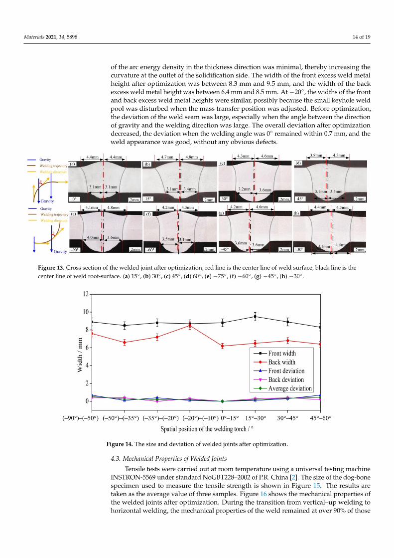
Figure 13 shows the welded joints at different angles obtained using the optimizedvariable position welding strategy. Figure 13a,b shows the transition stage from vertical–upwelding to horizontal welding, during which the welded joints were symmetric. Whenthe angle was approximately 60◦, there was a slight front deviation. In the transition fromvertical-up welding to horizontal welding, the maximum front deviation was 0.7 mm, andthe maximum back deviation was 0.4 mm. In the transition from horizontal welding tovertical-up welding, the keyhole weld pool was established stably at −90◦, with a stableliquid bridge on the solidification side and good weld formation. In addition, the maximumfront deviation was 0.7 mm, and the maximum back deviation was 0.4 mm.
Figure 14 shows the size and deviation of welded joints after optimization. Becausethe welding parameters were the same, the size of the welded joints remained stable asthe welding position varied. However, due to the optimized asymmetric heat source, thecurvature of the solidification side was smaller than that of the molten side and smallerthan that of the solidification side when using a symmetric heat source. Thus, the size ofthe welded joints after optimization was smaller than that when using a symmetric heatsource. The asymmetric heat source reduced the curvature of the solidification side of theweld pool and the equivalent arc length of the solidification side; thus, the attenuation
Materials 2021, 14, 5898 14 of 19
of the arc energy density in the thickness direction was minimal, thereby increasing thecurvature at the outlet of the solidification side. The width of the front excess weld metalheight after optimization was between 8.3 mm and 9.5 mm, and the width of the backexcess weld metal height was between 6.4 mm and 8.5 mm. At−20◦, the widths of the frontand back excess weld metal heights were similar, possibly because the small keyhole weldpool was disturbed when the mass transfer position was adjusted. Before optimization,the deviation of the weld seam was large, especially when the angle between the directionof gravity and the welding direction was large. The overall deviation after optimizationdecreased, the deviation when the welding angle was 0◦ remained within 0.7 mm, and theweld appearance was good, without any obvious defects.
Materials 2021, 14, 5898 14 of 19
tion of the arc energy density in the thickness direction was minimal, thereby increasing the curvature at the outlet of the solidification side. The width of the front excess weld metal height after optimization was between 8.3 mm and 9.5 mm, and the width of the back excess weld metal height was between 6.4 mm and 8.5 mm. At −20°, the widths of the front and back excess weld metal heights were similar, possibly because the small keyhole weld pool was disturbed when the mass transfer position was adjusted. Before optimization, the deviation of the weld seam was large, especially when the angle be-tween the direction of gravity and the welding direction was large. The overall deviation after optimization decreased, the deviation when the welding angle was 0° remained within 0.7 mm, and the weld appearance was good, without any obvious defects.
Figure 13. Cross section of the welded joint after optimization, red line is the center line of weld surface, black line is the center line of weld root-surface. (a) 15°, (b) 30°, (c) 45°, (d) 60°, (e) −75°, (f) −60°, (g) −45°, (h) −30°
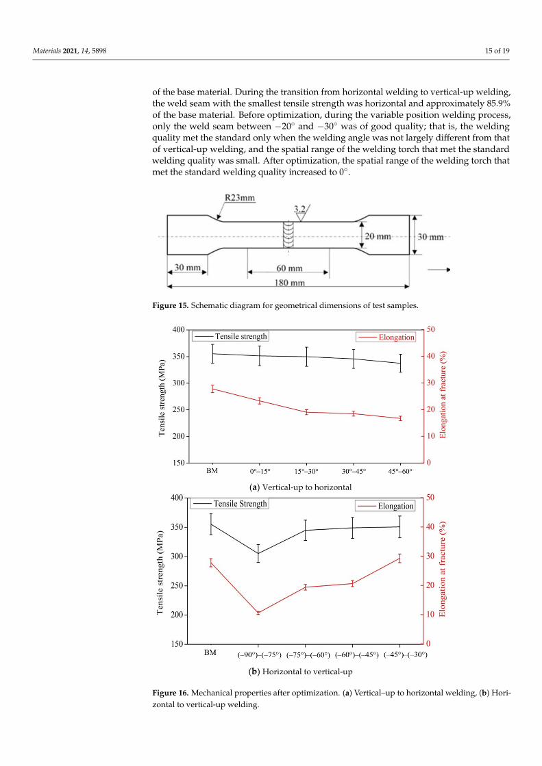
Figure 14. The size and deviation of welded joints after optimization.
4.3. Mechanical Properties of Welded Joints Tensile tests were carried out at room temperature using a universal testing ma-
chine INSTRON-5569 under standard NoGBT228–2002 of P.R. China [2]. The size of the dog-bone specimen used to measure the tensile strength is shown in Figure 15. The re-sults are taken as the average value of three samples. Figure 16 shows the mechanical properties of the welded joints after optimization. During the transition from vertical–up welding to horizontal welding, the mechanical properties of the weld remained at over 90% of those of the base material. During the transition from horizontal welding to ver-
Figure 13. Cross section of the welded joint after optimization, red line is the center line of weld surface, black line is thecenter line of weld root-surface. (a) 15◦, (b) 30◦, (c) 45◦, (d) 60◦, (e) −75◦, (f) −60◦, (g) −45◦, (h) −30◦.
Materials 2021, 14, 5898 14 of 19
tion of the arc energy density in the thickness direction was minimal, thereby increasing the curvature at the outlet of the solidification side. The width of the front excess weld metal height after optimization was between 8.3 mm and 9.5 mm, and the width of the back excess weld metal height was between 6.4 mm and 8.5 mm. At −20°, the widths of the front and back excess weld metal heights were similar, possibly because the small keyhole weld pool was disturbed when the mass transfer position was adjusted. Before optimization, the deviation of the weld seam was large, especially when the angle be-tween the direction of gravity and the welding direction was large. The overall deviation after optimization decreased, the deviation when the welding angle was 0° remained within 0.7 mm, and the weld appearance was good, without any obvious defects.
Figure 13. Cross section of the welded joint after optimization, red line is the center line of weld surface, black line is the center line of weld root-surface. (a) 15°, (b) 30°, (c) 45°, (d) 60°, (e) −75°, (f) −60°, (g) −45°, (h) −30°
Figure 14. The size and deviation of welded joints after optimization.
4.3. Mechanical Properties of Welded Joints Tensile tests were carried out at room temperature using a universal testing ma-
chine INSTRON-5569 under standard NoGBT228–2002 of P.R. China [2]. The size of the dog-bone specimen used to measure the tensile strength is shown in Figure 15. The re-sults are taken as the average value of three samples. Figure 16 shows the mechanical
Figure 14. The size and deviation of welded joints after optimization.
4.3. Mechanical Properties of Welded Joints
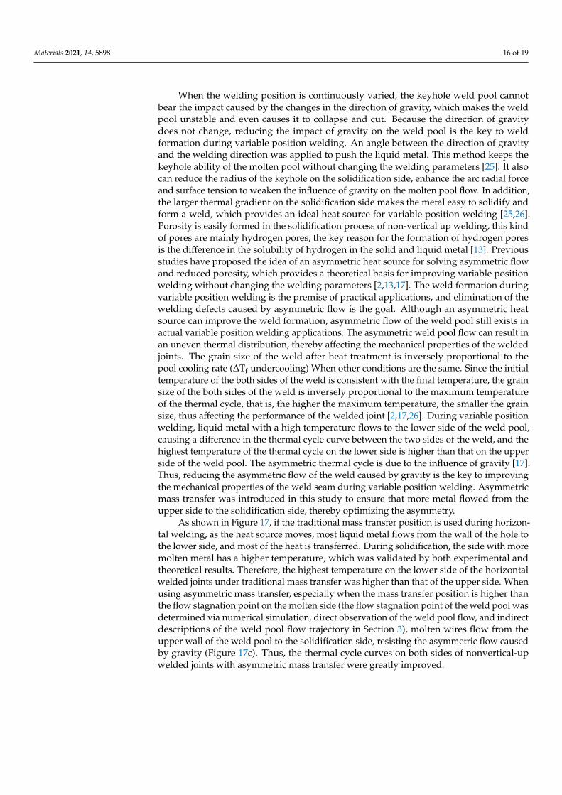
Tensile tests were carried out at room temperature using a universal testing machineINSTRON-5569 under standard NoGBT228–2002 of P.R. China [2]. The size of the dog-bonespecimen used to measure the tensile strength is shown in Figure 15. The results aretaken as the average value of three samples. Figure 16 shows the mechanical properties ofthe welded joints after optimization. During the transition from vertical–up welding tohorizontal welding, the mechanical properties of the weld remained at over 90% of those
Materials 2021, 14, 5898 15 of 19
of the base material. During the transition from horizontal welding to vertical-up welding,the weld seam with the smallest tensile strength was horizontal and approximately 85.9%of the base material. Before optimization, during the variable position welding process,only the weld seam between −20◦ and −30◦ was of good quality; that is, the weldingquality met the standard only when the welding angle was not largely different from thatof vertical-up welding, and the spatial range of the welding torch that met the standardwelding quality was small. After optimization, the spatial range of the welding torch thatmet the standard welding quality increased to 0◦.
Materials 2021, 14, 5898 15 of 19
tical-up welding, the weld seam with the smallest tensile strength was horizontal and approximately 85.9% of the base material. Before optimization, during the variable posi-tion welding process, only the weld seam between −20° and −30° was of good quality; that is, the welding quality met the standard only when the welding angle was not largely different from that of vertical-up welding, and the spatial range of the welding torch that met the standard welding quality was small. After optimization, the spatial range of the welding torch that met the standard welding quality increased to 0°.
Figure 15. Schematic diagram for geometrical dimensions of test samples.
(a) Vertical-up to horizontal
(b) Horizontal to vertical-up
Figure 16. Mechanical properties after optimization. (a) Vertical–up to horizontal welding, (b) Horizontal to vertical-up welding.
When the welding position is continuously varied, the keyhole weld pool cannot bear the impact caused by the changes in the direction of gravity, which makes the weld pool unstable and even causes it to collapse and cut. Because the direction of gravity does not change, reducing the impact of gravity on the weld pool is the key to weld
Figure 15. Schematic diagram for geometrical dimensions of test samples.
Materials 2021, 14, 5898 15 of 19
properties of the welded joints after optimization. During the transition from vertical–up welding to horizontal welding, the mechanical properties of the weld remained at over 90% of those of the base material. During the transition from horizontal welding to ver-tical-up welding, the weld seam with the smallest tensile strength was horizontal and approximately 85.9% of the base material. Before optimization, during the variable posi-tion welding process, only the weld seam between −20° and −30° was of good quality; that is, the welding quality met the standard only when the welding angle was not largely different from that of vertical-up welding, and the spatial range of the welding torch that met the standard welding quality was small. After optimization, the spatial range of the welding torch that met the standard welding quality increased to 0°.
Figure 15. Schematic diagram for geometrical dimensions of test samples.
(a) Vertical-up to horizontal
(b) Horizontal to vertical-up
Figure 16. Mechanical properties after optimization. (a) Vertical–up to horizontal welding, (b) Hori-zontal to vertical-up welding.
Materials 2021, 14, 5898 16 of 19
When the welding position is continuously varied, the keyhole weld pool cannotbear the impact caused by the changes in the direction of gravity, which makes the weldpool unstable and even causes it to collapse and cut. Because the direction of gravitydoes not change, reducing the impact of gravity on the weld pool is the key to weldformation during variable position welding. An angle between the direction of gravityand the welding direction was applied to push the liquid metal. This method keeps thekeyhole ability of the molten pool without changing the welding parameters [25]. It alsocan reduce the radius of the keyhole on the solidification side, enhance the arc radial forceand surface tension to weaken the influence of gravity on the molten pool flow. In addition,the larger thermal gradient on the solidification side makes the metal easy to solidify andform a weld, which provides an ideal heat source for variable position welding [25,26].Porosity is easily formed in the solidification process of non-vertical up welding, this kindof pores are mainly hydrogen pores, the key reason for the formation of hydrogen poresis the difference in the solubility of hydrogen in the solid and liquid metal [13]. Previousstudies have proposed the idea of an asymmetric heat source for solving asymmetric flowand reduced porosity, which provides a theoretical basis for improving variable positionwelding without changing the welding parameters [2,13,17]. The weld formation duringvariable position welding is the premise of practical applications, and elimination of thewelding defects caused by asymmetric flow is the goal. Although an asymmetric heatsource can improve the weld formation, asymmetric flow of the weld pool still exists inactual variable position welding applications. The asymmetric weld pool flow can result inan uneven thermal distribution, thereby affecting the mechanical properties of the weldedjoints. The grain size of the weld after heat treatment is inversely proportional to thepool cooling rate (∆Tf undercooling) When other conditions are the same. Since the initialtemperature of the both sides of the weld is consistent with the final temperature, the grainsize of the both sides of the weld is inversely proportional to the maximum temperatureof the thermal cycle, that is, the higher the maximum temperature, the smaller the grainsize, thus affecting the performance of the welded joint [2,17,26]. During variable positionwelding, liquid metal with a high temperature flows to the lower side of the weld pool,causing a difference in the thermal cycle curve between the two sides of the weld, and thehighest temperature of the thermal cycle on the lower side is higher than that on the upperside of the weld pool. The asymmetric thermal cycle is due to the influence of gravity [17].Thus, reducing the asymmetric flow of the weld caused by gravity is the key to improvingthe mechanical properties of the weld seam during variable position welding. Asymmetricmass transfer was introduced in this study to ensure that more metal flowed from theupper side to the solidification side, thereby optimizing the asymmetry.
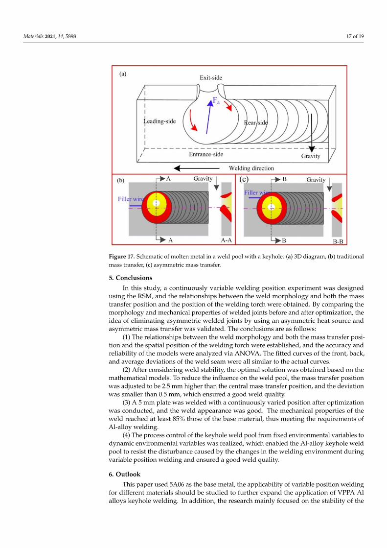
As shown in Figure 17, if the traditional mass transfer position is used during horizon-tal welding, as the heat source moves, most liquid metal flows from the wall of the hole tothe lower side, and most of the heat is transferred. During solidification, the side with moremolten metal has a higher temperature, which was validated by both experimental andtheoretical results. Therefore, the highest temperature on the lower side of the horizontalwelded joints under traditional mass transfer was higher than that of the upper side. Whenusing asymmetric mass transfer, especially when the mass transfer position is higher thanthe flow stagnation point on the molten side (the flow stagnation point of the weld pool wasdetermined via numerical simulation, direct observation of the weld pool flow, and indirectdescriptions of the weld pool flow trajectory in Section 3), molten wires flow from theupper wall of the weld pool to the solidification side, resisting the asymmetric flow causedby gravity (Figure 17c). Thus, the thermal cycle curves on both sides of nonvertical-upwelded joints with asymmetric mass transfer were greatly improved.
Materials 2021, 14, 5898 17 of 19Materials 2021, 14, 5898 17 of 19
Figure 17. Schematic of molten metal in a weld pool with a keyhole. (a) 3D diagram, (b) traditional mass transfer, (c) asymmetric mass transfer.
5. Conclusions In this study, a continuously variable welding position experiment was designed
using the RSM, and the relationships between the weld morphology and both the mass transfer position and the position of the welding torch were obtained. By comparing the morphology and mechanical properties of welded joints before and after optimization, the idea of eliminating asymmetric welded joints by using an asymmetric heat source and asymmetric mass transfer was validated. The conclusions are as follows:
(1) The relationships between the weld morphology and both the mass transfer po-sition and the spatial position of the welding torch were established, and the accuracy and reliability of the models were analyzed via ANOVA. The fitted curves of the front, back, and average deviations of the weld seam were all similar to the actual curves.
(2) After considering weld stability, the optimal solution was obtained based on the mathematical models. To reduce the influence on the weld pool, the mass transfer posi-tion was adjusted to be 2.5 mm higher than the central mass transfer position, and the deviation was smaller than 0.5 mm, which ensured a good weld quality.
(3) A 5 mm plate was welded with a continuously varied position after optimiza-tion was conducted, and the weld appearance was good. The mechanical properties of the weld reached at least 85% those of the base material, thus meeting the requirements of Al-alloy welding.
(4) The process control of the keyhole weld pool from fixed environmental variables to dynamic environmental variables was realized, which enabled the Al-alloy keyhole weld pool to resist the disturbance caused by the changes in the welding environment during variable position welding and ensured a good weld quality.
6. Outlook This paper used 5A06 as the base metal, the applicability of variable position weld-
ing for different materials should be studied to further expand the application of VPPA Al alloys keyhole welding. In addition, the research mainly focused on the stability of the keyhole molten pool caused by the change of welding direction in a plane, but the
Figure 17. Schematic of molten metal in a weld pool with a keyhole. (a) 3D diagram, (b) traditionalmass transfer, (c) asymmetric mass transfer.
5. Conclusions
In this study, a continuously variable welding position experiment was designedusing the RSM, and the relationships between the weld morphology and both the masstransfer position and the position of the welding torch were obtained. By comparing themorphology and mechanical properties of welded joints before and after optimization, theidea of eliminating asymmetric welded joints by using an asymmetric heat source andasymmetric mass transfer was validated. The conclusions are as follows:
(1) The relationships between the weld morphology and both the mass transfer posi-tion and the spatial position of the welding torch were established, and the accuracy andreliability of the models were analyzed via ANOVA. The fitted curves of the front, back,and average deviations of the weld seam were all similar to the actual curves.
(2) After considering weld stability, the optimal solution was obtained based on themathematical models. To reduce the influence on the weld pool, the mass transfer positionwas adjusted to be 2.5 mm higher than the central mass transfer position, and the deviationwas smaller than 0.5 mm, which ensured a good weld quality.
(3) A 5 mm plate was welded with a continuously varied position after optimizationwas conducted, and the weld appearance was good. The mechanical properties of theweld reached at least 85% those of the base material, thus meeting the requirements ofAl-alloy welding.
(4) The process control of the keyhole weld pool from fixed environmental variables todynamic environmental variables was realized, which enabled the Al-alloy keyhole weldpool to resist the disturbance caused by the changes in the welding environment duringvariable position welding and ensured a good weld quality.
6. Outlook
This paper used 5A06 as the base metal, the applicability of variable position weldingfor different materials should be studied to further expand the application of VPPA Alalloys keyhole welding. In addition, the research mainly focused on the stability of the
Materials 2021, 14, 5898 18 of 19
keyhole molten pool caused by the change of welding direction in a plane, but the stateof the molten pool and weld quality under the continuous variable force in space has notbeen verified.
Author Contributions: Conceptualization, Z.Y. and F.J.; methodology, S.C.; validation, Z.Y., J.Z. andX.M.; investigation, Z.Y.; resources, J.Z. and X.M.; data curation, Z.Y. and W.C.; writing—originaldraft preparation, Z.Y. and W.C.; writing—review and editing, F.J.; visualization, F.J. and S.C.;supervision, S.C.; funding acquisition, F.J. All authors have read and agreed to the published versionof the manuscript.
Funding: This work is supported by National Natural Science Foundation of China (U1937207),National Natural Science Foundation of China (No.51875004), Beijing Natural Science Foundation(No.3172004).
Institutional Review Board Statement: Not applicable.
Informed Consent Statement: Not applicable.
Data Availability Statement: Not applicable.
Conflicts of Interest: The authors declare no conflict of interest.
References1. Lang, R.; Han, Y.; Bai, X.; Hong, H. Prediction of the Weld Pool Stability by Material Flow Behavior of the Perforated Weld Pool.
Materials 2020, 13, 303. [CrossRef]2. Yan, Z.; Chen, S.; Jiang, F.; Zheng, X.; Tian, O.; Cheng, W.; Ma, X. Effect of Asymmetric Material Flow on the Microstructure and
Mechanical Properties of 5A06 Al-Alloy Welded Joint by VPPA Welding. Metals 2021, 11, 120. [CrossRef]3. David, S.A.; DebRoy, T. Current Issues and Problems in Welding Science. Science 1992, 257, 497–502. [CrossRef]4. Kartal, M.; Liljedahl, C.; Gungor, S.; Edwards, L.; Fitzpatrick, M. Determination of the profile of the complete residual stress
tensor in a VPPA weld using the multi-axial contour method. Acta Mater. 2008, 56, 4417–4428. [CrossRef]5. Woodward, N.J.; Richardson, I.M.; Thomas, A. Variable polarity plasma arc welding of 6•35 mm aluminium alloys: Parameter
development and preliminary analysis. Sci. Technol. Weld. Join. 2000, 5, 21–1718. [CrossRef]6. Liu, Z.M.; Cui, S.L.; Luo, Z.; Zhang, C.Z.; Wang, Z.M.; Zhang, Y.C. Plasma arc welding: Process variants and its recent
developments of sensing, controlling and modelling. J. Manuf. Process. 2016, 23, 315–327. [CrossRef]7. Tang, Z.Q.; Jiang, F.; Xu, P.; Jiang, J.Y.; Zeng, J.J.; Lu, L.Y.; Tong, M.M. Investigation on microstructure, mechanical properties and
corrosion behavior of VPPA welded Al–Mg–Mn–Sc–Zr alloy. Mater. Today Commun. 2020, 25, 101480. [CrossRef]8. Sun, Z.; Han, Y.; Du, M.; Hong, H.; Tong, J. Numerical simulation of VPPA-GMAW hybrid welding of thick aluminum alloy
plates considering variable heat input and droplet kinetic energy. J. Manuf. Process. 2018, 34, 688–696. [CrossRef]9. Sun, Z.B.; Han, Y.Q.; Du, M.H.; Tong, J.H.; Hong, H.T. An improved simulation of temperature field in VPPA–GMAW of
Al–Cu–Mg alloy. J. Mater. Process. Technol. 2019, 263, 366–373. [CrossRef]10. Wang, S.; Lefebvre, F.; Yan, J.; Sinclair, I.; Starink, M. VPPA welds of Al-2024 alloys: Analysis and modelling of local microstructure
and strength. Mater. Sci. Eng. A 2006, 431, 123–136. [CrossRef]11. Zhang, Q.L.; Fan, C.L.; Lin, S.; Yang, C.L. Novel soft variable polarity plasma arc and its influence on keyhole in horizontal
welding of aluminium alloys. Sci. Technol. Weld. Join. 2014, 19, 493–499. [CrossRef]12. Zhang, Q.L.; Yang, C.L.; Lin, S.B.; Fan, C.L. Soft variable polarity plasma arc horizontal welding technology and weld asymmetry.
Sci. Technol. Weld. Join. 2015, 4, 29–306. [CrossRef]13. Yan, Z.; Chen, S.; Jiang, F.; Zhang, W.; Huang, N.; Chen, R. Control of gravity effects on weld porosity distribution during variable
polarity plasma arc welding of aluminum alloys. J. Mater. Process. Technol. 2020, 282, 116693. [CrossRef]14. Li, T.Q.; Chen, L.; Zhang, Y.; Yang, X.M.; Lei, Y.C. Metal flow of weld pool and keyhole evolution in gas focusing plasma arc
welding. Int. J. Heat Mass Transf. 2020, 150, 119296. [CrossRef]15. Xu, B.; Tashiro, S.; Jiang, F.; Chen, S.; Tanaka, M. Effect of Arc Pressure on the Digging Process in Variable Polarity Plasma Arc
Welding of A5052P Aluminum Alloy. Materials 2019, 12, 1071. [CrossRef]16. Tashiro, S.; Mukai, N.; Inoue, Y.; Murphy, A.B.; Suga, T.; Tanaka, M. Numerical Simulation of the Behavior of Hydrogen Source in
a Novel Welding Process to Reduce Diffusible Hydrogen. Materials 2020, 13, 1619. [CrossRef]17. Yan, Z.; Chen, S.; Jiang, F.; Tian, O.; Huang, N.; Zhang, S. Weld properties and residual stresses of VPPA Al welds at varying
welding positions. J. Mater. Res. Technol. 2020, 9, 2892–2902. [CrossRef]18. Pandit, M.; Sood, S.; Mishra, P.; Khanna, P. Mathematical analysis of the effect of process parameters on angular distortion of MIG
welded stainless steel 202 plates by using the technique of response surface Methodology. Mater. Today Proc. 2020, 41, 1045–1054.[CrossRef]
19. Sahu, A.K.; Sahu, N.K.; Sahu, A.K.; Rajput, M.S.; Narang, H.K. Modeling the predictive values of ultimate tensile strength inwelded joint by response surface methodology. Mater. Today Proc. 2021, 44, 3110–3114. [CrossRef]
Materials 2021, 14, 5898 19 of 19
20. Sharma, P.; Chattopadhyaya, S.; Singh, N.K.; Bogdan-Chudy, M.; Krolczyk, G. The Effect of an External Magnetic Field onthe Aspect Ratio and Heat Input of Gas-Metal-Arc-Welded AZ31B Alloy Weld Joints Using a Response Surface Methodology.Materials 2020, 13, 5269. [CrossRef]
21. Kiaee, N.; Aghaie-Khafri, M. Optimization of gas tungsten arc welding process by response surface methodology. Mater. Des.2014, 54, 25–31. [CrossRef]
22. Kalenda, M.; Madeleine, D.T. Corrosion fatigue behaviour of aluminium alloy 6061-T651 welded using fully automatic gas metalarc welding and ER5183 filler alloy. Int. J. Fatigue 2011, 33, 1539–1547.
23. Yang, B.; Tan, C.W.; Zhao, Y.B.; Wu, L.J.; Chen, B.; Song, X.G.; Zhao, H.Y.; Feng, J.C. Influence of ultrasonic peening onmicrostructure and surface performance of laser-arc hybrid welded 5A06 aluminum alloy joint. J. Mater. Res. Technol. 2020, 9,9576–9587. [CrossRef]
24. Jiang, X.; Chen, S.; Gong, J. Effect of non-axisymmetric arc on microstructure, texture and properties of variable polarity plasmaarc welded 5A06 Al alloy. Mater. Charact. 2018, 139, 70–80. [CrossRef]
25. Chen, S.; Yan, Z.; Jiang, F.; Zhang, W. Gravity effects on horizontal variable polarity plasma arc welding. J. Mater. Process. Technol.2018, 255, 831–840. [CrossRef]
26. Yan, Z.; Chen, S.; Jiang, F.; Zhang, W.; Huang, N. Study and optimization against the gravity effect on mechanical property ofVPPA horizontal welding of aluminum alloys. J. Manuf. Process. 2019, 46, 109–117. [CrossRef]
Related Documents