Spring 2012, Apr 4 . . . Spring 2012, Apr 4 . . . ELEC 7770: Advanced VLSI Design ELEC 7770: Advanced VLSI Design (Agrawal) (Agrawal) 1 ELEC 7770 ELEC 7770 Advanced VLSI Design Advanced VLSI Design Spring 2012 Spring 2012 Power and Ground Power and Ground Vishwani D. Agrawal Vishwani D. Agrawal James J. Danaher Professor James J. Danaher Professor ECE Department, Auburn University ECE Department, Auburn University Auburn, AL 36849 Auburn, AL 36849 [email protected] http://www.eng.auburn.edu/~vagrawal/COURSE/E77 70_Spr12

Spring 2012, Apr 4...ELEC 7770: Advanced VLSI Design (Agrawal)1 ELEC 7770 Advanced VLSI Design Spring 2012 Power and Ground Vishwani D. Agrawal James J.
Dec 19, 2015
Welcome message from author
This document is posted to help you gain knowledge. Please leave a comment to let me know what you think about it! Share it to your friends and learn new things together.
Transcript
Spring 2012, Apr 4 . . .Spring 2012, Apr 4 . . . ELEC 7770: Advanced VLSI Design (Agrawal)ELEC 7770: Advanced VLSI Design (Agrawal) 11
ELEC 7770ELEC 7770Advanced VLSI DesignAdvanced VLSI Design
Spring 2012Spring 2012Power and GroundPower and Ground
Vishwani D. AgrawalVishwani D. AgrawalJames J. Danaher ProfessorJames J. Danaher Professor
ECE Department, Auburn UniversityECE Department, Auburn University
Auburn, AL 36849Auburn, AL 36849
http://www.eng.auburn.edu/~vagrawal/COURSE/E7770_Spr12

ReferencesReferences Q. K. Zhu, Q. K. Zhu, Power Distribution Network Design for VLSIPower Distribution Network Design for VLSI, Hoboken, New , Hoboken, New
Jersey: Wiley, 2004.Jersey: Wiley, 2004. M. Popovich, A. Mezhiba and E. G. Friedman, M. Popovich, A. Mezhiba and E. G. Friedman, Power Distribution Power Distribution
Networks with On-Chip Decoupling CapacitorsNetworks with On-Chip Decoupling Capacitors , Springer, 2008., Springer, 2008. C.-K. Koh, J. Jain and S. F. Cauley, “Synthesis of Clock and C.-K. Koh, J. Jain and S. F. Cauley, “Synthesis of Clock and
Power/Ground Network,” Chapter 13, L.-T. Wang, Y.-W. Chang and K.-Power/Ground Network,” Chapter 13, L.-T. Wang, Y.-W. Chang and K.-T. Cheng (Editors), T. Cheng (Editors), Electronic Design AutomationElectronic Design Automation, Morgan-Kaufmann, , Morgan-Kaufmann, 2009. pp. 751-850.2009. pp. 751-850.
J. Fu, Z. Luo, X. Hong, Y. Cai, S. X.-D. Tan, Z. Pan, “J. Fu, Z. Luo, X. Hong, Y. Cai, S. X.-D. Tan, Z. Pan, “VLSI On-Chip VLSI On-Chip Power/Ground Network Optimization Considering Decap Leakage Power/Ground Network Optimization Considering Decap Leakage Currents,” Currents,” Proc. Asia and South Pacific Design Automation Conf.Proc. Asia and South Pacific Design Automation Conf. , , 20052005 , pp. 735-738., pp. 735-738.
Decoupling Capacitors, Decoupling Capacitors, http://www.vlsichipdesign.com/index.php/Chip-Design-Articles/decoupling-capacitors.html
Spring 2012, Apr 4 . . .Spring 2012, Apr 4 . . . ELEC 7770: Advanced VLSI Design (Agrawal)ELEC 7770: Advanced VLSI Design (Agrawal) 22

Supply VoltageSupply Voltage
Spring 2012, Apr 4 . . .Spring 2012, Apr 4 . . . ELEC 7770: Advanced VLSI Design (Agrawal)ELEC 7770: Advanced VLSI Design (Agrawal) 33
3.0
2.5
2.0
1.5
1.0
0.5
0.00.25 0.18 0.13 0.1
Minimum feature size (μm)
Sup
ply
volta
ge (
V)

Gate Oxide ThicknessGate Oxide Thickness
Spring 2012, Apr 4 . . .Spring 2012, Apr 4 . . . ELEC 7770: Advanced VLSI Design (Agrawal)ELEC 7770: Advanced VLSI Design (Agrawal) 44
60
50
40
30
20
10
00.25 0.18 0.13 0.1
Minimum feature size (μm)
Gat
e ox
ide
thic
knes
s (A
)
High gate leakage

Power Supply NoisePower Supply Noise
Transient behavior of supply voltage and ground Transient behavior of supply voltage and ground level.level.
Caused by transient currents:Caused by transient currents: Power droopPower droop Ground bounceGround bounce
Spring 2012, Apr 4 . . .Spring 2012, Apr 4 . . . ELEC 7770: Advanced VLSI Design (Agrawal)ELEC 7770: Advanced VLSI Design (Agrawal) 55

Power SupplyPower Supply
Spring 2012, Apr 4 . . .Spring 2012, Apr 4 . . . ELEC 7770: Advanced VLSI Design (Agrawal)ELEC 7770: Advanced VLSI Design (Agrawal) 66
+
– Gat
e 1
Gat
e 2
VDD
Rg
R
C
R
C
V(t)

Switching TransientsSwitching Transients Only Gate 1 switches (turns on):Only Gate 1 switches (turns on):
V(t) = VDD – Rg VDD exp[– t/{C(R+Rg)}]/(R+Rg)V(t) = VDD – Rg VDD exp[– t/{C(R+Rg)}]/(R+Rg)
Spring 2012, Apr 4 . . .Spring 2012, Apr 4 . . . ELEC 7770: Advanced VLSI Design (Agrawal)ELEC 7770: Advanced VLSI Design (Agrawal) 77
V(t
)
VDD
0 time, t
VDD Rg/(R+Rg)
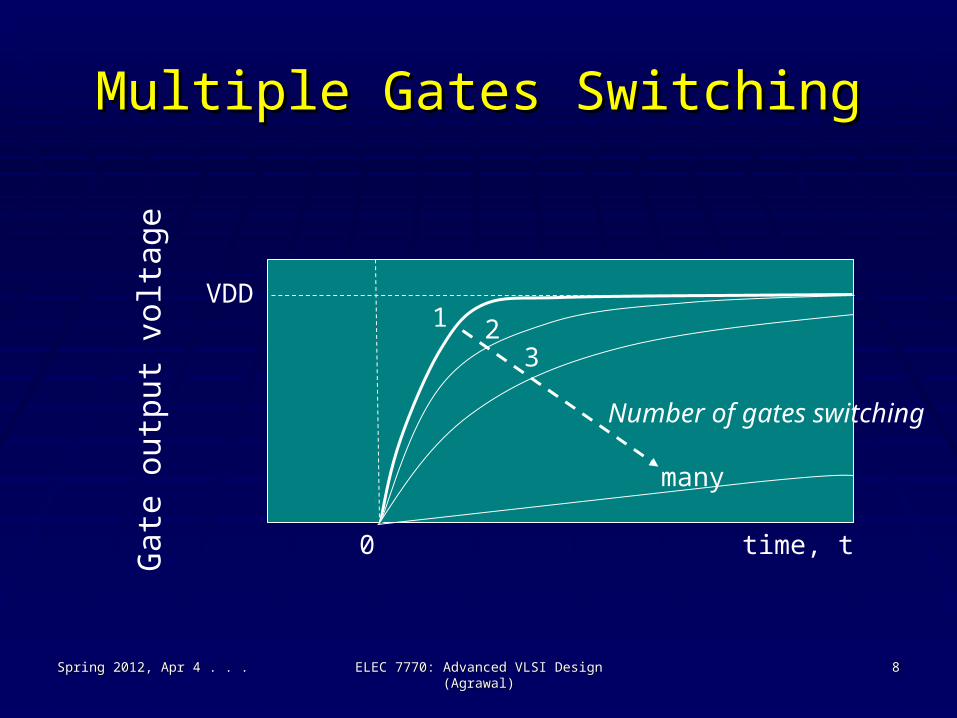
Multiple Gates SwitchingMultiple Gates Switching
Spring 2012, Apr 4 . . .Spring 2012, Apr 4 . . . ELEC 7770: Advanced VLSI Design (Agrawal)ELEC 7770: Advanced VLSI Design (Agrawal) 88
Gat
e ou
tput
vol
tage
VDD
0 time, t
many
Number of gates switching
1 23

Decoupling CapacitorDecoupling Capacitor A capacitor to isolate two electrical circuits.A capacitor to isolate two electrical circuits. Illustration: An approximate model:Illustration: An approximate model:
Spring 2012, Apr 4 . . .Spring 2012, Apr 4 . . . ELEC 7770: Advanced VLSI Design (Agrawal)ELEC 7770: Advanced VLSI Design (Agrawal) 99
+
–
VDD = 1Rg
Rd
CdIL
VL(t)
t
i(t)
a
t=0
t=0

Approximate Load Current, ILApproximate Load Current, IL
0,0, t < 0t < 0
at,at, t < tpt < tp
ILIL ==
a(2tp – t),a(2tp – t), t < 2tpt < 2tp
0,0, t > 2tpt > 2tp
Spring 2012, Apr 4 . . .Spring 2012, Apr 4 . . . ELEC 7770: Advanced VLSI Design (Agrawal)ELEC 7770: Advanced VLSI Design (Agrawal) 1010

Transient Load VoltageTransient Load Voltage
VL(t) = 1 – a Rg [ t – Cd Rg (1 – eVL(t) = 1 – a Rg [ t – Cd Rg (1 – e – t/T – t/T) ], 0 < t < tp) ], 0 < t < tp
TT == Cd (Rg + Rd)Cd (Rg + Rd)
Spring 2012, Apr 4 . . .Spring 2012, Apr 4 . . . ELEC 7770: Advanced VLSI Design (Agrawal)ELEC 7770: Advanced VLSI Design (Agrawal) 1111

Realizing Decoupling CapacitorRealizing Decoupling Capacitor
Spring 2012, Apr 4 . . .Spring 2012, Apr 4 . . . ELEC 7770: Advanced VLSI Design (Agrawal)ELEC 7770: Advanced VLSI Design (Agrawal) 1212
GND
S B D
VDD
GND
S B D
VDD
OR

CapacitanceCapacitanceCdCd == γ×γ×WLWL×ε×ε×ε×ε00/Tox/Tox
≈≈ 0.26fF, for 70nm BSIM0.26fF, for 70nm BSIM
LL == 38nm,38nm, WW == 200nm200nm
γγ == 1.54621.5462
εε == 44
Spring 2012, Apr 4 . . .Spring 2012, Apr 4 . . . ELEC 7770: Advanced VLSI Design (Agrawal)ELEC 7770: Advanced VLSI Design (Agrawal) 1313

Leakage ResistanceLeakage Resistance
IgateIgate == αα ×× e e – – ββToxTox ××WW
where where αα and and ββ are technology parameters. are technology parameters.
RdRd == VL(t)/IgateVL(t)/Igate
Because V(t) is a function of time, Rd is Because V(t) is a function of time, Rd is difficult to estimate. The decoupling difficult to estimate. The decoupling capacitance is simulated in spice.capacitance is simulated in spice.
Spring 2012, Apr 4 . . .Spring 2012, Apr 4 . . . ELEC 7770: Advanced VLSI Design (Agrawal)ELEC 7770: Advanced VLSI Design (Agrawal) 1414

Power-Ground LayoutPower-Ground Layout
Spring 2012, Apr 4 . . .Spring 2012, Apr 4 . . . ELEC 7770: Advanced VLSI Design (Agrawal)ELEC 7770: Advanced VLSI Design (Agrawal) 1515
Vss VssVdd
VssVddVdd
Solder bump pads
M5
M4
Via
Vdd/Vss supply
Vdd/Vssequalization

Power GridPower Grid
Spring 2012, Apr 4 . . .Spring 2012, Apr 4 . . . ELEC 7770: Advanced VLSI Design (Agrawal)ELEC 7770: Advanced VLSI Design (Agrawal) 1616
+
–

Nodal AnalysisNodal Analysis
Spring 2012, Apr 4 . . .Spring 2012, Apr 4 . . . ELEC 7770: Advanced VLSI Design (Agrawal)ELEC 7770: Advanced VLSI Design (Agrawal) 1717
V1
V2
V3
V4
Ci
Vi
BiApply KCL to node i:
4 ∑ (Vk – Vi) gk – Ci ∂Vi/∂t = Bik=1
g1g2
g3
g4

Nodal AnalysisNodal Analysis
Spring 2012, Apr 4 . . .Spring 2012, Apr 4 . . . ELEC 7770: Advanced VLSI Design (Agrawal)ELEC 7770: Advanced VLSI Design (Agrawal) 1818
G V – C V’ = B
Where G is conductance matrixV is nodal voltage vectorC is admittance matrixB is vector of currents
V(t) is a function of time, V(0) = VDD
B(t) is a function of time, B(0) ≈ 0 or leakage current
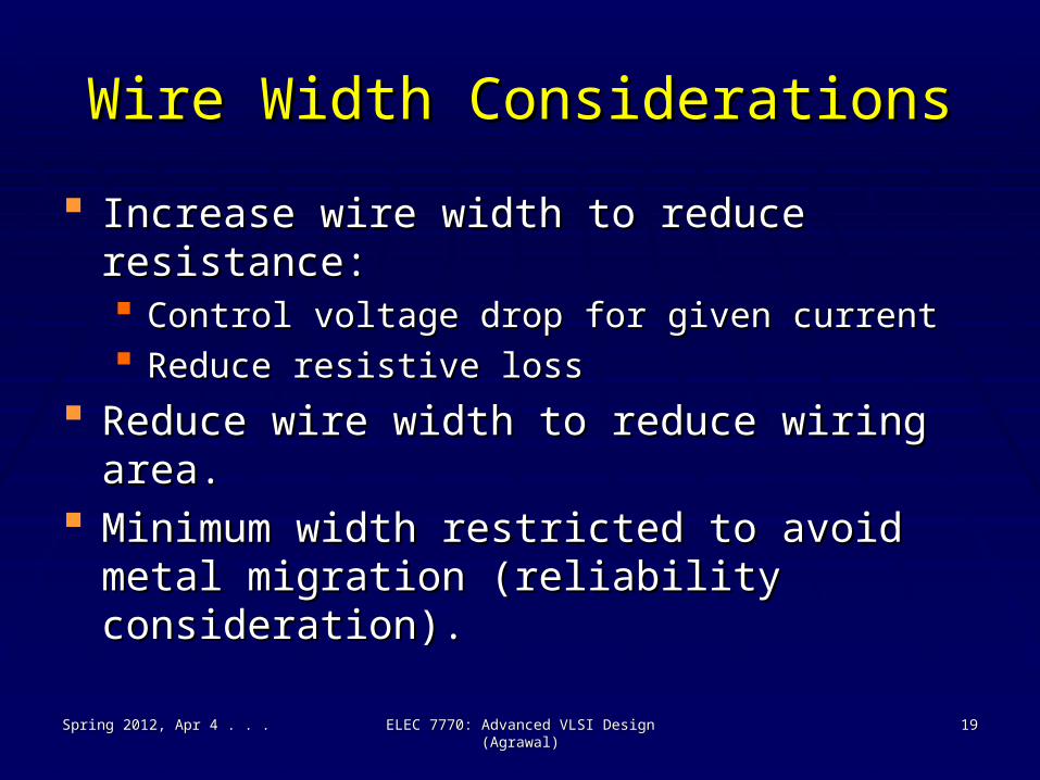
Wire Width ConsiderationsWire Width Considerations
Increase wire width to reduce resistance:Increase wire width to reduce resistance: Control voltage drop for given currentControl voltage drop for given current Reduce resistive lossReduce resistive loss
Reduce wire width to reduce wiring area.Reduce wire width to reduce wiring area. Minimum width restricted to avoid metal Minimum width restricted to avoid metal
migration (reliability consideration).migration (reliability consideration).
Spring 2012, Apr 4 . . .Spring 2012, Apr 4 . . . ELEC 7770: Advanced VLSI Design (Agrawal)ELEC 7770: Advanced VLSI Design (Agrawal) 1919
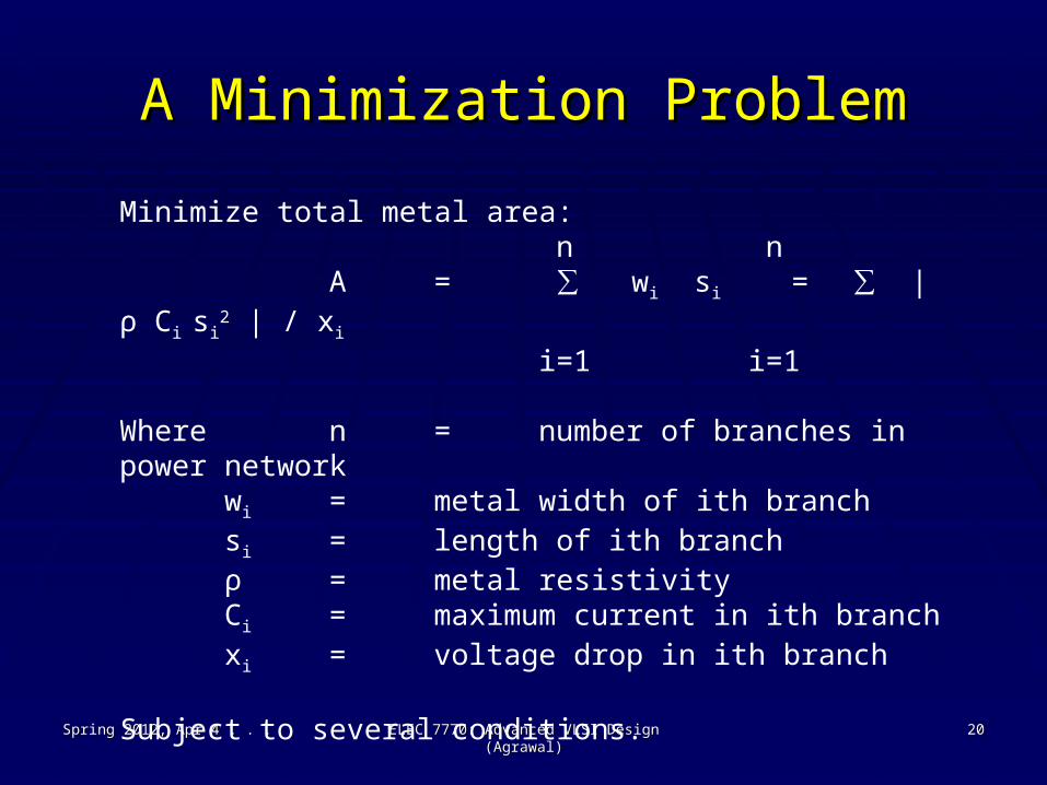
A Minimization ProblemA Minimization Problem
Spring 2012, Apr 4 . . .Spring 2012, Apr 4 . . . ELEC 7770: Advanced VLSI Design (Agrawal)ELEC 7770: Advanced VLSI Design (Agrawal) 2020
Minimize total metal area: n n
A = ∑ wi si = ∑ | ρ Ci si2 | / xi
i=1 i=1
Where n = number of branches in power networkwi = metal width of ith branchsi = length of ith branchρ = metal resistivityCi = maximum current in ith branchxi = voltage drop in ith branch
Subject to several conditions.

Condition 1: Voltage DropCondition 1: Voltage Drop
Spring 2012, Apr 4 . . .Spring 2012, Apr 4 . . . ELEC 7770: Advanced VLSI Design (Agrawal)ELEC 7770: Advanced VLSI Design (Agrawal) 2121
Voltage drop on path Pk:
∑ xi ≤ Δvk
i ε Pk
Where Δvk = maximum allowable voltage drop on kth path

Condition 2: Minimum WidthCondition 2: Minimum Width
Spring 2012, Apr 4 . . .Spring 2012, Apr 4 . . . ELEC 7770: Advanced VLSI Design (Agrawal)ELEC 7770: Advanced VLSI Design (Agrawal) 2222
Minimum width allowed by fabrication process:
wi = ρ Ci si / xi ≥ W
Where wi = metal width of ith branchsi = length of ith branchρ = metal resistivityCi = maximum current in ith branchxi = voltage drop in ith branchW = minimum line width

Condition 3: Metal MigrationCondition 3: Metal Migration
Spring 2012, Apr 4 . . .Spring 2012, Apr 4 . . . ELEC 7770: Advanced VLSI Design (Agrawal)ELEC 7770: Advanced VLSI Design (Agrawal) 2323
Do not exceed maximum current to wire-width ratio:
Ci / wi = xi /(ρ si) ≤ σi
Where wi = metal width of ith branchsi = length of ith branchρ = metal resistivityCi = maximum current in ith branchxi = voltage drop in ith branchσi = maximum allowable current density
across ith branch

Decoupling CapacitanceDecoupling Capacitance
Spring 2012, Apr 4 . . .Spring 2012, Apr 4 . . . ELEC 7770: Advanced VLSI Design (Agrawal)ELEC 7770: Advanced VLSI Design (Agrawal) 2424
+
–
VDDRg
Cd I(t)

Decoupling CapacitanceDecoupling Capacitance
Initial charge on Cd, QInitial charge on Cd, Q00 = Cd VDD = Cd VDD
I(t): current waveform at a nodeI(t): current waveform at a node T: duration of currentT: duration of current Total charge supplied to load:Total charge supplied to load:
TT
Q = ∫ I(t) dtQ = ∫ I(t) dt
00
Spring 2012, Apr 4 . . .Spring 2012, Apr 4 . . . ELEC 7770: Advanced VLSI Design (Agrawal)ELEC 7770: Advanced VLSI Design (Agrawal) 2525

Decoupling CapacitanceDecoupling Capacitance
Assume that charge is completely supplied by Cd.Assume that charge is completely supplied by Cd. Remaining charge on Cd = Cd VDD – QRemaining charge on Cd = Cd VDD – Q Voltage of supply node = VDD – Q/CdVoltage of supply node = VDD – Q/Cd For a maximum supply noise For a maximum supply noise ΔΔVDDmax,VDDmax,
VDD – (VDD – Q/Cd) ≤ VDD – (VDD – Q/Cd) ≤ ΔΔVDDmaxVDDmax
OrOr CdCd ≥≥ Q /Q / Δ ΔVDDmaxVDDmax
Spring 2012, Apr 4 . . .Spring 2012, Apr 4 . . . ELEC 7770: Advanced VLSI Design (Agrawal)ELEC 7770: Advanced VLSI Design (Agrawal) 2626
Related Documents