SolarEdge StorEdge Installation Guide For Smart Energy Management using the StorEdge Interface For Europe, APAC & SouthAfrica Version 1.0

Welcome message from author
This document is posted to help you gain knowledge. Please leave a comment to let me know what you think about it! Share it to your friends and learn new things together.
Transcript

SolarEdgeStorEdge
Installation GuideFor Smart Energy Management
using the StorEdge Interface
For Europe, APAC & SouthAfrica
Version 1.0
DisclaimersImportant NoticeCopyright © SolarEdge Inc. All rights reserved.No part of this document may be reproduced, stored in a retrieval system or transmitted, in any form or by any means, electronic, mechanical, photographic, magnetic or otherwise, without the prior written permission of SolarEdge Inc.The material furnished in this document is believed to be accurate and reliable. However, SolarEdge assumes no responsibility for the use of this material. SolarEdge reserves the right to make changes to the material at any time and without notice. You may refer to the SolarEdge web site (www.solaredge.com) for the most updated version.All company and brand products and service names are trademarks or registered trademarks of their respective holders.Patent marking notice: see http://www.solaredge.com/groups/patent The general terms and conditions of delivery of SolarEdge shall apply.The content of these documents is continually reviewed and amended, where necessary. However, discrepancies cannot be excluded. No guarantee is made for the completeness of these documents.The images contained in this document are for illustrative purposes only and may vary depending on product models.
Disclaimers
SolarEdge-StorEdge Installation Guide MAN-01-00249-1.0 1
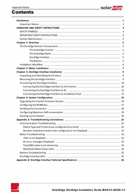
ContentsDisclaimers 1
Important Notice 1HANDLING AND SAFETY INSTRUCTIONS 3
SAFETY SYMBOLS 3IMPORTANT SAFETY INSTRUCTIONS 3System Maintenance 4
Chapter 1: Overview 5The StorEdge Solution Components 5
The SolarEdge Inverter 5The SolarEdge Meter 5StorEdge Interface 5The Battery 5
Installation Workflow 6Chapter 2: Meter Installation 7Chapter 3: StorEdge Interface Installation 9
Unpacking and Identifying the Product 9Mounting the StorEdge Interface 9Connecting the StorEdge Interface 10
Connecting the StorEdge Interface to the Inverter 10Connecting the StorEdge Interface to AC 13Connecting the StorEdge Interface to the Battery Pack 13
Chapter 4: System Configuration 16Upgrading the Inverter Firmware Version 16Configuring the RS485 Bus 17Verifying the Connection 18Configuring Maximum Self-consumption 19Starting-up the System 20
Appendix A: Troubleshooting Connections 22Communication Troubleshooting 22
Device Type and Protocol are configured incorrectly 22Number of devices is lower than configured or not displayed 22
Meter Troubleshooting 23<OK> is not displayed 23An error message is displayed 23Total [Wh] value is not advancing 23WattNode Meter Status LEDs 24
Battery Troubleshooting 25StorEdge Interface LEDs 25
Appendix B: StorEdge Interface Technical Specifications 26
SolarEdge-StorEdge Installation Guide MAN-01-00249-1.02
Important Notice
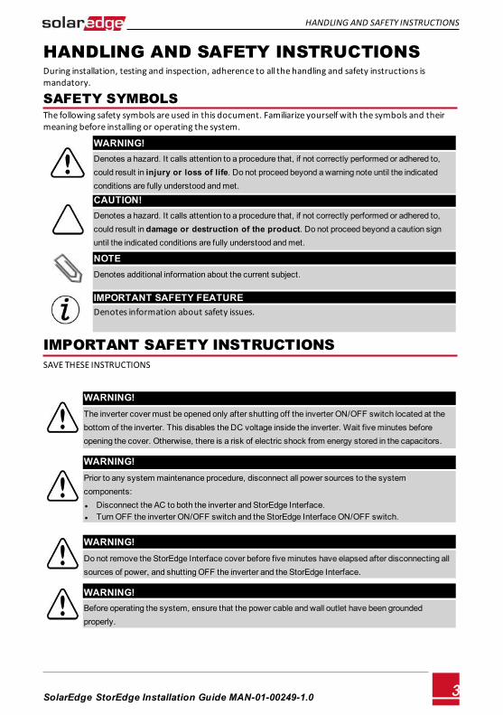
HANDLING AND SAFETY INSTRUCTIONSDuring installation, testing and inspection, adherence to all the handling and safety instructions is mandatory.
SAFETY SYMBOLSThe following safety symbols are used in this document. Familiarize yourself with the symbols and their meaning before installing or operating the system.
WARNING!Denotes a hazard. It calls attention to a procedure that, if not correctly performed or adhered to, could result in injury or loss of life. Do not proceed beyond a warning note until the indicated conditions are fully understood and met.
CAUTION!Denotes a hazard. It calls attention to a procedure that, if not correctly performed or adhered to, could result in damage or destruction of the product. Do not proceed beyond a caution sign until the indicated conditions are fully understood and met.
NOTEDenotes additional information about the current subject.
IMPORTANT SAFETY FEATUREDenotes information about safety issues.
IMPORTANT SAFETY INSTRUCTIONS SAVE THESE INSTRUCTIONS
WARNING!The inverter cover must be opened only after shutting off the inverter ON/OFF switch located at the bottom of the inverter. This disables the DC voltage inside the inverter. Wait five minutes before opening the cover. Otherwise, there is a risk of electric shock from energy stored in the capacitors.
WARNING!Prior to any system maintenance procedure, disconnect all power sources to the system components: l Disconnect the AC to both the inverter and StorEdge Interface. l Turn OFF the inverter ON/OFF switch and the StorEdge Interface ON/OFF switch.
WARNING!Do not remove the StorEdge Interface cover before five minutes have elapsed after disconnecting all sources of power, and shutting OFF the inverter and the StorEdge Interface.
WARNING!Before operating the system, ensure that the power cable and wall outlet have been grounded properly.
HANDLING AND SAFETY INSTRUCTIONS
SolarEdge-StorEdge Installation Guide MAN-01-00249-1.0 3
WARNING!
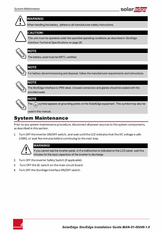
When handling the battery, adhere to all manufacturer safety instructions.
CAUTION!This unit must be operated under the specified operating conditions as described in StorEdge Interface Technical Specifications on page 26.
NOTE
The battery used must be NRTL certified.
NOTE
For battery decommissioning and disposal, follow the manufacturer requirements and instructions.
NOTEThe StorEdge Interface is IP65 rated. Unused connectors and glands should be sealed with the provided seals.
NOTEThe symbol appears at grounding points on the SolarEdge equipment. This symbol may also be
used in this manual.
System MaintenancePrior to any system maintenance procedure, disconnect all power sources to the system components, as described in this section.
1. Turn OFF the inverter ON/OFF switch, and wait until the LCD indicates that the DC voltage is safe (<50V), or wait five minutes before continuing to the next step.
WARNING!If you cannot see the inverter panel, or if a malfunction is indicated on the LCD panel, wait five minutes for the input capacitors of the inverter to discharge.
2. Turn OFF the inverter Safety Switch (if applicable).
3. Turn OFF the AC switch on the main circuit board.
4. Turn OFF the StorEdge Interface ON/OFF switch.
SolarEdge-StorEdge Installation Guide MAN-01-00249-1.04
System Maintenance
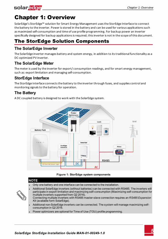
Chapter 1: OverviewSolarEdge’s StorEdge™ solution for Smart Energy Management uses the StorEdge Interface to connect the battery to the inverter. Power is stored in the battery and can be used for various applications such as maximized self-consumption and time of use profile programming. For backup power an inverter specifically designed for backup applications is required; this inverter is not in the scope of this document.
The StorEdge Solution Components The SolarEdge InverterThe SolarEdge inverter manages battery and system energy, in addition to its traditional functionality as a DC-optimized PV inverter.
The SolarEdge MeterThe meter is used by the inverter for export/ consumption readings, and for smart energy management, such as: export limitation and managing self-consumption.
StorEdge Interface The StorEdge Interface connects the battery to the inverter through fuses, and supplies control and monitoring signals to the battery for operation.
The BatteryA DC coupled battery is designed to work with the SolarEdge system.
Figure 1: StorEdge system components
NOTEl Only one battery and one interface can be connected to the installation.l Additional SolarEdge inverters (without batteries) can be connected with RS485. The inverters will
participate in export limitation and maximizing self-consumption (Maximizing self-consumption for multiple inverters supported from Q2 2016).Connecting multiple inverters with RS485 master-slave connection requires an RS485 Expansion Kit (available form SolarEdge).
l Additional non-SolarEdge inverters can be connected. The system will manage maximizing self-consumption in Q2 2016.
l Power optimizers are optional for Time of Use (TOU) profile programming.
Chapter 1: Overview
SolarEdge-StorEdge Installation Guide MAN-01-00249-1.0 5
Installation WorkflowWhen installing the StorEdge system, follow this workflow to ensure all the components are connected and functioning correctly.
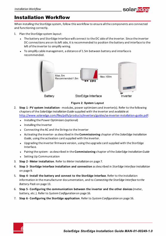
1. Plan the StorEdge system layout:l The battery and StorEdge Interface will connect to the DC side of the inverter. Since the inverter
DC connections are on its left side, it is recommended to position the battery and interface to the left of the inverter to simplify wiring.
l To simplify cable management, a distance of 1.5m between battery and interface is recommended.
Figure 2: System Layout 2. Step 1 - PV system installation - modules, power optimizers and inverter(s). Refer to the following
chapters of the SolarEdge Installation Guide supplied with the inverter and available at http://www.solaredge.com/files/pdfs/products/inverters/guides/se-inverter-installation-guide.pdf: l Installing the Power Optimizers (optional)l Installing the Inverterl Connecting the AC and the Strings to the Inverterl Activating the inverter- as described in the Commissioning chapter of the SolarEdge Installation
Guide, using the activation card supplied with the inverter.l Upgrading the inverter firmware version, using the upgrade card supplied with the StorEdge
Interface.l Pairing the system - as described in the Commissioning chapter of the SolarEdge Installation Guidel Setting Up Communication
3. Step 2 - Meter installation. Refer to Meter Installation on page 7.
4. Step 3 - StorEdge Interface installation and connection as described in StorEdge Interface Installation on page 9.
5. Step 4 - Install the battery and connect to the StorEdge Interface. Refer to the installationinformation in the manufacturer documentation, and to Connecting the StorEdge Interface to the Battery Pack on page 13.
6. Step 5 - Configuring the communication between the inverter and the other devices (meter,battery, etc.). Refer to System Configuration on page 16.
7. Step 6 - Configuring the StorEdge application. Refer to System Configuration on page 16.
SolarEdge-StorEdge Installation Guide MAN-01-00249-1.06
Installation Workflow
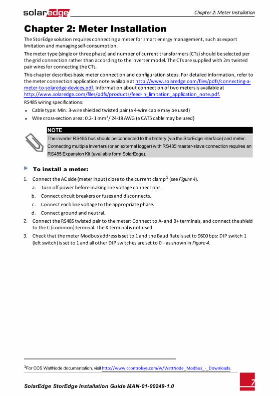
Chapter 2: Meter InstallationThe StorEdge solution requires connecting a meter for smart energy management, such as export limitation and managing self-consumption.The meter type (single or three phase) and number of current transformers (CTs) should be selected per the grid connection rather than according to the inverter model. The CTs are supplied with 2m twisted pair wires for connecting the CTs.This chapter describes basic meter connection and configuration steps. For detailed information, refer to the meter connection application note available at http://www.solaredge.com/files/pdfs/connecting-a-meter-to-solaredge-devices.pdf. Information about connection of two meters is available at http://www.solaredge.com/files/pdfs/products/feed-in_limitation_application_note.pdf.RS485 wiring specifications: l Cable type: Min. 3-wire shielded twisted pair (a 4-wire cable may be used) l Wire cross-section area: 0.2- 1 mm²/ 24-18 AWG (a CAT5 cable may be used)
NOTEThe inverter RS485 bus should be connected to the battery (via the StorEdge interface) and meter.
Connecting multiple inverters (or an external logger) with RS485 master-slave connection requires an
RS485 Expansion Kit (available form SolarEdge).
To install a meter:
1. Connect the AC side (meter input) close to the current clamp1 (see Figure 4). a. Turn off power before making line voltage connections.
b. Connect circuit breakers or fuses and disconnects.
c. Connect each line voltage to the appropriate phase.
d. Connect ground and neutral. 2. Connect the RS485 twisted pair to the meter: Connect to A- and B+ terminals, and connect the shield
to the C (common) terminal. The X terminal is not used. 3. Check that the meter Modbus address is set to 1 and the Baud Rate is set to 9600 bps: DIP switch 1
(left switch) is set to 1 and all other DIP switches are set to 0 – as shown in Figure 4.
1For CCS WattNode documentation, visit http://www.ccontrolsys.com/w/WattNode_Modbus_-_Downloads.
Chapter 2: Meter Installation
SolarEdge-StorEdge Installation Guide MAN-01-00249-1.0 7
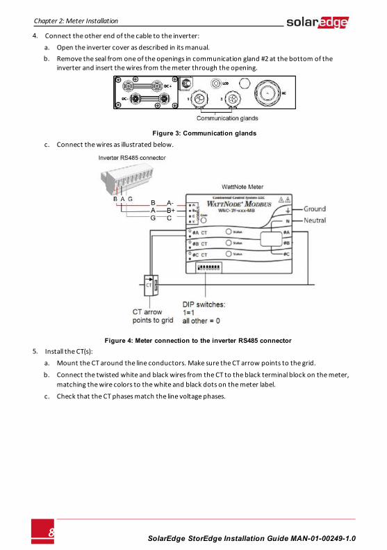
4. Connect the other end of the cable to the inverter: a. Open the inverter cover as described in its manual. b. Remove the seal from one of the openings in communication gland #2 at the bottom of the
inverter and insert the wires from the meter through the opening.
Figure 3: Communication glands
c. Connect the wires as illustrated below.
Figure 4: Meter connection to the inverter RS485 connector 5. Install the CT(s):
a. Mount the CT around the line conductors. Make sure the CT arrow points to the grid.
b. Connect the twisted white and black wires from the CT to the black terminal block on the meter,matching the wire colors to the white and black dots on the meter label.
c. Check that the CT phases match the line voltage phases.
SolarEdge-StorEdge Installation Guide MAN-01-00249-1.08
Chapter 2: Meter Installation
Chapter 3: StorEdge Interface InstallationUnpacking and Identifying the Product 1. Check the equipment for damage before starting installation: There are no loose parts. All parts are
either mounted or located in the accessory kit. If any damage is found, document the damage, andcontact SolarEdge.
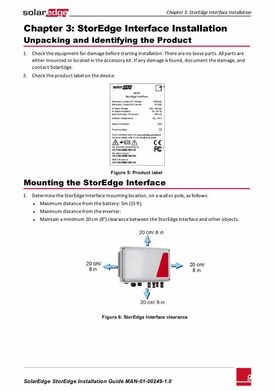
2. Check the product label on the device:
Figure 5: Product label
Mounting the StorEdge Interface 1. Determine the StorEdge Interface mounting location, on a wall or pole, as follows:
l Maximum distance from the battery: 5m (15 ft).l Maximum distance from the inverter: l Maintain a minimum 20 cm (8”) clearance between the StorEdge interface and other objects.
Figure 6: StorEdge Interface clearance
Chapter 3: StorEdge Interface Installation
SolarEdge-StorEdge Installation Guide MAN-01-00249-1.0 9
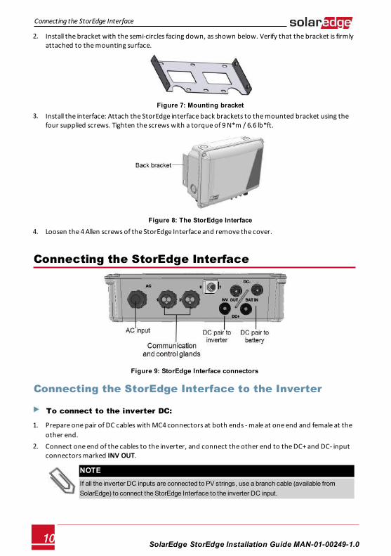
2. Install the bracket with the semi-circles facing down, as shown below. Verify that the bracket is firmlyattached to the mounting surface.
Figure 7: Mounting bracket 3. Install the interface: Attach the StorEdge interface back brackets to the mounted bracket using the
four supplied screws. Tighten the screws with a torque of 9 N*m / 6.6 lb*ft.
Figure 8: The StorEdge Interface
4. Loosen the 4 Allen screws of the StorEdge Interface and remove the cover.
Connecting the StorEdge Interface
Figure 9: StorEdge Interface connectors
Connecting the StorEdge Interface to the Inverter
To connect to the inverter DC:
1. Prepare one pair of DC cables with MC4 connectors at both ends - male at one end and female at the other end.
2. Connect one end of the cables to the inverter, and connect the other end to the DC+ and DC- inputconnectors marked INV OUT.
NOTEIf all the inverter DC inputs are connected to PV strings, use a branch cable (available from SolarEdge) to connect the StorEdge Interface to the inverter DC input.
SolarEdge-StorEdge Installation Guide MAN-01-00249-1.010
Connecting the StorEdge Interface
To connect RS485 communication to the inverter:
RS485 wiring specifications: l Cable type: Min. 3-wire shielded twisted pair (a 4-wire cable may be used) l Wire cross-section area: 0.2- 1 mm²/ 24-18 AWG (a CAT5 cable may be used)
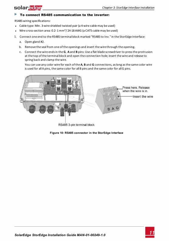
1. Connect one end to the RS485 terminal block marked "RS485 to Inv." in the StorEdge Interface: a. Open gland #2.
b. Remove the seal from one of the openings and insert the wire through the opening. c. Connect the wire ends in the G, A and B pins: Use a flat blade screwdriver to press the protrusion
at the top of the terminal block and open the connection hole; insert the wire and release tospring back and clamp the wire.You can use any color wire for each of the A, B and G connections, as long as the same color wire is used for all A pins, the same color for all B pins and the same color for all G pins.
Figure 10: RS485 connector in the StorEdge Interface
Chapter 3: StorEdge Interface Installation
SolarEdge-StorEdge Installation Guide MAN-01-00249-1.0 11
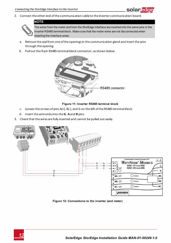
2. Connect the other end of the communication cable to the inverter communication board:
NOTEThe wires from the meter and from the StorEdge Interface are inserted into the same pins in the inverter RS485 terminal block. Make sure that the meter wires are not disconnected when inserting the Interface wires.
a. Remove the seal from one of the openings in the communication gland and insert the wire through the opening.
b. Pull out the 9-pin RS485 terminal block connector, as shown below:
Figure 11: Inverter RS485 terminal block
c. Loosen the screws of pins A(+), B(-), and G on the left of the RS485 terminal block.
d. Insert the wire ends into the G, A and B pins. 3. Check that the wires are fully inserted and cannot be pulled out easily.
Figure 12: Connections to the inverter (and meter)
SolarEdge-StorEdge Installation Guide MAN-01-00249-1.012
Connecting the StorEdge Interface to the Inverter
Connecting the StorEdge Interface to AC
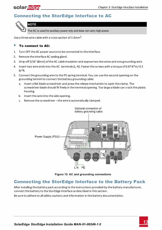
NOTE
The AC is used for auxiliary power only and does not carry high power.
Use a three-wire cable with a cross section of 1-2mm2.
To connect to AC:
1. Turn OFF the AC power source to be connected to the interface.
2. Remove the interface AC sealing gland.
3. Strip off 5/16" (8mm) of the AC cable insulation and expose two line wires and one grounding wire.
4. Insert two wire ends into the AC terminals (L, N). Fasten the screws with a torque of 0.67 N*m/ 0.5 lb*ft.
5. Connect the grounding wire to the PE spring terminal. You can use the second opening on the grounding terminl to connect the battery grounding cable: a. Insert a flat blade screwdriver and press the release mechanism to open the clamp. The
screwdriver blade should fit freely in the terminal opening. Too large a blade can crack the plastichousing.
b. Insert the wire into the side opening. c. Remove the screwdriver – the wire is automatically clamped.
Figure 13: AC and grounding connections
Connecting the StorEdge Interface to the Battery PackAfter installing the battery pack according to the instructions provided by the battery manufacturer, connect the battery to the StorEdge Interface as described in this section.Be sure to adhere to all safety cautions and information in the battery documentation.
Chapter 3: StorEdge Interface Installation
SolarEdge-StorEdge Installation Guide MAN-01-00249-1.0 13
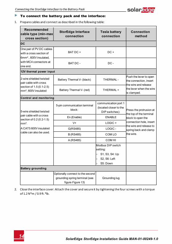
To connect the battery pack and the interface:
1. Prepare cables and connect as described in the following table:
Recommended cable type (min-max
cross section)
StorEdge Interface connection
Tesla battery connection
Connection method
DC
One pair of PV DC cables with a cross section of 6mm² , 600V insulated, with MC4 connectors at one end.
BAT DC + DC +
BAT DC - DC -
12V thermal power input
2-wire shielded twisted pair cable with cross section of 1.5 (0.1-2.5) mm², 600V insulated
Battery Thermal V- (black) THERMAL - Push the lever to open the connection, insert the wire and release the lever when the wire is clamped.
Battery Thermal V- (red) THERMAL +
Control and monitoring
5-wire shielded twisted pair cable with a cross section of 0.2 (0.2-1.5) mm².
A CAT5 600V insulated cable can also be used.
5-pin communication terminal block:
communication port 1 (located closer to the
DIP switches):Press the protrusion at the top of the terminal block to open the connection hole, insert the wire and release to spring back and clamp the wire.
En (Enable) ENABLE
V+ LOGIC +
G(RS485) LOGIC -
B (RS485) COM LO
A (RS485) COM HI
Modbus DIP switch setting: o S1, S3, S4: Up o S2, S6: Left o S5: Down
Battery grounding
Optionally connect to the second grounding spring terminal (see
figure Figure 13)Grounding lug
2. Close the interface cover: Attach the cover and secure it by tightening the four screws with a torque of 1.2 N*m / 0.9 ft.*lb.
SolarEdge-StorEdge Installation Guide MAN-01-00249-1.014
Connecting the StorEdge Interface to the Battery Pack
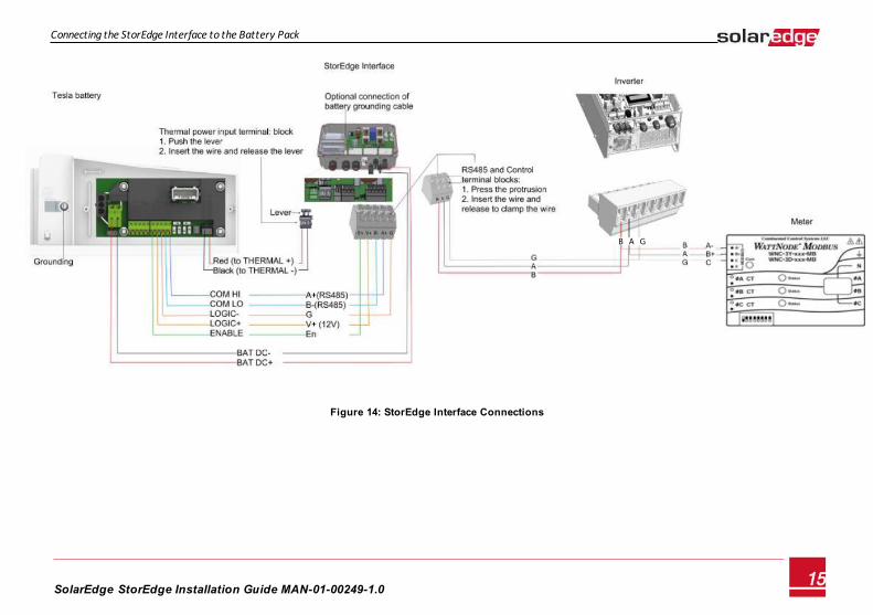
Figure 14: StorEdge Interface Connections
SolarEdge-StorEdge Installation Guide MAN-01-00249-1.015
Connecting the StorEdge Interface to the Battery Pack
B A G
Chapter 4: System ConfigurationThis chapter describes how to configure your SolarEdge system by setting up the communication between the system components and setting up the required application. To use the StorEdge applications, the inverter communication board firmware (CPU) version must be 3.xxxx and later. If you have an inverter with CPU version 2.xxxx, contact SolarEdge support.
Upgrading the Inverter Firmware VersionUpgrade the inverter firmware using the card supplied with the StorEdge Interface.
To upgrade the inverter firmware:
1. Make sure the inverter has been activated using the card supplied with the inverter.
2. Make sure the ON/OFF switch of the StorEdge Interface is OFF.
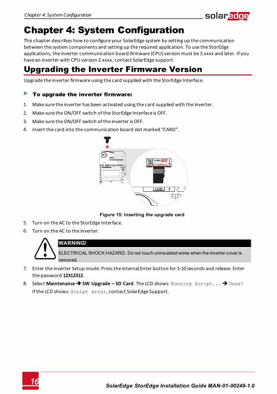
3. Make sure the ON/OFF switch of the inverter is OFF. 4. Insert the card into the communication board slot marked “CARD”.
Figure 15: Inserting the upgrade card
5. Turn on the AC to the StorEdge Interface. 6. Turn on the AC to the inverter.
WARNING!
ELECTRICAL SHOCK HAZARD. Do not touch uninsulated wires when the inverter cover is removed.
7. Enter the inverter Setup mode: Press the internal Enter button for 5-10 seconds and release. Enterthe password 12312312.
8. Select Maintenance è SW Upgrade – SD Card. The LCD shows: Running Script... è Done!If the LCD shows: Script error, contact SolarEdge Support.
SolarEdge-StorEdge Installation Guide MAN-01-00249-1.016
Chapter 4: System Configuration
Configuring the RS485 Bus This section describes how to set up the RS485 communication between the inverter, meter, StorEdge Interface, and battery.
To configure the RS485 bus:
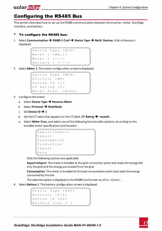
1. Select Communication è RS485-1 Conf è Device Type è Multi Devices. A list of devices is displayed.
D e v i c e T y p e < M L T >
M e t e r 1 < W N , 1 >
M e t e r 2 < - - - >
B a t t e r y 1 < - - - >
2. Select Meter 1. The meter configuration screen is displayed:
D e v i c e T y p e < M T R >
P r o t o c o l < W N >
D e v i c e I D < 1 >
C T R a t i n g < 0 >
M e t e r F u n c . < N o n e >
3. Configure the meter: a. Select Device Type è Revenue Meter
b. Select Protocol è WattNode
c. Set Device ID è 1
d. Set the CT value that appears on the CT label: CT Rating è <xxxxA>.
e. Select Meter Func. and select one of the following functionality options, according to the installed meter specifications and location.
E x p o r t + I m p o r t
E x p o r t
C o n s u m p t i o n
P r o d u c t i o n
I m p o r t
N o n e
Only the following options are applicable:Export+Import: The meter is installed at the grid connection point and reads the energy fed into the grid and the energy purchased from the grid Consumption: The meter is installed at the load consumption point and reads the energy consumed by the site The selected option is displayed in the RS485 Conf screen as <E+I>, <Cons>, .
4. Select Battery 1. The battery configuration screen is displayed:
D e v i c e T y p e < B A T >
P r o t o c o l < T 7 4 >
D e v i c e I D < 2 4 >
B a t t e r y I n f o < >
Chapter 4: System Configuration
SolarEdge-StorEdge Installation Guide MAN-01-00249-1.0 17
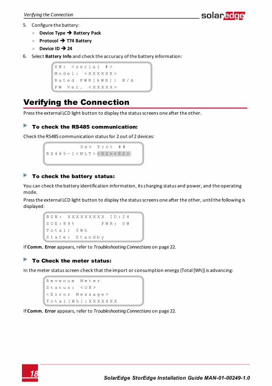
5. Configure the battery: o Device Type è Battery Pack o Protocol è T74 Battery o Device ID è 24
6. Select Battery Info and check the accuracy of the battery information:
S N : < s e r i a l # >
M o d e l : < X X X X X X >
R a t e d P W R [ k W H ] : N / A
F W V e r . < X X X X X >
Verifying the ConnectionPress the external LCD light button to display the status screens one after the other.
To check the RS485 communication:
Check the RS485 communication status for 2 out of 2 devices:
w w w w w w w w D e v P r o t # #
R S 4 8 5 - 1 < M L T > < 0 2 > < 0 2 >
To check the battery status:
You can check the battery identification information, its charging status and power, and the operating mode.Press the external LCD light button to display the status screens one after the other, until the following is displayed:
B S N : X X X X X X X X X I D : 2 4
S O E : 8 9 % W W W W W P W R : 0 W
T o t a l : 0 W h
S t a t e : S t a n d b y
If Comm. Error appears, refer to Troubleshooting Connections on page 22.
To Check the meter status:
In the meter status screen check that the import or consumption energy (Total [Wh]) is advancing:
R e v e n u e M e t e r
S t a t u s : < O K >
< E r r o r M e s s a g e >
T o t a l [ W h ] : X X X X X X X
If Comm. Error appears, refer to Troubleshooting Connections on page 22.
SolarEdge-StorEdge Installation Guide MAN-01-00249-1.018
Verifying the Connection
Configuring Maximum Self-consumptionThe following StorEdge applications are available: l Maximize self-consumption - The battery is automatically charged and discharged to meet
consumption needs. The battery has two states:OFF – the battery is in standbyON – the battery is controlled for maximized self-consumptionBattery OFF periods can be configured to extend battery lifetime by minimizing the number of shallow discharges (for example at nighttime or during the winter).
l Profile Programming (for time of use arbitrage): The StorEdge system operates according to a configured charge/ discharge profile. This option is covered in a separate application note available at http://www.solaredge.com/files/pdfs/StorEdge_TOU_profile_programming.pdf.
To set up max. self-consumption:
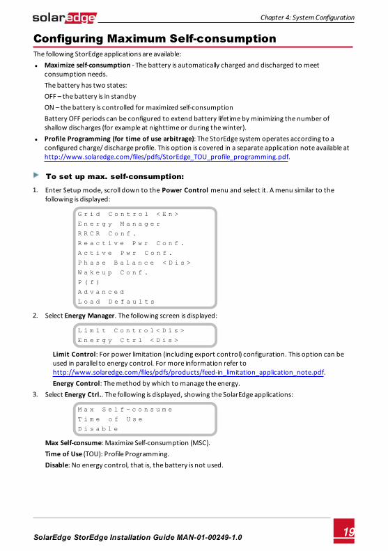
1. Enter Setup mode, scroll down to the Power Control menu and select it. A menu similar to the following is displayed:
G r i d C o n t r o l < E n >
E n e r g y M a n a g e r
R R C R C o n f .
R e a c t i v e P w r C o n f .
A c t i v e P w r C o n f .
P h a s e B a l a n c e < D i s >
W a k e u p C o n f .
P ( f )
A d v a n c e d
L o a d D e f a u l t s
2. Select Energy Manager. The following screen is displayed:
L i m i t C o n t r o l < D i s >
E n e r g y C t r l < D i s >
Limit Control: For power limitation (including export control) configuration. This option can be used in parallel to energy control. For more information refer to http://www.solaredge.com/files/pdfs/products/feed-in_limitation_application_note.pdf. Energy Control: The method by which to manage the energy.
3. Select Energy Ctrl.. The following is displayed, showing the SolarEdge applications:
M a x S e l f - c o n s u m e
T i m e o f U s e
D i s a b l e
Max Self-consume: Maximize Self-consumption (MSC).Time of Use (TOU): Profile Programming.Disable: No energy control, that is, the battery is not used.
Chapter 4: System Configuration
SolarEdge-StorEdge Installation Guide MAN-01-00249-1.0 19
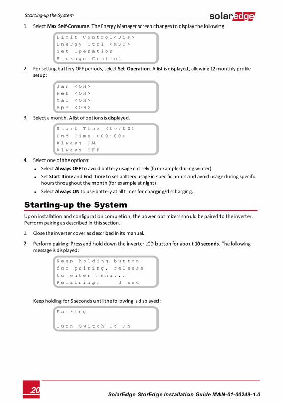
1. Select Max Self-Consume. The Energy Manager screen changes to display the following:
L i m i t C o n t r o l < D i s >
E n e r g y C t r l < M S C >
S e t O p e r a t i o n
S t o r a g e C o n t r o l
2. For setting battery OFF periods, select Set Operation. A list is displayed, allowing 12 monthly profile setup:
J a n < O N >
F e b < O N >
M a r < O N >
A p r < O N >
3. Select a month. A list of options is displayed.
S t a r t T i m e < 0 0 : 0 0 >
E n d T i m e < 0 0 : 0 0 >
A l w a y s O N
A l w a y s O F F
4. Select one of the options: l Select Always OFF to avoid battery usage entirely (for example during winter) l Set Start Time and End Time to set battery usage in specific hours and avoid usage during specific
hours throughout the month (for example at night) l Select Always ON to use battery at all times for charging/discharging.
Starting-up the SystemUpon installation and configuration completion, the power optimizers should be paired to the inverter. Perform pairing as described in this section.
1. Close the inverter cover as described in its manual.
2. Perform pairing: Press and hold down the inverter LCD button for about 10 seconds. The following message is displayed:
K e e p h o l d i n g b u t t o n
f o r p a i r i n g , r e l e a s e
t o e n t e r m e n u . . .
R e m a i n i n g : 3 s e c
Keep holding for 5 seconds until the following is displayed:
P a i r i n g
T u r n S w i t c h T o O n
SolarEdge-StorEdge Installation Guide MAN-01-00249-1.020
Starting-up the System
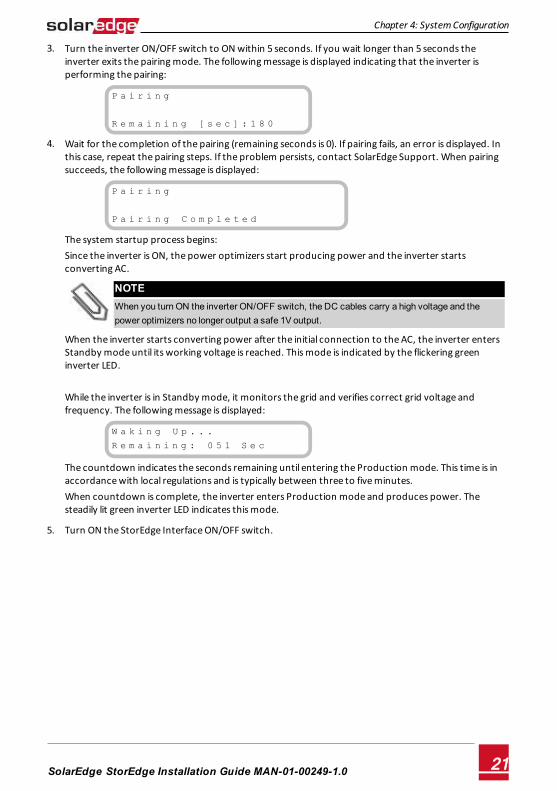
3. Turn the inverter ON/OFF switch to ON within 5 seconds. If you wait longer than 5 seconds the inverter exits the pairing mode. The following message is displayed indicating that the inverter is performing the pairing:
P a i r i n g
R e m a i n i n g [ s e c ] : 1 8 0
4. Wait for the completion of the pairing (remaining seconds is 0). If pairing fails, an error is displayed. In this case, repeat the pairing steps. If the problem persists, contact SolarEdge Support. When pairing succeeds, the following message is displayed:
P a i r i n g
P a i r i n g C o m p l e t e d
The system startup process begins:Since the inverter is ON, the power optimizers start producing power and the inverter starts converting AC.
NOTEWhen you turn ON the inverter ON/OFF switch, the DC cables carry a high voltage and the power optimizers no longer output a safe 1V output.
When the inverter starts converting power after the initial connection to the AC, the inverter enters Standby mode until its working voltage is reached. This mode is indicated by the flickering green inverter LED. While the inverter is in Standby mode, it monitors the grid and verifies correct grid voltage and frequency. The following message is displayed:
W a k i n g U p . . .
R e m a i n i n g : 0 5 1 S e c
The countdown indicates the seconds remaining until entering the Production mode. This time is in accordance with local regulations and is typically between three to five minutes. When countdown is complete, the inverter enters Production mode and produces power. The steadily lit green inverter LED indicates this mode.
5. Turn ON the StorEdge Interface ON/OFF switch.
Chapter 4: System Configuration
SolarEdge-StorEdge Installation Guide MAN-01-00249-1.0 21
Appendix A: Troubleshooting ConnectionsThis appendix describes how to troubleshoot meter and battery related errors.
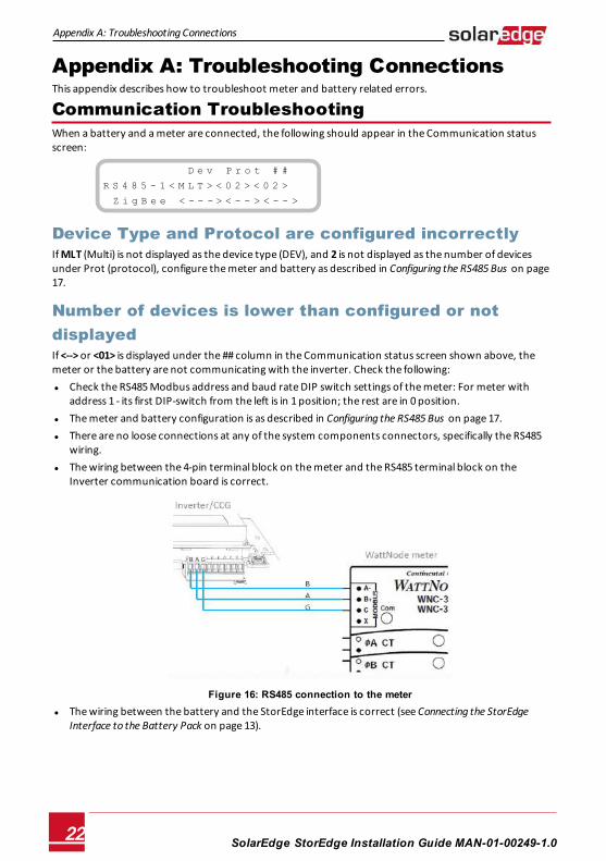
Communication TroubleshootingWhen a battery and a meter are connected, the following should appear in the Communication status screen:
w w w w w w w w D e v P r o t # #
R S 4 8 5 - 1 < M L T > < 0 2 > < 0 2 >
Z i g B e e < - - - > < - - > < - - >
Device Type and Protocol are configured incorrectlyIf MLT (Multi) is not displayed as the device type (DEV), and 2 is not displayed as the number of devices under Prot (protocol), configure the meter and battery as described in Configuring the RS485 Bus on page 17.
Number of devices is lower than configured or not displayedIf <--> or <01> is displayed under the ## column in the Communication status screen shown above, the meter or the battery are not communicating with the inverter. Check the following: l Check the RS485 Modbus address and baud rate DIP switch settings of the meter: For meter with
address 1 - its first DIP-switch from the left is in 1 position; the rest are in 0 position. l The meter and battery configuration is as described in Configuring the RS485 Bus on page 17. l There are no loose connections at any of the system components connectors, specifically the RS485
wiring. l The wiring between the 4-pin terminal block on the meter and the RS485 terminal block on the
Inverter communication board is correct.
Figure 16: RS485 connection to the meter l The wiring between the battery and the StorEdge interface is correct (see Connecting the StorEdge
Interface to the Battery Pack on page 13).
SolarEdge-StorEdge Installation Guide MAN-01-00249-1.022
Appendix A: Troubleshooting Connections
Meter TroubleshootingWhen an Export +Import (E+I) meter is connected, there will be a status screen for each meter function. When a consumption meter is installed, there is only one status screen. The following is an example of the export meter function status:
E x p o r t M e t e r
S t a t u s : < O K >
< E r r o r M e s s a g e >
T o t a l [ W h ] : X X X X X X X
<OK> is not displayedIf <OK> is not displayed in the Status line of the status screens, the meter is not communicating with the inverter communication board. Check the following: l There are no loose connections at the inverter communication board and at the meter. l The wiring between the 4-pin terminal block on the meter and the RS485 terminal block on the
Inverter communication board is correct (see Figure 16).
An error message is displayed l If Comm. Error is displayed, verify proper connection of:
o The RS485 cables and connectors o The AC connection of the meter
l If Error 185 Meter Comm Error message is displayed in the meter status screen, contact SolarEdge support.
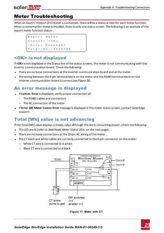
Total [Wh] value is not advancingIf the Total [Wh] value displays a steady value although the site is consuming power, check the following: l The LED are lit (refer to WattNode Meter Status LEDs on the next page). l There are no loose connections at the 10-pin AC wiring of the meter . l The CT black and white cables are correctly connected to the 6-pin connector on the meter:
o White CT wire is connected to A white o Black CT wire is connected to A black
Figure 17: Meter with CT
Appendix A: Troubleshooting Connections
SolarEdge-StorEdge Installation Guide MAN-01-00249-1.0 23
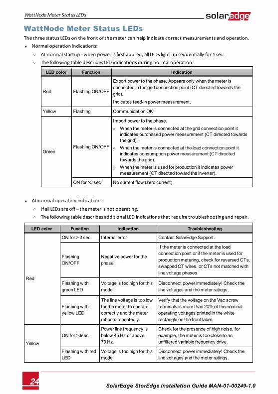
WattNode Meter Status LEDs The three status LEDs on the front of the meter can help indicate correct measurements and operation. l Normal operation indications:
o At normal startup - when power is first applied, all LEDs light up sequentially for 1 sec. o The following table describes LED indications during normal operation:
LED color Function Indication
Red Flashing ON/OFF
Export power to the phase. Appears only when the meter is connected in the grid connection point (CT directed towards the grid).
Indicates feed-in power measurement.
Yellow Flashing Communication OK
GreenFlashing ON/OFF
Import power to the phase. o When the meter is connected at the grid connection point it
indicates purchased power measurement (CT directed towards the grid).
o When the meter is connected at the load connection point it indicates consumption power measurement (CT directed towards the grid).
o When the meter is used for production it indicates power measurement (CT directed toward the inverter).
ON for >3 sec No current flow (zero current)
l Abnormal operation indications:
o If all LEDs are off – the meter is not operating. o The following table describes additional LED indications that require troubleshooting and repair.
LED color Function Indication Troubleshooting
Red
ON for > 3 sec. Internal error Contact SolarEdge Support.
Flashing ON/OFF
Negative power for the phase
If the meter is connected at the load connection point or if the meter is used for production metering, check for reversed CTs, swapped CT wires, or CTs not matched with line voltage phases.
Flashing with green LED
Voltage is too high for this model
Disconnect power immediately! Check the line voltages and the meter ratings.
Flashing with yellow LED
The line voltage is too low for the meter to operate correctly and the meter reboots repeatedly.
Verify that the voltage on the Vac screw terminals is more than 20% of the nominal operating voltages printed in the white rectangle on the front label.
Yellow
ON for >3sec. Power line frequency is below 45 Hz or above 70 Hz.
Check for the presence of high noise, for example, the meter is too close to an unfiltered variable frequency drive.
Flashing with red LED
Voltage is too high for this model
Disconnect power immediately! Check the line voltages and the meter ratings.
SolarEdge-StorEdge Installation Guide MAN-01-00249-1.024
WattNode Meter Status LEDs
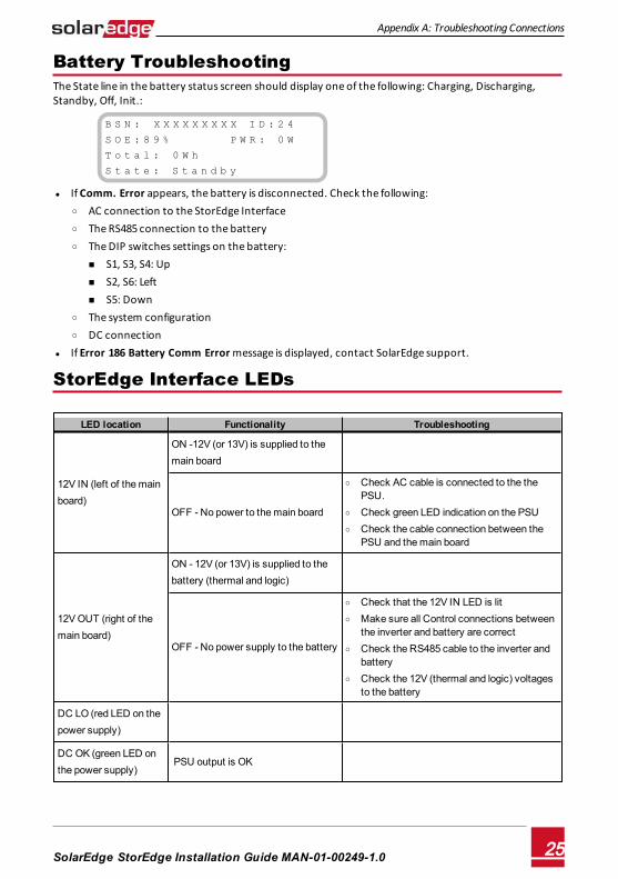
Battery TroubleshootingThe State line in the battery status screen should display one of the following: Charging, Discharging, Standby, Off, Init.:
B S N : X X X X X X X X X I D : 2 4
S O E : 8 9 % W W W W W P W R : 0 W
T o t a l : 0 W h
S t a t e : S t a n d b y
l If Comm. Error appears, the battery is disconnected. Check the following: o AC connection to the StorEdge Interface o The RS485 connection to the battery o The DIP switches settings on the battery:
n S1, S3, S4: Up n S2, S6: Left n S5: Down
o The system configuration o DC connection
l If Error 186 Battery Comm Error message is displayed, contact SolarEdge support.
StorEdge Interface LEDs
LED location Functionality Troubleshooting
12V IN (left of the main board)
ON -12V (or 13V) is supplied to the main board
OFF - No power to the main board
o Check AC cable is connected to the the PSU.
o Check green LED indication on the PSU o Check the cable connection between the
PSU and the main board
12V OUT (right of the main board)
ON - 12V (or 13V) is supplied to the battery (thermal and logic)
OFF - No power supply to the battery
o Check that the 12V IN LED is lit o Make sure all Control connections between
the inverter and battery are correct o Check the RS485 cable to the inverter and
battery o Check the 12V (thermal and logic) voltages
to the battery
DC LO (red LED on the power supply)
DC OK (green LED on the power supply)
PSU output is OK
Appendix A: Troubleshooting Connections
SolarEdge-StorEdge Installation Guide MAN-01-00249-1.0 25
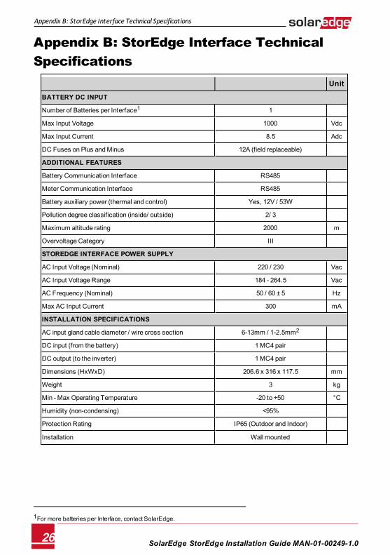
Appendix B: StorEdge Interface Technical Specifications
Unit
BATTERY DC INPUT
Number of Batteries per Interface1 1
Max Input Voltage 1000 Vdc
Max Input Current 8.5 Adc
DC Fuses on Plus and Minus 12A (field replaceable)
ADDITIONAL FEATURES
Battery Communication Interface RS485
Meter Communication Interface RS485
Battery auxiliary power (thermal and control) Yes, 12V / 53W
Pollution degree classification (inside/ outside) 2/ 3
Maximum altitude rating 2000 m
Overvoltage Category III
STOREDGE INTERFACE POWER SUPPLY
AC Input Voltage (Nominal) 220 / 230 Vac
AC Input Voltage Range 184 - 264.5 Vac
AC Frequency (Nominal) 50 / 60 ± 5 Hz
Max AC Input Current 300 mA
INSTALLATION SPECIFICATIONS
AC input gland cable diameter / wire cross section 6-13mm / 1-2.5mm2
DC input (from the battery) 1 MC4 pair
DC output (to the inverter) 1 MC4 pair
Dimensions (HxWxD) 206.6 x 316 x 117.5 mm
Weight 3 kg
Min - Max Operating Temperature -20 to +50 °C
Humidity (non-condensing) <95%
Protection Rating IP65 (Outdoor and Indoor)
Installation Wall mounted
1For more batteries per Interface, contact SolarEdge.
SolarEdge-StorEdge Installation Guide MAN-01-00249-1.026
Appendix B: StorEdge Interface Technical Specifications
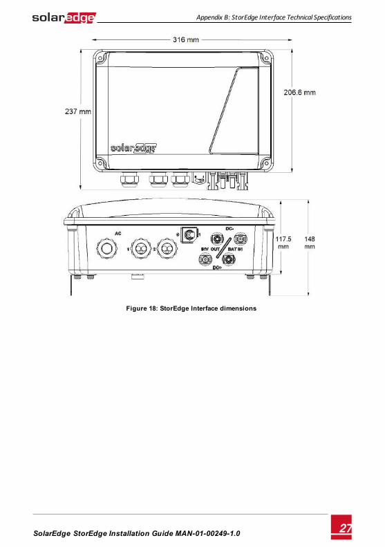
Figure 18: StorEdge Interface dimensions
Appendix B: StorEdge Interface Technical Specifications
SolarEdge-StorEdge Installation Guide MAN-01-00249-1.0 27

Related Documents