Rev. 1.3 7/13 Copyright © 2013 by Silicon Laboratories AN137 AN137 L ITHIUM I ON B ATTERY C HARGER U SING C8051F300 Introduction Driven by the need for untethered mobility and ease of use, many systems rely on rechargable bat- teries as their primary power source. The battery charging circuitry for these systems is typically implemented using a fixed-function IC to control the charging current/voltage profile. The C8051F30x family provides a flexible alterna- tive to fixed-function battery chargers. This appli- cation note discusses how to use the C8051F30x family in Li-Ion battery charger applications. The Li-Ion charging algorithms can be easily adapted to other battery chemistries, but an understanding of other battery chemistries is required to ensure proper charging for those chemistries. The code accompanying this application note was originally written for C8051F30x devices. The code can also be ported to other devices in the Sili- con Labs microcontroller range. Key Points • On-chip high-speed, 8-bit ADC provides supe- rior accuracy in monitoring charge voltage (critical to prevent overcharging in Li-Ion applications), maximizing charge effectiveness and battery life. • On-chip PWM provides means to implement buck converter with a very small external inductor. • On-chip Temp sensor provides an accurate and stable drive voltage for determining battery temperature. An external RTD (resistive tem- perature device) can also be used via the flexi- ble analog input AMUX. • A single C8051F30x platform provides full product range for multi-chemistry chargers, expediting time to market and reducing inven- tory. V Pos (+) V Neg (-) LED Buck Converter Sense Resistor Li-Ion Cells 8k FLASH, PWM, Temp Sensor, Precision Time Base 8051F30x Cygnal Integrated Products Resistor Divider LDO PWM Out AIN Figure 1. Lithium Ion Battery Charge Block Diagram.

Welcome message from author
This document is posted to help you gain knowledge. Please leave a comment to let me know what you think about it! Share it to your friends and learn new things together.
Transcript
Rev. 1.3 7/13 Copyright © 2013 by Silicon Laboratories AN137
AN137
LITHIUM ION BATTERY CHARGER USING C8051F300
IntroductionDriven by the need for untethered mobility andease of use, many systems rely on rechargable bat-teries as their primary power source. The batterycharging circuitry for these systems is typicallyimplemented using a fixed-function IC to controlthe charging current/voltage profile.
The C8051F30x family provides a flexible alterna-tive to fixed-function battery chargers. This appli-cation note discusses how to use the C8051F30xfamily in Li-Ion battery charger applications. TheLi-Ion charging algorithms can be easily adapted toother battery chemistries, but an understanding ofother battery chemistries is required to ensureproper charging for those chemistries.
The code accompanying this application note wasoriginally written for C8051F30x devices. Thecode can also be ported to other devices in the Sili-con Labs microcontroller range.
Key Points• On-chip high-speed, 8-bit ADC provides supe-
rior accuracy in monitoring charge voltage (critical to prevent overcharging in Li-Ion applications), maximizing charge effectiveness and battery life.
• On-chip PWM provides means to implement buck converter with a very small external inductor.
• On-chip Temp sensor provides an accurate and stable drive voltage for determining battery temperature. An external RTD (resistive tem-perature device) can also be used via the flexi-ble analog input AMUX.
• A single C8051F30x platform provides full product range for multi-chemistry chargers, expediting time to market and reducing inven-tory.
V Pos (+)
V Neg (-)
LED
BuckConverter
Sense Resistor
Li-IonCells
8k FLASH, PWM,Temp Sensor,
Precision Time Base
8051F30x
CygnalIntegratedProducts
ResistorDivider
LDO
PWM Out
AIN
Figure 1. Lithium Ion Battery Charge Block Diagram.

AN137
2 Rev. 1.3
Charging BasicsBatteries are exhaustively characterized to deter-mine safe yet time-efficient charging profiles. Theoptimum charging method for a battery is depen-dent on the battery’s chemistry (Li-Ion, NiMH,NiCd, SLA, etc.). However, most charging strate-gies implement a 3-phase scheme:
1. Low-current conditioning phase
2. Constant-current phase
3. Constant-voltage phase/charge termination
All batteries are charged by transferring electricalenergy into them (refer to the references at the endof this note for a battery primer). The maximumcharge current for a battery is dependent on the bat-tery’s rated capacity (C). For example, a batterywith a cell capacity of 1000mAh is referred to asbeing charged at 1C (1 times the battery capacity) ifthe charge current is 1000mA. A battery can becharged at 1/50C (20 mA) or lower if desired.However, this is a common trickle-charge rate andis not practical in fast charge schemes where shortcharge-time is desired.
Most modern chargers utilize both trickle-chargeand rated charge (also referred to as bulk charge)while charging a battery. The trickle-charge currentis usually used in the initial phases of charging tominimize early self heating which can lead to pre-mature charge termination. The bulk charge is usu-ally used in the middle phase where the most of thebattery’s energy is restored.
During the final phase of battery charge, whichgenerally takes the majority of the charge time,either the current or voltage or a combination ofboth are monitored to determine when charging iscomplete. Again, the termination scheme dependson the battery’s chemistry. For instance, most Lith-ium Ion battery chargers hold the battery voltageconstant, and monitor for minimum current. NiCd
batteries use a rate of change in voltage or tempera-ture to determine when to terminate.
Note that while charging a battery, most of the elec-trical energy is stored in a chemical process, but notall as no system is 100 percent efficient. Some ofthe electrical energy is converter to thermal energy,heating up the battery. This is fine until the batteryreaches full charge at which time all the electricalenergy is converted to thermal energy. In this case,if charging isn’t terminated, the battery can bedamaged or destroyed. Fast chargers (chargers thatcharge batteries fully in less than a couple hours)compound this issue, as these chargers use a highcharge current to minimize charge time. As one cansee, monitoring a battery’s temperature is critical(especially for Li-Ion as they explode if over-charged). Therefore, the temperature is monitoredduring all phases. Charge is terminated immedi-ately if the temperature rises out of range.
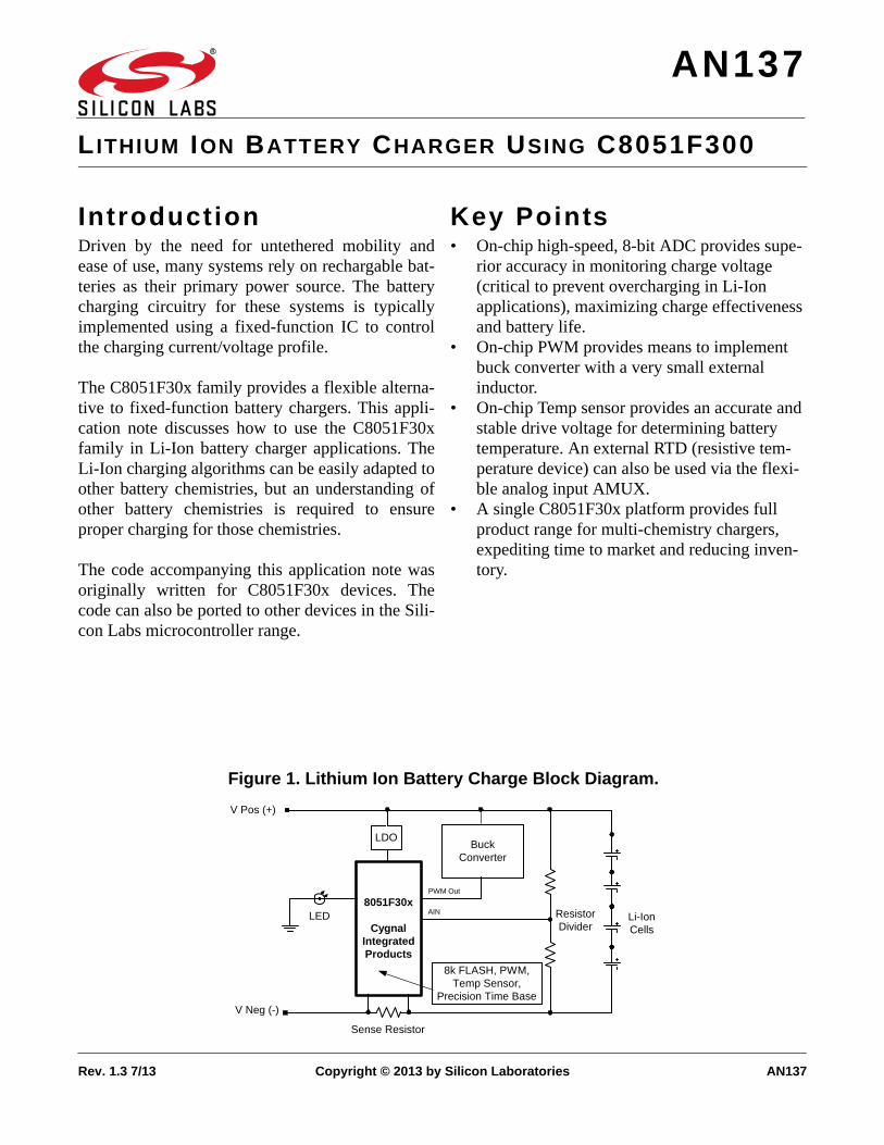
Li-Ion Battery Charger - HardwareCurrently, Li-Ion batteries are the battery chemistryof choice for most applications due to their highenergy/space and energy/weight characteristicswhen compared to other chemistries. Most modernLi-Ion chargers use the tapered charge termination,minimum current (see Figure 2), method to ensurethe battery is fully charged as does the examplecode provided at the end of this note.
Buck ConverterThe most economical way to create a tapered ter-mination charger is to use a buck converter. A buckconverter is a switching regulator that uses aninductor and/or a transformer (if isolation isdesired), as an energy storage element to transferenergy from the input to the output in discretepackets (for our example we use an inductor; thecapacitor in Figure 3 is used for ripple reduction).Feedback circuitry regulates the energy transfer viathe transistor, also referred to as the pass switch, tomaintain a constant voltage or constant current
AN137
Rev. 1.3 3
within the load limits of the circuit. See Figure 3for details.
Tapered Charger Using the F30xFigure 3 illustrates an example buck converterusing the ‘F30x. The pass switch is controlled viathe on-chip 8-bit PWM (Pulse Width Modulator)output of the PCA. When the switch is on, currentwill flow like in Figure 3A. The capacitor ischarged from the input through the inductor. Theinductor is also charged. When the switch isopened (Figure 3B), the inductor will try to main-tain its current flow by inducing a voltage as thecurrent through an inductor can’t change instanta-neously. The current then flows through the diodeand the inductor charges the capacitor. Then thecycle repeats itself. On a larger scale, if the dutycycle is decreased (shorter “on” time), the averagevoltage decreases and vice versa. Therefore, con-
trolling the duty cycles allows one to regulate thevoltage or the current to within desired limits.
Selecting the Buck Converter InductorTo size the inductor in the buck converter, one firstassumes a 50 percent duty cycle, as this is wherethe converter operates most efficiently.
Duty cycle is given by Equation 1, where T is theperiod of the PWM (in our example T = 10.5S).
Charge Current
Charge Voltage
TimeConditioningPhase
Current regulation Voltage regulation
Figure 2. Lithium Ion Charge Profile.
Inductor
CapacitorPowerSource
Battery
Inductor
Pass Switch Off
CapacitorPowerSource
Battery
(A) (B)
Pass Switch On
ShottkyDiode
ShottkyDiode
Figure 3. Buck Converter.
DutyCycletonT
---------=
Equation 1. Duty Cycle.

AN137
4 Rev. 1.3
With this established, select a PWM switching fre-quency. As Equation 2
shows, the larger the PWM switching frequency,the smaller (and more cost effective) the inductor.Our example code configures the ‘F30x’s 8-bithardware PWM to use the internal master clock of24.5MHz divided by 256 to generate a 95.7kHzswitch rate.
Now we can calculate the inductor’s size. Assum-ing Vi, the charging voltage, is 15V, Vsat, the satu-ration voltage, is 0.5V, the desired output voltage,Vo, is 4.2V, and I0MAX, the maximum output cur-rent, is 1500 mA, the inductor should be at least18H.
Note that the capacitor in this circuit is simply aripple reducer. The larger it is the better as ripple isinversely proportional to the size of the cap. Formore details on buck converters, refer to the refer-ences listed at the end of this note.
Li-Ion Battery Charger - SoftwareThe software example that follows demonstrates aLi-Ion battery charger using the C8051F300. TheF300 is designed for high-level languages like “C”and includes an 8-bit 8051 based micro-controller,an 8-bit 500 ksps ADC, 8k FLASH, an 8-bit and16-bit PWM, and a 2% accurate oscillator all on-chip. The algorithms discussed are written entirelyin “C” making them easily portable. Refer to theF300’s datasheet for a full description of thedevice.
CalibrationTo ensure accurate voltage and current measure-ments, the algorithms use a two-point system cali-bration scheme. In this scheme, the user is expectedto apply two known voltages and two known cur-rents, preferable, one point near ground and theother point near full-scale. The algorithm thentakes these two points, calculates a slope and anoffset for both the current and voltage channels,and stores the results in FLASH. All future conver-sions are scaled relative to these slope and offsetcalculations. Note that if an external amplifier isused for the current channel, it will need to be cali-brated with a similar two-point calibration schemeto ensure maximum accuracy.
TemperatureTo monitor the temperature, the algorithms use theon-chip temperature sensor. The sensor is leftuncalibrated, but still provides a sufficiently accu-rate temperature measurement. For more accuratetemperature measurement, one or two-point tem-perature calibration is required.
An external temperature sensor can be used ifdesired. The AMUX can to be reconfigured toaccommodate this additional input voltage.
CurrentThe charge-current to the battery cells is monitoredby taking a differential voltage reading across asmall but accurate sense resistor. The current isamplified through the on-chip PGA, digitized bythe on-chip 8-bit ADC, and scaled accordingly viathe slope and offset calibration coefficients. Anexternal gain stage may be necessary if more reso-lution is desired for the current measurement.
VoltageThe battery’s voltages are divided down and moni-tored via external resistors. Note that this exampleuses the supply voltage as the ADC voltage refer-ence. Any monitored voltage above the reference
LVi Vsat– Vo– ton
2Iomax----------------------------------------------------=
Equation 2. Inductor Size.

AN137
Rev. 1.3 5
voltage must be divided down for accurate moni-toring. If a more accurate reference is required, anexternal voltage reference can be used. Adjustmentto the divide resistors must be made accordingly.
Charging - Phase1In phase 1, (for description purposes, we assumethe battery is initially discharged), the ‘F30x regu-lates the battery’s current to ILOWCURRENT (typi-cally 1/50 C) until the battery’s voltage reachesVMINVOLTBULK. Note that the battery’s charge cur-rent is current limited to ILOWCURRENT to ensuresafe initial charge and to minimize battery self-heating. If at any time the temperature increases outof limit, charging is halted.
Charging - Phase 2Once the battery reaches VMINVOLTBULK the char-ger enters phase 2, where the battery’s algorithmcontrols the PWM pass switch to ensure the outputvoltage provides a constant charge-current IBULKto the battery (rate or bulk current is usually 1C andis definable in the header file as is ILOWCURRENTand VMINVOLTBULK).
Charging - Phase 3After the battery reaches VTop (typically 4.2 V insingle cell charger), the charger algorithm entersphase 3, where the PWM feeds back and regulatesthe battery’s voltage. In phase 3, the battery contin-ues to charge until the battery’s charge currentreaches IMINIBULKl, after which, the battery ischarged for an additional 30 minutes and thencharge terminates. Phase 3 typically takes themajority of the charging time.
Note that in most practical applications, such as aportable PC, the batteries may be in any of the threephases when charging is activated. This doesn’treally affect the charger as it simply monitor’s thebattery’s current condition and starts charging fromthat point.
ConclusionThe C8051F300’s high level of analog integration,small form-factor, integrated FLASH memory, andlow power consumption makes it ideal for flexiblenext generation battery charging applications. Thisapplication note discussed how to use theC8051F30x family in Lithium Ion battery chargerapplications. Example code is provided as well.
ReferencesMaxim Integrated Product, “DC-DC ConverterTutorial”.
Martinez, Carlos and Drori, Yossi and Ciancio,Joe, “AN126 Smart Battery Primer”, Xicor, Octo-ber 1999.

AN137
6 Rev. 1.3
APPENDIXFigure 4. 1 Cell Battery Charger Schematic.

AN137
Rev. 1.3 7
Figure 5. 1 Cell Buck Converter Schematic.

AN137
8 Rev. 1.3
main()
Config_F300()
ErrorDetected
?
BULK_charge()
Turn off LED0, Error
Yes
No
No
CalibrateADCforMeasurement()
Enable Interrupts
Clear Termination FlagsClear Charge Status Flags
Yes
LOWCURRENT_charge()
No
Status = BULK?
Status =LOWCURRENT
?
SW0Pressed?
?
ErrorDetected
?
Infinite Loop
Yes/No
Yes
No
Yes
Turn on LED0
InfiniteLoop
Yes/No
Figure 6. main() Flow Chart.

AN137
Rev. 1.3 9
CalibrateADCforMearurement()
END
NoSW0
Pushed?
Setup ADC0's AMUX,Throughput, Gain, for nearzero-scale voltage cal point
Yes
Acquire 16-bitMeasurement
Setup ADC0's AMUX,Throughput, Gain, for nearfull-scale voltage cal point
Calculate Voltage SlopeCoefficient
Calculate Voltage OffsetCoefficient
Erase Memory Page0x1A00
Store Voltage Offset andSlope Coefficients in
FLASH Memory
Acquire16-bitMeasurement
SW0Pushed
?
Setup ADC0's AMUX,Throughput, Gain, for nearzero-scale Current cal point
Yes
Acquire 16-bitMeasurement
Setup ADC0's AMUX,Throughput, Gain, for nearfull-scale Current cal point
Calculate Current SlopeCoefficient
Calculate Current OffsetCoefficient
Store Current Offset andSlope Coefficients in
FLASH Memory
Acquire16-bitMeasurement
No
Figure 7. CalibrateADCforMeasurement() Flow Chart.
AN137
10 Rev. 1.3
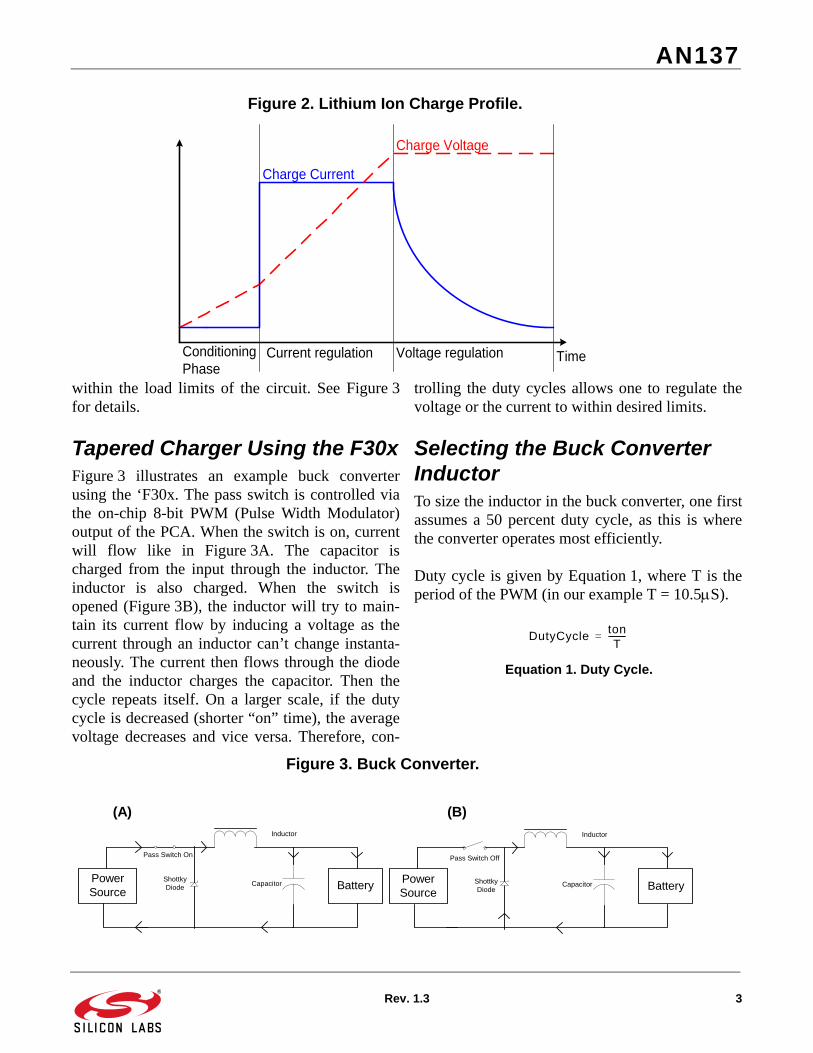
Monitor_Battery()
MeasurementType
?
AMUX = Current AMUX = Volt
AV = AV + ADC0 Turn PWM on
Stop PWM
I?
ADC0 Done?
AMUX = Volt
Stop PWM
AMUX = Temperature
Start ADC0
AV = AV/10
END
No
Current Charge Voltage Temperature Battery Voltage
AV = 0I = 0
Yes
No
Yes
Calculate Voltage w/Calibration Coefficients
Calculate Current w/Calibration Coefficients
Calculate Temperature w/Calibration Coefficients
TemperatureCurrentVoltage w/ or w/out PWM
Return Desired Parameter
Figure 8. Monitor_Battery() Flow Chart.

AN137
Rev. 1.3 11
Bulk_Charge()
Start PWM w/ Zero Output
TWithin Limits
?
Yes
Status = const_C
Calculate bulk_finish_time
Green LED On
Regulate Battery Current
Read Charge Voltage
Change Status fromconst_C to const_V
V<max_V &> min_Bulk
?
Status =BULK & No
Error?
Status =const_c
?
ChargeVoltage Within
Limits?
Yes
No
No
ACB D
Yes
No
No
No
Yes
Yes
Set Appropriate Flags
Figure 9. Bulk_Charge() Flow Chart (Part 1).

AN137
12 Rev. 1.3
Status =const_V
?
Yes
Regulate Voltage()
Stop PWM& Flag Error
Stop PWM& Flag Error
Status = const_CStatus = LOWCURRENT
Green LED Off
TimeOverflow
?
Temp.Overflow
?
60 Sec.Over
?
DelayTimeOver
?
Yes
No
No
ACB D
Yes
No
No
Yes
END
Stop PWM
const_V, NOT Delay & Current
Below Threshold?
Calculate bulk_finish_time
Status = Delay
No
No
Yes
Yes
Figure 10. BULKCurrent() Flow Chart (Part 2).

AN137
Rev. 1.3 13
LOWCURRENT_charge()
ResetTimeBase()
Tempwithin Limits
?
ChargeVoltage
Within Limits?
V<max_V
?
Green LED Blinking
Status = const_V
Regulate Voltage
LowcurrentFinish Timereached?
Stop PWMand flag error
Change Statusfrom const_C to
const_V
Status = Delay
Green LED Off
END
No
Yes
No
Yes
Yes
Yes
Yes
No
No
Yes
Calculate Finish_time
No ERROR &LOWCURRENT =1
?
No
Regulate Current
V<BulkThreshold
?
Prepare Flags to enterBulk Mode
No
Yes
No
Figure 11. LowCurrent_Charge() Flow Chart.

AN137
14 Rev. 1.3
Turn_PWM_Off()
END
Increment CEX0Counter
CEX0Counter<0x0F?
CEX0Counter<0x0F?
No
Yes
No
Disable PWM Mode
Yes
Figure 12. Turn_PWM_Off() Flow Chart.
AN137
Rev. 1.3 15
measure()
END
i = 0?
Set accumulator andcounter i variables to zero
Yes
accumulator =accumulator + ADC0
Increment i
Clear End of ConversionFlag
ConversionComplete
?
No
Return 16-bitMeasurement
No
Start New Conversion
Yes
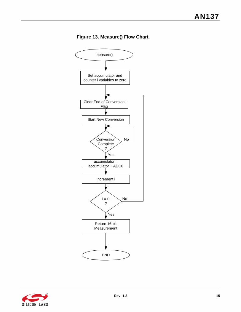
Figure 13. Measure() Flow Chart.
AN137
16 Rev. 1.3
Make Duty Cycle Larger
Voltage <VOLT_BULK &PCA not max
?
END
Measure Battery'svoltage
Voltage >VOLT_BULK &
PCA not 0
Make Duty Cycle Smaller
Regulate_Voltage()
Voltage< VOLT_BULK + Tolerence
& > VOLT_BULK?
No
Yes
Yes
Yes
No
No
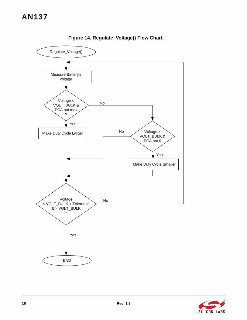
Figure 14. Regulate_Voltage() Flow Chart.

AN137
Rev. 1.3 17
Make Duty Cycle Larger
Current <passed current &
PCA not max?
END
Current >passed current &
PCA not 0
Make Duty Cycle Smaller
Regulate_Current()
No
Yes
Yes
Yes
No
No
Measure Current
Monitor Voltagew/ PWM off
Current =passed value
?
Voltage < VOLT_LOWCURRENT
± Tolerence?
CHARGE_STATUS =const_V
No
Yes
Figure 15. Regulate_Current() Flow Chart.

AN137
18 Rev. 1.3
PCA_OVERFLOW_ISR()
END
60 = time.sec?
Yes
Increment time.hour
Reset time.hour
Reset time.count tooverflow value
0 = time.count
No
No
24 = time.hour
LOWCURRENTcharge &no errors
?
oddsecond
?
Reset PCA Counter andPCA Interrupts
Yes
Increment time.min
60 = time.min?
Yes
Reset time.min
Reset time.sec
Increment time.sec
No
Yes
No
No
No
Yes
Yes
Turn on LED
Turn Off LED
Decrement time.count
Figure 16. PCA_OVERFLOW_ISR() Flow Chart.

AN137
Rev. 1.3 19
//-----------------------------------------------------------------------------//// Copyright 2002 Cygnal Integrated Products, Inc.//// Filename: LIION_BC_MAIN.h// Target Device: 8051F300// Created: 11 SEP 2002// Created By: DKC// Tool chain: KEIL Eval C51//// This header file is used to define all preprocessor directives, prototypes,// and global variable for LIION_BC_MAIN.c.//// The user should modify this header file before proceeding as key// battery parameter limits are set here.//
//-----------------------------------------------------------------------------// Function Prototypes//-----------------------------------------------------------------------------void Config_F300(void);void Reset_Time_Base(void);void CalibrateADCforMeasurement(void);void Regulate_Current(int);void Regulate_Voltage(void);void Turn_PWM_Off(void);int Monitor_Battery(unsigned char);void Bulk_Charge(void);void Lowcurrent_Charge(void);unsigned int Measure(void);void Delay_Loop(void);
//-----------------------------------------------------------------------------// UNIONs, STRUCTUREs, and ENUMs//-----------------------------------------------------------------------------typedef union LONG { // byte-addressable LONG long l; unsigned char b[4];} LONG;
typedef union INT { // byte-addressable INT int i; unsigned char b[2];} INT;
typedef struct{ unsigned long int t_count; int sec; // global seconds int min; // global minutes int hour; // global hour}time_struct;
//-----------------------------------------------------------------------------// Global Variable Definitions
AN137
20 Rev. 1.3
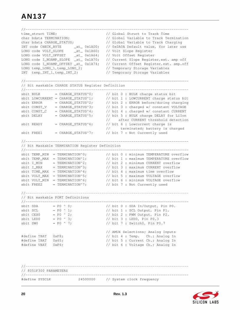
//-----------------------------------------------------------------------------time_struct TIME; // Global Struct to Track Timechar bdata TERMINATION; // Global Variable to Track Terminationchar bdata CHARGE_STATUS; // Global Variable to Track ChargingINT code CHECK_BYTE _at_ 0x1A00; // 0x0A0A Default value, for later useLONG code VOLT_SLOPE _at_ 0x1A60; // Volt Slope RegisterLONG code VOLT_OFFSET _at_ 0x1A64; // Volt Offset RegisterLONG code I_NOAMP_SLOPE _at_ 0x1A70; // Current Slope Register,ext. amp offLONG code I_NOAMP_OFFSET _at_ 0x1A74; // Current Offset Register,ext. amp.offLONG temp_LONG_1,temp_LONG_2; // Temporary Storage VariablesINT temp_INT_1,temp_INT_2; // Temporary Storage Variables
//-----------------------------------------------------------------------------// Bit maskable CHARGE STATUS Register Definition//-----------------------------------------------------------------------------sbit BULK = CHARGE_STATUS^0; // bit 0 : BULK charge status bitsbit LOWCURRENT = CHARGE_STATUS^1; // bit 1 : LOWCURRENT charge status bitsbit ERROR = CHARGE_STATUS^2; // bit 2 : ERROR before/during chargingsbit CONST_V = CHARGE_STATUS^3; // bit 3 : charged w/ constant VOLTAGEsbit CONST_C = CHARGE_STATUS^4; // bit 4 : charged w/ constant CURRENTsbit DELAY = CHARGE_STATUS^5; // bit 5 : BULK charge DELAY for LiIon // after CURRENT threshold detectionsbit READY = CHARGE_STATUS^6; // bit 6 : Lowcurrent charge is // terminated; battery is chargedsbit FREE1 = CHARGE_STATUS^7; // bit 7 : Not Currently used
//-----------------------------------------------------------------------------// Bit Maskable TERMINATION Register Definition//-----------------------------------------------------------------------------sbit TEMP_MIN = TERMINATION^0; // bit 0 : minimum TEMPERATURE overflowsbit TEMP_MAX = TERMINATION^1; // bit 1 : maximum TEMPERATURE overflowsbit I_MIN = TERMINATION^2; // bit 2 : minimum CURRENT overflowsbit I_MAX = TERMINATION^3; // bit 3 : maximum CURRENT overflowsbit TIME_MAX = TERMINATION^4; // bit 4 : maximum time overflowsbit VOLT_MAX = TERMINATION^5; // bit 5 : maximum VOLTAGE overflowsbit VOLT_MIN = TERMINATION^6; // bit 6 : minimum VOLTAGE overflowsbit FREE2 = TERMINATION^7; // bit 7 : Not Currently used
//-----------------------------------------------------------------------------// Bit maskable PORT Definitions//-----------------------------------------------------------------------------sbit SDA = P0 ^ 0; // bit 0 : SDA In/Output, Pin P0.sbit SCL = P0 ^ 1; // bit 1 : SCL Output, Pin P1.sbit CEX0 = P0 ^ 2; // bit 2 : PWM Output, Pin P2.sbit LED0 = P0 ^ 3; // bit 3 : LED0, Pin P0.3sbit SW0 = P0 ^ 7; // bit 7 : Switch0, Pin P0.7
// AMUX Selections; Analog Inputs#define TBAT 0xF8; // bit 4 : Temp. Ch.; Analog In#define IBAT 0x65; // bit 5 : Current Ch.; Analog In#define VBAT 0xF6; // bit 6 : Voltage Ch.; Analog In
//-----------------------------------------------------------------------------// 8051F300 PARAMETERS//-----------------------------------------------------------------------------#define SYSCLK 24500000 // System clock frequency

AN137
Rev. 1.3 21
#define TEMP_SENSOR_GAIN 3300 // Temp Sensor Gain in (uV / degC)#define TEMP_GAIN 2 // PGA gain setting#define CURRENT_GAIN 4 // PGA gain setting#define VREF 3200 // ADC Voltage Reference (mV)#define SCRATCH_PAGE 0x1C00 // FLASH page used for temp storage#define PWM_CLOCK SYSCLK/255 // PWM frequency is 96 kHz
//-----------------------------------------------------------------------------// Calibration/Calculation PARAMETERS//-----------------------------------------------------------------------------#define V1_CAL 67 // 1st cal point for 2 point cal.#define V2_CAL 2800 // 2nd cal point for 2 point cal.#define I1_CAL 67 // 1st cal point for 2 point cal.#define I2_CAL 133 // 2nd cal point for 2 point cal.#define RSENSE 1 // RSENSE is assumed to be 1/2 ohm#define RESB 20 // 10k Ohms, Voltage Divide Resistor#define RESAB 30 // 20k Ohms, Voltage Divide Resistor
#define TEMP_SLOPE ((long) TEMP_GAIN * TEMP_SENSOR_GAIN * 65536 / 100 / VREF) // An estimate of the Temperature<SLOPE> // in [tenth codes / K] // The temperature measurement is // within 3 degrees of accuracy.
//-----------------------------------------------------------------------------// Monitor_Battyer Switch PARAMETERS//-----------------------------------------------------------------------------#define TEMPERATURE 7 // Value for Switch Statement#define VOLTAGE 5 // Value for Switch Statement#define VOLTAGE_PWM_OFF 3 // Value for Switch Statement#define CURRENT 1 // Value for Switch Statement
//-----------------------------------------------------------------------------// Battery/Pack Parameters//-----------------------------------------------------------------------------#define CELLS 1 // Number of cells in the battery pack#define CAPACITY 150 // mAh, Battery Capacity (LiIon)#define LiIon_CELL_VOLT 4200 // mV, Nominal Charge Voltage#define I_BULK (unsigned int)(CAPACITY)#define I_LOWCURRENT (unsigned int)(CAPACITY/4)#define VOLT_BULK (unsigned int)(LiIon_CELL_VOLT)
#define VOLT_LOWCURRENT (unsigned int)(LiIon_CELL_VOLT)
#define VOLT_TOLERANCE (unsigned int)(LiIon_CELL_VOLT/100)// 1 Percent Acc#define CURRENT_TOLERENCE (unsigned int)(CAPACITY/10) // 10 Percent Acc
//-----------------------------------------------------------------------------// Battery Characteristics: Charge TERMINATION Limits//-----------------------------------------------------------------------------#define MIN_TEMP_ABS 26300 // Abs. min. TEMPERATURE = -10 C, 263K#define MAX_TEMP_ABS 32300 // Abs. max. TEMPERATURE = 50C, 323K:
AN137
22 Rev. 1.3
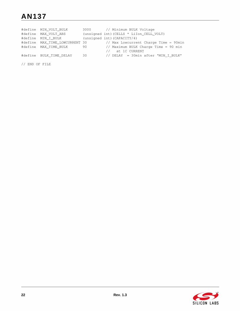
#define MIN_VOLT_BULK 3000 // Minimum BULK Voltage#define MAX_VOLT_ABS (unsigned int)(CELLS * LiIon_CELL_VOLT)#define MIN_I_BULK (unsigned int)(CAPACITY/4)#define MAX_TIME_LOWCURRENT 30 // Max Lowcurrent Charge Time = 90min#define MAX_TIME_BULK 90 // Maximum BULK Charge Time = 90 min // at 1C CURRENT#define BULK_TIME_DELAY 30 // DELAY = 30min after “MIN_I_BULK”
// END OF FILE
AN137
Rev. 1.3 23
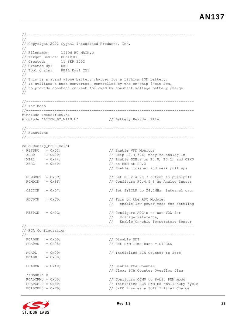
//-----------------------------------------------------------------------------//// Copyright 2002 Cygnal Integrated Products, Inc.// // Filename: LIION_BC_MAIN.c// Target Device: 8051F300// Created: 11 SEP 2002// Created By: DKC// Tool chain: KEIL Eval C51//// This is a stand alone battery charger for a Lithium ION battery.// It utilizes a buck converter, controlled by the on-chip 8-bit PWM,// to provide constant current followed by constant voltage battery charge.//
//-----------------------------------------------------------------------------// Includes//-----------------------------------------------------------------------------#include <c8051f300.h>#include “LIION_BC_MAIN.h” // Battery Hearder File //-----------------------------------------------------------------------------// Functions//-----------------------------------------------------------------------------
void Config_F300(void){ RSTSRC = 0x02; // Enable VDD Monitor XBR0 = 0x70; // Skip P0.4,5,6; they’re analog In XBR1 = 0x44; // Enable SMBus on P0.0, P0.1, and CEX0 XBR2 = 0x40; // as PWM at P0.2 // Enable crossbar and weak pull-ups
P0MDOUT = 0x0C; // Set P0.2 & P0.3 output to push-pull P0MDIN = 0x8F; // Configure P0.4,5,6 as Analog Inputs
OSCICN = 0x07; // Set SYSCLK to 24.5MHz, internal osc.
ADC0CN = 0xC0; // Turn on the ADC Module; // enable low power mode for settling REF0CN = 0x0C; // Configure ADC’s to use VDD for // Voltage Reference, // Enable On-chip Temperature Sensor//-----------------------------------------------------------------------------// PCA Configuration//----------------------------------------------------------------------------- PCA0MD = 0x00; // Disable WDT PCA0MD = 0x08; // Set PWM Time base = SYSCLK
PCA0L = 0x00; // Initialize PCA Counter to Zero PCA0H = 0x00; PCA0CN = 0x40; // Enable PCA Counter // Clear PCA Counter Overflow flag //Module 0 PCA0CPM0 = 0x00; // Configure CCM0 to 8-bit PWM mode PCA0CPL0 = 0xF0; // Initialize PCA PWM to small duty cycle PCA0CPH0 = 0xF0; // 0xF0 Ensures a Soft Initial Charge
AN137
24 Rev. 1.3
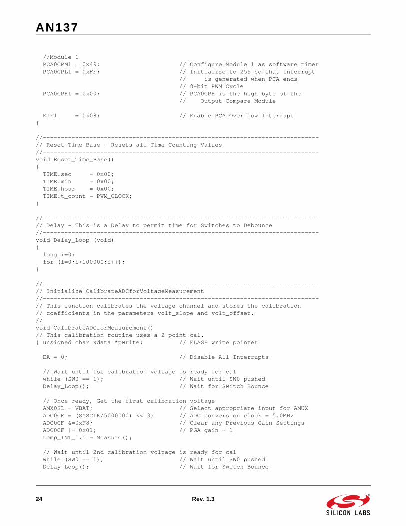
//Module 1 PCA0CPM1 = 0x49; // Configure Module 1 as software timer PCA0CPL1 = 0xFF; // Initialize to 255 so that Interrupt // is generated when PCA ends // 8-bit PWM Cycle PCA0CPH1 = 0x00; // PCA0CPH is the high byte of the // Output Compare Module
EIE1 = 0x08; // Enable PCA Overflow Interrupt }
//-----------------------------------------------------------------------------// Reset_Time_Base - Resets all Time Counting Values//-----------------------------------------------------------------------------void Reset_Time_Base(){ TIME.sec = 0x00; TIME.min = 0x00; TIME.hour = 0x00; TIME.t_count = PWM_CLOCK; }
//-----------------------------------------------------------------------------// Delay - This is a Delay to permit time for Switches to Debounce//-----------------------------------------------------------------------------void Delay_Loop (void){ long i=0; for (i=0;i<100000;i++);}
//-----------------------------------------------------------------------------// Initialize CalibrateADCforVoltageMeasurement//-----------------------------------------------------------------------------// This function calibrates the voltage channel and stores the calibration// coefficients in the parameters volt_slope and volt_offset.//void CalibrateADCforMeasurement()// This calibration routine uses a 2 point cal. { unsigned char xdata *pwrite; // FLASH write pointer EA = 0; // Disable All Interrupts
// Wait until 1st calibration voltage is ready for cal while (SW0 == 1); // Wait until SW0 pushed Delay_Loop(); // Wait for Switch Bounce
// Once ready, Get the first calibration voltage AMX0SL = VBAT; // Select appropriate input for AMUX ADC0CF = (SYSCLK/5000000) << 3; // ADC conversion clock = 5.0MHz ADC0CF &=0xF8; // Clear any Previous Gain Settings ADC0CF |= 0x01; // PGA gain = 1 temp_INT_1.i = Measure(); // Wait until 2nd calibration voltage is ready for cal while (SW0 == 1); // Wait until SW0 pushed Delay_Loop(); // Wait for Switch Bounce
AN137
Rev. 1.3 25
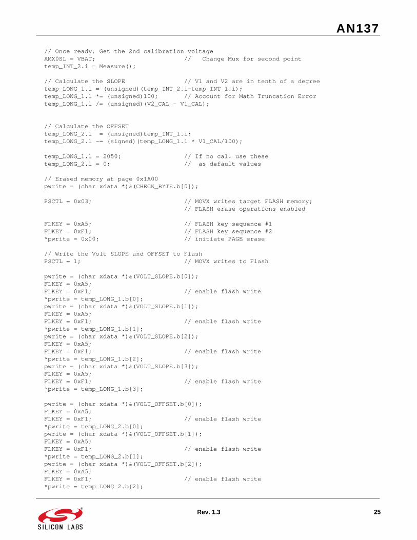
// Once ready, Get the 2nd calibration voltage AMX0SL = VBAT; // Change Mux for second point temp_INT_2.i = Measure(); // Calculate the SLOPE // V1 and V2 are in tenth of a degree temp_LONG_1.l = (unsigned)(temp_INT_2.i-temp_INT_1.i); temp_LONG_1.l *= (unsigned)100; // Account for Math Truncation Error temp_LONG_1.l /= (unsigned)(V2_CAL - V1_CAL); // Calculate the OFFSET temp_LONG_2.l = (unsigned)temp_INT_1.i; temp_LONG_2.l -= (signed)(temp_LONG_1.l * V1_CAL/100); temp_LONG_1.l = 2050; // If no cal. use these temp_LONG_2.l = 0; // as default values // Erased memory at page 0x1A00 pwrite = (char xdata *)&(CHECK_BYTE.b[0]);
PSCTL = 0x03; // MOVX writes target FLASH memory; // FLASH erase operations enabled
FLKEY = 0xA5; // FLASH key sequence #1 FLKEY = 0xF1; // FLASH key sequence #2 *pwrite = 0x00; // initiate PAGE erase
// Write the Volt SLOPE and OFFSET to Flash PSCTL = 1; // MOVX writes to Flash pwrite = (char xdata *)&(VOLT_SLOPE.b[0]); FLKEY = 0xA5; FLKEY = 0xF1; // enable flash write *pwrite = temp_LONG_1.b[0]; pwrite = (char xdata *)&(VOLT_SLOPE.b[1]); FLKEY = 0xA5; FLKEY = 0xF1; // enable flash write *pwrite = temp_LONG_1.b[1]; pwrite = (char xdata *)&(VOLT_SLOPE.b[2]); FLKEY = 0xA5; FLKEY = 0xF1; // enable flash write *pwrite = temp_LONG_1.b[2]; pwrite = (char xdata *)&(VOLT_SLOPE.b[3]); FLKEY = 0xA5; FLKEY = 0xF1; // enable flash write *pwrite = temp_LONG_1.b[3];
pwrite = (char xdata *)&(VOLT_OFFSET.b[0]); FLKEY = 0xA5; FLKEY = 0xF1; // enable flash write *pwrite = temp_LONG_2.b[0]; pwrite = (char xdata *)&(VOLT_OFFSET.b[1]); FLKEY = 0xA5; FLKEY = 0xF1; // enable flash write *pwrite = temp_LONG_2.b[1]; pwrite = (char xdata *)&(VOLT_OFFSET.b[2]); FLKEY = 0xA5; FLKEY = 0xF1; // enable flash write *pwrite = temp_LONG_2.b[2];
AN137
26 Rev. 1.3
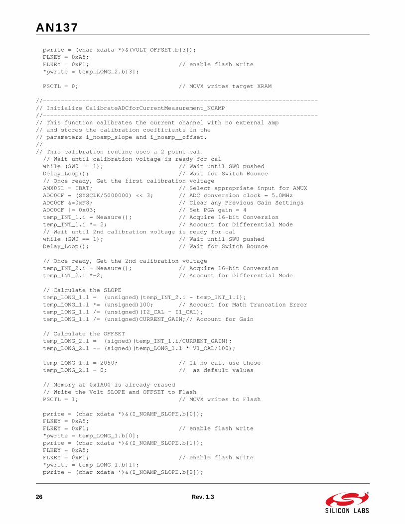
pwrite = (char xdata *)&(VOLT_OFFSET.b[3]); FLKEY = 0xA5; FLKEY = 0xF1; // enable flash write *pwrite = temp_LONG_2.b[3]; PSCTL = 0; // MOVX writes target XRAM
//-----------------------------------------------------------------------------// Initialize CalibrateADCforCurrentMeasurement_NOAMP//-----------------------------------------------------------------------------// This function calibrates the current channel with no external amp// and stores the calibration coefficients in the // parameters i_noamp_slope and i_noamp__offset.//// This calibration routine uses a 2 point cal. // Wait until calibration voltage is ready for cal while (SW0 == 1); // Wait until SW0 pushed Delay_Loop(); // Wait for Switch Bounce // Once ready, Get the first calibration voltage AMX0SL = IBAT; // Select appropriate input for AMUX ADC0CF = (SYSCLK/5000000) << 3; // ADC conversion clock = 5.0MHz ADC0CF &=0xF8; // Clear any Previous Gain Settings ADC0CF |= 0x03; // Set PGA gain = 4 temp_INT_1.i = Measure(); // Acquire 16-bit Conversion temp_INT_1.i *= 2; // Account for Differential Mode // Wait until 2nd calibration voltage is ready for cal while (SW0 == 1); // Wait until SW0 pushed Delay_Loop(); // Wait for Switch Bounce
// Once ready, Get the 2nd calibration voltage temp_INT_2.i = Measure(); // Acquire 16-bit Conversion temp_INT_2.i *=2; // Account for Differential Mode // Calculate the SLOPE temp_LONG_1.l = (unsigned)(temp_INT_2.i - temp_INT_1.i); temp_LONG_1.l *= (unsigned)100; // Account for Math Truncation Error temp_LONG_1.l /= (unsigned)(I2_CAL - I1_CAL); temp_LONG_1.l /= (unsigned)CURRENT_GAIN;// Account for Gain
// Calculate the OFFSET temp_LONG_2.l = (signed)(temp_INT_1.i/CURRENT_GAIN); temp_LONG_2.l -= (signed)(temp_LONG_1.l * V1_CAL/100); temp_LONG_1.l = 2050; // If no cal. use these temp_LONG_2.l = 0; // as default values
// Memory at 0x1A00 is already erased // Write the Volt SLOPE and OFFSET to Flash PSCTL = 1; // MOVX writes to Flash pwrite = (char xdata *)&(I_NOAMP_SLOPE.b[0]); FLKEY = 0xA5; FLKEY = 0xF1; // enable flash write *pwrite = temp_LONG_1.b[0]; pwrite = (char xdata *)&(I_NOAMP_SLOPE.b[1]); FLKEY = 0xA5; FLKEY = 0xF1; // enable flash write *pwrite = temp_LONG_1.b[1]; pwrite = (char xdata *)&(I_NOAMP_SLOPE.b[2]);
AN137
Rev. 1.3 27
FLKEY = 0xA5; FLKEY = 0xF1; // enable flash write *pwrite = temp_LONG_1.b[2]; pwrite = (char xdata *)&(I_NOAMP_SLOPE.b[3]); FLKEY = 0xA5; FLKEY = 0xF1; // enable flash write *pwrite = temp_LONG_1.b[3]; pwrite = (char xdata *)&(I_NOAMP_OFFSET.b[0]); FLKEY = 0xA5; FLKEY = 0xF1; // enable flash write *pwrite = temp_LONG_2.b[0]; pwrite = (char xdata *)&(I_NOAMP_OFFSET.b[1]); FLKEY = 0xA5; FLKEY = 0xF1; // enable flash write *pwrite = temp_LONG_2.b[1]; pwrite = (char xdata *)&(I_NOAMP_OFFSET.b[2]); FLKEY = 0xA5; FLKEY = 0xF1; // enable flash write *pwrite = temp_LONG_2.b[2]; pwrite = (char xdata *)&(I_NOAMP_OFFSET.b[3]); FLKEY = 0xA5; FLKEY = 0xF1; // enable flash write *pwrite = temp_LONG_2.b[3]; PSCTL = 0; // MOVX writes target XRAM}
//-----------------------------------------------------------------------------// Measure//-----------------------------------------------------------------------------//// This routine averages 65536 ADC samples and returns a 16-bit unsigned // result.// unsigned int Measure (void){ unsigned i; // sample counter unsigned long accumulator=0L; // here’s where we integrate the // ADC samples
// read the ADC value and add to running total i = 0; do { AD0INT = 0; // clear end-of-conversion indicator AD0BUSY = 1; // initiate conversion while(!AD0INT); // wait for conversion to complete accumulator += ADC0; // read adc value and accumulate i++; // update counter } while (i != 0x0000); // the accumulator now contains 16 added bits of which 8 are usable return (unsigned int) (accumulator >> 8); }
//-----------------------------------------------------------------------------// Regulate_Current//-----------------------------------------------------------------------------// This routine monitors the battery’s current and adjusts // the PWM (i.e. duty cycle) to keep the current at a known value
AN137
28 Rev. 1.3
//void Regulate_Current(int passed_current){ unsigned int temp = 0; do{ temp = Monitor_Battery(CURRENT); // Measure Current
if (temp < passed_current) PCA0CPH0--; if (temp > passed_current) PCA0CPH0++; }while ((temp < (passed_current - CURRENT_TOLERENCE)) || (temp > (passed_current + CURRENT_TOLERENCE))); // I_BULK or I_LOWCURRENT is set now
temp = Monitor_Battery(VOLTAGE_PWM_OFF); // If VOLTAGE within range, // change from constant CURRENT charge // mode to constant VOLTAGE charge mode if ((temp >= (VOLT_LOWCURRENT - VOLT_TOLERANCE)) && (temp <= (VOLT_LOWCURRENT + VOLT_TOLERANCE))) { CONST_C = 0; CONST_V = 1; }
}
//-----------------------------------------------------------------------------// Regulate_Voltage//-----------------------------------------------------------------------------// This routine monitors the battery’s voltage and adjusts // the PWM (i.e. duty cycle) to keep the voltage at a known value//void Regulate_Voltage(void){ unsigned int temp = 0; // set VOLT_BULK (with “soft start”) do{ temp = Monitor_Battery(VOLTAGE); if (temp < VOLT_BULK) PCA0CPH0--; if (temp > VOLT_BULK) PCA0CPH0++;
}while ((temp < (VOLT_BULK - VOLT_TOLERANCE)) || (temp > (VOLT_BULK + VOLT_TOLERANCE))); // VOLTAGE is set now}
//-----------------------------------------------------------------------------// Turn_PWM_Off//-----------------------------------------------------------------------------// This routine peforms a soft charge turn off by taking the PWM’s // duty cycle slowly to zero.//void Turn_PWM_Off(void){
AN137
Rev. 1.3 29
do{ if (PCA0CPH0 < 0xF0) PCA0CPH0++; }while (PCA0CPH0 < 0xF0); // Duty Cycle is now small and safe to turn off.
PCA0CPM0 = 0x00; // Disable PWM}
//-----------------------------------------------------------------------------// Monitor_Battery//-----------------------------------------------------------------------------// This routine acts as a switch when gathering different conversion types.// It adjusts the throughput, adjust the AMUX and returns the current in mA,// voltage in mV, and temperature in C, 2% accurate.//int Monitor_Battery(unsigned char value){ char i; unsigned long av =0; long signed result;
ADC0CF = (SYSCLK/5000000) << 3; // ADC conversion clock = 5.0MHz ADC0CF &= 0xF8; // Clear any Previous Gain Settings switch (value) { case TEMPERATURE: Turn_PWM_Off(); // Turn PWM Off AMX0SL = TBAT; // Select appropriate input for AMUX ADC0CF |= 0x02; // Set PGA gain = 2 break; case VOLTAGE: AMX0SL = VBAT; // Select appropriate input for AMUX ADC0CF |= 0x01; // Set PGA gain = 1 break;
case VOLTAGE_PWM_OFF: Turn_PWM_Off(); // Turn PWM Off AMX0SL = VBAT; // Select appropriate input for AMUX ADC0CF |= 0x01; // Set PGA gain = 1 break;
case CURRENT: AMX0SL = IBAT; // Select appropriate input for AMUX ADC0CF |= 0x03; // Set PGA gain = 4 break; } //Compute average of next 10 A/D conversions for(av=0,i=10;i;--i){ AD0INT = 0; // clear end-of-conversion indicator AD0BUSY = 1; // initiate conversion while(!AD0INT); // wait for conversion to complete av = av+ADC0; }
AN137
30 Rev. 1.3
av = av/10; // Compute the average av = av<<8; // Convert to 16-bit conversion // ...to account for 16-bit cal. // coefficients
PCA0CPM0 = 0x42; // Turn on PWM
switch (value) { case TEMPERATURE: result = (long) av * 1000/TEMP_SLOPE; break;
case VOLTAGE: case VOLTAGE_PWM_OFF: result = (av - VOLT_OFFSET.l); // Account for System Errors result /= VOLT_SLOPE.l; // Convert to Voltage in Millivolts result *= 100; // Account for Math Truncation Error result *= RESAB; // Account for Divide Resistors result /= RESB; break; case CURRENT: result = av*2; // Account for Differential Mode result -= I_NOAMP_OFFSET.l; // Account for System Errors result /= I_NOAMP_SLOPE.l; // Convert to Milliamps result *= 100; // Account for Math Truncation Error result /= RSENSE; // Account for Sense Resistor result *= RESAB; // Account for Divide Resistors result /= RESB; result /= CURRENT_GAIN; break; }
return (int) result; }
//-----------------------------------------------------------------------------// Bulk_Charge Function//-----------------------------------------------------------------------------void Bulk_Charge(void){ unsigned int temp = 0; unsigned int bulk_finish_hour = 0; unsigned int bulk_finish_min = 0; unsigned int delay_hour = 0; unsigned int delay_min = 0; unsigned int last_min = 0; Reset_Time_Base(); // Reset Time Base to zero
// Calculate BULK charge finish time bulk_finish_min = (TIME.min + MAX_TIME_BULK); bulk_finish_hour = TIME.hour; while (bulk_finish_min > 60) { bulk_finish_min = bulk_finish_min - 60; bulk_finish_hour++; }
AN137
Rev. 1.3 31
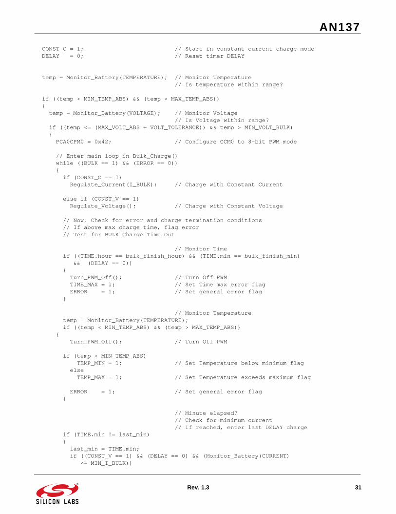
CONST_C = 1; // Start in constant current charge mode DELAY = 0; // Reset timer DELAY
temp = Monitor_Battery(TEMPERATURE); // Monitor Temperature // Is temperature within range?
if ((temp > MIN_TEMP_ABS) && (temp < MAX_TEMP_ABS)) { temp = Monitor_Battery(VOLTAGE); // Monitor Voltage // Is Voltage within range? if ((temp <= (MAX_VOLT_ABS + VOLT_TOLERANCE)) && temp > MIN_VOLT_BULK) { PCA0CPM0 = 0x42; // Configure CCM0 to 8-bit PWM mode // Enter main loop in Bulk_Charge() while ((BULK == 1) && (ERROR == 0)) { if (CONST_C == 1) Regulate_Current(I_BULK); // Charge with Constant Current else if (CONST_V == 1) Regulate_Voltage(); // Charge with Constant Voltage // Now, Check for error and charge termination conditions // If above max charge time, flag error // Test for BULK Charge Time Out
// Monitor Time if ((TIME.hour == bulk_finish_hour) && (TIME.min == bulk_finish_min) && (DELAY == 0)) { Turn_PWM_Off(); // Turn Off PWM TIME_MAX = 1; // Set Time max error flag ERROR = 1; // Set general error flag }
// Monitor Temperature temp = Monitor_Battery(TEMPERATURE); if ((temp < MIN_TEMP_ABS) && (temp > MAX_TEMP_ABS)) { Turn_PWM_Off(); // Turn Off PWM if (temp < MIN_TEMP_ABS) TEMP_MIN = 1; // Set Temperature below minimum flag else TEMP_MAX = 1; // Set Temperature exceeds maximum flag ERROR = 1; // Set general error flag }
// Minute elapsed? // Check for minimum current // if reached, enter last DELAY charge if (TIME.min != last_min) { last_min = TIME.min; if ((CONST_V == 1) && (DELAY == 0) && (Monitor_Battery(CURRENT) <= MIN_I_BULK))
AN137
32 Rev. 1.3
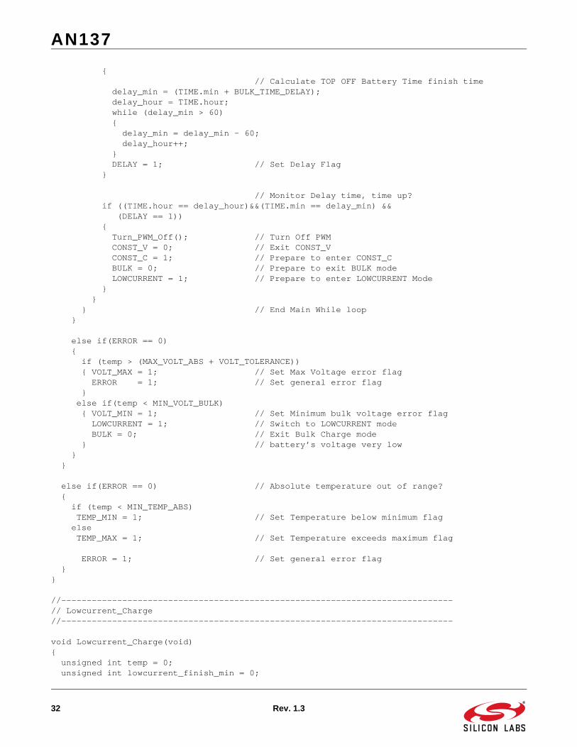
{ // Calculate TOP OFF Battery Time finish time delay_min = (TIME.min + BULK_TIME_DELAY); delay_hour = TIME.hour; while (delay_min > 60) { delay_min = delay_min - 60; delay_hour++; } DELAY = 1; // Set Delay Flag } // Monitor Delay time, time up? if ((TIME.hour == delay_hour)&&(TIME.min == delay_min) && (DELAY == 1)) { Turn_PWM_Off(); // Turn Off PWM CONST_V = 0; // Exit CONST_V CONST_C = 1; // Prepare to enter CONST_C BULK = 0; // Prepare to exit BULK mode LOWCURRENT = 1; // Prepare to enter LOWCURRENT Mode } } } // End Main While loop }
else if(ERROR == 0) { if (temp > (MAX_VOLT_ABS + VOLT_TOLERANCE)) { VOLT_MAX = 1; // Set Max Voltage error flag ERROR = 1; // Set general error flag } else if(temp < MIN_VOLT_BULK) { VOLT_MIN = 1; // Set Minimum bulk voltage error flag LOWCURRENT = 1; // Switch to LOWCURRENT mode BULK = 0; // Exit Bulk Charge mode } // battery’s voltage very low } }
else if(ERROR == 0) // Absolute temperature out of range? { if (temp < MIN_TEMP_ABS) TEMP_MIN = 1; // Set Temperature below minimum flag else TEMP_MAX = 1; // Set Temperature exceeds maximum flag
ERROR = 1; // Set general error flag }}
//-----------------------------------------------------------------------------// Lowcurrent_Charge //-----------------------------------------------------------------------------
void Lowcurrent_Charge(void){ unsigned int temp = 0; unsigned int lowcurrent_finish_min = 0;
AN137
Rev. 1.3 33
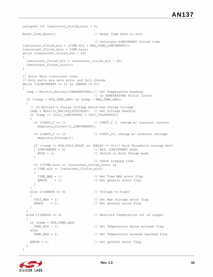
unsigned int lowcurrent_finish_hour = 0;
Reset_Time_Base(); // Reset Time base to zero
// Calculate LOWCURRENT finish time lowcurrent_finish_min = (TIME.min + MAX_TIME_LOWCURRENT); lowcurrent_finish_hour = TIME.hour; while (lowcurrent_finish_min > 60) { lowcurrent_finish_min = lowcurrent_finish_min - 60; lowcurrent_finish_hour++; }
// Enter Main Lowcurrent Loop. // Only exits are upon error and full charge while ((LOWCURRENT == 1) && (ERROR == 0)) { temp = Monitor_Battery(TEMPERATURE);// Get Temperature Reading // Is TEMPERATURE within limits if ((temp > MIN_TEMP_ABS) && (temp < MAX_TEMP_ABS)) { // Is Battery’s Charge Voltage below max charge voltage temp = Monitor_Battery(VOLTAGE); // Get Voltage Reading if (temp <= (VOLT_LOWCURRENT + VOLT_TOLERANCE)) { if (CONST_C == 1) // CONST_C ?, charge w/ constant current Regulate_Current(I_LOWCURRENT);
if (CONST_V == 1) // CONST_V?, charge w/ constant voltage Regulate_Voltage(); if ((temp >= MIN_VOLT_BULK) && (DELAY == 0))// Bulk Threshold voltage met? { LOWCURRENT = 0; // Exit LOWCURRENT mode BULK = 1; // Switch to Bulk Charge mode } // Check elapsed time if ((TIME.hour == lowcurrent_finish_hour) && ( TIME.min == lowcurrent_finish_min)) { TIME_MAX = 1; // Set Time MAX error flag ERROR = 1; // Set general error flag } } else if(ERROR == 0) // Voltage to high? { VOLT_MAX = 1; // Set Max voltage error flag ERROR = 1; // Set general error flag } } else if(ERROR == 0) // Absolute temperature out of range? { if (temp < MIN_TEMP_ABS) TEMP_MIN = 1; // Set Temperature below minimum flag else TEMP_MAX = 1; // Set Temperature exceeds maximum flag ERROR = 1; // Set general error flag } }
AN137
34 Rev. 1.3
}
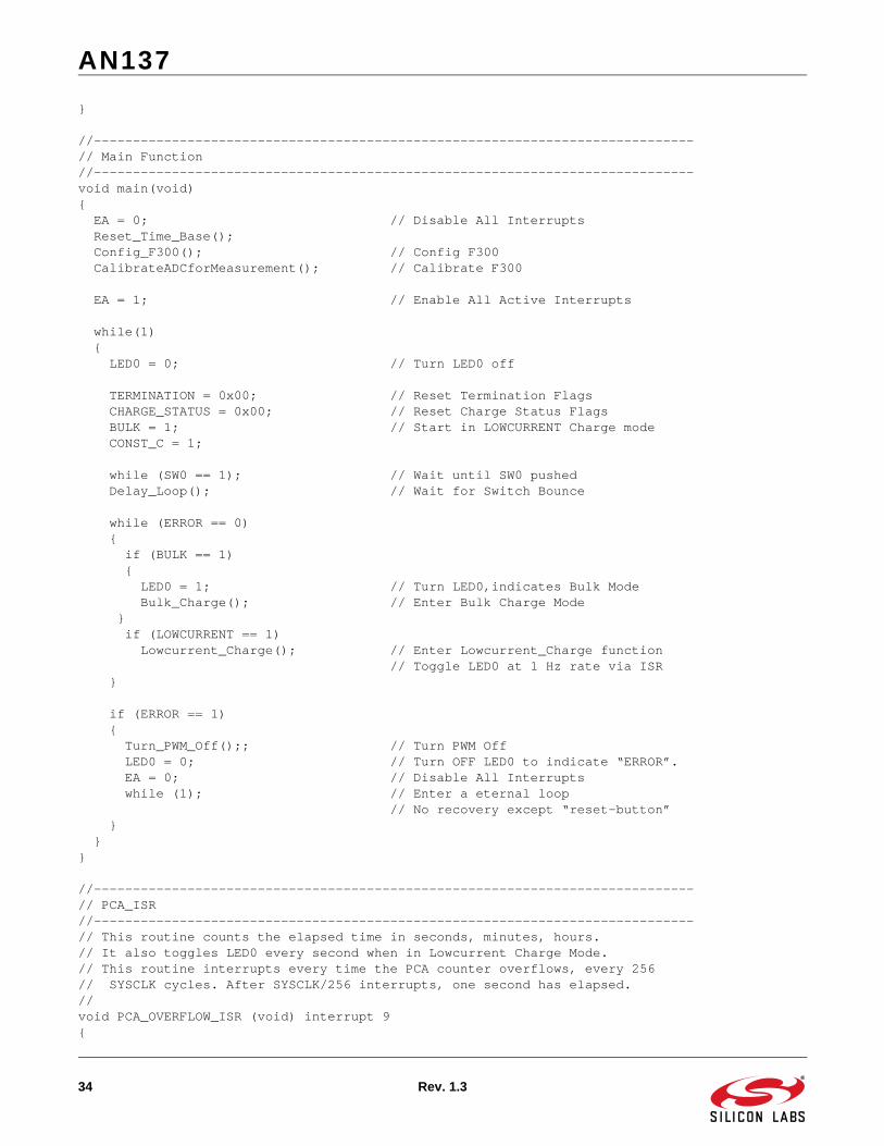
//-----------------------------------------------------------------------------// Main Function//-----------------------------------------------------------------------------void main(void){ EA = 0; // Disable All Interrupts Reset_Time_Base(); Config_F300(); // Config F300 CalibrateADCforMeasurement(); // Calibrate F300
EA = 1; // Enable All Active Interrupts while(1) { LED0 = 0; // Turn LED0 off TERMINATION = 0x00; // Reset Termination Flags CHARGE_STATUS = 0x00; // Reset Charge Status Flags BULK = 1; // Start in LOWCURRENT Charge mode CONST_C = 1; while (SW0 == 1); // Wait until SW0 pushed Delay_Loop(); // Wait for Switch Bounce while (ERROR == 0) { if (BULK == 1) { LED0 = 1; // Turn LED0,indicates Bulk Mode Bulk_Charge(); // Enter Bulk Charge Mode } if (LOWCURRENT == 1) Lowcurrent_Charge(); // Enter Lowcurrent_Charge function // Toggle LED0 at 1 Hz rate via ISR }
if (ERROR == 1) { Turn_PWM_Off();; // Turn PWM Off LED0 = 0; // Turn OFF LED0 to indicate “ERROR”. EA = 0; // Disable All Interrupts while (1); // Enter a eternal loop // No recovery except “reset-button” } } }
//-----------------------------------------------------------------------------// PCA_ISR//-----------------------------------------------------------------------------// This routine counts the elapsed time in seconds, minutes, hours.// It also toggles LED0 every second when in Lowcurrent Charge Mode.// This routine interrupts every time the PCA counter overflows, every 256// SYSCLK cycles. After SYSCLK/256 interrupts, one second has elapsed.// void PCA_OVERFLOW_ISR (void) interrupt 9{
AN137
Rev. 1.3 35
PCA0CN = 0x40; // Reset all PCA Interrupt Flags
PCA0H = 0x00; // Reset High Byte of PCA Counter // of 8-bit PWM we are using Module1
if (0x0000 == --TIME.t_count) { TIME.t_count = PWM_CLOCK; // Reset 1 Second Clock if ( 60 == ++TIME.sec ) // Account for elapsed seconds { // Reset second counter every minute TIME.sec = 0x00; if ( 60 == ++TIME.min ) // Account for elapsed minutes { // Reset minute counter every hour TIME.min = 0x00; if ( 24 == ++TIME.hour ) // Account for elapsed hours TIME.hour = 0x00; // Reset hour counter every day } }
if ((LOWCURRENT == 1) && (ERROR == 0)) { // Blink LED0 at 1 Hz if in Lowcurrent if (TIME.sec % 2) LED0 = 0; // Turn on LED every odd second else LED0 = 1; // Turn on LED every even second } }}
// END OF FILE

http://www.silabs.com
Silicon Laboratories Inc.400 West Cesar ChavezAustin, TX 78701USA
Simplicity Studio
One-click access to MCU and wireless tools, documentation, software, source code libraries & more. Available for Windows, Mac and Linux!
IoT Portfoliowww.silabs.com/IoT
SW/HWwww.silabs.com/simplicity
Qualitywww.silabs.com/quality
Support and Communitycommunity.silabs.com
DisclaimerSilicon Labs intends to provide customers with the latest, accurate, and in-depth documentation of all peripherals and modules available for system and software implementers using or intending to use the Silicon Labs products. Characterization data, available modules and peripherals, memory sizes and memory addresses refer to each specific device, and "Typical" parameters provided can and do vary in different applications. Application examples described herein are for illustrative purposes only. Silicon Labs reserves the right to make changes without further notice and limitation to product information, specifications, and descriptions herein, and does not give warranties as to the accuracy or completeness of the included information. Silicon Labs shall have no liability for the consequences of use of the information supplied herein. This document does not imply or express copyright licenses granted hereunder to design or fabricate any integrated circuits. The products are not designed or authorized to be used within any Life Support System without the specific written consent of Silicon Labs. A "Life Support System" is any product or system intended to support or sustain life and/or health, which, if it fails, can be reasonably expected to result in significant personal injury or death. Silicon Labs products are not designed or authorized for military applications. Silicon Labs products shall under no circumstances be used in weapons of mass destruction including (but not limited to) nuclear, biological or chemical weapons, or missiles capable of delivering such weapons.
Trademark InformationSilicon Laboratories Inc.® , Silicon Laboratories®, Silicon Labs®, SiLabs® and the Silicon Labs logo®, Bluegiga®, Bluegiga Logo®, Clockbuilder®, CMEMS®, DSPLL®, EFM®, EFM32®, EFR, Ember®, Energy Micro, Energy Micro logo and combinations thereof, "the world’s most energy friendly microcontrollers", Ember®, EZLink®, EZRadio®, EZRadioPRO®, Gecko®, ISOmodem®, Precision32®, ProSLIC®, Simplicity Studio®, SiPHY®, Telegesis, the Telegesis Logo®, USBXpress® and others are trademarks or registered trademarks of Silicon Labs. ARM, CORTEX, Cortex-M3 and THUMB are trademarks or registered trademarks of ARM Holdings. Keil is a registered trademark of ARM Limited. All other products or brand names mentioned herein are trademarks of their respective holders.
Related Documents