BALL VALVES CHECK VALVES 3-WAY BALL VALVES THROTTLE BALL VALVES POPPET DIVERTER VALVES MANIFOLD COMPONENTS SMARTER MANIFOLD SYSTEMS O P T I M U M - F L O W T E C H N O L O G Y B Y P I P E R O I L S T A T E S P I P E R V A L V E O I L S T A T E S P I P E R V A L V E

Welcome message from author
This document is posted to help you gain knowledge. Please leave a comment to let me know what you think about it! Share it to your friends and learn new things together.
Transcript

BA L L VA LV E S
CH E C K VA LV E S
3 -WAY B A L L VA LV E S
THRO T T L E B A L L VA LV E S
POP P E T D I V E RT E R VA LV E S
MAN I FO LD COMPONEN T S
S M A R T E R M A N I F O L D S Y S T E M S
O P T I M U M - F L O W T E C H N O L O G Y B Y P I P E R
O I L S T A T E S P I P E R V A L V EO I L S T A T E S P I P E R V A L V E

2
WO R K H O R S E O F T H E P I P E R M A N I F O L D S Y S T E M
Piper Series PB Ball Valves are engineered for optimum-flow performance under diverse pressure and flow situations, and offer the economy of field repairability.
Start saving the weight, space and money when building manifold systems. See theillustrated comparison below between a conventional 6" ANSI 1500 full port trunnionball valve with flanged end connections including companion flanges, and a PiperSeries PB ANSI Class 15006" nominal valve.
S E R I E S P B VA LV ED E S I G N B E N E F I T S
• Piper’s Optimum-Flow Technology:Maximum-Flow bore sizes are offeredthat correspond to the inside diametersof ASTM A106 Grade B pipe, reducingor completely eliminating transitionareas and thereby minimizing systemfriction pressure loss.
• Minimal line spread required for easy removal from service.
• Modular 3-Piece design provides multiple end connection options.
• Compact design occupies up to 40%less space than conventional flanged-end ball valves for skids or manifolds.(See right)
D E S I G N E D , E N G I N E E R E D A N D B U I L T F O R P E R F O R M A N C E
• Valve Bonnet easily accommodatesactuators or gear operators.
• Extra-Large Ball-to-Seat Contact Area reduces torque, assures positive sealing and distributes theforce between ball and seat seal for reduced wear
and extended life.
• Removable Seat Carriers serve two important functions:1) They allow equalization of pressure around the
seat, reducing torque while opening the valve;and 2) Allow valve repair evenif minor erosion of theseat pocket occurs.
• L-Seal Aids In Lower Torquewith a uni-directional seal design that allows
pressurization of central body cavity, eliminating the possibility of anupstream seal thereby reducing operating torque.
B U I L D Y OU R M AN I F O L D L I G H T E R , S M A L L E R , S M A R T E R .
Dimensional andWeight Comparison
• Total weight is 70 % less.• Total length is 43% less.• Relative height to bonnetis 28% less.
P I P E R
Series PB Ball Valves
p i p e r v a l v e . c o m
O P T I M U M - F L O W T E C H N O L O G Y

3
P O S I T I V E , S Y S T E M B A C K F L OW P R E V E N T I O N
Piper Series PB Check Valves are engineered and manufactured for compact size andoptimum-flow performance capabilities. Economical and field repairable, the Series PBCheck Valve is a true performer, offering system-wide positive backflow protection.
•Fire-Safe Design is accomplishedutilizing metal-to-metal secondarysealing in critical areas.
p i p e r v a l v e . c o m
Fitting Connection
Direct Connection
• Swivel Flange ConnectionsThese connections offer the benefit
of fast, easy installationor removal of all SeriesPB valves. (See page 10for more details.)
Series PBCheckValves
• Body Style provides short end-to-enddimension and is easily removed from service for repair.
• Flapper Type Disc DesignOur Check Valve design utilizes a flapper type disc to provide for a full open flow path andis fully piggable.
• End Connection Design Offers VersatilityPiper’s built-in flange design offers the benefit of more connectionoptions including Fitting Connections,Direct Bolted or Piper’s easy-to-installSwivel Flange Connection.
• Ball/Check Valve Combination AssembliesThese assemblies offer the shortest overalllength available for maximum space savingsas illustrated here.
For even greater space and weight savings,smaller size check valves can be bolted directly to ball valve body shown here.
C O N T E N T S
Series PB Ball Valve Features . . . . . . . 2Series PB Check Valve Features . . . . . 3Ball Valve Model Numbers . . . . . . . . . 4Ball Valve Selection Table . . . . . . . . . 5Check Valve Model Numbers . . . . . . . 6Check Valve Selection Table . . . . . . . . 7Ball Valve Component Parts . . . . . . . . 8Check Valve Component Parts . . . . . . 9Swivel Flange Features . . . . . . . . . . 10End Connection Kits . . . . . . . . . . . . 11Ball Valve Dimensional Data (in.) . . 12Check Valve Dimensional Data (in.) . 13Ball Valve Dimensional Data (mm) . . 14Check Valve Dimensional Data (mm) 15Manifold Systems . . . . . . . . . . . . . . 16System Fittings and Piper Certification .17Poppet 3-Way Diverter Valve . . . . . . 18Double Ball, Large Bore & Subsea . . . 19Piper Capabilities . . . . . . . Back Cover
P I P E RO P T I M U M - F L O W T E C H N O L O G Y B Y
4 p i p e r v a l v e . c o m
SpecifyingBall ValveModel Numbers
SpecifyingBall ValveModel Numbers
Manifold assembly preparedfor actuator installation.
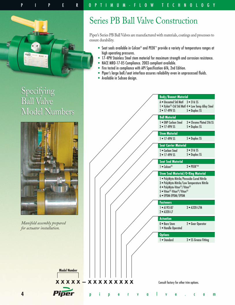
Piper’s Series PB Ball Valves are manufactured with materials, coatings and processes toensure durability.
• Seat seals available in Celcon® and PEEK™ provide a variety of temperature ranges athigh operating pressures.
• 17-4PH Stainless Steel stem material for maximum strength and corrosion resistance.• NACE MRO-17-05 Compliance. 2003 compliant available.• Fire tested in compliance with API Specification 6FA, 2nd Edition. • Piper’s large ball/seat interface assures reliability even in unprocessed fluids.• Available in Subsea design.
Series PB Ball Valve Construction
X X X X X — X X X X X X X X X
Model Number
Body/Bonnet MaterialA • Uncoated Std Matl1 • Xylan®-Ctd Std Matl2 • 17-4PH SS
Ball Material1 • ENP Carbon Steel2 • 17-4PH SS
Stem Material1 • 17-4PH SS
Seat Carrier Material1 • Carbon Steel2 • 17-4PH SS
Seat Seal Material1 • Celcon®
Stem Seal Material/O-Ring Material1 • PolyMyte-Nitrile/Peroxide-Cured Nitrile3 • PolyMyte-Nitrile/Low Temperature Nitrile4 • PolyMyte-Viton®/Viton®
5 • Viton®-Viton®/Viton®
6 • EPDM-EPDM/EPDM
Fasteners1 • A193-B72 • A320-L7
Actuation0 • Bare Stem1 • Handle Operated
Options1 • Standard
3 • 316 SS4 • Low Temp Alloy Steel5 • Duplex SS
3 • Chrome Plated 316 SS5 • Duplex SS
5 • Duplex SS
3 • 316 SS5 • Duplex SS
2 • PEEK™
3 • A320-L7M
2 • Gear Operator
3 • SS Grease Fitting
Consult factory for other trim options.
P I P E R O P T I M U M - F L O W T E C H N O L O G Y
5p i p e r v a l v e . c o m
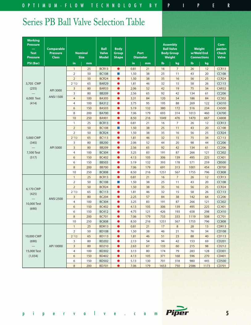
Series PB Ball Valve Selection Table
WorkingPressure Assembly Com-
— Comparable Ball Body Ball Valve Weight panionTest Pressure Nominal Valve Group Port Body Group w/Weld End Check
Pressure Class Size Model Shape Diameter Weight Connections Valve
PSI (Bar) in mm in mm lb kg lb kg
1 25 BCR13 � 0.81 21 16 7 26 12 CCR13
2 50 BC108 � 1.50 38 25 11 43 20 CC108
2 50 BCR24 � 1.50 38 35 16 56 25 CCR24
3,705 CWP 2 1/2 65 BAR29 � 1.81 46 32 15 58 26 CC113
(255)API 3000
3 80 BAR33 � 2.06 52 42 19 75 34 CAR32
— 3 80 BB209 � 2.56 65 92 42 134 61 CC206
6,000 Test ANSI 1500 4 100 BA305 � 3.31 84 120 54 186 84 CC302
(414) 4 100 BA312 � 3.75 95 195 88 269 122 CA310
6 150 BA503 � 5.19 132 380 172 516 234 CA500
8 200 BA700 � 7.06 179 693 314 1013 460 CA700
10 250 BA901 � 8.50 216 1049 476 1470 667 CA808
1 25 BCR13 � 0.81 21 16 7 26 12 CCR13
2 50 BC108 � 1.50 38 25 11 43 20 CC108
2 50 BCR24 � 1.50 38 35 16 56 25 CCR24
5,000 CWP 2 1/2 65 BC113 � 1.81 46 32 15 75 34 CC113
(345) 3 80 BB200 � 2.06 52 44 20 98 44 CC206
— API 5000 3 80 BB209 � 2.56 65 92 42 134 61 CC206
7,500 Test 4 100 BC304 � 3.25 83 191 87 266 121 CC302
(517) 6 150 BC402 � 4.13 105 306 139 495 225 CC401
6 150 BB503 � 5.19 132 393 178 571 259 CB500
8 200 BB700 � 7.06 179 691 313 1001 454 CB700
10 250 BC808 � 8.50 216 1251 567 1755 796 CC808
1 25 BCR13 � 0.81 21 16 7 26 12 CCR13
2 50 BC108 � 1.50 38 25 11 43 20 CC108
6,170 CWP2 50 BCR24 � 1.50 38 35 16 56 25 CCR24
(425)2 1/2 65 BC113 � 1.81 46 32 15 58 26 CC113
— ANSI 25003 80 BC204 � 2.25 57 84 38 142 64 CC206
10,000 Test4 100 BC304 � 3.25 83 191 87 266 121 CC302
(690)6 150 BC402 � 4.13 105 306 139 495 225 CC401
6 150 BC412 � 4.75 121 426 193 658 298 CC410
8 200 BC701 � 7.06 179 733 333 1119 508 CC701
10 250 BC808 � 8.50 216 1251 567 1755 796 CC808
1 25 BDR13 � 0.81 21 17 8 28 13 CDR13
2 50 BD108 � 1.50 38 46 21 76 34 CD108
10,000 CWP 2 1/2 65 BD113 � 1.81 46 51 23 88 40 CD113
(690) 3 80 BD202 � 2.13 54 94 42 153 69 CD201
— API 10000 3 80 BD210 � 2.63 67 133 60 215 98 CD212
15,000 Test 4 100 BD302 � 3.13 80 174 79 283 128 CD301
(1,034) 6 150 BD402 � 4.13 105 371 168 596 270 CD401
6 150 BD502 � 5.13 130 701 318 980 445 CD500
8 200 BD701 � 7.06 179 1653 750 2586 1173 CD701
P I P E RO P T I M U M - F L O W T E C H N O L O G Y B Y

6 p i p e r v a l v e . c o m
SpecifyingCheck ValveModel Numbers
SpecifyingCheck ValveModel Numbers
Series PB Check Valve ConstructionPiper’s Series PB Check Valves are manufactured with material, coatings and processesto ensure durability.
• Flappers available in a variety of materials for maximum corrosion anderosion resistance.
• Spring material is Inconel® X-750 for additional corrosion resistance.• Teflon® flapper seal promotes positive sealing and extended service life.• Fire tested in compliance with API specification 6FD, 1st Edition.• Available in Subsea design.
X X X X X — X X X X X
Body MaterialA • Uncoated Std Matl1 • Xylan®-Ctd Std Matl2 • 17-4PH SS
Flapper Material1 • 17-4PH SS2 • Nitronic 603 • 316 SS
Retainer/Seat Carrier Material1 • 17-4PH SS2 • 316 SS3 • Carbon Steel
O-Ring Material1 • Peroxide-Cured Nitrile3 • Low Temperature Nitrile4 • Viton®
5 • EPDM6 • Aflas®
Check Valve Orientation1 • Other Than Vertical Downflow2 • Vertical Downflow
Consult factory for other trim options.
Model Number
3 • 316 SS4 • Low Temp Alloy Steel5 • Duplex SS
4 • Alloy Steel5 • Duplex SS
P I P E R O P T I M U M - F L O W T E C H N O L O G Y

7p i p e r v a l v e . c o m
Series PB Check Valve Selection Table
WorkingPressure Assembly Com-
— Comparable Check Body Check Valve Weight panionTest Pressure Nominal Valve Group Port Body Group w/Weld End Ball
Pressure Class Size Model Shape Diameter Weight Connections Valve
PSI (Bar) in mm in mm lb kg lb kg
1 25 CCR13 � 0.81 21 12 5 26 12 BCR13
2 50 CC108 � 1.50 38 15 7 29 13 BC108
2 50 CCR24 � 1.50 38 22 10 42 19 BCR24
3,705 CWP 2 1/2 65 CC113 � 1.81 46 35 16 65 29 BAR29
(255) API 3000 3 80 CAR32 � 2.00 51 31 14 62 28 BAR33
— 3 80 CC206 � 2.38 60 29 13 65 30 BB209
6,000 Test ANSI 1500 4 100 CC302 � 3.13 80 66 30 130 59 BA305
(414) 4 100 CA310 � 3.63 92 62 28 127 58 BA312
6 150 CA500 � 5.00 127 120 54 209 95 BA503
8 200 CB700 � 7.06 179 374 170 571 259 BA700
10 250 CA808 � 8.50 216 689 313 900 409 BA808
1 25 CCR13 � 0.81 21 12 5 26 12 BCR13
2 50 CC108 � 1.50 38 15 7 29 13 BC108
5,000 CWP2 50 CCR24 � 1.50 38 22 10 42 19 BCR24
(345)2 1/2 65 CC113 � 1.81 46 35 16 65 29 BAR29
— API 50003 80 CC206 � 2.38 60 29 13 65 30 BB200/209
7,500 Test4 100 CC302 � 3.13 80 65 30 130 59 BC304
(517)6 150 CC401 � 4.06 103 300 136 379 280 BC402
6 150 CB500 � 5.00 127 306 139 400 182 BB503
8 200 CB700 � 7.06 179 467 212 451 333 BB700
10 250 CC808 � 8.50 216 727 330 1050 774 BC808
1 25 CCR13 � 0.81 21 12 5 26 12 BCR13
2 50 CC108 � 1.50 38 15 7 29 13 BC108
6,170 CWP2 50 CCR24 � 1.50 38 22 10 42 19 BCR24
(425)2 1/2 65 CC113 � 1.81 46 35 16 65 29 BAR29
— ANSI 25003 80 CC206 � 2.38 60 29 13 65 30 BC204
10,000 Test4 100 CC302 � 3.13 80 66 30 130 59 BC304
(690)6 150 CC401 � 4.06 103 200 91 379 280 BC402
6 150 CC410 � 4.63 118 287 130 375 170 BC412
8 200 CC701 � 7.06 179 467 212 610 277 BC701
10 250 CC808 � 8.50 216 727 330 1050 774 BC808
1 25 CDR13 � 0.81 21 8 4 25 18 BDR13
2 50 CD108 � 1.50 38 57 26 42 31 BD108
10,000 CWP 2 1/2 65 CD113 � 1.81 46 50 23 72 33 BD113
(690) 3 80 CD201 � 2.06 52 46 21 83 61 BD202
— API 10000 3 80 CD212 � 2.75 70 150 68 181 133 BD210
15,000 Test 4 100 CD301 � 3.06 78 200 91 190 86 BD302
(1,034) 6 150 CD401 � 4.06 103 280 127 373 275 BD402
6 150 CD502 � 5.00 127 634 288 576 425 BD502
8 200 CD701 � 7.06 179 744 338 1350 613 BD701
P I P E RO P T I M U M - F L O W T E C H N O L O G Y B Y

8 p i p e r v a l v e . c o m
PB Ball ValveComponent PartsIllustration shows integral x swivelend connections. Other endconnections may apply.
2322a
2128
2425
23
20
6
3
4
2
24
22b
28
15
16
25
14
13
12
11
12
13
14
1
19 18
26
27
17
7
8
5
10
Index Qty Description Standard Materials Optional Materials1
1 1 Body Carbon Steel 2, Alloy Steel 3 316 SS, 17-4PH SS, Duplex SS
2 1 Bonnet Carbon Steel 316 SS, 17-4PH SS, Duplex SS
3 2 Stop Cap Screw A193-B7 (Xylan®) A320-L7 (Xylan®), A320-L7M (Xylan®)
4 4 Bonnet Cap Screw A193-B7 (Xylan®) A320-L7 (Xylan®), A320-L7M (Xylan®)
5 1 Bonnet Seal Peroxide-Cured Nitrile Viton® A, Low Temp Nitrile, Aflas®, EPDM
6 1 Stem Bearing Garlock DU
7 1 Stem 17-4PH SS Duplex SS
8 1 Stem Seal PolyMyte/Peroxide-Cured Nitrile Polymyte/Viton® & Viton®/Viton®
10 1 Thrust Bearing Alloy Steel (Xylan®) Xylan®-Coated Nitronic 60
11 1 Ball ENP Carbon Steel 316 SS, Nitronic 60, Duplex SS
12 2 Seat Celcon® PEEK™
13 2 Seat Carrier Carbon Steel, (SBN-QPQ) 316 SS, 17-4PH SS, Duplex SS
14 2 L-Seal Peroxide-Cured Nitrile Viton® A, Low Temp Nitrile, Aflas®, EPDM
15 1 Retainer Carbon Steel 316 SS, 17-4PH SS, Duplex SS
16 1 Retainer Seal Peroxide-Cured Nitrile Viton® A, Low Temp Nitrile, Aflas®, EPDM
17 2 Retainer Screw Carbon Steel, Plated
18 1 Handle Carbon Steel
19 1 Handle Cap Plastic
20 1 Stop Plate Carbon Steel
21 2 Swivel Flange Carbon Steel
22a 2 Bevel for Weld Nipple Carbon Steel, Alloy Steel 316L SS, Duplex SS
22b 2 Integral Flange Carbon Steel, Alloy Steel 316L SS, Duplex SS
23 2 Half Ring Alloy Steel
24 Varies End Connection Cap Screw A193-B7 (Xylan®) A320-L7 (Xylan®), A320-L7M (Xylan®)
25 2 End Connection Seal Peroxide-Cured Nitrile Viton® A, Low Temp Nitrile, Aflas®, EPDM
26 1 Body Grease Fitting Alloy/Inconel® 316 SS/Inconel®
27 1 Handle Bolt Stainless Steel
28 2 Corrosion Gasket EPDM
• 1 Consult factory for other material. • 2 Employed up to and including 6,170 CWP valves. • 3 Employed on 10,000 psi CWP valves.
P I P E R O P T I M U M - F L O W T E C H N O L O G Y
9p i p e r v a l v e . c o m
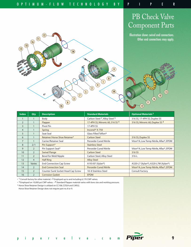
PB Check ValveComponent PartsIllustration shows swivel end connections.
Other end connections may apply.
1211
147
3
14
5
615
2
1
9
8
4
1016
13
12
1310
1611
14
14
15
Index Qty Description Standard Materials Optional Materials1
1 1 Body Carbon Steel 2, Alloy Steel 3 316 SS, 17-4PH SS, Duplex SS
2 1 Flapper 17-4PH SS, Nitronic 60, 316 SS 4 316 SS, Nitronic 60, Duplex SS 4
3 1 Pivot Pin 17-4PH SS
4 1 Spring Inconel® X-750
5 1 Seat Seal Glass Filled Teflon®
6 1 Retainer/Horse Shoe Retainer* Carbon Steel 316 SS, Duplex SS
7 1 Carrier/Retainer Seal Peroxide-Cured Nitrile Viton®A, Low Temp Nitrile, Aflas®, EPDM
8 2/1 Pin Support* Stainless Steel
9 2 Pin Support Seal* Peroxide-Cured Nitrile Viton®A, Low Temp Nitrile, Aflas®, EPDM
10 2 Swivel Flange Carbon Steel 316 SS
11 2 Bevel for Weld Nipple Carbon Steel, Alloy Steel 316-L
12 4 Half Ring Alloy Steel
13 Varies End Connection Cap Screw A193-B7 (Xylan®) A320-L7 (Xylan®), A320-L7M (Xylan®)
14 2 End Connection Seal Peroxide-Cured Nitrile Viton®A, Low Temp Nitrile, Aflas®, EPDM
15 2 Counter Sunk Socket Head Cap Screw 18-8 Stainless Steel Consult Factory
16 2 Corrosion Gasket EPDM
• 1 Consult factory for other material. • 2 Employed up to and including 6,170 CWP valves.
• 3 Employed on 10,000 psi CWP valves. • 4 Standard Flapper material varies with bore size and working pressure.
* Horse Shoe Retainer Design is utilized on CC108, CCR24 and CAR32.
Horse Shoe Retainer Design does not require part no. 8 or 9.
P I P E RO P T I M U M - F L O W T E C H N O L O G Y B Y

Position BodyAnd Install Capscrews
Slide FlangesOver Half-Rings
Insert Half-RingsInto Grooves
A convenient feature of the Series PBmanifold system, this connection con-sists of the swivel flange, a nipple (ortube) with a half-ring groove, and twohalf-rings. The nipple-end can be aweld-end, male-threaded, hub-type,or other possible end configurationincluding a second half-ring groove toconnect another swivel flange.
10 p i p e r v a l v e . c o m
Most Piper Series PB valves and block fit-tings utilize swivel flange and half-ringconnections.
1. Measure assembled valve or componentand cut pipe to appropriate length.
5
Piper’s Swivel Flange Connection
S W I V E L F L A N G ED E S I G N B E N E F I T S
• Faster, easier installations. • Minimal line spread facilitates easy installation and removal of valves.
• Unlimited end connection options.• Ends match bore sizes to maximize Piper’s Optimum - Flow Technology.
The versatility of Piper’s SwivelFlange Connection results in
lower cost for manufacturingand for the end user.
2. Disassemble valve ends and weld thebeveled-for-weld nipples to the pipe.
3. Slide Swivel Flanges onto nipples andinsert half-rings into grooves.
4. Slide Swivel Flanges over half-rings tolock flanges into place.
5. Install valve body betweenflanges, rotating flanges asnecessary, and secure with
12-point capscrews.
Weld Nipple EndsTo Pipe
See The Steps BelowIllustrating The Ease of Installation
Cut Pipe ToAssembled Length
1
2 3 4
P I P E R O P T I M U M - F L O W T E C H N O L O G Y

11p i p e r v a l v e . c o m
This End Connection Kit Order Code Number Chart is for Series PB Ball and CheckValves, and is available to assist users in accurately ordering end connections.
E X — X X X X X — X X X X X X
D • 2"E • 21/2"F • 3"
G • 4"J • 6"L • 8"
N • 10"4 • 1/2"6 • 3/4"
C • Sch 120D • Sch 160
E • XXHH • Special Wall
B • 8-Round
K • Socket Weld FlangeM • Male Threaded EndsR • API RTJ
U • Hammer UnionW • Weld Ends
Connection TypeUsed with 2nd digit of suffix code titled “Pipe Schedule, Flange Pressure Class,...”A • ANSI Raised FaceF • Female Threaded EndsJ • ANSI Ring Type Joint
Nominal Pipe or Flange SizeA • 1"B • 11/4"C • 11/2"
Pipe Schedule, Flange Pressure Class, Thread Type or Union ClassPipe Schedule-Weld Ends (Connection Type W)A • Sch 40B • Sch 80
Pressure Class-Flanged Ends (Connection Type A, J and R)A • API 2000 (R)B • API 3000 (R)C • API 5000 (R)D • API 10,000 (R)E • API 15,000 (R)
Thread Type-Threaded Ends (Connection Type F and M)A • NPT
Pressure Class-Hammer Union Ends (Connection Type U)NOTE: Retainer-end listed first.A • Fig. 602 M x FB • Fig. 602 F x M
End Connection MaterialOther materials available upon request.1 • Standard2 • 17-4PH SS3 • 316 SS or 316-L SS
Fasteners1 • 12-Point, A193-B7A • 12-Point, A320-L7B • 12-Point, A320-L7M
Corrosion GasketSuggested for highly corrosive environments.0 • Not Included
O-Ring SealsRequired only on some threaded connections for Models BC108 or CC108.0 • O-Rings Not Required1 • Peroxide-Cured Nitrile3 • Viton®
Valve Model No.See Pages 5 & 7
Consult factory for other configurations.
4 • Low Temp Alloy Steel5 • Duplex SS(2205)
1 • Included
C • Fig. 1002 M x FD • Fig. 1002 F x M
E • Fig. 1502 M x FF • Fig. 1502 F x M
4 • Low Temperature Nitrile5 • EPDM
J • ANSI 300 (A & J)K • ANSI 600 (A & J)F • ANSI 900 (A & J)
C • ANSI 1200 (A & J)G • ANSI 1500 (A & J)H • ANSI 2500 (A & J)
Series PB End Connection Kits
SpecifyingEnd ConnectionKit Numbers
P I P E RO P T I M U M - F L O W T E C H N O L O G Y B Y
12 p i p e r v a l v e . c o m
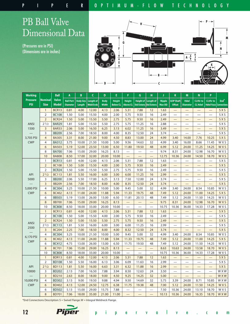
PB Ball ValveDimensional Data
F
G
B
J
H
E
D
P
A
M
N
K
C
(Pressures are in PSI)(Dimensions are in inches)
Working Ball A B C D E F G H J K M N P
Pressure Nominal Valve Ball Port Body Grp Length of Body Height Height Height of Length of Nipple GOP Shaft Hdwl CLVlv to CLVlv to End*
PSI Size Model Diameter Length WeldEnds Width Below CL Above CL Std Extens Std Extens Max OD Offset Diameter CL Hdwl Hdwl Face Connections
1 BCR13 0.81 4.00 12.00 4.13 2.06 5.31 7.88 12 1.63 — — — — S X S
2 BC108 1.50 5.00 15.50 4.00 2.00 5.75 9.50 16 2.49 — — — — S X S
2 BCR24 1.50 5.00 15.50 5.50 2.75 5.75 9.50 16 2.49 — — — — S X S
ANSI 21/2 BAR29 1.81 5.00 15.50 5.50 2.75 5.75 11.25 16 2.88 — — — — S X S
1500 3 BAR33 2.06 5.00 16.50 6.25 3.13 6.02 11.25 16 3.49 — — — — S X S
— 3 BB209 2.56 7.00 18.50 8.00 4.00 8.35 12.50 24 3.74 — — — — S X S
3,705 PSI 4 BA305 3.31 8.00 21.00 9.00 4.50 8.83 13.00 24 4.99 3.40 14.00 7.76 10.25 S X S
CWP 4 BA312 3.75 10.00 21.50 10.00 5.00 9.56 14.63 32 4.99 3.40 16.00 8.66 11.45 W X S
6 BA503 5.19 12.00 23.50 13.00 6.50 11.80 19.50 48 6.99 5.12 24.00 11.25 14.25 W X S
8 BA700 7.06 15.00 29.00 16.25 8.13 — — — 9.74 8.31 24.00 12.98 16.70 W X S
10 BA808 8.50 17.00 32.00 20.00 10.00 — — — 12.75 10.36 24.00 14.50 18.70 W X S
1 BCR13 0.81 4.00 12.00 4.13 2.06 5.31 7.88 12 1.63 — — — — S X S
2 BC108 1.50 5.00 15.50 4.00 2.00 5.75 9.50 16 2.49 — — — — S X S
2 BCR24 1.50 5.00 15.50 5.50 2.75 5.75 9.50 16 2.49 — — — — S X S
API 21/2 BC113 1.81 5.50 16.00 6.00 3.00 6.00 11.25 16 2.99 — — — — S X S
5000 3 BB200 2.06 5.50 17.00 6.25 3.13 7.50 12.00 24 3.74 — — — — S X S
— 3 BB209 2.56 7.00 18.50 8.00 4.00 8.35 12.50 24 3.74 — — — — S X S
5,000 PSI 4 BC304 3.25 10.00 21.50 10.00 5.00 9.45 5.00 32 4.99 3.40 24.00 8.54 10.85 W X S
CWP 6 BC402 4.13 11.00 24.00 11.88 5.94 11.33 19.75 48 7.49 5.12 24.00 11.00 14.25 S X S
6 BB503 5.19 13.00 26.00 13.00 6.50 11.81 20.13 48 7.49 5.12 24.00 11.50 14.25 W X S
8 BB700 7.06 15.00 29.00 16.25 8.13 — — — 9.75 8.31 24.00 12.98 16.70 W X S
10 BC808 8.50 18.00 33.00 20.00 10.00 — — — 10.75 10.36 36.00 14.33 17.28 W X S
1 BCR13 0.81 4.00 12.00 4.13 2.06 5.31 7.88 12 1.63 — — — — S X S
2 BC108 1.50 5.00 15.50 4.00 2.00 5.75 9.50 16 2.49 — — — — S X S
ANSI2 BCR24 1.50 5.00 15.50 5.50 2.75 5.75 9.50 16 2.49 — — — — S X S
250021/2 BC113 1.81 5.50 16.00 6.00 3.00 6.00 11.25 16 2.99 — — — — S X S
—3 BC204 2.25 7.00 18.50 8.00 4.00 8.32 12.50 24 3.74 — — — — S X S
6,170 PSI4 BC304 3.25 10.00 21.50 10.00 5.00 9.45 5.00 32 4.99 3.40 24.00 8.54 10.85 W X S
CWP6 BC402 4.13 11.00 24.00 11.88 5.94 11.33 19.75 48 7.49 5.12 24.00 11.00 14.25 S X S
6 BC412 4.75 13.00 26.00 13.00 6.50 11.75 19.50 48 7.49 5.12 24.00 11.50 14.25 W X S
8 BC701 7.06 15.00 29.00 16.25 8.13 — — — 8.63 10.63 24.00 13.58 18.70 W X S
10 BC808 8.50 18.00 33.00 20.00 10.00 — — — 10.75 10.36 36.00 14.33 17.28 W X S
1 BDR13 0.81 4.00 12.00 4.13 2.06 5.31 7.88 12 1.63 — — — — S X S
2 BD108 1.50 5.50 16.00 6.13 3.06 6.09 11.63 16 2.99 — — — — S X S
API 21/2 BD113 1.81 5.50 16.00 6.63 3.31 6.32 11.88 16 2.99 — — — — S X S
10000 3 BD202 2.13 7.00 16.50 7.88 3.94 8.50 12.63 24 3.50 — — — — W X W
— 3 BD210 2.63 8.00 18.00 9.00 4.50 9.25 14.25 32 5.00 — — — — W X W
10,000 PSI 4 BD302 3.13 9.00 19.50 9.88 4.94 9.50 14.69 32 5.75 3.39 24.00 8.71 10.85 W X W
CWP 6 BD402 4.13 12.00 24.50 12.75 6.38 11.75 19.38 48 7.00 5.12 24.00 11.50 14.25 W X S
6 BD502 5.13 15.00 29.00 15.75 7.88 — — — 7.50 10.36 24.00 13.10 18.70 W X S
8 BD701 7.06 18.00 35.00 21.00 11.00 — — — 10.13 10.36 24.00 16.35 18.70 W X W
*End Connections Description: S = Swivel Flange. W = Integral Weldneck Flange.
P I P E R O P T I M U M - F L O W T E C H N O L O G Y
13p i p e r v a l v e . c o m
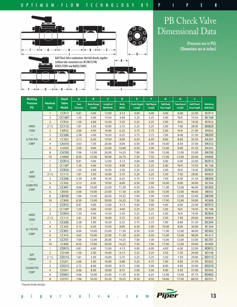
PB Check Valve Dimensional Data
Ball/Check Valve combinations that bolt directly together(without tube connection) are: BC108/CC108,BCR24/CCR24 and BAR33/CAR32.
F G B EJH
CF B EG
D
B
(Pressures are in PSI)(Dimensions are in inches)
Working Check A B C D E F G H JPressure Nominal Valve Seat Body Group Length of Body Check Nipple Ball Nipple Ball Body Tube/Spool Ball/Check Matching
PSI Size Model Diameter Length Weld Ends Width Length Length Grp Length Length AssyLength Ball Valve
1 CCR13 0.81 4.00 12.00 4.13 4.00 4.00 4.00 6.00 22.00 BCR13
2 CC108* 1.50 4.00 14.50 4.00 5.25 5.25 5.00 N/A 19.50 BC108
2 CCR24 1.50 4.00 14.50 5.50 5.25 5.25 5.00 N/A 19.50 BCR24
ANSI 2 1/2 CC113 1.81 5.50 16.00 5.75 5.25 5.25 5.00 7.00 28.00 BAR29
1500 3 CAR32 2.00 4.50 16.00 6.25 5.75 5.75 5.00 N/A 21.00 BAR33
— 3 CC206 2.38 5.00 16.50 6.25 5.75 5.75 7.00 8.00 31.50 BB209
3,705 PSI 4 CC302 3.13 6.50 19.50 8.00 6.50 6.50 8.00 8.00 35.50 BA305
CWP 4 CA310 3.63 7.00 20.00 8.00 6.50 5.00 10.00 8.50 37.00 BA312
6 CA500 5.00 9.00 22.00 10.00 6.50 5.00 12.00 9.00 41.50 BA503
8 CA700 7.06 12.00 26.00 14.25 7.00 7.00 15.00 12.00 53.00 BA700
10 CA808 8.50 15.00 30.00 16.75 7.50 7.50 17.00 12.00 59.00 BA808
1 CCR13 0.81 4.00 12.00 4.13 4.00 4.00 4.00 6.00 22.00 BCR13
2 CC108* 1.50 4.00 14.50 4.00 5.25 5.25 5.00 N/A 19.50 BC108
API2 CCR24 1.50 4.00 14.50 5.50 5.25 5.25 5.00 N/A 19.50 BCR24
500021/2 CC113 1.81 5.50 16.00 5.75 5.25 5.25 5.50 7.50 29.00 BAR29
—3 CC206 2.38 5.00 16.50 6.25 5.75 5.75 7.00 8.00 31.50 BB209
5,000 PSI4 CC302 3.13 6.50 19.50 8.00 6.50 5.00 10.00 8.00 36.00 BC304
CWP6 CC401 4.06 10.00 23.00 11.50 6.50 6.50 11.00 12.00 46.00 BC402
6 CB500 5.00 10.00 23.00 11.50 6.50 6.50 13.00 12.00 48.00 BB503
8 CB700 7.06 12.00 26.00 14.25 7.00 7.00 15.00 12.00 53.00 BB700
10 CC808 8.50 15.00 30.00 16.25 7.50 7.50 17.00 12.00 59.00 BC808
1 CCR13 0.81 4.00 12.00 4.13 4.00 4.00 4.00 6.00 22.00 BCR13
2 CC108* 1.50 4.00 14.50 4.00 5.25 5.25 5.00 N/A 19.50 BC108
ANSI 2 CCR24 1.50 4.00 14.50 5.50 5.25 5.25 5.00 N/A 19.50 BCR24
25002 1/2 CC113 1.81 5.50 16.00 5.75 5.25 5.25 5.50 7.50 29.00 BAR29
—3 CC206 2.38 5.00 16.50 6.25 5.75 5.75 7.00 8.00 31.50 BC204
4 CC302 3.13 6.50 19.50 8.00 6.50 5.00 10.00 8.00 36.00 BC3046,170 PSI
6 CC401 4.06 10.00 23.00 11.50 6.50 6.50 11.00 12.00 46.00 BC402CWP 6 CC410 4.63 10.00 23.00 11.50 6.50 6.50 13.00 12.00 48.00 BC412
8 CC701 7.06 12.00 26.00 14.25 7.00 7.00 15.00 12.00 53.00 BC701
10 CC808 8.50 15.00 30.00 16.25 7.50 7.50 17.00 12.00 59.00 BC808
1 CDR13 0.81 4.00 12.00 4.13 4.00 4.00 4.00 6.00 22.00 BDR13
2 CD108 1.50 5.50 16.00 6.13 5.25 5.25 5.50 7.50 29.00 BD108API
2 1/2 CD113 1.81 5.50 16.00 5.75 5.25 5.25 5.50 7.50 29.00 BD11310000
3 CD201 2.06 5.50 16.00 6.88 5.25 4.75 7.00 9.00 31.50 BD202—
3 CD212 2.75 8.00 18.00 8.75 5.00 5.00 8.00 9.00 35.00 BD21010,000 PSI
4 CD301 3.06 8.00 18.00 8.75 5.00 5.50 9.00 9.50 37.00 BD302CWP
6 CD401 4.06 10.00 23.00 11.50 6.50 6.25 12.00 13.00 47.75 BD402
8 CD701 7.06 16.50 33.50 18.25 8.50 8.50 18.00 17.00 68.50 BD701
*Square body design.
P I P E RO P T I M U M - F L O W T E C H N O L O G Y B Y

14 p i p e r v a l v e . c o m
PB Ball ValveDimensional Data
F
G
B
J
H
E
D
P
A
M
N
K
C
Metric(Pressures are in BAR)(Dimensions are in millimeters)
Working Ball A B C D E F G H J K M N PPressure Nominal Valve Ball Port Body Grp Length of Body Height Height Height of Length of Nipple GOP Shaft Hdwl CLVlv to CLVlv to End*
PSI Size Model Diameter Length WeldEnds Width Below CL Above CL Std Extens Std Extens Max OD Offset Diameter CL Hdwl Hdwl Face Connections
25 BCR13 21 102 305 105 52 135 200 305 41 — — — — S X S
51 BC108 38 127 394 102 51 146 241 406 63 — — — — S X S
51 BCR24 38 127 394 140 70 146 241 406 63 — — — — S X S
ANSI 64 BAR29 46 127 394 140 70 146 286 406 73 — — — — S X S
1500 76 BAR33 52 127 419 159 79 153 286 406 89 — — — — S X S
— 76 BB209 65 178 470 203 102 212 318 610 95 — — — — S X S
255 Bar 102 BA305 84 203 533 229 114 224 330 610 127 86 356 197 260 S X S
CWP 102 BA312 95 254 546 254 127 243 372 813 127 86 406 220 291 W X S
152 BA503 132 305 597 330 165 300 495 1219 178 130 610 286 362 W X S
203 BA700 179 381 737 413 207 — — — 247 211 610 330 424 W X S
254 BA808 216 432 813 508 254 — — — 324 263 610 368 475 W X S
25 BCR13 21 102 305 105 52 135 200 305 41 — — — — S X S
51 BC108 38 127 394 102 51 146 241 406 63 — — — — S X S
51 BCR24 38 127 394 140 70 146 241 406 63 — — — — S X S
API 64 BC113 46 140 406 152 76 152 286 406 76 — — — — S X S
5000 76 BB200 52 140 432 159 80 191 305 610 95 — — — — S X S
— 76 BB209 65 178 470 203 102 212 318 610 95 — — — — S X S
345 Bar 102 BC304 83 254 546 254 127 240 127 813 127 86 610 217 276 W X S
CWP 152 BC402 105 279 610 302 151 288 502 1219 190 130 610 279 362 S X S
152 BB503 132 330 660 330 165 300 511 1219 190 130 610 292 362 W X S
203 BB700 179 381 737 413 207 — — — 248 211 610 330 424 W X S
254 BC808 216 457 838 508 254 — — — 273 263 914 364 439 W X S
25 BCR13 21 102 305 105 52 135 200 305 41 — — — — S X S
51 BC108 38 127 394 102 51 146 241 406 63 — — — — S X S
ANSI51 BCR24 38 127 394 140 70 146 241 406 63 — — — — S X S
250064 BC113 46 140 406 152 76 152 286 406 76 — — — — S X S
—76 BC204 57 178 470 203 102 211 318 610 95 — — — — S X S
425 Bar102 BC304 83 254 546 254 127 240 127 813 127 86 610 217 276 W X S
CWP152 BC402 105 279 610 302 151 288 502 1219 190 130 610 279 362 S X S
152 BC412 121 330 660 330 165 298 495 1219 190 130 610 292 362 W X S
203 BC701 179 381 737 413 207 — — — 219 270 610 345 475 W X S
254 BC808 216 457 838 508 254 — — — 273 263 914 364 439 W X S
25 BDR13 21 102 305 105 52 135 200 305 41 — — — — S X S
51 BD108 38 140 406 156 78 155 295 406 76 — — — — S X S
API 64 BD113 46 140 406 168 84 161 302 406 76 — — — — S X S
10000 76 BD202 54 178 419 200 100 216 321 610 89 — — — — W X W
— 76 BD210 67 203 457 229 114 235 362 813 127 — — — — W X W
690 Bar 102 BD302 80 229 495 251 125 241 373 813 146 86 610 221 276 W X W
CWP 152 BD402 105 305 622 324 162 298 492 1219 178 130 610 292 362 W X S
152 BD502 130 381 737 400 200 — — — 191 263 610 333 475 W X S
203 BD701 179 457 889 533 279 — — — 257 263 610 415 475 W X W
*End Connections Description: S = Swivel Flange. W = Integral Weldneck Flange.
P I P E R O P T I M U M - F L O W T E C H N O L O G Y

15p i p e r v a l v e . c o m
PB Check ValveDimensional Data
Ball/Check Valve combinations that bolt directly together(without tube connection) are: BC108/CC108,BCR24/CCR24 and BAR33/CAR32.
F G B EJH
CF B EG
D
B
Metric(Pressures are in BAR)
(Dimensions are in millimeters)
Working Check A B C D E F G H JPressure Nominal Valve Seat Body Group Length of Body Check Nipple Ball Nipple Ball Body Tube/Spool Ball/Check Matching
PSI Size Model Diameter Length Weld Ends Width Length Length Grp Length Length AssyLength Ball Valve
25 CCR13 21 102 305 105 102 102 102 152 559 BCR13
51 CC108* 38 102 368 102 133 133 127 N/A 495 BC108
51 CCR24 38 102 368 140 133 133 127 N/A 495 BCR24
ANSI 64 CC113 46 140 406 146 133 133 127 178 711 BAR29
1500 76 CAR32 51 114 406 159 146 146 127 N/A 533 BAR33
— 76 CC206 60 127 419 159 146 146 178 203 800 BB209
255 Bar 102 CC302 80 165 495 203 165 165 203 203 902 BA305
CWP 102 CA310 92 178 508 203 165 127 254 216 940 BA312
152 CA500 127 229 559 254 165 127 305 229 1054 BA503
203 CA700 179 305 660 362 178 178 381 305 1346 BA700
254 CA808 216 381 762 425 191 191 432 305 1499 BA808
25 CCR13 21 102 305 105 102 102 102 152 559 BCR13
51 CC108* 38 102 368 102 133 133 127 N/A 495 BC108
API51 CCR24 38 102 368 140 133 133 127 N/A 495 BCR24
500064 CC113 46 140 406 146 133 133 140 191 737 BAR29
—76 CC206 60 127 419 159 146 146 178 203 800 BB209
345 Bar102 CC302 80 165 495 203 165 127 254 203 914 BC304
CWP152 CC401 103 254 584 292 165 165 279 305 1168 BC402
152 CB500 127 254 584 292 165 165 330 305 1219 BB503
203 CB700 179 305 660 362 178 178 381 305 1346 BB700
254 CC808 216 381 762 413 191 191 432 305 1499 BC808
25 CCR13 21 102 305 105 102 102 102 152 559 BCR13
51 CC108* 38 102 368 102 133 133 127 N/A 495 BC108
ANSI51 CCR24 38 102 368 140 133 133 127 N/A 495 BCR24
250064 CC113 46 140 406 146 133 133 140 191 737 BAR29
—76 CC206 60 127 419 159 146 146 178 203 800 BC204
425 Bar102 CC302 80 165 495 203 165 127 254 203 914 BC304
CWP152 CC401 103 254 584 292 165 165 279 305 1168 BC402
152 CC410 118 254 584 292 165 165 330 305 1219 BC412
203 CC701 179 305 660 362 178 178 381 305 1346 BC701
254 CC808 216 381 762 413 191 191 432 305 1499 BC808
25 CDR13 21 102 305 105 102 102 102 152 559 BDR13
API51 CD108 38 140 406 156 133 133 140 191 737 BD108
1000064 CD113 46 140 406 146 133 133 140 191 737 BD113
—76 CD201 52 140 406 175 133 121 178 229 800 BD202
690 Bar76 CD212 70 203 457 222 127 127 203 229 889 BD210
CWP102 CD301 78 203 457 222 127 140 229 241 940 BD302
152 CD401 103 254 584 292 165 159 305 330 1213 BD402
203 CD701 179 419 851 464 216 216 457 432 1740 BD701
*Square body design
P I P E RO P T I M U M - F L O W T E C H N O L O G Y B Y

16
• Production manifold designs which incorporate Piper Compact Manifold Ball Valvesachieve a footprint area that is 50% - 60% less than manifolds utilizing API 6D Valves.
• Piper Compact Manifold Valves are specifically designed for maximum life in critical service, including sand-laden, uprocessed production fluids.
• Smallest line spread distance for quick and easy valve removal.
p i p e r v a l v e . c o m
P I P E R
Offshore ProductionManifoldsM A N I F O L D S Y S T E M S B U I L T F O R V E R S A T I L I T Y
M A N I F O L D S Y S T E M F E A T U R E S
28-Slot Offshore Production Manifold utilizing compact manifold ball valves, check valves and poppet diverter valves.
O P T I M U M - F L O W T E C H N O L O G Y

17p i p e r v a l v e . c o m
Weld-Free Manifold ConstructionA T R U LY M O D U L A R S Y S T E M
In addition to our welded manifolds, we also offer components for weld-freemanifold construction. This design is useful where material constructionmakes welding difficult, or for installations on producing locations wherewelding is prohibited.
S Y S T E M F I T T I N G S
• Tees• Crosses• Elbows• Swivel Flange Tubes• Adapter Nipples• Adapter Flanges• Hub Connection
Piper CertificationAt Oil States Piper Valve, we continually update ourcertification programs to comply with our industry’sleading qualifying authorities. Piper products aredesigned and manufactured to conform to manyinternational qualifying authorities, as well as our ownstringent Quality Assurance Procedures.
P I P E R
System Fittings
QualityCommitment
Contact your local Piper representativeor visit our website at www.pipervalve.comto learn more about quality Piper products.
D E D I C A T E D T O Y O U R S U C C E S S
O P T I M U M - F L O W T E C H N O L O G Y B Y

18
Piper’s Poppet 3-Way Diverter ValveS W I T C H F R O M P R O D U C T I O N T O T E S T H E A D E R E A S I LY
For total optimization of Piper’s compact manifold systems, use the Poppet 3-WayDiverter Valve for switching each well from the production header to the test header.
This compact valve replaces two ball valves, pipe and fittings necessaryfor switching between headers on conventional API 6D manifolds.
If valve automation is required, the space and weight saved by utilizingPiper’s Poppet Diverter Valve are even greater.
A D VA N TA G E S
• The Poppet Diverter Valve comes complete with a spring return hydraulic/pneumatic actuator. Conventional two-valve switching systems require two actuators.
• Only one instrumentation line required.• The 3-way flow pattern of the Poppet Diverter Valve eliminates the need for additional weld fittings.
• Can be manually operated.• Linear operation of valve is more resistant to seat damage in unprocessed production applications.
• Field -repairable with no line spread required for removal.• Balanced design allows for switching with minimal operating pressure.
Requires as little as 80 psi pneumatic pressure to operate the valve at6,170 psi well pressure.
• Valve Sizes Available:2 "- 6", with working pressuresfrom 2,220 to 6,170 psi.
ACTUATED POSITION“TO TEST HEADER”
When actuated, the Poppet strokes downward to seal off the production header and flow is directed to the test header, via the annular space between the Poppet and the body inside diameter.
P O P P E T O P E R A T I O N
Piper’s Poppet 3-way Diverter Valve is the easiest way to switch wells from production to test headers.
NORMAL POSITION“TO PRODUCTION HEADER”
Production flow from the well enters the inlet andis directed downward to the production header. The path to the test header is sealed off.
Contact your localPiper representativeor visit our website atwww.pipervalve.comto learn more abouthow Piper’s manifoldsystems can saveyou weight, spaceand money.
p i p e r v a l v e . c o m
Series PB PoppetDiverterValveT O T A L S Y S T E M O P T I M I Z A T I O N
P I P E R O P T I M U M - F L O W T E C H N O L O G Y

19
Series DC Ball ValvesD R I L L I N G D I V E R T E R VA LV E S
Purpose-built for drilling diverter service. Bore sizes exactly match inside diameter of diverter overboard line, eliminating potential errosion points.
• Available in 12" thru 18" sizes. • Available in 500, 1000 and 2000 psi working pressure. • Wide range of materials available to suit your application requirements.
Double Ball ValvesDOU B L E B A L L ( D O U B L E B L O C K & B L E E D ) VA LV E S
For valve applications requiring double barrier safety, Piper offers a full range of double ball valves for umbilicals, risers, flow lines and manifold applications.
• Available in 1" thru 10" sizes. • Pressures up to 10,000 psi C.W.P.• Other sizes available on request.• Variety of materials available to suit your specific application.
p i p e r v a l v e . c o m
P I P E R
Topside & Subsea Valves
SubseaValvesT E M P O R A RY & P E RM AN E N T S E R V I C E VA LV E S
Piper offers a full line of reliable subsea ball valves and check valves.
• Available in all sizes and classes. • Temporary service valves (five years). • Permanent service valves (twenty years).• Hyperbaric testing up to 12,000 ft. equivalent water depth.
• Subsea gear operation, ROVOperationor Hydraulic Actuated.
• Optional API 17D ROV interfaces available.
O P T I M U M - F L O W T E C H N O L O G Y B Y
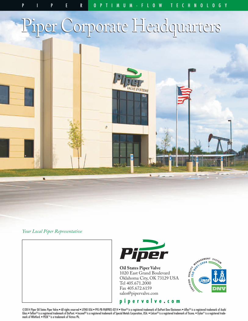
©2014 Piper Oil States Piper Valve • All rights reserved • LITHO USA • PVS-PB-PARPRES-0214 • Viton® is a registered trademark of DuPont Dow Elastomers • Aflas® is a registered trademark of AsahiGlass • Teflon® is a registered trademark of DuPont. • Inconel® is a registered trademark of Special Metals Corporation, USA. • Celcon® is a registered trademark of Ticona. • Xylan® is a registered trade-mark of Whitford. • PEEK™ is a trademark of Victrex Plc.
P I P E R
Your Local Piper Representative
p i p e r v a l v e . c o m
Oil States Piper Valve1020 East Grand BoulevardOklahoma City, OK 73129 USATel 405.671.2000Fax [email protected]
O P T I M U M - F L O W T E C H N O L O G Y
Piper Corporate HeadquartersPiper Corporate Headquarters
Related Documents