C-A-2016 ©2015 SIMPSON STRONG-TIE COMPANY INC. 184 Mechanical Anchors Simpson Strong-Tie ® Anchoring and Fastening Systems for Concrete and Masonry The original high-strength screw anchor for use in cracked and uncracked concrete, as well as uncracked masonry. The Titen HD ® offers low installation torque and outstanding performance. Designed and tested in dry, interior, non-corrosive environments or temporary outdoor applications, the Titen HD ® demonstrates industry-leading performance even in seismic conditions. Features • Code listed under IBC/IRC in accordance with ICC-ES AC193 for cracked and uncracked concrete per ICC-ES ESR-2713 • Code listed under IBC/IRC in accordance with ICC-ES AC106 for masonry per ICC-ES ESR-1056 • Qualiied for static and seismic loading conditions • Thread design undercuts to eficiently transfer the load to the base material • Standard fractional sizes • Specialized heat-treating process creates tip hardness for better cutting without compromising the ductility • No special drill bit required — designed to install using standard-sized ANSI tolerance drill bits • Testing shows the Titen HD ® installs in concrete with 50% less torque than competitor anchors • Hex-washer head requires no separate washer and provides a clean installed appearance • Removable — ideal for temporary anchoring (e.g., formwork, bracing) or applications where ixtures may need to be moved (reuse of the anchor to achieve listed load values is not recommended) Codes: ICC-ES ESR-2713 (concrete); ICC-ES ESR-1056 (masonry); City of L.A. RR25741 (concrete), RR25560 (masonry); Florida FL-15730.6; FM 3017082, 3035761 and 3043442; Multiple DOT listings Material: Carbon steel Coating: Zinc plated or mechanically galvanized Installation Holes in metal ixtures to be mounted should match the diameter speciied in the table below. Use a Titen HD ® screw anchor one time only — installing the anchor multiple times may result in excessive thread wear and reduce load capacity. Do not use impact wrenches to install into hollow CMU. Caution: Oversized holes in base material will reduce or eliminate the mechanical interlock of the threads with the base material and reduce the anchor’s load capacity. 1. Drill a hole in the base material using a carbide drill bit the same diameter as the nominal diameter of the anchor to be installed. Drill the hole to the speciied embedment depth plus minimum hole depth overall (see table below right) to allow the thread tapping dust to settle, and blow it clean using compressed air. (Overhead installations need not be blown clean.) Alternatively, drill the hole deep enough to accommodate embedment depth and the dust from drilling and tapping. 2. Insert the anchor through the ixture and into the hole. 3. Tighten the anchor into the base material until the hex-washer head contacts the ixture. Titen HD ® Heavy-Duty Screw Anchor Serrated teeth on the tip of the Titen HD ® screw anchor facilitate cutting and reduce installation torque. Titen HD ® Screw Anchor U.S. Patents 5,674,035 and 6,623,228 Cracked Concrete CODE LISTED Additional Installation Information Titen HD ® Diameter (in.) Wrench Size (in.) Recommended Fixture Hole Size (in.) Min. Hole Depth Overdrill (in.) 4 8 8 to 7⁄16 8 8 9⁄16 2 to 9⁄16 4 2 4 8 to 11⁄16 2 8 15⁄16 4 to 13⁄16 2 4 1 8 8 to 15⁄16 2 Installation Sequence NEW 4" Titen HD ® Screw Anchor U.S. Patents 5,674,035 and 6,623,228

Welcome message from author
This document is posted to help you gain knowledge. Please leave a comment to let me know what you think about it! Share it to your friends and learn new things together.
Transcript
C-A
-2016 ©
2015 S
IMP
SO
N S
TR
ON
G-T
IE C
OM
PA
NY
IN
C.
184
Me
ch
an
ica
l A
nchors
Simpson Strong-Tie® Anchoring and Fastening Systems for Concrete and Masonry
The original high-strength screw anchor for use in cracked and uncracked concrete, as well as uncracked
masonry. The Titen HD® offers low installation torque and outstanding performance. Designed and tested
in dry, interior, non-corrosive environments or temporary outdoor applications, the Titen HD® demonstrates
industry-leading performance even in seismic conditions.
Features
• Code listed under IBC/IRC in accordance with ICC-ES AC193 for
cracked and uncracked concrete per ICC-ES ESR-2713
• Code listed under IBC/IRC in accordance with ICC-ES AC106 for
masonry per ICC-ES ESR-1056
• Qualiied for static and seismic loading conditions
• Thread design undercuts to eficiently transfer the load to the base
material
• Standard fractional sizes
• Specialized heat-treating process creates tip hardness for better
cutting without compromising the ductility
• No special drill bit required — designed to install using standard-sized
ANSI tolerance drill bits
• Testing shows the Titen HD® installs in concrete with 50% less torque
than competitor anchors
• Hex-washer head requires no separate washer and provides a clean
installed appearance
• Removable — ideal for temporary anchoring (e.g., formwork, bracing)
or applications where ixtures may need to be moved (reuse of the
anchor to achieve listed load values is not recommended)
Codes: ICC-ES ESR-2713 (concrete); ICC-ES ESR-1056
(masonry); City of L.A. RR25741 (concrete), RR25560
(masonry); Florida FL-15730.6; FM 3017082, 3035761 and
3043442; Multiple DOT listings
Material: Carbon steel
Coating: Zinc plated or mechanically galvanized
Installation
Holes in metal ixtures to be mounted should match the diameter speciied in the table below.
Use a Titen HD® screw anchor one time only — installing the anchor multiple times may result in excessive thread wear and reduce load capacity.
Do not use impact wrenches to install into hollow CMU.
Caution: Oversized holes in base material will reduce or eliminate the mechanical interlock of the threads with the base material and reduce the anchor’s load capacity.
1. Drill a hole in the base material using a carbide drill bit the same diameter
as the nominal diameter of the anchor to be installed. Drill the hole to the
speciied embedment depth plus minimum hole depth overall (see table
below right) to allow the thread tapping dust to settle, and blow it clean
using compressed air. (Overhead installations need not be blown clean.)
Alternatively, drill the hole deep enough to accommodate embedment
depth and the dust from drilling and tapping.
2. Insert the anchor through the ixture and into the hole.
3. Tighten the anchor into the base material until the hex-washer head
contacts the ixture.
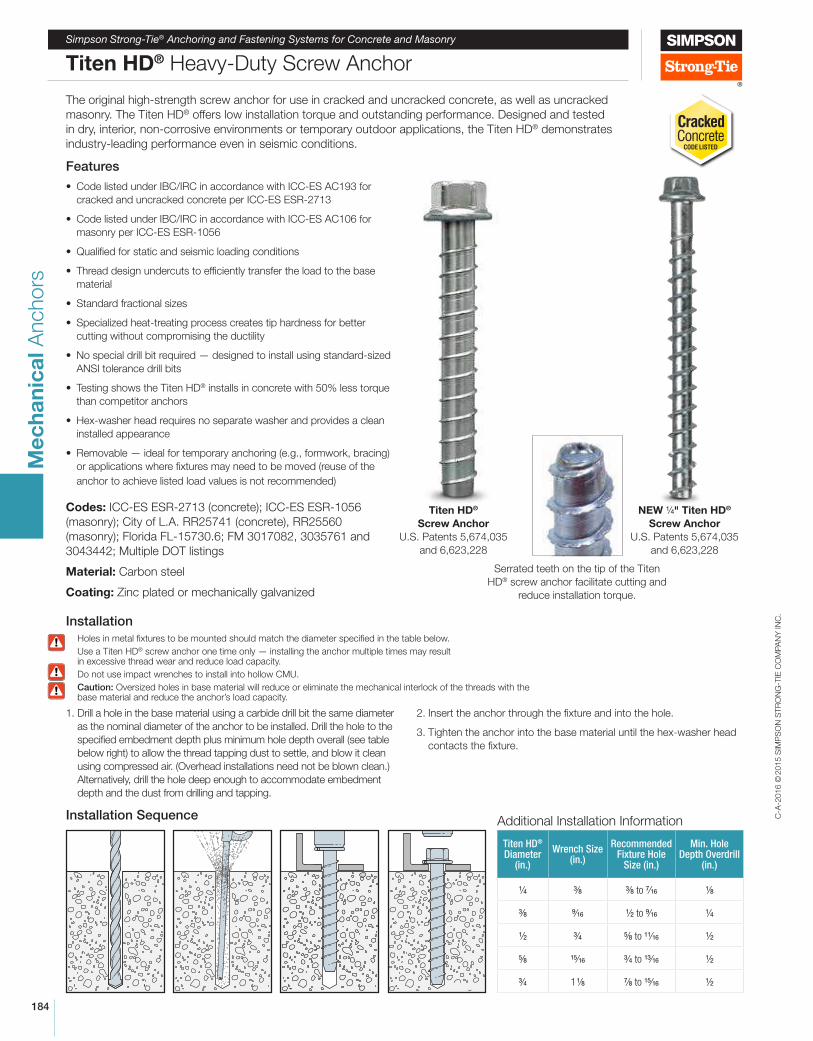
Titen HD® Heavy-Duty Screw Anchor
Serrated teeth on the tip of the Titen
HD® screw anchor facilitate cutting and
reduce installation torque.
Titen HD®
Screw Anchor
U.S. Patents 5,674,035
and 6,623,228
CrackedConcrete CODE LISTED
Additional Installation Information
Titen HD® Diameter
(in.)
Wrench Size (in.)
Recommended Fixture Hole
Size (in.)
Min. Hole Depth Overdrill
(in.)
4 8 8 to 7⁄16 8
8 9⁄16 2 to 9⁄16 4
2 4 8 to 11⁄16 2
8 15⁄16 4 to 13⁄16 2
4 1 8 8 to 15⁄16 2
Installation Sequence
NEW 4" Titen HD®
Screw Anchor
U.S. Patents 5,674,035
and 6,623,228
C-A
-2016 ©
2015 S
IMP
SO
N S
TR
ON
G-T
IE C
OM
PA
NY
IN
C.
185
Me
ch
an
ica
l A
nchors
Simpson Strong-Tie® Anchoring and Fastening Systems for Concrete and Masonry
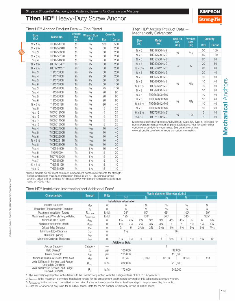
Titen HD® Heavy-Duty Screw Anchor
Titen HD® Anchor Product Data — Zinc Plated
Size (in.)
Model No.Drill Bit
Dia. (in.)
Wrench Size (in.)
Quantity
Box Carton
4 x 1 8 THDB25178H 4 8 100 500
4 x 2 4 THDB25234H 4 8 50 250
4 x 3 THDB25300H 4 8 50 250
4 x 3 2 THDB25312H 4 8 50 250
4 x 4 THDB25400H 4 8 50 250
8 x 1 4 THD37134H* 8 9⁄16 50 250
8 x 2 2 THD37212H* 8 9⁄16 50 200
8 x 3 THD37300H 8 9⁄16 50 200
8 x 4 THD37400H 8 9⁄16 50 200
8 x 5 THD37500H 8 9⁄16 50 100
8 x 6 THD37600H 8 9⁄16 50 100
2 x 3 THD50300H 2 4 25 100
2 x 4 THD50400H 2 4 20 80
2 x 5 THD50500H 2 4 20 80
2 x 6 THD50600H 2 4 20 80
2 x 6 2 THD50612H 2 4 20 40
2 x 8 THD50800H 2 4 5 25
2 x 12 THD501200H 2 4 5 25
2 x 13 THD501300H 2 4 5 25
2 x 14 THD501400H 2 4 5 25
2 x 15 THD501500H 2 4 5 25
8 x 4 THDB62400H 8 15⁄16 10 40
8 x 5 THDB62500H 8 15⁄16 10 40
8 x 6 THDB62600H 8 15⁄16 10 40
8 x 6 2 THDB62612H 8 15⁄16 10 40
8 x 8 THDB62800H 8 15⁄16 10 20
4 x 4 THD75400H 4 1 8 10 40
4 x 5 THD7500H 4 1 8 5 20
4 x 6 THDT75600H 4 1 8 5 20
4 x 7 THD75700H 4 1 8 5 10
4 x 8 2 THD75812H 4 1 8 5 10
4 x 10 THD75100H 4 1 8 5 10
* These models do not meet minimum embedment depth requirements for strength design and require maximum installation torque of 25 ft. – lb. using a torque wrench, driver drill or cordless 4" impact driver with a maximum permitted torque rating of 100 ft. – lb.
Titen HD® Anchor Product Data — Mechanically Galvanized
Size (in.)
Model No.
Drill Bit Dia. (in.)
Wrench Size (in.)
Quantity
Box Carton
8 x 5 THD37500HMG8 9⁄16
50 100
8 x 6 THD37600HMG 50 100
2 x 5 THD50500HMG
2 4
20 80
2 x 6 THD50600HMG 20 80
2 x 6 2 THD50612HMG 20 40
2 x 8 THD50800HMG 20 40
8 x 5 THD62500HMG
8 15⁄16
10 40
8 x 6 THD62600HMG 10 40
8 x 6 2 THD62612HMG 10 40
8 x 8 THD62800HMG 10 20
8 x 5 THDB62500HMG
8 15⁄16
10 40
8 x 6 THDB62600HMG 10 40
8 x 6 2 THDB62612HMG 10 40
8 x 8 THDB62800HMG 10 20
4 x 8 2 THD75812HMG4 1 8
5 10
4 x 10 THD75100HMG 5 10
Mechanical galvanizing meets ASTM B695, Class 65, Type 1. Intended for some pressure-treated wood sill plate applications. Not for use in other corrosive or outdoor environments. See page 316 or visit www.strongtie.com/info for more corrosion information.
Titen HD® Installation Information and Additional Data1
Characteristic Symbol UnitsNominal Anchor Diameter, da (in.)
4 4 8 2 8 4 4
Installation Information
Drill Bit Diameter dbit in. 4 8 2 8 4
Baseplate Clearance Hole Diameter dc in. 8 2 8 4 8
Maximum Installation Torque Tinst,max ft.-lbf 242 502 652 1002 1502
Maximum Impact Wrench Torque Rating Timpact,max ft.-lbf 1253 1503 3403 3403 3853
Minimum Hole Depth hhole in. 1 4 2 8 2 4 3 2 3 4 4 2 4 2 6 6 6 4Nominal Embedment Depth hnom in. 1 8 2 2 2 2 3 4 3 4 4 4 5 2 5 2 6 4
Critical Edge Distance cac in. 3 6 2 11⁄16 3 8 3 9⁄16 4 2 4 2 6 8 6 8 7 5⁄16Minimum Edge Distance cmin in. 1 2 1 4
Minimum Spacing smin in. 3
Minimum Concrete Thickness hmin in. 3 4 3 2 4 5 5 6 4 6 8 2 8 4 10
Additional Data
Anchor Category Category — 1
Yield Strength fya psi 100,000 97,000
Tensile Strength futa psi 125,000 110,000
Minimum Tensile & Shear Stress Area Ase in2 0.042 0.099 0.183 0.276 0.414Axial Stiffness in Service Load Range –
Uncracked Concreteβuncr lb./in. 202,000 715,000
Axial Stiffness in Service Load Range – Cracked Concrete
βcr lb./in. 173,000 345,000
1. The information presented in this table is to be used in conjunction with the design criteria of ACI 318 Appendix D.
2. Tinst,max is the maximum permitted installation torque for the embedment depth range covered by this table using a torque wrench.
3. Timpact,max is the maximum permitted torque rating for impact wrenches for the embedment depth range covered by this table.
4. Data for 4" anchor is only valid for THDB25 series. Data for the 8" anchor is valid only for the THDB62 series.
C-A
-2016 ©
2015 S
IMP
SO
N S
TR
ON
G-T
IE C
OM
PA
NY
IN
C.
186
Me
ch
an
ica
l A
nchors SD
SD
Simpson Strong-Tie® Anchoring and Fastening Systems for Concrete and Masonry
Titen HD® Design Information — Concrete
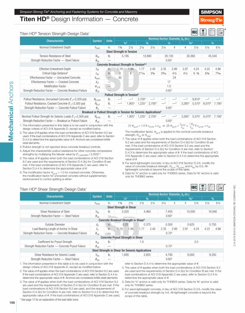
Titen HD® Shear Strength Design Data1
Characteristic Symbol UnitsNominal Anchor Diameter, da (in.)
4 5 8 2 8 5 4
Nominal Embedment Depth hnom in. 1 8 2 2 2 2 3 4 3 4 4 4 5 2 5 2 6 4
Steel Strength in Shear
Shear Resistance of Steel Vsa lb. 2,020 4,460 7,455 10,000 16,840
Strength Reduction Factor — Steel Failure fsa — 0.602
Concrete Breakout Strength in Shear6
Outside Diameter da in. 0.25 0.375 0.500 0.625 0.750
Load Bearing Length of Anchor in Shear ℓe in. 1.19 1.94 1.77 2.40 2.35 2.99 2.97 4.24 4.22 4.86
Strength Reduction Factor — Concrete Breakout Failure fcb — 0.704
Concrete Pryout Strength in Shear
Coeficient for Pryout Strength kcp lb. 1.0 2.0
Strength Reduction Factor — Concrete Pryout Failure fcp — 0.704
Steel Strength in Shear for Seismic Applications
Shear Resistance for Seismic Loads Veq lb. 1,695 2,855 4,790 8,000 9,350
Strength Reduction Factor — Steel Failure feq — 0.602
1. The information presented in this table is to be used in conjunction with the
design criteria of ACI 318 Appendix D, except as modiied below.
2. The value of f applies when the load combinations of ACI 318 Section 9.2 are used.
If the load combinations of ACI 318 Appendix C are used, refer to Section D.4.4 to
determine the appropriate value of f. Anchors are considered brittle steel elements.
3. The value of f applies when both the load combinations of ACI 318 Section 9.2
are used and the requirements of Section D.4.3(c) for Condition B are met. If the
load combinations of ACI 318 Section 9.2 are used, and the requirements of
Section D.4.3(c) for Condition A are met, refer to Section D.4.3 to determine the
appropriate value of f. If the load combinations of ACI 318 Appendix C are used,
refer to Section D.4.4 to determine the appropriate value of f.
4. The value of f applies when both the load combinations of ACI 318 Section 9.2
are used and the requirements of Section D.4.3(c) for Condition B are met. If the
load combinations of ACI 318 Appendix C are used, refer to Section D.4.4 to
determine the appropriate value of f.
5. Data for 4" anchor is valid only for THDB25 series. Data for 8" anchor is valid
only for THDB62 series.
6. For sand-lightweight concrete, in lieu of ACI 318 Section D.3.6, modify the value
of concrete breakout strength by 0.6. All-lightweight concrete is beyond the
scope of this table.
Titen HD® Tension Strength Design Data1
Characteristic Symbol UnitsNominal Anchor Diameter, da (in.)
4 9 8 2 8 9 4
Nominal Embedment Depth hnom in. 1 8 2 2 2 2 3 4 3 4 4 4 5 2 5 2 6 4
Steel Strength in Tension
Tension Resistance of Steel Nsa lb. 5,195 10,890 20,130 30,360 45,540
Strength Reduction Factor — Steel Failure fsa — 0.652
Concrete Breakout Strength in Tension6,8
Effective Embedment Depth hef in. 1.19 1.94 1.77 2.40 2.35 2.99 2.97 4.24 4.22 4.86
Critical Edge Distance6 cac in. 3 6 2 11⁄16 3 8 3 9⁄16 4 2 4 2 6 8 6 8 7 5⁄16
Effectiveness Factor — Uncracked Concrete kuncr — 30 24
Effectiveness Factor — Cracked Concrete kcr — 17
Modification Factor ψc,N — 1.0
Strength Reduction Factor — Concrete Breakout Failure fcb — 0.657
Pullout Strength in Tension8
Pullout Resistance, Uncracked Concrete (f'c=2,500 psi) Np,uncr lb. —3 —3 2,7004 —3 —3 —3 —3 9,8104 —3 —3
Pullout Resistance, Cracked Concrete (f'c=2,500 psi) Np,cr lb. —3 1,9054 1,2354 2,7004 —3 —3 3,2604 5,5704 6,0704 7,1954
Strength Reduction Factor — Concrete Pullout Failure fp — 0.655
Breakout or Pullout Strength in Tension for Seismic Applications8
Nominal Pullout Strength for Seismic Loads (f'c=2,500 psi) Np,eq lb. —3 1,9054 1,2354 2,7004 —3 —3 3,2604 5,5704 6,0704 7,1954
Strength Reduction Factor — Breakout or Pullout Failure feq — 0.655
1. The information presented in this table is to be used in conjunction with the
design criteria of ACI 318 Appendix D, except as modiied below.
2. The value of f applies when the load combinations of ACI 318 Section 9.2 are
used. If the load combinations of ACI 318 Appendix C are used, refer to Section
D.4.4 to determine the appropriate value of f. Anchors are considered brittle
steel elements.
3. Pullout strength is not reported since concrete breakout controls.
4. Adjust the characteristic pullout resistance for other concrete compressive
strengths by multiplying the tabular value by (f'c,specified / 2,500)0.5.
5. The value of f applies when both the load combinations of ACI 318 Section
9.2 are used and the requirements of Section D.4.3(c) for Condition B are
met. If the load combinations of ACI 318 Appendix C are used, refer to
Section D.4.4 to determine the appropriate value of f.
6. The modiication factor ψcp,N = 1.0 for cracked concrete. Otherwise,
the modiication factor for uncracked concrete without supplementary
reinforcement to control splitting is either:
(1) ψcp,N = 1.0 if ca,min ≥ cac or (2) ψcp,N = ca,min
cac
≥ 1.5hef
cac
if ca,min < cac
The modiication factor, ψcp,N is applied to the nominal concrete breakout strength, Ncb or Ncbg.
7. The value of f applies when both the load combinations of ACI 318 Section
9.2 are used and the requirements of Section D.4.3(c) for Condition B are
met. If the load combinations of ACI 318 Section 9.2 are used and the
requirements of Section D.4.3(c) for Condition A are met, refer to Section
D.4.3 to determine the appropriate value of f. If the load combinations of ACI
318 Appendix C are used, refer to Section D.4.4 to determine the appropriate
value of f.
8. For sand-lightweight concrete, in lieu of ACI 318 Section D.3.6, modify the value of concrete breakout strength, Np,cr, Np,uncr and Neq by 0.6. All-lightweight concrete is beyond the scope of this table.
9. Data for 4" anchor is valid only for THDB25 series. Data for 8" anchor is valid only for THDB62 series.
* See page 12 for an explanation of the load table icons.
*IBC
*IBC
C-A
-2016 ©
2015 S
IMP
SO
N S
TR
ON
G-T
IE C
OM
PA
NY
IN
C.
187
Me
ch
an
ica
l A
nchors
SD
Simpson Strong-Tie® Anchoring and Fastening Systems for Concrete and Masonry
Titen HD® Design Information — Concrete
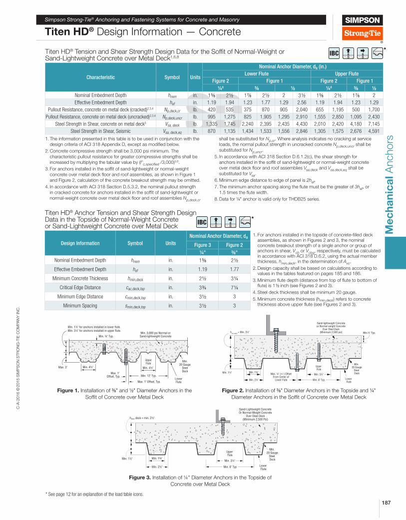
Titen HD® Tension and Shear Strength Design Data for the Sofit of Normal-Weight or Sand-Lightweight Concrete over Metal Deck1,6,8
Characteristic Symbol Units
Nominal Anchor Diameter, da (in.)
Lower Flute Upper Flute
Figure 2 Figure 1 Figure 2 Figure 1
4 8 8 2 4 8 8 2
Nominal Embedment Depth hnom in. 1 8 2 2 1 8 2 2 2 3 2 1 8 2 2 1 8 2
Effective Embedment Depth hef in. 1.19 1.94 1.23 1.77 1.29 2.56 1.19 1.94 1.23 1.29
Pullout Resistance, concrete on metal deck (cracked)2,3,4 Np,deck,cr lb. 420 535 375 870 905 2,040 655 1,195 500 1,700
Pullout Resistance, concrete on metal deck (uncracked)2,3,4 Np,deck,uncr lb. 995 1,275 825 1,905 1,295 2,910 1,555 2,850 1,095 2,430
Steel Strength in Shear, concrete on metal deck5 Vsa, deck lb. 1,335 1,745 2,240 2,395 2,435 4,430 2,010 2,420 4,180 7,145
Steel Strength in Shear, Seismic Vsa, deck,eq lb. 870 1,135 1,434 1,533 1,556 2,846 1,305 1,575 2,676 4,591
1. The information presented in this table is to be used in conjunction with the
design criteria of ACI 318 Appendix D, except as modiied below.
2. Concrete compressive strength shall be 3,000 psi minimum. The
characteristic pullout resistance for greater compressive strengths shall be
increased by multiplying the tabular value by (f'c,specified /3,000)0.5.
3. For anchors installed in the sofit of sand-lightweight or normal-weight
concrete over metal deck loor and roof assemblies, as shown in Figure 1
and Figure 2, calculation of the concrete breakout strength may be omitted.
4. In accordance with ACI 318 Section D.5.3.2, the nominal pullout strength
in cracked concrete for anchors installed in the sofit of sand-lightweight or
normal-weight concrete over metal deck loor and roof assemblies Np,deck,cr
shall be substituted for Np,cr. Where analysis indicates no cracking at service
loads, the normal pullout strength in uncracked concrete Np,deck,uncr shall be
substituted for Np,uncr.
5. In accordance with ACI 318 Section D.6.1.2(c), the shear strength for
anchors installed in the sofit of sand-lightweight or normal-weight concrete
over metal deck loor and roof assemblies Vsa,deck and Vsa,deck,eq shall be
substituted for Vsa.
6. Minimum edge distance to edge of panel is 2hef.
7. The minimum anchor spacing along the lute must be the greater of 3hef, or
1.5 times the lute width.
8. Data for 4" anchor is valid only for THDB25 series.
Titen HD® Anchor Tension and Shear Strength Design Data in the Topside of Normal-Weight Concrete or Sand-Lightweight Concrete over Metal Deck
Design Information Symbol Units
Nominal Anchor Diameter, da1. For anchors installed in the topside of concrete-illed deck
assemblies, as shown in Figures 2 and 3, the nominal concrete breakout strength of a single anchor or group of anchors in shear, Vcb or Vcbg, respectively, must be calculated in accordance with ACI 318 D.6.2, using the actual member thickness, hmin,deck, in the determination of Avc.
2. Design capacity shall be based on calculations according to values in the tables featured on pages 185 and 186.
3. Minimum lute depth (distance from top of lute to bottom of lute) is 1 2 inch (see Figures 2 and 3).
4. Steel deck thickness shall be minimum 20 gauge.
5. Minimum concrete thickness (hmin,deck) refers to concrete thickness above upper lute (see Figures 2 and 3).
Figure 3 Figure 2
4" 8"
Nominal Embedment Depth hnom in. 1 8 2 2
Effective Embedment Depth hef in. 1.19 1.77
Minimum Concrete Thickness hmin,deck in. 2 2 3 4
Critical Edge Distance cac,deck,top in. 3 4 7 4
Minimum Edge Distance cmin,deck,top in. 3 2 3
Minimum Spacing smin,deck,top in. 3 2 3
* See page 12 for an explanation of the load table icons.
*IBC
*IBC
Figure 1. Installation of 8" and 2" Diameter Anchors in the
Sofit of Concrete over Metal Deck
Min. 3,000 psi Normal orSand-lightweight Concrete
Min.20 Gauge
SteelDeck
LowerFlute
UpperFlute
Min. 12" Typ.
Max. 1" Offset, Typ.
Max. 1" Offset, Typ.
Max. 3" Min. 4½"
Min. ¾" Typ.
Min. 4½"
Min. 1½" for anchors installed in lower flute.Min. 3¼" for anchors installed in upper flute.
Sand-lightweight Concreteor Normal-weight Concrete
Over Steel Deck(Minimum 2,500 psi)
Min. 20 Gauge
Steel Deck
Lower Flute
Min. 3½"
Upper Flute
Min. 1¾"
Min. 6" Typ.
Min.¾" Typ.
Max. ¼" (+/-) OffsetFrom Center of
Lower FluteMin. 2½"
hmin,deck
= Min. 3¼"
Min. 1½"
Figure 2. Installation of 8" Diameter Anchors in the Topside and 4"
Diameter Anchors in the Sofit of Concrete over Metal Deck
Figure 3. Installation of ¼" Diameter Anchors in the Topside of
Concrete over Metal Deck
Min. 20 Gauge
Steel Deck
Lower Flute
Upper Flute
Min. 1¾"Min. 3½"
Min. 6" TypMin. 2½"
Sand-Lightweight ConcreteOr Normal-Weight Concrete
Over Steel Deck(Minimum 2,500 Psi)
Min. 1½"
hmin deck = min. 2½"
C-A
-2016 ©
2015 S
IMP
SO
N S
TR
ON
G-T
IE C
OM
PA
NY
IN
C.
188
Me
ch
an
ica
l A
nchors SD
Simpson Strong-Tie® Anchoring and Fastening Systems for Concrete and Masonry
Titen HD® Design Information — Concrete
* See page 12 for an explanation of the load table icons.
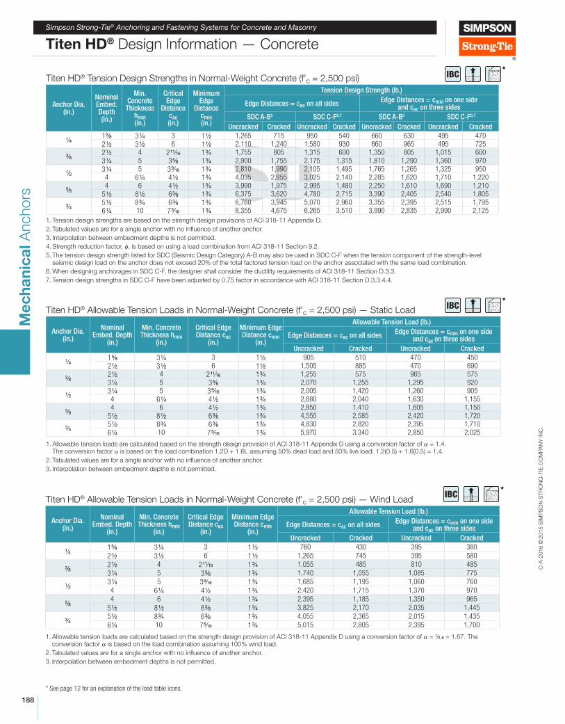
Titen HD® Allowable Tension Loads in Normal-Weight Concrete (f'c = 2,500 psi) — Static Load
Anchor Dia.(in.)
Nominal Embed. Depth
(in.)
Min. Concrete Thickness hmin
(in.)
Critical Edge Distance cac
(in.)
Minimum Edge Distance cmin
(in.)
Allowable Tension Load (lb.)
Edge Distances = cac on all sidesEdge Distances = cmin on one side
and cac on three sides
Uncracked Cracked Uncracked Cracked
4 1 8 3 4 3 1 2 905 510 470 450 2 2 3 2 6 1 2 1,505 885 470 690
8 2 2 4 2 11⁄16 1 4 1,255 575 965 575 3 4 5 3 8 1 4 2,070 1,255 1,295 920
2 3 4 5 3 9⁄16 1 4 2,005 1,420 1,260 905 4 6 4 4 2 1 4 2,880 2,040 1,630 1,155
8 4 6 4 2 1 4 2,850 1,410 1,605 1,150
5 2 8 2 6 8 1 4 4,555 2,585 2,420 1,720
4 5 2 8 4 6 8 1 4 4,830 2,820 2,395 1,710 6 4 10 7 5⁄16 1 4 5,970 3,340 2,850 2,025
1. Allowable tension loads are calculated based on the strength design provision of ACI 318-11 Appendix D using a conversion factor of α = 1.4. The conversion factor α is based on the load combination 1.2D + 1.6L assuming 50% dead load and 50% live load: 1.2(0.5) + 1.6(0.5) = 1.4.
2. Tabulated values are for a single anchor with no inluence of another anchor.
3. Interpolation between embedment depths is not permitted.
Titen HD® Tension Design Strengths in Normal-Weight Concrete (f'c = 2,500 psi)
Anchor Dia.(in.)
Nominal Embed. Depth(in.)
Min. Concrete Thickness
hmin(in.)
Critical Edge
Distance cac(in.)
Minimum Edge
Distance cmin(in.)
Tension Design Strength (lb.)
Edge Distances = cac on all sidesEdge Distances = cmin on one side
and cac on three sides
SDC A-B5 SDC C-F6,7 SDC A-B5 SDC C-F6,7
Uncracked Cracked Uncracked Cracked Uncracked Cracked Uncracked Cracked
4 1 8 3 4 3 1 2 1,265 715 950 540 660 630 495 4702 2 3 2 6 1 2 2,110 1,240 1,580 930 660 965 495 725
8 2 2 4 2 11/16 1 4 1,755 805 1,315 600 1,350 805 1,015 6003 4 5 3 8 1 4 2,900 1,755 2,175 1,315 1,810 1,290 1,360 970
2 3 4 5 3 9/16 1 4 2,810 1,990 2,105 1,495 1,765 1,265 1,325 9504 6 4 4 2 1 4 4,035 2,855 3,025 2,140 2,285 1,620 1,710 1,220
8 4 6 4 2 1 4 3,990 1,975 2,995 1,480 2,250 1,610 1,690 1,210
5 2 8 2 6 8 1 4 6,375 3,620 4,780 2,715 3,390 2,405 2,540 1,805
4 5 2 8 4 6 8 1 4 6,760 3,945 5,070 2,960 3,355 2,395 2,515 1,7956 4 10 7 5/16 1 4 8,355 4,675 6,265 3,510 3,990 2,835 2,990 2,125
1. Tension design strengths are based on the strength design provisions of ACI 318-11 Appendix D.
2. Tabulated values are for a single anchor with no influence of another anchor.
3. Interpolation between embedment depths is not permitted.
4. Strength reduction factor, f, is based on using a load combination from ACI 318-11 Section 9.2.
5. The tension design strength listed for SDC (Seismic Design Category) A-B may also be used in SDC C-F when the tension component of the strength-level seismic design load on the anchor does not exceed 20% of the total factored tension load on the anchor associated with the same load combination.
6. When designing anchorages in SDC C-F, the designer shall consider the ductility requirements of ACI 318-11 Section D.3.3.
7. Tension design strengths in SDC C-F have been adjusted by 0.75 factor in accordance with ACI 318-11 Section D.3.3.4.4.
Titen HD® Allowable Tension Loads in Normal-Weight Concrete (f'c = 2,500 psi) — Wind Load
Anchor Dia.(in.)
Nominal Embed. Depth
(in.)
Min. Concrete Thickness hmin
(in.)
Critical Edge Distance cac
(in.)
Minimum Edge Distance cmin
(in.)
Allowable Tension Load (lb.)
Edge Distances = cac on all sidesEdge Distances = cmin on one side
and cac on three sides
Uncracked Cracked Uncracked Cracked
4 1 8 3 4 3 1 2 760 430 395 380
2 2 3 2 6 1 2 1,265 745 395 580
8 2 2 4 2 11⁄16 1 4 1,055 485 810 485
3 4 5 3 8 1 4 1,740 1,055 1,085 775
2 3 4 5 3 9⁄16 1 4 1,685 1,195 1,060 7604 6 4 4 2 1 4 2,420 1,715 1,370 970
8 4 6 4 2 1 4 2,395 1,185 1,350 965
5 2 8 2 6 8 1 4 3,825 2,170 2,035 1,445
4 5 2 8 4 6 8 1 4 4,055 2,365 2,015 1,435
6 4 10 7 5⁄16 1 4 5,015 2,805 2,395 1,700
1. Allowable tension loads are calculated based on the strength design provision of ACI 318-11 Appendix D using a conversion factor of α = 1⁄0.6 = 1.67. The conversion factor α is based on the load combination assuming 100% wind load.
2. Tabulated values are for a single anchor with no inluence of another anchor.
3. Interpolation between embedment depths is not permitted.
*IBC
*IBC
*IBC
C-A
-2016 ©
2015 S
IMP
SO
N S
TR
ON
G-T
IE C
OM
PA
NY
IN
C.
189
Me
ch
an
ica
l A
nchors
Simpson Strong-Tie® Anchoring and Fastening Systems for Concrete and Masonry
Titen HD® Design Information — Concrete
* See page 12 for an explanation of the load table icons.
*IBC
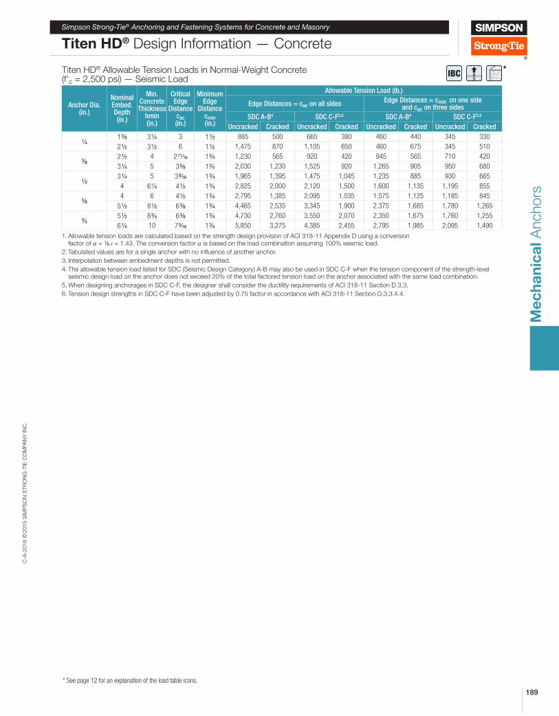
Titen HD® Allowable Tension Loads in Normal-Weight Concrete (f'c = 2,500 psi) — Seismic Load
Anchor Dia.(in.)
Nominal Embed. Depth(in.)
Min. Concrete Thickness
hmin(in.)
Critical Edge
Distance cac(in.)
Minimum Edge
Distance cmin(in.)
Allowable Tension Load (lb.)
Edge Distances = cac on all sidesEdge Distances = cmin on one side
and cac on three sides
SDC A-B4 SDC C-F5,6 SDC A-B4 SDC C-F5,6
Uncracked Cracked Uncracked Cracked Uncracked Cracked Uncracked Cracked
4 1 8 3 4 3 1 2 885 500 665 380 460 440 345 330
2 2 3 2 6 1 2 1,475 870 1,105 650 460 675 345 510
8 2 2 4 2 11⁄16 1 4 1,230 565 920 420 945 565 710 420
3 4 5 3 8 1 4 2,030 1,230 1,525 920 1,265 905 950 680
2 3 4 5 3 9⁄16 1 4 1,965 1,395 1,475 1,045 1,235 885 930 665
4 6 4 4 2 1 4 2,825 2,000 2,120 1,500 1,600 1,135 1,195 855
8 4 6 4 2 1 4 2,795 1,385 2,095 1,035 1,575 1,125 1,185 845
5 2 8 2 6 8 1 4 4,465 2,535 3,345 1,900 2,375 1,685 1,780 1,265
4 5 2 8 4 6 8 1 4 4,730 2,760 3,550 2,070 2,350 1,675 1,760 1,255
6 4 10 7 5⁄16 1 4 5,850 3,275 4,385 2,455 2,795 1,985 2,095 1,490
1. Allowable tension loads are calculated based on the strength design provision of ACI 318-11 Appendix D using a conversion factor of α = 1⁄0.7 = 1.43. The conversion factor α is based on the load combination assuming 100% seismic load.
2. Tabulated values are for a single anchor with no inluence of another anchor.
3. Interpolation between embedment depths is not permitted.
4. The allowable tension load listed for SDC (Seismic Design Category) A-B may also be used in SDC C-F when the tension component of the strength-level seismic design load on the anchor does not exceed 20% of the total factored tension load on the anchor associated with the same load combination.
5. When designing anchorages in SDC C-F, the designer shall consider the ductility requirements of ACI 318-11 Section D.3.3.
6. Tension design strengths in SDC C-F have been adjusted by 0.75 factor in accordance with ACI 318-11 Section D.3.3.4.4.
C-A
-2016 ©
2015 S
IMP
SO
N S
TR
ON
G-T
IE C
OM
PA
NY
IN
C.
190
Me
ch
an
ica
l A
nchors
SD
Simpson Strong-Tie® Anchoring and Fastening Systems for Concrete and Masonry
Titen HD® Design Information — Concrete
* See page 12 for an explanation of the load table icons.
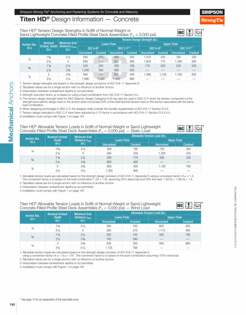
Titen HD® Allowable Tension Loads in Sofit of Normal-Weight or Sand-Lightweight Concrete-Filled Proile Steel Deck Assemblies (f'c = 3,000 psi) — Static Load
Anchor Dia.(in.)
Nominal Embed. Depth(in.)
Minimum End Distance cmin
(in.)
Allowable Tension Load (lb.)
Lower Flute Upper Flute
Uncracked Cracked Uncracked Cracked
4 1 8 2 2 460 195 720 305
2 2 4 595 250 1,325 555
8 1 8 2 2 380 175 505 230
2 2 3 8 885 405 — —
2 2 2 8 600 420 1,130 790
3 2 5 4 1,350 945 — —
1. Allowable tension loads are calculated based on the strength design provision of ACI 318-11 Appendix D using a conversion factor of α = 1.4. The conversion factor α is based on the load combination 1.2D + 1.6L assuming 50% dead load and 50% live load: 1.2(0.5) + 1.6(0.5) = 1.4.
2. Tabulated values are for a single anchor with no inluence of another anchor.
3. Interpolation between embedment depths is not permitted.
4. Installation must comply with Figure 1 on page 187.
Titen HD® Allowable Tension Loads in Sofit of Normal-Weight or Sand-Lightweight Concrete-Filled Proile Steel Deck Assemblies (f'c = 3,000 psi) — Wind Load
Anchor Dia.(in.)
Nominal Embed. Depth(in.)
Minimum End Distance cmin
(in.)
Allowable Tension Load (lb.)
Lower Flute Upper Flute
Uncracked Cracked Uncracked Cracked
4 1 8 2 2 385 165 605 255
2 2 4 500 210 1,115 465
8 1 8 2 2 320 145 425 195
2 2 3 8 745 340 — —
2 2 2 8 505 355 950 665
3 2 5 4 1,135 795 — —
1. Allowable tension loads are calculated based on the strength design provision of ACI 318-11 Appendix D using a conversion factor of α = 1⁄0.6 = 1.67. The conversion factor α is based on the load combination assuming 100% wind load.
2. Tabulated values are for a single anchor with no inluence of another anchor.
3. Interpolation between embedment depths is not permitted.
4. Installation must comply with Figure 1 on page 187.
Titen HD® Tension Design Strengths in Sofit of Normal-Weight or Sand-Lightweight Concrete-Filled Proile Steel Deck Assemblies (f'c = 3,000 psi)
Anchor Dia.(in.)
Nominal Embed. Depth
(in.)
Minimum End Distance cmin
(in.)
Tension Design Strength (lb.)
Lower Flute Upper Flute
SDC A-B5 SDC C-F6,7 SDC A-B5 SDC C-F6,7
Uncracked Cracked Uncracked Cracked Uncracked Cracked Uncracked Cracked
4 1 8 2 2 645 275 485 205 1,010 425 760 320
2 2 4 830 350 620 260 1,855 775 1,390 585
8 1 8 2 2 535 245 400 185 710 325 535 245
2 2 3 8 1,240 565 930 425 — — — —
2 2 2 8 840 590 630 440 1,580 1,105 1,185 830
3 2 5 4 1,890 1,325 1,420 995 — — — —
1. Tension design strengths are based on the strength design provisions of ACI 318-11 Appendix D.
2. Tabulated values are for a single anchor with no inluence of another anchor.
3. Interpolation between embedment depths is not permitted.
4. Strength reduction factor, f, is based on using a load combination from ACI 318-11 Section 9.2.
5. The tension design strength listed for SDC (Seismic Design Category) A-B may also be used in SDC C-F when the tension component of the strength-level seismic design load on the anchor does not exceed 20% of the total factored tension load on the anchor associated with the same load combination.
6. When designing anchorages in SDC C-F, the designer shall consider the ductility requirements of ACI 318-11 Section D.3.3.
7. Tension design strengths in SDC C-F have been adjusted by 0.75 factor in accordance with ACI 318-11 Section D.3.3.4.4.
8. Installation must comply with Figure 1 on page 187.
*IBC
*IBC
*IBC
C-A
-2016 ©
2015 S
IMP
SO
N S
TR
ON
G-T
IE C
OM
PA
NY
IN
C.
191
Me
ch
an
ica
l A
nchors
Simpson Strong-Tie® Anchoring and Fastening Systems for Concrete and Masonry
Titen HD® Design Information — Concrete
* See page 12 for an explanation of the load table icons.
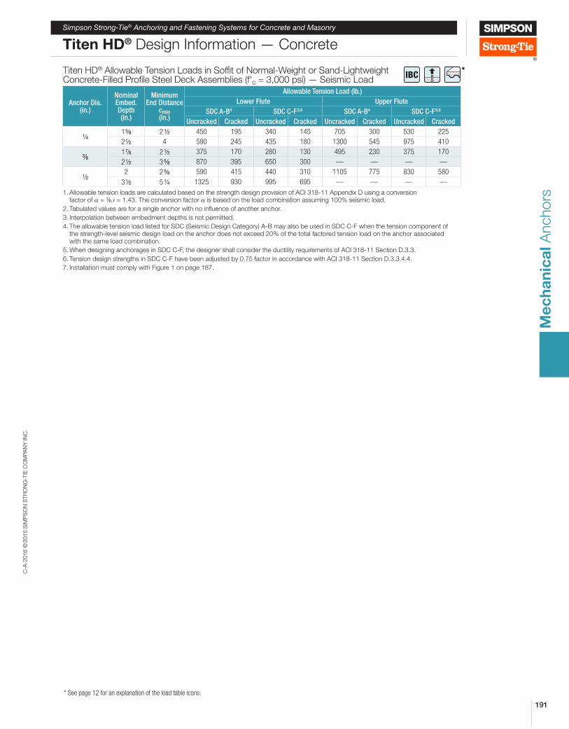
Titen HD® Allowable Tension Loads in Sofit of Normal-Weight or Sand-Lightweight Concrete-Filled Proile Steel Deck Assemblies (f'c = 3,000 psi) — Seismic Load
Anchor Dia.(in.)
Nominal Embed. Depth(in.)
Minimum End Distance
cmin(in.)
Allowable Tension Load (lb.)
Lower Flute Upper Flute
SDC A-B4 SDC C-F5,6 SDC A-B4 SDC C-F5,6
Uncracked Cracked Uncracked Cracked Uncracked Cracked Uncracked Cracked
4 1 8 2 2 450 195 340 145 705 300 530 225
2 2 4 580 245 435 180 1300 545 975 410
8 1 8 2 2 375 170 280 130 495 230 375 170
2 2 3 8 870 395 650 300 — — — —
2 2 2 8 590 415 440 310 1105 775 830 580
3 2 5 4 1325 930 995 695 — — — —
1. Allowable tension loads are calculated based on the strength design provision of ACI 318-11 Appendix D using a conversion factor of α = 1⁄0.7 = 1.43. The conversion factor α is based on the load combination assuming 100% seismic load.
2. Tabulated values are for a single anchor with no inluence of another anchor.
3. Interpolation between embedment depths is not permitted.
4. The allowable tension load listed for SDC (Seismic Design Category) A-B may also be used in SDC C-F when the tension component of the strength-level seismic design load on the anchor does not exceed 20% of the total factored tension load on the anchor associated with the same load combination.
5. When designing anchorages in SDC C-F, the designer shall consider the ductility requirements of ACI 318-11 Section D.3.3.
6. Tension design strengths in SDC C-F have been adjusted by 0.75 factor in accordance with ACI 318-11 Section D.3.3.4.4.
7. Installation must comply with Figure 1 on page 187.
*IBC
C-A
-2016 ©
2015 S
IMP
SO
N S
TR
ON
G-T
IE C
OM
PA
NY
IN
C.
192
Me
ch
an
ica
l A
nchors
Simpson Strong-Tie® Anchoring and Fastening Systems for Concrete and Masonry
Titen HD® Design Information — Concrete
* See page 12 for an explanation of the load table icons.
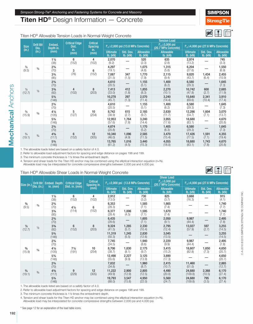
Titen HD® Allowable Shear Loads in Normal-Weight Concrete
Size (in.)Drill Bit Dia. (in.)
Embed. Depth in. (mm)
Critical Edge Dist. in. (mm)
Critical Spacing in.
(mm)
Shear Load
f'c ≥2,000 psi (13.8 MPa Concrete)f'c ≥3,000 psi
(20.7 MPa Concrete)f'c ≥4,000 psi (27.6 MPa Concrete)
Ultimate lb. (kN)
Std. Dev. lb. (kN)
Allowable lb. (kN)
Allowable lb. (kN)
Ultimate lb. (kN)
Std. Dev. lb. (kN)
Allowable lb. (kN)
8 (9.5)
8
1 2 (38)
6 (152)
4 (102)
2,912 (13.0)
—730 (3.2)
825 (3.7)
3,668 (16.3)
—915 (4.1)
2 4 (70) 4 2
(114)6
(152)
6,353 (28.3)
—1,585 (7.1)
1,665 (7.4)
— —1,740 (7.7)
3 4 (95)
6,377 (28.4)
1,006 (4.5)
1,595 (7.1)
1,670 (7.4)
— —1,740 (7.7)
2 (12.7)
2
2 4 (70)
6 (152)
8 (203)
6,435 (28.6)
—1,605 (7.1)
2,050 (9.1)
9,987 (44.4)
—2,495 (7.8)
3 8 (92)
9,324 (41.5)
1,285 (5.7)
2,330 (10.4)
2,795 (12.4)
13,027 (57.9)
597 (2.7)
3,255 (14.5)
5 4 (146)
11,319 (50.3)
1,245 (5.5)
2,830 (12.6)
3,045 (13.5)
— —3,255 (14.5)
8 (15.9)
8
2 4 (70)
7 2 (191)
10 (254)
7,745 (34.5)
—1,940 (8.6)
2,220 (9.9)
9,987 (44.4)
—2,495 (7.8)
4 8 (105)
8,706 (38.7)
1,830 (8.1)
2,175 (9.7)
3,415 (15.2)
18,607 (82.8)
1,650 (7.3)
4,650 (20.7)
5 4 (146)
12,498 (55.6)
2,227 (9.9)
3,125 (13.9)
3,890 (17.3)
— —4,650 (20.7)
4 (19.1)
4
2 4 (70)
9 (229)
12 (305)
7,832 (34.8)
—1,960 (8.7)
2,415 (10.7)
11,460 (51.0)
—2,865 (12.7)
4 8 (117)
11,222 (49.9)
2,900 (12.9)
2,805 (12.5)
4,490 (20.0)
24,680 (109.8)
2,368 (10.5)
6,170 (27.4)
5 4 (146)
19,793 (88.0)
3,547 (15.8)
4,950 (22.0)
5,560 (24.7)
24,680 (109.8)
795 (3.5)
6,170 (27.4)
1. The allowable loads listed are based on a safefy factor of 4.0.
2. Refer to allowable load-adjustment factors for spacing and edge distance on pages 198 and 199.
3. The minimum concrete thickness is 1 2 times the embedment depth.
4. Tension and shear loads for the Titen HD anchor may be combined using the elliptical interaction equation (n=5⁄3). Allowable load may be interpolated for concrete compressive strengths between 2,000 psi and 4,000 psi.
Titen HD® Allowable Tension Loads in Normal-Weight Concrete
Size (in.)
Drill Bit Dia. (in.)
Embed. Depth in.
(mm)
Critical Edge Dist. in.
(mm)
Critical Spacing
in. (mm)
Tension Load
f'c ≥2,000 psi (13.8 MPa Concrete)f'c ≥3,000 psi
(20.7 MPa Concrete)f'c ≥4,000 psi (27.6 MPa Concrete)
Ultimate lb. (kN)
Std. Dev. lb. (kN)
Allowable lb. (kN)
Allowable lb. (kN)
Ultimate lb. (kN)
Std. Dev. lb. (kN)
Allowable lb. (kN)
8 (9.5)
8
1 2 (38)
6 (152)
4 (102)
2,070 (9.2)
—520 (2.3)
635 (2.8)
2,974 (13.2)
—745 (3.3)
2 4 (70) 3
(76)6
(152)
4,297 (19.1)
—1,075 (4.8)
1,315 (5.8)
6,204 (27.6)
—1,550 (6.9)
3 4 (95)
7,087 (31.5)
347 (1.5)
1,770 (7.9)
2,115 (9.4)
9,820 (43.7)
1,434 (6.4)
2,455 (10.9)
2 (12.7)
2
2 4 (70)
4 (102)
8 (203)
4,610 (20.5)
—1,155 (5.1)
1,400 (6.2)
6,580 (29.3)
—1,645 (7.3)
3 8 (92)
7,413 (33.0)
412 (1.8)
1,855 (8.3)
2,270 (10.1)
10,742 (47.8)
600 (2.7)
2,685 (11.9)
5 4 (146)
10,278 (45.7)
297 (1.3)
2,570 (11.4)
3,240 (14.4)
15,640 (69.6)
2,341 (10.4)
3,910 (17.4)
8 (15.9)
8
2 4 (70)
5 (127)
10 (254)
4,610 (20.5)
—1,155 (5.1)
1,400 (6.2)
6,580 (29.3)
—1,645 (7.3)
4 8 (105)
8,742 (38.9)
615 (2.7)
2,185 (9.7)
2,630 (11.7)
12,286 (54.7)
1,604 (7.1)
3,070 (13.7)
5 4 (146)
12,953 (57.6)
1,764 (7.8)
3,240 (14.4)
3,955 (17.6)
18,680 (83.1)
—4,670 (20.8)
4 (19.1)
4
2 4 (70)
6 (152)
12 (305)
4,674 (20.8)
—1,170 (5.2)
1,405 (6.3)
6,580 (29.3)
—1,645 (7.3)
4 8 (117)
10,340 (46.0)
1,096 (4.9)
2,585 (11.5)
3,470 (15.4)
17,426 (77.5)
1,591 (7.1)
4,355 (19.4)
5 4 (146)
13,765 (61.2)
1,016 (4.5)
3,440 (15.3)
4,055 (18.0)
18,680 (83.1)
1,743 (7.8)
4,670 (20.8)
1. The allowable loads listed are based on a safety factor of 4.0.
2. Refer to allowable load-adjustment factors for spacing and edge distance on pages 198 and 199.
3. The minimum concrete thickness is 1 2 times the embedment depth.
4. Tension and shear loads for the Titen HD anchor may be combined using the elliptical interaction equation (n=5⁄3). Allowable load may be interpolated for concrete compressive strengths between 2,000 psi and 4,000 psi.
*IBC
*IBC
C-A
-2016 ©
2015 S
IMP
SO
N S
TR
ON
G-T
IE C
OM
PA
NY
IN
C.
193
Me
ch
an
ica
l A
nchors
Simpson Strong-Tie® Anchoring and Fastening Systems for Concrete and Masonry
Titen HD® Design Information — Concrete
* See page 12 for an explanation of the load table icons.
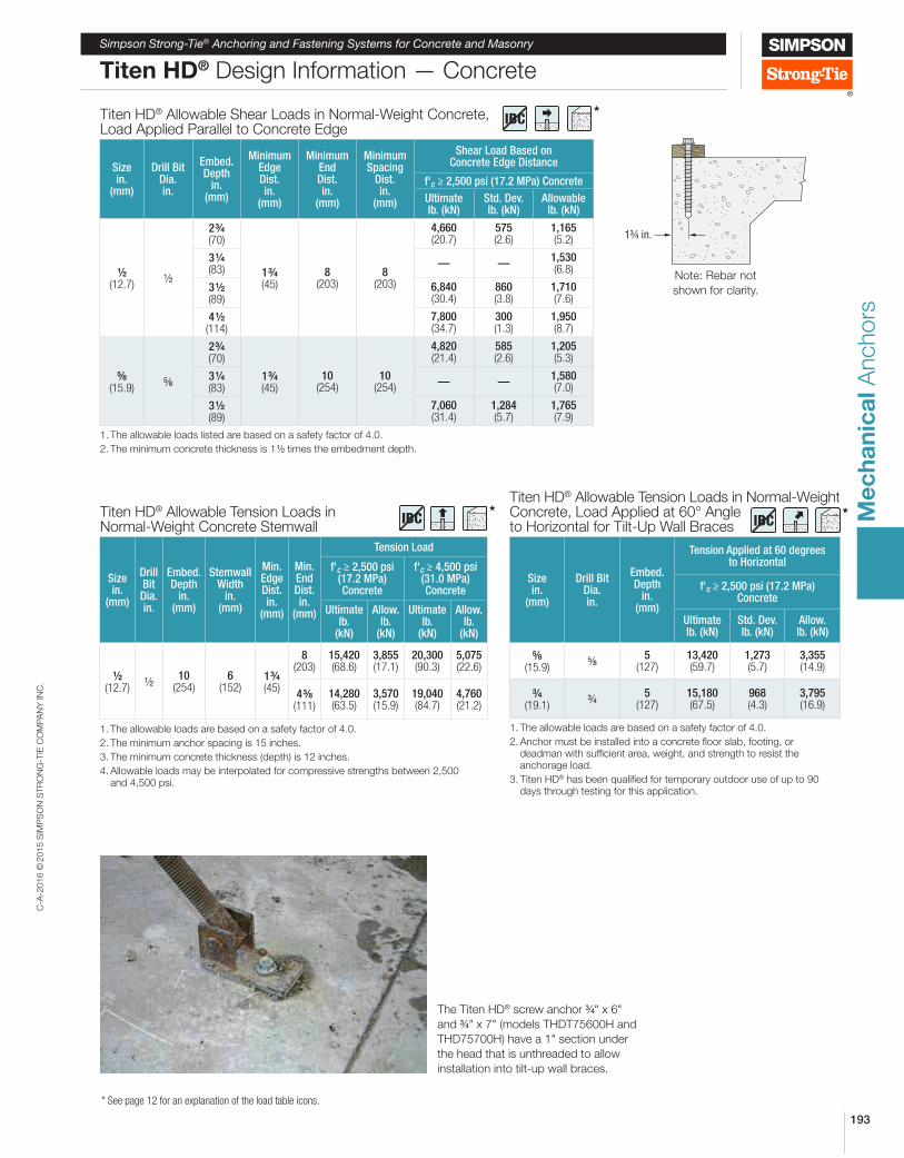
Titen HD® Allowable Tension Loads in Normal-Weight Concrete Stemwall
Size in.
(mm)
Drill Bit Dia. in.
Embed. Depth
in. (mm)
Stemwall Width
in. (mm)
Min. Edge Dist. in.
(mm)
Min. End Dist. in.
(mm)
Tension Load
f'c ≥ 2,500 psi (17.2 MPa) Concrete
f'c ≥ 4,500 psi (31.0 MPa) Concrete
Ultimate lb.
(kN)
Allow. lb.
(kN)
Ultimate lb.
(kN)
Allow. lb.
(kN)
2 (12.7)
210
(254)6
(152)1 4 (45)
8 (203)
15,420 (68.6)
3,855 (17.1)
20,300 (90.3)
5,075 (22.6)
4 8 (111)
14,280 (63.5)
3,570 (15.9)
19,040 (84.7)
4,760 (21.2)
1. The allowable loads are based on a safety factor of 4.0.
2. The minimum anchor spacing is 15 inches.
3. The minimum concrete thickness (depth) is 12 inches.
4. Allowable loads may be interpolated for compressive strengths between 2,500 and 4,500 psi.
Titen HD® Allowable Tension Loads in Normal-Weight Concrete, Load Applied at 60° Angle to Horizontal for Tilt-Up Wall Braces
Size in.
(mm)
Drill Bit Dia. in.
Embed. Depth
in. (mm)
Tension Applied at 60 degrees to Horizontal
f'c ≥ 2,500 psi (17.2 MPa) Concrete
Ultimate lb. (kN)
Std. Dev. lb. (kN)
Allow. lb. (kN)
8 (15.9)
85
(127)13,420 (59.7)
1,273 (5.7)
3,355 (14.9)
4 (19.1)
45
(127)15,180 (67.5)
968 (4.3)
3,795 (16.9)
1. The allowable loads are based on a safety factor of 4.0.
2. Anchor must be installed into a concrete loor slab, footing, or deadman with suficient area, weight, and strength to resist the anchorage load.
3. Titen HD® has been qualiied for temporary outdoor use of up to 90 days through testing for this application.
Titen HD® Allowable Shear Loads in Normal-Weight Concrete, Load Applied Parallel to Concrete Edge
Size in.
(mm)
Drill Bit Dia. in.
Embed. Depth
in. (mm)
Minimum Edge Dist. in.
(mm)
Minimum End Dist. in.
(mm)
Minimum Spacing
Dist. in.
(mm)
Shear Load Based on Concrete Edge Distance
f'c ≥ 2,500 psi (17.2 MPa) Concrete
Ultimate lb. (kN)
Std. Dev. lb. (kN)
Allowable lb. (kN)
2 (12.7)
2
2 4 (70)
1 4 (45)
8 (203)
8 (203)
4,660 (20.7)
575 (2.6)
1,165 (5.2)
3 4 (83)
— —1,530 (6.8)
3 2 (89)
6,840 (30.4)
860 (3.8)
1,710 (7.6)
4 2 (114)
7,800 (34.7)
300 (1.3)
1,950 (8.7)
8 (15.9)
8
2 4 (70)
1 4 (45)
10 (254)
10 (254)
4,820 (21.4)
585 (2.6)
1,205 (5.3)
3 4 (83)
— —1,580 (7.0)
3 2 (89)
7,060 (31.4)
1,284 (5.7)
1,765 (7.9)
1. The allowable loads listed are based on a safety factor of 4.0.
2. The minimum concrete thickness is 1 2 times the embedment depth.
1¾ in.
Note: Rebar not
shown for clarity.
The Titen HD® screw anchor 4" x 6"
and 4" x 7" (models THDT75600H and
THD75700H) have a 1" section under
the head that is unthreaded to allow
installation into tilt-up wall braces.
*IBC
*IBC *
IBC
C-A
-2016 ©
2015 S
IMP
SO
N S
TR
ON
G-T
IE C
OM
PA
NY
IN
C.
194
Me
ch
an
ica
l A
nchors
Simpson Strong-Tie® Anchoring and Fastening Systems for Concrete and Masonry
* See page 12 for an explanation of the load table icons.
Titen HD® Design Information — Concrete
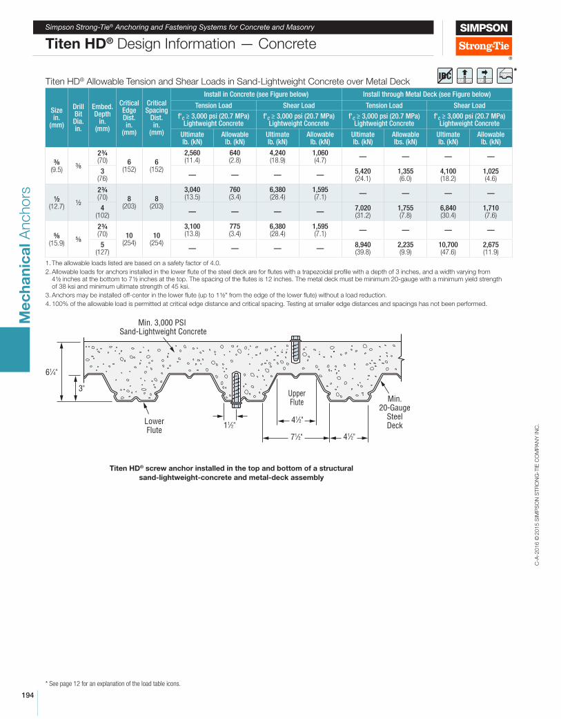
Titen HD® Allowable Tension and Shear Loads in Sand-Lightweight Concrete over Metal Deck
Size in.
(mm)
Drill Bit Dia. in.
Embed. Depth
in. (mm)
Critical Edge Dist. in.
(mm)
Critical Spacing
Dist. in.
(mm)
Install in Concrete (see Figure below) Install through Metal Deck (see Figure below)
Tension Load Shear Load Tension Load Shear Load
f'c ≥ 3,000 psi (20.7 MPa) Lightweight Concrete
f'c ≥ 3,000 psi (20.7 MPa) Lightweight Concrete
f'c ≥ 3,000 psi (20.7 MPa) Lightweight Concrete
f'c ≥ 3,000 psi (20.7 MPa) Lightweight Concrete
Ultimate lb. (kN)
Allowable lb. (kN)
Ultimate lb. (kN)
Allowable lb. (kN)
Ultimate lb. (kN)
Allowable lbs. (kN)
Ultimate lb. (kN)
Allowable lb. (kN)
8 (9.5)
8
2 4 (70) 6
(152)6
(152)
2,560 (11.4)
640 (2.8)
4,240 (18.9)
1,060 (4.7)
— — — —
3 (76)
— — — —5,420 (24.1)
1,355 (6.0)
4,100 (18.2)
1,025 (4.6)
2 (12.7)
2
2 4 (70) 8
(203)8
(203)
3,040 (13.5)
760 (3.4)
6,380 (28.4)
1,595 (7.1)
— — — —
4 (102)
— — — —7,020 (31.2)
1,755 (7.8)
6,840 (30.4)
1,710 (7.6)
8 (15.9)
8
2 4 (70) 10
(254)10
(254)
3,100 (13.8)
775 (3.4)
6,380 (28.4)
1,595 (7.1)
— — — —
5 (127)
— — — —8,940 (39.8)
2,235 (9.9)
10,700 (47.6)
2,675 (11.9)
1. The allowable loads listed are based on a safety factor of 4.0.
2. Allowable loads for anchors installed in the lower lute of the steel deck are for lutes with a trapezoidal proile with a depth of 3 inches, and a width varying from 4 2 inches at the bottom to 7 2 inches at the top. The spacing of the lutes is 12 inches. The metal deck must be minimum 20-gauge with a minimum yield strength of 38 ksi and minimum ultimate strength of 45 ksi.
3. Anchors may be installed off-center in the lower lute (up to 1 2" from the edge of the lower lute) without a load reduction.
4. 100% of the allowable load is permitted at critical edge distance and critical spacing. Testing at smaller edge distances and spacings has not been performed.
Min. 3,000 PSI Sand-Lightweight Concrete
Min.20-Gauge
SteelDeck
LowerFlute
UpperFlute
3"
61⁄4"
11⁄2"41⁄2"
41⁄2"71⁄2"
Titen HD® screw anchor installed in the top and bottom of a structural
sand-lightweight-concrete and metal-deck assembly
*IBC
C-A
-2016 ©
2015 S
IMP
SO
N S
TR
ON
G-T
IE C
OM
PA
NY
IN
C.
195
Me
ch
an
ica
l A
nchors
Simpson Strong-Tie® Anchoring and Fastening Systems for Concrete and Masonry
* See page 12 for an explanation of the load table icons.
Titen HD® Design Information — Masonry
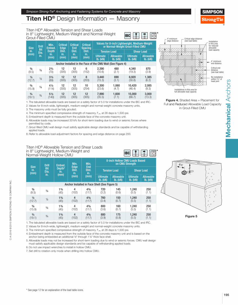
Titen HD® Allowable Tension and Shear Loads in 8" Lightweight, Medium-Weight and Normal-Weight Grout-Filled CMU
Size in.
(mm)
Drill Bit Dia. in.
Min. Embed. Depth
in. (mm)
Critical Edge Dist. in.
(mm)
Critical End Dist. in.
(mm)
Critical Spacing
Dist. in.
(mm)
Values for 8-inch Lightweight, Medium-Weight or Normal-Weight Grout-Filled CMU
Tension Load Shear Load
Ultimate lb. (kN)
Allowable lb. (kN)
Ultimate lb. (kN)
Allowable lb. (kN)
Anchor Installed in the Face of the CMU Wall (See Figure 4)
8 (9.5)
82 4 (70)
12 (305)
12 (305)
6 (152)
2,390 (10.6)
480 (2.1)
4,340 (19.3)
870 (3.9)
2 (12.7)
23 2 (89)
12 (305)
12 (305)
8 (203)
3,440 (15.3)
690 (3.1)
6,920 (30.8)
1,385 (6.2)
8 (15.9)
84 2
(114)12
(305)12
(305)10
(254)5,300 (23.6)
1,060 (4.7)
10,420 (46.4)
2,085 (9.3)
4 (19.1)
45 2
(140)12
(305)12
(305)12
(305)7,990 (35.5)
1,600 (7.1)
15,000 (66.7)
3,000 (13.3)
1. The tabulated allowable loads are based on a safety factor of 5.0 for installations under the IBC and IRC.
2. Values for 8-inch-wide, lightweight, medium-weight and normal-weight concrete masonry units.
3. The masonry units must be fully grouted.
4. The minimum speciied compressive strength of masonry, f'm, at 28 days is 1,500 psi.
5. Embedment depth is measured from the outside face of the concrete masonry unit.
6. Allowable loads may be increased 33 3% for short-term loading due to wind or seismic forces where permitted by code.
7. Grout-illed CMU wall design must satisfy applicable design standards and be capable of withstanding applied loads.
8. Refer to allowable load-adjustment factors for spacing and edge distance on page 200.
Titen HD® Allowable Tension and Shear Loads in 8" Lightweight, Medium-Weight and Normal-Weight Hollow CMU
Size in.
(mm)
Drill Bit Dia. in.
Embed. Depth4
in. (mm)
Min. Edge Dist. in.
(mm)
Min. End Dist. in.
(mm)
8-inch Hollow CMU Loads Based on CMU Strength
Tension Load Shear Load
Ultimate lb. (kN)
Allowable lb. (kN)
Ultimate lb. (kN)
Allowable lb. (kN)
Anchor Installed in Face Shell (See Figure 5)
8 (9.5)
81 4 (45)
4 (102)
4 8 (117)
720 (3.2)
145 (0.6)
1,240 (5.5)
250 (1.1)
2 (12.7)
21 4 (45)
4 (102)
4 8 (117)
760 (3.4)
150 (0.7)
1,240 (5.5)
250 (1.1)
8 (15.9)
81 4 (45)
4 (102)
4 8 (117)
800 (3.6)
160 (0.7)
1,240 (5.5)
250 (1.1)
4 (19.1)
41 4 (45)
4 (102)
4 8 (117)
880 (3.9)
175 (0.8)
1,240 (5.5)
250 (1.1)
1. The tabulated allowable loads are based on a safety factor of 5.0 for installations under the IBC and IRC.
2. Values for 8-inch-wide, lightweight, medium-weight and normal-weight concrete masonry units.
3. The minimum speciied compressive strength of masonry, f'm, at 28 days is 1,500 psi.
4. Embedment depth is measured from the outside face of the concrete masonry unit and is based on the anchor being embedded an additional 2" through 1 4" thick face shell.
5. Allowable loads may not be increased for short-term loading due to wind or seismic forces. CMU wall design must satisfy applicable design standards and be capable of withstanding applied loads.
6. Do not use impact wrenches to install in hollow CMU.
7. Set drill to rotation-only mode when drilling into hollow CMU.
45⁄8"4"
Installations in this area forfull allowable load capacity
Installationin this areafor reducedallowableload capacity
4" minimumend distance
Critical enddistance(see load table)
No installationwithin 1½" ofhead joint
4" minimumedge distance
Critical edge distance(see load table)
Figure 4. Shaded Area = Placement for
Full and Reduced Allowable Load Capacity
in Grout-Filled CMU
Figure 5
*IBC
*IBC
C-A
-2016 ©
2015 S
IMP
SO
N S
TR
ON
G-T
IE C
OM
PA
NY
IN
C.
196
Me
ch
an
ica
l A
nchors
Simpson Strong-Tie® Anchoring and Fastening Systems for Concrete and Masonry
* See page 12 for an explanation of the load table icons.
Titen HD® Design Information — Masonry
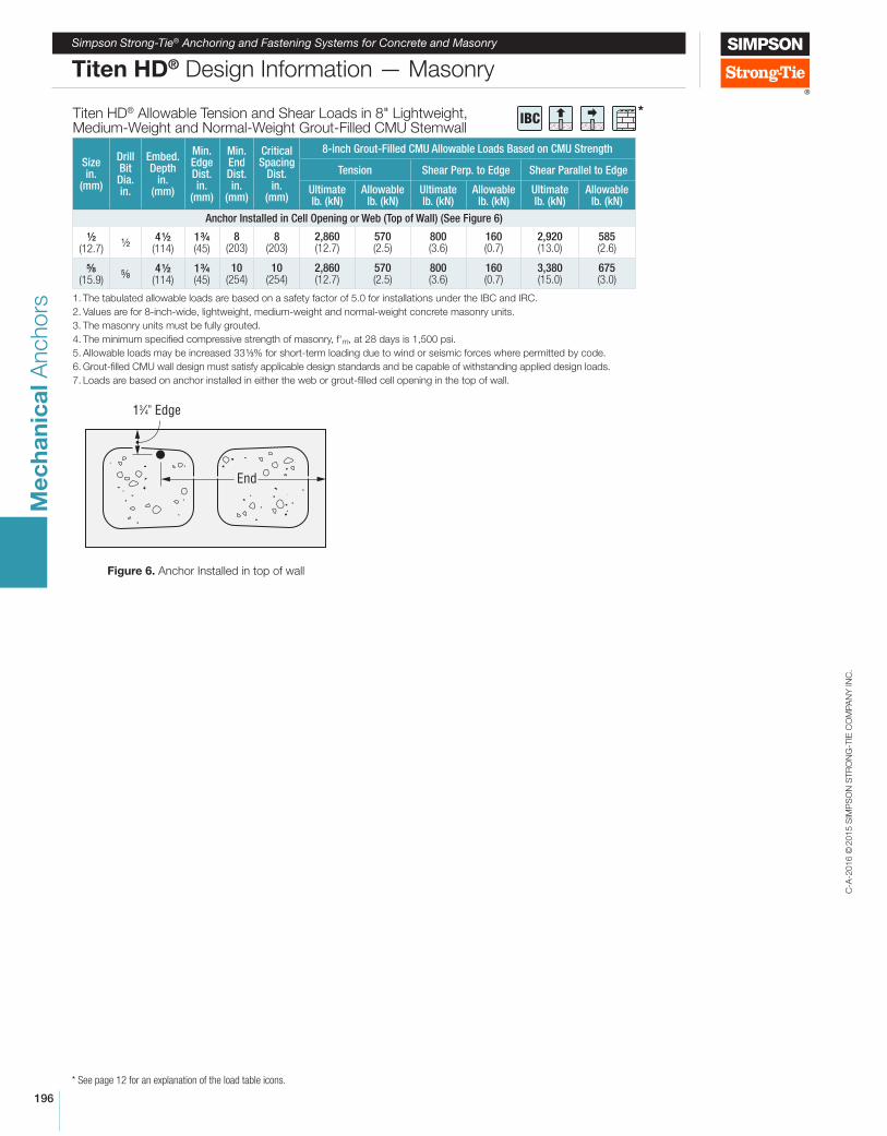
Titen HD® Allowable Tension and Shear Loads in 8" Lightweight, Medium-Weight and Normal-Weight Grout-Filled CMU Stemwall
Size in.
(mm)
Drill Bit Dia. in.
Embed. Depth
in. (mm)
Min. Edge Dist. in.
(mm)
Min. End Dist. in.
(mm)
Critical Spacing
Dist. in.
(mm)
8-inch Grout-Filled CMU Allowable Loads Based on CMU Strength
Tension Shear Perp. to Edge Shear Parallel to Edge
Ultimate lb. (kN)
Allowable lb. (kN)
Ultimate lb. (kN)
Allowable lb. (kN)
Ultimate lb. (kN)
Allowable lb. (kN)
Anchor Installed in Cell Opening or Web (Top of Wall) (See Figure 6)
2 (12.7)
24 2
(114)1 4 (45)
8 (203)
8 (203)
2,860 (12.7)
570 (2.5)
800 (3.6)
160 (0.7)
2,920 (13.0)
585 (2.6)
8 (15.9)
84 2
(114)1 4 (45)
10 (254)
10 (254)
2,860 (12.7)
570 (2.5)
800 (3.6)
160 (0.7)
3,380 (15.0)
675 (3.0)
1. The tabulated allowable loads are based on a safety factor of 5.0 for installations under the IBC and IRC.
2. Values are for 8-inch-wide, lightweight, medium-weight and normal-weight concrete masonry units.
3. The masonry units must be fully grouted.
4. The minimum speciied compressive strength of masonry, f'm, at 28 days is 1,500 psi.
5. Allowable loads may be increased 33 3% for short-term loading due to wind or seismic forces where permitted by code.
6. Grout-illed CMU wall design must satisfy applicable design standards and be capable of withstanding applied design loads.
7. Loads are based on anchor installed in either the web or grout-illed cell opening in the top of wall.
13⁄4" Edge
End
Figure 6. Anchor Installed in top of wall
*IBC
C-A
-2016 ©
2015 S
IMP
SO
N S
TR
ON
G-T
IE C
OM
PA
NY
IN
C.
197
Me
ch
an
ica
l A
nchors
Simpson Strong-Tie® Anchoring and Fastening Systems for Concrete and Masonry
* See page 12 for an explanation of the load table icons.
Titen HD® Design Information — Masonry
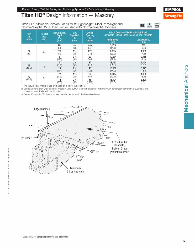
Titen HD® Allowable Tension Loads for 8" Lightweight, Medium-Weight and Normal-Weight CMU Chair Blocks Filled with Normal-Weight Concrete
Size in.
(mm)
Drill Bit Dia. (in.)
Min. Embed. Depth
in. (mm)
Min. Edge Dist.
in. (mm)
Critical Spacing
in. (mm)
8-inch Concrete-Filled CMU Chair Block Allowable Tension Loads Based on CMU Strength
Ultimate lb. (kN)
Allowable lb. (kN)
8 (9.5)
8
2 8 (60)
1 4 (44)
9 2 (241)
3,175 (14.1)
635 (2.8)
3 8 (86)
1 4 (44)
13 2 (343)
5,175 (23.0)
1,035 (4.6)
5 (127)
2 4 (57)
20 (508)
10,584 (47.1)
2,115 (9.4)
2 (12.7)
2
8 (203)
2 4 (57)
32 (813)
13,722 (61.0)
2,754 (12.2)
10 (254)
2 4 (57)
40 (1016)
16,630 (74.0)
3,325 (14.8)
8 (15.9)
8
5 2 (140)
1 4 (44)
22 (559)
9,025 (40.1)
1,805 (8.1)
12 (305)
2 4 (57)
48 (1219)
18,104 (80.5)
3,620 (16.1)
1. The tabulated allowable loads are based on a safety factor of 5.0.
2. Values are for 8-inch-wide concrete masonry units (CMU) illed with concrete, with minimum compressive strength of 2,500 psi and poured monolithically with the loor slab.
3. Center #5 rebar in CMU cell and concrete slab as shown in the illustration below.
#5 Rebar
Edge Distance
4" ThickSlab
f'c ≥ 2,500 psiConcrete,
Slab on Grade(Monolithic Pour)
Minimum3 Courses High
*IBC
C-A
-2016 ©
2015 S
IMP
SO
N S
TR
ON
G-T
IE C
OM
PA
NY
IN
C.
198
Me
ch
an
ica
l A
nchors
Simpson Strong-Tie® Anchoring and Fastening Systems for Concrete and Masonry
* See page 12 for an explanation of the load table icons.
Titen HD® Design Information — Concrete
Edge Distance Tension (fc)
Edge Dist. cact (in.)
Dia. 8 2 8 4
E 1 2 2 4 3 4 2 4 3 8 5 4 2 4 4 8 5 4 2 4 4 8 5 4ccr 6 3 3 4 4 4 5 5 5 6 6 6
cmin 6 1 4 1 4 1 4 1 4 1 4 1 4 1 4 1 4 1 4 1 4 1 4
fcmin 1.00 0.83 0.73 0.67 0.57 0.73 0.67 0.57 0.59 0.67 0.48 0.58
1 4 0.83 0.73 0.67 0.57 0.73 0.67 0.57 0.59 0.67 0.48 0.582 0.86 0.78 0.71 0.62 0.76 0.70 0.60 0.62 0.69 0.51 0.60
2 4 0.90 0.84 0.74 0.67 0.79 0.72 0.64 0.65 0.71 0.54 0.63
2 2 0.93 0.89 0.78 0.71 0.82 0.75 0.67 0.68 0.73 0.57 0.65
2 4 0.97 0.95 0.82 0.76 0.85 0.77 0.70 0.72 0.75 0.60 0.683 1.00 1.00 0.85 0.81 0.88 0.80 0.74 0.75 0.77 0.63 0.70
3 4 0.89 0.86 0.91 0.82 0.77 0.78 0.79 0.66 0.73
3 2 0.93 0.90 0.94 0.85 0.80 0.81 0.81 0.69 0.75
3 4 0.96 0.95 0.97 0.87 0.83 0.84 0.83 0.72 0.784 1.00 1.00 1.00 0.90 0.87 0.87 0.84 0.76 0.80
4 4 0.92 0.90 0.91 0.86 0.79 0.83
4 2 0.95 0.93 0.94 0.88 0.82 0.85
4 4 0.97 0.97 0.97 0.90 0.85 0.885 1.00 1.00 1.00 0.92 0.88 0.90
5 4 0.94 0.91 0.93
5 2 0.96 0.94 0.95
5 4 0.98 0.97 0.986 1.00 1.00 1.00 1.00
See notes below.
Edge Distance Shear (fc)
Edge Dist. cact (in.)
Dia. 8 2 8 4
E 1 2 2 4 3 4 2 4 3 8 5 4 2 4 4 8 5 4 2 4 4 8 5 4ccr 6 4 2 4 2 6 6 6 7 2 7 2 7 2 9 9 9
cmin 6 1 4 1 4 1 4 1 4 1 4 1 4 1 4 1 4 1 4 1 4 1 4
fcmin 1.00 0.25 0.24 0.25 0.20 0.17 0.19 0.16 0.19 0.19 0.14 0.13
1 4 0.25 0.24 0.25 0.20 0.17 0.19 0.16 0.19 0.19 0.14 0.132 0.32 0.31 0.29 0.25 0.22 0.23 0.20 0.23 0.22 0.17 0.16
2 2 0.45 0.45 0.38 0.34 0.32 0.30 0.27 0.30 0.27 0.23 0.223 0.59 0.59 0.47 0.44 0.41 0.37 0.34 0.37 0.33 0.29 0.28
3 2 0.73 0.72 0.56 0.53 0.51 0.44 0.42 0.44 0.39 0.35 0.344 0.86 0.86 0.65 0.62 0.61 0.51 0.49 0.51 0.44 0.41 0.40
4 2 1.00 1.00 0.74 0.72 0.71 0.58 0.56 0.58 0.50 0.47 0.465 0.82 0.81 0.80 0.65 0.63 0.65 0.55 0.53 0.52
5 2 0.91 0.91 0.90 0.72 0.71 0.72 0.61 0.58 0.586 1.00 1.00 1.00 1.00 0.79 0.78 0.79 0.66 0.64 0.64
6 2 0.86 0.85 0.86 0.72 0.70 0.707 0.93 0.93 0.93 0.78 0.76 0.76
7 2 1.00 1.00 1.00 0.83 0.82 0.828 0.89 0.88 0.88
8 2 0.94 0.94 0.949 1.00 1.00 1.00
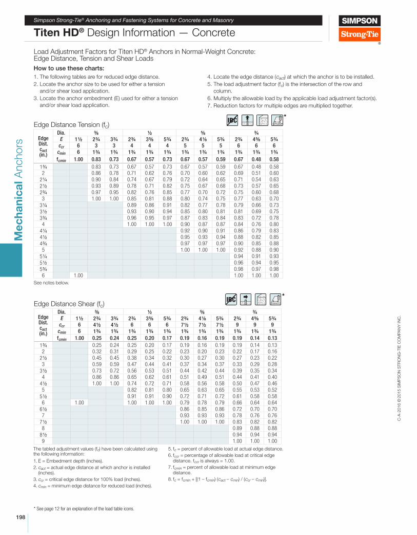
Load Adjustment Factors for Titen HD® Anchors in Normal-Weight Concrete: Edge Distance, Tension and Shear Loads
How to use these charts:
1. The following tables are for reduced edge distance.
2. Locate the anchor size to be used for either a tension
and/or shear load application.
3. Locate the anchor embedment (E) used for either a tension
and/or shear load application.
4. Locate the edge distance (cact) at which the anchor is to be installed.
5. The load adjustment factor (fc) is the intersection of the row and
column.
6. Multiply the allowable load by the applicable load adjustment factor(s).
7. Reduction factors for multiple edges are multiplied together.
The tabled adjustment values (fc) have been calculated using the following information:
1. E = Embedment depth (inches).
2. cact = actual edge distance at which anchor is installed (inches).
3. ccr = critical edge distance for 100% load (inches).
4. cmin = minimum edge distance for reduced load (inches).
5. fc = percent of allowable load at actual edge distance.
6. fccr = percentage of allowable load at critical edge distance. fccr is always = 1.00.
7. fcmin = percent of allowable load at minimum edge distance.
8. fc = fcmin + [(1 – fcmin) (cact – cmin) / (ccr – cmin)].
*IBC
*IBC
C-A
-2016 ©
2015 S
IMP
SO
N S
TR
ON
G-T
IE C
OM
PA
NY
IN
C.
199
Me
ch
an
ica
l A
nchors
Simpson Strong-Tie® Anchoring and Fastening Systems for Concrete and Masonry
* See page 12 for an explanation of the load table icons.
Titen HD® Design Information — Concrete
Spacing Tension (fs)
sact (in)
Dia. 8 2 8 4
E 1 2 2 4 3 4 2 4 3 8 5 4 2 4 4 8 5 4 2 4 4 8 5 4
scr 4 6 6 8 8 8 10 10 10 12 12 12
smin 4 1 2 1 2 2 2 2 2 2 2 2 2 2 3 3 3
fsmin 1.00 0.66 0.56 0.72 0.63 0.76 0.79 0.69 0.73 0.80 0.70 0.72
1
1 2 0.66 0.56
2 0.70 0.61 0.72 0.63 0.76
2 2 0.74 0.66 0.74 0.66 0.78 0.79 0.69 0.73
3 0.77 0.71 0.77 0.69 0.80 0.80 0.71 0.75 0.80 0.70 0.72
4 1.00 0.85 0.80 0.81 0.75 0.84 0.83 0.75 0.78 0.82 0.73 0.75
5 0.92 0.90 0.86 0.82 0.88 0.86 0.79 0.82 0.84 0.77 0.78
6 1.00 1.00 0.91 0.88 0.92 0.89 0.83 0.86 0.87 0.80 0.81
7 0.95 0.94 0.96 0.92 0.88 0.89 0.89 0.83 0.84
8 1.00 1.00 1.00 0.94 0.92 0.93 0.91 0.87 0.88
9 0.97 0.96 0.96 0.93 0.90 0.91
10 1.00 1.00 1.00 0.96 0.93 0.94
11 0.98 0.97 0.97
12 1.00 1.00 1.00
See notes below
Spacing Shear (fs)
sact (in)
Dia. 8 2 8 4
E 1 2 2 4 3 4 2 4 3 8 5 4 2 4 4 8 5 4 2 4 4 8 5 4
scr 4 0 0 0 0 0 0 0 0 0 0 0
smin 4 0 0 0 0 0 0 0 0 0 0 0
fsmin 1.00 0.77 0.77 0.77 0.77 0.77 0.77 0.77 0.77 0.77 0.77 0.77
1
1 2 0.77 0.77 0.88
2 0.80 0.80 0.77 0.77 0.77
2 2 0.82 0.82 0.79 0.79 0.79 0.77 0.77 0.77
3 0.85 0.85 0.81 0.81 0.81 0.79 0.79 0.79 0.77 0.77 0.77
4 1.00 0.90 0.90 0.85 0.85 0.85 0.82 0.82 0.82 0.80 0.80 0.80
5 0.95 0.95 0.89 0.89 0.89 0.85 0.85 0.85 0.82 0.82 0.82
6 1.00 1.00 0.92 0.92 0.92 0.88 0.88 0.88 0.85 0.85 0.85
7 0.96 0.96 0.96 0.91 0.91 0.91 0.87 0.87 0.87
8 1.00 1.00 1.00 0.94 0.94 0.94 0.90 0.90 0.90
9 0.97 0.97 0.97 0.92 0.92 0.92
10 1.00 1.00 1.00 0.95 0.95 0.95
11 0.97 0.97 0.97
12 1.00 1.00 1.00
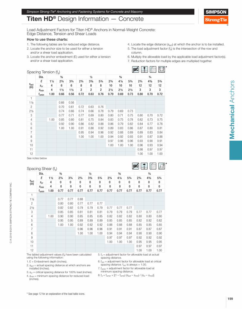
Load Adjustment Factors for Titen HD® Anchors in Normal-Weight Concrete: Edge Distance, Tension and Shear Loads
How to use these charts:
1. The following tables are for reduced edge distance.
2. Locate the anchor size to be used for either a tension
and/or a shear load application.
3. Locate the anchor embedment (E) used for either a tension
and/or a shear load application.
4. Locate the edge distance (sact) at which the anchor is to be installed.
5. The load adjustment factor (fs) is the intersection of the row and
column.
6. Multiply the allowable load by the applicable load adjustment factor(s).
7. Reduction factors for multiple edges are multiplied together.
The tabled adjustment values (fs) have been calculated using the following information:
1. E = Embedment depth (inches).
2. sact = actual spacing distance at which anchors are installed (inches).
3. scr = critical spacing distance for 100% load (inches).
4. smin = minimum spacing distance for reduced load (inches).
5. fs = adjustment factor for allowable load at actual spacing distance.
6. fscr = adjustment factor for allowable load at critical spacing distance. fscr is always = 1.00.
7. fsmin = adjustment factor for allowable load at minimum spacing distance.
8. fs = fsmin + [(1 – fsmin) (sact – smin) / (scr – smin)].
*IBC
*IBC
C-A
-2016 ©
2015 S
IMP
SO
N S
TR
ON
G-T
IE C
OM
PA
NY
IN
C.
200
Me
ch
an
ica
l A
nchors
Simpson Strong-Tie® Anchoring and Fastening Systems for Concrete and Masonry
Titen HD® Design Information — Masonry
* See page 12 for an explanation of the load table icons.
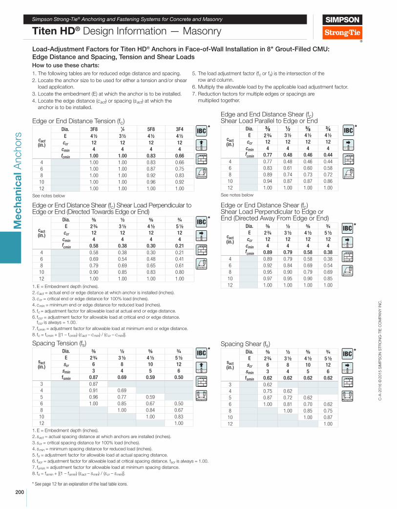
Load-Adjustment Factors for Titen HD® Anchors in Face-of-Wall Installation in 8" Grout-Filled CMU:
Edge Distance and Spacing, Tension and Shear Loads
How to use these charts:
1. The following tables are for reduced edge distance and spacing.
2. Locate the anchor size to be used for either a tension and/or shear
load application.
3. Locate the embedment (E) at which the anchor is to be installed.
4. Locate the edge distance (cact) or spacing (sact) at which the
anchor is to be installed.
5. The load adjustment factor (fc or fs) is the intersection of the
row and column.
6. Multiply the allowable load by the applicable load adjustment factor.
7. Reduction factors for multiple edges or spacings are
multiplied together.
Edge or End Distance Tension (fc)
cact (in.)
Dia. 3F8 1/2 5F8 3F4
E 4 ½ 3 ½ 4 ½ 4 ½
ccr 12 12 12 12
cmin 4 4 4 4
fcmin 1.00 1.00 0.83 0.66
4 1.00 1.00 0.83 0.66
6 1.00 1.00 0.87 0.75
8 1.00 1.00 0.92 0.83
10 1.00 1.00 0.96 0.92
12 1.00 1.00 1.00 1.00
See notes below
Edge and End Distance Shear (fc) Shear Load Parallel to Edge or End
cact (in.)
Dia. 3⁄8 1⁄2 5⁄8 3⁄4E 2 34 3 ½ 4 ½ 4 ½
ccr 12 12 12 12
cmin 4 4 4 4fcmin 0.77 0.48 0.46 0.44
4 0.77 0.48 0.46 0.44
6 0.83 0.61 0.60 0.58
8 0.89 0.74 0.73 0.72
10 0.94 0.87 0.87 0.86
12 1.00 1.00 1.00 1.00
See notes below
Edge or End Distance Shear (fc) Shear Load Perpendicular to Edge or End (Directed Towards Edge or End)
cact (in.)
Dia. 8 2 8 4
E 2 4 3 2 4 2 5 2
ccr 12 12 12 12
cmin 4 4 4 4fcmin 0.58 0.38 0.30 0.21
4 0.58 0.38 0.30 0.21
6 0.69 0.54 0.48 0.41
8 0.79 0.69 0.65 0.61
10 0.90 0.85 0.83 0.80
12 1.00 1.00 1.00 1.00
1. E = Embedment depth (inches).
2. cact = actual end or edge distance at which anchor is installed (inches).
3. ccr = critical end or edge distance for 100% load (inches).
4. cmin = minimum end or edge distance for reduced load (inches).
5. fc = adjustment factor for allowable load at actual end or edge distance.
6. fccr = adjustment factor for allowable load at critical end or edge distance. fccr is always = 1.00.
7. fcmin = adjustment factor for allowable load at minimum end or edge distance.
8. fc = fcmin + [(1 – fcmin) (cact – cmin) / (ccr – cmin)].
Edge or End Distance Shear (fc) Shear Load Perpendicular to Edge or End (Directed Away From Edge or End)
cact (in.)
Dia. 8 2 8 4
E 2 4 3 2 4 2 5 2
ccr 12 12 12 12
cmin 4 4 4 4fcmin 0.89 0.79 0.58 0.38
4 0.89 0.79 0.58 0.38
6 0.92 0.84 0.69 0.54
8 0.95 0.90 0.79 0.69
10 0.97 0.95 0.90 0.85
12 1.00 1.00 1.00 1.00
Spacing Tension (fs)
sact (in.)
Dia. 8 2 8 4
E 2 4 3 2 4 2 5 2
scr 6 8 10 12
smin 3 4 5 6
fsmin 0.87 0.69 0.59 0.50
3 0.87
4 0.91 0.69
5 0.96 0.77 0.59
6 1.00 0.85 0.67 0.50
8 1.00 0.84 0.67
10 1.00 0.83
12 1.00
1. E = Embedment depth (inches).
2. sact = actual spacing distance at which anchors are installed (inches).
3. scr = critical spacing distance for 100% load (inches).
4. smin = minimum spacing distance for reduced load (inches).
5. fs = adjustment factor for allowable load at actual spacing distance.
6. fscr = adjustment factor for allowable load at critical spacing distance. fscr is always = 1.00.
7. fsmin = adjustment factor for allowable load at minimum spacing distance.
8. fs = fsmin + [(1 – fsmin) (sact – smin) / (scr – smin)].
Spacing Shear (fs)
sact (in.)
Dia. 8 2 8 4
E 2 4 3 2 4 2 5 2
scr 6 8 10 12
smin 3 4 5 6
fsmin 0.62 0.62 0.62 0.62
3 0.62
4 0.75 0.62
5 0.87 0.72 0.62
6 1.00 0.81 0.70 0.62
8 1.00 0.85 0.75
10 1.00 0.87
12 1.00
*IBC
*IBC
*IBC *
IBC
*IBC
*IBC
Related Documents