Sandwich Materials for Wind Turbine Blades – Present and Future OLE THYBO THOMSEN* Department of Mechanical Engineering, Aalborg University Pontoppidanstræde 101, DK-9220 Aalborg East, Denmark ABSTRACT: Wind turbine blades are being manufactured using polymer matrix composite materials, in a combination of monolithic (single skin) and sandwich composites. Present day designs are mainly based on glass fiber-reinforced composites (GFRP), but for very large blades carbon fiber-reinforced composites are being used increasingly, in addition to GFRP by several manufacturers to reduce the weight. The size of wind turbines have increased significantly over the last 25 years, and this trend is expected to continue in the future. Thus, it is anticipated that wind turbines with a rated power output in the range of 8–10 MW and a rotor diameter about 170–180 m will be developed and installed within the next 10–15 years. The article presents an overview of current day design principles and materials technology applied for wind turbine blades, and it highlights the limitations and important design issues to be addressed for up-scaling of wind turbine blades from the current maximum length in excess of 61 m to blade lengths in the vicinity of 90 m as envisaged for future very large wind turbines. In particular, the article discusses the potential advantages and challenges of applying sandwich type construction to a larger extent than is currently being practiced for the load-carrying parts of wind turbine blades. KEY WORDS: composite wind turbine blades, sandwich, design, challenges. INTRODUCTION M ODERN WIND TURBINES are becoming increasingly larger. The largest present day wind turbines have rated power output of 5 MW and rotor diameters in excess of 126 m. The driving motivation behind this is that larger wind turbines have larger energy output per unit rotor area due to increased mean wind velocity with height. Moreover, even though larger wind turbines are more expensive than smaller ones, the general trend is that the total production cost per kilowatt hour of electricity produced decreases with increasing wind turbine size. The development of wind turbine size Journal of SANDWICH STRUCTURES AND MATERIALS, Vol. 11—January 2009 7 1099-6362/09/01 0007–20 $10.00/0 DOI: 10.1177/1099636208099710 ß SAGE Publications 2009 Los Angeles, London, New Delhi and Singapore *E-mail: [email protected] Figures 1–3, 5, 9 and 10 appear in color online: http://jsm.sagepub.com at PENNSYLVANIA STATE UNIV on September 16, 2016 jsm.sagepub.com Downloaded from

Welcome message from author
This document is posted to help you gain knowledge. Please leave a comment to let me know what you think about it! Share it to your friends and learn new things together.
Transcript
Sandwich Materials for WindTurbine Blades – Present and Future
OLE THYBO THOMSEN*
Department of Mechanical Engineering, Aalborg UniversityPontoppidanstræde 101, DK-9220 Aalborg East, Denmark
ABSTRACT: Wind turbine blades are being manufactured using polymer matrixcomposite materials, in a combination of monolithic (single skin) and sandwichcomposites. Present day designs are mainly based on glass fiber-reinforced composites(GFRP), but for very large blades carbon fiber-reinforced composites are being usedincreasingly, in addition to GFRP by several manufacturers to reduce the weight.The size of wind turbines have increased significantly over the last 25 years, and thistrend is expected to continue in the future. Thus, it is anticipated that wind turbineswith a rated power output in the range of 8–10MW and a rotor diameter about170–180m will be developed and installed within the next 10–15 years. The articlepresents an overview of current day design principles andmaterials technology appliedfor wind turbine blades, and it highlights the limitations and important design issues tobe addressed for up-scaling of wind turbine blades from the current maximum lengthin excess of 61m to blade lengths in the vicinity of 90m as envisaged for future verylarge wind turbines. In particular, the article discusses the potential advantages andchallenges of applying sandwich type construction to a larger extent than is currentlybeing practiced for the load-carrying parts of wind turbine blades.
KEY WORDS: composite wind turbine blades, sandwich, design, challenges.
INTRODUCTION
MODERN WIND TURBINES are becoming increasingly larger. The largestpresent day wind turbines have rated power output of 5MW and
rotor diameters in excess of 126m. The driving motivation behind this is thatlarger wind turbines have larger energy output per unit rotor area due toincreased mean wind velocity with height. Moreover, even though largerwind turbines are more expensive than smaller ones, the general trend is thatthe total production cost per kilowatt hour of electricity produced decreaseswith increasing wind turbine size. The development of wind turbine size
Journal of SANDWICH STRUCTURES AND MATERIALS, Vol. 11—January 2009 7
1099-6362/09/01 0007–20 $10.00/0 DOI: 10.1177/1099636208099710� SAGE Publications 2009
Los Angeles, London, New Delhi and Singapore
*E-mail: [email protected] 1–3, 5, 9 and 10 appear in color online: http://jsm.sagepub.com
at PENNSYLVANIA STATE UNIV on September 16, 2016jsm.sagepub.comDownloaded from
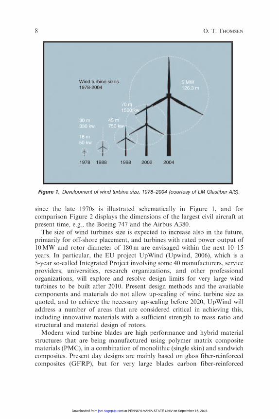
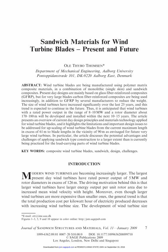
since the late 1970s is illustrated schematically in Figure 1, and forcomparison Figure 2 displays the dimensions of the largest civil aircraft atpresent time, e.g., the Boeing 747 and the Airbus A380.
The size of wind turbines size is expected to increase also in the future,primarily for off-shore placement, and turbines with rated power output of10MW and rotor diameter of 180m are envisaged within the next 10–15years. In particular, the EU project UpWind (Upwind, 2006), which is a5-year so-called Integrated Project involving some 40 manufacturers, serviceproviders, universities, research organizations, and other professionalorganizations, will explore and resolve design limits for very large windturbines to be built after 2010. Present design methods and the availablecomponents and materials do not allow up-scaling of wind turbine size asquoted, and to achieve the necessary up-scaling before 2020, UpWind willaddress a number of areas that are considered critical in achieving this,including innovative materials with a sufficient strength to mass ratio andstructural and material design of rotors.
Modern wind turbine blades are high performance and hybrid materialstructures that are being manufactured using polymer matrix compositematerials (PMC), in a combination of monolithic (single skin) and sandwichcomposites. Present day designs are mainly based on glass fiber-reinforcedcomposites (GFRP), but for very large blades carbon fiber-reinforced
1978
30 m330 kw
16 m50 kw
45 m750 kw
70 m1500 kw
5 MW126.3 m
Wind turbine sizes1978-2004
1988 1998 2002 2004
Figure 1. Development of wind turbine size, 1978–2004 (courtesy of LM Glasfiber A/S).
8 O. T. THOMSEN
at PENNSYLVANIA STATE UNIV on September 16, 2016jsm.sagepub.comDownloaded from
composites (CFRP) are being used increasingly, in addition to GFRP byseveral manufacturers to reduce the weight.
The term ‘sandwich composites’ mentioned above refers to sandwichmaterials/structures, which can be considered as a special type of compositelaminate where two (or more) thin, stiff, strong and relatively dense faces(composite laminates in the present context) are separated by a thick,lightweight and compliant core material. Such sandwich structures havegained widespread acceptance as an excellent way to obtain extremelylightweight components and structures with very high bending stiffness, highstrength, and high buckling resistance.
The article presents an overview of current day design principles andmaterials technology applied for wind turbine blades, and it highlightsthe limitations and design issues to be addressed for up-scaling of windturbine blades from the current maximum length in excess of 61m toblade lengths in the vicinity of 90m as envisaged for future very largewind turbines. In particular, the article discusses the potential advantagesand challenges of applying sandwich type construction to a larger extentthan is currently being done for the different load-carrying parts of windturbine blades. Future wind turbine applications may include other(and entirely new) concepts than the present day standard of the ‘3 bladeupwind high-speed aero-generator’ type, but the discussion in the followingwill be based on the assumption that future very large wind turbines will alsobe based on this concept.
Boeing 747 Airbus A380
Seating: 416Internal cabin
Internal cabinWidth: 6.1m
Seating: 555(max 840)
Width: 6.58m64.4m
24.1m
79.8m
73m70.7m19.4m
London bus to scale Source: Airbus/Boeing
Figure 2. Dimensions of passenger aircraft Boeing 747 and Airbus A380.
Sandwich Materials for Wind Turbine Blades 9
at PENNSYLVANIA STATE UNIV on September 16, 2016jsm.sagepub.comDownloaded from
LOAD CONDITIONS, CURRENT BLADE
DESIGNS, AND FAILURE MODES
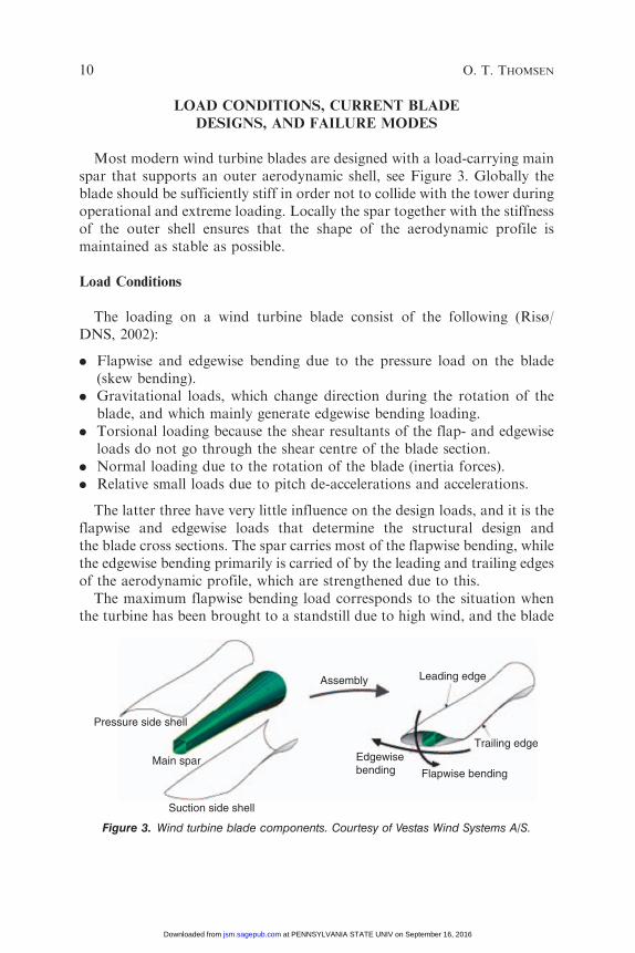
Most modern wind turbine blades are designed with a load-carrying mainspar that supports an outer aerodynamic shell, see Figure 3. Globally theblade should be sufficiently stiff in order not to collide with the tower duringoperational and extreme loading. Locally the spar together with the stiffnessof the outer shell ensures that the shape of the aerodynamic profile ismaintained as stable as possible.
Load Conditions
The loading on a wind turbine blade consist of the following (Risø/DNS, 2002):
. Flapwise and edgewise bending due to the pressure load on the blade(skew bending).
. Gravitational loads, which change direction during the rotation of theblade, and which mainly generate edgewise bending loading.
. Torsional loading because the shear resultants of the flap- and edgewiseloads do not go through the shear centre of the blade section.
. Normal loading due to the rotation of the blade (inertia forces).
. Relative small loads due to pitch de-accelerations and accelerations.
The latter three have very little influence on the design loads, and it is theflapwise and edgewise loads that determine the structural design andthe blade cross sections. The spar carries most of the flapwise bending, whilethe edgewise bending primarily is carried of by the leading and trailing edgesof the aerodynamic profile, which are strengthened due to this.
The maximum flapwise bending load corresponds to the situation whenthe turbine has been brought to a standstill due to high wind, and the blade
Pressure side shell
Main spar
Suction side shell
Assembly
Edgewisebending Flapwise bending
Trailing edge
Leading edge
Figure 3. Wind turbine blade components. Courtesy of Vestas Wind Systems A/S.
10 O. T. THOMSEN
at PENNSYLVANIA STATE UNIV on September 16, 2016jsm.sagepub.comDownloaded from
is hit by the 50-year extreme gust wind. The maximum edgewise bendingload used in the design is derived from a combination of different loadingsituations taken from dynamic simulations.
Wind turbine blades are subjected also to severe fatigue loads. Fatigueanalysis is performed for all critical sections of the blade, the blade root andthe load introduction parts. The fatigue strength verification shall be basedon characteristic S/N curves established for the laminates and the loadintroduction parts. The allowable fatigue limit is usually based on anequivalent strain measure corresponding to 107 cycles derived using anappropriate damage accumulation hypothesis (Palmgren/Miner law).The main drivers for fatigue are the flatwise and the edgewise bendingmoments, as these two moments are responsible for �97% of the damage inthe blade. Because of this, it is in general sufficient to perform the fatigueanalysis with these two moments. For the fatigue analysis it is necessary toconsider the simultaneously acting bending moments, therefore the fatigueanalysis shall be performed with time series. Further details about the designand loading of wind turbine blades can be found in Wacker (2003).
Current Blade Design Features
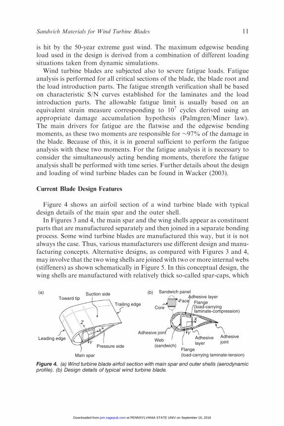
Figure 4 shows an airfoil section of a wind turbine blade with typicaldesign details of the main spar and the outer shell.
In Figures 3 and 4, the main spar and the wing shells appear as constituentparts that are manufactured separately and then joined in a separate bondingprocess. Some wind turbine blades are manufactured this way, but it is notalways the case. Thus, various manufacturers use different design and manu-facturing concepts. Alternative designs, as compared with Figures 3 and 4,may involve that the twowing shells are joined with two ormore internal webs(stiffeners) as shown schematically in Figure 5. In this conceptual design, thewing shells are manufactured with relatively thick so-called spar-caps, which
Toward tipSuction side Sandwich panel
Adhesive layer
Core
Adhesive joint
Web(sandwich)
Flange(load-carrying laminate-tension)
Face Flange(load-carryinglaminate-compression)
Trailing edge
Pressure side
Adhesivejoint
Adhesivelayer
Main spar
Leading edge
(a) (b)
Z
Y
YX
X
Figure 4. (a) Wind turbine blade airfoil section with main spar and outer shells (aerodynamicprofile). (b) Design details of typical wind turbine blade.
Sandwich Materials for Wind Turbine Blades 11
at PENNSYLVANIA STATE UNIV on September 16, 2016jsm.sagepub.comDownloaded from
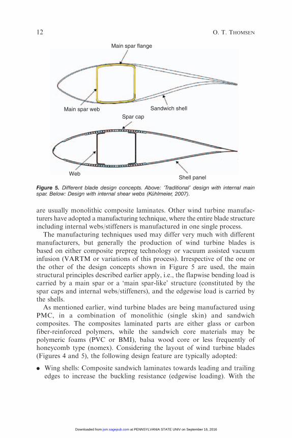
are usually monolithic composite laminates. Other wind turbine manufac-turers have adopted a manufacturing technique, where the entire blade structureincluding internal webs/stiffeners is manufactured in one single process.
The manufacturing techniques used may differ very much with differentmanufacturers, but generally the production of wind turbine blades isbased on either composite prepreg technology or vacuum assisted vacuuminfusion (VARTM or variations of this process). Irrespective of the one orthe other of the design concepts shown in Figure 5 are used, the mainstructural principles described earlier apply, i.e., the flapwise bending load iscarried by a main spar or a ‘main spar-like’ structure (constituted by thespar caps and internal webs/stiffeners), and the edgewise load is carried bythe shells.
As mentioned earlier, wind turbine blades are being manufactured usingPMC, in a combination of monolithic (single skin) and sandwichcomposites. The composites laminated parts are either glass or carbonfiber-reinforced polymers, while the sandwich core materials may bepolymeric foams (PVC or BMI), balsa wood core or less frequently ofhoneycomb type (nomex). Considering the layout of wind turbine blades(Figures 4 and 5), the following design feature are typically adopted:
. Wing shells: Composite sandwich laminates towards leading and trailingedges to increase the buckling resistance (edgewise loading). With the
Main spar flange
Main spar webSpar cap
WebShell panel
Sandwich shell
Figure 5. Different blade design concepts. Above: ‘Traditional’ design with internal mainspar. Below: Design with internal shear webs (Kuhlmeier, 2007).
12 O. T. THOMSEN
at PENNSYLVANIA STATE UNIV on September 16, 2016jsm.sagepub.comDownloaded from
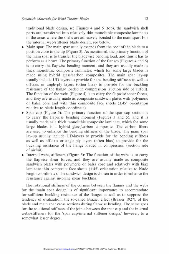
traditional blade design, see Figures 4 and 5 (top), the sandwich shellparts are transferred into relatively thin monolithic composite laminatesin the areas where the shells are adhesively bonded to the main spar. Forthe internal web/stiffener blade design, see below.
. Main spar: The main spar usually extends from the root of the blade to aposition close to the tip (Figure 3). As mentioned, the primary function ofthe main spar is to transfer the bladewise bending load, and thus it has toperform as a beam. The primary function of the flanges (Figures 4 and 5)is to carry the flapwise bending moment, and they are usually made asthick monolithic composite laminates, which for some large blades ismade using hybrid glass/carbon composites. The main spar lay-upusually include UD-layers to provide for the bending stiffness as well asoff-axis or angle-ply layers (often biax) to provide for the bucklingresistance of the flange loaded in compression (suction side of airfoil).The function of the webs (Figure 4) is to carry the flapwise shear forces,and they are usually made as composite sandwich plates with polymericor balsa core and with thin composite face sheets (�458 orientationrelative to blade length coordinate).
. Spar cap (Figure 5): The primary function of the spar cap section isto carry the flapwise bending moment (Figures 3 and 5), and it isusually made as a thick monolithic composite laminate, which for somelarge blades is a hybrid glass/carbon composite. The carbon fibersare used to enhance the bending stiffness of the blade. The main sparlay-up usually include UD-layers to provide for the bending stiffnessas well as off-axis or angle-ply layers (often biax) to provide for thebuckling resistance of the flange loaded in compression (suction sideof airfoil).
. Internal webs/stiffeners (Figure 5): The function of the webs is to carrythe flapwise shear forces, and they are usually made as compositesandwich plates with polymeric or balsa core and relatively with biaxlaminate thin composite face sheets (�458 orientation relative to bladelength coordinate). The sandwich design is chosen in order to enhance theresistance against in-plane shear buckling.
The rotational stiffness of the corners between the flanges and the websfor the ‘main spar design’ is of significant importance to accommodatefor sufficient buckling resistance of the flanges as well as to suppress thetendency of ovalization, the so-called Brazier effect (Brazier 1927), of theblade and main spar cross sections during flapwise bending. The same goesfor the rotational stiffness of the joints between the spar cap and the internalwebs/stiffeners for the ‘spar cap/internal stiffener design,’ however, to asomewhat lesser degree.
Sandwich Materials for Wind Turbine Blades 13
at PENNSYLVANIA STATE UNIV on September 16, 2016jsm.sagepub.comDownloaded from
Modes of Failure
Considering present day wind turbine blade designs, the single mostcritical load is probably the flapwise bending load that arises when theturbine has been brought to a standstill due to high wind, and the blade ishit by the 50-year extreme gust wind assuming a uniform wind profile,Risø/DNV (2002). As mentioned, this load is mainly resisted by the mainspar or a ‘main spar-like’ structure (constituted by the spar caps and internalwebs/stiffeners), which extends from the root of the blade to a position closeto the tip. The load-carrying flanges of this structure are usually made asmonolithic composite laminates, and thus large wind turbine blades willhave very large unstiffened monolithic shallow shell caps, which may besensitive to failure in local buckling. Experience shows, that local bucklingor a local ‘buckling-like’ mode is by far the governing failure mode for themonolithic laminate design of the main spar flanges (Jørgensen et al., 2004;Sørensen et al., 2004; Kuhlmeier et al., 2005; Overgaard, 2005a, b;Kuhlmeier, 2007). The local ‘buckling-like’ mode of failure is stronglygoverned by the presence of imperfections, which occurs due to variability ofthe production facilities and methods. Examples of manufacturingimperfections are thickness variations of the core materials in the webs,angle misalignments of the composite layers for the flanges and geometricimperfections due to section variations (Kuhlmeier et al., 2005; Kuhlmeier,2007; Overgaard, 2005a, b).
POTENTIAL USE OF SANDWICH MATERIALS
IN WIND TURBINE BLADES?
From the previous chapter it is clear that sandwich materials or structuralelements already play a very important role in modern wind turbine bladedesign. Thus, sandwich materials/elements are presently used for the wingshells and the webs of the main spar, see Figures 4 and 5. In all cases, theprincipal rationale behind the use of sandwich elements is to enhance thebuckling resistance and minimize the weight at the same time.
An interesting question in this context is whether it would beadvantageous to use composite sandwich materials/structures for morestructural parts than is practiced in current day wind turbine blades? Sincemost blade parts are already based on sandwich materials, this reduces tothe question whether it will be advantageous if the main spar flanges are alsomanufactured as composite sandwich materials/structures. To give ameaningful answer to this question requires that the entire blade designconcept is re-evaluated considering all relevant load cases. This would be anelaborate task, which is considered to be beyond the scope of this article.
14 O. T. THOMSEN
at PENNSYLVANIA STATE UNIV on September 16, 2016jsm.sagepub.comDownloaded from
However, on the basis of recent research it is possible to address the questionpartially, and based on this give and indication of what the complete answermight be. This will be discussed in the following, where only the flapwisebending load case is discussed.
A number of criteria must be considered in the design of the main sparincluding:
. global stiffness (blade tip deflection – tower clearance),
. buckling resistance (main flange or spar cap on suction side of airfoil),
. blade eigenfrequencies. The blade eigenfrequencies should not coincidewith the tower passing frequencies 1P and 3P. 4P can also be critical,
. material failure under static and fatigue loading. See Wacker (2003),
. local face instability of sandwich parts, Leissa (1985) and Zenkert (1995).
These criteria will be addressed in some detail in the forthcomingdiscussion.
Optimized Blade Design Concepts based on ‘Discrete Material Optimization’
In the recent works by Stegmann and Lund (2005), Lund and Stegmann(2006), and Lund et al. (2005), a new method for structural optimization oflaminated composite shell structures has been presented. The approach, knownas ‘discrete material optimization’ (DMO), is based on ideas frommultiphasetopology optimization where the material stiffness (or density) is computed asa weighted sum of candidate materials, and it is very easy to implement inexisting finite element analysis codes. In this way, the discrete problem ofchoosing the best material (with the right orientation) is converted to acontinuous formulation where the design variables are the scaling factors (orweight functions) on each candidate material. The design objective is chosento be a global quantity such as maximum stiffness (global stiffness), lowesteigenfrequency, or maximum buckling load with a constraint on the totalmass, such that the cost of material can be considered. Local failure modessuch as material or wrinkling failure cannot be addressed in the approach atpresent time, but further research is ongoing to include this as well.
The DMOmethod has been applied for maximum (global) stiffness designoptimization of a wind turbine main spar structure (Figure 3), as well as todesign optimization of a wind turbine ‘spar cap’ (Figure 5) with the objectiveof increase the buckling load factor, taking weight considerations intoaccount. In all cases, the DMO method has been combined with linear finiteelement analysis using composite shell elements. Here, only results relatedto the maximum stiffness design of a blade main will be referenced, butresults concerning buckling load optimization ‘spar cap’ can be found inLund et al. (2005a) and Lund (2006).
Sandwich Materials for Wind Turbine Blades 15
at PENNSYLVANIA STATE UNIV on September 16, 2016jsm.sagepub.comDownloaded from
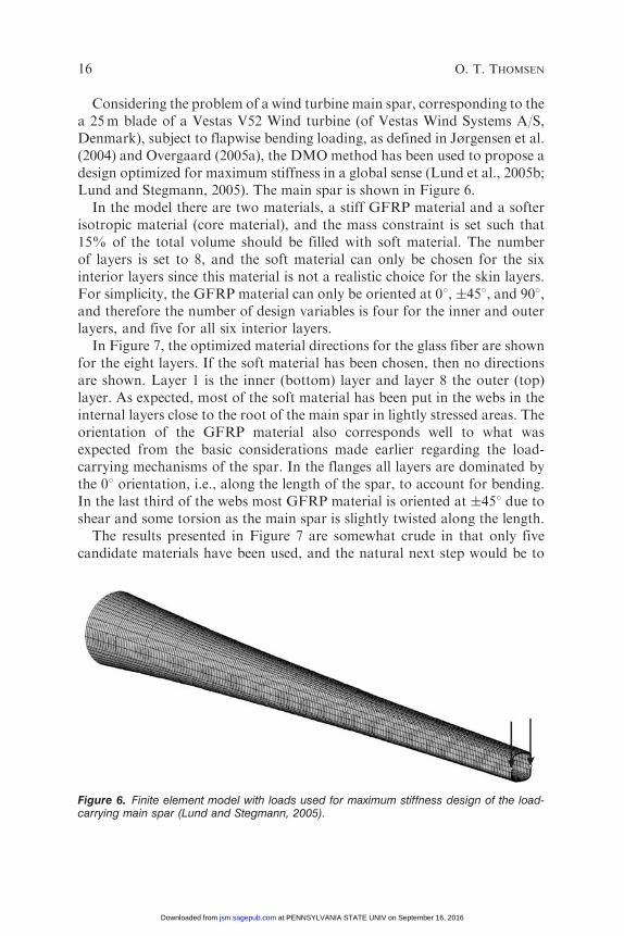
Considering the problem of a wind turbine main spar, corresponding to thea 25m blade of a Vestas V52 Wind turbine (of Vestas Wind Systems A/S,Denmark), subject to flapwise bending loading, as defined in Jørgensen et al.(2004) and Overgaard (2005a), the DMOmethod has been used to propose adesign optimized for maximum stiffness in a global sense (Lund et al., 2005b;Lund and Stegmann, 2005). The main spar is shown in Figure 6.
In the model there are two materials, a stiff GFRP material and a softerisotropic material (core material), and the mass constraint is set such that15% of the total volume should be filled with soft material. The numberof layers is set to 8, and the soft material can only be chosen for the sixinterior layers since this material is not a realistic choice for the skin layers.For simplicity, the GFRP material can only be oriented at 08, �458, and 908,and therefore the number of design variables is four for the inner and outerlayers, and five for all six interior layers.
In Figure 7, the optimized material directions for the glass fiber are shownfor the eight layers. If the soft material has been chosen, then no directionsare shown. Layer 1 is the inner (bottom) layer and layer 8 the outer (top)layer. As expected, most of the soft material has been put in the webs in theinternal layers close to the root of the main spar in lightly stressed areas. Theorientation of the GFRP material also corresponds well to what wasexpected from the basic considerations made earlier regarding the load-carrying mechanisms of the spar. In the flanges all layers are dominated bythe 08 orientation, i.e., along the length of the spar, to account for bending.In the last third of the webs most GFRP material is oriented at �458 due toshear and some torsion as the main spar is slightly twisted along the length.
The results presented in Figure 7 are somewhat crude in that only fivecandidate materials have been used, and the natural next step would be to
Figure 6. Finite element model with loads used for maximum stiffness design of the load-carrying main spar (Lund and Stegmann, 2005).
16 O. T. THOMSEN
at PENNSYLVANIA STATE UNIV on September 16, 2016jsm.sagepub.comDownloaded from
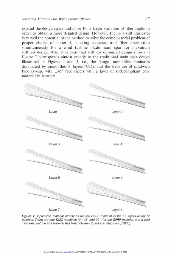
expand the design space and allow for a larger variation of fiber angles inorder to obtain a more detailed design. However, Figure 7 still illustratesvery well the potential of the method to solve the combinatorial problem ofproper choice of material, stacking sequence and fiber orientationsimultaneously for a wind turbine blade main spar for maximumstiffness design. Also, it is clear that stiffness optimized design shown inFigure 7 corresponds almost exactly to the traditional main spar designillustrated in Figures 4 and 5, i.e., the flanges monolithic laminatesdominated by monolithic 08 layers (UD), and the webs are of sandwichtype lay-up, with �458 face sheets with a layer of soft/compliant corematerial in between.
Layer 1 Layer 2
Layer 3 Layer 4
Layer 5 Layer 6
Layer 7 Layer 8
Figure 7. Optimized material directions for the GFRP material in the 16 layers using 77patches. There are four DMO variables (08, 458 and 908) for the GFRP material, and a voidindicates that the soft material has been chosen (Lund and Stegmann, 2005).
Sandwich Materials for Wind Turbine Blades 17
at PENNSYLVANIA STATE UNIV on September 16, 2016jsm.sagepub.comDownloaded from
Thus, the classical monolithic main spar design concept can be regardedas ‘optimal’ (or at least a very good choice) in regard to maximum stiffnessunder flapwise bending loading. Returning to the question posed, i.e., if itcould be advantageous to use sandwich structures to a larger extent for windturbine blades than currently practiced, the answer is negative with respectto the main spar considering maximum stiffness design under flapwisebending loading.
Optimized Blade Design Concept based on Nonlinear Analysis
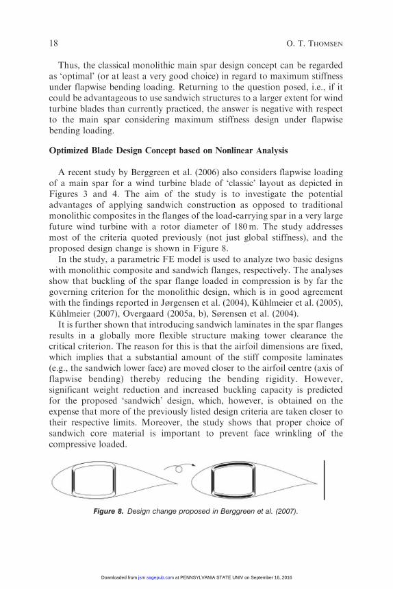
A recent study by Berggreen et al. (2006) also considers flapwise loadingof a main spar for a wind turbine blade of ‘classic’ layout as depicted inFigures 3 and 4. The aim of the study is to investigate the potentialadvantages of applying sandwich construction as opposed to traditionalmonolithic composites in the flanges of the load-carrying spar in a very largefuture wind turbine with a rotor diameter of 180m. The study addressesmost of the criteria quoted previously (not just global stiffness), and theproposed design change is shown in Figure 8.
In the study, a parametric FE model is used to analyze two basic designswith monolithic composite and sandwich flanges, respectively. The analysesshow that buckling of the spar flange loaded in compression is by far thegoverning criterion for the monolithic design, which is in good agreementwith the findings reported in Jørgensen et al. (2004), Kuhlmeier et al. (2005),Kuhlmeier (2007), Overgaard (2005a, b), Sørensen et al. (2004).
It is further shown that introducing sandwich laminates in the spar flangesresults in a globally more flexible structure making tower clearance thecritical criterion. The reason for this is that the airfoil dimensions are fixed,which implies that a substantial amount of the stiff composite laminates(e.g., the sandwich lower face) are moved closer to the airfoil centre (axis offlapwise bending) thereby reducing the bending rigidity. However,significant weight reduction and increased buckling capacity is predictedfor the proposed ‘sandwich’ design, which, however, is obtained on theexpense that more of the previously listed design criteria are taken closer totheir respective limits. Moreover, the study shows that proper choice ofsandwich core material is important to prevent face wrinkling of thecompressive loaded.
Figure 8. Design change proposed in Berggreen et al. (2007).
18 O. T. THOMSEN
at PENNSYLVANIA STATE UNIV on September 16, 2016jsm.sagepub.comDownloaded from
The study also includes an investigation of the influence of geometricimperfections. This is conducted by geometric nonlinear FE analyses,assuming imperfections corresponding to the mode shapes obtained fromlinear analysis with maximum geometric imperfection amplitude (max. GIA)of 10 and 20% of the flange thickness, respectively. The nonlinear analysesshow significant sensitivity to imperfections, and also show that materialfailure of the spar web corners become critical when the flanges buckle andthereby soften. In an overall sense, these results correlate well with theexperimental findings reported from large scale tests in Kuhlmeier et al.(2005), Kuhlmeier (2007), Overgaard (2005a b); except that the realimperfections do not resemble the mode shapes assumed by Berggreenet al. (2007). Thus, in the experimental tests it was found that the local‘buckling-like’ mode, which led to failure, closely followed geometricimperfections introduced during the manufacturing process. Also, it wasfound that no mode interactions of mode jumps took place, meaning that theload deflection followed a primary path until a limit point withoutencountering a bifurcation or turning behavior. Thus, the response curvesdid not show snap-through or snap-back characteristics. Failure occurred duethe combined effect of interlaminar and compressive normal stresses in theflange laminate, which led to a progressive delamination and final collapse.
The study of Berggreen et al. (2007) concludes that linear bucklinganalysis is insufficient, as the buckling capacity is overestimated and doesnot take into account the inevitable presence of imperfections. Sincebuckling is sensitive to imperfections, and deflections are not, it is proposedthat the most feasible spar design would include extra buckling capacity,rather than safety on deflections. In particular, due to larger bucklingcapacity, the sandwich design accommodates these demands better than thesingle skin design.
CHALLENGES RELATED TO INCREASED
USE OF SANDWICH MATERIALS
The findings reported in the previous section indicate that local bucklingof the main spar flange (or spar cap) on the suction side of a wind turbineblade is the dominating failure mode. Thus, the use of sandwich rather thanmonolithic composite laminates for the flange (or spar cap) loaded incompression would be advantageous, since a sandwich laminate will provideadditional buckling capacity and/or provide a more lightweight design withsimilar buckling capacity.
However, a number of potential problems (challenges) associated withincreased use of composite sandwich laminates can be identified. Some ofthese will be discussed briefly in the following.
Sandwich Materials for Wind Turbine Blades 19
at PENNSYLVANIA STATE UNIV on September 16, 2016jsm.sagepub.comDownloaded from
Design Against Fatigue
The potential enhancement of the buckling capacity comes on the expenseof the global stiffness that is reduced (Berggreen et al., 2006). This means thatthe strains in the flanges will increase significantly, which may in turn lead toproblems with respect to the fatigue design. This issue needs to be addressedmeticulously through systematic design studies including consideration of allrelevant loads cases including flapwise and edgewise bending under extremegust wind, fatigue and impact load conditions. To this end, systematic designstudies based on advanced optimization strategies could be very useful.In particular, the DMO method proposed by Stegmann and Lund (2005),Lund and Stegmann (2006), and Lund et al. (2005) could be a powerful tool inthis, since it will allow rational evaluation of different design concepts againsteach other based on the available material systems (composite GFRP andCFRP systems, material orientations and core materials) and the prespeci-fication of different amounts of monolithic and sandwich laminates(set through the mass constraint by specifying different amounts of thetotal material volume to be ‘soft’ material). Candidate sandwich designconcepts developed through the DMO analysis should then be analyzedthoroughly under the action of realistic load conditions including fatigue.
Damage Tolerance
Damage tolerance is another very important issue to be addressed.A prerequisite for replacing the most important primary load-carryingstructural parts of a wind turbine blade, e.g., the flanges of themain spar, withcomposite sandwich laminates is that the overall structural reliability is notcompromised in doing so. Wind turbines are generally much less safety-critical than aircraft or ships, see Herrmann et al (2005) and Hayman (2006).However, wind turbine blades present a special challenge in that they areproduced in large numbers, similar to aircraft (or larger), but the possibilitiesfor regular in-service inspection are much more limited or even nonexistent,because of accessibility problems. The key characteristic of wind turbineblades in regard to damage tolerance can be listed as (Hayman, 2006):
. generally not safety-critical; losses are economic,
. can readily be taken out of service,
. largely inaccessible after installation; regular in-service inspectiondifficult or impossible,
. many defect types, dependent on manufacturer and processes; fewin-service damage types,
. few in-service damage scenarios (bird, hail, lightning),
20 O. T. THOMSEN
at PENNSYLVANIA STATE UNIV on September 16, 2016jsm.sagepub.comDownloaded from
. relatively well-defined loading (aerodynamic, gravity),
. mass production, often very large numbers.
Thus, the ideal approach would be safe-life design accounting for theworst combination of production defects that is likely to go undetectedduring production, and the worst in-service damage that is likely to occurwithout being noticed.
To implement a safe-life design approach in a systematic way requires thedevelopment of a comprehensive and reliable overview of both in-servicedamage events and the defects that may occur in practical production,including the statistics of their incidence. Ideally, the result of this process isthe definition of maximum allowable defects and damages and their visibility.
This presents a major challenge for the industry since competitionbetween manufacturers limits the amount of information they are able toshare while differences in production techniques make the productiondefects more manufacturer-dependent than in many other industries. Withhigh production volumes, improvement of all aspects of production control,including nondestructive inspection capabilities, should be a cost-effectivemeans of reducing the incidence of such defects and of the uncertaintiesassociated with them.
NDI Methods
With the information of maximum allowable defects/damages at hand theissue of detectability becomes important. A major disadvantage of sandwichstructures is thatmanufacturing defects and damages (especially in deep in thecore and the interfaces) cannot always be detected by common methods. Onesided access only (in some cases) and large area inspection poses furtherchallenges. A number of NDI technologies are available and underdevelopment that better fit the needs to inspect sandwich panels, where themost promising nondestructive inspection techniques for composite sandwichstructures are based ultrasound, shearography, and X-ray principles.
Quoting Hayman (2006), major challenges in regard to the detection ofdefects and damages in relatively thick sandwich structures include:
. the ability to detect deep defects/damage in thick sandwich structuresremains limited,
. sandwich structures with cores of end-grain balsa are especially difficultto inspect because the defects are masked by the many joints between coreblocks and by natural features in the core material leading to large localdensity variations,
. it is generally not possible to detect far-side defects with one-sidedinspection methods,
Sandwich Materials for Wind Turbine Blades 21
at PENNSYLVANIA STATE UNIV on September 16, 2016jsm.sagepub.comDownloaded from
. at present there is insufficient knowledge about the sensitivity andreliability of many NDI systems when applied to composites to enabledetectability limits and probabilities of detection to be quantified.
. nondestructive testing standards are not yet well developed forapplication on sandwich composites. For some of the newer NDItechniques they do not exist at all.
A development that is likely to improve the situation for wind turbines isthe widespread use of structural health monitoring of blades using, forexample, fiber optic sensors. These may be used both to detect abnormalevents and to detect changes in dynamic response associated with theincidence of damage or major growth of a defect.
Innovative Sandwich Material Concepts and Local Effects
Naturally, any approach to introduce composite sandwich materials as aprimary structure depends heavily on the design, architecture and materialselection of the sandwich structure itself. A major issue (disadvantage)of sandwich materials/structures compared with monolithic composites isthat they are more prone to delamination and failure due to the presence oflarge weak interfaces between adjacent materials with very different stiffnessand strength properties.
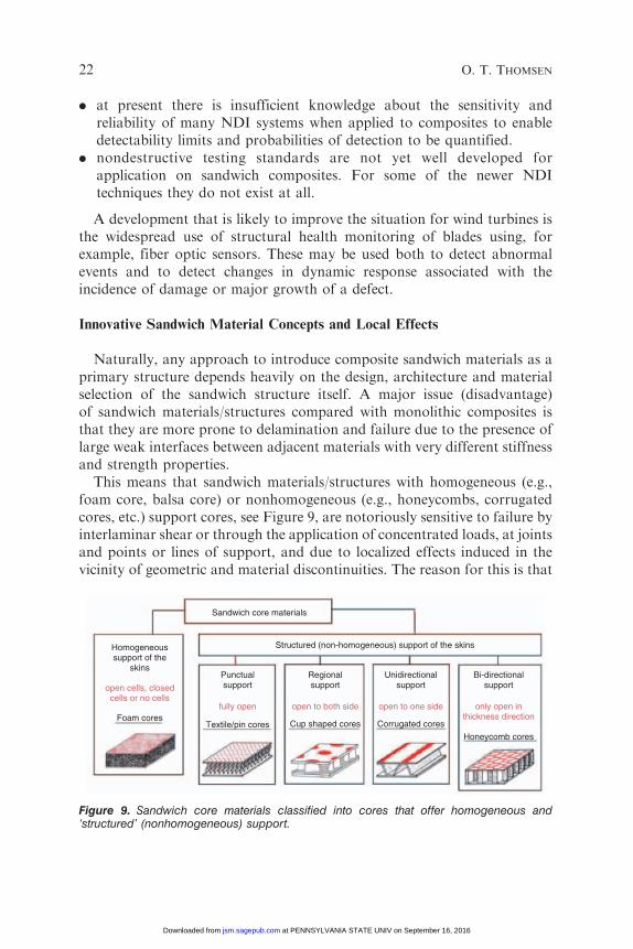
This means that sandwich materials/structures with homogeneous (e.g.,foam core, balsa core) or nonhomogeneous (e.g., honeycombs, corrugatedcores, etc.) support cores, see Figure 9, are notoriously sensitive to failure byinterlaminar shear or through the application of concentrated loads, at jointsand points or lines of support, and due to localized effects induced in thevicinity of geometric and material discontinuities. The reason for this is that
Sandwich core materials
Homogeneoussupport of the
skinsPunctualsupport
Regionalsupport
Structured (non-homogeneous) support of the skins
Unidirectionalsupport
Bi-directionalsupport
fully open open to both side open to one side only open inthickness direction
Cup shaped cores Corrugated cores
Honeycomb coresTextile/pin cores
open cells, closedcells or no cells
Foam cores
Figure 9. Sandwich core materials classified into cores that offer homogeneous and‘structured’ (nonhomogeneous) support.
22 O. T. THOMSEN
at PENNSYLVANIA STATE UNIV on September 16, 2016jsm.sagepub.comDownloaded from
although sandwich structures are well suited for the transfer of overallbending and shearing loads, localized shearing, and bending effects, asmentioned above, induce severe through-thickness shear and normal stresses.These through-thickness stress components can be of significant magnitude,and may approach or exceed the allowable stresses in the sandwichconstituents as well as in the material interfaces (Zenkert, 1995).
Wind turbine blades include numerous joints (at leading and trailingedges of the wing shells, between wing shells and main spar, between sparcap and internal stiffeners/shear webs), see Figures 4 and 5, and in thevicinity of these, localized effects as described above cause the inducement ofstress concentrations that may significantly affect the static and fatiguestrengths of the sandwich parts (Thomsen et al., 2005;, Bozhevolnaya et al.,2005); Bozhevolnaya and Thomsen, 2005a, 2005b). Moreover, bucklingphenomena, as discussed in the previous section, also induce severeinterlaminar and through-thickness normal stresses, which in many casesdetermine the ultimate load-carrying capability of wind turbine bladestructures (Kuhlmeier et al., 2005; Kuhlmeier, 2007; Overgaard, 2005a, b).Thus, composite sandwich material systems with improved/enhanceddamage tolerance as well as innovative crack stopper and load introductionconcepts will be key issues.
A way of improving the damage tolerance as well as the skin/coreinterface properties is to develop composite sandwich materials systems withstructural elements in the form of fibers, pins, stitches, or even structuralplate elements extending in the through-thickness direction of the sandwichlaminate, see Figure 9. These ‘z direction’ elements should provide stiffand strong connections between the face sheets/skins (Figure 9) that alsoallow for load redistribution if local damage occurs, and at the same timethe in-plane stiffness and strength properties of the sandwich should notbe compromised.
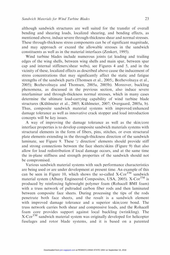
Various sandwich material systems with such performance characteristicsare being used or are under development at present time. An example of thiscan be seen in Figure 10, which shows the so-called X-CorTM sandwichmaterial system (Albany Engineered Composites, USA, 2005). X-CorTM isproduced by reinforcing lightweight polymer foam (Rohacell BMI foam)with a truss network of pultruded carbon fiber rods and then laminatedbetween composite face sheets. During processing the tips of the rodspenetrate both face sheets, and the result is a sandwich elementwith improved damage tolerance and a superior skin/core bond. Thetruss network carries both shear and compressive loads, and the Rohacellfoam core provides support against local buckling (wrinkling). TheX-CorTM sandwich material system was originally developed for helicopterfuselages and rotor blade systems, and it is based on a patented
Sandwich Materials for Wind Turbine Blades 23
at PENNSYLVANIA STATE UNIV on September 16, 2016jsm.sagepub.comDownloaded from
manufacturing process. It is probably not of direct interest for applicationfor wind turbine blades, but sandwich material systems aimed specificallyfor wind turbine blade applications, adapted for the manufacturingprocesses used for wind turbine blades, and with similar enhancedperformance features, could be developed.
SUMMARY AND CONCLUSIONS
The use of composite materials for wind turbine blades has been discussedin this article. Current day wind turbine blades already include substantialamounts of sandwich materials/structures, but it is likely that even moresandwich elements may be used future very large blades. Thus, severalstudies have shown that the limiting failure mode for wind turbine bladesunder extreme gust wind conditions is buckling of the spar flange loaded incompression. From this it appears that the use of sandwich ratherthan monolithic composite laminates for the main spar flanges (or sparcaps), in particular the flange on the suction side of the airfoil, wouldbe advantageous, since a sandwich design will provide additionalbuckling capacity and/or provide a more lightweight design with similarbuckling capacity.
However, an increased use of composite sandwich materials for the mosthighly loaded wind turbine blade parts also is associated with a number ofchallenges that need to be addressed. These challenges include damagetolerance, NDI methods and the design of internal joints. Thus, materialsystems with improved/enhanced damage tolerance as well as innovative
Figure 10. Stitched foam core sandwich with CFRP faces, X-CorTM (Albany EngineeredComposites, USA, 2005).
24 O. T. THOMSEN
at PENNSYLVANIA STATE UNIV on September 16, 2016jsm.sagepub.comDownloaded from
crack stopper and load introduction concepts will be key issues for futuresuccessful applications of sandwich structures for wind turbine blades.
REFERENCES
1. Berggren, C., Branner, K., Jensen, J.F. and Schultz, J.P. (2007). Application and Analysisof Sandwich Elements in the Primary Structure of Large Wind Turbine Blades, Journal ofSandwich Structures and Materials (Special Issue – 7th International Conference onSandwich Structures), 9(6): 525–552.
2. Bozhevolnaya. E. and Thomsen, O.T. (2005a). Structurally Graded Core Junctions inSandwich Panels: Quasi Static Loading Conditions, Composite Structures, 70(1): 517–527.
3. Bozhevolnaya. E. and Thomsen, O.T. (2005b). Structurally Graded Core Junctions inSandwich Panels: Fatigue Loading Conditions, Composite Structures, 70(1): 528–539.
4. Bozhevolnaya, E., Lyckegaard, A. and Thomsen, O.T. (2005). Localized Effects AcrossCore Junctions in Sandwich Beams Subjected to In-Plane and Out-of-Plane Loading,Applied Composite Materials, 12: 135–147.
5. Brazier, L.G. (1927). On the Flexure of Thin Cylindrical Shells and Other Thin Sections,In: Proceedings of the Royal Society of London, Series A Containing Papers of aMathematical and Physical Character, pp. 104–114.
6. EU Project ‘UpWind’ (2006). http://www.upwind.eu/default.aspx
7. Hayman, B. (2007). Damage Assessment and Damage Tolerance of Sandwich Stuctures,Journal of Sandwich Structures and Materials (Special Issue – 7th International Conferenceon Sandwich Structures), 9(6): 571–596.
8. Herrmann, A.S., Zahlen, P.C. and Zuardy, I. (2005). Sandwich Structures Technology inCommercial Aviation – Present Application and Future Trends, In: Thomsen, O.T. et al.(eds), Sandwich Structures 7: Advancing with Sandwich Structures and Materials,Proceedings of the 7th International Conference on Sandwich Structures (ICSS-7),Aalborg, Denmark, pp. 13–26.
9. Jørgensen, E.R., Borum, K.K., McGugan, M., Thomsen, C.L., Jensen, F.M., Debel, C.P.and Sørensen, B.F. (2004). Full Scale Testing of Wind Turbine Blade to Failure – FlapwiseLoading, Risø-R-1392(EN), Risø National Laboratory, Roskilde, Denmark.
10. Kuhlmeier, L., Thomsen, O.T. and Lund, E. (2005). Large Scale Buckling Experiment andValidation of Predictive Capabilities, In: Proceedings (CD-rom) of the 15th InternationalConference on Composite Materials (ICCM-15), Durban, South Africa.
11. Kuhlmeier, L. (2007). Buckling of Wind Turbine Rotor Blades: Analysis, Design andExperimental Validation, Ph.D. Thesis, Special Report No. 95, Department of MechanicalEngineering, Aalborg University.
12. Leissa, A.W. (1985). Buckling of Laminated Composite Plates and Shell Panels, AFWAL-TR-85-3069.
13. Lund, E., Kuhlmeier, L. and Stegmann, J. (2005a). Buckling Optimization of LaminatedHybrid Composite Shell Structures Using Discrete Material Optimization, In: Proceedingsof the 6th World Congress on Structural and Multidisciplinary Optimization (WCSMO-6),Rio de Janeiro, Brazil.
14. Lund, E., Stegmann, J., Johansen, L. and Jakobsen, J. (2005b). On Methods for GradientBased Structural Optimization of Sandwich Structures, In: Shenoi, R.A., Groves, A. andRajapakse, Y.D.S., Theory and Applications of Sandwich Structures, University ofSouthampton, Southampton, UK, August 2005, pp. 287–322.
15. Lund, E. and Stegmann, J. (2005). On Structural Optimization of Composite ShellStructures Using a Discrete Constitutive Parameterization, Wind Energy, 8(1): 109–124.
Sandwich Materials for Wind Turbine Blades 25
at PENNSYLVANIA STATE UNIV on September 16, 2016jsm.sagepub.comDownloaded from
16. Lund, E. (2006). Large Scale Optimization of Compression Loaded Composite Structures.In: Proceedings of the 3rd European Conference on Computational Mechanics (ECCM-2006), Lisbon, Portugal.
17. Lund, E. and Stegmann, J. (2006). Eigenfrequency and Buckling Optimizationof Laminated Composite Shell Structures Using Discrete Material Optimization,In: Bendsøe, M.P., Olhoff, N. and Sigmund, O. (eds), In: Proceedings of IUTUAMSymposium on Topological Design Optimization of Structures, Machines and Materials:Status and Perspectives, Copenhagen, October 2006, Springer, Solid Mechanics and ItsApplications Series (ISSN 0925-0042), Volume 137, Copenhagen, pp. 147–156,.
18. Overgaard, L.C.T. (2005a). On the Structural Assessment of Failure Mechanismsand Instability Phenomena in the V52 Turbine Blade Static Test Performed within theEFP2003 Programme, Technical Report, Department of Mechanical Engineering, AalborgUniversity, Denmark.
19. Overgaard, L.C.T. (2005b). Structural Design Sensitivity Analysis and Optimization ofVestas V52 Wind Turbine Blade, In: Proceedings of the 6th World Congress on Structuraland Multidisciplinary Optimization (WCSMO-6), Rio de Janeiro, Brazil.
20. Risø/DNV (2002). Guidelines for Design of Wind Turbines, 2nd edn, Jysk Centraltrykkeri,Denmark.
21. Stegmann, J. and Lund, E. (2005). Discrete Material Optimization of GeneralComposite Shell Structures, International Journal for Numerical Methods in Engineering62(14): 2009–2027.
22. Sørensen, B.F., Jørgensen, E., Debel, C.P., Jensen, F.M., Jensen, H.M., Jacobsen, T.K. andHalling, K.M. (2004). Improved Design of Large Wind Turbine Blade of Fibre Compositesbased on Studies of Scale Effects (Phase 1) - Summary Report, Risø-R-1390(EN), RisøNational Laboratory, Roskilde, Denmark.
23. Thomsen, O.T., Bozhevolnaya, E. and Lyckegaard, A. (2005). Structurally Graded CoreJunctions in Sandwich Elements, Composites Part A: Applied Science and Manufacturing,36(10): 1397–1411.
24. Wacker, G. (2003). Requirements for the Certification of Rotor Blades, Germanisher LloydWindEnergie GmbH, Hamburg, Germany.
25. X-CorTM Data sheet (2005). Albany Engineered Composites, USA.
26. Zenkert, D. (1995). An Introduction to Sandwich Construction, Chameleon Press, London,United Kingdom.
26 O. T. THOMSEN
at PENNSYLVANIA STATE UNIV on September 16, 2016jsm.sagepub.comDownloaded from
Related Documents