Safety Design and Analysis Hiroyuki Sato Japan Atomic Energy Agency Training Course on High Temperature Gas-cooled Reactor Technology October 19-23, Serpong, Indonesia

Welcome message from author
This document is posted to help you gain knowledge. Please leave a comment to let me know what you think about it! Share it to your friends and learn new things together.
Transcript
Safety Design and Analysis
Hiroyuki Sato
Japan Atomic Energy Agency
Training Course on
High Temperature Gas-cooled Reactor Technology
October 19-23, Serpong, Indonesia
p.2
Safety Design Objective
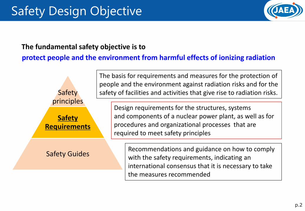
protect people and the environment from harmful effects of ionizing radiation
Safety principles
Safety Requirements
Safety Guides
The fundamental safety objective is to
The basis for requirements and measures for the protection of people and the environment against radiation risks and for the safety of facilities and activities that give rise to radiation risks.
Design requirements for the structures, systems and components of a nuclear power plant, as well as for procedures and organizational processes that are required to meet safety principles
Recommendations and guidance on how to comply with the safety requirements, indicating an international consensus that it is necessary to take the measures recommended
p.3
Safety Requirements
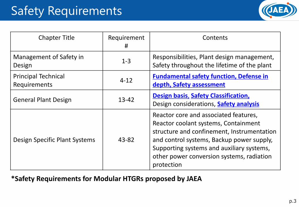
Chapter Title Requirement #
Contents
Management of Safety in Design
1-3 Responsibilities, Plant design management, Safety throughout the lifetime of the plant
Principal Technical Requirements
4-12 Fundamental safety function, Defense in depth, Safety assessment
General Plant Design 13-42 Design basis, Safety Classification, Design considerations, Safety analysis
Design Specific Plant Systems 43-82
Reactor core and associated features, Reactor coolant systems, Containment structure and confinement, Instrumentation and control systems, Backup power supply, Supporting systems and auxiliary systems, other power conversion systems, radiation protection
*Safety Requirements for Modular HTGRs proposed by JAEA
p.4
Fundamental Safety Function
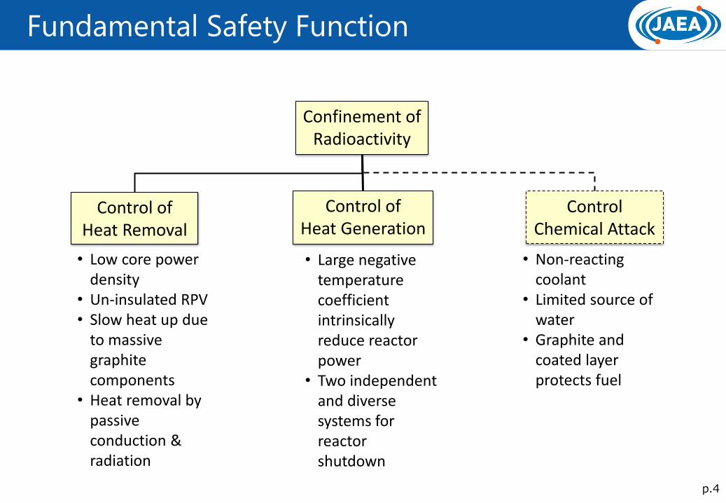
Confinement of Radioactivity
Control of Heat Removal
Control of Heat Generation
Control Chemical Attack
• Low core power density
• Un-insulated RPV • Slow heat up due
to massive graphite components
• Heat removal by passive conduction & radiation
• Large negative temperature coefficient intrinsically reduce reactor power
• Two independent and diverse systems for reactor shutdown
• Non-reacting coolant
• Limited source of water
• Graphite and coated layer protects fuel
p.5
Inherent Features on Radioactivity Confinement
1.0
0.8
0.6
0.4
0.2
0
Temperature [oC]
Failu
re f
raction [
-]
1600 1800 2000 2200 2400 2600 2800
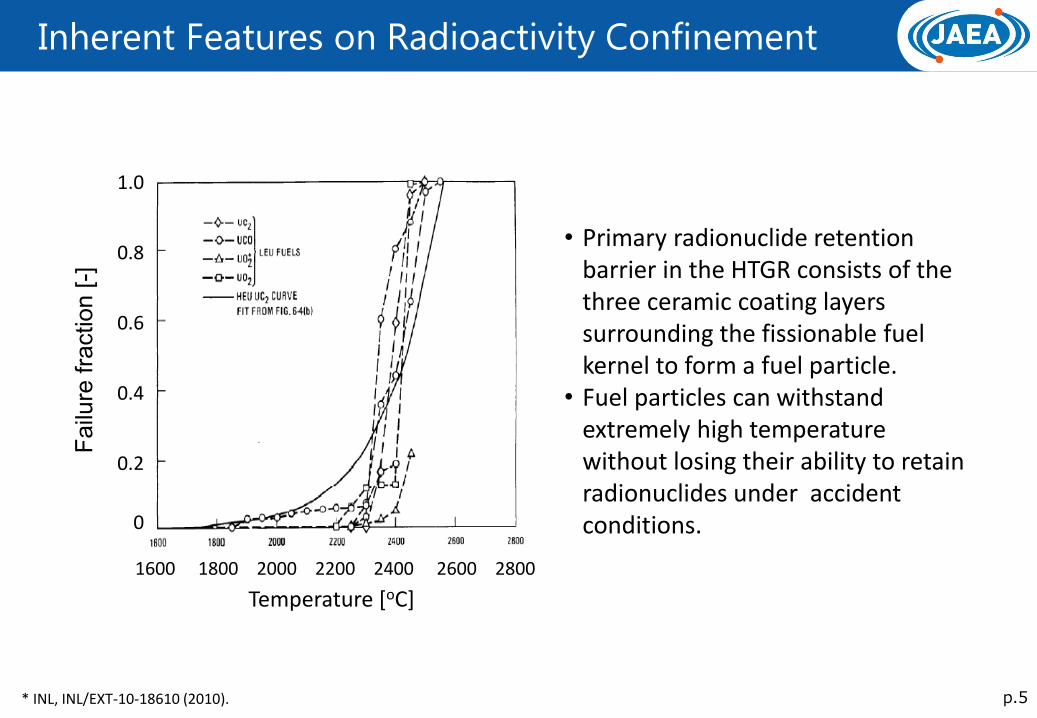
• Primary radionuclide retention barrier in the HTGR consists of the three ceramic coating layers surrounding the fissionable fuel kernel to form a fuel particle.
• Fuel particles can withstand extremely high temperature without losing their ability to retain radionuclides under accident conditions.
* INL, INL/EXT-10-18610 (2010).
p.6
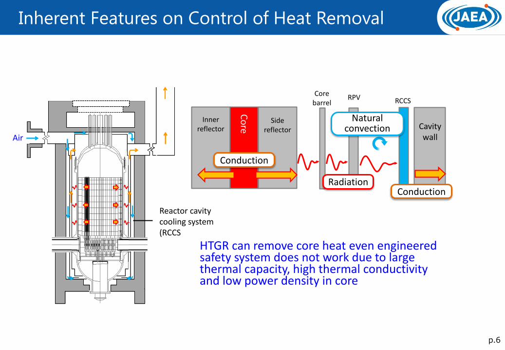
Inherent Features on Control of Heat Removal
Air
Reactor cavity cooling system (RCCS
Co
re
Inner reflector
Side reflector
Core barrel
RPV RCCS
Cavity wall
Conduction
Radiation
Natural convection
HTGR can remove core heat even engineered safety system does not work due to large thermal capacity, high thermal conductivity and low power density in core
Conduction
p.7
Inherent Features on Control of Heat Generation
Control rod
Circulator
VCS
Radiation
Natural convection
Water
Primary system
Reject to atmosphere
RPV
Heat removal
Heat removal
HTTR LOFC Test
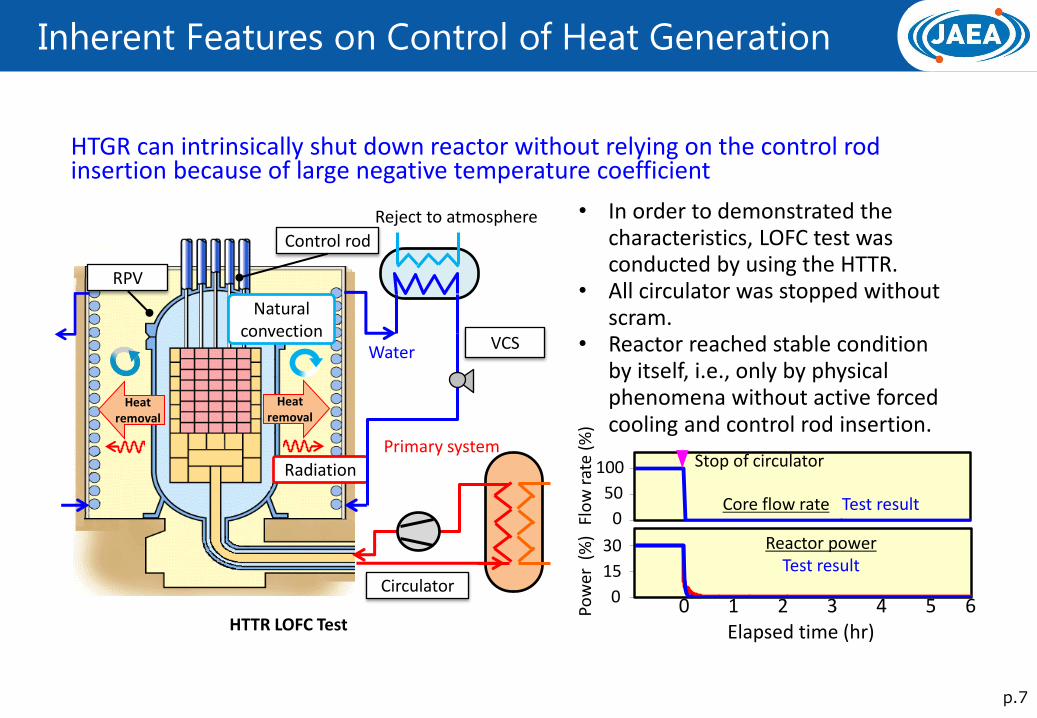
• In order to demonstrated the characteristics, LOFC test was conducted by using the HTTR.
• All circulator was stopped without scram.
• Reactor reached stable condition by itself, i.e., only by physical phenomena without active forced cooling and control rod insertion.
Stop of circulator
Core flow rate Test result
Reactor power Test result
100
50
0
Flo
w r
ate
(%)
30
15
0 P
ow
er (
%)
Elapsed time (hr) 0 1 2 3 4 5 6
HTGR can intrinsically shut down reactor without relying on the control rod insertion because of large negative temperature coefficient
p.8
Inherent Features on Control of Chemical Attack
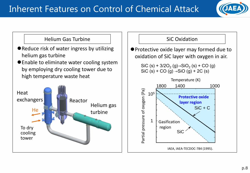
Helium Gas Turbine
Reduce risk of water ingress by utilizing helium gas turbine
Enable to eliminate water cooling system by employing dry cooling tower due to high temperature waste heat
SiC Oxidation
SiC (s) + 3/2O2 (g)→SiO2 (s) + CO (g)
SiC (s) + CO (g) →SiO (g) + 2C (s)
105
1
Temperature (K)
SiC
SiC + C
Protective oxide layer region
Gasification region
1800 1400 1000
Protective oxide layer may formed due to oxidation of SiC layer with oxygen in air.
Helium gas turbine
Reactor
To dry cooling tower
He
Heat exchangers
Part
ial p
ress
ure
of
oxy
gen
(Pa
) IAEA, IAEA-TECDOC-784 (1995).
p.9
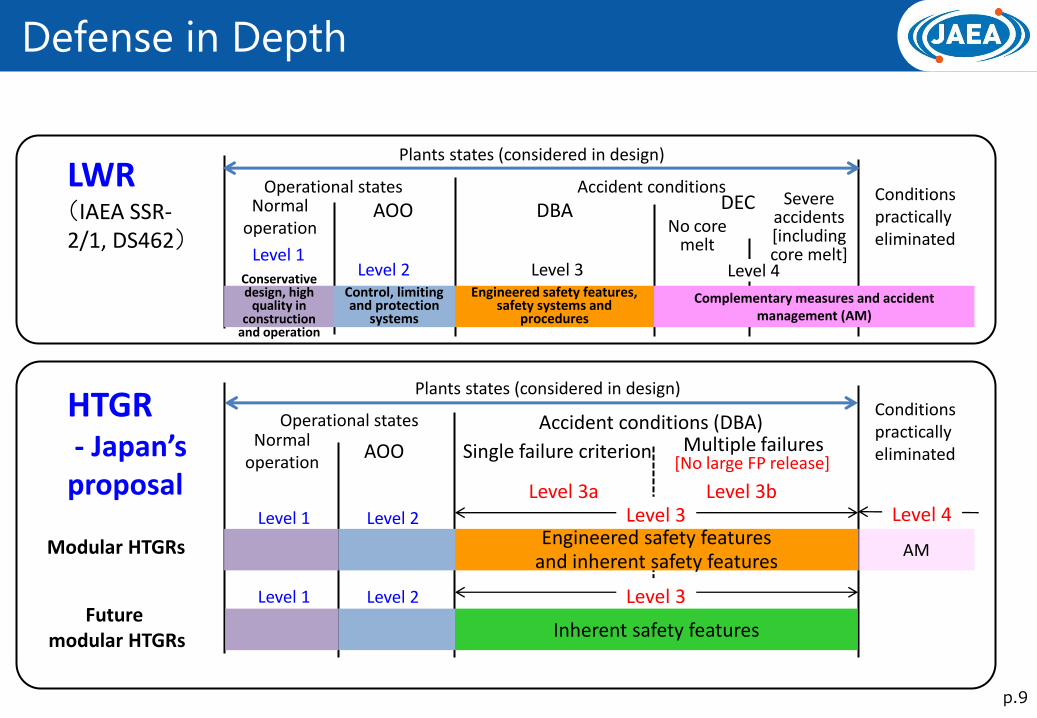
Defense in Depth
Normal operation
AOO DBA DEC Operational states Accident conditions
Control, limiting and protection
systems
Conservative design, high
quality in construction
and operation
Engineered safety features, safety systems and
procedures
Complementary measures and accident management (AM)
No core melt
Conditions practically eliminated
Level 1 Level 2 Level 3
Plants states (considered in design)
LWR (IAEA SSR-2/1, DS462)
Modular HTGRs
AOO Multiple failures
AM
Conditions practically eliminated
HTGR - Japan’s proposal
Level 4
Severe accidents [including core melt]
Normal operation
Operational states
Level 1 Level 2
Level 1 Level 2 Future
modular HTGRs
Level 3 Level 4
Level 3
Inherent safety features
Engineered safety features and inherent safety features
Plants states (considered in design)
Accident conditions (DBA)
Level 3a Level 3b
[No large FP release] Single failure criterion
p.10
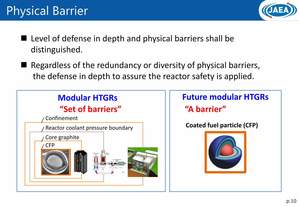
Physical Barrier
“Set of barriers”
Coated fuel particle (CFP)
CFP
Core graphite
Reactor coolant pressure boundary
Confinement
Modular HTGRs Future modular HTGRs
“A barrier”
Level of defense in depth and physical barriers shall be distinguished.
Regardless of the redundancy or diversity of physical barriers, the defense in depth to assure the reactor safety is applied.
p.11
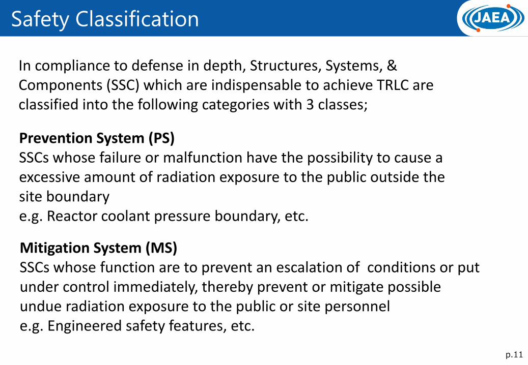
Safety Classification
In compliance to defense in depth, Structures, Systems, & Components (SSC) which are indispensable to achieve TRLC are classified into the following categories with 3 classes;
Prevention System (PS) SSCs whose failure or malfunction have the possibility to cause a excessive amount of radiation exposure to the public outside the site boundary e.g. Reactor coolant pressure boundary, etc.
Mitigation System (MS) SSCs whose function are to prevent an escalation of conditions or put under control immediately, thereby prevent or mitigate possible undue radiation exposure to the public or site personnel e.g. Engineered safety features, etc.
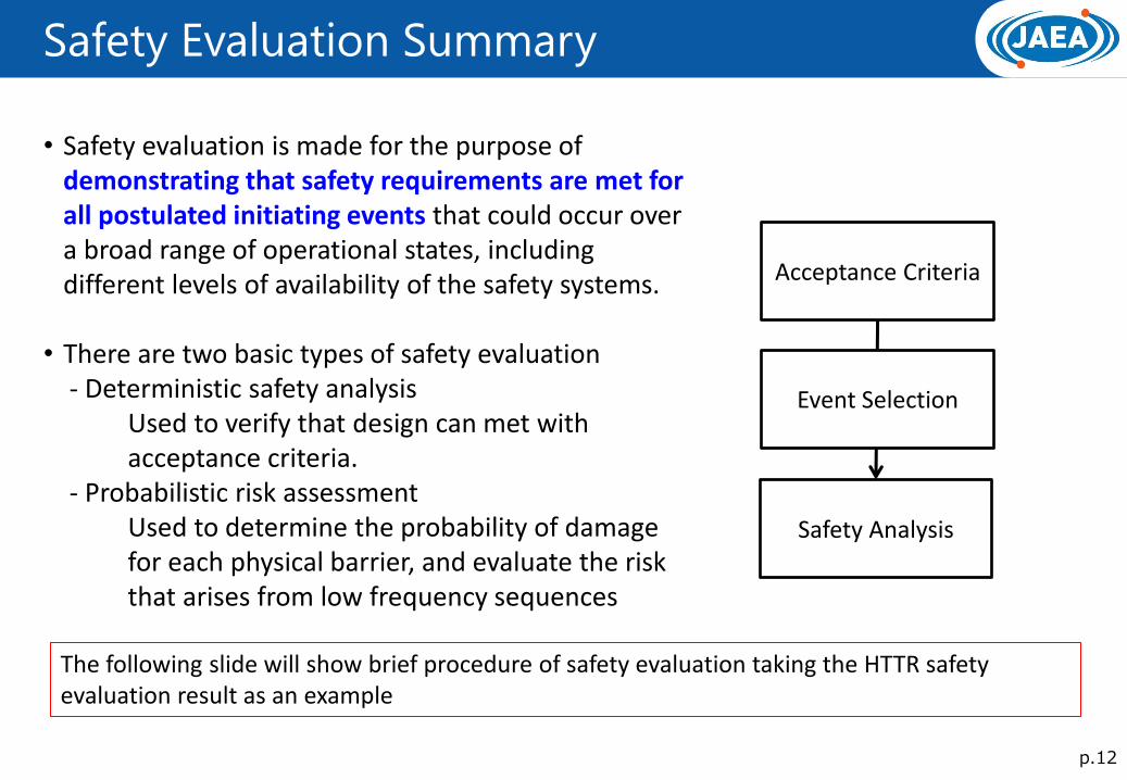
Safety Evaluation Summary
p.12
• Safety evaluation is made for the purpose of demonstrating that safety requirements are met for all postulated initiating events that could occur over a broad range of operational states, including different levels of availability of the safety systems.
• There are two basic types of safety evaluation - Deterministic safety analysis Used to verify that design can met with acceptance criteria. - Probabilistic risk assessment Used to determine the probability of damage for each physical barrier, and evaluate the risk that arises from low frequency sequences
Acceptance Criteria
Event Selection
Safety Analysis
The following slide will show brief procedure of safety evaluation taking the HTTR safety evaluation result as an example
HTTR Outline
p.13
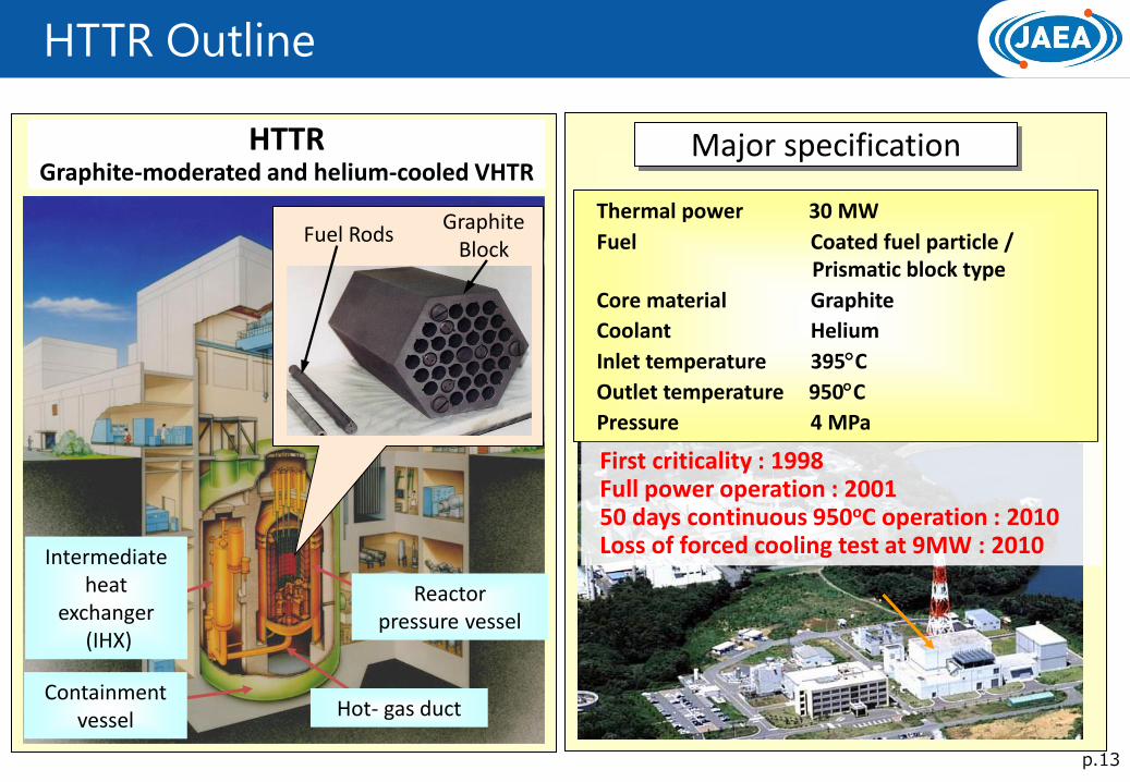
Major specification
Thermal power 30 MW
Fuel Coated fuel particle / Prismatic block type
Core material Graphite
Coolant Helium
Inlet temperature 395C
Outlet temperature 950C
Pressure 4 MPa
Containment vessel
Reactor pressure vessel
Intermediate heat
exchanger (IHX)
Hot- gas duct
HTTR Graphite-moderated and helium-cooled VHTR
Fuel Rods Graphite
Block
First criticality : 1998 Full power operation : 2001 50 days continuous 950oC operation : 2010 Loss of forced cooling test at 9MW : 2010
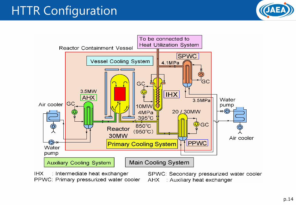
HTTR Configuration
p.14
TLRC and Plant States
p.15
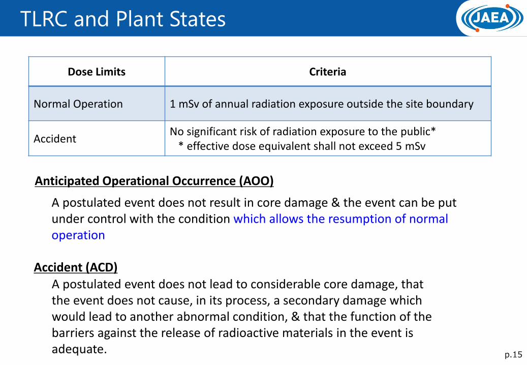
Dose Limits Criteria
Normal Operation 1 mSv of annual radiation exposure outside the site boundary
Accident No significant risk of radiation exposure to the public* * effective dose equivalent shall not exceed 5 mSv
Anticipated Operational Occurrence (AOO)
A postulated event does not result in core damage & the event can be put under control with the condition which allows the resumption of normal operation
Accident (ACD) A postulated event does not lead to considerable core damage, that the event does not cause, in its process, a secondary damage which would lead to another abnormal condition, & that the function of the barriers against the release of radioactive materials in the event is adequate.
p.16
Acceptance Criteria for Fuel during AOOs
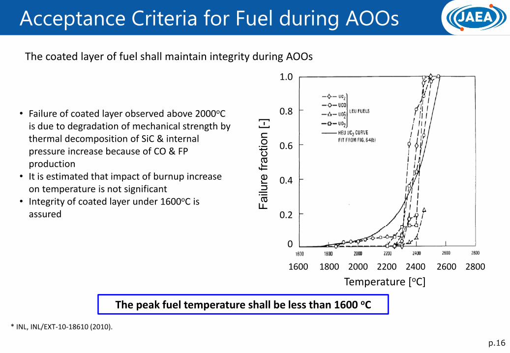
The coated layer of fuel shall maintain integrity during AOOs
• Failure of coated layer observed above 2000oC is due to degradation of mechanical strength by thermal decomposition of SiC & internal pressure increase because of CO & FP production
• It is estimated that impact of burnup increase on temperature is not significant
• Integrity of coated layer under 1600oC is assured
The peak fuel temperature shall be less than 1600 oC
1.0
0.8
0.6
0.4
0.2
0
Temperature [oC]
Failu
re f
raction [
-]
1600 1800 2000 2200 2400 2600 2800
* INL, INL/EXT-10-18610 (2010).
p.17
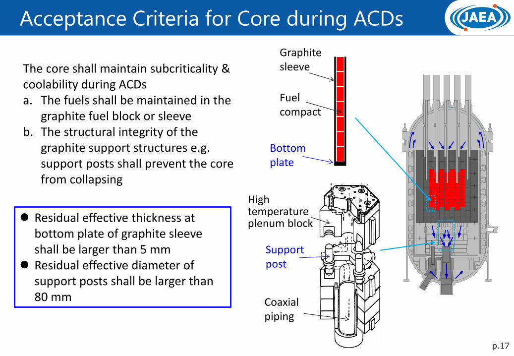
Acceptance Criteria for Core during ACDs
The core shall maintain subcriticality & coolability during ACDs a. The fuels shall be maintained in the
graphite fuel block or sleeve b. The structural integrity of the
graphite support structures e.g. support posts shall prevent the core from collapsing
Residual effective thickness at bottom plate of graphite sleeve shall be larger than 5 mm
Residual effective diameter of support posts shall be larger than 80 mm
Graphite sleeve
Fuel compact
Bottom plate
Support post
Coaxial piping
High temperature plenum block
p.18
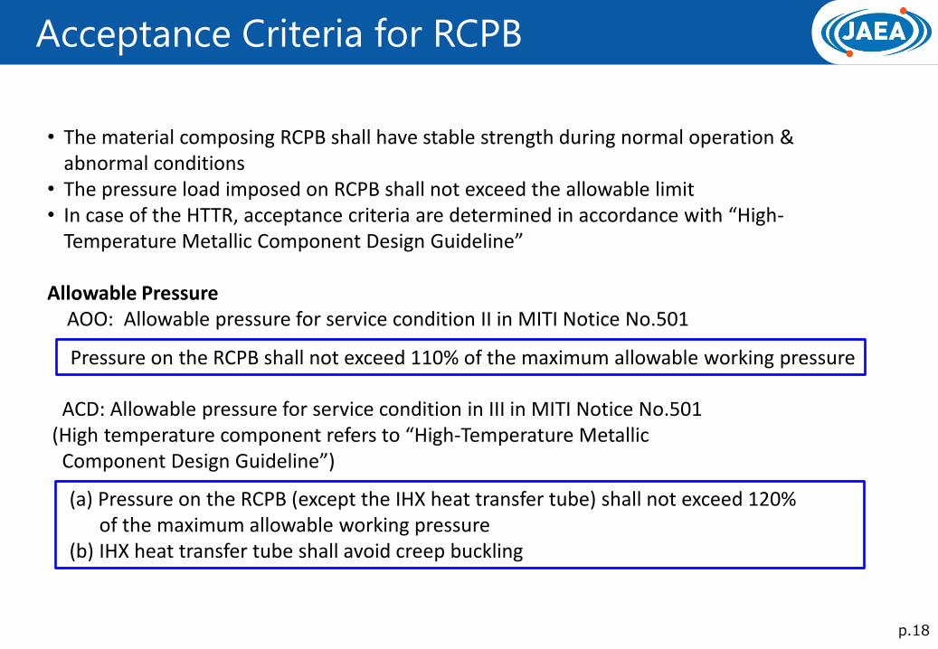
Acceptance Criteria for RCPB
• The material composing RCPB shall have stable strength during normal operation & abnormal conditions
• The pressure load imposed on RCPB shall not exceed the allowable limit • In case of the HTTR, acceptance criteria are determined in accordance with “High-
Temperature Metallic Component Design Guideline”
Allowable Pressure AOO: Allowable pressure for service condition II in MITI Notice No.501 ACD: Allowable pressure for service condition in III in MITI Notice No.501 (High temperature component refers to “High-Temperature Metallic Component Design Guideline”)
Pressure on the RCPB shall not exceed 110% of the maximum allowable working pressure
(a) Pressure on the RCPB (except the IHX heat transfer tube) shall not exceed 120% of the maximum allowable working pressure (b) IHX heat transfer tube shall avoid creep buckling
p.19
Acceptance Criteria for RCPB
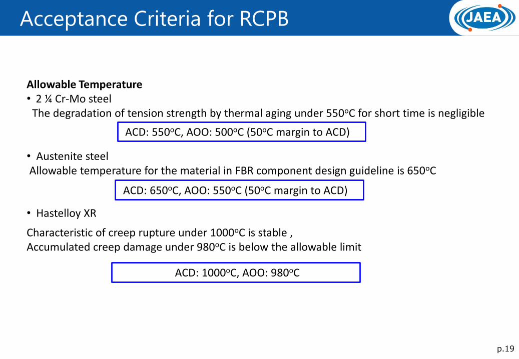
Allowable Temperature • 2 ¼ Cr-Mo steel The degradation of tension strength by thermal aging under 550oC for short time is negligible • Austenite steel Allowable temperature for the material in FBR component design guideline is 650oC • Hastelloy XR Characteristic of creep rupture under 1000oC is stable , Accumulated creep damage under 980oC is below the allowable limit
ACD: 550oC, AOO: 500oC (50oC margin to ACD)
ACD: 650oC, AOO: 550oC (50oC margin to ACD)
ACD: 1000oC, AOO: 980oC
p.20
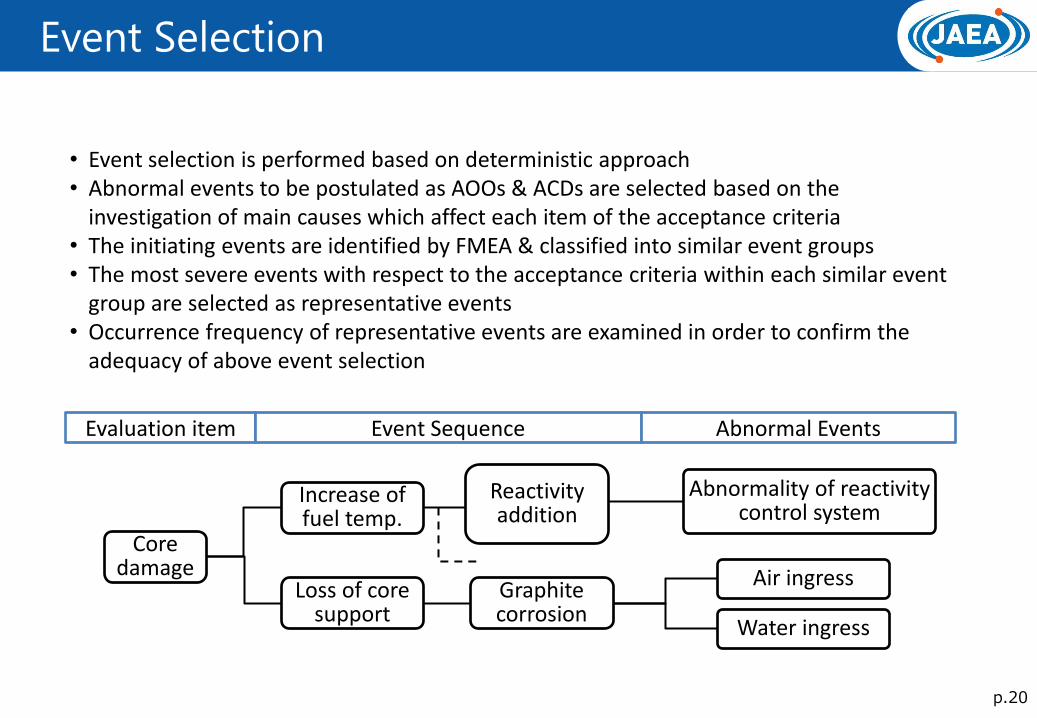
Event Selection
• Event selection is performed based on deterministic approach • Abnormal events to be postulated as AOOs & ACDs are selected based on the
investigation of main causes which affect each item of the acceptance criteria • The initiating events are identified by FMEA & classified into similar event groups • The most severe events with respect to the acceptance criteria within each similar event
group are selected as representative events • Occurrence frequency of representative events are examined in order to confirm the
adequacy of above event selection
Core damage
Increase of fuel temp.
Graphite corrosion
Air ingress
Abnormality of reactivity control system
Loss of core support
Reactivity addition
Evaluation item Event Sequence Abnormal Events
Water ingress
p.21
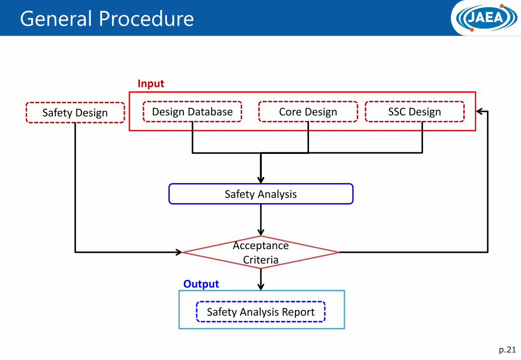
General Procedure
Design Database Safety Design Core Design
Safety Analysis
Acceptance Criteria
Safety Analysis Report
Output
Input
SSC Design
p.22
Safety Analysis Code
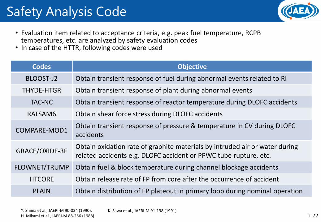
• Evaluation item related to acceptance criteria, e.g. peak fuel temperature, RCPB temperatures, etc. are analyzed by safety evaluation codes
• In case of the HTTR, following codes were used
Codes Objective
BLOOST-J2 Obtain transient response of fuel during abnormal events related to RI
THYDE-HTGR Obtain transient response of plant during abnormal events
TAC-NC Obtain transient response of reactor temperature during DLOFC accidents
RATSAM6 Obtain shear force stress during DLOFC accidents
COMPARE-MOD1 Obtain transient response of pressure & temperature in CV during DLOFC accidents
GRACE/OXIDE-3F Obtain oxidation rate of graphite materials by intruded air or water during related accidents e.g. DLOFC accident or PPWC tube rupture, etc.
FLOWNET/TRUMP Obtain fuel & block temperature during channel blockage accidents
HTCORE Obtain release rate of FP from core after the occurrence of accident
PLAIN Obtain distribution of FP plateout in primary loop during nominal operation
Y. Shiina et al., JAERI-M 90-034 (1990). H. Mikami et al., JAERI-M 88-256 (1988).
K. Sawa et al., JAERI-M 91-198 (1991).
p.23
Calculation Condition (1/2)
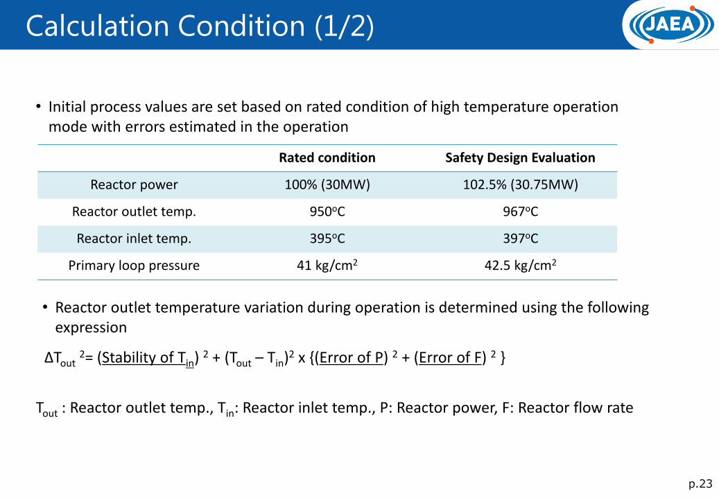
• Initial process values are set based on rated condition of high temperature operation mode with errors estimated in the operation
Rated condition Safety Design Evaluation
Reactor power 100% (30MW) 102.5% (30.75MW)
Reactor outlet temp. 950oC 967oC
Reactor inlet temp. 395oC 397oC
Primary loop pressure 41 kg/cm2 42.5 kg/cm2
∆Tout 2= (Stability of Tin) 2 + (Tout – Tin)2 x {(Error of P) 2 + (Error of F) 2 }
• Reactor outlet temperature variation during operation is determined using the following expression
Tout : Reactor outlet temp., Tin: Reactor inlet temp., P: Reactor power, F: Reactor flow rate
p.24
Calculation Condition (2/2)
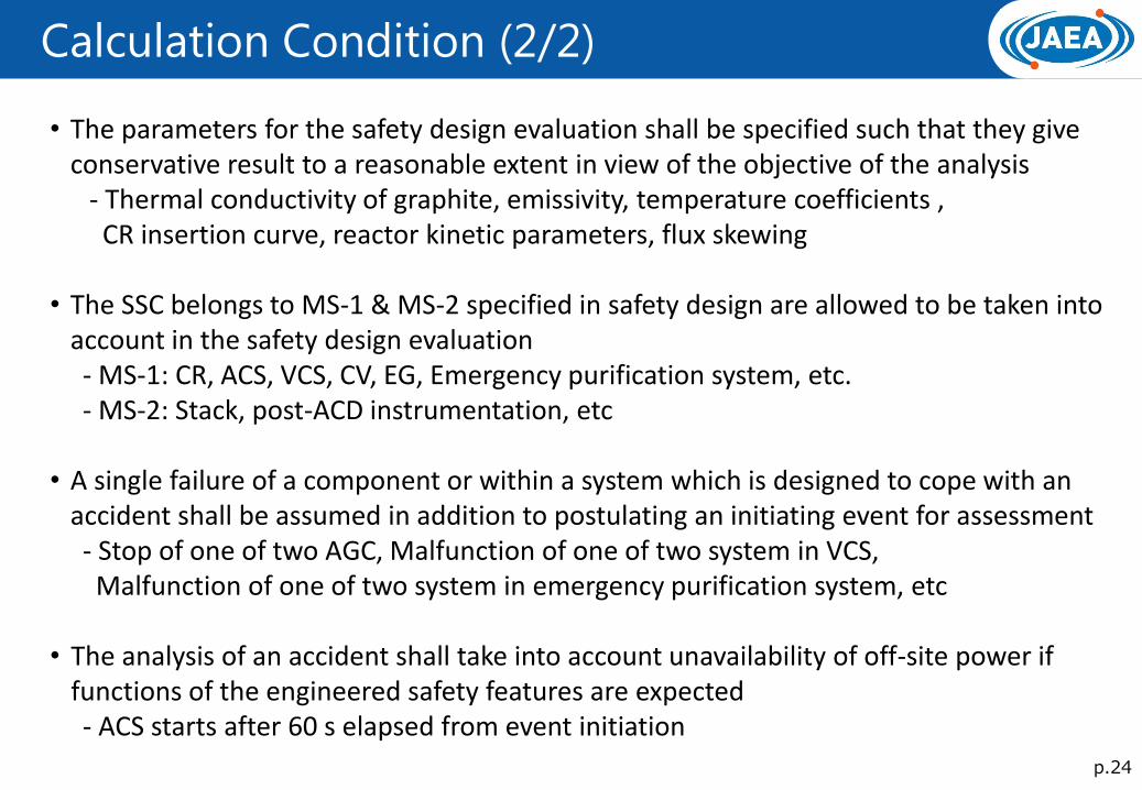
• The parameters for the safety design evaluation shall be specified such that they give conservative result to a reasonable extent in view of the objective of the analysis
- Thermal conductivity of graphite, emissivity, temperature coefficients , CR insertion curve, reactor kinetic parameters, flux skewing • The SSC belongs to MS-1 & MS-2 specified in safety design are allowed to be taken into
account in the safety design evaluation - MS-1: CR, ACS, VCS, CV, EG, Emergency purification system, etc. - MS-2: Stack, post-ACD instrumentation, etc • A single failure of a component or within a system which is designed to cope with an
accident shall be assumed in addition to postulating an initiating event for assessment - Stop of one of two AGC, Malfunction of one of two system in VCS, Malfunction of one of two system in emergency purification system, etc • The analysis of an accident shall take into account unavailability of off-site power if
functions of the engineered safety features are expected - ACS starts after 60 s elapsed from event initiation
p.25
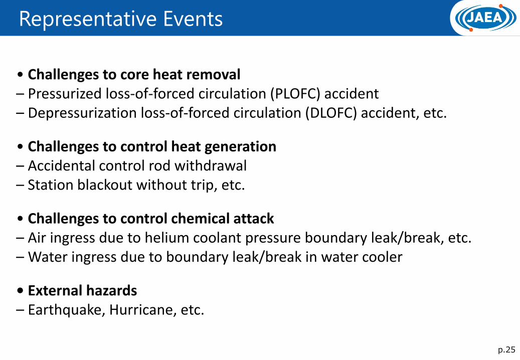
Representative Events
• Challenges to core heat removal – Pressurized loss-of-forced circulation (PLOFC) accident – Depressurization loss-of-forced circulation (DLOFC) accident, etc.
• Challenges to control heat generation – Accidental control rod withdrawal – Station blackout without trip, etc.
• Challenges to control chemical attack – Air ingress due to helium coolant pressure boundary leak/break, etc. – Water ingress due to boundary leak/break in water cooler
• External hazards – Earthquake, Hurricane, etc.
p.26
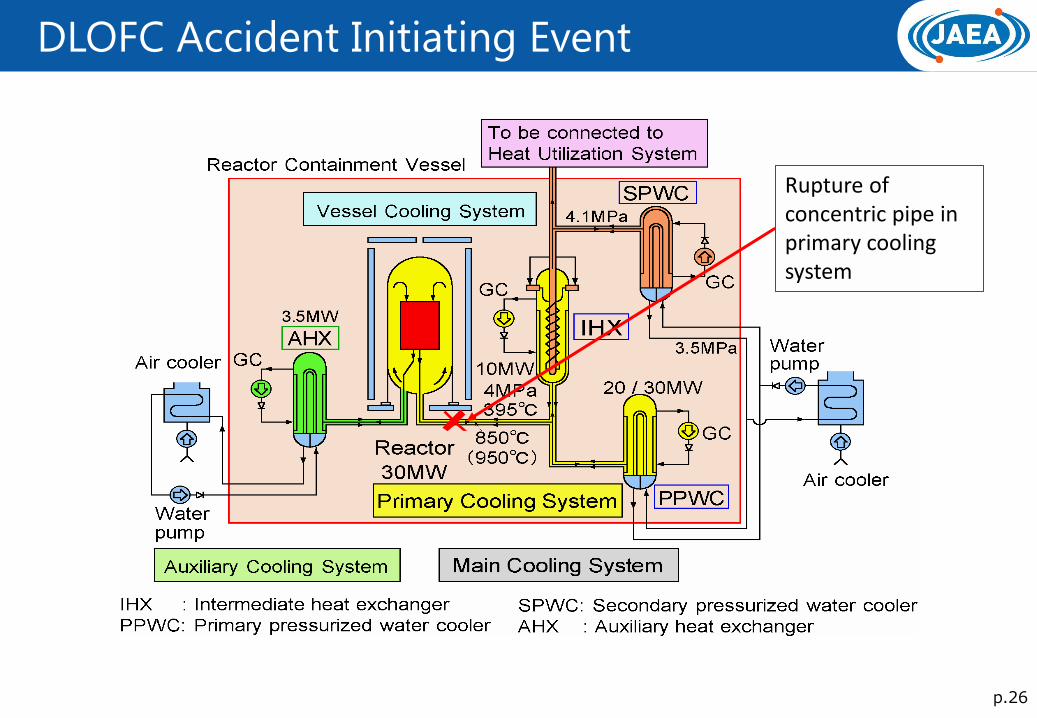
DLOFC Accident Initiating Event
Rupture of concentric pipe in primary cooling system
p.27
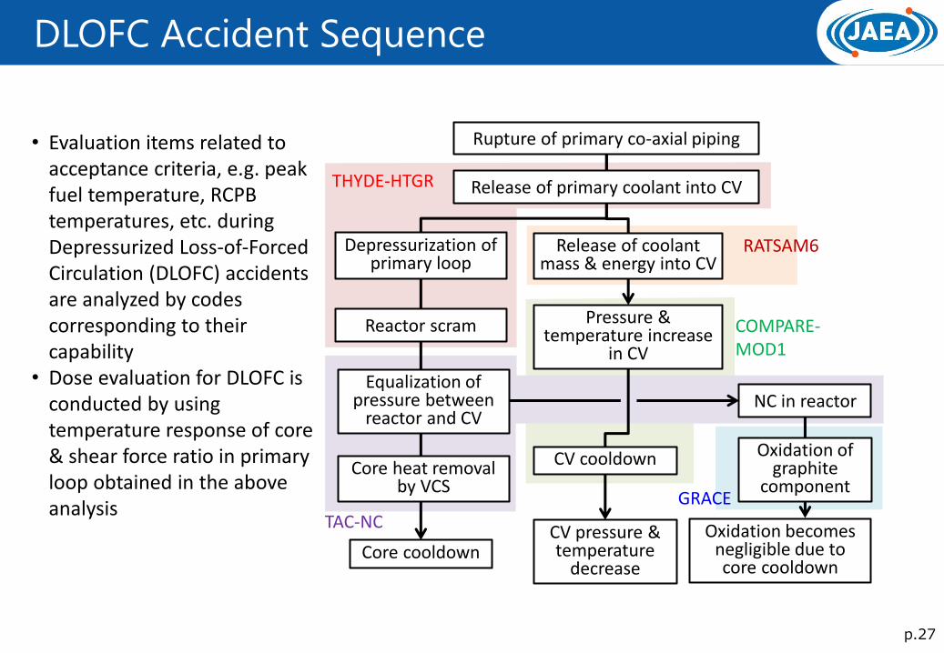
DLOFC Accident Sequence
• Evaluation items related to acceptance criteria, e.g. peak fuel temperature, RCPB temperatures, etc. during Depressurized Loss-of-Forced Circulation (DLOFC) accidents are analyzed by codes corresponding to their capability
• Dose evaluation for DLOFC is conducted by using temperature response of core & shear force ratio in primary loop obtained in the above analysis
Rupture of primary co-axial piping
Release of primary coolant into CV
Depressurization of primary loop
Reactor scram
Equalization of pressure between
reactor and CV
Core heat removal by VCS
NC in reactor
Oxidation of graphite
component
Release of coolant mass & energy into CV
Pressure & temperature increase
in CV
Oxidation becomes negligible due to core cooldown
CV pressure & temperature
decrease Core cooldown
CV cooldown
RATSAM6
COMPARE-MOD1
GRACE
THYDE-HTGR
TAC-NC
p.28
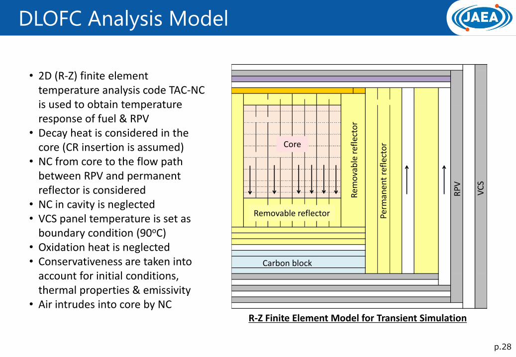
DLOFC Analysis Model
• 2D (R-Z) finite element temperature analysis code TAC-NC is used to obtain temperature response of fuel & RPV
• Decay heat is considered in the core (CR insertion is assumed)
• NC from core to the flow path between RPV and permanent reflector is considered
• NC in cavity is neglected • VCS panel temperature is set as
boundary condition (90oC) • Oxidation heat is neglected • Conservativeness are taken into
account for initial conditions, thermal properties & emissivity
• Air intrudes into core by NC
RP
V
VC
S
Perm
anen
t re
flec
tor
Rem
ova
ble
ref
lect
or
Core
Removable reflector
Carbon block
R-Z Finite Element Model for Transient Simulation
p.29
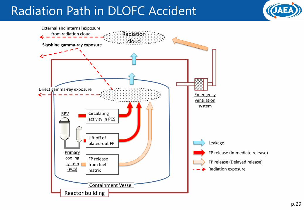
Radiation Path in DLOFC Accident
Containment Vessel
Reactor building
RPV Circulating activity in PCS
Primary cooling system (PCS)
Lift off of plated-out FP
FP release from fuel matrix
Radiation cloud
Emergency ventilation
system
Leakage
FP release (Immediate release)
Skyshine gamma-ray exposure
External and internal exposure from radiation cloud
Direct gamma-ray exposure
Radiation exposure
FP release (Delayed release)
p.30
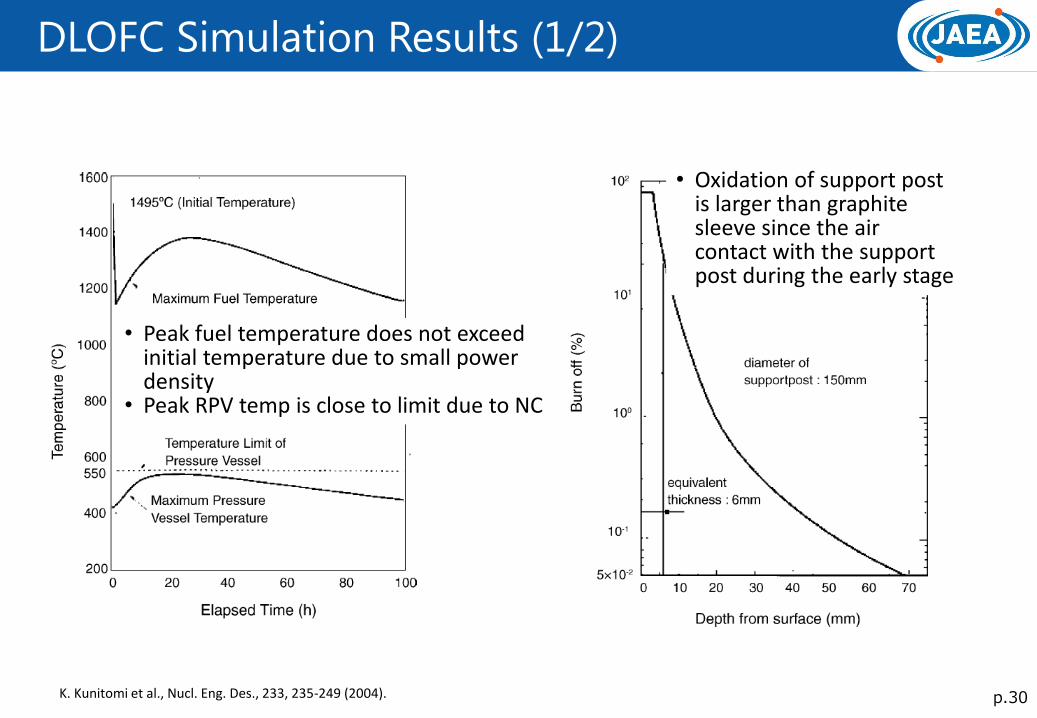
DLOFC Simulation Results (1/2)
• Peak fuel temperature does not exceed initial temperature due to small power density
• Peak RPV temp is close to limit due to NC
• Oxidation of support post is larger than graphite sleeve since the air contact with the support post during the early stage
K. Kunitomi et al., Nucl. Eng. Des., 233, 235-249 (2004).
p.31
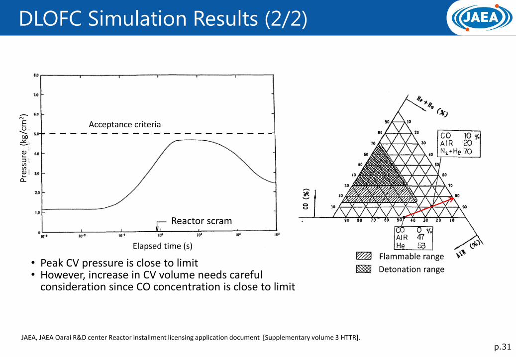
DLOFC Simulation Results (2/2)
• Peak CV pressure is close to limit • However, increase in CV volume needs careful
consideration since CO concentration is close to limit
Reactor scram
Elapsed time (s)
Pre
ssu
re (
kg/c
m2)
Acceptance criteria
Flammable range
Detonation range
JAEA, JAEA Oarai R&D center Reactor installment licensing application document [Supplementary volume 3 HTTR].
p.32
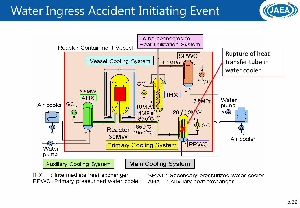
Water Ingress Accident Initiating Event
Rupture of heat transfer tube in water cooler
p.33
Water Ingress Accident Sequence
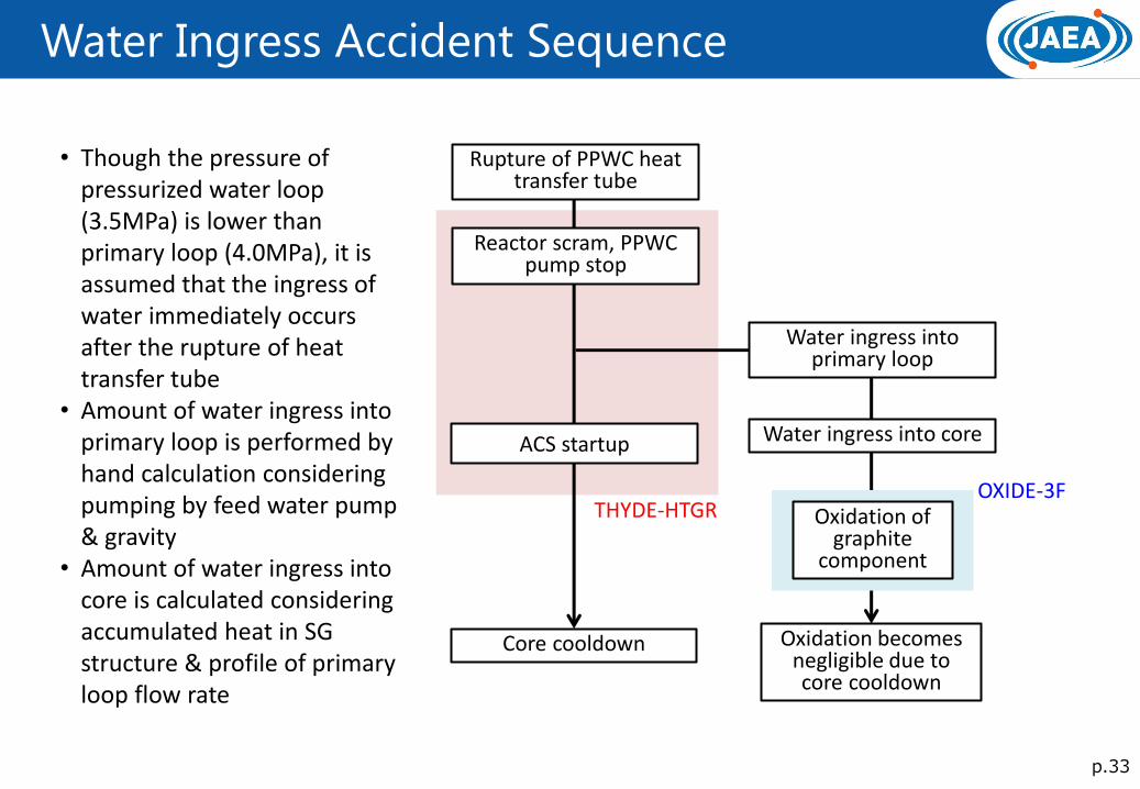
• Though the pressure of pressurized water loop (3.5MPa) is lower than primary loop (4.0MPa), it is assumed that the ingress of water immediately occurs after the rupture of heat transfer tube
• Amount of water ingress into primary loop is performed by hand calculation considering pumping by feed water pump & gravity
• Amount of water ingress into core is calculated considering accumulated heat in SG structure & profile of primary loop flow rate
Rupture of PPWC heat transfer tube
Reactor scram, PPWC pump stop
Oxidation of graphite
component
Oxidation becomes negligible due to core cooldown
OXIDE-3F
ACS startup
Water ingress into primary loop
Water ingress into core
Core cooldown
THYDE-HTGR
p.34
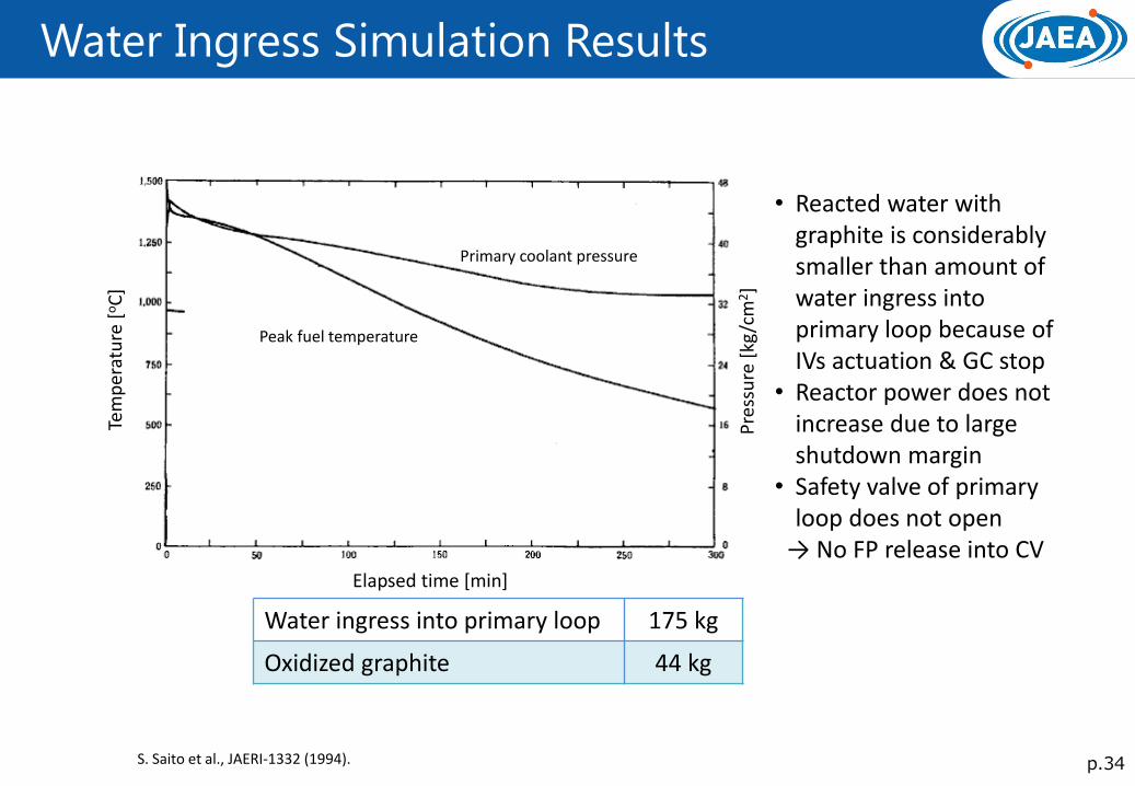
Water Ingress Simulation Results
Water ingress into primary loop 175 kg
Oxidized graphite 44 kg
• Reacted water with graphite is considerably smaller than amount of water ingress into primary loop because of IVs actuation & GC stop
• Reactor power does not increase due to large shutdown margin
• Safety valve of primary loop does not open
→ No FP release into CV Elapsed time [min]
Pre
ssu
re [
kg/c
m2]
Tem
per
atu
re [
oC
]
S. Saito et al., JAERI-1332 (1994).
Primary coolant pressure
Peak fuel temperature
p.35
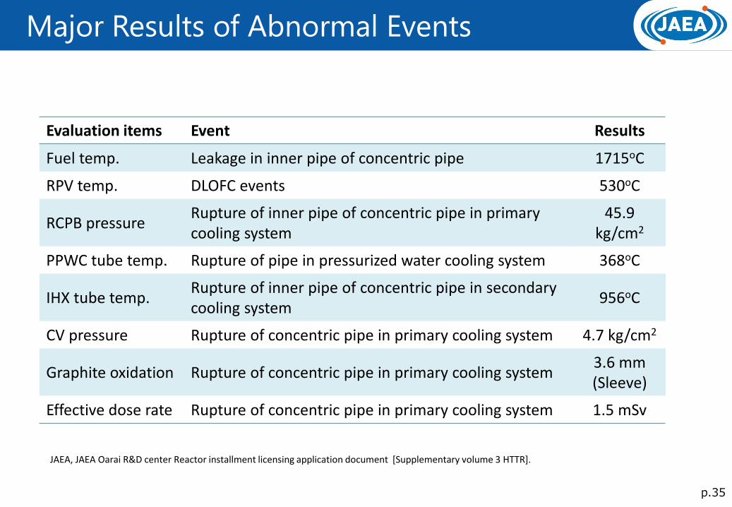
Major Results of Abnormal Events
Evaluation items Event Results
Fuel temp. Leakage in inner pipe of concentric pipe 1715oC
RPV temp. DLOFC events 530oC
RCPB pressure Rupture of inner pipe of concentric pipe in primary cooling system
45.9 kg/cm2
PPWC tube temp. Rupture of pipe in pressurized water cooling system 368oC
IHX tube temp. Rupture of inner pipe of concentric pipe in secondary cooling system
956oC
CV pressure Rupture of concentric pipe in primary cooling system 4.7 kg/cm2
Graphite oxidation Rupture of concentric pipe in primary cooling system 3.6 mm (Sleeve)
Effective dose rate Rupture of concentric pipe in primary cooling system 1.5 mSv
JAEA, JAEA Oarai R&D center Reactor installment licensing application document [Supplementary volume 3 HTTR].
p.36
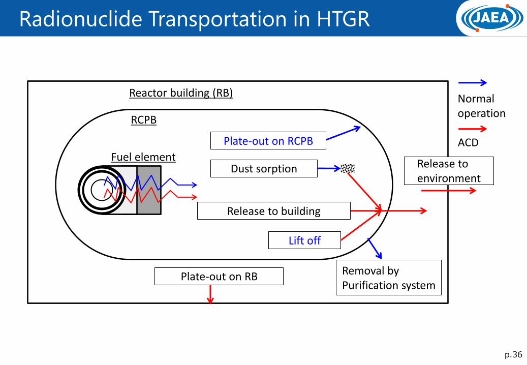
Radionuclide Transportation in HTGR
RCPB
Reactor building (RB)
Fuel element
Removal by Purification system
Dust sorption
Plate-out on RCPB
Plate-out on RB
Release to building
Lift off
Release to environment
Normal operation
ACD

p.37
Plate-out on RCPB
Coolant flow
Mass transfer region
Mass transfer
Diffusion
Sublimation
Adsorption desorption
FP concentration
RCPB
Circulating FP in primary loop deposits on RCPB “Plate-out”.
The deposited FP becomes radiation source for worker does in maintenance.
A part of deposited FP departures from RCPB in case of ACD
The mechanism of plate-out can be classified in to the following:
- Mass transfer from coolant flow to wall proximity region of RCPB
- Adsorption and desorption equilibrium between wall proximity region and RCPB surface
- Diffusion in RCPB
- Sublimation from RCPB to coolant
p.38
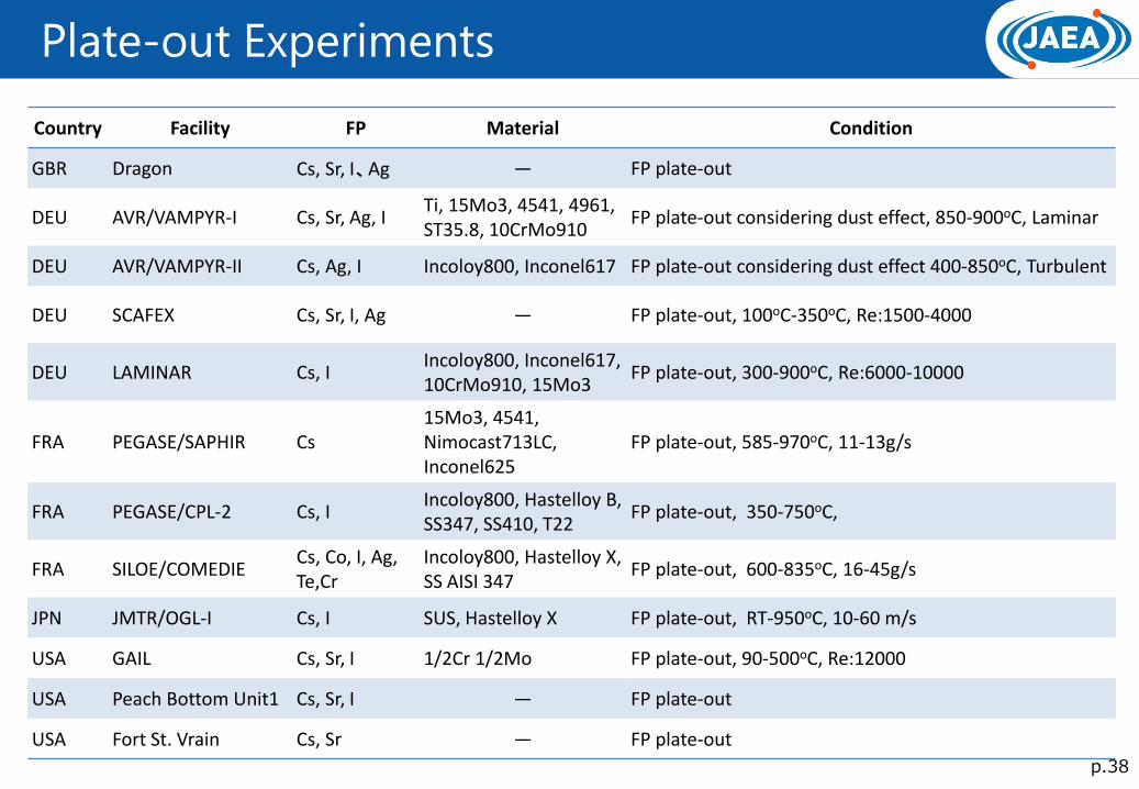
Plate-out Experiments
Country Facility FP Material Condition
GBR Dragon Cs, Sr, I、Ag ― FP plate-out
DEU AVR/VAMPYR-I Cs, Sr, Ag, I Ti, 15Mo3, 4541, 4961, ST35.8, 10CrMo910
FP plate-out considering dust effect, 850-900oC, Laminar
DEU AVR/VAMPYR-II Cs, Ag, I Incoloy800, Inconel617 FP plate-out considering dust effect 400-850oC, Turbulent
DEU SCAFEX Cs, Sr, I, Ag ― FP plate-out, 100oC-350oC, Re:1500-4000
DEU LAMINAR Cs, I Incoloy800, Inconel617, 10CrMo910, 15Mo3
FP plate-out, 300-900oC, Re:6000-10000
FRA PEGASE/SAPHIR Cs 15Mo3, 4541, Nimocast713LC, Inconel625
FP plate-out, 585-970oC, 11-13g/s
FRA PEGASE/CPL-2 Cs, I Incoloy800, Hastelloy B, SS347, SS410, T22
FP plate-out, 350-750oC,
FRA SILOE/COMEDIE Cs, Co, I, Ag, Te,Cr
Incoloy800, Hastelloy X, SS AISI 347
FP plate-out, 600-835oC, 16-45g/s
JPN JMTR/OGL-I Cs, I SUS, Hastelloy X FP plate-out, RT-950oC, 10-60 m/s
USA GAIL Cs, Sr, I 1/2Cr 1/2Mo FP plate-out, 90-500oC, Re:12000
USA Peach Bottom Unit1 Cs, Sr, I ― FP plate-out
USA Fort St. Vrain Cs, Sr ― FP plate-out
p.39
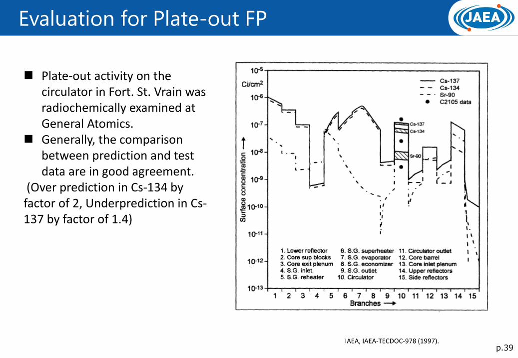
Evaluation for Plate-out FP
IAEA, IAEA-TECDOC-978 (1997).
Plate-out activity on the circulator in Fort. St. Vrain was radiochemically examined at General Atomics.
Generally, the comparison between prediction and test data are in good agreement.
(Over prediction in Cs-134 by factor of 2, Underprediction in Cs-137 by factor of 1.4)
p.40
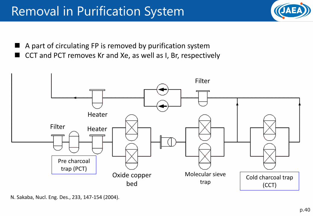
Removal in Purification System
Pre charcoal trap (PCT)
Oxide copper bed
Cold charcoal trap (CCT)
Molecular sieve trap
Filter
Filter
Heater
Heater
A part of circulating FP is removed by purification system CCT and PCT removes Kr and Xe, as well as I, Br, respectively
N. Sakaba, Nucl. Eng. Des., 233, 147-154 (2004).
p.41
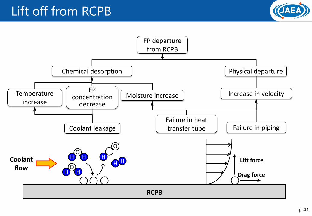
Lift off from RCPB
Chemical desorption
FP departure from RCPB
Increase in velocity Temperature increase
Moisture increase
Failure in piping Failure in heat transfer tube Coolant leakage
Physical departure
FP concentration
decrease
RCPB
Coolant flow
Lift force
Drag force
O H H
O H H
O
H H H
p.42
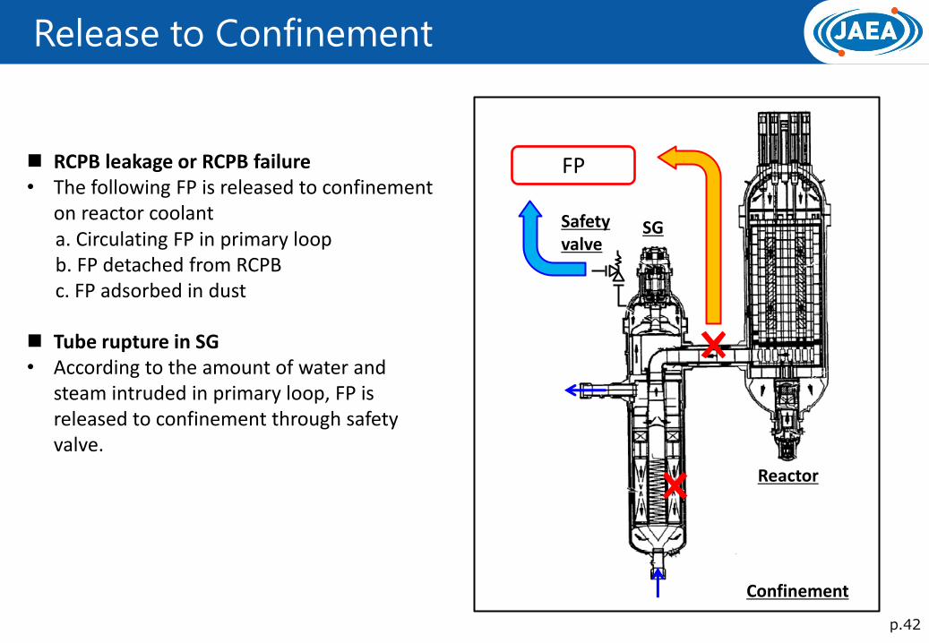
Release to Confinement
RCPB leakage or RCPB failure • The following FP is released to confinement
on reactor coolant a. Circulating FP in primary loop b. FP detached from RCPB c. FP adsorbed in dust Tube rupture in SG • According to the amount of water and
steam intruded in primary loop, FP is released to confinement through safety valve.
SG
Reactor
Safety valve
FP
Confinement

p.43
Release to Environment
Released FP from primary loop
FP accumulated in core
Confinement A part of FP is deposited on the
confinement surface Velocity is the dominant parameter
because of the large velocity in case of rupture in RCPB
Environment
Released from stack
Leakage in confinement
Related Documents