1/09 Installation & Operating Manual MN604 RPMIII DC Motor Frames DC180ATZ − C180ATZ and DC210ATZ Designed for operation with an SCR Control

Welcome message from author
This document is posted to help you gain knowledge. Please leave a comment to let me know what you think about it! Share it to your friends and learn new things together.
Transcript

1/09 Installation & Operating Manual MN604
RPMIII DC Motor
Frames DC180ATZ − C180ATZ and
DC210ATZ
Designed for operation with an SCR Control

Any trademarks used in this manual are the property of their respective owners.
Important: Be sure to check www.baldor.com to download the latest version of this manual in Adobe Acrobat PDF format.

iMN604
Table of Contents
Section 1 General Information . . . . . . . . . . . . . . . . . . . . . . . . . . . . . . . . . . . . . . . . . . . . . . . . . . . . . . . . . . . . . . . . . 1−1
Overview . . . . . . . . . . . . . . . . . . . . . . . . . . . . . . . . . . . . . . . . . . . . . . . . . . . . . . . . . . . . . . . . . . . . . . 1−1Important: . . . . . . . . . . . . . . . . . . . . . . . . . . . . . . . . . . . . . . . . . . . . . . . . . . . . . . . . . . . . . . . . . . . . . . 1−1Safety Notice: . . . . . . . . . . . . . . . . . . . . . . . . . . . . . . . . . . . . . . . . . . . . . . . . . . . . . . . . . . . . . . . . . . . 1−1Receiving . . . . . . . . . . . . . . . . . . . . . . . . . . . . . . . . . . . . . . . . . . . . . . . . . . . . . . . . . . . . . . . . . . . . . . 1−2Handling . . . . . . . . . . . . . . . . . . . . . . . . . . . . . . . . . . . . . . . . . . . . . . . . . . . . . . . . . . . . . . . . . . . . . . . . 1−2Storage . . . . . . . . . . . . . . . . . . . . . . . . . . . . . . . . . . . . . . . . . . . . . . . . . . . . . . . . . . . . . . . . . . . . . . . . 1−3Preparation for Storage . . . . . . . . . . . . . . . . . . . . . . . . . . . . . . . . . . . . . . . . . . . . . . . . . . . . . . . . . . . . 1−3Removal From Storage . . . . . . . . . . . . . . . . . . . . . . . . . . . . . . . . . . . . . . . . . . . . . . . . . . . . . . . . . . . . 1−4EMC Compliance Statement for European Union . . . . . . . . . . . . . . . . . . . . . . . . . . . . . . . . . . . . . . . . 1−4
Section 2 Installation & Operation . . . . . . . . . . . . . . . . . . . . . . . . . . . . . . . . . . . . . . . . . . . . . . . . . . . . . . . . . . . . . . 2−1
Overview . . . . . . . . . . . . . . . . . . . . . . . . . . . . . . . . . . . . . . . . . . . . . . . . . . . . . . . . . . . . . . . . . . . . . . . 2−1Considerations . . . . . . . . . . . . . . . . . . . . . . . . . . . . . . . . . . . . . . . . . . . . . . . . . . . . . . . . . . . . . . . . . . . 2−1Location . . . . . . . . . . . . . . . . . . . . . . . . . . . . . . . . . . . . . . . . . . . . . . . . . . . . . . . . . . . . . . . . . . . . . . . 2−1Air Supply . . . . . . . . . . . . . . . . . . . . . . . . . . . . . . . . . . . . . . . . . . . . . . . . . . . . . . . . . . . . . . . . . . . . . . 2−1Ambient . . . . . . . . . . . . . . . . . . . . . . . . . . . . . . . . . . . . . . . . . . . . . . . . . . . . . . . . . . . . . . . . . . . . . . . . 2−1Maximum Safe Speed . . . . . . . . . . . . . . . . . . . . . . . . . . . . . . . . . . . . . . . . . . . . . . . . . . . . . . . . . . . . . 2−1Minimum Sheave Diameters . . . . . . . . . . . . . . . . . . . . . . . . . . . . . . . . . . . . . . . . . . . . . . . . . . . . . . . . 2−1Installation . . . . . . . . . . . . . . . . . . . . . . . . . . . . . . . . . . . . . . . . . . . . . . . . . . . . . . . . . . . . . . . . . . . . . . 2−2Shipping Blocks . . . . . . . . . . . . . . . . . . . . . . . . . . . . . . . . . . . . . . . . . . . . . . . . . . . . . . . . . . . . . . . . . . 2−3Alignment . . . . . . . . . . . . . . . . . . . . . . . . . . . . . . . . . . . . . . . . . . . . . . . . . . . . . . . . . . . . . . . . . . . . . . 2−3Doweling & Bolting . . . . . . . . . . . . . . . . . . . . . . . . . . . . . . . . . . . . . . . . . . . . . . . . . . . . . . . . . . . . . . . 2−3Guarding . . . . . . . . . . . . . . . . . . . . . . . . . . . . . . . . . . . . . . . . . . . . . . . . . . . . . . . . . . . . . . . . . . . . . . . 2−3Electrical Installation . . . . . . . . . . . . . . . . . . . . . . . . . . . . . . . . . . . . . . . . . . . . . . . . . . . . . . . . . . . . . . 2−3Terminal Box . . . . . . . . . . . . . . . . . . . . . . . . . . . . . . . . . . . . . . . . . . . . . . . . . . . . . . . . . . . . . . . . . . . . 2−3Power . . . . . . . . . . . . . . . . . . . . . . . . . . . . . . . . . . . . . . . . . . . . . . . . . . . . . . . . . . . . . . . . . . . . . . . . . 2−3Motor Connections . . . . . . . . . . . . . . . . . . . . . . . . . . . . . . . . . . . . . . . . . . . . . . . . . . . . . . . . . . . . . . . 2−4Thermostat Connection . . . . . . . . . . . . . . . . . . . . . . . . . . . . . . . . . . . . . . . . . . . . . . . . . . . . . . . . . . . . 2−5Grounding . . . . . . . . . . . . . . . . . . . . . . . . . . . . . . . . . . . . . . . . . . . . . . . . . . . . . . . . . . . . . . . . . . . . . . 2−5Overspeed Switch . . . . . . . . . . . . . . . . . . . . . . . . . . . . . . . . . . . . . . . . . . . . . . . . . . . . . . . . . . . . . . . 2−5Feedback Connections . . . . . . . . . . . . . . . . . . . . . . . . . . . . . . . . . . . . . . . . . . . . . . . . . . . . . . . . . . . . . . . . . . . . 2−5Blower Motor Connection . . . . . . . . . . . . . . . . . . . . . . . . . . . . . . . . . . . . . . . . . . . . . . . . . . . . . . . . . . 2−5First Time Start Up . . . . . . . . . . . . . . . . . . . . . . . . . . . . . . . . . . . . . . . . . . . . . . . . . . . . . . . . . . . . . . . 2−6Operation Considerations . . . . . . . . . . . . . . . . . . . . . . . . . . . . . . . . . . . . . . . . . . . . . . . . . . . . . . . . . . 2−6Determining Motor Constants . . . . . . . . . . . . . . . . . . . . . . . . . . . . . . . . . . . . . . . . . . . . . . . . . . . . . . . 2−7Suggested bearing and winding RTD setting guidelines . . . . . . . . . . . . . . . . . . . . . . . . . . . . . . . . . . . 2−7
Section 3 Maintenance & Troubleshooting . . . . . . . . . . . . . . . . . . . . . . . . . . . . . . . . . . . . . . . . . . . . . . . . . . . . . . . 3−1
General Inspection . . . . . . . . . . . . . . . . . . . . . . . . . . . . . . . . . . . . . . . . . . . . . . . . . . . . . . . . . . . . . . . . 3−1Relubrication & Bearings . . . . . . . . . . . . . . . . . . . . . . . . . . . . . . . . . . . . . . . . . . . . . . . . . . . . . . . . . . 3−1Brushes . . . . . . . . . . . . . . . . . . . . . . . . . . . . . . . . . . . . . . . . . . . . . . . . . . . . . . . . . . . . . . . . . . . . . . . . 3−2Troubleshooting . . . . . . . . . . . . . . . . . . . . . . . . . . . . . . . . . . . . . . . . . . . . . . . . . . . . . . . . . . . . . . . . . . 3−3Armature Overheating . . . . . . . . . . . . . . . . . . . . . . . . . . . . . . . . . . . . . . . . . . . . . . . . . . . . . . . . . . . . . 3−3Field Coil Overheating . . . . . . . . . . . . . . . . . . . . . . . . . . . . . . . . . . . . . . . . . . . . . . . . . . . . . . . . . . . . 3−3Excessive Load . . . . . . . . . . . . . . . . . . . . . . . . . . . . . . . . . . . . . . . . . . . . . . . . . . . . . . . . . . . . . . . . . . 3−3Jogging and Repeated Starts . . . . . . . . . . . . . . . . . . . . . . . . . . . . . . . . . . . . . . . . . . . . . . . . . . . . . . . 3−3Heating . . . . . . . . . . . . . . . . . . . . . . . . . . . . . . . . . . . . . . . . . . . . . . . . . . . . . . . . . . . . . . . . . . . . . . . . 3−3Thermostat . . . . . . . . . . . . . . . . . . . . . . . . . . . . . . . . . . . . . . . . . . . . . . . . . . . . . . . . . . . . . . . . . . . . . 3−3Checking Relative Polarity of DC Motor Fields . . . . . . . . . . . . . . . . . . . . . . . . . . . . . . . . . . . . . . . . . . 3−4Humidity And Brush Wear . . . . . . . . . . . . . . . . . . . . . . . . . . . . . . . . . . . . . . . . . . . . . . . . . . . . . . . . . . 3−4Guide To Commutator Appearance . . . . . . . . . . . . . . . . . . . . . . . . . . . . . . . . . . . . . . . . . . . . . . . . . . . . . . . . . . 3−6
Section 4 Connection Diagrams . . . . . . . . . . . . . . . . . . . . . . . . . . . . . . . . . . . . . . . . . . . . . . . . . . . . . . . . . . . . . . . 4−1

ii MN604
1-1MN604
Section 1General Information
Overview This manual contains general procedures that apply to Baldor Motor products. Be sure to read and understand the Safety Notice statements in this manual. For your protection, do not install, operate or attempt to perform maintenance procedures until you understand the Warning and Caution statements.A Warning statement indicates a possible unsafe condition that can cause harm to personnel.A Caution statement indicates a condition that can cause damage to equipment.
Important: This instruction manual is not intended to include a comprehensive listing of all details for all procedures required for installation, operation and maintenance. This manual describes general guidelines that apply to most of the motor products shipped by Baldor. If you have a question about a procedure or are uncertain about any detail, Do Not Proceed. Please contact your Baldor District Office for more information or clarification.
Before you install, operate or perform maintenance, become familiar with the following:• NEMA Publication MG-2, Safety Standard for Construction and guide for Selection, Installation and
Use of Electric Motors and Generators.• ANSI C51.1• The National Electrical Code • Local codes and Practices
Safety Notice: This equipment contains high voltage! Electrical shock can cause serious or fatal injury. Only qualified personnel should attempt installation, operation and maintenance of electrical equipment. Be sure that you are completely familiar with NEMA publication MG-2, safety standards for construction and guide for selection, installation and use of electric motors and generators, the National Electrical Code and local codes and practices. Unsafe installation or use can cause conditions that lead to serious or fatal injury. Only qualified personnel should attempt the installation, operation and maintenance of this equipment.
WARNING: Do not touch electrical connections before you first ensure that power has been disconnected. Electrical shock can cause serious or fatal injury. Only qualified personnel should attempt the installation, operation and maintenance of this equipment.
WARNING: Disconnect all electrical power from the motor windings and accessory devices before disassembling of the motor. Electrical shock can cause serious or fatal injury.
WARNING: Be sure the system is properly grounded before applying power. Do not apply AC power before you ensure that all grounding instructions have been followed. Electrical shock can cause serious or fatal injury.
WARNING: Avoid extended exposure to machinery with high noise levels. Be sure to wear ear protective devices to reduce harmful effects to your hearing.
WARNING: Surface temperatures of motor enclosures may reach temperatures which can cause discomfort or injury to personnel accidentally coming into contact with hot surfaces. When installing, protection should be provided by the user to protect against accidental contact with hot surfaces. Failure to observe this precaution could result in bodily injury.
WARNING: Guards must be installed for rotating parts to prevent accidental contact by personnel. Accidental contact with body parts or clothing can cause serious or fatal injury.
WARNING: This equipment may be connected to other machinery that has rotating parts or parts that are driven by this equipment. Improper use can cause serious or fatal injury. Only qualified personnel should attempt to install operate or maintain this equipment.
WARNING: Do not by-pass or disable protective devices or safety guards. Safety features are designed to prevent damage to personnel or equipment. These devices can only provide protection if they remain operative.
WARNING: Avoid the use of automatic reset devices if the automatic restarting of equipment can be hazardous to personnel or equipment.
WARNING: Be sure the load is properly coupled to the motor shaft before applying power. The shaft key must be fully captive by the load device. Improper coupling can cause harm to personnel or equipment if the load decouples from the shaft during operation.
WARNING: Use proper care and procedures that are safe during handling, lifting, installing, operating and maintaining operations. Improper methods may cause muscle strain or other harm.
WARNING: Pacemaker danger − Magnetic and electromagnetic fields in the vicinity of current carrying carrying conductors and permanent magnet motors can result result in a serious health hazard to persons with cardiac pacemakers, metal implants, and hearing aids. To avoid risk, stay way from the area surrounding a permanent magnet motor.
WARNING: Before performing any motor maintenance procedure, be sure that the equipment connected to the motor shaft cannot cause shaft rotation. If the load can cause shaft rotation, disconnect the load from the motor shaft before maintenance is performed. Unexpected mechanical rotation of the motor parts can cause injury or motor damage.
WARNING: Motors that are to be used in flammable and/or explosive atmospheres must display the UL label on the nameplate along with CSA listed logo. Specific service conditions for these motors are defined in NFPA 70 (NEC) Article 500.
WARNING: The SCR controller may apply hazardous voltages to the motor leads after power to the controller has been turned off. Verify the controller is incapable of delivering hazardous voltages and that the voltage at the motor leads is zero before proceeding. Failure to observe this precaution may result is severe bodily injury or death.
WARNING: Do not use non UL/CSA listed explosion proof motors in the presence of flammable or combustible vapors or dust. These motors are not designed for atmospheric conditions that require explosion proof operation.

1-2 MN604
Safety Notice Continued
WARNING: Motors that are to be used in flammable and/or explosive atmospheres must display the UL label on the nameplate along with CSA listed logo. Specific service conditions for these motors are defined in NFPA 70 (NEC) Article 500.
WARNING: UL Listed motors must only be serviced by UL Approved Authorized Baldor Service Centers if these motors are to be returned to a hazardous and/or explosive atmosphere.
WARNING: Rotating parts can cause serious or fatal injury. If relubrication is performed with the motor running, to avoid injury do not contact any rotating parts.
WARNING: Space Heaters operate at line voltage. Disconnect power to space heaters before performing maintenance work on motor. Failure to observe this precaution could result in severe bodily injury or loss of life.
WARNING: Thermostat contacts automatically reset when the motor has slightly cooled down. To prevent injury or damage, the control circuit should be designed so that automatic starting of the motor is not possible when the thermostat resets.
Caution: To prevent premature equipment failure or damage, only qualified maintenance personnel should perform maintenance.
Caution: Do not over−lubricate motor as this may cause premature bearing failure. Caution: Do not lift the motor and its driven load by the motor lifting hardware. The motor lifting hardware is
adequate for lifting only the motor. Disconnect the load (gears, pumps, compressors, or other driven equipment) from the motor shaft before lifting the motor.
Caution: If eye bolts are used for lifting a motor, be sure they are securely tightened. The lifting direction should not exceed a 20 ° angle from the shank of the eye bolt or lifting lug. Excessive lifting angles can cause damage.
Caution: Do not use the coupling to compensate for poor alignment. This can result in vibration, noise, coupling wear, overloaded bearings and early failure.
Caution: To prevent equipment damage, be sure that the electrical service is not capable of delivering more than the maximum motor rated amps listed on the rating plate.
Caution: If a Motor Insulation test (High Potential Insulation test) must be performed, disconnect the motor from any Speed Control or drive to avoid damage to connected equipment.
Caution: Do not use Silicone grease or Sealing Compounds (RTV) on or in the vicinity of the motor or its air supply. Silicone vapor inside the motor will result in extremely rapid brush wear.
Caution: Vertical mount hand hole covers are required to provide protection to vertically mounted drip−proof motors. Stock motors and other motors designed for horizontal mounting can be adapted for vertical mounting by ordering vertical mount hand hole covers from Baldor.
Caution: Use of these radial load capacities requires the accurate calculation of the radial load for the application. Radial loads for gears, sprockets, and flywheel are usually accurately determined. Radial loads for V−belt drives are subject to error due to the exclusion of pre−tension load (belt tightening). The calculations of the radial load for a V−belt drive must include the pre−tension for transmitting the horsepower, pre−tension for centrifugal force on the belts, Pre−tension for high start torques, Rapid acceleration or deceleration, Pre−tension for drives with short arc−of−contact between the V−belt and sheave and low coefficient of friction between belt and sheave caused by moisture, oil or dust.
Caution: Series wound motors must never be allowed to run with no load (broken belt etc.) An unloaded motor may reach destructive high speeds.
Caution: Motors designed for forced ventilation must have cooling air when fields are excited at rated voltage. Installations having the air supply interrupted when the motor is not operating must have field disconnected or field voltage reduced to 50% rated by means of field economizing resistor and relay or motor insulation life will be significantly reduced.If you have any questions or are uncertain about any statement or procedure, or if you require additional information please contact your Baldor District Office.
Receiving Each Baldor Electric Motor is thoroughly tested at the factory and carefully packaged for shipment. When you receive your motor, there are several things you should do immediately. Do not unpack until ready for use. 1. Observe the condition of the shipping container and report any damage immediately to the commercial
carrier that delivered your motor.2. Verify that the part number of the motor you received is the same as the part number listed on your purchase order.
Caution: Do not lift the motor and its driven load by the motor lifting hardware. The motor lifting hardware is adequate for lifting only the motor. Disconnect the load (gears, pumps, compressors, or other driven equipment) from the motor shaft before lifting the motor.
Handling The motor should be lifted using the lifting lugs or eye bolts provided.1. Use the lugs or eye bolts provided to lift the motor. Never attempt to lift the motor and additional equipment
connected to the motor by this method. The lugs or eye bolts provided are designed to lift only the motor. Never lift the motor by the motor shaft or the hood of a WPII motor. If eye bolts are used for lifting a motor, be sure they are securely tightened. The lifting direction should not exceed a 20° angle from the shank of the eye bolt. Excessive lifting angles can cause motor damage.
2. To avoid condensation inside the motor, do not unpack until the motor has reached room temperature. (Room temperature is the temperature of the room in which it will be installed). The packing provides insulation from temperature changes during transportation.
3. When lifting a WPII (Weather Proof Type 2) motor, do not lift the motor by inserting lifting lugs into holes on top of the cooling hood. These lugs are to be used for hood removal only. A spreader bar should be used to lift the motor by the cast lifting lugs located on the motor frame.
4. If the motor must be mounted to a plate with the driven equipment such as pump, compressor etc., it may not be possible to lift the motor alone. For this case, the assembly should be lifted by a sling around the
1-3MN604
mounting base. The entire assembly can be lifted as an assembly for installation. Do not lift the assembly using the motor lugs or eye bolts provided. Lugs or eye bolts are designed to lift motor only. If the load is unbalanced (as with couplings or additional attachments) additional slings or other means must be used to prevent tipping. In any event, the load must be secure before lifting.
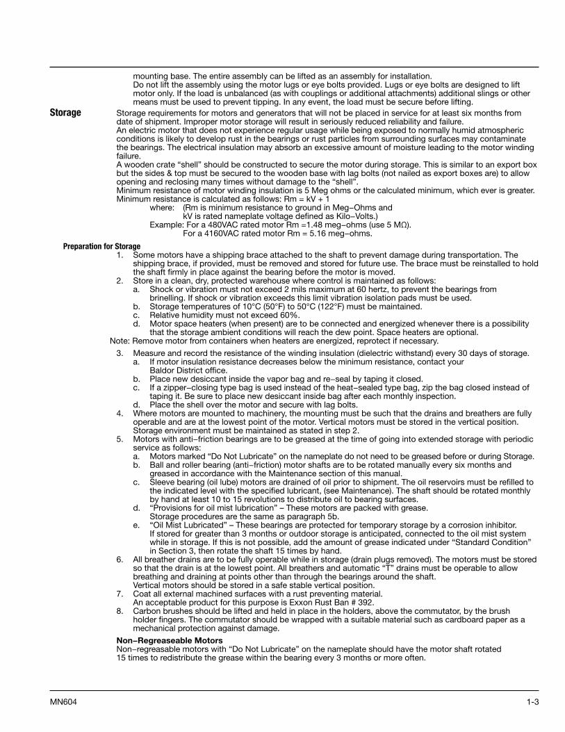
Storage Storage requirements for motors and generators that will not be placed in service for at least six months from date of shipment. Improper motor storage will result in seriously reduced reliability and failure.An electric motor that does not experience regular usage while being exposed to normally humid atmospheric conditions is likely to develop rust in the bearings or rust particles from surrounding surfaces may contaminate the bearings. The electrical insulation may absorb an excessive amount of moisture leading to the motor winding failure.A wooden crate “shell” should be constructed to secure the motor during storage. This is similar to an export box but the sides & top must be secured to the wooden base with lag bolts (not nailed as export boxes are) to allow opening and reclosing many times without damage to the “shell”.Minimum resistance of motor winding insulation is 5 Meg ohms or the calculated minimum, which ever is greater. Minimum resistance is calculated as follows: Rm = kV + 1 where: (Rm is minimum resistance to ground in Meg−Ohms and kV is rated nameplate voltage defined as Kilo−Volts.) Example: For a 480VAC rated motor Rm =1.48 meg−ohms (use 5 MΩ). For a 4160VAC rated motor Rm = 5.16 meg−ohms.
Preparation for Storage1. Some motors have a shipping brace attached to the shaft to prevent damage during transportation. The
shipping brace, if provided, must be removed and stored for future use. The brace must be reinstalled to hold the shaft firmly in place against the bearing before the motor is moved.
2. Store in a clean, dry, protected warehouse where control is maintained as follows: a. Shock or vibration must not exceed 2 mils maximum at 60 hertz, to prevent the bearings from
brinelling. If shock or vibration exceeds this limit vibration isolation pads must be used. b. Storage temperatures of 10°C (50°F) to 50°C (122°F) must be maintained. c. Relative humidity must not exceed 60%. d. Motor space heaters (when present) are to be connected and energized whenever there is a possibility
that the storage ambient conditions will reach the dew point. Space heaters are optional.Note: Remove motor from containers when heaters are energized, reprotect if necessary.
3. Measure and record the resistance of the winding insulation (dielectric withstand) every 30 days of storage. a. If motor insulation resistance decreases below the minimum resistance, contact your
Baldor District office. b. Place new desiccant inside the vapor bag and re−seal by taping it closed. c. If a zipper−closing type bag is used instead of the heat−sealed type bag, zip the bag closed instead of
taping it. Be sure to place new desiccant inside bag after each monthly inspection. d. Place the shell over the motor and secure with lag bolts.4. Where motors are mounted to machinery, the mounting must be such that the drains and breathers are fully
operable and are at the lowest point of the motor. Vertical motors must be stored in the vertical position. Storage environment must be maintained as stated in step 2.
5. Motors with anti−friction bearings are to be greased at the time of going into extended storage with periodic service as follows:
a. Motors marked “Do Not Lubricate” on the nameplate do not need to be greased before or during Storage. b. Ball and roller bearing (anti−friction) motor shafts are to be rotated manually every six months and
greased in accordance with the Maintenance section of this manual. c. Sleeve bearing (oil lube) motors are drained of oil prior to shipment. The oil reservoirs must be refilled to
the indicated level with the specified lubricant, (see Maintenance). The shaft should be rotated monthly by hand at least 10 to 15 revolutions to distribute oil to bearing surfaces.
d. “Provisions for oil mist lubrication” – These motors are packed with grease. Storage procedures are the same as paragraph 5b.
e. “Oil Mist Lubricated” – These bearings are protected for temporary storage by a corrosion inhibitor. If stored for greater than 3 months or outdoor storage is anticipated, connected to the oil mist system while in storage. If this is not possible, add the amount of grease indicated under “Standard Condition” in Section 3, then rotate the shaft 15 times by hand.
6. All breather drains are to be fully operable while in storage (drain plugs removed). The motors must be stored so that the drain is at the lowest point. All breathers and automatic “T” drains must be operable to allow breathing and draining at points other than through the bearings around the shaft. Vertical motors should be stored in a safe stable vertical position.
7. Coat all external machined surfaces with a rust preventing material. An acceptable product for this purpose is Exxon Rust Ban # 392.
8. Carbon brushes should be lifted and held in place in the holders, above the commutator, by the brush holder fingers. The commutator should be wrapped with a suitable material such as cardboard paper as a mechanical protection against damage.
Non−Regreaseable MotorsNon−regreasable motors with “Do Not Lubricate” on the nameplate should have the motor shaft rotated 15 times to redistribute the grease within the bearing every 3 months or more often.

1-4 MN604
All Other Motor TypesBefore storage, the following procedure must be performed.1. Remove the grease drain plug, if supplied, (opposite the grease fitting) on the bottom of each bracket prior
to lubricating the motor.2. The motor with regreasable bearing must be greased as instructed in Section 3 of this manual.3. Replace the grease drain plug after greasing.4. The motor shaft must be rotated a minimum of 15 times after greasing.5. Motor Shafts are to be rotated at least 15 revolutions manually every 3 months and additional grease
added every nine months (see Section 3) to each bearing.6. Bearings are to be greased at the time of removal from storage.
Removal From Storage1. Remove all packing material.2. Measure and record the electrical resistance of the winding insulation resistance meter at the time
of removal from storage. The insulation resistance must not be less than 50% from the initial reading recorded when the motor was placed into storage. A decrease in resistance indicates moisture in the windings and necessitates electrical or mechanical drying before the motor can be placed into service. If resistance is low, contact your Baldor District office.
3. Regrease the bearings as instructed in Section 3 of this manual.4. Reinstall the original shipping brace if motor is to be moved. This will hold the shaft firmly against the
bearing and prevent damage during movement.
EMC Compliance Statement for European UnionThe motors described in this instruction manual are designed to comply 2004/108/EC . These motors arecommercial in design and not intended for residential use. When used with converters, please consult converter manufacturers literature regarding recommendations on cable types, cable shielding, cable shielding termination, connection recommendations and any filters which may be recommended for EMC compliance. For additional information, consult Baldor MN1383.

2-1MN604
Section 2General Information
Overview Installation should conform to the National Electrical Code, IEC as well as local codes and practices.When other devices are coupled to the shaft, be sure to install protective devices to prevent futureaccidents. Some protective devices include, coupling, belt guard, chain guard, shaft covers etc.These protect against accidental contact with moving parts. Machinery that is accessible to personnelshould provide more protection in the form of guard rails, screening, warning signs etc.
ConsiderationsCaution: Do not lift the motor and its driven load by the motor lifting hardware. The motor lifting hardware is
adequate for lifting only the motor. Disconnect the load (gears, pumps, compressors, or other driven equipment) from the motor shaft before lifting the motor.
Caution: If eye bolts are used for lifting a motor, be sure they are securely tightened. The lifting direction should not exceed a 20° angle from the shank of the eye bolt or lifting lug. Excessive lifting angles can cause damage.After storage or after unpacking and inspection to see that all parts are in good condition, do the following:1. Rotate the motor or generator shaft by hand to be sure there are no obstructions to free rotation. 2. A motor or generator that has been in storage for >3 months should be tested for moisture (dielectric
withstand insulation test) and relubricated (if regreaseable type) prior to being put into service.3. A motor with roller bearings is shipped with a shaft block. After removing the shaft block, be sure to replace
any bolts used to hold the shaft block in place during shipment that are required in service.Caution: Do not use Silicone Sealing Compounds (RTV) on or in the vicinity of the motor or its air supply.
Silicone vapor inside the motor will result in extremely rapid brush wear.Location
Air Supply Sufficient clearance must be provided on all inlet and outlet openings to provide for unrestricted flow of air. Separately ventilated motors with exhaust to ambient (pipe-in only) must have at least 6 in (150mm) of clearance between the opening and adjacent walls or floor. Cooling air through a self−ventilated or forced−ventilated motor must be clean and have relative humiditybetween 30 and 100% with no free water in the air. Use of damp, cool outside air with high humidity andfree water may cause the motor to flash over. Extremely dry air may cause excessive brush andcommutator wear. Cooling air temperature must not exceed the maximum ambient temperature indicatedon the motor nameplate (Standard 40°C). Cooling air temperature must be less than than 0°C to providebase speed and regulation withinNEMA and IEC limits. Use of air <0°C may cause excessive brush andcommutator wear due to the low relative humidity. Cooling air absolute humidity must be at least 2 grainsper cu. ft.
Table 2-1 Required Air Volume
Frame Base Speed RPM
Required Air Flow Clearance
Air Volume Static Pressure
CFM M3/Sec in-H2O mm-H2O
DC180ATZ, C180ATZ and DC210ATZ
2500 8in (200mm) 152 0 .505 2 .00 50 .80
≤ 1750 12in (300mm) 105 0 .349 0 .95 24 .13
Ambient The motor or generator should be installed in a location compatible with the enclosure and specific ambient. Allow adequate air flow clearance between the motor and any obstruction, see Table 2−1.Locate the machine where the ambient temperature is not over 40°C (104°F) unless otherwise marked on the nameplate and where clean air has free access to ventilating intake and outlet openings. Except for machines with a suitable protective enclosure, the location should be clean and dry.
Note: Motors located in damp, moist environment must have space heater, or fields energized at 50% voltage to protect against condensation when motor is not operating.
Separately ventilated motors must have sufficient volume of air to adequately cool the motor unless the motor nameplate specifies a different value, see Table 2−1. If used, ventilating air filters must be kept clean or replaced to ensure full volume of cooling air.
Maximum Safe SpeedThe maximum safe speed shown on the nameplate is the maximum mechanical safe speed for motoroperation. This speed must not be exceeded under any condition. Motor control must not exceed themaximum speed for all load conditions including no−load. Drive systems whose design characteristicsinherently prevent the DC motor or generator from exceeding the maximum safe operating speed mustalso prevent the motor or generator from exceeding the maximum safe speed if a single componentfailure should occur.
Minimum Sheave DiametersTo avoid excessive bearing loads and shaft stresses, belts should not be tightened more than necessaryto transmit the rated torque. The pre−tensioning of the V−belt drive should be based on the totaltightening force required to transmit the horsepower divided by the number of belts.In general, the closer pulleys, sheaves, sprockets or gears are mounted to the bearing on the shaft, theless will be the load on the bearing. The center point of the belt, or system of V−belts, must not be beyondthe end of the shaft. The inner edge of the sheave or pulley rim should not be closer to the bearing thanthe shoulder on the shaft but should be as close to this point as possible.The outer edge of a chain sprocket or gear must not extend beyond the end of the shaft.
2-2 MN604
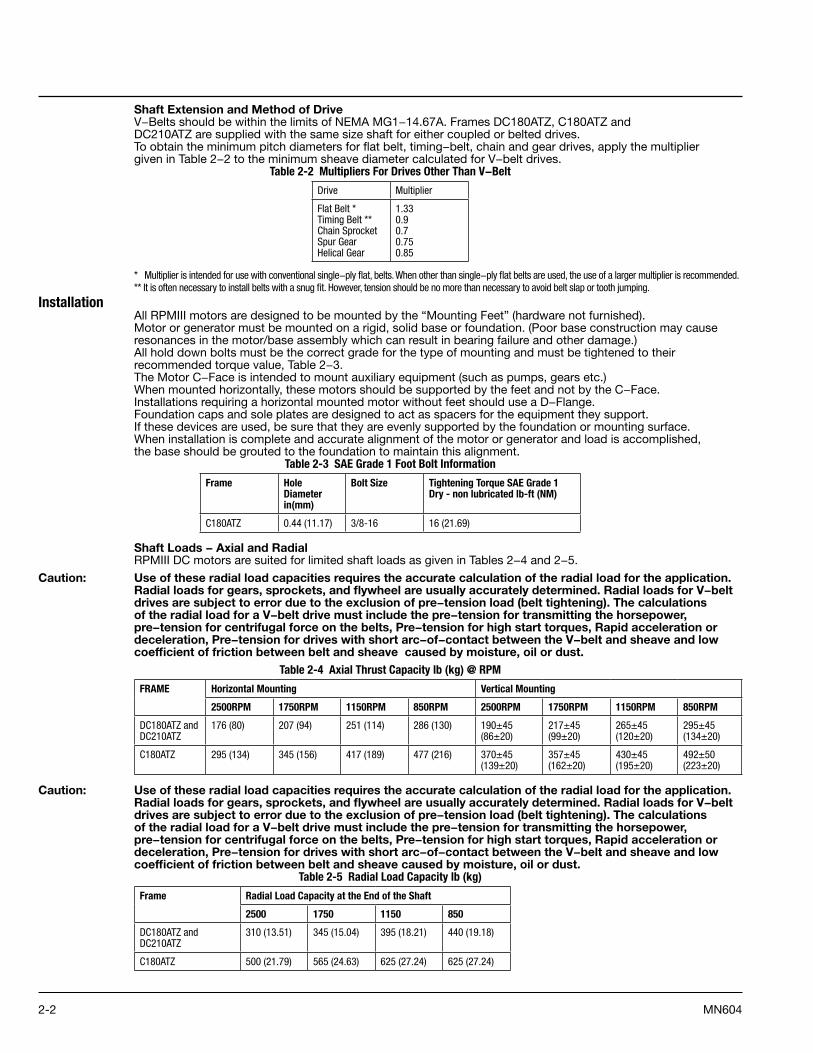
Shaft Extension and Method of DriveV−Belts should be within the limits of NEMA MG1−14.67A. Frames DC180ATZ, C180ATZ andDC210ATZ are supplied with the same size shaft for either coupled or belted drives.To obtain the minimum pitch diameters for flat belt, timing−belt, chain and gear drives, apply the multipliergiven in Table 2−2 to the minimum sheave diameter calculated for V−belt drives.
Table 2-2 Multipliers For Drives Other Than V−Belt
Drive Multiplier
Flat Belt * Timing Belt ** Chain Sprocket Spur Gear Helical Gear
1 .33 0 .9 0 .7 0 .75 0 .85
* Multiplier is intended for use with conventional single−ply flat, belts . When other than single−ply flat belts are used, the use of a larger multiplier is recommended .** It is often necessary to install belts with a snug fit . However, tension should be no more than necessary to avoid belt slap or tooth jumping .
Installation All RPMIII motors are designed to be mounted by the “Mounting Feet” (hardware not furnished).Motor or generator must be mounted on a rigid, solid base or foundation. (Poor base construction may cause resonances in the motor/base assembly which can result in bearing failure and other damage.)All hold down bolts must be the correct grade for the type of mounting and must be tightened to their recommended torque value, Table 2−3.The Motor C−Face is intended to mount auxiliary equipment (such as pumps, gears etc.) When mounted horizontally, these motors should be supported by the feet and not by the C−Face. Installations requiring a horizontal mounted motor without feet should use a D−Flange.Foundation caps and sole plates are designed to act as spacers for the equipment they support.If these devices are used, be sure that they are evenly supported by the foundation or mounting surface.When installation is complete and accurate alignment of the motor or generator and load is accomplished,the base should be grouted to the foundation to maintain this alignment.
Table 2-3 SAE Grade 1 Foot Bolt Information
Frame Hole Diameter in(mm)
Bolt Size Tightening Torque SAE Grade 1 Dry - non lubricated lb-ft (NM)
C180ATZ 0 .44 (11 .17) 3/8-16 16 (21 .69)
Shaft Loads − Axial and RadialRPMIII DC motors are suited for limited shaft loads as given in Tables 2−4 and 2−5.
Caution: Use of these radial load capacities requires the accurate calculation of the radial load for the application. Radial loads for gears, sprockets, and flywheel are usually accurately determined. Radial loads for V−belt drives are subject to error due to the exclusion of pre−tension load (belt tightening). The calculations of the radial load for a V−belt drive must include the pre−tension for transmitting the horsepower, pre−tension for centrifugal force on the belts, Pre−tension for high start torques, Rapid acceleration or deceleration, Pre−tension for drives with short arc−of−contact between the V−belt and sheave and low coefficient of friction between belt and sheave caused by moisture, oil or dust.
Table 2-4 Axial Thrust Capacity lb (kg) @ RPM
FRAME Horizontal Mounting Vertical Mounting
2500RPM 1750RPM 1150RPM 850RPM 2500RPM 1750RPM 1150RPM 850RPM
DC180ATZ and DC210ATZ
176 (80) 207 (94) 251 (114) 286 (130) 190±45 (86±20)
217±45 (99±20)
265±45 (120±20)
295±45 (134±20)
C180ATZ 295 (134) 345 (156) 417 (189) 477 (216) 370±45 (139±20)
357±45 (162±20)
430±45 (195±20)
492±50 (223±20)
Caution: Use of these radial load capacities requires the accurate calculation of the radial load for the application. Radial loads for gears, sprockets, and flywheel are usually accurately determined. Radial loads for V−belt drives are subject to error due to the exclusion of pre−tension load (belt tightening). The calculations of the radial load for a V−belt drive must include the pre−tension for transmitting the horsepower, pre−tension for centrifugal force on the belts, Pre−tension for high start torques, Rapid acceleration or deceleration, Pre−tension for drives with short arc−of−contact between the V−belt and sheave and low coefficient of friction between belt and sheave caused by moisture, oil or dust.
Table 2-5 Radial Load Capacity lb (kg)
Frame Radial Load Capacity at the End of the Shaft
2500 1750 1150 850
DC180ATZ and DC210ATZ
310 (13 .51) 345 (15 .04) 395 (18 .21) 440 (19 .18)
C180ATZ 500 (21 .79) 565 (24 .63) 625 (27 .24) 625 (27 .24)
2-3MN604
Shipping BlocksMotors supplied with roller bearings at the drive end are shipped with wooden blocking to prevent axial movement of the shaft during shipment. Remove the blocking and bolts securing it and discard. Make sure motor shafts turn freely. If motor is to be reshipped, blocking of bearing is required.
Alignment Accurate alignment of the motor with the driven equipment is extremely important. Proper alignment is akey step for long life of bearings, shafts and belts, and minimum downtime. Misalignment can causeexcessive vibration and damaging forces on shaft and bearings. For direct coupled drives, flexiblecouplings facilitate alignment. For belt drives, the driving and driven tension must be adjusted as requiredfor proper operation. The belt sheave should be placed as close as possible to the motor bracket.For direct drive, flexible couplings must be used between the motor shaft and the load shaft.Motor shaft and load shaft must be aligned to values recommended for the specific coupling beforecoupling is connected. Mechanical vibration and roughness during operation may indicate poor alignment.Use dial indicators to check alignment. The space between coupling hubs should be maintained asrecommended by the coupling manufacturer.
Caution: Series wound motors must never be allowed to run with no load (broken belt etc.) An unloaded motor may reach destructive high speeds.
Doweling & Bolting After proper alignment is verified, dowel pins should be inserted through the motor feet into the foundation. This will maintain the correct motor position should motor removal be required.(Baldor motors are designed for doweling.)1. Drill dowel holes in diagonally opposite motor feet in the locations provided.2. Drill corresponding holes in the foundation.3. Ream all holes.4. Install proper fitting dowels.5. Mounting bolts must be carefully tightened to prevent changes in alignment.
Use a flat washer and lock washer under each nut or bolt head to hold the motor feet secure. Flanged nuts or bolts may be used as an alternative to washers.
GuardingWARNING: Guards must be installed for rotating parts such as couplings, pulleys, external fans, belts, chains and
unused shaft extensions, should be permanently guarded to prevent accidental contact by personnel. Accidental contact with body parts or clothing can cause serious or fatal injury.Guards must be installed for rotating parts such as couplings, pulleys, external fans, and unused shaft extensions. This is particularly important where the parts have surface irregularities such as keys, key ways or set screws.Surface temperature of motor enclosure may reach temperatures which can cause discomfort or injury to personnel accidentally coming into contact with hot surfaces. When installing, protection should be provided by user to protect against accidental contact with hot surface.Some satisfactory methods of guarding are:1. Covering the machine and associated rotating parts with structural or decorative parts of the driven
equipment.2. Providing covers for the rotating parts. Covers should be sufficiently rigid to maintain adequate guarding
during normal service.Electrical InstallationWARNING: Do not touch electrical connections before you first ensure that power has been disconnected.
Electrical shock can cause serious or fatal injury. Only qualified personnel should attempt the installation, operation and maintenance of this equipment.
WARNING: The SCR Controller may apply hazardous voltages to the motor leads after power to the controller has been turned off. Verify that the controller is incapable of delivering hazardous voltages and that the voltage at the motor leads is zero before proceeding. Failure to observe this precaution may result in severe bodily injury or death.
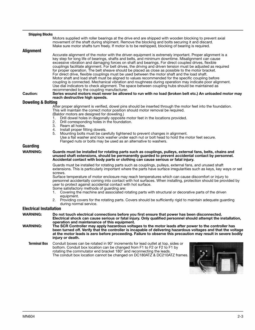
Terminal Box Conduit boxes can be rotated in 90° increments for lead outlet at top, sides or bottom. Conduit box location can be changed from F1 to F2 or F2 to F1 by rotating the commutator end bracket 180° and reconnecting the leads. The conduit box location cannot be changed on DC180ATZ & DC210ATZ frames.
2-4 MN604
Power Check the motor nameplate and the SCR Control nameplate to be sure the voltage and type of power rating is the same for both. The power code of the motor and power source should be the same. The letter code for the control may be equal or less than the motor. For example a motor with a “D” power code may be used on a supply with a “D” or “C” or less code. Table 2−6 defines these codes.
Table 2-6 Power Codes
Code Description
A DC Generator, battery or twelve pulse/cycle 6 phase, full control
C Six pulse/cycle, 3 phase, full control, 230VAC or 460VAC, 60Hz, input to rectifier .
D Three pulse/cycle, 3 phase, semi−bridge, half control, 230VAC or 460VAC, 60Hz, input to rectifier .
E Three pulse/cycle, 3 phase, half wave (single way), 460VAC, 60Hz, input to rectifier .
K Two pulse/cycle, single phase, full wave (bridge circuit with 2 controlled rectifiers and 2 uncontrolled rectifiers with free−wheeling rectifier), 230VAC, 60Hz, input to rectifier .
When the armature power supply cannot be designated by a single letter code (A−K) the power source can be determined by the code stamped on the nameplate: M/N F−V−H−L Where: M Total pulses per cycle N Total controlled pulses per cycle F Free Wheeling (if used), F=used, blank=not used V Nominal Line−to−Line voltage at input to rectifier H Line frequency (in Hz) L Value of inductance (in milli henries) to be added externally to the motor armature circuit
Example 1: “6/3 F-380-60-12”Requires a power supply with 6 total pulses per cycle, 3 controlled pulses per cycle (S-3), with free wheeling, 380 volts, 60 Hz AC input to bridge, and a 12 millinery choke to be added externally to the motor armature circuit.
WARNING: Be sure the system is properly grounded before applying power. Do not apply AC power before you ensure that all grounding instructions have been followed. Electrical shock can cause serious or fatal injury. National Electrical Code, IEC and Local codes must be carefully followed.
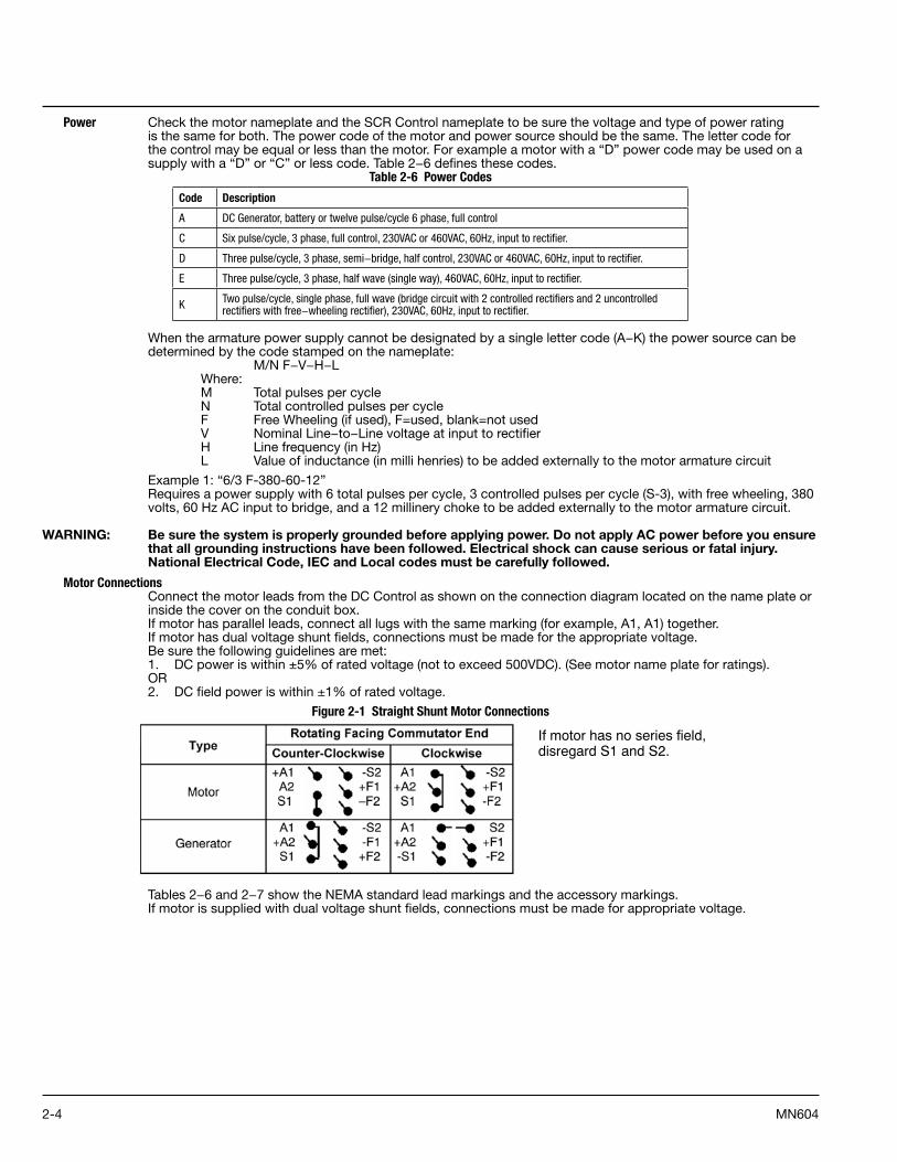
Motor Connections Connect the motor leads from the DC Control as shown on the connection diagram located on the name plate or inside the cover on the conduit box.If motor has parallel leads, connect all lugs with the same marking (for example, A1, A1) together.If motor has dual voltage shunt fields, connections must be made for the appropriate voltage.Be sure the following guidelines are met:1. DC power is within ±5% of rated voltage (not to exceed 500VDC). (See motor name plate for ratings).OR2. DC field power is within ±1% of rated voltage.
Figure 2-1 Straight Shunt Motor Connections
If motor has no series field, disregard S1 and S2.
Tables 2−6 and 2−7 show the NEMA standard lead markings and the accessory markings.If motor is supplied with dual voltage shunt fields, connections must be made for appropriate voltage.

2-5MN604
Table 2-7 NEMA Standard Lead Markings
Lead Markings Motor
Armature A1, A2
Field (shunt) F1, F2, F3, F4, etc .
Field (series) S1, S2
Thermostat P1, P2, etc .
Space Heater H1, H2, H3, H4, etc .
Thermal Protector P1, P2, P3, P4, etc .
Resistance Temperature Detector (RTD) R1, R2, R3, R4, etc .
Optional Brush Monitor System A1Probe, A2Probe
Table 2-8 Accessory Markings
DC Tachometers + —
XPY 1 2 G
XC Red (1) Black (2) G
RL
AC Tachometers 45/90V Output
45V Red White
90V Red Black
Brake Coil Leads B1, B2, B3, etc .
Space Heater (Brake) H1, H2, H3, H4, etc .
Brake Interlock Switch BS1, BS2, BS3, etc .
Thermostat ConnectionMotors may have one or more thermostats (leads marked P1, P2, etc.) to indicate motor overheating.Thermostat contacts must be connected in the motor control or indicating circuit. Failure to connect the thermostat leads will void the motor warranty. Thermostat contact ratings are listed below.Motors having thermistors or resistance temperature detectors to indicate motor over temperature must have these devices connected in the proper control circuit to protect the motor.Follow the SCR control instruction manual for correct thermostat lead connections.
Table 2-9 Thermostat Ratings
Maximum Current Ratings for Thermostats (Normally Open or Closed Contacts)
Voltage 250VAC
Rated Current 6 .3A
Maximum Current 20AGrounding
In the USA consult the National Electrical Code, Article 430 for information on grounding of motors and generators, and Article 250 for general information on grounding. In making the ground connection, the installer should make certain that there is a solid and permanent metallic connection between the ground point, the motor or generator terminal housing, and the motor or generator frame.Motors with resilient cushion rings usually must be provided with a bonding conductor across the resilient member. Some motors are supplied with the bonding conductor on the concealed side of the cushion ring to protect the bond from damage. Motors with bonded cushion rings should usually be grounded at the time of installation in accordance with the above recommendations for making ground connections. When motors with bonded cushion rings are used in multimotor installations employing group fusing or group protection, the bonding of the cushion ring should be checked to determine that it is adequate for the rating of the branch circuit over current protective device being used.There are applications where grounding the exterior parts of a motor or generator may result in greater hazard by increasing the possibility of a person in the area simultaneously contacting ground and some other nearby live electrical parts of other ungrounded electrical equipment. In portable equipment it is difficult to be sure that a positive ground connection is maintained as the equipment is moved, and providing a grounding conductor may lead to a false sense of security.Select a motor starter and over current protection suitable for this motor and its application. Consult motor starter application data as well as the National Electrical Code, IEC and/or other applicable local codes. Due to the higher switching frequencies of inverter controls, the ground connection/path must be low impedance, not only low resistance.

2-6 MN604
Overspeed Switch Motors having an overspeed switch must have the overspeed switch terminals properly connected in the control circuit to remove armature power when the motor reaches maximum speed.
Feedback Connections Tach or EncoderDue to the wide variety of brands and types of feedback devices available, please consult the installation and instruction diagrams provided with the device.
Blower Motor Connection Three phase blower motors.Blower cooled motors incorporate an independently powered three phase AC blower motor to assurecontinuous cooling air flow regardless of motor speed.The specific blower motor depends on frame size and enclosure.
Note: Blower motor fuse protection kits are required for blower motor overload protection.
WARNING: Guards must be installed for rotating parts such as couplings, pulleys, external fans, and unused shaft extensions, should be permanently guarded to prevent accidental contact by personnel. Accidental contact with body parts or clothing can cause serious or fatal injury.
WARNING: Be sure the system is properly grounded before applying power. Do not apply power before you ensure that all grounding instructions have been followed. Electrical shock can cause serious or fatal injury. National Electrical Code, IEC and Local codes must be carefully followed.
Caution: Do not operate motors with a roller bearing unless a radial load is applied so that damage to the roller bearing does not occur.
First Time Start Up If motor has been in storage or idle for some time, check winding insulation integrity.1. Be sure that all power to motor and accessories is off.2. Disconnect motor shaft from the load.3. Manually rotate the motor shaft to ensure that it rotates freely.4. The brushes should move easily in their holders and should make proper contact on the commutator.5. The interior of the motor should be clean and dry.6. Couple the load to the motor shaft.7. Install all panels and covers that were removed during installation.8. Verify the mechanical installation is secure. All bolts and nuts are tightened etc., covers and protective
devices are securely in their places.9. Remove all unused shaft keys and loose rotating parts to prevent them from flying off.10. The driven machine should be unloaded if possible.11. Ensure that all separately excited fields are excited at their rated voltage and that relative polarities of all
fields are correct. Refer to checking relative polarity of DC motor fields.12. When motor or generator is supplied as part of drive system, refer to the drive system instruction manual
for operating instructions. Tachometer feedback must be properly connected for closed loop operation. Reversed polarity or broken connections can cause dangerous overspeed conditions.
13. Inspect all electrical connections for proper termination, clearance, mechanical strength and electrical continuity.
14. Be sure all shipping materials and braces (if used) are removed from motor shaft.15. Unless otherwise ordered, brush rigging is assembled for standard direction of rotation, counterclockwise for
motors and clockwise for generators facing the commutator end. RPMIII motors and generators operate in either direction of rotation.
Caution: Motors designed for cooling by a separate source of forced ventilation must not be operated without the air supply. Be sure blower is running in proper direction to avoid motor overheating.16. Start the motor and ensure rotation is correct and operation is smooth without excessive vibration or noise. If
rotation direction is incorrect, change the direction in the SCR Control programming.Note: When starting, small sparks may appear on the commutator due to particles of dirt. Other than this, there
should be few if any, sparking at the brushes.
WARNING: Surface temperatures of motor enclosures may reach temperatures which can cause discomfort or injury to personnel accidentally coming into contact with hot surfaces. Protection should be provided by the user to protect against accidental contact with hot surfaces. Failure to observe this precaution could result in bodily injury.17. After 1 hour of operation, disconnect power and connect the load to the motor shaft.18. Verify all coupling guards and protective devices are installed. Ensure motor is properly ventilated.19. If motor is totally enclosed fan−cooled or non−ventilated it is recommended that condensation drain plugs, if
present, be removed. These are located in the lower portion of the end−shields. Totally enclosed fan−cooled “XT” motors are normally equipped with automatic drains which may be left in place as received.
While operating the motor, observe the performance. It should run smoothly with little noise. The bearings should not overheat and temperature should level off at normal operating temperature. Any undue noise, overheating, or erratic performance should be investigated and necessary corrective action taken immediately to prevent serious dam age. Refer to Maintenance and Troubleshooting section of this manual.All RPMIII motors are lubricated before shipment and will operate for a long period before regreasing is required. The period will vary depending on environmental and service conditions. Refer to Maintenance section.

2-7MN604
Operation ConsiderationsWARNING: Do not touch electrical connections before you first ensure that power has been disconnected. Electrical
shock can cause serious or fatal injury. Only qualified personnel should attempt the installation, operation and maintenance of this equipment.
WARNING: Surface temperatures of motor enclosures may reach temperatures which can cause discomfort or injury to personnel accidentally coming into contact with hot surfaces. When installing, protection should be provided by the user to protect against accidental contact with hot surfaces. Failure to observe this precaution could result in bodily injury.
WARNING: Incorrect motor rotation direction can cause serious or fatal injury or equipment damage. Be sure to verify motor rotation direction before coupling the load to the motor shaft.
WARNING: Guards must be installed for rotating parts such as couplings, pulleys, external fans, and unused shaft extensions, should be permanently guarded to prevent accidental contact by personnel. Accidental contact with body parts or clothing can cause serious or fatal injury.
WARNING: Thermostat contacts automatically reset when the motor has slightly cooled down. To prevent injury or damage, the control circuit should be designed so that automatic starting of the motor is not possible when the thermostat resets.
Caution: Do not operate motors with a roller bearing unless a radial load is applied so that damage to the roller bearing does not occur.BalanceMotors are dynamically balanced to commercial limits unless ordered differently, Table 2−10.Balance is done with a full length 1/2 height shaft key. A full shaft key is shipped with motor.Sheave or coupling should be balanced with a 1/2 height shaft key.
Table 2-10 Dynamic Balance Limits
Rated RPM Max Amplitude inches (mm)
1500−16000 1000−1499 <999
0 .0015 (0 .04) 0 .0020 (0 .05) 0 .0025 (0 .06)
SCR Control SettingsBe sure to properly set the Control parameters according to the Motor Nameplate ratings.Many parameter values can be set but as a minimum the following are very important:
Acceleration/Deceleration time Set according to the load requirements to prevent excess heat buildup.
Field Control Parameters Field Power Supply settings, limits and gain settings .
Control Output Limits Minimum and Maximum Speed values and Current Limit values .
Control Output Protection values Overload, Torque and other values to protect the motor .
Feedback parameters Set according to the feedback device being used .
Determining Motor ConstantsSeveral motor constants are necessary to program the correct values into the DC Motor Control settings.The following formulas and Table 2−11 make it possible to calculate these values from information on theMotor nameplate.
La = La x VaRPM
2 Arm. Cir. Inductance (milli henries)
Ra = Ra x VaRPM
2
Arm. Cir. Resistance (ohms)e e
e LaRa
x 103
J (sec) = WK2 x RPM2
1.62 x 10⁶ x hp where WK2 is in terms of lb−ft2
J (sec) = WK2 x RPM2
0.0922 x 10⁶ x kw where WK2 is in terms of kg−M2
RLa x Ra
Va LaRa
Table 2-11 Inductance and Resistance Factors
Frame SizeWk2
Ra9 La9 τe9lb-ft2 kg-m2
DC210ATZ and DC180ATZ 0 .683 0 .029 56 .6 616 0 .011
C180ATZ 0 .787 0 .033 49 .5 500 0 .012
Table 2−11 is for estimating purposes only .

2-8 MN604
Suggested bearing and winding RTD setting guidelines for Non−Hazardous Locations ONLYThe following table shows the suggested alarm and trip settings for RTDs. Proper bearing and winding RTD alarm and trip settings should be selected based on these tables unless otherwise specified for specific applications.If the driven load is found to operate well below the initial temperature settings under normal conditions, the alarm and trip settings may be reduced so that an abnormal machine load will be identified.The temperature limits are based on the installation of the winding RTDs imbedded in the winding as specified by NEMA. Bearing RTDs should be installed so they are in contact with the outer race on ball or roller bearings or in direct contact with the sleeve bearing shell.
Winding RTDs − Temperature Limit In °C (40°C Maximum Ambient)
Type Class F Temp Rise = 100°C Class H Temp Rise = 130°C
Alarm Trip Alarm Trip
Winding 130 140 160 170
Bearing 100 110 100 110
Note: Winding RTDs are factory production installed, not from Mod−Express .

3-1MN604
Section 3Maintenance & Troubleshooting WARNING: UL Listed motors must only be serviced by UL Approved Authorized Baldor Service Centers if these
motors are to be returned to a hazardous and/or explosive atmosphere.WARNING: Do not touch electrical connections before you first ensure that power has been disconnected. Electrical
shock can cause serious or fatal injury. Only qualified personnel should attempt the installation, operation and maintenance of this equipment.
WARNING: The SCR Controller may apply hazardous voltages to the motor leads after power to the controller has been turned off. Verify that the controller is incapable of delivering hazardous voltages and that the voltage at the motor leads is zero before proceeding. Failure to observe this precaution may result in severe bodily injury or death.
WARNING: Surface temperatures of motor enclosures may reach temperatures which can cause discomfort or injury to personnel accidentally coming into contact with hot surfaces. When installing, protection should be provided by the user to protect against accidental contact with hot surfaces. Failure to observe this precaution could result in bodily injury.
WARNING: Guards must be installed for rotating parts such as couplings, pulleys, external fans, and unused shaft extensions, should be permanently guarded to prevent accidental contact by personnel. Accidental contact with body parts or clothing can cause serious or fatal injury.
General Inspection Inspect the motor at regular intervals, approximately every 500 hours of operation or every 3 months, whichever occurs first. Keep the motor clean and the ventilation openings clear. The following steps should be performed at each inspection:1. Check that the motor is clean. Check that the interior and exterior of the motor is free of dirt, oil, grease,
water, etc. Oily vapor, paper pulp, textile lint, etc. can accumulate and block motor ventilation. If the motor is not properly ventilated, overheating can occur and cause early motor failure.
2. Perform a dielectric with stand test periodically to ensure that the integrity of the winding insulation has been maintained. Record the readings. Immediately investigate any significant decrease in insulation resistance.
3. Check all electrical connectors to be sure that they are tight.4. If used, ventilating air filters must be kept clean or replaced to ensure full volume of cooling air.
Caution: Do not use Silicone grease or Sealing Compounds (RTV) on or in the vicinity of the motor or its air supply. Silicone vapor inside the motor will result in extremely rapid brush wear.
Relubrication & Bearings Bearing grease will lose its lubricating ability over time, not suddenly.The lubricating ability of a grease (over time) depends primarily on the type of grease, the size of the bearing, the speed at which the bearing operates and the severity of the operating conditions.Good results can be obtained if the following recommendations are used in your maintenance program.Relubrication with the shaft stationary and a warm motor is recommended.
Procedure RPMIII motors have the exclusive Positive Lubrication System PLS which routes new grease directly into the bearing. The relubrication periods shown in Table 3-3 are offered as a guide for varying service conditions, speeds, bearing types and operating hours.
Note: Certain special motors may have a lubrication instruction plate permanently attached.
These specific lubricating instructions must be followed.
1. Relubrication with the shaft stationary and a warm motor is recommended. If lubrication must be done with motor running, stay clear of rotating parts and electrical circuits.
2. Wipe all dirt from the outside of the grease fills and drains.3. Locate the grease inlet at the top of the bearing hub, clean the area and replace the 1/8−inch pipe plug with
a grease fitting if the motor is not equipped with grease fitting.4. Remove grease drain plug located opposite the grease inlet.5. If used, ventilating air filters must be kept clean or replaced to ensure full volume of cooling air.
Caution: Do not use Silicone grease or Sealing Compounds (RTV) on or in the vicinity of the motor or its air supply. Silicone vapor inside the motor will result in extremely rapid brush wear.6. Use the correct grease. If the motor nameplate does not specify a special grease use the following:
Mobil Polyrex EM or equivalent grease.
Using a manual grease gun, pump in the recommended grease in the amount shown, Table 3-1.This amount of grease will provide an ample supply of lubricant between lubrication periods for the service condition listed in Tables 3-2 and 3-3. Use only clean, fresh grease from clean containers and handle so as to keep it clean. In general, mixing of greases is not recommended. If an incompatible grease is used, the lube system must be thoroughly cleaned and repacked completely with the new grease.
7. Wipe away any excess grease at the grease drain or relief and replace drain plugs.
3-2 MN604
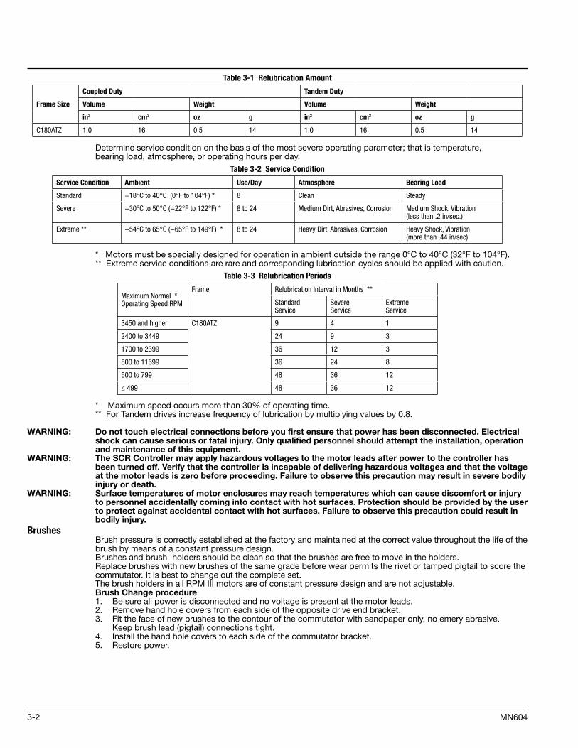
Table 3-1 Relubrication Amount
Frame Size
Coupled Duty Tandem Duty
Volume Weight Volume Weight
in3 cm3 oz g in3 cm3 oz g
C180ATZ 1 .0 16 0 .5 14 1 .0 16 0 .5 14
Determine service condition on the basis of the most severe operating parameter; that is temperature,bearing load, atmosphere, or operating hours per day.
Table 3-2 Service Condition
Service Condition Ambient Use/Day Atmosphere Bearing Load
Standard −18°C to 40°C (0°F to 104°F) * 8 Clean Steady
Severe −30°C to 50°C (−22°F to 122°F) * 8 to 24 Medium Dirt, Abrasives, Corrosion Medium Shock, Vibration (less than .2 in/sec .)
Extreme ** −54°C to 65°C (−65°F to 149°F) * 8 to 24 Heavy Dirt, Abrasives, Corrosion Heavy Shock, Vibration (more than .44 in/sec)
* Motors must be specially designed for operation in ambient outside the range 0°C to 40°C (32°F to 104°F).** Extreme service conditions are rare and corresponding lubrication cycles should be applied with caution.
Table 3-3 Relubrication Periods
Maximum Normal * Operating Speed RPM
Frame Relubrication Interval in Months **
Standard Service
Severe Service
Extreme Service
3450 and higher C180ATZ 9 4 1
2400 to 3449 24 9 3
1700 to 2399 36 12 3
800 to 11699 36 24 8
500 to 799 48 36 12
≤ 499 48 36 12
* Maximum speed occurs more than 30% of operating time.** For Tandem drives increase frequency of lubrication by multiplying values by 0.8.
WARNING: Do not touch electrical connections before you first ensure that power has been disconnected. Electrical shock can cause serious or fatal injury. Only qualified personnel should attempt the installation, operation and maintenance of this equipment.
WARNING: The SCR Controller may apply hazardous voltages to the motor leads after power to the controller has been turned off. Verify that the controller is incapable of delivering hazardous voltages and that the voltage at the motor leads is zero before proceeding. Failure to observe this precaution may result in severe bodily injury or death.
WARNING: Surface temperatures of motor enclosures may reach temperatures which can cause discomfort or injury to personnel accidentally coming into contact with hot surfaces. Protection should be provided by the user to protect against accidental contact with hot surfaces. Failure to observe this precaution could result in bodily injury.
Brushes Brush pressure is correctly established at the factory and maintained at the correct value throughout the life of the brush by means of a constant pressure design.Brushes and brush−holders should be clean so that the brushes are free to move in the holders.Replace brushes with new brushes of the same grade before wear permits the rivet or tamped pigtail to score the commutator. It is best to change out the complete set.The brush holders in all RPM III motors are of constant pressure design and are not adjustable. Brush Change procedure1. Be sure all power is disconnected and no voltage is present at the motor leads.2. Remove hand hole covers from each side of the opposite drive end bracket.3. Fit the face of new brushes to the contour of the commutator with sandpaper only, no emery abrasive.
Keep brush lead (pigtail) connections tight.4. Install the hand hole covers to each side of the commutator bracket.5. Restore power.
3-3MN604
CommutatorA commutator in good condition is clean and smooth with a medium polish and a light brown color.Keep clean by occasionally wiping with a canvas pad.Use no lubricant or emery abrasive.If a commutator becomes rough, it needs to be resurfaced.
BrakesMotor mounted brake, when supplied, must be adjusted and maintained in accordance with the instructions for the specific brake. Refer to separate instructions supplied.
TroubleshootingWARNING: Do not touch electrical connections before you first ensure that power has been disconnected. Electrical
shock can cause serious or fatal injury. Only qualified personnel should attempt the installation, operation and maintenance of this equipment.
WARNING: The SCR Controller may apply hazardous voltages to the motor leads after power to the controller has been turned off. Verify that the controller is incapable of delivering hazardous voltages and that the voltage at the motor leads is zero before proceeding. Failure to observe this precaution may result in severe bodily injury or death.
WARNING: Surface temperatures of motor enclosures may reach temperatures which can cause discomfort or injury to personnel accidentally coming into contact with hot surfaces. Protection should be provided by the user to protect against accidental contact with hot surfaces. Failure to observe this precaution could result in bodily injury.
Armature Overheating Excessive overloads will cause a noticeable odor of overheated varnish or charred insulation.The commutator may eventually become blackened and pitted and the brushes burned. This overheating may be general and uniform. Remedy, remove the overload and rewind or replace armature if damaged beyond use.An open-circuited armature coil will cause flashing at the commutator. Two adjacent bars will show severe burning and a resulting overheated armature. Short-circuited coils or commutator bars may cause local heating that could destroy the insulation at that spot. This may result in the burning of the armature coils, banding or commutator bars.Grounds in the armature circuit may be found by measuring insulation resistance from the motor frame and to a commutator bar. If the armature is grounded, the resistance is less than 1 meg ohm.
Field Coil Overheating The blowers or external cooling systems must remain in operation if the main field windings remain fully energized with the motor at standstill. Failure to do so may cause too much heat build-up which could cause reduced insulation life.When using field economy circuits to reduce voltage to the main fields during standstill, blowers do not need to be operating. The most common failure with overheated field coils is a short in one or more of the shunt coils.Shorted coils show less than line voltage. This is with the fields connected for high voltage (in series). A grounded coil may cause overheating. This defect may be tested as shown by the ground test for an armature. With brushes lifted, place one test point of the megger on either field lead, the other on the motor frame. The megger will read less than 1 meg ohm, if a grounded coil is present.An open field coil on a motor will cause the armature to have no torque. The motor may run at a very high speed at no load. The commutator may be flashing. To locate an open coil, apply line voltage to the shunt coils (brushes lifted). A voltmeter will show no reading across a good coil. It will show about the line voltage across the open coil.These tests should be done by experienced and qualified personnel. If you find any of these defects, don’t run the motor. Contact your local Baldor District Office.
Excessive Load Excessive load may be found by checking the DC armature ampere input and comparing it with the rating on the nameplate. An excessive load may prevent the motor from starting or accelerating to full load speed. It could finally result in premature failure of the motor or control. Be sure to use an averaging type ammeter if the motor’s power is coming from a rectifier or SCR control.
Jogging and Repeated StartsRepeated starts or jogs of motors may reduce the life of the brushes and winding insulation. The heat produced by excessive starting may be more than what can be dissipated by the motor under a constant full load conditions. If you must frequently start or jog a motor, you should check the application with the local Baldor District Office.
Heating Duty cycle and maximum ambient temperature are shown on the nameplate of the motor. If there is any question about safe operation, contact the local Baldor District Office.Motor overheating may be caused by improper ventilation, excessive ambient temperature, dirty conditions or an inoperable blower or dirty filter. Electrical causes may be due to excess current caused by an overload or over-voltage to the fields.

3-4 MN604
Thermostat Most stock Baldor DC motors 180 frame and above have a standard temperature-sensing thermostat mounted to their interpole winding. This normally closed thermostat opens when the temperature limit is exceeded. Another option available is a normally open thermostat that closes with temperature.On blower cooled or separately ventilated motors, the protection capabilities of the thermostats are greatly reduced at low speeds. This is because the interpoles have the same amount of heat transfer regardless of speed. Armature heat transfer is less at low speed. There is less internal air turbulence at low speeds causing higher temperatures at the armature. RPMIII motors are designed with the thermostat located in the end of the motor, opposite the blower.The thermal time constant for interpoles can be as much as five times longer than the armature’s time constant. Because of this, the thermostat cannot be relied upon to protect the armature during extreme overloads lasting a short time.The ripple of the rectified power supply and manufacturing tolerances of mounting the device affect the thermostat’s accuracy.For thermostat contact ratings, refer to Thermostats in Section 2 of this manual.
Checking Relative Polarity of DC Motor FieldsMotor speed is unstable if speed increases due to an increase in load current. As a result of instability, motor speed may hunt or overspeed. One possible cause of unstable performance of shunt wound DC motors is incorrect series field polarity relative to the shunt field due to improper connection.Relative polarity of the shunt and series fields can be checked as follows:1. Connect a low scale (3 volts) DC voltmeter across the shunt field terminals P1 and P2 with P1 connected to
the positive (+) meter terminal. At least one of the shunt field leads must be disconnected from the controller.2. Use two flashlight batteries as a source of low voltage (3 volts). Connect the negative battery post to the S-2
series field terminal. Hold one end of a jumper wire to the positive (+) battery post so the other end of the wire can be used to make and break contact with the S-1 series field terminal.
3. The procedure is to watch the deflection of the voltmeter needle when contact is made with S- I and when contact is broken.
4. When contact is made, the needle will first deflect in either the up scale or down scale direction and then return to zero. Deflection will be in the opposite direction when contact is broken.
5. Relative polarities of the shunt and series fields are correct (ampere-turns are cumulative) if the voltmeter needle deflects up scale when contact is made and down scale when contact is broken.
6. Relative polarities of the shunt and series fields are incorrect (ampere-turns are differential) if the voltmeter needle deflects down scale when contact is made and up scale when contact is broken. The motor connections must be changed so that relative polarity is correct.
If only one series field terminal is available at the controller, use it and the available armature terminal for the test. For example, use S-2 and A-1 if S-1 and A-2 are connected together at the motor and not brought to the controller.
Humidity And Brush Wear This curve represents 2 grains of water per cubic foot of dry air or 4.6 grams per cubic meter of dry air.
Zone of Safe Brush Operation 110
100
90
80
70
60
50
40
30
45
40
35
30
25
20
15
10
5
0
10 20 30 40 50 60 70 80 90 100
Percent Relative Humidity
Tem
pera
ture
Deg
rees
F
Tem
pera
ture
Deg
rees
C
Danger ZoneToo Low Humidity
3-5MN604
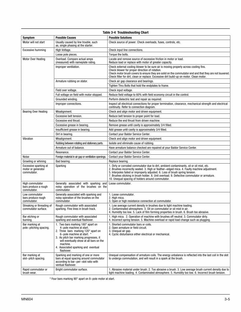
Table 3-4 Troubleshooting Chart Symptom Possible Causes Possible SolutionsMotor will not start Usually caused by line trouble, such
as, single phasing at the starter .Check source of power . Check overloads, fuses, controls, etc .
Excessive humming High Voltage . Check input line connections .
Loose pole pieces . Torque the bolts .
Motor Over Heating Overload . Compare actual amps (measured) with nameplate rating .
Locate and remove source of excessive friction in motor or load . Reduce load or replace with motor of greater capacity .
Improper ventilation . Check external cooling blower to be sure air is moving properly across cooling fins . Check blower for proper direction of rotation .Check motor brush covers to ensure they are solid on the commutator end and that they are not louvered .Check filter for dirt, clean or replace . Excessive dirt build-up on motor . Clean motor .
Armature rubbing on stator . Check air gap clearance and bearings .
Tighten Thru Bolts that hold the endplates to frame .
Field over voltage . Check input voltage .
Full voltage on field with motor stopped . Reduce field voltage to 60% with field economy circuit in the control .
Grounded winding . Perform dielectric test and repair as required .
Improper connections . Inspect all electrical connections for proper termination, clearance, mechanical strength and electrical continuity . Refer to connection diagram .
Bearing Over Heating Misalignment . Check and align motor and driven equipment .
Excessive belt tension . Reduce belt tension to proper point for load .
Excessive end thrust . Reduce the end thrust from driven machine .
Excessive grease in bearing . Remove grease until cavity is approximately 3/4 filled .
Insufficient grease in bearing . Add grease until cavity is approximately 3/4 filled .
Dirt in bearing . Contact your Baldor Service Center .
Vibration Misalignment . Check and align motor and driven equipment .
Rubbing between rotating and stationary parts . Isolate and eliminate cause of rubbing .
Armature out of balance . Have armature balance checked are repaired at your Baldor Service Center .
Resonance . Contact your Baldor Service Center .
Noise Foreign material in air gap or ventilation openings . Contact your Baldor Service Center .
Growling or whining Bad bearing . Replace bearing .
Excessive sparking at motor or generator commutator .
Sparking 1 . Dirty or corroded commutator due to dirt, ambient contaminants, oil or oil mist, etc . 2 . Brushes incorrectly seated . 3 . High or feather−edged mica . 4 . Faulty machine adjustment . 5 . Interpoles failed or improperly adjusted . 6 . Loss of brush spring tension . 7 . Brushes sticking in brush holder . 8 . Unit overload . 9 . Defective commutator or armature . 10 . Unequal spacing of holders around commutator .
High commutator bars produce a rough commutator .
Generally associated with sparking and noisy operation of the brushes on the commutator .
Loose commutator .
Low commutator bars produce rough commutator .
Generally associated with sparking and noisy operation of the brushes on the commutator .
1 . Loose commutator . 2 . High mica . 3 . Open or high resistance connection at commutator .
Streaking or threading of commutator surface .
Rough commutator with associated sparking . Fine lines in brush track .
1 . Low average current density in brushes due to light machine loading . 2 . Contaminated atmosphere . 3 . Oil on commutator or oil mist in air . 4 . Humidity too low . 5 . Lack of film forming properties in brush . 6 . Brush too abrasive .
Bar etching or burning .
Rough commutator with associated sparking and eventual flashover .
1 . High mica . 2 . Operation of machine with brushes off neutral . 3 . Commutator dirty . 4 . Incorrect spring tension . 5 . Machine overload or rapid load change such as plugging .
Bar marking at pole−pitching spacing .
1 . Two bars marking 180° apart on 4−pole machine at start .
2 . Three bars marking 120° apart on 6−pole machine at start . *
3 . As pitch bar marking progresses, it will eventually show at all bars on the machine .
4 . Associated sparking and eventual flashover .
1 . Shorted commutator bars or coils . 2 . Open armature or field circuit . 3 . Unequal air gap . 4 . Cyclic disturbance either electrical or mechanical .
Bar marking at slot−pitch spacing .
Sparking and marking of one or more bars at equal spacing around commutator according to bar−per−slot ratio with ventual flashover .
Unequal compensation of armature coils . The energy unbalance is reflected into the last coil in the slot to undergo commutation, and will result in a spark at the brush .
Rapid commutator or brush wear .
Bright commutator surface . 1 . Abrasive material under brush . 2 . Too abrasive a brush . 3 . Low average brush current density due to light machine loading . 4 . Contaminated atmosphere . 5 . Humidity too low . 6 . Incorrect brush tension .
* Four bars marking 90° apart on 8−pole motor at start .

3-6 MN604
Guide To Commutator Appearance (This chart courtesy of Helwig Carbon Products, Inc ., Milwaukee, WI)
Light Film: Indicates good brushperformance. Light load, low humidity,brush grades with low filming rates, or filmreducing contamination can cause lightercolor.
Medium Film: Is the ideal commutatorcondition for maximum brush andcommutator life.
Heavy Film: Results from high load, highhumidity or heavy filming rate grades. Colorsnot in the brown tones indicate contaminationresulting in high friction and high resistance.
Streaking: Results from metal transfer tothe brush face. Light loads and/or lightspring pressure are most common causes.Contamination can also be a contributingfactor.
Threading: Is a further development of thestreaking condition as the metaltransferred becomes work hardened andmachines into the commutator surface.With increased loads and increased springpressure this condition can be avoided.
Grooving: May result from an overlyabrasive brush grade. The more commoncause is poor electrical contact resulting inarcing and the electrical machining of thecommutator surface. Increased springpressure reduces this electrical wear.
Copper Drag: Develops as the commutatorsurface becomes overheated andsoftened. Vibration or an abrasive gradecauses the copper to be pulled across theslots. Increased spring pressure willreduce commutator temperature.
Bar Edge Burning: Results from poorcommutation. Check that brush grade hasadequate voltage drop, that the brushesare properly set on neutral and that theinterpole strength is correct.
Slot Bar Marking: Results from a fault inthe armature windings. The pattern relatesto the number of conductors per slot.
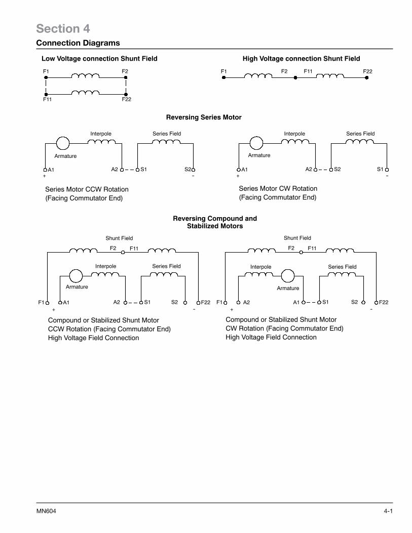
4-1MN604
Section 4Connection Diagrams
Low Voltage connection Shunt Field
F11 F22
F1 F2 F11 F22F1 F2
High Voltage connection Shunt Field
Reversing Series Motor
Interpole
Armature
A1+
A2 S2S1--
Series Field
Series Motor CCW Rotation(Facing Commutator End)
A1+
A2 S1S2
Interpole
Armature
Series Field
Series Motor CW Rotation(Facing Commutator End)
--
Armature
A1+
A2 S2S1
Compound or Stabilized Shunt MotorCCW Rotation (Facing Commutator End)High Voltage Field Connection
Shunt Field
F1
F2 F11
1A22F+
A2 S2S1
Shunt Field
F1
F2 F11
F22
Reversing Compound andStabilized Motors
Compound or Stabilized Shunt MotorCW Rotation (Facing Commutator End)High Voltage Field Connection
-- --
dleiFseireSelopretnIInterpole Series Field
Armature
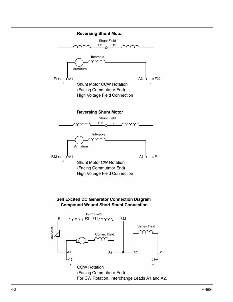
4-2 MN604
A1+
A2F1
F2 F11
F22
A1+
A2F22
F11 F2
F1
+
Rhe
osta
t
F1 F2 F11 F22
A1 A2 S2 S1
Reversing Shunt Motor
Shunt Motor CCW Rotation (Facing Commutator End)High Voltage Field Connection
−
Armature
Shunt Field
Interpole
Series Field
Comm. Field
Shunt Field
Shunt Motor CW Rotation (Facing Commutator End)High Voltage Field Connection
Armature
Shunt Field
Interpole
Reversing Shunt Motor
−
CCW Rotation (Facing Commutator End)For CW Rotation, Interchange Leads A1 and A2.
Self Excited DC Generator Connection Diagram Compound Wound Short Shunt Connection
−


Baldor Electric Company
P.O. Box 2400, Fort Smith, AR 72902-2400 U.S.A., Ph: (1) 479.646.4711, Fax (1) 479.648.5792, International Fax (1) 479.648.5895 www.baldor.com
© Baldor Electric CompanyMN604
All Rights Reserved. Printed in USA.1/09
Related Documents