DEVELOPMENT OF DC-DC CONVERTER FOR DC MOTOR USING FUZZY LOGIC CONTROLLER MOHD FAIZ HUSNY BIN YUSOF A project report submitted in partial fulfilment of the requirement for the award of the Degree of Master of Electrical Engineering Faculty of Electrical and Electronics Engineering Universiti Tun Hussein Onn Malaysia

Welcome message from author
This document is posted to help you gain knowledge. Please leave a comment to let me know what you think about it! Share it to your friends and learn new things together.
Transcript
DEVELOPMENT OF DC-DC CONVERTER FOR DC MOTOR USING
FUZZY LOGIC CONTROLLER
MOHD FAIZ HUSNY BIN YUSOF
A project report submitted in partial
fulfilment of the requirement for the award of the
Degree of Master of Electrical Engineering
Faculty of Electrical and Electronics Engineering
Universiti Tun Hussein Onn Malaysia
V
ABSTRACT
When the DC motor is turned on, the start dc motor speed will experience overshoot
at the starting speed of the motor. This overshoot will affect the current rise high as if
connected to a load. The use of conventional controllers has long been used to
control the dc motor and reduce overshoot starting. Fuzzy logic controller is one
controller that can be used to control the speed of a dc motor including motor control
overshoot starting. To see the effectiveness of fuzzy logic controller in dc motor
speed control, a study done by designing a conventional two-Integrated controllers of
proportional controller (PI) and proportional-Integrated-Derivatives controller (PID)
and compared with fuzzy logic controller. The design of Fuzzy Logic Controller
(FLC) does not require an exact mathematical model. Instead, it is design based on
general knowledge of the plant. Both three controllers are connected to a dc motor as
a load to control the motor speed to the required level. The effectiveness of the
designed FLC is compared with designed conventional controllers to examine
aspects of starting overshoot, settling time and ripple factor for dc motor speed.
VI
ABSTRAK
Apabila dc motor dihidupkan, kelajuan permulaan motor arus terus akan mengalami
lanjakan semasa permulaan motor. Lanjakan ini akan memberi kesan seperti
kenaikan arus yang tinggi jika disambungkan kepada beban. Penggunaan pengawal
konvensional telah lama digunakan bagi mengawal motor arus terus dan
mengurangkan lanjakan permulaan kelajuan. Fuzzy logic controller merupakan salah
satu pengawal yang boleh digunakan untuk mengawal kelajuan sesebuah motor arus
terus termasuklah mengawal lanjakan kelajuan permulaan motor. Bagi melihat
keberkesanan pengawal logic kabur (FLC) dalam mengawal kelajuan motor arus
terus, kajian dilakukan dengan membina dua pengawal konvensional iaitu
Proportional-Integrated controller (PI) dan Proportional-Integrated-Derivatives
controller (PID). Reka bentuk FLC tidak memerlukan model matematik yang tepat.
Sebaliknya, ia adalah reka bentuk berdasarkan kepada pengetahuan am tentang
pengawal. Ketiga-tiga penagawal ini disambungkan kepada motor arus terus sebagai
beban bagi mengawal kelajuan motor ke tahap yang dikehendaki. Keberkesanan FLC
dibandingkan dengan pengawal konvensional dengan meneliti aspek lanjakan
permulaan kelajuan motor, penetapan masa dan factor riak bagi kelajuan motor arus
terus.
VII
CONTENTS
TITLE I
DECLARATION II
DEDICATION III
ACKNOWLEDGEMENT IV
ABSTRACT V
CONTENTS VII
LIST OF FIGURES IX
LIST OF TABLES XI
LIST OF SYMBOLS AND ABBREVIATIONS XII
CHAPTER 1 INTRODUCTION 1
1.1 Project Overview 1
1.2 Problem Statement 3
1.3 Project Objectives 4
1.4 Scope of Project 4
CHAPTER 2 LITERATURE REVIEW 5
2.1 Existing Papers 5
2.2 DC-DC Converter 6
2.2.1 Buck Converter 8
2.3 Fuzzy Logic Controller (FLC) 9
2.4 Motor Model 14
2.4.1 Transfer Function 15
2.5 PID Controller 16
VIII
CHAPTER 3 METHODOLOGY 18
3.1 Project Design 18
3.2 Proposed DC Motor 20
3.3 Proposed PI Controller 21
3.4 Proposed PID Controller 21
3.5 Proposed Fuzzy Controller 22
3.6 Fuzzy Logic Controller Design 22
3.6.1 Fuzzification Interface 22
3.6.2 Fuzzy Rules 24
3.6.3 Defuzzification Interface 27
CHAPTER 4 RESULT AND DISCUSSION 28
4.1 Introduction 28
4.2 Simulation Model for DC Motor 28
4.3 Simulation Model For Buck Converter 30
4.4 Simulation Model For PI Controller 30
4.5 Simulation model of DC-DC Buck converter 31
with PI controller
4.6 Simulation model of DC-DC Buck converter 33
with PID controller
4.7 Simulation model of DC-DC Buck converter 34
with Fuzzy Logic Controller
4.8 Comparison between PI and PID controller and 36
Fuzzy Logic Controller (FLC)
CHAPTER 5 CONCLUSION AND RECOMMENDATION 38
5.1 Conclusion 38
5.2 Future Works 38
REFERENCES 39
IX
LIST OF FIGURES
2.1 Equivalent Circuit of Buck Converter 8
2.2 Output Waveform of Buck Converter 8
2.3 Structure of FLC 10
2.4 Block Diagram of the FLC for DC-DC Converters 10
2.5 Block Diagram of Fuzzy Control Scheme for DC-DC Converter 11
2.6 Block Diagram of Fuzzy Logic Controller 13
2.7 A Block Diagram of the DC Motor 15
2.8 MATLAB/Simulink Model of DC Motor 16
2.9 PID Control Structure 17
3.1 Block Diagram for Propose DC-DC Buck Converter using 18
Fuzzy Logic Controller
3.2 The Flow Chart of Methodology 19
3.3 Proposed Design of DC Motor 20
3.4 The model for PI controller in MATLAB/Simulink 21
3.5 The model for PID controller in MATLAB/Simulink 21
3.6 The proposed model of the controller 22
3.7 FIS Editor 23
3.8 Trapezoidal Membership Function 24
3.9 Rule Base for Proposed Fuzzy Logic Controller 25
3.10 Rule View for Propose Fuzzy Logic Controller 26
3.11 Surface View for Propose Fuzzy Logic Controller 26
3.12 Set-up for Defuzzification 27
4.1 Model of DC Motor using MATLAB/Simulink 29
4.2 Simulation Parameter used for DC Motor 29
4.3 Function Model of the DC-DC Buck Converter 30
4.4 Simulation model of the DC-DC Buck Converter 31
4.5 Simulation model of the DC-DC Buck Converter with 31
PI controller
4.6 Simulation Result of Output Speed of the DC Motor with 32
PI controller
X
4.7 Simulation Result of PI Controller Maximum Overshoot and 32
Ripple Value
4.8 Simulation Model of the DC-DC Buck Converter with 33
PID controller
4.9 Simulation Result of Output Speed of the DC Motor with 33
PID controller
4.10 Simulation Result of PID controller for Maximum Overshoot 34
and Ripple Value
4.11 Simulation Model of the DC-DC Buck Converter with 34
Fuzzy Logic Controller
4.12 Simulation Result of Output Speed of the DC Motor with 35
Fuzzy Logic Controller
4.13 Simulation Result of Fuzzy Logic controller for Maximum 35
Overshoot and Ripple Value
4.14 Simulation Result of the error, e and change of error, ce 36

XI
LIST OF TABLES
3.1 Rules of Error 24
4.1 Comparison of PI, PID and Fuzzy Logic Controller (FLC) 36

XII
LIST OF SYMBOLS AND ABBREVIATIONS
D - Duty Cycle
T - Time
VS - Supply Voltage
VO - Output Voltage
MV - Ratio
VREF - Reference Voltage
e - Error
ce - Change of Error
J - Motor Inertia
L - Inductance
R - Resistance
NO - Output Speed
NREF - Reference Speed
1
CHAPTER I
INTRODUCTION
1.1 Project Overview
With the rapid changes in development of power electronics,
switching element for power supplies are widely applied in various field. DC-
DC switching converters are the main components of switching power
supplies. DC-DC converters are a class of electronics power circuits that is
used extensively in regulated dc power supplies and dc motor drive
applications due to its advantages features in terms of size, weight and
reliable performance [1]. As an importance branch of power electronics, the
investigations on DC-DC switching converters are widely carried out in the
world [2].
The idea of using DC-DC converter is to convert fix dc source into a
variable dc voltage source or desired dc output source. The output of the DC-
DC converter can be higher or lower than the input source depends on the
application used. The converter is widely used for motor in electric
automobile, forklift truck and others. DC converter can be used in
regenerative braking of DC motor to return energy braking into the supply
and this feature result in energy saving for transportation system with
frequent stop and also used in DC voltage regulation [3].
2
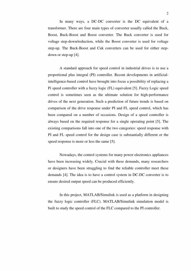
In many ways, a DC-DC converter is the DC equivalent of a
transformer. There are four main types of converter usually called the Buck,
Boost, Buck-Boost and Boost converter. The Buck converter is used for
voltage step-down/reduction, while the Boost converter is used for voltage
step-up. The Buck-Boost and Cuk converters can be used for either step-
down or step-up [4].
A standard approach for speed control in industrial drives is to use a
proportional plus integral (PI) controller. Recent developments in artificial-
intelligence-based control have brought into focus a possibility of replacing a
Pi speed controller with a fuzzy logic (FL) equivalent [5]. Fuzzy Logic speed
control is sometimes seen as the ultimate solution for high-performance
drives of the next generation. Such a prediction of future trends is based on
comparison of the drive response under PI and FL speed control, which has
been compared on a number of occasions. Design of a speed controller is
always based on the required response for a single operating point [5]. The
existing comparisons fall into one of the two categories: speed response with
PI and FL speed control for the design case is substantially different or the
speed response is more or less the same [5].
Nowadays, the control systems for many power electronics appliances
have been increasing widely. Crucial with these demands, many researchers
or designers have been struggling to find the reliable controller meet these
demands [4]. The idea is to have a control system in DC-DC converter is to
ensure desired output speed can be produced efficiently.
In this project, MATLAB/Simulink is used as a platform in designing
the fuzzy logic controller (FLC). MATLAB/Simulink simulation model is
built to study the speed control of the FLC compared to the PI controller.
3
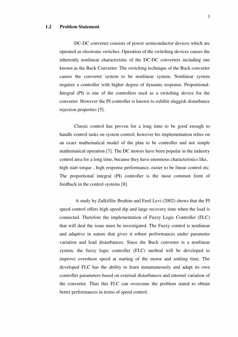
1.2 Problem Statement
DC-DC converter consists of power semiconductor devices which are
operated as electronic switches. Operation of the switching devices causes the
inherently nonlinear characteristic of the DC-DC converters including one
known as the Buck Converter. The switching technique of the Buck converter
causes the converter system to be nonlinear system. Nonlinear system
requires a controller with higher degree of dynamic response. Proportional-
Integral (PI) is one of the controllers used as a switching device for the
converter. However the PI controller is known to exhibit sluggish disturbance
rejection properties [5].
Classic control has proven for a long time to be good enough to
handle control tasks on system control; however his implementation relies on
an exact mathematical model of the plan to be controller and not simple
mathematical operation [7]. The DC motors have been popular in the industry
control area for a long time, because they have enormous characteristics like,
high start torque , high response performance, easier to be linear control etc.
The proportional integral (PI) controller is the most common form of
feedback in the control systems [8].
A study by Zulkifilie Ibrahim and Emil Levi (2002) shows that the PI
speed control offers high speed dip and large recovery time when the load is
connected. Therefore the implementation of Fuzzy Logic Controller (FLC)
that will deal the issue must be investigated. The Fuzzy control is nonlinear
and adaptive in nature that gives it robust performances under parameter
variation and load disturbances. Since the Buck converter is a nonlinear
system, the fuzzy logic controller (FLC) method will be developed to
improve overshoot speed at starting of the motor and settling time. The
developed FLC has the ability to learn instantaneously and adapt its own
controller parameters based on external disturbances and internal variation of
the converter. Thus this FLC can overcome the problem stated to obtain
better performances in terms of speed control.
4
1.3 Project Objectives
The objectives of this project are:
i) To develop a DC-DC Buck Converter using Proportional-Integrated
Controller (PI) and Proportional-Integrated-Derivative Controller
(PID)
ii) To develop a DC-DC Buck converter using Fuzzy Logic controller
(FLC)
iii) To compare the FLC with PI performance in terms of starting speed
overshoot, settling time and ripple factor.
1.4 Scope of Project
The scopes of the project are:
i) Modelling the DC-DC Buck converter with DC Motor
ii) Modelling the Proportional-Integrated (PI) and Proportional-
Integrated-Derivative (PID) controller for speed control
iii) Modelling the Fuzzy Logic Controller (FLC) controller for speed
control
iv) Compare the output speed of the DC motor for both PI and PID with
FLC in terms of starting overshoot, ripple factor and settling time.
5
CHAPTER 2
LITERATURE REVIEW
2.1 Existing Papers
Fuzzy control also supports nonlinear design techniques that are now
being exploited in motor control applications. A thorough literature overview
was done on the usage of fuzzy logic controller as applied to DC-DC
converter.
K.Viswanathan, D. Srinivasan, R. Oruganti (2002) proposed a
universal fuzzy controller and compares its performances at various operating
points with local PI controllers designed for the particular points. The settling
time and overshoot for start-up and step response obtained by computer
simulations have been compared. The simulation result shown the fuzzy
controllers achieve good transient response under different operating
conditions is clearly established.
Sinan Pravadalioglu (2005) present the feasibility of a high-
performance non-linear fuzzy logic controller which can be implemented by
using a general purpose was simulated in MATLAB/Simulink. The
theoretical and experimental results indicate that the implemented fuzzy logic
controller has a high performance for real-time control over a wide range of
operating conditions.
Zulkifilie Ibrahima and Emil Levi (2002) proposed a comparison of
the drive behaviour under PI and Fuzzy logic speed control. Experimental
result indicated that the superiority of Fuzzy logic speed control is less
6
pronounced than it often portrayed in the literature on the basis of limited
comparisons while the PI speed control provided a superior speed response.
Based on those related work, the researchers make a great effort to
propose the good to overcome DC-DC converter problems. Their applications
of each method differ, thus the further investigation of this controller is
needed.
2.2 DC-DC Converters
DC-DC converters are a class of electronic power circuits that is used
extensively in regulated dc power supplies and dc motor drive applications
due to its advantageous features in terms of size, weight and reliable
performances. The main difficulty in controlling dc-dc converters stems from
their hybrid nature as their switched circuit topology entails different modes
of operation, each with its own associated linear continuous-time dynamics.
Hard constraints are also present on the input variable (duty cycle), and
additional constraint may be imposed as safety measures, such as current
limiting [1].
DC-DC switching converters are the main components of switching
power supplies. As an importance branch of power electronics, the
investigations on DC-DC switching converters are widely carried out in the
world in which control of converters is one of the hotspots [2].
Modern electronics systems require high-quality, small, light-weight,
reliable and efficient power supplies. Linear power regulators, whose
principle of operation is based on a voltage or current divider, are inefficient
[5]. In many industrial applications, it is required to convert a fixed-voltage
dc source into a variable-voltage dc source. A DC-DC converter converts
directly from DC to DC and is simply known as a DC converter. A DC
converter can be considered as DC equivalent to an AC transformer with
continuously variable turn’s ratio. Like transformer, it can be used to step
down or step up a DC voltage source [5].
7
DC converters widely used for traction motor in electric automobiles,
trolley cars, marine hoists, and forklift trucks. They provide smooth
acceleration control, high efficiency, and fast dynamic response. DC
converter can be used in regenerative braking of dc motor to return energy
bake into the supply, and this feature results in energy 5 saving for
transportation system with frequent stop; and also are used, in DC voltage
regulation. There are many types of DC-DC convertor which is buck (step
down) converter, boost (step-up) converter, buck-boost (step up- step-down)
convertor [5].
DC conversion is of great importance in many applications, starting
from low power applications to high power applications. The goal of any
system is to emphasize and achieve the efficiency to meet the system needs
and requirements. Several topologies have been developed in this area, but all
these topologies can be considered as apart or a combination of the basic
topologies which are buck, boost and flyback [5].
For low power levels, linear regulators can provide a very high-
quality output voltage. For higher power levels, switching regulators are used.
Switching regulators use power electronic semiconductor switches in ON and
OFF states [3].
High-frequency electronic power processors are used in DC-DC
power conversion. The function of DC-DC converters are [5]:
1) To convert a dc input voltage VS into a dc output voltage VO
2) To regulate the dc output voltage against load and line variations
3) To reduce the ac voltage ripple on the dc output voltage below the
required level
4) To provide isolation between the input source and the load (isolation
is not always required);
5) To protect the supplied system and the input source from
electromagnetic interference (EMI)
6) To satisfy various international and national safety standards
8
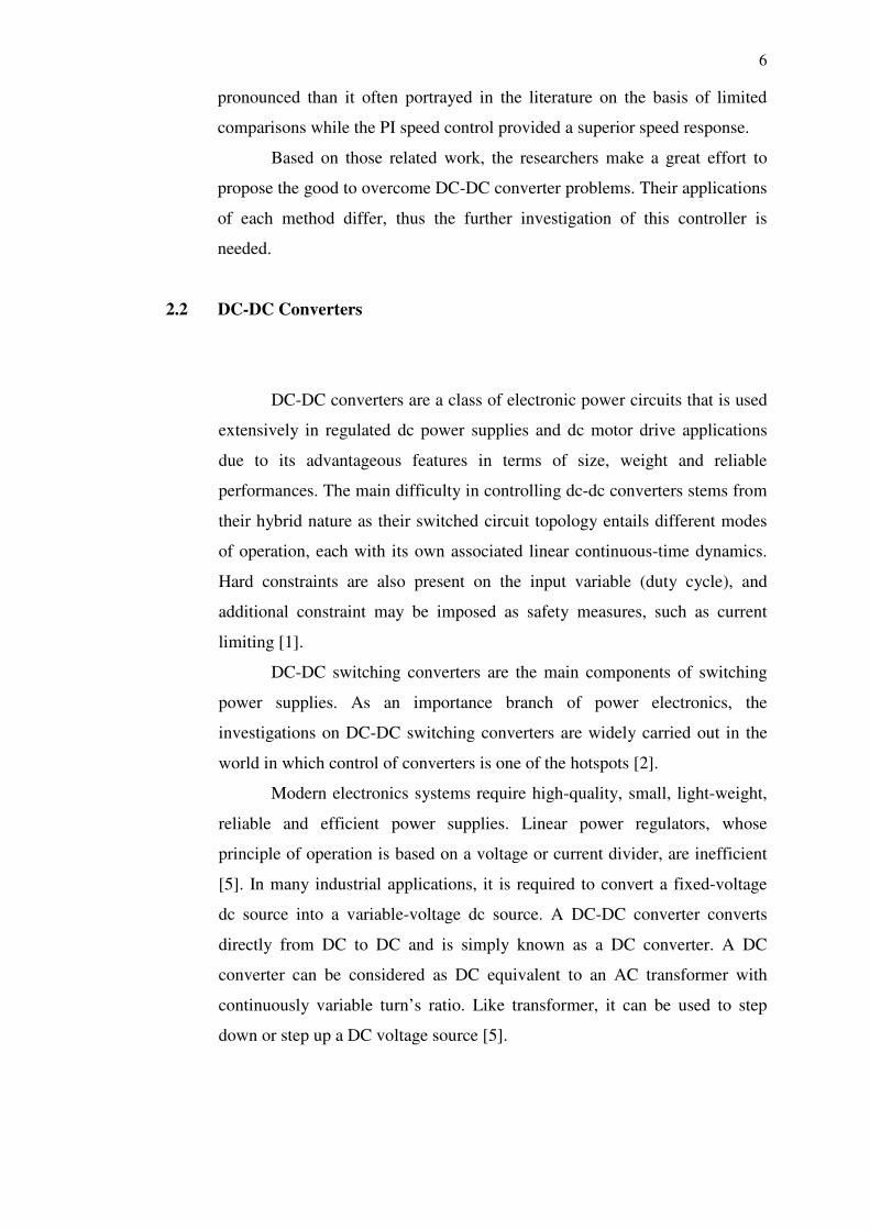
2.2.1 Buck Converter
The step-down DC-DC converter, commonly known as a buck
converter. It consists of dc input voltage source VS, controlled switch S, diode
D, filter inductor L, filter capacitor C, and load resistance R as shown below:
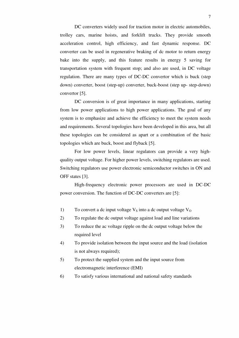
FIGURE 2.1: Equivalent circuit of Buck Converter [10]
The waveform in the converter is shown below under the assumption
that the inductor current is always positive [10].
FIGURE 2.2: Output waveform of Buck Converter [10]
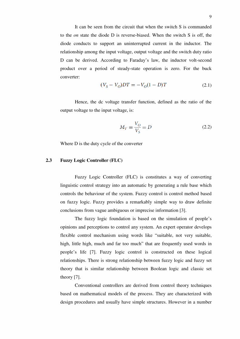
9
It can be seen from the circuit that when the switch S is commanded
to the on state the diode D is reverse-biased. When the switch S is off, the
diode conducts to support an uninterrupted current in the inductor. The
relationship among the input voltage, output voltage and the switch duty ratio
D can be derived. According to Faraday’s law, the inductor volt-second
product over a period of steady-state operation is zero. For the buck
converter:
(2.1)
Hence, the dc voltage transfer function, defined as the ratio of the
output voltage to the input voltage, is:
(2.2)
Where D is the duty cycle of the converter
2.3 Fuzzy Logic Controller (FLC)
Fuzzy Logic Controller (FLC) is constitutes a way of converting
linguistic control strategy into an automatic by generating a rule base which
controls the behaviour of the system. Fuzzy control is control method based
on fuzzy logic. Fuzzy provides a remarkably simple way to draw definite
conclusions from vague ambiguous or imprecise information [3].
The fuzzy logic foundation is based on the simulation of people’s
opinions and perceptions to control any system. An expert operator develops
flexible control mechanism using words like “suitable, not very suitable,
high, little high, much and far too much” that are frequently used words in
people’s life [7]. Fuzzy logic control is constructed on these logical
relationships. There is strong relationship between fuzzy logic and fuzzy set
theory that is similar relationship between Boolean logic and classic set
theory [7].
Conventional controllers are derived from control theory techniques
based on mathematical models of the process. They are characterized with
design procedures and usually have simple structures. However in a number
10
of cases, when parameter variations take place, or when disturbance are
present or when there is no simple mathematical model, fuzzy logic based
control systems have shown superior performance to those obtained by
conventional control algorithm. Fuzzy control can be described simply as
“control with sentences rather than equations”. It provides an algorithm to
convert a linguistic control strategy – based on expert knowledge-into an
automatic control strategy [11].
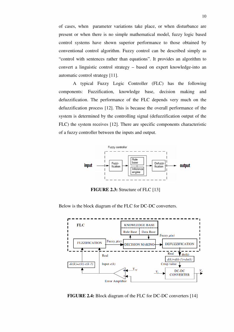
A typical Fuzzy Logic Controller (FLC) has the following
components: Fuzzification, knowledge base, decision making and
defuzzification. The performance of the FLC depends very much on the
defuzzification process [12]. This is because the overall performance of the
system is determined by the controlling signal (defuzzification output of the
FLC) the system receives [12]. There are specific components characteristic
of a fuzzy controller between the inputs and output.
FIGURE 2.3: Structure of FLC [13]
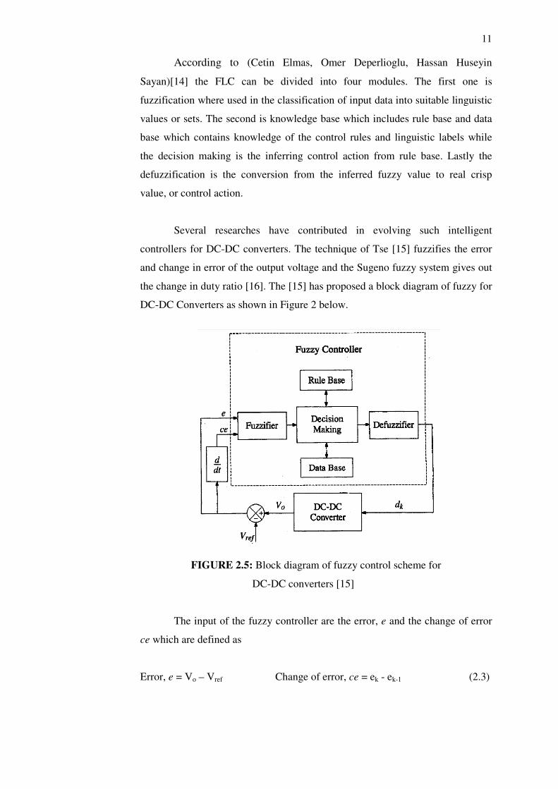
Below is the block diagram of the FLC for DC-DC converters.
FIGURE 2.4: Block diagram of the FLC for DC-DC converters [14]
11
According to (Cetin Elmas, Omer Deperlioglu, Hassan Huseyin
Sayan)[14] the FLC can be divided into four modules. The first one is
fuzzification where used in the classification of input data into suitable linguistic
values or sets. The second is knowledge base which includes rule base and data
base which contains knowledge of the control rules and linguistic labels while
the decision making is the inferring control action from rule base. Lastly the
defuzzification is the conversion from the inferred fuzzy value to real crisp
value, or control action.
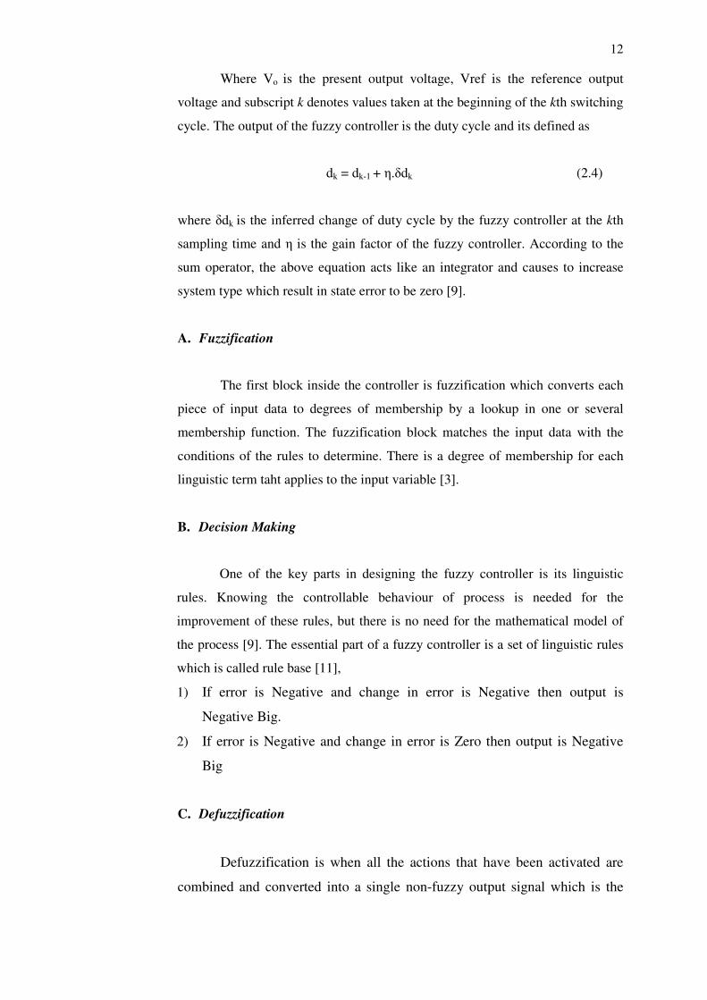
Several researches have contributed in evolving such intelligent
controllers for DC-DC converters. The technique of Tse [15] fuzzifies the error
and change in error of the output voltage and the Sugeno fuzzy system gives out
the change in duty ratio [16]. The [15] has proposed a block diagram of fuzzy for
DC-DC Converters as shown in Figure 2 below.
FIGURE 2.5: Block diagram of fuzzy control scheme for
DC-DC converters [15]
The input of the fuzzy controller are the error, e and the change of error
ce which are defined as
Error, e = Vo – Vref Change of error, ce = ek - ek-1 (2.3)
12
Where Vo is the present output voltage, Vref is the reference output
voltage and subscript k denotes values taken at the beginning of the kth switching
cycle. The output of the fuzzy controller is the duty cycle and its defined as
dk = dk-1 + η.δdk (2.4)
where δdk is the inferred change of duty cycle by the fuzzy controller at the kth
sampling time and η is the gain factor of the fuzzy controller. According to the
sum operator, the above equation acts like an integrator and causes to increase
system type which result in state error to be zero [9].
A. Fuzzification
The first block inside the controller is fuzzification which converts each
piece of input data to degrees of membership by a lookup in one or several
membership function. The fuzzification block matches the input data with the
conditions of the rules to determine. There is a degree of membership for each
linguistic term taht applies to the input variable [3].
B. Decision Making
One of the key parts in designing the fuzzy controller is its linguistic
rules. Knowing the controllable behaviour of process is needed for the
improvement of these rules, but there is no need for the mathematical model of
the process [9]. The essential part of a fuzzy controller is a set of linguistic rules
which is called rule base [11],
1) If error is Negative and change in error is Negative then output is
Negative Big.
2) If error is Negative and change in error is Zero then output is Negative
Big
C. Defuzzification
Defuzzification is when all the actions that have been activated are
combined and converted into a single non-fuzzy output signal which is the
13
control of the system [3]. The output levels are depending on the rules that
the systems have and the positions depending on the non-linearities existing
to the systems [3]. To achive the result, develop the control curve of the
system representing the I/O relation of the systems and based on the
information, define the output degree of the membership function with the
aims to minimize the effect of the non-linearity [13].
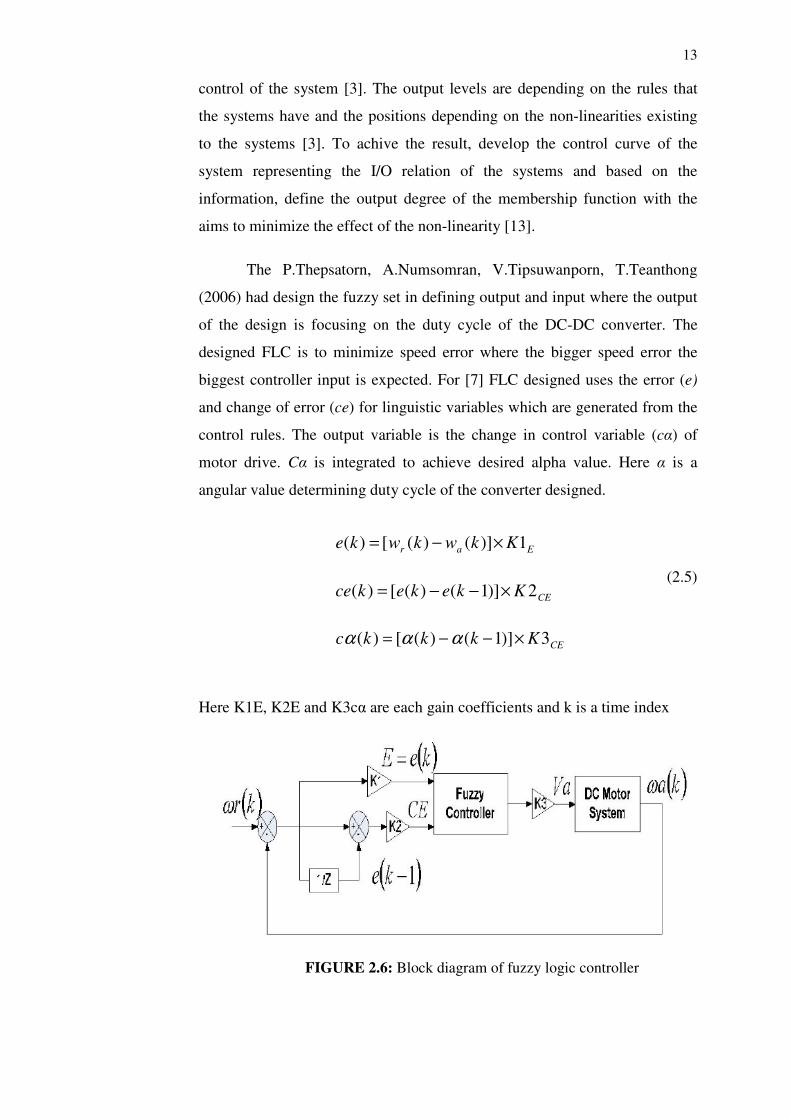
The P.Thepsatorn, A.Numsomran, V.Tipsuwanporn, T.Teanthong
(2006) had design the fuzzy set in defining output and input where the output
of the design is focusing on the duty cycle of the DC-DC converter. The
designed FLC is to minimize speed error where the bigger speed error the
biggest controller input is expected. For [7] FLC designed uses the error (e)
and change of error (ce) for linguistic variables which are generated from the
control rules. The output variable is the change in control variable (cα) of
motor drive. Cα is integrated to achieve desired alpha value. Here α is a
angular value determining duty cycle of the converter designed.
(2.5)
Here K1E, K2E and K3cα are each gain coefficients and k is a time index
FIGURE 2.6: Block diagram of fuzzy logic controller
Ear Kkwkwke 1)]()([)( ×−=
CEKkekekce 2)]1()([)( ×−−=
CEKkkkc 3)]1()([)( ×−−= ααα
14
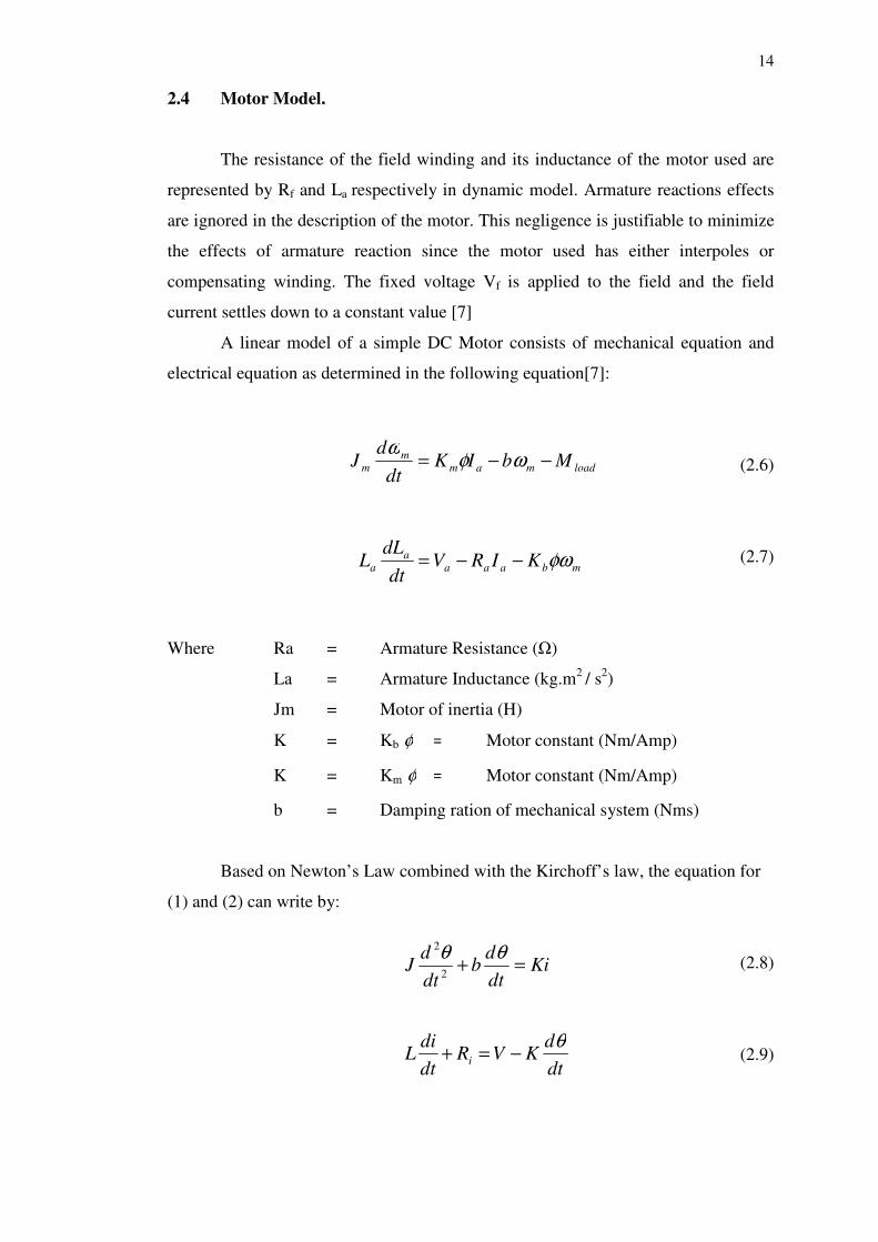
2.4 Motor Model.
The resistance of the field winding and its inductance of the motor used are
represented by Rf and La respectively in dynamic model. Armature reactions effects
are ignored in the description of the motor. This negligence is justifiable to minimize
the effects of armature reaction since the motor used has either interpoles or
compensating winding. The fixed voltage Vf is applied to the field and the field
current settles down to a constant value [7]
A linear model of a simple DC Motor consists of mechanical equation and
electrical equation as determined in the following equation[7]:
(2.6)
(2.7)
Where Ra = Armature Resistance (Ω)
La = Armature Inductance (kg.m2
/ s2)
Jm = Motor of inertia (H)
K = Kb φ = Motor constant (Nm/Amp)
K = Km φ = Motor constant (Nm/Amp)
b = Damping ration of mechanical system (Nms)
Based on Newton’s Law combined with the Kirchoff’s law, the equation for
(1) and (2) can write by:
(2.8)
(2.9)
loadmamm
m MbIKdt
dJ −−= ωφ
ω
mbaaaa
a KIRVdt
dLL φω−−=
Kidt
db
dt
dJ =+
θθ2
2
dt
dKVR
dt
diL i
θ−=+
15
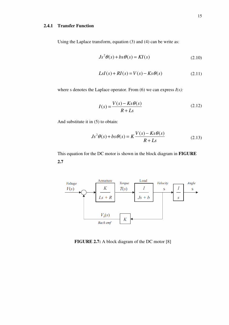
2.4.1 Transfer Function
Using the Laplace transform, equation (3) and (4) can be write as:
(2.10)
(2.11)
where s denotes the Laplace operator. From (6) we can express I(s):
(2.12)
And substitute it in (5) to obtain:
(2.13)
This equation for the DC motor is shown in the block diagram in FIGURE
2.7
FIGURE 2.7: A block diagram of the DC motor [8]
)()()(2sKIsbssJs =+ θθ
)()()()( sKssVsRIsLsI θ−=+
LsR
sKssVsI
+
−=
)()()(
θ
LsR
sKssVKsbssJs
+
−=+
)()()()(2 θ
θθ
16
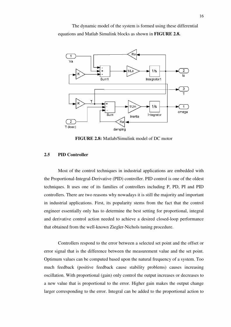
The dynamic model of the system is formed using these differential
equations and Matlab Simulink blocks as shown in FIGURE 2.8.
FIGURE 2.8: Matlab/Simulink model of DC motor
2.5 PID Controller
Most of the control techniques in industrial applications are embedded with
the Proportional-Integral-Derivative (PID) controller. PID control is one of the oldest
techniques. It uses one of its families of controllers including P, PD, PI and PID
controllers. There are two reasons why nowadays it is still the majority and important
in industrial applications. First, its popularity stems from the fact that the control
engineer essentially only has to determine the best setting for proportional, integral
and derivative control action needed to achieve a desired closed-loop performance
that obtained from the well-known Ziegler-Nichols tuning procedure.
Controllers respond to the error between a selected set point and the offset or
error signal that is the difference between the measurement value and the set point.
Optimum values can be computed based upon the natural frequency of a system. Too
much feedback (positive feedback cause stability problems) causes increasing
oscillation. With proportional (gain) only control the output increases or decreases to
a new value that is proportional to the error. Higher gain makes the output change
larger corresponding to the error. Integral can be added to the proportional action to
17
ramp the output at a particular rate thus bring the error back toward zero. Derivative
can be added as a momentary spike of corrective action that tails off.
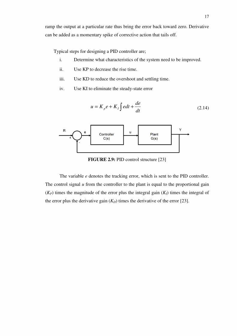
Typical steps for designing a PID controller are;
i. Determine what characteristics of the system need to be improved.
ii. Use KP to decrease the rise time.
iii. Use KD to reduce the overshoot and settling time.
iv. Use KI to eliminate the steady-state error
(2.14)
FIGURE 2.9: PID control structure [23]
The variable e denotes the tracking error, which is sent to the PID controller.
The control signal u from the controller to the plant is equal to the proportional gain
(KP) times the magnitude of the error plus the integral gain (KI) times the integral of
the error plus the derivative gain (KD) times the derivative of the error [23].
∫ ++=dt
deedtKeKu Ip
18
CHAPTER 3
METHODOLOGY
3.1 Project Design
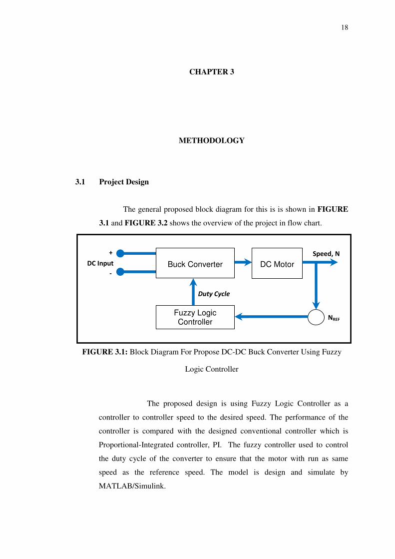
The general proposed block diagram for this is is shown in FIGURE
3.1 and FIGURE 3.2 shows the overview of the project in flow chart.
FIGURE 3.1: Block Diagram For Propose DC-DC Buck Converter Using Fuzzy
Logic Controller
The proposed design is using Fuzzy Logic Controller as a
controller to controller speed to the desired speed. The performance of the
controller is compared with the designed conventional controller which is
Proportional-Integrated controller, PI. The fuzzy controller used to control
the duty cycle of the converter to ensure that the motor with run as same
speed as the reference speed. The model is design and simulate by
MATLAB/Simulink.
Speed, N Buck Converter
Fuzzy Logic Controller
DC Motor
DC Input
+
-
NREF
Duty Cycle
19
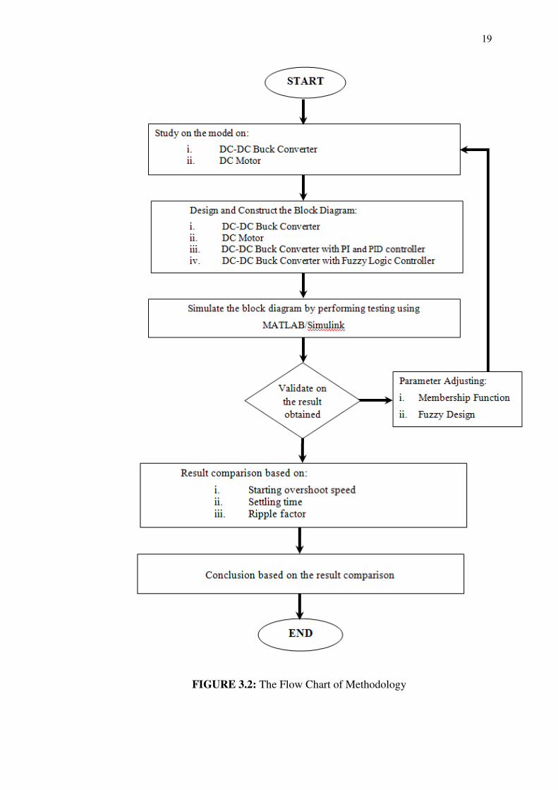
FIGURE 3.2: The Flow Chart of Methodology
20
3.2 Proposed DC Motor
There were several papers such as Zulkifilie Ibrahim and Emil Levi
(2002) and Teresa Orlowska-Kowalska (2001) had proposed the DC motor
design using MATLAB/Simulink. The design DC motor is used to analyse of
the system dynamics. But for this project, I have made the design made by
Zulkifilie Ibrahim and Emil Levi as my reference due to the application of the
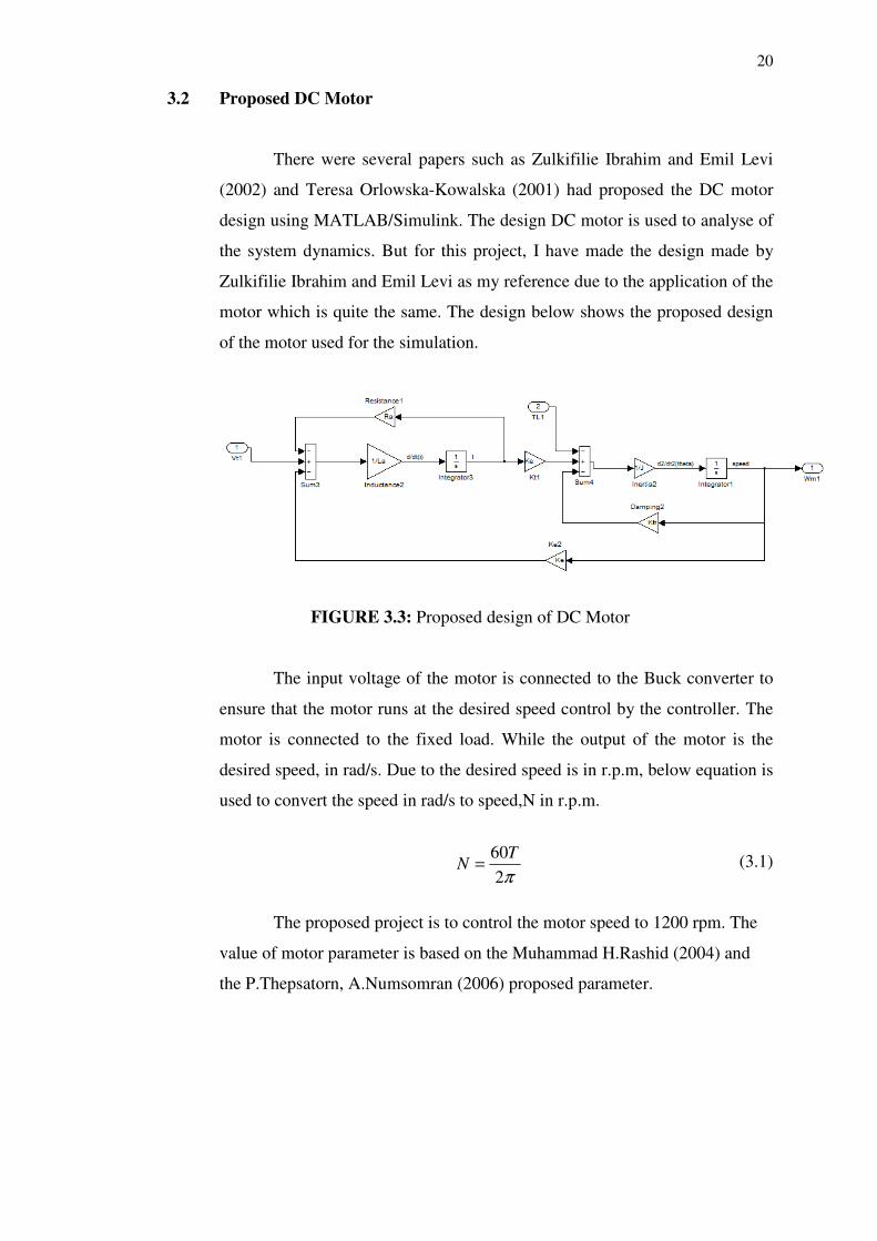
motor which is quite the same. The design below shows the proposed design
of the motor used for the simulation.
FIGURE 3.3: Proposed design of DC Motor
The input voltage of the motor is connected to the Buck converter to
ensure that the motor runs at the desired speed control by the controller. The
motor is connected to the fixed load. While the output of the motor is the
desired speed, in rad/s. Due to the desired speed is in r.p.m, below equation is
used to convert the speed in rad/s to speed,N in r.p.m.
(3.1)
The proposed project is to control the motor speed to 1200 rpm. The
value of motor parameter is based on the Muhammad H.Rashid (2004) and
the P.Thepsatorn, A.Numsomran (2006) proposed parameter.
π2
60TN =
21
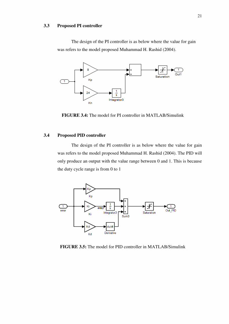
3.3 Proposed PI controller
The design of the PI controller is as below where the value for gain
was refers to the model proposed Muhammad H. Rashid (2004).
FIGURE 3.4: The model for PI controller in MATLAB/Simulink
3.4 Proposed PID controller
The design of the PI controller is as below where the value for gain
was refers to the model proposed Muhammad H. Rashid (2004). The PID will
only produce an output with the value range between 0 and 1. This is because
the duty cycle range is from 0 to 1
FIGURE 3.5: The model for PID controller in MATLAB/Simulink
22
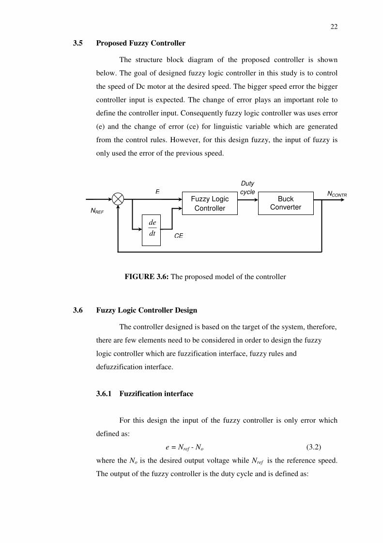
3.5 Proposed Fuzzy Controller
The structure block diagram of the proposed controller is shown
below. The goal of designed fuzzy logic controller in this study is to control
the speed of Dc motor at the desired speed. The bigger speed error the bigger
controller input is expected. The change of error plays an important role to
define the controller input. Consequently fuzzy logic controller was uses error
(e) and the change of error (ce) for linguistic variable which are generated
from the control rules. However, for this design fuzzy, the input of fuzzy is
only used the error of the previous speed.
FIGURE 3.6: The proposed model of the controller
3.6 Fuzzy Logic Controller Design
The controller designed is based on the target of the system, therefore,
there are few elements need to be considered in order to design the fuzzy
logic controller which are fuzzification interface, fuzzy rules and
defuzzification interface.
3.6.1 Fuzzification interface
For this design the input of the fuzzy controller is only error which
defined as:
e = Nref - No (3.2)
where the No is the desired output voltage while Nref is the reference speed.
The output of the fuzzy controller is the duty cycle and is defined as:
Fuzzy Logic
Controller
dt
de
Buck Converter
E
CE
NREF
NCONTR
Duty
cycle
23
dk = dk-1 + n.δdk (3.3)
where δdk is inferred change of duty cycle by the fuzzy controller at the
sampling time kth sampling time and n is the gain factor of the fuzzy
controller. Adjusting n can be change the effective gain if the controller.
Specifically the fuzzy rules are in the form:
If e is A, then dk is C (3.4)
Where A is fuzzy subset in their universe of discourse and C is a fuzzy
singleton. Each universe of discourse is divided into four fuzzy subsets:
Negative Big (NB), Negative Small (NS), Positive Small (PS) and Positive
Big (PB) are representing the linguistic variables for error (input). The range
of error is set from -1 to +1. While for Zero (Z), Positive Small (PS), Positive
Medium (PM) and Positive Big (PB) are represent the linguistic variables for
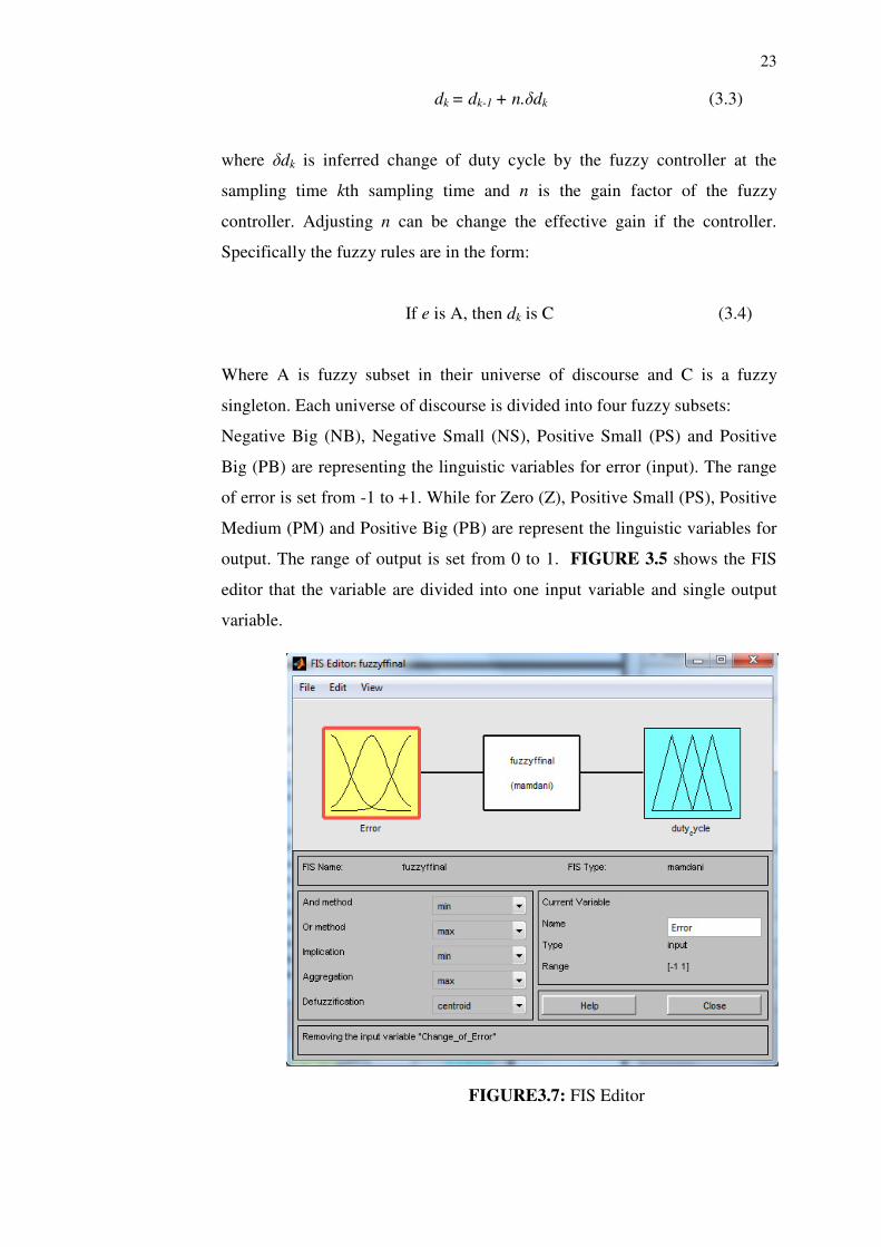
output. The range of output is set from 0 to 1. FIGURE 3.5 shows the FIS
editor that the variable are divided into one input variable and single output
variable.
FIGURE3.7: FIS Editor
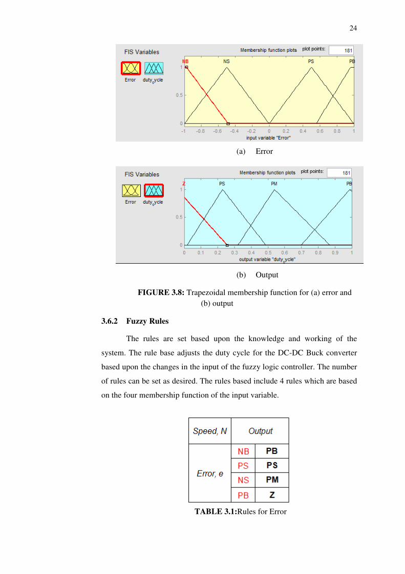
24
(a) Error
(b) Output
FIGURE 3.8: Trapezoidal membership function for (a) error and
(b) output
3.6.2 Fuzzy Rules
The rules are set based upon the knowledge and working of the
system. The rule base adjusts the duty cycle for the DC-DC Buck converter
based upon the changes in the input of the fuzzy logic controller. The number
of rules can be set as desired. The rules based include 4 rules which are based
on the four membership function of the input variable.
TABLE 3.1:Rules for Error
39
REFERENCES
[1] A. Giovanni Beccuti, Georgios Papafotiou and Manfred Morari, (2005)
“Optimal control of the Boost dc-dc converter”. IEEE conference on decision
and control
[2] Liu Qingfeng, Leng Zhaoxia, Sun Jinkun, Wang Huamin, (2011) “A
composite PWM control strategy for Boost converter”. 2012 International
conference.
[3] Fathi Shaban Jaber (2011) “Development of a Buck-Boost Converter Using
Fuzzy Logic Control”. Degree of Master Thesis, UTHM
[4] Siti Hasmah Binti Jamali (2011) “Voltage Tracking of DC-DC Boost
Converter Using Fuzzy Logic Controller”, Master Thesis UTHM
[5] Zulkiflilie Ibrahim and Emil Levi (2002)“A Comparative Analysis of Fuzzy
Logic and PI Speed Control in High-Performance AC Drives Using
Experimental Approach”, IEEE Transaction on Industry Application.
[6] B. Heber, L.Xu and Y.Tang “Fuzzy Logic enhanced speed control of an
indirect field oriented induction motor drive”, IEEE Trans. Power Electron,
vol.12, pp. 772-778, Sept 1997
[7] P.Thepsatorn, A. Numsomran, V. Tipsuwanporn, T.Teanthong (2006)”DC
Motor Speed Control using Fuzzy Logic based on LabVIEW”. SICE-ICASE
International Joint Conference 2006.
[8] Ramesh Chandra Chourasia, Mukesh Kumar (2013)”, Speed Control of
S.E.D.C Motor by Using PI and Fuzzy Logic Controller. International Journal
of Soft Computing and Engineering (IJSCE)
[9] H. Feshki Farahani (2011)“Designing and Implementation of a Fuzzy
Controller for DC-DC Converters and Comparing With PI Digital
Controller”. Islamic Azad University, Iran
[10] Muhammad H. Rashid (2004):”Power electronics Circuits, Devices and
Applications” Electrical computer Engineering University of west Florida.
[11] Sinan Pravadalioglu (2005), “Single-chip fuzzy logic controller design and an
application on a permanent magnet dc motor”. Engineering Application of
Artificial Intelligence
[12] Yigang Shi and P.C Sen (2000) “A New Defuzzification Method for Fuzzy
Control of Power Converters. IEEE members.
[13] Jan Jantzen (1998),”Design of Fuzzy Controllers”. Technical University of
Denmark
[14] Cetin Elmas, Omer Deperlioglu, Hassan Huseyin Sayan (2007),” Adaptive fuzzy
logic controller for DC-DC converters”. Expert system with application.
40
[15] Wing-Chi So, Chi K.Tse, Yim-Shu Lee (1996), “Development of a Fuzzy Logic
Controller for DC/DC Converter : Design, Computer Simulation and
Experimental Evaluation. IEEE transaction on Power electronics
[16] K. Viswanathan, D. Srinivisan, R.Oruganti (2002),”A Universal Fuzzy
Controller for A Non-Linear Power Electronic Converter”. National University
of Singapore.
[17] Teresa Orlowska-Kowalska, Krzysztof Szabat, Krzysztof Jaszczak (2001) “The
Influence of parameter and structure of PI-Type fuzzy-logic controller on DC
drive system dynamics”, Fuzzy set and systems
[18] C.K. Tse and K. M Adams (1992), “Quasilinear modelling and control of
DC/DC Converters,” IEEE Trans. Power Electron
[19] V.S. C Raviraj and P.C. Sen, “Comparative Study of Proportional-Integral,
Sliding Mode and Fuzzy Logic Controllers for Power Converters”. IEEE IAS
Proceeding.
[20] K. Somsai, A. Oonsivilai, A. Srikaew & T.
Kulworawanichpong,(2007),”Optimal PI Controller Design andSimulation of a
static VAR Compensator Using MATLAB/SIMULINK”. International Conference
on Power System.
[21] P.C Sen, (1990) “Electric Motor Drives and control – Past, Present, and future”.
IEEE Trans on Inductrial Electronics, Vol37, No 6,
[22] Robert Babuska and Stefano Stramigiolo (1999)” Matlab and Simulink for
Modeling and Control”, Delft University of Technology
[23] PID Control Tuning: A Short Tutorial, Retrieved June 22, 2013 from
http://wwwdsa.uqac.ca/~rbeguena/Systemes_Asservis/PID.pdf
Related Documents