DC MOTOR PRINCIPLES Lecture 15

Welcome message from author
This document is posted to help you gain knowledge. Please leave a comment to let me know what you think about it! Share it to your friends and learn new things together.
Transcript

DC MOTOR PRINCIPLES
Lecture 15

Basic DC Motors• The most simplest DC motor has a stationary set of
magnetic poles. This is called the stator. The stator can use permanent magnets or electro-magnets which creates a stationary magnetic field. The stator can have multiple magnetic fields.
• The DC motor has a rotating set of electro-magnetic poles called the rotor. A DC voltage is applied to the rotor through a set of terminals called brushes. The brushes are attached to a rotating device called a commutator which feeds the rotor winding(s) that create the rotor’s electro-magnetic field(s).
• The commutator is designed to switch the direction of the current in the rotor windings to cause the rotor magnetic fields to be out of phase with the stator’s magnetic field(s).

SStator
N
Stator
Rotor winding
Commutator
The direction of motion CW
Rotor’s Magnetic field
Stator’s Magnetic field
Force on the rotor due to the magnetic field.
1. The magnetic field of the stator goes from N to S.
2. The commutator gap is perpendicular to the brushes
3. The current flowing through the rotor loop caused the perpendicular magnetic field to point downward.
4. There is now a force on the rotor to align the rotor’s magnetic field with the
Brush
Brush

S
N1. The magnetic field of
the stator goes from N to S.
2. The commutator gap is at angle to the brushes
3. The current flowing through the rotor loop caused the perpendicular magnetic field to point downward.
4. The force on the rotor to align the magnetic fields is reduced.
S
N1. The magnetic field of
the stator goes from N to S.
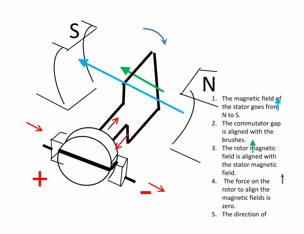
2. The commutator gap is aligned with the brushes.
3. The rotor magnetic field is aligned with the stator magnetic field.
4. The force on the rotor to align the magnetic fields is zero.
5. The direction of motion is CW.

S
N1. The magnetic field of
the stator goes from N to S.
2. The momentum of the rotor causes commutator gap reverse the current in the rotor.
3. The rotor magnetic field is now opposite to the stator magnetic field.
4. The force on the rotor reappears to align the magnetic fields is zero.
S
N1. The magnetic field of
the stator goes from N to S.
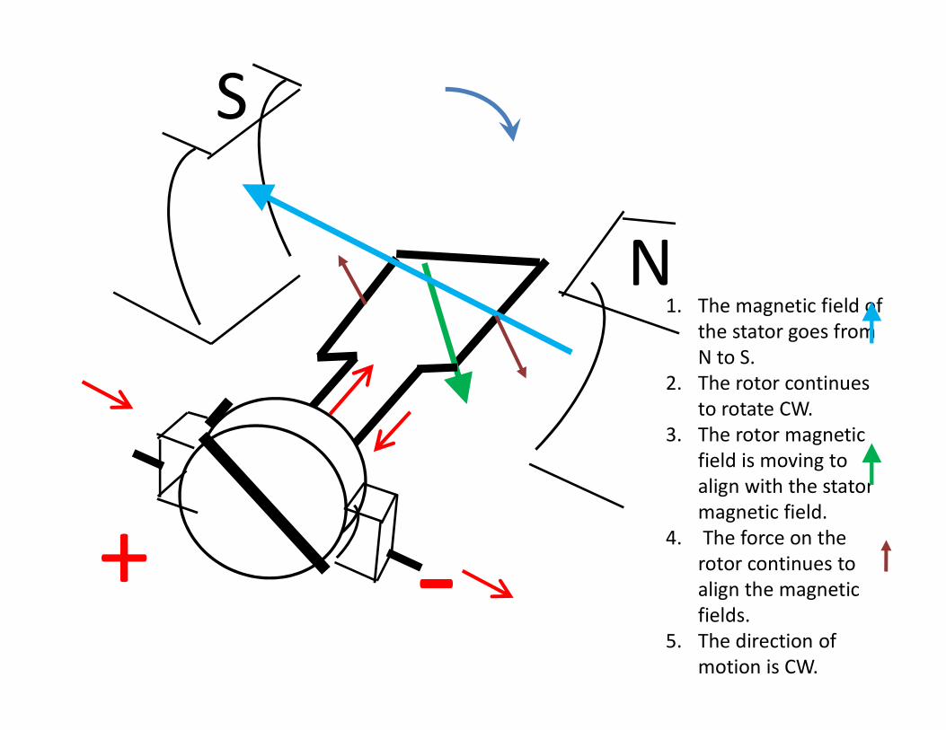
2. The rotor continues to rotate CW.
3. The rotor magnetic field is moving to align with the stator magnetic field.
4. The force on the rotor continues to align the magnetic fields.
5. The direction of motion is CW.

S
N1. The magnetic field of
the stator goes from N to S.
2. The rotor continues to rotate CW and has moved 180 degrees.
3. The rotor magnetic field is moving to align with the stator magnetic field.
4. The force on the rotor continues to align the magnetic fields.
5. The direction of motion is CW.

Some properties of DC motors• Reversing the direction of the motor can be achieved by
reversing the polarity of the DC supply voltage.
• The speed of rotation is a function of the current and therefore the DC supply voltage.
NS
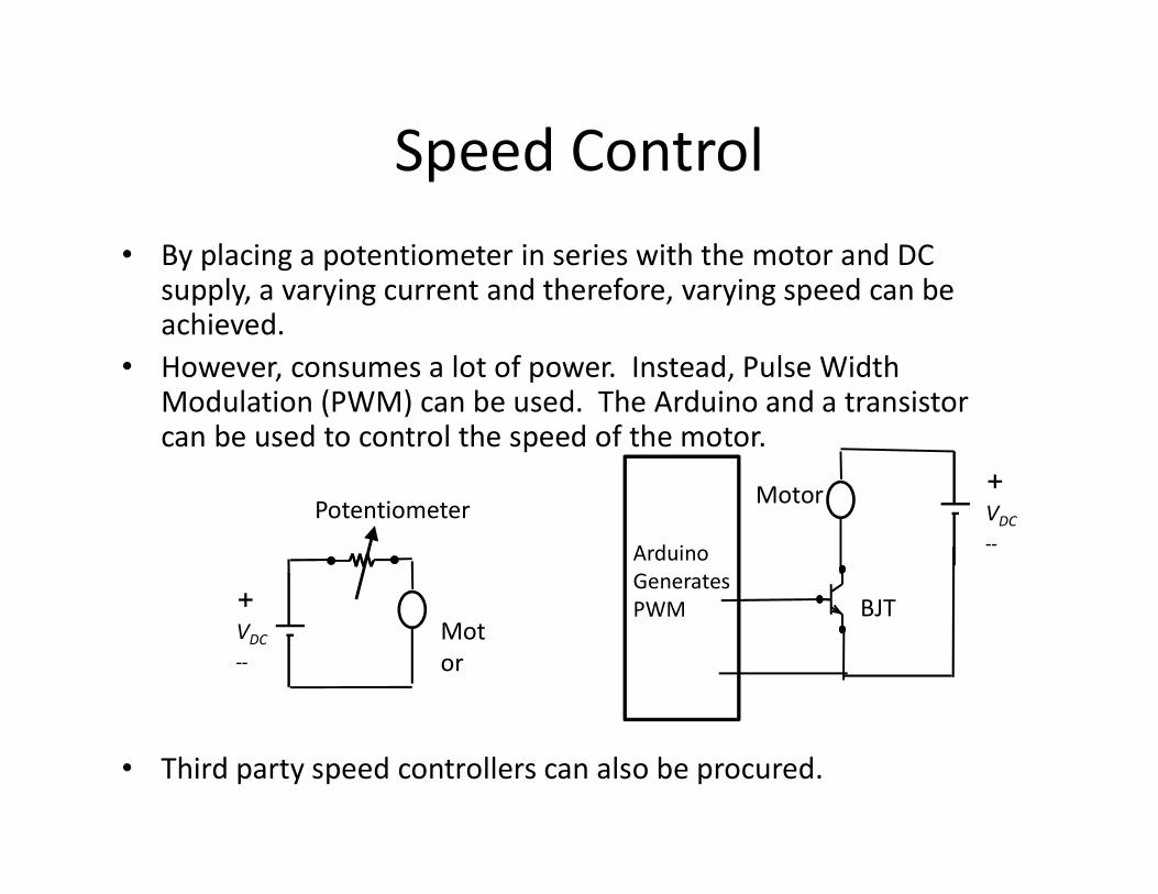
Speed Control• By placing a potentiometer in series with the motor and DC
supply, a varying current and therefore, varying speed can be achieved.
• However, consumes a lot of power. Instead, Pulse Width Modulation (PWM) can be used. The Arduino and a transistor can be used to control the speed of the motor.
• Third party speed controllers can also be procured.
+VDC--
Motor
Potentiometer+VDC--
Motor
BJT
ArduinoGenerates PWM

Reversing the direction of rotationHow an H-Bridge works
https://www.build-electronic-circuits.com/h-bridge/
By switching the relays, the motor voltage is reversed and the changes direction of rotation.

Reversing the direction of rotation
• To reverse the direction of rotation of a DC motor, a switching matrix called an H-bridge can be used.
• A H-bridge can be configured using simple relays or an electronic device.
Drawings from https://www.electronics-tutorials.ws/io/io_7.html
Stepper Motors• Stepper Motors are DC motor which only move a specific
number of degrees at a time.• Typical Stepper Motors have steps of 1.8 degrees; that is
200 steps.• Stepper motors have multiple windings to achieve the
stepping action. The order in which the multiple windings are energies determines the direction of rotation of the rotor.
• Typically a hardware or software controller is used to facilitate the sequencing of the multiple windings. Therefore, such a controller uses two bits: one for determined direction of rotation and one to send a pulse per step.

Typical Stepper Motor
Drawings from https://www.electronics-tutorials.ws/io/io_7.html
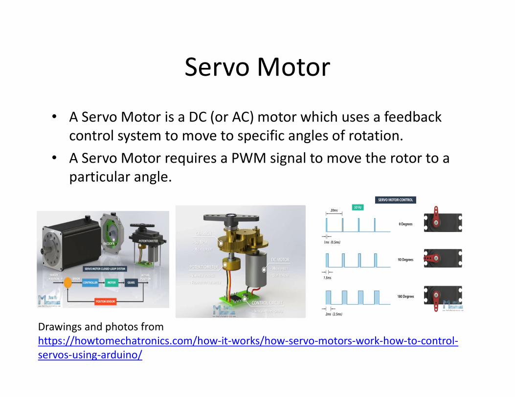
Servo Motor
• A Servo Motor is a DC (or AC) motor which uses a feedback control system to move to specific angles of rotation.
• A Servo Motor requires a PWM signal to move the rotor to a particular angle.
Drawings and photos from https://howtomechatronics.com/how-it-works/how-servo-motors-work-how-to-control-servos-using-arduino/
Related Documents