Generation of Space V ector PWM Using Microcontroller Atmega 16 Slamet Abstract— This paper describes the use of a microcontroller atmega 16 to generate the space vector pulse wid th modulation (SVP WM) signa ls. The main featur e of the re searc h is the si mplici ty of the hard ware an d easy to digit ally prog rammed . T estin g and ana lyzin g syste m is done at no load condition with varying carrier frequency, amplitude, and sinusoidal frequency. Varying carrier frequency is done by utilizing software with code vision A VR tools, while the amplitude and the sinusoidal frequency are varied by using potentiometers as analog input data. Based on the results of testing and analyzing, it is shown that the SVPWM signals could be implemented with micro contro ller Atmega 16 at carr ier frequ ency 490 Hz and THD at s inusoidal freque ncy of 25Hz, 50Hz, and 100Hz is abou t 13.85%, 23.89%, and 17.43%.. Index Terms— Space Vector PWM, microcontroller, software, varying carrier frequency , amplitude, sinusoidal frequency , analog input. —————————— —————————— 1 INTRODUCTION Nowadays, harmonic pollution in electrical power systems due to nonlinear loads such as Inverter power converter has become a serious problem. Inverter power converter is a voltage converter DC to AC with adjustable voltage and output frequency so that applicable to control three phase AC induction motor. There are some inverter type between it is an inverter power converter with the SVPWM (Spa ce Vec tor Pu lse Widt h Modu lat ion)[1]. Advantage of technique SVPWM is very economic and practical to be applied operation of three phase AC induction motor. Besides if generation of signal SVPWM is done digitally will be able to be obtained system work short exchange is more impenetrably to noise. Design of a signal generator SVPWM applies microcontroller to have some advantages that is easy to be program and inverter circuit to become simple. To eliminate or reduce harmonics in the power systems, a number of methods have been d eveloped and put in to pr actice. SVPWM methods is used to generate active power filter. The active power filter built fom SVPWM can be programmed with microcontroller. In this research using microcontroller atmega 16 which is the local content. Therefore, we can design a power converter to supply DC power to its own load and, at the same time, operates as an active filter to supply to the AC line a compensating current equal to the harmonic current produced by the nonlinear load connected to the same AC line[3][4][5][6]. 2 PRINCIPLE OF SVPWM The principle of Space Vector PWM is based on the fact that there are only eight possible switch combinations for a three phase inverter. The basic inverter switch states are shown in Figure 1. Two of these states (SV0 and SV7) correspond to short circuit while the other six can be considered to form stationary vectors in the d-q plane as shown in Fig.2. The magnitude of each of the six active vectors corresponding to the maximum possible phase voltage is: 2 3 m dc V V (1) Having identified the stationary vectors, at any point in time, an arbitrary target output voltage vector can then be made up by the summation (“averaging”) of the adjacent space vectors within one switching period. Target vectors in the other five segments of the hexagon are clearly obtained in a similar manner. The geomet ric summation shown in F ig.2. can be expre ssed mathe matica lly as [5], 1 2 0 0 0 (cos ) (cos sin ) 3 3 2 m m T Tsv V Tsv V jsin V j (2) for each switching period ΔT . Equating real and imaginary components yield the solution, ———————————————— Slamet is cu rrent ly wo rking as a researc her a t th e Re seacrh and Develop ment Cen ter for Elect ricity , new energ y, renewa ble, and energ y conservation, Ministry of Energy and Mineral Resources. Jl. Ciledug Raya Kav . 109 , Keb ayo ran L ama - Jaka rta Sela tan , Ind one sia . E-mail: [email protected] This paper prese nts an active filter in power inve rter control met hod ent itled SVPWM str ate gy ba sed o n microcont roller atmega 16 [2][3]. International Journal of Scientific & Engineering Research, Volume 4, Issue 3, March-2013 ISSN 2229-5518 IJSER © 2013 http://www.ijser.org

Welcome message from author
This document is posted to help you gain knowledge. Please leave a comment to let me know what you think about it! Share it to your friends and learn new things together.
Transcript
7/23/2019 Researchpsvpwmaper Generation of Space Vector PWM Using Microcontroller Atmega 16
http://slidepdf.com/reader/full/researchpsvpwmaper-generation-of-space-vector-pwm-using-microcontroller-atmega 1/5
Generation of Space Vector PWM UsingMicrocontroller Atmega 16
Slamet
Abstract— This paper describes the use of a microcontroller atmega 16 to generate the space vector pulse width modulation (SVPWM)
signals. The main feature of the research is the simplicity of the hardware and easy to digitally programmed. Testing and analyzing system
is done at no load condition with varying carrier frequency, amplitude, and sinusoidal frequency. Varying carrier frequency is done by
utilizing software with code vision AVR tools, while the amplitude and the sinusoidal frequency are varied by using potentiometers as
analog input data. Based on the results of testing and analyzing, it is shown that the SVPWM signals could be implemented with
microcontroller Atmega 16 at carrier frequency 490 Hz and THD at sinusoidal frequency of 25Hz, 50Hz, and 100Hz is about 13.85%,
23.89%, and 17.43%..
Index Terms— Space Vector PWM, microcontroller, software, varying carrier frequency, amplitude, sinusoidal frequency, analog input.
—————————— ——————————
1 INTRODUCTIONNowadays, harmonic pollution in electrical power
systems due to nonlinear loads such as Inverter power
converter has become a serious problem. Inverter power
converter is a voltage converter DC to AC with adjustable
voltage and output frequency so that applicable to control
three phase AC induction motor. There are some inverter
type between it is an inverter power converter with the
SVPWM (Space Vector Pulse Width Modulation)[1].
Advantage of technique SVPWM is very economic and
practical to be applied operation of three phase AC
induction motor. Besides if generation of signal SVPWM
is done digitally will be able to be obtained system work
short exchange is more impenetrably to noise. Design of a
signal generator SVPWM applies microcontroller to have
some advantages that is easy to be program and inverter
circuit to become simple. To eliminate or reduce
harmonics in the power systems, a number of methods
have been developed and put into practice. SVPWM
methods is used to generate active power filter. The active
power filter built fom SVPWM can be programmed with
microcontroller. In this research using microcontroller
atmega 16 which is the local content. Therefore, we can
design a power converter to supply DC power to its ownload and, at the same time, operates as an active filter to
supply to the AC line a compensating current equal to the
harmonic current produced by the nonlinear load
connected to the same AC line[3][4][5][6].
2 PRINCIPLE OF SVPWM
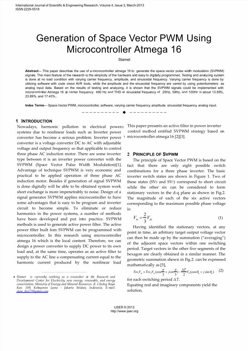
The principle of Space Vector PWM is based on the
fact that there are only eight possible switch
combinations for a three phase inverter. The basic
inverter switch states are shown in Figure 1. Two of
these states (SV0 and SV7) correspond to short circuit
while the other six can be considered to form
stationary vectors in the d-q plane as shown in Fig.2.
The magnitude of each of the six active vectors
corresponding to the maximum possible phase voltage
is:
2
3m dcV V (1)
Having identified the stationary vectors, at any
point in time, an arbitrary target output voltage vector
can then be made up by the summation (“averaging”)
of the adjacent space vectors within one switching
period. Target vectors in the other five segments of the
hexagon are clearly obtained in a similar manner. The
geometric summation shown in Fig.2. can be expressed
mathematically as [5],
1 2 0 0 0(cos ) (cos sin )3 3 2
m m
T Tsv V Tsv V jsin V j
(2)
for each switching period ΔT .
Equating real and imaginary components yield the
solution,
————————————————
Slamet is currently working as a researcher at the Reseacrh andDevelopment Center for Electricity, new energy, renewable, and energyconservation, Ministry of Energy and Mineral Resources. Jl. Ciledug RayaKav. 109, Kebayoran Lama - Jakarta Selatan, Indonesia. E-mail:[email protected]
This paper presents an active filter in power inverter
control method entitled SVPWM strategy based on
microcontroller atmega 16 [2][3].
International Journal of Scientific & Engineering Research, Volume 4, Issue 3, March-2013
ISSN 2229-5518
IJSER © 2013http://www.ijser.org
7/23/2019 Researchpsvpwmaper Generation of Space Vector PWM Using Microcontroller Atmega 16
http://slidepdf.com/reader/full/researchpsvpwmaper-generation-of-space-vector-pwm-using-microcontroller-atmega 2/5
00
1
sin( )3
2sin
3m
V T Tsv
V
(active time for sv1) (3)
0 02
sin
2sin
3
m
V T Tsv
V
(active time for sv2) (4)
Fig. 1. Eight possible switch combinations for a three
phase
Fig 2. Space Vector representation
Since1, 2
02
T Tsv Tsv
, the maximum possible
magnitude for Vo is V m, which can occur at
03
o r
. From simple geometry, the limiting
case for the constraint1 2
2
T Tsv Tsv
occurs at
06
which means,
01 2
2sin6 1
sin2 3
m
V Tsv Tsv
T V
(5)
and this relationship constrains the maximum possible
magnitude of V o to,
0
1sin( )
3 3m busV V V
(6)
where Vbus is the D.C link voltage. Since Vo is the
magnitude of the output phase voltage, the maximum
possible line to line output voltage using Space Vector
PWM must equal,
0( ) 03 * L L busV V V (7)
So duration of time switching or duty cycle for sector
1,2...6 can expressed in tables of 1 as follows:
Table 1. Expressions of the duty cycles in each
sector[5]
This result represents that SVPWM is an intrinsically a
regular sampled process, since in essence it matches
the sum of two space vector volt– second averages
over a half carrier period to a sampled target volt–second average [2].
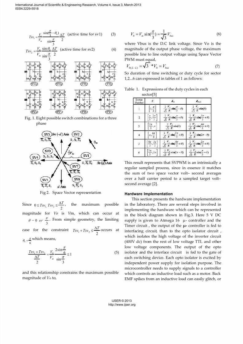
Hardware Implementation
This section presents the hardware implementation
in the laboratory. There are several steps involved in
implementing the hardware which can be represented
in the block diagram shown in Fig.3. Here 5 V DC
supply is given to Atmega 16 µ- controller and the
Timer circuit , the output of the µ- controller is fed to
interfacing circuit, than to the opto isolator circuit ,
which isolates the high voltage of the inverter circuit
(400V dc) from the rest of low voltage TTL and otherlow voltage components. The output of the opto
isolator and the interface circuit is fed to the gate of
each switching device. Each opto isolator is excited by
independent power supply for isolation purpose. The
microcontroller needs to supply signals to a controller
which controls an inductive load such as a motor. Back
EMF spikes from an inductive load can easily glitch, or
International Journal of Scientific & Engineering Research, Volume 4, Issue 3, March-2013
ISSN 2229-5518
IJSER © 2013http://www.ijser.org
7/23/2019 Researchpsvpwmaper Generation of Space Vector PWM Using Microcontroller Atmega 16
http://slidepdf.com/reader/full/researchpsvpwmaper-generation-of-space-vector-pwm-using-microcontroller-atmega 3/5
destroy a microcontroller. Back EMF spikes typically
manifest themselves as very short duration spikes
which may or may not contain enough energy to
actually destroy a microcontroller. Hence by using the
opto coupler such high voltage spikes etc can be
prevented[1].
Fig.3. Block Diagram representation of gating signal
generation.
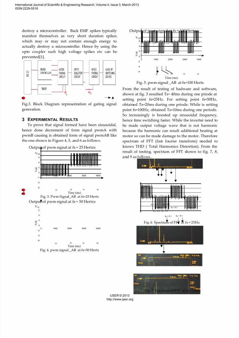
3 EXPERIMENTAL RESULTS
To prove that signal formed have been sinusoidal,
hence done decrement of form signal pwmA with
pwmB causing is obtained form of signal pwmAB like
the one shown to Figure 4, 5, and 6 as follows.
Output of pwm signal at fs = 25 Hertzs
-6
-4
-2
0
2
4
6
0 1000 2000 3000 4000
Fig. 3. Pwm Signal_AB at fs=25 Herts
Output of pwm signal at fs = 50 Hertzs
-6
-4
-2
0
2
4
6
0 1000 2000 3000 4000
Fig. 4. pwm signal _AB at fs=50 Herts
Output of pwm signal at fs = 100 Hertzs
-6
-4
-2
0
2
4
6
0 1000 2000 3000 4000
Fig. 5. pwm signal _AB at fs=100 Herts
From the result of testing of hadware and software,
shown at fig. 3 resulted Ts= 40ms during one priode at
setting point fs=25Hz. For setting point fs=50Hz,
obtained Ts=20ms during one priode. While is setting
point fs=100Hz, obtained Ts=10ms during one periods.
So increasingly is boosted up sinusoidal frequency,
hence time switching faster. While the inverter need to
be made output voltage wave that is not harmonic
because the harmonic can result additional heating at
motor so can be made damage to the motor. Therefore
spectrum of FFT (fast fourier transform) needed to
knows THD ( Total Harmonics Distortion). From the
result of testing, spectrum of FFT shown to fig. 7, 8,
and 9 as follows.
V o l t
10
VAB
30 40
Time (ms)20
V o l t
10
VAB
30 4020
Time (ms)
h6= 0.1
h2= 0.2
h3= 0.6
h5 = 0.2
h4= 0.1
h7= 0.1
h8= 0.1
h6= 0.1
h2= 0.1
h3= 1.2
h5= 0.2
h4= 0.2 h7= 0.1
V o l t
10
VAB
30 40
Time (ms)20
Fig. 6 Spectrum of FFT at fs = 25Hz
Fig. 7 Spectrum of FFT at fs = 50Hz
International Journal of Scientific & Engineering Research, Volume 4, Issue 3, March-2013
ISSN 2229-5518
IJSER © 2013http://www.ijser.org
7/23/2019 Researchpsvpwmaper Generation of Space Vector PWM Using Microcontroller Atmega 16
http://slidepdf.com/reader/full/researchpsvpwmaper-generation-of-space-vector-pwm-using-microcontroller-atmega 4/5
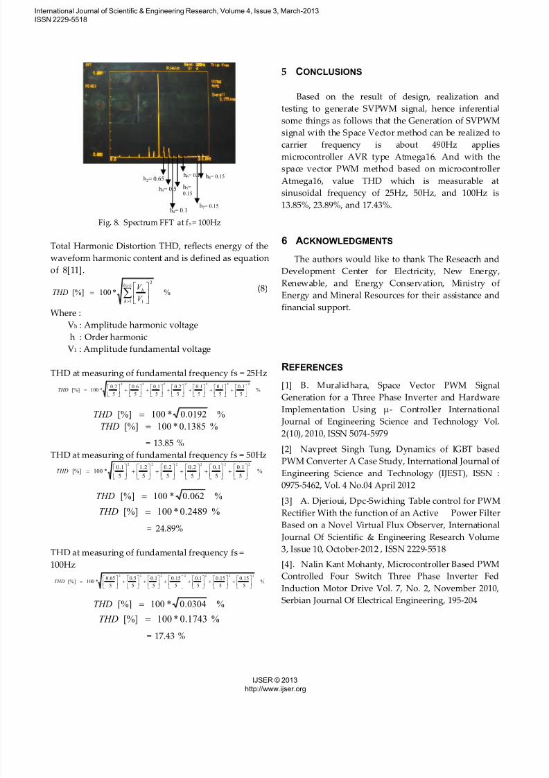
Fig. 8. Spectrum FFT at fs = 100Hz
Total Harmonic Distortion THD, reflects energy of the
waveform harmonic content and is defined as equation
of 8[11].
%*100[%]1
2
1
h
h
h
V
V THD
(8)
Where :
Vh : Amplitude harmonic voltage
h : Order harmonic
V1 : Amplitude fundamental voltage
THD at measuring of fundamental frequency fs = 25Hz
%5
1.0
5
1.0
5
1.0
5
2.0
5
1.0
5
6.0
5
2.0*100[%]
2222222
THD
%0192.0*100[%] THD
%1385.0*100[%] THD
= 13.85 %
THD at measuring of fundamental frequency fs = 50Hz
%5
1.0
5
1.0
5
2.0
5
2.0
5
2.1
5
1.0*100[%]
222222
THD
%062.0*100[%] THD
%2489.0*100[%] THD
= 24.89%
THD at measuring of fundamental frequency fs =
100Hz
%5
15.0
5
15.0
5
1.0
5
15.0
5
1.0
5
5.0
5
65.0*100[%]
2222222
THD
%0304.0*100[%] THD
%1743.0*100[%] THD
= 17.43 %
5 CONCLUSIONS
Based on the result of design, realization and
testing to generate SVPWM signal, hence inferential
some things as follows that the Generation of SVPWM
signal with the Space Vector method can be realized tocarrier frequency is about 490Hz applies
microcontroller AVR type Atmega16. And with the
space vector PWM method based on microcontroller
Atmega16, value THD which is measurable at
sinusoidal frequency of 25Hz, 50Hz, and 100Hz is
13.85%, 23.89%, and 17.43%.
6 ACKNOWLEDGMENTS
The authors would like to thank The Reseacrh and
Development Center for Electricity, New Energy,Renewable, and Energy Conservation, Ministry of
Energy and Mineral Resources for their assistance and
financial support.
REFERENCES
[1] B. Muralidhara, Space Vector PWM Signal
Generation for a Three Phase Inverter and Hardware
Implementation Using µ- Controller International Journal of Engineering Science and Technology Vol.
2(10), 2010, ISSN 5074-5979
[2] Navpreet Singh Tung, Dynamics of IGBT based
PWM Converter A Case Study, International Journal of
Engineering Science and Technology (IJEST), ISSN :
0975-5462, Vol. 4 No.04 April 2012
[3] A. Djerioui, Dpc-Swiching Table control for PWM
Rectifier With the function of an Active Power Filter
Based on a Novel Virtual Flux Observer, International
Journal Of Scientific & Engineering Research Volume
3, Issue 10, October-2012 , ISSN 2229-5518
[4]. Nalin Kant Mohanty, Microcontroller Based PWM
Controlled Four Switch Three Phase Inverter Fed
Induction Motor Drive Vol. 7, No. 2, November 2010,
Serbian Journal Of Electrical Engineering, 195-204
h2= 0.65
h3= 0.5 h5=
0.15
h4= 0.1
h6= 0.1
h7= 0.15
h8= 0.15
International Journal of Scientific & Engineering Research, Volume 4, Issue 3, March-2013
ISSN 2229-5518
IJSER © 2013http://www.ijser.org
7/23/2019 Researchpsvpwmaper Generation of Space Vector PWM Using Microcontroller Atmega 16
http://slidepdf.com/reader/full/researchpsvpwmaper-generation-of-space-vector-pwm-using-microcontroller-atmega 5/5
[5]. Bin Wu, “High-Power Converters and AC Drives”,
IEEE press, John Wiley & Sons, Inc., Hoboken, New
Jersey, 2006.
[6] K. Zhou, D. Wang, “Relation between space-vector
modulation and three-phase carrier-based PWM”,
IEEE Transactions on Industrial Electronics, Vol. 49,No. 1, pp 186-196, February 2002.
[7]. Mohd Wazir Bin Mustafa, “Static And Dynamic
Impacts Of Three To Six-Phase Conversion Of Selected
Transmission Line In An Electric Energy System” ,
Research vote no:74164, Universiti Teknologi Malaysia,
2006.
[8]. Peter Vas, “Electrical Machines and Drives A
space-vector theory approach”, Oxforf University
Press, New York, 1992.
[9] Raman Nair Harish Gopala Pillai, “ Design And
Development Of Embedded Dsp Controllers For
Power Electronic Applications”, Thesis, University Of
Texas At Arlington, May 2006.
[10]. Remus Teodorescu, “Space Vector Modulation
Applied to Modular Multilevel Converters”,
Department of Electrical Engineering,Texas A&M
University, 1999.
[11]. Zaenal Salam & Khosru Mohammad Salim,
“Generation of Pulse Width Modulation(PWM) Signal
for Three-Phase Inverter Using A Single Chip
Microcontroller” , , Jurnal Teknologi, UniversitiTeknologi Malaysia, 34(D) Jun 2001.
International Journal of Scientific & Engineering Research, Volume 4, Issue 3, March-2013
ISSN 2229-5518
IJSER © 2013http://www.ijser.org
Related Documents