AN ABSTRACT OF THE THESIS OF Lucian Chis for the degree of Master of Science in Electrical and Computer Engineering presented on August 24, 1998. Title: Testing and Modeling of the Single-Phase Written-Pole Motor Abstract approved. Alan Wallace A relatively new development in the electric machines field has been the written-pole technology, of which the latest product is the large single-phase electric motor, the single phase Written-Pole Motor (WPM). The WPM is a synchronous, permanent-magnet single-phase motor having a weak rotor cage for start-up which in addition exhibits significant hysteresis effects at speeds below or above true syn- chronism. The electrical configuration of the WPM places it in the capacitor-start capacitor-run category of single-phase motors, due to the large size and need for an approximation of a round rather than elliptic rotating magnetic field. This thesis presents the results of the research conducted by the author in the Motor Systems Resource Facility (MSRF) of the Electrical and Computer Engineer- ing Department at Oregon State University. The thesis is structured into two main parts: Testing and Modeling. The tests conducted on the WPM were trying to independently verify manu- facturer's claims with regards to efficiency, power factor, robustness, power-outage ride-through and furthermore to study the behaviour of the machine during voltage sags, overvoltages and undervoltages. Tests were conducting in order to develop a Redacted for Privacy

Welcome message from author
This document is posted to help you gain knowledge. Please leave a comment to let me know what you think about it! Share it to your friends and learn new things together.
Transcript

AN ABSTRACT OF THE THESIS OF
Lucian Chis for the degree of Master of Science in
Electrical and Computer Engineering presented on August 24, 1998.
Title: Testing and Modeling of the Single-Phase Written-Pole Motor
Abstract approved.
Alan Wallace
A relatively new development in the electric machines field has been the
written-pole technology, of which the latest product is the large single-phase electric
motor, the single phase Written-Pole Motor (WPM). The WPM is a synchronous,
permanent-magnet single-phase motor having a weak rotor cage for start-up which
in addition exhibits significant hysteresis effects at speeds below or above true syn
chronism. The electrical configuration of the WPM places it in the capacitor-start
capacitor-run category of single-phase motors, due to the large size and need for an
approximation of a round rather than elliptic rotating magnetic field.
This thesis presents the results of the research conducted by the author in the
Motor Systems Resource Facility (MSRF) of the Electrical and Computer Engineer
ing Department at Oregon State University. The thesis is structured into two main
parts: Testing and Modeling.
The tests conducted on the WPM were trying to independently verify manu
facturer's claims with regards to efficiency, power factor, robustness, power-outage
ride-through and furthermore to study the behaviour of the machine during voltage
sags, overvoltages and undervoltages. Tests were conducting in order to develop a
Redacted for Privacy

mathematical model from which the performance of the machine can be predicted.
The modeling efforts were concentrated in the development of a comprehensive
model which would include all three major aspects of the WPM, and the perfor
mance of the resulting model was compared with the sampled data.

©Copyright by Lucian Chis
August 24, 1998
All rights reserved

Testing and Modeling of the Single-Phase Written-Pole Motor
by
Lucian Chis
A THESIS
submitted to
Oregon State University
in partial fulfillment of the requirements for the
degree of
Master of Science
Completed August 24, 1998 Commencement June 1999

Master of Science thesis of Lucian Chis presented on August 24, 1998
APPROVED:
Major Professo , representing Electrical and Computer Engineering
Chair of the Department of Electrical and Computer Engineering
Dean of the Grad e School
I understand that my thesis will become part of the permanent collection of Oregon
State University libraries. My signature below authorizes release of my thesis to
any reader upon request.
Lucian Chis. Author
Redacted for Privacy
Redacted for Privacy
Redacted for Privacy
Redacted for Privacy

TABLE OF CONTENTS
Page
1. INTRODUCTION 1
1.1. Overview of the Written-Pole Technology 1
1.2. Single-Phase Written-Pole Motor Configuration 3
2. PROPOSED MODELS FOR THE WPM 7
2.1. Induction Motor Component 8
2.2. Hysteresis Motor Component 9
2.3. Synchronous Motor Component 11
3. TESTING OF THE WRITTEN-POLE MOTOR 13
3.1. Overview of the MSRF Testing Facility 13
3.2. The testing set-up 14
3.3. Load tests 15
3.4. Starting Test 16
3.5. WPM System load tests 18
3.5.1. Rated voltage tests 18
3.5.2. Effect of Supply Voltage Variation on the Performance of WPM 21
3.6. Restarting Test and Power Outage Simulation 23
3.7. Voltage Sag Test 24
3.8. Induction Motor Performance and Characterization 27
3.8.1. Induction Motor Load tests 27
3.8.2. Locked Rotor Tests. 28
3.8.3. Main Winding Tests 29
Load Tests 30
Locked Rotor Test 30

TABLE OF CONTENTS (Continued)
Page
3.8.4. Auxiliary Winding Tests 31
3.9. Hysteresis Motor Component Tests 32
3.10. Synchronous Machine Tests 33
3.10.1.Open Circuit Test 34
3.10.2.Short Circuit Test 34
4. COMPUTER SIMULATIONS 36
4.1. Quasi Steady-state Model for the WPM 36
4.2. Parameter Optimization 40
5. CHARACTERIZATION AND PROBLEMS WITH THE WPM 45
5.1. Overexcited Synchronous Machines 45
5.2. Hysteresis Motor 46
6. CONCLUSIONS AND RECOMMENDATIONS 49
6.1. Performance 49
6.2. Problems 50
6.2.1. Dynamic Instability 50
6.2.2. Cogging 51
6.2.3. Shaft Dimension 51
6.3. Recommendations 52
6.3.1. Dynamic stability 52
6.3.2. Cogging 53
6.3.3. Shaft size 53
7. LIST OF ABBREVIATIONS 54

TABLE OF CONTENTS (Continued)
Page
7.1. General Abbreviations 54
7.2. Nomenclature 54
APPENDICES 57
A Name Plate Data for the Single-phase Written Pole Motor 58
B Mat lab programs used in modeling the WPM 58
BIBLIOGRAPHY 65

LIST OF FIGURES
Figure Page
1.1 Typical Capacitor-Start Capacitor-Run Single-Phase Motor 2
1.2 Written-Pole Motor Structure Schematic 4
2.1 Extended Veinott Equivalent Circuit for the Single-phase Motor 9
2.2 Single Phase PM Balanced Synchronous Machine Equivalent Circuit 12
3.1 The Test Configuration 16
3.2 Net Torque Available, Line Current and Speed, during start-up 17
3.3 Maximum Amplitude Hunting Condition 20
3.4 Minimum Amplitude Hunting Condition 21
3.5 WPM and Typical 3-phase Induction Motor Efficiency 22
3.6 WPM and Typical 3-phase Induction Motor Power Factor 23
3.7 Voltage Variation effect on Efficiency 24
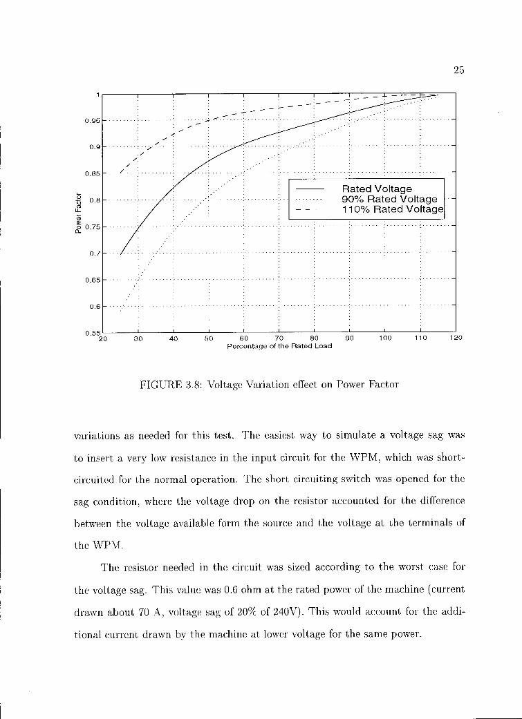
3.8 Voltage Variation effect on Power Factor 25
3.9 Rated Load 15 Seconds Power Outage Simulation 26
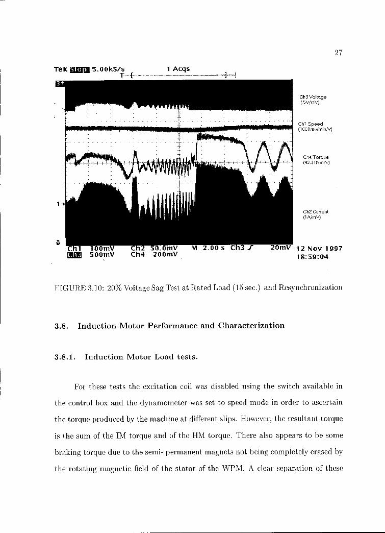
3.10 20% Voltage Sag Test at Rated Load (15 sec.) and Resynchronization 27
3.11 Steady-State Induction and Hysteresis Resultant Torque 28
3.12 Main Winding Torque-Speed Characteristic 31
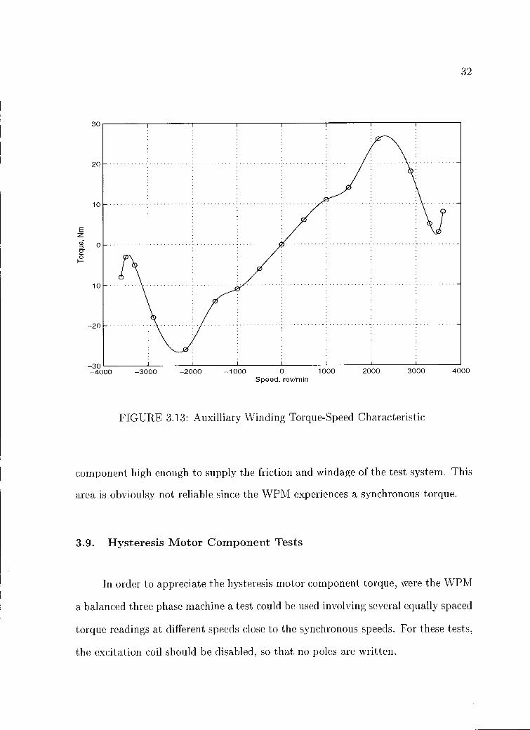
3.13 Auxilliary Winding Torque-Speed Characteristic 32
3.14 Permanent Magnet Synchronous Machine Equivalent Circuit 34
4.1 The First and Second Rotor Circumference Pole Writing Process. 37
4.2 Single-Phase Written-Pole Motor Equivalent Circuit 39
4.3 Series Form of the Single-Phase WPM Equivalent Circuit 41
4.4 Comparison of Measured and Model Torques after Optimization . 43
TESTING AND MODELING OF THE SINGLE-PHASE
WRITTEN-POLE MOTOR
1. INTRODUCTION
1.1. Overview of the Written-Pole Technology
Precise Power Corporation's "Written-Pole" technology has been emerging
for some time in the field of Uninterruptable Power Supplies, three-phase motor-
generator sets (Roessel Motor-Generators) and others [13]. The latest offshoot of
this technology is the large single phase "Written-Pole Motor" [11]. Conventional
single-phase motors, typically using a capacitor-start/capacitor run induction ma
chine configuration as shown in Fig 1.1, are generally limited to applications requir
ing less than 5kW, at 240V. One reason for this limitation is the starting current,
which is typically 6 to 10 times the rated current of the machine. This magnitude
of the current can cause voltage sag or flicker conditions for other equipment, espe
cially in weak lines found in remote locations as farms, small mines, and recreational
facilities fed by long lines having an appreciable equivalent source impedance. In
order to satisfy larger loads, such as pumps and fans without the prohibitive con
struction cost of three-phase distribution systems, several alternatives have been
proposed [1]. The Written-Pole motor joins these ranks besides the following op
tions: operation of a conventional three-phase induction motor via a single-phase
to three-phase power converter (i.e. a modified adjustable speed drive) with soft
start capability; operation of a conventional three-phase motor from a single-phase
supply via a "semi-hex" connection, as developed by Smith [10]. The Written-Pole
single phase motor (WPM) is the result of the research and development of Precise

2
Start
capacitor
Run V1 capacitor
Main
Switch
7Thr-Y-vm
Auxiliary
FIGURE 1.1: Typical Capacitor-Start Capacitor-Run Single-Phase Motor
Power Corporation with funding from a group of North American power utilities,
under the auspices of the Electric Power Research Institute (EPRI), in response to
the changing requirements of their remotely located customers. The range of powers
initially envisioned for these motors was 15 to 60 kW.
A 20hp Written-Pole motor, having the nameplate data given in Appendix
1, was obtained for independent study and testing at the Motor Systems Resource
Facility (MSRF) of Oregon State University (OSU).
The MSRF study was intended to complement and add to an earlier evalu
ation by Manitoba Hydro [4]. The Manitoba Hydro team studied the run-up and
normal synchronous operation performance of an 1800rev/min machine in order to
verify the manufacturer's claims.
The study presented here seeks to confirm the Manitoba Hydro findings and
in addition investigates other WPM features such as performance during voltage
sags, power outages, supply voltage variation effects . Also, a series of tests were
performed in order to determine machine parameters, leading to an appropriate uni

3
tary model of the WPM for performance prediction, since no analyses of this type
are available in the published literature.
1.2. Single-Phase Written-Pole Motor Configuration
In order to operate from a single-phase supply, the WPM, as most single-phase
motors of high power rating, emulates a balanced two-phase stator machine system
which is required to develop a rotating magnetic field without undue counter rotating
component. This arrangement is shown in the schematic of Fig 1.1. This represents
a two-phase quadrature-winding arrangement with both switched (start) and per
manent (run) capacitors which approximate a balanced operation during starting
and running. In addition to this conventional stator configuration, several unique
features have been incorporated into the machine in order to meet specific perfor
mance requirements. Several of these features are evident from a cross-sectional
diagram of Fig 1.2:
1. In order to limit the line current during start-up, the WPM has a high-
resistance cage rotor and a long effective air gap. The mechanical rotor-stator
clearance of the WPM is similar to that of a conventional machine of the same
size: the long magnetic "air" gap is due to a layer of ferrite, having a low
relative permeability, attached to the rotor surface facing the stator. During
start-up the ferrite exhibits a small amount of permanent magnetization which
can not be completely erased by the rotating magnetic field, which is residual
from previous operation. This layer is responsible for the greater part of a
hysteresis torque which augments the induction torque of the rotor cage dur
ing starting, given the low flux densities the rotor laminations are subjected
to.

4
Excitation Rotor Sleeve RotorStator Main Coil
LaminationsWindings
Stator Magnet layer laminations
Squirrel cage
FIGURE 1.2: Written-Pole Motor Structure Schematic
2. In order to provide high efficiency and good power factor, the WPM operates as
a synchronous permanent magnet machine under normal operating conditions.
This is ingeniously achieved by "writing" "permanent" magnetic poles onto
the ferrite layer by employing a special additional stator coil. This unusual
stator coil, having a very small pitch is referred to, by the manufacturer, as
the "excitation coil".
3. In order to avoid severe transients between the induction/hysteresis run-up
and the synchronous normal operation, magnetic poles are repeatedly written
on the rotor ferrite layer. Below 3600rev/min, for our 2 pole 60Hz machine,
the length of the poles being written is shorter than a true pole pitch. This

5
makes the motor operate synchronously at less than synchronous speeds. This
has been achieved by applying the line frequency currents to the excitation
coil, without any electronic power processing.
4. In order to provide a measure of ride-through capability during supply voltage
disturbances, the WPM has a high inertia external rotor, having a double cup
design.
5. The WPM operation is controlled and monitored by an Intel 8051 serial mi
crocontroller. The software can be customized in order to meet specific loads
during start-up or sudden overload. The addition of a serial port enables
on-line remote monitoring and control.
The WPM offers the following claimed advantages over other single-phase designs:
1. The starting current of the WPM is only 2.1pu (per-unit) enabling its ratings
to be 300 % to 600% higher than previous induction machines in remote single-
phase applications, without undue disturbance to other equipment.
2. The WPM, being a permanent magnet synchronous machine, has a higher
efficiency than comparably sized induction motors for loads exceeding 60 % of
the rated load.
3. It has a very high leading power factor, up to about 115% of the rated load.
This substantially exceeds in value the power factor of comparable induction
machines at all loads.
4. The high inertia of the rotor has the advantage that the starting of the motor is
very slow thus making the WPM ideal for pumping applications where water
hammer can be a problem. The same inertia provides ride-through during
power outages of up to 15 seconds.

6
The objectives of the test program described in this thesis were to examine these
claims.

7
2. PROPOSED MODELS FOR THE WPM
From the beginning it is evident, by examining the structure of the WPM,
that it has three major electric machine torque-producing components. These are
the induction, hysteresis and synchronous components.
The same stator configuration is responsible for all three components, whereas
the rotor elements contribute to them as follows:
1. The rotor cage is responsible for an asynchronous or induction motor compo
nent at any speed other than synchronous.
2. The rotor ferrite layer and its laminations are the cause of the hysteresis motor
component which is again present at all speeds other than synchronous. Most
of this component however is located in the ferrite, which has a much larger
area of the hysteresis loop compared to the laminations which are designed
with a small hysteresis premise, operating at low flux densities (less than 1T).
This conclusion is the result of the remanent flux density in the air gap at the
synchronism being 0.4T as per manufacturer's data.
3. The rotor ferrite layer is responsible for the permanent magnet synchronous
motor component at synchronism and in a speed range betweeen 80% and
100% of the rated speed (this range can be customized by changing the pro
gramming of the microcontroller). The writing, or excitation coil, located on
the stator, is responsible for the appropriate magnetic pole configuration (i.e.
the pole pitch) on the rotor.
8
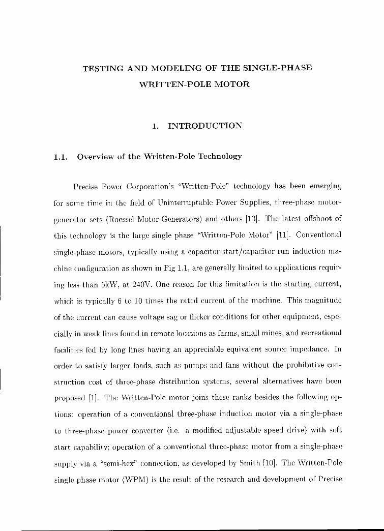
2.1. Induction Motor Component
Between standstill and 80% of the rated speed (2880 rev/min in our partic
ular case) the WPM has an induction component which derives from a high rotor
cage resistance (steel conductors), high rotor leakage reactance (bars deeply set in
the rotor laminations), and low magnetizing impedance (long electromagnetic gap).
These features have the effect of (i) limiting the magnetization inrush current of the
first cycle of the applied voltage, (ii) keeping the starting currents to a tolerable
level and (iii) providing a high starting torque per amp ratio. Between standstill
and full-speed a first capacitor switching is performed in order to maintain an ap
proximation to balanced two-phase operation. A second capacitor switching takes
place five seconds after synchronous speed operation has been attained. Due to the
limited input power during start-up, and the high rotor inertia, the acceleration
of the machine is very small. In consequence, the electrical time constants of the
system are very small compared to the mechanical time constant of the machine
and thus a transient or dynamic model of the WPM is unnecessary. Hence, the
induction motor performance can be predicted by a steady-state equivalent circuit
such as the one due to Veinott as shown in Fig 2.1, which accounts for the effects
of both forward-rotating and backward-rotating field components of the unbalanced
rotating magnetic field. However, in practice the WPM is substantially balanced
by winding design and choice of capacitors, such that the conventional "per-phase"
circuit may be adequate. Current and torque can be calculated by solving the
circuit.

9
Forward
branch
r 2/2s a2r 2/2s
ja2Xm/2
2/2 ja2x2/2
vi
a2r212(2-s)
r2/2(2-s) ja2Xm/2
jx2/2 ja2x212
Backward
branch
Main Winding Auxilliary Winding
FIGURE 2.1: Extended Veinott Equivalent Circuit for the Single-phase Motor
2.2. Hysteresis Motor Component
The nature of the hysteresis torque rests in the fact that the magnetic field
intensity (H) due to the stator windings, leads the resulting magnetic flux density
(B) case, where the shape of the hysteresis loop is idealized as an ellipse or, more

10
realistically, the fundamental of the B waveform, by an angle OH [8]. In the general
case, an eddy-curent component due to the electrical conductivity of the magnetic
material would develop as well. The hysteresis component of the WPM is due
mostly to the unmagnetized ferrite and therefore does not have any eddy-current
component, because of the particular structure of the ferrite, which presents a high
resistivity, due to its sinterized ferrous oxide structure. Also, the eddy-currents
that appear in the rotor laminations are insignificant by design. In this case, were
the WPM a balanced three-phase machine, the hysteresis torque would be constant
throughout the speed range, having a value TH given by [6]
Ah X V 01 X pTH (2.1)
47r
in which AH is the area of the hysteresis curve through which the material passes
during each cycle, Vol is the volume of the ferrite, and p is the number of poles. It is
to be remarked that during start-up the machine does not have a constant hysteresis.
This is due, in a small amount, to the fact that the capacitors in the circuit seem to
be overdesigned for the balanced two-phase operation (because the second step in
the auxiliary circuit is only taken out 5 seconds after synchronism is attained). It
is also due, in a larger amount, to the fact that, during the pole-writing mode, the
poles are being fully magnetized for the first time and also an area that is dependent
to the slip is being rewritten with a more or less different permanent magnetization.
However, a major problem in estimating this component is finding the area of the
hysteresis cycle which is followed by the ferrite, because the written poles from
previous operation are not completely erased by the rotating magnetic field during
all asynchronous operation. Thus in reality the ferrite is following minor hysteresis
loops whose shape and size depend on the location relative to the last writing of
the poles, which are effectivelly written in a sinusoidal fashion by the excitation coil

11
along the circumference of the rotor. The hysteresis component in general can be
represented in a d-q equivalent circuit as a short-circuited winding in each circuit
having a resistance to reactance ratio which is independent of the frequency (or slip)
in acordance with the constant angle OH, and its resistance is inversely proportional
to the slip, like an induction machine. In practice, the value of the torque can be
calculated from the power dissipated in the equivalent resistance.
Determination of the necessary magnetic field information would require the
use of a flux density probe or search coils to be inserted in the air gap of the WPM.
This cannot be performed without irreversible modifications to the motor, which
were not permitted in this investigation. Consequently, a matching technique was
used to evaluate the hysteresis component of the torque and, from that, the the
effective resistance for the equivalent circuit was obtained.
2.3. Synchronous Motor Component
When the WPM has attained 80% of the rated speed (synchronous) the micro-
controller energizes the excitation coil and from this point forward the machine has
a synchronous component. During the pole-writing mode the synchronous machine
component is operating in an unusual manner: the power angle is constant, being
dictated by the excitation coil spatial displacement with respect to the main stator
coil. After the synchronous speed has been attained the poles are overwritten (there
is actually an oversynchronous speed given by the negative slip of the rotor poles due
to the position of the excitation pole) for another 5 seconds and then the excitation
coil is deenergized and the dominant variable of the motor performance becomes the
power angle, the machine behaving like a synchronous permanent magnet machine
with a weak ammortiseur.

12
Main Auxilliary
FIGURE 2.2: Single Phase PM Balanced Synchronous Machine Equivalent Circuit
In this mode of operation we can predict the torque by using the knowledge
of the induced emfs. IMEM + IAEA
Ts (2.2)1207r
in which EM and EA are the main and auxiliary induced emfs, and TA/ and IA are
the respective currents for the WPM considered here (2 pole), as shown in Fig2.2.

13
3. TESTING OF THE WRITTEN-POLE MOTOR
The testing of the WPM was conducted in order to accomplish the following
objectives:
1. First of all the system performance of the WPM needed to be evaluated
through a thorough testing under different loads and supply voltage levels,
during power outages, and supply voltage sags.
2. For the separation and quantization of the torque producing components of
the WPM, which is required by an in depth understanding of this complex
machine, a series of tests were devised, from which an appropriate equivalent
circuit was obtained.
3. In order to obtain the parameters of the equivalent circuits of the individual
torque producing components, short circuit, locked rotor, open circuit and no
load, synchronous rotation tests were performed.
The testing of the WPM was accomplished using the resources of the Motor Systems
Resource Facility of Oregon State University.
3.1. Overview of the MSRF Testing Facility.
The Motor Systems Resource Facility (MSRF) is a modern test and research fa
cility funded by the Electric Power Research institute (EPRI) and Bonneville Power
Administration (BPA) at the Electrical and Computer Engineering Department of
Oregon State University. It has been designed as an industrial laboratory for stan
dard motor tests as prescribed in the IEEE Standards 112 and 115 for polyphase
induction and synchronous machines respectively, as well as testing of other kinds of

14
rotating or non-rotating electric machinery, adjustable speed drive systems, active
and passive filters and general research in the field of electric machinery [2]. The
MSRF has three test beds designed for machine ranges of up to 15hp, 75hp (under
construction at this time) and up to 300hp for the large one. The large test bed of
the Motor Systems Research Facility of Oregon State University was used for testing
the WPM, due to the special nature of the testing required. This was dictated by
the large inertia of the WPM and also by its physical size, both of which would
place it in the 100hp range were it a standard induction machine.
3.2. The testing set-up
The large test bed of the MSRF can accommodate rotating electric machinery
of up to 300hp and up to 4000rev/min and various tests can be performed employ
ing a dynamometer which consists of a cage-rotor, inverter-grade induction machine
fed by a four quadrant adjustable speed drive. The testing is done fully regenera
tively, the only energy loss being due to the losses in the machine under test, the
dynamometer machine and the power electronics conversion of the dynamometer
converter. The dynamometer can be operated at this time in constant torque or
constant speed modes. It has a speed transducer on its shaft and it has a torque
estimator. The mechanical output or input of the machine under test is obtained
through a strain gauge torque transducer (model 7540 made by Eaton-Lebow).
Use of a Philips type PM6666 frequency counter enables measurement of the speed
within hundreds of rev/min rather than just integral rev/min as obtainable from the
Eaton-Lebow speed measurement. The electrical quantities of the machine under
test are monitored through a Voltech type PMA 3300 true RMS power analyzer,
which accepts also as auxiliary inputs the torque and speed as DC signals from

15
the Eaton-Lebow torque and speed transducer. The voltage was fed directly to the
power analyzer whereas the currents were monitored through the use of Hall effect
transducers (Model LT-500S by L.E.M.). These Hall effect Fig transducers have a
distinct advantage over the regular shunts in that they provide galvanic isolation
and at the same time are able to sense dc current components. The WPM was fed
through two of the three computer regulated autotransformers available normally
for three-phase testing configurations. The data can be remotely aquired through
a parallel GP/IB bus through which the frequency counter and the power analyzer
are connected to a computer equipped with the proper interface. In addition, dur
ing the testing, a Tektronix TDC460 four channel digitizing oscilloscope was used
in order to obtain the time variation of torque, speed, current and voltage during
"steady-state" and transients. Also the oscilloscope has waveform saving capability
which has been used extensively during the course of the testing and research.
A schematic of the complete test system is shown in Fig 3.1.
3.3. Load tests
The bulk of the tests was done in order to verify manufacturer's claims with
regard to the efficiency, power factor, inrush current magnitude, temperature rise,
power outage ride-through, and robustness of the control circuit. Further tests were
performed in order to analyze the effect of input voltage variations or sudden sags
on WPM performance.

16
480V BUS
Autotransformer
\k tech PM3300 Tattrank
TOS LBA Hall A Power Analyzer 630A
Effect Current T S
Sensors
Eaton Lebow 7540
a
VVPIV1 T S 300HP
Dynamometer N
ASD 300 A N \I V
PC
1
FIGURE 3.1: The Test Configuration
3.4. Starting Test.
For this test the WPM was connected to rated voltage in the configuration
it was delivered which is the normal intended mode of operation. The current and
torque during start-up were recorded on scope captures as shown in Fig 3.2. It has
been found that the claims of the manufacturer with respect to the line current
during start-up are justified, having recorded a starting current of 2.1pu. The cold
WPM took an average of 57 seconds to start-up and synchronize working against the

17
Te k Sto : 1.00kS/s 1 Acqs
Ch3 Speed (10rprn/mV)
Ch2 Current (1 A,/mV)
Cho Torque (43.31NmN)
Ch2 200mV M 10.0 S Ch2 92mV 25 Nov 1997 a I 50.OmV Ch4 200mV 20:39:55
FIGURE 3.2: Net Torque Available, Line Current and Speed, during start-up
inertia, friction and windage of the test set consisting of itself and the dynamometer.
The inertia of the WPM has to be figured in the estimation of the torque during
start-up, given the very high polar moment of inertia (134.5 lb f t2 or 5.67kgm2).
The acceleration during start-up is then almost constant having a value of about
7.25 radlsec2. This requires an acceleration torque of about 41.1 Nm which is not
perceived at the shaft by the torque meter. This acceleration torque is very close
to the rated torque of the machine so the oscilloscope capture of the torque during
start-up shows the starting torque component in excess of the WPM rated torque.
It is discovered that the machine exhibits an appreciable cogging torque around
900 rev/min even after the smoothing action of the WPM inertia. This can be

18
attributed to a permanent magnet braking effect due to the previously written
poles not being completely erased by the rotating magnetic field up to the respective
speed. The starting characteristic also reveals the first capacitor switching which
takes place around 2400rev/min. The beginning of the pole-writing process can be
seen as a definite spike denoting the "catching" into synchronism while the machine
still experiences induction and hysteresis torques. The second capacitor switching
takes place immediately after proper synchronism is attained (5 seconds). The
inertia corrected torque versus time characteristic can be used as the torque-speed
characteristic with the appropriate scaling of the time axis (the speed is almost
linear with time), because the mechanical time constant is a lot larger than the
electrical ones.
3.5. WPM System load tests
The main part of the test program was devoted to the load testing of the
WPM.
3.5.1. Rated voltage tests
Since there are no relevant test procedures for this novel type of machine, a
test program had to be designed by adapting the standard tests prescribed by IEEE
Standards 112 and 115 for polyphase induction and synchronous machines respec
tively. During these tests, the machine was loaded at a particular level and the load
kept constant until the WPM reached thermal stabilization. Because of the large
thermal mass of the WPM compared to its ratings, this took approximately 6 hours
for the rated load. The temperature of the windings of the WPM was monitored

19
through the internal temperature measurement devices with which the WPM was
equipped from the factory. There are two sets of temperature measurement devices:
a set of 4 thermistors which are monitored by the WPM microcontroller, one for
each of the two phase stator windings and one for each of the excitation coils in the
two halves of the machine. The WPM has redundant thermal protection having, in
addition to these thermistors, a set of thermal cutouts in series in the control circuit
input power.
A set of two thermocouples is available as well for field testing at the terminal
box on the machine itself. The latter were connected to a Fluke handheld meter
equipped with a thermocouple interface. The WPM microcontroller was connected
through its serial port to a laptop computer operating in a VAX environment and
so the temperatures measured by the internal thermistors were displayed along with
a host of other useful information. Another temperature probe was used to mea
sure the case temperature even though for this configuration of the WPM (external
rotor) this information is less relevant.
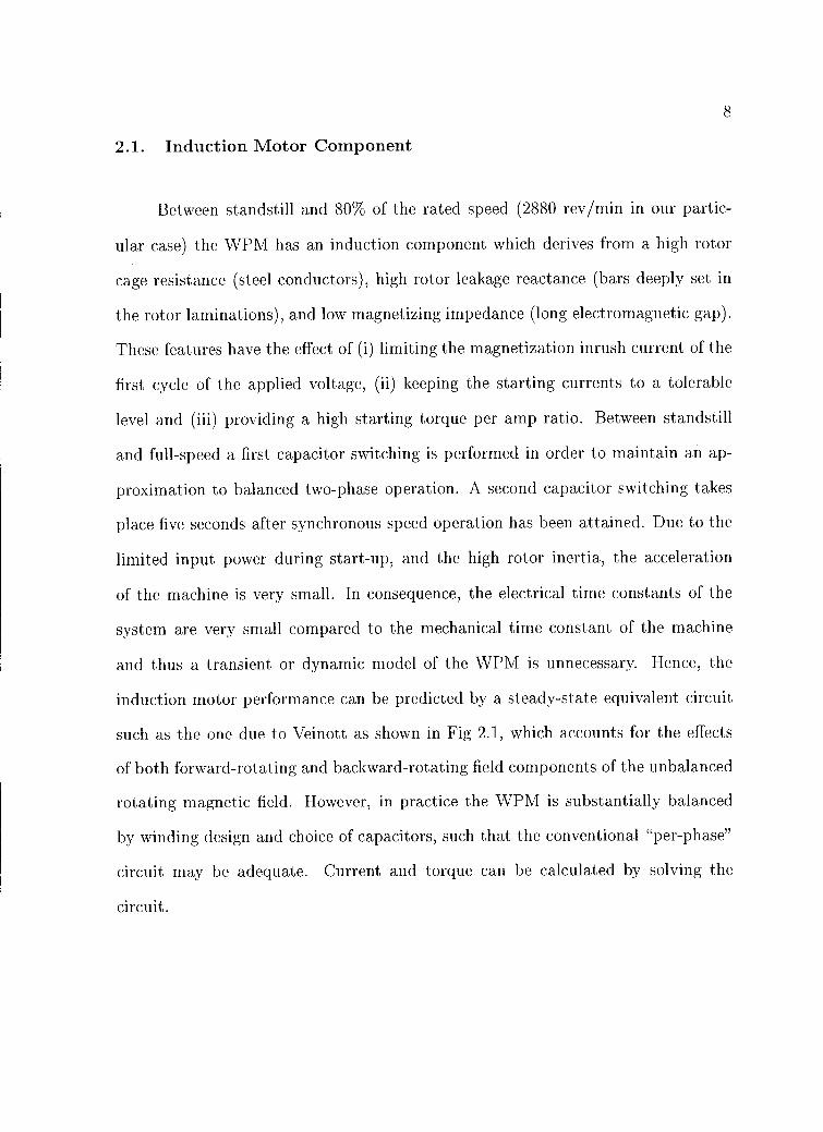
The WPM during loaded or unloaded operation displays hunting or dynamic
instability similar to that normally associated with an overexcited, underdamped
synchronous machine coupled with a hysteresis type hunting effect. The amplitude
of this hunting modulation of the available torque is itself time varying with a period
of about 4 minutes. The two extremes are shown in Fig 3.3 and Fig 3.4. The
torque and current waveforms were observed on the digitizing oscilloscope in order
to get a qualitative measure of the modulating oscillation. In order to get meaning
ful results the minimum hunting condition has been chosen as the data aquisition
point. The data was taken using the maximum number of averaging points available
on the power analyser (64 readings were averaged over about 1 minute). There were
4 readings taken at each load and voltage points and their results averaged. A range

20
Tek Run: 2.50MS/s Sample
Chl Current (1 A/mV)
200mV M4.00ms Cftl 0 V 6 Nov 1997 17:42:37
FIGURE 3.3: Maximum Amplitude Hunting Condition
of loads between 25% and 125% of the rated load were simulated first at the rated
voltage and the resulting efficiency and power factor curves are presented in Fig 3.5
and Fig 3.6, respectively, along with typical induction motor respective curves for
the same ratings. The WPM recommended overload is only 115% of the rated load,
above which the motor reverts to the pole-writing mode in order to account for the
excess load. This condition tends to overheat the rotor thus making it susceptible
to a Curie point type loss of its magnetic properties.
It was found that the WPM was able to keep a 125% load stable during the
testing. As is seen from the characteristics of Fig 3.5, the WPM has a higher effi
ciency than a typical induction motor of comparable ratings beginning from about
65% of its rating up to 125%.
This comparison doesn't take into account the fact that in the same type of
21
Tek Run: 2.50MS/s Sample
Chi Current : 4.i i :
CIA/mV)
Mai 200mV M4.00ms Chl J 0 V 6 Nov 1997 17:40:05
FIGURE 3.4: Minimum Amplitude Hunting Condition
applications (single-phase) the induction motor would be fed through an adjustable
speed drive or a converter of some sort which would not have 100% efficiency.
As far as the power factor is concerned, the WPM outperforms the induction
machine at all loads, as would be expected from a synchronous machine, as readily
seen from Fig 3.6. As an added benefit, the power factor is leading up to about
120% of the rated load, from where it becomes lagging. As we shall see later, this
benefit comes at the cost of dynamic instability or overstability.
3.5.2. Effect of Supply Voltage Variation on the Performance of WPM
In order to investigate the performance of the machine with the variation of
the supply voltage, the load tests were repeated at 90% and 110% of the rated

22
0.95
a
0.9
0.8
0 o WPM0.75 InterpolatedTypical Induction Motor
0.7 0
0.65 20 30 40 50 60 70 80 90 100 110 120 130
Percentage of the Rated Load
FIGURE 3.5: WPM and Typical 3-phase Induction Motor Efficiency
voltage. The results are presented in Fig 3.7 and Fig 3.8. It can be seen that the
efficiency did vary slightly with the voltage throughout the load range, with minimal
variation at the rated load and maximum at 50% load, hence it can be concluded
that the voltage deviation from the rated value doesn't have a major impact on the
efficiency. However, the power factor is affected strongly, especially at decreased
loads, and its value is directly proportional to the value of the supply voltage.

0.9
23
a
0 cL
0.7 0 0 WPM
InterpolatedTypical Induction Motor
C.
0.6
0.520 30 40 50 60 70 80 90 100 110 120 130 Percentage of the Rated Load
FIGURE 3.6: WPM and Typical 3-phase Induction Motor Power Factor
3.6. Restarting Test and Power Outage Simulation
It has been considered relevant for the performance analysis of the WPM to
observe its behaviour when it was started at different coast-down speeds, at different
loads. All these loads were handled well by the control software, which has energized
the machine in the appropriate modes for the speeds and loads present. The most
representative of these tests was the power outage test where the WPM, operating
at full load in the constant torque mode of the dynamometer, was disconnected from
the power supply for 15 seconds and then reconnected. The results are presented
in the oscilloscope capture of Fig 3.9. As is seen from this oscilloscope capture, the
inertia of the WPM covers the load requirements while its speed decreases to 2900

24
0.95
0.9
0.85 o>"
a) (7)
LU
0.8
0.75
Rated Voltage90% Rated Voltage110% Rated Voltage
0.7
0.65 20 30 40 50 60 70 80
Percentage of the Rated Load 90 100 110 120
FIGURE 3.7: Voltage Variation effect on Efficiency
rev/min, and, after the power is restored, the current drawn does not exceed 2.1 pu
as the machine returns to synchronism (3600 rev/min).
3.7. Voltage Sag Test
In the case of remote locations, voltage sags are seen more often than in a
strong line, hence the need to simulate such voltage sags during the testing of the
motor.
A sudden voltage sag is not obtainable with the autotransformers which were
feeding the WPM, since they have a slow tap changing speed, especially in large
25
0.95
0.9
0.85
Rated Voltage0.8 90% Rated Voltage
as 110% Rated Voltage
o 0.75 o_
0.7
0.65
0.6
0.55 20 30 40 50 60 70 80 90 100 110 120
Percentage of the Rated Load
FIGURE 3.8: Voltage Variation effect on Power Factor
variations as needed for this test. The easiest way to simulate a voltage sag was
to insert a very low resistance in the input circuit for the WPM, which was short
circuited for the normal operation. The short circuiting switch was opened for the
sag condition, where the voltage drop on the resistor accounted for the difference
between the voltage available form the source and the voltage at the terminals of
the WPM.
The resistor needed in the circuit was sized according to the worst case for
the voltage sag. This value was 0.6 ohm at the rated power of the machine (current
drawn about 70 A, voltage sag of 20% of 240V). This would account for the addi
tional current drawn by the machine at lower voltage for the same power.

26
Tek Roll: 1.00kSis Sample I
Chi Speed (10rp rnirnV)
CFA Torque 1-+ (43 31Nm,M
Ch2 Current A/rnV)
C 1 100mV SO.OmV M 10.0 s C 2 f 0 V 10 Nov 1997C 4 200mV 16:40:09
FIGURE 3.9: Rated Load 15 Seconds Power Outage Simulation
At the beginning of the test, the machine was loaded to rated power, its tem
perature stabilized, and then the voltage sag performed for about 15 seconds. The
result if this test is shown in Fig 3.10. The WPM subjected to the voltage sag lost
synchronism and its current increased to the level of the starting current. This in
crease is due to the switching into the circuit of the additional start capacitor (step
2), as well as the pole writing excitation coil becoming energized. Upon removal of
the voltage sag, the WPM resynchronizes its load and the current drawn reassumes
its pre-fault value. A slight modulation of the available voltage can be observed,
which is due to the resistor in the circuit, but still the results are relevant for the
field operation of this machine.
27
Tek Ems 5.00kSfs 1 Acqs
Ch3 %/doge (.5WrriV)
Chi Speed (1 000rev/rninN)
0114 Torque (43.31NmN)
Ch2 Current (1A/mV)
a Om . mV M 2.00 s C mV 12 Nov 1997
500mV Ch4 200mV 18:59:04
FIGURE 3.10: 20% Voltage Sag Test at Rated Load (15 sec.) and Resynchronization
3.8. Induction Motor Performance and Characterization
3.8.1. Induction Motor Load tests.
For these tests the excitation coil was disabled using the switch available in
the control box and the dynamometer was set to speed mode in order to ascertain
the torque produced by the machine at different slips. However, the resultant torque
is the sum of the IM torque and of the HM torque. There also appears to be some
braking torque due to the semi- permanent magnets not being completely erased by
the rotating magnetic field of the stator of the WPM. A clear separation of these

28
components is not readily available. The results of this test are presented in Fig
3.11.
0.1 0.2 0.3 0.4 0.5 0.6 0.7 0.8 0.9 Relative Speed
FIGURE 3.11: Steady-State Induction and Hysteresis Resultant Torque
3.8.2. Locked Rotor Tests.
For the locked rotor test, it was feasible for the machine to be energized at
rated voltage, due to the very low inrush current (which never exceeds 2.1pu) and to
the fact that in normal operating conditions the machine can take up to 5 minutes
to start and synchronize its load. This test has been performed both with the motor
cold and after the load tests, when the motor was warm.
1

29
A significant decrease in the value of the torque and current at the locked-
rotor condition was observed when the WPM warmed-up. This reduction can be
attributed to the increase of the resistance of the stator windings and rotor cage
and to the decrease of the magnetic reluctance of the machine due to the increased
thermal motion within the magnetic material of the rotor, and especially of the
ferrite ring which seems to be sensitive to temperature variations. The hot locked-
rotor torque was 48.6 Nm (122% of the rated torque) whereas the cold test yielded
a value of 63 Nm which is about 157.5% of the rated torque of the machine.
3.8.3. Main Winding Tests
The main winding was isolated for testing in the circuit by disconnnecting
the auxiliary winding. This configuration eliminates the rotating magnetic field
so that there is no torque produced at standstill. However, the magnetic field is
sinusoidally distributed in the machine, with a time-varying amplitude modulated
at the frequency of the supply (60Hz). The magnetic field can be viewed as the
phasor addition of two counter-rotating magnetic fields each with half the amplitude
of the real oscillating field. When the machine is driven by external means out of
standstill, its behavior towards the two counter-rotating fields changes. Because of
hysteresis there is also a delay of the magnetization of the rotor with respect to
the inducing mmf wave. Thus, a hysteresis torque, which is a synchronous motor
action produced by the angular shift between the axis of rotating primary mmf and
the axis of secondary magnetization, is developed [9]. However, the WPM did not
produce sufficient torque in order to overcome the friction and the windage of the
test system, with the result that the machine did not accelerate towards synchronism
or maintain a low slip, but it repeatedly slowed down towards zero speed.

30
Load Tests
The machine could not be loaded as an induction motor combined with hys
teresis motor per se, because the friction and windage of the dynamometer machine
exceeded the breakdown torque of the WPM having only one phase connected. In
order to investigate the performance of the WPM in this mode, the dynamometer
was operated in speed mode and the torque output of the WPM was averaged ev
ery time over a period of around 20 seconds in order to get a meaningful result.
This was required by the pulsations of the torque exhibited especially at low slips.
The torque versus speed characteristic of the main winding section of the motor
after using a cubic spline interpolation between the measured points, is presented
in Fig 3.12. The motor has been kept at speeds between positive and negative 3600
rev/min in order to investigate the symmetry of the forward and backward rotat
ing field sections of the equivalent circuit. The behaviour was observed to be very
symmetrical, this confirming the earlier assumptions that machine can be rotated
in either direction with the same performance. It can be seen that the torque is
nonzero at synchronous speed. This is due to the following factors: the hysteresis
and the superposition of the forward-rotating component of the torque with the
backward-rotating one.
Locked Rotor Test
The locked rotor test has been performed at a reduced voltage, for which the
controller could not activate the input contactor, thus requiring the input contactor
to be manually actuated. The reduced voltage has also the effect of reducing the
hysteresis component in the equivalent circuit.

31
25
20
15
10
5
If0 0
5
10
15
20
254000 3000 2000 1000 0 1000 2000 3000 4000
Speed, rev/min
FIGURE 3.12: Main Winding Torque-Speed Characteristic
3.8.4. Auxiliary Winding Tests
The tests performed with the main winding alone were repeated with the aux
iliary winding alone in the circuit. In this case the current drawn was significantly
higher due to the reduction of the impedance compared to the main winding case,
due to the capacitors in the circuit. The resulting torque-speed characteristic are
also presented in Fig 3.13.
As we can observe there is a discontinuity around synchronous speed and we
can atribute that to the fact that the remanent magnetic poles interacting with
the increased current due to the capacitors in the circuit result in a synchronous
32
30
20 0
10 0
0 E f,
a) 0 E.0I 0
10
0 20
304000 3000 2000 1000 0 1 000 2000 3000 4000
Speed, rev/min
FIGURE 3.13: Auxilliary Winding Torque-Speed Characteristic
component high enough to supply the friction and windage of the test system. This
area is obvioulsy not reliable since the WPM experiences a synchronous torque.
3.9. Hysteresis Motor Component Tests
In order to appreciate the hysteresis motor component torque, were the WPM
a balanced three phase machine a test could be used involving several equally spaced
torque readings at different speeds close to the synchronous speeds. For these tests,
the excitation coil should be disabled, so that no poles are written.
33
An extrapolation towards the synchronous speed of these values would yield
the constant component of the torque, which can be assumed to be the hysteresis
component for the all modes except the pole writing. This strategy is based on
the fact that in a balanced three phase induction machine the torque is zero at
synchronism. However, a single phase induction machine exhibits a negative torque
at synchronism, the zero torque condition being attained at some subsynchronous
speed, close but not equal to the synchronous. Therefore, it is not possible to use
this technique for separating the hysteresis and induction torques. This seems to be
possible only with a computer based model matching technique, based on several
torque points at different speeds. The resulting characteristic, obtained from the
torque measurements of the machine without the excitation pole active, and then
interpolated for an equal weight in the model matching throughout the speed range
was compared with the characteristic of the mathematical model and the parameters
of this model were adjusted so that the best fit was obtained. Large pulsations of
the torque were recorded at those points and they are attributed to the remanent
permanent pole slip.
3.10. Synchronous Machine Tests
For a normal synchronous machine the standard tests involve the open-circuit
and short-circuit tests. However, in the case of the WPM there is no way to perform
the short-circuit test which involves, in a regular synchronous machine, reduced
excitation, at the rated speed.

34
3.10.1. Open Circuit Test
Immediately following a loaded run of the WPM, when the poles have been
freshly written, the WPM was disconnected from its power supply and the dy
namometer set in speed mode in order to keep synchronous speed. The open circuit
voltage was measured at the main and auxiliary terminals on the motor connec
tion box, without any capacitors in the auxiliary circuit. The recorded open circuit
voltage, which, in this case, is equal to the induced emf, having no current in the
circuits, was 238V.
3.10.2. Short Circuit Test
In order to pass rated current through the windings, the machine was left to
coast down to standstill from the previous experiment and a short circuit was applied
initially to each winding and then to all of them together. The WPM was carefully
R1(0.085) Ra(0.085) C(330uF)
Main Winding Auxilliary Winding
FIGURE 3.14: Permanent Magnet Synchronous Machine Equivalent Circuit

35
driven by the dynamometer at increasing but slow speeds until rated rms current
was observed through the windings. The rated currents were considered to be the
currents observed through each winding at rated load. A problem encountered in
this test was the fact that the machine produced very low frequencies at the low
speeds observed, and the inductive pickups would present large errors. Thus, a Hall
effect current probe was used, which is able to accurately measure DC as well as AC
currents. The resulting waveform was then integrated on the digitizing oscilloscope
in order to find a meaningful rms value. The speed at which the rated current was
observed was on average 80 rev/min. The respective frequency was considered in
the impedance calculations and the resulting values introduced in the equivalent
circuit of Fig 3.14.

36
4. COMPUTER SIMULATIONS
The WPM was modeled through an equivalent circuit by which its performance
can be predicted. The equivalent circuit is an unitary combination of the three
aspects of the WPM.
4.1. Quasi Steady-state Model for the WPM
The equivalent circuit of the WPM contains the induction machine component
in the form of Veinott's equivalent circuit, in which the synchronous component will
be switched on beginning at 80% of the rated speed (2880 rev/min). In addition
to these components, the forward and backward rotating halves of the main and
auxiliary windings have an additional real element, the hysteresis resistor. The
backward rotating part takes into account the hysteresis loss, since at locked rotor
condition the two halves of each circuit have the same impedance. Thus the net
power developed by the hysteresis torque is zero. During the pole-writing mode the
hysteresis torque component does not exist in its proper form because the regime is
synchronous, and at synchronism the classic hysteresis torque is zero. This is due
to the fact that the rotating magnetic field of the stator windings doesn't sweep
the rotor field in order to have a phase difference between the stator mmf and the
rotor flux density. However, the hysteresis phenomenon is still present due to the
excitation pole. A novel kind of hysteresis torque is developed, which is very difficult
to estimate, because of the particular condition; for the first run of the pole-writing
around the rotor circumference it will write a sinusoidal permanent magnet flux
density profile which will continue for an additional time before reaching the same
point on the rotor. The process incurs a hysteresis effect which is proportional to

37
the remanent value of the flux density. When reaching the reference, starting point,
the previously magnetized points on the rotor will be remagnetized to another value,
higher or lower, depending on the position of the waveform produced by slip of the
machine. This process results in an additional half of a different hysteresis loop.
This process is represented in Fig 4.1
6 8 10 12 14 Physical Location (Radians)
FIGURE 4.1: The First and Second Rotor Circumference Pole Writing Process
A simple solution to this problem reveals a non-linear slip dependence of the
hysteresis area covered in a mechanical revolution. Empirical formulas list the hys
teresis loss as
Ph kh X V 01 x f x (Bn,)n (4.1)

38
where kh is a proportionality constant dependent on the magnetic characteristics of
the material, Vol is the volume of the material, f is the frequency of excitation, B,
is the maximum value of the flux density and the exponent n ranges from 1.5 to 2.5.
It is usual for estimating purposes to attribute a value of 2 to n, which is actually
consistent with a square profile of the hysteresis loop as is the case with the ferrite
materials. A common approximation in minor hysteresis analysis approximates the
minor hysteresis profiles with an ellipse even for the saturated case. In this case
their area is proportional with the square of the excursions about the zero mmf
point. Therefore, the dependance of the hysteresis area with the slip for a period of
the input voltage can be expressed by Eq4.2, which reduces to 87rs.
2ir
A/Lim = f sin(x) sin(x 2R-s) dx. (4.2)
The dependance is difficult to simplify analytically when the upper limit of inte
gration depends on the slip, which is the case when we are interested in the area
covered during a mechanical revolution, but its computer generated form is very
linear with the slip for the range in question (0 to 0.2). However, the individual
points incurr asymmetric hysteresis effects which not yet analytically quantized.
Hence, in the pole-writing mode the hysteresis phenomenon will be represented
by a resistor having not a constant value with the slip but one which has a value
Rho = Rh x 1/s; (4.3)
The unknown becomes the constant value Rh which will be determined from curve
fitting in a nonlinear system identification fashion.
In order to avoid "divide by zero" errors in the simulaton, the elements con
taining the slip in the denominator are switched out of the circuit at a slip of 0.1%
From 80% to 100% of the rated speed the power angle of the synchronous compo
nent equivalent emf is a constant and immediately following synchronization the slip
39
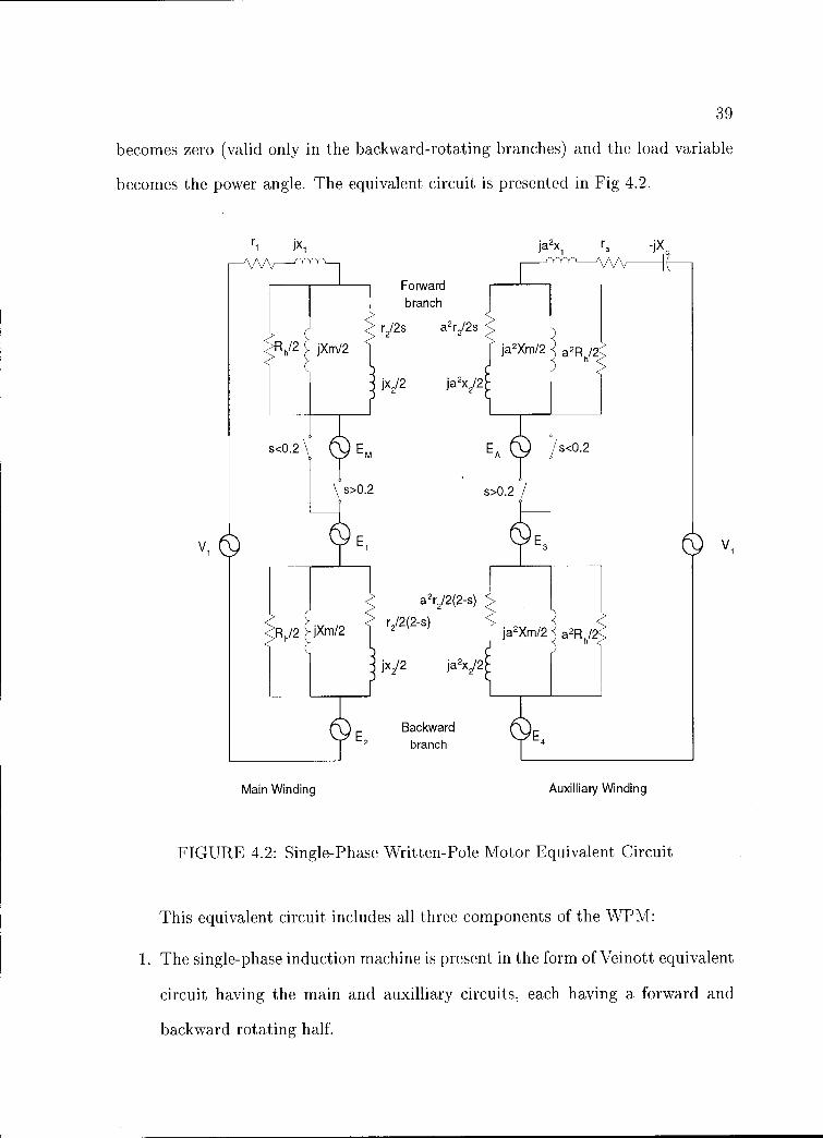
becomes zero (valid only in the backward-rotating branches) and the load variable
becomes the power angle. The equivalent circuit is presented in Fig 4.2.
rr1 ja2xi a
Forward branch
Rh/2 jXm/2
s<0.2 OEM
s>0.2
Vi
Rh/2 jXm/2
Backward E2
branch
Main Winding Auxilliary Winding
FIGURE 4.2: Single-Phase Written-Pole Motor Equivalent Circuit
This equivalent circuit includes all three components of the WPM:
1. The single-phase induction machine is present in the form of Veinott equivalent
circuit having the main and auxilliary circuits, each having a forward and
backward rotating half.
40
2. The synchronous machine is represented, from a slip of 20% on towards the
synchronous speed, by Em and Ea, the back-emfs due to the permanent mag
nets in each circuit. Their absolute value depends on the actual speed, and
they have a relative phase displacement of 90 degrees electrical, in the general
case, due to the spatial displacement of the main and auxilliary windings in
the machine. In our particular case (for a machine having one pole pair) the
mechanical displacement is 90 degrees as well)
3. The hysteresis machine is represented by the resistor Rh which is divided
between forward and backward rotating branches just as the cage rotor equiv
alent resistor. The power dissipated on the forward rotating halves, less that
which is dissipated in the backward branches, represents the air gap power.
This air gap power, which would be constant in the case of a balanced three
phase pure hysteresis machine, is being divided into mechanical power and
heat loss in the ratio 1-s:s. Hence, at synchronism, all the hysteresis air gap
power is converted into mechanical power, therefore the torque due to this
component can be calculated as the ratio of the air gap power to the syn
chronous speed of the machine. This is valid for all machine modes, with
some considerations for the value of the resistor during pole-writing.
4.2. Parameter Optimization
The analytical model of the WPM leaves us with at least two unknown or qual
itatively known parameters: The value of the hysteresis equivalent resistor, hence
that of the hysteresis torque and the value of the power angle during the pole-writing
mode.

41
In order to get these values, the known parameters in the circuit were substi
tuted in the torque equation along with trial values of the unknown ones and the
resulting torque compared with the real torque of the machine in several points. The
differences were squared and then added to obtain a cost which was to be minimized
by a minimizing subroutine available in Mat lab. This approach was dictated by the
fact that the torque characteristic is highly nonlinear and the circuit itself is non
linear as well. The stator and rotor leakage reactances are considered equal in this
model and the classical single phase machine theory must be modified to account for
the additional real part in the forward and backward parts of the series equivalent
circuit used to calculate the induction torque, as shown in Fig4.3. Normally, the
a2X, R C
v, v,
FIGURE 4.3: Series Form of the Single-Phase WPM Equivalent Circuit

42
induction machine air gap power in the forward rotating branch of the main circuit,
for example, is expressed as
Pgfrri = Re[(Efm + El) x in; (4.4)
and so on
Pgbrn = Re[(Ebm E2) X (4.5)1-11;
P9 fa = Re[(Efa E3) x in; (4.6)
Pgba = Re[(Eba E4) X Ii]; (4.7)
where the asterisk (*) denotes the complex conjugate. In our case the relationships
become
Pg fm = Re[(Efm + El) x Abs(Efm/(Rh/2)); (4.8)
and so on for each branch.
Pgbrn = Re[(Ebm E2) x Abs(Ebm /(Rh /2)); (4.9)
Pg fa = Re[(Efa + E3) x Abs(Efa/(Rh/2)); (4.10)
Pgba = Re[(Eba E4) x Abs(Eba I (RhI2)); (4.11)
The total induction machine air gap power becomes:
+ a2/D(Rf Rb)+ 2a(Rf + Rb)IiI2sin021 21 Rh(4n+ EL na); (4.12)
Where the subscripts f, b, m, and a denote forward, backward, main and auxilliary
respectively.
The data used in the optimization of the induction and hysteresis components
(no pole writing) as well as the resulting torque-speed characteristic of the machine
model are presented in Fig4.4. The parameters of the equivalent circuit are corn

43
70
60
5°0
40 E z
0 o Measured 30 Curve fitted
Simulated
20
10
500 1000 1500 2000 2500 3000 3500 Speed, rev /min
FIGURE 4.4: Comparison of Measured and Model Torques after Optimization
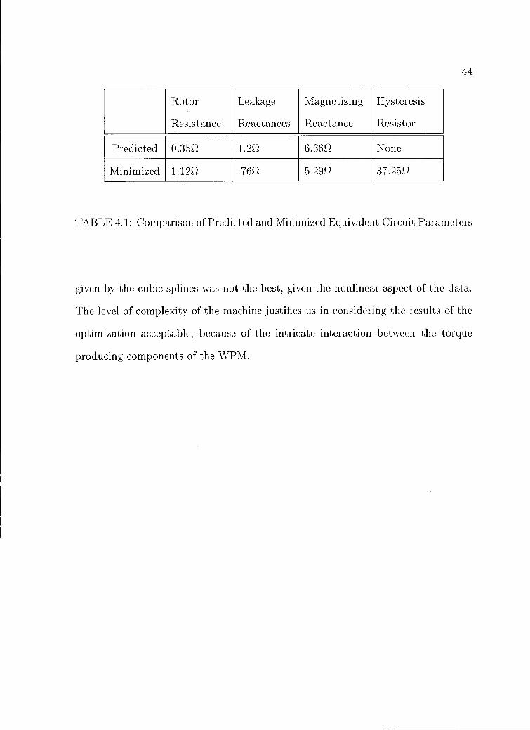
pared with the predicted values in Table 4.1 The parameters resulting from this
minimization were reasonably close to the predicted ones. The estimated magne
tizing reactance was calculated from the physical dimensions of the machine and
assuming a sinusoidal winding distribution and is the closest matched parameter.
The rotor resistance turns out to be higher than the predicted value, whereas the
predicted leakage reactance was found to be about half the predicted value. The
inrush current in the minimized model is slightly lower than the measured value, at
134 A.
The results of this minimization didn't account for any friction and windage,
and it is admitted that the data was insufficient for a good fit. The interpolation
44
Rotor Leakage Magnetizing Hysteresis
Resistance Reactances Reactance Resistor
Predicted 0.355 1.2Q 6.3652 None
Minimized 1.1252 .76Q 5.2952 37.2552
TABLE 4.1: Comparison of Predicted and Minimized Equivalent Circuit Parameters
given by the cubic splines was not the best, given the nonlinear aspect of the data.
The level of complexity of the machine justifies us in considering the results of the
optimization acceptable, because of the intricate interaction between the torque
producing components of the WPM.
45
5. CHARACTERIZATION AND PROBLEMS WITH THE WPM
As is apparent from the results of the testing, the WPM turns out to be
difficult to understand in detail. The main problem rests in trying to get an in-
depth understanding of the interweaving of the induction, permanent magnet, and
hysteresis components. During our tests as well as in previous tests conducted
by Manitoba Hydro and by the manufacturer itself, one of the problems which
is not readily evident is the hunting or dynamic instability of the machine. This
phenomenon has been observed at all loads, and seems to be unavoidable with the
physical configuration of the machine and the combination of weak induction cage
and relatively strong permanent magnet excitation.
This hunting phenomenon requires further investigation not covered in the
initial test and analysis plans.
5.1. Overexcited Synchronous Machines
In normal steady state operating conditions a synchronous machine will oper
ate at a fixed load angle, defined as that between the peak of the rotating magnetic
field of the armature and the magnetic rotor axis. As the load torque changes, the
load angle must be modified to meet the new condition. It is known from the ele
mentary theory of electric machinery that a synchronous machine without damper
windings exhibits dynamic instability or overstability or negative damping when one
or more of the following are true
1. The machine is overexcited.
2. The machine is operating at large values of the load angle, 60.

46
3. The machine has a high value of the armature resistance.
5.2. Hysteresis Motor
In general, a hysteresis motor includes eddy-current effects. However, due to
the laminar structure of the rotor and the sintered powder nature of the ferrite,
eddy-current effects are negligible in the case of WPM. Hence it is valid to consider
an ideal hysteresis motor in the following analyses. It is well known that a typical
hysteresis motor has a constant torque versus speed characteristic. In the case of
a single-phase machine the torque will vary with the capacitance in the circuit, be
cause of modified current through the auxiliary winding.
However, this would induce us into believing that there is a discontinuity about
the synchronous speed point.
The hysteresis torque-speed characteristic is actually irrelevant at synchro
nism, where the characteristic should be expanded to show another parameter, sim
ilar to the load angle in a synchronous machine, which should take into account
the oscillations of the machine around the stable operating point. In the case of
a hysteresis machine the ideal synchronous operation eliminates the hysteresis and
the machine operates as a permanent magnet synchronous machine. However, as
soon as the load angle is changed, there appears a small hysteresis effect, based
on an elliptical B-H curve up to the saturation point. The area of the ellipse is
proportional to the square of the change in mmf. In a WPM the magnetic material
is permanently magnetized by the writing pole energized at the supply frequency,
thus it is subjected to a sinusoidally time-varying mmf. The resulting remanent flux
density in the ideal case would be sinusoidally distributed, but having a slight phase
shift with respect to the writing mmf. In reality the flux density will have space

47
harmonics around the rotor circumference. These higher harmonics would actually
have an additional beneficial effect on the torque production.
During a small deviation cycle from the steady-state load angle, each point of
the rotor circumference would suffer an elementary hysteresis which follows an el
liptic path. These paths do not enclose equal areas and they depend on the starting
point. This poses major problems in getting a thorough insight into the WPM.
The overstability or dynamic stability of the WPM poses some problems in
the following areas:
1. The efficiency of the machine is affected because there is a hysteresis effect
associated with the oscillations around the ideal stable point. This leads to
unnecessary warming of the rotor layer and it can lead to a loss of the magnetic
properties if the temperature increases over the Curie point. During testing,
results were taken at the closest point to true "stable" operation (i.e. for a
minimum amplitude of the modulating oscilations to appear). Only then was
averaging and recording of the data performed. Thus, measurements obtained
are prbably slightly optimistic for evaluation of the efficiency.
2. Some applications may require a rigorously constant speed and, for certain load
torque profiles, the oscillations of the WPM might resonate with mechanical
systems causing beats which might increase in amplitude. This could result
in desynchronization the WPM at loads close to the rated load (note that
the maximum load recommended for the WPM by the manufacturer is 115%
because the WPM reverts to the pole-writing mode in order to compensate
for loads in excess of 125%).
3. The shaft may not withstand the increased torsional stress and it may shear
due to fatigue if a sufficient factor of safety could not be introduced into the

48
design. It should be remembered here that, due to the non-conventional me
chanical design of this machine, the length of the shaft subjected to torsional
stress is half the apparent length of the motor.

49
6. CONCLUSIONS AND RECOMMENDATIONS
6.1. Performance
The WPM proved to deliver most of what its manufacturer promised: high ef
ficiency, high power factor, low starting current, slow acceleration and decelleration
during sudden load changes or power supply perturbations.
The measured efficiency of the WPM has been within 1% of the advertised
value of 93%. This is very high for a single-phase machine. It also outperforms a
three-phase induction machine with the same ratings in the range of loads beginning
from 65% of the rated load and up. A disadvantage is that the WPM will not work
for extended periods at loads exceeding 125%, whereas the induction machine will
tolerate 150% loads for considerable time albeit with a shortening of the insulation
life. The power factor of the WPM is remarkably high and would prove beneficial
in maintaining the voltage in a long line if it were the dominant load, because it
is leading throughout most of the useful range of loads (therefore behaving as a
synchronous capacitor).
Unfortunately the machine does not work in the uninterruptable power supply
mode in this single-phase configuration at this time. This is because it has a prob
lem commuting the supply of the controller circuit from the line side of the input
contactor over to the motor side, where the induced emf of the slowing rotor would
provide for it and for the excitation coil. This is needed in order to have a constant
frequency at the output of the WPM in the generator mode, when there is no prime
mover available at the shaft.
Low starting current appears to be the WPM's strongest selling point, its value
of 2.lpu gives the machine the advantage to be the only choice currently available
50
without the use of power electronics, which a lot of remote applications users resent
at this time.
The external rotor configuration provides more than adequate load ride-through
in either reduced voltage or loss of supply conditions. In addition it enables run-up
as the inertia is sufficient to overcome the cogging torque present at submultiples
of the synchronous speed due to the braking torque of the semi-permanent magnets
which are not completely erased during start up.
The cost of the machine, even though higher than some other options available
is justified at this time by the very high quality of the mechanical workmanship and
the low series production runs.
6.2. Problems
The WPM at this time presents some minor problems:
6.2.1. Dynamic Instability
The WPM does not operate in precise synchronism: hunting, dynamic insta
bility or overstability seems to be the biggest problem of the WPM at this time. This
seems to be due to the fact that the machine in the synchronous mode of operation
is overexcited and its induction motor cage, which fulfills the role of amortisseur in
the synchronouos mode of operation, is too weak to dampen the resulting oscilla
tions. The cage is "weak" because of its relative high resistance and also because
of the large effective air gap due to the ferrite layer located on the rotor, between
the stator and the rotor laminations. The overexcitation of the machine might stem
from the fact that the WPM is an offshoot of the Written Pole Technology which

51
started primarily with uninterruptible power supply applications. In these applica
tions, a higher induced emf is necessary for the generator mode of operation.
Another cause for the hunting of the WPM during synchronous operation is
the high minor hysteresis of the ferrite layer, which is a non-linear effect for any
thing over 2 deg of deviation from the equilibrium condition [3]. It should be noted,
however, that in many applications the hunting, which is less than 0.1% of the
synchronous speed, would not be noticeable.
6.2.2. Cogging
As in any typical permanent magnet machine, the WPM exhibits a permanent
magnet braking torque at subsynchronous speeds, due to the written poles of the
previous operation not being completely erased by the rotating magnetic field. This
cogging torque would not be a problem if the machine would go through these speed
points faster but, as its acceleration is so low, it tends to dwell there, and, even in
the experience of the manufacturer, with the wrong choice of capacitor switching
point, might "catch" there and not speed up. An added problem at these points is
the length of the shaft, which results in increased elastic deformation.
6.2.3. Shaft Dimension
The shaft of the WPM is designed to match the load machine of the same
rating and therefore, if it has the same diameter inside the motor might prove to
be subjected to excessive stress because it has a length a considerably greater than
comparably sized standard machinery. The length of the stressed section of the
shaft is half of the motor length plus the exposed part. During sudden overloads

52
the inertia of the WPM will exert a high torque spike on the shaft; also the togging
condition and the hunting present at synchronous run subject the shaft to fatigue.
6.3. Recommendations
As added results of the research here are some recommendations for the im
provement of the WPM:
6.3.1. Dynamic stability
The dynamic instability of the WPM might be aleviated by redesigning the
excitation coil to bring the equivalent permanent magnet excitation down to lower
levels, which would eliminate the overexcitation of the synchronous machine compo
nent of the WPM, or better yet, since the permanet remanent flux density is directly
responsible for the value of the torque in the synchronous mode, by redesigning the
stator coils. Future research of the WPM should investigate the behaviour of the
machine in steady-state synchronous mode of operation. The excitation should be
performed at rated voltage as well as lower or higher levels. Then the voltage levels
should be varied and the behaviour of the machine recorded. Improved dynamic
stability at higher voltage than the writing voltage would validate our presumption
that the machine is indeed overexcited. No passive solution is envisioned for the
hunting due to hysteresis without changing the semi-permanent magnet material
layer itself. There are active solutions to the hysteresis hunting which might work
with the WPM, but that would defeat its purpose of eliminating the electronics in
the power path. One possibility is to investigate the effectiveness of an active filter,
placed in the supply path.

53
6.3.2. Cogging
The solution envisioned for the cogging problem of the WPM, which is prob
ably the major obstacle to the development of a physically conventional WPM (in
ternal rotor, low inertia), is the "writing" of poles onto the rotor for the first 5 turns
of the start-up of the motor. This is equivalent to a proper demagnetization of the
magnetic layer through gradually reduced hysteresis cycles connected to each other,
because of the finite pitch of the excitation pole piece and the very low speeds at
start. This operation will subject the rotor to increasing amplitude hysteresis cycles
followed by decreasing ones due to the fringing effect and the long effective air gap.
6.3.3. Shaft size
The problems stemming from the mechanical design of the machine might be
solved by trying a single cup rotor configuration where the shaft is connectted to
the bottom of the cup thus having a much reduced length. This might have the
result of an increased rotor diameter (for the same inertia and radial play at the end
of the cup) and thus of reduced number of applications due to the increased frame
size (shorter length and larger diameter).

54
7. LIST OF ABBREVIATIONS
7.1. General Abbreviations
The following general abbreviations have been used in this thesis:
MSRF Motor Systems Resource Facility
EPRI Electric Power Research Institute
WPM Written-Pole Motor
IEEE Institute of Electrical and Electronic Engineers
BPA Bonnevile Power Administration
7.2. Nomenclature
The mathematical models and equations given in this thesis use the following
symbols:
Vl Supply voltage
ri Main stator winding resistance
ra Auxilliary stator winding resistance
Xl Main stator winding leakage reactance
X, Main winding magnetizing reactance
X2 Equivalent main circuit rotor leakage reactance
r2 Equivalent main circuit rotor resistance
El Voltage induced by the auxilliary forward rotating branch into the main wind
ing forward rotating branch
E2 Voltage induced by the auxilliary winding backward rotating branch into the
main winding backward rotating branch
55
E3 Voltage induced by the main winding forward rotating branch into the auxil
liary winding forward rotating branch
E4 Voltage induced by the main winding backward rotating branch into the aux
illiary winding backward rotating branch
TH Hysteresis torque
Ah Area of the hysteresis curve
p number of poles of the machine
emf electromagnetic force
EM Permanent magnet induced emf in the main winding of a synchronous ma
chine
EA Permanent magnet induced emf in the auxilliary winding of a synchronous
machine
Ts Synchronous torque
IM Main circuit current in a synchronous single-phase machine
IA Auxilliary circuit current in a synchronous single-phase machine
Ph Power being converted into hysteresis
f Frequency
Maximum value of flux density.
kh Proportionality constant in the hysteresis power equation
Ahp,, Area between the previous flux density and the writing flux density for a
period of the input voltage during pole-writing
s slip of the machine
Rhp,, Effective hysteresis equivalent resistance during pole-writing mode
Reh- Hysteresis equivalent resistance during pole-writing mode
Rh Hysteresis equivalent resistance
a Turns ratio between the main and auxilliary windings.

56
Pgf, Air gap power in the forward main branch of the equivalent circuit
Pgbn, Air gap power in the backward main branch of the equivalent circuit
Pgfa Air gap power in the forward auxilliary branch of the equivalent circuit
Pgba Air gap power in the backward auxilliary branch of the equivalent circuit
Efra Voltage drop on the forward branch of the main circuit
Ebm Voltage drop on the backward branch of the main circuit
Efa Voltage drop on the forward branch of the auxilliary circuit
Eba Voltage drop on the backward branch of the auxilliary circuit
Rf Equivalent resistance for the forward main rotating branch of the series equiv
alent circuit of a single-phase machine.
Rb Equivalent resistance for the backward main rotating branch of the series equiv
alent circuit of a single-phase machine.
B - Magnetic flux density
H Magnetic field intensity

57
APPENDICES

58
A Name Plate Data for the Single-phase Written Pole Motor
Manufacturer: Precise Power Corporation
Model No.: ME 210020
Serial No.: 125
Rated Power: 20horsepower (15kW);
Phase: 1
Hertz: 60
Rev/min: 3600
Rated Current: 67A;
Rated Voltage: 240V;
Inrush Current: 140A;
Duty: Continuous
Frame: 365Y
Power Factor: 1
Rotor Inertia: 5.77kg x m2
Max. Inertia Load: 6.32kg x m2
B Mat lab programs used in modeling the WPM
% This is the file which will call on the minimization subroutine which will call
% on the equation solver to get the behaviour of the model for the parameters
%to be optimized.
%The parameters initialization is done here.
global TT Z;

59
load sample
samplel=sample(1:5);
sample2=sample(6:11);
xi1=1:1:700;
x1=[1 200 400 600 700];
xi2=701:1:999;
x2=[701 800 916 944 975 999];
for i=1:700
Z(1:700)=spline(xl, samplel, xil);
end
for i=701:999
Z(701:999)=spline(x2, sample2, xi2);
end
X0,[32 .9 2 .25 .46];
xoptim= fmins('wpmcost', X0)
save xoptim;
%plot (TT);
%(curve(:,1), curve(:,2)));
hold on;
plot (sample);
%This is the subroutine which calculates the cost associated with the fitting of the
model having parameters given in the input vector X to the experimental data
%s is the slip of the machine
%S is the index of the loop
%omegas=synchronous speed in rad/sec
%a=turns ration between main and auxiliary windings

60
function y=wpmcost(X);
global Zf Zb curve I Z;
V1=240; %Input Voltage
Rh=X(1) % Hysteresis Equivalent Resistance
Rr1=X(2) %Rotor Resistance
Rr2=X(5)
Rs=.085; %Stator Resistance
Xls=X(4) %Stator Leakage Reactance
Xmag=X(3) %Magnetizing Reactance
a=1; %Main to Auxilliary Turns Ratio
omegas=2*pi*3600/60; %Synchronous Angular Speed
R1=--Rs;
ra=R1;
X1r=Xls; %Rotor Leakage Reactance
Z1=R1H-j*Xls;
%delta=X(5) % Load Angle of the Synchronous Machine Component During
Pole Writing
%H=X(5) % Value of the Hysteresis Equivalent Resistor for Slip = 0.2
for S=1:999;
if Si=700;
Xc=-1/(.00066*2*pi*60);
Rr=Rrl; % First Capacitor Step
else
Xc=-1/(.00055*2*pi*60); % Second Capacitor Step
Rr=Rr2;

61
end
s=1-S/1000; % Slip
I(:,S)=Iimodel(s,Z1,Xmag,Xc,Rr,X1r, Rh);
prod12=abs(I(1,S))*abs(I(2,S));
prod1=(abs(41,S)))2;
prod2.(abs(I(2,S)))2;
Rf=real(ZO; % Forward Branch Resistance
Rb=real(Zb); % Backward Branch Resistance
Efm=abs(I(1,S)*Zf); % Voltage Drop on the Forward Main Circuit Branch
Efa=abs(I(2,S)*ZO; % Voltage Drop on the Forward Auxilliary Circuit Branch
Ebm=abs(I(1,S)*Zb); % Voltage Drop on the Backward Main Circuit Branch
Eba=abs(I(1,S)*Zb); % Voltage Drop on the Backward Auxilliary Circuit Branch
E1=I(9,S); % Induced EMF in the Equivalent Circuit
E2=I(10,S); % Induced EMF in the Equivalent Circuit
E3=I(11,S); % Induced EMF in the Equivalent Circuit
E4=I(12,S); % Induced EMF in the Equivalent Circuit
SumE2=Efin2+Efa2-Ebm2-Eba2; %Sum of Voltages squared used in the Calcu
lation of the Hysteresis Torque
% if SH975;
TS=0;
%else
% Rh =H *s;
% TS=syncseries(S,Z1,Xc, Zf, Zb, delta,E1,E2,E3,E4);
%end
Pag(S)=((prod1H-a2*prod2)*(Rf-Rb)+2*a*(Rf+Rb) *prod12*sin(angle(I(2,S))
angle(I(1,S))));

62
NetIMPag(S)=((prodl+a2*prod2)*(Rf-Rb)+2*a*(Rf+Rb)*prod12*
sin(angle(I(2,S))-angle(I(1,S))))-2/Rh*SumE2;
HT(S)=2/Rh*(SumE2);
TT(S)=Pag(S)/omegas+TS;
end
cost=0;
%keyboard
for in=1:999
cost=cost-I-(TT(in)-Z(in))2;
end
y=cost
plot(TT(:));
save I;
save TT;
function y=smodel(S,Z1,Xc,Zf,Zb,delta,E1,E2,E3,E4) V1=240;
ind=.238*S/1091;
[xy}=pol2cart(delta,ind);
EM=x+i*y;
delta2=delta+pi/2;
[x2y2]=pol2cart(delta2,ind);
EA=x2+i*y2;
IM= (V1- EM- E1- E2) /(Z1 +Zf +Zb);
IA,(V1-EA-E3-E4)/(Z1H-Zf+Zb+j*Xc);
y=(abs(IM)*abs(E1)+abs(IA)*abs(E2))/120/pi;
function y= hmodel(s, Z1, Xmag, Xc, Rr, Xlr, Rh);
%function y= model2(s, Z1, Xmag, Xc, R2, Rr, Xlr, Rh);

63
global Zb Zf;
V=240+0i;
R1=real(Z1);
Xls=imag(Z1);
Yf=2/Rh+1/(j*Xmag/2)+1/(j*X1r/2+Rx/(2*s));
Zf=1/Yf;
a=1;
Yb=2/Rh+1/(j*Xmag/2)+1/(j*X1r/2+Rr/(2*(2-s)));
Zb=1/Yb;
R2=R1;
Za=R2+j*Xc;
Z(1,1)=Z1+Zf+Zb;
Z(1,2)=-j*a*(Zf-Zb);
Z(2,1)=j*a*(Zf-Zb);
Z(2,2)=Za+a2*(Zf+Zb+j*Xls);
il=V*(Z(2,2)-Z(1,2))/(Z(1,1)*Z(2,2)-Z(1,2)*Z(2,1));
i2=V*(Z(1,1)-Z(2,1))/(Z(1,1)*Z(2,2)-Z(1,2)*Z(2,1));
E1=---j*a*i2*Zf;
E2=j*a*i2*Zb;
E3=j*a*il*Zf;
E4=-j*a*it*Zb;
J=[il i2].';
m=[1 1;
1 1];
m(1,1)=Z1+.5*(Zf+Zb);
m(1,2)=-j*a*.5*(Zf-Zb);

64
m(2,1)=j*a*.5*(Zf-Zb);
m(2,2)=Za-.5*a2*(Zf-Zb);
i(1:2)=J(:).*Zf/(j*X1r/2±Rr/2/s);
i(3:4)=J(:).*ZbAj*X1r/2+Rr/2/(2-s));
y=[il i2 i(1) i(2) i(3) i(4) Zf Zb El E2 E3 E4].';

65
BIBLIOGRAPHY
1. Shabam A. and Mar D.B. A low-cost single-phase high-efficiency motor. IEEE Trans. on Energy Conversion, 7(3):560-569, Sept 1992.
2. Wallace A.K., von Jouanne A., and Rollman T. A fully regenerative high-power testing facility for motors, drives and generators. In IEEE International Electric Machines Drives Conference record, pp. MB2-13.1-3, 1997.
3. Stanley P. Clurman. On hunting in hysteresis motors and new damping techniques. IEEE Transactions on Magnetics, pages 512-517,1971. September.
4. Friesen D. and St. George D. Independent laboratory and field tests of a Written-Pole Motor. In Wescon '96 Conference Proceedings, Anaheim, CA, Oct 1996.
5. Levi E. Polyphase Motors, A Direct Approach to Their Design. John Wiley & Sons, 1984.
6. McPherson G. and Laramore R. D. An introduction to Electrical Machines and Transformers. John Wiley & Sons, 1990.
7. Veinott C. G. Theory and Design of Small Induction Motors. McGraw-Hill, 1959.
8. Retter G. J. Matrix and Space-Phasor Theory of Electrical Machines. Akademiai Kiado, Budapest, 1987.
9. Sarma M.S. Electric Machines, Steady-State Theory and Dynamic Performance. Wm. C. Brown, Dubuque, IA, 1985.
10. Smith O.J.M. Three phase motor control. In US Patent No. 5,300,870, 1994.
11. Morash R.T.and Roesel Jr. J.F.and Barber R.J. Improved power quality with "Written Pole "TM motor-generators and "Written Pole "TM motors. In Third International Conference on Power Quality: End Use Applications and Perspectives, Amsterdam, The Netherlands, Oct 1994.
12. Guru B. S. and Hiziroglu H. R. Electric Machinery and Transformers. Harcourt Brace Jovanovich, 1988.
13. Hoffman S. The Written-Pole revolution. EPRI Journal, 22:26-35, 1997. May/June.
14. Boldea I.and Nasar S.A. Linear Motion Electromagnetic Systems. John Wiley & Sons, 1985.
Related Documents