HIGH TEMPERATURE HTC I I GASM~LED R ~CT~R PROGRAM HIGH-TEMPERATURE *~rifnR' - ad PKESSSIEAT DESIGN AND COST STATUS REPORT VOLUME II APPENDICES PREPARED UNDER CONTRACT DE-AC03-78SF02034 FOR THE SAN FRANCISCO OPERATIONS OFFICE DEPARTMENT OF ENERGY PRINCIPAL CONTRIBUTORS BECHTEL GROUP INC. GAS-COOLED REACTOR ASSOCIA1 GENERAL ATOMIC COMPANY GENERAL ELECTRIC COMPANY 'ES I ISSUED BY: GAS-COOLED REACTOR ASSOCIATES DECEMBER 1981 ~57R@lJTiCM OF TH18 WCUMENT 15 UNYwED 1

Welcome message from author
This document is posted to help you gain knowledge. Please leave a comment to let me know what you think about it! Share it to your friends and learn new things together.
Transcript

HIGH TEMPERATURE HTC I I GASM~LED R ~ C T ~ R PROGRAM
HIGH-TEMPERATURE *~rifnR' - ad PKESSSIEAT DESIGN AND
COST STATUS REPORT
VOLUME II APPENDICES
PREPARED UNDER CONTRACT DE-AC03-78SF02034 FOR THE SAN FRANCISCO OPERATIONS OFFICE
DEPARTMENT OF ENERGY
PRINCIPAL CONTRIBUTORS
BECHTEL GROUP INC. GAS-COOLED REACTOR ASSOCIA1 GENERAL ATOMIC COMPANY GENERAL ELECTRIC COMPANY
'ES I
ISSUED BY: GAS-COOLED REACTOR ASSOCIATES
DECEMBER 1981
~57R@lJTiCM OF TH18 WCUMENT 15 UNYwED 1

DISCLAIMER
This report was prepared as an account of work sponsored by an agency of the United States Government. Neither the United States Government nor any agency Thereof, nor any of their employees, makes any warranty, express or implied, or assumes any legal liability or responsibility for the accuracy, completeness, or usefulness of any information, apparatus, product, or process disclosed, or represents that its use would not infringe privately owned rights. Reference herein to any specific commercial product, process, or service by trade name, trademark, manufacturer, or otherwise does not necessarily constitute or imply its endorsement, recommendation, or favoring by the United States Government or any agency thereof. The views and opinions of authors expressed herein do not necessarily state or reflect those of the United States Government or any agency thereof.

DISCLAIMER
Portions of this document may be illegible in electronic image products. Images are produced from the best available original document.

I DISCLAIMER
This report was prepared as an account of work sponsored by an agency of the United States Government. N e i i the United States Government nor any agency thereof, nor any of their employees, makes any warranty, express or implied, or assumes any legal liability or responsibiilty for the accuracy, completeness, or usefulness of any information, apparatus, product, or process disclosed, w represents that its use would not infringe privately owned rights. Reference herein to any apedfic commercial product, process, or sewice by trade name, trademark. manufacturer, or otherwise, does not necessarily constitute or imply its endorsement, reoommendation, or favoring by the United States Government or any agency thereof. The views and opinions of authors expressed herein UO not necessarily state or reflect thwe of the United States Government or any agency thereof.
COPIES AVAILABLE FROM: GAS-COOLED REACTOR ASSOCIATES 3344 NORTH TORREY PINES COURT LA JOLLA, CALIFORNIA
92037

HTGR H I GH-TEMPERATURE - PROCESS-HEAT DESIGN AND
COST STATUS REPORT
VOLUME I1
APPENDICES
DISCLAIMER
NOTICE
pORTIONS OF THIS REPORT P:RE IT-JJEG~~B_~F::,. 1% t 1 8 5 b e ~ n r e p T O d ~ c e d f r 0 ~ t h e b e s t available Copyt .~permit thebroadestposs ib le avalL-
December 1981

VOLUME I1
APPENDICES
CONTENTS
Appendix
A
B
C
D .
E F
G
H
I
J
K
L,
Design Details - 850°C IDC Reactor Vessel
Design Details - Primary Cooling System
Design Details - Secondary Helium System Design Details - Steam Generator
Heat Cycle Eva1 uations , 850°C. IDC PI an t .
Design Details - 950°C' DC Reactor Vessel
Design Details - 950% DC Steam Generator
Design Details - Direct and 1nd.irect Cycle Reformers
Design Details - Methanation Plant
henn no chemical Pi pel i ne - Process Considerations
Methodology fo r Screening Candidate Synfuel Processes
Process Description - ECCG Process
Project Technical Requirements , Functional ~ p e c i f i cation - HTGR-PH Reference Pl a n t Process Gas Explosion Assessment Reports - Preliminary Probabilist ic Risk Assessment fo r Process Side of HTGR-PH
0 HTGR' Program Ecbnomi c Guide1 i nes
P Vendor Responses

Appendix A
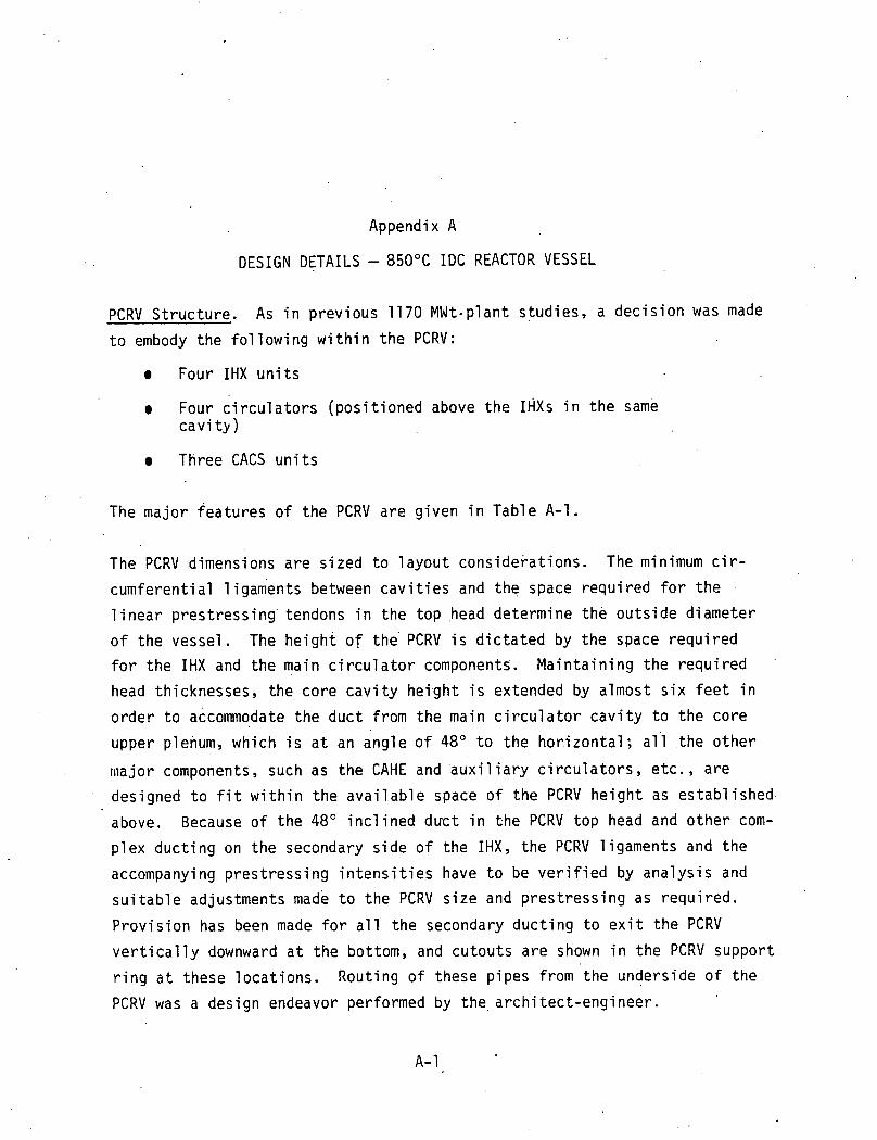
DESIGN DETAILS - 850°C IDC REACTOR VESSEL
PCRV S t ruc tu re . As i n p rev ious 1170 MWt-p lant s tud ies , a d e c i s i o n was made
t o embody the fo l l ow ing w i t h i n t h e PCRV:
e Four IHX u n i t s
e Four c i r c u l a t o r s (pos i t i oned above t h e IHXS i n t h e same c a v i t y )
Three CACS u n i t s
The major f ea tu res o f the PCRV a re g iven i n Table A-1.
The PCRV dimensions are s i zed t o l a y o u t cons idera t ions . The minimum c i r -
cumferent i a1 1 igaments between c a v i t i e s and t h e space requ i red f o r t h e
l i n e a r p res t ress ing ' tendons i n t he top ,head determine t h e ou ts ide d iameter
o f t he vessel. The h e i g h t o f the' PCRV i s d i c t a t e d by the space requ i red
f o r t he IHX and the main c i r c u l a t o r components. Ma in ta in ing t h e requ i red
head thicknesses, the core c a v i t y h e i g h t i s extended by almost s i x f e e t i n
o rder t o accommodate the duc t f rom the main c i r c u l a t o r c a v i t y t o t h e core
upper plenum, which i s a t an angle o f 48" t o t he hor.izonta1; a l ' l t he o t h e r
r~ ia jo r components, such as t h e CAHE and ' a u x i l i a r y c i r c u l a t o r s , e tc . , a re
designed t o f i t w i t h i n t h e a v a i l a b l e space o f t he PCRV h e i g h t as es tab l i shed
above. Because o f t he 48" i n c l i n e d duc t i n t he PCRV top head and o t h e r com-
p lex d u c t i n g on the secondary s ide o f the IHX, t he PCRV l igaments and t h e
accompanying p res t ress ing i n t e n s i t i e s have t o be v e r i f i e d by ana l ys i s and
s u i t a b l e adjustments made t o t h e PCRV s i z e and p res t ress ing as requ i red .
P rov i s i on has been made f o r a l l t he secondary duc t i ng t o e x i t t h e PCRV
v e r t i c a l l y downward a t t he bottom, and cu tou ts a re shown i n t he PCRV suppor t
r i n g a t these l oca t i ons . Rout ing o f these p ipes from the underside o f t he
PCRV was a design endeavor performed by t h e , a r c h i t e c t - e n g i n e e r .

Table A-1
MAIN FEATURES OF PCRV FOR 850°C I D C PLANT
PCRV concrete stength
LPS tendon s t rength ( a t GUTS) '
CPS cable s t reng th ( a t GUTS)
Refuel ing scheme In-vessel r e f ue l i ng (see memo
6.31 : 11 n:TFII: 81 d ~ t e r l 4/29/81
f o r deta i 1 s o f design)
Intermediate heat exchanger Precast concrete prestressed r i n g
c a v i t y (w i th main c i r c u l a t o r
A plan view o f the PCRV i s shown i n Figure A-1. The p lan shows an arrange-
ment w i t h a cen t ra l i zed core c a v i t y and o r i e n t a t i o n o f the major equipment
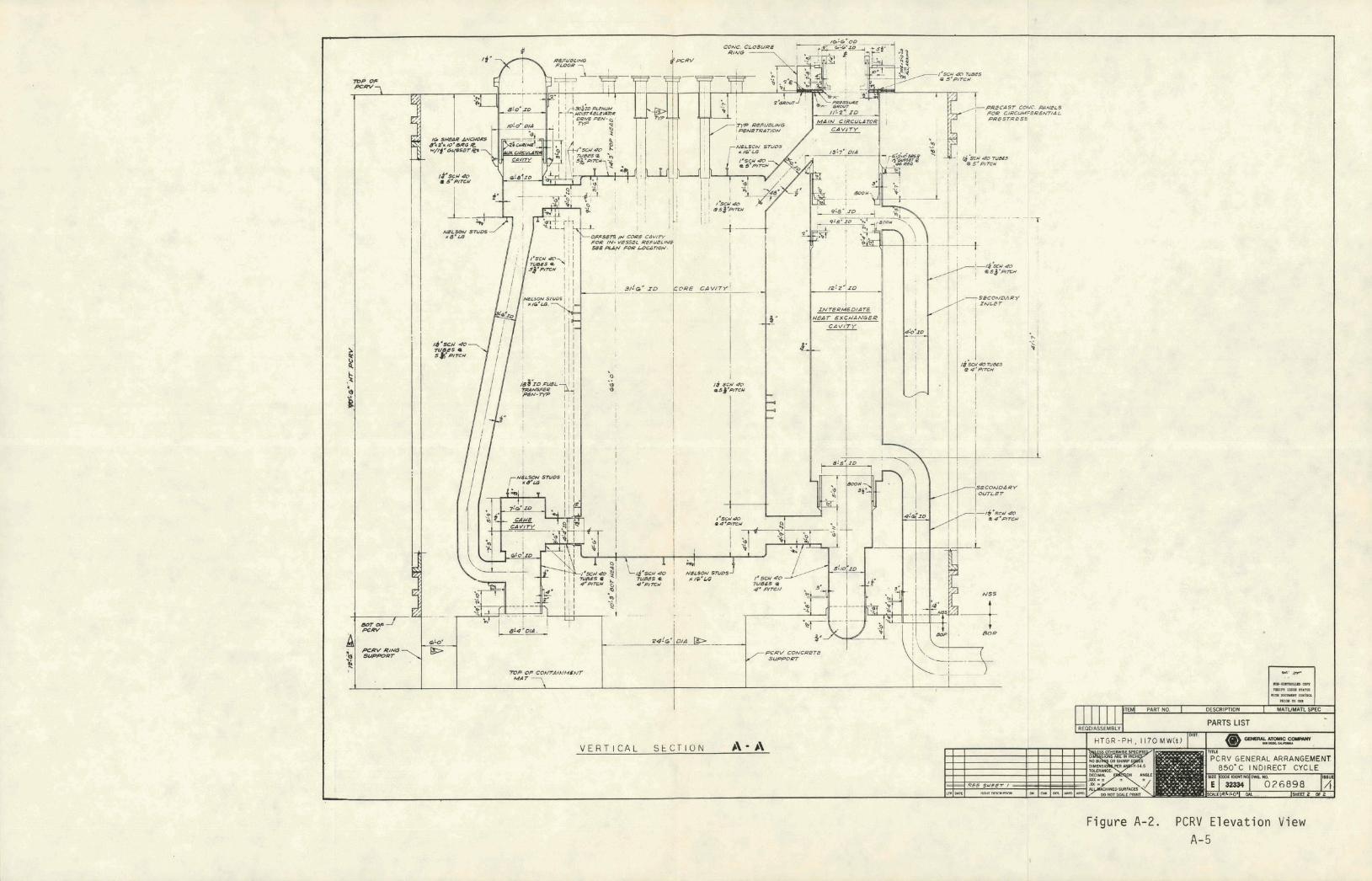
s ide w a l l c a v i t i e s t o y i e l d a PCRV o f minimum diameter. An e leva t ion view
o f t he PCRV i s shown i n Figure A-2, i l l u s t r a t i n g the primary system gas
f l ow paths. The pr imary coo lant passes through the lower ho t duct from the j
core t o the IHX and re tu rns (through an i n c l i n e d duct) t o the core c a v i t y
upper plenum v i a the main c i r c u l a t o r c a v i t y located above the IHX, t r a v e l i n g
downward on the she l l side, accumulating heat from the primary coolant and
e x i t i n g the PCRV a t the bottom onto a c l u s t e r o f f ou r PCPVs located outs ide
the reac to r containment bu i ld ing . Pipe chases are provided f o r those second-
a ry i n l e t and o u t l e t pipes i n the PCRV. The major PCRV parameters are given
i n Table A-2.

8. LINER MATER/ALS ARa M d O N STEEL PXCEPT M.4 /N GCNdRAL AS NOTED: ME COAlcIpElz PWI- - PLATE TO a C 3 4 - 5 9 7 , CLASS 2 2. 7Ne Vb0-L S/tlm
CPCILING WATeR YeADER PIT - FOIKilNGS TO&# SA-508,CLASS ZA. RCS VCR/P/CAT/OAl AT 1G10' BELOW ?VP N PCRV,
TOIAL Z N P , TOTAL 3. WMERE UATERtAL IS Ih'DlCAT~D AS PW CUR- : - PLATE Ta a 3 A - 3 8 7 , OR 12. - FORGINGS TO 52 Sd - S S 6 , CLASS F 22. WUeRP MATIRIAL IS /NL)/$ATED AS ALLOY &OH. ' SIGN ARC 4.5 FOLLOWS :
-+ +.% L --- -> - - PLATS TO 6.C S8- 4 0 4 , ALLOV 8 0 0 Y - FORGINGS TO dP S b - 364, CONDITION P.
9 UNCS TYICCNCSS 7D 6 S / m " f n o r ~ ) SXCCPT WYIRE NOZCD OWCRWISP -
rU COOLIN6 tube PITCM ?W & ~ ~ ) k r ' ~C&/SM) rS*C@Pl WH@RE NOTED OTYPRWISII .
/I ALL LINER STUOS TO 8.5 &'~O,OZM~~A.*LCMSTY SMOWN ON TME DRAWING. PeOVIDP CWC STUD PSR 50 SMOWN .SO tU. ON (0.03 THE DRAWING SP M / OF LlNaR SURFACE WYCRC
i2 dt46aDOQD COOL/UG AND #7CUCONN@CTlMG CYPING TO CONSIST OF *SO00 L/N SECT //)krZ/0.@3 MI SCHaDUL6 40 P / P P
PeOVIDE l /U /41k l ,~ OF CCMPRESSIDLC MAT@R/AL EN p 7 H . e ouren SutwAcE-CF eAcu RzFueL/NG P=Nzm.. -
ncM O V e r,d LENGTH tNOICAT@D (FOIP TYC UNdOND/NB PF CONCRPZE IN 7 M ARCA SMOWNJ
L 4-P Z D SC'LWYIIIZPIWL*, N P - TOTAL 4 a. cduSane Ll-NT5 ra Um?W.IO aY WALWI8
6 TENDON INTERFPRCAICC W D UWUr STWWaS
C CAVlZY WYCLOFSS 05TWNffO FALW NISd RPFEUENCC DRAWINfiS.'
r )xureer/ rotd l r usrr r x w ~ & a . m M oa%w!&+
z JNAlr/ CIIKULA~R. DM w. oae77/(/1. SIAUXlLlARV UXULATOQ , OHG M. 0r0217/1
4lCoRr AUXIUAW Y , T EXCUANGIR (CAM&), Wfi ND 0 2 5 7 9 / / / .
5 1 IN-V6SSEL RCFUCLING, OW6 N a CVb499// . 7. FOR U m I P T Y A L DBS/CiiV AUO DCTA/LS OF ZYC
IACVSSSCL REFUSLING STRUC?VRC AN0 W C W r D L I S RCFdR ?V h%AU Na BSIIIIO: TFUI81, DAT80 4R#.
n'P - TOTAL I.
PCRV QUANTfTldS : - FOR R R V (NANT/T/ES W C R 7p 64 MWO MD.G.W: 125~MCV:BI . DATED 5-B-8/.
4 b ' ~ . ACCCSS ?V eOOuNG W T M Y&A PIT, TYP- TOTAL Z
8.z~ FUIL TR~NSFEB Pphl MLOW, 7YP- TOTAL 2
P L A N - P C R V T O P H E A D
Figure A-1 . PCRV Plan View A- 3

THIS PAGE
WAS INTENTIONALLY
LEFT BLANK
PRECAST CDYT. PeNfLS
V E R T I C A L S k C T I O N A\
Figure A-2. PCRV Elevation View A-5

T H I S PAGE
WAS INTENTIONALLY
LEFT BLANK
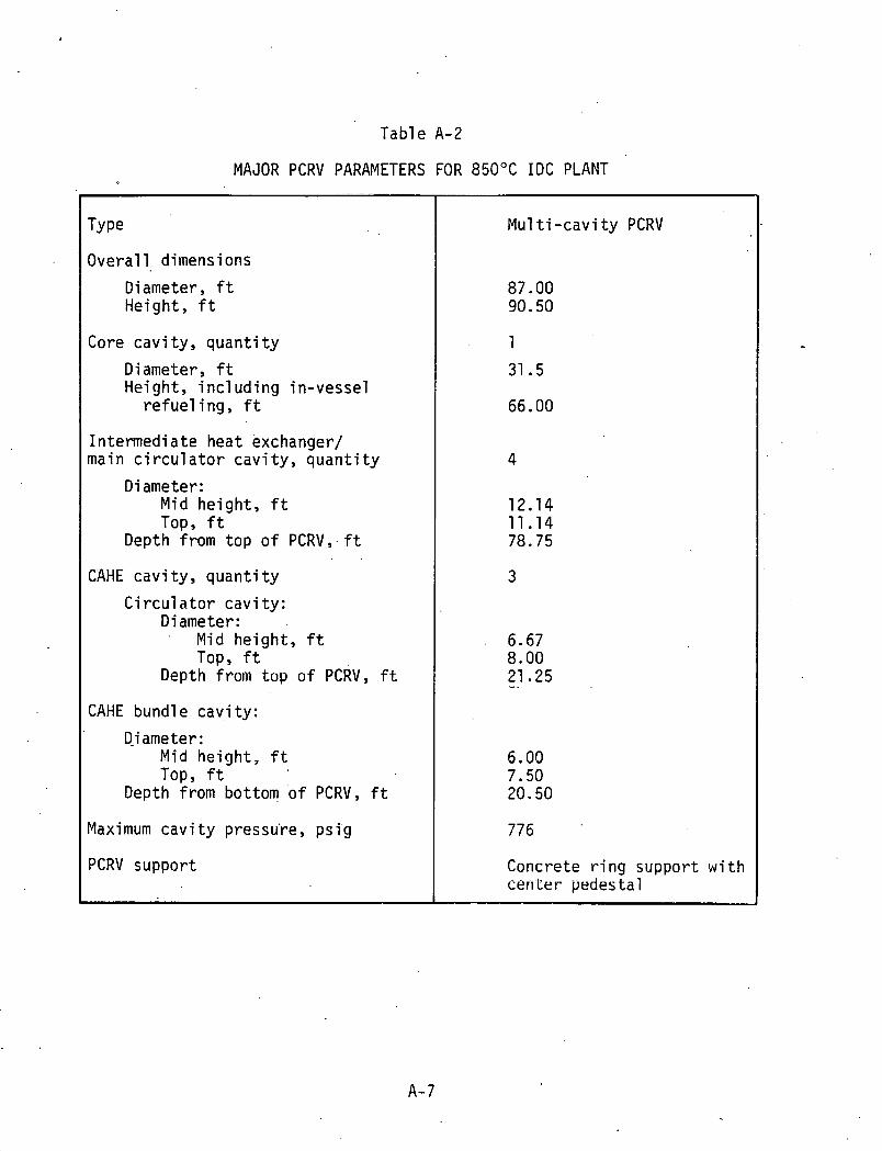
Table A-2
MAJOR PCRV PARAMETERS FOR 850°C I D C PLANT
Overa l l dimensions !
Diameter, ft Height, f t
Core cav i t y , q u a n t i t y
Diameter, ft Height, i n c l uding in -vesse l
r e f ue l i ng , f t
In termedia te heat exchanger/ main c i r c u l a t o r cav i t y , q u a n t i t y
Diameter: Mid he ight , f t TOP, f t
Depth from top o f PCRV, ft
CAHE cav i t y , quant i ty
C i r c u l a t o r c a v i t y : D i ameter:
Mid height , ft TOP, ft
Depth from top o f PCRV, f t
CAHE bundle cav i t y :
Diameter : Mid he ight , f t TOP, f t
Depth from bottom o f PCRV, f t
Maximum c a v i t y pressu're, p s i g
PCRV support
Mu1 ti - c a v i t y PCRV
Concrete r i n g support w i t h cer i ter pedestal

PCRV L i ners, Penetrations, and Closure's. The steel cavi ty 1 iners, penetra-
t ions , and penetration closures form the continuous gas-tight boundary of
the PCRV. The l iner and penetration anchors transmit loads from internal equipment support structures and axial loads from closure to the PCRV concrete.
A 1 iner cooling system i s included to remove the heat transmitted through
the thermal barrier before i t reaches the concrete. The l iners , penetra-
t ions , and closures are similar to those of recent HTGR-SC designs where
similar components are housed. The HTGR-PH, however, requires a new closure
design for the intermediate heat exchanger cavity; th i s new design i s briefly nirt.1 i n ~ r l he1 ow.
The top cap,of the cavity l iner i s welded to the l iner a f t e r the heat
exchanger i s instal led. The prestressed concrete closure, containing a
housing for the main circulator, i s placed in position on the top of the
PCRV, concentric with the cavity top cap. The bottom end of the circulator . .
housing i s welded to the l iner top cap, forming an annulus between the tap
cap and closure. This annul us i s f i l l ed with grout by means of small
penetrations extending through the closure. The closure i s retained w i t h
the PCRV vertical tendons.
An internal dome closure, located in the upper end of the IHX cavity, separates the primary coolant from the secondary coolant. If an accidental loss . of secondary coolant occurs, the closure i s sub.je.cted t o the f ~ , l l
reactor pressure of i t s external surface. A flange and ring forging with shear anchors i s therefore provided t o transmit the dnwnward axial force
from the IXH closure to the PCRV conciete.
PCRV Thermal Barrier..- The thermal barrier has been separated into 19 zones
according t o service temperature and 1 iner geometry consider.ations, with four
di f ferent material selections made for these zones. The preliminary thermal
barrier sizing calculations proceeded according to the following sequence:
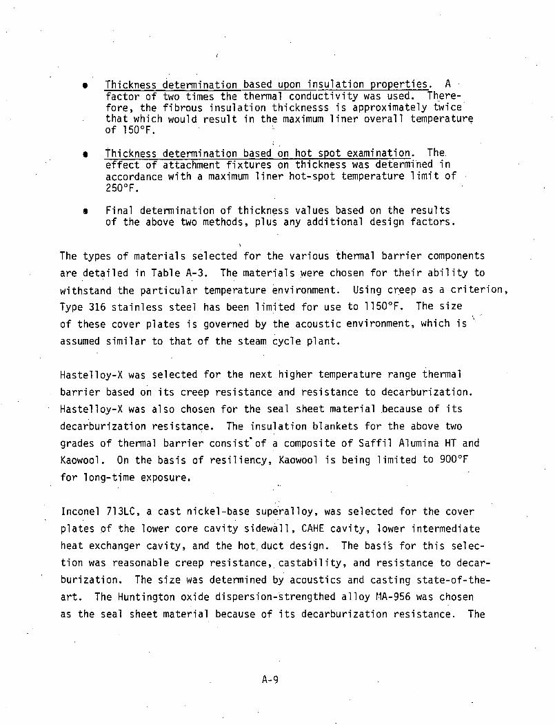
Thickness de te rm ina t ion based upon i n s u l a t i o n p r o p e r t i e s . A f a c t o r o f two t imes t h e thermal c o n d u c t i v i t y was used. There- f o r e , t h e f i b r o u s i n s u l a, t ion th icknesss i s approx imate ly t w i c e ' t h a t which would r e s u l t i n t h e maximum l i n e r o v e r a l l temperature o f 150°F.
- . Thickness de te rm ina t ion based on h o t spo t examinat ion. The. e f f e c t o f attachment f i x t u r e s on th i ckness was determi'ned i n accordance w i t h a maximum l i n e r ho t -spot temperature l i m i t o f 250°F.
e F i n a l de te rm ina t ion o f t h i ckness values based on t h e r e s u l t s o f t h e above two methods, p l u s any a d d i t i o n a l design f a c t o r s .
The types o f m a t e r i a l s se lec ted f o r t h e va r ious thermal b a r r i e r components
a r e d e t a i l e d i n Tab le A-3. The m a t e r i a l s were chosen f o r t h e i r a b i l i ty t o
w i ths tand t h e p a r t i c u l a r temperature environment. Using creep as a c r i t e r i o n ,
Type 316 s t a i n l e s s s t e e l has been l i m i t e d f o r use t o 1150°F. The s i z e
o f these cover p l a t e s i s governed by t h e a c o u s t i c environment, which i s '
assumed s i m i l a r t o t h a t o f t h e steam cyc le p l a n t .
Haste l loy-X was se lec ted f o r t h e n e x t h ighe r temperature range thermal
b a r r i e r -based on i t s c reep r e s i s t a n c e and r e s i s tance t o decarbu r i za t i on .
Haste l loy-X was a l s o chosen f o r t h e sea l sheet m a t e r i a l .because o f i t s
d e c a r b u r i z a t i on res i s tance . The i n s u l a t i o n b l ankets f o r t h e above two
grades o f thermal b a r r i e r cons is t ' o f a composite o f S a f f i l Alumina HT and
Kaowool. On t h e b a s i s o f r e s i l i e n c y , Kaowool i s be ing l i m i t e d t o 900°F
f o r 1 ong-time exposure.
Incone l 713LC, a c a s t n icke l -base supera l l oy , was se lec ted f o r t h e cover
p l a t e s o f t h e lower core c a v i t y s i d e w a l l , CAHE c a v i t y , lower i n t e r m e d i a t e
heat exchanger c a v i t y , and t h e h o t , d u c t design. The bas is f o r t h i s se lec-
t i o n was reasonable creep res i s tance , c a s t a b i l i t y , and r e s i s t a n c e t o decar-
b u r i z a t i o n . The s i z e was determined by acous t i cs and c a s t i n g s ta te -o f - the -
a r t . The Hunt ing ton ox ide d i spe rs ion -s t reng thed a l l o y MA-956 was chosen
as t h e seal sheet m a t e r i a l because o f i t s d e c a r b u r i z a t i o n res i s tance . The

Tab1 e A-3
THERMAL BARRIEE MATERIAL SELECTION FOR 850°C I D C PLANT
Cover P l a t e
Type 316 s t a i n l e s s s t e e l
H a s t e l l o y X
I nconel 71 3LC
Type 316 s t a i n l e s s s t e e l
Pads
-
-
-
P y r o l y t i c graph'te, a1 umi na , fused s i l i c a
I n s u l a t i o n
S a f f i 1 + Kaowool
S a f f i l + Kaowool
S a f f i l
S a f f i l + Kaowool
r . ,
Seal Sheet
Type 316 s t a i n l e s s s t e e l
H a s t e l l o y X
MA 356
Type 316 s t a i n l e s s s t e e l
Blocks
-
-
-
Graph i te

i n s u l a t i o n b lankets a re a l l S a f f i l because o f i t s h igh r e s i l i e n c y and
low compression f o r c e (hence, low loads app l i ed t o t he cover p l a t es ) .
The bottom. head. thermal b a r r i e r o f the core o u t l e t plenum d i f f e r s f rom the
. ' standard system i n degree o f complexity. The f u n c t i o n o f the bottom heat
thermal b a r r i e r i s n o t o n l y t o p r o t e c t t he PCRV l i n e r b u t a l so t o p rov ide a
s t a b i l i z e d i nsu la ted s t r u c t u r a l base f o r t he g raph i t e core support posts.
The c o n f i g u r a t i o n cons is ts of layered polygonal g raph i t e b locks w i t h
i n s u l a t i o n b lankets through which a se r i es o f ceramic support columns
penetrate. The polygonal b locks a re exposed t o the d i r e c t gas stream and
hence, the h ighes t core o u t l e t temperatures. Here, t he main problem i s t o
d i s s i p a t e the gas streaks, thereby min imiz ing the thermal shock imparted t o
the subs t ra te layers . The support columns cons i s t o f pads which a re s ized
t o accommodate t he mechanical 1 oads t ransmi t ted through t he support posts
( i n c l u d i n g seismic cond i t i ons ) as w e l l as t o a c t as i nsu la to r s . The thermal
loads genera l l y d . i c ta te t he thicknesses o f the pads. P y r o l y t i c g raph i t e i s
designated f o r the top pad. High p u r i t y (85%) alumina i s designated f o r
a l l remaining pads w i t h the except ion o f the bottom pad, which i s t he f i n a l
insu la to ' r . The ma te r i a l f o r the bottom pad i s a h igh dens i t y , f i n e g r a i n .
s i l i c a . -.


Appendix B
DESIGN DETAILS - 850°C I D C PRIMARY COOLING SYSTEM
In te rmed ia te Heat Exchanger (IHX) . E f f o r t s conLinued i n FY81 t o es tab l i sh
an improved IHX f rom b o t h the s t r u c t u r a l and economic s tandpo in ts . I n s u f -
f i c i e n t funds were appropr ia ted f o r a f u l l eng ineer ing e v a l u a t i o n t o be
performed ( i . e . , survey o f d i f f e r e n t c o n f i g u r a t i o n s such as s t r a i g h t tube,
U-tube, he1 i c a l bundle, e t c . ) . A new re fe rence IHX design c o n f i g u r a t i o n
was se lec ted f o r p l a n t l a y o u t purposes and update c o s t est imates. Whi le
the s t r a i g h t - t u b e concept was re ta ined , t h e secondary system gas f l o w
( o u t s i d e t h e tubes) was changed from a x i a l f l o w t o mu l t i pass cross
counter f iow f o r t h e f o l 1 owing reason.
The pr imary problem area which prompted t h e change t o the crossf low' .con-
cept was assoc ia ted w i t h the tube- to- tube d i f f e r e n t i a l expansion i n t h e
axia.1 f l o w concept brought about by the e f f e c t s o f , h o t s t reaks e n t e r i n g
the c a v i t y . I n a d d i t i o n , t he e f f e c t s o f nonuni form f l o w d i s t r i b u t i o n
across the tube bundle on the s h e l l s i d e due t o t h e r e s t r i c t i v e na tu re
o f t he c ross f l ow i n t o and o u t o f t h e cen te r reg ions tended t o compound
the d i f f e r e n t i a l expansion problems. M o d i f i c a t i o n s t o the .concep t were
conceived, i n c l ud ing monof i t h i c counter c ross f l ow and modular counter
c ross f l ow concepts. A f t e r cons ide ra t i on o f i n h e r e n t problem areas,
e f f e c t s on t h e PCRV, and u n i t cos ts , i t was decided t h a t t h e counter
crossf low m o n o l i t h i c arrangement w i t h the pr imary gas on t h e tube s i d e
showed t h e most promise f o r an updated re ference design.
A d d i t i o n a l problem areas addressed were:

Design and analysis of an acceptable and licensable thermal expansion jo in t
Preli~ninary evaluation of a segmented tubesheet to minimize tubesheet s i ze
Preliminary study of the s t ructural adequacy of the tubes as ver t ical support members
The use of a cross counterflow configuration has several primary
advantages:
Achieves a more uniform flow dis tr ibut ion on the she1 1 s ide , thereby minimizing thermal expansion differences between the tubes from t h i s solrrce
Provides room i n t h e bundle cavity fu r lhe .inclusion of individual tube expansion loops to allow f o r thermal expansion differences which may e x i s t due to hot s t reaks o r other causes
m Allows a more posit ive method of sealing against circumferential bypass flow on the shell s ide
The current reference IHX- i s a monolithic s t raight- tube gas-to-gas baffled
cross counterflow assembly as shown in Fi.gure B-1. The baff les a re of the disk and doughnut type, causing the shell s ide flow path t o flow radia l ly in and out across the tubes with each pass, u t i l i z ing center and peripheral
tubeless areas f o r turning. I he primary g a s (hear lng gas) Is on the tube
, s ide and makes a s ingle pass through the tubes. ' The secondary gas (heated
gas) i s on the shel l s ide and makes eight passes across the tubes.
The tubes a re fabricated of Inconel 617 and have a wall thickness capable
of withstanding the f u l l l i f e operating pressure which, though nearly pres-
sure balanced, ca r r i e s a small external or compression pressure load. In
addi t ion, the tubes a re designed to withstand the f u l l internal primary
gas pressure f o r a t o t a l ' pe r iod of u p t o two hours in the event of loss of
secondary loop pressure. The tubesheets a re s ingle piece forgings d r i l l ed
and machined to the f ina l configuration. The hot tubesheet i s fabricated of Inconel 61 7, while the cold tubesheet i s . Inconel 800H.

Figure B-1 . Intermediate Heat Exchanger Configuration
B-3

T H I S PAGE *. .I
WAS INTENTIONALLY . '
L E F T BLANK

The tubes are welded t o the h o t (lower) tubesheet by means of internal
bore fusion we'lds with the tubes butted t o spigots machined into the plate
upper face. A t the upper end of the bundle, the tubes' are welded t o the
cold tubesheet after h a v i n g been formed into Z-shaped expansion loops or
offsets. The purpose of the offsets i s to accommodate the differential
expansion of those tubes which may be subjected t o higher t h a n average
shell side gas temperatures. The offsets are shaped t o uti l ize ' the
center turning section of the bundle, thereby forming a homogeneous tube
field a t the cold tubesheet as opposed t o the annular or ri.ng-shaped h o t
tubesheet hole pattern. The 'tubes above the offsets penetrate the tube-
sheet and are welded t o the t o p surface.
The tubes are supported laterally by the ring- and disk- (disk and dough-
n u t ) shaped baffles, a l l of which are supported by.the outer shroud. These
baffles, three disk-shaped and twelve ring-shaped, are located t o route the
she1 1 side helium flow radially across the tubes eight times during i t s passage through the IHX. A peripheral shroud i s provided around the tube
bundle which i s sealed against bypass helium flow between i t and the cavity
l iner. The shroud has flow "windows" t o admit and discharge the shell side gas a t the t o p and bottom, respectively.
The IHX i s located entirely in the PCRV and i s welded a t the lower end t o a l iner extension support. The upper end of the unit i s attached t o a primary/secondary gas boundary dome via a bellows/seal assembly, which compensates for. IHX axial . .tlser-~~~dl expansion. Prlmary gas flow res t r i ctors . are provided a t each end of the unit t o guard against the unlikely simul-
taneous failure of the tubesheet/head weld and the secondary piping outside
of the PCRV.
Primary helium from the core enters the IHX a t the bottom, flows upward through the tubes, and exits a t the t o p t o the circulator located in the
same cavity, where i t i s compressed and returned t o the reactor. The
secondary helium enters the IHX cavity a t the t o p and flows radially

t h rough t h e bund le t o t h e empty c e n t r a l sec t i on . I t then t u r n s 90" and
f l ows downward t h r o u g h t h e bundle i n .a d i s k and doughnut p a t h t o t h e
bottom, where i t e x i t s t h e bundle i n 'a r a d i a l d i r e c t i o n .
Access has been p rov ided t o .tube ends, tubesheets, and headers f o r tube . .
l e a k d e t e c t i o n and s e a l i n g as w e l l as f o r i n s e r v i c e i n s p e c t i o n deemed
necessary t o c o n f i r m t h e heat exchanger i n t e g r i t y . A l l ope ra t i ons can
be accomplished e x t e r n a l t o t h e u n i t c a v i t y us ing remote hand l i ng methods
v i a access p e n e t r a t i n n s . '
The IHX has bee11 des i gried for rep1 aceabi 1 i t y . Fol 1 owing rcmoval o f t h e
c a v i t y p lug. t t j e u n i t can be separated f rom t h e 1 i n e r by c u t t i n g two
pr imar-y- to-sec~ndary gas boundar ies . A t t h e lower end, t h i s i s done
a t t h e tubesheet. assembly-to-1 i n e r i n t e r f a c e , whi 1 e a t t h e upper end, ... '
i t i s done a t ..the dome-to-1 i n e r i n t e r f a c e . once separated, t h e IHX can
be withdrawn f rom i ' t s c a v i t y . I n s t a l l a t i o n takes p lace by t h e reverse
process.
P r e l imina0ry r e s u l t s o f i n v e s t i g a t i o n s i n t o t h e des ign o f a c o l d p r imary
gas d u c t e.xpansion j o i n t i n d i c a t e t h a t adapt ing a t y p i c a l be l lows des ign
t o t h e l a r g e d iameter (36 i n c h I D ) duc t t h a t w i l l accommodate t h e l a r g e
thermal expansion (up t o 10 inches) , be a b l e t o w l t h s t a n d a t o t a l depres-
s u r i z a t i o n on one s i d e w h i l e soaking a t h i g h temperature, and be inspec-
t a b l e and rep laceab le w i l l be q u i t e . d i f f i c u l t . Several a1 t e r n a t e
approaches t o t h e des ign have been proposed. The most a t t r a c t i v e approach
i s a t y p i c a l convo lu ted be.llows des ign . - which i s a c t i v e l y cooTed and backed
up w i t h a s a f e t y c l a s s he l ium source t h a t w i l l m a i n t a i n a des ign l e v e l
p ressure d i f f e r e n t i a l across t h e be l lows i n t h e event o f t h e l o s s of
secondary l oop pressure.
I t i s recognized t h a t t h e IHX i s a c r i t i c a l component i n t h e 850°C I D C . .
p l a n t and t h a t ex tens ive des ign s t u d i e s a r e r e q u i r e d t o i d e n t i f y a design
concept t h a t s a t i s f i e s a l l o f t h e c r i t e r i a . D e t a i l s o f t h e c u r r e n t
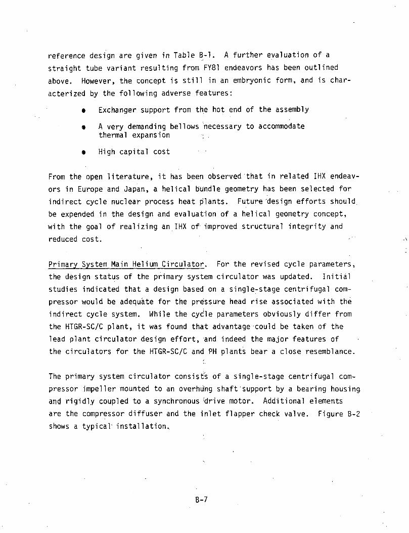
reference design are given in Table B - 1 . A further evaluation of a
straight tube variant resulting from FY81 endeavors has been outlined
above. However, the concept i s s t i l l in an embryonic form, and i s char-
acterized by the fol lowing adverse features:
8 Exchanger support from th,e h o t end of the assembly
e A very demanding be1 1 ows 'necessary t o accommodate thermal expansion , .
e High capital cost
From the open l i terature , i t has been observed'that in related IHX endeav-
ors in Europe and Japan, a helical bundle geometry has been selected for
indirect cycle nuclear process heat p'lants. Future 'design efforts should,
be expended in the design and evaluation of a helical geometry concept,
with the goal of realizing an IHX of improved structural integrity and
reduced cost. . .
Primary System Main Helium Circulator. For the revised cycle parameters, the design status of the primary system circulator was updated. Init ial
studies indicated t h a t a design based' on a single-stage centrifugal com- pressor would be adequate for the prsssure head rise associated with the
indirect cycle system. While the cycle parameters obviously differ from
the HTGR-SC/C plant, i t was found that advantage-could be taken of the
lead p l a n t circulator design effort;and indeed the major features of .
the circulators for the HTGR-SC/C and PH plants bear a close resemblance.
The primary system circulator consis& of a sing1 e-stage centrifugal com-
pressor impeller mounted t o an overhung shaft'support by a bearing housing
and rigid1.y coupled t o a synchronous !drive motor. Additional elements
are the compressor diffuser and the inlet flapper check valve. Figure B-2
shows a typical. installation..

Table B-1
DETAILS OF INTERMEDIATE HEAT EXCHANGER FOR 850°C I D C PLANT
( a ) Does no t inc lude allowance f o r f l ow m a l d i s t r i bu t i on
S t r a i g h t Tube, Cross Counte r f l ow
Number o f Tubes
Tube Size (OD/Wall Thickness), i n
Tube P i t ch , i n
Tube P i t c h Pa t t e rn
A c t i v e Tube Length, f t
.Overal l Height , ft
Shroud OD, i n
Shroud Flange Diameter, i n
Upper Cone Flange Diameter, i n
Empty Weight, , 1 b
Primary Coolant (Tube Side) Condi t ions:
Flow Rate, l b / h r
Temperature, In /ou t , OF
I n l e t Pressure, p s i
Pressure Loss, p s i
.. Secondary Coolant (She1 1 Side) Condi t ions :
Flow Rate, I b / h r
Temperature, l n / ou t , "F
O u t l e t Pressure, p s i
pressure ~ o s s ( ~ ) , p s i
7 07
9.5
1,019,000
650/ 1460
707
12
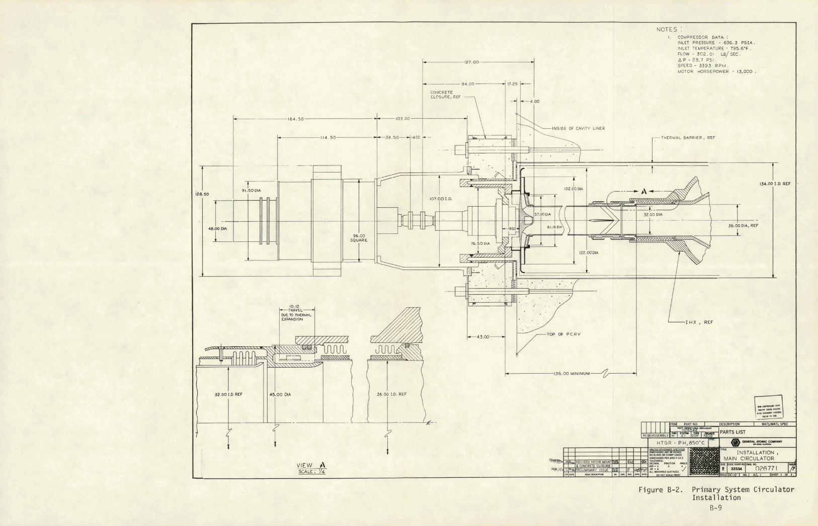
INLET PRESSURE - 696.3 P S I A . INLET TEMPERATURE - 795.6.F. FLOW - 3 C 2 . 0 1 LB/ SEC . A P - 23.7 PSI SPEED - 3 3 9 3 R P M . MOTOR HORSEPOWER - 13,000 .
- 1 6 4 . 5 0
THERMAL BARRIER, REF
1 3 6 . 0 0 MINIMUM
VIEW b\
Figure 8-2. Primary System Circula tor Ins ta l l a t i on
B- 9

THIS PAGE
W A S INTENTIONALLY i
LEFT BLANK

The bear ing housing u t i l i z e s w a t e r - l u b r i c a t e d h y b r i d bear ings t o p r o v i d e
r a d i a l p o s i t i o n i n g o f t h e compressor r o t o r . ' A b u f f e r he l ium l a b y r i n t h
seal system i s used t o p rov ide separa t i on between t h e r e a c t o r c o o l a n t
and t h e bear ing l u b r i c a t i n g water . Fu r the r , t h e bear ing water i s sealed
from t h e containment atmosphere w i t h a s l i d i n g s h a f t sea l . The synchron-
. ous d r i v e motor and t h e bear ing housing a r e b o t h mounted on t h e PCRV l i n e r .
A s e c t i o n o f d r i v e s h a f t between t h e d r i v e motor and bear ing housing i s
removable, a l l o w i n g f o r maintenance o f t h e s h a f t s l i d i n g sea l w i t h o u t t h e
removal o f t h e d r i v e motor o r t h e bear ing housing. The major compressor :.
parameters f o r t h e pr imary system c i r c u l a t o r a r e g i ven i n Tab le B-2.
Core A u x i l i a r y Cool i n g System (CACS). The CACS c o n s i s t s of t h r e e fo rced ..
c i r c u l a t i o n c o o l i n g loops. Each l o o p con ta ins a c o r e a u x i l i a r y heat .'."
exchanger (CAHE) and an a u x i l i a r y c i r c u l a t o r assembly i n c l u d i n g a d r i v e ..:.'
motor and 1 oop s h u t o f f va lve. These components a r e l o c a t e d i n PCRV . ' . :. . .
c a v i t i e s p e r i p h e r a l t o t h e c e n t r a l r e a c t o r core c a v i t y . The CACS , .
c a v i t i e s a r e connected t o t h e c e n t r a l c a v i t y by a p p r o p r i a t e c ross ducts .
Each o f t h e t h r e e CACS loops i s f u l l y ca.pable o f removing t h e core r e s i -
r e s i d u a l and decay hea t a t a r a t e f o r sa fe cooldown from 102% of r a t e d
r e a c t o r power 1 eve1 under p ressu r i zed condi t i o n s . Two 1 oops a r e r e q u i r e d
f o r cooldown f rom t h e same opera t i ng c o n d i t i o n s when t h e PCRV i s depres-
sur ized. I n e i t h e r case, t h e cool i n g c a p a b i l i t y i s such t h a t t h e tempera-'
t u res o f a1 1 components i n t h e PCRV ,are main ta ined w i t h i n t h e i r ' s p e c i f i c
sa te l i m i t s . The design b a s i s CACS performance i s g i ven i n Table B-3.
Th is performance i s f rom t h e 1170 M W t HTGR-PS/C e f f o r t , b u t i t i s judged
t o be adequate f o r conceptual d i r e c t c y c l e HTGR-PH eval ua t i ons .

Table B-2
PRIMARY CIRCULATOR DETAILS FOR 850°C I D C PLANT
I n 1 e t pressure
I n1 e t temperature
302.01 1 b/sec
Ro ta t tona l speed ,
S p e c i f i c speed
Compressor t ype Sing1 e stage c e n t r i f u g a l
6 1 . 1 6 i n ,
Compressor tip speed
Compressor e f f i c i e n c y
Compres'sor power 13,311 hp . .
C i r c u l a t o r d r i v e E l e c t r i c motor

Table 8-3
CACS PERFORMANCE (DATA. FOR 11 70 M W t HTGR-SC/C BUT ASSUMED REPRESENTATIVE FOR HTGR-PH)
Pressurized PCRV
1 5.0
1050.0
1 .414+08
116,352
1580
1580
700
5.107+05
1100
1363
292
544
207
3
205
CACS 1 oops operat ing
Primary coo lan t molecular weight.
Primary coo lan t pressure, p s i a
Heat duty per CACS loop, Btu /hr
Primary cool an t c i r c u i t
Flow per CACS loop, l b / h r ,
Core o u t l e t temperature, OF
CAHE i n l e t temperature, OF
Core i n l e t temperature, OF
Pressure drop, ps-ia
CAHE
Core Ducts and plena
Secondary (CACWS) c i r c u i t
Mass f l ow per CACS loop, 1 b l h r
Pump vo lumetr ic f low, gpm
Volumetr ic f l o w a t CAHE .ou t l e t , , QPm CAHE i n l e t temperature, OF
A i r b l a s t heat exchanger i n l e t temperature, O F
Pressure drop, ps i a
CAHE
P ip i ng and a i r b l a s t HX
Depressurized
Pure He
2
4.0
23.6
4.557+07
30,861
1746
1746
557
.-
5.396+05
1 100
1136
165
2 48
. -
PCRV
A i r Ingress .
2
12 .O
23.6
3.896+07
68,113
1746
1746
46 5
.47
.39
.05
.03
5.409+05
1100
1129
157
228
. .

Appendix C
DESIGN DETAILS - 850°C I D C SECONDARY 'HELIUM .SYSTEM
PCPV S t ruc tu re . Each o f t h e f o u r PCPV s t r u c t u r e s comprises two re fo rmer
c a v i t i e s (GE des ign) and one steam genera tor c a v i t y (GA des ign ) . I t a l s o
con ta ins one c o o l i n g water header p i t and one pressure r e l i e f p i t . The
PCPV general arrangement i s shown i n F igures C-1 and C-2 f o r p l a n view
and e l e v a t i o n , r e s p e c t i v e l y .
The secondary c o o l a n t f rom t h e in te rmed ia te heat exchanger ( IHX) i n t h e
PCRV en te rs t h e re former c a v i t i e s by means o f duc ts a t t h e bottom o f t h e
PCPV., The c o o l a n t e x i t s bo th re former c a v i t i e s t o a s i n g l e steam gen-
e r a t o r a t t h e t o p and f l o w s through t h e s h e l l s i d e o f t h e component. The
coo lan t then leaves t h e steam genera tor c a v i t y and r e t u r n s t o t h e I H X i n
t h e PCRV. Four PCPVs a r e r e q u i r e d t o complete a1 1 t h e l i n e s f rom t h e I H X .
I t i s p o s s i b l e t o conso l i da te a l l f o u r loops i n one m u l t i l o o p PCPV which
has been found t o be more economical than f o u r s i n g l e l oop PCPVs.
The PCPV dimensions a r e c o n t r o l l e d by l a y o u t cons ide ra t i ons . The minimum
c i r c u m f e r e n t i a l l igaments .between c a v i t i e s and t h e spa'ce r e q u i r e d f o r l i n -
ear p r e s t r e s s i n g tendons determine t h e o u t s i d e d iameter o f t h e vessel .
.The h e i g h t o f t h e PCPV i s d i c t a t e d by t h e space r e q u i r e d f o r t h e re fo rmer
c a v i t y . A l l t h e o t h e r component c a v i t i e s , such as steam generator , p ressure
r e l i e f , and c o o l i n g water system, a r e designed t o f i t w i t h i n t h e a v a i l a b l e
space i n t h e h e i g h t o f t h e PCPV.
PCPV L ine rs , Penet ra t ions , and Closures. The s t e e l c a v i t y l i n e r s , pene-
t r a t i o n s , and p e n e t r a t i o n c losures form t h e cont inuous g a s - t i g h t boundary
o f t h e PCPV. The l i n e r and p e n e t r a t i o n anchors t r a n s m i t loads f rom

internal equipment support structures and axial loads from the closure
to the PCPV concrete. A l iner cooling system i s included t o control the
heat emitted through the thermal barrier before i t reaches.the concrete.
The PCPV has a new closure design for the steam generator cavity. This
new closure i s described be1 ow.
The top cap of the cavity l iner i s welded t o the l iner af ter the heat
exchanger i s installed. The prestressed concrete closure, containing a
man access penetrati,on, i s placed in position on the t o p of the PCPV,
concentric with the cavity t o p cap. The bottom end of the man access
penetration i s welded to the l iner t o p cap, forming an interspace between
the t o p cap and closure. This interspace i s f i l led with grout through '
ducts extending through the closure. The closure i s retained with the
PCPV vertical tendons.
The reformer cavity configuration and i t s closures are dictated by G E
requirements. Their design includes a dome closure which i s recessed in
the former cavity and i s attached t o a large ring forging, cast integral
with the PCPV, and has a sleeve and flange that extends i n t o the cavity.
The reformer i s retained with this flange. The axial load from the
reformer is transmitted from the ring forging into the PCPV. For biological shielding purposes, there i s a solid concrete slab t o be
supplied by others, a t the t o p of the reformer cavity.
PCPV Thermal Barrier. The thermal barrier has been separated into ten .
zones, according t o serv'ice temperature and l iner geometry considerations.
Three different material selections have been made for these zones accord-
ing t o h o t surface temperature. The prel imi nary thermal barrier sizing calculations proceeded according t o the following sequence:
e Thickness determination based on insulation properties. A factor of two times the thermal conductivity was used. Therefwre, the fibrous insulation thickness is approxi- mately twice t h a t which would result in the maximum liner overall' temperature of 150°F.

CC)OI/ffG WATER MEADfrP dPr- -PRESSURE ESLIPF VALVE P/T fffi'd~~w ?VP OF 1 P/T f r ~ RPO'D I FCPV I F P R V P/TUSEO; ONPPWISE FULL Wff RPVI '
6ENERA L NOTES:
6. LINER T#fICCNh 55 TE 8s %?"&-9l MJ~XCEPI W-E b TC/S FC:W 19 IN GLNERAL COMalAMCE WIZW M N3TPD OTfdSRWISP . ACl 3/8 -97 bU/LL1,NG CODC REQUIRWCN7S. I
7. INTCRCWNCCTING PIPING 7P CPNSIBT OF I330 FSET =, SYSTbU F)IIaMCZIrPS (3-.+4MI OF /~~T.(oosM~ ~ L W L C UO PI=. OF THE W O R S7RUCTuRAL COMPOU8MTS USCD W
8. ALL LINE* STUDS X, W ~ ~ O O Z M ) D / A . dIfNGTU THE PCPV DESIGN ARS AS FOLLOWS: I SHOWN ON THC DRAWING. PR~VIOP LWP STUG PIFR
% IN. (a EB 50 M I OF L/NCR SUUFACC W&RC U. S P K I F I E D CON€- C D M m e / Y . SlrPCNOM
ShWWN ON W E DR4WING. AT 60 DAYS - GSOS PSI (44.82 M e ) FO@ PCPV AND PRECAST e N E L S; aOCIO PSI (S tG M e J FOR STEAM 6 E A l P R A M C - m CLOSURS. . I
--- -- PROCPSS GAS INLB- CHASE - TYF
I REFORMER CAVITY,
I T)'P- TOTAL 7 7
0 CONCRETE LlGdMEN7S 7V &C VEUICKO I Y A M L M l S . I
P L A N - P C P V T O P H E A D
b. 8ONOpD REINFORCEMENT PdrP A9TW 4615. -40. 1 C. LINEAR PUZSTRESSINS; GO- /&#, 7 WIRE S7rPAUD.
T E N M S - MAX. CAR& CITY * 2478 KIPS f5.U k0 1
~ D I M E N S ~ N S AND OPENINGS SWOWN L.V w e PCPV SUPPORT STL)UCTUR@ ARE SUGGESTED ARLIAME - MCAlTS ONLY.
4. W E FEASlblLIW OF TY/S GENERAL AC1PAUGCMbf7' IS SUA'ECT rn TYP FOLLOWIUG C O N W O C R A ~ ~ S .
& LAYOUT STUDIPS 7@ M UADC FOR PDSS/&C TENDON /NTERFPRdNCE.
C. C@@-,.Us WA7C.e SySrs*r REeU/RdM6NTs.
d REFERENC DRAWINGS USPD #I WE OdVE-LIT OF Tuf PCPV NSIT&U '
L) REFOeMeU - G.L. H E M NO. YL-W- /OoUS, 3JTSD 4-90-81. I
2.1 STEAM GEAPRATOR - 179 MWCfl lNR%?EC7' SKU, GENERA- ARRANGOUENT OW5 NL+ OZGU7//1. I
d)FCRV GENERAL ARRANGCMdNT--6J W G . NO 02689B/ I .
5. LINER MATERIALS ARb CARdON S76dL. CPXIPT A6 NO7.D.'
- PLATZ 70 61 SA- 567, EL 2 . - FORG/NGSVBE S l - S 8 , C L Z .
WMERE MATErPIAL I S INDICATED AS PI CIfRcWC : - PLATE ;rC SA-SS;r,Ga 22, CL 2. - FORGINGS 7D 8 P SA-8s. CL F 22. I
QUANT/TlES : EL cv
m-0IIPI h C-rPPTE :
PCI,PV- G500 PSI (QaBP MPa 1 H E C A S T m N E L S - -- ( * I b f W b ) .LSb CY ST: G ~ N CLOSURIC RIM- uun /W @%.e.wmj- JI cr
3 PRf9Me9SIN.5 - US.' I Na 9- 69 -Q% STUAND TENDONS 00 LENGTH OF TENDONS ~ C T W ~ C N -4alc -85
R4i-&'S AND Tz I STeAM GENCRdW
*&LOW FOR TPNSIONIN6 5 LIN fV' ADD/TXWAL . LG7Y PC#?
4. PREST*.cSSlNG'- CPS ,' 'Bed XWHI SWINDS- 'IOrdL & & W S T ~ l l l i 0 ' LP ~ ' d &olN) STRANDS- m A L L b ~ W - / . 7 * / 0 * LP I No. oF LoJM) -AND L A W ? R S IZO NP. w )5% (WMI STRIND LAYCRS - 5 NO. OF 30' W u d L s /2G I NO. DP LOAD MONI7OR PANCLS " I
6 I N S ~ ~ N Z 1 7 I D N : Aw. a= LLP S CCUS S NO. OF CPS LOAD MWTORS 0 m. c3= pCpV WSORS wo M. OF LINER SPNSWRS / s o rn OF RPV sm* ssU30RS PD NO QF LINES? m I p C SENSOUS 15
Figure C-1 . PCPV Plan View 11-3

T H I S PAGE
W A S INTENTIONALLY
LEFT BLANK

Figure C-2. PCPV Elevat ion View C-5

THIS PAGE
WAS INTENTIONALLY
a Thickness determination based on hot spot examination. The e f f e c t of attachment fix:tures.on thickness was de ter - mined in accordance with a maximum l i n e r hot-spot tempera- tu re l imi t of 250°F.
Final determination of thickness values based on the r e su l t s of the above two methods plus any additional design fac tors .
The types of material selected f o r the various thermal ba r r i e r components
a re out1 ined below.
Material Code Cover Plates Material
Seal Sheets Insulation
1 Low carbon s teel '... Low .carbon s tee l Kaowool . .
2 Type 31 6 stain'- ..: Type 31 6 s ta in- Kaowool pl us l e s s s tee l . l e s s s tee l Sa f f i l
. . . . .,
3 Inconel 71 3LC '. . :' Haste1 1 oy X Kaowool plus S'affil
The materials were chosen f o r t h e i r abi l i t y to ' withstand the pa r t i cu la r
temperature environment. Using creep as a c r i t e r i o n , low carbon s t ee l and
Type 316 s t a in l e s s s tee l have been limited f o r use to 700°F and 1150°F,
respectively. The s i z e of these cover plates i s governed by the acoustic. environment, which i s assumed s imi lar t o t h a t of the steam cycle plant and
by the des i re t o maintain commonality with the PCRV thermal bar r ie r as much
as possible.
Inconel 713LC, a c a s t nickel-base superalloy; was selected f o r the cover
plates o f the refqrmer cavity. The basis f o r t h i s select ion was reason- able creep res i s tance , castabi l i ty , and resis tance to decarburi zation. The s i ze was determined by acoustics and cast ing s ta te -of - the-ar t .
Hastelloy X was chosen as the seal sheet mater ial .
The insulat ion bl ar~kets f o r the 1 ow temperature thermal barr ier ' c0nsi.s.t o f Kaowool . On the basis of ' res i 7 iency, Kaowool i s being 1 imi ted to 900°F
f
f o r long-t ime exposure. For the h igher temperature thermal b a r r i e r s , a
composite o f S a f f il Alumina HT and Kaowool has been selected.
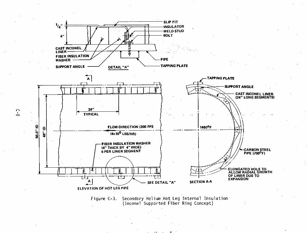
The he1 ium ho t l e g temperature (7460°F) ' r equ i res i n t e r n a l i n s u l a t i o n t o
ma in ta in the p i pe w a l l tempera&re w i t h i n code l i m i t s . Two i n t e r n a l insu-
l a t i o n concepts a re under study. one cons is ts o f a cas t n i cke l base a l l o y
( Inconel 71 3LC) i n n e r 1 i n e r w i t h h igh temperature f i b e r i n s u l a t i o n between
t he inconel 1 i n e r and the p ipe w a l l , as shown i n F igure C-3. The second
concept u t i l i z e s a r e f r a c t o r y l i n e r w ide ly used i n the re f inery /process
i ndus t r y . The r e f r a c t o r y inner l i n e r cons is ts o f a cast - in -p lace smooth
hard 1 i n e r anchored t o the p ipe by metal anchors. Between. the hard 1 i n e r
and t he pipe:, wa l l i s a l i g h t e r i n s u l a t i n g r e f r a c t o r y . F igure C-4 i s a
cross secti'o'n o f t he r e f r a c t o r y - l i n e d hel ium ho t l e g p ip ing .
An even more . d i f f i c u l t . t echn ica l problem than the ho t l e g i n s u l a t i o n i s
t h e ho t l e g i s o l a t i o n valves, which a re exposed t o temperatures w e l l above
the desi 'gntemperatures o f ASME Sect ion I 1 1 h igh temperature code cases.
No s a t i s f a c t o r y s o l u t i o n has ' ye t been proposed.
1 1 SLIP FIT .ATOR STUD
. SUPPORT ANGLE - DETAIL *#A" .-TAPPING PLATE
. P F,LOW DIRECTION (200 FPS A
I (4x lo6 LBSIHR) 4
FIBER INSULATION WASHER (14" THICK BY 4" WIDE)
.
6 PER LINER SEGMENT i SEE DETAIL
ELEVATION 0 6 HOT LEG PIPE
TAPPING PLATE
"A"
1
SECTION A-A EXPANSION
F igu re C-3. Secondary He1 ium .Hot Leg I n t e r n a l I n s u l a t i o n ( Incone l Supported F%ber Ring Concept)

BACKING FOR WELDING RING 2F"r'Gj LOW DE#S!TY ( 90 L B / F T ~ ' ~
REFRACTORY INSULATION (5'i4")
JOINT IS BUTTERED HARD, DENSE ( 670 LBIFT~) WITH REFRACTORY REFRACTORY (1") CEMENT AT ASSEMBLY
HEX STEEL (EMBEDDED1 IN REFRACTORY)
DETAIL "A" TYlPlCAL PlPE WELD
/--SEE DETAIL "A"
- L L ELEVATION OF HOT LEG PlPE 9
HEX STEEL (EMBEDDED IN REFRACTORY)
SECTION A-A
~ i ~ ~ d r e C-4. Secondary Helium Hot Leg I n t e r n a l I r ~ s u l a t i o n ' (R.?f r ac ta r y I n s u l a t i o n L i ne r Concept)

Appendix D
DESIGN DETAILS - 850°C I D C STEAM GENERATOR
A l a y o u t o f t h e i n d i r e c t c y c l e p l a n t steam genera tor i s shown i n F igu re D-1.
Tab le D-1 g ives d e t a i l s .
The concept se lec ted f o r t h e process heat p l a n t i s t h e Mark IV-A steam
genera tor used i n . the HTGR steam cyc le , t h e d i f f e r e n c e be ing t h a t i t i s
i n s t a l l e d i n a PCPV i n s t e a d o f a PCRV. The process heat p l a n t steam
genera tor i s designed (and, w i l l be f a b r i c a t e d ) t o ASME Sec t ion V I I I ,
D iv . 1 requirements.
~ l o w paths a r e s i m i l a r t o t h e i n - v e i s e l Mark I v - A concept; h o t he l ium
en te rs the . bottom o f t h e s t e e l vessel , f l ows upward th rough t h e s t r a i g h t
superheater, t u r n s 180" a t t h e t o p o f t h e s t r a i g h t superheater t o f l o w
down through t h e EES c o i l , and then f l ows o u t o f t h e u n i t a t t h e bottom ,
o f t h e c o i l . Water en te rs t h e u n i t a t t h e feedwater tubesheet j u s t below .
t h e EES c o i l , r i s e s t o t h e c o i l i n i n d i v i d u a l rubes, s p i r a l s upward i n a
h e l i c a l f ash ion t o t h e t o p o f t h e c o i l , crosses t o t h e c e n t e r v i a expan-
' i i o n loops above t h e gas f l ow , and f l ows downward th rough t h e s t r a i g h t
superheat tubes t o t h e supqrheat tubesheet. The EES i n n e r shroud i s t i e d
t o t h e s h e l l w i t h a c o n i c a l s e c t i o n below t h e feedwater nozz le and w i t h a
p e r f o r a t e d h o r i z o n t a l p l a t e above t h e EES c o i l . The s t r a i g h t superheater
shroud i s supported r a d i a l l y from' t h e EES i n n e r shroud a t t h e bot tom and
hung f rom t h e gas t u r n i n g vane a t t h e top. The EES suppor t p l a t e s a r e
each supported by a s e r i e s o f l o n g bars f rom t h e c o n i c a l s e c t i o n f o r dead
we ight loads and by t h e shrouds f o r l a t e r a l loads.

M a t e r i a l s a r e t h e same as t h e in -vesse l MK-IVA. Tubing (and tubesheet)
i s 2-1/4 C r - 1 Mo and A l l o y 800H w i t h a b i m e t a l l i c weld i n t h e qu iescen t
zone a t t h e t o p o f t h e u n i t ; suppor t p l a t e s a r e 2-114 C r - 1 Mo, and shrouds
a r e 304 and 316 s t a i n l e s s s t e e l . The concept p rov ides 187°F o f superheat
a t t h e b i m e t a l l i c weld. The weld has a nominal o p e r a t i n g temperature o f
811°F. The o t h e r c r i t i c a l area, t h e t o p o f t h e 2-114 C r co re superheater,
has a nominal maximum temperature o f 906°F w i t h a 30°F g rad ien t . A19 o f
t h e above values a r e regarded as be ing s a t i s f a c t o r y .

2 rlLL DMENSIONS &RE IN W M W CDLO CONDITION. 5 Or*tENSlhuS IN [] ERMXElS &RE IN MILLIMETERS
rado fa*] - @ITEMS 51. ~ W D 87 /IRE NOT m c m as EZ~CT Lorarm OF O E a Y L mmlN6 Lwbrk BLI7TOM OF KPV W S K)T BCEN DETERMINED kTWI5 T M E
i, - -- - --- - - - -- - -. -
- MD r n D
FIELD -
FIELO WLD --
"G? - [&q - [Zf' - - DETAIL A
SCILE . (*.. 1'0.
Figure D-1 . Steam Generator Assembly D-3

THIS PAGE
WAS INTENTIONALLY
LEFT BLANK

Table D-1
STEAM GENERATOR DETAILS FOR 850°C I D C PLANT
Overa l l 1 ength
Nu~ilber o f tubes
FW, EC, .EV, SH-1 1.00 OD x .12 wa l l x 255 f t long
1.00 OD x .074 wa l l x 56 f t long
Design condi t ions:
He1 i urn temperature
He1 iurn pressure
Helium mass f l ow
Water pressure


Appendix E
HEAT CYCLE EVALUATIONS - 850°C I D C PLANT
A1 though a mu1 t i tude o f p o t e n t i a l heat cyc les were considered i n t h e
e v a l u a t i o n of op t i ons , t h e main e f f o r t was d i r e c t e d t o comparison o f t h e
f o l l o w i n g t h r e e re former t r a i n l t u r b i n e p l a n t c o n f i g u r a t i o n s :
a Case A: t h e r m a l l y d r i v e n heat c y c l e
0 Case B:. - 'compression . d r i v e n heat c y c l e
a Case C;', d i r e c t steam i n j e c t i o n heat c y c l e . .
. .
The f o l lowing approach' was used i n eval u a t i n g these cases :
a ~ e v i e w i n ~ p r i o r r e p o r t s and documents on HTGR-R heat c y c l e designs
a Comparing conceptual designs f o r . t he t h r e e heat c y c l e cases us ing a c o n s i s t e n t des ign bas is
a S e l e c t i n g t h e most p romis ing heat c y c l e case by us ing a screening methodology t o r a t e t h e o p e r a b i l i t y as we1 1 as t h e economic and e f f i c i e n c y f a c t o r f o r t h e cyc les
The e v a l u a t i o n of t h e t h r e e heat c y c l e cases was based on t h e design cond i - - t i o n s used i n General E l ec t , r i c ' s Corporate Research and Development r e p o r t
"HTGR-R Lead Project-Reformer Heat Exchange and Steam Turb ine Cycle," dated
J u l y 11, 1980. Th is design bas is i s summarized i n Tab le E-1. For t h e '
bas i c designs, an e f f o r t was made t o min imize interdependence between t h e
re former heat exchange system and t h e tu rb ine -genera to r system. As a con-
sequence, use o f su rp lus heat f rom t h e re former heat exchange t r a i n t o heat
b o i l e r feedwater, i.n a manner s i m i l a r t o t h a t shown i n . G E 1 s CR&D r e p o r t ,
has n o t been inc luded i'n t h e bas ic designs f o r Cases A, B, and C. Such

Table E-1
HEAT C Y C L E EVALUATION DESIGN BASIS
Reformer System
HTGR heat t o reformer
Reforr~ier gas i ri1 e t temperature Inlet pressure Outlet temperature Outlet pressure
Reformer feed gas quantity
Reformer feed composition, %-mol..
Reformer product composi ti.on, % mol .
Steam genera tnr system HTGR heat to stcam gcncrJtor Steam generator pressure Steam generator temperature
723 MW 1800 psia 1000°F

heat economics were, however, subsequ,ently i ncorporated i n the ref inements
to the selected basic design. I n these basic designs, the heat exchange
between the refbrme~ feed and effluent assumes the use of mixed feed
evaporators (MFE) . I n the MFE, a two-phased 'stream containing both 1 iquid
water and a gaseous phase ( i . e . , steam and process gas) i s flowing on one
or both sides of the heat exchanger. The MFE concept has _not been incor-
porated into the refined version of the selected cycle (see Appendix I1 A ) .
Since the reformer and steam generator operating conditions were held con-
stant in th is comparison of cycle a1 ternatives, the design e f for t centered
on developing the heat and material balances fo r the reformer' heat exchange
t ra in and for the turbine-generator plant. I n th i s design e f fo r t , the
reformer heat exchange cycle was conceptualized f i r s t , and the turbine-
generator cycle was designed to match the needs of the reformer system.
Descriptions for each of three cases evaluated follow. . .
Alternate Cases Evaluated
Case A - Thermally Driven Heat Cycle. The heat cycle diagram for the Case A design i s shown in Figure E - 1 . I n th i s design, the methane-water
mixture fed to the reformer i s heated by the following exchanger sequence:
r Heated with partial ly-condensi ng reformed gas i n a mi xed feed evaporator
0 Further heated by steam a t two temperature levels in series exchangers
e Heated to reformer feed conditions by exchange with the reformer out le t gas mixture
The reformer out le t gas i s cooled prior to compression for pipeline trans-
mission by the following exchange sequence: I
a Cuoled in i t i a l l y in the reformer feed-product exchanger
Further cooled in the MFE with a vaporizing methane-water mixture

a Cooled ahead of compression by exchange w i t h coo l i ng tower water
* The two pressure l e v e l s o f steam which p rov ide heat f o r t he cyc l e are '
exhausts from the h i gh and' i n te rmed ia te pressure tu rb ines .
Case B - Compression-Driven Heat Cycle. A heat c y c l e diagram ' f o r Case B
i s shown i n F igu re E-2. I n t h i s ' h e a t cyc le , the temperature o f t he
reformed gas i s main ta ined a t a l e v e l above t h a t o f the methane-water
m i x tu re , w i t h which i t i s be ing exchanged, by compression o f the ho t
reformed gas. The compression n o t on l y adds heat t o the gas mix ture ,
b u t i n i nc reas ing t he pressure, i t a l s o r a i ses t he temperature of p a r z l a l
condensation o f the water present . For t h i s case. t he methane-water heat-
i n g sequence i s :
a I n i t i a l hea t ing by exchange aga ins t t he reformed gas i n t h e MFE
a Fur the r hea t ing by exchange w i t h the reformed gas i n the h o t gas compressor i n t e r - and a f te rcoo l e r s
a F ina l hea t ing t o reformer i n l e t temperature i n t he feed- product exchanger
The sequence f o r c o o l i n g t he reformed gas i s as f o l l o w s : -.
a I n i t i a l c o o l i n g by exchange w i t h the methane-water m i x tu re i n the feed-product exchanger
a Cool ing t o 380°F ahead o f compression us ing coo l i ng tower water.
a Compressing t he reformed gas f rom 137 t o 535 p s i a and us ing t he methane-water m i x tu re f o r heat exchange i n the compressor i n t e r - and a f t e r c o o l e r s
a Coo l ing .w i th feed methane-water m ix tu re i n t he MFE
a Cool ing t o 120°F w i t h coo l i ng tower water

MULTISTAGE COOPRESSOR 1 0 0 Mue
7-1 MIXED FEED EVAPORATOR
I CRSE R-HEAT CYCLE OIflGRflM THERNILLY DRIVEN CYCLE I
Figure E-1 . Heat Cycle Diagram - Case A

THIS PAGE
WAS INTENTIONALLY
LEFT BLANK

Figure E-2. Heat Cycle Diagram - Case B
J
MULTISTRGE COMPRESSOR REFORMEO COOLER GRS
5 0 HWt
FEED-PRODUCT SYNGRS MIXED FEE0 PIPELINE GRS PIPELINE GRS DRYING SEPRRRTOR EXCHRNGER COOLER EVRPORRTOR - COMPRESSOR GRS COOLER RND ODORIZING
31MWt
1 1460T 710.2P 4.100F
I 1 tCUT
RE-RS
HELIUM
515MWt 9 3 T k ! ! ! ! !L d l 2 2 0 P 8 2 4 T 3 6 7 T
3 5 4 T 6 0 T RCTIVRTEO - BED CARBON RETURN GRS
INTERMEDIATE
SEE NOTE HERT EXCHRNGE
FROM PIPELINE
6 0 1 3 0 0 P RETURN WRTER
0.468F
1562T t r------------------------------------------------------------ 711.4P HELIUM 1 MRKE-UP -
4.200F 1 I I WRTER
I 6 6 0 T 4 5 0 P
I ONE I 4 3 0 T
L----------------------------
HTGR - 150P CORE 1 2 3 6 H
11xi'Fwt 1.960F
PRIMARY HELIUM
CIRCULRTOR -- 45 MWe - INTERMEDIATE PRESSURE TURBINE
650T 716.7P
1. DIAGRAM I S TYPICRL FOR:
*FOUR PRIMRRY HELIUM LOOPS
F~I IR ~ F T ~ N ~ R R Y HFI rlln I n n p s
EIGHT REFORMERS FOUR REFORMER TRRINS
*FOUR STEAM GENERRTORS
*ONE SET OF HIGH PRESSURE, INTER- MEDIRTE RND LOW PRESSURE TURBINES. RND TWO GENERRTORS.
FLOW RRTES AND ENERGY VALUES ARE TOTRLS FOR RLL 4 LOOPS RNO TRRINS --
2. RRER ON REFORMER TRRIN IRT) SIDE --
OF ORSHED LINE I S TYPICAL OF FOUR -- LOOPS/TRRINS PER NOTE 1. RRER BELOW DRSHEO L I N E REPRESENTS THE SINGLE TURBINE PLRNT
3.RRROWS DENOTE FLOW TO RND FROM OTHER PRIMRRY HELIUM LOOPS OR REFORMER TRRINS
PUMP - FW. HTR. NO. 4 FW. HTR. NO. 3 FW. HTR. NO. 2 FW. HTR. NO. I 4. PRRRMETER UNITS
T-TEMPERATURE1 OF P-PRESSURE, PSIA F-FLOW, ~O"B/HR H-ENTHRLPY* BTU/LB

T H I S PAGE
W A S INTENTIONALLY
LEFT BLANK

Th is heat c y c l e maximizes t h e heat exchange between t h e re fo rmer gas and
t h e methane-water m ix tu re , b u t s u b s t a n t i a l l y inc reases t h e t o t a l amount o f
energy r e q u i r e d f o r compressing t h e reformed gas t o p i p e l i n e p ressure
(1200 p s i a ) .
Case C - D i r e c t Steam I n j e c t i o n Heat Cycle. F i g u r e E-3 shows t h e d i r e c t
steam i n j e c t i o n heat cyc le , Case C . T h i s c y c l e i s s i m i l a r t o Case A, b u t
t h e heat p rov ided f rom t h e tu rb ine -gene ra to r c y c l e i s w i t h d i r e c t steam
i n j e c t i o n r a t h e r than th rough an exchanger. The methane-water h e a t i n g
sequence f o r t h i s case i s :
a I n i t i a l exchange w i t h t h e reformed gas i n t h e MFE
e D i r e c t i n j e c t i o n o f steam t o f u r t h e r hea t t h e methane- water m i x t u r e
e Heat ing t o r e f o r ~ ~ i e r i n l e t temperature by exchange w i t h t h e reformed o u t l e t gas
The c o o l i n g sequence f o r t h e reformed gas i s :
e I n i t i a l exchange w i t h methane-water m i x t u r e i n t h e feed- p roduc t exchanger
e F u r t h e r c o o l i n g by exchange w i t h methane-water m i x t u r e i n t h e MFE
e Coo l i ng t o 120°F w i t h c o o l i n g tower water
The i n j e c t i o n steam r e q u i r e d f o r t h i s case i s exhaust f rom t h e h i g h pressure
t u r b i n e . Since condensate re tu rned f rom t h e methanator and f rom t h e re fo rmer
t r a i n i s sen t t o t h e tu rb ine -gene ra to r p l a n t , a d d i t i o n a l t r ea tmen t o f t h i s
condensate i s p rov ided be fo re i t passes t o t h e steam genera tor .
Se lec ted Cycle and Suppor t ing Ra t i ona le
Heat c y c l e e v a l u a t i o n da ta f o r t h e t h r e e a1 t e r n a t i v e designs were d e t e r -
mined and t a b u l a t e d t o a i d i n making a r a t i o n a l s e l e c t i o n o f t he p r e f e r r e d
heat cyc le . A summary o f energy t r a n s f e r s and n e t e l e c t r i c i t y f o r e x p o r t

f o r t h e t h r e e cases i s presented i n Table E-2. The amount o f thennochemical
energy i n t h e syngas product i s t h e same f o r each o f t h e a l t e r n a t i v e s and
amounts t o approx imate ly 560 MWt. Table E-3 shows t h e comparat ive equip-
ment d u t i e s o f t h e heat exchangers, compressors, c o o l i n g towers, and
tu rb ine -genera to rs f o r t h e t h r e e cases. Table E-4 presents rough e s t i -
mates o f t he c a p i t a l d i f f e r e n c e s developed f o r t h e t h r e e cases.
The r e s u l t s o f t h e eva lua t i ons i n d i c a t e t h a t t h e r e i s o n l y marginal d i f -
ference between t h e cases. The compression d r i v e n c y c l e (Case B ) i s
s l i g h t l y s u p e r i o r t o Cases A and C i n regard t o n e t e l e c t r i c a l power f o r
expo r t . Case A and Case C a r e n e a r l y equ iva len t w i t h respec t t o n e t power
f o r expo r t . Because o f t h e c o s t l y h o t gas compressors i n Case B, i t i s t he
l e a s t a t t r a c t i v e w i t h regard t o p l a n t c a p i t a l cos t . Case C, t h e steam
i n j e c t i o n . case, i s s1 i g h t l y b e t t e r than Case A w i t h regard t o p l a n t c a p i t a l
cos t , p r i m a r i l y due t o t h e e l i m i n a t i o n o f much heat exchange sur face i n
.heat ing re former feed w i t h steam i n j e c t i o n . Case A i s judged t o have
advantage ove r t h e o t h e r two cases w i t h respect . t o c o n t r o l 1 ab i 1 i ty and
s a f e t y . Case A i s c o n s i d e r e d ' t o have a s i g n i f i c a n t advantage i n s a f e t y
ove r Case C because o f a poss ib le problem o f t r i t i u m c o n t r o l i n t h e
process gas w i t h d i r e c t steam i n j e c t i o n .
I n s e l e c t i n g t h e p re fe r red bas i c heat c y c l e f o r t h e base l i ne p l a n t design,
seven e v a l u a t i o n f a c t o r s , shown i n Table E-5, were i d e n t i f i e d f o r r a t i n g
t h e cycles.. Importance we igh t i ng f a c t o r s were assigned t o each eva lua t i on
f a c t o r , and t h e r a t i n g was determined as t h e product o f t h e rank ing and
t h e importance w e i g h t i n g f a c t o r .
W i th t h e a i d o f t h e tabu la ted heat c y c l e i n fo rma t ion , and cons ide ra t i on o f
t h e f l e x i b i l i t y , c o n t r o l l a b i l i t y , and s a f e t y i n p l a n t ope ra t i on f o r t h e
a l t e r n a t i v e heat cyc les , 'each o f t h e t h r e e cases was ra ted . The r e s u l t s
o f t h i s procedure, g iven i n Table E-5, i n d i c a t e t h a t Case A, t h e the rma l l y
d r i v e n case, i s s l i g h t l y supe r io r t o Cases B and C.

MULTISTRGE COOPRESSOR 1 0 0 MUe
ONE I 4 3 0 T HTGR 150P CORE 1236H
1 1 7 0 ~ t 1.172F LOW PRESSURE
e o o . s ~ l TURBINE 726P I /\J- n
PRIMRRY 0 N 0
OUTPUT 2 1 8 ~ 0 0 0 KWe GENERRTOR !g&g n
CIRCULRTOR * 4 5 MWe
INTERMEDIATE PRESSURE TURBINE ---
6 5 0 T 71C.7P w = = E
1. DIAGRAM I S TYPICAL FOR: 4 3 0 T
OFOUR PRIMRRY HELIUM LOOPS 1 5 0 P 1236M
OFOUR SECONDRRY HELIUM LOOPS 0.302F
EIGHT REFORMERS l FOUR REFORMER TRRINS
*FOUR STERM GENERATORS
*ONE SET OF HIGH PRESSUREI INTER- MEOIRTE RND LOW PRESSURE TURBINES, RNO TWO GENERRTORS. CONDENSRTE
POLISHER FLOW RATES AND ENERGY VRLUES RRE TOTRLS FOR RLL 4 LOOPS RNO TRRINS --
2. AREA ON REFORMER TRAIN IRT) SIDE DERERRTOR --
OF ORSHED L I N E I S TYPICRL OF FOUR I -- LOOPS/TRRINS PER NOTE 1. RRER BELOW 341.7T DRSHEO L I N E REPRESENTS THE 120P SINGLE TURBINE PLRNT 312.6H
'
?.11F, - 3.HKHUWS UCNOl t FLOW TO RND FROM
OTHER PRIMRRY HELIUM LOOPS OR REFORMER TRRINS FEEDWRTER .-
PUMP - FW. HTR. NO. 4 FW. HTR. NO. 3 FW. HTR. NO. 2 FW. HTR. NO. 1 , 4. PRRRMETER UNITS
T-TEMPERRTURE. OF P-PRESSURE, PSIR F-FLOW, los LB/HR H-ENTHRLPY, BTU/LB
RETURN WATER
Figure E-3. Heat Cycle Diagram - C d ~ t ! C

THIS PAGE
WAS INTENTIONALLY
LEFT BLANK

Based on these r e su l t s , the thermally driven heat cycle is' recommended
for . the' 850°C I D C base1 ine plant design.

Table E-2
ENERGY TRANSFER SUMMARY
Feed-product exchangers Methane-water heaters Compressed gas c o o l e r Mixed feed evapora tors
Heat Removed f rom Syngas (MWt)
Feed-product exchanger Mixed feed evapora tors Syngas c o o l e r Compressed gas coo l e r Reformed gas c o o l e r
Heat Rejected (MWt)
Pipe1 i n e gas coo l er
Net E l e c t r i c a l Power (MWe)
E l e c t r i c i t y generated
E l e c t r i c i t y used Hot syngas compressor P i pel i ne compressor He1 .I UIII c i r c u l a t o r s Otlier a u x i 1 i a v y power-
(1) No heat exchanger r e q u i r e d ( 2 ) The t o t a l i s l a r g e r than i n Cases A and C because o f heat i n p u t by
t h e compressor
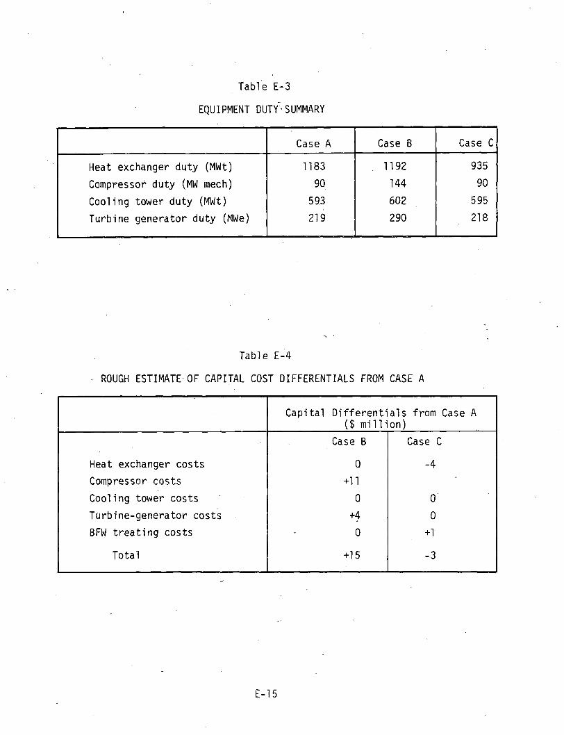
Table E-4
ROUGH ESTIMATE OF CAPITAL COST DIFFERENTIALS FROM CASE A
Case C
935
90
5 95
21 8
Case B
11 92
144
602
2 90
Heat exchanger du ty (MWt)
Compressor d u t y (MW mech)
Coo l ing tower d u t y (MWt)
Turb ine genera tor d u t y (MWe)
Heat exchanger cos ts
Compressor c a s t s
Cool i ng tower cos ts
Turbine-generator cos ts
BFW t r e a t i n g cos ts
T o t a l
Case A
1183
90
5 93
21 9
C a p i t a l D i f f e r e n t i a l s f rom Case A ( $ m i l l i o n )
Case B
0
+11
0
+ fr 0
+15
Case C
-4
0
0
+1
-3

Tab le E-5
HEAT CYCLE EVALUATION FACTORS FOR THE 850°C IDC HTGR-R PLANT
Each q u a l i t a t i v e f z c t o r i s ass ig lxd an importance weigbt on a sca le o f 10 t o 1. For each case, a ranking o f 1 t o 10 i s assigned. The r a t i n g i s the importance re ig.?t x t t e ra rk ing .
Heat Cycle Evailualiion Fd:tors
P l a ~ t n e t output
Comparative c a p i t b l c ~ s t ( cos t d i f f e r e n t i a l s from base case1 . ,
A b i l i t y t o operate PICP dur ing T-6 t r i p
A b i l i t y t o operate w i th.one YHS loop down (shor t term) ,
Use o f standard, c a n u n e r c i a l l ~ proven equipment: exceptions a r e 1 i sced on attached page
Overa l l operationa-. re1 i a b i l ' t y (passive versus r o t a t i n g equipmentj
C o n t r o l l a b i l i ty /opcra t iona l f l e x t b i l i t y .
Safety ( t r i t i u m , etc . )
Sumnary o f r a t i n g s
10 to 1
Importance Weight
10
7
3
3
3
7
3
3
Case A Thermally Dr iven
Ranking
9
9
9
9
16
9
10
10
Rat ing
90
63
27
27
30
63
40
90
430
Case B Conpressor Dr i ven
Ranking
13
7
1 I
13
3
s
3
.J
Case C D i r e c t Steam I n j e c t i o n
Rat ing
100
49
30
30
24
49
32
81
395
Ranking
9
10
9
9
10
10
9
7
Rat ing
90
70
27
27
30
70
36
63
41 3
Appendix F
DESIGN DETAILS - 950°C DC REACTOR VESSEL
PCRV Structure. The PCRV structure for the 950°C direct cycle reforming
p l a n t i s characterized by a central core cavity, surrounded by the follow-
ing major cavities:
Reformers (4 , G E design)
Steam Generators ( 2 , GA design)
Primary Circulators ( 2 above steam generator, .: .
2 in separate cavities)
Provision has also been made in the. PCRV for four cool ing water header pits and two pressure relief pits . The main features of the PCRV are ou t -
1 ined in Tab1 e F-1 , and the cavity envelopes used i n the' design are shown
in Table F-2.
The primary coolant passes through the core on t o the reformer and steam
generator cavities in series and returns t o the core, cavity via the main
circulators. The. process. heat 1 ines come o u t of the t o p of the reformer
cavity and are routed vertically downwa-rd through the PCRV and exit a t the bottom. Both the superheat and feedwater lines of the'steam generator cavity
are located in the bottom of the PCRV. The necessary NHS and NSS/BOP inter-
facing connections have been identified. Plan and elevation views of the
PCRV are given in Figure F-1 and F-2, respectively.
The PCRV dimensions are sized t o layout considerations. The minimum cir-
cumferential ligaments between cavities and the space required for the
linear prestressing tendons.in the t o p head determined the outside diameter
of the vessel. The height of the PCRV i s dictated by the overall height

Table F-1
MAIN FEATURES OF PCRV FOR 950°C DC PLANT . PCRV concrete s teng th
LPS tendon s t r eng th ( a t GUTS)
CPS cab le s t r eng th ( a t GUTS)
Re fue l ing scheme
Closures
Reformer cav i ty
Steam generator c a v i t y (wi t h mai n c i r c u l a t o r on top)
CAHE c a v i t y
Main c i r c u l a t o r c a v i t y
Steam generatnr type
CAHE
I
6500 p s i
2478 k i p s
41.3 , k i ps
In-vessel r e f u e l i ng (see memo #631: 1 10: TFU: 81 dated 4/29/81 f o r d e t a i l s o f design)
Sh ie ld p l ug f l u s h w i t h top o f PCRV
Precast concrete prest ressed r i n g
Stee l dome
Stee l dome
Once through bottom f e d type
Compact bayonet type
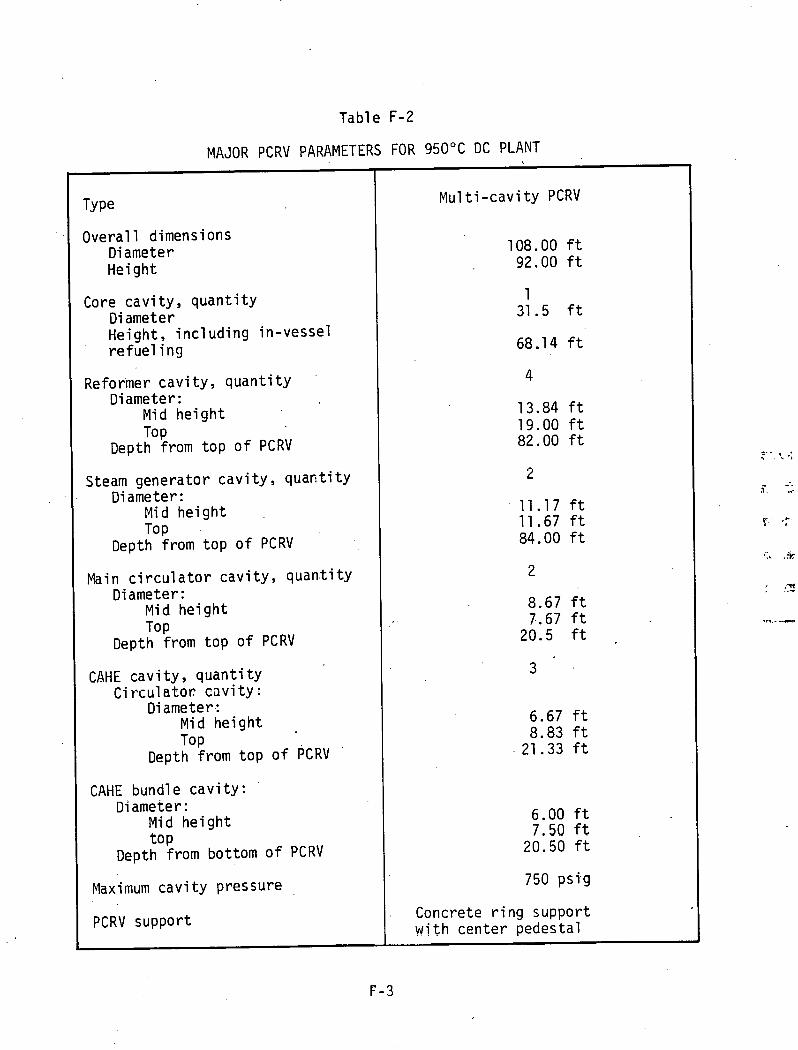
Table F-2
MAJOR PCRV PARAMETERS FOR 950°C DC PLANT
I
Overa l l dimensions Diameter He igh t
Core c a v i t y , q u a n t i t y D i ameter Height , i n c l u d i n g in -vesse l r e f u e l i ng
Reformer c a v i t y , q u a n t i t y Diameter:
Mid h e i g h t To P
Depth from t o p o f PCRV
Steam genera tor c a v i t y , q u a n t i t y Diameter:
Mid h e i g h t To P
Depth f rom t o p o f PCRV
Main c i r c u l a t o r c a v i t y , quan.ti t y Diameter :
Mid h e i g h t TOP
Depth f rom t o p o f PCRV
CAHE c a v i t y , q u a n t i t y C i r c u l a t o s c s v i t y :
Diameter: Mid h e i g h t TOP
Depth f rom t o p o f PCRV
CAHE bundl e c a v i t y : Diameter :
Mid h e i g h t t o P
Depth f rom bottom o f PCRV
Maximum c a v i t y pressure
Mu1 t i -cav i t y PCRV
PCRV support . Concrete r i n g suppor t w i t h cen te r pedesta l

required for the refoyer component cavity. Maintaining the .required head
thicknesses, the .core . cavity . height was extended by 8 feet in order t o accom-
modate the core in le t duct from the main circulator cavities a t an angle n o t
greater t h a n 30" t o the horizontal. All the other major components, such as
steam generators and main circulators, e tc . , were designed t o f i t within the
available space of the PCRV height as established above. Because of the
large and complex ductlng on the primary and secondary side of the major components, the PCRV ligaments and the corresponding prestressing inten-
s i t i e s have to be verified by analysis and suitable adjustments made t o
the PCRV size and prestressing as required. Provision has been made, for a l l the secondary ducting t o exit the PCRV vertically,dowards to the bot tom,
and cutouts are shown in the PCRV support ring a t these locations. The
routing of these pipes from the underside of the PCRV i s the responsibility
of the architect-engineer.
PCRV Lines, Penetrations , and Closures . The s tee1 'cavity 1 i ners , penetra- tions, and penetration closures form the continuous gas-tight boundary of
the PCRV. The l.iner and penetration anchors transmit loads from internal
equipment support structures and axial loads from closure to the PCRV con-
crete. A 1 iner cool ing system i s incl ude.d t o remove the heat transmitted
through the thermal barrier 'before i t reaches the concrete. The 1 iners, penetrations, and closures are similar t o those of recent HTGR-SC designs
where similar components are housed. The HTGR-PH requires a new closure design for the steam generator cavity. This new closure i s described below.
The top cap of the cavity l iner i s welded t o the l iner af ter the steam
generator i s instal led. The prestressed concrete closure. containing a housing for t h ~ main circulator, i s placed in pasi tion on t h ~ t o p oF the PCRV, concentric with the cavity t o p cap. The bottom end of the circulator housing i s welded t o the l iner t o p cap, forming a cavity between the t o p cap
and closure. This cavity i s f i l led with g r o u t , through penetrations ext.en- ding through the closure. The closure i s retained with the PCRV vertical

C=,'r' i P 5 WPiFIfATJCN B Y INALYSJS.
Z N4TZ&fAi PRBPPPTl6S AND SySZCM PBRAM6lXUS OF TYP M A J m STRUCZWAL C O H v 7 S USCD JN -ME FT&V CES;wN ARC AS F - U O W J :
0 SRECIFIED CCNCRETLI CEMPRESWVC SZRCNGW AT 69 .CA)'b .6SOO PSI (44LBP MF(IJ CDR PCW
TYP - 7 V T A I 4 AND PRZCAST W C L S ; 8 0 0 0 PSI fSS.8G M R ) F0U CErr'CRS7-C CLCSUR&S.
s !~ 'DIA. PIP8 CNASE -. C. LJNPAR P.R-CSIU€SSJNG : 60- fh 'd .7- WJB.9 -NO
W C S S GAS I N L f f T , TEMDONS MAX CAPACITY - 2478 KIPS (U-rS )
d CfUCUhfWREN7JAL paESTRES3lNG.' &"d, 7-WIUd =RAND CA6LPS-MAX CAPACITY. 4l.S COPS (biUZSJ
8. MXJUUM C A V I N PWSSURE (&- 75QPSl&17hl&
~ M # N S / @ N S AND OPENJNGS W O W W IYC PGPV S U W R T STRYCTURC ARS SU66EZT~ ONLY. FINAL CeWFGURAT/W AND L4CAZILW ARC 6WRT OF THE bop DCSJGN . PcRV DESIGN ONLY AND W Y a C TffRH1M.TUD 4r 7Ua - MA1.V CGCL/LdTOR eO77OM QP ?Me FTPV. Z# UMUIRCO IN M DOP
CAVITY, 'NP -7n7il.L Z Ci?S/6N, N6Y UAY M USED IN 77dS FCRV SUP-7.
T W I ~ ~ s a v L e m u r PQCJ + + r w w ~*ca M G U ~ D carrr k'E5lON OYTLET TdMCTRA- AVNETlZIlTMS rMlD OrYle MJNOR IS? R S 4 ~ R I T l O N S . , k L O W C e *C4S = I N MADE AV TNS MSJGN FOR SUCM RIQUR#WAUTS.
6 me F C A S ~ ~ J U N OF w s U S N C ~ ~ L A m m a H a N r IS suwzcr TC, m e MLLEWINQ CCWWDERITKWO: - a CCWCeCTE USAhfbNTJ TO dC VdrPJFSO BY AM1LYU#S.
STEA M GEhrSRi T o e / L\ L d w r STUDJCS TD ae MA= FOR FQSS~U.
MAIM CJRCMAWG TENDON /NTERF(PffENCC.
CAVI~Y, 7 ) ' P - m ~ r l ~ 2 C CAVITY PNYILOPRS ARC OdT&NPD CRGU WICd RCFCUWCP PRAW/N6S .'
L ) REFnffUeR- 6 E DW6 NC\ X L W P - I D M ' I / P r Z R , OATCO 3-5-8j.
o . ) a s A M ~NERATOR - NO. CP.IOS/I . ~ ~ M A J N GIRWLCTOR - D W ~ Na oroas&A .' 4) CWx/Ltmar C I R C U L A ~ ~ ~ - ow6 NU 0 1 ~ l l 7 A . 5 ICCWp IUX IUARI *PAT dXWAN6ER @AM*/-
nwfi &m n r s 7 a 1 n .
GJ I N - VbSS6L RCFUCLIN6 - M CXI OPdIQOfl.
PffPSSURE ff#l.lEP VALVE TYP- TOTAL PIT A IG'+'DP, 2. - FLATe TOM Sd-557, CLASS 2. - CORGWGS ?V d E SA- sod, C U S S ZA .
W e e M T H L IS AVOJC1TffO AS tl* C-.' - pure 79 er SA-sm. OR i s . - FORGllUCiS 70 51? &-as, GUS3 PIC.
WN~RC - ~ A Z C M A ~ ~ A L 79 BE S B - Q ~ ~ , /S I V D / C ~ ~ D ALLOY AS -I/. A- ma.+
- FoR6lNGs 7r) DC Sb-# ,ceNamoN 2. - 9 LINCU TIUCKNdSS 7P 68 M'famuJa.cffPr *.IY.Y
o r r D oruruwec. ra COOLING ruse PIW m e4 s %J(a~l/b(~) eXC/ev
WYERP NOTED OWffRWISC
JL aw 41~e.e nuos mac W * ( a o z ~ ) a ~ . a ~ a ~ f i w
PCRV RING =LOW SUPPORT @.
P t R V PUANTJTJPS .' AUX. CIIKULAZW CLIVJTY -' ~ O L Z mnv QUW~T,IS ue?III) m GA UCMO m
I AZT0P;CAMECAVITY 651: lZ5: MCV: 81, DAT80 6-t6-&I.
AT D O r OF PCUV, TYP I g S P L A C C S .
Dn/VC # HWST SPRVJCC. FOR W-VSSSeL ReFULILJNG , TyP- TOTAL 2
l ~ 6 ~ ' Z D PEN. BIZLOW. FUEL W - TRANSFPU TOTAL 2
CO@LlNG WATeff NEAOPU -J P J T /6:O-bCLOW TOP OF FCRV, TYP- TOTAL 4
P L A N - P C R V TOP M E A D
Figure F-1 . PCRV Plan View F- 5

THIS PAGE
WAS INTENTIONALLY
LEFTBLANK

V E R T I C A L S E C T , I O N b\ b\
Figure F-2. PCRV Elevat ion View

THIS PAGE
WAS INTENTIONALLY
LEFTBLANK

I tendons. The re fo rmer c a v i t y c o n f i g u r a t i o n and i t s c losu res a r e d i c t a t e d
by re fo rmer requirements. The design inc ludes a dome c l o s u r e which i s
recessed i n t h e re former c a v i t y and i s a t tached t o a l a r g e r i n g f o r g i n g ,
c a s t i n t h e PCRV, and has a s leeve and f l a n g e t h a t extends i n t o t h e c a v i t y .
The re former i s r e t a i n e d w i t h t h i s f l ange . The a x i a l l o a d f rom t h e re fo rmer
i s t r a n s m i t t e d from t h e r i n g f o r g i n g i n t o t h e PCRV.
PCRV Thermal B a r r i e r . The thermal b a r r i e r has been separated i n t o a num-
be r o f zones, accord ing t o s e r v i c e temperature and l i n e r geometry cons idera-
t i o n s . Four d i f f e r e n t m a t e r i a l s e l e c t i o n s have been made f o r t h e v a r i o u s
zones accord ing t o h o t su r face temperature. The p r e l i m i n a r y thermal b a r r i e r
s i z i n g , c a l c u l a t i o n s proceeded accord ing t o t h e f o l l o w i n g sequence:
Thickness determinat ion based on i n s u l a t i o n p r o p e r t i e s . A f a c t o r o f two t i n e s t h e thermal c o n d u c t i v i t y was used. There fore t h e f i b r o u s i n s u l a t i o n th i ckness i s approx imate ly t w i c e t h a t which would r e s u l t i n t h e maximum l i n e r o v e r a l l temperature o f 150°F.
Thickness de te rm ina t ion based on h o t spot examinat ion. The e f f e c t o f attachment f i x t u r e s on th ickness was determined i n accordance w i t h a maximum l i n e r ho t -spot temperature l i m i t o f 250°F.
e F i n a l de te rm ina t ion of t h i ckness values based on t h e r e s u l t s o f t h e above methods, p l u s any a d d i t i o n a l design f a c t o r s .
The types of m a t e r i a l s se lec ted f o r t h e va r ious thermal b a r r i e r components
a r e shown i n Tab le F-3. The m a t e r i a l s were chosen on t h e i r a b i l i ty t o
w i ths tand t h e p a r t i c u l a r temperature environment. Using creep as a c r i -
t e r i o n , Type 316 s t a i n l e s s s t e e l has been 1 i m i t e d f o r use t o 11 50°F. The
s i z e o f these cover p l a t e s (F igures F-3 and F-4) i s governed by t h e a c o u s t i c
environment, which i s assumed s i m i l a r t o t h a t o f t h e steam c y c l e p l a n t .
H a s t e l l o y X was se lec ted f o r t h e nex t h ighe r temperature range thermal
b a r r i e r . The bas is f o r t h i s s e l e c t i o n i s based on creep r e s i s t a n c e and
r e s i s t a n c e t o decarbu r i za t i on . H a s t e l l o y X was a l s o chosen f o r t h e seal
sheet m a t e r i a l because o f i t s d e c a r b u r i z a t i o n res is tance.
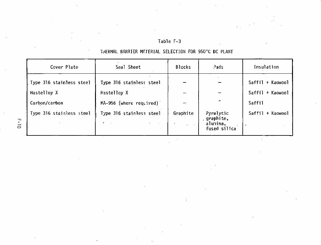
Table F-3
Tk-IERMAL BARRIER Mf-TERIAL SELECTION FOR 950°C BC PLANT
Cover Plate. Seal Sheet Blocks
, Type 316 s t a i n l e s s s t ~ e l
~ a s t e l l o y . X
Carb.on/carbon
Type 316 s t a i n l e s s s t e e l
-
-
-
Graph i te
. .
Type 316 s t a i n l e s s s t e e l
Haste1 l o y X
MA-956 (where r e q ~ i r e d ) '
T3pe 316 s t a i n l e s s s t e e l
3.3d s
6 . ' 1 .
-t
I n s u l a t i o n
-
-
-
P y r o l y t i c . gragh i t'e,
a lunina, fused s i l i c a
S a f f i l + Kaowool
S a f f i l + Kaowool
S a f f i l
S a f f i l + Kaowool

Figure F-3. Thermal Barr ier Coverplate With Integrated Attachment Fixture (Sheet 1 o f 2 )

4.83 (0.19 mm in.) i , 6.35 (0.25 mm in.)
I 2.29 mrn / (OlOiiO in.) R ' ' C.1i mm
10.28 111.) 11
VIEW B 12.7 mm
I
1 3.05 mm 25.4 inm
11.00 in.) (0.12 in.) A TYP '
SECTION A - A
Figure F-4. Thermal Barrier Coverpl ate Wi t h Integrated Attachment Fixture (Sheet 2 of 2 )

The insulation blankets for the above two grades of thermal barrier con-
s i s t of a composite of Saffi l alumina HT and Kaowool. On the basis of
resi 1 iency, Kaowool i s being 1 imi ted to 900°F for long-time exposure.
The base1 i ne material selected for the lower core cavity sidewall, reformer
cavity, CAHE cavity, and the hot duct designs i s carbon-carbon ( C / C ) . The
duct designs employ high temperature, high resilience insulation (Saffi 1 )
made in segments to form a washer f i t t ed between a C/C inner shield and a
conventional steel l iner. The lower core cavity sidewall reformer cavity
and lower CAHE cavity thermal barriers are, in general, similar to the metallic-fibrous classes of design employing coverplates and seal sheets
b u t employing the different material selection. The Huntington oxide dis-
persion-strengthed a1 1 oy 'IA-956 was chosen as the seal she'et material
because of i t s decarburization resistance.
The function of the bottom head thermal barrier i s not only to protect the
PCRV l iner , b u t to provide a stabilized insulated structural base for the
graphite core support posts. The configuration consists of layered poly-
gonal. graphite blocks with insulation blankets through which a series of
ceramic support columns penetrate. These support columns consist of pads
which are sized to accommodate mechanical loads transmitted through the
support posts (including seismic conditions), as we1 1 as t o act as insulators.
The thermal loads dictate the thicknesses of the pads. Pyrolytic graphite
i s designated for the top pad. High purity (99.5%) al'umina i s designated
for a1 1 the remaining pads, with the exception of the bottom pad, which
i s the final insulator. The material for the bottom pad i s ' a high density,
f ine grain s i l i ca .
The polygonal blocks are exposed to the di rect gas stream and, hence, the
highest core outlet temperatures. Here the main problem i s to dissipate
the gas streakes, thereby minimizing the thermal shock imparted to the substrate layers.


Appendix G
DESIGN DETAILS - 950.OC DC STEAM GENERATOR
The steam generator assembly (shown in Figure G - 1 ) consis ts of a s ingle
he l ica l ly coiled tube bundle which i s made u p of 195 continuous tubes.
Each tube i s fabricated of three d i f f e ren t mater ials with four d i f f e ren t
wall thicknesses, b u t with a common outside diameter. The uni t i s b u i l t
to ASME B and PV Code Section 111, Class 1 and high temperature Code Case N-47. ,
The a1 1 -he1 ical tube bundle i s proposed t o take advantage of. the fact. t h a t
the i n l e t he1 ium i s discharged from the top of the. reformer cavity p r io r to
entering the steam generator cavi ty. Thus, the gas can conveniently en ter
the steam generator a t the top, flow down across the tube bundle,. and d i s -
charge a t the bottom.
/
Feedwater enters the uni t through a tubesheet located a t the bottom and
flows up through r i s e r tubes to the tube bundle, through the tubes t o the -.
top of the bundle, through expansion loops t o downcomers located in the
center of the bundle, and then down to the superheater tubesheet. Primary dimensions and flow cha rac te r i s t i c s a re shown in Table G-1.
This steam generator d i f f e r s from the M K IV-A concept in tha t the helium
makes a s ingle top to bottom pass over the,bundle. In the M K IV-A, the
gas enters a t the bottom, r i s e s over the "high" temperature s t r a i g h t tube superheater, turns and flows downward over. the "1 ow" temperature hkl ical
bundles of the f i r s t superheater, the evaporator, and the economizer. The two bundle sections a r e joined by bimetall ic welds (BMWs) located in
a quiescent he1 ium zone.

Table G-1
DETAILS OF STEAM GENERATOR FOR 950°C DC PLANT
Number o f un i t s / p l an ts
U n i t thermal r a t i n g
Overa l l 1 ength
Number o f tubes
1 i n on x Q.14/0.08/0.13/0.11 x 170 f t l ong
Design cond i t i ons :
Helium temperature
He1 i um pressure
He1 i um f 1 ow r a t e
Waterlsteam pressure
'Water f l o w r a t e
2900 p s i a 2400 psSa
9'.5 x l o 5 1 b /h r

NOTES : I
Figure G-1. Steam Generator Assembly 6- 3

THIS PAGE
WAS INTENTIONALLY
LEFTBLANK

The basic problem with the 1ocat.ion of the BMW i s t o place i t in a section
of the bundle where the metal temperature does n o t exceed t h a t of the low
temperature materials' capability and yet in a region where dry steam i s
present s o t h a t the austenitic. material (Inconel 800H), which is subject
t o stress corrosion, will n o t be wetted.
I n this design, i t i s proposed t o use Inconel 800H in most of the super-
heater section and switch t o Inconel 800 a t the 50°F superheat point.
Inconel 800 has shown greater resistance t o stress corrosi,on than has
Inconel 800H. This material would be carried down into the evaporator
section until i t i s joined with the lower temperature 2-1/4 Cr - 1 Mo
which i s used in the rest of the evaporator and the economizer section.
I t should be noted-that Alloy 800 i s in Section V I I I , Div. 1 a t the ele-
vated temperatures of interest. An additional effort would be required
t o get i t into the Section 111, Class 1 Code Case.

Appenaix H
DESIGN DETAILS - DIRECT AND INDIRECT CYCLE REFORMERS
Figures H-1 and H-2 shows the conceptual designs of the 950°C DC reformer and the 850°C IDC reformer, respectively. Since there i s a comonal i ty i n the basic configuration of the two reformers, the comon features are described and the unique characteristics of each reformer design are indicated explicitly.
Design Description. For both the 950°C and 850°C reformers, hot he1 iun
enters the lower inlet plenum and flows upwards on the shell side of the reforming tubes in a serpentine pattern. A serpentine flow pattern i s achieved by installing baffles spaced axially along the tubes. The helium exits the reformers below the support plate and flows downward through the inner flow shroud and into the exit nozzle. The heat required for the 950°C DC reformer i s supplied by the primary helium. The 850°C IDC reformer uses the heat from the secondary heliwn which circulates through the intermediate heat exchanger (IHX) .
The process gas i s introduced into the upper plenum, as shown i n
Figure H-3, for both the 950°C and 850°C reformers. The gas flows between the tubesheet and the support plate and enters the' catalyst-fi 11 ed reform- ing tubes, where the reforming process takes place. After flowing down-
ward to the bottom of the tube, the reformed gas enters the internal pig- tail tube. The pigtail tube acts both as a return tube and as a secondary heat regeneration for the incoming process gas. Finally, the gas i s dis- charged into the outlet plenum above the support plate and exits the reformers.

Figure H - 1 . Conceptual Design f o r Steam Reformer - 950°C Di rect Cycle Reforming Plant

Figure H-2. Conceptual Design for Steam Reformer - 850°C Indirect Cycle Reforming Plant
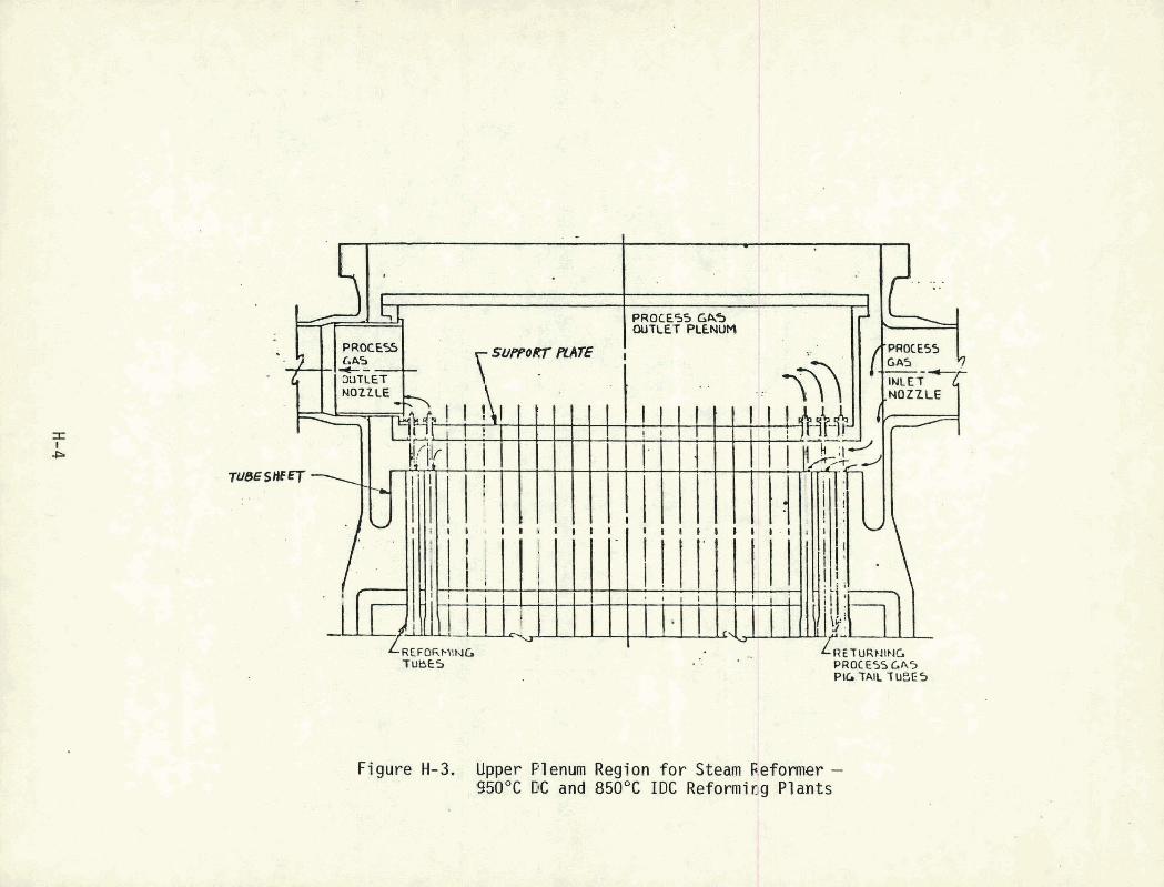
LREFORMING TUBES
LRETURMING PROC €55 Gl45 PI6 TAIL 1 USE 5
Figure H-3. Upper Plenum Region f o r Steam f;.eformer - 950°C DC and 850°C I D C Reforming Plants

The tubesheet j s used t o suspend the c a t a l y s t - f i l l e d re forming tubes.
Since the tubesheet i s a boundary between the process gas and the incoming
ho t he1 ium, i t w i l l ' be exposed to' the most severe t r a n s i e n t cond i t i ons .
Consequently, the tubesheet i s q u i t e l a r g e and complex. I n cont rast , the
support p l a t e i s used on ly t o support t he process gas p i g t a i l tubes and
i s exposed t o the outgoing' hel ium o f a l o w e r temperature. The support
p l a t e i s designed t o be e a s i l y removed from the vessel i n order t o perform
maintenance and r e p a i r operat ions. The re forming tube diameter i s reduced
a t the upper end t o permi t a reasonable tubesheet i n t e g r i t y w i t hou t exces-
s i ve tube spacing.
Reformer Tube Bundle. The pr imary con f igu ra t iona l d i f f e rence between t he
DC and I D C reformers i s the reforming tube i t s e l f . For the 950°C DC
app l i ca t ion , a duplex tube design i s selected, because i t provides a
double phys ica l b a r r i e r between the rad ioac t i ve pr imary he1 i um and the
non-radioact ive process gas and a means t o moni tor the tubes f o r leaks.
The 850°C I D C reformer uses a s ing le -wa l l ed re forming tube^. The con-
s t r u c t i o n o f the i n d i v i d u a l reformer tube i s shown schemat ica l ly i n
Figures H-4 .and H-5. The c a t a l y s t - f i l l ed re forming tube i s suspended
v e r t i c a l l y from the tubesheet. A p i g t a i l tube f o r process gas r e t u r n
i s suspended w i t h i n the reforming tube by the support p l a te . Both -.
tubes are al lowed t o expand a x i a l l y bu t are res t ra ined h o r i z o n t a l l y
by b a f f l e s spaced a x i a l l y along the reformer tubes. Each reformer
tube i s welded t o t he tubesheet. The ou te r tube o f the 950°C duplex
reforming tube i s welded d i r e c t l y t.0 t he bottom o f the tubesheet. The
i nne r tube o f the duplex tube extends through the tubesheet and i s
welded t o the upper surface o f t he tubesheet. The i n t e r n a l p i g t a i l
extends upward i n t o the process gas o u t l e t plenum and i s at tached t o a
clamp and seal assembly located on top o f the support p l a te . The 950°C
duplex tube is formed i n two wa l l s separated by a b u f f e r gas gap. Th is
gap i s about 0.2 mm wide and al lows f o r the op t i on o f r e l eas ing f i s s i o n
gas and t r i t i u m t o a b u f f e r gas system. . .

PROCESS 6AS OUTLET PROCESS C I S
O U l L E B PLENUM
..I31 . TUBE A LENGTtli
v HOT SPUN 0 1 - PLUG WELDED
Figure H-4. Bupl ex Reforming Tube f o r 950°C iDC

PROCESS GAS OUTLE7 PLENUM
23MM 1.906)I.D.
PROCESS GAS
TUBE SHEET
REFORMER TUBE 107.5BIAKl~ .2321 76.67 UM(3.0191 I
REFO3MER TUBE ISVIAGED 8 Q E ) 86.03lk!.!~3.386IO.D. . ?3.66Hh!l2.90311.0.
Figu re H-5. S i n g l e Walled Reforming ~ u b e ' f o r 850°C IDC

Operat iona l Condi t ions. The s p e c i f i c d i f f e r e n c e between the two reformers
r e s u l t s from the h igher re forming temperatures i n t he 950°C DC. Tables H-1
and H-2 show the steam reformer design data f o r the 950°C DC and the 850°C
IDC.
For t h e 950°C DC reforming p lan t , the re a r e f o u r steam reformers i n t he
p l an t . One steam reformer of thermal du ty o f 163.5 MWt i s provided f o r
each one o f t h e f o u r independent pr imary hel ium loops. Each reformer i s
l oca ted i n s i d e a c a v i t y i n the PCRV which i s w i t h i n the reac to r contain-
ment bu i 1 ding. Dur ing normal p l an t ope ra t i on, pr imary he1 i um o f
125.6 kg/sec enters each reformer a t 947°C and e x i t s a t b9baC, and pro- cess gas o f 69.6 kg/sec a t a steam/methane r a t i o o f 2.5 enters each
reformer a t 538°C and e x i t s a t 631°C. Process gas pressure (49 bars)
i s s l i g h t l y h igher than t h e pr imary hel ium pressure t o prevent process
gas contaminat ion i n the event o f a reformer tube leak. Using 86 mm O.D.
duplex tubes w i t h 12.5 rn a c t i v e length, a t o t a l o f 1400 tubes and a bundle
diameter o f 3.7 m a re requ i red f o r each reformer. A methane conversion
o f 60% can be achieved. Because t he re forming tubes a c t as the pr imary
coo lan t boundary and can a l so be used f o r leak detect ion, the design o f
the 950°C DC reformer conforms t o the requirements o f the ASME Code Sec-
t i o n 111, Class 1 component. Due t o the h igh temperature/pressure environ-
ment i n the 950°C DC reformer, ma te r i a l se l ec t i on i s a c r l t i c a l design
cons iderat ion. P re l i m i nary s t ress ana lys i s i nd i cates t h a t Inconel 617
o r a s i m i l a r ma te r i a l i s requ i red f o r the re forming tubes, tubesheet, and
the shroud.
Because o f t h e lower he1 ium i n 1 e t temperature, t he re forming e f f i c i e n c y
o f t he 850°C I D C reformer i s reduced. Two steam reformers are requ i red
f o r each o f t he f o u r secondary hel ium loops t o prov ide an acceptable
bundle diameter f o r shipment by the conventional r a i l . The. design o f the
850°C I D C reformer i s g r e a t l y s i m p l i f i e d over the 950°C DC reformer, due
t o t h e phys ica l l o c a t i o n and temperature/pressure 'env i ronment. I n the

STEAM REFORMER DESIGN DATA 950°C DIRECT CYCLE REFORMING PLANT
J
Number of steam reformers in plant Thermal duty per module, M W t Primary he1 i um conditions :
Mass flow, kg/sec. In1 e t temperature, "C Outlet temperature, "C In le t pressure, bar Out1 e t pressure, bar
Process gas conditions : Mass flow, kg/sec.
- Steam/methane r a t i o In le t temperature, "C Out1 e t temperature, "C In1 e t pressure, bar Out1 e t pressure, bar Maximum reformi ng temperature, "C Methane conversion, X
Reforming tube dimensions: Outer tube O . D . , mm Outer tube I.D., mm Inner'tube O . D . , rmn Inner tube I.D., mm Active length, m
Number of tubes Pitch fac tor Pigtai 1 :
O . D . , mm I.D., mm
Catalyst: O . D . , m I.D./O.D., % Length, mm Life, years
Baffled regions Bundle diameter, m Design l i f e , years
ASME code c lass i f ica t ion Sei smi c categ0r.y
4 ' 163.5
1 2.5 .6 947 696
47.0 46.3
69.6 2.5 538 631 4 9 44
844 60
86.0 73.7
' 73.3 61.3 ,
12.5 1400 1.18
2 0 18
6.7 62
6.7 7-10
3 3.7
40
Section 111, Class 1 I

Table H-1 (Cont 'd )
M a t e r i a l o f cons t ruc t ion :
Reforming tubes - Upper tubesheet
Lower tubesheet
Shroud
Vessel head
Cover p l a t e
Inconel 617
I nco l oy 800H
Inconel 617
Inconel 61 7
t. SS 316
SS 316 . ..

Table H-2
STEAM REFORMER DESIGN DATA 850°C INDIRECT CYCLE REFORMING PLANT
*
Number of steam reformers in plant Thermal duty per module, M W t Primary he1 i um conditions :
Mass flow, kgfsec. In1 e t temperature, "C Outlet temperature, "C I n l e t pressure, bar Out1 e t pressure, bar
Process gas conditions: Mass flow, kg/sec. Steam/methane r a t i o I n l e t temperature, "C Outlet temperature, "C In le t pressure, bar Out1 e t pressure, bar Maximum reforming temperature, "C Methane curivers i on, %
Reforming tube dimensions: O . D . , mm I.D., mm Active length, m
Number of tubes Pitch fac tor Pi gtai 1 :
O.D. , mm E ; D . , nun
. Catalyst: O . D . , mm I.D./O.D., % Length, mm - Life, years
Baffled regions Bundle diameter, m Design l i f e , years
ASME code c l a s s i f i ca t ion Seismic category
8 65.5
64.3 791 595
48.7 48.3
39.0 4.0 450 562
2 5 20
7 2 7 6 0
107.5 76.7 12.5
533 1.18
25.0 22.3
8.3 62
8.3 7-10
4 3.3 40
Section 111, Class .2 I I

Tab1 e H-2 (Cont 'd)
M a t e r i a l o f cons t ruc t i on :
Reforming tubes
Upper tubesheet
Lower tubesheet
Shroud
Vessel head
Cover p l a t e
I nco loy 800H
Inco loy 800H
Inconel 617
I n c o l oy 800H
SS 316
SS 316

850°C IDC reforming plant, since the IHX constitutes the primary coolant
boundary and the steam reformer i s located in the secondary coolant loop,
the reformer i s designed as an ASME Code Section 111, Class 2 component,
which i s not so stringent as that of the 950°C DC reformer. Two 850°C IDC
reformers are contained in a single prestressed concrete pressure vessel (PCPV) which i s housed in a reformer building. The four reformer build-
ings in the plant are located outside the reactor containment building.
Each of the eight 850°C IDC reformers has a thermal duty of 65.5 M W t . Reforming tubes are of 107.5 mm O . D . , single-walled, and 12.5 m active
length. A total of 533 tubes i s required for each reformer. During normal
plant operation, secondary helium of 64.3 kg/sec enters each reformer a t
791°C and exits a t 595"C, and process gas of 39 kg/sec a t a steam/methane
ra t io of 4.0 enters each reformer a t 450°C and exi ts a t 562°C. Helium
pressure i s 49 bars, and process gas pressure i s 25 bars. A methane con-
version of 60% can be achieved. Due to the lower helium in le t temperature
(790°C) of the 850°C IDC reformer, a less expensive material, Incoloy 800H,
can be used for the reforming tubes.
Catalyst replacement can be accomplished by two methods. In the f i r s t method, each tube i s handled individually. The reformer'head and the pro-
\
cess gas outlet plenum cover plate are covered. Each straight pigtail i s then removed individually and the catalyst vacuumed out. The tube i s then inspected, re f i l l ed , and tested for uniform catalyst loading by measuring
the pressure drop through the tube. The second method enta i ls having the pigtail tubes attached to the upper tubesheet and pulling a l l tubes a t once. The catalyst replacement can then proceed the same as individual tubes.
If tube plugging i s required, the pigtail i s removed and an end cap i s
inserted and welded into the upper end of the reformer tube. A plug replaces the pigtail and i s welded in place.
1


Appendix I
..'DESIGN DETAILS - METHANATION PLANT
The process flow diagram for the 40 M W t methanation p l a n t , Figure 1-1, shows
the syngas being received from the HTGR-R via the TCP. The syngas contains
5 ppmv sulfur in the form of 50% butylmercaptan and 50% demethyl sulfide
added as an odorant t o provide leak detection capability. Prior t o methan-
ation the total1 sulfur content of the reformed gas must be reduced to less
than 0.1 ppmv..'to prevent sulfur poisoning of the methanation catalyst. . . . . ..
. . .. .
The desulfuri.zed syngas then flows through a fixed-bed combination methanator/
evaporator ( isothermal process) fol 1 owed by two f ixed-bed adiabatic catalytic .
reactors. Between reactors, exothermic heat. of reaction i s removed from the
system by 'the generation of high pressure steam and by feed-effl uent ex-
changed in conventional heat exchangers. As the flow p,rogresses through the
reactors and heat exchangers, the bul k of the syngas i s methanated. The temperature of the process gas i s progressively lowered, final ly resul t'ing
in a reduced temperature favorable for achieving a high conversion of hydro-
gen and carbon oxides t o methane. 1
The methane gas from this.plant i s returned t o the HTGR-R plant via the
., return leg of the TCP. The condensate generated by converting syngas to methane may be returned t o the HTGR-R p l a n t via a pipeline, or i t may be used as a,feedwater for.steam generated a t the methanation p l a n t . -
Mcthanation. I n the methanaLiun of syngas mixtures, these chemical equations
represent the net reactions taking place:

Water-gas s h i f t :
CO + H20 = C02 + H e ; - AH^^^^ = 9.85 kcal/mole ( 1 )
Carbon monoxide methanation:
CO + 3H2 = CH4 + H20; - M H t S o C = 49.3 kcal/rnale
Carbon di oxi de methanation:
C02 + 4H2 = CH4 + 2H20; - aHzSoC = 39.4 kcal/mol e ( 3 )
The water-gas s h i f t (Eq. 1 ) takes place rapidly and IS essen t i a l ly l 'n '
thermodynamic equilibrium. In syngas mjxtures, the carbon rnunoxide r-e-
ac t ion (Eq. 2) dominates. Only when carbon monoxide depletes t o ppm leve ls
does carbon dioxide methanation (Eq. 3 ) take place. The reactions a r e
catalyzed by various metal s. Nickel -on-a1 umina i s the most commonly used,
commercial ly .
The r a t e s of conversion and heat generation in a c a t a l y t i c methanation process a re determined by the r a t e of reaction a t the ca t a lys t s i t e s and
t he r a t e s of mass and heat t ransport in the gas and in the ca t a lys t pores.
To predict accurately the process temperature changes, bul k conversions,
and ca ta lys t volume required, the methanation model used in designing the process takes in to account the reaction paths and f ac to r s in the contri- .
. / butTons of the following reaction parameters:
Catalyst a c t i v i t y in terms of ac t ive metal ' s i t e s per gram uf ca,talys,L
Mass t r a n s f e r r a t e s of reacting gases through the gas and through thc c a t a l y s t pores
Temperature differences between gas and ca ta lys t pa r t i c l e s
Reaction r a t e s a t the metal s i t e s based on experimentally de ten11.i r~ed k'i rle t i cs

PROCES LEGEND
LEO an- PIPE OIL-SWBXILE
F igure 1-1. Process Flow Diagram, 40 MWt Methanation Plant

THIS PAGE
WAS INTENTIONALLY
LEFT BLANK

methanation Catalysts. A t the core o f the methanation process i s the metha-
nat ion ca ta l ys t t h a t promotes the exothermic methanation and water-gas s h i f t
reactions. The react ions are catalyzed by a number o f t r a n s i t i o n metals,
the more ac t i ve ones being N i , Ru, Pd, Co, Fe, Mo, P t and Rh. The metal i s
dispersed on a porous support such as alumina, s i l i c a , o r magnesia t o increase
the amount o f metal s i t e s ava i lab le f o r ca ta l ys i s and t o reduce metal agglo-
meration dur ing reaction. A t present, essen t ia l l y a1 1 methanation ca ta lys ts
employ N i as the ac t i ve metal, w i t h alumina being the preferred support.
Catalyst spec i f i ca t ions f o r the methanation i n the GE-ARSD process are
l i s t e d i n Table 1-1. The ca ta l ys t i s manufactured as n icke l oxide on
alumina.. It i s act ivated p r i o r t o use by reduct ion o f the n icke l oxide
t o n icke l i n a reducing gas mixture o f from 20 t o 100 percent hydrogen.
Combination Methanator/Evaporator. The combination methanator/evaporator
(C M/E) shown i n Figure 1-2 consists of c a t a l y s t - f i l l e d tubes w i t h water
flow between the tubes and the pressure vessel wa l l . This isothermal pro-
cess was chosen f o r the fol lowing reasons:
Combining the f i r s t methanator w i t h the evaporator el iminates the evaporator as a separate heat exchanger and hence reduces cost.
The use o f water as a coolant helps contro l the temperature o f the process gas w i t h i n the desired 1 i m i ts.
By l i m i t i n g the temperature o f the C M/E t o 1015°F maximum, the tubes, tubesheets, vessel, and vessel ends can be f a b r i - cated of ASME-approved materi a1 s.
The need for i n te rna l re f rac to ry i nsu la t i on as normally used fo r high temperature adiabat ic methanators i s e l iminated. This i s a lso a cost savings.
The C M/E consists o f 336 s ta in less s tee l tubes 4.00 inches O.D. (3.62 inches
1 .D.) x 270 inches long. The bottom tubesheet i s secured t o the pressure vessel, wh i le the top tubesheet i s f r e e t o f l o a t w i t h temperature changes.
The ca ta l ys t i s supported by a perforated metal cone i n each tube. It i s

4-f-
" .: I ' . . 4% -; I , ' A
Table I-l-
CATALYST SPECIFICATIONS FOR THE GE-ARSD PROCESS
Methanator 1 Methanators 2 and 3
Form Tab1 e t Tab1 e t
Size, in. 0.25 x 0.25 0.25 x 0.25
Temperature range, O F 600 - 1200 450 - 850
Pressure range, ps ig up t o 1500 up tb 1500
Composition (dry), w t %
N i O 32 75
2'3 62 2 2 Others 6 3
Bulk density, p f3 60 58
Surface area (BET), m21g 110 225
Pore volume, cc/g 0.25 - 0-45 0.45 - 0.55
Crush strength, ps i - > 700 > 500


estimated t h a t t he l i f e of the ca ta l ys t w i l l be 2.5-3 years. The vessel i s
8 ' -0" I.D. x 34'-8" high, w i th a wa l l thickness o f 4 inches. The body o f
t he vessel i s designated for 550°F, the bottom end f o r 650°F, the top end
f o r 1015"F, and a l l pa r t s fo r a pressure o f 900 psia. , .' ,! ''.I.?;! - : 1:--,<. *::s. i, : ' - - - , !-I, - y2 :?- +'' - - ' -Y .,, j., I L 8 - I . . - ..- ' 8 , = 8 > L \ . , -.
- 8 7 ' , , " -- l i 8 - . - I - , ' 8 i "
rL 8 , ,.. :. - . ._ i . . .- ; -, :2 p & - . , z a . , ; , , , q . 7 , 7 ; , = k r j t ---* >>-L-- . - - . . - - 7 - . I--..,; .. , , , . - - 2 :. 8 , ' - -:, ..
Adiabat ic ~ e t h a n a t o r . Two adiabat ic methanators, shbw'h i n Figure 1-3. and
located i n ser ies, are used f o r f i n a l conversion o f syngas t o methane and
f o r po l i sh ing the methane p r i o r t o cool ing i t f o r re tu rn t o the HTGR
reforming p lan t . The temperatures o f these methanators are from 550°F t o
650°F so t h a t i n t e r n a l re f rac to ry i nsu la t i on i s not required. The adia- b a t i c methanator vessels are 8'-0" I.D. x 18'-1" high, w i t h a wa l l thickness
t o 4 inches. The vessels are designed f o r a pressure o f 900 psia.
Both adiabat ic methanators have packed beds o f ca ta l ys t supported on a
mono l i th ic ceramic grate. Personways are located i n the top and i n the
side, near the bottom o f the ca ta l ys t bed, f o r loading and unloading the
cata lyst . It i s an t ic ipa ted t h a t the l i f e of the ca ta l ys t i n thes,e two
aethanators w i l l be 5 years.

VESSEL 9 6 .IN. I.D. 104 IN. O.D. 217 IN. HlGH
EXTERNAL INSULATION 4 IN. THICK
C A T A L Y S T BED 9 6 IN. D IA 132 IN. HlGH 5 5 2 CU.FT
C A T A L Y S T SUPPORT (MONOLITHIC) 12 IN. THICK
-.
t
Figure 1-3. Adiabatic Methanator
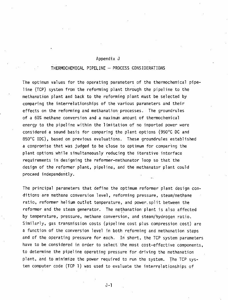
Appendix J
THERMOCHEMICAL PIPELINE - PROCESS CONSIDERATIONS
The optimum values for the operating parameters of the thermochemical pipe- 1 ine (TCP) system from the reforming p l a n t thriugh the pipe1 ine t o the
methanation p l a n t and back t o the reforming plant must be selected by comparing the interrelationships of the various parameters and their
effects on the reforming and methanation. processes. . The groundrul es I
of a 60% methane conversion and a maximlim amount of thermochemical
energy t o the pipeline within the limitation of no imported power were
considered a sound basis for comparing the p l a n t options (950°C DC and
850°C IDC), based on previous evaluations. These groundrules established a compromise that was judged t o be 'close t o optimum for compar'ing the
plant options while simultaneously reducing the i terative interface
requirements in designing the reformer-methanator loop so t h a t the
design of the reformer plant, pipe1 ine, and the methanator plant could
proceed independently. .- .
The principal parameters t h a t define the optimum reformer p l a n t design con-
ditions. are methane conversion level, reforming pressure, steamhethane .
ratio, reformer helium outlet temperature, and power-split between the
reformer and the steam generator. The methanation.plant i s also affected - ,
by temperature, pressure, methane conversion, and steam/hydrogen ratio.
Similarly, gas transmission costs (pipe1 ine cost plus compression cost) are
a function of the conversion level in b o t h reformjng and methanation steps and of the operating pressure for each. I' short, the TCP system parameters have t o be considered in order t o select the most cost-effective components,
t o determine the pipeline operating pressure for driving the methanation
plant, and t o minimize the power required t o run the system. The TCP sys- tem computer code (TCP 1 ) was used t o evaluate the interrelationships of

the principal system parameters. The operating parameters for the TCP
system were then chosen from these relationships within the groundrules
selected for the various plant options, as shown on the flowsheets for
the 850°C IDC and the 950°C DC cases. Appendixes H and I i l lustrate some
of the calculational detai 1 s for ' the refofmer and methanator, respectively.
Evaluation of Reforming Plant Parameters. For a given reformer tube design
and catalyst formulation, the key operating factors that determine reformer
conversion are the helium stream inlet conditions and the reformer feed
in le t conditions. The helium inlet stream dictates the achievable temper-
ature profile in the catalyst bed in each reformer tube. This temperature
profile sets the reaction rate a t the catalyst particles. A t a given
reacting temperature,, a high steam/methane stoichiometry in the process gas enhances conversion while a high process gas pressure reduces conversion.
Even though the higher steam/nethane ratio stimuiates the reforming activity
and reduces the reformer size, the requirement of boiling more feedwater
for the reforming process results in a reduction of t h e , overall plant cyile
efficiency.
For the f i r s t part of the process considerations, the reformer tube config-
uration assumed was for the 950°C DC design. The helium stream temperatrlre a t the reformer shell inlet was varied between 850°C t o 950°C t o determine
the corresponding change in process gas flow rate and reformer conversion.
The methanation plant yield was set t o give about 95% methane in dry feed . to reformer. The reformer process gas pressure was maintained a t the design value of' abou t 680 psia. The TCP 1 code was used to-simulate the reformer conversion a t he1 ium inlet temperatures of 850°C, 9 0 0 " ~ and 950°C, respec-
tively. TCP 1 calculates conversion assuming equil i brium a t the process gas
pressure and temperature a t the exit of the reformer tube. In actual opera- tion, of course, equilibrium i s closely approached, b u t never'quite reached.
To obtain the points a t a conversion level of 50%, 60%, 70%, or 80% a t each
temperature, the steam/methane ratio in the feed was varied until the desired

convers ion was reached. As shown i n F igu re J-1, t h e increased process gas
f l o w r a t e s a t t h e h igher convers ions and lower temperatures i s a d i r e c t
r e s u l t o f t h e increase i n steamhethane r a t i o . F igu re 5-2 shows t h e nega-
t i v e e f f e c t on convers ion o f lower re fo rm ing temperature as a r e s u l t o f
decreasing t h e he l ium ' i n l e t temperature i f no adjustment i s made i n t h e
steam/methane r a t i o t o compensate. Tab le J-1 summarizes t h e c o n d i t i o n s
used i n t h e TCP 1 s imu la t i ons corresponding t o t h e p o i n t s p l o t t e d i n
F igures J-1 and 5-2.
Table J-.1
I
SUMMARY OF PROCESS CONDITIONS USED I N TCP 1
For t h e second p a r t o f t h e process cons ide ra t i ons , severa l re fo rm ing and
methanat ion c o n d i t i o n s were simu9ated i n TCP 1 i n o r d e r t o r e l a t e t h e behav-
i o r o f convers ion and d r y product y i e l d t o :
0 Temperature
He1 i urn I n 1 e t Temperature
("C)
850
900 .
950
Pressure
Steam/Methane R a t i o i n Feed f o r
Amount o f steam i n feed
Bottom o f Reformer Tube
F igu re 5-3 shows t h e re fo rm ing methane convers ion as i n f l u e n c e d by process
gas temperature, pressure, and steam/methane r a t i o i n feed. H igher conver-
s ions a r e achieved a t h ighe r temperatures and steam/methane r a t i o s , and a t
lower pressures. F igu re 5-4 presents t h e r e s u l t s i n F igu re 5-3 i n terms o f
methane composi t ion i n t h e re former product stream.
80% Con- ve rs i on
-8.29
6.10
4.49 ,
Temperature ("C)
764
808
851
70% Con- v e r s i o n .,
6.10 -
4.44
3 . 1 9 ,
Pressure , ( p s i a )
656
6 56
656
50% Con- v e r s i o n
3.21
2.26
1.57
60% Con- v e r s i on
4.88
3.50
2.50

HELIUM INLET ( O C ) vs REFORMER FLOU RATE (LB/HR) AT EACH 9: CONVERSION
0 0
2 .0 3 . 0 4 . 0 L I
-.
PROCESS 0 \ S FLOW RATE 1u6 ( lb /hr)
. .
Figure J-1. Helium Inle t Temperature Effect on Process Gas Flow Rate
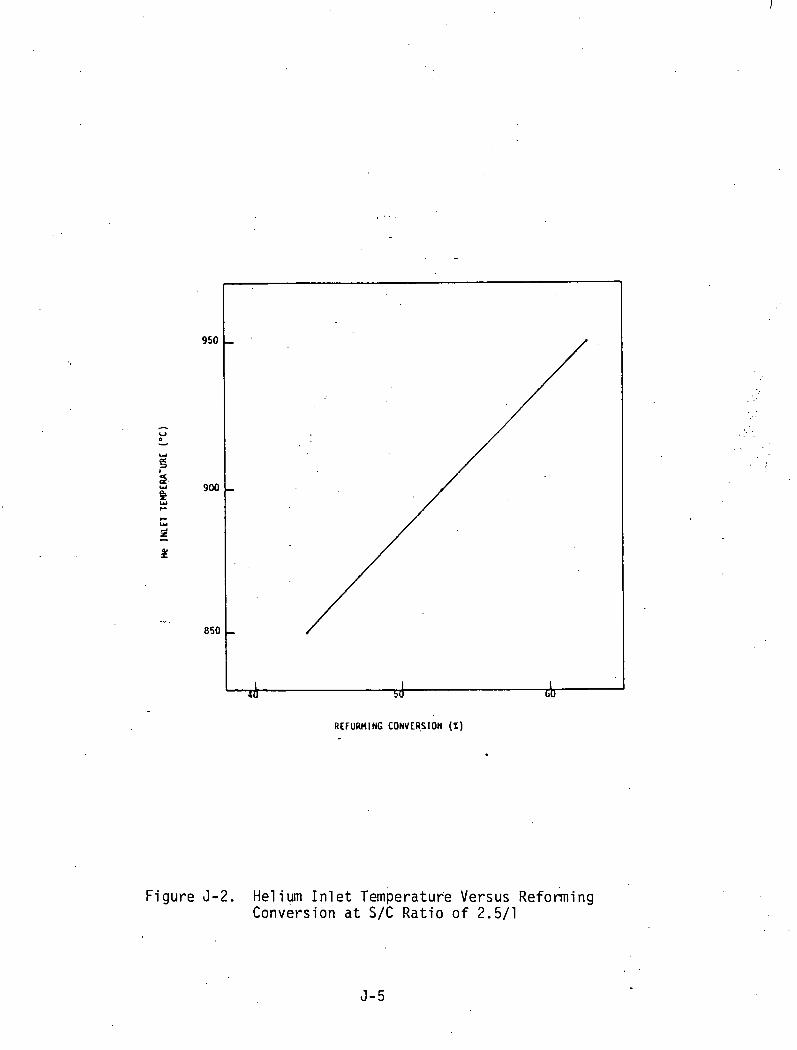
REFURMINC CONVERSION (%)
F i g u r e 5-2. He1 ium I n l e t ~ e m p e r a t u r e Versus Reforming Convers ion a t S/C R a t i o o f 2.5/1

PSI nzo:c - I
F igure 5-3. Equ i l i b r i urn Methane Conversion i n Reformer (as % Conversion)
I CHI IN D R Y PRODUCT
F igure 5-4. E q u i l i b r i u m Methane Composition i n Reformer (as % Dry Product)

Eva1 uation of Methanation Plant .Parameters. For the third part of the pro-.
cess considerations, methanation conversions were simulated in TCP 1 a t
various equilibrium temperatures and pressures. A dry methanator feed was
used i n practically al l cases. The dry feed makeup i s similar t o feed
from a reformer operating a t a 60% 'conversion. Figure J-5 shows the results
of .the simulations. Plots 1 and 3 , when compared t o Plot 6 , show.'that
diluting the feed with steam reduces the achievable conversion for a given
temperature and pressure of the process gas. For a specified process tem-
.perature and feed makeup, increasing the pressure will improve achievable
conversion. The number of methanation steps required to achieve a conversion
of approximately 98% will be largely determined by the design of the methana-
? tor vessel and catalyst bed. ,
. . i' Figure 5-6 compares three methanation process a1 te rna t ives ; to i 11 ustrate how
methanator vessel design .determines the number of methanation: st,eps. I n al l
three a1 ternatives, the dry syngas feed had 9.9 mole% CO, 9.5 mole% C02, and
12 .9 mole% CHq Process A i s a typical adiabatic process without an in-vessel temperature control system. Six steps are required in this process t o achieve
a 98% conversion. This process has the advantage of reaching effluent tem- peratures well over 800°C in the f i r s t methanator. Process B employees active
in-vessel temperature control. Product recycle ( A 1 ternative 1 ) or internal
cooling ( A 1 ternative 2 ) i s used t o slow down the process temperature rise.
As Figure 5-5 shows, a moderate-to-slow cl.imb in process temperature results
in a lower equilibrium (or effluent) temperature b u t a higher conversion in a single step. As a result, only three methanation steps are required in Process B t o achieve 98% conversion. Process B requires fewer components t o achieve the same conversion as Process A .

HETHANATOR OUTPUT CH4 URY FHACTIOM
F i gure 5-5. Methane Equi 1 i b r i um Conversion Versus Temperature and Pressure

Process A
Conversion, % o f Feed
Process B
Dry Syngas
. .
!
I i Al te rna t i ve 1. Recycle . k- - - - - - - - - -. - - - -
Conversion, ': o f Feed
Figure J-6. Methanation. Process A1 ternatives


Appendix K
METHODOLOGY FOR SCREENING CANDIDATE SYNFUEL PROCESSES
The c r i t e r i a and w e i g h t i n g f a c t o r s which were used i n t h i s second screen ing
process a r e shown i n Tab le K-1. The l i s t o f assumptions i s shown i n
Tab le K-2. Each process was ranked on a sca le o f 10 f o r each c r i t e r i o n .
That rank ing was then mu1 t i p l i e d by t h e corresponding we igh t ing f a c t o r . . .
The t o t a l r a t i n g f o r each process was t h e sum o f t h e weighted r a t i n g s f o r . . a1 1 c r i t e r i a .
, ,. . . . . . .. I . . . A d d i t i o n a l da ta were c o l l e c t e d from each o f t h e s i x t e e n remain ing processes.
. . . : . The data c o l l e c t e d inc luded t h e amount o f h i g h t e ~ p e r a t u r e (>900°F) heat .
,needed by t h e process and t h e temperature l e v e l s f o r these requtrements. In
a d d i t i o n , da ta were c o l l e c t e d on t h e q u a n t i t y o f steam and e l e c t r i c i t y
needed t o be imported t o t h e process. The e l e c t r i c a l energy requirements,
i n megawatts e l e c t r i c a l ,. were mu1 t i p l i e d by t h r e e t o conver t them t o . mega-
wa t t s thermal . A'summary o f t he .da ta c o l l e c t e d f o r a l l s i x t e e n processes
i s presented i n Tab le K-3.
~ e ~ r e s e n t ' a t i v e s f rom a1 1 f o u r o f t h e p a r t i c i p a t i n g o rgan iza t i ons then r a n k e d
a l l o f t h e process'es. The r e s u l t s a r e summarized i n Tab le K-4. As can be
seen, . the r a t i n g s by t h e f o u r p a r t i c i p a n t s a re u s u a l l y s i m i l a r and cons is ten t .
For t h e purpose o f t h e p resen t study, i t was in tended t o take a t l e a s t one
.process f o r each c l a s s o f product ; however, syngas s imply d i d n o t look, 1 i ke
a good a p p l i c a t i o n , and no syngas process was se lec ted. The processes which -
were se lec ted f o r e v a l u a t i o n a t t h i s t ime a r e two sha le processes (Paraho and
TO.SC0 11), a t rans .por ta t i 'on f u e l process (SRC-11), and an SNG process (Exxon
. c a t a l y t i c coa l gas1 f i c a t i o n ) . The r a t i o n a l e f o r s e l e c t i o n o f these processes
i s c l e a r from Tab le K-4. Where a p a i r o f s i m i l a r processes i s judged equiva-
l e n t , t h e process which was se lec ted i s t h e one about which more i s known.
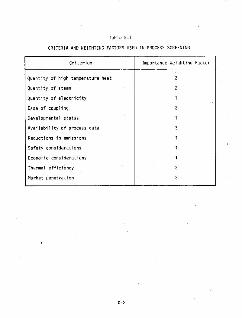
Table K-1
CRITERIA A N D WEIGHTING FACTORS USED IN PROCESS SCREENING
Cri ter ion
Quantity of high temperature heat
Quant i ty of steam
Quantity of e l ec t r i e f ty
Ease s f coup1 i ng
Developmental s t a t u s
Avai 1 abi 1 i ty of process data
Reductions in emissions
Safety considerations
Economi c considerations
Thermal e f f ic iency
Market penetration 4
Importance Weighting Factor
2
2
1
2
1
3
1
1
1
2
2 - -- - - - .-

T a b l e K - 2
LIST OF ASSUMPTrONS
. Scope i s l i m i t e d t o a p p l i c a t i o n s i n t h e U.S.
0 Coal and o i l s h a l e a r e t h e f e e d s t o c k s t o be cons ide red
P l a n t c a p a c i t y assumed t o be 50,000 b/d o i l e q u i v a l e n t p roduc t
m Products f o r t h e v a r i o u s c a t e g o r i e s a r e a s f o l l o w s :
Coal ' g a s i f i c a t i o n
Marke tab le SNG and syngas
Coal L i q u e f a c t i o n - d i r e c t
Acceptab le r e f i n e r y f e e d s t o c k and t r a n s p o r a t i o n f u e l
Coal L i q u e f a c t i o n - i n d i r e c t
T r a n s p o r t a t i o n f u e l
Oil s h a l e r e t o r t i n g
Acceptab le r e f i n e r y f e e d s t o c k , .
Advanced p r o c e s s e s
Not t o be cons ide red i n t h e c u r r e n t s c r e e n i n g e f f o r t

T a b l e K - 3 . .
SUMMARY OF ENERGY REC!UI REMENTS FOR CANDIDATE PR0C;ESSES
' (1 ) Eased on p; a n t capaci ty of 50,OCO 3/d o i l e q u i m l e n t (2) F.or nlezhane reformer. Heat requir?ments can be lowered t o 1200-1.100~~
l e v e l w i t h loher process e f f i c i e n c y
Product
Syncrude ( o i l shale)
Transportat ion f u e l s
SNG
Syngas
Froces s
Uniop-8 Parat-o Tusrc- I I H3to r t
H -Co~ l
SRC- I I Texaco and Mobil-K Lu rg i and Irlobil-M
E:cxor Ca ta l y t i c Wilnkler L u r g i 100 Bar
Texaco Kopp~rs-Totzek L u r g i Slagging U-Gas West inghouse
Process Therma 1 E f f i c i e n c y (Approx. )
70 70 70 60
60
65 50 5 5
65 50 -
6 5 55 70 75 75
Remarks
Shale o i l upgrade Shale o i l upgrade Shale o i l upgrade For eastern o i l
shale
Energy f o r h igh ash coal
I
I
SNG could be con- ver ted t o syngas by reforming
Process Energy Needs i n blWc (1
Electrical : M W ~ =
3
345 340 300 71 0
11 20
15 770
1250
540 590
249 1230
705
Process Steam
140 2 7
680
535
243
11 30 800
194
High Temp. Heat
~~~~l
997 1015 1149 1380
2105
1140 1066 1493
1850 1526
486 1348 899 188 140
1400°F- 16Ci"F
1 4 5 ( ~ ) 1 ~ 5 ' ~ )
2 d 2 )
50
1200°F- 1400 'F
583 670
70
No
87
900°F- 1200°F
484 390
54
305
300 296
60 136
data ava i l ab le
237 118
1 88 53

Tab le K-4
PROCESS SCREENIbG SUMMARY
Remarks
Processes a r e e q u i v a l e n t ; n e i t h e r handles s h a l e f i n e s
Handles s h a l e f i n e s b u t more compl ex sys ten1
For e a s t e r n s h a l e and n o t near tern1 devel opnien t
Processes a r e e q u i v a l e n t ; 111ore pub1 i c d a t a be1 ieved a v a i l a b l e on SRC-I1
I n d i r e c t l i q u e f a c t i o n i s l e s s a t t r a c t i v e t h a n t h e above d i r e c t l i q u e f a c t i o n processes
Recomnended f o r SNG
Syngas does n o t appear t o be as good an a p p l i c a t i o n as t h e o t h e r t h r e e p roduc t areas shown above, wh ich a r e e s s e n t i a l l y e q u i v a l e n t -
Group Average R a t i n g
118 119
115
105
121 120
103 104
116 104
87 94 94 68 67
Product
Syncrude
Transpor ta- t i o n f u e l s
SNG
Syngas
Process
Union-B Paraho
Tosco- I I
H y t o r t
H-Coal SRC-I1
Texaco and Mobi l -M L u r g i and Mobi l -M
Exxon C a t a l y t i c Wink le r
Texaco Koppers-Totzek L u r g i S lagg ing U-Gas Wes t inghouse
A p p l i c a t i o n
P a r t i c i p a n t A
107 107
109
98
11 5 98
88 92
115 102
82 89
109 60 51
Rat ings
P a r t i c i p a n t B
1 2.1 127
98
101
122 137
120 113
130 112
99 102 106
90 81
by Group
P a r t i c i p a n t C
127 130
134
115
118 120
123 123 .
125 118
94 117 108 NR 80
P a r t i c i p a n t s
P a r t i c i p a n t D
11 5 110
117
106
127 123
80 89
94 83
72 68
, 53 54 5 7

Appendix L
PROCESS DESCRIPTION E X X O N CATALYTIC COAL GAS1 FICATION (ECCG)
An Exxon study design (Reference 1 ) of a p l an t t o produce 254 mi l l ion
standard cubic f e e t per day ( s c fd ) of syngas from mine mouth I l l i no i s
No. 6 coal has been used a s a bas i s f o r t he H T G R I E C C G evaluat ion. Coal
i s fed a t a r a t e of 14,500 tons per day ( t / d ) t o in tegra ted coal crushing/ . .
drying systems. The coal i s crushed t o minus 8 mesh s i z e and dr ied t.0
4 w t % moisture in entra ined bed d rye r s , using 900°F c a r r i e r gas. Ca ta lys t
so lu t i on , cons i s t ing of a mixture of potassium s a l t s in water , i s added t o
t h e dr ied coa l , and t he coal i s dr ied again i n a s i m i l a r manner. An addi-
t iona l 700 t / d of coal i s used a s fuel i n t he two drying s t eps .
The coa l -ca ta lys t mixture i s pressurized t o 545 psia in. lock-hopper systems
with recycle syn thes i s gas. ' Coal p a r t i c l e s a r e conveyed pneumatically from
the pressurized vessel using p a r t i a l l y heated 800°F recycle gas. a s t he con- .
veying medium. The catalyzed coal p a r t i c l e s in t h e g a s i f i e r a r e f l u id i zed
with a preheated mixture of steam and recycled CO and H z in jec ted i n t o t h e
g a s i f i e r through d i s t r i b u t o r s . The main react ions taking place i n t he
g a s i f i e r a r e the highly endothermic steam/carbon g a s i f i c a t i o n reac t ion
( C O + H20 = CO + H z ) , t h e m i l d l y exothermic water-gas s h i f t r eac t ion . (CO + H 0 = C02 + H z ) , and t he highly-exothermic methanation reac t ion
2 . . ( C O + 3H2 = CH4 + H 2 0 ) The top sec t ion o f t h e g a s i f i @ r contains a
s o l i d s disengagement zone and two external cyclones in s e r i e s t o mini-
mize f i n e s carryover. A t t h e bottom of t h e g a s i f i e r , a char so l i d s
stream i s withdrawn t o control bed level and ash buildup. This char
stream i s cooled w i t h recycle syn thes i s gas and process water. I t i s then s l u r r i e d with a semi-rich c a t a l y s t so lu t ion f o r feed t o c a t a l y s t
recovery. The steam/recycle gas mixture i s heated t o o u t l e t conditions
of 1550°F and 520 psia in the preheat furnace.
The high level sensible heat in the e f f luent gas i s recovered and used
f o r preheating the steamlrecycl e gas and f o r generating high pressure
steam. Exchanger fouling i s not a problem, s ince heavy hydrocarbons
a r e present i n only t r ace concentrations a t the g a s i f i e r e x i t tempera-
t u r e of 1275°F and in the presence of the potassium ca ta lys t . Fine
so l ids remaining in the gas leaving the high pressure waste heat boi lers
a r e removed in a two stage water scrubbing system consis t ing of spray
s a t u r a t o r towers and venturi scrubbers. The so l ids- f ree scrubbed gas
i s f u r t h e r cooled in low pressure waste heat boi le rs .
A heavy glycol solvent absorption process removes HpS and C02 from the
g a s i f i e r product gas. The resu l t ing clean gas consis ts primarily of . '
CH4, CO, and H Z , along with some N 2 . In the methane recovery system,
cryogenic f rac t ionat ion i s used to s p l i t t h i s stream in to a product
CH4 stream and a recycle stream. The product methane stream from the tower bottoms i s 99.9% CH4 and 0.1% CO. Small amounts of t h i s stream
a r e withdrawn f o r use as plant fuel and methane ref r igerant makeup.
The remainder, the product SNG, i s compressed t o 1000 psig f o r del ivery t o - a natural gas pipel ine. The tower overhead stream, containing C O Y
H E , N 2 y and 10% C H q 9 i s compressed f o r recycle to the reactor system.
The s lu r ry of char/ash so l ids withdrawn from the g a s i f i e r s and the s1urr.y
of f i n e g a s i f i e r so l ids from the water scrubbing system a re fed t o the c a t a l y s t recovery sect ion. The two streams a r e depressured in to Ca(OH)* digest ion vessels. Feed lime (CaO) and makeup potassium in the form of a 30 w t % KOH solut ion a r e a l so fed in to these vessels. About 90% of the
potassium in the feed so l ids i s so lubi l ized , and about 98.5% of the
potassium s a l t s so solubi l ized i s recovered in the subsequent multistage
water washing f a c i l i t y . Overall , t h i s section recovers 87% of the to t a l potassium ca ta lys t which entered the gas i f i e r s with the feed coal.
The o f f s i t e f a c i l i t i e s f o r the ECCG plant include mater ials handling
equipment to:
a Receive, s t o r e , and d i s t r i b u t e coal,.makeup c a t a l y s t , and Time
a . Store and ship byproducts
a Handle and s to re waste so l ids and truck them t o a nearby di sposal s i t e
A f u l l range 'of u t i l i t i e s systems i s provided, including raw water supply,
water t r ea t ing , steam generation and d i s t r ibu t ion , f l u e gas desulfur iza-
t i on , cool ing water, and e l e c t r i c power d i s t r ibu t ion . The general o f f -
s i t e s area encompasses wastewater t r ea t ing , safety and f i r e protection
systems, buildings, and miscellaneous items such as maintenance and
mobile equipment, communications, and others .

OOLED REACTOR ASSOCIATES
APPENDIX M
reject Technical PTR- 4.0 P a g e 1 of- 27.
'"'FUNCTIONAL SPECIFICATION - ' HTGR-PH REFERENCE' PLANT - Title . . . . . . .
A P P R O V A L
Rev. No.
RECORD
Approval Date
P.pp!ov~d By
General Manager
Concurrod By
- ..

PROJECT TECHNICAL REQUIREMENTS
: TABLE OF CONTENTS
Page - 4 .
PARAGRAPH 2.0--BACKGROUND/SCOPE 4
PARAGRAPH 3.0--PLANT REQUIREMENTS/OBJECTIYES 5
. 3,l GENERAL 5
3.1.1 Standard izat ion S
3.1.2 Design Margins 7 3.'1.3 Codes and Standards
3.2 PLANT PERFORMANCE 8
3.2.1 c a p a b i l i t y 8 3.2.2 ~ v a i l a b i l i t ~ Factor 8 3.2.3 Capacity Factor 9 3.2.4 Serv ice L i f e 10 3.2.5 Operat ing Charac te r i s t i cs 1 0 3.2.6 Reactor Power .Level 12 3.2.7 Steam Condi t.ions 12
3.3 CONFIGURATION . 12
3.3.1Overal l P l an t . P 2 3,3,2 Nuclear Heat Source 13 3.3.3 S i t e Layout 13 3.3.4 B u i l d i ng Arrangements
3.4 FUEL AND FUEL CYCLE. 19
3.5 OPERATING ENVIRONMENT 20
3.5.1 Area Ambi en t Condl t j ons 20 3.5.2 Radia t ion Pro tec t ion 21
3.6 OPERATIONAL CONTROL . ' 21
PARAGRAPH 4.0--SITE REQUIREMENTS 2 2
PARAGRAPH 5,O--SAFETY AND ENVIRONMENTAL IMPACT 22
PARAGRAPH ~ . O - - Q L ~ A L ITY ASSURANCE 22

TABLE OF CONTENTS
. 7.1 ENERGY GENERATION COST
7.2' CAPITAL COST
7.3 .PLANT OPERATING AND MAINTENANCE COST .

1.0 PURPOSE T h i s spec i f ica t ion del ineates functional requirements and objectives gove;ning the design and development of a Reference Commercial High Temperature Gas-
Cooled Reactor-Process Heat (HTGR-PH) plant. I t i s intended to be the f i r s t embodiment of a plant specification which will ensure the uniform application
of the s ta ted c r i t e r i a to a l l design agents .so t h a t the plant charac ter i s t ics wi l l . conform t o the functional requi rements of Gas-Cool ed Reactor Associ a t e s
. , ( G C R A ) , while complying. ful ly w i t h applicable regulatory requirements.
The HTGR-PH commercial plant i s defined as the f i r s t process heat p l an t ( s )
contracted w i t h guarantees, warranties and performance penal t i e s included in
the commerci a1 terms and condi ti ons . ~ e E i n i t i ~ n of the commerci a1 pl ant
cia1 involvement required by the government. I t i s also assumed t h a t the f i r s t commercial p lan t will be preceded by one o r more demonstration plants
development of technologies necessary for the heat source and components.
. The cognizant* des,ign agents have the responsibil i ty to design and develop
qua1 i ty power pl a n t systems, components and 'structures consis tent w i t h the overal I. objective of safe , dependable and economic power generation.
2.0 BACKGROUND/SCOPE
design and development a c t i v i t i e s i n order t o a s s u r e t h e i r r e l evance t o u t i l i ty/user in t c rcs t . ~ c c o r d i n ~ i ~ , GCRA has pt-eparGed this specif icatfon t o d e f i n e the major p l a n t funct ional requirements of t h e H T G R - P H . As t h e Program proceeds, t h i s s p e c i f i c a t i o n w i l l be upg.raded w i t h q u a n t i t a t i v e
This specif icat ion i s intended to be the f i r s t embodiment of a plant spec i f i -
cat ion which wil l ensure the uniform application of the s ta ted c ' r i t e r i a t o - a1 1 design agen t s s o t h a t t h e p l a n t c h a r a c t e r i s t i c s w i l l conform t o t h e
appl icable regulatory requirements.

.
. . . a - 4.0 REV. NO.
D r a f t 4 /81,
PAGE 5 OF 37
PROJECT TECHNICAL REQUIREMENTS GAS-COOLED REACTOR ASSOCIATES
These p l a n t l e v e l c r i t e r i a w i l l f o r m t h e b a s i s f o r a1 1 i n t e r - s y s t e m and . .
system l e v e l c r i t e r i a which w i l l , be developed and used b y the design agents.
These lower l e v e l c r i t e r i a w i l l be presented i n design c r i t e r i a documents f o r
s p e c i f i c t echn ica l areas (e.g., p ip ing , sa fe ty , seismic, e l e c t r i c a l , e t c . ) . and
i n system desc r ip t i ons , which w i l l extend t h e d e f i n i t i o n o f requirements and
o b j e c t i v e s t o the e x t e n t r e q u i r e d t o ensure. c o n s i s t e n t a p p l i c a t i o n o f t h e
p l a n t l e v e l c r i t e r i a t o a l l systems, components and s t ruc tu res . GCRA w i l l
i d e n t i f y t h o s e documents which w i l l r e q u i r e t h e i r concurrence.
The NHS design agent s h a l l take a l e a d i n g techn ica l p o s i t i o n i n recommending
t h e optimum nuc lea r heat source and primary/secondary he l i um system condi-
t i o n s , con f i gu ra t i on , and performance c h a r a c t e r i s t i c s t o meet t h e r e q u i rements
o r o b j e c t i v e s s p e c i f i e d here in. The BOP design agent s h a l l be respons ib le f o r i n t e g r a t i ng NHS, BOP and s i t e i n t e r f a c e requ i rements p resc r ibed by any design
agency. Depending upon 'the s p e c i f i c process heat app l i ca t i on , a process
design agent may a l s o be i n v o l v e d and be respons ib le f o r ' d e f i n i n g t h e systems
requirements o f t h e process and the energy d e l i v e r y systems. A l l t e c h n i c a l
i n fo rma t ion developed under DOE funds and i n accordance w i t h DOE requirements
and c e r t a i n design agent p r o p r i e t a r y da ta necessary f o r t h e design and l i c e n s -
i n g o f t h i s p l a n t s h a l l be made a v a i l a b l e t o . GCRA and t h e NRC r e s p e c t i v e l y
d u r i n g t h e design and development phases o f t h e pla,nt.
3.0 PLANT REQUI REMENTS/OBJECTIVES
3.1 GENERAL
.3.1.1 Standard iza t ion .
A l l design and development a c t i v i t y s h a l l be aimed a t producing a
commerci a1 p l a n t design which w i l l accommodate t h e requi rements of
t h e u t i l i ty/u'ser i n d u s t r i e s and which w i 11 be p r e - r e v i ewed under the
NRC s tandard i za t i on program f o r subsequent use by any u t i l i t y / u s e r
on a s p e c i f i c p r o j e c t .
I
C

PROJECT TECHNICAL REQUIREMENTS
The commercial p l an t design s h a l l inc lude a s t a t i o n p l o t plan fo r the following major s t ructures which comprise the power genera-
t ion block:
- Reactor Containment Buil d i n g
- Reactor Service Building
- Fuel Storage Buil ding
= Turbine B u i l d i n g
- Access Control Building - Engineered Safeguards Structures (Ultimate Heat Sinks,
Di esel Generator Cool i ng/Fuel Storage, e tc . ) - Process/Chemical B u i l ding
- Cooling Towers
- Helium Storage Area
- Fuel Oil Storage Area - Fire Protection Pumping and Storage Area
- Trai n l ng Faci 1 i t ies
- Security F a c i l i t i e s
- Technical Support Center
The commercial p l a n t d e s i g n s h a l l a l s o include an arrangement
suppliers during the i n i t i a l phases of the design e f fo r t . The
GAS-COOLED REACTOR ASSOCIAfES.
A uniform approach t o c r i t e r i a , descriptions, and specifications . .
(includi ng instal la t ion and construction) fo r systems', components
and s t ructures shall be employed throughout the plant design by and
among the design agents and the i r contractors . .
The plant design shall be ' based on concepts, configurations and
arrangements of s t ructures , systems and components which have been . t es ted , demonstrated and/or proven re l iab le in previous or current
power programs when a t a l l feasible .
Equipment and materi a1 c r i t e r i a speci f ied throughout the design
s h a l l be s tandard ized and, t o t h e maximum e x t e n t p r a c t i c a b l e , equipment and materials meeting these c r i t e r i a shal l be commer-
c ia l ly available in the United States . This does not, however,
preclude the use of equipment or materials made by foreign manu-
facturers , provided the vendors have the capabil i ty of instal la-
t i on, s tar tup, operation and maintenance services and have been evaluated by GCRA. .
3.1.2 Design Margins .
Design margins shall be applied to a l l systems and component sizing and performance cal cul a t i ons and safety analyses. Margins shall
a1 low f o r uncertainties of design analyses, probabil i ty of achieving design r a t i n g , and appl i'cable experience. The assignment of rea- l i s t i c design margins s h a l l be based o n ac tua l experience and performance data. collected from other thermal gas reactors to the
maximum practicable extent. The design agents shall identify major
design marg.i ns affecting plant performance, safety and/or avail a-
\ b i l i ty. These margins will be subject t o concurrence by GCRA.
3 . 1 . 3 Codes and Standards
A1 1 equipment, apparatus, s t ructures , design analysis methods and
design requirements sha l l , in general, comply w i t h a l l appropriate
Codes of Federal Regulation, Nuclear Regulatory 'Commission Regul a-
tory Guides, and industry codes and standards. S ta t e and local

PROJECT TECHNICAL REQUIREMENTS
government regul ations, codes and standards shal l be considered
when such requirements have. a fundamental e f f ec t on the design. A t
the appropriate time during the design process, applicable codes and
. standards will be invoked.
3.2 PLANT PERFORMANCE
3 . 2 , l Capability '
P l a n t design shal l be 'based o n generating approximately 1200 MW
thermal t.o the primary heat exchangers. I t i s an ob.iective t o del iver maximum usable process heat to the user w i t h i n the l imita-
t ion t h a t e l e c t r i c power will not be imported. The f inal design net e l ec t r i ca l and process heat outputs will depend on the configura- t ion, the application, and the performance ratlngs o f major NHS and
plant concept, systems shall be designed to generate e l e c t r i c i t y and
process heat a t maximum avai lab i l i ty and efficiency consistent w i t h
su4 t ehe maxlmum capacity o f the NHS,
3.2.2 Avai labi l i ty Factor
" Availabi l i ty i s defined as the percentage of time, over a one-year
period, t h a t the plant i s i n , or ready fo r , service a t any level
The annual ava i lab i l i ty fac tor for the process heat plant must be a t
. a high level in order to serve effectfvely the users fo r whfch the
process heat plant i s being designed t o serve, The ava i lab i l i ty
fac tor i s chosen to provide an achi,evable, industry-accepted value.
Where a spec i f ic application of process heat requires a higher
ava i l ab i l i t y than achievable by a s ingle plant, i t will be provided f o r by the use of multjple plants.
Sustained. plant operation w i t h an annual ava i l ab i l i t y fac tor of 90
percent (7889 hours per year) shall be a plant design objective.

inspect ion, and refueling sha l l be no grea te r than 20 days per year
w i t h no greater than - TBD days per year a l located f o r refuel ing.
The sum of a l l o c a t i o n s f o r unplanned maintenance s h a l l be no
g r ea t e r than 16..5 days per year .
PTR- 4.0 REV. NO.
Draft 4/81,
PAGE LOFX
To achieve the 90%p1 a n t avai labi l i ty ob jec t ive , p a r t i c u l a r a t ten-
t i o n shal l be given t o the following:
PROJECT TECHNICAL REQUIREMENTS GESCOOLED REACTOP b&SOCWS
- A n i n t e g r a t e d eng inee r ing r e l i a b i l i t y a n d m a i n t a i n a b i l i t y
program shal l be implemented by the agencies responsible f o r the design.
- Minimizing the potential f o r water and o i l leakage i n to the ' P C R V s h a l l be a major de'sign o b j e c t i v e . Methods s h a l l be
provided f o r determining the locat ion of an o i l , steam o r water
leak i n PCRV components' such t h a t rapid leak i s o l a t i o n and
repa i r i s provided. Methods shal l a l so be provided f o r e a s i l y
8 .
removing e i t h e r l a rge quan t i t i e s of water o r small amounts of
.moisture 7rom the P ~ R V , should i t en te r .
- Component avail abi l i ty between overhaul s shal l be cons i s ten t
wi t h the pl an t avai labi l i ty f a c t o r object ive . When this cannot
be done, s u f f i c i e n t redundancy shal l be provided t o preclude
l imi t ing. p lant ava i l ab i l i t y .
3.2 .3 Capacity Factor
Plant operation w i t h an .annual capacity f a c t o r of 80 percent sha l l
be a p lan t design objective. Major BOP .equipment sha l l be s ized t o achieve p l an t operation a t near f u l l u n i t capaci ty of the plant
w i t h a' . compo'nent o u t of service. Speci f i c re1 i abi 1 i ty c r i t e r i a and ana lys i s sha l l be developed during the de t a i l ed design s tage
t o insure t h a t the 80% capacity f a c t o r can be achieved. In general ,
an i n s t a l led spare shall be provided f o r a1 1 continuously operating
r o t a t i ng equipment (excludi ng the tu rb i ne-generator) whose f a i l u r e would lead t o s i gn i f i c an t reduction i n power level o r u n i t outage.

. PROJECT TECHNICAL REQUIREMENTS
The plant shall be capable of meeting process heat design condi-
t ions while the e l ec t r i c i a l generation equipment i s out of service.
For non-rotati ng equipment, operational redundancy requirements
shall be es tab l i shed based upon expected component f a i l u r e proba-
production capabili ty.
. 3.2.4 Service Life
Material and component selection shal l consider service 1 i f e and periodic maintenance requirements as part of the overall r e l i a b i l -
l i f e . The design service l i f e of a l l NHS components u n i q u e t o the
HTGR shall be specified by the NHS design agent. For a l l plant
components with a s e r v i c e l i f e l e s s than 40 y e a r s , t h e design
maintenance p lan t h a t w i l l ensure systems w i l l perform t h e i r . intended function a t the end of t h e i r 40 year l i f e .
, ,
3.2.5 Operating Characteristics
3.2.5.1 Normal Ope~ation
The p l a n t s h a l l be designed t o be capable o f cont inuous
power level between. mi nimum self-sustaining 1 oad and 100%
design power. . Manually i n i t i a t e d shim type adjustments
t h i s 'requirement.'
3.2.5.2 Abnormal Operation The a b i l i t y o f the p l a n t t o recover o r s a f e l y shutdown
from plant t rans ien ts associated with sudden shutdown or
f a i l u r e of major NHS or BOP components shal l be provided.

. ." - *." REV. N
$raf t 4/81
11 27 PAGE O F - PROJECT TECHNICAL REQUIREMENTS
GASCOOLED REACTOR ASSOCIATES
The plant design shal l be capable of sustaining safe con-
t ro l l ed operation fo r the conditions s tated i n the following
paragraphs.
The plant design shall be capable of reject ing up t o f u l l
load from the e l ec t r i c dis t r ibut ion network and remain i n
operation supporting i t s own auxi 1 i ary 1 oads. Steam re1 ease
t o atmosphere i s acceptable only f o r the duratfon of the
transient.
The reactor shall be designed t o be capable of continued opera t ion a t reduced thermal power fo l lowing a t u r b i n e
t r i p from any load level. The steam system shal l be designed t o bypass the turbine during t h i s mode of operation.
The plant design shall be capable of s ta r tup and continued operation a t reduced thermal power output with one loop out
of service.
The plant design shal l be capable of remaining operational a t
appropriate reduced 1 oad where possible, with other major
equipment o u t of service, e.g., feedwater pump, c i rcu la t ing water pump, condensate pump, etc.
3.2.5.3 Startup and Shutdown
The plant design wi l l have the a b i l i t y t o perform a normal
shutdown and return to power a t the r a t e of TBD% per minute
a t the beginning of core l i f e .
L imi ta t ions on s t a r t u p due t o t r a n s i e n t xenon bui ldup
shall be minimized; the NHS design agent sha l l recommend the degree of xenon override capabili ty which i s considered
necessary and economical t o accompl i sh this requirement.

PROJECT TECHNICAL REQUlREMENT'S
3.2.6 Reactor Power Level The reactor core sh i l l be designed fo r a nominal reactor
power level of 1170 M W ( t ) . T h i s i s the thermal power level
will be licensed.
. .
. 3.2-7 Steam Conditions
The h i g h pressure turbine generator will be desfgned f o r one o f t h e following steam corrdi't;.ior~s d l the t!lrbffle Stop
val ves dependi ng on the appl i cation speci f i ed:
Main Steam Temperature ('F)/Pressure (ps i a ) - 1050/2400
.Or 1000/1800
3.3 CONFIGURATION
3.3.1 ke- raI1 p l a n t The reference plant design shall be based on a s j n g l a u n i t con-
f i g u r a t i o n a n d stla1 1 inc lude cons ide ra t ions such a s s e c u r i t y ,
cons t r u c t i b i 1 i t y , ope ra t ion and maintenance, access , e t c . , i n
concept. The plant shall consfst o f one high temperature gas-cooled
p l a n t systems, buildings and f a c i l i t i e s as necessary t o makc a corrlpl e t e power generating statioil. Thc process heat p o r t f o r i of
the reference plant shall consis t of a l l piping and equipment w i t h i n
the exclusion area boundary fence required t o del iver process heat o r steam t o the user.

rln- 4. U
REV. NO. '
Draft 4/81
PAGE A OF 27
PROJECTTECHNlCALREQUlREMENTS GAS-cOOLED REACTOR ASSOClATES
3.3.2 Nuclear Heat Source (NHS)
The NHS shall consist of a high tmperature gas (helium) cooled
reactor having four ( 4 ) main, coolant loops. Each coolant loop shall
contain the primary heat exchanger and one e l e c t r i c motor driven
main cool ant ci rcul a to r w i t h i t s auxil i ary service system.
A prestressed concrete reactor vessel wil l provide the primary ' pressure containment of the h i g h tmpera tu re reactor coolant, and
will contain the reactor core, heat exchangers, core auxil i-
ary heat exchangers, primary and auxiliary he1 i u m c i rcu la tors ,
portions of the helium purification e q u i p ~ n t t o the maximum pract i -
cable extent, and control rod drives. .
' 3 . 3 . 3 S i t e Layout The de.signated s i t e boundaries, i .e., r e s t r i c t ed area boundary
( R A B ) fo r 'normal operation and exclusion area boundary ( E A B ) for - postulated accidents, shall be a t l e a s t 425' w t e r s from a l l radio-
active release points. A n appropriate secondary containment, in a d d i t i o n t o the pyes t r e s s e d c o n c r e t e r e a c t o r v e s s e l , s h a l l be
provi ded.
.The turbine generators shal l be located re la t ive t o the containment building i n such ' a way t o ensure protection from postulated turbine
missiles. For multiple units, the layout shall .ensure tha t turbine
missiles from one u n i t cannot penetrate the containment building on
the second u n i t o r vi'ce versa.
Access t o the s i t e s h a l l be through a s i n g l e po in t ; bu i ld ings
which have normally h i g h personnel t r a f f i c , e.g., administration
building, v i s i t o r ' s center, etc. , shall be located outside the primary security perimeter (protected area boundary). Within the primary security perimeter, personnel access and health physics
control shal l b e integrated t o optimize the monitoring of personnel * t r a f f i c w i t h i n the power generation block.
.

PROJECT TECHNICAL REOUIREMENTS
The p lant ' s storage capacity ' fo r spent fuel shall be based on 1.3
cores of fuel capacity. The s tat ion layout shal l provide addi- t ional space f o r spent fuel storage t o acconmdate a l l fuel used
during t h e 40 y e a r p l a n t l i f e . Building r e l a t i o n s h i p s i n the nuclear island shall be arranged such tha t expansion of the spent
fuel storage f a c i l i t y can be readily accomplished even a f t e r the
p1 an t has become operational .
Separation between engineered-safety features f a c i l i t i e s , such as
the ultimate heat s i n k , pt.r., < h a l l be by distance; i f this i s not prac t ica l , structural barr iers (ex is t ing s t ructures)
shall be interposed between any two safety t r a ins , common t o such f a c i l i t i e s , to avoid common-mode f a i l u r e from natural o r nonnatural
design basis events.
Rail and truck access within the s i t e shall be provided f o r trans-
portation of equipment, new and spent . fuel , radioactive waste,
supplies, e tc . I t shall be assumed t h a t 'rail transportation i s available t o r the-reterence site .
Bui ld ings s h a l l be so a r ~ a n g e d a s to avoid t h c p o s s i b i l i t y o f
confined deflagration; i .e. , use of confined spaces where flammable .
o r expl osive . materi a1 s might be handled o r transferred shoul d be
3 . 3 - 4 B u i 1 ding Arrangements
The plant layout and equipmentjpi pi ng arrangement shall provfde access f o r orderly construction, maintenance,. and inspection in
addition to the o p t i m u m layout f o r functional equipment grouping,
opera to r conveni ence, personnel protection from radiation exposure
and requi red separation between redundant safety equipment and
An e f f o r t sha l l be made t o achieve the highest degree of construct-
ib i l i ty possible by speci a1 coot-effective design' considerations
b

PROJECT TECHRICAL REOUIREMEMTS
such as modularization, functional equipment grouping, prefabri-
cated equipment assemblies and auto la t ic fabricat ion processes.
fu l ly consider maintenance access requirements and requirements f o r shop assembly by c r a f t unions t o avoid disas'sembly/reassembly
problems on-si te.
- Provi sions f o r decommi ssioni ng and ul tirnate di sposal o f radioactive
ease of d i sassembly, decontamination, r a d i a t i o n exposure and burial .
The design agents should consider the use of models during the
design process t o verify arrangement requirements such as those
s t a t e d here in . Scale models may be used ' f o r o v e r a l l p l a n t o r
ered f o r s p e c i f i c a r e a s where arrangement space i s l i m i t e d o r
unusual conditions e x i s t (e .g . , control room layout, reactor t o p
head layout). An overall plant model shal l be. constructed by the
. architect/engineer, i f requi red.
3.3.4.1 General Arrangement Considerations
between systems performa'nce, o p e r a b i l i t y , ma in ta inab i l - i ty , constructibil i ty and i n i t i a l investment cost .
The turbine plant. shal l be an indoor type system, requi r i ng a
f u l ly-enclosed t u r b i ne bui l di ng, i ncl.udi ng t h e t u r b i ne
building crane(s1.
Each buil di ng shall be compartmented in to areas according
t o the potential f o r radioactive release, pipe breaks in .
requirements. Compartment pressure fo r potential ly radio-
a c t i v e a reas s houl d a1 so be considered t o 1 imi t outward
PROJECT TECHNICAL REQUIREMENTS
l e a k a g e . Each s a f e t y t r a i n and a s s o c i a t e d equ ipmen t i n
v a r i o u s compar tmen ts s h a l l be s e r v e d b y a u n i q u e H V A C
system t o ensure p r o t e c t i o n aga ins t envi ronmental ly- induced
common-mode f a i l u r e s . The HVAC design s h a l l be such t h a t t h e
f l o w o f a i r i s always from nonrad ioac t ive t o p o t e n t i a l l y
r a d i o a c t i v e areas,
A 200-foot separa t ion s h a l l be main ta ined between b u i l dings,
components, and p i p i n g c o n t a i n i n g p r o c e s s gases and any
scpapst ion, t he appl-spl-iate phys i ca l bdr.r.ier.i ur systems
design s h a l l be i nco rpo ra ted t o p rec lude damage t o safety-
r e l a t e d p l a n t s t r u c t u r e s and components as a r e s u l t o f
p o s t u l a t e d process gas expl osions.
t u r a l b a r r i e r s . I n general, d is tance i s p re ferab le i f i t
can be achieved w i t h o u t c o s t penalty.
E l e c t r i c a l and I 8 C components a s s o c i a t e d w i t h d i f f e r e n t
safety. d i v i s ions s h a l l be 1 ocated i n d i f f e r e n t noncommuni-
Where poss ib le , components hand1 i ng o r p roccss i ng radio-
a c t i v e or p o t e n t i a l l y r a d i o a c t i v e mat.eria1 s h a l l . b e arranged
i n . cont iguous areas separate from nonrad ioac t i ve areas t o
op t im ize access c m t r o l and c o n t r o l t h e spread o f r a d i o a c t i v e
contaminat ion.
3.3.4.2 Access
Normal access t o the p l a n t s h a l l be through o n l y one access
c o n t r o l f a c i 1 i ty.
Normal access t o the power genera t ion b lock , except f o r t he
t u r b i n e b u i l d i n g , s h a l l be through o n l y one p o i n t f rom which ,

PTR- 4.0 REV. NO.
Draft 4/81
17 2 7 PAGE O F - PROJECT TECHNICAL REQUIREMENTS
G M O O L E D REACTOP USOCIATES
personnel can proceed to uncontrolled areas or to the access control p o i n t f o r the controlled areas.
Normal access t o c o n t r o l l e d a reas s h a l l be only through the change rooms i n the health physics areas.
Access to these areas for unusual o r emergency s i tuat ions shall also be provided as necessary.
Accessi b i 1 i ty c r i t e r i a for each radi oactive component shal l be devel oped on the basis of:
1. In t r ins ic radiation level in the area where the component is located.
2. Radiation level of the cornpon~nt. 3 . Frequency and average dura t ion of the ope ra t iona l
ac t i v i t i e s requi red. 4. Frequency and average dura t ion of the maintenance
a c t i v i t i e s . 5. Frequency and average dura t ion of in spec t ions and
t e s t s . 6. Security classif icat ion.
The values of the cumulative doses to personnel from these c r i t e r i a shal l form the basis f o r configuration, shielding and access des igna t ion , w i t h the underlyi n g purpose of ensuring personnel exposure as 1 ow a s reasonably achievable.
Instrumentation required f o r continuity of plant operation -shall not be located i n areas where access would require. a p l a n t shutdown. Access r o u t e s to ins t ruments r equ i r ing r o u t i n e a c c e s s i b i l i t y s h a l l be loca ted i n 1 ow r a d i a t i o n zones. Otherwi se, access route zoning shall be consis tent w i t h the inspection frequency and duration, and the radiat ion environment associated w i t h the area i n which the instruments are located.
-

PROJECT TECHNICAL REQUIREMENTS
Instrument and e lec t r ica l cabi nets and local panel s asso- c ia ted w i t h systems throughout the plant shall i n general be
located i n low radiation zones.
3 . 3 . 4 . 3 Maintainability
A p lan s h a l l be prepared f o r a1 1 p l a n t equipment which
addresses the requirements f o r i n s p e c t i o n , maintenance,
repa i r and removal or replacement. This plan shall address
the economic considerations of working on the equipment i n
place versus making provision fo r removal and remote repair.
working on equipment i n place will require provision f o r handl i ng eq~~rpment, pull space, 1 aydown space and possibly
on-the-spot decontami nation. Remote repa i r o r rep1 acement w i l l r e q u i r e provi s ion f o r handl ing equipment, a c c e s s
through t h e plant t o the equipment.
The PCRV shall provide a means f o r removal of a1 1 components
contai ned wi t h i n the PCRV cavi t i e s includi ng core components,
primary heat exchangers, he1 i um c i rcu la tors , auxi l iary core
c o o l i ng hea t exchangers and helium p u r i f i c a t i o n system
components. The capabi 1 i ty t o i sol a t e these cavi t i e s fo r
component removal s h a l l a1 so be provided. Permanently
in s t a l l ed reactor internals such as the PCRV l i n e r , thermal
ba r r i e r , hot gas ducts, spring packs, and side re f lec tors a re
excepted from these requi rerr~ents.
Space a n d s t r u c t u r a l capac i ty s h a l l be provided i n t h e
r ~ a c t n r ~ o n t ai nrnent buil d i ng and the selected contiguous
bui l ding( s ) f o r temporary handl i ng equipment t o remove, decontaminate, and s h i p a primary heat exchanger, as well a s other such major components i n o r around the' PCRV.
Pull space shal l be provided f o r a l l shell, and tube heat
exchangers, pumps, motors, val ves, e t c .

. 1 8 8 - 4. U q q .>I.. . - R.EV. NO. f .
.. -.
D ra f t 4 /81 PROJECT TECHNICAL REQUIREMENTS , *-- -.-.
PAGE 19 OF 27 . -
GASCOOLED REACT02 ASSOClATES ..- ~
H igh maintenance components, e.g., va lves and pumps, asso-
c i a t e d w i t h systems processi ng r a d i o a c t i v e m a t e r i a l s s h a l l be
arranged i n sh i e l di.ng c o n f i g u r a t i o n s such t h a t t he requ i r e d
maintenance access t o them can be achieved i n compliance w i t h
t h e A S - L O W - A S - ~ e a s o n a b 1 ~ - A c h i e v a b l e (ALARA) c r i t e r i a .
L i m i t i n g the number o f such components t o a minimum w i l l be a
major design ob jec t i ve .
A c e n t r a l decontamination f a c i l i t y and a smal l h o t machine
shop s h a l l be p rov i ded. Local decontami n a t i o n f a c i l i t i e s
( p o r t a b l e o r temporary i n - s i t u setup) fo , r components which
a re mainta ined i n -p lace s h a l l be prov ided f o r i n t h e design.
3.3.4.4 Inspec t i on and T e s t i n g
NHS and BOP equ ipment and systems s h a l l be des igned f o r
i n s p e c t i o n and t e s t i n g where such an i n s p e c t i o n and/or t e s t
program wi 11 improve p l an t ava i 1 abi ' l i ty, v e r i f y t he read i ness
o f s a f e t y r e l a t e d f u n c t i o n s , o r where i t i s r e q u i r e d by
a p p l i c a b l e codes, standards, and 1 i c e n s i n g requirements. The
.need f o r and capabi 1 i ' ty o f ach iev i ng i n-serv ice i n s p e c t i o n o f
t h e PCRV l i n e r , pr imary heat exchangers, and o t h e r components
l o c a t e d i n s i d e t h e PCRV s h a l l be evaluated by the NHS design
agent. I n -se rv i ce i n s p e c t i o n requirements o f a l l o t h e r NHS
components w i l l a l so be evaluated by the NHS des ign agent.
The necessary a c c e s s i b i l i t y requ i rements, p r e f e r r e d component
c o n f i g u r a t i o n and exami n a t i o n methods s h a l l be fac to red i n t o
the design.
3.4 F U E L AND FUEL CYCLE
The f u e l design must be l i c e n s a b l e and a v a i l a b l e t o meet t h e commer-
c i a l i z a t i o n program schedule. The f u e l s h a l l be designed t o achieve
f u l l expos i re through a core res idence t ime of. four yea rs o r more
wi t h annual r e l o a d i ng w i t h o u t . requ i r i n g a r e d u c t i o n i n power. F o r
9 ~ 0 ' ~ c n r e o u t l e t t e m p e r a t u r e p l a n t des igns , t h e f u e l w i l l be
designed f o r a core res idence t ime o f t h r e e years o r more. The
- - - - -- -

PROJECT TECHNICAL REQUI'REMENTS
fuel element design shal l allow HEU or LEU fuel cycles, w i t h . or without fuel recycle, t o be empl oyed without modification of plant components o r f a c i l i t i e s .
resources and should be consis tent w i t h the economic objectives of
Section 7.0.
spent fuel shal l be stored i n a fuel storage f a c i l i t y . Considera-
t ion will be given t o cvcntual rcc jc lc and u l t imate disposal as
requi red f o r assessment of' environmental impact and l icensing, as
anci l lary f a c i l i t i e s .
The design level of c irculat ing and plated-out a c t i v i t y i n the
primary coolant helium c i r c u i t shall meet ALARA c r i t e r i a t o minimize
personnel exposure .during maintenance operations, b u t i n no case
should these levels cause the total allowed exposure f o r the s t a t ion
crew t o be exceeded during. expected maintenance operati ons; i .e.,
there should not be a need t o provide additional personnel fo r such maintenance because of exposure l imits .
3.5 OPERATING ENVIRONMENT
T h e plant shal l be designed to ensure t h a t appropriate environments during normal operation fo r personnel 'and equipment a r e established
and maintained. As a corol lary, equipment shall . be designed to
withstand the environment i t will be located in without operational
degradation.
3.5.1 Area Ambient Conditions
Ambient condi t i ons f o r temperature and humidity dur ing normal
operation in various areas ,and compartments shall be established
based upon the type of equipment located and the operational ac t iv i -
t i e s which will be conducted therein.

PROJECT TECHNICAL REQUIREMENTS
3.5.2 Radiation Protection The radiation protection philosophy tha t shal.1 govern the plant
' design i s t o control radiation exposure t o plant personnel and the
general public within the applicable prescribed limi t s under a l l
anticipated normal and abnormal plant operating or accident con-
d i tions. The ALARA c r i t e r i a shall be applied i n the design, which
shall encompass a l l operational phases such as routine inspections,
- maintenance operations, refueling operations, i n-service inspec-
t i o n s , per i od ic t e s t s , e t c . Component arrangement, r a d i a t i o n
shiel di ng design, HVAC design and procedures fo r personnel access management and control shall be systematically re.viewed to ensure
compl i ance w i t h ALARA. Personnel exposure t o radiation shal l be determined frcm the cumul.ative e f fec ts of fixed and airborne radia-
t i o n sources .wherever practicable. Considerati on shal l be given to the additional neutron shielding requirements imposed by the use of
low enriched. uranium ( L E U ) fuel f o r the reference deslgn.
The plant shal l be divided i n t o various radiation zones fo r access
control , in ccxnpl i ance wi t h . - Regul atory Guides 818 and 8.10 and 10
CFR 20.
3.6 OPERATIONAL CONTROL
The p l a n t sha l l be operated 'from a c e n t r a l con t ro l room which w i l l
con ta in i nstrumentat ion and con t ro l equipment requi red ' t o s t a r t u p , operate, and shutdown the plant f o r normal conditions and t o shutdown the
plant under accident conditions. The reactor control system shall a lso
be designed t o permit a safe and orderly shutdown t o cold plant condi-
t ions frcm outside the main control room.
System and control simplicity and ease of plant operation shal l be h i g h
1 ongi ng the time available fo r restor i ng reactor cooling a f t e r cmpl e t e
l a s s of forced circulat ion ' and to simplici ty i n the requi red operator
I

PROJECT TECHNICAL REQUlREMEWITS
The plant instrumentation and control system design shal l monitor 'and annunciate, when necessary, a1 1 signals required to determine the s t a tus
and performance of major plant functions and protective systems- A plant
however, i t will not be required t o perform any safety related functions.
The r e a c t o r con t ro l system, i n conjunct ion w i t h r e a c t o r p r o t e c t i v e
function shall cause fuel damage or c rea te a continued unsafe plant
condi t i o n . Sa fe ty grade con t ro l systems wi l l have on-l i ne t e s t i n g
c a p a b i l i t i e s i n accordance with appl icable codes and standards. All
t e s t ing , inspection, or surveillance.
4.0 SITE REQUIREMENTS
he reference plant design shall be based on a reference or hypothetical
s i t e having t h e parameters shown- in Table I. or seismic design purposes, two ( 2 1 combi nations of ground acceleration and soil characteri s t i c s are
defined, b o t h of which must be sa t i s f i ed .
5.0 SAFETY AND ENVIRONMENTAL IMPACT
. The plant shall be . designed to protect the health and safety of . the pub1 i c
through a l l phases of normal a'nd abnormal (including accident) plant condi-
t i ons, i n compl i ance wi t h a1 1 .re1 evant regul atory requirements, codes and
standards. Appropriate referenci ng t o Federal Regul a t ions, Industry Stan-
dards, NRC Regulatory Guides and Standard Review Plans, e t c . , shall be made
f o r each o r i t e r i a category.
6.0 QUALITY ASSURANCE
The e f f o r t of a l l organizations and individuals involved in the development
of the HTGR-PH power plant from conceptual through detai led design, pro-
curement, fabricat ion, cons truct'ion, tes t ing , s ta r tup , and operati ng shal l
be characterized by the commitment t o h i g h quality.

SITE PARAMETERS
A. S i t e Conditions
Finn Soil - Hard Rock
Shear Wave Vel oci t y ( f ps) 1000-1200
Soil Shear Modulus ( p s i ) 1.7~104-2.5~104 2.5~104-2.5~106
A1 lowable S t a t i c Bearing Capaci ty (KSF)
2. Foundation No speci a1 compensating foundation requi red. Assume sha l l ow embedment of reac to r b u i l d i ng.
3. Kater Table ~ormal grouridwater e leva t ion is approxi - mately e i g h t ( 8 ' ) f e e t below grade
4. P rec ip i t a t ion (Snow)
5. k'i nd Vel oci ty 100 mph a t a height 'of 30 f t . above grade per ANSI A58.1.
6. Air Temperature Hot t e s t Day of Record Coldest Day of Record
Low Population Zone ( L P Z ) 1600 meters Atmospheric D i spersion Annual average; eguival ent groun'd 1 eve1
X/Q Values re lease - 2 x 1 0 ' ~ sec/m3
Nonbracki sh r i v e r water( 6 0 0 ppm TDS)

PROJECT TECHNICAL REQUlREMENTS
TABLE I (Continued)
SITE PARAMETERS
0 - S i t e Events
1. . Seismic Maximum Horizontal Ground Accel e r a ti on: Firm Soil Firm Soil - Hard Rock
' Safe Shutdown Earthquake 0.39 0.39 Operating Basi s Earthquake 0.159 0.159
2 . 'lornado Designation ( R G 1 .76) Tangential Vel oci ty 290 MPH Trans1 a t ional Vel oci t y 70 MPH .
External Pressure Drop 3.0 psi Q 2 psi/sec.
3. Flooding No special provisions required. Maxi- mum probable f lood level be1 ow p l an t
4. A i r c r a f t Hardening,. . No speci a1 . provi sions requi red. Industr i a l /Transpor ta t ion

..., . . . . . . . . . . . . . . GASCOOLED REACTOR ASSOCIATES ...
Documentation ('e.g., bases, d e s c r i p t i o n , i n t e r f a c e data,. etc.) f o r eng i -
neer ing and design concept choices s h a l l be p r o p e r l y reviewed, repo r ted and
permanently stored.
The q u a l i t y assurance program app l i ed t o ' nuc lea r s a f e f y - r e l a t e d s t ruc tu res ,
' systems and components s h a l l be i n s t r i c t compliance w i t h a p p l i c a b l e codes,
standards and federa l regu la t i ons . The qua1 i t y assurance program o f design
agents, equipment manufacturers and engi nee r i ng s e r v i c e organi r a t i o n s work i ng
on t h e HTGR-PH r e f e r e n c e p l a n t d e s i g n w i l l be s u b j e c t t o GCRA r e v i e w .
Dur ing t h e course o f t he work, GCRA w i l l a u d i t t h e a c t i v i t i e s o f these par- . .
t : i c i pa t i n g o rgan iza t i ons t o assure t h a t they are imp1 ementi ng t h e i r approved
.qua1 i ty assurance programs.
. . . .
- ' The q u a l i t y assurance program implemented f o r non-nuclear s a f e t y - r e l a t e d . .
I
s t r u c t u r e s , systems and components s h a l l be s u f f i c i e n t t o ensure t h a t the
in tended design f u n c t i o n s are achieved a n d the r e l i a b i l i t y performance i s
acceptable.
The d e t a i l s f o r t h e above programs s h a l l be presented i n q u a l i t y assurance
, manual s by the pa r t ' . i c i pa t i ng organ iza t ions .
7.0 ECONOMICS
7.1 ENERGY GENERATION COST
The c o s t of generated energy, cons ide r ing c a p i t a l cos t , f u e l cos t ,
o p e r a t i on and maintenance cos t , capac i t y f a c t o r and o t h e r eva lua ted cos ts
must n o t exceed t h a t f o r competing systems i n the yea r o f perce ived
commerci a1 depl oyment. Eva1 uated cos ts i nc lude e q u i v a l e n t c o s t f o r o t h e r
f a c t o r s such as sa fe ty features, water u t i l i z a t i o n , r a d i a t i o n considera-
t i o n s , c o s t unce r ta in t i es , e tc .
7.2 CAPITAL COST
A concer ted e f f o r t s h a l l be made du r ing t h e e n t i r e design process; t o
m i n imize p l a n t c a p i t ' a l cost . However, design and component s e l e c t i o n I
I a c t i v i t i e s s h a l l n o t compromi se o r degrade p l a n t re1 i a b i l i ty, a v a i l a -

PROJECT TECHNICAL REQU~REMENTS
b i l i t y , m a i n t a i n a b i l i t y , o r capac i ty f a c t o r t o reduce c a p i t a l c o s t
unless i t can be shown t h a t the net economic performance i s improved.
7 . 3 PLANT OPERATING AND MAINTENANCE COST
A concerted e f f o r t shal l be made du;ing the design process to minimize
p1.ant manpower requi rements and plant consummabl es. System design and
equipment selection shall consider labor cost requirements fo r both
operation and maintenance. Part icular a t tent ion shall be paid t o pro-
viding t h e necessary access ib i l i ty t o plant equipment so tha t main- tenance , r e p a i r o r rep!acement can be made i n reasonable downtime,
thereby minimizing the impact o n . the plant ava i lab i l i ty factor .
Mi nimizi ng he1 i u m leakage shall be a high pr ior i ty system design objec-
t i ve . Par t icu lar a t tent ion shall be paid t o t h i s fac tor i n the select ion
of valves, f i t t i n g s and components.
7.4 ECONOMIC PARAMETERS
In preparing the c o s t estimates and i n evaluating design trade-offs and
dereml n l ng the tost-ef fectiveness o t certain desfgn deci sions, the fol 1 owi ng cos t parame t e r s s ha1 1 be used:

8 l a b - 4.u
REV. NO. D r a f t 4/81
27 2 7 PAGE O F - PROJECT TECHNICAL REQUIREMENTS
GASCOOLED REACTOR ASSOCIATES ~. ~ -
Region: Nor theast Region near W i l m i ngton, DE' Cornwrci a1 P l a n t Basis Nth P l a n t Capaci ty F a c t o r 70% Base Date f o r a1 1 Costs January 1980 Date o f Operat ion f o r a l l P l a n t s January 1995 Investment L i f e f o r a l l P l a n t s .30 Years E l e c t r i c i ty Rep1 acement Po.wer Costs 40 mi 1 1 s/KW-hr
, 1995 Fuel Cost P r o j e c t i o n s (Jan. 1980 $) Coal 2.25 $/MBtu
. O i l . 9.25 $/MBtu Natura l Gas 8.25 $/MBtu Urani um 40 $/1 b U308 Conversion . . 6 $/kg UF6 . Separat ive Work ( .2%. t a i 1 s ) 120 $/SWU Nuclear Fuel ~ ~ c l < ~ o s t s : Based on d e t a i l e d a n a l y s i s a t
, . General Atomic
. . . _ . . . F i xed Var i ab3,e
Operzt ion and ~ a i n t e n h c e Costs (Jan. 1980 $) [S/KW(t)-yr) ] C$/KW(t)'-h] HTGR-SC, SC/C TB D TBD '
HTGR-SETS, R TBD TBD .
LWR TBD TB D Coal TBD. , TB D
Constant I n f l a t e d Common Cost Fac tors - U t i 1 i ty-Owned Fac i 1 i ty Do1 1 a r s Do1 1 a r s Weighted Cost o f Cap i ta l 4.3% 10.5% Leve l i zed F i xed Charge Rate 8.5% TB D Allowance f o r Funds Dur ing Const ruc t ion 3.5% TB D
' Common Cost Fac tors - Private-Industry-Owned F a c i l i ty
Weighted Cast o f Capi t .a l 7.4% 13.8% Leve l i zed F i xed Charge Rate 13.2% TB D A1 1 owance f o r Funds Dur ing Con.struct ion 6.9% TBD
Real Escalat , ion Rates - Base I n f l a t i o n Cons t ruc t i on 6% 1.00% 7.06% O&M' 6% 1.00%. 7.06% E l e c t r i c Power 6% 2.00% 8.12% Fuel ( A l l ) 6% 3.00% 9.18%
Level i z i ng Fac tors (30-Year Level i z e d ) O&M 1.136 2.108 . E l e c t r i c Power 1.297 2.408 Fuel ( A l l 1
. . 1.490 2.767 .
- -


APPENDIX N
1 ISSUE SUMMARY I
TLE: PRELIMINARY PROBABILISTIC RISK. . 0 R & D 0 D V & S
2 1
ASSESSMENT FOR PROCESS SIDE OF 'HTGR-PH APPROVAL LEVEL -,
1 a DESIGN
SEISMIC CATEGORY ELECTRICAL CLASSIFICATION
~ n i t i a l I s s u e .

906006 /1 Page 2
ABSTRACT
This study is a preliminary probabilistic risk assessment of the
1170 W ( t ) RPGR-PR (reformer) plant. The primary interest of this study
was to determine the hazard pesed to the nuclear plant by the reformer and
its associated equipment. The major hazare to the nuclear plant is posed
by vapor cloud explosions (VCE's) , in particular vapor clouds which explode as they drift toward the nuclear heat source. This study looks at vapor
release scenarios initiated by a compressor failure in the reformer train. This failure leads to the release of synthesis gas (primarily hydrogen and
carbon monoxide) to the atmosphere. The release is modeled as a puff
release of gas, using Gaussian dispersion characteristics to describe the
vapor cloud dispersion. 1gnition.and detonation of the cloud leads to
blast overpressures in the nuclear plant area, possibly causing damage to
the containment building, the ultimate heat sink structure,-or the diesel
cooling and fuel oil storage building leading to core heatup and eventual
fission product release. Consequences to the public were determined by
scaling known results obtained from similar core heatup sequences for the
HTGR-SC (steam cycle). From that scaling, the highest risk scenario was
that in which VCE damage causes loss of containment integrity and core
hea tup.
The overall result of this preliminary study is that vapor cloud
explosions initiated by compressor failure in the reformer train pose an
additional risk to the public that is similar in size to the risk
associated with a normal RPGR-SC plant and is therefore small. The
uncertainties on this result.are large and a detailed uncertainty analysis
is needed in order to bound the range of predicted values. This study,
however, only looked at the incremental risk due to a single initiating
event and further PRW work must be done to confirm these results and
investigate more fully this complex problem of damage to the nuclear plant
due to potentially explosive vapor clouds and the risks of additional
initiating events and accident sequences.

906006 /1 Page 3
This report satisfies milestone Al of task number 7213070001, serving
as an update of previous work perfotmed during EY-80.
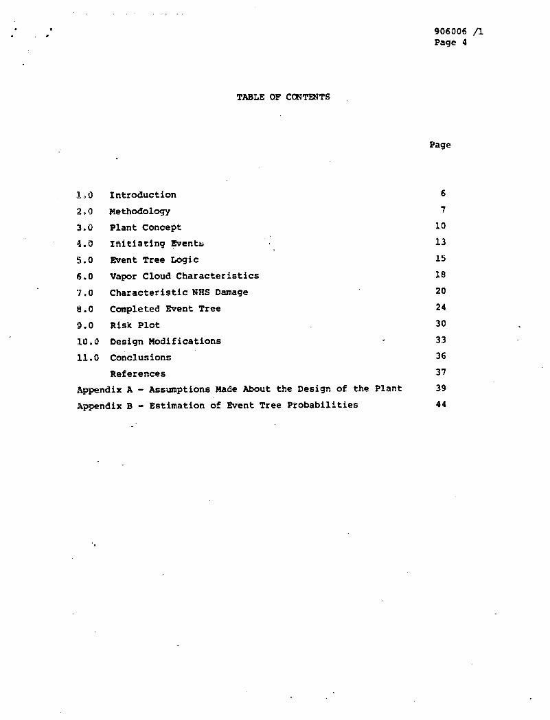
906006 /1 Page 4
TABLE OF C O N m T S
Page
1, O Introduction
2,0 Me thodology
3.0 Plant Concept
4.0 Initlaring Events . .
5.0 Event Tree Logic
6.0 Vapor Cloud Characteristics
7 . 8 Characteristic NHS Damage
8.0 Completed Event Tree
9.0 Risk Plot
19.0 Design Modifications
11.0 Conclusions
References
Appendix A - Assumptions Made About the Design of the Plant ~ppendix B - Estimation of Event Tree Probabilities

906006 /1 ' Page 5
LIST OF F'IGURES
Page
2-1 Methodology Diagram
3 Plant Plot Plan
3-2 Reformer Train - General Arrangement 5-1 Event Tree - Logic 6-1 Peak static Overpressure vs. Distance Plot
8-1 Event Tree - Completed 9-1 Risk Plot
LIST OF TABLES
4-1 Initiating Events 14
7-1 Building Damage 21
7-2 Building and Component Damage 2 3
8-1 Categories of Plant Damage 2 6
8-2 calculations for Damage to Plant 28
10-1 Design Modifications 35

906006 /1 Page 6
The purpose of this study was to perform a probabilistic risk
essesament of the indirect cycle BTGR-PA (reformer) plant. A first assump-
tion was made that the only risks to the public that were signif icantlv
different than those from a steam cycle plant were those risks associated
with the process plant. For this reason, this study looks only at process
plant hazards and their associated risk to the public.
I. 1 BACKGROUND
In studying the risk to the public we are primarily interested in
event sequences which lead to release of radioactivity to the atmosphere.
Since core heatup threatens release of fuel body inventory and is the
dominant risk contributor, only event sequences leading to core heatup were
investigated. Event sequences leading to this undesired end result can be
initiated by process plant hazards which include: vapor cloud explosions
(VCE's), vapor cloud fires, and other fires associates with the handling of'
combustible materials. These hazards can lead to, basically, one of five
threats to the nuclear plant which could cause &re heatup. TAeSe thfeats
include AC power loss, total or partial containment collapse, main loop and
CACS loop loss, air blast heat exchanger loss (diesel or CACWS), control
roan and RSB loss,

906006 /1 Page 7
In order to systematically proceed through this risk assessment it
was necessary to develop a kethodology. for study. Figure 2-1 shows a
diagramatic representation of the methodology used in this study.
It was first necessary to understand the plant as it is currently
designed. This meant knowing where the various .buildings (containment,
reformer train, ultimate heat sink, etc.) are in relation to each other, . . '
' , understanding the design and materials of construction of these buildings,
:...' and understanding the location and relation of key safety and core cooling
. . systems. It also included understanding the reforming process, the
. . . . . . reformer train components, and the process side layout. Since the design. . .
. .: :' o f the process plant is still only at the aonceptual level, many as'sump-
. - - tions had to be made a b u t the layout and design, these assumptions and . ,
other details of the process plant are' given in Appendix. A.
Once the plant design was understood, initiating events could be
found. Initiating events are component failures which lead to a
combustible gas release. These include pipe rupture, pressure vessel
rupture, and others. Process plant scenarios were then developed in order
to better understand what could happen to the combustible gas in the
process plant once it was released from one of the components. These
scenarios assisted i n generating event trees, beginning with a specific intitidting event and ending in core heatup and fission product release.
Vapor release descr.iptions were developed to characterize the manner in
which the combustible gas escaped from the reformer train buildings to the
atmosphere.
From these descriptions and knowledge of the siie and composition of
the release, models.for the behavkor of the combustible cloud were
developed. These models' described the displacement of the cloud through
the atmosphere, its potential burning and sometimes the blast produced by

9 0 6 0 0 6 11 P a g e 8
FIGURE. 2-1
METHODOLOGY DIAGRAM
PLANT CONCEPT
. I F I I T I A T I N C
EVENTS
L
I PROCESS PLANT
SCENARIOS
SUGGESTIONS FOR

906006 /1 Page 9
the explosive cloud. With knowledge of cloud blast characteristics and
plant building design it was possible to calculate characteristic NHS
damage for a given cloud.
Based on the obtained results, it was then possible to find the
dominant considerationsfor the safety risk, which leads to suggestions for
future PRA work, design mdifications,.and possible safety research areas.

906006 /1 Page 10
3.0 PLANT CCMCEPT
, The basic plant design used in this study is in accordance with the
plant drawings by United engineer,^ and Constructors (Ref. I). Information
on the methanation train flows and heat balance are from data supplied by
General ~lectrfc (Ref. 2) . The plot plan for the plant is shown in Figure 3-1 (Ref. 3 ) , labeled are the containment building, the ultimate
heat sink structutes, and the diesel cooling and fuei oil storage building.
. These buildings are of prinatjf interest in thls fitudy., &s they contain many
, o f the core caoling related components and systems which are susceptible to
damage by VCE1s. Also labeled are the reformer train buildingc, which
.contain the reformers, reformer train, and associated eqiupnent.
Figure 3-2 (Ref. 4) shows the general arrangement of one of the reformer
train buildings, giving the relative position of the reformer and
prestressed concrete pressure vessel (PCPV), heat exchangers, and
compressors. Very little piping is shown on this diagram, however, in
reality this building will be crowded with piping. The layout lends itself
to a very complex system of piping due to the separation of eomprcosors and
coolers and the confinement which the building surrounding the components
imposes (Ref. 5). .Design assumptions made are presented in Appendix A.


906006 /1 Page 13
4.0 INITIATING EVeJTS
Some mpowent failure leading to a release of inventory from the
system must occur in order to release combustible gas to the environment.
Table 4-1 lists the five most important (and frequent) failure modes for
the process plant, their cgnponent failure rates, the quantity of the
specific component ih the plant, and a plant failure rate. Of.these five, I
valve stem leak has, by'far, the highest plant failure rate. 'Because of
this fact, valve stem leaks were investigated as a possible initiating
event for combustible vapor release. For a typical valve stem leak, the
leak rate is on the order of. five to s i x gallons per day. ,1:t was found
that, for that size leak rates, combustible gas could never, 'accumulate to a I. .
point where ignition could lead to events which mald dam.a* the nuclear
plant (Ref. 6) . The other four failure modes all lead to rel.&ively large
releases (and release rates), and among them compressor failure has the
highest plant failure rate. For this reason, and the fact that no reason
was known to believe that any of the other initiating events would lead to
higher risk, compressor failure was chosen as 'a representative initiating
event to be studied in depth. By compressor failure we are referring to a
rupture of the casing due to the throwing of blades. The possibility of.
blades as projectiles was considered, but was found to be of little
significance in the werail evaluation. It must.be.painted out that,
although event trees for the other initiating events are likely to be
'similar, the frequencies and cansequences included in those trees may be
different.

Component
Valves
TABLE 4-1
PROCESS SIDE COMPONENTS AND FAILURE fams
Failure Rate
8 x 10⁻²/valve-yr* (Steam Leak)
Compressors 5 x l~-~/conpyr**
Valves 8 r l~-~halve-yr* (Valve Rupture)
Pressure Vessels 5 x 10⁻⁵/vessel-yr** (Heat Exchangers, Dryers, etc.)
Piping 3 x 10-'/ineter-yr**
* - GCR Databank [Ref. 8)
** - Canvey Island {Ref. 7)
,Quantity 'Failure Rate/Plant-Yr
..
?I500 meters 1 .S x 10-(/plant-yr
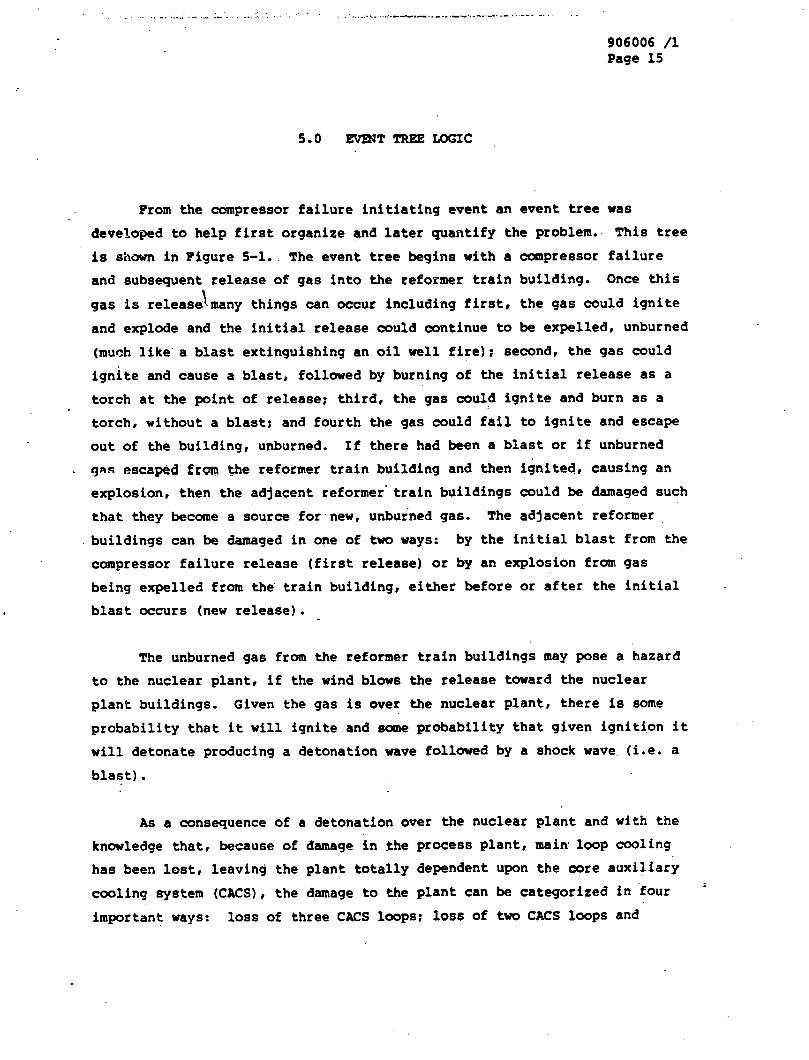
906006 /1 Page 15
From the compressor failure initiating event an event tree was
developed to help first organize and later quantify the problem.. This tree
is shown in Figure 5-1.. The event tree begin8 with a cornpressor failure
and subsequent release of gas into the reformer train building. Once this
\ gas is release many things can occur including first, the gas could ignite
and explode and the initial release could continue to be expelled, unburned
(much like a blast extinguishing an oil well fire); second, the gas could
ignite and cause a blast, followed by burning of the initial release as a
torch at the point of release; third, the gas could ignite and burn as a
torch, without a blast; and fourth the gas could fail to ignite and escape
out of the building, unburned. If there had been a blast or if unburned
gns escaped frm the reformer train building and then ignited, causing an explosion, then the adjacent reformer' train buildings could be damaged such
that they become a source for new, unburned gas. The adjacent reformer
buildings can be damaged in one of two ways: by the initial blast from the
compressor failure release (first release) or by an explosion from gas
being expelled from the train building, either before or after the initial
blast occurs (new release) .
The unburned gas from the reformer train buildings may pose a hazard
to the nuclear plant, if the wind blows the release toward the nuclear
plane buildings. Given the gas is over the nuclear plant, there is some
probability that it will ignite and same probability that given ignition it
will detonate producing a detonation wave followed by a shock wave. (i.e. a
blast).
As a consequence of a detonation over the nuclear plant and with the
knowledge that, because of damage in the process plant, main'loop cooling
has been lost, leaving the plant totally dependent upon the core auxiliary
cooling system (CACS), the damage to the plant can be categorized in 'four '
important ways: loss of three CACS loops; loss of tvlo CACS loops and

906006 /1 Page 17 .
failure of the third independently; containment building damage and
resulting lass of thtee CACS loops; and loss of no, 1 or 2 CACS loop(=).
For a given damage there is, then, some probabiliey that the damage could
: be repaired before the mximun time to restore cooling (MTRC) is passed,
otherwise a core heatup occurs and fission products are eventually released
to the atmosphere. .
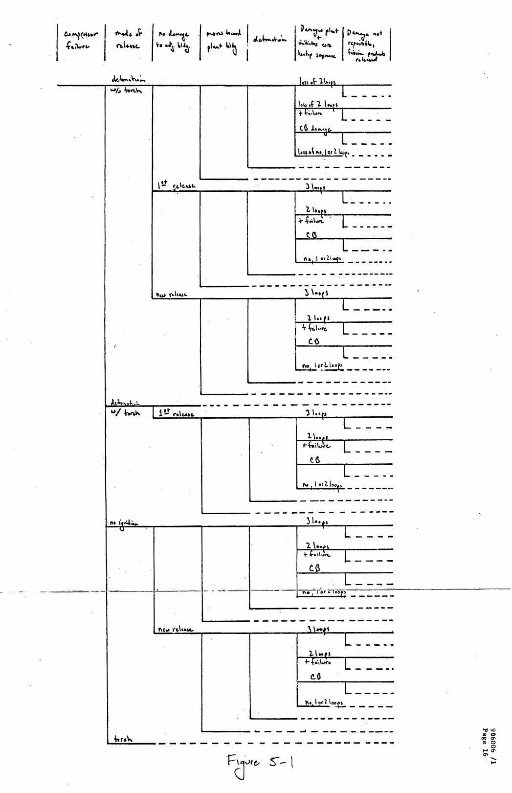

THIS PAGE
WAS I[NTE~NTIONA&LY
. . LEFTBLANK
., .

906006 /I. Page 18
6.0 VAPOR CLOUD U C T W I S T I C S
The models used for the combustible vapor clouds were compiled by
Landoni and are described in Document No. 905311 (Ref. 9). This model is
for instantaneous ('puffm) releases and can model cloud performance in all
six Pasquill stability classes (A th~ough F). Gaussian dispersion charac-
teristics are assumed for the cloud, whose vertical displacement is
predicted according to the theory of thermals, and horizontal displacement
determined by full entrainment by the wind. The potential explosive
behavior is predicted by the point explosion model for unbounded detonable
mixtures, taking into account the amount of gas contained in the flammable
region of the cloud and the position sf the cloud (vertical and horizontal)
relative to various buildings in the plant at specific time intervals along
the trajectory of the cloud. An example of the overpressure produced by
the detonation vs. distance for various size clouds is given in Figure 6-1.
This, figure gives peak static overpressure (PSO) vs. distance from the
center of the cloud.for cloud sizes of 100, 3000, and 100,000 lbs. All of
these clouds have PSO's of approximately 325 psi inside the burning cloud,.
but, as can be seen, the "reachm of the explosion is greatly a function of
cloud mass. For the 100 lb cloud, for example, the PSO drops to less than
one psi within approximately 50 ftr whereas for the 100,000 lb cloud the
PSO doesn't drop to one psi until approximately 1000 ft. For the
initiating events considered in this study, the .clouds of most interest,
however, are those in the 100 to 6000 lb range because one isolated tiain
contains about 6000 lbs of gas. Each-train has isolation valves on the
incoming and outgoing gas lines with multiple sensors to detect large
changes in flow, temperature, pressure, etc. which automatically, with a
high reliability, isolateythe train and thereby limit the amount of gas
.released. Deflagration explosions were also considered, but, since the
Clouds considered in this study are buoyant, in terms of plant damage the
overpressures produced by deflagrations are insignificant. . . . .


90.6006 /l Page 20
7.0 CEAlUCTERISTIC NHS DAMAGE
It was initially thought that the area in the plant most vulnerable
. to damage by VCE's was the cantainment building. In order to determine the
dynamic response of the containment to VCE's, an elaborate computer model
was developed by the Structural Dynamics Branch (Ref. 10). This computer
code uses a very large finite element model for the containment to deter-
mine the building's response to a theoretical point source explosion
occurring 200 ft away. Studies were done with overpressures of approxi-
mately 2 psi and it was found that there would be no damage to th= building
at those pressure levels, and that it could withstand overpressures an
order of magnitude higher without sustaining any damage. The overpressure
needed to blow-in part of the containment, breaking the eantainment liner,
showering in large pieces of concrete onto the top of and down beside the
PCRV, it was extrapolated from these results and was found to be approxi-
mately 100 psi. Combining these results with the VCE blast overpressure
vs. distance plot, it is obvious that.the only time the containment is
vulnerable to damage is when a VCE occurs within approximately 50 ft of the
containment.
Damage to the nuclear plant in other areas was also investigated.
Calculations were done by the Structural Dynamics Branch in order to
determine the overpressure needed to damage walls of the various buildings
containing core cooling systems or components. Buildings evaluated
included the ultimate heat sink structure ( W S ) , the diesel cooling and
fuel oil storage building (DCPSB), the containment annulus building, and
the.contro1 and auxiliary diesel building. The analysis was done by
calculating the blast overpressure needed to damage, sufficient to blow in
large amounts of concrete, the largest (weakest) wall i~ each building.
This limit was taken because it was felt that elastic deformations of the
walls could not cause sufficient damage to the components within the
buildings to render them inoperable. The results of these studies are
shown in Table 7-1. Full details on this work are given in Ref. 11. When

. . . . . . . . . . . . . . . . . . . . . . . . . . . . . . . . . . . . . . . . . . . . . . . . . . - - I ....;.. ......................... . . . . . . . . .
- . 906006 /1 Page 21
TABLE 7-1
BLAST OVERPESSURES NECESSARY FOR BUILDING DAMAGE.
Building
Containment Annulus Building
Control and Auxiliary Diesel Building
Overpressure
100 psi
60 psi
Ultimate Heat Sink Structure 110 psi
Diesel Cooling and Fuel Oil Storage Building
Containment Dome
120 psi
100 psi

906006 /1 Page 22
these results were combined with the vapor cloud characteristics, it was
found that overpressures, sufficient to structurally damage these
buildings, did not occur. That is, overpressures of 60-100 psi did. not
. occur at the elevations of these buildings.
Core cooling system components, in,particular the air blast heat
exchanger fans, were also examined in order to determine their
vulnerability to VCF's. Blast wave propagation through the air intake
ducts of the W S were modeled using the W A m E T computer program for the
transient response of a one-dimensional duct, of the same proportions as
those in the W S , to a transient acoustic load (blast wave pulse)
(Ref. 12). The main result was that the initial overpressure would be
reduced by 50% for the duct analyzed. Other calculations showed that an
overpressure of only one psi at the fan could bend the blades such that the
fan rreuld ba inoperah1.e bef. 13). BY m i n i n g these two results it was
found that an overpressure of only two psi at the W S structure was
sufficient to render the CACS loop inoperable. Since two of the UHS
structures are adjacent to each other, this means that a single, relatively
distant cloud can damage two C W S loops.
The DCFSB has a.similar ducting system and a similar heat exchanger;'
khus rather than performing another complete analysis, it was assumed that
an overpressure of two psi would also damage a diesel cooling heat
exchanger fan and keep the associated diesel from operating. The three
DCFSB .are all adjacent to each'other SO, it is possible, by one VCE, to
damage all DCFSB heat exchangers, keeping all the diesels from operating.
This circumstance only. poses a hazard to the nuclear plant if the same
cloud that damages the three DCFSB is also able to damage the equipment
assckiated with supplying offsite power to the plant, or if offsite power
at that time is not available for some other reason. This type of accident
would then initiate a core heatup sequence because the plant would be
without AC power.
A summary of these results is shown in Table 7-2.
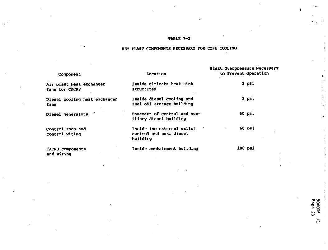
Air blast heat exchanger fans for CACWS
Diesel cooling heat exchanger f ana
Diesel generators '
~ont.ro1 r&m and control wiring
CACWS components and wiring
TABLE 7-2
KEY PLANT COMrnENTS NECESSARY FOR COPE COOLING
Location
Inaide ultimate heat sink structc.res
Inside diesel coaling and fmel oil storage building
Basemergt of control .and aux- iliary diesel building
Inside (no external walls] '
control and aux. diesel -buildir.g
Inside containment building
BEast Overpressure Necessary to Prevent Operation
2 pa:!
60 psl
100 pa.!

906006 /1 Page 24
8.0 COMPLETED m T TREE
The event tree for an initiating event of a compressor failure shown
in Figure 5-1 is now quantitatively interpreted in Figure 8-1. Proba- I
bilities are assigned for each branchland total probabilities per reactor
year are indicated for core heatup branches. Complete details on how the
probabilities for each branch were estimated are given i~ Appendix 8. The
two areas in which the analysis is most sensitive are the frequency of the
initiating event (campressor failure) and the calculation of the proba-
bility of damage to the plant. The frequency of a campressor failure, as
noted before, comes directly from literature on process pla~t type
experience with comparable equipment and can be expected to be relatively
accurate, The calculation of the probability of damage to the plant,.
howevei, i s mate involved end rwquires further elaboration.
8.1 Probability Calculations for Damage to Plant
If 'the heat sink associated with the main loop has k e n lost due to
damage in the process plant (reformer train) area, the nuclear plant would
be totally reliant on the CACS to supply core cooling. The CACS for the C)
1170 M(t) HIY;R-PH plant cukists of three independent loops, each,wfth 100%
capacity to cool the core while pressurized, and 50% capacity while
depressurized. For the scenarios wnsidered in this *etudy, the primary .
.loop is always pressurized, so the plant requires one CAeS loop for core
cooling. Consequently, the damage inflicted to the nuclear plant by VCE's
can be divided, basically, into four categories: loss of three CACS loops
because of the explosion; loss of two CACS loops by the explosion and
failure of the third independently; containment damage and resulting loss.
of three CACS loops; and loss of no, one or two CACS loops. A breakdown of
damage in these categories is given in Table 8-1. Loss of three loops
includes loss of three W S heat exchanger fans, or loss of three DCPSB heat
exchanger fans and loss of offsite power (LOSP), or loss sf control room.
Loss of two loops and failure includes loss of two W S heat exchanger fans
and failure of the third loop, or loss of two WFSB heat exchanger fans and
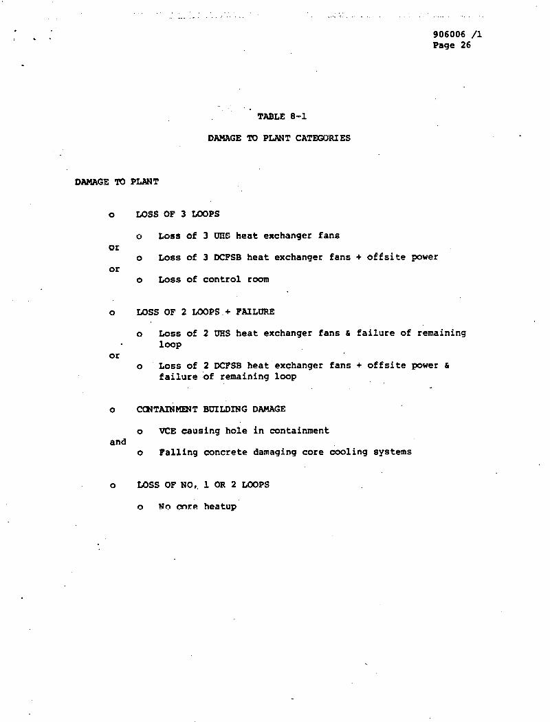
906006 /l Page 26
. .
TABLE 8-1
DAMAGE TO PLANT CATM;OWIES
DAMAGE PLANT
0 LOSS OF 3 LOOPS
o Loss of 3 UXE heat exchanger fans or
o Loss of 3 DCFSB heat exchanger fans + offsite power or
o Loss of control room
0 LOSS OF 2 LOOPS.+ FAILURE
o Loss of 2 UHS heat exchanger fans & failure of remaining loop
or o Loss of 2 DCF'SB heat'exchanger fans + offsite power &
failure :of remaining loop
0 CCNTAINmT BUILDING DAMAGE
o VCE causing hole in containment and
o Falling concrete damaging core coaling systems
0 LOSS OF NO,, 1 OR 2 LOOPS

QJ4 h.5 S 93 3 t- ,PI. kOL =TZ 3
' A' *7.t :-It 3
-----ao---a- - - - ------me
0-0- 0 0 -9 - - - - - q Y'J4 L9'0 *
060 m.I.0.. 0-- -.I---
0,C.O +
----I
Cloo\ 2JO l'*q
93 4-ol*t'l, bb-0 h?14¶*J* 03 --111
or0 l"v?+ 77 m."l*3*~ ,. .,.4y" 17
-----
n
a
'1 ,,.el* 4.1 ob'o SW u* g tC'Q %V7\SJ, d)U ..I81 ,, , , , L ,*k, LL- - - - - - 9.9
t7.9 -om---- --.) -0
--- - - - -- - - - - - 6S.Q -* -*& ---i, -- ------ - (d00\ f ). \feu
1
a=---
Iro t - 9, 8-ol A ,*I #'@ k-.r*l'}* g 3
17 ,PI "S'Z - - 9 - - ,!!V'b - Ql'O I I
‘I[ b_cl*'t'Z wo 1**.1 c asg Q tt0o h' 0 "q9.1 ou $W't*b @
-- - -- - - --
-..--... - ---..,-I c--- C9.Q
....------ 0 -- - as0 '
.-00 - 0 . 0
sdo.1 TH I I- +
' t * 10'0
\
-. " ---
01 '0
1
- eb'o - 0s' @ ti3 *m\*J
~$1 wrm %'@
-w ry
..m----o----- --CI---w $9.0 3fV ----o -0-m- - - OS'O
93 ,-Ql .S'f - - a\o - 1 'U"r-3 + 7 -t 0,-@I x U'Z OK" .a.ql.! r "1 t --a\a-?
9-9 =/-
7C ,,3ldS'Z Qb- Q ,,,rl+u c Jam\ p osWo t r 'Q ?503;1A @Q
..--I.o- --.---..------ ~s-9 c9-6'
---.-----.. 0 - ---. 0s '0 .. -0- - - 0
ocO lCrnrt+'"o\ c 0s-o tt.0 3h?\7J
7C Q, -01 *8 obv 5"'1 f -Y ''7 QL' 0 tt *o 01'0 %at TI# ?"t'."t3P
Sl'Q
------- ------------ . C9.0 ..----- - - --a 0S.Q A
msm--- doIz~elre. ow
-.... - '- - 1N \ 1' 10'0
h
92 a- cl *TI KO b..,y?;* -7 02 ----- 0)-e , ."@\!'3 + Ql *Z'b 77 ,I- *@ ''"\ 2 P'I
r r - - rr .,-m*$.bw 01'0
I,
04 '0

THIS PAGE
WAS INTENTIONALLY
LEFT BLANK , :'
906006 /1 Page 27
LOSP and failure of the third loop. Containment building damage can be
characterized as a hole in the containment, by a VCE, with falling concrete
damaging the core cooling systems located inside. The loss of no, one or
two loops does not lead to core heatup and encampasses any damage to the
plant that does not prevent core cooling.
The calculation of the probabilities associated with these types of
damage are simple, but involved. A sample calculation is given in
Table 8-2, outlining the calculation of the probability of losing the two
W S heat exchangers located in "adjacent buildings and losing the third
loop, leading to a core heatup sequence being initiated. For a given
sequence of branches in the event tree, the size of the released cloud can
be estimated which constitutes the starting point for calculating the
probability of damage.
For this analysis a reference site was needed in order to enable
frequencies to be assigned to the six Pasquill stability classes (Ref. 14).
In this study Morgantm, West Virginia, the proposed SRC 11 site, was
used. The atmospheric conditions determine the drift, lift (or buoyancy)
and diffusion of the cloud; so each branch must be evaluated under each of
the six stability classes. For the branch we are considering in this
example, only stability class C leads to a cloud which has the potential to
damage the two DElS heat exchangers. For that stability class and the
estimated size of the cloud, an angle around the UHS structure in which the
center of the cloud must be in order to damage the fans can be determined,.
In this analysis a random wind direction is assumed since the- relative
location and orientation of the nuclear plant-reformer complex has not been
firmly established yet. Thus, the probability of the cloud being within
that angle is just that angle divided 'by the angle in which the cloud must
be over the plant in order to damage the plant. This probability, based on
the angle of cloud emission, is due to the fact that in a previous branch
of the event tree we already took into account the fact that the.wind might
blow the cloud away from the nuclear plant. Next, a probability must be
given for ignition of the cloud. There are two factors to be considered

906006 /1 Page 28
TABLE 8-2
PROBABILITY B m OF DAMAGE TO PLANT FOR LOSS OF 2 UHS HEAT WCHANGERS
STABILITY CLASS'
Probability of stability class C occurring = 0.0877
WIND DIRECTICN
Bar given atability olaas and cloud size:
Half angle for damage = 32O
Total angle cloud must be in =' 13s0
Probability of wind direction being one that causes damage = 0.48
I a 1 T I a SOURCE
Probability that cloud will not ignite at point of release = 10-I
Probability that cloud will ignite during flight while in region of damage = 10-
TOTAL PROJABILITY OF I@lITIUJ OCCURRING AT A TIME Wffm DAMAGE CAN =CUR = 10-
TOTAL PROBABILI'lY OF R D W N I N G CACS LOOP FAILURE =
TOTAL PROBABILIT!l OF DAMAGE = (0.48) (0.0877) (lo-') (10-2) = 4.2 x

906006 /1 Page 29
here: the probability that the cloud will not ignite at the paint of . .
release and the 'probability that the cJoud will ignite while over the UHS
and in a region where,it could cause damage. These probabilities are
estimated from information on drifting vapor clouds in the literature and
are independent of the probability of ignition. A probability must also be
assigned to the failure of the other, undamaged CACS loop. This estimate
comes from information in the AIPA study,on failure of CACS loops after
operating for a period of time. It is very likely that the lone CACS loop
will be depended upon for core cooling for quite some time, because of all
the repairs necessary in the process plant and repairs needed.in the other',
damaged CACS loops. Thetotal probabilities of damage leading to
initiation of a core heatup sequence is given by the product of all these
probabilities.
These calculations include.many factors both measurable and
unmeasurable. The estimates,of each probability,were made as realistically
as possible based on the information available. It is recognized that
there. are. uncertainties in the estimates, but a full scale uncertainty
analysis was outside the scope of this study. Some uncertainties in the
probabilities were, instead, estimated for the final result and are
included in the risk plot.
906006 /1 Page 30
9.0 RISK PLOT
The assigned probabilities per reactor yeas for the core heatup
branches of the event tree were s m e d according to the types of damage to
the plant (3 loopo 2 loop 4 failure, or containment) and are displayed on a
risk plot in Figure 9-1. The consequences for these sequences were scaled
from similar core heatup eequences for the ETGR-SC (steam cycle). The 3L
and 2L + failure points were scaled with reactor thermal power from point Cn-4 on the risk plot for cere heatup with eve~tual containment failure by
overpressurization due to accumulation of non-c6ndeRsible gases. The CB
point was scaled with reactor thermal power from point CH-1 for core heatup
without containment isolation. This risk plot shows median point estimates
for various care heatup sequences considered in the AIPA study (Ref. 15)
and median point estimates for the three damage categories considered in
this study. The other darkened lines are limit lines for the quantitative
safety goals (Ref. 16) for an emphasized risk policy (with a simplifying
assumption that mean/median is 2). Risk curves for LWR's and probable
safety goals for LWR's are less restrictive than these proposed goals by
several orders of magnitude. The dashed lines aCtbS8 a t a probability of
lo-' is a licensing line used to determine the limit of events to be
studied for licensing purposes. The larger; darkened triangles labelea
with 3L, 2L + failure and CB represent the summed probabilities for three loop damage, two loop damage + failure of the third, and containment building damage, respectively. The open triangles above each of these
represent where the point estimate would be if the event trees for the
other intitiating events were the same as for compressor failure (which may
not bo the case).
Uncertainty bars were shown on each of the three point estimates on
the risk plot in order to indicate, qualitatively, the uncertainties
incurred in the estimates. For the 2L and 3L points, the uncertainty bars ..
extent one order of magnitude in both directions. This uncertainty is due
to two factors: sensitivity of the results to the cloud height model (a
decrease in cloud height of fifty percent could give frequencies an order


906006 /1 Page 32
of magnitude higher) and the uncertainties in estimating the other, less
sensitive probabilities. For the CB point, the uncertainty band extends an
order sf magnitude in t!!e increasing frequency direction and more than an
or9ar sf magnitude in the decreasing frequency direction. The single order
OR magnitude uncertainty is due to the same factors as mentioned for the 2L
and 3L Cases, but the increase in uncertainty in the decreasinq frequency
di~oction is due to another factor. With the cloud models used in this
study, the only size cloud which could cause containment building damage is
cloud of 100 lbs; and since the entire contents (6000 lbs) of a damaged
geformer train would be expelled after any accideRt, there is uncertainty
as to how a cloud of only 100 lbs is formed. It must be emphasized that
thest? uncertainty estimates are just that, estimates. No attempt was made
to quantitatively determine the uncertainties since it was outside the
scope of this study.
The paint estimates for all three core heatup categories fall well
below LWR risk curves, and all three point estimates fall within the
licensing limit line. The 3L and 2L points and uncertaity bands also fall
within the safety goals and would have little effect an the overall risk
curve for the plant. The CB point, however, lies close to the limit line.
and its unocrtatnty band extends up Cntn the unacceptable region and above -.
the licensing limit line. The CB point would also be expected to slightly
raise the overall risk curve for the plant. It must be stressed, however,
that none of these points are significantly different than the other core
heaeug points for a BTCR-SC. This result is quite encouraqinq.

906006 /1 Page 33
10.0 POSSIBLE DESICN MODIFICATImS
The fact that the plant design is at a very early stage has
advantages and disadvantages in a.study of this type. First, it allows
input in the early stages of the design process should any of the results
from this study suggest that design changes might be necessary. Second, it
forces the people working on the study to make assumptions without
assurance that the final design will be able to satisfy the assumptions.
Assumptions made' in this study have begn mentioned throughout this report
and are detailed in Appendix A, but there is one more assumption that
should be addressed here. That is, the assumption was made that all
possible ignition sources would be eliminated from the top of the
containment. This assumption greatly reduces the chance that a VCE would
occur .while the containment d m e is being engulfed by a vapor cloud. '
Therefore, the PRA results require elimination of these ignition sources
from the top of the containment.
Changes in the plant which would, reduce the risk of 'the CB point on
Fig. 9-1 do not appear justified because the points .for CH-5 and (33-3
provide similar risk. However, if the plant design is changed, such as by
the adoption of enhanced safety features, and the risks from CH-3, CH-4,
CH-5, and CH-6 are thereby reduced, then a design change to reduce the risk
of point CB should be seriously considered. One such change is evident as
a result of this study but the change may be accomplished in either of two
ways. First, move the entire reformer train.another 200 ft from the
containment (this has adverse effects on the performance of the NRS). Or
second, move the reformer train, ekcept the reformer, another 200 ft away.
The second alternative would probably be performed because it would have
virtually no impact on plant performance. Either of these alternatives
would result in most of the released vapor clouds being much higher by the
time they approach the containment and would thereby reducesthe probability
that a VCE could damage the containment.
906006 /1 Page 34 ,
Two design changes greatly reducing the probability that a single VCE
could damage both the diesel coolers and cause LOSP include splitting the
triple DCF'SB into three single DCFSB with a minimum separation distance of
500 ft and separating the DCFSB and all equipment associated with offsite
power greater than 600 ft, but the risk is already low for damage of this . .
type and these changes are not necessary at this time. Splitting the
double W S would reduce the probability that two loops could be damaged
such that a core heatup was initiated, thereby lowering the two loop (2L) '
p i n t . nn the risk plot. This ~uqqested design change, too, is not
necessary at this time since both the 2L and the 3L points are very low on.'
the risk plot. Another possible design change, removing the walls and rp6f
around the reformer train buildings, would be done, primarily, to reduce:.'
investment risk. By enclosing the reformer train a blast is very likely ' . . .
.once flammable gas is released, leading to extensive damage to the . .
expensive reformer train. Elimination of the roof and walls would greatly
reduce this chance, while not affecting the plant risk.
A summary of these possible design modifications is given in
Table 10-1.

906006 /1 Page 35
TABLE 10-1
DES1C;N M3DIFICATICXJS
REQUIRED FOR VALIDITY OF M A L Y Sf S
o Eliminate all ignition sources from .top of containment
o Move entire reformer train another 200 ft from containment (this alternative has adverse effects on NES performance)
or o Move reformer train (except reformer) another. 200 ft from
containment
CHANGES WHICH APPEAR mECESSARY FOR SAFETY
o Splitting triple DCPSB into' three single DCFSB's with minimum separation of 500 ft, possibly combining UBS and DCFSB
o Separating DCFSB and all equipment associated with offsite power greater than 600 ft
o Removing walls and roof around reformer train (investment risk)
o Splitting double UHS structure into two single UAS structures with a separation distance of greater than 500 ft

906006 /1 Page 36
11.0 CONCLUSION
The results of this preliminary probabilistic risk assessment of the
1170 Kg(t) an;R-PH (reformer) plant shows that the risk to the public due
to Che addition of the reformer train are not significantly greater than
thsee risks already associated with a HTGR-SC plant. The risks associated
with the plant fall far below the risks for LWR1s, exhibiting the HTGR
superiority in process plant applications. This conclusion is, however,
obtained from preliminary results and further study would be needed to
explore all the facets of the very complex problem of VCE1s in nuclear
plants. Further study is also needed to assure tha: the other initiating
events do not pose significantly greater hazard to the nuclear plant
including explosions within the reformer. additional . . . work should also be
done to accurately evaluate the uncertainties associated with the methods
used in this study and to do an uncertainty propagation'analysis in order
to bound the range of predicted values.

906006 /1 Page 37
1. .United Engdn@ers and Constructors, Plant drawings, SK-147 through SK-156.
2. Presentation by General ~leetric' Co. - Advanced Reactor Systems Division under D. Allen, October 30, 1980 in Sunnyvale, viewgraph copies.
3. United Engineers and Constructors, Plant drawing, SIC-147.
4. United Engineers and Constructors, Plant drawing, SK-154.
5. Private ~omnunication, D. Peterman.
6 . Landoni , J. , 'Small continuous Leaks of Syn Gas in Heater k" , General Atomic Co., Document No. 905734, December 18, 1980.
7 . 'Canvey: An Investigation sf Potential Hazards from Operations in the Canvey Tslandflhurrock Area", Health and.Safety Executive, U.K., 1978.
8. Eiannaman, G. , 'GCR Reliability Data Bank Status Report" ,. DOE Report GA-A14839, General Atomic Co., July 1978.
9. Landoni, J., 'Accidental Releases of Combustible Clouds", General Atomic Co., Document No. 905311, September 22, 1980.
10. Jones, 0. , mETGR-R containment Building Blast Response Analysisw, General Atomic Co., Document No. 905572, Nov. 19, 1980.
11. Jones, D., "HTGR-R Reformer Plant Shock Analysis", General Xtomic Co., October 1980.
12. Blevins, R., 'Acoustic Wave Propagation Analysis of Reformer Plant Heat Sink Buildingn, General Atomic Co., Document No. 905780, Jan. 16, 1981.
13. ones, D., 'Air Blast Heat Exchanger Blast Responsew, General, Atomic . Co. , November 1980.
14. Annual Wind Distribution By Pasquill Stability Classes, STAR Program (six classes), .Job No. 50886, National Climatic Center, Asheville; NC, 1975.
15. 'BTGR Accident Initiation and Progression Analysis Status Report, Phase I1 Risk Assessment", DOE Report.GA-U5000, General Atomic Co., April 1978.

90600.6 /1 Page 38
16. Joksimvic, V., and W. J. Houghton, "A Path to Development of Quantitative Safety Goalsn, DOE Report GA-A15625, General Atomic Co., April 1980.
. 17. Gugan, K., Unconfined Vapor Cloud Explosions, The Institution of ' Chemical Engineerso 1978.

906006 /1 Page 39
APPENDIX A
ASSUMPTIONS MADE ABOUT '%PIE DESI(N OF TEIE PLANT
In order to do a PRA on this type of plant, many details not included
in the early stages of the design must be known. In particular, since the
present design of the process plant has tea little detail for this type of
atudy: then many assumptions had to be made. . Also in the nuclear plant,
there are areas in which the design of the HTGR-PH has not progressed to a
paint of adequate detail. Since the results of this study depend upon
these assumptions, the reasoning and thought behind each assumption must be
documented; 1t is the purpose of this appendix to present the design
assumptions made in this preliminary PRA study and to, aiso, present some
background as to why these assumptions were made.
Nuclear Plant ~esign Assumptions
As mentioned earlier in the repdrt, the basic. design for the plant
was taken from United Engineers and Constructors' plant drawings (Ref. 1).
Those drawings included a plot plan of the plant, general arrangement
diagrams of the containment, containment penetration building, and reactor
service building at two .different elevations, a general arrangement
elevation diagram of the containment, 'general arrangement diagrams of the
turbine building (floor plan and elevation view), general arrangement
diagrams of the reformer train buildings (floor plan and elevation view),. a
heat balance diagram, and a key one line diagram of the unit electrical
distribution. The plot plan was used to determine the relative position of
the various plant buildings. Distances for cloud travel and distances for
blast overpressure calculations were taken for the plot plan, also. The
details of nuclear plant building design were assumed to be'the same as for
the 900 W(e) ETGR plant, since that design had the most detail and was
similar 'in layout to the process heat plant. The topography of the site
was3tsarimed to be flat in order to simplify calculations of cloud height.
This' is probably a fair assumption since many nuclear plants are layed out
on level sites.

906006 /1 Page 40
Two assumptions were made about the operation of the nuclear plant
during process plant accidents. First, it was assumed that main loop
cooling is lost when an accident occurs in the process plant area. This
. assumption is a logical one since, when an accident occurs in the process
plant, combustible gas is being released in the reformer train area, and
rather than risk further releases of combustible gas, it makes sense that
the process would be shutdown immediately after the accident is discovered.
This means that the nuclear plant will be reliant upon the core auxiliary
cooling system (CACS) for core cooling. The second assumption was that the
CACS would not have been put into operation before the-damaging W E occurs.
This assumption also seems correct, because it only takes about a minute
for a .vapor cloud to reach the nuclear plant after it has been released and
it is,.iinlikely that the release muld be detected and the CACS started , .
within. that time. . .
Process Plant Design Assumptions
- Unlike the nuclear plant where many designs of similar plants have
been developed in great detail, the process plant is a new design and
consequently there were many more design assumptions made. The basic
design for the process plant comes from the UELC drawings of the reformer
train buildings (drawings SK-153 and SK-154). These drawings show only the
largest components and include very little detail, even in such areas as
piping. The first, most general, assumption made was that the components
used in the process plant were not made of nuclear grade materials. This
assumption was made because of the fact that the components in the reformer
train are not nuclear safety related and, therefore, it would not be
necessary to require the mare expensive nuclear grade materials. This
asslimption is important because failure rates for non-nuclear grade
components are generally higher than those for nuclear grade components.
The assumption was also made that the reformer train buildings would be
made with sheet metal type walls a n d . r a a f , similar to the Fort St. Vrain
design. This assumption, also, is because the reformer train is not
considered nuclear safety related and therefore would be required to be

906006 /1 Page 41
enclosed in rei~forced concrete. Another general assmption for the
reformer train was made about the maintenance on the four reformer trains . which would be done at the same time. That is, there would never be
. maintenance d 0 ~ e on one train while the other trains were operating. Once
, again, the fact that combustible gases are in use in the process plant
would seem to dictate that all maintenance be done at the same time, in the
abse~ce of combustible gases. MaifItenance in the reformer train area
during operation would not only increase the. chance of uas being released
(because of accidents), but also it would increase the chance of finding an
ignition source for the combustible gas.
Other, less general, assumpt$ons on design details were also
necessary for the present study. One such assumption was that the
pipelines that link the nuclear plant (reformer train) to the surrounding
user plants, would be routed such that the closest approach to any safety
related nuclear plant structure would be at the reformer train buildings.
This assumption was made for two reasons: first, the nuclear plant and
process plant m u h d probably be designed such that the reformer traLn would
be positioned as close to the user plants as possible, thus justifying the
assumption made: second, by designing the piping in this way it greatly
reduces the risk to the nuclear plant by moving a potential source of
combustible gas as far from the nuclear plant as possible. Another
Hssumption made about these pipelines was that they would have automatic
isolation. valves within the nuclear plant boundary to cut off the flow of
methane'and synthesis gas between plants. Presumably, there w u l d be an . .
isolation valve at the nuclear =ite boundary on each of the pipelines going
20. the four reformer ttains. The further assumption was made that those
lines w u l d be combined into two single pipelines before they left the
nuclear plant end that there would be an isolation valve on each of them.
Tt was also assumed that all the piping within the reformer train buildings
would be overhead because of the space limitations imposed by enclosing the
reformer train komponents in buildings. From'the reformer train layout and
.tihe process heat belance it is clear that the piping within each building
h i l l be both considerable and complex. Much of this piping is associated

90W06 /1 Page 42
with the compressors and inter-stage &lers for the compressors. One
additional assumption made about the compressors was that during normal
operation, one of each of the two sizes of compressors muld not be in use
.&nd would serve as a backup. This assumption was made because it was felt
that an extra compressor would be,supplied so that the process could
esi~tinue at full flows even if one compressat was down. Because those
eempressors would have to be valved into and out of service, it was assumed
that there were approximately two valves per compressor in each reformer
train. Each reformer train building has eleven ventilation fans on the
roof of the buildins. Por same of the calculations on combustible gas
accumulation it was necessary to estimate the circulation rate of those
Pans. This estimate was done by making a rough measurement of the size of
the fan from the plant diagrams and checking the flow rate for a comparable
size fan in.equipment'eatalogs. The circulation rate for each fan was
estimated to be approximately 20,000 cfm. Another assumption made about
the reformer train was that the reformers must have pressure relief valves
on them, although they were not shown in the UEhC drawings. Putting relief
valves on barge reactor vessels, such as reformers, in order to-prevent
vessel overpressurization is common practice in the chemical industry.
Because' these relief valves are a potential source of combustible gas, it.
was assumed that all rel.ief valves would be vented into a separate piping
system and sent to a flare some distance away as it is camon practice in
the chemical process industry.
In order to estimate the maas of raleaocd alouds, i t was necessary to
calculate the inventory of gas in a reformer train. This calculation was
done by, first, estimating the volume of all the vessels in a single
reformer train from the plant diagrams. From these volumes and with the
knowledge of the pressure, composition and temperature of the gases inside
the vessels, it was possible to calculate the amount of.gas con'tained in
each reformer train. Since the only isolation valves for each reformer
train are at the plant boundary, it was necessary to estimate the volume of
all the (including the piping to the plant boundary). Prom that
volume and similar knowledge of the process operating conditions, the

906006 /1 Page 43
amount of gas in the piping was calculated. Those quantities were summed
and used as an approximate maximum mass for released clouds. This method
was very approximate, but the analysis is not sensitive enough to cloud
.. size to require a precise calculation of the amount of gas present. The
maximum mass of the cloud used was 6000 lbs.
906006 /1 Page 44
APPRIDIX B
ESTIMATf (TJ OF EVENT TREE PROBABILITIES
The purpose of this appendix is to provide documentation of the
methods used in estimating the frequencies B R ~ probabilities in the event
err@@ used'in this study. A great deal of groundwork was done before
probabilities were ever estimated and it is hoped that the important
information pertaining to those probabilities can be passed on in this
appendix, The event tree used in this study is shown in Figure 8-1. This
appendix will go through the event tree column by' column, explaining the
estimate of the probabilities shown in each branch,
The first freque~cy included in the tree is the frequency of the
initiating event, in this case a compressor failure. This frequency comes
from data supplied by the Canvey Island study (Ref. 7). The other
initiating event frequencies listed in the body of the report came from
Canvey Island and the &R Databank (Ref. 8) for components generic to all
power plants. As mentioned in Appendix A, one of the design assumptions of
this study was that the components in the reformer train were not made of
nuclear grade materials. These frequencies are for similar components, in
similar operating conditions and are consequently applicable to our study.
The probabilities designed to the different ways the gaseous release
behaves, as far as combustion is concerned, must be examined next. Prom
literature (Ref. 171, it is found that a release of combustible gas has a
probability of not ignitihg equal to 0.10; this accounts for the branch
labeled "no ignitionw. The literature (Ref. 17) also states that the
of deflagratian ( I .e. sl-combustion or burning accompanied by
radiant heat but without pressure wave) after successful ignition is nearly
equal to the probability of detonation after successful ignition for
unconfined vapor clouds. For a release of this type, within a Building,
the probability of detonation must be taken as being higher than the
probability of deflagration since it is a confined vapor cloud. For this

906006 /1 Page 45
reason, the probability'of deflagration (branch labeled 'torch') was chosen
to be 0.40. This means that the probability of detonation is 0.50.
However, after a detonation, the following release from the reformer train
may'behave in two different ways, that is it could burn as a torch, or it
could continue to be expelled, unburned (eimilar to what occurs when
explosives are used to extinguish an oil well fire) . It was assumed, since
there would probably be extra ignition sources due to the blast damage,
that the probability of the release burning as a torch after detonation
would be approximately twice the probability of the release continuing
unburned. This assumption leads to probabilities of 0.35 end 0.15 for
detonation with torch and detonation without torch, respectively.
If an explosion occurs, there is a probability that the adjacent
reformer train buildings could be 'damaged, releasing more combustible gas.
For an explosion without a subsequent torch there are two ways the adjacent d b
reformer buildings could be damaged as already mentioned in Section 5.0.
That is, by the initial blase (first release), or by an explosion from the
unburned gas being expelled from the train (new release). The probability .
of the adjacent reformer train buildings not being damaged was assumed
0.10. This assumption is because, for the amounts of gas being considered,
the blast effects in the near field would be appreciable. Further, the
probability that the adjacent buildings would be damaged by the initial
blast was assumed twice the probability that the new release would damage
them. This assumption is due to the.fact that the new release cduld be
blown away from the reformer buildings before it ignites and there is also
some chance that the release may never ignite (or detonate). For detona- . .
tion with a torch, the same assumptions were mad=. That is, the proba-
bility of no damage to adjacent buildings is 0.10 and, since there is no
other 'murce of unburned gas, the probability of the initial blast damaging
the adjacent buildings is 0.90. For a release that has escaped the
building without igniting, the probability of not damaging the adjacent
reformer train buildings is estimated to be 0.40. This probability is
associated with the fact that the wind could be blowing the release away
from the adjacent buildings and the consideration that, since the gas has

906006 /1 Page 46
nok found an ignition source inside the building, the probability that it . .
finds one outside the building is much less. This leads to a probability
of 0.60 for the release damaging the adjacent reformer buildings.
At this point in the event tree, the probabilities have been
eakiraated for a releaae of combustible gas to the atmosphere occurring in
the ~eformer train area. The direction of the wind need be considered in
estimating the probability that this cloud could damage the nuclear plant.
Fsc this reason, a probability was estimated for the wind blowing a cloud,
released from the reformer train area, toward the nuclear plant. This
probability was estimated by sssming no preferential wind orientation,
which means the quotient of the angle covering the area of damage by 2 n,
i.e., a geometrically defined probability. Thus, the prevailing winds were
net considered and, for the cloud sizes considered in this analysis, the
limits of the wind direction covering the area of damage were taken as the
limits of the range of angles containing clouds which could damage the
nuclear plant. Damage to the nuclear plant, is considered to be any damage
to plant components or systems such that a core heatup sequence could be
initiated. The range of the clouds that could cause damage was found to be
within an angle of 13s0. For a randomly oriented wind (i.e., wind without
preferential orientation) the probability that the cloud moved toward the
piant would then be 133 divided by 360 or 8.37.
If a combustible cloud is over the area where it could damage the
nuclear plant,then a probability must be assigned to account for the
chance that the cloud could detonate. According to the literature
(Ref. 17), for unconfined vapor clouds, the probability of detonation is
approximately 0.50.
Once the probability of a VCE occurring over the nuclear plant has
been determined, it is necessary to'determine whether the damage, if any,
initiates a core heatup sequence. For this determination, the damage to
the plant was divided into four categories: loss of three CACS loops,
containment building damage and loss of three CACS loops, loss of two CACS

906006 /1 Page 47
loops and failure of the third, and loss of no, one, or two loops. The
breakdown of these categories is given in the body of the report. An
example of the calculations, with an explanation, for one of these branches
is also given in the report. Therefore, elaboration on the calculation of
each branch will not be given, as each branch uses a similar logic. A
listing of the probabilities used in the calculation of the branches is . - given in Table B-1. The probabilities for each category of damage are
aasrrmed to be approximately the same throughout the event tree. This
assumption can b made because the size of the cloud and the mode of
release have little influence on the probabilities used in the calcula-
tions. The range of cloud sizes is relatively limited, due to the limita-
tion on the amount of gas released which is imposed by the closing of the
isolation valves. In case of failure of the isolation valves, the
increased size of the cloud would only decrease the probability of damage.
This fact is because larger clouds rise faster due to the increase in
buoyancy associated with the .increased mass, which prolongs its diffusivity
in air. The influence of cloud size on rise rate is mare pronounced in the'
case of containment building damage. The only size cloud which could
damage the containment is a cloud of approximately 100 lbs. Because the
small cloud rises slowly,,at the point when the cloud reaches the
.containment it is approximately even with the top. Thus, if ignition were
to occur leading to a cloud detonation, then the containment would be
exposed to large detonation overpressures on the order of 300 psi, well
above the structural limit of the containment. The fact that only clouds
of approximately 100 lbs can cause containment damage, leads to the large
uncertainty bars on the containment building damage point estimate used on
the risk plot. Experimental data on detonating cloud masses indicates no
references for 100 lb clouds (Ref. 17).
For a given type of damage, there is some probability that the damage
could be repaired, and subsequent core cooling restoration, before reaching
the #MR. For the three loop and two loop with failure of the third loop
damage categories, this probability was estimated to be 0.10; giving a
probability of 0..90 that the damage would result in a core heatup as shown

TABLE 5-1
BREAKDOW OF PROBABILITIES FOR DAMAGE 'lU FLAW
Damage Category Event 3 BCFSB 2 DCFSB + LOSP 2 URS + Containment
+ U)SP + Failure of Other Loop Failure of Other Loop Building
Probability of atabllity 0.0877 0.0877 class
Angle of Damage (135~) 0.48 0.18 0.48 0.106
Probability of ignition at 10'~ 10'~ lom2 10'~ time when damage caula occur
-
Probability of Damaging OSP equipment with same blast
Probability of failure of - 10'~ -- remaining loop
4.2 x 10" 4.2 x lo-.' 4.2 x 10 -6
TOTAL 5.3
3L = 1.2 x 10'~
2L + Failure = 4.2 x lo-' + 4.2 x = 1.6 x

906006 /1 Page 49
in Fig. 8-1. For the containment building damage category, the probability
oi repair was estimated to be 0.01. The more cxteneive damage represented
in this category justifies the lower probability of repair.
The total probabilities for.each mquence leading to core heatup and
fission product release are ehcnm adjacentto the appropriate sequence at
the right of the caqleted event tree shown in Pig. 8-1. These proba-
bilities were calculated by taking the product of all the. individual
probabilities for each sequence. The total probabilities of fission
product. release due to each of the three categories of damage are shown at
the bottom of the tree. These total probabilities were calculated by
summing the individual total probabilities for similar eequences. These
'total probabilities were 'later used ds median .point estimates' of the
frequencies of the correspoding core heatup sequences. The consequences
for these point estimates e r e ecaled 'from similar sequences in the AIPA
study (Ref. 15) . The consequences for the three loop damage (3L) and two
loop damage and failure of the third (2L + failure) points were. taken f rm
core heatup and eventual containment werpressurization sequences in the
AIPA study and scaled in accordance with the reactor thermal power to
cot rectly represent the total fission product inventory. The consequences
for the containment building damage (CB) point was taken from a core heatup
and failure of containment isolation valves sequence and was also scaled
with reactor thermal power to represent the fission product inventory.


APPENDIX 0
HTGR PROGRAM
ECONOMIC G U I D E L I N E S
Research and Engineer ing Bech te l Group, Xnc.
San F r a n c i s c o , C a l i f o r n i a
Simcha Golan P r o j e c t Manager

ABSTRACT
INTRODUCTION
ESCALATION AND I N F L A T I O K
FIXED COSTS
VARIABLE COSTS
L E V E L I Z E D COST OF ENERGY
COMPARISON O F ALTERNATIVE GENERATING SOURCES
A p p e n d i x
A GLOSSARY
B >.lWUAL F I X E D CHARGE RATE
C L E V E L I Z I N G FACTOR
E ECONOmC ASSUMPTIONS
TABLES
Tahl F! . .
1 Financ i a l A s s u m p t i o n s A s s u m i n g Z e r o I n f l a t i o n R a t e
2 Financia l A s s u m p t i o n s A s s u m i n g 6% I n f l a t i o n R a t e
3 R e v e n u e R e q u i r e m e n t s

ABSTRACT
- T h i s paper e x p l a i n s t h e methodology and i n p u t n e c e s s a r y t o de te rmine t h e
a n n u a l o r l e v e l i z e d revenue requ i rements f o r a f i r m ' s a n t i c i p a t e d expendi-
t u r e s f o r a s p e c i f i e d c a p i t a l investment . T h i s method does n o t e v a l u a t e t h e
p r o f i t a b i l i t y of a g iven p r o j e c t based on t h e p r o d u c t ' s market p r i c e . Ins tead , ' , i t de te rmines t h e annua l o r l e v e l i z e d c o s t of energy p r o d u c t i o n based on t h e
f i r m ' s f i n a n c i a l r equ i rements and a n t i c i p q t e d o p e r a t i n g expenses . . .
A d i s c u s s i o n of t h e u s e s of c o n s t a n t and i n f l a t e d d o l l a r s i s inc luded .
B e c h t e l recommends t h a t a l l s t u d i e s f o r t h e GCRA p r o j e c t be performed i n
c o n s t a n t d o l l a r s . The d e r i v a t i o n of bo th methods is inc luded f o r r e f e r e n c e .
T y p i c a l r a t e s of r e t u r n and f ' i n a n c i a l ' s t r u c t u r e s a r e recommended f o r use i n
g e n e r i c energy p lann ing o r comparison s t u d i e s . These r a t e s a r e t y p i c a l of an
average r e g u l a t e d u t i l i t y company o r a p u b l i c l y owned, nonregu la ted corpora-
t i o n t h a t would t y p i c a l l y own an energy complex. These r a t e s should be u s e d '
i n a l l t r a d e o f f s t u d i e s f o r c o n s i s t e n c y .
Included i n t h i s paper , a r e examples of t r a d e o f f s t u d i e s which a r e based on
bo th c o n s t a n t and i n f l a t e d d o l l a r s . A method c o n s i s t e n t wi th t h e c o n s t a n t ,
d o l l a r approach is recommended,
A g l o s s a r y and d e t a i l s of t h e c a l c u l a t i o n methodologies ' a re inc luded .as
appendices f o r r e f e r e n c e .
iii

INTRODUCTION
The c o s t of energy can be determined by c a l c u l a t i n g t h e annua l revenue
r e q u i r e m e n t s n e c e s s a r y t o pay a l l expenses a s s o c i a t e d w i t h producing energy
o v e r t h e economic l i f e of t h e f a c i l i t y . Revenue requ i rements i n c l u d e two
components: f i x e d c o s t s , and v a r i a b l e c o s t s . Fixed c o s t s a r e those c o s t s
n e c e s s a r y t o pay t h e o b l i g a t i o n s i n h e r e n t i n an investment d e c i s i o n . Vari-
a b l e c o s t s i n c l u d e f u e l e x p e n d i t u r e s , o p e r a t i n g c o s t s , and maintenance
c o s t s of t h e f a c i l i t y .
The revenue requ i rement of an a l t e r n a t i v e technology i s t h e d i s c r e t e charge
a s s o c i a t e d wi th . t h e a l t e r n a t i v e . It i s used t o de te rmine t h e economic conse-
quences of t h e a l t e r n a t i v e . The revenue requirement is n o t n e c e s s a r i l y assoc-
i a t e d wi th t h e r a t e s o r p r i c e s charged by a company. Ra ther , i t r e p r e s e n t s t h e
minimum t h a t a company must charge t o under take t h e a l t e r n a t i v e . Any lower
c h a r g e would reduce t h e r a t e of r e t u r n on i n v e s t e d c a p i t a l r e c e i v e d by t h e
owners of t h e company and would prompt a d e c i s i o n n o t t o proceed w i t h t h e
p r o j e c t .
Revenue requirement c a l c u l a t i o n s can be performed i n s e v e r a l d i f f e r e n t ways
depending upon t h e requ i rements of t h e s tudy . Comparisons can be made i n
c o n s t a n t d o l l a r terms o r i n f l a t e d d o l l a r terms ( i . e . , t h o s e c o s t s t h a t a r e
g e n e r a l l y expec ted t o be exper ienced) . Also, t h e s e comparisons .can be
expressed a s annua l revenue requ i rements o r l e v e l i z e d revenue requ i rements .
Each of t h e s e a l t e r n a t i v e s and t h e i r i m p l i c a t i o n s are d i s c u s s e d i n t h i s
paper .
ESCALATION AND INFLATION
I n f l a t i o n , o r t h e change i n t h e va lue of t h e d o l l a r over t ime , g r e a t l y a l t e r s
t h e revenue requ i rements over t h e lift of an inves tment . F i n a n c i a l a n a l y s e s
can b e performed i n t e rms of c o n s t a n t d o l l a r s o r i n f l a t e d d o l l a r s depending
on t h e requ i rements of t h e s tudy .

The b a s i c i n f l a t i o n dilemma is how t o p r e s e n t t h e most comprehensible and
u s e f u l r e s u l t t o t h e r e a d e r . When t h e a n a l y s i s i s c a r r i e d o u t u s i n g ..
i n f l a t e d d o l l a r s , t h e r e s u l t i n g c o s t of energy over t h e l i f e of t h e p r o j e c t
i s s u b s t a n t i a l l y g r e a t e r than c u r r e n t market v a l u e s , making i t d i f f i c u l t
t o compare t h e p r e s e n t c o s t s of competing f u e l s . '
A l t e r n a t i v e l y , comparisons can be made i n c o n s t a n t d o l l a r s , where t h e c o s t
of energy can be d i r e c t l y compared a g a i n s t t o d a y ' s market v a l u e of energy.
To do s o , r e a l r a t e s of r e t u r n on money a r e used t o a c c u r a t e l y perform t h e
a n a l y s i s . These v a l u e s r e p r e s e n t t h e a c c e p t a b l e r e t u r n s t o i n v e s t o r s , a n t i -
c i p a t i n g no d e c r e a s e i n t h e v a l u e of r e t u r n e d money. Hence, t h e r a t e s of
r e t u r n on i n v e s t e d c a p i t a l appear i n o r d i n a t e l y low when compared wi th r e q u i r e d
r e t u r n s d c r i n g p e r i o d s of h i g h i n f l a t i o n a r y e x p e c t a t i o n s . Thus, bo th
approaches i n v o l v e v a l u e s n o t immediately r e c o g n i z a b l e and t h e r e f o r e
p o t e n t i a l l y c o n f u s i n g t o t h e r e a d e r . The two methods a r e e q u a l l y a c c u r a t e
f o r decision-making purposes , when c o r r e c t l y a p p l i e d . The d i f f e r e n c e
between t h e r e s u l t s i s i n t h e magnitude of t h e c o s t of energy , r a t h e r t h a n
t h e r e l a t i v e r a n k i n g s of t h e a l t e r n a t i v e s cons idered . The c o n s t a n t d o l l a r <
approach i s p r e f e r a b l e because of t h e u s e f u l n e s s of comparing p r e s e n t c o s t s
of energy. The v a l i d i t y of t h e c o n s t a n t d o l l a r approach f o r rank ing a l t e r -
n a t i v e s has been proven i n The Real Cost of S y n t h e t i c F u e l s , B. M. Louks
and M. I. Gluckman, .E lec t r i c Power Research I n s t i t u t e , August 1980.
Assoc ia ted w i t h every revenue requirement c a l c u l a t i o n i s a r e a l e s c a l a t i o n
r a t e , a n apparen t e s c a l a t i o n r a t e , an assumed i n f l a t i o n r a t e , and a d i s c o u n t
r a t e . The r e a l e s c a l a t i o n r a t e is t h e annua l r a t e of i n c r e a s e i n . a c o s t
and is independent o f , and i n a d d i t i o n t o , i n f l a t i o n . Rea l e s c a l a t i o n
r e s u l t s from r e s o u r c e d e p l e t i o n , i n c r e a s e d demand w i t h l i m i t e d supp ly , e t c .
The .apparen t e s c a l a t i o n r a t e , o n ' t h e o t h e r hand, i s t h e t o t a l . a n n u a 1 r a t e of
increase i n c o s t . The apparen t e s c a l a t i o n r a t e i n c l u d e s t h e e f f e c t s of
i n f l a t i o n and r e a l e s c a l a t i o n . The a p p a r e n t e s c a l a t i o n r a t e ( e ) , i s
d e s c r i b e d as :
e = (1 + e ' ) ( 1 + i ) -1
e = apparen t e s c a l a t i o n r a t e
el = r e a l e s c a l a t i o n r a t e
i = i n f l a t i o n r a t e

When d e t e r m i n i n g l e v e l i z i n g f a c t o r s and f i x e d charge rates, we need t o know
t h e f i r m ' s d i s c o u n t r a t e . The d i s c o u n t r a t e ( r ) , o r weighted c o s t of c a p i t a l ,
i s t h e annua l r a t e r e p r e s e n t i n g t h e p o t e n t i a l e a r n i n g power of i n v e s t e d c a p i t a l .
T h i s r a t e and t h e e f f e c t s of i n f l a t i o n a r e used when d o l l a r amounts a r e
moved e i t h e r forward o r backward i n t i m e f o r comparison. I n g e n e r a l :
c = ( 1 + r ' ) (1 + i) - 1
r = d i s c o u n t r a t e (weighted c o s t of c a p i t a l )
r ' = weighted c o s t of c a p i t a l i n t h e absence of i n f l a t i o n
The impor tan t a s p e c t of t h i s is t h a t i f a s t u d y i s made where i n f l a t i o n i s
n e g l e c t e d i n f u t u r e c o s t s , i n f l a t i o n must a l s o be n e g l e c t e d i n t h e c o s t
of money, and v i c e v e r s a . Cons i s tency between v a r i a b l e s i s e s s e n t i a l i n
making p roper inves tment d e c i s i o n s . T h i s a s p e c t i s inc luded i n de tenn in-
i n g and u s i n g f i x e d c o s t s , v a r i a b l e c o s t s , and c a p i t a l c o s t s .
FIXED COSTS
I n g e n e r a l , t h e annua l revenue requ i rements a s s o c i a t e d w i t h t h e f i x e d c o s t s
of a p r o j e c t a r e e q u a l t o :
C a p i t a l i z e d - Fixed' F a c i l i t y Cos t Charge R a t e
T h i s v a l u e i s t h e a n n u a l cash i n f l o w (revenue) n e c e s s a r y t o pay f o r t h e use
of t h e i n v e s t e d c a p i t a l . I.£ t h i s v a l u e is r e t u r n e d every y e a r d u r i n g t h e
inves tment , t h e f i r m would j u s t r ecover i t s c a p i t a l inves tment , a l o n g w i t h
t h e n e c e s s a r y r a t e of r . e tu rn on t h e i n v e s t e d c a p i t a l .
C a p i t a l i z e d F a c i l i t y Cos t
C a p i t a l i z e d e x p e n d i t u r e s occur o v e r t h e l i f e of , t h e p l a n n i n g , e n g i n e e r i n g ,
and c o n s t r u c t i o n phases of a p r o j e c t . T h e r e f o r e , c a p i t a l c o s t s must be

a d j u s t e d t o r e f l e c t t h e t ime sequence of a n t i c i p a t e d spending. To do
s o , a d e t a i l e d p r o j e c t e x p e n d i t u r e schedu le i s u s u a l l y assumed. I n t h e
absence of such a s c h e d u l e , t h e c e n t e r of g r a v i t y of e x p e n d i t u r e s a t a '
p o i n t 70 p e r c e n t through t h e p r o j e c t d u r a t i o n can b e assumed. T h i s v a l u e
i s c o n s i d e r e d t y p i c a l f o r l a r g e energy p r o j e c t s , such a s s y n f u e l and e l e c -
t r i c power' g e n e r a t i o n f a c i l i t i e s .
I n g e n e r a l , c a p i t a l c o s t e s t i m a t e s a r e expressed i n c o n s t a n t d o l l a r s w i t h o u t
a l lowances f o r e s c a l a t i o n d u r i n g t h e c o n s t r u c t i o n p e r i o d . However, t o
de te rmine t h e c a p i t a l i z e d v a l u e of t h e p r o j e c t , t h e a p p a r e n t e s c a l a t i o n of
expenses d u r i n g c o n s t r u c t i o n ' m u s t be e s t i m a t e d . I t w i l l b e n e c e s s a r y t o
e s t i m a t e b o t h r e a l e s c a l a t i o n of c o n s t r u c t i o n expenses , as w e l l a s f u t u r e
i n f l a t i o n r a t e t r e n d s . .
Allowance f o r funds d u r i n g c o n s t r u c t i o n (AFDC) i s t h e c a r r y i n g c o s t s a s so-
c i a t e d w i t h borrowing money ( e i t h e r th rough o u t s i d e f i n a n c i a l t r a n s a c t i o n s -;
o r th rough t h e u s e of r e t a i n e d e a r n i n g s ) t o pay t h e expenses of t h e con-
s t r u c t i o n p r o j e c t p r i o r t o s t a r t u p . For t h e inves tment a n a l y s i s , t h e cor -
r e spond ing i n t e r e s t expenses a r e assumed t o be c a p i t a l i z e d a t t h e p o i n t of
t h e p r o j e c t s t a r t u p . The AFDC r a t e (x ) i s de f ined a s t h e a f t e r t a x weighted
c o s t of c a p i t a l .
The c a p i t a l i z e d v a l u e of t h e f a c i l i t y can be o b t a i n e d when t h e e s c a l a t e d
c o n s t r u c t i o n c o s t i s combined w i t h t h e i n t e r e s t expenses a s s o c i a t e d w i t h
t h e c a p i t a l expend i tu re . I n g e n e r a l , c a p i t a l i z e d v a l u e i s d e f i n e d a s :
(Base $ ) ( 1 + e ) 0.7C
( 1 + x) ( 1 -0.7)C
where: Base $ E s t i m a t e Base $ E s t i y a t e
Base $ = of c o n s t r u c t i o n + of owner ' s c o s t s c o s t s
Base $ = Cons tan t d o l l a r e s t i m a t e s t a t e d i n a given b a s e y e a r (1981)
e = Apparent e s c a l a t i o n r a t e . o n c o n s t r u c t i o n expenses
x = AFDC r a t e
= A f t e r t a x weighted c o s t of c a p i t a l (nominal terms)
0.7 = C e n t e r of g r a v i t y of c a p i ' t a l e x p e n d i t u r e
C = P r o j e c t engineesieg/csostructlon d u r a t i o n

T h i s v a l u e r e f l e c t s t h e t o t a l c a p i t a l c o s t r equ i rements i n as-spent d o l l a r s .
T h i s is t h e a c t u a l d o l l a r v a l u e which is expected t o be paid o u t o v e r t h e
p e r i o d . p r i o r t o p l a n t s t a r t u p and would appear i n t h e f i r m ' s i n i t i a l ba lance
s h e e t a f t e r . p l a n t s t a r t u p .
I n t h e c a s e o f r e a l o r z e r o i n f l a t i o n r a t e s , t h e c a p i t a l i z e d v a l u e can be
found as f o l l o w s :
0*7C ( 1 + x l ) ( 1 - 0.7)C
(Base $) ( 1 + e ' )
where e ' r e f l e c t s t h e assumed r e a l e s c a l a t i o n r a t e i n c o n s t r u c t i o n expenses ,
and x ' i s e q u a l t o t h e a f t e r t a x weighted c o s t of c a p i t a l i n t h e absence of
i n f l a t ' i o n . T h i s v a l u e r e f l e c t s t h e c a p i t a l c o s t r equ i rements expressed i n
c o n s t a n t d o l l a r s .
F i n a n c i a l Assumptions
T y p i c a l f i n a n c i a l s t r u c t u r e s have been developed i n T a b l e s 1 and 2 t o
r e f l e c t t h e ownership of an energy f a c i l i t y by a r e g u l a t e d p r i v a t e power
g e n e r a t i n g u t i l i t y , o r by a nonregu la ted p u b l i c c o r p o r a t i o n , such a s an o i l
company t h a t t y p i c a l l y owns a s y n f u e l f a c i l i t y . Corresponding f i n a n c i a l
r equ i rements a r e p r e s e n t e d which r e p r e s e n t v a l u e s t y p i c a l of t h o s e e x p e r i -
enced i n r e s p e c t i v e i n d u s t r i e s .
Two s e t s of assumptions a r e shown f o r each ownership scheme, based on two
a l t e r n a t i v e economic c r i t e r i a . T a b l e 1 e x p r e s s e s t h e f i n a n c i n g c o s t s i n
r e a l , o r z e r o i n f l a t i o n r a t e , terms. These v a l u e s a r e meant t o r e f l e c t t h e
r e a l r a t e s o f r e t u r n , o v e r and above t h e u n d e r l y i n g i n f l a t i o n r a t e a n t i c i -
p a t e d , b y t h e i n v e s t o r . H i s t o r i c a l l y , t h e s e v a l u e s s t a y r a t h e r c o n s t a n t ,
w i t h t h e change i n market r a t e s r e f l e c t i n g d i f f e r i n g l e v e l s of i n f l a t i o n a r y
e x p e c t a t i o n s .
\
A l t e r n a t i v e l y , T a b l e 2 e x p r e s s e s t h e f i n a n c i n g c o s t s i n market , o r i n f l a t i o f i
a d j u s t e d , t e rms , based on an 6 p e r c e n t under ly ing i n f l a t i o n r a t e . S i x
p e r c e n t i s meant t o b e a t y p i c a l e s t i m a t e f o r t h e u n d e r l y i n g i n f l a t i o n r a t e ,
b u t i s n o t a f o r e c a s t of f u t u r e i n f l a t i o n t r e n d s . Allowances f o r investment
t a x c r e d i t s have been s p e c i f i c a l l y excluded from t h i s a n a l y s i s because t h e
l a w ' s a p p l i c a b i l i t y i s u n c e r t a i n . Use of t h e r e t i r e m e n t d i s p e r s i o n allowance
i s a l s o excluded.

Table I
FINANCIAL ASSUMPTIONS ASSUMING ZERO INFLATION RATE
Regulated P u b l i c (1) U t i l i t y Corpora t ion
C a p i t a l s t r u c t u r e %
Debt P r e f e r r e d Equi ty Common Equi ty
~ i n a n c i n ~ C o s t s %
Bond Yie ld P r e f e r r e d Equi ty Yie ld Common Equi ty Y i e l d Weighted Cost of C a p i t a l P r o p e r t y Taxes and I n s u r a n c e E f f e c t i v e Tax R a t e AFDC Rate
R e s u l t i n g Fixed Charge R a t e
P l a n t Investment L i f e (Years)
P l a n t Tax . L i f e (Years)
D e p r e c i a t i o n Method Acce le ra ted SYD
Acce le ra ted SYD-.
(1 ) A company such a s Exxon.

Table 2
FINANCIAL ASSUMPTIONS ASSUMING 6% INFLATION RATE
Regulated (1) Pub l i c U t i l i t y Corporat ion
C a p i t a l S t r u c t u r e %
Debt P r e f e r r e d Equi ty Common Equity
Pi.nenr- in.^ Costs %
Bond Yie ld P r e f e r r e d Equi ty Yie ld Common Equity Yie ld Weighted Cost of C a p i t a l Proper ty Taxes and Insurance E f f e c t i v e Tax Rate AFDC Rate
Resu l t i ng Fixed Charge Rate
P l a n t Investment L i f e (Years) 30 30
Plant 'Tax L i t e (Years) .20 20
Deprec ia t ion Method Accelerated Accelerated SYD SYD
(1) A company such a s Exxon.

The fixed charge rate represents the percentage of the plant's capitalized
value that must be recovered yearly, in revenues, over the investment life to
meet the firm's required return on capital. The fixed charge rate includes
the percentage of return on invested capital, as well as a capital.recovery
portion and the funds necessary to pay income taxes. An allowance for plant
insurance is also included.
a
Fixed charge rates have been calculated based on the two alternative owner-
ship schemes and two assumptions about inflation. The specific derivation
of the fixed charge rate is developed in Appendix B.
VARIABLE COSTS
Variable costs, also called operating costs, consist of fuel expenses plus
operating and maintenance (0 b M) expenses. Total variable costs can be
determined by estimating the annual 0 & M and fuel requirements based on the
anticipated annual energy production, assuming a given capacity factor and
the design rating. of the facility.
The annual revenue requirement associated with a given technology must be
adjusted from the estimated base cost to the initial year of operation.
This adjustment can be made as follows:
(Variable Cost $ ) (1 + e) D -.
where :
e = ~ ~ ~ a r e n i escalation trends .associated with the O&M and fuel expenses
D = Duration between the cost estimate of Gariable costs and initial ope'ration (expressed in years)
'It is important to realize that variable costs will also escalate over the
life of the facility. To account for this, we have the option to express
the revenue requirements associated with these expenses in either year-by-
year terms, or in levelized terns.

To determine t h e t o t a l year-by-year revenue requirements , t h e l e v e l i z e d
f i x e d charges a r e added t o t h e year-by-year e sca l a t ed va lue of v a r i a b l e
c o s t s . A comparison of t h e s e va lues is b e s t expressed i n graphic form
when comparing between a l t e r n a t i v e s .
The problem w i t h year-by-year requirements i s t h a t t he se va lues do not
r e f l e c t t h e f i r m ' s c o s t of money. I n o t h e r words, a d o l l a r spent today
is n o t equ iva l en t t o a d o l l a r spen t tomorrow, given a f i r m ' s c o s t of
u t i l i z i n g c a p i t a l . For t h e sake of comparison, we can l e v e l i z e d these
y e a r l y requirements by mu l t i p ly ing t h e presen t worth of t he se expendi tures
by t h e f i r m ' s c a p i t a l recovery f ac to r . * By l e v e l i z i n g , t h e a n t i c i p a t e d .
e s c a l a t i n g s t ream of expenses can be reduced t o a s i n g l e va lue which, when
combined w i t h t h e l e v c l i z c d f i x e d c o s t s , y i e l d s a va lue f o r t h e c o s t of
energy product ion.
LEVELIZED COST ENERGY
To determine t h e t o t a l c o s t of energy product'ion, add t h e revenue requi re -
ments a s s o c i a t e d wi th t h e l e v e l i z e d f i x e d c o s t s ( c a p i t a l i z e d investment
x FCR) and t h e l e v e l i z e d v a r i a b l e c o s t s ( v a r i a b l e c o s t s x LF) over the
l i f e of t he investment . These revenue requirements a r e shown i n Table 3 .
Through t h e l e v e l i z i n g process , we a r e a b l e t o reduce a l l of t h e c o s t
in format ion a v a i l a b l e t o a s i n g l e va lue of mer i t which. when compared
a g a i n s t a l t e r n a t i v e s , y i e l d s r e l a t i v e f i n a n c i a l consequences between a l t e r -
n a t i v e s . S ince t he l e v e l i z e d revenue requirements method inco rpo ra t e s a l l of
t h e a n t i c i p a t e d expendi tures over t he l i f e of t he investment , i t i s the recom-
mended method t o compare technologies wi th s i m i l a r func t ions and economic l i v e s .
T h i s permi ts a d e c i s i o n of t he p r e f e r r e d choice among a l t e r n a t ' i v e s , based
on a given s e t . o f common assumptions.
* See Appendix C f o r t h e d e r i v a t i o n of t h e Leve l iz ing Fac to r (LF).

TABLE 3
REVEWE REQUIREMENTS
TOTAL REVENUES
FUEL COSTS
0 & M COSTS
h
VARIABLE COSTS

T h i s l e v e l i z e d c o s t of product ion c a l c u l a t i o n can be made i n both cons tan t do l l a r
terms, expressed i n base year d o l l a r s , o r i n i n f l a t i o n a r y terms, expressed i n
as-spent d o l l a r s . E i t h e r va lue can be used e f f e c t i v e l y t o compare a l t e r n a t i v e s ,
and t h e choice of e i t h e r one depends on t h e requirements of t h e s tudy.
I n many i n s t a n c e s , i t is necessary t o c a l c u l a t e t h e l eve l i zed c o s t of energy,
expressed i n terms of $ / u n i t of product ion. T h i s va lue i s determined by
d i v i d i n g the l e v e l i z e d revenue requirements by t h e annual energy product ion.
I n gene ra l , t h i s v a l u e can be determined a s fol lows:
$ Cap i t a l i zed )+ (Annual VariaLle Iuvrs; Cn~en~: R FCK Costs r! tF
Level ized Cost of Energy = Levelized* T o t a l Energy Capaci ty x Product ion a t
Fac tor Design Capacity pe r Year
COMPARISON OF ALTERNATIVE GENERATING SOURCES
A s noted e a r l i e r , t h e l e v e l i z e d , revenue requirements a r e equa l t o t he sum
of t h e l e v e l i z e d f i x e d c o s t s a s soc i a t ed wi.th t h e c a p i t a l i z e d va lue of t h e
investment p l u s t h e ' l eve l i zed v a r i a b l e c o s t s . Once t h e s e two c o s t s have
been c a l c u l a t e d , they should be added toge the r f o r each a l t e r n a t i v e . The
a l t e r n a t i v e w i t h t he lowest t o t a l revenue requirement should be s e l e c t e d .
Th i s energy c o s t c a l c u l a t i o n is a u s e f u l means of comparing t h e economic
consequences of energy generat ing/producing a l t e r n a t i v e s i n a s i m p l i s t i c ,
y e t c o n s i s t e n t manner. It is a convenient concept t h a t condenses t h e c o s t
information i n t o a s i n g l e f i g u r e of m e r i t , o f f e r i n g dec i s ion makers an easy
mechanism t o perform comparisons between a l t e r n a t i v e technologies o r pro-
cesses. It should on ly be used when comparing l i k e func t ions and technologies .
*See Appendix D.

Two example calculations of' differential revenue requirements follow.
Example.1 is performed in constant dollars, and Example 2 in inflated
dollars. Assuming that both methods yield consistent results, Bechtel
recommends that constant dollar analysis be used. In either case, the .
most important aspect is to be consistent in the use of escalation rates and
rates of return. Prior' to calculation, all costs must be adjusted to a con--
-sistent dollar value, either in base year cost or in dollar requirements in.the
initial year of operation. Once these values are determined, consistent
financial assumptions must be used.

Economic ~ v a ' l u a t i o n Methodology Example 1
Constant Do l l a r Case
T h i s example i l l u s t r a t e s t he revenue requirements method Bechtel proposes t o use i n t h i s s tudy f o r t h e economic eva lua t ion of a l t e r n a t i v e s i n p l a n t des ign . Regulated u t i l i t y f i n a n c i a l assumptions a r e used.
. Problem
Compare two p l a n t de s ign a l t e r n a t i v e s t o d e t e r i n e t h e most economic a l t e r - n a t i v e . The p l a n t c h a r a c t e r i s t i c s a r e :
Case 1 Case 2
Base y e a r c a p i t a l c o s t ('$ / k ~ e j
Base yea r 0 & M c o s t ( $ / k ~ e )
N e t p l a n t hea t r a t e (Btu/kWh)
Common Cost Fac to r s
F i n a n c i a l c r i t e r i a
P l a n t economic l i f e .
Const ruc t ion per iod
P l a n t capac i ty schedule
Weighted c o s t of c a p i t a l
Level ized f i x e d charge r a t e
Allowance f o r funds dur ing construc- t i o n r a t e
Esca l a t i on r a t e s - Const ruc t ion
- Fuel (Uranium, Coal and O i l )
Leve l i z ing f a c t o r s - 0 & M
- Fuel
Fue l expense
Base + 5 U
+ 5 ' Base
9,000 8,800
cons tan t d o l l a r s
30 yea r s
11 y e a r s
year 1 40%
2 .SO%
3 65%
4-30 70%
4 . 3 %
8 . 3 %
Keal
1 %
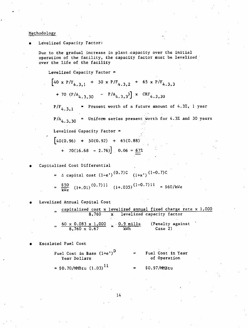
Methodology
Leve l i zed Capac i ty F a c t o r :
Due t o t h e g r a d u a l i n c r e a s e i n p l a n t . . c a p a c i t y o v e r t h e i n i t i a l o p e r a t i o n of t h e f a c i l i t y , t h e c a p a c i t y f a c t o r must b e l e v e l i z e d over t h e l i f e of t h e f a c i l i t y
L e v e l i z e d C a p a c i t y F a c t o r =
' IF4.3,1 = P r e s e n t worth of a f u t u r e amount of 4.3%, 1 y e a r
'IA4. 3.30 = Uniform s e r i e s p r e s e n t wor th f o r 4.3% and 30 y e a r s
. .
Level-ized Capac i ty F a c t o r = I. . . .
' [40(0.96) + sO(0.92) + 65(0.88) . ' , .
C a p i t a l i z e d Cost D i f f e r e n t i a l
= A c a p i t a l c o s t (1-e ') (0.7)C ( l+x , ) (1-0.7)C
Leve l i zed Annual C a p i t a l Cost
c a p i t a l i z e d c o s t x l e v e l i z e d annua l f i x e d charge r a t e x 1-,000 - - 8,760 x l e v e l i z e d c a p a c i t y f a c t o r
- - 60 x 0.083 x 1,000 ,. 0.9 m i l l s ( P e n a l t y a g a i n s t \ - 8,760 x 0.67 kW h Case 2)
E s c a l a t e d F u e l Cost
D F u e l Cost i n Base ( l + e 9 ) = F u e l Cost i n Year
Year D o l l a r s of Opera t ion
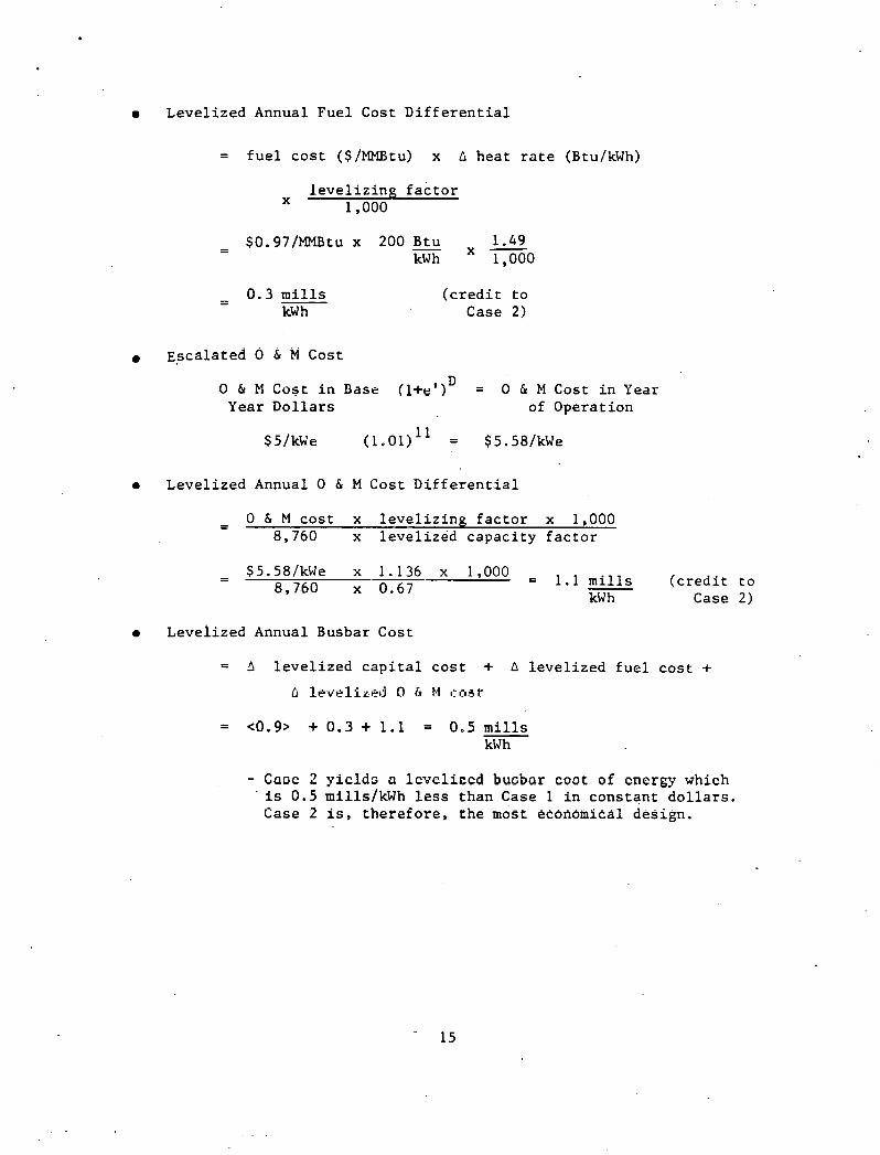
Level ized Annual Fuel Cost D i f f e r e n t i a l
= f u e l c o s t ($/MMBtu) x G hea t r a t e (BtuIkWh)
l e v e l i z i n g f a c t o r X 1,000
- - 0 . 3 m i l l s kW h
( c r e d i t t o Case 2)
Esca la ted 0 & M Cost
0 6 M Cost i n Dase ( ~ + e ' ) ~ = 0 & M Cost i n Year Year D o l l a r s of Operat ion
Level ized Annual 0 & M Cost D i f f e r e n t i a l
- - 0 & M c o s t x l e v e l i z i n g f a c t o r x 1,000 8,760 x l e v e l i z e d capac i ty f a c t o r
- - $5.58/kWe x 1.136 x 1,000 = sills 8,760 x 0.67 ( c r e d i t t o
kW h Case 2)
Levei ized Annual Busbar Cost
= b l e v e l i z e d c a p i t a l c o s t + A l eve l i zed f u e l c o s t + A 1pv .p l i r~1 ) O b bf I : I : I ~ ~
- Caoc 2 y i c l d o a l cvc l iocd buabar coot of cncrgy which ' i s 0 .5 mills/kWh l e s s than Case 1 i n cons tan t d o l l a r s .
Case 2 i s , t h e r e f o r e , t h e most economical design.

Economic Evaluation Methodology Example 2
1nf lated Dollars Case
This example illustrates an alternative revenue.requirements method to use in this study for the economic evaluation of alternatives. in plant design. Regulated utility financial assumptions'are used.
Problem
Compared two plant design alternatives to determine the most economic alter- native. The plant characteristics are:
Case 1 Case 2
Base year capital cost ($ kWe) Base + 50 Base year 0 & M cost ($/kWe) + 5 Base
Net plant heat rate (Btulk~h) 9,000 8,800
,. . Common Cost Factors . . . . . . .
Financial cri ter ia . . ' inflated dollars
Plant economic life 30 years
Construction period 1 1 years '
Plant capacity schedule year 1 40%
2 50%
3 65%
4-30 70%
Weighted cost of capital 10.5%
Levelized fixed charge rate 15.3%
Allowance for funds during construction rate 8 ..2X
\
. , Apparent ~nflation Real
Escalation rates - construction 7.06% 6% 1 .O%
- Fuel (uranium, coal, and oil) 9.18% 6 % 3.0%
Levelizing factors - 0 & M 2.108
- Fuel 2. 76.7
Fuel expense ' $0.70/MMBtu

Methodology
Level ized Capaci ty Fac tor :
Due t o t h e g radua l i n c r e a s e i n p l a n t capac i ty over t h e i n i t i a l ope ra t i on of t h e f a c i l i t y , t h e capac i ty f a c t o r must be l e v e l i z e d over t h e l i f e of t h e f a c i l i t y .
Level ized Capac i ty Fac tor =
P'F!o. 5 , l = Presen t worth of a f u t u r e amount of lU.52, i year
P/A10.5,30 = Uniform s e r i e s p re sen t worth f o r 10.5% and 30 years
Levelized Capaci ty Fac tor =
Cap i t a l i zed Cost D i f f e r e n t i a l
= A c a p i t a l c o s t i l+e ) ( 0 . 7 ) C (1-0.7)C
Level ized Annual C a p i t a l Cost .
- A cnp i tn l i oed eoct x l eve l lxed annual fixed charge r e t e x l n n n 8,760 x l e v e l i z e d capac i ty f a c t o r
= 110 xO.153 x 1,000 - - 3.0 m i l l s (Penal ty aga ins t 8,76(3 x U.65 kWh Case 2)
e Esca la ted Fue l Cost
Fuel Cost i n Base ( l+e lD = Fuel Cost i n Year Year D o l l a r s of Operat ion

Leve l i zed Annual F u e l Cost D i f f e r e n t i a l
= f u e l c o s t ($/MMBtu) = A h e a t r a t e ( ~ t u l k ~ h )
x l e v e l i z i n g . f a c t o r 1 ,000
.= . . $1.84/MMBtu x 200 Btu x 2.767 kwh 1,000
= 1.0 m i l l s kW h
( c r e d i t t o Case 2)
. . E s c a l a t e d 0 & M Cost
. . ': 0 & M Cos t i n Base ( l+e lD = 0 & M Cost i n Year
. . 'Year D o l l a r s of Opera t ion
. .
Leve l i zed Annual 0 & M Cost D i f f e r e n t i a l
" ,= 0&M c o s t x l e v e l i z i n g f a c t o r x 1 ,000 8 , 7 6 0 . x l e v e l i z e d c a p a c i t y f a c t o r
= $ll .2/kWe x 2.108 x 1,000 = 4.1 ' m i l l s ( c r e d i t t o 8,760 x 0 .65 kW h Case 2)
L e v e l i z e d Annual Busbar Cost
= A l e v e l i z e d c a p i t a l c o s t + A l e v e l i z e d f u e l c o s t +
A l e v e l i z e d 0 & M c o s t . .
= <3.0> + 1 . 0 + 4 .1 = 2.1 m i l l s kwh
- Case 2 y i e l d s a l e v e l i z e d busbar c o s t of energy which is 2.1 mills/kWh l e s s than Case 1 i n i n f l a t e d d o l l a r s . Case 2 i s , t h e r e f o r e , t h e most economical d e s i g n .

Appendix A
GLOSSARY
Acce le ra ted d e p r e c i a t i o n . A t a x p re fe r ence allowance which a c c e l e r a t e s
t h e d e p r e c i a t i o n of i nves t ed c a p i t a l . This w i l l a l low f o r lower income
t a x e s being pa id i n t h e e a r l y l i f e of t h e investment. There a r e two meth-
ods f a r determining a c c e l e r a t e d dep rec i a t i on t h a t a r e allowed and commonly
used; t h e sum-of-the-year's d ig i t s 'me thod , a n d . t h e double d e c l i n i n g balance
swi tch ing t o s t r a i g h t ' l i n e method.
Allowance f o r funds du r ing cons t ruc t ion (AFDC) . The i n t e r e s t paid on money
used t o cons t ruc t an energy f a c i l i t y . AFDC i s c a l c u l a t e d over t h e t ime
per iod from t h e s t a r t of t h e p r o j e c t u n t i l t h e commercial ope ra t i on da t e .
It i s included a s a s e p a r a t e c o s t account i n t h e t o t a l c a p i t a l r equ i r e -
ments of t h e p l a n t . The a f t e r t a x c o s t of c a p i t a l is used a s t h e AFDC r a t e .
Apparent e s c a l a t i o n ( e ) . The t o t a l annual r a t e of i nc rease i n a c o s t .
The apparen t e s c a l a t i o n r a t e inc ludes t h e e f f e c t s of i n f l a t i o n and r e a l
e s c a l a t i o n .
As-spent d o l l a r s . The investment requirements expressed i n i n f l a t e d a
d o l l a r requi iements . Th i s va lue r e f l e c t s t h e a c t u a l cos t i ncu r r ed ,
including t h e e f f e c t s of i n f l a t i o n and r e a l e s c a l a t i o n .
A v a i l a b i l i t y . The a c t u a l per iod of t ime wi th in t h e year i n which a f a c i l -
i t y i s a v a i l a b l e f o r opera t ion . .

Book L i f e . The average y e a r s of s e r v i c e expec ted from a p i e c e of equip-
ment b e f o r e i t i s r e t i r e d . Book l i f e is used a s a b a s i s f o r d e p r e c i a t i o n
a c c o u n t i n g .
Capac i ty . The n e t p r o d u c t i o n o u t p u t f o r which a n energy g e n e r a t i n g o r
p roduc ing u n i t i s r a t e d .
Capac i ty f a c t o r . The t o t a l g e n e r a t i o n d i v i d e d by t h e p roduc t of t h e
p e r i o d hours and t h e u n i t c a p a c i t y .
C a p i t a l i z e d v a l u e . The t o t a l c a p i t a l o u t l a y f o r a f a c i l i t y , i n c l u d i n g
e s c a l a t i o n d u r i n g c o n s t r u c t i o n , a l lowance f o r . f u n d s d u r i n g c o n s t r u c t i o n ,
owner ' s c o s t s , e t c . T h i s v a l u e i s t h e b a s i s from which revenue r e q u i r e -
ments p e r t a i n i n g t o t h e f i x e d c o s t s a're c a l c u l a t e d . I t can be expressed
i n r e a l d o l l a r s o r a s s p e n t d o l l a r s , depending upon t h e demands of t h e
s t u d y .
C a p i t a l r ecovery f a c t o r . The p e r c e n t a g e v a l u e a p p l i e d a g a i n s t a g i v e n
c a p i t a l inves tment which e q u a l s t h e r e q u i r e d r a t e df r e t u r n p l u s a
d e p r e c i a t i o n r e s e r v e s u f f i c i e n t t o r e c p v e r t h e i n v e s t e d c a p i t a l a t t h e
end .of t h e inves tment l i f e .
Common s t o c k c o s t . The weighted a v e r a g e r e t u r n on a l l common s t o c k i s s u e d
by a c o r p o r a t i o n .
Cominon Stock ratio. The amount of c a p i t a l r a i s e d by t h e s a l e of common
s t o c k d i v i d e d by t h e t o t a l amount of c a p i t a l r a i s e d from t h e ' s a l e of
p r e f e r r e d and common s t o c k s and bonds by a c o r p o r a t i o n .
Commercial o p e r a t i o n d a t e . The d a t e t h a t a u n i t i s d e c l a r e d t o be a v a i l -
a b l e f o r r e g u l a r p roduc t ion .

Cost of c a p i t a l . The r e t u r n requi red by i n v e s t o r s f o r making investments ,
expressed a s a percentage of t h e c a p i t a l funds (deb t , p r e f e r r ed e q u i t y ,
common e q u i t y ) .
Debt c o s t . The weighted average i n t e r e s t paid on a l l bonds o r d i r e c t loan
f i n a n c i n g .
Debt r a t i o . The amount of c a p i t a l r a i s e d from t h e s a l e of bonds and/or
d i r e c t loans d iv ided by t h e t o t a l amount of c a p i t a l r a i s e d from t h e s a l e
of p r e f e r r ed and common s rocks, aid bonds.
- - - - . - ... - -- -- - - - - -.
Deprec ia t ion . Charges made againsf- income to~'provide-~~ui'-distributing - - - -
t h e c o s t of t h e p l a n t ( l e s s es t imated nec sa lvage ) over t h c es t imated
u s e f u l l i f e of th'e a s s e t i n such a way a s t o a l l o c a t e i t a s ' e q u i t a b l y
a s p o s s i b l e t o t h e pe r iod dur ing which s e r v i c e s a r e obtained from t h e
u se of f a c i l i t i e s . Th i s ' r educes t h e e f f e c t i v e t axes paid on g ros s income.
Discount r a t e . The annual r a t e t h a t i s used t o take i n t o account t h e
p o t e n t i a l e a rn ing power of money whi le moving d o l l a r amounts e i t h e r fo r -
ward o r backward through time t o a s i n g l e po in t i n t ime f o r comparison.
The weighted c o s t . o f c a p i t a l i s used a s t h e d i scount r a t e .
Energy e f f i c i e n c y . The r a t i o of t h e u s e f u l energy de l ive red by a system
t o t h e energy supp l i ed t o i t .
7. The u n i t a v a i l a b i l i t y a f t e r cons ider ing
t h e unscheduled p a r t i a l and f u l l outages p l u s those due t o scheduled
outages .
F i n a n c i a l instrumet~t. A l t e r n a t i v e methods of f i nanc ing avadlab le t o
c a p i t a l consumers. These ins t ruments inc lude bonds, p r e f e r r e d s tock ,
and common s tock .

F i r s t commercial s e rv i ce . The e a r l i e s t t ime of i n i t i a l s e r v i c e s of a ,
new technology - t h a t has been s e l e c t e d f o r commercial use and f o r which
an o r d e r was placed on t h e d a t e i t was a v a i l a b l e f o r commercial o rde r s .
Fixed charges o r f i xed c o s t s . The annual c o s t s a s soc i a t ed w i th t h e
ownership of p roper ty , such a s dep rec i a t i on , t axes , insurance , c o s t of
c a p i t a l .
F'ixed charge r a t e . The amount of revenue per d o l l a r of inves ted c a p i t a l
t h a t must be c o l l e c t e d f o r each year of p l a n t l i f e i n order t o pay t h e
f i xed charges. _
Generating s t a t i o n (genera t ing p l a n t o r power p l a n t ) . A s t a t i o n . a t , .
which a r e l oca t ed prime movers, and/or e l e c t r i c gene ra to r s , and a u x i l -
i a r y equipment f o r convert ing mechanical, chemical and/or nuc lear energy
i n t o e l e c t r i c energy.
Heat r a t e . The amount' of energy. expressed i n Btu ' s of higher hea t ing .
value r equ i r ed t o produce a u n i t of e l e c t r i c i t y expressed i n kwh's.
Income tax r a t e . The percentage of g ros s income which must be paid t o . .
t h e government p r i o r t o income d i s t r i b u t i o n t o e q u i t y ho lde r s . This
i nc ludes payment t o both t h e f e d e r a l and s t a t e governments, and i s
assumed t o be 50 percent .
I n f l a t i o n (i). The change i n the va lue of t h e d o l l a r over time. The combi-
na t ion of r e a l e s c a l a t i o n and i n f l a t i o n g ives t h e apparent e s c a l a t i o n .
Leve l iz ing . The process of conver t ing a t ime varying s e r i e s of payinents '.'
t o an equiva len t cons tan t s e r i e s . This is accomplished by mul t ip ly ing
t h e p re sen t worth of expenses by t h e c a p i t a l r ec ive ry f a c t o r .

Level ized c a p a c i t y f a c t o r . The capac i ty f a c t o r t h a t an energy f a c i l i t y
would run each yea r such t h a t t h e p re sen t worth of each y e a r ' s a c t u a l
c a p a c i t y equa l s t h e p r e s e n t worth of t h e l e v e l i z e d capac i ty f a c t o r over the
same per iod .
Market r a t e of r e t u r n . The r a t e of r e t u r n on inves ted c a p i t a l which i s . .- .
demanded i n the market p l ace . The investment community a d j u s t s i t s
r e q u i r e d r a t e of r e t u r n depending upon t h e percept ion of r i s k of a given
f i n a n c i a l ins t rument a s w e l l a s because of a n t i c i p a t e d changes i n t h e
i n f l a t i o n r a t e .
Owner's c o s t s . Those c o s t s which a r e experienced by the owner dur ing t h e
p lanning , eng inee r ing , and cons t ruc t ion of a . given f a c i l i t y . These va lues
a r e assumed t o be c a p i t a l i z e d when con-sidering an investment .
Planned outage r a t e . The r a t e f o r a l l planned o r scheduled outage hours
over a given s e r v i c e per iod of ope ra t i on .
P re fe r r ed s tock c o s t . The weighted average r e t u r n on a l l p r e f e r r ed s tock .
P r e f e r r e d s t o c k r a t i o . The amount of c a p i t a l r a i s e d from t h e s a l e of
p r e f e r r e d s t o c k d iv ided by the t o t a l amount of c a p i t a l r a i s ed by t h e
s a l e of p r e f e r r e d and common s tocks and bonds by a corpora t ion .
Rate of r e t u r n . The percentage of c a p i t a l which must be re turned t o
t h e i n v e s t o r annua l ly f o r t he use of t h e inves ted c a p i t a l . This r e t u r n
i nc ludes i n t e r e s t and dividend expenses a s we l l a s t h e app rec i a t i on on
e q u i t y c a p i t a l .
Real d o l l a r s . The investment requirements expressed i n d o l l a r s of con-
s t a n t purchasing power. This c o s t r e f l e c t s t h e changes a s a r e s u l t of
r e a l e s c a l a t i o n , bu t excludes t h e e f f e c t of i n f l a t i o n .
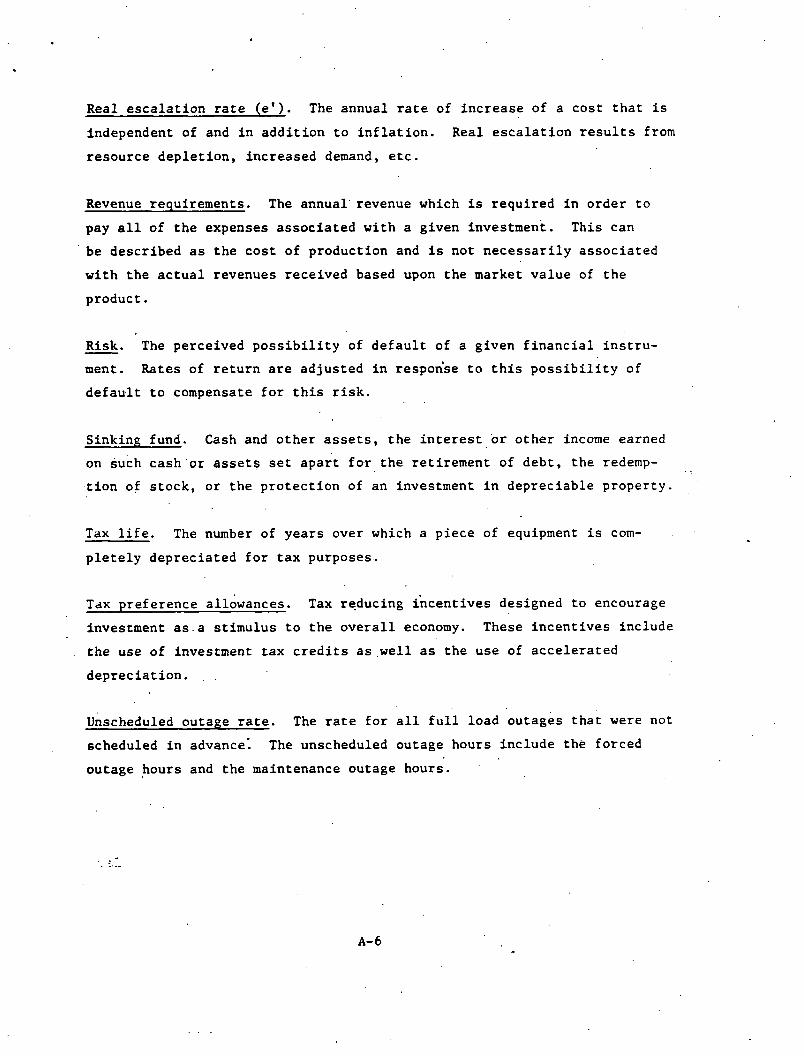
Real e s c a l a t i o n r a t e ( e ' ) . The annua l r a t e of i n c r e a s e of a c o s t t h a t i s
independent of and i n a d d i t i o n t o i n f l a t i o n . Real e s c a l a t i o n r e s u l t s from
r e s o u r c e d e p l e t i o n , i n c r e a s e d demand, e t c .
Revenue requ i rements . The a n n u a l ' r e v e n u e which is r e q u i r e d i n o r d e r t o
pay a l l of t h e expenses a s s o c i a t e d w i t h a g iven inves tment . Th i s can
be d e s c r i b e d a s t h e c o s t of p roduc t ion and i s n o t n e c e s s a r i l y a s s o c i a t e d
w i t h t h e a c t u a l revenues r e c e i v e d based upon t h e market v a l u e of t h e
p r o d u c t .
Risk. The perce ived p o s s i b i l i t y of d e f a u l t of a g i v e n f i n a n c i a l i n s t r u - - ment. Rates of r e t u r n a r e a d j u s t e d i n respon'se t o t h i s p o s s i b i l i t y of
d e f a u l t t o compensate f o r t h i s r i s k .
S ink ing fund. Cash and o t h e r a s s e t s , t h e i n t e r e s t o r o t h e r income earned
on Such c a s h . o r a s s e t s s e t a p a r t f o r t h e r e t i r e m e n t of d e b t , t h e redemp- . . t i o n of s t o c k , o r t h e p r o t e c t i o n of an investment i n d e p r e c i a b l e p r o p e r t y .
Tax l i f e . The number of y e a r s over which a p i e c e of equipment i s com-
p l e t e l y d e p r e c i a t e d f o r t a x purposes..
Tax p r e f e r e n c e a l ldwances . Tax reduc ing L c e n t i v e s des igned t o encourage
investment a s . a s t i m u l u s t o t h e o v e r a l l economy. These i n c e n t i v e s i n c l u d e
t h e use of investment t a x c r e d i t s as ,wel l a s t h e u s e of a c c e l e r a t e d
d e p r e c i a t i o n . . .
unscheduled ou tage r a t e . The r a t e f o r a l l f u l l l o a d o u t a g e s t h a t were no t
scheduled i n advance: The unscheduled ou tage hours i n c l u d e t h e f o r c e d
ou tage h o u r s and t h e maintenance ou tage hours .

V a r i a b l e c o s t s . Those c o s t s which v a r y w i t h d i f f e r e n t l e v e l s of produc-
t i o n . These c o s t s g e n e r a l l y i n c l u d e annua l o p e r a t i n g , maintenance, and
f u e l expenses .
Weighted c o s t of c a p i t a l ( r) . The d e b t r a t i o t i m e s t h e d e b t c o s t p l u s
p r e f e r r e d s t o c k r a t i o t i m e s t h e p r e f e r r e d s t o c k c o s t p l u s t h e common s t o c k
r a t i o t imes t h e common s t o c k c o s t e q u a l s t h e weighted c o s t of c a p i t a l .

- Appendix B
ANNUAL FIXED CHARGE RATE
The f i x e d charge r a t e is t h e m u l t i p l i e r which, when a p p l i e d t o t h e i n i t i a l
p l a n t c a p i t a l inves tment , y i e l d s t h e l e v e l i z e d (average) annua l revenue r e -
quirements a s s o c i a r e d w i t h c a p i t a l e x p e n d i t u r e s f o r t h e p l a n t . When added
t o t h e annua l f u e l expenses - and o p e r a t i o n and maintenance expenses , y i e l d s
t h e t o t a l annua l revenues requ i rements . For comparison, bo th t h e subse-
quent year-by-year revenue requ i rements as w e l l as t h e l e v e l i z e d revenue
requ i rements must be examined. The revenue requ i rements f o r a c a p i t a l i n -
vestment i n c l u d e r e t u r n , s i n k i n g fund d e p r e c i a t i o n , income t a x e s , and o t h e r
t a x e s and i n s u r a n c e ( f i x e d c o s t s a s s o c i a t e d wi th c a p i t a l e x p e n d i t u r e s ) .
RATE OF RETURN
The term " r a t e of r e t u r n " i s d e f i n e d a s t h e sum of r e t u r n s t o s t o c k h o l d e r s
and bondholders . To compute t h i s v a l u e , t h e weighted r a t e of r e t u r n on
bo th s t o c k and bonds i s used, and can be found a s fo l lows :
Rate of Return = Weighted Cost of C a p i t a l ( r )
= (Bond Yield x Debt F r a c t i o n )
+ (Common Stock Yie ld x Common F r a c t i o n )
+ ( P r e f e r r e d Stock Yield x P r e f e r r e d F r a c t i o n )
S t u d i e s can be performed i n e i t h e r real terms ( i n f l a t i o n f r e e ) o r i n
market terms ( t h e c o s t of money i s a d j u s t e d t o r e f l e c t i n f l a t i o n a r y expec-
t a t i o n s ) . ' The r e s u l t i n g a r r a y of answers w i l l y i e l d c o n s i s t e n t v a l u e s f o r
comparing between competing a l t e r n a t i v e inves tments .

I n gene ra l :
Market Rate = b+ Real ate) of Return of Return
Rea l r a t e s of r e t u r n gene ra l l y remain cons t an t over t ime, with v a r i a t i o n s
o c c u r r i n g a s a r e s u l t of t h e assumed r i s k of a f i n a n c i a l ins t rument .
Market va lues on t h e o t h e r hand w i l l f l u c t u a t e over time depending upon
t h e long-term i n f l a t i o n a r y expec t a t i ons of t he f i n a n c i a l community.
I n computing a l e v e l i z e d f i xed charge r a t e , dep rec i a t i on may be s t a t e d i n
terms of a s i n k i n g fund f a c t o r t o s imp l i fy t he c a l c u l a t i o n . This f a c t o r
i s obta ined us ing book l i f e and d iscount f a c t o r ; i t s use w i l l provide a
fund which a t t h e end of t he t ime per iod w i l l be equal t o t h e o r i g i n a l
investment . The equa t ion f o r t h i s f a c t o r i s :
Sinking Fund Deprec ia t ion = - ?\'
( l + r j - 1
LEVELIZED ANNUAL INCOFIE TAX
I n o r d e r t o o b t a i n a given return K O l n v e s r o r s , a company must pay income
t a x e s p r i o r t o any income d i s t r i b u t i o n t o equ i ty ho lders . I t i s important
t o r e a l i z e t h a t i n t e r e s t expenses which occur .due t o t he use of bonds a r e
cons idered o p e r a t i n g expenses i n terms of income t ax p rov i s ions , and a r e
pa id ou t of ea rn ings p r i o r t o income t a x cons ide ra t i ons . On t h e o the r
hand, t h e r e t u r n t o p re fe r r ed and common s tock ho lde r s ' ( d iv idends ) i s paid
o u t of a f t e r - t a x do l l a r s ' . Because a f t e r - t a x d o l l a r s a r e used, t he e f f ec -
t l v e c o s t of e q u i t y f i nanc ing is h igher than t h e i n i t i a l i m p l i c i t c o s t of
deb t f inanc ing .
*The t o t a l r e t u r n p l u s s ink ing fund dep rec i a t i on equa ls t h e c a p i t a l rccovcry f a c t o r , wherc c a p i t a l rccovery f a c t o r = r ( 1 + P) N
(T+ r)N - 1 N = book l i f e

To de te rmine t h e revenue r e q u i r e m e n t s a s s o c i a t e d w i t h pay ing income t a x e s ,
t h e v a l u e can be c a l c u l a t e d a s f o l l o w s :
Leve l i zed annua l income t a x = ( c a p i t a l r ecovery f a c t o r - s t r a i g h t l i n e d e p r e c i a t i o n )
d e b t r a t i o x d e b t c o s t - weighted c o s t of c a p i t a l
t a x r a t e (i - t a x ra te)
LEVELIZED ACCELERATED INCOME TAX
A c c e l e r a t e d d e p r e c i a t i o n i s a n i n c e n t i v e des igned t o encourage inves tment
as a s t i m u l u s t o t h e o v e r a l l economy. There a r e two methods f o r d e t e r -
mining a c c e l e r a t e d d e p r e c i a t i o n t h a t a r e commonly used : t h e sum-of-the-
y e a r s d i g i t s method and t h e doub le -dec l in ing b a l a n c e changing t o t h e
s t r a i g h t l i n e method. The e f f e c t of t h e d i f f e r e n c e between t h e s e met i~ods
on t h e l e v e l i z e d f i x e d charge r a t e i s n e g l i g i b l e c o n s i d e r i n g t h e ac 'curacy ,-'
of t h e c a l c u l a t i o n . The sum-of-the-years d i g i t s method i s adopted because
of i t s , c o n s i s t e n c y and r e l a t i v e e a s e of a p p l i c a t i o n . The f o l l o w i n g formu-
l a s may be used t o c a l c u l a t e t a x p r e f e r e n c e a l lowances :
Leve l i zed annua l a c c e l e r a t e d d e p r e c i a t i o n a l lowance =
( a c c e l e r a t e d t a x d e p r e c i a t i o n - s t r a i g h t l i n e d e p r e c i a t i o n )
X (l- t a x r a t e weighted ( d e b t c o s t r a t i o ) o f . c a p i t a 1 (debt c o s t ) )
t a x r a t e 6 - t a x r a t . ) .
where a c c e l e r a t e d t a x d e p r e c i a t i o n =
2 X.(:apital r ecovery f a c t o r f o r N yea r s )
X ( n - p r e s e n t worth f a c t o r f o r n y e a r s )
+ n (n + I ) (wadghted cost of c a p i t a l )

1 S t r a i g h t l i n e d e p r e c i a t i o n = -
N
N = book l i f e
n = t a x l i f e = 2 / 3 book l i f e
p re sen t worth f a c t o r = l / c a p i t a l recovery f a c t o r
OTHER TAXES AND INSURANCE
An allowance of 2 percent of the c a p i t a l investment i s included t o cover
l o c a l proper ty t axes and insurance. , S p e c i f i c va lues a r e t o be used when
d e t a i l e d e s t ima te s a r e a v a i l a b l e f o r c l i e n t requirements o r f o r a s p e c i f i c
s i t e l oca t ion .
I n summary, t h e annual l e v e l i z e d f ixed charge r a t e (FCR) can be determined
a s fol lows:
FCR = r e t u r n
+ s ink ing fund d.epreciat ion
+ l e v e l i z e d annual incomeatax
- a c c e l e r a t e d income t ax
+ o t h e r t axes and insurance - - - - - - --
(7:) Fixed Charge Rate
and where
Levelized ~ n n u a l Fixed Costs = FCR x Capi ta l ized Value
REAL RATE OF RETURN
To d e r i v e a comparable f i xed charge r a t e i n the absence of i n f l a t i o n , the
v a l u e is found by d i v i d i n g the nominal f i xed charge r a t e by the l e v e l i z i n g
f a c t o r based on t h e gene ra l i n f l a t i o n r a t e and the nominal discount r a t e .
Th i s w i l l i n s u r e a c o n s i s t e n t t r ea tmen t ' o f the t a x l i a b i l i t i e s i n an
i n f l a t i n g world environment.
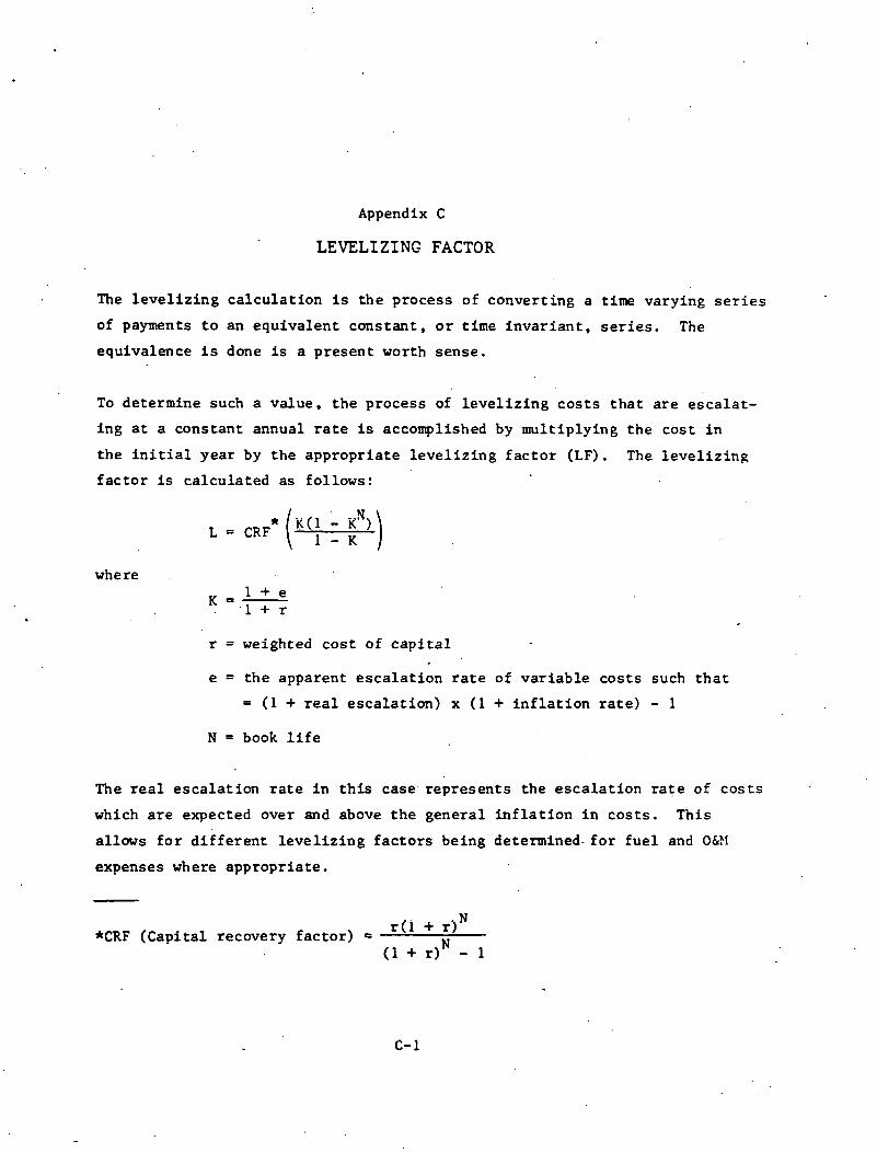
Appendix C
LEVELIZING FACTOR
The l e v e l i z i n g c a l c u l a t i o n is t h e process of conver t ing a time varying s e r i e s
of payments t o an equ iva l en t cons t an t , o r t ime i n v a r i a n t , s e r i e s . The
equivalence i s done is a p re sen t worth sense .
To determine such a va lue , t h e process of l e v e l i z i n g c o s t s t h a t a r e e s c a l a t -
i n g a t a cons tan t annual r a t e is accomplished by mu l t i p ly ing t h e cos t i n
t h e i n i t i a l year by t h e app rop r i a t e l e v e l i z i n g f a c t o r (LF). The l e v e l i z i n g
f a c t o r is ca l cu l a t ed a s fol lows:
where
r = weighted c o s t of c a p i t a l
e = t h e apparent e s c a l a t i o n r a t e of v a r i a b l e c o s t s such t h a t
= (1 + r e a l e s c a l a t i o n ) x ( 1 + i n f l a t i o n r a t e ) - 1
N = book l i f e
The r e a l e s c a l a t i o n r a t e i n t h i s case. r ep re sen t s t h e e s c a l a t i o n r a t e of c o s t s
which a r e expected over and above t h e gene ra l i n f l a t i o n i n c o s t s . Th i s
a l lows f o r d i f f e r e n t l e v e l i z i n g f a c t o r s being determined- f o r f u e l and 0&?1
expenses where app rop r i a t e .
*CRF (Cap i t a l recovery f a c t o r ) = r ( i + rlN )rt

Appendix D
LEVELIZED CAPACITY FACTOR
W e can gene ra l l y expect a va r i ance i n a f a c i l i t y ' s ope ra t i ng capac i ty i n
the e a r l y y e a r s of t h e p r o j e c t when i t is i n i t s c i n i t i a l s t a g e s of opera-
t i o n , To compensate f o r t h i s va r i ance , w e m s c d i scoun t t h e year ly p l a n t
ou tpu t t o p r e s e n t worth, r e t u r n i n g i t t o a yea r ly va lue by mul t ip ly ing by
, bhe f i rm ' s c a p i t a l recovery f a c t o r . This w i l l put t he p l a n t ou tput on a
l e v e l i z e d va lue comparable t o t h e ca l cu l a t ed l e v e l i z e d revenue requirements. .
Dividing t h e l e v e l i z e d revenue requirements by t h e l e v e l i z e d p l a n t , o u t p u t
w i l l y i e l d t h e l e v e l i z e d cos t of energy.
To accomplish t h e l e v e l i z i n g of t h e ,plants . c apac i ty , we mul t ip ly t h e presen t
worth of t h e capac i ty l e v e l s .by t h e f i r m ' s c a p i t a l recovery a s fo l lows:
Level ized Capacity Fac tor = c p~.;;r+n;;;~t x CKk' r ,M
i = O
r = weighted cos t of money
N = book l i f e

APPENDIX E
ECONOMIC ASSUMPTIONS FOR HTGR PROGRAM
Commercial p l a n t bas is Nth P l a n t Capaci ty f a c t o r 70% '
Base da te f o r a l l cos ts January 1980 Date o f opera t ion f o r a l l p l an t s January 1995 Investment l i f e f o r a1 1 p l a n t s 30 Years E l e c t r i c i t y replacement power cos ts (Jan. 1980 $ ) 40 m i l l s / k ~ - h r ( 1 2 . 7 3 $110; B t u ) Electricity busbar sa le p r i c e (Jan. 1980$) 22 m i l ls/kW-hr($7.51 $110 B tu ) Fuel cos t p r o j e c t i o n s (Jan. 1980 $ ) i n 1995
Coal 2.25 $/MBtu O i 1 9.25 $/MBtu Natura l gas 8.25 $/MBtu Urani um 40 $ / l b U308 Conversion $6/kg UFg
$12O/SWU Separa t i ve work (0.2% t a i l s ) Nuclear fue l c y c l e cos ts (LEU/Th once through) $1.22/MBtu (1180 $ l e v e l i z e d Coke over 30 years )
$4.98MBtu (1195 $ . l e v e l i z e d over 30 .years)
Operat ion and Maintenance Costs (Jan. 1980 $) F i xed Var iab le - ( lo6 S j y r ) mi 1 l ~ / k W t - h r
HTGR-SC (SCIC) 12.0 (12.2) 0.45 .(0.95) Coal E l e c t r i c (SCIC) 11.0 (11.2) 1.10 (1.60) HTGR-NHS 12.0 0.60
Constant I n f l a t e d Common Cost Fac to rs - U t i l i t y -owned F a c i l i t y D o l l a r s Do1 1 a r s
Weighed cos t o f c a p i t a l 4.3% . 10.5% Leve l i zed f i x e d charge r a t e 8.3% 15.3% A1 lowance f o r funds du r i ng cons t ruc t i o n 3.5% 8.2%
Common Cost Fac to rs - Pr ivate- Indust ry-Owned-Faci l i ty
Weighed cos t o f cap ' i ta l 7.4% 13.8% Level i zed f i x e d charge r a t e 13.0% 22.2% A1 lowance f o r funds du r i ng cons t ruc t i o n 6.9% 12.5%
Real Esca la t i on Rates Base I n f l a t i o n Const ruct i o n 6% O&M 6% 1 .OO% 7.06% E l e c t r i c power 6% 2.00% 8.12% Fuel ( a l l ) a f t e r 1995 6% 3.00% 9.18%
Average Real Base 1995 Cost Real 1980 Cost Esca la t i on Rate I n 1980 Do1 l a r s Esca la t i on Rate
Fossi 1 Fuel ($/MBtu) 1980-1995 (%/Y r ) ( $ / ~ B t u ) Post-1995 ( % / y r )
Coal 1.40 3.2 2.25 O i 1 4.30 5.2 ' 9.25 Natu ra l . gas 2.60 8.0 8.25

APPENDIX E (Cont ' d )
Leve l i z i ng Fac to rs (30-Year ~ e v e l i zed)
U t il'i ty-owned Faci 1 i ty O&M E l e c t r i c power Fuel ( a l l )
Private-Industry-Owned-Faci 1 i ty O&M E l e c t r i c power Fuel (a1 1 )

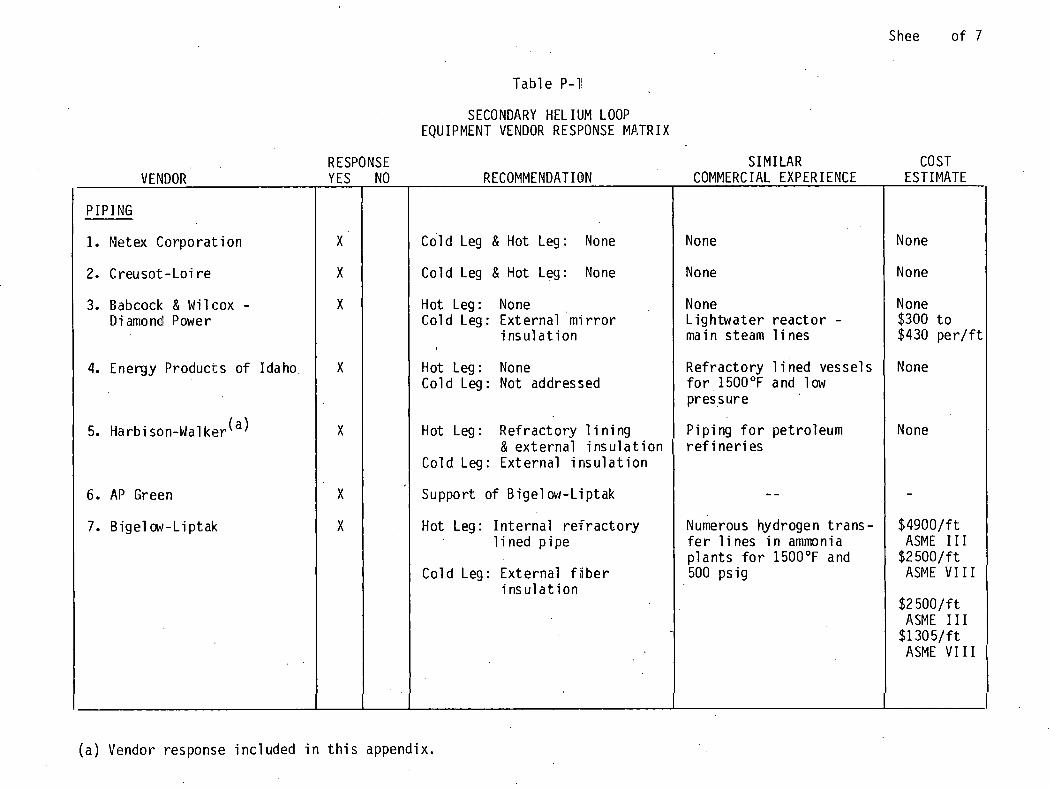
Shee o f 7
Table P-l!
SECONDARY HEL IUM LOOP EQUIPMENT VENDOR RESPONSE MATRIX
VENDOR
PIPING
1. Netex Corpora t ion
2. Creusot-Loi r e
3. Babcock & N i l cox - Diamond Power
4. Energy Products of Idaho.
5. Harb i son-Wal k e r ( a )
6. AP Green
7. B i ge l ow-Liptak
RESP'ONSE SIMILAR COST YES
X
X
X
X
X
X
X
RECOMMENDATION COMMERCIAL EXPERIENCE ESTIMATE NO
Cold Leg & Hot Leg : None I None I None I Cold Leg & Hot Leg : None I None I None I
Hot Leg: None Cold Leg: Not addressed
Hot Leg: None Cold Leg: Externa l m i r r o r
i n s u l a t i o n
Hot Leg: Re f rac to r y l i n i n g 1 P ip ing f o r pet ro leum & e x t e r n a l i n s u l a t i o n r e f i n e r i e s
Cold Leg: Externa l i n s u l a t i o n I
None L i gh twa te r r e a c t o r - main steam l i n e s
Re f rac to r y 1 i ned vessels f o r 1500°F and low pressure
None
None $300 t o $430 p e r / f t
None
Support o f bigel ow-Liptak I - - I - I Hot Leg : I n t e r n a l r e f r a c t o r y
l i n e d p i pe
Cold Leg : Ex te rna l f i b e r i n s u l a t i o n
~umerous hydrogen t r ans - f e r l i n e s i n ammonia p l an t s f o r 1500°F and 500 ps ig
$4900 / f t ASME I 1 1
$2500/ f t ASME V I I I
$2500/ f t ASME I 1 1
$1305/ f t ASME V I I I
( a ) Vendor response inc luded i n t h i s appendix.

Sheet 2 o f 7
VENDOR
SECC NDARY HEL I !JM LOOP EQUIPMENT \'ENDOR RESPONSE AATR I X (Cont ' d )
RESPONSE YES NO
I PIPING (Cont I d )
8. P l i b r i c o West
9. Tapco In t ie rna t iona l
10. Metco Inc.
11. Val l u r e c
12. Darchem Energy Ltd.
BELLOWS
1. Path iay Bellows, Inc.
Hot Leg .& Cold Leg: None
Hot Leg: Gimbal o r hinged expansion j o i n t s w i t h pressure boundary temp- e ra tu res l i m i t e d t o $ 0 0 T o r l ess
I Cold Leg: Not addressed
Hot Leg: None Cold Leg: -Not ad'dres:;ed
Hot Leg : .Gimbal' j o i n t bu t not s u r e how t o take bo th t e m p r a t u r e and pressure
Cold Leg: Not addressed
SIMILAR COST SOeilMEECIAL EXPERIENCE
N3m, except f o r sprayed ce ran i c c o a t i ngs
N 3 rte,
P.?troleum & petrcchemi - c 3 l a p p l i c a t i o n s w i t h t mp? ra tu res ranging f-om 1200 t o 180C°F
A s m j pace appl i c a t ions b q t smal l e r d iameter
N ~ c l , z a r appl i c a t tons
ESTIMATE
None
None
$66K/uni t ASME I 1 1
None
None
-

Shee , o f 7
VENDOR r
BELLOWS (Cont I d )
4. C r o l 1 -Reynolds ( a 1
5. EG&G Seal01
VALVES
1. G&W F l u i d
SECONDARY HELIUM LOOP EQUIPMENT VENDOR RESPONSE MATRIX (Cont ' d )
Hot Leg: Double be1 lcws e x t e r n a l l y r e s t r a i n e d b u t not s u r e o f m a t e r i a l f o r temperature b pressure
RESPONSE
Co ld Leg: Same expans i o n j o i n t des ign w i t h s t a i n l e s s s t e e l
Hot Leg & Co ld Leg : None
YES
X
X
.X
X
Hot Leg & Co ld Leg: None, G&W sees a develop- ment program f o r a r e l a t i ' v e - l y new product
NO
Hot Leg & Co ld Leg: None, B-W sees a r e a l problem w i t h t h e h o t l e g 40" va l ve; suggest severa l s m a l l e r valves i n para1 l e l
SIMILAR COMMERCIAL EXPERIENCE
Pet ro leum a p p l i c a t i o n s w i t h p ressure o f 650 p s i g and ,temperature o f 10OO0F
None
None, except f o r va l ves i n non-nuclear a p p l i c a t i o n s up t o 1400°F
None, except f o r actua - t o r f o r 28" steam i s o l a t i o n va l ve w i t h 5 second c l o s i n g t i m e
COST ESTIMATE .
None
None
None
None
~ - -
(a) Vendor response i n c l u d e d i n t h i s appendix.

Sheet 4 o f 7
SECONDARY HELIUM LOOP EQUIPNENT VENCOF RESPONSE MATRIX (Cont ' d )
VENDOR
VALVES (Cont ' d l
3. The Lunkenheimer Coo
4. Consol idated Contro ls Corp.
5. Anchor/Darl i ng Val v. ' Company
I
6. Su lzer Bros: i a )
RESP( YES
X
X
X
X
' RECOMMENDATION
I Hot Leg & Cold Leg:
None, suggested Consol idated Contro ls
Hot Leg & Cold Leg: None
Hot Leg: Fe f rac to r y 1 i ned 400 l b t o t ~ e develobed
Cold Leg: 600 l b valve w i t h pne~mat ic /hydrau l i c o r e l c t r o l hyd rau l i c ac tua to r
Hot Leg: None, f o r t ime being Cold Leg:. Gate val ve, system
mediun operated
SIMILAR CCNMERC IAL EXPER I ENCE
Mare
Developed 8" s l i d i n g ga te valve f o r coal c a ~ v e r s i o n p r o j e c t f o r t m p e r a t u r e s t o 2000°F & pressures up t o 1600 @ igl
b ~ e d i scussed
I s o l a t i o n & c o n t r o l val ves f o r 1200°F steam AGR valves f o r C02
COST ESTIMATE
None
None
Hot Leg: None Cold Leg: $750K t o $800K
Hot Leg: $150K t o 1 $210K f o r d e t a i l e d des i g n s tudy Cold Leg: $350K t o $450K
(a ) Vendor response inc luded i n t h i s appendix.
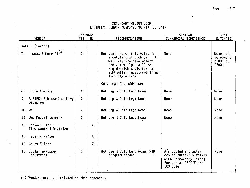
S hec o f 7
SECONDARY HEL IUM LOOP EQUIPMENT VENDOR RESPONSE MATRIX (Cont I d )
RES?ONSE SIMILAR COST VENDOR YES NO
I I VALVES (Cont I d )
7. Atwood & a or rill (a ) X .
8. Crane Company X
9. AMETEK: Schutte-:Koert i ng X D i v i s i o n
10. WKM I X I 11. Wm. Powel 1 Company I X I 12. Rockwel l I n t ' 1 - X
Flaw C o n t r o l D i v i s i o n
13. P a c i f i c Val ves 1 I x
14. Copes-Vul can I l x 15. Eco la i re-Mosser I ' X 1
RECOMMENDATION COMMERCIAL EXPERIENCE
Hot Leg: None, t h i s v a l v e i s a s u b s t a n t i a l problem: i t w i 11 r e q u i r e development and a t e s t l oop w i l l be r e q ' d which c o u l d t a k e a subt an t i a1 investment i f no f a c i 1 i ty e x i s t s
None
I Cd ld Leg: Not addressed
Hot Leg & Co ld Leg: None I Hot Leg & Co ld Leg: None 1 I Hot Leg & c o l d Leg: None I None
Hot Leg & Co ld Leg : None
Hot Leg & Co ld Leg: None, R&D program needed
None
A i r coo led and w a t e r coo led b u t t e r f l y va lves w i t h r e f r a c t o r y 1 i n i n g f o r gas a t 1500°F and 300 p s i g
(a ) Vendor response i n c l u d e d i n t h i s appendix.

Sheet 6 o f 7
SECCNDARY HELIUM LOOP '
EQUIPMENT VENCOF RESPONSE MATRIX (Cont ' d )
VENDOR
VALVES (Cont ' d )
16. Hopki nsons L i m i t e d
I
CIRCULATORS
1. Mechanical Tech., LIC.
2. Dresser Clark
3. Brown-Boveri
4. Su lze r BPOS. ( a )
5. Creusot-Loi r e
6. Ro to f low ( a
~
( a ) ldor response inc'uced
RESP.OWSE YES NO RECOMMENDATION
SIMILAR COST SOMMEKCIAL EXPEFIENCE ESTIMATE
X
x
1 X .
X.
V31 ves f o r gas cc801ed r e a c t o r s t a t i o n s
None
X
None
Hot Leg & Cold Leg: None
None
None
2 s tage a x i a l compressor power input. 10 MW o r 1 stage c e n t r i - f u g a l - p w e r i n p u t 11 MW
N me I None I
One stage cen t r i f uga l -power i n p u t 15,870 HP
X
33 blowers f o r r e a c t o r a 3 p l i c a t i o n s w i t t h d i u m , argon, & C02
Max Lower i n p u t : 16 MW Max Fressure:
75 b a r (11CO p s i ) Max t emperature :
350°C (6OOcF)
n t h i s appendix..
X
Ndmrous c e n t r i f ~ g a l c~rnpressors w i t h n i t r o - gen, n ~ t u r a l gas, oxy- gen, he1 i um
?lax power i n p u t : 10,000 HP
4$x pressure: E00 p s i i & . ~ temperature : 400°F

SECONDARY HEL I!JM LOOP EQUIPMENT VENDOR RESPONSE MATRIX (Cont ' d )
RESPONSE RECOMMENDATI 3N
3 Four c e n t r i f u g a l u n i t s i n para1 l e l -power i n p u t 13,268 HP
S I M I L A R COST
(a ) Vendor response i n c l u d e d i n t h i s appendix.

Sheet. 1 o f 1 Tab le P-2
STEAM GENERATOR EQUIPMEN- 'JEMDOR RESPONSE MATRIX
RESPO.NSE SIMILAR COST VENDOR YES NO RECOMMENDATION CCIMMERCIAL EXPERIENCE ESTIMATE
2. NEI power Energy
4. Rockwell I n t l . , Energy Systems Group
6. Fos te r Wheeler
7. General Atomic Co.
8. Babcock & W i l cox
None
High Pressure: Undula t ing tube bund P e
Low Pressure: None
None Rot addressed
Not addressed
U n i t s f o r Berkeley & Erzc ley, 01 dbury , k incsca le , H ink l ey P o i r t B and Hunters ton B w i t k CQ2
None
None
None
High Pressure: Two h e l i c a l tube bur d ies Low Pressure: One h e l i c a l tube bundle
( a ) Vendor response inc luded i n t h i s appendix.
No.r E
High Pressure: Spl i t h e l i c a l bund-'e; a new design
None
Un i t s f o r gas cooled rezc to r s - l a t e s t d e l i v e r e d f o r 300 MWe TIH TR
I
$52 M f o r e i g h t u n i t s , $5.2 M f o r one u n i t
tnQR None

APPENDIX P - ATTACHYENT 1
JAMES A. CAPRI0 PRODUCTS MANAGER - PROCESS MAINTENANCE & DEVELOPMENT INDUSTRIAL MARKET
HARBISON- WAL KER REFRACTORIES Division of Dresser Industries, lnc.,
2 Gateway Center, Pittsburgh, Pennsylvania 15222
July 9, 1981 TELEPHONE: 412.562-6606
Mr. Charles R. Snyder Bechtel Group, Inc. P. 0. Box 3965 San Francisco, California 941 19
SUBJECT: Insulated Piping For High Temperature Helium Service
Dear Mr. Snyder:
Harbison-Wal ker has had no expeyience in 1 ining piping systems as described in Mr. Leary Is 1 etter . Harbi son-Wal ker does manufacture both refractories and calcium silicate external insulations, both of which will probably have to be incorporated in some way. in the pipe 1 ining design. Referring to your "secondary he1 ium 1 oop flow schematic", locations two and three, downstream from the user heat exchanger, can probably be safely lined with an external calcium silicate insulation, as the temper- atures are sufficiently low to accommodate this material's maximum service temperature of 1200°F. For this application, we suggest using our Calsilite Insulation, which has excellent insulating properties as well as high strength and good weather ability, typical for calcium silicate type insul- ations.
For the -hot leg piping, in both Case 1 and Case 2, the high tem- peratures would preclude the use of such insulations without lowering the steel pipe temperature. In addition, lowering the steel pipe wall temper- ature would probably be beneficial in decreasing the stresses on the pipe. In order to do .this, some type of internal insulation composed of refrac- tory would be necessary,
Harbison-Walker has been. involved in pipe insulations for petro- leum refineries, where the pipe is carrying a errosive catalyst at high temperatures (around 1200°F.) and at significant velocities, notably in FCCU 1 ines. The type of refractory 1 ining I propose is similar to these catalyst lines. The lining will consist of 2" of an erosion resistant refractory, our. HARCAST ES brand with wire fiber reinforcement, 5" of H-W LIGHTWEIGHT CASTABLE 20, and l-lL2.!! of Calsil i te External Insulation. The erosion resistant refractory could give the 1 ining the strength to with- stand the high gas velocity. The lightweight material would provide the

Bechtel Group, Inc. San Francisco, California - 2 - July 9, 1981
bulk of the internal insulation properties. I have performed some thermal calculations to . represent the heat flow through the pipe lining. These appear on the attachment.
F i r s t note tha t using th i s proposed lining, i t i s not possible to get the s teel pipe temperature much below 1000°F. Second, the cold face of the pipe i s between approximately 170°F. and 200°F., depending on the hot face temperature. If 150°F. or lower i s required, more thermal calculations will have to be performed. Finally, please note the d i f fe r - ence between the two thermal models. Model BC03 and BC02 incorporate a correction for small (40" O D ) diameter thermal properties. Models BECH and B t C S corres ond to a s t raight wall calculation. The calculations 1 incorporating t e small diameter correction probably are closer to repre- sentat.ians o f what would actually be experienced.
I must add some words of caution. ~ r a n k l ~ , we have no feel for the erosion resistance of HARCAST ES i n a gas flow of 80,000 cubic fee t per minute. Only actual testing could determine the effects . If the grains of the refractory would be eroded by the gas flow, some provision for removal of the grains would have to be incorporated. Another possi- b i l i t y would be to u t i l i z e an erosion resis tant metal shroud on the inter ior of the lined pipe. Since these refractories are installed wet, the pipe l inings would have to be dried out, prior to assembly of the piping or prior to service. The refractory, of course, will have to be anchored inside the piping, and a standard anchorage method could accomplish th i s .
To review, we have no actual experience w i t h internal pipe insul- ation for a high volocity helium system. In terms of a thermal analysis,
' a two-component castable lining could work. ~ ~ o n ~ e r q ~ . e ~ $ f f w i t h the abUjJy.,-ot t h e z e f ractory . t.0 wi.thstand , the . hi.gh. ve~,ociTi.es. you feel m s avenue i s worth purusing , please contact me by phone and we could prepare some budgetary material costs for you. The actual instal 1 ation of the castable r.efractory and external insulation would have to be per- formed by a contractor, as we1 1 as the dry-out of the refractory.
I f you have further interest in th i s , I may be reached a t 412- 562-6603. I apologize for the delay i n my sending you th is information. Thank you f o r your interest in our products.
Christoper L. Macey Products Specialist
Prycess Maintenance & Development
CLM/ jmp
Attach.

BECHTEL GROUP
HELIUM LOOP
- ..
40" I . D . PIPE, 2" HARCAST ES . .
. -. . . - . . . . . ' 5" H-W LIGHTWEIGHT CASTABLE 20 1-112" C a l s i l i t e I n s u l a t i o n
STRAIGHT WALL CALCULATIONS (ALL I N OF.)
PIPE WALL CASE - MODEL - HOT FACE TEMPERATURE COLD FACE
1 BECH , ' 1460" 876" 184" .
SMALL fl CORRECTION (ALL I N OF.)
CASE - MODEL - HOT FACE
* I N UNITS OF BTUISQ. FT. /HR .
HEAT FLOW
PIPE WALL TEMPERATURE COLD FACE ' HEAT FLOW
Estimates performed a t .950 em iss i v i t y , 80°F. ambient, no wind, 100% He i n t e r n a l atmosphere.

April 2, 1981
APPENDIX P - ATTACHMENT 2 RECEIVEO
N c . C. R. Snyder for J. E. Leary Project Engineer Research & Engineering
. Bechtel 'Group, Inc. P,iZ{:.y Beale Street P . 0 , Box 3965 San Francisco, CA 94119
IELEPHONE: 203-371-1'?83 CABLE: CRECO TRUMBLECONN
SUBJECT: Expansion Joints for High Temperature Helium Ser'vice
Dear Mr. Snyder:
Thanks for your letter of March 16, 1981 detailing the conceptual design work you are doing for a high temperature helium recirculating heat transport loop piping system referred to as the secondary he.l.i.um system.
We have given consideration to the schematic which accompanied your letter and feel that it might be possible for us to offer expansion joints of quite viable design for locations 2 and 3 in either cases 1 or 2. The equipment we have in mind would utilize fairly conven- tional materials of construction including austenitic stainless steels.
In regard to the expansion joints required for location 1 ineither case 1 or 2, the combination of pressure and temperature associated with your design thinking is an entirely different picture. We have supplied expansion joints for installation in piping intended to operate at extremely high levels of temperature, but in all such cases, the operating pressure was really quite low. For example, back in 1953, we supplied a large group of expansion joints con- structed almost entirely out of Type 310 stainless steel for installation in a municipal facility in Lansing, Michigan for which the operating temperature was 17000F.
For combinations of relatively high pressure and temperature, we have supplied expansion joints constructed of stainless steels including, for example, on Bechtel Corporation order No. 1991-14-E-1 for the General Petroleum Corporation in 1953, we supplied a group of
. . . continued
CIARITEQ FILTERS AND STRAINERS FLEXODISC lM1 FLEXOLEED lM EXPANSION JOINTS

Mr. C. R. Snyder Page 2 April 2, 1981
expansion joints designed to operate under a pressure of 650 psig at a temperature of 1000°F. These particulcar expansion joints had FlexoDisc Bellows which were constructed from type 321 stainless :;tael utilizing rather heavy gauges of metal. The performance of i:.hi!:; :?quip~nent as well as the large number o f expansion joints 6ul;pl.ied for the facility in Lansing, Michigan, has been quite satisfactory during the many years in which they have been in service.
Concerning -the location 1 posiibilities, we are currently evaluating iA:e potential suitability of various materials such as alloy SB-435X and other materials which might possibly offer sufficient strength at.elevated temperature as to make practical the design of expansion 'joints to suit your purposes.
As mentioned in our telephone conversation, where amounts of move- ment are to be absorbed by expansion joints which must function while conveying fluid under extremely high temperature and pressure, the best approach is normally one which involves joint designs of the double bellows variety so that the major component of movement can be absorbed as parallel lateral movement. If you will examine the enclosed literature items, the type expansion joint construction we have in mind is that we term our FlexoLeed type. Two bellows, acting together and separated by a center pipe portion, each are subjected to angular bending as a single cantalever to correct back into parallelism thus affording the opportunity to-absorb relatively great amounts of movement using bellows of practical length.
ToSbe quite frank with you, Mr. Snyder, we are not overly opti.mistic that there will be a metal or metals available to us that will possess the unique combination of strength and formability factors that may enable us to come up with a viable design for the location 1 applications in which you have interest. On the other hand, if you will be patient with us,' we will continue to explore the metallurgical aspects of materials that are either already in existence or soon to be available that may provide a viable answer to your needs.
We thank you for being in contact with us. Should you have any additional specific questions at this time, we will be happy to try to answer them for you. We do thank you for your interest in our company and its products.
Very truly yours,
C - Lf'RE,YNOLDS ENGINEERING COMPANY, INC. . A??.. , ..
,l / President
Enclosures

APPENDIX P - ATT,'ICH!ENT 3
Fluid Systems Gulf + Western Manufacturing Company
February 6, 1981
25 Graystone St. Warwick. RI 02886 401 -739-3300 Telex: 927778
Mr. J. E. Leary . . Project Engineer
Research & Engineering Bechtel Group, Inca F i f ty Beale S t ree t Po .Om Box 3965 San Francisco, CA 94119
Subject: I so la t ion Valves f o r High Temperature Helium Service
Dear Mr. Leary:
' We have received your l e t t e r addressed t o M r . Soderberg and have reviewed the subject internal ly . Our Mr. Croy spoke t o you, on February 6 regarding the connecting pipe se lec t ion and some c l a r i f i c a t i o n f o r your valves.
The Fluid Systems Division of the Gulf + Western Manufac- tu r ing Company produces a high qual i ty , double trunnion b a l l valve f o r nuclear applications, Class 1 and Class 2. For your information, we have supplied valves as large a s 28 inches f o r main steam i s o l a t i o n i n nuclear plants. We have a l so supplied valves i n non-nuclear applications up t o UOOUFa
We have never produced valves a t the temperatures and the pressures you s ec i f ied , and t h i s would be a development pro- wP j ec t f o r us. e know of no other valve manufacturer who does provide such high temperature valves, pa r t i cu la r ly with any nuclear application. A s we see it, you must involve yourself i n a development program f o r a . r e l a t i v e l y new product.
We would be open t o considering such a development project f o r you and have in-house a complete Engineering s t a f f which does design spec ia l valves f o r spec ia l purposes. If you would be in te res ted i n pursuing t h i s fur ther , I suggest t h a t you con- t a c t us and plan t o v i s i t us a t our Warwick, mode Island f a c i l i - t i e s t o discuss the project further.
Very t r u l y yours, G+W FLUID SYSTEGJIS
/pf r cc: Ha Eminger
b ~ r . John Fa Walter General Manager

SULZER BROS. INC.. SAN FRANCISCO. CA 94109 WESTERN DISTRICT OFFICE
RECEIVED
APR 2 1 1981 Mailing Address: 1255 Post Street. Suite 911
J. E. LEARY San Francisco, CA 94109 Telephone: Area Code 415 ,.
441 -7230
Cable Address: Sulwest Telex: (WU) 34282 '
Please quote our reference in correspondence and telephone calls
Your reference Your letter of
Bechtel Group Ins. P.O. Box 3965 SAN FRANCISCO, CA 94119
Attn: Mr. J. E. Leary
Our reference
SED/sch
Date
April 21, 1981
Re Isolation Valves for Hiqh Temperature Service
Gentlemen:
In addition to my'letter of Apr. 16, 1981 which discussed gas circulators I am pleased to offer our comments on isolation valves. Sulzer has operating experience with isolation and control valves' up to 12000F medium steam.
Hot leg valves (.location 1)
For the time being we do not have a technical soluizion for a valve to withstand temperatures ranging from 1460 to 1650°F.
Cold leg valves .(location 3)
We propose to use valves as described'and illustrated in the pamphlet "System Medium Operated Main Steam Isolation Valves for Nuclear Power .Stationsm which is enclosed for your informa- tion. Since the required stroking time is less than 5 sec. and about 30 in. size valves with a large actuating force are in- volved we suggest to employ system medium operated valves, type DAS630 angle' or in-line design (see page 5, fig. 4 of enclosed pamphlet). The costs for one such valve, delivered to U.S. arrival port, duty paid would be between $ 350,000.- to 450,000.-. A set of four valves is about 10% to 20% less ex- pensive per valve than one valve only. The material is according to nuclear QA standards for pressure parts, i.e.' SA 182 F 22.
We do not envisage problems by using Helium instead of steam as operating medium since we have already design proven experience using C02 gas (AGR reactors in England).
SULZER BROS. INC.. with Headquarters at 200 Park Ave.. New York, NY 10017 is a Subsidiary of Sulzer Brothers Ltd.. Winterthur. Switzerland

Our reference SED/s ch
son Francisco TO Bechtel Group Inc., San Francisco
I shall be happy to provide you with any additional information which you may require.
Yours sincerely, SULZER BROS. INC.
Enclosure: 26.75,03; 21.2,8.00; '
Nuclear Technique "Nuclex 72"

SULZER BROS. INC.. S A N FRANCISCO. C A 94109 WESTERN D I S T R I C T O F F I C E
Mailing Address: 1255 Post Street. Suite 911 San Francisco, CA 94109 Telephone: Area Code 415 '
44 1-7230
Cable Address: Sulwest Telex: (WU) 34282
Bechtel Group Inc. P.O. Box 3965 SAN FRANCISCO, CA 94119
Attn: Mr. J. E. Leary
Please quote our reference in correspondence and telephone calls
Your reference Your letter of Our reference Date
SED/sch September 15, 1981
Gentlemen:
Upon receipt of our letter of April 21, 1981 your Mr. C. R. Snyder inquired about development costs for the hot leg valves. For a conceptional design study of these valves which comprises identifying technical requiremgnts, reviewing existing documents and literature and preparing.a valve con- cept we estimate that it will take about 4 to 6 manmonths. For a detailed design study consisting of preparing an over- all assembly drawing, stress and functional calculations (open/closing behaviour) we estimate the use of,an additional 6 to 8 manmonths.The total budget price for above activities would amount to $ 150,000 to $ 210,000.-.
I shall be happy to provide you with any additional informa- tion which you may require.
Yours sincerely, SULZER BROS. INC.
Edy 0. Sennhauser
R,x F"::
SFP 17 1981
J. E. LEARY
SUUER BROS. INC.. with Headquarters at 200 Park Ave.. New York. NY 10017 is a Subsidiary of Sulzer Brothers Ltd.. Winterthur. Switzerland
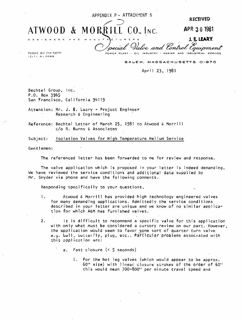
APPENDIX P - ATTACH:?ENT 5 - RECEIVED
ATWOOD & M O R , R I L L CO.. INC. > . D E S I G N E R 5 A N D M A N U F A C T U R E R S
P O W E R PLANT . O I L I N D U S T R Y . M A R I N E A N D I N D U S T R I A L S E R V I C E
S A L E M , M A S S A C H U S E T T S 01970
A p r i l 23, 1981
Bech te l Group, Inc. P.O. Box 3965 San Franc isco , Cal i f o r n i a 941 19
A t t e n t i o n : M r . J. E . Loary - P r o j c e t Engineer Research & Eng i neer i ng
Reference: Bechte l L e t t e r o f March 25, 1981 t o Atwood & M o r r i l l C /O R. Burns & Assoc ia tes
Sub jec t : I s o l a t i o n Valves f o r High Temperature Hel ium Serv ice
Gent 1 emen :
The re fe renced l e t t e r has been forwarded t o me f o r rev iew and response.
The v a l v e a p p l i c a t i o n which i s proposed i n your l e t t e r i s indeed demanding. We have reviewed t h e s e r v i c e c o n d i t i o n s and addit ional data supp l i ed by M r . Snyder v i a phone and have t h e f o l l o w i n g comments.
Responding s p e c i f i c a l l y t o your ques t i ons ,
1 . Atwood & Morr i 1 1 has p rov ided h i g h technology engineered va lves f o r many demanding a p p l i c a t i o n s . Adm i t t ed l y t h e s e r v i c e c o n d i t i o n s descr ibed i n your l e t t e r a r e un ique and we know o f no s i m i l a r a p p l i c a - t i o n f o r which A&M has f u r n i s h e d va lves ,
2. I t i s d i f f i c u l t t o recommend a s p e c i f i c v a l v e f o r t h i s a p p l i c a t i o n w i t h o n l y what must be cons idered a cu rso ry rev iew on ou r p a r t . However, t he a p p l i c a t i o n would seem t o favor some s o r t o f q u a r t e r t u r n va l ve e.3. l ~ c r l l , L U L L ~ I Tly, p l u y , e t c . . ~ar 'r ' fcu lar pia661ems a s s o c ~ a t e d w i t h t h i s a p p l i c a t i o n a r c :
a. Fast c l o s u r e (< 5 seconds)
i . For the h o t l e g va lves (which would appear t o be approx. 60" s i z e ) w i t h l i n e a l - c1usur.e s t r v k e s o f t he o rde r 6 f 60" t h i s would mean 70'0-800" per m inu te t r a v e l speed and

Bechtel Group, Inc. A p r i l 23, 1981 Page Two
represen ts a major problem f o r power a c t u a t o r s on ga te o r +.- g lobe type va lves . - - .. - . . - . - . .
i i . Swing check type va lves a r e n o t , i n o u r op in i on , s u i t a b l e f o r such f a s t c l o s u r e and cons iderat ' ion must be g iven , i n any case, t o t h e p ressure t r a n s i e n t r e s u l t i n g f rom such q u i c k c losure .
i i i . For t he c o l d l e g va lves t he problem i s o n l y s l i g h t l y l e s s severe due t o t h e apparent1 y smal l e r va l ve s i z e s (30").
3 . Drawings a re n o t a v a i l a b l e f o r any o f the aforement ioned q u a r t e r t u r n va lves .
4. We b e l i e v e t h e r e a r e severa l major technology problems which must be so lved be fo re an e f f e c t i . v e va l ve des ign can be made. These i n c l u d e
i. Re f rac to r y l i n i n g o f t h e v a l v e body .-- .. .
i i . Valve seat seal des ign
... I I I . Shaf t seal des ign
i v . M a t e r i a l s e l e c t i o n
v . Manufactur ing methods r e l a t e d t o t he use o f r e f r a c t o r y 1 ined va lve.
I t i s , again, d i f f i c u l t ' t o e s t i m a t e development cos t s , schedules and i n d i v i d u a l v a l v e cos t s based on the i n f o r m a t i o n a v a i l a b l e . However, development cos t s cou ld be o f t he o r d e r of-$500 t o $700 thousand d o l l a r s w i t h a t ime o f 2 t o 3 years. I n d i v i d u a l va l ve cos t s a r e v i r t u a l l y - . . . . . . . . . imposs ib le t o p r e d i c t . ow ever, s i n c e m a t e r i a l w i l l be a s u b s t a n t i a l p o r t i o n o f t he va l ve cos t , t he c o s t o f t he Nth s e t o f va lves wi.11 be h i g h l y dependent on when i t . i s ordered as w e l l as s t a r t up c o s t s such
. . a s p a t t e r n s , t o o l i n g , e tc . .
I' hope t h e ab.ove i n fo rma t i on i's use fu l . I f you d e s i r e t o discus's t he s u b j e c t f u r t h e r , f e e l f r e e t o c a l l .
Very. t ru1.y: . , . , I ypu rs ,
/ Vice Pres iden t - Eng ineer ing SNS: ndg cc: Robert Burns & Assoc ia tes
A. J. McKay, A&M C . R. Snyder, Bechtel D. F. S u l l i v a n , AGM

' APPENDIX P - ATTACHMENT 6 SULZER BROS. INC.. S A N FRANCISCO. CA 9 4 1 09
WESTERN D I S T R ! C T OFFICE
Mailing Address: 1255 Post Street. Suite 911 San Francisco. CA 94109 Telephone: Area Code 415
RKE'vrD ' Bechtel Group Inc. 44 1-7230 P . O o , BOX 3965
Cable ~ d d r u s s : Suiwesr ' 1g81 3, FI3.MJCIBCOt CA 94119 Telex: (WU) 34282
'ELE*RY Attn: M r . J. E. Leary
Please quote our reterence in cnrrn?pnndpnrq rind tnlcphono oollb . Your reference Your letter of Our reference Date
SED/sch April 16, 1981
Re Gas Circulators for High Temperature Service
Gentlemen:
In reply to your letter of Mar. 19, 1981 I am pleased to offer our comments as follows:
1) Description of the Application In the last 20 years we have manufactured about 30 blowers for nuclear reactors. Most of these blowers were at one stage axial or centrifugal machines compressing Helium, Argon,Carbondioxyde or air. The maximum power input was about 16'000 KW, the highest pressure 75 bar and the highest inlet temperature 350 OC.
2) Materials of Construction
The material for the proposed circulators are used i.n S n 3 z ~ r standard compressors and gas turbines, i.e. no special materials are required,
3 ) Recommended Circulators
Por each case of the scheiaalic whiuh w d r j attauhed to your letter we would propose a blower which is hermetically sealed including the driving motor. The construction allows easy accessability to the motor. No rotating seals are required, only tight stuffing boxes for cabling. The unit is one compact casing (see page 17 of the enclosed palukphlet) . Case 1: Axial compressor 3 stages overhung, power input about 10,000 KW. Case 2: Axial compressor 3 stages overhung, maximum pressure ratio 1.06, power input about 11,000 KW.
SULZER BROS. INC., with Headquarters at 200 Park Ave., New York. NY ;0017 Is a Subsidiary of Sulzer Brothers Ltd.. W~nterthur. Switzerland

Our reference SED/SC~ -
San Francisco TO Bechtel Group Inc., San Francisco, Mr. J.E. Leary
Alternatively one centrifugal stage overhung, pressure ratio 1.0758, power input about 15,000 KW.
Note: Power values are very approximate and are to be confirmed.
4) Drawings
To follow later
5) Driver
Preferred type of driver is electric motor
6) Costs
Approximate costs for circulator units will follow later.
More detailed information will follow shortly.
Yours sincerely, SULZER BROS. INC.
. . . \ - . . . . .
Edy 0. Sennhauser
Enclosure: . pamphlet no. 25.01.10

.- .,,..:
SULZER BROS. INC.. SAN FRANCISCO. CA 94109 WESTERN DISTRICT OFFICE
1255 Post St San Francisc
Attn: Mr. J. E. Leary
telephone oall?i
Your reference Your letter of Our reference Date
SED/sch June 10, 1981
Re Gas Circulators for High Temperature Service
Gentlemen:
In addition to our letter of April 16, 1981 I am pleased to submit our more specific comments as follows.
1, General
For more than 20 years, Sulzer has deve.l.oped, designed and supplied gas circulators for different kinds of nuclear re- actors. More than 40 centrifugal and a ~ j . . ~ l . type circulators for testloops and commercial reactors were delivered. Extended studies were also made for Helim circulators for the Gas Cooled Breeder Reactor and a few patents are registered. The number, type and main technical data of the circulators supplied are indicated in the enclosed reference list.
2. Recommended Circulator fo r each case
For both bases centrifugal as well as axial type circulators can be offered. The main advantages of the axial circulators are :
- Higher efficiency (approx. 5%) - Smaller dimensions and lower weights - Lower installation costs
The main parameters of the circulators are:
- Centrifugal type circulator one stage overhung impeller
SULZER BROS. INC.. with Headquarters at 200 Park Ave.. New York, NY 10017 i$ a Subsidiary of Sulzer Brothers Ltd.. Winterthur, Switzerland

Our reference SED/sch Page 2
523 Francisco To Bechtel Group Inc., San Francisco
Case
Impeller diameter (mm) Tip speed (m/sec) Operating speed (rpm) Power input (KW) Compressor frame
- Axial type circulator two or three overhung axial stages
Case 1
Rotor diameter (mm) 400 400 2 3 Number of stages
Rotor tip speed (m/sec.) ,230 230 Operating speed (rpm) 10900 10900 Power input (KW) 9900 14000 Compressor frame
- . A40-2 A40-3
3. Description of circulator
The centrifugal type gas circulator is described and illustrated on pages 10 and 11 of the enclosed copy'"A design and assessment study of gas cooled breeder reactors".
a A sectional drawing of the axial type. circulator is also enclosed. The main configuration is similar to the centrifugal type circulator.
4. Materials of construction -
The materials chosen are Sulzer standard materials for compressors of this pressure and temperature range. The main materials of con- struction are:
Casing andcovers: cast steel Inner parts: steel or nodular cast iron. Shaft: ,low alloy steel Blading: alloy steel ('13% Cr) Impeller: low alloy steel
5. Approximate costs
It is rather difficult to indicate costs at this stage of the project. Our best estimate, however, for budgetary purposes is:
One centrifugal circulator: One axial circulator:
The cost reduction for more than 30 sets would be 10% - 20% per unit. The cost reduction for four circulators would be approx. 5% per unit.

Our reference SED/sch
Son Francisco To Bechtel Group Inc. , San Francisco
We would be interested in completing more detailed information regarding the circulator such as:
- Comparison axial - centrifugal compressor - Construction details - Flow control details - Information regarding sealing system, lubrication system, bearings, materials of construction, dimensions, erection and maintenance, cooling system, instrumentation, electric motor.
This study is offered at engineering costs (approx.'500 hrs x $ 60.-/hr.).
1,appreciate your replying to above offer. I
Yours sincerely, SULZER BROS. INC:
. .
Edy 0. Sennhauser
EnePwsure: Ref. : Gascirculators "A design and assessment study of gas cooled breeder reactors" Drwg. 0-837 751820; paper by K. Feer and H. Benz "Gas Circulators in the St-Laurent I Nuclear P.S." (all in duplicate)

- ATTACHMENT 7 + * T H I S i l S G WAS AUTO-INTERCEfTED**@l
T S B C BBZB 2 1 : 97CMT SSFI) 8231 22:84GMT 0 4 / 1 4 / 8 1
'OFLOW LSAROTOFLOW A LSA
S.aN FRANCISCO
4TTN: MR CHUCK SNYDER
QCZA ?:EF ! H E L I U M COMPRESSOR/SDG AND E ? L A JOLLQ
OUR F I L E RC13E4 i \
, S;E THANK YOU FOR YUIJR VqLUED INQUIRY AND HAVE COMPLETED EXPECTED b
FERFORMANCE CALCULATIONS #NO FRICXNC FOR YOUR A P P L I C A T I O N . I N ACCORD-
) ANCE WITH I:ONDITIONS GI'VEN I N YOUR TELECON W1.Tj-l LARRY B L I T Z ON
-' \ J
ROTOFLOU OFFERS A C U S T ~ ~ F ~ P SINGLE-STAGE, CENTRIFUGAL~COMFRESSOR WITH
S T A I N L E S S STEEL CASE AND A T ITANI IJM I M P E L L E R ? FOR COUPLING TO THE 1
:L& 9 GfGU HCIRSEFOWER? 198aU R P M ? 4?60WJ/ .3PH/CB HZ9 DRIP-FROOF ELECTRII:
. THRlTJlJGH THE 1:4 SPEED INCREASING GEARBOX. THE COFIFRESSOR AND' GEAR ARE ..' '1
3rJlJNTED ON AN 18' X 139 FABRICATED STEEL EASEPLATE WITH THE WATER-. , .'
' CdOLED? DUAL-PUHP LUBE SET AND NEPlA-4 ELECTRICAL SYSTEY AND CONTROL
B' PANEL.
COUPLINGS AND COUPLING GUARDS ARE PROVIDED. MOTOR STARTERS ARE
PURCHASER-SUFPLIED, AS ARE PERSONNEL BURN CUARDS, I F REQUIRED.

r Y ? E C T E S .- PERFOfirdANCE FOR THE PlACHINE OFFERED I S A 6 FOLLOWS (YOUR
.". ', st EC i = I ED NIJrlSERS 1 N PARENTHESES) : -
~ < i ~ i L E ! ~ i j L A S W E i GHT (HE) ( 4
E S T I 8 A T E D P R I C E ? F.O.B. LOS ANGELES? C A P FOR THE COMFLETEI TESTED
SYSTEi'l, A S DESCRIBED9 I S : IJSD S50~0(17B.@B.
I F THE C2:IPRESSOR D R I V E flOTOR I S DELETED FRDM ROTOFLi2WJS SCOPE OF
C:'JFPLY ? DEDlJCT IJSD 276 ? 6 5 5 . O U FROH THE SYSTEM FR I C E QUOTED ABOVE.
?RESENT SC i iED iJL INC I S : P R E L I M I N A R Y DR4UINGS M A I L E D S I X WEEKS AFTER
ORDER D A T E ? EQlJ IFMENT S H I P P E D E I G H T TO TEN MONTHS AFTER F I N A L DRAM-
I N G APPROVAL, DEPENDENT l)N GEAR A'NO MOTOR L E A D - T I M E S . IMFROVED \
D E L i V E R l I S F O S S I D L E P AS R E I ~ U I R E U P W I T H S P E C I A L EXPEDITING I)F LONG . I L E A D I T E M S . .
- ECAFT S E A L I N G F O R T H I S A P P L I C A T I O N WILL R E Q U I R E S P E C I A L 1 T T E N T I U N p 7
r "' I F OIJR OFFER I S OF I N T E R E S T .


APPENDIX P - ATTACHMENT 8
I n r e p l y r e f e r t o : SJAT-1129-0609
June 9, 1981
BECHTEL GROUP, INC. Pi 0, Box 3965 Sen r rsne i3c0, Gal i f s r n i e 941 13
A t t e n t ion: M r . C . R . Snyder
s u b j e c t : Hel ium C i r c u l a t o r
Gentlemen:
Th is l e t t e r i s t o con f i rm t h e telephone conversat ion o f May 8, 1981, w i t h M r . ' ~ u r t Wieland, dur ing which the techn ica l approach f o r the design and development o f a he l ium c i r c u l a t o r f o r your requirements as s t i p u l a t e d i n your l e t t e r t o M r . A 1 Stimac, G a r r e t t Turb ine ~ n g i n e Company, Phoenix, Ar izona, was discussed.
A p re l im ina ry de terminat ion o f t h e dimensions o f the c i r c u l a t o r and the power requirements was made f o r f o u r u n i t s opera t ing i n p a r a l l e l a t Case 1 and Case 2 c o n d i t i o n s .
'l'he resu l t s a re as to1 lows:
Weight Flow Rate Ib /h r '
1 b/sec
l n l e t Pressure, PS l A
Out l e t Pressure, PS lA
l n l e t Temperature, OF
Out l e t Temperature, OF
lmpe l l e r Input Power, HP
lmpe l l e r Ro ta t i ona l Speed, RPM
Case 1
1.02 & 106 70.83
Case 2
.92 x 106 63.88
The impe l le r diameter would be approximately 22 inches and the housing diameter approximately 60 inches.

BECHTEL GROUP, I N C . - 2 S JAT- 1 129-0609 June 9, 1981
We do n o t have a ~ i r c u ~ l a t o r u n i t developed f o r these requi rements. However, we have components i n our s t a b l e o f turbomachines t h a t have the d e s i r e d performance o r can be adapted w i t h n o t t ~ o s i g n i f i c a n t changes.
The c i r c u l a t o r would be con f i gu red s i m i l a r t o the c i r c u l a t o r u n i t b u i l t by AiResearch f o r General Atomic which was ope ra t i ng a t 1000 p s i g , except t h a t the impe l l e r diameter would be increased approx imate ly 2.5 t imes; t h i s a l l o w s the use o f an a v a i l a b l e gas t u r b i n e compressor i m p e l l e r . A l s o a d i f f e r e n t c o o l i n g concept would be used f o r c o m p a t i b i l i . t y w i t h t h e h i g h e r i n l e t temperature. AiResearch has b u i l t compressor u n i t s f o r temperatures o f 1000°F i n l e t and l5OOOF o u t l e t . S i m i l a r c o n s t r u c t i o n methods, s e l e c t i o n o f m a t e r i a l s and c o o l i n g methods can be employed.
The s h a f t sea l would be a p ressure balanced carbon face sea l . A d i f f e r e n t i a . : l . pressure c o n t r o l l e r would m a i n t a i n a d i f f e r e n t i a l p ressure o f 5 p s i nominal ' .
between t he he l i um and lube o i l used as ba lance f l u i d . . . . .
The r o t a t i n g assembly would be supported on hydrodynamic bear ings incorporating a n t i -wh i r 1 feat1,lres.
Hydrodynamic double a c t i n g t h r u s t bear ings w i l l absorb the impe l l e r t h r u s t .
A commercial gear speed inc reaser t r ansm i t s the power f rom an AC induc t ion motor (e.g., 2300 v o l t s 3-phase) t o t he impel l e r v i a gear t ype f l e x i b l e coup l i ngs . The h i g h speed coup l i ng would be our own des ign w i t h v i b r a t i o n dampers - i t would be incorpora ted i n t o the compressor module.
The h y d r a u l i c system inc ludes n o t o n l y t he d i f f e r e n t i a l p ressure c o n t r o l b u t a l s o h r i h pressure and low pressure lube pumps; a r e c i r c u l a t i o n pump for o i 1 coo l ing, the o i 1 t o water heat exchanger, o i 1 f i 1 t e r s ( r ep laceab le d u r i n g ope ra t ion ) and pressure c o n t r o l l e r s .
The c i rc1.11ator ' ) n i t would be designed as complete system f o r turn-key i n s t a l l a t i o n a t the customer p l a n t . The t e s t i n g would be done on a i r t o measure t h e a i r
. . equ i va len t performance on an a v a i l a b l e dynamometer. S t a t i c t e s t i n g would be done w i t h he l ium t o t e s t f o r l eak t i gh tness . Unless funded, no f u l l power t e s t s would be performed a t the manufac tu re r ' s f a c i l i t y due t o l a c k o f r e q u i r e d e l e c t r i c a l power. However, f u l l speed t e s t s would be done on a i r w i t h a sma l l e r motor .
The des ign and development c o s t would be rough ly between $2 a n d $ 4 ~ i l l i o n , ex- c l u s i v e o f the f i r s t s e t of hardware. The hardware c o s t f o r a developed p roduc t s t a t i s t i c a l l y ranges between $200 and $500 per hp w i t h the h i ghe r f i g u r e p robab ly be ing more r e p r e s e n t a t i v e f o r a smal l q u a n t i t y re lease , cons ide r i ng a l s o t he spec ia l des ign f ea tu res .

BECHTEL GROUP, INC. - 3 S JAT- 1 129-0609 June 9, 1981
As d iscussed, i t appears t o be d e s i r a b l e t o p r o v i d e some p r o t e c t i o n o f the i m p e l l e r f rom p a r t i c l e s t h a t may separate f rom the r e f r a c t o r y l i n i n g o f the duc t i ng . You have asked f o r q u a n t i t a t i v e i n f o r m a t i o n about the e r r o s i v e e f f e c t s o f e n t r a i n e d .
s o l i d s . I t j u s t so happened t h a t an a r t i c l e pub l i shed i n t h e l a s t T ransac t ion o f The ASME, Journa l o f Eng ineer ing f o r Power, d' iscusses t h i s sub jec t . We have en'closed -a copy f o r your i n fo rma t i on .
Our exper ience i n d i c a t e s t h a t the i n j e c t i o n o f j u s t a few pounds o f crushed q u a r t z can cause complete. l o s s of t h e b l ade t i p s ; t he re fo re , some s e t t l i ng chamber ahead o f t h e compressor i n l e t o r i n e r t i a t ype f i l t e r s , as used on h e l i c o p t e r engines, may be cons idered i f f u r t h e r s t u d i e s i n d i c a t e t h a t m i g r a t i o n o f r e f r a c t o r y . l i n i n g m a t e r i a l may be a d i s t i n c t p o s s i b i l i t y .
We t r u s t t h a t t h i s i n f o r m a t i o n w i l l be o f he lp . I f you have fu , r ther ques t ions , p l ease do n o t h e s i t a t e t o c o n t a c t t h i s o f f i c e .
Very t r u l y yours ,
A I RES EARCH MANUFACTUR l NG COMPANY Corpo ra t i on
/ ..
JAT: 1 hs Enc losure

T E L E P H O N E : 5 6 2 . 6 4 . 1 0 563.92.99 - 563.87.68 - .563.62.17
TELEX : 290446 F TELEGR. : REFROITREPO-PARIS
ATELIERS : STE OE CONSTRUCTION OES 'APPAREILS TREPAUO
155 0UAI.AULAGNIER 92600 ASNIERES S.A. AU CAPITAL OE 1.638.000 F
~ / ~ k f . J E L / ~ ~ du 9 avril 1981
44 R.LABOETlE 75008 PARIS- -
BECHTEL GROUP ,mC.', Fifty Beale Street P. 0. Box 3965' SAN FRANCISCO CA 94119
N/R& GT/DA - 155 375 U. S. A. Dos. 7730 L J
'a l lattentim de Monsieur J. E. LEARY Project Engineer Research ,Engineering
. . - .
, . Messieurs, . .
, . .
. .
Suite 5 votre appel d'offre cite e n reference, nous avons lthonneur de vous remettre sous ce pli nos meilleures conditions de prix et dklai pour la fourniture de :
- 8 G6nBrateurs de vapeur de 240 MWth - 1 G 6n6rateur de vapeur de 1 18 MW th
Votre commande serai t rkalisee par les Ateliers Mecanique e t Chaudronnerie de CREUSOT LOIRE, en application de nos proc6dCs brevetgs.
Vous souhaitant bonne rkception de ce courr ier et en espkrant avoir le ploisir de vous recevoir B PARIS, nous restons 5 votre disposition pour vous fournir tout rense ipement complkmentaire.
Veuillez agrger, Messieurs, l'expre s s i m de nos sentiments '
Conditions commerciales.
P. S. - I1 ne vous se ra pas demand6 de rCmunCration supplCmentaire ,
pourl'application de nos b r d e t s B.cktte affaire.
SOCIETE ANONYME AU CAPITAL DE 200000 FRANCS Ji RC PARIS B 582064069 4 i I.N.S.E.E. 205-75-138-;016
. ;;:. ,..; . . ' - I . . _ 1 _ . --,.- E!-. . . . . , . , . : : : - - . . . . .. 4- ...?".'.'l'. ".' '.:' . . , . . . - . . . . . . : , ,. . , , . . . . . ..
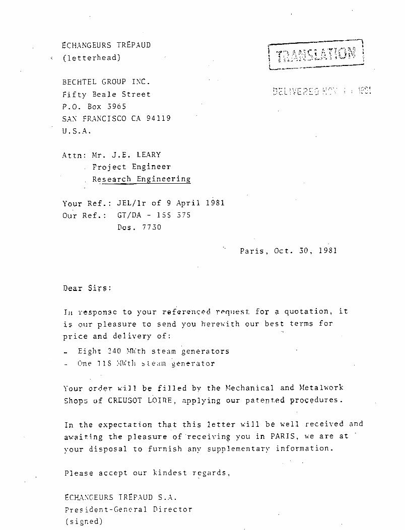
ECHiAXGEURS T R E P A U D i ( l e t t e r h e a d )
BECHTEL GROUP I X C .
F i f t y B e a l e S c r e e t
P.O. Box 5965
SXN FR:WCISCO C.4 94119
U.S .A .
- 4 t t n : b l r . J.E. LEARY
F r o j e c t Engineer
R e s e a r c h - E n g i n e e r i n g
Your R e f . : J E L / l r o f 9 A p r i l 1981
Our R e f . : GT/DA - 155 3 7 5
Dos. 7 7 3 0
P a r i s , Oct . 3 0 , 1981
Dear Sirs :
111 r e s p o n 3 c t o y o u r r e f e r e n c e d rrqiirst f o r a q u o t a t i o n , i t
i s o u r p l e a s u r e t o s e n d you h e r e u i t h o u r b e s t t e r m s f o r
p r i c e and d e l i v e r y o f :
- E i g h t 3 4 0 With s t e a m g e n e r a t o r s
- Clne 1 1 s : \ l l i t l i i l eC im $ e n e l e a t o r
Your o r d e r xi11 b e f i l l e d by t h e P lechanica l and h l e t a l ~ i o r k
Shops uf CRKUSOT LOIRE, a p p l y i n g o u r p a t s n t . e d p r o c e d u r e s .
In t h e e x p e c t a t i o n t h a t t h i s l e t t e r \ , . i l l b e u e l l r e c e i v e d and
a w a i t i n g t h e p l e a s u r e o f ' r e c e i v i n g you i n PARIS, v e a r e a t -
y o u r d i s p o s a l t o f u r n i s h any s u p p l e m e n t a r y i n f o r m a t i o n .
P l e a s e a c c e p t o u r k i n d e s t r e g a r d s ,
ECHASGEURS T R E F A U D s . .A.
F r e s i d e n t - C e f i ~ r a l D i r e c t o r
( s i g n e d j

Encl.: Specification 30. 811138.00.602 I I No. 811138.00.601
Commercial conditions
P . S . .You will not be requested to :pay an)- additional compensa- tion for the use of. our p a t e n i s in ? h i regard.

T E L E P H O N E : 5 6 2 . 6 4 . 1 0 563.92.99 - 563.87.68 - 563.62.17
TELEX : 290446 F TELEGR. : REFROITREPO-PARIS
ATELIERS 1 STE DE CONSTRUCTION OES APPAREILS TREPAUD
156 QUAI AULAGNIER 92600 ASNIERES S.A. AU CAPITAL DE 1.636.000 F
44 R.LA BOETlE 75008 PARIS : a;.
~ / ~ 6 f . dos. 7730 - 1 5 5 375
PARIS. LE 3 0 OCT. lgol
COMMERCIAL QUOTATION
SOCIETE ANONYME AU CAPITAL DE 200000 FRANCS -3k RC PARIS B 582064069 + I.N.S.E.E. 205-75-108-1016 , . . , . .

DIVISION CHAUDRONNERIE - PRESSURE. VESSEL DIVISION USlNE DE CHALON sur SAONE .- PUNT of CHALON sur SAONE
T6lex : 800131 -761. (85) 46.80.34 -1, Avenue de Verdun. B.P. 78 - 7l103 Chalon sur Sa6ne Cbde:
-- DISTRIBUTION DISTRIBUTION
Par c BY .g 4 ,B Z s C
Z r
ECHANGEURS TREPAUD ------------------ ..................
1 + 8 STEAM GENERATORS
F O R H l G H TEMPERATURE
TREPAUD PATEXTS
- 2 E a q I COFIMERCIAL. OUOTATIOK I r' . ? .I)
. .g . .
3 f
>
Date
V iu
-----
NOM Nrnr
C
.r= z
.r a 2 . a ., e" u - C
3 a s '2 .
OuqlitC Oudity
P ~ o e
Date Vim
Ind Rev
- -
VCrifiC par R u ~ o b l e CAcEkrd by R~sponribk
025 172
NOM Y m r
Etabli par Established by
NOM Nune
DATE '
Dare
-
date - ~ --
Vim A
s m i E T L ANONYME AU
Date
Viu -
NOM. Nuns
R.C. PARIS B 702 CAPITAL DL 360 380 100 F SIREWE : 702 026 972 00017

COMMERCIAL QUOTATION --=-=..=-=-=-=-=-=-=- -
1. SUPPLY - WEIGHTS
1.1 8 steam generatfirs according technical spccificatisn N O 8 1 1135 00601 rev 1 and drawlng ~ ' 1 0 001
Approx. unit weight = 142 tons
. *
1.2 1 steam generator according to technical specification n"S1 1138 00 6C2 rev 0
and drawing n o 20 001
Approx. unit weight = 71 tons
7. \INIT PRICES
2.1 For each of the 8 steam generators of item 1.1
............. 10 9Q6 000 french francs
2 .1 For the steam generator of item 1.2
............ .6 620 000 french francs
' Above prices are t o be understood :
. free of any french or foreign taxes : for vessels packed in a sea worthy packing, leigth weight type, a n d w i t h a lcad
dis t r ibutor under the saddles . . openings packed, set t ing under nytrogen pressure when leaving our works but wi tho1
pressure keeping device.
. for material delivered from FOR to FOB bE HAVRE, without intermediate storage,
french clearance included.
. subject t o escalation.,.aecording to the escalation formula given i n fj 3
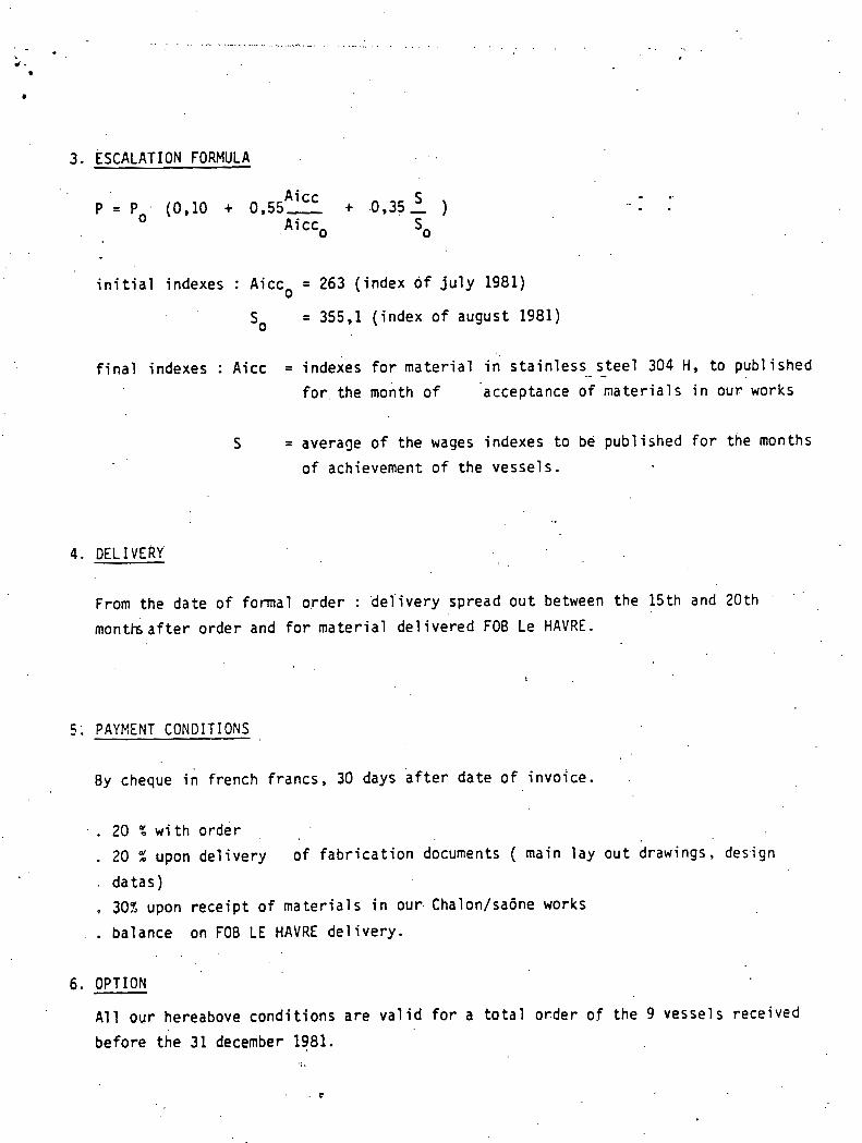
3. ESCALATION FORMULA . - .
i n i t i a l indexes : Aicco = 263 (index of july 1981)
o = 355,l (index of august 1981)
final indexes : Aicc = indexes for material in s ta inless .- steel - 304 H , to pub1 ished
f o r t h e month o f acceptance of materials in our works
S = average of the wages indexes to be published for the months
of achievement of the vessels.
From the date of formal order : 'delivery spread out between the 15th and 20th . ' '
montk af te r order and for material delivered FOB Le H A V R E .
5 ; PAYMENT CONDITIONS
By cheque in french francs, 30 days a f t e r date of invoice.
. 20 % w i t h order
. 20 % upon delivery of fabrication documents ( main lay o u t drawings, design
. datas)
302 upon receipt of materials in our. Chalon/sadne works
. . balance on FOB LE HAVRE delivery.
6. OPTION
A11 our hereabove conditions are valid for a total order of the 9 vessels received
before the 31 december 1981.

T E L E P H O N E : 5 6 2 . 6 4 . 1 0 563.92.99 - 563.87.68 - 563.62.17
TELEX : 290446 F 44 R.LA BOETlE 75008 PARIS . . TELEGR. : REFROITREPO-PARIS
r
ATELIERS : ST€ OE CONSTRUCTION DES APPAREILS TREPAUD
155 QUAI AULAGNIER 92600 ASNIERES S.A. AU CAPITAL DE 1.88.000 F
SPECIFICATION N o 811138. 00. 601 Rev. 1
8 STEAM GEXERATORS TOR HIGH TEMPERATURE
TREPAUD Patents
24'0 Mwth
SOCIETE ANOidYME AU CAPITAL DE 200000 FRANCS 3:- RC PARIS B 582064069 35 I.N.S.E.E. 205-75-i06-1016

. - - -. - - - .- . - - - . .
W V DIVISION CHAUDRONNERIE - PRESSURE VESSEL , DIVISION USlNE DE CHALON sur SAONE 2 ' - PLANT of CHALON sur SAONE
TBlex : 800131 -74. (85) 46.80.34 -1, Avenue de Verdun. B.P. 78 - n103 ChalonsurSe6ne Cedex
-.-.-
DISTRIBUTION DISTRIBUTION
Par -- BY
ECHANGEURS TREPALID ------------------ ............*.....
8 STEM! GENERATORS FOR HlGH TPlPERATllKE .
TREPAUD Pat en t s
240 Mwth
SIEGE 8OC!AL : c. RUE D0AM#)U - 7 W PP.P.!S
6
Ind Rev
29.10.81
DATE Oafe
Etabli par Established by
K.BOVAGNE
NO M Name
Vkrifie par Checked by
.2q'10.g' .
Date
Vim
SOelETE ANONYME A U R.C. PARIS 9 701 026 !7? I
CAPITAL DL 368 310 100 F(SIRENE : 702 026 172 00017 1 L
P a y
Responsable Responsbk
'
NOM . Name
QualitC " a~rliry
~
Date
Visa
-
NO M N m r
Date
V ia
NOM Name .
Date ,
.
SUMMARY -=I=-=-
I . S U B J E C T
2 . GEXERAL D E S C R I P T I O N O F THE P R O C E S S
3 . WORKING C O N D I T I O N S
4 . STEAM G E N E U T O R D E S C R I P T I O N -
5. CONSTRUCTION CODE
6 . D L S I G N C O K D I T I O N S
7 . F A B R I C A T I O N ARUNGEME?:TS
7 . 4 . Inner s h e l l ----..------
8.1. P l a t e s SA 7 4 0 Grade 304 M .........................

8 . 2 Forgings-SA-182-Sraie,-EF,2O_4-: ---
8 a 3 . . Eo_Ltin_g-SA-122-BI-~-S4-124~Z-H,
8 . 4 . Tubcs : 800 H alloy ------------------
8 . 5 . Plafes-SA-115-Grade-lG
9. FABRICATION
9 1 Lax-out-=-cutting
9 . 2 . Forming
1 0. INSPECTION
1 1 . TESTS
12. PICKLING AND PASSIVATIOK

1 . S U B J E C T
This specification concerns the construction of 8 steam generators, - . heated with helium (240 Mwth) .
2. GENERAL D E S C R I P T I O N - O F THE P R O C E S S --
It consists of producing overheated steam from a heating gas, which
is helium.
Heating process and the main constieuencs are in agreemeuL w i t h
TREBAUD Pa c e n t s .
Water and steam flows around inside tubes, helium flows around outside
the tubes.
3 . W O W I N G C O N D I T I O N S
4 . STEAM GENERATOR D E S C R I P T I O N ----- .
The steam generator is set vertically on a skirt.
water steam
IIC 1 i uni C
Its main characteristics are :
-$ i 7 300
- distance between tubesheets : 14 000
- 13 baffles
- 2 652 undulates tubes I$ 16 x 12
. T'c P MP'a
i n l e t
232
7 9 3
outlet
565
328
Output
a
inlet
. 16,55
4,8
kg/h outlet 1
!
16,45
4,6
349266
394 625
v

- inner shell @e 1 330
- helium inlet and outlet @ 900
- 2 water inlets $ 300
- 2 steam outlets @ 350
- overall height 18 200
5. CONSTRUCTION CODE
ASME Code - Section VIII - Division 2 - 1980 edition - Winter 1980 Addenda and Code Case 1 592 included.
6. DESIGN CONDITIONS
,
Temperatures of the components of top channel and top p'art of the
I i
Top channel
I top j Cylindrical sh.ell bottom ! Bottom channel
top Tubes
bottom 1
cylindrical shell are calculated considering use of a thermal barrier.
7. FABRICATION ARRANGETIENTS
Temperature
" C
565
680 -
328
23 2
680
232
7.1. Cvlindrical shell --_-------_------
pressure (MPa) . .
steam water
16,55
16,55
16,55
!h,55
helium
4,8
4,8
. 4,8
4., 8
4,8
4 , 8

- bottom part : 3 shells @i 2 . 3 0 0
thick. 58, 62, 67
- top part : 2 shells $i 2 300
thick. 72
The closing taper ensures junction between bottom shell and
bottom channel. Its thickness is 58 mm. It is supported by
the skirt.
Both are corpposed with the same elements
Thickness
Top channel is equipped with 2 $team outlcts $330 and
Z manholes.
Enttnm r h a n n e l i s eqilipped with 2 wacer inlet nozzles @ 300
and 2 manholes.
Bottom channel
80
185
9 0
,
Middle part
$i YOU
~ubesheet
. Spllctt'i.ccl1 crow11
b
An inner .shell -@e 1 330, thick. 15- fills the middle part of
the stcnm generator. It provides an annular area for the tubes.
Top channel
150
240
I l l

Each end of the shell is sealed by an elliptical head. TO^ and bottom parts of the shell are centered in the bore of top and
bottom channels.
It is composed of 2 652 undulated tubes, TREPAUD patents, equally
distributed in 6 sectors.
The tubes -$e 16, thick. 2- are welded together on to the
tubesheet through Internal Bore Welding -proci..ss.
.7.6. ~affles :
The 13 baffles ensure supporting and guiding of the tubes. They
are composed of toothed-rack shaped bended plates -50 x I-,
welded together.
The skirt ensures to support the vessel, keep it steady an2
fixed on the foundations. It is 30 rn thick. The bottom part
is a crown equipped with anchors,
.- .
Thermal barrier is used to protect the channel and top shells
from high temperature helium, so as to reduce component elements
temperature.
It is composed df a stainless steel shell, 10 mm thick.
On helium side, it concerns the middle part, the tubeshcet and
t l ~ c c y l i ~ ~ ~ l l - i c a l sllcll . I t involves a'lso increase of helium flowing
rate.

They are in agreement with ASME Code Section 11.
e .
8 . 1 . Plates SA 240 Grade 304 H : .........................
Cylindrical shell, closing taper, spherical.crowns, inner shell,
baffles, thermal barrier.
8 . 2 . Forgings 182 Grade F 304 H : --- -- -------------------
Middle parts, tubesheets.
Manholes equipment.
8 . 4 . Tubcs 800 H alloy ----------------
Skirt.
9.1. Lay out-- cutting :
Stainless steels are laid out through conventional means. They are
cut by plasma torch or sheared or machined.
9.2. Forming ' :
Cold bending of the cylindrical shell, of the inner shell, of the
c 10s i I I ~ t ; ~ l , c > r .
Hot forming of spherical crowns.

9.3. Welding :
Manual coated electrode welding.
Automatic.submerged arc welding or TIG.
Welding of tubes on the tubesheet is performed through automatic
TIG process Internal Bore Welding.
Assembling of the generator is performed through different steps :
a. Positionning and fitting of the 2 channels, spherical crowns ,
not assembled.
b. Assembling of the inner shell.
c. Fitting and. welding of the tubes bundle and baffles.
d. Assembling and welding of the thermal barrier, the cylindrical
shell and the closing taper.
e. Hydraulic and tightness tests outside the. tubes.
f. Assembling, welding of the spherical crowns of t6e channels.
g. Assembling, fitting and welding of the skirt.
1 1 . l l y t l l - ; ~ t ~ l i c ;111tl t i glltn~*ss tcsts insidc tlic tubcs.
No heat treatment.
10. ISSPECTION
Inspection shall be performed by a qualified external Office chosen by
common consent of the Client and the Fabricant.
It shall mainly consist in :
- mill tests of materials with provided records ; - checking of fabrication drawings and mechanical calculation sheets ;

- qualification of welding procedures ; - attending main inspection.operations ; - examination of fabrication test plates ; - attending the hydraulic and'tightness tests.
A fabrication file shall be set up for each vessel.
1 1 . TESTS
Hydraulic test of the cxlindrical shell : at a minimum pressure of - ..................... --------------- 6 , 2 4 MPa for' a design pressure of 4,8 MPa.
Hydraulic test of the bundle : at a minimum of 21,52 MPa - .......................... for a design pressure of 16,55 MPa.
. .
. .. A tightness test shall be performed on the whole tubes bundle, first
from .outside, tlien from inside.
12. PICKLING AND PASSIVATION
Pickling and passivation of the vessels shall be performgd,
1 3 . SHfPPlSG , -:d-
The steam generators shall be entirely completed in the shops.
Packase shall be made to meet sea transport conditions with tight
closing of nozzles, under dry nitrogen.
They shall be equipped with 2 supports for sea transport.
They shall be protected by a polypropylene eigktening covering.

563.92.99 - 563.87.68 - 563.62.17 TELEX : 290446 F 44 R.LABOETlE 75008 PARIS- - .
TELEGR. : REFROITREPO-PARIS r -I
ATELIERS : STE DE CONSTRUCTION DES APPAREILS TREPAUD .
155 QUAI .AULAGNIER 92WO ASNIERES S.A. AU CAPITAL DS 1.638.m f
PARIS. LE 3 0 OCT. 9981
SPECIFICATIOFv N o 81 1138. 00, 602 . " .. ' Rev. 0 . .
1 STEAM GENERATOR FOR HIGH TEMPERATURE
TREPAUD P a t e n t s
118 Mwth
SOCIETE ANONYME AU CAPITAL DE 200000 FRANCS 3:- RC PARIS B 582064069 35 I.N.S.E.E. 205-75-108-1016

CREUSOT- .OOWE DIVISION CHAUDRONNERIE - PRESSURE VESSEL DIVISION
USlNE DE CHALON sur SAONE - PLANT of CHALON sur SAONE . - 6 I
Telex : 800131 - J6l. (85) 46.80.34-1, Avenue de Verdun. B.P. 78 - 71103 Chalonsur Sadne Cedex I
1
SPEClFlCATlON INDICE . '- REVISION '
0 SPEClf lCA TION
ECHANGEURS TREPAUD
------------------ ..................
I .STEAM GENERATOR FOR HIGH TEMPERATURE
SUMMARY -=I=-=-
1 . S U B J E C T
GENERAL D E S C R I P T I O N O F THE P R O C E S S
3 . WORKING CONDITIONS
STEAM GENERATOR DESCRIPTIOP.! -
6 . D E S I G N CONDITIONS -
7 . F A B R I C A T I O N XRUNGEZIIEE;TS
7 . 4 . Inner s h e l l e----------
7.8. ~~'~mal harr ier

B o l t i n g SA 193 B 7 - SA 194 2 H ------ .......................
8 . 4 . T u b c s : 800 H alloy ------------------
8.5. Plates SA 515 Grade 70 ......................
9. FABRICATION -
9 - 1 . Lar-out,:,cutrise
9.2. Forming ------
9 . 3 . Welding ------
9.5. Heat treatment --------------
10. INSPECTION
1 1 . TESTS
12. PICKLING AND PASSIVATION . ~ -

1 . SUBJECT
This . s p e c i f i c a t i o n c o n c e r n s t h e c o n s t r u c t i o n of 1 s team g e n e r a t o r , h e a t e d w i t h he l ium ( I 18 Mwth).
?..GENERAL DESCRIPTION -- OF THE PROCESS .-----
It c o n s i s t s o f p roduc ing o v e r h e a t e d s team from a h e a t i n g g a s , which
i s hel ium.
H e a t i n g p r o c e s s 'and t h e main c o n s t i t u e n t s a r e i n agreement w i t h
TKEPAUD P a t e n t s .
Water and s tenm f l o w s around i n s i d e t u b e s , helium f lows around o u t s i d e
t h e t u b e s .
3 . WORKING CONDITIONS
4 . STEAM GENERATOR DESCRIPTION
w a t e r s t eam
lie 1 iurn
C
The s t t a m g e n e r a t o r i s s e t v c r t i c a l l y . o n a s k i r t .
I t c main c h a r a c t c r i a t i c s a r e :
- &i I 7 0 ~
- d i s t a n c e between t u b e s h e e t s : 1 6 000
- 1 5 'baf f l ' e s
T'C
- 1 782 undula ted ' t u b e s @ 16 x 13
i n l c t
25 7
6 9 0
Output k.8 /h
P MPa
o u t l e t
3 4 3
3A3
i n l e t o u t l e t
4 , 3 8
4 , 3 8
, 1 2 1 8 8 8 3
4 , 1 8 235 8 6 8

- inner shell @e 1 040
- helium inlet : (I 900 - helium outlet : @ 800
- 1 water inlet @ 250
- 2 steam outlets (I 350
- overall height 19 250
5. CONSTRUCTION CODE
ASME Code, Section VIII, division 2, 1980 edition, Winter 1980
Addenda and Code Case 1 592 included. . .
. 6. DESIGN COhQITIONS
Temperatures of the components of top channel and top part of the
cylindrical shell are calculated considering use of a thermal barrier.
7. FABRICATION ARRANGEMENTS
7.1. Cvlindrical shell : -&---^---I-------
It is composed of ;
Temperature
O c
565
500
430
290
500
290
Pression (MPa)
Top channel
top Cylindrical shell '
bottom
Bottom channel
top Tubes
bottom
steam water
4,38
4,38
4,38
4,38
1
helium
4,38
4,38
4,38
4,38
4,38
4,38

- bottom part : 2 shells @i 1 700
thick. 38
- top part : 3 shells $i 1 700
tlli ck. 40
~he'closing taper ensures junction between bottom shell and
bottom channel. Its thickness is 58 mm. It is supported by
che skirr.
Both arc composed with the same elements
Thickness (mm)
. Top channel is equipped with 2 steam outlets 4350 and
2 manholes;
Bottom channel is equipped with 1 water inlet nozzle + 250 and 2 manholes.
7.4. Inner shell : -----------.
An inner shell -$e 1 040, thick. 20- fills the middle part of
the steam generator. It provides an annular area Tor the tubes.

Each end of the sliell is scalcd by'a~i c~1lil)tical Ilc;~cl. 'I'op i l l l c l
bottom parts of the shell are centered in the bore of top and
bottom .channels. - ..
It is composed of 1 782 undulated tubes, TREPAUD patents, equally
distributed in 6 sectors.
The.tubes -$e 16, thick.p- are welded together on to the
tubesheet through Internal Bore Welding process.
7.6. Baffles : -------
The 15 b r ~ f f l c s cnsurc stlpporti!~g and gl~idi~~g of tlic t ~ l ~ ~ s . 'l'llcy
are composed of toothed-rack shaped bended plates -50 x I-,
welded toze ther.
7.7. Skirt : -----
The skirt ensures to support the vessel, keep it steady and
fixed on the foundations. It is 30 mm thick. The bottom part
is a crown equipped with anchors. . .
7.8. Tliermal barrier : ---------------
Thermal barrier is used to protect the channel and top sllells
from high temperature helium, so as to reduce component elements
temperature.
It is compos~,d of a stainless steel shell, 10 mm thick.
On helium side, it concerns the middle part, the tubeshcet and
the cylindrical shell. It involves also increase of Iieiium Ilowing
rate.

8. MATERIALS
They are in agreement with ASME Code Section 11.
8.1. Plates Sil 240 Grade 304 H : .........................
Cylindrical shell, closing taper, spherical crowns, 'inner shell,
baffles, thermal barrier.
8.2. 1:orgings 182 Grade F -304 H : --- -- -------------------
Middle parrs, ~i ibesheets'
8.3. Bolting SA 193 B 7 - SA 194 2 H : ------ ........................
Manholes equipment.
8.4. Tubes 800 H alloy ----------------
Plates SA 51 5 Grade 70 .....................
Skirt.
Lay out - cutting : -- -------------
stainless ~ ~ e e l s are laid but through conventiorlal means, T l ~ c y are
c u t by plasma torch or sheared or machined.
Cold bending of the cylindrical shell, of the inner shell, of the
closing t ape r .
Hot forming of spherical crowns.

9.3. Welding :
Manual coated electrode welding.
Automatic submerged arc welding or TIG.
Welding of tubes on the tubesheet is perfornicd tl~rougli automiltic
TIG process Internal Bore Welding.
. Assembling of the generator is performed through different steps :
a. Positionning and fitting of the 2 channels, spherical crowns
not assembled.
c , Fitting end welding of the tubes bundle and baffles.
d. Assembling and, welding of the thermal barrier, the cylindrical
shell and the closing taper.
c . Hydraulic and tightness tests outside the tubes.
f. Assembling, welding of the spherical crowns of the channels.
g. Assembling, fitting and welding of the skirt.
h . Hydraulic and tightness tests inside the tul~es.
9.5. !gai-q-ga trne ti t :
No heat treatment.
10. INSPECTION
Inspection shall be performed by a qualified external Officc clioscn by
comalon consent of tlie Client and the Fiibricatlt.
It shall mainly consist in :
- mill t e s t s of materials wich prnvi .ded records ;
- checking of fabrication drawings and mechanical calculation sheets ;

- q u a l i f i c a t i o n - o f we ld ing p r o c e d u r e s ;
- a t t e n d i n g main i n s p e c t i o n o p e r a t i o n s ;
- e x a m i n a t i o n of f a b r i c a t i o n t e s t p l a t e s ;
- attending tllc h y d r a u l i c and t i g l i t t ~ c s s t c s t s .
. A f a b r i c a t i o n f i l e s h a l l be s e t up f o r e a c h v e s s e l .
1 1 . TESTS
H v d r a u l i c t e s t of t h e c y l i n d r i c a l s h e l l : a t a minimum p r e s s u r e of -L--------------------- --------------- 6:5Y PIPa Lur a design pressure of 4 , 3 8
1lvdr; tul ic t e s t o f clte Irund'lc! : aC a minimum prcssurc! of 6957 FlI'ii ............................ . .
fo r ;i c l c s i g t ~ p r c s s u r c cr f 4 , 3 8 MPa.
A t i g h t n e s s t e s ' t s h a l l be performed on t h e whole t u b e s b u n d l e , f i r s t
f rom o u t s i d e , t h e n from i n s i d e .
I ? . P I C K L I K G AND PASSIVATION
P i c k l i n g and p a s s i v a t i o n of t h e v e s s e l s h a l l be performed.
The s team g e n e r a t o r s h a l l be e n t i r e l y completed i n t h e s h o p s .
Pzckage s h a l l be made t o meet s e a t r a n s p o r t c o n d i t i o n s w i t h t i g h t
c l o s i n g o f n o z z l c s , under d r y n i t r o g e n .
It - s h a l l be equipped w i t 1 1 2 s u p p o r t s f o r s e a t r a n s p o r e .
Ic s l l a l l be procecced by a polypropylene t i g h t e n i n g c o v e r i n g .

. - .. . APPENDIX P - ATTACHMENT 10 SULZER
Mailing Address: 1255 Post Street. Suite 91 1 San Francisco. CA 94109 Telephone: Area Code 415
441 -7230
Cable Address: Sulwest Telex: (WU) 34282
BROS. INC.. SAN FRANCISCO. CA 941 09 W E S T E R N D I S T R I C T OFFICE
' 1. Bechtel Group hc. P.O. BOX 3965 SAN FRANCISCO, CA 94119
Attn: Mr. J. E. Learv
Please quote our reference i r ~ ~urt~jspu~sdence and LelepI~Qhc Call5
Your reference *Your letter of Our reference Date
. . SED/sch June 11, 1981
Re Steam Gen'erators for.HTGR Indirect Cycle Plant
Gentlemen:
In reply to your letter' of April 9, 1.981 please' note that Sulzer has developed and manufactured steam generators for gas- cooled reactors for about 20 years. A descriptive documentation of some of these is enclosed. The latest steam generator de- livered was the one for the German HTGR Prototype (THTR-300 MWe). .P.resently we'are evaluating steam generators for a German 2250 MWth HTGR co-generation .plant.
We have reviewed your scheme. In the following we present our comments on the two types of steam generators as inquired.
1. HP-Steam Generator (1 of 8 units)
We have based our calculations an the water/steam side power ( 2 4 0 MWth) and- in order to satisfy the heat balance - h ~ l ? t.0 adjust the helium side. We have selected to leave'the temperat- ures unchanqed and reduce the'heliuin flow from 109.7 kg/s (870000 lbs/h) to 99.3 kg/s.
Thermal layout:
The thermal data per steam generator unit are as follows:
Thermal power transferred 240 MW
Helium: inlet temperature 7 9 3OC inlet pressure 4 9 bar outlet temperature 328% pressure drop 0.85 bar massf low 99.3 kg/s
SUUER BROS. INC., with Headquarters at 200 Park Ave.. .New York.' NY 10017 is a Subsidiary of Sulzer Brothers Ltd., Winterthur. Switzerland

Cur referents SED/SC~
:G.C Francisco TO Bechtel Group Inc., San Francisco
Water/steam: FW temperature 232Oc FW pressure 186 bar steam temperature 566Oc steam pressure 165 bar mass flow 97 kg/s
The helium pressure drop of 0.85 bar is dissipated in the heat transfer section. For parasitic losses another 0.2 to 0.3 bar should be added.Thus not moxe than approx. 50% of the allowable pressure drop (30 psi) can be used with a reasonable steam generator design. Note that this reduction in pressure drop reduces consider- ably the circulator pumping power.
The water/steam side pressure drop of 21 bar includes orificing for flow stability.
Design:
After reviewing several conceptual options we have selected the once-through helix steam generator consisting of two bundles of helically coiled tubes. In the upper (hot end) bundle the tubes are spaced more widely than in the lower bundle. This is to reduce the adverse e.ffect of the extremly high helium temperature gradient through the relatively thick tube wall. The high temperature together with a large gradient poses severe material and stress problems.
The tube bundles are surrounded by a gas-guiding shroud which is externally insulated. The whole unit is enclosed in a pressure shell which would normally be insulated on the outside. Inspection and safety considerations may suggest inside insulations.
The hot helium enters at top centre, flows over the heat exchange surface, and after leaving the lower bundle is passed through the annulus to the exit sideways on the top. With external insulation the pressure shell is thus kept at cold helium temperature. Feed- water enters sideways at the bottom, flows upwards through the tubes. Steam 1eaving.the upper bundle is passed through straight tubes in the.centre of the bundle down to the bottom exit.
The dimensions are shown on the enclosed drawing no, 2-103.074.400.
Materials:
The upper bundle and the upper section of the lower bundle are made from Incoloy 800 tubing. The lower section is 2% Cr 1 Mo. The same material combination is used for the tube support plates and the shroud. Optionally the whole unit could be made from Incoloy 800 should a detailed stress analysis show bimetallic welds to be critical.
For the pressure shell n steel similar to the SA 533 Grade A Class 1 is recommended.

Our reference S E D / ~ ~ ~
.?on Frcncisco To Bechtel Group Inc., San Francisco
Price:
We have estimated the price for 8 units, including kngineering, to be in the order of $ 52 million. This is for the HP steam generator as shown on the drawing 2-103.074.400, (price basis 1981) ,.
The price does not include external collectors, control systems, valves, flash tanks ,etc.
9 second set of 7 similar units could probably be 10 - 15% less expensive.
2. LP-Steam . - Generator (.1 unit)
Since one figure is missing to determine the apparatus we have. assumed the feedwater temperature to be 14g0c.. The helium mass- flow is taken to b q 5.2 x lo5 lb/hr as specified in the data list, although we could not explain the difference between this mass- flow returnin from the coal gasification plant and the massflow of 1.224 x 10% lb/hr being supplied to it.
Thermal lay-out :
The thermal data for this unit are as follows:
Thermal power transferred 118.2 MW
Helium: ' inlet temperature 691°C inlet pressure 56 bar uutlet t t l ~ ~ ~ p e r d t u ru 3 4 3 O ~ pressure drop 0.45 bar massf low 65.5 kg/s
Water/steam: FW temperature 14 9OC FW pressure 56 bar steam temperature 343 OC
' steam pressure 45 bar .massf low 48.. 6 kg/s
Adding the parasitic losses of 0.2 to 0.3 h a r to the "active" helium pressure drop, the pressure drop is within the allowed limits. Water/steam side pressure drop includes orificing.
The design is basically the.same as for the HP-steam generator. There is, however, only one bundle with a normal tube pitch since the helium inlet temperature is at a "conventional" level and tube sheets are used for water and steam col1ecto.r~. The dimension: - are shown on the encldsed drawing 3-103.074.401.

O u r reference SED/SC~
SOC Francisco To Bechtel Group Inc. ,. San Francisco
Note: The temperature difference between gas and water/steam is extremly large resulting in high stresses particularly due to differential thermal expansion of tubes and tube support struct- ures. If this unit was designed to produce HP-'steam the advantage would be twofold: more efficient use made of the available helium temperature and reduced effort in stress analysis and design.
Material:.
2% Cr 1 Mo is used throughout.
Price :
We have estimated the price of this unit to be in the order of $ 5.2 million. This is for the LP-steam generator as shown on drawing no. 3-103.074.401 (.price basis 1981), with control systems, valves; flash tanks, etc. not included.
Due to the extensive analytical work required a second identical unit would be by approximately 40% less expensive. . .
3. Comments on Conceptual Heat Cycle
As pointed out above the helium inlet temperature to the HP-steam generator is unusually high. Other than with fossil fired boilers the forced gas circulation improves the gas side heat transfer and thus moves the tube temperature considerably above steam temperature. The temperature gradient over the tube wall becomes large and increases thermal stresses.
For the generation.of steam of more or less conventional conditions the advantage drawn from a high helium temperature is marginal. A reduction in size and weight is opposed to increased material, design and stress problems. These latter factors may well outweigh the advantage of compactness, particularly in a case where the apparatus is not integrated within the expensive environment of a PCRV.
A plant that converts about 80% of the power into electricity should in our opinion be primarily designed with regard to this application rather than with priority given to the 20% of process heat.
Obvious alternatives to the proposed heat cycle are:
- to reduce helium IHX exit temperature (now at 1 4 6 0 ~ ~ ) and in- clude a fossil helium heat at the gasification plant. This would probably also have a cost reduction effect on the hot helium supply line.
Our reference SED/sch
S C ; ~ F:oncisco TO Bechte l Group I n c . , San F ranc i sco
- t o f o r e s e e a hel ium r e c i r c u l a t i o n from steam g e n e r a t o r . . o u t l e t t o i n l e t i n o r d e r t o mix h o t hel ium w i t h about 2 0 % of co ld helium.
- t o i n t e g r a t e t h e steam g e n e r a t o r w i t h i n t h e primary c i r c u i t behind a s m a l l I H X .
I n t h i s c o n t e x t w e want t o mention t h a t w e a r e involved i n t h e German PNP p roces s h e a t program a s c o n t r a c t o r f o r t h e . I H X , development.
I hope thak above in fg rma t ion w i l l be h e l p f u l t o you.
I s h a l l be happy t o prov ide you w i t h any a d d i t i o n a l in format ion which you may r e q u i r e . /
Yours s i n c e r e l y , SULZER BROS. INC.
Edy 0. Sennhauser
Enc~losurc : drawinqs as mentioned: 2-103.674.400 ( 2 X) 3-103.074.401 (.2 X) Ref. l i s t steam g e n e r a t o r s 4 .1 ,2 ,3 . (.2 x) 28.39.03 ( 2 x ) ; 28.46.03 ( 2 x) 3 . 6 2 ( 2 x )

/ -- GENERAL ATOMIC COMPANY . P . O . W X 8 1 ~ 8
DIEG@. CALIFORNIA 021M (714) 4553000
Zfay 13, 1981 GA/BSI-,027-81 P r o j . 1/7500 WBS 7582080100
Mr. J. E. Leary
SO Bcale S t r e e c San F ranc i sco , CX 94119
S u b j e c t : BNI I n q u i r y o n He l iun Heated Steam Gene ra to r '
Ref.: L e t t e r from BNI t o GA (R. N. Quade) d a t e d A p r i l , 1, 1 9 8 1
Dear Jack:
W e have r ev i evod ::our i n q u i r y on t h e h e l i u n h e a t e d steazi g e n e r a t o r and o f f e r t h e f o l l o v i n ~ t e c h n i c a l c o m e n t s on t h e d e s i g n c o n d i t i o n :
The c o n d i t i o n s p tov ided are v e r y s i n i l a r t o t h e PH-HTGR p l a n t , e x c e p t t h a t s i n c e t h s z s i s ng r e i o x , e r i n :he c i r c u i t , t h e s t e a a z e n e r a t o r r e c e i v e s a v e r j h i g h h e l i u n i n l s t t eDpera tu re (1460°F) f r 5 3 t h e IHY. It would be p r z i s r a 3 l z i f t b i s t e ? ? e r r t u r e cou ld be reduced :o 1250- 1300°F t o s v o i d =akin% s t r u c t u r a l :e:jers of expecs ive e x o t i c z r t e r i a l s such as I n c o n e l 617. -41~0, h igh i n i e t g a s t e q e r a t u r e s r e q u i r e t h a t t h e h e a t t r a n s f e r r a t 2 3e s p o i l e d a t t h e h igh t empera tu re end :o a v o i d e x c e s s i v e t e=?e racx re s and graCis r . t s i n t h e tub ing: t h i s w i l l i n c r e a s e the complexi ty and c o s t of t h e steazl g e n e r a t o r de s ign .
There are two ways t o r educe t h e i n l e t t empera tu re ; f i r s t , a t t e m ~ e r a t i o n . The i n l e t , , g a s czn be c i x e d w i t h o u t l e t ga s dot ;nstrem of t h e c i r c u l a t o r .
. This w i l l i n c r s a s e :he mass Flow t h r o u g 5 , t h e s team g e n e r a t o r (nas s f l o w . t h rough t h e IF.< is unchanged) by a p ? r o x i a a t e l y 30:; r s s u l t i n g i n e i t h e r
g r e a t e r puzgir.3 r e t u i r e s e n t s o r an -8:: l a r g e r d i a n z t e r n e a t eschanger . Second, a gas rekies: cyrcle. T h i s s o l u t i o n p r o v l d e s a r e h e a c e r up s t r e a n of t h e r a i n s t e a = a z i t t h u s lor-:crinq gas t e z p e r a r u r e s . Such a conce? t r e q u i r e s a ss?arz:e bundle and gas v e l o c i t y and h e a t f l u x cill nave t o Se c a r e f u l l y c o n t r a l l e i . Also , h i g h t e z p e r a t u r e t u b e . s u p p o r t s x i 1 1 be r e q u i r e d .
' Howe-~cr, a reSea:er bundle still be s r ~ l l and t h e t u b i n s , alt?.ou%n f a i r l y S o t , v i l l have l o u s r > r e s s u r e s t r e s s t h a n t h e c a i n s t e m t u b i n g and t h u s should be a b l e t o hand le h i g h e r t e n p e r a t u r e s and g r a d i e n t s . Although t h i s method is more c o s t l y t han a c t e q e r a t i o n , i t rill p r o v i d e a c o r e e f i i c i e n t c y c l e ( 1 0 0 O 0 ~ HP/1030°7 L?). Design c o n d i t i o n s c o u l d be ana logous t o F o r t S t . Vrain (1425°F g a s i n l e t a t design c o n d i t i o n s ) , b u t n o r e s eve re .

p- ./' .
Mr. J. E. .Leary - 2 - Hay 13, 1981
In either the attemperation or reheat cycle, a main steam unit, similar to chat shobm on*Drawing 026871 would be selected. The reheater vould probably be a straight tube cross-counter flow concept - . with a rectangular bundle inside a round shcll. Katerials of the main steam unit would be as shown on Drawing 026871 bhilc the reheaters would have Alloy 800 for the tubing and tubeshcct, 1-617 for tube supports, gas guide and seals at the hot end, and low alloy material for the internally insulated shell and.cold tubesheet.
'If it is necessary to live with the high temperatures in the main steam unit, a nev,dcsi~n vould be required. It would have a split helical bundle with 1-617 shrouds and tube supports. The.Xlloy 800H material vould have to extend into the boiler because of the hish gas temperzture. The tubing i a the high tez?erature bundle would be spread apart to spoil the heat transfer rate. Expansion loops would be diffieulc to design because of the necessity to shield them fxom the flow.
The data provided for the HP steam generator shows a diffeient Q for the h e l i m and steam flows. Holding che outlet steam bem?ersture and
. steam and heliura =ass flows together with the given heliumet, the feedwater inlet tenperature should be 350'~ rather than 4 5 0 ~ ~ . Also the allowa5le A? on the helian side of 30 PSI seems excessive. We usually use about 8 PSI.
Steam mass flow and required temperature rise was not provided in the . LP conditions and, therefore, it is not clear what the preferred ccncept
should be. If the mass flow is large and the.temperature rise is snall (large nucber of tubes,.short length),, a straight tube cross-counter flow would be selected. If ths Eass flow is small and the tenperature rise is large (few tubes, very long) a helical coil would be preferred. (U-tube would probably not work because of excessive At while a bayonet would have a too large tubesheet and nigh h e l i u sideQF. Note that traditional fossil plant boiler concept does not apply because of the! high helium pressure).
Note that because these components are in the- secondaw loop outside the PCRV, ve believe they can be built to Section VIPI, Div. 1 Code witn lower seisnkc requirements which will reduce costs.
We will be providing a cost for steam generator shown on 6ur drawing as part of the DOE work, and 'it cay serve as a guide for the cest of ehe unit needed for the CCG process.
If we can help you fGrther on the subject, please let me know.
Sincerely,
7%- 8. N, Quade Project Manages
* Please note that drawing 026871 is being sent under bee: E. Hurn
separate transmittal PHICCRX-013-81 to CCRA with J. I:issir.gcr C. >fc3or,ald
copy to B N I C. Pcinado

GAS-COOLED REAC I dR ASSOCIATES 3344 N. TORREY PINES COURT, SUITE 300
LA JOLLA, CALIFORNIA 92037-1081
Related Documents