LA-6536 UCOiS Issued: February la/7 Coordinated Safeguards for Materiais Management in a Mixed-Oxide Fuel facility by J. P. Shiplev D. D. Cobb R. JlPietz M. L. Evans E^P. Schftonka D.B, imith R. 8. Walton alamos Sicienfifiolaboratory of the University of California IOS ALAMOS, NEW MEXICO 87545 An Afliimative Aciion/Eq.ijgJ Oppaitunity_.C ENESGV RESEARCH AND DEVELOPMENT ADMINISJJ : - ' CONTRACT W-7405-EN5_i£--—— ""

Welcome message from author
This document is posted to help you gain knowledge. Please leave a comment to let me know what you think about it! Share it to your friends and learn new things together.
Transcript

LA-6536UCOiS
Issued: February l a / 7
Coordinated Safeguards for Materiais
Management in a Mixed-Oxide Fuel facility
by
J. P. Shiplev
D. D. CobbR. JlPietz
M. L. Evans
E^P. SchftonkaD.B, imithR. 8. Walton
alamosSicienfifiolaboratory
of the University of CaliforniaIOS ALAMOS, NEW MEXICO 87545
An Afliimative Aciion/Eq.ijgJ Oppaitunity_.C
ENESGV RESEARCH AND DEVELOPMENT ADMINISJJ: - ' CONTRACT W-7405-EN5_i£--—— " "


======a;^=== The problems of sa1\. :'uard iny. . nuc lea r "'materi a l s a g a i n s t un- ; ; ; ' =
;.;, : aulJ^oH ;cd dTVFfsi=mr=xfn^=a^iL=J:iave been d e s c r i b e d in :;umy ways: ,
by charat"tCM"i;TjfT!"^^c«=4,i^tJisJ,cn t h r e a t " s"=Trvc=iit==&A":.-Jc.Oi!_crt , *!:•<T '•" '""^TiWv^^i^it-i^rjJ^^terror i s t s or iJ'ns i ders"v:itrr=-!vvwd4xlcLin-s' * ' : e I-'1'0'
t oct i ve i"casures t hen>e 1 •v'c^-'^i'it^iTltC1 rtrteeetrie^-ja-f,.rP;h>;? ica i~r^Tc -~-
t e c t i o n ' and inatcr iaJ s fIVcount ah i I i t y . ' rrfec-t-j-v^ jr;ana.i;e::,ent of
-=... v.xic 1 "-••ir. r ^ ' t e r i a l s can '"e.^acconpl ished wi thout unacceptatYTe' 1: •• .....
•"-•-------.--;_. JLei;al ,. "pol i t i ca l , and s d o i e t a l consequences . Covert d i v e r s i o n
!•>• t-rii<tT-d-'TrtS^^-rSA..^Q_n_ c> p i e c e n e a l b a s i s or b l a c k r . a i l t h r e a t s
^ _ ^ ^ ^ y t e r r o r i s t groups a re r.oTe~ fnSi dioixs ji rob lcr.s than f o r c i b l e
t h e f t , ajf3 Ti i* •"t4ve--.fo.rncr _.threjrtj^ for
and accountUvg^pyster .s p rov ide a s o l u t i d n T
This r e p o r t provi"3"e"'?:="":}ri?iiie-Eici_.i|_osi, ns and evaHrat=ion -o t thqds
for advanced n u c l e a r nffCjcria^-r.anat'.enien.t sysTcf^p^^rJ jafeg^ard1------.-i-a-.rJj.>,ro-\:es-s-,_E3a,t:_e_rialp in coiiirrerc i a l r i x e d - o x i d e f>!0,) fuel r e far"---""
r i c a t i o n f n c | T i t ; i e ? r The g e n e r i c d e s i g n s a rc b a s e d ' o n a „
thprough e v a l u a t i o n of pfdposed ^ l a r i t d e s i g n s , and r e p r e s e n t "
minor V x t r a p o l a Y i d W ' of e x i s t i n g fuel fab'r i c a t ion-teKjhno logy
and s t a t e - o f - t h e - a r t n o n d e s t r u c t i v c assay (NDA) and d a t a ,
process ing; s y s t e m s . The de s igns a r e a p p l i c a b l e to commercial
f a c i l i t i e s t o T je^bu i l t^J j 1 the n e x t "decade- and have^been e v a l u -
a ted with -simuiate^pj"&duc0oir*daijL,__ Const r u c t i o n d e t a i l s a r e
taken from the l a t e s t v e r s i o n of t h e VresTringhoase^orporatlbTi:*a -.c.
Recycle r:uel^--"Plan^CK"i?i^"".--~5==S; =^--,....;:_.. " ^ 1 ^ ^ ^ - - - " ; ^ ^ ~ '"'"'""""
t h i s s tudy shows t h a t a nealr-^rcai^tlime;"• •"itfaij.&gLM.l.?L .account ini;
systein based on u n i t p roces s accoun t ing and conVeiiTi'io^gl and
NDA measurements can p rov ide e f f e c t i v e m a t e r i a l s a c c o u n t a b i l i t y
, in MOu,: f a c i l i t i e s ^ a t r e a s o n a b l e c o s t , and.jivijfKolrtr d i s r u p t i n g
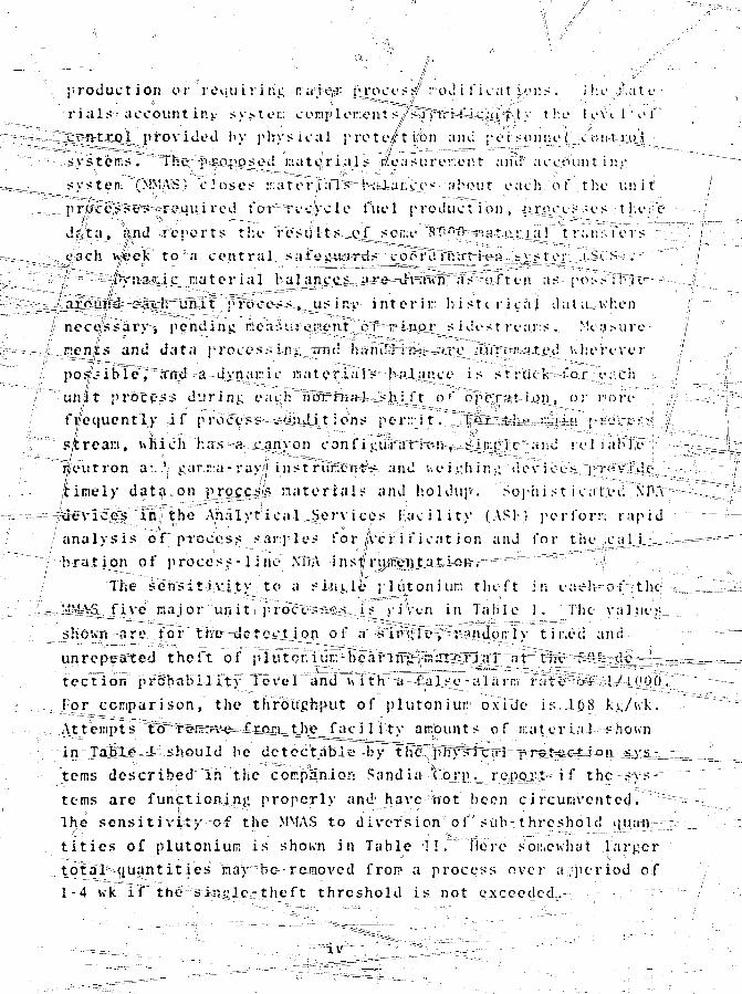
p r o d u c t i o n or ' r e q u i r i n g r.aiepj- i\ro c e s / rod i f i c a t }CM:S . i k e j i a t e -
•rial-* account in-, systei:; cor.iplor.ent s/s^T^'^^^iitl'F'^ >' x ''•L' 1 evt 1 ' o i"
pro \ i Jed bv ph-vsical p ro te / t i fbn ami pe r sonne l .-c'o-si-t-iioj' ', ; -J'L- -iu. -:-™--= ----=-'zr~•-—^y - — ^
T h e j i-.CLp;o^ed i : i a t e , , r i a l s # e a s u r e r : e T . t and* a c c o u n t i ns'
« v * t e p f.MV\S' c l o s e s Ea to r J ; r I "S^Ni ! Aai ; i i . e s a b o u t e a c h o f t h e u n i t
: i r u c e > M ' . ; r e q u i r e d f o T ~ T e c y c l e f u e l p r o d u c t "ion , - i y ^ c e s - . i e s t heiie1
d^ t a , r n d » e i ' O i t s t h e r e s u l t S - . j i ^ s o n a ' 1 ? ' ' j n ^ p ^ t e j ; x a _ i " i ri .ns- 'fers ; . ;~-
e a c h \ \ e e k t o <i c e n t r a l .sai"y t H i a r d s co^fUTrTTrt^i^H-^feiiiti^iv.^-.i S C ' S i :
iiyp..'? i c r a t e r i a l bajj in_cj^_ ; jLK^=^vtfvlT^Trs^;»/t e n a s - p o s s iTrrv^—
» un J . t ^ i^Toce . i ^ , ^ u s in->' i n t e r in: b i s t c r i c a j d a t a - K f : en
p e n t ! i n j ; r . c a s u r e J i ^ n t ^ ^ ^ ^ ^ ^ A i s ' d e s t r e a r s • Me;,! M i r e -
^~]:L._j\enJt$ a n d d a t a p r o c e s s i ru ; irru: h^h't!^mi^ux.e__i'«.irftrsHa-t4' :j! u i i e r e v e r
rci =a 4 v n a r ' Lc n a t e r i . a i ' K h a l o n i c e i s s t r u r k - * f o r - o a t h -
E?!:s d u r i n g cachTfffffTHK^i^^shJJ^t o '" o ^ e r f H - i t J ' J , o r n o r e
f r e q u e n t l y i f p r o c c - p - ' s ^ - t ^ u l i t i o n s p e r s r i t . ^ 1 p t e ^ l ^ r : , E U i H » - - : - ^ ; c s v i ^ . J
s t r e a m , i » h i c h h a s -a . c a n y o n c b n f i i : u ' f a ' t i ^ - n - , ^ s ^ c y r " I ^ : «i;d l e i i a l i T F i
n e u t r o n a:..1,, j : , a r . r a - r a y / i i n s t r u r c r r t ^ a n d # « e i i ; h i n i : d e v i c c-^ r p i ^ \vTd c-
/ t i m e l y d a t a , o n VZ9S-<i0 n a t e r i a l s a n d h o l d u p * . S o p h i s t i c a t e ! . . M>A
- 7 ^ e v i c e s ^ i n ' « t h e A h a l v r i c a l . S e r v i c e s H a c i l i t v ( A S ! ) j ^ e r f o r r . r a p i d
/ a n a l y s i s o f p r o c a s s s a r . p - l e s f o r A c r i f i c a t i o n a n d f o r t h e jCjtl i , : „ . ,
"1 h r a t i o n o f p r o c e s s - 1 ine"'.VHA •-- insf ru^Rgai.a^is-R=r^-r:'":"r"''"~"r!r"""- /
T h e s e n s i t i A u t v t o a s i i i j . , l e p l i j j r o n i u i " t h e f t i n e a ^ - G i " - t h e ;
„->JsSA£L;_f i v e m a j o r " u n i t N procc=:-^s.&d-:_i_s_ i i V e n i n T a b l e ! . The v a l u e : -
s h o w n o r e , f o r " T h e — d c - t c i t i o n o f n i r i - T e v ^ t i t u I o n l v t i n e d a m itheft of plutoniu^b^aTf^riSa^T^
t e c t ion p fahial! i 1 I t y To ve=i "and ~i%~i" t h Tt—-Sai_s_e - a 1 a rni ••••fa:t ' -T-i-J:i.Uj,!?r.~'"~'~ —^-
For compar i son , t he th roughput of p l u t o n i u r oxitle i s 168 kj;/wk. .~~"'i~-i-
. ,:\ttempts'~'tB^;r^R^r^#==;fctQQ=_f=h_e f a c i l i t y amounts of r . a t e r i a l :-howi
i^nTaijlfe^-ri -should be d e t e c t a b l e )Jy~^h~C'!^^y^TCTri"^^
terns d e s c r i b e d ' i n t he cor.pa/nion Sand i a ^ t o r p . = repfljvt-i f t he sys-"
terns a r e f u n c t i o n i n g p r o p e r l y and1 have not been c i r c u n v c n t c d . : ~~-~~ ~ - :
The s ens i t i v i t y of t h e MMA:p t o d i v e r s i o n o f sub- t h r e s h o l d quai-Vf_~-"..'.' "
t i t i e s of p lu ton ium i s shojvn in Table -1 ! . " " "liere son.ewiiat l a r g e r
to / t f f l ^ iuan t i t i e s nay be-relboved from a p r o c e s s over a . pe r i od of
1-4 wk i f the s i n e l ^ - t h e f t t h r e s h o l d i s not exceeded.- --- ^ -
IV
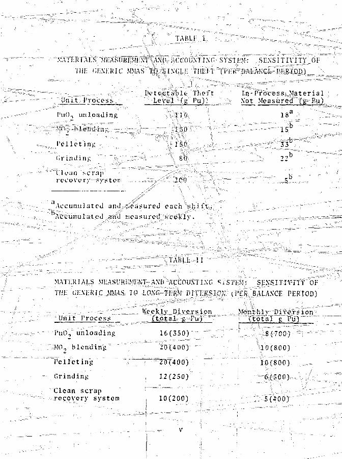
1 '1ABLI l
MAT I RIALS Mi ASiJKJT.MI \ 1 \\NH ACCOUNT I.\C~ SYS'II M: SENSITIVITY 01
'illi MA'IRIC M.MAS 10 i lM' .Li . TUll'i (T'l K bALANCL PI-.RIOD)
Unit !'roces^. __
1'UOT unloading
P e l l e t i n g
dr imiing
("lean H"r;iprccovciv ^vsten
J '<.' t e cLevel
0
3
J
1
]f;
M»
50
n.efPu)
t in* 1Not
? r o c eMe as
£Sur
1
i
3
Materialed (g Pit)
8a
K5"
JPfl
2 2 b
5
Accumulated and,'-.c.isured each s h i f t .
'Ac(.u;:!ulatod and vicasurod ««ceklv.
'1AML II
MAI!.RIALS MI ASMRj-VIM A.VIi ACLTHJN"! I \C ^i
THJ li'l.M-.RIC MMAS 70 LO.NC-TI RM Df\I.R^ICN
L n i t P r o c e s s
i'un, unloading
M-.\ blending
Pelleting
Grinding
Clean scraprecovery system
U'ceklv Diversion_ (total £ Pu)
16(350)
20(400)
20(400)"
:i 12(250)
] 7| 10(200)
M: Sl:.\STT IVi ly O j :
'I'K BALAXC1 PHRIOD)
Mor.thlv Diversion( t o t a l g Pu)
8(700)
10(800)
10(800)
6(500)
5(400)

Accumu 1 a t i on_ otjthese—te-t-a Is a i fer te r wou 1 d rt>qifire his
repeated exposure to deteuLtior. by othfr mcan:v and the avail-
ab i l i ty of acorftinu ing series^crf- diversion oppo r tun i t i e s .The
j 'eX<LgJ -. JJIP-H?h-t-S, .,-Shawn |p ertrrKa la n c & p e r io d - c a n be, detected w i t h - a
probability o?f-_ 85A at a false-alarm rate of 1/6./ Again, - _ _
attempts to remove these quantit ies from the fac i l i ty would, be ^ =
physical protect ion" systems,. ftfmeluiTnpire'r1 g are readily tietectjed
portal monitors. / ^ '--— -,,
^" 'The safeguard systeiTH^TrnpTerrented through a \parallel °
management hierarchy cojis-isting of a Safeguards Officer and
staff for|each operat ing/shif t . The Safeguards-Officer reports
t%rth'ie':r6^TFai?oi^y=aa-t-hQ^ity and to plant management ,\ and J)TOJS^—~
viiies human modulation /of the1 Safeguards-,:decisions. TlalTir bp.er-
%^ are directlx=_Kflected by safeguards (without iTuman input)
the case of an extreme jnerjjejicAtiP^S:Uch--as—* xi r r f
^ r ;^lsx ssive, rather ^ ^
l^ - denial- -jR^de-, %itd' -zri^tiKT^MffW^M proc%s5J functions
only to|accun:ulate iriformation. High r e l i a b i l i t y and a low "
are^ assured by opera ting the safeguards com-
^ u l a y redundancy liiVde (TMR) and by direct-
ing a l l con^uter-origina^ed commands through the humarTdecision
:~ :rr|^^ve^bur^enfs^;:s;a consist.Sv^of
s---staf-fr s—tlmn- 101theiayt_onpn!flu|T_..splant operatidlis staff s exclusiye^^^io:f^s^curit\^ guards) , the cost
of"t he;jneajs^Tftipnt%mnd ^ds*a;;p^aSoss^ii^^ystev\r f 1 esi t than- Si, of
the t o t a l plaiit/coftj ,- ajid^a^ve^yj^xnfrequentCjfaise"alarm rate
oiving to conservatism in rde5'ign, performance goals., and selec-
tion of demonstTalteji^technplogy. "— ; ..,,.-•-"""' -—- •"'"''""" r V 0
bejigjflts.ipf:, an .-effect I've materials safeguards •!
pb'e;> rigorously defined. If no diversion threat is
made, th^re" is no; &e:nefit; if a threat is thwarted, the benefits
axe adarlyj.imitle^sv. - IBecause. of the open -ended consequences
.of a sujcej?ful ..ja.4vjB.; s.Lpa an-d.-=t-he-- rap-Oi *"ance - oi' p] ant

' - • • - ~.L
productivity to the cost of operation in any commercial facil-
ity,/ the worth of a safeguards system is jbest measured by its
'effectiveness and its cost best measured/by the system7^! Wr-'"
obtrusiveness. For this reason, we have/ chosen a materials
control system that complements the existing processing and
management structure of the baseline plant and provides addi-
tional important bejiefjjtj for production operations. The cost
pCanalternative non-process-integrated safeguards system
might, of itself, be affordable, bGt i(f it adversely affects
the plant output unnecessarily, the cost of reduced production 1
is directly chargeable to safeguards,/and is intolerable.
In addition to providingl-working' generic safeguards designs
for MO, facilities and the meaffs to evaluate them, these studies2 _ \. ,. | , —=-" ' _
have defined the materials control"architecture, evaluation;
methodology and logic, and pperafi'd'njal D:Kn;edu¥S£=-riecje=%s rx. 5 v
extend the concept of •-n _ar.-xealjtt'4ijrii -saTegiTards on a unit
process basis to other pr«ductio»j facilities throughout the
fuel cHxle. '\^---^'^' : ««4 ' -••*- . • '""

•••"" ;; ' '• o . \ C O N T E N T S r ^ " " '
C O N T E N T S ^ . . . . . . . . TT~7~."~T~\ • • ,;• v i i i
FIGURES-
GLOSSARY
I. '- .. I N T R O D U C T I O N , B A C K G R O U N D , A N D S U M M A R Y . . . 1-1
'T~ ' A. ObjectfivescrfTTthe Study ; T " . ! ' r r "v ^ - ^ = = ^ 4 = ^•—-=-"• B. His toryjDf^Trevious U'ork . 1-3
l.vi ^Trie Lawrence Li\'ermore :" Labora?.pjr4L.rCliLL)=-J<e-pQ t-==-.---=--i--r==v"=:t= "= -tT™"=
B ^ — - 2 . The Mound Laboratory Report . . 1-73. The P a c i f i c Northwest Labora-
c to ry (PNL) Report 1-84. The Brookhaveri National
i Laboratory (BNL) Report 1-9 .5. .,., The Los Alamos Report . . . . . . 1-9
C. Sunffnary and Strategy .•.,-_ 1-9D. Format and Contents. . I-11
XI. BIE "BASELINE MIXED-OXIDE RECYCLE FUEL - ,FABRiCATION I^CILITJy . _\ .„, _.^, . . . . . . " II-l
- A. Major Features . v . . . . . . . . ; . iI-2B. Process Description. . . . . . . .,.;. . I;I-4
1. Process Streams . . , . . . . . . 11^42.J Holdup. . . . . . . . . . . ."-. . 11-14
C." Process Controlv v ^ . » % - . . . .«.-=-..-i ., 11-151. Control Hierarchy ?. . . " 11-20
./ 2.°-, PCQ Subsystems. ... ± . .^_. ,.,.. .11-20
5. Hardware Implementation . / ... ,x .....,. .,,.1.-1^-25D. Process Information System;;^;-y;*
;l .7. .? 11 - 30- E. Plant Management 7 .' ,,'..... .- •--•>-:.... 11-31F. Plant Layout / . . . . 1 1 - 3 3G. Material Handling and Peisonnel. . . . 11-41
I I J . 7 _ THE SAFFGUARDS SYSTEM . ,; $. . ,''J ... . . . . JIJ-I
"A. Introduction . . . .''."' . . . . . . . . III-lB. Structure of the Integrated System . . 111-2
v i i i ---=-'••"•""""•""""T~r ~ , •
/ " ' " • • •
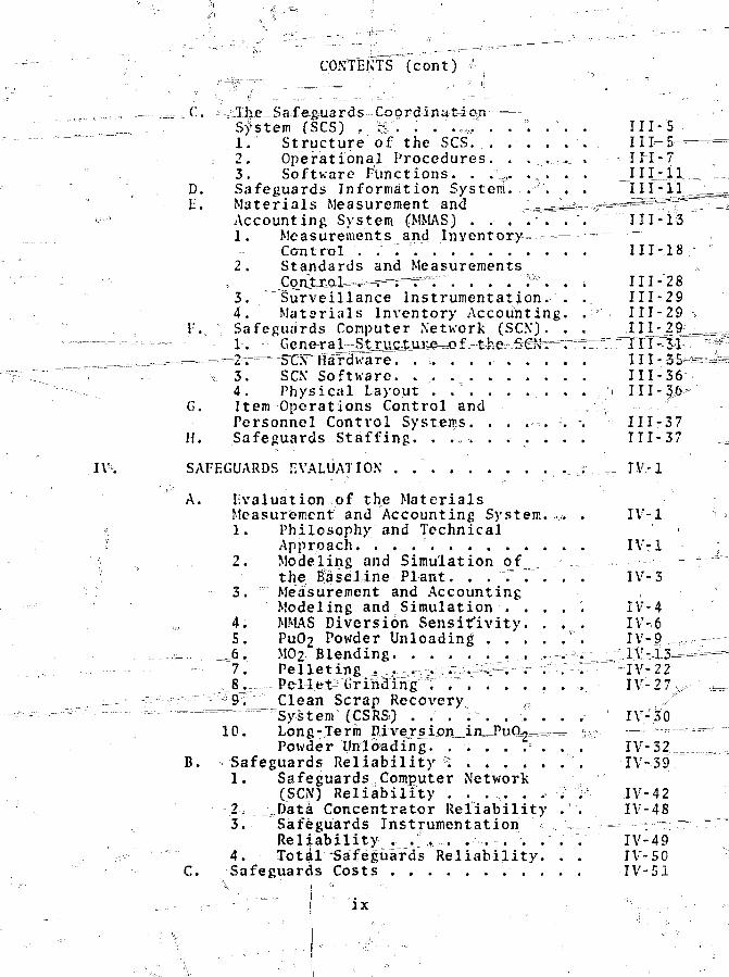
CONTENTS (cont)
...,, -__ C. ^Ihe-Safeguards-Co^rdinatiGn- =—_ __, System fSCS) . & 7 ) . 7 , 7 . . °. . . .
1. Structure of the SCS. . . . . . .2. Operational Procedures. . . ..._ .3. Software Functions. . .%,. . . . .
D. Safeguards Information System. ..-••_'. . .17 Materials Measurement and ^ ^ 7 4 —
<-••••' Accounting System (MMAS) .- . . 7 . . .1. Measurements and Inventory -
Control . "."" .2. Standards and Measurements
_Conjtxol--.'==T===r==ri. . . . . 7°7 . . Ill - 2 83. Surveillance Instrumentation. .. 111 - 2 94. Materials Inventory Accounting. . III-29
p..., Safeguards Computer Network (SCN). . . lljjjj^— = —~- = i . GeneraJ^^S^jicJLuee^of^t'he^S6fvira=r=Tr":7T7iii-3l
=. =. -™'--'- "2•-.r=^ SCx'Ffardware. 111-35*3. SCN Software. . . 111-364. Physical Layout . . . . . . . . . > III-36-
G. Item Operations Control andPersonnel Control Systems. . . .-. . . 111-37
H. Safeguards Staffing. . .„. . . . . . . Ill-37
IV. SAFEGUARDS EVALUATION . .,j:....-T IV--1
A. Evaluation of the MaterialsMeasurement and Accounting System. . IV-1
f • 1. Philosophy and Technical'•• Approach. 7 . IV-1
2. Modeling and Simulation of , ----- -: the Baseline Plant. . . 7 7 . . . IV-3
3. Measurement and AccountingModeling and Simulation . . . . . IV-4
4. MMAS Diversion Sensitivity. . . . IV-65. PuC"2 Powder Unloading 7 IV-9••_.,
-_.. = ^ = J . MO2 Blending , . .i. :iA7i.3==7. P e l l e t i n g . ^ , , ;. ^^^7=^ r 7 ; 7" IV-22
, &.~ P e l l ^ f Grindi^ngJ7 , ' . . . . . . . IV-2 7 ^-::?-'-- ': ~:-::;";^77 Clean Scrap Recovery r 7
. — — • • • — = - ^system (CSRS) . . . ': ' . . 7. . . IV-3010. Long-Jerm piversipn^in—BuO2=-^—a: ^ - -
Powder Unloading. . . . . . . . . IV-527B. Safeguards Reliability °i 7 IV-39
1. Safeguards Computer Network(SCN) Reliability . . . . . . . 7 IV-42
2. ^JData Concentrator Reliability . . IV-483. Safeguards Instrumentation ,. = - ?~=
Reliability . 7:7,:. . . . . . . . IV-49v : 4. Total "Safeguards Reliability. . . IV-50
C. Safeguards Costs 7 . . . . IV-51
ix

CONTENTS' (cont)
V.. ~ RESULTS, CONfeLUSIQNS, AND RECOMMENDATIONS . __\lzlfeQS,
^ XJ
3. Diversion Detection Algorithms. . V-34.3, Diversidk Sensitivity Y-3' ^ \ y . . '. . V-.o ' ;
6. ; Cost.". . \ . ._". . V;r"^~": /B. Conclusions. . .X . . . . A'-3 /C. Areas for Further Effort \-b
APPENDIX: A - DETAILED DESCRIPTION OF, PROCESSING . J^^^ = =L^^=-r
= r;" =r" ;r . . . . A-l
S I S ^ T T~7 A-iA. Gener.fl Description. 7"7XT^. .:. . . . A-J.sB. Subsy¥teTn's*"and Components. \ A-4
1. i PuO2 Receiving and j^ :_Jjgcontamination Area. . . . . . . A-4
" " ^ 2 . Snipping Container STorage Area .y A-43. Shipping Container and Contents . A-44. Unloading—Staitjlon /. A-55. PuO2 Blender-S^r^ge^^js^JLs^^ "... A-6
C. Instrumentation and ControL . . ./ . . (i A-8D. Operation. . . . ,X)i. . . . . . . /. . . ' A-9- --=,1=-- Introduction oi~CbWt;ainer £,._., . >\-9
2. Container OpeningSaildCanister Removalv . . j^vi . . v-T v A-9
3. ? Canister...Keifhing and Sajnplin_g^^^^^A--^— 4; PuO£ Transfer and "ivas^eTiis card . A-JO
5. PuO2 Blending:and Storage . . . . A-11E. Maintenance. .. . . A-11
II. POKDER PREPARATION AND STORAGE
A. General Description. A-12B. Subsystems and Xampjonenis ..=„.•=—,-.-.=.,--=.= .==A-1=2--
"""I; ' Mixed-Oxi^ae'^BItching. . . . .'"". . A-122. Enrichment BleHding . . _.,_. L_.___. _ A-16™37 Milling, Sampling, /and Storage. T "7 7A-.17
C. * Instrumentation and Control. A-19D. Operation. ; . . . . . . . A-20E. Maintenance, -r—^^T7rr^^-^~.^i^.*7r^^"^:^"X^:^"
iV.
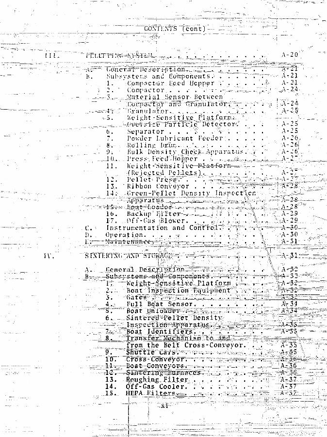
A - 2 0
B.. " 7JT--1
S u b s y s t e;;: - an tl Cfo-mp-o n e n t s . > ., ~ TT~". "7=-; - -, ,<-. A - 2 J.1- .Cpmpflct&.r i'c:ed Hopper '$ 2p p p p J2 . " C o m p a c t o r . . . .-• . . . -.— - . ; - . - _ - — 1 ^ . ' . . ' - ' ^ ; ' ^ - 2 , 4
Kei j ;
0, p7. Powder L u b r i c a n t f e e d e r8-.-- R o l l i n g Drtiin. , . .^. ,- ;•:• . . - .., . \r -
-9. " Bulk Dcns i t v |:hex:]v..Apparatus. VJ . !
11." IVei.cht - Se•
A-. A -
•; A -
;. A-
2S252 626i2 6j
A-27(Rqlected• Pe-lJLpjU) . _. . . _ . . ' . : A-212 . Pel le t - l\r e,s^F^'""." ". ^-^gLiSr^rv^s.^ ---A - 213. "Ribbon Conveyor . .' ". ~\~:^?^^^li^^ - (.reen-Pel-let Density In.^pec-f'|crr' '• ' -j
1 6 . B a c k u p 0 ' I | i " ' r t " C - t P = = - . - = = = i = = = . . _ J ••;ji1' i ! • » " r \ «J >'•'i:"f..1-7. ,.,.Pfi'-Cas iBloKcr. ^ . ".;,.£», >••';;.;-..^X,.* !iInstrument at ion and C6nf¥W^:r^"?~^^S^=:f~r:
O p e r a t i j p n . . ; . . :s- . . . • .': . • . , i " > '>. \ ' .?
L t r 4 i l ' : J ' :iv
A-29 \ ;. A . - 2 9 ^•=!"--
;.-A-30 - 3 :^i^LjAjol^f J^_:
A..S»SJ3^a:
-WBoat
F u l l
6 .=
Tgp^Jt
?rpm the Bel | Gross-Conveyor. , . ^
TO.
13. ftpugMng, F i l t e r . . . ".'"•" •v14. Qff-Gas Cooler. : . . . v\ .
CONTENTS (COnt)
SINTERING AN1D STORAGE (cont^ ===—=.-.-- !*" ." |
C. Instrumentation and" Control. . . . . . \ A-37 a~ - D. Operation i° .....-'... ^ \A-38> !:"
E. M a i n t e n a n c e . ' °. ."*•..,. ~. . . . pA-38 j
V. PELLET" GRINpING, INSPECTION, AND -STORAGE. . AJr39 t
A. General Description A-J59B. Subsystems and Coflipcnents A-39
1. Pellet Feeder ,„ A-392.,' Pellet Grander Entrance Conveyor. A-4 3 '3.'••••-•'Pellet Grinder \-434. Pellet Grinder Exit CoTA'evor. . , A-43
{y
5. Sludge Separator and Dryer
_ 6. Pellet rinst-r and Dryc-i A-447. r: Dianett'r Control Unit A-448..;' Weight-Se>ii<:itivc Matform . . f . A-45
_ 9. Final Pt]lpf InspectionSubsystem ' A-4S
10. Tray'Loader -- A-'4511. Pellet-Trays A-4512. Tray Indexing and Transfer
Device , A-4613. „ Pellet Tra> ^vajgh Scale A-4614. Pellet Tray Stacker and _--
/Storage Unit A-4615. Pellet Drying Heater and Blower . A-4716. ; Tray Unloader A-4717. Weight-Sensitive Platform'/ for Reject Pellet Trays A-47
C. Instrumentation and Control. . . . . " . A-43D. Operation A-48E. Maintenance. ,. . . . . . ?. . • •/'. . A-4JJF. Special Precautions. . . ,,. . . . . * . A-j49
VI. POD LOADING AND' REPAIR. ., .;V . ,. . . . | . A-49,
A. General Description.] .° . . .s^=f=.|. ." A-49B. Subsystems and Components.y p
1. oRod Loading/Pli2. Fuel Rod Pellet3. Plenum Gauging4. " Fuel Rod End, = Decontamiiiatiion"
Station
6. Rod Welding Box
Loading!'Station . A1-50,Station,!1 -._... .A . .- /;A-5d
A-515. Top Plug Pressing Station . . . . A-51
A-51
VI. ROD ,_.
,»-.'••• , ' ^ ^ a ^ H e r Red Tpf) Plug °* ' ] i^L^^^r^^'•°^.^=z^:^~^' ao Welding Station o. . ^ - ^ ^ T ^ T i . " A-5i
'-'^r~'~~:. ?- = 8. =£uel Rodr-Pressurfff?£on/•• ^ ^ ^ f e l ^ n g *talapn ..o - ... ._ : »
/ c , o . . ^ ^ ' Z T , Fuel'JRod Assembly^ Full Lengt;h^= =i=== : ;^^"s
: ^ : i> =' Alpha-Scannirig E<gaipment./ . / ' . ^ . ^.,. A-52"';-;-.-^ TO. F^el; Rod^Cgnveyjng System . . - . • ' . • A-52
".-,. ,^-'=- 11. Rod-Reii^ffr (llovebox; . . ,j.--.". ,. . ^ ^ v - ^ A - ^•:,,,- ° " ;. - " 12.•'"•"T'y%l Hoc' Repa'ir^Mcch'and&in ^ = ^ES5^ ? -«:£5l-'• ' , . ' : >= - 1 3 . Fuel °Rod.."Salvage''G!lg^ii4sl^2^!===T-^;:i'';r="Jf5 5--31
•• - „ ! : =14. Fuel Rod^EeJg^^^I^S^e^^STatTbn .:^^^sssSi~ - V ;C." Ins^ftSiSJ^^^^&^rrtf^
^l^sss^5518^^ F : «""fej*^cisT Precautions . .- _As^^y^'^f^r%^js^^^':;^^h^
~~Vi"U~ .-• ' ; FUEL R0]3 ^1XS0£¥Z0~^^
^=:~'''^'-''^"'B^r'^Siibs^&tejas and "Comppji^^'S^^JT-i^^^-^^S^^^P^.;"l.Ji---^- -——"'" 1,. Bar dKa^sr Pf epara tiipiiggs::;: ^^zsZirrl^^^g^STj•^ '" " ; ^.s:2^r^IWspe,cjti@^^
~^-%*^*tr.;Z" "• ••. C. ^ ^hs^xul^rit a io5«= ali^ Con t r o l j i ^ r r ^ ? ^r i^1,-A" ifi.'••: ^^..r^a^SES^^Oper^feiroffr^' . ,,;.;...> . =. "v.: . , , . ..= ^ : .X-^^r^"^t3^
^f:^^"""' lU.—^s"Muf ht'enaiiGe..- .e.i;.,.'.i.-l;^..•.,./' / . ,v=. T^T^^^g^^MS^r^ : \ : T = . ^ - : ^^ S ? S T, .. S p e c i a l ' P r e c a u t i o n s , , / . . ••;• •"^-•,.;'..,, ^ . ^ ^ / S ^ ^ ^ S ' S===^~r." " G. P e r i o d i c T e s t s and A s p e c t . i o i v s ^^Sv^^- 'T. , .Aj-59i,
APPENDIX B - J U N T INFORMATION:"-SYStl-M DETAILS . . . ^SfTt
C ^ : r * PROCESS INE01MATIOX SYSTEM. . . ...... . ^.^^f^^l/:
^'•'""•'/":'"1"sS;^-j--=,.^'Rj!gce.ip't and o - r a g e ^ C l A j B; 2Av BJ o.° . - B-l ;
' :^=- B^ :Bu3feMe2 " O p e r a t i o n s : PuO^ a n d ^ U O ^ ^ ^ ^ / _ ^ ' f
" s _-• -= • :^ : s r s ' : Unloading 1 1 t3A,,_B) ^ _ . _ ^ . - r V T " . . . ,^s^F&-lr^"°:Z-.--:•'••-•-"•""'C. Bulk MO^^pperat'tSh^-;.; J ^u f l ^and UpV
_ _ -- ^^riae^-S>orj^ • • ;B-3V
"J I). Bulk.MO^^pelations: Powder , -;, - Pfeparalion a nd Storage (SX<at, .-•. ... . ^""*B-3
... -;,-' " /^E .^TBulk M02 Operatiojrs-s^MrtTi^^ i-:
." " " • Sampl£a|^- irag^;g&rggg^'5 :J'r/T/. i^s^,*T^^^ T-::.. :1 ^^.^^^^fta^Her/^istdU^^aa^^ B-,4'..,=—^^^C3" G. ,BizeT~t(Qd 0:^er^:tji=oiisT^ ?|-u,el?#'i*>3';.. ". ^ ..J--
^^^'^-^/LJ^ad-iTrg^antf R e g a i ^ f f f / 14V!^7X%i;^^==^3^SSK26-r^^^^-Vf;~ "Fuel 'Rqd.^o^ge and §hX^i30WL5^&f^^ B-7
xm-

1 1 ^ ^ - ^ ^ O D U C T l o ^ . ; - ^; ' - , ' . -> '* ' " :> ' r : V* r ^"" v ' ; «^; t : '3 |^^
HOLDUP MEASFfBeitti™.- " ! , . . ^ . . . ; , , : ^ , , 4 , ^*v • : C-2,. -«°LDUP MEASUREMENTS- '" . ^ W - " - - ^
''W^JO* ANALYSIS S^WJi " J ^ d ^V. .., . .,.,„ _. , . .. ... ,
'wx.i . , ;. •; ;"" " :. _.„«._.. . , " '
C 20
C-21
'-V III. L-.:LjUSrFii7uS.
• r A r - ' • r ^ E i ^ ^ a u * — ^ — - — = • - - • • • • • " • • • • v . . ..
1i7
3D-3

CONTENTS (cont)
II.
2. Process , D-3__ 3. Final .._..._ D-3
<J. PuO Unloading C3A) ~~ . U-31. * Initial . . . . - . , . . . . , . . D-32. Process , • D-43. Final D-4
C. PuO 7 Blending and Bulk Storage (4A) . . D-51. Initial . . . ., . , ....... . . D-52. Process ;r. A v . v ."".___. "T.,. D-5
D. SfO^ BleirigbriEs^^^s; v , . v^T . . . . D-6
~" P."'-.- v W , ,-v ...... D-6^ ^ ^ _3. Final „ . . . . . . . . . ^ . . . "D-7
E. •-•f.MP^ S t o r a g e (6) .: . - D-71 . " I n i t i a l ^ . . . . . * . . . • ? . . . p - 7
-m--f=2..U,..--_Pi^ceis^----Star-t--4£^--SM£t-ffii;iii=i=.=. _ D - 73. Process;, MO2 Powder Transfer to
Itle Compaetor Fee<i^Hopper at# l l i t l i . r . . . D-7
D-8F.
afrindxng:- andv'Treij'^Storage
D-9
^
D-12
^ Boatsifteradecf and^Kay^ Jvpaaed . .

CONTEXTS fc
VLM DESCRIPTION B\ UM1 I'KOCIISS f c o n t ) , _ _ ^
3 Process, rnd of Shift p . ^4 ! • F i n a l . - . - .,. -. • \ •'; •••
~ Koa-tsacUrifeJ^pa1^ and; • ^ D . 1 4Storage (1S-17)T. • v . • ^ - • ; _ _ cj .1 4
1. In i t i a l " " t fi-U2 Process • • • • • ' . rl • * ' ' D-143 Process, End of Shift l v l 5l i i ' ^r Cie ;I I n i t i a l . 0-ii>2 . p r o c e s s • • • \ . D-163. F i n a l . • : • • ' . : , ; . ' • ' . . . D-16
L Analytical Services r > c n w • * _ ^ D . l o1. ' I n i t i a l t . p-172. Process . n-17
ACKNOWLEDGMENT.
2. Proc«*s^!,^ • • • ' * ' ' * ,".,ii. u-i»3. Final . . • • • • /
-—--•~-~~r'7:*""~~'~ ;.*—--- - — • . , _ : . , : r ^ ; = — ^ . _ ':....<> D-18.
I I I # % MOXSIM RESULTS,
APPENDIX T ~ -ALGUM=TIIMS, ^ ^ ^
^^^•^^sHQl^y|^i:':bl.VERSIOK.;.;r._--.--^> • •,' • 'P5^ ? " 7 "
~^-—A, E-9
"^-- ' A. -Cus^Clva^lndiV-M^ks .;, ^;p-^^|r||
l-ICURbS
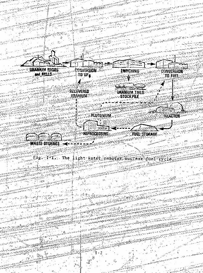
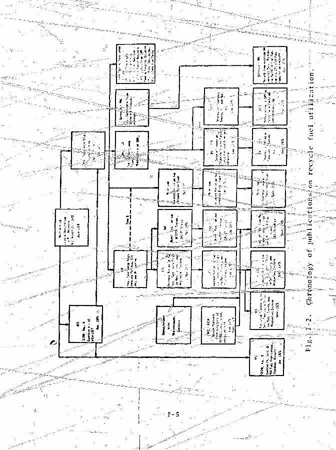
1-1 Tlte light-water reactor nuclear fuehxyel-e = ._,r.._.i;-t1-2 Chronology of publications on recycle 7_ 1
fuel nr ill ?:i ion. •--"»—• -. • .-~. -. . -.-^777 :^ L-S
11-i MO? piocess line (average flow per 8-hs h u t ) _ . . . . ...... . : . . . - . : r . ^^-^ S : . . S l ' s
11-2 Clean scrap rtco\tlx systvii. T . . . . . ^ . ; Cla-1111-3 Analytical service^^^eilit)^. . • .---v^S fp. . ;- 11-12
•II—5- P r -o ' ce s - s^bn- f r a i h i e r a r c h y ...._.,_,, -.".- " ^ s & S ^ j . 11 -19
I I - 7 ~VLXxa^^Srr^dntxol hardware "configuration. . * .L I_I-2-6II-8 Plant "ma S^: es !KFFVwt s e-'.i--r= -_ J jj . . . . ir-"S211-9^ " First-f loor plan o~f iTfie^siinghouse RFP.H~ 41-54Il-lfr Second - flexor plan oj7 the Uestfngfea^^rc , . 11-3511-11 Powder comp^ctsioJi sy sXeni section. . . ''"r^r^^.T"^^.' -!"^^Xi-=J2 s t o r a g e ves_sel_ s e ^ i o n T ^ v -. ^ ^ ^ . . , J . . 3^^^ :^J i -a>11-13 Canyon s e c t i o n . n. . . , V . . . . . 7" ,=^ ^ t ^ , . IT-38
-11-14 Chargie^ weighing and b lend ing sys tem, " ^ - 7
JI-I-2 Structure of the safeguards cdorutimtien--.4^7 "l";-737~r;¥--4 i_---.s_>*stejn. . . .' v . . . 7 . 7 ~. .->-..........,»<~"V .'•!-.xisk^x ; Safegtjards^"ciogip^nn|r network a r c h i t e c t u r e ; Ti
U l r ^ — — Safeguards comi>utei^ network vo te r a r ray . 7
IV-1 Mater ia l balaivceTats^-cusup data from4 wk of ty\iicpl^hxO2 powder urflaading
I_VJI2_ Materi?st balance and c\vsum data frompowder unloading
-.——v
^ y ^\ t and cutfum data |ronF~ ~~
"4 wk of typicalJ^uO^ powder unloadingusing measurement strategy 3.
I-V--4 Material balance and cu5u'm data fromA -wk of t>j:ical MOT jiowder blending . . .
I \ -5 Compaii^op of cusuJn data from two d i f f e r -pent 4-vvk p e r i o d *f MO2 powder blending .
IV-6 Mater ia l balance and cn.;;:ni data frnri4 >%k of t y p i c a l p e l l e t i n g
IIIIIIIII
,r-
IV-
IV-
IV*
IV-
IVi
- 6-32-;34
14
15
16
20
21
24
xvi 1

^ - - • • -
^ p ^p'l^0^_z_L; Material balance l l ^ ^ _
IV-&_,., ,.v: v-Miftifr^l'•"b^il^^ 4 wk
^i^feTial' balance^ and c;us,um;|dat3 ffqni J_ ^ g j ^of typical oclean Lusing a 5° JviDA
powder ilnloldiing opera t ion • .•::--^,..Cupper) wi th that=w£pT ,a ,^i»dom d ivers ion i~- :!\ ;scJieme^appiiea^ttciilgl | . T jJ .^-L,.-^;-.'"'.^'.__ •_ * • • ;IV-36(
-V-raaslTchar^ in normal^PuO, J » 6 ^ e a i d f X b * C ^
' i h a
5. p ^ ^ ^ ^ ^ ^ ^ ^nbrraal ^yO^p^w^F unloading operations
7 _" Cupper) vifh"tlte^ox^aj\inifp:rin diyersiori..=-.. 7] " ^ "scheme ^ppHed-(lo\^e^SE<a^gi',"!:."". • . • w ^1-VSSL" •^^Vysasi=.:^hart^_of- trends_.dei£^s^^Tv^n-o^i^
# S ; : ^ ! 1 ^ ^
IV -15 Rei i a DiTri ty-s-fas functions-01
^." ability of the PSG, SCC,; or MAC .. . , . r . iy~?]
A-l Feed material receiving and initialstorage , A-2PuCK unloading from containers. . . . . . . A-3Flow diagram for PuO2 Jtorage and blending. A-7I-'low diagram for MO, blending* and storage . A-13MO2 powder blending". . . . > A-.14flow diagram fet -MQ_ pelleting A-22M0 2 pelleting . . A-25Pellet sintering. , . A-33I'low diagram of pellet grinding,inspection, and storage . . .~^^rj. . . . % A-4GPellet grinding , . ,~. . . .-- .3. . . :. . A-41Pellet inspection and fuel rod;;loMi^g. " v W •• A-4?Fuel rod inspect|ioh^ storage,""ana shipping .A-56
A-\-
A -A-«
A-A-A-
2345tf
8y
A-10A-A-
11•12
C-l A&s-eini>ly?"drawing of tfreT pdrtablp^SNAP."_. ,._.._!;.- l£~'?~-O 2 Schematic^At-'thc 252cf jr^.s±-ne^ut^ng«^=ay; "in—; ,-.;;:
C- 3 SGS^s^tsiiirfSTlpasla^e ar ialysis ;:dx r^r~ ^Z; :n - ,.•;;--:..
M rgnl l i ra ^ a ^ d ^ p ^ t o n i J J j f t ^ s ^ r ^ f c S r ^ ; > "T.«.;-;_.L_4---.»-: «! - - ^ ^ -C-4 P r e ^ ^ q r i Q y r ^ B ^ :--•'-.--,.,_ .^
D-l(a) PUO2 c a n i s t e r lcofctes*a,. _. '• •""•"" "• 1 • • "."•" • - • L .-D-l-9P-lfb) PuO^'j^jKper^^fansferrcJd ltd- the 'bulk ' I •;-; :'
D-l(c) ^ | ^ ^ ^ | ) ^nnS^roj^cJ^nsp^opej^ftlons v .:r . . ....,, , . D-20
D-lfd} PuC^rpOKler holdup-a-t^th'ei routihg valve 1in tKd ^hAfiffilirlt" trailsfgr-k-MSe-.^'. . .J . . . P"2-0
D-l {%) Sample^ ot a 3<enjy^pE&se5tclf cani^te^r and-^r--1 —,, , v _[•._.,;..from trhe&toii^^^iror^ge v ^ s e f for a h a l | ' s i s , v D-21
D- l ( r ) Acc^mu^fed fuC|j p o V d e r J i p J ^ ^ i ^ f t ^ f i ; ^ "E; s to rage j ;
thev-'compact-'oS'r1"""-""^-'.!; ,.;. :. ••,.__._. * .----r-j'c"^ "v ;"V . D - 2 3
boats ar* iret ^resolyeiO • • v . r ; > ir v ^ ^ D-23
B-2{c) MO.2 J3owd<y StivGnto^y in the press b; 1 h & " > :
B-2 fd) Accu^Ulat^jMgo^P^wd'l? ' ^Mr";T2p i n• peli-^H^fiT^tati'ojiVi.J'/^r.,,^-""-;-::':^". / - / r r V - v - . ••;• D-24
i i - ^ ( e ) Clea; i^M^ u&c^S ;p--fro"i i rpel le t ing and s ; i-cleaj i f lpi ioperrat ions. . , . , . , . r- . . . . D-25
15-2 (f> DirtACseraj» and was t e from t h e p e l l e t i n g ioperation . . ~ 7 = 7 T — ^ , , . . . . . . . . . D-25
D"2(g) MO2 powder flow ([integrated each hdur)from the storage silos into the compactorfeed hopper . . . . . . . . . . . f . . . . D-26
D-2(h) Inventory in green-pellet boats onija •con\reypr to the sintering furn^ceil, , . . D-26
E-.l FAP as a function of AL . . . : . 1 .^ v . Et3E-.2 DP vs magnitude of diversion for several
^-3 ProtraMllty p'f-not detecting a diversionof w a ^ # t a i d e ^ ; E ^ p j r - ^ v e r a l va lue? <?f-At:. , K-;6
E-4 Relat4eR^*ip^|aiiiong"AL, FAP, and DP fo r nod i v e r s i o n andLfor d i v e r s i o n of magnitude B.
• The DP i s thejp^tim of the tvo shaded a reas . E-7
xix

•F/UURfS fcont)
XX
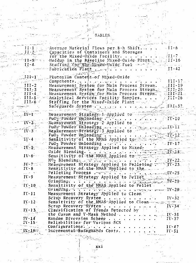
TABLES
11 -1 ;• Average M a t e r i a l Plows p e r 8-h. S h i f t . . . . - 11-6J I - 2 _ r2Z Cajjacifties of Con ta ine r s and S to rages~^-~~~^ f o r ^ t h e M i x e d - o i i d e F a c i l i t y . . . . . . . . . . J I 1 - ? •"W^~~ Hoidup-in-tJie_Bfseline Mixed-Qxid® KarKt> "_.:: '._.., i 1-16
- — -•••• - -Fabricat ion' Flaift _,_l.-^4-.. '"-"•. •."• . . • | l - 4 2-• = " I I ! "
y_ Conte*tt=«of Mixed-Oxide^ : : r ^ : " " - Compchents. „„ . | . J,.-. . 4 - , "; • • • •"""• • •- • : ' H I - 1 7
I I I - 2 ,; Measuremerit^Svsjtent for Main Process Stream, .....jIII-19l=iI-3 Me-a.&ureinehf" System for JMain Process Stream.i;; j;III;-2Q11T - 4 Measurement Sys temifor |Ma in Process ~Strf£inT\ - i i l l ^ i l -IIIH*> - - - A n a l y t i c a l Service 's F a c i l i t y Saniples. . . . ; J31-26I l l - B '-•• . Staff f-ing. for t h e "Mixed;':Pxide .Plant---v.--- ; i" ^ >< : _
=— '-.. Safeguards System-. '^ ._ •_?,_?:..•_• • • •.. •- ->^—^- -.— i./'"—- -XIX- 3Z.
Measurement- ^ti^jtegAarl---%5pl;-teci to -:•^^=#^;x-^v^U~. -fe|%^dF^S^^r\^C^. . . . / . . , . . f\'-10
2 Applied to y^ = ; d
IV-3 Meaisureinerrt^Sifra"treg>r i 3 Applied to " , t -PuO2-Powder Un^oadiirfTr « • • • • • • ^ . ^ ; ? : : ? ^ r l 2
l^'-4 - Sens i^ iv i ty^of the JIMAS Applied toAi^^-^^^^~^^S.:i PuG2 ^Powderi Unloading .v-7a^V . . . . . .% '•:,• IV-17
IA--5 : Measurement Strategy Applied to Mixed;- ! „ _ ^ ^ = = = -Oxidci Blending. D ^^^^^i^J&
4fMO2 Blendingv... ^"tS.Z^ / 1 ^?X
1V-7:: Measurement Strategy Applied to P e l l e t i n g " " " ^ TV-23IV-8 Senfl t ivi tv :io,f--the«MMAS"Applied to' the, _ - —- Tell^tihg ProcesLS T^V=^~ r . . . 5 v". 'j_ ^^.^^^sl/v-25IV-9 Measurement Strategy Applied^ to PelXelL.Ji: £ :
Grinding-.' . T r ^ 1 . , ..''v'•.;;. i.^^i^2~=~-=3M^§-IV-10 Sensjitivity of tJte^MNL^JtnpXied to Pellet
d ^ T = r f; gIV-11 Measjurement-Strategy"Applied to Clean"/•"•'"
Scfap Recovery System]. . .-,..... . . . . . ."'• . IV- 32IV-12 Sens i t i v i t y Of theJ^MAS^Applied t o C k a n - - s s E r 3 ^ :
Scrap Recovery'SyTtem . . . . . . . . . . 4 IV-34IY-13 Grass i f i ca tMn of Trends Detected by ? ^ -
; • the Cusum and V-Mask Method , . . . ' . i . . .,, < IV--35IV-14 Random Diversion Scheiiie iV-37IV-IS Reliabilities for Various SCN
Configurations. .';. = . . I . . IV-47^ i ^ i t b s t s . -. IV-51
xxi

TABLES (cont)^
V-l Estimated Sensitivity of the=Ceneric MMASfor Selected Unit Processes in the r rBaseline Plant. . . . e . . . . . . . . . . V-4
C-l Emission Rate for One Gram of Plutonium . . 0 3C-2 \... __. Typical Neutron Coincidence Counter^
Uncertainties .......... .i. . . . C-4C-3 H i ^ J j o j j ^ m ^ P e i e c t a b i l i t y L i m i t s : MEqAS . . . C-13C-4 Gamjaa^pLyis^i^uT^/rTir Isot^|ra:(r="
b e t e r m i n a t i o n s i . . . r . . i . i . .1 . . . . C-l5C-S Enrichment teeter Parameters . . . . 1 . . . . C-20C - 6 •• Specific Powers of Pliitpnjum^and
_. •• - : ^ ^ M j ^ i z 3 A X t i i r ^ : : : : T ~ . r ' " . ' > ~ . ~ ^ . - . V . . \ . . ' . . • • ' . . . 0-25C-l -CaloriipetTy Error Due to Uncertainties in
Isotopic Abundances for Various Burnups . . C-26
JS-I Dejtejction^and^Miss Probabi l i - t ies E-8E-2 Detectson-and-False-Alarm P r o b a b i l i t i e s . . E-l?
XXI1
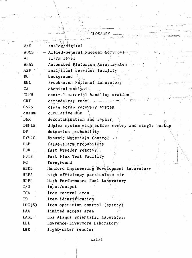
- = — - GLOSSARY™-:-— .-._™_ZIZZr
H "VA/DAGNS:
AL
APA.S
ASF
BG
BNL
CA
CMHS
CRT
CSRS
cusum
D§R
DBM1B
DP
DYMAC
FAP
FBR
FFTF
FG
HEDL
HEPA
HPFL
I/O
ICA
ID
IOC(S)
LAA
LASLLLL
LWR
analog/digital
Allied-General-Nue-lear
alarm level1 '•-. ^
Automated Rlutonium A s s a y y
analytical 'Services facility
background *v , ,
Brookhaven Kational Laboratory
chemical analysis
central material handling station
cathode-x^y ...'.tub'te 1 =; — - ^ === - -
clean scrap recovery system
cumulative sum \
decontaminatibn an.d ropair ,
duplex system Kith\ buffer memory and single backup
detection probability b
Dynamic Materials Control
false-alarm probability
fast breeder reactOrf
Fast Flux Test Facility
foreground ! -\ \
Hanford Engineering Development Laboratory
high efficiency partdculate air
High Performance Fuel Laboratory
input/output
item control area
item identificatioh
item operation control (system)
limited access area
Los Alamos Scientific Laboratory
Lawrence Livermore Laboratory
light-water jreactor
xxii. i
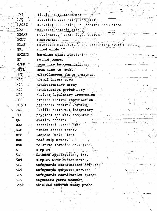
LUT
MAC
MACSIM
MBA
ME GAS
MGMT
MMAS
M02.
MOXSIM
MT :
MTBF "
MKT
XDA
NDP
NRC
PCC
PC(S)
PNL
PSC
QC
RAA
RAM
RFP
ROM
RSD
S
SAtSBMsecSCN
scsSGS
SNAP
liquid waste treatment
materials accounting compjter
material accounting and control simulation
material balance, ar_ea
multi-energy yamma assay system
management
materials measurement and accounting ?y&tcm
mixed u.\jde
baseline plant s,ajiula"tion_cod,e
metric, tonnes ^
mean
mean time to repair
miscellaneous Waste treatment
hofmal" access a r e a
nondestructive assay
nondetectiop probability ~ ;
Nuclear Regulatory Commission-
process, control eoordj.nation ,
personnel control fsystem)
Pacific Northwest' Laboratory
physicAl security computer
quality pontro| ' ^
restricted access area
random-access memory
Recycle Fuels Plant §
read-only memory '
relative standard deviation
simplex ^ L ^ ,— =--
Sciietice Apfliclitiohs, Inc.
simplex with buffer memory
safeguards coordihation coWptiter
safeguards computer network
safeguards coordination system
segmented gamma-scanner
shieldect tieufrbn assay probe
XXIV

^ ^
TMiv triple-modular redundancy"
TRL1 transurjknic --• "
TU; metric-ton of uranium ,-.-_••.'..-
UI'C unit process" COSt rblliSr ,.-.:;,z
V" : v o t e r -- - "•• ; .,— ,_ _ _J__l-.,. _..,---,L•
ZPPR Zero Foker Plutonium Reactpf' I .- '"" :!
XXV

COORDINATLD SAFEGUARDS FOR MATERIALS.MANAGEMENT IN A MIXED-OXIDE FUEL FACILITY
by
J. P. ShipleyD. D. CobbR. J. DietzM. L. EvansE. P. SchelonkaD. B. Smith
ABSTRACT
A coordinated safeguards system is de-scribed for safeguarding strategic quantitiesof special nuclear materials in[mixedjLffxxde re-cycle fuel fabrication facilities. £-thel_safe-guards system is compatible witlji,industrialprocess requirements and combines maximumeffectiveness consistent with modest cost andminimal process interfer«nce. It is based onunit process ac_caujLtiiyLjjuyjig a combinationof conventional anjj~state^£->the-art NDAmeasurement techniques. The effectivenessof the system against single and multiplethefts is evaluated usih^ computer modelingand simulation trcliSiiqUelrr r~"~T"~
•<f
-xxvi
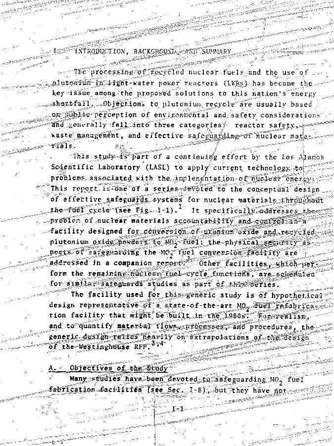
I INTRODUCTION,
The professing of recycled nuclear fuel5- and the us>e of
-nlutcnium in light-water pon.er reactors (LWRs) has become the
key issue among the proposed solutions to this njitJ.cn's '"energy
shortfall. Objection* to plutcniuM recye-lre'are usually based
on public perception of environnental and;safety considerations
and ^eiicrally fall into three categories^ reactor
Kaste0 puvagemfht, and effective f ^
This stjijd Hii part of a continuing effort by the Los AJlarfos
Scientific Laboratory (LASLj to apply current technology to
problems associated with the irr.pleire'ntatioji of' nuclear "energy.
This report ii one of a serips leveled to the conceptual design
of effective_saf*guards systems for nuclear materials throughout
fuel cycle (see Fig. I-i). It specificaUy -sddresscs_tii€-' '
.-" of nuclear materials accountability and control' in a
facility designed foj conversion of urarJuir uxi3e and recycled „
plutoniufi oxide. poK'Sers to M'^ fuel; the physicals-security as-
pects of safep««iruing the MC, tuel conversion facility are
Laddressed in a companion rppcixr" Other facilities,
form the remaining r.ucLeai fuel cycle ftmctions, are
for similsr safcegitSids studies as part of tlri- Scries.
The facility used for this-generic study is of hypothetical
design representative of a state-of-the-art M02 'fuel "refabrica- -
tion facility that might be built in the '1980s.' 'For
and to quantify material flows, processes, and procedures, the
generic desrfgr. relioi'TTeaviiy on extrapolations O-f the "design
>£ the Westir.ghouse H
A. Objectives of the^Study "
Many ^sudies hava been devoted tu safeguarding MO,, fuel
fabrication faciliiies'Csee Sec. I-Bl, but they have not
I . 1
TQUfg
£TO FUEL
^ffi®m£D U8ANJUMJFAILSSTOCKPILE
I - l . The light V.3UT reactor nuclear fuel cycli».
1-2

CIIC-:: in ".^crossing the problem - "flant i tat iycl f. rhic-:ei>ort
th-* techniques _j::J ln^trufnen* ai Ion required uni pro-
vides generic ce-s]j.sri-''for cnorJinated safem-a-ruTT svster.b. rihp
stated ob iprtive1? oi the study crc t?'• —
a- ey^'^'-i^e 'or independent e I'alunt i cu
.si---'-rnt'egrate the ?a{enusia? and f^<"ility 7unctions of
real is t ic- ' tatfr ials control aijd dccnuntinii systems for 'generic
baseline f a r i l i t i e - . " - , ~
# - Sef-ne proposed design cLinc"cpts and economic Inipact
• De-£i-ric the neces<arj KSD effort required to <Ti«er
jflinneu object:\es. _ - '
• Provide the base tor a coordinntcd approach to, L
guards_aiv.ed at tlie l icensabili t) of generic facilitic-rs.
These objectives haxo been adilresr^u-'in a njprihcT'coxi
ent vvith the rcquirc-'cntf-s^C ITRDA-DSS- (Djvisjon of Safeguards
and _Se.cur-.ty) and the- recomnicnda^rons of their Technical Advi-
sorv Committee on SafeguardsXTAC) . .Ihis co^ntt'ee was formed
by DSS in 1975 to serve as'an ef,f'i^crit means fnr obtaining
safejjuards requirements arvd views from NRC, ERDA-DRDD (Division
of Reactor Development and Demonstration), and ERDA-DNFCP
(Division of Nuclea? j-uel Cycle and Production) and for coordi-
nating the efforts of various participating RpD organizations.
E^ History of Previous Work" In July 1973, the license application for the Westinghouse
RFP stimulated a review of the problems of the large-scale useof piutonium within the LWR fuel cycle,
One year later, the AEC Regulatory Division (the predeces'-soi o± NSC) issued Volume 4 of the draft GESMO, addressing thesafeguards and environmental implications of p]utonium recycleas well as alternative uses of the plutonium. The report madethe following conclusions:.
1-3

^ s . • " Timely.<recycle..,of .plutonluiii^i^^c-lGarly the most ad-
vantageous alternative from ther standpoint of Both^conomics
and conservation of energy- resources . r;?~^;^3 _
«• So significantfadditional environmental impacts should
be associated with plutohium recycle if currently available
measures and controls are fully exploited. '
• Current safeguards measures will not meet safeguards
objectives for piutonium recycle.^—HGivevei^ a careXul^revieu of
present development programs has revealed xbnTce^ts^thal^JiOj.ilu
significantly inprove safeguards. .The Commission iyas confident^
that the safeguards objective for piutonium recycle could be
met through the implemeritationoof .%onfe combination of (these)
concepts, " ^ ^ • •- __•,
Tneneed for improv^ecKsafeguards was stressed throughout
the GESMO report. Additional.Safeguards measures emphasized by
the GESMO and relative to* this" st udy were to incorr]u©rate mate-
rials inventory features into the plant dj^sigif'and to require
improved materials control and accounting.
In effect, the RFP license application in 1973--followed
by Killrich § Taylor's book and the GESMO in 1974--triggered
the assessment of issues very basic to th<2• A E C s ^
guards program. Accordingly, under the authoriiation of a
Special Safeguards Study' a total of 8 priirate and ERDA con-
tractor organizations were given a comprehensive series of 19
tasks that uere directed toward-(1) setting the safeguards ob-
jective, (2) establishing the range of threats with which the
safeguards system will liave to cope, (3) performing a vulner-
ability analysis uf safeguards systems based on the range of
threats an»l the facilities to be protected, and (4) analyzing
the 1? options outlined and discussed in Chap. IV of GESMO.
Work on r.ost of the special safeguards studies began in
March 1975 and was completed by September of that year. The
chronology of the nuclear-materials-related studies and other
reports is outlined in Fig. 1-2: the final reports are summa-
rized below.
L-4
eo
1
tI
i
2 i J - , t !•
'J
c:o
•u,o
oc
• • " « « . . .
I-5

-::-:-l--r '"•~ii* La-wrency--Ll\ie-fJiro-r-e-...L_aPO.r3.i:76r-y (LLL) -Repor t , The
fi-Riil 4-cp'irt of "Matcri/Tl Co*H^T~~UniT~Accouiit ing Sys tems" by~~~"~- -.g
I.'i"".f:--«iJisists of an E x e c u t i v e Summary, an a s s o c i a t e d Techn ica lV "••" 1 0
Appendix," and the Science-Applications Inc. report. The
? vtjity -Uii c d the We s i i n g h o u s e RIP l i cense a p p l i c a t i o n for a base-1 ine 10.;' faci-1 i t y . RLTIMAC, ^--as a_ .Jbasejjiae rea l - t l ine me te r i a l s
aniliomputcTF^fRTuirat-tQjis, Consultations1 with"tt^p"stifff of Kesft inghousc' s lUiLtojiium !:uel-s DeveTopinent Labbra-t'im'v £he?vvick , and the ARC/TRPA- review-provideu the"noebssaryt ie to- r ea l i t y . The reports describe in detaiT the processesp;nd material flows in a recycle fiiel plant , discuss the c r i t e r i aand provide guidelines for a rca-l^tjjne materials control systemas applied to such a f ac i l i t y , examine in deta i l the physicalprotection and ""rh-eft-= Ltt i=c-at=9-i~= AJLuc;tur£L.- ajid provide estiinatesof the economic implications. 'Following are selected findings.
r ^ of "e|lectivg_rG2l = t imc materials con-Sp^nmxciaJ njuclear material j -
ig plant~s is feaSiWor^Jiv the 1980-1990 time frame.1 » As tradeoffs and[ ifhTmg^s^iri-1.he design:i of the
real-t ime ..system took pi arce-,—it._ jb g came obvious that an i r-t;p r l i -Ierft Glance between matorials control and accounting-ineasures-,and physical security measures was required to define an ade-tiuaterand economical praTftes= a=£e,gi?jards system.
" • Scrap, waste, holdu^Y^nct^iiT^pTacess material , Jinventaries are the most important parameters^a^fejcting^the. -sens i t iv i ty ?ind timeline&^s^ o/ the real-time system material;balance capabi l i ty . >°
• -The...-r.ange_s for ma1:efl=al-balance uncertaint ies inmainijtrcam process areas are °21)^^0^g^Oi p i u t o j i i ^ ^ or 0 ^ - 4 i 0 1 r -of througliput. „ ,^- ^= " —==— —
• UncertaiirtTe^s^associated with weekly-WaTeTialbalance are^ in^^tor:i=e^^"ftreF"runout generally range from 300-ISOO g of plutonium, or[from 0/2-11 of throughput. One Specialcase involving several large PuO, bulk storage vessels , whichare normally 67$ f i l l ed ! g&ve a material inventory uncertainty
1-6

o f J !vc o f j . l u t o n i u n , 0 1 2 . ' ) o f w e e k l y t l . r o u j - l . p u t aun o.Z
o f m o n t h l y t i n u U j , n » ' - . i i .
- - • - -•—••--•, • ' l h e j i i ' o p c r " u / ' C ' V ' T " • } * o r t - a n d ] o n ( r - t e r n d i v e r s i o n
d e t e c t J o n . i l D C u t i ' B i . - p r o \ i d d a r e ^ i l t i n c S J I " c - s ; u a r d s •••• s y s t e m f o r
de tec t ing thef t of nuclear m a t e r i a l . ' ih i s , coupled ivith piiys'i-"
c i i s e c u n t ) , nukes the thef t of s igni f icant'"arcoTmts of inate-->
U J I \ i r t u a i l v impossible.-- r, " " " 7 --=„-, ^r r " ^
• The ^ti idy-4ndic3ted . tha t . t.h,e cosi^oJ^^J-jista^ilinsz .,
a real-.t ime ^matprTal-s^cpjitrol and accounting system in a new
plant may be as much -is 10: of tiie o r i g i n a l cru-t _..o.f.Jthe- plari^.""
• In addi t ion iu t lie in^taJ l a t i o n c o ^ t ^ t ^ ^ ^ s t i - ;
nsatcd annual ope-iatmj: cos>ts amount to about SI. 6 .mi l l ion .
• It Was concluded that no additional cost penalty:
would result from the insertion of a real-time safeguards sys- '
tern.in the production line, i.e. , the plant production wouldv\\ not be diirdnished by the presence of the monitoring system.
\ • ? The economic impact'on electric utility rates,
\\would be 0.015 mil per kU'h, or a 0.041 increase ovrer present
\ ~ • " •
r a t e s . o _ : =- r" '" . ..-. *- I-. The: MpUEil-LabcvGatorv Report . The second s tudy con-
cerned with ruaterials contxoi
formed by Mourrd^sb'6-ratory. *" The major objective of the
to promote th^use^ of calorimetric assaf?in a recyclefuel
plant. For this NDA technique, full i3ctopic-reen4:^ol
sary because isotopic variations are the main source of error.
Isotopic control is to be achievea by first blending large
quantities of plutonium to a unifjorjm _soto.p4c fll? jSiti n-an4-r .--=
Sthen instituitinj^^anifhistrative and physical controls to prevent
mixing j)f plutonium from different blend Icxts. On the premise '
that the specific power of the piutoniurn from a sln^l^ isotopic
blend is constant-,-caloximetry can==be used for the assay, rb^al-l--
plutonium-bearing material - feedT^Tod'uctj^qr scrap. The /
study draws the following conclusions. 0 ^
^ ^ " • ~ If°the|Se measurejs -were instituted in the pro-/
posed Westinghous^-AnldersohRFP, the uncertainties in material
f\

.i=~ • . b a l a n c e s c o u l d be r edUccrd^ tq (). L i K ^ Q r - 2 , 3 kg o £—jv-htttsnFijCTK^vitly-
^ jX^£4HLrj£n; ; t j ry^^^^ : "_
^ ^ ^ = = ^ ^ 3 1 1 ^ ^ ^ ^ iivt i e s
f o r |UutOj i ium iTi f y t j i r e , J L a b r i c a t ion 'pl-aaf"S''="c":T^^u.v:ai;gh_i..eved by
i f l i j i g r o v e t t NJlAinst«ut; ien#aisbeiV:r^ e s p e c i a l I >• c a S ?
v i"t: i s e s t i m a t e d t h a t
^nX~c-an be improved byus ing _ isotopie^^nt^3l=and==ca=lGr imet fy mea suremcnt s. The ca 1 o -rinie-fry measurements wouid provider fEC.y.umi_t chec.ks_o_f.. t_he_N&V.:instruments and i>erve as-highly representative standards for
ibration, purposes. This improved measurement accuracy canused at those points'in the process whereijoro accurate
m of the plutpnjuin accountingor will hei^localize accounting discrepancies. ^
• Uncertainties^ in the .quantity of material ..JiettSMup_-JJ,n-==Ehe*pToT:ess must be Kept to the minimum practicable (84°of materials discrepancies are due tjouerrorsMtn deteTtttlhlng "holdup)." •'""" -j^Jr^-r - •• ' .X • '"" :
3. The Pacific Northwest Laboratory (PNL) Report. Thisreport concentrates on majterials co l t ro i and accountinc^andstresses the need for improvements in the sens i t iv i ty and time-iinesg^Gf^^s^s^^detection. I t examines methods of increasing „ s
promptness in diversion ^ities of unit loss detection and of various rates of loss overextended^periods of time. Tabular data are given on measurementerrors for various plants"; error sensitivity as a function oftime, andthe effect of frequent running inventories. Data onholdup for each^mcess component including clean scrap, dirtyscrap, and miscellanebus^^ffste^jare shown. These data were de-rived from PNt's "Generic Mixed-Oxide Fuel Fabrication Pliant-
14Decommissioning Study." Information" ^ ^trol and measurement errors for various inventory piTrioils
•• -••"ir o

of tlic suggestions-and recommendations made were:
• To incorporate u real-time dynamic materials
control and accounting system,
• lo designate the Pun., storage area as a material
balance area--ifith daily weight measurements, and
• To conduct a monthly formal plant inventory.
4, The BrookhavenWati^nal Laboratory (BNL) Report. The
ixurpose of trie report was to evaluate the eTr&v¥ivejies.s of
incorpor.it ing small percentages of radioactive additives into
special nuclear materials to increase the sensitjyj.ty_ fox their
ifeferct ion by doorway monitors. Three basic sensors (metal,
•gamma* and neutron detectors) were evaluated for various spiking
schemes and ii{ateria_l,_shi«4-d-s-.—The increased cost o-f .-spiking
and Hand littg tJiese materials was substantial and would result
in ah increase in the costof generated electricity 0^ wore than
l i v l R general the ejffects of spiking on measurement methods
ivere detrimental. As an alternative to spiking, a group working
with BNL recommended attaching Co sources to fuel rods and
canisters during shipment. ,
5. The Los Alamos Report. The LASL report1 'SMate r.ials
Measurement and Control for a Mixed-Oxide Recycle Fuel Fabrica-
tion Facility; A Preliminary Review,*'" reviewed qualitatively
the materials control and accounting aspects of the safeguards
problem and identified the problem areas amenable to quantita-
tive solution with existing, or reasonable extrapolations of
exist^iS|^ technology. In-this way it served to define the scope
of the present study and[^urnishtd an orderly;J&tlir\#~Jnz ±h#
work presented in •his -report:, - wnich supersedes the Preliminary
Review. ^ „=====
C. Summary and Strategy -
This report describesa coordinated safeguards system that
will^provide reliabielandeffective safeguards for a commercial
M02 fuel fabrication facility without adversely affecting its
production goals..^^Th^ugsoand^ru^^'ifbr' this study and the de-
srgn~pfiilosophy of the safeguards system are summarized below.
1-9

The safeguards system philosophy should be one of
permissive operation, rather than use denial. Accordingly, the
process must he ailoV^od to pi-oceeJ normally so long ;i.s safe-
guards requirements are .satisfied.
(2) The safeguards system must be unobtrusive. it;should
interact passively with the process,.. collecting information from
process functions. All process--control liny decisions, except
those requiring immediate shutdown for health and safety reasons
(e.g., fire)» must be subjected to human evaluation before they
can be implemented.
(.3.1 The--safeguard:?- system, like the plant itself, should
be based on current demonstrated technology or minor est^apoia-
tio55r. of existing operating systems. The use of developmental
systems rausti:.,b£ .minimized. :
(4) The safeguards system should be autonomous in that
subversion of the system by plant personnel should be as diffi-
cult as possible.
(5) The safeguards system ifccold be acceptable to ;< com-
mercial operator, having minimal interference with a properly
run production plant, high reliability, and a low-false alarm
rate,. Furthermore, the safeguards system should provide useful
data for improving process operations.
The objectives have been satisified in the following way
(items are keyed to the above criteria).
(1) The basic system architect tire is such that disruptions
of the proce=S5 are minima1. Most data are collected an d
processed automat ically, and s afeguards inquiries a re coordi-
nated through the process control coordination (TCC) unit.
(2) Process control is implemented with an automated data
acquisition syatem that provides human-modulated control deci-
sion capability for adaptability and efficiency;
(3) Nearly all the technology used in the plant has been
accepted for use=by the nuclear industry and should result in
increased r^Tiablrity, e ffsier maintenance, and lower costs.
Some software development may be necessary before detailed de-
sign is made. j
1-10
(-J ) The ji 1 ;m t i n format i on system consists of a process
in fo IT. at inn .-.y tem ciud n safeguards information system, both of
uhich are accessible to authorised users. The safeguards in-
fo nation system cannot lie affected by plant personnel without
nriur approval of the Safeguards Officer.
(5) The-safeguards system attains reliability by operating
througl] three computers connected in a triple-modular redundancy
(TMRj mode, each checking the other two by means of background
processing. The system gains respectability, and the associated
acceptability, because it is based on current technology and
has been developed with the close cooperation of the designers
of this nation's first large-scale MO., facility.
The feasibility -and effectiveness of the system have been
tested by applying efficient diversion detection algorithms to
data from simulated plant operations. Typical threshold sensi-
tivity levels that include unmeasured in-process and diverted
special nuclear material (SN'M) in major plant process areas are:
.100-200 g Pu (about 2* of throughput) for a single material
balance period during winch a. 8 kg Pu, is processed; 200-40G g
Pu (about 0.2' of throughput) for any 1-wk period during which
-v 160 kg Pu is processed; and 400-800 g Pu (about 0.1% of
throughput) for any 4-wk period during which! 640 kg Pu is
processed. These results indicate that materials control on a
unit process basis carl result in the effective safeguarding of
nuclesr materials in a MO- fuel fabrication facility.
The overall costs of the integrated safeguards systems
described in this report are not well defined, Hovever, we
believe they are considerably lower than the 10$ of capital in-
vestment previously estimated. The staff required to operate
the safeguards system, exclusive of guard personnel, is less
than 101 of the total plant staff.
D. Format and Contents, "
the baseline,plant—design, based on the Westinghouse RFP,
is discussed in Chap. tl. Processes, capacities, and flows are' -..• if " .:
I-11

described, as well as requirements for staff. Details ofioper-ations and equipment are given in Appendix A.
The safeguards system and its subsystems are described inChap. III. Desi'gns and operation of the materials measurementand accounting system (MMAS),the safeguards coordination sys-tem (SCS) and the safeguards computer network (SCN) are de-tailed. Safeguards operating procedures and staffing require-ments are defined. Details of the plant information syste7ir=aTe—giA'en in Appendix B. The NDA techniques employed for materialscontrol and accounting management are described in Appendix C.
The performance of the conceptual system design is evalu-ated in Chap. IV. The modeling, siiulation, diversion ;analysis,reliability, and costs are described. Details of MOXSI'M, thebaseline plant simulation code, are given in Appendix D, which1
includes a detailed description of the unit processes into whichthe plant operations are broken down for modeling, simulation,and performance evaluation. The algorithms developed for theftdetection are described in Appendix E,
Conclusions, results, alternatives, and recommendationsare presented in Chap. V.
1-12
.1.
II. THE BASELINE MIXED-OXIDt-RECYCLir PUEIrFABRlCATIONr'FACfLiT
A. Major Features , v ;
The model facility for this study of MO, recycle fuel fab
rication facilities is based on the Westinghouse-Anderson de-
sign, vrhich has been use4 -in -severs! healtfc,
guards analyses. Nestinghouse has repeatedly^modafi^dPt
sign since its 1973 ^License applicati^ in -an-a^t^empteto
pace ivith changes in technological, economic, <ind regulatory
x Sfactors. Kith few exceptions, some of which are
the companion SandiMJ Corp. [report, the design 'used in this= -
preliminary report ijs taken from/the 1975 Science Applications
Incorporated (SAI) version used in the KRC^^Speciai^ Studies re-
port. This reference design has been further modified to in-
corporate improvements resulting ffrom, the joint LASL-Sandia
effort to design an^integrated safeguards system and has been
updated to reflect current Westinghouse operating plans.
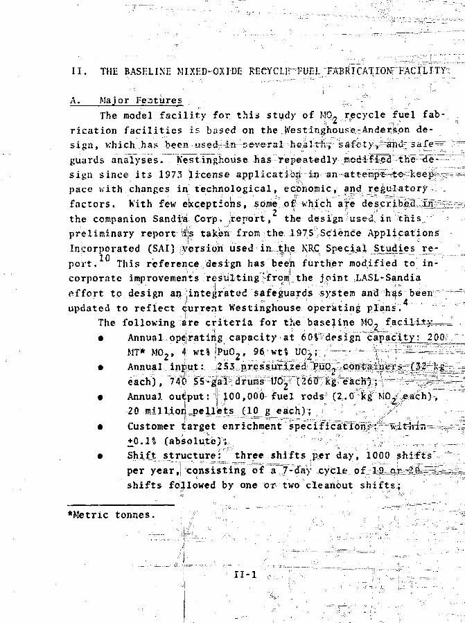
The following are criteria for the baseline MO-
• Annual operating capacity at 60^design ^: Mf* M 0 2 , 4 wt% !PuO2, 96"Wtl UO^;:. ;"•—
J
• Annual.. input..:,. jij?.j!U,,-R:r,e.$;3JJ®
each^), I'tit) •'rS^gp:?dru.J!|i--W^t^• Annual outiput: 100,000 fuel rods (2,.0nkg MOJleach)
20 millijM jiellMs Jl^ g_ each); •,.---•= „ ^
Customer target enrichment "+0.1^ (absolute)!,^ . \ ' ''' ^',^^ , '•}•$ \, •,7TTO,
Sjiiftr structure: three shifts per day, 1000 shifts
per year, consisting of a^7-day .cycle...o.f^lSs^o
shifts followed by one or twocleanbut shifts;
*Metric tonnes.
II-l

• l . i t c i t n a t u r e one 2 J 5 - k r Mj \ Mil M i n d pe i pip--..
I'lk t i>! " f l i t , J M e n d = _J- 'Mih- l j 'on, is ( a s s u r v one
• \ i , i " r i t f . ] 0 <->f t h r o u g h p u t i a i c h \ l a- ( . loan
u i , i r , 1 t o ; d i r t \ s c r a p
• . e t . n M . " \ t o i p o j - n n n c l . 4'>0 n n l i \ i dp 11 > -ivcrtoi'npfs
i r t s \ ' i t \ o i a i i u i ' i d i n i n j ; a r e a . ' '••>-.._/
l h c n o r l H . ' t H | t \ , i t i ' L1 *. i i . u i t \ h a s . w p l e tn. i t ^ M I t o <. o r p t n s . i t e
I O J p c r » o v . i t - t i . t v ' o u i ^ ' i t o t o m ' i - r t T o t w o p i o d u c t i o n s h i f t s
,ivd i ' r . , " l o t ^ t , i i u ' ) " s h i f t . P i v K s i o n o f p l a n t o p o i . ' t i o n s
! n t i > s h i f t s ; > • i n .i | i i C O M H I , c o n > t i i . i n t . \ ' a i n I ' n i ' A ' s i C s ' a r e •
o n t m i u ' i i > u . i - ' ! i ! t t i i - x r x J ^ i : ; c s , a r \ t ' p i o t C i s e s c a n n o t a J ^ a y s
• ' o ^ i K l ' i M n r t 1 . 1 e l - I n i t - - . ^ h i f t s- a ( e u s e l u l i . ' i n l ^ f o i p c r -
V n r t i a l | l u t t ' i i i f . I o c J J o i t h e l u h i ' l i n e p l a n t i s 8 0 0 0 k i ; ,
o r . ( K n i t t i n ' t 1 i K l . oi : J o p l u t o n i u i \ o u t p u t o f t h e p r o p o s e d -, • .
M I i f . ! ' c n o r 11 i u l i . i i ^ c r v n c s f \ C N l \ ) l a c i l i t \ f o i l c p r o t e s s i n j :
t i > e s p o i l t f l i t . 1 ' i i i t i t o i 1 a n n u a l l y h^ . f\j f t > L0(10-MUi? p o i ^ e t i e ; i c , -
t o r s , f o r f u i t l i c j >. .•:• ' p ; i r l s o n { a n n u a l ^ t - i | x r o u i : l ; p u t o f c i t h e r t l i e x
\ M ' V ! i" ,ov" K e r r ' i k i ' ^ i ' I ' m . i ! i t i e . s i s T ^ f ^ l : , ^ p l i k t o r i i u n i (^> Z.2 MT ri
\ ' • • • p r F K V i : o l ^ - M h " i ! a t \\ i cTfJ I K l | f u e l Cabj\ c a \ i o n s p l a n t h a s a " "
3 t ! : r : n i V . { t p i V t i n t h e r a i u . f 'oi' K f O O r i o O P MT l o i " t o t a l ' u r a n i u m f u e l .
I n t l ' e ' ^ . i - o l i i * . J i s i i u , h i j i h t h r o i u h p u t o f r e c y c l e v p l u t o -
v . u i- . u li 11 \ • i. , i t ' i o ' . t e x c . ' s s i v e r a d i a t i o n e x p o s u r e b y a u t o -
>! i i u t l . e ' . i s i . j : c« - "• n L i i i a n d I n I c x a t i n j . 1 , i t i n c a n y o n s
a i t ' , s i . u i j i j t \ a l i s I m o a i j r i a v s o f p i o c e s s i i i L ' , . e c j i i i p m o n t i n
t l i v n r . o n , i I ». i I i s t * » e % h e . i d C)_ , in« . s . n u l o t h e r e q u i p m e n t f o i -
ii% o f t r a i t 1 t ( . i l a 1 , . 1 0 L O I ' O I I t o s p e n t f u e l r e p r o c e s s i n g f a c i l -
i t i e s . H o a u t o 1 i t i o n . i i u i . a t e r i a l l s o l a t s o n o l " s u c l i a r r a n g e -
ivt a n . IT'A i! t i i o n i o t i n - p l a n t " ^ j f e j M i . n d s a n d c o n t r o l o f
* V ai'i i1. t a c i 1 i t ' T i t e t h e i n t e k r a t i o j h o f N'DA", ; i n d a u t o m a t i c d a t a
; i i H ' t - > i n j 1 , i n t r .i c o r - r o n p r o c e s s a n d > a J £ e p , u ; r r d > c o n i t i : o l - s y s t e m .
> t' c o u r s e , n o t a l l i ; : a t c j i a l . , h o n J l i n j ; o ] > c j " ' ' t i Q n s -••'iTre ' a u t o m a t i c - -
M>: i ' a r c ; ' o r i j y r ; " . e d r e t i - e t c l y u i t h m a n i p u i l V t ' o r s , o r i m u i u a l l y
N - 2

through gloves. In contrast, existing plutoniuin facilities!
rely heavily on--manual operations. ..; j
The iiuiin-fr ytc Trtrear.i for the M0 7 facili t>V comprises!
receipt* and storage of feed materials, transfer of feed to £h
main process stream, blending I'uO., and UO,, paw4er preparation,
pellet pressing, pellet sintering am? grinding, and fuel rod
loading, storing;, and sjaipjsint.',. Coupled .to the main processes
is a clean scrap recovery system (CSRS). !
lissent,ially all recyclable scran (10' of thrcLujjJiput) i?
recovered in the CSRS and recycled as MQ^feed material. The
XSRts condltifJjrs rejected pellets and powders hy crushing the
scrap and subjecting it to successive oxidation and reduction
steps to produce a powder with characteristies suitable forI
blending, pressing, and sinter inc. The plant has no capabilityto recoyer dirty scrap and waste, which amount to 0,5° of the
throughput. ^ I
Support ope r airiorxs i n, the ma n u Ca c tiiriJ1- % a r ea a^e t he ar;ja -
lytical services faci_lit)i {ASI-") , miscellaneous waste treatment
facility fMWT) , liquid waste treatment fLU'T) , and decontaminia-
t ion ;md rejuiir (PfiR) collar*,
the AS1' is a complete analytical chemistry laboratory for
analyzing smaj 1 samples from th(? process line. Conventional
-analytical metho^g^ arsJ4i&e«3li ^
The MWT operations, : re essentially sorting and highgradjinj;
functions, siniil jc t;6 the hoad-end operations of a full scrap
recovery plant, but without Waste recovery capability. The •!
products of-MCE., and LWT are disposable wastes that are shipped
out in 5£-j^il drums, and recyclable material and "concentrated
scrap that srj stoxed^in fi-"l|ter containers for future disposi-
tion. No acids are usSd [in tshe plant, except to dissolve small]
samples in the ASFV"°and mjost operations involving liquids arcj
performed with detcrgeni^jor w,ater which is subsequently fil- •,
as Isby evaporation,
eefitrfete, which, is cast i
am|nat ion . y\fter volume reduction!
aqueous solutions arc fixed in
55-gal drums.
It-3

The DcjR cel'iLs ai-e of conventional design and provide both
direct and remot-e-maintenance capabilities for equipment >-o*
cated in the canyon processing line.
E. Process Pgscr'ipticn-
Tfce processes for the base line facility have been de-
scribed by'SAl.iU The following descriptions were derived from
that document, and were updated and verified in discussions
with K'est!\nghouse. They arc intended primarily to provide the
design basis for our critique. Appendix A contains more detail
on the main stream processes.
1. Process Streams. The feed, product, and clean scrap
flows for the MO. p«i>nt are shown in Fig. II-l.4'10 Average
material flows, including sidestreamss per S-h shift are given
in Table II'1, and capacities of containers and storages are
presented in lubic II-2.
Processes 1A to 4A: PuO2 receiving, storage, unloading,
and process storage. Shipping containers^ for PuO, feed contain
shielding for personnel protection, ami-can dissipate up to 20
h'/kg of the heal generated by the .plutonium. Typically, 32 kg
PuC, is contained in four Ctin? (primary containers) inside a
secondary pressure vessel, vhich x^ centrally located in a
shipping cask. The shipping container design, which differ •
from the L-10 configuration assunedl by SAI, is described in thei -f
procedures for receipt and storage given by Sandia Corp." The
storage vault, located on the second floor of the manufacturing
huiluing, has a capacity for 40 shipping -containers, correspond-
ing to a S3-day feed supply. PuO, is unloaded from a shipping
container into three isolation compartments in series to avoid
contaminating the shipping container. The primary container
for the PuU7 is disposable as waste. "In the original design
the cans of PuQ7_-2re weighed, openeK. and randomly sampled for
chemical analysis The contained powder—fs transferred pneumat-
ically to one of three ciitlcality-safe bulk storage vessels,
II-4
; f
M V ' . . . i i i - : ' . " ' , i i . i ' . - r
t=i-;! < ^ S ^ - v 1 - ^•.««.v.;..,-'TT , . .
:L• • ' I L : t » - ^ _ i _ - = - ' _ ' _ . _ - - — ' :
J j ^
I W.IMO • II SL>H fl • MISttuiteiiNo - J.--MV:I_
MO, • 4 *1T. fuOj t *, A1 I **.
i Fun. Rt.o rou PiLif T«i ruct KODs'ii.";iN''. c
• % CIIANNLf.S- raiua KQOS
. 1 _ . , |' " l l , . K >. - .
^" * t
1 '
11-1. M02 process line, (average flo* per 8-h shift4)
I I - 5

•• M
Unit Process
1A. ; Pu°? receiving••'• \ ' 1
3A. PuO- unloading
4A. ,PUO, blen|ingf and storage
S. blending
\
,_, \ 6. Mq2 powder storageV • | , 7. MCL pelletizing ,'\*
9. Pellet sintering
II. Pellet grinding'
12. Pellet inspection
13. Rod loading ;
•I , .;'
.14. Rod inspection
1;7. Fuel rod repair
iiir. • C S R S ' I i
\\ if i:\AVfERAGE MATERIAL
TABLE^lf-1
PER 8-h SHIFT
PuOL Throughput (kg) t>uO, Sidestreaw Type
«.09.; :i.
:S.O7?
Si. 0 8 M
^ Analytical samples
jj Analytical samples., !: i .'i
Analytical! .samplesf- t : R e t i i r n s • ? | . - ;i
• - ". \ 'l • \ - , ' ; i 1
MO, Throughput (kg) MO, Sidestteam Type__2 ^^-> u z . i ; . .. — 2 — r ~ -
, ^ " : - ° ' W a s t e * ' -• . -iDirty iicrapAnalytical samples
236
225
223
221
203
203
Reject subr
Clean sctapKaste \\ iDirty, scrap - T
Clean scrap ;nirty scrap
Kaste ';' \Dirty scrap \Clean scrap |,Undamaged pelletsAnalytical samples
Dirty scrap «
K a s t e •• „ '""'\Clean scrap \
: 200\\
23-4>\
* Minus sign denotes return flow.
RejectedRepaired rods, VWaste V ^i<aste ;• i.Analytical samples \
Stdestreaw (kg)!
0.006 to ASF> <
0.002 to ASF
0.002\ to ASF-0.008 from MKT*
Sidcatt-eam (kg)
0 . 1 t o MKT0.1 to MK!T0.024 td\ASF !11.2 to recycle Mp,
1.0 to CSRS,0.3 to MKT0.3 to; MKT t. --"'
2.0 toU;SRS 7 '.Oil to4 MKT ; i0 .? t o MKT = : |0 .3 t o MKT l
IS .6 t o CSRS- 0 . 8 from rod repair*"
0.033 to ASF ; ;|
0.1- t o MKT
0.1 to MKT;; ; \1.0.; t o rod;\repair \ \2.4 t o i i o d j r e p a i r '••]
- 0 . 2 from r<)d r e p a i r *
• 0 . 0 2 ' i t p -MWT ..v •!
0.1 to MIVT '0 .001 to ASF «•
UnitProcess
3A
4A
1B.2B
23
43 -
'it
5
5
5
5
5
6 " : . -'
6 ^ ---'•••'
7,8,3,10.11
8
10
TABLE I I - 2
CAPACITJ.'.S Of COM \IM'Hc
FOR lHi. M!Si.!)-OXJ!)!.
I icscr j p t i o n
\\l) STORAGESi M:ILITYNumber of
Units
FuO, shipping container
PuO, storage vault
PuO, can (4r per shippingc6ntsiner)
Pup, blending and bulkstorage
SS-gal drum UO2
L'Q,, bulk storage
MO.,- recycle storage
PuO, feed hopper *
PuO, weigh hopper "
Recycled MO7 feed hppp^V
Recycled M0 2 jweign hopper/
UO, feeq^hoipper ^..^ 1_
UO. ileiRh hopper
MO, blender
M0 2 storage silo
Compactor feed hopper
Pellet press feed hopper
Pellet boat™ '(5 in. x 12 in. x 12 in.)
Green-pellet belt conveyor.. storage "j^^'
Si n t erec1 -pel \exMitfiT age(bufferj^f"
32
92
Unit Capacity
?2 kg PuO,
l'lO PuO., shipping'containers
8 kg PuG2
170 kfc Fun, (l blerd)
2SO kg U02
100 drums -—^
3000 kg UO2
720 kg MO,
kg PuO2
kg PuO2
2
^2SO kg UO2
11,1212
13,14,is; 1615
15
1 5,16 _ ^ ,
Pc llft't ray
; Sintered-pellet trsystorage (buffer)
«* Fuel;rod -,p .. _^*r^\.~
Fuel; «rod#storage channel
Fuel rod storage -*^
^Shipping oox^*
kg M0
225 kg MO2
kg MO2
ISOOpellets,,7 TPi,kgTMO2
58 boats
13S bolts
900 pellets, ? kg MO2
444 trays
200 pellets,, 2 kg, MO,
50 ro<|s, 10Q.; kg MO2
25,000 rods, '\
200 rods , 400 kg MO2
II -7

capacity of > 170 kgr-the amount
Lj|aterrial in eac1T=itS;raTge=Tresse-i,=is-JbJLenjed j"melima t-
... ically with vdry air and Efiefi":1a:mpled for^analysis.
Processes IB to 4B: UP., -receiving, storage, unloading^—
and process jftbrage. the ,U0, is received in 55-gal dru.ns and
stored in a separate area. The contents of a drum are moved „'•'
pneumatically to a transfer hopper located inside tHe=Tnai3T=K==-=
process building. . '"..,, ,,
Process 4C: Recycle MO- blending and storage. Three
blending and siorage vpssels, each having a capacity of 720 kg,
receive MO- povder from the CSRS via pneumatic transfer. The
MO." in each vessel is blended pneumatically (using nitrogen),
s amp lejl^f ox char act e ri 2 atlgn jaild returned to _y e_j)r_oce sj__J;
stream in ther courseidr preparing % sub'Ms^end. Rejected MO^
sub-blends are returned to recycle storage. 4 ^ ^===^"^
,., Processes 5 and 6: "MO, blending and storage. A sub-blend
of materials is made up from three different feed1 supplies:
PuO,, lib,, and ..MO- recycled from the process stream. Each type
of material is transferred from bulk storage to ajfeejdjiopper „
which thenVautomatically meter^ out a programmed amount of
material to a-'Weigh hopper. Materials from the three Weigh
hoppers are then released to the blende^., A^, the completion of
the blending cycle, the sub-blend is transferred pneuraatifcally
through a reduction mill to one,of the nine MO- storage s'ilos
reserved for a singlef sub-ble,nd^f225 kg .MO,). s
Processes 7 and J8: Powder prepaFSti-en^^ellet pressing,
and pellet ;Storage. ifThe incoming feed fo=r, the powder gTaitaia
tion^anti pellet-pressj|ing steps is a 225-kg sub-ble:nd from one
of the MO- silos. The material is,compacted, granulated, sand -
mixed with lubricantj The granulated particles are fed to the
pellet press. The resulting^greejl pellets are loadecLinto
boats that sit on a donveyor, The gre«n pellets ,^e inspected
for density, and rejects are returned to the GSRS1. The con-
veyor transfers the boats to' tHe sintering furnaces and acts as;'
a buffer storage. | ,, \ f
- " 1 .':. ' • • 1 1 - 8 ':' , •••'- "i
9 and" 10 r Pe71 iet sinterinR and storage. Boats
of green pellets are selected from green-pellet storage aYid /
conveyed mechanically; to the pel|et:js inhering process. Five
sintering furnaces op^isg^^iri^ipjaXjaYlipl. The density o^T^se3^^^-^
lected pellejts is/letermihed, and any bverTired pellets are/
returned to the CSRS. Underfired pellets are returned for more
sintering. Boats of acceptable pelleits are stored on the r ^=STnter;eu=-pellet conveyor pending thei'r release to the pellet
grinder. / " . &, ,=; " _•> ' "~j --==^-1..—_ "^J/~ r: •
"""* Processes 11 and 12: Pellet grinding, inspection, and "^ I-
storage. These processes take sintered pellets frosti the boats,
grind their surfaces to a specified _d_ ajme_tfi.r,-inspect them for
dimension^ and ~jiar£~ic§r» nd load the accepted pelleis. into trays.
—Two independent process lines (one operational, one stand-by)
are available. Grinder sludge, chips, and off^specification
pallets generated in these processes are returned to the CSRS.
^Trays are mechanically conveyed tooone of two buffer storage/
dryer unitTrami-stored by a stacker-retriever system. 0Pellet
samples are taken from the storage/dryer after 4 h for moisture
Processes 13, 14 and 17: FUgl rod loading and inspection.
A tray of pellets is retrieveiTTtom storage, and "^bw^b^f spei-^
lets is aligned with the open end of a rod and fed_ into the rod;
This is repeated until the specified number of pellets has been
inserted. Each rod receixes_an end spring and a top'-end plug,
and is then decontaminated^ The end plug is welded in a helium
atmosphere, after which the^roSs are inspected visually, radio-
graphically, and with a helium Jeajk_detector. "There is also
provision for x-ray inspection and a passT!'vV;=gaTM-a7T**)s===£ujUl=41od__
scan to check the uniformity of the plutonium enrichment. Re-
jected rods are unloaded and-,,th«?.,...j,ellets are returned to the
main process stream ox to the CSRS. Mino'r*'"'rod'"'re":p'alrs-:are'inade.
Froceases 15 and 16: Fuel rod storage:and inspection.
Fuel rods are stored in channel carriers, whTch^aTe=-plac,ed_in
one of four shielded storage compartments by a stacker- //
retriever, the yauit as described by Westinghouse can hold
- ."• I I - 9 •"-• • / ' •

25 jOOO^^il^gr 500 channels. Boxes whji j 2.0.0- rod capacity are;used for i T i j
^>^ Process 18: Clean scra^"r<ss^vry system. The CSRS condi-
tioiiV clean (high-purity) MO, scrap y lTVttt dL fr01'1 pellet fab-
ion operations (process steps 7, 9, and 11) ralf3~-£wcatK fuel
air and dismantling (process step 17), as shown in, l:ig>~~
11-2. Batches of 20-30 kg are reduced in sire in a "\rusher" and
are subsequently processed by multiple oxidation-reduction ,:,
steps. A batch is processed through one of tuo, uxid^tJ9'V~
reduction reactors. The forming gas used TOT reduction is non-
explosive64 II,-94'! N?. The recovered MO, powder is transferred
to recycle storage. i
"Process 19. Analytical services facility. The ASP is a
conventional _ analytical chemistry laboratory in jyJucth small sam-
ples from the main process stream and^the- I.lVT tuuI Mf'T^Tiicn lties
are analyzed, as shown in Fig._TTj 3. l-ach of six cHticality
control zones maintained within theASTC^n^a plutohium...Jimit
of 290:_..g.± —-tA,l-l-samples "are transferred pneuniat ica] ]'jy fi'pm the*
source to the central material handling station (CN'jllS) of the
..ASF1', where they are logged in, split, and distributjed for dif-
ferent types of analysis. The estimated weekly lo;kl is 200-300
s a m p l e s . . . • ^ . c,".:->- .. •'
Processes 20 and 21: Miscellaneous waste treatment and
dirty scrap. A block diagram of this sorting and high-grading
operation is shown In Fig. ,11-4. The- following/typical mate-
rials arc received.X f ] "
Solid WastW /
• Combustibles--waste paper ,
• Plastiy: and rubber — gloves ,! bottles , tubing,
9" Filter elements and cartridges, and
•.., Miscellaneous hardware.-
Dirty Scrap „ s.=.,,^^=^-^-^—^^\,_:-^-
• Contaminated MO- pellets, chips, and sweepings,
• ' Excess analytical and quality control samples,;, "' a n d ' 1 u , • • ' .-, • ""•
• Filter elements from LWT;
!'• = i l - i o . ' '• " . . • " •-. -
Storage
C_N~_-
M)eiin<l
.,=_-=,
. —
— " "" '
— ,
Pel
Sin
_:—~--T7-
<-t -
L«-l t !)•_!
1
_ - _ = — _ . - ,
—->
fTiTpbTi.jt"
Ijrindlnfl
; w ) ! •..1 -fiiiiI ) • " !
Cont.iirit'rr.
Powder
5cr.ii) RecoverySy s trip
Crusher
ReactorFeeder
Rodi torFrodn"
Oxidation-Rcdacttpir"Reactor
i8f tluc t ionRpiK'tor
Pneumatic Transfer
PncumatieTransfer (<C) Recycled MO:
Blcridino and
Recycle-HO-
Fig. II-?,. IClean scrap recovery system.
11-11

AMAIVTCM.iAMfiii. ronocmx P«*1HII!UJ
— — -. ^
~IlJSu=.~ J Jb^—,4-J5S^T r -1 — M
UU0 4*w <rtL( HI
euAhr.,0* — ™--
CfNlH»L MAHfllAlHANDLING &IATICN
MCMWATICTHAKii FA /^i, KHfUMATK
^ ' 1HANSI I I I
• *
ICi ' .UViLAM<ALA30KATaaV
iCSVSAVfLE:
rtivsiCAi.CHANACTCKI2ATI3*!
J
oilAStoilACC HS5CL'NG AND »Ullt
f.-ISCt LIANC OOS WASt(TH'ATMINt IMWTI
IIOUIOMAIIC
„_ 1_J_
UttAliruMAfHIClAiO^AfUHV
V(CINCril«AI*MICLAMOHATOnV
IIOUIO WASTEfRUdlAIMCNT
• A M A l IM I t l D I O I M , » # fu
I:ig. II-3. Analytical services facility.
5-3
i r jt t r
Flltrr
-----
To------
ifllUr
C«keReittiii's
_ 1 -
toIVT
Wast«
IKep'ilr andRecyclt
mi
Dr.- ••>•!
I l l t t r
5o1ut(cw
u ur
fltvtrnn
C«mb'Jft1ble
I _1«s«it
Dirty Scrip
Crutfi•nd Blend
1 1-Mler
Fig. 11 - 4 . Miscellaneous waste treat/nent system.
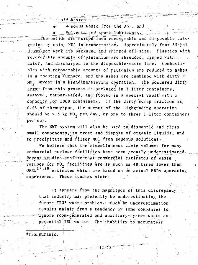
Z " " — ~Aqueous ua&te from the ASF, and
lf into recoverable and disposable cate-
gories by using XDA instrumentation. Approximately four 55-gal
thrtinrsfpef week are packaged and shipped off-site. Plastics with
recoverable amounts^o-f plutonium? are shredded, washed with
water, and discharged to the disposable-waste line. Combusti-
bles with recoverable amounts of plutonium are reduced to ashes
in a roasting furnace, and the ashes are combined with dirty °
MO, powder in a blending/sieving operation. The powdered dirty
scrap from this process^is packaged in 1-liter containers,
assayed, tamper-safed, and stored in a special vault with a
capacity for lOOO^dontainers. If the dirt)" scrap fraction is
0.5! of throughput, the output of the highgrading operation
should be '- 3 kg MO, pet day, or one to three 1-liter containers
per day.
The MIVT system will also be used to" dismantle and clean
small components, to treat and dispose of organic liquids, and
to precipitate and filter MO- from aqueous solutions,1
he believe that the miscellaneous waste volumes for many
commercial nuclear facilities have been greatly underestimated.^
Recent_sjtudies confirm that"commerc 1 ar estimates of waste
volumes for MO, facilities are as much as 40 times lower than
ORXL* * estimates which are based on on actual ERDA operating
experience. These studies state:
It appears from the magnitude of this discrepancy
that industry may presently be underestimating the
future TRu* waste problem. Such ah underestimation
results mainly from a tendency by some companies to
ignore room-generated and auxiliary-system waste as ,
potential• STRU waste; ;The inability to accurately
*Transuranic.
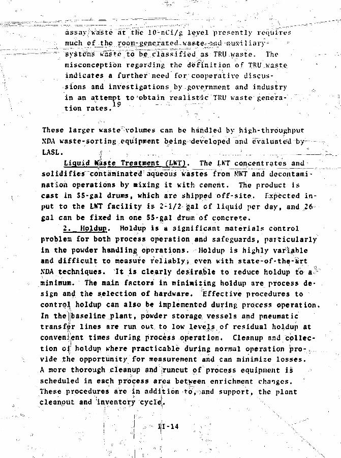
assayFWaste at the 10-nCi/g level presently requires
much of the rpom g?nej:at£d.. a*4«eT-aiid"--a'U-s-i';l-ia'i'y-
- ^ systems waste to be classified as TRL) waste. The
misconception regarding the definition of TRU waste
indicates a further need for; cooperative discus-
sions and investigations by government and industry
in an attempt to obtain realistic TRU waste genera-
tion rates.
These larger waste -volumes can be handled by high-throughput
NDA waste-sorting equipment being developed and evaluated by——-•
LASL. . i - „ ,. _-_v, . „--.-.-, _..._i_. .-.-,,.-T ,_.__lm_iLiquid Kjastc Treatment (LWTJ. The I.KT concentrates and
solidifies contaminated aqueous Wastes from MhT and decontami-
nation operations by mixing it with cement. The product is
cast in 55-gal drums, which are shipped off-site. Expected in-
put to the LKT facility is 2-1/2 gal of liquid per day, and ,26
gal can be fixed in one 55-gal drum of concrete.
2. Holdup. Holdup is a significant materials control
problem for both process operation and safeguards, particularly
in the powder handling operations. Holdup is highly variable
and difficult to measure reliably^ even with state-of-the-art
XDA techniques. It is clearly desirable to reduce holdup to a v
minimum. The main factors in minimizing holdup are process de-
sign and the selection of hardware. Effective procedures to
control holdup can also be implemented during process operation.
In the baseline plant, powder storage vessels and pneumatic
transfer lines are run out to low levels of residual holdup at
convenient times during process operation. Cleanup and collec-
tion o| holdup where practicable during normal operation pro-
vide the opportunity for measurement and can minimize losses.
A more thorough cleanup and runcut of process equipment is
scheduled in each process area between enrichment changes.
These procedures are in addition to,jand support, the plant
cleanout and inventory cycle.
f-14
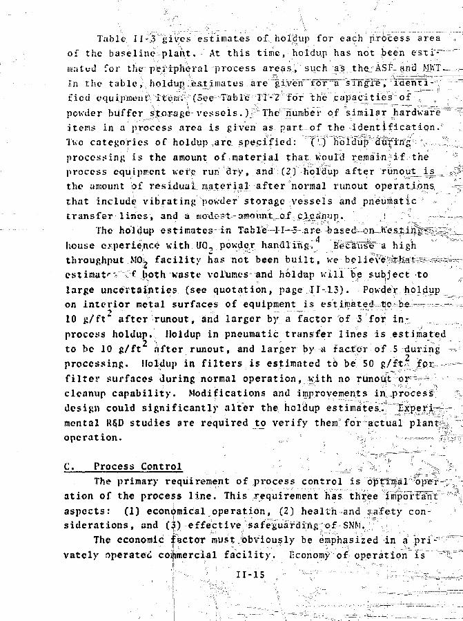
Table II-3 gives estimates of holidup for each process area ,of the baseline, plant. At this time, holdup has not J>een esti^ "mated for the peripheral process areas, such as theiASF <ind; .Mb'T—-,.-In the table holdun Jjstjimates are iyen-:'iorr;""a"''sTn"fiiB;"p'"'rdenrt"-i:y"---- j:
fieci equipineiJtS it^Wo (See;1 Table'FI-2; for the capacities of r,powder buffer s^rage vessels. )#¥ The number of similar hardware "=
items in a process area is given as part of the identification.Two categories of holdup are, specified: ''t'lT"^^^^^^^^processing is the amount of material that would resiainfif the ;!
process equipment Jvefe run dry, and (2) holdup after runout_jLs_ c-5*the amount of residual ...material after normal runout operations, ^that include* vibrating powder storage vessels and pneumatictransfer lines, and a modest amouatoi".
The ho!dup estimates in
house experience with UO, powder handlihgT BlcTatisw1 a highthroughput MOu facility has not been built, we•estimate'- <cj,>oth waste volumes and holdup will be subject tolarge uncertainties (see quotation, page 11-13). Powder, holdupon interior metal surfaces of equipment is estimated-. ii -===- -= ==10 g/ft" after runout* and larger by a factor bf 3 for in-,process holdup. Holdup in pneumatic transfer lines is estimatedto be 10 g/ft after runout, and larger by a factpr of; 5 duringprocessing. Holdup in filters is estimated to be 50 g/f^« jfpii »*filter surfaces during normal operation, with no ruhoftt or f^cleanup capability. Modifications and improvements in1=procesfdesign could significantly alter the holctup estimatesV; "TE^er|pv|mental R$D studies are required to verify them" for actual planti|operation. ,., „ :;
v ?%•"•. •• ••. < •J-- o . ^ . ^ : S
C. Process Control , •-•'-•••. '••••,; _ f_^, ^%,-, 5 ; - " %
The primary requirement of process control is ^ation of the process line. This requirement has threeaspects: (1) economical operation, (2) health and safety con-siderations, and (|) effective safeguarding of SNM.
The economic factor must obviously be emphasized in a pri-vately operated commercial facility. Fconomy of operation is
11-15
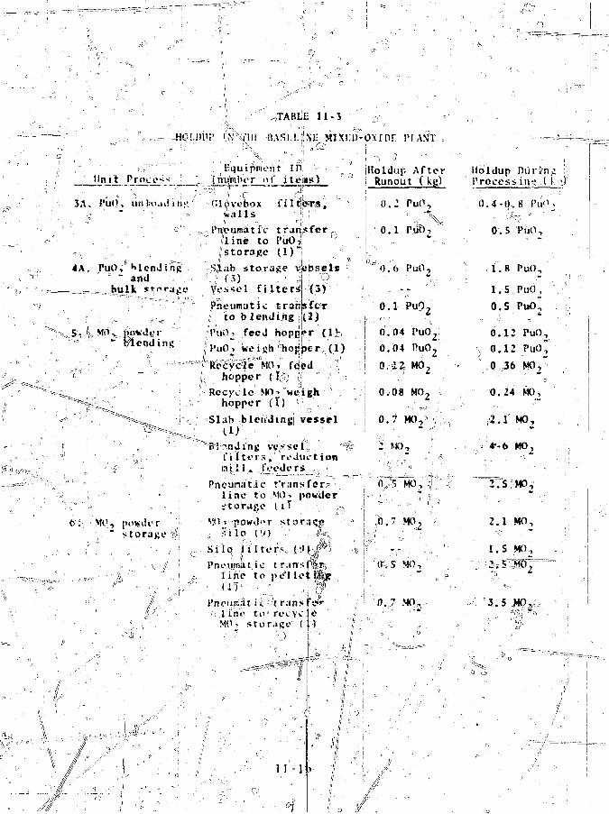
11-3
Equipment in!T nf j te|»s)
™ 3 —JA. PuO,
<A. PuO, Mending~ and
bulk J^faji
5. "), powder" r/lendmi;
*•'•: M O ,
torage *f;
Gl^veboxw a l l s •: ;
Vri'eumat IV t ranjsfer ...fline to PuOJ! 1J
,; storage (l)"j|Slab storage vs;bsels
Vessel filtersPnvunat.ic trarjsftr
to b lending (.1JVnO, feed hopper {IV,PuO i we ifih °hoj;!bc r., (1)
(3)
yhopper (I,fV;
Recycle MO-< weijghhopper ( t) '
Sl.ib blending vesselID '
Bl-nding . vv.ssci',.t" 11 to 1 •<,' rediK't ionmil l , foeders
Pneumatic r'r.insferl tne to Mi)-, powderi - t o r j j j e l i T
,; S i l O I'M
S i l o l i l t e r . s , t'-'
Pne111r .1 t i c t r i n s tlirte to pel letHI
PncuK.it ii. tr.inhfa*l i n o to rei.\cji*MO, s t o r a g e ( 1 )
11-1
>xinr 1'I.AVIT ,
Holdup AfterRunout ( kg)
0 . 2
0 . 1
0 i
" 0 . 6
PuO,
Pii), '
PuO,
0 . 1 PuO,
0 .04
0.04 PuO2
0.08 MO2 ;"
0.7 M07 ;
: : MO, ' ''"
0,,c, MO, 1 '
n ." M O ,
0.S MOj
0 .7 MO,
loldup nurinL'.iVocess in.tt,l 1 ".)
0 .4
0
nl
1
0
0
0
0
-o.
. 5
. 8
. 5
.S
. 1 2
.12
36
.24
.i
•b
8 PuO ,
P'40, :|
PuO,
PuO, "PuO~
PuO,
PuO*MO,"
K 1 O ,
MO,
I T S MO
2.1 MO,
1. S MO,2 , 5 ^ 0 ^
" 3 . 5 JHO,^

TABLE 11-3 U\onti .^
0 . 5 - l . S HOL

accomplished by designing the process' control to maximizei
throughput while consuming minimum resources. For the M00 fuel
plant this requires that FuO- be converted to fuel rod assem-
blies at the desAgn rate with as few interruptions as possible
and,with a minimum rejection rate. |
health and safety are important in-such a facility because
of the radiological hazard of,multiple recycle plutonium. As
much material handling as possible must be done remotely; con-
sequently, some customary process line techniques are inappli-
cable. For example, most on-line equipment repair must be done
primarily with manipulators, not" directly by hand.
The adequate safeguarding of SNM could have an adverseli
impact on the economical operation of the plant. Consider the
case of a small amount of plutonium lojst from the process at
some intermediate point. Normal process .control would probably
ignore this event; indeed, it would pxiobably be unaware of it, -
However, the safeguards system, through its-MMAS, is expected
to detect the loss and asjk for an investigation, and some inter-
ruption of operations mp> be necessary while the «cuice of the
problem is determinrJ. If the loss, is the result of malicious,
purposeful diversion of SNM, or is a false a'3 ?-vm, the process
control function tends to regard the interruption as a nuisance.
On the other hand, if the loss is benign (e.g., equipment mal-
function or 'powder leak"1, process control receives useful ar.J
otherwise unavailable information from the safeguard? system.
This is also true during normal operations because the MMAS
monitors the material flows in greater detail and \silh niore
accuracy than the process control system. The material flow
data are accessible by the process control function through the
adaptive -data link to the MMAS. (Fig. II-5J.
These considerations result in i slightlv different- concept— ir
of process control__th:jn that normally followed. The process
control function nurt be willing and able to Interact t\ith the
health and safety and safeguards' functions so that all tlnee"i
opera* ional Requirement if are satisfied-. Economical riantII-18
f
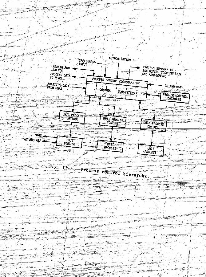

operation a] one is not >u$fici&nt. It is our opit^io.n_.tjiat,
with proper design, economical operation can be achieved with
minimum disruption :andm_aximumibenefit from the health a
safe ty and safeguard's systerns^v-.^^:—-::-:'"'""v
I . Control Hierarchy. The, process 1 ine fisi^i^ided into 'a
number of unit processes,, j^c&^MsyLijig: -its own unit process Con-
t ro l l e r ^UPC) ; which reports to ipjieipf the control subsystem?
(Fig. II- 5). In'; ad^jJjo^trSr*tHe control subsystems, the ;pr<j)cess
TtBii (FtC)Tsystjem also contains other sulj
directly concernedx with^proicesj; - pji,t-Edl-r.};' 1,; ---^; •;>-#i;:' i
'J The PCC; unit a^;r^g^|0i3ite3^ffo^ th^feohererit operation | of
the entire'process l i'&e -- -- i t jserfoMW^a^ supervisory, fun^ticjrh;
^It determines operating levels and operationaTrsequencesfo^
each U^C so thatj they all/workj^pjether. This form
chical eontrpl-i* ^^ff^A?ttP©iint control and is
ef fgctiYe, and xsr$/i§X^^^STS^0^ Iri thsi process7control ;
^ ^ ^ t ^ ^ a h i UPC to be
. n t e r a c 1 1 o n 5 A $ E l i f 3 5 ^ ^ ^ ^ l i i ^
A genei^lSH^g^ur^tS^^lF^TSgrain^ iji^3-i'gtrTl-6
% e ^ override, o|r laof theses ' Th"<| jg^fem^fy 'Informal Jnrs^tran^fe^r^,]:
the UPC is^fee^^'sif^e;' sfetpoint of 'the unit,process.
^rMt^i^^atsb capaRleror"! retrifev£ng:;UPC^
ies that have been compiled irotnt^^&t-^dlrfa. ^
; " Tlie instvujneji^wigfa^EBi^ired^ o r a j e
j u n i t r p i * 3 c e a s e s a s - a l s o ^ f t ^ |
r e s u l t i n y measurement dajpa\areir;8ent in p a r a l l e l ;tq J*1A-— 2. PCC Subsystems. r^TKg^O^j^G'^j^lb^5^6^'5 and! the i r , prji-
••••< mary functions are^lJj^s^5lirelb^"Kfr^'fer to Fig. If-1).» Some are
self-explanatory. ~ ~
- ^ dj lixecutrive%0f';pfocess dpntro 1. and
Produc t ip11 p 1ann in\g a rid s cliedu 1 ing , au tho r i ze"k-
p ^
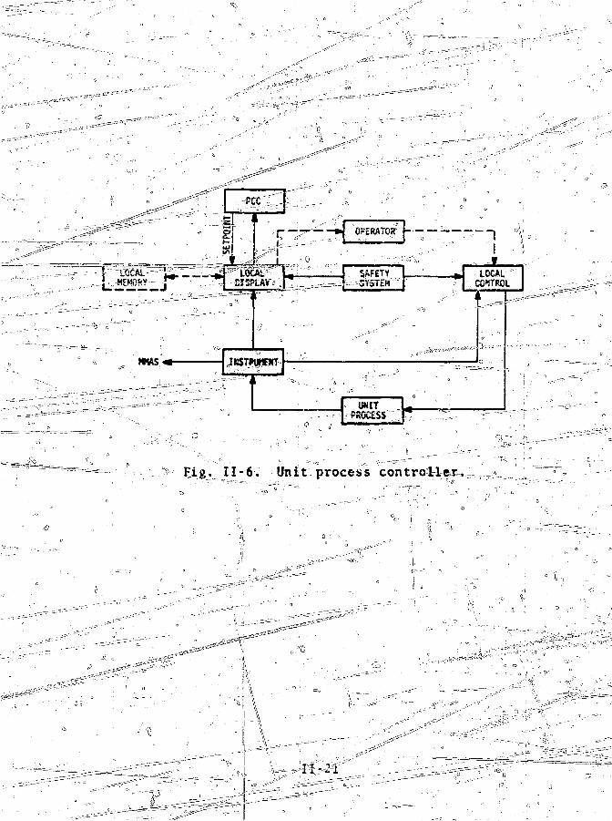
FJLg, 1I - 6. Unit process controller, .
ri-21

• Process data management, ...including" report . corjipi-lation a-nd'"-''sTfiain-aT4-sa4:-i.Qn, and
';,§#- ^Inter face with safeguards systems.b. Receiving and Storage (1A, B; 2A, BY*• Control and monitor PuQ-j and U0o_ powder,*4 and stbrage., ... t'':C^^X*^~r-:~--"." K ; ' - ^"~J-~"cr"".\BUl-k-^tDi:kp-pWan:Q;ys;^(^^^lCj"At B, 6; 5; 6; 25)
--•"T::: Control* and «mbh [tor .-|l07"\pbwd-er- blending and stor-
:$. Clean Scrap Recovery (L8)et Pelleting (7, 8,19, 10, 11, 12)
Control and;j ibhij |or^ellet ing f ^sintering, ?"tcjr-
f. Fuel Rod C13,HL4^f i;73
3.
gj. Fuel Rod Storage and Shipping (15, 16)h. Miscellaneous Waste Treatwent (2U, 21, 22, '23, 24ji. Analytical Services nC19) -•••^•:-iiUn^
• Perfbrin^ssay on| various samplesT?rom tht processline,- .;.-":" , '" \ ..-; ~i. . ;
y - . / '\"""j^• Perform quality control for the process linev,.-'>:"""'.and ^-^'e" •• . " . • / ; / ".' " . • v'!':" ?
^» Maintain^instrument calibration. ^tf-5"j . H e a l t h and Safe ty4 :::-'^fr - ','/••• ;'*'>
•- gr i.^^nMnuip^sSx^bniFtor ^all safety^requirementjii^ throughout the
£!• Perform cr i t icOperating; ProcejjiXrss. ^sQ€:€01 s of the operating
in Appendixj^fand i
F»T(A)'""s:t^ndby;^?|Bd^ (S) |shbfd^vmT^;All
ei into
which may b e
:antjm|nagiss^t?r£ The o^ly^niode t l a t ^
rs in j>arentheja
p i a n t fgnate unst processes
**r
functions. All other modes require at least the concurrence of
management for activation. .-, ..____
, a. ~Norma1 Mode. The normal mode exists when plant
operations are proceeding as expected.
b. Maintenance and Inventory Mode. The maintenance
S Z or special mate-
rials accounting procedures^are^feqatred. Runouts and cleanoutns
are also performed during this time. Any part of the plant iSffir
be in-this-mode, while the remainder can be in normal, standby,
or shutdown modest In 'other words, the entire plant ;is -not^^
always expected to be in the maintenance and inventory mode.
Maintenance and inventory are usually done Iji a stepwi.se fash-
ion }pnei or a few unit processes at a times except as NRC regu-
reqiiire= pjtherwlfe^--.==. -^1 I =,
c.~ Emergency Mode. Jke^e^a^^T^ej^IT^typii^of emer-
es ,_classi£letkajcclording .to_the;:swstems that are directly™"*
'< conccflied^^i^h ° theau ,, I • • ? < '" ' ,
> (1) He lthTaiiil sMe^fey^ "jcrijticality,'radioactive ;
material release, personnel injury accident T etcr' ~ :";' =r •--••-•--..-S&
(2) Process control: for ejcample, catastrophic __ =failure of process_Line equi^mentT-e^'ulting in severe economic :a
damage^ this n ay also cause a Type If and/or Type^ 3 emergency.
" 03) Safeguards: Ith^sihv^blv^'"""=-—--——---. .,;y 9 Personnel control--_?.._ a breach in physical ZZ
- security, " Ij ' ^ "^ 'T-—=™—^^^0 I ! " •••' - - - - - • •
„ • Item operations control , or -.__•: =-• Materials measurement and Recounting.
The f i r s t ^wo items under^^s>feguards cmcrgeffcleV^are^t'teated in
the-Sandia Corp. r e | o r t . The l a s t item is dri&eussed in de ta i las
From the" vie^polnT^of process/confr^T^tfie^ r-espon^eto the eMergencxjip^friSs^aiS^^ to'^ir
relatively secure sjts.te.= This^an be done by moving SNM to
areas of the process line that /are Hies s Accessible to personnel,
//
Ill '•Ii-=2'3

d. Standby"''Mode.,1 The jtandby mode is used for rela-
tively""Tn'ort (less than 1 >uw lO yifft err upt ions'] in plant operations
^ej^^arj^y^gt^on is expected to resume Cfthcjut the more exten-
sive shiitdolaT procedure^ It can be applied to all j>r, ailv jTart "
of the/plant. Tne^poftions on standby are operationally ready
and ne/ed" only a conanand from PCC to resume operations.
( e. ' Shutdown Mode. When the plant goes,into the shut-
down mode, it is expected to b^ itile for?=sometime (longer than
_^ro:cess lines are c^eained out and SNM is measured
ia sealed containers ,^which are locked in vaults.
4jr" Software Functions. Thetmain burden of the process
cbntrpi software functions^liels i=n=?CC and its subsystems.
Almost no contfoT-Yelated calculations are made by the UPCs but
performed by the associated PCC control subsystems. The
three nonstandard subsystems are: « o
" - Execut Ive -. " _;-.,.. /,
• Overall control coordination, including responses
""" ^ - ^ to the five^opjeration modes, ^ f
, • Pfp3uct4oii planning and scheduling; an infbrma-
s=s 4=^^""^= t ion s e.r vice jrdyt'd'ed^to p 1 an t m an a pern en t includ-
ing report compilation and s^Win^ra^^atTdn,// • Process data transfer to the safeguarlfsSa=sys4Len>.,
" , ' / • " ' . • • " . " 5 = s * - =
• Overall.process operating history compilation,
• ••"• . - •"• a n d _ , , •' •• - : .,
• MMAS data transfer to PCC for possible improved
control; u \
Health and Safety ^
• Personnel exposure compilation, contamination
surveys, and %
"™-"I77======»-=-"--Criticality calculations for all process areas;
Analytical Services; Eaci1ity• Quality,control calculations,
• Material flbw data processinp, ,,,!?'--—..-.-.
• Detaile<i,/6perating history compilation,
• Operating sequence definjyti6n, and• Material analysis calculations.
Jy . ' ^
5 5" ' • - " ' . "
The other sev4n VCC subsystems (see Sec. II-C-2) generally per-
form three software functions: (1)- material flow data process..-
Ing, (*), operating sequence definition, and (3) detailed oper-
ating history compilation. Another function is the calculation
of MG, ipoivder blends in the bulk MO, operations subsystem.
Tlie main software burden is that of data management. The
control algorithms required in the operating sequence defini-
tions Eire very simple, in some cases nonexistent. Most of the
sequences are determined off-line, conipilejdrrt-n-- :ZlfaftSSFT5zf=roper-
ating procedures, and perhaps stored in memory for machine,1
accessibility. Because the plant has been designed to be inher-
ently criticality-safe°, any required on-line critical,ity £i;lcu-
latiori^ are straightforward. They are necessary primarily for
gloveb^xeitand'storage areas uhcrc the amount of S.NM can vary
,i greatly, jf" "-•; .,--,• - i ^ ____-__--- --- §=S
^- "The" process, control functions
descrxtied in the preceding sections can be implementjeorin many-
ways •, but to be effective, the imp-l smentat-roTi lifu^t^KiXh^sen on,^
the ba^lis dC trade-offs betweeTT"Teveral competing factors. The
harilwarie mustx fee simple, reliable, and as Inexpensive is possi-
ble. It must be Capable of communicating tjidirectjonally with
the safeguards systems, the0 process operators, and:the plant
management. Because of unexpected events , "it must provide for
close h jman-machine interaction, 1'inally\ jj ip should lend itself
to upgrading as the technology improves, wJiiile making unauthoi-
i:ed modifications difficult^ \\\\ • - '"'
Us® of the hardware configuration shown^in Fi^. 11-7 is
ijife Kajf to accomplish these goals. Most ojf the hardware is a
multi-ii||^Qt<lata acquisition system that/coliects all the
process data at tif^^executive processo^; These dSta are stored
in the process informatioir^s^tem aml'selected portions are
available to the operatbi at the^cre^ijiand/display consofe. The
unit process control level also has accosttj^operating history
data stored in the process information system, ifs^Kgll as a
small amount of computational capability in the
.. - • t ] - 2 5 :
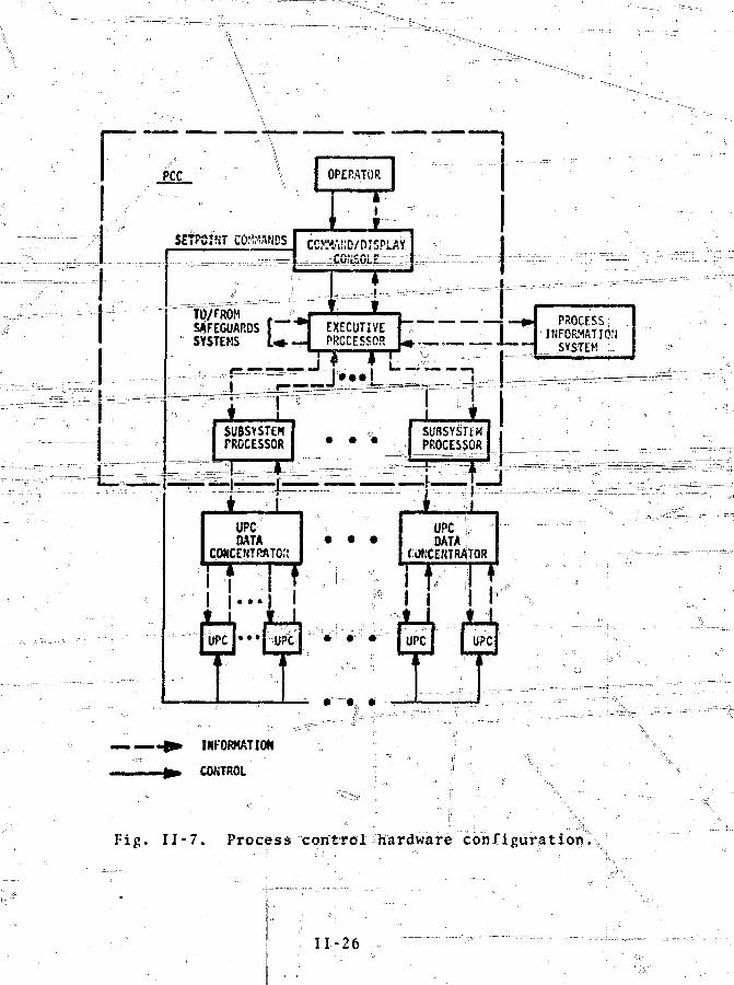
TO/FROM , 'SAFEGUARDS I ™ "
INFORMATION
CONTROL
Fig. 11 - 7. Process ""control""hardware configuration,
11-26
processors '(e.g., for blend ratio calculations). The operatorgenerates sjbtpoint commands using process data, management in-put, and safeguards information. The setpoint commands are
i y UPCs over hardwired communica-
tions links. !
The UPC data concentrators are located in the process line
area, close to the unit processes they serve. There is
centrator for eachJPCC subsystem. This is possible
UPC data rates are low; furthermore, cabling co^ts
Cinput/output) port requirements for the subsystem processors
are reduced.
This configuration allots efficient- rhLLa—ii.atkeriirs^ror-- - ~
^.ukirifedeCTsTbns that are difficult to circumvent by machine
fault. Even if the data acquisition system fails completely,
effective! control can be maintained through the hardwired com-
munications links. The sajne is true for the failure of anyfsub-
=-3ystBFrr^i^uch~"=f^il^r¥"Ti^"inffi^nTip'iact on the WiSindier of
the process. _„;.... ^,
Harpware xomponerirs™anli"xKexTrcharacteristics re Tfrte T™™- - b e l o w . S ;; •--•• '-•'• • : - - ^ K i : - - - r ^ T ' ••,. :;
I a. Control Instrumentation. The control instrumenta-tion, whjich interfaces directly with the' UPCs and the processline, is] shown in Fig. II-6; at least initially^ i t is ,cs|rvenil:!ltional In design except that outputs are interfaced to the dataacquisition system. This may be done directly or through anoperatof who records the instrument reading and later-enters itinto th| machine data streak through a terminal. We recommendthat thils interface be direct to eliminate human error andunnecessary delays. "( i
Eight types of instrumentation are used in the baselineplant for process control: (1) material level sensors, (2)radiation monitors for alpha particles, gamma rays, and neu-trons, (3) pressure sensors, (4) load cells and balances forweight measurement, |(5)i flowro(e.Jt,e|
>,s..,-,4X) • mechanical- gauging,analytical measurements required for material assay, and (8)temperature sensorsJ For most measurements (except for
ri-27 •'

weights), It off full scale resolution6 is sufficient; thi:s re-sults in an instrument data word lcngtir requirement after. A/P(analog/digital) conyerjjsion__qjF_ojjiht,,_b,ij s ._Js.eyen,4uts pi f2[ .. .,,sign). The required weight, nj!easurement resolution is 0.01%,..and it can be satisfied by linking two tf-.bit words together.We recoraiaend that the fundamental instrument data word size be
- precis ion capability available.Insofar as possible, the A/D conversion interface for each
type of measurement instrument should be modular and standards,ized to facilitate replacement and repair and decrease the
|r&nisa£uyei5-srrts=ii^^^by^Lvo"tiP3
control system and the safeguard? systems, the A/D con-version interface must lie capable of driving both systems. Thiscan be easily achieved i f the digital outputs are buffered;
b. UPC Local Displays. The instrument readings aredisplayed locally in conventional fashion. The volume of dataftom"tlie•"""jptoe'eSi c'lhTo^a€lbh'system'"'anjdf''the subsystern^?rocessorsthat^is useful to the UPCs on a s^ort time scale is very smallaiitl specific to each UPC It can be output at the^ local displayt h rough hardwi red de v ice s; I'icre vo 1 umliiou s p roce s s ope ratinghis tor ies , infrequently needed, are sent to the UPC in hardcopyform, thereby eliminating the need for keyboard terminals atmost UPCsT terminals can he added i f the" data flowT*4ritantthe added expenseX°r i f manual data entry i« desired. Ifterminals are used, they are the recommended communications No-vices between the UPC^and the PCC operator.
c. UPC Data Concentrators. Rach UPC data concentra-tor compresses onto one i\ne (or one set of parallel l ines) thedata frosn the unit processors that are Kinder the control of asingle PCC subsystem.„ Each #|so routes data from i t s subsystemprocessor to the correct UPC. The maximum number of data chan-nels from any of the UPCs to it^PCC subsysteru is 63 for thepelleting subsystem. 'Ttii_* does not\ influde channels for jda taflowing from tho sxibsysifceffl p/Tocessor\t<ji the UPC«. We recommendthat 128-channel concentrators be used for aJl subsystems to
rr-28
aiJoK so.se roon. for expansion1^ arid* to^
interchangeable.' :."••. '.,., ^•..!|.,,,»lI,-,,,',-,,1..,5.;,,,, ::;.,,,,,,,d. Subsystem Prbcjessors. The
can he reTaTive\i;)p'lJT^^ ' "
burden * They ar^^FfmariTy I/O :iirtTerface¥ tliat act 'TM^pw&£0s/ ^
between the executive processor am! the UPC data"concentrators^. fc^
They s h o u 1 >! Itsvs^exe
be added l a t e r .
: The subsystem proce^soTsjca^b^iTTrpleJiim
Microprocessors having 4 kiljjbwprds o f ^ O M ^
I/O p o r t s . The RAM is used to b u f f e r - s t o r e tljje data anid the™—f-^= „-ROM ;c<mtains^^ff^ :ne;fesssas5sv^ttfes^^
increased fry adding, bu-££"eir: memory-. |Ln',-tfee-'"-^&^m:-i^_ra\"2^"sie^£":^R^rTi~unit . The processors are! thus TnT§rchangeable;i frpja^AihisysteinV
tc subsystem 'with" qhJY^^^^^^n^mk^^^^^
e tixecutive Pirocessor^•••--The-r-;
4-ji tfrijna t;ir on=—
conplicated than tiit^ubsysjtem
nan a gc a large vq 1 ume of d at a
for the comraand/dispiay consuleTT^^Z^nWrl^leifWtT'tMinformation system and safeguards systems, 4 ]?ood choice for •,'
the executive processor is a minicomputer withii l6-bit"word°
and 22 kilowoirds of menioTy^ f ^ i s 7 7 ^ ^ ^ ^ ^ ^
control of the command/display ^ L
tion system. -••-ln
the peripherals, such|as a printer^^jjs^d^to generate rep|oj"tsV=
f. Command/Display
console can be implemented with a CRT
graphics terminal Sffid /printer^ fhe executive roqes&or ^controls
the CRT using the graphics software and K
hardcopy output. The command links are hardwired |o the! UPCsby voice and/or signal lines. : rtr---- -. ---. ™ ———--;—-- :_
&. • - IftterfiSceyDallr---:liji:j^^^v^CT^v^'n:3^ni inter face/ ••
data links compatibly Kith" the^haTrdwaTe ma!ysbe=psed, but they *
should be designed according to existing standards.

to" sa m(> Jiust bc*..desi,ji;
ijdffxih-t^the/other f jI ori*t?oinu discuss
•JH
t/hat night be used; specif|c:at"|on should bc^letie^In consulta-
tionohitli cu|uiir,ent manufacturer^.
Kit a failure in one system
sjigge t":; the type of
0rocess 1 nTo rsr.at ion ty
Process data storage, nanipulation, and distribution within
Jacil.ity are aecoropl i *ihfd»l)>y the process information system.i • " ' ''•'" 11 I !'' ' 1 ° • '• ' •
,Spurces°of iinfofiiat ion ;ir4 p*4p a v a i l a b l e for those control de-dat a proccssing to augment manualc i > t on .< =t ha tj re*i u i ro
fiinct ionsr.~ |DM;i Istse access | .f^pm r<?moje loca t ions allows infor-
mation to be; r:adc aVailabl;je ^WSaCetfua^ds and pfcant management.
ts dataj fa 11 i n t o ' t h ^ s e d;atepo|ies
* \ Roia i iiii=aax!iivlferia |f| c __ o If
in;\*j s [h J c to t|ie\j»|©ducit ion flow;
functions essen*4ally
Process at'inj: a directo influence on theout; ut p i o d i u t ; and
• " t M - t i , n < : i t ' 'M" thf isipi't and output 'products ,
ihc l a s t t.io u i u C M C .ire <M(tphasi:ou.
t U U . I I 1 ! ' ^S'u.iJ i n i ^ u ^to •< *•> »
t.ot l 'o.»n\«. !>\ i n J n . u i t a
wccj / f J^. tne use r' j o f cievice hardkarc^ but
.nt> j JTt o! .i^d I tii!)i;i»'i ' --uit icomponent system. Thi* \ y t f ' 'u j l
>nii;le dat I_>J -re i w t . n : s bjckJ4iJ' and tedundanci jwt read i lv
' j f j i i -n t Id tl:t u^i'i*-, I'cta f^*f of the riiforpiat ion sy-stem arc.1 , .-
t eu t i . r c .Ms. - J C L I I icd -:n ^cc. I t l - T . rhe J'ull range of da ta
ir\ |ut i.itftiis^S urn he ;*!o\ id*^% "fiTHn d i r e c t reading in^ rusnen ta
to t e rmina l actcs> -fc-'maiyiaJ, c i t t r i e s .
>tt»rri tv •- 31 loca ted foje^&ctf'Oithe najo/,,) process a r e a s ,
i P ' - p i i t o r
r 31 l o c a t e d
• l u - I i n ! iii>i « , u a l j t \ v'.'f«£"f(|>r|l
,:,^ i ^ J - ^ o i o " 1 linl- - am! -iiiitai
.m .Kim.- ta ' l e le i t'u. par t i
"^nd health and safety,
All byji-Ziie Tleid s i : e ,
s&^tyT' I)at_a_(.ftrir(«rf is_ i- trmd-
ijr(vr,ir and a uniforn' set
for datn sea
- - f
t a' Arfluyatt traps 10•• fp^^ka^&^^^xs"p^j^e^^rlt JJ-JROIIth
Jntervap' -<yx^i"S0:^^^^00^^^il1 ion -jchxrHe.ter r_andom
Categoric?^** intimation common to ailTi«ter|ifl5 ava,il^!l^^p^cje^4*-pjE^
^li»grin3^rrctida|| pflc#^» 'qpiB^ft^in^j^ii^fl^tija^e^^^ipo^nt, ope rat ing ?i«4'Nmcjg* ej ¥&fl' produSffr^fciirggll^
c^* 8 s e s tk^? f^W 1^^^^^Sit^?tore "Ire ••<f|iy J| c s:--silirie ^r'^s^^^Slli^a^mT iiidivlid^ili ' n^el^d^u^t^m"}"11 \5f;ortf ^5 ir"clMlil# ' M~^b^»etii^^^^«aH^^n^rt^.' "«i jlierlevels 4f" itfforiitti||.••ptp^^^r?^^ r "~"probes\ [s1 tajfcE f'" ||»!|t*'" ^0jK^^0^^^^^^^i^^^i^^0T^Ztibn" in iproducjtjy^^^^^^^c^^^Si^irtl^rolt^^fsa^^i^d^
_ Thelar to traditipre*«nte o f t

_^ _^ _ ; r _,-;____ " i _ i — i - s - -~-cC-
^^pgggjly^^g^^V^V ^^^^^^^» ^ W M ^ W r ^•••P" ^ — W J ^ ^ " "
1 ' ^ ^ " ^ ^ ^ ^ ^ ^ B ^ ^ ^ -n - ^ v ^^v ^ —
i t
)-—The "plant t lie""work plan with any
and ..issues authorization to start work.
-A"~1snop order-describes the technical requirements ...and cin.g,. The""|jH»e'ijTfo'fisstion is tran*"irica to the safeguards
i pl^nt-raatfager continually reviews the shop order-
status and -safeguard? system inputs and initiates*-airy njeces^ar- '-
act ion._ _— —'=—=^-~~~~~' , __J1'- LrrU---"-• ~~ ~^^ ^ '^Z^{f>) Line wanaganent^iri^r^Si^Sljelp o f PCC, organises the
t,loj»s--on the basi-s >/f feed-
fr, Qc""XASP) .^nd-hff-alth and sa-fet^tiGn system. -' - ^
^iT'feifease* aad_»«in^ains^siirveil lance on product
^ calib r at jjaj>--«nd~ Inspect ions,
ifj0iSSiff^af|»d Material
system continually:of the plant
IffSi^safe/
guards
^l |^ s r fe^01^r^| t©i*ag# i | ; ; l^ j^^^ f^^f i i is _af«_jJ|HSf j s e s J s i K l S ^ ; tie'
"fithjlKe
11"
^ - ? r :Miir
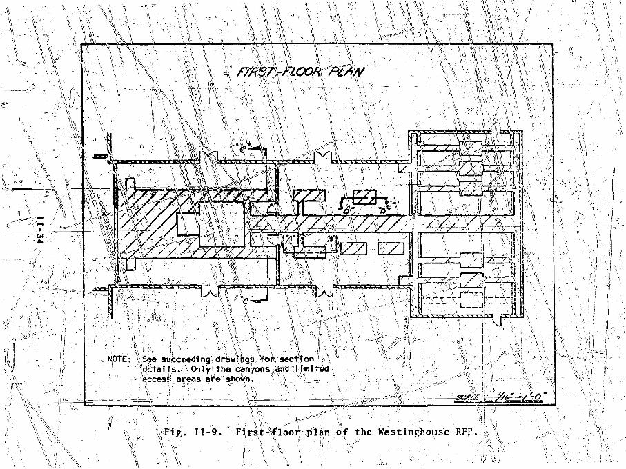
— L
NOTE: \See succeeding drawfhgs for section'g gde ta i l s . Only the Cctn'/ons ^rtd IFmfteaccess areas are shown.
\\__ v >
if \ \Fig. I I -9 . Fi rs t - f loor plan of the K'estinghouse RFP.
\ *I \
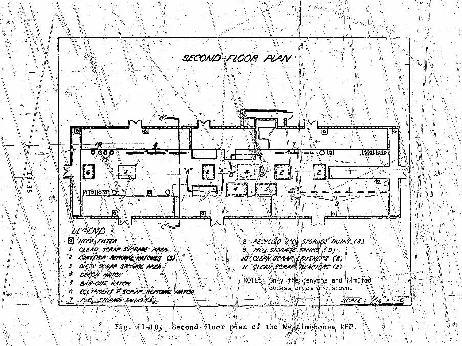
, oWVW //
I "
1\//• V '
\ \ • SM
W / iCMen¥
\\ \\ JO CtW/i' SCAAP C*(/S//A*S
MirewNOTE: CnJy thp cenyois and Mmi
dipo shov>n.
Ji^^4gsh«i^m^(sMx
Fig . I I -1C. Second-Tloor plan of the HeFtin(*hou£e RFP.

Fig. 11-11. Powder compaction system section.
11-36

Fig. II -12. Storage vessel section.
W-'"' 11-37 :
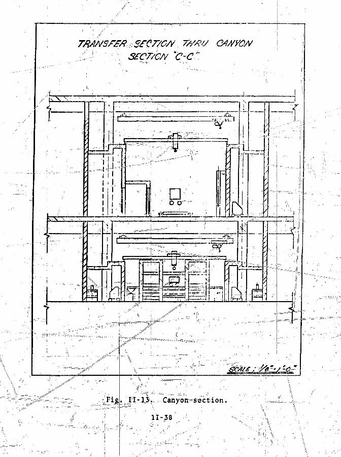
TRAMSf£/?vS T//W G4//yQA/'c-c"
i I
JiL
SI
IF
LL_J
n-ni[
, 1 1 - 1 3 . Canyon-section.
11-38
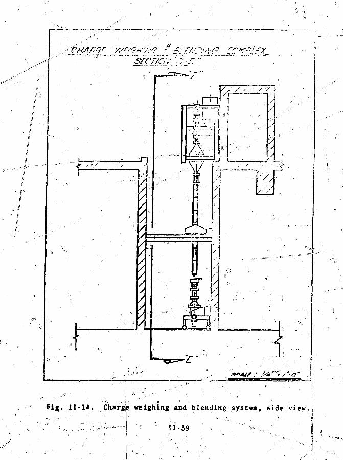
L
.
7//////////
/ . • ' / /
Fig. 11-14. Chargle weighing and blending system, side
~~ " = ! *' ' 1 1 - 5 9 • * ^ > - ^ . ^ •
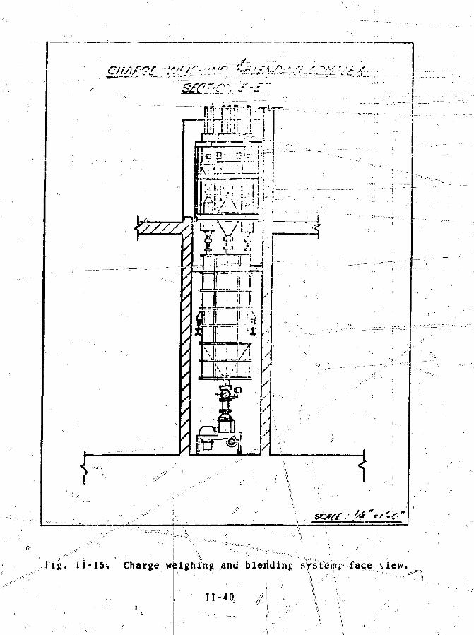
•Fig. 11 -1S. Charge weighing and bleriding system; facei view.
II--4Q, //i

pneuiratic systems for transfer of po do-rrr•;rc-qTQri:r-e5"-[»n '.cxteivair f i l t e r ing system. : |[ __ ... . yj^. -1; '\ - '• v
\
£. Material hanttling and Personnel ; ' ": ,iv.'-:V" "jT""""""" ~'vt\: "~^AH process, recycle, r|j.covery, and chc^icajl ^hal.N'si.
operations i nvolv-inp Tpiuton 1j[unf and MO, are perfprr^pdnjins-ide -fe -sealed, negative pressure jca||yons or in glovebcx|c^.! l|ve5e areas \arc desisnated rc>tricted\access aroas fRAA). Area;; ajJiacent
, : : ' \ ••;,' ' ' \ - i ,••••-• 1 it1
to Ji>\As, where sampling, maintenance, coiftrol, t'Jnd 'monitoring;\ \ ii'L '.i 'I -. :i i1 •• •• ::
occur, arc rallcds limited'accjcssto LAAs are called normal access areas' (NAA)r theand NAA are epjpparable to vent i la t ionbv Zones 1, 2 £-S$ t re.spec.t.iveify,J i«^-N,'RC K^guiatdry" iiuici'Eir:\">".T2\' "TMaterial handling l i n e s , e,£I!, pneumatic t ransfer systems,mechanical conveyers, or pipjls for; ^iquids, connect the main ,,'processyarea to tho ASrr M^rLsCT, ^iid si
The estimated number of^necessary s taff people and ' the i rfunctions are given in Table I I -4 . Entries for' 2OO"M3r)yr pro-duction capacity show the tojial personnel required fcfr^four- -••shift ojieratieiv. Tcf-- WRcit4JjJ.R£-:yinvelviB-g"l8Vfle-":;awou|iit's-:;of ura-nium or Plutonium, «v 97/pebp|.e^ have d i rec t access1 to the jnat<?r i a l . Table II-4 does not include personnel requireSdito Wan n
the safeguard? system. $afe|puard$ s taff ing is discus^ffd inde ta i l in Chap. I l l and in the Sandia Corp. repor t . "
o
\>
,r, ^i _^r f...,;
\ '' 'V !
: :~t"
^ix1 " A ' • '
• • \
: V•: ' •• " " : \
—~rr-: : "=—V - •"
"• \' •- 'V-
- -
•VA •" • •• Vi ' ' • . , ..s \
V.
.-^i-...ii.,:A,-,.-«,u,
\\,:\s ..£
P ^ ^ T - ^ - , •K-'.XV-

TA8LE iI-4
STAFFING FOR THEMIXED-OXiSc FUEL FABRICATION PLANT
Proce*%
Chesical
fttj unload tStore, bleai, saatpl»fO-Pu bund »
fj ge fSlug, granulate, pre»*atsriagSriaU. inspect, storeReceive, ciMiii firs* *Fuel rod loading tRepair. dt'oaatlinM••« ia»p4ctloa aad itorag*Clm»m *cr«p r«cov«rr *y»t««Anslrtical *«rvic«t.'Urty scrap, r«covtr)r sy«t«aMa$t« trtatacutLin* sup*rvlAio«
Subtotal
PersonnelRequired
24
«
420
32
1*3**
3216
Personnel wirh Recessto Inrce A»ounU of SXM
35
413IS21
11
Smiport
titter* \staff
im t
Ia«truw«ot icpaJr md calikration»'h«»t aetal aW wldlnff*inters'-and-carpenter*— --,r
_ j_., __^J'!„ •. • - •
z"9 '" :
4:• s ' - •
i"' •
'JO.117
TOTAL
• \
!., j_
i,
\
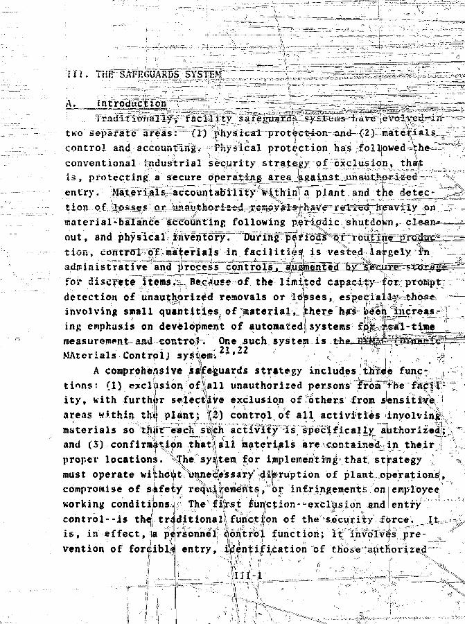
Til. iHE SAFEGUARDS SYSTEM - - _-__
A. introduction " -_-
Traditionally, tacility safenuards^sy&ieiiio^iciVe evolved in
two' separate areas: (1) physical protection and (2) materials
control and accounting, Ph/sieal protection has followed-the
conventional industrial security strategy of exclusion, that
is, protecting a secure operating area against unauthorized
entry. Materials accountability within a plant and the detec- --J;
tion of losses or unauthorized removals,have relied"heavily on
material-balance accounting following periodic shutdown, clean- —
out, and physical inventory. During periods" of routine"pfodut-r_-__
tion, control of materials in facilities is vested largely in
administrative and j rocess controls, 'augmented "by secure—5 taESjfig--
for discrete items. B*c«*use of the limited capacity for prompt
detection of unauthorized removals or losses, especially-thos**
involving snail quantities of material, there has been increas-
ing emphasis on development of automated,systems for real-time
measurement aa^coRtrofh One such system is the_DYM&C—(PYTIPmjg- ^ °
MAterials ContrplJ sysieffiC2i*22 ?
A comprehensive safeguards strategy includes three func-
tions: (1) exclusion of|aj.l unauthorized persons from >he facil-
ity, with further selectlive exclusion of others from sensitive -
areas within thi plant; |i) control of all activities involving1
materials so'^t^t^rch's%;h.'"actlvTtJrn;ls specifically authoriz«d; "
and (5) confirmijition thatlall materials are contained in their
proper locations. v "he.'''sy t-em for implementing that strategy
must operate without\nneiiessaryd|jsruction of plant operations,
compromise of safefy requ||rements, ao^ infringements on employee
working conditi|Bnsi|i The'fi|r^t fiiifliction--exclusion and entry
control--is the1 traditional'function of the security force. It ;.
is, in effect, a personnel Control function; it involves pre-
vention of forcible entry, identification of those authorized

111 , tijidj ^ n~f < r e ijidj ^ n re .Mtt^rflcuri t \f hi-stri 41 • t d. lhe ihi rd f i
e,L u I a f I o n - o\ o j
Jit. t ^ii"t i t J t n - w -ton
- t l k | » ' l « l t t M ! 1 f l l S
Q! \ i n f_ vistv r i J 1 ts
J, f ^ T '
"t t h . i l
at .on^ -uclt- as~ unloa<LJ'a I , Is.ir.dl
Mi.il ire p p i j o ^ l i ,
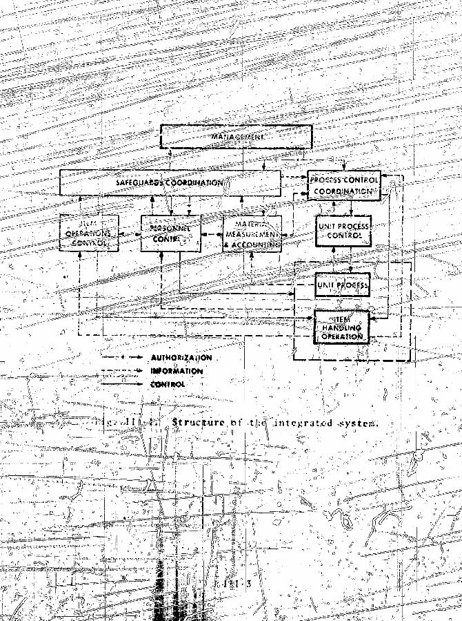
SAl-EGUARSs'COOtDIHATlON
»• L. — OPtSAV.OM
-r +
_;:a
" v ^ t >
• ?'&
—TJT*"V
V
si JS
. ' . °:
_i._f_. j ^ , . , . ,
AUTHORf?AllON
nVO>MATIOH
L i ~ ,: rr, > L
i ( i * (?
??lf : S t r u c t u r e ibf
4- ^
i
U n t e.g ra Led #y-& ten;.
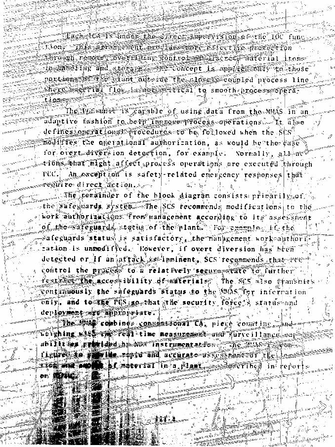
jL.<*ck ICA-is" under _t^e—vlir<.'ct jjU^sTVisioji cf the JOC
t ion. This -^arr-»^csiTe7iti=.pxri''?vJti5-jTSnVpc r* f f c c U \ P - i.iOtcot ion
^^^^^^^^^^^^3i^$^^{i^i^f^^^^^^^^^^l^d •'jVifoeesi 1 ine :'
Jg^r^'g^^^^J^J^.^fe^-^^^ls^^ar'; to smooYhjipjMS^s^0^irsT^^
:(f"•-' j^^^^^^^^^^T^^^^^ ^--^iM-siT^^d_at"S' {romjikfir^^A§ uv anj^~ad"a vt..iv'e" fcshituj^p^^ sffis „«
gaS34tfff'V Cse ctjlerati^sirtfl^ aajhpr i :a t i6n, 3 s would be^thc^Taifcr'Y
Cox pver-t^rgr^^fr^ ion dete^fic|n, for exampio. Vernal ly, y\A ««at^r
^^^•^^^izht^aJ^^^pyQ^vsii oper#ti|>nls are e x e c u t e "^lrough
Tt.C. AjrLgfl^sc^tlo^i$ sa fe t ) - r e l a t ed eacucency responses tfefflt
^gu>irw di reel l e t ion. ^ ~ i: ^ " ^ i / i1!. » . •!i . = . : > \
^—;,j;"3Ti.e',ir|;erafndier of the bjock ^iagr^ri consists* priiriari [y^of ,>
-the^srafe-iluards., .s;|^tfE^fThe.;SCS .recomBiendjij modificut lions to t;he;n.
wOTK|^tij^£i;|^^^r^frot#iaa^al;erient a3jccor|di!ang''ito i ttf as^o^siiien?
feguardjL.^sttif ;o,f ''ih«%laniC^-;lw--i:'fe3ta^l^^i;t*-;)tih«;- i t ' '
i 'statuss j s satisfactory^Jt4ve^mniii;cr;en,thork-aiithbriii-
nation i5 uns*pd°i ffed. = However, i f overt diversion ha£ be-•-iffC "',]•..
detected or i f an mftacJ^A^ i^miriento, SCS recojnjnt'nds jfhii;' iH'tfai
coAtlrel the n^gi^p? to : a'' rtiat j^'ely °sfjyj*ef^#^^ ;7fMirtiier^ :- V1;
^ ^ 3 f p ^ ^ | f ^ l M y ^ 4 l b i l i t y ^ ^ " f f i « f e r l a l s f : The S^S: also ^anVbfcti;
tontji?ifiii>usiK the sMdcu'ard^ itat4i* ?..|o the, \>!MA8. fter ini 'crratioh
eiTIyJ. and - t«fS^£j*,|Sr^^s^*at f(tHe°-»«cur.i ty0 fcfc^ff'"4 S:.t<'itdV Q-i
of
ah ffl
'^<f^ iln3 j-t4f'ot|s=

C. The""'Safeguards' Coordination System (SCS)The^SCS is the heart of the safeguards system. I t s func-
t ion is to supervise the MMAS, IOCS, and PCS._aini t-Q-ifiteract- • • > . . , - • • • • i |
hith plant management and PCC so that effective safeguards^dssasures are assured, ,It is the focal point for decisions
affecting the safeguarding of SNM for the entire plant.The S(2^\\j^&'Well as the complete safeeuards system, must
4|e as simple,, jcella^leji and expensive as possible, iujrther-more9 the SCS decisJ=p.B=-f.ra1cing functionjnui't be uell designed.Decision critfesMSfthat |^us|e jBuJsfff^^Tfalse- alarm rate cause yn-n e c e s s a,t-f p r o cejy;dri
)n the other hand, decisionusi' be such matqMe -iro^atbi-lit^-r""of-'effectiveflih t «» c i f^ciikrf*; Iv vml »t i r%n ic «nffirii»nt1v 'hito any credible saf^g
1. Structure of tjhe SJCS. j As"* the? central --componentsaXcjjua-rtS" system, the SCS?data collection and j>re cess ingguards coft^ition as/essjnient
Iviolttion is sufficiently hi
has [(three primary functions:
thei/lre^ponse,, diteriirin«jiijion decision.0 \A
shown in
which is required for (2) safe-*l turn Is the
Sake "good decisionsiertinent safeguards data, sianafienwnt inputs-^and projc
trot ii\.fof mat ion.,-'jJZzitrcnt iiafeflHtrdi^ata are availatand M*|AS,.an<l the safeguards operatingthe rcSlt
is sto-retF'in the data baseMl management ..alithorisatinWs art «e%t in parallel to
the SCS Must have access to
th« safeguards informatihistory
response
of the(I).
a l l
ess cor.-l c
on
to their pr destinations» the, processajtquTred fro» the process
lmk< to tth>, scs isMuch of the infdI
^ f processing Wps|pti|?at the oisplay^ i f t
suitable for
^sufiniarizes
t generitf•* regulatoryretired for |RanageJ»ent
console to
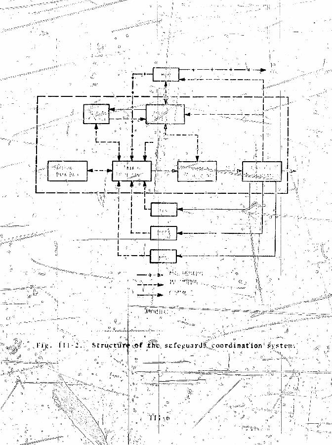
V,
,- 8)

as i e s snen t furiction? *"The r e s u l t of the cond i t ion assessment i s
the p l a n t ' s s t a t u s - wijth f eSpect ter safc^urrds ' r equ i remen t s .
Many of t h e n u n o r c o n d i t i o n assei.M'ient'. can be automated h i t h
manual o v e r r i d e , but #iost r e q u i r e d i r e c t ac t ion from the Safe-
guards Of f i ce r . Incoming SCS data are machine-monitored for
jKjs^ible indicirv1on;s of s t a t u s changes (for example, b> obscrv-
ing ma te r i a l imbalances or machine f a i l u t e t i , and a response to
etfch poss ib le , change i s reques ted from the .i>afeguarJs (Office-! .
He "( thendevaluates the prrant *afci;uarJs s t a t u s and determines
a p p r o p r i a t e ^responses for the PCS, IOCS, ar.^ M^AS, tak ing i n to
account process o p e r a t i o n s . These i e>poi iac arc- t r an smi t t ed t>
management and TCC, flion^ with rocommenJat ions for nod i f ioc
proefss au thor iza t ionSj .
\.- ^iny V t a t u s / r ^ ' p o i i i e s i t u a t i o n s a^ i>osi>ib]e <ixz s tand-
a rd i sed in a manual of ope ra t ing nroceuuie ' - . This nanual (01
apj>i opr i a t e p o r t i o n s the reof ) i s a v a i j - n l e to p lan t pcr»onnt.l
on a need-to-know b a s i s . Of c o u r s e , :.tard.*rJ Lprs^ediire^ i u \
not have been w r i t t e n ag for many s i t u a t i o n s , and tha t i" t v e
jii^in' roiison for the Safeguards Of f i ce r . This scheme cc rb^ res
ftlfeir^Vi;tTInency" of a raachine a, data hjiRdlin>' v i t h "the at'^i^-i-
b i l i t y of a human superviii>r in 5iaKinxs de^i* i^jns.
1 2 . '•-ptfiffa t fona l-yfrocedurc s . The prm cdure^ c a i t . c J ? :* * >
i thc SCS a r t c l o s e l y l inked to the procc<- oj-erat i ons , *h f ?;v
d e r a i l e d in Appendix A. A t y p i c a l sequence "it/.""ht''he .T> f.ii;«»i--r , ! fa'}. The general nan . i^ ' r is^uc1- .in a b t h o r i r a t io" »(
: • - : . . ' ' •
iryripcqctf witJv processing on a fue] contract .
!b}- '-he SCS receives the auit.on.-at ion and ,«U-rt'
tlu1 >jfc^u'irtis bv&tetn that material j»riS>ccs' mg is
\<r) Ihe S a f e g u a r d ^ O f f i c e r an.*. s s « . b ' t h e
the i - j t e i i u r J i t-y->tem and xnToiris p l a n t ri.iiiiij'cmont and f'( ( . I f
tnc j-afe^u.irJ*. *-vstcm i s n o t ; r e a d ^ , he n - i onn..'nds s- 4si-j . \ .
( a j \ f i « . i
e. t^Rditior1 of fhe s';jfej:i;»i ds <; i • s cr and the silt1
a.f is ot rhe plaiur.i
' - - 711 " /
' V_ I ^ i
\ r~ i ~T?r~ y

(e) If a safeguards' system malfunction occurs, the__ _ - 1. ',' V, !
Safeguards Officer ass"e^p|js'3^extejvt :of.::.ihe^i.ingact., i(or confirms) remedial action,^ and makes appropriate fei:s»nniLen-dations to plant management and PCC.
(f) If a clear safeguardsimpending, the Safeguards Offficer alerts t M safeguards system,plant nanagement, and PCC, assesses the impact and recommends acourse of actionto alle"! , ';(•(g'y If a pos»ibic^»afegu_rds violation is detecttfd,the S|ufeguafids Officer alerti^ the safeguards system, plant
, and PCC and, i
rtent jam! PCC,H Ft "fltf::;fhe; SC3 Jani "MMAS) may supply PCC with detiilscf aajtejrlal flows (adaptioju data) to aid PCC in improving the
x proc«M;
(i) During •*d
/g/ {The safeguards syste^
i$e,\ *p#cial arraitg
lIti-=a&s#**iftB the
ii consultation wi|th the plant manage-
it of irTiie.
any reports required for plantand the regulatory authority.
has the same five operating modes asC-3): (V) normal, (2) maintenance(4) stai|dby, and (S) shutldpwn.
NIL is moying^, the safeguardsif ft all pdisible. Other-
recording material transfers mast
T
• = ~ - ^ - ^ ^ ^ — -
ftf the plant, the S
fiver, Jthe infioriiltrran
^W^.A ,^i/ '
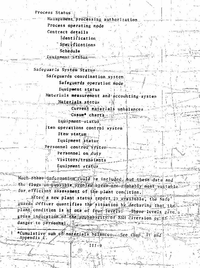
Process Status i
jau_t_hrgr.i.3jatiQ.n_-
Process operating nodeContract details
Identification"SpecificationsSchedule
Safeguards System StatusSafeguards coordination system
Safeguards operation niodeEquipment status ,
Materials measurement and accounting systen-Materials status 11 '
Current materials unbalancesCusum* charts i
Item operations dontrbl systemItem- s*a4yjs2j ••' j .,;:" ,: :' .-
EquipmenteontroXj
Personnel on0du)ty !!
Visttors/t rajiis lent sEquipnient st&tus *
(eH3^^<?te&$p?z&.t!it,ir Could lie included, but tjiesr data arid
i jreas ate- r-®bably most suitablyof *,',}\c plant contfition.
| j , new plant statu^ report i., available, the Safe| Officer quantifies the7 situation b/ ti^claring that thrcondition is at one of four levels. These levels s:ive a^ thc_prubabillt>r of SX?! diversion oi oid a n g e r t o
I' "*Cumvlative/ sul^.ra^l^J^ifWlfc^^aisee A f r #^ppendix i;. ,^/-j;\»|5^^J=r^^=i^=^7"=t7--^. *- v.
and
I I I - 9

; Level A is the normal operating level.Level B is in effect whenever the possibility of diversion
of a small amount of SNM existsl£r_Khenbv«r there nia>r becomehiiard to personnel. |- "" ? T -; >c ' . • Q' ''•'•. "\ ' ' •
Leftel C indicates tjiat s j ^^ B { Q ^ i ^ prc/lxt --•-
afci l i ty fef harm to plant pe,r;?onnel.'|';:;:'f.: ' iT-\ ^ I1, r>>.';:: .,
T^^v^ Levje.!^ j s ^ t h ^ TheJ . ivers ion of-,/$£M.^ ^ ^ ' "h ujISh ,•, J;i vlesT ]ir&MD i .nuriijn e n t . ^
s ^ | ^ s u c h <--a£The/details includ^a^tistj.,|ie^^fi|;iie,|;t. ^for pt)Tf>pr4;a;te plaint!personnel t ^ V ^ ^
. . / • ;
^ k ; ^ -^••.-• 1 ^ , : . 1 . : - :
jt)fe' four levels1 are,. de5crjnje,4--in-atthan?iff I af :iit?eratint;fd'tfre -i ^alon^<v^fifi^ftnt:^ble,'';respon.ses,> !;, Th'fs/relieveiSi^l'gslajrdjs^f-ficer's deci^ifOn/miaking ^^rdeiv-^soimeKHat, a$d^
tiohs7/ "'"After
1Safe-1!
fii^ sLtiaa-.^-p'fopriaii^eii' respon|pS";"ivave %ee^d«, tei#inEd' .v ;"the^^r.t.r4njsrt5.ii,s_tljdp'i:t;^ =-
je!nd8tfpr©;T^d plant; .pi^na.geineht^^ti.d -P=2c..«u.> „.,.'"{'^"'~"l"'r"l"1Wt'StS recomSftendatiiiilsrcan range from ho- recomniendat ion \
to the extremespofpr<|C;esi shutdown arid plant evacuartiDn. J f
he no recommendation oatit|;ail. '''in^^y'-V'ase^Hi^iii^^^^^^&dUtQjin; abnormal situations_%%= chosef\ btj^cMreemeht? amone the Safe- ,,"guards. Off icer , , plah't^-j^hW^'n^tL;and' rrcc^*1a^^^responses may be dftta|ed4by &scrip-
T h e s a f e g u a r d s L ^ s y j t e i r s a t a t u s i s a v a i l a b l e ? o n l y i t o ; t h o j i c j 0
ed," 1*. e;."f
^ ^ ^ ^ . Q Jhjs helps Ip^fa potent ial SN*I diRjerter jrom t a M n l ^ ^ i ^ ^ t S ^ p M ! ^ ^ ;*L
fanctions ^ fsu
x.
- K> •17.
J
-'• " V
Ul-ltr '• • f V =
command to prompt appropriate action when discfepa nicies are
detected. \ ;i .N •;!." ^ - jj'
Software Functions. The first software function ;bf„-•>.
the SCS is data management in .support of the- Safeguards
Officer's decision iunction, and
iT;anafienient and the regulatory authority. lit is nota difficult
task, and normally invbi-ves very l i t t l e computational burdpn.: ; The second SL'S software function consists mo'stjiy of airpar i son of the la tes t materials;'"data in t:Ji'e(" safeguards lind;; process informal" ion1 systems . TM''computations required! are
simple anil ^r^i^htforward. MC data are compared Kith th?MMAS data tp ensure that; they 4g?ec on material t ransferslocat ions. ! The probabili ty ttl|iegitiiniate disagreement i s ,<;because almost a l l material monjdt^rs Used for process control;;"
,!l are also used fosr;;the MMAS. T!i!is ^ch^tne provides both a i | i : e J
r i a l s check anu a systems in tegr i ty check. If sijin5. ficant;j , ••., i ' y ' . i
agreement ijs de t ec t ed , an immediate i nves t i ga r i on must he |launched. '' ' - * " _ j . ' \ ' j .!
• The thjii'd function of the StS sof'tK!xr>i is to spotchecji;; thei n t e g r i t y o|f the MMAS and the rGS/JOfS'\comput:;inj,i systems. | t h i <is'done.:.in the liackgrouhd of ,the SCS cofpputerisb tha^ norn i l
is not disrupted.
th
Abnormal Results, causeprocesssisitclunj; nnio«^ the computers to ir-aintai'irj | ! |^t£mneff |edti0 e t a i j s ? b f t h i s arrangement are iiiyen in \sec , , \ MI- i .
load
D. Safe^ujirds jnforination system.T-JiV-tpi. i.-'.i-ii»fi..t,^Mt.i.iiyiiH!ijpa-C "1 .• .U'«.li I,':"'";I'1..11.1
The s iijF0rm«tion s'v.s a d a t a|ment struct j j i re1 f o r c o o r ^ J n a t int' and sujiervlisinj:T'act^Vi ty rijrla-
,.tjiv.c.:r^bi:,:S.i\.ML.cQnt tol. Ayai l-a^Ie osouxce!?.. "o-f \ ihfbrmat-i(c>ni.:,'are:| com.
an1d''""cj!pfi.t-Ka-ifet 42^M».&-,=,;a to,p|a!U;d-- da t a p r o c e s s i n g
| 1 ^ i ^Ki^fit r e n d s , and jtend
f)iefiles U-ithi) \ K 1 i
Consoles•,-djiVt4/ o*t
anoxia 1 oil stoward 'poss ib le t"fi!c.fjt~ oT'-dlv^^sion . I! "All
a re
and miinual!
i monitors 1 cent roli
1
er fornis» of ^rj^tcii anil oriil c|yapunicat io:u ^
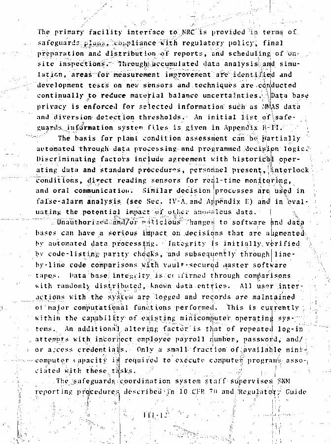
The primary facility interface to N8C is provided in terms of,
safeguard;: j;luiict v.-^pliance with regulatory policy; final
preparation and distribution of reports, and scheduliingj of on
site inspections. Through accumulated <Jata analysis lvan d simu-
lation, areas for measurement improvement arVidentllaed and
development tests on new sensors and techniques are conducted
continually to reduce matvirial balance uncertainties.! \ Data base
privacy is enforced for rejected information such as fft\S data
and diversion detection thresholds. An initial list ofj'\safe- j
guaytlsvinformation system files is given in Appendix 3i~jH. \
The basis for plant condition assessment can bej alrtially
automated through data processing and programmed 4eciisiipn logic;
Discriminating factors include agreement with historical oper- V
ating data and standard procedure's, personnel present;, 1 (Interlock
conditions, direct reading sensors for real-time monitcU*|>ng,
and oral communication. Similar decision processes arelj used in
false-alarm analysis (see Sec. FV-A and Appendix I;) and! in Wai-
uating the potential impact yf other anomalous data. I 'i
Unauthorises &nd/or i /vliclous "hange^i to software and dat a
bases can have a serious impact on decisions that are augmented^
by automated data processing. Integrity i!s initially verified
by code-list ing- parity checks, and subsequently through line-
by -1 ;ine code comparisons with vault -secureid niaster software
tapes, i'ata base intensity is d l-firmed through comparisons
uith randomly; distrilnttcd, known data entijies. All user inter-
actions with the sy tvin arp lodged and reciords arc maintained ••, ..;••
oi major computational functionsperformed. This is currently „ i
within the capability of existing -minicomputer operating sys- i j
terns. An addition.-il altering factor is triat of repeatet
, attempt's with incorrect empioyee payroll number, passwoi
log-in
d, and/
or a.'coss credent ialis. Only a small f rac t ion o f^ava i l ab le mini-cojiiputcr t«|>acity i a requ i red to execute computei" progrdiu's asso-:
i j • ' ' ' • , ' . . . , • • ' • n ; . , . •• • - i ;,' • i j , ;.
ciated with these tasks. i ,;?rhejsafeguards,
report ing procedurescoordination system, sta{{• suhervise,s SNM
described in 10 ,C}:K "n •and,i/Regu|!at0Jt"/ Guide
III -1 ;'*.

10.1 for normal and iinusual occurrences. Thesej reports are
listed in Sec. III-f;, materials measurement andj accounting syss-\
tem. Information f^om J|hese and process line report^ is sum-
marized for plant ^nagewient cognizance °^ S.NM:-istatusj. The sum-
mary can be placed^on-lipe for interactive terminal Recess or
can be put into hardcopy format. JFurther file accessj for^ustom
searches and datf processing by authorized personnel is avail-
able through theMnfornat ion store; Reports shOKing |how the
more comprehensive and precise safeguards ,lnfcrjmatlon| can bene-
fit tJte proce^ linear^ gerierated|and nsade ava'ilable through
d a t a basve a c c e s s . " - - , i- . IPl -\' '!. » • ''"-'•. • ••
The safeguards coordination system Assists production con-
resolvii\gtrol in *t^ interfict^ons with repinessijig plants in
shipper-receiver differences, tracing shipments, and negotiating
^t! fissile-content material exchange6 with nuclear powe^r
companies^^SCS responsibilities also include supervising
chanp.es in SNfM measurement techniques, revising and updating
the SNM control plan, and obtaining corresponding approvals from
K;.' Materials Measurement and Accounting Syst<?|n (MMAS) \
The MMAS design selected for the recycle MO, plant is an
extension of HYH;\C. This system takes full advantage of re-
cently developed NfDA methods and supportive cornbuter and data
base managewent technology to provide timely asses&Mient of the
location and amount of material within a plant. Con/entional
safeguards inventory control consists of major inventories con-
ducted during periodic plant shutdowns and numerous accounting
and administrative procedures for interim plant,'ope rat irtjj
periods. The classical material balance associated with this !
system may not be sufficiently sensitive tx? detect a trigger
quantity of SNM when plant throughput is lairg"&. Conventional
inventory Methods are not fast enoiigh to deter SNM diversion..........,,!'
effectively, and furthermore, economic penalties of more frc- I
quent plant-wide shutdowns for tighter control are severe.
111 -13
3 Ci (1
1

Sysltems similar to D*i?!AC that address these problems ha\|e been8 ^ 2
To implement iths DYMAC approach* the . b«3elirtc fsciljity i sf i r s t par t i t ioned into d iscre te accounting envelopes, referredto as unit process accounting jjireas that cap. be one or njorechejnical or physical prbcessse^jor a storage area. In con t ras t ,storage vaults ana buffer; Sttorii|;es for d iscre te containers c»fmaterial are conventionally Referred to as itersi control( I ) i b [ {MBA) d f i d hof geography, function, custotliments. By partitioning a faci:
\ V \ ° 1
areasmaterial balance ai'«afei[ {MBAs) are defined on the! basis
pnship, and regulatory relquire-ity into unit processes and meas-
uring all material flows, qtianfities of material much Mailerthan the total plant \nventoryjjcan be controllfed on a tiknelybasis, Computer-gen^rk^edojCpjttLr^-charts<ieriYcd from measure-ments nand ^rociess, opera ting character! sit^cs ;c..pijl be used ]to
theftskjbsses, or exjee** Lve holdup (see Clhap. iV a|ndThis detailed coi
k sufficiently *\Appendix E).to steal smual removals kill be manked byto obtain a fiizabla quantity ocomair many thefts witn the co^
by the accounting systea,
trot fot^es % patential divertor
»«11 quantities tjlhat his i^divid-
nonitors, and physical protect Lori system.
' The conctf%of tiwely #«t|»ri«l,
yto be practicably Its applica
measurement uncejrtainties. Thu*,r Rsterial, the dlverter
conltant high risk of detection
illanre instruKents, d
ion should be gr4|1ed acco
Istrategic ]v« ue/Wl [ ( i b
illegible
rial. , Often these tl*«ly aat^rit.l balan es are.
mutely closed/the r^k*^ for|whfcli ar«j best"
comparison with th<- traditional period^ plant inventory anc
material | balwiceiiresidual holdup iuusing the equation
Material B«|Unc«
oil1h
! & •
d
stocks of SNM rnd
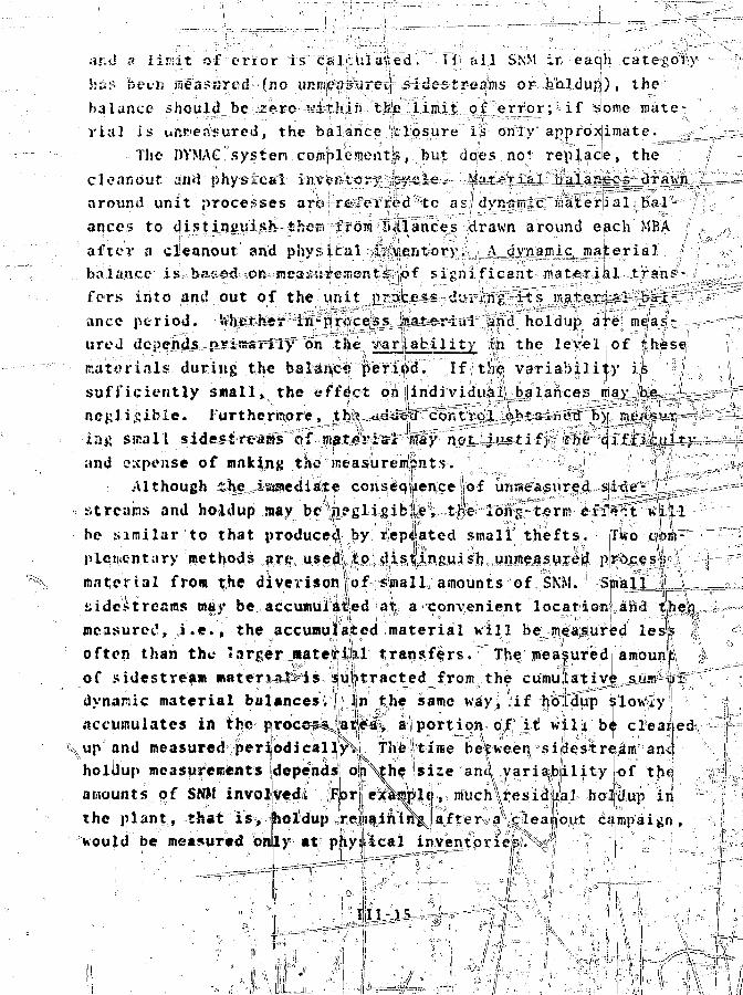
;ir.d a lir.it of enor is calculated I i" all b.SM ir each category
httt- been measured (no uRmeuiurvM sidestrea.ms or holdup) , the
balance should be zero '••itlun the limit of error; if some mate-
rial is unr<en«ureti, the balance 'closure is only approximate.
-The DVMAC systen complement?, but does no' replace, the
cleanout an«J physical in\e«tcr>° tjuie. M:*t^fial balances Jraun
around unit processes arc rtTerred te as dynamic material bal-
ances to distinguish then from ?><tlances drawn around each MBA
after a cleanout and physical inventory. \ dynamic materia]
balance is based OR ne3::i:rcment& of significant material tranf-
fers into and out of the unit process dviang its material bai-
ance period, fcherher in-pr<icess luateriai and holdup are meas-
ureJ depends primarily on the variability in the level of these
materials during the balanc? period. If the variability is
sufficiently small, the effect on lindividual balances may be -i
negligible, furthermore, thft 'juideLti control obtained by jriCp yT- - -
ia$t sir.ail sidestreams of material hay not justif> the difficulty-
and expense of making tSie neasurempnts. 'i
Although the iaswe<liate conseqUence of unmeasured side- ,
streams and holdup mav be nffgli^ible, th!e Ions-term eiiir.t ui^l
he similar to that produced by repeated small thefts. Two com-
plementary methods are used to distinguish unmeasured process
material from the diverison of small, amounts of SN'M. Small_. _ -
yidestreams may be, accumiilijled ai a convenient locationianei 'I[he)o, -U—
measured, i.e., the accumulated material will be measured lest?
often than the larger material transfers. The measured amounf:
of sidestreain material-is -subtracted from the cumulative sum of
dynamic material balances.1 In the same way, if holdup slowly
accumulates in the process^ area, a portion of it will be cleaned \'
\up and measured periodically^^ The time betneen sidestream anJ i
holdup measurements depends on\the size and variability of thf
amounts of Sf»t involved^ F,or|| exsaplif, much residual holdup in
the plant, that is, holdup remaining after a cleanout campaign,
would be measured on|ly at physical inventories. - ] '
1,11-15
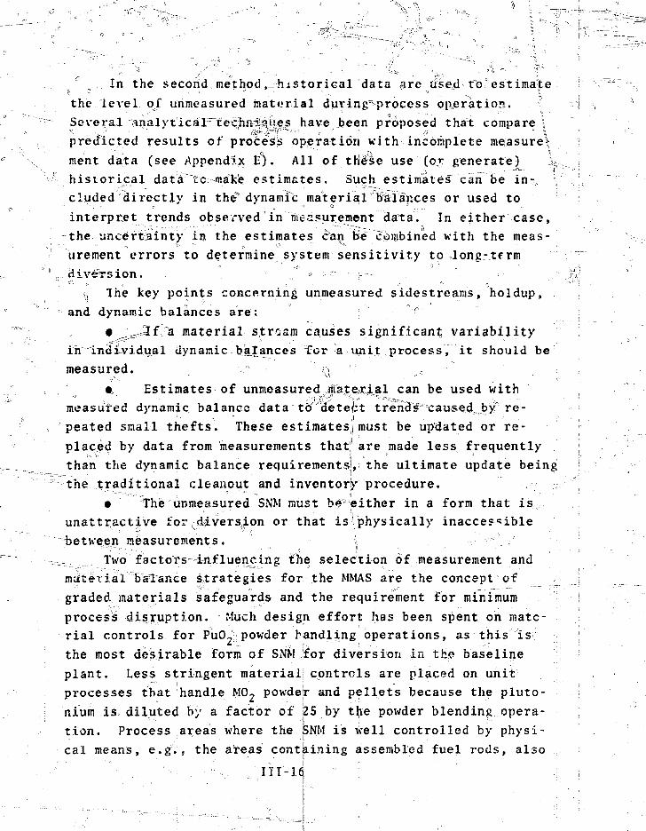
In the second method,-historical data fire use,d to°estimate
the level of unmeasured material during==process operation. |
Several analytical"techiwi?!^! have been proposed that compare!
predicted results of procesis operation with incomplete measured ,
ment data (see Appendix E'). All of these use (or: generate) \
historical data to make estimates. Such estimates can be in 7...
eluded directly in the5dynamic material balances or used to
interpret trends observed innressurement data. In either case,
the uncertainty in the estimates can be combined with the meas-
urement errors to determine system sensitivity to long-term
..Jlt-version. . " - ." * • ~ H---~
v, The key points concerning unmeasured sidestreams, holdup,
and dynamic balances are: :v °
• ^.JZfa material stream causes significant; variability
in individual dynamic balances for a unit process, it should be
measured. ,.r> \l c"
• Estimates of unmeasured Aateirial c a n D e used with
measured dynamic balance data to detect trends caused,by re-
peated small thefts. These estimates^must be updated or re-
placed by data from measurements that1 are made less frequently
than the dynamic balance requirements], the ultimate update being
the traditional cleanout and inventor)' procedure.
• The unmeasured SNM must b*? either in a form that is
unattractive for diversion or that is physically inaccessible
between measurements. \
_-..... Two factors-influencing the selection of measurement and
material balance strategies for the MMAS are the concept of
graded materials safeguards and the requirement for minimum
process disruption. Much design effort has been spent on mate-
rial controls for PuO, powder handling operations, as this is
the most desirable form of SNM .'for diversion in "the baseline
plant. Less stringent material!controls are placed on unit
processes that handle MO- powder and pellets because the pluto-
nium is diluted by a factor of 25 by the powder blending opera-
tion. Process areas where the SNM is well controlled by physi-
cal means, e.g., the areas containing assembled fuel rods, also
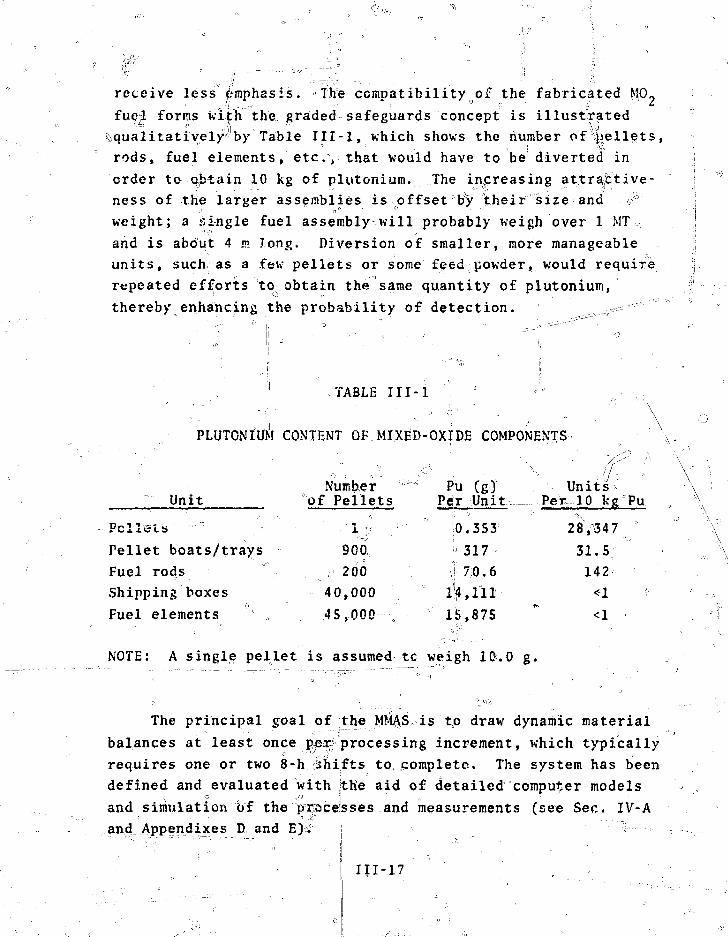
receive less f>mphasis. »The. compatibilityoof the fabricated M0«
fue L forms with the graded safeguards concept is illustrated
^qualitatively'-'by Table III-l, which shows the number of p
rods, fuel elements, etc,, that would have to be diverted in
order to obtain 10 kg of plutonium. The increasing attractive-
ness of the larger assemblies is offset"by their size-and ?v
weight; a single fuel assembly will probably weigh over .1 MT=
and is about 4 m long. Diversion of smaller, more manageable
units, such as a few pellets or some feed powder,, would require
repeated efforts to obtain the same quantity of plutonium,
thereby enhancing the probability of detection. ^
1 TABLE III-l . • °
PLUTONIUM CONTENT OF MIXED-OXIDE COMPONENTS
"•" Unit
Pellets
Pellet boats/trays
Fuel rodsShipping boxes
Fuel elements
NOTE: A single pellet
Numberof Pellets
900,
, 20040,000
45,000 .
is assumed
^ Pu (gjPer Unit
0. 353
! 317
•j 70.6
1^,111
1^,875
tc weigh 10.0
Units....Pet 10 kg'Pu
28>347 *
31.5142
<1<1
g-
• \
The principal goal of the; .M?#AS is to draw dynamic material
balances at least once pe$ processing increment, which typically
requires one or two 8-h shifts to, pomplete. The system has been
defined and evaluated with the aid of detailed computer models
and simulation of the i^rpcesses and measurements (see Sec. IV-Aand Appendixes D and E)i" :!
"• -•'.. ••• i • ' ii ''•
' I III-17

1. Measurements and Inventory Control. The measurement
system for inventory control is a combination" of weighing and"
CA, nuclear NDA, and item identification (IP) and counting.
The recommended system,j although similar to the original West-
inghouse design, includes the upgrading of some existing instru-
ments, and the inclusion of a small number of additional instru- ;
ments to permit material balances to be drawn around each unit
process. For the main process stream,;Which includes the CSRS,
simple neutron and gjamma-ray instruments and weighing devices
were added, to provide timely data on process materials and hold-
up. The instruments and, to a large extent, the measuring and
calibration procedures, are automated so that data are fed di-
rectly to the materials accounting computer with minimal opera-
tor interaction. Sophisticated NDA devices were added to the
ASF to provide rapid analysis of process samples for verifica-
tion and for the calibration of process-line 1,'DA instrumentation
for current process materials. Theseli instruments may in some
cases eliminate the need for further fcA measurement in the ASF.
NDA instrumentation in the Mlt'T and LWJ facilities provides es-
sentially all the data needed for material balances in these
areas and for their principal functions of wlste and scrap
management. „ |
Weighing and nuclear NDA instruments selected for the MMAS
are described in Appendix C. Typical measurement uncertainties/
needed for the essential description of the MMAS are given be-
low. Specific subsets of these measurements and their associ-
ated uncertainties used for the performance evaluation of dy-
namic material balances with the MMAS are given In Sees. IV-5
through IV-9. A more extensive review of the uncertainties of
both CA and NDX methods" for.materials of the fuel cycle has24
been made by Reilly and Evans.•• x . « r; • •,-. ; »
Main Process Stream. The measurements system for inventory
control of materials in the main process stream is presented in
TablefiIII-2, III-3, and III-4. • The only measurements shown for
the U02 receiving and storage ofjerations are those required for
III-l
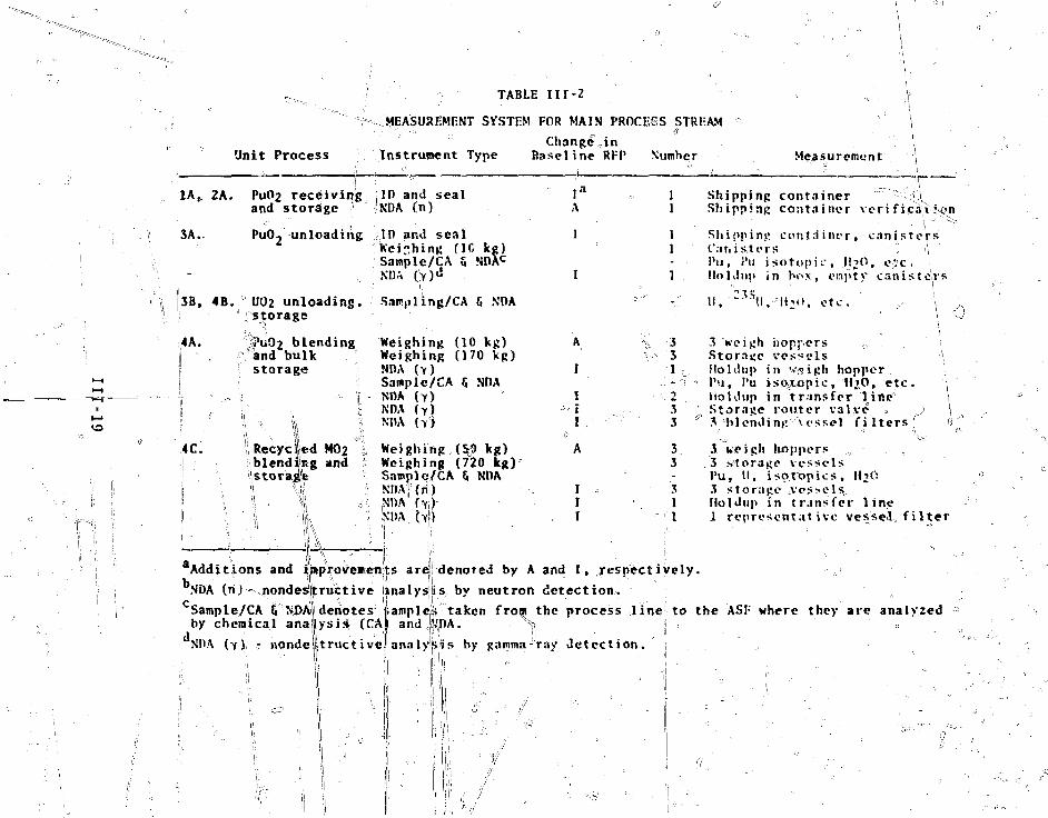
TABLE Iir-2
MEASUREMENT SYSTEM FOR MAIN PROCESS STREAM
Unit Process Instrument TypeChange, in
Easeline Vumher Measurement
3A.
2A. PuC>2 receivingand storage f
PuOj unloading,
IP and seal(n)
';ID and sealWeighing flC kg)Sample/CA 5 NDA^NDA (;>)<*
A
1
Shipping container ''"-iAS h i i container veri fica't^jn
3B, 4B. UO2 unloading, Sampling/CA 6 NDAI storage
4A. fuO2 blending Weighing (10 kg)«. and bulk Weighing (170 kg)
f storage NDA (Y)j ! Samplc/CA 5 NDAI - ,*=-4 - i - NDA (y)
1 (Y)
4C. 1i Recycled MO2I iiblendiiRg and
'istoragW
Weighing (Sj) kg)Weighing (720 kg)Samplci/CA ^ NDAKDA'(ni)
;NDA
A
I
III
331
233
33
31
11 1
Shipping container, canistersCanisters „ ':\i'ti, J'u isotopic, H^O, e*:c.Holdup in box, empty canisters
ll,"-S*SU,-:!«->(t,: etc. ..,- \
i
3 weigh hoppers 1Storage vessels >Holdup in vaigh hopperI'M, PU isoytopic.'HjO, etc. \Holdup in transfer line'Storage router valve = j \3 -blending vessel f i l tersf <•>
3 weigh hoppers . ,j storage vessels '
Pu, II, isot'opics, HiO3 storage A'es>els,Holdup in transfer line1 representative vessel^ f i l t er
aAdditions and iaprovemenits are denored by A and I, respectively.bNDA (rij - nondestructive IcSample/CA 5 NDA|denotesby chemical analysis (CA
1 ' w
NDA (Y) - "nondettructivc
nalys;is by neutron detection..
ampleis taken from the process line to the AS!" where they are analyzedand^DA. •, \ i , • =
analysis by gamma-ray detection.
i ! :/
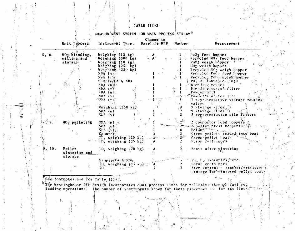
• |i j:; '! TABLE III-3 j
MEASUREMENT SYSTEM FOR MAIN PROCESS!STREAMa
S, 6.
I
I
II'' i !' ' S
= M = = =JTL1,_, ,_JU-jL -
; t >
, S ... :j ••• ;
1i
• , : . . - .
7-? .8.°1
\ 1Ir ••" '9, i o . .
. \ r-:
\i
i 1
!iiUnit Pir
jj iocess
MO2 blending.millingstoragjt
iand
. . ' I •!
//' 1 \i |i
X1 '
'*.MO2 pelleting
~J 1
Pelletsintering andstorage
!l
Instrument Type
Keighing (15 kg)Weighing (300 kg)Weighing (10 kg)Weigh inn (250 kg)Weighing {25(1 kg)N!;A ( n )NI;A ( , ) , ; ;»Sample/jjj'A -i NBANDA f n ) | !M ' A •( Y I ! 'NI»A ( n l ; ;!NDA (y): if
""?i!>A ( Y ) i | . . {----•' !;- • "" ' {
Weighing (250 kg)NDA (n) 'M'A ( Y ) J
NDA ( n ) viN1>A ( n ) -S J H \ ("i )ii ;
Clpunterf\), weighing (20
~I|>, weighing (35
li), weighing {fO
Sample/CA T, N!UII), ueighinfi (35i n .
Change inBasel :ne RFP
Ar, A
II
IIII
- I • - • > ) • • " " "
i a
;i I •:'i I
., " I"
IA
k s i •*••" "--"--- ; - ; =
k g ) A
k g ) A
-fc K-}"'-" 'AI
= •
dumber
j 1 .11111
• • • ^ 1 ,-.
f1
' - • • • 1 =
"••v 1
- - • - = . V : -"
, 3: • iJ
!
'. '
3
= = - • . 2 = =
(.
2
-'2
Measurement
PuO2 feed hopper , • - -• -o
Recycled M^i^feed hopperPuf>2 weigh hftpper • ,, 1 :
li>:'2 we/igh hopper "3"lecyc l ed y.^2 weigh jiopper !
Recycled l'ui'j feed-popper °Kecvclcd I'u'1-' wci !'h"1'h»pperl ' u . U . 'isotrtf.US ,"li'2f ^Blending vessel -1 •Hlen.iing ves: c ! f i l t e ri'i)w\l(-r ffii 1:1 / ;*-.••? y
^Toisfor^t-ra-nsfer l i n e >. t* r « ' p r e s e n t a t i v e s t o r a g e r o u t i n g sval'vvs '-• / -j *D s'to^n-f siles-^.j \\'.• ^torai;e f i l o s " ^ '#"" |j • • = •3 r e p r e s e n t a t i v e s i l o f i l t e r s
2 compactor feed hoppers f- ^ p e l l ; l e t p ress hoppers * ;L\ ;
Holifiip ~~~s-- :'ireen ru-llcts ifrfttJcJ- into boatftreen pel let boat's "^-4^Scrap containers ,11."
Boats after -sintering
Ivii, 11, i sotopics ^ e t c .Scrap containers!ten control - stacker/retrieverstorage T?firwintered pellet boat-
alSee footnotes a-d tor Table IH-2.
|The Kestinghousc RFP desig'h incorporates dual process lines for pelleting tf.ron h fuel,, rodloading operations. The number of instruments shown for these processes i;- for ]two lints;,."
t i
|
\ \
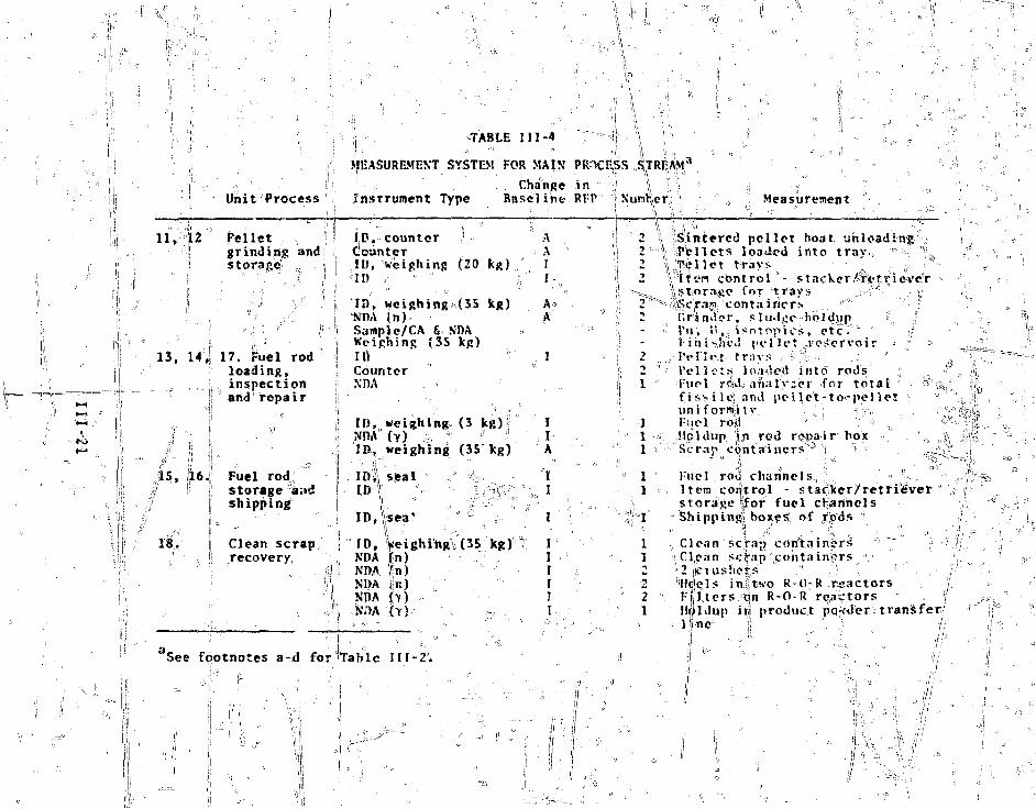
, " • ; *
TABLE I I I -4
Unit Process
MEASUREMENT SYSTEM FOR MAIN
Ins t rument Type, ChangeBasel ine
E I ^RH' \) Nunfter; Measurement
11, 12
? grinding andstorage _. . •
13, 14,;| 17. Fuel rodloading,
j; inspection!| and repair
I;D, c o u n t e r ••!CounterID, weighing (20 kg)
"
ID, wcighinj>a(35W)A (n)Sample/CA 6 NDAWeighing (3S kg)II) ^CounterNDA
AAII-
|5, ,16J: Fuel rod:• j storage a.id
j shippingji c
18. Clean scrapl| recovery
• '. ' ' iilj
• ; 5
See footnotes a-d for"
ID,NDA"IDf
ID \
ID,
ID,NI)ANDANpA
Table
weighing (3 kg)(>) . 'weighing (35 leg)
seal
Ifea'VWeighing (35 kg) '-^n)*n) ' - <
t?)
1 1 1 - 2 ° .
IIA
1I
I
III
II
ij 2h 2\ 1
.Sintered pellet boat unloadingiPellets loaded into tray, * '\""' Hot trays ; ;!
control - stacker^ric'trie-vexso for trays , ;lc ° <;contairicrs "'"- "' »
' I'll, ! t , , j so topiCS, Ctf; " yJiniSjhcJ pel l e t voscrvoir =
, . /PcTl tvt - t rays ..• =• %: - . - - . ' • 3Pel l - j t s loaded in to rods iY\\(-\ rcldj anal 'yicr for t o t a l ' "> ^,f i s M I-e) and p e l l e t - t o » p e l l e tuni formi ty : ,„l-'tiel ro|! •• V '-> ^
,!!pldup |ji rod r e p a i r box \ \\1 Scrap c o n t a i n e r s J j ; - ,^Vr
Fuel roil channels., > "•Item control - stac-ker/retfi^verstorage |for fuel cHaiinels
Clean sera;? corfta.inir.s ^! Cl.jpan scS"ap containers r;>2 jicjushois .," .:'. , •'''Hdqls in|itwo R-fl-R reactors!:|tiers on R-O-R reactors "Holdup i?jj product pq^der transfer(1 -nc5 !l \ ':!

safeguards management"o£ materials in the main process stream.
The total numbers of instruments oi"5each type used in the main
process stream were not always'specified in tha original RFP
design/ and their function was usually threshold indication in-
stead of quantitative analysis. Similarly, the recommended ID
system uses' an Automatic label= reader, Whereas the RFP ID design
uses mcCnjaal,reallin s. thus, many of the-changes reflect ad-
vances in technology since the, original design o'f the RFP.
^ 6stj*i3f the instruments used in the main process stream
are weighing devices and nuclear XDA neutron and gamma-ray de-
tection systems for measuring holdup and process materials.
Digital balances with measurement standard deviations between
0,01 and 0.02$ of full scale are specified for tSePuOi unload-
ing operation. For load celis, which are used for all ofher
weighing operations, the standard; deyiat ion of-a jiieasurement
lies in the range of 0.1-0.5^ of full scale, depending or/
process line constraints. Uncertainties in the holdupmeasure-
ments currently specified BTC considerably lower than those
achieved with portable instruments. Typically, the/rel,atjve
standard deviation of a nuclear NDA measurement of/holdup or
process material is expected to be in the 5-€5t range. These
projections are based ori holdup measurements pe.ryq.rmed,-under ;,
le:', than ideai-cdriUTTrohs at fcASL, K-25 (the Oak Ridge gaseous_ "' " '•' '; ••••••• ••••-.• " ^ X '•• • I "••'• •' '• " 2 5 - 2 7 ' r
diffusion plant) , and/a|: the Kerr-McGee plutoniilim facility.
The technique used to verify the nuclear contents of shipping
containers of PubJ( in"the receiving area is similar to that
used for holdup• eVjil'Xiati Dh 'B P-fi-e -tTdn-"detection" and is/expected
to have a relative uncertainty o f * 5^ (la). ^r ; sS
For the operation of the MMAS, the most important measure-
ments of samples sent to the ASF are plutonium and uranium
weight fractions an°d isotopic compositions, specific neutron
yields, and moisture content. The weightr'frac.tions and the
moisture measurement affect the Weighing of bulk-materials in
the main process =steam, while the isojtppdfc'5'compositions and neu-
tron yields are needed for the calibration and interpretation
III-22
•of the nuclear J^DA measurements in therprocess line. The uncer-
tainty of the Plutonium fraction derived'from CA ranges from'•• •• ' - . : . ' • * ' ••.''• r- ' A '" 2 8 "^':
'v, 0.14 foTr=iTT©^^cedfi!!aterial to 0.3?« for clean scrap. Un-
certainties in ^otopLc^analysis depend on the abundanc^i,J»f the
isotope and the form of the material-, as jiiscussed in Appendix o.
Pellet counters supplement vcq1tgJit= .mea-surements in^^ffe
process line,l|rom the loading of green-pellet boats to the
loading, of fuel rods. Ccuntirtg""fi tern control) -provides-better
control;ahd eliminates tho need to weigh rods between welding
and inspection operations. Pellet counters with""Tat=es=of V'o/s
have been designed for, the High Performamce Fuel Laboratory
(HPFI.) to; be constructed at the Hanford iSngiheering Development
Laboratory (HEDL). /
The .VDA /uel roxd analysis system for the fuel inspection
operations (unit process 14), is a key\nuclear NDA system for
safeguards, as well as for product Equality assurance. A device
similar to that designed by Menlqye et al., for analysis of
1 T'M: fuel rods can analyze^all rods produced, at a rate of about
13/h. Total fissile content of the rod arid pellet-to-pellet
uniformity are measured.. The relative., precis ion for analysis
of the fissile, content of a single rod" is, O'\5$ (la), and°the
uncertainty of the measured fissile, content of a large number
of rods niay be as smalTTas CKit, •-depending on factors such as
Jie quality of "esLifeaJionst^ndafds. ." Pellets^with en-
richments that are out of specification by 5? (relative)"or more
can be detected with almost 100» efficiency and a false rejec-6>
tion rate of less than 2!<. Additional straightforward develop-
ment is required to adapt the 1;FTF fuel rod analyzer design for
LJV'R- recycle fuel rods. " t . • . > J
Miscellaneous Waste Treatment. The instrumentation needed
for MU'T scrap and waste sorting and concentration operations is
almost identical to that used roAttihely in the LASL plutonium
scrap recoviery facility. • Materials received at MWT include
high-concentration fuel scr^p, low-concentration combustibles,
hardware, and glass, and plutonium-rich solutions. Containers
1 111-23 -
'••>,,•

i,
|or these materials range in size up to 20 liters. As shown in
Figs. II-3 and II-4, the produe-tj?; of3 the MWT are: (1) small
^ containers o£Sh fii y,!\conce|)trated solid scrap to be stored for
future recovery, (2) drums of treated organic solvents and dense
waste destined for waste disposal, and (3) contaminated fil-
trates and wash solutions for return to LWT. The following in-
struments should suffice for the accounting and management of
materials in MKT with minimal need for sample .analysis at the
" A S F : '" ,.,.- . :- , ^ L _ J f '.' . . _ • . " \ " ' • ' -"••.•:•..
• Two ID and weighing systems,for receipts and products," ' '" •- '* ~~ ° -• 3 4 ^ 5 "
• One large neutron,coincidence unit ' f o r analysis
of receipts and products and for sorting,
•V One multi-energy gamma assay system (MEGAS), with a
' metal detector, for porting combustible waste at the
10-nGi/g fiducial, ^" "%TL
• One Ge(Li) gamroa=ray analysis system with segmented
^^= -^^scanning^and selected isotopic analysis capabilities
for analysis of solids and liquids,
• One on-line solution analyzer at the solution receiv-
=:,.,.- ing tank/* ° .
• One in-line^neutron coincidence counter and Nal
detector in the glovebox for shredding, washing, and
filtering, and
• One portable Nal gamma-ray system for hollliip nfeas-
••••-=•-_-. u r e m e n t s . ,_ v~
The fixed instruments, listed^above will be interfaced with
the MMAS computing system, and for accounting purposes MUT is-
treated! as a single unit process. With the abovefihstruments^-
the measurement uncertainty o£ the product containers of dirty
scrap, which contain the bulk of the MWT plutonium throughput, .
is expected to.be less than 51 (la). ,, , /
Liquid Waste Treatment. Be cause t he f unct^onL: p f LKTu-,ii-,jtP-- r
receive and spl.idi'fy aqueous v-'astes that" do not contain -pecoiFer-
able quantities^of plutonium, the only measurement required is
that of the solution plutonium concentration after filtration.
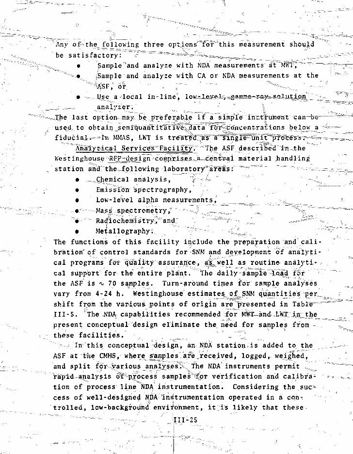
Any~'o.£"the__foilowing three opt>ions=~~for~~t.his measurement should
'"be satisfactory: 'F ~Ss=s=s^ai^^^ • !5ample and analyze with NDA measurements at
"* • (Sample and analyze with CA or NDA measurements at the"H&F," or ' ~-'--» ^f " "'* """— ^*=--^.. ' —
• . \ise a local in-l ine, loK^Agjuy^^asma
=mra~.™ analyzer.
last option may be jirefer^able if a simple instrument
used to obtain semiquanTTfat"ilr'es data for concentrations
fidutiiaW==In MNL\S, LWT is t re i tedas" a^arrigie~
Analytdca1 Sefvices FaciIfty. The ASF described
IVestinghousej^FP^&sign complrises_ a central material handling
station and the^pllowing laboratory"areas: ---=— ._ __
• ,^^Chemieal analysis,• Emission spectrography,• Low-leVel alpha measurements, ^
• Radfiochemlstry^and: ^.^==2=^ ;%
• Metallography;
The functions of this facility include the preparation and cali-bration1 of control standards for SNM and development of analyti-cal programs for quality "-assurance-,. ;;.ajjL w?ll as routine- analytic =cal support for= the entire plant. The daily sample Iqad fcfrthe ASF is *v 70 samples. Turn-around times for sample analysesvary from 4-24 h. Westinghouse estimates_of_SNM quantitiesshift from the various points of origin are "presented inIII-5. The NDA capabilities recommended for Sffe-and-LMTI iaithepresent conceptual design eliminate the, need for samples fromthese facilities. ^ al
In this conceptual design, an NDA station^is added to, theASF at the CMHS, wherg^mples are received, logged, weighed,and split fot' various analysesiv The NDA instruments permit !=ariapid analysis cff%p^rocess samples**£pt verification and calibra-tion of process line NDA instrumentation. Considering the suc-cess of well-designed NDA instrumentation operated in a con-trolled, low-backgroiihd environment, it is likely that these
111-25

TABLE III-5
ANALYTICAL SERVICES FACILITY SAMPLES
-_ _ _ _ _ " ----- _-==-=~*^— --_-..-«: Quantity oOUi-terialPoint- of Origin" St»M~f-igtrsureiiients "'7 (g/8-h shift)
PuO, receiving plutonium, plutonium 2 7.1(vendor samples). isotopes, trace uraniumPuO, unloading plutonium, plutonitim :, ^^Ji^-'vS" •-._.
- isotopes, moistureu s^^^i"~"
PuO, slaji storage plutonium, plutonium 1.4___ and blending isotopes " ft
UO, receiving ^ujranium, uranium ^"= 7.1
U02 blending uranium, uranium / 3J8•"'<•"= ~~z"~" Isotopes, moisture "• y/'
Recycle MO? slab plutonium, plutonium 1.Z/storage and isotopes, uranium, = = = = = ^ = = = = f e ;blending aoisture^ £>
MO5 pellets(after sintering)=r^
Plutonium, plutoniumisctopes. uranium
_ plutonium, plutonium~"CSf"feT=si-ntet4>-ingLl_ isotopes, uranium,
Mr«n.iuj...iso-tqpes-»--r-,.E,
M02 pallets N.A.(after drying) <r»,
LWT feed tank plutXtuum
cell, liquid plutoniumhold tank ^
ASF liquid waste plutoniumpretreatment
MWT,, treated plutonium, plutoniumscrap (MO?) isotopes, uranium ^MWT, organic plutoniumwt^te
:^MWTm£iltrates plutonium
23,
40.
33.
<0.
2
==2-
. 8 /f
,0
,3
8
1
8
a i l
n i l
•Not applicable.

instrument5 will frequently reduce or eliminate the need forfurther CAa . "~~ "• •••^---•- = = = = = = « ^ , . -
The XI) A statTorr consjrS fcs cf t<-.o ir^f'unipnts: ( 3 L_it._P_P lv-
ethyiene-moderated neutron coincidence veil detector, and (2) a,
high resolution CefLi) gar.ma-ray .spectrometer V These instru-
ments and the digital balance used for weighing the samples can
be serviced with one small mini computer.,.. which- can also "'do the :
AST accounting and report" to the MMA^^,ojnpjUt=e^.^ ^^ ™v"' r ••-! ±;r,'.,
The neutron coincidence detector measures. a= combiriat167r~Tq7f.f
the " i"'u and " ~Pu content of the sample, afl^ccnversely, if
these isetopic abundances are known, the total plutonium con-"~
tent can be obtained. Such detectors~ aTtvnroSc well de-vel- .,u• ^ s - j ~ •' • > = ~ - . I —
opcd,Wi " and nit-a&ti-reHent^uaGertainties of less jthan 0.5« [lc)
should be cbtaincd for sampre^:^ith,jnore than 10 g^pl^utonium. 'T
This detector can also measure the spec i fie-ne^L^QnFJ'i^l'feocf"
1'UOT and MO, materials drawn troni key pointy in the "process
line, thereby providing a calibration foxjun .ine._inei!;fcr.=o-n,.jieij;
tectors that are usedifor dynamic material fraTances.
The He (Li) gainmaAray spectrometer can be used to measure'.'39 ">4 2 • ^ 3 8 •) ,^h&£}£ , B ^ -
the " i'u, " Pu, and " Pu relative abu^d^ntfe's^i^^d^^utjp^ijj^ng^
and uranium contents. "The 'U isotopic abundance of UO2 feed
material can also be readily obtained. Tjhe optimunr Hetectbr1 |
for this wide ran^e of applicationsi has a resolution .better than0.8 keV at 122 keV and da efficiency of about 10^
Nal) for Co gamma rays; Detectors with these characteristi^|I^l _:°^
3rc cOfiuusrcialiy available, although at premium prices., :
It may also be necessarv to add a 'Ivigh-efficiency Xal ..•"•"'"f"".':• .j_ _s£==
gamma-ray analysis system to the at^ove systems for the analysis _„./,
of small samples such as individual pellets. Such a detector ', ,'~'\
is fully compatible with the NDA stlatiunssdesi&H^^ahd should n.ot=-»==- ;' .
increase the cost much. Another available option is a caloriii^^ = ^r ™
ter, which, together with the ir.ass "'.spectrometer, could be used i - [ ™
for verification of plutoniUm assay and as a part of the standV , il
ards and measurements control program for the nuclear NDA sys-> V 1
terns. The use of calorimet^y for plutonium-inalysTs;"Ts^ well • = i=ips
.- •- - i t 1 1 - 2 7 : - • . \
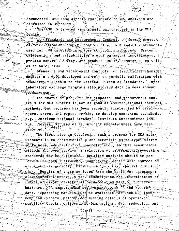
documented, ar.I sons aspects that relate to MO., analysis are
discussed in .^>pendix •*. !
Fhe ASF is treated as a single unit proce_ss in the MMAS
'" K^-«r-v"^~ _ 2. Standards and Measurements^Control. *- formal program
\ _ o:f CalJiiJtaon an<i quality controi of all NDA and CA instruments
^-^JL^^ used for t>NM material inventory control IJ .required. System
~~"ca"li.- T*tJLo:vs and reliabilities -are of paramount importance to
c i' process controL, safety, and product quality assurance, as well
as to safeguards.
Standards j'nd meflsuiemunt controls for traditional chs.mical
^& ^ methods a-".- .ell developed and rely on periodic calibration with
standards traceable to 'he National Bureau of Standards. Inter-
laboratory exchange programs also;.provide data on measurement
u The status of prcv-« " ''or standards and measurement con
trols for NDA i- stems is net as good as toi traditional chemical
methods, <but progress has been recently accelerated by devel-
opers, users, and groups wrrking to develop consensus standards,
e-g«> American National Strnrtards Institute Subcommittee INMM-
9.4, Several studies of mi .ur-.Tynt uncertainties have been
The first >tep in deielopins such a program for NDA meas-
f - ureraents is to '-hara- terize plant materials as ta type, matrix,
' - contTamers, administr..tive controls,"etc. , so that measurement
^ " methods' and construction or sei< )taon of representative walking
_ _ standards may be nptimised Detailed analysis should be per-
formed £c-r each liisriiuncnt, quantifying identifiable sources of
error such as geometry, matrix, isotopic mix, spatial distribu-
tion. Results of these analyses form the basis for assessment
~ <>-£ measurement errors, a task essential to the determination of
limits oi~<?rror for material "balances. _ /is pt?rt of the error
analyses, NDA nieasuremen~ts <u o:*t:<:'.-T.p2recI_>'ith CA and recovery
data. Operating manuals /oiust be available for" each MDA instru-
ment and chemical method/,, dodumenting details of operation, ~~
stability checks, calibration,, limitations, data reduction, and
1111-28
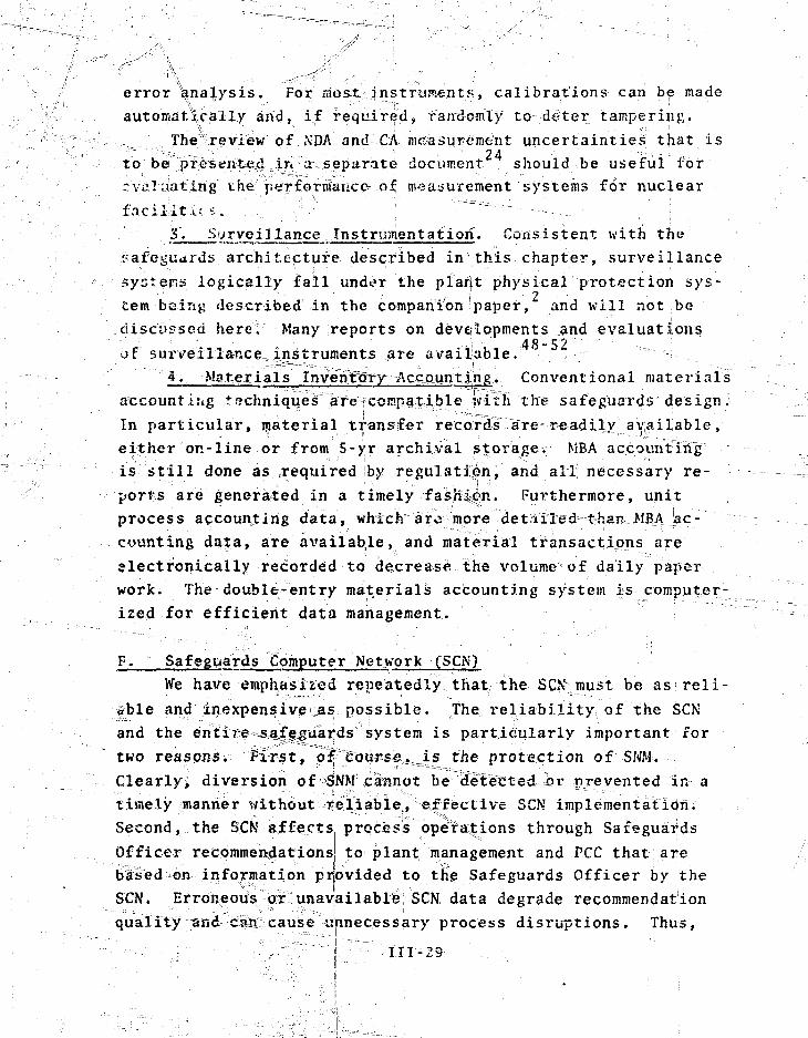
error analysis. For most instruments, calibrations caii be made
automatically and, if required, randomly to deter tampering.
The review of XDA and CA measurement uncertainties that is
to be presented in a separate document should be useful ibr
rvul.iating the performance of measurement systems for nuclear
1 acil.it.i.4 i....
Sj, Surveillance Instrumentation. Consistent with the
?afegu<irds architecture described in this chapter, surveillance
systems logically fall under the plaift physical protection sys-
tern being described in the companionipaper, and will not be
.discussed here. Many reports on developments and evaluations
yf surveillance^Instruments are available.
4, Materia 1 s InVe nTttny Accaun13ng. Conventional materials
aecountiiig techniqu.es; are;rcomnaxi.ble with the safeguards design.
In particular, material transfer records are readily available,
either on-line or from 5-yr archival istorage. MBA accounting
is still done as required by regulation, and all; necessary re-
ports are generated in a timely fash^n. Furthermore, unit
process accounting data, which aro more detailed tha^ MBA 'ac-
counting dat;a, are available, and material transactions are
electronically recorded to decrease the volume of daily paper
work. The double-entry materials accounting system- is computer-
ized for efficient data management.
F. Safeguards Computer Network C5CN)
We have - emphasised repeatedly that the SCK must be as reli-
able and Inexpensive as possible. The, reliability of the SCN
and the entire safeguards system is particularly important for
two reasons. First, oif course, is the protection of SNM.
Clearly, diversion of SNM cannot be detected br prevented in a
timely manner without reliable, effective SCN implementation.
Second, the SCN affects process operations through Safeguards
Officer recommendationsj to plant management and PCC that are
based or, information provided to the Safeguards Officer by the
SCN. Erroneous or unavailable; SCN data degrade recommendation
quality and can cause unnecessary process disruptions. Thus,
111-29

}>•••
\
A.-1
SCN reliability directly affects economical operation of the
p l a n t s „ . : ., v ^ .. •• '• "• " •• ^ ,/ ,
Many implementations of a reliable safeguards'-computer net-
work ate possible. However, economic and performance con- x
strlaints dictate that the SCN design be used on well-known, i
prpven technology that is readily available. The SCN, as well
as the entire plant*, is a product ion-oriented' system, not a de-
velopmental oae . Although valuable experience will be gained,
production of fuel rod assemblies is the prime objective. New
?concepts can"of course be "tried if their impact oi= the pYocess
is carefully considered beforehand.
The use of proven technology has several advantages; in a
ad$itj.dn to reliability^ Most important is that much of the
equipment, both hardware asd software, is stocked by manufac-
turers as off-the-shelf items. Capital costs for proven systems
are generally lower^than* for untried systems, and developmental
and testring programs sire less extensive and costly. Further
more, maintenance and repai!^ capabilitieis already^exi^st. ,
^ Security of sthe SCN, wlliich is related to its reliability,
severely constrains^the SCN design. The main security threats
are sabotage aud data misappropriation^ Sabotage can grange from
destructidn, which results in immediately apparent catastrophic
^failure of some portion of the system", to functional subversion,
whtch covertly compromises system integrity^, Physical security,
controlling access to the SC%-is Jthe first line%of defense
against sabotage, but it is vulnerable to attack by an insider.
Equipment an;d functional redundancy, also required for reliabil-
ity,; are important threat deterrents at all levels, and salf-
'checking capabilities can effectively eliminate the possibility
of undetected subversion. : " c
Physical security also helps prevent data misappropriation,
and includes not only personnel movement control, but control
and monitoring of mart-machine interfaces. The personal magnetic
ca rd for terminal, activation exemplifies this approach. Re-
stricted access file struetufe"s" are-an^ln_t^g£al part of software1
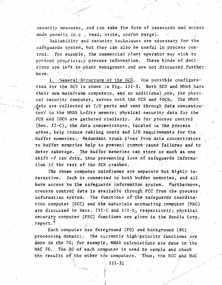
security measures, and can take the form of passwords and access
mode permits (e.g., read, write, and/or purge). ,:
Reliability and security techniques are necessary for the
safeguards system, but they can also be useful in process con-
trol. For example, the commercial plant operator may wish to
protect prbiirietaiy process information. These kinds of deci-
sions are left to plant mshagement and are not discussed further
here.
1. •General,?Structure of the -5CN. One possible configura-
tion for the SCX is shown In Fig. III-3. Both SCS and MMAS have
their own mainframe computers, and an additional on^i the physi-
cal security computer, serves both the PCS and IOCS, The MMAS
.data are collected at I/O ports and sent through data concentra-
tors to the MMAS Lyffcr memory; physical security data for the
PCS arid IOCS are gatheredcsimilarly. As for process control
(Sec. II-C), the data concentrators, located in the process
areas, help reduce cabling costs and I/O requirements for the
buffer memories.- Redundant trunk lines^ from data concentrators
to buffer memories help to prevent cojnmon-cause failures and to
deter sabotage. The buffer'memories can store as much as, one
shift of raw data, thus preventing loss of safeguards informa-
tion if the rest of the SCN crashes.
The three computer mainframes are separate but highly in-
teractive. Each is connected to both buffer memories, and all
have access to the safeguards information system. Furthermore,
process control data is available through PCC from the process
information system. The functions of\the safeguards coordina-
tion computer (SCC) and thefmatcrials accounting,computer (MAC)
are discussed in Sees. III-C and III-E, respectively; physical
security computer (PSC) functions are given in the Sandia Corp.2
report.
Each computer has foreground (FG) and background (BG)
processing domair-c. The currently high-priority functions are
done in the FG; for example, MMAS calculations are done in the
MAC FG. The BG of each computer is used to sample and check
the results of\the other tv,o computers. Thus, the SCC and MAC
III-31
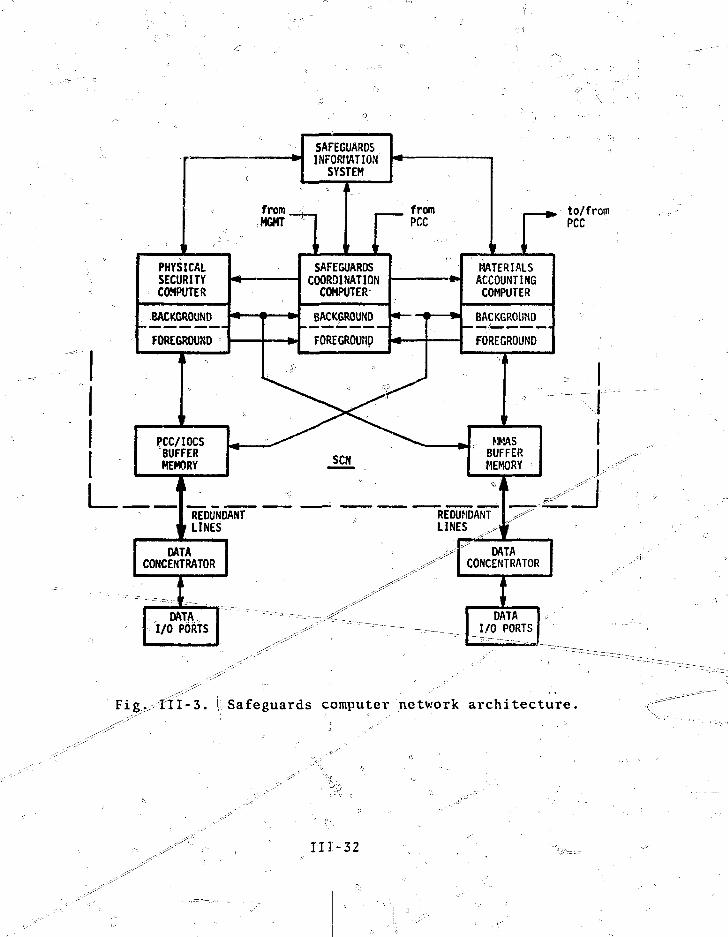
" \
1
PHYSICALSECURITYCOMPUTER
BACKGROUND
FOREGROUND
I
PCC/IOCSBUFFERMEMORY
1
m—(
REDUNDANTLINES
DATACONCENTRATOR
1
DATA,I/O PORTS
SAFEGUARDSINFORT1ATION
SYSTEM
From
«MT n 1SAFEGUARDS
COORDINATIONCOMPUTER
BACKGROUND
FOREGROUHD
sew
fromPCC
> ft
i
MATERIALSACCOUNTINGCOMPUTER
BACKGROUND
FOREGROUND
\
. , MMASBUFFERMEMORY
REDUNDANTLINES ^
^'"
i
DATACONCENTRATOR
DATAI/O PORTS
to/fromPCC
Fig^II I -3 . (Safeguards computer network architecture.
I l l -32

BG check PSC \-G results, .and—so-- forth. Because of the sampling
feature, the computational burden3 oYT each computer increases
only 10-201 under normal conditions. However, each is capable
of assuming the mos t important tasks of the other twbxin the
event of a failure. In that case, all absolutely necessary work
can still be done, although with &vqine increase in processing
delays. This means that a factor-ofx? increase in each main-
frame's eapabi-lity-is not r^uired.if speed arid unnecessary
tasks can be sacrificed. ;
This scheme uses available computer power much more effect-
ively than, foi" example, fully redundant backups for each com-
puter, or even one backup for all three. Furthermore, the sys-
tem described above is fault-correcting, whereas single backup
(a duplex configuration) only gives fault detection; the faulty
machine must be identified by other means.
Fault correction can be done with the voter array shown in
Fig. 111-4. Voters V1-V3 compare the results of the three com-y
puters, one EG to two BGs, for each safeguards subsystem, pri
the basis of these three comparisons, voter V4 decides which
machine, if any, is faulty and switches the load of that "
machine to the other two. The extra load can be apportioned to
the two remaining computers according to their current Kork-
loads. If one machine fails, the SCN becomes a duplex system
with fault-detection^ but not fault*-correct ion, capability.
The simplest\voter implementation^!s human supervision .
whereby results are compared by h rfd. This is a very useful
method (and a good one to star.,?' with), although it is slow and ,;.
susceptible to errors. The^voting function can be shared among !
the machines themselves,but questions of voter reliability in
the face of machine . Failure are unresolved. A third, more
costly, altcrimtj^e is a microprocessor-based voter array re-
quiring a 16-vbit microprocessor with some computational ability.
In any case*, voter-array relia'bility is important, and careful
designers imperative. ;i jj H^
- The SCN event sequence^ during times of machine failure
must be studied in detail, jln partijc^lar, machine
• -1 -r-i-i—*s , .._ •

I PSC
PSCCONTROL
MAC
PSCBG
secBG
MACFG
\MAC
CONTROL
1I
.1111
Fig. III-4. Safeguards computer network "voter array:.
111-34

resynchronization following failure repair is necessary (see _.
Refs. 53 and 54). The paper by Torin;: discusses various types
of faults and their consequences, as well as several redundancy
techniques. * •:,----
This three-machine SCN configuration is a form of triplerl
x ^ level of
orfc by von
Neumann in/i956 and subsequently expanded by others (see Refs.
57-61), Technology for TMR implementation^ well devel-
oped, " and minicomputer systems compatible with this form
^ are r
2. SCN Hardware. Suitable^choictes for the computer main-
frames are 16-bit minicomputer^ with 64, kildwords (expandable
to 128 kilowords) of memory for each. They~ must be compatible
with the TMR concept and be- of a design that has been exten-
sively tested. The machines should be similar to facilitate
maintenance and repair. \ ^^ 1 = ".,
Each computer should have its own^seT of central I/O, .„
peripherals. These can consist of a keyboard CRT graphics ter-
minal, line printer, magnetic tape drivjsVZ^d 7 ^ ^ =draveT ^ a g ^
netic tapes• s_joxe o.peratTn"g s'ystems% ~per%ane'nt programs, anjC
aTchival data; i.e., tapes ar<? used fpt long-term storage.-^
netic discs hold transient datja and programs; portions of the
disc contents can bftransferred to tape as desired.
The PCS/IOCS and MMAS buffer memories"should be nonvolatile
because they are backups in case of machine failure. Two floppy
discs or small "cassette tape units with S kilbwords of memory
each are adequate for storing all raw data for one shift.. Re-
dundant buffer memories jarfr^nnecessary because the mainframe^.
computer memories^ providje short: terif facicup - ;
Data concentrators are the same type-as, that used for ~~"^h-
process control (Sec. 11-C)^ but have only 6A-channel capacity.?
To eliminate commbiT-cfaSse faii;ures in which a process control
fault disrupts the safeguards system, data concentrators should
not be common to both systems. Tht§ also allows special *3ir
IH-35 :
security precautions^ such^as accessibility barriers, for thesafeguards data concentrator's^.
Gab=liiig b'Stveen the buffer memories and data concentratorsis redtipdant for improved reliability and security. Redundancy
common, for example, in the nuclear reactorfield,^arid anumber of equipment standardsBexist.
! As wilS process control (Sec. II-C) and the MMAS\(Sec. III-E) , we recommend that data I/O ports be directly cqiinected to ,process lin,;5r instrumentation wherever possible. Human errorsare minimised and hardware costs are lower because fewer com-puter terminals are required.
The SGN must have an uninterruptible power supply; forexample, commercial power with battery backup. This is a stand-ard item for niost computer installations and is readily avail-
. . a b l e . • ' " ' " , ' . ..;,. " , _•••-' ••• - • - - = - _ „ . ; . _ r . _ _
, 3 . SCij Software. Software functions for the SCC (Sec.Ill-t) and MMAS (Sec. III-E) have already been discussed; the ;Sandia Corp. report describes the PCS/IOCS software functions.The computer should have fi high-level (e.g., FORTRAN) compilerfor ease of programming and to decrease development, atid modifi-cation costs. Commercially available operating systems thathave already been field-tested are preferable. Custom softwaredevelopment sh uld:;b:fefflinimi2ed.
Operating ^systems must have ^tlon processing to prevent misuse of data and sabot age of pro-grams. Government^agencies, military installations, and manycommercial companies have year^ of experience with secure oper-ating systems thatsare available to systems designers. "^ /
4. Physical Layout. Techniques for a^iKThTng'-s ecu re phys-ical layout are available in several standards, ' particu-'larly for nuclear power jilantsi Standards primarily attempt toprevent common-cause failures^by specifying separations and bar-riers between redundant devices. For example, tfie PSC.'SCC,and MAC should be separated \>y fire-retardant vails. The SandiaCorpvf jrepojet disx^us^sei|j>hyslcai layouts In more
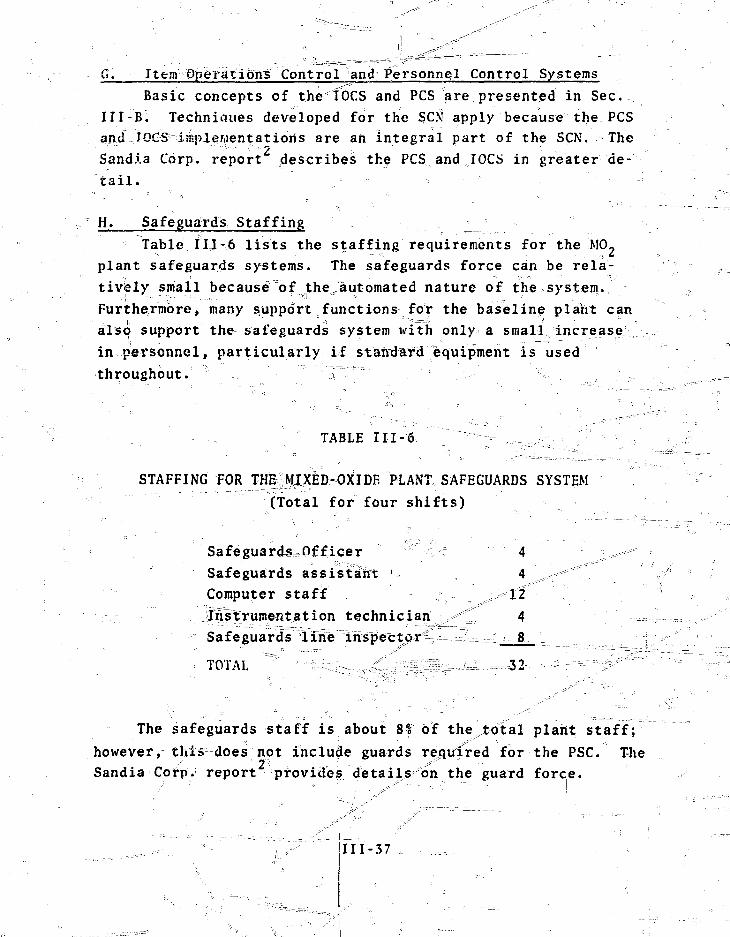
G. Item OperatTbns Control and Personnel Control SystemsBasic concepts of the IOCS and PCS are presented in Sec.
Ill-B. Techniciues developed for the SCN apply because the PCSand TGGS1 iinpiewentatioris are ah integral part of the SCN. TheSand.la Corp. report describes the PCS and IOCS in greater de-tail.
H. Safeguards StaffingTable III-6 lists the staffing requirements for the M0 2
plant safeguards systems. The safeguards force can be rela-tively small because of the automated nature of the system.Furthermore, many support functions for the baseline plant canalso support the safeguards system tvitn only a small increasein personnel, particularly if standard equipment is usedthroughout. ; " ; .-,
TABLE III -6
STAFFING FOR THE|MI)CED-OXiDE PLANT, SAFEGUARDS SYSTEM(Total for four shifts)
Safeguards-Officer vr 4 ^ 'Safeguards assistant 4 , *" -;/Computer staff ,.>>""!2Instrumentation technician 4Safeguards line inspector 8
TOTAL 32
The safeguards staff is about 8? of the total plafit staff;however, this does not include guards required for the PSC. TheSandia Corp. report provide? details on the guard force.
-37

IV. SAFEGUARDS EVALUATION
Chapter III and Appendixes B-E define the safeguards sys-tem and its operation in some detail. Because a high-throughput-MO2 fuel refabrication facility hasnot^ijein built, evaluationof a coordinated safeguards system for such a facility must be
abased on detailed models and computer simulations.The safeguards system is evaluated from three viewpoints:
(1) SNM diversion sensitivity, (2) safeguards xelability* and(3) cost, the results that follow Vindicatethat SNM in a MO-fuel refabrication facility can be safeguarded in a tlmfely,effective, reliable manneT"at"a felTdhable cost..
A. Evaluation of the Materials M&asuremeHt anTi y
Accounting Systemin this section, the sensitivity-ojELthe generic MMAS is
evaluated. The data and results reported here are based onmaterial presented elsewhere in the Report. In particular, ther ead e %- i s^diMcte£ t ?i t n e description.of t he bas efin e ;M0 , f ue 1fabrication plant in ^hap.II and Appendix A, the descriptionof MMAS measurements and instrumentation in Chap. Ill and Appen-dix C, the baseline plant model; MOXSI*J=,-in^J^egdix D, and thediversion detection algorithms in Appendix E. Before the' re-Isuits are presented, the philosophy and technical approach arereviewed, followed by a discussion of the models of plantprocess operation and materials measurements fromjwhlch the datawere derived, Relatidhships of the parMieTer^in-the dirersiondetection algorithms to the measurement data are given. Final-ly, these relationships are used to maiceT^uantitativg estimatesof the sensitivity obtained in major plant process areas withthe generic MMAS.
1. Philosophy and Technical Approach. The DYMAC approachcomplements the traditional cycle of periodic plant cleanouts

and physical-inventories (see Sec. III-E)"".T In the DYMAC con-
cept, the baseline plant is divided into unit processes, and ^
SNM flowing through each unit process arc controlled using
timely dynamic material balances. Often these dynamic balances
are closed only approximately because some in-process holdup
.and minor material-sidestreams may be measured less frequently
than major material transfers. Dynamic material balance data
updated when holdup and sidestream measurements are made.
During the interim, historical data can"1re==u-«ed to interpret
^trends in the material^balance data. ~-_ i
The concept of graded safeguards and the economic require-
ment— £qr=nun^mum-r^px<^&s^=dl?|%uption are important factors in
the gene?ic MMAS^desgLgn=.^_JForLexample^^the^n6s*&=si>Tinsent-coti-
trols are applied to PuO- powder handling operations; less con-
trol is maintained on operations involving M02 powder where the
plutonium is diluted by a factor-of 25.For^SNM—that is well
coiiiroTlW^rby "phXsircaHjar^Eiers (security vaults, fuel rods,
etc.)» verification measurements that supportti^tem control are
incorporated. ^ _
The generic MMAS includes a minimal set of measurements
tnat pTbfide dynamic balances at least once per major process
step for each unit process.* Most measurements included ,n the
j)rigirialt|Vestinghouse plant design are incorporated in the
generic MMAS. In particular, most of the^ original weight meas-
urements (some of iv'hicH Iiave been upgraded) and traditional CAs
af¥ us ed by the ^lAS. ^^ ^ "°~ ":3v^~
To identify^ required SNM measureinents and control problems,
a detailed model of plant operation was constructed fsee Appen-
dix D ) , and modifications of pi-ocess operations that enhance
materials control were used in the model_,_ Rrgcejss rdata^gener=
ated from simulated plaTit^o^eTatiron are input jto a corresponding
model of SNM measurements. This measurement model generates
material balance data by applying measurements to the process
*A major process step usually corresponds to the processing ofone sub-blend, ^ 8 kg Pu. I ":.r«-

data. Separation of the process models from the measurement ^ f ;
models enhances flexibility in simulating- botliJirQcjess opera- v"^
tions and MMAS measurement^. .;. ,!=-='™-:=,'---- -~:: -^\-^~ r ?
Detection algorithms fdr-siiigletlie'ft; and long-term diver- ' — —
sion were developed ^n parallel with the baseline plant and^fc^.,41 '
measurement models (see Appendix E). The MMAS design has been "~= -=--.==J
evaluated and revised on the basis of the sensitTv^xS2iobtained^;——^.^^L,
from various measurement strategies. -=-•- =-. .~LI^^^^^^_
2» Modeling and Simulation of the Baseline Plant. Appen- //[
dix D describes a Monte Carlo simulation model of process opera-r™—^===™
tions based on the plant definition given in Chap. II and Appen- , ,•
dix A. The plant is divided into 11 unit process aTeas and 2
peripheral process areas. Each unit process is modeled sepa- !
rately, which permits a detailed descriptiorP^S^g^s^s opera-
tions that are specific to each. Because process variability,
particularly in the levels of.in-process holdup and material ^.^—^^.
sidestrearns, can have a significant effect on materials control, A
a very detailed baseline plant model is required for making ;
quantitative estimates of MMAS sensitivity. \ _ = =
In the model, a schedule of material fl&v events is speci- '^JL^~-- °
fied for each unit process. The schedule ;rncludes^n^j?nlirial =- ^
event in which beginning inventoriesr are s iu JL minimumi'"q"fT
type of process event, and a final event:3iT^^h4^c]^^Souts
cleanups are performed. The process descri!px;rdjrs=iaiiu the—unit ^
process event schedules are incorporated in a computer program
called MOXSIM that simulates baseline plant operation 1 wk at a. U
time. MOXSIM uses the executive of the GASP IV simulatiren r ": ^
language " to schedule the individual unit process events in —
proper sequence. The GASP IV controller provides added flcxibil-
ity. In addition to timed events, it can schedule conditional
events that arise during process operation; for example,
stopping the flow of material when a tank has been filled.
The simulated process operation is defined in terms of true
material flow data from each event. These data are saved for
IV-3
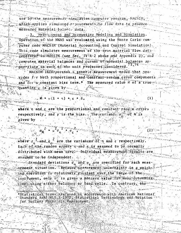
1 use by" the rr.easurem ix pimnlation-computer proyvaiu, MAt'SlM,
n:___ -^hidi-applies simulated rf*asureme:its LO flow djra to produce1 r measured materJ.nl balance data.
5. Me as' ueiacnt and Accouatipg Modeling and Simulation.
\r> Opexarion. of the MMAS was evaluated using the Monte Carle com-
puter code MACSIM (Material Accounting and Control Simulation).
This code simulates measurement "of the true material flow data
generate^ in: MOXSIM (see Sec. IV-A-2 above and Appendix U), and
computes material balances and cusuros of material balances ap-- - 73 74
—prn"\riate to each of the unit processes considered. '
MACSIM incorporates a_j>eneric measurement model that pro-
•> ~ >lide-s fVr both proportional and constant r-MuJom error components
, and for a constant bias term.* The measui-ed value M of a true
"quantity u is given by //
(1)
lyhere n end c are the proportional and constant rai!dc;n error
respectively, and j? is the bias. The .variance ov" of M is
given by
where o " and o are the variances of n and e respectively.
Each of the random errors n and e,.is assumed to be normally
distributed with mean zero. Individual measurement results are
assumed to be independent. s-
-Standard deviations a and ae are specified for each meas-
urement situation. Because KCa*nrecent.uiicei'tainty in a__weicJi->
operation is-relatively jryiiftjnt over the rangu c>f
Xunent, only o" is givca a nonzero value "for ir.os
ion? uXing"either balances or (.oad colls. In contrast, the\ ' ' '
*Statistica\ terms a,ro used An accordance with American NationalStandard ANSI 3H S.S-1972» Statistical Terminology and S'otationfor Nuclear £fater';iis M
\
uncertainty of a NDA measurement tends to be proportional to
the quantity pf material being measured, and only y is as-
signed a nonzero value for this type 6f measurement, further-
more, because the plant is expected to have an effective^ oper-
ating measurement control program (designed to eliminate\sources
of measurement bias, or to estimate the effects of potential
sources of bias and correct measurement data as needed), the
bias term P in Lq. (1) is set to zero for all measuiemeiYtj.v.
NDA measurements are assumed to produce directly a value
for the quantity of plutonium element present. The uncertain-
ties in the piutdriiuin isotopic composition and instrument cali-
&re ingot-porated into the imprecision (o ) specified
for each NDA measurement•> In the case of a weighing operation,
the measured weight is multiplied by "ah element factor (g Pu/g
sample) to obtain the plutonium mass. The element factor' isa" - . '. '
determined by chemical analysis of samples taken during plant
operation. In MACSIM, the element factor is obtained by simu-
lated measurement, using the uncertainty appropriate to the CA
of PuO2 or MO-. The assigned uncertainty includes both analysis
errors and sampling errors. The frequency with which the ele-
sr.ent factcr Is determined corresponds to the samplJr.g schedule
anticipated by VTestinghouse. !
The precisions assigned to the measurements are based on
estimates obtained from the literature ' ' for similar in-
strumentation. In general, 0.25% of full scale is taken As the
rexat~i%'e precision for a typical load cell in normal operation,
and 0.02% of tlull scale as the relative precision for a digital
balance. The relative precision of the plutonium element factor
is assumed to be 0.13 for PuO, and 0.24 for M07, in most cfases.
For NDA measurement, a special effort was niade to assign conserv-
ative values of measureiaent precisions.; i .;
Each material balance computed in MACSIM is a linear combi-
Mstiea 03" ;net5£T>resi fjuant-ities of plutonium. The uncertainty in
tiie computed value of the material balance 5 s produced by the
combined effects of uncertainties in the contributing measured
values. In MACSIM, the measurement results are assumed to be—, ^ ' IV-5
i
I• • • " • • " I
iI • •
independent, ana the variance associated with each material i
balance is the sum u"f the variances of the terms in the material
balance equation.
A cusum is computed by M.ACSTM after each material balance
period. It is the sum of all smteTTat balances for the unit
process since the beginning of the accounting period. The cusum;
variance is a complex combination of the variances of individual
material balances, as these balances usually are not independ>
ent. Most unit processes will have one or more variables for
which a single measurement value appears as output in one mate-
rial balance period (i.e., this value has a negative sign in
the material balance equation) and as input in the next. For
example, this can be the result of accumulating material in a
tank or scrap container and measuring the contents during each
balance period. In such cases, only the first and last measure-
ments of the container contents appear in the cusum, and only
the corresponding variances appear in the cusum variance.
The design of the generic MMAS is based on studies using
MACSIM. The code is sufficiently versatile to permit independ-
ent investigation of materials control sensitivity as a function
of process variability, measurement variability, and instrument
configuration. Fixod sets of measurements have been applied to
different sets of material flow data, and a variety of measure-
ment strategies applied to fixed sets of flow data. Design
choices were based on the dual criteria of satisfactory sensi-
tivity to both single theft and long-term diversion and minimal
perturbation of process operation. Results of the evaluation
of the MMAS are described in Sees^ IV-A-5 to IV-A-10.
4. MMAS Diversion Sensitivity. Sensitivity of the MMAS
is determined quantitatively I from relationships between parame-
ters in the diversion detection algorithms and the dynamic mate-
rial balance data. Algorithms for the detection of short-term |
and long-term diversion of ma-terials are discussed in-
Short-term diversion refers to the single theft of a rela-
tively large amount of material. The sensitivity of the MMAS
to short-term diversion depends on the measurement uncertainty
(standard deviation, a) associated with individual material
balances. If unmeasured holdup or material sidestreams signifi-
cantly affect the individual balances, that is, if an average
positive bias on the order, of la is introduced by not making
the measurements, the material probably should be measured and
included in each dynamic balance.
If B is the measured value of a material balance (i.e., an
estimate of the unmeasured material), the ratio B/o is used with
the design curves (Appendix E_;, Figs. E-l - E-3) to detect single
thefts. A reasonable threshold sensitivity is B • 3o for which
the detection probability is 0.5 if the false-alarm probability
is set at approximately 1 in 1000, -A..iiseful format for presen-
tation of the material balance data is the so-called Shewhart
chart on which the data are plotted with la error bars, and;
lines are drawn at the average 2 and 3a levels so that outliers
are readily apparent. ^ "
Long-term diversion refers to repeated thefts pF nuclear
material on a scale too small to be detected in ...a? single mate-
rial balance because of measurement uncertainties. Repeated
small thefts of SNM are indicated by the] trend (positive slope)
they induce in the cusum chart of matj-erial balances. Detection
of trends due to small thefts is complicated by unmeasured hold-
up and sinal 1 sidestreams of m-ate?ial that introduce, similar
trends in the cusum data. Analysis of trends is complicated by
correlations between the cusum dat i and the variability of meas-
urement errors in a sequence of material balances.
A technique for detecting trends^is"the cusum chart and
V-mask method of control discussed in Appendix E. By this
approach, levels pf^en^TtTivity are se^ for small theft detec-
tion Tsased or^etfsum uncertainties. • - 'o
Iiriplementation of thafs technique is still under develop-
ment, and in its present form is rigorous only for independent
material balances of constant and equaljvariance. It is appli-
cable ito the case in which ithe cusum variance grows linearly
" : \ " " • '•,'. • . * ".. ' ' • ; '
ii I IV-7." A , A

with the sequence length L of material balances. in this case,
the average positive bias B that can be detected over a sequence
of material balances of length L is proportional to or/t, where
ar is one standard deviation of the "„ cusum. A-reasonable esti-
mate of the threshold sensitivity to small amounts of unmeasured
material is B = 2 o^/L, corresponding to a detection probability
of 0.84 and a false-alarm probability of about 1 in 6.
Patterns in the cusum associated with unmeasured holdup
and^nfaterial sidestreams can be identified by the cusum chart
and V-mask method. For example, in many instances in the base-
line plant, hoidup is cleaned up and measured, and accumulated
sidestreams of material are measured, on a weekly cycle. This
cycle produces a sawtooth pattern in the cusum, i.e.,TheseusunT"
has a positive trend between the weekly measurements, then re-
turns near zero at the end of the week when the measurements
are made. The V-mask detects these trends as short sequences
of material balances, each with an average positive bias. If
historical data indicate that the cleanups are reasonably effec-
tive, e.g., ithe level of holdup is restored near a residual
(irreducible) level, then the V-mask will detect only these
weekly trends. If longei trends are detected as operation con-
tinues beyond 1 wk small thefts are indicated. ; f
In the following sections, sensitivity levels will be given
for the major unit process areas in the baseline^plant on the
basis of the generic MMAS design. The sensitivity to large
thefts is given as 3a, where a is the average standard deviation
of the dynamic material balances. The sensitivity to small
thefts is given as 2oJh, where the cusum standard deviation,
a-i is evaluated at the end of 1 wk and at the end of 4 wk of
operation. It is assumed that tfie cusum is rezeroed periodi-
cally, perhaps after a cleahout" and physical inventory. The
expected amount of unmeasured material in normal process opera-
tions, based ,on the plant process model (see Appendix D), is
also given.
IV-

The sensitivities to smal^-'scale diversions are not neces-
sarily indicative of the arotfunt of SNM that a single person
juj.ght steal. They are deteotability limits for average amounts
of missin^maTeTi^l^^X^iniaterial balance period. For a single
diverter to-steal SN'M at a rate equal to the average-detectable
amount, each pribTt would^e larger by a factor of 3 or 4, with
a corresponding increase in probability of detection.
S.^VxxO-, Powder Unloading. In this unit process, one
shipping container containing four canisters of PuO- powder is ,-•
Received during each unloading shift. One canister is opened,
sampled, and unloaded to bulk storage during a nominal 2-h
period. Xormal process operation is one shift per day for five
consecutive days per week, followed by a cleanup.
Three jitaterial control strategies were investigated, for
this unit process. a -s --v .... J. Strategy 1. A dynamic material balance is drawn^
around the unloading <>fi each^canister to bulk storage and around
the cleanup operation. The measured"va'ffafbi::ec3~-a--ra.-=;=-J=.____..=.
BI PuO, contents oT each canister.
EWM • Residual PuO^ in emptied canisters; canisters
are accumulated and sent to MWT for measurement
•/; and disposal at weekly cleanup.
HU Holdup in the routing valve after runout: of the
pneumatic transfer line, measured after unloading
each canister. !
AS Sample sent to the ASF. ;^-w
ADV The portion of unmeasured holdup in filters and
the glovebox recovered and measured i?t, cleanup.
XM Inventory in the Pu'O./st'orage tank.
PuF Plutonium element ifactorv
The measurements; and associated precisions (o_ and a ) are given
in TablP IV-1. I ' . I •]. ' , ',
IV-9
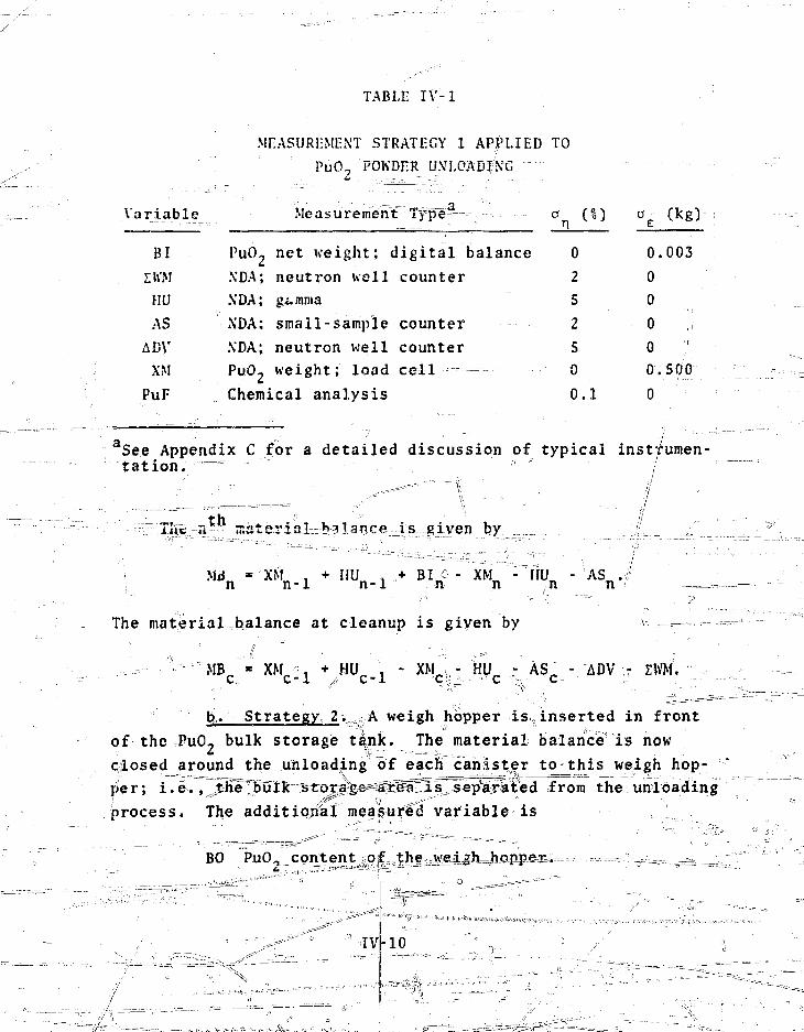
TABLE IV-1
MEASUREMENT STRATEGY 1 APPLIED TOPuO/"POKDER UNLOADING
Variable Measurement T y p e ^
BI PuO 2 net weight; digital balanceZh'iM XDA; neutron well counterHU XDA; gtmmaAS NDA; small-sample counter
ADV XDA; neutron well counterXM PuO2 weight; load cell
PuF Chemical analysis
0
2
5
25
0
0 . 1
a£
0.
0
0
0
0
0.
0
(kg)
003
500
aSee Appendix C for a detailed discussion of typical instrumen-tation. = "" /
Tiie Ti ma te r i a l Miance i s given by
- XMn - IIUn
The material balance at cleanup is given by
MB • XM n + HU , - XM - HU - AS - ADV r ZWM.C C-l // C-l '"C^Jr-- -" C 1-,: • C - -•-">
b,;. Strategy 2y. ?A weigh hopper is inserted in frontof the PuO- bulk storage tank. The material balance is nowclosed around the unloading of each canister to-this weigh hop-per; i.e., ihT^bulk stora-ge^gS^^TsT^ep^arafed from the unloadingprocess. The additional measured variable is
BO PuO^ content of the weigh hopper. - _
IVil-10

The measurements and associatefLprecisions for this materialcontrol strategy are given in Table IV-2.
TABLE IV-2
MEASUREMENT STRATEGY 2 APPLIED TO_ _ PuO^ POKDER UNLOADING
Variable Measurement "TypB-":"-'"7-:-r.s=-- o r%) 0 fke)
BI -J^uO,-ne-t-;weight; digital—balance-BO PuOT net weight i load =ce=Llr
ZWM NDA; neutron well counterHU NOA; gajima ...... ., .... ;,-- .-,,.,, .-..•..,,AS h!DA;_ small^sanjple counter
ADV NDA; neutron well counter"'-'-PuF Chemical analysis
00
2
5
2
5
0.1
0
0
0
0
0
0
0
.003
.035
aSee footnote to Table IV-1.
The n m a t e T i a l balance is given by
^ n " *h - B 6n * HUn-I; " « % " n ^
The material balance at cleanup is given^T
MB C « mc^vL^JiU_s- B0 c - EWM - ADV,
where BO^ represents material that is obtained duringand runout ojf the pneuinatic conveyo^ and router valve arrdilTsent to the weigh hppper. ™ xs
c. Strategy 3, The material balances arg; ^in strategy 2; however, a room monitor has been installed topermit measurement of holdup in filters and glovebox once each
IV-11
shift, and the empty canisters arc sent to MU'T for measurement
once each shit*. An additional measured variable is introduced:
DV Holdup in filters and gl'ovebox.
The measurements^ nd associated precisions are Riven in
Table IV-5. / , , 1
TABLE IV-3 /
MEASUREMENT STRATEGY 3 APPL/ED TO
Variable
BIBO
I KM
HUASDV
iDV
PuF
pU(i2PuO2
\TDA;
NDA;NDA:
NDA;
NDA;
PuO2 POiVDER UNLOAD I Nf>/ / ' •
i
•1 ."•"' /
Measurement Type' /
he t wei gh t; di gita 1 balance
net weight; load ceTTF ^:^
neutron well counter
gamma f
i sma11-s amp1e c oun t e rneutron
neutron well counter
Chemical analysis \
an'(i)
0
5
22 5
o.i-;
oE
0
0
0
0
00
0
i 0
Ckg)
.003
,035
aSee footnote to Table IV-1.
The n material balance is given by
/ ; ' ' • " . • - . : " •
MB = BI - BO + rtU . - HU - AS .n n n ' n-l n n
The end-of-shi£t material balance is given by
MB r - BI_ - B0 n + HU- , -I HU C - AS_ + DVn . - DV., - £WM.11 C E ')E"1. | JC t, \ '15.-4 C
IV-12
The material balanceatcleanujLis given by
MR = MU , - UU - BO +/-DV ,-.- DV - IWM - ADV.c c-.l- , c c c-1 c
Material balance and cusum plots corresponding to the three
-material control strategies are given in Figs, IV-1 to IV-3,
: T^spjzctiyely*—for purposes of comparison,* each plot represents
the same 4-wk of typical unloading operations. The uncertainty
in each material balance is significantly reduced by inserting
a weigh hopper in front of the PuO- powder bulk storage vessel.
(Coispast? Figs* JV-4 ind IV-2). Thrr^isclates the bulk powder
storage arcsfrom fneTAinloading operation. The positive trends
in the ciisum data that occur weekly for strategy 2 (Fig. IV-2)
are produced by unmeasured waste and holdup in the unloading
station. These trends are also present in strategy 1, but are
obscured by the large uncertainty in the cusum. The weekly
measurements of accumulated waste and the amount of holdup that
is cleaned up from the unloading station produce the four large
negative material balance data points in Fig. IV-2. The PuCL
powder"""tliat"lj'xl a-ned-up--M..p=ajrt4.cularly vulnerable to diver-
sion under strategy 2 and added security precautions would Se
taken during cleanups -
No significsnt trends are apparent in the cusum for strat-
egy 3 (Fig. IV>3) because measurements of-holdup" aiRT waste in
the unloading station are included in the cusum at the end of
each shift. Note that the PuO- powder from weekly cleanup is
better controlled Tinder strategy 3 becausV the residual level
of holdup in the jurilolcTiftg station^isIjteMttyedr after cleanup.
Estimates of the sensitivity for each strategy are given
in TaMe HP-4.
6. MO^BlendiRg^^jrhe. blender is charged with sufficient
maferial ifor a single-sub-blend froin PuQ^, U02, and recycle MO,
weigh hoppers. At the completion of the blending cycle, the
sub-blend is transferred^Jtp^ne_j^the=MQ^^^orajge silos. Nor-
mal operati^fifihvolyes 20 sub-lblerids per we^k followed by a
cleanup operation.

fI i
!
•< i t! - J- j
t " l . l i P i : ! ! ! ri•i i i. i[
, j i i i , r ; i; \\ :j-!-j
t-ffTTf;!i i j
' t j : f i i j - l T i l!
P
7+! X+1
i :
!Tit !
rs
" tTml i i .1 rriiitridfTTiitfmiT4,tl":iTi4^
il
l i
' i i f i in! I ii-M
f i r ;! 4 4 11 l l
i n n
Fig. IV-1. Materiarrbalancfe and cusum data from 4 w>c oftypical P11O2 powder- unloading using measurementstrategy '%.

c13v
U
tC
_J•r
!.
'a 2 S
&«=*l_RNCE NUMfeER
l e t
E.
3
u
r ' r- Tiiim™''''''''TnTiffliTWm
2 S 7 5 1DD
Fig. IV-2. Material balanc|e and cusum data from 4 wk oftypical"Pud- po|wder unloading using measurementstrategy 2^ ||
&HLRNCE NUM6ER
1DD
25 ' . '' :: SO ; 75
MRTERIRL &RLRNCE NUMSJER
1QD
Fig. IV-5. Material balance snd cusum data from 4 *«k oftypical PuO- powder unloading using measurementstrategy 3.
IV-16
TAfeLE IV-
SENSITIVITY DF THE MMAS APPLIED TO PuO., POWDER UNLOADING \
Single Theft,' Long-Term Diversion ' ](l-wk_ average,'g Pu) (4 -wk average; g Piij)
ExpectedUnmeasuredMaterialc\(g Pu) ,\
Strategy 1 1900
fstrjategy 2 liO
Strategy 3 110
61
14(330)
16(350^) 8(700)
18
^Amount (3c) of unmeasured material that can, foe detected in a single balance periodwith a probability of 501 at a false-alarm irate of approximately 1 in 1000. !
5 . • ' < I;1 'J •• -• ':•, \ I ;! • :
bm,iur/ i ) V e r a 6 e Amount '(2or/L) of unmeasured material per balance period tJiaj can bedetected during 1-wE arrd 4-wk periods withija ^probability1 of ^ 85%i a't a iji^ffise-alarmrate of\; aboutkl in 1 The to ta l amount (29rj; i s given in parentheses.1 .,-...I ''$**'?''•' \ \ i\ \ ,: y* \ \:<"\i :" , !", w\ • | ' • ^Ar\rerage amount l|j6f unmeasured'material exlpected per balance period |dtiring normal processOperation taken) front, the baseline plant (model (Appendix D). The a'ctjual amount typi-cal ly ranges from zero tp twice s the aveijiag - value. , | ?i , \ \ . f , ? '.
d '•> • - i ' !ii •":'i • X
Accumulated and measured each week.
".Accumulated and, measured each shift.

' A material balance is dravn ground each sub-Mend, f 1 om
the heigh hoppers that feed the blendci , truough the MO., -storage
silo. A material balance is also computed at cleanup. The
measured variables are:
BI(1> PuP, ueifih hoppei.
BI(2) MO, recycle heigh hopper.
~~ BO - Storage silo contents.
ISM Accumulated scrap sent to MKT once per uet>k.
nVM Accumulated uastc sen: ~co MWT at cleanup.
/AS S.-wpLe_ sent ?c th'-ASt.
/ PuF Ptutoniuin element factor.
V L
The measurements and associated precision (i* and o ) :-.ve yivt»n
in Table IV-5.
"~ - - ___ TABLI i-V-5
MLASURf'MI:NT SIRATLGV AI'PLII.D T0~
*Ji\2a^rfel<f Measurement Ty^>e*^p^==;=^=====a_===£^ .• p (ks)
BI Cl) (fSj'uO, net wejLftht; lo,^4 ce^t ° J 0 ;
z
BO |1O,,; ne t weight; -; lpMd eel 1 \ • c Q '•:"f^~~~~ ;0XDA°; neutron well counter ^ 2 0
// |:KM " ^ NDA!; neutron w^lF counter .- S 2L_HlAXs^^'^^^-^^LJA.^s-ma 11 - sample co#iBTv-- -^"^"^^Z'T" ., ">--^PuF 7/ - H^inicairartalysi^--^^------, ,- , . . , ' ' O.:2 ™ 0
.=,:£.:>/ i«.K-
*.-i$ee. footnote to; TaNle; IJ ' - l .
' '
IV-18
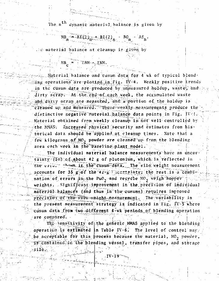
°ihe n dynamic material balance is given by
- BO - ASn,
>. material balance at cleanup i
MB - ZKM.
by
Material balance and cusum <3a£8f for 4 wk of typical b[Zend-
inj; operations are plotted in Fig. IV-4. h'eejely positive trends
in the cusunt data are produced by unmeasured holdup, waste, and
dirty scrap. At the end «£ each week, the accumulated waste
and dirty scrap are measured, and a portion ot_the holdup jis
cleaned up and fflcasurcd. rncsc veslly nuoasureiiients produce the
dist inct ive negative material balance data point? in Fig. Jv-i .
ftfaterial obtained frpjii weekly cleanup isi; no'lf well controlled b)'
/tJt€ M tAS. luciieaitfiitf physical security and Estimates from his-
torical data should b^ap^ i .«4-a t cleanup times. Note thai a
few kilograias_g|L=MO, powder are clean^if^tit' f om t n e blend iifp
area each week in fKe^Tyaselinej ^LanJLjvodel. !
The individual material balance measureit|ents have an uncer-
taYhry;;iv^1SJ. Cfefsjgbout 42 g of plutoni°um, whichj is reflected in -
the vif:|ir?" " wn_ij;i, tlie^cTaiswH^iatal^^The s 11 oi we i ght measur| emen t
accouo|s for 35 gfo'f tKen^^f^ lC££ta|n±yj t|^e rest is a caTifffi—=
nation I of errors ln| the PuO- and recycle MO, Ke~igh^opp^T :f •'=
SigiixffGaiJi improvement in theu precision of individual
#1= =talancjfs (imd thus innthe^ eu«um&) refiu;res imriroveid
^W^^^^^tea^ifeigi^^jfi^a^-SLi'ieJBif^ti- The °variabTlity [in
the present measui*eriientrstrate|yisj indicated in r ig. TY-T iwhere
Tc4SUili 4ata froia tws^-d^f^ejrjmt ,4-wk per=ioidsi!!of y#itding operiation
are xo^^rec?-... -
t fe iepssijcivily of the gefieric MMAS applied to the blehdinc
operatw^i %s estimfted |Ln. Tabl^ IV-6. The level of control liiay
b@ 'acceptable'" for this process because the material, MO, ponder,
bleeding% •
- i
transfer pipes, and storage

MHTERI3L feRLHNCE NUMBER
i d o
Fig. IV-4. Material balajnce and cusum data from 4 wk o£typical MO- pjowder blending.
: ' iv-20
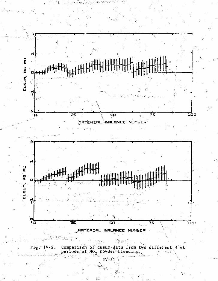
3
13
xin
3 ri .
ID A SO - ^ 7S
^fcRLRNCE NUMbEH
1QO
1DD
MHTERIP1U &RLRNCE NUM&ER
Frg. IV-5,. Comparison of ciiSum?data from two different, 4-wkperiods of MO- powder blending. - , \
lY-21
. . » " • •

SENSITIVITY OF Till: MMAS 7\PP!JK1) TO MO,, BLliXDI\tla
lixjiectedS ing le "" s'[" UnmeasuredTheft Long-Term diversion Material(g Puj (1-wk average, g Pu)(4-wk average, g Pu) (g Pu)
130 20(400) 10(800) 15h
See footnotes a-c in Table IV-4.
Accumulated and measured each week.
7. Pelleting. > The MO, powder is transferred from a bulk-
storage silo to the compactor feed hopper. From the compactor,
the prepared powder is fed to the pellet press via the press
Cce<i hoppej, and the resulting green pellets are loaded onto
boats. Approximately 15 boats can be made from one sub-blend
of MO, (T. 225 kg). Normal operation is 19 sub-blends per week,
followed by runout and cleanup.
: A material balance is drawn around each sub-blend, from
the silo through loaded green-pellet boats. One is also com- ,4puted at cleanup. The^measured variables are:
BIC1) MO, content of silo.
BI(2) Compactor feed hopper inventory.
£B0 Sum of green-pellet bteats.
SM Accumulated clean scrap.
WM(1) Accumulated dirty scrap sent to Mh'T and measured at
cleanup. x _.
KM(2) Accumulated waste sent to MWT and measured at
cleanup. J
UV Press fee^T^pper inventory.
(V PuF Plutonium element factor..
IV-2 2 "'X,

Jhn .;.e-!suremcnts and associated precisions (rtr_andJ c „)' are given
\n Table JV-7. / ---..•••—-—-....__. ._ r
•, TABU: IV-7 j
- . . . ' • '
MKASUREMliXT STRATIFY APPLIED TO
Variable
BI(1)
BI(2)
BOSM .
KM(1)KM (2)
HU
PuF
• Measurement Tyjaea J
MO, net weight; load cell
M"DA; neutron
MO-., height; load cell
MO, weight; load cell
NDA; neutron well counter
XD.*«; neutron well counter
NDA; neutron
Chemical analysis— -
50
1 0
5
5
5
0.2
"°c (
0.
S ••
' ... :<f o .0.
0
0
= 0
kg)
884
-.
100
12S
aSee footnote to Table IV-1.
tli'- 'The ii dynamic material balance is given by
The dynamic material balance after runout and cleanup is given by
MBc - BI(2)c_l + UVc_l +4?Mc-l " £
BOc " SMc " WM(1) " mW>-
Material balance and cusura data are plotted in Fig. IV-6
for 4 wk of pelleting operation. Variability in the cusum data
is produced by a combination of measurement errors and process
variability in the amount o#'jnoldup that is cleaned up and meas-
ured weekly. The uncertainty in individual material balances
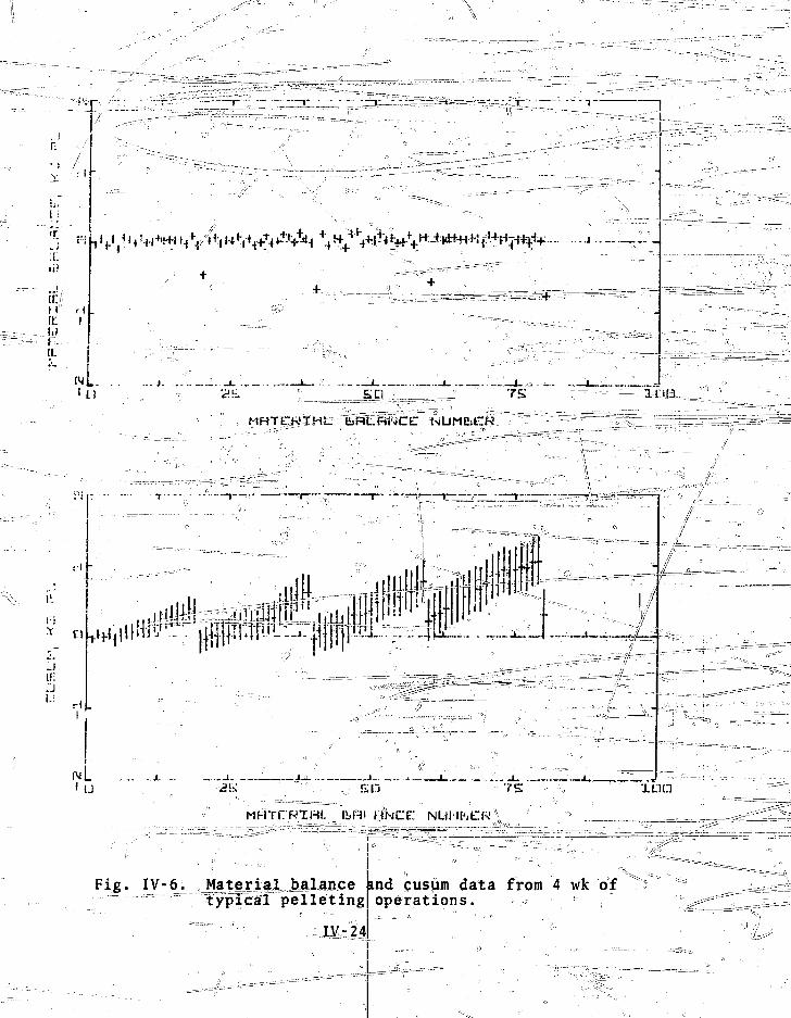
^=-~~ "T
1 j
• n
H HIE !I'Ii(I.
i n
...I
SO-
MHTCWIHtT
IL
* n2.
If.
r\ .
U
d l . ffll*
i
Mf-iTCRIHt. IINCC
:" " ; • . " " "itiD
Fig. IV-6^ J4jte_ry,l_MLance knd cusjam data from 4 wk of" typical ' pe l l e t i ng operations.
il ' ' '
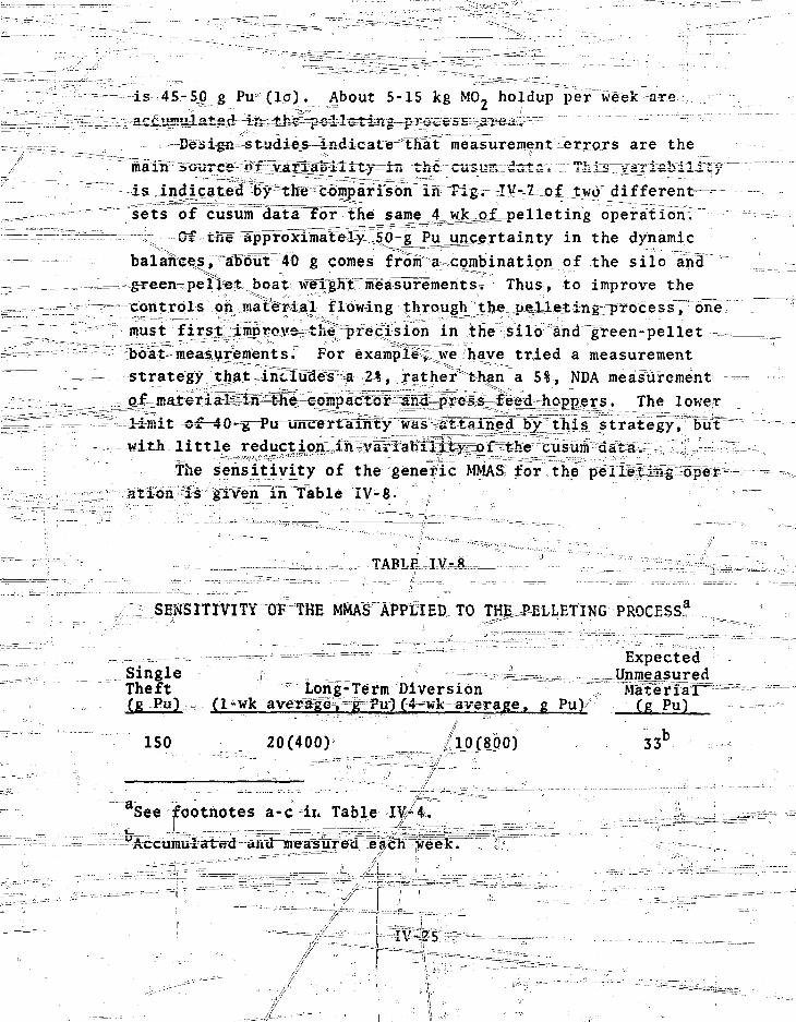
is 45-50 g Pu ( l a ) . ^About 5-15 kg MO- holdup per week are
measurement errors are the
the--cus«®::d3different—
sets of cusunTdSta=foFTKe sajne 4=swkeoJLpe l i e t ing operation.r; ~OiL-fne^^pplrb^tSSt^ly ^ in the dynamic
balances,^IFSut"40 g cones froia^combinatipn of the s i l o ancT 'boat wigfilt measurementsi™ Thus, to improve the
controls oft maternal flowing Jhrough^^be^pj^lle^iivgrFrocess, one,must j f i r^^prb^^th^pr^crsIon in the{sil6^and^green-pelletboat measurements.L For example^^we have t r i ed a measurementstrategy' j^ai^intTtuligf^a 21, gather than a 5%, NDA measurement
rSagg^gye^s^JeBd hojapers. The lowertt^or-4G^g=Firaincerrtiau^y"^a5^1113Hi3lbyj]^is strategyj luIT
with l i t t le redj^ijtn;;H™vai^^lii33^^The sensitivity o£ the generic MMAS: for the
•-8.1 ioh;'':ixs ^LVQn^in Table TV-8- ;
TABLE
SENSITIVITY OF THE MMAS" APPLIED TO THE^ELLETING PROCESS^
-••••• ^ - ^ - ~ ^ - f = = = - = " - = - a = = = = ^ ^ - = " : " ; - ^ " = •""" . Expected
Single i * -•-== "=g4s=a=,; ^_g i 4a ^Theft Long-Term Diversion 7( P ) (1-wk average^j^Pu|C4-wk-average, g Pu) (g Pu)
ISO 20(400) ./lp_(.8ftO) 3 3 b
See footnotes a-c in Table IV-4.
each week.
IV-ZS ~-~
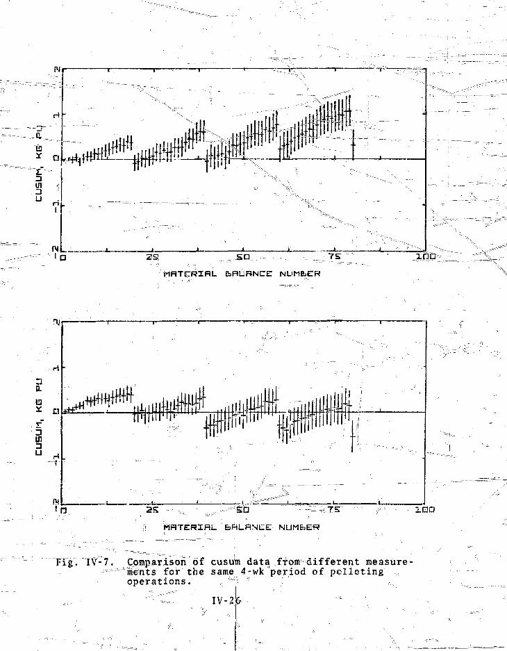
1OD
H R T E T R I H L NUM6ER
1DD
NUMbER
Fig. IV-7. Comparison of cusum data from different measure--";==r"""=ime'nts for the same] 4-wk period of pelleting
operations. ...Hi '
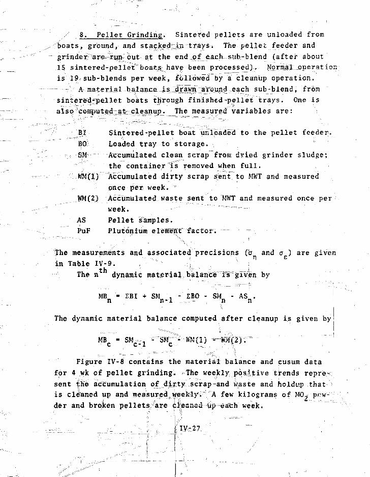
8. Pellet Grinding. Sintered pellets are unloaded fromboats, ground, and sta^jke^fcin trays^ The pellet feeder andgrindex are^iiin; out at the end of :each SJib-blend (after about15 sintered-pelleVbosts^have been processed), Normal operationis 19 sub-blends per week, followed by a cleanup operation.
A materiaL balance JLS j[xa^n IJffiu d each sub-blend, fromsinjeTedfpeUet boats through finished-pellet trays. One isi T h e measured variables are:
B| Sintered-pellet boat unloaded to the pellet feeder.BO Loaded tray to storage.
••:•>•-—SM'•• Accumulated clean scrap from dried grinder sludge;the container is removed when full.
WM(Ij Accumulated dirty scrap sent to MWT and measuredonce per week.
WM(2) Accumulated waste sent to Mh'T and measured once perweek.
AS Pellet samples.PuF Plutonium elenvenT factor. — -
The measurements and associated precisions (a and a ) are givenin Table IV-9. , ;
The n dynamic material balancl Tssgiven by
MB - SBI + SM'"'. - ZBO - SM - AS . in n-l n n
The dynamic material balance computed after cleanup is given by'i
Figure IV-8 contains the material balance and cusum datafor 4 wk of pellet grinding. The weekly, positive trends represent ihe accumulation of dirty scrap and \vfaste and holdup thatis cleaned up and measured^weekly.^ A few kilograms of M0 7 prwder and broken pellets; are ci^aned tip each week.
if IVr27. ^
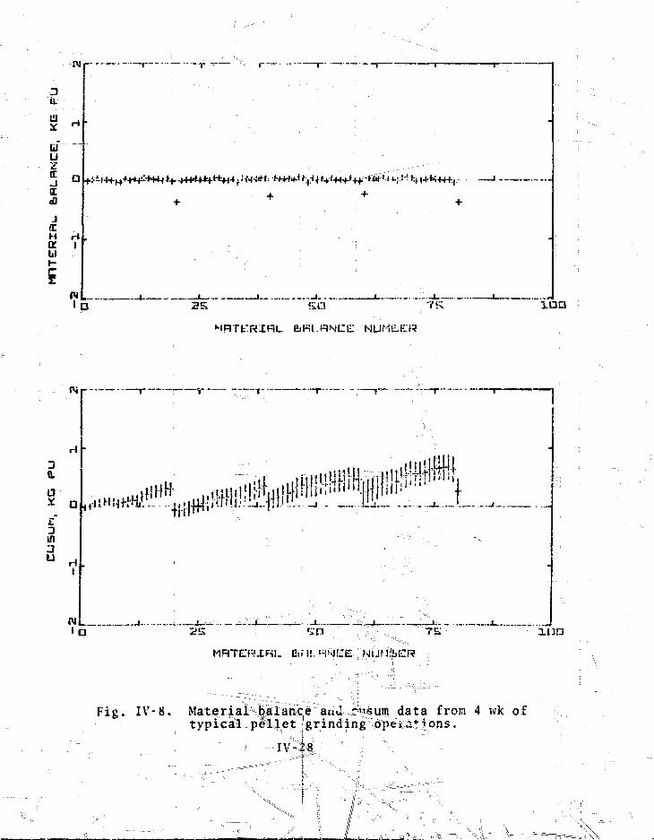
a.
u
j
H Ha iK
D ^i
2 K i a a
NRTt:RIHL
a
3in
' a
*«»!
113P
XFil- Eif I! MMirC NiJM&ICR
Fig. I\r-8. Material balance ami c'isum data from 4 wk oftypical pellet grinding ope*.:tions.
IV-28
* \1= V
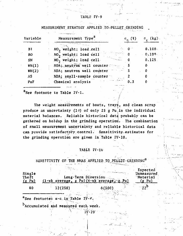
f TABLE IV-9
MEASUREMENT STRATEGY APPLIED TO^PELLEI GRINDING
Variable
Bl
BO
S.M
WM(1)
WMC2)
ASPuF
Measurement Type- • . • • • • - - . - . ^ ~ T - . . _ .
MOi weight; load cel lMO2 weight; load ce l lM02 weight; load ce l lNDA^neiitjrdn" well counterNDA; neutron well couinterNDAj^mall-sample counterChemical analysis
0
• • • • T ' - : G ••
— . 0• : - - . - - - . . . . . . 5
- - - 52
• - = • - — - - - - 0 . 3
a
0.
0 .
0 .
0
0
00
(kg)1--
100
100
125
aSee footnote to Table IV-1.
The weight measurements of boats, trays, an<J clean scrapproduce an uncertainty (1 CT) of only 25 g Pulin the individualmaterial balances. Reliable historical dat£| probably can begathered on holdup in the grinding operation. The combinationof small measurement uncertainty and reliable historical datacan provide s at is fact pry control. Sensitivi=tyuestimates forthe grinding operation are given in Table IV-10.
TABLE IV-10
SENSITIVITY OF THE MMAS A P P L I E B TCL
: 7"'""~:: •-•;- ..,.'. =_. -; E x p e c t e d - ;1\Single ^ ™ — ; UnmeasuredTheft Long-term Diversion~--.,; 5 MaterialCg Pu) Cl-wk average, g Pu)(4-wk average,^g^Pu) (g Pu)
80 12(250) 6(500) M22b
aSee footnoted a-c in stable I^-'&y
Accumulated and measured eachl week.
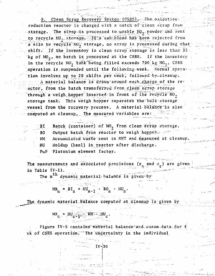
9. Clean Scrap Recovery System: (CS:RSj ^T-h-e--Oxidation-
reduction reactor is charged with a batch of clean scrap from
storage. The scrap -is processed to usably JID-, powder "and sent
to recycle >lG«fi ^ rejected from
a silo to recycle"M0_' storage, no scrap is processed during that
shift. If the inventory in clean scrap storage is less than 35
~kg of M0-, no batch is processed at the CSRS. If the inventory
in the recycle MO- anT'Being filled exceeds 700 kg MC,., CSRS
operation is suspended until the followingweek. Normal opera-
tion involves up to 20 shifts per week",~ foliowed—b-}t=c-l-e-an'iip.
A material balance isi drawnraround eachmc!jiax8J?_of t n e re"
actor, from the batch transferred from clean" sjcrap; storage
through a iveigh. hopper inserted in front of the recycle" HO,
storage tank. This weigh hopper separates the bulk storage
vessel from the recovery-process. A material baTarTce™is also
computed at cleanup.^ The^ measured variables are: s ^—
BI Batch (container) of MO, from clean scrap storage.
BO Output batch from reactor to weigh h q p p e i ^ "
ivM Accuniulatcd Vas"fe sent to MWT and measured at cleanup.
HU Holdup (heel) in reactor after discharge.
PuF Plutonium element factor.
The measurements and associated precisions (a and a ) are given
in Table IV-11. ^ ^ ^ "" ' " ^The n dynamic material balance is given by
M V * BIn + HUn-l ; BOn " HUn' ' •
The. dynamic material balance computed at cleanup is given by
Figure IV-9 contains^nvaterial balanee^and= eusum-data for 4
wk of CSRS operation. The^Sgertainty in the individual
IV-J30

uuzI t D
J..a:..-,IE I
(C
IV!1
1~
1 i > I
' • . . • ! • • • . ' - ,
-X-PQ
L. L.-F:L.«:,'I:E: NU'
30.
U
3I/!
U
i " ~ •• 7K" i n n
Fig ^Material balance and cusum data from>4.-t-ypi-G-a-l-cieair^crap recovery o p e r a t i o n s151 NDA 3nea.sJUT.em.ent oi the
' •• IV - 31 "
,,^'f
TABU 1 V - 1 !
VJ VslIKi \'J \ J MKUfl t:\_AJTJ ri.iiAN SCRAP UlCOU'-'KY SVSTliM
MiMsureir . K-*: 1]
MO, u ' e i ih t ; load c o l l
us-, uf i oh*" , rrrad c e l l
M>\, iiieution ve i l ' _countoi
\ [ U ; lieiiL ron
I'tiT \ r Vhomiyal a n a l v s i s} \ I
(1
(1
5
IS
0. 3
d.\gs0.125
0
... o: 0
--"T ^
-'free Too t mit e to j j,!h te" J \ -1 r
nijat e r i;iTpl^ a l a n c e s IK' =„ iM^-li|£V|5lHiV i s dominated by Ahc 1 :">'!••
%V>\ measuroMent of the^JM'ocess; hee l Ln t h e . d e a n s c r a p redVtoiv.
TKO*^^^lu^4e_j^easiiltements a p p t ^ i r - h i each dynamic b a l a n c e . I'or
/ 'comparison, ' t h e same p r g c e s s d a t a aind measurements ue re run v.ith
chemica l r eac to r^ pe^sUremelut. These r e s u l t s a r e
/• p l o t ted, ,(?in lij1 ,- IV-10. "The lo m a t e r i a l b a l a n c e u n c e r t a i n t y inf/ tl ' . is c=i*-so is -v 30 i<" 1'u, The imcertniir tv in ohc-Jr"material bal-
ance J-T* e s s e n t i a l l y equals to the M^\ measurement u n c e r t a i n t y .
\
:',. : ^ '
The uncert a iiity in t!ieo cusum ajso; r e f l e c t s the fact that
\ ..,U».o VPA reac to r iA'asuremenXs appear in each cusun! r a i i t e . The
^ u s T n r r u j i c e r t a i r . l v J -as a l a i > : e i n i t i a l v a l u e ' c l o s e t o t h e XV.\ j
J b t ' a s t i r c j ' V r i t u i K e r t a i n t v . As b a l a n c e s a r e a d d e d , t h e c i i s u m e r r o r ]
^ ? o u 1 > v-iowV:. b e c a u s e o f e r r o r s i n t h e u e « t : h t measurement - .< . . . ;
t b e s o n s i t i v i t v o f - t l i e i : e n e r i c ;MMAS f o r CjSKS o p e r a t i o n s I s j
r i v o n Mi T a b l e l \ U . ' • " . ! " , |
l i i . toni1" ' T o i r d i v e r s i o n sn ! ' » o , I ' o u d e r U i v l o a d n n t : . l : o r d e - i
l o i t i c i i of l o r n t t i r i l n o r - i i i i i , c u s u m d a t a t r e n d s d u e t o u n n i e a s -
u i e d i . i t e i i a l : i i ' i I K M I M L | M \ K ' C " - < < o p e i a t i o n s m u s t b e s e p a r a t e d f
t u > i t i e i u i ^ uUv- t o t h e f t . I h i > i - a k i n d of p a t t e r n recioi^n i t i o n
;< r o b l e i t o i h h u h t h e V i(nsl> t e c l u i M j i i o (*-ee Appe ju l i V I • I I )
V
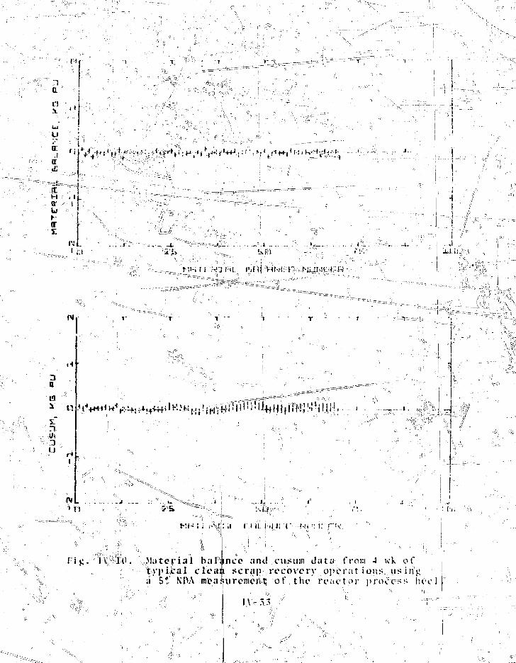
11
aL')
f iIT
H
tr
Uhli
X I J ;
3a
1J
rvMl
T
i V l O Material baltypical cleasi' 5* KOA meafr
,. ,:!ij..j:.
t ' u I iJJi I " N ' I •• i; ,;•"'<•
ncc and cusum data from A wk ofscra|r recovery ppcrat i 011. us i li'j;
uremo'irtj of tlie fo.-icMor process lie
•a: *

TABIT IV-12
SENSITIVITY OF THE MMAS APPLIED TO CLEAN SCRAP RECOVERY SYSTEM0
SingleTheft ^Long-lerm Diversion
average, g Pu)(4-wk average, g Pu)
ExpectedunmeasuredMaterialCg PtQ
290
100
3 0250)
5%!:30)
6(500)
3(250)
See footnotes a.-jc: in Table IV-4.
NDA measurement on process heel.
NDA measurement on process heel.
Accumulated jyuHffteasured each vfeek.
appears to be a promising tool. Kith the V-mask, the analyst
can detect significant positive trends in the cusum data and
record the sequence lengths in each trend. In addition, the
average value of material balances in each trend can be calcu-
lated, giving anjestimate o.f. the "average positive bias. 'Vn
estimate of the totgA bias is found by multiplying the average
balance b!y^h© "sequence length.
JVat diversion detection probability is estimated from the^***"••• :> ri ^ - . . , ' i . ' • - • ^ . - A , - - ' " ' •'
'average b ias , sequence lengthy and CU*J> -•t-ffidard deviation,and trends are c lass i f ied according to t h e i r estimated detec-tion probabi l i ty . '3The c lass i f ica t ion scheme currently in tiseis given in^Taible IV-I3.J-, ' .iiV?»..'i ,. I *: ';;;•• . . •..
Examples of the V-ma^k m th<|>d as applied to the PuO^ un-iloading process are given-here. Two pat terns of small the f t ,one random and the otlfer uniform^ were aptjlied to measurementstrategy,2 (s^idestlreams measured!each wee?c)? and to strategy 3(sidestrdams and hpldup^.mpasured; each shift, see Sec. rV-Ar5)jp .

-••TABLE IV-13
CLASSIFICATION OF .TRENDS DETECTED BY THE CUSUMAND V-MASK METHOD
Classification
A :
B
C
D
E
Fr*
Detection ribbability
70-80 ;Q , ; 3 0 - J 5 ; . -•••'
85-90 ; i"90-95
•~^ m^$S^9IL_L_-,,: 98-99 -:\.^\
_ _ r .^rT _,;_
False-Alarm iProbability Range Ct)
/ • " ' ^ "3t»-20 ' V "
2 0 - 1 5 i
1 5 - 1 0
? v • 1 0 - 5 •- ^ ;
- / ' ' 5 ' 2 " ' • = • ; -
Probability of detecting an apparent trend when no trendexists. The probability of missing a real trend has beenset equal to the false-alarm probability (see Appendix E)..
The diversion patterns^are unrealistic because a theft usuallyoccurs each shift, a situation which would require collusionamong several people. However^-tjie examples illustrate the \jimplementation of the V-mask method.x^ \ ; ; :
Only the results from measurement itkategy 2 are presentedhere; these cusum data exhibit the weekly positive trends causedby unmeasured holdup and sidestreams that are typical of datafrom most unit processes. The only historical information as-sumed is that the cleanups are reasonably effective, viz., atleast half the in-process holdup, on thf^sverage, is cleaned upand measured each Week. .. |] -"
In Fig. IV-11, cusum data from 4 wk of normal powder un-loading operation are compared with data from the same 4 wk wi^ha random series of small trefts applied. In the diversion ;
powder could be removed from thesingle canister, with only one theft
IV-35 i
scheme, 60 to 70 g of PuO,contents ( 8 kg PuO2) of a
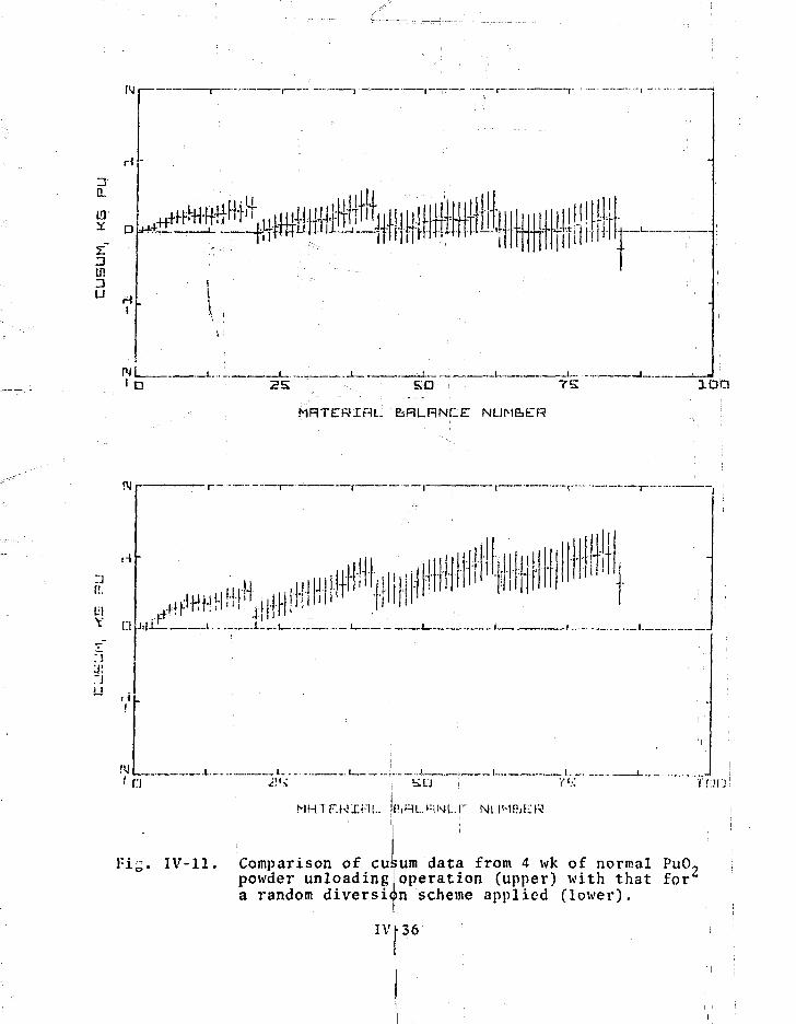
N
0.
in
iv L_ID
II rfyifii
25 SO TS
MRTERIRU feRLRNCE NLJM&ER
p..
• J !"J
D-J-i
I I I 1 -I.J-11
ittliljl.J1 '
jjff fflfill1 Ki ih i !
•nilij . . . - - • •
• | l
' r:j
i c . IV-11
. . i-. •:"" ^
MHTF.K'XR!.. i
Comparison of cusum data from 4 wk of normal PuO?powder unloading!operation (upper) with that fora random diversion scheme applied (lower).
IVL36

during each unloading shift. The amount actually stolen is
given in Table IV-14. ;
TABLE IV-14
RANDOM DIVERSION SCHEME
Week Total per Week Cumulative Amount Fraction of Total
No. (g PuO2) Stolen (g PuOp ,• Throughput (%)
1 196 196 0.12
2 268 464s .; 0.15
3 331 795 0.17 -
4 193 988 0.15
From the cusum data in Fig. lV-11 (loi|er plot), one would
suspect an abnormal condition during the sejcond week of opera-
tion, and after cleanup at the end.=9f the, second week one would
probably conclude that material was being diverted. Evidence
based on the cusum data alone is somewhat ambiguous during the
second week because of the trending due to normal operation.
Figure IV-12 shows trends detected by the V-mask for•normal
operation (upper plot) and with random thefts (lower plot).
The letter symbols correspond to the classifications given in
Table IV-13. The trends are plotted according to the initial
and final sequence numbers (I, and L2, respectively) of the |
material balances in a trend. Note that any sequence of length
one (a single material balance) would fall on a 45 line through
the origin. All other sequences fall below this line, i.e., in
the lower right half of the jplot. !
During normal operation, the symbols representing detected
trends cluster in groups near the 45° line. Each cluster of \
trends corresponds to in-process material that is not measured
during the week. The symbols on the L2-axis in the lower plot i
•I ; • i • \
: TV-37 ; ;
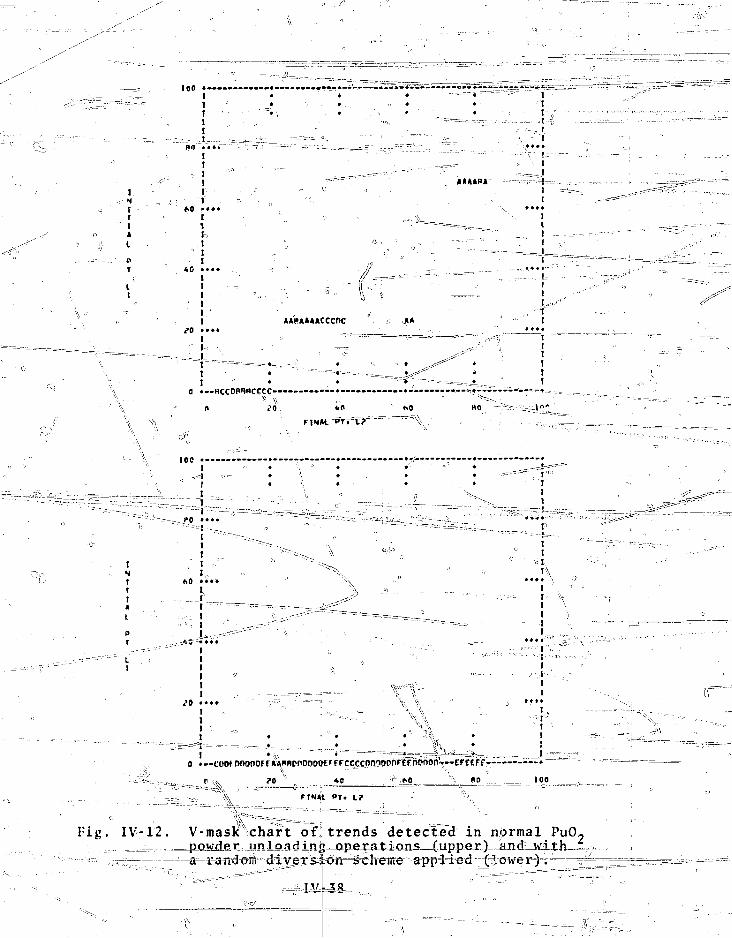
t
'•• 1
I• » • »
III
*«p»»«»cccnc
0 •—BCCDPHHCCCC-
' (.0
10(f •-I
*^ii
-•— 3"
-_ ("0 ••
• - ~ - - - ;
i
I!„
!
- L_
!•>
- ' = -,;„II
iii
# * # •
i
t
Ii '
FINM. Pr. L?
• Fig. IV-12. V-mask chart of]trends detected in ndrmal PuO2
: herne^ app=H=ed- ff^o w e r1"fi==r^r==^is^rf=s=i=^== --==

qcz:
of i;ig. IV-12 correspond to longer trends. By the middle of
the second week (L:- ~=3'($), these* trends ,h.ave become so uext
sistent thar an abBorinaT 'condition is indicated. Thus, combin-
ing the V-mask with cusunudata to detect patterns of trends =asB
well as the txiends jJiemselves,7appears= to improve sensiti\*ity
to long-term diversjLojKj JVe note that the average theft per_
balance period in this case was ^ 9"gTiniuring the first week,
and <v ld'.T"g""Puc^^^ detection
limits given in %able IV-4 are 16 and 8, respectively.
To test further the sensitivity of the V-mask and cusum
method, we imposed a uniform (but unreaiistic) diversion"scheme
of very small thefts (4 gRuO-) from each canister. The total
amount diverted dj^Mg" the 4 wk was 320 g^EuOyC282 g Pu) in 80
thefts, which Ts to be coinifafed with the 700-g detection limit
quoted in Table IV-4^ Figures^iyjU-S lind IV-14 are the cusum 7
aha l^-mask plots for this™scheme.^=The-^u5um-givcs little e v i - ^ i "
aencr^crf dive-rsicmt^it-i^s^anpjaj^n^ly^^yunthe limits of normal
(Fig|. IV-14, lower plot) also doe:.
not contain conclusive evidence 6f tlieft", b=uTs=t1il peisisxcnce
of long trends along the L\-axis £L_ > 20) should be of concern.
This result is gratifying because the level of theft is smaller
~ limit and is con-
sistent with our intent to make conservative sensitivity esti-mates for long-term diversion pending ^uinther study of the cusumand V-mask method. 0 :~-^~---=--:• J -^
B. ^Safeguards Reliability n ; ^
Safeguards reliability is an important consideration be-
cause, as discussed in Chap. 111^ it: affects SNM safeguards and
economical plant operation. This.section examines the compara-
tive reliabi.l-i.tyr of the safeguards system (see Chap^.
several alternatives. \T ^ "
treatment Jherje s u i t j f t f f f ^ ^ ^ y ^ ^ p ^ g i y f k ^ a ^ ^ i ^of expected^results. Actual reliability depends .on^a,number of
factors: local equipment environment,; computer 'Hplrkloads, arid
. / , . . . , . . • ' ° \ - • = = = i- • . - > • • - • • -
i IV- 39 >.. = ,
. - • ' • • )
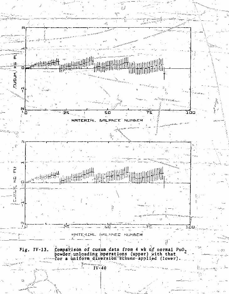
13
5U!
L1
£3P» tip.
5 D
MHTERIRl. EaFlL-RNCE ' NUMbER ••Ii a a
u.
I . , _ ; I ,
Fig. IV-13. Comparison of cusum data from 4 wk o | normal PuO2powderi=usiqading; Operations (upper) p t h thatfor a uniform d£v^rsioTT^heme applied (lower).

>90
IHTV-«t , ••
I
»
|
at • »••/'
m"/
• ft' t•L- « "•
A ; " j •'••
/ • / . •
'"/ • {
1 ?• •••* ,i t ':
p I
i f
;; -. .
i f ';•
' ::''-:. /°- AARAAAACCCOC I)
;- • _ _=
• IT "' ' • * " r- •1 • •
* •
* « * * « «
^ -I , il
o • — BCCOMUCCCC—
100
rtHM. *T> it
• -
o
• • - - — • • ^ \
sIf
••; l
>
r :. T
i
(r
'i
\1r,•\
I'i
' I •_;_-:
:\?'' - - I ' v ,»'<,0 • • • • ' - ^
'- 1
* 0 • • • •
?0 ' • • •
.-JU._.:
* •
//
= -
-
° ----- ' "" ij- ; ',)
C CDOOO
• • - ' • : •
o •--Bccocccnww——«A*«*RKCC
0 ?0 *#
.--_._..—jcr.- - n
,(//
y r \
M IOC
fIN*l ^T. L?
Fig. IV-14. V-mask chart of trends detected in normal PuO,""'••,'-' powder unloading operations (uppfer) and wltiw^
s a uniform diversion s?chem&\ applied (lower). °
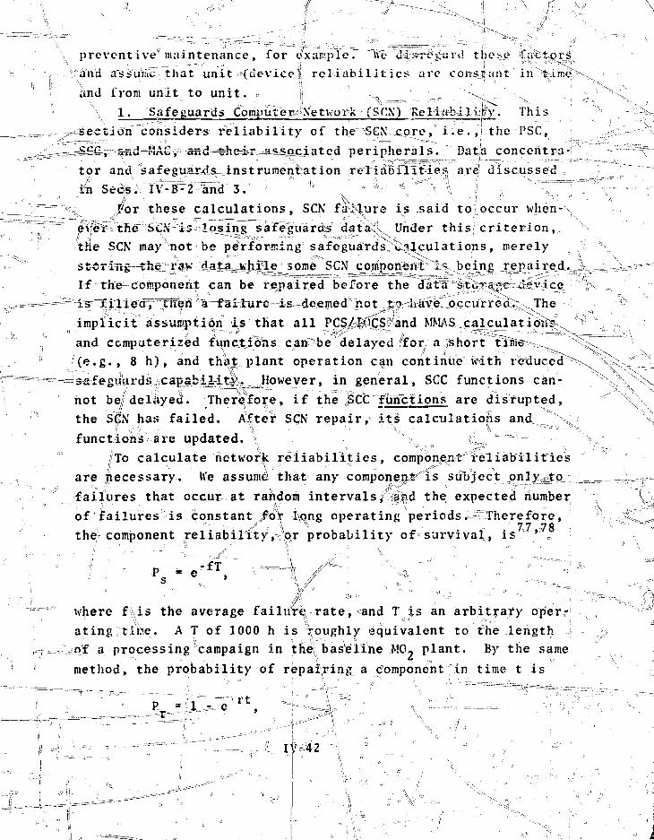
preventive'maintenance, for e'xampleT ive J4si^i*tiri! tljiCM? factors
"and'ass uiiVc that unit - (dev ice} r e l i a b i l i t i e s are constant in time
&nd from unit to uni t . •= |j ^ •__. -.^
1. Safeguards Computer^Xetwork ^(SC\) ReH^bllWy . Thi s
considers r e l i a b i l i t y of the "SGX core," i . e . ,i) the PSC,
peripherals. Datja concentra-tor and safeguar^is^instrumeniation reliab'ilTfcies are discussedtti Sees. IV-B^Z lnd 3." ' * / ' \es
/ox these calculations, SCN future is .said to occur when-4s icijsing safeguard^ data^ Under this; criterion,
the SCK may not be performing safeguards calculations, merely
some SCN cornnonont 1* being repaired..
If the component can be i\epaired before the data sti-v'V;c Je^ic
^ ^ i ^ f have occurrea, The
implicit 'assumption.'is that all PC§/^.)QS and MMAS calculations
and computerized funcjLicfas cari be delayed for a short time
(e.g., 8 h ) , and that plant operation can continue with reduced
™^lsafeguards iCapjrbi it|v. However, in general, SCC functions can-
hot be/deliiyecL Therefore, if the SCC functions are disrupted,
the SCN has failed. After SCN repair, its calculations and ^
functions are updated. \ J^ ™
/'To calculate network reliabilities, compbnenir'reliabilities
are jtiecessary. h'e assume that any component^is subject ^nly^tp^i
failures that occur at random intervals i |||jd the expected number
of failures is constant /or 4\qng operating periods;S^Therefore,v - ^'J • ^ ' •• 7 7 -7 8
the component reliability, or probability of survival, is * ,
I ' '" .fT' " \ jL.. '•-.. =-' ,. •' • " T'Tr—
where f ,is the average failure rate, and T is an arbitrary oper-
ating tibe. A T of 1000 h is Roughly equivalent to the length
of a processing campaign in the,baseline M02 plant. By.the same
method, the probability of repairing a component In time t is
-^,Ti...i.M?
.' j
^ the average repair crate. Foriexajnpfe, if th'eof a component is 1/1000 h^and' its repair rate^i^f/2 k7
then the probability of one .failure/^in—tMiLJuis151368 and theB^ that it wiill be repaired in 8 n is 0.982. , \
For thesfe"^calculations, four probabilities are necessary:P, the reliabHitiy^of the PSC, SCC, and MAC, _ _ ^P., the reliability of any associated buffer memory,P«9 the probability that the PSC,_.SCC, or MAC can be
repaired within 8 h after a failure, and _P,, the probability that after repair the PSC, SCC,
or MAC will operate longjmough to empty a buffer
Th« fundamental reliability, ;P, of each. mp.i>i computer is not L
controllable (except through chjuce^crf Jqui;pment or operatingconditions^, but it strongly affects n^fapr^l^MmffiHyi^-TMe^same is; true for buffer memory,^reM^i!4^yi-Pt-.X'riie!?-probabilityPd is fixed by selection of P^^they are related-through achange of lime scale. fjrhV;8-h fix TiTmined by a number of factors including effectiveness ofnance personnel and availahvjijty^of spare parts. '*
Reliabilities fosf six possible SCN configurations are cal-culated* The configvrEations ar^i="representative of those whichmight logically be Chosenj and they Include that given in Chap.H I . „ : ' : : - - - ^ ; 1 ' • • 'ca "-' '"• .-. \ / : =T - ^"" , •"•"
Tne simplex (S) configuration consists of the PSC, SCC,arid MAC in series, with no redundancy or buffer memorAt.^^itsr e l i a b i l i t y a s - . " —•--•-•-•v^, ••*,. -.. rd!
:' • -;; " = ' . „ * >! / v ' •
1 •• • * • • ' ^ ". , ^ - 7
That is, the SCN' fails if any portion fails. fThe simplex withP buffer memory' (SBM3 adds memory backiaps
to the?;PSC and MAl! tS=pi;event loss of data when either fails.i is the probability that PSC^and/or its' buf fer
memory is working, and that SCC is working, and that MAC and/or ; ?,its buffer memory is working,! i.e.,

p 2 - 4 ^aF'"this case, thV rel:Ubi|a£ies-of1 the2PSCland MAC have been
increased by the term "(i-P}P.PgPd, which is thfr probabil i ty thatthe,„PS€=or MAC lias JjuJ^axC^^ memory' has ftotC?^) and the PSC or MAC can-*..e-r^en.a^eAjwithinjT h (Pg) and w
"work long enough to empty the buffer memory^XRa^^""Tor the duplex system with buffer memory and single backupji, the spare computer can back up the PSC, SCC, -or the
J" [V:•+: (i-p'JJ^fPj]2" [V:::where ~°-P_f -,,P + P5- P ^ V T " " t " - ^ ^ T p -
This has the sarae fora as PL, but the reliability P has beenincreased tb Pr by the single backup. ^
The duplex systew with buffer memory and triple backup(DBM3B) is the same as DBM1B except that the PSC, SCC, and MACcan be backed up simultaneously. The reliability is
where P" - 2P - P2 ,\_sr, ^ ' £ "/-\ * ^ 7 " " ^ ^ — ^
The three backups can be three separate machines or one bigmachine with equivalent capability. • " \- i ;
The triple - moduxar^TidUndali"TtKfltj^It^wo'rTfTfitTi baf^eTmemory is discussed in Sec. III-F and is the safeguards design.It effectively links the PSC, SCC, and MAC into one large modulewith reliability79*80 J *
PT - p
so th^tCfie"total network reliability is
/ CIV"44!i^r
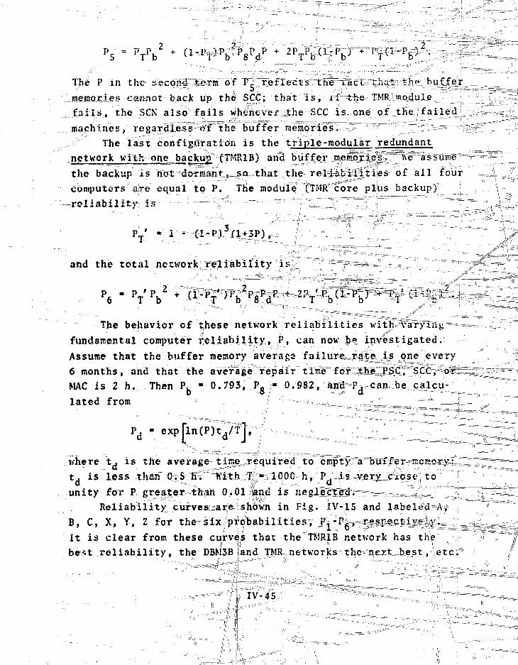
P 5
The P in the secgnjI^iKnirof^P^^
mejncrries cannot back up the SCC; that is, xiNrhe .^TMRimqdule:'^ :_i :_i.f
fails;, the SCN also fails wh^neveivithe SCC is one af ^
machines/ regardless ;*ff the buffer memqfTes^^"s;:r"^^^:^.^^^
The last confimiratiOii is the triple-modular redundant
network with one backup fFHIUB) and
the backup is not^ds^Haniu^o J:hat the re l^b^r t i ies of all fourcomputers are equal to P. The module tTMR'Tfore plus backupy ;
-re-1 i a b i l i t V : is - • —•••-: ^ ' - =
PT ' « i - ci-pJ3Ci
and the total nerwork:;xfli:abxlity 'i
The behavior of these network re l iabi l i t ies with>v tryxivg™==|====-fundamental; computer re l iabi l i ty , P, can now $M»7 investigated.Assume that the buffer memory average failure^r^te^lsjne every6 months, and that the average repair time=£ol5Ehe PSC, SCC", o r -MAC is 2 h. Then P, " 0.793, Po « 0.982, and^Pv can be calcu-lated from ;' ~._
where tT is the average ^ti^ine^required to empty atj is less than Oi5 hv
d "- ^ „ . :j(f - • • : . .
unity for P great;er^tKah 0.01 fand isReliability cufves^are shown in Fig. 1V-15 and labeled=v'tf \ =
B, C, X, Y, Z for the sixfprofbabilitiesv J\'P^^-^^T^^i^^L^l^M£^^^-£It is clear from these curves that the TMR1B network has the i ;? r~^7best re l iabi l i ty , the DBM3B land TMR, networks the next^bejst,\etcf:i j
^-^ tlNv-45.
,; i.-.->==^=Tr— -.TIP"

\
. I V t l S i KeHabU4=4 t i o n s
i'SC, SCC, ^pr MAC.

it is also true that the THR^etwork (or TMR1B, depending
available equipment) makes, *o >t eff icientnislFTjrf ,?the machionnes .
if a value for •P.&s&aii be obtained, the networkfor each configuration can be] rpada off the curves. l"or thetypesjof computing^system* discussed here, a typical failure
• • - • • • ' • ' ' ' • '< < e > , • • • • ' " • = ' • ! i ' • ' ; ; . • - . . _ _ . '
for the PSC, SCC,T or MAC is about one failure every 3y•onths , so that P » 0.629. Tiible IV-1S summariizeis the netjworfcrel i a b i l i t i e s for "ffifs case !
T i i
. !sg;
SCN CONFIGURATIONS
S
SBM
DBM1B
TMKTMR1B
0.
0.0.
0.
0.
0.
249
530
63S
811
810
910
t ^ 719
1,575
2,203
4,773
4,746
10,615
Mean time between failures.
Thus, SC>T fai lure ratt; can be improved by a factor of moreihan 6 by usitt£ a TMR COB* igurntior. rather than a simplex.I-urt her/no re , TMR r t l i a h i l i t y is about the .sane as for DBM3k,
it uses liklf as »»ny machines. This comparison i s not quitefai r Df§stj*^^b©ut the *a«ie to ta l coapttar power is necessaryfor, e i ther T IR however, °if thecPSC, SCC, and MA(!
chosen so that each can fti^ie a 1 1 necessary SCK functions, the
TMR Coitfieuratifg givesi betterj^e^tijib^ilityand hardware u t i l i -zation tj amTJBMSR. ' | Z5*^5*^
""^ For TMR, the modulo °i* as-tuned €oXfa/l ^ h > ^ amat-hines f a i l , i.e. y vihtn pne machine fa i l s there
^ ' i , ' fa\ i • IV, 4 7 a
two
arc it.'.^
I....

procedure for choosing between the other two, a necessity for
any duplex system. If such a procedure is available for TMK,
then the TMR module reliability is
PT '3 3F(1-P)2-
Tor P * 0.629, I\_ • 0.949 and the network reliability is 0.969
at 1000 h for d 31,667-h fabout 3.7-yr) MTBF.
One advantage of the TMR network is its self-checking and1co.meeting capability through the voter array (see Sec. III-F).
For the duplex networks, this functirn must be done either by
r^n-operator or by a checking rout me" that is executed by a
machine that ml|' be failing, with concomitant possibility of
error. For these calculations, changeover reliabilities and
times for the redundant networks are assumed to have: no effect.
These results should fee viewed with|;caution because they
provide orily rough guidelines "tb/SJCN reliability. Quantitative
answers v.ill require more detiail;£d\calculallons.
2L. Data Concentrator Reliability.g. Four data concentratoris
. form the interface between' the safeguards instrumentation and ]the SCX. Vor reliability calculation^, the concenferators can |~• cor.sidcretl to be1 in series because if any one fails the SGbe
loses data.
network is
Therefore, athe reliability? &f tfeS€N
iden dc i,;\where P. is the reliability of any single data\ concentrator.
The data concentrators fare relatively simpre and highly
reliable. if the failure rate f«?r pne' y -|t'=is bri every 3 yr,
then P/r = 0.9622 and P, * 0.858 at lo^O^h; the \etwcrk MTBFd c •••:; •• ,. • .- d e n , •-• \. rv" -,,... 0£.. '• \
is about 6530 h, of-a little) more than ^months. A 1
—•""--"•-'— t'--'-1-- cannot be ,
•I-
switched into the network fast enough; td 'increase reliability,
any spares must be fully redundant (operating in parallel).
48
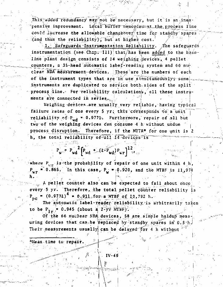
Thrs^added redundancy mary/not be fnecessary, but i t is anineix-
improvement. Loical l inecould increase the allowable chflngeove|^ time rfejr standby spajres(and thus the reliabili ty}";" but at higher, c o s t /
3 . Safeguards InstruBentatoion Reliability. /The safeguardsinstrumentation (see Ghsin III)! that/has bteen added to the bjafe-line plant design consists of 14 weighing devices, 4 pelletcounters, a 35-head automatic label-reading system and 66 nuj-clear in3tT^?a^urT^eniHdevices. These^are the numbers of eachof the instrument types that are: in use simulflneTjuViyT^sojneJ™mm^instruments are duplicated to service both*sides of the splitproces^ line.- For reliability calculation^, all these instru-ments are connected in series.^.J = \j = j
Weighing devices~are usually very reljiable, having typicalfailure rates of one every 5 yr; thts~^cdrfjesponds to a uhiTreLiabilitw of P—j *-0.9771% Furthermore, repair of all buttwo of the weighing devices can consume 4 h without undueprocess disruption, therefore, if the MTTR* for one unit is
h, the totrtl r e l i a b i l i t y of-ali"Jr4"-dcvi.cocs i s
P • P 2
w» wd0 ' " • • • " - - - : . . -
where P _ is'the probabjility of repair of one unit within 4 h
wr0.865. In this case, 0.920, and the MTBF is 11,974
h.A pellet counter also can be expected to fail about once
every S yr
pc
Therefore, the total pellet c&unter reliability is• (0.9|7&l)4 » 0^11^for-a MTBF of 1JL792 h. |The Automatic label-ieade^ reliability rs arbitrarily taken
to be Plr0.945 (about ^ 2-fi; MffBF).
Of the 66 nuclear NDAi devices, 58 are simple hpJLdup meas-1uring devices that:can^beTheir measurements usually
replaceja by standby spares iif 0^5 h.can be delated'^or 4 h without ' j
*Mean t ime to repair
IV- 49

process disruption. The failure rate of .gamma-ray instruments
is about one per year and that for neutron counters about one
every 2yr, so that the holdup measurement reliability is
h (l-P )P 32 [P[ n )PJ J26
where P is the probability of repair within 4 h at a 2/h repair
Then P = 0.9997, p-1 • 0.891. P * 0.944 ami P, = 0.9985.• a «- -.'•' Y
rate.
The other 8 devices are more complicated (many use a mini- '•
computer fbr control and calibration) and can be expected to
-fail 4about pnee every 6 months. However, standby spares provide
a O.SVh repair time, and down time can be 4 h. therefore, the
reliability for these eight units is
[Pc 8
so that ?c * 0.999. Thus, the total safeguards instrumentation
reliability is P . » P X ^ ' i f;uPr "-0~:79.
4. Total Safeguards Reliability. The total safeguards
reliability is the product of the reliabilities of the SCNj data
concentrators, and instrumentation. Thus, ^ L
SP P PTMR den si
0.55 at 1000 h,
and the total MTBj- is v 2.3 months, i.e., plant management can
expect a safeguards-related failure about every 2 months, on
the average. ;
Note that these (calculations do not take into account sec-
ondary backup systems, for example, manually implementedT safe-
guards functions] thit are normally present. As a result, many
failures will nort significant
moreover, the seemingly high
restrictive definition of fai
tions is to give a rough idea;
y disrupt process operations; \railure rate is due partly to the
ure. the intent of the calcula1-
of the system reliability and to
pinpoint areas where improvement might be needed
IV 50

C. Safeguards Costs T^^^~L;=
The safeguards costs are estimates ojffL_the differences be-
tween the costs for the safeguardslsystem descfibed^in this
report and the safeguards costs f'd'r the proposed Westinghouse,
RFP design. The cost data listed in. Table I.V-16 include hard-
ware, floor space, engineering planning (architectural engi
neerisg) , installation, equipment engineering design an/Lpro-^
vu>v.-mcui | auui.uiii.ili g c i i v . ; .
, .Ij . ^ '• •• ,;. V "
TABLE IV-16 ,
INCREMENTAL SAFEGUARDS
Item
PSC, MAC, arid SCCminicomputers
SCN voter array
Data concentrators i
Cabling
Buffer memories
Memory backups:disctape drivescontroller
Spare SCN parts(at 20t)
Software development
Weigh hoppers, PuO2blending and storage
Weigh hoppersi, MO2blending and storage
Unit Cost
'"• '- :• ".swf;."
12; ''
'-'"• 0 " 1 ••
. • • » t • : ; =
•••• 1
29'10,10
1! •••-i- • f\-
75/man*yrif .•/
•fli •->I
COSTS
/ Number
3
• " ' • " • • • • "
' • • 2 f i ,
12
S mari-yr
- = , s . • -
\ %
X '''*••\•\
Extension
600
„ 48
20
= •= 10 ^
150
•^•^^375
'I ' ...18
Weigh system, PUO2 feedhopper td MO" blending
i
V"
V-51

TABLE
Iftem
Keigh system, MG^ feedhopper to MO* blending
Pellet boat Weigh system
Scrap can weigh system
Pellet counters (with twospares) =
NDA (Y) holdup analysisunits (with eight spares)
NDA (n) holdup analysisunits (with four spares)
NDA (n) verificatioh sta-tion for PuO2 shipping
Automatic IP readerwith 40 heads "~"
Large neutron coincidencedetector
Ge(Li) gamma-ray analysissystem with segmentedscanning option
MEGAS: Ge(Li) systemwith Nal backup
On-line solution analyzer
ASF NDA station; includesa neutron coincidence de-tector, Ge(Li) gamma-rayspectrometer, Nal wellcounter, assay cell andminicomputer for data =reduction and CMHS manage-ment , .
Spare electronics
Spare Ge(Li) detector
Unit Cost
K3ir11.5-
9
45
—250
90
Number
4
8
10
40
30
1
1
1
Extension($k) !•
...'.. .~^-4
30
40
116 !
100 \
460 |
270-i
45
2 50
90
85
6J
35
200
15
1
1
85
60
70
80
. is:
IV- 52
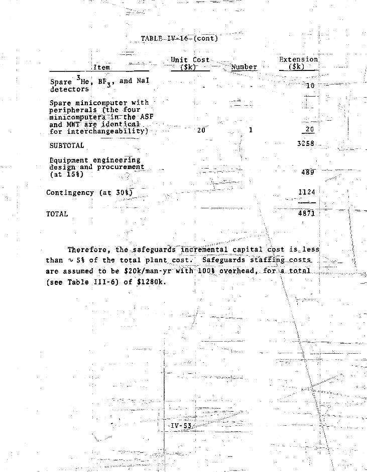
Item
Spare He, BF-, and Naldetectors
Spare minicomputer withperipherals (the fourminlcoihpufe r^ -in the ASFand MWT are identical;for interchangeability)
SUBTOTAL
Equipment engineeringdesign and procurement(at 151) ; -
Contingency (at 300
TOTAL
TABLE, IV=16
Unit
(cont)
Cost-.^f^Number
Extension($k)
20
I \ _^_^Zt~^r=^=^'
10
20
3^58
1124
4871
Therefore, the safeguards IncfeTnental^capital cbst is less
than ^ 5* of the total plant cost. Safeguards sMfl^ng
are assumed to be $20k/man-yr with 100^overhead, fox\a
(see Table III-6) of $1280k. - \
T
IV-S3,\ \ \ •
V. RESULTS, CONetUSIQNS^.AN'n RECOMM ENjP AT IQNS
\
A. Results X -^
The major result^of^this study isjthe conceptual design of
an effective safeguards materials management system for generic
,M02 facilities that provides minimal interference Kith fuel j
production goals att a reasonable cost. Details of this desigij '
are given in Chap_s_r___II_=a.nd-.sI11 and7Appendixes B-E. Other re- •
suits include the development of the control logic, management}
strategy, systems architecture ,vl§nd the methodology necessary
to evaluate the system j'ina 0rm largely transferable to safe-
guards studies of o ther nuclear fuel xYclcL-ifacilitics.
1. Design Features of the MMAS. The major features of 4
the MMAS are iistedjb#low. - i • ''
(a) Conventional process control is implemented by
an automated data acquisition system that supports human-
modulated control decisions. This approach combines human
adaptability With machine efficiency. | / +^
(b) The plant information system comprises tlie
process and safeguards information systems, and is1accessible
to both process and safeguards personnel1 on a need-to-k
basis, riowevefj the safeguards information system cannot be
affected by process personnel without prior^appr4valJjy the
Safeguards Offjicer^__2 ^ , ^ 1 ! \
(c) : The(plant managiementr structure is conventional, | j
except tltiSt the sj(fejMiX^!iSis;^ein-can affec* t|he process through""
Safeguards Officer's recommendations to the plant managerSf^!-—
(d) The'safeguarded plant architecture allows the
plant to operate in accord with g^odjndu^trial practice and
introduces minimal process disruptions. p ~
(e) The safeguards sy^steiri^can"bem?;de reliable enough
to have a minimal impact on the process by connecting the thre^
main safeguardls n a TMR^configHration, each,
V-l

checking the other two by background processing. Buffer memo-
ries provide reliable data acquisition, and spare units increase
safeguards instrumentation reliability.
(f) Almost all the safeguards system technology is
already used extensively. Experimental or developmental systems
are avoided where possible, resulting in higher maintainability
and reliability and lower capital and developmental costs.
(g) Materials accounting can be significantly im-
proved by relatively minqjr changes in the process line, for
example, by separating large powder storage vessels by weigh
hoppers. ;
(h) The concept"of graded materials safeguards and
ithe economic requirement for minimum process disruption are im-
portant factors in the generic MMAS design. Thus, the most
stringent controls are applied to PuO, powder handling opera-
tions. Less control;'-i 5 ~34^tsined OIL ope; rat ions, involving MO-
powder because the Plutonium in this form is diluted by a factor
of 25. For SNM that is well controlled by physical barriers
(security vaults, fuel rods, e*;c.),. verification measurements
that support item control are used. \
(i) Dynamic material balances are drawn around unit
processes that include the primary flows of material through
the unit process. These dynamic balances pro\fide effective con-
trol of SNM even though measurements of sojine in-prdcess holdup
and small material sidestreams are not included in each balance.
2. Performance Evaluation Tools. Because the baseline
plant has not yet been built, evaluation of the safeguards sys-
tem depends on process ajQidjneasurement simulation models. To
quantify safeguards effectiveness, detained models, including
holdup and sidestream estimates, are used. Separation of mate-
rials flow simulation from materials measurement simulation
gives greater flexibility in investigating various process and
measurement techniques and STO diversion schemes.
The GASP IV simulation language has been very"useful for
the simulatiiins. A schedule of material flow events is supplied',' ' i:iif • '

\ \ • • • • - • .
-A
foi each iunlt proces??, and the GASP I\i==conitrol/le% properly se-quences the events. a " {'
5. Diversion Detection Algorithms. The MMAS sensitivityto .short-term diversion (sirxgle^t^ftJj^^pejLa^oTi the-measure-:;
..merit uncertainty (standard deviation, o) associated with iridifvidual material balances. U useful" format for gr^hical i-Fescn
• • ' • • • ' (^~. " •• • j " • y
tat ion of the material balance data isl the Slievvhart chart onwhich ihe data are plotted with la error? bars, and lineis are\drawn at the average 2 and 3<i._le±el^so that) outliers_jire appar
""ent. ' ' " ^ ^ ^ ^ i' " •• ' ^ 4 ' : : ~ " <•">•>* "*'] ~ '• o .
Long-term diversion (repeated^ small thefts of SNM) is indicated by the trend it induces into the cusum chart of materialbalances. Such trends can be detected^by applying the Y-masktechnique to the cusun chart. This corc^in^rion is° a jvromisingXpol for separating t%^nds caused by unmeasUrea-sidestreams= andhoWup from those caused by long-terirr diversion. o 1^ adaitdron, =<historical data on holdup and inor sidestr^ams cahlbe useclleffectivelvL^in interpreting trends! =
4. Pi very ioh Sens i t iv i ty. Diversion sensitivities for /(— . . • •••. - t , ' ' l - .
five major unit proce%se» are^given in-Table V-L.son> the: tjvroughput of plutonittin o^de^-irS jTdl
5. Reliability. With proper safeguards computer
For c6mpar|U
configuration (TMR vithp buffer jnetnpries) and spare safeguardsinstrumentation, tlie safeguards failure rate can be reduced toless than one e\pery 2 months. FuVthcnno^te^thc "'UJSCL of well-developed technology minimizes downtime .whe^ a fa41t|re does
o c c u r . . . . i •' , , ' ^ _ i L i ' * = " , o ' " ' ; ^ < .-••",
6. Cost. The capital cost of ^ i ^
a large part of the physicalless than 5k of1 the tcfsTcc^tl (exclud-
ting guards) constitutes about 8% o£ the total pLant
B. Cone 1 us igns -^ primary conclusion from this study is .that ^current—-^
technology provides • Means for safeguarding strategic quanti-ties of SJ J in MO2 f ac i l i t y s at an acceptable cost and with

TABLE V-l
ESTIMATED SENSITIVITY OF THE GENERIC MMAS
FOR SELECTED UNIT PROCESSES IN THE BASELINE PLANT
Unit Process
PuO~ unload-ing''
MO2 blending
PelfLetjing
Grinding
eteani^crecovery
Single Theft'(g Pu)
110u ' 130/ « • "ISO-
80
200
Long-Term Diversion(1-wk average , g Pu) (4-wk average , g Pti)
16(350)
20(4Pp)
12(250)
10 (2Q0)
8(7qO)
10(800)
10(800)
6(5J)0)
5(400)
ExpectedUnmeasuredMaterial(g Pu)
18 d
15 e
33fi
22 e
Amount (3a)of unmeasured material that can be detected in a single balance period witha probability of 505 at a false-alarm rate of approximately 1 in 1000.
The average amount (2o(>/L) of unmeasured material per balance period that can be de-tected during 1-Wk and'4-wk periods with a probability of approximately 85% at a fal.se-alarniratelofi about 3/ in 6. The total amount (2<jr) is given in parentheses.
(;• i . i '•. - f f s * 4 -;/ ft - - ' .. - -•• L -:l •'•..'''•',.'' ! • ;
Average amount of/unmeasuredmaterial expected per balance period during normal processoperation taken f,rbro the baseline plant model (Appendix D). The actual amount typi-cally ranges froM zeVb .|to twipe the average value.
Accumulated and measurea each shift.
Accumulated and measured each week.
minimal disruption of production processes, the need to evalu-—
ate the effectiveness of-such materials control systems, without
actually having trie opportunity to k £ ^ i
cxtrejtiely important secondary cqi^clu^xopJ'.^^Wxile the re-pay 15 er'"g"eTfeTi"e"-~soluti-dn ~t:o;:5¥S3!guauc s problems, the concept of a
generic facility desjxgn is fLyery_ Hmrted usefulness. ?.
To safeguard graiajjuantities of SNM throughout tHe^eTrt^re
process, including waste streams, sampling streams, and holdups;,
these flows and processes must be krilawn Tn Retail-and with'
greater precision than can^^^ss-cMb^d-sinJany.gene¥Icpor pTO^O=S=={^I7^
typical facility. The need for quantitative performance evalua;^ 4 !
tions therefore requires that a specific (or archtypical) v '•— -.JJJ™-
nuclear facility bell described in engineering detail, aTvd-as-a=- =. i]
result, a generic design rapidly^becomes very much a detailed^t_^ u-»?
practical study ofLthe^effe^ts of seemingly minor process,
operational, and equipment features. The alternative is to pro^^Lg^rr^
vide a qualitative review, which largely ignores the problem. ^j^^^Z-
This has been done severjal times in 't$e pastesv:ith predictable,--^' '
-results.. ' : I --'^— '--^gg^ {-__'_•_ ~~ ~ '. "~ ~ "^""TT^^p:
Although the fffCiiit4£S'Ltiiemselves need to be analyzed in ^ \ \'
great detail, the generic approach can be usedin the specifica- |l ^
tion of the measurements, systems, and methodology that are
needed to address specific problems, once they are identifier
The features most common to all nuclear facilities,, such as con-
trol logic, measurement requirements, management structure,
safeguards strategiesr and f'VPluaticn methodology, are subject
to generic treatment ancL; accordingly, represent highly trans-
ferable technologies. JElant designs,, flowsheets,, and;materials
balances are not held in common by generic f|cilities| and are _.
not readily transferable. This consideration highlights the ;
necessity for industrial participation in the systems design c
and the type of close cooperation between plar.t designers and,
safeguards systems designers that is reflected in this report, j- _ _ ••_ / • . •[_ j
Another impdrrant"coTicl-u lxrn= regards the practical effec-tiveness of process-coordinated materials controls integrated
ti 1
with" physical security iis a alanced safeguards, system.

Both components provide e"}sti>Hai incidental i-entt 'its; the i r^ n i [ircbjyice provides an iraporiant p*y cholo^ic't] deterrent andin iri,;.ediate ver if icat ion or denial of tie c lass ic blacknail or
threa t . Above a l l* the existence of ti>o interact ive^ components has a valuable syp.er/.ist IC effect because
the tharjcttn-i.^t ics of the^raaterials management ^y<ten forcetiu,>-pott;r«-jir>--uf-\tT'"ter to decide whether to aitenpt a .series ofrelat 4\'el> ' lar>,e, preplanned ^ j ^ r t s , timed to eva^e the physical
security .sy-j^in, or to launch an even longer cinpaign of ,smalleidiversion bclofc-^he <letec>iQi*=ihxeshol^ of the materials controlj?ystem.,_J»aji.u.V fciii^|k to escape detection^by the physical
secuffiV system. rhe "fvWljabiiity, of euvhe/ approach resultingift the successfulremoteL - _ ~
ies of S\M iseems
C. Areas for Iu r t he r r f f o r t , " ' . v
Several :ukmi. need more, studv to improve and verify^siifce f f e c t i v e n e s s of the saf**j:uards syrtem. v The J i s t i nc ludes :
(1) fxper imentai ver"i f ic3tipji_oJ_rjym_i r-i-J=»E:i*=e- ,~T:Sw=iSc"«isureir.tnt uncertainties in an operating
-ofacility.(21 turtht'i study jrtv! evaluation oi the cusu^tiifdT V-mask
rethod for detect ion/Of long-terr, diversion; X(,3V lvalu.it 10^'of pth^r . f i l t e r ing ^icchhi(jue» ("e'.>T,r the
Kal'mih f i l t e r ) for" <i*&v t-moothinj: and/or detection of- lonK-ieifW 'divers ion, » ^ v
{•*? ^Itudy of specific measurement models with regard toincl'i.-ijon of covai-iance tu/ ms and dW/'alled cal ibrat ion e f f e t t s ;
tS) I v.i lua'-t ion -cP'niAterials i."on.trol fisr _nj?^sertiTdirf<i or
*satholoj.jjL-.iI {-rsTress.cs"Te.fi.V"pi!ot blending), and forvperiphe>-
< t»J S%iu1 \ o fo f Kt"I re 1 at ionsh ipi"o f dynat I c mater fi» > cofttrol
to t ' n c leaar r t -wd phy*icali Inventory cycle; ' ^-^^ '
£
of
fa V-
tf the physical protection
-

(8) Definition of the details of the mate-rial? accoi.n t
s o f t w a r e ; ^ r, - \ ', ..":'~~~~ ^"- •- • !• •, , > , • ' '
;; , (9) Evaluation qf thtv^se of:-K^tiOTical data in roatdri,al s
'Hcicount injc; i; . i,«-=—' ' " (10) J uiM^Ker. def in i t ion" of tHeTl^fU^«('r'4Fri')*'0^«s,.s i n t e r s ' 1
: a c t i o n ; , ; ~" ^ r ' ^ i * ""•"">•', -v.^ \ \ ^ £ _ _ ^ §'« -L. "-? (11) "More: detailedanjissa^etrrate calc^a^ons^&f^re^alvi l-b
i t i e s and'cp^i^gsS^F^^ • : " ' • ' ^'C* ' d ' "'' - ~ •• "
•• .•:fv[^^.sri*^^^^:KeTiiife^nta\>'f measutemerii meltrooS fo jc£2llbiy3***Hre| ^
^S^ t l ' e s. - : ._^.. ° : * - ' =====TT~~ ;. " '' : " „ "V* " " • . . . - ' - : • • " • • • ••• ' ' " " ;;- " * • = ! o ' .'l .v . ° ' ! '» ' , '
jv - " " fn a d d i t i o n t o addrt-rvsini1 t h e above Md, cor!;s i d r r a t i o n s , 9
tithe approach u^ctl in t h i s siutjly s h o u l d b e a p p l i e d t o o t h e r
n u c l e a r fuel c y c l e f a c H i t i c . ^ l t d y.rpvid&-^iVm v i t h of f ee t ilve
m a t e r i a l s c o n t r o l i ^ # f c « u ^ r ^ i s v^ell as t o t e s t tfve w%
!_v a p p l i c a b i l i t y of the c o n c c p ^ j j j u i t e c h n i i i u e s tiiij/r;o>c'd.
DETAILED DESCRtPTTON'uFi V,
PROCESSING
Th i s in d^epfth^theiritairi proces s ° s t rearn,= \
particularly with regard to plutoniunf flow. \Reiationships be-
tween th&'yarioits: processes are shbiwinin l:ig. \ I - : 1. .? v : h
T. PuO, RiiCi;iVl\(;, BLENDING, AXD STORAGF \
The PuO, i-eccixiujRv blending, and storage *ystem V;ecciVes
and stores incoming shipping contaibfirs of PuO» powder, bnloddV
tise i'uOf fron the containers, verifier the contents,3 and
fers the^povder tu ei>sels for blending and storage. '\ SN
SystemjJbo-undaries extend from ithe fee^Lmsteriai receiving
area through the PuO- storage vessel star feeders.a Figures A-r
, A-2 -ire block diagrams of
A. General Descr ip t ion "T'"'^^^.. .^^~~:-^=-.:t. "" r
, TuO> powder iix Specialised shipping) containers arsfves «'»t
the •utfe by secured truck; The trupk with i t s contents entefis
the receiving area on the= f i r s t °flojor''6f* ^he'feed material
rcct-iving buildiriK. Health and Safpty Se|vicpsDsurvcy5 thes Inr
coming shipment for*alpha contaminajtipnj and QC verif ies the
shij>ping tiotumehts. If contaminatibh is detected ion^the'extfirii
or of a ?hii^">nR container, deccAlunnnation 1%ne^mpljshe-d in?
a special -area in the rccei\|in£ buijlding.& o 8 „, -d1 ?
1 ' . > . ••• S 3 " — " I ' •••— - J _ " -' ° '••-• ! - ° • • > • • .
Samples of th&^fuCL^^JLram 9 tfUfcir-SJiipmeiit arc^-soicei^ed
analyzed befjSr«S that trucK : s!
4
3 - • • ; • - - -
to the AS1-.
' :'-7y:-'-" Tilled
iiij; and placed on an elevate
r i» f he second floorV
arr ives .
" ° , ri
rilled shipping cto ntpin|^rs: a re transported into the builj[t-
for tjransfer. to pontaifier stojragc
ng containers afce tran^iortod as >
A-l
\
— v ^ l O
\ -l.\
I/I
J
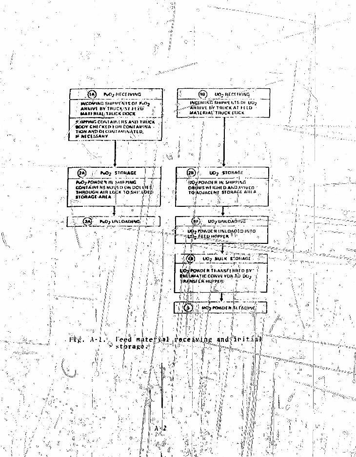
.'! IMCOVING SHli'V! AHhIVl 8V TfUlCK^T Ht&
(! MAT* R»Al,im)CK DOCK
COM A IM HS AM) THlfCK
I I* N1CI&SAHV
I
SfiSMIPWt f« IS OS UOj^atfirnvt UV 1K1ICK AT H I DMAURIAL THUCK t-OCK.
S 0
STOHAGE
fuOj fftwot^Tt) •smn-intG | |CON! AINf HS WOV't I> ON DOLlIu iTHROUGH AIR LOlpK TO SMI ibCDSTDHAOI AM(A ! " ' I f
rSIOHAGf
rq*ojAct*yr sio«Afii AIUA
ro/.ut H uMD,f.o: o INTO
.fr
r<«Ju J It— - J.. i 1

SIOKAGE
)•;> ;PuO? UNLOAQIfcU
p J f U INSM'll'PIMltCUNTAIMK M^VtOON POLlV IN10 COMPAHTMtM 1 OF PuOjUMOAtm.'i; M A!KJ\- i
?
1. tID ASM ISUllV 111 il'OVf of ' - \ | " , -J. AL^HASUHVI yt'l i;fC)HMID ,3 fAtititt) VltiMfl L'l l i t HIMOVIU ' V ;, _4. ALrHAit i l .ytfr i t i luir.uo It. VIN? VAtVl tibVI ii ANUWUSSUKl VI i!.t I H ANCE Hi MOVtOC AlPHAHMVE V flliiOMMlU7 CUMAINLh JALKIDUP 1O'.U.1I I'.l 111 &l Al, AKUDIMI) O»'tj5lMG JO COMPAHTMf NT 2I CUMf'AIHVi M I LJlXJHUt.-^ i) ' " ..." •
"IZ1 SIAI It) C.U1I H ( ;.', HI Tl Plly MCMSI O'JI >lh CO">)TAI^t'i«?*«Wf4^3r'VVon>ORAIt O^'tR TO
DOOM I OH LI..•» .1 M ' l f . f j „•.[( n .-.! lit I'UV nOiSl IN lUjXIUKAH TMLN.,1 3 - "--
I WSIUI
III I'llVIO ANU r.t K.lUUMHAt' AUtV
-*«itiifv.M" '• in."•.•.amiiuSIOI AI.I VI ..rtj
ihHlDTOCOr.1l>AI<lr/l f," 4 I (JH LMMf Al_IIOfJ A V I rhAI.MlK 10ifilSiCtH.ANl0USTVATn-l TTT-r.SVi-^a
FHCK'I^ICJI\ i.1 vAt^r ran c«a i f c'lfj^, r..(>? f<nvui n SWVPI is IN VIAI S AND ff.'f UVAI ICAI LVlHftr.tHHHI'»C VIALS, !O/iN/. lVI ' l 1! : S."VJ<-1 1 AOll lV iASM fOM AN/.IVSIS
I'uO? t.! t NUirjC ANO mjlH SIORAGt
;l r I'uO^ HUWUt H UUU K $ I OUAOt Vt i it-Li WMt n{ f OMUL H IS
*
i——f—rI ^ j .

required to unloading operatioiiss,_t4^keTe"li coirtainer is opened,!ar|d the contained PuO7 ^ajrtpled , and trans!- i
j^iijJ^GaJ;!;): to a blender-storage vessely After astorage vessel i s f i l led, the cdnt^^^WrW^'ntenucd, sampled for
onisa^ioni and certifi^d^By QC before release as feed m^jteMal f<>r enTichinent blending,, ," ^~-=^-: :::.--,- .. ~-:..-.\ _-_r:
:-',^l:4-
B_. Subsystems and Components1. PMO, Re&egiving and i natibrTXreq. ^The truek
dock" can accommodate only..a, siiThe area set aside for •decontamination has the fetjtiired \~^-":^^:~%..
s u p pi 1^3 y-t ncTi id ing., t he a pp^b^TSfe^a^c orrtrnn i n uistroiSSSSiAi ipiK I J;IT Z '.T^^-Jwipes , plaistic mat:eria^j^ajii^li|;s"g;Tiffbv"'c^ <t-ri"diJ- • ej'ifc4; r-' >JU ' '---"*'"-'"''\drum for s t o r 4 n g bagged con tami^a t fed^^ ipes and p las t4Gi» T a
a j - p r o i i r l a j e ^ r a d i a t i £ 0 j i p f l l t ^ i S ^ ^ i n ^ \ u a t ; a £ ^ ' i ^ / n cqulament. ._j\_..iL-. .-^>-~^/
age a r e a j ) rovides« s p a c e =;for . t h e ; I > ^
w e l l a s f o j ^ . . t t e ^ ; . % ® ! ^ " d i r t y sc rd |p
and. t J ^ ^ ' l l ^ L ^ L ^ l l ! i i J ' m : ' i :
...„ it^.b^1;,|;h,xv0,u:gh,:|:^e si
An. authorized person co!r|tVols.- oper;a^iionT&|^he;:s!u
;i =«-t:Qntents,v:__iIM^M4e4..g,Mp.p:iMi^^.^^^
it;aJ,^e3"^ompr.tseji,-,:fouj^;tira^i^P^^ift^^
mate 1 y =8
ifrar y:»p r e s s U£fi^bsjjeJj^J£jaj[^ ?^hji |23i^o^^ -9-Ip^ Uj= -JV4ili- i--leak - checking rYM$fejyy|iiJ^
="" "= ^ri41 = ^n" 'overprjek ]|cohf;aaIjn/^n-|!»vt-he-;-s'e^prtdary^^r8^.sure:
i:.t h.L- ;/. -. 1
'overprjek ] | ^
vesse l and. oute]r"]rack:3"§4;l|jjhe pttte^ :pafe^a£ef/ -Includes nuclear
'•••>:' 1-^'!
; jl _.
r~~j^:~

shielding and thermal control features.The overpack cover
with plug is sealed with a gasket.
A. Unloading Station. The PuO7 unloading station is afour-compartment, shielded, glovebox enclosure. Filter**" aii
is drawn through the enclosure and exhausted through absolute
Compartment 2
• A motorized monorail hoist-that positions:,
lowers, and raises,and which is operated by a hand switch.
• An-impact wrench, which is air-actuated by hand
switch; the impact wrench may be manually connected to the hoist
hTftk and can remove bolts from the shipping container lid and
the secondary pressure vessei lid*
Compartment 2 contains __
• A drum jack en which a shipping container is
recureJ; the- drum jtrck, activated by hand switch, raises the --
shipping container until it is sealed t_Q t.h& entrance of ComA, - —
partraent 3; Eenr.Ii> {Tile vices at the sealing point indicate when
a positive seal has been made. _ " N
Compartment 3 contains
» A motorized bridge crane.* operated by hand
switch, for canister uni^adinp, canister storage, and canister
rsrwv^l from storace*
• An impact wrench, lid-lift ing tool, and canister-
lifting tool, all air-actuated by hand switches and connected
tt5 tYic viiUIti J»OQK 5-y rCBSJXc tO33tT01. "
• A shielded and criticality-safe c^Tister storage
array fox 3tarir«£ ?s many as four canisxers-i sensing device*
indicate when the~stprage «lot is occupied.
Compartment 4 vbntalns-
• A jr,otcr-driven conveyor, activated by hand
?.v)trh, for trnn^porran^ a jingle canictier te C-JCH
loading operation; the"conveyor is reversible.
J i •
u_Kls "*—--
|
i. J - t-L.f
"pV Wgjgh scale fof reinoto readout of canister r
an;d fjjinal tare weight.A motpxiiejLu^aaister opener activated by hand
aii:ister must: be posiiione^ properly for the openeimotor to operate. ., 0
• An air-activa^e^Wani^by hand switch, for removing^anister lids, ih_ • A PuO, unloader inserte4Lby remote control intopowder canisters to transfer powder pneumatically to one ofthree PuO, storage ves^e^rs5. , - ?j - """===== ======---_^= • A mechanical, reversible conveyor^ =: ™
S. ^"^2 ^ e n ^ e r " S t o r a g e Vessels. These ve&sels^provide
Receive and accumulate I uO7 from the unloadingi ~~
the fbiTowing functions:•%\ Receive
™ - h station,
Store Put2 in large blends, s ^Supply PuOl to tlie fabrication process, :;,and
Provide sampling capability.slab vessels are provided. Vessel
controls interface w ith the batching controls for enrichmentiu. in n9rrflftf""o]ji!fWlB^ material
the fabrication process,jM¥^^the unloading s*ftt4^Jn, and a third; vessel i°s isolated
in the process 0f Mendingf and certifying material^. for" reTeaicT\ (e.;
L vessel cont^nTf «nre blep^i&d.=pjn>umaticallyo and eachvessel contains a bank f porous filters. Reverse-flow blow-back is provided -to the "filters and-operates intermittentlyduring the blending operation. The off-gaV from the vessel
through a backup filter and~a HEPA (high efficiency pa~-:E: AIE_) -ijL_l_tcr_ bfLTPT~e"- discnwrge into the plant off-gas \
system. A schematic of ar^neumat_ir transfer operation is shownin Fig. A-3. Weigh ielis are provided on each vessel for inventory purposes. __ JL" | ^
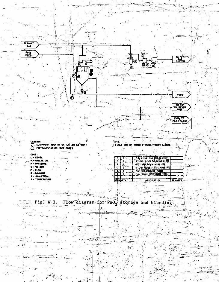
LtMW
d COUIMHEST iMNTiriUTioM civ terra*)IWNUMtNUTIOM (SCI COKJ
COM:L-UtVtt
W-WtltMTr-rtow
» - AMALYTtCM.T - TCMKMTUM
tfo(
J •:''
ITEM
1 ;'
1
Of TV
H%x WM-X UW nWmK IMf
kti imt.uk mm* mi«:i-5f mm. r>bj tttbuiiii mhit n» xitu'K him
• »,». «!;««! 1»»IVIIUM 1MWI
I PMCRIFTION «E"MKS
l ig . A-3r riovr diagram for"PuO2 stpra^e and blending.
^ V ,
t L I e
-X. ^ Instrumentation ahd Control .-.'j\ -—.-£—""The pTegence ,oiLs^shij)ping^ container js verified visually
in the unloading bc&, and by cdhtTines^d&ntification input.Confirmation,(of thje container iidjotitif ication and an
/ ••• ,'j • i « |; J^"'i'' '•• - ' ' ''••'
"occupied" indication^ attjLvlajLe^^e" mjWrail hoist, permittinglid removals and^p^rfiinr^f ^he secondary pressure vessel. Re-
'positioning of the opened container to the drum jack for elevartion to the second cora|artmeiit is confirmed by-a second positionindicator. The primary pressure vessel closure is removed andthe canisters ar« lTfied out by the^bridge crane. ^ 2 U11EE
Completion of ihe=canister removal operation is verifiedVisualiy at the^ sa^e^rrayjstorage; i'tW third compartment is ,then isolated by a, remotely actuated air-locjk^door. After iso-lation of the safe array storage, the bridge crane and conveyor^transfer the canistersl to weigh inland sampling areas.
Gross weight measuretHents-aremade arid compared toshipper's values. Out-of-limit weight differences are reportedand require management action before the perattein may p£oceed1 ?Individual nc?t weight confirmations, completoojL pirLiexiuirMLcanister operations,. and acknowledgment;! of sample transfers are ,necessary before the unloading bperaticj^ and Pup. transfer cancontinue. ;
c - '•l' : I, ^ - -• ;Interface acknowledgments are also required before tlie
transfer operations can begin. Confirmation of receiver vesselweight readout, inventory status, and transfer inputs must beacknowledged for each canister. The tare weight of each emptiedcanister must be confirmed before it can be transferred out ofthe unloading box.
FuO, is transferred to the blender-storage vessels by acti-vating routing valves from keyed lock-out switches. Once avessel has been valued to accept material, its contents cannotbe dischaj'ijed until'another keyed lock out has been switched byan authorized persoi|.
Supervisory action is required to change material routingbecause the routing jlvaillves are operated from keyed actuators.
"A-8
When the contents of a vessel have been discharged to the ;process, valving is switched to prevenCfurther discharge andto penult filling; material is introduced%nto the transfer sys^tern until the vessel is filled, after which the vessel is iso-lated and a blending cycle is initiated. Samples of the blendedproduct are extracted and transferred to the ASF. The vesselremains isolated until certified and re4«as-e4^bif-_Q£..After re- ilease, the material routing valves can be switched'arid the Pu52|discharged upon demand of the powder batching system.
D . O p e r a t i o n ; ~ 7 " ^ - ~ •--- "•• .. '""-- •• ..; " i ; :
the mode 6£ ops^iation for thciPuOi receiving, blending,and storage system intludes^direct handling Dof full and emptyshipping containers, gloved access for in-box operations, semi-
material movement, and p^ivel-controlled material trans-
1. IntroductioftTbf^Container, VV shipping^container istransferred from the secured storage area to_-a" self-propelleddolly fprxintroduction"lr»tpiJjJie enclosure where^eoiitainer iden-!tification is verified. Access to tlie unloadUfg- box is con-trolled by keyed switches with reRQte,
C r\ 2. Container Pilfering and Canister Removal. The top lid ^of t!k shipping container is remWili^and alpha-surveyed; cnlyriegiigible contamination is expected and defected areas arecleaned in place.TThe secondary"pressure;^vessel is then openedand survey and cleanup performed as necessary. /
The container is moved to a second position and is elevatedto the seal opening of the second compartment. The seal1 estab-lishes a negative pressure with respect £0 the first compart- 'ment. The repositioning is confirned by a position sensor ,yithlocal and remote readouts.
A bridge crane Manipulator in the second ccwpa t'nent re-moves the tc>p closure of the primary pressure vesj.^1 o, lowingaccess to the canisters. The canisters are lifted cur a^dplaced in a safe stores?, array in Compartment 3; afte" rcnoval
\,
of all four canisters, Compartment 3 is isolated from Compart- r
isent 2 to minimize back-contamination. The primary pressure
\ressel is closed, and the container is disengaged, surveyed,
and returned to the first compartment position where closure of;
the secondary pressure vessel ami the extenial^contLainer *s com-
:;/jjri_lB.t.e{L_: et-tirn"""D'"f the container to storage Tequires confirma-
tion of canister contents as itemized below.
3. Canister Weighing and Sampling. The canisters are
moved by the bridge crane through an air^lock^closure onto a
conveyor in Compartswfft" •" for transfer to a weighing area. Each
canister is taken through all steps, Including canister discard,
before the next canister is introduced. A canister is moved by
manipulator, from the conveyor to the scale, which provides both
local printout and remote input. The manipulator places the
canister back on the conveyor for positioningat t se next sta-
tion' fotlld removal and sasripling.^•"=T™7* ' C-^*^^""* '"•''
) At that station, the canister is fixed in place and the
lid removed by the remotely operated tool. A powder sample is
remotely withdrawn to a sample container and transferred via
pneumatic tube to the AS§. A second sampling^system permits
pc riouit- extract|on of larger quantities of powder as feed foi
pilot fabrication testing.
4. P u C Transfer and Waste Discard. The canister is con-
vcyed to the powder transfer system. The intsrfece with the
blend-storage module is cons»lted to confirm that the following
conditions are satisfiedLto permit initi?tion'vi transfer:
"•::~"-r""' « Confirmation of shipping container net weight,
\ « Confirmation of sampling,
• A canister is positioned in the transfer systssr.,
•\ Pneumatic transfer system /;r:lows and -pvessisr-..".?
y-\ setpoints are satisfied,
• ,\ The selected storage vessel is below *ts high
value setpoint, and / |
• j The routing vafvei,* positioned to the selected. i • •" \ , ' " -
\ •;' '• .--essel. '
I
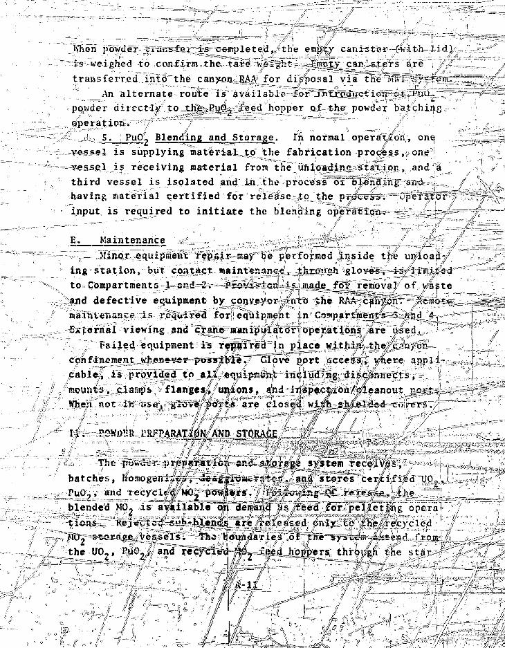
When powder zzi*m>lei ~is completed, the en%'cy canister (v.ith lid)
is veighed to confirm the tare weight .I-ranty can'.s^rs are
transfeired into the canyon RAA for disposal via the M'A'I -•;'=*?&.'
An alternate route is available for .introduction of PUU~
pohder aiiectly to th^-PuCL, x'eed hopper of the powder batching
operation.
5. Pup'!, Blending and Storage. In normal operation, one
vessel is supplying matt-rial to the fabrication process, one
vessel is receiving material from the unloading station, and a
third vessel is isolated and in the process of bXendi.ng and
having material certified for release to the process. Operator" "
input is required to initiate the blending operation. — -7-=; \
E. Maintenance /
Minor equipment repair say be performed jLnside the unload-7
ing station, but contact maintenance, through gloves, is, limited
to Compartments 1 and 2,- -Prova>icR i« Jiwide for removal of viste
and defective equipment by conveyor -nto the RAA cafiydn. Rerre^
maintenance is. required for equipment In Compartments 3 and 4.
External viewing and crane manipulator operations are used,i /,
failed equipment is repaired in place within the/c- Vijon
confinement Kh£ney«r-possible7 ~Glove port access, v/nere appli-
cable, is provided to all equipment including di.se/nnects,ll £
mounts, clamps flanges,., unions, and irispection/^ieanout ports'I if // // •*
When rot in t*s } glove"; ^o?t* are clos iJl wi0j shi-el^d copers.,,// /' ' . I /
i ; . POWDl'R rRi:PARATj(riN/AND STORAGE//'/
The
batches, y |PuO ? , and recycl«j<<|j /MO^powtUrs. / ^sX
b l d d M0 i " i l b l ! h " l ! d
and- stojragie _syStem Tec©iv^s,
/ ' ' ^ stores cer^cifi^d UO,
^ the
lblended M 0 2 is" available o!h"l!eii?and |isyfeed for pel/|e"t»ng opera-tions. Reje^tc^ £ « ^ - M * n ^ ire/released <inly tp he/recycled>IO storace vessels The b o n d a i s "f " T n * y s i ^ j t d i'storage vessels. The boundaries of prrySvuiB -tetfiaii i'roxi
the UO,, PuO./ and recfcle^-|4t. feed hoppers throvftK the
/ '/ : •

MO, powder storage silos. A schematicof the MO, powder blending system is sn3ow°n in liy. A-4, and
A-5 shows a block diagram of the.,system.
A. General DescriptionjaifcJlQ^-.is,i, required for production, the
i==tfhree components--U02» PuO,, and the recycled MO, powder re-quired for, the batch--are calculated and programmed into thebatchrcontrbj system. Control logic activates the proper equip-ment to prepare the batch. This is accomplished by filling thefeed hopper for each component to a predetermined povder level,then transferring the required weight of each powder componentfrom the Respective feed hopper to its weigh hopper. Predeter-mined quantities from each weigh hopper are transferred intothe blender, and operation of the blender is Initiated.
h'hen a sub-blend of MO. powder is uniformly blended, it isdischarged through a reduction mill, sampled5 and pneumaticallytransferred to one of nine MO. storage silos. Sub-blends re-leased by QC are fed to the pelleting operations. Reject sub-blends are pneumatically transferred to one of three CSRS stor-age vessels.
B. Subsystems and Components1. Mixed-Oxide Batching. This subsystem interfaces with
the Pu(>2» UO,, and recycle MO, feed material storage vesselsand performs the following functions: \
(a) U02, PuO2, and recycle MO2 feed hopper charging,(b) UO,, PuO_, and recycle MO- weigh hopper charging,(c) U02, PuO2, and recycle MO2 weighing, and(d) MO2 enrichment blender charging.
The batching system control logic activates and controls theappropriate equipment
a. UO,, PuOPowder is transferred
"or each sub-blend as described below.and Recycle MO, Feed Hopper Charging.
from a storage hopper to the correspond-9 *.
ing feed hopper as directed by the batch control system.
A? 12
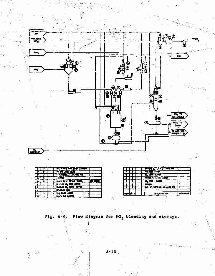
.jus*
"Ms*m
1
"111I+
ItfM
m-m nc.[i.«;i tumtt m
kftam MfiiMia ,'•!} HiJ MMM| IP WW
— - —
Fig. A-4, Flow diagran for M0 2 blending and storage.
A-13

AMD"BULK'STORAGE
^ ) uo,BULK STORAGE
V\ \ZS ' a'", PC.'2E« BLESOIV.
PuO», UO, . A H 9 | »ECYCL£D
kf. L C H M^fft-S F I U 5 D WITH I?0n BATCH C:SU:L
1IT«
1PuOj, UOj, AW »fCVCLCOntNOEt » O » A ! t
1« 0 j M.eM>C4 0PEV.TE3 TOU Pf i£DETEWI«9 TIME
H0? INSIDE HO2 BLENDER Q.^nA-SCANNED Br f IKED[AT TWO 8L£N0£< LOCATIONS TS VERIFY y«IfOfWITY OF BlEf.D
I[6J H0? fOWOEB
MO, POWOEX (2;j kg PER SATCN) TRANSFERRED THROUGH POWDERREDUCTION KILL TO ROUTED
HILLEO M0 2 POWDER SAHPLtS COLLECTED PERIODICALLY IN VIALSANO VIALS PNEUMATICALLY TRANSFERRED TO ASF FOR ANALYSIS
1MOj POWDER TRANSFERRED BY PNEUHATt^COKVEYER TO ONE OFMINE MO; STORAGE SILOS SELECTtO BY ROUTCR WHERE POWDERIS WEIGHEO AND HELD UNTIL QC RELEASE
\ iM02
Fig. A-5. AO- powder blending.
A-14
_ ^ ^ . _ _ _ ^ -._ • - 7 ^ . 1/ ~

to their passive mode. The ?feed hqj
quantity of powder than is required.
The following conditions and sequence of events are required
for this° transfer:
• The rate feeder is off,
• The weigh cells of the feed hopper indicate that
the required powder weight has not been reached,
o • Tche unit vacuum conveyor* is actuated,= ^,
-» • The storage hopper discharge positive^j,hut-*6TT
^ va've is op^n, anl ,-=«''^
• The .storage hopper==i>=i=ir==Sctivator and rate feeder
1 All ,deviceyr=tfre actuated by the batch control system when
it receives the coirmrfhd t;o,eharge the feed hopper. Transfer.-
continues until the powder weight in' the feed hopper has been
reached, at which t i m e ^ h e batch doiljtrol Soys'tegn shuts-down the-
transfer of powder, restoring allo intervening autonatic devices
per is charged to a larger
for one b,atch. This powder
transfer may be performed with manual "controls.
\ b_. U 0 2 , £uO,» and Recycle MO, Weigh Hopper Charging.
After the\ feed hoppers of all three component (U0,» T'uO^t and
MO.,) powders afe fully charged, the batch control system inter-
locks will permit the charging of the UO,, PuO,, and MO. we°igh
hoppers if the folloKing conditions exist: &
9 The enrichment blender has been discharged since
the lsast fill-discharge cycle of the weigh .oppers (to prevent
double charging of the blender),
• The positive shut-off discharge valve on each ;
weigh hopper is closed,
= • The U02 dual-sequencing isolation valve is closed
(this valve allows transfer of U©2 into the RAA between the
weigh hopper and the blender), and
• The weigh hopper load cell calibration
been completed. / °<o
When the signal tor l6ad=the weighiilmnuers is received, allscrew feeders are startedweighing system indicates
at full speed. As each w
that its hopper has received most of
A-15

its scheduled material , the respective screw feeder switch/s to
low spged/'and stops when the required amount of material lias
been received. —,,... 4After charging of the weigh hopper© is completed, operator
action Is required-before the batch control system will permit
discharge into the blender. Moreover, blender charging can be
initiated only if each of the three weigh hoppers possesses the
weight of powder that had originally been programmed into the
batch" controller.^*
The contents of the UO, weigh hopper, located in the l.AA, " /?
are discharged incrementally by gravity into the blender'via a
dual sequencing isolation valve. The blender discharge valve
is in the off position, the positive discharge shut-off valve
of the weigh hopper is opened, and the vibrator is actuated.
When all of the UO, has been transferred to the blender, the
hopper viitratoris deactivated, the hopper discharge and isola- c,
tion valves are closed, and the^oi^h hopper is reweighed to
assure complete transfer. " V1'ie contents of the PuC, and recycle MO, weigh hoppers are
discharged by gravity into the blender. The blender discharge ' ?.
valve is in the off position, the positive discharge shut-off
valve of each weigh hopper is opened, and the Vibrators are
actuated. .When allof the PuO, and recycle MO, has been trans-
ferjred to th=e^blender, the hopper vibrators arc deactivated,
thejvbpper discharge valves are closed, and the weigh hoppers
are, recalibrated to assure complete transfer; * ;
2. Enrichment Blending. This subsystem receives UO.,
PuO2, and recycled M02 powders from the weigh hoppers, pneumat-
ically blends the three powder components to a homogeneous mix-
ture, and discharges the blended mixture to storage.
a. Enrichment Blender. The blender is, a rectangular-
shaped, criticality-safe, stainless) steel slab vessel with a "b
V-shaped bottom section. A timing device actuated at the con-
troii panel automatically initiates all powder blending events
for a specific;; time interval. At the completion ofthe blending
i1 ' • • , • \ ]
1/ ! - A - 1 6 .- - — -.. •.,«

cycle, t!ie timer shuts off and the events previously "described.-"1 o //
for powder discharge are automatically actuated.
(ontrols are programmed so that discharge valves to the
weigh hoppers are opened only when powder transfer from the en-
richment blender is complete and the blender discharge valve is
in the off position. Powder discharge fror: the blender cannot
occur until PuO, and UO, for MO,) powders arc charged to the
blender. This is "to prevent undiluted PuO, from being charged
tqvthe storage silos. Manual overrides arc provided for ab-
norral conditions.
A cyclic timer uith a fixed cm time and interval time pro-
vides control of pulsed air to the porous filters. Overrides
perr.it the blender blow-back systen. to cle^m out and operate
under emergency conditions. A pressure differential sensor
located in parallel with the porous filter elements indicates
filter blockage or breakage. A pressure relief device prevents
vessel overpressuriratjon, and off-gases from the blender are
vented to' the off-gas system.
«\ Interlocks shut down upstream operations (weigh hopper dis-
charge valves), blender operations, and downstream operations
(rate feeder, reduction mill;) if the dijichiarge valve is not
positioned properly. IShis 'valve has aSagiuRjial override^^^——*""'
b. Hate Feeder. The ra;e fe^d^mafor interlocks5^'
with the pronrarame<l_ .on-t-rc-lY"-Tfi'"operations immediately upstream
(previously described) and operations downstream so that the
feeder will not operate if there is a malfunction to the equip-
ment involved in those operations. If the rate feeder malfunc-
tions, these interlocks shut down equipment immediately upstream
and downstream of the feeder until corrective action is taken.
The rate feeder has manual overrides. {>)
3. Milling, Sampling and Storage. This subsystem mills,
samples, and stores sub-blends of MO, powder from the enrichment
blender. Nine storage iio*,nroAUde_s_ufficient stpxage for
powder to be avaJJ._ab_le iit._xhei,TAtft=ie.qulT.&dJ4o-KnsXTeaBi*.rfi:-----T-iv-i:-s -
subsystem interfaces with the pelleting operations compactor,
A-l
CSIJS vessel^, ASF transfer system, and the pneumatic transfersystem. .. "'. „.-. — s , - - • •
When a sub-blend of MO, powder is uniformly blended, andready for release from the blender, one of nine MO- silos isselected for storage. Diverter valves in the pneumatic con-veyor, which routes the powder from the powder reduction mill,are positioned to allow flow to the selected silo. The blenderdischarge valve is opened and the reduction mill drive and ratefeeder drive are actuated for the interval required to com-pletely empty the contents of the blender and rojLll. The dis-charged milled MO, powder is transferred to the silo via thepneumatic conveyor. A weigh cell system indicates the tareweight of the empty silo assembly and the gross weight of thesilo and powder when the silo is full.
Samples of milled powder are extracted from each sub-blendat the discharge of the reduction mill by means of a presetperiodic sampler. The sample containers are placed in a specialconveyoi container and dispatched via pneumatic transport, con-veyor to the ASF.
The results of the sample analysis determine the disposi-tion of stored powder. If the sub-blend is within specifica-tion, it is released for pelleting operations; if not, the sub-blend is transferred to theaclean scrap storage vessels.
a. Reduction Mill, the reduction mill is locatedimmediately downstream from the rate feeder and interlocks withthose upstream control functions described in the enrichmentblender subsystem, The ai11 and pertinent upstream equipmentare controlled on a specific time cycle; failure of any pieceof equipment will "result in"'tKe=Tn"u"tclown~ o"f~'"the other equipmentcontrolled b> the same time cycleV This applies to downstreamoperations, i.e., pneumatic conveying, sampling, and divertervalve positioning on the silos. The mill has manual override.
b. Powder Sampler. The MO- powder sampling deviceis programmed—toextract several samples from the discharge jofthe reduction mill. Samples are accumulated and placed in a
A-18
container, manually transferred, to a sample pneumatic station,and pneumatically transpprted to the ASF.
The sampler is programmed on a time cycle. During powderdischarge, the sampler extracts a single sample within a. presettime, holds for a preset time, extracts the second sample,holds, etc; After powder discharge is completed, the samplercycles for a preset time and then shuts^off. Any malfunctionin the immediate upstream operations will deactivate the sam-pler. Manual override is provided.
c. Storage Silos. The nine MO- powder storage silosare stainless steel slab vessels equipped with valve'd dischargeports, heigh cell systems, filtration system, air pads, andpneumatic vibrators.
Routing of sub-blends through diverter valves to the stor-age vessels is performed manually fron keyed^activators. Thisguarantees that ah authorized p'li er srrvisC take positive actionto change a material routing path and to allow powder transferto occur. The position of the diverter valves during operationis monitored by indicator lamp. The position of a divertervalve must mesh with the charging end of the selected silo orpowder transfer is blocked. Once a silo is filled, a lock-outswitch prevents further powder from being charged to that silountil the silo has been emptied.
A weighing system on each silo is provided for inventorypurposes and to determine when powder discharge is complete.Hide-out detectoi5 may be required to ensure that no significantquantities of powder remain in the silos.
C. Instrumentation md ControlValues input tu the batch control system activate and con-
trol the proper equipment for preparing each sub-blend. Thebatch control system directs all activities upstreamofrom the-enrichment blender, v The processing equipment (including theoff-gas system) is controlled to ts top under the following condi-
tions : ! " * . V - 5 - • • ••'• - . ''••• <\
A-19
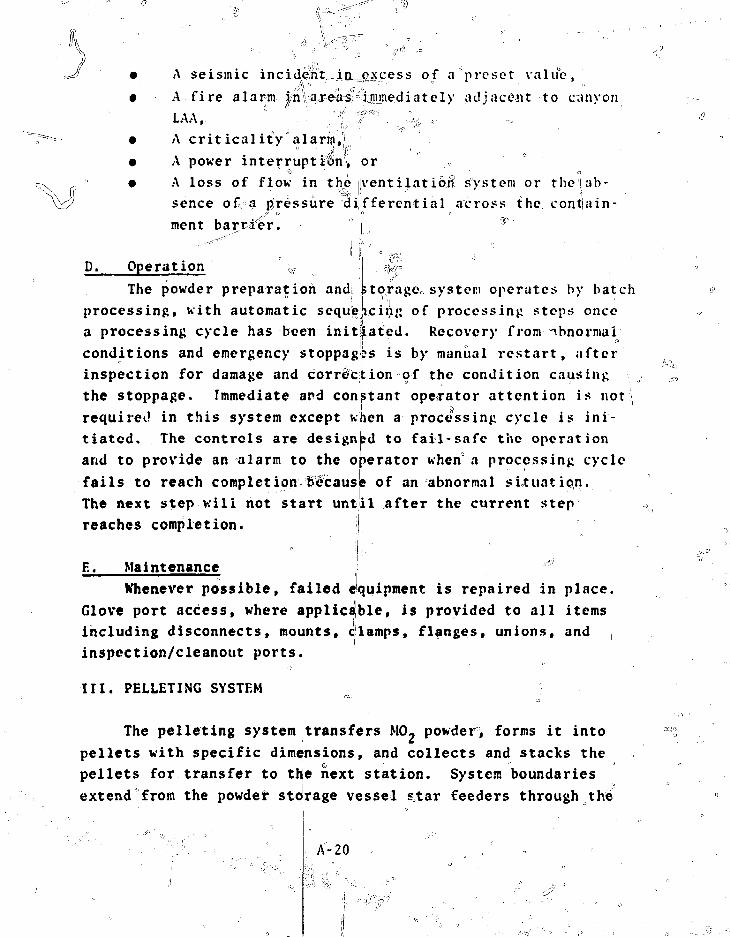
• A seismic
• A fire alarm
s of a'"preset value,
adjacent to canyon
• A criticality "alarm'.,').,.
• A power interrupti&n, or
• A loss of flow in the [ventilation system or the'lab-
sence of. a pressure differential across the contiain
ment barrier.
D. Operation «
The powder preparation and" '!
processing, with automatic sequei
storage system operates by batch
icing of processing steps once
a processing; cycle has been initl' at' d. Recovery from abnormal
conditions and emergency stoppag
inspection for damage and corre-c>s is by manual restart, after
:ion of the condition causing
the stoppage. Immediate and constant operator attention is not
required in this system except when a processing cycle is ini-
tiated. The controls are designed to fail-safe the operation
and to provide an alarm to the operator when a processing cycle
fails to reach completion because of an abnormal situation.
The next step will not start unt
reaches completion.
il after the current step
E. Maintenance
Whenever possible, failed equipment is repaired in place.
Glove port access, where applicable, is provided to all items
including disconnects, mounts, clamps, flanges, unions, and
inspcction/cleanout ports.
III. PELLETING SYSTEM
The pelleting system transfers MO. powder, forms it into
pellets with specific dimensions, and collects and stacks the
pellets for transfer to the next station. System boundaries
extend from the powder storage vessel sctar feeders through the
A-20

boat loader. The off-gas system is also included in this area- of-the,-plant.. '- • ,,/ Q " ' ;,_ .. . -"-
The pelleting system consists of a compactor feed hopper,compactor, weight-sensing platforms, separator, powder lubricantfeeder, rolling dram, bulk; density, check, press feed hopper,pellet press, ribbon conveyor, gfAe6n density inspection appara-tus, boat loader, backup filter^ off-gas blower, and associatedinstiHimCTttation and controls for each of th%se components. Aschematic of this system is shovm in. Fig. A-6 and a block dia-gram is given in Fig. A-7." \
A. General IJescription~7 "The pelleting system receives blended MO, powder, precom-
pacts—it, granulates=the precompacted material, and separatesthe fines ffbin the granule stream for recycle. The granulesare conditioned by rollin^with^lubricant§ sampled for bulk den-sitXi an4.f^ to;tf lopper. Process feed sis dispensed to thepellet press. The pellets^are conveyed away from the press,sampled for density, collected, and stacked into sinteringb o a t s . •'•""""" '' •. , ]-,.s ' ,, iK\ ; >
B. Subsystems and Components
1. Compactor Feed Hopper. ?to>t?ing valves serving eitherside A or B "are manually operated within the RAA through gloveports. A selector system, accessible only to authorized person-nel, has position indicators which must match the valve positionor the silos will not discharge tgv^the vacuum transfer system.
The feed hopper has level fensors which control upstreamand downstream equipment by means of the following signals andcontrol functions: ^
+* Hl'HI limit — shuts off the discharge system fromthe powder storage silos to the vacuum transfer line and ini-tiates an alarm; ,, " |
• HI limit--pjroyides visual warning that the sys-tem is approaching HI-HI shut-off;
A-21
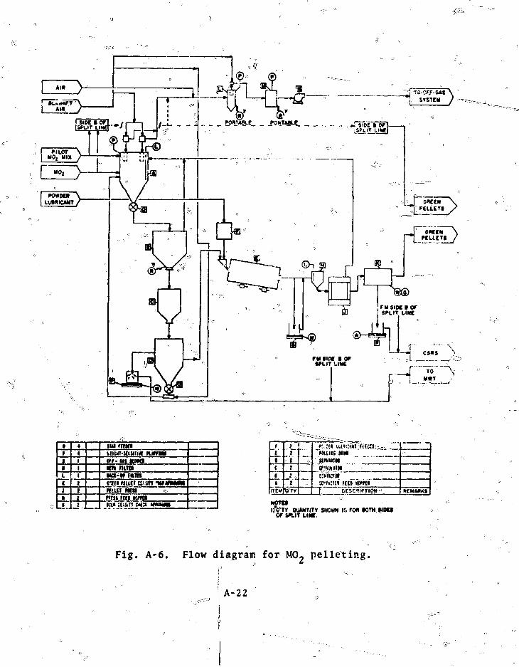
1
4«1I111I1
sui nnniiicnT-stuiiiM Kamae»»- CM M t aKM ramMCI-W nunciti mm cji.sm -w«MMtmm mtt .ncu rat ncmt•Lit ;ni.i» ana tmtmt
r
t{
1>
ITEM
|
1tiI
Vrr
»:.:t« uvsi•HUCC MMUMtKNCf^DKIMC7WMCTMKff»:tt« ftfin m m
REMMXS
NOTE*DO'Tf OUANTITY SHOWN IS fOfl KITH WDM
or P U T LINE,
Fig. A-6. Flow diagram for MO- pelleting.
A-22
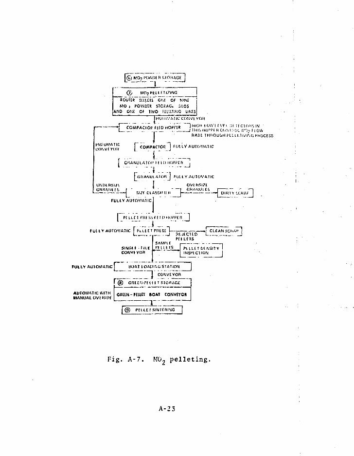
I © M0? IW.!>£ R SlOUAGtj
Q) MO?PtUFTI?ING
ROU1IR lUtCIS ONE OF NINE
MO i POWEtR SICRAC. 111.05
AKD ONE Of IV/O P£LLS!!NG UKES
J f M ll.VA JIC CONVl VOH
-i COMPACTOR MID ~ " ) M I « H I O W ' I F V F I . :;i u c i O H f i IN".',IZ I THIS IIO"I-I H C ! ; \ l \:<jl !,•';•. I | OW
HAT I 1MHOUGH('ELU.ll?l"r;UI'MOCESS
PM;UMATICCONVI YOU
r: T , .I COMPACTOR J f l ) lLV AUTOMATIC
f C'.ANULATOK I I lOHOW'IH ~j
[CillAfJULAUJfi J FUll V AUTOVATIC
?l I OVIHSI7E
1 S U ( ClASSIMI l< I «j UIRTV i.CHAt' j
fUlEV AUIOMAltcl
f Pi ini Piussr f i nHOPPER I
f UHV AUtO'.iATIC Fl ' tLUT PfUSS~l
S I N O I F • F I I E
_ — . ) CLEAN SCIi^nut CUD iPELLfTS
SAMPl E , ' ,PHiEIS PELLET OIN5ITV I
INSI'fCTION I
FUILY AU'IOMATIC BOAT lOAPir.G STATION
~~\ CONVEVQR
OfiElfJ-PEil tT S
l @ PELLET SINTERING
Fig. A-7. M02 pelleting,
A-23

• Upper \leyel--turns equipment'on from LO-LO limitshut-off;; powder lubricant is introduced after a time delay;!!
• Lower levels-turns equipment on from HI-HI limit
• LO limit--provides visual warning that the systemis approaching LO-LO shufe*off; \ I
• LO-LO
feeder (after a time delay), andactivates an alarm. , " fNOTE. The above limits are adjustable and may coincide.
..Th compactor, star feeder, powder lubri-cant, grlnulator, separator, and feeder are all controlled as a
^jujigleTXinyt uhless otherwise specified. Compactor pressuresajre manualff controlled. ... ~r :" f\, ''''''( v'
The °cpmp|c,tpr drive motor(s) have manual speed adjustmentsand are^located in thjs Lkk, driving through the containment wallMy means of rotary seals. The:systeUtpressure and the power in-
to thep^ocess drive mechanisms aye indicated on a pari,©! orerwis^tfffplayed. , - .»,_."- _.i,rilM»-»-
i;i"-"lir"*;:I'"1"" " ':i
sys|em RAA. Vacuumis intYOdM.ceSpf,SiougJi'•""lUie compactor feeH hopper^ which collectsarid^recyc'les entrained dust. The vacuum system is designed tomaintain f minimum of 1 in. water gauge vacuum in all of theequipmen't;''it
The following equipment is internally connected to, thevacuum system:J\j^ *>:': .... i; ; "
x ° ••"•- • A Compactor, ' _ —-—j % Granulatcr.,
* Separator,• Oversize particle container, and
==&=~-^,_- •= ; Roiling drum.3T: MSKfeElal^Scnsor Betweeij Compajctor and Granulator. The
material se^SOXJ d«=t«ctrSl;eXc?ss nfaterial that may bridge theand clause" a jam. =l^en it detects this condition, the
A-24

" " sensor shuts down the compactor and star feeder and ajptivates° i ° j' •
an alarm. I4. Granul^oY. The granulator equipment in contact with
M02 is of stainless steel. A shroud provides for internal in-v spection and periodic cleaning.((
Ventilation within the unit is held at a negative pressure
ff£SSSS3S5_provided through upstream equipment.1 The drive Motor is located in the LAA, and rotary seals
: - surround the drive shaft where the shaft extends through thecontainment wall. —=
5. Weight-Sensitive Platform; Oversize Particle Detector.The weight-sensitive platform in this contaminated scrap streamfrom the separator is used to detect a possible malfunction inthe granulator and the presence of excessively large MO. parti-cles in the product. The upstream equipment, including the com-pactor and star feeder, will not operate if a scrap containeris out of position. During operation, material flow into thescrap contained is sensed as soon as possible and a signal im-mediately stops the compactor and star feeder. The signal alsoallows the granulator and separator to rui« for a preset time toclean out the granulator for repair and to clear out-of-specification feed material from the separator.
6. Separator. The separator consists of three segregatedchambers and a sealed scrap collector which is placed on aweight-sensitive platform. The first chamber separates oversizegranules from the product stream and routes them to the scrapcan. The second chamber transfers the properly sized productgranules downstream but intercepts any flues. The third chamberreturns the fines to the compactor feed hppper through a rotaryfeeder valve to maintain the negative pressure in the system.A cleancut port above the rotary feeder valve is used to emptythe equipment.
The product granules are fed to the rolling drum. Inletand exit connections and chamber seals ensure that negativepressure is maintained butfunctions.
A-2S
do not interfere with separator

7. Powder Lubricant Feeder. The powder lubricant feederis controlled automatically in sequence with the compactor. Anadjustable time delay with manual override is included in thecontrol circuit to permit process material to enter the rollingdrum before the powder lubricants i* added. Delayed stopping bythe same time delay is included in the control circuit to assurelubrication to the material In process.Speed adjustments onthis feeder are performed nsnuaiiy.
A level sensing system in the feeder hopper has the follow-ing level adjustments:
• LO-liBit--actuates^a visual-warning' that LO-LOshut-off is being approached and provides recovery from LO-LOshut-off; o
• JO-LO lirait--shuts down all process equipmentbetween and including th<t star feeder to the compactor and therolling drum.
8. Rollin£ Drum. The rolling drum is controlled in paral-lel with the compactor and is designed to roll the product fora specified retention time; the time is manually set and ad-justable.
Internal ventilation maintains a negative pressure thatoriginates upstream and travels through the process equipment.
The complete unit can be emptied conveniently during runoutand enrichment changes. The drum is of stainless steel.
9. Bulk Density Check Apparatus. The bulk density checkapparatus is set to perform two functions between preset densitylimits (by weight}, which are obtained from a known constantvolume sample:
' (a) Over or under set limit--recycle immediately witha visual indication of the density,
(b) Sesond test(1) If the density is acceptable, operations
continue normally;
A-26
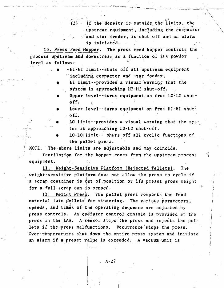
- • • • < - • • « : • . < : . . . * * '
(2) If the density is outside the limits, theupstream equipment, including the compactor
° and star feeder, is shut off and an alarmis initiated.
10. Press Feed Hopper. The press feed hopper controls theprocess upstream and downstream as a function of its powderlevel as follows:
, • °HI-HI limit--shuts off all upstream equipmentincluding compactor and star feeder;
• HI limit--provides a visual warning that the=. system is approaching HI-HI shut-off. ,
••• Upper level--turns equipment on from'LO-Ld shut-;: • - o f f . ^ „ ' ; • °- ' • ^
• Lower level--turns equipment on from HI-HI shut-off.
• LO limit--provides a visual warning that the sys-tem is approaching LO-LO shut-off.
• LO-LO|| limit-- shuts off all cyclic functions ofthe pellet pre.'-j.
NOTE. The ai\ove limits are adjustable and may coincide.Ventilation for the hopper comes from the upstream process
equipment.11. Weight-Sensitive Platform (Rejected Pellets). The
weight-sensitive platform does not allow the press to cycle ifa scrap container is out of position or ifa preset gross weightfor a full scrap can is sensed. •
12. Pell|t Press. The pellet press comparts the feedmaterial into pellets' for sintering. The various parameters,speeds, and times of the operating sequence are adjusted bypress controls. An operator control console is provided at thepress in the LAA. A sensor steps the press and rejects the pel-lets if the press malfunctions. Recurrence stops the press.Over-temperatures shut down the entire press system and initiatean alarm if a preset value is exceeded. A vacuum unit is
A-27
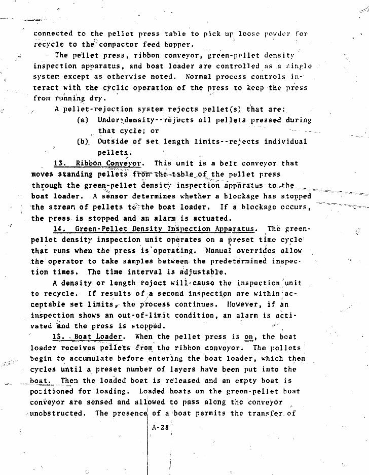
connected to the pellet press table to pick up loose powder forrecycle to the compactor feed hopper.
The pellet press, ribbon conveyor, green-pellet densityinspection apparatus, and boat loader are controlled as a tunj'lesystem except as otherwise noted. Normal process controls in-teract with the cyclic operation of the press to keep the pressfrom running dry.
r A pellet-rejection system rejects pellet(s) that are:(a) Undertdensity-rejects all pellets pressed during
that cycle; or(b) Outside of set length limits--rejects individual
o
pellets.13. Ribbon Conveyor. This unit is a belt conveyor that
moves standing pellets ffoir^th^M^ahlfiupf the pellet pressthrough the green-pellet density inspection apparatus t o - i h e ^boat loader. A sensor determines whether a blockage has stoppedthe strean of pellets to the boat loader. If a blockage occurs,the press is stopped and an alarm is actuated.
14. Green-Pellet Density Inspection Apparatus. The green-pellet density inspection unit operates on a preset time cyclethat runs when the press is operating. Manual overrides allowthe operator to take samples between the predetermined inspec-tion times. The time interval is adjustable.
A density or length reject wilicause the inspection unitto recycle. If results of a second inspection are within ac-ceptable set limits,, the process continues. However, if aninspection shows an out-of-limit condition, an alarm is acti-vated and the press i,s stopped. ^
15. Boat Loader. When the pellet press is cm, the boatloader receives pellets from the ribbon conveyor. The pelletsbegin to accumulate before entering the boat loader, which thencycles until a preset number of layers have been put into the.J?oa_t. Then the loaded boat is released and an empty boat ispositioned for loading. Loaded boats on the green-pellet boatconveyor are sensed and allowed to pass along the conveyorunobstructed. The presence of a boat permits the transfer of
A-28

pellets into the boat. 0 Indexing is done by stepping motor, andalljQjcher motions are initiated by air actuators. When one stepin the cycle is sensed, the next step is initiated; time delaysare included where necessary. • * «
A weight-sensitive element is provided for a pellet recep-tacle that catches errant pellets. When the receptacle hasreached a preset weight, the pellet press, ribbon conveyor|green-pellet density inspection apparatus, and boat loader areturned off and an alarm is actuated that requires the operatorto empty the container, replace it, and restart the system.
16. Backup Filter, The backup filter xoiisists of a geo-metrically favorable steel filter housing. The internal filtershave blow-back capability and provisions for collecting accumu-lated material in a standard clean scrap container. The backupfilter serves the powder transfer system and acts as a pre<filterto protect the HEPA filter.
•"••'••'••"••••'••••"-The---eontTiPli,.consist o f : ^
• Switches, control indicators, and alarms locatedat the local control station;
• A hand switch override for maintenance; activat-ing controls for the sequential filcer blow-backsystem are interlocked so that the system blowermust be in operation to permit activation;
• A low differential pressure 3larm to indicatefilter failure;
• A high differential pressure alarm to indicatefilter plugging;
• Neutron hide-out detectors and alarms to detecta buildup of SNM.
Blow-back valves close on failure: all blow-back is shut offin the event of a power failure and when the timer is shut off.
17. Off-Gas Blowerij. This continuously operating blowercirculates the air in the primary transfer system. It providesthe primary air flow forj the transfer system. Air from thetransfer system is returhed to the RAA atmosphere.
A-29
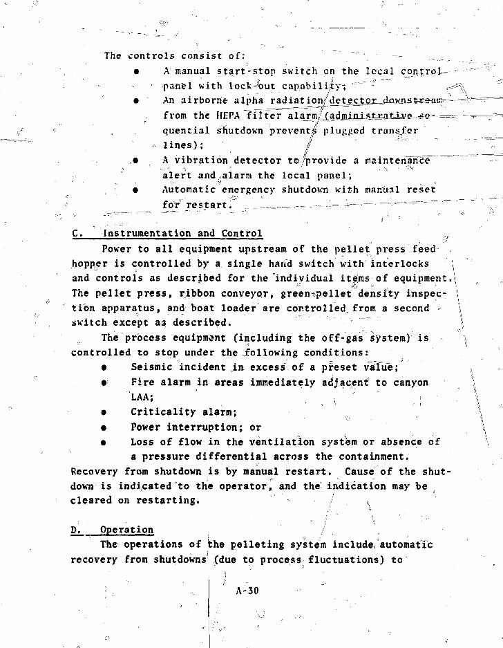
The controls consist of: — ^• A manual start-stop switch on the lccal controJU
panel with lock-"but capabilLty;
• An airborne alpha radiat ion£d j e£tor=dAiv'rist ean>-
from the HEPA filter larmiiquential shutdown prevent^ plugged transfer
o lines); ' / '• A vibration detector to/provide a maintenance"""^
alert and alarm the local panel;• Automatic emergency shutdown with mantral reset
for restart. _. _...__ ...,.m, -. -,--=-—-——=—-"--••="=-——- - - ^
C. Instrumentation and ControlPower to all equipment upstream of the pellet press feed
hopper is controlled by a single haifd switch with interlocks \and controls as described for the individual items of equipment.The pellet press, ribbon conveypr, green«pellet density inspec- \tion apparatus, and boat loader are controlled from a second \switch except as described. " \
The process equipment (including the off-gas system) is \controlled to stop under the following conditions:
• Seismic incident in excess of a preset value;• Fire alarm in areas immediately adjacent" to canyon
LAA; ' ^ - * , = .. \• Criticality alarm; \• Power interruption; or \• Loss of flow in the ventilation system or absence of
a pressure differential across the containment.Recovery from shutdown is by manual restart. Cause of the shut-down is indicated to the operator, and the indication may becleared on restarting. ^
D. Operation /The operations of |the pelleting system include automatic
recovery from shutdowns!(due to process fluctuations) to
A-30
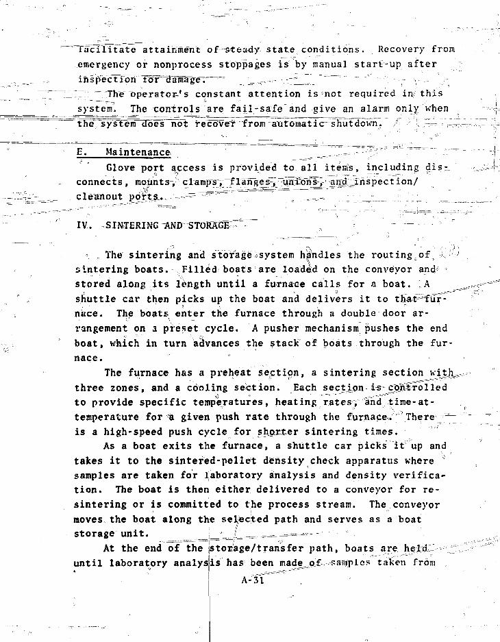
facilitate attainment of=stea4y state conditions. Recovery from
emergency or nonprocess stoppages is by manual start-up after
77 "The operator,'s constant attention isnot required in this
system. The controls are fail-safe and give an alarm only when
the system doelTnbt recover from automati e shutdown.
E. Maintenance ^-=^ -^ "
Glove port access is provided to all items, including
connects, mounts,
cleanout
IV. „
The sintering and storage^system handles the routingoof
sintering boats. Filled boats are loaded on the conveyor and/
stored along its length until a furnace calls for a boat. A
shuttle car then picks up the boat and delivers it to thatPifCfr-
nace. The boats enter the furnace through a double door ar-
rangement on a preset cycle. A pusher mechanism pushes the end
boat, which in turn advances the stack of boats through the fur
nace.
The furnace has a preheat section, a sintering section
three zones, and a cooling section. Each secxipii is eggSrolled
to provide specific temperatures, heating rates, ahcf time-at-
temperature for a given push rate through the furnace. There ~
is a high-speed push cycle for shyoxter sintering times.
As a boat exits the furnace, a shuttle car picks it up and
takes it to the sintered-pellet density check apparatus where
samples are taken for laboratory analysis and density verifica-
tion. The boat is then either delivered to a conveyor for re-
sintering or is committed to the process stream. The conveyor
moves the boat along the selected path and serves as a boat
storage unit. 1 _|^==^^===—«==="
At the end of the istOEage/trarisfer path, boats are 0
until laboratory analysis has been made^qX. samples taken from
A-TT
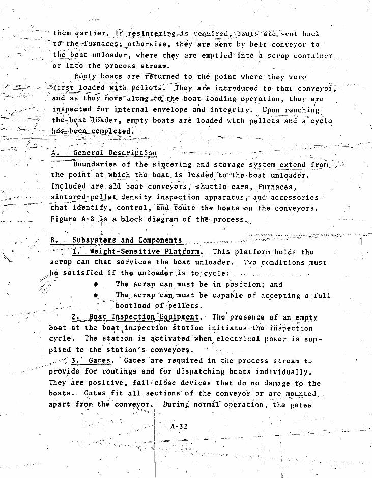
them earlier. j^5rej^i.n^er.i^ hack^to"=the2^iirnacej_j otherwise, tKey" are sent by belt conveyor totheboat unloader, where they are emptied into a scrap containeror into the process stream. "
Empty boats are returned to= the point where they werefirst loaded with pellets.' they_ are introdueed-to that coriveydr,and as they move along Ijyhe boat loading operation, they areinspected for internal envelope and integrity. Upon reachingthe-boat loader, empty boats are loaded with pellets and a cyclehas been completed. »
A. General Description >•»—--,r,,,_T.,,,... „ ----—— '"""7 1
Boundaries of the sintering and storage system^extend fromOTJ1the po^ht at which the boat, is loaded to the boat unloader.Included are all boat conveyors, shuttle cars, furnaces,
^^ sintered-peLleJLdensity inspection apparatus, ^nd accessoriesT'" ^hat identify, control, and routethe boats on the conveyors.
, „ Figure A-t|s-a block-diagram of the process.N
**» Subsystems and Components ,,,,,,,,.,o.-,,.i\ ° ; ir Weight-Sensitive Platform. This platform holds the
X R •::
N^ scrap can that services the boat unloader. Two conditions must
Jje satisfied if the unloader „is to; cycle: , . ;(:' JclV • Tne scrap can must be in position; and
• The scrap can must be capable of accepting a full! ° boatload of pellets.
2. Boat Inspection Equipment. The presence of an emptf.yboat at the boat^inspection station initiates the inspectioncycle. The station is activated when electrical power is sup-plied to the station's conveyors.
< 3. Gates. Gates are required in the process stream tjprovide for routings and for dispatching boats individually.They are positive, fail-close devices that do no damage to theboats. Gates fit all septions of the conveyor or are mountedapart from the conveyor.:! During noTlnal operation, the gates
- A - 3 2 - -; ••.

f (l /CHEtNFEUEl SIOfiAGE "1 »
I SMUmitARIIAUTOMAtlCWITHWANUALOVtRRIDEI
I VHOfK * ' f|K*AI tO'.V
r.(»)P(lltTSI')TfFINC
M ANDMH»IULrUHNACESSEUCHCIFGXUOAT
NO OF«'JAIS
^ (UIWAB
f SHUIUCCARI±ENTRA«CE lOOKCUFfl1VC (URNACES
1 HJHNMJl iNIHAVJE SlEtfCGNVlVOB
3L.1_J HIRMACE EMHAMCi. AIR LOCK
B — j BOA1SOFGREENMLLUS
JOATSXMEBjilB LOCH ON CONVEYOR ONE AT A 1IME
SHUTTLE CAP IIlOnbt'NSlTT
AUTOMATIC WITHMANUAL OVERRIDE
( I M J I W A C E PREHEAT SECTIOfJ . I BOATS ON CONVEVOR.1 . : _ . i 1
lUHNACt HEA1IMGSE.C1ION
FURNACE COOt ING SICTION
BOAT j ADVANCED THROUGH HEATING SECTION
BOATS ON CCWtVOR
BOATS LEAVE AIR LOCK OH CONVEYOR ONE AT A I » S
SPACE FOR MOLOING THREESCATSOF SINTERED PEUUTS
SINTfHCO rt l . t lTf l f .SI7VINSHCTION STATIOi»
EXIT FROM OM OF HVE FURNACf^S M U I a e ecu u
SHUTTLE CAR II I REJECTED
HIUHOEN5ITV I CONVEVOR
REJECTEDfUtETBOATDUMPER
SMUTHCCARII
SINTCREO - >ELUT BOfti STACKINGAND pt tRItVING MACHINE
SINTERCO-PEILCTBOAT STORAGE
SHIELDED ENCLOSUREHOLDS 1.15 LOADED BOATS
© PELLET GmNDlNG
Fig. A-8. Pel let s in ter ing.
A-33
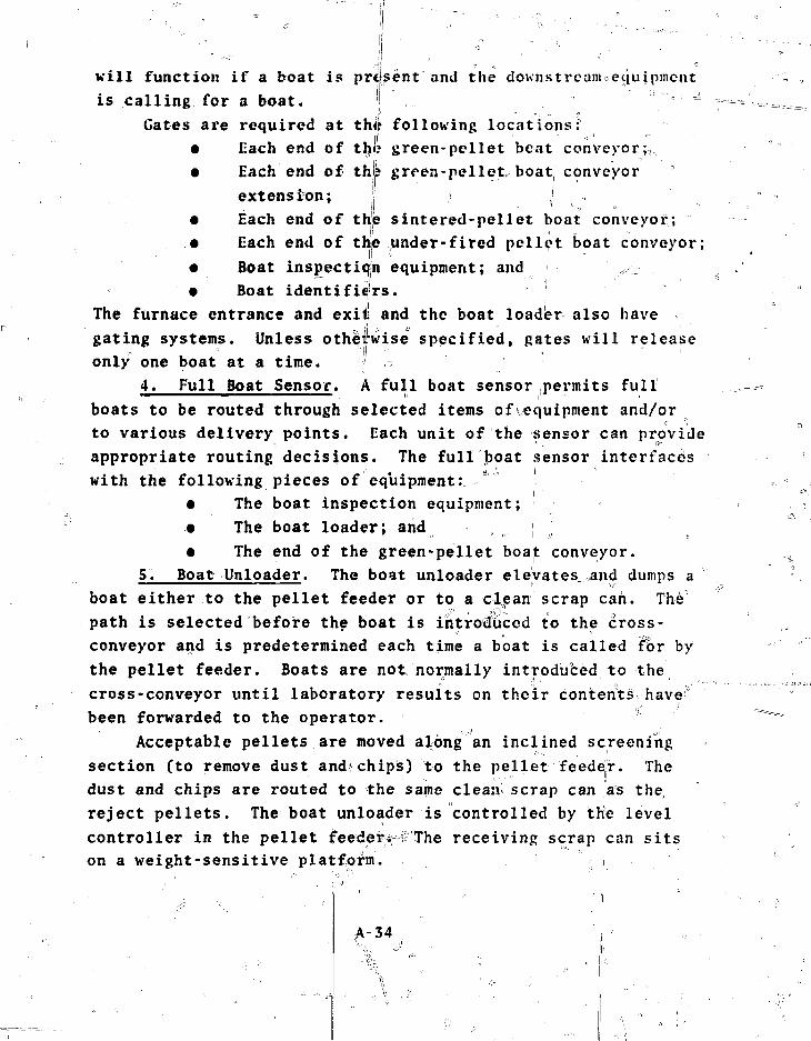
will function i f a boat is prefsent and the dounstreanueciuipmcnt
is calling for a boat. '
Gates are required at the following locations:• Each end of the green-pel let beat conveyor;,
• Each end of thjp grren-pellet boat, conveyorextension; ' • : I , ;i
• Each end of the sintered-pellet boat conveyor;• Each end of the under-fired pellet boat conveyor;• Boat inspection equipment; and• Boat identifiers.
The furnace entrance and exit and the boat loader also havegating systems. Unless otherwise specified, gates will releaseonly one boat at a time. ~>
4. Full Boat Sensor. A full boat sensor permits fullboats to be routed through selected items of equipment and/orto various delivery points. Each unit of "the sensor can provideappropriate routing decisions. The full boat sensor interfaceswith the following pieces of equipment:
• The boat inspection equipment;• The boat loader; arid ;• The end of the green-pellet boat conveyor.
5. Boat Unloader. The boat unloader elevatesCTiand dumps aboat either to the pellet feeder or to a cljean scrap can. The'path is selected before the boat is introduced to the cross-conveyor and is predetermined each time a boat is called for bythe pellet feeder. Boats are not normally introduced to thecross-conveyor until laboratory results on their contents havebeen forwarded to the operator.
Acceptable pellets are moved along an inclined screeningsection (to remove dust and chips) to the pellet feeder. Thedust and chips are routed to the same clean scrap can as thereject pellets. The boat unloader is controlled by the levelcontroller in the pellet feeder*"f'The receiving scrap can sitson a weight-sensitive platform.
A-34

After the dumping cycle, the unloader reverses and replacesthe empty boat on the cross-conveyor. After the boat has been
- xery^eed£and the lifting mechanism cleared, the cross-conveyorreturns the boajt to its normal routingJLocation. The presenceof a boat in the lifting mechanism and the\select ionandposi- =,tioning of the diverter chute allow the boat unloader to startits cycle on demand from the level controller in the pelle^
"———feeder. _ :: o , ' [, .•""" -
6. Sintered-Pellet Density Inspection Apparatus.; Pelletsfrom a boat on a shuttle car are loaded manually into thesintered-pellet density inspection apparatus. This inspectionunit provides a signal that is coordinated with the operator'ssignal to allow the sKuttl*car to move onward. An operatorselects the route by using the results of the density inspec-tion. "• "; /:' = -• ,. -"••
7. Boat Identifiers. The boat identifiers sense identifi-cation marks encoded into:, the surface of each boat. Duringoperation, thejmxgkzngs are translated into decimal form on adigital readout device. Under normal conditions, a boat^willbe released by the operator to a predetermined route. ^
-ftA- transfer Mechanism to and from the Belt Cross-Conveyor.These mechanisms^:ransfer a boat from the sintered-pellet boatAconveyor to_therbett~ cross-conveyor and, in af reverse^directidn,
3
back to the green-pellet boat conveyor. ., The transfer mechanismwill not cycre^uhTess the boat? ;is accurately positioned.,\Cycling willthen occ-urnori sj/gnal demand from a control circuitor operator response, whichever is Applicable.
9. Shuttle Cars.- Shuttle car A picks up loaided ofboats from the green-peMet boat conveyor and moves them to
\ of the four storage^conveyors between the furnaces. It also' ,0, t--akes--a boat from the exit end of a demanding furnace, cdnveys ,\ it to the densltySclec^station, and waits there until released.\ Upon release, shuttlar^cajr As goes to the under-fired pellet boirt\ conveyor or to the sintered-pellet boat conveyor. Shuttle car
* \B picks up a boat frrim a preassigned storage conveyor and de-livers it to a-demanding furnace.• \ " O \ • ''
- ' \\ - ,;' "*•"• !l A - 3 5 ... ' ' ^ . . • • • • • - • • \
V

-unused space underneath each car track is blanked off
from the RAAT^-^Construetion ics :vueh that the floor or bases will,;
slope toward potentiai^eolleKtion areas.
10. Cros s - Convey or j&The, cross.-conveyor receives boats
from the sintered-pellet boat conveyor, moves tho?e tofrr^afsIlK
natedfor ,resinter-to a discharge position in line with the,
green-pellet $oat conveyor, and moves other boats to the boat
unloader. Empty 'Scat's• ate traiis£er; ed jfronr the boat unloader
to the discharge position in dine with the green-pellet" boat
conveyor.. When boats are ii the discharge position, a boat ?
transfer mechanism transfers them fi*pm the cross-conveydipto
the green-pellet boat conveyor. This section of conveyor is in
line with and connected directly to the corresponding convoyor-
in side B of the split process line. Crossover may be performed
at |his location. \
Cycling is automatic'.once a boat is in position rnd the
operator has selected the proper routing for that boat. An
interlock installed with the boat unloader assures that the
scrap/product diversion chute is in the proper position for non-
resinter routings prior to conveyor start-up. Conveyor reverse
infff is controlled by the boat unloader circuitry.
11. Boat Conveyors. Boat conveyors move pellet boats as
necessary. They also satisfy equipment interfaces and permit .
safe /convenient maintenance.
12. Sintering Furnaces. Cooling water for the sintering
furnaces is supplied through a heat exchanger and pump system. t\;
This cooling system is redundant to handle emergency shutdown
conditions.
Chambers (enlarged furnace entrance/exit vestibules) have
glove ports and a sectioned molybdenum rod suitable for probing
boats in the furnace.
The following failure modes are provided for:
• Loss of power;
• Loss of coolant pumpfs);
• Loss of farming gas;
Loss of power to the furnace pusher or doors;
A-36
• Over-temperature in a furnace or exhaust duct;^
• Lack of water in the bubbler; * \ \
• Failure of the furnace door to close; \
• Presence of excess moisture in the gas fe'ekl lines
or exhaust gas stream; and Vx
• Cross-contamination between the furnace atmb-
sphere or cooling toVer^ Abater and the furnace
.'. 'cooling water H~-- ••--.' \ ' '
13. Roughing Filter. A roughing filter on the exhaust'
gas system protects the HEPA filter and, when necessary",' ,the -
off-gas cooler.
14. Off-Gas Cooler. The off-gas cooler is installed in \
the exhaust gas line to reduce the temperature of the forming \
gas before it sis mixed with air in the ventilation ductwork. i
It further serves to protect the HEPA filter in this system £rom\
high temperatures. __ =_ ?:'-v V-v) \
15. HtiPA Filters. HEPA filters fn the exhaust gas system J\
filter the forming gas exhaust before the offrgas is introduced
into the ventilation system ductwork. V
C. Instrumentation and Control = t
• The green-pellet boat conveyor^nd.all connected or
associated equipment along its length (excluding boat loader) °
are powered from a single hand switch;
• The sintered-pellet boat conveyor, cross- conveyor» i = = =
boat unloader, and the connected or associated equipment for
thcse units are powered from a single hand switelTr the"cTe^—=^r
conveyor is operated by an independent control; j
• Shuttle cars are powered TErom sirgle hand switches;
• The green-pellet conveyor extension and the under-
fired pellet boat conveyor are powered from a single hand ^-„
switch; ;
• Furnaces are powered from their own separate controls ;
• The siritered-pbllet density inspection apparatus is
powered from its own hanfl switch. *
' A - 3 7 " •, . . •, ; '"' ,. )V ... • "'
\ Manual overrides are provided for cle^riimt purposes and to
permit manual^ cycling and routing. I ,1
Controls also stop,the process equipment under iihe follow-
M h g conditions: ~"T" -" *- - • . •-• I • *' . f^ \- v" ;" ; „_-'-• ----"-** c J s ""' ' i!
? c • \ Seismic incident in excess of preset value;;
\.::i. • , "'Power'* interruption; or •. .,
•B Boss of flow in ventilating system or pressure dif-
fer enti^r=^ac:fo'ss containment.L'' "•' '" -. - ' : ' ' / /Z Q: ' " 'I
4^,Recovery from ,s€utdc>\Xn ,,is by manual re's t a r t , Th!p,cause ofthe shutdown is indicated to the operator and themay ,be cleared upon restarting.D r
- The sintering and0storage system operates by automatic „
cycling coupled with operltor decisions at rout#cgsjpoint3T^ The
constant attention of an operator is planned for the ^intered-
pellet density inspecjiiQe^apjgaratus: at routing points "ag> tJie^,^
end of the5 sintered-pellet boat conveyor and after ther^eilS:fl?^
inspection* Manning becomes0mandatory only" after the bufter ,
sjtprage areas beccsme full.
Maintenance/ •• ' 0 °" : ' : %
Conveyor sections are .replaced remotely, and shuttle cars
in place after the, shuttle car has been moved by
pickup point. \*
Furnaces are"s^jviced in a separate area under a specialscheme; /The,^furnacelen^^are bagged off, and the\furnace islifted^onte a eart. Tbe/ibr^^%Jiook is4&hen'disconnected. Fur-
seiloVder,. Boats from thesfections are repla?ced in''/^furnace and =the exit and entrance chambers are serviced in• .. ^spgcial chambers. ' ,..« ^ " ^.^ •''<, - ^ .^"
^\ Then grindef ^area c^ajie and manipulator are usedVwn©n the/
cross-conveyor ; nds the boa^uriloilader need ^sje^viciiig dr replace-
A-,38

V. PELLET GRINDING, INSPECTION, AND STORAGE
The pellet grinding, inspection, and storage system takesthe sintered MO. pellets and shapes then into right circular ;
cylinders by a grinding operation that removes slight surfaceirregularities. The physical characteristics of the pelletsare analyzed and inspected in detail. bffqxA the pellets aresent to the next area whereathe fuel rods are fabricated. Astorage area is provided.
Support systems handle the cooling water from the grinderand separate the MO- that was removed from the pellets for re-cycle back into the feed material. A system is provided forputting the pellets onto trays for orderly and controlled stor-age, and a versatile tray handling and storage system permitsrecovery of defective pellets from trays for recycle. n
A. General Descripjjjm
The pellet grinding, inspection, and storage system shapesthe ceramic pellets to final size, inspects them, and placesthe acceptable pellets in *. heated storage unit. The scrap ^material is recovered an<|_recycled by special units designedfor sludge recovery.
System boundaries extend from the pellet feeder throughthe pellet storage dryer. A duplicate, line is in parallel withtlis system (sifieB of the split line), and there is a cross-over between the pellet storage dryers.' Fi64?e A-9 is a sche-matic and Figs. A-JO and A-ll are block diagrams of the process.
- - •' • ^ ,: ° o
Bj, Subsystems and Components "
f 1. PellctjTeeder, The pellet feeder^ receives pellets£roro t|sfs3fe#at unloader in the upstream system, orients themehd-to-end, and conveys them to the grinder entrance conveyor.A level-sensing element in the feeder controls theQsoat un-loader, and downstream equipment controls feeder operation.
! " '
A-39

- J -
I1
11
I
t «
mm cnwc newd.III.UWM
nut %?•$?et»x**4ittt -HUM llfHt ^ 5:Pturi !ikuu Mia
5 j
t
ITEM
22
OfTY
1 p ft l i t ! ( U / f T[«= CKtIOl H i t
JU1::! (?A-H:I t ttrft jtsttifilm « I I « I
1 -?/ OE5COIPTION
, •-'
ftCMMKS
I
Fiq. A-9. Flow diagram of pellet grinding, inspection,* and' storage. » ;' ;• .• ,
A-40

-iKOUTtH SClfCTSONEOF 1*0
"]~ ctwivtvo*
Fig. A IO. Pelletigrinding.
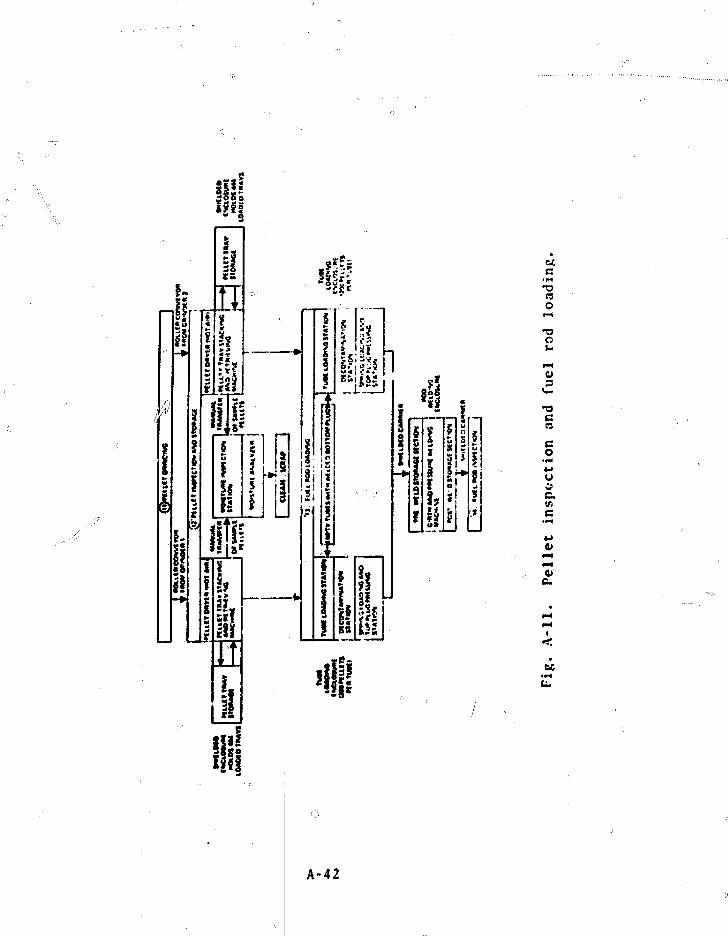
uc
3CI-
O3
•T3CCB
CO
c(ftc
« " •
A-42

Ventilation in the feeder permits separation and gatheringof dust and chips which collect ther^U^ Runout and cleanout canbe accomplished by the feeder.
2. 1'ellet Grinder In trance Conveyor. The pellet grinderentrance conveyor noves the pellets from the pellet feeder tothe grirder and has a racchanisn to feed the pellets between thegrinding wheels. • '
3. Pellet (irindei. The pellet grinder is a conterlessgrinder that uses a regulating wheel to control pellet rotationand a work-rest blade to support the pellets during grinding.Coolant water is furnished to the grinding area. The grinderwheels are shrouded anil vented to contain the sludge (water andMO, dust) in the immediate vicinity of the wheels and to mini-wise the potential for build-up or retention of M0-.
A drain collection vessel with level elements collects thesludge from the grinder and controls the sump pump. The levelelements function as follows:
• III level--shut 5 off water supply and the grinderfeed system, including the pellet feeder and the grinder en-trance conveyor; \
• 10 level1--shuts off the grinder feed system;recovery is by time delay; if the condition still exists afterthe time delay, an alarm is activated.
An indicator senses When pellets are being ground and pro-vides display and control input for the pellet gjinder diametercontrol unit.
The grinder interfaces with the sludge separator and dryersystem, pumps, entrance and exit conveyors, the pellet grinderdiameter control unit, and the overflow sump. A filtered recir-culation system separates the products of the regulating wheeldressing operation front the coolant supply system.
4. Pellet Grinder Exit Conveyor, The exit conveyor trans-fers the pellets from the grinder to the tray loader. It inter-faces with the pellet grinder, the,grinder diameter controlunit, the pellet rinse and dry unit, the tray loader, a clean
A-43
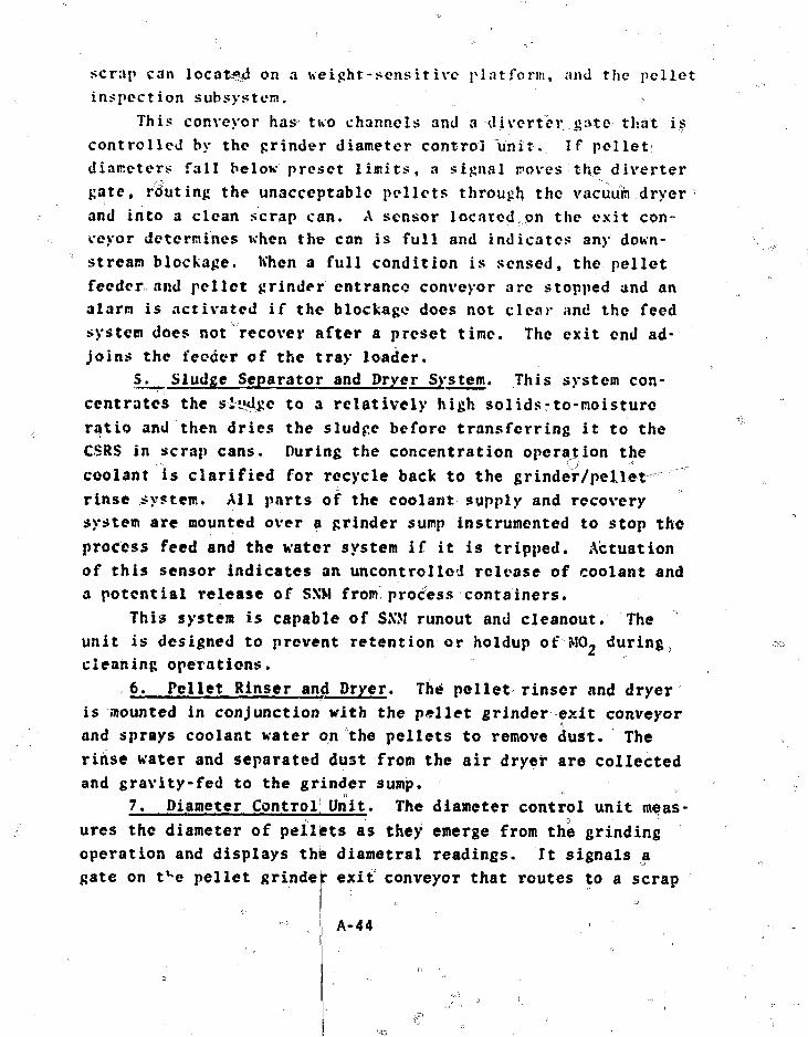
scrap can located on a weight-sensitive platform, and the pelletinspection subsystem. >,
This conveyor has two channels and a diverter gate that iscontrolled by the grinder diameter control unit. If pelletdiameters fall below preset limits, a signal roves the divertergate, routing the unacceptable pellets through the vacuuin dryerand into a clean scrap can. A sensor located on the exit con-ceyor determines when the can is full and indicates any down-stream blockage, When a full condition is sensed, the pelletfeeder and pellet grinder entrance conveyor are stopped and analarm is activated if the blockage does not clear and the feedsystem does not recover after a preset time. The exit end ad-joins the feeder of the tray loader.
5. Sludge Separator and Dryer System. This system con-centrates the sludge to a relatively high solids-to-moisturoratio and then dries the sludge before transferring it to theCSRS in scrap cans. During the concentration operation thecoolant is clarified for recycle back to the grinder/pelletrinse system. All parts of the coolant supply and recoverysystem are mounted over a grinder sump instrumented to stop theprocess feed and the water system if it is tripped. Actuationof this sensor indicates an uncontrolled release of coolant anda potential release of SN'M from process containers.
This system is capable of SXM runout and cleanout. Theunit is designed to prevent retention or holdup of MO, during,cleaning operations.
6. Pellet Rinser and Dryer. The pellet rinser and dryeris mounted in conjunction with the pellet grinder exit conveyorand sprays coolant water on the pellets to remove dust. Therinse water and separated dust from the air dryer are collectedand gravity-fed to the grinder sump.
7. Diameter Control Unit. The diameter control unit meas-ures the diameter of pellets as they emerge from the grindingoperation and displays the diametral readings. It signals agate on t^e pellet grinder exit conveyor that routes to a scrap
A-44
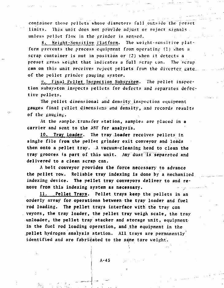
container those pellets whose diameters fall outside the presetlimits. This unit does not provide adjust or reject signalsunless pellet flow in the grinder is sensed.
8. freight-Sensitive t'latform. the wei jiht - sensi t i ve plat-form prevents the process equipment from operating (1) when ascrap container is not in position or (2) when it detects apreset uross iveight that indicates a full scrap can. The scrapcan on this unit receives reject pellets fron the diverter jjateof the pellet grinder ^au^in^ syster.
t». linal t'ellet Inspection Subsystem. The pellet inspec-tion subsystem inspects pellets for defects and separates defec-tive pellets.
The pellet dimensional and density inspection equipmentgauges final relict dimension:? and density, and records resultsof the gauging.
At the sample transfer station, samples are placed in acarrier and sent to the ASF for analysis.
10. Tray Loader. The tray loader receives pellets insingle file from the pellet grinder exit conveyor and loadsthem onto a pellet tray. A vacuum-cleaning head to clean thetray grooves is part of this unit. Any dust is separated anddelivered to a clean scrap can.
A belt conveyor provides the force necessary to advancethe pellet rov. Reliable tray indexing is done by a mechanizedindexing device. The pellet tray conveyors deliver to and re-move from this indexing system as necessary. :
11. Pellet Trays. Pellet trays keep the pellets in anorderly array for operations between the tray loader and fuelrod loading. The pellet trays interface with the tray conveyors, the tray loader, the pellet tray weigh scale, the trayunloader, the pellet tray stacker and storage unit, equipmentin the fuel rod loading operation, and the equipment in thepellet hydrogen analysis station. All trays are permanentlyidentified and are fabricated to the same tare weight.
A-45
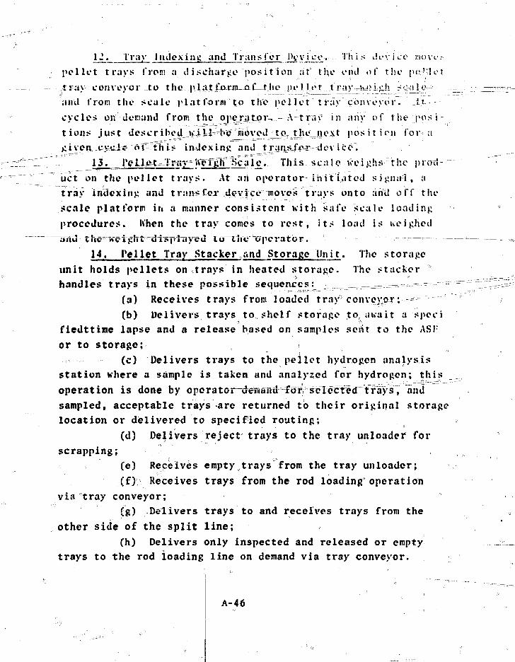
12. Tray Indexing and Transfer Pev ij£tv Hi i s d e v i c e mo v <.• .-
pellet trays from a discharge "position at the end of the pi;'let
tray conveyor to the j>latjfe«yn=:ojf1=1: ho pel lot;--..t ray uj?Lok i rlfi --
and from the scale platform to the pellet'tray conveyor. Jj
cycles on deriand from the ojiexatqr-r,-- A-tray in any of the posi-
tions just describedvtJ-il'be""""inbvcd tQ.__t]u?._juixt position for a
jiiven cys-he-"o"f":t"his indexing and traasXcj- device.
15. j'fcll t Tray ivciXii Sea 1 c. This scale weighs the prod-
uct on the pellet trays. At an operator-initiated signal, a
tray iiidexins and trnn^fer device moves trays onto and off the
jscale platform ir» a manner consistent with safe scale loading
procedures. IVhen the tray conies to rest, its load is weighed
and the- Keij-ht displayed tor"Thc Cfperator. ••—
14. Pellet Tray Stacker and Storage Unit. The storage
unit holds pellets on trays in heated storage. The stacker
handles trays in these possible sequences: .^^_-;=.r=r^-"——•"--"
(a) Receives trays from loaded tray convenor;-"
(b) Delivers trays to shelf storage to await a speci
fiedttime lapse and a release based on samples sct'st to the AST
or to storage;
(c) Delivers trays to the peilct hydrogen analysis
station where a sample is taken and analyzed for hydrogen; this
operation is done by opcrator~denraiiafot ^clecte^d T^ays, and
sampled, acceptable trays are returned to their original storage
location or delivered to specified routing;
(d) Delivers reject trays to the tray unloadef for
scrapping;
(e) Receives empty traysfrom the tray unloadcr;
(f) Receives trays from the rod loading operation
via tray conveyor;
(g) Delivers trays to and receives trays from the
other side of the split line;
(h) Delivers Only inspected and released or empty
trays to the rod loading line on demand via tray conveyor.
A-46
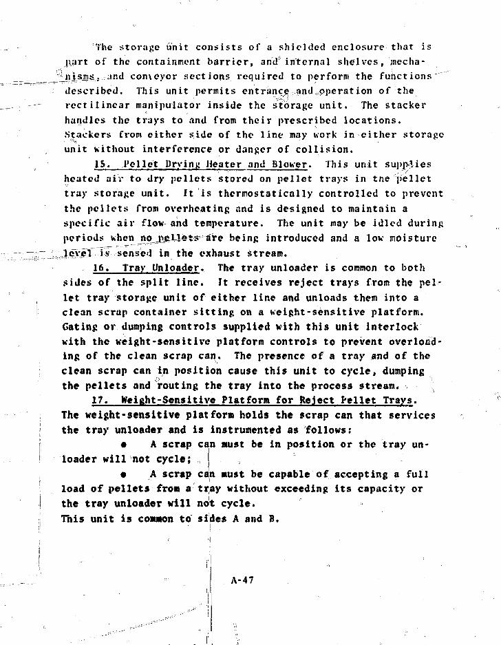
The storage unit consists of a shielded enclosure that ispart of the containment barrier, and*internal shelves, mecha-
os. and conveyor sections required to perform the functionsdescribed. This unit permits entrance-andoperation of therectilinear manipulator inside the storage unit. The stackerhandles the trays to and from their prescribed locations.Stackers from either side of the line may work in either storageunit without interference or danger of collision.
15, Pellet Drying Heater and Blower. This unit suppliesheated air to dry pellets stored on pellet trays in the pellettray storage unit. It is thermostatically controlled to preventthe pellets from overheating and is designed to maintain aspecific air flow and temperature. The unit may be idled duringperiods when no^jveXle**' are being introduced and a low moisture:iiivel itf sensed in the exhaust stream.
16, Tray Unloader. The tray unloader is common to bothsides of the split line. It receives reject trays from the pel-let tray storage unit of either line and unloads them into aclean scrap container sitting on a weight-sensitive platform.Gating or dumping controls supplied vith this unit interlockwith the weight-sensitive platform controls to prevent overload-ing of the clean scrap can. The presence of a tray and of theclean scrap can in position cause this unit to cycle, dumpingthe pellets and routing the tray into the process stream.
17, Weight-Sensitive Platform for Reject Pellet Trays.The weight-sensitive platform holds the scrap can that servicesthe tray unloader and is instrumented as follows:
• A scrap can must be in position or the tray un-loader will not cycle;
• A scrap can must be capable of accepting a fullload of pellets from a tray without exceeding its capacity orthe tray unloader will not cycle.This unit is common to sides A and B.
A-47
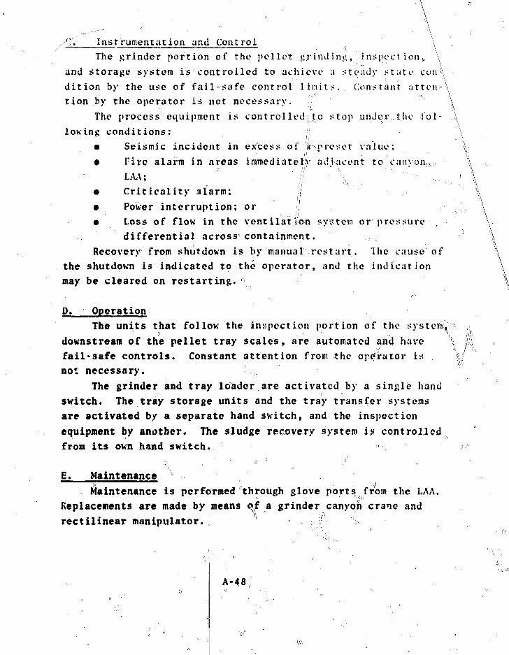
A-— ' ' ' " . , \
C Instrumentation and Control \
The grinder portion of the pellet grind intv, i aspect ion ,, \
and storage system is controlled to achieve a steady state con\
dition by the use of fail-safe control limits. Constant at ten-A
tion by the operator is not necessary. \
The process equipment is controlled ;!to stop under the 1*ol - \
lowing conditions: •; \
• Seismic incident in excess of .^preset value; \
• Fire alarm in areas immediately adjacent to canyon,, >
LAA; '• . "// \^ ~ : _ l
• Criticality alarm:
• Power interruption; or ;;
• Loss of flow in the ventilation system or pressure
differential across containment.
Recovery from shutdown is by manual restart. Ihe cau.se of
the shutdown is indicated to the operator, and the indication
may be cleared on restarting.
D. Operation
The units that follow the inspection portion of the systete^
downstream of the pellet tray scales* are automated and have \
fail-safe controls. Constant attention from the operator is %•!
not necessary.
The grinder and tray leader are activated by a single hand
switch. The tray storage units and the tray transfer systems
are activated by a separate hand switch, and the inspection
equipment by another. The sludge recovery system is controlled
from its own hand switch.
E. Maintenance
Maintenance is performed through glove ports from the LAA.
Replacements are made by means of a grinder canyon crane and
rectilinear manipulator. r
A-48

J . Special Precautions LThe pellet gri rial fig, inspection, and storage area is physi-
cally separated from other canyon process areas. ^lt is venti-la ted separately so that the moist air expected will not inter-mingle uith the air in or supplied to the other process areas.
Specific items of equipment require local ventilation tocontrol MO., dust and moist air. Separators and distribution toan off-gas system are provided as?reijuired. Such systems canbe readily cleaned and are designed to minimise any retentionof MO,. They can be scanned with portable instruments toverify normal holdup.
VF. ROD LOADING ANiT KliPAUt
>)•
The rod loading and repair system inserts the released fuelpellets into tubing, seals the fuel rod, and sends it to thefuel rod inspection operation. These operations are performedin sequence in a glovebox. Support systems fqr ventilation,sealing, and fire control are described in this section.
The tubing and rods are carried on chain conveyors and inchannels that serve to group, support, and protect the product.Pellets are introduced on trays and the fuel rod hardware isreceived in containers.
Facilities are also provided for manual processing of fuelrods that are to be repaired or salvaged.
A. General DescriptionThe rod loading and repair system encapsulates the fuel
pellets in the tubing with a pressurized atmosphere. The pel-let length is measured, the plenum is gauged, the tube ends arecleaned, a spring is inserted, a top end plug is pressed andgirth-welded, and finally the tube is pressurized and seal-welded. The tube is scanned for any contamination and the fuelrods arc accumulated in a channel for transfer to the next oper-ation. I :
A-49

System boundaries extend from the ends of the pellet trayconveyors to, but not including, the fuel rod leak test cham-bers. A duplicate line is fed from the common pallet traystorage system and runs to a duplicate set of fuel rod leak testchambers. Figure A-11 contains a block diagram of this system.
B. Subsystems and Components1. Rod Loading/Plugging Clovebox. The rod loading/
plugging glovebox encloses the pellet handling mechanism of therod loading station, the plenum gauging station, the tube endcleaning station, the spring insertion station, the plug press-ing station, and the rod end alpha-scanning station. The accessface(s) of this box are provided with windows, glove ports, andshielding as required for maintenance and operating access tothe equipment within.
2. Fuel Rod Pellet Loading Station. The loading stationreceives trays of pellets from the pellet tray storage unit viathe pellet tray conveyor and positions and indexes them intoalignment with its tube loading positions. When the tubes areloaded, all of the rods at this station are transferred to thenext operation. After a tray is emptied, it is returned to thepellet tray storage unit via the pellet tray conveyor. Whenthe rods have cleared this station, the operator is signaled toplace more tubing into the station.
3. Plenum Gauging Station. As the fuel rods are dispensedfrom the fuel rod loading station, they are accumulated in asmall surge area where the plenums are gauged to assure theproper drawing dimensions. The rods are held securely while agauging head enters the tube and registers against the end ofthe pellet column and end of the tube. An unaccer able condi-tion causes an alarm that must be cleared by an operator; hemust either correct the equipment malfunction or adjust theplenum by insertion or removal of a pellet. Pellets removedfrom or added to the rods go^to or come from a pellet tray atthe loading station. f
A-50
Repaired rods have their temporary end seals manually re-
moved at this station before beilrig gauged. Subsequent opera-
tions are common to iboth repaired and production rods. ,/ ^
4. 1'uel Rod End Decontamination Station. As the fuel rods
are conveyed into the decontamination station, they are held in".
place while a rotating cleaning mechanism removes surface con-
tamination that may have been deposited during previous opera-
tions. Two stations for cleaning are provided. An $l/p ha'^detec-
tor in the second station scans the end of the fuel rod id/
verify cleanliness before releasing the rod. If alpha contami-
nation is present, an alarm is sounded and the unit must be
manually recycled. Soiled cleaning ntE&ia are put into a waste
container for transfer to Mh*f after removal from the gloveboX;.
After successful cleaning, the fuel rod is released from the v
v.
clamp. 4
5. Top Plug Pressing Station. When tie fuel rod Kith
spring arrives at the top plug pressing station, it is firmly
clamped and an end plug is pressed into the end of the fuel rod.
The pressing mechanism retracts, the rod clamps relax, and the
rod is moved to the next station. / \
6. Rod Welding Box. This glovebox/is an extension of the
rod loading/plugging glovebox. Its front face has openings for
attachment of the welding equipment. ^Ventilation in the box w=
extends into the rod loading/plugging glovebox. = c-^
7. Fuel Rod Top Plug Welding Station. 4s the plugged fuel
rod enters this station, it is xhucKed and girth-welded. On
completion of the weld, th^ rod is released. • ^
8. Fuel Rod Pressurization/WciaihiB Station. The plugged
and welded rod advances into the pressurizat;.on wel4 chamber ;
and t.3ie rod seal is actuated, sealing the ,rod in the chamber.
Gas is then introduced into the ifpd to a preset pressure and
allowed to stabilize. When the pressure has stabilized, the
hole is seal-welded and allowed io cool. If a preliminary teak
check shows that the rod is not sealed^ an alarm sounds and tfee,• ii -1
rod is manually set aside.
A-51

9-<-* Fuel Rod' Assemb'tv^rufl'length Alphaggcgnning Equipment.
As rods approach the alpha scanner, they are deposited by the
conveyor on an accumulation ramp and then dispensed into the
full-length alpha-scanning unit. As rolls rotate the rod in a
fixed position, a scanning head moves along its length sensing
for alpha contamination. If contaminated, the rod i>- manually
removed; if not, it is transported to the helium leak test cham-
ber, part of a subsequent system.
> 10• Fuel Rod Conveying System.. The fuel rod convcv ins
'system transports fuel rods through the various process steps.
Tne conveyors arc specially designed to support and protect the
fuel rods during handling.
The fuel rod assembly conveyo? picks up rods at the^plenum
gauging station, carries then through, the decontamination sta-
lions, the spring insertion station, the plug pressing station,
and past- an end alpha scan before depositing them on a gravity-
sfeed ramp that carries them through a fire .door opening. Inter
locks prevent conveyor operation if the rod has not been cleared
or if alpha contamination is detected.w The^fuel rod uelding conveyor,picks up_j*qds at a point near
the firo door and advances vtlicm through the fuel rod top pluji
welding station and the pressurdzatiot^'welding station, then
deposits them on a gravity feed raite th^t feeds the full-length
alpha-scanning station. Intellockb prevent conveyor operation
until the fuel rods are in a position for unobstructed transfer.
The leak test transfer conveyor holds a channel in position
fchile finished fuel rods move from the -ful 1 -lenjctji alpha scan
into the channels. A counting device signals tH> operator when
a fixed number of rods have been loaded info eachichannel, The
operator then activates the conveyor h'hich transfers the loaded
channel to thf next step in thef production sequence.
II. Rod Repair (llovebox. , Ke rod repair glovebox houses
th.e equipment required to deprelssuriz^ and prepare the end of
the .fuel rod for subsequent repair or salvage operations.
Windows, gloves, ventilation, and utility
\ A-52.-fi .^.. • - - • - • - •

jis r e t i r e d . 1 lie box permits the rods to be alpha-scanned
^ b e f o r e they are transferred to the next^ opcrat ion. Scrap
ctvl'iw^t.ion and removal are accomplished though a port in thjs• ^ i i l o v i h o A . ' J " ° ' " 7 ' ™ ; ' 1 ^ . ^ " ^ • • • • ! • • • • ' • • •• • • • • • • - ; : ' ; • • , ----•••
,, 1J . 1'uel Rod Repa i r Mechanism. The fuel... r o c K r e p a i r nccha
".-nisr^-holds t fie rod. i* h i 11? i t i s bein.c d r i l l e d and ven te tL
ti : i s c vrt , t h e . p l v>£ and s p r jii ji. v. i t^!^
drau t i , ,<rd t h e tube end d c b u r r e d and chamfered . ^
, - ^ n f l u v l l!uif SalvaKi? t i lovebox. The fuel ?od s a l v a g e
j ' I c v t ' b o x o i i ' . ' l o s i ^ i ^ J j j e - ^ H j s H h ' T s o a s U u r i n g . < « t J i v a g p ' 1 o p e r a t i o n s i n _ _
h h i c h fuel p e l l e t s a r c r e c o v e r e d and meta l vcc=rrfKJhents a r e / / / e n t
for u a s t e t r e a t m e n t . The rods a r e i n t r o d u c o d 4rhto^the box
th rough ai: a; I^IOAZX t h S T " p T e V C n t S r e k a s c o f c o n t a m i n a n t s from
t h e io.v. This box e n c l o s e s the fuel rod .salvage cquTpTOirr"lTiru==
i s proAided iv i t h ; ,• hi t l d inj",, vent i i a t ion , and u t i l i t y se rv ice :? s
ri« TeT(Vi; i ed i S».- r I«JL" a-nd fuel n ;a tep ia l a r e c o l l e c t e d and removed
I }% i uo 1 I'o°dI!'o 1Jet Salvage Stat.ioa.,;fe^!^tse 1 rod/pellet
^ biilviiic ftatioi: co»S i st s, a£ JH I l^t removal and tube cut-up
A eijuipnent uhich rerso-yes the fuel pe l le t s fror: tho tubing and
cuts Qjind/or; compact > the tubing for convenient t ransfer . A
s°c a 1 e is .required to r na t e•_*> i a 1 s a c c o u r. t i n j ; mirfip s fes, to we i h
the arui'iht of fuel bein^! transferred. <= ",
^ Instrumentat ioh "Hnd t'ontvp 1 °
The nod loading/ueldinj; portion of the rod loading a
epjiir: systcn rcqui i ei constant surveillance by* an operator to
tt^ ^ii' JTTtlons a=rid handle unusual si" illations. The rod re-
ynur aiui salvage portion i^manua'lly controlled and oj-eratcd.
S>sten: ciT.yeyors are coiitrolicsl to ?toj ' (and3 not in i t i a te ;i new
process se<iuence) in the event of.; „ "
%%jt' ;V sei'sr.fic incident' in excess of a pres?t value;% ' " ^ ^ . . ,. - • - " ' ' ' • " ' - . , - ' ? . . - „ - f ^ * ' ^ , . , . ' •
# " ^ 7 ^ t i r e a l a r n i n t h i s a r e a o r a j o n g ; i s ; : h c : n i ; i t c , " ^ ^'.(
n" " .;; e^^H'e r o u t e ; - •"' , a * %. . . v % ' ^ - ., ; . ., - . CP ^ = -
, s • A cri t ic?,! l ty alarm °
• A power interruption; or• A loss of flow in the ventilation system, loss of
pressure differentia! across the confinement bairrier,or malfunction of any of the glovebox seals.
Recovery from shutdown rf^by manual restart. Cause of the \shutdown is indicated to the operator, and the indication iscleared on restarting. Local controls with interlocks arfe pro-vided for all drive mechanisms and valves in the system. ;
D. Operation_ ii i
The fuel rod loading/welding operations are powered from asingle hand switch. The repair and salvage gloveboxes a)re oper-:ated from a single hand switch for each. The area; adjacent tothe operating faces of the boxes is shielded to meet the wradiation-level requirements of the NAA; this are a is considereda potential contamination risk because pf the glo'ye ports int h e b o x . • „ ' • , /J „ "• " ' 'N t •. ' ' '•• "' :.
E. Maintenance '., •'[,}'All equipment arid boxes in this area can be dismantled for
removal and replacement by passing fhemThToTTglT the mariufactur-ii.g building. In-box equipment is remoy;ed by a bag-out tech-nique. ~" "'<" "•
-••-.:-': " j ; . " .'
F. Special Precaution^ .., . . I j
& pressure differential is maintained on the gloveboxf\ thesystem must not draw the humid air 'ofsthe grinder-canyon iijto ,the gloveboxes even though they are connected/by the pellet trayconveyors.. The air in the loading/plugging glovebox flows ;toward the loading station * which is the dlistiest part of theoperation. The air nca,rby flows from the; normally occupied^ areato the gloveboxes.
The filter systemin the gloveboxes, with
consists of standard canisters mountedthe central exhaust system providing
the pressure differential; a pressure differential or flow
' • • • • \ « ' " •
A-54 a '' ' ::'

element controls an air-operated valve to maintain the desiredflow or pressure ait a preset value.
The gloveboxes are monitored for temperature and smoke withone element of the monitoring system that is located near thefilters. Detection of smoke or a rise in temperature activatesthe Malon extinguishing system, stops all the process equipment,and closes the fire door between the rod loading glovebox andthe rod welding box.
VII. FUEL ROD INSPECTION AND STORAGE
The fuel rod inspection and storage system routes rod hard-ware from the receiving and storage areas to the shipping areavifhere fuel rods are prepared for transfer to final assembly.System boundaries extend from receipt of tubes and hardware tofinal fuel red inspection, except for rod loading (see Appendix
.A-VI).
A. General DescriptionEach incoming shipment of fuel rod tubing and hardware is
received in cardboard shipping boxes which are visually inspected for superficial damage. The hardware is then storeduntil time for cleaning. Bottom end plugs are pressed intoempty fuel tubes and welded, and the tubes are transported tothe x-ray inspection station for bottom plug weld inspection.
The empty tubes with bottom ends plugged are then sent torod loading (Appendix A-VI) for final rod assembly, after whichthey are stored in air locks pending inspection.
Loaded fuel rod inspection consists of (1) a helium leaktest, (2) gamma scan, (3) top plug weld x-ray inspection, and(4) physical inspectionjand weighing. Reject rods are sent torod repair and salvage For repair or recovery of hardi^are andMO- pellets. Accepted-rods are transferred to the rod storageunit to await final disposition. Figure A-12 is a block diagramof this system.
A-55
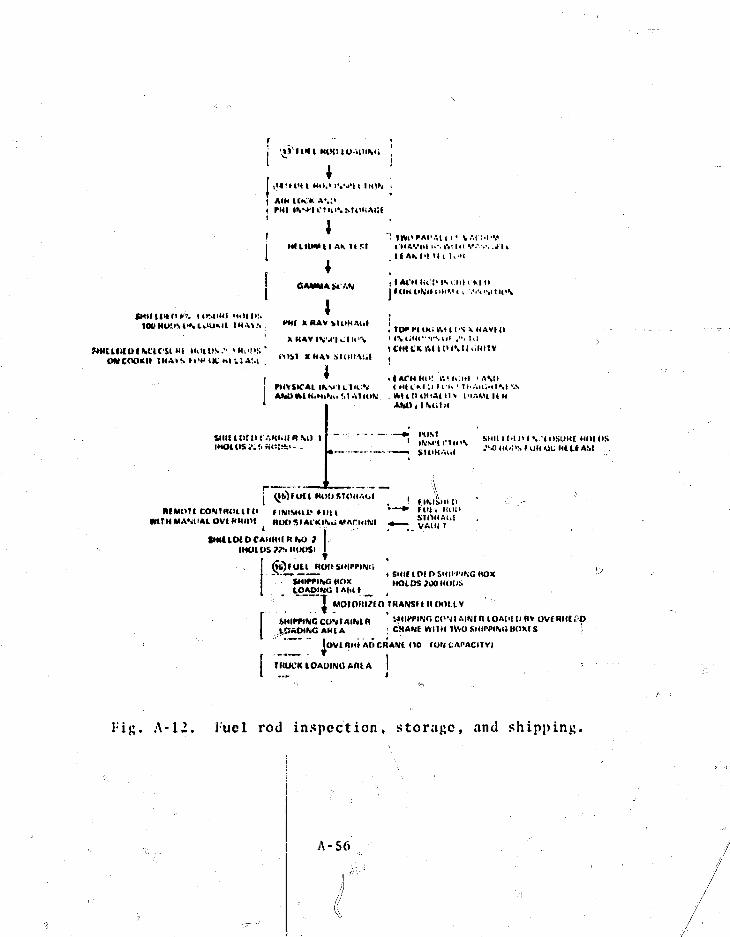
I I I H l KWI 0 ••PIMi
I vM'H'H MO,> IN
( AIM UK>. A*,:<i rut iv-^iCTin',
; »
M'll
II MAVI'I 1.'. ft! Ill V." • V. VI II f AKI't I I l Wit
OAMMAMANI I At'KiU ij I OK I I M H ' I i ',•<•> >Mtll<\
ULNfM-.tUMt H4AVS Wl X IIAV 41ltHAti» !,_.„...,..
1K» MtltOV.-" >•!!>!>•. ' ' CHICK A I I IHMt l iH I IVOMCOOKII !HA»S»OW»K.«lilAM . " • > ' * « * » SKIHAlil ,
I PtlVSICAL IK 'J IU I l 1 . < H U M ;i l i K • t..-.iL,ulM-.sI ANUHUK-NiV. M AllOfC . Wr( 11) ()<<A1 II > L'lAViUU
; : ! : .".KI.IIR M( I H VIOSUKC HOIHS
HI MOT I COM HOt I fOWltH MANUAL OVtHHUll
Hit I RlHI STOHAiil
1• MArilINt
(MOl US ??•. U(K>Sl
(lOruttSHlff ir«C HOKlOAOiNU
1
nun.-.li!
VAIH I
SHII t Of D SHIITlfwG (tOXHOLDS ?OOH(I[JS
MOTOIll/(n THANSf I I I (Kit IV
L£~t>INC AHCA
C";I.Mtjfn LOAdlUflV OVf RHIi'OCMAME kVIIH TMO SHirpiMl BOKC 5 '
lOVlHM* AOCRANi <10 lONLAPACIFYI
UtUCK IOAUINC ARt A
I-ig. A-12. Fuel rod inspection, storage, and shipping.
A-56

,'i. Suhsystcna and.... Componcn ts :
1. Harduare Preparation. The plug marking machine jar df££der stamps end plugs uith an identification number beforecleaning. A..letter on the plug end surface can be used todesignate. enrichment. This unit is ut/ed intermittently On pro-duction control demand. |i
At the hardware cleaning station., tubes, end plugs, jjftdsprings arc cleaned to remove any surface contamination^ andthen stored until released for fabrication. Cleaning is alsodone as required by production control.
After cleaning, enpt> fuel tubes and plugs are cycledthrough the bottom plug press and transferred to the bottom plugwelding station, where a tungsten-inert gas welding processjoins the bottom end plug to the empty fuel tube.
The tube cor^eyor transports tubes through the cleaning,plugging, and >elding processes. At the;, end of the conveyor,tubes arc loaded onto the empty tube cart where they are visu-ally inspected and transfcri*ed to the x-ray inspection equipmentfor bottom weld mdiographic inspection.
2. Inspection 1-quipment. The helium leak test chamberchecks batches of encapsulated fuel rods (rods in channels),It contains a helium leak detector, standard leak source, con-trol panel, and the vacuum system. After the system attains aspecified vacuum, a mass spectrometer (heliun leak detector)determines the system's leak rate. Each fuel rod assembly linehas a leak test chamber. s
The gamma-scanner station scans fuel rods to determine en-richment content by gamma emission and consists of af control,panel, gamma-scanning head with shielding and source, and sun-port stands. '' ' •; " t , ! '" • '••
The x-ray inspection station tests batch quantlitles ofempty fuel tube bottom welds r^nd loaded fuel rod t ip welds.This station consists ofi-'ajn x-ray unit with controjl panel, posi-tioning fixture, correction blocks, penetrometers; a film iden-
f " <•• J
tification system, and> /(Llm. X-ray shielding is required in
" A - 5 7 ! :"•" - i ; . ,!
the e.\posure chamber, which must also have adequate shieldingto prevent beta, gamma, and neutron exposure to operating per-sonnel. Interlocks prevent operation if access ports, doors,or removable safety shields are not in place. •>
The film developing station processes the x-ray film.Discharge water is routed to the cold waste system through in-line filtering equipment.
After being scanned, the rod is moved to the final inspec-tion unit, which is equipped with a rod weigh scale and surfaceplate for final QC tests. Rod weight and identification areinput to the process information system. —.-
Loaded rods are moved about on the shielded transfer cart,wh^ch has space for about 50 fuel rods. This cart travels be-tween the helium leak test area and the entrance to x-ray in-spection., Rods are loaded and unloaded through shielded doorslocated at both ends of this route. The tray loader, whichtransfers loaded rods into the x-ray machine, is requiredbecause of radiation exposure limits to operating personnel; itis not required for loading empty tubing.
3. Fuel Rod Storage, The rod storage unit consists ofthe storage device and a shielded, compartmentalized carrier tohold loaded rods. In operation, rods are inserted into theshielded carrier at the final inspection station, and then aretraversed until aligned with a preselected storage shelf. Fuelrod storage location is recorded. Filtered ventilation airremoves autogenous heat.
i!
C. Instrumentation and ControlAll pieces of process equipment are powered through indi-
vidual hand switches with built-in interlocks and controls.Process equipment is controlled to stop under the following con-ditions:
• Seismic incident in excess of a preset value;• Fire alarm in :he fuel rod inspection building;• A criticality alarm in any part of the plant; or
A-58

• Power interruption, except for those items that mayrequire emergcnc^^^e|fe-%=
Recovexv==frosi shutdown is by manual restart. Cause of theshutdown is indicated to the operator, and the indication canbe cleared upon restarting.
D. OperationRecovery from emergency or nonprocess stoppages is accomp-
lished manually after inspection for damage. Immediate and con-stant attention by an operator is not required in these systems.Fail-safe controls provide an alarm to an operator only whenthe system does not recover from automatic shutdown.
.I•A
t. MaintenanceMaintenance and repair are performed in place by conven-
tional shop procedures under normal cold conditions. If fuelrods are present, the rods are removed to a temporary storagearea and adequately protected and shielded. Replacement opera-tions on failed equipment are made with conventional auxiliaryequipment and tools.
F. Special PrecautionsNo special ventilation considerations exist in these areas
of the plant, except at the station for cleaning end plugs and.springs and at the storage unit.
Shielding of x-rays is irequirlfed in the_x?rray inspectionequipment. In addition, the x-ray unit and the storage unitmust be adequately contained by appropriate shielding to preventbeta, gamma, and neutron exposure to personnel.
All efforts must be made to avoid contact between the fuelrod and contaminants.
G. Periodic Tests and InspectionsThe following tests are performed on a regularly scheduled
basis:
A-S9
(1)(2)(5)(4) Gamma scan un i t , verify ca l ibra t ion; and(5) X-ray un i t , verify parameters and source strength.
luel rod welder samples;Leak test, verify calibration;Rod vv^^Ji scaies^—«o^i-f>^cai ibrat ion;
A - G O
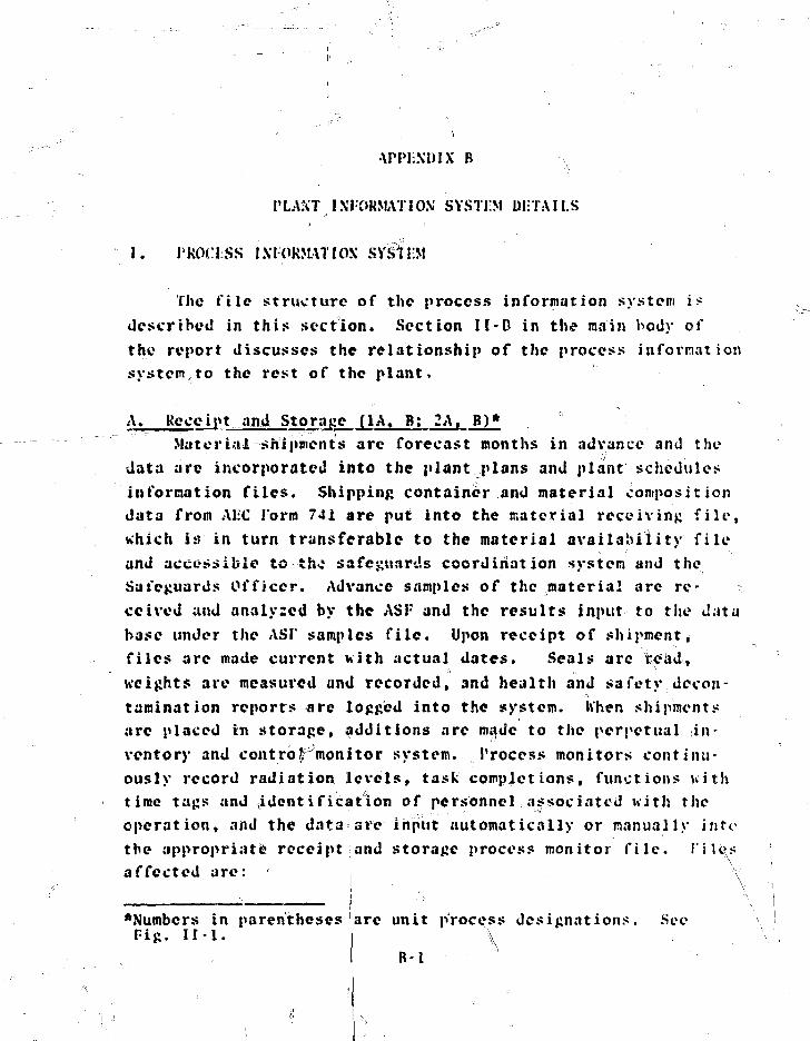
•\PPI:NUIX B
J'LAKT 1XI0HMAT10.V SYSTEM DETAILS
I. PKOCJSS 1XJORMATIOX SYSTD1
The file structure of the process information system i*described in this section. Section II-D in the main body ofthe report discusses the relationship of the process in formationsystem to the rest of the plant,
A, Receipt...and Storage (1A. B: 2A. B)*Material shipments arc forecast months in advance and the
data arc incorporated into the plant plans and plant schedulesinformation files. Shipping container and material compositiondata from ALC J'orm 741 are put into the material receiving file,which is in turn transferable to the material availability fileand accessible to the safeguards coordination system and theSafeguards Officer. Advance samples of the material are re-ceived and analyzed by the ASF and the results input to the database under the AST samples file. Upon receipt of shipment,files arc made current uith actual dates. Seals arc roaJtweights are measured and recorded, and health and safety,decon-
o
tamination reports are logged into the system. IVhen shipmentsarc placed in storage, additions are made to the perpetual in-ventory and control monitor system. Process monitors continu-ously record radiation levels, task completions, functions withtime tags and identification of personnel ..associated with theoperation, and the data are input automatically or manually intothe appropriate receipt and storage process monitor file, rilesaffected are: :| y
•Numbers in parenthesesPig. H I .
are unit process designations. Sec
B-l
r • Material receiving;• Material availability;• ASF samples; „ >• Pecontamination reports;• Inventory monitor;• Area radiation level;• Personnel exposure;• Optical scan label;• Operator identification;• Materials release;• Hopper weights (full and empty);• Pneumatic pressure differential monitor; and• Process operating history. ,
Approximate storage required: 2 million characters. i
B. Bulk MO, Operations: PuO: and UP, Unloading (3A, B)Canisters of plutonium that arc placed in the unloading
position generate an occupied signal that is recorded with veri-fication of canister identification number. Weight measurementsare made and input to the system and a response is generatedconfirming that values are within sensor measurement accuracy.Discrepancies are reported in shipper-receiver difference re-ports required by NRC. Decontamination survey, ASF analysis,and QC release data are generated and recorded. Canister emptyweight is compared with the full weight and contents data toverify that the canister is actually empty. It is then sent ,back to MKT and assayed, and a record made of the event. Eventrecords with time tags are compared with nominal values forprocess efficiency analysis and for any indication of possible
• • • \ • • ' ' ; -
malicious action. Corresponding steps are taken for (JO. unload-ing. F\les affected are:
• Process monitors;• Operator identification;• Canister weightf• Material release;
,B-2
\\\

• Blend record;• Feed hopper weight;• Weigh hopper weight;• ASF samples;• Vessel holdup;• Process monitor;• Operator identification;• Blend calculations;• Material release; and• Process history.
Approximate storage required: l.S million characters.
E. Bulk MO, Operations: Milling, Sampling, and Storage (5)Empty and full storage silo weight data are recorded, and
ASF samples after size milling are analyzed and the data re-corded. Silo hide-out detector data are read out and recorded,and data on off-gas moisture content are collected. Data filesused are:
• Blend record;• Hide-out detector; ' .,- -,,„-_._ B /• Off-gas moisture monitor; /• Process monitor; " /• Operator identification; /• ASF samples; « j• Material release; and _™ —,-,-.=l-. w :
• Process history. * jApproximate storage required: 800,000 characters.
F. Pelleting (7. 8, 9, 10. 11, 12) fSamples of granules are analyzed in-line for bulk density.
As green pellets ate produced, a density check is made a!nd re-jected pellets are sent to a clean scrap bucket on a weight-sensitive platform. Pellet0boat full indicator data are re-corded with the boat identification number providing a totalpellet count. Pellet samples sent to the ASF are analyzed and ,
E-4

• Blend record;• Feed hopjaer weight;• Weigh hopper weight;• ASF samples;• Vessel holdup;• Process monitor;• Operator identification;• Blend calculations;• Material release; and• Process history.
Approximate storage required: l.S million characters.
E. Bulk MO, Operations; Milling, Sampling, and Storage (5)Empty and full storage silo weight data are recorded, and
ASF samples after size milling are analyzed and the data re-corded. Silo hide-out detector data are read out and recorded,and data on off-gas moisture content are collected. Data filesused are:
• Blend record;• Hide-out detector; ' .,_ _ , , „ _ . _ m /• Off-gas moisture monitor; /• Process monitor; " /• Operator identification; j• ASF samples; « ij• Material release; and _ ™ ,(:i^_J.-^• Process history. * j
Approximate storage required: 800,000 characters.
F. Pelleting (7. 8, 9. 10. 11, 12) fSamples of granules are analyzed in-line for bulk density.
As green pellets ate produced, a density check is made and re-jected pellets are sent to a clean scrap bucket on a weight-sensitive platform. Pellet0boat full indicator data are re-corded with the boat identification number providing a totalpellet count. Pellet samples sent to the ASF are analyzed and ...
E-4
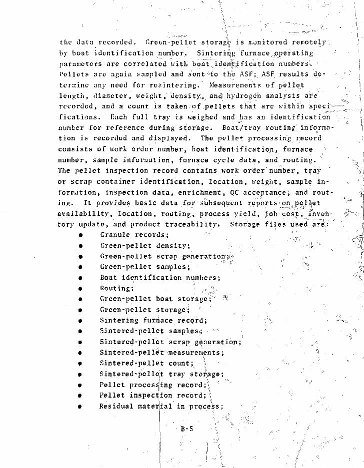
f c j
the data recorded. Green-pellet storag^ is monitored remotely
by boat identification number. Sinterirjg furnace operating
parameters are correlated with boat,identification numbers.
Pellets are again sampled and sent to thfe ASF; ASF results de-
termine any need for resintering. Measurements of pellet
length, diameter, weight, density^ and hydrogen analysis are
recorded, and a count is taken of pellets that are within speci-
fications. Fach full tray is weighed and has an identification
number for reference during storage. Boat/tray routing informa-
tion is recorded and displayed. The pellet processing record J
consists of work order number, boat identification, furnace ]
number, sample information, furnace cycle data, and routing. "^ i
The pellet inspection record contains work order number, tray V(
or scrap container identification, location, weight, sample in- =• ° '
formation, inspection data, enrichment, QC acceptance, and rout- M
ing. It provides basic data for subsequent reports on pellet
availability, location, routing, process yield, job cost, inven-
tory update, and product traceabilityi. Storage files used,are>
• Granule records; ".!_„
• Green-pellet density; > .-., |i" JS;.
• Green-pellet scrap generation;;! _/ ^ f
• Green-pellet samples; ' ' J 4;
• Boat identification numbers; ?"3j
• Routing; ,'
• Green-pellet boat storage; a
• Green-pellet sstorage;
• Sintering furnace record; f' = ^
• Sintered-pellot samples; ^
• Sintercd-pellet scrap generation;
• Sintered-peliiet measurements; a ,
9 Sintered-pellet count; \ "
• Sintered-pellet tray storage;
• Pellet processing recprd;* :!
• Pellet inspection record;!
• Residual material in process; > V
9.

^ ^ 5
L ___
e Process monitor; -v
= e Operator identification;
'S e QC Release; and5,i '•'
• „ Process lustory.
Approximate storage required: 4 million characters.
Op^
\ L
rationgi Fu»lfto4 Loading iad: ftepair
I Lmpty tubes are weighed, and ris lei and x-ray inspection
data on the first end welCof each tu3>e are recordedwith rthe
weight and tube identification nuuber. Installed pellet stack
length is measured and these dnta are incorj»«rated into the rod
fabrication aiid loading record containing work tfrder nuwber,
acceptance 1^ number, rod identification nuftber, weld data,
and spring, plug, and tube let nusberu. Coajpleted rod weight
and rod scan dita are input to the roil inspection record con-
taining work arder number, rod id-5nti:ritatioii^ weight, inspec-
tion, QC acceptance, and routing infoiiwtios/ iejected rod data
are coHected in the rod repair and salvage record incorporating
uork order nuwjber, rod identificatior. number, scrap container
___ _____ '__ ' _ rtvrrmr?^=cable files ate:
T
Tubei= cleaninug inspectlon
Rod identificatianr; ""
Rod Weight;
Rod a c c e p t a n c e l o t nJUiiibers;T
Rod jgpmpipnent l o t „ numbers;:Rod ' i s ran i ' '}: '" ° • } o •
Rod Inspection;
Rod repair and salvage;
Scrap generations
Proces.s monitor; (41 r
Operator identification; s-sd--
F'rocess history. |
stornye required: II million characters.
'.•a.s. .s.v. i
T *

II. Fuel Rod Storage and Shipping (15, 16)Rod storage in channel barriers is identified by rod and
channel identification number. Each shipping box holds fourchannels, each container holds two shipping boxes, and each ,truck carries four containers. A rod storage and shippingrecord is made uj|. o^^&.JIdeaii^ieaMon, customer identifica]tion,shipping notice number, carrier, alpha" survey, weights, assay,AEC Form 741 number, and identification1 numbers for channelsj,shipping boxes, containers, and truck. Files affected are: j
• Channel identification;. • i
• Shipping box; | ^• Container; i• Rod storage;]> Health and safety radiological survey;• Shipping notice.; '• Shipping schedule;• Proce^# monitor; o ^• Operator identification; and• Process history.
storage required: Ij million" characters.
I. Clean Scrap Recovery C18, 253This function includes pir^tcpperations. A measurement of
green density is taken manually bn material from the pilot pressand the data are recorded. BlenB recordIsMre kept and related
i ! , . - •• r '••-" -•' " x . •••; \ . | ••••
to pellet measnarepepjts taken before ai d after sintering, i QCrelease is generated^ from data falling ^ithin established speci-fications.
Clean sciwp storage fionitors check the position of eachcan on a sampled basis, a id a graphical display of filled ^age locations is generated and r^corded^ Scrap containers ar|eweighed when full and empty. Th$ CSRS furnacs operating parame-ter monitors provide dataof container number, weigMO_ storage weijght is reccapacity, and samples are
for the CSRS furnace record consistingit, and cycle data as needed. Recycledrded f0r three vessels of 72O-kg Isent to the ASF for analysis of !
B-7
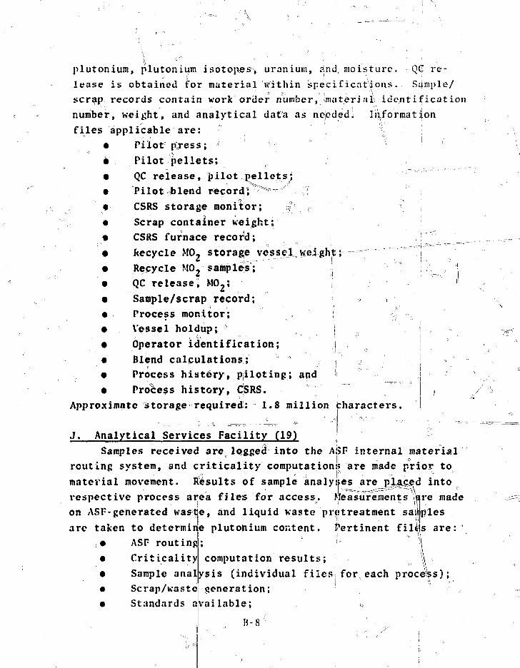
plutonium, plutonium isotopes-, uranium, and moisture. QC re-»' if • ' .
lease is obtained for material within specifications. Sample/scrap, records contain work order number, {material, identificationnumber, weight, and analytical data as noededi Informationfiles applicable are:
• Pilot p^ress; •'' ;• Pilot pellets;• QC release, pilot pellets;• Pilot^blend recordjr ^ ^ IT• CSRS storage monitor; ?
• Scrap container weight;• CSRS furnace record; _• Recycle MO, storage vessel Height; j• Recycle M0 2 samples; j• QC release, M02; I• Sample/scrap record; j >• Process monitor; i• Vessel holdup; ° „.. j• Operator identification; j• Blend calculations; ,• Process history, piloting; and '• Process history, CSRS.
Approximate storage required: 1.8 million pharacters.
J. Analytical Services Facility (19)Samples received are logged into the ASF internal material
1 l| • °
routing system, and criticality computations? are made prijoy tomaterial movement.respective process ariea files for access.on ASF-generated waste, and liquid waste pretreatment samplesare taken to determine plutonium content. Pertinent filijjs are:
Results of sample analyses are pJUcec intoMeasurements 'Wre made
ASF routingCriticalitySample analScrap/wasteStandards a
computation results;ysis (individual files;for each procegeneration;
vailable; *,
B-8
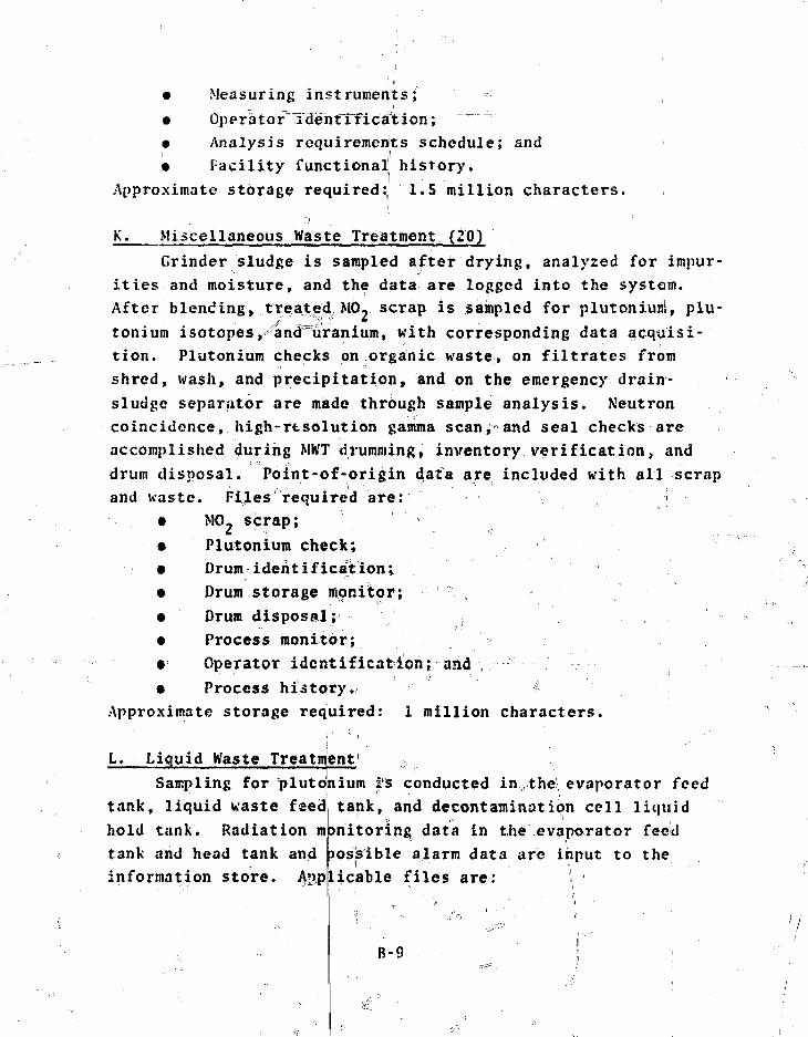
• Measuring instruments;• Operator^iaentTficajtion;• Analysis requirements schedule; and• Facility functional history.
Approximate storage required: 1.5 million characters.
•K. Miscellaneous Waste Treatment (20)
Grinder sludge is sampled after drying, analyzed for impur-ities and moisture, and the data are logged into the system.After blending, treatecL MO- scrap is sampled for plutoniunj, plu-tonium isotopes,^ancTuranium, with corresponding data acquisi-tion. Plutonium checks on organic waste, on filtrates fromshred, wash, and precipitation, and on the emergency drain-sludge separator are made through sample analysis. Neutroncoincidence, high-resolution gamma scan, and seal checks areaccomplished during Mh'T drumming, inventory verification, anddrum disposal. Point-of-origin data are included with all scrapand waste. Files required are:
• MO- scrap;• Plutonium check;• Drum identification;• Drum storage monitor;• Drum disposal;• Process monitor;• Operator identificationj and• Process history. J(-
Approximate storage required: 1 million characters.
L. Liquid Waste Treatment 0
Sampling for "plutonium i's conducted in the, evaporator feedtank, liquid waste feed tank, and decontamination cell liquidhold tank. Radiation monitoring data in the"'.evaporator feedtank and head tank and possible alarm data are input to theinformation store. Applicable files are: \
B-9
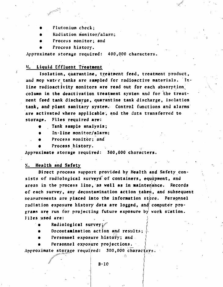
• Plutonium check;• Radiation monitor/alarn;• Process monitor; and• Process history. 0
Approximate storage required: 400,000 characters.
M. Liquid Effluent TreatmentIsolation, quarantine, treatment feed, treatment product,
and mop water tanks are sampled for radioactive materials. In-line radioactivity monitors are read out for each absorption,column in the deactivation treatment system and for "the treat-ment feed tank discharge, quarantine tank discharge, isolationtank, and plant sanitary system. Control functions and alarmsare activated where applicable; and the data transferred tostorage. Files required are:
• Tank sample analysis;• In-line monitor/alarm;• Process monitor; and• Process history. s
Approximate storage required: 300,000 characters.
X. Health and SafetyDirect process support provided by Health and Safety con-
sists of radiological surveys of containers, equipment, andareas in the process line, as well as in maintenance. Recordsof each survey, any decontamination action taken, and subsequentmeasurements arc placed into the information stpre. Personnelradiation exposure history data are logged, and computer pro-grams are run for projecting future exposure by work station.Files used are: „ ,|
• Radiological survey:• Decontamination action and results;• Personnel exposure history; and• Personnel expos
Approximate storage requiure projections.red: 300,000 characters.
B-10

0. Quality ControlVerification^of adherence to product specifications is pro-
vided through sampling and direct measurement in the processline. Data are stored and analyzed, and resulting QC releasesare generated and recorded on-line^ Instrument calibration dataare maintained with updated projections made available throughdata base access. End-to-end system verification and diagnosticchecks are recorded for known stimuli and measured output re-sponse. Applicable files are:
• Incoming material acceptability;• Process specifications;• QC inspection;t QC acceptance and release;• Product traceability;• Plant/process diagnostics;• Instrument calibration history; and• Instrument calibration projections.
Approximate storage required: 400,000 characters.
II. SAFEGUARDS INFORMATION SYSTEMc -
••;, •'>
Recent and historical data files are continually updatedand those related to SKM control are accessed for reference.They are available for transfer to the safeguards informationsystem for duplication and subsequent searches, sorts, process-ing, and inclusion of relevant real-time data. An initial listof applicable files is:
• Plant plans is• Plant schedules;• Plant operating reports;• Material availability;• Material routing, with selective r.al-time monitoring;• Sensor characteristics and status;• Plant diagnostics and confirmatory test results;
B-ll
• Item operation control event records, with selectivereal-time monitoring;
• LAA and RAA occupancy, with selected real-time moni-toring;
• Alarm status;• False-alarm history;• Guard force deployment;• Plant simulation models, parameters, and results;• Effluent release;• Safeguards coordination system historical file;• All files of the NMAS; and• Files of second and third generation processed summary
information.Approximate storage required: l.S million characters.
°, I
I•I
B-12

APPENDIX C
TECHNIQUES FOR NUCLEAR NONDESTRUCTIVE ANALYSIS
I.* INTRODUCTION
NDA measurements are vital to the implementation of dynamicmaterials control, frequently being the only available meansfor timely measurement of in-process material and holdup. Theyprovide direct measurements of SNM in liquid and solid scrapand wastes that are difficult if not impossible to sample reli-ably for CA. NDA is also used for verification in item control,rapid analysis of small samples, and for the safeguards account-ing and quality assurance of product fuel rods. NDA instrumen-tation is included in the plant measurement system wherever SNMis handled: receiving and storage, main process line, MWT, LWT,and the ASF. NDA instrumentation has been placed only whereneeded for timely safeguards and to complement CA methods.
Many of the NDA instruments specified for this M02 facil-ity design are used routinely in plutoniura facilities and wouldrequire, at most, minor modifications for M02 applications.These instruments are usually amply documented and commerciallyavailable. The remaining instrumentation systems are suffi-ciently advanced that meaningful projections of performance canbe made, and no difficulties are foreseen in developing engi-neered units in time to meet the earliest possible constructionschedules. No attempt has been made here to provide a completebibliography of the reports on NDA instrumentation; however, aconvenient source of general information on NDA technology andits applications is the training manuals that are used for theLASL-ERDA NDA Training Program.37'81
This appendix describes some of the NDA instruments andmethods selected for tlie M02 facility. A description of
C-l
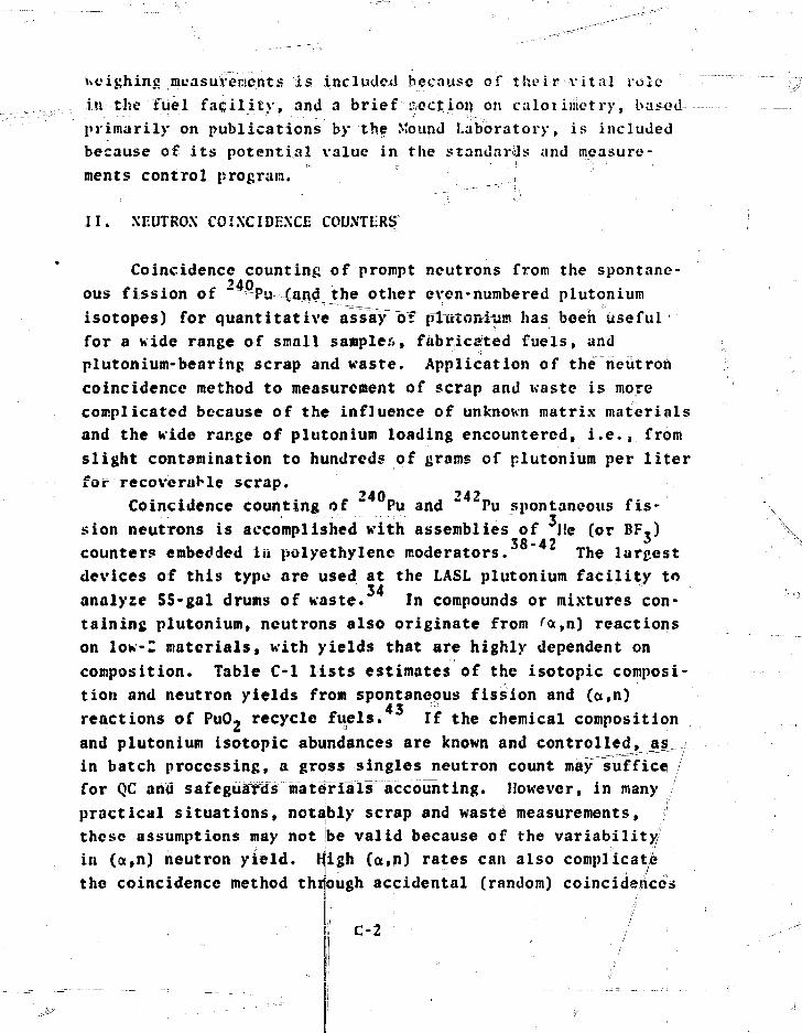
ueighinc measurements is included because of their vital rolein the fuel facility, and a brief ^ectj.on on caloi inietry, bu^edprimarily on publications by the Mound Laboratory, is includedbecause of its potential value in the standards and measure-ments control program.
II. XEUTROX COINCIDENCE COUNTERS
Coincidence counting of prompt neutrons from the spontane-'40ous fission of " Pu (and_the other even-numbered plutonium
isotopes) for quantitative assay"of"pTutonium has been usefulfor a wide range of small sampler., fabricated fuels, andplutonium-bearing scrap and waste. Application of the neutroncoincidence method to measurement of scrap and waste is morecomplicated because of the influence of unknown matrix materialsand the wide range of plutonium loading encountered, i.e., fromslight contamination to hundreds of grains of plutonium per literfor recoveraHe scrap.
740 742Coincidence counting of Pu and " Pu spontaneous fis-
sion neutrons is accomplished with assemblies of lie (or BF.)counters embedded in polyethylene moderators. The largestdevices of this typo are used at the LASL plutonium facility toanalyse SS-gal drums of waste. In compounds or mixtures con-taining plutonium, neutrons also originate from rct,n) reactionson low-I materials, with yields that are highly dependent oncomposition. Table C-l lists estimates of the isotopic composi-tion and neutron yields from spontaneous fission and (a,n)reactions of PuO2 recycle fuels. If the chemical compositionand plutonium isotopic abundances are known and controlled, asin batch processing, a gross singles neutron count may sufficefor QC ami safeguardsTniatelrials" accounting. However, in manypractical situations, notably scrap and waste measurements,these assumptions may not be valid because of the variability/in (a,n) neutron yield. High (a,n) rates can also complicate
' • • • • ' / . '
the coincidence method through accidental (random) coincidences
C-2

n
\ TABLE C - l
EMISSION RATE FOR ONE GRAM-SF JP1.UTONIUM
Isotope (wtl)Spontaneous Fission
LtvR Fuel w i th 3 5 . 0 0 0 MWd/TU Burnup
238,8Pu
240
241
242
241
Pu
Pu
Pu
An
63.0
19.0
12.0
3.8
0.6
Total
20.9
0
89. S
0
30.4
0
140.8
14.8
0
63.6
0
21.6
0
100.0
Average Composition {Including Recycle in 1990)238.
239
240
241
242
241
°Pu
Pu
Pu
Pu
Pu
Am
1.2
S3.0
25.8
13. S
6.0
0.7
Total 182.7
7.2
0
66.S
0
26.2
0
100.0
Spontaneous FissionPro*pt Neutrons(/s) (t)ro*pt(n/s)
307.1
ron(t)
IS.30
63.20
21.40
100.0
300
264
0
103
0
.0
.0
.7
70
66
0
26
0
.5
.4
.1
(a,n) Neutronsfro* PuO2
(n/s) (f)
266.0
28.4
32.3
1.2
0.4
21.4
349.7
168.0
23.9
43.9
1.4
0.6
26.3
76.1
8.19.2
0.3
0.1
6.1
100.0
63.6
9.0
16.6
O.S0.2
10.0
1
397.7 100.0 264.1 100.0
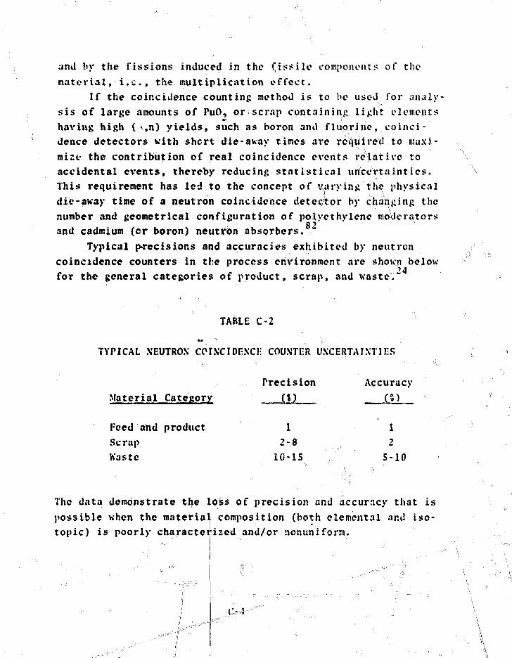
and by the fissions induced in the fissile components of thematerial, i.e., the multiplication effect.
If the coincidence counting method is to be used for analy-sis of large amounts of PuO, or scrap containing light elementshaving high ( <,n) yields, such as boron and fluorine, coinci-dence detectors with short die-away times are required to maxi-mize the contribution of real coincidence events relative toaccidental events, thereby reducing statistical uncertainties.This requirement has led to the concept of varying the physicaldie-away time of a neutron coincidence detector by changing thenumber and geometrical configuration of polyethylene moderatorsand cadmium (cr boron) neutron absorbers.
Typical precisions and accuracies exhibited by neutroncoincidence counters in the process environment are shown belowfor the general categories of product, scrap, and waste."
TABLE C-2
TYPICAL NEUTRON CPIXCIDEXCE COUNTER UNCERTAINTIES
Precision AccuracyMaterial Category (%) (I)
Peed and product 1 1Scrap 2-8 2Haste 10-15 5-10
The data demonstrate the loss of precision and accuracy that ispossible when the material composition (both elemental and iso-topic) is poorly characterized and/or nonuniform.
C.-.-4--
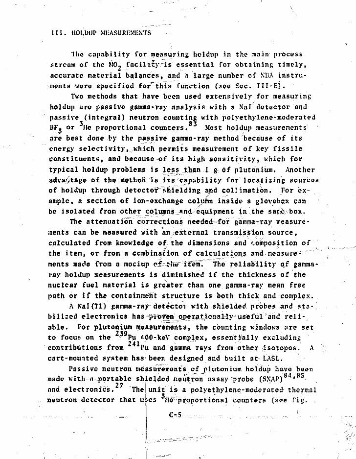
III. HOLDUP MEASUREMENTS
The capability for measuring holdup in the main processstream of the MO- facility is essential for obtaining timely,accurate material balances, and a large number of KDA instru-ments were specified for this function (see Sec. III-E).
Two methods that have been used extensively for measuringholdup are passive gamma-ray analysis with a Xal detector andpassive (integral) neutron counting with polyethylene-moderatedBF. or lie proportional counters. Most holdup measurements
•• i
arc best done by the passive gamma-ray method because of itsenergy selectivity, which permits measurement of key fissileconstituents, and because of its high sensitivity, which fortypical holdup problems is less than 1 g of plutonium. Anotheradvantage of the raethoS^is its capability for localizing sourcesof holdup through detector"shielding and collimation. For ex-
a section of ion-exchange column inside a glovebox canbe isolated from other columns~&nd equipment in the same box.
The attenuation corrections needed-for gamraa-ray measure-ments can be measured with an external transmission source,calculated from knowledge of the dimensions and composition ofthe item, or from a combination of calculations and measure-ments made from a mociup ©£=t-h«"ifeHii' "'The reliability of gamma-ray holdup measurements is diminished if the thickness of thenuclear fuel material is greater than one gamma-ray mean freepath or if the containment structure is both thick and complex.
A Nal(Tl) gamma-raydetector with shielded probes and sta-bilized electronics has proywjope^atiojiaHy useful and reli-able. For plutonium measurements, the counting windows arc setto focus on the j Pu *pO>keV complex, essentially excludingcontributions from Pu and gamma rays from other isotopes. Acart-mounted system has been designed and built at LASL.
Passive neutron measurements of plutonium holdup have beenmade with is portable shielded neutron assay probe (SNAP) '
unit is a polyethylene-moderated thermal27and electronics. The
neutron detector that uJ es H# proportional counters (see Tig.
C-5

C-l). The detector exhibits modest directionality, which aiJsin isolating sources of holdup. Because of the great penetra-biJLity of:—fa-strneutrons, these measurements need not be cor-rected for attenuation; however, background inter fei-ences (andinability to localize sources) and variable (a,n) yields canlimit the method. The sensitivity of the neutron method fortypical process line geometries is 10-100 g of plutonium.
A new technique, which uses a large-area neutron detectorto measure with high sensitivity the neutron field near the cen-ter of a room containing process equipment, sets an upper limiton holdup for the entire room. Measurements made with anarray of five polyethylene-moderated He tubes can achieve anaccuracy" comparable to much more time-consuming Nal(Tl) detectorgamma-ray measurements. Kith this technique, the fissile mate-rial must be fairly uniformly distributed^ the room must beshielded from external sources, and the specific neutron activ-ity of the material must be known. )€iire^ul instrument calibra- -tion by both calculational and experimental methods is neces-sary. . * _ i: <•',••"'.„
A vital part of any holdup measurement is the relationshipbetween the measured signal and the amount of material it rep-resents. Along a process 'line, various geometries are en-countered: cylinders (e.g., ion-exchange cdlumn.s), flat sur-faces (e.g., gloveboxes), jline sources (e.£;, sm;jai-di,ameter=piping), and extended volumes (e.g., filters measured""a-f closedistances). In many cases, an accurate calibration can be ob- ,tained from measurements iffith3 a point-source, coupled with ap-propriate geometric efficiency functions. For other bases,more extensive calculations and calibrations aic required. Inmany cases, the calibration and operation of the fixed NDA hold-up devices in the MO, facility should be simpler and more accu-
ji rate because instrument placement and calibration can be; thoroughly planned in the design phase aof the facility.
ii "' -.-•, ... ..Hi ::'.'. -•' - o ..
C-6ji
T

Poiycihyirr-c ~~\
Cadmium
He-3 neutroncounters14-crn adivo length
36 cm
r
TIL.
I'll-J
! <••j {
! '1 i
1 "i
t ;
-•23-cm diom—*J
I'ig. C-l. Assembly drawing of the portableSSA't'. ' •' ' ^ - *
C-7
M.° XDA VfRiriCATIOX 01 J'ut), I.TSfllTTING (TXIMXI\%
A simple measurement of fee t^e_rr.rT%eutron lea'kaj;i- fiot"
r c»>hij>pinj; con ta ine r s w i l l be used to ver i fy qulTnt i ta t iveiy thePuO/ c o n t e n t ? , thereby supplesfintiiU ID, s e a l , ajid -.-monitor
The measurement. wJLJJU-b wade" with one or two nal vetln -neutron dpicctors (similar to SNAI ',) Lpeated L
' ° to 1c. 5 a1 f,rpm The Shipping container. Ttve"sHT-ppini; container
Dnfliay- Have-tfo be-jrotated if tn« internal neutron s tudding is nor°suff tciffttly homogeneous°. , °-> ° i .
:w Theverif fpatioa measuceasene qan be based oh the specific-A ^eutroi* y ie lds for the contained PuO. deriybd fr<yn ' c a l i b r a t ions
and ta^ values gf the i so top ic abundances. Should the iiit
vary aiaong.t i o n > o u l d have to b« coapared to a
containers, verifico-
irmeasurement ma<}% atthe
rpbsed «oas«re^ent coiU'ifuratJony AtWS greatly^exceed 100
a
; Couirtin.g rajtes c|lciilated for the >the shipping
in 2 alii s=r l-esai ' Theis dicitattfd by «nC'"!rtii»ti«s
permit^of 19*$, than f3V t 'obe
1 acc"uracf -.of *h«n,eutron
t r&oiijjSps it Ion yeome t ry,
signed for the ptf«»u|i^|itand is /&
iuel facility-
; V f< ilowever, the iRea-sureaemtc
\ ' cj6
JI
J -a t ip .und s igna tu re s wi l l b«; th&
o O"- a*v,1 \K
Oi i °

II
-V
Va a
ft
il
same, and the (pasic characteristics of the instrument are notexpected to=differ significant|y fro% those shown here. !
Thei'"" Cfj, fue^rod assay"ifstern1 u§6«4both active and pas-
technique^ fo,r otfee neasupeilet-to-pell'et wriiforiaity of NJO,
j- i ' •" ! " *
portion of the,, measurement, a 2QO-6(?0-jjg,,
a ent of fisslle^c-ontent andNJO, fuel rods. Foi^the activ?fuel rods.
Cf source isVsedto interrogatejj the 1,fuel rods. The source is positioned incenter of the imoderiator shown* in! Fig. C-2, and the fu#l rods |are moved past! the source and into the gamma-ray detectors, iThe total fissile content is then determined by counting the
elayed gamma rays resulting fropi^fe* induced fisi-jj
high-energy delayed gamma rays resultingsion ,rea<tioni». ' •„. „ .*?'":$' \
?he neution atoderafor is designed to give a fast-neutronirradiation (the^ irradiation chai|inel=-is lined with cadmium) a|sveil as a hign fissil;!/fertile fission ratio (400/1).
To measure the delayed gamma rays from the fuel rod, two&• by 5-in-diam Ml detectors witjh through-holes for the passageof the fuel rods are positioned near the Cf shield as shownin Fig. C-2., Only the h i g h - en e | g|y^delayjcd_gawma_rays Ji>^ 1200Jk«Y) are used!0 for J.he total fissile measurement because of thoirRigher penetration Jhr^ugh the roid a?nd their good signal-to-
In to_^otal fissile active pellet-to-pel| etuniformitycan be determined simultaneously by counting therelatively ad ire intense, lower enjsrfcy, passive gamma fays TronLthe fuel by u^ing^he same Nal de^ectofi. Each of thel two Naldetectors examines a different ldi'-en/rgy^window on a pellet-to-pellet basis<Using a tungsten sleevewith a collimation slit
of <, OvJ iln.°"W« detectormainly from "^fAm* whereasplutonium gamma rays in
keV) acts;ijt a batch monitor
tounts ^0-KeV gamma rays^iich arethe second detector counts primaril
the fuel is time-dependentqualitative measure of tie fissile plutonium in the rod.
i as
of 100-500 keV.241because the
the windowAm content of
The 100-° to 500-'keV window-provides
Cr9
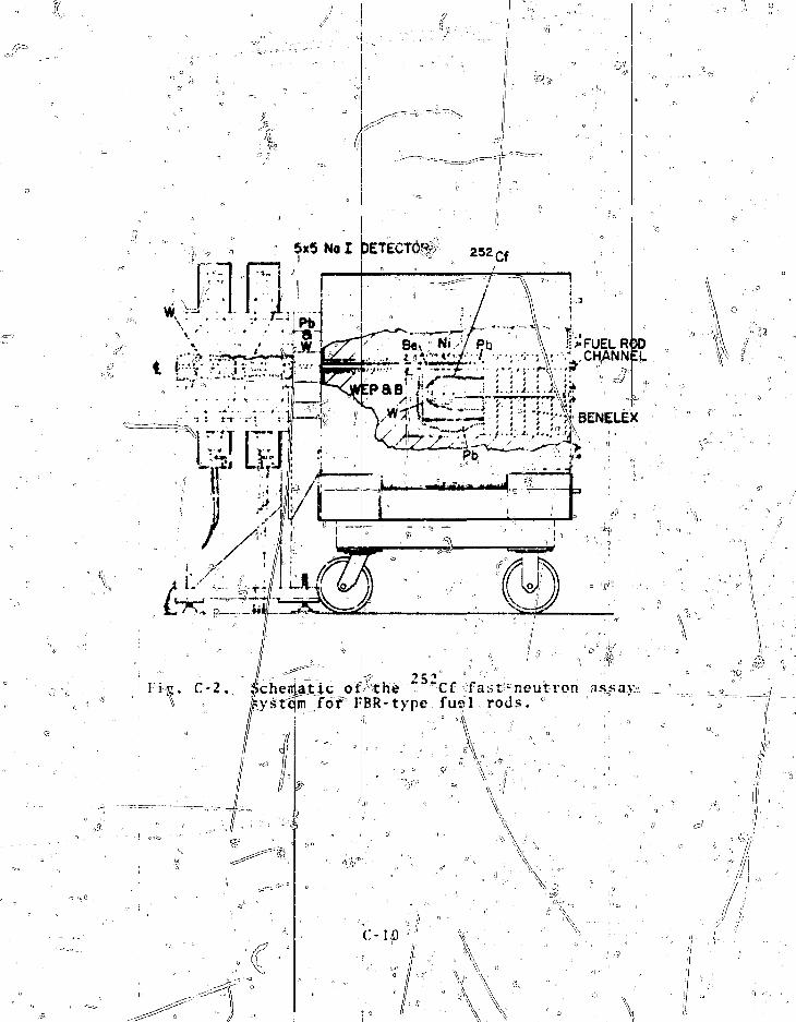
V
5x5 No I pETECKif? 2 5 2 c f
\ J!> FUEL ROOJ\:-- -CHANNEL
Schematic otpthe """"Cf -fast-neutron assa);ystQnTfor I^BR-type fusil rods. °
-.A
C-IQ
V\\
4
During operation, as lanV as 30 fuel-, rods are placed in
the loading magazine of thi? fyel rod translator* The automated
translator piclts up the °roi3 t(j> be assayed and moves it thrpugh
the \af crystals andthe f C^ assembly at 2.5 in;/s so thjit a
background count of the nonirradiated rod can be made. Th^
direction of trauel is thenf re!versed, and the rod is withdrawn
at 0.36 in./s,| during whicHtijme the delayed fission gamma+ray
data are acquired and Hie pelljet-to-pellct scans are made.'
After the irradiation and scan! of the fuel column, the rodjis
unloaded into the tray dirjectlk' below the loading magazine iand
the cycle is repeated"for the hext rod. j
IVith theatjove assay cycle and typical FFTF fuel rods,! the
count rate (sumio'fe both crystals for gamma-ray energies abo!ve
1.2 MeV) for thi{ total fissile measurement is ^ 6000 Hz, with a
net signal -to-b icfeground ratio , of 3/1 for a 600-pg "Cf sojurce.
Typical rates i) the 60-keV and 100- to 500-keV pejlet-to-pellet
windows are 8O,pot) Hz and 50,000 H2, respectively. The rela-
tive precision jjjf the measureme;nt of the;?fissile content ofja
single rod is 0]L 5% (la): A relative pellet-to-pellet nonun|-
foriiiity. of 'v Si can be readily detected. i
VI. SOLID TRANSURANIC"WASTE ASSAY (MEGAS) i
A detection systein has been developed for assaying low-i
density, solid alpha wastes (paper, plastics, rubber, incineira-
tor ash, etc.) in bulk form at and below the 10-nCi/g level.!
This is the currently recommended maximum activity level fbr
alpiia uastes that are tojbe placed in rionretrievablc storage or
buried. The design;objective was to develop a package as's:ayi'•' " 1 • " „ ' 3 '<
system capable of measuring activity levels of 2-ft boxesl i . it . || • '••'• • ;
tnining ^ 4000 g of low-(
The detection;systerscheme coupled with one that detects x rays, both of which rfj
ations are emitted in cojious quantities by the transuranics.
This MFGAS87"90 allowssnb-10-nCi/g samples>
or
ensity wastes. ; • |
is a-hybrid ..of a gamma-ray detection
e to monitor the x-ray region for th|o
subsequently to cross over to:- ' c - . f r ••.." !

progressively higher'energy gamma rays as the activity.. levj?l
increases. The detector is 5 + in. in diameier and 2-in.-thick
Xal with-,a 10-mil beryllium window. The window is thin enpugh
to allow x-ray transmission iiito the crystal, whereas the tjie-
tector itself is thick enough to absorb Jhijljh-energy gamma fays,
e.g., the 400-ke\f complex from,plutonium. i
Such a hybrid system combines the Ijigh sensitivity . (ajjid
relatively poor accuracy) of x-ray detection at the 10-nCi/g
level with the lower sensitivity, but improved accuracy, of
gamma-ray detection at higher activity levels. The errorsjre-
ferred to here are due to absorption by the matrix material and
self-shielding by the transuranics. The self-shielding effects
are severe for all photon energies considered here, particularly01
for the low-energy L x rays.* Part of the self-shieldingiprob-
lem can be alleviated by using proper standards (e.g., dricfd
liquid plutonium standards for assaying process-line-generated
wastes from ion-exchange columns). Also, for typical room-l
generated wastes that are reasonably free of contamination,
essentially no self-absorption effects exist.
As;say accuracy of the package scanner is approximately
• 505 at 10 nCi/g, but can be 2001 or more, depending on soiurce
location and the relative particulate size of the transuranic
material in the standards and unknown. Above ^ 70 nCi/g (i 4
mg Pu/4000 g waste), accuracy is approximately ± 30". In this
latter region, complete crossover has been accomplished frojii
.\-ray detection to higher energy gamma detection. The dynajnic
range of the system extends from a few micrograms to gram quan-
tities of plutonium fa factor Of % 10 jT The samples of hither
activity are monitored uith a 0.5-mm copper shield over the de-
tector to remove the lov
Typical plutonium c
shown in Table C.,-3 and £
packaged in a 2-ft cardboard cairifbn. Detectability ^imits are
given for both 100- and
ity limit is defined as
detected signal equal to
er energy (E < 50 keV) photons.
etectability limits for the system
re based on 4000 g of low-dens/ity wastes
100-0-s counting'times. The
that amount of plutonium giving
three standard deviations above

background (3c level). The table shows that for 1000-s coupt-
ing times, both the x-ray and J.2O-keV regions allow 10-nCi/g
detectability for such massive and bulky samples. The transi-
tion to total gamma-ray monitoring would occur at approximately
the 70-nCi/g level. \
,. ' ^ ,'"•'• T A B L E C - 3 \ • |
PLUTONIUM DETECTABILITY LIMITS: MEGAS j.
Detectability Limit3 (3o)Photon
16
120
200
4 00
Energy Region
(keV'f(L x rays)
100-sCnCi/g)
¥.111.0
84.120.
Count(we Pu)
6.6
S90.
4700.
6300.
1000-s(nCi/g)
0.04
3.427.36.
CountCUE PU)
2..J190.
isool.2000.
Detectability limit at the 3c level for|4000 g of lbn-densitywastes in a 0.057-m3 corrugated paper box. Note that 10 nCj./gfor 4 00'0-g bastes it, equivalent to SS6 g plutonium with a 0?24opu content. '' ii ^
VII. PLUTONIUM ISOTOPIC MEASUREMENTS BY GAMMA-RAY SPECTROS\COPY• i t ' " !
• , ' / / -; ,. • ••• \ •
The most common method: for determining the isotopic con-
tent of plutonium materials;, is surface-ionization mass spec; j
trametry, This is often supplemented with alpha spectroscopy!
to determine low levels of;, Pu, // Gamma-ray spectroscopy is an
attractive alternative to mass spectrometry because it is non-
destructive, instrumentally simpler, and has different sources
of interferences. Kith varying degrees, of >prec/ision and accul-
racy it is currently possible to obtain isotopic information j
from gamma-ray spectroscopy, and in a few special cases the !
accuracy of such NDA determinations approaches that of destruc-
tive analysis based on either mass or alpha |pectrometry.
•• ° * J ,, I ! ' ' • • ' • • ' i' I - -, i
[ i / " •' • i
c - 1 3 ° -s~-:;i : - -.• .. • •' ! :
_- 11'
lioueve^r, t h e M>.\ measurement may o f t en he ' a \y
f o r c i b l e on t h e b a s e s o f c o s t ami l i v e l i n e s s , i
A total of several hundred jjani:ia myif is emitted by /
i ' i lation of energies and intensi t ies is that of ("unnink and /
-Vorrow. "•" Table Ll4 is^SV^xti^ld:.-•'xorc_ t hter:ost of t h o s e yannn r ays with1 ene iv i . e s >_ 120 ke\ ' f u s e fu l in dc^
t e r n u n i n g i s o t o p i c r a t i o s a n d / o r r e l a t i v e c o u n t i n g e f f i c i e n c i e s .
sAll t h e ener&Li'S a t e a c c u r a | e t o ^ jjQ.l keVI, but t h e i n t e n s i t i e s
/; of .>*or:e of t h e ueakc r j;anr.:i r a y s a f e known, t o be somewhat in
e r r o r . ' The i n t e n s i t i e s a r e j^iveni,f l iercJl^ ' lLJi
to the possible usefulness of, a part icular Kamnia rav. Two com-
ments are in order, l i r s t , "; "Pii emits .no; gamma rays and there-
fore cannot be included direct ly ' in any pin: a-ray measurement' i •• ' " • ' ' 4 1
of isotopic distribution. Second, the gainna ravs labeled " Pu(" U) are actnallv emitted >y the ~ U daughter of " Pu. In-
A •• " * 3 " *
asmiich as " 'i: !ia;i a ().7S-d;iy hal f -1 i f e f ; the ac t iv i t i es will .
c:o%ihc intq equilibrium in about; a month, after which the gamma
riiys may be used a ^ r<easure;of " Pu; The total amount of
each isotope, in /rhe sample cannot be obtained from gamma-ray
spectroscopy alone, but rat ios of the isotopic masses cari bei ; •• f'/
determined. These are, of course, the same as the ratios ofthe isotopic ^factions. In principle, three ratios
the isotopes | 3 8' 2 3 9' 2 4?' 2 4 lPu are sufficient to determine
their relative isotopic abundances.
Within the problem area of determining plutonium isotopic
distributions by pasjsive gamma-ray spe<j'troscopy there are per-
haps 10 different cases and situations/, each requiring a some-
what different approach. Only a few have been solved in the
sense of having been thoroughly investigated^ and of having93
equipment and procedures set up to operate reliably. Two of
these methods wiJLl be described here.
In the first method, which yields more extensive isotopic
information for samples ot arbitrary shape and composition, a
gamma-ray spectrum of the
or in t r ins ic germanium del
sample is measured with a small Ge(Li)
ector of the highest obtainable
C-14°
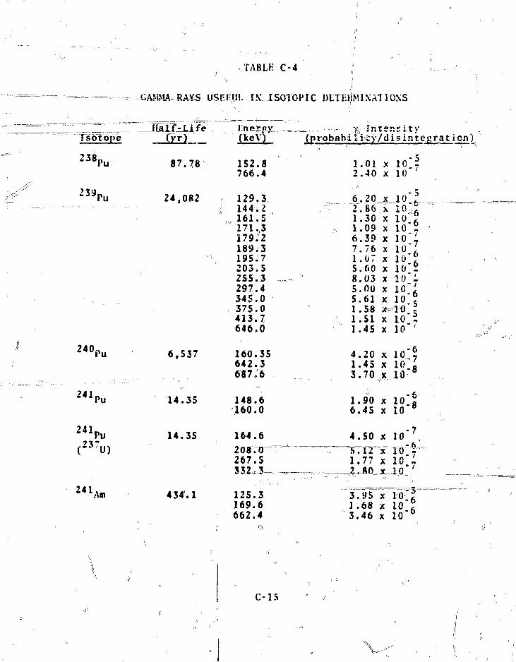
TABLE C-4
GAMMA-RAYS USEFUL IX...ISOTOP.IC DETEIjMlNAT 1ONS
— - - J - • - • • • •
TsotojVe
238pu
239 ru
— • • - • • • • • • - • • - • •
24°i>u
241I>u
H 1 P uC237U)
2 4 1 A.
Half-J-ife-(yr)
87.78
24,082
•;-'J
6,537
14.35
14.35
434.1
i
.tnera.v(keV)'
152.8766.4
129.3144.2161.5171,3nrii189J3195.7203.5255.3297.4345.0375.0413.7646.0
160.35642.3687:6
148.6160.0
164.6
208.0267.5
125.3169.6662.4
0
— , — r Y,- Intensity(probability/disintegrat ion)
1.01 x 10 -2.40 x 10"'
6 ,202 . IS 61.301.096.397.761.075.608.035.005.611.581.511.45
4 . 2 01.453 .70
1.906 .4S
4 .505T121.77
3 .951 .683 . 4 6
XXXXXXXXXXX
XX
XX
,,x.
XX
X
x~X
XXX
i o - | - ;lo.r
io.51 0 . 11 0 A1 0 " m
to":1 0 -610 ?
^10 "r10"T
io L.1.6"8
10" &
10 " 8
J o " 7 ,TO'f
10"6
C-15
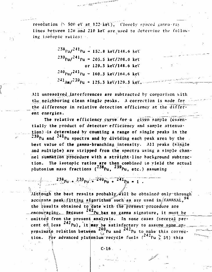
resolution ("- 500 eV at 122 keV), Closely spaced arirca-raylines between 120 and 210 keV are used to determine the follow-ing isotopic ratios:
' J 1Pu - 152.8 keV/148.6 keV
2 3 9Pu/ 2 4 1Pu - 205.5 ke\7208.0 keVor 129.3 keV/148.6 keV
2 4 OPu/ 2 4 1Pu - 160.3 ke\/164.6 keV
- 125.3 keV/129.3 ke\'.
All unresolved^interferences are subtracted by comparison withthejieiiihbcrlng clean single peiks. A correction is made for
the difference in relative detection efficiency at the differ-ent energies. 3
The relative efficiency curve for a given sample (essen-tially the product of detector?efficiency and sample attenua-tion) is determined by counting a range of single peaks in the•»«o '41
Pu and " Pu spectra and by dividing each peak area by thebest value of the gamma-branching intensity. All peaks (singleand multiple) are stripped from the spectra using a simple chan-nel sumnTatTdni procedure with a straight-line background subtrac-tion. The isotopic ratios are then combined to yield the actualPlutonium mass fractions (" Pu, Pu, etc.) assuming
Although the best results probabl^n.11 be obtained only through94^ f i t t i ng atgorithiSs^such as are used-iniGAMANAL,
the resu l t s obtained to date with Hie^rWent procedure are-encQ.uVag,i
will not be satisfactory,, and other procedures, such as neutroncoincidence counting, garrna-ray transmission, or K- and I.-edgoabsorption densitometry measurements must be used,
Calibration can be accomplished either b>L_cpmparison withstandards oXkRown^lsbtopic composition or by use of the funda-mental dat^ on half-lives and gairma-ray intensities. The firstprocedure is recommended for routine use because of the uncert-ainty uiso^e 6 f the half-life and intensity dava, but thefjujuLsmehtal data are extremely useful in predicting possibil-jitics and probable performance* Fvidently the following per-fsmance can be achieved: r ^ ; ^
„ • R a t i o Pu/"^IPu: < 1% (lo) for samples of arbi-trary geometry and composition, and ••""Better for morecontrolled samples.
• Ratio 2 3 8Pu/ : 4 1Pu: ^ 1$ (lo) for" 238Pu isotopicabundances > II. »
• Ratio 2 4 OPu/ 2 4 1Pu: ^ 10! (lo) for a 2 4 0Pu isotopicabundance greater then 15! and a counting time of1000 s. For plutonium recycle ( 281 *" Pu) and10,000-s counting times, better accuracies arc ob-tained. '
. • - ^ A m / ^ P u : < 2% (lc).This technique is^stjLn^ feeing developedy but encouraging
results have been obtained thus far. Results from somewhatdifferent techniques and more stringently controlled samplecompositions and configurations have also beerrrep&ftedT''
The second_jusefui Tnethod for selected isotopic analysis ofpovrd€fs such as PuO- and MO^ or other dense samples is the en-richment meter principle! which has become a mainstay fbr theNDA measurement of uraai=unh=Snrichment and is equally applicableto plutoniutr. The rae^hGdqjinskes-use ,of the, fact that the in-
tensity of a low-energjf gamm|"ray of uranium or plutonium iso-topes from a uniform 0Dject3lh^t has a major weight fraction ofuranium or plutonium is proportional H o the isotopic abundanceof the isotope emitting the gamma ray. The essential
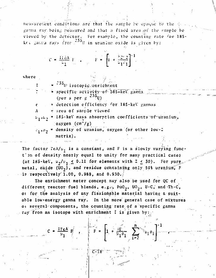
!=ur:i>urei\"ent conditions are that tin- sample he opaque to the ;
t;a-::r:i;i ray hern,; J'.eaMiroJ and that a fixed area ot the sample be
viev.ed by the detector. l:or exap^pio, the counting rate *"or 185
k( i ar..:;1;! rav> fror- " [.! in uranium oxide is -.;iven by:
I i <;A rL
where
'35I- i 5 o t o p i c en r i c hr.e n t
T = sjVecrfic nctriv4^r-c^
(per s per £ 235lj)
e - detection efficiency for 185-keV
A " area of sampjle viewed
U*tL-y * 185-keV mass absorption coefficients of™
oxygen _(cm"/g) •i:. , p , = density of uranium, oxygen Cor other low
matrix) . f
The factor TeA/u. is a constant, and F is a slowly varying func-
t'3n of density nearly equal to unity for many practical case?
(at itSS-keV, w,/^, £ 0.11 for elements with Z £ 30). For pure^
metal, oitide (UO-)» and residue c&htainijng only 50% uraniuitt, F
is respectively 1,00, 0.988, and 0.930./
The enrichment meter concept may also be used for QC of
different reactor fuel blends, e.g., PuCU, UO_, U-C, and Th-C»
07 for the analysis of any fissionable material having a suit-
able low-energy gamma ray. In the more general case of mixtures
oi several components, the counting rate of a specific gamma
ray from an isotope with enrichment 1 is given by:=
iTeAn
1 t jipi
-1
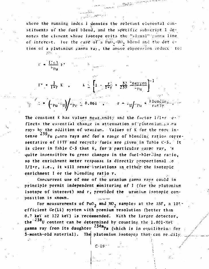
where the running index i denotes the relevant elemental con-
stituents of the fuel blend, and the specific subscript 1 de-
notes the clement whose isotope ei;>its the ."si j-mii" '-t air.r.a line
of interest, lor the rastro? a PuO,-UO, blend nrul the det c-
tion of a plutonium j;ariira ra> , the above expression reduce to
i : c \uPu
0.061 , - r - i : ' - 'hlenain*;
The constant K has values near~uftity and the factor 1/1 + r e- '.:fleets the essential change in attenuation of plutoniuxv ua..tarays by the addition of uraniun. Values of K for the rorc in-tense ** I'u £amra rays and for a range of blendini: ratios repre-
sentative of I fTF nnd recycle fuels are £iven in Table C-5. It
is clear in Table C-S that K, for a particular RaiMjrr ray, s
quite insensitive to fiross changes in the fuel-blcr.iinp ratio,
so the enrichment Vneter response is directly proportional .0
l/l*r, i.e., it will sense variations in either the isotopic
enrichment I or the biending ratio r.
Concurrent use of one of the uranium Rantna rays could in
principle permit independent monitoring of I (for the plutoriium
isotope of interest) and r, provided the uranium isotopic com-
position is Known. ?-===='
For maasurements of PuO- and ,MO- samples at the ASF, a 10V-
efficient (ie(Li) system with premium resolution (better than
0.7 keV at 122 keV) is recommended. Kith the larper detector,238
the U content can be d^tjernined by counting the 1.001-MeV
gamma ray from its daughter * mPa (which is in equilibrium for3-month-old material). The Plutonium i s o t o peDs t h a 11 c a n r e . d i 1 >r
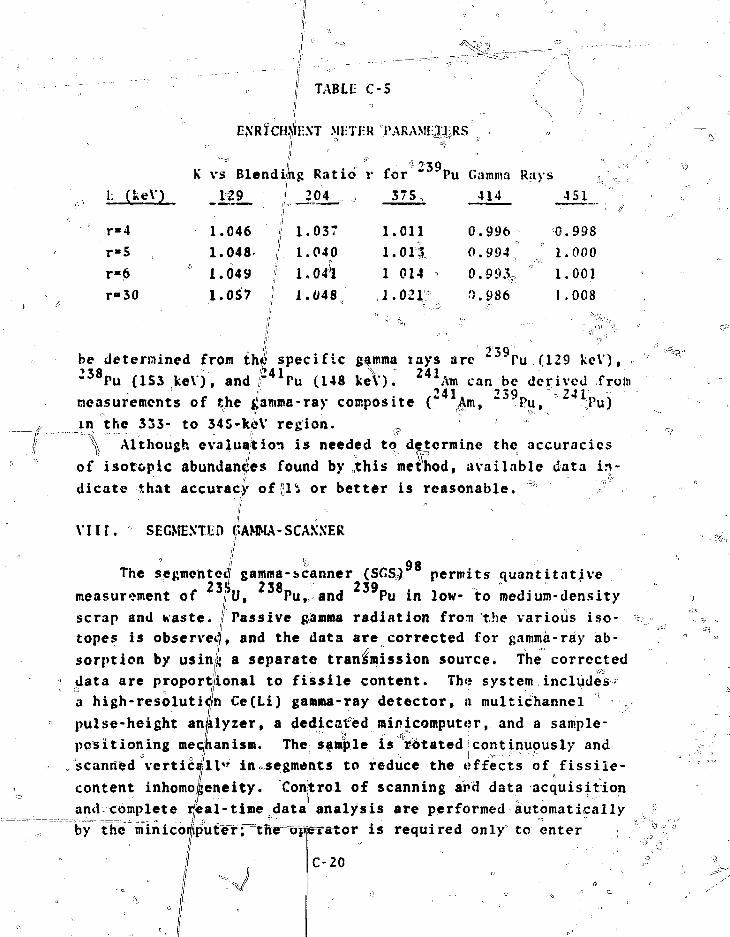
TABLE C-S
MI-TI-R PARAMIilURS
ii •- ' ^ 3 9K vs Blending Ratio r for " Pu Gamma Rays
1L (keVj
r«4
r-S
r-6
r-30
-ML.1.046
1.048
1.049
1.0S7
I 204
i 1.037
\ 1.04^
1.048
375O
1.011
i.o ii1 014
1.021^
414
0.996
0.994
'•). 986
451
0.998
1.000
1.001
1 .008
be determined from thi' specific gfmma lays arc *" Pu (129 keV),fl !}A1 \ 241"^Pu (1S3 keV), and f T u (148 keV). * *Ata can.be dej-ived froin
measurements of the ^amma-ray composite (** Am, " Pu, Pu)
in the 333- to 345-keV region.
\ Although evaluation is needed to determine the accuracies
of isotopic abundances found by ,this method, available data in-
dicate that accuracy of gl'i or better is reasonable. "
VIII. SEGNENTI-O CAMMA-SCANNER
QgThe segmelnted gamma-scanner (SGSQ permits quantitative
measurement of fu, Pu, and Pu in low- to medium-densityPassive gamma radiation from the various iso-
, and the data are corrected for gamma-ray ab-"
scrap and waste.
topes is observe
sorption by usinl; a separate transmission source. The corrected
data are proportional to fissile content. The system includes?
a high-resolution Ce(Li) gamma-ray detector, a multichannel
pulse-height analyzer, a dedicated minicomputer, and a sample-
positioning mechanism. The sample is rotated!continuously and
scanned vertically in segments to reduce the effects of fissile-
content inhomo/geneity. Control of scanning and data acquisition
anci^complete real-time data analysis are performed automatically
by thV~minico^put=eTT=inxe=TBp|eTstor is required only to enter .
C-20
sample identification. Quantities of 1^300 g.of fissile ma^e-; " • i1/ ' I '\
rial can be measured. Relative precision is 1-51, depending on
container size and transmission* The assay requires :-i> 10 s for
each 1-cm vertical segment. '
The segmented gamma-scan instrument' is shjpwh in Fig. C-:3.
The teletype, which is used for hardcopy output and program in-
put, as well as the keyboard used for entry of comments, con-?
stunts, and parameter interrogation make up the] unit on the far
left of the figure. The complete electronics rack is' in the ,
center. The two units to the right of the rack comprise the
scan table and Ge(Li) detector systems. The'transmission source
is to the left of the sample in this figure,? |md the detlector
with its dewar of liquid nitrogen is $o thefr/ight. ,
Sei',fi.ented gamma-scanning units are commercially available
and are used routinely at tASlT, General Aotofmi(f Corp., Atlantic,Richfield-Hanford, Nuclear Fuel Services-F.f-vfir
Operations, and elsewhere. I IISavannah River
•) I
ix.
Weight measurement" are the mainstay iof ti e material con-
trol program for the MO- plant, -covering// the vide range from
the few-gran ASF samples to the 200- to 18,00-kg bulk storage
vessels. Two types of weight measurement! will ibe used. The
first involves a determination of gross ivfeicht, the uncertainty
in which includes errors in -ero balance, hysteresis^ linearity,
and repeatability. The second type involves a determination of
both tare and gross weights in which thelnet weight is found b°y.,
subtraction. This method minimizes, if not eliminates,,, errors ».\ ")'• 0
due to zero balance (the largest error) and hysteresis, hence1 '
yields more accurate values? of net weight. ^Re^gjrdless ofiitheweight determirsation method, cal ibrat ion and check weig'hirigjpro-
il ' 1 ''I oil
dgrams should be implemented to ensure that acciirjate and reliable
weights result. All weighing systems should be protected from;i ° • I' " • ' '' "°
sudden overloads and horizontal forces. If properly used,weighing systems are inhere ntly stable and dependable'.'

I'IM p^->\!\f an,'i I \ ^ i s ro f nr.miui" and

f}. !j-,.,- The tivd types o f . w e i g h i n g i n s t r u m e n t s a r e load c e l l s and
'•balances,. Load c e l l weighing sys tems a r e used for bul|k q u a n t i t y
m e a s u r e r e n t s in t h e MO,, p l a n t , c . g. , for s h i p p i n g c o n t a i n e r s ^
c a n i s t e r s , weigh and feud h o p p e r s , and v a r i o u s storagcf v e s s e l s .
Theft range ol" i:;easui-,cr.ient i s " 1 - 8 0 0 kg , n e c e s s i t a t ing • the us<j>
o ^ j | e rhaps t h r e e c a t e g o r i e s of J|oad c e l l s with, c a p a c i t i e s of
10, | l 0 0 , and iOOf) kg.. Commercial., imit.s. avrii 1 a b l e f o r L t h e s c
c a t e g o r i e s d i s p l a y the following; r anges of nicasurcjrierit e r ro r s , ' ' "
( pe rcen t of f u l l s c a l e ) : \ ' "'," , •/'
q o
-er*> b a l a n c e
H y s t e r e s i s
„ Repca tab i1 i ty
>-. L i n e a r i t v ,,'
0.01-0. 0 51',-'
l.^a-d c e l l syftcfms a r e v e i l 1 s u i t e d fpr nuclear , m a t e r i a l s . ]
wo r k. I The wc i gh ing ,J \±Uitf°orrai can ' k |)h#sii\a U y separa11d fror.
eTec'f'roTtics„ and r ^ a ^ o u t mechanism,. Only t h e
p l a t fc,fr^nc%'4~(b° cxjpo^sed to» pieo( j?nvironnont • o i ' a g lovebox o r
Onth^rfeilc^rosure7-an|d i\he e l e c t r o n i c s can be jp1 l aced in a n ' a r e a
.^lle.p.s 'y-liccess .: fd;rollmaii|tsgnance and c!lal i b r a t ion . ° ° ; Ti, =• |
A i ^ f ^ c a ] b a l a n c e ^ a r e u s e ^ i n t h e AS1:; I'uO, powder inth
loat1 iin«from 2-5V g in" the A>n-><i|Ki O-J-O
sb a r c used in t h e ' A S F ; 1'uO^ powder
^and, I ' p s s i b l y , in MKT. Sample s i z e s rar\\ - •pb^wder ualoading
these r a s s c s , ().d)l - 0. 02 to accuracies can b \ read i ]v(; ob ta ined u lit
a wide var ie ty of commercially ava i lab le un^ ts . Jiouevc'r ,L h ig
prec is ion balances are slow} and are sensit=iv\ tp==e|KvTTronnienta
X.
i t 'n\np , u\, well
-cn:roRiM!.fRv ;
s^ei |nj |3i i )q |e^t^ vc~-^era- t \ r e r r o r .
PUito^ium cfa.lori;
J i e a t i i ^ rated
but
transformed into !ieafp when
io !o,ioi .• sr- - n. ° • ? ° B J
ciijj " r jnvojA'es the measurement: of=
oa.ptiy^ej decay of plutonium and
decay onergy i §!'o
fal^ha, be ta ,
—te
> = •
0 ft
v a ;'O
and -lpK-energy!! gamma) Ure absorbed by the sample and the ca lo-
r imeter walls. '1 Heat generated by a plutonium sample can be
measured accurately^by ca lor imet ry because the heat dete.rmjna-
_rrtion can be tralced t a primary NBS e l e c t r i c a l s t andards , thereby
e l imina t ing the' need for accurate plutonium s tandards . Table
C-6 gives* the h a l f - l i v e s , s p e ^ f i c powers, and e r ro r s in the
spec i f i c powers for, the radioRuclides con t r ibu t ing heat'i %
£ o The plutonium i so top ic composi t ian and ",, Am content durst
be kjiown oV determined i f* the amount of p].utonium is to be in- '
~f^erre4 fj-om the moasuted heat. : Table C-J " l i s t s the coinposi-i
t ion of recycle plutonium for^d i f ferent J-'urnups, alQiir, ui %\) the
f rac t ion of the to ta l , h!&\at j)rdduced=by., each isotoj 'e , the uijicer-
t a i n t y in the determinat ion of plutonium mqssM4uc .jto the uncer-
t a i n t y in abundance I^or each i so tope , and the spec i f i c |5OK«;r of
each byrnup iiimpIp5 _J i^urip C-4 shows the precisjoii of masJ*-".,.•>
spect r o n e t r i c is(|top;ic 7dc°terninat ions as a furict^01^ 9' alnfndaiice
lor both an NB$ standard (optimum case) and a plutonitir: n i : 1 a t c
process solut ion;i Qioorly charucterizfeil r f a t c r i a l j . " • If clo$
c o n t r o l l e d , tHe InominaJ cosj)3 ed i t i on for .a process l ine may hj
adequa te ' fo r fcjxUand product" m a t e r i a l s . <"n t!|c other jiajijl,
scrap and wastep ma te r i a l s teml to have -Variables plutonium <|:oift="
pps i t ions and "^-An content.0 /Asb a° r e s u l t , e r r o i s in the .iso-
tSpic determinat ion are usual ly the l a r g c s | u n c e r t a i n t i e s , in
the plutonium mcasurement'L Uncertaint ies >Lio ^v>;ist tij-tho
spec i f i c potters, hent 'iiet'?r"ninat ion, heat d i s t r i b u t i o n , and lieat
p r q J t u e d by r e a c t i o n s >uch as r ad fb lys o i s . S t i
plutonium determinat ion bv c a l o n m e t r y t y p i c a l l y is3 acci;u;ai
b c t t e r t h a n 0.5^<Kith p rec i s ion bett^tfl'Warii, O^'^i?
t .alcrimeiry measurements are usually; tvin-.c-cpinsumin^ because
the sample and c;,i 1 or,imet;£x must' cojnct°o'L thetR)a! c<|ui 1 ; '
befori? the heat ^determination can be made, ,3'or ";|*u(\7<.fccdas.
" tion Htime» Can bt^ie^st hart f §IT* s'' 2^'JR*" "fife
r 0
l C j i b°e
i
irpd.
s°i;e -? t
'In caso°s
ib
1 °li; -'A c a l o r i m e t e r has Ve^i l bui1 ? (e a e h** 1 -im^ i a r? v b y Qj >-%' n-* "l c n >
• 1 .
ra-
l t 0
•3,'.«

TABU- r - 6
SITCIl|IC
41", Isotope =- " Half- Life (yr)
259n
-... - l u
° 240.,Pu
24 l nu
'Pu
6 , S3"
' U ' 1- '5 "9/000
454.1
01 n.UTONHJV A.M.) AMIiHICIUM
Specif ic Power (W/gj
5.671b x 10
1.9293 r. 10
-1
- _•>
7.098 x 10"15
3.390 x 10"
1 .146 x 10
1 . 1 4 2 3 x 10
-4
-1
U n c e r t a i n t y inSpec i f i c , 'Power (°a> l c )
a, JO
0.2
0.06
0.14

T A B U ' C - :
24 h'u2 4 2 P u2 4 1 A,
2 4 I P u24 2 ,2 4 1 A H
240p u
>M'Pu24J224! Am
241,,,,2 4 2 Pu241 A/n
'CALORWI.'TRY 1 k!?H !K>[VTO ^Ci lM'A J NTI ! S •• I .
( i n ' ' ' , | '2-a,, l e v e l ) /
R e l a t i v e F r a c t i o n ofMinJanco i " I Tor a ! l. ''» t L i i. J I^ ( I I . I . J *yty\ ,i I ..•Sput- i f ie ' ,Power :
1 - . S ; •"_'
5 2 . 6 .'•'.; . .-
22 .4
-.&• 5^r
0.01
0
87
10
2
0
0
.1
. 1
.1
.4
. 3
. 1 3
.iaccrtaintv i n\buini:
3 .1H
", ' 50
0.
° 0 .
'•••' ' 2 .
3 .
n i c e (•'• )
raK/'K
•9-, V -
it41)
S2
-•3
A "' •
Uiu o r t a i i : t \I'l u ton i tr'i 6
' 0 .<i i J
0 . K>
•• , " T 1 0
0 . O H
0 . 0 0
0 . 1 (••
.25
. 5
..5
.1
. 24
0
•'s18
4
'"\
0
1.05825
970.48
2
45
"•7
15
11
0.
U'i.l/T Specific•••f'ower:' ;;
,. ..' 30.731.6 , - .28.43.3 ,,, .0.03 ;
5.9c- v''
W.jAl1 Sp ec i f i c Power-
60,2
11.918.83.2
* 0.09: | "'] . 5 . 8
, , . _ . J L _/•.'• ..
f ie Power:
12.43.30.085.2
'(A
O
Total4 . 6 J nlV/8
2 • %, 0 .13
• 0 . 3 0
0.60
9 .4
^ T o t a l
mlV/g
0.26
0.4 3
0.43
Total
0.391.5
Total
o .C-26
0 . ''(I
0.10
0. 10
o . n :0, 00
0.15 'BT^2
0.04
0.06
0.01
0.00
0.11
0 ~h(<
0.04
0.1*1
0 .00
n . o s
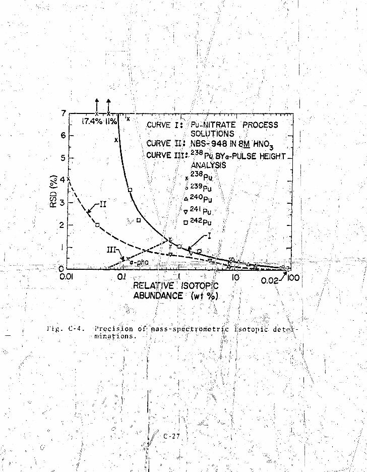
7
6
5
••] "—"J^ jn ^ • y » . | ^ f
17.4% CURVE i : VPu-fjJITRATE PROCESS'. L SOLUTIONS ;i -,' •;.
CURVE 1 0 NBS1948 JN SM HNO3 ••'.;CURVE m:2?8P| BYa-PULSE HEIGHT.
'!: r ^ • 'a : A N A L Y S I S :> : /V - - , , f ' -^ 3 8 Pu: l : ;' ; / .
O.OIRELATIVE ISOTOPfCABUNDANCE (wt%)
0.02.7l00
]"ig. C-4. Precision of mass-spectrometr^c isotopic deter- minatj ons. /
C-2 7
containing 13-26 g of plutonium) in 20 nrln. J In addition,
techniques for predicting calorimeter equilibrium heat values
promise to substantially reduce sample turn-around time. Recent
results indicate that calorimetric assay times may be reduced
by1 more than a factor of 2 while predicting equilibrium values
to uithin 0.05*.
An automated plutonium assay system (Al'AS) * that uses a
calorimeter for plutonium measurement is being developed by
Mound Laboratory as an accurate in-line glovebox assay system
for MO., fuels. A process control computer will control the
movement I and measurement of the samples along a glovebox line
in addition to processing the resulting data as part of material
control and safeguards accountability programs.
In the current MO- design, the benefits from in-line cajo-
fimetry did not compare favorably Kith less costlv measurement
strategies. Questions concerning nonequilibrium ..calorimetryj
and effects of entrained moisture for the fe'ed'TuO, material
are not resolved.
o •• 'i.
C-28
\\
APPENDIX D
EVENT DESCRIPTION' OF MOXSIM:BASELINE MIXED-OXIDE PLANT SIMULATION PROGRAM
I. INTRODUCTION
MOXSIM provides a time-event Monte Carlo simulation of thebaseline MO. plant operation. ' The plant is divided into11 main process areas and 2 peripheral process areas. Processoperation and-ma te-f la 1 - f4ovs^;rrc-rnodoTcd™onr the has is o f t heplant definition gi'Ven in Chap. II and Appendix A. A scheduleof material flow events is supplied for each unit process; theevents are properly Sequenced by the controller of the GASP IVsimulation program. GASP IV also allows continuous simula-tion for treating dynamic system behavior and process controlfunctions.
Each materirai—Tiow event t¥ associatedunit process: batches are selected from uniform distributions,inventories are updated, and event data are stored. ' Only trifematerial flow dataware generated, i.e.. no simulated measure-ments are applied. The code; has provisions for linking succes-sive weeks of continuous operation, for varying the procejssoperation, and for inserting various diversion schemes. I!ven.tdata irom each week of simulated plant operation are stored^ina permanent file for access by the measurement^siniulation and ^analygta-er-ds MACS I'M. Typically. lijllor jiaju;xlall..f low eventsoccur dut; ,s 1 wk of simulated operation, this representsabout 8000 individual material tjJransfets. *
The operation of eafh jtmj^|j)r^£es^=^^Jieianc^ ,lowing events: an initiil event that specifies starting inven- 5
tories at the Beginning 'dfaJ=th.e_,we.ek> at..=le-ast,--one;---p.ro-cess event,and a final event of ru|uguis that determines final inventories /
" D - I •'. " ' jr'- !'-: -', if
at the end oi~ the ueek. 1'ach event is defined In' data entriesstored in a 10-dimensional vector. Kith a few except ions,•thetype of data stored in each entry is:
UP--unit process identification number
Tl--tin:e of the event
BI--input batch
RO-.-output batch
SM- -scrap
IVM-waste
ilU--holdup, usually accumulated via an asymptotic node!
AS--samples for analysis
in- - losses , including addit-ioivai holdup aiui/or diverted
Material. "XM--e.\tra variable, often used for in-process inventory.
Thus1, each event can represent as many as eight material trans-• f : i . '
fer*. l o r example, cons ide r a un i t p r o c e s s - i n which measurable
holdup is accumulated in v a r i a b l e HU, addi t ional , holdup is
.accumulated in. PV, and in -p roces s inventory r e s i d e s in XM. ; A
t r u e n r i t e r i a l hal -an-ce MB_ Xpr s J : J ien : J v c n t is yiven bv " •••,
ML5 = XM , + iltl ~, + DV , + BI . - XM • HU - DVn n - l n-1 n - i n ~ ~ - - - — - n - • • • • - - n = - — = - i
-BO • SM - IVM A - AS ,: ""•• = ^> n n n „ n ' • _ ^_
and MB = ()' by d e f i n i t i o n . U'c have v e r i f ij?d J that __
a l l ma t e r i a l balances^ in ^ Q X S T M ^ S : l§vo> _ _ ^ _. ;; ;]
Although s h i f t s and weeks, of j irocesadng are used as event
f i d u c i a l s , the ac tua l p rocesses w i l l seldom be synch^bnirec!
uitli-j;thcir. This has no iiiipoi taii t e f f ec t on the mate:riiU.=fioK
s i m u l a t i o n , aud-^'shoufd jiot~lberv'=i'ewed~as---.-.n process cons t fe i in t . A
The nSiiii ft ^slrwcty re is a convenient se t of f i d u c i a l s usefu l for \
s i m u l a t i o n , personnel sch(| |Ailing, and1 some d i s c r e t e event . \
t iming . I ,v ' --^.""-^'-^ "" •• -, . »^^ \ \ \
XP-2
rTTnxl;Y UM'i J'KUCi SS
This sec t ion o u t l i n e s i n i t i a l , p rocess , and fiiuil eventsfor each unit process in MOXSjy.. iiach nonnero mate r ia l J'louthat i s descr ibed -is __a uujXcnri randoi:: va r i ab l e i s i d e n t i f i e d ,and i t s ran.i;e i s g iven.
About 15 00 events are t a l l i e d by *!OXSIM for a s ing le weekof p lan t opera t ion . These events contain perhaps SHOO .individ-ual mate r ia l t r a n s f e r s vrhich occur alonp sowe, 90 flow l i n e s .Only ;s r e p r e s e n t a t i v e sainpiy of the sin-ulat ion d.ut;r can he; >ri venhere . M a t e r i a l flou data are p l o t t e d \in Figs . l)-l ami V-?. ,i>T =~Sec. I'-I II in tJu..s,,-appe^nuj_x__Xp,r_ra ty\yiJial'^^ckof l'u0o powderunloading and p e l l e t i n g c p e r a t i o n s . i
A. -, kecciyIni;.::Jajxd^^to-yagc7,-(l-A-,- 2A)-|y, a
. {U'H- y,9_n:1. I n i t i a l . XM, in i t ia l \PuO-,t a i n e r s s to red ijj the v a u l t , in kj; PuO-,.|
2, Process . One shipping cont.a\jiB:t,. i s , sent to the PuO.,inUoad ing s tnT ien i / , 2 . JL a f t e r the s t a r t ^ p f ; t i |e s h i f t . Thisoperat ion occurs during one s h i f t each day fc|r five consecut ivedays each••••weefc'-;™" '•' .--/r^-^-,^;. ';. _ . _ _ | "', _
• i5U, conient's o i one „ s'tiipplng-eontaineT,,
XM, PuO. inventory alrrdic^^^d-^if^h^-^^^^
3. Wlhal. XM, i'jaul Pu0^inventoxy= i n s to rage v a u l t , inky PuO,.
B.7 PuOy?Un:loadinfi (5A1
*The numbersVln
Illi;, i n i t i a l holdup irtj; tire^Tieymatic ]->owdt?rlii|e~to PuD^bjulk nstora^c i; in kg PuO,. S^
baseline p 1 a%t definition, (see:fSe.c. If-
• - - " D - 3 ' " • • ;
\\! \
0 ' ,111
i n
-#
• f>V, initial unmeasured holdup in the: room filters,
gloveboxes, etc., 0.1 kg PuO? minimum.
• XM, initial inventory in the PuO- storage tank to be
filled, in kg PuO,. ;
2. Process. One shipping container with four canisters
of PuO, powder is unloaded each shift. One canister is unloaded
to bulk storage every 2 h. The pneumatic transfer line is run
out after each canister is unloaded. "This operation-occurs' one
shift each day for five consecutive days each week.
• BI, contents of unopened PuO, canisters, 7.92p^.0| kg '
P U O 0 . ' " . . •C;-':- i; *.- ! '; •
• KM, residual••"-'Waste in empty canisters that are sent
to MhT, in kj«, PuO,; -rtfM = IVF-BI, KF = G.001-0.003,,
the waste fraction, -i-'-"--""'"'1"" """ ^ ^ -----i ; .,i: _.
• I!U, accumulated holdup trapped in the transfer line
after runout, 0 - 0.1 Jcjr PuO,, plus holdup trapped in
the valve that routes powder to the PuO-, 'storage
tanks, 0.15-0.25 kg PuO,.
• AS, samples to the ASF from each canister, 0.002 kg
: PuO,. ,
• DV, accumulated holdup in the room filters, etc., at
the end of the current cvent;, in
DK-BI, Dl\* 0-0.001, the holdup fraction.
• BO, jiovrUef received lift "the Pup_ storage tank, in kg
PuO,. , '
• XM, inventory in the i'uC, storage tank at the end of
the even;, in kg PuO2«
3. Final. Holdup trapped in ihe conveyor and routine
valve is cleaned up and sen* to the PuO, storage tank. Holdup
that is cleaned up from the unloading station is sent as waste
to MIVT.
PuO_. ADV =
IVM, holilup thai
-!W~^^:
i s cleaned up and sent to MKT, in kg
p in'the pneumatic transfer line after
PuO,. \
\
I 11..1
D-"4"
C.
AS, sample sent to the ASF from''the, filled PuO,storage tank, 0.027-0.933 kg PuO-.DV, final holdup in the unloading room after cleanup,0.1 kg PuO, tnininuc.XM, final inventory in the filled PuO- storage tank,in kg PuOj. //
PuO.. Blending and Bulk Storage (4A)
1, Initial• BI, initial inventory in the PuO, storage tank that
_ — • . 4 *
is feeding the blending process, in kg PuCL.• MU, initial holdup in the pneumatic transfer line to
the PuO. feed hopper, in kg PuO,.• XM, initial inventory in the PuO, feed hopper, in kj:
PuO,.2. Process. A batch is sent from the PuO, storage tank
to the PuO, feed hopper at the blender 1/4 h after the start ofthe shift. This operation occurs 20 consecutive shifts per ?
week.• BI, inventory in the PuO2 storage tankat the end of
the event, in kg PuO,.• BO, batch transferred from the PuO- storage hopper to
the PU02 weigh hopper/ 7.92-8.08 kg PuO .• W*i, waste sent to MKT from each batch, in kg PuQ*; W
» hF'BO, WF • 0-0*0005, the waste fraction. j• HUjthe pneumatic transfer line is run out to hel i
PaO, feed hopper after each batch. HU is the holdviiin the line after runout. O^O^lke FuO,T"
• XM. inventory ih the PuO- feed hopper after chargingthe weigh hopper. 1-2 kg Pub_.
storage tank, in kg
transfer line toPuO,--fe«d-hippe.rt- in
n-sit.

• XM, final inventory in the PuO, feed hopper, in. kg
PuO,. " \ |
D_. MO, Blending 15)
1. Initial
HU, initial holdup in the pneumatic transfe\f Tine:
the blender to the MO, powder storage silos,\in kg
2 : ;,
D\", initial unmeasured holdup in the blender filters,
etc., 1.5 kg MO, minimum. —
XM, residual holdup in .the blender, in kg MO,.
Process. The blender is charged at the start of a
U0.shift /.rom the PuO,
lows.'2'
and recycle MO. weigh hoppers as
The HO, batch is determined from the PuO., batch to sat-- i i -. '•
isfy constant plutonium enrichment (4 5'PuO- by weight); the
recycle MO, batch is assumed to have the same plutonium enrich-
ment. The total blender contents jjjjne^sub-blend ,J 225 kg
MO... A sub-blend is transferred to an available MO, storage
silo 7 li after the start of the shift. This process operates 20
consecutive shifts each week. = °
u o , , \l151, t o t a l input to the blender from the PuO,
and recycle MO, Keigt^ h o p p e r s / i n kg MO,. _
SM, dirtjj ' scrap "to MhT, 0-0.2 kg MO2. " - n .
U'M, waste- sehi. to MUT, "0-0.2 kg MO-:
the pnjRiimatic traiisffer—line t o - t h e s i l o s i s run'' i S r ^ J ^ ^ ' " ' r-'' is
, - - •<—v' -v—
o\it afte^f=reachj event . HU \s the holdup a f t e r runout ,
hpi
AS, ^ n a l y s * 5 s.ampjles from a s \ b - b l e n d , 0 . 0 2 2 5 - 0 . 0 2 7 5
^ f n kg MQ^; ADA' > DP-BJ^DF =4
unmeasured, h o l d u p . •> ,
J, - - ^ s ^ .
DV,
0-0 .0092r••XM., rejjLdual hjold|ip in the blender." The blender i s
i s the holdup in the
; = 5 = £ f e & - 4 ! Q 2 . 1 ^ , . - • • - • - " - - a -•',-
e sub-.b4endo transferred to a s,iio,
i n - kg MO2
n-6
Tinal ' ' = T i
SM, unmeasured holdup that is cleaned ./up and sent to
MUT as dirty scrap, in kg MO,.
liLJ.J final holdup in the pneumatic transfer line, ill
kg;MO,. ,, : \,.. ' - ;: /
DVj! final holdup, in kgHP,. -
XMj1 final holdup in the blender," in kg MO,.
(6)
\
i. Initial
• BI, 'initial contents of the next full silo available
for 'emptying, in kg MQ->.
• UU, initial holdup in the pneumatic transfer line frorB"
the silos tc the compactor" feed hopper at the 'pellet-
ing operation, in kg MO,,. * >
2. Process, Start of Shift.:. The silo is checked; for QC '
release. If the sub-blend is rejected, the contents of the • si lip
are sent to rec>xle MO, bulk storage if acUr;ua,te storage is
available. One sub,-blend is rejected each u-ee)'(, on the average,
A QC-relcased silo is selected to feed the pellet ing o] eration.
• 1U, silo contents selected to feed the pelleting o .,.
operation, in kg MO... , ''
• SM, silo contents rejected to recycle M07 storage," 'in
kg MO,.
• UU, initial holdup in the transfer line tOjthe con-" 0 » I, il
pactov feed hopper, in kg M0-. '•3. Process, MO- Powder Transfer to the Compactoy Feed
Hopper at the Pelleting Operation. ° The'amount of MO,} trans-V
TcrroJ to the compactor f ed hopper is "undated each hbur,
beginning 1 h after the start of a shift.' This amount \s_ deftpr-,.
mined by the pell'etinj; operation. The silo is^run out, ••> n
7 h after, the r:§tart of a
is estimated to be 'v 0.05
is neglected in thf; model
compac|or feed hopper is
This operation"occurs for
er
"f;i
Residual holdup in the si
kg'MO,, Variation in thisi quant it, *• -... <- : i i
The pneumatic transfer l'lnesto|tun cut after the silo.is ewptie<
19 consecuti\re shifts each' weok|

; •• • BI>, inventory in tht silo at "tiro end of the event; .;
the silo is emptied and'Vun ou| -he fore' the end of "the
shift, in. kg M 0 ? . •• ' o
% • SO, powder transferred :t-p the compactor feed hopper
, ==- during- the previous hour; "the rate is set by the, pel-
leting' operation, 30-35 kg: MO^/h.
• HU, holdup in the pneumatic transfer line; the asymp-
••"> totic ievel is 2-3 kg MO-,. The transfer line is run
; T out before the end of the shift, 0. 2 5 -f^l- -5 kg MO2>
4.'Process, End of Shift. The next full silo available
for emptying is selected. ' frf"" o"
'#, BI, the initial contents <oi the next silo to be
emptied, in kg M0 s.
• HU, holdup in the transfer line at the end of the
i shift, in kg MO,. „ =#^ ;^ '
• " 5» F i n a l . _ , , ^ - ,c . ,- •
™ , • HU, final holdup inVthe pneumatic transfer line, in
F. Recycle MQ^ Blending and Bulk Storagte C4C)
1. I n i t i a l ,. , " *' • "' » ,; rr'" :\ ,?
• BI,; initial inventory in the recycle MO- storage tank
that has been QC-released to feed the blending opera-
tion, in kg»MO^. P " -'' • c•• • • HU, initial holdup in the pneumatic transfer line from
the recycle J O9 storage tanks to the recycle MO- feed'
egv |iopper at9-" Blending, in kg MO-. ^ °• =XM, i n i t i a l inventory in the recycle MO- feed hopper,
iii kg M09.2. iProcess. A recycle MO- batch is sent to blending 1/4"
h after the start of the shift. The pneumatic transfer linjp to
the recycle MO2 feed hopper at the blending operation is run
out after each batch. This operation occurs for 20 consecutive• I " '•' \ •••
shifts each week. i \ -• BO, recycle MO_°batc|i that is sent to the w'eigh hopper
at the blender, 25-3
D
) kg MQ2.

HU, holdup in the trajrafer lin* is run out after f
each batch: HU isyehe holdup after runout, 0.1-0.3kg MO,. ' • <» M •• .. • i
XiM, the remaining inventory in the recycle M0_ feedhopper a f ter charging the weigh hopper , 7.5-12.5 kg
• B If3 inventory in the recycle MO- storage tank feedingy the blending operation after the'event, yiJifi M O T
3. Processt End of Shift:+ WM, waste that is sent "to MWT, 0-0.2 kg MO.,.• * HU, holdup in the transfer line at the end of the
shift, in kg MOV.° "•-'•fc 0 a y, O
t XMjtifivefttory in^the recycle MO- feed hopper at the^ end =gf the shift, in kg MO2.• BI, inventory in the recycle MO2 storage tank feeding
the blending operation at the end of the shift, in kg
4. Final• BI, final invehtdrj? iftthe recyHe'MD2 storage tank,vr
in kg MO 2. .. . " ' ..; •• ' /" '
• HU, final holdup^in the transfer line tp'the recycleMO2 feed hopper, in kg MO».
• XM, final inventory In the recycle MO, feed hopper,in kg MO2.
G. Pelleting and Green-Pellet^Storage!(7^8) y
1 . I n i t i a l - " "»••> ' , ..._.. _
in the compactor feed hopper,BIr initial Uin kg MO2.HU, initial inventory in the press feed hopper, in kgM O , . ,, = , " 'L . - • K •• •".. ' •, "
DV, initial unmeasured holdup in the pelleting opera-tion, 2 kg MO., minimum.XM, initial inventory in green-pellet boats stored on/the mechanical conveyor to the sintering furnace, inkg MO
2.D-9
\ ,
' "-• Process, M0o Powder Tran/feY Yr,om QC-Re leased Si 1 o "• • ! > . - _ _ . -.... ^ . . - . ^ t ^ " ' ' l i r " A • •- ii
to t-uOTpactor t-eedJHbp;rer*.\ The/'irive.ri'kory of the MO-,?iPoudoi>'-'cc' -Tf~~—:—\, -•- • \ \ . - \ - /
pactor feed hopper is updated hourlv, s\artd*ni; 1 h aftVf^fi .shiftbegins. A green-pellet bbatN^i;' loaded and sen^ to storage every,1/2 h s tar t ing 1 h after the 'Star t of a sjt^ftj^a maximum, of= 15boat-fe-is stdred by the- end of she sh^ft^ The opCvC'at ion occurs ;for 19 cons ecu tU^&HiJ-
• AS, M0? poi\'der="received at the-cofiipactor feed hopper'during th«:- p'revlous hour, 27-33 kg;M07. (An addi- - 1
3Ttslr=4U^L2U^k^g MO« are" recei%pt?i at th£ heglifiu'ng"r" ^of the simulation for s tar tup . )„ ; "
• HU,S irrventory in the press feed Kbpper after tJieevent, 5-10 \cg MO,. I"; / o
• ,DV, accumulated holdup in the pelleting operation, in
»=======—J^JJP^i==4D^_j^0_^0JL5j^Ei_^t) kg MO,/boat.
• § 0 , c o j i t ^ ^ n t s = o = f a - l ^ o a i l e i L .gire .en.r p _ e l l e J L b o a t ^ I 4 . 9 5 -
1 5 . 0 k g M O , . ' ° "• '
• BI, inventory in the compactor feed hopper after the
event, in kg, MX^*
• XM, inventory after the event in the green-pelletboats stored on the mechanical conveyor, nrkg MO 7.
3. Process",, End of Shift * y\
• BO, the last boat of the shift that is loaded, 14.95-
15. 0 kg MO.,. ,
• SM, clean scrap that is collected in Containers,
0.5-l.S^kg MO,. ° ^ ' o ,
• WM, dirty scrap and waste that is sent to Mh'T, 0-1,2 ,,.
HU,, contents of Tie? press feed hopper at the end of
the shift, 5-10 kg MO-. • , '
DV, accumulated holdup at^the end of the shift, in kg
MO,; ADV -0q.0r5- 0. 030 oKg MO, /boat •=-===-=—=
BI, contents of "the compactor (feed hopper at the end
of the s h i f t / i n kg MO,. "*~ , \
D-10

• XM, inyeiitor5^'t7f=];xtfe=h^j)el l e t Kb;lts s t o r e d on the
conveyor t o s i n t e r i r . j : at the end of the s h i f t , in kj;: 5
4_. I ina 1. Load the f ina l boa t s ofs>the blend ar.if c lean u;1
the pefclet ini'. p r o c e s s . ' •-••=*=, Jft = • . ' ; ! • \ = *
• BO, f i n a l g r een -pe l l e t boa t s .that ray c o n s i s t of
one p a r t i £ y . v loaded boat ('- 15 cK^ MPn): or one fu l l
and one p a r t i a l l y loat'ed oboat , iif k.u MO.,. /
• lil?, r e s i d u a l holdup in the p e l l e t j)rcss feed hopper
a f t e r runout ,} in kf J '!<3,. s,
= '• • hi, residual |ioldup" in the' co)::pacLorr,feed,.hgLn{>er, aftcjjr:
• 5 r u n o u t , U K " k g j ! ° M O , ; . ' " . .,.._,. #.v;.,, • - 1 / ' ,."
• .SM,,-clean scrap from runout,oof the compactor^sand press
^ , feed hoppers, and fror. cleanup of holdup sent t6 ci^in
scrap ^tftrape, in kg VO,. „
/MI . ___JWli_r_j£sidu-a4-=4?=e=l'd-up afte^ cleanup, 2 kg MOv1'nininium. li• XM, final inventory in greenrneliat..hoifts, in ki?f..Mpi. ,„
• *? . ~=st=s=L~ , 'U. S i n t e r i i t g and S i n t e r e d - P e l l e t S torage (9 ? 10) 0
q
1. initial =Q . ;'?
• HU, initial inventory in the sintering furnfaces, in J^
• XM, initial inventory in pellet boots at sinterejd-
° pellet storage, in kg MO,; ° ° 0 - v
2. Process. A green-pellet boat is input to a sintering
furnace, and a sinteredc-pellet boat0 is removed from £ furnace
and sent to storage. One output sintared-pellct boat is re«
turned to the input stream for resJbntering each shift, on the
average, tvents occur-5every Y/JTK and/2t consecutive shifts |
occur each week. ° „ ,, ??
- cy:> • BI, one green-pellet boat input to the* sintering
S.M, $he contents o'ffa s intered-pel le t bo^at that hasbeen rejected tp clpttL scrap" storage, in kc, M0-.
\
A\
yX
-11
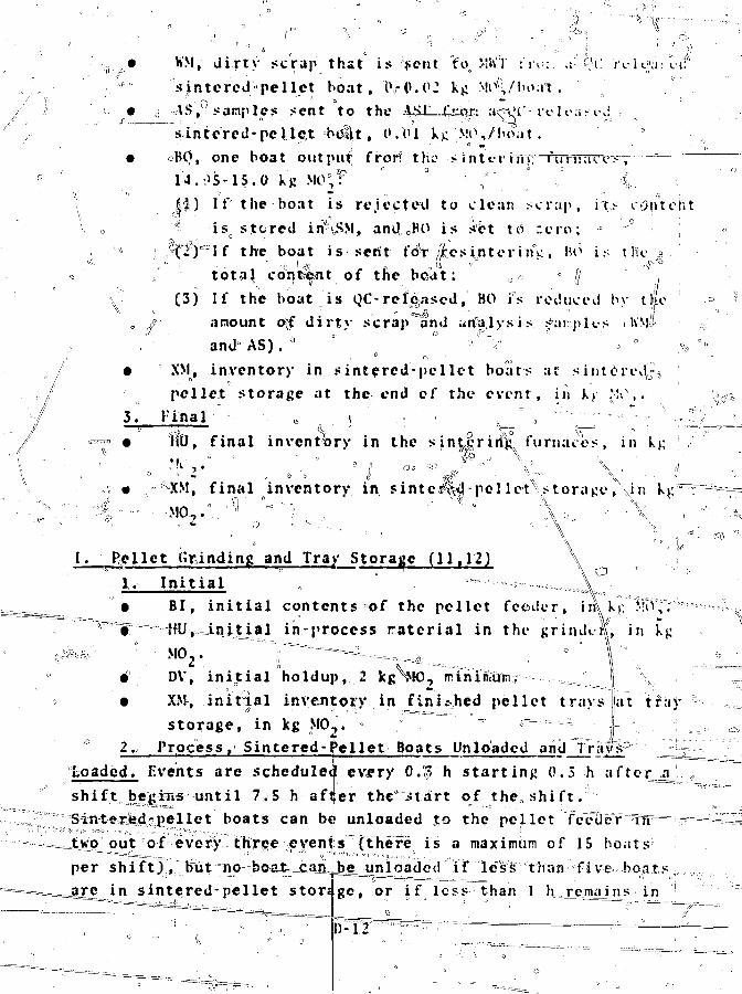
•""T
KM, d i r t v s c r a p t h a t i s s e n t "fo, MWT f r^ ; . .t--&i: i v i o^-lif1'
" . s i n t e r ed ; 1 -pe l l e t b o a t , t V P . 0 2 kg S!tvi,/!>«.-« a°t .
• <] AS, samples sent to the
sintered-pellet bel t , tf/Ol k.c N!P,/hoat .
• oBO, one boat output fror? tho sinteriTTt:"firninvry, •==—•0 i 4 . 0 5 - i 5 . o kg M O ; ? : '• ;••' ' ! %_ •
J J ) If the boat is re jec ted to clean sc rap , i t s content
: o ' iso s tored inHSM, and oB0 is s-rct td : c r o ; *
"•'• :: ,%f)°If the boat i s serit foV Acs i n t e r inV . NO i •'• t He
t o t a l c d n ^ n t of the boa t ; 0« - /"/ J „
(5) If the boat i s QC-released," BO is reduced by t | e
„ / amount o>f d i r t y scrap and analysis , .far.plts 1 WM&
."• and6 AS). * ° a ° ' ^ V 0 a %/
/ • XM, inventory in sintercd'-pellet boats at sintered,;-1^
-.,/ pellet storage at the end of the event, in k> .'-S\.
''/ 5 . F i n a l - ' •• o « ; " • . % " ' 'x^ ' " " • •;•. " :^
/ =^ • V(tl, final inventory in the sin|^rirfX furnaces, in kj;
•h'f ' B I 00 ";r> -'~ """ \ ° \ . fj
• SXM, final inventory in sinte^%^-pellet^storage, \in k^r^
I. Relict Grinding and Tray Storage (11.12) \
1. Initial „ " "=-—s «=,=;,.,,:\
^ ^ ^ • BI, i n i t i a l c o n t e n t s of the p e l l e t f e e d e r , inVkj: MT^,.
'V*'3"t"===-=KU^--J..njtial i n - p r o c e s s r a t c r i a l in the g r i n d t L in V$
DV, initial holdup, 2 kg^MO, mi
• XMv initial inventoijiy in ini^hed pellet trays at t'faystorage, in kg MOj. = = — - - L
2. Process, Sintered-Pellet Boats Unloaded andTrafiP lii;Loaded. Events are scheduled every O.p h starting 0.3 h ashift be|iTss until 7.5 h afier the ".start of theo shift."Sintexkd^pellet boats can be unloaded -to the pellet CccUbf
' • f v -•*>•• , . „ „ , ; • „ ; • ° r j : - \ " - . . , , , . . , . 1 _ _ _ . . • .•''•
Jtwq^out of every tKree evenfs (there is a maximum of 15 boats
per shift).,,^biit ^o^be^u^cajijj^e^jinloadec! if less than five boatsge, or if less than 1 h^reinajj^s in
a
^ n sintered-pellet storj
the shift. 'Irayh are loaded at° each eveont, starting 0;6h^ after-
a' shift begins until 7.5 h after the start, of th«y shift (there
is a maximum of 24 trays per shift). " All trays are completely
filled. Jhe^ pellet feeder and grinder are runout by the ehd s
of the shift. The operation occurs for 19 consecutive shifts1!
e a c h w e e k . . "''" . ~- •• • ':-5'' • " . . •
• ' ™fWv&oflients oj" a sintered-pellet boat that is ur- ',;
loaded=pto the pellet feeder, 14/195-15.0 kg°MO2. ^
• r |O, contents of a tray loaded with finished pellet$
that is senjfjto traj.1 storjage,0 9.0 kg MCL.
• =MU, in-process material^at the grinder at the end Of
•--«-'- -^thej^ent ,,5-10 kg MO,°. o ; ,
'~«--~~~ # , SM, dried grinder s Iudge that ijjcollecte°d in a con-
tainer as clean svrap, 0=. 2-0.4 kg MO2/tray.a=5=5=*4.« DV, accumulated holdup in the grinding operation, in
=zr-^= kg MO,; iDV • 0-0.01 kg MO2/tray. ,;
\ • XM, pellet feeder .content at the end of the event, in
k 8 W , . V - e '
V. Processf End of Shift. The pellet feeder and grinder
"^eT^T?^V^"vdTi¥irbiTS--j>e-llst-s- are returned to the input
stream.- W ''''""-
• BO, retrievable finiphed pellets at the er.d of the1 ; •,•• • • " ' h
^ shift ths|t arejieturned to th. input stream, in kg
• TIU, residual holdup an the grinder and pellet feeder
after Runout, an kg MC . s^rr i :
• SM, one tray rejected and transferred to a clean s^rap
and wa&te from the previous' shift1 df
grinding operation that is sent to MWT, 0-1 kg MO?.
• AS,==aattal.vsis:==samiile^s_that are sent to the ASF, 0.04
^iiiJLCirLis_h^l^^rtlet tYa
the end of the shif t , in kg M0-«
is ""
*,

4 .l Final 7SM, h o l d u p tJfat i s c l e a n e d up and s t o r e d a s
s c r a p , i n kg MO^ „., | B : ° • , f ;' 'i;V ' °
\' f i n a l hD\', final^hpldup af ter cleanup, 2 kg }JO^ *fyinimtXM, fin41 inventory in tne tray storage area, in kg
M O , . . L . ^ - ' = • c % " ° " -"' J' '^'T
J. Rod Loading", Repair'^ and Storage (13-1^ ^ ^ L ; " v
"1. Initial ; / '\ \ ;,\ " lr ,.. - * > ^ •• \
', • HU, initial inventory »of M02» contained in rods al the ,
loading or/repair station', in kg tyO,. •=> ,?
-"..._ • DV, initial holdup, primarily in the rod repair, glove-
;• XM. .initial in veptti ry^ ln| QC-re leased rods at rod stor- ^
V \ age.yln Vg-MCJf. ; ' / \ " S\ - "Jt^^----2. Process. The accumulate| material unloaded irojii
trays is updated, and one channel^(50 rods) is sent^j
Vage. Events occur at 3.5 and 7.a0;h after the start c.5;,
shift. Tne operat<fofn occurs for 20 consecutive shifts/ each
week. ,/ ^ •' • W ' - • - V .-:. ? ' '-. ' &*.^ %{"
• ' BI, finished pellets that ,have been sent in trayis to
v rod loading since the last event, 99 kg M0^_XAJ=====r
7~^ ~ "= ra -S-). If,, the in^process ir|venj35 y irt rod loading
is less than 10 kg M(M, an additional tray is inj ut;
/:. 1 if it is greater than 1st kg MCL,, one less tr ay is
• BO, one channel containing 50 rods, sent to rod stor-/
HU, in-pro^ess inventory at rod loading and repair
DV, aceumul^.fe'^h^^tfp^^^rSpsgElfiiit.^--i,^.Jc^MQij^-^
XM, inventory in |jQC-released rods at rod storage
after the event, in kg MOjl
o SMj Qiean scrap hat is collected in containers, 2-3
QsiV

/ /' ,,• " ' f -
J
/
/ • IVM, waste that ife sent to MKT, 0-0.3 kg M0 o.
• DV, accumulated/hol;jdup at the end of the^hift, in kg
MO2; ADV »= 0-A0J1 kgi MCK each shift, primarily in t h e ^
rod repair glovebox." •.--, ^ x
• HU, in-process inventory in rod loading and repair a t
^ the end of the shift, in kg MO,.°"
• XM, inventory in6 rod storage at the end of the shift,
. in'kg^MO2. 2--. \ " : "" K*' - " •• " ~ - " ;
4. F i n a l .' -;, , ,. ^ ^ - ' . - .'^••':
• SM, in-process hdldup, not in lojds, that is cleaned
up and stored as clean scrap, inNkg^Mpy.
• 'IVM, holdup that is cleaned>un and seht^as^^iste to >->
sMWT, in kg MO-. ;r , ' " ^ - ^ „ • w-\• >rHU;^residual iii-prqcess material conta"iiped in rods,'• in kg MO|. . o^w...... ^ ^ ••' ....•..:
• DV, residual; holdupj after cleanup,^ 0.1 kg MO, mini-
mum . „ , « • , •-. " • -
• XM, final inventory Jin rod storage, in kg M0-.
If ':%•••• ••? II ii
K. Clean Scrap Recovery System (18)
i.' I n i t i a l • =• ® ; =
^^^A^^^^^Sily^Jjiiiial, inventory in clean scrap containers at
clean scrap storage* in kg MO_.
• HU, initial holdup in the clean scrap reactor, in kgM O 2 . •':• ; '- - , °_ \.,
• D\r, initial holdup in the CSRS, 2 kg MO, minimuniy.
• XM, initial contents of the recycle MO2 tahki that: will
receive reprocessed powder from the CSRS,= in kg MO,*
2. Pr6ce|'s. The reactor is charged with a batch of clean
scrap from storage that is processed to usable MO- powler /and
sent to the recycle MOi, storage tank. If a sub-blend has been
rejected—from a silo to recycle MO, storage, no batch*is sent ,
from the CSRS to stor^ge^durdng that shift. If the inventory' v
in clean scrap storage is less than 35 kg MO_, no batch is
processed at the CSRS. If the inventory in the recycle MO^

tank beT1?&g filled exceeds 700 kg MO,, tfee/CSRS operation is sus-pended until the following week. , Events are scheduled at theend of each shift. The operation normally occurs for 20 con-secutive shifts each week. y ~<
• BI, one batch sent^to the /reactor from clean scrap s
- , ^ •<
* # ° ' - = * /J '••' • : • / • .!'• • "
J- storage (at the start of the shifV) , 25-35 kg MO,.• SM, inventory in clean scrap storage at ihe end of....,.,,4he shifty jin kg MO2. '',f.,/', „ »•> ' \
0« HU, holdup in the reactor after;the event; 10-15 kgM0-. ' '-" / - ' ' '•, ' '• ,
• KM, waste sent to lilKT/ 0-0.2 kg MQ..• DV> accumulated holdup at the end ofj^he"'shift, in kg
MO2; ADV • DF-BI, DF » 0.001-0.002, holdup factor.• BQ, a processed'batch that is-sent to the recycle MO,
'"st¥rageTtaSt'fYojn tHeT CSRS, in kg " M O ^ ^ _ ••_• XM, inventory in,the"recycle MO, storage tank at the
end of^thc shift, in kg MP ..:4 This includes rejectsub-Mends" from MO2 stbralge silos.
° 3. Final • • \ \ [SM, final inventory in clean scrap storage, in^kg MO
' '' "HU,NI02
final holdup in t|ie clean scrap =reaiH:©r=, in kg
WM, holdup that is cleaned up and sent as wa$te toMKT, in'pkg MO,. "^ =r, " • - ' ",DV, final accumulated holdup after cleanup, 2 kg MO-minimum. =?
-i \ " • ••
AS, samples from the filled recycle MO, storage tank'sent to the ASF, 0.027-0.033 kg MO2. /XM, final inventory in the^filled recycle MO2 storagetank., in kg Moj. i / ^-; ° / ^
L. Analytical Services1. Initial
I:XM,^ initial inventory in the ASF, in kg PuO,
I
16
ill

' 2. Pr'QCJess. Update, the ASF inventory at5 the end of theshift. The operation is one shift each day for six consecutivedays each week. i° V^ , i
• BI, total samples input sinceTthe last event, in kgP,uO, e q u i v a l e n t . ^ ••*,.
• XM, inventory in the ASF at the end of the shifty\ »'- 0.3-0.9 kg PuO- equivalent. To determine the amcfunt,\ of, scrap and waste sent to MWT from the ASF, let R *\ XM(last) + BI - XM(now). If R < 0, then XM(now) isL: set eqm\l to XM(last) + BI, and SM and WM are set to\ zero, if R > 0, scrap and waste are sent to MWT as''-'
. \ follows: ' "'•% *
I \ (1) SM, 0:8 R is sent as scrap to MWT, in kg PuO-: ^'|;. '•• e q u i v a l e n t . ~ • '••• - ^^'"- '
\ (2) WM, 0.2 R is sent as waste to MWT, in^kflPuO-equivalent. ^^ '
• 3. Final / .... o
• BI, input samples since the last event, in kg PuO- \equivalent. 9 " 's ' • "'" o'r •-[
• XM, final, inventory in the ASF, in kg PuO- equivalent';
M. Miscellaneous Waste Treatment"1 . I n i t i a l ^ ,.. • _,••.. ^ ' ,.. >
• SM,%initial inventory of dirty scrap -at MWT and inthe dirty^scrap^storage area, in kg Pup2 equivalent. X
• hit, initia^ inventory of waste atr>WT and in the wastestprage are\, in\kg PuO2 equivalent.0
2. Process.J'U1>dajte the accumulated scrap and waste §tMWT since the\last evenl.V Operation is one shift each day forsix consecutive days each week. ^ ,
, • BI, input scran and waste since the last event, inPuO- equiyaleniSM, scrap invenftotPuO- equivalent.WM, waste inventorPuO- equivalent.
at the^end of the shift, in kg
^ at\thjB end of the shift, in kg
3 . F i n a l \ „ ' •' - • • o
• Bl, input scrap and waste since the last event, in kj;
•-•guO- equivalent. ,
• SM, final scrap inventory at MKT, in kg PuO,
equivalent. o
• KM, final waste inventory at, MUT, in kg Pud,
equivalent.
III. MOXSIM RESULTS
Although all; of the most important unit processes have been
simulated, the volume of dafa is too great for complete presen-
tation. Results are given for only two unit processes, PuCV
powder unloading an'jfl pelleting. Figures D-l(a)-(g) shou mate-
rial flow datii generated by MOXSIM for a typical week of PuOL,
powder unloading operation. . ="
4• ,•:,;.....-<(.
-18
\
"V"

rt» >v
Fit;. D-lfa). Pull, canister contents.
vw
!
Fig. D-l(b). PuO?bulk
scq
powder transferred to thestorage vessel.
D-19 !

o - —.,
% ' °E
3
D-at
<T V
...»«»1DD 2 G 0
Fig. D-l(c,)., Jtesidual_waste in empty canister's•^ and fronTcTeanup operations. ,
e '3 (J\
VQ
^ i g , D-l(d) PuO ?= powder hvalve in theline. /, '
D-10
&
>ldup at th© ioutingmeumatic transfer
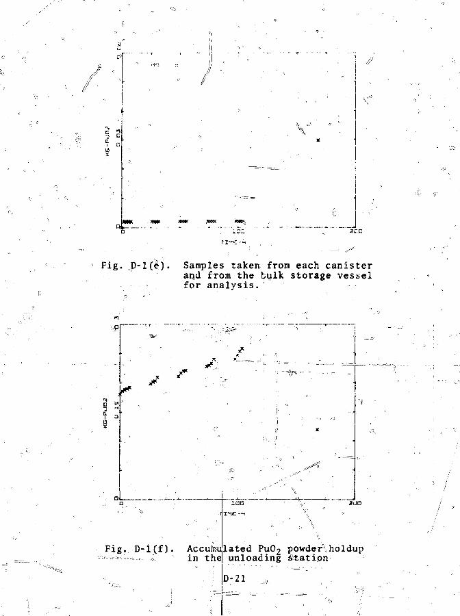
V"
Fig. JD-l(e). Samples taken•,, from each canisterarjd from the bulk storage vesselfor analysis.
I.
n " " "
Fig. D-l(f).
M ' I
1QG
\\.li
sac
Accuin the
.ated PuO2 powder\holdupunloading Station
D-21
C L .
XX
xx
Fig, D-l(g). PUO2 inventory iri5 the bulkstorage vessel.-
Typical material flow data generate^ by MOXSIM for a week
of pelleting operation are shown in Figsi D-2(a)-(h). Vertical
scales are expressed in'terms of kilograms of PuO-; the MO-
equivalent is 25 times the PuO- amount. 0
DfP22
'• ii
H
2i
•'" *• -.,- x •: x
* -x
*- X X *X -v *
* «. *# «« >'x _*
xx _ "x-r% , ,
» *.
200
Pig. 2 powder inventory 1 # the soni?pac tor ofeed h'oppey; * , G / cD' ".
N
i
X X X—*p
I
Fig. D-2(b). Contents of green-pellet boats(individual boats are notresolved).
D-23
13 *
I
ii Hti
ft
Fig. D-2(c) MO, powder inventory^in-the pressfeed, hopper. ?";=1""r""""
Fig. D-2(d)T"TVccumuthe l>e'
o
ateclleting

Dirtly scrap a«id jlWaste from thepel le t ing operation. .. = ,,^

-APPENDIX I:
ALGORITHMS VQ$ DIVERSION .DETECTION ._..'. _•.
The sensitivity of the MMAS can.be determined quantita-tively by analyzing simulated materials^liieasurementChap. IV) '. The measurements provide aC least approximate clos-
of material balances around each Unit process. Analysisalgorithms are ijapplfelf^to^Ste'iRaterial \b. alanceip detect=both^5ha4t?tJtrWT^^Tffcis appenciix describes \the detection algorithms developed to
' ' ' I^
divers ion re fers to the s ingle theft of a rela- - \material. Lawrence Livermoredesign curves that establish ' •,
.alarm leve^s=-l0r=the detection of a single-theft event. LLLassumed that in-process holdup could not be measured or other*;
\\ • • i-« • - i> < y
wise estimated. Therefore, the0 algorithms, required uniform °operation of the process so" that diversibn indicators ocould be! '"•""""'based on the differe^e betw&Sn measured" and expected output.
Design curved for estabXiTIfiTTf ai.TfrTri?=re'veis in a system0based on unit process material balances ,f?i.e. , measured in- rprocess holdup and material sidestreams) look identical to thosegiven by ILL. However, interpretation of some of the parameters13 different. j - \ •'•'• "^
Design curves fqV single-theft detection are based on corilventional probability- arguments. Consider a true raterlalance folr a unit proces^a^^a^sjum^^^that' it is normally dis-tributed with mean B and VEare obtained fronTtiie measurement of input, output,,: scrap,
iu, ' -:
M
a . Estimates o T 3 and a
E-l
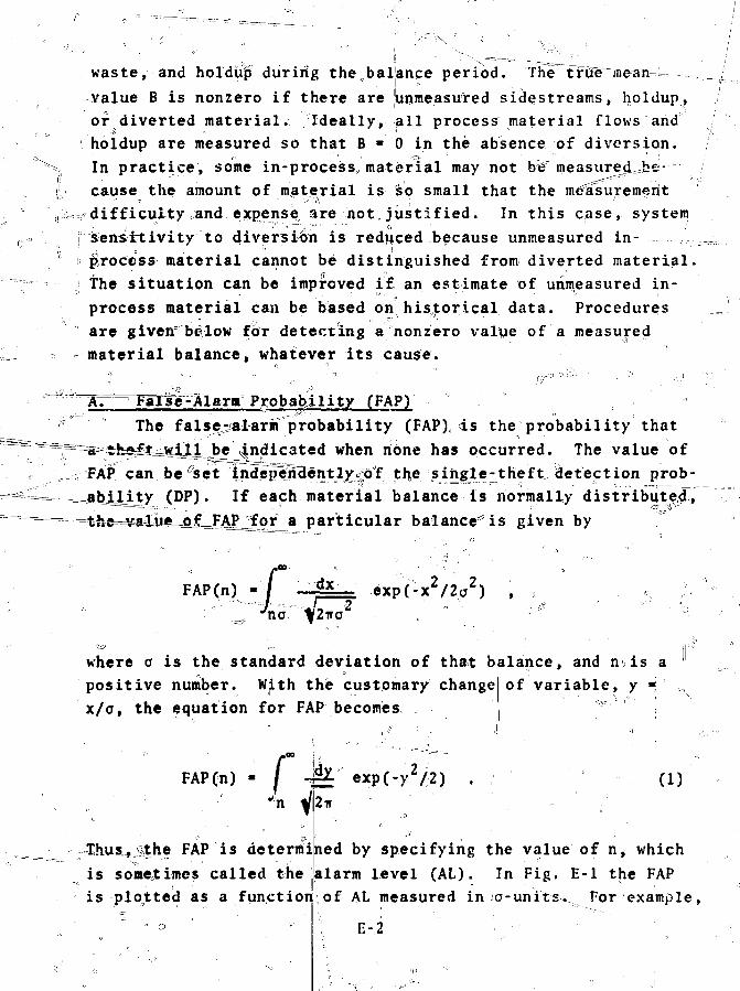
waste, and holdup during the balance period. The true^mean-value B is nonzero if there are yinmeasured sidestreams, holdup,or diverted material. Ideally, all process material flows and\ holdup are measured so that B * 0 in the absence of diversion.In practice, some in-process, material may not bW measured^-e---cause the amount of material is "so small that the measurementdifficulty and expense, are not justified. In this case, systemsensTTtivity to diversion is reduced because unmeasured in-• .- ;| ' ii
process material cannot be distinguished from diverted material.The situation can be improved if an estimate of unmeasured in-process material can be based on historical data. Proceduresare given' below fdr detecting a nonzero val%ie of a measuredmaterial balance, whatever its cause.
vWTse-Alarm Probability fFAP)The falser-alarm probability (FAP),, ds the probability that
l be indicated when none has occurred. The value ofFAP can be^set indepellently^bf the single-theft detection prob-^abijoty (DP). If each material balance is normally distribute^,'=t-he=*aIiij«=o£=F_AP_jfor a particular balance'is given by
F A P ( n ) -••••/
_ "'no
dx exp(-x2/2u2)
where a is the standard deviation of that balance, and n is apositive number. With the customary changex/o, the equation for FAP becomes
of variable, y
FAPCn) - / -&f ji—
(1)Jn
Thus,...ithe FAP isis sometimes called theis plotted as a function
determined by specifying the value of n, whichalarm level (AL). In Fig. E-l the FAPof AL measured in o-units. For example,
15-2
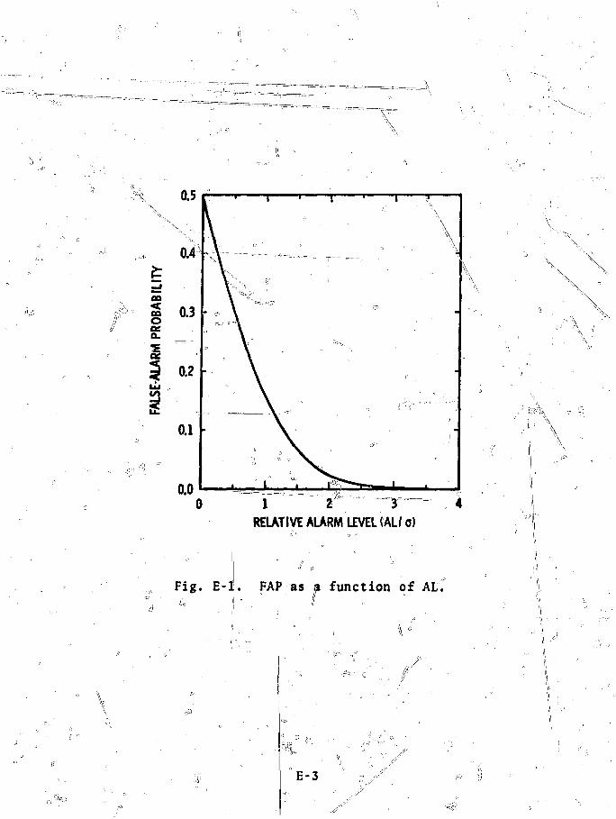
'•i '
1 2 3T— 4RELATIVE ALARM LEVEL fAL/ o)
Fig. E-l. FAP as a function of AL.t\ <••
E-3
if the AL is set at 1, 2, or 3a, corresponding FAP values are0.159, 0.023, and 0.0013.
B. Detection Probability (DP) /The DP is the probability that a truly nonzero/material
balance B Will be detected for a specified AL. For a normallydistributed material balance", the value of DP is/given by
DP(n)
- .. ix
dxt4 exp[-{x-*B)72a ] .
no %2:ra^1 ' ^ :
By a change of variable, and expressing n and B in o-units, theft |l y
DP becomes » I' / • •
DP(n) LNote that if B 4 0, the DPs and\FAPs are equal.,
qE-2^
the DP is plottejd as a function qf the mean material/balance/Bfpr several values of the AL: AL « n. The probability of amiss (not detecting/a truly nonzero yalue of B) is piotxed in=
Fig. E-3. The nohdetection probability (NDP) is equal to 1 -DP. , ' .. /" ~J\ ' •' ' -"p—^ ;=" x
Figures E-l to E-3 are the design curves^detection. For example, i^imately one falslT^iarm in 1000 material balances, the probability of detecting a nonzero balance of magnitude B is Kiven i%Table E-l... , ., f i --' -- *\ ' &, - .j^/ •
The relationships aiming JAL, FAP, and DP or NDP are shbwnin Fig. E-4. As AL is increased,,,the FAP decreases, but theprobability of detecting theft of a given amount of materialalso decreases. The tradekpff between a minimurn__ number offalse alarms and maximum sensitivity to theft is obvious.
E-4

' i 2 3 4
RELATIVE MAGNITUDE1'OF
Fig. h-l. DP vs magnitude of diversionfor several values of AL.
E-5

RELATIVE MAGNITUDE OF DIVERSION W ,
Fig. E-3. Probability of not detecting adiversion of raagnituWt^B^for-several values of AL.
E-6 "

MAGNITUDEt* DIVERSION
DETECTIONPROBABILITY
FALSE-ALARMPROBABILITY^
Fig. E-4. Relationship g 5 ^ ^ 7vv to&^iif^ireftiisn and for
"" diversion of magnitude B. TheDP is the= sum of the twp shaded
•areasv^"" " '
E47

*.•••:»
ABM: E-Tv
DETECTION ANJ) MISS PROBABILITIES .
3/c DP
1 ° •
1" "
3 ••'
6 ?
X f jO.0.23 , :'
o.soo0.841
0.977\ s 0.999" XI "Y ".,.„. .
y -0.97/'•* s ' s 0 . 8 4 1
^0.500
*0% 1S9
0.025
0 .001
C, Procedure for Single-Theft Detection^ = Q ° /
For c l a r i t y , we include the procedure for using the '-single-'theft des=lcn cyrves. Consider the i material balance 6a£ a a °unitfprocess with "tfueinvean value B. and standard deviation o . .
-tet x. be an estimate of E. obtained from measurements of input ,outputs scrap, waste, and holdup; s. i s an estiinate^of-"o- ob-t^i^ed from a| propagation-of-error analysis bjLsed on individual,^measurement tincer-|rtiinties^ »The estimator for a.' must be . sspecif ic to th<f mtjajciring devices and t a l w r a t i o n procedures Iused to close the i material balance. TJjTe design curves,shown i n F i g s . H-l t o S - 3 r a r e used w i th x . / s . aSfan e s t i m a t e
°of B . / c . t o t e s t i f d i v e r s i 'oi i '^s, i n d i c a t e ^ l T = = ," -c - ," •';;' I: ,;:'..
fiFo^f example , i f x / s . « S, t h e p r o b a b i l i t y that: a b i a s b f ^
t h i s magni tude would1 b e " d e t e c t e d i s §8% a t t h e ZJJ AL,%and oiauned-
i a t c a c t i o n should- .be t a k e n . I f x l / s . - 2 , t h e DP i ^ Q o n l y » 0 . 1 6
a t c t h e 3 n Al. a>TyLJ3.5O a t t h e * 2a AL I
1 4n 2S'fr. "The l a t t e r c a s e wouldj
monitor subsequent material balanG
veloping.' Detection of trends0 is>s to= see if a trend, was de- /•the subject of the next "sec-
•«t i o n .
E-8
a false-alal-m ra te ofand the analyst

Lon^-term diversion refers to repeated thefts of nuclear
material, each too small to be detected because of measurement''
uncertainties. Detection - o€ repeated small thefts is based on
identifying the presence of trends ir^ process operations. The
cusum control chart has been effective, for detecting trends in
industrial process dan.i Pa.sk experience at LASL with cusumsf~ ' ' ' \
of material balances indicates llfat the cusurn chart provides" • ' " " * , •• \ • r '
graphic evidence of repeated small amounts of unmeasured mate-. ; ,74 - , - ,. «.
r i a l . • . . . . „ '
Identification, of trends is\one aspect of the problem, but
it is equally important to quantify the^loss. One suggested
approach applies linear filtering techniques (e.g., the\Kalman
filter) to materials measurement data. In this approach, pre >
dictions from a process model are compared with measurements of
process^operation. A thorough evaluation of the method applied
to detailed process models is not yet available for fuel cycle
plants. The assumption that fuel cycle plant processes Can be
modeled realistically as linear systems is questionable. How-
ever, the approach merits further study, particularly as an aidh
in extracting redundant"information available in material bal-
ance data from adjacent unit processes. \
A. Cusum Chayt's and V-Masks - . W
An altern|itive. approach, used^successfully to evaluate ^
industrial process operation, is the use of V-masks in conjunc
tion with the cusum charjt. * =i-igur^E-S i'i a cusum chart of ,
material balance data^from iJjEMtitious batcih-operated uni t
process^ Each dataopoiat repfesenits the cusum of measured mate-
rial balances, iyt! trend in the cusum data
have a positive bias. The
, beginning
ac€ that the slope .of the .data is
roughly" constant from balances 7sv to 23 .suggests, that the posi-
tive bias of each balance i> nearly constant during this period.
E-9\
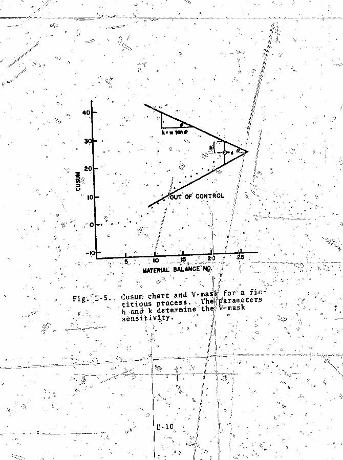
5 10 19MATERIAL 8AUANCE NO
h andksensitivity.
& , = . = =

^ J_The V-shapjeri mask j.n Fig• _ErJ5 is a eometric construction
applied to cusurn data toadetermine the presence of out-of-
control (alarmf conditions. The V-mask is .applied to each suc-
cessive cusum data point; if any previous point falls outside
the arms of-'the V,° an alarm condition is set. ,3ne V-maskfsensi-
tivity: is determined by two parameters: a reference level k
and a decision level h>L The value of k determines the slope of
the V-m&sk, k « w tan <|> and the value of h determines the
tance d; from the vertexVto the
c tan 6; w'isj a scaling factor applied for plotting purposes. A
suggested rule of thumb is to set the reference level k to a/1
and the decision level h to 3a, where o is the standard devia-
tion of each§material balance. * ' ?
Two parameters, the AL and the material balance standard
deviation, govern the sensitivity to single-theft detectiVri. A
third parameter, the avtYaCge runlength L, must be added for
detection of related thefts. The^average, runlength i% that
^length, of a sequence of process data points requiredjto detect i
an out-of-control con^tiWy on the average. In, general, t^e !
average runlength is smaller for, the "cusum.chart and^V-mask
technique than for the standard method of charting individual
process data points and^ their standard deviations; i.e., /the
V-mask technique is more sensitive tc>, small changes in process
™ operationr;' Some improvement in V-mask sensitivity for/moder-
ate deviations from average,process operation, viz., the la tb
3a rangei has been obtained by replacing the region near the
vertex with a parabolic contour^ ° c ; ^ , „
The V-mask tecltini ue "for detection of\repeateAaSmall ="
thefts of nuclear material is still under development. V-mask
theory ' is based on the as&umptiion of independent^ process ?
variables having constatnt-jarid equal ovariance» the V-mask parame-^
ter^^rQ— ch£sik^aj5<diQ&i^^ given here/T:nc=lspdes"a
procedure for choosing t'he; V-mask parameters h and koChat is " !
based on probability arguneiits, and provides quantitative esti-
mates of FAP ando D^- H is'rigorous^ only for the case of
o ,:.

independent, normally distributed, material b a l a n c e uith et|iva
variances. !!In the &asie of unequal variances, the analysis is
more complex and the present, treatment is only approximate.
*-*B. Analyt ic V-MasksM> The ifrap h i c fV^mafsTTr' Fxg. E :!
W
K a r d a n a -
Jfftic representa/cionr "Consider a set of material balances fori -'''' • " li .*> '-••• ••' " - v » '"•- t h ••
fa unit process, each normal^ distributed such that the i ""balance has meari b^ and variance1 ^v1.' The cusur. obtained froma sequence of lengths of such material balances" Is ;; -
The V-mask can be used tOi test for--sitfee~Tc,4VosLtiye or neiia-bias. U'e shall consider only the V-masJc test for a true
, i.e., for diverted material and/or unmeasured
prpcess sidestreams. The test requires evaluation of the s
O
wheite k i s , the V-mask refer(ence level . „ %\ote'that' this ' sum is'C. - P.k. The V-jmask testrelasted to the cusura by S,
alarin condition (a true positive bias) has two steps.
t i(l)™ I| S. < 0, set the sum to zero and begin a neK se
an
an i
(2) Let h be the V-mask decision level. If S. o> h, set«5
.condition^ .- - ' - - '• '• a1 ' '" "' •
The cusum 3G. is an estimate of the total bias for a se-
i l4
quence of material balances o£length I. The average bias B,
is related to the cusum by
i * k
(3)

IT the V-inas-k- alarr.1 condition st—s-a-t-hrficcJ""'($^s% h) the
B = k
-The .variance -.," ofj the average, U,ias is re la ted to tira,
cusuni v a rial nee <;,," by ' " -i -„=
2 1 2
.\ote-*«hat the cusum variance!
ual materijil bal_anye yariancie> '/\
5- ' ( 4 )<
c sum of the individ- '
l''"1 t;~J only if the b'al-
ances are independent. "Thijj is seldopi t rue for balances based
on nuclear mater ia ls moasurcjneri't^. 5 ,r
TJJC dependence of, tlie cusurar variance on the runlength i " i s
^^^^-gjj.jiC'eg with j?t|ug.liv__va_i\L_aiiCc .__ In
genera l , the dependence of the cusun varJ-aneg_^on_if~i:?~anl"y^_ — ^
l) Hried-i" SVc .-hc-il .-.-stsurse that -e r" « ; and define- — - _ _ _
Viuajice c" by > _ " "
-2 1; = — O,
%here d" is only weakly ^^^Men^oh^l. f he ef lec't' oTT a weaKly?-dependent a" on %he• ifcilbwing analysis is under .i
C. '. V - Ma s k I'a 1 s e -
The V-maSik AL is k*+ h/jj^so tha t the" FAIs.. (see Appendix
K - I - A - ) i s - 0 , ... = i = - ^ - ' ' !! - ' * - '--•--• ••'
I wK/S. Viva B
Noting that oB
ard formjlives0 "II anc t rans f o rm in S_ ;r a 1: ~i 6 - s: t
ft 13

: FAP ' I
inhere t h e l o w e r l i m i t is »• _ _ ^ vii.: ..;I.I1,,.I „ , , „ : : „ . , „ . , „ „ „ —5 ..-.-•..-.- '-v -•-•..; --...>•-•.• _•= -
The variables rr^k^a^TT\ave=ireen==expressed in units of cf.«iw.i&w.^^ tO
u -Therefore, specifying the V-mask parameters* k and h de-the maximum FAP. Further, this maximum FAP corresponds
to an AL of 2 kh and occurs1 for a runlenjth; of h/k.c Setting2\fkh"* n Co-units) thus ensures,; that the FAP for "any run lengthwill b^^^i^issttess^sis^Aig^^jL^ri^^ ng _to_ n.
D, V-Mask Detection Probability 7 1 | =The DP for a true, nonzero average bias B is ^
.-. , n , - ^ ' "&''. %''""L'-: '''''^ •"'•'°^ -!t---i •'i'1'f"V"r^i%:'V .^^u'.'-;V._.': v;s
Again, transforming the integral to standard form and ex£r£ssing" o F T givers 5
DP / dy
where
m
7 Wl4 V"
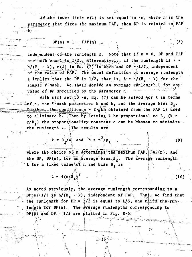
X£ the lower limit m(£) is set equal to -n, where n is theparajnejtejvthat fixes the maximum FAP, then DP is related to FAP
DP(n) - 1 % FAP(n) (8)
•vindependent of-the runlength •£. Note that if n • 0, DP and/ FAP
^q W a^^ runlength is I •
- k), m(A)_ in E^YjcVf't's" i&foMndVBP'«jo/2>; independentof thervalue" of FAPT The" usual definition off average runlengthL implies that tfie DP is 1/2, that is, L "^h/(B? - k) for thesimple V-mask. We shall deriie^anave^tage runlength, II for any3
value of DP specified by the parameter n. == 'With m(fc) set\td -n, Eq. (7) can be solved^or I in termsthe V'-niask parsmetors k and h, and the average bias Be.
2 \ k h obtained from the FAP is usedto eliminate h. ffhen By letting k be proportional to B. (k *
Ithe runlength £,.c/B.J the proportionality constant c can be chosen to minimize
•The results are
and h •
J\
(9)
where the choice, o^ n d/terpines thjumaximum F,AP,fFAP(n), andthe DP, DP(n), for Sn/Iverage bias, B^. The aVeraije runlengthL for a fixed value W£ n and bias B. is
i I 2Cio)
As noted previously, the average runlength corresponding to aDP-of cl/2;is h/(B. - k), independent of FAPs ThuJ, we find that
• '•' . '' ** . . . " s ^ :; •> - - = " '^-'-11 _._ '
the runlength for DFI* If2 is equal to L/3, one-tEird the run-length for DP(n). The iverage runlengths corresponding toDP(n) and DP:°l/2 are plotted in Fig. E-6. ^

Fig. p-6. Average runlengths that produce V-/"• mask alarms. The parameter n
/ specifies, the PAP alid DP; B is the/ average Kias in the material bal-
/ anses forming a sequence of lengthL '
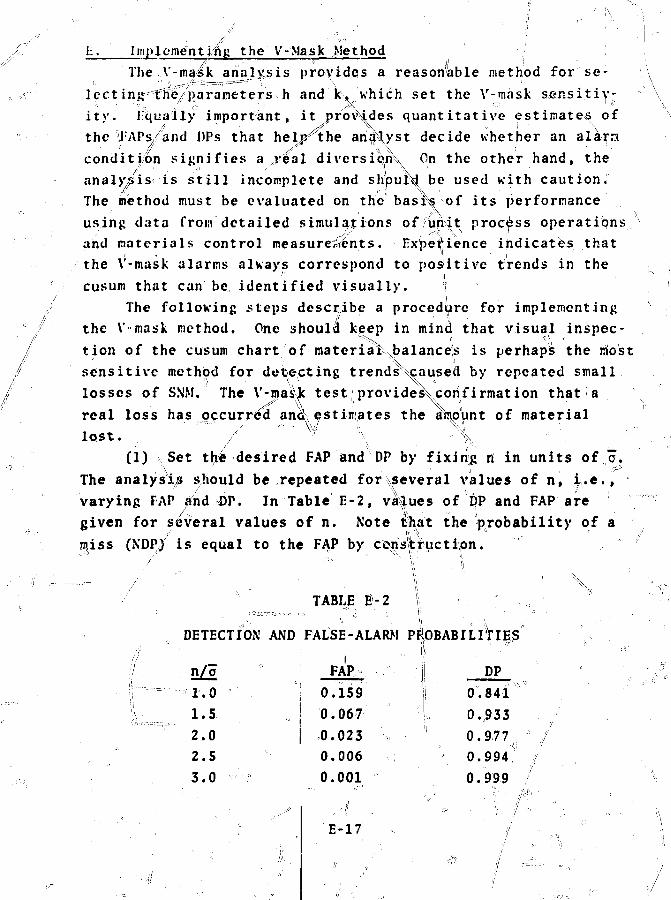
Implementing the V-Mask Method
The Y-maik analysis provides a reasonable method for se-
lect in^tiie/parameters h and k, which set the V-mask sensitiv-
ity, ilqually important, it provides quantitative estimates of
the I APs,/and DPs that helj^the ari^yst decide whether an alarra
condition signifies a jreal diversion^ On the other hand, the
analysis is still incomplete and should, be used with caution.
The method must be evaluated on the bask of its performance
using data from detailed simulations of iiriit process operations
and materials control measurements. Expedience indicates that
the V-mask alarms always correspond to positive trends in the* ij
cusum that can be identified visually. f'!
The following steps describe a procedure for implementing/ / ' • ;
the V-mask method. One should keep in mind that visual inspec-
tion of the cusum chart of materiai\balance!s is perhaps the riost
sensitive method for detecting trendsNcausetl by repeated small
losses of SNM." The V-mask tes^ providesVcorifirmation that a
real loss has occurred ancK estimates the amount of material
lost. , /' " ' Vl> \ ->\
(1) Set the desired FAP and DP by fixing n in units of Jo.
The analysis should be repeated for several values of n, i.e.,
varying FAP and DP. In Table E-2, values of DP and FAP are
given for several values of n. Note that the probability of a
jijiss (NDP) is equal to the FAP by constructipn.
TABLE E-2
DETECTION AND FALSE-ALARM PROBABILITIES
n/o1.0
l.S.
2.0
2.5
3.0
E-17

(2) Set the average funiength equal to the current totalruniength, L • £. Not;ec that the analysis is repeated as eachNo|
umaterial balance measurement is added to the cusum.~ (3) Obtain the current estimate of ~o from the cusum stand-
ard deviation c~: "a *-a~/^L. We assum^ar has been made from the measurement errors. .......L^^J^I^ZL
>(4) S£t the minimuiif detectable—avtaage bias B and the V-mas|k parameters-4i andf!t: ^
| - -\ , B / f - 2 ( n / o ) | / > r H • ••••o -• "j '• x
\| h/t - (n/o)Cn/B) , !
Jk/? - B/4a , ,(5) Apply the analytic V-mask tes i to the total sequence
of measured material balances using the current values of>h andk. If an alarm condition is encountered, go to step (6); if-not, return to step (2). = m
(6) The V-mask alarm condition has been satisfied by asubsequence of length L1 £ L. If a pr eyi ifs alarm conditionhas been set for sequence L' at level n, go to step (10). Ifnot, compute the average bias B' over sequence L1,
b, ii-q
where q and pj; are the initial and final points of sequence L'.In terms of cusums, the value of B1 i
(7) Obtain an estimate of a/ for sequence^L' from thef>' // ' I ''" ^
cusum variances. • A Simple esti, - p f0C %.
where L1 «/p - q + 1.
a/ for sequeate is given
, , , •'>»
, • : / , .
I •
E-18

T
(8) Obtain an\estimate of (u,'/p') for sequence L' from\e
\
—i- L_i_£a)"" If n1 < n, reject the alarm and go to step (10)i,e., continue the search. Note that if h'*< n, the FAPs andDPs for sequence L' are FAPfn'a_ >^FAP(r.)4and DP(n') < DP(n).
(b) If n' >_ n. the alarm condition is accepted, ije,FAP(n') < TAPfn) and DP(n;) >.'DP(n); go to s t ^ O )
(9) An alarm condition has been accepted.!\ Save thelowing parameter value?.VL *
| B' the average bias! L' the subsequence length with end points q and^
P the average standard deviation of sequence L','.'/ n V ? determines FAP(n*r) and DPCn'iSf^r sequence L1
P.
ri/o7
ciirre|it «I|?I»UIB detectabi. »ivi rage bias,thj current tota^' sequence length, |,the current average standard deviation, ariddetermines the current FAP(n) and DP^ti).
rh(10) Continue to search through the total sequence start-ing at material balance number (p + 1); go to step (S).
^ /
• \
E-19
({

ACKNOWLEDGMENT
The authors wish to acknowledge the extraordinary effortsof Charlene Brandon and G. Richard Dooley in the preparation ofthis aanuscript. The entire staff o f the LASL R-l JCSafeguards group' provided^;|lf^i^i55ftcnl'fcar'andsupport to this activity. The designers of the KestinghouseRecycle Fuels*Plant were extremely helpful and generous Withtlieir time in providing the detailed plant, process, andmaterials flowjlescriptionsi that allowed us to quantify this
V.,
N \
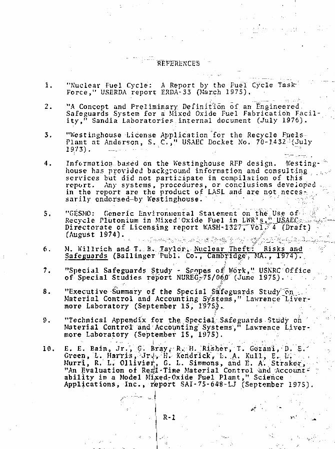
REFEREJttTFS
1. "Nuclear Fuel Cycle: A Report by the Fuel Cycle TaskForce," USERDA report ERDA-33 (March 1975).
2. "A Concept and Preliminary Definition of an Engineered.Safeguards System for a Mixed Oxide Fuel Fabrication Facil-ity," Sandia Laboratories internal document (July 1976).
3. "Iv'estinghouse License Application for the Recycle FuelsPlant at Anderson, S. C , " USAEC Docket No. 70-1432 (July1973).
4. Information based on the Westinghouse RFP design. Westing-house has provided background information and consultingservices but did not participate in compilation of this:report. Any systems, procedures, or conclusions developedin the report are the product of LASL and are not neces-sarily endorsed-by Westinghouse.
5. "GESMO: Generic Environmental Statement on the Use ofRecycle Plutonium in Mixed'Oxide Fuel in LWR's," USAECDirectorate of Licensing report WASH-1327, Vol. 4 (Draft)(August 1974).
6. M. Killrich and T, B, Taylor, Nuclear Theft: Risks andSafeguards (Ballinger Publ. Co., Cambridge,- MA., 1974).,
7. "Special Safeguards Study - Scopes of/Work," USNRC Officeof Special Studies report NUREG^S/OjjS7 (June 1975). .
=-- " • • ,^f •
8. "Executive Summary of the Special ^"feguards Study3>nMaterial Control and Accounting Systems," Lawrence Liver-more Laboratory (September 15, 19751.,
9. "Technical Appendix for the Special Safeguards Study onMaterial Control and Accounting•Systems"," Lawrence Liver-more Laboratory (September 15, 1975).
10. E. E. Bain, Jr., G. Bray, R. H. Risher, T. Gozani, D. E.!Green, L. Flarris, ;Jrj r H. Keridrick, L, A. Kull,, E. L.Murri, R. L. Ollivierj, G. L. Simmons, and B. A. Straker,;"An Evaluation of Res]!-Time Material Control iknd Account-ability in a Model Mixed-Oxide Fuel Plant," ScienceApplications, Inc., report SAI-75-648-LJ (September 1975).
R-l

I I . fi. Bain, R.
ILi -
12
f4,
15.
Ii. Bain, R. FiVireT;; _T. Gozani, L. Harris, II. Kendrick,I. Kull, i:. Murri, R. Olli^dajr, and if. Simmons, "Quantita-tive Hvaluation pf the'REriMAC System," Science-Applica-tion^, Inc. , report SAI-75-595"-LJ(Ju^ne JO* 1975). „ ° c
"Plutonium Isotopic Co1{fe£ol: A Special Safeguards Study,"Mound Laboratory\( September 1975). ° ,
cf. I . McSweeney, "iijiyproyedHater^feAccounting Jfor Pluto-nium J'rocessingc Facll^t ies and" a "%p3'DrHT(TR FTueT Fabrics"^ "t ion 'Tac i l i ty , " E^tte'i^e Pacific Jfor^hwest Laborator iesreport BNKI.V2098 tOctobfec 197S) (uiafiubJished).
7K A. Ldt^llen, "Generic Mi'*e^Oxi<fe Fuel Fabri^ation JPlant-Decommissioning Study.^H&Lttel,1J6 Pacific Korthwesjtg y . HLaboratory, Richland, WasJhington (January 1975>7 (drarft)
Modifications of Strategic Special Nuclear Materials to
tDeter"Tneir Theft or^aaufnorued us>at vois. I and II(Broofchaven National Laboratory, November 6, 1975). =^
=16. JU /.Walton, D. B. Snith, J , H. Men|e°^ p. Vi Schelonk;*and,,R. J; Dietz, "Materiali Measurement and*CoatVt»Jt jEorJMixedjpxide Recycle P ^ l fabricffltionlFacility:: ^liminary Review," Los AllaiROs ScientJfic L ^LA"-6J!82-MS (May 1976)/ I'l j , _ - =1^ r = ^ S
18,
|J. W. Codhee and J . f. $iikho$?&&'"Sourices ofSolid Waste and the i r Z|tfluenca on the Proposed NatiomIRadioactive Waste Repository,11 Oak RiUce National Labora-tory report 0RNL-TH-32|7 (Jantuiry i m \ . %,....-?
J . 0. Blomeke, C. W. fete, and J . P. l i cho l s , "Projecti»««cf Radioactive K'astes to b« G4mmrmtt>4 by the 8. S. Stecl«ar
Industry," OakORKL TM-3^65 (F^Trua
y %Natioiuil Laboratory report
it -•
Waste Problems in \ tPresented at the MTft
DouglasBackup ."
R. Keepin Assayiols Control - DYMAC,"Nucl*nr Materials,
In-PISyjy
ienna, Austria, Oct

22.
23.
24.
25.
26.
27.
29
30.
31
"Development and .Implementation of Dynamic Materials Con- *
private communication (June 1975). 7;
I.E. Shea, "RETINlAC, A Real-Time Material Control Conceptfor Strategic Special Nuclear Material," NRC-Working PaperB (January 1975J. j
T. D. Reilly andM. L. Evans, "Measurement I Reliability forNuclear Material Assay," Los Alamos Scientific Laboratoryreport L&-6S74 (December 1976).° \ j\
iB Total RoomJ. K. Tape, D. A. Close, * and'" R. B.Ah'aJton,
Holdup of Plutonium Measured with a\ Large-/irea NeutronDetector," Proc. 17th Anr^al Meeting0of the Institute ofNuclear Materials Management, Seattle, KA^ June 22-24,1976/-^:..^ : =
R. B. Kalton, .1. L, Parker, J. Meniel, and T. D. Reilly,"Me' lie Nondestructive Laboratory,"in Los AlamosScientific Laboratory report LA-4794-MS (May-August 1971)
h. A. Higinbotham, .J. %$^jTapi, and D. M. Sikes, "Measure- »went of Plutonium in Processing Equipment at Kerr-McCee ft
Plutoniflm luel Fabrication Facility," Los Alamos Scientific'Laboratory report (in preparation). '
J. Rein, Los Alamos Scientific Laboratory, private" communi-cation (1976). o =
K. de Merschnjan, Hanford Engineering Development Labora-tory, private communication (1976). • " ' , , .
H. 0; Menlove, R. A. Forster, J. L. Parker,, and D. B.Smith, "252c£ Assay System for 1-BR-Type Fuel Pins," Nucl.Technol. 20, No. 2, pp. 124-133 (November 1973).
P. Goris, "FFTF Fuel Pin Nondestructive Assay 'Measurements•&,Summary Technical Report FY-1974tj? Ifanford EngineeringDevelopment Laboratory report IfErU-TME 74-S^ (September
) ) • • "
32
33
II, 0. Menlove, R. A. Fbrster, J. L. Parker, and D. B.Smith, "252cf A^say Syand Operating Procedures Manual," Los Ala nos= ScientificLaboratory report LA-5
oR. H. Augastson, "Deverials Control: The DYiMeeting of the- InstituSeattle" WA, June 22-2
)71-M
opmentr j ^ ^ J J ^ yIAC Program,'1 Proc. 17th Annuale of Nuclear Matefial,* Management
tern for FBR Fuel Pins: Description

o-34. J . E. Foley, "4^ Neutron Coilnter for 3P"GallQrtWBari-els,!V
*• in Los Alamos Scient i f ic LMbratory report" LA-470J-MS(January-April 1971), p. 2 Of •<" ._• ,.i
35.
36.
37,
38,
39 .
41
43
44
J. E. Foley, "4 TI Neutron Coincidence Assay System," in ;Los Alamos Scientific Laboratory report1 LA-4794--MS '(May-August 1971), p. 22. ( =
D. F. Jones, L. R. Cowdf^, jand E/ R. Martin, "ComputerizedLow-Level. Waste Assay System Operation! Manual,'^*Los AlamosScientific Laboratbry°Freport LA-6202-M (E,ebruaryU976).
T. D. Reilly, $t. H. August son, J. L.° Parker, R. R. Walton,T. L. Atweli; t. J. Umbarglfef, ind C. EJ Burns, "F^inda- ?
mentals of Passive Nondestructive Assay of Fissionable fMaterial: Laboratory Workbook," Los Alamos ScientificLaboratory report 'LA-S651-M, Supply (February 197&).
R. Berg, R. Swennen, G. Birkhoff, l\ Bondar, J._ Ley, and ,Gl<b Buscar "Determination of the IPu-240 in S<jlid Waste ° °Containers by Spontaneous Fission Neutron MeksuremeniSu. 0%,.Application to Reprocessing Plant Wafte." EUR 5158e (1974).
K. Bohnel,o"Die PlutoniuKbestimmung in Kernbrennstoffen_" mit der Neutronenkpinzenmeihode," KernfbrschungszentiumKarlsruhe report KFK 2203 (1975). \
= • r-. ' ' *.. n Yx ••• -.: .--:40. K. P. Lambert and J . W. Leake, "A Cojjij3ari|pn of the Ispra^ ^ ^ l a a ^ M a r w e l l ^rv^rC. Systems ifpr the AlrsayrbfX2^0pu by ¥ ^ ;
Spontaneous Fission Neutron Measurement's," UKAEA report vAERE-R 8300 (April 19716). / \ i
M. M. Stephens, Z.-X. East, T. L. Atwebl, and T. D.Reil ly, "Automated Neutron Assay for Rich 1 arid OperationsOffice," in los Mamos ScientifitC Laboratory reportfTLA-
- 6142-PR (MayffAugust 1975), p . 13'.
42. J . E. Foley, "Neutron Coincidence*Counters for NuclearSafeguards Applications," IEEE Trans. Nucl. "Sci.n NS-19,1No.
E. V, W e i n s t b c k , " T h e LMFBR F u e l C y c l e : Pa^rt 1°, pjand. Schedules," report? prepared by BNL-TSO for the Dwtsionof"Nuclear Materials | ^cur i ty of the AEC=(November 15,197f) 39. '"• '- jl . _,-'•- ' - -" :'_, " °,
, J . L. Parker, and H. M. ._of aPel le tWto-Pel le t \252Cf
A N l S 15' IV 2
//R. A. Fors te r ; U. 0.
J r . ,Fuel ;p . 680 ( 1 9 7 2 ^
JAmer. Nucl. Spc. 15'",
R-i: '\ .

,//
45.''• D. B. Smith, "Ph^sicfi Standards and Valid Calibration," i|Proc. IAEA Symp./'-Safeguarding of Nuclear Materials, Viennk,Austria, October 20-24 ,., 1975 ,, pp. 6.3-71.
R. A. Forster, D.: Bv Smith, and H. 0. Menlave, "ErrorAnalysis of a 252icf Fuel Rod Assay System," Los Alamos
/ ^Soientiffc Laboratory report LA-5317^(ApriF 1974).
/ 47. D. M. Bishop, "New Scope and Goals for N15 SubcommitteeI-NMM-9 (Nondestructive Assay)," Nucl. Mater. Manage. IV,No. 3, pp. 285-298 (1975^.
48.o h. H.- Chambers, H. F. Atwater, P.F.. Fehlau,,R. D. fHastings, C. N. Henry, W. E., Kunz, T. E. Sampson, T.'H.WKl-ttlesey., and G. Ms Worth, "Portal Monitor for DiversioSafeguards," Los Alamos Scientific Laboratory report LA-S0i 5(December= 1974).
i
n
49. K. E. Kunz, K. H. Chambers, C. X. Henry, ,S. h': France,0 D. R. Millegan, R. D. Hastings, and G. M. Worth, "ffand
Personnel and Vehicle Monitors," Los Alamos ScientificLaboratory report^ L(A°-6359 (September ,1976).
50,P W, H. Chambers, "Continuous Inventory in SNM StorageFacilities," losaAlamos Scientific LabbratoryiinternalreP°rt U97Sh g : • - "' \ •
51. W. H. Chambers, and J? F. Ney, "Tamper Indicating RadiationSurveillSnce Instrumentati^n_t^tp
s Alamos Scir^itific Lab-oratory internal, report *
52. G. M. Worth, C. N. Henry, R. 3s Hastings, and S. W. France,"A Portable Gamma-Pay Detection System for Location ofRadioactive Sources," Los Alamos Scientific Laljtqratoryinternal report (197Ji). ••-» \
53. J.5F. WaJ<;erly, "Transient Failures in Triple Modular Re-dundancy Systems with Sequential Modules," IEEE (Trans.
^ fi24 N 5 (M 7 ) *\y y q
Comput. fi-24ff No. 5 (May 1975).
q u l u l , E (5 (May 1975) ^ *\
54. J. F. Kakerly, "Microcomputer Reliability Improvement "Using Triple-Modular Redundancy," Proc. IEEE 64, No. 6, /pp. 889r89S (June 1976). K"""" V /
ot. - ' ' '.ft,' • • i - a * ^ ; \ , '/
55. J. M. Torin, "Fault Tolerant Compilting in Satellites,"J. Brit. Interplanet. Soc. 29, pp. 21=9-231 (1976).!,
J. von Neumann, "PiStudies (Princeton
obabilistic Logiics," in Automata!,Univ. Pr.ess, 19S6) . ',
, , \R - . S " • „ • • ' " • - A
<5

58.
59.
60,
61
62
63.
64
65,
66,
67
68
W. G, Brown, J. Tierney, and R. -Nasserman, /'Improveinciitof Electronic Computer Reliability Through the Use of Re-dundaney." IRE Trans. Electron. Computt EC-10, 407-41(>-- ~^~zl:(October y>jyx==^~^= i -^^ —
B. J. Flehinger, "Reliability Improvement Through Redun-dancy at Various System Levels," IBM J. Res. Dev. 2 ^ — — "148-158 (April 1958).
E. F. Moore and C. P.. Shannon, •'Reliable Circuits-UsingLess Reliable Relays," J. Pranklin Tiist. 2J 2, 191-208,281-297 (September/October ?19|6J. \
K. I;. Dickinson and R.H. Walker, "Reliability Imprby the Use of Multiple-Element Switching Circuits,"J. Res. Dev. 2, 142-147 (April 1958). ----
IBM
R. !•-. Lyons and IV. A^nderkujk, "The Use of Triple-ModularRedundancy to Improve Computer Reliability," IBM J. Res.Dev. 6, 200-209 (April 1962).
K. J. Gurzi, "Estimates for the Best Placement of Votersin a Triplicated NetWork," IEEE Trans. .Electron. Comput.EG-14, 711-717 (October 1965).
A. Avirienis, I'De.sign pi Fault Tolerant! ••Computers/1' AFIPS=cfnifv Proc., 1967 FJCC, Vol. 51 (Thompson Books, Jvashing-ton, DC^
F. NUjtthur and A. Avizienis, ''Reliability Ajnalysis and ,Architecture of a Hybrid-RedundapS Digital System: Gener-alised Triple Modular Redunda,ncfCwith Self-Repair,"'MIPSSpring Joint Comput. Conf. Proq. , Vol. 26, pp. 375-3^3(1970). _ v ;,.. .
y i x ^ . P. tathur, I). A.^enneJc,J. A. Rohr, ^ d D. K. RuFiir;; ife-=S5M^^clZ-]Zc_st^lngRepairing) Coihputer:. An ^nvestTgation of the l'Ke )r7Practice of5 Fault-Tolerant Computer design," IBI:F Trans.Comput. C-20, No. 11, 1312-1321°(NoVember 1971). s
"IEEE S|ahdard Installation, In-pection, and Testing andAcceptance Criteria^^RtCqufrements for Instrumentation andElectrical Equipment during the Construction of NuclearPower Generating Stations," IEEE-336-1971.
"Designand InstajllatjGene rat i ng St at ioils ,"
.on of Wire and Cable Systems in PowerIEEE-JCNPS/SC2.4
"General Guide for Qualifying Class I Electrical liquiji- ^====iroent," IEEE-32i. °
R-6 /
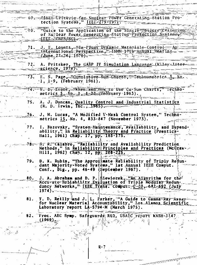
tec t ion Sysfrelf," lEElT-279-l"Pave r G Station Pro-'
"Guit'e to the Application of the Single "isl-iure C « ti-rj on -of XuVleaa; £aKe^s^e=n^^5^Ji^-Statii^tr~PY^_tj?cllon__Sy_steni^-,L?" -
gllUxaIr^4^*!==^t3^^fflffl3^efiJJSe=
72 A. Pritsker, The GASP IV Simulation^science,
f3
74,
75.
E. S. Pag^^-4!£u™ut3"t /c--^£!iS^S]v^^1, 1-9, (February 1961).
ft. D.- Evans^ "tfhen '~andr"H<rx\ to Use Cu-Summetrics 5_? No.^-1, 1-22. vi?.e'3ruary
A. J. Duncan, Quality Control and Industrial S t a t i s t i c s(R. D. Irwin, T n c T 7 ~ I S E 5 ^ ^ "^ ~ip"
J. M. Lucas, "A Modified V-Mask Control System," TechhO-metrics H , No. 4, 833-847 (November 1973). JUi
77. I . Bazovsky, "Sy=stess=K{a4mtenaneeT A v a i l a b i l i t y , and Depend-ability, '• in Reliability!Hall, 1961) Chap. 17, pp
Methods," in R e l i a b i l i t yH i l l , 1962) Chap. 12, pp
79. D. K. Rubin, "The Appro:, dant Majority-Voted Sysi
Conf., Dig . , pp. 46-49
J. A. Abraham and D. P.
dancy Networks,"1974)b-===
80.
81. T. D. Reilly and J. L. I
Theory and Practicery an-125.
ty and Availability PredictionPrinciples and Practices (Mc itav-JOiZZS ' " !!
mate S¥l iabi1i ty of Triply Repun-m5," 1st Annual IEEE Comput.eptember 1967).
for
alOrrXDiof Triple^MoaulaT^RedunJ-
for Nuclear MateriaLaboratory report L.
arker, CIIA Guide to=
Accoun^bil i t y , " Xo5==Alamoj|=5c=ti:1-S794-M (March 1975).
82. Proc. AEC Symp. Safeguards\ R§D, USAEC report WASH-3447
™<*-«»^wr>^:
R-7

y Holdup, i n .l l L o s Alamos S c i e n t i f i c
Laboratory^ repoTrsXA-S889-PR (April 1975) p . 16. V
v—Hfer=B. jValtqn^and T. L.iAtv,ell, "Portable NeutrSftrprobe",m™=tgXAT'"V
1- in L6;s A lames Scientific Laboratoryc-report LA-" ^5291-PR (June 3.973'), p . 14. - ,o , -^j
=Jw§»ajiT Neut ron Detec t o r - SNAP 11 ,repor t LA-jyi6-PR
S[7
88,
89
90
r l e r , \ I . L. havren, K. A. Pashman, arfdiJ. W. Ilealy,"Transuranic Waste Research and Development Program," Loj?Alamos S c i e n t i f i c Laboratory repor t LA-S281-MS (May 19,73"J.
C. J . Umbarger and R. A. Fos t e r , "Alpha Waste Measurementsat. the 10-nCi/g* Leve l , " in Los Alamos S c i e n t i f i c Labora-tory r epo r t L A 2 9 P R ' i ' " t J F T 9 T 3 T r T " ' ' ' s ' 7
C. J. Umbarger and R. A.Totster, "Solid Transuranicj;gste Assay at the 10-nCi/g Levelf" in Los Alamos Scien-tific Laboratory report LA-S431-PR (November 1975), p,. 16.
C. J. Umbarger, "Solid Transuranic Kastjg Agsay^at the LfljjiCi/g = Level," in Los Alamos Scientific Labor a torV reportLA-5557-PR (February 1974), pp. 8-10. -
C. J. .Umbarger and M. E. McLdj|iift*&Solid Transuranic Wasteat the 10-nCi/g Level," in Lqis Alamos Scientific Labora-tory report LA-5771-PR (Noveniber 1974), pp. 4-S.
R. A. Forster- and C, J. Umbarger,, "Photon S«lf-Attenuationin spheTical Particles," ijn Los Alamos Scientific Labora- -
PR C"Ovcsr.ber 1973)°, p . -24i°
92 R. Cunnink and R. J. Morrow, 'Gamma-Ray Enercieslute Branching Intensities for 238,239,240,24lpu and241A!IB," Lawrence Livprmore Laboratory report UCRL-51087(July 1971). » ":—*-.=i=-l__ JL."
4!Kuclear _Analysis Research and Development Program StatusReport,IT~toT~Alianios-Sieientifie Laboratory report LA5675
p. 11. ° n -
JLR. Gunnink and J. B.94
the CAMANAL Program,"UCRL-51061, Vol. I f l
95. Anrf Gibbs , "Evaluatio;tern for the NondestruUranium," Dupont, Sav
a i l -20° "(No vefmber 1974)
y, "Computeri;zed ,Quantitatiye ^Spectrdmetry," ih "Description ofLawrence Livermore Laboratory report
J 7 2 ) . • • , ......... .. . ' -,=_•" ; ,[_
of a Camma/X-Ray Spectrometer Sys-:tive Analysis of Plutonium andinnah River Labojratory report DPSPU-
R-8

*5raftips=o^pP 1 ut"owrum=«--Is®-topic Measurements by^ ^ y l , ' ' Lawrence Livermpre Laboratory
UCRl/-M4l8||(Jun> 19^5). "• ,, r ,
97, T. t\. R e i l l y , R. B}>: Kaht on, arid J . L. Parker , "The] Enrich-mentfcMeter^-- A S.imple| Method for Measuring I so top lc Enrr ichment , " i n Lrds ^'lam'psT 'Scientific liaboratory r e p p r t "LA-4605-MS (January 1971) , pp. 1?9-21.L ; . K
98.
99.
E. R. Martin, D/F.[?Uo1ierrsOTaL. C. Speir, "Passiye Seg-mented Gamma Scan Operation Manual," Los Alamos ScientificLaboratory-report L^-565?-M (July 1974).
For definitions of the measurement errors as well as theirnumerical values, see Bulletin 72A of Transducers, Inc.,12140 E. Rivera Rd/. .h'hittier? CA 90606. Other manufac-turers oJ load cefisiinclude:
The A. H. Emery Co.70 Pine St.; aNew Canaan,\CT 16840
Interface, Inc.7401 East Butherus Dr,Scotfssdale, MH-85260
land1 0 -Sensotec Inc.1400 Holly Ave.Columbus, OH 43212
100. F. A. C'Hara, J. D. Nutter, W. h'. Rodenburg, and M. L<Dinsmore, '^Calorimetry T o F Safeguards Purposes Determina-tion of Plutonium in Reactor Fee^Majterdalv" Mound Labora3
; toryj-eport MLM-J798 (January 1972).
101. American,Nationals Standar^aT^XWxirbTaHon Techniques for theC^\lorimetric Ass^y of Plutonium-Bearing Solids Applied toNuclear ^terials Control,, ANSI Nld.22 (1975).
E. V. Weinstock, "Plutonium in the Light Water Reactor andCl^tr4pMe^aX_Eas.t=BreedexjJ^ : Part I L , = = =Safeguards Measurement Problems and Recommendations forResearch and Development," report prepared by BNL-TSO for *
102^.
the Division of Nuj(August 28, 1974),
N. S. Beyer, R. N.
:lear Materials Security of the AECpp. 13-l6;'.
Lewis.^ B. Perry, "Small, FastResponse Callofimeters ip^yeloped at Argonne National Labora-tory for the! Nondestructive Assay of Plutonium Fuel Rods,"in "Proc. Symp. Ca:.orime|:ric Assay of Plutonium," Mound ,laboratory report !tLM-21*77 (October pp, 99-118.

104. C. L. Fellers and P. W. Sjeabaugh, "prediction of Calorime-ter Equilibrium," Mound Laboratory report MLM-2302 (July- •_,December 1975), pp. 8-16..
105. J. F. Lemming^ J. H. BirdC. L. Fellers, M. F. DuffPlutonium Assay Systems,"2286 (December 1975), pp.
106. J. Kleijnen, Statistical
n, J. ,K. Ferguson, D. 0. Page,and W. W. Rodenburg, "Automatedin Mound Laboratory report MLM-16-23. \
echniques in Simulation (MarcelDekker, Inc., 1974J.
107. T. Naylor, J. L. Balintfiy, P. S. Burdick, and Kong Chu,Computer Simulation Techniques (Wiley, 1966).
Related Documents