www.lmc-couplings.com CATALOGUE 2015

Welcome message from author
This document is posted to help you gain knowledge. Please leave a comment to let me know what you think about it! Share it to your friends and learn new things together.
Transcript

www.lmc-couplings.com
CATALOGUE 2015
Untitled-4 1 27/05/13 10:21

A.1. Cam & groove couplings
A.2. Guillemin couplings
A.3. DSP couplings
A.4. TW couplings
A.5. ‘GK’ couplings
A.6. Express couplings
A.7. European air couplings
A.8. Triclamp couplings
A.9. Cardan couplings
A.10. Chemaline 2000
AQuiCKCouPlinGS
Untitled-4 2 27/05/13 10:40

W W W . L M C - C O U P L I N G S . C O M
Chapter A Page
A.1.
A.2.
A.3.
A.4.
A.5.
A.6.
A.7.
A.7.
A.8.
Quick couplings
Cam & groove couplings Federal Mil / EN / DIN Guillemin couplings EN 14420-8 / NF E 29-572 DSP couplings NF S61-704 / NF S61-705
TW couplings EN 14420-6 / DIN 28450
‘GK’ couplings
Express couplings NF E 29-573
European air couplings DIN 3489
European air safety couplings
Triclamp couplings DIN / INCH / ISO / IMPERIAL Cardan couplings
Chemaline 2000
A.9.
Chapter B Threaded couplings
Screw hose couplings B.1.
Nipples B.2.
Food couplings DIN 11851 B.3.
Food couplings SMS 1145 B.4.
Steam couplings EN 14423 / DIN 2826 B.5.
DINBO steam couplings B.6.
Petrol hose couplings EN 14424 B.7.
Chapter C Flange couplings
Flange couplings EN 14420-4 / DIN 2673 C.1.
Chapter D
D.1.
D.2.
D.3.
D.4.
D.5.
Assembly clamps & ferrules
RK safety clamps EN 14420-3 / DIN 2817 RKP safety clamps EN 14420-3 / DIN 2817 FLEXOLINE safety clamps
RKS steam clamps EN 14423 / DIN 2826 FIXP band clamps
Swage ferrules D.6.
Chapter E Technical information
Seals E.1.
Inspection documents E.2.
Production methods E.3
Materials E.4.
Threads E.5.
Flanges E.6.
Hose assemblies E.7.
Temperature & pressure E.8.
Resistance table E.9.
Chapter F Price list
General sales conditions
CONTENT TABLE
Reasonable care has been taken in preparing this catalogue. However
errors may exist and information should be used as guideline only.
LMC-Couplings nv reserves the right to make corrections and price
changes at any time without prior notice.
content table 9/20/07 8:37 AM Pagina 2
A.10.

A-Z INDEX
AAlloyed steel - stainless steel Chapter E E.4.1Assembly method safety clamps Chapter E E.7.1ASTM 1418 Chapter E E.1.6
BBand clamps Chapter D D.5.1Brass Chapter E E.4.4Bronze Chapter E E.4.5BucklingBleed Off
Chapter EChapter A
E.7.4A.1.43
CCam & groove couplings Chapter A A.1.1Cardan couplings Chapter A A.9.1Chemical resistance table Chapter E E.9.1Chemical terms Chapter E E.1.6Claw couplings Chapter A A.5-6-7Coatings Chapter A A.1.10
DDie-casting Chapter E E.3.1DIN 11866 series A Chapter A A.8.5DIN 11866 series B Chapter A A.8.5DIN 11866 series C Chapter A A.8.5DIN 2826 Chapter B B.5.1DIN 2828 Chapter A A.1.1DIN 28450 Chapter A A.4.1DIN 3017 Chapter D D.5.5DIN 32676 Chapter A A.8.1DIN 3489 Chapter A A.7.1DIN 405/1 Chapter B B.3.3DINBO steam couplings Chapter B B.6.1Drop forging Chapter E E.3.2DSP couplings Chapter A A.3.1
EElastomer Chapter E E.1.1EN 10204 Chapter E E.2.1EN 1026-1 Chapter A A.1.6EN 14420-2 Chapter B B.1.1EN 14420-3 Chapter D D.1.1-D.2.1EN 14420-4 Chapter C C.1.1EN 14420-5 Chapter B B.1.1EN 14420-6 Chapter A A.4.1EN 14420-7 Chapter A A.1.1EN 14420-8 Chapter A A.2.1EN 14423 Chapter B B.5.1-D.4.1EN 14424 Chapter B B.7.1EN ISO 228-1 Chapter A A.1.6European air couplings Chapter A A.7.1European air safety couplings Chapter A A.7.5Express couplings Chapter A A.6.1
FChapter A A.1.1
Chapter D D.6.1
Chapter C C.1.1
Chapter D D.6.3
Chapter E E.6.4
Chapter E E.6.1
Chapter D D.3.1
Chapter B B.3.1
Federal Mil-A-A-59326A Ferrules
Flange couplings
Flange dimensions Flange types
Flanges
FLEXOLINE safety clamps Food couplings DIN 11851 Food couplings SMS 1145
FIXPChapter BChapter D
B.4.1D.5.1
G‘GK’ couplings Chapter A A.5.1
Galvanised steel Chapter E E.4.6
General sales conditions Chapter F -
Guillemin couplings Chapter A A.2.1
HHose assemblies Chapter E E.7.1
HRP swage ferrules Chapter D D.6.1HRRK swage ferrules Chapter D D.6.1
IIMPERIAL Chapter A A.8.1
INCH Chapter A A.8.1
Inspection documents Chapter E E.2.1
Investment casting Chapter E E.3.1
ISO 127 Chapter A A.8.1
ISO 1629 Chapter E E.1.6
LLost wax casting Chapter E E.3.1
MM Chapter E E.4.1
Chapter E E.1.1
Chapter E A.1.1
aterials
Media
MIL-C-27487
NNF E 29-572 Chapter A A.2.1
NF E 29-573 Chapter A A.6.1
NF S61-704 Chapter A A.3.1
NF S61-705 Chapter A A.3.1
Nipples Chapter B B.2.1
Non ferrous alloys Chapter E E.4.4
Nylon Chapter E E.4.6
content table 9/20/07 8:37 AM Pagina 4

A-Z INDEX
PPetrol hose couplings Chapter B B.7.1
Polyethylene Chapter E E.4.6
Polypropylene Chapter E E.4.6
Pressure units Chapter E E.8.2
Price list Chapter F -
Production methods Chapter E E.3.1
PTFE Chapter E E.1.1
QQuick couplings Chapter A
RRa test report Chapter A A.8.2
Ra value Chapter E E.4.7
Resistance table Chapter E F.8.1
RK safety clamps Chapter D D.1.1
RKP safety clamps Chapter D D.2.1
RKS safety clamps Chapter D D.4.1
Roughness certificate Chapter E E.4.9
SChapter D D.1.1
Chapter A A.1.10
Chapter E E.3.2
Chapter B B.1.9
Chapter E E.1.1
Chapter B B.4.1
Chapter E E.4.1
Chapter A A.1.1
Chapter A A.1.1
Chapter A A.1.1
Chapter D D.4.1
Chapter B B.5.1
Chapter E E.4.6
Chapter E E.4.7
Chapter D D.6.1
Safety clamps
Safety handles
Sand casting
Screw hose couplings
Seals
SMS food couplings
Stainless steel
Standard DIN2828
Standard EN 14420-7
Standard Federal Mil-A-A-59326A
Steam clamps
Steam couplings
Steel
Surface treatments
Swage ferrules
Swaging
SaflokChapter EChapter A
E.7.4A.1.43
TTemperature Chapter E E.8
Thermoplastics Chapter E E.4.6
Thin-wall hoses Chapter D D.3.1
Threaded couplings Chapter B
Threads Chapter E E.5.1
Triclamp couplings Chapter A A.8.1
TW couplings Chapter A A.4.1
UUnalloyed steel - steel Chapter E E.4.3
WWire binding Chapter E E.7.4
Worm drive clamps Chapter E E.7.4
Wrench Chapter A A.2.12
content table 9/20/07 8:37 AM Pagina 5

CA
M&
GR
OO
VE
CO
UP
LING
SFED
MIL / EN
/ DIN
A.1
A.1.1
CAM & GROOVE COUPLINGS FED MIL / EN / DIN
STANDARD
� Federal Mil A-A-59326A
The standard for cam & groove couplings is based on the US Military
Specification Mil-C-27487. The Mil-C-27487 specified the casting methods,
materials, dimensions, tolerances, pressure ratings and inspection proce-
dures. In 1998, the original Mil-C-27487 specification was replaced by a new
Federal Military standard: A-A-59326A. Federal Mil A-A-59326A guarantees
interchangeability of couplings designed to the same specification.
Interchangeability with other brands
Between manufacturers cam & groove couplings are interchangeable with
the exception of 1/2" (12.7 mm), 5" (127 mm) and 8" (203.2 mm).
The A-A-59326A Mil-specification does not apply to 1/2", 5" and 8" cam & groove
couplings, due to the presence of two versions of cam & groove couplings in
today’s market.
Limitations: Hose shanks with larger serrations are not designed to be
assembled with a ferrule or sleeve. Hose damage can result if they are
swaged. The larger shank serrations will cut into the inner wall of the hose
resulting in leakage or permanent hose failure.
N.B.: Cam & groove couplings must never be used for steam or compressed air
applications.
� EN 14420-7
The European standard EN 14420-7 was approved by CEN in September
2004, and was applied to cam & groove couplings manufactured to American
“military specification” MIL-C-27487 / A-A-59326A. This American standard
does not apply to the connection side, but only to the coupling side. Other
parts like levers, bolts, rings and seals are not standardized.
Cam & groove couplings produced to EN 14420-7 are interchangeable with
those produced to the original MIL-C-27487 standard, but differ in terms of
hose tail design, thread, part number etc. A flat thread seal has been added
to the female threaded parts, and a smooth hose shank complying with
EN 14420-2 / DIN 2817 has been added for assembly with RK safety clamps
complying with EN 14420-3 / DIN 2817.
N.B.: European standard EN 14420-7 replaces DIN 2828 but does not replace
MIL-C-27487 and Federal Mil A-A-59326A.
� DIN 2828
Couplings produced to DIN 2828 are interchangeable with those produced
to the original MIL-C-27487 standard, but differ in terms of hose tail design,
thread, part number etc. A flat thread seal has been added to the female
threaded parts, and a smooth hose shank complying with EN14420-3/
DIN 2817 has been added for assembly with RK safety clamps complying with
EN 14420-3/DIN 2817.
a1-c&g 7/17/07 2:40 PM Pagina 1


Saok/Bleedoff

A.1.5Chapter A: Quick couplings
CA
M&
GR
OO
VE
CO
UP
LING
SFED
MIL / EN
/ DIN
A.1W W W . L M C - C O U P L I N G S . C O M
PTFE envelope FPM core (standard)VMQ core (on request)
Closed envelope sealThe closed envelope seal removes all contact between chemicals and the seal core. The fully-closed PTFE envelope completely encapsulates the FPM. The maximum temperature for this type is 200°C / 392°F.
Thread sealFemale threaded coupler and adaptor components complying with EN 14420-7 / DIN 2828 standards contain a thread seal. Female threaded cam & groove couplings are sealed by screwing a male BSPT / BSP thread up to the thread seal. Thread seals are available in: PTFE - PU
Properties seals
NBR= Perbunan® is a registered trademark of Bayer AG / EPDM= Keltan® is a registered trademark of DSM / FPM= Viton® is a registered trademark of DuPont Performance Elastomer
CSM= Hypalon® is a registered trademark of DuPont Performance Elastomer / PTFE = Teflon® is a registered trademark of DuPont Performance Elastomer
VMQ = Silplus® is a registered trademark of General Electric Co / TFMTM is a registered trademark of Dyneon.
PTFE or PU
REF. ASTM POLYMER TRADE NAME HARDNESS °C °F + PROPERTIES -
VLXB... NBR Acrylonitrile Butadiene Perbunan® 60 +/- 5 -30°C -22°F Oil based hydraulic Ozone,Shore A 120°C 248°F fluid, fats, animal and sunlight
vegetable oils, flame weatherretardant, liquids, grease,water and air
VLXE... EPDM Ethylene-propylene- Keltan® 70 +/- 5 -40°C -40°F Acids, steam, alcohol Oil,Diene Rubber Shore A 145°C 293°F greases
VLXV... FPM Fluorocarbon Viton® 70 +/- 5 -30°C -22°F Mineral oils and greases, SteamShore A 200°C 392°F alifatic, aromatic, and also
special chlorinated hydro-carbons, petrol, diesel fuels,silicon oils and greases
VLXH... CSM Chlorosylfonated Hypalon® 70 +/- 5 -40°C -40°F Acids and oils, obsolescent Chlorinepolyethylene Shore A 140°C 284°F and ozone resistant
VLXPSG... FEP / Copolymer of Hexa-fluorpropylene / Teflon® / 60 +/- 5 -60°C -76°F Resistant to almost all kinds HardnessVMQ Silicone Silicone Shore D 204°C 399°F of chemical products, steam,
oils... Excellent self-lubricatingand anti adhesive properties
VLXP... PTFE / Poly tetrafluorethylene / Teflon® / 85 +/-5 -25°C -13°F Alcohols, acids HardnessEPDM Keltan® Shore D 100°C 212°F Oil, greases
VLXP...V PTFE / Poly tetrafluorethylene / Teflon® / 85 +/-5 -10°C 14°F Mineral oils and greases, Low temp.FPM Fluorocarbon Viton® Shore D 200°C 392°F alifatics, aromatics
VLXPG... PTFE / Poly tetrafluorethylene / TFMTM/ 74 +/- 5 -15°C -5°F Acids and oils, obsolescent Benzene, FPM Fluorocarbon Viton® Shore D 200°C 392°F and ozone resistant toluene,
petrol
CAM & GROOVE COUPLINGS FED MIL / EN / DIN
a1-c&g 7/17/07 2:41 PM Pagina 5

A.1.6 Chapter A: Quick couplings
W W W . L M C - C O U P L I N G S . C O M
THREADS
Three different types of thread are generally used for cam & groove couplings:
� BSP = British Standard Pipe
� BSPT = British Standard Pipe Taper
� NPT = National Pipe Taper
In Europe, BSP and BSPT threads are more commonly used than NPT threads. NPT threads are typically American threads. Since manyAmerican industrial machines and products are exported to European markets, couplings with NPT threads are a regular requirement. Themain difference between the three thread types referred to above is the seal method used. Although BSP threads are sealed using a sealor o-ring, BSPT and NPT threads are sealed by their conical thread.
THREAD DESCRIPTION STANDARD TYPICAL CALL OUT SEALING METHOD PROPERTIES
BSP British standard pipe EN ISO 228-1 G1 � Parallel thread � 55° degree thread angleDIN ISO 228-1 � Pressure tight joint is � Trucation of rood and crest
obtained with a seal are roundor o-ring � Diameter measured in inches
BSPT British standard EN 10226-1 R1 � Conical thread. � 55° degree thread anglepipe taper DIN 2999-1 � Pressure tight joint is � Trucation of rood and crest
achieved by the thread are round
BSPP British standard G 1(cyl) � Cylindrical thread � 55° degree thread anglepipe parallel � Trucation of rood and crest
are round
NPT National pipe taper ANSI B 1.20.1 NPT 1 � Conical thread � 60° degree round angle(American standard pipe thread) � Pressure tight joint is � Trucation of rood and crest
achieved by the thread are flat
COUPLING TYPE STANDARD ON REQUEST
ADAPTOR
Female threaded A BSP EN ISO 228-1/ DIN ISO 228-1 NPT ANSI B 1.20.1
Male threaded F BSPT EN 10226-1 / DIN 2999-1 NPT ANSI B 1.20.1
COUPLER
Female threaded D BSP EN ISO 228-1/ DIN ISO 228-1 NPT ANSI B 1.20.1
Male threaded B BSPT EN 10226-1 / DIN 2999-1 NPT ANSI B 1.20.1
ASSEMBLY
Worm drive clampsRK safety clamps to EN14420-3 / DIN 2817RKP safety clamps to EN14420-3 / DIN 2817
FLEXOLINE® safety clampsWelding: butt welding and socket welding (see pg. A.1.27)
CAM & GROOVE COUPLINGS FED MIL / EN / DIN
Cam & groove threads
a1-c&g 7/17/07 2:41 PM Pagina 6

TESTING
The following aspects of LMC’s cam & groove couplings are tested in house:
� Adaptor and coupler dimensions
� Material quality
� Handle strength
� Seal properties
� Thread dimensions
� Impact resistant
� Adaptor and coupler dimensions
High-technology measuring equipment
High-technology measuring tools are used to measure the specific dimensions of cam &
groove couplings to ensure compliance with the dimensions required under the Federal Mil
A-A-59326A, European EN 14420-7 and the German DIN 2828 standards. Although ordinary
measuring systems are unable to give sufficiently precise dimensions for this purpose, our
high-technology measuring system is able to measure complex cam & groove coupling product
positions and shapes.
Dimension gauges
The shape of the adaptor coupling enables the interchangeability of coupler parts. Specially
designed gauges are used in addition to measurement systems. The use of test gauges
minimises inspection times, ensures interchangeability and maintains seal properties when
using specially-designed seals, such as envelope seals.
Two gauges are used for each dimension; one small and the other larger. In the first stage of
testing, the small gauge is passed across the head of the adaptor section. If the gauge can not
pass, the adapter head falls within the permissible – (minus) tolerances.
If the larger gauge passes across the adaptor head with no interruption, the component is
compliant and its dimensions fall within the permissible + (plus) tolerances.
� Material quality
An in-house spectroscope is used to identify the materials used in the cam & groove couplings.
The spectroscope analyses the precise quantity of all materials of the coupling.
We can therefore offer our customers a guarantee that the materials used comply fully with the
relevant standard.
Chapter A: Quick couplings A.1.7
CA
M&
GR
OO
VE
CO
UP
LING
SFED
MIL / EN
/ DIN
A.1W W W . L M C - C O U P L I N G S . C O MCAM & GROOVE COUPLINGS FED MIL / EN / DIN
a1-c&g 7/17/07 2:41 PM Pagina 7

W W W . L M C - C O U P L I N G S . C O M
A.1.8 Chapter A: Quick couplings
� Handle strength
LMC handles are designed to resist a wide range of applications in many industries. All standard handles are investment-cast and
triangular in section. The production method and triangular section guarantees excellent mechanical properties. The wear resistance
of this material was tested using a Rockwell hardness tester. LMC handles achieve better test results than sintered handles.
Sintered handles begin to fracture when subjected to a load of 1600 Kg, LMC handles do not even start to bend until subjected to a
load of 1000 Kg. Even when subjected to a load of 2400 Kg, LMC cam & groove handles still show no sign of fracture.
� Seal properties
After chemical structure, seal compression set has the next most significant effect on the seal of cam & groove couplings. A seal of
correct hardness will ensure that the cam & groove coupling is sealed properly and safely. Cam & groove seal hardness is tested using
a durometer.
� Thread dimensions
All cam & groove threads are tested using thread gauges. Our production site has gauges for all dimensions and all standards.
� Impact resistance
Impact resistance tests were carried out on 3” and 4” aluminium couplers and nine other brands in order to test the mechanical
strength of LMC cam & groove couplings. A 2.3 kg / 5 lbs weight was dropped from a height of 1.5 metres / 5 feet, and the impact on
the coupler body measured.
A
B
Impact
Drop weight impact onbowl of coupler
Original ID: AID after impact: B
BRAND PRODUCTION METHOD
E Gravity cast
F Gravity cast
G Sand cast
H High pressure die cast
I High pressure die cast
J Squeeze die cast
K High pressure die cast
LMC High pressure die cast
M High pressure die cast
0.0 2.5 5.0 7.5 10.0 12.5 15.0
6000
5000
4000
3000
2000
1000
0
* LMC
X0 0P/M
(*) Fractured.
(0, ) Bend, not fracture.
Bending stroke (mm) Bend investment cast LMC handle
Load
(kg
)
Fractured sintered handle
CAM & GROOVE COUPLINGS FED MIL / EN / DIN
a1-c&g 7/17/07 2:41 PM Pagina 8

A.1.9Chapter A: Quick couplings
CA
M&
GR
OO
VE
CO
UP
LING
SFED
MIL / EN
/ DIN
A.1W W W . L M C - C O U P L I N G S . C O M
Test result
The impact resistance test showed that the product quality of cam & groove couplings is variable. Nine couplers from different
manufacturers were also tested.
Four brands of adaptor were unable to fit the corresponding coupler following a single impact from a 2.3 kg / 5 lbs weight dropped
from a height of 1.5 metres / 5 feet. However, it took 18 such impacts before LMC-Couplings couplers were unable to fit their adaptors.
The average number of impacts required before fractures became aparent was 4.25. LMC-Couplings couplers resisted 23 impacts before
showing signs of fracture; a result far in excess of the average value.
Imp
ac
t ti
me
s B
94.50
88.50
90.50
92.50
C(E) C(F) C(G) C(H) C(H) C(I) C(J) B(K) B(K) C(K) C(K) D(K) C(LMC) C(LMC)
*0*0
*0
*1
*1
*0
*1 *1*1
*0 *0
*0
*1*1
*17
*18 *18
*19
*0*0
*0
*1
*2
*2
*2*2
*0
*0
*1
*1
*1
*0
*2
*2*2
*3
*0
FUNCTIONAL
DX
(MM
)
DISABLED
CAM & GROOVE COUPLINGS FED MIL / EN / DIN
Size 3”Type C C C C C C C B B C C D CBrand E F G H H I J K K K K K LMC
Original ID A 92.14 91.72 91.98 92.21 92.01 92.53 91.98 92.24 92.42 92.74 92.58 92.15 93.541 91.75 89.43 89.86 91.06 91.67 90.98 91.16 91.43 91.12 91.48 91.59 91.31 93.172 91.38 88.65 90.57 90.54 90.08 89.57 91.00 90.43 90.68 91.20 90.75 92.573 90.73 90.54 90.27 89.06 88.66 90.26 90.30 90.28 91.11 90.38 92.574 90.56 90.25 90.09 90.12 89.28 90.68 90.30 92.355 90.16 90.05 89.83 90.65 89.78 92.196 90.11 90.00 90.47 89.72 91.927 89.55 89.49 91.898 89.35 89.44 91.879 89.37 89.33 91.79
10 89.33 91.7711 89.22 91.7612 89.14 91.5513 91.6814 91.5815 91.5816 91.6517 91.6118 91.1919 91.1520 91.1821 91.0822 90.5823 90.05
Measurements in mm� Adaptor unable to fit in coupler� Coupler cracked
a1-c&g 7/17/07 2:41 PM Pagina 9

290°C / 550°F.
290°C / 550°F.


A.1.14LMC
Chapter A: Quick couplings
W W W . L M C - C O U P L I N G S . C O MCAM & GROOVE COUPLINGS FED MIL / EN / DIN
ND Inch A B C D E F G H J K L M13 1/2” 66,40 37,70 33,00 53,00 12,50 33,00 73,60 15,00 53,00 29,00 34,50 11,00
13-19 1/2”-3/4” 110,30 53,30 33,00 53,00 12,50 33,00 73,60 15,00 53,00 29,00 - -
19 3/4” 110,30 53,30 33,00 55,00 17,50 33,00 84,00 21,50 54,00 35,20 34,80 11,0025 1” 130,80 61,90 39,00 62,00 22,00 39,00 100,00 27,00 61,00 40,60 41,10 11,5032 1.1/4” 181,30 82,60 46,00 72,00 30,00 46,00 109,40 33,50 70,00 51,00 48,60 13,60
38-32 1.1/4”-1.1/2” 180,20 83,30 47,00 73,00 30,00 47,00 110,40 33,50 71,00 51,00 - -38 2.1/2” 180,20 83,30 46,00 72,00 35,80 46,00 112,80 39,20 71,00 60,00 48,80 13,5050 2” 189,50 94,20 53,00 86,00 47,00 53,00 140,50 52,80 81,00 69,00 56,30 12,0075 3” 245,00 128,10 59,00 99,00 70,00 59,00 162,60 78,50 95,00 102,00 65,20 16,00
100 4” 272,20 159,40 59,00 101,00 95,00 59,00 168,70 104,30 99,00 129,00 65,20 16,00
ND Inch N O P R S T U V W X Y Z AA13 1/2” 29,00 46,60 12,10 27,00 15,00 78,20 37,60 27,00 59,60 39,60 12,10 11,00 27,70
13-19 1/2”-3/4” 35,20 41,60 16,50 35,00 15,00 78,20 37,60 35,20 61,60 41,60 16,50 - -19 3/4” 35,20 47,60 19,00 35,00 21,50 88,60 37,60 35,20 63,60 41,60 18,90 11,60 28,0025 1” 41,00 48,60 23,00 40,00 27,00 107,60 46,60 40,00 71,60 48,60 22,80 13,40 35,2032 1.1/4” 51,00 67,00 27,50 650,00 33,50 116,90 53,50 51,00 81,00 55,00 27,90 15,00 42,00
38-32 1.1/4”-1.1/2” 56,00 56,50 35,20 50,00 33,50 118,40 55,00 56,00 82,50 56,50 35,20 - -38 2.1/2” 60,00 67,50 35,80 57,00 39,20 121,80 55,00 39,20 82,50 56,50 35,80 14,70 43,8050 2” 70,00 77,00 45,50 68,00 52,80 149,50 62,00 68,00 97,00 63,00 45,50 14,20 50,8075 3” 101,00 91,40 70,40 98,00 78,50 173,10 69,50 98,00 111,20 71,20 70,40 15,20 64,80
100 4” 129,00 96,50 96,00 128,00 104,30 180,70 71,00 129,00 113,70 71,70 96,00 14,80 57,70
POLYPROPYLENE
ND Inch A B C D E F G H J K L M13 1/2” 67,00 38,50 31,00 46,20 11,50 31,45 80,00 14,20 47,00 26,60 32,50 13,50
19 3/4” 110,60 52,60 32,50 49,90 19,00 32,50 92,50 21,20 49,90 33,40 33,60 7,50
25 1” 136,00 62,20 38,50 59,80 24,20 38,50 107,60 27,00 59,80 38,60 39,70 8,0032 1.1/4” 182,60 80,20 42,40 63,70 32,50 42,40 115,00 33,20 63,70 47,60 48,90 8,4038 1.1/2” 190,20 87,80 45,20 67,60 38,50 45,20 121,30 39,60 67,60 55,00 46,90 8,5050 2” 199,60 97,20 51,60 75,40 49,60 56,10 139,30 52,80 75,40 66,00 53,70 8,5063 2.1/2” 212,30 109,90 53,00 86,00 65,00 52,20 149,50 65,00 85,00 82,00 54,50 8,8075 3” 252,30 137,10 56,10 89,10 75,50 56,10 173,00 78,50 89,10 96,00 59,00 9,40
100 4” 280,30 165,00 56,40 93,40 101,00 56,40 180,00 103,80 93,40 124,00 60,40 12,00125 5” 306,10 191,10 61,00 103,00 126,00 61,00 187,50 129,60 103,00 152,00 68,60 15,00150 6” 414,50 240,00 64,00 107,00 149,00 84,00 243,00 154,50 103,00 180,00 64,00 16,00200 8” 467,40 286,80 68,00 118,00 199,00 68,00 243,00 205,00 118,00 234,00 74,40 7,00
ND Inch N O P R S T U V W X Y Z AA13 1/2” 26,30 42,30 13,50 23,80 14,20 72,00 39,00 25,20 57,00 40,50 13,45 13,75 29,00
19 3/4” 33,40 37,90 21,50 35,00 21,20 86,00 36,00 33,40 53,80 36,50 21,50 13,10 25,6025 1” 38,60 46,60 24,20 39,00 27,00 103,80 44,80 38,60 68,60 47,00 24,20 13,20 33,2032 1.1/4” 47,60 52,70 28,20 48,00 33,20 113,90 51,90 47,60 74,70 53,40 28,20 13,20 39,6038 1.1/2” 55,00 54,70 36,40 56,60 39,60 119,70 55,70 55,00 77,40 54,40 36,40 13,10 41,3050 2” 65,40 61,50 46,00 68,00 52,80 135,90 60,90 65,40 84,00 60,70 46,00 12,80 48,0063 2.1/2” 82,00 81,70 56,60 82,00 65,00 144,70 61,70 80,00 99,70 67,70 59,60 13,20 49,2075 3” 95,40 69,50 73,30 98,00 78,80 167,40 64,90 95,40 100,90 67,90 73,30 13,10 51,60
100 4” 124,00 77,70 98,40 127,00 103,80 174,50 67,50 122,00 112,00 74,90 98,40 16,80 54,40125 5” 152,00 82,00 123,30 154,00 129,60 192,50 72,50 150,00 124,00 82,00 125,30 17,80 59,20150 6” 189,50 82,00 150,00 178,50 154,70 254,00 77,00 189,00 126,30 83,30 149,80 24,70 56,50200 8” 234,00 108,00 197,00 232,00 205,00 254,00 79,00 232,00 138,00 88,00 197,00 28,00 58,00
STAINLESS STEEL


8” 5.00 VLPR200

A.1.23Chapter A: Quick couplings
CAM & GROOVE COUPLINGS EN 14420-7 / DIN 2828
CA
M&
GR
OO
VE
CO
UP
LING
SFED
MIL / EN
/ DIN
A.1W W W . L M C - C O U P L I N G S . C O M
TYPE AF: ADAPTOR FEMALE THREADED WITH THREAD SEAL
ND Inch Thread Thread Material Weight/pc ReferenceEN ISO 228-1 seal Kg
20 3/4” G 3/4 PTFE Stainless steel 0.11 VLAR019D25 1” G 1 PTFE Stainless steel 0.18 VLAR025D32 1.1/4” G 1.1/4 PTFE Stainless steel 0.31 VLAR032D40 1.1/2” G 1.1/2 PTFE Stainless steel 0.44 VLAR038D50 2” G 2 PTFE Stainless steel 0.60 VLAR050D65 2.1/2” G 2.1/2 PTFE Stainless steel 1.02 VLAR063D80 3” G 3 PTFE Stainless steel 1.12 VLAR075D
100 4” G 4 PTFE Stainless steel 1.87 VLAR100D
50 2” G 2 PU Brass 0.71 VLAM050D65 2.1/2” G 2.1/2 PU Brass 0.80 VLAM063D80 3” G 3 PU Brass 1.38 VLAM075D
100 4” G 4 PU Brass 1.51 VLAM100D
Coupling standard: EN 14420-7 / DIN 2828Female thread: EN ISO 228-1, BSPThread seal: PTFE for stainless steel coupling
PU for brass coupling Stainless steel: AISI 316 - EN 1.4401
Coupling standard: EN 14420-7 / DIN 2828Shank standard: EN 14420-2 / DIN 2828Assembly: RK safety clamps EN 14420-3 / DIN 2817, FLEXOLINE® safety clamps (see chapter E)Stainless steel: AISI 316 - EN 1.4401
TYPE EC: ADAPTOR WITH SMOOTH HOSE SHANK
ND Inch For hose Material Weight/pc Referencemm Kg
20 3/4” 19 Stainless steel 0.13 VLER019D25 1” 25 Stainless steel 0.20 VLER025D32 1.1/4” 32 Stainless steel 0.33 VLER032D40 1.1/2” 38 Stainless steel 0.45 VLER038D50 2” 50 Stainless steel 0.58 VLER050D65 2.1/2” 63 Stainless steel 0.96 VLER063D80 3” 75 Stainless steel 1.16 VLER075D
100 4” 100 Stainless steel 2.26 VLER100D
20 3/4” 19 Brass 0.14 VLEM019D25 1” 25 Brass 0.21 VLEM025D32 1.1/4” 32 Brass 0.35 VLEM032D40 1.1/2” 38 Brass 0.45 VLEM038D50 2” 50 Brass 0.66 VLEM050D65 2.1/2” 63 Brass 0.98 VLEM063D80 3” 75 Brass 1.26 VLEM075D
100 4” 100 Brass 2.69 VLEM100D
Thread seal
Smooth hose shankand collar
a1-c&g 7/17/07 2:46 PM Pagina 23

A.1.24 Chapter A: Quick couplings
CAM & GROOVE COUPLINGS EN 14420-7 / DIN 2828
W W W . L M C - C O U P L I N G S . C O M
TYPE DF: COUPLER FEMALE THREADED WITH THREAD SEAL
ND Inch Thread Thread Material Coupler Weight/pc ReferenceEN ISO 228-1 seal seal Kg
20 3/4” G 3/4 PTFE Stainless steel NBR 0.18 VLDR019D25 1” G 1 PTFE Stainless steel NBR 0.29 VLDR025D32 1.1/4” G 1.1/4 PTFE Stainless steel NBR 0.58 VLDR032D40 1.1/2” G 1.1/2 PTFE Stainless steel NBR 0.57 VLDR038D50 2” G 2 PTFE Stainless steel NBR 0.71 VLDR050D65 2.1/2” G 2.1/2 PTFE Stainless steel NBR 0.96 VLDR063D80 3” G 3 PTFE Stainless steel NBR 1.28 VLDR075D
100 4” G 4 PTFE Stainless steel NBR 2.01 VLDR100D
Coupling standard: EN 14420-7 / DIN 2828Female thread: EN ISO 228-1, BSPThread seal: PTFE - white for stainless steel couplingStainless steel: AISI 316 - EN 1.4401Brass available upon request
Coupling standard: EN 14420-7 / DIN 2828Shank standard: EN 14420-2 / DIN 2828Assembly: RK safety clamps EN 14420-3 / DIN 2817, FLEXOLINE® safety clamps (see chapter E)Stainless steel: AISI 316 - EN 1.4401
TYPE CC: COUPLER WITH SMOOTH HOSE SHANK
ND Inch For hose Coupler Material Weight/pc Referencemm seal Kg
20 3/4” 19 NBR Stainless steel 0.24 VLCR019D25 1” 25 NBR Stainless steel 0.35 VLCR025D32 1.1/4” 32 NBR Stainless steel 0.59 VLCR032D40 1.1/2” 38 NBR Stainless steel 0.68 VLCR038D50 2” 50 NBR Stainless steel 0.90 VLCR050D65 2.1/2” 63 NBR Stainless steel 1.24 VLCR063D80 3” 75 NBR Stainless steel 1.57 VLCR075D
100 4” 100 NBR Stainless steel 2.59 VLCR100D
20 3/4” 19 NBR Brass 0.25 VLCM019D25 1” 25 NBR Brass 0.38 VLCM025D32 1.1/4” 32 NBR Brass 0.63 VLCM032D40 1.1/2” 38 NBR Brass 0.69 VLCM038D50 2” 50 NBR Brass 0.91 VLCM050D65 2.1/2” 63 NBR Brass 1.18 VLCM063D80 3” 75 NBR Brass 1.57 VLCM075D
100 4” 100 NBR Brass 2.71 VLCM100D
Thread seal
Smooth hose shankand collar
a1-c&g 7/17/07 2:46 PM Pagina 24
A.1.25Chapter A: Quick couplings
CAM & GROOVE SAFETY COUPLINGS
CA
M&
GR
OO
VE
CO
UP
LING
SFED
MIL / EN
/ DIN
A.1W W W . L M C - C O U P L I N G S . C O M
Coupling standard: Federal Mil A-A-59326AFemale thread: EN IS0 228-1, BSPVersion: monoblock safety bodyStainless steel: AISI 316 - EN 1.4401
TYPE D: COUPLER FEMALE THREADED WITH SAFETY HANDLES
ND Inch Thread Material Weight/pc ReferenceEN ISO 228-1 Kg
25 1” G 1” Stainless steel 0.47 VLDR025S40 1.1/2” G 1.1/2” Stainless steel 0.82 VLDR038S50 2” G 2” Stainless steel 1.07 VLDR050S80 3” G 3” Stainless steel 1.76 VLDR075S
100 4” G 4” Stainless steel 2.48 VLDR100S
Coupling standard: Federal Mil A-A-59326A / EN 14420-7 / DIN 2828Male thread: EN 10226-1 / DIN 2999-1, BSPTVersion: monoblock safety bodyStainless steel: AISI 316 - EN 1.4401
TYPE B: COUPLER MALE THREADED WITH SAFETY HANDLES
ND Inch Thread Material Weight/pc ReferenceEN 10226-1 Kg
25 1” R 1 Stainless steel 0.45 VLBR025S40 1.1/2” R 1.1/2 Stainless steel 0.75 VLBR038S50 2” R 2 Stainless steel 0.98 VLBR050S80 3” R 3 Stainless steel 1.68 VLBR075S
100 4” R 4 Stainless steel 2.35 VLBR100S
Coupling standard: Federal Mil A-A-59326AAssembly: worm drive clamps, buckling, binding and band clampsVersion: monoblock safety bodyStainless steel: AISI 316 - EN 1.4401Collar is subjet to change without prior notice
TYPE C: COUPLER WITH SERRATED HOSE SHANK AND SAFETY HANDLES
ND Inch For hose Collar Material Weight/pc Referencemm Kg
25 1” 25 - Stainless steel 0.51 VLCR025S40 1.1/2” 38 x Stainless steel 0.90 VLCR038S50 2” 50 x Stainless steel 1.33 VLCR050S80 3” 75 x Stainless steel 2.39 VLCR075S
100 4” 100 x Stainless steel 3.55 VLCR100S
a1-c&g 7/17/07 2:46 PM Pagina 25

A.1.26 Chapter A: Quick couplings
CAM & GROOVE SAFETY COUPLINGSW W W . L M C - C O U P L I N G S . C O M
Coupling standard: EN 14420-7 / DIN 2828Shank standard: EN 14420-2 / DIN 2828Assembly: RK safety clamps EN 14420-3 / DIN 2817, FLEXOLINE® safety clamps (see chapter E)Version: monoblock safety bodyStainless steel: AISI 316 - EN 1.4401
TYPE CC: COUPLER WITH SMOOTH HOSE SHANK AND SAFETY HANDLES
ND Inch For hose Material Weight/pc Referencemm Kg
40 1.1/2” 38 Stainless steel 0.79 VLCR038SD50 2” 50 Stainless steel 1.06 VLCR050SD
Coupling standard: Federal Mil A-A-59326A / EN 14420-7 / DIN 2828Standard chain accessVersion: monoblock safety bodyStainless steel: AISI 316 - EN 1.4401
TYPE DC: FEMALE DUST CAP WITH SAFETY HANDLES
ND Inch Material Weight/pc ReferenceKg
25 1” Stainless steel 0.43 VLKR025S40 1.1/2” Stainless steel 0.70 VLKR038S50 2” Stainless steel 0.88 VLKR050S80 3” Stainless steel 1.58 VLKR075S
SAFETY REBUILDING SET
ND Inch Material Weight/pc Reference Kg
25 1” Stainless steel 0.10 VLHRPR2S
32 - 65 1.1/2” - 2” Stainless steel 0.13 VLHRPR3S
80 - 100 3”-4” Stainless steel 0.17 VLHRPR4S
Safety rebuilding set: Safety handle stainless steel AISI 304 - EN 1.4301Pull ring stainless steel AISI 304 - EN 1.4301Safety pin stainless steel AISI 304 - EN 1.4301Safety hook stainless steel AISI 304 - EN 1.4301
VLHRPR2S VLHRPR4S SAFETY
VLHRPR3S HOOK
a1-c&g 7/17/07 2:47 PM Pagina 26

A.1.27Chapter A: Quick couplings
CAM & GROOVE WELDING COUPLINGS
CA
M&
GR
OO
VE
CO
UP
LING
SFED
MIL / EN
/ DIN
A.1W W W . L M C - C O U P L I N G S . C O M
Coupling standard: Federal Mil A-A-59326AWelding end: butt weld end to inch sizeStainless steel: AISI 316 - EN 1.4401
TYPE AWB: ADAPTOR WITH BUTT WELD CONNECTION
ND Inch Material Weight/pc ReferenceKg
15 1/2” Stainless steel 0.11 VLAWBR01320 3/4” Stainless steel 0.16 VLAWBR01925 1” Stainless steel 0.26 VLAWBR02532 1.1/4” Stainless steel 0.41 VLAWBR03240 1.1/2” Stainless steel 0.53 VLAWBR03850 2” Stainless steel 0.69 VLAWBR05065 2.1/2” Stainless steel 0.96 VLAWBR06380 3” Stainless steel 1.38 VLAWBR075
100 4” Stainless steel 2.04 VLAWBR100125 5” Stainless steel 3.52 VLAWBR125150 6” Stainless steel 5.14 VLAWBR150
Butt weld vs socket weld
Cam & groove couplings can be welded on hoses, pipes an other welding couplings by using:
� cam & groove couplings with butt weld connection � cam & groove couplings with socket weld connection
Butt weldingWelding ends with a butt weld connection are used for welding the majority of cam & groovecouplings. A butt weld connection consists of a 30° welding end. During the welding process,the butt weld cam & groove coupling is connected to a hose, pipe or coupling by the applicationof heat and pressure.
Socket weldingIn socket welding, the pipe or hose slides partially inside the coupling. Both components are thenwelded together at the point of insertion. Stainless steel socket welding couplings provide a tightand integral line system that remains unaffected by shock, vibration or termal distortion.
Welding dimensionsThe welding dimensions for cam & groove couplings are based on inch sizes.
ND INCH A mm B mm
15 1/2" 21.34 2.0
20 3/4" 26.67 2.3
25 1" 33.40 2.6
32 1.1/4” 42.16 2.6
40 1.1/2” 48.26 2.6
50 2" 60.33 2.9
65 2.1/2” 76.03 2.9
80 3" 88.90 3.2
100 4" 114.30 3.6
125 5" 139.70 4.0
150 6" 168.28 4.5
30°
Butt weld connection
Socket weld connection
B
A
A
a1-c&g 7/17/07 2:47 PM Pagina 27

A.1.28 Chapter A: Quick couplings
CAM & GROOVE WELDING COUPLINGSW W W . L M C - C O U P L I N G S . C O M
Coupling standard: Federal Mil A-A-59326AWelding end: socket weld end to inch sizeStainless steel: AISI 316 - EN 1.4401
TYPE AWS: ADAPTOR WITH SOCKET WELD CONNECTION
ND Inch Material Weight/pc ReferenceKg
15 1/2” Stainless steel 0.07 VLAWSR01320 3/4” Stainless steel 0.11 VLAWSR01925 1” Stainless steel 0.15 VLAWSR02532 1.1/4” Stainless steel 0.24 VLAWSR03240 1.1/2” Stainless steel 0.27 VLAWSR03850 2” Stainless steel 0.42 VLAWSR05065 2.1/2” Stainless steel 0.71 VLAWSR06380 3” Stainless steel 0.73 VLAWSR075
100 4” Stainless steel 1.42 VLAWSR100150 6” Stainless steel 3.17 VLAWSR150
Coupling standard: Federal Mil A-A-59326AWelding end: socket weld end to inch sizeStainless steel: AISI 316 - EN 1.4401
TYPE DWS: COUPLER WITH SOCKET WELD CONNECTION
ND Inch Material Weight/pc ReferenceKg
15 1/2” Stainless steel 0.13 VLDWSR01320 3/4” Stainless steel 0.23 VLDWSR01925 1” Stainless steel 0.36 VLDWSR02532 1.1/4” Stainless steel 0.48 VLDWSR03240 1.1/2” Stainless steel 0.57 VLDWSR03850 2” Stainless steel 0.90 VLDWSR05065 2.1/2” Stainless steel 1.03 VLDWSR06380 3” Stainless steel 1.23 VLDWSR075
100 4” Stainless steel 2.30 VLDWSR100150 6” Stainless steel 4.42 VLDWSR150
Coupling standard: Federal Mil A-A-59326AWelding end: butt weld end to inch sizeStainless steel: AISI 316 - EN 1.4401
TYPE DWB: COUPLER WITH BUTT WELD CONNECTION
ND Inch Material Weight/pc ReferenceKg
15 1/2” Stainless steel 0.12 VLDWBR01320 3/4” Stainless steel 0.20 VLDWBR01925 1” Stainless steel 0.29 VLDWBR02532 1.1/4” Stainless steel 0.50 VLDWBR03240 1.1/2” Stainless steel 0.54 VLDWBR03850 2” Stainless steel 0.67 VLDWBR05065 2.1/2” Stainless steel 1.04 VLDWBR06380 3” Stainless steel 1.36 VLDWBR075
100 4” Stainless steel 1.84 VLDWBR100125 5” Stainless steel 3.36 VLDWBR125150 6” Stainless steel 3.67 VLDWBR150 30°
a1-c&g 7/17/07 2:48 PM Pagina 28

A.1.29Chapter A: Quick couplings
CAM & GROOVE FLANGE T.11B COUPLINGS
CA
M&
GR
OO
VE
CO
UP
LING
SFED
MIL / EN
/ DIN
A.1W W W . L M C - C O U P L I N G S . C O M
Coupling standard: Federal Mil A-A-59326A Flange standard: EN 1092 T.11B, PN25/40Stainless steel: AISI 316 - EN 1.4401
*Total length flange coupling in mm and is subject to change without prior notice
TYPE AF: ADAPTOR WITH FIXED FLANGE IN COMPLIANCE WITH DIN
ND Inch Material Welding neck flange Total Weight/pc Referencelength* Kg
15 1/2” Stainless steel EN1092 T11B - PN 25/40 92.0 0.82 VLAFDR013
20 3/4” Stainless steel 95.0 1.22 VLAFDR019
25 1” Stainless steel 105.0 1.35 VLAFDR025
32 1.1/4” Stainless steel 114.0 2.05 VLAFDR032
40 1.1/2” Stainless steel 119.0 2.45 VLAFDR038
50 2” Stainless steel 129.0 3.29 VLAFDR050
65 2.1/2” Stainless steel 133.0 3.85 VLAFDR063
80 3” Stainless steel 144.0 4.80 VLAFDR075
100 4” Stainless steel 155.0 7.21 VLAFDR100
125 5” Stainless steel 160.0 9.82 VLAFDR125
150 6” Stainless steel 162.0 13.86 VLAFDR150
Coupling standard: Federal Mil A-A-59326AFlange standard: ASTM A 182 and ASME B16.5, RF, ASA 150 lbsStainless steel: AISI 316 - EN 1.4401*Total length flange coupling in mm and is subject to change without prior notice
TYPE AF: ADAPTOR WITH FIXED FLANGE IN COMPLIANCE WITH ASTM
ND Inch Material Welding neck flange Total Weight/pc Referencelength* Kg
15 1/2” Stainless steel ASTM - ASA 150 lbs 105.0 0.81 VLAFA1R013
20 3/4” Stainless steel ASTM - ASA 150 lbs 113.0 0.96 VLAFA1R019
25 1” Stainless steel ASTM - ASA 150 lbs 123.0 1.36 VLAFA1R025
32 1.1/4” Stainless steel ASTM - ASA 150 lbs 131.0 1.91 VLAFA1R032
40 1.1/2” Stainless steel ASTM - ASA 150 lbs 139.0 2.33 VLAFA1R038
50 2” Stainless steel ASTM - ASA 150 lbs 148.0 3.39 VLAFA1R050
65 2.1/2” Stainless steel ASTM - ASA 150 lbs 158.0 5.36 VLAFA1R063
80 3” Stainless steel ASTM - ASA 150 lbs 164.0 6.58 VLAFA1R075
100 4” Stainless steel ASTM - ASA 150 lbs 180.0 9.54 VLAFA1R100
125 5” Stainless steel ASTM - ASA 150 lbs 194.0 12.72 VLAFA1R125
150 6” Stainless steel ASTM - ASA 150 lbs 196.0 16.14 VLAFA1R150
a1-c&g 7/17/07 2:48 PM Pagina 29
EN1092 T11B - PN 25/40EN1092 T11B - PN 25/40
EN1092 T11B - PN 25/40EN1092 T11B - PN 25/40
EN1092 T11B - PN 10/16EN1092 T11B - PN 10/16
EN1092 T11B - PN 10/16EN1092 T11B - PN 10/16EN1092 T11B - PN 10/16
EN1092 T11B - PN 10/16


A.1.31Chapter A: Quick couplings
CAM & GROOVE SPOOL COUPLINGS
CA
M&
GR
OO
VE
CO
UP
LING
SFED
MIL / EN
/ DIN
A.1W W W . L M C - C O U P L I N G S . C O M
TYPE AA: SPOOL ADAPTOR
ND Inch Material Weight/pc ReferenceKg
40 1.1/2” Aluminium 0.20 VLAAA03850 2” Aluminium 0.30 VLAAA050
50-80 2” - 3” Aluminium 0.48 VLAAA05007565 2.1/2” Aluminium 0.49 VLAAA06380 3” Aluminium 0.47 VLAAA075 80 3” - 4” Aluminium 0.81 VLAAA075100
100 4” Aluminium 0.89 VLAAA100
20 3/4” Stainless steel 0.22 VLAAR01925 1” Stainless steel 0.36 VLAAR02540 1.1/2” Stainless steel 0.82 VLAAR038
40-50 1.1/2” - 2” Stainless steel 0.96 VLAAR03805050 2” Stainless steel 2.08 VLAAR050
50-80 2” - 3” Stainless steel 1.46 VLAAR05007580 3” Stainless steel 2.08 VLAAR075
80-100 3” - 4” Stainless steel 2.55 VLAAR075100100 4” Stainless steel 3.32 VLAAR100
Coupling standard: Federal Mil A-A-59326AVersion: monoblockStainless steel: AISI 316 - EN 1.4401
40 1.1/2” Brass 0.59 VLAAM03850 2” Brass 0.90 VLAAM05065 2.1/2” Brass 1.49 VLAAM06380 3” Brass 1.45 VLAAM075
100 4” Brass 2.33 VLAAM100
Coupling standard: Federal Mil A-A-59326AVersion: monoblockStainless steel: AISI 316 - EN 1.4401
TYPE DD: SPOOL COUPLER
ND Inch Material Coupler Weight Referenceseal kg
40 1.1/2” Stainless steel NBR 0.96 VLDDR03850 2” Stainless steel NBR 1.29 VLDDR05080 3” Stainless steel NBR 2.17 VLDDR075
100 4” Stainless steel NBR 3.02 VLDDR100
a1-c&g 7/17/07 2:49 PM Pagina 31

A.1.32 Chapter A: Quick couplings
CAM & GROOVE SPOOL COUPLINGSW W W . L M C - C O U P L I N G S . C O M
Coupling standard: Federal Mil A-A-59326AVersion: monoblockStainless steel: AISI 316 - EN 1.4401
50-80 2” - 3” Brass 1.96 VLDAM05007580-50 3” - 2” Brass 2.80 VLDAM075050
100-50 4” - 2” Brass 3.22 VLDAM100050100-80 4” - 3” Brass 4.31 VLDAM100075
150-100 6” - 4” Brass 8.16 VLDAM150100
TYPE DA: SPOOL COUPLER - ADAPTOR
ND Inch Material Weight/pc ReferenceCoupler-Adaptor Coupler-Adaptor Kg
50-80 2” - 3” Aluminium 0.75 VLDAA05007580-50 3” - 2” Aluminium 1.14 VLDAA075050
80-100 3” - 4” Aluminium 1.30 VLDAA075100100-50 4” - 2” Aluminium 1.26 VLDAA100050100-80 4” - 3” Aluminium 1.51 VLDAA100075
100-150 4” - 6” Aluminium 1.92 VLDAA100150
50-80 2” - 3” Stainless steel 1.75 VLDAR05007580-50 3” - 2” Stainless steel 1.85 VLDAR075050
100-80 4” - 3” Stainless steel 4.31 VLDAR100075150-100 6” - 4” Stainless steel 5.71 VLDAR150100
a1-c&g 7/17/07 2:49 PM Pagina 32

A.1.33Chapter A: Quick couplings
CA
M&
GR
OO
VE
CO
UP
LING
SFED
MIL / EN
/ DIN
A.1W W W . L M C - C O U P L I N G S . C O M
CAM & GROOVE REDUCING COUPLINGS
TYPE B: REDUCING COUPLER MALE THREADED
ND - Inch ND Thread EN 10226-1 Material Weight/pc Referencethread Kg
40 - 1.1/2” 25 R 1 Aluminium 0.31 VLBA03802550 - 2” 40 R 1.1/2 Aluminium 0.37 VLBA05003880 - 3” 50 R 2 Aluminium 0.86 VLBA075050
100 - 4” 80 R 3 Aluminium 1.20 VLBA100075
Coupler
20 - 3/4” 15 R 1/2 Polypropylene 0.07 VLBP01901340 - 1.1/2” 32 R 1.1/4 Polypropylene 0.23 VLBP038032
TYPE C: REDUCING COUPLER WITH SERRATED HOSE SHANK
ND - Inch For hose Material Weight/pc Referencemm Kg
50 - 2” 38 Aluminium 0.44 VLCA05003880 - 3” 50 Aluminium 0.86 VLCA07505080 - 3” 100 Aluminium 1.10 VLCA075100
100 - 4” 75 Aluminium 1.20 VLCA100075
Coupler
Coupling standard: Federal Mil A-A-59326AAssembly: worm drive clamps, buckling, binding and band clamps
20 - 3/4” 13 Polypropylene 0.07 VLCP01901340 - 1.1/2” 32 Polypropylene 0.24 VLCP038032
Coupling standard: Federal Mil A-A-59326AMale thread: EN 10226-1, BSPT
TYPE A: REDUCING ADAPTOR FEMALE THREADED
ND - Inch ND Thread EN ISO 228-1 Material Weight/pc Referencethre thread Kg
20 - 3/4" 15 G 1/2 Polypropylene 0.03 VLAP01901340 - 1.1/2" 32 G 1.1/4 Polypropylene 0.23 VLAP038032
Adaptor
Coupling standard: Federal Mil A-A-59326AFemale thread: EN ISO 228-1, BSP
a1-c&g 7/17/07 2:50 PM Pagina 33

A.1.34 Chapter A: Quick couplings
W W W . L M C - C O U P L I N G S . C O M
Coupling standard: Federal Mil A-A-59326AAssembly: worm drive clamps, buckling, binding and band clamps
TYPE E: REDUCING ADAPTOR WITH SERRATED HOSE SHANK
ND - Inch For hose Material Weight/pc Referencemm Kg
20 - 3/4” 13 Polypropylene 0.03 VLEP01901340 - 1.1/2” 32 Polypropylene 0.08 VLEP038032
Adaptor
Coupling standard: Federal Mil A-A-59326AMale thread: EN 10226-1, BSPT
TYPE F: REDUCING ADAPTOR MALE THREADED
ND - Inch ND Thread EN 10226-1 Material Weight/pc ReferenceThread Kg
20 - 3/4” 15 R 1/2 Polypropylene 0.03 VLFP01901340 - 1.1/2” 32 R 1.1/4 Polypropylene 0.09 VLFP038032
Adaptor
CAM & GROOVE REDUCING COUPLINGS
Coupling standard: Federal Mil A-A-59326AFemale thread: EN ISO 228-1, BSP
TYPE D: REDUCING COUPLER FEMALE THREADED
ND - Inch ND Thread EN ISO 228-1 Material Weight/pc Referencethread Kg
40 - 1.1/2” 25 G 1 Aluminium 0.32 VLDA038025
50 - 2” 40 G 1.1/2 Aluminium 0.39 VLDA050038
80 - 3” 50 G 2 Aluminium 0.72 VLDA075050
100 - 4” 80 G 3 Aluminium 1.11 VLDA100075
Coupler
a1-c&g 7/17/07 2:50 PM Pagina 34

A.1.35Chapter A: Quick couplings
CA
M&
GR
OO
VE
CO
UP
LING
SFED
MIL / EN
/ DIN
A.1W W W . L M C - C O U P L I N G S . C O M
CAM & GROOVE SEALS
SQUARE SEAL - NBR
ND Inch OD Ø +/- 0.3 mm ID Ø +/- 0.2 mm Height +/- 0.2 mm Weight/pc ReferenceKg
15 1/2” 26.5 17.5 4.0 0.002 VLXB01320 3/4” 35.0 22.0 5.5 0.005 VLXB01925 1” 40.0 27.0 6.4 0.007 VLXB02532 1.1/4” 50.0 35.0 6.4 0.009 VLXB03240 1.1/2” 56.0 41.0 6.4 0.010 VLXB03850 2” 67.0 51.0 6.4 0.010 VLXB05065 2.1/2” 80.0 60.0 6.4 0.020 VLXB06380 3” 95.0 76.0 6.4 0.020 VLXB075
100 4” 124.0 102.0 6.4 0.030 VLXB100125 5” 150.5 124.0 6.4 0.050 VLXB125150 6” 180.0 153.0 6.4 0.060 VLXB150200 8” 232.5 203.5 7.9 0.070 VLXB200
Material: NBR - Silicone freeColour: BlackDimensions in compliance with EN 14420-7 / FED MIL A-A59326A, with exception of ND 15, ND 125, ND 150 and ND 200 See chapter F for more information regarding chemical resistance
SQUARE SEAL - EPDM
ND Inch OD Ø +/- 0.3 mm ID Ø +/- 0.2 mm Height +/- 0.2 mm Weight/pc ReferenceKg
15 1/2” 26.5 17.5 4.0 0.002 VLXE013
20 3/4” 35.0 22.0 5.5 0.005 VLXE019
25 1” 40.0 27.0 6.4 0.007 VLXE025
32 1.1/4” 50.0 35.0 6.4 0.009 VLXE032
40 1.1/2” 56.0 41.0 6.4 0.010 VLXE038
50 2” 67.0 51.0 6.4 0.010 VLXE050
65 2.1/2” 80.0 60.0 6.4 0.020 VLXE063
80 3” 95.0 76.0 6.4 0.020 VLXE075
100 4” 124.0 102.0 6.4 0.030 VLXE100
125 5” 150.5 124.0 6.4 0.050 VLXE125
150 6” 180.0 153.0 6.4 0.060 VLXE150
Material: EPDMColour: Black yellow markedDimensions in compliance with EN 14420-7 / FED MIL A-A59326A, with exception of ND 15, ND 125, ND 150 and ND 200 See chapter F for more information regarding chemical resistance
a1-c&g 7/17/07 2:50 PM Pagina 35

A.1.36 Chapter A: Quick couplings
W W W . L M C - C O U P L I N G S . C O M
SQUARE SEAL - FPM
ND Inch OD Ø +/- 0.3 mm ID Ø +/- 0.2 mm Height +/- 0.2 mm Weight/pc ReferenceKg
15 1/2” 26.5 17.5 4.0 0.002 VLXV013
20 3/4” 35.0 22.0 5.5 0.005 VLXV019
25 1” 40.0 27.0 6.4 0.007 VLXV025
32 1.1/4” 50.0 35.0 6.4 0.009 VLXV032
40 1.1/2” 56.0 41.0 6.4 0.010 VLXV038
50 2” 67.0 51.0 6.4 0.010 VLXV050
65 2.1/2” 80.0 60.0 6.4 0.020 VLXV063
80 3” 95.0 76.0 6.4 0.020 VLXV075
100 4” 124.0 102.0 6.4 0.030 VLXV100
125 5” 150.5 124.0 6.4 0.050 VLXV125
150 6” 180.0 153.0 6.4 0.060 VLXV150
Material: FPMColour: GreenDimensions in compliance with EN 14420-7 / FED MIL A-A59326A, with exception of ND 15, ND 125, ND 150 and ND 200 See chapter F for more information regarding chemical resistance
SQUARE SEAL - CSM
ND Inch OD Ø +/- 0.3 mm ID Ø +/- 0.2 mm Height +/- 0.2 mm Weight/pc ReferenceKg
15 1/2” 26.5 17.5 4.0 0.002 VLXH013
20 3/4” 35.0 22.0 5.5 0.005 VLXH019
25 1” 40.0 27.0 6.4 0.007 VLXH025
32 1.1/4” 50.0 35.0 6.4 0.009 VLXH032
40 1.1/2” 56.0 41.0 6.4 0.010 VLXH038
50 2” 67.0 51.0 6.4 0.010 VLXH050
65 2.1/2” 80.0 60.0 6.4 0.020 VLXH063
80 3” 95.0 76.0 6.4 0.020 VLXH075
100 4” 124.0 102.0 6.4 0.030 VLXH100
125 5” 150.5 124.0 6.4 0.050 VLXH125
150 6” 180.0 153.0 6.4 0.060 VLXH150
Material: CSMColour: Black green markedDimensions in compliance with EN 14420-7 / FED MIL A-A59326A, with exception of ND 15, ND 125, ND 150 and ND 200 See chapter F for more information regarding chemical resistance
CAM & GROOVE SEALS
a1-c&g 7/17/07 2:50 PM Pagina 36

A.1.37Chapter A: Quick couplings
CA
M&
GR
OO
VE
CO
UP
LING
SFED
MIL / EN
/ DIN
A.1W W W . L M C - C O U P L I N G S . C O M
CLOSED SEAL - FEP / SILICONE
ND Inch OD Ø +/- 0.3 mm ID Ø +/- 0.2 mm Height +/- 0.2 mm Weight/pc ReferenceKg
15 1/2” 26.6 17.5 4.0 0.002 VLXPSG01320 3/4” 35.0 22.2 5.5 0.004 VLXPSG01925 1” 39.7 27.0 6.5 0.006 VLXPSG02532 1.1/4” 49.2 34.5 6.5 0.010 VLXPSG03240 1.1/2” 55.5 41.3 6.5 0.012 VLXPSG03850 2” 66.7 50.8 6.5 0.014 VLXPSG05065 2.1/2” 79.4 60.3 6.5 0.018 VLXPSG06380 3” 95.5 76.2 6.5 0.022 VLXPSG075
Material: FEP encapsulation - Silicone coreColour: Translucent outside / red insideSeal and seal dimensions not specified by EN 14420-7 / FED MIL A-A59326AFDA conformity certificate on request availableSee chapter F for more information regarding chemical resistance
OPEN ENVELOPE SEAL - PTFE / EPDM
ND Inch OD Ø +/- 0.3 mm ID Ø +/- 0.2 mm Height +/- 0.2 mm Weight/pc ReferenceKg
15 1/2” 26.2 17.5 4.0 0.002 VLXP013
20 3/4” 35.3 21.2 5.5 0.004 VLXP01925 1” 39.0 23.0 6.4 0.006 VLXP02532 1.1/4” 49.5 32.4 6.4 0.009 VLXP03240 1.1/2” 55.2 35.2 6.4 0.012 VLXP03850 2” 66.0 47.0 6.4 0.014 VLXP05063 2.1/2” 79.0 58.5 6.4 0.020 VLXP06380 3” 94.5 76.3 6.4 0.022 VLXP075
100 4” 124.0 102.0 6.4 0.032 VLXP100
Material: PTFE envelope / EPDM coreColour: White outside / black insideSeal and seal dimensions not specified by EN 14420-7 / FED MIL A-A59326ASee chapter F for more information regarding chemical resistance
CAM & GROOVE SEALS
a1-c&g 7/17/07 2:50 PM Pagina 37

A.1.38 Chapter A: Quick couplings
CAM & GROOVE SEALSW W W . L M C - C O U P L I N G S . C O M
OPEN ENVELOPE SEAL - PTFE / FPM
ND Inch OD Ø +/- 0.3 mm ID Ø +/- 0.2 mm Height +/- 0.2 mm Weight/pc ReferenceKg
15 1/2” 26.2 17.5 4.0 0.002 VLXP013V20 3/4” 35.3 21.2 5.5 0.004 VLXP019V25 1” 39.0 23.0 6.4 0.006 VLXP025V32 1.1/4” 49.5 32.4 6.4 0.009 VLXP032V40 1.1/2” 55.2 35.2 6.4 0.012 VLXP038V50 2” 66.0 47.0 6.4 0.014 VLXP050V65 2.1/2” 79.0 58.5 6.4 0.020 VLXP063V80 3” 94.5 76.3 6.4 0.022 VLXP075V
100 4” 124.0 102.0 6.4 0.032 VLXP100V
Material: PTFE envelope / FPM coreColour: White outside / black grey marked insideSeal and seal dimensions not specified by EN 14420-7 / FED MIL A-A59326ASee chapter F for more information regarding chemical resistance
CLOSED ENVELOPE SEAL - PTFE / FPM
ND Inch OD Ø +/- 0.3 mm ID Ø +/- 0.2 mm Height +/- 0.2 mm Weight/pc ReferenceKg
15 1/2” 26.5 13.5 4.5 0.002 VLXPG01320 3/4” 35.0 18.0 5.7 0.004 VLXPG02025 1” 41.8 23.5 6.5 0.006 VLXPG02532 1.1/4” 48.0 30.0 6.5 0.009 VLXPG03240 1.1/2” 56.0 35.5 6.5 0.010 VLXPG03850 2” 67.0 46.5 6.5 0.012 VLXPG05065 2.1/2” 81.5 60.0 6.6 0.016 VLXPG06580 3” 94.0 76.0 6.6 0.018 VLXPG075
100 4” 122.5 100.5 6.6 0.024 VLXPG100
Material: TFMTM PTFE enveloppe / FPM core; TFMTM is a registered trademark of Dyneon
Colour: Translucent outside / black insideFDA conformity certificate on request availableSeal and seal dimensions not specified by EN 14420-7 / FED MIL A-A59326ASee chapter F for more information regarding chemical resistance
On request cam & groove seals made of anti-microbiological rubber available
a1-c&g 7/17/07 2:50 PM Pagina 38


A.1.40 Chapter A: Quick couplings
CAM & GROOVE ACCESSORIESW W W . L M C - C O U P L I N G S . C O M
STANDARD HANDLE
ND Inch Material Weight/pc Reference Kg
15 - 20 1/2” - 3/4” Stainless steel 0.02 VLHRPR1K25 1” Stainless steel 0.03 VLHRPR2K
32 - 65 1.1/4” - 2.1/2” Stainless steel 0.06 VLHRPR3K80 - 125 3” - 5” Stainless steel 0.11 VLHRPR4K
150 6” Stainless steel 0.25 VLHRPR6K
PULL RING
25 1” Brass 0.04 VLHRPM2K32-65 1.1/4” - 2.1/2” Brass 0.08 VLHRPM3K
80-125 3” - 5” Brass 0.10 VLHRPM4K150 6” Brass 0.26 VLHRPM6K
SAFETY REBUILDING SET
ND Inch Material Weight/pc Reference Kg
25 1” Stainless steel 0.10 VLHRPR2SK
32 - 65 1.1/2” - 2” Stainless steel 0.13 VLHRPR3SK
80 - 100 3” -4” Stainless steel 0.17 VLHRPR4SK
Safety rebuilding set: Safety handle stainless steel AISI 304 - EN 1.4301Pull ring stainless steel AISI 304 - EN 1.4301 Safety pin carbon steelSafety hook stainless steel AISI 304 - EN 1.4301
Standard handle: Handle stainless steel AISI 304 - EN 1.4301Pull ring stainless steel AISI 304 - EN 1.4301 Safety pin carbon steel
ND Inch Nr of wires ID mm OD mm Material Weight/pc Referencekg
15 - 65 1/2” - 2.1/2” 2 30.0 34.0 Stainless steel 0.005 VLRR180 - 150 3” - 6” 3 30.0 34.5 Stainless steel 0.007 VLRR2
Stainless steel AISI 304 - EN 1.4301
VLHRPR2S VLHRPR4S SAFETY
VLHRPR3S HOOK
a1-c&g 7/17/07 2:51 PM Pagina 40

A.1.41Chapter A: Quick couplings
CAM & GROOVE ACCESSORIES
CA
M&
GR
OO
VE
CO
UP
LING
SFED
MIL / EN
/ DIN
A.1W W W . L M C - C O U P L I N G S . C O M
PIN
ND Inch Material Weight/pc ReferenceKg
15-20 1/2” - 3/4” Stainless steel AISI 304 0.002 VLPR125 1” Stainless steel AISI 304 0.004 VLPR2
32-65 1.1/4” - 2.1/2” Stainless steel AISI 304 0.008 VLPR380-100 3” - 4” Stainless steel AISI 304 0.014 VLPR4
CAP L-HANDLE 90°
ND Inch Material Weight/pc ReferenceKg
32-65 1.1/4” - 2.1/2” Stainless steel AISI 304 0.08 VLHRPR3LK80-100 3” - 4” Stainless steel AISI 304 0.16 VLHRPR4LK
150 6” Stainless steel AISI 304 0.27 VLHRPR6LK
S-HOOK
Material Weight/pc ReferenceKg
Stainless steel AISI 304 0.002 KETRSBrass 0.002 KETMS
Material Weight/pc ReferenceKg
Galvanized steel 0.018 VLBVS2Stainless steel AISI 304 0.018 VLBVR2
CHAIN WITH S-HOOK
Length Material Weight/pc Referencemm Kg200 Stainless steel AISI 304 0.015 KETR200150 Brass 0.013 KETM150
SAFETY PIN
L-handle: Patented handle stainless steel AISI 304 - EN 1.4301 Pull ring: stainless steel AISI 304 - EN 1.4301 Safety pin: carbon steel
a1-c&g 7/17/07 2:51 PM Pagina 41

STANDARD
The connection system of SAFLOK couplings is based on Fed Mil A-A-59326A orDIN 2828. Cam & groove couplings produced according these standards areinterchangeable.
OPERATION
The operating system of SAFLOK cam & groove couplings is similar to those ofstandard cam & groove. The male adaptor part is pushed into the female coupler part which causes an upward lifting of the handles of the female coupler. To secure the connection both handles are pushed downwards by the operator. To disconnect the finger pull rings are pulled down– and outwards.
APPLICATIONFor hose-to-hose or hose-to-pipe manifold connections to transfer liquids or dry bulk products with the exception of liquid gas and steam.
WORKING PRESSURE25 bar
TEMPERATUREMinimum working pressure: 0,1 bar
Maximum working pressure: 25 bar
TEMPERATURE
-20°C / -40°F up to 65°C / 149°F
MATERIAL
Stainless steel AISI 316C / 1.4408 / CF8M for body and spare parts
ASSEMBLYSerrated hose shank: band or bolted clampsSmooth hose shank: safety clamps EN 14420-3 and FLEXOLINE clamps
LMCChapter A: Quick couplings
SAFLO
K CAM
& G
ROO
VE COU
PLING
SA.1.
A.1.43
W W W . L M C - C O U P L I N G S . C O MSAFLOK CAM & GROOVE COUPLINGS
Axe SS 316C
NBR seal
Finger pull ring SS 316C
Inspection documentEN 10204-3.1
Threads: NPT, BSPT, BSPShank: serrated vs smooth Welding end: butt weld 30°
saflock-standaard.indd 1 17/12/14 12:26

Chapter A: Quick couplings
SAFLOK CAM & GROOVE COUPLINGSSA
FLOK CA
M &
GRO
OVE CO
UPLIN
GS
A.1
A.1.45
W W W . L M C - C O U P L I N G S . C O M
TYPE C: COUPLER WITH SMOOTH HOSE SHANK
ND Inch For hosemm
Coupler seal Weightkg
Reference
20253240506580
100
4050
3/4”1”
1.1/4”1.1/2”
2”2.1/2”
3”4”
1.1/2”2”
19253238506375
100
3850
NBRNBRNBRNBRNBRNBRNBRNBR
NBRNBR
0,420,500,760,800,951,161,662,96
0,921,09
VLCR019DSAFVLCR025DSAFVLCR032DSAFVLCR038DSAFVLCR050DSAFVLCR063DSAFVLCR075DSAFVLCR100DSAF
VLCR038DSAFSVLCR050DSAFS
Coupling standard: Federal Mil-A-A-59326A / DIN 2828Male thread: EN 10226-1 / DIN 2999-1, BSPTStainless steel: AISI 316C / 1.4408
TYPE B: COUPLER MALE THREADED BSPT
ND Inch EN 10226-1 Coupler seal Weightkg
Reference
2020253240506580
100
3/4”3/4”
1”1.1/4”1.1/2”
2”2.1/2”
3”4”
R 1/2R 3/4
R 1R 1.1/4R 1.1/2
R 2R 2.1/2
R 3R 4
NBRNBRNBRNBRNBRNBRNBRNBRNBR
0,390,400,500,760,780,921,281,652,57
VLBR019013SAFVLBR019SAFVLBR025SAFVLBR032SAFVLBR038SAFVLBR050SAFVLBR063SAFVLBR075SAFVLBR100SAF
Swivel version
TYPE C: COUPLER WITH SERRATED HOSE SHANK
ND Inch For hosemm
Coupler seal Weightkg
Reference
20253240506580
100
3/4”1”
1.1/4”1.1/2”
2”2.1/2”
3”4”
19253238506375
100
NBRNBRNBRNBRNBRNBRNBRNBR
0,350,550,850,901,201,302,153,55
VLCR019SAFVLCR025SAFVLCR032SAFVLCR038SAFVLCR050SAFVLCR063SAFVLCR075SAFVLCR100SAF
Coupling standard: Federal Mil A-A-59326AAssembly: worm drive clamps, buckling, binding and band clampsStainless steel: AISI 316C / 1.4408
saflock-standaard.indd 2 17/12/14 12:26

Chapter A: Quick couplings
SAFLOK CAM & GROOVE COUPLINGS
A.1.46
W W W . L M C - C O U P L I N G S . C O M
Coupling standard: DIN 2828Female thread: EN ISO 228-1 BSP + PTFE thread seal according to EN 14420-5Stainless steel: AISI 316C / 1.4408
TYPE D: COUPLER DIN 2828 FEMALE THREADED BSP
ND Inch EN ISO 228-1 Coupler seal Weightkg
Reference
2020253240506580
100
3/4”3/4”
1”1.1/4”1.1/2”
2”2.1/2”
3”4”
G 1/2G 3/4
G 1G 1.1/4G 1.1/2
G 2G 2.1/2
G 3G 4
NBRNBRNBRNBRNBRNBRNBRNBRNBR
0,420,420,490,760,850,921,171,642,70
VLDR019013DSAFVLDR019DSAFVLDR025DSAFVLDR032DSAFVLDR038DSAFVLDR050DSAFVLDR063DSAFVLDR075DSAFVLDR100DSAF
Coupling standard: Federal Mil A-A-59326AFemale thread: ANSI B.1.20.1 NPTStainless steel: AISI 316C / 1.4408
TYPE D: COUPLER FEMALE THREADED NPT
ND Inch AISI B.1.20.1 Coupler seal Weightkg
Reference
254050
1”1.1/2”
2”
NPT 1NPT 1.1/2
NPT 2
NBRNBRNBR
0,490,850,92
VLDR025NSAFVLDR038NSAFVLDR050NSAF
TYPE B: COUPLER MALE THREADED NPT
ND Inch AISI B.1.20.1 Coupler seal Weightkg
Reference
20253240506580
100
3/4”1”
1.1/4”1.1/2”
2”2.1/2”
3”4”
NPT 3/4NPT 1
NPT 1.1/4NPT 1.1/2
NPT 2NPT 2.1/2
NPT 3NPT 4
NBRNBRNBRNBRNBRNBRNBRNBR
0,400,500,760,780,921,281,652,57
VLBR019NSAFVLBR025NSAFVLBR032NSAFVLBR038NSAFVLBR050NSAFVLBR063NSAFVLBR075NSAFVLBR100NSAF
Coupling standard: Federal Mil A-A-59326AMale thread: ANSI B.1.20.1Stainless steel: AISI 316C / 1.4408
saflock-standaard.indd 3 17/12/14 12:26

Chapter A: Quick couplings
SAFLOK CAM & GROOVE COUPLINGS
SAFLO
K CAM
& G
ROO
VE COU
PLING
SA.1
A.1.47
W W W . L M C - C O U P L I N G S . C O M
TYPE DWB: COUPLER BUTT WELD CONNECTION DIN 2828
ND Inch DIN 2828 Coupler seal Weightkg
Reference
20253240506580
100
3/4”1”
1.1/4”1.1/2”
2”2.1/2”
3”4”
26,9 x 2,333,7 x 2,642,4 x 2,648,3 x 2,660,3 x 2,976,1 x 2,988,9 x 3,2
114,3 x 3,6
NBRNBRNBRNBRNBRNBRNBRNBR
0,400,550,750,800,901,201,602,55
VLDWBR019SAFVLDWBR025SAFVLDWBR032SAFVLDWBR038SAFVLDWBR050SAFVLDWBR063SAFVLDWBR075SAFVLDWBR100SAF
Coupling standard: Federal Mil A-A-59326AWelding end: butt weld for pipe system according to DINStainless steel: AISI 316C / 1.4408
Coupling standard: Federal Mil A-A-59326AStainless steel: AISI 316C / 1.4408
TYPE DC: COUPLER DUST CAP
ND Inch Coupler seal Weightkg
Reference
20253240506580
100
3/4”1”
1.1/4”1.1/2”
2”2.1/2”
3”4”
NBRNBRNBRNBRNBRNBRNBRNBR
0,400,450,700,720,790,971,002,20
VLKR019SAFVLKR025SAFVLKR032SAFVLKR038SAFVLKR050SAFVLKR063SAFVLKR075SAFVLKR100SAF
TYPE DWB: COUPLER BUTT WELD CONNECTION INCH
ND Inch INCH SCH 10S Coupler seal Weightkg
Reference
20253240506580
100
3/4”1”
1.1/4”1.1/2”
2”2.1/2”
3”4”
26,67 x 2,1133,4 x 2,77
42,16 x 2,7748,26 x 2,7760,33 x 2,7773,03 x 3,0588,90 x 3,05
114,30 x 3,05
NBRNBRNBRNBRNBRNBRNBRNBR
0,400,550,750,800,901,201,602,55
VLDWBR019S10SAFVLDWBR025S10SAFVLDWBR032S10SAFVLDWBR038S10SAFVLDWBR050S10SAFVLDWBR063S10SAFVLDWBR075S10SAFVLDWBR100S10SAF
Coupling standard: Federal Mil A-A-59326AWelding end: butt weld for pipe system according to INCH Sch 10SStainless steel: AISI 316C / 1.4408
saflock-standaard.indd 4 17/12/14 12:26

Chapter A: Quick couplings
SAFLOK CAM & GROOVE COUPLINGS
A.1.48
W W W . L M C - C O U P L I N G S . C O M
TYPE DWB: COUPLER BUTT WELD CONNECTION INCH
ND Inch INCH SCH 10S Coupler seal Weightkg
Reference
20253240506580
100
3/4”1”
1.1/4”1.1/2”
2”2.1/2”
3”4”
26,67 x 2,1133,4 x 2,77
42,16 x 2,7748,26 x 2,7760,33 x 2,7773,03 x 3,0588,90 x 3,05
114,30 x 3,05
NBRNBRNBRNBRNBRNBRNBRNBR
0,400,550,750,800,901,201,602,55
VLDWBR019S40SAFVLDWBR025S40SAFVLDWBR032S40SAFVLDWBR038S40SAFVLDWBR050S40SAFVLDWBR063S40SAFVLDWBR075S40SAFVLDWBR100S40SAF
Coupling standard: Federal Mil A-A-59326AWelding end: butt weld for pipe system according to INCH Sch 40S STDStainless steel: AISI 316C / 1.4408
TYPE DF: COUPLER WITH FIXED FLANGE
ND Inch Welding neck flange Coupler seal Reference
20253240506580
100
3/4”1”
1.1/4”1.1/2”
2”2.1/2”
3”4”
EN 1092-1 type 11 PN 25/40EN 1092-1 type 11 PN 25/40EN 1092-1 type 11 PN 25/40EN 1092-1 type 11 PN 25/40EN 1092-1 type 11 PN 10/16EN 1092-1 type 11 PN 10/16EN 1092-1 type 11 PN 10/16EN 1092-1 type 11 PN 10/16
NBRNBRNBRNBRNBRNBRNBRNBR
VLDFDR019SAFVLDFDR025SAFVLDFDR032SAFVLDFDR038SAFVLDFDR050SAFVLDFDR063SAFVLDFDR075SAFVLDFDR100SAF
Coupling standard: Federal Mil A-A-59326AFixed flange according to EN 1092-1 type 11BStainless steel: AISI 316C / 1.4408 coupling / flange ring and stub end AISI 316
TYPE DF: COUPLER WITH SWIVEL FLANGE
ND Inch Swivel flange Coupler seal Reference
20253240506580
100
3/4”1”
1.1/4”1.1/2”
2”2.1/2”
3”4”
EN 1092-1 type 11 PN 25/40EN 1092-1 type 11 PN 25/40EN 1092-1 type 11 PN 25/40EN 1092-1 type 11 PN 25/40EN 1092-1 type 11 PN 10/16EN 1092-1 type 11 PN 10/16EN 1092-1 type 11 PN 10/16EN 1092-1 type 11 PN 10/16
NBRNBRNBRNBRNBRNBRNBRNBR
VLDFDR019SAFSVLDFDR025SAFSVLDFDR032SAFSVLDFDR038SAFSVLDFDR050SAFSVLDFDR063SAFSVLDFDR075SAFSVLDFDR100SAFS
Coupling standard: Federal Mil A-A-59326ASwivel flange according to EN 1092-1 type 4Stainless steel: AISI 316C / 1.4408 coupling / flange ring and stub end AISI 316
saflock-standaard.indd 5 17/12/14 12:26

Chapter A: Quick couplings
SAFLOK CAM & GROOVE COUPLINGSSA
FLOK CA
M &
GRO
OVE CO
UPLIN
GS
A.1
A.1.49
W W W . L M C - C O U P L I N G S . C O M
Material handle + pull ring: stainless steel: AISI 316C / 1.4408
SPAREPARTS: SAFETY HANDLE
ND Inch Weightkg
Reference
2025
32-6580-100
3/4”1”
1.1/4”-2.1/2”3”-4”
0,050,100,100,15
VLHRPR1SAFKVLHRPR2SAFKVLHRPR3SAFKVLHRPR4SAFK
Material handle + pull ring: stainless steel: AISI 316 / 1.4401
SPAREPARTS: PULL RING
ND Inch Weightkg
Reference
20-100 3/4”-4” 0,05 VLRRSAF
saflock-standaard.indd 6 17/12/14 12:26

STANDARD
The connection system of Saflok couplings is based on Fed Mil A-A-59326A or DIN 2828. Cam & Groove couplings produced according these standards are interchangeable. The bleed off coupler features a patented self-locking cam arm with bleed off function.
OPERATIONThe operating system of the Saflok bleed off cam & groove couplings is similar to those of standard cam & groove couplings. To disconnect the finger pull rings are pulled down- and outwards. The coupler has an additional feature which allows pressure bleed off. The bleed off device in each arm automatically engage into the body of the coupler to help prevent accidental disengagement.
APPLICATIONFor hose-to-hose or hose-to-pipe manifold connections to transfer liquids or dry bulk products when failure is not an option. Not suitable to transfer liquid gas or steam.
WORKING PRESSUREMinimum working pressure: 0,1 bar
Maximum working pressure: 25 bar
TEMPERATURE
-20°C / -40°F up to 65°C / 149°F
MATERIAL
Stainless steel AISI 316C / 1.4408 / CF8M for body and spare parts
ASSEMBLYSerrated hose shank: band or bolted clampsSmooth hose shank: safety clamps EN 14420-3 and FLEXOLINE clamps
LMCChapter A: Quick couplings
BLEED O
FF SAFLO
K COU
PLING
SA.1.
A.1.51
W W W . L M C - C O U P L I N G S . C O MBLEED OFF SAFLOK COUPLINGS
NBR seal
Axe SS 316C
Lock-
Unlock
Patented finger pull ring SS 316C
Heat number for inspection document EN 10204-3.1
Threads: NPT, BSPT, BSPShank: serrated vs smoothWelding end: butt weld 30°
saflock-bleedoff.indd 1 17/12/14 12:32

W W W . L M C - C O U P L I N G S . C O MBLEED OFF SAFLOK COUPLINGS
Chapter A: Quick couplingsA.1.52
OPENThe bleed off coupler stays engaged with the adaptor until the operator has decides to make the final release action of both
BLEED OFFThe bleed off function takes place when both arms are released to the 35°-40° angle.
CLOSEDthe bleed off couples has a patended bleed off feature with selflocking arm
PATENTED BLEED OFF SySTEMThe bleed off device in each arm automatically engage into the body of the coupler to help prevent accidential disengagement
saflock-bleedoff.indd 2 17/12/14 12:32

53
Chapter A: Quick couplings
BLEED OFF SAFLOK COUPLINGS
BLEED O
FF SAFLO
K COU
PLING
SA.1
A.1.53
W W W . L M C - C O U P L I N G S . C O M
Swivel version: VLCR...DSAFSBO available upon request
TYPE C: COUPLER WITH SMOOTH HOSE SHANK
ND Inch For hosemm
Coupler seal Weightkg
Reference
20253240506580
100
3/4”1”
1.1/4”1.1/2”
2”2.1/2”
3”4”
19253238506375
100
NBRNBRNBRNBRNBRNBRNBRNBR
0,420,500,760,800,951,161,662,96
VLCR019DSAFBOVLCR025DSAFBOVLCR032DSAFBOVLCR038DSAFBOVLCR050DSAFBOVLCR063DSAFBOVLCR075DSAFBOVLCR100DSAFBO
Coupling standard: Federal Mil-A-A-59326A / DIN 2828Male thread: EN 10226-1 / DIN 2999-1, BSPTStainless steel: AISI 316C / 1.4408
TYPE B: COUPLER MALE THREADED BSPT
ND Inch EN 10226-1 Coupler seal Weightkg
Reference
2020253240506580
100
3/4”3/4”
1”1.1/4”1.1/2”
2”2.1/2”
3”4”
R 1/2R 3/4
R 1R 1.1/4R 1.1/2
R 2R 2.1/2
R 3R 4
NBRNBRNBRNBRNBRNBRNBRNBRNBR
0,390,400,500,760,780,921,281,652,57
VLBR019013SAFBOVLBR019SAFBOVLBR025SAFBOVLBR032SAFBOVLBR038SAFBOVLBR050SAFBOVLBR063SAFBOVLBR075SAFBOVLBR100SAFBO
Coupling standard: Federal Mil-A-A-59326A Male thread: ANSI B.1.20.1 NPTStainless steel: AISI 316C / 1.4408
TYPE B: COUPLER MALE THREADED NPT
ND Inch AISI B.1.20.1 Coupler seal Weightkg
Reference
20253240506580
100
3/4”1”
1.1/4”1.1/2”
2”2.1/2”
3”4”
NPT 3/4NPT 1
NPT 1.1/4NPT 1.1/2
NPT 2NPT 2.1/2
NPT 3NPT 4
NBRNBRNBRNBRNBRNBRNBRNBR
0,400,500,760,780,921,281,652,57
VLBR019NSAFBOVLBR025NSAFBOVLBR032NSAFBOVLBR038NSAFBOVLBR050NSAFBOVLBR063NSAFBOVLBR075NSAFBOVLBR100NSAFBO
saflock-bleedoff.indd 3 17/12/14 12:32

Chapter A: Quick couplings
BLEED OFF SAFLOK COUPLINGS
A.1.54
W W W . L M C - C O U P L I N G S . C O M
Coupling standard: DIN 2828Female thread: EN ISO 228-1 BSP + PTFE thread seal according to EN 14420-5Stainless steel: AISI 316C / 1.4408
TYPE D: COUPLER DIN 2828 FEMALE THREADED BSP
ND Inch EN ISO 228-1 Coupler seal Weightkg
Reference
2020253240506580
100
3/4”3/4”
1”1.1/4”1.1/2”
2”2.1/2”
3”4”
G 1/2G 3/4
G 1G 1.1/4G 1.1/2
G 2G 2.1/2
G 3G 4
NBRNBRNBRNBRNBRNBRNBRNBRNBR
0,420,420,490,760,850,921,171,642,70
VLDR019013DSAFBOVLDR019DSAFBOVLDR025DSAFBOVLDR032DSAFBOVLDR038DSAFBOVLDR050DSAFBOVLDR063DSAFBOVLDR075DSAFBOVLDR100DSAFBO
Coupling standard: Federal Mil A-A-59326AFemale thread: ANSI B.1.20.1 NPTStainless steel: AISI 316C / 1.4408
TYPE D: COUPLER FEMALE THREADED NPT
ND Inch AISI B.1.20.1 Coupler seal Weightkg
Reference
20253240506580
100
3/4”1”
1.1/4”1.1/2”
2”2.1/2”
3”4”
NPT 3/4NPT 1
NPT 1.1/4NPT 1.1/2
NPT 2NPT 2.1/2
NPT 3NPT 4
NBRNBRNBRNBRNBRNBRNBRNBR
0,420,490,760,850,921,171,642,70
VLDR019NSAFBOVLDR025NSAFBOVLDR032NSAFBOVLDR038NSAFBOVLDR050NSAFBOVLDR063NSAFBOVLDR075NSAFBOVLDR100NSAFBO
Coupling standard: Federal Mil A-A-59326AStainless steel: AISI 316C / 1.4408
TYPE DC: COUPLER DUST CAP
ND Inch Coupler seal Weightkg
Reference
20253240506580
100
3/4”1”
1.1/4”1.1/2”
2”2.1/2”
3”4”
NBRNBRNBRNBRNBRNBRNBRNBR
0,400,450,700,720,790,971,002,20
VLKR019NSAFBOVLKR025NSAFBOVLKR032NSAFBOVLKR038NSAFBOVLKR050NSAFBOVLKR063NSAFBOVLKR075NSAFBOVLKR100NSAFBO
saflock-bleedoff.indd 4 17/12/14 12:32

Chapter A: Quick couplings
BLEED OFF SAFLOK COUPLINGSBLEED
OFF SA
FLOK CO
UPLIN
GS
A.1
A.1.55
W W W . L M C - C O U P L I N G S . C O M
TYPE DWB: COUPLER BUTT WELD CONNECTION SCH40
ND Inch DIN 2828 Coupler seal Weightkg
Reference
20253240506580
100
3/4”1”
1.1/4”1.1/2”
2”2.1/2”
3”4”
26,9 x 2,333,7 x 2,642,4 x 2,648,3 x 2,660,3 x 2,976,1 x 2,988,9 x 3,2
114,3 x 3,6
NBRNBRNBRNBRNBRNBRNBRNBR
0,400,550,750,800,901,201,602,55
VLDWBR019S40SAFBOVLDWBR025S40SAFBOVLDWBR032S40SAFBOVLDWBR038S40SAFBOVLDWBR050S40SAFBOVLDWBR063S40SAFBOVLDWBR075S40SAFBOVLDWBR100S40SAFBO
Coupling standard: FederalMil A-A-59326AWelding end: butt weld for pipe system according to INCH Sch 40S STDStainless steel: AISI 316C / 1.4408
saflock-bleedoff.indd 5 17/12/14 12:32

GU
ILLEMIN
CO
UP
LING
SEN
14
42
0-8
/ NF E 2
9-5
72
A.2.1
A.2.W W W . L M C - C O U P L I N G S . C O M
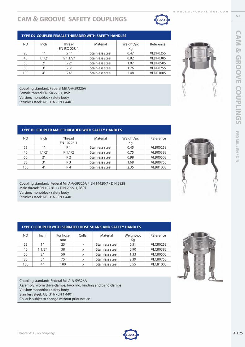
STANDARD
LMC’s Guillemin couplings are symmetric couplings designed in compliance
with EN 14420-8 / NF E 29-572.
OPERATION
A Guillemin coupling, consist of a seal * on the connection surface and is
closed by placing two identical coupling pieces together. This symmetrical
coupling is closed by turning the locking ring through a quarter turn, and is
sealed by tightening the locking ring behind the lugs. Extra closure can be
applied by locking the Guillemin coupling using a Guillemin GY wrench.
Guillemin coupling locking rings can be turned through 360° when disconnected.
*Seal available only on Guillemin couplings with locking ring.
FEATURES
N.B.: Guillemin couplings are not interchangeable with DSP couplings
APPLICATION
For pressure and suction delivery of liquids and solids (such as powders and
granulates)
Irrigation: ND 65 – 100
Hydrocarbons: ND 40 - 50 - 65 - 80 - 100
Granulates: ND 80 - 100
Chemicals: ND 20 - 100 (stainless steel)
N.B.: Guillemin couplings must never be used for steam or liquid gas applications
WORKING PRESSURE
16 bar / 230 psi
Test pressure: 30 bar / 435 psi
Minimum burst pressure: 50 bar / 725 psi
1. High quality surface finishing
2. Long hose shank for extra hose
assembly rigidity
3. Extra wall thickness for longer
life time
4. Reinforcement device with hole
for chain attachment
5. Extra large collar
6. LMC-Couplings brand name
7. Heat treated material
8. Material composition as required
by the standard
9. Standard black seal with excellent
compression set properties
9
4 5
6
4
21
3
GUILLEMIN COUPLINGS EN 14420-8 / NF E 29-572
a2-guillemin 9/6/07 1:23 PM Pagina 1

Chapter A: Quick couplingsA.2.2
W W W . L M C - C O U P L I N G S . C O M
TEMPERATURE
-20°C / -4°F up to +65°C / 149°F
Hose, coupling, assembly method and seal must be chosen in relation with the desired application and temperature range.
MATERIAL
� Coupling
Aluminium heat treated
Stainless steel AISI 316 / 1.4401
� Seal
NBR - black standard for stainless steel and aluminium
EPDM - white
FPM - green
PTFE - white
ASSEMBLY
Worm drive clamps
Band clamps
RK-safety clamps complying with EN 14420-3 / DIN 2817
FLEXOLINE® safety clamps
Swage ferrules for helical hose shank
Butt welding
THREADS
Male thread: EN ISO 228-1, BSP
Female thread: EN ISO 228-1, BSP
TESTING
Guillemin couplings are often submitted to heavy handling impact when loading and unloading liquids and solids. These couplings are
therefore subject to more demanding testing methods than other couplings.
LMC’s guillemin couplings undergo a number of tests executed by our Research & Development department. In addition to our own testing
methods, we also use the latest gauges specified by the European EN 14420-8 standard. The following product properties are tested:
� Lugs
� Locking ring
� Material test
� Dimensions
� Quality finishing
GUILLEMIN COUPLINGS EN 14420-8 / NF E 29-572
a2-guillemin 9/6/07 1:23 PM Pagina 2

Chapter A: Quick couplings
GU
ILLEMIN
CO
UP
LING
SEN
14
42
0-8
/ NF E 2
9-5
72
A.2.3
W W W . L M C - C O U P L I N G S . C O M
� Lugs
A fall of a hose, assembled with Guillemin couplings, causes an import impact on the lugs of the
coupling. Therefore the mechanical strength of the lugs must be tested.
The mechanical strength of the lugs is tested using a conical weight falling around its axis onto
the coupling lugs. This 'Chinese head' test is developed to test the internal impact of the
lugs. The external impact of the lugs is tested using the ‘pan’ test, which is the opposite of the
'Chinese head' procedure. LMC guillemin couplings passed both lug tests successfully.
A gauge is then used to check the dimensions of the lug spacing, as specified by the EN 14420-8
standard.
� Locking ring
The locking ring is tested by simulating a fall to the ground. The test device consists of a sway
arm and a weight. When the arm falls onto the locking ring, the ring deforms as a result of the
heavy impact. LMC-Couplings conducts this test to discover whether there are any signs of
post-impact deformation or fracturing. In practice, a locking ring cannot deform, since it is
mounted onto the body of the Guillemin coupling. However, if the chemical structure of the
locking ring is inadequate, then the locking ring will break immediately. The LMC-Couplings
locking ring resumed its original shape after testing, and displayed no evidence of fracture.
� Material test
An in-house spectroscope is used to test the materials used in the Guillemin couplings.
The spectroscope analyses the precise material substances found in the coupling.
We can therefore offer our customers a guarantee that the materials used comply fully
with the relevant standard.
� Dimensions
The dimensions of LMC Guillemin couplings comply with EN 14420-8 / NF E 29-572.
Guillemin couplings manufactured in compliance with this standard are interchangeable.
The Guillemin couplings are randomly checked for correct dimensions using two
different measuring methods:
1. Measuring tool
2. Gauges
Our measuring system compares the dimensions of our Guillemin couplings comply with the
standard. Although ordinary measuring systems are unable to give precise measurements, our
measuring system is able to measure the less accessible parts and shapes of Guillemin coup-
lings. This minimizes inspection times and ensures the highest levels of product quality.
The European EN 14420-8 standard requires the use of gauges to guarantee interchangeability
of Guillemin couplings. LMC-Couplings uses gauges as a random quality measurement system at
several production stages, in our production department, on arrival in our warehouse and
before goods are shipped to our customers. Using the gauges required by the European
EN 14420-8 standard, LMC-Couplings measures the following four quality-point dimensions of its
Guillemin couplings:
A. Seal groove
B. Locking ring
C. Outside diameter
D. Inside diameter
GUILLEMIN COUPLINGS EN 14420-8 / NF E 29-572A.2.
a2-guillemin 9/6/07 1:23 PM Pagina 3

Chapter A: Quick couplingsA.2.4
W W W . L M C - C O U P L I N G S . C O M
� Quality finishing
LMC’s Guillemin couplings meet the high requirements of the EN 14420-8 / NF E 29-572 standard. A lot of attention was focused on
product design. The design of the lugs, the ergonomic locking ring, the special treated surface, length of hose tail, plug with chain,
branding ... and many more details guarantee a highly finished product.
Guillemin couplings vs DSP couplings
GUILLEMIN COUPLINGS DSP COUPLINGS
Standard EN 14420-8 / NF E 29-572 NF S61-704 / NF S61-705
Main application Pressure and suction purposes Pressure and suction purposes in
in wide range of industries fire fighting
Lug Smooth (a) Triangular (b)
Locking ring Smooth Serrated
Rotation of 360° Rotation of 45°
Seal Square seal Profiled seal
GUILLEMIN COUPLINGS EN 14420-8 / NF E 29-572
(a)
(b)
a2-guillemin 9/6/07 1:24 PM Pagina 4
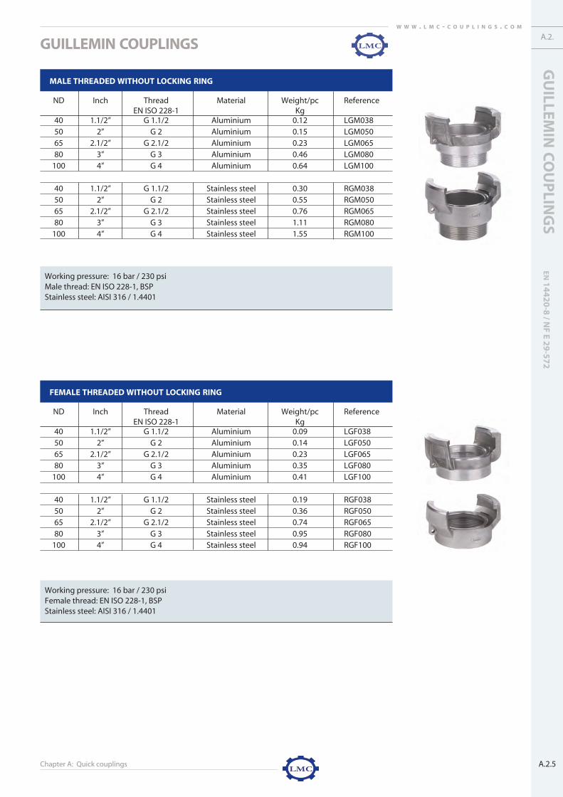
Chapter A: Quick couplings
GUILLEMIN COUPLINGS
GU
ILLEMIN
CO
UP
LING
SEN
14
42
0-8
/ NF E 2
9-5
72
A.2.5
A.2.W W W . L M C - C O U P L I N G S . C O M
MALE THREADED WITHOUT LOCKING RING
ND Inch Thread Material Weight/pc ReferenceEN ISO 228-1 Kg
40 1.1/2” G 1.1/2 Aluminium 0.12 LGM03850 2” G 2 Aluminium 0.15 LGM05065 2.1/2” G 2.1/2 Aluminium 0.23 LGM06580 3” G 3 Aluminium 0.46 LGM080
100 4” G 4 Aluminium 0.64 LGM100
40 1.1/2” G 1.1/2 Stainless steel 0.30 RGM03850 2” G 2 Stainless steel 0.55 RGM05065 2.1/2” G 2.1/2 Stainless steel 0.76 RGM06580 3” G 3 Stainless steel 1.11 RGM080
100 4” G 4 Stainless steel 1.55 RGM100
Working pressure: 16 bar / 230 psiMale thread: EN ISO 228-1, BSP Stainless steel: AISI 316 / 1.4401
FEMALE THREADED WITHOUT LOCKING RING
ND Inch Thread Material Weight/pc ReferenceEN ISO 228-1 Kg
40 1.1/2” G 1.1/2 Aluminium 0.09 LGF03850 2” G 2 Aluminium 0.14 LGF05065 2.1/2” G 2.1/2 Aluminium 0.23 LGF06580 3” G 3 Aluminium 0.35 LGF080
100 4” G 4 Aluminium 0.41 LGF100
40 1.1/2” G 1.1/2 Stainless steel 0.19 RGF03850 2” G 2 Stainless steel 0.36 RGF05065 2.1/2” G 2.1/2 Stainless steel 0.74 RGF06580 3” G 3 Stainless steel 0.95 RGF080
100 4” G 4 Stainless steel 0.94 RGF100
Working pressure: 16 bar / 230 psiFemale thread: EN ISO 228-1, BSP Stainless steel: AISI 316 / 1.4401
a2-guillemin 9/6/07 1:24 PM Pagina 5

Chapter A: Quick couplings
GUILLEMIN COUPLINGS
A.2.6
W W W . L M C - C O U P L I N G S . C O M
MALE THREADED WITH LOCKING RING
ND Inch Thread Material Weight/pc ReferenceEN ISO 228-1 Kg
40 1.1/2” G 1.1/2 Aluminium 0.16 LGMG03850 2” G 2 Aluminium 0.30 LGMG05065 2.1/2” G 2.1/2 Aluminium 0.47 LGMG06580 3” G 3 Aluminium 0.61 LGMG080
100 4” G 4 Aluminium 0.87 LGMG100
40 1.1/2” G 1.1/2 Stainless steel 0.43 RGMG03850 2” G 2 Stainless steel 0.85 RGMG05065 2.1/2” G 2.1/2 Stainless steel 0.98 RGMG06580 3” G 3 Stainless steel 1.11 RGMG080
100 4” G 4 Stainless steel 1.59 RGMG100
Working pressure: 16 bar / 230 psiSeal: NBR - blackMale thread: EN ISO 228-1, BSP Stainless steel: AISI 316 / 1.4401
FEMALE THREADED WITH LOCKING RING
ND Inch Thread Material Weight/pc ReferenceEN ISO 228-1 Kg
40 1.1/2” G 1.1/2 Aluminium 0.23 LGFG03850 2” G 2 Aluminium 0.40 LGFG05065 2.1/2” G 2.1/2 Aluminium 0.47 LGFG06580 3” G 3 Aluminium 0.60 LGFG080
100 4” G 4 Aluminium 1.17 LGFG100
40 1.1/2” G 1 .1/2 Stainless steel 0.60 RGFG03850 2” G 2 Stainless steel 0.78 RGFG05065 2.1/2” G 2.1/2 Stainless steel 1.24 RGFG06580 3” G 3 Stainless steel 1.65 RGFG080
100 4” G 4 Stainless steel 3.07 RGFG100
Working pressure: 16 bar / 230 psiSeal: NBR - blackFemale thread: EN ISO 228-1, BSP Stainless steel: AISI 316 / 1.4401
a2-guillemin 9/6/07 1:24 PM Pagina 6

Chapter A: Quick couplings
GUILLEMIN COUPLINGS
GU
ILLEMIN
CO
UP
LING
SEN
14
42
0-8
/ NF E 2
9-5
72
A.2.7
A.2.W W W . L M C - C O U P L I N G S . C O M
SERRATED HOSE SHANK WITH LOCKING RING
ND Inch For hose Collar Material Weight/pc Referencemm Kg
40 1.1/2” 38 - Aluminium 0.17 LGSG03840 1.1/2” 40 - Aluminium 0.20 LGSG04040 1.1/2” 45 - Aluminium 0.25 LGSG04550 2” 50 x Aluminium 0.33 LGSG05050 2” 55 - Aluminium 0.38 LGSG05565 2.1/2” 65 x Aluminium 0.41 LGSG06565 2.1/2” 70 - Aluminium 0.60 LGSG07080 3” 75 x Aluminium 0.77 LGSG07580 3” 80 - Aluminium 0.79 LGSG08080 3” 90 - Aluminium 0.85 LGSG090
100 4” 100 x Aluminium 1.33 LGSG100100 4” 105 - Aluminium 1.03 LGSG105100 4” 110 - Aluminium 1.26 LGSG110
40 1.1/2” 40 x Stainless steel 0.52 RGSG03850 2” 50 x Stainless steel 0.93 RGSG05050 2” 55 - Stainless steel 0.87 RGSG05565 2.1/2” 65 x Stainless steel 1.05 RGSG06580 3” 75 x Stainless steel 2.27 RGSG07580 3” 80 x Stainless steel 2.28 RGSG08080 3” 90 - Stainless steel 2.04 RGSG090
100 4” 100 x Stainless steel 3.31 RGSG100
SERRATED HOSE SHANK WITH LOCKING RING WITHOUT LUGS
ND Inch For hose mm Collar Material Weight/pc ReferenceKg
40 1.1/2” 38 - Aluminium 0.12 LGSG038SO40 1.1/2” 40 - Aluminium 0.16 LGSG040SO40 1.1/2” 45 - Aluminium 0.20 LGSG045SO50 2” 50 x Aluminium 0.21 LGSG050SO50 2” 55 - Aluminium 0.28 LGSG055SO65 2.1/2” 65 x Aluminium 0.35 LGSG065SO65 2.1/2” 70 - Aluminium 0.45 LGSG070SO80 3” 75 x Aluminium 0.65 LGSG075SO80 3” 80 - Aluminium 0.69 LGSG080SO80 3” 90 - Aluminium 0.71 LGSG090SO
100 4” 100 x Aluminium 1.21 LGSG100SO100 4” 105 - Aluminium 0.95 LGSG105SO100 4” 110 - Aluminium 1.15 LGSG110SO
Working pressure: 16 bar / 230 psiSeal: NBR - blackStainless steel: AISI 316 / 1.4401Assembly: band clamps and ferrules
Working pressure: 8 bar / 115 psiSeal: NBR - blackAssembly: band clamps and ferrulesGuillemin couplings without lugs are recommended to prevent torsion of the hose when connecting the coupling on a fixed Guillemin coupling. Also available in male, female and butt-weld version.
a2-guillemin 9/6/07 1:25 PM Pagina 7

Chapter A: Quick couplings
GUILLEMIN COUPLINGS
A.2.8
W W W . L M C - C O U P L I N G S . C O M
BUTT WELD VERSION WITHOUT LOCKING RING
ND Inch Welding end Material Weight/pc Referencemm Kg
40 1.1/2” 48.26 x 3.68 Stainless steel 0.33 RGBW03850 2” 60.33 x 3.91 Stainless steel 0.86 RGBW05065 2.1/2” 73.03 x 5.16 Stainless steel 1.01 RGBW06580 3” 88.90 x 5.49 Stainless steel 1.18 RGBW080
100 4” 114.30 x 6.02 Stainless steel 1.57 RGBW100
Working pressure: 16 bar / 230 psiWelding end: butt weld end to inch and schedule 40 pipe sizeStainless steel: AISI 316 / 1.4401
BUTT WELD VERSION WITH LOCKING RING
ND Inch Welding end Material Weight/pc Referencemm Kg
40 1.1/2” 48.26 x 3.68 Stainless steel 0.44 RGBWG03850 2” 60.33 x 3.91 Stainless steel 091 RGBWG05065 2.1/2” 73.03 x 5.16 Stainless steel 1.08 RGBWG06580 3” 88.90 x 5.49 Stainless steel 1.83 RGBWG080
100 4” 114.30 x 6.02 Stainless steel 2.10 RGBWG100
Working pressure: 16 bar / 230 psiWelding end: butt weld end to inch and schedule 40 pipe sizeSeal: NBR - blackStainless steel: AISI 316 / 1.4401
PLUG WITH HANDLE
ND Inch Material Weight/pc ReferenceKg
40 1.1/2" Aluminium 0.15 LGP03850 2" Aluminium 0.20 LGP05065 2.1/2” Aluminium 0.22 LGP06580 3" Aluminium 0.34 LGP080
Working pressure: 16 bar / 230 psiSeal: NBR - blackChain included
a2-guillemin 9/6/07 1:25 PM Pagina 8

Chapter A: Quick couplings
GUILLEMIN COUPLINGS
GU
ILLEMIN
CO
UP
LING
SEN
14
42
0-8
/ NF E 2
9-5
72
A.2.9
A.2.W W W . L M C - C O U P L I N G S . C O M
PLUG WITHOUT LOCKING RING
ND Inch Material Weight/pc ReferenceKg
40 1.1/2” Stainless steel 0.11 RGP03850 2” Stainless steel 0.23 RGP05065 2.1/2” Stainless steel 0.32 RGP06580 3” Stainless steel 0.43 RGP080
100 4” Stainless steel 0.81 RGP100
50 2" Polypropylene 0.04 GPL050
Working pressure: 16 bar / 230 psiSeal: NBR - blackChain includedStainless steel: AISI 316 / 1.4401
PLUG WITH LOCKING RING
ND Inch Material Weight/pc ReferenceKg
40 1.1/2" Aluminium 0.15 LGPG03850 2” Aluminium 0.25 LGPG05065 2.1/2" Aluminium 0.31 LGPG06580 3” Aluminium 0.48 LGPG080
100 4” Aluminium 0.75 LGPG100
40 1.1/2” Stainless steel 0.29 RGPG03850 2” Stainless steel 0.60 RGPG05065 2.1/2” Stainless steel 0.76 RGPG06580 3” Stainless steel 1.26 RGPG080
100 4” Stainless steel 1.68 RGPG100
Working pressure: 16 bar / 230 psiSeal: NBR - blackChain includedStainless steel: AISI 316 / 1.4401
a2-guillemin 9/6/07 1:25 PM Pagina 9

Chapter A: Quick couplings
GUILLEMIN COUPLINGS
A.2.10
W W W . L M C - C O U P L I N G S . C O M
REDUCING COUPLING GUILLEMIN - GUILLEMIN
ND Inch Material Weight/pc ReferenceKg
40 - 50 1.1/2” - 2” Aluminium 0.60 LGVG04005040 - 65 1.1/2” - 2.1/2” Aluminium 0.55 LGVG04006540 - 80 1.1/2” - 3” Aluminium 0.98 LGVG04008050 - 65 2” - 2.1/2” Aluminium 0.65 LGVG05006550 - 80 2” - 3” Aluminium 1.14 LGVG050080
50 - 100 2” - 4” Aluminium 1.07 LGVG05010065 - 80 2.1/2” - 3” Aluminium 1.22 LGVG065080
65 - 100 2.1/2” - 4” Aluminium 1.72 LGVG06510080 - 100 3” - 4” Aluminium 1.87 LGVG080100
40 - 50 1.1/2” - 2” Stainless steel 1.50 RGVG03805040 - 65 1.1/2” - 2.1/2” Stainless steel 1.66 RGVG03806550 - 65 2” - 2.1/2” Stainless steel 2.13 RGVG05006550 - 80 2” - 3” Stainless steel 2.05 RGVG050080
50 - 100 2” - 4” Stainless steel 4.01 RGVG05010065 - 80 2.1/2” - 3” Stainless steel 3.10 RGVG065080
65 - 100 2.1/2” - 4” Stainless steel 3.50 RGVG06510080 - 100 3” - 4” Stainless steel 4.91 RGVG080100
REDUCING COUPLING GUILLEMIN - DSP
ND Inch Material Weight/pc ReferenceGuillemin - DSP Guillemin - DSP Kg
40 - DSP 40 1.1/2” - 1.1/2” Aluminium 0.43 LGVD03804040 - DSP 65 1.1/2” - 2.1/2” Aluminium 0.76 LGVD03807050 - DSP 65 2” - 2.1/2” Aluminium 1.09 LGVD05007050 - AR 100 2” - 4” Aluminium 1.75 LGVD05010065 - DSP 65 2.1/2” - 2.1/2” Aluminium 1.01 LGVD06507065 - AR 100 2.1/2” - 4” Aluminium 1.75 LGVD06510080 - AR 100 3” - 4” Aluminium 1.85 LGVD080100
100 - AR 100 4” - 4” Aluminium 2.08 LGVD100100
REDUCING COUPLING GUILLEMIN - STORZ
ND Inch Material Weight/pc ReferenceGuillemin - Storz Guillemin - Storz Kg40 - 52C LD 66 1.1/2” - 2” Aluminium 0.57 LGVS03806640 - 75B LD 89 1.1/2” - 3” Aluminium 0.63 LGVS03808950 - 52C LD 66 2” - 2” Aluminium 0.66 LGVS05006650 - 75B LD 89 2” - 3” Aluminium 0.95 LGVS050089
50 - 110A LD 133 2” - 4” Aluminium 1.71 LGVS05013365 - 52C LD 66 2.1/2” - 2” Aluminium 1.11 LGVS06506665 - 75B LD 89 2.1/2” - 3” Aluminium 1.12 LGVS065089
65 - 110A LD 133 2.1/2” - 4” Aluminium 1.57 LGVS06513380 - 52C LD 66 3” - 2” Aluminium 1.1 LGVS08006680 - 75B LD 89 3” - 3” Aluminium 1.23 LGVS080089
80 - 110A LD 133 3” - 4” Aluminium 1.81 LGVS080133100 - 52C LD 66 4” - 2” Aluminium 1.63 LGVS100066100 - 75B LD 89 4” - 3” Aluminium 1.58 LGVS100089100 - 110A LD 133 4” - 4” Aluminium 2.04 LGVS100133
Working pressure: 16 bar / 230 psiStainless steel: AISI 316 / 1.4401Guillemin and DSP couplings with locking ringGuillemin square seal NBR; DSP coupling profiled seal NBR; Storz coupling profiled seal NBRLD: Lug distance
a2-guillemin 9/6/07 1:26 PM Pagina 10

Chapter A: Quick couplings
GUILLEMIN COUPLINGS
GU
ILLEMIN
CO
UP
LING
SEN
14
42
0-8
/ NF E 2
9-5
72
A.2.11
A.2.W W W . L M C - C O U P L I N G S . C O M
HELICAL HOSE SHANK FOR COMPOSITE HOSE WITH LOCKING RING
ND Inch For hose Material Weight/pc Referencemm Kg
50 2” 50 Aluminium 0.42 CLGSG05065 2.1/2” 65 Aluminium 0.56 CLGSG06580 3” 80 Aluminium 0.83 CLGSG080
100 4” 100 Aluminium 1.42 CLGSG100
50 2” 50 Stainless steel 1.14 CRGSG05080 3” 80 Stainless steel 2.33 CRGSG080
100 4” 100 Stainless steel 3.55 CRGSG100
Working pressure: 16 bar / 230 psiSeal: NBR - blackShank: composite hose shank in metric sizeStainless steel: AISI 316 / 1.4401Assembly: swage ferrules with crimping seal
SWAGE FERRULE FOR HELICAL HOSE SHANK AND COMPOSITE HOSE
ND Inch Material Ø ID mm +/- Ø ID mm +/- Length mm +/- Weight/pc Referencecoupling side hose side kg
50 2” Stainless steel 53.6 65.7 67.0 0.15 CHR05065 2.1/2” Stainless steel 68.0 83.0 73.0 0.24 CHR06580 3” Stainless steel 84.6 98.0 76.2 0.24 CHR080
100 4” Stainless steel 107.5 124.0 107.0 0.63 CHR100
Stainless steel AISI 304 - 1.4301Steel swage ferrules on request available
EPDM / FPM available on request
CRIMPING SEAL FOR HELICAL SHANK COUPLING
ND Inch Material Colour Ø OD +/- 2 mm Ø ID +/- 1mm Weight/pc Referencekg
50 2” NBR Black 65.5 50 0.02 CXN05065 2.1/2” NBR Black 84 65 0.03 CXN06580 3” NBR Black 100 80 0.04 CXN080
100 4” NBR Black 112.5 100 0.07 CXN100
a2-guillemin 9/6/07 1:26 PM Pagina 11

ND Inch Material Weight/pc ReferenceKg
40 1.1/2” Red coated steel 0.54 GY04080 3” Red coated steel 0.88 GY080
Chapter A: Quick couplings
GUILLEMIN COUPLINGS
A.2.12
W W W . L M C - C O U P L I N G S . C O M
SEALS
MULTI WRENCH - GY®
ND Inch Material Weight/pc ReferenceKg
40 - 100 1.1/2” - 4" Blue coated steel 0.54 GY
WRENCH
CHAIN WITH S-HOOK
Material Length Weight/pc ReferenceKg
Stainless steel 200 mm 0.015 KETR200
SQUARE SEAL FOR COUPLING PART - NBR
ND Inch Material Colour Ø OD Ø ID Height Weight/pc Referencemm mm mm Kg
25 1” NBR Black 34.3 27.3 4.0 0.001 GXB02532 1.1/4” NBR Black 38.0 32.0 4.5 0.002 GXB03240 1.1/2” NBR Black 51.0 43.0 5.0 0.004 GXB03850 2” NBR Black 64.0 54.0 5.0 0.007 GXB05065 2.1/2” NBR Black 79.0 69.0 6.0 0.010 GXB06580 3” NBR Black 96.0 85.0 6.0 0.015 GXB080
100 4” NBR Black 117.5 103.5 7.0 0.020 GXB100
SQUARE SEAL FOR COUPLING PART - EPDM
ND Inch Material Colour Ø OD Ø ID Height Weight/pc Referencemm mm mm Kg
25 1” EPDM White 34.3 27.3 4.0 0.001 GXE02540 1.1/2” EPDM White 51.0 43.0 5.0 0.005 GXE03850 2” EPDM White 64.0 54.0 5.0 0.007 GXE05065 2.1/2” EPDM White 79.0 69.0 6.0 0.010 GXE06580 3” EPDM White 96.0 85.0 6.0 0.015 GXE080
100 4” EPDM White 117.5 103.5 7.0 0.020 GXE100
Stainless steel AISI 304 - 1.4301
a2-guillemin 9/6/07 1:27 PM Pagina 12

Chapter A: Quick couplings
GU
ILLEMIN
CO
UP
LING
SEN
14
42
0-8
/ NF E 2
9-5
72
A.2.13
A.2.W W W . L M C - C O U P L I N G S . C O M
GUILLEMIN COUPLINGS
SQUARE SEAL FOR COUPLING PART - FPM
ND Inch Material Colour Ø OD Ø ID Height Weight/pc Referencemm mm mm Kg
25 1” FPM Green 34.3 27.3 4.0 0.001 GXV02540 1.1/2” FPM Green 51.0 43.0 5.0 0.006 GXV03850 2” FPM Green 64.0 54.0 5.0 0.009 GXV05065 2.1/2” FPM Green 79.0 69.0 6.0 0.012 GXV06580 3” FPM Green 96.0 85.0 6.0 0.018 GXV080
100 4” FPM Green 117.5 103.5 7.0 0.033 GXV100
SQUARE SEAL FOR COUPLING PART - PTFE
ND Inch Material Colour Ø OD Ø ID Height Weight/pc Referencemm mm mm Kg
25 1" PTFE White 34.3 27.3 4.0 0.005 GXP02540 1.1/2” PTFE White 51.0 43.0 5.0 0.006 GXP03850 2” PTFE White 64.0 54.0 5.0 0.010 GXP05065 2.1/2” PTFE White 79.0 69.0 6.0 0.015 GXP06580 3” PTFE White 96.0 85.0 6.0 0.020 GXP080
100 4” PTFE White 117.5 103.5 7.0 0.036 GXP100
FLAT SEAL FOR PLUG - NBR
ND Inch Material Colour Ø OD Ø ID Height Weight/pc Referencemm mm mm Kg
50 2” NBR Black 67.9 37.5 2.8 0.01 GXB050GP65 2.1/2” NBR Black 83.5 48.0 2.8 0.02 GXB065GP80 3” NBR Black 100.5 62.0 3.5 0.03 GXB080GP
NBR white on request available
a2-guillemin 9/6/07 1:27 PM Pagina 13

A.3.W W W . L M C - C O U P L I N G S . C O M
A.3.1
STANDARD
LMC’s DSP couplings are manufactured in compliance with NF S61-704 for
the dimensions ND 40 and ND 65. The ND 100 dimension is manufactured in
compliance with NF S61-705.
OPERATION
A DSP coupling is a self-sealing* symmetrical coupling which is secured by
interconnecting two DSP couplings. The half coupling is closed by turning
the locking ring beneath the triangular section of the opposed DSP coupling.
Extra closure can be applied by locking the connection with LMC-Couplings
patented multi wrench. The DSP coupling locking system is similar to that of
the Guillemin coupling. There are however differences to the preformed ser-
ration on the locking ring and the design of the lugs. The locking ring of DSP
couplings can be turned up to 45°.
*Seal available only on DSP couplings with locking rings
The DSP coupling range includes two types of coupling:
� DSP couplings in ND 40 and ND 65 are used for pressure and delivery applications
� AR couplings in ND 100 are used for suction and delivery applications
Lug positions:
Please refer to the following assembly instructions where DSP couplings are to
be fitted to a fixed installation.
N.B.: DSP couplings are not interchangeable with Guillemin couplings.
FEATURES
DSP COUPLINGS NF S61-704 / NF S61-705
Figure 1: The lugs in this illustration are referred to as “top and bot-
tom lugs“. “Top and bottom lugs” are normally used for
outlets and in delivery operations.
Figure 2: The lugs in this illustration are referred to as “ear lugs”.
“Ear lugs” are used for inlets and in suction operations.
1. High-quality surface finishing
2. Extra-thick wall for longer life
3. Hole in each lug for chain attachment
4. LMC-Couplings brand name
5. Heat-treated material
6. Material composition as required by
the standard
1
2
34
a3-dsp 9/6/07 1:37 PM Pagina 1

, BSP
, BSP

Chapter A: Quick couplings
DSP
CO
UP
LING
SN
F S61
-70
4 / N
F S61
-70
5
A.3.3
A.3.
� Lugs
A fall of a hose, assembled with DSP couplings, causes an import impact on the lugs of the cou-
pling. Therefore the mechanical strength of the lugs needs to be tested.
The mechanical strength of the lugs is tested using a conical weight falling around its axis onto the
coupling lugs. This 'Chinese head' test is developed to test the internal impact of the lugs.
The external impact strength of the lugs is tested using the ‘pan’ test, which is the opposite of the
'Chinese head' procedure. LMC’s DSP couplings passed both lug tests successfully.
� Locking ring
The locking ring is tested by simulating a fall to the ground. The testing device consists of a sway
arm and a weight. When the arm hits the locking ring, the ring deforms as a result of the heavy
impact. This test enables us to discover whether there are any signs of post-impact deformation or frac-
turing. In practice, a locking ring can’t deform, because it is mounted onto the body of the
DSP coupling. However, if the chemical structure of the locking ring is inadequate, the locking
ring will break immediately. The LMC-Couplings locking ring maintained its original shape after
testing, and showed no evidence of fracture.
� Material
An in-house spectroscope is used to test the material composition of the heat treated aluminium
used for DSP couplings. This test guarantees our customers DSP couplings developed in full
compliance with the relevant standard.
� Dimensions
The dimensions of LMC DSP couplings comply with NF S61-704 / NF S61-705. All DSP couplings
manufactured in compliance with this standard are interchangeable. All the DSP couplings are ran-
domly checked for correct dimensions using LMC’s measuring system.
Our measuring system checks if the dimensions of our DSP couplings comply with the standard.
Although ordinary measuring systems are unable to give precise measurements, our measuring
system is able to measure the less accessible parts and shapes of DSP couplings. This method mini-
mizes inspection times and ensures the highest levels of product quality.
� Quality of finish
LMC’s DSP couplings not only meet the high requirements of the standard NF S61-704 / NF S61-705,
a lot of attention was focused on product design. The design of the lugs, the ergonomic locking ring,
the special treated surface, plug with chain, branding ... and many more details guarantee a highly
finished product.
DSP COUPLINGS NF S61-704 / NF S61-705
a3-dsp 9/6/07 1:37 PM Pagina 3

Chapter A: Quick couplingsA.3.4
W W W . L M C - C O U P L I N G S . C O M
DSP COUPLINGS GUILLEMIN COUPLINGS
Standard NF S61-704 / NF S61-705 EN 14420-8 / NF E 29-572
Main application Pressure and suction purposes in Pressure and suction purposes
fire fighting in wide range of industries
Lug Triangular (a) Smooth (b)
Locking ring Serrated Smooth
Rotates up to 45° Rotates up to 360°
Seal Profiled seal Square-section seal
(b)
(a)
DSP couplings vs Guillemin couplings
N.B.: LMC’s DSP couplings are not interchangeable with LMC’s Guillemin couplings.
DSP COUPLINGS NF S61-704 / NF S61-705
Multi wrench GY®
a3-dsp 9/6/07 1:37 PM Pagina 4

MALE THREADED WITHOUT LOCKING RING
ND Inch Thread Material Weight/pc ReferenceEN ISO 228-1 Kg
DSP 40 1.1/2” G 1.1/2 Aluminium 0.11 LDM040
DSP 40 1.1/2” G 2 Aluminium 0.19 LDM0402
DSP 65 2.1/2” G 2 Aluminium 0.36 LDM0702
DSP 65 2.1/2” G 2.1/2 Aluminium 0.25 LDM070
DSP 65 2.1/2” G 3 Aluminium 0.47 LDM0703
AR 100 4” G 4 Aluminium 0.55 LDM100
Working pressure: 16 bar / 230 psiMale thread: EN ISO 228-1, BSP Profiled seal: NBR black
FEMALE THREADED WITHOUT LOCKING RING
ND Inch Thread Material Weight/pc ReferenceEN ISO 228-1 Kg
DSP 40 1.1/2” G 1.1/2 Aluminium 0.09 LDF040
DSP 40 1.1/2” G 2 Aluminium 0.18 LDF0402
DSP 65 2.1/2” G 2 Aluminium 0.30 LDF0702
DSP 65 2.1/2” G 2.1/2 Aluminium 0.17 LDF070
DSP 65 2.1/2” G 3 Aluminium 0.41 LDF0703
AR 100 4” G 4 Aluminium 0.54 LDF100
Working pressure: 16 bar / 230 psiFemale thread: EN ISO 228-1, BSP Profiled seal: NBR black
MALE THREADED WITH LOCKING RING
ND Inch Thread Material Weight/pc ReferenceEN ISO 228-1 Kg
DSP 40 1.1/2” G 1.1/2 Aluminium 0.17 LDMG040
DSP 40 1.1/2” G 2 Aluminium 0.21 LDMG0402
DSP 65 2.1/2” G 2 Aluminium 0.46 LDMG0702
DSP 65 2.1/2” G 2.1/2 Aluminium 0.36 LDMG070
DSP 65 2.1/2” G 3 Aluminium 0.61 LDMG0703
AR 100 4” G 4 Aluminium 0.90 LDMG100
Working pressure: 16 bar / 230 psiMale thread: EN ISO 228-1, BSP Profiled seal: NBR black
Chapter A: Quick couplings
DSP COUPLINGS
DSP
CO
UP
LING
SN
F S61
-70
4 / N
F S61
-70
5
A.3.5
A.3.W W W . L M C - C O U P L I N G S . C O M
a3-dsp 9/6/07 1:37 PM Pagina 5

Chapter A: Quick couplings
DSP COUPLINGS
A.3.6
W W W . L M C - C O U P L I N G S . C O M
FEMALE THREADED WITH LOCKING RING
ND Inch Thread Material Weight/pc ReferenceEN ISO 228-1 Kg
DSP 40 1.1/2” G 1.1/2 Aluminium 0.24 LDFG040
DSP 40 1.1/2” G 2 Aluminium 0.29 LDFG0402
DSP 65 2.1/2” G 2 Aluminium 0.49 LDFG0702
DSP 65 2.1/2” G 2.1/2 Aluminium 0.44 LDFG070
DSP 65 2.1/2” G 3 Aluminium 0.77 LDFG0703
AR 100 4” G 4 Aluminium 1.15 LDFG100
Working pressure: 16 bar / 230 psiFemale thread: EN ISO 228-1, BSP Profiled seal: NBR black
SERRATED HOSE SHANK WITH LOCKING RING FOR WIRE BINDING
ND Inch For hose Material Weight/pc Referencemm Kg
DSP 40 1.1/2” 38 Aluminium 0.16 LDSG038
DSP 40 1.1/2” 40 Aluminium 0.18 LDSG040
DSP 40 1.1/2” 45 Aluminium 0.18 LDSG045
DSP 65 2.1/2” 70 Aluminium 0.41 LDSG070
AR 100 4” 110 Aluminium 1.03 LDSG110
Working pressure: 16 bar / 230 psiProfiled seal: NBR blackAssembly: wire binding
PLUG WITH LOCKING RING
ND Inch Material Weight/pc ReferenceKg
DSP 40 1.1/2” Aluminium 0.14 LDPG040
DSP 65 2.1/2” Aluminium 0.3 LDPG070
AR 100 4” Aluminium 0.74 LDPG100
Working pressure: 16 bar / 230 psiProfiled seal: NBR blackChain included
MULTI-SERRATED HOSE SHANK WITH LOCKING RING FOR SWAGING
ND Inch For hose Material Weight/pc Referencemm Kg
DSP 40 1.1/2” 45 Aluminium 0.16 LDSGK045
DSP 65 2.1/2” 70 Aluminium 0.18 LDSGK070
Working pressure: 16 bar / 230 psiProfiled seal: NBR blackAssembly: swage ferrules
a3-dsp 9/6/07 1:37 PM Pagina 6

Chapter A: Quick couplings
DSP COUPLINGS
DSP
CO
UP
LING
SN
F S61
-70
4 / N
F S61
-70
5
A.3.7
A.3.W W W . L M C - C O U P L I N G S . C O M
REDUCING COUPLING DSP - DSP
ND Inch Material Weight/pc ReferenceKg
DSP 40 - DSP 65 1.1/2” - 2.1/2” Aluminium 0.55 LDVD040070
DSP 40 - AR 100 1.1/2” - 4” Aluminium 1.18 LDVD040100
DSP 65 - AR 100 2.1/2” - 4" Aluminium 1.27 LDVD070100
Working pressure: 16 bar / 230 psiDSP and Guillemin couplings with locking ringDSP coupling profiled seal NBR; Guillemin square seal NBR; Storz coupling profiled seal NBRLD: Lug distance
REDUCING COUPLING GUILLEMIN - DSP
ND Inch Material Weight/pc ReferenceGuillemin - DSP Guillemin - DSP Kg
40 - DSP 40 1.1/2” - 1.1/2” Aluminium 0.43 LGVD038040
40 - DSP 65 1.1/2” - 2.1/2” Aluminium 0.76 LGVD038070
50 - DSP 65 2” - 2.1/2” Aluminium 1.09 LGVD050070
50 - AR 100 2” - 4” Aluminium 1.75 LGVD050100
65 - DSP 65 2.1/2” - 2.1/2” Aluminium 1.01 LGVD065070
65 - AR 100 2.1/2” - 4” Aluminium 1.75 LGVD065100
80 - AR 100 3” - 4” Aluminium 1.85 LGVD080100
100 - AR 100 4” - 4” Aluminium 2.08 LGVD100100
REDUCING COUPLING DSP - STORZ
ND Inch Material Weight/pc ReferenceDSP - Storz DSP - Storz Kg
DSP 40 - 52C LD 66 1 1/2" - 2" Aluminium 0.58 LDVS040066
DSP 40 - 75B LD 89 1 1/2" - 3" Aluminium 0.64 LDVS040089
DSP 65 - 52C LD 66 2 .1/2” - 2” Aluminium 1.00 LDVS070066
DSP 65 - 75B LD 89 2 .1/2” - 3” Aluminium 1.01 LDVS070089
DSP 65 - 110A LD 133 2 .1/2” - 4” Aluminium 1.46 LDVS070113
AR 100 - 52C LD 66 4” - 2” Aluminium 1.66 LDVS100066
AR 100 - 75B LD 89 4” - 3” Aluminium 1.61 LDVS100089
AR 100 - 110A LD 133 4” - 4” Aluminium 2.07 LDVS100113
a3-dsp 9/6/07 1:38 PM Pagina 7

Chapter A: Quick couplingsA.3.8
W W W . L M C - C O U P L I N G S . C O M
DSP COUPLINGS
MULTI WRENCH - GY®
ND Inch Material Weight/pc ReferenceKg
40 - 100 1.1/2” - 4" Blue coated steel 0.54 GY
CHAIN WITH S-HOOK
Material Length Weight/pc ReferenceKg
Stainless steel 200 mm 0.015 KETR200
Stainless steel AISI 304 - 1.4301
ND 40 - ND 65 and ND 100 are profiled seals but vary in execution (see chapter E)
SEALS
PROFILED SEAL FOR COUPLING PART
ND Inch Material Colour Ø OD Ø ID Height Weight/pc Referencemm mm mm Kg
DSP 40 1.1/2” NBR Black 50.0 37.0 8.0 0.01 DXB040
DSP 65 2.1/2” NBR Black 79.0 63.0 10.0 0.02 DXB070
AR 100 4” NBR Black 117.0 100.0 12.0 0.03 DXB100
WRENCH
ND Inch Material Weight/pc ReferenceKg
40 1.1/2” Red coated steel 0.54 GY04080 3” Red coated steel 0.88 GY080
a3-dsp 9/6/07 1:38 PM Pagina 8

TW
CO
UP
LING
SEN
14
42
0-6
/ DIN
28
45
0
A.4.W W W . L M C - C O U P L I N G S . C O M
A.4.1
STANDARD
LMC’s TW couplings are asymmetric couplings used for the transport of
liquids, solids and gases, with the exception of liquefied gas and steam.
The locking lever fitted to the female (MK) coupling engages in the rim of the male
(VK) coupling. It is turned until both halves are tightly compressed. The locking
lever is then pushed downwards and is used to prevent loosening which can lead
to disconnection.
OPERATION
The female coupling (type MK) is connected to the male coupling (type VK) of
the same diameter by pushing one into the other. The locking lever fitted to
the female (MK) coupling engages in the rim of the male (VK) coupling. The
locking lever is turned untill both couplings are compressed tightly.
The locking lever is then pushed downwards to seal the MK-VK joint.
The locking lever prevents the connection from becoming loose as a result of
vibration.
N.B.: Male and female dust caps (types VB and MB) are pressure-resistantplugs, with the exception of polypropylene dust plugs. A locking device must be used for all connected and pressurised hose assemblies.
FEATURES
1. Designed in full compliance with
EN 14420-6 / DIN 28450
2. Brass TW coupling is forged
3. Right material composition
4. Mechanical resistant lever
5. Couplings are tested using the latest gauges
required by the EN 14420-6 standard
APPLICATION
For the transport of liquids, solids and gases, with the exception of liquefied
gas and steam
WORKING PRESSURE
25 bar / 362 psi
TEMPERATURE
-30°C / -22°F up to 120°C / 248°F
Hose, coupling, assembly method and seal must be chosen in relation with
the desired application and temperature range.
MATERIAL
� Coupling
Stainless steel AISI 316 / 1.4408 by investment casting
Brass CW1617N by forging
Aluminium by forging
Polypropylene
TW COUPLINGS EN 14420-6 / DIN 28450
a4-tw 9/6/07 1:58 PM Pagina 1

A.4.2
W W W . L M C - C O U P L I N G S . C O M
Chapter A: Quick couplings
� Seal
ASSEMBLY
RK and RKP safety clamps in compliance with EN 14420-3 / DIN 2817
FLEXOLINE® safety clamps
Band clamps
Worm drive clamps
THREADS
Female thread EN ISO 228-1, BSP
TESTING
TW couplings at LMC-Couplings are regularly tested. Because the TW locking ring is mostly affected by falling, extra testing is done to
ensure our customers a high quality product. Test levels:
� Mechanical resistance
� Material composition
� Manufacturing process
� Dimensions
� Design
� Mechanical resistance
The locking ring of the TW coupling is one of the components most likely to be affected by
impact. Distortion of the TW locking ring is tested using pressures in excess of the accepted
upper pressure limit. Under normal circumstances, the locking ring is prevented from
distorting by its crown. The distortion test checks the mechanical strength of the locking ring.
COUPLING MATERIAL COUPLING TYPE SEAL STANDARD SEAL
Type MK: female part, female threaded with locking lever Brass Profiled seal* NBR-black
Thread seal PU- brown
Type VK: male part, female threaded Brass Thread seal PU- brown
Type MB: dust cap Brass Square seal NBR-black
Type MK: female part, female threaded with locking lever Stainless steel Profiled seal* CSM-green
Thread seal PTFE-white
Type VK: male part, female threaded Stainless steel Thread seal PTFE-white
Type MB: dust cap Stainless steel Square seal CSM-green
Type MB: dust cap Aluminium Square seal NBR-black
* Profiled seals only valid for the dimensions ND 50 and ND 80.For the dimension ND 100 an o-ring seal is used.
TW COUPLINGS EN 14420-6 / DIN 28450
a4-tw 9/6/07 1:58 PM Pagina 2

Chapter A: Quick couplings
TW
CO
UP
LING
SEN
14
42
0-6
/ DIN
28
45
0
A.4.3
A.4.W W W . L M C - C O U P L I N G S . C O M
Test results:
• Mechanical reformed (as accepted)
• No signs of fractions
• No signs of cracks
• Elasticity not affected
The fact that LMC-Couplings brass TW locking rings pass the distortion test demonstrates that their material structure complies with
the recommendations of the EN 14420-6 and DIN 28450 standards.
�Material composition
Material quality effects the elasticity of the lever. In compliance with EN 14420-6 the following materials can be used:
Brass
• CuZn39Pb3-H80 material CW614N as specified in EN 12420
Stainless steel
• GX5CrNiMo19-11-2 material 1.4408 as specified in 10213-4
An in-house spectroscope is used to test the material composition used in TW couplings.
We can therefore offer our customers a guarantee that the materials used comply fully
with the EN 14420-6 standard.
� Manufacturing process
LMC-Couplings TW couplings are manufactured in compliance with EN 14420-6 / DIN 28450.
Compliance with the EN 14420-6 and DIN 28450 standards guarantees material quality
and the manufacturing process. The European 14420-6 standard requires brass TW
couplings to be drop-forged. During the forging process, the solid brass piece is subject
to heavy impact. Evidence of this impact on the resulting coupling is a sign of quality.
Stainless steel couplings are manufactured from investment-castings, as required by the
European 14420-6 standard.
� Dimensions
TW coupling dimensions are specified in EN 14420-6 and DIN 28450. All TW couplings
manufactured in compliance with this standard are interchangeable. LMC-Couplings
TW couplings are randomly checked for correct dimensions using two different measuring
methods:
A. Measuring tooling
B. Gauges
Our high-technology measuring system checks that the dimensions of our TW couplings
comply with the standard. Although ordinary measuring systems are unable to give
precise measurements, our measuring system is able to measure the less accessible
parts and shapes. This minimizes inspection times and ensures the highest levels of
product quality. The European EN 14420-6 standard requires the use of gauges to
guarantee interchangeability of TW couplings. LMC-Couplings uses gauges at random
as a quality measurement system at several production stages, in our production plants,
on arrival in our warehouse and before goods are shipped to our customers.
TW COUPLINGS EN 14420-6 / DIN 28450
a4-tw 9/6/07 1:58 PM Pagina 3

Chapter A: Quick couplingsA.4.4
W W W . L M C - C O U P L I N G S . C O M
Using the gauges required by the European EN 14420-6 standard, LMC-Couplings measures the following four quality-point dimensions
of its TW couplings:
A. Seal groove
B. Locking ring
C. Seal ring
D. Inside diameter
� Design
Not only do LMC’s TW couplings meet the high requirements set by EN 14420-6 and DIN 28450, but we also pay a lot of attention to
the design of the coupling. The design of the complete coupling, its ergonomic locking lever, smooth inner surface, branding, etc.
All these properties ensure a product with a high quality of finish.
CROSS REFERENCES
MK050 TW 1502-5
MK080 TW 502-5
VK050 TW 1501
VK080 TW 501
MKH050 TW 1503-4
MKH080 TW 503-4
MKV050 TW 1502
MKV080 TW 502
MB050 TW 1506
MB080 TW 506
VB050 TW 1507
VB080 TW 507
TWFB050 1505
TWFB080 505
GSDH050 1505 GSD
GSDH080 505 GSD
TW COUPLINGS EN 14420-6 / DIN 28450
a4-tw 9/6/07 1:58 PM Pagina 4

Chapter A: Quick couplings
TW
CO
UP
LING
SEN
14
42
0-6
/ DIN
28
45
0
A.4.5
A.4.W W W . L M C - C O U P L I N G S . C O M
TW COUPLINGS
TYPE MK: FEMALE PART - FEMALE THREADED WITH LOCKING LEVER
ND Inch Thread Thread seal Profiled seal Material Weight/pc ReferenceEN ISO 228-1 Kg
50 2" G 2 PU NBR Brass 0.74 MK05080 3" G 3 PU NBR Brass 1.46 MK080
100 4" G 4 PU NBR Brass 2.71 MK100
50 2" G 2 PTFE CSM Stainless steel 0.63 MKRR05080 3" G 3 PTFE CSM Stainless steel 1.30 MKRR080
100 4" G 4 PTFE CSM Stainless steel 2.16 MKRR100
TYPE VK: MALE PART - FEMALE THREADED WITH THREAD SEAL
ND Inch Thread Thread seal Material Weight/pc ReferenceEN ISO 228-1 Kg
50 2" G 2 PU Brass 0.30 VK05080 3" G 3 PU Brass 0.78 VK080
100 4" G 4 PU Brass 1.22 VK100
50 2" G 2 PTFE Stainless steel 0.32 VKR05080 3" G 3 PTFE Stainless steel 0.74 VKR080
100 4" G 4 PTFE Stainless steel 1.25 VKR100
Stainless steel: AISI 316 - 1.4408Female thread: EN ISO 228-1, BSP
Stainless steel: AISI 316 - 1.4408The locking ring with lever in the dimension ND 100 is not seperately available.
Stainless steel: AISI 316 - 1.4408Female thread: EN ISO 228-1, BSPFor the dimension ND 100 an o-ring seal is used.
TYPE MKH: LOCKING RING WITH LEVER
ND Inch Material Weight/pc ReferenceKg
50 2" Brass 0.51 MKH05080 3" Brass 0.93 MKH080
50 2" Stainless steel 0.43 MKHR05080 3" Stainless steel 0.91 MKHR080
a4-tw 9/6/07 1:59 PM Pagina 5

1.10 VB100

Chapter A: Quick couplings
TW COUPLINGS
TW
CO
UP
LING
SEN
14
42
0-6
/ DIN
28
45
0
A.4.7
A.4.W W W . L M C - C O U P L I N G S . C O M
TYPE MKST: FEMALE PART WITH LOCKING LEVER AND SMOOTH HOSE SHANK
ND Inch Material For hose Weight/pc Referencemm Kg
50 2" Brass 50 1.20 MKST050
80 3" Brass 75 2.37 MKST080
50 2" Stainless steel 50 1.09 MKSTRR050
80 3" Stainless steel 75 2.21 MKSTRR080
The female part, type MKST is a monoblock version Standard hose shank EN 14420-2 / DIN 2817Assembly: RK and RKP safety clamps EN 14420-3 / DIN 2817
FLEXOLINE® safety clampsStainless steel AISI 316 - 1.4408
TYPE VKST: MALE PART WITH SMOOTH HOSE SHANK
ND Inch Material For hose Weight/pc Referencemm Kg
50 2" Brass 50 0.76 VKST050
80 3" Brass 75 1.69 VKST080
50 2" Stainless steel 50 0.78 VKSTR050
80 3" Stainless steel 75 1.65 VKSTR080
The male part, type VKST is a monoblock version Standard hose shank EN 14420-2 / DIN 2817Assembly: RK and RKP safety clamps EN 14420-3 / DIN 2817
FLEXOLINE® safety clampsStainless steel AISI 316 - 1.4408
ACCESSORIES
Stainless steel AISI 304 - 1.4301
CHAIN WITH S-HOOK
Length Material Weight/pc Referencemm Kg200 Stainless steel 0.015 KETR200
a4-tw 9/6/07 2:00 PM Pagina 7
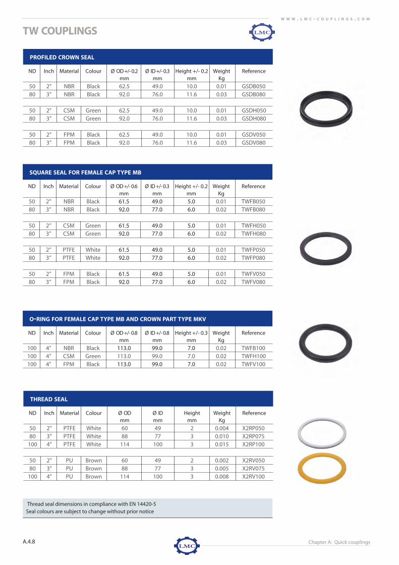
Chapter A: Quick couplings
TW COUPLINGS
A.4.8
W W W . L M C - C O U P L I N G S . C O M
PROFILED CROWN SEAL
ND Inch Material Colour Ø OD +/- 0.2 Ø ID +/- 0.3 Height +/- 0.2 Weight Referencemm mm mm Kg
50 2” NBR Black 62.5 49.0 10.0 0.01 GSDB05080 3” NBR Black 92.0 76.0 11.6 0.03 GSDB080
50 2” CSM Green 62.5 49.0 10.0 0.01 GSDH05080 3” CSM Green 92.0 76.0 11.6 0.03 GSDH080
50 2” FPM Black 62.5 49.0 10.0 0.01 GSDV05080 3” FPM Black 92.0 76.0 11.6 0.03 GSDV080
SQUARE SEAL FOR FEMALE CAP TYPE MB
ND Inch Material Colour Ø OD +/- 0.6 Ø ID +/- 0.3 Height +/- 0.2 Weight Referencemm mm mm Kg
50 2” NBR Black 61.5 49.0 5.0 0.01 TWFB05080 3” NBR Black 92.0 77.0 6.0 0.02 TWFB080
50 2” CSM Green 61.5 49.0 5.0 0.01 TWFH05080 3” CSM Green 92.0 77.0 6.0 0.02 TWFH080
50 2” PTFE White 61.5 49.0 5.0 0.01 TWFP05080 3” PTFE White 92.0 77.0 6.0 0.02 TWFP080
50 2” FPM Black 61.5 49.0 5.0 0.01 TWFV05080 3” FPM Black 92.0 77.0 6.0 0.02 TWFV080
O-RING FOR FEMALE CAP TYPE MB AND CROWN PART TYPE MKV
ND Inch Material Colour Ø OD +/- 0.8 Ø ID +/- 0.8 Height +/- 0.3 Weight Referencemm mm mm Kg
100 4” NBR Black 113.0 99.0 7.0 0.02 TWFB100100 4” CSM Green 113.0 99.0 7.0 0.02 TWFH100100 4” FPM Black 113.0 99.0 7.0 0.02 TWFV100
THREAD SEAL
ND Inch Material Colour Ø OD Ø ID Height Weight Referencemm mm mm Kg
50 2” PTFE White 60 49 2 0.004 X2RP05080 3” PTFE White 88 77 3 0.010 X2RP075
100 4” PTFE White 114 100 3 0.015 X2RP100
50 2” PU Brown 60 49 2 0.002 X2RV05080 3” PU Brown 88 77 3 0.005 X2RV075
100 4” PU Brown 114 100 3 0.008 X2RV100
Thread seal dimensions in compliance with EN 14420-5 Seal colours are subject to change without prior notice
a4-tw 9/6/07 2:01 PM Pagina 8

‘GK’CO
UP
LING
S
A.5.
W W W . L M C - C O U P L I N G S . C O M
A.5.1
STANDARD
LMC’s 'GK' couplings are symmetric quick couplings designed for agricultural,
gardening, construction and public service applications.
OPERATION
‘GK’ couplings are connected by pushing and rotating the two couplingstogether. The claw distance is a 40 mm and therefore interchangeablebetween all dimensions from DN 10 to DN 38. 'GK' couplings are not interchangeable with Express couplings complyingwith NF E 29.573 and European air couplings complying with DIN 3489.
N.B.: Due to the wide range of ‘GK’-type seals, ‘GK’ couplings can not always be connected with those of other manufacturers.
FEATURES
APPLICATION
For agricultural, gardening, construction and public service applications.
WORKING PRESSURE
10 bar / 145 psi
TEMPERATURE
-30°C / -22°F up to 120°C / 248°F
Hose, coupling, assembly method and seal must be chosen in relation with
the desired application and temperature range.
MATERIAL
� Coupling
Brass 2.0401 - Ms 58 hot forged
� Seal
NBR standard
FPM on request
1. Claw distance 40 mm2. Easily connected and disconnected
coupling3. The serrated shank ensures perfect
rigidity when assembled with worm drive clamps or low pressure ferrules
4. The high mechanical strength of ‘GK’ claws ensures longer working life
5. Hot drop forged chrome-treated brass Ms58
4
3
1
‘GK’ COUPLINGS
a5-GK 9/10/07 8:58 AM Pagina 1

A.5.2
W W W . L M C - C O U P L I N G S . C O M
ASSEMBLY
Worm drive clampsLow pressure ferrules
THREADS
Male thread: EN ISO 228-1, BSPFemale thread: EN ISO 228-1, BSP
TESTING
LMC-Couplings ‘GK’ couplings are subject to a number of quality tests. The mechanical
structure, chemical composition, seal compression set and claw strength are all important
product properties for high-quality couplings.
� Impact testing of ‘GK’-claws
In addition to being manufactured from the right material quality (brass 2.0401 – Ms 58)
using the right production method (hot drop forged), the claws of LMC’s ‘GK’ couplings
are tested for mechanical strength by means of an impact test. Above the accepted
pressure limit, ‘GK’ coupling claws may distort, although this is impossible under normal
working conditions when both parts of the ‘GK’ coupling are connected.
However, ‘GK’ claws are often dropped by operators, which can result in fractures or
even claw breakage. Following impact testing, LMC’s ‘GK’ coupling claws show no sign
of fracture or breakage. LMC-Couplings ‘GK’ couplings are manufactured from the right
quality of material, have the right mechanical structure and are produced using the
right production method.
Deformed ‘GK’-claws
Not deformed ‘GK’-claws
‘GK’ COUPLINGS
a5-GK 9/10/07 8:59 AM Pagina 2

Chapter A: Quick couplings
‘GK’ COUPLINGS
‘GK’
COU
PLIN
GS
A.5.3
A.5.W W W . L M C - C O U P L I N G S . C O M
‘GK’ COUPLING MALE THREADED
ND Inch Thread Material Weight/pc ReferenceEN ISO 228-1 Kg
10 3/8" G 3/8 Brass Ms 58 0.07 GKM01015 1/2" G 1/2 Brass Ms 58 0.07 GKM01320 3/4" G 3/4 Brass Ms 58 0.07 GKM01925 1" G 1 Brass Ms 58 0.08 GKM02532 1.1/4" G 1.1/4 Brass Ms 58 0.10 GKM03240 1.1/2" G 1.1/2 Brass Ms 58 0.14 GKM038
Claw distance: 40 mmWorking pressure: 20 bar / 290 psiProfiled seal: NBR standardMale thread: EN ISO 228-1, BSP
‘GK’ COUPLING FEMALE THREADED
ND Inch Thread Material Weight/pc ReferenceEN ISO 228-1 Kg
10 3/8" G 3/8 Brass Ms 58 0.07 GKF01015 1/2" G 1/2 Brass Ms 58 0.07 GKF01320 3/4" G 3/4 Brass Ms 58 0.08 GKF01925 1" G 1 Brass Ms 58 0.08 GKF02532 1.1/4" G 1.1/4 Brass Ms 58 0.11 GKF03240 1.1/2" G 1.1/2 Brass Ms 58 0.13 GKF038
Claw distance: 40 mmWorking pressure: 20 bar / 290 psiSeal: coupling side NBR standard
thread side SBRFemale thread: EN ISO 228-1, BSP
‘GK’ COUPLING WITH SERRATED HOSE SHANK
ND Inch For hose Material Weight/pc Referencemm Kg
10 3/8” 10 Brass Ms 58 0.07 GKS01013 1/2” 13 Brass Ms 58 0.07 GKS01316 5/8’ 16 Brass Ms 58 0.08 GKS01619 3/4” 19 Brass Ms 58 0.08 GKS01925 1” 25 Brass Ms 58 0.10 GKS02532 1.1/4” 32 Brass Ms 58 0.14 GKS03238 1.1/2” 38 Brass Ms 58 0.18 GKS038
Claw distance: 40 mmWorking pressure: 20 bar / 290 psiProfiled seal: NBR standardAssembly: worm drive clamps or low pressure ferrules
a5-GK 9/10/07 8:59 AM Pagina 3

Chapter A: Quick couplings
‘GK’ COUPLINGS COUPLINGS
A.5.4
W W W . L M C - C O U P L I N G S . C O M
SEAL
Claw distance: 40 mmWorking pressure: 20 bar / 290 psiProfiled seal: NBR standardCap without chain
‘GK’ COUPLING CAP
Material Weight/pc ReferenceKg
Brass 0.09 GKK
PROFILED SEAL
Material Colour OD Ø ID Ø Height Box Weight Referencemm mm mm pieces kg
NBR black 35.0 24.0 12.0 50 0.005 GKXBFPM green 35.0 24.0 12.0 50 0.009 GKXV
a5-GK 9/10/07 8:59 AM Pagina 4

EXP
RESS
COU
PLIN
GS
NF E 2
9-5
73
A.6.1
A.6.
W W W . L M C - C O U P L I N G S . C O M
STANDARD
LMC’s Express couplings are symmetrical half-couplings used for water andair applications complying with the NF E 29-573 standard.
OPERATION
The two couplings are pushed together and rotated to form a seal. The clawsof express couplings are spaced at a standard 41 mm, and are not inter-changeable with 'GK' and European air couplings.
FEATURES
APPLICATION
For water and air applications
WORKING PRESSURE
10 bar / 145 psi
TEMPERATURE
-30°C / -22°F up to 120°C / 248°FHose, coupling, assembly method and seal must be chosen in relation withthe desired application and temperature range.
MATERIAL
� CouplingBrassStainless steel AISI 316 - 1.4401
� SealNBR for brass version (standard)FPM for stainless steel version
ASSEMBLY
Worm drive clampsClamps
THREADS
Male thread: EN ISO 228-1, BSPFemale thread: EN ISO 228-1, BSP
1. Claw distance 41 mm
2. Supplied as standard with profiled NBR
seal offering excellent sealing properties
and with an operating temperature range
of -30°C / -22°F to 120°C / 248°F
3. Machined seal sitting
4. Machined serrated hose shank for perfect
rigidity when assembled with worm
drive or claw clamps
5. The high mechanical strength of Express
coupling claws ensures longer working life
2 - 34
5
1
EXPRESS COUPLINGS NF E 29-573
a6-express 9/19/07 10:24 AM Pagina 1

Chapter A: Quick couplings
EXPRESS COUPLINGS
EXP
RESS
COU
PLIN
GS
NF E 2
9-5
73
A.6.3
A.6.W W W . L M C - C O U P L I N G S . C O M
EXPRESS COUPLING MALE THREADED
ND Inch Thread Material Weight/pc ReferenceEN ISO 228-1 Kg
6 1/4" G 1/4 Brass 0.09 EXM00610 3/8" G 3/8 Brass 0.10 EXM01015 1/2" G 1/2 Brass 0.10 EXM01320 3/4" G 3/4 Brass 0.10 EXM01925 1" G 1 Brass 0.14 EXM02532 1.1/4" G 1.1/4 Brass 0.25 EXM032
10 3/8" G 3/8 Stainless steel 0.10 EXMR01015 1/2" G 1/2 Stainless steel 0.10 EXMR01320 3/4" G 3/4 Stainless steel 0.10 EXMR01925 1" G 1 Stainless steel 0.25 EXMR025
Claw distance: 41 mmWorking pressure: 10 bar / 145 psiProfiled seal: NBR (standard) for brass version
FPM for stainless steel versionStainless steel: AISI 316 / 1.4401Male thread EN ISO 228-1, BSP
EXPRESS COUPLING FEMALE THREADED
ND Inch Thread Material Weight/pc ReferenceEN ISO 228-1 Kg
6 1/4" G 1/4 Brass 0.09 EXF00610 3/8" G 3/8 Brass 0.10 EXF01015 1/2" G 1/2 Brass 0.10 EXF01320 3/4" G 3/4 Brass 0.11 EXF01925 1" G 1 Brass 0.11 EXF02532 1.1/4" G 1.1/4 Brass 0.25 EXF032
10 3/8" G 3/8 Stainless steel 0.10 EXFR01015 1/2" G 1/2 Stainless steel 0.10 EXFR01320 3/4" G 3/4 Stainless steel 0.11 EXFR01925 1" G 1 Stainless steel 0.25 EXFR025
Claw distance: 41 mmWorking pressure: 10 bar / 145 psiProfiled seal: NBR (standard) for brass version
FPM for stainless steel versionStainless steel: AISI 316 / 1.4401Female thread EN ISO 228-1, BSP
a6-express 9/19/07 10:24 AM Pagina 3

Chapter A: Quick couplings
EXPRESS COUPLINGS
A.6.4
W W W . L M C - C O U P L I N G S . C O M
Claw distance: 41 mmWorking pressure: 10 bar / 145 psiProfiled seal: NBR (standard) for brass version
FPM for stainless steel versionCap without chainStainless steel: AISI 316 / 1.4401
EXPRESS COUPLING CAP
Material Weight/pc ReferenceKg
Brass 0.13 EXKStainless steel 0.13 EXKR
EXPRESS COUPLING WITH SERRATED HOSE SHANK
ND Inch For hose Material Weight/pc Referencemm Kg
6 1/4" 6 Brass 0.10 EXS00610 3/8" 10 Brass 0.12 EXS01013 1/2" 13 Brass 0.12 EXS01316 5/8” 16 Brass 0.13 EXS01620 3/4" 20 Brass 0.13 EXS02025 1" 25 Brass 0.15 EXS025
13 1/2" 13 Stainless steel 0.11 EXSR01316 5/8” 16 Stainless steel 0.12 EXSR01620 3/4" 20 Stainless steel 0.13 EXSR01925 1" 25 Stainless steel 0.16 EXSR025
Claw distance: 41 mmWorking pressure: 10 bar / 145 psiProfiled seal: NBR (standard) for brass version
FPM for stainless steel versionAssembly: worm drive clampsStainless steel: AISI 316 / 1.4401
CLAMPS
Material Outside hose Weight/pc Referencemin-max mm Kg
Carbon steel 19-21 0.04 EXK019Carbon steel 22-25 0.04 EXK022Carbon steel 25-27 0.06 EXK025Carbon steel 28-30 0.06 EXK028Carbon steel 31-33 0.08 EXK031Carbon steel 34-36 0.13 EXK034Carbon steel 37-39 0.15 EXK037
a6-express 9/19/07 10:24 AM Pagina 4

Chapter A: Quick couplings
EXPRESS COUPLINGS
EXP
RESS
COU
PLIN
GS
NF E 2
9-5
73
A.6.5
A.6.W W W . L M C - C O U P L I N G S . C O M
PROFILED SEAL
Material Colour OD Ø ID Ø Height +0,5 Box Weight Referencemm mm mm pieces kg
NBR black 35.0 15.0 10.0 50 0.01 EXXFPM green 35.0 15.0 10.0 50 0.01 EXXV
a6-express 9/19/07 10:24 AM Pagina 5

EUR
OP
EAN
AIR
COU
PLIN
GS
DIN
34
89
STANDARD
LMC’s European air couplings are heavy-duty claw couplings manufacturedin compliance with DIN 3489.
OPERATION
The claw distance is standardised to 42 mm. The couplings are pushedtogether and rotated to form a seal. Due to the lateral and angular shape ofthe seal an instant force is set, which prevent pressure loss due to vibration.The head of a European air coupling is identical and exchangeable with otherEuropean air-versions.
FEATURES
APPLICATION
For air and water applications. N.B.: European air couplings should never be used for steam applications
WORKING PRESSURE
10 bar / 145 psi
TEMPERATURE
-30°C / -22°F up to 120°C / 248°FHose, coupling, assembly method and seal must be chosen in relation withthe desired application and temperature range.
MATERIAL
� Coupling Galvanized steel, stainless steel AISI 316, 14401
� SealNBR
ASSEMBLY
Two-bolt saddle clampsWorm drive clamps
THREADS
Male thread: EN 10226-1 / DIN 2999, BSPT (not complying with DIN 3489)Female thread: EN ISO 228-1, BSP
1. Claw distance: 42mm
2. LMC's EA couplings include a specially
designed profiled NBR seal, the lateral
and angular shape of which offers excellent
compression properties.
Pressure is applied as soon as the coupling
is connected.
3. The serrated shank ensures perfect rigidity
when assembled with saddle and worm
drive clamps.
4. The LMC-Couplings brand name is
marked on the top of the coupling.
21
4
3
EUROPEAN AIR COUPLINGS DIN 3489
A.7.
A.7.1
EUR
OP
EAN
AIR
COU
PLIN
GS
DIN
34
89
a7-european air couplings 9/19/07 10:29 AM Pagina 1

Chapter A: Quick couplings
EUROPEAN AIR COUPLINGS
EUR
OP
EAN
AIR
COU
PLIN
GS
DIN
34
89
A.7.
A.7.3
W W W . L M C - C O U P L I N G S . C O M
EA COUPLING MALE THREADED, DIN 3489 - VBA
ND Inch Thread Material Weight/pc ReferenceDIN 2999 Kg
6 1/4” R 1/4 Galvanized steel 0.14 EAM00610 3/8” R 3/8 Galvanized steel 0.15 EAM01015 1/2” R 1/2 Galvanized steel 0.15 EAM01320 3/4” R 3/4 Galvanized steel 0.18 EAM01925 1” R 1 Galvanized steel 0.19 EAM02532 1.1/4” R 11/4 Galvanized steel 0.26 EAM032
Claw distance: 42 mmWorking pressure: 10 bar / 145 PsiProfiled seal DIN 3489-D: NBRMale thread EN 10226-1 / DIN 2999, BSPT (not complying with DIN 3489)
EA COUPLING FEMALE THREADED, DIN 3489 - VBI
ND Inch Thread Material Weight/pc ReferenceEN ISO 228-1 Kg
6 1/4” G 1/4 Galvanized steel 0.13 EAF00610 3/8” G 3/8 Galvanized steel 0.14 EAF01015 1/2” G 1/2 Galvanized steel 0.14 EAF01320 3/4” G 3/4 Galvanized steel 0.15 EAF01925 1” G 1 Galvanized steel 0.18 EAF02532 1.1/4” G 11/4 Galvanized steel 0.25 EAF032
Claw distance: 42 mmWorking pressure: 10 bar / 145 PsiProfiled seal DIN 3489-D: NBRFemale thread EN ISO 228-1, BSP
EA COUPLING WITH SERRATED HOSE SHANK, DIN 3489 - VB1
ND Inch For hose Material Weight/pc Referencemm Kg
10 3/8” 10.0 Galvanized steel 0.15 EAS01013 1/2” 13.0 Galvanized steel 0.16 EAS01316 5/8” 16.0 Galvanized steel 0.15 EAS01619 3/4” 19.0 Galvanized steel 0.18 EAS01925 1” 25.0 Galvanized steel 0.21 EAS02532 1.1/4” 32.0 Galvanized steel 0.22 EAS032
Claw distance: 42 mmWorking pressure: 10 bar / 145 PsiProfiled seal DIN 3489-D: NBRAssembly: two bolt saddle clamps, worm drive clamps
a7-european air couplings 9/19/07 10:29 AM Pagina 3

green

STANDARD
The safety version of LMC’s European air couplings is similar to the EuropeanDIN 3489 standard for air couplings, but with the addition of a safety lockingpin for extra security.
OPERATION
Similar to air couplings complying with the European DIN 3489 standard, theclaw distance of European air safety couplings is standard 42 mm. Next to the claws of the safety European air coupling, a hole is provided.Both couplings are pushed together and rotated untill the holes of both cou-plings are placed in opposite of each other. A safety pin is inserted in theholes and the connection is extra secured.
FEATURES
APPLICATION
For air and water applicationsN.B.: European air safety couplings should never be used for steam applications
WORKING PRESSURE
10 bar / 145 psi
MATERIAL
� CouplingGalvanized steel
� SealNBR
TEMPERATURE
-30°C / -22°F up to 120°C / 248°FHose, coupling, assembly method and seal must be chosen in relation withthe desired application and temperature range.
ASSEMBLY
Two-bolt saddle clampsWorm drive clamps
THREADS
Male thread: EN 10226-1 / DIN 2999, BSPT Female thread: EN ISO 228-1, BSP
1. Claw distance: 42mm2. Safety locking pin for additional security3. LMC's EA couplings include a specially-
designed profiled NBR seal, the lateral and angular shape of which offers excellent compression properties. Pressure is applied as soon as the coupling is con-nected, which prevents the connection from becoming loose as a result of vibration.
4. The hose shank ensures perfect rigiditywhen assembled with saddle and worm drive clamps .
5. The LMC-Couplings brand name is marked on the top of the coupling.
2
3
4
Chapter A: Quick couplings
EUR
OP
EAN
AIR
SAFET
YCO
UP
LING
S
A.7.
A.7.5
W W W . L M C - C O U P L I N G S . C O MEUROPEAN AIR SAFETY COUPLINGS
a7-european air couplings 9/19/07 10:30 AM Pagina 5

ND Inch Thread Material Weight/pc ReferenceDIN 2999 Kg
10 3/8” R 3/8 Galvanized steel 0.19 EAMS01015 1/2” R 1/2 Galvanized steel 0.23 EAMS01320 3/4” R 3/4 Galvanized steel 0.24 EAMS01925 1” R 1 Galvanized steel 0.25 EAMS02532 1.1/4” R 11/4 Galvanized steel 0.25 EAMS032
Chapter A: Quick couplings
EUROPEAN AIR SAFETY COUPLINGS
EUR
OP
EAN
AIR
SAFET
YCO
UP
LING
S
A.7.
A.7.7
W W W . L M C - C O U P L I N G S . C O M
EA SAFETY COUPLING MALE THREADED
Claw distance: 42 mmWorking pressure: 10 bar / 145 PsiProfiled seal DIN 3489-D: NBR Male thread EN 10226-1 / DIN 2999, BSPT
EA SAFETY COUPLING FEMALE THREADED
ND Inch Thread Material Weight/pc ReferenceEN ISO 228-1 Kg
10 3/8” G 3/8 Galvanized steel 0.19 EAFS01015 1/2” G 1/2 Galvanized steel 0.19 EAFS01320 3/4” G 3/4 Galvanized steel 0.19 EAFS01925 1” G 1 Galvanized steel 0.23 EAFS02532 1.1/4” G 11/4 Galvanized steel 0.28 EAFS032
Claw distance: 42 mmWorking pressure: 10 bar / 145 PsiProfiled seal DIN 3489-D: NBR Female thread EN ISO 228-1, BSP
Claw distance: 42mmWorking pressure: 10 bar / 145 PsiProfiled seal DIN 3489-D: NBR Assembly: saddle and worm drive clamps
EA SAFETY COUPLING WITH SERRATED HOSE SHANK
ND Inch For hose Material Weight/pc Referencemm Kg
10 3/8” 10.0 Galvanized steel 0.20 EASS01013 1/2” 13.0 Galvanized steel 0.19 EASS01319 3/4” 19.0 Galvanized steel 0.22 EASS01925 1” 25.0 Galvanized steel 0.24 EASS02532 1.1/4” 32.0 Galvanized steel 0.32 EASS032
a7-european air couplings 9/19/07 10:30 AM Pagina 7

Chapter A: Quick couplings
EUROPEAN AIR SAFETY COUPLINGS
A.7.8
W W W . L M C - C O U P L I N G S . C O M
Claw distance: 42mmWorking pressure: 10 bar / 145 PsiProfiled seal DIN 3489-D: NBR
EA SAFETY COUPLING CAP
Material Weight/pc ReferenceKg
Galvanized steel 0.31 EAKS
Claw distance: 42 mmWorking pressure: 10 bar / 145 PsiProfiled seal DIN 3489-D: NBR
EA SAFETY COUPLING - 3 WAY CONNECTION
Material Weight/pc ReferenceKg
Galvanized steel 0.61 EAYS
SAFETY CLIP
Material Weight/pc ReferenceKg
Stainless steel AISI 304 0.018 VLBVR2Galvanized steel 0.018 VLBVS2
SEAL
PROFILED SEAL DIN 3489-D
Material Colour OD mm ID mm Height Box Weight Reference+0.1 / -0.2 +0.2 / -0.1 pieces kg
NBR black 34.0 20.0 11.0 50 0.006 EAX
a7-european air couplings 9/19/07 10:31 AM Pagina 8

STANDARD
The safety version of LMC’s European air couplings is similar to the European DIN 3489 standard for air couplings, but with the addition of a safety locking pin for extra security and easy crimp swaging features.
OPERATION
Similar to air couplings complying with the European DIN 3489 standard, the claw distance of European air safety couplings is standard 42 mm. Next to the claws of the safety European air coupling, a hole is provided. Both couplings are pushed together and rotated untill the holes of both cou plings are placed in opposite of each other. A safety pin is inserted in the holes and the connection is extra secured.
FEATURES
APPLICATION
For air and water applications
N.B.: European air safety couplings should never be used for steam
applications
WORKING PRESSURE
20 bar / 290 psi
MATERIAL
* CouplingWhite galvanized steel
* SealNBR Blue
TEMPERATURE
-30°C / -22°F up to 120°C / 248°FHose, coupling, assembly method and seal must be chosen in relation with the desired application and temperature range.
ASSEMBLY
• Easy crimp ferrule• Worm drive clamps• Air safety clamps
1. Claw distance: 42mm2. Safety locking pin for additional security3. LMC’s EA couplings include a specially-
designed profiled blue EPDM seal, the lateral and angular shape of which offers excellent compression properties. Pressure is applied as soon as the coupling is con nected, which prevents the connection from becoming loose as a result of vibration.
4. The serrated hose shank ensures perfect rigidity
5. The LMC-Couplings brand name is marked on the top of the coupling.
6. White plate galvanized7. Extra long tail with special shape for more
power (20 bar)8. Easy fit into all kinds of hoses (PVC, rubber…)
without hammering
2
3
4
Chapter A: Quick couplings
EURO
PEAN
AIR CRIM
P COU
PLING
SA.7
A.7.9
W W W . L M C - C O U P L I N G S . C O MEUROPEAN AIR CRIMP COUPLINGS
7
EASSC 1 28/10/14 13:18
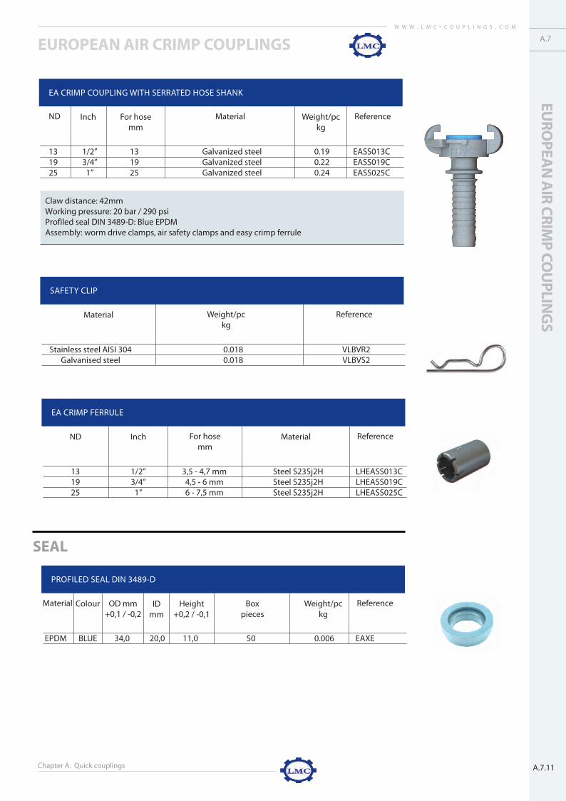
Chapter A: Quick couplings
EUROPEAN AIR CRIMP COUPLINGS
EURO
PEAN
AIR CRIM
P COU
PLING
SA.7
A.7.11
W W W . L M C - C O U P L I N G S . C O M
Claw distance: 42mmWorking pressure: 20 bar / 290 psiProfiled seal DIN 3489-D: Blue EPDMAssembly: worm drive clamps, air safety clamps and easy crimp ferrule
EA CRIMP COUPLING WITH SERRATED HOSE SHANK
13 1/2” 13 Galvanized steel 0.19 EASS013C19 3/4” 19 Galvanized steel 0.22 EASS019C25 1” 25 Galvanized steel 0.24 EASS025C
ND Inch For hosemm
Material Weight/pckg
Reference
SAFETY CLIP
Stainless steel AISI 304 0.018 VLBVR2Galvanised steel 0.018 VLBVS2
Material Weight/pckg
Reference
EA CRIMP FERRULE
13 1/2” 3,5 - 4,7 mm Steel S235j2H LHEASS013C19 3/4” 4,5 - 6 mm Steel S235j2H LHEASS019C25 1” 6 - 7,5 mm Steel S235j2H LHEASS025C
ND Inch For hosemm
Material Reference
SEAL
PROFILED SEAL DIN 3489-D
EPDM BLUE 34,0 20,0 11,0 50 0.006 EAXE
Material Colour OD mm+0,1 / -0,2
IDmm
Weight/pckg
ReferenceHeight+0,2 / -0,1
Boxpieces
EASSC 3 28/10/14 13:18

Chapter A: Quick couplings
EUROPEAN AIR CRIMP COUPLINGS
A.7.12
W W W . L M C - C O U P L I N G S . C O M
Claw distance: 42mmWorking pressure: 10 bar / 145 Psi Profiled seal DIN 3489-D: NBR
EA SAFETY COUPLING CAP
Material Weight/pc ReferenceKg
Galvanized steel 0.31 EAKS
Claw distance: 42 mmWorking pressure: 10 bar / 145 Psi Profiled seal DIN 3489-D: NBR
EA SAFETY COUPLING - 3 WAY CONNECTION
Material Weight/pc ReferenceKg
Galvanized steel 0.61 EAYS
SAFETY CLIP
Material Weight/pc ReferenceKg
Stainless steel AISI 304 0.018 VLBVR2 Galvanized steel 0.018 VLBVS2
SEAL
PROFILED SEAL DIN 3489-D
Material Colour OD mm ID mm Height Box Weight Reference+0.1 / -0.2 +0.2 / -0.1 pieces kg
EPDM BLUE 34.0 20.0 11.0 50 0.006 EAXE
EASSC 4 28/10/14 13:18

TRICLAMP COUPLINGS DIN / INCH / ISO / IMPERIALTR
ICLA
MP
CO
UP
LING
SD
IN/
INC
H/
ISO/
IMP
ERIA
L
A.8.1
A.8.
STANDARD
LMC’s Triclamp couplings are quick couplings used in working environments
demanding high levels of hygiene; e.g. the food, pharmaceutical, chemical and life
science industries. The Triclamp couplings are available in DIN 32676, INCH, IMPER-
IAL or ISO 1127 standards.
OPERATION
Triclamp couplings are easily identified by their flange design. The transition from
the flange side to the hose side is made by a conical profile. The flange side is used
to connect to another flange of the same dimension and standard. Users should
ensure that only Triclamp’s complying with the same standard are connected
together. The Triclamp seal (profiled or non-profiled) is fitted to one of the flanges.
The second Triclamp is then brought together with the flange containing the seal.
The heavy-duty clamp is applied to the flanges and closed.
The coupling can easily be connected, disconnected and reused .
N.B.: Closing the heavy-duty clamp too tightly will alter the mechanical structure
of the flange seal. Always use the recommended torque setting of 5 NM.
FEATURES
1. Lightly-grooved hose shank for assembly
with EN 14420-3 RK safety clamps, HRRK
or HRP-swage ferrules
2. Bacterial growth is prevented due to the
sanitary transition of the inside of the hose shank
3. The rounded end of the hose shank
prevents hose damage
4. Low internal Ra value of < 0.8 µm
(Ra test report available)
5. Outer diameter in relation with inner flange
dimension. No disconnection necessary to
define the type of tube system.
6. All sizes are fully vacuum-resistant up to
130°C / 265°F
7. Transition is possible between Triclamp
couplings with same flange size/standard,
same ID flange side and different hose
dimension
8. EN 10204-type 3.1 certificate available on
request
1
3
2 - 4
5
Triclamp coupling with
welding end - type RTRIL ...
Triclamp seal profiled /
non profiled type TRIX ...
Triclamp coupling with
welding end - type RTRIL ...
Heavy duty clamp single
bolt - type TRIK ...
a8-triclmap 9/11/07 9:21 AM Pagina 1
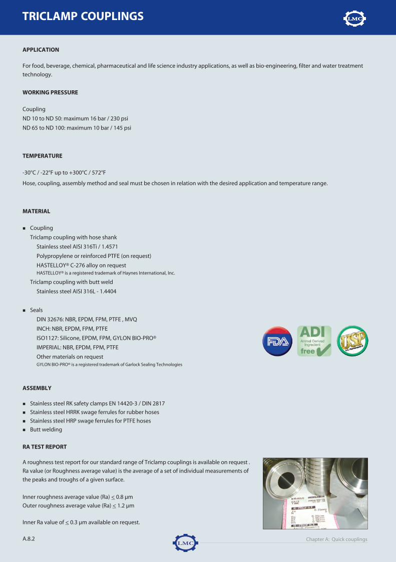
Chapter A: Quick couplingsA.8.2
W W W . L M C - C O U P L I N G S . C O MTRICLAMP COUPLINGS
APPLICATION
For food, beverage, chemical, pharmaceutical and life science industry applications, as well as bio-engineering, filter and water treatment
technology.
WORKING PRESSURE
Coupling
ND 10 to ND 50: maximum 16 bar / 230 psi
ND 65 to ND 100: maximum 10 bar / 145 psi
TEMPERATURE
-30°C / -22°F up to +300°C / 572°F
Hose, coupling, assembly method and seal must be chosen in relation with the desired application and temperature range.
MATERIAL
� Coupling
Triclamp coupling with hose shank
Stainless steel AISI 316Ti / 1.4571
Polypropylene or reinforced PTFE (on request)
HASTELLOY® C-276 alloy on requestHASTELLOY® is a registered trademark of Haynes International, Inc.
Triclamp coupling with butt weld
Stainless steel AISI 316L - 1.4404
� Seals
DIN 32676: NBR, EPDM, FPM, PTFE , MVQ
INCH: NBR, EPDM, FPM, PTFE
ISO1127: Silicone, EPDM, FPM, GYLON BIO-PRO®
IMPERIAL: NBR, EPDM, FPM, PTFE
Other materials on requestGYLON BIO-PRO® is a registered trademark of Garlock Sealing Technologies
ASSEMBLY
� Stainless steel RK safety clamps EN 14420-3 / DIN 2817
� Stainless steel HRRK swage ferrules for rubber hoses
� Stainless steel HRP swage ferrules for PTFE hoses
� Butt welding
RA TEST REPORT
A roughness test report for our standard range of Triclamp couplings is available on request .
Ra value (or Roughness average value) is the average of a set of individual measurements of
the peaks and troughs of a given surface.
Inner roughness average value (Ra) < 0.8 µm
Outer roughness average value (Ra) < 1.2 µm
Inner Ra value of < 0.3 µm available on request.
a8-triclmap 9/11/07 9:21 AM Pagina 2


Chapter A: Quick couplings
TRICLAMP COUPLINGS
A.8.4
W W W . L M C - C O U P L I N G S . C O M
TRICLAMP COUPLING WITH HOSE SHANK - INCH
Assembly: RK safety clamps in stainless steelHRRK swage ferrulesHRP swage ferrules
Material: stainless steel AISI 316Ti / 1.4571Corresponding pipe system DIN 11850, InchOther dimensions on request available
TRICLAMP COUPLING WITH HOSE SHANK - IMPERIAL
Assembly: RK safety clamps in stainless steelHRRK swage ferrulesHRP swage ferrules
Material: stainless steel AISI 316Ti / 1.4571Corresponding pipe system DIN 11866 series COther dimensions on request available
Standard Inch For hose OD Ø flange ID Ø flange ID hose shank Referencemm mm mm mm
INCH 1/2" 12.0 25.0 9.40 9.0 RTRI1225ID9.4
INCH 3/4" 20.0 25.0 15.75 15.0 RTRI2025ID15.8
INCH 1" 25.0 50.5 22.90 21.0 RTRI2550ID22.9
INCH 1" 32.0 50.5 22.90 28.0 RTRI3250ID22.9
INCH 1" 38.0 50.5 22.90 33.5 RTRI3850ID22.9
INCH 1 1/2" 25.0 50.5 35.10 21.0 RTRI2550ID35.1
INCH 1 1/2" 32.0 50.5 35.10 28.0 RTRI3250ID35.1
INCH 1 1/2" 38.0 50.5 35.10 33.5 RTRI3850ID35.1
INCH 2" 38.0 64.0 47.80 33.5 RTRI3864ID47.8
INCH 2" 50.0 64.0 47.80 43.5 RTRI5064ID47.8
INCH 2 1/2" 50.0 77.5 60.50 43.5 RTRI5077ID60.5
INCH 2 1/2" 63.0 77.5 60.50 58.5 RTRI6377ID60.5
INCH 3" 63.0 91.0 72.10 58.5 RTRI6391ID72.1
INCH 3" 75.0 91.0 72.10 70.5 RTRI7591ID72.1
INCH 4" 100.0 119.0 97.60 94.0 RTRI100119ID97.6
Standard Inch For hose OD Ø flange ID Ø flange ID hose shank Referencemm mm mm mm
IMPERIAL 1/2" 12.0 25.0 9.40 9.0 RTRI1225ID9.5
IMPERIAL 3/4" 20.0 25.0 15.75 15.0 RTRI2025ID15.75
IMPERIAL 1" 25.0 50.5 22.10 21.0 RTRI2550ID22.2
IMPERIAL 1" 32.0 50.5 22.10 28.0 RTRI3250ID22.2
IMPERIAL 1" 38.0 50.5 22.10 33.5 RTRI3850ID22.2
IMPERIAL 1 1/2" 25.0 50.5 34.80 21.0 RTRI2550ID34.9
IMPERIAL 1 1/2" 32.0 50.5 34.80 28.0 RTRI3250ID34.9
IMPERIAL 1 1/2" 38.0 50.5 34.80 33.5 RTRI3850ID34.9
IMPERIAL 2" 38.0 64.0 47.50 33.5 RTRI3864ID47.8IMPERIAL 2" 50.0 64.0 47.50 43.5 RTRI5064ID47.6
IMPERIAL 2 1/2" 50.0 77.5 60.20 43.5 RTRI5077ID60.3
IMPERIAL 2 1/2" 63.0 77.5 60.20 58.5 RTRI6377ID60.3
IMPERIAL 3” 50.0 91.0 72.90 43.5 RTRI5091ID73.0
IMPERIAL 3" 63.0 91.0 72.90 58.5 RTRI6391ID73.0
IMPERIAL 3" 75.0 91.0 72.90 70.5 RTRI7591ID73.0
IMPERIAL 4" 100.0 119.0 97.38 94.0 RTRI100119ID97.6
a8-triclmap 9/11/07 9:21 AM Pagina 4

Chapter A: Quick couplings
TRICLAMP COUPLINGS
TRIC
LAM
PC
OU
PLIN
GS
DIN
/IN
CH
/ISO
/IM
PER
IAL
A.8.5
A.8.
W W W . L M C - C O U P L I N G S . C O M
TRICLAMP COUPLING WITH HOSE SHANK - ISO 1127
Assembly: RK safety clamps in stainless steelHRRK swage ferrulesHRP swage ferrules
Material: stainless steel AISI 316Ti / 1.4571Corresponding pipe system DIN 11866 series BOther dimensions on request available
Standard ND For hose OD Ø flange ID Ø flange ID hose shank Referencemm mm mm mm
ISO 1127 8 8.0 34.0 10.3 5.5 RTRI0834ID10.3
ISO 1127 8 10.0 34.0 10.3 7.0 RTRI1034ID10.3
ISO 1127 8 12.0 34.0 10.3 9.0 RTRI1234ID10.3
ISO 1127 8 20.0 34.0 10.3 15.0 RTRI2034ID10.3
ISO 1127 8 25.0 34.0 10.3 21.0 RTRI2534ID10.3
ISO 1127 10 8.0 34.0 14.0 5.5 RTRI0834ID14.0
ISO 1127 10 10.0 34.0 14.0 7.0 RTRI1034ID14.0
ISO 1127 10 12.0 34.0 14.0 9.0 RTRI1234ID14.0
ISO 1127 10 20.0 34.0 14.0 15.0 RTRI2034ID14.0
ISO 1127 10 25.0 34.0 14.0 21.0 RTRI2534ID14.0
ISO 1127 15 8.0 34.0 18.1 5.5 RTRI0834ID18.1
ISO 1127 15 10.0 34.0 18.1 7.0 RTRI1034ID18.1
ISO 1127 15 12.0 34.0 18.1 9.0 RTRI1234ID18.1
ISO 1127 15 20.0 34.0 18.1 15.0 RTRI2034ID18.1
ISO 1127 15 25.0 34.0 18.1 21.0 RTRI2534ID18.1
ISO 1127 20 12.0 50.5 23.7 9.0 RTRI1250ID23.7
ISO 1127 20 20.0 50.5 23.7 15.0 RTRI2050ID23.7
ISO 1127 20 25.0 50.5 23.7 21.0 RTRI2550ID23.7
ISO 1127 20 32.0 50.5 23.7 28.0 RTRI3250ID23.7
ISO 1127 20 38.0 50.5 23.7 33.5 RTRI3850ID23.7
ISO 1127 25 12.0 50.5 29.7 9.0 RTRI1250ID29.7
ISO 1127 25 20.0 50.5 29.7 15.0 RTRI2050ID29.7
ISO 1127 25 25.0 50.5 29.7 21.0 RTRI2550ID29.7
ISO 1127 25 32.0 50.5 29.7 28.0 RTRI3250ID29.7
ISO 1127 25 38.0 50.5 29.7 33.5 RTRI3850ID29.7
ISO 1127 32 12.0 50.5 38.4 9.0 RTRI1250ID38.4
ISO 1127 32 20.0 50.5 38.4 15.0 RTRI2050ID38.4
ISO 1127 32 25.0 50.5 38.4 21.0 RTRI2550ID38.4
ISO 1127 32 32.0 50.5 38.4 28.0 RTRI3250ID38.4
ISO 1127 32 38.0 50.5 38.4 33.5 RTRI3850ID38.4
ISO 1127 40 38.0 64.0 44.3 33.5 RTRI3864ID44.3
ISO 1127 40 50.0 64.0 44.3 43.5 RTRI5064ID44.3
ISO 1127 50 50.0 77.5 56.3 43.5 RTRI5077ID56.3
ISO 1127 50 63.0 77.5 56.3 58.5 RTRI6377ID56.3
ISO 1127 65 63.0 91.0 72.1 58.5 RTRI6391ID72.1
ISO 1127 65 75.0 91.0 72.1 70.5 RTRI7591ID72.1
ISO 1127 80 75.0 106.0 84.3 70.5 RTRI75106ID84.3
ISO 1127 80 100.0 106.0 84.3 94.0 RTRI100106ID84.3
ISO 1127 100 100.0 130.0 109.7 94.0 RTRI100130ID109.7
a8-triclmap 9/11/07 9:21 AM Pagina 5


Chapter A: Quick couplings
TRICLAMP COUPLINGS
TRIC
LAM
PC
OU
PLIN
GS
DIN
/IN
CH
/ISO
/IM
PER
IAL
A.8.7
A.8.
W W W . L M C - C O U P L I N G S . C O M
Other dimensions on request available
HEAVY DUTY CLAMP SINGLE BOLT
For flange Material Referencemm25.0 Stainless steel AISI 316 - 1.4401 TRIK02534.0 Stainless steel AISI 316 - 1.4401 TRIK03450.5 Stainless steel AISI 316 - 1.4401 TRIK05064.0 Stainless steel AISI 316 - 1.4401 TRIK06477.5 Stainless steel AISI 316 - 1.4401 TRIK07791.0 Stainless steel AISI 316 - 1.4401 TRIK091
106.0 Stainless steel AISI 316 - 1.4401 TRIK106119.0 Stainless steel AISI 316 - 1.4401 TRIK119130.0 Stainless steel AISI 316 - 1.4401 TRIK130
Other dimensions on request available
SOLID END CAP
Flange Height Material Referencemm mm25.0 4.7 Stainless steel AISI 316L - .4404 TRIP02534.0 6.0 Stainless steel AISI 316L - 1.4404 TRIP03450.5 6.0 Stainless steel AISI 316L - 1.4404 TRIP05064.0 6.0 Stainless steel AISI 316L - 1.4404 TRIP06477.5 6.0 Stainless steel AISI 316L - 1.4404 TRIP07791.0 7.0 Stainless steel AISI 316L - 1.4404 TRIP091
106.0 8.0 Stainless steel AISI 316L - 1.4404 TRIP106119.0 8.0 Stainless steel AISI 316L - 1.4404 TRIP119130.0 8.0 Stainless steel AISI 316L - 1.4404 TRIP130
a8-triclmap 9/11/07 9:21 AM Pagina 7

Chapter A: Quick couplings
TRICLAMP COUPLINGS
A.8.8
W W W . L M C - C O U P L I N G S . C O M
SEALS - DIN 32676
Standard ND For flange ID Ø Material Colour Profiled / Reference
mm mm Non-profiled
DIN 32676 10 34.0 10.2 NBR Black Profiled TRIXB034.0X10.2P
DIN 32676 15 34.0 16.2 NBR Black Profiled TRIXB034.0X16.2P
DIN 32676 20 34.0 20.2 NBR Black Profiled TRIXB034.0X20.2P
DIN 32676 25 50.5 26.2 NBR Black Profiled TRIXB050.5X26.2P
DIN 32676 32 50.5 32.2 NBR Black Profiled TRIXB050.5X32.2P
DIN 32676 40 50.5 38.2 NBR Black Profiled TRIXB050.5X38.2P
DIN 32676 50 64.0 50.2 NBR Black Profiled TRIXB064.0X50.2P
DIN 32676 65 91.0 66.2 NBR Black Profiled TRIXB091.0X66.2P
DIN 32676 80 106.0 81.2 NBR Black Profiled TRIXB106.0X81.2P
DIN 32676 100 119.0 100.2 NBR Black Profiled TRIXB119.0X100.2P
DIN 32676 10 34.0 10.2 EPDM Black Profiled TRIXE034.0X10.2P
DIN 32676 15 34.0 16.2 EPDM Black Profiled TRIXE034.0X16.2P
DIN 32676 20 34.0 20.2 EPDM Black Profiled TRIXE034.0X20.2P
DIN 32676 25 50.5 26.2 EPDM Black Profiled TRIXE050.5X26.2P
DIN 32676 32 50.5 32.2 EPDM Black Profiled TRIXE050.5X32.2P
DIN 32676 40 50.5 38.2 EPDM Black Profiled TRIXE050.5X38.2P
DIN 32676 50 64.0 50.2 EPDM Black Profiled TRIXE064.0X50.2P
DIN 32676 65 91.0 66.2 EPDM Black Profiled TRIXE091.0X66.2P
DIN 32676 80 106.0 81.2 EPDM Black Profiled TRIXE106.0X81.2P
DIN 32676 100 119.0 100.2 EPDM Black Profiled TRIXE119.0X100.2P
DIN 32676 10 34.0 10.2 FPM Green Profiled TRIXV034.0X10.2P
DIN 32676 15 34.0 16.2 FPM Green Profiled TRIXV034.0X16.2P
DIN 32676 20 34.0 20.2 FPM Green Profiled TRIXV034.0X20.2P
DIN 32676 25 50.5 26.2 FPM Green Profiled TRIXV050.5X26.2P
DIN 32676 32 50.5 32.2 FPM Green Profiled TRIXV050.5X32.2P
DIN 32676 40 50.5 38.2 FPM Green Profiled TRIXV050.5X38.2P
DIN 32676 50 64.0 50.2 FPM Green Profiled TRIXV064.0X50.2P
DIN 32676 65 91.0 66.2 FPM Green Profiled TRIXV091.0X66.2P
DIN 32676 80 106.0 81.2 FPM Green Profiled TRIXV106.0X81.2P
DIN 32676 100 119.0 100.2 FPM Green Profiled TRIXV119.0X100.2P
DIN 32676 10 34.0 10.2 PTFE White Profiled TRIXP034.0X10.2P
DIN 32676 15 34.0 16.2 PTFE White Profiled TRIXP034.0X16.2P
DIN 32676 20 34.0 20.2 PTFE White Profiled TRIXP034.0X20.2P
DIN 32676 25 50.5 26.2 PTFE White Profiled TRIXP050.5X26.2P
DIN 32676 32 50.5 32.2 PTFE White Profiled TRIXP050.5X32.2P
DIN 32676 40 50.5 38.2 PTFE White Profiled TRIXP050.5X38.2P
DIN 32676 50 64.0 50.2 PTFE White Profiled TRIXP064.0X50.2P
DIN 32676 65 91.0 66.2 PTFE White Profiled TRIXP091.0X66.2P
DIN 32676 80 106.0 81.2 PTFE White Profiled TRIXP106.0X81.2P
DIN 32676 100 119.0 100.2 PTFE White Profiled TRIXP119.0X100.2P
DIN 32676 10 34.0 10.2 MVQ Red Profiled TRIXS034.0X10.2P
DIN 32676 15 34.0 16.2 MVQ Red Profiled TRIXS034.0X16.2P
DIN 32676 20 34.0 20.2 MVQ Red Profiled TRIXS034.0X20.2P
DIN 32676 25 50.5 26.2 MVQ Red Profiled TRIXS050.5X26.2P
DIN 32676 32 50.5 32.2 MVQ Red Profiled TRIXS050.5X32.2P
DIN 32676 40 50.5 38.2 MVQ Red Profiled TRIXS050.5X38.2P
DIN 32676 50 64.0 50.2 MVQ Red Profiled TRIXS064.0X50.2P
DIN 32676 65 91.0 66.2 MVQ Red Profiled TRIXS091.0X66.2P
DIN 32676 80 106.0 81.2 MVQ Red Profiled TRIXS106.0X81.2P
DIN 32676 100 119.0 100.2 MVQ Red Profiled TRIXS119.0X100.2P
Profiled
a8-triclmap 9/11/07 9:21 AM Pagina 8


Chapter A: Quick couplings
TRICLAMP COUPLINGS
A.8.10
W W W . L M C - C O U P L I N G S . C O M
SEALS - ISO 1127
Standard ND For flange ID Ø Material Colour Profiled / Referencemm mm Non-profiled
ISO 1127 8 34.0 10.2 Silicone Translucent Profiled TRIXS034.0X10.2P
ISO 1127 10 34.0 14.2 Silicone Translucent Profiled TRIXS034.0X14.2P
ISO 1127 15 34.0 18.3 Silicone Translucent Profiled TRIXS034.0X18.3P
ISO 1127 20 50.5 23.9 Silicone Translucent Profiled TRIXS050.5X23.9P
ISO 1127 25 50.5 29.9 Silicone Translucent Profiled TRIXS050.5X29.9P
ISO 1127 32 50.5 38.6 Silicone Translucent Profiled TRIXS050.5X38.6P
ISO 1127 40 64.0 44.5 Silicone Translucent Profiled TRIXS064.0X44.5P
ISO 1127 50 77.5 56.5 Silicone Translucent Profiled TRIXS077.5X56.5P
ISO 1127 65 91.0 72.3 Silicone Translucent Profiled TRIXS091.0X72.3P
ISO 1127 80 106.0 85.1 Silicone Translucent Profiled TRIXS106.0X85.1P
ISO 1127 100 130.0 110.5 Silicone Translucent Profiled TRIXS130.0X110.5P
ISO 1127 8 34.0 10.2 EPDM Black Profiled TRIXE034.0X10.2P
ISO 1127 10 34.0 14.2 EPDM Black Profiled TRIXE034.0X14.2P
ISO 1127 15 34.0 18.3 EPDM Black Profiled TRIXE034.0X18.3P
ISO 1127 20 50.5 23.9 EPDM Black Profiled TRIXE050.5X23.9P
ISO 1127 25 50.5 29.9 EPDM Black Profiled TRIXE050.5X29.9P
ISO 1127 32 50.5 38.6 EPDM Black Profiled TRIXE050.5X38.6P
ISO 1127 40 64.0 44.5 EPDM Black Profiled TRIXE064.0X44.5P
ISO 1127 50 77.5 56.5 EPDM Black Profiled TRIXE077.5X56.5P
ISO 1127 65 91.0 72.3 EPDM Black Profiled TRIXE091.0X72.3P
ISO 1127 80 106.0 85.1 EPDM Black Profiled TRIXE106.0X85.1P
ISO 1127 100 130.0 110.5 EPDM Black Profiled TRIXE130.0X110.5P
ISO 1127 8 34.0 10.2 FPM White or black Profiled TRIXV034.0X10.2P
ISO 1127 10 34.0 14.2 FPM White or black Profiled TRIXV034.0X14.2P
ISO 1127 15 34.0 18.3 FPM White or black Profiled TRIXV034.0X18.3P
ISO 1127 20 50.5 23.9 FPM White or black Profiled TRIXV050.5X23.9P
ISO 1127 25 50.5 29.9 FPM White or black Profiled TRIXV050.5X29.9P
ISO 1127 32 50.5 38.6 FPM White or black Profiled TRIXV050.5X38.6P
ISO 1127 40 64.0 44.5 FPM White or black Profiled TRIXV064.0X44.5P
ISO 1127 50 77.5 56.5 FPM White or black Profiled TRIXV077.5X56.5P
ISO 1127 65 91.0 72.3 FPM White or black Profiled TRIXV091.0X72.3P
ISO 1127 80 106.0 85.1 FPM White or black Profiled TRIXV106.0X85.1P
ISO 1127 100 130.0 110.5 FPM White or black Profiled TRIXV130.0X110.5P
ISO 1127 8 34.0 10.2 BIO-PRO® Blue Profiled TRIXBP034.0X10.2P
ISO 1127 10 34.0 14.2 BIO-PRO® Blue Profiled TRIXBP034.0X14.2P
ISO 1127 15 34.0 18.3 BIO-PRO® Blue Profiled TRIXBP034.0X18.3P
ISO 1127 20 50.5 23.9 BIO-PRO® Blue Profiled TRIXBP050.5X23.9P
ISO 1127 25 50.5 29.9 BIO-PRO® Blue Profiled TRIXBP050.5X29.9P
ISO 1127 32 50.5 38.6 BIO-PRO® Blue Profiled TRIXBP050.5X38.6P
ISO 1127 40 64.0 44.5 BIO-PRO® Blue Profiled TRIXBP064.0X44.5P
ISO 1127 50 77.5 56.5 BIO-PRO® Blue Profiled TRIXBP077.5X56.5P
ISO 1127 65 91.0 72.3 BIO-PRO® Blue Profiled TRIXBP091.0X72.3P
ISO 1127 80 106.0 85.1 BIO-PRO® Blue Profiled TRIXBP106.0X85.1P
ISO 1127 100 130.0 110.5 BIO-PRO® Blue Profiled TRIXBP130.0X110.5P
Profiled
Colours are subject to change without prior notice.GYLON BIO-PRO® is a registered trademark of Garlock Sealing Technologies.
a8-triclmap 9/11/07 9:21 AM Pagina 10

Chapter A: Quick couplings
TRICLAMP COUPLINGS
TRIC
LAM
PC
OU
PLIN
GS
DIN
/IN
CH
/ISO
/IM
PER
IAL
A.8.11
A.8.
W W W . L M C - C O U P L I N G S . C O M
SEALS - IMPERIAL
Standard Inch For flange ID Ø Material Colour Profiled / Referencemm mm Non-profiled
IMPERIAL 1" 50.5 22.9 NBR Black Non-profiled TRIXB050.5X22.9
IMPERIAL 1.1/2” 50.5 35.6 NBR Black Non-profiled TRIXB050.5X35.6
IMPERIAL 2.1/2" 77.5 60.2 NBR Black Non-profiled TRIXB077.5X60.2
IMPERIAL 3" 91.0 73.3 NBR Black Non-profiled TRIXB09.0X73.3
IMPERIAL 4" 119.0 97.8 NBR Black Non-profiled TRIXB119.0X97.8
IMPERIAL 1" 50.5 22.9 EPDM Black Non-profiled TRIXE050.5X22.9
IMPERIAL 1.1/2" 50.5 35.6 EPDM Black Non-profiled TRIXE050.5X35.6
IMPERIAL 2" 64.0 48.0 EPDM Black Non-profiled TRIXE064X48.0
IMPERIAL 2.1/2" 77.5 60.2 EPDM Black Non-profiled TRIXE077.5X60.2
IMPERIAL 3" 91.0 73.3 EPDM Black Non-profiled TRIXE091X73.3
IMPERIAL 1" 50.5 22.9 PTFE White Non-profiled TRIXP050.5X22.9
IMPERIAL 1.1/2" 50.5 35.6 PTFE White Non-profiled TRIXP050.5X35.6
IMPERIAL 2" 64.0 48.0 PTFE White Non-profiled TRIXP064X48.0
IMPERIAL 2.1/2" 77.5 60.2 PTFE White Non-profiled TRIXP077.5X60.2
IMPERIAL 3" 91.0 73.3 PTFE White Non-profiled TRIXP091X73.3
IMPERIAL 4" 119.0 97.8 PTFE White Non-profiled TRIXP119X97.8
IMPERIAL 1" 50.5 22.9 FPM Black Non-profiled TRIXV050.5X22.9
IMPERIAL 1 1/2" 50.5 35.6 FPM Black Non-profiled TRIXV050.5X35.6
IMPERIAL 2" 64.0 48.0 FPM Black Non-profiled TRIXV064X48.0
IMPERIAL 2 1/2" 77.5 60.2 FPM Black Non-profiled TRIXV077.5X60.2
IMPERIAL 3" 91.0 73.3 FPM Black Non-profiled TRIXV091X73.3
IMPERIAL 4" 119.0 97.8 FPM Black Non-profiled TRIXV119X97.8
Colours are subject to change without prior notice.
Non-profiled
a8-triclmap 9/11/07 9:21 AM Pagina 11

CA
RD
AN
CO
UP
LING
SA.9
W W W . L M C - C O U P L I N G S . C O M
A.9.1
STANDARD
LMC’s cardan couplings are heavy duty quick couplings used in agricultural,
irrigation, cleaning and construction applications. They are most commonly
used with systems carrying water, mortar, bitumen, bulk products, etc.
OPERATION
Cardan couplings consist of a male and a
female section. The female section incorpo-
rates a thick o-ring seal and a lever-operated
2-claw latch. The male section is inserted
into the female section and the joint closed by
latching the lever over the conical head of the
male section. The seal between the male and
female section enables the cardan coupling to
remain secure up to 15° deflection.
LMC’s Cardan couplings hose shanks are
designed to be used in heavy applications.
This feature makes LMC’s Cardan couplings
more resistant to impact and wear, ensuring
a longer working life.
N.B.: Cardan couplings are not interchangeable with Bauer couplings.
FEATURES
1. Specially designed serrated
hose shank for a perfect binding
assembly using band clamps
and safety clamps
2. Extra-thick wall for longer
working life
3. Thick SBR o-ring seal for a guar-
anteed total seal in pressure
and vacuum applications
4. Deflection up to 30° when closed
(-15°/+15° axis)
5. Easy single handed closure
1
5
3
2
4
CARDAN COUPLINGS
a9-cardan 7/17/07 3:41 PM Pagina 1

Chapter A: Quick couplingsA.9.2
W W W . L M C - C O U P L I N G S . C O M
APPLICATION
� Emptying tanks and reservoirs containing environmentally harmful waste products
� Transporting bulk products, such as grain, flour, feed, pellets, granulates, concrete and
minerals
� Transporting water
� Pressure and suction connections to pumps
WORKING PRESSURE
TEMPERATURE
-40°C / -40°F up to +80°C / +176°F
Hose, coupling, assembly method and seal must be chosen in relation with the desired applica-
tion and temperature range.
MATERIAL
� Coupling
Galvanized carbon steel St 37-2 (female section with steel lever)
Stainless steel AISI 304 - EN 1.4301 (female section with steel lever)
� Seal
SBR
NBR, EPDM on request
ASSEMBLY
Band, bolt clamps
RK safety clamps to EN 14420-3 / DIN 2817FLEXOLINE® safety clamp
Welding
ND BAR PSI
50 20 29070 20 29089 15 217
108 15 217133 10 145159 10 145
ND A MM B MM C MM D MM E MM F MM
50 230.0 128.0 85.0 76.0 51.0 2.60
70 270.0 163.0 108.0 103.0 63.0 3.60
89 310.0 194.0 136.0 133.0 76.1 2.90
108 360.0 232.0 161.0 154.0 101.6 3.60
133 370.0 264.0 188.0 179.0 127.0 4.00
159 370.0 313.0 223.0 210.0 152.4 4.00
Dimensions are given as illustration only
A
C D BE
F
CARDAN COUPLINGS
DIMENSIONS
a9-cardan 7/17/07 3:41 PM Pagina 2

MALE HEAVY DUTY COUPLING WITH SERRATED HOSE SHANK
ND For hose Material Weight/pc Referencemm Kg
50 50 Carbon steel 0.48 KVS05070 63 Carbon steel 0.88 KVS06389 75 Carbon steel 1.62 KVS075
108 100 Carbon steel 2.19 KVS100133 125 Carbon steel 3.62 KVS125159 150 Carbon steel 4.30 KVS150
50 50 Stainless steel 0.45 RKVS05070 63 Stainless steel 0.83 RKVS06389 75 Stainless steel 1.57 RKVS075
108 100 Stainless steel 2.10 RKVS100133 125 Stainless steel 3.50 RKVS125159 150 Stainless steel 4.12 RKVS150
Galvanized carbon steelStainless steel AISI 304 - EN 1.4301Assembly: band or bolt clamps
FEMALE HEAVY DUTY COUPLING WITH SERRATED HOSE SHANK
ND For hose Material Weight/pc Referencemm Kg
50 50 Carbon steel 1.13 KMS05070 63 Carbon steel 1.89 KMS06389 75 Carbon steel 3.19 KMS075
108 100 Carbon steel 5.06 KMS100133 125 Carbon steel 8.01 KMS125159 150 Carbon steel 9.11 KMS150
50 50 Stainless steel 1.07 RKMS05070 63 Stainless steel 1.77 RKMS06389 75 Stainless steel 3.05 RKMS075
108 100 Stainless steel 4.92 RKMS100133 125 Stainless steel 7.91 RKMS125159 150 Stainless steel 9.00 RKMS150
Galvanized carbon steelStainless steel AISI 304 - EN 1.4301Stainless steel coupling: lever in galvanized carbon steelAssembly: band or bolt clamps
Chapter A: Quick couplings
CARDAN COUPLINGS
CA
RD
AN
CO
UP
LING
S
A.9.3
A.9
W W W . L M C - C O U P L I N G S . C O M
a9-cardan 7/17/07 3:41 PM Pagina 3

Chapter A: Quick couplings
CARDAN COUPLINGS
A.9.4
W W W . L M C - C O U P L I N G S . C O M
FEMALE HEAVY DUTY CARDAN COUPLING WITH SMOOTH HOSE SHANK
ND For hose Material Weight/pc Referencemm Kg
50 50 Carbon steel 1.21 KMSK05070 63 Carbon steel 2.75 KMSK06389 75 Carbon steel 3.15 KMSK075
108 100 Carbon steel 5.66 KMSK100133 125 Carbon steel 7.82 KMSK125159 150 Carbon steel 10.04 KMSK150
50 50 Stainless steel 1.15 RKMSK05070 63 Stainless steel 2.60 RKMSK06389 75 Stainless steel 3.01 RKMSK075
108 100 Stainless steel 5.55 RKMSK100133 125 Stainless steel 7.65 RKMSK125159 150 Stainless steel 10.00 RKMSK150
Galvanized carbon steelStainless steel AISI 304 - EN 1.4301Stainless steel coupling: lever in galvanized carbon steelAssembly: RK safety clamps complying with EN 14420-3 / DIN 2817
FLEXOLINE® safety clamps
MALE HEAVY DUTY CARDAN COUPLING WITH SMOOTH HOSE SHANK
ND For hose Material Weight/pc Referencemm Kg
50 50 Carbon steel 0.54 KVSK05070 63 Carbon steel 1.02 KVSK06389 75 Carbon steel 1.42 KVSK075
108 100 Carbon steel 2.49 KVSK100133 125 Carbon steel 4.39 KVSK125159 150 Carbon steel 5.09 KVSK150
50 50 Stainless steel 0.50 RKVSK05070 63 Stainless steel 0.92 RKVSK06389 75 Stainless steel 1.30 RKVSK075
108 100 Stainless steel 2.35 RKVSK100133 125 Stainless steel 4.12 RKVSK125159 150 Stainless steel 5.01 RKVSK150
Galvanized carbon steelStainless steel AISI 304 - EN 1.4301Assembly: RK safety clamps complying with EN 14420-3 / DIN 2817
FLEXOLINE® safety clamps
a9-cardan 7/17/07 3:41 PM Pagina 4

Chapter A: Quick couplings
CARDAN COUPLINGS
CA
RD
AN
CO
UP
LING
S
A.9.5
A.9
W W W . L M C - C O U P L I N G S . C O M
MALE WELDING PART
ND For tube Material Weight/pc Referencemm Kg
50 51.0 Carbon steel 0.12 KVRK05070 70.0 Carbon steel 0.27 KVRK07089 89.0 Carbon steel 0.42 KVRK089
108 108.0 Carbon steel 0.63 KVRK108133 133.0 Carbon steel 0.81 KVRK133159 159.0 Carbon steel 1.28 KVRK159
50 51.0 Stainless steel 0.10 RKVRK05070 70.0 Stainless steel 0.23 RKVRK07089 89.0 Stainless steel 0.36 RKVRK089
108 108.0 Stainless steel 0.55 RKVRK108133 133.0 Stainless steel 0.76 RKVRK133159 159.0 Stainless steel 1.22 RKVRK159
FEMALE WELDING PART
ND For tube Material Weight/pc Referencemm Kg
50 51.0 Carbon steel 0.76 KMRK05070 70.0 Carbon steel 1.46 KMRK07089 89.0 Carbon steel 1.79 KMRK089
108 108.0 Carbon steel 3.40 KMRK108133 133.0 Carbon steel 5.14 KMRK133159 159.0 Carbon steel 6.03 KMRK159
50 51.0 Stainless steel 0.74 RKMRK05070 70.0 Stainless steel 1.36 RKMRK07089 89.0 Stainless steel 1.65 RKMRK089
108 108.0 Stainless steel 3.25 RKMRK108133 133.0 Stainless steel 5.06 RKMRK133159 159.0 Stainless steel 5.95 RKMRK159
Non-galvanized carbon steelStainless steel AISI 304 - EN 1.4301Stainless steel coupling: lever in galvanized carbon steelAssembly: Welding
Non-galvanized carbon steelStainless steel AISI 304 - EN 1.4301Assembly: Welding
a9-cardan 7/17/07 3:42 PM Pagina 5

Chapter A: Quick couplings
CARDAN COUPLINGS
A.9.6
W W W . L M C - C O U P L I N G S . C O M
MALE PART WITH FLANGE IN COMPLIANCE WITH DIN 2633
ND Material Weight/pc ReferenceKg
50 Carbon steel 3.07 KF05070 Carbon steel 3.95 KF07089 Carbon steel 5.16 KF089
108 Carbon steel 5.84 KF108133 Carbon steel 7.11 KF133159 Carbon steel 10.76 KF159
Galvanized carbon steel
FEMALE CAP
ND Material Weight/pc ReferenceKg
50 Carbon steel 1.82 KKM05070 Carbon steel 1.53 KKM06389 Carbon steel 2.15 KKM075
108 Carbon steel 3.65 KKM100133 Carbon steel 5.49 KKM125159 Carbon steel 6.68 KKM150
50 Stainless steel 1.69 RKKM05070 Stainless steel 1.50 RKKM06389 Stainless steel 2.01 RKKM075
108 Stainless steel 3.45 RKKM100133 Stainless steel 5.40 RKKM125159 Stainless steel 6.53 RKKM150
MALE PLUG
ND Material Weight/pc ReferenceKg
50 Carbon steel 0.30 KKV05070 Carbon steel 0.42 KKV06389 Carbon steel 0.55 KKV075
108 Carbon steel 0.86 KKV100133 Carbon steel 1.19 KKV125159 Carbon steel 1.70 KKV150
50 Stainless steel 0.25 RKKV05070 Stainless steel 0.39 RKKV06389 Stainless steel 0.50 RKKV075
108 Stainless steel 0.79 RKKV100133 Stainless steel 1.05 RKKV125159 Stainless steel 1.55 RKKV150
Galvanized carbon steelStainless steel AISI 304 - EN 1.4301
Galvanized carbon steelStainless steel AISI 304 - EN 1.4301Stainless steel coupling: lever in galvanized carbon steel
a9-cardan 7/17/07 3:42 PM Pagina 6

Chapter A: Quick couplings
CA
RD
AN
CO
UP
LING
S
CARDAN COUPLINGS
A.9.7
A.9
W W W . L M C - C O U P L I N G S . C O M
FEMALE PART WITH FLANGE IN COMPLIANCE WITH DIN 2633
ND Material Weight/pc ReferenceKg
50 Carbon steel 6.07 KE05070 Carbon steel 8.10 KE07089 Carbon steel 12.22 KE089
108 Carbon steel 13.51 KE108133 Carbon steel 16.20 KE133159 Carbon steel 20.59 KE159
Galvanized carbon steel
MALE REDUCING COUPLING WITH SERRATED HOSE SHANK
ND For hose Material Weight/pc Referencemm Kg
108 50 Carbon steel 1.76 KVS05010089 63 Carbon steel 1.70 KVS063075
108 75 Carbon steel 2.05 KVS07510089 100 Carbon steel 2.14 KVS100075
Other dimensions and materials on requestAssembly: band or bolt clamps
FEMALE REDUCING COUPLING WITH SERRATED HOSE SHANK
ND For hose Material Weight/pc Referencemm Kg
108 50 Carbon steel 4.48 KMS050100108 75 Carbon steel 4.69 KMS07510089 100 Carbon steel 5.01 KMS100075
108 150 Carbon steel 5.80 KMS150100133 150 Carbon steel 6.55 KMS150125
Other dimensions and materials on requestAssembly: band or bolt clamps
a9-cardan 7/17/07 3:42 PM Pagina 7

Chapter A: Quick couplings
CARDAN COUPLINGS
A.9.8
W W W . L M C - C O U P L I N G S . C O M
O-RING SEAL SBR
ND OD Ø mm ID Ø mm Height mm Material Weight/pc Referencekg
50 86.0 64.0 11.0 SBR 0.03 KX05070 110.0 87.0 11.5 SBR 0.04 KX06389 140.0 112.0 14.0 SBR 0.08 KX075
108 160.0 124.0 18.0 SBR 0.15 KX100133 190.0 146.0 22.0 SBR 0.27 KX125159 220.0 180.0 20.0 SBR 0.26 KX150
SBR = Styrene Butadiene RubberNBR, EPDM on request
Other Cardan couplings on request available
Male-male reversing coupling
Type: KDVT...
Female-female reversing coupling
Type: KDMT...
Female-male reversing coupling
Type: KGMKV...
a9-cardan 7/17/07 3:42 PM Pagina 8

improved ptfe lining
For highly corrosive chemicals LMC-Couplings offers his customers, industrial
hose couplings with improved PTFE lining. This unique lining process is totally
handled at LMC’s production facilities. Where conventional materials like brass,
bronze, aluminium and even stainless steel are sometimes unsatisfactory in
chemical resistance and/or working pressure, stainless steel couplings with
CHEMALINE 2000 are often the perfect technical solution. Today we improved
our PTFE lining process by using a NEW type of PTFE. Due to this improved PTFE
the application possibilities of CHEMALINE 2000 are wider than conventional
PFTE.
pfA & ptfe
The improved PTFE incorporates a perfluoropropyl vinyl ether modifier as used
in the melt-processable fluorothermoplastic, PFA. Because the modifier content
for the improved PTFE is much lower (less than 1%) than PFA, the molecular
weight is reduced by one-fifth to that of conventional PTFE.
By using the same modifier, the same property profile of PFA is used without
losing the typical properties of conventional PTFE.
Due to its lower permeability of the improved PTFE we guarantee a better
corrosion resistance than conventional PTFE.
SUrfACe roUgHneSS
In the pharmaceutical and the bio industry the use of hose couplings with a
low surface roughness is often required. The difference can clearly be spotted
under a microscope at 50x magnification.
LMCChapter A: Quick couplings
CHem
Alin
e 2000A.10
A.10.1
W W W . L M C - C O U P L I N G S . C O MCHemAline 2000
1. Substantially lower deformation under load
2. Lower permeation due to denser polymer structure and fewer voids
3. FDA compliant
4. Smoother surface finishes and excellent cleanability
5. Higher transparency
6. Higher barrier properties due to lower permeability
Conventional PTFE Improved PTFE
chemaline.indd 1 28/10/14 14:56

W W W . L M C - C O U P L I N G S . C O MCHemAline 2000
Chapter A: Quick couplingsA.10.2
W W W . L M C - C O U P L I N G S . C O MCHEMALINE 2000
KEY FEATURES
ELASTIC MODULUS IMPROVEMENT
INDUSTRY FEATURES
CHEMICAL INDUSTRY
FOOD, BIO-TECH & PHARMACEUTICAL PROCESSING
SEMICONDUCTOR MANUFACTURINGFEATURES
Exceptional chemical & thermal resistance
Low permeability
Reduced deformation under load
Smooth surfaces
High creep resistance
Excellent smooth surfaces
Excellent cleanability
FDA compliant
Good weldability
Extremely high purity
Effect of temperature on elastic modules
psi
100,000
10,000
10000 100 200 300
Temperature °C
Compared to conventional PTFE, the decline in elastic modulus with increasing temperature is in a lesser extent than the improved PTFE ofLMC-Couplings. The advantages becomes even greater at higher temperatures.
DELIVERY PROGRAM
Quick couplings Threaded couplings Flange couplings
Cam & groove couplings EN 14420-7 Screw hose couplings EN 14420-5 Flange couplings EN 14420-4
TW couplings EN 14420-6 Nipples
Guillemin couplings EN 14420-8 Food couplings DIN 11851 / SMS 1145
Conventional PTFE Improved PTFE
- 4 -www.lmc-couplings.com
CHEMALINE 2000 ATEX
Safe and healthy working conditions are an
important issue in today’s industrial busi-
ness.
The EU directives ATEX 137 (directive
1999/92 EG) and ATEX 95 (directive
94/9/EG) describe the kind of equipment
and protective systems intended for use in
potentially explosive atmospheres like gas,
vapor and dust areas.
Industrial couplings provided with CHEMA-
LINE 2000-ATEX technology consist of the improved PTFE lining CHEMALINE 2000 but has additional electrical discharging proper-
ties. This results in a minimized ignition chance and an increased safety level for each employee.
a10-enhanced ptfe lining 2/17/10 11:09 AM Pagina 4
chemaline.indd 2 28/10/14 14:56

Chapter A: Quick couplings
CHemAline 2000 - Cam&groove en 14420-7/din2828
CHem
Alin
e 2000A.10
A.10.3
W W W . L M C - C O U P L I N G S . C O M
CHEMALINE 2000 CAM & GROOVE COUPLINGS
TYPE A: ADAPTOR FEMALE THREADED WITH THREAD SEAL
ND Inch Thread Thread seal D +- 0,1 D 2 min ReferenceEN ISO 228-1
20 3/4” G 3/4 PTFE 32,1 35,4 VLAR019DCHEM225 1” G 1 PTFE 36,7 49,3 VLAR025DCHEM232 1.1/4” G 1.1/4 PTFE 45,5 57,1 VLAR032DCHEM240 1.1/2” G 1.1/2 PTFE 53,4 62,7 VLAR038DCHEM250 2” G 2 PTFE 63,0 71,0 VLAR050DCHEM265 2.1/2” G 2.1/2 PTFE 75,8 75,2 VLAR063DCHEM280 3” G 3 PTFE 91,5 78,8 VLAR075DCHEM2
100 4” G4 PTFE 119,5 80,3 VLAR100DCHEM2
TYPE E: ADAPTOR WITH SMOOTH HOSE SHANK
ND Inch For hose D +- 0,1 D 2 min D3 min Referencemm
20 3/4” 19 32,1 68,5 34,0 VLER019DCHEM225 1” 25 36,7 76,5 34,0 VLER025DCHEM232 1.1/4” 32 45,5 83,0 34,0 VLER032DCHEM240 1.1/2” 38 53,4 84,5 34,0 VLER038DCHEM250 2” 50 63,0 97,5 40,0 VLER050DCHEM265 2.1/2” 63 75,8 113,5 52,0 VLER063DCHEM280 3” 75 91,5 119,0 56,0 VLER075DCHEM2
100 4” 100 119,5 161,5 80,5 VLER100DCHEM2
Coupling standard: EN 14420-7 / DIN 2828Female thread: EN ISO 228-1 BSPIncorporated thread seal during lining processMaterial coupling: stainless steel AISI 316/1.4401
Coupling standard: EN 14420-7 / DIN 2828Shank standard: EN 14420-2 / DIN 2817Assembly: RK safety clamps EN 14420-3/ DIN 2817, FLEXOLINE safety clamps (see chapter D)Material coupling: stainless steel AISI 316/1.4401
TYPE DP: MALE DUST PLUG
ND Inch D +- 0,1 D 2 min Reference
20 3/4” 32,1 37,0 VLPR019DCHEM225 1” 36,7 45,0 VLPR025DCHEM232 1.1/4” 45,5 52,0 VLPR032DCHEM240 1.1/2” 53,4 53,0 VLPR038DCHEM250 2” 63,0 59,0 VLPR050DCHEM265 2.1/2” 75,8 62,0 VLPR063DCHEM280 3” 91,5 64,0 VLPR075DCHEM2
100 4” 119,5 66,0 VLPR100DCHEM2
Coupling standard: Federal Mil A-A59326-A / EN 14420-7 / DIN 2828Material coupling: stainless steel AISI 316/1.4401
D2
D2
D2
D3
D
D
D
EN 14420-7 / DIN 2828
- 5 -www.lmc-couplings.com
a10-enhanced ptfe lining 2/17/10 11:09 AM Pagina 5
D
D2
D
D2
D3
D
D2
chemaline.indd 3 28/10/14 14:56

Chapter A: Quick couplingsA.10.4
W W W . L M C - C O U P L I N G S . C O M
CHEMALINE 2000 CAM & GROOVE COUPLINGS
TYPE D: COUPLER FEMALE THREADED WITH THREAD SEAL
ND Inch Thread Thread seal D +- 0,1 D 2 min ReferenceEN ISO 228-1
20 3/4” G 3/4 PTFE 32,4 45,0 VLDR019DCHEM225 1” G 1 PTFE 37,3 53,0 VLDR025DCHEM232 1.1/4” G 1.1/4 PTFE 46,0 59,0 VLDR032DCHEM240 1.1/2” G 1.1/2 PTFE 54,0 65,0 VLDR038DCHEM250 2” G 2 PTFE 63,8 73,0 VLDR050DCHEM265 2.1/2” G 2.1/2 PTFE 76,5 77,5 VLDR063DCHEM280 3” G 3 PTFE 92,2 81,0 VLDR075DCHEM2
100 4” G4 PTFE 120,3 85,5 VLDR100DCHEM2
TYPE C: COUPLER WITH SMOOTH HOSE SHANK
ND Inch For hose D +- 0,1 D 2 min D3 min Referencemm
20 3/4” 19 32,4 76,0 34,0 VLCR019DCHEM225 1” 25 37,3 82,0 34,0 VLCR025DCHEM232 1.1/4” 32 46,0 88,0 34,0 VLCR032DCHEM240 1.1/2” 38 54,0 90,0 34,0 VLCR038DCHEM250 2” 50 63,8 103,0 40,0 VLCR050DCHEM265 2.1/2” 63 76,5 119,5 52,0 VLCR063DCHEM280 3” 75 92,2 125,0 56,0 VLCR075DCHEM2
100 4” 100 120,3 169,5 80,5 VLCR100DCHEM2
Coupling standard: EN 14420-7 / DIN 2828Female thread: EN ISO 228-1 BSPIncorporated thread seal during lining processMaterial coupling: stainless steel AISI 316/1.4401Material coupler seal: open envelope seal PTFE / EPDM type VLXP ...
Coupling standard: EN 14420-7 / DIN 2828Shank standard: EN 14420-2 / DIN 2817Assembly: RK safety clamps EN 14420-3/ DIN 2817, FLEXOLINE safety clamps (see cat. chapter D)Material coupling: stainless steel AISI 316/1.4401Material coupler seal: open envelope seal PTFE / EPDM type VLXP ...
TYPE DC: FEMALE DUST CAP
ND Inch D +- 0,1 Referencemm
20 3/4” 32,4 VLKR019DCHEM225 1” 37,3 VLKR025DCHEM232 1.1/4” 46,0 VLKR032DCHEM240 1.1/2” 54,0 VLKR038DCHEM250 2” 63,8 VLKR050DCHEM265 2.1/2” 76,5 VLKR063DCHEM280 3” 92,2 VLKR075DCHEM2
100 4” 120,3 VLKR100DCHEM2
Coupling standard: Federal Mil A-A59326-A Material coupling: stainless steel AISI 316/1.4401Material coupler seal: open envelope seal PTFE / EPDM type VLXP ...
D2
D
D2
D
D3
D
EN 14420-7 / DIN 2828
- 6 -www.lmc-couplings.com
a10-enhanced ptfe lining 2/17/10 11:09 AM Pagina 6
D
D2
D
D2
D3
D
CHemAline 2000 - Cam&groove en 14420-7/din2828
chemaline.indd 4 28/10/14 14:56

Chapter A: Quick couplings
CHemAline 2000 - Cam&groove en 14420-7/din2828
CHem
Alin
e 2000A.10
A.10.5
W W W . L M C - C O U P L I N G S . C O M
CHEMALINE 2000 CAM & GROOVE SAFETY COUPLINGS
TYPE D: COUPLER FEMALE THREADED WITH THREAD SEAL
ND Inch Thread Thread seal D +- 0,1 D 2 min ReferenceEN ISO 228-1
20 3/4" G 1/2 PTFE 32,0 48,0 VLDR019DSAFCHEM225 1" G 1 PTFE 37,0 57,0 VLDR025DSAFCHEM232 1.1/4" G 1.1/4 PTFE 46,0 63,0 VLDR032DSAFCHEM240 1.1/2" G 1.1/2 PTFE 54,0 68,0 VLDR038DSAFCHEM250 2" G 2 PTFE 64,0 72,0 VLDR050DSAFCHEM265 2.1/2" G 2.1/2 PTFE 77,0 79,0 VLDR063DSAFCHEM280 3" G 3 PTFE 92,2 81,0 VLDR075DSAFCHEM2
100 4" G 4 PTFE 120,0 84,0 VLDR100DSAFCHEM2
Coupling standard: EN 14420-7 / DIN 2828Female thread: EN ISO 228-1 BSPIncorporated thread seal during lining processMaterial coupling: stainless steel AISI 316/1.4401Material coupler seal: open envelope seal PTFE / EPDM type VLXP ...
TYPE C: COUPLER WITH SMOOTH HOSE SHANK
ND Inch For hose D +- 0,1 D 2 min D3 min Referencemm
20 3/4" 19 32,0 79,0 34,0 VLCR019DSAFCHEM225 1" 25 37,0 86,0 34,0 VLCR025DSAFCHEM232 1.1/4" 32 46,0 92,0 34,0 VLCR032DSAFCHEM240 1.1/2" 38 54,0 93,0 34,0 VLCR038DSAFCHEM250 2" 50 64,0 102,0 40,0 VLCR050DSAFCHEM265 2.1/2" 63 77,0 121,0 52,0 VLCR063DSAFCHEM280 3" 75 92,2 125,0 56,0 VLCR075DSAFCHEM2
100 4" 100 120,0 168,0 80,5 VLCR100DSAFCHEM2
Coupling standard: EN 14420-7 / DIN 2828Shank standard: EN 14420-2 / DIN 2817Assembly: RK safety clamps EN 14420-3/ DIN 2817, FLEXOLINE safety clamps (see cat. chapter D)Material coupling: stainless steel AISI 316/1.4401Material coupler seal: open envelope seal PTFE / EPDM type VLXP ...
TYPE DC: FEMALE DUST CAP
ND Inch D +- 0,1 D 2 min Reference
20 3/4" 32,0 33,0 VLKR019DSAFCHEM225 1" 37,0 40,0 VLKR025DSAFCHEM232 1.1/4" 46,0 46,0 VLKR032DSAFCHEM240 1.1/2" 54,0 46,0 VLKR038DSAFCHEM250 2" 64,0 49,0 VLKR050DSAFCHEM265 2.1/2" 77,0 51,0 VLKR063DSAFCHEM280 3" 92,2 56,0 VLKR075DSAFCHEM2
100 4" 120,0 56,0 VLKR100DSAFCHEM2
Coupling standard: Federal Mil A-A59326-A / EN 14420-7 / DIN 2828Material coupling: stainless steel AISI 316/1.4401Material coupler seal: open envelope seal PTFE / EPDM type VLXP ...
D2
D
D2
D
D3
D2
D
EN 14420-7 / DIN 2828
- 7 -www.lmc-couplings.com
a10-enhanced ptfe lining 2/17/10 11:09 AM Pagina 7
D
D2
D
D2
D3
D
D2
chemaline.indd 5 28/10/14 14:56

CHEMALINE 2000 CAM & GROOVE FLANGE COUPLINGS
TYPE AF: ADAPTOR WITH FIXED FLANGE IN COMPLIANCE WITH EN/DIN
ND Inch Welding neck flange D +- 0,1 D 2 min Reference
20 3/4” DIN / EN - PN25/40 32,1 95,0 VLAFDR019DCHEM225 1” DIN / EN - PN25/40 36,7 105,0 VLAFDR025DCHEM232 1.1/4” DIN / EN - PN25/40 45,5 114,0 VLAFDR032DCHEM240 1.1/2” DIN / EN - PN25/40 53,4 119,0 VLAFDR038DCHEM250 2” DIN / EN - PN10/16 63,0 129,0 VLAFDR050DCHEM265 2.1/2” DIN / EN - PN10/16 75,8 133,0 VLAFDR063DCHEM280 3” DIN / EN - PN10/16 91,5 144,0 VLAFDR075DCHEM2
100 4” DIN / EN - PN10/16 119,5 155,0 VLAFDR100DCHEM2
ND Inch Welding neck flange D +- 0,1 D 2 min Reference
20 3/4” DIN / EN - PN25/40 32,4 90,0 VLDFDR019DCHEM225 1” DIN / EN - PN25/40 37,3 96,0 VLDFDR025DCHEM232 1.1/4” DIN / EN - PN25/40 46,0 111,0 VLDFDR032DCHEM240 1.1/2” DIN / EN - PN25/40 54,0 115,0 VLDFDR038DCHEM250 2” DIN / EN - PN10/16 63,8 122,0 VLDFDR050DCHEM265 2.1/2” DIN / EN - PN10/16 76,5 125,0 VLDFDR063DCHEM280 3” DIN / EN - PN10/16 92,2 132,0 VLDFDR075DCHEM2
100 4” DIN / EN - PN10/16 120,3 137,0 VLDFDR100DCHEM2
TYPE DF: COUPLER WITH FIXED FLANGE IN COMPLIANCE WITH EN/DIN
Coupling standard: EN 14420-7 / DIN 2828Flange standard: EN 1092-1 / 11 B1Incorporated flange gasket during the lining process Material coupling: stainless steel AISI 316/1.4401
Coupling standard: EN 14420-7 / DIN 2828Flange standard: EN 1092-1 / 11 B1Incorporated flange gasket during the lining process Material coupling: stainless steel AISI 316/1.4401
D
D2
D
D2
CHEMALINE 2000
- 8 -www.lmc-couplings.com
a10-enhanced ptfe lining 2/17/10 11:09 AM Pagina 8
Chapter A: Quick couplingsA.10.6
W W W . L M C - C O U P L I N G S . C O M
D
D2
D
D2
CHemAline 2000 - Cam&groove en 14420-7/din2828
chemaline.indd 6 28/10/14 14:56

Chapter A: Quick couplings
CHemAline 2000 - guillemin en 14420-8/nf e 29-572
CHem
Alin
e 2000A.10
A.10.7
W W W . L M C - C O U P L I N G S . C O M
CHEMALINE 2000 GUILLEMIN COUPLINGS
SERRATED HOSE SHANK WITH LOCKING RING
ND Inch For hose D D 2 min D3 min Referencemm
40 1.1/2” 38 55,0 104,0 35,5 RGSG038PTFE50 2” 50 69,0 135,0 57,0 RGSG050PTFE50 2” 55 69,0 115,0 46,0 RGSG055PTFE65 2.1/2” 65 84,0 129,0 51,5 RGSG065PTFE80 3” 75 103,0 169,0 77,0 RGSG075PTFE80 3” 90 103,0 150,0 70,0 RGSG090PTFE
100 4” 100 123,0 182,0 85,0 RGSG100PTFE
Coupling standard: NF E 29-572Assembly: band clamps, ferrules, safety clampsIncorporated seal during the lining processMaterial coupling: stainless steel AISI 316 / 1.4401
MALE THREADED
ND Inch Thread D D 2 min ReferenceEN ISO 228-1
40 1.1/2” G 1.1/2 55,0 75,0 RGMG038CHEM250 2” G 2 69,0 90,0 RGMG050CHEM265 2.1/2” G 2.1/2 69,0 90,0 RGMG065CHEM280 3” G 3 84,0 109,0 RGMG080CHEM2
100 4” G 4 103,0 109,0 RGMG100CHEM2
Coupling standard: EN 14420-8 / NF E 29-572Male thread EN ISO 228-1 BSPIncorporated seal during the lining processMaterial coupling: stainless steel AISI 316 / 1.4401
EN 14420-8 / NF E 29-572
PLUG WITH LOCKING RING
ND Inch D Reference
40 1.1/2” 54,0 RGPG038CHEM250 2” 68,0 RGPG050CHEM250 2.1/2” 68,0 RGPG065CHEM265 3” 83,0 RGPG080CHEM280 4” 101,0 RGPG100CHEM2
Coupling standard: EN 14420-8 / NF E 29-572Incorporated seal during the lining processMaterial coupling: stainless steel AISI 316 / 1.4401
D2
D3
D
D2
D
D
- 9 -www.lmc-couplings.com
a10-enhanced ptfe lining 2/17/10 11:09 AM Pagina 9
D
D2
D
chemaline.indd 7 28/10/14 14:56

Chapter A: Quick couplings
CHemAline 2000 - tW en14420-6/din28450
A.10.8
W W W . L M C - C O U P L I N G S . C O M
CHEMALINE 2000 TW COUPLINGS
TYPE MKST: FEMALE PART WITH LOCKING RING AND SMOOTH HOSE SHANK
ND Inch For hose D 1 min D 2 min Monoblock Referencemm
50 2” 38 92,0 34,0 No MKSTRR038050CHEM250 2” 50 75,0 40,0 Yes MKSTRR050CHEM280 3” 50 112,0 40,0 No MKSTRR050080CHEM280 3” 75 102,0 56,0 Yes MKSTRR080CHEM2
Coupling standard: EN 14420-6 / DIN 28450Shank standard: EN 14420-2 / DIN 2817Assembly: RK safety clamps EN 14420-3/ DIN 2817, FLEXOLINE safety clamps (see cat. chapter D)Material seal: closed enveloppe seal PTFE / FPMMaterial coupling: stainless steel AISI 316 / 1.4408
EN 14420-6 / DIN 28450
TYPE VKST: MALE PART WITH LOCKING RING AND SMOOTH HOSE SHANK
ND Inch For hose D 1 min D 2 min Monoblock Referencemm
50 2” 38 90,0 34,0 No VKSTR038050CHEM250 2” 50 87,0 40,0 Yes VKSTR050CHEM280 3” 50 108,0 40,0 No VKSTR050080CHEM280 3” 75 115,0 56,0 Yes VKSTR080CHEM2
Coupling standard: EN 14420-6 / DIN 28450Shank standard: EN 14420-2 / DIN 2817Assembly: RK safety clamps EN 14420-3/ DIN 2817, FLEXOLINE safety clamps (see chapter D)Material coupling: stainless steel AISI 316 / 1.4408
TYPE MKV: CROWN PART FEMALE THREADED
ND Inch Thread Thread seal D 0 mm D2 min ReferenceEN ISO 228-1 0,5 mm
50 2” G 2 PTFE 69,7 40,5 MKVR050CHEM280 3” G 3 PTFE 101 52,5 MKVR080CHEM2
Coupling standard: EN 14420-6 / DIN 28450Material seal: closed enveloppe seal PTFE / FPMIncorporated thread seal during the lining processMaterial coupling: stainless steel AISI 316 / 1.4401
TYPE VK: MALE PART - FEMALE THREADED WITH THREAD SEAL
ND Inch Thread Thread seal D 2 D 3 min ReferenceEN ISO 228-1 +/- 0,5 mm +/- 1mm
50 2” G 2 PTFE 67,0 39,0 VKR050CHEM280 3” G 3 PTFE 100,0 48,0 VKR080CHEM2
Coupling standard: EN 14420-6 / DIN 28450Incorporated thread seal during the lining processMaterial coupling: stainless steel AISI 316 / 1.4401
D1
D2
D1
D2
D2
D
D3
D2
- 10 -www.lmc-couplings.com
a10-enhanced ptfe lining 2/17/10 11:09 AM Pagina 10
D1
D2
D1
D2
D2
D
D3
D2
chemaline.indd 8 28/10/14 14:56

Chapter A: Quick couplings
CHemAline 2000 - Screw hose en 14420-5
CHem
Alin
e 2000A.10
A.10.9
W W W . L M C - C O U P L I N G S . C O M
CHEMALINE 2000 SCREW HOSE COUPLINGS
MALE THREADED WITH SMOOTH HOSE SHANK
ND Inch For hose Thread D 2 min D3 min Referencemm EN ISO 228-1
20 3/4" 19 G 3/4 62,0 34,0 RRM019CHEM225 1" 25 G 1 63,0 34,0 RRM025CHEM232 1.1/4" 32 G 1.1/4 63,5 34,0 RRM032CHEM240 1.1/2" 38 G 1.1/2 66,5 34,0 RRM038CHEM250 2" 50 G 2 75,5 40,0 RRM050CHEM265 2.1/2" 63 G 2.1/2 94,5 52,0 RRM063CHEM275 3" 75 G 3 97,5 56,0 RRM075CHEM2
100 4" 100 G 4 131,0 80,5 RRM100CHEM2
Coupling standard: EN 14420-8/ DIN 2817
Shank standard: EN 14420-2 / DIN 2817
Assembly: RK safety clamps EN 14420-3 / DIN 2817, FLEXOLINE safety clamps (see chapter D)
Material coupling: stainless steel AISI 316 / 1.4401
FEMALE THREADED WITH SMOOTH HOSE SHANK
ND Inch For hose Thread D 2 min D3 min Referencemm EN ISO 228-1
20 3/4" 19 G 3/4 59,0 34,0 RRV019CHEM225 1" 25 G 1 62,0 34,0 RRV025CHEM232 1.1/4" 32 G 1,1/4 62,0 34,0 RRV032CHEM240 1.1/2" 38 G 1.1/2 67,0 34,0 RRV038CHEM250 2" 50 G 2 78,0 40,0 RRV050CHEM265 2.1/2" 63 G 2.1/2 93,0 52,0 RRV063CHEM275 3" 75 G 3 101,0 56,0 RRV075CHEM2
100 4" 100 G 4 139,0 80,5 RRV100CHEM2
Coupling standard: EN 14420-8/ DIN 2817
Shank standard: EN 14420-2 / DIN 2817
Assembly: RK safety clamps EN 14420-3 / DIN 2817, FLEXOLINE safety clamps (see chapter D)
Material coupling: stainless steel AISI 316 / 1.4401
Incorporated seal during the lining process
EN 14420-5
- 11 -www.lmc-couplings.com
D2
D3
D2
D3
a10-enhanced ptfe lining 2/17/10 11:09 AM Pagina 11
D2
D3
D2
D3
chemaline.indd 9 28/10/14 14:56

Chapter A: Quick couplings
CHemAline 2000 - nipples
A.10.10
W W W . L M C - C O U P L I N G S . C O M
- 12 -
CHEMALINE 2000 NIPPLES
MALE - MALE DOUBLE NIPPLE
Male thread Male thread SW Total lenght D3 min ReferenceEN ISO 228-1 EN ISO 228-1 mm coupling
G 3/4 G 3/4 24 27 34.0 RUMM019019CHEM2G 1 G 1 37 37 34.0 RUMM025025CHEM2
G 1.1/4 G 1.1/4 46 39 34.0 RUMM032032CHEM2G 1.1/2 G 1.1/2 55 45 34.0 RUMM038038CHEM2
G 2 G 2 65 50 40.0 RUMM050050CHEM2G 2.1/2 G 2.1/2 85 57 52.0 RUMM063063CHEM2
G 3 G 3 95 56 56.0 RUMM075075CHEM2G 4 G 4 124 60 80.5 RUMM100100CHEM2
Material coupling: stainless steel AISI 316 / 1.4401
www.lmc-couplings.com
D3
CHEMALINE 2000
a10-enhanced ptfe lining 2/17/10 11:09 AM Pagina 12
D3
chemaline.indd 10 28/10/14 14:56

Chapter A: Quick couplings
CHemAline 2000 - food Couplings din 11851
CHem
Alin
e 2000A.10
A.10.11
W W W . L M C - C O U P L I N G S . C O M
CHEMALINE 2000 FOOD COUPLINGS
FEMALE COUPLING WITH SMOOTH HOSE SHANK WITHOU NUT
ND Inch For hose D D 2 min D 3 min Referencemm
20 3/4” 19 36,0 68,0 34,0 DKVS019CHEM225 1” 25 44,0 70,0 34,0 DKVS025CHEM232 1.1/4” 32 50,0 70,0 34,0 DKVS032CHEM240 1.1/2” 38 56,0 70,0 34,0 DKVS038CHEM240 1.1/2” 40 56,0 70,0 34,0 DKVS040CHEM250 2” 50 68,0 78,0 40,0 DKVS050CHEM265 2.1/2” 63 86,0 103,0 52,0 DKVS063CHEM265 2.1/2” 65 86,0 103,0 52,0 DKVS065CHEM280 3” 75 100,0 121,0 56,0 DKVS075CHEM280 3” 80 100,0 121,0 56,0 DKVS080CHEM2
100 4” 100 121,0 140,0 80,5 DKVS100CHEM2
Coupling standard: DIN 11851Shank standard: EN 14420-2 / DIN 2817Assembly: RK safety clamps EN 14420-3/ DIN 2817, FLEXOLINE safety clamps (see chapter D)Material coupling: stainless steel AISI 316 / 1.4401
DIN 11851
MALE COUPLING WITH SMOOTH HOSE SHANK WITHOU NUT
ND Inch For hose D Thread D 2 min D 3 min Referencemm DIN 405/1
20 3/4” 19 Rd 44 x 1/6” 74,0 34,0 DKM019CHEM225 1” 25 Rd 52 x 1/6” 74,0 34,0 DKM025CHEM232 1.1/4” 32 Rd 58 x 1/6” 74,0 34,0 DKM032CHEM240 1.1/2” 38 Rd 65 x 1/6” 74,0 33,5 DKM038CHEM240 1.1/2” 40 Rd 65 x 1/6” 74,0 33,5 DKM040CHEM250 2” 50 Rd 78 x 1/6” 80,5 40,0 DKM050CHEM265 2.1/2” 63 Rd 95 x 1/6” 107,0 52,0 DKM063CHEM265 2.1/2” 65 Rd 95 x 1/6” 107,0 52,0 DKM065CHEM280 3” 75 Rd 110 x 1/6” 127,5 56,0 DKM075CHEM280 3” 80 Rd 110 x 1/4” 127,5 56,0 DKM080CHEM2
100 4” 100 Rd 130 x 1/4” 144,0 80,5 DKM100CHEM2
Coupling standard: DIN 11851Shank standard: EN 14420-2 / DIN 2817Assembly: RK safety clamps EN 14420-3/ DIN 2817, FLEXOLINE safety clamps (see chapter D)Material coupling: stainless steel AISI 316 / 1.4401Incorporated seal during the lining process
D3
D2
D
D3
D2
D
- 13 -www.lmc-couplings.com
a10-enhanced ptfe lining 2/17/10 11:09 AM Pagina 13
D2
D3
D
D2
D3
D
chemaline.indd 11 28/10/14 14:56

Chapter A: Quick couplings
CHemAline 2000 - food Couplings SmS 1145
A.10.12
W W W . L M C - C O U P L I N G S . C O M
CHEMALINE 2000 FOOD COUPLINGS
FEMALE COUPLING WITH SMOOTH HOSE SHANK WITHOUT NUT
ND Inch For hose D D 2 min D 3 min Referencemm
1” 25 25 35,5 59,0 34,0 SMSV025DZMCHEM21.1/4” 32 32 42,5 59,0 34,0 SMSV032DZMCHEM21.1/2” 38 38 55,0 67,5 34,0 SMSV038DZMCHEM2
2” 51 50 65,0 75,6 40,0 SMSV050DZMCHEM22.1/2” 63,5 63 80,0 100,0 52,0 SMSV063DZMCHEM2
3” 76 75 93,0 115,0 56,0 SMSV075DZMCHEM24” 101,6 100 127,0 122,0 80,5 SMSV100DZMCHEM2
Coupling standard: SMS 1145Shank standard: EN 14420-2 / DIN 2817Assembly: RK safety clamps EN 14420-3/ DIN 2817, FLEXOLINE safety clamps (see cat. chapter D)Material coupling: stainless steel AISI 316 / 1.4401
SMS 1145
MALE COUPLING WITH SMOOTH HOSE SHANK
ND Inch For hose Thread D 2 min D 3 min Referencemm DIN 405/1
1” 25 25 RD 40 x 1/6” 68,0 34,0 SMSM025DCHEM21.1/4” 32 32 RD 48 x 1/6” 71,0 34,0 SMSM032DCHEM21.1/2” 38 38 RD 60 x 1/6” 80,0 33,5 SMSM038DCHEM2
2” 51 50 RD 70 x 1/6” 87,0 40,0 SMSM050DCHEM22.1/2” 63,5 63 RD 85 x 1/6” 111,0 52,0 SMSM063DCHEM2
3” 76 75 RD 98 x 1/6” 124,5 56,0 SMSM075DCHEM24” 101,6 100 RD 132 x 1/6” 150,0 80,5 SMSM100DCHEM2
Coupling standard: SMS 1145Shank standard: EN 14420-2 / DIN 2817Assembly: RK safety clamps EN 14420-3/ DIN 2817, FLEXOLINE safety clamps (see cat. chapter D)Material coupling: stainless steel AISI 316 / 1.4401Incorporated seal during the lining process
D3
D2
D
D3
D2
D
- 14 -www.lmc-couplings.com
a10-enhanced ptfe lining 2/17/10 11:09 AM Pagina 14
D2
D3
D
D2
D3
D
chemaline.indd 12 28/10/14 14:56

Chapter A: Quick couplings
CHemAline 2000 - flange Couplings en 1442-4
CHem
Alin
e 2000A.10
A.10.13
W W W . L M C - C O U P L I N G S . C O M
CHEMALINE 2000 FLANGE COUPLINGS
SWIVEL FLANGE COUPLING WITH SMOOTH HOSE SHANK
ND Inch Flange For hose D1 D2 Referencepressure class mm
20 3/4” EN-DIN PN 25/40 19 90,0 34,0 RRFLG019CHEM225 1” EN-DIN PN 25/40 25 90,0 34,0 RRFLG025CHEM232 1.1/4” EN-DIN PN 25/40 32 90,0 34,0 RRFLG032CHEM240 1.1/2” EN-DIN PN 25/40 38 91,0 33,5 RRFLG038CHEM250 2” EN-DIN PN 10/16 50 107,0 40,0 RRFLG050CHEM265 2.1/2” EN-DIN PN 10/16 63 120,0 52,0 RRFLG063CHEM280 3” EN-DIN PN 10/16 75 129,0 56,0 RRFLG075CHEM2
100 4” EN-DIN PN 10/16 100 169,0 80,5 RRFLG100CHEM2
Swivel flange: DIN 2673 PN10, DIN 2674 PN16 / EN 1092-1 -04 ASwivel flange according to ASTM A 182 150/300 lbs on request availableShank standard: EN 14420-2 / DIN 2817Material coupling: stainless steel AISI 316 / 1.4401Incorporated flange gasket during the lining process
FIXED FLANGE COUPLING WITH SMOOTH HOSE SHANK
ND Inch Flange For hose D1 D2 Referencepressure class mm
20 3/4” EN-DIN PN 25/40 19 88,0 34,0 RRFVG019CHEM225 1” EN-DIN PN 25/40 25 88,0 34,0 RRFVG025CHEM232 1.1/4” EN-DIN PN 25/40 32 90,0 34,0 RRFVG032CHEM240 1.1/2” EN-DIN PN 25/40 38 93,0 34,0 RRFVG038CHEM250 2” EN-DIN PN 10/16 50 107,0 40,0 RRFVG050CHEM265 2.1/2” EN-DIN PN 10/16 63 120,0 52,0 RRFVG063CHEM280 3” EN-DIN PN 10/16 75 129,0 56,0 RRFVG075CHEM2
100 4” EN-DIN PN 10/16 100 171,0 80,5 RRFVG100CHEM2
Welding neck flange: DIN 2632 PN10, DIN 2633 PN16; EN 1092-11BASTM A 182 150/300 lbs on request availableShank standard: EN 14420-2 / DIN 2817Material coupling: stainless steel AISI 316 / 1.4401Incorporated flange gasket during the lining process
D1
D2
D1
D2
EN 1442-4
- 15 -www.lmc-couplings.com
a10-enhanced ptfe lining 2/17/10 11:09 AM Pagina 15
D1
D2
D1D2
chemaline.indd 13 28/10/14 14:56

B.1. Screw hose couplings
B.2. nipples
B.3. Food Din couplings
B.4. Food SMS couplings
B.5. Steam couplings
B.6. DinBo steam couplings
B.7. Petrol couplings
BTHREADEDCouPlinGS
Untitled-4 3 27/05/13 10:41

SCR
EWH
OSE
COU
PLIN
GS
B.1.
W W W . L M C - C O U P L I N G S . C O M
B.1.1
STANDARD
LMC’s screw hose couplings with a smooth hose shank comply with EN 14420-5 /
DIN 2817.
OPERATION
Screw hose couplings are used to connect hoses with male or female BSP,
BSPT or NPT threaded couplings. The hose shank can be divided in 3 types:
1. Screw hose couplings with a smooth hose shank are designed in
compliance with EN 14420-5 / DIN 2817. The hose shank complies with
EN 14420-2. The EN 14420-2 / DIN 2817 standard refers to coupling
assemblies using RK safety clamps complying with EN 14420-3 / DIN 2817.
2. Screw hose couplings with serrated hose shank are used for worm drive
clamp assemblies.
3. Screw hose couplings with serrated hose shank and collar can be used
with worm drive clamps.
(Available on request)
The parallel BSP sealing thread used as standard in screw hose couplings
complies with EN ISO 228-1. A pressure-tight joint is obtained by using a flat
seal. LMC screw hose couplings are easy to assemble by hand or using a
wrench.
N.B.: Screw hose couplings are not interchangeable with steam hose
couplings, due to differences in application and overall dimensions.
APPLICATION
To connect rubber, thermoplastic and plastic hoses.
WORKING PRESSURE
25 bar / 362 psi
TEMPERATURE
-30°C / -22°F up to +300°C / 572°F
Hose, coupling, assembly method and seal must be chosen in relation with
the desired application and temperature range.
MATERIAL
� Coupling
Stainless steel AISI 316 / 1.4401
Brass
� Seal
PU for brass screw hose couplings
PTFE for stainless steel screw hose couplings
SCREW HOSE COUPLINGS
b1-screw hose couplings 9/19/07 10:52 AM Pagina 1

B.1.2
W W W . L M C - C O U P L I N G S . C O M
ASSEMBLY
� RK and RKPsafety clamps complying with EN 14420-3 / DIN 2817 and FLEXOLINE® safety clamps for screw hose couplings with smooth
hose shank complying with EN 14420-2 / DIN 2817
� Worm drive clamps for screw hose couplings with serrated hose shank
THREAD
SCREW HOSE COUPLINGS
THREAD DESCRIPTION STANDARD TYPICAL CALL OUT SEALING METHOD PROPERTIES
BSP British standard pipe EN ISO 228-1 G1 � Parallel thread � 55° degree thread anglethread � Pressure tight joint is � Trucation of rood and crest
obtained using a seal are roundor o-ring
BSPT British standard EN 10226-1 R1 � Conical thread. � 55° degree thread anglepipe taper thread DIN 2999-1 � Pressure tight joint is � Trucation of rood and crest
achieved by the thread are round
NPT National pipe taper ANSI B 1.20.1 NPT 1 � Conical thread � 60° degree round anglethread � Pressure tight joint is � Trucation of rood and crest (American standard pipe thread) achieved by the thread are flat
Screw hose couplings with BSPT thread on request available.
b1-screw hose couplings 9/19/07 10:52 AM Pagina 2


Chapter B: Threaded couplings
SCREW HOSE COUPLINGSUPLINGS
B.1.4
W W W . L M C - C O U P L I N G S . C O M
Coupling standard: EN 14420-5 / DIN 2817
Hose shank standard: EN 14420-2 / DIN 2817
Female thread: EN ISO 228-1, BSPAssembly: RK and RKP safety clamps EN 14420-3 / DIN 2817, FLEXOLINE® safety clamps
SS = Stainless steel AISI 316 - 1.4401
Type of screw nut is subject to change without prior notice* available on request
FEMALE THREADED WITH SMOOTH HOSE SHANK
ND Inch For hose Thread Thread Material SW Weight Referencemm EN ISO 228-1 seal min. size mm pc/kg
15 1/2" 13 G 1/2 PU Brass 24 0.06 RV013
20 3/4" 19 G 3/4 PU Brass 30 0.10 RV019
25 1" 25 G 1 PU Brass 36 0.13 RV025
32 1.1/4” 32 G 1.1/4 PU Brass 46 0.20 RV032
40 1.1/2” 38 G 1.1/2 PU Brass 55 0.38 RV038
50 2" 50 G 2 PU Brass 65 0.42 RV050
65 2.1/2” 63 G 2.1/2 PU Brass 85 0.68 RV063
65 2.1/2” 65 G 2.1/2 PU Brass 85 0.68 RV065*
80 3" 75 G 3 PU Brass 100 0.98 RV075
80 3" 80 G 3 PU Brass 100 0.98 RV080*
100 4" 100 G 4 PU Brass 125 3.60 RV100
15 1/2" 13 G 3/4 PU Brass 30 0.07 RV013019
20 3/4" 19 G 1 PU Brass 36 0.12 RV019025
25 1" 25 G 1.1/4 PU Brass 46 0.19 RV025032
32 1.1/4” 32 G 1.1/2 PU Brass 55 0.30 RV032038
38 1.1/2” 38 G 2 PU Brass 65 0.40 RV038050
50 2" 50 G 2.1/2 PU Brass 85 0.75 RV050063
63 2.1/2” 63 G 3 PU Brass 100 1.04 RV063075
15 1/2" 13 G 1/2 PTFE SS 24 0.10 RRV013
20 3/4" 19 G 3/4 PTFE SS 30 0.15 RRV019
25 1" 25 G 1 PTFE SS 36 0.16 RRV025
32 1.1/4” 32 G 1.1/4 PTFE SS 46 0.18 RRV032
40 1.1/2” 38 G 1.1/2 PTFE SS 55 0.29 RRV038
50 2" 50 G 2 PTFE SS 5 0.44 RRV050
65 2.1/2” 63 G 2.1/2 PTFE SS 85 0.75 RRV063
65 2.1/2” 65 G 2.1/2 PTFE SS 85 0.75 RRV065*
80 3" 75 G 3 PTFE SS 100 1.12 RRV075
80 3" 80 G 3 PTFE SS 100 1.12 RRV080*
100 4" 100 G 4 PTFE SS 125 3.90 RRV100
15 1/2" 13 G 3/4 PTFE SS 30 0.14 RRV013019
20 3/4" 19 G 1 PTFE SS 36 0.22 RRV019025
25 1" 25 G 1.1/4 PTFE SS 46 0.38 RRV025032
32 1.1/4” 32 G 1.1/2 PTFE SS 55 0.46 RRV032038
40 1.1/2” 38 G 2 PTFE SS 65 0.62 RRV038050
50 2" 50 G 2.1/2 PTFE SS 85 0.70 RRV050063
65 2.1/2” 63 G 3 PTFE SS 100 0.85 RRV063075
b1-screw hose couplings 9/19/07 10:52 AM Pagina 4

Chapter B: Threaded couplings
SCREW HOSE COUPLINGS
SCR
EWH
OSE
COU
PLIN
GS
B.1.5
B.1.W W W . L M C - C O U P L I N G S . C O M
Male thread EN ISO 228-1, BSP, flat sealingAssembly: worm drive clampsSS = Stainless steel AISI 316 - 1.4401Type of hexagon or octagon is subject to change without prior notice* available on request
MALE THREADED WITH SERRATED HOSE SHANK
ND Inch For hose Thread Material SW Weight Referencemm EN ISO 228-1 min. size mm pc/kg
15 1/2" 13 G 1/2 Brass 22 0.08 1R013
20 3/4" 19 G 3/4 Brass 27 0.11 1R019
25 1" 25 G 1 Brass 36 0.15 1R025
32 1.1/4” 32 G 1.1/4 Brass 46 0.26 1R032
40 1.1/2” 38 G 1.1/2 Brass 55 0.27 1R038
50 2" 50 G 2 Brass 65 0.50 1R050
65 2.1/2” 63 G 2.1/2 Brass 85 0.92 1R065
80 3" 75 G 3 Brass 100 1.00 1R075
80 3" 80 G 3 Brass 100 0.89 1R080*
100 4" 100 G 4 Brass 125 1.89 1R100
15 1/2" 13 G 3/4 Brass 27 0.12 1R013019
20 3/4" 19 G 1 Brass 36 0.17 1R019025
25 1" 25 G 1.1/4 Brass 46 0.24 1R025032
32 1.1/4” 32 G 1.1/2 Brass 55 0.36 1R032038
40 1.1/2” 38 G 2 Brass 65 0.51 1R038050
50 2" 50 G 2.1/2 Brass 85 0.75 1R050065
65 2.1/2” 63 G 3 Brass 100 0.83 1R065075
15 1/2" 13 G 1/2 SS 22 0.07 R1R013
20 3/4" 19 G 3/4 SS 27 0.10 R1R019
25 1" 25 G 1 SS 36 0.16 R1R025
32 1.1/4” 32 G 1.1/4 SS 46 0.30 R1R032
40 1.1/2” 38 G 1.1/2 SS 55 0.38 R1R038
50 2" 50 G 2 SS 65 0.54 R1R050
65 2.1/2” 63 G 2.1/2 SS 85 0.87 R1R065
80 3" 75 G 3 SS 95 0.96 R1R075
80 3" 80 G 3 SS 95 0.70 R1R080*
100 4" 100 G 4 SS 100 1.84 R1R100
b1-screw hose couplings 9/19/07 10:53 AM Pagina 5

Chapter B: Threaded couplings
SCREW HOSE COUPLINGSK’ COUPLINGS
B.1.6
W W W . L M C - C O U P L I N G S . C O M
Female thread EN ISO 228-1, BSPAssembly: worm drive clampsSS = Stainless steel AISI 316 - 1.4401Type of screw nut is subject to change without prior notice* available on request
FEMALE THREADED SWIVEL WITH SERRATED HOSE SHANK
ND Inch For hose Thread Thread Material Socket wrench Weight Referencemm EN ISO 228-1 seal min. size mm kg/pc
15 1/2" 13 G 1/2 PU Brass 24 0.05 2R013
20 3/4" 19 G 3/4 PU Brass 30 0.07 2R019
25 1" 25 G 1 PU Brass 36 0.09 2R025
32 1.1/4” 32 G 1.1/4 PU Brass 46 0.16 2R032
40 1.1/2” 38 G 1.1/2 PU Brass 55 0.20 2R038
50 2" 50 G 2 PU Brass 65 0.31 2R050
65 2.1/2” 63 G 2.1/2 PU Brass 85 0.55 2R065
80 3" 75 G 3 PU Brass 100 0.54 2R075
80 3" 80 G 3 PU Brass 100 0.61 2R080*
100 4" 100 G 4 PU Brass 125 1.89 2R100
20 3/4" 19 G 1 PU Brass 36 0.18 2R019025
25 1" 25 G 1.1/4 PU Brass 46 0.32 2R025032
32 1.1/4” 32 G 1.1/2 PU Brass 55 0.54 2R032038
40 1.1/2” 38 G 2 PU Brass 65 0.72 2R038050
50 2" 50 G 2.1/2 PU Brass 85 0.86 2R050065
65 2.1/2” 63 G 3 PU Brass 100 1.13 2R065075
15 1/2" 13 G 1/2 PTFE SS 24 0.09 R2R013
20 3/4" 19 G 3/4 PTFE SS 30 0.10 R2R019
25 1" 25 G 1 PTFE SS 36 0.16 R2R025
32 1.1/4” 32 G 1.1/4 PTFE SS 46 0.20 R2R032
40 1.1/2” 38 G 1.1/2 PTFE SS 55 0.39 R2R038
50 2" 50 G 2 PTFE SS 65 0.44 R2R050
65 2.1/2” 63 G 2.1/2 PTFE SS 85 0.82 R2R065
80 3" 75 G 3 PTFE SS 100 0.94 R2R075
80 3" 80 G 3 PTFE SS 100 0.91 R2R080*
100 4" 100 G 4 PTFE SS 125 2.30 R2R100
b1-screw hose couplings 9/19/07 10:53 AM Pagina 6

Chapter B: Threaded couplings
SCREW HOSE COUPLINGS
SCR
EWH
OSE
COU
PLIN
GS
B.1.7
B.1.W W W . L M C - C O U P L I N G S . C O M
Male thread EN ISO 228-1, BSP, flat sealingAssembly: swage ferrules for composite hosesSS = Stainless steel AISI 316 - 1.4401Type of hexagon or octagon nut is subject to change without prior notice Aluminium available on request
MALE THREADED WITH HELICAL HOSE SHANK FOR COMPOSITE HOSE
ND Inch For hose Thread Material Weight pc/ Referencemm EN ISO 228-1 Kg
25 1" 25 G 1 Brass 0.20 CM1R025
32 1.1/4” 32 G 1 1/4 Brass 0.38 CM1R032
40 1.1/2” 40 G 1 1/2 Brass 0.52 CM1R040
50 2" 50 G 2 Brass 0.77 CM1R050
65 2.1/2” 65 G 2 1/2 Brass 1.51 CM1R065
80 3" 80 G 3 Brass 1.82 CM1R080
100 4” 100 G 4 Brass 2.15 CM1R100
25 1" 25 G 1 SS 0.19 CR1R025
32 1.1/4” 32 G 1 1/4 SS 0.35 CR1R032
40 1.1/2” 40 G 1 1/2 SS 0.48 CR1R040
50 2" 50 G 2 SS 0.81 CR1R050
65 2.1/2” 65 G 2 1/2 SS 1.26 CR1R065
80 3" 80 G 3 SS 1.56 CR1R080
100 4” 100 G 4 SS 2.11 CR1R100
FEMALE THREADED WITH HELICAL HOSE SHANK FOR COMPOSITE HOSE
ND Inch For hose Thread Thread Material Weight pc/ Referencemm EN ISO 228-1 seal Kg
25 1" 25 G 1 PU Brass 0.26 CM2R025
32 1.1/4” 32 G 1 1/4 PU Brass 0.44 CM2R032
40 1.1/2” 40 G 1 1/2 PU Brass 0.60 CM2R040
50 2" 50 G 2 PU Brass O.82 CM2R050
65 2.1/2” 65 G 2 1/2 PU Brass 1.66 CM2R065
80 3" 80 G 3 PU Brass 2.20 CM2R080
25 1" 25 G 1 PTFE SS 0.35 CR2R025
32 1.1/4” 32 G 1 1/4 PTFE SS 0.59 CR2R032
40 1.1/2” 40 G 1 1/2 PTFE SS 0.76 CR2R040
50 2" 50 G 2 PTFE SS 0.96 CR2R050
65 2.1/2” 65 G 2 1/2 PTFE SS 1.92 CR2R065
80 3" 80 G 3 PTFE SS 2.51 CR2R080
Female thread EN ISO 228-1, BSPAssembly: swage ferrules for composite hosesSS = Stainless steel AISI 316 - 1.4401Type of screw nut is subject to change without prior noticeAluminium available on request
b1-screw hose couplings 9/19/07 10:53 AM Pagina 7

Chapter B: Threaded couplings
SCREW HOSE COUPLINGSK’ COUK’ COUPLINGS
B.1.8
W W W . L M C - C O U P L I N G S . C O M
SWAGE FERRULE FOR HELICAL HOSE SHANK AND COMPOSITE HOSE
ND Inch Material Ø ID mm +/- Ø ID mm +/- Length mm +/- Weight/pc Referencecoupling side hose side kg
25 1” Stainless steel 27.7 42.0 42.0 0.09 CHR02532 1.1/4” Stainless steel 36.0 50.0 42.5 0.11 CHR03240 1.1/2” Stainless steel 45.0 57.0 60.0 0.13 CHR04050 2” Stainless steel 53.6 65.7 67.0 0.15 CHR05065 2.1/2” Stainless steel 68.1 83.0 73.0 0.24 CHR06580 3” Stainless steel 84.6 98.0 76.2 0.24 CHR080
100 4” Stainless steel 107.5 124.0 107.0 0.63 CHR100
40 1.1/2” Aluminium 45.0 57.0 60.0 0.05 CHA04050 2” Aluminium 53.6 65.7 67.0 0.07 CHA05065 2.1/2” Aluminium 68.1 83.0 73.0 0.09 CHA06580 3” Aluminium 84.6 98.0 76.2 0.14 CHA080
Stainless steel AISI 304 - 1.4301Steel swage ferrules on request available
EPDM / FPM available on request
CRIMPING SEAL FOR HELICAL SHANK COUPLING
ND Inch Material Colour Ø OD +/- 2 mm Ø ID +/- 1mm Weight/pc Referencekg
25 1” NBR Black 41.5 25.5 0.005 CXN02532 1.1/4” NBR Black 48.0 32.5 0.008 CXN03240 1.1/2” NBR Black 58.0 38.0 0.01 CXN04050 2” NBR Black 65.5 50.0 0.02 CXN05065 2.1/2” NBR Black 84 65.0 0.03 CXN06580 3” NBR Black 100 80.0 0.04 CXN080
100 4” NBR Black 112.5 100.0 0.07 CXN100
b1-screw hose couplings 9/19/07 10:53 AM Pagina 8

Chapter B: Threaded couplings
SCREW HOSE COUPLINGSK’ COU
SCR
EWH
OSE
COU
PLIN
GS
B.1.9
B.1.W W W . L M C - C O U P L I N G S . C O M
THREAD SEAL - PTFE
ND Inch OD Ø mm ID Ø mm Height mm Weight/pc Referencekg
15 1/2” 20.0 13.0 1.5 0.001 X2RP013
20 3/4” 26.0 19.0 1.5 0.001 X2RP020
25 1” 33.0 24.0 2.0 0.002 X2RP025
32 1.1/4” 42.0 33.0 2.0 0.002 X2RP032
40 1.1/2” 48.0 39.0 2.0 0.003 X2RP038
50 2” 60.0 49.0 2.0 0.004 X2RP050
65 2.1/2” 76.0 63.0 2.5 0.006 X2RP065
80 3” 88.0 77.0 3.0 0.010 X2RP075
100 4” 114.0 100.0 3.0 0.015 X2RP100
Material: PTFEColour: White Seal dimensions in compliance with EN 14420-5See chapter E for more information regarding chemical resistance
THREAD SEAL - PU
ND Inch OD Ø mm ID Ø mm Height mm Weight/pc Referencekg
15 1/2” 20.0 13.0 1.5 0.001 X2RV01320 3/4” 26.0 19.0 1.5 0.001 X2RV02025 1” 33.0 24.0 2.0 0.001 X2RV02532 1.1/4” 42.0 33.0 2.0 0.001 X2RV03240 1.1/2” 48.0 39.0 2.0 0.001 X2RV03850 2” 60.0 49.0 2.0 0.002 X2RV05065 2.1/2” 76.0 63.0 2.5 0.003 X2RV06580 3” 88.0 77.0 3.0 0.005 X2RV075
100 4” 114.0 100.0 3.0 0.008 X2RV100
Material: PUColour: Brown Seal dimensions in compliance with EN 14420-5See chapter E for more information regarding chemical resistance
b1-screw hose couplings 9/19/07 10:54 AM Pagina 9

LMCChapter B: Threaded couplings
SCREW H
OSE CO
UPLIN
GS RM
GB.1.
B.1.11
W W W . L M C - C O U P L I N G S . C O MSCREW HOSE COUPLINGS RMG
According to EN 14420-5 Male threaded G EN ISO 228-1
Serrated hose shank + collar Brass CW 614N
WP 25 bar ND 15 - ND 100
RMG series Combine the best advantages of two couplings and you get a screw hose coupling that can be assembled with EN 14420-3 safety clamps, FLEXOLINE safety clamps, swage ferrules or band clamps. The hose shank of the male threaded RMG-couplings is slightly serrated and provided with a collar according to EN 14420-2.
Screw hose couplings RMG
LMC-Couplings nv - Z.5 Mollem 192 - 1730 Asse Belgium | Tel +32 2 453 10 87 - Fax +32 2 452 98 78 | [email protected] | www.lmc-couplings.com
+ +
EN 14420-3 and FLEXOLINE safety clamps
HRRK and HRRL swage ferrules
Band & worm drive clamps
RMG screw hose couplings
Standard EN 14420-5
Male thread Flat sealing G EN ISO 228-1
Dimension ND 15 - ND 100
Assembly EN 14420-3 safety clamps FLEXOLINE safety clamps HRRK and HRRL swage ferrules Band & worm drive clamps
Finishing Inner and outer surface machined Hexagon wrench surface
WP PN 25
Material Brass CW 614N
ND For hose Thread Reference
15 13 mm G 1/2 RMG013
20 19 mm G 3/4 RMG019
25 25 mm G 1 RMG025
32 32 mm G 1.1/4 RMG032
40 38 mm G 1.1/2 RMG038
50 50 mm G 2 RMG050
65 63 mm G 2.1/2 RMG063
80 75 mm G 3 RMG075
100 100 mm G 4 RMG100
OD Ø
14 mm
20 mm
26 mm
33 mm
39 mm
51 mm
65 mm
76,1 mm
101,6 mm
Stainless steel and other thread types on request available. [email protected]
RMG.indd 1 28/10/14 15:12

Chapter B: Threaded couplings
SCREW H
OSE CO
UPLIN
GS A
RMG
B.1.
B.1.13
W W W . L M C - C O U P L I N G S . C O MSCREW HOSE COUPLINGS ARMG
EASSC 2 5/11/14 19:16

NIP
PLES
B.2.
W W W . L M C - C O U P L I N G S . C O M
B.2.1
STANDARD
LMC’S nipples are used to make threaded connections between cou-
plings. The nipple consist of a standard BSP thread complying with
EN ISO 228-1. NPT threaded nipples complying with ANSI B 1.20.1 are also
available on request.
OPERATION
The nipple is screwed by hand into a counter coupling equipped with the
same thread standard. BSP threads are closed using the flat sealing surface of
the nipple. Stainless steel and brass nipples consist of a hexagonal nut which
facilitates assembly. For extra rigidity, the coupling connection can be tight-
ened using a wrench.
APPLICATION
To connect all types of low pressure couplings up to 16 bar / 232 psi.
WORKING PRESSURE
16 bar / 232 psi
TEMPERATURE
-40°C / -40°F up to 280°C / 536°F
Hose, coupling, assembly method and seal must be chosen in relation with
the desired application and temperature range.
MATERIAL
� Coupling
Brass
Stainless steel AISI 316 / 1.4401
Aluminium
� Seal
PU for brass nipples
THREAD
Standard: EN ISO 228-1, BSP
ANSI B1.20.1, NPT available on request
NIPPLES
b2-nipples 9/11/07 9:16 AM Pagina 1

Chapter B: Threaded couplings
NIPPLES
NIP
PLES
B.2.3
B.2.W W W . L M C - C O U P L I N G S . C O M
Thread EN ISO 228-1, BSP
Stainless steel AISI 316 - 1.4401
Thread EN ISO 228-1, BSPPU thread seal for brass version, NBR for aluminium versionStainless steel available on request
MALE - MALE DOUBLE NIPPLE
Male thread Male thread Material Weight/pc ReferenceEN ISO 228-1 EN ISO 228-1 Kg
G 1/2 G 1/2 Brass 0.04 UMM013013G 3/4 G 3/4 Brass 0.06 UMM019019
G 1 G 1 Brass 0.14 UMM025025G 1.1/4 G 1.1/4 Brass 0.17 UMM032032G 1.1/2 G 1.1/2 Brass 0.23 UMM038038
G 2 G 2 Brass 0.32 UMM050050G 2.1/2 G 2.1/2 Brass 0.56 UMM063063
G 3 G 3 Brass 0.64 UMM075075G 4 G 4 Brass 1.03 UMM100100
G 1/2 G 1/2 Stainless steel 0.05 RUMM013013G 3/4 G 3/4 Stainless steel 0.06 RUMM019019
G 1 G 1 Stainless steel 0.13 RUMM025025G 1.1/4 G 1.1/4 Stainless steel 0.16 RUMM032032G 1.1/2 G 1.1/2 Stainless steel 0.25 RUMM038038
G 2 G 2 Stainless steel 0.37 RUMM050050G 2.1/2 G 2.1/2 Stainless steel 0.55 RUMM063063
G 3 G 3 Stainless steel 0.66 RUMM075075G 4 G 4 Stainless steel 1.05 RUMM100100
G 1.1/2 G 1.1/2 Aluminium 0.04 AUMM038038G 2 G 2 Aluminium 0.11 AUMM050050
G 2.1/2 G 2.1/2 Aluminium 0.12 AUMM063063G 3 G 3 Aluminium 0.20 AUMM075075G 4 G 4 Aluminium 0.27 AUMM100100G 5 G 5 Aluminium 0.44 AUMM125125G 6 G 6 Aluminium 0.55 AUMM150150
FEMALE - FEMALE DOUBLE NIPPLE
Female thread Female thread Material Weight/pc ReferenceEN ISO 228-1 EN ISO 228-1 Kg
G 1 G 1 Brass 0.11 UFF025025G 1.1/4 G 1.1/4 Brass 0.17 UFF032032G 1.1/2 G 1.1/2 Brass 0.28 UFF038038
G 2 G 2 Brass 0.31 UFF050050G 2.1/2 G 2.1/2 Brass 0.70 UFF063063
G 3 G 3 Brass 0.91 UFF075075
G 2 G 2 Aluminium 0.15 AUFF050050G 2.1/2 G 2.1/2 Aluminium 0.18 AUFF063063
G 3 G 3 Aluminium 0.25 AUFF075075G 4 G 4 Aluminium 0.31 AUFF100100G 5 G 5 Aluminium 0.34 AUFF125125
b2-nipples 9/11/07 9:17 AM Pagina 3

Chapter B: Threaded couplings
NIPPLES COUPLINGS
B.2.4
W W W . L M C - C O U P L I N G S . C O M
Thread EN ISO 228-1, BSP
Stainless steel AISI 316 - 1.4401
MALE - MALE REDUCING NIPPLE
Male thread Male thread Material Weight/pc ReferenceEN ISO 228-1 EN ISO 228-1 Kg
G 1/2 G 3/4 Brass 0.13 UMM013019G 3/4 G 1 Brass 0.10 UMM019025
G 1 G 1.1/4 Brass 0.20 UMM025032G 1 G 1.1/2 Brass 0.25 UMM025038
G 1.1/4 G 1.1/2 Brass 0.24 UMM032038G 1.1/4 G 2 Brass 0.32 UMM032050G 1.1/2 G 2 Brass 0.32 UMM038050
G 2 G 2.1/2 Brass 0.55 UMM050063G 2 G 3 Brass 0.54 UMM050075
G 2.1/2 G 3 Brass 0.58 UMM063075G 3 G 4 Brass 1.24 UMM075100
G 1/2 G 3/4 Stainless steel 0.05 RUMM013019G 3/4 G 1 Stainless steel 0.13 RUMM019025
G 1 G 1.1/4 Stainless steel 0.20 RUMM025032G 1 G 1.1/2 Stainless steel 0.25 RUMM025038
G 1.1/4 G 1.1/2 Stainless steel 0.22 RUMM032038G 1.1/4 G 2 Stainless steel 0.41 RUMM032050G 1.1/2 G 2 Stainless steel 0.35 RUMM038050
G 2 G 2.1/2 Stainless steel 0.69 RUMM050063G 2 G 3 Stainless steel 0.73 RUMM050075
G 2.1/2 G 3 Stainless steel 0.59 RUMM063075G 3 G 4 Stainless steel 1.05 RUMM075100
G 1.1/2 G 2 Aluminium 0.14 AUMM038050G 2 G 3 Aluminium 0.22 AUMM050075
G 2.1/2 G 3 Aluminium 0.19 AUMM063075G 3 G 4 Aluminium 0.23 AUMM075100
Thread complying with EN ISO 228-1, BSPPU thread seal
MALE - FEMALE DOUBLE NIPPLE
Male thread Female thread Material Weight/pc ReferenceEN ISO 228-1 EN ISO 228-1 Kg
G 1/2 G 1/2 Brass 0.03 UMF013013
G 3/4 G 3/4 Brass 0.07 UMF019019
G 1 G 1 Brass 0.08 UMF025025
G 1.1/4 G 1.1/4 Brass 0.15 UMF032032
G 1.1/2 G 1.1/2 Brass 0.25 UMF038038
G 2 G 2 Brass 0.23 UMF050050
G 2.1/2 G 2.1/2 Brass 0.63 UMF063063
G 3 G 3 Brass 0.78 UMF075075
b2-nipples 9/11/07 9:17 AM Pagina 4

Chapter B: Threaded couplings
NIPPLES
NIP
PLES
B.2.5
B.2.W W W . L M C - C O U P L I N G S . C O M
FEMALE - FEMALE REDUCING NIPPLE
Female thread Female thread Material Weight/pc ReferenceEN ISO 228-1 EN ISO 228-1 Kg
G 3/4 G 1 Brass 0.13 UFF019025G 1 G 1.1/4 Brass 0.27 UFF025032
G 1.1/4 G 1.1/2 Brass 0.37 UFF032038G 1.1/2 G 2 Brass 0.38 UFF038050
G 2 G 2.1/2 Brass 0.62 UFF050063G 2.1/2 G 3 Brass 0.78 UFF063075
G 3 G 4 Brass 1.55 UFF075100
G 2 G 2.1/2 Aluminium 0.43 AUFF050063G 2 G 3 Aluminium 0.35 AUFF050075
G 2.1/2 G 3 Aluminium 0.24 AUFF063075G 2.1/2 G 4 Aluminium 0.38 AUFF063100
G 3 G 4 Aluminium 0.34 AUFF075100G 4 G 5 Aluminium 1.22 AUFF100125G 5 G 6 Aluminium 0.72 AUFF125150
Thread EN ISO 228-1, BSPPU thread seal for brass version
MALE - FEMALE REDUCING NIPPLE
Male thread Female thread Material Weight/pc ReferenceEN ISO 228-1 EN ISO 228-1 Kg
G 1/2 G 3/4 Brass 0.03 UMF013019G 3/4 G 1 Brass 0.13 UMF019025
G 1 G 3/4 Brass 0.13 UMF025019G 1 G 1.1/4 Brass 0.14 UMF025032G 1 G 1.1/2 Brass 0.25 UMF025038
G 1.1/4 G 1 Brass 0.14 UMF032025G 1.1/4 G 1.1/2 Brass 0.23 UMF032038G 1.1/4 G 2 Brass 0.32 UMF032050G 1.1/2 G 1 Brass 0.23 UMF038025G 1.1/2 G 1.1/4 Brass 0.24 UMF038032G 1.1/2 G 2 Brass 0.35 UMF038050
G 2 G 1.1/4 Brass 0.31 UMF050032G 2 G 1.1/2 Brass 0.23 UMF050038G 2 G 2.1/2 Brass 0.42 UMF050063G 2 G 3 Brass 1.17 UMF050075
G 2.1/2 G 2 Brass 0.52 UMF063050G 2.1/2 G 3 Brass 0.72 UMF063075
G 3 G 2 Brass 0.41 UMF075050G 3 G 2.1/2 Brass 0.57 UMF075063G 3 G 4 Brass 1.08 UMF075100G 4 G 3 Brass 0.97 UMF100075
G 2 G 1.1/4 Aluminium 0.18 AUMF050032G 2 G 1/2 Aluminium 0.17 AUMF050038
G 2.1/2 G 2 Aluminium 0.18 AUMF063050G 3 G 2 Aluminium 0.33 AUMF075050G 2 G 2.1/2 Aluminium 0.25 AUMF050063G 3 G 2.1/2 Aluminium 0.30 AUMF075063G 4 G 2.1/2 Aluminium 0.34 AUMF100063G 2 G 3 Aluminium 0.23 AUMF050075
G 2.1/2 G 3 Aluminium 0.22 AUMF063075G 4 G 3 Aluminium 0.34 AUMF100075G 5 G 4 Aluminium 0.34 AUMF125100G 6 G 5 Aluminium 0.72 AUMF125150
b2-nipples 9/11/07 9:17 AM Pagina 5

FOO
DC
OU
PLIN
GS
DIN
11
85
1
B.3.
W W W . L M C - C O U P L I N G S . C O M
B.3.1
STANDARD
Food couplings complying with DIN 11851 are used in the food, chemical
and pharmaceutical industries to connect rubber food hoses and stainless
steel pipes (in compliance with DIN 11850).
On request aseptic food couplings complying with DIN 11864 are available.
OPERATION
The seal must be inserted correctly into the seal sitting of the male coupling
before connection. The conical female coupling is then pushed onto the
male threaded coupling. The two are secured by sliding the nut across the
conical head of the female coupling and onto the thread of the male
coupling. The flanged seal enables easy assembly and prevents any
displacement by vacuum or pressure.
Threaded food couplings complying with DIN 11851 have a rounded thread
complying with DIN 405/1. This rounded thread ensures that DIN 11851
compliant food couplings are easy to connect by hand or using a wrench.
FOOD COUPLINGS DIN 11851
FEATURES
1. Electro-polished external surface for
improved hygiene
2. Additional wrench surface to prevent
twisting of the hose when fitting one
half of the coupling to the other half.
3. Extra-long head for easy assembly
and disassembly + marking heat number + size
4. Low Ra-value of inner surface up to≤1.6 µm
5. Hose shank for assembly with RK and
RKF safety clamps, FLEXOLINE® safety
clamps or HHRK and HRP swage ferrules
6. Easy assembly of rubber protection ring
7. Standard NBR seal conforming
FDA directive and ADI-free
1.
2.
5.
3.
7.
b3-fooddin 9/5/07 2:05 PM Pagina 1

Chapter B: Threaded couplingsB.3.2
FOOD COUPLINGS DIN 11851
Food couplings complying with DIN 11851 vs SMS 1145
APPLICATION
For the food, beverage, pharmaceutical and chemical industries.
WORKING PRESSURE
Working pressure of the coupling must be chosen in relation with the working pressure of the desired hose and pipe.
DIN 11851 SMS 1145
Female coupling Conical face Flat face
Male coupling Deep seal Turned-up seal
Seal U-shape seal Square seal
Male and female thread Rounded thread Rounded thread
complying with DIN 405/1 complying with DIN 405/1
Max. working pressure 40 bar / 580 psi 6 bar / 87 psi
ND BAR PSI
15 40 580
20 40 580
25 40 580
32 40 580
40 40 580
50 25 362
65 25 362
80 25 362
100 25 362
1. Male threaded welding coupling type DIN213...
2. NBR seal type DIN211...
3. Female welding coupling type DIN214...
4. Nut type DIN210...
CONNECTION
DIN 11851 SMS 1145
b3-fooddin 9/5/07 2:06 PM Pagina 2

Chapter B: Threaded couplings
FOO
DC
OU
PLIN
GS
DIN
11
85
1
B.3.3
B.3.FOOD COUPLINGS DIN 11851
ASSEMBLY
1. RK and RKP safety clamps complying with EN 14420-3 / DIN 2817
2. FLEXOLINE® safety clamps
3. HRRK or HRP swage ferrules
4. Welding
THREADS
Food couplings complying with DIN 11851 are not interchangeable with SMS 1145 food couplings. Although the threads
of both couplings comply with DIN 405/1, precise dimensions vary, making them non-interchangeable.
3” = on request
RA-VALUE
Roughness average value (Ra-value) DIN 11851 couplings
1. Ra-value inner side ≤ 1.6 µm
2. Ra-value outer side ≤ 3.2 µm
Other Ra-values and Ra-report available on request.
ND THREAD COMPLYING WITH DIN 405/1
15 RD 34 x 1/8"
20 RD 44 x 1/6"
25 RD 52 x 1/6"
32 RD 58 x 1/6"
40 RD 65 x 1/6"
50 RD 78 x 1/6"
65 RD 95 x 1/6"
3” RD 104 x 1/6"
80 RD 110 x 1/4"
100 RD 130 x 1/4"
TEMPERATURE
-30°C / -22°F up to 120°C/ 248°F
Hose, coupling, assembly method and seal must be chosen in relation with the desired temperature and working pressure.
MATERIAL
� Coupling
Stainless steel AISI 316 - 1.4401 = hose coupling (standard)
Stainless steel AISI 304 - 1.4301 = nut, cap and welding coupling (standard)
� Seal
NBR (standard),
EPDM, FPM, H-NBR, MVQ available on request
b3-fooddin 9/5/07 2:06 PM Pagina 3

Chapter B: Threaded couplings
FOOD COUPLINGS DIN 11851
FOO
DC
OU
PLIN
GS
DIN
11
85
1
B.3.5
B.3.W W W . L M C - C O U P L I N G S . C O M
FEMALE COUPLING WITH SMOOTH HOSE SHANK AND NUT
ND Inch For hose Thread nut Weight/pc Referencemm DIN 405/1 Kg
15 1/2" 13 RD 34 x 1/8" 0.22 DKV013
20 3/4" 19 RD 44 x 1/6" 0.28 DKV019
25 1" 25 RD 52 x 1/6" 0.37 DKV025
32 1.1/4" 32 RD 58 x 1/6" 0.44 DKV032
40 1.1/2" 38 RD 65 x 1/6" 0.55 DKV038
40 1.1/2" 40 RD 65 x 1/6" 0.67 DKV040*
50 2" 50 RD 78 x 1/6" 0.76 DKV050
65 2.1/2" 63 RD 95 x 1/6" 1.40 DKV063
65 2.1/2" 65 RD 95 x 1/6" 1.46 DKV065*
80 3" 75 RD 110 x 1/4" 1.89 DKV075
80 3" 80 RD 110 x 1/4" 2.10 DKV080*
100 4" 100 RD 130 x 1/4" 2.89 DKV100
ND Inch For hose Thread nut Weight/pc Referencemm DIN 405/1 Kg
15 1/2" 13 RD 34 x 1/8" 0.14 DKVR013
20 3/4" 19 RD 44 x 1/6" 0.23 DKVR019
25 1" 25 RD 52 x 1/6" 0.34 DKVR025
32 1.1/4" 32 RD 58 x 1/6" 0.44 DKVR032
40 1.1/2" 38 RD 65 x 1/6" 0.56 DKVR038
40 1.1/2" 40 RD 65 x 1/6" 0.63 DKVR040*
50 2" 50 RD 78 x 1/6" 0.81 DKVR050
65 2.1/2" 63 RD 95 x 1/6" 1.34 DKVR063
65 2.1/2" 65 RD 95 x 1/6" 1.37 DKVR065*
80 3" 75 RD 110 x 1/4" 1.62 DKVR075
80 3" 80 RD 110 x 1/4" 2.27 DKVR080*
100 4" 100 RD 130 x 1/4" 2.91 DKVR100
Hose shank standard: EN 14420-2 / DIN 2817
Coupling material: stainless steel AISI 316 - 1.4401
Nut material: stainless steel AISI 304 - EN 1.4301
Assembly: RK and RKP safety clamps EN 14420-3 / DIN 2817 or FLEXOLINE® safety clamps
*on request
FEMALE COUPLING WITH SERRATED HOSE SHANK AND NUT
Coupling material: stainless steel AISI 316 - 1.4401Nut material: stainless steel AISI 304 - EN 1.4301Assembly: HRRK swage ferrules*on request
b3-fooddin 9/5/07 2:06 PM Pagina 5

Chapter B: Threaded couplings
FOOD COUPLINGS DIN 11851 COUPLINGS
B.3.6
W W W . L M C - C O U P L I N G S . C O M
FEMALE COUPLING WITH SERRATED HOSE SHANK WITHOUT NUT
Coupling material: stainless steel AISI 316 - 1.4401Assembly: HRRK swage ferrules*on request
FEMALE COUPLING WITH SMOOTH HOSE SHANK WITHOUT NUT
Hose shank standard: EN 14420-2 / DIN 2817Coupling material: stainless steel AISI 316 - 1.4401Assembly: RK and RKP safety clamps EN 14420-3 / DIN 2817 or FLEXOLINE® safety clamps*on request
ND Inch For hose Weight/pc Referencemm Kg
15 1/2" 13 0.13 DKVS013
20 3/4" 19 0.15 DKVS019
25 1" 25 0.20 DKVS025
32 1.1/4" 32 0.24 DKVS032
40 1.1/2" 38 0.31 DKVS038
40 1.1/2" 40 0.36 DKVS040*
50 2" 50 0.48 DKVS050
65 2.1/2" 63 0.48 DKVS063
65 2.1/2" 65 0.90 DKVS065*
80 3" 75 1.15 DKVS075
80 3" 80 1.32 DKVS080*
100 4" 100 1.88 DKVS100
ND Inch For hose Weight/pc Referencemm Kg
15 1/2" 13 0.05 DKVSR013
20 3/4" 19 0.10 DKVSR019
25 1" 25 0.17 DKVSR025
32 1.1/4" 32 0.24 DKVSR032
40 1.1/2" 38 0.32 DKVSR038
40 1.1/2" 40 0.35 DKVSR040*
50 2" 50 0.47 DKVSR050
65 2.1/2" 63 0.78 DKVSR063
65 2.1/2" 65 0.81 DKVSR065*
80 3" 75 1.08 DKVSR075
80 3" 80 1.49 DKVSR080*
100 4" 100 1.90 DKVSR100
b3-fooddin 9/5/07 2:06 PM Pagina 6

ND Inch For hose Thread Weight/pc Referencemm DIN 405/1 Kg
15 1/2" 13 RD 34 x 1/8" 0.10 DKM013
20 3/4" 19 RD 44 x 1/6" 0.14 DKM019
25 1" 25 RD 52 x 1/6" 0.24 DKM025
32 1.1/4" 32 RD 58 x 1/6" 0.32 DKM032
40 1.1/2" 38 RD 65 x 1/6" 0.38 DKM038
40 1.1/2" 40 RD 65 x 1/6" 0.40 DKM040*
50 2" 50 RD 78 x 1/6" 0.41 DKM050
65 2.1/2" 63 RD 95 x 1/6" 0.89 DKM063
65 2.1/2" 65 RD 95 x 1/6" 0.91 DKM065*
80 3" 75 RD 110 x 1/4" 1.35 DKM075
80 3" 80 RD 110 x 1/4" 1.43 DKM080*
100 4" 100 RD 130 x 1/4" 1.84 DKM100
Chapter B: Threaded couplings
FOOD COUPLINGS DIN 11851
FOO
DC
OU
PLIN
GS
DIN
11
85
1
B.3.7
B.3.W W W . L M C - C O U P L I N G S . C O M
MALE COUPLING WITH SMOOTH HOSE SHANK
Hose shank standard: EN 14420-2 / DIN 2817Coupling material: stainless steel AISI 316 - 1.4401Assembly: RK and RKP safety clamps EN 14420-3 / DIN 2817 or FLEXOLINE® safety clampsSeal: NBR blue included*on request
MALE COUPLING WITH SERRATED HOSE SHANK
Coupling material: stainless steel AISI 316 - 1.4401Assembly: HRRK swage ferrulesSeal: NBR blue included*on request
ND Inch For hose Thread Weight/pc Referencemm DIN 405/1 Kg
15 1/2" 13 RD 34 x 1/8" 0.11 DKMR013
20 3/4" 19 RD 44 x 1/6" 0.19 DKMR019
25 1" 25 RD 52 x 1/6" 0.23 DKMR025
32 1.1/4" 32 RD 58 x 1/6" 0.28 DKMR032
40 1.1/2" 38 RD 65 x 1/6" 0.36 DKMR038
40 1.1/2" 40 RD 65 x 1/6" 0.40 DKMR040*
50 2" 50 RD 78 x 1/6" 0.51 DKMR050
65 2.1/2" 63 RD 95 x 1/6" 1.10 DKMR063
65 2.1/2" 65 RD 95 x 1/6" 1.15 DKMR065*
80 3" 75 RD 110 x 1/4" 1.30 DKMR075
80 3" 80 RD 110 x 1/4" 1.35 DKMR080*
100 4" 100 RD 130 x 1/4" 1.84 DKMR100
b3-fooddin 9/5/07 2:07 PM Pagina 7

Chapter B: Threaded couplings
FOOD COUPLINGS DIN 11851’ COUPLINGS
B.3.8
W W W . L M C - C O U P L I N G S . C O M
NUT
ND Inch Thread OD Ø ID Ø nut Height Weight/pc ReferenceDIN 405/1 mm mm mm kg
15 1/2" RD 34 x 1/8" 44.0 25.0 18.0 0.09 DIN210015
20 3/4" RD 44 x 1/6" 54.0 31.0 20.0 0.13 DIN210020
25 1" RD 52 x 1/6" 63.0 36.0 21.0 0.17 DIN210025
32 1.1/4" RD 58 x 1/6" 70.0 42.0 21.0 0.20 DIN210032
40 1.1/2" RD 65 x 1/6" 78.0 49.0 21.0 0.24 DIN210040
50 2" RD 78 x 1/6" 92.0 62.0 22.0 0.34 DIN210050
65 2.1/2" RD 95 x 1/6" 112.0 80.0 25.0 0.56 DIN210065
- 3" RD 104 x 1/6" 119.0 88.0 25.0 0.74 DIN210075*
80 3" RD 110 x 1/4" 127.0 94.0 29.0 0.78 DIN210080
100 4" RD 130 x 1/4" 148.0 115.0 31.0 1.01 DIN210100
Stainless steel AISI 304 - 1.4301Stainless steel AISI 316L - 1.4404 on request* on request
MALE THREADED WELDING COUPLING
ND Inch Thread OD welding part ID welding part Weight/pc ReferenceDIN 405/1 mm mm kg
15 1/2" RD 34 x 1/8" 21.0 16.0 0.05 DIN213015
20 3/4" RD 44 x 1/6" 25.0 20.0 0.09 DIN213020
25 1" RD 52 x 1/6" 31.0 26.0 0.13 DIN213025
32 1.1/4" RD 58 x 1/6" 37.0 32.0 0.15 DIN213032
40 1.1/2" RD 65 x 1/6" 43.0 38.0 0.17 DIN213040
50 2" RD 78 x 1/6" 55.0 50.0 0.17 DIN213050
65 2.1/2" RD 95 x 1/6" 72.0 66.0 0.40 DIN213065
- 3” RD 104 x 1/6” 86.0 72.1 0.48 DIN213075*
80 3" RD 110 x 1/4" 87.0 81.0 0.57 DIN213080
100 4" RD 130 x 1/4" 106.0 100.0 0.72 DIN213100
Stainless steel AISI 304 - 1.4301; Stainless steel AISI 316L - 1.4404 on request Seal not included* on request
FEMALE WELDING COUPLING
ND Inch OD cone part OD welding part ID welding part Weight/pc Referencemm mm mm kg
15 1/2" 28.0 21.0 16.0 0.03 DIN214015
20 3/4" 36.0 25.0 20.0 0.05 DIN214020
25 1" 44.0 31.0 26.0 0.09 DIN214025
32 1.1/4" 50.0 37.0 32.0 0.12 DIN214032
40 1.1/2" 56.0 43.0 38.0 0.14 DIN214040
50 2" 68.0 55.0 50.0 0.19 DIN214050
65 2.1/2" 86.0 72.0 66.0 0.32 DIN214065
- 3” 93.0 76.1 72.1 0.35 DIN214075*
80 3" 100.0 87.0 81.0 0.39 DIN214080
100 4" 121.0 106.0 100.0 0.62 DIN214100
Stainless steel AISI 304 -1.4301; Stainless steel AISI 316L - 1.4404 on request*on request
b3-fooddin 9/5/07 2:07 PM Pagina 8

Chapter B: Threaded couplings
FOOD COUPLINGS DIN 11851G
FOO
DC
OU
PLIN
GS
DIN
11
85
1
B.3.9
B.3.W W W . L M C - C O U P L I N G S . C O M
MALE PLUG
ND Inch Thread SW Height Weight/pc ReferenceDIN 405/1 mm mm kg
25 1" RD 52 x 1/6" 27.0 24.0 0.19 DIN217025
32 1.1/4" RD 58 x 1/6" 27.0 24.0 0.22 DIN217032
40 1.1/2" RD 65 x 1/6" 27.0 24.0 0.25 DIN217040
50 2" RD 78 x 1/6" 27.0 24.0 0.35 DIN217050
65 2.1/2" RD 95 x 1/6" 27.0 28.0 0.64 DIN217065
80 3" RD 110 x 1/4" 27.0 30.0 1.30 DIN217080
100 4" RD 130 x 1/4" 27.0 30.0 2.10 DIN217100
Stainless steel AISI 304 - 1.4301Seal not included
FEMALE CAP
ND Inch Thread OD Ø Height Weight/pc ReferenceDIN 405/1 mm mm kg
15 1/2" RD 34 x 1/8" 44.0 18.0 0.10 DIN220015
20 3/4" RD 44 x 1/6" 54.0 21.0 0.14 DIN220020
25 1" RD 52 x 1/6" 63.0 21.0 0.33 DIN220025
32 1.1/4" RD 58 x 1/6" 70.0 21.0 0.41 DIN220032
40 1.1/2" RD 65 x 1/6" 78.0 21.0 0.49 DIN220040
50 2" RD 78 x 1/6" 92.0 22.0 0.71 DIN220050
65 2.1/2" RD 95 x 1/6" 112.0 25.0 1.24 DIN220065
- 3" RD 104 x 1/6" 119.0 25.0 1.35 DIN220075*
80 3" RD 110 x 1/4" 127.0 30.0 1.75 DIN220080
100 4" RD 130 x 1/4" 148.0 31.0 2.43 DIN220100
Stainless steel AISI 304 - 1.4301Seal type DIN222... not included* on request
FEMALE CAP WITH BOSS
ND Inch Thread OD Ø Height Weight/pc ReferenceDIN 405/1 mm mm kg
15 1/2" RD 34 x 1/8" 44.0 18.0 0.15 DIN221015
20 3/4" RD 44 x 1/6" 54.0 21.0 0.23 DIN221020
25 1" RD 52 x 1/6" 63.0 21.0 0.33 DIN221025
32 1.1/4" RD 58 x 1/6" 70.0 21.0 0.41 DIN221032
40 1.1/2" RD 65 x 1/6" 78.0 21.0 0.49 DIN221040
50 2" RD 78 x 1/6" 92.0 22.0 0.71 DIN221050
65 2.1/2" RD 95 x 1/6" 112.0 25.0 1.24 DIN221065
- 3" RD 104 x 1/6" 119.0 25.0 1.20 DIN221075*
80 3" RD 110 x 1/4" 127.0 30.0 1.75 DIN221080
100 4" RD 130 x 1/4" 148.0 31.0 2.43 DIN221100
Stainless steel AISI 304 - 1.4301Seal type DIN222... not included* on request
b3-fooddin 9/5/07 2:07 PM Pagina 9


Chapter B: Threaded couplings
PRODUCT RANGEG B.4.
W W W . L M C - C O U P L I N G S . C O M
FOO
DC
OU
PLIN
GS
SMS 1
14
5
B.4.1
STANDARD
SMS 1145 (Swedish Manufacturing Standard) food couplings are used in the
food, chemical and pharmaceutical industries.
OPERATION
SMS 1145 food couplings are connected in the same way as DIN 11851-com-
pliant food couplings. The nut is slid across the head of the female coupling
and onto the male coupling. The flat face of the female coupling is brought
into contact with the turned-up seal of the male coupling. The nut is then
tightened by hand or using a wrench.
LMC-Couplings offer male and female SMS 1145 food couplings with smooth
or serrated hose shank. The smooth hose shank with collar is designed in
accordance with EN 14420-2 / DIN2817 for assembly using RK and RKP safety
clamps or FLEXOLINE® safety clamps. Where a serrated hose shank assembly
is required, HRRK swage ferrules are recommended.
FEATURES
1. Electro-polished external surface for
improved hygiene
2. Additional wrench surface to prevent
twisting of the hose when fitting one
half of the coupling to the other half
3. Extra-long head for easy assembly and
disassembly + heat number + size
4. Low Ra-value of inner surface up to≤1.6 µm
5. Hose shank for assembly with RK and
RKP safety clamps, FLEXOLINE® safety
clamps or HRRK or HRP swage ferrules
6. Easy assembly of a rubber protection ring
7. Standard EPDM seal, conforming FDA
directive
FOOD COUPLINGS SMS 1145
1.
2.
5.
3.
7.
b4-foodsms 9/5/07 2:09 PM Pagina 1

Food couplings SMS 1145 vs DIN 11851
CONNECTION
1. Male coupling with smooth hose shank type SMSM ... D
2. EPDM seal type DIN273 ...
3. Female coupling with smooth hose shank type SMSV ... D
4. Nut type DIN 272 ...
Chapter B: Threaded couplingsB.4.2
APPLICATION
For the food (beverage, pharmaceutical and chemical) industrie(s).
WORKING PRESSURE
6 bar / 87 psi
TEMPERATURE
-40°C / -40°F up to 145°C / 293°F
Hose, coupling, assembly method and seal must be chosen in relation with the disired temperature and working pressure.
FOOD COUPLINGS SMS 1145
SMS 1145 DIN 11851
Female coupling Flat face Conical face
Male coupling Turned-up seal Deep seal
Seal Square seal U-shape seal
Male and female thread Rounded thread Rounded thread
complying with DIN 405/1 complying with DIN 405/1
Max. working pressure 6 bar / 87 psi 40 bar / 580 psi
SMS 1145 DIN 11851
b4-foodsms 9/5/07 2:09 PM Pagina 2

Chapter B: Threaded couplings
FOO
DC
OU
PLIN
GS
SMS 1
14
5
B.4.3
B.4.
MATERIAL
� CouplingStainless steel AISI 316 - 1.4401 = hose shank coupling (standard)Stainless steel AISI 304 - 1.4301 = nut and cap (standard)
� SealEPDMNBR, FPM on request available
ASSEMBLY
1. RK and RKP safety clamps complying with EN 14420-3 / DIN 2817
2. FLEXOLINE® safety clamps
3. HRRK or HRP swage ferrules
4. Welding
THREADS
Food couplings complying with SMS 1145 are not interchangeable with DIN 11851 couplings. Although the threads of bothcouplings comply with DIN 405/1, precise dimensions vary, making them non-interchangeable.
RA-VALUE
Roughness average value (Ra-value) SMS 1145 couplings
1. Ra-value inner side ≤ 1.6 µm
2. Ra-value outer side ≤ 3.2 µm
Other Ra-values and Ra-report available on request.
FOOD COUPLINGS SMS 1145
ND THREAD COMPLYING WITH DIN 405/1
25 RD 40 x 1/6"
32 RD 48 x 1/6"
38 RD 60 x 1/6"
51 RD 70 x 1/6"
63.5 RD 85 x 1/6"
76 RD 98 x 1/6"
101.6 RD 132 x 1/6”
b4-foodsms 9/5/07 2:09 PM Pagina 3

FEMALE COUPLING WITH SMOOTH HOSE SHANK AND NUT
Hose shank standard: EN 14420-2 / DIN 2817Coupling material: stainless steel AISI 316 - 1.4401Nut material: stainless steel AISI 304 - 1.4301Assembly: RK and RKP safety clamps EN 14420-3 / DIN 2817 or FLEXOLINE® safety clamps
Chapter B: Threaded couplings
FOOD COUPLINGS SMS 1145
FOO
DC
OU
PLIN
GS
SMS 1
14
5
B.4.5
B.4.W W W . L M C - C O U P L I N G S . C O M
Coupling material: stainless steel AISI 316 - 1.4401Nut material: stainless steel AISI 304 - 1.4301Assembly: HRRK swage ferrules
FEMALE COUPLING WITH SERRATED HOSE SHANK AND NUT
ND Inch For hose Thread Weight/pc Referencemm DIN 405/1 Kg
25 1" 25 RD 40 x 1/6" 0.23 SMSV025D
32 1.1/4" 32 RD 48 x 1/6" 0.32 SMSV032D
38 1.1/2" 38 RD 60 x 1/6" 0.51 SMSV038D
51 2" 50 RD 70 x 1/6" 0.70 SMSV050D
63.5 2.1/2" 63 RD 85 x 1/6" 1.04 SMSV063D
76 3" 75 RD 98 x 1/6" 1.61 SMSV075D
101.6 4" 100 RD 132 x 1/6” 3.32 SMSV100D
ND Inch For hose Thread Weight/pc Referencemm DIN 405/1 Kg
25 1" 25 RD 40 x 1/6" 0.24 SMSV025
32 1.1/4" 32 RD 48 x 1/6" 0.33 SMSV032
38 1.1/2" 38 RD 60 x 1/6" 0.53 SMSV038
51 2" 50 RD 70 x 1/6" 0.74 SMSV050
63.5 2.1/2" 63 RD 85 x 1/6" 1.14 SMSV063
76 3" 75 RD 98 x 1/6" 1.52 SMSV075
101.6 4" 100 RD 132 x 1/6” 3.02 SMSV100
FEMALE COUPLING WITH SMOOTH HOSE SHANK - WITHOUT NUT
Hose shank standard: EN 14420-2 / DIN 2817Coupling material: stainless steel AISI 316 - 1.4401Assembly: RK and RKP safety clamps EN 14420-3 / DIN 2817 or FLEXOLINE® safety clamps
ND Inch For hose Weight/pc Referencemm Kg
25 1" 25 0.12 SMSV025DZM
32 1.1/4" 32 0.16 SMSV032DZM
38 1.1/2" 38 0.26 SMSV038DZM
51 2" 50 0.42 SMSV050DZM
63.5 2.1/2" 63 0.64 SMSV063DZM
76 3" 75 0.80 SMSV075DZM
101.6 4" 100 1.70 SMSV100DZM
b4-foodsms 9/5/07 2:09 PM Pagina 5

Chapter B: Threaded couplings
FOOD COUPLINGS SMS 1145 NGS
B.4.6
W W W . L M C - C O U P L I N G S . C O M
Coupling material: stainless steel AISI 316 - 1.4401Assembly: HRRK swage ferrules
FEMALE COUPLING WITH SERRATED HOSE SHANK - WITHOUT NUT
MALE COUPLING WITH SERRATED HOSE SHANK
Coupling material: stainless steel AISI 316 - 1.4401Assembly: HRRK swage ferrulesSeal: EPDM black included
MALE COUPLING WITH SMOOTH HOSE SHANK
Hose shank standard: EN 14420-2 / DIN 2817Coupling material: stainless steel AISI 316 - 1.4401Assembly: RK and RKP safety clamps EN 14420-3 / DIN 2817 or FLEXOLINE® safety clampsSeal: EPDM black included
ND Inch For hose Weight/pc Referencemm Kg
25 1" 25 0.13 SMSV025ZM
32 1.1/4" 32 0.17 SMSV032ZM
38 1.1/2" 38 0.28 SMSV038ZM
51 2" 50 0.42 SMSV050ZM
63.5 2.1/2" 63 0.65 SMSV063ZM
76 3" 75 0.87 SMSV075ZM
101.6 4" 100 1.38 SMSV100ZM
ND Inch For hose Thread Weight/pc Referencemm DIN 405/1 Kg
25 1" 25 RD 40 x 1/6" 0.18 SMSM025D
32 1.1/4" 32 RD 48 x 1/6" 0.25 SMSM032D
38 1.1/2" 38 RD 60 x 1/6" 0.44 SMSM038D
51 2" 50 RD 70 x 1/6" 0.54 SMSM050D
63.5 2.1/2" 63 RD 85 x 1/6" 0.96 SMSM063D
76 3" 75 RD 98 x 1/6" 1.25 SMSM075D
101.6 4" 100 RD 132 x 1/6” 1.60 SMSM100D
ND Inch For hose Thread Weight/pc Referencemm DIN 405/1 Kg
25 1" 25 RD 40 x 1/6" 0.18 SMSM025
32 1.1/4" 32 RD 48 x 1/6" 0.25 SMSM032
38 1.1/2" 38 RD 60 x 1/6" 0.44 SMSM038
51 2" 50 RD 70 x 1/6" 0.60 SMSM050
63.5 2.1/2" 63 RD 85 x 1/6" 0.86 SMSM063
76 3" 75 RD 98 x 1/6" 1.18 SMSM075
101.6 4" 100 RD 132 x 1/6” 1.60 SMSM100
b4-foodsms 9/5/07 2:09 PM Pagina 6

Chapter B: Threaded couplings
FOOD COUPLINGS SMS 1145 L
FOO
DC
OU
PLIN
GS
SMS 1
14
5
B.4.
B.4.7
SQUARE SEAL - EPDM
ND Inch OD Ø ID Ø Height Weight/pc Referencemm mm mm kg
25 1" 32.0 25.0 5.50 0.002 DIN273025
32 1.1/4" 40.0 32.0 5.50 0.003 DIN273032
38 1.1/2" 48.0 38.0 5.50 0.004 DIN273040
51 2" 61.0 51.0 5.50 0.005 DIN273050
63.5 2.1/2" 73.5 63.5 5.50 0.007 DIN273065
76 3" 86.0 76.0 5.50 0.009 DIN273076
101.6 4" 113.5 101.6 5.50 0.011 DIN273100
Material: EPDM, blackNBR, FPM on request available
NUT
ND Inch Thread OD Ø ID Ø nut Height Weight/pc ReferenceDIN 405/1 mm mm mm kg
25 1" RD 40x1/6" 51.0 32.0 20.0 0.11 DIN272025
32 1.1/4" RD 48x1/6" 60.0 40.0 22.0 0.16 DIN272032
38 1.1/2" RD 60x1/6" 74.0 48.0 25.0 0.25 DIN272040
51 2" RD 70x1/6" 84.0 60.50 26.0 0.32 DIN272050
63.5 2.1/2" RD 85x1/6" 100.0 74.0 30.0 0.49 DIN272065
76 3" RD 98x1/6" 114.0 87.0 32.0 0.65 DIN272080
101.6 4" RD 132x1/6" 160.0 112.0 45.0 1.64 DIN272100
Nut material: AISI 304 - 1.4301Other materials available on request
W W W . L M C - C O U P L I N G S . C O M
b4-foodsms 9/5/07 2:10 PM Pagina 7


W W W . L M C - C O U P L I N G S . C O MSTEAM COUPLINGS EN 14423 / DIN 2826
MATERIAL
� Coupling
Stainless steel: AISI 304 / 1.4301
Galvanized steel: 95MnPb28 – 1.0718
Brass: CW614N / EN 12420
� Flange
Swivel flange
Galvanized carbon steel Rst 37.2
Stainless steel AISI 316 / 1.4401 Fixed flange
Galvanized carbon steel Rst 37.2 Stainless steel AISI 316 / 1.4401
� Seal
For steam couplings
novatec® PREMIUM II with para-aramid fibres (KEVLAR®) for brass and steel steam couplings
PTFE for stainless steel steam couplings
For steam flanges
novatec® PREMIUM II with KEVLAR®
novatec® PREMIUM II is a registered trademark of FrenzelitKEVLAR® is a registered trademark of Dupont Dow Elastomers
ASSEMBLY
RKS steam clamps complying with EN 14423 / DIN 2826
N.B.: The bolts used for RKS steam clamps are not standard bolts. They differ from standard bolts in terms of their length, diameter, overall
thread length and material hardness. These bolts can be re-torqued, but it is not recommended that they are reused, since they are
designed for one-off use only. We recommend using only factory-supplied replacement bolts.
Under no circumstances RK safety clamps complying with EN 14420-3 / DIN 2817, worm drive clamps or swage ferrules shall be
used for steam applications.
THREADS
Male thread: EN 10226-1 / DIN 2999, BSPT
ANSI B.1.20.1, NPT
Female thread: EN ISO 228-1, BSP
ANSI B.1.20.1, NPT available on request
B.5.2
b5-steam 9/19/07 10:59 AM Pagina 2

Chapter B: Threaded couplings
STEAM COUPLINGS
STEAM
COU
PLIN
GS
EN 1
44
23
/ DIN
28
26
B.5.3
B.5.
W W W . L M C - C O U P L I N G S . C O M
Male thread: EN 10226-1 / DIN 2999, BSPT
ANSI B 1.20.1, NPT
Assembly: RKS steam clamps complying with EN 14423 / DIN 2826
Stainless steel AISI 304 - 1.4301
MALE THREADED WITH HOSE SHANK
ND Inch For hose Thread Material Weight/pc Referencemm Kg
15 1/2" 13 R 1/2 Galvanized steel 0.10 RMSS013
20 3/4" 19 R 3/4 Galvanized steel 0.17 RMSS019
25 1" 25 R 1 Galvanized steel 0.26 RMSS025
32 1.1/4" 32 R 1.1/4 Galvanized steel 0.40 RMSS032
40 1.1/2" 38 R 1.1/2 Galvanized steel 0.51 RMSS038
50 2" 50 R 2 Galvanized steel 0.80 RMSS050
15 1/2" 13 NPT 1/2 Galvanized steel 0.10 RMSS013N
20 3/4" 19 NPT 3/4 Galvanized steel 0.17 RMSS019N
25 1" 25 NPT 1 Galvanized steel 0.26 RMSS025N
32 1.1/4" 32 NPT 1.1/4 Galvanized steel 0.40 RMSS032N
40 1.1/2" 38 NPT 1.1/2 Galvanized steel 0.51 RMSS038N
50 2" 50 NPT 2 Galvanized steel 0.80 RMSS050N
15 1/2" 13 R 1/2 Stainless steel 0.11 RMSR013
20 3/4" 19 R 3/4 Stainless steel 0.17 RMSR019
25 1" 25 R 1 Stainless steel 0.25 RMSR025
32 1.1/4" 32 R 1.1/4 Stainless steel 0.39 RMSR032
40 1.1/2" 38 R 1.1/2 Stainless steel 0.51 RMSR038
50 2" 50 R 2 Stainless steel 0.83 RMSR050
15 1/2" 13 NPT 1/2 Stainless steel 0.11 RMSR013N
20 3/4" 19 NPT 3/4 Stainless steel 0.17 RMSR019N
25 1" 25 NPT 1 Stainless steel 0.25 RMSR025N
32 1.1/4" 32 NPT 1.1/4 Stainless steel 0.39 RMSR032N
40 1.1/2" 38 NPT 1.1/2 Stainless steel 0.51 RMSR038N
50 2" 50 NPT 2 Stainless steel 0.83 RMSR050N
15 1/2" 13 R 1/2 Brass 0.12 RMSM013
20 3/4" 19 R 3/4 Brass 0.18 RMSM019
25 1" 25 R 1 Brass 0.28 RMSM025
32 1.1/4" 32 R 1.1/4 Brass 0.43 RMSM032
40 1.1/2" 38 R 1.1/2 Brass 0.52 RMSM038
50 2" 50 R 2 Brass 0.89 RMSM050
15 1/2" 13 NPT 1/2 Brass 0.12 RMSM013N
20 3/4" 19 NPT 3/4 Brass 0.18 RMSM019N
25 1" 25 NPT 1 Brass 0.28 RMSM025N
32 1.1/4" 32 NPT 1.1/4 Brass 0.43 RMSM032N
40 1.1/2" 38 NPT 1.1/2 Brass 0.43 RMSM038N
50 2" 50 NPT 2 Brass 0.89 RMSM050N
b5-steam 9/19/07 10:59 AM Pagina 3

Chapter B: Threaded couplings
STEAM COUPLINGSGK’ COUPLINGS
B.5.4
W W W . L M C - C O U P L I N G S . C O M
FEMALE THREADED WITH HOSE SHANK
ND Inch For hose Thread Thread Material Weight/pc Referencemm EN ISO 228-1 seal Kg
15 1/2" 13 G 1/2 novatec® Galvanized steel 0.11 RVSS013PREMIUM II
20 3/4" 19 G 3/4 novatec® Galvanized steel 0.18 RVSS019PREMIUM II
25 1" 25 G 1 novatec® Galvanized steel 0.26 RVSS025PREMIUM II
32 1.1/4" 32 G 1.1/4 novatec®I Galvanized steel 0.39 RVSS032PREMIUM II
40 1.1/2" 38 G 1.1/2 novatec® Galvanized steel 0.48 RVSS038PREMIUM II
50 2" 50 G 2 novatec® Galvanized steel 0.80 RVSS050PREMIUM II
15 1/2" 13 G 1/2 PTFE Stainless steel 0.11 RVSR013
20 3/4" 19 G 3/4 PTFE Stainless steel 0.18 RVSR019
25 1" 25 G 1 PTFE Stainless steel 0.27 RVSR025
32 1.1/4" 32 G 1.1/4 PTFE Stainless steel 0.39 RVSR032
40 1.1/2" 38 G 1.1/2 PTFE Stainless steel 0.49 RVSR038
50 2" 50 G 2 PTFE Stainless steel 0.81 RVSR050
15 1/2" 13 G 1/2 novatec® Brass 0.12 RVSM013PREMIUM II
20 3/4" 19 G 3/4 novatec® Brass 0.18 RVSM019PREMIUM II
25 1" 25 G 1 novatec® Brass 0.28 RVSM025PREMIUM II
32 1.1/4" 32 G 1.1/4 novatec® Brass 0.44 RVSM032PREMIUM II
40 1.1/2" 38 G 1.1/2 novatec® Brass 0.54 RVSM038PREMIUM II
50 2" 50 G 2 novatec® Brass 0.85 RVSM050PREMIUM II
Female thread: EN ISO 228-1, BSP
Assembly: RKS steam clamps complying with EN 14423 / DIN 2826Stainless steel AISI 304 - 1.4301Thread seal: novatec® PREMIUM II with KEVLAR® novatec® PREMIUM II is a registered trademark of Frenzelit - KEVLAR® is a registered trademark of Dupont Dow Elastomers
b5-steam 9/19/07 10:59 AM Pagina 4

Chapter B: Threaded couplings
STEAM COUPLINGS
STEAM
COU
PLIN
GS
EN 1
44
23
/ DIN
28
26
B.5.5
B.5.
W W W . L M C - C O U P L I N G S . C O M
SWIVEL STEAM FLANGE
ND Inch Flange For hose Material Material Weight/pc Referencepressure class mm hose shank flange kg
15 1/2" EN-DIN PN 25/40 13 Steel Steel 1.30 FLMG013
20 3/4" EN-DIN PN 25/40 19 Steel Steel 1.62 FLMG019
25 1" EN-DIN PN 25/40 25 Steel Steel 2.48 FLMG025
32 1 1/4" EN-DIN PN 25/40 32 Steel Steel 3.00 FLMG032
40 1 1/2" EN-DIN PN 25/40 38 Steel Steel 4.30 FLMG038
50 2" EN-DIN PN 10/16 50 Steel Steel 5.30 FLMG050
15 13 SS SS 1.24 RRFLMG013
20
1/2" EN-DIN PN 25/40 3/4" EN-DIN PN 25/40 19 SS SS 1.77 RRFLMG019
25 1" EN-DIN PN 25/40 25 SS SS 2.32 RRFLMG025
32 1 1/4" EN-DIN PN 25/40 32 SS SS 3.10 RRFLMG032
40 1 1/2" EN-DIN PN 25/40 38 SS SS 4.20 RRFLMG038
50 2" EN-DIN PN 10/16 50 SS SS 5.80 RRFLMG050
15 13 SS Steel 1.24 RSFLMG013
20
1/2" EN-DIN PN 25/40 3/4" EN-DIN PN 25/40 19 SS Steel 1.77 RSFLMG019
25 1" EN-DIN PN 25/40 25 SS Steel 2.32 RSFLMG025
32 1 1/4" EN-DIN PN 25/40 32 SS Steel 3.40 RSFLMG032
40 1 1/2" EN-DIN PN 25/40 38 SS Steel 3.91 RSFLMG038
50 2" EN-DIN PN 10/16 50 SS Steel 5.20 RSFLMG050
15 1/2" EN-DIN PN 25/40 13 Steel Steel 1.40 FLMGP4013
20 3/4" EN-DIN PN 25/40 19 Steel Steel 1.92 FLMGP4019
25 1" EN-DIN PN 25/40 25 Steel Steel 2.58 FLMGP4025
32 1 1/4" EN-DIN PN 25/40 32 Steel Steel 3.20 FLMGP4032
40 1 1/2" EN-DIN PN 25/40 38 Steel Steel 4.50 FLMGP4038
50 2" EN-DIN PN 25/40 50 Steel Steel 5.80 FLMGP4050
Swivel flange: EN 1092-1 / 04 A
ASTM / A 182/ ANSI B16.5, ASA 150 lbs, ASA 300 lbsAssembly: RKS steam clamps complying with EN 14423 / DIN 2826SS = Stainless steel AISI 316 - 1.4401Steel = galvanized steel
b5-steam 9/19/07 11:00 AM Pagina 5

Chapter B: Threaded couplings
STEAM COUPLINGSK’ COUPLINGS
B.5.6
W W W . L M C - C O U P L I N G S . C O M
Swivel flange: EN 1092-1 / 04 A
ASTM / A 182/ ANSI B16.5, ASA 150 lbs, ASA 300 lbsAssembly: RKS steam clamps complying with EN 14423 / DIN 2826SS = Stainless steel AISI 316 - 1.4401Steel = galvanized steel
SWIVEL STEAM FLANGE
ND Inch Flange For hose Material Material Weight/pc Referencepressure class mm hose shank flange kg
15 1/2" EN-DIN PN 25/40 13 SS SS 1.24 RRFLMGP4013
20 3/4" EN-DIN PN 25/40 19 SS SS 1.77 RRFLMGP4019
25 1" EN-DIN PN 25/40 25 SS SS 2.32 RRFLMGP4025
32 1 1/4" EN-DIN PN 25/40 32 SS SS 3.10 RRFLMGP4032
40 1 1/2" EN-DIN PN 25/40 38 SS SS 4.20 RRFLMGP4038
50 2" EN-DIN PN 25/40 50 SS SS 5.80 RRFLMGP4050
15 1/2" EN-DIN PN 25/40 13 SS Steel 1.44 RSFLMGP4013
20 3/4" EN-DIN PN 25/40 19 SS Steel 1.97 RSFLMGP4019
25 1" EN-DIN PN 25/40 25 SS Steel 2.52 RSFLMGP4025
32 1 1/4" EN-DIN PN 25/40 32 SS Steel 3.40 RSFLMGP4032
40 1 1/2" EN-DIN PN 25/40 38 SS Steel 4.51 RSFLMGP4038
50 2" EN-DIN PN 25/40 50 SS Steel 5.80 RSFLMGP4050
15 1/2" ASTM 150 lbs 13 Steel Steel 1.00 FLMGA1013
20 3/4" ASTM 150 lbs 19 Steel Steel 1.32 FLMGA1019
25 1" ASTM 150 lbs 25 Steel Steel 1.88 FLMGA1025
32 1 1/4" ASTM 150 lbs 32 Steel Steel 2.50 FLMGA1032
40 1 1/2" ASTM 150 lbs 38 Steel Steel 3.75 FLMGA1038
50 2" ASTM 150 lbs 50 Steel Steel 5.10 FLMGA1050
15 1/2" ASTM 300 lbs 13 Steel Steel 1.60 FLMGA3013
20 3/4" ASTM 300 lbs 19 Steel Steel 2.02 FLMGA3019
25 1" ASTM 300 lbs 25 Steel Steel 2.68 FLMGA3025
32 1 1/4" ASTM 300 lbs 32 Steel Steel 3.25 FLMGA3032
40 1 1/2" ASTM 300 lbs 38 Steel Steel 4.90 FLMGA3038
50 2" ASTM 300 lbs 50 Steel Steel 5.90 FLMGA3050
b5-steam 9/19/07 11:00 AM Pagina 6

Chapter B: Threaded couplings
STEAM COUPLINGSG
STEAM
COU
PLIN
GS
EN 1
44
23
/ DIN
28
26
B.5.7
B.5.
W W W . L M C - C O U P L I N G S . C O M
Fixed flange: EN 1092-1 / 11 B1
ASTM / A 182/ ANSI B16.5, ASA 150 lbs, ASA 300 lbsAssembly: RKS steam clamps complying with EN 14423 / DIN 2826SS = Stainless steel AISI 316 - 1.4401Steel = galvanized steel
FIXED STEAM FLANGE
ND Inch Flange For hose Material Weight/pc Referencepressure class mm flange kg
15 1/2" EN-DIN PN 25/40 13 Steel 0.77 FVMG013
20 3/4" EN-DIN PN 25/40 19 Steel 1.20 FVMG019
25 1" EN-DIN PN 25/40 25 Steel 1.32 FVMG025
32 1 1/4" EN-DIN PN 25/40 32 Steel 1.98 FVMG032
40 1 1/2" EN-DIN PN 25/40 38 Steel 2.40 FVMG038
50 2" EN-DIN PN 10/16 50 Steel 3.22 FVMG050
15 1/2" EN-DIN PN 25/40 13 SS 0.79 RFVMG013
20 3/4" EN-DIN PN 25/40 19 SS 1.24 RFVMG019
25 1" EN-DIN PN 25/40 25 SS 1.47 RFVMG025
32 1 1/4" EN-DIN PN 25/40 32 SS 2.02 RFVMG032
40 1 1/2" EN-DIN PN 25/40 38 SS 3.10 RFVMG038
50 2" EN-DIN PN 10/16 50 SS 3.51 RFVMG050
15 1/2" EN-DIN PN 25/40 13 Steel 0.87 FVMGP4013
20 3/4" EN-DIN PN 25/40 19 Steel 1.30 FVMGP4019
25 1" EN-DIN PN 25/40 25 Steel 1.52 FVMGP4025
32 1 1/4" EN-DIN PN 25/40 32 Steel 2.18 FVMGP4032
40 1 1/2" EN-DIN PN 25/40 38 Steel 2.90 FVMGP4038
50 2" EN-DIN PN 25/40 50 Steel 3.52 FVMGP4050
b5-steam 9/19/07 11:00 AM Pagina 7

Chapter B: Threaded couplings
STEAM COUPLINGSK’ COUPLINGS
B.5.8
W W W . L M C - C O U P L I N G S . C O M
Fixed flange: EN 1092-1 / 11 B1
ASTM / A 182/ ANSI B16.5, ASA 150 lbs, ASA 300 lbsAssembly: RKS steam clamps complying with EN 14423 / DIN 2826Stainless steel AISI 316 - 1.4401Steel = galvanized steel
FIXED STEAM FLANGE
ND Inch Flange For hose Material Weight/pc Referencepressure class mm flange kg
15 1/2" EN-DIN PN 25/40 13 SS 0.87 RFVMG4013
20 3/4" EN-DIN PN 25/40 19 SS 1.34 RFVMG4019
25 1" EN-DIN PN 25/40 25 SS 1.67 RFVMG4025
32 1 1/4" EN-DIN PN 25/40 32 SS 2.62 RFVMG4032
40 1 1/2" EN-DIN PN 25/40 38 SS 3.10 RFVMG4038
50 2" EN-DIN PN 25/40 50 SS 3.81 RFVMG4050
15 1/2" ASTM 150 lbs 13 Steel 1.07 FVMGA1013
20 3/4" ASTM 150 lbs 19 Steel 1.10 FVMGA1019
25 1" ASTM 150 lbs 25 Steel 1.62 FVMGA1025
32 1 1/4" ASTM 150 lbs 32 Steel 1.78 FVMGA1032
40 1 1/2" ASTM 150 lbs 38 Steel 2.30 FVMGA1038
50 2" ASTM 150 lbs 50 Steel 3.42 FVMGA1050
15 1/2" ASTM 300 lbs 13 Steel 1.07 FVMGA3013
20 3/4" ASTM 300 lbs 19 Steel 1.60 FVMGA3019
25 1" ASTM 300 lbs 25 Steel 2.02 FVMGA3025
32 1 1/4" ASTM 300 lbs 32 Steel 2.68 FVMGA3032
40 1 1/2" ASTM 300 lbs 38 Steel 3.70 FVMGA3038
50 2" ASTM 300 lbs 50 Steel 4.82 FVMGA3050
b5-steam 9/19/07 11:01 AM Pagina 8

Chapter B: Threaded couplings
STEAM COUPLINGSG
STEAM
COU
PLIN
GS
EN 1
44
23
/ DIN
28
26
B.5.9
B.5.
W W W . L M C - C O U P L I N G S . C O M
PTFE for stainless steel steam couplings, tolerances complying with EN 14420-5
novatec® PREMIUM II with para-aramid fibre (KEVLAR®) for brass and steel steam couplingsnovatec® PREMIUM II is a registered trademark of Frenzelit; KEVLAR® is a registered trademark of Dupont Dow
Elastomers
THREAD SEAL - novatec® PREMIUM II
ND Inch Material OD Ø mm ID Ø mm Height / mm Weight/pc ReferenceKg
15 1/2" novatec® PREMIUM II 20.0 13.0 2.0 0.001 XRVSN013
20 3/4" novatec® PREMIUM II 26.0 18.0 2.0 0.001 XRVSN019
25 1" novatec® PREMIUM II 33.0 23.0 2.0 0.002 XRVSN025
32 1.1/4" novatec® PREMIUM II 42.0 33.0 2.0 0.002 XRVSN032
40 1.1/2" novatec® PREMIUM II 48.0 38.0 2.0 0.002 XRVSN038
50 2" novatec® PREMIUM II 60.0 49.0 2.0 0.003 XRVSN050
THREAD SEAL - PTFE
ND Inch Material OD Ø mm ID Ø mm Height / mm Weight/pc ReferenceKg
15 1/2" PTFE 20.0 13.0 1.5 0.001 X2RP013
20 3/4" PTFE 26.0 19.0 1.5 0.001 X2RP020
25 1" PTFE 33.0 24.0 2.0 0.002 X2RP025
32 1.1/4" PTFE 42.0 33.0 2.0 0.002 X2RP032
40 1.1/2" PTFE 48.0 39.0 2.0 0.003 X2RP038
50 2" PTFE 60.0 49.0 2.0 0.005 X2RP050
b5-steam 9/19/07 11:01 AM Pagina 9

Chapter B: Threaded couplingsB.5.10
W W W . L M C - C O U P L I N G S . C O M
STEAM COUPLINGSG
novatec® PREMIUM II is a registered trademark of FrenzelitKEVLAR® is a registered trademark of Dupont Dow ElastomersSeal colour is subject to change without prior noticeGasket dimensions in compliance with EN 12560-1 for flanges complying with ASTM A 182 /ANSI B 16.5 ASA 150lbs
novatec® PREMIUM II is a registered trademark of FrenzelitKEVLAR® is a registered trademark of Dupont Dow ElastomersSeal colour is subject to change without prior noticeGasket dimensions in compliance with EN 1514-1 for flanges complying with EN 1092-1 andDIN 2631, DIN 2632, DIN 2633 and DIN 2634
RAISED FACE GASKET FOR EN / DIN FLANGE - novatec® PREMIUM II WITH KEVLAR®
ND EN-DIN OD Ø ID Ø Height Colour Referencemm mm mm
15 PN 10/40 51.0 22.0 2.0 Blue FXN013DINRF
20 PN 10/40 61.0 27.0 2.0 Blue FXN019DINRF
25 PN 10/40 71.0 34.0 2.0 Blue FXN025DINRF
32 PN 10/40 82.0 43.0 2.0 Blue FXN032DINRF
40 PN 10/40 92.0 49.0 2.0 Blue FXN038DINRF
50 PN 10/40 107.0 61.0 2.0 Blue FXN050DINRF
RAISED FACE SEAL FOR ANSI FLANGE - novatec® PREMIUM II WITH KEVLAR®
ND ANSI OD Ø ID Ø Height Colour Referencemm mm mm
1/2" ASA 150lbs 47.5 22.0 2.0 Blue FXN013A1RF
3/4" ASA 150lbs 57.0 27.0 2.0 Blue FXN019A1RF
1" ASA 150lbs 66.5 34.0 2.0 Blue FXN025A1RF
1.1/4” ASA 150lbs 76.0 43.0 2.0 Blue FXN032A1RF
1.1/2” ASA 150lbs 85.5 49.0 2.0 Blue FXN038A1RF
2" ASA 150lbs 104.5 61.0 2.0 Blue FXN050A1RF
b5-steam 9/19/07 11:01 AM Pagina 10

Chapter B: Threaded couplings
STEAM COUPLINGSGK’ COUPLINGS
STEAM
COU
PLIN
GS
EN 1
44
23
/ DIN
28
26
B.5.11
B.5.
W W W . L M C - C O U P L I N G S . C O M
RKS STEAM CLAMPS EN 14423 / DIN 2826: BRASS
ND For hose OD hose Material Height Width Weight Referencemm min-max mm mm Quantity Thread kg
mm metric
15 13 x 6 24 - 26 Brass 65 53 4 M6 0.33 RKS013
20 19 x 7 32 - 34 Brass 65 68 4 M8 0.50 RKS019
25 25 x 7.5 39 - 41 Brass 65 77 4 M8 0.58 RKS025
32 32 x 8 47 - 50 Brass 75 86 4 M8 0.72 RKS032
40 38 x 8 53 - 56 Brass 90 101 4 M10 1.30 RKS038
50 50 x 9 67 - 69 Brass 100 111 4 M10 1.58 RKS050
Production method: forged
Set of RKS steam clamps = one pair of clamps, nuts and bolts included
Bolts DIN 912 / EN ISO 4762, zinc plated 8.8
Nuts DIN 934 / EN ISO 4032, zinc plated 8
RKS STEAM CLAMPS EN 14423 / DIN 2826: STAINLESS STEEL
ND For hose OD hose Material Height Width Weight Referencemm min-max mm mm Quantity Thread kg
mm metric
13 13 x 6 24 - 26 SS 65 53 4 M6 0.31 RKSR013
20 19 x 7 32 - 34 SS 65 68 4 M8 0.46 RKSR019
25 25 x 7.5 39 - 41 SS 65 77 4 M8 0.53 RKSR025
32 32 x 8 47 - 50 SS 75 86 4 M8 0.78 RKSR032
40 38 x 8 53 - 56 SS 90 101 4 M10 1.10 RKSR038
50 50 x 9 67 - 69 SS 100 111 4 M10 1.29 RKSR050
Production method: investment casting
Set of RKS steam clamps = one pair of clamps, nuts and bolts included
Bolts DIN 912 / EN ISO 4762, stainless steel A.2
Nuts DIN 934 / EN ISO 4032, stainless steel A.2
Nuts and bolts
Nuts and bolts
b5-steam 9/19/07 11:01 AM Pagina 11

DIN
BO
STEAM
COU
PLIN
GS
B.6.
W W W . L M C - C O U P L I N G S . C O M
B.6.1
STANDARD
LMC’s DINBO couplings have been developed for use in steam applications
up to 18 bar / 260 psi. The hose shank is designed in compliance with EN 14423 /
DIN 2826 for assembly with RKS steam clamps complying with EN 14423 /
DIN 2826.
OPERATION
The round head of the hose shank is designed to fit the ground joint cou-
pling. The spud forms one half of the LMC’s DINBO coupling and is usually
permanently fixed to the equipment. The hose shank and wing nut are
clamped to the hose using RKS steam clamps complying with EN 14423 / DIN 2826.
The spud and hose shank are connected/disconnected by rotating the wing
nut on the spud to achieve a mechanical and pressure connection. The
rounded head of the hose shank contacts the bevelled polymer insert of the
spud, creating a soft-to-hard polymer connection.
APPLICATION
DINBO couplings are commonly used for compressed air, water, liquid
petroleum gas, fluid petroleum products, chemical, potable fluids and
almost any other type of fluid or gas. They can be used with all types of
rubber, synthetic, plastic, metal (with special stems) or semi-metal hoses.
N.B.: Steam is dangerous. Never use quick-release couplings for steam
applications.
WORKING PRESSURE
18 bar / 260 psi
TEMPERATURE
-51°C / -60°F up to 232°C / 450°F
Hose, coupling, assembly method and seal must be chosen in relation withthe desired application and temperature range.
MATERIAL
� Coupling
Stainless steel AISI 316 - 1.4401
Zinc plated steel
Bronze 2.10 90.01 G-CuSn7ZnPb
� Seal
PTFE + 15% graphite
DINBO STEAM COUPLINGS
b6-dinbo 9/5/07 3:13 PM Pagina 1

Chapter B: Threaded couplingsB.6.2
W W W . L M C - C O U P L I N G S . C O MDINBO STEAM COUPLINGS
ASSEMBLY
RKS steam clamps complying with EN 14423 / DIN 2826
N.B.: The bolts used for RKS steam clamps are not standard bolts. They differ from standard bolts in terms of their length, diameter, overall
thread length and material hardness. The bolts can be re-torqued, but this is not recommended, since they are designed for one-off
use only. We recommend using only factory-supplied replacement bolts.
THREADS
Wing nut: NPSM (American National Straight Pipe thread for Mechanical Joints)
Spud
Female thread: EN 10226-1 / DIN 2999, BSPT ( NPT available on request )
Male thread: NPSM
Female thread BSPT
Male thread NPSM
b6-dinbo 9/5/07 3:14 PM Pagina 2

DINBO STEAM COUPLINGS
Assembly: RKS steam clamps complying with EN 14423 / DIN 2826Seal: PTFE +15% graphiteStainless steel AISI 316 - 1.4401; Zinc plated steel
FEMALE SPUD, HOSE SHANK AND WING NUT
ND Inch For hose Material Spud material Weight/pc Referencemm hose shank + nut Kg
15 1/2" 13 Steel Steel 0.35 BGFL013
20 3/4" 19 Steel Steel 0.94 BGFL019
25 1" 25 Steel Steel 0.82 BGFL025
15 1/2" 13 SS SS 0.39 BGFL013RR
20 3/4" 19 SS SS 0.95 BGFL019RR
25 1" 25 SS SS 0.90 BGFL025RR
15 1/2" 13 SS Bronze 0.38 BGFL013RB
20 3/4" 19 SS Bronze 0.99 BGFL019RB
25 1" 25 SS Bronze 0.92 BGFL025RB
Female thread: NPSMStainless steel AISI 316 - 1.4401; Zinc plated steel
WING NUT
ND Inch Material Thread Weight/pc ReferenceKg
15 1/2" Steel NPSM 1" 0.13 BOML013
20 3/4" Steel NPSM 1 1/2" 0.33 BOML019
25 1" Steel NPSM 1 1/2" 0.33 BOML019
15 1/2" Stainless steel NPSM 1" 0.15 BOML013R
20 3/4" Stainless steel NPSM 1 1/2" 0.37 BOML019R
25 1" Stainless steel NPSM 1 1/2" 0.37 BOML019R
Hose shank: EN 14423 / DIN 2826Assembly: RKS steam clamps complying with EN 14423 / DIN 2826Stainless steel AISI 316 - 1.4401; Zinc plated steel
HOSE SHANK
ND Inch For hose Material Weight/pc Referencemm Kg
15 1/2” 13 Steel 0.18 BOPL013
20 3/4" 19 Steel 0.20 BOPL019
25 1" 25 Steel 0.25 BOPL025
15 1/2" 13 Stainless steel 0.10 BOPL013R
20 3/4" 19 Stainless steel 0.24 BOPL019R
25 1" 25 Stainless steel 0.25 BOPL025R
Chapter B: Threaded couplings
DIN
BO
STEAM
COU
PLIN
GS
B.6.3
B.6.W W W . L M C - C O U P L I N G S . C O M
b6-dinbo 9/5/07 3:14 PM Pagina 3

Chapter B: Threaded couplings
PRODUCT RANGEGK’ COUPLINGS
B.6.4
W W W . L M C - C O U P L I N G S . C O M
Male thread: NPSMFemale thread: EN 10226-1 / DIN 2999, BSPTSeal: PTFE +15% graphiteStainless steel AISI 316 - 1.4401; Zinc plated steel
FEMALE SPUD FOR WING NUT
ND Inch Material Male thread Female thread Weight/pc ReferenceEN 10226-1 Kg
15 1/2" Steel NPSM 1" R 1/2” 0.11 BOF013
20 3/4" Steel NPSM 1 1/2" R 3/4” 0.32 BOF019
25 1" Steel NPSM 1 1/2" R 1” 0.25 BOF025
15 1/2" Stainless steel NPSM 1" R 1/2” 0.14 BOF013R
20 3/4" Stainless steel NPSM 1 1/2" R 3/4” 0.34 BOF019R
25 1" Stainless steel NPSM 1 1/2" R 1” 0.28 BOF025R
15 1/2" Bronze NPSM 1" R 1/2” 0.13 BOF013B
20 3/4" Bronze NPSM 1 1/2" R 3/4” 0.38 BOF019B
25 1" Bronze NPSM 1 1/2" R 1” 0.30 BOF025B
RKS STEAM CLAMPS EN 14423 / DIN 2826: BRASS
ND For hose OD hose Material Height Width Weight Referencemm min-max mm mm Quantity Thread kg
mm metric
15 13 x 6 24 - 26 Brass 65 53 4 M6 0.33 RKS013
20 19 x 7 32 - 34 Brass 65 68 4 M8 0.50 RKS019
25 25 x 7.5 39 - 41 Brass 65 77 4 M8 0.58 RKS025
Production method: forged
Set of RKS steam clamps = one pair of clamps, nuts and bolts included
Bolts DIN 912 / EN ISO 4762, zinc plated 8.8
Nuts DIN 934 / EN ISO 4032, zinc plated 8
RKS STEAM CLAMPS EN 14423 / DIN 2826: STAINLESS STEEL
ND For hose OD hose Material Height Width Weight Referencemm min-max mm mm Quantity Thread kg
mm metric
13 13 x 6 24 - 26 SS 65 53 4 M6 0.31 RKSR013
20 19 x 7 32 - 34 SS 65 68 4 M8 0.46 RKSR019
25 25 x 7.5 39 - 41 SS 65 77 4 M8 0.53 RKSR025
Production method: investment casting
Set of RKS steam clamps = one pair of clamps, nuts and bolts included
Bolts DIN 912 / EN ISO 4762, stainless steel A.2
Nuts DIN 934 / EN ISO 4032, stainless steel A.2
Nuts and bolts
Nuts and bolts
b6-dinbo 9/5/07 3:14 PM Pagina 4

PETR
OL
HO
SECO
UP
LING
SEN
14
42
4
B.7.
W W W . L M C - C O U P L I N G S . C O M
B.7.1
STANDARD
Petrol hose couplings complying with EN 14424 are hose fittings with
screwed ferrules for use with rubber and thermoplastic hoses carrying flam-
mable and non-flammable liquids or gases.
OPERATION
The hose is fully inserted into the threaded ferrule. The hose can be accu-
rately positioned using the inspection hole in the ferrule. The male or female
hose shank is inserted into the hose and screwed into the ferrule. The inside
of the hose shank consists of two opposing grooves. When male or female
hose shanks are screwed into the ferrule, the assembly is tightened using a
specially-designed petrol hose wrench, which slides over the two opposing
grooves. When the petrol hose coupling is tightened, the threaded ferrule is
pressed up to the hose.
APPLICATION
For the assembly of:
1. Fuel dispensing hoses
2. Liquid natural gas hoses (LPG)
3. Tank truck hoses
4. Hoses for liquids and chemicals
WORKING PRESSURE
Minimum -0.8 bar / 11.6 psi
Maximum 16 bar / 232 psi
TEMPERATURE
-20°C / - 4 °F to + 65°C / 149 °F
Hose, coupling, assembly method and seal must be chosen in relation withthe desired application and temperature range.
MATERIAL
� Coupling
Brass CW614N EN12420
� Seal
PU
PETROL HOSE COUPLINGS EN 14424
b7-petrol 9/5/07 3:37 PM Pagina 1

Chapter B: Threaded couplingsB.7.2
W W W . L M C - C O U P L I N G S . C O MPETROL HOSE COUPLINGS
ASSEMBLY
Threaded ferrule
THREADS
Male part
Male thread - connection side: EN 10226-1, BSPT
EN ISO 228-1, BSP and ANSI B.1.20.1, NPT on request
Male thread - hose side: Metric ISO thread complying with DIN 13
Female thread ferrule: Metric ISO thread complying with DIN 13
Female part
Female thread - connection side: EN ISO 228-1, BSP
Male thread - hose side: Metric ISO thread complying with DIN 13
Female thread ferrule: Metric ISO thread complying with DIN 13
b7-petrol 9/5/07 3:38 PM Pagina 2

PETROL HOSE COUPLINGS
Chapter B: Threaded couplings
PETR
OL
HO
SECO
UP
LING
SEN
14
42
4
B.7.3
B.7.W W W . L M C - C O U P L I N G S . C O M
Male thread connection side: EN 10226-1, BSPTEN ISO 228-1, BSP and ANSI B 1.20.1, NPT on request
Male thread hose side: ISO metric DIN 13Female thread ferrule: ISO metric DIN 13Other dimensions available on request
MALE PART WITH THREADED FERRULE
For Male thread Male thread Female thread Material Weight/pc Referencehose connection side hose side ferrule Kgmm EN 10226-1 DIN 13 DIN 13
13 x 5 R 1/2 M 16 x 1.0 Brass 0.13 BPK11305T
15 x 5 R 3/4 M 19 x 1.0 Brass 0.19 BPK1151905T
19 x 4 R 3/4 M 22 x 1.5 Brass 0.16 BPK11904T
19 x 5 R 3/4 M 22 x 1.5 Brass 0.17 BPK11905T
19 x 6 R 3/4 M 22 x 1.5 Brass 0.20 BPK11906T
19 x 4 R 1 M 22 x 1.5 Brass 0.19 BPK1192504T
19 x 5 R 1 M 22 x 1.5 Brass 0.20 BPK1192505T
19 x 6 R 1 M 22 x 1.5 Brass 0.21 BPK1192506T
25 x 5 R 1 M 28 x 1.5 Brass 0.25 BPK12505T
25 x 6 R 1 M 28 x 1.5 Brass 0.27 BPK12506T
32 x 6 R 1.1/4 M 36 x 1.5 Brass 0.44 BPK13206T
38 x 6.5 R 1.1/2 M 42 x 1.5 Brass 0.56 BPK13806T
Female thread connection side: EN ISO 228-1, BSPMale thread hose side: ISO metric DIN 13Female thread ferrule: ISO metric DIN 13Thread seal: PUOther dimensions available on request
FEMALE PART WITH THREADED FERRULE
For Female thread Male thread Female thread Material Weight/pc Referencehose nut hose side ferrule Kgmm EN ISO 228-1 DIN 13 DIN 13
13 x 5 G 1/2 M 16 x 1.0 Brass 0.13 BPK21305
15 x 5 G 3/4 M 19 x 1.0 Brass 0.14 BPK2151905
19 x 4 G 3/4 M 22 x 1.5 Brass 0.15 BPK21904
19 x 5 G 3/4 M 22 x 1.5 Brass 0.16 BPK21905
19 x 6 G 3/4 M 22 x 1.5 Brass 0.19 BPK21906
19 x 4 G 1 M 22 x 1.5 Brass 0.17 BPK2192504
19 x 5 G 1 M 22 x 1.5 Brass 0.18 BPK2192505
19 x 6 G 1 M 22 x 1.5 Brass 0.19 BPK2192506
25 x 5 G 1 M 28 x 1.5 Brass 0.21 BPK22505
25 x 6 G 1 M 28 x 1.5 Brass 0.23 BPK22506
32 x 6 G 1 1/4 M 36 x 1.5 Brass 0.38 BPK23206
38 x 6.5 G 1.1/2 M 42 x 1.5 Brass 0.60 BPK23806
b7-petrol 9/5/07 3:38 PM Pagina 3

Chapter B: Threaded couplings
PETROL HOSE COUPLINGS’ COUPLINGS
B.7.4
W W W . L M C - C O U P L I N G S . C O M
ACCESSORIESUPLINGS
WRENCH
ND Material Weight/pc ReferenceKg
15-20-25 Brass 0.06 BPKEY1
32-40 Brass 0.06 BPKEY2
THREAD SEAL - PU
ND Inch OD Ø mm ID Ø mm Height mm Weight/pc Referencekg
15 1/2” 20.0 13.0 1.5 0.001 X2RV01320 3/4” 26.0 19.0 1.5 0.001 X2RV02025 1” 33.0 24.0 2.0 0.001 X2RV02532 1.1/4” 42.0 33.0 2.0 0.001 X2RV03240 1.1/2” 48.0 39.0 2.0 0.001 X2RV038
Material: PUColour: Brown Seal dimensions in compliance with EN 14420-5See chapter E for more information regarding chemical resistance
b7-petrol 9/5/07 3:38 PM Pagina 4

C.1. Flange couplings
CFlAnGECouPlinGS
Untitled-4 4 27/05/13 10:41

FLAN
GE
CO
UP
LING
SEN
14
42
0-4
/ DIN
28
17
C.1.W W W . L M C - C O U P L I N G S . C O M
C.1.1
STANDARD
Flange hose couplings are used to connect rubber, pvc and thermoplastic
hoses.
OPERATION
A flange coupling is fitted to a rubber, pvc or thermoplastic hose using a hose
shank coupling, which is inserted into the hose. The hose shank may be smooth
in compliance with EN 14420-2 / DIN 2817, or serrated with collar.
1. Flange couplings with smooth hose shanks complying with EN 14420-2 / DIN 2817
are developed to comply with EN 14420-4, which makes them suitable for
assembly using RK and RKP safety clamps complying with EN 14220-3 /
DIN 2817 or FLEXOLINE® safety clamps for thin wall hoses.
2. Serrated hose shanks with collars are recommended for assembly using HRRK
swage ferrules, worm drive, band or bolt clamps.
The hose shank can be assembled with a fixed or swivel flange. A flange-to-hose
connection should preferably be fitted with at least one swivel flange. During
assembly, the connection with the fixed flange is fitted to the piping system first,
followed by the swivel flange. The swivel flange prevents twisting of the hose dur-
ing assembly.
APPLICATION
To connect rubber, pvc and thermoplastic hoses.
WORKING PRESSURE
TEMPERATURE
-20°C / -40°F up to 65°C / 149°F
Hose, coupling, assembly method and seal must be chosen in relation with
the desired application and temperature.
MATERIAL
� Swivel flange coupling
FLANGE COUPLINGS EN 14420-4 / DIN 2817
EN-DIN FLANGES ANSI FLANGES
PN 10/16 standard 150 lbs
PN 25 300 lbs*
PN 40 600 lbs*
HOSE SHANK FLANGE
Galvanized steel Galvanized steel
Stainless steel AISI 316 / 1.4401 Stainless steel AISI 316 / 1.4401
Polypropylene Galvanized steel
Stainless steel AISI 316 / 1.4401 Galvanized steel
LMC’s steel and stainless steel hose shanks consist of a monoblock version.
* on request
c1-flange couplings 9/5/07 4:15 PM Pagina 1

C.1.2
W W W . L M C - C O U P L I N G S . C O M
Chapter C: Flange couplings
FLANGE COUPLINGS EN 14420-4 / DIN 2817
� Swivel flange coupling
Galvanized steel
Stainless steel AISI 316 / 1.4401
Polypropylene available on request
� Flange gasket
• novatec® PREMIUM II, RF for flanges complying with EN / DIN / ANSI
• GORE™ Universal Pipe Seal (UPG) Style 800, RF for flanges complying with EN / DIN / ANSI
Raised-face flange gaskets are used in applications where the gasket is seated directly on the contact face of the flange, between the
flange holes.
• GORE™ Universal Pipe Seal (UPG) Style 800 is 100% expanded PTFE. Their multidirectional fibre structure and unique (envelope)
profile enables GORE™ UPG Style 800 gaskets to be used in a wide range of chemical industry applications.
Features:
• chemically inert and temperature resistant
• seals at low bolt loadings
• high dimensional stability
• high resistance to creep and cold flow
• seals all types of standard piping
• resistant to all media in the 0-14 pH range, with the exception of alkalis
and fluorine, particularly at high temperatures and pressures
• temperature range: -210°C / -346°F up to 260 °C / 500°F
• dimensions comply with EN-DIN and ANSI
• novatec® PREMIUM II is a flange seal for general and chemical industry applications. The combination of graphite, paramide fibres
(KEVLAR®) and low binder content, allows the flange gasket to be resistant to 80% of all common chemical industry media.
Features:
• good stress relief
• resistant to high temperatures
• good ductility
• non-stick coating
• excellent torque retention
• temperature : 320°C / 608°F
• resistant to a wide range of chemicals and steam applications
• dimensions comply with EN-DIN and ANSI
novatec® PREMIUM II is a registered trademark of Frenzelit
KEVLAR® is a registered trademark of Dupont Dow Elastomers
GORE™ Universal Pipe Seal Style 800 is a registered trademark of W.L. Gore & Associates, Inc.
ASSEMBLY
RK and RKP safety clamps in compliance with EN 14420-3 / DIN 2817 FLEXOLINE® safety clampsHRRK swage ferrules
HRP swage ferrules
Worm drive, band or bolted clamps
c1-flange couplings 9/5/07 4:15 PM Pagina 2

Chapter C: Flange couplings
FLAN
GE
CO
UP
LING
SEN
14
42
0-4
/ DIN
28
17
C.1.3
C.1.W W W . L M C - C O U P L I N G S . C O MFLANGE COUPLINGS EN 14420-4 / DIN 2817
EN-DIN PN 6
“ ND D K N D21/2” 15 80 55 4 113/4” 20 90 65 4 11
1” 25 100 75 4 111.1/4” 32 120 90 4 141.1/2” 40 130 100 4 14
2” 50 140 110 4 142.1/2” 65 160 130 4 14
3” 80 190 150 4 184” 100 210 170 4 185” 125 240 200 8 186” 150 265 225 8 188” 200 320 280 8 18
10” 250 375 335 12 1812” 300 440 395 12 22
EN-DIN PN 10
ND D K N D215 95 65 4 1420 105 75 4 1425 115 85 4 1432 140 100 4 1840 150 110 4 1850 165 125 4 1865 185 145 4/8 1880 200 160 8 18
100 220 180 8 18125 250 210 8 18150 285 240 8 22200 340 295 8 22250 395 350 12 22300 445 400 12 22
EN-DIN PN 16
“ ND D K N D21/2” 15 95 65 4 143/4” 20 105 75 4 14
1” 25 115 85 4 141.1/4” 32 140 100 4 181.1/2” 40 150 110 4 18
2” 50 165 125 4 182.1/2” 65 185 145 4 18
3” 80 200 160 8 184” 100 220 180 8 185” 125 250 210 8 186” 150 285 240 8 228” 200 340 295 12 22
10” 250 405 355 12 2612” 300 460 410 12 26
D2
K
D
EN-DIN PN 25
ND D K N D215 95 65 4 1420 105 75 4 1425 115 85 4 1432 140 100 4 1840 150 110 4 1850 165 125 4 1865 185 145 8 1880 200 160 8 18
100 235 190 8 22125 270 220 8 26150 300 250 8 26200 360 310 12 26250 425 370 12 30300 485 430 16 30
EN-DIN PN 40
ND D K N D215 95 65 4 1420 105 75 4 1425 115 85 4 1432 140 100 4 1840 150 110 4 1850 165 125 4 1865 185 145 8 1880 200 160 8 18
100 235 190 8 22125 270 220 8 26150 300 250 8 26200 375 320 12 30250 450 385 12 33300 515 450 16 33
ASTM 150 lbs
“ D K N D21/2” 88.9 60.3 4 15.93/4” 98.4 69.8 4 15.9
1” 107.9 79.4 4 15.91.1/4” 117.5 88.9 4 15.91.1/2” 127.0 98.4 4 15.9
2” 152.4 120.6 4 19.02.1/2” 177.8 139.7 4 19.0
3” 190.5 152.4 4 19.04” 228.6 190.5 8 19.05” 254.0 215.9 8 22.26” 279.4 241.3 8 22.28” 342.9 298.4 8 22.2
10” 406.4 361.9 12 25.412” 482.6 431.8 12 25.4
ASTM 300 lbs
“ D K N D21/2” 95.2 66.7 4 15.93/4” 117.5 82.5 4 19.1
1” 123.8 88.9 4 19.11.1/4” 133.3 98.4 4 19.11.1/2” 155.6 114.3 4 22.2
2” 165.1 127.0 8 19.12.1/2” 190.5 149.2 8 22.2
3” 209.5 168.3 8 22.24” 254.0 200.0 8 22.25” 279.4 234.9 8 22.26” 317.5 269.9 12 22.28” 381.0 330.2 12 25.4
10” 444.5 387.3 16 28.612” 520.7 450.8 16 31.7
ASTM 600 lbs
“ D K N D21/2” 95.2 66.7 4 15.93/4” 117.5 82.5 4 19.1
1” 123.8 88.9 4 19.11.1/4” 133.3 98.4 4 19.11.1/2” 155.6 114.3 4 22.2
2” 165.1 127.0 8 19.12.1/2” 190.5 149.2 8 22.2
3” 209.5 168.3 8 22.24” 273.0 184.1 8 25.45” 330.2 266.7 8 28.66” 355.6 292.1 12 28.68” 419.1 349.2 12 31.7
10” 508.0 431.8 16 34.912” 558.8 488.9 20 34.9
FLANGE DIMENSIONS
N= number of bolts
c1-flange couplings 9/5/07 4:15 PM Pagina 3

SWIVEL FLANGE COUPLING WITH SMOOTH HOSE SHANK
ND Inch Flange For hose Material Flange Weight/pc Referencepressure class mm hose shank material kg
15 1/2" EN-DIN PN 25/40 13 Steel Steel 0.82 FLG01320 3/4" EN-DIN PN 25/40 19 Steel Steel 1.12 FLG01925 1" EN-DIN PN 25/40 25 Steel Steel 1.56 FLG02532 1.1/4” EN-DIN PN 25/40 32 Steel Steel 2.10 FLG03240 1.1/2” EN-DIN PN 25/40 38 Steel Steel 2.65 FLG03840 1.1/2” EN-DIN PN 25/40 40 Steel Steel 2.65 FLG040*50 2" EN-DIN PN 10/16 50 Steel Steel 3.22 FLG05065 2.1/2” EN-DIN PN 10/16 63 Steel Steel 4.45 FLG06365 2.1/2” EN-DIN PN 10/16 65 Steel Steel 4.45 FLG065*80 3" EN-DIN PN 10/16 75 Steel Steel 5.54 FLG07580 3" EN-DIN PN 10/16 80 Steel Steel 5.60 FLG080*
100 4" EN-DIN PN 10/16 100 Steel Steel 6.73 FLG100125 5" EN-DIN PN 10/16 125 Steel Steel 9.61 FLG125150 6" EN-DIN PN 10/16 150 Steel Steel 12.34 FLG150200 8" EN-DIN PN 10 200 Steel Steel 18.55 FLG200PN10*200 8" EN-DIN PN 16 200 Steel Steel 18.00 FLG200PN16
15 13 SS SS 0.81 RRFLG01320
1/2" EN-DIN PN 25/40 3/4" EN-DIN PN 25/40 19 SS SS 1.11 RRFLG019
25 1" EN-DIN PN 25/40 25 SS SS 1.50 RRFLG02532 1.1/4” EN-DIN PN 25/40 32 SS SS 2.19 RRFLG03240 1.1/2” EN-DIN PN 25/40 38 SS SS 2.68 RRFLG03840 1.1/2” EN-DIN PN 25/40 40 SS SS 2.68 RRFLG040*50 2" EN-DIN PN 10/16 50 SS SS 3.58 RRFLG05065 2.1/2” EN-DIN PN 10/16 63 SS SS 4.18 RRFLG06365 2.1/2” EN-DIN PN 10/16 65 SS SS 4.45 RRFLG065*80 3" EN-DIN PN 10/16 75 SS SS 5.43 RRFLG07580 3" EN-DIN PN 10/16 80 SS SS 5.54 RRFLG080*
100 4" EN-DIN PN 10/16 100 SS SS 6.89 RRFLG100125 5" EN-DIN PN 10/16 125 SS SS 9.13 RRFLG125150 6" EN-DIN PN 10/16 150 SS SS 12.44 RRFLG150
15 13 PP Steel 0.66 PSFLG01320
1/2" EN-DIN PN 25/40 3/4" EN-DIN PN 25/40 19 PP Steel 0.81 PSFLG019
25 1" EN-DIN PN 25/40 25 PP Steel 1.07 PSFLG02532 1.1/4” EN-DIN PN 25/40 32 PP Steel 1.41 PSFLG03240 1.1/2” EN-DIN PN 25/40 38 PP Steel 1.85 PSFLG03840 1.1/2” EN-DIN PN 25/40 40 PP Steel 1.85 PSFLG040*50 2" EN-DIN PN 10/16 50 PP Steel 2.00 PSFLG05065 2.1/2” EN-DIN PN 10/16 63 PP Steel 2.69 PSFLG06365 2.1/2” EN-DIN PN 10/16 65 PP Steel 2.8 PSFLG065*80 3" EN-DIN PN 10/16 75 PP Steel 3.52 PSFLG07580 3" EN-DIN PN 10/16 80 PP Steel 3.52 PSFLG080*
100 4" EN-DIN PN 10/16 100 PP Steel 4.00 PSFLG100
15 13 SS Steel 0.81 RSFLG01320
1/2" EN-DIN PN 25/40 3/4" EN-DIN PN 25/40 19 SS Steel 1.11 RSFLG019
25 1" EN-DIN PN 25/40 25 SS Steel 1.49 RSFLG02532 1.1/4” EN-DIN PN 25/40 32 SS Steel 2.16 RSFLG03240 1.1/2” EN-DIN PN 25/40 38 SS Steel 2.70 RSFLG03840 1.1/2” EN-DIN PN 25/40 40 SS Steel 2.70 RSFLG040*50 2" EN-DIN PN 10/16 50 SS Steel 3.26 RSFLG05065 2.1/2” EN-DIN PN 10/16 63 SS Steel 4.28 RSFLG06365 2.1/2” EN-DIN PN 10/16 65 SS Steel 4.28 RSFLG065*80 3" EN-DIN PN 10/16 75 SS Steel 5.52 RSFLG07580 3" EN-DIN PN 10/16 80 SS Steel 5.52 RSFLG080*
100 4" EN-DIN PN 10/16 100 SS Steel 7.01 RSFLG100150 6" EN-DIN PN 10/16 150 SS Steel 12.49 RSFLG150
* available on request
Chapter C: Flange couplings
FLANGE COUPLINGS
FLAN
GE
CO
UP
LING
SEN
14
42
0-4
/ DIN
28
17
C.1.5
C.1.W W W . L M C - C O U P L I N G S . C O M
c1-flange couplings 9/5/07 4:16 PM Pagina 5

Chapter C: Flange couplings
FLANGE COUPLINGS
C.1.6
W W W . L M C - C O U P L I N G S . C O M
SWIVEL FLANGE COUPLING WITH SMOOTH HOSE SHANK
ND Inch Flange For hose Material Flange Weight/pc Referencepressure class mm hose shank material kg
15 1/2" EN-DIN PN 25/40 13 Steel Steel 0.92 FLGP401320 3/4" EN-DIN PN 25/40 19 Steel Steel 1.17 FLGP401925 1" EN-DIN PN 25/40 25 Steel Steel 1.94 FLGP402532 1.1/4” EN-DIN PN 25/40 32 Steel Steel 2.82 FLGP403240 1.1/2” EN-DIN PN 25/40 38 Steel Steel 3.28 FLGP403850 2" EN-DIN PN 25/40 50 Steel Steel 4.61 FLGP405065 2.1/2” EN-DIN PN 25/40 63 Steel Steel 6.16 FLGP406380 3" EN-DIN PN 25/40 75 Steel Steel 8.33 FLGP4075
100 4” EN-DIN PN 25/40 100 Steel Steel 9.88 FLGP4100
15 1/2" EN-DIN PN 25/40 13 SS SS 1.01 RRFLGP401320 3/4" EN-DIN PN 25/40 19 SS SS 1.61 RRFLGP401925 1" EN-DIN PN 25/40 25 SS SS 1.87 RRFLGP402532 1.1/4” EN-DIN PN 25/40 32 SS SS 2.78 RRFLGP403240 1.1/2” EN-DIN PN 25/40 38 SS SS 3.33 RRFLGP403850 2" EN-DIN PN 25/40 50 SS SS 4.65 RRFLGP405065 2.1/2” EN-DIN PN 25/40 63 SS SS 6.17 RRFLGP406380 3" EN-DIN PN 25/40 75 SS SS 8.31 RRFLGP4075
100 4" EN-DIN PN 25/40 100 SS SS 9.58 RRFLGP4100
15 1/2" ASTM 150 lbs 13 Steel Steel 0.59 FLGA101320 3/4" ASTM 150 lbs 19 Steel Steel 0.92 FLGA101925 1" ASTM 150 lbs 25 Steel Steel 1.34 FLGA102532 1.1/4” ASTM 150 lbs 32 Steel Steel 1.82 FLGA103240 1.1/2” ASTM 150 lbs 38 Steel Steel 2.25 FLGA103840 1.1/2” ASTM 150 lbs 40 Steel Steel 2.25 FLGA1040*50 2" ASTM 150 lbs 50 Steel Steel 3.47 FLGA105065 2.1/2” ASTM 150 lbs 63 Steel Steel 5.68 FLGA106365 2.1/2” ASTM 150 lbs 65 Steel Steel 5.68 FLGA1065*80 3" ASTM 150 lbs 75 Steel Steel 6.30 FLGA107580 3" ASTM 150 lbs 80 Steel Steel 6.30 FLGA1080*
100 4" ASTM 150 lbs 100 Steel Steel 8.83 FLGA1100125 5" ASTM 150 lbs 125 Steel Steel 12.34 FLGA1125150 6" ASTM 150 lbs 150 Steel Steel 15.34 FLGA1150
15 1/2" ASTM 150 lbs 13 SS SS 0.60 RRFLGA101320 3/4" ASTM 150 lbs 19 SS SS 1.07 RRFLGA101925 1" ASTM 150 lbs 25 SS SS 1.29 RRFLGA102532 1.1/4” ASTM 150 lbs 32 SS SS 1.95 RRFLGA103240 1.1/2” ASTM 150 lbs 38 SS SS 2.38 RRFLGA103840 1.1/2” ASTM 150 lbs 40 SS SS 2.38 RRFLGA1040*50 2" ASTM 150 lbs 50 SS SS 3.65 RRFLGA105065 2.1/2” ASTM 150 lbs 63 SS SS 5.38 RRFLGA106365 2.1/2” ASTM 150 lbs 65 SS SS 5.38 RRFLGA1065*80 3" ASTM 150 lbs 75 SS SS 6.23 RRFLGA107580 3" ASTM 150 lbs 80 SS SS 6.23 RRFLGA1080*
100 4" ASTM 150 lbs 100 SS SS 7.55 RRFLGA1100125 5" ASTM 150 lbs 125 SS SS 11.74 RRFLGA1125150 6" ASTM 150 lbs 150 SS SS 15.94 RRFLGA1150
Swivel flange: EN 1092-1 / 04 ADIN 2673 PN 10, DIN 2674 PN 16, DIN 2634 PN 25 and DIN 2635 PN 40ASTM / A 182/ ANSI B16.5, ASA 150 lbs
Assembly: RK and RKP safety clamps complying with EN 14420-3 / DIN 2817, FLEXOLINE® safety clampsSS = Stainless steel AISI 316 - 1.4401 / Steel = galvanized steel / PP = Polypropylene* available on request
c1-flange couplings 9/5/07 4:16 PM Pagina 6
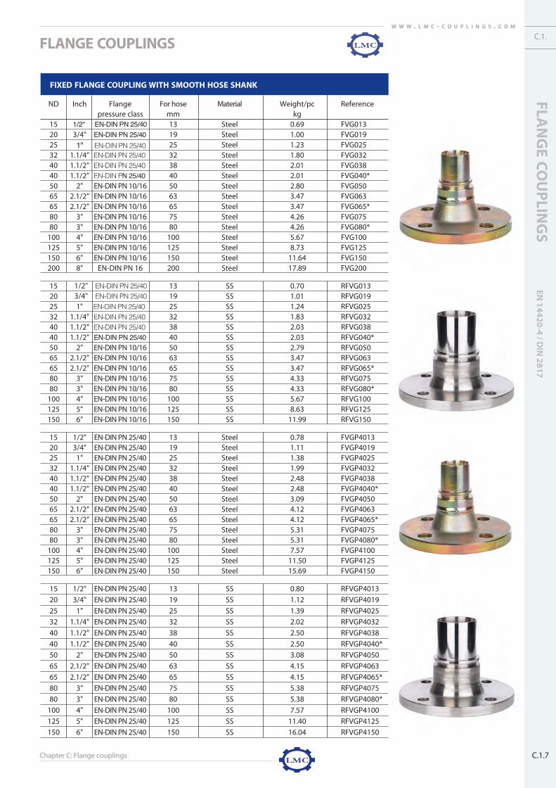
Chapter C: Flange couplings
FLANGE COUPLINGS
FLAN
GE
CO
UP
LING
SEN
14
42
0-4
/ DIN
28
17
C.1.7
C.1.W W W . L M C - C O U P L I N G S . C O M
FIXED FLANGE COUPLING WITH SMOOTH HOSE SHANK
ND Inch Flange For hose Material Weight/pc Referencepressure class mm kg
15 1/2" EN-DIN PN 25/40 13 Steel 0.69 FVG01320 3/4" EN-DIN PN 25/40 19 Steel 1.00 FVG01925 1" EN-DIN PN 25/40 25 Steel 1.23 FVG02532 1.1/4” EN-DIN PN 25/40 32 Steel 1.80 FVG03240 1.1/2” EN-DIN PN 25/40 38 Steel 2.01 FVG03840 1.1/2” EN-DIN PN 25/40 40 Steel 2.01 FVG040*50 2" EN-DIN PN 10/16 50 Steel 2.80 FVG05065 2.1/2” EN-DIN PN 10/16 63 Steel 3.47 FVG06365 2.1/2” EN-DIN PN 10/16 65 Steel 3.47 FVG065*80 3" EN-DIN PN 10/16 75 Steel 4.26 FVG07580 3" EN-DIN PN 10/16 80 Steel 4.26 FVG080*
100 4" EN-DIN PN 10/16 100 Steel 5.67 FVG100125 5" EN-DIN PN 10/16 125 Steel 8.73 FVG125150 6" EN-DIN PN 10/16 150 Steel 11.64 FVG150200 8" EN-DIN PN 16 200 Steel 17.89 FVG200
15 13 SS 0.70 RFVG01320
1/2" EN-DIN PN 25/40 3/4" EN-DIN PN 25/40 19 SS 1.01 RFVG019
25 1" EN-DIN PN 25/40 25 SS 1.24 RFVG02532 1.1/4” EN-DIN PN 25/40 32 SS 1.83 RFVG03240 1.1/2” EN-DIN PN 25/40 38 SS 2.03 RFVG03840 1.1/2” EN-DIN PN 25/40 40 SS 2.03 RFVG040*50 2" EN-DIN PN 10/16 50 SS 2.79 RFVG05065 2.1/2” EN-DIN PN 10/16 63 SS 3.47 RFVG06365 2.1/2” EN-DIN PN 10/16 65 SS 3.47 RFVG065*80 3" EN-DIN PN 10/16 75 SS 4.33 RFVG07580 3" EN-DIN PN 10/16 80 SS 4.33 RFVG080*
100 4" EN-DIN PN 10/16 100 SS 5.67 RFVG100125 5" EN-DIN PN 10/16 125 SS 8.63 RFVG125150 6" EN-DIN PN 10/16 150 SS 11.99 RFVG150
15 1/2" EN-DIN PN 25/40 13 Steel 0.78 FVGP401320 3/4" EN-DIN PN 25/40 19 Steel 1.11 FVGP401925 1" EN-DIN PN 25/40 25 Steel 1.38 FVGP402532 1.1/4” EN-DIN PN 25/40 32 Steel 1.99 FVGP403240 1.1/2” EN-DIN PN 25/40 38 Steel 2.48 FVGP403840 1.1/2” EN-DIN PN 25/40 40 Steel 2.48 FVGP4040*50 2" EN-DIN PN 25/40 50 Steel 3.09 FVGP405065 2.1/2” EN-DIN PN 25/40 63 Steel 4.12 FVGP406365 2.1/2” EN-DIN PN 25/40 65 Steel 4.12 FVGP4065*80 3" EN-DIN PN 25/40 75 Steel 5.31 FVGP407580 3" EN-DIN PN 25/40 80 Steel 5.31 FVGP4080*
100 4" EN-DIN PN 25/40 100 Steel 7.57 FVGP4100125 5" EN-DIN PN 25/40 125 Steel 11.50 FVGP4125150 6" EN-DIN PN 25/40 150 Steel 15.69 FVGP4150
15 1/2" EN-DIN PN 25/40 13 SS 0.80 RFVGP4013
20 3/4" EN-DIN PN 25/40 19 SS 1.12 RFVGP4019
25 1" EN-DIN PN 25/40 25 SS 1.39 RFVGP4025
32 1.1/4” EN-DIN PN 25/40 32 SS 2.02 RFVGP4032
40 1.1/2” EN-DIN PN 25/40 38 SS 2.50 RFVGP4038
40 1.1/2” EN-DIN PN 25/40 40 SS 2.50 RFVGP4040*
50 2" EN-DIN PN 25/40 50 SS 3.08 RFVGP4050
65 2.1/2” EN-DIN PN 25/40 63 SS 4.15 RFVGP4063
65 2.1/2” EN-DIN PN 25/40 65 SS 4.15 RFVGP4065*
80 3" EN-DIN PN 25/40 75 SS 5.38 RFVGP4075
80 3" EN-DIN PN 25/40 80 SS 5.38 RFVGP4080*
100 4" EN-DIN PN 25/40 100 SS 7.57 RFVGP4100
125 5" EN-DIN PN 25/40 125 SS 11.40 RFVGP4125
150 6" EN-DIN PN 25/40 150 SS 16.04 RFVGP4150
c1-flange couplings 9/5/07 4:17 PM Pagina 7

Chapter C: Flange couplings
FLANGE COUPLINGS
C.1.8
W W W . L M C - C O U P L I N G S . C O M
FIXED FLANGE COUPLING WITH SMOOTH HOSE SHANK
ND Inch Flange For hose Material Weight/pc Referencepressure class mm kg
15 1/2" ASTM 150 lbs 13 Steel 0.52 FVGA101320 3/4" ASTM 150 lbs 19 Steel 0.76 FVGA101925 1" ASTM 150 lbs 25 Steel 1.10 FVGA102532 1.1/4” ASTM 150 lbs 32 Steel 1.44 FVGA103240 1.1/2” ASTM 150 lbs 38 Steel 1.87 FVGA103840 1.1/2” ASTM 150 lbs 40 Steel 1.87 FVGA1040*50 2" ASTM 150 lbs 50 Steel 2.85 FVGA105065 2.1/2” ASTM 150 lbs 63 Steel 4.52 FVGA106365 2.1/2” ASTM 150 lbs 65 Steel 4.52 FVGA1065*80 3" ASTM 150 lbs 75 Steel 5.48 FVGA107580 3" ASTM 150 lbs 80 Steel 5.48 FVGA1080*
100 4" ASTM 150 lbs 100 Steel 7.89 FVGA1100125 5" ASTM 150 lbs 125 Steel 10.99 FVGA1125150 6" ASTM 150 lbs 150 Steel 14.49 FVGA1150
15 1/2" ASTM 150 lbs 13 SS 0.75 RFVGA1013
20 3/4" ASTM 150 lbs 19 SS 0.86 RFVGA1019
25 1" ASTM 150 lbs 25 SS 1.20 RFVGA1025
32 1.1/4” ASTM 150 lbs 32 SS 1.64 RFVGA1032
40 1.1/2” ASTM 150 lbs 38 SS 1.97 RFVGA1038
40 1.1/2” ASTM 150 lbs 40 SS 1.97 RFVGA1040*
50 2" ASTM 150 lbs 50 SS 2.96 RFVGA1050
65 2.1/2” ASTM 150 lbs 63 SS 4.81 RFVGA1063
65 2.1/2” ASTM 150 lbs 65 SS 4.81 RFVGA1065*
80 3" ASTM 150 lbs 75 SS 5.83 RFVGA1075
80 3" ASTM 150 lbs 80 SS 5.83 RFVGA1080*
100 4" ASTM 150 lbs 100 SS 8.55 RFVGA1100
125 5" ASTM 150 lbs 125 SS 11.53 RFVGA1125
150 6" ASTM 150 lbs 150 SS 15.24 RFVGA1150
Fixed flange: EN 1092-1 / 11 BDIN 2632 PN 10, DIN 2633 PN 16, DIN 2634 PN 25 and DIN 2635 PN 40ASTM / A 182/ ANSI B16.5, ASA 150 lbs
Assembly: RK and RKP safety clamps complying with EN 14420-3 / DIN 2817, FLEXOLINE® safety clampsSS = Stainless steel AISI 316 - 1.4401Steel = galvanized steel
c1-flange couplings 9/5/07 4:17 PM Pagina 8

Chapter C: Flange couplings
FLANGE COUPLINGS
FLAN
GE
CO
UP
LING
SEN
14
42
0-4
/ DIN
28
17
C.1.9
C.1.W W W . L M C - C O U P L I N G S . C O M
SWIVEL FLANGE COUPLING WITH SERRATED HOSE SHANK AND COLLAR
ND Inch Flange For hose Material Flange Weight/pc Referencepressure class mm hose shank material kg
15 1/2" EN-DIN PN 25/40 13 Steel Steel 0.82 FLP013
20 3/4" EN-DIN PN 25/40 19 Steel Steel 1.10 FLP019
25 1" EN-DIN PN 25/40 25 Steel Steel 1.53 FLP025
32 1.1/4” EN-DIN PN 25/40 32 Steel Steel 2.06 FLP032
40 1.1/2” EN-DIN PN 25/40 38 Steel Steel 2.68 FLP038
40 1.1/2” EN-DIN PN 25/40 40 Steel Steel 2.68 FLP040*
50 2" EN-DIN PN 10/16 50 Steel Steel 3.22 FLP050
65 2.1/2” EN-DIN PN 10/16 63 Steel Steel 4.18 FLP063
65 2.1/2” EN-DIN PN 10/16 65 Steel Steel 4.18 FLP065*
80 3" EN-DIN PN 10/16 75 Steel Steel 5.29 FLP075
80 3" EN-DIN PN 10/16 80 Steel Steel 5.29 FLP080*
100 4" EN-DIN PN 10/16 100 Steel Steel 7.01 FLP100
125 5" EN-DIN PN 10/16 125 Steel Steel 14.19 FLP125
150 6" EN-DIN PN 10/16 150 Steel Steel 17.72 FLP150
200 8" EN-DIN PN 10 200 Steel Steel 20.0 FLP200PN10*
200 8" EN-DIN PN 16 200 Steel Steel 22.6 FLP200PN16
15 13 SS SS 0.79 RRFLP013
20
1/2" EN-DIN PN 25/40 3/4" EN-DIN PN 25/40 19 SS SS 1.10 RRFLP019
25 1" EN-DIN PN 25/40 25 SS SS 1.49 RRFLP025
32 1.1/4” EN-DIN PN 25/40 32 SS SS 2.12 RRFLP032
40 1.1/2” EN-DIN PN 25/40 38 SS SS 2.50 RRFLP038
40 1.1/2” EN-DIN PN 25/40 40 SS SS 2.50 RRFLP040*
50 2" EN-DIN PN 10/16 50 SS SS 3.43 RRFLP050
65 2.1/2” EN-DIN PN 10/16 63 SS SS 3.85 RRFLP063
65 2.1/2” EN-DIN PN 10/16 65 SS SS 3.85 RRFLP065*
80 3" EN-DIN PN 10/16 75 SS SS 5.25 RRFLP075
80 3" EN-DIN PN 10/16 80 SS SS 5.25 RRFLP080*
100 4" EN-DIN PN 10/16 100 SS SS 6.02 RRFLP100
125 5" EN-DIN PN 10/16 125 SS SS 9.13 RRFLP125
150 6" EN-DIN PN 10/16 150 SS SS 11.83 RRFLP150
15 13 SS Steel 0.82 RSFLP013
20
1/2" EN-DIN PN 25/40 3/4" EN-DIN PN 25/40 19 SS Steel 1.12 RSFLP019
25 1" EN-DIN PN 25/40 25 SS Steel 1.53 RSFLP025
32 1.1/4” EN-DIN PN 25/40 32 SS Steel 1.99 RSFLP032
40 1.1/2” EN-DIN PN 25/40 38 SS Steel 2.52 RSFLP038
40 1.1/2” EN-DIN PN 25/40 40 SS Steel 2.52 RSFLP040*
50 2" EN-DIN PN 10/16 50 SS Steel 3.11 RSFLP050
65 2.1/2” EN-DIN PN 10/16 63 SS Steel 3.95 RSFLP063
65 2.1/2” EN-DIN PN 10/16 65 SS Steel 3.95 RSFLP065*
80 3" EN-DIN PN 10/16 75 SS Steel 5.34 RSFLP075
80 3" EN-DIN PN 10/16 80 SS Steel 5.34 RSFLP080*
100 4" EN-DIN PN 10/16 100 SS Steel 6.14 RSFLP100
125 5" EN-DIN PN 10/16 125 SS Steel 9.01 RSFLP125
150 6" EN-DIN PN 10/16 150 SS Steel 11.68 RSFLP150
c1-flange couplings 9/5/07 4:18 PM Pagina 9

Chapter C: Flange couplings
FLANGE COUPLINGS
C.1.10
W W W . L M C - C O U P L I N G S . C O M
SWIVEL FLANGE COUPLING WITH SERRATED HOSE SHANK AND COLLAR
ND Inch Flange For hose Material Flange Weight/pc Referencepressure class mm hose shank material kg
15 1/2" ASTM 150 lbs 13 Steel Steel 0.57 FLPA1013
20 3/4" ASTM 150 lbs 19 Steel Steel 0.90 FLPA1019
25 1" ASTM 150 lbs 25 Steel Steel 1.31 FLPA1025
32 1.1/4” ASTM 150 lbs 32 Steel Steel 1.78 FLPA1032
40 1.1/2” ASTM 150 lbs 38 Steel Steel 2.28 FLPA1038
40 1.1/2” ASTM 150 lbs 40 Steel Steel 2.28 FLPA1040*
50 2" ASTM 150 lbs 50 Steel Steel 3.47 FLPA1050
65 2.1/2” ASTM 150 lbs 63 Steel Steel 5.34 FLPA1063
65 2.1/2” ASTM 150 lbs 65 Steel Steel 5.34 FLPA1065*
80 3" ASTM 150 lbs 75 Steel Steel 6.05 FLPA1075
80 3" ASTM 150 lbs 80 Steel Steel 6.05 FLPA1080*
100 4" ASTM 150 lbs 100 Steel Steel 9.11 FLPA1100
125 5" ASTM 150 lbs 125 Steel Steel 16.49 FLPA1125
150 6" ASTM 150 lbs 150 Steel Steel 20.72 FLPA1150
15 1/2" ASTM 150 lbs 13 SS SS 0.79 RRFLPA1013
20 3/4" ASTM 150 lbs 19 SS SS 1.10 RRFLPA1019
25 1" ASTM 150 lbs 25 SS SS 1.50 RRFLPA1025
32 1.1/4” ASTM 150 lbs 32 SS SS 2.12 RRFLPA1032
40 1.1/2” ASTM 150 lbs 38 SS SS 2.50 RRFLPA1038
40 1.1/2” ASTM 150 lbs 40 SS SS 2.50 RRFLPA1040*
50 2" ASTM 150 lbs 50 SS SS 3.43 RRFLPA1050
65 2.1/2” ASTM 150 lbs 63 SS SS 3.85 RRFLPA1063
65 2.1/2” ASTM 150 lbs 65 SS SS 3.85 RRFLPA1065*
80 3" ASTM 150 lbs 75 SS SS 5.25 RRFLPA1075
80 3" ASTM 150 lbs 80 SS SS 5.25 RRFLPA1080*
100 4" ASTM 150 lbs 100 SS SS 6.02 RRFLPA1100
125 5" ASTM 150 lbs 125 SS SS 11.74 RRFLPA1125
150 6" ASTM 150 lbs 150 SS SS 15.33 RRFLPA1150
Swivel flange: EN 1092-1 / 04 ADIN 2673 PN 10, DIN 2674 PN 16, DIN 2634 PN 25 and DIN 2635 PN 40ASTM / A 182/ ANSI B16.5, ASA 150 lbs
Assembly: HRRK swage ferrules, worm drive and band clampsSS = Stainless steel AISI 316 - 1.4401Steel = galvanized steelPolypropylene flange available on request* Available on request
c1-flange couplings 9/5/07 4:18 PM Pagina 10

Chapter C: Flange couplings
FLANGE COUPLINGS
FLAN
GE
CO
UP
LING
SEN
14
42
0-4
/ DIN
28
17
C.1.11
C.1.W W W . L M C - C O U P L I N G S . C O M
FIXED FLANGE COUPLING WITH SERRATED HOSE SHANK AND COLLAR
ND Inch Flange For hose Material Weight/pc Referencepressure class mm kg
15 1/2" EN-DIN PN 25/40 13 Steel 0.70 FVP013
20 3/4" EN-DIN PN 25/40 19 Steel 1.02 FVP019
25 1" EN-DIN PN 25/40 25 Steel 1.23 FVP025
32 1.1/4” EN-DIN PN 25/40 32 Steel 1.82 FVP032
40 1.1/2” EN-DIN PN 25/40 38 Steel 2.01 FVP038
40 1.1/2” EN-DIN PN 25/40 40 Steel 2.01 FVP040*
50 2" EN-DIN PN 10/16 50 Steel 2.79 FVP050
65 2.1/2” EN-DIN PN 10/16 63 Steel 3.70 FVP063
65 2.1/2” EN-DIN PN 10/16 65 Steel 3.70 FVP065*
80 3" EN-DIN PN 10/16 75 Steel 4.26 FVP075
80 3" EN-DIN PN 10/16 80 Steel 4.26 FVP080*
100 4" EN-DIN PN 10/16 100 Steel 5.68 FVP100
125 5" EN-DIN PN 10/16 125 Steel 8.51 FVP125
150 6" EN-DIN PN 10/16 150 Steel 11.29 FVP150
200 8" EN-DIN PN 10 200 Steel 17.44 FVP200PN10*
200 8" EN-DIN PN 16 200 Steel 17.44 FVP200PN16
15 13 SS 0.70 RFVP013
20
1/2" EN-DIN PN 25/40 3/4" EN-DIN PN 25/40 19 SS 1.01 RFVP019
25 1" EN-DIN PN 25/40 25 SS 1.24 RFVP025
32 1.1/4” EN-DIN PN 25/40 32 SS 1.83 RFVP032
40 1.1/2” EN-DIN PN 25/40 38 SS 2.03 RFVP038
40 1.1/2” EN-DIN PN 25/40 40 SS 2.03 RFVP040*
50 2" EN-DIN PN 10/16 50 SS 2.79 RFVP050
65 2.1/2” EN-DIN PN 10/16 63 SS 3.47 RFVP063
65 2.1/2” EN-DIN PN 10/16 65 SS 3.47 RFVP065*
80 3" EN-DIN PN 10/16 75 SS 4.33 RFVP075
80 3" EN-DIN PN 10/16 80 SS 4.33 RFVP080*
100 4" EN-DIN PN 10/16 100 SS 5.67 RFVP100
125 5" EN-DIN PN 10/16 125 SS 8.63 RFVP125
150 6" EN-DIN PN 10/16 150 SS 11.99 RFVP150
15 1/2" ASTM 150 lbs 13 Steel 0.53 FVPA1013
20 3/4" ASTM 150 lbs 19 Steel 0.78 FVPA1019
25 1" ASTM 150 lbs 25 Steel 1.10 FVPA1025
32 1.1/4” ASTM 150 lbs 32 Steel 1.46 FVPA1032
40 1.1/2” ASTM 150 lbs 38 Steel 1.87 FVPA1038
40 1.1/2” ASTM 150 lbs 40 Steel 1.87 FVPA1040*
50 2" ASTM 150 lbs 50 Steel 2.84 FVPA1050
65 2.1/2” ASTM 150 lbs 63 Steel 4.75 FVPA1063
65 2.1/2” ASTM 150 lbs 65 Steel 4.75 FVPA1065*
80 3" ASTM 150 lbs 75 Steel 5.48 FVPA1075
80 3" ASTM 150 lbs 80 Steel 5.48 FVPA1080*
100 4" ASTM 150 lbs 100 Steel 7.90 FVPA1100
125 5" ASTM 150 lbs 125 Steel 10.77 FVPA1125
150 6" ASTM 150 lbs 150 Steel 10.60 FVPA1150
Fixed flange: EN 1092-1 / 11 BDIN 2632 PN 10, DIN 2633 PN 16, DIN 2634 PN 25 and DIN 2635 PN 40ASTM / A 182/ ANSI B16.5, ASA 150 lbs
Assembly: HRRK swage ferrules, worm drive and band clampsSS = Stainless steel AISI 316 - EN 1.4401 / Steel = galvanized steel
c1-flange couplings 9/5/07 4:19 PM Pagina 11

Chapter C: Flange couplings
FLANGE COUPLINGS
C.1.12
W W W . L M C - C O U P L I N G S . C O M
Fixed flange: EN 1092-1 / 11 BDIN 2632 PN 10, DIN 2633 PN 16, DIN 2634 PN 25 and DIN 2635 PN 40ASTM / A 182/ ANSI B16.5, ASA 150 lbs
Assembly: HRRK swage ferrules, worm drive and band clampsSS = Stainless steel AISI 316 - 1.4401 / Steel = galvanized steel* available on request
FIXED FLANGE COUPLING WITH SERRATED HOSE SHANK AND COLLAR
ND Inch Flange For hose Material Weight/pc Referencepressure class mm kg
15 1/2" ASTM 150 lbs 13 SS 0.75 RFVPA1013
20 3/4" ASTM 150 lbs 19 SS 0.86 RFVPA1019
25 1" ASTM 150 lbs 25 SS 1.20 RFVPA1025
32 1.1/4” ASTM 150 lbs 32 SS 1.64 RFVPA1032
40 1.1/2” ASTM 150 lbs 38 SS 1.97 RFVPA1038
40 1.1/2” ASTM 150 lbs 40 SS 1.97 RFVPA1040*
50 2" ASTM 150 lbs 50 SS 2.96 RFVPA1050
65 2.1/2” ASTM 150 lbs 63 SS 4.81 RFVPA1063
65 2.1/2” ASTM 150 lbs 65 SS 4.81 RFVPA1065*
80 3" ASTM 150 lbs 75 SS 5.83 RFVPA1075
80 3" ASTM 150 lbs 80 SS 5.83 RFVPA1080*
100 4" ASTM 150 lbs 100 SS 8.55 RFVPA1100
125 5" ASTM 150 lbs 125 SS 11.53 RFVPA1125
150 6" ASTM 150 lbs 150 SS 15.24 RFVPA1150
c1-flange couplings 9/5/07 4:19 PM Pagina 12

Chapter C: Flange couplings
FLANGE COUPLINGS
FLAN
GE
CO
UP
LING
SEN
14
42
0-4
/ DIN
28
17
C.1.13
C.1.W W W . L M C - C O U P L I N G S . C O M
SS = Stainless steel AISI 316 - EN 1.4401 / Steel = non-galvanized steelAssembly: RK and RKP safety clamps complying with EN 14420-3 / DIN 2817, FLEXOLINE® safety clamps
SMOOTH WELDING HOSE SHANK EN 14420-2 / DIN 2817
ND Inch Material For hose OD Ø welding end Weight/pc Referencemm mm kg
15 1/2" Steel 13 21.3 0.04 FTU013
20 3/4" Steel 19 26.9 0.05 FTU019
25 1" Steel 25 33.7 0.09 FTU025
32 1.1/4” Steel 32 42.4 0.11 FTU032
40 1.1/2” Steel 38 48.3 0.15 FTU038
40 1.1/2” Steel 40 48.3 0.15 FTU040*
50 2" Steel 50 60.3 0.27 FTU050
65 2.1/2” Steel 63 76.1 0.41 FTU063
65 2.1/2” Steel 65 76.1 0.41 FTU065*
80 3" Steel 75 88.9 0.56 FTU075
80 3" Steel 80 88.9 0.59 FTU080*
100 4" Steel 100 114.3 1.05 FTU100
125 5" Steel 125 139.7 2.43 FTU125
150 6" Steel 150 168.3 3.89 FTU150
200 8" Steel 200 219.1 6.89 FTU200
15 1/2" SS 13 21.3 0.05 RFTU013
20 3/4" SS 19 26.9 0.06 RFTU019
25 1" SS 25 33.7 0.10 RFTU025
32 1.1/4” SS 32 42.4 0.14 RFTU032
40 1.1/2” SS 38 48.3 0.17 RFTU038
40 1.1/2” SS 40 48.3 0.17 RFTU040*
50 2" SS 50 60.3 0.26 RFTU050
65 2.1/2” SS 63 76.1 0.41 RFTU063
65 2.1/2” SS 65 76.1 0.41 RFTU065*
80 3" SS 75 88.9 0.63 RFTU075
80 3" SS 80 88.9 0.66 RFTU080*
100 4" SS 100 114.3 1.05 RFTU100
125 5" SS 125 139.7 2.33 RFTU125
150 6" SS 150 168.3 4.24 RFTU150
200 8" SS 200 219.1 7.11 RFTU200
c1-flange couplings 9/5/07 4:19 PM Pagina 13

Chapter C: Flange couplings
FLANGE COUPLINGS
C.1.14
W W W . L M C - C O U P L I N G S . C O M
SS = Stainless steel AISI 316 - 1.4401 / Steel = non-galvanized steelAssembly: HRRK swage ferrules, worm drive and band clamps
SERRATED WELDING HOSE SHANK
ND Inch Material For hose OD Ø welding end Weight/pc Referencemm mm kg
15 1/2" Steel 13 21.3 0.05 FTP013
20 3/4" Steel 19 26.9 0.07 FTP019
25 1" Steel 25 33.7 0.09 FTP025
32 1.1/4” Steel 32 42.4 0.13 FTP032
40 1.1/2” Steel 38 48.3 0.15 FTP038
40 1.1/2” Steel 40 48.3 0.15 FTP040*
50 2" Steel 50 60.3 0.26 FTP050
65 2.1/2” Steel 63 76.1 0.64 FTP063
65 2.1/2” Steel 65 76.1 0.64 FTP065*
80 3" Steel 75 88.9 0.56 FTP075
80 3" Steel 80 88.9 0.61 FTP080*
100 4" Steel 100 114.3 1.06 FTP100
125 5" Steel 125 139.7 2.21 FTP125
150 6" Steel 150 168.3 3.54 FTP150
200 8" Steel 200 219.1 6.44 FTP200
15 1/2" SS 13 21.3 0.05 RFTP013
20 3/4" SS 19 26.9 0.07 RFTP019
25 1" SS 25 33.7 0.09 RFTP025
32 1.1/4” SS 32 42.4 0.13 RFTP032
40 1.1/2” SS 38 48.3 0.17 RFTP038
40 1.1/2” SS 40 48.3 0.17 RFTP040*
50 2" SS 50 60.3 0.27 RFTP050
65 2.1/2” SS 63 76.1 0.46 RFTP063
65 2.1/2” SS 65 76.1 0.46 RFTP065*
80 3" SS 75 88.9 0.55 RFTP075
80 3" SS 80 88.9 0.59 RFTP080*
100 4" SS 100 114.3 1.22 RFTP100
125 5" SS 125 139.7 2.45 RFTP125
150 6" SS 150 168.3 3.44 RFTP150
200 8" SS 200 219.1 6.20 RFTP200
c1-flange couplings 9/5/07 4:19 PM Pagina 14

Chapter C: Flange couplings
FLANGE COUPLINGS
FLAN
GE
CO
UP
LING
SEN
14
42
0-4
/ DIN
28
17
C.1.15
C.1.W W W . L M C - C O U P L I N G S . C O M
RAISED FACE GASKET FOR EN / DIN FLANGE - GORE™ UPG STYLE 800
ND EN-DIN OD Ø ID Ø Height Colour Referencemm mm mm
15 PN 10/40 51.0 22.0 3.0 White FXG013DINRF
20 PN 10/40 61.0 27.0 3.0 White FXG019DINRF
25 PN 10/40 71.0 34.0 3.0 White FXG025DINRF
32 PN 10/40 82.0 43.0 3.0 White FXG032DINRF
40 PN 10/40 92.0 49.0 3.0 White FXG038DINRF
50 PN 10/40 107.0 61.0 3.0 White FXG050DINRF
65 PN 10/40 127.0 77.0 3.0 White FXG063DINRF
80 PN 10/40 142.0 89.0 3.0 White FXG075DINRF
100 PN 10/16 162.0 115.0 3.0 White FXG100DINRF
125 PN 10/16 192.0 141.0 3.0 White FXG125DINRF
150 PN 10/16 218.0 169.0 3.0 White FXG150DINRF
200 PN 10/16 273.0 220.0 3.0 White FXG200DINRF
RAISED FACE GASKET FOR EN / DIN FLANGE - novatec® PREMIUM II
ND EN-DIN OD Ø ID Ø Height Colour Referencemm mm mm
15 PN 10/40 51.0 22.0 2.0 Blue FXN013DINRF
20 PN 10/40 61.0 27.0 2.0 Blue FXN019DINRF
25 PN 10/40 71.0 34.0 2.0 Blue FXN025DINRF
32 PN 10/40 82.0 43.0 2.0 Blue FXN032DINRF
40 PN 10/40 92.0 49.0 2.0 Blue FXN038DINRF
50 PN 10/40 107.0 61.0 2.0 Blue FXN050DINRF
65 PN 10/40 127.0 77.0 2.0 Blue FXN063DINRF
80 PN 10/40 142.0 89.0 2.0 Blue FXN075DINRF
100 PN 10/16 162.0 115.0 2.0 Blue FXN100DINRF
125 PN 10/16 192.0 141.0 2.0 Blue FXN125DINRF
150 PN 10/16 218.0 169.0 2.0 Blue FXN150DINRF
200 PN 10/16 273.0 220.0 2.0 Blue FXN200DINRF
Seal colour is subject to change without prior noticeGORE™ Universal Pipe Seal Style 800 is a registered trademark of W.L. Gore & Associates, Inc.
novatec® PREMIUM II is a registered trademark of FrenzelitKEVLAR® is a registered trademark of Dupont Dow ElastomersSeal colour is subject to change without prior notice
c1-flange couplings 9/5/07 4:19 PM Pagina 15

Chapter C: Flange couplingsC.1.16
W W W . L M C - C O U P L I N G S . C O M
FLANGE COUPLINGS
novatec® PREMIUM II is a registered trademark of FrenzelitKEVLAR® is a registered trademark of Dupont Dow ElastomersSeal colour is subject to change without prior notice
RAISED FACE GASKET FOR ANSI FLANGE - novatec® PREMIUM II
ND ANSI OD Ø ID Ø Height Colour Referencemm mm mm
1/2" ASA 150lbs 47.5 22.0 2.0 Blue FXN013A1RF
3/4" ASA 150lbs 57.0 27.0 2.0 Blue FXN019A1RF
1" ASA 150lbs 66.5 34.0 2.0 Blue FXN025A1RF
1.1/4” ASA 150lbs 76.0 43.0 2.0 Blue FXN032A1RF
1.1/2” ASA 150lbs 85.5 49.0 2.0 Blue FXN038A1RF
2" ASA 150lbs 104.5 61.0 2.0 Blue FXN050A1RF
2.1/2” ASA 150lbs 124.0 73.0 2.0 Blue FXN063A1RF
3" ASA 150lbs 136.5 89.0 2.0 Blue FXN075A1RF
4" ASA 150lbs 174.5 115.0 2.0 Blue FXN100A1RF
5" ASA 150lbs 196.5 141.0 2.0 Blue FXN125A1RF
6" ASA 150lbs 222.0 169.0 2.0 Blue FXN150A1RF
8" ASA 150lbs 279.0 220.0 2.0 Blue FXN200A1RF
Seal colour is subject to change without prior noticeGORE™ Universal Pipe Seal Style 800 is a registered trademark of W.L. Gore & Associates, Inc.
RAISED FACE GASKET FOR ANSI FLANGE - GORE™ UPG STYLE 800
ND ANSI OD Ø ID Ø Height Colour Referencemm mm mm
1/2" ASA 150lbs 47.5 22.0 3.0 White FXG013A1RF
3/4" ASA 150lbs 57.0 27.0 3.0 White FXG019A1RF
1" ASA 150lbs 66.5 34.0 3.0 White FXG025A1RF
1.1/4” ASA 150lbs 76.0 43.0 3.0 White FXG032A1RF
1.1/2” ASA 150lbs 85.5 49.0 3.0 White FXG038A1RF
2" ASA 150lbs 104.5 61.0 3.0 White FXG050A1RF
2.1/2” ASA 150lbs 124.0 73.0 3.0 White FXG063A1RF
3" ASA 150lbs 136.5 89.0 3.0 White FXG075A1RF
4" ASA 150lbs 174.5 115.0 3.0 White FXG100A1RF
5" ASA 150lbs 196.5 141.0 3.0 White FXG125A1RF
6" ASA 150lbs 222.0 169.0 3.0 White FXG150A1RF
8" ASA 150lbs 279.0 220.0 3.0 White FXG200A1RF
c1-flange couplings 9/5/07 4:20 PM Pagina 16
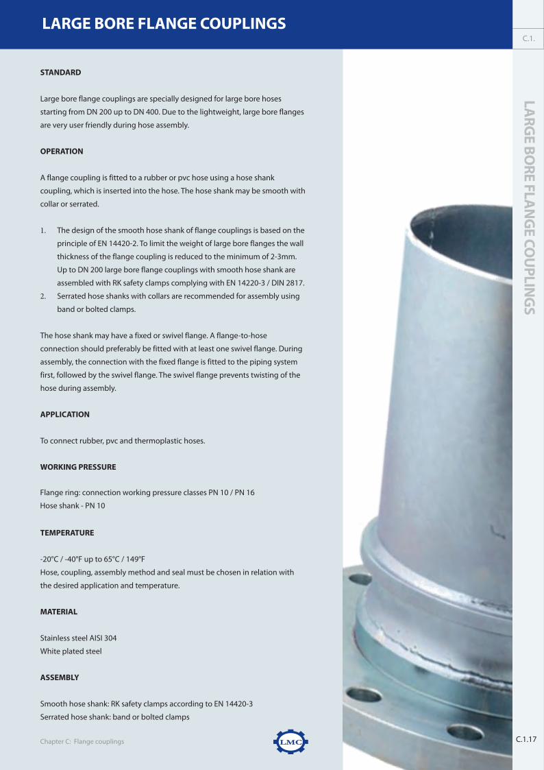
STANDARD
Large bore flange couplings are specially designed for large bore hoses
starting from DN 200 up to DN 400. Due to the lightweight, large bore flanges
are very user friendly during hose assembly.
OPERATION
A flange coupling is fitted to a rubber or pvc hose using a hose shank
coupling, which is inserted into the hose. The hose shank may be smooth with
collar or serrated.
1. The design of the smooth hose shank of flange couplings is based on the
principle of EN 14420-2. To limit the weight of large bore flanges the wall
thickness of the flange coupling is reduced to the minimum of 2-3mm.
Up to DN 200 large bore flange couplings with smooth hose shank are
assembled with RK safety clamps complying with EN 14220-3 / DIN 2817.
2. Serrated hose shanks with collars are recommended for assembly using
band or bolted clamps.
The hose shank may have a fixed or swivel flange. A flange-to-hose
connection should preferably be fitted with at least one swivel flange. During
assembly, the connection with the fixed flange is fitted to the piping system
first, followed by the swivel flange. The swivel flange prevents twisting of the
hose during assembly.
APPLICATION
To connect rubber, pvc and thermoplastic hoses.
WORKING PRESSURE
Flange ring: connection working pressure classes PN 10 / PN 16
Hose shank - PN 10
TEMPERATURE
-20°C / -40°F up to 65°C / 149°F
Hose, coupling, assembly method and seal must be chosen in relation with
the desired application and temperature.
MATERIAL
Stainless steel AISI 304
White plated steel
ASSEMBLY
Smooth hose shank: RK safety clamps according to EN 14420-3
Serrated hose shank: band or bolted clamps
LMCChapter C: Flange couplings
LARG
E BORE FLA
NG
E COU
PLING
SC.1.
C.1.17
W W W . L M C - C O U P L I N G S . C O MLARGE BORE FLANGE COUPLINGS
largeboreflange.indd 1 28/10/14 14:27

LARG
E BORE FLA
NG
E COU
PLING
S
C.1.
C.1.17 Chapter C: Flange couplingsC.1.18
LARGE BORE FLANGE COUPLINGS
largeboreflange.indd 2 28/10/14 14:27

Chapter C: Flange couplings
LARGE BORE FLANGE COUPLINGS
LARG
E BORE FLA
NG
E COU
PLING
S
A.1
C.1.19
W W W . L M C - C O U P L I N G S . C O M
largeboreflange.indd 3 28/10/14 14:27

Chapter C: Flange couplings
LARGE BORE FLANGE COUPLINGS
C.1.20
W W W . L M C - C O U P L I N G S . C O M
largeboreflange.indd 4 28/10/14 14:27

Chapter C: Flange couplings
LARGE BORE FLANGE COUPLINGS
LARG
E BORE FLA
NG
E COU
PLING
SA.1
C.1.21
W W W . L M C - C O U P L I N G S . C O M
largeboreflange.indd 5 28/10/14 14:27

D.1. RK safety clamps
D.2. RKP safety clamps
D.3. FlEXolinE® safety clamps
D.4. RKS steam clamps
D.5. Mira band clamps
D.6. Swage ferrules
DClAMPS &FERRulES
Untitled-4 5 27/05/13 10:41


W W W . L M C - C O U P L I N G S . C O M
MATERIAL
� RK safety clamp shells
Drop forged aluminium USA ASTM B247, grade 6061-T6
Germany DIN 1749 grade AIMgSi1 F28 work stock No. 3.2315.61
UK BS 1472 HE 20 Grade 6061
Drop forged brass USA ASTM B16, grade C36000
Germany DIN 17660 grade CuZn36Pb3
UK BS 2847 grade CZ124
Cast stainless steel USA ASTM A666 grade 316 stainless steel
Germany DIN 17440 grade1.4401 X5CrNiMo1810
UK NF A35-579 grade Z6CND17.11
� Nuts and bolts
Aluminium RK safety clamps: bolts complying with EN ISO 4762 / DIN 912, zinc plated 8.8
nuts complying with EN ISO 4032 / DIN 934, zinc plated 8.8
Brass RK safety clamps: bolts complying with EN ISO 4762 / DIN 912, zinc plated 8.8
nuts complying with EN ISO 4032 / DIN 934, zinc plated 8.8
Stainless steel RK safety clamps:bolts complying with EN ISO 4762 / DIN 912, stainless steel A.2
nuts complying with EN ISO 4032 / DIN 934, stainless steel A.2
RK safety clamps are supplied complete with nuts and bolts.
ASSEMBLY
See chapter E for the correct assembly instructions
RK SAFETY CLAMPS EN 14420-3 / DIN 2817
Chapter E: Assembly clamps & ferrulesD.1.2
d1-rk safety 7/17/07 4:32 PM Pagina 2
Untitled-3 2 10/06/13 16:25


Chapter E: Assembly clamps & ferrules
RK SAFETY CLAMPS
RK
SAFET
YC
LAM
PS
EN 1
44
20
-3 /
DIN
28
17
D.1.5
D.1.W W W . L M C - C O U P L I N G S . C O M
BOLTS EN ISO 4762
Size Material Box quantity Weight/pc ReferenceKg
M6x20 Zinc plated 8.8 500 3.22 BVID06X20
M8x25 Zinc plated 8.8 200 2.94 BVID08X25
M10x40 Zinc plated 8.8 100 3.20 BVID10X40
M6x20 Stainless steel A.2 500 3.16 BRID06X20
M8x25 Stainless steel A.2 200 3.00 BRID08X25
M10x40 Stainless steel A.2 100 3.20 BRID10X40
NUTS EN ISO 4032
Size Material Box quantity Weight/pc ReferenceKg
M6 Zinc plated 8.8 250 0.55 MVD06
M8 Zinc plated 8.8 250 1.20 MVD08
M10 Zinc plated 8.8 250 1.75 MVD10
M6 Stainless steel A.2 250 0.50 MRD06
M8 Stainless steel A.2 250 1.10 MRD08
M10 Stainless steel A.2 250 1.60 MRD10
IDENTIFICATION RING
ND Material OD Weight/pc Referencemm Kg
13 Stainless steel 31.0 0.03 IR013
19 Stainless steel 34.0 0.06 IR019
25 Stainless steel 40.0 0.07 IR025
32 Stainless steel 45.0 0.08 IR032
38 Stainless steel 56.0 0.12 IR038
50 Stainless steel 66.0 0.11 IR050
75 Stainless steel 92.0 0.28 IR075
100 Stainless steel 120.0 0.44 IR100
Polished stainless steel AISI 304 - EN 1.4301
d1-rk safety 7/17/07 4:32 PM Pagina 5
Untitled-3 5 10/06/13 16:25

RK
PSA
FETY
CLA
MP
SEN
14
42
0-3
/D
IN 2
81
7
D.2.
W W W . L M C - C O U P L I N G S . C O M
STANDARD
RKP safety clamps and pins are manufactured in compliance with EN 11420-3 /
DIN 2817 and are used to assemble EN/DIN standardized hoses.
OPERATION
RKP safety clamps are pre-assembled by means of a hinge pin on one side of
the assembly, which facilitates and speeds up assembly. Once opened, the
RKP shells are slid across the hose and the hose coupling collar. The inside of
each shell clamp is grooved to grip the outer wall of the hose when the shell
clamps are closed and the locking pin is inserted into the RKP safety clamp
joint. When RKP safety clamps are correctly assembled, the coupling cannot
be pulled out of the hose. RKP safety clamps are easy to assemble and disas-
semble. When the clamps are not damaged they can be reused.
APPLICATION
Assembly of the rubber hoses used in food, pharmaceutical and transport
industry applications.
WORKING PRESSURE
-0.8 bar / -11 psi to 25 bar / 362 psi
TEMPERATURE
-20°C/-4 °F to + 65°C/149°F
Hose, coupling, assembly method and seal must be chosen in relation with
the desired application and temperature.
MATERIAL
� RKP safety clamp shells
Forged aluminium
� Hinge and locking pin
Stainless steel AISI 305 - 1.4303
RKP safety clamps are supplied complete with locking pins.
RKP SAFETY CLAMPS EN 14420-3 / DIN 2817
D.2.1
d2-rkp safety 9/19/07 11:10 AM Pagina 1

100 100 x 8 114 - 119 82 123 0.55 100

FLEXO
LINE® SA
FETY
CLA
MP
SD.3.
W W W . L M C - C O U P L I N G S . C O M
STANDARD
FLEXOLINE® safety clamps have been developed and manufactured in close collab-oration with customers and hose manufacturers. The hose industry developedthin-wall hoses that are lighter and more flexible then ever before. The standardRK safety clamps complying with EN 14420-3 / DIN 2817 are too big for this newgeneration thin-wall hoses. To solve this inconvenience and for safety reasonsLMC-Couplings developed FLEXOLINE® safety clamps for thin-wall rubber hoses.
OPERATION
FLEXOLINE® safety clamps are based on the shell type clamps, and are intended foruse with thin-wall hoses. FLEXOLINE® safety clamps have a rim on the inside, whichfits over the hose tail collar when the bolts are tightened. When FLEXOLINE® safetyclamps are assembled correctly, the coupling cannot be pulled out of the hose.Another advantage of FLEXOLINE® safety clamps is that when a hose is withdrawnfrom service for any reason, the LMC-Couplings shells and couplings can be easilydismantled for reuse if not damaged during service.FLEXOLINE® safety clamps can be used to replace worm drive clamps or boltclamps in hose coupling assemblies.
APPLICATION
Assembly of thin-wall rubber hoses
WORKING PRESSURE
-0.8 bar / -11 psi up to 25 bar/360 psi
TEMPERATURE
-20°C/-4 °F to + 65°C/149°FHose, coupling, assembly method and seal must be chosen in relation with thedesired application and temperature.
MATERIAL
� FLEXOLINE® safety clamp shellsForged aluminium USA ASTM B247, grade 6061-T6
Germany DIN 1749 grade AIMgSi1 F28 work stock No. 3.2315.61
UK BS 1472 HE 20 Grade 6061
Cast stainless steel USA ASTM A666 grade 316 stainless steelGermany DIN 17440 grade1.4401 X5CrNiMo1810UK BS 316 S16
� Nuts and boltsAluminium FLEXOLINE® safety clamps: bolts complying with EN ISO 4762 / DIN 912,
zinc plated 10.9nuts complying with EN ISO 4032 / DIN 934,zinc plated 10.9
FLEXOLINE® safety clamps are supplied complete with nuts and bolts.
ASSEMBLY
See chapter E for assembly instructions on smooth hose shank couplings.
FLEXOLINE® SAFETY CLAMPS
D.3.1
d3-flexoline safety 11/14/07 11:12 AM Pagina 1

Chapter D: Assembly clamps & ferrules
FLEXOLINE® SAFETY CLAMPS
FLEXO
LINE® SA
FETY
CLA
MP
S
D.3.3
D.3.W W W . L M C - C O U P L I N G S . C O M
FLEXOLINE® SAFETY CLAMPS: ALUMINIUM
ND For hose OD hose Height Width Quantity Thread Weight/pc Referencemin-max metric
mm mm mm mm Kg25 25 x 5.0 34 - 36 50 69 4 M6 0.19 FRK025005
32 32 x 5.0 41 - 43 50 76 4 M6 0.28 FRK032005
40 38 x 5.0 47 - 49 50 83 4 M6 0.28 FRK038005
50 50 x 5.0 59 - 61 56 96 4 M8 0.38 FRK050005
65 63 x 6.0 74 - 76 74 117 4 M8 0.53 FRK063006
80 75 x 6.0 86 - 88 76 128 4 M8 0.58 FRK075006
100 100 x 6.5 112 - 114 120 166 4 M10 1.16 FRK100065
Production method: forging
Set of FLEXOLINE® safety clamps = one pair of clamps, nuts and bolts included
Bolts: DIN 912 / EN ISO 4762, zinc plated 10.9
Nuts: DIN 934 / EN ISO 4032, zinc plated 10.9
Nuts and boltsDimensions
FLEXOLINE® SAFETY CLAMPS: STAINLESS STEEL
ND For hose OD hose Height Width Quantity Thread Weight/pc Referencemin-max metric
mm mm mm mm Kg
50 50 x 5.5 60 - 62 56 96 4 M8 0.38 FRKR050005
65 63 x 6.0 74 - 76 74 117 4 M8 0.53 FRKR063006
80 75 x 6.5 87 - 89 76 128 4 M8 0.58 FRKR075006
Production method: investment casting
Set of FLEXOLINE® safety clamps = one pair of clamps, nuts and bolts included
Bolts: DIN 912 / EN ISO 4762, stainless steel A.2 class 70
Nuts: DIN 934 / EN ISO 4032, stainless steel A.2 class 70
Nuts and boltsDimensions
d3-flexoline safety 11/14/07 11:13 AM Pagina 3

Chapter D: Assembly clamps & ferrules
FLEXOLINE® SAFETY CLAMPS
D.3.4
W W W . L M C - C O U P L I N G S . C O M
BOLTS EN ISO 4762
Size Material Box quantity Weight/pc ReferenceKg
M6x20 Zinc plated 10.9 500 3.22 BVID06X20
M8x25 Zinc plated 10.9 200 2.94 BVID08X25
M10x40 Zinc plated 10.9 100 3.20 BVID10X40
M6x20 Stainless steel A.2 500 3.16 BRID06X20
M8x25 Stainless steel A.2 200 3.00 BRID08X25
NUTS EN ISO 4032
Size Material Box quantity Weight/pc ReferenceKg
M6 Zinc plated 10.9 250 0.55 MVD06
M8 Zinc plated 10.9 250 1.20 MVD08
M10 Zinc plated 10.9 250 1.75 MVD10
M6 Stainless steel A.2 250 0.50 MRD06
M8 Stainless steel A.2 250 1.10 MRD08
IDENTIFICATION RING
ND Material Ø ID Weight/pc Referencemm Kg
25 Stainless steel 43.0 0.07 IR025
32 Stainless steel 48.3 0.08 IR032
40 Stainless steel 60.3 0.12 IR038
50 Stainless steel 70.0 0.11 IR050
80 Stainless steel 101.6 0.28 IR075
100 Stainless steel 129.0 0.44 IR100
Polished stainless steel AISI 304 - 1.4301Identification rings are slid across the hose containing engraved technical information likeworking pressure, hose identification, certification number, ...
d3-flexoline safety 11/14/07 11:13 AM Pagina 4


Chapter D: Assembly clamps & ferrules
RKS STEAM CLAMPS
D.4.4
W W W . L M C - C O U P L I N G S . C O M
BOLTS COMPLYING EN ISO 4762
Size Material Box quantity Weight Reference
M6x20 Zinc plated 8.8 500 3.22 BVID06X20
M8x25 Zinc plated 8.8 200 2.94 BVID08X25
M10x40 Zinc plated 8.8 100 3.20 BVID10X40
M6x20 Stainless steel A.2 500 3.16 BRID06X20
M8x25 Stainless steel A.2 200 3.00 BRID08X25
M10x40 Stainless steel A.2 100 3.20 BRID10X40
NUTS EN ISO 4032
Size Material Box quantity Weight Reference
M6 Zinc plated 8 250 0.55 MVD06
M8 Zinc plated 8 250 1.20 MVD08
M10 Zinc plated 8 250 1.75 MVD10
M6 Stainless steel A.2 250 0.50 MRD06
M8 Stainless steel A.2 250 1.10 MRD08
M10 Stainless steel A.2 250 1.60 MRD10
IDENTIFICATION RING
ND Material For hose Ø OD Weight/pc Referencemm Kg
15 Stainless steel 34.0 0.03 IR013
20 Stainless steel 38.0 0.06 IR019
25 Stainless steel 43.0 0.07 IR025
32 Stainless steel 48.3 0.08 IR032
40 Stainless steel 60.3 0.12 IR038
50 Stainless steel 70.0 0.11 IR050
Polished stainless steel AISI 304 - 1.4301Identification rings are slid across the hose containing engraved technical information likeworking pressure, hose identification, certification number, ...
d4-rks safety 9/19/07 11:53 AM Pagina 4

FIXP BA
ND
CLA
MP
SD
IN 3
01
7
D.5.W W W . L M C - C O U P L I N G S . C O M
STANDARD
FIXP band clamps are designed in compliance with DIN 3017, and are used to
assemble all kinds of industrial hoses.
OPERATION
In case of smaller hose dimensions a single band clamp is used. For larger
hose diameters the use of two bold clamps is recommended. When two FIXP
clamps are assembled on a serrated hose shank always place them in a quarter
turn opposed to each other. This will prevent leakage.
FIXP band clamps are preferably assembled with a torque wrench. Always
use the recommended torque value because clamping force is vital to
prevent leakage or blow-off. Thanks to the large band width together with the
rounded band edges damage to the hose is prevented.
FEATURES
FIXP BAND CLAMPS DIN 3017
D.5.1
1. Tool spacer for easy assembly
2. Rounded bridge
3. High-quality spot welds for
strength
4. Full bushing for strong bridge con-
structions
5. Guiding bridges guide the clamp
ensuring smooth running when
torqued tight
6. Rounded edge to prevent burrs
and perforations when torqued
tightly
1
2 3
6
4
5
1. 2. 3. 4. 5. 6.
d5-mira band clamps 9/6/07 10:55 AM Pagina 1

APPLICATION
Sealing and retaining suction and pressure hoses with steel or plastic reinforcement and high shore hardness.
Torque moment - Nm for steel band clamps
MATERIAL
W1 clamps are the most frequently used. W4 clamps are recommended where greater corrosion resistance is required.
We recommend W5 for use in high-corrosion environments.
FIXP BAND CLAMPS DIN 3017
Chapter D: Assembly clamps & ferrulesD.5.2
HOSE DIAMETER NM NMMIN - MAX STEEL CLAMP SS CLAMP
17 - 19 4.5 25.0
20 - 22 4.5 25.0
23 - 25 4.5 25.0
26 - 28 4.5 25.0
29 - 31 8.0 25.0
32 - 35 8.0 25.0
36 - 39 8.0 25.0
40 - 43 8.0 50.0
44 - 47 8.0 50.0
48 - 51 8.0 50.0
52 - 55 8.0 50.0
56 - 59 8.0 50.0
60 - 63 25.0 50.0
64 - 67 25.0 50.0
68 - 73 25.0 50.0
74 - 79 25.0 50.0
80 - 85 25.0 50.0
Clamp
Bushing
STEEL (FIXP)
W1, galvanised steel band
Zinc-plated Q235LL
Screw 8.8
Bridge W1, galvanised steel plate
STAINLESS STEEL (FIXPR)
W4, stainless steel AISI 304 - 1.4301
W4, Stainless steel AISI 304 - 1.4301
Stainless steel A2 - galvanized
Stainless steel AISI 304 - 1.4301
HOSE DIAMETER NM NMMIN - MAX STEEL CLAMP SS CLAMP
86 - 91 25.0 50.0
92 - 97 25.0 50.0
98 - 103 25.0 50.0
104 - 112 25.0 50.0
113 - 121 25.0 50.0
122 - 130 25.0 50.0
131 - 139 50.0 50.0
140 - 148 50.0 50.0
149 - 162 50.0 50.0
163 - 174 50.0 50.0
174 - 187 50.0 50.0
188 - 200 50.0 50.0
210 - 213 50.0 50.0
214 - 226 50.0 50.0
227 - 239 50.0 50.0
240 - 252 50.0 50.0
Nm= maximum advised torque moment, we recommend working at 72% of the maximum values
d5-mira band clamps 9/6/07 10:55 AM Pagina 2

Chapter D: Assembly clamps & ferrules
FIXP BAND CLAMPS DIN 3017FIXP B
AN
D C
LAM
PS
DIN
30
17
D.5.
W 1 Galvanised steel band. Low corrosion resistance.
Application: Household and indoor plumbing applications.
W 2 Chrome steel band and housing (AISI 430 – 1.4016). Zinc-plated mild steel screw. Low to average corrosion resistance,
ensuring that corroded connections can be loosened.
Application: Cars, trucks and mechanical engineering applications with low corrosion-resistance requirements.
W 3 All components in chrome steel (AISI 430 – 1.4016). W3 is used exclusively in original equipment applications.
Medium corrosion resistance.
Application: Automotive industry.
W 4 Nickel chrome steel band (AISI 304 – 1.4301, also known as V2A). High corrosion resistance and bright durable surface.
Application: For critical automotive connections, such as fuel lines (SM 9 clamps made from W4), top-grade mechanical
engineering applications, agricultural machinery, motorcycles, etc ...
W 5 All components in nickel chrome molybdenum steel (AISI 316 – 1.4401, also known as V4A). W5 is saltwater-resistant and
is very hard to magnetise. Maximum corrosion resistance. Used close to critical components and electronic circuits.
Application: Ship building, defence, food , sewage treatment, chemical and high-specification mechanical engineering
applications.
THREADS
Bolt: Metric
D.5.3
d5-mira band clamps 9/6/07 10:55 AM Pagina 3

Chapter D: Assembly clamps & ferrules
FIXP BAND CLAMPS
FIXP BA
ND
CLA
MP
SD
IN 3
01
7
D.5.5
D.5.W W W . L M C - C O U P L I N G S . C O M
FIXP BAND CLAMP: STEEL W1
ND Band with Band thickness Screw Nm Referencemm +/- 1 mm mm
17 - 19 18.0 0.6 M5 4.5 FIXP017
20 - 22 18.0 0.6 M5 4.5 FIXP020
23 - 25 18.0 0.6 M5 4.5 FIXP023
26 - 28 18.0 0.6 M5 4.5 FIXP026
29 - 31 20.0 0.6 M6 8.0 FIXP029
32 - 35 20.0 0.8 M6 8.0 FIXP032
36 - 39 20.0 0.8 M6 8.0 FIXP036
40 - 43 20.0 0.8 M6 8.0 FIXP040
44 - 47 22.0 1.2 M6 8.0 FIXP044
48 - 51 22.0 1.2 M6 8.0 FIXP048
52 - 55 22.0 1.2 M6 8.0 FIXP052
56 - 59 22.0 1.2 M6 8.0 FIXP056
60 - 63 22.0 1.2 M8 25.0 FIXP060
64 - 67 22.0 1.2 M8 25.0 FIXP064
68 - 73 24.0 1.5 M8 25.0 FIXP068
74 - 79 24.0 1.5 M8 25.0 FIXP074
80 - 85 24.0 1.5 M8 25.0 FIXP080
86 - 91 24.0 1.5 M8 25.0 FIXP086
92 - 97 24.0 1.5 M8 25.0 FIXP092
98 - 103 24.0 1.5 M8 25.0 FIXP098
104 - 112 24.0 1.5 M8 25.0 FIXP104
113 - 121 24.0 1.5 M8 25.0 FIXP113
122 - 130 24.0 1.5 M8 25.0 FIXP122
131 - 139 26.0 1.7 M10 50.0 FIXP131
140 - 148 26.0 1.7 M10 50.0 FIXP140
149 - 161 26.0 1.7 M10 50.0 FIXP149
162 - 174 26.0 1.7 M10 50.0 FIXP162
175 - 187 26.0 1.7 M10 50.0 FIXP175
188 - 200 26.0 1.7 M10 50.0 FIXP188
201 - 213 26.0 1.7 M10 50.0 FIXP201
214 - 226 26.0 1.7 M10 50.0 FIXP214
227 - 239 26.0 1.7 M10 50.0 FIXP227
240 - 252 26.0 1.7 M10 50.0 FIXP240
Band material: W1, steel Nm = torque moment
d5-mira band clamps 9/6/07 10:56 AM Pagina 5

Chapter D: Assembly clamps & ferrules
FIXP BAND CLAMPS
D.5.6
W W W . L M C - C O U P L I N G S . C O M
FIXP BAND CLAMP: STAINLESS STEEL W4
ND Band with Band thickness Screw Nm Reference
mm +/- 1 mm mm
17 - 19 18.0 0.6 M5 4.5 FIXPR017
20 - 22 18.0 0.6 M5 4.5 FIXPR020
23 - 25 18.0 0.6 M5 4.5 FIXPR023
26 - 28 18.0 0.6 M5 4.5 FIXPR026
29 - 31 20.0 0.6 M6 8.0 FIXPR029
32 - 35 20.0 0.6 M6 8.0 FIXPR032
36 - 39 20.0 0.6 M6 8.0 FIXPR036
40 - 43 20.0 0.6 M6 8.0 FIXPR040
44 - 47 22.0 0.8 M6 8.0 FIXPR044
48 - 51 22.0 0.8 M6 8.0 FIXPR048
52 - 55 22.0 0.8 M6 8.0 FIXPR052
56 - 59 22.0 0.8 M6 25.0 FIXPR056
60 - 63 22.0 0.8 M8 25.0 FIXPR060
64 - 67 22.0 0.8 M8 25.0 FIXPR064
68 - 73 24.0 0.8 M8 25.0 FIXPR068
74 - 79 24.0 0.8 M8 25.0 FIXPR074
80 - 85 24.0 0.8 M8 25.0 FIXPR080
86 - 91 24.0 0.8 M8 25.0 FIXPR086
92 - 97 24.0 0.8 M8 25.0 FIXPR092
98 - 103 24.0 0.8 M8 25.0 FIXPR098
104 - 112 24.0 0.8 M8 25.0 FIXPR104
113 - 121 24.0 0.8 M8 25.0 FIXPR113
122 - 130 24.0 0.8 M8 25.0 FIXPR122
131 - 139 26.0 1.0 M10 50.0 FIXPR131
140 - 148 26.0 1.0 M10 50.0 FIXPR140
149 - 161 26.0 1.0 M10 50.0 FIXPR149
162 - 174 26.0 1.0 M10 50.0 FIXPR162
175 - 187 26.0 1.0 M10 50.0 FIXPR175
188 - 200 26.0 1.0 M10 50.0 FIXPR188
201 - 213 26.0 1.0 M10 50.0 FIXPR201
214 - 226 26.0 1.0 M10 50.0 FIXPR214
227 - 239 26.0 1.0 M10 50.0 FIXPR227
240 - 252 26.0 1.0 M10 50.0 FIXPR240
Band material: W4, stainless steel AISI 304 - 1.4301Nm = torque moment
d5-mira band clamps 9/6/07 10:56 AM Pagina 6

HR
RK
SWA
GE
FERR
ULES
D.6.W W W . L M C - C O U P L I N G S . C O M
STANDARD
LMC-Couplings offers HRRK swage ferrules for the assembly of rubber hoses and
HRP swage ferrules to assemble PTFE hoses.
OPERATION
HRRK swage ferrules
HRRK ferrules are swaged on rubber hoses using serrated hose couplings
with collar. The HRRK ferrule is first placed around the top of the rubber hose
and the hose shank with collar is inserted into the hose afterwards. The hose
assembly is then placed in the swaging machine and the ferrule is crimped
radially. The ferrule penetrates the hose wall, providing a 360° uninterrupted
compression band around the hose. Special hose ferrules for hygienic hose
coupling connection on request available.
HRP swage ferrules
Compared with rubber hoses PTFE hoses are physically harder. HRP swage
ferrules are used to swage on smooth hose couplings with collar. The swaging
process is similar to that of HRRK swage ferrules. When swaging HRP ferrules,
the PTFE hose, the HRP ferrule and the smooth hose shank are pressed
together.
FEATURES
LMC's swage ferrules are designed to ensure long-term quality, hygiene and
safety.
1. The smooth hose-coupling connection
created by the swage
ferrule prevents bacterial growth
2. Ferrules are specially designed to
eliminate the risk of hose damage
3. Ferrule thickness ensures optimum
crimping with no distortion, thus
reducing the risk of disconnection
4. The internal profile of HRRK swage fer-
rules is similar to the grooved internal
surface of RK safety clamps
SWAGE FERRULES
D.6.1
d6-ferrules 9/6/07 11:07 AM Pagina 1

Chapter D: Assembly clamps & ferrules
PRODUCT RANGE
D.6.2
W W W . L M C - C O U P L I N G S . C O M
APPLICATION
HRRK swage ferrules
HRRK swage ferrules are used for the assembly of rubber hose assemblies from ND 15 up to ND 100.
HRP swage ferrules
HRP swage ferrules are used for the assembly of PTFE hoses. From ND 6 up to ND 100.
WORKING PRESSURE
25 bar / 362 psi
MATERIAL
Stainless steel AISI 316 / 1.4401
SWAGE FERRULES
d6-ferrules 9/6/07 11:07 AM Pagina 2

HRRK SWAGE FERRULES FOR RUBBER HOSES
ND Inch Hose Hose Hose A B C D Weight/pc Referencemin max mm mm mm mm kg
15 1/2’ 13 x 4 20.7 22.2 28.5 19.2 42.0 22.2 0.06 HRRK01304015 1/2’ 15 x 5 22.7 24.2 31.4 20.5 42.0 24.2 0.04 HRRK01505020 3/4’ 20 x 6 30.9 32.4 39.8 27.7 42.0 32.4 0.10 HRRK02006025 1’ 25 x 7 39.1 40.6 47.5 34.4 42.2 40.6 0.12 HRRK02507032 1.1/4’ 32 x 6 43.9 45.4 52.0 40.7 42.0 45.4 0.13 HRRK03206032 1.1/4’ 32 x 8 48.4 49.9 58.1 42.2 42.0 49.9 0.18 HRRK03208040 1.1/2’ 38 x 6.5 51.8 53.3 60.0 47.1 44.5 53.3 0.19 HRRK03806540 1.1/2’ 38 x 9 56.6 58.1 67.5 48.9 47.5 58.1 0.26 HRRK03809050 2’ 50 x 6.5 63.0 64.5 72.7 59.6 60.0 64.5 0.33 HRRK05006550 2’ 50 x 8 66.4 67.9 77.0 60.7 60.0 67.9 0.39 HRRK05008050 2’ 50 x 11 73.1 74.6 86.0 62.9 60.0 74.6 0.55 HRRK05011065 2.1/2’ 65 x 8 81.4 82.9 93.0 74.7 70.0 82.9 0.55 HRRK06508065 2.1/2’ 65 x 12 90.3 91.8 104.0 77.6 70.0 91.8 0.66 HRRK06512080 3’ 75 x 8 91.4 92.9 102.7 86.7 83.0 92.9 0.70 HRRK07508080 3’ 75 x 12 100.3 101.8 114.0 89.6 83.0 101.8 1.05 HRRK075120
100 4’ 100 x 10 120.9 122.4 135.0 113.2 99.0 122.4 1.47 HRRK100100100 4’ 100 x 16 134.3 135.8 150.0 117.6 99.0 135.8 1.47 HRRK100160
HRRK swage ferrules: stainless steel AISI 316 / 1.4401Steel HSRK swage ferrules on request available.Other dimensions available on request.Assembly: HRRK swage ferrules are recommended for the assembly of rubber hoses.
A
B
C
D
Chapter D: Assembly clamps & ferrules
SWAGE FERRULES
HR
RK
SWA
GE
FERR
ULES
D.6.3
D.6.W W W . L M C - C O U P L I N G S . C O M
HRP SWAGE FERRULES FOR PTFE HOSES
ND Inch A B C D Weight/pc Referencemm mm mm mm kg
6 1/4’ 15.0 11.3 33.6 10.2 0.02 HRP068 5/16’ 17.9 14.0 35.2 14.3 0.02 HRP08
10 3/8’ 19.9 14.2 35.2 16.3 0.03 HRP1012 1/2’ 23.6 19.2 43.0 18.7 0.05 HRP1216 5/8’ 28.3 20.8 45.1 23.9 0.06 HRP1620 3/4’ 31.5 26.3 43.55 27.0 0.07 HRP2025 1’ 38.1 32.3 46.0 33.9 0.08 HRP2532 1.1/4’ 48.5 39.3 46.0 41.0 0.16 HRP3240 1.1/2’ 52.0 45.5 46.0 45.8 0.18 HRP3850 2’ 65.0 58.4 51.4 59.5 0.20 HRP5065 2.1/2’ 81.0 73.2 68.0 72.5 0.51 HRP6580 3’ 93.7 85.1 70.0 85.1 0.61 HRP75
100 4’ 119.9 112.0 103.2 111.0 0.84 HRP100
HRP swage ferrules: stainless steel AISI 316 / 1.4401Other dimensions available on requestAssembly: HRP swage ferrules are recommended for the assembly of PTFE hoses.
A
B
C
D
d6-ferrules 9/6/07 11:07 AM Pagina 3

STANDARD
LMC-Couplings offers HRRL swage ferrules for the assembly of industrial rubber
hoses.
OPERATION
HRRL swage ferrules are swaged on industrial rubber hoses using hose couplings
with collar. The HRRL is first placed around the top of the hose and the hose
shank with collar is inserted into the hose afterwards. The hose assembly is then
placed in the swaging machine and the ferrule is crimped radially. The ferrule
penetrates the hose wall, providing a 360° uninterr upted compression band
around the hose.
FEATURES
LMC’s HRRL swage ferrules are cold drawn stainless steel ferrules with an inside
sharp serration and designed to ensure long-term quality and safety.
1. Ferrules are specially designed to eliminate the risk of hose damage;
2. Ferrule thickness ensures optimum crimping with no distortion, thus
reducing the risk of disconnection;
3. The internal surface of the HRRL swage ferrules is designed to have a very
firm grip on the hose;
4. Also to use on thin-walled hoses.
APPLICATION
HRRL swage ferrules are used for the assembly of industrial rubber hoses from
ND 38 up to ND 100 where a light version is required.
WORKING PRESSURE
10 bar / 150 psi (for couplings with smooth tail)
16 bar / 230 psi (for couplings with serrated tail)
MATERIAL
Stainless steel AISI 304 / 1.4301
LMCChapter D: Assembly clamps & ferrules
SS SWAG
E FERRULES H
RRLD.6.
D.6.5.
W W W . L M C - C O U P L I N G S . C O MSS SWAGE FERRULES HRRL
chemaline.indd 1 28/10/14 15:54

W W W . L M C - C O U P L I N G S . C O MSS SWAGE FERRULES HRRL
Chapter D: Assembly clamps & ferrulesD.6.6.
Swage ferrules HRRK vs. HRRL
Style Heavy duty, also heavy wall sizes Light duty, also thin wall sizes
Working pressure 25 bar 10 bar (assembled with smooth tail and collar)
16 bar (assembled with serrated tail and collar)
Dimension ND 15 / 20 / 25 / 32 / 40 / 50 / 65 / 80 / 100 ND 40 / 50 / 65 / 80 / 100
Application Food and pharma hoses General applications
Finishing Machined Cold drawn
Advantages Hygienic crimping method Cost-saving up to 45%
To fit with couplings acc. EN 14420-2 To fit with couplings acc. EN 14420-2
Material Stainless steel AISI 316 / 1.4401 Stainless steel AISI 304 / 1.4301
HRRK swage ferrules new HRRL swage ferrules
chemaline.indd 2 28/10/14 15:54

Chapter D: Assembly clamps & ferrules
SS SWAGE FERRULES HRRLSS SW
AGE FERRU
LES HRRL
D.6.
D.6.7.
W W W . L M C - C O U P L I N G S . C O M
HRRL swage ferrules: stainless steel AISI 304 / 1.4301Assembly: HRRL swage ferrules are recommended for the assembly of industrial rubber hoses.
EA CRIMP COUPLING WITH SERRATED HOSE SHANK
ND For hose mm
OD Ø min. OD Ø max. Lenght Reference
4040505065658080
100100
38 x 5 mm38 x 6,5 mm50 x 5,5 mm50 x 8 mm63 x 6 mm63 x 8 mm
76 x 6,5 mm76 x 8 mm
100 x 6,5 mm100 x 8 mm
46,948,959,564
73,875,585,891,2
112,5114,5
48,951,961,966,975,979,988,993,2
115,8118,1
5555616175759090
110110
HRRL038050HRRL038065HRRL050055HRRL050080HRRL065060HRRL065080HRRL075065HRRL075080HRRL100065HRRL100080
chemaline.indd 3 28/10/14 15:54

E.1. Seals
E.2. inspection documents
E.3. Production methods
E.4. Materials
E.5. Threads
E.6. Flanges
E.7. Hose assemblies
E.8. Temperature & pressure
E.9. Resistance table
ETECHniCAl inFoRMATion
Untitled-4 6 27/05/13 10:41

SEALS
E.1.W W W . L M C - C O U P L I N G S . C O M
Though "elastomer" is synonymous with "rubber", it is more formally a poly-
mer that can be modified to a state exhibiting little plastic flow and quick or
nearly complete recovery from an extending force, and upon immediate
release of the stress, will return to approximately its own shape. According
to the definition of the American Society for Testing and Materials (ASTM) for
the term "elastomer" it is essential that: An elastomer part must not break
when stretched approximately 100%. After being stretched 100%, held for 5
minutes and then released, it must retract to within 10% of its original length
within 5 minutes after release.
Resistance to the media
As used throughout this manual, the term "media" denotes the substance
retained by the seal like liquids, gasses, or a mixture of both, powders or
solids. The chemical effect of the media on the seal is of prime importance.
It must not alter the operational characteristics or reduce the life expectancy
of the seal. Excessive deterioration of the seal must be avoided. It is easy,
however, to be misled on this point. A significant amount of volume shrink-
age usually results in premature leakage of any seal, whether static or
dynamic. On the other hand, a compound that swells excessively, or devel-
ops a large increase or decrease in hardness, tensile strength, or elongation,
will often continue to serve well for a long time as a static seal, in spite of
undesirable test results on elastomer compounds. The first step in selecting
the correct material is to select an elastomer that is compatible with the
chemical environment.
Compound
A compound is a mixture of base polymer(s) and other chemicals which form
a finished rubber material. More precisely, the term 'compound' refers to a
specific blend of ingredients tailored for particular characteristics required to
optimize performance in some specific service. The basis of compound
design is selection of the polymer type. To the elastomer, the compounder
may add reinforcing agents, such as carbon black, coloured pigments, curing
or vulcanizing agents, activators, plasticizers, accelerators, anti-oxidants or
anti-radiation addiditives. There may be hundreds of such combinations.
The physics of rubber
Rubber is composed of long chains of randomly oriented molecules. These
long chains are subject to entanglement and cross-linking. The entangle-
ment has a significant impact on the viscoelastic properties such as stress
relaxation. When a rubber is exposed to stress or strain energy, internal
rearrangements such as rotation and extension of the polymer chains occur.
These changes occur as a function of the energy applied or the duration and
rate of application, as well as the temperature at which the energy is applied.
ISO 1629 identifies approximately 25 elastomeric types.
SEALS
E.1.1
e-technical information 9/19/07 4:18 PM Pagina 1

Chapter E: Technical information
SEAL MATERIALS
SEALS
E.1.3
E.1.W W W . L M C - C O U P L I N G S . C O M
NBR / Acrylonitrile butadiene
Nitrile, chemically, is a copolymer of butadiene and acrylonitrile. Acrylonitrile content varies in commercial products from 18%
to 50%. As the nitrile content increases, resistance to petroleum base oils and hydrocarbon fuels increases, but low tempera-
ture flexibility decreases. Due to its excellent resistance to petroleum products, and its ability to be compounded for service
over a temperature range of -30°C / -22°F to 120°C / 248°F nitrile is the most widely used elastomer in the seal industry today.
Also many military rubber specifications for fuel and oil resistant seals require nitrile based compounds. It should be mentio-
ned that to obtain good resistance to low temperature, it is often necessary to sacrifice some high temperature resistance.
Nitrile compounds are superior to most elastomers with regard to compression set, tear, and abrasion resistance. Nitrile
compounds do not possess good resistance to ozone, sunlight, or weather. They should not be stored near electric motors or
other ozone generating equipment. They should be kept from direct sunlight. However, this can be improved through comp-
ounding. NBR is the standard material for hydraulics and pneumatics. NBR resists oil-based hydraulic fluids, fats, animal and
vegetable oils, flame retardant liquids (HFA, HFB, HFC), grease, water and air.
EPDM - EPM / Ethylene Propylene, and Ethylene Propylene Diene rubberEthylene propylene rubber is an elastomer prepared from ethylene and propylene monomers (ethylene propylene copolymer)
and at times with an amount of a third monomer (ethylene propylene terpolymers). Ethylene propylene rubber has a
temperature range of -40°C / -40°F to 145°C / 293°F, depending on the curing system.
It has a great acceptance in the sealing world because of its excellent resistance to heat, water and steam, alkali, mild acidic
and oxygenated solvents, ozone, and sunlight. These compounds also withstand the affect of brake fluids and other phospha-
te ester-based hydraulic fluids. EPDM compounds are not recommended for gasoline, petroleum oil and grease, and hydro-
carbon environments. Special EPDM compounds have good resistance to steam.
FPM - FKM / Fluorocarbon rubber
Fluorocarbon elastomers have grown to major importance in the seal industry. Due to its wide range of chemical compatibili-
ty, temperature range, low compression set, and excellent aging characteristics, fluorocarbon rubber is the most significant
single elastomer developed in recent history.
Fluorocarbon elastomers are highly fluorinated carbon-based polymers used in applications to resist harsh chemical and
ozone attack. The working temperature range is considered to be -30°C / -22°F to +200°C / 392°F. But for short working
periods it will take even higher temperatures. Special compounds having improved chemical resistance are also available
with new types always being developed. Generally speaking, with increasing fluorine content, resistance to chemical attack is
improved while low temperature characteristics are diminished. There are, however, specialty grade fluorocarbons that can
provide high fluorine content with low temperature properties.
FPM resists mineral oils and greases, aliphatic, aromatic and also special chlorinated hydrocarbons, petrol, diesel fuels, silicone
oils and greases. It is suitable for high vacuum applications. Many fluorocarbon compounds have a higher than normal mould
shrinkage rate, molds for fluorocarbon products are often different from molds for Nitrile.
AU - EU / Polyurethane rubber (PU)
Polyurethanes (Polyester-urethane AU and Polyether-urethane EU) exhibit outstanding mechanical and physical properties in
comparison with other elastomers. Urethanes provide outstanding resistance to abrasion and tear and have the highest avai-
lable tensile strength among all elastomers while providing good elongation characteristics. Ether based urethanes (EU) are
directed toward low temperature flexibility applications. The ester based urethanes (AU) provide improved abrasion, heat,
and oil swell resistance.
Over a temperature range of -40°C / -40°F up to 82°C / 180°F, resistance to petroleum based oils, hydrocarbon fuels, oxygen,
ozone and weathering is good. However, polyurethanes quickly deteriorate when exposed to acids, ketones and chlorinated
hydrocarbons. Certain types of polyester-urethanes (AU) are also sensitive to water and humidity. Polyether-urethanes (EU)
offer better resistance to water and humidity.
The inherent toughness and abrasion resistance of polyurethane (EU) seals is particularly desirable in hydraulic systems where
high pressures, shock loads, wide metal tolerances, or abrasive contamination is anticipated.
e-technical information 9/19/07 4:18 PM Pagina 3
Chapter E: Technical information
SEAL MATERIALS
E.1.4
W W W . L M C - C O U P L I N G S . C O M
CSM / Chlorosulfonated polyethylene
CSM show excellent resistance to weathering and give good service in many media. It is inherent ozone resistant and shows a
very low erosion rate in rain and hail, regardless of colour. CSM provides good oil, acid, and flame resistance. The temperatu-
re range is -40°C / -40°F to 140°C / 284°F
FEP / Fluorinated ethylene propylene
FEP is a copolymer of tetrafluorethylene and hexafluorpropylene. FEP has a lower melting point than PTFE making it suitable
for injection moulding. FEP is used for encapsulation with for example Silicone square seals. FEP has a wide spectrum of che-
mical compatibility and temperature range and excellent aging characteristics. The temperature range for Silicone - FEP
encapsulated seals is -60°C / -76°F to 205°C / 401°F.
PTFE / Poly tetrafluorethylene
Poly TetraFluoroEthylene is a fluorocarbon-based polymer and is commonly abbreviated PTFE. PTFE's mechanical properties
are low compared to other plastics, but its properties remain at a useful level over a wide temperature range of -30°C / -22°F to
300°C / 572°F. Mechanical properties are often enhanced by adding fillers. It has excellent thermal and electrical insulation
properties and a low coefficient of friction. PTFE is very dense and cannot be melt processed - it must be compressed and sin-
tered to form useful shapes.
PTFE + 15% graphite / Poly tetrafluorethylene + 15% graphite
PTFE seals filled with 15% graphite have a low coefficient of friction compared to other filled PTFE materials. Compared to
unmodified PTFE they show a higher flexural modulus and surface hardness up to 97 Shore A, a lower notched impact
strength, tensile strength, elongation at break and electrical characteristics compared with unmodified PTFE.
VMQ / MVQ / Silicone rubber
Silicones are a group of elastomeric materials made from silicone, oxygen, hydrogen, and carbon. Extreme temperature range
and low temperature flexibility are characteristics of silicone compounds. As a group, silicones have poor tensile strength, tear
resistance, and abrasion resistance. Special compounds have been developed with exceptional heat and compression set
resistance. High strength compounds have also been made, but their strength does not compare to conventional rubber.
Silicones possess excellent resistance to extreme temperatures -55°C / -67°F to 230°C / 446°F. Some special compounds resist
even higher temperatures. Retention of properties of silicone at high temperature is superior to most other elastic materials.
Silicone compounds are very clean and are used in many food and medical applications because they do not impart odour or
taste. Silicone compounds are not recommended for dynamic sealing applications due to relatively low tear strength and
high coefficient of friction.
Silicone is resistant to hot air, ozone, UV radiation, engine and transmission oils, animal and vegetable fats and oils, and brake
fluids. VMQ also has low resistance to mineral oils. Silicone can be compounded to be electrically resistant, conductive, or
flame retardant. Silicones are also fungous resistant, odorless, tasteless and non-toxic but are not resistant to petrol oils.
SBR / Styrene Butadiene Rubber
This material is similar to natural rubber. SBR still finds service in brake fluid applications, although the high temperature
range is inferior to that of ethylene propylene compounds. Service range for this material is -50°C / -58°F to +110°C / +230°F.
e-technical information 9/19/07 4:18 PM Pagina 4

Chapter E: Technical information
SEAL MATERIALS
SEALS
E.1.5
E.1.W W W . L M C - C O U P L I N G S . C O M
novatec® PREMIUM II
novatec® PREMIUM II offers flange seals for raised face and flat face applications. Raised face flange seals are used in circum-
stances where the seal is directly placed on the contact face of the flange, between the flange holes. Flat face flange seals are
placed over the full flange surface, including the flange holes.
novatec® PREMIUM II is a flange seal used in a wide range of industries. Due to the combination of graphite and aramide
fibres (KEVLAR®) and a low percentage of binder the flange seal is very good temperature resistance and therefore resistant to
80% of all common media in the chemical industry. novatec® PREMIUM II seals show good stress relaxation, high temperature
resistant, good ductility, anti stick coating, excellent torque retention, high tensile strength and a temperature range of
+320°C / +608°F.
novatec® PREMIUM II is a registered trademark of Frenzelit
KEVLAR® is a registered trademark of Dupont Dow Elastomers
GORE™ Universal Pipe Seal (UPG) Style 800
GORE™ Universal Pipe Seal (UPG) Style 800 is composed out of 100% expanded PTFE. They are offered for flat face and raised
face applications. Due to his multidirectional fibre structure and his unique profile (envelope type) GORE™ UPG Style 800
seals are used for a wide range of applications in the chemical industry. Following features are to be mentioned: chemically
inert and temperature resistant (-210°C / -346°F up to +260 °C / 500°F), seals at low bolt load, high dimensional stability, high
resistance against creep and cold flow, resistant to all media in the 0-14 pH range with exception for alkali metals and element
fluorine.
GORE™ is a registered trademark of W.L. Gore & Associates, Inc.
BIO-PRO®
As the process conditions in pharmaceutical installations are getting more and more severe (temperature - CIP - SIP -aseptic),
the need of a universal applicable product is relevant. GYLON BIO-PRO is a perfect combination between virgin PTFE and
glass based microspheres. Due to its inorganic microspheres, GYLON BIO-PRO is highly compressible and can be used in a
wide range of applications. The mix of PTFE with microspheres permits GYLON BIO-PRO to resist to a universal range of
liquids, and combines a high temperature resistance (from -210°C / -346°F to 260°C / 500°F) with an exceptional good mecha-
nical stability. Indeed, cold-flow, usually recognised as one of the major problems with virgin PTFE-seals, is completely elimi-
nated when using a modified PTFE-seal such as GYLON BIO-PRO.
GYLON BIO-PRO can be used in low- stress-applications, which means that this material can be used in plastic, glass as well as
in stainless steel couplings like triclamp couplings.
GYLON BIO-PRO is a registered trademark of Garlock Sealing Technologies
e-technical information 9/19/07 4:18 PM Pagina 5

Chapter E: Technical information
CHEMICAL TERMS
E.1.6
W W W . L M C - C O U P L I N G S . C O M
* Natural* Synthetic
Chemical term ASTM 1418 ISO 1629 Polymer trade name Registered trade mark of
Acrylonitrile Butadiene NBR NBR Perbunan N®, Buna N® Bayer Corporation
Highly Saturated Nitrile HNBR HNR Therban® Bayer Corporation
Carboxylated Nitrile XNBR XNBR Nipol® Zeon Chemicals Inc.
Fluorocarbon FKM FPM Viton® DuPont Dow Elastomers
Ethylene Propylene EPDM EPDM Nordel® DuPont Dow Elastomers
Styrene Butadiene SBR SBR Stereon® Dow Corning Corp.
Poly Tetrafluorethylene PTFE PTFE Teflon® DuPont Dow Elastomers
Polychloroprene CR CR Neoprene® DuPont Dow Elastomers
lsobutylene lsoprene IIR IIR Butyl® ExxonMobil Chemical
Silicone VMQ MVQ Silastic® Dow Corning Corp.
Fluorosilicone FVMQ MFQ FSE® General Electric Co.
Chlorosulfonaled Polyethylene CSM CSM Hypalon® DuPont Dow Elastomers
Polyisoprene NR / IR NR / IR SMR® Goodyear Rubber Products
Natsyn® Copr.
Polyurethane (Polyester or Polyether) AU or EU AU or EU Vulkollan® Bayer Corporation
Perfluoroelastomer FFPM FFPM Kalrez® DuPont Dow Elastomers
Fluorinated etylene propylene FEP FEP - -
e-technical information 9/19/07 4:18 PM Pagina 6

Form: SquareSeal place: Coupling side coupler partMaterial: NBR, EPDM, FPM, CSM,Reference: NBR: VLXB ...
EPDM: VLXE ...FPM: VLXV ...CSM: VLXH ...
Temperature range: NBR: -30°C / -22°F to 120°C / 248°FEPDM: -40°C / -40°F to 145°C / 293°FFPM: -30°C / -22°F to 200°C / 392°FCSM: -40°C / -40°F to 140°C / 284°F
Colour: NBR: blackEPDM: black yellow stripedFPM: greenCSM: black green striped
Hardness: NBR: 60 +/- 5 Shore AEPDM: 70 +/- 5 Shore AFPM: 70 +/- 5 Shore ACSM: 70 +/- 5 Shore A
Chapter E: Technical information
CAM & GROOVE COUPLINGS
SEALS
E.1.7
E.1.
Cam & groove couplings in compliance with FEDERAL Mil A-A-59326A / EN 14420-7 / DIN 2828
Coupler seal
� Square seal
Dimensions
ND Inch OD Ø +/- 0.3 mm ID Ø +/- 0.2 mm Height +/- 0.2 mm
15 1/2” 26.5 17.5 4.0
20 3/4” 35.0 22.0 5.5
25 1” 40.0 27.0 6.4
32 1.1/4” 50.0 35.0 6.4
40 1.1/2” 56.0 41.0 6.4
50 2” 67.0 51.0 6.4
65 2.1/2” 80.0 60.0 6.4
80 3” 95.0 76.0 6.4
100 4” 124.0 102.0 6.4
125 5” 150.5 124.0 6.4
150 6” 180.0 153.0 6.4 200 8” 232.5 203.5 7.9
W W W . L M C - C O U P L I N G S . C O M
e-technical information 9/19/07 4:18 PM Pagina 7

Chapter E: Technical information
CAM & GROOVE COUPLINGS
E.1.8
W W W . L M C - C O U P L I N G S . C O M
� Closed seal
Dimensions
Form: Square + closedSeal place: Coupling side coupler partMaterial: FEP outside, Silicone insideReference: VLXPSG ...Temperature range: -60°C / -76°F to 204°C / 399°FColour: Transparent outside, red insideHardness: 60 +/- 5 Shore D
ND Inch OD Ø +/- 0.3 mm ID Ø +/- 0.2 mm Height +/- 0.2 mm
15 1/2" 26.6 17.5 4.0
20 3/4" 35.0 22.2 5.5
25 1" 39.7 27.0 6.5
32 1 1/4" 49.2 34.5 6.5
40 1 1/2" 55.5 41.3 6.5
50 2" 66.7 50.8 6.5
65 2 1/2" 79.4 60.3 6.5
80 3" 95.5 76.2 6.5
� Open envelope seal
Dimensions
Form: Open envelopeSeal place: Coupler sideMaterial: PTFE outside, EPDM or FPM insideReference: PTFE - EPDM : VLXP ...
PTFE - FPM : VLXP ... VTemperature range: PTFE - EPDM : -25°C / -13°F to 100°C / 212°F
PTFE - FPM : -10°C / 14°F to 200°C / 392°FColour: PTFE: white outside
EPDM: black insideFPM: black grey striped inside
Hardness: PTFE - EPDM: 85 +/- 5 Shore DFPM - FPM: 85 +/- 5 Shore D
ND Inch OD Ø +/- 0.3 mm ID Ø +/- 0.2 mm Height +/- 0.2 mm
15 1/2" 26.2 17.5 4.0
20 3/4" 35.3 21.2 5.5
25 1" 39.0 23.0 6.4
32 1 1/4" 49.5 32.4 6.4
40 1 1/2" 55.2 35.2 6.4
50 2" 66.0 47.0 6.4
65 2 1/2" 79.0 58.5 6.4
80 3" 94.5 76.3 6.4
100 4" 124.0 102.0 6.4
e-technical information 9/19/07 4:19 PM Pagina 8

Chapter E: Technical information
CAM & GROOVE COUPLINGS
SEALS
E.1.9
E.1.W W W . L M C - C O U P L I N G S . C O M
� Closed envelope seal
Dimensions
Thread seal
Dimensions
Form: Closed envelopeSeal place: Coupler sideMaterial: PTFE outside, FPM core insideReference: VLXPG ...Temperature range: -15°C / -26°F to 200°C / 392°FColour: PTFE: white outside
FPM: black insideHardness: PTFE - FPM: 74 +/- 5 Shore D
ND Inch OD Ø +/- 0.3 mm ID Ø +/- 0.2 mm Height +/- 0.2 mm
15 1/2" 26.5 13.5 4.5
20 3/4" 35.0 18.0 5.7
25 1" 41.8 23.5 6.5
32 1 1/4" 48.0 30.0 6.5
40 1 1/2" 56.0 35.5 6.5
50 2" 67.0 46.5 6.5
65 2 1/2" 81.5 60.0 6.6
80 3" 94.0 76.0 6.6
100 4" 122.5 100.5 6.6
Form: Square + flatSeal place: Female thread side for adaptor / coupler partMaterial: PTFE or PUReference: PTFE: X2RP ...
PU: X2RV ...Temperature range: PTFE: -30°C / -22°F to 300°C / 572°F
PU: -40°C / -40°F to 82°C / 180°FColour: PTFE: white
PU: brownHardness: PTFE: 90 +/- 5 Shore A
PU: 65 +/- 5 Shore A
ND Inch OD Ø +/- 0.3 mm ID Ø +/- 0.2 mm Height +/- 0.2 mm
20 3/4” 26.0 19.0 1.5
25 1” 33.0 24.0 2.0
32 1.1/4” 42.0 33.0 2.0
40 1.1/2” 48.0 39.0 2.0
50 2” 60.0 49.0 2.0
65 2.1/2” 76.0 63.0 2.5
80 3” 88.0 77.0 3.0
100 4” 114.0 100.0 3.0
e-technical information 9/19/07 4:19 PM Pagina 9

Chapter E: Technical information
GUILLEMIN COUPLINGS
E.1.10
W W W . L M C - C O U P L I N G S . C O M
Guillemin couplings in compliance with EN 14420-8 / NF E 29.572
Square seal for coupling part
Dimensions
Flat seal for plug
Dimensions
Form: SquareSeal place: Coupling sideMaterial: NBR, FPM, EPDM, PTFEReference: NBR: GXB ...
FPM: GXV ...EPDM: GXE ...PTFE: GXP ...
Temperature range: NBR: -30°C / -22°F to 120°C / 248°FFPM: -30°C / -22°F to 200°C / 392°FEPDM: -40°C / -40°F to 145°C / 293°FPTFE: -30°C / -22°F to 300°C / 572°F
Colour: NBR: blackFPM: greenEPDM: whitePTFE: white
Hardness: NBR: 60 +/- 5 Shore AFPM: 75 +/- 5 Shore AEPDM: 60 +/- 5 Shore APTFE: 95 +/- 5 Shore A
ND Inch Ø OD mm Ø ID mm Height mm
25 1” 34.3 27.3 4.040 1 1/2” 51.0 43.0 5.050 2” 64.0 54.0 5.065 2 1/2” 79.0 69.0 6.080 3” 96.0 85.0 6.0
100 4” 117.5 103.5 7.0
ND Inch Ø OD mm Ø ID mm Height mm
50 2” 67.9 37.5 2.8
65 2.1/2” 83.5 48.0 2.8
80 3” 100.5 62.0 3.5
Form: FlatSeal place: Male plug without locking ringMaterial: NBR, EPDMReference: GXB ... GP
GXE ... GPTemperature range: NBR: -30°C / -22°F to 120°C / 248°F
EPDM: -40°C / -40°F to 145°C / 293°FColour: NBR: beigeHardness: NBR: 60 +/-5 Shore A
EPDM: 60 +/- 5 Shore A
e-technical information 9/19/07 4:19 PM Pagina 10

Chapter E: Technical information
GUILLEMIN COUPLINGS
SEALS
E.1.11
E.1.
ND Inch OD Ø +/- 2 mm ID mm
50 2” 65.5 50.065 2 1/2” 84.0 65.080 3” 100.0 80.0
100 4” 112.5 100.0
Form: ProfiledSeal place: Composite swage ferruleMaterial: NBRReference: CX ...Temperature range: NBR: -30°C / -22°F to 120°C / 248°FColour: BlackHardness: 65 +/- 5 Shore A
Crimping seal for helical coupling and composite hoses
Dimensions
W W W . L M C - C O U P L I N G S . C O M
e-technical information 9/19/07 4:19 PM Pagina 11

Chapter E: Technical information
DSP COUPLINGS
E.1.12
W W W . L M C - C O U P L I N G S . C O M
DSP-couplings in compliance with NF S61-704 / NF S61-705
Profiled seal for coupling part
Dimensions
Form: ProfiledSeal place: Coupling sideMaterial: NBRReference: DXB ...Temperature range: -30°C / -22°F to 120°C / 248°FColour: Black
ND Inch Ø OD mm Ø ID mm Height mm
DSP 40 2” 50.0 37.0 8.0
DSP 65 2 1/2” 79.0 63.0 10.0
AR 100 4” 117.0 100.0 12.0
ND 40-65
ND 100
e-technical information 9/19/07 4:19 PM Pagina 12

Chapter E: Technical information
TW COUPLINGS
SEALS
E.1.13
E.1.W W W . L M C - C O U P L I N G S . C O M
TW couplings in compliance with EN 14420-6 / DIN 28450
Profiled crown seal
Dimensions
O-ring
Dimensions
Form: ProfiledSeal place: Coupling side crown part ND 50-80Material: NBR, FPM, CSMReference: NBR: GSDB ...
FPM: GSDV ...CSM: GSDH ...
Temperature range: NBR: -30°C / -22°F to 120°C / 248°FFPM: -30°C / -22°F to 200°C / 392°FCSM: -40°C / -40°F to 140°C / 293°F
Colour: NBR: blackFPM: blackCSM: green
Form: O-ringSeal place: Coupling side crown part ND 100,
Female dust cap ND 100Material: NBR, FPM, CSMReference: NBR: TWFB100
FPM: TWFV100CSM: TWFH100
Temperature range: NBR: -30°C / -22°F to 120°C / 248°FFPM: -30°C / -22°F to 200°C / 392°FCSM: -40°C / -40°F to 145°C / 293°F
Colour: NBR: blackFPM: blackCSM: green
Hardness: 70 / 80 +/- 5 Shore A
ND Inch Ø OD mm Ø ID mm Height mm
50 2” 62.5 49.0 10.0
80 3” 92.0 76.0 11.6
ND Inch Ø OD +/- 0.8 mm Ø ID +/- 0.8 mm Height +/- 0.3 mm
100 4” 113.0 99.0 7.0
Dimension ND 100 is only available in o-ring version.
e-technical information 9/19/07 4:19 PM Pagina 13

Chapter E: Technical information
TW COUPLINGS
E.1.14
W W W . L M C - C O U P L I N G S . C O M
Square seal
Dimensions
Thread seal in compliance with EN 14420-5 / DIN 2817
ND Inch Ø OD mm Ø ID mm Height mm
50 2” 61.5 49.0 5.0
80 3” 92.0 77.0 6.0
Dimension ND 100 is only available in o-ring version.
Form: SquareSeal place: Female cap ND 50 and ND 80Material: NBR, FPM, CSMReference: NBR: TWFB ...
FPM: TWFV ...CSM: TWFH ...PTFE: TWFP ...
Temperature range: NBR: -30°C / -22°F to 120°C / 248°FFPM: -30°C / -22°F to 200°C / 392°FCSM: -40°C / -40°F to 140°C / 293°FPTFE: -30°C / -22°F to 300°C / 572°F
Colour: NBR: blackFPM: blackCSM: greenPTFE: white
Hardness: 70 / 80 +/- 5 Shore APTFE: 90 +/- 5 Shore A
Form: Square + flatSeal place: Female thread side for EN 14420-7 / DIN 2828Material: PTFE or PUReference: PTFE: X2RP ...
PU: X2RV ...Temperature range: PTFE: -30°C / -22°F to 300°C / 572°F
PU: -40°C / -40°F to 82°C / 180°FColour: PTFE: white
PU: brownHardness: PTFE: 90 +/- 5 Shore A
PU: 65 +/- 5 Shore A
ND Inch Ø OD mm Ø ID +/- 1 mm Height mm
50 2” 60.0 49.0 2.0
80 3” 88.0 77.0 3.0
100 4” 114.0 100.0 3.0
e-technical information 9/19/07 4:19 PM Pagina 14

Chapter E: Technical information
‘GK’ COUPLINGS
SEALS
E.1.15
E.1.W W W . L M C - C O U P L I N G S . C O M
Profiled seal
Dimensions
Ø OD mm Ø ID mm Height mm
35.0 24.0 12.0
Form: ProfiledSeal place: Coupling sideMaterial: NBR, FPMReference: NBR: GKX
FPM: GKXVTemperature range: NBR: -30°C / -22°F to 120°C / 248°F
FPM: -30°C / -22°F to 200°C / 392°FColour: NBR: black
FPM: green
e-technical information 9/19/07 4:19 PM Pagina 15

Chapter E: Technical information
EXPRESS COUPLINGS
E.1.16
W W W . L M C - C O U P L I N G S . C O M
Express couplings in compliance with NF E 29.573
Profiled seal
Dimensions
Form: ProfiledSeal place: Coupling sideMaterial: NBRReference: EXXTemperature range: -30°C / -22°F to 120°C / 248°FColour: Black
Ø OD mm Ø ID mm Height +0.5mm0
35.0 15.0 10.0
e-technical information 9/19/07 4:19 PM Pagina 16

Chapter E: Technical information
EUROPEAN AIR COUPLING
SEALS
E.1.17
E.1.W W W . L M C - C O U P L I N G S . C O M
European air coupling in compliance with DIN 3489
Profiled seal
Dimensions
Form: ProfiledSeal place: Coupling sideMaterial: NBRReference: EAXTemperature range: -30°C / -22°F to 120°C / 248°FColour: Black
Ø OD mm Ø ID mm Height mm+0.1 / -0.2 +0.2 / -0.1
34.0 20.0 11.0
e-technical information 9/19/07 4:19 PM Pagina 17

Chapter E: Technical information
TRICLAMP COUPLINGS
E.1.18
W W W . L M C - C O U P L I N G S . C O M
Triclamp couplings in compliance with DIN 32676
Profiled seal
Dimensions
Form: ProfiledSeal place: Flange sideMaterial: NBR, FPM, EPDM, PTFE, SiliconeReference: TRIX ... PTemperature range: NBR: -30°C / -22°F to 120°C / 248°F
FPM: -30°C / -22°F to 200°C / 392°FEPDM: -40°C / -40°F to 145°C / 293°FPTFE: -30°C / -22°F to 300°C / 572°FSilicone: -55°C/ -67°F to 230°C / 440°F
Colour: NBR: blackFPM: greenEPDM: blackPTFE: whiteSilicone: red
ND For flange mm Ø ID mm
10 34.0 10.215 34.0 16.220 34.0 20.225 50.5 26.232 50.5 32.240 50.5 38.250 64.0 50.265 91.0 66.280 106.0 81.2
100 119.0 100.2
Triclamp couplings in compliance with INCH
Non-profiled seal
Dimensions
Form: Non-profiledSeal place: Flange sideMaterial: NBR, FPM, EPDM, PTFEReference: TRIX ...Temperature range: NBR: -35°C / -30°F to 120°C / 248°F
FPM: -30°C / -22°F to 200°C / 392°FEPDM: -40°C / -40°F to 145°C / 293°FPTFE: -30°C / -22°F to 300°C / 572°F
Colour: NBR: black red dottedFPM: greenEPDM: black green dottedPTFE: white
ND For flange mm Ø ID mm
1" 50.5 22.91 1/2" 50.5 35.1
2" 64.0 47.82 1/2" 77.5 60.5
3" 91.0 72.14" 119.0 97.6
e-technical information 9/19/07 4:19 PM Pagina 18

Chapter E: Technical information
SEALS
E.1.19
E.1.TRICLAMP COUPLINGSW W W . L M C - C O U P L I N G S . C O M
Triclamp couplings in compliance with ISO 1127
Profiled seal
Dimensions
Form: ProfiledSeal place: Flange sideMaterial: Silicone, EPDM, FPM, BIO-PRO®Reference: TRIX ... PTemperature range: Silicone: -55°C / -67°F to 230°C / 440°F
EPDM: -40°C / -40°F to 140°C / 284°FFPM: -30°C / -22°F to 200°C / 392°FBIO-PRO: -210°C / +346°F to 260°C / 500°F
Colour: Silicone: translucentEPDM: blackFPM: white or blackBIO-PRO®:blue
ND For flange mm Ø ID mm
8 34.0 10.210 34.0 14.215 34.0 18.320 50.5 23.925 50.5 29.932 50.5 33.640 64.0 44.550 77.5 56.565 91.0 72.380 106.0 85.1
100 130.0 110.5
Triclamp couplings in compliance with IMPERIAL
Non-profiled seal
Form: Non-profiledSeal place: Flange sideMaterial: NBR, FPM, EPDM, PTFEReference: TRIX ...Temperature range: NBR: -35°C / -30°F to 120°C / 250°F
FPM: -30°C / -22°F to 200°C / 392°FEPDM: -40°C / -40°F to 145°C / 293°FPTFE: -30°C / -22°F to 300°C / 572°F
Colour: NBR: blackFPM: greenEPDM: blackPTFE: white
ND For flange mm Ø ID mm
1" 50.5 22.91 1/2" 50.5 35.6
2" 64.0 48.02 1/2" 77.5 60.2
3" 91.0 73.34" 119.0 97.8
e-technical information 9/19/07 4:19 PM Pagina 19

Chapter E: Technical information
CARDAN COUPLINGS
E.1.20
W W W . L M C - C O U P L I N G S . C O M
O-ring seal
Dimensions
Form: O-ringSeal place: Coupling side female partMaterial: SBRReference: KX ...Temperature range: -50°C / -58°F to 110°C / 230°FColour: BlackHardness: 50 +/- 5 Shore A
ND Ø OD mm Ø ID mm Height mm
50 86.0 64.0 11.0
70 110.0 87.0 11.5
89 140.0 112.0 14.0
108 160.0 124.0 18.0
133 190.0 146.0 22.0
159 220.0 180.0 20.0
e-technical information 9/19/07 4:19 PM Pagina 20

Chapter E: Technical information
SCREW HOSE COUPLINGS
SEALS
E.1.21
E.1.W W W . L M C - C O U P L I N G S . C O M
ND Inch Ø OD mm Ø ID mm Height mm+/-1
15 1/2” 20.0 13.0 1.5
20 3/4” 26.0 19.0 1.5
25 1” 33.0 24.0 2.0
32 1.1/4” 42.0 33.0 2.0
40 1.1/2” 48.0 39.0 2.0
50 2” 60.0 49.0 2.0
65 2.1/2” 76.0 63.0 2.5
80 3” 88.0 77.0 3.0
100 4” 114.0 100.0 3.0
Screw hose couplings in compliance with EN 14420-5 / DIN 2817
Thread seal
Dimensions
Form: Square + flatSeal place: Coupling side female partMaterial: PU
PTFEReference: X2RV...
X2RP...Temperature range: PTFE: -30°C / -22°F to 300°C / 572°F
PU: -40°C / -40°F to 82°C / 180°FColour: PTFE: white
PU: brown
e-technical information 9/19/07 4:19 PM Pagina 21

Chapter E: Technical information
NIPPLES
E.1.22
W W W . L M C - C O U P L I N G S . C O M
ND Inch Ø OD mm Ø ID mm Height mm+/-1
15 1/2” 20.0 13.0 1.5
20 3/4” 26.0 19.0 1.5
25 1” 33.0 24.0 2.0
32 1.1/4” 42.0 33.0 2.0
40 1.1/2” 48.0 39.0 2.0
50 2” 60.0 49.0 2.0
65 2.1/2” 76.0 63.0 2.0
80 3” 88.0 77.0 3.0
100 4” 114.0 100.0 3.0
Thread seal
Dimensions
Form: Square + flatSeal place: Female threadMaterial: PUReference: PU: X2RV ... for brass couplingTemperature range: PU: -40°C / -40°F to 82°C / 180°FColour: PU: brownHardness: PU: 65 +/- 5 Shore A
e-technical information 9/19/07 4:19 PM Pagina 22

Chapter E: Technical information
FOOD COUPLINGS - DIN 11851
SEALS
E.1.23
E.1.W W W . L M C - C O U P L I N G S . C O M
ND Inch Ø OD mm Ø ID mm Height mm
15 1/2" 26.0 18.0 4.5
20 3/4" 33.0 23.0 4.5
25 1" 40.0 30.0 5.0
32 1 1/4" 46.0 36.0 5.0
40 1 1/2" 52.0 42.0 5.0
50 2" 64.0 54.0 5.0
65 2 1/2" 81.0 71.0 5.0
75 3" 88.0 78.0 5.0
80 3" 95.0 85.0 5.0
100 4" 114.0 104.0 6.0
Food couplings in compliance with DIN 11851
U-shape seal
Dimensions
Form: Semi-roundedSeal place: Coupling side male threaded partMaterial: NBRReference: DIN211 ...Temperature range: -30°C / -22°F to 120°C / 248°FColour: BlueHardness: 75-85 Shore A
Seal disk
Dimensions
Form: Squared + flatSeal place: Blind nutMaterial: NBRReference: DIN222 ...Temperature range: -30°C / -22°F to 120°C / 248°FColour: BeigeHardness: 60 +/- 5 Shore A
ND Ø OD mm Ø ID mm Height mm
15 1/2" 34.0 3.0
20 3/4" 44.0 3.0
25 1" 52.0 3.0
32 1 1/4" 58.0 3.0
40 1 1/2" 65.0 3.0
50 2" 78.0 3.0
65 2 1/2" 95.0 3.0
75 3" 104.0 3.0
80 3" 110.0 3.0
100 4" 130.0 3.0
e-technical information 9/19/07 4:19 PM Pagina 23

Chapter E: Technical information
FOOD COUPLINGS - SMS
E.1.24
W W W . L M C - C O U P L I N G S . C O M
ND Inch Ø OD mm Ø ID mm Height mm
25 1" 32.0 25.0 5.50
32 1 1/4" 40.0 32.0 5.50
38 1 1/2" 48.0 38.0 5.50
51 2" 61.0 51.0 5.50
63.5 2 1/2" 73.5 63.5 5.50
76 3" 86.0 76.0 5.50
101.6 4" 113.50 101.60 5.50
Food couplings in compliance with SMS
Square seal
Dimensions
Form: SquareSeal place: Couplings side male threaded partMaterial: EPDMReference: DIN273 ...Temperature range: -40°C / -40°F to 145°C / 293°FColour: BlackHardness: 60-80 Shore A
e-technical information 9/19/07 4:19 PM Pagina 24

Chapter E: Technical information
STEAM COUPLINGS
SEALS
E.1.25
E.1.W W W . L M C - C O U P L I N G S . C O M
ND Inch Ø OD mm Ø ID mm Height mm+0 / -0.5 mm +/- 1
15 1/2" 20.0 13.0 1.5
20 3/4" 26.0 19.0 1.5
25 1" 33.0 24.0 2.0
32 1 1/4" 42.0 33.0 2.0
40 1 1/2" 48.0 39.0 2.0
50 2" 60.0 49.0 2.0
ND Inch Ø OD mm Ø ID mm Height mm+0 / -0.5 mm +/- 1
15 1/2" 20.0 13.0 2.0
20 3/4" 26.0 18.0 2.0
25 1" 33.0 23.0 2.0
32 1 1/4" 42.0 33.0 2.0
40 1 1/2" 48.0 38.0 2.0
50 2" 60.0 49.0 2.0
Steam couplings in compliance with EN 14423 / DIN 2826
Thread seal
Dimensions for PTFE thread seal
Dimensions for PTFE thread seal novatec® PREMIUM II
Form: FlatSeal place: Female thread side for EN 14423 /
DIN 2826 versionMaterial: PTFE or novatec® PREMIUM II with KEVLAR®Reference: PTFE: X2RP ...
novatec®: XRVSN ...Temperature range: PTFE: -30°C / -22°F to 300°C / 572 °F
novatec® PREMIUM II with KEVLAR®: 320°C / 608°F
Colour: PTFE: Whitenovatec® PREMIUM II with KEVLAR®: blue
Hardness: PTFE: 90 +/- 5 Shore Anovatec® PREMIUM II with KEVLAR®: 95 +/- 5 Shore A
novatec® PREMIUM II is a registered trademark of FrenzelitKEVLAR® is a registered trademark of Dupont Dow Elastomers
e-technical information 9/19/07 4:19 PM Pagina 25

ND Inch Ø OD mm Ø ID mm Height mm
15 1/2” 27.2 16.0 5.0
20 3/4” 38.2 24.5 6.0
25 1” 38.2 24.5 6.0
Chapter E: Technical information
DINBO STEAM COUPLINGS
E.1.26
W W W . L M C - C O U P L I N G S . C O M
Profiled seal
Dimensions
Form: ProfiledSeal place: DINBO female spud male thread sideMaterial: PTFE + 15% graphiteReference: BOFXP ...Temperature range: 180°C / 356°FColour: Carbon blackHardness: 97 +/- 2 Shore A
e-technical information 9/19/07 4:19 PM Pagina 26

Chapter E: Technical information
PETROL HOSE COUPLINGS
SEALS
E.1.27
E.1.W W W . L M C - C O U P L I N G S . C O M
ND Inch Ø OD mm Ø ID mm Height mm+/- 1 +/- 1
15 1/2" 20.0 13.0 1.5
20 3/4" 26.0 19.0 1.5
25 1" 33.0 24.0 2.0
32 1.1/4" 42.0 33.0 2.0
40 1.1/2" 48.0 39.0 2.0
Petrol hose couplings in compliance with EN 14424
Thread seal
Dimensions
Form: Square + flatSeal place: Coupling side swivel nutMaterial: PUReference: X2RV ...Temperature range: -40°C / -40°F to 82°C / 180°FColour: BrownHardness: 65+/- 5 Shore A
e-technical information 9/19/07 4:19 PM Pagina 27

Chapter E: Technical information
FLANGE COUPLINGS
E.1.28
W W W . L M C - C O U P L I N G S . C O M
ND EN / DIN Ø OD mm Ø ID mm Height mm
15 PN10/40 51.0 22.0 3.0
20 PN10/40 61.0 27.0 3.0
25 PN10/40 71.0 34.0 3.0
32 PN10/40 82.0 43.0 3.0
40 PN10/40 92.0 49.0 3.0
50 PN10/40 107.0 61.0 3.0
65 PN10/40 127.0 77.0 3.0
80 PN10/40 142.0 89.0 3.0
100 PN10/16 162.0 115.0 3.0
125 PN10/16 192.0 141.0 3.0
150 PN10/16 218.0 169.0 3.0
200 PN10/16 273.0 220.0 3.0
INCH ANSI Ø OD mm Ø ID mm Height mm
1/2" ASA 150lbs 47.5 22.0 3.0
3/4" ASA 150lbs 57.0 27.0 3.0
1" ASA 150lbs 66.5 34.0 3.0
1 1/4" ASA 150lbs 76.0 43.0 3.0
1 1/2" ASA 150lbs 85.5 49.0 3.0
2" ASA 150lbs 104.5 61.0 3.0
2 1/2" ASA 150lbs 124.0 73.0 3.0
3" ASA 150lbs 136.5 89.0 3.0
4" ASA 150lbs 174.5 115.0 3.0
5" ASA 150lbs 196.5 141.0 3.0
6" ASA 150lbs 222.0 169.0 3.0
8" ASA 150lbs 279.0 220.0 3.0
Flange couplings in compliance with EN / DIN and ASTM
Raised face flange gasket
Dimensions for DIN flanges
Dimensions for ANSI flanges
Form: FlatSeal place: Raised faceWorking pressure: DIN: PN 10-16-40
ASTM: ASA 150 lbsMaterial: GORE™ UPG Style 800
novatec® PREMIUM IIReference: EN / DIN: FXG ... DIN
ASTM: FXN ... A1Temperature range: GORE™ UPG Style 800: -210°C / -346°F
to 260°C / 500°Fnovatec® PREMIUM II: 320°C / 608°F
Colour: GORE™ UPG Style 800: whitenovatec® PREMIUM II: blue
e-technical information 9/19/07 4:19 PM Pagina 28

Chapter E: Technical information
INSP
ECTIO
ND
OC
UM
ENTS
E.2.1
E.2.W W W . L M C - C O U P L I N G S . C O M
Inspection documents
Where materials, fabricated parts and assemblies are manufactured, the
manufacturer produces documents including declarations and test reports to
confirm the nature of the manufacturing, inspection and testing processes
applied.
Types of inspection document
2.1. Declaration of order compliance
Inspection documents drawn up on the basis of inspections and tests
conducted by production personnel authorised by the manufacturer.
3.1 Inspection document 3.1
These documents are marked as ‘3.1’ and are drawn up on the basis of
inspections and tests carried out or supervised by the manufacturer's
authorised representative independent of the manufacturing and
based on specific testing. The former certificate with designation 3.1 B
is replaced by the new 3.1 certificate.
Inspection documents are validated by the person(s) responsible by signing
or marking in an appropriate way. Where certificates are prepared by com-
puter, the signature may be replaced by the name and job title of the person
responsible for validating the document.
INSPECTION DOCUMENTS
e-technical information 9/19/07 4:19 PM Pagina 29


Chapter E: Technical information
PRODUCTION METHODS
PR
OD
UC
TION
METH
OD
S
E.3.1
E.3.W W W . L M C - C O U P L I N G S . C O M
Investment or lost wax casting
LMC-Couplings stainless steel cam & groove couplings and stainless steel
cam & groove handles are produced using the investment casting process.
The basic concept of investment casting is the creation of a sacrificial wax or
plastic mould, which is then coated with refractory material to form the cas-
ting mould.
2000 years ago, the sacrificial mould was carved painstakingly from wax.
Sprues and risers would be added to the wax mould to create a completely
wax pattern, which would then be covered with clay or plaster, allowed to
set, and baked. The baking process would melt the wax, leaving a one-time
pattern in the plaster mould. Modern investment casting involves one more
step. Skilled model makers create metal dies containing the primary pat-
terns. Wax or plastic is then injected into these dies to create the wax pattern.
Typically, the wax pattern contains many different patterns gated together
by sprues and risers.
The wax pattern is then covered with a refractory material by dipping in cera-
mic slurry, or coating with refractory moulding material. The mould is then
baked, and the wax or plastic allowed to drain out or vaporize. Molten metal
is then poured into the mould.
Removing the cast metal from the mould is more difficult with investment
casting than with other casting methods, because the mould material (typi-
cally refractory) is often resistant to removal. Chemicals, high-pressure water
jet washing and sand blasting are some of the methods used to remove
moulds.
Die casting
The basis of the method is to force molten metal into a reusable mould under
high pressure. The metal then cools (often assisted by water cooling of the
die), opened and the casting ejected.
Moulds for die-casting are quite complex, and are usually made from steel
alloy in two sections (the cover and ejector). The die must be able to with-
stand high temperatures and pressures, and so is typically made from steel
alloys containing chromium or tungsten. To increase die life and improve
throughput, dies are normally cooled using water, air or nitrogen.
There are two major types of die-casting machines. Hot chamber die-casting
machines are used for low melting point materials.
Aluminium, magnesium, brass and bronze die-castings are all produced
using cold chamber machines. In cold chamber die-casting, the metal is fed
from the holding furnace into a chamber, from where a plunger forces it into
the die. Cold chamber machines are typically rather slower than hot chamber
machines
Materials best-suited for die casting are zinc, aluminium, magnesium, copper,
lead and tin. High pressure die-casting is generally limited to non-ferrous
metals, due to the difficulty of making refractory moulds capable of withstan-
ding the high temperatures and pressures involved.
PRODUCTION METHODS
e-technical information 9/19/07 4:19 PM Pagina 31

Chapter E: Technical information
PRODUCTION METHODS
E.3.2
W W W . L M C - C O U P L I N G S . C O M
Drop forging
A heated work piece is formed by the rapid closing of a punch and die, forcing the work piece to conform to a die cavity. A
work piece may be forged by a series of punch and die operations (or by several cavities in the same die) which gradually
change its shape. The structure of the basic material remains intact, which means that drop-forged components retain excel-
lent mechanical properties, like LMC-Couplings TW couplings in brass. Forged components are highly elastic, ductile and very
strong. As a result, components are not brittle and, when subject to sudden overload do not break, but reduce maximum ten-
sion through plastic flow off without imposing unreasonable loads. These already-excellent mechanical properties can be
further improved by heat treatment. This production method creates components that are very well-suited to subsequent
machining operations.
Sand casting
Sand casting is used to produce brass, bronze and aluminium cam & groove couplings.
Sand casting is one of the most widely-used industrial casting processes, and is the technique used to produce over 90% of all metal cas-
tings. The process begins with the fabrication of a pattern of the finished component, which is often in two pieces due to the mould con-
struction method. The pattern can be made from virtually any material, including wood, foam, clay and plastic.
The mould containing the sand is called a flask, and is in two pieces: the top (or cope) and the bottom (or drag) which is separated by the
centre line. Holes called sprues are used to feed the molten metal into the flask, whilst holes called risers allow any air bubbles to escape.
To begin the casting process, the flask is divided into its two parts.
The pattern is then inserted, and the flask reassembled. Sand is then packed very tightly around the pattern, the flask opened and the pat-
tern removed. The sand imprint is checked carefully, and any additional risers and sprues added where necessary (if not included in the
original pattern). The flask is then closed and molten metal poured into the sprues until it emerges from the risers.
Once the metal has cooled, the flask is broken open and the casting removed. The sand is cleaned and recycled for future casting opera-
tions.
The sprues and risers are removed and the part is cleaned.
Either ‘green’ sand (actually black in colour) or dry sand is used for the casting process. In green sand casting, the sand binder is kept moist
with water, and the component is cast as quickly as possible after the pattern is removed. In dry sand casting, the binder is organic, and the
mould is baked after the pattern is removed. Green sand casting is cheaper, but dry sand casting can achieve closer dimensional tolerances.
A baked sand core is inserted into the mould after the pattern has been removed in order to create a hollow casting. The core is then
destroyed and removed after casting to leave a hollow component.
e-technical information 9/19/07 4:19 PM Pagina 32

Chapter E: Technical information
MATERIALS
MATER
IALS
E.4.1
E.4.W W W . L M C - C O U P L I N G S . C O M
1. STEEL
ALLOYED STEEL - STAINLESS STEEL
AISI 304 / 1.4301
This is the most common Cr-Ni 18/8 quality and is used widely in the food
processing and pharmaceutical industries for piping and storage units.
AISI 304 is also used to manufacture all kinds of equipment for the brewing
industry, margarine factories and abattoirs, as well as in the chemical industry
to manufacture equipment for processes involved in the production of mate-
rials such as nitric acid, nitrates, nitrate fertilizers and explosives.
AISI 304L / 1.4306
Stainless steel 1.4306 is more highly-resistant to nitric acid at high concen-
trations and temperatures than 1.4301. This alloy is used primarily in the che-
mical, food processing, pharmaceutical and other industries for reactor ves-
sels, storage tanks and other equipment. Stainless steel AISI 304L / 1.4306
is used chiefly in applications where the metal is deformed or subjected to
thermal loads over extended periods. Use of this material is particularly
recommended where temperatures of between 500°C / 932°F and
900°C/ 1652°F are likely to be encountered.
AISI 316 / 1.4401
Grade AISI 316 is the standard molybdenum-bearing grade, second only in
importance to AISI 304 amongst the austenitic stainless steels. The molybde-
num gives AISI 316 better overall corrosion-resistance properties than Grade
AISI 304, and particularly higher resistance to pitting and crevice corrosion in
chloride environments. It is readily brake-formed or roll-formed into a variety
of components for industrial, construction and transport applications.
AISI 316 offers excellent corrosion resistance in a range of atmospheric envi-
ronments and many corrosive media (generally more resistant than AISI 304).
This material is subject to pitting and crevice corrosion in warm chloride
environments, and to stress corrosion cracking above approximately
60°C/140°F. It can be considered as resistant to potable water containing a
maximum chloride content of approximately 1000mg/L at ambient tempera-
ture, reducing to around 500mg/L at 60°C.
Grade AISI 316 is usually regarded as the standard “marine grade stainless
steel”, but it is not resistant to warm sea water. In many marine environ-
ments, AISI 316 does exhibit surface corrosion, usually in the form of brown
staining, particularly in association with crevices and rough surface finishes.
MATERIALS
e-technical information 9/19/07 4:19 PM Pagina 33

Chapter E: Technical information
MATERIALS
E.4.2
W W W . L M C - C O U P L I N G S . C O M
14571316Ti
16,5-19,5 Cr
10,5-13,5 Ni
2-2,5 Mo
Ti
14541321
17-19 Cr
9-12 Ni
Ti
14550347
17-19 Cr
9-12 Ni
No
14449317
18-20 Cr
11-14 Ni
3-4 Mo
14401316
16,5-18,5 Cr
10,5-13,5 Ni
2-2,5 Mo
0.10 C
14301304
10 -19 Cr
8,5-10,5 Ni
0.08 C
14300302
17-19 Cr
8-10 Ni
0.15 C
14306304L
18-20 Cr
10-12,5 Ni
0.08 C
14404316L
16,5-18,5 Cr
11-14 Ni
2-2,5 Mo
Low C-gradeimproves wel-ding capacities
Addition of Niimproves wel-ding capacities
Low C-grade impro-ves welding capaci-ties
Mo additionimproves pit-ting resistance
Addition of Mo improves the resistan-ce against pitting andthe tear strength athigh temperatures
Increasing Cr andNi improves theoxidation andcorrosion resi-stance
Addition of Timinimizeschromium
Low C-gradeimprovesweldingcapacities
Addition of Nbimproves weldingcapacities
AISI 316L / 1.4404
Grade AISI 316L is the low-carbon version of AISI 316 and is immune from sensitisation (grain boundary carbide precipitation). AISI 316L is
used extensively in heavy gauge welded components (over about 6mm). Use of this material is particularly recommended where tempera-
tures of between 500°C/932°F and 900°C/1652°F are likely to be encountered.
AISI 316Ti / 1.4571
Compared to AISI 304, AISI 316Ti is characterised by its properties in niric acid and in orgnic cooled acid solutions. Optimal processing
properties are achieved by means of het treatment in the temperature range of +/- 1100°C followed by rapid cooling in air or water.
e-technical information 9/19/07 4:19 PM Pagina 34

Chapter E: Technical information
MATERIALS
MATER
IALS
E.4.3
E.4.W W W . L M C - C O U P L I N G S . C O M
Germany USA SWEDEN FRANCE UK ITALY SPAIN JAPAN RUSSIA
W.-Nr. AISI UNS SS AFNOR BS UNI UNE JIS GOST
1.4301 304 S 30400 2332 Z 6 CN 18.09 304 S 15 X 5 CrNi 18.10 F.3504-X 5 CrNi 18.10 SUS 304 08Ch18N10
1.4305 303 S 30300 2346 Z 10 CNF 18.09 303 S 21 - - - -
1.4306 304L S 30403 2352 Z 2 CN 18.10 304 S 12 X 3 CrNi18.11 F.3503-X 2 CrNi 18.10 SUS 304L 03Ch18N11
1.4301 301 S 30100 - Z12Cn17-07 301 S 21 - - SUS 301 -
1.4401 316 S 31600 2347 Z 6 CND 17.11 316 S 16 X 5 CrNiMo 17.12 F,3534-X 5 CrNiMo 17.12.2 SUS 316 -
1.4404 316L S 31603 2348 Z 2 CND 17.12 316 S 14 X 2 CrNiMo 17.12 F.3533-X 2 CrNiMo 17.13.2 SUS 316L -
1.4541 321 S 32100 2337 Z 6 CNT 18.10 321 S 31 X 6 CrNiTi 18.11 F.3523-X 6 CrNiTi 18.10 SUS 321 06Ch18N10T
1.4571 316Ti S 31635 2350 Z 6 CNDT 17.12 320 S 31 X 6 CrNiMoTi 17.12 F.3535-X 6 CrNiMoTi 17.12.2 SUS 316Ti 10Ch17N13M2T
International material comparison - stainless steel
UNALLOYED STEEL
STEEL
The wide range of grades available allows steel to be used in a wide range of applications, including the automotive, construc-
tion and packaging industries. The excellent shape retention and strength characteristics of steel have made it one of the most
important products created by man. Steel has a huge range of properties, including:
1. Weldability
2. Fatigue resistance
3. Electrical conductivity / thermal conductivity
4. Corrosion resistance when galvanized
5. Mouldability
6. Reusability
7. Mechanical strenght
International material comparison - steel
GALVANIZED STEEL
For example, steel flange couplings are galvanized to improve their corrosion resistance. The galvanizing process involves the
adding of a zinc layer to the coupling surface. Zinc coatings prevent oxidation of the protected metal by forming a barrier and
acting as a sacrificial anode if this barrier becomes damaged. Galvanized steel can be welded, but this is not recommended.
Galvanized steel is suitable for high-temperature applications of up to 200°C / 392°F. Use at temperatures above this level will
result in the zinc layer peeling off at the intermetallic layer.
EN 10025-2 Material number EN 10025 (former) Germany France UKS235JR 1.0038 S235JR St 37-2 E 24-2 -S355J0 1.0553 S355J0 St 52-3 U E 36-3 50 CS355JR 1.0577 S355J2G3 St 52-3 N - 50 D
e-technical information 9/19/07 4:19 PM Pagina 35

Chapter E: Technical information
MATERIALS
E.4.4
W W W . L M C - C O U P L I N G S . C O M
NON FERROUS ALLOYS
BRASS
Brass is an alloy of copper and zinc, which becomes mutually soluble when melted and therefore lose their individual identities. On cool-
ing, the combination becomes brass. Small amounts of other elements can be added to brass to deliver specific effects and thereby add
useful properties and desirable characteristics to the parent alloy.
1) Tin
Additions of around 1% are usual, giving a small increase in tensile strength and improved corrosion resistance under marine conditions.
2) Lead
Virtually insoluble in brass, it can be introduced to form discrete particles finely distributed throughout the alloy. These particles act
as "chip breakers" in machining operations and enable higher-speed machining, finer swarf and reduced tool wear. The actual
amount of lead added depend on end-user requirements, but normally range from 1.5% to 4.5%.
3) Iron
The addition of small amounts of iron (around 0.5%) increases tensile strength, but higher amounts can result in excessive tool wear
and machining problems.
4) Aluminium
Use of this element increases hardness and tensile strength, but only at the expense of some reduction in ductility. 0.5% - 1.0% is
normal, but some brass alloys may contain as much as 6% aluminium. These alloys offer high corrosion resistance in marine applications.
5) Manganese
The addition of 0.5 - 2.5%, usually in association with iron, increases tensile strength and hardness with only a slight reduction in
ductility.
6) Nickel
Occasionally added in concentrations of 1 - 2%, nickel delivers some improvement in tensile strength with no
reduction in ductility.
7) Arsenic
Arsenic in concentrations of 0.03 - 0.25% delivers high resistance to 'dezincification', a specific form of corrosion.
International material comparison - Brass
EN US Germany France UK InternationalCuZN39Pb3 CW614N B455 C 38500 MS 58 CuZn40Pb3 CZ 121 CuZN39Pb3CuZn40Pb2 CW617N B455 C 38000 MS 58 CuZn39Pb2 CZ 122 CuZn40Pb2
e-technical information 9/19/07 4:19 PM Pagina 36

Chapter E: Technical information
MATERIALS
MATER
IALS
E.4.5
E.4.W W W . L M C - C O U P L I N G S . C O M
BRONZE
Bronze is a copper alloy made from natural ores alloyed with tin or other elements to create a metal which does not exist in
nature. When such ore is refined, the metal looks like copper, but is harder and more useful for making tools, weapons and
sculptures. Bronze is now widely used in tool and machinery manufacture, as well as in the minting of coins. The bronze soli-
dification process is quite unique. When molten bronze is poured into a mould, it expands as it cools and fills every detail of
the mould. As it cools further and solidifies, it shrinks slightly, so that the final result does not stick to the mould. Over time,
bronze takes on a range of colours caused by surface oxidation. This effect is referred to as patina.
Traditionally, bronze was defined as a copper alloy containing tin (not exceeding 10%). Tin increases hardness, making bronze
more wear-resistant than copper. Bronzes with a tin content of 10% or more are harder, stronger and more corrosion-resistant
than brass.
Today’s bronzes may vary quite significantly, and are typically copper alloys which may contain silicon (Si), manganese (Mn),
aluminium (Al), zinc (Zn), lead (Pb), iron (Fe) and other elements, either with or without tin (Sn). The variations in bronze (both
in proportion and elemental composition) can significantly affect its characteristics, whether by improving wear-resistance
and/or machine-ability, or reducing corrosion in water, etc.
ALUMINIUM
Aluminium is easily formed, machined and cast. Alloys containing small amounts of copper, magnesium, silicon, manganese,
and other elements have very useful properties. One of the key properties of aluminium is its low density, being only one-third
as heavy as steel. Aluminium and most of its alloys are highly resistant to most forms of corrosion. The metal's natural coating
of aluminium oxide provides a highly-effective barrier to the ravages of air, temperature, moisture and chemical attack.
Aluminium is also a very good conductor of electricity, which, in combination with its other intrinsic qualities, has ensured its
use as a replacement for copper in many applications. Aluminium is non-magnetic and non-combustible; properties invalu-
able in advanced industries like electronics and offshore engineering. Aluminium is non-toxic and impervious; qualities that
quickly established it as a preferred material in the food and packaging industries. Other valuable properties include high
reflectivity, heat barrier properties and heat conduction. The metal is malleable and easily worked using all the usual manufac-
turing and shaping processes.
EN US Germany France UK InternationalCuSn5Zn5Pb5-C CC491K C83600 G-CuSn5ZnPb CuSn5Pbn5Zn5LG2 CuPb5SnZn5
International material comparison - Bronze
International material comparison - Aluminium
Europe Germany USA FRANCE UK ITALY
EN W.-Nr. AISI AFNOR BS UNI
EN AW-6082 AlMg Si 1 6082 6082 6082 3571
EN AC-42100 G-AlSi 7CMG A375.0 A-S7G03 2L99 -
e-technical information 9/19/07 4:19 PM Pagina 37

Chapter E: Technical information
MATERIALS
E.4.6
W W W . L M C - C O U P L I N G S . C O M
THERMOPLASTICS
POLYPROPYLENE
Polypropylene is an economical material that offers a combination of outstanding physical, chemical, mechanical, thermal and electrical
properties not found in any other thermoplastic. Compared with low- and high-density polyethylene, it has lower impact strength, but
superior working temperature and tensile strength.
Polypropylene offers excellent resistance to organic solvents, degreasing agents and electrolytic attack. It is light in weight, stain-resistant
and has a low moisture absorption rate. Polypropylene is a tough, heat-resistant, semi-rigid material, ideal for the transfer of hot liquids or
gases. It is recommended for vacuum systems and wherever high temperatures and pressures are likely to be encountered. It offers excel-
lent resistance to acids and alkalies, but performs poorly with aromatic, aliphatic and chlorinated solvents.
HIGH DENSITY POLYETHYLENE (HDPE)
A linear polymer, High Density Polyethylene (HDPE) is prepared from ethylene by a catalytic process. The absence of branching results in a
more closely packed structure with a higher density and somewhat higher chemical resistance than LDPE. HDPE is also somewhat harder
and more opaque and it can withstand rather higher temperatures 120°C / 248°F for short periods and 110° C / 230°F continuously.
High density polyethylene lends itself particularly well to blow molding, e.g. for bottles, cutting boards, dipping baskets, dippers, trays and
containers. Dynalab Corp's plastic fabrication shop fabricates thousands of catalog and custom acrylic products.
HDPE is excellent resistance (no attack) to dilute and concentrated acids, alcohols and bases. It shows good resistance (minor attack) to
aldehydes, esters, aliphatic and aromatic hydrocarbons, ketones and mineral and vegetable oils.
NYLON (POLYAMIDE)
Nylon (Polyamide), is considered to be the first engineering thermoplastic. It is one of many heterochain thermoplastics which has atoms
other than C in the chain. Nylon is created when a condensation reaction occurs between amino acids, dibasic acids and diamines.
Commercially Nylon is commonly used in the production of tire cords, rope, belts, filter cloths, sports equipment and bristles. It is particu-
larly useful when machined into bearings, gears, rollers and thread guides.
Polyamide is excellent resistance (no attack) to oils and bases. It has a good resistance (no attack) to solvents, formaldehyde and alcohols.
It’s resistance is limited (moderate attack and suitable for short term use only) to dilute acids. Polyamide has poor resistance (not recom-
mended for use with) to phenols
e-technical information 9/19/07 4:19 PM Pagina 38

Chapter E: Technical information
MATERIALS
MATER
IALS
E.4.7
E.4.W W W . L M C - C O U P L I N G S . C O M
2. Surface treatments
Stainless steel surface cleanliness and smoothness
Microbiological cleanliness and particle control is of greatest importance and necessity in industrial applications like semi-
conductor manufacturing, pharmacy and biotechnology. The demand for process cleanliness in respect of analysis of pro-
cess gases, water, chemicals and products in the pharmacy and biotechnology industries also plays a major role.
Stainless steel is a common and obvious choice of material where sanitary and cleanliness is required. It looks clean and is
easily handled, welded, bent and formed. Under normal conditions it does not rust.
Stainless steel is available in cold-rolled or hot-rolled sheets, seamless tubes, welded tubes, bars and many other forms.
Surface roughness requirements have become increasingly common in the food and beverage industries in order to avoid
contamination, particle build-up or the growth of impurities in gases and liquids. There is also a need to avoid fouling and
surface contamination in pipelines and vessels.
These demanding and highly-specified requirements for stainless steel surfaces have resulted in the development of
electro-polishing, which is now accepted as a standard industrial method of meeting the highest demands of surface rough-
ness and surface cleanliness for stainless steel products and components.
Ra value
Stainless steel surfaces vary depending on the manufacturing method used (cold-rolled, hot-rolled, extruded, drawn or wel-
ded). Mechanical treatments like grinding will also affect the surface of stainless steel.
Surface roughness measurement (Ra, R max) is the most common way of evaluating surface quality.
However, this method reveals nothing about metallurgical cleanliness, characteristics or the material’s ability to resist sur-
face contamination, since all it shows is an average vertical deviation from a straight line. So surface roughness figures are
just a small part of evaluating surface quality. Microscopic examination of the surface provides valuable information about
its microstructure and character.
e-technical information 9/19/07 4:19 PM Pagina 39

Chapter E: Technical information
MATERIALS
E.4.8
W W W . L M C - C O U P L I N G S . C O M
The following methods are used in order to obtain surfaces with a fine and low Ra values:
1. Grinding/mechanical polishing
2. Blasting
3. Electro-polishing
1. Grinding/mechanical polishing is a very useful way of removing scratches or other mechanical defects.
The surface acquires a uniform appearance, and very low Ra values can be achieved by repeated polis-
hing. However, the outer surface layer and grain boundaries are contaminated with oxides, material from
the grinding belt and lubricants (where used). The austenitic structure is also damaged, and the surface
loses the properties of the underlying material. This defective surface layer is well-defined and is known
as the “Beilby” layer. Its negative effects are poor corrosion resistance and risk of contamination between
surface and medium.
2. Blasting has similar negative effects to grinding. Blasting should not be used as a preparation for electro-
polishing. Blasting gives an even appearance and is used primarily for surfaces not intended to come into
contact with media.
3. Electro-polishing is an electrochemical method which removes a surface layer approximately 20µm thick,
most of which comes from the peaks of the micro-profile. The austenitic structure appears very clean, the
surface has a bright, shiny appearance, and even the outer surface has the same properties as the under-
lying material. The technical advantages of electro-polishing are:
* Metallurgical cleanliness
* Reduced friction
* Improved corrosion resistance
* Reduced surface area
* Easy cleaning
The electro-polishing process may improve a surface finish by up to 50%, and removes material at the same time as redu-
cing surface roughness. Since material is removed, process runtimes are often limited to maintain dimensional tolerances,
thus delivering actual surface roughness improvements of between 10% and 35%. Electro-polishing improves surfaces at
the microscopic level, so if the material has a surface texture or scratching, electro-polishing will only produce a shiny textu-
re or shiny scratch. Mechanical polishing should be used to remove macroscopic texture or blemishes.
The life span of electro-polished surfaces
Electro-polishing is a surface treatment, not a surface coating, so polished surfaces can be physically damaged or degraded
in the same way as the underlying material. An electro-polished AISI 316 stainless steel surface has the same strength and
hardness as those published for AISI 316 material. It should however be noted that electro-polishing can produce such a
shiny finish that even the finest surface scratch may be visible. Electro-polished surfaces are more resistant to corrosion, and
are therefore more resilient in many corrosive environments.
The difference between electro-polishing and mechanical polishing
Electro-polishing is an electrochemical process, whereas mechanical polishing is a mechanical process. Electro-polishing is a
surface treatment that can improve surface finish, since it dissolves material from the surface. Mechanical polishing, like
machining, alters a surface by cutting material from it. Electro-polishing improves surface finish at the microscopic level,
whilst mechanical polishing improves it at the macroscopic level.
e-technical information 9/19/07 4:19 PM Pagina 40

Chapter E: Technical information
MATERIALS
MATER
IALS
E.4.9
E.4.W W W . L M C - C O U P L I N G S . C O M
Roughness certificate
When considering roughness measurements, measuring instru-
ments work within a specific spatial bandwidth, which means that
some features are too wide (or far apart) to be detected, whilst
some are too narrow (or close together). These limits are com-
monly expressed in terms of spatial frequency (i.e., the inverse of
maximum or minimum widths). The degree of roughness meas-
ured (RMS or Ra) does not include features outside this range.
For comparisons between measurements (or instruments) to be
valid, the spatial bandwidths must be identical. There are also
limits of operation for measuring the amplitude of surface features.
When expressing roughness, it is important to specify not only
bandwidth, but also to state the specific range of surface amplitu-
des covered by the instrument used.
LMC-Couplings triclamp couplings can be supplied with rough-
ness certificates on request. This certificate demonstrates that the
requested roughness average is achieved. The roughness certifi-
cate contains several reference measurements:
1. Ra
2. Ry
3. Rz
4. Rq
Ra – Arithmetical Roughness average
Ra is the arithmetic average of the absolute values of profile
height deviations from the mean line, recorded within the evalu-
ation length. Simply put, Ra is the average of a set of individual
measurements of the peaks and valleys of a surface within the
scanning path. Ra is the preferred method for evaluating gradual
surface changes. The calculation formula used means that the
numerical value measured for Ra is always smaller than that for Rz
for the same roughness profile.
L = evaluation length
Z(x) = the profile height function
The digital approximation is:
e-technical information 9/19/07 4:19 PM Pagina 41

Chapter E: Technical information
MATERIALS
E.4.10
W W W . L M C - C O U P L I N G S . C O M
Ry – Maximum height
A portion stretching over a reference length in the direction in which
the average line extends is cut out from the roughness curve. The gap
between the peak line and the trough line is measured in microns (µm)
in the direction of the magnitude axis.
Rz – Determined roughness
The determined roughness depth Rz is the mathematical average of the
largest individual roughness depths Zn from a number of individual
measurement paths l5 = c. Averaging the largest roughness depths of
measurement paths directly adjacent to each other reduces the influen-
ce exerted by individual peaks and ridges. The complete path L is the
sum of the individual measurement paths.
Rz = Z1 + Z2 + Z3 + Z4 + Z5
5
RMS (Rq) – Root mean square average
RMS is the root mean square average of the profile height deviations
from the mean line, recorded within the evaluation length.
L= evaluation length
Z(x) = the profile height function
The digital approximation is:
e-technical information 9/19/07 4:19 PM Pagina 42

Chapter E: Technical information
MATERIALS
MATER
IALS
E.4.11
E.4.W W W . L M C - C O U P L I N G S . C O M
Difference between Ra and RMS
Ra and RMS both represent surface roughness, but are calculated differently. Ra is the Roughness Average of the
measured microscopic peaks and valleys of a surface. RMS is the Root Mean Square of the measured microscopic
peaks and valleys of a surface. Each value uses the same individual height measurements of surface peaks and valleys,
but in different formula. The formulas are shown above. It can be seen that a single large peak or flaw within the
microscopic surface texture will affect (raise) the RMS value more than the Ra value.
Equivalent Ra values for surface finish grade numbers
Roughness values Ra Roughness values Ra Roughnessmicrometres micro inches Grade Numbers
50 2000 N1225 1000 N11
12.5 500 N108.3 250 N93.2 125 N81.6 63 N70.8 32 N60.4 16 N50.2 8 N40.1 4 N3
0.05 2 N20.025 1 N1
e-technical information 9/19/07 4:19 PM Pagina 43

Chapter E: Technical information
MATERIALS
E.4.12
W W W . L M C - C O U P L I N G S . C O M
1.4301 X 5 CrNi 18 10 304 Z6CN18.09 304S151.4305 X 10 CrNiS 18 9 303 Z10CNF18.09 303S211.4306 X 2 CrNi 19 11 304L Z2CN18.10 304S121.4401 X 5 CrNiMo 17 12 2 316 Z6CND17.11 316S161.4435 X 2 CrNiMo 18 14 3 316L Z2CND17.13 316S121.4541 X 6 CrNiTi 18 10 321 Z6CN18.10 321S121.4571 X 6 CrNiMoTi 17 12 2 316Ti Z6CNDT17.12 320S172,4602 - Hastelloy® C-22™ -2.4360 - Monel® Alloy 400™ -
1.0116 Fe 360 D 1 (St37-3) A573-81 65 E 24-U 4360 40 C1.0570 Fe 510 D 1 (St52-3) SAE 1518 E 36-3 4360 50 B1.0727 45S20 SAE 1151 45 MF 4 212 M 441.0737 9SMnPb36k 12L14 S300Pb -1.1181 Ck35 SAE 1035 XC38 080 A 321.1191 Ck45 SAE 1045 XC42 080 M 461,5217 20MnV6 - - -
3.0615 AlMgSiPb 6012 A SgPb -3.1645 AlCuMgPb 2007 A-U4PB -3.3215 AlMgSi 1 6082 A-SGM 0,7 H303.3206 AlMgSi 0,5 6060 A-GS H93.3503 AlMg 3 5754 A-G3M -
2.0401 CuZn 39 Pb3 (Ms58) ASTM 360 UZ39PB2 CZ121Pb32.0321 CuZn 37 (Ms63) ASTM 272 UZ36 CZ108
MATERIAL DESCRIPTION
W.-nr GERMANY - DIN USA - AISI/SAE FRANCE - AFNOR UK - BS
195 500~700 45 60 85 130~180195 500~700 35 60 - 130~180180 460~680 45 60 85 120~180205 510~710 40 60 85 130~180190 490~690 35 60 85 120~180200 500~730 40 50 85 130~190210 500~730 35 50 85 130~190372 786 62 - - -
276~690 552~758 30~60 - - 75~100
235 340~510 26 24 27 -355 490~680 22 - 23 -375 640~830 7 - - -390 490~740 8 - - -370 600~750 19 45 40 48~58430 650~800 16 40 30 55~62400 520~720 17 - - -
200 275 8 - - 80220~250 340~370 7 - - 90~100200~260 275~310 12~10 - - 80~95
160 215 12 - - 7080 180 14 - - 45
250 430 15 - - 125370 440~540 8 - - 135
120 270 12 - - 70
MECHANICAL PROPERTIESRP0.2 Rm A5 Z Av HRC
N/mm2 N/mm2 % %
Stainless steel
Steel
Aluminium
Brass
Bronze
1.43011.43051.43061.44011.44351.45411.45712,46022.4360
1.01161.05701.07271.07371.11811.11911,5217
3.06153.16453.32153.32063.3503
2.04012.0321
2.1090
0,070 1,000 2,000 0,045 0,030 17,000~19,000 - 8,500~10,500 -12,000 1,000 2,000 0,060 0,150~0,350 17,000~19,000 - 8,000~10,000 -0,030 1,000 2,000 0,045 0,030 18,000~20,000 - 10,000~12,500 -0,070 1,000 2,000 0,045 0,030 16,500~18,500 2,000~2,500 10,500~13,500 -0,030 1,000 2,000 0,045 0,025 17,000~18,500 2,500~3,000 12,500~15,000 -0,080 1,000 2,000 0,045 0,030 17,000~19,000 - 9,000~12,000 Ti ≥(5x%C)≤ 0,8000,080 1,000 2,000 0,045 0,030 16,500~18,500 2,000~2,500 10,500~13,500 Ti ≥(5x%C)≤ 0,8000,010 0,080 0,500 - - 22,000 13,000 55,560 Co2.5/W3/Fe3/V 0.35
0,500 2,000 - 0,024 - - 66,500 Fe 2.5 / Cu 31
0,170 - 1,400 0,045 0,045 - - - -0,200 0,550 1,600 0,045 0,045 - - - -
0,42~0,50 - 0,700~1,100 0,060 0,180~0,250 - - - -0,150 0,050 1,100~1,500 0,100 0,340~0,400 - - - Pb: 0,150~0,350
0,320~0,39 0,400 - 0,035 0,030 0,400 0,100 0,400 -- 0,400 0,500~0,800 0,035 0,030 0,400 0,100 0,400 -
0,220 0,500 1.200~1,700 0,040 0,040 - - - V: 0.15
0,60~1,40 0,50 0,10 0,40~1,00 0,60~1,20 0,30 0,30 0,20 -0,80 0,80 3,30~4,60 0,50~1,00 0,40~1,80 0,10 0,80 0,20 -
0,70~1,30 0,50 0,10 0,40~1,00 0,60~1,20 0,25 0,20 0,10 -0,30~0,60 0,10~0,30 0,10 0,10 0,35~0,60 0,05 0,15 0,10 -
0,40 0,40 0,10 0,50 2,60~3,60 0,30 0,20 0,15 -
57,0~59,0 2,5~3,5 35,5~38,5 0,10 0,50 0,50 0,30 0,40 -62,0~64,0 0,10 35,2~37,2 0,03 0,10 0,30 0,05 0,10 -
0,05 4,0~6,0 4,0~6,0 - 0,30 2,50 - 4,00~6,00 Cu 81~85 / Sb 0.3
CHEMICAL PROPERTIESW.-nr C Si Mn P S Cr Mo Ni Others
% % % % % % % % %
Stainless steel
Steel
Aluminium
Brass
Bronze
e-technical information 9/19/07 4:19 PM Pagina 44

Chapter E: Technical information E.4.13
MATERIALSW W W . L M C - C O U P L I N G S . C O M
TECHNICAL INFORMATION: PROPERTIES OF ELASTOMERS
AST
M 1
418
NR
SB
R
NB
R
EPD
M
IIRC
R
AU
C
SM
VM
Q
FVM
Q
FK
M
ISO
co
de
1629
NR
SBR
NB
REP
DM
IIRC
RA
UC
SMM
VQ
MFQ
FPM
Sho
ren
ess
(Sh
ore
A)
30-9
040
-90
40-9
540
-80
20-8
020
-90
50-9
040
-90
10-9
040
-80
60-9
0Pu
ll st
ren
gth
(p.s
.i.)
3000
3000
2500
2500
2000
3000
5000
2500
1400
900
2000
Tear
str
eng
ht
EV
GG
VV
EF
NN
GW
ear s
tren
gth
EE
GG
GG
VV
NN
G
Infla
mm
able
NN
NV
VF
NN
GV
F to
Eh
ydr.
liqu
ids
Lub
rica
nts
NN
GN
NF
VF
FE
EFu
el o
ilsN
NG
NN
FV
FR
EE
Hyd
rau
lic o
ilsN
NU
NN
GV
UG
EE
Veg
etab
le o
ilsN
FU
FU
GV
GG
EE
An
imal
fats
NF
UF
UG
VG
GE
E
Trad
e g
aso
line
NN
VN
NF
VF
FE
EG
aso
line
hig
h o
ctan
eN
NG
NN
NV
NN
EE
Ker
ose
ne
NN
VN
NF
VF
FE
E
Aro
mat
ic
NN
FN
NN
GR
NE
E
hyd
roca
rbo
ns
Alif
atic
NN
VN
NG
VG
FE
E
hyd
roca
rbo
ns
Wat
er (<
80°
C -
176°
F)G
VV
EE
FF
to N
EE
EE
Wat
er (>
80°
C -
176°
F)N
FF
EG
NN
EE
EG
Alc
oh
ols
GG
VE
EE
FV
EE
E
Ket
on
esN
NN
GV
NN
FG
NN
Co
nce
ntr
ated
NN
NF
FN
NV
FF
V
acid
s
Dilu
ted
aci
ds
FF
FG
EG
NE
GV
E
Alk
alis
?G
GF
VE
GN
EG
FG
Ch
lora
ted
NN
FN
NN
FN
NE
E
solv
ents
Ozo
ne
/ o
bse
len
ce li
gh
tF
FF
UU
EE
UU
UU
Max
. C°/
F°co
nti
nu
e70
°C/1
55°F
110°
C/23
0°F
120°
C/24
8°F
145°
C/29
3°F
120°
C/24
8°F
105°
C/22
0°F
70°C
/155
°F14
0°C/
284°
F23
0°C/
446°
F20
5°C/
400°
F20
0°C/
392°
F
Elec
tr. p
rop
erti
esU
EN
UU
EG
GU
UU
Flam
e ex
tin
gu
ish
ing
No
No
No
No
No
Yes
No
Yes
No
No
Yes
E= Excellent V= Very good G= Good F= Fair N= Not recomended
e-technical information 9/19/07 4:19 PM Pagina 45

SEALS
E.1.
W W W . L M C - C O U P L I N G S . C O M
Chapter E: Technical information
THR
EAD
S
E.5.1
E.5.
Generally three types of threads are used for low pressure couplings:
• BSP
• BSPT
• NPT
• NPSM
• DIN 405-1
In Europe, BSP and BSPT threads are more commonly used than NPT threads.
NPT threads are typically American threads. Since many American industrial
machines and products are exported to European markets, couplings with
NPT threads are a regular requirement. The main difference between the
three types referred to above is the seal method used. BSP threads are
sealed using a thread seal or o-ring. BSPT and NPT threads are sealed by their
conical thread.
For food couplings, like food couplings complying with DIN 11851 and SMS,
a round thread is used. Due to the round thread these couplings are easy to
assemble, disassemble and to clean.
NPSM, or the National Standard Free-fitting Straight Mechanical Pipe Thread,
is an American thread type used for DINBO steam couplings. Due to the
mechanical sealing of DINBO couplings and the steam application, a straight
pipe thread NPSM is used.
The connection of petrol hose couplings is made by screwing the ISO Metric
fine thread DIN 13, of the male or female coupling into the ferrule. The ISO
MF is an exception in thread type used for other low pressure couplings used
in this catalogue.
THREADS
e-technical information 9/19/07 4:19 PM Pagina 47

Chapter E: Technical information
THR
EAD
S
E.5.3
E.5.W W W . L M C - C O U P L I N G S . C O M
THREADS
Female thread
D Pitch Threads Metric BSP NPT NPSM DIN 11851(inch)
8,565 28 1/8
8,674 27 1/8
8,701 1 M10X1
9,025 1,5 M10X1,5
9,094 20 1/8
10,052 1,5 M12X1,5
11,265 18 1/4
11,445 19 1/4
11,888 1/4
12,052 1,5 M14X1,5
14,052 1,5 M16X1,5
14,348 18
14,704 18 3/8
14,950 19 3/8
15,317 3/8
16,052 1,5 M18X1,5
18,052 1,5 M20X1,5
18,161 14 1/2
18,633 14 1/2
18,974 1/2
20,052 1,5 M22X1,5
20,589 14 5/8
22,052 1,5 M24X1,5
23,508 14 3/4
24,052 1,5 M26X1,5
24,120 14 3/4
24,334 3/4
24,402 2 M27X2
24,50 8 NW10(Rd28x1/8’)
27,402 2 M30X2
28,052 1,5 M30X1,5
29,517 11 1/2 1
30,292 11 1
30,402 2 M33X2
30,506 1
31,600 8 NW15(Rd34x1/8’)
33,402 2 M36X2
36,052 1,5 M38X1,5
38,252 11 1/2 1 1/4
38,953 11 1 1/4
39,269 1 1/4
39,402 2 M42X2
40,50 8 NW20(Rd44X1/6’)
Female thread
D Pitch Threads Metrisch BSP NPT NPSM DIN 11851(inch)
42,402 2 M45X243,052 1,5 M45X1,544,323 11 1/2 1 1/244,846 11 1 1/245,339 1 1/245,402 2 M48X248,90 6 NW25(Rd52x1/6’)
49,402 2 M52X250,052 1,5 M52X1,550,790 11 1 3/454,80 6 NW32(RD58X1/6’)
56,363 11 1/2 256,657 11 257,379 261,60 6 NW65(Rd65X1/6’)
62,402 2 M65X266,98 8 2 1/268,75 3 M72X3 2 1/269,84 2 M72X272,22 11 2 1/274,70 6 NW50(Rd78x1/6’)
75,67 2 M80X477,83 4 M80X282,90 8 3
84,694 384,93 11 387,40 2 M90X488,70 4 M90X291,80 6 NW65(Rd95X1/6’)
97,40 2 M100X4 3 1/298,70 4 M100X2
104,30 4 NW80(Rd110X1/4’)
107,40 4 M110X4108,26 8 4110,07 11 4 4122,40 4 M125X4124,30 4 NW100(Rd130X1/4’)
135,24 8 5135,47 11 5137,40 4 M140X4 5154,82 4 NW125(Rd160X1/4’)
156,10 6 M160X6160,87 11 6162,07 8 6
163,881 6184,30 4 NW150(Rd160X1/4’)
e-technical information 9/19/07 4:19 PM Pagina 49

Chapter E: Technical informationE.5.4
W W W . L M C - C O U P L I N G S . C O M
THREADS
Male thread
D Pitch Threads Metric BSP NPT NPSM DIN 11851(inch)
9,728 28 1/8
9,910 1/8
10,00 1 M10X1
10,00 1,5 M10X1,5
10,287 27 1/8
12,00 1,5 M12X1,5
13,157 19 1/4 1/4
13,718 18 1/4
14,00 1,5 M14X1,5
16,00 1,5 M16X1,5
16,622 19 3/8 3/8
17,145 18 3/8
18,00 1,5 M18X1,5
20,00 1,5 M20X1,5
20,904 1/2
20,955 14 1/2
21,366 14 1/2
22,00 1,5 M22X1,5
22,911 14 5/8
24,00 1,5 M24X1,5
26,00 1,5 M26X1,5
26,263 3/4
26,441 14 3/4
26,67 14 3/4
27,00 2 M27X2.0
28,00 8 NW10(Rd28x1/8’)
30,00 1.5 M30X1.5
30,00 2 M30X2.0
32,842 1
33,00 2 M33X2.0
33,249 11 1
33,401 11 1/2 1
34,00 8 NW15(Rd34x1/8’)
36,00 2 M36X2.0
38,00 1,5 M38X1,5
41,605 1 1/4
41,91 11 1 1/4
42,00 2 M42X2.0
42,164 11 1/2 1 1/4
Male thread
D Pitch Threads Metric BSP NPT NPSM DIN 11851(inch)
44,00 6 NW20(Rd44x1/6’)
45,00 1,5 M45X1,545,00 2 M45X247,371 1 1/247,803 11 1 1/248,00 2 M48X248,26 11 1/2 1 1/252,00 2 M52X252,00 1,5 M52X1,552,00 6 NW25(Rd52x1/6’)
53,476 11 1 3/458,00 6 NW32(Rd58x1/6’)
59,614 11 259,715 260,325 11 1/2 265,00 2 M65X265,00 6 NW40(Rd65x1/6’)
72,00 3 M72X3 2 1/272,00 2 M72X273,03 8 2 1/275,18 11 2 1/278,00 6 NW50(Rd78x1/6’)
80,00 4 M80X480,00 2 M80X287,88 11 3 388,90 8 390,00 4 M90X490,00 2 M90X295,00 6 NW65(Rd95x1/6’)
100,00 4 M100X4 3 1/2100,00 2 M100X2110,00 M110X4 NW80(Rd110x1/4’)
113,03 11 4 4114,30 8 4125,00 4 M125X4130,00 4 NW100(Rd130x1/4’)
138,43 11 5140,00 4 M140X4140,03 5141,30 8 5160,00 6 M160X6160,00 4 NW125(Rd160x1/4’)
163,83 11 6168,28 8 6190,00 4 NW150(Rd190x1/4’)
e-technical information 9/19/07 4:19 PM Pagina 50

Chapter E: Technical information
FLAN
GES
E.6.1
E.6.W W W . L M C - C O U P L I N G S . C O M
For flange couplings standardized flanges are used complying with EN / DIN
or ASTM. The flange coupling can be swivel or fixed. A flange-to-hose con-
nection should preferably be fitted with at least one swivel flange. During
assembly, the connection with the fixed flange is fitted to the pipe system
first, followed by the swivel flange.
The swivel flange prevents twisting of the hose during assembly.
For flange couplings, flanges complying with EN 1092-1 / DIN 2673 and
ASTM A 182 ANSI B16.5 are used. Always connect flanges of the same stan-
dard EN/DIN or ASTM and pressure range. Due to difference in overall
dimensions ASTM and EN / DIN flanges can not be connected.
In the next table you’ll find an overview of flange types with their correspon-
ding pressure classes.
FLANGES
e-technical information 9/19/07 4:20 PM Pagina 51

Chapter E: Technical information
E.6.W W W . L M C - C O U P L I N G S . C O M
FLANGE TYPES
FLAN
GES
E.6.3
WELDING NECK FLANGE EN 1092-1/ Type 11
PN 6 = DIN2631
PN 10 = DIN2632
PN 16 = DIN2633
PN 25 = DIN2634
PN 40 = DIN2635
THREADED FLANGE EN 1092-1 / Type 13
PN 10/16 = DIN2566
BLIND FLANGE EN 1092-1/ Type 5
PN 10/16 = DIN2527
SLIP-ON FLANGE EN 1092-1/ Type 4
PN 6 = DIN2641
PN 10 = DIN2642
PN 25 = DIN2655
PN 40 = DIN2656
WELDING NECK FLANGE ASTM
RF 150 lbs
RF 300 lbs
RF 600 lbs
THREADED FLANGE ASTM
RF 150 lbs
BLIND FLANGE ASTM
RF 150 lbs
RF 300 lbs
RF 600 lbs
LAP-JOINT FLANGE ASTM
RF 150 lbs
RF 300 lbs
e-technical information 9/19/07 4:20 PM Pagina 53

Chapter E: Technical information
W W W . L M C - C O U P L I N G S . C O M
FLANGE DIMENSIONS
E.6.4
EN-DIN PN 6
“ ND D K N D21/2” 15 80 55 4 113/4” 20 90 65 4 11
1” 25 100 75 4 111.1/4” 32 120 90 4 141.1/2” 40 130 100 4 14
2” 50 140 110 4 142.1/2” 65 160 130 4 14
3” 80 190 150 4 184” 100 210 170 4 185” 125 240 200 8 186” 150 265 225 8 188” 200 320 280 8 18
10” 250 375 335 12 1812” 300 440 395 12 22
EN-DIN PN 10
ND D K N D215 95 65 4 1420 105 75 4 1425 115 85 4 1432 140 100 4 1840 150 110 4 1850 165 125 4 1865 185 145 4/8 1880 200 160 8 18
100 220 180 8 18125 250 210 8 18150 285 240 8 22200 340 295 8 22250 395 350 12 22300 445 400 12 22
EN-DIN PN 16
“ ND D K N D21/2” 15 95 65 4 143/4” 20 105 75 4 14
1” 25 115 85 4 141.1/4” 32 140 100 4 181.1/2” 40 150 110 4 18
2” 50 165 125 4 182.1/2” 65 185 145 4 18
3” 80 200 160 8 184” 100 220 180 8 185” 125 250 210 8 186” 150 285 240 8 228” 200 340 295 12 22
10” 250 405 355 12 2612” 300 460 410 12 26
D2
K
D
EN-DIN PN 25
ND D K N D215 95 65 4 1420 105 75 4 1425 115 85 4 1432 140 100 4 1840 150 110 4 1850 165 125 4 1865 185 145 8 1880 200 160 8 18
100 235 190 8 22125 270 220 8 26150 300 250 8 26200 360 310 12 26250 425 370 12 30300 485 430 16 30
EN-DIN PN 40
ND D K N D215 95 65 4 1420 105 75 4 1425 115 85 4 1432 140 100 4 1840 150 110 4 1850 165 125 4 1865 185 145 8 1880 200 160 8 18
100 235 190 8 22125 270 220 8 26150 300 250 8 26200 375 320 12 30250 450 385 12 33300 515 450 16 33
ASTM 150 lbs
“ D K N D21/2” 88.9 60.3 4 15.93/4” 98.4 69.8 4 15.9
1” 107.9 79.4 4 15.91.1/4” 117.5 88.9 4 15.91.1/2” 127.0 98.4 4 15.9
2” 152.4 120.6 4 19.02.1/2” 177.8 139.7 4 19.0
3” 190.5 152.4 4 19.04” 228.6 190.5 8 19.05” 254.0 215.9 8 22.26” 279.4 241.3 8 22.28” 342.9 298.4 8 22.2
10” 406.4 361.9 12 25.412” 482.6 431.8 12 25.4
ASTM 300 lbs
“ D K N D21/2” 95.2 66.7 4 15.93/4” 117.5 82.5 4 19.1
1” 123.8 88.9 4 19.11.1/4” 133.3 98.4 4 19.11.1/2” 155.6 114.3 4 22.2
2” 165.1 127.0 8 19.12.1/2” 190.5 149.2 8 22.2
3” 209.5 168.3 8 22.24” 254.0 200.0 8 22.25” 279.4 234.9 8 22.26” 317.5 269.9 12 22.28” 381.0 330.2 12 25.4
10” 444.5 387.3 16 28.612” 520.7 450.8 16 31.7
ASTM 600 lbs
“ D K N D21/2” 95.2 66.7 4 15.93/4” 117.5 82.5 4 19.1
1” 123.8 88.9 4 19.11.1/4” 133.3 98.4 4 19.11.1/2” 155.6 114.3 4 22.2
2” 165.1 127.0 8 19.12.1/2” 190.5 149.2 8 22.2
3” 209.5 168.3 8 22.24” 273.0 184.1 8 25.45” 330.2 266.7 8 28.66” 355.6 292.1 12 28.68” 419.1 349.2 12 31.7
10” 508.0 431.8 16 34.912” 558.8 488.9 20 34.9
N= number of bolts
e-technical information 9/19/07 4:20 PM Pagina 54

Chapter E: Technical information
HO
SEA
SSEMB
LIES
E.7.1
E.7.W W W . L M C - C O U P L I N G S . C O MHOSE ASSEMBLIES
The way how low pressure hoses and couplings are assembled depends on
many factors like hose type, hose tail of the coupling, working pressure of the
hose and coupling, temperature range, application, etc. For low pressure
couplings following hose assemblies are often used.
• Safety clamps
• Worm drive clamps
• Two bolt saddle clamps
• Wire Binding
• Buckling
• Swaging
e-technical information 9/19/07 4:20 PM Pagina 55

W W W . L M C - C O U P L I N G S . C O M
HOSE ASSEMBLIES
Assembly instructions for coupling hoses using safety clamps
E.7.2
Choose a hose that is designed for assembly using safety
clamps.
Assembly is easier if you use a work bench for safety and
stability.
To achieve effective electrical conductivity, hoses incor-
porating copper strands should be brushed with contact
paste.
Insert the hose tail into the hose-end by hand and press it in
as far as the safety collar.
A rubber hammer can be used to tap larger diameter
hose tails into place.
Locate the clamp shells around the collar of the inserted
coupling and screw the safety clamps together tempora-
rily using hardened steel bolts.
Chapter E: Technical information
e-technical information 9/19/07 4:20 PM Pagina 56

Chapter E: Technical information
HO
SEA
SSEMB
LIESE.7.
W W W . L M C - C O U P L I N G S . C O M
HOSE ASSEMBLIES
E.7.3
Assembly instructions for coupling hoses using safety clamps
Always tighten the hardened steel bolts diagonally.
Replace them later with stainless steel nuts and bolts.
Avoid using silicone sealants, since these are not always
permitted for use in industrial plants.
Once the clamps have been fitted, examine the hose
assembly closely. Check that the safety clamps are paral-
lel.
In correctly-dimensioned joints, there will always be a
space between the clamp shells .
e-technical information 9/19/07 4:21 PM Pagina 57

HOSE ASSEMBLIES
E.7.4 Chapter E: Technical information
W W W . L M C - C O U P L I N G S . C O M
Safety clampsOne of the safest ways to assemble hoses is to use safety clamps. Safetyclamps consist of two clamp shells, and are clamped around the hose end bymeans of nuts and bolts. In order to assemble hoses using safety clamps, youmust use either a smooth hose shank complying with EN 14420-2 / DIN 2817or a serrated hose shank with safety collar complying with EN 14423 / DIN 2826. The safety clamp collar is located behind the coupling collar toachieve a safe, secure assembly. Always check the wall thickness of hosesfirst, and select the recommended safety clamp accordingly. Safety clampsand couplings can be used in all applications.For not standardized thin wall hoses LMC-Couplings offers not standardizedsafety clamps. The assembly methods of these safety clamps are similar tothe standardized once.
Worm drive clamps
Worm drive clamps are often used with industrial couplings in smalle dimen-
sions. The worm drive clamp is placed over the hose end, and closed simply
by turning a screw. This fast, easy assembly method is recommended for aspi-
ration hoses, suction hoses and (small diameter) low pressure hoses. Worm
drive clamps are NOT recommended for use in assembling high pressure
Buckling
Buckling assemblies involve the use of a stainless steel band and stainless
steel buckling clip. Using a tensioning tool, the stainless steel band is tighte-
ned around the hose and secured by closing the buckling rings. This fast, easy
assembly method is recommended for aspiration hoses, suction hoses and
(small diameter) low pressure hoses.
Wire binding
Hose binding involves pulling a fine steel wire tightly around the hose using a
hose binding machine. This assembly is recommended for use with flexible
thin wall hoses, like fire hoses.
Swaging
Swaging is a metal forming technique in which the metal is formed to shape
under high pressure. Swaging differs from forging in that the metal is worked
cold. To swage rubber hoses HRRK swage ferrules are recommended. The
internal surface of HHRK swage ferrules is similar to grooved internal surface
of RK-safety clamps. For PTFE hoses HRP swage ferrules are used. The intern-
al surface of HRP swage ferrules is smooth to avoid hose damage when swa-
ging. Composite hoses are swaged using CHR swage ferrules in combination
with a CX crimping seal.
e-technical information 9/19/07 4:21 PM Pagina 58

Chapter E: Technical information
SEALS
E.1.W W W . L M C - C O U P L I N G S . C O M
Chapter E: Technical information
W W W . L M C - C O U P L I N G S . C O M
TEMP
ERATU
RE
AN
DP
RESSU
RE
E.8.1
E.8.TEMPERATURE AND PRESSURE
TEMPERATURE UNITS
PRESSURE TEMPERATURE DIAMETER ND / INCHSATURATED STEAM
°C°C
°F
e-technical information 9/19/07 4:21 PM Pagina 59

Chapter E: Technical information
W W W . L M C - C O U P L I N G S . C O M
PRESSURE UNITS
Pa= Bar m barN
mm2
Torr Vacuüm (%)
(mmHg)
N
m2(at. = )
k
cm2g
13 x 104
12 x 104
11 x 104
10 x 104
9 x 10⁴
8 x 10⁴
7 x 10⁴
6 x 10⁴
5 x 10⁴
4 x 10⁴
3 x 10⁴
2 x 10⁴
1 x 10⁴
0
1,3
1,2
1,1
1,0
0,9
0,8
0,7
0,6
0,5
0,4
0,3
0,2
0,1
0
1,3
1,2
1,1
1,0
0,9
0,8
0,7
0,6
0,5
0,4
0,3
0,2
0,1
0
1000
900
800
700
600
500
400
300
200
100
0
750
675
600
525
450
375
300
225
150
75
0
0,1
0,09
0,08
0,07
0,06
0,05
0,04
0,03
0,02
0,01
0
0%
10%
20%
30%
40%
50%
60%
70%
80%
90%
100%
9,8 x 10⁴ 0,986651,0197
kgf/cm Torr
(=at) kgf cm gf cm (mm N/m2 MN m2
Hg)
kgf/cm2 1 10 1000 735,56 98066,5 0,09807
(=at)
kgf/m2 10 1 0,1 0,7356 10 9,80665 9,807 106
gf cm2 10 10 1 0,7356 98,0665 9,807 105
Torr 0,001359 13,5951 1.35951 1 133,322 0,1333 103
(m2mmHg)
N/m2 1,0197 10 0,101972 0,0102 0,750 10 1 106
MN m2 10,1972 101972 10197,2 7501,87 10 1
bar 1,01972 10197.2 1019,72 750,062 10 0.1
m bar 1,01972 10 10,197 1,01972 0,7501 100 10
mmWK 0,0001 1 0,1 0,07355 9,807 9,807 106
m WK 0,1 1000 100 73,556 9807 0,009807
atm 1,03323 10332 1033,2 760 1,0133 105 0,10133
lb/in2
(=psi) 0,07031 703,07 70,307 51,715 6894,76 0,006895
(=psig
lb/in
bar m bar mm WK m WK atm. (=psi)
(=psig
0,9807 980,7 10000 10 0,96784 14,2233
0,9807 10 980,7 104 1 0,001 0,96784 102 0,1411 102
0,0009807 0,980665 10 0,01 0,00097084 0,01422
0,00133 1,3332 13,5951 0,01359 0,00132 0,01934
105 0.01 0,10197 0,000102 0,987 105 0,145 103
10 104 101972 101,972 9,869 145,038
1 1000 10197,16 10,1972 0,98692 14,5038
0,001 1 10,197 0,010197 0,98692 103 0,0145
0,000098 0,098 1 0,001 0,000097 0,00142
0,09806 98,0665 1000 1 0,09678 1,4223
1,01325 1013,25 10332 10,332 1 14,696
0,06895 68,950 703,07 0,70307 0,6805 1
2
2
4
6
4
5
4
-1
-2
-3
3
5
3
2
2
e-technical information 9/19/07 4:21 PM Pagina 60

Chapter E: Technical information
RESISTA
NC
ETA
BLE
E.9.1
E.9.RESISTANCE TABLE
The following data has been compiled from generally available sources.
Results are obtained by immerse tests without mechanical load. The basis
for the ratings in this guide includes actual service experience and the advice of
various polymer suppliers. In case of doubt, a sample of the compound
should always be tested with the particular chemical. The given results are
based on a temperature range of 20°C / 68°F and for concentrated or saturated
substance.
LMC-Couplings rejects every kind of responsibility related to this chemical
resistance table.
Declaration of used abbreviations
A Excellent resistant
The chosen material is not or hardly affected by the medium
B Good resistant
The chosen material gives a satisfactory result. On the long term a
small impact on the material have to be taken in mind.
C Limited resistant
In case of constant use the impact on the material can be small till
extremely. In case of temporary use, it is to be recommended that material
and medium are tested first.
D Not suitable
-
- Not known
No results available. It is recommended that resistance will be checked
together with the working environment.
ASTM COMPOSITION
NR Natural rubber
SBR Styrene butadiene rubber
IIR Isobutylene isoprene rubber
EPDM Ethylene propylene diene terpolymer
EPM Ethylene propylene monomer
NBR Nitrile butadiene rubber
CR Chloroprene rubber
CSM Chloro-sulfonated polyethylene
FPM Fluorocarbon
PE-X Cross linked polyethylene
UHMW Ultra high molecular weight polyethylene
VMQ Silicone
FMQ Fluorosilicone
AU Polyurethane
PVDF Polyvinylidenefluoride
PTFE Tetrafluoroethylene
PFA Perfluoroalkoxy
MFA Perfluormethylether
H3PO4
KHCO3
C3H8O3
C3H8O3
C 3H 8
O 2
NaOH
FeS
e-technical information 9/19/07 4:21 PM Pagina 61
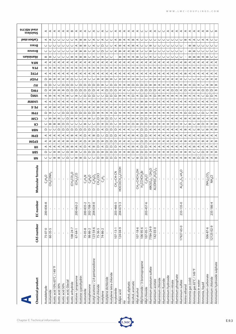
Chapter E: Technical information E.9.3
W W W . L M C - C O U P L I N G S . C O M
Ch
emic
al p
rod
uct
CA
S n
um
ber
EC n
um
ber
Mo
lecu
lar
form
ula
Ace
tald
ehyd
e75
-07-
020
0-83
6-8
C2H
4OC
DA
AA
DC
CD
AA
AD
DD
AA
AB
CC
AA
Ace
tam
ide
60-3
5-5
-C
H3C
ON
H2
CC
AA
AC
BB
BA
AB
AD
BA
AA
BC
CA
A
Ace
tic
acid
10%
65°
C /
149
°F-
--
BB
AA
AC
BB
CB
AA
BC
AA
AA
CC
CC
A
Ace
tic
acid
30%
--
-B
BA
AA
DB
BC
AA
AB
CA
AA
AC
CC
CA
Ace
tic
acid
50%
--
-C
CA
AA
DD
CD
AA
AB
DA
AA
AC
CC
CA
Ace
tic
acid
, Gla
cial
--
-D
DB
BA
DD
DD
AA
BD
DA
AA
AC
CC
CA
Ace
tic
anh
ydri
de
108-
24-7
-(C
H3C
O) 2
OC
BB
BB
DC
BD
AA
CD
DD
AA
AB
CC
CB
Ace
ton
e /
pro
pan
on
e67
-64-
120
0-66
2-2
(CH
3)2C
O
BB
AA
AD
CA
DA
AB
DC
CA
AA
AA
AA
A
Ace
ton
e cy
ano
hyd
rin
--
-B
CA
AA
DC
AD
AA
CD
DC
AA
AB
BB
BA
Ace
ton
itri
le75
-05-
820
0-83
5-2
C2H
3ND
DD
DD
DB
BD
BA
DD
DA
AA
AB
BB
BA
Ace
top
hen
on
e98
-86-
220
2-70
8-7
C8H
8OC
DA
AA
DC
BD
AA
DD
DC
AA
AC
CC
CC
Ace
tyl a
ceto
ne
/ 2,
4-p
enta
ned
ion
e12
3-54
-620
4-63
4-0
C5H
8O2
CD
BB
BD
CC
DA
AD
DD
CA
AA
AA
AA
A
Ace
tyl c
hlo
rid
e75
-36-
5 -
CH
3CO
Cl
DD
DD
DD
DD
BB
BC
AD
BA
AA
CC
CC
C
Ace
tyle
ne
74-8
6-2
-C
2H2
BB
AB
CA
AB
AA
AC
AB
AA
AA
AD
DA
A
Ace
tyle
ne
dic
hlo
rid
e-
--
DD
DD
DD
DD
AA
AD
DC
BA
AA
CC
CC
C
Ace
tyle
ne
tetr
a ch
lori
de
--
-D
DD
DD
DD
DA
AA
DD
DB
AA
AC
CC
CC
Acr
ylo
nit
rile
107-
13-1
203-
466-
5C
H2=
CH
-CN
DD
DD
DD
CC
DA
AD
DD
CA
AA
-A
AA
A
Ad
ipic
aci
d12
4-04
-920
4-67
3-3
HO
CO
(CH
2)4C
OO
HA
AA
AA
AA
AA
AA
BA
AA
AA
AB
BB
BA
Air
--
-A
AA
AA
AA
AA
AA
AA
AA
AA
AA
AA
AA
Alc
oh
ol,
alip
hat
ic-
--
AB
AA
AA
AA
AA
AA
CB
AA
AA
AA
AA
A
Alc
oh
ol,
aro
mat
ic-
--
CD
BC
BC
DB
AA
AD
BD
AA
AA
AB
BB
A
Ally
l alc
oh
ol
107-
18-6
-C
H2=
CH
CH
2OH
BB
AB
AA
BA
BA
AA
CD
BA
AA
BA
AA
A
Ally
l bro
mid
e /
3-b
rom
op
rop
ene
106-
95-6
-H
2CC
HC
H2B
rD
DD
DD
DD
DB
BB
DD
DC
AA
AC
CC
CC
Ally
l ch
lori
de
107-
05-1
203-
457-
6C
3H5C
lD
DD
DD
DD
DB
BB
DD
DC
AA
AC
CC
CC
Alu
min
ium
po
tasi
um
su
lfate
7784
-24-
9-
AlK
(SO
4)2
12H
2OA
AA
AA
AA
AA
AA
AD
BA
AA
AA
BB
CA
Alu
min
ium
ace
tate
142-
03-0
-A
L(O
H)(
C2H
3O2)
2A
AA
AA
AA
AA
AA
DD
BA
AA
AC
CC
CA
Alu
min
ium
ch
lori
de
--
-A
AA
AA
AA
AA
AA
BA
AA
AA
AC
CC
CC
Alu
min
ium
flu
ori
de
--
-A
AA
AA
AA
AA
AA
BA
AA
AA
AC
CC
CC
Alu
min
ium
hyd
roxi
de
--
-A
AA
AA
AA
AA
AA
AA
AA
AA
AC
CC
CA
Alu
min
ium
nit
rate
--
-A
AA
AA
AA
AA
AA
BD
AA
AA
AC
CC
CA
Alu
min
ium
ph
osp
hat
e-
--
AA
AA
AA
AA
AA
AA
DA
AA
AA
CC
CC
A
Alu
min
ium
su
lfate
1792
7-65
-023
3-13
5-0
Al 2
O12
S 3xH
2OA
AA
AA
AA
AA
AA
AA
AA
AA
AC
CC
CA
Am
ino
eth
ano
l-
--
BB
AB
AB
CB
DA
AB
DB
CB
BB
--
-B
A
Am
mo
nia
gas
(co
ld)
--
-A
AA
AA
AB
AD
AA
AA
AC
AA
AB
BB
AA
Am
mo
nia
gas
65°
C /
149
°F-
--
BC
BB
AC
CB
DB
AA
BD
CA
AA
BB
BA
A
Am
mo
nia
in w
ater
--
-D
CA
AA
BB
BC
AA
AB
AA
AA
AB
CC
CA
Am
mo
nia
, liq
uid
--
-D
DA
BB
CD
AD
AA
CD
CC
AA
AA
CC
AA
Am
mo
niu
m c
arb
on
ate
506-
87-6
-(N
H4)
2CO
3A
AA
AA
BA
AC
AA
DD
AA
AA
AB
CC
AB
Am
mo
niu
m c
hlo
rid
e12
125-
02-9
235-
186-
4N
H4C
lA
AA
AA
AA
AA
AA
DD
BA
AA
AC
CC
CC
Am
mo
niu
m h
ydro
xid
e su
lph
ate
--
-B
BA
BA
BB
BB
AA
AB
BA
AA
AC
CC
CB
NR
SBR
IIR
EPDM
EPM
NBR
CR
CSM
FPM
PE-X
UHMW
VMQ
FMQ
AU
PVDF
PTFE
PFA
MFA
Aluminium
Bronze
Brass
Carbon steel
Stainless steel AISI 316
A
e-technical information 9/19/07 4:21 PM Pagina 63

Chapter E: Technical informationE.9.4
W W W . L M C - C O U P L I N G S . C O M
Ch
emic
al p
rod
uct
CA
S n
um
ber
EC n
um
ber
Mo
lecu
lar
form
ula
Am
mo
niu
m m
etap
ho
shat
e-
--
AA
AA
AA
AA
AA
AA
DA
AA
AA
BC
CC
A
Am
mo
niu
m n
itra
te64
84-5
2-2
229-
347-
8N
H4N
O3
AA
AA
AA
AA
AA
AD
DA
AA
AA
-C
C-
-
Am
mo
niu
m p
ersu
lfate
7727
-54-
023
1-78
6-5
H8N
2O8S
2A
AA
AA
AA
AA
AA
DD
BC
AA
AC
CC
CA
Am
mo
niu
m p
ho
sph
ate
--
AA
AA
AA
AA
AA
AA
DB
AA
AA
BC
C-
-
Am
mo
niu
m s
ulfi
de
1213
5-76
-1-
(NH
4)2S
BA
AA
AB
AA
CA
AD
DB
BA
AA
CC
BC
B
Am
mo
niu
m s
ulfi
te10
196-
04-0
-H
8N2O
3SB
AA
AA
BA
AA
AA
DD
BB
AA
AC
CB
CB
Am
mo
niu
m t
hio
cyan
ate
1762
-95-
421
7-17
5-6
CH
4N2S
AA
AA
AB
AA
AA
AA
AA
AA
AA
BC
CC
A
Am
mo
niu
m t
hio
sulfa
te77
83-1
8-8
-(H
3N) 2
H2O
3S2
AA
AA
AA
AA
AA
AA
AA
AA
AA
CC
CC
B
Am
yl a
ceta
te-
-C
H3C
OO
C5H
11D
DA
BA
DC
CD
AA
DD
CC
AA
AA
BB
BA
Am
yl a
ceto
ne
--
-B
BA
AA
DC
AD
AA
BD
CC
AA
AA
AA
AA
Am
yl a
lco
ho
l-
-C
5H11
OH
BA
AA
AB
AA
BA
AD
AC
AA
AA
-A
AB
A
Am
yl b
ora
te-
--
DD
DD
DA
DA
DA
AD
DD
DA
AA
--
--
-
Am
yl c
hlo
rid
e-
--
DD
DD
DD
DD
AA
AD
BD
AA
AC
CC
CC
C
Am
yl c
hlo
ran
aph
thal
ene
--
-D
DD
DD
DD
DA
AA
AD
BD
BA
AA
CC
CC
Am
yl o
leat
e-
--
DD
BC
CB
DD
AA
AB
BD
AA
AA
AA
AA
A
Am
yl p
hen
ol
--
-D
DD
DC
CD
DA
AA
DA
DB
AA
AA
AA
AA
Am
yl p
hth
alat
e-
--
DD
AC
BD
DD
CA
AB
CD
BA
AA
-A
AA
A
Am
ylam
ine
--
-C
CA
BA
CC
CD
AA
BD
DA
AA
A-
CC
CA
An
ilin
e62
-53-
320
0-53
9-3
C6H
7ND
DA
AA
DD
BB
AA
DC
CB
AA
AC
CC
CA
An
ilin
e h
ydro
chlo
rid
e14
2-04
-1-
C6H
5NH
2 . H
Cl
BC
AA
AB
BB
AA
AD
BB
BA
AA
-C
CC
C
An
imal
fats
--
-D
DB
CB
AB
BA
AA
BA
AA
AA
AA
AA
AA
An
tim
on
y ch
lori
de
1002
5-91
-9-
SbC
l 3B
BA
BA
BB
BA
AA
AA
AB
AA
AC
CC
CC
An
tim
on
y p
enta
chlo
rid
e76
47-1
8-9
-Sb
Cl 5
DD
DD
DD
DD
DB
BA
AA
BA
AA
CC
CC
C
Aq
ua
reg
ia80
07-5
6-5
-H
Cl +
HN
O3
DD
DC
CD
DC
BD
DD
CD
BA
AA
CC
CC
C
Aro
mat
ic h
ydro
carb
on
s-
--
DD
DD
DB
CC
AA
AD
BC
AA
AA
AA
AA
A
Ars
enic
aci
d77
78-3
9-4
-H
3AsO
4B
BA
AA
BB
AA
AA
AA
DA
AA
AC
CC
CB
Ars
enic
tri
chlo
rid
e /
arse
nic
ch
lori
de
7784
-34-
1-
AsC
l 3D
DD
DC
BC
DD
DD
DD
DA
AA
AC
CC
CC
Asp
hal
tD
DD
DD
BD
DA
BB
DD
DA
AA
AC
AA
AA
Ast
m 1
oil
--
-D
DD
DD
AB
AA
AA
AA
AA
AA
AA
AA
AA
Ast
m 2
oil
--
-D
DD
DD
AC
BA
AA
CA
AA
AA
AA
AA
AA
Ast
m 3
oil
--
-D
DD
DD
BD
CA
BA
CA
BA
AA
AA
AA
AA
Avi
atio
n g
aso
line
--
-D
DD
DD
AC
CA
AA
DA
AA
AA
AA
AA
AA
NR
SBR
IIR
EPDM
EPM
NBR
CR
CSM
FPM
PE-X
UHMW
VMQ
FMQ
AU
PVDF
PTFE
PFA
MFA
Aluminium
Bronze
Brass
Carbon steel
Stainless steel AISI 316
A
e-technical information 9/19/07 4:21 PM Pagina 64

Chapter E: Technical information E.9.5
W W W . L M C - C O U P L I N G S . C O M
Ch
emic
al p
rod
uct
CA
S n
um
ber
EC n
um
ber
Mo
lecu
lar
form
ula
Bar
ium
car
bo
nat
e-
--
AA
AA
AA
AA
AA
AA
AA
AA
AA
-A
AB
A
Bar
ium
ch
lori
de
--
-A
AA
AA
AA
AA
AA
AA
BA
AA
AC
CC
CC
Bar
ium
hyd
roxi
de
1719
4-00
-205
6-00
2-00
-7B
a(O
H) 2
AA
AA
AA
AA
AA
AA
AC
AA
AA
-C
CC
A
Bar
ium
su
lfate
7727
-43-
7-
BaS
O4
AA
AA
AA
AA
AA
AA
AB
AA
AA
-B
BA
A
Bar
ium
su
lfid
e21
109-
95-5
-B
aSB
AA
AA
BA
AA
AA
AA
BA
AA
A-
CC
CA
Bee
r-
--
CC
AA
AA
AA
AA
AA
AD
AA
AA
AA
AC
A
Bee
t su
gar
liq
uar
s-
--
AA
AA
AA
AA
AA
AA
AA
AA
AA
A-
-B
A
Ben
zald
ehyd
e /
ben
zoic
ald
ehyd
e10
0-52
-7-
C6H
5CH
OD
DB
BB
DD
DD
AA
DD
DC
AA
A-
AA
BA
Ben
zen
e71
-43-
220
0-75
3-7
C6H
6D
DD
DD
DD
DA
AA
DA
DA
AA
AA
AA
AA
Ben
zen
esu
lfon
ic a
cid
98-1
1-3
-C
6H6S
O3
DD
DD
DD
DD
BB
BD
CD
CB
AA
-B
BC
B
Ben
zin
e so
lven
t /
ligro
ine
/ p
etro
leu
m e
ther
8032
-32-
423
2-45
3-7
-D
DD
DD
AC
DA
AA
DA
BA
AA
AA
AA
AA
Ben
zoic
aci
d65
-85-
020
0-61
8-2
C6H
5CO
OH
AA
AA
AB
BA
AB
AB
BD
AA
AA
-C
C-
A
Ben
zoic
ald
ehyd
e /
ben
zald
ehyd
e10
0-52
-7-
C6H
5CH
OD
DB
BB
DD
DD
AA
DD
DC
AA
A-
AA
BA
Ben
zyl a
ceta
te-
--
DD
AB
AD
BB
DA
AD
DD
CA
AA
--
--
-
Ben
zyl a
lco
ho
l10
0-51
-620
2-85
9-9
C7H
8OB
BB
BB
DC
CA
AA
DB
DA
AA
A-
AA
BA
Ble
ach
liq
uo
r-
DD
AA
AD
DC
AB
AB
AC
AA
AA
CC
CC
A
Bo
rax
/ b
ora
x d
ecah
ydra
te13
03-9
6-4
-B
4Na 2
O7
10H
2OA
AA
AA
AA
AA
AA
AA
AA
AA
AB
AA
AA
Bo
rdea
ux
mix
ture
--
-A
AA
AA
AA
AA
AA
AA
CA
AA
AC
CC
CA
Bo
ric
acid
1004
3-35
-323
3-13
9-2
H3B
O3
AA
AA
AA
AA
AB
AA
AD
AA
AA
BB
BB
A
Bra
nd
y-
--
AA
AA
AA
AA
AA
AA
AB
AA
AA
AA
AA
A
Bri
ne
65°C
/ 1
49 °F
--
-A
AA
AA
CA
AA
BA
DD
DA
AA
A-
AA
CA
Bro
min
e77
26-9
5-6
231-
778-
1B
r 2D
DD
DD
DD
DA
DD
DB
DA
AA
AC
CC
CC
Bro
min
e w
ater
--
Br 2
dis
solv
ed in
H2O
DD
CC
CD
DB
AB
AD
BD
AA
AA
CC
CC
C
Bro
mo
ch
loro
met
han
e-
--
DD
DD
DD
DD
AB
BD
BD
AA
AA
CC
CC
C
Bro
mo
ben
zen
e10
8-86
-1-
C6H
5Br
DD
DD
DD
DD
BC
CD
AD
AA
AA
CA
AA
A
Bu
tad
ien
eD
DD
DD
BD
BA
AA
DB
DA
AA
AA
AA
AA
Bu
tan
e10
6-97
-8C
4H10
DD
DD
DA
AA
AA
AD
AA
AA
AA
AA
AA
A
Bu
tan
ol /
1-b
uta
no
l / b
uty
l alc
oh
ol
71-3
6-3
200-
751-
6C
4H10
OA
AA
AA
AA
AA
AA
BA
CA
AA
A-
BB
-A
Bu
tter
CC
BB
BA
BA
AA
AB
AD
AA
AA
AA
AA
A
Bu
tyl a
ceta
te12
3-86
-4-
CH
3CO
OC
H2C
H2C
H2C
H3
DD
BB
BD
CC
DA
AD
DD
CA
AA
-B
BB
A
Bu
tyl a
cryl
ate
/ 2-
pro
pen
oic
aci
d b
uty
l est
er14
1-32
-2-
C7H
12O
2D
DD
DD
DD
DD
BB
DD
DA
AA
A-
--
--
Bu
tyl a
ldh
eyd
e /
bu
tyra
ldeh
yde
123-
72-8
204-
646-
6C
4H8O
DC
BC
BD
CC
DA
AD
DD
BA
AA
BC
CA
A
Bu
tyl b
enze
ne
104-
51-8
203-
209-
7C
10H
14D
DD
DD
DD
DA
AA
DA
DA
AA
AA
AA
AA
Bu
tyl b
enzy
l ph
thal
ate
--
-D
DA
BA
DD
DC
AA
DD
DB
AA
A-
AA
AA
Bu
tyl b
rom
ide
109-
65-9
--
DD
DD
DD
DD
BB
BD
BD
AA
AA
CB
BB
B
Bu
tyl b
uty
rate
109-
21-7
-C
8H16
O2
DD
BB
BC
DD
CB
BD
AD
AA
AA
BB
BB
A
Bu
tyl c
arb
ito
l11
2-34
-5-
-D
DA
AA
CC
BC
AA
DD
DB
AA
A-
AA
BA
NR
SBR
IIR
EPDM
EPM
NBR
CR
CSM
FPM
PE-X
UHMW
VMQ
FMQ
AU
PVDF
PTFE
PFA
MFA
Aluminium
Bronze
Brass
Carbon steel
Stainless steel AISI 316
B
e-technical information 9/19/07 4:21 PM Pagina 65

Chapter E: Technical informationE.9.6
W W W . L M C - C O U P L I N G S . C O M
Ch
emic
al p
rod
uct
CA
S n
um
ber
EC n
um
ber
Mo
lecu
lar
form
ula
Bu
tyl c
hlo
rid
e /
1-ch
loro
bu
tan
e10
9-69
-320
3-69
6-6
C4H
9Cl
DD
CC
CD
DC
AA
AD
BD
AA
AA
CC
CC
C
Bu
tyl e
ther
/ d
ibu
tyl e
ther
142-
96-1
-C
8H18
OD
DD
DD
BC
BC
AA
DC
DB
AA
AB
AA
BA
Bu
tyl e
thyl
ace
tald
ehyd
e-
--
DD
BB
AD
CC
DA
AD
DD
CA
AA
BC
CA
A
Bu
tyl e
thyl
eth
er62
8-81
-9-
C6H
14O
DD
DD
DB
CB
CA
AD
CD
AA
AA
BA
AB
A
Bu
tyl g
lyco
l-
--
AA
AA
AA
AA
AA
AA
AA
AA
AA
-A
AA
A
Bu
tyl o
leat
e14
2-77
-8
-C
22H
42O
2D
DB
BB
BC
BA
AA
DB
CA
AA
AA
AA
AA
Bu
tyl p
hth
alat
e-
--
DD
AA
AD
DC
CA
AD
DD
BA
AA
BA
AA
A
Bu
tyl s
tear
ate
123-
95-5
--
DD
CB
BB
DD
AA
AD
BC
AA
AA
AA
AA
A
Bu
tyla
min
e10
9-73
-920
3-99
-2C
4H11
NC
CA
BA
DD
CB
AA
CD
DB
AA
AC
CC
CA
Bu
tyra
ldeh
yde
123-
72-8
204-
646-
6C
4H8O
CC
AB
AD
CC
CA
AD
DD
CA
AA
BC
CA
A
Bu
tyri
c ac
id10
7-92
-6-
C4H
8O2
CC
BB
BB
BB
AA
AD
DA
AA
AA
BA
AC
A
Bu
tyri
c an
hyd
rid
e10
6-31
-0-
-C
DB
CB
DB
BC
AA
CD
DC
BA
AB
CC
CB
NR
SBR
IIR
EPDM
EPM
NBR
CR
CSM
FPM
PE-X
UHMW
VMQ
FMQ
AU
PVDF
PTFE
PFA
MFA
Aluminium
Bronze
Brass
Carbon steel
Stainless steel AISI 316
B
e-technical information 9/19/07 4:21 PM Pagina 66

Chapter E: Technical information E.9.7
W W W . L M C - C O U P L I N G S . C O M
Ch
emic
al p
rod
uct
CA
S n
um
ber
EC n
um
ber
Mo
lecu
lar
form
ula
Cadm
ium
ace
tate
/ ca
dmiu
m a
ceta
te d
ihyd
rate
5743
-04-
4-
(CH
3CO
O) 2
Cd
2H
2OA
AA
AA
BA
AB
AA
AA
AA
AA
AB
BB
BA
Cal
ciu
m a
ceta
te /
cal
ciu
m a
ceta
te h
ydra
te62
-54-
420
0-54
0-9
Ca
C4H
6O4
AA
AA
AB
AA
BA
AA
AA
BA
AA
BB
BB
A
Cal
ciu
m b
ich
rom
ate
dry
--
-B
AA
AA
BB
AB
AA
AA
BA
AA
AB
BB
BB
Cal
ciu
m b
isu
lfate
dry
--
-A
AA
AA
AA
AA
AA
AA
AA
AA
AB
BB
AA
Cal
ciu
m b
isu
lfite
dry
--
-B
AA
AA
BA
AA
AA
AA
AA
AA
AD
CC
CA
Cal
ciu
m c
arb
on
ate
dry
--
-A
AA
AA
AA
AA
AA
AA
AA
AA
AC
CC
BA
Cal
ciu
m c
hlo
rid
e d
ry-
--
AA
AA
AA
AA
AA
AA
AA
AA
AA
CB
BC
A
Cal
ciu
m h
ydro
xid
e13
05-6
2-0
215-
137-
3C
a(O
H) 2
AB
AB
AA
BA
AA
AA
AC
AA
AA
CC
CC
A
Cal
ciu
m h
ypo
chlo
rite
7778
-54-
3-
Ca
Cl 2O
2D
DA
AA
CD
AA
AA
DA
DA
AA
AC
CC
CA
Cal
ciu
m n
itra
te-
--
AA
AA
AA
AA
AA
AB
AD
AA
AA
CC
BB
A
Cal
ciu
m s
ulfa
te /
cal
ciu
m s
ulfa
te d
ihyd
rate
1010
1-41
-4-
CaS
O4
2H2O
AA
AA
AA
AA
AA
AA
AA
AA
AA
CA
AB
A
Cal
ciu
m s
ulfi
de
--
-B
BA
AA
BA
AA
AA
BA
BA
AA
AC
CB
CA
Cal
ciu
m s
ulfi
te-
--
BB
AA
AB
AA
AA
AA
AA
AA
AA
CC
BC
A
Can
e su
gar
liq
uo
rs-
--
AA
AA
AA
AA
AA
AA
AA
AA
AA
-A
AA
A
Cap
rylic
aci
d12
4-07
-2-
CH
3-[C
H2]
6-C
OO
(-)
DD
AC
BA
CB
BA
AB
BD
AA
AA
--
-B
A
Car
bit
ol
112-
34-5
--
DD
AB
AD
DB
AA
AB
BD
AA
AA
-B
BB
B
Car
bit
ol a
ceta
te11
2-15
-2-
-D
DB
BB
DD
DD
AA
DD
DC
AA
A-
BB
BA
Car
bo
lic a
cid
/ p
hen
ol
108-
95-2
203-
632-
7C
6H5O
HD
DB
BA
DD
CA
AA
DA
DA
AA
A-
AA
CA
Car
bo
n d
ioxi
de
/ d
ry ic
e12
4-38
-9-
CO
2A
AA
AA
AA
AA
AA
AA
AA
AA
AA
AA
AA
Car
bo
n d
isu
lfid
e75
-15-
020
0-84
3-6
CS 2
DD
DD
CC
DD
BA
AD
AD
BA
AA
-B
BA
A
Car
bo
n t
etra
chlo
rid
e56
-23-
520
0-26
2-8
CC
l 4D
DD
DD
DD
DA
BB
DA
BA
AA
AD
AA
AA
Car
bo
n t
etra
fluo
rid
e75
-73-
020
0-89
6-5
CF 4
DD
DD
DD
DD
DA
AD
DD
CA
AA
DA
AA
A
Cas
tor o
il /
rici
nu
s o
il80
01-7
9-4
--
CC
BB
BA
AA
AA
AA
AA
AA
AA
AA
AA
A
Cau
stic
po
tash
65°
C /
149
°F-
--
AB
AA
AB
AA
CB
AC
CD
AA
AA
CC
CB
A
Ch
lora
ceto
ne
--
-D
DB
BB
DC
CD
AA
DD
DC
AA
AC
CC
CC
Ch
lori
nat
ed h
ydro
carb
on
s-
--
DD
DD
DD
DD
DA
AD
DD
CA
AA
CC
CC
C
Ch
lori
ne
gas
dry
--
-D
DD
DC
DC
DA
AA
DA
DA
AA
AC
CC
CC
Ch
lori
ne
wat
er s
olu
tio
ns
--
-C
CC
CC
CB
CA
AA
CA
CA
AA
AD
CC
CC
Ch
loro
acet
ic a
cid
/ m
on
och
loro
acet
ic a
cid
79-1
1-8
-C
lCH
2CO
OH
DD
AB
AD
CB
BA
AD
DD
BA
AA
CC
CC
C
Ch
loro
ben
zen
e10
8-90
-720
3-62
8-5
C6H
5Cl
DD
DD
DD
DD
AB
AD
BD
BA
AA
CC
CC
C
Ch
loro
bu
tad
ien
e-
--
DD
DD
DD
DD
AA
AD
BD
AA
AA
CC
CC
C
Ch
loro
bu
tan
e-
--
DD
CC
BD
DD
AA
AD
BD
AA
AA
CC
CC
C
Ch
loro
form
67-6
6-3
200-
663-
8C
HC
l 3D
DD
DD
DD
DA
AA
DB
DB
AA
AC
CC
CC
Ch
loro
pen
tan
e-
--
DD
DD
DD
DD
AA
AD
BD
AA
AA
CC
CC
C
Ch
loro
ph
eno
l-
--
DD
DD
DD
DD
BA
AD
BD
BA
AA
CC
CC
C
Ch
loro
sulfo
nic
aci
d77
90-9
4-5
-H
ClS
O3
DD
DD
DD
DD
DD
CD
DD
CB
AA
CC
CC
C
Ch
loro
tolu
ene
--
-D
DB
CA
DD
DA
BD
BB
DC
BB
AC
CC
CC
NR
SBR
IIR
EPDM
EPM
NBR
CR
CSM
FPM
PE-X
UHMW
VMQ
FMQ
AU
PVDF
PTFE
PFA
MFA
Aluminium
Bronze
Brass
Carbon steel
Stainless steel AISI 316
C
e-technical information 9/19/07 4:21 PM Pagina 67

Chapter E: Technical informationE.9.8
W W W . L M C - C O U P L I N G S . C O M
Ch
emic
al p
rod
uct
CA
S n
um
ber
EC n
um
ber
Mo
lecu
lar
form
ula
Ch
rom
e p
lati
ng
so
luti
on
--
-D
DB
CA
DD
DA
BD
BB
DC
AA
AA
--
-C
Ch
rom
ic a
cid
40°
C /
104
°F-
--
DD
CC
BD
DC
BC
BC
CD
BA
AA
CC
CC
B
Cit
ric
acid
/ m
on
oh
ydra
te59
49-2
9-1
C6H
8O7
AA
AA
AA
AA
AA
AA
AA
AA
AA
CC
CC
C
Co
al t
ar-
--
DD
DD
AD
BA
DD
DD
AA
AA
AA
AA
AA
A
Co
al t
ar n
aph
ta-
--
DD
DD
AD
DA
AA
DD
DA
AA
AA
AA
AA
A
Co
bal
t ch
lori
de
--
-A
AA
AA
AA
AA
AA
AA
AA
AA
AC
CC
CC
Co
con
ut
oil
--
-D
DB
CB
AB
BA
AA
AA
AA
AA
AA
AA
AA
Co
d li
ver o
il-
--
DD
AB
BA
BA
AA
AB
AA
AA
AA
AA
AA
A
Co
ke o
ven
gas
--
-D
DB
BB
AB
AA
CA
BB
CA
AA
AB
BB
AA
Co
pp
er a
rsen
ate
--
-A
AA
AA
AA
AA
AA
AA
AA
AA
AC
CC
CC
Co
pp
er (I
) cya
nid
e54
4-92
-3-
Cu
CN
AA
AA
AA
AA
AA
AA
AA
AA
AC
CC
CA
Co
pp
er (I
I) n
itra
te32
51-2
3-8
-C
u N
O3
AA
AA
AA
AA
AA
AA
AA
AA
AA
CC
CC
A
Co
pp
er n
itri
te-
--
AA
AA
AA
AA
AA
AA
AA
AA
AA
CC
CC
A
Co
pp
er s
ulfi
de
--
-B
AA
AA
BA
AA
AA
AA
AA
AA
AC
AA
CA
Co
pp
er c
arb
on
ate
1184
-64-
1-
mix
ture
of C
uCO
3an
d C
u(O
H) 2
CC
AA
AB
CB
AA
AC
BB
AA
AA
--
--
A
Co
pp
er c
hlo
rid
e74
47-3
9-4
231-
210-
2C
uC
l 2A
AA
AA
AA
AA
AA
AA
AA
AA
AC
CC
-C
Co
pp
er s
ulfa
te-
--
AA
AA
AA
AA
AA
AA
AA
AA
AA
D-
--
B
Co
rn o
il-
--
DD
BB
AA
BB
AA
AA
AA
AA
AA
AB
BB
A
Co
tto
nse
ed o
il 80
01-2
9-4
--
DD
BC
BA
BA
AA
AA
AA
AA
AA
AB
BB
A
Cre
oso
te80
01-5
8-9
--
DD
DD
DA
DC
AA
AD
CD
AA
AA
AB
BA
A
Cre
sol
1319
-77-
3-
C7H
8OD
DD
DD
DD
BA
AA
DB
DA
AA
AA
--
-B
Cre
sylic
aci
d-
--
DD
DD
DD
DD
AA
AD
BD
AA
AA
-A
AB
A
Cro
ton
ald
ehyd
e41
70-3
0-3
-C
4H6O
DD
BB
AD
DC
CA
AD
DD
BA
AA
BC
CA
A
Cu
men
e /
iso
pro
pyl
ben
zen
e98
-82-
8-
C6H
5CH
(CH
3) 2D
DD
DD
DD
DA
AA
DB
DB
AA
A-
--
BB
Cyc
loh
exan
e11
0-82
-720
3-80
6-2
C6H
12D
DD
DD
AC
CA
AA
DA
BA
AA
AA
AA
AA
Cyc
loh
exan
ol
108-
93-0
203-
630-
6C
6H12
OD
DD
DD
AC
CA
AA
DA
BA
AA
AA
AA
AA
Cyc
loh
exan
on
e10
8-94
-1-
C6H
10O
CC
CC
CA
BB
AA
AD
AB
AA
AA
-A
AA
A
Cyc
lop
enta
ne
/ p
enta
met
hyl
ene
287-
92-3
-C
5H10
DD
DD
DA
CC
AA
AD
AB
AA
AA
-A
AA
A
Cyc
lop
enta
no
l96
-41-
3-
C5H
10O
CC
CC
CA
BB
AA
AA
AB
AA
AA
-A
AA
A
Cyc
lop
enta
no
ne
120-
92-3
-C
5H8O
DD
BB
BD
DD
DA
AD
DD
BA
AA
-B
BB
A
NR
SBR
IIR
EPDM
EPM
NBR
CR
CSM
FPM
PE-X
UHMW
VMQ
FMQ
AU
PVDF
PTFE
PFA
MFA
Aluminium
Bronze
Brass
Carbon steel
Stainless steel AISI 316
C
e-technical information 9/19/07 4:21 PM Pagina 68

Chapter E: Technical information E.9.9
W W W . L M C - C O U P L I N G S . C O M
Ch
emic
al p
rod
uct
CA
S n
um
ber
EC n
um
ber
Mo
lecu
lar
form
ula
DD
T in
Ker
ose
ne
--
-D
DD
DD
BD
CA
AA
DB
BA
AA
AC
AA
AA
Dec
alin
e-
--
DD
DD
DA
CC
AA
AD
AA
AA
AA
BB
BA
Dec
ane
124-
18-5
204-
686-
4C
10H
22D
DD
DD
AD
DA
AA
BA
AA
AA
AA
AA
AA
Dec
ano
l / d
ecyl
alc
oh
ol
112-
30-1
-C
10H
22O
AA
AA
AA
AA
AA
AA
AA
AA
AA
AA
AA
A
Det
erg
ent
solu
tio
n-
--
BB
AA
AA
BA
AA
AA
AA
AA
AA
-A
AA
A
Dia
ceto
ne
alco
ho
l12
3-42
-2-
-C
CA
AA
DD
AD
AA
DD
DC
AA
A-
AA
AA
Dia
myl
amin
e-
--
CD
AB
AD
CC
DA
AD
DD
CA
AA
DD
DD
B
Dib
rom
o b
enze
ne
--
-D
DD
DD
DD
DD
BC
CD
BD
AA
AA
AA
AA
Dib
uty
l seb
acat
e10
9-43
-3-
[(C
H2)
4CO
2(C
H2)
3CH
3]2
DD
C
CC
CD
CC
AA
BB
DB
AA
A-
AA
AA
Dib
uty
lam
ine
111-
92-2
--
DD
DD
DD
AD
AA
AC
DD
CA
AA
DC
CC
A
Dib
uty
leth
er14
2-96
-1-
C8H
18O
DD
DD
DC
DD
CA
AD
CD
BA
AA
CA
-B
A
Dib
uty
lph
thal
ate
84-7
4-2
-C
16H
22O
4D
DB
AA
DD
DC
AA
BC
DB
AA
A-
AA
AA
Dic
hlo
ro p
rop
ane
--
-D
DD
DD
DD
DA
AA
DB
DA
AA
AC
CC
CC
Dic
hlo
rora
ceti
c ac
id79
-43-
6-
C2H
2Cl 2
O2
DD
AB
AD
DC
DA
AA
BD
AA
AA
CC
CC
C
Dic
hlo
rob
uta
ne
--
-D
DD
DD
DD
DA
AA
DB
DA
AA
AC
CC
CC
Dic
hlo
roet
han
e-
--
DD
DD
DD
DD
AA
AD
BD
AA
AA
CC
CC
C
Dic
hlo
roet
hyl
eth
er-
--
DD
DD
DD
DD
BA
AD
BD
AA
AA
CC
CC
C
Dic
hlo
roh
eth
ylen
e-
--
DD
DD
DD
DD
AA
AD
BD
AA
AA
CC
CC
C
Dic
hlo
roh
exan
e-
--
DD
DD
DD
DD
AA
AD
BD
AA
AA
CC
CC
C
Dic
hlo
rois
op
rop
yl e
ther
--
-D
DD
DD
DD
DB
AA
DB
DA
AA
AC
CC
CC
Dic
hlo
rom
eth
ane
75-0
9-2
200-
838-
9C
H2C
l 2D
DD
DD
DD
DA
AA
DB
DA
AA
AC
CC
CC
Dic
hlo
rop
enta
ne
--
-D
DD
DD
DD
DA
AA
DB
DA
AA
AC
CC
CC
Dic
yclo
hex
ylam
ine
101-
83-7
-C
12H
23N
DD
DD
DD
AD
AB
BD
DD
CA
AA
DC
CC
A
Die
sel o
il +
65°C
/ 1
49°F
--
-D
DD
DD
AA
CA
BA
DA
AA
AA
AA
AA
AA
Die
than
ola
min
e11
1-42
-2-
(HO
CH
2CH
2)2N
HB
BA
BA
DC
CD
AA
BD
DC
AA
AD
CC
CA
Die
thyl
e b
enze
ne
--
-D
DD
DD
CD
DA
AA
DC
DA
AA
AA
AA
AA
Die
thyl
oxa
late
--
-B
BA
AA
DD
DC
AA
DD
DA
AA
AD
BB
BA
Die
thyl
ph
tala
te84
-66-
220
1-55
0-6
C6H
4-1,
2-(C
OO
C2H
5)2
CC
BA
AD
DD
CA
AB
CD
BA
AA
-A
AA
A
Die
thyl
seb
acat
e-
--
DD
AA
AC
DD
CA
AB
BD
BA
AA
-A
AA
A
Die
thyl
su
lfate
64-6
7-5
C4H
10O
4SD
DB
BB
CD
DA
AA
DD
DA
AA
AD
--
-A
Die
thyl
amin
e10
9-89
-720
3-71
6-3
C4H
11N
BB
BB
AD
AC
DA
AB
DD
CA
CA
-C
CC
A
Die
thyl
enet
riam
ine
--
-B
BA
BA
DA
CD
AA
BD
DC
AC
A-
CC
CA
Dih
ydro
xyet
hyl
am
ine
--
-B
BA
AA
DA
CD
AA
BD
DC
AC
A-
CC
CA
Dih
ydro
xyet
hyl
eth
er-
--
AA
AA
AD
DA
AA
AD
BD
AA
AA
-C
CC
A
Diis
ob
uty
l ket
on
e10
8-83
-8
-C
9H18
OD
DB
BA
DD
DD
AA
DD
DB
AA
AA
AA
AA
Diis
ob
uty
len
e-
--
DD
DD
DA
DD
AA
AD
CD
AA
AA
AA
AA
A
Diis
od
ecyl
ad
ipat
e27
178-
16-1
--
DD
BB
BD
DD
CA
AC
CD
BA
AA
-A
AA
A
NR
SBR
IIR
EPDM
EPM
NBR
CR
CSM
FPM
PE-X
UHMW
VMQ
FMQ
AU
PVDF
PTFE
PFA
MFA
Aluminium
Bronze
Brass
Carbon steel
Stainless steel AISI 316
D
e-technical information 9/19/07 4:21 PM Pagina 69

Chapter E: Technical informationE.9.10
W W W . L M C - C O U P L I N G S . C O M
Ch
emic
al p
rod
uct
CA
S n
um
ber
EC n
um
ber
Mo
lecu
lar
form
ula
Diis
od
ecyl
ph
thal
ate
2676
1-40
-0-
C28
H46
O4
DD
BB
BD
DD
BA
AD
BD
BA
AA
-A
AA
A
Diis
oo
ctyl
ad
ipat
e-
--
DD
BB
BD
DD
CA
AC
CD
BA
AA
-A
AA
A
Diis
oo
ctyl
ph
thal
ate
2755
4-26
-3-
C6H
4(C
OO
C8H
17) 2
DD
BB
BD
DD
CA
AC
BD
BA
AA
-A
AC
A
Diis
op
rop
ano
lam
ine
110-
97-4
-C
H3C
H(O
H)C
H2]
2NH
BB
AA
AD
AC
DA
AB
DD
CA
CA
BC
CC
A
Diis
op
rop
yl b
enze
ne
2532
1-09
-9-
-D
DD
DC
DD
AA
AD
BD
AA
AA
AA
AA
AA
Diis
op
rop
yl k
eto
ne
565-
80-0
--
DD
AA
AD
DD
DA
AD
DD
BA
AA
AA
AA
A
Dim
eth
yl a
ceta
mid
e-
--
BB
BA
AD
DD
DA
AD
DD
CA
AA
-C
CC
A
Dim
eth
yl b
enze
ne
--
-D
DD
DD
CD
DA
AA
DB
DA
AA
AA
AA
AA
Dim
eth
yl b
enzy
lam
ine
--
-D
DD
DD
DD
DD
AA
DD
DC
AC
A-
CC
CA
Dim
eth
yl p
hen
ol
--
-D
DD
DD
DD
DD
AA
DC
DC
AA
AA
AA
CA
Dim
eth
yl p
hth
alat
e13
1-11
-3-
C6H
4-1,
2-(C
OO
CH
3)2
DD
AA
AD
DD
BA
AD
BD
BA
AA
-A
AA
A
Dim
eth
yl s
ulfa
te77
-78-
1-
C2H
6SO
4D
DB
BB
DD
DA
AA
DD
DA
AA
AD
--
-A
Die
met
hyl
su
lfid
e75
-18-
3-
C2H
6SD
DC
BB
DD
DA
BB
DD
DA
AA
A-
--
-A
Dim
eth
ylam
ine
124-
40-3
-C
2H7N
BC
AC
CD
AC
AA
AB
DD
CA
CA
BC
CC
A
Dim
eth
ylan
ilin
e /
n,n
-dim
eth
ylan
ilin
e12
1-69
-7-
C8H
11N
DD
CB
BD
DD
DA
AD
DD
CA
CA
CC
CC
A
Dim
eth
ylfo
rmam
ide
68-1
2-2
-C
3H7N
O /
HC
ON
(CH
3)2
DD
CC
CC
DC
DA
AB
DD
BA
AA
AB
BB
A
Din
itro
ben
zen
e-
--
DD
CC
BD
DD
AA
AD
DD
BA
AA
-B
BA
A
Din
itro
tolu
ene
--
-D
DD
DD
DD
DC
AA
DD
DB
AA
A-
BB
AA
Dio
ctyl
ad
ipat
e10
3-23
-1-
-D
DB
BB
DD
DC
AA
CD
DA
AA
A-
AA
AA
Dio
ctyl
ph
thal
ate
117-
81-7
204-
211-
0C
24H
38O
4D
DB
BB
DD
DC
AA
CB
DB
AA
A-
AA
CA
Dio
ctyl
seb
acat
e12
2-62
-320
4-55
8-8
C26
H50
O4
DD
BB
BD
DD
BA
AC
CD
BA
AA
-A
AA
A
Dio
ctyl
amin
e /
2,2-
die
thyl
hex
ylam
ine
106-
20-7
-C
16H
35N
CC
BB
BC
DC
AA
AB
DD
CA
CA
BC
CC
A
Dio
xan
e /
1,4-
dio
xan
e12
3-91
-1-
C4H
8O2
DD
BB
BD
DD
DA
AD
DD
BA
AA
-A
AA
A
Dip
ente
ne
--
-D
DD
DD
DD
DA
AA
AD
DA
AA
A-
--
-A
Dip
hen
yl /
bip
hen
yl92
-52-
420
2-16
3-5
C6H
5-C
6H5
DD
DD
DD
DD
AA
AD
BD
AA
AA
-B
BA
A
Dip
hen
yl o
xid
e10
1-84
-8-
C12
H10
OD
DD
DD
DD
DA
AA
CB
DA
AA
A-
AA
-A
Dip
hen
yl p
hth
alat
e-
--
DD
BB
BD
DD
CA
AC
BD
BA
AA
-A
AC
A
Dip
rop
yl g
lico
l-
--
AA
AA
AA
AA
AA
AA
AA
AA
AA
CA
AA
A
Dip
rop
yl k
eto
ne
/ 4-
hep
tan
on
e12
3-19
-3-
C7H
14O
DD
AA
AD
DD
DA
AD
DD
CA
AA
AA
AA
A
Dip
rop
ylam
ine
--
-B
BA
AA
DD
CA
AA
BD
DC
AC
AB
CC
CA
Div
inyl
ben
zen
e-
--
DD
DD
DD
DD
AA
AD
DD
AA
AA
AA
AA
A
Do
dec
iylt
olu
ene
--
-D
DD
DD
BD
DA
AA
DB
BA
AA
AA
AA
AA
Do
dec
ylb
enze
ne
/ 1-
ph
enyl
do
dec
ane
123-
01-3
204-
591-
8C
18H
30D
DD
DD
BD
DA
AA
DA
BA
AA
AA
AA
AA
Do
w-p
er /
per
chlo
roet
hyl
ene
127-
18-4
C2C
l 4D
DD
DD
CD
DA
BB
DB
DA
AA
AC
BB
BA
NR
SBR
IIR
EPDM
EPM
NBR
CR
CSM
FPM
PE-X
UHMW
VMQ
FMQ
AU
PVDF
PTFE
PFA
MFA
Aluminium
Bronze
Brass
Carbon steel
Stainless steel AISI 316
D
e-technical information 9/19/07 4:21 PM Pagina 70

Chapter E: Technical information E.9.11
W W W . L M C - C O U P L I N G S . C O M
Ch
emic
al p
rod
uct
CA
S n
um
ber
EC n
um
ber
Mo
lecu
lar
form
ula
Epic
hlo
roh
ydri
n10
6-89
-820
3-43
9-8
ClC
H2C
2H3O
DD
BB
BD
DD
DB
BD
DD
CA
AA
CC
CC
B
Eth
ano
lam
ine
141-
43-5
-C
2H7N
OB
BA
AA
DB
CD
AA
BD
DC
AC
AB
CC
CC
Eth
ers
60-2
9-7
200-
467-
2C
4H10
OD
DC
DC
DC
CC
AA
DC
DB
AA
AB
AA
BA
Eth
yl a
ceta
te14
1-78
-620
5-50
0-4
CH
3CO
OC
2H5
DD
BB
AD
DD
DA
AB
DD
CA
AA
BA
AA
A
Eth
yl a
ceto
acet
ate
141-
97-9
205-
516-
1C
6H10
O3
DD
BB
AD
DD
DA
AB
DD
CA
AA
BA
AA
A
Eth
yl a
cryl
ate
140-
88-5
-C
5H8O
2D
DB
BA
DD
DD
AA
BD
DA
AA
AB
AA
AA
Eth
yl b
enze
ne
--
-D
DD
DD
DD
DA
AA
DA
DA
AA
AB
BB
A
Eth
yl b
enzo
ate
93-8
9-0
C6H
5CO
OC
2H5
DD
BB
AD
DC
AA
AD
AD
AA
AA
BA
AA
A
Eth
yl b
uty
l alc
oh
ol
--
-A
AA
AA
AA
AA
AA
AA
AA
AA
AA
AA
AA
Eth
yl b
uty
l am
ine
--
-B
BA
AA
DD
CA
AA
BD
DC
AC
AB
CC
CA
Eth
yl b
uty
l ket
on
e-
--
DD
AA
AD
DD
DA
AD
DD
CA
AA
AA
AA
A
Eth
yl c
hlo
rid
e-
--
DD
CC
BD
DB
AA
AD
AD
AA
AA
CC
CC
C
Eth
yl d
ich
lori
de
--
-D
DD
DC
DD
DB
AA
DB
DA
AA
AC
CC
CC
Eth
yl e
ther
60-2
9-7
200-
467-
2C
4H10
OD
DD
DC
DD
DD
AA
DC
DB
AA
AB
AA
BA
Eth
yl fo
rmat
e10
9-94
-4-
HC
OO
C2H
5D
DA
AA
DD
DD
AA
DA
DA
AA
AB
AA
AA
Eth
yl h
exan
ol
--
-D
DA
BA
AA
AA
AA
AA
AA
AA
AA
AA
AA
Eth
yl m
eth
yl K
eto
ne
78-9
3-3
-C
4H8O
CC
AA
AD
DD
DA
AD
DD
CA
AA
AA
AA
A
Eth
yl o
xala
te-
--
BB
AA
AD
DC
CA
AD
BD
AA
AA
DB
BB
A
Eth
yl p
hth
alat
e-
--
DD
AA
AD
DD
CA
AB
DD
BA
AA
-A
AC
A
Eth
yl p
rop
yl E
ther
--
-D
DD
DC
DD
DD
AA
DC
DB
AA
AB
AA
BA
Eth
yl p
rop
yl K
eto
ne
589-
38-8
-C
6H12
OD
DA
AA
DD
DD
AA
DD
DC
AA
AA
AA
AA
Eth
yl s
ilica
te78
-10-
4-
(C2H
5O) 4
SiB
BA
AA
AA
AA
AA
DA
AA
AA
A-
--
-A
Eth
yl s
ulfa
te64
-67-
5-
C4H
10O
4SD
DB
BB
DD
DA
AA
DD
DA
AA
AD
--
-A
Eth
ylen
e74
-85-
1-
C2H
4D
DD
DD
AC
CA
AA
DA
AA
AA
AA
AA
AA
Eth
ylen
e ch
lori
de
107-
06-2
203-
458-
1C
2H4C
l 2D
DD
DD
DD
DA
AA
DC
DA
AA
AC
CC
CC
Eth
ylen
e d
iam
ine
--
-C
CA
AA
BB
BB
AA
AD
BC
AC
AB
CC
CA
Eth
ylen
e d
ibro
mid
e-
--
DD
DD
DD
DD
BB
BD
CD
AA
AA
CB
BB
B
Eth
ylen
e g
lyco
l10
7-21
-120
3-47
3-3
C2H
6O2
AA
AA
AA
AA
AA
AA
AA
AA
AA
AA
AA
A
Eth
ylen
e G
gyc
ol 6
5°C
/ 1
49°F
--
-A
AA
AA
BA
AA
BA
AA
AA
AA
AA
AA
AA
Etyl
ene
bro
mid
e-
--
DD
DD
DD
DD
AA
AD
CD
AA
AA
CB
BB
B
NR
SBR
IIR
EPDM
EPM
NBR
CR
CSM
FPM
PE-X
UHMW
VMQ
FMQ
AU
PVDF
PTFE
PFA
MFA
Aluminium
Bronze
Brass
Carbon steel
Stainless steel AISI 316
E
e-technical information 9/19/07 4:21 PM Pagina 71

Chapter E: Technical informationE.9.12
W W W . L M C - C O U P L I N G S . C O M
Ch
emic
al p
rod
uct
CA
S n
um
ber
EC n
um
ber
Mo
lecu
lar
form
ula
Freo
n 1
14 /
1,2
-dic
hlo
rote
traf
luo
reth
ane
76-1
4-2
-C
2Cl 2
F4D
DD
DD
DD
DD
CD
DD
DB
AA
AD
AA
BA
Freo
n 1
15-
--
DD
DD
DD
DD
DD
CD
DD
BA
AA
DD
DD
A
Freo
n 1
2 /
dic
hlo
rod
iflu
oro
met
han
e75
-73-
020
0-89
6-5
CF 4
DD
DD
DD
DD
DD
CD
DD
BA
AA
DD
DD
A
Freo
n 1
3-
--
DD
DD
DD
DD
DD
CD
DD
BA
AA
DD
DD
A
Freo
n 1
4 /
carb
on
tet
raflu
ori
de
--
-A
AD
DD
DD
DD
DC
DD
DB
AA
AD
DD
DA
Freo
n 2
1-
--
DD
DD
DD
DD
DD
CD
DD
BA
AA
DD
DD
A
Freo
n 2
18-
--
AA
DD
DD
DD
DD
CD
DD
BA
AA
DD
DD
A
Freo
n 2
2 /
chlo
rod
iflu
oro
met
han
e75
-45-
6-
CH
ClF
2C
CD
DD
DD
DD
DC
DD
DB
AA
AC
AA
BA
Freo
n 3
1-
--
DD
DD
DD
DD
DD
CD
DD
BA
AA
DD
DD
A
Freo
n 3
2 /
difl
uo
rmet
han
e75
-10-
5-
CH
2F2
DD
DD
DD
DD
DD
CD
DD
BA
AA
DD
DD
A
Freo
n 5
02-
--
AA
DD
DD
DD
DD
CD
DD
BA
AA
DD
DD
A
Freo
n B
F-
--
DD
DD
DD
DD
DD
DC
DD
DB
AA
AD
DD
DA
Freo
n C
316
--
-A
AD
DD
DD
DD
DC
DD
DB
AA
AD
DD
DA
Freo
n C
318
--
-A
AD
DD
DD
DD
DC
DD
DB
AA
AD
DD
DA
Freo
n M
F75
-69-
4-
CFC
l 3D
DD
DD
DD
DD
DC
DD
DB
AA
AD
DD
DA
Fuel
Oil
--
-D
DD
DD
AD
DA
AA
DA
AA
AA
AA
AA
AA
Fum
aric
aci
d11
0-17
-820
3-74
3-0
C4H
4O4
AA
AA
AA
AA
AA
AB
AA
AA
AA
AC
CC
A
Fura
n11
0-00
-920
3-72
7-3
C4H
4OD
DD
DD
DD
DD
AA
DD
DA
AA
AB
AA
AA
Furf
ura
l98
-01-
1-
C5H
4O2
DD
BB
AD
CC
DA
AD
DD
AA
AA
BA
AA
A
Furf
ury
l alc
oh
ol
98-0
0-0
-C
5H6O
2D
DB
BA
DD
DD
AA
DD
DA
AA
AB
AA
AA
Gal
lic a
cid
149-
91-7
205-
749-
9C
7H6O
5B
BB
BA
BB
BA
AA
DA
BB
AA
AD
BB
CA
Gas
olin
e Le
ad F
ree
--
-D
DD
DD
AD
DA
AA
DA
AA
AA
AA
AA
AA
Gas
olin
e. H
i Tes
t-
--
DD
DD
DB
DD
AA
AD
AA
AA
AA
AA
AA
A
Gas
olin
e, R
eg-
--
DD
DD
DA
DD
AA
AD
AA
AA
AA
AA
AA
A
Gel
atin
--
-A
AA
AA
AA
AA
AA
AA
AA
AA
AA
AA
AA
Glu
con
ic a
cid
--
-B
BA
AA
CC
BA
AA
AA
AA
AA
AA
AA
AA
Glu
cose
50-9
9-7
200-
075-
1C
6H12
O6
AA
AA
AA
AA
AA
AA
AA
AA
AA
AA
AA
A
Glu
e-
--
AA
AA
AA
AA
AA
AA
AA
AA
AA
AA
AA
A
Gly
ceri
ne
56-8
1-5
200-
289-
5C
3H8O
3A
AA
AA
AA
AA
AA
AA
AA
AA
AA
AA
AA
Gly
cols
107-
21-1
203-
473-
3C
2H6O
2A
AA
AA
AA
AA
AA
AA
AA
AA
AA
AA
AA
Gre
ase
--
-D
DD
DD
AB
CA
AA
DA
AA
AA
A-
CC
AA
Gre
en S
ulfa
te L
iqu
ors
--
-A
AA
AA
AA
AA
AA
AB
AA
AA
A-
CC
AA
NR
SBR
IIR
EPDM
EPM
NBR
CR
CSM
FPM
PE-X
UHMW
VMQ
FMQ
AU
PVDF
PTFE
PFA
MFA
Aluminium
Bronze
Brass
Carbon steel
Stainless steel AISI 316
F G
e-technical information 9/19/07 4:21 PM Pagina 72

Chapter E: Technical information E.9.13
W W W . L M C - C O U P L I N G S . C O M
Ch
emic
al p
rod
uct
CA
S n
um
ber
EC n
um
ber
Mo
lecu
lar
form
ula
Hal
ow
ax O
il-
--
DD
DD
DD
DD
AA
AD
AD
AA
AA
--
--
-
Hep
tan
e /
n-H
epta
ne
142-
82-5
205-
563-
8 C
7H16
DD
DD
DA
BB
AA
AD
AA
AA
AA
AA
AA
A
Hep
tan
e C
arb
oxy
lic A
cid
--
-D
DC
CC
CC
BA
AA
DA
CA
AA
AA
CC
CA
Hep
tan
ol
--
-D
DC
DC
AC
AA
AA
AA
AA
AA
AA
AA
AA
Hex
ane
/ n
-Hex
ane
110-
54-3
203-
777-
6C
6H14
DD
DD
DA
BB
AA
AD
AA
AA
AA
AA
AA
A
Hex
ilen
e G
lico
l 65°
C /
149
°F-
--
CC
AB
AA
BA
AB
AA
AA
AA
AA
AA
AA
A
Hex
ylm
eth
ylke
ton
e /
2-o
ctan
on
e11
1-13
-7-
C8H
16O
DD
BB
BD
DD
DA
AD
DD
CA
AA
AA
AA
A
Hex
ylam
ine
111-
26-2
-
C6H
15N
D
DB
BB
CC
CA
AA
BD
DC
AC
AB
CC
CA
Hex
ylen
e10
7- 4
1-5
--
DD
DD
DA
BB
AA
AD
AA
AA
AA
AA
AA
A
Hyd
rau
lic fl
uid
(Pet
role
um
)-
--
DD
DD
DA
CB
AA
AD
AA
AA
AA
DA
AA
A
Hyd
rau
lic fl
uid
(Ph
osp
hat
e Es
ter B
ase)
--
-D
DA
AA
DD
DD
AA
DD
DA
AA
AA
AA
AA
Hyd
rau
lic fl
uid
(Po
ly A
lkyl
ene
Gly
col B
ase)
--
-B
BB
AA
AB
AA
AA
BA
AA
AA
AA
AA
AA
Hyd
rob
rom
ic a
cid
65°
C /
149
°F10
035-
10-6
233-
113-
0H
Br
DD
BB
AD
DC
AB
AD
BD
AA
AA
DC
CC
C
Hyd
roch
lori
c ac
id 3
7% 5
0°C
/ 1
22°F
--
-D
DB
BA
DD
CA
BA
DA
DA
AA
AD
DD
DC
Hyd
rocy
anic
aci
d74
-90-
820
0-82
1-6
HC
NA
AA
AA
AA
AA
AA
AA
AA
AA
AC
CC
CA
Hyd
roflu
ori
c ac
id 5
0°C
/ 1
22°F
7664
-39-
3-
HF
(aq
.)D
DD
DD
DD
DD
CC
DD
DB
AA
AC
CC
CC
Hyd
rog
en g
as-
--
AA
AA
AA
AA
AA
AA
AA
AA
AA
AA
AA
A
Hyd
rog
en p
ero
xid
e 10
%-
--
DD
BB
AD
CB
AA
AA
AD
AA
AA
CC
CB
A
Hyd
rog
en s
ulfi
de
7783
-06-
4 23
1-97
7-3
H2S
DD
CA
AD
DB
AA
AC
AD
AA
AA
BB
BB
A
Hyd
roq
uin
on
e12
3-31
-9-
C6H
6O2
CC
CB
AC
DB
CA
AD
BC
AA
AA
--
-A
A
Hyp
och
loro
us
acid
--
-D
DD
BA
DD
CA
AA
DA
DA
AA
AD
DD
DC
NR
SBR
IIR
EPDM
EPM
NBR
CR
CSM
FPM
PE-X
UHMW
VMQ
FMQ
AU
PVDF
PTFE
PFA
MFA
Aluminium
Bronze
Brass
Carbon steel
Stainless steel AISI 316
H
e-technical information 9/19/07 4:21 PM Pagina 73

Chapter E: Technical informationE.9.14
W W W . L M C - C O U P L I N G S . C O M
Ch
emic
al p
rod
uct
CA
S n
um
ber
EC n
um
ber
Mo
lecu
lar
form
ula
Ink
oil
(Lin
sed
Oil
Bas
e)-
--
DD
CC
CA
BB
AA
AD
AA
AA
AA
-A
-C
A
Insu
lati
ng
oil
--
-D
DD
DD
AC
CA
AA
DA
AA
AA
AD
AA
AA
Iod
ine
7553
-56-
223
1-44
2-4
I 2D
DD
DD
DD
DA
DD
DB
DA
AA
AC
CC
CC
Iro
n a
ceta
te-
--
DD
AA
AD
CC
CA
AD
DC
BA
AA
BA
AA
A
Iro
n s
alts
--
-A
AA
AA
AA
AA
AA
AA
AA
AA
AA
AA
AA
Iro
n s
ulfi
de
1317
-37-
9-
FeS
BB
AA
AB
AA
AA
AA
AA
AA
AA
AA
AA
A
Iso
amyl
ace
tate
123-
92-2
-C
H3C
OO
CH
2CH
2CH
(CH
3) 2D
DB
AA
DC
CD
AA
BD
DC
AA
AB
AA
AA
Iso
amyl
alc
oh
ol
123-
51-3
204-
633-
5(C
H3) 2C
HC
H2C
H2O
HC
CB
BB
AA
AA
AA
AA
AA
AA
AA
AA
AA
Iso
amyl
bro
mid
e-
--
DD
DD
DD
DD
BB
AD
CD
AA
AA
CB
BB
B
Iso
amyl
bu
tyra
te-
--
DD
BD
CB
CB
DB
AD
AB
AA
AA
AA
AA
A
Iso
amyl
ch
lori
de
--
-D
DD
DD
DD
DB
BA
DC
DA
AA
AC
CC
CC
Iso
amyl
eth
er-
--
DD
DD
DD
DD
DA
AD
CD
BA
AA
BA
AB
A
Iso
amyl
ph
thal
ate
--
-D
DA
AA
DD
DC
AA
BD
DB
AA
A-
AA
CA
lso
bu
tan
e75
-28-
5-
C4H
10D
DD
DD
AB
CB
AA
DA
AA
AA
AA
AA
AA
Iso
bu
tan
ol
78-8
3-1
-(C
H3) 2C
HC
H2O
HC
CA
BA
AA
BA
AA
AB
AA
AA
AA
AA
AA
Iso
bu
tyl a
ceta
te-
--
DD
AA
AD
CC
DA
AB
DD
CA
AA
BA
AA
A
Iso
bu
tyl a
ldeh
yde
--
-D
DA
BA
DC
CC
AA
DD
DA
AA
AB
CC
CA
Iso
bu
tyl a
min
e-
--
CC
AA
AD
DC
AA
AB
DD
CA
CA
BC
CC
A
Iso
bu
tyl b
rom
ide
--
-D
DD
DD
DD
DC
CA
DC
AA
AA
AC
BB
BB
Iso
bu
tyl c
hlo
rid
e-
--
DD
DD
DD
BD
BB
AD
CD
AA
AA
CC
CC
C
Iso
bu
tyl e
ther
--
-D
DD
DD
DD
DD
AA
DC
DB
AA
AB
AA
BC
Iso
bu
tyle
ne
--
-D
DD
DD
AB
BA
AA
DA
AA
AA
AA
AA
AA
Iso
ctan
e54
0-84
-120
8-75
9-1
(CH
3) 3CC
H2C
H(C
H3) 2
DD
DD
DA
CC
AA
AD
AA
AA
AA
AA
AA
A
Iso
cyan
ate
--
-D
DB
BB
DD
DD
CB
DD
DB
AA
A-
--
-A
Iso
pro
pyl
ace
tate
108-
21-4
-C
H3C
OO
CH
(CH
3) 2D
DA
AA
DC
CD
AA
BD
DC
AA
AB
AA
AA
Iso
pro
pyl
alc
oh
ol
67-6
3-0
200-
661-
7C
H3C
HO
HC
H3
AA
AA
AA
AA
AA
AA
AA
AA
AA
AA
AA
A
Iso
pro
pyl
am
ine
--
-C
CA
AA
DD
CA
AA
BD
DC
AC
AB
CC
CA
Iso
pro
pyl
ben
zen
e-
--
DD
DD
DC
DD
AA
AD
BC
AA
AA
AA
AA
A
Iso
pro
pyl
ch
lori
de
75-2
9-6
200-
858-
8C
3H7C
lD
DD
DD
DD
DB
BA
DC
DA
AA
AC
CC
CC
Iso
pro
pyl
eth
er10
8-20
-320
3-56
0-6
(CH
3) 2CH
OC
H(C
H3) 2
DD
DD
DD
DD
DA
AD
CD
BA
AA
BA
AA
A
Iso
pro
pyl
to
luen
e-
--
DD
DD
DD
DD
AA
AD
BD
AA
AA
AA
AA
A
NR
SBR
IIR
EPDM
EPM
NBR
CR
CSM
FPM
PE-X
UHMW
VMQ
FMQ
AU
PVDF
PTFE
PFA
MFA
Aluminium
Bronze
Brass
Carbon steel
Stainless steel AISI 316
I
e-technical information 9/19/07 4:21 PM Pagina 74

Chapter E: Technical information E.9.15
W W W . L M C - C O U P L I N G S . C O M
Ch
emic
al p
rod
uct
CA
S n
um
ber
EC n
um
ber
Mo
lecu
lar
form
ula
Jet
Fuel
s (J
P1 -
JP6)
--
-D
DD
DD
AD
CA
AA
DB
AA
AA
AA
AA
AA
Ker
ose
ne
8008
-20-
6-
-D
DD
DD
AD
DA
AA
DA
AA
AA
AB
AA
AA
Ket
on
es-
--
DD
AA
AD
DD
DA
AD
DD
CA
AA
AA
AA
A
Lacq
uer
s-
--
DD
DD
DC
DD
DB
BD
DC
BA
AA
AA
AA
A
Lacq
uer
s so
lven
ts-
--
DD
DD
DD
DD
DB
BD
DD
BA
AA
AA
AA
A
Lact
ic a
cid
50-2
1-5
200-
018-
0C
H3C
HO
HC
OO
HA
AA
AA
AA
AA
AA
AA
AA
AA
AC
CC
CC
Lard
--
-D
DB
DB
AD
DA
AA
BA
AA
AA
AA
CC
BA
Lau
ryl a
lco
ho
l-
--
BB
AB
AA
AA
AA
AB
AA
AA
AA
AA
AA
A
Lead
ace
tate
--
(CH
3CO
O) 2
xPb
DD
AA
AD
CC
CA
AD
DD
BA
AA
-C
CC
A
Lead
nit
rate
1009
9-74
-823
3-24
5-9
Pb(N
O3) 2
AA
AA
AA
AA
AA
AB
AA
AA
AA
AA
AA
A
Lead
su
lfate
65°
C /
149
°F74
46-1
4-2
-Pb
SO4
AA
AA
AA
AA
AB
AB
AA
AA
AA
AA
AA
A
Lig
roin
8032
-32-
423
2-45
3-7
-D
DD
DD
AD
DA
AA
DA
AA
AA
AA
AA
AA
Lim
e w
ater
--
-A
AA
AA
AA
AA
AA
BA
AA
AA
AA
AA
AA
Lin
seed
oil
8001
-26-
1-
-D
DC
CC
AC
CA
AA
AA
AA
AA
AA
AA
AA
Liq
uid
so
ap-
--
AA
AA
AA
AA
AA
AA
AA
AA
AA
AA
AA
A
Liq
uifi
ed p
etro
leu
m g
as-
--
DD
DD
DA
DD
AA
AC
CA
AA
AA
AA
AA
A
Lub
rific
atin
gs
oil
--
-D
DD
DD
AC
CA
AA
DB
AA
AA
AA
AA
AA
Lye
/ so
diu
m h
ydro
xid
e13
10-7
3-2
215-
185-
5N
aOH
BB
AA
AB
CA
DA
AB
BB
BA
AA
CA
AB
A
NR
SBR
IIR
EPDM
EPM
NBR
CR
CSM
FPM
PE-X
UHMW
VMQ
FMQ
AU
PVDF
PTFE
PFA
MFA
Aluminium
Bronze
Brass
Carbon steel
Stainless steel AISI 316
J K L
e-technical information 9/19/07 4:21 PM Pagina 75

Chapter E: Technical informationE.9.16
W W W . L M C - C O U P L I N G S . C O M
Ch
emic
al p
rod
uct
CA
S n
um
ber
EC n
um
ber
Mo
lecu
lar
form
ula
Mag
nes
iurn
ace
tate
142-
72-3
-(C
H3C
OO
) 2M
g 4
H2O
AA
AA
AA
AA
AA
AA
AA
AA
AA
AB
BB
A
Mag
nes
ium
car
bo
nat
e23
389-
33-5
-M
gC
O3
nH
2OA
AA
AA
AA
AA
AA
AA
AA
AA
AA
BB
BA
Mag
nes
ium
ch
lori
de
7786
-30-
323
2-09
4-6
Mg
Cl 2
AA
AA
AA
AA
AA
AA
AA
AA
AA
CC
CC
C
Mag
nes
ium
hyd
roxi
de
1309
-42-
8-
Mg
(OH
) 2A
BA
BA
AA
AA
AA
DD
AA
AA
AC
BB
BA
Mag
nes
ium
nit
rate
1344
6-18
-9-
Mg
(NO
3)2
6H2O
AA
AA
AA
AA
AA
AA
AA
AA
AA
BB
BB
A
Mag
nes
ium
su
lfate
7487
-88-
923
1-29
8-2
Mg
SO4
AA
AA
AA
AA
AA
AA
AA
AA
AA
BB
BB
A
Mal
eic
acid
110-
16-7
-H
OC
OC
H:C
HO
OH
AA
AA
AA
BA
AA
AD
DA
AA
AA
BC
CC
A
Mal
eic
anh
ydri
de
108-
31-6
-C
4H2O
3A
AA
AA
AC
AA
AA
DD
AA
AA
AB
CC
CA
Mal
ic a
cid
65°
C /
149
°F-
--
AB
DD
CA
DB
AB
AB
AA
AA
AA
BC
CC
A
Man
gan
ese
sulfa
te10
034-
96-5
-M
nSO
4A
AA
AA
AA
AA
AA
AA
AA
AA
A-
AA
BA
Man
gan
ese
sulfi
de
--
-B
AA
AA
BA
AA
AA
AA
AA
AA
A-
AA
BA
Man
gan
ese
sulfi
te-
--
AA
AA
AA
AA
AA
AA
AA
AA
AA
-A
AB
A
Mer
curi
c ch
lori
de
7487
-94-
7-
Hg
Cl 2
AA
AA
AA
AA
AA
AD
DA
AA
AA
CC
CC
C
Mer
cury
7439
-97-
6-
Hg
AA
AA
AA
AA
AA
AD
DA
AA
AA
CC
CA
A
Met
ano
l-
--
AA
AA
AA
AA
AA
AA
AA
AA
AA
AA
AA
A
Met
hac
rylic
aci
d79
-41-
420
1-20
4-4
C4H
6O2
DD
BB
AB
BB
BA
AD
DA
AA
AA
BC
CC
A
Met
han
e74
-82-
8-
CH
4D
DD
DD
AC
CA
AA
DB
AA
AA
AA
AA
AA
Met
hyl
ace
tate
79-2
0-9
-C
H3C
OO
CH
3D
DA
AA
DC
CD
AA
DD
AC
AA
AA
BB
B-
Met
hyl
acr
ylat
e96
-33-
320
2-50
0-6
C4H
6O2
DD
BB
AD
BD
DA
AD
DD
BA
AA
--
--
A
Met
hyl
bro
mid
e74
-83-
9-
CH
3Br
DD
DD
DD
DD
DA
AA
DA
DA
AA
CC
CB
B
Met
hyl
bu
tyl k
eto
ne
591-
78-6
-C
6H12
OD
DA
AA
DC
CD
AA
DD
DC
AA
AA
AA
AA
Met
hyl
ch
lori
de
74-8
7-3
200-
817-
4C
H3C
lD
DD
DD
DD
DB
BA
DB
DA
AA
AC
CC
CC
Met
hyl
cyc
loex
ane
--
-D
DD
DD
DD
DA
AA
DB
DA
AA
AA
AA
AA
Met
hyl
eth
yl k
eto
ne
(MEK
)78
-93-
3-
C4H
8OD
DA
AA
DC
CD
AA
DD
DC
AA
AA
AA
AA
Met
hyl
exy
l ket
on
e-
--
DD
AA
AD
CC
DA
AB
DD
CA
AA
AA
AA
A
Met
hyl
form
ate
107-
31-3
-H
CO
OC
H3
DD
AA
AD
DD
DA
AB
DD
CA
AA
AA
AA
A
Met
hyl
hex
ano
l-
--
DD
CC
CA
BA
AA
AA
AA
AA
AA
AA
AA
A
Met
hyl
iso
bu
tyl k
eto
ne
(MIB
K)
108-
10-1
-C
H3C
OC
H2C
H(C
H3)
2D
DA
AA
DC
CD
AA
DD
DC
AA
AA
AA
AA
Met
hyl
iso
pro
pyl
ket
on
e-
--
DD
AA
AD
CC
DA
AD
DD
CA
AA
AA
AA
A
Met
hyl
met
hac
ryla
te-
--
DD
BB
AD
CD
DA
AD
DD
BA
AA
--
--
-
Met
hyl
pro
pyl
eth
er-
--
DD
DD
CD
DD
DA
AD
CD
BA
AA
BA
AB
A
Met
hyl
pro
pyl
ket
on
e10
7-87
-9-
C5H
10O
DD
AA
AD
CC
DA
AD
DD
CA
AA
AA
AA
A
Met
hyl
saI
ycila
te11
9-36
-820
4-31
7-7
C8H
8O3
DD
BB
AD
DD
DA
AD
DD
AA
AA
B-
--
B
Met
hyl
ene
bro
mid
e74
-95-
3-
CH
2Br 2
DD
DD
DD
DD
AB
AD
BD
AA
AA
CC
CB
B
Met
hyl
ene
chlo
rid
e75
-09-
220
0-83
8-9
CH
2Cl 2
DD
DD
DD
DD
BB
AD
BD
AA
AA
CC
CC
C
Min
eral
oil
8020
-83-
5-
-D
DD
DD
AC
BA
AA
BA
AA
AA
AA
AA
AA
Mo
tor o
il-
--
DD
DD
DA
DD
AA
AD
AA
AA
AA
AA
AA
A
NR
SBR
IIR
EPDM
EPM
NBR
CR
CSM
FPM
PE-X
UHMW
VMQ
FMQ
AU
PVDF
PTFE
PFA
MFA
Aluminium
Bronze
Brass
Carbon steel
Stainless steel AISI 316
M
e-technical information 9/19/07 4:21 PM Pagina 76
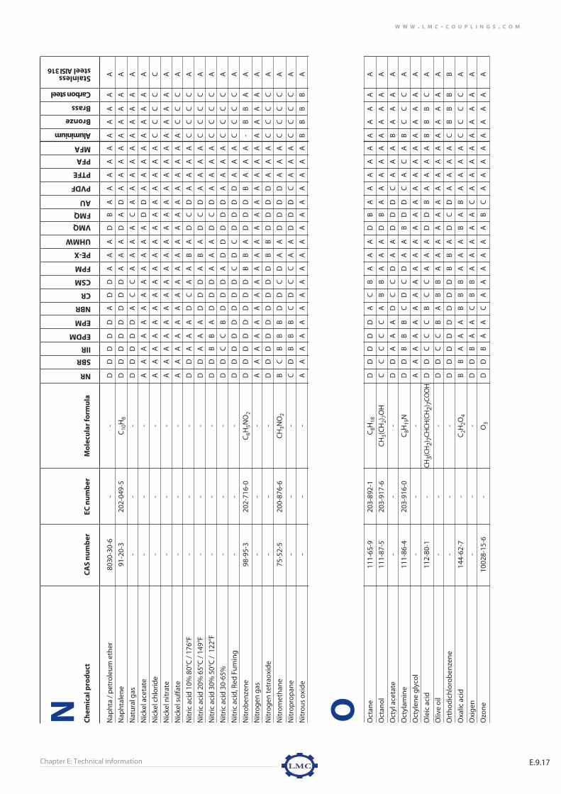
Chapter E: Technical information E.9.17
W W W . L M C - C O U P L I N G S . C O M
Ch
emic
al p
rod
uct
CA
S n
um
ber
EC n
um
ber
Mo
lecu
lar
form
ula
Nap
hta
/ p
etro
leu
m e
ther
8030
-30-
6-
-D
DD
DD
AD
DA
AA
DB
AA
AA
AA
AA
AA
Nap
hta
len
e91
-20-
320
2-04
9-5
C10
H8
DD
DD
DD
DD
AA
AD
AD
AA
AA
AA
AA
A
Nat
ura
l gas
--
-D
DD
DD
AC
CA
AA
AC
AA
AA
AA
AA
AA
Nic
kel a
ceta
te-
--
AA
AA
AA
AA
AA
AA
DD
AA
AA
AA
AA
A
Nic
kel c
hlo
rid
e-
--
AA
AA
AA
AA
AA
AA
AA
AA
AA
CC
CC
C
Nic
kel n
itra
te-
--
AA
AA
AA
AA
AA
AA
AA
AA
AA
AA
AA
A
Nic
kel s
ulfa
te-
--
AA
AA
AA
AA
AA
AA
AA
AA
AA
AC
CC
A
Nit
ric
acid
10%
80°
C /
176
°F-
--
DD
AA
AD
CA
AB
AD
CD
AA
AA
CC
CC
A
Nit
ric
acid
20%
65°
C /
149
°F-
--
DD
AA
AD
DD
AB
AD
CD
AA
AA
CC
CC
A
Nit
ric
acid
30%
50°
C /
122
°F-
--
DD
BB
AD
DD
AA
AD
CD
AA
AA
CC
CC
A
Nit
ric
acid
30-
65%
--
-D
DC
CB
DD
DA
DD
DD
DA
AA
AC
CC
CA
Nit
ric
acid
, Red
Fu
min
g-
--
DD
DD
DD
DD
CD
CD
DD
DA
AA
CC
CC
A
Nit
rob
enze
ne
98-9
5-3
202-
716-
0C
6H5N
O2
DD
DD
DD
DD
BB
AD
DD
BA
AA
-B
BA
A
Nit
rog
en g
as-
--
AA
AA
AA
AA
AA
AA
AA
AA
AA
AA
AA
A
Nit
rog
en t
etra
oxi
de
--
-D
DD
DD
DD
DD
BB
DD
DD
AA
AC
CC
CA
Nit
rom
eth
ane
75-5
2-5
200-
876-
6C
H3N
O2
BC
BB
BD
DC
DA
AD
DD
DA
AA
CC
CC
A
Nit
rop
rop
ane
--
-C
DB
BB
CD
CC
AA
DD
DC
AA
AC
CC
CA
Nit
rou
s o
xid
e-
--
AA
AA
AA
AA
AA
AA
AA
AA
AA
BB
BB
A
Oct
ane
111-
65-9
203-
892-
1C
8H18
DD
DD
DA
CB
AA
AD
BA
AA
AA
AA
AA
A
Oct
ano
l11
1-87
-520
3-91
7-6
CH
3(C
H2)
7OH
CC
CC
CA
BB
AA
AD
BA
AA
AA
AA
AA
A
Oct
yl a
ceta
te-
--
DD
AA
AD
CC
DA
AD
DD
CA
AA
BA
AA
A
Oct
ylam
ine
111-
86-4
203-
916-
0C
8H19
ND
DB
BB
CD
CD
AA
BD
DC
AC
AB
CC
CA
Oct
ylen
e g
lyco
l-
--
AA
AA
AA
AA
AA
AA
AA
AA
AA
AA
AA
A
Ole
ic a
cid
112-
80-1
-C
H3(C
H2) 7C
HC
H(C
H2) 7C
OO
HD
DC
CC
BC
CA
AA
DD
BA
AA
AB
BB
CA
Oliv
e o
il-
--
DD
CC
BA
BB
AA
AA
AA
AA
AA
AA
AA
A
Ort
ho
dic
hlo
rob
enze
ne
--
-D
DD
DD
DD
DB
BA
DC
DA
AA
AC
BB
BB
Oxa
lic a
cid
144-
62-7
-C
2H2O
4B
BA
AA
BB
BA
AA
BA
BA
AA
AC
CC
CA
Oxi
gen
--
-D
DB
AA
CB
BA
AA
AA
CA
AA
AA
AA
AA
Ozo
ne
1002
8-15
-6-
O3
DD
BA
AC
AA
AA
AA
BC
AA
AA
AA
AA
A
NR
SBR
IIR
EPDM
EPM
NBR
CR
CSM
FPM
PE-X
UHMW
VMQ
FMQ
AU
PVDF
PTFE
PFA
MFA
Aluminium
Bronze
Brass
Carbon steel
Stainless steel AISI 316
N O
e-technical information 9/19/07 4:21 PM Pagina 77

Chapter E: Technical informationE.9.18
W W W . L M C - C O U P L I N G S . C O M
Ch
emic
al p
rod
uct
CA
S n
um
ber
EC n
um
ber
Mo
lecu
lar
form
ula
P-D
ich
loro
ben
zen
e-
--
DD
DD
DD
DD
BB
AD
CD
AA
AA
CC
CC
C
Palm
oil
8002
-75-
323
2-31
6-1
-D
DB
BA
AD
AA
AA
DA
AA
AA
A-
CC
CA
Palm
itic
aci
d57
-10-
3-
C16
H32
O2
DD
CC
CA
CC
AA
AD
AA
AA
AA
BB
AB
A
Para
ffin
80°
C /
176
°F80
02-7
4-2
--
DD
CC
CA
AB
AB
AD
BA
AA
AA
AA
AA
A
Pen
aut
oil
--
-D
DB
BB
AB
BA
AA
AA
AA
AA
AA
AA
AA
Pen
tan
e10
9-66
-020
3-69
2-4
C5H
12D
DD
DD
AC
BA
AA
DB
AA
AA
AA
AA
AA
Pera
ceti
c ac
id 4
0%79
-21-
0-
C2H
4O3
DD
CC
BD
DD
DA
AD
DD
BA
AA
CC
CC
B
Perc
hllo
roet
hyl
ene
127-
18-4
-C
2Cl 4
DD
DD
DD
DD
AB
AD
CD
AA
AA
CC
CC
C
Petr
ole
um
--
-D
DD
DD
AC
BA
AA
DA
AA
AA
AA
AA
AA
Phen
ol 5
0°C
/ 1
22°F
108-
95-2
203-
632-
7C
6H5O
HD
DB
CB
DC
CA
AA
DB
DA
AA
A-
AA
CC
Phen
ols
ulfo
nic
aci
d98
-67-
9-
C6H
6O4S
DD
BC
BD
DD
AB
AD
DD
AA
AA
CC
CC
B
Phen
yl c
hlo
rid
e-
--
DD
DD
DD
DD
AA
AD
CD
AA
AA
CC
CC
C
Phen
ylh
ydra
zin
e10
0-63
-0-
C6H
5NH
NH
2C
CB
BA
DD
DA
AA
DD
DA
AA
AA
AA
AA
Pho
sph
ate
este
rs-
--
DD
AA
AD
CC
DA
AD
DD
CA
AA
-C
CC
A
Pho
sph
ori
c ac
id76
64-3
8-2
231-
633-
2H
3PO
4D
DA
AA
DD
CA
AA
DB
DA
AA
AC
CC
CA
Pick
ling
so
luti
on
--
-D
DB
BA
DD
CA
AA
DD
DA
AA
AC
CC
CA
Picr
ic a
cid
, mo
lten
--
-D
DB
BA
CB
BA
BA
DB
CA
AA
A-
BB
-A
Picr
ic a
cid
, wat
er s
olu
tio
n-
--
DD
BA
AC
BB
AA
AD
BC
AA
AA
-B
B-
A
Pin
e o
il-
--
DD
DD
DA
CC
AA
AD
AA
AA
AA
AC
CB
A
Pin
ene
--
-D
DD
DD
AC
CA
AA
DA
AA
AA
AA
AA
AA
Pip
erid
ine
110-
89-4
-C
5H11
ND
DB
BA
DD
DD
AA
BD
DC
AA
AB
CC
CA
Poly
eth
ylen
e g
lyco
l-
--
AA
AA
AA
AA
AA
AA
AA
AA
AA
AA
AA
A
Pota
ssiu
m a
ceta
te12
7-08
-220
4-82
2-2
CH
3CO
OK
AA
AA
AA
AA
AA
AA
AA
AA
AA
AA
AA
A
Pota
ssiu
m b
icar
bo
nat
e29
8-14
-6-
KH
CO
3A
AA
AA
AA
AA
AA
AA
AA
AA
AA
AA
AA
Pota
ssiu
m b
isu
lfate
7646
-93-
723
1-59
4-1
KH
SO4
AA
AA
AA
AA
AA
AA
AA
AA
AA
AA
AA
A
Pota
ssiu
m b
isu
lfite
--
-B
AA
AA
BA
AA
AA
AA
AA
AA
AA
AA
AA
Pota
ssiu
m c
arb
on
ate
--
-A
AA
AA
AA
AA
AA
AA
AA
AA
AA
AA
AA
Pota
ssiu
m c
hlo
rid
e74
47-4
0-7
231-
211-
8K
Cl
AA
AA
AA
AA
AA
AA
AA
AA
AA
DC
CC
C
Pota
ssiu
m c
hro
mat
e77
89-0
0-6
-K
2CrO
4A
AA
AA
AA
AA
AA
AA
AA
AA
AB
AA
BA
Pota
ssiu
m c
yan
ide
151-
50-8
205-
792-
3K
CN
AA
AA
AA
AA
AA
AA
AA
AA
AA
CC
CB
A
Pota
ssiu
m d
ich
rom
ate
7778
-50-
9-
K2C
r 2O
7A
AA
AA
AA
AA
AA
AA
AA
AA
AB
BB
CA
Pota
ssiu
m h
ydro
xid
e w
ater
so
luti
on
1310
-58-
321
5-18
1-3
KO
HB
CA
AA
CC
BC
AA
CC
CA
AA
AC
CC
BA
Pota
ssiu
m n
itra
te77
57-7
9-1
231-
818-
8K
NO
3A
AA
AA
AA
AA
AA
AA
AA
AA
AB
AB
BA
Pota
ssiu
m p
erm
ang
anat
e77
22-6
4-7
231-
760-
3K
Mn
O4
AA
AA
AA
AA
AA
AA
AA
AA
AA
BB
BA
A
Pota
ssiu
m s
ilica
te10
006-
28-7
-K
2SiO
3A
AA
AA
AA
AA
AA
AA
AA
AA
AA
AA
AA
Pota
ssiu
m s
ulfa
te77
78-8
0-5
231-
915-
5K
2SO
4A
AA
AA
AA
AA
AA
AA
AA
AA
AA
AB
AA
NR
SBR
IIR
EPDM
EPM
NBR
CR
CSM
FPM
PE-X
UHMW
VMQ
FMQ
AU
PVDF
PTFE
PFA
MFA
Aluminium
Bronze
Brass
Carbon steel
Stainless steel AISI 316
P
e-technical information 9/19/07 4:21 PM Pagina 78

Chapter E: Technical information E.9.19
W W W . L M C - C O U P L I N G S . C O M
Ch
emic
al p
rod
uct
CA
S n
um
ber
EC n
um
ber
Mo
lecu
lar
form
ula
Pota
ssiu
m s
ulfi
de
1312
-73-
821
5-19
7-0
K2S
BA
AA
AB
AA
AA
AA
AA
AA
AA
BC
CC
A
Pota
ssiu
m s
ulfi
te-
--
BA
AA
AB
AA
AA
AA
AA
AA
AA
BB
BC
A
Pro
pan
e g
as74
-98-
620
0-82
7-9
C3H
8D
DD
DD
AB
BA
AA
DB
AA
AA
AA
AA
AA
Pro
pan
edio
l-
--
AA
AA
AA
AA
AA
AA
AA
AA
AA
AA
AA
A
Pro
pan
ol
--
-A
AA
AA
AA
AA
AA
AA
AA
AA
AA
AA
AA
Pro
pyl
ace
tate
109-
60-4
-C
H3C
OO
CH
2CH
2CH
3D
DB
BB
DC
CD
AA
DD
DC
AA
AA
AA
AA
Pro
pyl
ald
ehyd
e-
--
DD
AA
AD
BB
DA
AD
DD
CA
AA
AA
AA
A
Pro
pyl
am
ine
--
-D
DB
BB
DD
CC
AA
DD
DC
AC
AB
CC
CA
Pro
pyl
ch
lori
de
540-
54-5
-C
3H7C
lD
DD
DD
DD
DB
BA
DB
DA
AA
AC
CC
CC
Pro
pyl
ene
dia
min
e-
--
DD
BB
BD
BB
DA
AD
DD
CA
CA
BC
CC
A
Pro
pyl
ene
gly
col
57-5
5-6
200-
338-
0C
3H8O
2A
AA
AA
AA
AA
AA
AA
AA
AA
AA
AA
AA
Pyra
no
l-
--
DD
DD
DA
CB
AA
AD
BA
AA
AA
AA
AA
A
Pyri
din
e11
0-86
-1-
C5H
5ND
DC
CB
DD
DD
AA
DD
DC
AA
AB
BB
BB
Rhu
m-
--
AA
AA
AA
AA
AA
AA
AA
AA
AA
AA
AA
A
NR
SBR
IIR
EPDM
EPM
NBR
CR
CSM
FPM
PE-X
UHMW
VMQ
FMQ
AU
PVDF
PTFE
PFA
MFA
Aluminium
Bronze
Brass
Carbon steel
Stainless steel AISI 316
P R
e-technical information 9/19/07 4:21 PM Pagina 79

Chapter E: Technical informationE.9.20
W W W . L M C - C O U P L I N G S . C O M
Ch
emic
al p
rod
uct
CA
S n
um
ber
EC n
um
ber
Mo
lecu
lar
form
ula
Salic
ylic
aci
d69
-72-
720
0-71
2-3
C7H
6O3
AA
AA
AA
AA
AA
AA
AA
AA
AA
-B
BC
A
Salt
wat
er /
sea
wat
er-
--
AA
AA
AB
AA
AA
AA
AA
AA
AA
AA
AA
A
Sew
age
--
-B
BA
AA
CB
AA
AA
DB
CA
AA
AB
CC
BA
Silic
on
e o
il63
148-
62-9
--
AA
AA
AA
AA
AA
AD
AA
AA
AA
AA
AA
A
Silic
on
s g
reas
es-
--
AA
AA
AA
AA
AA
AC
AA
AA
AA
AA
AA
A
SiIv
er n
itra
te77
61-8
8-8
231-
853-
9A
gN
O3
AA
AA
AC
AA
AA
AA
AA
AA
AA
CC
CC
A
Sod
a ca
ust
ic 6
5°C
/ 1
49°F
so
diu
m h
ydro
xid
e13
10-7
3-2
215-
185-
5N
aOH
CC
AA
AB
AA
AA
AB
BB
AA
AA
CC
CB
A
Sod
ium
ace
tate
127-
09-3
204-
823-
8C
H3C
OO
Na
AA
AA
AA
AA
AA
AA
AA
AA
AA
AA
AC
A
Sod
ium
alu
min
ate
--
-A
AA
AA
AA
AA
AA
AA
AA
AA
AB
CC
AA
Sod
ium
bic
arb
on
ate
144-
55-8
-N
aHC
O3
AA
AA
AA
AA
AA
AA
AA
AA
AA
AA
BC
A
Sod
ium
bic
hro
mat
e-
--
CC
AA
AA
BB
AA
AA
AA
AA
AA
BC
CC
A
Sod
ium
bis
ulfa
te-
--
AA
AA
AA
AA
AA
AA
AA
AA
AA
BC
CC
A
Sod
ium
bis
ulfi
te76
31-9
0-5
-N
aHSO
3B
AA
AA
BA
AA
AA
AA
AA
AA
AB
BB
CA
Sod
ium
bo
rate
--
-A
AA
AA
AA
AA
AA
AA
AA
AA
AA
AA
AA
Sod
ium
car
bo
nat
e-
--
AA
AA
AA
AA
AA
AA
AA
AA
AA
AA
AA
A
Sod
ium
ch
lori
de
7647
-14-
523
1-59
8-3
NaC
lA
AA
AA
AA
AA
AA
AA
AA
AA
AC
CC
CC
Sod
ium
ch
rom
ate
1003
4-82
-9-
Na 2
CrO
44H
2OC
CA
AA
BB
BA
AA
BA
BA
AA
AB
AB
BA
Sod
ium
cya
nid
e14
3-33
-9-
NaC
NA
AA
AA
AA
AA
AA
AA
AA
AA
A-
AC
AA
Sod
ium
flu
ori
de
7681
-49-
423
1-66
7-8
NaF
AA
AA
AA
AA
AA
AA
AA
AA
AA
-A
AC
A
Sod
ium
hyp
och
lori
te76
81-5
2-9
231-
668-
3C
lON
aD
DB
BB
DC
BA
AA
BB
BA
AA
AC
CC
CC
Sod
ium
met
aph
osp
hat
e-
--
AA
AA
AA
AA
AA
AD
AA
AA
AA
CC
CC
A
Sod
ium
nit
rate
7631
-99-
423
1-55
4-3
NaN
O3
AA
AA
AA
AA
AA
AD
CB
AA
AA
AA
AA
A
Sod
ium
nit
rite
7632
-00-
0-
NaN
O2
AA
AA
AA
AA
AA
AA
AB
AA
AA
AA
AA
A
Sod
ium
per
bo
rate
wat
er s
olu
tio
n10
486-
00-7
-N
aBO
34H
2OB
BA
AA
BB
BA
AA
BA
BA
AA
A-
CC
BA
Sod
ium
ph
osp
hat
e76
01-5
4-9
231-
509-
8N
a 3PO
4A
AA
AA
AA
AA
AA
DB
BA
AA
AB
BB
BA
Sod
ium
sili
cate
1344
-09-
823
9-98
1-7
Na 4
O4S
iA
AA
AA
AA
AA
AA
DD
AA
AA
A-
CC
AA
Sod
ium
su
lfate
7757
-82-
6-
Na 2
SO4
AA
AA
AA
AA
AA
AA
AA
AA
AA
AA
BA
A
Sod
ium
su
lfid
e13
13-8
4-4
-N
a2S
9H2O
BB
AA
AB
AA
AA
AA
AB
AA
AA
-C
CA
A
Sod
ium
su
lfite
7757
-83-
723
1-82
1-4
Na 2
SO3
BA
AA
AB
AA
AA
AA
AA
AA
AA
AA
AB
A
Sod
ium
th
iosu
lfate
7772
-98-
7-
Na 2
S 2O
3A
AA
AA
AA
AA
AA
AA
AA
AA
AA
BB
CA
Soyb
ean
oil
--
-D
DD
DD
AC
CA
AA
AA
AA
AA
AA
AA
AA
Stan
nic
ch
lori
de
--
-A
AA
AA
AA
AA
AA
BA
AA
AA
CC
CC
CC
Stan
nic
su
lfid
e-
--
BA
AA
AB
AA
AA
AA
AA
AA
AA
CC
CA
A
Stan
no
us
chlo
rid
e10
025-
69-1
-Sn
Cl 2
2H2O
AA
AA
AA
AA
AA
AB
BA
AA
AA
CC
CC
C
Stan
no
us
sulfi
de
--
-B
AA
AA
BA
AA
AA
AA
AA
AA
AC
CC
AA
NR
SBR
IIR
EPDM
EPM
NBR
CR
CSM
FPM
PE-X
UHMW
VMQ
FMQ
AU
PVDF
PTFE
PFA
MFA
Aluminium
Bronze
Brass
Carbon steel
Stainless steel AISI 316
S
e-technical information 9/19/07 4:21 PM Pagina 80

Chapter E: Technical information E.9.21
W W W . L M C - C O U P L I N G S . C O M
Ch
emic
al p
rod
uct
CA
S n
um
ber
EC n
um
ber
Mo
lecu
lar
form
ula
Stea
l ove
r 120
°C /
248
°F-
--
DD
AA
AB
DD
DD
DD
DD
AA
AA
CC
CA
A
Stea
l un
der
120
°C /
248
°F-
--
DD
AA
AA
DD
DD
DD
DD
AA
AA
AA
AA
A
Stea
ric
acid
--
-C
CB
BA
DB
BA
AA
BD
DA
AA
AB
BB
CA
Sto
dd
ard
s so
lven
t-
--
DD
DD
DA
CC
AA
AD
AA
AA
AA
AA
AA
A
Styr
ene
100-
42-5
20
2-85
1-5
C8H
8D
DD
DD
DD
DC
AA
DD
DA
AA
AB
BB
BA
Sulfo
nic
aci
d-
--
DD
CC
BD
DC
DA
AD
DD
AA
AA
CC
CC
A
Sulfu
r ch
lori
de
--
-D
DD
DC
DD
BA
AA
DD
DA
AA
AC
CC
CC
Sulfu
r dio
xid
e74
46-0
9-5
231-
195-
2SO
2D
DB
CB
DC
AA
AA
DD
DA
AA
AA
AA
AA
Sulfu
r tri
oxi
de
7446
-11-
9 23
1-19
7-3
SO3
DD
BC
BD
DD
AA
AD
DD
AA
AA
CC
CC
A
Sulfu
ric
acid
25%
--
-C
DA
AA
DB
AA
AA
DD
DA
AA
AC
CC
CA
Sulfu
ric
acid
25-
50%
--
-D
DB
BA
DD
AA
AA
DD
DA
AA
AC
CC
CA
Sulfu
ric
acid
50-
96%
--
-D
DD
DC
DD
CA
AA
DD
DA
AA
AC
CC
CC
Sulfu
ric
acid
, fu
min
g80
14-9
5-7
016-
019-
00-2
H
2SO
4co
nta
inin
g c
a. 2
0%SO
3D
DD
DD
DD
DA
DD
DD
DC
AA
AC
CC
CC
Sulfu
rou
s ac
id 1
0-75
%-
--
DD
AA
AD
DA
AA
AD
DD
AA
AA
BC
CC
A
NR
SBR
IIR
EPDM
EPM
NBR
CR
CSM
FPM
PE-X
UHMW
VMQ
FMQ
AU
PVDF
PTFE
PFA
MFA
Aluminium
Bronze
Brass
Carbon steel
Stainless steel AISI 316
S
e-technical information 9/19/07 4:21 PM Pagina 81

Chapter E: Technical informationE.9.22
W W W . L M C - C O U P L I N G S . C O M
Ch
emic
al p
rod
uct
CA
S n
um
ber
EC n
um
ber
Mo
lecu
lar
form
ula
Tan
nic
Aci
d14
01-5
5-4
215-
753-
2C
76H
52O
46B
BA
AA
BB
AA
AA
BD
BA
AA
AC
AA
CA
Tart
aric
Aci
d-
--
AA
AA
AA
AA
AA
AA
AA
AA
AA
BA
CC
A
Terp
ino
l80
00-4
1-7
-C
10H
18O
DD
CC
CA
BA
AA
AD
AA
AA
AA
AA
AA
A
Tert
iary
bu
tyl a
lco
ho
l-
--
CC
CC
BA
AA
AA
AB
BA
AA
AA
AA
AA
A
Tetr
ach
loro
ben
zen
e-
--
DD
DD
DD
DD
BB
AD
CD
AA
AA
CC
CC
C
Tetr
ach
loro
eth
ane
--
-D
DD
DD
DD
DB
BA
DC
DA
AA
AC
CC
CC
Tetr
ach
loro
eth
ylen
e12
7-18
-4-
C2C
l4D
DD
DD
DD
DB
BA
DC
DA
AA
AC
CC
CB
Tetr
ach
loro
met
ane
56-2
3-5
200-
262-
8C
Cl4
DD
DD
DD
DD
BB
AD
CD
AA
AA
CC
CC
B
Tetr
ach
loro
nap
hta
len
e-
--
DD
DD
DD
DD
BB
AD
DD
AA
AA
CC
CC
C
Tetr
aeth
ylen
e g
lyco
l11
2-60
-7-
C8H
18O
5A
AA
AA
AA
AA
AA
AA
AA
AA
AA
AA
AA
Tetr
ahyd
rofu
ran
109-
99-9
203-
726-
8C
4H8O
DD
DD
CD
DD
DA
AD
DD
BA
AA
BA
AB
A
Thio
nyl
ch
lori
de
7719
-09-
7 -
SOC
l2D
DD
DD
DD
DB
DD
DD
DA
AA
AC
CC
CC
Thio
ph
ene
110-
02-1
-C
4H4S
DD
DD
CD
DD
AA
AD
DD
BA
AA
BA
AB
C
Tolu
ene
108-
88-3
203-
625-
9C
7H8
DD
DD
DC
DD
AB
AD
DB
AA
AA
AA
AA
A
Tolu
ene
Diis
ocy
anat
e (T
DI)
--
-D
DD
DD
AC
BA
AA
DD
AA
AA
AA
AA
AA
Tria
ceti
n10
2-76
-120
3-05
1-9
C9H
14O
6C
CA
AA
DC
BD
AA
DD
DC
AA
AA
AA
AA
Trib
uty
Iam
ine
102-
82-9
-C
12H
27N
DD
AA
AD
DC
CA
AD
DD
CA
CA
BC
CC
A
Trib
uty
l ph
osp
hat
e12
6-73
-8-
(CH
3CH
2CH
2CH
2O)3
POD
DC
CB
BD
DD
AA
DD
DB
AA
A-
BB
AA
Tric
hlo
ro p
rop
ane
--
-D
DD
DD
DD
DB
BA
DD
DA
AA
AC
CC
CC
Tric
hlo
rob
enze
ne
--
-D
DD
DD
DD
DB
BA
DD
DA
AA
AC
CC
CC
Tric
hlo
roet
han
e-
--
DD
DD
DD
DD
BB
AD
DD
AA
AA
CC
CC
C
Tric
hlo
roet
hyl
ene
79-0
1-6
201-
167-
4C
2HC
l3D
DD
DD
DD
DB
BA
DD
DA
AA
AC
CC
CC
Tric
resy
l ph
osp
hat
e TC
P13
30-7
8-5
-(C
H3C
6H4O
)3PO
DD
BB
AD
DD
DA
AD
DD
BA
AA
-B
BA
A
Trie
than
ola
min
e (T
EA)
102-
71-6
203-
049-
8C
6H15
NO
3D
DA
AA
BD
CC
AA
DD
DC
AC
AB
CC
CA
Trie
thyl
amin
e12
1-44
-820
4-46
9-4
(C2H
5)3N
DD
AA
AD
DC
CA
AD
DD
CA
CA
BC
CC
A
Trie
thyl
ene
gly
col
112-
27-6
-H
O(C
H2C
H2O
)2C
H2C
H2O
HA
AA
AA
AA
AA
AA
AA
AA
AA
AA
AA
AA
Trin
itro
tolu
ene
(TN
T)-
--
DD
DD
DD
DB
AD
DD
DD
AA
AA
BB
BB
A
Trip
hen
yl p
ho
sph
ate
--
-D
DB
BB
DD
DD
AA
DD
DB
AA
A-
BB
AA
Turb
ine
oil
--
-D
DD
DD
AC
CA
AA
DD
AA
AA
AA
AA
AA
Un
dec
ano
l11
2-42
-520
3-97
0-5
C11
H24
OD
DC
DC
AA
AA
AA
AA
AA
AA
AA
AA
AA
Ure
a57
-13-
620
0-31
5-5
CH
4N2O
AA
AA
AA
AA
AA
AA
AA
AA
AA
BB
BC
A
NR
SBR
IIR
EPDM
EPM
NBR
CR
CSM
FPM
PE-X
UHMW
VMQ
FMQ
AU
PVDF
PTFE
PFA
MFA
Aluminium
Bronze
Brass
Carbon steel
Stainless steel AISI 316
T U
e-technical information 9/19/07 4:21 PM Pagina 82

Chapter E: Technical information E.9.23
W W W . L M C - C O U P L I N G S . C O M
Ch
emic
al p
rod
uct
CA
S n
um
ber
EC n
um
ber
Mo
lecu
lar
form
ula
Var
nis
h-
--
DD
DD
DA
CC
AA
AD
DA
AA
AA
AA
AC
A
Vas
elin
e-
--
DD
CC
CA
BB
AA
AD
DA
AA
AA
AA
AA
A
Veg
etab
le O
ils-
--
DD
BB
BA
BB
AA
AD
DA
AA
AA
AA
AA
A
Vin
egar
--
-B
CA
AA
CC
CD
AA
AD
CA
AA
AC
CC
CA
Vin
yl a
ceta
te10
8-05
-4-
C4H
6O2
DD
AA
AD
CC
DA
AD
DD
CA
AA
AA
AA
A
Vin
yl b
enze
ne
--
-D
DD
DD
DD
AA
AD
DD
AA
AA
AA
BB
AA
Vin
yl c
hlo
rid
e m
on
om
er75
-01-
4-
C2H
3Cl
DD
DD
DD
DD
AA
AD
DD
AA
AA
CC
CC
C
Vin
yl e
ther
--
-D
DD
DD
DD
DD
AA
DC
DB
AA
AA
BA
AA
Vin
yl t
olu
ene
2501
3-15
-4-
C9H
10D
DD
DD
DD
AA
AD
DD
AA
AA
AA
BB
AA
Vin
yl t
rich
lori
de
79-0
0-5
201-
166-
9C
2H3C
l 3D
DD
DD
DD
DA
AA
DD
DA
AA
AC
CC
CC
Wat
er, f
resh
82°
C /
180
°F-
--
AA
AA
AA
AA
AA
BA
AA
AA
AA
AA
AA
A
Wat
er, s
alt
82°C
/ 1
80°F
--
-B
AA
AA
CA
AA
BA
AA
AA
AA
AC
BC
CA
Wh
iske
y, w
ines
--
-A
AA
AA
AA
AA
AA
AA
AA
AA
AA
CC
CA
Xyl
ene
--
-D
DD
DD
DD
DA
AA
DD
DA
AA
AA
AA
AA
Zeo
lites
--
-A
AA
AA
AA
AA
AA
AA
AA
AA
AA
AA
AA
Zin
c ac
etat
e59
70-4
5-6
-(C
H3C
OO
) 2Z
n 2
H2O
AA
AA
AA
AA
AA
AA
AA
AA
AA
AC
CC
A
Zin
c ca
rbo
nat
e34
86-3
5-9
-Z
nC
O3
AA
AA
AA
AA
AA
AA
AA
AA
AA
AA
AA
A
Zin
c ch
lori
de
7646
-85-
723
1-59
2-0
Zn
Cl 2
AA
AA
AA
AA
AA
AA
AA
AA
AA
CC
CC
C
Zin
c ch
rom
ate
--
-B
BA
AA
BB
BA
AA
BA
BA
AA
AB
AA
BA
Zin
c su
lfate
--
-A
AA
AA
AA
AA
AA
AA
AA
AA
AA
CC
CA
NR
SBR
IIR
EPDM
EPM
NBR
CR
CSM
FPM
PE-X
UHMW
VMQ
FMQ
AU
PVDF
PTFE
PFA
MFA
Aluminium
Bronze
Brass
Carbon steel
Stainless steel AISI 316
V W X Z
e-technical information 9/19/07 4:21 PM Pagina 83
Related Documents