1 HEAT TREATMENT OF PRESSURE VESSELS

Welcome message from author
This document is posted to help you gain knowledge. Please leave a comment to let me know what you think about it! Share it to your friends and learn new things together.
Transcript
1
HEAT TREATMENT OF PRESSURE VESSELS
2
WHAT IS HEAT TREATMENT?
• MATERIALS TREATED BY APPLICATION OF HEAT - NORMALLY DONE IN SOLID STATE
• HEATING BY VARIOUS SOURCES
• PARAMETERS – RATE OF HEATING
– SOAKING TEMP.
– SOAKING TIME
– COOLING RATE
– COOLING MEDIA

3
WHY HT REQUIRED ?
• TO ENHANCE PROPERTIES–Strength–Toughness–Hardness TO BRING THE PROPERIES SUITABLE FOR FABRICATION
• CARRIED OUT IN –FABRICATION INDUSTRIES–STEEL PLANTS– FOUNDRY– FORGING SHOPS
4
MATERIALS HEAT TREATED
• METALS & ALLOYS – SINGLE PHASE – MULTIPHASE
• ALLOYS– Single Phase : Copper Nickel – Multiphase : Steels
• METALS (Single phase ) – Titanium
5
HEAT TREATEMENT
CRITERIA
• COLD WORKED to NORMAL– All materials
• UNEQUILIBRIUM PHASES to EQUILIBRIUM– Stainless Steels ,Maraging Steels
• STRESSED to UNSTRESED– All Materials
6
MATERIALS HEAT TREATED
• CS
• C-Mn , C-Mo , Cr-Mo , Cr-Mo-V, Ni -Steels
• Stainless Steels
• Non Ferrous Materials
7
TYPES OF HEAT TREATMENT
• NORMALIZING
• ANNEALING
• STRESS RELIEVING
• SOLUTION ANNEALING
• HARDENING
• TEMPERING
• AGEING
8
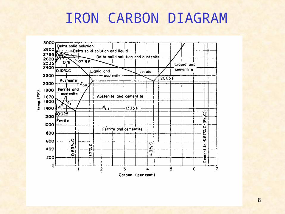
IRON CARBON DIAGRAM
9
NORMALIZING • The steel is heated to 40° C above the upper
critical temperature followed by cooling in the still air.
To achieve
• Uniform structure
• Change in Mechanical properties,– UTS & YS– Hardness – Impact properties
• To refine the grains
10
ANNEALING
• Steel is heated 10 to 50°C above the upper critical temperature and held for the desired length of time followed by very slow cooling within the furnace
To achieve:
• Softness & better ductility• Stresses free material – Stress generated due
to mechanical working / previous HT• Uniform property through out the material
11
SOLUTION ANNEALING
• Austenitic Stainless steels is heated to above 1050°C and held for the desired time followed by cooling to room temperature within few minutes by quenching / blowing the air.
Solution annealing is done on stainless steel and non ferrous alloys to achieve following:
• To soften the material
• To remove carbide precipitation formed at grain boundaries during manufacturing process
• To improve Corrosion Resistance
12
AGEING
The Material is heated to a certain temperature, and held for the desired time; followed by quenching or cooling in air
Ageing is done on materials susceptible for ageing characteristics : Maraging Steels
• Normally increases strength
• Improve Toughness
13
AGEING
Maraging Steels
M250
• Temperature : 485° C • Normally 3 Hrs 15 mts
• Heating Rate : 200 C per hr per inch thick
• Cooling Rate : Cool in Air / Quench in water
14
STRESS RELIEVING
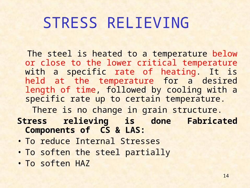
The steel is heated to a temperature below or close to the lower critical temperature with a specific rate of heating. It is held at the temperature for a desired length of time, followed by cooling with a specific rate up to certain temperature.
There is no change in grain structure.Stress relieving is done Fabricated Components of CS
& LAS: • To reduce Internal Stresses• To soften the steel partially • To soften HAZ
15
STRESS RELIEVING
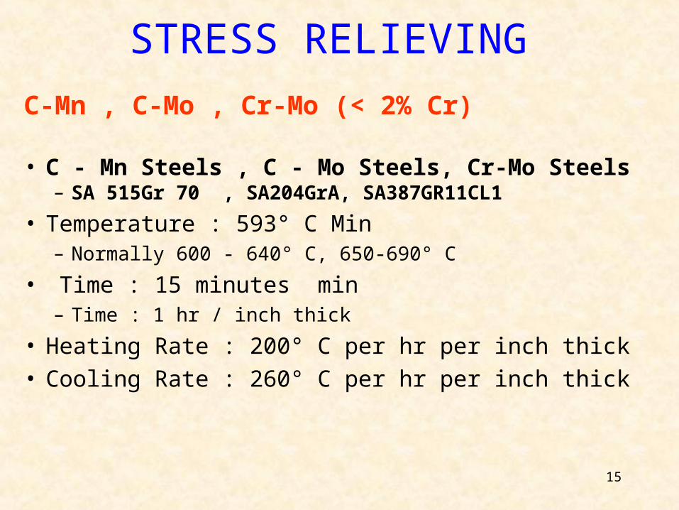
C-Mn , C-Mo , Cr-Mo (< 2% Cr)
• C - Mn Steels , C - Mo Steels, Cr-Mo Steels – SA 515Gr 70 , SA204GrA, SA387GR11CL1
• Temperature : 593° C Min– Normally 600 - 640° C, 650-690° C
• Time : 15 minutes min– Time : 1 hr / inch thick
• Heating Rate : 200° C per hr per inch thick• Cooling Rate : 260° C per hr per inch thick
16
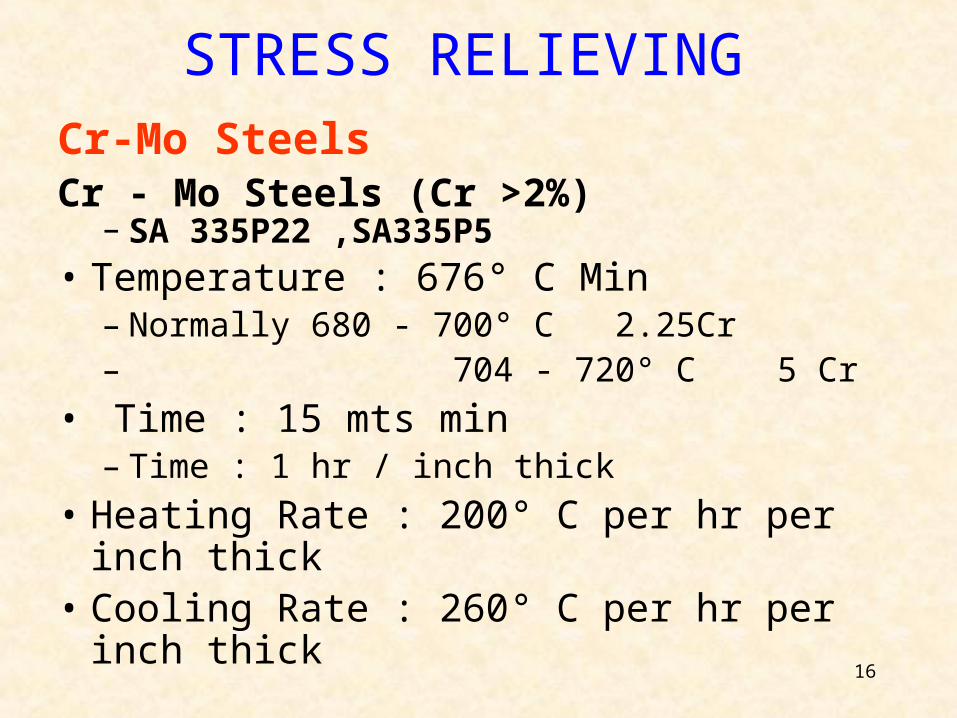
Cr-Mo SteelsCr - Mo Steels (Cr >2%)
– SA 335P22 ,SA335P5• Temperature : 676° C Min
– Normally 680 - 700° C 2.25Cr– 704 - 720° C 5 Cr
• Time : 15 mts min– Time : 1 hr / inch thick
• Heating Rate : 200° C per hr per inch thick• Cooling Rate : 260° C per hr per inch thick
STRESS RELIEVING
17
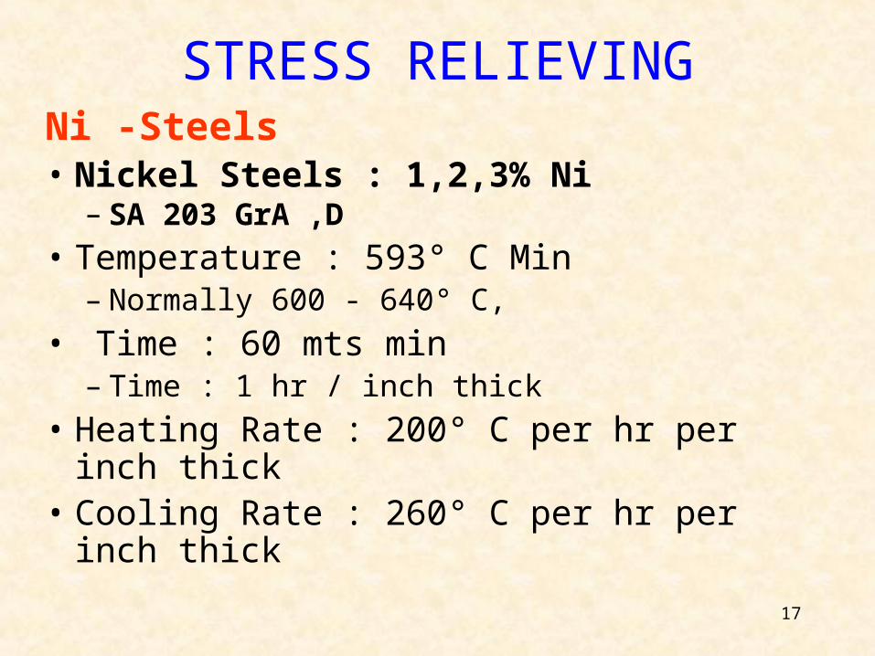
Ni -Steels• Nickel Steels : 1,2,3% Ni
– SA 203 GrA ,D
• Temperature : 593° C Min– Normally 600 - 640° C,
• Time : 60 mts min– Time : 1 hr / inch thick
• Heating Rate : 200° C per hr per inch thick• Cooling Rate : 260° C per hr per inch thick
STRESS RELIEVING
18
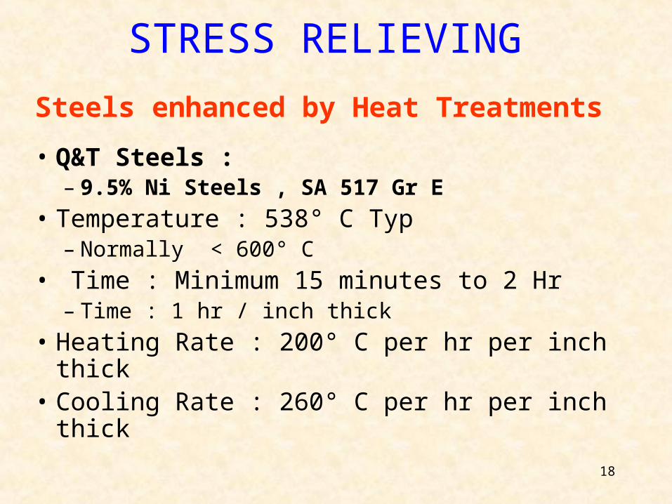
Steels enhanced by Heat Treatments
• Q&T Steels :– 9.5% Ni Steels , SA 517 Gr E
• Temperature : 538° C Typ– Normally < 600° C
• Time : Minimum 15 minutes to 2 Hr– Time : 1 hr / inch thick
• Heating Rate : 200° C per hr per inch thick• Cooling Rate : 260° C per hr per inch thick
STRESS RELIEVING
19
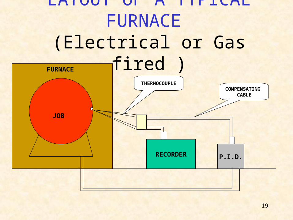
LAYOUT OF A TYPICAL FURNACE
(Electrical or Gas fired )
RECORDER P.I.D.
FURNACE
JOB
COMPENSATING CABLE
THERMOCOUPLE
20
THERMOCOUPLES
• PRINCIPLE OF A THERMOCOUPLE
• THERMOCOUPLE MATERIAL
• TYPES OF THERMOCOUPLE BEING USED IN HZW
21
PRINCIPLE OF THERMOCOUPLE
The basic principle of thermoelectric thermometry is that a thermocouple develops an emf which is a function of the difference in temperature of its measuring junction & reference junction. If the temperature of reference junction is known, the temperature of the measuring junction can be determined by measuring the emf generated in the circuit.
22
THERMOCOUPLE MATERIAL REQUIREMENT
1. High coefficient of thermal emf.
2. Continuously increasing relation of emf to temperature over a long range.
3. Freedom from phase changes or other phenomenon giving rise to discontinuity in temperature emf relationships.
4. Resistance to oxidation, corrosion and contamination.
5. Homogeneity and reproducibility to fit an establish temperature & emf relationship.
SPEED OF RESPONSE MAY BE IMPROVED AND RADIATION & CONDUCTION ERRORS MAY BE REDUCED BY THE USE OF SMALL DIAMETER THERMOCOUPLES.
23
TYPES OF THERMOCOUPLE BEING USED IN HZW
K type :
Material : Chromel + Alumel
Nickel based ( 10 %Cr ) + ( 2 % Al )
Properties : Non-Magnetic + Magnetic
In this type of thermocouple, the wires are joined at one end only to form a point-type temperature sensor. Instrumentation converts the millivolt signal to related temperature.
24
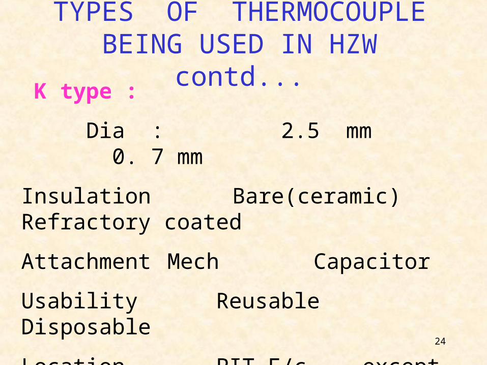
TYPES OF THERMOCOUPLE BEING USED IN HZW contd...
K type :
Dia : 2.5 mm 0. 7 mm
Insulation Bare(ceramic) Refractory coated
Attachment Mech Capacitor
Usability Reusable Disposable
Location PIT F/c except PIT F/c
Color - Red & Yellow
25
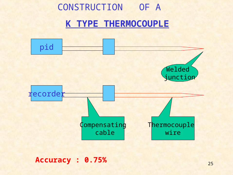
recorder
pid
Compensating cable
Thermocouple wire
Welded junction
CONSTRUCTION OF A
K TYPE THERMOCOUPLE
Accuracy : 0.75%
26
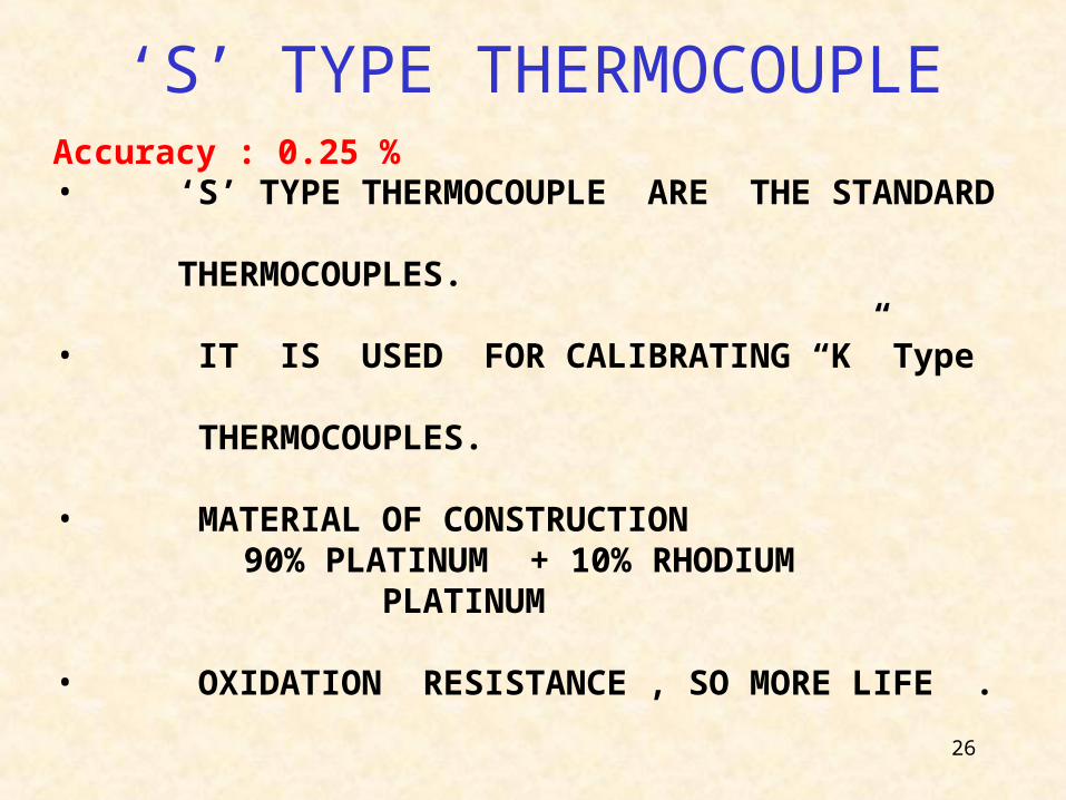
‘S’ TYPE THERMOCOUPLE
• ‘S’ TYPE THERMOCOUPLE ARE THE STANDARD THERMOCOUPLES.
• IT IS USED FOR CALIBRATING “K” Type THERMOCOUPLES.
• MATERIAL OF CONSTRUCTION 90% PLATINUM + 10% RHODIUM
PLATINUM
• OXIDATION RESISTANCE , SO MORE LIFE .
Accuracy : 0.25 %
27
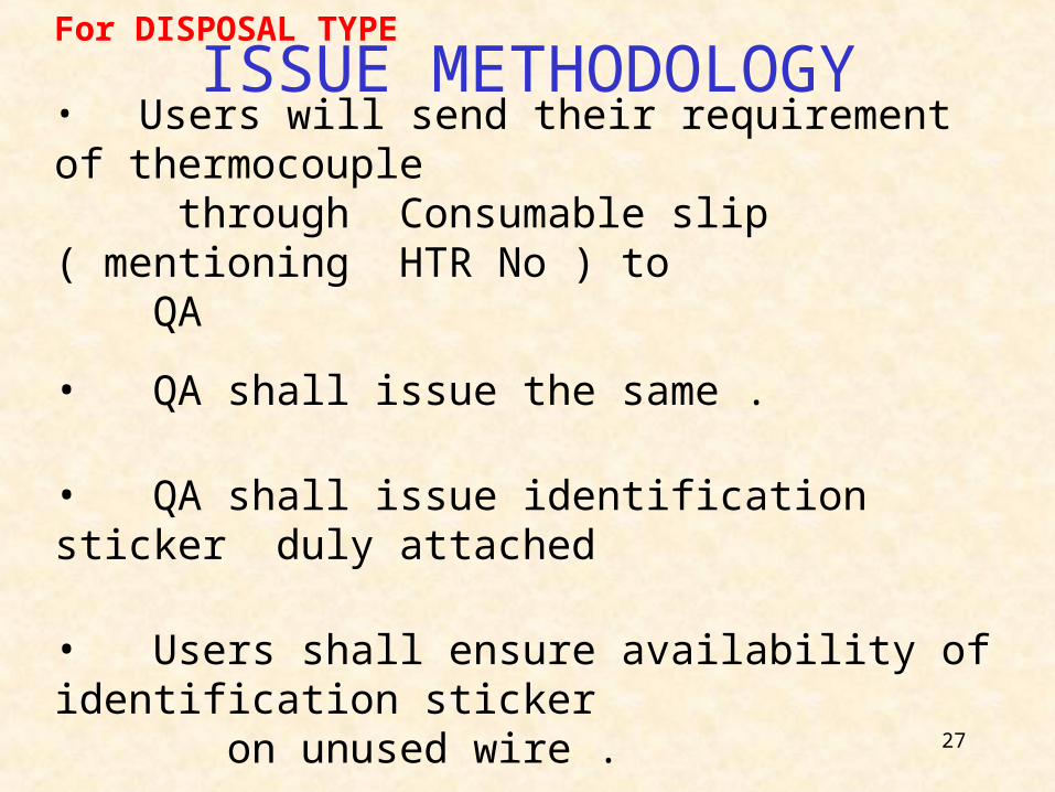
ISSUE METHODOLOGYFor DISPOSAL TYPE
• Users will send their requirement of thermocouple through Consumable slip ( mentioning HTR No ) to QA
• QA shall issue the same .
• QA shall issue identification sticker duly attached
• Users shall ensure availability of identification sticker on unused wire .
28
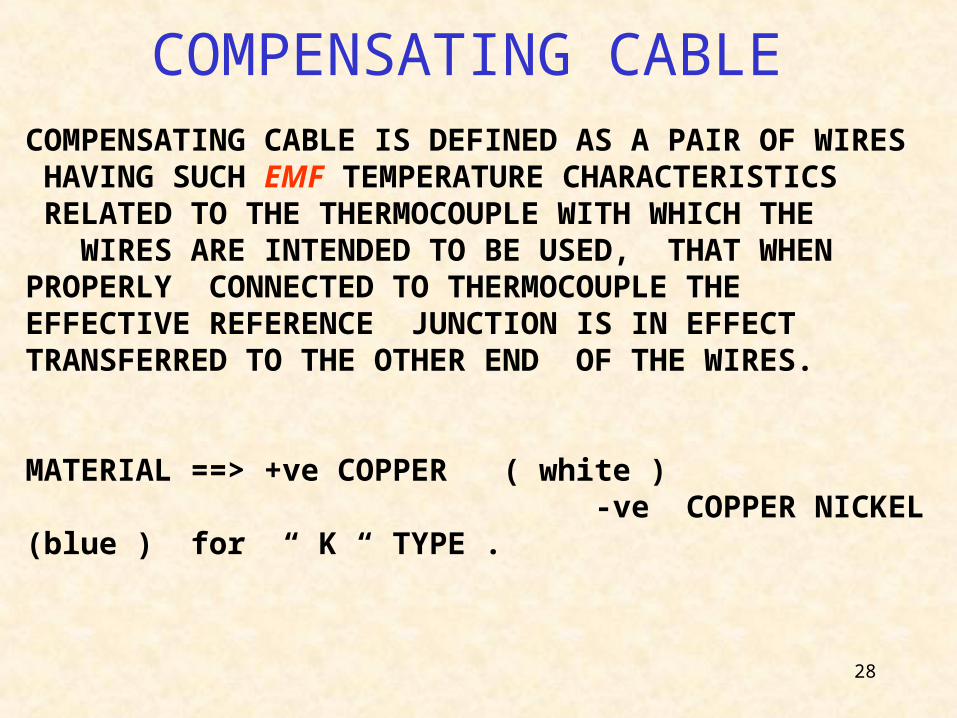
COMPENSATING CABLE
COMPENSATING CABLE IS DEFINED AS A PAIR OF WIRES HAVING SUCH EMF TEMPERATURE CHARACTERISTICS RELATED TO THE THERMOCOUPLE WITH WHICH THE WIRES ARE INTENDED TO BE USED, THAT WHEN PROPERLY CONNECTED TO THERMOCOUPLE THE EFFECTIVE REFERENCE JUNCTION IS IN EFFECT TRANSFERRED TO THE OTHER END OF THE WIRES.
MATERIAL ==> +ve COPPER ( white ) -ve COPPER NICKEL (blue ) for “ K “ TYPE .
29
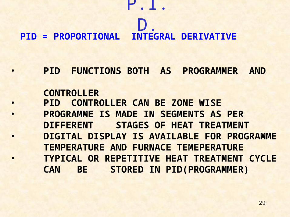
P.I.D.PID = PROPORTIONAL INTEGRAL DERIVATIVE
• PID FUNCTIONS BOTH AS PROGRAMMER AND CONTROLLER• PID CONTROLLER CAN BE ZONE WISE • PROGRAMME IS MADE IN SEGMENTS AS PER DIFFERENT STAGES OF HEAT TREATMENT • DIGITAL DISPLAY IS AVAILABLE FOR PROGRAMME TEMPERATURE AND FURNACE TEMEPERATURE • TYPICAL OR REPETITIVE HEAT TREATMENT CYCLE CAN BE STORED IN PID(PROGRAMMER)
30
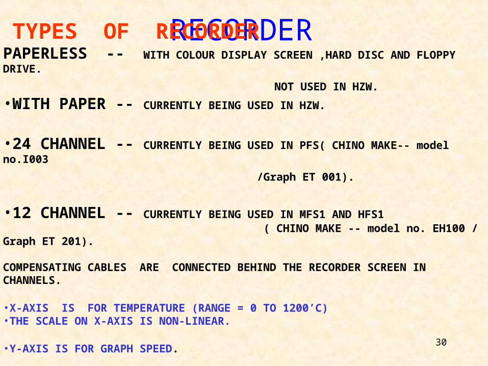
RECORDER TYPES OF RECORDERPAPERLESS -- WITH COLOUR DISPLAY SCREEN ,HARD DISC AND FLOPPY DRIVE.
NOT USED IN HZW.
•WITH PAPER -- CURRENTLY BEING USED IN HZW.
•24 CHANNEL -- CURRENTLY BEING USED IN PFS( CHINO MAKE-- model no.I003
/Graph ET 001). •12 CHANNEL -- CURRENTLY BEING USED IN MFS1 AND HFS1 ( CHINO MAKE -- model no. EH100 / Graph ET 201).
COMPENSATING CABLES ARE CONNECTED BEHIND THE RECORDER SCREEN IN CHANNELS.
•X-AXIS IS FOR TEMPERATURE (RANGE = 0 TO 1200’C)•THE SCALE ON X-AXIS IS NON-LINEAR.
•Y-AXIS IS FOR GRAPH SPEED.
•VARIOUS SPEED OF GRAPHS ARE 12.5, 25, 50, 100 MM / HOUR• GENERALLY KEEP 25 MM / HOUR.
31
GRAPH PAPER
• GRAPH PAPERS ARE USED FOR PLOTTING THE FURNACE TEMPERATURE VIA THERMOCOUPLE. THEY ARE FITTED ON THE RECORDER.• GRAPH PAPER RECOMMENDED ON RECORDER ONLY TO BE USED
• GRAPH PAPER FOR MFS1 AND HFS1 FURNACE ==> ET 201 CHINO MAKE, JAPAN GRAPH PAPER FOR PFS FURNACE ==> ET 001 CHINO MAKE, JAPAN• THE LENGTH OF ONE BUNDLE OF GRAPH PAPER IS GENERALLY 2000 MM.
• DOTTING TYPE RECORDER INK (CHINO MAKE, JAPAN) IS USED IN RECORDER FOR PLOTTING OF GRAPH. USUALLY , 6 COLOURS ARE FILLED FOR PLOTTING.
32
STANDARD OPERATING PROCEDURE FOR HFS-1
FURNACE
33
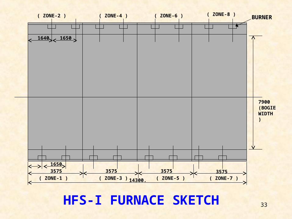
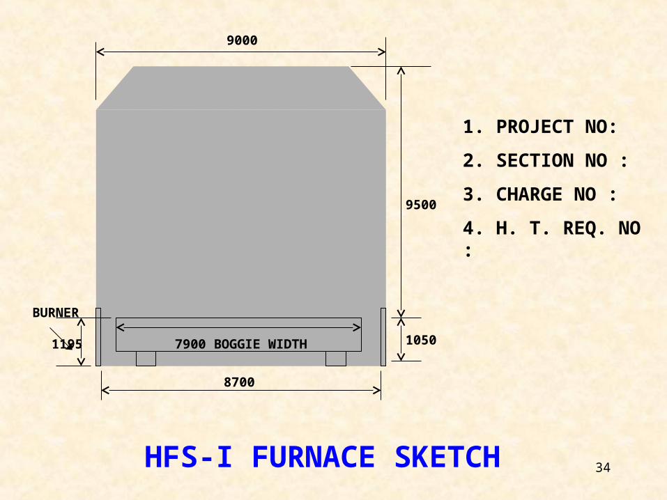
1650
3575
14300.
3575 3575 3575( ZONE-1 ) ( ZONE-3 ) ( ZONE-5 ) ( ZONE-7 )
( ZONE-2 ) ( ZONE-4 ) ( ZONE-6 ) ( ZONE-8 )
1640 1650
7900 (BOGIE WIDTH )
BURNER
HFS-I FURNACE SKETCH
34
7900 BOGGIE WIDTH
8700
1050
9500
9000
1195
1. PROJECT NO:
2. SECTION NO :
3. CHARGE NO :
4. H. T. REQ. NO :
BURNER
HFS-I FURNACE SKETCH
35
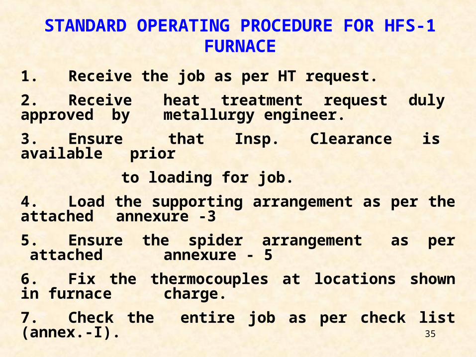
STANDARD OPERATING PROCEDURE FOR HFS-1 FURNACE
1. Receive the job as per HT request.
2. Receive heat treatment request duly approved bymetallurgy engineer.
3. Ensure that Insp. Clearance is available prior
to loading for job.
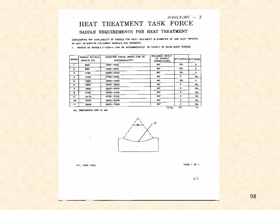
4. Load the supporting arrangement as per the attachedannexure -3
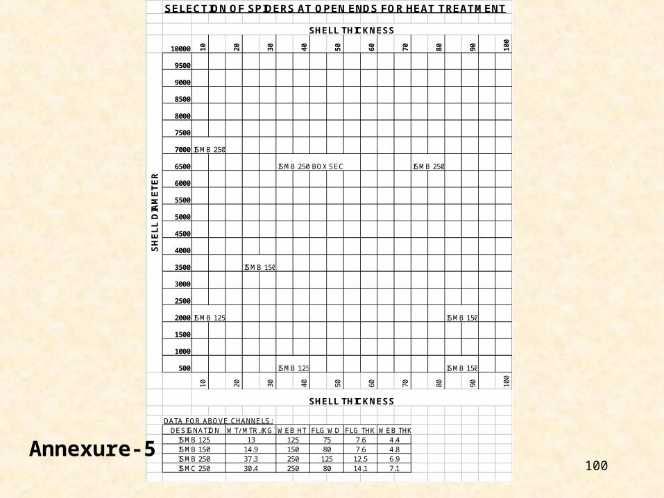
5. Ensure the spider arrangement as per attachedannexure - 5
6. Fix the thermocouples at locations shown in furnacecharge.
7. Check the entire job as per check list (annex.-I).
36
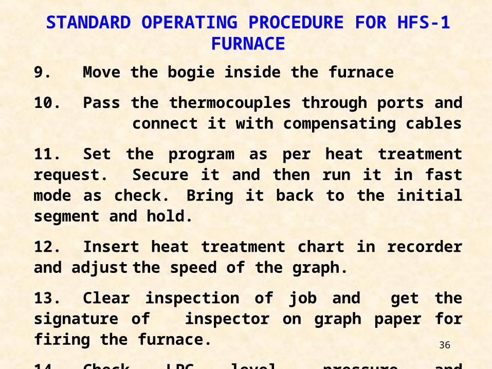
STANDARD OPERATING PROCEDURE FOR HFS-1 FURNACE
9. Move the bogie inside the furnace
10. Pass the thermocouples through ports andconnect it with compensating cables
11. Set the program as per heat treatment request.Secure it and then run it in fast mode as check.Bring it back to the initial segment and hold.
12. Insert heat treatment chart in recorder and adjustthe speed of the graph.
13. Clear inspection of job and get the signature ofinspector on graph paper for firing the furnace.
14. Check LPG level, pressure and temperature in thestorage tanks and note down in logbook.
37
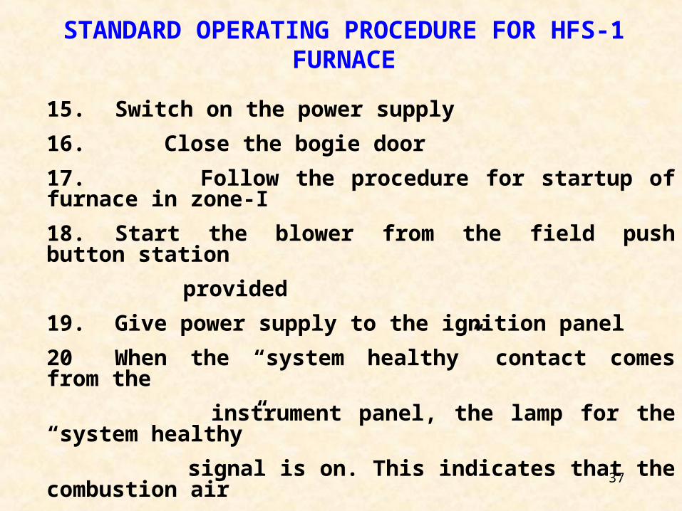
STANDARD OPERATING PROCEDURE FOR HFS-1 FURNACE
15. Switch on the power supply
16. Close the bogie door
17. Follow the procedure for startup of furnace in zone-I
18. Start the blower from the field push button station
provided
19. Give power supply to the ignition panel
20 When the “system healthy” contact comes from the
instrument panel, the lamp for the “system healthy”
signal is on. This indicates that the combustion air
pressure and gas pressure are within the specified
limits
21. Now the firing on the cycle can start.
38
STANDARD OPERATING PROCEDURE FOR HFS-1 FURNACE
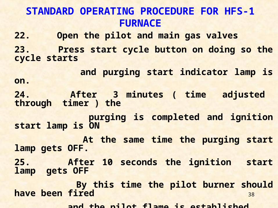
22. Open the pilot and main gas valves
23. Press start cycle button on doing so the cycle starts
and purging start indicator lamp is on.
24. After 3 minutes ( time adjusted through timer ) the
purging is completed and ignition start lamp is ON
At the same time the purging start lamp gets OFF.
25. After 10 seconds the ignition start lamp gets OFF
By this time the pilot burner should have been fired
and the pilot flame is established.
26. Flame healthy signal LED gets on which is provided
on the flame sensor relay. This can be viewed through
the glass window provided in the ignition panel.
39
STANDARD OPERATING PROCEDURE FOR HFS-1 FURNACE
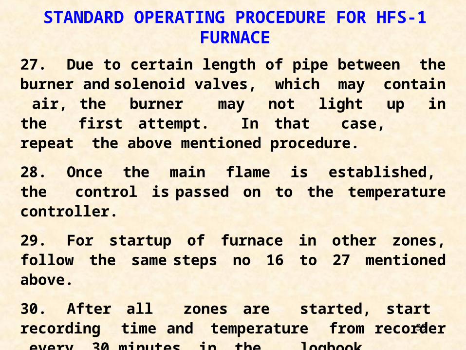
27. Due to certain length of pipe between the burner andsolenoid valves, which may contain air, the burnermay not light up in the first attempt. In that case,repeat the above mentioned procedure.
28. Once the main flame is established, the control ispassed on to the temperature controller.
29. For startup of furnace in other zones, follow the same steps no 16 to 27 mentioned above.
30. After all zones are started, start recording time andtemperature from recorder every 30 minutes in thelogbook.
31. Conduct spot checks for heat treatment every 4hoursand fill the spot check format.
40
STANDARD OPERATING PROCEDURE FOR HFS-1 FURNACE
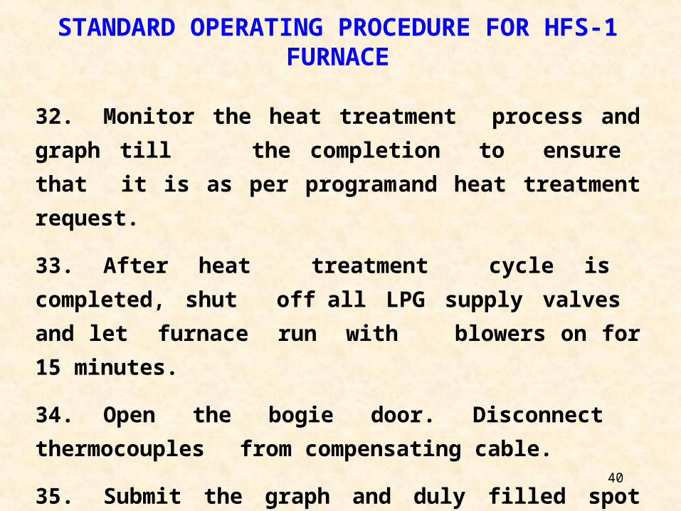
32. Monitor the heat treatment process and graph till
the completion to ensure that it is as per program
and heat treatment request.
33. After heat treatment cycle is completed, shut off
all LPG supply valves and let furnace run with
blowers on for 15 minutes.
34. Open the bogie door. Disconnect thermocouples
from compensating cable.
35. Submit the graph and duly filled spot check formats
to inspection for approval of heat treatment.
41
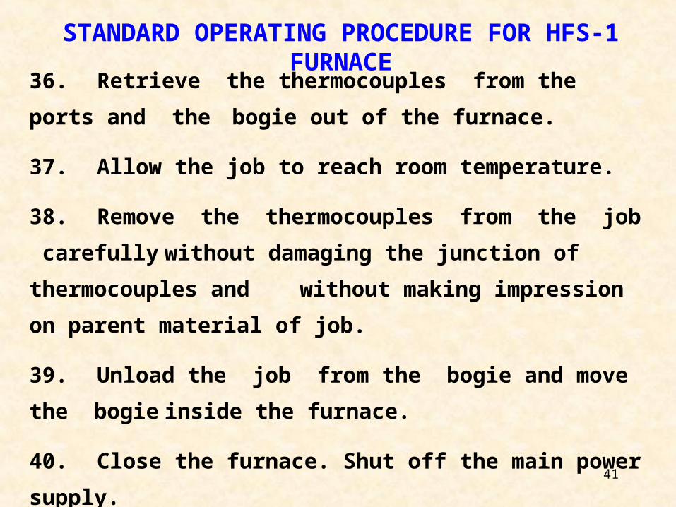
36. Retrieve the thermocouples from the ports and the
bogie out of the furnace.
37. Allow the job to reach room temperature.
38. Remove the thermocouples from the job carefully
without damaging the junction of thermocouples and
without making impression on parent material of job.
39. Unload the job from the bogie and move the bogie
inside the furnace.
40. Close the furnace. Shut off the main power supply.
STANDARD OPERATING PROCEDURE FOR HFS-1 FURNACE
42
STANDARD OPERATING PROCEDURE FOR PFS
FURNACE
43
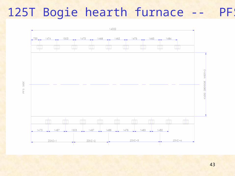
125T Bogie hearth furnace -- PFS
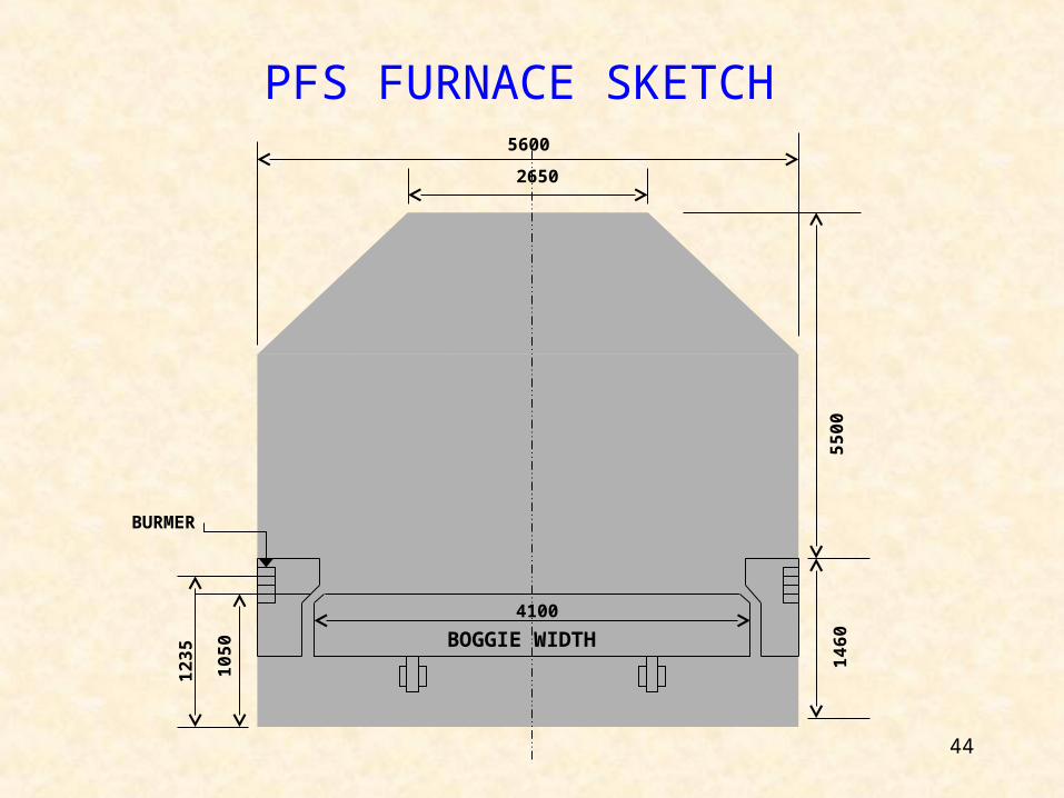
44
BOGGIE WIDTH
4100
2650
5600
10
50
12
35
14
60
55
00
BURMER
PFS FURNACE SKETCH
45
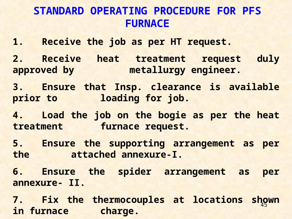
STANDARD OPERATING PROCEDURE FOR PFS FURNACE
1. Receive the job as per HT request.
2. Receive heat treatment request duly approved bymetallurgy engineer.
3. Ensure that Insp. clearance is available prior toloading for job.
4. Load the job on the bogie as per the heat treatmentfurnace request.
5. Ensure the supporting arrangement as per theattached annexure-I.
6. Ensure the spider arrangement as per annexure- II.
7. Fix the thermocouples at locations shown in furnacecharge.
46
STANDARD OPERATING PROCEDURE FOR PFS FURNACE
8. Check the entire job as per check list attached as
annexure-III
9. Move the bogie inside the furnace.
10. Pass the thermocouples through ports and
connect it with compensating cables.
11. Insert heat treatment chart in recorder and adjust
the speed of the graph.
12. Clear inspection of job and get the signature
of inspector on graph paper for firing the furnace.
13. Check LPG level, pressure and temperature in
the storage tanks and note down in logbook.
47
STANDARD OPERATING PROCEDURE FOR PFS FURNACE
14. Switch on the power supply.
15. Close the bogie door.
16. Switch on ID blower first and then the air blowerand maintain pressure at about 800mm WG by slowly opening the suction valve.
17. Ensure that pressure of LPG from yard to inlet of pressure regulator is always less than 20psi (1.5kg/CM2).
18. Open the inlet valve to the regulator and open the outlet valve.
19. If pressure exceeds 1600 mm WG , isolate thepressure by lifting the handle of safety shut off valve.
48
STANDARD OPERATING PROCEDURE FOR PFS FURNACE
20. Immediately start lighting the pilot burners and adjust the flame with the air valve .
21. Open the isolating valve for pressure gauge andadjust the pressure regulator by turning the screwprovided in the stem so that the pressure is maintained at about 1000mm WG.
22. Light up alternate main burners and adjust the flame lengths uniformly.
23. Lock the doors by pneumatic locking.
24. After all zones start, record time and temperaturefrom recorder every 30 minutes in the logbook.
49
STANDARD OPERATING PROCEDURE FOR PFS FURNACE
25. Conduct spot checks for heat treatment every
4 hours and fill the spot check format. Monitor the
heat treatment process and graph per heat
treatment request.
26. After the heat treatment cycle is completed, shut
off all LPG valves and let furnace run with blowers on
for 15 minutes.
27. Open the bogie door. Disconnect thermocouples
from compensating cables.
28. Submit the graph and duly filled spot check formats
to inspection for approval of heat treatment.
50
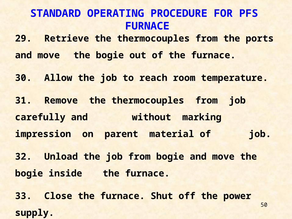
29. Retrieve the thermocouples from the ports and move
the bogie out of the furnace.
30. Allow the job to reach room temperature.
31. Remove the thermocouples from job carefully and
without marking impression on parent material of
job.
32. Unload the job from bogie and move the bogie
inside the furnace.
33. Close the furnace. Shut off the power supply.
STANDARD OPERATING PROCEDURE FOR PFS FURNACE
51
STANDARD OPERATING PROCEDURE FOR PIT
FURNACE IN MFS-I
52B
LO
WE
R
3700 1/D O
F B
AF
FL
E
4150 ( RE
FR
AC
TO
RY
I/S
)
49611000
250125
1380
4020
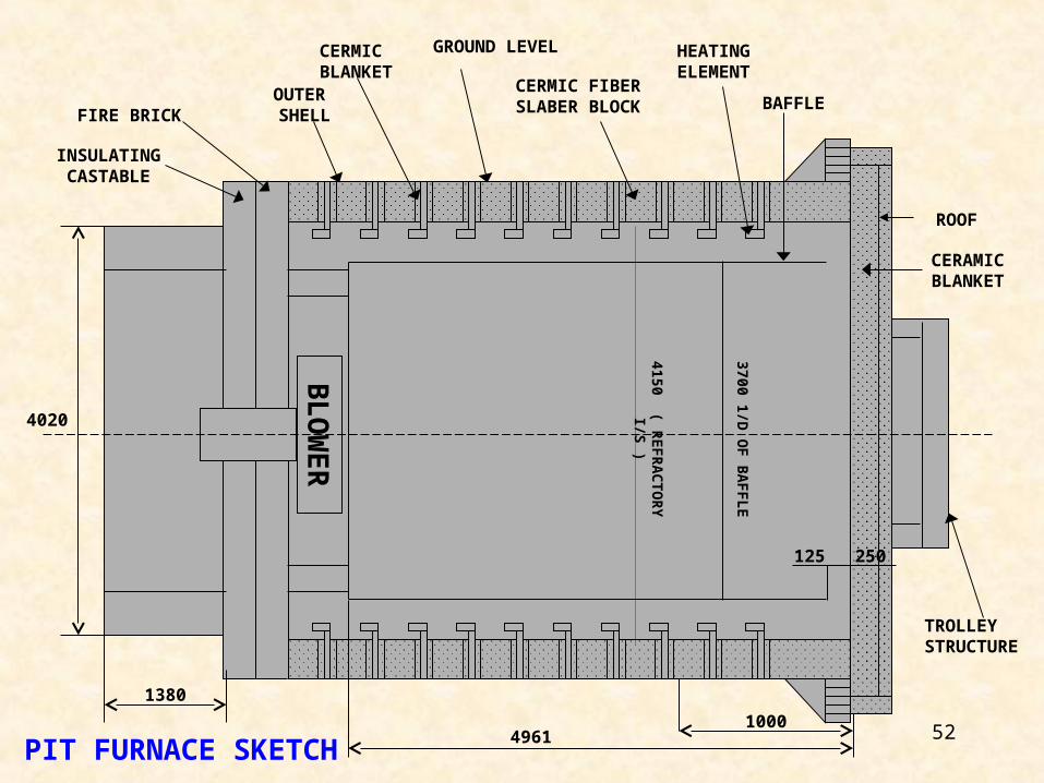
TROLLEY STRUCTURE
CERAMIC BLANKET
ROOF
BAFFLE
HEATING ELEMENT
CERMIC FIBER SLABER BLOCK
INSULATINGCASTABLE
FIRE BRICK OUTER SHELL
CERMIC BLANKET
GROUND LEVEL
PIT FURNACE SKETCH
53
STANDARD OPERATING PROCEDURE
FOR PIT FURNACE
1. Receive heat treatment request duly authorizedby metallurgy engineer.
2. Receive the job for heat treatment withinspection clearance.
3. Put the job either on support or on heattreatment fixture inside the furnace.
4. Ensure that equal clearance is available on allsides between job and baffle.
5. Ensure that the furnace is calibrated.
6. Connect thermocouples with compensatingcable to PID.
54
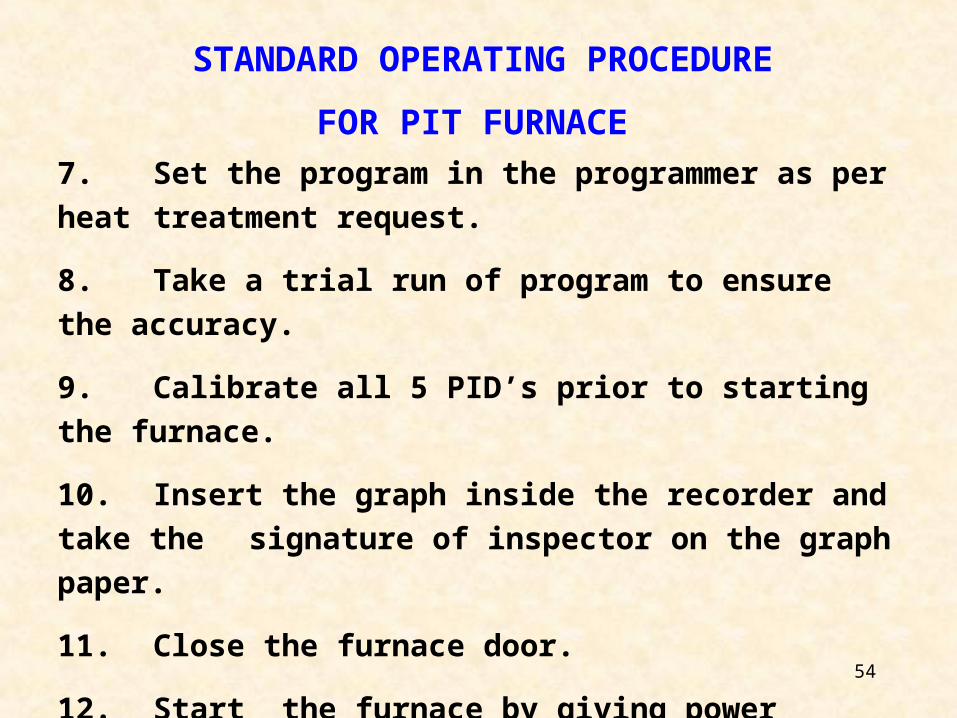
7. Set the program in the programmer as per heat
treatment request.
8. Take a trial run of program to ensure the accuracy.
9. Calibrate all 5 PID’s prior to starting the furnace.
10. Insert the graph inside the recorder and take the
signature of inspector on the graph paper.
11. Close the furnace door.
12. Start the furnace by giving power supply ‘ON’
STANDARD OPERATING PROCEDURE
FOR PIT FURNACE
55
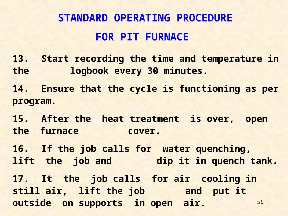
13. Start recording the time and temperature in thelogbook every 30 minutes.
14. Ensure that the cycle is functioning as per program.
15. After the heat treatment is over, open the furnacecover.
16. If the job calls for water quenching, lift the job anddip it in quench tank.
17. It the job calls for air cooling in still air, lift the joband put it outside on supports in open air.
STANDARD OPERATING PROCEDURE
FOR PIT FURNACE
56
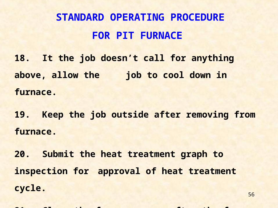
18. It the job doesn’t call for anything above, allow the
job to cool down in furnace.
19. Keep the job outside after removing from furnace.
20. Submit the heat treatment graph to inspection for
approval of heat treatment cycle.
21. Close the furnace cover after the furnace is cooled
down to room temperature.
STANDARD OPERATING PROCEDURE
FOR PIT FURNACE
57
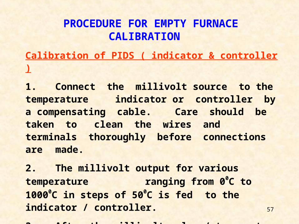
PROCEDURE FOR EMPTY FURNACE CALIBRATION
Calibration of PIDS ( indicator & controller )
1. Connect the millivolt source to the temperatureindicator or controller by a compensating
cable. Care should be taken to clean the wires andterminals thoroughly before connections aremade.
2. The millivolt output for various temperature
ranging from 00C to 10000C in steps of 500C is fedto the indicator / controller.
3. After the millivolt value / temperature readingdisplayed is steady, the reading ofindicator/controller shall be noted.
58
PROCEDURE FOR EMPTY FURNACE CALIBRATION
Calibration of recorder
1. Connect the millivolt source to the recorder by acompensating cable. Care should be taken toclean the wires and terminals thoroughly beforethe connections are made.
4. If the error in the indicated readings is more than
the specified accuracy ( +/- 10C ), then correction
to be carried out for the indicator / controller and
points 1 to 4 shall be repeated till the specified
accuracy is obtained is obtained.
59
PROCEDURE FOR EMPTY FURNACE CALIBRATION
2. The millivolt output for various temperature
ranging from 400 C to 10000C is fed to the
recorder and is allowed to plot on a graph.
3. The graph thus obtained is reviewed for time
and temperature values. These values should
meet the accuracy requirements.
4. If there is error in the values plotted on the
graph, then correction to be carried out for
the recorder and points 1 to 4 shall be
repeated till the specified accuracy is
obtained.
60
PROCEDURE FOR EMPTY FURNACE CALIBRATION
EQUIPMENT REQUIRED ACCURACY
1. 20 Nos. big K-type thermocouples +/- 0.25%
2. 10 Nos. small K-type thermocouples +/- 0.25%
3. Millivolt source (wahl unit )
( 1 micro volt at 1000 micro volts )
4. Heat treatment fixture.
5. Temperature indicators (PID) +/- 10C
6. Recorder +/- on temperature scale.
+/- minutes on time scale.
61
PIT FURNACE CALIBRATION PROCEDURE
1. Ensure that the PIDs are calibrated as mentioned above.
2. Ensure that the recorder is calibrated as mentioned
above.
3. Ensure that all the thermocouples used are calibrated.
4. Ensure that the thermocouples are attached to the heat
treatment fixture as shown in sketch-I.
5. Place the heat treatment fixture inside the furnace with
thermocouples in position.
6. Close the furnace lid. Start the furnace and the
recorder.
62
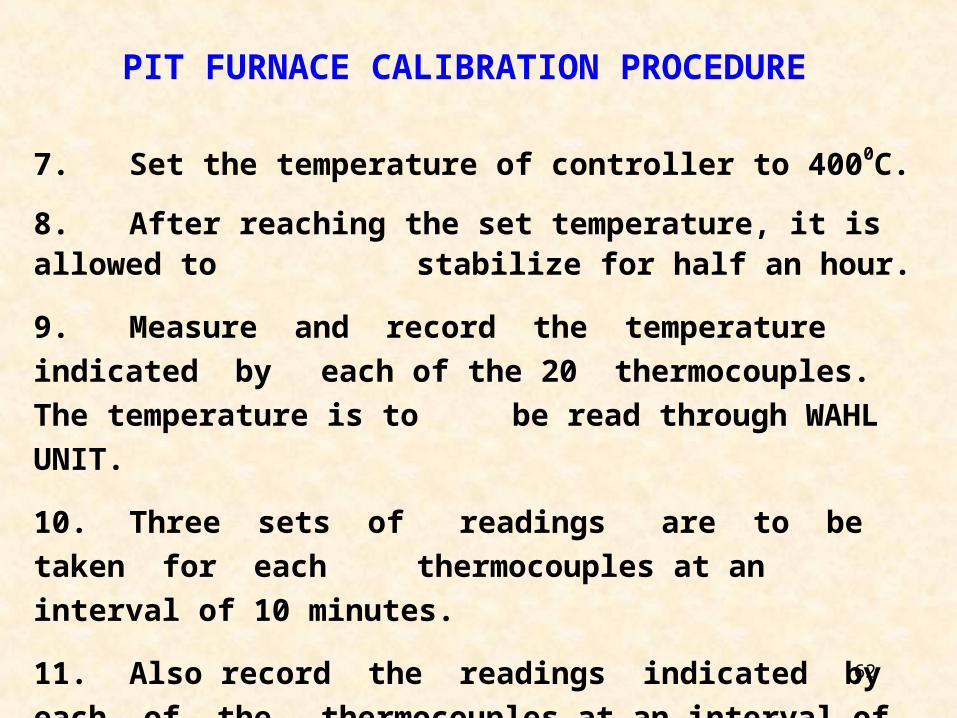
7. Set the temperature of controller to 4000C.
8. After reaching the set temperature, it is allowed to stabilize for half an hour.
9. Measure and record the temperature indicated by
each of the 20 thermocouples. The temperature is to
be read through WAHL UNIT.
10. Three sets of readings are to be taken for each
thermocouples at an interval of 10 minutes.
11. Also record the readings indicated by each of the
thermocouples at an interval of 10 minutes.
PIT FURNACE CALIBRATION PROCEDURE
63
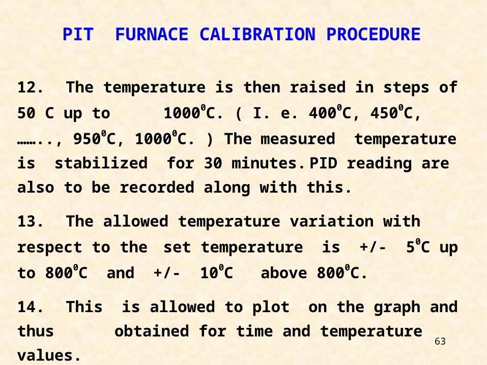
PIT FURNACE CALIBRATION PROCEDURE
12. The temperature is then raised in steps of 50 C up to
10000C. ( I. e. 4000C, 4500C, …….., 9500C, 10000C. ) The
measured temperature is stabilized for 30 minutes.
PID reading are also to be recorded along with this.
13. The allowed temperature variation with respect to the
set temperature is +/- 50C up to 8000C and +/- 100C
above 8000C.
14. This is allowed to plot on the graph and thus
obtained for time and temperature values.
15. Calibration of furnace is valid for 1 year.
64
STANDARD OPERATING PRACTICES FOR LOCAL
STRESS RELIEVING
65
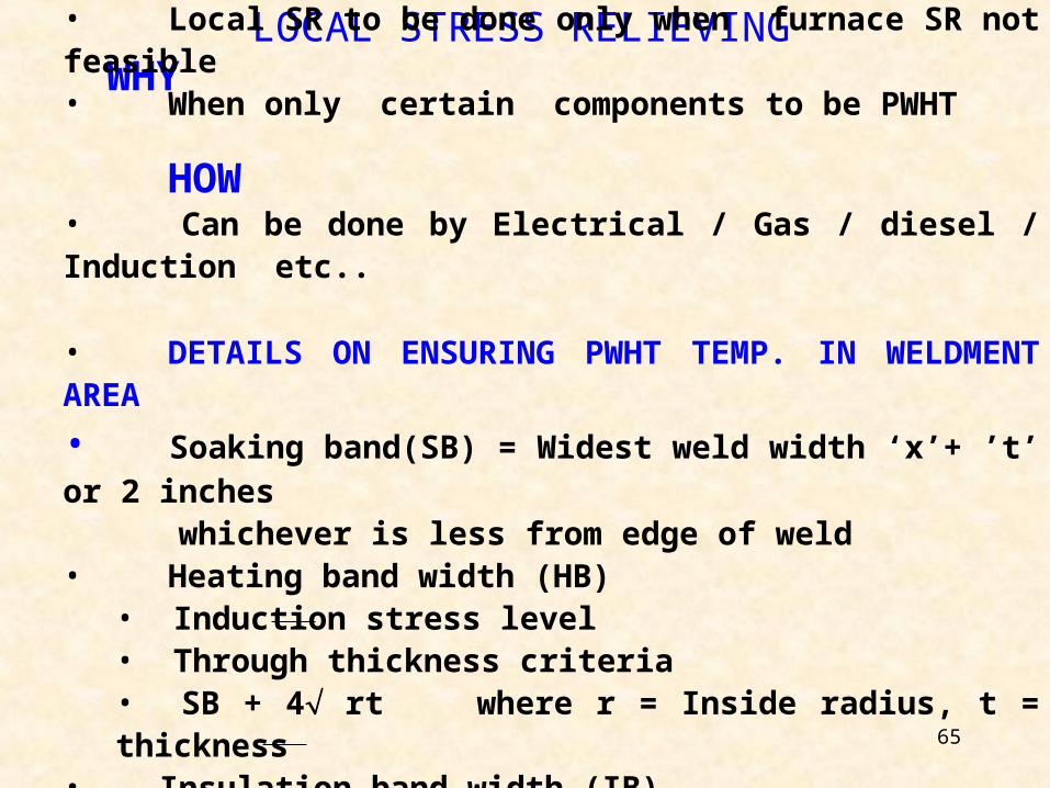
LOCAL STRESS RELIEVINGWHY • Local SR to be done only when furnace SR not feasible
• When only certain components to be PWHT
HOW• Can be done by Electrical / Gas / diesel / Induction etc..
• DETAILS ON ENSURING PWHT TEMP. IN WELDMENT AREA
• Soaking band(SB) = Widest weld width ‘x’+ ’t’ or 2 inches whichever is less from edge of weld• Heating band width (HB)
• Induction stress level• Through thickness criteria• SB + 4 rt where r = Inside radius, t = thickness
• Insulation band width (IB)• Axial gradient• HB + 4 rt
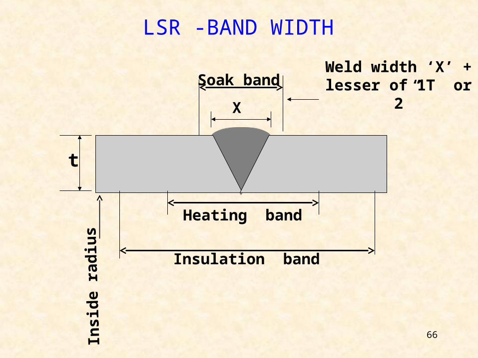
66
LSR -BAND WIDTH
Weld width ‘X’ + lesser of 1T or 2”
X
t
Soak band
Insulation band
Heating band
Insi
de
rad
ius
67
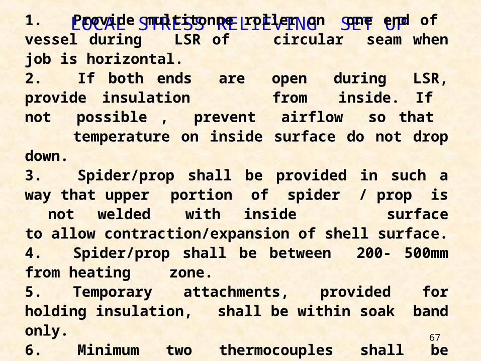
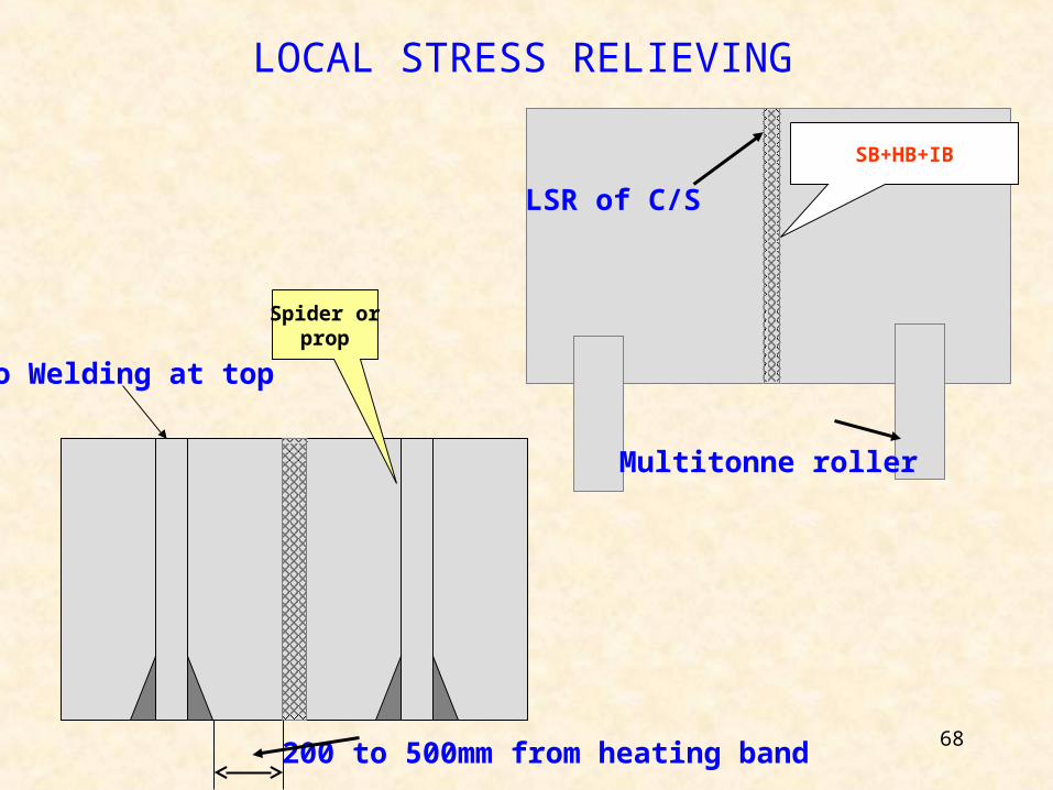
LOCAL STRESS RELIEVING SET UP1. Provide multitonne roller on one end of vessel during LSR ofcircular seam when job is horizontal.2. If both ends are open during LSR, provide insulation from inside. If not possible , prevent airflow so that temperature on inside surface do not drop down.3. Spider/prop shall be provided in such a way that upper portion of spider / prop is not welded with inside surface to allow contraction/expansion of shell surface.4. Spider/prop shall be between 200- 500mm from heating zone.5. Temporary attachments, provided for holding insulation, shall be within soak band only.6. Minimum two thermocouples shall be provided from inside, when accessible.
68
LOCAL STRESS RELIEVING
No Welding at top
Multitonne roller
200 to 500mm from heating band
LSR of C/S
SB+HB+IB
Spider orprop
69
GOOD ENGG. PRACTICES FOR FURNACE CHARGES
& L S R
70
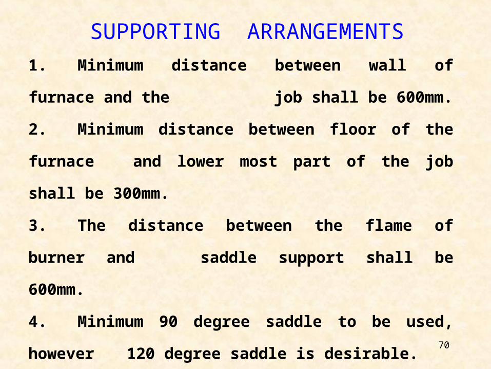
SUPPORTING ARRANGEMENTS
1. Minimum distance between wall of furnace and
the job shall be 600mm.
2. Minimum distance between floor of the furnace
and lower most part of the job shall be 300mm.
3. The distance between the flame of burner and
saddle support shall be 600mm.
4. Minimum 90 degree saddle to be used, however
120 degree saddle is desirable.
71
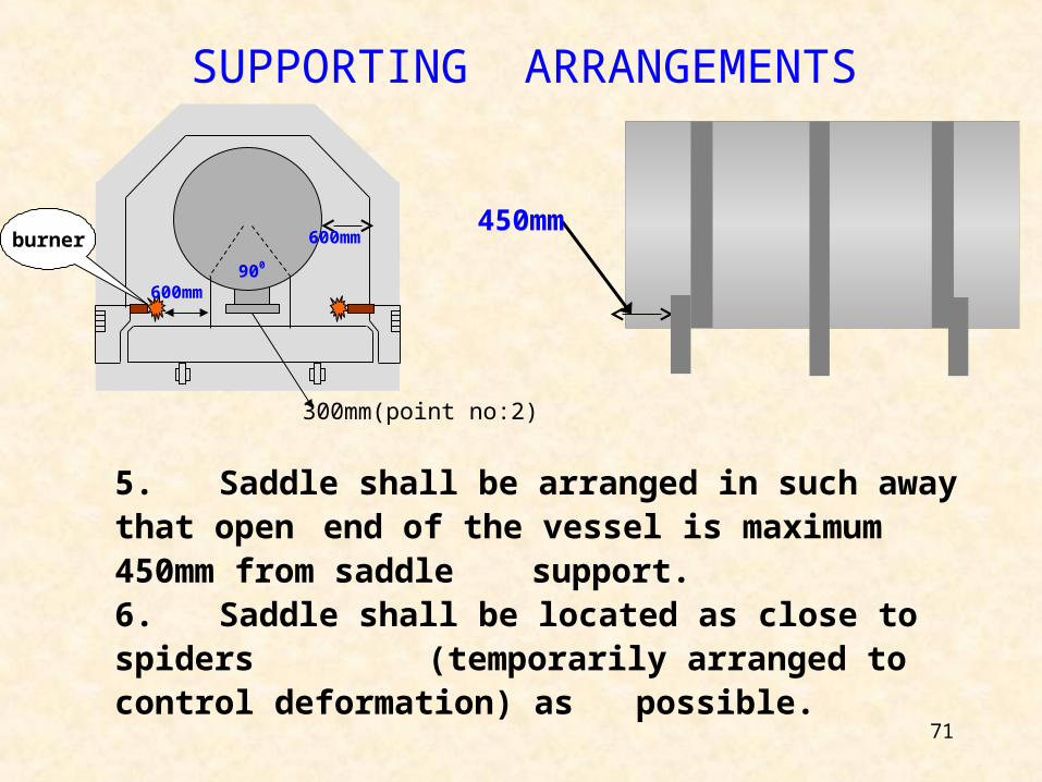
600mm
900
600mm
SUPPORTING ARRANGEMENTS
450mm
5. Saddle shall be arranged in such away that openend of the vessel is maximum 450mm from
saddle support.6. Saddle shall be located as close to spiders
(temporarily arranged to control deformation) as possible.
burner
300mm(point no:2)
72
SUPPORTING ARRANGEMENTS7. Spiders shall be provided as per annexure-5
8 Saddle supports shall be selected as per
annexure.-3
9. Spiders or vertical prop shall be provided at open
ends, center and below man way/nozzles
above 24” 10. Avoid gap between saddle support and job
surface
73
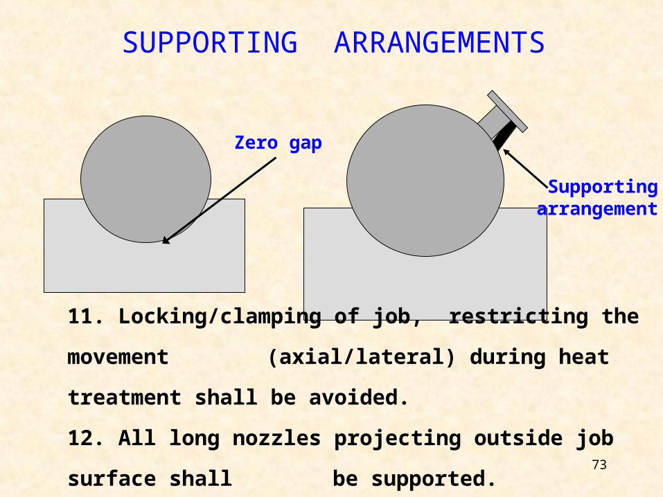
Zero gap
Supporting arrangement
SUPPORTING ARRANGEMENTS
11. Locking/clamping of job, restricting the movement
(axial/lateral) during heat treatment shall be
avoided.
12. All long nozzles projecting outside job surface shall
be supported.
74
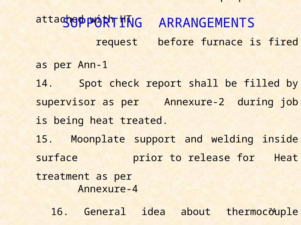
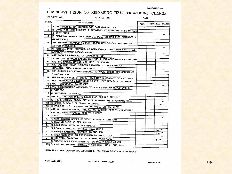
13. Checklist shall be prepared and attached with HT
request before furnace is fired as per Ann-1
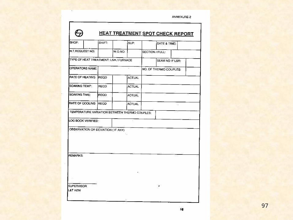
14. Spot check report shall be filled by supervisor as
per Annexure-2 during job is being heat treated.
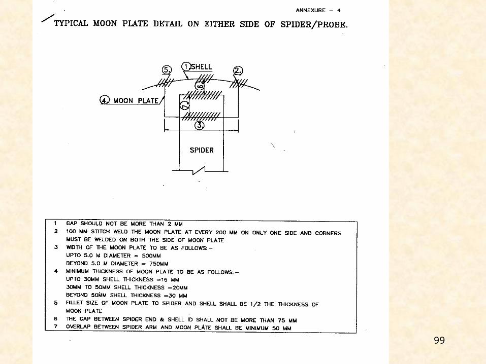
15. Moonplate support and welding inside surface
prior to release for Heat treatment as per Annexure-4
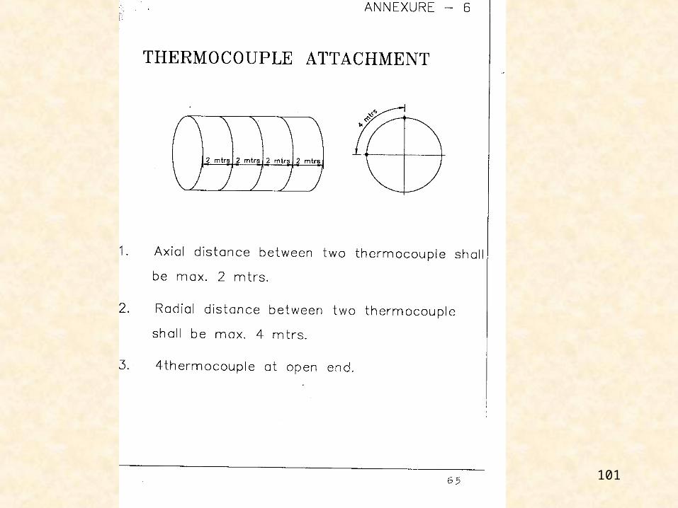
16. General idea about thermocouple locations and its
attachments is as per Annexure-6
SUPPORTING ARRANGEMENTS
75
GENERAL
1. Blocking the flame of the burner is not
desirable
2. Burner shall have blue flame and not yellow
3. Flame shall not directly impinge on job
4. All burners shall be fired at a time
5. Keep all job nozzles open during heat
treatment
6. Above “24” nozzles / manways shall be
located towards bottom
76
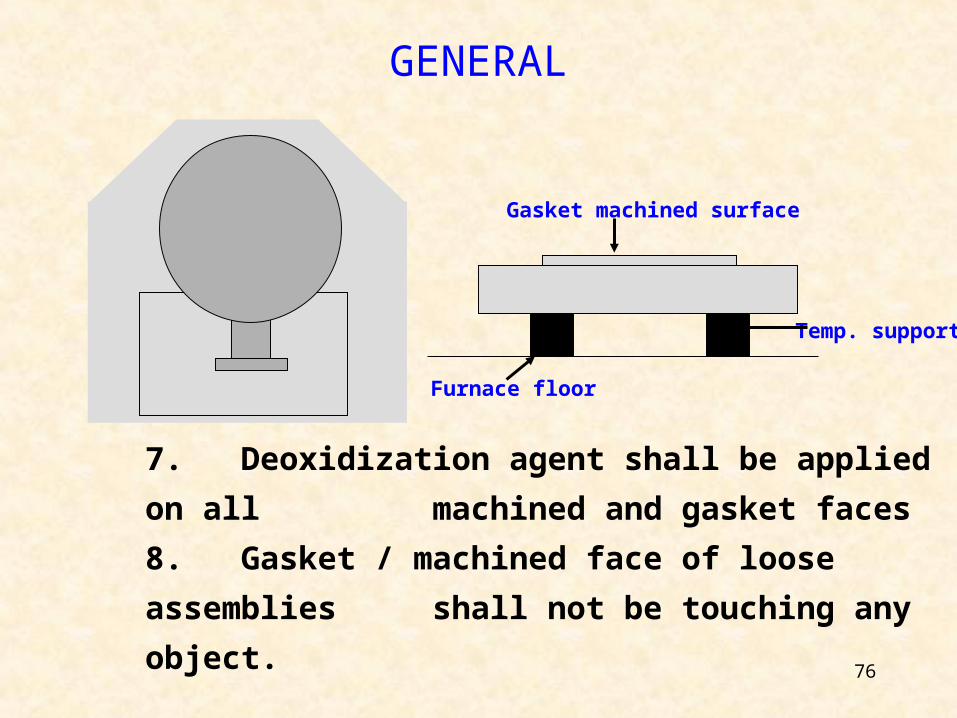
GENERAL
Temp. support
Furnace floor
Gasket machined surface
7. Deoxidization agent shall be applied on all
machined and gasket faces
8. Gasket / machined face of loose assemblies
shall not be touching any object.
77
THERMOCOUPLES1. All the thermocouples shall be tagged with aluminum sheet and identification hard punched on it. (For PIT furnace only)
2. Minimum two thermocouples to be attached for any charge.
78
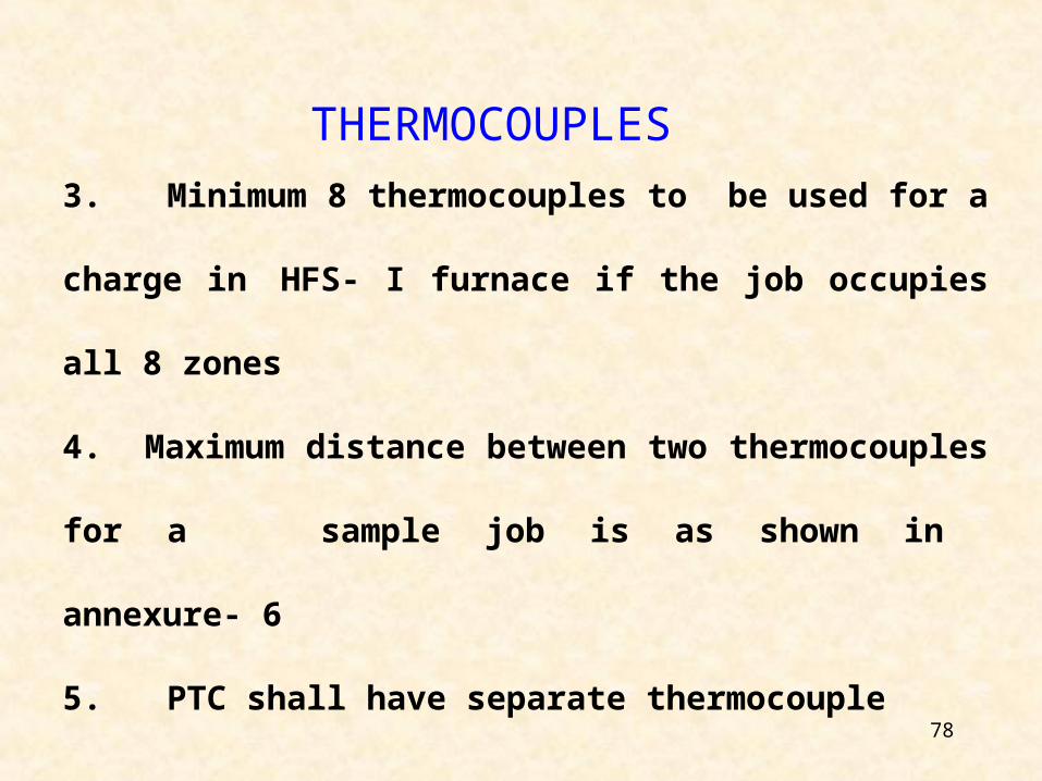
3. Minimum 8 thermocouples to be used for a charge
in HFS- I furnace if the job occupies all 8 zones
4. Maximum distance between two thermocouples for a
sample job is as shown in annexure- 6
5. PTC shall have separate thermocouple
THERMOCOUPLES
79
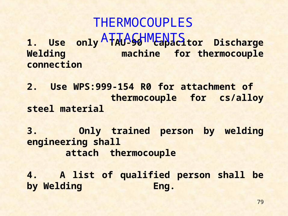
1. Use only TAU-90 capacitor Discharge Welding machine for thermocouple connection
2. Use WPS:999-154 R0 for attachment of thermocouple for cs/alloy steel material
3. Only trained person by welding engineering shall attach thermocouple
4. A list of qualified person shall be by Welding Eng.
THERMOCOUPLES ATTACHMENTS
80
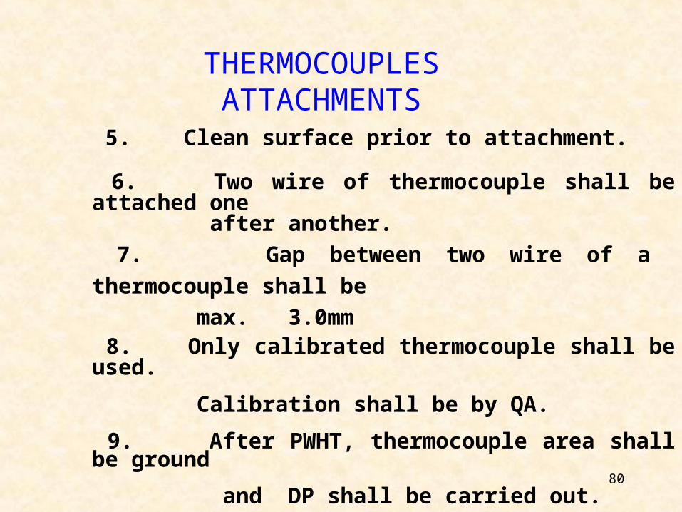
5. Clean surface prior to attachment.
6. Two wire of thermocouple shall be attached one after another.
7. Gap between two wire of a thermocouple shall be
max. 3.0mm 8. Only calibrated thermocouple shall be used.
Calibration shall be by QA.
9. After PWHT, thermocouple area shall be ground
and DP shall be carried out.
THERMOCOUPLES ATTACHMENTS
81
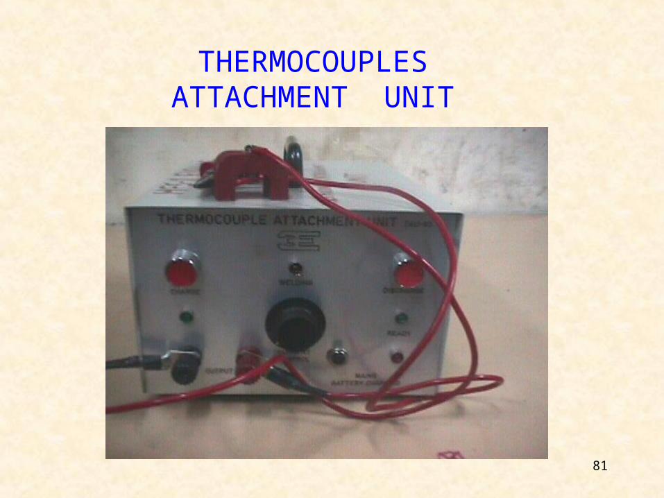
THERMOCOUPLES ATTACHMENT UNIT
82
SPECIAL NOTE
IF THE TEMPERATURE OF HEAT TREATMENT
EXCEEEDS 650-DEGREE CENTIGRADE, THE
MATERIAL AND SIZE OF SPIDERS AND SUPPORTS
TO BE DECIDED BY PLANNING AND APPROVED BY
DESIGN.
83
CODE EXTRACTS •FURNACE PWHT• L S R
84
REQUIREMENT OF HEAT TREATMENTAS PER ASME-SEC VIII Div.-1
• SERVICE CONDITION (UW-2)
• MATERIAL (UG-85, UW-40,UCS-56,UAT-80,UHA-32,UNF-79)
• THICKNESS (UG-85, UW-40,UCS-56,UAT-80,UHA-32,UNF-79)
• LOW TEMERATURE
OPERATION (UCS-68)
• COLD WORKING (UG-79)
• CUSTOMER SPEC.
85
CODE EXTRACT FOR HEAT TREATMENT( 1 ) The soak band shall contain the weld, heat affected zone and a portion of base metal adjacent to the weld being heat treated. The minimum width of this volume is the widest width of weld plus 1T or 2 inches, whichever is less, on each side or end of the weld. The term ‘T’ is the nominal thickness.( 2 ) The operation of postweld heat treatment shall be performed either by heating the vessel as a whole in an enclosed furnace or heating the vessel in more than one heat in a furnace, provided the overlap of the heated sections of the vessel is at least 5 feet ( 1.5m). When this procedure is used, the portion outside of the furnace shall be shielded so that the temperature gradient is not harmful. The cross section where the vessel projects from the furnace shall not intersect a nozzle or other structural discontinuity.
86
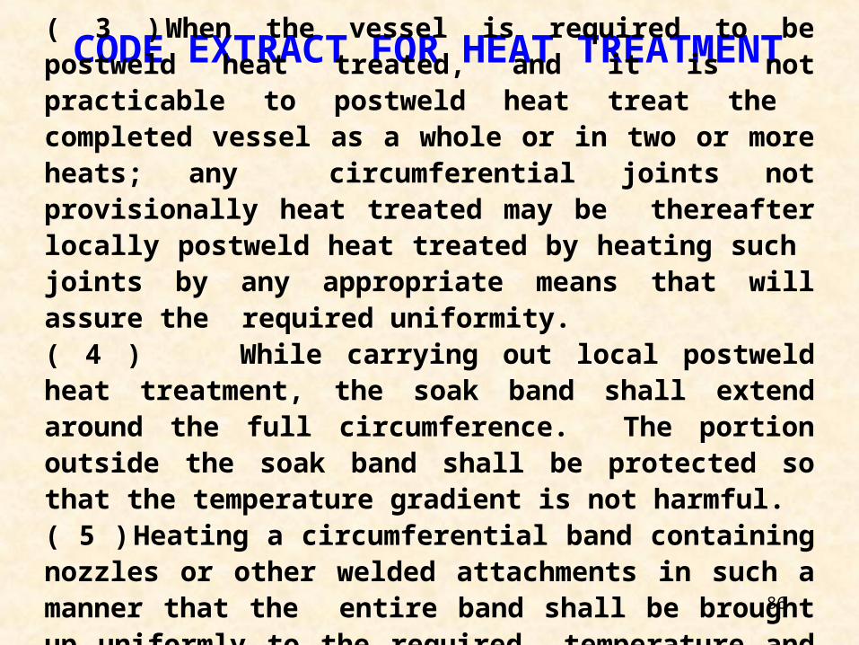
CODE EXTRACT FOR HEAT TREATMENT( 3 ) When the vessel is required to be postweld heat treated, and it is not practicable to postweld heat treat the completed vessel as a whole or in two or more heats; any circumferential joints not provisionally heat treated may be thereafter locally postweld heat treated by heating such joints by any appropriate means that will assure the required uniformity.( 4 ) While carrying out local postweld heat treatment, the soak band shall extend around the full circumference. The portion outside the soak band shall be protected so that the temperature gradient is not harmful.( 5 ) Heating a circumferential band containing nozzles or other welded attachments in such a manner that the entire band shall be brought up uniformly to the required temperature and held for the specified time.
87
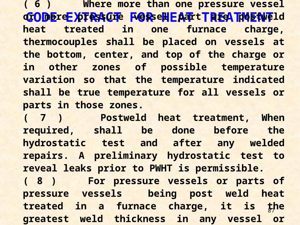
CODE EXTRACT FOR HEAT TREATMENT( 6 ) Where more than one pressure vessel or more pressure vessel part are postweld heat treated in one furnace charge, thermocouples shall be placed on vessels at the bottom, center, and top of the charge or in other zones of possible temperature variation so that the temperature indicated shall be true temperature for all vessels or parts in those zones. ( 7 ) Postweld heat treatment, When required, shall be done before the hydrostatic test and after any welded repairs. A preliminary hydrostatic test to reveal leaks prior to PWHT is permissible.( 8 ) For pressure vessels or parts of pressure vessels being post weld heat treated in a furnace charge, it is the greatest weld thickness in any vessel or vessel part which has not previously been postweld heat treated.
88
CODE EXTRACT FOR HEAT TREATMENT
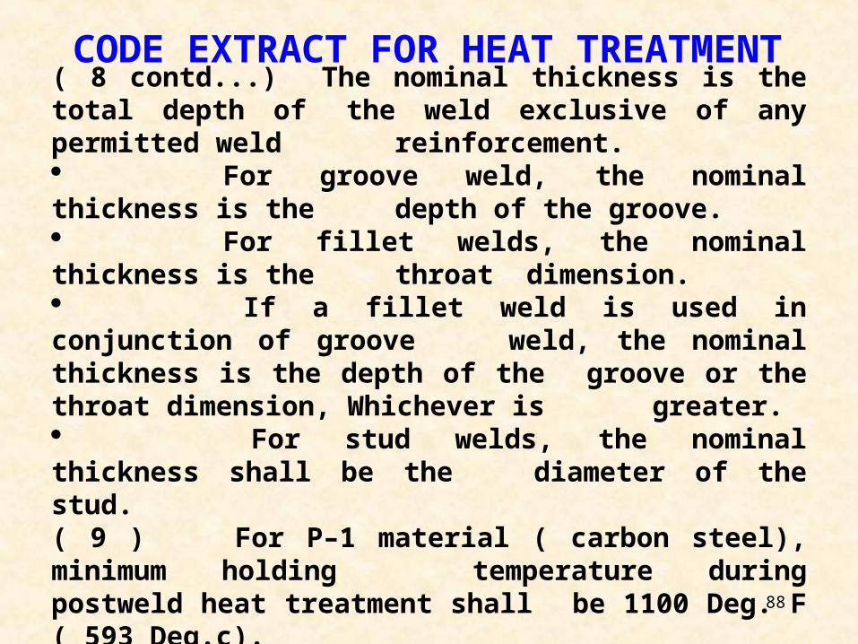
( 8 contd...) The nominal thickness is the total depth of the weld exclusive of any permitted weld
reinforcement. For groove weld, the nominal thickness is the depth of the groove. For fillet welds, the nominal thickness is the throat dimension. If a fillet weld is used in conjunction of groove weld, the nominal thickness is the depth of the groove or the throat dimension, Whichever is greater. For stud welds, the nominal thickness shall be the diameter of the stud.( 9 ) For P–1 material ( carbon steel), minimum holding temperature during postweld heat treatment shall be 1100 Deg. F ( 593 Deg.c).
89
CODE EXTRACT FOR HEAT TREATMENT
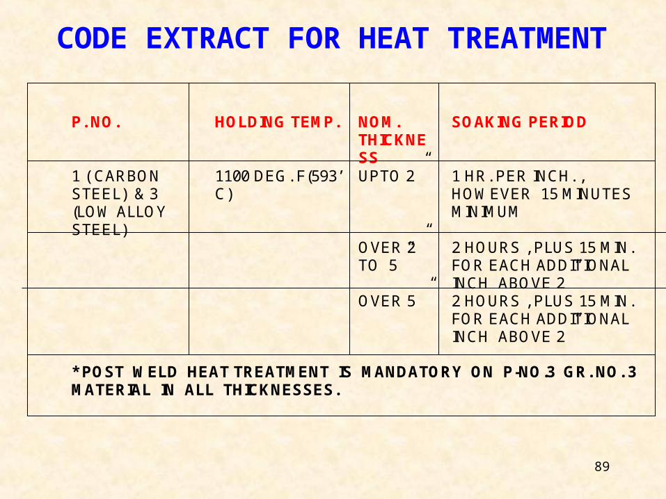
P. NO. HOLDING TEMP. NOM.THICKNESS
SOAKING PERIOD
1 ( CARBONSTEEL) & 3(LOW ALLOYSTEEL)
1100 DEG. F(593’C)
UPTO 2” 1 HR. PER INCH. ,HOWEVER 15 MINUTESMINIMUM
OVER 2”TO 5”
2 HOURS , PLUS 15 MIN.FOR EACH ADDITIONALINCH ABOVE 2”
OVER 5 ” 2 HOURS , PLUS 15 MIN.FOR EACH ADDITIONALINCH ABOVE 2”
* POST WELD HEAT TREATMENT IS MANDATORY ON P-NO.3 GR. NO. 3MATERIAL IN ALL THICKNESSES.
90
( 10 ) Postweld heat treatment is mandatory in Following conditions :
• For welded joints over 1. 5” nominal thickness.• For welded joints over 1.25” nom. Thickness through 1.5” nom. Thickness, unless preheat is applied at a min. Temperature of 200’F ( 94‘c ) during welding.• Vessels or parts of vessels constructed of base material with corrosion resistant integral or weld metal overlay cladding or applied corrosion resistant lining material shall be postweld heat treated when the base material is required to be postweld heat treated. In applying this rule, the determining thickness shall be the total thickness of base material.
• When the PWHT is a service requirement.
CODE EXTRACT FOR HEAT TREATMENT
91
SERVICE CONDITION
• LETHAL SERVICE PWHT IS MANDATORY
• EXEMPTIONS ARE FEW
CODE EXTRACT FOR HEAT TREATMENT
92
CODE EXTRACT FOR HEAT TREATMENT( 11 ) Postweld heat treatment is not mandatory for carbon
steel jobs (P1 material ) in Following conditions (UG2):
If groove welds is not over ½” in size or fillet weld with a throat thickness of ½” or less used for attaching non pressure parts to pressure parts provided preheat to a minimum temperature of 200’F is applied when the thickness of pressure Part exceeds 1.25”. If studs are welded to pressure parts provided preheat to a minimum temperature of 200’F is applied when the thickness of the pressure parts exceeds 1.25”. for corrosion resistant weld metal overlay cladding or for welds attaching corrosion resistant applied lining provided preheat to a minimum temperature of 200’f is maintained during application of the first layer when the thickness of the pressure part exceeds 1.25”.
93
CODE EXTRACT FOR HEAT TREATMENT
• The temperature of furnace shall not exceed
800’F
( 4270C) at the time when the vessel or part is placed in it.
• Above 8000F( 4270C), the rate of heating shall not be more
than 4000F Per hour (2000C/Hour) divided by the maximum
metal thickness of the shell or head plate in inches, but in no
case more than 4000F Per hour( 2220C Per hour ).
• During the heating period, There shall not be a greater
variation in temperature throughout the portion of the vessel
being heat treated than 2500F( 1390C) within any 15 feet
( 4.6m) interval of length.
94
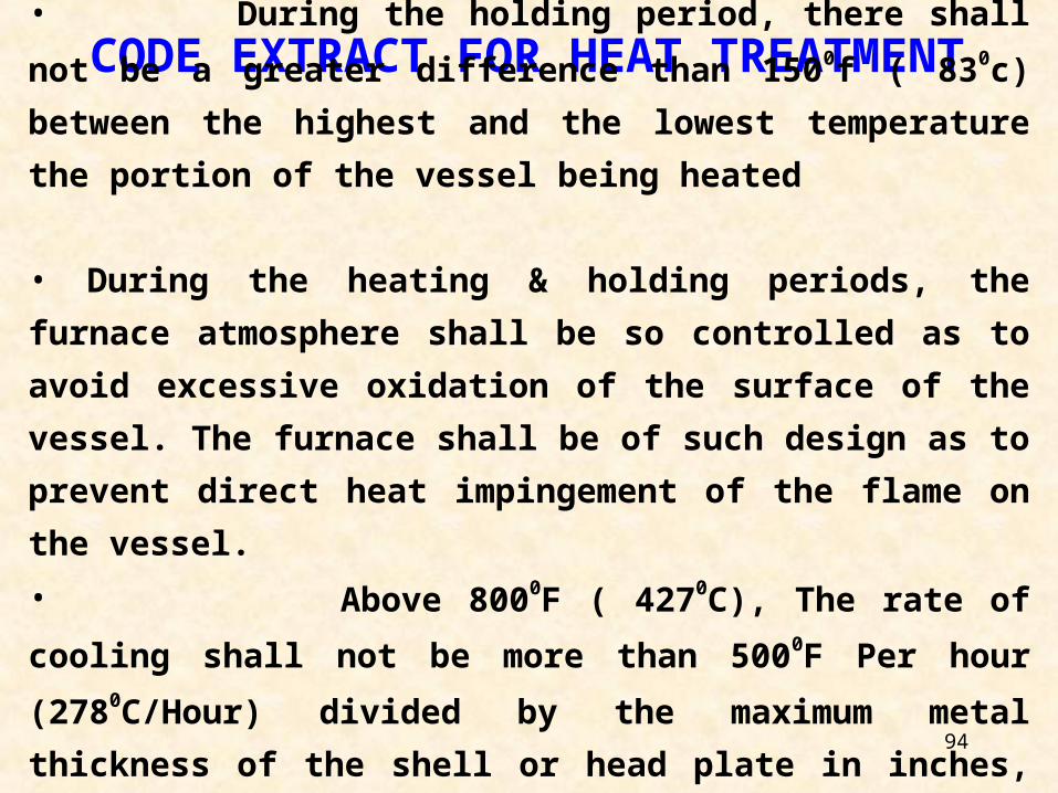
CODE EXTRACT FOR HEAT TREATMENT• During the holding period, there shall not be a
greater difference than 1500f ( 830c) between the highest and
the lowest temperature the portion of the vessel being heated
• During the heating & holding periods, the furnace
atmosphere shall be so controlled as to avoid excessive
oxidation of the surface of the vessel. The furnace shall be of
such design as to prevent direct heat impingement of the
flame on the vessel.
• Above 8000F ( 4270C), The rate of cooling shall not be
more than 5000F Per hour (2780C/Hour) divided by the
maximum metal thickness of the shell or head plate in inches,
but in no case more than 5000F Per hour ( 2780C Per hour).
95
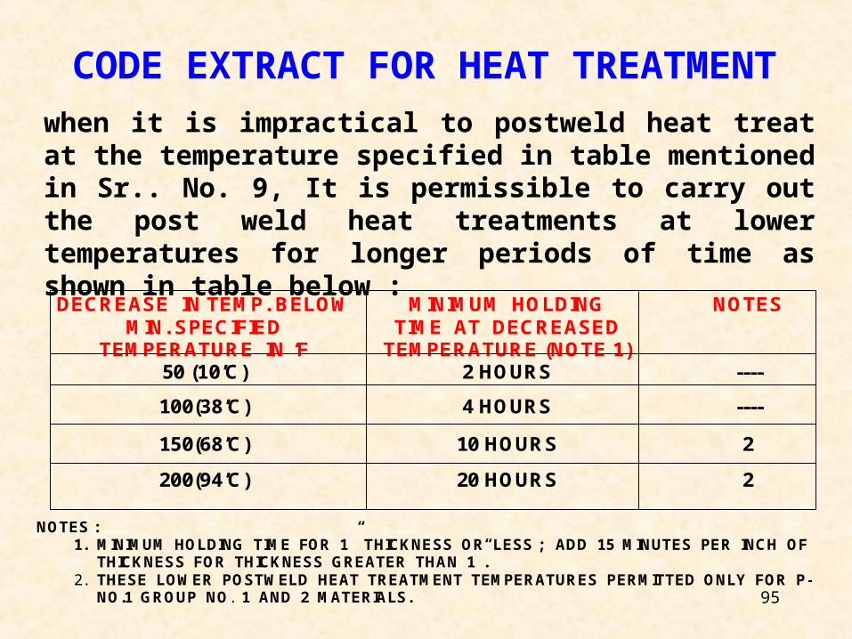
when it is impractical to postweld heat treat at the temperature specified in table mentioned in Sr.. No. 9, It is permissible to carry out the post weld heat treatments at lower temperatures for longer periods of time as shown in table below :
CODE EXTRACT FOR HEAT TREATMENT
DECREASE IN TEMP. BELOWMIN. SPECIFIED
TEMPERATURE IN ‘F
MINIMUM HOLDINGTIME AT DECREASED
TEMPERATURE (NOTE 1)
NOTES
50 (10’C) 2 HOURS ----
100(38’C) 4 HOURS ----
150(68’C) 10 HOURS 2
200(94’C) 20 HOURS 2
NOTES :1. MINIMUM HOLDING TIME FOR 1” THICKNESS OR LESS ; ADD 15 MINUTES PER INCH OF
THICKNESS FOR THICKNESS GREATER THAN 1”.2. THESE LOWER POSTWELD HEAT TREATMENT TEMPERATURES PERMITTED ONLY FOR P-
NO.1 GROUP NO. 1 AND 2 MATERIALS.
96
97
98
99
100
SELECTION OF SPIDERS AT OPEN ENDS FOR HEAT TREATMENT
10000 10 20 30 40 50 60 70 80 90 100
9500
9000
8500
8000
7500
7000 ISMB 250
6500 ISMB 250 BOX SEC ISMB 250
6000
5500
5000
4500
4000
3500 ISMB 150
3000
2500
2000 ISMB 125 ISMB 150
1500
1000
500 ISMB 125 ISMB 150
10 20 30 40 50 60 70 80 90 100
DATA FOR ABOVE CHANNELS:WEB HT FLG WD FLG THK WEB THK
SH
EL
L D
IAM
ET
ER
WT/ MTR.(KG)13
SHELL THICKNESS
ISMB 125 75
ISMB 25014.937.3
SHELL THICKNESS
ISMC 250
DESIGNATION
30.4
125150250250
ISMB 150 8012580
7.67.6
12.514.1
4.44.86.97.1
Annexure-5
101
102
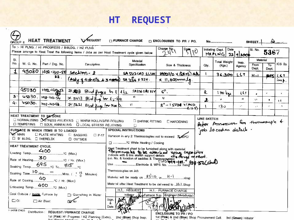
HT REQUEST
103
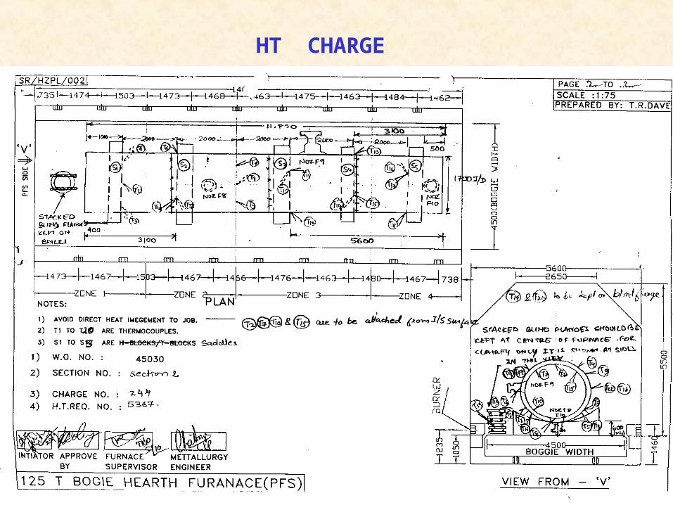
HT CHARGE
Related Documents