Study of PWHT Microstructures and Mechanical Properties for Mild Steel and SA106B Pipe Material by MOHD AZAHARI MOHAMED BUANG A project dissertation submitted to the Mechanical Engineering Program in partial fulfillment of the requirements for the Bachelor of Engineering (Hons) (Mechanical Engineering) UNIVERSITI TEKNOLOGI PETRONAS TRONOH, PERAK November 2010

Welcome message from author
This document is posted to help you gain knowledge. Please leave a comment to let me know what you think about it! Share it to your friends and learn new things together.
Transcript
Study of PWHT Microstructures and Mechanical Properties for
Mild Steel and SA106B Pipe Material
by
MOHD AZAHARI MOHAMED BUANG
A project dissertation submitted to the
Mechanical Engineering Program
in partial fulfillment of the requirements for the
Bachelor of Engineering (Hons)
(Mechanical Engineering)
UNIVERSITI TEKNOLOGI PETRONAS
TRONOH, PERAK
November 2010

STUDY OF PWHT MICROSTRUCTURES AND MECHANICAL
PROPERTIES FOR MILD STEEL AND SA106B PIPE MATERIAL
MOHD AZAHARI BIN MOHAMED BUANG
(ID NO: 9508)
MECHANICAL ENGINEERING
UNIVERSITI TEKNOLOGY PETRONAS
NOVEMBER 2010

i
ACKNOWLEDGEMENTS
I would like to take this opportunity to express my gratitude and thanks to everyone
that has given me support and guidance throughout the whole period of completing this final
year project report.
Firstly, I would like to take this opportunity to acknowledge the endless help and
support receive from my supervisor, Mr. Mohd Faizairi bin Mohd Nor throughout the whole
completing this final year project. Without his guidance and advices, I will not be able to
achieve what I have today within the given duration. Apart from that, I would like extend my
appreciation to all laboratory technicians who have given their help and assistance during my
laboratory work.
I also would like to say thank you to Universiti Teknologi PETRONAS and the
Coordinator of Final Year Project of Mechanical Engineering Department, Dr. Saravanan
Karuppanan who has planned and coordinated all activities and made the necessary
arrangement, especially on term of logistics and matters related to this study.
Lastly, I would like to convey thousands of thanks to my fellow colleagues for their
ideas, assistance and facilitation throughout completion of this project. Thanks also to all who
contributed directly and indirectly, your continuous assistance are highly appreciated.

ii
TABLE OF CONTENT
ACKNOWLEDGEMENTS ..................................................................................................................................... I
TABLE OF CONTENT ......................................................................................................................................... II
LIST OF FIGURES ............................................................................................................................................. IV
LIST OF TABLES ............................................................................................................................................... V
CERTIFICATION OF APPROVAL ....................................................................................................................... VI
CERTIFICATION OF ORIGINALITY ................................................................................................................... VII
ABSTRACT .................................................................................................................................................... VIII
CHAPTER 1 ....................................................................................................................................................... 1
INTRODUCTION .................................................................................................................................................. 1
1.1 PROJECT BACKGROUND ........................................................................................................................... 1
1.2 PROBLEM STATEMENT ............................................................................................................................. 1
1.3 OBJECTIVES AND SCOPE OF STUDY .......................................................................................................... 1
CHAPTER 2 ....................................................................................................................................................... 2
LITERATURE REVIEW .......................................................................................................................................... 2
2.1 CARBON STEEL TYPE ................................................................................................................................. 2
2.2 THE METALLURGY OF CARBON STEEL ...................................................................................................... 3
2.3 METAL ETCHING FOR OPTICAL MICROSCOPE OBSERVATION .................................................................. 5
2.4 HEAT TREATMENT .................................................................................................................................... 7
2.5 WELDING .................................................................................................................................................. 9
2.6 MECHANICAL TESTING ........................................................................................................................... 11
CHAPTER 3 ..................................................................................................................................................... 14
METHODOLOGY AND PROJECT WORK ............................................................................................................... 14
3.1 METHODOLOGY FLOWCHART ................................................................................................................ 14
3.2 X-RAY FLUORESCENCE SAMPLE PREPARATION ...................................................................................... 15
3.3 CARBON STEEL WELDING PROCEDURE .................................................................................................. 16
3.4 SAMPLE PREPARATION FOR MICROSTRUCTURE OBSERVATION ........................................................... 18
3.5 CARBON STEEL HEAT TREATMENT PARAMETER .................................................................................... 19
3.6 VICKERS HARDNESS TEST ....................................................................................................................... 20
3.7 TENSILE TEST .......................................................................................................................................... 21
CHAPTER 4 ..................................................................................................................................................... 22
RESULT AND DISCUSSION ................................................................................................................................. 22
4.1 X-RAY FLUORESCENCE (XRF) RESULT ..................................................................................................... 22
4.2 MICROSTRUCTURE OBSERVATIONS FOR 6MM MILD STEEL THICKNESS (BEFORE PWHT) ..................... 23
4.3 MICROSTRUCTURE OBSERVATIONS FOR 6MM MILD STEEL THICKNESS (AFTER PWHT) ....................... 28
4.4 MICROSTRUCTURE OBSERVATIONS FOR 13MM SA106B STEEL THICKNESS (BEFORE PWHT) ............... 31
4.5 MICROSTRUCTURE OBSERVATIONS FOR 13MM SA106B STEEL THICKNESS (After PWHT) .................... 33
4.6 VICKERS MICRO HARDNESS TEST RESULT .............................................................................................. 36
4.7 TENSILE TEST RESULT ............................................................................................................................. 40

iii
CHAPTER 5 ..................................................................................................................................................... 43
CONCLUSION .................................................................................................................................................... 43
5.1 X-RAY FLUORESCENCE ............................................................................................................................ 43
5.2 MICROSTRUCTURE ................................................................................................................................. 43
5.3 HARDNESS TEST ..................................................................................................................................... 44
5.4 TENSILE TEST .......................................................................................................................................... 44
5.5 WORK CONTINUATION .......................................................................................................................... 44
REFERENCES ................................................................................................................................................... 46

iv
LIST OF FIGURES
FIGURE 2.1: IRON-CARBON PHASE ................................................................................................................. 3
FIGURE 2.2: HEAT TREATMENT TEMPERATURE ON PHASE DIAGRAM ................................................................... 7
FIGURE 2.3: SMAW ILLUSTRATION ................................................................................................................ 9
FIGURE 2.4: TERMS OF A BUTT WELDED BUTT JOINT ...................................................................................... 10
FIGURE 2.5: SIDE VIEW DURING INDENTATION ............................................................................................... 11
FIGURE 2.6: TOP VIEW OF INDENTATION ON TEST SAMPLE................................................................................ 11
FIGURE 2.7: SHAPE OF INDENTATION (SIDE VIEW) ........................................................................................... 12
FIGURE 2.8: EXAMPLE OF INDENTATION IMPRESSION ON TEST SAMPLE .............................................................. 12
FIGURE 2.9: TENSION SPECIMEN FOR PLATE (REFERENCE: ASME IX, 2007, QW-462) ........................................ 13
FIGURE 3.1: TEST SAMPLE FOR X-RAY FLUORESCENCE..................................................................................... 15
FIGURE 3.2: BEVEL PREPARATION ILLUSTRATION ............................................................................................. 16
FIGURE 3.3: BEVEL PREPARATION ................................................................................................................ 16
FIGURE 3.4: ELECTRODE E6013 RB-26, 3MM DIAMETER ................................................................................ 17
FIGURE 3.5: SHIELDED METAL ARC WELDING ................................................................................................ 17
FIGURE 3.6: EXAMPLE OF METALLURGICAL SAMPLE ......................................................................................... 18
FIGURE 3.7: EXAMPLE OF SAND PAPERS DISCS ................................................................................................ 18
FIGURE 3.8: HARDNESS TEST AREA. (RED DOT: BASE METAL, GREEN DOT: WELD METAL, ....................................... 20
BETWEEN YELLOW LINE: HAZ) ..................................................................................................................... 20
FIGURE 4.1: MILD STEEL MICROSTRUCTURE UNDER 500X MAGNIFICATION BY OPTICAL MICROSCOPE. ..................... 25
FIGURE 4.2: BASE/PARENT METAL MICROSTRUCTURE UNDER 100X MAGNIFICATION ........................................... 26
FIGURE 4.3: WELD/FILLER METAL, ALSO KNOWN AS FUSION ZONE MICROSTRUCTURE UNDER 100X MAGNIFICATION 26
FIGURE 4.4: HEAT AFFECTED ZONE MICROSTRUCTURE UNDER 50X MAGNIFICATION ............................................. 27
FIGURE 4.5: MICROSTRUCTURE OF MILD STEEL UNDER 500 X MAGNIFICATIONS AT (A) BASE METAL, (B) HEAT AFFECTED
ZONE, (C) FUSION ZONE. ..................................................................................................................... 27
FIGURE 4.6: MICROSTRUCTURE COMPARISON OF 6MM MILD STEEL THICKNESS UNDER 100 X MAGNIFICATIONS AT BASE
METAL. (A)BEFORE PWHT, (B) AFTER PWHT ....................................................................................... 30
FIGURE 4.7: MICROSTRUCTURE COMPARISON OF 6MM MILD STEEL THICKNESS UNDER 100 X MAGNIFICATIONS AT HAZ.
(A)BEFORE PWHT, (B) AFTER PWHT .................................................................................................. 30
FIGURE 4.8: MICROSTRUCTURE COMPARISON OF 6MM MILD STEEL THICKNESS UNDER 100 X MAGNIFICATIONS AT
WELD METAL. (A)BEFORE PWHT, (B) AFTER PWHT ............................................................................... 30
FIGURE 4.9: MICROSTRUCTURE COMPARISON OF 13MM SA106B THICKNESS UNDER 100 X MAGNIFICATIONS AT BASE
METAL. (A)BEFORE PWHT, (B) AFTER PWHT ....................................................................................... 35
FIGURE 4.10: MICROSTRUCTURE COMPARISON OF 13MM SA106B THICKNESS UNDER 100 X MAGNIFICATIONS AT
HAZ. (A)BEFORE PWHT, (B) AFTER PWHT .......................................................................................... 35
FIGURE 4.11: MICROSTRUCTURE COMPARISON OF 13MM SA106B THICKNESS UNDER 100 X MAGNIFICATIONS AT
WELD METAL. (A)BEFORE PWHT, (B) AFTER PWHT ............................................................................... 35
FIGURE 4.12: MILD STEEL HARDNESS COMPARISON BEFORE AND AFTER HEAT TREATMENT .................................... 36
FIGURE 4.13: SA106B STEEL HARDNESS COMPARISON BEFORE AND AFTER HEAT TREATMENT ............................... 38
FIGURE 4.14: FORCE VERSUS STRAIN FOR SA106B STEEL (BEFORE HEAT TREATMENT) ........................................ 40
FIGURE 4.15: FORCE VERSUS STRAIN FOR SA106B STEEL (AFTER HEAT TREATMENT) .......................................... 41
FIGURE 5.1: EXAMPLE OF SAMPLE UNABLE TO CONTINUE CUTTING. (A) IMPACT TEST SAMPLE, (B) TENSILE TEST SAMPLE
...................................................................................................................................................... 45
v
LIST OF TABLES
TABLE 2.1: IRON-PHASE TYPE AND DESCRIPTION .............................................................................................. 4
TABLE 2.2: COMMON ETCHING REAGENTS USED FOR VARIOUS STEEL ETCH ............................................................ 6
TABLE 3.1: TENSILE TEST SAMPLE DIMENSION AND PARAMETER ........................................................................ 21
TABLE 4.1: XRF RESULTS FOR STEEL A .......................................................................................................... 22
TABLE 4.2: XRF RESULTS FOR STEEL B ........................................................................................................... 22
TABLE 4.3: MILD STEEL MICROSTRUCTURE AFTER WELDING BEFORE HEAT TREATMENT .......................................... 24
TABLE 4.4: CARBON STEEL MICROSTRUCTURE AFTER PWHT............................................................................ 29
TABLE 4.5: SA106B STEEL MICROSTRUCTURE AFTER WELDING BEFORE HEAT TREATMENT ..................................... 32
TABLE 4.6: SA106B STEEL MICROSTRUCTURE AFTER WELDING BEFORE HEAT TREATMENT ..................................... 34
TABLE 4.7: VICKERS MICRO HARDNESS RESULTS (BEFORE HEAT TREATMENT) ...................................................... 36
TABLE 4.8: VICKERS MICRO HARDNESS RESULTS (AFTER HEAT TREATMENT) ........................................................ 36
TABLE 4.9: APPROXIMATE TENSILE STRENGTH CONVERTED FROM VICKERS HARDNESS (BEFORE HEAT TREATMENT) .... 37
TABLE 4.10: APPROXIMATE TENSILE STRENGTH CONVERTED FROM VICKERS HARDNESS (AFTER HEAT TREATMENT) .... 37
TABLE 4.11: VICKERS MICRO HARDNESS RESULTS (BEFORE HEAT TREATMENT).................................................... 38
TABLE 4.12: VICKERS MICRO HARDNESS RESULTS (AFTER HEAT TREATMENT) ...................................................... 38
TABLE 4.13: APPROXIMATE TENSILE STRENGTH CONVERTED FROM VICKERS HARDNESS (BEFORE HEAT TREATMENT) .. 39
TABLE 4.14: APPROXIMATE TENSILE STRENGTH CONVERTED FROM VICKERS HARDNESS (AFTER HEAT TREATMENT) .... 39
TABLE 4.15: TENSILE TEST PROPERTIES COMPARISON BEFORE AND AFTER HEAT TREATMENT ............................... 42

vi
CERTIFICATION OF APPROVAL
STUDY OF PWHT MICROSTRUCTURES AND MECHANICAL PROPERTIES FOR
MILD STEEL AND SA106B PIPE MATERIAL
By
Mohd Azahari bin Mohamed Buang
A project dissertation submitted to the
Mechanical Engineering Programme
Universiti Teknologi PETRONAS
in partial fulfillment of the requirement for the
BACHELOR OF ENGINEERING (Hons.)
(MECHANICAL ENGINEERING)
Approved by,
__________________________
Mr. Mohd Faizairi bin Mohd Nor
UTP Supervisor
UNIVERSITI TEKNOLOGI PETRONAS
TRONOH, PERAK
NOVEMBER 2010

vii
CERTIFICATION OF ORIGINALITY
This is to certify that I am responsible for the work submitted in this project, that the original
work is my own except as specified in the references and acknowledgements, and that the
original work contained herein have not been undertaken or done by unspecified sources or
persons.
___________________________________
MOHD AZAHARI MOHAMED BUANG

viii
ABSTRACT
Welding is a well-known process of steel fabrication especially in oil and gas
industry. Nowadays, we all can see a lot of improvement of welding quality on steel
fabrication sector. This is all involving remarkable finding about the behavior effect of steel
welding especially on weld defect cases. Defect is an excessive condition and outside the
acceptance limits. Weld defects include porosity, incomplete fusion, weld cracking, and
undercut. In order to control the welding defect, many researches have been done including
the heat treatment for weld. All of it is to avoid undesired failure that can lead to
catastrophic. On a carbon steel material structure, defect usually occurs at the weld region.
Welding process involve the process of heating and cooling of material being weld
together. This cyclic heat source from welding process will alter the base metal
microstructure. The alteration of base metal microstructure can cause the mechanical
properties at the welded structure to changes. Localized expansions also exist due to heat
from welding or molten metal. When the weld cools, some areas cool and contract more than
others. This contraction with the bulk metal surrounding weldment will provide residual
stresses. This residual stress is often become cause a premature failure of critical component
like bridge bar links and pressure vessel. One way to overcome this problem is heat
treatment.
Heat treatment is a method used to modify the physical properties of a material. The
use of heat treatment is to heating or chilling the material to extreme temperature to achieve a
desired result such stress relieving, hardening, or softening. Base on Iron-Carbon phase
diagram, we are able to see the changes in microstructure during heating and cooling.
This research is to characterize the mechanical properties and its microstructure of the
weld zone in order to avoid failure due to weld defect or microstructure refinement for
carbon steel material. This research is to characterize the mechanical properties by subjecting
the material microstructure to post weld heat treatment (PWHT). This study will provide
relationship of the steel microstructure, mechanical properties, and PWHT.
1
CHAPTER 1
INTRODUCTION
1.1 PROJECT BACKGROUND
The material involve with this research is low carbon steel which is mild steel.
Carbon steel is widely used because of lower cost and much easier to weld. Carbon steel will
be weld according to ASME IX, Article I, II, III, and IV standard. In industry especially in
oil and gas industry, heat treatment usually used to relieve residual stress cause by welding
process. For example is pressure vessel fabrication. Heat treatment is not only being used to
relieve internal stress on the vessel, but also as a solution to reduce the risk of brittle fracture.
For coded vessel, heat treatment criteria and parameter usually referred from ASME VIII,
2007 edition, division 1, UCS-56.
The welded joint will be send to metallurgy laboratory for mechanical properties
testing. This is to determine the level of welding quality. Before heat treatment the product, it
is important to make sure all the welding are within the acceptance limit. Iron-Carbon phase
diagram is a good material to understand the effect or heat treatment relative to
microstructure. With microstructure examination, we are able to categorized microstructure
shape and its mechanical properties. For example, martensitic iron which have brittle
properties. Material characterizations can be made according to the relationship between
mechanical properties, microstructure, and post weld heat treatment.
1.2 PROBLEM STATEMENT
Cyclic heating from welding process will alter the base metal microstructure. For a
carbon steel structure or part, the failure usually occurs at the welded region. It is beneficial
to understand the interaction between material microstructure, heat treatment, and
mechanical properties will provide at the welded region.
1.3 OBJECTIVES AND SCOPE OF STUDY
The research is to characterize the mechanical properties and microstructure of the
welded mild steel before and after subjecting the material to post-weld heat treatment.
2
CHAPTER 2
LITERATURE REVIEW
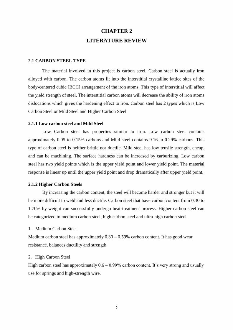
2.1 CARBON STEEL TYPE
The material involved in this project is carbon steel. Carbon steel is actually iron
alloyed with carbon. The carbon atoms fit into the interstitial crystalline lattice sites of the
body-centered cubic [BCC] arrangement of the iron atoms. This type of interstitial will affect
the yield strength of steel. The interstitial carbon atoms will decrease the ability of iron atoms
dislocations which gives the hardening effect to iron. Carbon steel has 2 types which is Low
Carbon Steel or Mild Steel and Higher Carbon Steel.
2.1.1 Low carbon steel and Mild Steel
Low Carbon steel has properties similar to iron. Low carbon steel contains
approximately 0.05 to 0.15% carbons and Mild steel contains 0.16 to 0.29% carbons. This
type of carbon steel is neither brittle nor ductile. Mild steel has low tensile strength, cheap,
and can be machining. The surface hardness can be increased by carburizing. Low carbon
steel has two yield points which is the upper yield point and lower yield point. The material
response is linear up until the upper yield point and drop dramatically after upper yield point.
2.1.2 Higher Carbon Steels
By increasing the carbon content, the steel will become harder and stronger but it will
be more difficult to weld and less ductile. Carbon steel that have carbon content from 0.30 to
1.70% by weight can successfully undergo heat-treatment process. Higher carbon steel can
be categorized to medium carbon steel, high carbon steel and ultra-high carbon steel.
1. Medium Carbon Steel
Medium carbon steel has approximately 0.30 – 0.59% carbon content. It has good wear
resistance, balances ductility and strength.
2. High Carbon Steel
High carbon steel has approximately 0.6 – 0.99% carbon content. It’s very strong and usually
use for springs and high-strength wire.

3
3. Ultra-high Carbon Steel
Ultra-high carbon steel has 1.0 – 2.0% carbon content. Steel with more than 1.2% carbon
content are made using powder metallurgy. Carbon steel which contain above 2.0% carbon
content is considered as cast iron. This steel can be tempered to great hardness.
Steel can be heat treated to allow part to be fabricated in an easy deformable soft
state. Steel are often wrought by cold working methods. If steel have enough carbon content,
the alloy can be hardened to increase strength, wear, and impact resistance.
2.2 THE METALLURGY OF CARBON STEEL
The diagram shown above is about transformation phase that occurs as a result of
slow heating. Slow cooling will reduce the transformation temperature. The fast heating and
cooling rates in welding will have a significant influence making the weld metallurgy
prediction using this diagram become difficult.
Figure 2.1: Iron-Carbon Phase

4
Iron Phase Microstructure Descriptions
Austenite
In liquid form, has Face Centre Cubic
[F.C.C] atomic structure, contain up to 2%
carbon.
Ferrite
This phase has Body Centre Cubic [B.C.C]
atomic structure, hold very little carbon
(0.0001% at room temperature), can be
either alpha or delta ferrite.
Cementite
This is a very hard intermetallic compound
having 6.7% carbon and remainder is iron,
very hard, hardness reduced when mixed
with soft ferrite layers, slow cooling gives
course perlite which is easy to machine but
low toughness, faster cooling produce very
fine layers of ferrite and cementite which
is harder and tougher.
Pearlite
Mixture of ferrite and cementite strips in
single grain, distance between the plates
and their thickness is depending on the
cooling rate of the material. Fast cooling
creates thin plates that are close together
and slow cooling creates a much course
structure having less toughness. Fully
pearlitic structure occurs at 0.8% carbon
Martensite
Exist when rapid cooling from austenite,
the F.C.C structure rapidly change to
B.C.C giving enough time for the carbon
to form pearlite. This will produce
distorted structure that has visual of fine
needles. Martensite is either forms or it
does not which is not a partial
transformation phase. Only the part that
cooled fast enough will form martensite.
Martensite hardness only depends on
carbon content and it is usually very high
except the carbon content is low
Table 2.1: Iron-Phase type and description Radhi Table 01 1
5
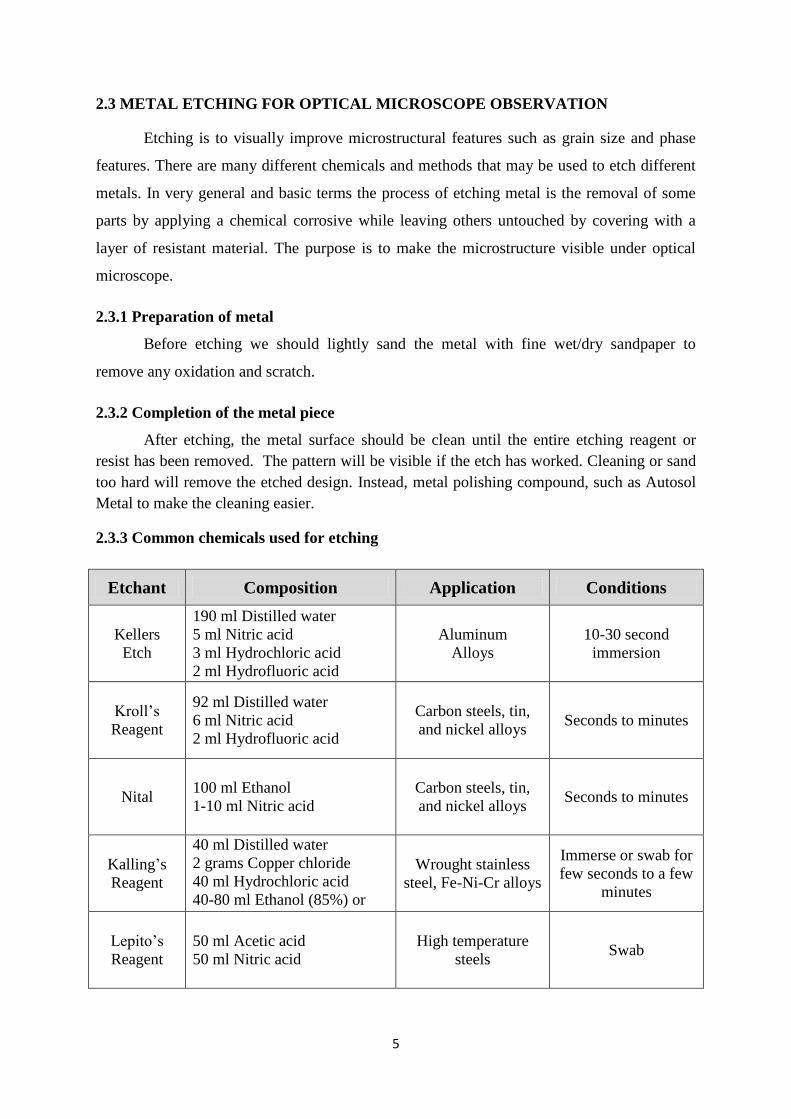
2.3 METAL ETCHING FOR OPTICAL MICROSCOPE OBSERVATION
Etching is to visually improve microstructural features such as grain size and phase
features. There are many different chemicals and methods that may be used to etch different
metals. In very general and basic terms the process of etching metal is the removal of some
parts by applying a chemical corrosive while leaving others untouched by covering with a
layer of resistant material. The purpose is to make the microstructure visible under optical
microscope.
2.3.1 Preparation of metal
Before etching we should lightly sand the metal with fine wet/dry sandpaper to
remove any oxidation and scratch.
2.3.2 Completion of the metal piece
After etching, the metal surface should be clean until the entire etching reagent or
resist has been removed. The pattern will be visible if the etch has worked. Cleaning or sand
too hard will remove the etched design. Instead, metal polishing compound, such as Autosol
Metal to make the cleaning easier.
2.3.3 Common chemicals used for etching
Etchant Composition Application Conditions
Kellers
Etch
190 ml Distilled water
5 ml Nitric acid
3 ml Hydrochloric acid
2 ml Hydrofluoric acid
Aluminum
Alloys
10-30 second
immersion
Kroll’s
Reagent
92 ml Distilled water
6 ml Nitric acid
2 ml Hydrofluoric acid
Carbon steels, tin,
and nickel alloys Seconds to minutes
Nital 100 ml Ethanol
1-10 ml Nitric acid
Carbon steels, tin,
and nickel alloys Seconds to minutes
Kalling’s
Reagent
40 ml Distilled water
2 grams Copper chloride
40 ml Hydrochloric acid
40-80 ml Ethanol (85%) or
Methanol (95%)
Wrought stainless
steel, Fe-Ni-Cr alloys
Immerse or swab for
few seconds to a few
minutes
Lepito’s
Reagent
50 ml Acetic acid
50 ml Nitric acid
High temperature
steels Swab

6
Etchant Composition Application Conditions
Marble’s
Reagent
50 ml Distilled water
50 ml Hydrochloric acid
10 grams Copper sulfate
Stainless steels,
Nickel alloys
Immersion or swab
etching for a few
seconds
Murakami
Reagent
100 ml Distilled water
10 grams K3Fe(CN)6
10 grams NaOH or KOH
Wrought Stainless
steel, tungsten alloys,
Silver alloys.
Immerse or swab for
seconds to minutes
Pieral 100 ml Ethanol
2-1 grams Picric acid
Iron and steel,
Tin alloys Seconds to minutes
Vilella’s
Reagent
45 ml Glycerol
15 ml Nitric acid
30 ml Hydrochloric acid
Stainless steel,
Carbon steel,
Cast iron
Seconds to minutes
Table 2.2: Common etching reagents used for various steel etch Radhiz 01 2

7
2.4 HEAT TREATMENT
2.4.1 Post Weld Heat Treatment
The post weld heat treatment is normally performed to reduce the risk of brittle
fracture. Post weld heat treatment is the most widely used form of stress relieving on
completion of fabrication of welded structures. This stresses exist when a weld cools and its
contractions is restricted by the bulk of the material surrounding it. Post weld heat treatment
will generally result in a modification of the microstructure of both the weld metal and heat
affected zone. With alloy steels, the thickness at which post weld heat treatment becomes
mandatory is much less. Typically, the range is 13 – 20 mm, and even below 13 mm, a series
of strict conditions have to be met before post weld heat treatment can be waived
2.4.2 Process Annealing
Annealing is a technique used to recover cold work and relax stresses within a metal.
A process used to relieve stress in cold-worked carbon steel with less than 0.3 wt% C. The
steel is usually heated up to 550–650 °C for 1 hour, but sometimes temperatures as high as
700 °C. The image rightward shows the area where process annealing occurs.
Figure 2.2: Heat Treatment Temperature on Phase Diagram

8
2.4.3 Full annealing
Carbon steel is heated to approximately 40 °C above Ac3 or Ac1 for 1 hour; this
assures all the ferrite transforms into austenite. The steel must then be cooled slowly, in the
realm of 38 °C (100 °F) per hour. Usually part allowed to cool in the furnace. This result in a
coarse pearlitic structure, which means the "bands" of pearlite are thick. Fully-annealed steel
is soft and ductile, with no internal stresses.
2.4.4 Isothermal annealing
It is a process in which hypoeutectoid steel is heated above the upper critical
temperature and this temperature is maintained for a time and then the temperature is brought
down below lower critical temperature and maintained. Then finally it is cooled at room
temperature. This method rids any temperature gradient.
2.4.5 Normalizing
Carbon steel is heated to approximately 55 °C above Ac3 or Acm for 1 hour; this
assures the steel completely transforms to austenite. The steel is then air-cooled, which is a
cooling rate of approximately 38 °C (68 °F) per minute. This results in a fine pearlitic
structure, and a more-uniform structure. Normalized steel has a higher strength than annealed
steel; it has a relatively high strength and ductility.
2.4.6 Quenching
To harden by quenching, carbon steel with at least 0.4 wt% C is heated to normalizing
temperatures (austenitic crystal phase) and then rapidly cooled (quenched) in water, brine, or
oil to the critical temperature. This results in a martensitic structure. Thus quenched steel is
extremely hard but brittle, usually too brittle for practical purposes. These internal stresses
cause stress cracks on the surface. Quenched steel is approximately three to four (with more
carbon) fold harder than normalized steel.
2.4.7 Tempering
Untempered martensite (after quenching), very hard and strong, is too brittle to be
useful for most applications. A solution for this problem is called tempering. Most
applications require quenched parts to be tempered (reheating quenched steel to a temperature
below the eutectoid temperature, often 150°C then cooling) to impart some toughness (restore
ductility, but reduces hardness).

9
2.5 WELDING
2.5.1 Shielded Metal Arc Welding (SMAW)
SMAW is the most widely use of arc welding type. Compared to others arc welding,
SMAW is more economical and its equipment is more portable and less complex. SMAW is
performed by striking an arc between coated-metal electrode and base metal. Arc established
and molten metal from electrode tip flow together with molten metal from base metal edge to
form a joints (known as fusion).
Figure 2.3: SMAW illustration

10
2.5.2 Electrodes for SMAW
Since the base metal to weld is mild steel, the suitable electrode is E6013 RB-26
(AWS Specification). This electrode type is common used for welding light sheet metals,
light duty steel structures, and for surfacing thick-section welds. The coating type for E6013
is high titania potassium. The current range for this electrode is 80-140 amps.
“E” stands for electrode, the first two digits, “60” is the minimum tensile strength
60,000 p.s.i, the second last digit, “1” indicates that this electrode suitable for all position,
and the last digit, “3” is the type of current. In this case is Direct Current Reverse Polarity
(electrode positive), Direct Current Straight Polarity (electrode negative), or Alternative
Current. The “R” in RB-26 stands for Rutile, which is major ingredient in the coating flux.
While the “B” means a slag-shield covered electrode. “26” represent the 26th
year of the show
era of japan, relative to 1951 when it was developed.
2.5.3 Welding Joints and Position
Welding joints for this project is single-v butt joint. Single sided preparations are
normally made on thinner materials, or when weld access from both sides is restricted. The
welding position used is Flat position 1G as in ASME IX, 2007, Article I, QW-110.
Figure 2.4: Terms of a Butt Welded Butt Joint

11
2.6 MECHANICAL TESTING
Hardness is one of the important mechanical properties, which is measurement of
material’s resistance to plastic deformation. Hardness test are usually performed because of
inexpensive, simple, non-destructive (only small indentation), and from hardness data we can
use it to estimate other mechanical properties such as tensile strength.
2.5.2 Brinell Hardness Test
In Brinell hardness testing, a hard spherical indenter is pressured into the surface of
the test sample. The diameter of the indenter is 10 mm and the standard loads range between
500 to 3000 kg with 500 kg increments. During the test, the load is maintained constant for
10 to 30 second. The diameter of indentation is then measured and converted to Brinell
Hardness Number using a chart. The reference used for this testing is ASTM E 10, Standard
Test Method for Brinell Hardness of Metallic Materials
Brinell harness number can be calculated using the formula:
√
Where: HB: Brinell Hardness Number
P : Load
D : Indenter diameter
d : Resulting indentation diameter on test sample
Figure 2.5: Side view during indentation Figure 2.6: Top view of indentation on test sample
12
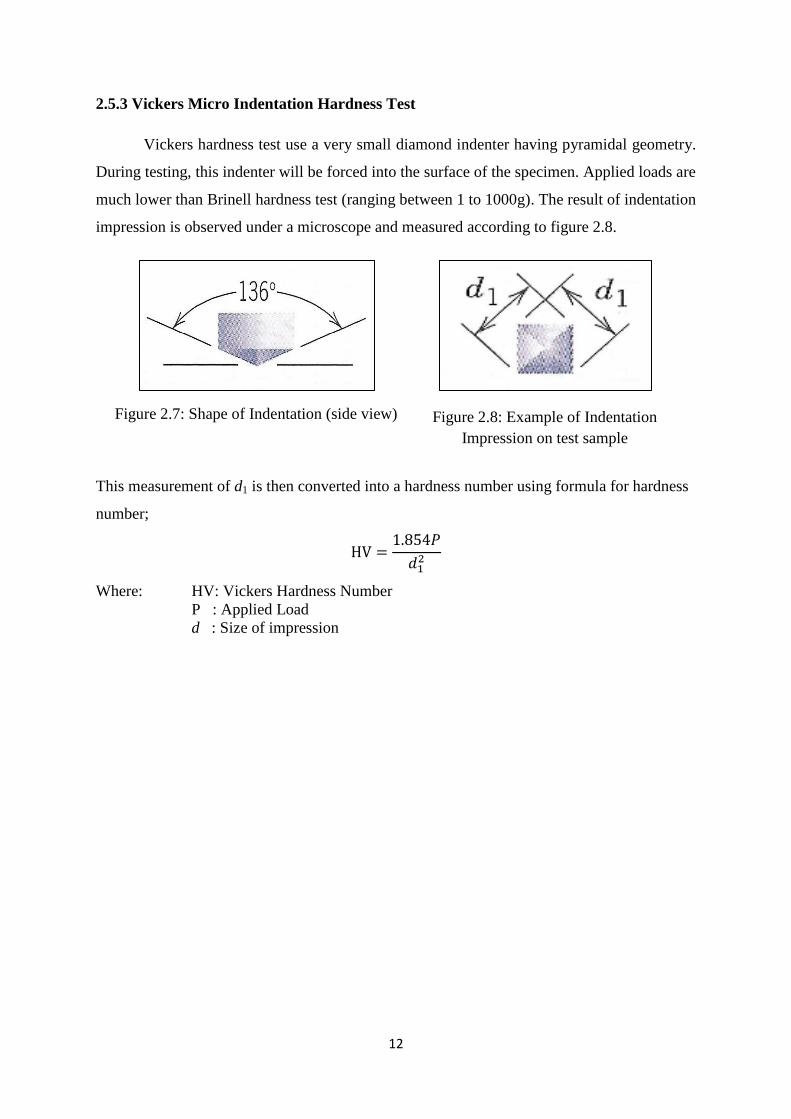
2.5.3 Vickers Micro Indentation Hardness Test
Vickers hardness test use a very small diamond indenter having pyramidal geometry.
During testing, this indenter will be forced into the surface of the specimen. Applied loads are
much lower than Brinell hardness test (ranging between 1 to 1000g). The result of indentation
impression is observed under a microscope and measured according to figure 2.8.
This measurement of d1 is then converted into a hardness number using formula for hardness
number;
Where: HV: Vickers Hardness Number
P : Applied Load
d : Size of impression
Figure 2.7: Shape of Indentation (side view) Figure 2.8: Example of Indentation
Impression on test sample

13
2.5.3 Tension Test
The purpose of tensile test is to determine the tensile strength of the weld metal. This
test is suitable for groove butt joint in plate. The usual size and shape of the specimens as in
figure below:
From the figure above, specimen width, W is equal to 19 mm and the grinding mark must be
parallel to the tensile force otherwise it may have a notch effect.
Figure 2.9: Tension specimen for plate (reference: ASME IX, 2007, QW-462)

14
CHAPTER 3
METHODOLOGY and PROJECT WORK
3.1 METHODOLOGY FLOWCHART
Preliminary research on welding, steel microstructure, mechanical properties and heat treatment
Welding preparation work; base metal is mild steel. The joint type will be butt joint, single-v grove.
Material chemical composition verification using X-ray Fluorescent
Commence Post-Weld Heat Treatment at the welded joint
Microstructure observation after heat treatment
Mechanical testing for base metal and welded metal such as hardness and ductility
All the finding will be used to characterize the mechanical properties and microstructure of steel after subjecting to heat treatment
15
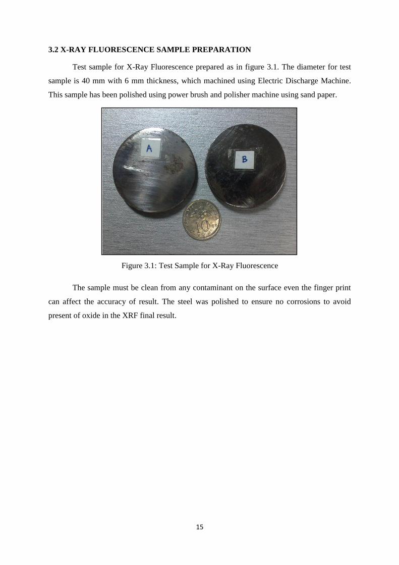
3.2 X-RAY FLUORESCENCE SAMPLE PREPARATION
Test sample for X-Ray Fluorescence prepared as in figure 3.1. The diameter for test
sample is 40 mm with 6 mm thickness, which machined using Electric Discharge Machine.
This sample has been polished using power brush and polisher machine using sand paper.
The sample must be clean from any contaminant on the surface even the finger print
can affect the accuracy of result. The steel was polished to ensure no corrosions to avoid
present of oxide in the XRF final result.
Figure 3.1: Test Sample for X-Ray Fluorescence

16
3.3 CARBON STEEL WELDING PROCEDURE
3.3.1 Single-V Bevel Weld Preparation
The choice of weld preparation is to compromise between maintaining adequate
access and minimizing the weld volume. I am using a typical pipe butt weld set-up. The
included angle would be 60°, ± 3 mm root gap, and zero to 2 mm thick root face.
This single-v bevel weld preparation was done by using conventional lathe machine.
Conventional lathe is to roughly shape the bevel into the desired angle. After that we use file
to remove corrosion or dirt around the area to be weld. The thickness of the metal plate to be
weld is about 7 mm. Therefore, one path of shielded metal arc welding is sufficient to weld
the plate.
Figure 3.2: Bevel preparation illustration
Figure 3.3: Bevel preparation
17
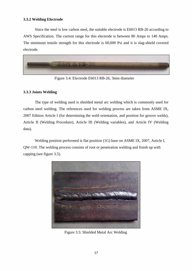
3.3.2 Welding Electrode
Since the steel is low carbon steel, the suitable electrode is E6013 RB-26 according to
AWS Specification. The current range for this electrode is between 80 Amps to 140 Amps.
The minimum tensile strength for this electrode is 60,000 Psi and it is slag-shield covered
electrode.
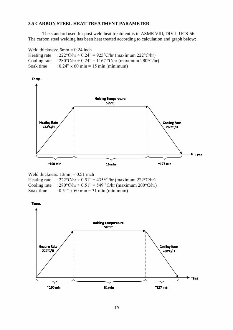
3.3.3 Joints Welding
The type of welding used is shielded metal arc welding which is commonly used for
carbon steel welding. The references used for welding process are taken from ASME IX,
2007 Edition Article I (for determining the weld orientation, and position for groove welds),
Article II (Welding Procedure), Article III (Welding variables), and Article IV (Welding
data).
Welding position performed is flat position (1G) base on ASME IX, 2007, Article I,
QW-110. The welding process consists of root or penetration welding and finish up with
capping (see figure 3.5).
Figure 3.5: Shielded Metal Arc Welding
Figure 3.4: Electrode E6013 RB-26, 3mm diameter

18
3.4 SAMPLE PREPARATION FOR MICROSTRUCTURE OBSERVATION
Previously welded mild steel cut into perpendicular cross section to weld path. After
that, sample will be mounted for easy grip during grind and polishing.
There are a few type of sand paper used. After cutting, we need rough sand paper (grit
60) to remove deep scratch first. After that follow by less roughness sand paper which is Grit
120, Grit 240, Grit 320, Grit 400, Grit 2400, and Grit 4000 in order.
Figure 3.7: Example of sand papers discs
Figure 3.6: Example of metallurgical sample
19
3.5 CARBON STEEL HEAT TREATMENT PARAMETER
The standard used for post weld heat treatment is in ASME VIII, DIV I, UCS-56.
The carbon steel welding has been heat treated according to calculation and graph below:
Weld thickness: 6mm = 0.24 inch
Heating rate : 222°C/hr ÷ 0.24” = 925°C/hr (maximum 222°C/hr)
Cooling rate : 280°C/hr ÷ 0.24” = 1167 °C/hr (maximum 280°C/hr)
Soak time : 0.24” x 60 min = 15 min (minimum)
Weld thickness: 13mm = 0.51 inch
Heating rate : 222°C/hr ÷ 0.51” = 435°C/hr (maximum 222°C/hr)
Cooling rate : 280°C/hr ÷ 0.51” = 549 °C/hr (maximum 280°C/hr)
Soak time : 0.51” x 60 min = 31 min (minimum)

20
3.6 VICKERS HARDNESS TEST
The hardness of the sample measured using Vickers Micro Indentation machine. The
load used is 300gram with pyramid indentation shape. The reason for using Vickers hardness
test because of it is more convenient to do hardness test at selected microstructure area.
Hardness test for sample consist of three areas which is base metal, weld metal and
heat affected zone. The base metal is indicated by the red dot in the figure 3.8 below. Next is
the weld metal or also known as fusion metal. This area indicated by green dot in the figure
3.8 below. The last area is the heat affected zone which is in the boundary between weld
metal and the base metal. This area indicated in between the yellow line in the figure 3.8
below.
Figure 3.8: Hardness test area. (Red dot: base metal, green dot: weld metal,
between yellow line: HAZ)

21
3.7 TENSILE TEST
Tensile test sample machined using EDM to get the “dog bone” shape. The total
length of the test sample is 203.2mm. The tensile test performed using 100kN capacity tensile
test machine.
Measurement of Samples Sample 1 Sample 2
Specimen Length 203.2mm 203.2mm
Original Gauge Length 34mm 34mm
Original Width 19mm 19mm
Original Area 133mm2 133mm
2
Testing Speed Rate 0.006mm/s 0.006mm/s
Table 3.1: Tensile test sample dimension and parameter

22
CHAPTER 4
RESULT AND DISCUSSION
4.1 X-RAY FLUORESCENCE (XRF) RESULT
The purpose of XRF is to verify the steel used is low carbon steel. From the result, we
can determine the chemical composition of the steel (table 4.1 and table 4.2). The amount of
carbon in the steel used is low therefore it is difficult to be detected. The absent of carbon in
the XRF result verify the steel is in low carbon content.
Oxide
(O)
Aluminium
(Al)
Silicon
(Si)
Sulfur
(S)
Chromium
(Cr)
Manganese
(Mn)
Iron
(Fe)
0.3 KCps 1.0 KCps 4.0 KCps 1.3 KCps 9.6 KCps 58.9 KCps 9982.7 KCps
30 0.0683 0.237 0.0304 0.0553 0.4665 68.48
Nickel
(Ni)
Copper
(Cu)
Zinc
(Zn)
Molybdenum
(Mo)
Terbium
(Tb)
Sulfur Trioxide
(SO3)
5.0 KCps 33.0 KCps 2.1 KCps 3.9 KCps 32.8 KCps 1.3 KCps
0.0689 0.406 0.0082 0.0105 0.0705 1.132
Oxide
(O)
Aluminium
(Al)
Silicon
(Si)
Sulfur
(S)
Chromium
(Cr)
Manganese
(Mn)
Iron
(Fe)
0.3 KCps 0.6 KCps 3.1 KCps 1.1 KCps 9.4 KCps 58.9 KCps 9674.7 KCps
30 0.040 0.185 0.0272 0.0559 0.4817 68.56
Nickel
(Ni)
Copper
(Cu)
Zinc
(Zn)
Molybdenum
(Mo)
Terbium
(Tb)
Sulfur Trioxide
(SO3)
5.1 KCps 32.3 KCps 2.3 KCps 3.8 KCps 33.1 KCps 1.1 KCps
0.0737 0.412 0.0114 0.0106 0.0782 1.168
Sample: Steel A Measurement Method: Elemental
Sample: Steel B Measurement Method: Elemental
Table 4.1: XRF results for steel A
Table 4.2: XRF results for steel B
23
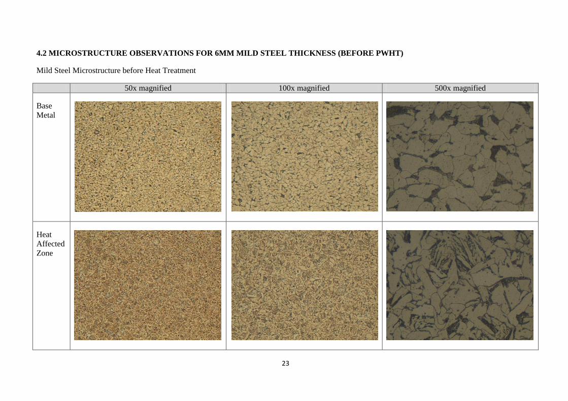
4.2 MICROSTRUCTURE OBSERVATIONS FOR 6MM MILD STEEL THICKNESS (BEFORE PWHT)
Mild Steel Microstructure before Heat Treatment
50x magnified 100x magnified 500x magnified
Base
Metal
Heat
Affected
Zone

24
50x magnified 100x magnified 500x magnified
Weld
Metal
Table 4.3: Mild steel microstructure after welding before heat treatment
25
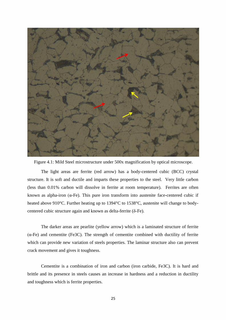
The light areas are ferrite (red arrow) has a body-centered cubic (BCC) crystal
structure. It is soft and ductile and imparts these properties to the steel. Very little carbon
(less than 0.01% carbon will dissolve in ferrite at room temperature). Ferrites are often
known as alpha-iron (α-Fe). This pure iron transform into austenite face-centered cubic if
heated above 910°C. Further heating up to 1394°C to 1538°C, austenite will change to body-
centered cubic structure again and known as delta-ferrite (δ-Fe).
The darker areas are pearlite (yellow arrow) which is a laminated structure of ferrite
(α-Fe) and cementite (Fe3C). The strength of cementite combined with ductility of ferrite
which can provide new variation of steels properties. The laminar structure also can prevent
crack movement and gives it toughness.
Cementite is a combination of iron and carbon (iron carbide, Fe3C). It is hard and
brittle and its presence in steels causes an increase in hardness and a reduction in ductility
and toughness which is ferrite properties.
Figure 4.1: Mild Steel microstructure under 500x magnification by optical microscope.

26
Base metal microstructure is almost the same grain size everywhere. It consists of
more ferrite (light area) and pearlite (darker area). The microstructure of the base metal is
totally different from the weld metal region in term of grain size and shape and also its phase
properties.
Weld metal have longer grain and bigger than the base metal. The direction of the
structure is toward the welding electrode. Less pearlite found in the base metal compared to
base metal (red arrow in figure 4.3). Due to rapid cooling after welding, some of the
martensitic structure exists along the weld metal (yellow circle in figure 4.3). Martensitic is a
very hard needle-like structure of iron and carbon.
From figure 4.3, inside the red circle, we can also identify the ferrite with non-aligned
MAC (martensite, austenite, and carbide). This constituent called ferrite with aligned second
phase (can also regarded as bainite). This second phase is mainly the iron carbide cementite.
Other constituents such as martensite and retained austenite (retained phases) are present in
small quantities.
Meanwhile, inside the black rectangular in figure 4.3 is the ferrite with aligned MAC.
The lighter grain shown by green arrow in figure 4.3 is the pro-eutectoid ferrite.
Figure 4.2: Base/Parent Metal microstructure under 100x magnification
Figure 4.3: Weld/Filler Metal, also known as fusion zone microstructure under 100x
magnification
27
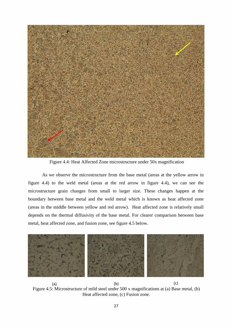
As we observe the microstructure from the base metal (areas at the yellow arrow in
figure 4.4) to the weld metal (areas at the red arrow in figure 4.4), we can see the
microstructure grain changes from small to larger size. These changes happen at the
boundary between base metal and the weld metal which is known as heat affected zone
(areas in the middle between yellow and red arrow). Heat affected zone is relatively small
depends on the thermal diffusivity of the base metal. For clearer comparison between base
metal, heat affected zone, and fusion zone, see figure 4.5 below.
Figure 4.4: Heat Affected Zone microstructure under 50x magnification
(a) (b) (c)
Figure 4.5: Microstructure of mild steel under 500 x magnifications at (a) Base metal, (b)
Heat affected zone, (c) Fusion zone.
28
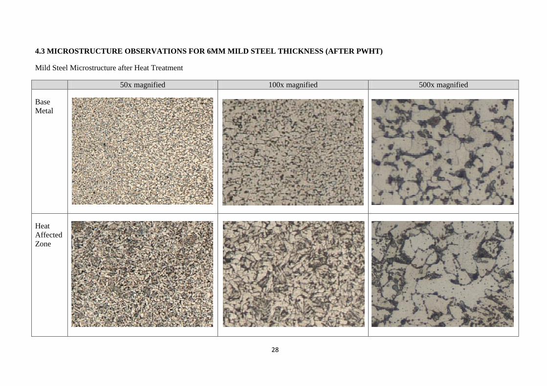
4.3 MICROSTRUCTURE OBSERVATIONS FOR 6MM MILD STEEL THICKNESS (AFTER PWHT)
Mild Steel Microstructure after Heat Treatment
50x magnified 100x magnified 500x magnified
Base
Metal
Heat
Affected
Zone

29
50x magnified 100x magnified 500x magnified
Weld
Metal
Table 4.4: Carbon Steel Microstructure after PWHT

30
Figure 4.6: Microstructure comparison of 6mm mild steel thickness under 100 x
magnifications at base metal. (a)Before PWHT, (b) After PWHT
(a) (b)
Figure 4.7: Microstructure comparison of 6mm mild steel thickness under 100 x
magnifications at HAZ. (a)Before PWHT, (b) After PWHT
(a) (b)
Figure 4.8: Microstructure comparison of 6mm mild steel thickness under 100 x
magnifications at weld metal. (a)Before PWHT, (b) After PWHT
(a) (b)

31
4.4 MICROSTRUCTURE OBSERVATIONS FOR 13MM SA106B STEEL THICKNESS (BEFORE PWHT)
SA106B Steel Microstructure before Heat Treatment
50x magnified 100x magnified 500x magnified
Base
Metal
Heat
Affected
Zone

32
50x magnified 100x magnified 500x magnified
Weld
Metal
Table 4.5: SA106B steel microstructure after welding before heat treatment
33
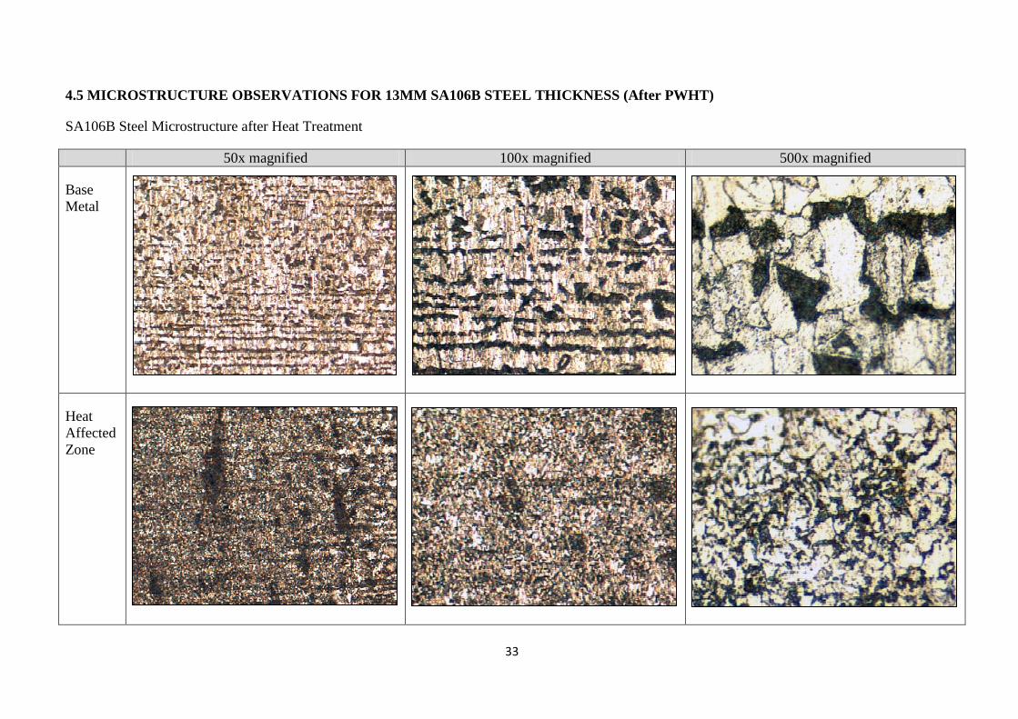
4.5 MICROSTRUCTURE OBSERVATIONS FOR 13MM SA106B STEEL THICKNESS (After PWHT)
SA106B Steel Microstructure after Heat Treatment
50x magnified 100x magnified 500x magnified
Base
Metal
Heat
Affected
Zone

34
50x magnified 100x magnified 500x magnified
Weld
Metal
Table 4.6: SA106B steel microstructure after welding before heat treatment

35
Figure 4.9: Microstructure comparison of 13mm SA106B thickness under 100 x
magnifications at base metal. (a)Before PWHT, (b) After PWHT
(a) (b)
Figure 4.10: Microstructure comparison of 13mm SA106B thickness under 100 x
magnifications at HAZ. (a)Before PWHT, (b) After PWHT
(a) (b)
Figure 4.11: Microstructure comparison of 13mm SA106B thickness under 100 x
magnifications at weld metal. (a)Before PWHT, (b) After PWHT
(a) (b)

36
4.6 VICKERS MICRO HARDNESS TEST RESULT
The purpose of hardness test is to measure the sample ability to resist plastic
deformation from a standard load. The results for both before and after heat treatment are
presented in the next subsection.
4.6.1 Hardness test result for 6mm mild steel thickness
First Reading
(HV) Second Reading
(HV) Third Reading
(HV) Mean (HV)
Base Metal 161.5 173.7 168.0 167.7
Weld Metal 212.0 193.4 212.8 206.1
HAZ 200.2 185.8 209.1 198.4
After heat treatment, hardness value at the base metal has increase from HV167.7 to
HV192.9. Inside the weld metal, there are no significant changes in hardness value due to
heat gain from welding process. Hardness value in the heat affected zone decrease from
HV198.4 to HV175.3. Ductility has been increase at the heat affected zone after heat
treatment.
0
50
100
150
200
250
Base Metal Weld Metal HAZ
HV
Before heat treatment
After heat treatment
First Reading
(HV) Second Reading
(HV) Third Reading
(HV) Mean (HV)
Base Metal 197.2 193.4 188.1 192.9
Weld Metal 206.5 211.2 216.0 211.2
HAZ 176.1 171.8 177.9 175.3
Figure 4.12: Mild steel hardness comparison before and after heat
treatment
Table 4.7: Vickers Micro Hardness Results (before heat treatment)
Table 4.8: Vickers Micro Hardness Results (after heat treatment)
192.9
211.2
175.3 167.7
206.1
198.4

37
Base on ASM Metals Reference Book, third edition, we can convert the hardness
value into approximate tensile strength. However, this conversion is limited to comparative
purposes only.
Mean (HV)
Approx. TS (MPa)
Base Metal 167.7 539
Weld Metal 206.1 656
HAZ 198.4 632
Mean (HV)
Approx. TS (MPa)
Base Metal 192.9 617
Weld Metal 211.2 671
HAZ 175.3 563
Table 4.9: Approximate tensile strength converted from Vickers Hardness (before heat treatment)
Table 4.10: Approximate tensile strength converted from Vickers Hardness (after heat treatment)
38
4.6.2 Hardness test result for 13mm SA106B steel thickness
First Reading
(HV) Second Reading
(HV) Third Reading
(HV) Mean (HV)
Base Metal 161.8 173.4 159.8 165.0
Weld Metal 184.8 202.5 230.4 205.9
HAZ 196.1 194.3 202.0 197.5
First Reading
(HV) Second Reading
(HV) Third Reading
(HV) Mean (HV)
Base Metal 174.5 164.0 188.6 175.7
Weld Metal 195.0 196.6 201.0 197.5
HAZ 175.2 178.0 184.7 179.3
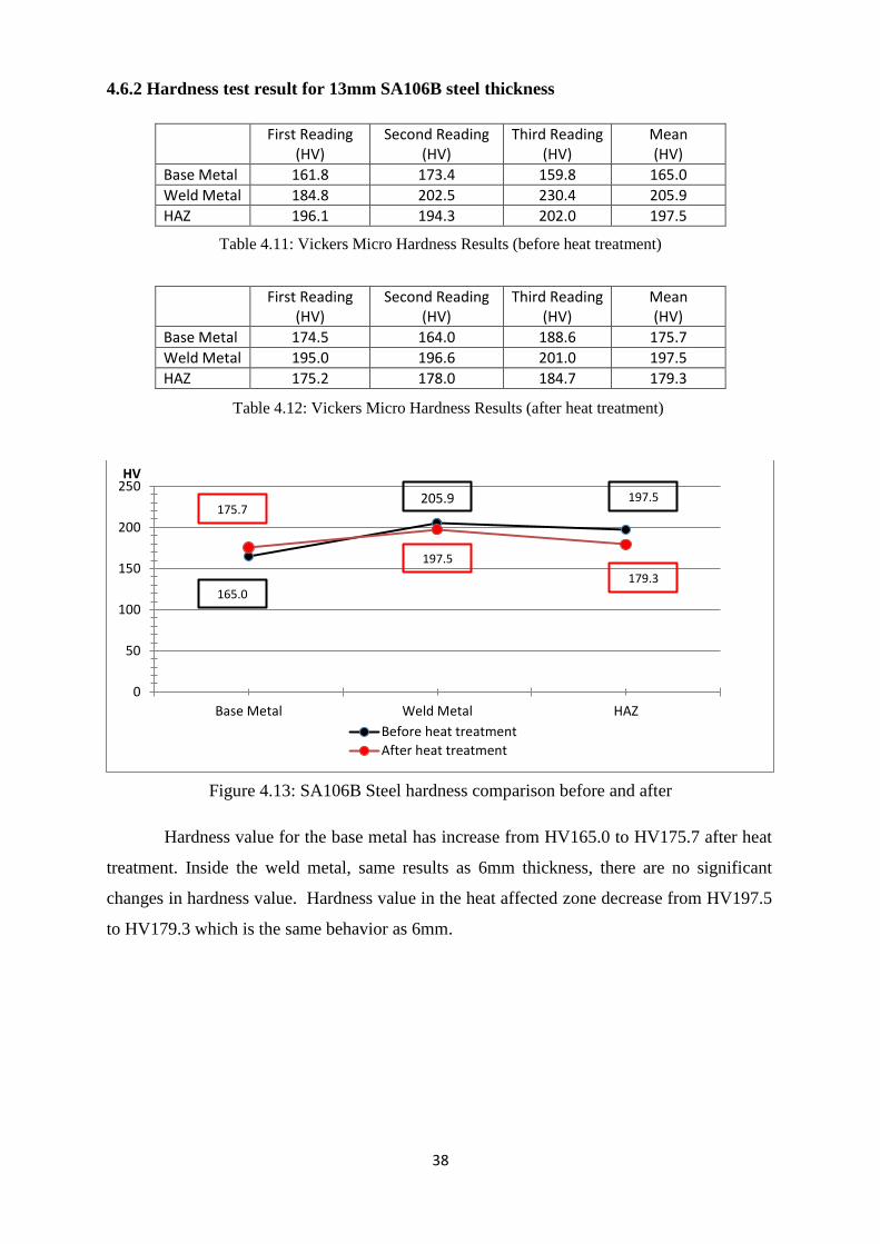
Hardness value for the base metal has increase from HV165.0 to HV175.7 after heat
treatment. Inside the weld metal, same results as 6mm thickness, there are no significant
changes in hardness value. Hardness value in the heat affected zone decrease from HV197.5
to HV179.3 which is the same behavior as 6mm.
0
50
100
150
200
250
Base Metal Weld Metal HAZ
HV
Before heat treatment
After heat treatment
Table 4.11: Vickers Micro Hardness Results (before heat treatment)
Table 4.12: Vickers Micro Hardness Results (after heat treatment)
175.7
197.5
179.3 165.0
205.9
197.5
Figure 4.13: SA106B Steel hardness comparison before and after
heat treatment
39
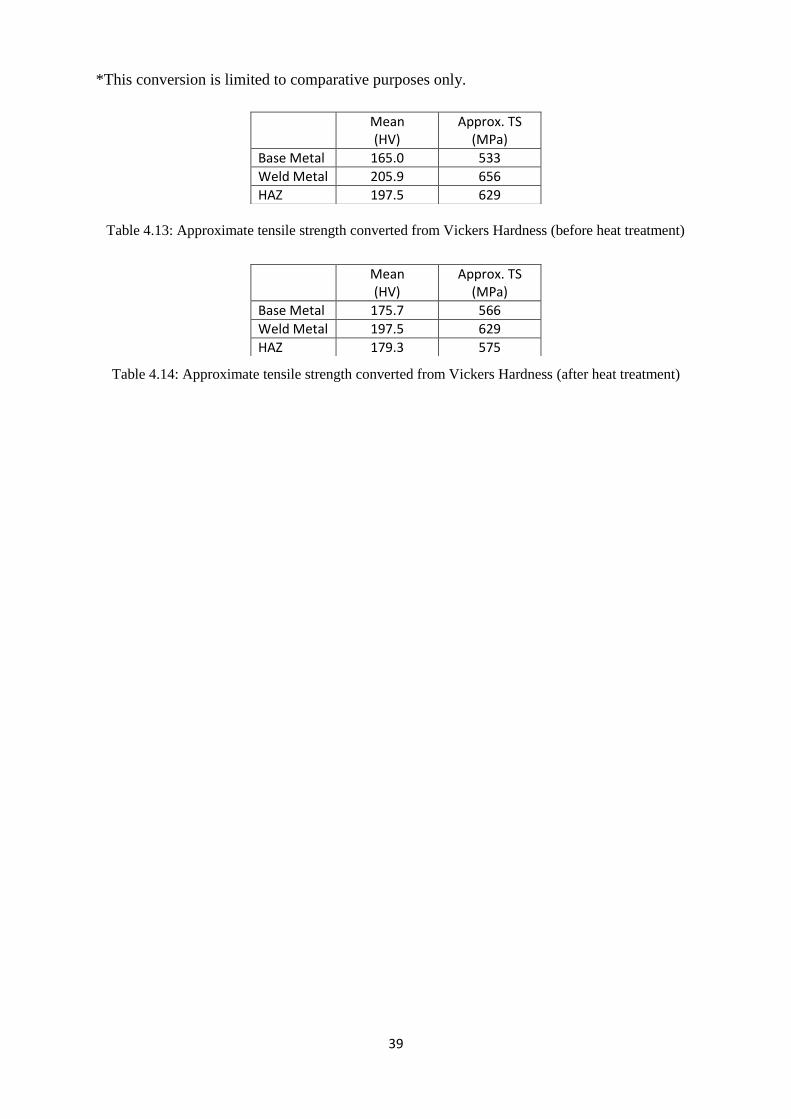
*This conversion is limited to comparative purposes only.
Mean (HV)
Approx. TS (MPa)
Base Metal 165.0 533
Weld Metal 205.9 656
HAZ 197.5 629
Mean (HV)
Approx. TS (MPa)
Base Metal 175.7 566
Weld Metal 197.5 629
HAZ 179.3 575
Table 4.13: Approximate tensile strength converted from Vickers Hardness (before heat treatment)
Table 4.14: Approximate tensile strength converted from Vickers Hardness (after heat treatment)
40
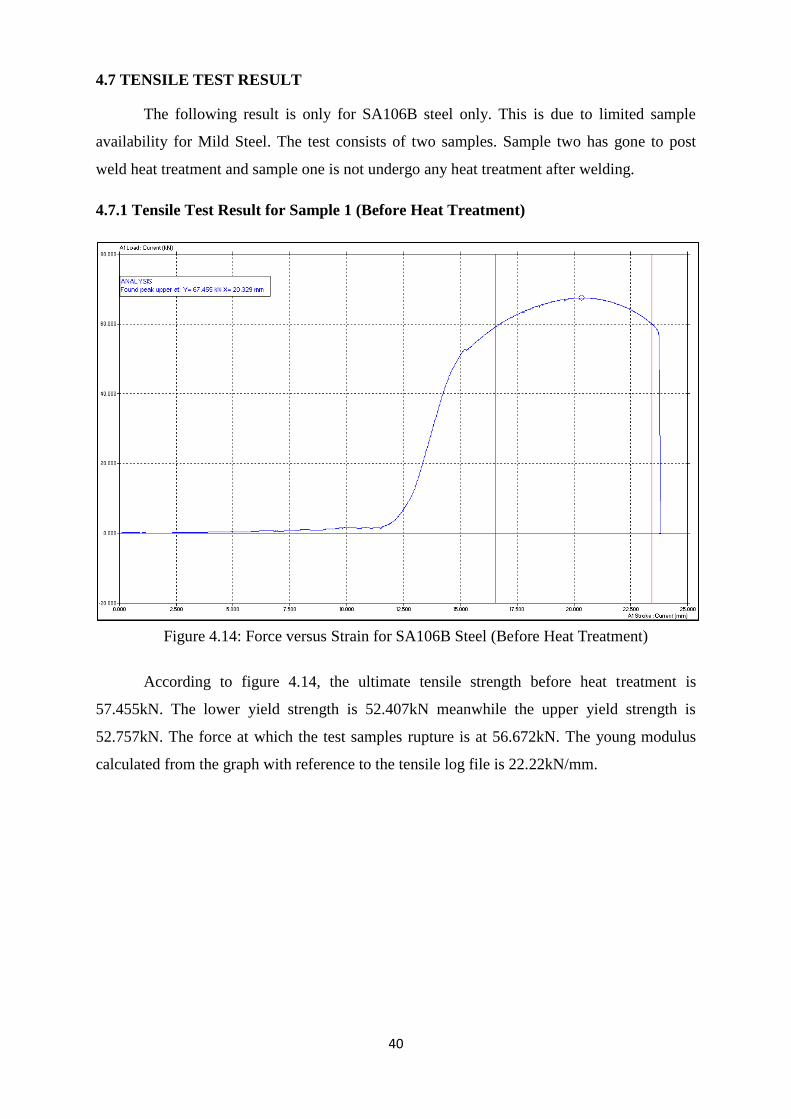
4.7 TENSILE TEST RESULT
The following result is only for SA106B steel only. This is due to limited sample
availability for Mild Steel. The test consists of two samples. Sample two has gone to post
weld heat treatment and sample one is not undergo any heat treatment after welding.
4.7.1 Tensile Test Result for Sample 1 (Before Heat Treatment)
According to figure 4.14, the ultimate tensile strength before heat treatment is
57.455kN. The lower yield strength is 52.407kN meanwhile the upper yield strength is
52.757kN. The force at which the test samples rupture is at 56.672kN. The young modulus
calculated from the graph with reference to the tensile log file is 22.22kN/mm.
Figure 4.14: Force versus Strain for SA106B Steel (Before Heat Treatment)
41
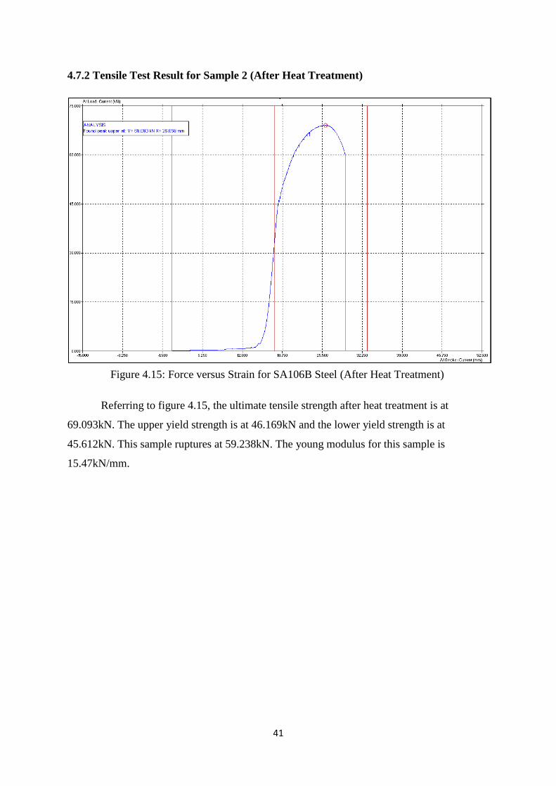
4.7.2 Tensile Test Result for Sample 2 (After Heat Treatment)
Referring to figure 4.15, the ultimate tensile strength after heat treatment is at
69.093kN. The upper yield strength is at 46.169kN and the lower yield strength is at
45.612kN. This sample ruptures at 59.238kN. The young modulus for this sample is
15.47kN/mm.
Figure 4.15: Force versus Strain for SA106B Steel (After Heat Treatment)
42
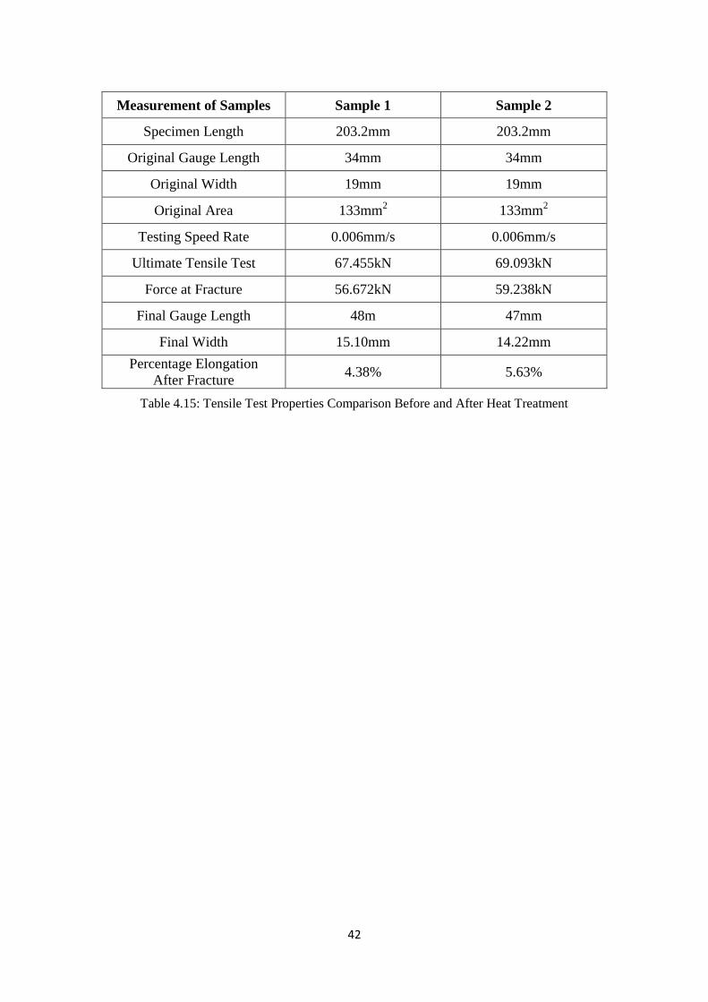
Measurement of Samples Sample 1 Sample 2
Specimen Length 203.2mm 203.2mm
Original Gauge Length 34mm 34mm
Original Width 19mm 19mm
Original Area 133mm2 133mm
2
Testing Speed Rate 0.006mm/s 0.006mm/s
Ultimate Tensile Test 67.455kN 69.093kN
Force at Fracture 56.672kN 59.238kN
Final Gauge Length 48m 47mm
Final Width 15.10mm 14.22mm
Percentage Elongation
After Fracture 4.38% 5.63%
Table 4.15: Tensile Test Properties Comparison Before and After Heat Treatment

43
CHAPTER 5
CONCLUSION
5.1 X-RAY FLUORESCENCE
Based on X-Ray Fluorescence result, I manage to identify the composition of the
carbon steel. Unfortunately, one important element which is carbon, unable to be identify in
the final result. The percentage of the carbon is very small causing the XRF unable to detect
it properly. So, undetectable carbon verifies the steel is in low carbon content. Others factor
like the unwanted present of oxide, which come from metal oxidation.
5.2 MICROSTRUCTURE
The image for carbon steel microstructure shown as expected earlier. For the base
metal, the microstructure is almost the same size everywhere. However, when we observe
from the base metal into the heat affected zone (HAZ) region, the microstructure started to
change. The grain sizes become smaller as we move from the base metal zone into the HAZ
zone. These changes happen along boundary between base metal and the weld metal.
Filler metal or the weld metal also seems to be difference from the base metal. The
grain structure was bigger and long in size. After post weld heat treatment, the base metal
show small variation in grain size. Some of the regions become smaller size and some remain
the same. This could be cause by uneven heat distribution during heat treatment.
After heat treatment, inside the heat affected zone, the grain size changes to almost
the same as base metal. Better carbon distribution at the heat affected zone make the grain
size become larger. It is become harder to determine where the heat affected zone is.
Microstructure inside the weld metal are not showing any significant changes although some
of the weld metal having microstructure shape almost the same as heat affected zone.

44
5.3 HARDNESS TEST
The base metal hardness has been increase after the heat treatment. This mean the
base metal has become harder than before heat treatment. Inside the heat affected zone, the
results show a reduction in hardness. The heat affected zone has become softer. Some
ductility has been imparted to this region. Hardness inside the weld metal is not showing any
significant changes in hardness.
5.4 TENSILE TEST
Ultimate tensile strength increase from before to after post weld heat treatment.
According to both graph, we can see the difference in graph direction. Graph for sample 2
shows the steel after heat treatment is more ductile than sample 1. Sample 2 has larger area
below the force strain graph which mean sample 2 can absorb more energy than sample 1.
5.5 WORK CONTINUATION
The thickness of the steel is initially with 6 mm thickness. Welding with 6mm
thickness usually not requires heat treatment. Therefore welding with 13mm thickness was
introduced to compare with 6mm thickness. Unfortunately, because of 13mm thickness
sample arrived late, some of the result for 13mm thickness not being able to gain.
Welding process also requires a lot of time and also depends on the laboratory and
technician availability. It is difficult to produce suitable welding quality for the sample,
especially welding for tensile test sample. Some of common problem is the lack of fusion,
incomplete root penetration, and also undercut near the weldment. So the work has been
repeated for a long time to acquire good sample.

45
Others problem contribution is machining for mechanical testing sample which is
tensile and impact test. Since production laboratory does not have notching tool, so the notch
has to make by using EDM machine. Present of impurities at the welded area cause the EDM
cutting wire to break. The effect is not being able to continue cutting process (see figure 5.1).
A suggestion for future work is to continue the mechanical testing.
Figure 5.1: Example of sample unable to continue cutting.
(a) Impact test sample, (b) Tensile test sample
(a) (b)
EDM Wire snap position

46
REFERENCES
1. William D. Callister, 2007. Material Science and Engineering: An Introduction,
7th
Edition, John Wiley & Sons (Asia) Pte Ltd.
2. Serope Kalpakjian and Steven R. Schmid, 2006. Manufacturing Engineering and
Technology, 5th
Edition, Pearson Prentice Hall.
3. WIS5, 2002. Welding Inspection. TWI Limited.
4. D. J. Abson, Y. Tkach, I Hadley, V. S. Wright, and F. M. Burdekin, (2006). Welding
Journal: A review of postweld heat treatment code exemption - Part 1 (Volume 85,
pp. 63-69).
5. ASME Boiler & Pressure Vessel Code, SECTION VIII DIV. 1 2004 EDITION.
6. ASME Boiler & Pressure Vessel Code, SECTION VIII DIV.1 2007 EDITION.
7. ASME Boiler & Pressure Vessel Code, SECTION IX, 2007 EDITION.
8. ASTM E8M-00b, Standard Test Methods for Tension Testing of Metallic Materials
9. D. Gandy. (2007). Carbon Steel Handbook, Final Report, March 2007, Retrieved
from the Web June 16, 2010, http://www.scribd.com/doc/28247782/Carbon-Steel-
Handbook#.
10. Prof. Kyung-Tae Park and Dong Hyuk Shin, (2001) Journal on Microstructural
Interpretation of Negligible Strain-Hardening Behavior of Submicrometer-Grained
Low-Carbon Steel during Tensile Deformation (Volume 33A, pp. 705-707).
11. D.A. Curry and J.F. Knot, (1976). Journal on The relationship between fracture
toughness and microstructure in the cleavage fracture of mild steel.
12. Welding Technology Institute of Australia, (2004) Post Weld Heat Treatment of
Welded Structures (Guidance Note 6, pp. 1-10).
13. M.J. SANTOFIMIA, L. ZHAO, and J. SIETSMA (2009) Journal on Microstructural
Evolution of a Low-Carbon Steel during Application of Quenching and Partitioning
Heat Treatments after Partial Austenitization (Volume 40A, pp. 46-56).
14. Raymond Sacks, 1981. Welding: Principles & Practices, Revised Edition,
Glencoe/McGraw-Hill.
15. Norman Bailey, 1994, Weldability of Ferritic Steels, Abington Publishing.
16. RWK Honeycombe & HKDH Bhasdeshia, 1995, Steels, Microstructure and
properties, 2th
edition, Edward Arnold and Gray Publishing.
17. Leonard E. Samuels, 1999, Light Microscopy of Carbon Steels, ASM International.
Related Documents

![THE MECHANICAL PROPERTIES AND MICROSTRUCTURES OF · PDF fileTHE MECHANICAL PROPERTIES AND MICROSTRUCTURES OF 9% CHROMIUM ... P91 would be possible [3] and secondly this value covers](https://static.cupdf.com/doc/110x72/5aa91a997f8b9a9a188c64aa/the-mechanical-properties-and-microstructures-of-mechanical-properties-and-microstructures.jpg)